JP2025041266A - Dishwashers - Google Patents
Dishwashers Download PDFInfo
- Publication number
- JP2025041266A JP2025041266A JP2023148457A JP2023148457A JP2025041266A JP 2025041266 A JP2025041266 A JP 2025041266A JP 2023148457 A JP2023148457 A JP 2023148457A JP 2023148457 A JP2023148457 A JP 2023148457A JP 2025041266 A JP2025041266 A JP 2025041266A
- Authority
- JP
- Japan
- Prior art keywords
- tank
- side connection
- storage tank
- treatment agent
- cleaning
- Prior art date
- Legal status (The legal status is an assumption and is not a legal conclusion. Google has not performed a legal analysis and makes no representation as to the accuracy of the status listed.)
- Pending
Links
Images
Classifications
-
- A—HUMAN NECESSITIES
- A47—FURNITURE; DOMESTIC ARTICLES OR APPLIANCES; COFFEE MILLS; SPICE MILLS; SUCTION CLEANERS IN GENERAL
- A47L—DOMESTIC WASHING OR CLEANING; SUCTION CLEANERS IN GENERAL
- A47L15/00—Washing or rinsing machines for crockery or tableware
- A47L15/14—Washing or rinsing machines for crockery or tableware with stationary crockery baskets and spraying devices within the cleaning chamber
- A47L15/18—Washing or rinsing machines for crockery or tableware with stationary crockery baskets and spraying devices within the cleaning chamber with movably-mounted spraying devices
- A47L15/22—Rotary spraying devices
-
- A—HUMAN NECESSITIES
- A47—FURNITURE; DOMESTIC ARTICLES OR APPLIANCES; COFFEE MILLS; SPICE MILLS; SUCTION CLEANERS IN GENERAL
- A47L—DOMESTIC WASHING OR CLEANING; SUCTION CLEANERS IN GENERAL
- A47L15/00—Washing or rinsing machines for crockery or tableware
- A47L15/42—Details
- A47L15/4246—Details of the tub
-
- A—HUMAN NECESSITIES
- A47—FURNITURE; DOMESTIC ARTICLES OR APPLIANCES; COFFEE MILLS; SPICE MILLS; SUCTION CLEANERS IN GENERAL
- A47L—DOMESTIC WASHING OR CLEANING; SUCTION CLEANERS IN GENERAL
- A47L15/00—Washing or rinsing machines for crockery or tableware
- A47L15/42—Details
- A47L15/4251—Details of the casing
- A47L15/4257—Details of the loading door
-
- A—HUMAN NECESSITIES
- A47—FURNITURE; DOMESTIC ARTICLES OR APPLIANCES; COFFEE MILLS; SPICE MILLS; SUCTION CLEANERS IN GENERAL
- A47L—DOMESTIC WASHING OR CLEANING; SUCTION CLEANERS IN GENERAL
- A47L15/00—Washing or rinsing machines for crockery or tableware
- A47L15/42—Details
- A47L15/44—Devices for adding cleaning agents; Devices for dispensing cleaning agents, rinsing aids or deodorants
- A47L15/4418—Devices for adding cleaning agents; Devices for dispensing cleaning agents, rinsing aids or deodorants in the form of liquids
-
- A—HUMAN NECESSITIES
- A47—FURNITURE; DOMESTIC ARTICLES OR APPLIANCES; COFFEE MILLS; SPICE MILLS; SUCTION CLEANERS IN GENERAL
- A47L—DOMESTIC WASHING OR CLEANING; SUCTION CLEANERS IN GENERAL
- A47L15/00—Washing or rinsing machines for crockery or tableware
- A47L15/42—Details
- A47L15/44—Devices for adding cleaning agents; Devices for dispensing cleaning agents, rinsing aids or deodorants
- A47L15/449—Metering controlling devices
-
- A—HUMAN NECESSITIES
- A47—FURNITURE; DOMESTIC ARTICLES OR APPLIANCES; COFFEE MILLS; SPICE MILLS; SUCTION CLEANERS IN GENERAL
- A47L—DOMESTIC WASHING OR CLEANING; SUCTION CLEANERS IN GENERAL
- A47L15/00—Washing or rinsing machines for crockery or tableware
- A47L15/42—Details
- A47L15/50—Racks ; Baskets
- A47L15/502—Cutlery baskets
-
- A—HUMAN NECESSITIES
- A47—FURNITURE; DOMESTIC ARTICLES OR APPLIANCES; COFFEE MILLS; SPICE MILLS; SUCTION CLEANERS IN GENERAL
- A47L—DOMESTIC WASHING OR CLEANING; SUCTION CLEANERS IN GENERAL
- A47L2401/00—Automatic detection in controlling methods of washing or rinsing machines for crockery or tableware, e.g. information provided by sensors entered into controlling devices
- A47L2401/02—Consumable products information, e.g. information on detergent, rinsing aid or salt; Dispensing device information, e.g. information on the type, e.g. detachable, or status of the device
- A47L2401/023—Quantity or concentration of the consumable product
-
- A—HUMAN NECESSITIES
- A47—FURNITURE; DOMESTIC ARTICLES OR APPLIANCES; COFFEE MILLS; SPICE MILLS; SUCTION CLEANERS IN GENERAL
- A47L—DOMESTIC WASHING OR CLEANING; SUCTION CLEANERS IN GENERAL
- A47L2501/00—Output in controlling method of washing or rinsing machines for crockery or tableware, i.e. quantities or components controlled, or actions performed by the controlling device executing the controlling method
- A47L2501/26—Indication or alarm to the controlling device or to the user
Landscapes
- Washing And Drying Of Tableware (AREA)
Abstract
Description
本発明は食器洗浄機に関する。 The present invention relates to a dishwasher.
特許文献1に従来の食器洗浄機が開示されている。この食器洗浄機は、洗浄槽と、蓋体と、貯蔵タンクと、処理剤供給装置と、処理剤供給路とを備えている。洗浄槽は上方が開放された槽開口を有している。蓋体は槽開口を開閉可能である。これらの蓋体と洗浄槽とは、洗浄水によって被洗浄物を洗浄する洗浄空間を形成している。また、洗浄槽には、貯蔵タンクを収容する収容部が形成されている。収容部は洗浄空間の外部、すなわち洗浄空間よりも前方に位置している。
貯蔵タンクは、被洗浄物に用いる処理剤を貯蔵している。処理剤供給装置は洗浄槽に取り付けられており、洗浄空間の外部に位置している。処理剤供給装置は、貯蔵タンクに貯蔵された処理剤を洗浄空間内に供給する。処理剤供給路は洗浄槽に取り付けられており、洗浄空間の外部に位置している。処理剤供給路はと接続している。また、処理剤供給路は供給路側接続部を有しており、この供給路側接続部に対して貯蔵タンクが着脱可能に取り付けられる。 The storage tank stores the processing agent to be used on the object to be cleaned. The processing agent supply device is attached to the cleaning tank and is located outside the cleaning space. The processing agent supply device supplies the processing agent stored in the storage tank into the cleaning space. The processing agent supply path is attached to the cleaning tank and is located outside the cleaning space. The processing agent supply path is connected to. The processing agent supply path also has a supply path side connection part, and the storage tank is detachably attached to this supply path side connection part.
この食器洗浄機では、貯蔵タンクが収容部に収容されつつ、供給路側接続部に取り付けられる。これにより、貯蔵タンクは、洗浄空間の外部に配置されつつ、処理剤供給路を通じて処理剤供給装置と接続される。こうして、貯蔵タンク内の処理剤が処理剤供給装置に流通する。一方、収容部から貯蔵タンクを引き出すことにより、貯蔵タンクが供給路側接続部から取り外される。これにより、この食器洗浄機では、貯蔵タンクを収容部から取り出すことができ、食器洗浄機の外部で貯蔵タンクに処理剤を補充することが可能となっている。 In this dishwasher, the storage tank is housed in the housing and attached to the supply path side connection part. As a result, the storage tank is located outside the washing space and connected to the treatment agent supply device through the treatment agent supply path. In this way, the treatment agent in the storage tank is circulated to the treatment agent supply device. Meanwhile, by pulling the storage tank out of the housing, the storage tank is detached from the supply path side connection part. As a result, in this dishwasher, the storage tank can be removed from the housing and the storage tank can be refilled with treatment agent outside the dishwasher.
上記従来の食器洗浄機では、貯蔵タンクに処理剤を補充する際に処理剤の一部が貯蔵タンクの表面に付着したり、供給路側接続部と貯蔵タンクとを着脱する際に貯蔵タンク内の処理剤が漏れ出たりし得る。そして、このような処理剤が供給路側接続部に付着することにより、供給路側接続部に次第に堆積する。このため、この食器洗浄機では、堆積した処理剤によって供給路側接続部と貯蔵タンクとが固着することで、供給路側接続部と貯蔵タンクとの着脱性が損なわれるおそれがある。 In the conventional dishwasher described above, when refilling the storage tank with treatment agent, some of the treatment agent may adhere to the surface of the storage tank, and when attaching or detaching the supply line side connector to the storage tank, the treatment agent may leak out from the storage tank. When this treatment agent adheres to the supply line side connector, it gradually accumulates on the supply line side connector. For this reason, in this dishwasher, the accumulated treatment agent may cause the supply line side connector to adhere to the storage tank, impairing the ability to attach or detach the supply line side connector to the storage tank.
そこで、この食器洗浄機の使用者は、収容部や供給路側接続部に堆積した処理剤を定期的に除去する必要があるものの、収容部及び供給路側接続部は洗浄空間の外部に位置している。このため、使用者は処理剤を除去し難い。 Therefore, users of this dishwasher need to periodically remove the treatment agent that has accumulated in the storage section and the supply line side connection section, but the storage section and the supply line side connection section are located outside the washing space. This makes it difficult for users to remove the treatment agent.
本発明は、上記従来の実情に鑑みてなされたものであって、処理剤を貯蔵する貯蔵タンクを有する構成において、貯蔵タンクの着脱性に優れた食器洗浄機を提供することを解決すべき課題としている。 The present invention was made in consideration of the above-mentioned conventional situation, and the problem to be solved is to provide a dishwasher having a storage tank for storing a treatment agent, in which the storage tank is easily attached and detached.
本発明の食器洗浄機は、一方に向かって開口する槽開口を有する洗浄槽と、
前記槽開口を開閉可能であり、かつ、洗浄水によって被洗浄物の洗浄を行う洗浄空間を前記洗浄槽とともに形成する蓋体と、
前記被洗浄物に用いる処理剤を貯蔵する貯蔵タンクと、
前記洗浄空間の外部に位置し、前記貯蔵タンクに貯蔵された前記処理剤を前記洗浄空間内に供給する処理剤供給装置と、
前記貯蔵タンクと前記処理剤供給装置とを接続する処理剤供給路とを備え、
前記洗浄槽又は前記蓋体は、前記洗浄空間に面する特定壁を有し、
前記処理剤供給路は、前記洗浄空間に臨む状態で前記特定壁に固定されるとともに、前記貯蔵タンクが着脱可能に取り付けられる供給路側接続部を有し、
前記貯蔵タンクは、前記供給路側接続部に取り付けられることにより、前記洗浄空間内に配置されることを特徴とする。
The dishwasher of the present invention comprises: a washing tub having a tub opening opening toward one side;
a cover body that can open and close the tank opening and that, together with the cleaning tank, forms a cleaning space in which an object to be cleaned is cleaned with cleaning water;
A storage tank for storing a treatment agent to be used on the object to be cleaned;
a treatment agent supply device located outside the cleaning space and supplying the treatment agent stored in the storage tank into the cleaning space;
a treatment agent supply passage connecting the storage tank and the treatment agent supply device,
The cleaning tank or the lid has a specific wall facing the cleaning space,
the treatment agent supply passage is fixed to the specific wall in a state facing the cleaning space, and has a supply passage side connection portion to which the storage tank is detachably attached,
The storage tank is attached to the supply path side connection portion and is disposed within the cleaning space.
本発明の食器洗浄機では、処理剤供給路が供給路側接続部を有しており、この供給路側接続部は、洗浄空間に臨む状態で特定壁に固定される。そして、この食器洗浄機では、供給路側接続部に貯蔵タンクが取り付けられることにより、貯蔵タンクは洗浄空間内に配置される。 In the dishwasher of the present invention, the treatment agent supply passage has a supply passage side connection part, and this supply passage side connection part is fixed to a specific wall in a state facing the washing space. In this dishwasher, a storage tank is attached to the supply passage side connection part, so that the storage tank is disposed within the washing space.
これにより、この食器洗浄機では、処理剤の補充時に貯蔵タンクの表面に付着した処理剤が貯蔵タンクを経て供給路側接続部に付着したり、貯蔵タンクと供給路側接続部とを着脱する際に不可避的に漏れ出た処理剤が供給路側接続部に付着したりした場合であっても、このような処理剤については、洗浄空間内の洗浄水によって、貯蔵タンクの表面や供給路側接続部から除去することができる。また、たとえ洗浄水によって処理剤を完全に除去し得ない場合であっても、貯蔵タンクは洗浄空間内に配置されるため、使用者は貯蔵タンクの表面や供給路側接続部に付着した処理剤を除去し易い。 As a result, in this dishwasher, even if the treating agent that adheres to the surface of the storage tank when refilling the treating agent passes through the storage tank and adheres to the supply line side connection part, or if the treating agent that inevitably leaks out when attaching or detaching the storage tank and the supply line side connection part adheres to the supply line side connection part, such treating agent can be removed from the surface of the storage tank and the supply line side connection part by the washing water in the washing space. Also, even if the treating agent cannot be completely removed by washing water, since the storage tank is located in the washing space, it is easy for the user to remove the treating agent that has adhered to the surface of the storage tank and the supply line side connection part.
この結果、この食器洗浄機では供給路側接続部に処理剤が堆積し難いことから、処理剤によって供給路側接続部と貯蔵タンクとが固着されることを抑制できる。 As a result, in this dishwasher, the treatment agent is less likely to accumulate at the supply line side connection, which prevents the supply line side connection and the storage tank from adhering to each other due to the treatment agent.
したがって、本発明の食器洗浄機は、処理剤を貯蔵する貯蔵タンクを有する構成において、貯蔵タンクの着脱性に優れている。 Therefore, the dishwasher of the present invention, in a configuration having a storage tank for storing a treatment agent, has excellent attachability and detachability of the storage tank.
貯蔵タンクは、処理剤を貯蔵するタンク本体と、タンク本体と連通し、供給路側接続部に着脱可能に取り付けられる第1タンク側接続部と、第1タンク側接続部よりも上方に位置して洗浄空間の外部とタンク本体内とを連通させる第2タンク側接続部とを有していることが好ましい。 It is preferable that the storage tank has a tank body that stores the treatment agent, a first tank side connection part that communicates with the tank body and is detachably attached to the supply line side connection part, and a second tank side connection part that is located above the first tank side connection part and communicates between the outside of the cleaning space and the inside of the tank body.
この場合には、第2タンク側接続部を通じて洗浄空間の外部とタンク本体内とを連通させることにより、タンク本体内が負圧となることを防止できる。このため、タンク本体内の処理剤を処理剤供給路、ひいては処理剤供給装置に好適に流通させることができる。 In this case, by connecting the outside of the cleaning space to the inside of the tank body through the second tank side connection, it is possible to prevent negative pressure from building up inside the tank body. This allows the treatment agent inside the tank body to flow efficiently to the treatment agent supply path and ultimately to the treatment agent supply device.
また、この場合、特定壁には、洗浄空間に臨む状態で固定されて洗浄空間の外部に連通するとともに、第2タンク側接続部が着脱可能に取り付けられる通気部が設けられ得る。そして、第1タンク側接続部と第2タンク側接続部とは、特定壁に向かって互いに平行に延びていることが好ましい。 In this case, the specific wall may be provided with a ventilation section that is fixed facing the cleaning space and communicates with the outside of the cleaning space, and to which the second tank side connection section is detachably attached. It is preferable that the first tank side connection section and the second tank side connection section extend parallel to each other toward the specific wall.
これにより、供給路側接続部に対する第1タンク側接続部の着脱と、通気部に対する第2タンク側接続部の着脱とを容易に行うことができる。 This makes it easy to attach and detach the first tank side connection part to the supply line side connection part, and the second tank side connection part to the ventilation part.
また、本発明の食器洗浄機は、貯蔵タンクが供給路側接続部に取り付けられているか否かを判断可能な判断手段と、判断手段の判断結果を報知する報知手段とを備えていることが好ましい。 The dishwasher of the present invention preferably also includes a determination means capable of determining whether or not the storage tank is attached to the supply line side connection portion, and a notification means for notifying the result of the determination by the determination means.
この場合には、貯蔵タンクが供給路側接続部に取り付けられているか否かについて、使用者は報知手段による報知を通じて容易に了知することができる。ここで、報知手段は判断手段の判断結果に基づいて、貯蔵タンクが供給路側接続部に取り付けられていることのみを報知しても良く、貯蔵タンクが供給路側接続部に取り付けられていないことのみを報知しても良い。また、報知手段は、貯蔵タンクが供給路側接続部に取り付けられている旨の報知と、貯蔵タンクが供給路側接続部に取り付けられていない旨の報知とをそれぞれ行っても良い。 In this case, the user can easily know whether or not the storage tank is attached to the supply line side connection part through the notification by the notification means. Here, the notification means may only notify that the storage tank is attached to the supply line side connection part, or may only notify that the storage tank is not attached to the supply line side connection part, based on the judgment result of the judgment means. Furthermore, the notification means may separately notify that the storage tank is attached to the supply line side connection part and that the storage tank is not attached to the supply line side connection part.
また、貯蔵タンクに貯蔵された処理剤の残量を検知する残量検知手段を備え得る。そして、判断手段は、残量検知手段が残量を未検知であるときには、貯蔵タンクが供給路側接続部に取り付けられていないと判断することが好ましい。 The storage tank may also be provided with a remaining amount detection means for detecting the remaining amount of treatment agent stored in the storage tank. It is preferable that the determination means determines that the storage tank is not attached to the supply line side connection portion when the remaining amount detection means has not detected the remaining amount.
この場合には、貯蔵タンクが供給路側接続部に取り付けられているか否かを判断手段が判断するに当たって、専用の検知装置等を用いる必要がない。このため、食器洗浄機の構成を簡素化できる。 In this case, there is no need for a dedicated detection device or the like when the determination means determines whether the storage tank is attached to the supply line side connection part. This simplifies the structure of the dishwasher.
洗浄槽には、洗浄空間と連通し、洗浄水が貯留される貯水部が形成され得る。そして、貯蔵タンクは、供給路側接続部に取り付けられることにより、貯水部よりも上方に位置していることが好ましい。 The cleaning tank may be formed with a water storage section that communicates with the cleaning space and stores cleaning water. The storage tank is preferably attached to the supply line side connection section and positioned above the water storage section.
この場合には、貯水部に貯留された洗浄水に貯蔵タンクが浸かることを防止できる。これにより、この食器洗浄機では、洗浄水が貯蔵タンク内に浸入し難くなる。 In this case, the storage tank can be prevented from being submerged in the wash water stored in the water storage section. This makes it difficult for wash water to seep into the storage tank in this dishwasher.
また、本発明の食器洗浄機は、被洗浄物を載置しつつ洗浄空間内に収納される載置部材を備え得る。そして、載置部材は、供給路側接続部に対する貯蔵タンクの取り付けが不完全であるときに貯蔵タンクと干渉する干渉部を有していることが好ましい。 The dishwasher of the present invention may also include a mounting member that is stored in the washing space while the items to be washed are placed on it. It is preferable that the mounting member has an interference portion that interferes with the storage tank when the attachment of the storage tank to the supply line side connection portion is incomplete.
この場合には、干渉部が貯蔵タンクと干渉することにより、使用者は、供給路側接続部に対して貯蔵タンクが不完全な状態で取り付けられていることを容易に了知することができる。 In this case, the interference with the storage tank allows the user to easily recognize that the storage tank is incompletely attached to the supply line side connection.
洗浄槽が特定壁を有していることが好ましい。この場合には、蓋体の構成を簡素化することができる。 It is preferable that the cleaning tank has a specific wall. In this case, the structure of the lid can be simplified.
また、この場合、本発明の食器洗浄機は、前方に向かって開口する筐体開口を有し、洗浄槽を内部に配置可能な筐体を備え得る。槽開口は前方に向かって開口して筐体開口と連通し得る。そして、蓋体は、揺動軸心周りで前後方向に揺動可能に筐体に取り付けられ、筐体開口及び槽開口を開放する開放位置と、筐体開口及び槽開口を閉鎖する閉鎖位置とに変位することが好ましい。 In this case, the dishwasher of the present invention may be provided with a housing having a housing opening that opens toward the front and in which a washing tub can be placed. The tub opening may open toward the front and communicate with the housing opening. The lid is attached to the housing so as to be swingable in the front-rear direction around the swing axis, and is preferably displaceable between an open position that opens the housing opening and the tub opening, and a closed position that closes the housing opening and the tub opening.
この場合には、所謂フロントオープン式の食器洗浄機を実現できる。また、蓋体は開放位置と閉鎖位置とに変位するものの、洗浄槽が特定壁を有することにより、蓋体には供給路側接続部、さらには貯蔵タンクが設けられることがない。このため、蓋体が変位することに起因する貯蔵タンクからの処理剤の漏れが生じ難い。 In this case, a so-called front-opening dishwasher can be realized. Although the lid is displaced between an open position and a closed position, the washing tank has a specific wall, so the lid does not have a supply channel side connection or a storage tank. Therefore, leakage of the treatment agent from the storage tank due to displacement of the lid is unlikely to occur.
本発明の食器洗浄機は、処理剤を貯蔵する貯蔵タンクを有する構成において、貯蔵タンクの着脱性に優れている。 The dishwasher of the present invention has a storage tank for storing a treatment agent, and the storage tank is easy to attach and detach.
以下、本発明を具体化した実施例を図面を参照しつつ説明する。 The following describes an embodiment of the present invention with reference to the drawings.
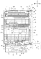
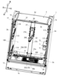
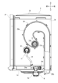
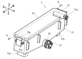
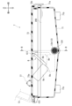
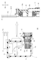
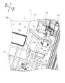
図1~3に示すように、実施例の食器洗浄機は、筐体1と、洗浄槽3と、蓋体5と、貯蔵タンク7と、処理剤供給装置9と、処理剤供給路11と、第1食器かご13と、第2食器かご14と、第3食器かご15と、操作部19と、制御部21とを備えている。第1食器かご13は、本発明における「載置部材」の一例である。また、操作部19は、本発明における「報知手段」の一例である。そして、制御部21は、本発明における「判断手段」の一例である。この食器洗浄機は、図示しないシステムキッチンに組み込まれている。なお、説明を容易にするため、図2では蓋体5及び第1食器かご13等の図示を省略しており、図3では筐体1及び蓋体5等の図示を省略している。
As shown in Figures 1 to 3, the dishwasher of the embodiment includes a
本実施例では、図1及び図2に示す各矢印によって、食器洗浄機の前後方向及び上下方向を規定している。また、図2では、食器洗浄機の使用者(図示略)が食器洗浄機の前方から対向した際を基準として、使用者の右側を食器洗浄機の右側とし、使用者の左側を食器洗浄機の左側として食器洗浄機の左右方向、すなわち幅方向を規定している。これらの前後方向、上下方向及び左右方向は互いに直交している。そして、図3以降では、図1及び図2に対応して食器洗浄機の前後方向、上下方向及び左右方向を規定している。 In this embodiment, the front-rear and up-down directions of the dishwasher are defined by the arrows shown in Figures 1 and 2. In Figure 2, the left-right direction of the dishwasher, i.e., the width direction, is defined based on the position of a user (not shown) of the dishwasher facing the front of the dishwasher, with the right side of the user being the right side of the dishwasher and the left side of the user being the left side of the dishwasher. These front-rear, up-down and left-right directions are mutually perpendicular. In Figures 3 and onwards, the front-rear, up-down and left-right directions of the dishwasher are defined in accordance with Figures 1 and 2.
図1及び図2に示すように、筐体1は、右側パネル1aと、左側パネル1bと、前下パネル1cと、後下パネル1dと、底部パネル1eと、筐体開口1fとを有している。右側パネル1a及び左側パネル1bは、それぞれ前後方向及び上下方向に延びる略矩形の板状に形成されている。右側パネル1aと左側パネル1bとは、それぞれ左右方向に離隔して配置されている。これにより、右側パネル1aは筐体1の右側面を構成しており、左側パネル1bは筐体1の左側面を構成している。
As shown in Figures 1 and 2, the
前下パネル1c及び後下パネル1dは、上下方向及び左右方向に延びる略矩形の板状に形成されている。前下パネル1c及び後下パネル1dは、それぞれ右側パネル1a及び左側パネル1bに取り付けられて右側パネル1aと左側パネル1bとの間に配置されている。より具体的には、前下パネル1cは、右側パネル1aと左側パネル1bとの間であって、右側パネル1a及び左側パネル1bの前方下部に配置されている。一方、後下パネル1dは、右側パネル1aと左側パネル1bとの間であって、右側パネル1a及び左側パネル1bの後方下部に配置されている。つまり、前下パネル1cと後下パネル1dとは、右側パネル1aと左側パネル1bとの間で前後方向に離隔して配置されている。
The front
底部パネル1eは、前後方向及び左右方向に延びる略矩形の板状に形成されている。底部パネル1eは、筐体1の最下部に配置されており、右側パネル1a、左側パネル1b、前下パネル1c及び後下パネル1dの各下端に取り付けられている。これらの右側パネル1a、左側パネル1b、前下パネル1c、後下パネル1d及び底部パネル1eにより、筐体1の下部には、収容空間10が形成されている。
The
筐体開口1fは、右側パネル1aと、左側パネル1bと、前下パネル1cとの間に形成されている。これにより、筐体開口1fは、収容空間10の上方に位置しつつ、筐体1の前方に向かって開口している。
The
図2に示すように、洗浄槽3は、右側壁3a、左側壁3b、後壁3c、上壁3d、下壁3e及び槽開口3fを有している。右側壁3aは、洗浄槽3の右側面を構成しており、前後方向及び上下方向に延びている。右側壁3aは、本発明における「特定壁」の一例である。左側壁3bは、洗浄槽3の左側面を構成しており、前後方向及び上下方向に延びている。右側壁3aと左側壁3bとは左右方向で対向している。
As shown in FIG. 2, the
後壁3cは、洗浄槽3の後面を構成しており、左右方向及び上下方向に延びている。後壁3cは、右側壁3aと左側壁3bとの間に配置されており、右側壁3a及び左側壁3bの各後端と接続している。上壁3dは、洗浄槽3の上面を構成しており、左右方向及び前後方向に延びている。上壁3dは、右側壁3aと左側壁3bと後壁3cとの間に配置されており、右側壁3a、左側壁3b及び後壁3cの各上端と接続している。下壁3eは、洗浄槽3の下面を構成しており、左右方向及び前後方向に延びている。下壁3eは、右側壁3aと左側壁3bと後壁3cとの間に配置されており、右側壁3a、左側壁3b及び後壁3cの各下端と接続している。これにより、上壁3dと下壁3eとは上下方向で対向している。
The
図1に示すように、下壁3eには貯水部23が形成されている。より具体的には、貯水部23は、下壁3eにおける前後方向及び左右方向の略中央となる個所を下方に凹設することで形成されている。貯水部23には、洗浄水が貯留される。また、詳細な図示を省略するものの、貯水部23の中央には上下方向に貫通する開口が形成されている。なお、洗浄水についての詳細は後述する。
As shown in FIG. 1, a
槽開口3fは洗浄槽3の前端に位置している。槽開口3fは、洗浄槽3の前方に向かって開口しており、洗浄槽3の内部と外部とを前後方向に連通させている。これらの右側壁3a、左側壁3b、後壁3c、上壁3d及び、下壁3e及び槽開口3fにより、洗浄槽3は、前方が開口する略矩形の箱状に形成されている。
The
また、図2に示すように、右側壁3aには、第1下段ガイド部材111と、第1中段ガイド部材112と、第1上段ガイド部材113とが取り付けられている。第1下段ガイド部材111は、右側壁3aの下部に取り付けられている。第1中段ガイド部材112は、右側壁3aにおいて第1下段ガイド部材111よりも上方に離隔した位置に取り付けられている。第1上段ガイド部材113は、右側壁3aにおいて第1中段ガイド部材112よりも上方に離隔した位置に取り付けられている。これらの第1下段ガイド部材111、第1中段ガイド部材112及び第1上段ガイド部材113は、それぞれ右側壁3aに沿って前後方向に平行に延びている。
As shown in FIG. 2, a first
一方、左側壁3bには、第2下段ガイド部材114と、第2中段ガイド部材115と、第2上段ガイド部材116とが取り付けられている。第2下段ガイド部材114は、第1下段ガイド部材111と等しい高さとなるように左側壁3bに取り付けられている。第2中段ガイド部材115は、第1中段ガイド部材112と等しい高さとなるように左側壁3bに取り付けられている。第2上段ガイド部材116は、第1上段ガイド部材113と等しい高さとなるように左側壁3bに取り付けられている。また、第2下段ガイド部材114、第2中段ガイド部材115及び第2上段ガイド部材116は、それぞれ左側壁3bに沿いつつ、第1下段ガイド部材111、第1中段ガイド部材112及び第1上段ガイド部材113と平行で前後方向に延びている。
On the other hand, the second
こうして、洗浄槽3の内部では、第1、2下段ガイド部材111、114同士が左右方向で対向しており、第1、2中段ガイド部材112、115同士が左右方向で対向しており、第1、2上段ガイド部材113、116同士が左右方向で対向している。
Thus, inside the
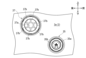
また、図1及び図4に示すように、右側壁3aにおいて、第1下段ガイド部材111と第1中段ガイド部材112との間となる個所には、供給路側接続部35及び通気部37が固定されている。供給路側接続部35についての詳細は後述する。
As shown in Figs. 1 and 4, a supply path
図4に示すように、通気部37は、右側壁3aにおいて供給路側接続部35よりも上方及び後方に離隔して配置されている。通気部37には、1つの第1通気口37aと、6つの第2通気口37bとが形成されている。各第2通気口37bは、第1通気口37aの周囲に配置されており、第1通気口37aを囲っている。第1通気口37a及び各第2通気口37bは、それぞれ右側壁3aを左右方向に貫通している。
As shown in FIG. 4, the
洗浄槽3は、筐体1の右側パネル1a及び左側パネル1bに固定されることにより、筐体1内に配置されており、図1に示す収容空間10の上方に位置している。そして、洗浄槽3では、槽開口3fが筐体1の筐体開口1fの内側に位置しつつ、前方に臨む状態となっている。
The
また、洗浄槽3には、水溜ケース25、分水器26、給水ダクト27、空気循環装置28及びフィルタユニット29及び係止装置50が設けられている。水溜ケース25は、上端が開口する有底の略筒状に形成されている。水溜ケース25は、収容空間10内に配置されており、洗浄槽3の下方に位置している。水溜ケース25は、自己の上端を下壁3eに固定することにより、貯水部23と連通している。
The
また、水溜ケース25には、貯水部23を経て洗浄槽3の内部に延びる接続筒部25aが形成されている。図1及び図2に示すように、接続筒部25aは、上下方向延びる円筒状に形成されている。接続筒部25aは下端が分水器26に接続している。また、接続筒部25aの上端には、第1噴射ノズル31が回転可能に取り付けられている。これにより、第1噴射ノズル31は、洗浄槽3の内部に配置されている。第1噴射ノズル31は洗浄槽3の内部で回転可能となっている。また、第1噴射ノズル31には複数の噴射部300が形成されている。
The
また、図1に示すように、水溜ケース25には、給水ホース41、給水ポンプ43及び排水ポンプ45が接続されている。これらの給水ポンプ43及び排水ポンプ45は、それぞれ収容空間10に配置されることにより、洗浄槽3の下方に位置している。
As shown in FIG. 1, a
給水ホース41は、一端が水溜ケース25に接続されている。そして、給水ホース41の他端は、筐体1の外部に延びており、食器洗浄機の外部に設けられた給水源(図示略)に接続されている。これにより、給水ホース41は、水溜ケース25と給水源とを接続している。給水ポンプ43及び排水ポンプ45は、それぞれ制御部21と通電可能に接続されている。また、給水ホース41には給水電磁弁(図示略)が設けられている。なお、給水ポンプ43及び排水ポンプ45の具体的な動作については後述する。
One end of the
また、水溜ケース25には、排水ホース47の一端が接続されている。そして、排水ホース47の他端は、筐体1の外部に延びており、食器洗浄機の外部に設けられた排水口(図示略)に接続されている。これにより、排水ホース47は、水溜ケース25と排水口とを接続している。また、排水ホース47には排水電磁弁(図示略)が設けられている。
One end of a
分水器26は収容空間10に配置されており、水溜ケース25に組み付けられている。分水器26は水溜ケース25とともに洗浄槽3の下壁3eに固定されている。また、分水器26は給水ポンプ43と接続している。
The
図1及び図2に示すように、給水ダクト27は洗浄槽3の内部に配置されている。給水ダクト27は内部を洗浄水が流通可能となっている。給水ダクト27は、第1ダクト27aと第2ダクト27bと第3ダクト27cと分岐ダクト27dとで構成されている。第1ダクト27aは下壁3eの上方に位置しており、下壁3eに沿って前後方向に延びている。第1ダクト27aの前端は接続筒部25aとは異なる位置で分水器26に接続されている。
As shown in Figures 1 and 2, the
第2ダクト27bは、後壁3cに固定されつつ、後壁3cに沿って洗浄槽3内を上下方向に延びている。第2ダクト27bは下端が第1ダクト27aの後端と接続している。第3ダクト27cは上壁3dに沿って洗浄槽3内を前後方向に延びている。第3ダクト27cは後端が第1ダクト27aの上端と接続している。分岐ダクト27dは、第2ダクト27bの上下方向の略中央となる個所で第2ダクト27bと接続しており、第2ダクト27bから前方に向かって延びている。
The
また、分岐ダクト27dの前端には第2噴射ノズル32が回転可能に接続されており、第3ダクト27cの前端には第3噴射ノズル33が回転可能に接続されている。この際、第2噴射ノズル32及び第3噴射ノズル33は、それぞれ分岐ダクト27dの前端及び第3ダクト27cの前端に対して下方から接続している。また、第1噴射ノズル31と同様、第2、3噴射ノズル32、33に対しても複数の噴射部300が形成されている。
The
空気循環装置28は、上述の通気部37と、図1及び図3に示す通気ダクト28aと、図3に示す接続ホース28bと、図1に示す給気ファン28cと、図2に示す空気供給部28dとで構成されている。図3に示すように、通気ダクト28aは洗浄槽3の右側壁3aに取り付けられており、右側壁3aと、筐体1の右側パネル1aとの間に位置している。つまり、通気ダクト28aは、右側壁3aにおいて、第1下段ガイド部材111、第1中段ガイド部材112及び第1上段ガイド部材113とは反対側に取り付けられており、洗浄槽3の外側に位置している。通気ダクト28aは、通気部37と接続している。これにより、通気ダクト28aは、通気部37の第1通気口37a及び各第2通気口37bと連通している。通気ダクト28aは、通気部37との接続個所から上方後部に向かって湾曲しつつ延びた後、右側壁3aの下方に向かって直線状に延びている。通気ダクト28aの内部には空気が流通可能となっている。
The
接続ホース28bは収容空間10内に配置されている。接続ホース28bは通気ダクト28aの下端と接続しつつ、収容空間10内を左方に向かって延びている。図1に示すように、給気ファン28cは収容空間10内に配置されている。詳細な図示を省略するものの、給気ファン28cは、ハウジングと、ハウジング内に設けられたファン本体とを有している。給気ファン28cは、通気ダクト28aとは反対側で接続ホース28bと接続されている。また、給気ファン28cは、制御部21と通電可能に接続されている。
The
図2に示す空気供給部28dは、給気ファン28cと接続しつつ下壁3eに挿通されており、洗浄槽3内に延びている。
The
フィルタユニット29は、第1フィルタ部29aと第2フィルタ部29bとを有している。第1フィルタ部29aは、洗浄槽3の下壁3eに載置されることにより、貯水部23を上方から覆っている。第2フィルタ部29bは、第1フィルタ部29aに挿通されており、貯水部23内及び水溜ケース25内に延びている。フィルタユニット29は、第1フィルタ部29a及び第2フィルタ部29bによって、洗浄水に含まれる残菜等の残滓を捕獲可能となっている。
The
係止装置50は、洗浄槽3の上壁3dに固定されている。これにより、係止装置50は、槽開口3fの上方であって、洗浄槽3における左右方向の略中央に位置している。
The locking
図1に示すように、蓋体5は、外側パネル5aと内側パネル5bとを有している。外側パネル5aは上下方向及び左右方向に延びる板材によって形成されている。外側パネル5aの上部には把持部5cが固定されている。内側パネル5bは、外側パネル5aの後方に固定されている。
As shown in FIG. 1, the
蓋体5は、ヒンジ機構51及び収容空間10内に設けられたダンパ機構(図示略)によって、筐体1の前部に取り付けられている。これにより、蓋体5は、筐体1に対して第1揺動軸心O1周りで前後方向に揺動可能となっている。第1揺動軸心O1は、本発明における「揺動軸心」の一例である。第1揺動軸心O1は、筐体1の左右方向に直線状に延びている。
The
蓋体5は、第1揺動軸心O1周りで後方向に揺動することにより、図1の実線で示す閉鎖位置に変位する。蓋体5は、閉鎖位置に変位することにより、筐体開口1f及び槽開口3fを前方から閉鎖する。そして、閉鎖位置に変位した蓋体5は、洗浄槽3とともに洗浄空間100を形成する。つまり、洗浄空間100は、洗浄槽3の右側壁3a、左側壁3b、後壁3c、上壁3d及び下壁3eと、蓋体5の内側パネル5bとの間に形成されている。
The
また、上述の通気部37(図4参照)は、洗浄空間100に臨んでいる。これにより、通気部37の第1通気口37a及び各第2通気口37bは、洗浄空間100と通気ダクト28aとを連通することにより、洗浄空間100を通気ダクト28a内、すなわち洗浄空間100の外部に連通させている。また、図1に示す係止装置50は、閉鎖位置に変位した蓋体5を係止することにより、蓋体5を閉鎖位置で保持する。
The above-mentioned ventilation section 37 (see FIG. 4) faces the cleaning
一方、蓋体5は、第1揺動軸心O1周りで前方向に揺動することにより、図1の仮想線で示す開放位置に変位する。蓋体5は、開放位置に変位することにより、筐体開口1f及び槽開口3fを前方に開放する。なお、この食器洗浄機では、蓋体5が開放位置に変位しても洗浄槽3は筐体1に対して前後方向に移動することはなく、筐体1内に位置し続ける。
Meanwhile, the
図5に示すように、貯蔵タンク7は、タンク本体71と、蓋体73と、第1タンク側接続部75と、第2タンク側接続部77とを有している。図6に示すように、タンク本体71は、上部が開口する略矩形の箱状に形成されている。タンク本体71は内部に液状の処理剤200を貯蔵可能となっている。処理剤200は、具体的には食器用のリンスである。
As shown in FIG. 5, the
また、タンク本体71の前部には係合突起71aが形成されている。係合突起71aは、タンク本体71から前方に突出している。さらに、タンク本体71の下部には一対の脚部71bが設けられている。これらの脚部71bは、貯蔵タンク7をキッチンの天板やテーブル等に載置した際、タンク本体71を含め貯蔵タンク7を水平な姿勢で維持させる。
An
蓋体73はタンク本体71の上部に取り付けられており、タンク本体71に対して第2揺動軸心O2周りで上下方向に揺動可能となっている。蓋体73は、図6の実線で示す第1位置に揺動することにより、タンク本体71の上部を覆いつつ、タンク本体71の上部を閉鎖する。一方、蓋体73は、図6の仮想線で示す第2位置に揺動することにより、タンク本体71の上部を開放する。
The
蓋体73には、通気連絡口73aが形成されている他、係合爪部73bが形成されている。通気連絡口73aは、蓋体73を上下方向に貫通しており、第2タンク側接続部77内に連通している。係合爪部73bは、蓋体73の前部に形成されており、係合突起71aに向かって延びている。係合爪部73bは、蓋体73が第1位置に揺動した際に係合突起71aと係合することにより、蓋体73を第1位置で維持させる。
The
また、蓋体73にはフロート装置8が設けられている。フロート装置8は、制御部21とともに本発明における「残量検知手段」を構成している。フロート装置8は、フロート本体8aと、フロートアーム8bとを有している。フロート本体8aは、内部が中空をなす矩形の箱状に形成されている。また、図示を省略するものの、フロート本体8aの内部には、空気室が形成されている他、複数個の磁石が設けられている。フロートアーム8bは、フロート本体8aと接続しつつ、蓋体73に向かって延びている。そして、フロートアーム8bは、蓋体73に対して第3揺動軸心O3周りで揺動可能に接続されている。
Furthermore, the
フロート装置8は、蓋体73が第1位置となることにより、タンク本体71内に配置される。そして、フロート装置8は、タンク本体71内における処理剤200の貯蔵量に応じて、第3揺動軸心O3周りで前後方向に揺動可能となっている。
The
図7及び図8に示すように、第1タンク側接続部75は、タンク本体71に一体に形成されている。より具体的には、第1タンク側接続部75は、タンク本体71の右下部からタンク本体71の右方、すなわち、洗浄槽3の右側壁3aに向かって略円筒状に延びている。第1タンク側接続部75は、タンク本体71内に連通している。
As shown in Figures 7 and 8, the first tank
第1タンク側接続部75の外周面には、Oリング75aが設けられている。また、第1タンク側接続部75の内部には、弁機構12が設けられている。弁機構12は、弁ハウジング12aと、弁体12bと、コイルバネ12cと、処理剤フィルタ12dとを有している。弁ハウジング12aには、弁開口121及び連通口122が形成されている他、座部123が形成されている。弁開口121及び連通口122は、それぞれ弁ハウジング12aを左右方向に貫通している。なお、図5ではOリング75aの図示を省略している。
An O-
図7及び図8に示すように、弁体12bは、弁ハウジング12a内に配置されており、弁開口121に対して左方から対向している。コイルバネ12cは、弁ハウジング12a内において、座部123と弁体12bとの間に配置されている。図7に示すように、コイルバネ12cは、弁体12bが弁開口121を塞ぐように、弁体12bを弁開口121に向けて付勢している。
As shown in Figures 7 and 8, the
処理剤フィルタ12dは、弁ハウジング12aに左端に取り付けられており、タンク本体71内に進入している。処理剤フィルタ12dに複数個の細孔124が形成されている。処理剤フィルタ12dは、処理剤200(図6参照)に不可避的に含まれた異物を捕獲しつつ、処理剤200を弁ハウジング12aの連通口122に向けて流通させる。
The
第2タンク側接続部77は、蓋体73に一体に形成されている。より具体的には、第2タンク側接続部77は、蓋体73から上方に突出しつつ、蓋体73の右方、すなわち、洗浄槽3の右側壁3aに向かって延びている。ここで、第1タンク側接続部75と第2タンク側接続部77とは、右側壁3aに向かって平行に延びている。
The second tank
第2タンク側接続部77は右端が開口する一方で左端が閉鎖された有底の筒状をなしている。また、第2タンク側接続部77の内部には空気が流通可能となっている。そして、第2タンク側接続部77は、蓋体73の通気連絡口73aと連通している。これにより、第2タンク側接続部77は、蓋体73が第1位置となることにより、通気連絡口73aを通じてタンク本体71内に連通する。また、第2タンク側接続部77の右端には、抜け止め部77aが形成されている。
The second tank
貯蔵タンク7は、第1タンク側接続部75が供給路側接続部35に対して着脱可能となっているとともに、第2タンク側接続部77が通気部37に対して着脱可能となっている。そして、図1及び図8に示すように、貯蔵タンク7は、第1タンク側接続部75及び第2タンク側接続部77がそれぞれ供給路側接続部35及び通気部37に取り付けられることにより、洗浄空間100内に配置される。なお、供給路側接続部35に対する第1タンク側接続部75の着脱、及び、通気部37に対する第2タンク側接続部77の着脱についての詳細は後述する。
The
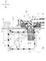
図3に示すように、処理剤供給装置9は洗浄槽3の右側壁3aの下部に取り付けられており、右側壁3aと、筐体1の右側パネル1aとの間に位置している。これにより、処理剤供給装置9は、洗浄槽3の外部、ひいては洗浄空間100の外部に配置されている。
As shown in FIG. 3, the treatment
処理剤供給装置9は、供給装置本体9aと、処理剤供給口9bとを有している。供給装置本体9aは内部にポンプ(図示略)が設けられている。供給装置本体9aは図1に示す制御部21と通電可能に接続されている。
The treatment
処理剤供給口9bは、供給装置本体9aよりも後方に位置しており、供給装置本体9aと接続している。処理剤供給口9bは、右側壁3aの下部に固定されることにより、洗浄空間100内に臨んでいる。
The treatment
処理剤供給路11は、供給路本体34と供給路側接続部35とを有している。供給路本体34は、右側壁3aと右側パネル1aとの間に位置しており、上下方向に延びている。供給路本体34は内部を処理剤200が流通可能となっている。また、供給路本体34は、下端が装置接続部34aとされている。供給路本体34は、装置接続部34aを通じて処理剤供給装置9の供給装置本体9aと接続している。
The treatment
供給路側接続部35は、供給路本体34の上端と接続されている。また、上述のように、供給路側接続部35は右側壁3aに固定されている。図7及び図8に示すように、供給路側接続部35には、接続開口35aと押圧突起35bとが形成されている。接続開口35aは、供給路側接続部35が右側壁3aに固定されることにより、洗浄空間100内に臨んでいる。これにより、接続開口35aは、洗浄空間100と供給路本体34とを連通している。接続開口35aは、内部に貯蔵タンク7の第1タンク側接続部75が進入可能となっている。押圧突起35bは、接続開口35a内に位置しており、接続開口35a内で右方から左方に向かって延びている。
The supply path
図1に示す第1食器かご13、第2食器かご14及び第3食器かご15は、それぞれ被洗浄物(図示略)を載置可能となっている。第1食器かご13、第2食器かご14及び第3食器かご15は、被洗浄物の種類等に応じて、載置可能な被洗浄物が区分けされている。そして、第1食器かご13には、主に大型の被洗浄物が載置されるように形成されている。なお、被洗浄物としては、例えば皿や茶碗等の食器類の他、箸やコップ等の飲食用具及び鍋等の調理容器が挙げられる。
The
第1食器かご13は、図2に示す第1下段ガイド部材111及び第2下段ガイド部材114によって前後方向に案内されつつ洗浄空間100からの出し入れが可能であるとともに、第1下段ガイド部材111及び第2下段ガイド部材114によって前後方向及び左右方向に水平な姿勢で洗浄空間100内に収容可能となっている。同様に、第2食器かご14は、第1中段ガイド部材112及び第2中段ガイド部材115によって前後方向に案内されつつ洗浄空間100からの出し入れが可能であるとともに、第1中段ガイド部材112及び第2中段ガイド部材115によって前後方向及び左右方向に水平な姿勢で洗浄空間100内に収容可能となっている。そして、第3食器かご15は、第1上段ガイド部材113及び第2上段ガイド部材116によって前後方向に案内されつつ洗浄空間100からの出し入れが可能であるとともに、第1上段ガイド部材113及び第2上段ガイド部材116によって前後方向及び左右方向に水平な姿勢で洗浄空間100内に収容可能となっている。
The
こうして、洗浄空間100内において、下方から上方に向かって第1食器かご13、第2食器かご14及び第3食器かご15がこの順で配置されている。
Thus, within the
また、図9に示すように、第1食器かご13は、持ち手部13aを有している他、干渉部13bを有している。持ち手部13aは、第1食器かご13の前部に設けられている。持ち手部13aは、第1食器かご13を洗浄空間100から出し入れするに当たって、使用者が把持可能となっている。
As shown in FIG. 9, the
干渉部13bは、第1食器かご13の右前部に設けられている。干渉部13bは、第1食器かご13の右部から左方に延びた後、第1食器かご13の上方に延びている。干渉部13bは、貯蔵タンク7が洗浄空間100内に配置された状態で第1食器かご13を洗浄空間100内に収容した際、貯蔵タンク7に対して左方から対向するように形成されている。
The
図1に示すように、操作部19は、蓋体5に設けられており、内側パネル5bの上部に配置されている。操作部19は、制御部21と通電可能に接続されている。また、操作部19は警告ランプ19aを有している他、図示しない操作ボタン及びディスプレイを有している。操作部19は、操作ボタンを通じて食器洗浄機を作動させるための操作が可能となっている。また、操作部19では、ディスプレイに食器洗浄機の運転時間等が表示される他、貯蔵タンク7のタンク本体71に貯蔵された処理剤200の残量が表示される。
As shown in FIG. 1, the
また、操作部19は、貯蔵タンク7が供給路側接続部35及び通気部37に取り付けられていない場合に、その旨を使用者に報知する。具体的には、操作部19では、貯蔵タンク7が供給路側接続部35及び通気部37に取り付けられていない場合に警告ランプ19aが点灯する。なお、操作部19は外側パネル5aに配置されても良い。
In addition, the
制御部21は蓋体5に設けられており、外側パネル5aと内側パネル5bとの間に配置されている。制御部21は、給水ポンプ43、排水ポンプ45、給水電磁弁、排水電磁弁、給気ファン28c及び供給装置本体9aの各作動制御を行う。これにより、制御部21は、洗浄運転と濯ぎ運転と乾燥運転とを実行する。なお、制御部21は収容空間10内に配置されても良い。
The
また、制御部21は、フロート装置8の磁石の磁力の変化を基に、タンク本体71に貯蔵された処理剤200の残量を検知する。そして、制御部21は、処理剤200の残量を未検知であるときには、貯蔵タンク7が供給路側接続部35及び通気部37に取り付けられていないと判断する。これにより、制御部21は操作部19を制御することにより、上述のように警告ランプ19aを点灯させる。
The
以上のように構成されたこの食器洗浄機において、処理剤200が貯蔵された状態にある貯蔵タンク7を供給路側接続部35及び通気部37に取り付けるに当たっては、使用者は、蓋体5を開放位置に揺動させて、筐体開口1f及び槽開口3fを前方に開放させる。そして、使用者は、貯蔵タンク7を洗浄槽3の内部、つまり洗浄空間100内に進入させ、図7に示すように、貯蔵タンク7を供給路側接続部35及び通気部37の左方に位置させる。
In the dishwasher configured as described above, when attaching the
ここで、貯蔵タンク7が供給路側接続部35及び通気部37に取り付けられていない状態では、弁機構12において、コイルバネ12cの付勢力によって弁体12bが弁開口121を塞いでいる。このため、貯蔵タンク7内の処理剤200が弁開口121及び第1タンク側接続部75から外部に漏れることが防止されている。
When the
そして、使用者は、図7の白色矢印で示すように、貯蔵タンク7を右方に移動させて供給路側接続部35及び通気部37に接近させる。これにより、図8に示すように、貯蔵タンク7では、第1タンク側接続部75が供給路側接続部35の接続開口35a内に進入することで、第1タンク側接続部75が供給路側接続部35に取り付けられる。処理剤供給路11によって、貯蔵タンク7と供給装置本体9aとが接続される。また、接続開口35a内に進入した第1タンク側接続部75は、供給路側接続部35によって保持されることにより、供給路側接続部35に取り付けられた状態を維持する。
Then, as shown by the white arrow in FIG. 7, the user moves the
また、上述のように、貯蔵タンク7では第2タンク側接続部77が第1タンク側接続部75と平行に延びている。このため、第1タンク側接続部75が供給路側接続部35に取り付けられると同時に、第2タンク側接続部77は、通気部37の第1通気口37aに進入する。こうして、第2タンク側接続部77が通気部37に取り付けられる。また、第2タンク側接続部77では、抜け止め部77aによって第1通気口37aからの抜け止めが行われる。この結果、第2タンク側接続部77は、通気部37に取り付けられた状態を維持する。
As described above, in the
これらにより、貯蔵タンク7は供給路側接続部35及び通気部37に取り付けられ、図1及び図9に示すように、洗浄空間100内に配置される。より具体的には、貯蔵タンク7は、洗浄空間100内において、洗浄槽3の右側壁3aの左側であって、第1下段ガイド部材111と第1中段ガイド部材112との間となる個所、すなわち、第1食器かご13と第2食器かご14との間となる個所に配置される。なお、貯蔵タンク7が供給路側接続部35及び通気部37に取り付けられても、通気部37の各第2通気口37bは、貯蔵タンク7によって完全に覆われることはない。
As a result, the
また、第1タンク側接続部75が供給路側接続部35に取り付けられることにより、供給路側接続部35の押圧突起35bが弁体12bを左方に向けて押圧する。このため、弁体12bは、コイルバネ12cの付勢力に抗して弁開口121を開放する。このため、弁機構12及び第1タンク側接続部75を介して、タンク本体71と供給路側接続部35とが連通する。この結果、図8の破線矢印で示すように、タンク本体71内に貯蔵された処理剤200は、処理剤フィルタ12d、連通口122、弁開口121及び接続開口35aを経て、処理剤供給路11の供給路本体34内を流通する。
In addition, by attaching the first tank
また、第1タンク側接続部75が供給路側接続部35に取り付けられることにより、第1タンク側接続部75に設けられたOリング75aが第1タンク側接続部75と接続開口35aとの間で弾性変形しつつ、第1タンク側接続部75と接続開口35aとの間を封止する。これにより、Oリング75aは、接続開口35a内を流通する処理剤200が洗浄空間100側に漏れることを防止する。
In addition, by attaching the first tank
そして、第2タンク側接続部77が通気部37に取り付けられることにより、通気連絡口73a、第2タンク側接続部77及び第1通気口37aを通じて、タンク本体71が通気ダクト28a(図3参照)内に連通する。つまり、タンク本体71が洗浄空間100の外部に連通する。
The second tank
一方、貯蔵タンク7を供給路側接続部35及び通気部37から取り外すに当たっては、使用者は、貯蔵タンク7を供給路側接続部35及び通気部37の左方に移動させる。これにより、第1タンク側接続部75が供給路側接続部35から取り外される。また同時に、第2タンク側接続部77が通気部37から取り外される。こうして、供給路側接続部35及び通気部37からの貯蔵タンク7の取り外しが完了する。この結果、使用者は、洗浄空間100の外部でタンク本体71内に処理剤200を補充することができる。
On the other hand, when removing the
ここで、第1タンク側接続部75が供給路側接続部35から取り外された際には、弁機構12では、コイルバネ12cの付勢力によって弁体12bが弁開口121を再び塞ぐことなる。このため、弁開口121からの処理剤200の漏れが防止される。
When the first tank
そして、この食器洗浄機では、貯蔵タンク7が供給路側接続部35及び通気部37に取り付けられた状態で、使用者は、被洗浄物が載置された第1~3食器かご13~15をそれぞれ洗浄空間100内に配置する。その後、使用者は、蓋体5を閉鎖位置に揺動させるとともに、操作部19を操作する。これにより、この食器洗浄機では、制御部21が洗浄運転、濯ぎ運転及び乾燥運転をこの順で実行する。なお、制御部21は、洗浄運転、濯ぎ運転及び乾燥運転のいずれかのみを実行することもできる。
In this dishwasher, with the
洗浄運転では、制御部21は、給水ホース41に設けられた給水電磁弁を開くとともに、給水ポンプ43を作動させる。これにより、給水源からの水が洗浄水として給水ホース41、給水ポンプ43、分水器26及び接続筒部25aを経て、第1噴射ノズル31の各噴射部300から洗浄空間100内に噴射される。また、洗浄水は、分水器26から給水ダクト27を経て、第2、3噴射ノズル32、33の各噴射部300からも洗浄空間100内に噴射される。さらに、洗浄運転では、洗浄槽3に設けられた洗剤自動投入装置(図示略)によって食器用の洗剤が洗浄空間100内に供給される。こうして、洗浄運転では、洗剤を含んだ洗浄水によって被洗浄物の洗浄が行われる。また、洗剤を含んだ洗浄水は貯水部23に貯留される。そしてこの洗浄水は、給水ポンプ43によって、水溜ケース25、分水器26及び給水ダクト27を経て第1~3噴射ノズル31~33の各噴射部300から再び洗浄空間100内に噴射される。なお、洗浄運転では、給水源から所定量の水が供給されることにより、制御部21は給水電磁弁を閉じる。
In the washing operation, the
そして、制御部21は、洗浄運転として設定された洗浄時間が経過すれば、排水ホース47に設けられた排水電磁弁を開くとともに、排水ポンプ45を作動させる。また、制御部21は、給水ポンプ43を停止させる。これにより、洗浄空間100内の洗浄水が排水ホース47を経て食器洗浄機の外部に排出される。こうして洗浄運転が終了する。
When the washing time set for the washing operation has elapsed, the
濯ぎ運転では、制御部21は、給水電磁弁を開くとともに給水ポンプ43を作動させる。これにより、洗浄運転と同様に、給水源からの水が洗浄水として第1~3噴射ノズル31~33の各噴射部300から洗浄空間100内に噴射される。また、濯ぎ運転では、制御部21は、供給装置本体9aを作動させる。これにより、貯蔵タンク7のタンク本体71内に貯蔵された処理剤200が処理剤供給口9bから洗浄空間100内に自動で供給される。こうして、濯ぎ運転では、処理剤200を含んだ洗浄水によって被洗浄物の濯ぎが行われる。
In the rinsing operation, the
制御部21は、濯ぎ洗浄運転として設定された洗浄時間が経過すれば、洗浄運転時と同様に、洗浄空間100内の洗浄水を食器洗浄機の外部に排出する。こうして濯ぎ運転が終了する。
When the cleaning time set for the rinsing operation has elapsed, the
乾燥運転では、制御部21は、給気ファン28cを作動させる。これにより、洗浄空間100内の空気が通気部37の各第2通気口37bから通気ダクト28a内を流通する。また、通気ダクト28a内の空気は、接続ホース28b及び給気ファン28cを経て、空気供給部28dから洗浄空間100内に供給される。こうして、乾燥運転では、洗浄空間100の内部と洗浄空間100の外部との間で空気が循環しつつ、被洗浄物の乾燥が行われる。制御部21は、乾燥運転として設定された洗浄時間が経過すれば、給気ファン28cを停止させる。こうして乾燥運転が終了させる。
In the drying operation, the
このように、この食器洗浄機では、供給路側接続部35及び通気部37に取り付けられた貯蔵タンク7が洗浄空間100内に配置される。このため、この食器洗浄機では、処理剤200の補充時にタンク本体71の表面等に付着した処理剤200が第1タンク側接続部75を経て供給路側接続部35に付着したり、貯蔵タンク7と供給路側接続部35とを着脱する際に不可避的に漏れ出た処理剤200が供給路側接続部35に付着したりした場合であっても、このような処理剤200については、洗浄空間100内の洗浄水によって、貯蔵タンク7や供給路側接続部35から除去することができる。つまり、この食器洗浄機では、タンク本体71の表面等や供給路側接続部35に付着した処理剤200については、第1~3噴射ノズル31~33の各噴射部300から洗浄空間100内に噴射された洗浄水が被洗浄物を洗浄する過程で、洗浄水によって洗い流すことができる。
In this way, in this dishwasher, the
また、この食器洗浄機では、たとえ洗浄水によって処理剤200を完全に除去し得ない場合であっても、貯蔵タンク7は洗浄空間100内に配置されるため、使用者は食器洗浄機の非作動時にタンク本体71表面等や供給路側接続部35に付着した処理剤200を除去し易くなっている。
In addition, in this dishwasher, even if the
この結果、この食器洗浄機では、供給路側接続部35に処理剤200が堆積し難いことから、供給路側接続部35に堆積した処理剤200によって供給路側接続部35と貯蔵タンク7の第1タンク側接続部75とが固着されることを抑制できる。
As a result, in this dishwasher, the
したがって、実施例の食器洗浄機は、処理剤200を貯蔵する貯蔵タンク7を有する構成において、貯蔵タンク7の着脱性に優れている。
Therefore, the dishwasher of the embodiment has a
特に、この食器洗浄機では、洗浄槽3の右側壁3aを本発明における「特定壁」としている。このため、この食器洗浄機では、蓋体5に対して供給路側接続部35及び通気部37は設けられることがなく、結果として、貯蔵タンク7は蓋体5に取り付けられることがない。このため、この食器洗浄機では、蓋体5を閉鎖位置と開放位置との間で揺動させても、それによってタンク本体71内の処理剤200が漏れることがなく、所謂フロントオープン式の食器洗浄機を好適に実現することが可能となっている。
In particular, in this dishwasher, the
また、この食器洗浄機では、貯蔵タンク7が通気部37に取り付けられることにより、通気連絡口73a、第2タンク側接続部77及び第1通気口37aを通じて、タンク本体71が洗浄空間100の外部に連通する。これにより、この食器洗浄機では、処理剤200の残量が減少する過程でタンク本体71内が負圧となり難い。このため、この食器洗浄機では、タンク本体71内の処理剤200を処理剤供給路11、ひいては供給装置本体9aに好適に流通させることが可能となっている。
In addition, in this dishwasher, the
また、供給路側接続部35及び通気部37に取り付けられた貯蔵タンク7は、洗浄空間100内において、第1下段ガイド部材111と第1中段ガイド部材112との間となる個所に配置される。これにより、貯蔵タンク7は、貯水部23よりも上方に位置している。このため、この食器洗浄機では、貯水部23に貯留された洗浄水に貯蔵タンク7が浸かることを防止できることから、洗浄水がタンク本体71内に浸入し難くなっている。
The
さらに、この食器洗浄機では、貯蔵タンク7の第1タンク側接続部75と第2タンク側接続部77とが洗浄槽3の右側壁3aに向かって平行に延びている。このため、この食器洗浄機では、供給路側接続部35に対する第1タンク側接続部75の着脱と、通気部37に対する第2タンク側接続部77の着脱とを容易かつ同時に行うことが可能となっている。
Furthermore, in this dishwasher, the first tank
また、この食器洗浄機では、フロート装置8及び制御部21によって、タンク本体71に貯蔵された処理剤200の残量を検知できるとともに、処理剤200の残量が操作部19のディスプレイに表示される。このため、この食器洗浄機では、使用者が処理剤200の残量を容易に了知することが可能となっており、利便性が高くなっている。ここで、制御部21は、タンク本体71内の処理剤200の残量を未検知であるときには、貯蔵タンク7が供給路側接続部35及び通気部37に取り付けられていないと判断する。そして、この場合には、操作部19の警告ランプ19aが点灯して使用者に報知されるため、使用者は、貯蔵タンク7が供給路側接続部35及び通気部37に取り付けられていないことを容易に了知することが可能となっている。この点においても、この食器洗浄機は利便性が高くなっている。さらに、この食器洗浄機では、貯蔵タンク7が供給路側接続部35及び通気部37に取り付けられているか否かを制御部21が判断するに当たって、専用の検知装置等を用いる必要がない。このため、この食器洗浄機では、利便性を高くしつつも構成を簡素化することが可能となっている。
In addition, in this dishwasher, the
さらに、この食器洗浄機では、第1食器かご13が干渉部13bを有している。この干渉部13bは、貯蔵タンク7が供給路側接続部35及び通気部37に適切に取り付けられている場合には、第1食器かご13を洗浄空間100内に収容した際、貯蔵タンク7に干渉することなく、貯蔵タンク7に対して左方から対向する。しかし、例えば接続開口35aへの第1タンク側接続部75の進入が不十分であったり、第1通気口37aへの第2タンク側接続部77の進入が不十分であったりするなど、供給路側接続部35及び通気部37に対する貯蔵タンク7の取り付けが不完全であるときには、干渉部13bが貯蔵タンク7と干渉する。そして、干渉部13bと貯蔵タンク7とが干渉すれば、使用者は、第1食器かご13を後方に移動させることができなくなる。この結果、この食器洗浄機では、使用者は、供給路側接続部35及び通気部37に対して貯蔵タンク7が不完全な状態で取り付けられていることを容易に了知できるようになっている。
Furthermore, in this dishwasher, the
以上において、本発明を実施例に即して説明したが、本発明は上記実施例に制限されるものではなく、その趣旨を逸脱しない範囲で適宜変更して適用できることはいうまでもない。 Although the present invention has been described above with reference to examples, it goes without saying that the present invention is not limited to the above examples and can be modified as appropriate without departing from the spirit of the invention.
例えば、実施例の食器洗浄機では、食器用のリンスを処理剤200としてタンク本体71内に貯蔵している。しかし、これに限らず、食器用の洗剤等を処理剤200としてタンク本体71内に貯蔵しても良い。
For example, in the dishwasher of the embodiment, dish rinse is stored in the
また、実施例の食器洗浄機において、洗浄槽3の左側壁3bや後壁3cを本発明における「特定壁」としても良い。また、蓋体5が本発明における「特定壁」を有する構成としても良い。
In addition, in the dishwasher of the embodiment, the
また、実施例の食器洗浄機では、フロート装置8及び制御部21によって本発明における「残量検知手段」を構成しているが、これに限らず、残量検知手段を他の構成としても良い。
In addition, in the dishwasher of the embodiment, the
また、実施例の食器洗浄機において、第2タンク側接続部77を省略し、貯蔵タンク7が第1タンク側接続部75を通じて供給路側接続部35のみに取り付けられる構成としても良い。
In addition, in the dishwasher of the embodiment, the second tank
また、実施例の食器洗浄機において、貯蔵タンク7が供給路側接続部35及び通気部37に取り付けられているか否かを検知する専用の検知装置等を設けても良い。
In addition, in the dishwasher of the embodiment, a dedicated detection device or the like may be provided to detect whether the
また、実施例の食器洗浄機において、警告ランプ19aの点灯に換えて、ブザー音や音声ガイド等を用いることにより、貯蔵タンク7が供給路側接続部35及び通気部37に取り付けられていないこと使用者に報知しても良い。
In addition, in the dishwasher of the embodiment, instead of turning on the
また、実施例の食器洗浄機において、貯蔵タンク7が供給路側接続部35及び通気部37に取り付けられている旨の報知と、貯蔵タンク7が供給路側接続部35及び通気部37に取り付けられていない旨の報知とをそれぞれ行う構成としても良い。
In addition, the dishwasher of the embodiment may be configured to provide a notification that the
また、実施例の食器洗浄機において、筐体1に対して洗浄槽3が前後方向に移動可能に設けられていても良い。
In addition, in the dishwasher of the embodiment, the
また、実施例の食器洗浄機において、給水ポンプ43及び排水ポンプ45に換えて、洗浄水の供給と洗浄水の排水とが可能な一つのポンプを設けても良い。
In addition, in the dishwasher of the embodiment, instead of the
本発明は、食器洗浄機、食器洗浄乾燥機又は厨房設備等に利用可能である。 The present invention can be used in dishwashers, dishwasher-dryers, kitchen equipment, etc.
1…筐体
1f…筐体開口
3…洗浄槽
3a…右側壁(特定壁)
3f…槽開口
5…蓋体
7…貯蔵タンク
8…フロート装置(残量検知手段)
9…処理剤供給装置
11…処理剤供給路
13…第1食器かご(載置部材)
13b…干渉部
19…操作部(報知手段)
21…制御部(判断手段、残量検知手段)
23…貯水部
35…供給路側接続部
37…通気部
71…タンク本体
75…第1タンク側接続部
77…第2タンク側接続部
100…洗浄空間
200…処理剤
O1…第1揺動軸心(揺動軸心)
1...
3f...
9... treatment
13b: interference unit 19: operation unit (notification means)
21...Control unit (determination means, remaining amount detection means)
23: Water storage section 35: Supply passage side connection section 37: Ventilation section 71: Tank body 75: First tank side connection section 77: Second tank side connection section 100: Cleaning space 200: Treatment agent O1: First swing axis (swing axis)
Claims (9)
前記槽開口を開閉可能であり、かつ、洗浄水によって被洗浄物の洗浄を行う洗浄空間を前記洗浄槽とともに形成する蓋体と、
前記被洗浄物に用いる処理剤を貯蔵する貯蔵タンクと、
前記洗浄空間の外部に位置し、前記貯蔵タンクに貯蔵された前記処理剤を前記洗浄空間内に供給する処理剤供給装置と、
前記貯蔵タンクと前記処理剤供給装置とを接続する処理剤供給路とを備え、
前記洗浄槽又は前記蓋体は、前記洗浄空間に面する特定壁を有し、
前記処理剤供給路は、前記洗浄空間に臨む状態で前記特定壁に固定されるとともに、前記貯蔵タンクが着脱可能に取り付けられる供給路側接続部を有し、
前記貯蔵タンクは、前記供給路側接続部に取り付けられることにより、前記洗浄空間内に配置されることを特徴とする食器洗浄機。 A cleaning tank having a tank opening that opens in one direction;
a cover body that can open and close the tank opening and that, together with the cleaning tank, forms a cleaning space in which an object to be cleaned is cleaned with cleaning water;
A storage tank for storing a treatment agent to be used on the object to be cleaned;
a treatment agent supply device located outside the cleaning space and supplying the treatment agent stored in the storage tank into the cleaning space;
a treatment agent supply passage connecting the storage tank and the treatment agent supply device,
The cleaning tank or the lid has a specific wall facing the cleaning space,
the treatment agent supply passage is fixed to the specific wall in a state facing the cleaning space, and has a supply passage side connection portion to which the storage tank is detachably attached,
The dishwasher, wherein the storage tank is attached to the supply passage side connection portion and disposed within the washing space.
前記タンク本体と連通し、前記供給路側接続部に着脱可能に取り付けられる第1タンク側接続部と、
前記第1タンク側接続部よりも上方に位置して前記洗浄空間の外部とタンク本体内とを連通させる第2タンク側接続部とを有している請求項1記載の食器洗浄機。 The storage tank includes a tank body for storing the treatment agent;
a first tank side connection portion that communicates with the tank body and is detachably attached to the supply path side connection portion;
2. The dishwasher according to claim 1, further comprising a second tank side connection portion located above the first tank side connection portion for connecting the outside of the washing space with the inside of the tank body.
前記第1タンク側接続部と前記第2タンク側接続部とは、前記特定壁に向かって互いに平行に延びている請求項2記載の食器洗浄機。 the specific wall is provided with a ventilation portion that is fixed to face the cleaning space and communicates with the outside of the cleaning space, and to which the second tank side connection portion is detachably attached;
The dishwasher according to claim 2 , wherein the first tank side connecting portion and the second tank side connecting portion extend parallel to each other toward the particular wall.
前記判断手段の判断結果を報知する報知手段とを備えている請求項1又は2記載の食器洗浄機。 a determination means for determining whether the storage tank is attached to the supply line side connection portion;
3. The dishwasher according to claim 1, further comprising a notification means for notifying a result of the determination made by said determination means.
前記判断手段は、前記残量検知手段が前記残量を未検知であるときには、前記貯蔵タンクが前記供給路側接続部に取り付けられていないと判断する請求項4記載の食器洗浄機。 a remaining amount detection means for detecting a remaining amount of the treatment agent stored in the storage tank,
5. The dishwasher according to claim 4, wherein the determining means determines that the storage tank is not attached to the supply passage side connection portion when the remaining amount detecting means has not detected the remaining amount.
前記貯蔵タンクは、前記供給路側接続部に取り付けられることにより、前記貯水部よりも上方に位置している請求項1又は2記載の食器洗浄機。 The cleaning tank is formed with a water storage section that communicates with the cleaning space and stores the cleaning water,
3. The dishwasher according to claim 1, wherein the storage tank is attached to the supply passage side connection portion so as to be located above the water storage portion.
前記載置部材は、前記供給路側接続部に対する前記貯蔵タンクの取り付けが不完全であるときに前記貯蔵タンクと干渉する干渉部を有している請求項1又は2記載の食器洗浄機。 a placement member that is accommodated in the cleaning space while placing the object to be cleaned thereon,
3. The dishwasher according to claim 1, wherein the mounting member has an interference portion that interferes with the storage tank when the attachment of the storage tank to the supply passage side connection portion is incomplete.
前記槽開口は前方に向かって開口して前記筐体開口と連通し、
前記蓋体は、揺動軸心周りで前後方向に揺動可能に前記筐体に取り付けられ、前記筐体開口及び前記槽開口を開放する開放位置と、前記筐体開口及び前記槽開口を閉鎖する閉鎖位置とに変位する請求項8記載の食器洗浄機。 a housing having a housing opening that opens forward and into which the cleaning tank can be placed;
The tank opening is open toward the front and communicates with the housing opening,
The dishwasher according to claim 8, wherein the lid body is attached to the housing so as to be swingable in the forward and backward directions around a swing axis, and is displaceable between an open position which opens the housing opening and the tub opening, and a closed position which closes the housing opening and the tub opening.
Priority Applications (2)
| Application Number | Priority Date | Filing Date | Title |
|---|---|---|---|
| JP2023148457A JP2025041266A (en) | 2023-09-13 | 2023-09-13 | Dishwashers |
| CN202410685715.9A CN119606275A (en) | 2023-09-13 | 2024-05-30 | Dishwashing Machine |
Applications Claiming Priority (1)
| Application Number | Priority Date | Filing Date | Title |
|---|---|---|---|
| JP2023148457A JP2025041266A (en) | 2023-09-13 | 2023-09-13 | Dishwashers |
Publications (1)
| Publication Number | Publication Date |
|---|---|
| JP2025041266A true JP2025041266A (en) | 2025-03-26 |
Family
ID=94891455
Family Applications (1)
| Application Number | Title | Priority Date | Filing Date |
|---|---|---|---|
| JP2023148457A Pending JP2025041266A (en) | 2023-09-13 | 2023-09-13 | Dishwashers |
Country Status (2)
| Country | Link |
|---|---|
| JP (1) | JP2025041266A (en) |
| CN (1) | CN119606275A (en) |
-
2023
- 2023-09-13 JP JP2023148457A patent/JP2025041266A/en active Pending
-
2024
- 2024-05-30 CN CN202410685715.9A patent/CN119606275A/en active Pending
Also Published As
| Publication number | Publication date |
|---|---|
| CN119606275A (en) | 2025-03-14 |
Similar Documents
| Publication | Publication Date | Title |
|---|---|---|
| JP4653349B2 (en) | Dishwasher | |
| JP7710561B2 (en) | Dishwashers | |
| KR20190024466A (en) | Dish washer | |
| JP2025041266A (en) | Dishwashers | |
| CN220800954U (en) | Dish washer and salt chamber assembly thereof | |
| KR200464781Y1 (en) | Drum type washing machine having detergent feeding device | |
| JP7546420B2 (en) | Dishwashers | |
| JP4483670B2 (en) | dishwasher | |
| JP2006167347A (en) | Dishwasher | |
| JP4600526B2 (en) | dishwasher | |
| CN111839395A (en) | Dishwasher | |
| WO2019163334A1 (en) | Dishwasher | |
| JP6964220B2 (en) | dishwasher | |
| JP2019080605A (en) | dishwasher | |
| JP2019080604A (en) | dishwasher | |
| JP2025041267A (en) | Dishwashers | |
| JP2020196994A (en) | Sink drainage structure and cooking table | |
| JP5636895B2 (en) | dishwasher | |
| KR100610140B1 (en) | Filter for dish washer and dish washer | |
| JP2007135650A (en) | dishwasher | |
| JP5636896B2 (en) | dishwasher | |
| JP4615775B2 (en) | Dishwasher | |
| JP2025066254A (en) | dishwasher | |
| JP2006288923A (en) | dishwasher | |
| JPH02161926A (en) | Dish washer |