JP2025041267A - Dishwashers - Google Patents

Dishwashers Download PDF

Info

Publication number
JP2025041267A
JP2025041267A JP2023148459A JP2023148459A JP2025041267A JP 2025041267 A JP2025041267 A JP 2025041267A JP 2023148459 A JP2023148459 A JP 2023148459A JP 2023148459 A JP2023148459 A JP 2023148459A JP 2025041267 A JP2025041267 A JP 2025041267A
Authority
JP
Japan
Prior art keywords
holes
filter
water
cleaning
filter portion
Prior art date
Legal status (The legal status is an assumption and is not a legal conclusion. Google has not performed a legal analysis and makes no representation as to the accuracy of the status listed.)
Pending
Application number
JP2023148459A
Other languages
Japanese (ja)
Inventor
敏男 佐橋
Toshio Sahashi
Current Assignee (The listed assignees may be inaccurate. Google has not performed a legal analysis and makes no representation or warranty as to the accuracy of the list.)
Rinnai Corp
Original Assignee
Rinnai Corp
Priority date (The priority date is an assumption and is not a legal conclusion. Google has not performed a legal analysis and makes no representation as to the accuracy of the date listed.)
Filing date
Publication date
Application filed by Rinnai Corp filed Critical Rinnai Corp
Priority to JP2023148459A priority Critical patent/JP2025041267A/en
Priority to CN202410853408.7A priority patent/CN119606280A/en
Publication of JP2025041267A publication Critical patent/JP2025041267A/en
Pending legal-status Critical Current

Links

Images

Classifications

    • AHUMAN NECESSITIES
    • A47FURNITURE; DOMESTIC ARTICLES OR APPLIANCES; COFFEE MILLS; SPICE MILLS; SUCTION CLEANERS IN GENERAL
    • A47LDOMESTIC WASHING OR CLEANING; SUCTION CLEANERS IN GENERAL
    • A47L15/00Washing or rinsing machines for crockery or tableware
    • A47L15/42Details
    • A47L15/4202Water filter means or strainers
    • AHUMAN NECESSITIES
    • A47FURNITURE; DOMESTIC ARTICLES OR APPLIANCES; COFFEE MILLS; SPICE MILLS; SUCTION CLEANERS IN GENERAL
    • A47LDOMESTIC WASHING OR CLEANING; SUCTION CLEANERS IN GENERAL
    • A47L15/00Washing or rinsing machines for crockery or tableware
    • A47L15/14Washing or rinsing machines for crockery or tableware with stationary crockery baskets and spraying devices within the cleaning chamber
    • A47L15/18Washing or rinsing machines for crockery or tableware with stationary crockery baskets and spraying devices within the cleaning chamber with movably-mounted spraying devices
    • A47L15/22Rotary spraying devices
    • AHUMAN NECESSITIES
    • A47FURNITURE; DOMESTIC ARTICLES OR APPLIANCES; COFFEE MILLS; SPICE MILLS; SUCTION CLEANERS IN GENERAL
    • A47LDOMESTIC WASHING OR CLEANING; SUCTION CLEANERS IN GENERAL
    • A47L15/00Washing or rinsing machines for crockery or tableware
    • A47L15/42Details
    • A47L15/4202Water filter means or strainers
    • A47L15/4208Arrangements to prevent clogging of the filters, e.g. self-cleaning
    • AHUMAN NECESSITIES
    • A47FURNITURE; DOMESTIC ARTICLES OR APPLIANCES; COFFEE MILLS; SPICE MILLS; SUCTION CLEANERS IN GENERAL
    • A47LDOMESTIC WASHING OR CLEANING; SUCTION CLEANERS IN GENERAL
    • A47L15/00Washing or rinsing machines for crockery or tableware
    • A47L15/42Details
    • A47L15/4214Water supply, recirculation or discharge arrangements; Devices therefor
    • A47L15/4217Fittings for water supply, e.g. valves or plumbing means to connect to cold or warm water lines, aquastops
    • AHUMAN NECESSITIES
    • A47FURNITURE; DOMESTIC ARTICLES OR APPLIANCES; COFFEE MILLS; SPICE MILLS; SUCTION CLEANERS IN GENERAL
    • A47LDOMESTIC WASHING OR CLEANING; SUCTION CLEANERS IN GENERAL
    • A47L15/00Washing or rinsing machines for crockery or tableware
    • A47L15/42Details
    • A47L15/4214Water supply, recirculation or discharge arrangements; Devices therefor
    • A47L15/4223Devices for water discharge, e.g. devices to prevent siphoning, non-return valves

Landscapes

  • Engineering & Computer Science (AREA)
  • Water Supply & Treatment (AREA)
  • Washing And Drying Of Tableware (AREA)

Abstract

To provide a dishwasher designed in view of conventional conditions, and having excellent residue collecting performance, washing performance and drainage performance.SOLUTION: A dishwasher comprises a filter unit 29 including a first body 61, a second body 62 and a third body 63. The first to third bodies 61 to 63 respectively include first to third filter parts 61a to 63a. The first filter part 61a has a plurality of first holes 610 formed therein. The second filter part 62a has a plurality of second holes 620 formed therein. The third filter part 63a has a plurality of third holes 630 formed therein. A gap S communicating with each of the second holes 620 and each of the third holes 630 is formed between the second filter part 62a and the third filter part 63a. The second body 62 includes a communication hole 624 formed therein, the communication hole communicating with the gap S from above and allowing wash water to flow into the gap S from above to below.SELECTED DRAWING: Figure 7

Description

本発明は食器洗浄機に関する。 The present invention relates to a dishwasher.

特許文献1に従来の食器洗浄機が開示されている。この食器洗浄機は、洗浄槽と、フィルタユニットと、ポンプと、供給路と、排出路とを備えている。洗浄槽には洗浄空間と貯水部とが形成されている。洗浄空間は、被洗浄物を収容しつつ洗浄水によって被洗浄物の洗浄が可能である。貯水部は洗浄空間の下方に位置しており、洗浄水が貯留される。 Patent Document 1 discloses a conventional dishwasher. This dishwasher includes a washing tank, a filter unit, a pump, a supply path, and a discharge path. A washing space and a water storage section are formed in the washing tank. The washing space is capable of storing an object to be washed and washing the object with washing water. The water storage section is located below the washing space, and stores the washing water.

フィルタユニットは、洗浄水を流通させつつ洗浄水に含まれる残滓を捕集可能である。ポンプは、洗浄水を洗浄空間に供給可能である。供給路は貯水部に連通しており、フィルタユニットを通過した洗浄水をポンプに流通させる。排出路は貯水部に連通しており、フィルタユニットを通過した洗浄水を洗浄槽の外部に排出する。 The filter unit is capable of collecting residue contained in the cleaning water while circulating the cleaning water. The pump is capable of supplying the cleaning water to the cleaning space. The supply path is connected to the water storage section and circulates the cleaning water that has passed through the filter unit to the pump. The discharge path is connected to the water storage section and discharges the cleaning water that has passed through the filter unit to the outside of the cleaning tank.

フィルタユニットは、具体的には、第1ボディと第2ボディと第3ボディとからなる。第1ボディは洗浄槽に設けられており、貯水部を上から覆っている。第1ボディは第1フィルタ部を有している。第2ボディは第1ボディに挿通されている。第2ボディは第2フィルタ部を有している。第2フィルタ部は、第1フィルタ部よりも下方に延びる筒状をなしており、内部を洗浄水及び残滓が流通可能である。第3ボディは、第1ボディの下方に位置しており、自己の上部に第1ボディを載置している。第3ボディは第3フィルタ部を有している。第3フィルタ部は、第2フィルタよりも大径の円筒状をなしており、第2フィルタ部を外側から覆っている。 Specifically, the filter unit is composed of a first body, a second body, and a third body. The first body is provided in the cleaning tank and covers the water storage section from above. The first body has a first filter section. The second body is inserted into the first body. The second body has a second filter section. The second filter section is cylindrical and extends downward from the first filter section, and cleaning water and residue can flow through it. The third body is located below the first body and has the first body placed on top of it. The third body has a third filter section. The third filter section is cylindrical and has a larger diameter than the second filter section, and covers the second filter section from the outside.

また、第1フィルタ部には複数の第1孔が形成されている。第2フィルタ部には、各第1孔よりも開口面積が大きい複数の第2孔が形成されている。第3フィルタ部には、各第2孔よりも開口面積が小さい複数の第3孔が形成されている。そして、第2フィルタ部と第3フィルタ部との間には空隙が形成されている。 The first filter section has a plurality of first holes formed therein. The second filter section has a plurality of second holes formed therein, each of which has a larger opening area than each of the first holes. The third filter section has a plurality of third holes formed therein, each of which has a smaller opening area than each of the second holes. A gap is formed between the second filter section and the third filter section.

この食器洗浄機では、洗浄空間内で被洗浄物が洗浄水によって洗浄されることにより、被洗浄物に付着した残菜等の残滓が被洗浄物から剥がれ落ちる。これにより、残滓が洗浄水に含まれる。そして、この残滓を含む洗浄水はフィルタユニット、すなわち第1~3ボディを流通する。この際、第1ボディの第1フィルタ部では、各第1孔を洗浄水が流通する一方、各第1孔よりも大きい残滓は各第1孔で捕集される。また、第2ボディの第2フィルタ部では、各第2孔を洗浄水が流通する一方、各第2孔よりも大きい残滓は各第2孔で捕集される。そして、各第2孔を流通した洗浄水及び残滓は、空隙に向けて第2フィルタ部の外側に流通する。第3フィルタ部では、空隙内に流通した洗浄水及び残滓のうち、洗浄水は各第3孔を流通する一方、各第3孔よりも大きい残滓は各第3孔で捕集される。 In this dishwasher, as the objects to be washed are washed with wash water in the washing space, food residue and other debris attached to the objects to be washed peels off from the objects to be washed. As a result, the debris is contained in the wash water. The wash water containing this debris then flows through the filter unit, i.e., the first to third bodies. At this time, in the first filter section of the first body, the wash water flows through each of the first holes, while debris larger than each of the first holes is collected by each of the first holes. In the second filter section of the second body, the wash water flows through each of the second holes, while debris larger than each of the second holes is collected by each of the second holes. The wash water and debris that have flowed through each of the second holes then flow to the outside of the second filter section toward the gaps. In the third filter section, of the cleaning water and residue that flow through the gap, the cleaning water flows through each of the third holes, while the residue that is larger than each of the third holes is captured by each of the third holes.

フィルタユニットを流通した洗浄水は、供給路を経てポンプによって再び洗浄空間内に供給される。また、被洗浄物の洗浄が終了した後は、フィルタユニットを流通した洗浄水は排水路を経て洗浄槽の外部、ひいては食器洗浄機の外部に排出される。こうして、この食器洗浄機では、フィルタユニットによって洗浄水を濾過できるため、ポンプによって洗浄空間内に供給される洗浄水や食器洗浄機の外部に排出される洗浄水には、残滓が含まれ難くなっている。 The wash water that has flowed through the filter unit is supplied again into the wash space by the pump via the supply path. After the objects to be washed have been washed, the wash water that has flowed through the filter unit is discharged through the drain path to the outside of the wash tank and ultimately to the outside of the dishwasher. In this way, in this dishwasher, the wash water can be filtered by the filter unit, so that the wash water supplied into the wash space by the pump and the wash water discharged to the outside of the dishwasher are less likely to contain residue.

特開平2-152431号公報Japanese Patent Application Publication No. 2-152431

しかし、上記従来の食器洗浄機では、第3フィルタ部によって捕集された残滓が第3フィルタ部に付着することにより、各第3孔に目詰まりが生じ易い。このため、この食器洗浄機では、供給路及び排水路に向かう洗浄水の流通が阻害され易くなる。これにより、被洗浄物の洗浄を行う洗浄運転時の他、被洗浄物の濯ぎを行う濯ぎ運転時に洗浄水の循環性が低下することから、この食器洗浄機では洗浄性能及び排水性能が低下する。 However, in the conventional dishwasher described above, the residues collected by the third filter section adhere to the third filter section, which easily causes clogging of the third holes. As a result, in this dishwasher, the flow of wash water toward the supply path and the drainage path is easily obstructed. This reduces the circulation of wash water during the wash operation in which the items to be washed are washed, as well as during the rinse operation in which the items to be washed are rinsed, resulting in reduced washing and drainage performance in this dishwasher.

本発明は、上記従来の実情に鑑みてなされたものであって、残滓の捕集性能に優れ、かつ、洗浄性能及び排水性能に優れた食器洗浄機を提供することを解決すべき課題としている。 The present invention was made in consideration of the above-mentioned conventional situation, and the problem to be solved is to provide a dishwasher that has excellent residue collection performance, as well as excellent cleaning and drainage performance.

本発明の食器洗浄機は、洗浄水によって被洗浄物の洗浄が可能な洗浄空間と、前記洗浄空間の下方に位置して前記洗浄水が貯留される貯水部とが形成された洗浄槽と、
前記洗浄水を流通させつつ前記洗浄水に含まれる残滓を捕集可能なフィルタユニットと、
前記洗浄水を前記洗浄空間に供給可能なポンプと、
前記貯水部に連通し、前記フィルタユニットを通過した前記洗浄水を前記ポンプに流通させる供給路と、
前記貯水部に連通し、前記フィルタユニットを通過した前記洗浄水を前記洗浄槽の外部に排出させる排出路とを備え、
前記フィルタユニットは、前記洗浄槽に設けられて前記貯水部を上方から覆う第1ボディと、前記第1ボディに挿通された第2ボディと、前記第1ボディの下方に位置する第3ボディとを有し、
前記第1ボディは板状をなす第1フィルタ部を有し、
前記第2ボディは、前記第1フィルタ部よりも下方に延びる筒状をなし、内部を前記洗浄水及び前記残滓が流通可能な第2フィルタ部を有し、
前記第3ボディは、前記第2フィルタ部よりも大径をなして前記第2フィルタ部を外側から覆う筒状の第3フィルタ部を有し、
前記第1フィルタ部には、前記貯水部に連通し、前記洗浄水を流通させる一方で自己よりも大きい前記残滓を捕集可能な複数の第1孔が形成され、
前記第2フィルタ部には、前記各第1孔よりも開口面積が大きく形成され、前記洗浄水を流通させる一方で自己よりも大きい前記残滓を捕集可能な複数の第2孔が形成され、
前記第3フィルタ部には、前記各第2孔よりも開口面積が小さく形成され、前記洗浄水を流通させる一方で自己よりも大きい前記残滓を捕集可能な複数の第3孔が形成され、
前記第2フィルタ部と前記第3フィルタ部との間には、筒状をなし、前記各第2孔及び前記各第3孔と連通する空隙が形成され、
前記各第2孔を流通する前記洗浄水及び前記残滓は、前記空隙に向けて前記第2フィルタ部の外側に流通し、
前記第1ボディ、前記第2ボディ又は前記第3ボディには、上方から前記空隙に連通し、前記洗浄水を上方から下方に向けて前記空隙内に流通させる連通孔が形成されていることを特徴とする。
The dishwasher of the present invention includes a washing tank having a washing space in which an object to be washed can be washed with washing water and a water storage section located below the washing space and storing the washing water;
a filter unit capable of collecting residue contained in the cleaning water while circulating the cleaning water;
a pump capable of supplying the cleaning water to the cleaning space;
a supply passage communicating with the water storage section and for circulating the cleaning water that has passed through the filter unit to the pump;
a discharge passage communicating with the water storage section and discharging the cleaning water that has passed through the filter unit to the outside of the cleaning tank;
the filter unit includes a first body that is provided in the cleaning tank and covers the water storage portion from above, a second body that is inserted into the first body, and a third body that is located below the first body,
The first body has a first filter portion having a plate shape,
the second body has a cylindrical shape extending downwardly beyond the first filter portion and includes a second filter portion through which the cleaning water and the residue can flow,
the third body has a cylindrical third filter portion having a larger diameter than the second filter portion and covering the second filter portion from the outside,
The first filter section is formed with a plurality of first holes that communicate with the water storage section and allow the cleaning water to flow while collecting the residue that is larger than the first filter section;
The second filter portion is formed with a plurality of second holes each having an opening area larger than each of the first holes and capable of collecting the residue larger than the second filter portion while allowing the cleaning water to flow therethrough,
The third filter portion is formed with a plurality of third holes each having an opening area smaller than each of the second holes and capable of collecting the residue larger than the third filter portion while allowing the cleaning water to flow therethrough,
A cylindrical gap is formed between the second filter portion and the third filter portion, the gap communicating with each of the second holes and each of the third holes.
The cleaning water and the residue flowing through each of the second holes flow to the outside of the second filter portion toward the gap,
The first body, the second body or the third body is characterized in that a communication hole is formed which communicates with the gap from above and allows the cleaning water to flow from above downward within the gap.

本発明の食器洗浄機は、フィルタユニットが第1ボディ、第2ボディ及び第3ボディを有している。また、第2ボディの第2フィルタ部と、第3ボディの第3フィルタ部との間には空隙が形成されており、この空隙は各第2孔及び各第3孔と連通している。 In the dishwasher of the present invention, the filter unit has a first body, a second body, and a third body. A gap is formed between the second filter part of the second body and the third filter part of the third body, and this gap communicates with each of the second holes and each of the third holes.

そして、第1ボディの第1フィルタ部では、各第1孔を洗浄水が流通する一方で各第1孔よりも大きい残滓は各第1孔を通過できずに各第1孔に捕集される。また、第2ボディの第2フィルタ部では、第2フィルタ部を流通する洗浄水及び残滓のうち、洗浄水は各第2孔を流通する一方で各第2孔よりも大きい残滓は各第2孔を通過できずに各第2孔に捕集される。そして、各第2孔を流通する洗浄水及び残滓は、空隙に向けて第2フィルタ部の外側に流通する。これにより、第3ボディの第3フィルタ部では、空隙内を流通した洗浄水及び残滓のうち、洗浄水は各第3孔を流通する一方、各第3孔よりも大きい残滓、すなわち各第2孔よりも小さく各第3孔よりも大きい残滓は、各第3孔を通過できずに各第3孔に捕集される。こうして、この食器洗浄機では、第1~3孔、ひいては第1~3フィルタ部によって残滓を好適に捕集できることから、供給路及び排水路を流通する洗浄水には残滓が含まれ難い。 In the first filter section of the first body, the cleaning water flows through each of the first holes, while residues larger than the first holes cannot pass through each of the first holes and are collected in each of the first holes. In the second filter section of the second body, among the cleaning water and residues flowing through the second filter section, the cleaning water flows through each of the second holes, while residues larger than the second holes cannot pass through each of the second holes and are collected in each of the second holes. Then, the cleaning water and residues flowing through each of the second holes flow to the outside of the second filter section toward the gap. As a result, in the third filter section of the third body, among the cleaning water and residues flowing through the gap, the cleaning water flows through each of the third holes, while residues larger than the third holes, i.e., residues smaller than the second holes and larger than the third holes, cannot pass through each of the third holes and are collected in each of the third holes. In this way, in this dishwasher, residue can be effectively collected by the first to third holes, and therefore the first to third filter sections, so residue is less likely to be contained in the wash water flowing through the supply passage and drain passage.

また、この食器洗浄機では、第1ボディ、第2ボディ又は第3ボディには、連通孔が形成されており、この連通孔は、空隙に対して上方から連通しつつ洗浄水を上方から下方に向けて空隙内に流通させる。このため、この食器洗浄機では、たとえ第3孔に捕集された残滓が第3フィルタ部に付着しても、このような残滓については、連通孔から空隙内に流入した洗浄水によって第3フィルタ部から好適に除去することができる。この結果、この食器洗浄機では、残滓による各第3孔の目詰まりが生じ難く、給水路及び排水路に向かう洗浄水の流通が阻害され難い。 In addition, in this dishwasher, the first body, the second body, or the third body is formed with a communication hole, which communicates with the gap from above and allows wash water to flow from above to below within the gap. Therefore, in this dishwasher, even if residue collected in the third hole adheres to the third filter section, such residue can be suitably removed from the third filter section by wash water flowing into the gap from the communication hole. As a result, in this dishwasher, clogging of each third hole by residue is unlikely to occur, and the flow of wash water toward the water supply passage and drain passage is unlikely to be impeded.

したがって、本発明の食器洗浄機は、残滓の捕集性能に優れ、かつ、洗浄性能及び排水性能に優れている。 Therefore, the dishwasher of the present invention has excellent residue collection performance, as well as excellent cleaning and drainage performance.

連通孔は複数であり得る。そして、各連通孔は、各第1孔及び各第3孔よりも開口面積が大きいことが好ましい。この場合には、各連通孔を流通する洗浄水の流量を確保し易くなるため、各連通孔から空隙内に流入した洗浄水によって、残滓を第3フィルタ部からより好適に除去することができる。 There may be multiple communication holes. It is preferable that each communication hole has a larger opening area than each of the first holes and each of the third holes. In this case, it is easier to ensure the flow rate of cleaning water flowing through each communication hole, so that residue can be more effectively removed from the third filter section by the cleaning water that flows into the gap from each communication hole.

第2ボディは、第2フィルタ部の内側に形成され、第2フィルタ部を流通する洗浄水及び残滓を各第2孔に向けて案内可能な案内部を有していることが好ましい。 It is preferable that the second body has a guide portion formed inside the second filter portion and capable of guiding the cleaning water and residue flowing through the second filter portion toward each of the second holes.

この場合には、第2フィルタ部を流通する洗浄水を各第2孔に向けて好適に流通させることができる。また、第2フィルタ部を流通する残滓について、各第2孔、さらには第3ボディの第3孔で好適に捕集することができる。 In this case, the cleaning water flowing through the second filter section can be preferably directed toward each of the second holes. Furthermore, the residue flowing through the second filter section can be preferably collected in each of the second holes and further in the third hole of the third body.

第2ボディと第3ボディとは着脱可能であり得る。そして、第3ボディは第2ボディに組み付けられた状態で第1ボディの下方に位置していることが好ましい。この場合には、第2ボディと第3ボディとを組み付けることにより、第2フィルタ部と第3フィルタ部との位置決めを容易に行うことができる。 The second body and the third body may be detachable. It is preferable that the third body is located below the first body when assembled to the second body. In this case, the second filter section and the third filter section can be easily positioned by assembling the second body and the third body.

第2ボディは、第2フィルタ部と接続して空隙を上方から覆う鍔部を有し得る。そして、連通孔は鍔部に形成されていることが好ましい。 The second body may have a flange portion that is connected to the second filter portion and covers the gap from above. It is preferable that the communication hole is formed in the flange portion.

この場合には、第2ボディに連通孔を容易に形成することができる。また、空隙に対して上方から残滓が入り込むことを鍔部によって防止できる。 In this case, a communication hole can be easily formed in the second body. In addition, the flange portion can prevent residue from entering the gap from above.

本発明の食器洗浄機は、残滓の捕集性能に優れ、かつ、洗浄性能及び排水性能に優れている。 The dishwasher of the present invention has excellent residue collection performance, as well as excellent cleaning and drainage performance.

図1は、実施例の食器洗浄機の断面図である。FIG. 1 is a cross-sectional view of a dishwasher according to an embodiment of the present invention. 図2は、実施例の食器洗浄機の斜視図である。FIG. 2 is a perspective view of the dishwasher according to the embodiment. 図3は、実施例の食器洗浄機に係り、処理剤供給路及び処理剤供給装置等を示す洗浄槽の右側面図である。FIG. 3 is a right side view of the washing tank of the dishwasher according to the embodiment, showing the treatment agent supply passage, the treatment agent supply device, etc. FIG. 図4は、実施例の食器洗浄機に係り、フィルタユニット等を示す斜視図である。FIG. 4 is a perspective view showing a filter unit and the like of the dishwasher according to the embodiment. 図5は、実施例の食器洗浄機に係り、フィルタユニット及び排水ポンプ等を示す図4のA-A断面図である。FIG. 5 is a cross-sectional view taken along line AA of FIG. 4, showing the filter unit, the drain pump, etc., of the dishwasher of the embodiment. 図6は、実施例の食器洗浄機に係り、フィルタユニット、水溜ケース及び給水ポンプ等を示す図4のB-B断面図である。FIG. 6 is a cross-sectional view taken along line BB of FIG. 4, showing the filter unit, the water reservoir case, the water supply pump, etc., of the dishwasher of the embodiment. 図7は、実施例の食器洗浄機に係り、フィルタユニットの分解斜視図である。FIG. 7 is an exploded perspective view of the filter unit of the dishwasher according to the embodiment. 図8は、実施例の食器洗浄機に係り、第1ボディ、第2ボディ及び第3ボディを示す図6の要部拡大断面図である。FIG. 8 is an enlarged cross-sectional view of the essential parts of the dishwasher of the embodiment, showing the first body, the second body and the third body of FIG. 図9は、実施例の食器洗浄機に係り、第2ボディの平面図である。FIG. 9 is a plan view of the second body of the dishwasher according to the embodiment.

以下、本発明を具体化した実施例を図面を参照しつつ説明する。 The following describes an embodiment of the present invention with reference to the drawings.

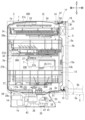
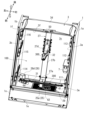
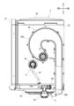
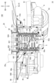
実施例の食器洗浄機は、図1~4に示す筐体1と、洗浄槽3と、蓋体5と、処理剤供給装置9と、処理剤供給路11と、フィルタユニット29と、貯蔵タンク7と、第1食器かご13と、第2食器かご14と、第3食器かご15と、操作部19と、制御部21とを備えている。また、この食器洗浄機は、図5及び図6に示す供給路6と、排水路8と、給水ポンプ43と、排水ポンプ45とを備えている。この食器洗浄機は、図示しないシステムキッチンに組み込まれている。なお、説明を容易にするため、図2では蓋体5及び第1食器かご13等の図示を省略しており、図3では筐体1及び蓋体5等の図示を省略している。 The dishwasher of the embodiment includes the housing 1, washing tank 3, lid 5, treatment agent supply device 9, treatment agent supply path 11, filter unit 29, storage tank 7, first dish basket 13, second dish basket 14, third dish basket 15, operation unit 19, and control unit 21 shown in Figs. 1 to 4. This dishwasher also includes the supply path 6, drainage path 8, water supply pump 43, and drainage pump 45 shown in Figs. 5 and 6. This dishwasher is incorporated in a system kitchen (not shown). For ease of explanation, the lid 5 and first dish basket 13 are omitted in Fig. 2, and the housing 1 and lid 5 are omitted in Fig. 3.

本実施例では、図1及び図2に示す各矢印によって、食器洗浄機の前後方向及び上下方向を規定している。また、図2では、食器洗浄機の使用者(図示略)が食器洗浄機の前方から対向した際を基準として、使用者の右側を食器洗浄機の右側とし、使用者の左側を食器洗浄機の左側として食器洗浄機の左右方向、すなわち幅方向を規定している。これらの前後方向、上下方向及び左右方向は互いに直交している。そして、図3以降では、図1及び図2に対応して食器洗浄機の前後方向、上下方向及び左右方向を規定している。 In this embodiment, the front-rear and up-down directions of the dishwasher are defined by the arrows shown in Figures 1 and 2. In Figure 2, the left-right direction of the dishwasher, i.e., the width direction, is defined based on the position of a user (not shown) of the dishwasher facing the front of the dishwasher, with the right side of the user being the right side of the dishwasher and the left side of the user being the left side of the dishwasher. These front-rear, up-down and left-right directions are mutually perpendicular. In Figures 3 and onwards, the front-rear, up-down and left-right directions of the dishwasher are defined in accordance with Figures 1 and 2.

図1及び図2に示すように、筐体1は、右側パネル1aと、左側パネル1bと、前下パネル1cと、後下パネル1dと、底部パネル1eと、筐体開口1fとを有している。右側パネル1a及び左側パネル1bは、それぞれ前後方向及び上下方向に延びる略矩形の板状に形成されている。右側パネル1aと左側パネル1bとは、それぞれ左右方向に離隔して配置されている。これにより、右側パネル1aは筐体1の右側面を構成しており、左側パネル1bは筐体1の左側面を構成している。 As shown in Figures 1 and 2, the housing 1 has a right side panel 1a, a left side panel 1b, a front lower panel 1c, a rear lower panel 1d, a bottom panel 1e, and a housing opening 1f. The right side panel 1a and the left side panel 1b are each formed into a roughly rectangular plate shape extending in the front-to-rear and up-down directions. The right side panel 1a and the left side panel 1b are each disposed separately in the left-right direction. As a result, the right side panel 1a forms the right side surface of the housing 1, and the left side panel 1b forms the left side surface of the housing 1.

前下パネル1c及び後下パネル1dは、上下方向及び左右方向に延びる略矩形の板状に形成されている。前下パネル1c及び後下パネル1dは、それぞれ右側パネル1a及び左側パネル1bに取り付けられて右側パネル1aと左側パネル1bとの間に配置されている。より具体的には、前下パネル1cは、右側パネル1aと左側パネル1bとの間であって、右側パネル1a及び左側パネル1bの前方下部に配置されている。一方、後下パネル1dは、右側パネル1aと左側パネル1bとの間であって、右側パネル1a及び左側パネル1bの後方下部に配置されている。つまり、前下パネル1cと後下パネル1dとは、右側パネル1aと左側パネル1bとの間で前後方向に離隔して配置されている。 The front lower panel 1c and the rear lower panel 1d are formed in a generally rectangular plate shape extending in the vertical and horizontal directions. The front lower panel 1c and the rear lower panel 1d are attached to the right panel 1a and the left panel 1b, respectively, and are disposed between the right panel 1a and the left panel 1b. More specifically, the front lower panel 1c is disposed between the right panel 1a and the left panel 1b, and is disposed in the front lower part of the right panel 1a and the left panel 1b. Meanwhile, the rear lower panel 1d is disposed between the right panel 1a and the left panel 1b, and is disposed in the rear lower part of the right panel 1a and the left panel 1b. In other words, the front lower panel 1c and the rear lower panel 1d are disposed at a distance in the front-to-rear direction between the right panel 1a and the left panel 1b.

底部パネル1eは、前後方向及び左右方向に延びる略矩形の板状に形成されている。底部パネル1eは、筐体1の最下部に配置されており、右側パネル1a、左側パネル1b、前下パネル1c及び後下パネル1dの各下端に取り付けられている。これらの右側パネル1a、左側パネル1b、前下パネル1c、後下パネル1d及び底部パネル1eにより、筐体1の下部には、収容空間10が形成されている。 The bottom panel 1e is formed in a generally rectangular plate shape extending in the front-rear and left-right directions. The bottom panel 1e is located at the bottom of the housing 1 and is attached to the bottom ends of the right side panel 1a, the left side panel 1b, the front lower panel 1c, and the rear lower panel 1d. The right side panel 1a, the left side panel 1b, the front lower panel 1c, the rear lower panel 1d, and the bottom panel 1e form a storage space 10 in the lower part of the housing 1.

筐体開口1fは、右側パネル1aと、左側パネル1bと、前下パネル1cとの間に形成されている。これにより、筐体開口1fは、収容空間10の上方に位置しつつ、筐体1の前方に向かって開口している。 The housing opening 1f is formed between the right panel 1a, the left panel 1b, and the lower front panel 1c. As a result, the housing opening 1f is located above the storage space 10 and opens toward the front of the housing 1.

図2に示すように、洗浄槽3は、右側壁3a、左側壁3b、後壁3c、上壁3d、下壁3e及び槽開口3fを有している。右側壁3aは、洗浄槽3の右側面を構成しており、前後方向及び上下方向に延びている。左側壁3bは、洗浄槽3の左側面を構成しており、前後方向及び上下方向に延びている。右側壁3aと左側壁3bとは左右方向で対向している。 As shown in FIG. 2, the cleaning tank 3 has a right side wall 3a, a left side wall 3b, a rear wall 3c, an upper wall 3d, a lower wall 3e, and a tank opening 3f. The right side wall 3a forms the right side of the cleaning tank 3 and extends in the front-to-rear and up-down directions. The left side wall 3b forms the left side of the cleaning tank 3 and extends in the front-to-rear and up-down directions. The right side wall 3a and the left side wall 3b face each other in the left-to-right direction.

後壁3cは、洗浄槽3の後面を構成しており、左右方向及び上下方向に延びている。後壁3cは、右側壁3aと左側壁3bとの間に配置されており、右側壁3a及び左側壁3bの各後端と接続している。上壁3dは、洗浄槽3の上面を構成しており、左右方向及び前後方向に延びている。上壁3dは、右側壁3aと左側壁3bと後壁3cとの間に配置されており、右側壁3a、左側壁3b及び後壁3cの各上端と接続している。下壁3eは、洗浄槽3の下面を構成しており、左右方向及び前後方向に延びている。下壁3eは、右側壁3aと左側壁3bと後壁3cとの間に配置されており、右側壁3a、左側壁3b及び後壁3cの各下端と接続している。これにより、上壁3dと下壁3eとは上下方向で対向している。 The rear wall 3c constitutes the rear surface of the cleaning tank 3 and extends in the left-right and up-down directions. The rear wall 3c is disposed between the right side wall 3a and the left side wall 3b, and is connected to the rear ends of the right side wall 3a and the left side wall 3b. The upper wall 3d constitutes the upper surface of the cleaning tank 3 and extends in the left-right and front-rear directions. The upper wall 3d is disposed between the right side wall 3a, the left side wall 3b, and the rear wall 3c, and is connected to the upper ends of the right side wall 3a, the left side wall 3b, and the rear wall 3c. The lower wall 3e constitutes the lower surface of the cleaning tank 3 and extends in the left-right and front-rear directions. The lower wall 3e is disposed between the right side wall 3a, the left side wall 3b, and the rear wall 3c, and is connected to the lower ends of the right side wall 3a, the left side wall 3b, and the rear wall 3c. As a result, the upper wall 3d and the lower wall 3e face each other in the up-down direction.

図1に示すように、下壁3eには貯水部23が形成されている。より具体的には、貯水部23は、下壁3eにおける前後方向及び左右方向の略中央となる個所を下方に凹設することで形成されている。貯水部23には洗浄水が貯留される。また、図5及び図6に示すように、下壁3eにおいて貯水部23の中央となる個所には、連絡口23aが形成されている。連絡口23aは下壁3eを上下方向に貫通している。連絡口23aは貯水部23の下部と接続しつつ、洗浄槽3の下方で貯水部23を洗浄槽3の外部に連通させている。なお、洗浄水についての詳細は後述する。 As shown in FIG. 1, a water storage section 23 is formed in the lower wall 3e. More specifically, the water storage section 23 is formed by recessing a portion of the lower wall 3e that is approximately in the center in the front-rear and left-right directions. Cleaning water is stored in the water storage section 23. As shown in FIG. 5 and FIG. 6, a communication port 23a is formed in the lower wall 3e in the center of the water storage section 23. The communication port 23a penetrates the lower wall 3e in the up-down direction. The communication port 23a connects to the lower part of the water storage section 23, and communicates the water storage section 23 with the outside of the cleaning tank 3 below the cleaning tank 3. Details of the cleaning water will be described later.

図1及び図2に示すように、槽開口3fは洗浄槽3の前端に位置している。槽開口3fは、洗浄槽3の前方に向かって開口しており、洗浄槽3の内部と外部とを前後方向に連通させている。これらの右側壁3a、左側壁3b、後壁3c、上壁3d及び、下壁3e及び槽開口3fにより、洗浄槽3は、前方が開口する略矩形の箱状に形成されている。 As shown in Figures 1 and 2, the tank opening 3f is located at the front end of the cleaning tank 3. The tank opening 3f opens toward the front of the cleaning tank 3, connecting the inside and outside of the cleaning tank 3 in the front-to-rear direction. The right side wall 3a, left side wall 3b, rear wall 3c, upper wall 3d, lower wall 3e, and tank opening 3f form the cleaning tank 3 into a roughly rectangular box shape that is open at the front.

また、図2に示すように、右側壁3aには、第1下段ガイド部材111と、第1中段ガイド部材112と、第1上段ガイド部材113とが取り付けられている。第1下段ガイド部材111は、右側壁3aの下部に取り付けられている。第1中段ガイド部材112は、右側壁3aにおいて第1下段ガイド部材111よりも上方に離隔した位置に取り付けられている。第1上段ガイド部材113は、右側壁3aにおいて第1中段ガイド部材112よりも上方に離隔した位置に取り付けられている。これらの第1下段ガイド部材111、第1中段ガイド部材112及び第1上段ガイド部材113は、それぞれ右側壁3aに沿って前後方向に平行に延びている。 As shown in FIG. 2, a first lower guide member 111, a first middle guide member 112, and a first upper guide member 113 are attached to the right side wall 3a. The first lower guide member 111 is attached to the lower part of the right side wall 3a. The first middle guide member 112 is attached to the right side wall 3a at a position spaced above the first lower guide member 111. The first upper guide member 113 is attached to the right side wall 3a at a position spaced above the first middle guide member 112. The first lower guide member 111, the first middle guide member 112, and the first upper guide member 113 each extend parallel to the front-rear direction along the right side wall 3a.

一方、左側壁3bには、第2下段ガイド部材114と、第2中段ガイド部材115と、第2上段ガイド部材116とが取り付けられている。第2下段ガイド部材114は、第1下段ガイド部材111と等しい高さとなるように左側壁3bに取り付けられている。第2中段ガイド部材115は、第1中段ガイド部材112と等しい高さとなるように左側壁3bに取り付けられている。第2上段ガイド部材116は、第1上段ガイド部材113と等しい高さとなるように左側壁3bに取り付けられている。また、第2下段ガイド部材114、第2中段ガイド部材115及び第2上段ガイド部材116は、それぞれ左側壁3bに沿いつつ、第1下段ガイド部材111、第1中段ガイド部材112及び第1上段ガイド部材113と平行で前後方向に延びている。 On the other hand, the second lower guide member 114, the second middle guide member 115, and the second upper guide member 116 are attached to the left side wall 3b. The second lower guide member 114 is attached to the left side wall 3b so as to be at the same height as the first lower guide member 111. The second middle guide member 115 is attached to the left side wall 3b so as to be at the same height as the first middle guide member 112. The second upper guide member 116 is attached to the left side wall 3b so as to be at the same height as the first upper guide member 113. In addition, the second lower guide member 114, the second middle guide member 115, and the second upper guide member 116 extend in the front-rear direction along the left side wall 3b, parallel to the first lower guide member 111, the first middle guide member 112, and the first upper guide member 113, respectively.

こうして、洗浄槽3の内部では、第1、2下段ガイド部材111、114同士が左右方向で対向しており、第1、2中段ガイド部材112、115同士が左右方向で対向しており、第1、2上段ガイド部材113、116同士が左右方向で対向している。 Thus, inside the cleaning tank 3, the first and second lower guide members 111, 114 face each other in the left-right direction, the first and second middle guide members 112, 115 face each other in the left-right direction, and the first and second upper guide members 113, 116 face each other in the left-right direction.

洗浄槽3は、筐体1の右側パネル1a及び左側パネル1bに固定されることにより、筐体1内に配置されており、図1に示す収容空間10の上方に位置している。そして、洗浄槽3では、槽開口3fが筐体1の筐体開口1fの内側に位置しつつ、前方に臨む状態となっている。 The cleaning tank 3 is disposed within the housing 1 by being fixed to the right panel 1a and the left panel 1b of the housing 1, and is located above the storage space 10 shown in FIG. 1. The cleaning tank 3 has a tank opening 3f located inside the housing opening 1f of the housing 1 and facing forward.

図1に示すように、蓋体5は、外側パネル5aと内側パネル5bとを有している。外側パネル5aは上下方向及び左右方向に延びる板材によって形成されている。外側パネル5aの上部には把持部5cが固定されている。内側パネル5bは、外側パネル5aの後方に固定されている。 As shown in FIG. 1, the cover 5 has an outer panel 5a and an inner panel 5b. The outer panel 5a is formed of a plate material extending in the vertical and horizontal directions. A grip portion 5c is fixed to the upper part of the outer panel 5a. The inner panel 5b is fixed to the rear of the outer panel 5a.

蓋体5は、ヒンジ機構51及び収容空間10内に設けられたダンパ機構(図示略)によって、筐体1の前部に取り付けられている。これにより、蓋体5は、筐体1に対して揺動軸心O周りで前後方向に揺動可能となっている。揺動軸心Oは、筐体1の左右方向に直線状に延びている。 The lid 5 is attached to the front of the housing 1 by a hinge mechanism 51 and a damper mechanism (not shown) provided in the storage space 10. This allows the lid 5 to swing in the front-rear direction around the swing axis O relative to the housing 1. The swing axis O extends linearly in the left-right direction of the housing 1.

蓋体5は、揺動軸心O周りで後方向に揺動することにより、図1の実線で示す閉鎖位置に変位する。蓋体5は、閉鎖位置に変位することにより、筐体開口1f及び槽開口3fを前方から閉鎖する。そして、閉鎖位置に変位した蓋体5は、洗浄槽3とともに洗浄空間100を形成する。つまり、洗浄空間100は、洗浄槽3の右側壁3a、左側壁3b、後壁3c、上壁3d及び下壁3eと、蓋体5の内側パネル5bとの間に形成されている。そして、貯水部23は、洗浄空間100の下方に位置しつつ洗浄空間100と連通している。 The lid body 5 is displaced to the closed position shown by the solid line in FIG. 1 by swinging backward around the swing axis O. When the lid body 5 is displaced to the closed position, it closes the housing opening 1f and the tank opening 3f from the front. The lid body 5 displaced to the closed position forms a cleaning space 100 together with the cleaning tank 3. In other words, the cleaning space 100 is formed between the right side wall 3a, left side wall 3b, rear wall 3c, upper wall 3d, and lower wall 3e of the cleaning tank 3 and the inner panel 5b of the lid body 5. The water storage section 23 is located below the cleaning space 100 and is connected to the cleaning space 100.

一方、蓋体5は、揺動軸心O周りで前方向に揺動することにより、図1の仮想線で示す開放位置に変位する。蓋体5は、開放位置に変位することにより、筐体開口1f及び槽開口3fを前方に開放する。なお、この食器洗浄機では、蓋体5が開放位置に変位しても洗浄槽3は筐体1に対して前後方向に移動することはなく、筐体1内に位置し続ける。 Meanwhile, the lid 5 is displaced to the open position shown by the imaginary line in FIG. 1 by swinging forward around the swing axis O. When the lid 5 is displaced to the open position, it opens the housing opening 1f and the tub opening 3f forward. In this dishwasher, even if the lid 5 is displaced to the open position, the washing tub 3 does not move forward or backward relative to the housing 1, but remains positioned within the housing 1.

図3に示すように、処理剤供給装置9は洗浄槽3の右側壁3aの下部に取り付けられており、右側壁3aと、筐体1の右側パネル1aとの間に位置している。これにより、処理剤供給装置9は、洗浄槽3の外部、ひいては洗浄空間100の外部に配置されている。 As shown in FIG. 3, the treatment agent supplying device 9 is attached to the lower part of the right side wall 3a of the cleaning tank 3, and is located between the right side wall 3a and the right panel 1a of the housing 1. As a result, the treatment agent supplying device 9 is located outside the cleaning tank 3, and therefore outside the cleaning space 100.

処理剤供給装置9は、供給装置本体9aと、処理剤供給口9bとを有している。供給装置本体9aは内部にポンプ(図示略)が設けられている。供給装置本体9aは図1に示す制御部21と通電可能に接続されている。 The treatment agent supply device 9 has a supply device main body 9a and a treatment agent supply port 9b. A pump (not shown) is provided inside the supply device main body 9a. The supply device main body 9a is electrically connected to the control unit 21 shown in FIG. 1.

処理剤供給口9bは、供給装置本体9aよりも後方に位置しており、供給装置本体9aと接続している。処理剤供給口9bは、右側壁3aの下部に固定されることにより、洗浄空間100内に臨んでいる。 The treatment agent supply port 9b is located rearward of the supply device main body 9a and is connected to the supply device main body 9a. The treatment agent supply port 9b is fixed to the lower part of the right side wall 3a and faces the cleaning space 100.

処理剤供給路11は、供給路本体34と供給路側接続部35とを有している。供給路本体34は、右側壁3aと右側パネル1aとの間に位置しており、上下方向に延びている。供給路本体34は内部を処理剤が流通可能となっている。また、供給路本体34は、下端が装置接続部34aとされている。供給路本体34は、装置接続部34aを通じて処理剤供給装置9の供給装置本体9aと接続している。 The treatment agent supply passage 11 has a supply passage main body 34 and a supply passage side connection part 35. The supply passage main body 34 is located between the right side wall 3a and the right side panel 1a, and extends in the vertical direction. The supply passage main body 34 allows the treatment agent to flow inside. The supply passage main body 34 also has an apparatus connection part 34a at its lower end. The supply passage main body 34 is connected to the supply device main body 9a of the treatment agent supply device 9 through the apparatus connection part 34a.

供給路側接続部35は、供給路本体34の上端と接続されている。また、供給路側接続部35は右側壁3aに固定されている。これにより、供給路側接続部35は、供給路本体34と接続しつつ洗浄空間100内に臨んでいる。 The supply path side connection part 35 is connected to the upper end of the supply path main body 34. The supply path side connection part 35 is also fixed to the right side wall 3a. As a result, the supply path side connection part 35 is connected to the supply path main body 34 and faces into the cleaning space 100.

また、図1に示すように、この食器洗浄機では、洗浄槽3に対して、水溜ケース25、分水器26、給水ダクト27、空気循環装置28及び係止装置50が設けられている。 As shown in FIG. 1, the dishwasher is also provided with a water storage case 25, a water distributor 26, a water supply duct 27, an air circulation device 28, and a locking device 50 for the washing tub 3.

図5及び図6に示すように、水溜ケース25は、上端が開口する有底の略筒状に形成されている。水溜ケース25は、収容空間10内に配置されており、洗浄槽3の下方に位置している。水溜ケース25は、自己の上端を下壁3eに固定することにより、連絡口23aを介して貯水部23に下方から連通している。これにより、貯水部23とともに水溜ケース25内にも洗浄水が貯留される。 As shown in Figures 5 and 6, the water storage case 25 is formed in a generally cylindrical shape with an open top and a bottom. The water storage case 25 is disposed within the storage space 10 and is located below the cleaning tank 3. The water storage case 25 is connected to the water storage section 23 from below via the communication port 23a by fixing its own top end to the bottom wall 3e. This allows cleaning water to be stored in the water storage case 25 as well as in the water storage section 23.

また、水溜ケース25の下部には、図5に示す第1接続口251と、図6に示す第2接続口252とが形成されている。これらの第1接続口251及び第2接続口252は、水溜ケース25の周方向で互いに異なる箇所に位置している。 The lower part of the water storage case 25 is formed with a first connection port 251 shown in FIG. 5 and a second connection port 252 shown in FIG. 6. The first connection port 251 and the second connection port 252 are located at different positions in the circumferential direction of the water storage case 25.

また、図5に示すように、水溜ケース25には接続筒部25aが形成されている。図1に示すように、接続筒部25aは、貯水部23を経て洗浄槽3の内部に延びている。図5に示すように、接続筒部25aは上下方向延びる円筒状に形成されており、下端が分水器26に接続している。また、図1及び図2に示すように、接続筒部25aの上端には、第1噴射ノズル31が回転可能に取り付けられている。これにより、第1噴射ノズル31は、洗浄空間100内に配置されており、洗浄空間100内で回転可能となっている。第1噴射ノズル31には複数の噴射部300が形成されている。 As shown in FIG. 5, the water reservoir case 25 is formed with a connecting tube 25a. As shown in FIG. 1, the connecting tube 25a extends into the inside of the cleaning tank 3 via the water storage section 23. As shown in FIG. 5, the connecting tube 25a is formed in a cylindrical shape extending in the vertical direction, and its lower end is connected to the water distributor 26. As shown in FIG. 1 and FIG. 2, a first jet nozzle 31 is rotatably attached to the upper end of the connecting tube 25a. As a result, the first jet nozzle 31 is disposed within the cleaning space 100 and is rotatable within the cleaning space 100. The first jet nozzle 31 is formed with a plurality of jetting portions 300.

さらに、図5に示すように、水溜ケース25には、給水ホース41が接続されている他、供給路6が設けられている。給水ホース41は、一端が水溜ケース25に接続されている。そして、給水ホース41の他端は、筐体1の外部に延びており、食器洗浄機の外部に設けられた給水源(図示略)に接続されている。これにより、給水ホース41は、水溜ケース25と給水源とを接続している。また、給水ホース41には給水電磁弁(図示略)が設けられている。 Furthermore, as shown in FIG. 5, the water storage case 25 is provided with a water supply hose 41 connected thereto and a supply passage 6. One end of the water supply hose 41 is connected to the water storage case 25. The other end of the water supply hose 41 extends outside the housing 1 and is connected to a water supply source (not shown) provided outside the dishwasher. In this way, the water supply hose 41 connects the water storage case 25 and the water supply source. The water supply hose 41 is also provided with a water supply solenoid valve (not shown).

供給路6は、給水ホース41と水溜ケース25との接続箇所とは異なる位置で水溜ケース25に一体に形成されており、水溜ケース25から右後方に向かって延びている。供給路6は第1接続口251を通じて水溜ケース25の内部に連通している。このため、供給路6は、水溜ケース25を通じて貯水部23と連通している。また、供給路6は、水溜ケース25とは反対側で給水ポンプ43と接続している。これにより、供給路6は、水溜ケース25と給水ポンプ43とを接続している。 The supply channel 6 is formed integrally with the water reservoir case 25 at a position different from the connection point between the water supply hose 41 and the water reservoir case 25, and extends from the water reservoir case 25 toward the rear right. The supply channel 6 communicates with the interior of the water reservoir case 25 through the first connection port 251. Therefore, the supply channel 6 communicates with the water storage section 23 through the water reservoir case 25. The supply channel 6 is also connected to the water supply pump 43 on the side opposite the water reservoir case 25. As a result, the supply channel 6 connects the water reservoir case 25 and the water supply pump 43.

また、図6に示すように、水溜ケース25には排水路8が設けられている。排水路8は、給水ホース41と水溜ケース25との接続箇所、及び、供給路6とは異なる位置で水溜ケース25に一体に形成されている。排水路8は第2接続口252を通じて水溜ケース25の内部に連通している。このため、供給路6についても、水溜ケース25を通じて貯水部23と連通している。また、排水路8には、ホース接続部8aが形成されている。ホース接続部8aには、図1に示す排水ホース47の一端が接続されている。 As shown in FIG. 6, the water reservoir case 25 is provided with a drainage channel 8. The drainage channel 8 is formed integrally with the water reservoir case 25 at a location different from the connection point between the water supply hose 41 and the water reservoir case 25 and from the supply channel 6. The drainage channel 8 is connected to the inside of the water reservoir case 25 through the second connection port 252. Therefore, the supply channel 6 is also connected to the water storage section 23 through the water reservoir case 25. The drainage channel 8 is also formed with a hose connection portion 8a. One end of the drainage hose 47 shown in FIG. 1 is connected to the hose connection portion 8a.

排水ホース47は、ホース接続部8aから筐体1の外部に延びている。そして、排水ホース47の他端は食器洗浄機の外部に設けられた排水口(図示略)に接続されている。これにより、排水ホース47は、排水路8を通じて水溜ケース25と排水口とを接続している。また、排水ホース47には排水電磁弁(図示略)が設けられている。 The drain hose 47 extends from the hose connection portion 8a to the outside of the housing 1. The other end of the drain hose 47 is connected to a drain outlet (not shown) provided on the outside of the dishwasher. This allows the drain hose 47 to connect the water reservoir case 25 to the drain outlet through the drainage channel 8. The drain hose 47 is also provided with a drain solenoid valve (not shown).

図5に示すように、分水器26は収容空間10に配置されており、水溜ケース25に組み付けられている。分水器26は水溜ケース25とともに洗浄槽3の下壁3eに固定されている。 As shown in FIG. 5, the water distributor 26 is disposed in the storage space 10 and is attached to the water storage case 25. The water distributor 26 is fixed to the bottom wall 3e of the cleaning tank 3 together with the water storage case 25.

図1及び図2に示すように、給水ダクト27は洗浄空間100内に配置されている。給水ダクト27は内部を洗浄水が流通可能となっている。給水ダクト27は、第1ダクト27aと第2ダクト27bと第3ダクト27cと分岐ダクト27dとで構成されている。第1ダクト27aは下壁3eの上方に位置しており、前後方向に延びている。第1ダクト27aの前端は接続筒部25aとは異なる位置で分水器26に接続されている。 As shown in Figures 1 and 2, the water supply duct 27 is disposed within the cleaning space 100. Cleaning water can flow through the water supply duct 27. The water supply duct 27 is composed of a first duct 27a, a second duct 27b, a third duct 27c, and a branch duct 27d. The first duct 27a is located above the lower wall 3e and extends in the front-rear direction. The front end of the first duct 27a is connected to the water distributor 26 at a position different from the connecting tube portion 25a.

第2ダクト27bは、後壁3cに固定されつつ、後壁3cに沿って上下方向に延びている。第2ダクト27bは下端が第1ダクト27aの後端と接続している。第3ダクト27cは上壁3dに沿って前後方向に延びている。第3ダクト27cは後端が第1ダクト27aの上端と接続している。分岐ダクト27dは、第2ダクト27bの上下方向の略中央となる個所で第2ダクト27bと接続しており、第2ダクト27bから前方に向かって延びている。 The second duct 27b is fixed to the rear wall 3c and extends vertically along the rear wall 3c. The lower end of the second duct 27b is connected to the rear end of the first duct 27a. The third duct 27c extends in the front-rear direction along the upper wall 3d. The rear end of the third duct 27c is connected to the upper end of the first duct 27a. The branch duct 27d is connected to the second duct 27b at a location that is approximately the center of the second duct 27b in the vertical direction, and extends forward from the second duct 27b.

また、分岐ダクト27dの前端には第2噴射ノズル32が回転可能に接続されており、第3ダクト27cの前端には第3噴射ノズル33が回転可能に接続されている。この際、第2噴射ノズル32及び第3噴射ノズル33は、それぞれ分岐ダクト27dの前端及び第3ダクト27cの前端に対して下方から接続している。また、第1噴射ノズル31と同様、第2、3噴射ノズル32、33に対しても複数の噴射部300が形成されている。 The second injection nozzle 32 is rotatably connected to the front end of the branch duct 27d, and the third injection nozzle 33 is rotatably connected to the front end of the third duct 27c. In this case, the second injection nozzle 32 and the third injection nozzle 33 are connected to the front end of the branch duct 27d and the front end of the third duct 27c from below. As with the first injection nozzle 31, the second and third injection nozzles 32 and 33 are also formed with a plurality of injection sections 300.

空気循環装置28は、通気部37と、図1及び図3に示す通気ダクト28aと、図3に示す接続ホース28bと、図1に示す給気ファン28cと、図2に示す空気供給部28dとで構成されている。 The air circulation device 28 is composed of a ventilation section 37, a ventilation duct 28a shown in Figures 1 and 3, a connection hose 28b shown in Figure 3, an air supply fan 28c shown in Figure 1, and an air supply section 28d shown in Figure 2.

図1に示すように、通気部37は洗浄槽3の右側壁3aに固定されている。また、通気部37は、右側壁3aにおいて供給路側接続部35よりも上方及び後方に離隔して配置されている。通気部37には複数の通気口37aが形成されている。各通気口37aはそれぞれ通気部37を左右方向に貫通している。 As shown in FIG. 1, the ventilation section 37 is fixed to the right side wall 3a of the cleaning tank 3. The ventilation section 37 is disposed on the right side wall 3a at a distance above and rearward of the supply line side connection section 35. A plurality of ventilation holes 37a are formed in the ventilation section 37. Each ventilation hole 37a penetrates the ventilation section 37 in the left-right direction.

図3に示すように、通気ダクト28aは洗浄槽3の右側壁3aに取り付けられており、右側壁3aと、筐体1の右側パネル1aとの間に位置している。つまり、通気ダクト28aは洗浄空間100の外側に位置している。通気ダクト28aは、通気部37と接続している。これにより、通気ダクト28aは、通気部37の各通気口37aと連通することにより、洗浄空間100内と連通している。通気ダクト28aは、通気部37との接続個所から上方後部に向かって湾曲しつつ延びた後、右側壁3aの下方に向かって直線状に延びている。通気ダクト28aの内部には空気が流通可能となっている。 As shown in FIG. 3, the ventilation duct 28a is attached to the right side wall 3a of the cleaning tank 3 and is located between the right side wall 3a and the right panel 1a of the housing 1. In other words, the ventilation duct 28a is located outside the cleaning space 100. The ventilation duct 28a is connected to the ventilation section 37. As a result, the ventilation duct 28a is connected to each ventilation port 37a of the ventilation section 37, and thereby communicates with the inside of the cleaning space 100. The ventilation duct 28a extends from the connection point with the ventilation section 37 while curving upward toward the rear, and then extends linearly downward toward the right side wall 3a. Air can flow inside the ventilation duct 28a.

接続ホース28bは収容空間10内に配置されている。接続ホース28bは通気ダクト28aの下端と接続しつつ、収容空間10内を左方に向かって延びている。図1に示すように、給気ファン28cは収容空間10内に配置されている。詳細な図示を省略するものの、給気ファン28cは、ハウジングと、ハウジング内に設けられたファン本体とを有している。給気ファン28cは、通気ダクト28aとは反対側で接続ホース28bと接続されている。また、給気ファン28cは、制御部21と通電可能に接続されている。 The connection hose 28b is disposed within the storage space 10. The connection hose 28b is connected to the lower end of the ventilation duct 28a and extends leftward within the storage space 10. As shown in FIG. 1, the air supply fan 28c is disposed within the storage space 10. Although detailed illustration is omitted, the air supply fan 28c has a housing and a fan body provided within the housing. The air supply fan 28c is connected to the connection hose 28b on the opposite side to the ventilation duct 28a. The air supply fan 28c is also electrically connected to the control unit 21.

図2に示す空気供給部28dは、給気ファン28cと接続しつつ洗浄槽3の下壁3eに挿通されており、洗浄空間100内に延びている。 The air supply unit 28d shown in FIG. 2 is connected to the air supply fan 28c and is inserted into the bottom wall 3e of the cleaning tank 3, and extends into the cleaning space 100.

係止装置50は、洗浄槽3の上壁3dに固定されている。これにより、係止装置50は、槽開口3fの上方であって、洗浄槽3における左右方向の略中央に位置している。係止装置50は、閉鎖位置に変位した蓋体5を係止することにより、蓋体5を閉鎖位置で保持する。 The locking device 50 is fixed to the upper wall 3d of the cleaning tank 3. As a result, the locking device 50 is located above the tank opening 3f and approximately in the center of the cleaning tank 3 in the left-right direction. The locking device 50 locks the lid body 5 that has been displaced to the closed position, thereby holding the lid body 5 in the closed position.

図5に示すように、給水ポンプ43は制御部21と通電可能に接続されている。また、給水ポンプ43は、供給路6とは異なる位置で分水器26と接続している。 As shown in FIG. 5, the water supply pump 43 is electrically connected to the control unit 21. The water supply pump 43 is also connected to the water distributor 26 at a position different from the supply line 6.

図6に示すように、排水ポンプ45は制御部21と通電可能に接続されている。また、上述のように、排水ポンプ45は水溜ケース25に組み付けられている。これにより、排水ポンプ45は排水路8と接続している。 As shown in FIG. 6, the drainage pump 45 is electrically connected to the control unit 21. As described above, the drainage pump 45 is attached to the water reservoir case 25. This connects the drainage pump 45 to the drainage channel 8.

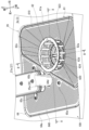
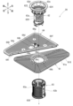
図4~図7に示すように、フィルタユニット29は、第1ボディ61と、第2ボディ62と、第3ボディ63と、第4ボディ64とで構成されている。 As shown in Figures 4 to 7, the filter unit 29 is composed of a first body 61, a second body 62, a third body 63, and a fourth body 64.

図7に示すように、第1ボディ61は平面視で略矩形の板状に形成されている。第1ボディ61は金属製である。第1ボディ61は第1フィルタ部61aと、挿通孔61bと、複数の連絡孔61cとを有している。第1フィルタ部61aは、第1ボディ61のほぼ全域を占めている。第1フィルタ部61aには、複数の第1孔610が形成されている。各第1孔610は丸孔形状をなしている。各第1孔610は、第1フィルタ部61aのほぼ全域、すなわち挿通孔61b及び各連絡孔61cを除いて第1ボディ61のほぼ全域に分布しており、第1フィルタ部61aを上下方向に貫通している。 As shown in FIG. 7, the first body 61 is formed in a substantially rectangular plate shape in a plan view. The first body 61 is made of metal. The first body 61 has a first filter portion 61a, an insertion hole 61b, and multiple communication holes 61c. The first filter portion 61a occupies almost the entire area of the first body 61. The first filter portion 61a has multiple first holes 610 formed therein. Each of the first holes 610 has a circular hole shape. Each of the first holes 610 is distributed over almost the entire area of the first filter portion 61a, i.e., over almost the entire area of the first body 61 except for the insertion hole 61b and each communication hole 61c, and penetrates the first filter portion 61a in the vertical direction.

挿通孔61b及び各連絡孔61cは第1フィルタ部61aに形成されており、第1フィルタ部61aを上下方向に貫通している。また、各連絡孔61cは、挿通孔61bの外側に配置されている。各連絡孔61c同士は挿通孔61bの周方向に等間隔で配置されており、挿通孔61bを外側から囲っている。なお、第1ボディ61は、第1孔610に相当する複数の貫通孔が形成された所謂パンチングメタルによって形成することができる。また、第1ボディ61を樹脂製としても良い。 The insertion hole 61b and each communication hole 61c are formed in the first filter part 61a and penetrate the first filter part 61a in the up-down direction. Each communication hole 61c is arranged outside the insertion hole 61b. Each communication hole 61c is arranged at equal intervals in the circumferential direction of the insertion hole 61b and surrounds the insertion hole 61b from the outside. The first body 61 can be formed from a so-called punching metal in which multiple through holes corresponding to the first hole 610 are formed. The first body 61 may also be made of resin.

図5~図8に示すように、第2ボディ62は樹脂製である。第2ボディ62は、第2フィルタ部62aと、第1案内部62bと、第2案内部62cと、鍔部62dと、延出部62eとで構成されている。 As shown in Figures 5 to 8, the second body 62 is made of resin. The second body 62 is composed of a second filter portion 62a, a first guide portion 62b, a second guide portion 62c, a flange portion 62d, and an extension portion 62e.

図8に示すように、第2フィルタ部62aは、上下方向に延びる円筒状に形成されており、第1ボディ61の挿通孔61bに挿通可能となっている。第2フィルタ部62aには、複数の第2孔620と、2つの係止片621と、係合リブ622とが形成されている。なお、図8では、説明を容易にするため、水溜ケース25等の図示を省略している他、第1孔610について一部の図示を省略している。 As shown in FIG. 8, the second filter portion 62a is formed in a cylindrical shape extending in the vertical direction and can be inserted into the insertion hole 61b of the first body 61. The second filter portion 62a is formed with a plurality of second holes 620, two locking pieces 621, and an engagement rib 622. Note that in FIG. 8, for ease of explanation, the water reservoir case 25 and the like are not shown, and some of the first holes 610 are not shown.

各第2孔620は、第2フィルタ部62aの外周面に形成されており、それぞれ第2フィルタ部62aの上下方向に配置されつつ第2フィルタ部62aの周方向に延びている。各第2孔620は、第2フィルタ部62aを径方向に貫通している。つまり、第2孔620は、第2フィルタ部62aの周方向に延びる略矩形の長孔形状をなしている。また、各第2孔620同士は、第2フィルタ部62aの上下方向及び周方向に互いに離隔していることから、各第2孔620同士は繋がっていない。 Each second hole 620 is formed on the outer peripheral surface of the second filter part 62a, and extends in the circumferential direction of the second filter part 62a while being disposed in the up-down direction of the second filter part 62a. Each second hole 620 penetrates the second filter part 62a in the radial direction. In other words, the second hole 620 has a substantially rectangular long hole shape extending in the circumferential direction of the second filter part 62a. In addition, since each second hole 620 is separated from each other in the up-down direction and the circumferential direction of the second filter part 62a, each second hole 620 is not connected to each other.

各係止片621は、第2フィルタ部62aの外周面に形成されており、それぞれ第2フィルタ部62aの上部に配置されている。各係止片621は、第2フィルタ部62aの外周面から第2フィルタ部62aの外側に向かって突出している。各係止片621同士は第2フィルタ部62aの周方向に等間隔で配置されている。係合リブ622は、第2フィルタ部62aの下部に配置されている。係合リブ622は、第2フィルタ部62aの外側に向かって突出しつつ、第2フィルタ部62aの周方向に一周している。 Each locking piece 621 is formed on the outer peripheral surface of the second filter part 62a and is disposed at the upper part of the second filter part 62a. Each locking piece 621 protrudes from the outer peripheral surface of the second filter part 62a toward the outside of the second filter part 62a. The locking pieces 621 are disposed at equal intervals in the circumferential direction of the second filter part 62a. The engagement rib 622 is disposed at the lower part of the second filter part 62a. The engagement rib 622 goes around the circumferential direction of the second filter part 62a while protruding toward the outside of the second filter part 62a.

図5に示すように、第1案内部62b及び第2案内部62cは、第2フィルタ部62aの内側に形成されている。また、第1案内部62bは、第2案内部62cよりも上方に配置されている。第1案内部62bと第2案内部62cとは、第2フィルタ部62aの内側を流通する洗浄水及び残滓を各第2孔620に向けて流通させるように第2フィルタ部62aの上下方向に傾斜して延びている。なお、第1案内部62b及び第2案内部62cの一方を省略しても良く、また、第1案内部62b及び第2案内部62cに加えて第2フィルタ部62aの内側に案内部を形成しても良い。 As shown in FIG. 5, the first guide portion 62b and the second guide portion 62c are formed on the inside of the second filter portion 62a. The first guide portion 62b is disposed above the second guide portion 62c. The first guide portion 62b and the second guide portion 62c extend at an incline in the vertical direction of the second filter portion 62a so as to direct the cleaning water and residue flowing inside the second filter portion 62a toward each second hole 620. Note that one of the first guide portion 62b and the second guide portion 62c may be omitted, or a guide portion may be formed on the inside of the second filter portion 62a in addition to the first guide portion 62b and the second guide portion 62c.

図8に示すように、鍔部62dは、第2フィルタ部62aの上端と一体をなしている。鍔部62dは、第2フィルタ部62aよりも大径に形成されている。図9に示すように、鍔部62dには、一つの第1連通孔623と、複数の第2連通孔624とが形成されている。各第2連通孔624は、本発明における「連通孔」の一例である。 As shown in FIG. 8, the flange 62d is integral with the upper end of the second filter portion 62a. The flange 62d is formed with a larger diameter than the second filter portion 62a. As shown in FIG. 9, the flange 62d is formed with one first communication hole 623 and multiple second communication holes 624. Each of the second communication holes 624 is an example of a "communication hole" according to the present invention.

第1連通孔623は鍔部62dの中央に位置している。第1連通孔623は、鍔部62dを上下方向に貫通しており、第2フィルタ部62aと連通している。このように第1連通孔623が鍔部62dに形成されることにより、鍔部62dは第2フィルタ部62aよりも大径の円環状をなしている。 The first communication hole 623 is located in the center of the flange 62d. The first communication hole 623 penetrates the flange 62d in the vertical direction and communicates with the second filter part 62a. By forming the first communication hole 623 in the flange 62d in this way, the flange 62d has a circular ring shape with a larger diameter than the second filter part 62a.

各第2連通孔624は第1連通孔623よりも小径に形成されており、それぞれ鍔部62dを上下方向に貫通している。各第2連通孔624は、第1連通孔623の外側かつ第2フィルタ部62aの外側となる箇所に配置されている。各第2連通孔624同士は第1連通孔623の周方向に等間隔で配置されており、第1連通孔623を外側から囲っている。なお、第2連通孔624の個数は適宜設計可能である。 Each second communication hole 624 is formed with a smaller diameter than the first communication hole 623, and each penetrates the flange portion 62d in the vertical direction. Each second communication hole 624 is arranged at a location that is outside the first communication hole 623 and outside the second filter portion 62a. Each second communication hole 624 is arranged at equal intervals in the circumferential direction of the first communication hole 623, and surrounds the first communication hole 623 from the outside. The number of second communication holes 624 can be designed as appropriate.

延出部62eは、鍔部62dの外周縁と一体をなしており、鍔部62dを囲いつつ鍔部62dから上方に向かって延びている。 The extension 62e is integral with the outer periphery of the flange 62d and extends upward from the flange 62d while surrounding it.

図7及び図8に示すように、第3ボディ63は、第3フィルタ部63aと、フレーム部63bとで構成されている。第3フィルタ部63aは、金属製の板材を円筒状に加工することによって形成されている。より具体的には、第3フィルタ部63aは、第2ボディ62の第2フィルタ部62aよりも大径の円筒状をなしている。第3フィルタ部63aには、複数の第3孔630が形成されている。各第3孔630は丸孔形状をなしている。各第3孔630は、第3フィルタ部63aのほぼ全域に分布しており、第3フィルタ部63aを径方向に貫通している。なお、第3フィルタ部63aについても、第3孔630に相当する複数の貫通孔が形成されたパンチングメタルによって形成することができる。また、第3フィルタ部63aを樹脂製としても良い。 7 and 8, the third body 63 is composed of a third filter portion 63a and a frame portion 63b. The third filter portion 63a is formed by processing a metal plate material into a cylindrical shape. More specifically, the third filter portion 63a has a cylindrical shape with a larger diameter than the second filter portion 62a of the second body 62. The third filter portion 63a has a plurality of third holes 630. Each of the third holes 630 has a round hole shape. Each of the third holes 630 is distributed over almost the entire area of the third filter portion 63a and penetrates the third filter portion 63a in the radial direction. The third filter portion 63a can also be formed of a punching metal in which a plurality of through holes corresponding to the third holes 630 are formed. The third filter portion 63a may also be made of resin.

フレーム部63bは樹脂製であり、上下方向に延びる略円筒の枠形状に形成されている。フレーム部63bについても、第2フィルタ部62aよりも大径に形成されている。フレーム部63bには第3フィルタ部63aが組み付けられている。これにより、フレーム部63bは第3フィルタ部63aを保持している。図8に示すように、フレーム部63bには、複数の係合爪631が形成されている。各係合爪631は、フレーム部63bの内側に向かって突出している。なお、フレーム部63bは上部と下部とが対称の形状に形成されている。 The frame portion 63b is made of resin and is formed in a generally cylindrical frame shape extending in the vertical direction. The frame portion 63b is also formed with a larger diameter than the second filter portion 62a. The third filter portion 63a is assembled to the frame portion 63b. In this way, the frame portion 63b holds the third filter portion 63a. As shown in FIG. 8, the frame portion 63b is formed with a plurality of engaging claws 631. Each engaging claw 631 protrudes toward the inside of the frame portion 63b. The upper and lower portions of the frame portion 63b are formed symmetrically.

図7に示すように、第4ボディ64は平面視で略矩形の板状に形成されている。第4ボディ64は樹脂製である。第4ボディ64は第4フィルタ部64aと、第1~3取付孔64b~64dと、第1~3ネジ孔64e~64gとを有している。第4フィルタ部64aは、第4ボディ64のほぼ全域を占めている。第4フィルタ部64aには、複数の第4孔640が形成されている他、支持片641が形成されている。各第4孔640は丸孔形状をなしている。各第4孔640は、第4フィルタ部64aのほぼ全域に分布しており、第4フィルタ部64aを上下方向に貫通している。 As shown in FIG. 7, the fourth body 64 is formed in a substantially rectangular plate shape in a plan view. The fourth body 64 is made of resin. The fourth body 64 has a fourth filter portion 64a, first to third mounting holes 64b to 64d, and first to third screw holes 64e to 64g. The fourth filter portion 64a occupies almost the entire area of the fourth body 64. The fourth filter portion 64a has a plurality of fourth holes 640 formed therein, as well as a support piece 641 formed therein. Each fourth hole 640 has a circular hole shape. Each fourth hole 640 is distributed over almost the entire area of the fourth filter portion 64a, and penetrates the fourth filter portion 64a in the vertical direction.

支持片641は、第4フィルタ部64aの前縁に形成されており、第4フィルタ部64aの前方に突出している。なお、第4ボディ64をパンチメンタル等の金属製としても良い。 The support piece 641 is formed on the front edge of the fourth filter part 64a and protrudes forward of the fourth filter part 64a. The fourth body 64 may be made of metal such as punched metal.

第1~3取付孔64b~64d及び第1~3ネジ孔64e~64gは、それぞれ第4フィルタ部64aに形成されており、第4フィルタ部64aを上下方向に貫通している。
第1取付孔64bには、水溜ケース25の接続筒部25aが挿通されるようになっている。第2、3取付孔64c、64dには、第1ダクト27aが取り付けられるようになっている。第1~3ネジ孔64e~64gには、それぞれ図4に示す第1~3取付ネジ65a~65cが挿通されるようになっている。
The first to third mounting holes 64b to 64d and the first to third screw holes 64e to 64g are respectively formed in the fourth filter portion 64a and pass through the fourth filter portion 64a in the up-down direction.
The first mounting hole 64b is adapted to receive the connecting tube portion 25a of the water reservoir case 25. The second and third mounting holes 64c, 64d are adapted to receive the first duct 27a. The first to third screw holes 64e to 64g are adapted to receive the first to third mounting screws 65a to 65c shown in FIG. 4, respectively.

図7に示すように、フィルタユニット29では、第1フィルタ部61aの各第1孔610の開口面積と、第3フィルタ部63aの各第3孔630の開口面積と、第4フィルタ部64aの各第4孔640の開口面積とがいずれも等しくされている。具体的には、各第1孔610、各第3孔630及び各第4孔640は、いずれも内径が約2mmに設定されている。 As shown in FIG. 7, in the filter unit 29, the opening area of each first hole 610 of the first filter section 61a, the opening area of each third hole 630 of the third filter section 63a, and the opening area of each fourth hole 640 of the fourth filter section 64a are all equal. Specifically, the inner diameter of each first hole 610, each third hole 630, and each fourth hole 640 is set to about 2 mm.

一方、第2フィルタ部62aの各第2孔620の開口面積は、各第1孔610、各第3孔630及び各第4孔640の開口面積よりも大きくなっている。さらに、各第2連通孔624及び各連絡孔61cの開口面積についても、各第1孔610、各第3孔630及び各第4孔640の開口面積よりも大きくなっている。なお、各第1孔610、各第3孔630及び各第4孔640の開口面積は、各第2孔620の開口面積よりも小さければ、互いに開口面積に差があっても良い。また、第2連通孔624の開口面積と第1ボディ61の各連絡孔61cの開口面積とは、同一であっても良く、互いに異なっていても良い。 On the other hand, the opening area of each second hole 620 of the second filter section 62a is larger than the opening area of each first hole 610, each third hole 630, and each fourth hole 640. Furthermore, the opening area of each second communication hole 624 and each communication hole 61c is also larger than the opening area of each first hole 610, each third hole 630, and each fourth hole 640. Note that the opening areas of each first hole 610, each third hole 630, and each fourth hole 640 may differ from each other as long as they are smaller than the opening area of each second hole 620. Furthermore, the opening area of the second communication hole 624 and the opening area of each communication hole 61c of the first body 61 may be the same or different from each other.

図5、図6及び図8に示すように、この食器洗浄機では、フィルタユニット29が洗浄空間100内、貯水部23内及び水溜ケース25内にわたって配置されている。フィルタユニット29を配置するに当たっては、まず初めに、図4に示すように、フィルタユニット29では、第4ボディ64の第1取付孔64bに水溜ケース25の接続筒部25aを挿通するとともに、第2、3取付孔64c、64dに第1ダクト27aを取り付ける。そして、この状態で第1~3取付ネジ65a~65cによって第4ボディ64を洗浄槽3の下壁3eに固定する。この際、第2、3取付ネジ65b、65cは、第1ダクト27aとともに第4ボディ64を下壁3eに固定している。 As shown in Figures 5, 6 and 8, in this dishwasher, the filter unit 29 is arranged throughout the washing space 100, the water storage section 23 and the water storage case 25. To arrange the filter unit 29, first, as shown in Figure 4, the connecting tube section 25a of the water storage case 25 is inserted into the first mounting hole 64b of the fourth body 64, and the first duct 27a is attached to the second and third mounting holes 64c and 64d. Then, in this state, the fourth body 64 is fixed to the bottom wall 3e of the washing tub 3 by the first to third mounting screws 65a to 65c. At this time, the second and third mounting screws 65b and 65c fix the fourth body 64 together with the first duct 27a to the bottom wall 3e.

次に、フィルタユニット29では、図5~図8に示すように、第3ボディ63を第1ボディ61の下方に配置する。そして、この状態で図7に示す第1ボディ61の挿通孔61bに対して、第2ボディ62の第2フィルタ部62aを上方から挿通する。これにより、図8に示すように、第2フィルタ部62aが第3ボディ63内、すなわち第3フィルタ部63a及びフレーム部63bの内側に進入する。また、第2フィルタ部62aでは、各係止片621が挿通孔61bの外周縁と係合する。これにより、第1ボディ61と第2ボディ62とが組み付けられる。また、この際、第1ボディ61の各連絡孔61cが各第2連通孔624に対して下方から連通する。 Next, in the filter unit 29, the third body 63 is placed below the first body 61 as shown in Figs. 5 to 8. Then, in this state, the second filter portion 62a of the second body 62 is inserted from above into the insertion hole 61b of the first body 61 shown in Fig. 7. As a result, as shown in Fig. 8, the second filter portion 62a enters the third body 63, that is, inside the third filter portion 63a and the frame portion 63b. Also, in the second filter portion 62a, each locking piece 621 engages with the outer periphery of the insertion hole 61b. This allows the first body 61 and the second body 62 to be assembled. Also, at this time, each communication hole 61c of the first body 61 communicates with each second communication hole 624 from below.

さらに、第2フィルタ部62aでは、係合リブ622が第3ボディ63の係合爪631と係合する。これにより、第2ボディ62と第3ボディ63とが組み付けられ、第3ボディ63は、第2ボディ62に組み付けられた状態で第1ボディ61の下方に位置することになる。こうして、第2ボディ62が第1ボディ61及び第3ボディ63に組み付けられることで、第1~3ボディ61~63が一体に組み付けられる。 Furthermore, in the second filter portion 62a, the engagement rib 622 engages with the engagement claw 631 of the third body 63. This causes the second body 62 and the third body 63 to be assembled together, and the third body 63, when assembled to the second body 62, is positioned below the first body 61. In this way, the second body 62 is assembled to the first body 61 and the third body 63, and the first to third bodies 61 to 63 are assembled together.

そして、図5及び図6に示すように、第1ボディ61を洗浄槽3の下壁3e及び第4ボディ64の支持片641に載置する。これにより、第1ボディ61及び第4ボディ64は、下壁3eに設けられて貯水部23を上方から覆う状態となる。また、第3ボディ63は、自己の上部を連絡口23aから貯水部23内に突出した状態で水溜ケース25内に配置される。 Then, as shown in Figures 5 and 6, the first body 61 is placed on the bottom wall 3e of the cleaning tank 3 and the support piece 641 of the fourth body 64. As a result, the first body 61 and the fourth body 64 are attached to the bottom wall 3e and cover the water storage section 23 from above. The third body 63 is placed in the water storage case 25 with its upper part protruding into the water storage section 23 from the communication port 23a.

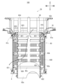
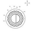
ここで、図5、図6及び図8に示すように、フィルタユニット29では、第3フィルタ部63aが第2フィルタ部62aよりも大径の円筒状に形成されているため、第2フィルタ部62aが第3フィルタ部63a及びフレーム部63bの内側に進入することにより、第3フィルタ部63aは第2フィルタ部62aを外側から覆う状態となる。これにより、第2フィルタ部62aと第3フィルタ部63aとの間には円筒状に延びる空隙Sが形成されている。そして、第2フィルタ部62aの各第2孔620と、第3フィルタ部63aの各第3孔630とは、空隙Sを介して第2フィルタ部62a及び第3フィルタ部63aの径方向で対向している。また、空隙Sは、下端で水溜ケース25内に連通している。 As shown in Figs. 5, 6 and 8, in the filter unit 29, the third filter portion 63a is formed in a cylindrical shape with a larger diameter than the second filter portion 62a. When the second filter portion 62a enters the inside of the third filter portion 63a and the frame portion 63b, the third filter portion 63a covers the second filter portion 62a from the outside. As a result, a cylindrically extending gap S is formed between the second filter portion 62a and the third filter portion 63a. The second holes 620 of the second filter portion 62a and the third holes 630 of the third filter portion 63a face each other in the radial direction of the second filter portion 62a and the third filter portion 63a through the gap S. The gap S also communicates with the inside of the water reservoir case 25 at the lower end.

さらに、第2ボディ62では、鍔部62dが空隙Sを上方から覆っている。そして、各第2連通孔624が各連絡孔61cを通じて空隙Sに上方から連通している。 Furthermore, in the second body 62, the flange portion 62d covers the gap S from above. And each second communication hole 624 communicates with the gap S from above through each communication hole 61c.

また、フィルタユニット29では、第1ボディ61は、下壁3e及び第4ボディ64に載置されているに過ぎず、下壁3e及び第4ボディ64に対して固定されていない。さらに、第2フィルタ部62aの各係止片621と第1ボディ61の挿通孔61bの外周縁とを係合又は非係合とすることにより、第1ボディ61と第2ボディ62とが着脱可能となっている。また、第2フィルタ部62aの係合リブ622と第3ボディ63の係合爪631とを係合又は非係合とすることにより、第2ボディ62と第3ボディ63とが着脱可能となっている。 In the filter unit 29, the first body 61 is merely placed on the bottom wall 3e and the fourth body 64, and is not fixed to the bottom wall 3e and the fourth body 64. Furthermore, the first body 61 and the second body 62 are detachable by engaging or disengaging each locking piece 621 of the second filter part 62a with the outer periphery of the insertion hole 61b of the first body 61. Also, the second body 62 and the third body 63 are detachable by engaging or disengaging the engagement rib 622 of the second filter part 62a with the engagement claw 631 of the third body 63.

これらにより、フィルタユニット29では、第1~3ボディ61~63が一体に組み付けられた状態では、これらの第1~3ボディ61~63を一体で洗浄槽3及び水溜ケース25から取り外すことが可能となっており、使用者は、食器洗浄機の外部で第1~3ボディ61~63の洗浄が可能となっている。この際、使用者は必要に応じて第1~3ボディ61~63を分解しつつ洗浄することも可能となっている。 As a result, in the filter unit 29, when the first to third bodies 61 to 63 are assembled together, these first to third bodies 61 to 63 can be removed together from the washing tank 3 and the water storage case 25, and the user can wash the first to third bodies 61 to 63 outside the dishwasher. At this time, the user can also disassemble the first to third bodies 61 to 63 while washing them, if necessary.

図1に示す貯蔵タンク7は、内部に処理剤としての食器用のリンスが貯蔵されている。なお、処理剤は、食器用の洗剤等であっても良い。 The storage tank 7 shown in FIG. 1 stores a dish rinse as a treatment agent inside. The treatment agent may also be a dish detergent, etc.

貯蔵タンク7は、供給路側接続部35及び通気部37に取り付けられており、洗浄空間100内に配置されている。詳細な図示を省略するものの、貯蔵タンク7は、供給路側接続部35及び通気部37に対して着脱可能となっている。これにより、貯蔵タンク7を供給路側接続部35及び通気部37から取り外すことで、貯蔵タンク7を洗浄空間100の外部に取り出すことが可能となっている。こうして、洗浄空間100の外部で貯蔵タンク7内に処理剤を補充することが可能となっている。 The storage tank 7 is attached to the supply line side connection part 35 and the ventilation part 37, and is disposed within the cleaning space 100. Although detailed illustration is omitted, the storage tank 7 is detachable from the supply line side connection part 35 and the ventilation part 37. This makes it possible to remove the storage tank 7 from the supply line side connection part 35 and the ventilation part 37 and take the storage tank 7 outside the cleaning space 100. In this way, it is possible to replenish the treatment agent in the storage tank 7 outside the cleaning space 100.

貯蔵タンク7は、供給路側接続部35及び通気部37に取り付けられることにより、供給路側接続部35及び図3に示す供給路本体34を通じて処理剤供給装置9と接続している。また、貯蔵タンク7は、通気部37に取り付けられることにより、貯蔵タンク7の内部が通気部37を通じて通気ダクト28aと連通している。 The storage tank 7 is attached to the supply line side connection part 35 and the ventilation part 37, and is connected to the treatment agent supply device 9 through the supply line side connection part 35 and the supply line main body 34 shown in FIG. 3. In addition, the storage tank 7 is attached to the ventilation part 37, and the inside of the storage tank 7 is connected to the ventilation duct 28a through the ventilation part 37.

図1に示す第1食器かご13、第2食器かご14及び第3食器かご15は、それぞれ被洗浄物(図示略)を載置可能となっている。第1食器かご13、第2食器かご14及び第3食器かご15は、被洗浄物の種類等に応じて、載置可能な被洗浄物が区分けされている。そして、第1食器かご13には、主に大型の被洗浄物が載置されるように形成されている。なお、被洗浄物としては、例えば皿や茶碗等の食器類の他、箸やコップ等の飲食用具及び鍋等の調理容器が挙げられる。 The first dish basket 13, the second dish basket 14, and the third dish basket 15 shown in FIG. 1 are each capable of placing items to be washed (not shown). The first dish basket 13, the second dish basket 14, and the third dish basket 15 are divided into categories for the items to be washed, depending on the type of item to be washed, etc. The first dish basket 13 is designed to mainly hold large items to be washed. Examples of items to be washed include tableware such as plates and bowls, as well as eating and drinking utensils such as chopsticks and cups, and cooking vessels such as pots.

第1食器かご13は、図2に示す第1下段ガイド部材111及び第2下段ガイド部材114によって前後方向に案内されつつ洗浄空間100からの出し入れが可能であるとともに、第1下段ガイド部材111及び第2下段ガイド部材114によって前後方向及び左右方向に水平な姿勢で洗浄空間100内に収容可能となっている。同様に、第2食器かご14は、第1中段ガイド部材112及び第2中段ガイド部材115によって前後方向に案内されつつ洗浄空間100からの出し入れが可能であるとともに、第1中段ガイド部材112及び第2中段ガイド部材115によって前後方向及び左右方向に水平な姿勢で洗浄空間100内に収容可能となっている。そして、第3食器かご15は、第1上段ガイド部材113及び第2上段ガイド部材116によって前後方向に案内されつつ洗浄空間100からの出し入れが可能であるとともに、第1上段ガイド部材113及び第2上段ガイド部材116によって前後方向及び左右方向に水平な姿勢で洗浄空間100内に収容可能となっている。 The first dishwashing basket 13 can be taken in and out of the washing space 100 while being guided in the front-to-rear direction by the first lower guide member 111 and the second lower guide member 114 shown in Figure 2, and can be stored in the washing space 100 in a horizontal position in the front-to-rear and left-to-right directions by the first lower guide member 111 and the second lower guide member 114. Similarly, the second dishwashing basket 14 can be taken in and out of the washing space 100 while being guided in the front-to-rear direction by the first middle guide member 112 and the second middle guide member 115, and can be stored in the washing space 100 in a horizontal position in the front-to-rear and left-to-right directions by the first middle guide member 112 and the second middle guide member 115. The third dish basket 15 can be taken in and out of the washing space 100 while being guided in the front-to-back direction by the first upper guide member 113 and the second upper guide member 116, and can be stored in the washing space 100 in a horizontal position in the front-to-back and left-to-right directions by the first upper guide member 113 and the second upper guide member 116.

また、第1食器かご13は、持ち手部13aを有している他、干渉部13bを有している。持ち手部13aは、第1食器かご13の前部に設けられている。持ち手部13aは、第1食器かご13を洗浄空間100から出し入れするに当たって、使用者が把持可能となっている。 In addition, the first dish basket 13 has a handle portion 13a and an interference portion 13b. The handle portion 13a is provided at the front portion of the first dish basket 13. The handle portion 13a can be grasped by the user when inserting or removing the first dish basket 13 from the cleaning space 100.

干渉部13bは、第1食器かご13の右部に設けられている。詳細な図示を省略するものの、干渉部13bは、第1食器かご13の右部から左方に延びた後、第1食器かご13の上方に延びている。干渉部13bは、貯蔵タンク7が洗浄空間100内に配置された状態で第1食器かご13を洗浄空間100内に収容した際、貯蔵タンク7が供給路側接続部35及び通気部37に適正に取り付けられいる状態であれば、貯蔵タンク7とは接触することなく、貯蔵タンク7に対して左方から対向する。これに対し、供給路側接続部35及び通気部37に対する貯蔵タンク7の取り付けが不完全であるときには、干渉部13bは、第1食器かご13を洗浄空間100内に収容した際に貯蔵タンク7と干渉する。 The interference portion 13b is provided on the right side of the first dish basket 13. Although detailed illustration is omitted, the interference portion 13b extends leftward from the right side of the first dish basket 13 and then extends above the first dish basket 13. When the first dish basket 13 is housed in the washing space 100 with the storage tank 7 disposed in the washing space 100, the interference portion 13b faces the storage tank 7 from the left without coming into contact with the storage tank 7 if the storage tank 7 is properly attached to the supply path side connection portion 35 and the ventilation portion 37. In contrast, when the storage tank 7 is not completely attached to the supply path side connection portion 35 and the ventilation portion 37, the interference portion 13b interferes with the storage tank 7 when the first dish basket 13 is housed in the washing space 100.

図1に示すように、操作部19は、蓋体5に設けられており、内側パネル5bの上部に配置されている。操作部19は、制御部21と通電可能に接続されている。また、操作部19は図示しない操作ボタン及びディスプレイを有している。操作部19は、操作ボタンを通じて食器洗浄機を作動させるための操作が可能となっている。また、操作部19では、ディスプレイに運転時間等が表示される。なお、操作部19は外側パネル5aに配置されても良い。 As shown in FIG. 1, the operation unit 19 is provided on the lid 5 and is arranged on the upper part of the inner panel 5b. The operation unit 19 is electrically connected to the control unit 21. The operation unit 19 also has operation buttons and a display (not shown). The operation unit 19 allows the user to operate the dishwasher via the operation buttons. The operation unit 19 also displays the operation time, etc. on the display. The operation unit 19 may also be arranged on the outer panel 5a.

制御部21は蓋体5に設けられており、外側パネル5aと内側パネル5bとの間に配置されている。制御部21は、給水ポンプ43、排水ポンプ45、給水電磁弁、排水電磁弁、給気ファン28c及び供給装置本体9aの各作動制御を行う。これにより、制御部21は、洗浄運転と濯ぎ運転と乾燥運転とを実行する。なお、制御部21は収容空間10内に配置されても良い。 The control unit 21 is provided on the cover 5 and is disposed between the outer panel 5a and the inner panel 5b. The control unit 21 controls the operation of the water supply pump 43, the drain pump 45, the water supply solenoid valve, the drain solenoid valve, the air supply fan 28c, and the supply device main body 9a. In this way, the control unit 21 executes the washing operation, the rinsing operation, and the drying operation. The control unit 21 may be disposed within the storage space 10.

この食器洗浄機において、被洗浄物の洗浄を行うに当たっては、使用者は、処理剤が貯蔵されている貯蔵タンク7を供給路側接続部35及び通気部37に取り付ける。そして、この状態で、使用者は被洗浄物が載置された第1~3食器かご13~15をそれぞれ洗浄空間100内に配置する。その後、使用者は、蓋体5を閉鎖位置に揺動させるとともに、操作部19を操作する。これにより、この食器洗浄機では、制御部21が洗浄運転、濯ぎ運転及び乾燥運転をこの順で実行する。なお、制御部21は、洗浄運転、濯ぎ運転及び乾燥運転のいずれかのみを実行することもできる。 When washing the items to be washed in this dishwasher, the user attaches the storage tank 7 in which the treatment agent is stored to the supply line side connection part 35 and the ventilation part 37. Then, in this state, the user places the first to third dish baskets 13 to 15, in which the items to be washed are placed, in the washing space 100. After that, the user swings the lid body 5 to the closed position and operates the operating part 19. As a result, in this dishwasher, the control part 21 executes the washing operation, the rinsing operation, and the drying operation in that order. Note that the control part 21 can also execute only any one of the washing operation, the rinsing operation, and the drying operation.

洗浄運転では、制御部21は、給水ホース41に設けられた給水電磁弁を開くとともに、給水ポンプ43を作動させる。これにより、給水源からの水が洗浄水として給水ホース41、給水ポンプ43、分水器26及び接続筒部25aを経て、第1噴射ノズル31の各噴射部300から洗浄空間100内に噴射される。また、洗浄水は、分水器26から給水ダクト27を経て、第2、3噴射ノズル32、33の各噴射部300からも洗浄空間100内に噴射される。また、洗浄運転では、洗浄槽3に設けられた洗剤自動投入装置(図示略)によって食器用の洗剤が洗浄空間100内に供給される。こうして、洗浄運転では、洗剤を含んだ洗浄水によって被洗浄物の洗浄が行われる。なお、洗浄運転では、給水源から所定量の水が供給されることにより、制御部21は給水電磁弁を閉じる。 In the washing operation, the control unit 21 opens the water supply solenoid valve provided on the water supply hose 41 and operates the water supply pump 43. As a result, water from the water supply source is sprayed as washing water from each spraying part 300 of the first spray nozzle 31 through the water supply hose 41, the water supply pump 43, the water distributor 26, and the connecting tube part 25a into the washing space 100. Also, washing water is sprayed from the water distributor 26 through the water supply duct 27 from each spraying part 300 of the second and third spray nozzles 32 and 33 into the washing space 100. Also, in the washing operation, dish detergent is supplied into the washing space 100 by an automatic detergent supplying device (not shown) provided in the washing tank 3. Thus, in the washing operation, the objects to be washed are washed with washing water containing detergent. In addition, in the washing operation, a predetermined amount of water is supplied from the water supply source, and the control unit 21 closes the water supply solenoid valve.

このように、洗浄空間100内で被洗浄物が洗浄水によって洗浄されることにより、被洗浄物に付着した残菜等の残滓が被洗浄物から剥がれ落ちる。これにより、残滓は洗浄水に含まれ、洗浄水とともに洗浄空間100内を下方に向かって流通する。こうして、残滓を含んだ洗浄水は、図5、図6及び図8の実線矢印で示すように、フィルタユニット29を流通しつつ、貯水部23及び水溜ケース25内に貯留される。 In this way, as the object to be washed is washed with the washing water in the washing space 100, food residue and other debris attached to the object to be washed falls off from the object to be washed. As a result, the debris is contained in the washing water and flows downward within the washing space 100 together with the washing water. In this way, the washing water containing the debris flows through the filter unit 29 and is stored in the water storage section 23 and the water storage case 25, as shown by the solid arrows in Figures 5, 6, and 8.

より具体的には、フィルタユニット29では、洗浄空間100内の残滓を含んだ洗浄水は、第1ボディ61の第1フィルタ部61a、第4ボディ64の第4フィルタ部64a、又は、第2ボディ62の延出部62eから第1連通孔623を経て第2フィルタ部62aを流通する。 More specifically, in the filter unit 29, cleaning water containing residue in the cleaning space 100 flows through the first filter section 61a of the first body 61, the fourth filter section 64a of the fourth body 64, or the second filter section 62a from the extension section 62e of the second body 62 via the first communication hole 623.

ここで、第1フィルタ部61aでは、各第1孔610を洗浄水が流通する一方で、各第1孔610よりも大きい残滓は各第1孔610を通過できずに各第1孔610に捕集される。同様に、第4フィルタ部64aでは、各第4孔640を洗浄水が流通する一方で、各第4孔640よりも大きい残滓は各第4孔640を通過できずに各第4孔640に捕集される。こうして、第1フィルタ部61a及び第4フィルタ部64aを流通した洗浄水と、各第1孔610及び各第4孔640よりも小さい残滓とは、貯水部23及び水溜ケース25内に貯留される。 Here, in the first filter section 61a, while the cleaning water flows through each of the first holes 610, residues larger than each of the first holes 610 cannot pass through each of the first holes 610 and are collected in each of the first holes 610. Similarly, in the fourth filter section 64a, while the cleaning water flows through each of the fourth holes 640, residues larger than each of the fourth holes 640 cannot pass through each of the fourth holes 640 and are collected in each of the fourth holes 640. In this way, the cleaning water that has flowed through the first filter section 61a and the fourth filter section 64a and the residues smaller than each of the first holes 610 and each of the fourth holes 640 are stored in the water storage section 23 and the water storage case 25.

また、第2フィルタ部62aでは、内部を流通する洗浄水及び残滓は、第1案内部62b及び第2案内部62cによって整流されつつ、各第2孔620に向かって第2フィルタ部62aの径方向に流通する。そして、第2フィルタ部62aでは、各第2孔620を洗浄水が流通する一方で、各第2孔620よりも大きい残滓は各第2孔620を通過できずに各第2孔620に捕集される。 In the second filter section 62a, the cleaning water and residue flowing therethrough are rectified by the first guide section 62b and the second guide section 62c, and flow in the radial direction of the second filter section 62a toward each of the second holes 620. In the second filter section 62a, the cleaning water flows through each of the second holes 620, while residue larger than each of the second holes 620 cannot pass through each of the second holes 620 and is collected in each of the second holes 620.

こうして、洗浄水及び各第2孔620よりも小さい残滓は、空隙S、さらには第3ボディ63の第3フィルタ部63aに向かって、第2フィルタ部62aの外側に流通する。これにより、第3フィルタ部63aでは、空隙S内を流通した洗浄水及び残滓のうち、洗浄水については、各第3孔630を流通しつつ、第3フィルタ部63aの径方向で水溜ケース25に向かって流通する。一方、各第3孔630よりも大きい残滓、すなわち各第2孔620よりも小さく各第3孔630よりも大きい残滓については、各第3孔630を通過できずに各第3孔630に捕集される。 In this way, the cleaning water and residue smaller than each second hole 620 flow to the outside of the second filter section 62a toward the gap S and further toward the third filter section 63a of the third body 63. As a result, in the third filter section 63a, of the cleaning water and residue that flowed through the gap S, the cleaning water flows through each third hole 630 and flows toward the water reservoir case 25 in the radial direction of the third filter section 63a. On the other hand, residue larger than each third hole 630, i.e., residue smaller than each second hole 620 and larger than each third hole 630, cannot pass through each third hole 630 and is collected in each third hole 630.

この結果、各第3孔630を流通した洗浄水と、各第3孔630よりも小さい残滓とは、水溜ケース25内に貯留される。そして、この食器洗浄機では、フィルタユニット29を通過した洗浄水、すなわち、各第1孔610、各第4孔640又は各第3孔630を通過した洗浄水は、図5に示す第1接続口251から供給路6内を給水ポンプ43に向かって流通する。そして、この洗浄水は、給水ポンプ43によって、分水器26及び給水ダクト27を経て第1~3噴射ノズル31~33の各噴射部300から再び洗浄空間100内に噴射される。これにより、洗浄運転として設定された洗浄時間が経過するまでは、引き続き洗浄空間100内での被洗浄物の洗浄が継続される。 As a result, the cleaning water that has flowed through each of the third holes 630 and residues smaller than the size of each of the third holes 630 are stored in the water reservoir case 25. In this dishwasher, the cleaning water that has passed through the filter unit 29, i.e., the cleaning water that has passed through each of the first holes 610, each of the fourth holes 640, or each of the third holes 630, flows from the first connection port 251 shown in FIG. 5 through the supply passage 6 toward the water supply pump 43. Then, this cleaning water is sprayed again into the cleaning space 100 from each of the spraying parts 300 of the first to third spray nozzles 31 to 33 through the water distributor 26 and the water supply duct 27 by the water supply pump 43. As a result, the cleaning of the objects to be washed in the cleaning space 100 continues until the cleaning time set as the cleaning operation has elapsed.

そして、制御部21は、洗浄運転として設定された洗浄時間が経過すれば、排水ホース47に設けられた排水電磁弁を開くとともに、排水ポンプ45を作動させる。また、制御部21は、給水ポンプ43を停止させる。 When the cleaning time set for the cleaning operation has elapsed, the control unit 21 opens the drain solenoid valve provided on the drain hose 47 and operates the drain pump 45. The control unit 21 also stops the water supply pump 43.

これにより、この食器洗浄機では、洗浄運転が終了する。そして、上述のようにフィルタユニット29を通過した洗浄水は、排水ポンプ45によって図6に示す第2接続口252から排水路8内及び排水ホース47内を流通することにより、食器洗浄機の外部に排出される。この際、各第1孔610、各第4孔640又は各第3孔630を通過した残滓についても、洗浄水とともに食器洗浄機の外部に不可避的に排出されことになる。 This ends the washing operation of the dishwasher. Then, the washing water that has passed through the filter unit 29 as described above is discharged to the outside of the dishwasher by circulating through the drainage channel 8 and the drainage hose 47 from the second connection port 252 shown in FIG. 6 by the drain pump 45. At this time, the residue that has passed through each of the first holes 610, each of the fourth holes 640, and each of the third holes 630 is also inevitably discharged to the outside of the dishwasher together with the washing water.

ここで、各第1孔610、各第3孔630及び各第4孔640は、いずれも内径が約2mmの丸孔とされていることから、各第1孔610、各第3孔630及び各第4孔640を通過する残滓は極めて小さいことになる。このため、残滓が食器洗浄機の外部に排出されることの影響は小さくなっている。 Since each of the first hole 610, the third hole 630, and the fourth hole 640 is a round hole with an inner diameter of about 2 mm, the residue passing through each of the first hole 610, the third hole 630, and the fourth hole 640 is extremely small. Therefore, the impact of the residue being discharged outside the dishwasher is small.

濯ぎ運転では、制御部21は、給水電磁弁を開くとともに給水ポンプ43を作動させる。これにより、洗浄運転と同様に、給水源からの水が洗浄水として第1~3噴射ノズル31~33の各噴射部300から洗浄空間100内に噴射される。また、濯ぎ運転では、制御部21は、供給装置本体9aを作動させる。これにより、貯蔵タンク7に貯蔵された処理剤が処理剤供給路11を経て供給装置本体9aに流通する。そして、処理剤は、処理剤供給口9bから洗浄空間100内に自動で供給される。こうして、濯ぎ運転では、処理剤を含んだ洗浄水によって被洗浄物の濯ぎが行われる。 In the rinsing operation, the control unit 21 opens the water supply solenoid valve and operates the water supply pump 43. As a result, similar to the washing operation, water from the water supply source is sprayed as washing water from each of the spraying units 300 of the first to third spray nozzles 31 to 33 into the washing space 100. Also, in the rinsing operation, the control unit 21 operates the supply device main body 9a. As a result, the treatment agent stored in the storage tank 7 flows into the supply device main body 9a via the treatment agent supply path 11. The treatment agent is then automatically supplied into the washing space 100 from the treatment agent supply port 9b. Thus, in the rinsing operation, the object to be washed is rinsed with washing water containing the treatment agent.

制御部21は、濯ぎ洗浄運転として設定された洗浄時間が経過すれば、洗浄運転時と同様に、洗浄空間100内の洗浄水を食器洗浄機の外部に排出する。こうして濯ぎ運転が終了する。 When the cleaning time set for the rinsing operation has elapsed, the control unit 21 discharges the cleaning water in the cleaning space 100 to the outside of the dishwasher, just as in the cleaning operation. This ends the rinsing operation.

乾燥運転では、制御部21は、給気ファン28cを作動させる。これにより、洗浄空間100内の空気が通気部37の各通気口37aから通気ダクト28a内を流通する。また、通気ダクト28a内の空気は、接続ホース28b及び給気ファン28cを経て、空気供給部28dから洗浄空間100内に供給される。こうして、乾燥運転では、洗浄空間100の内部と洗浄空間100の外部、すなわち洗浄槽3の外部との間で空気が循環しつつ、被洗浄物の乾燥が行われる。制御部21は、乾燥運転として設定された洗浄時間が経過すれば、給気ファン28cを停止させる。こうして乾燥運転が終了させる。 In the drying operation, the control unit 21 operates the air supply fan 28c. This causes air in the cleaning space 100 to flow through the ventilation duct 28a from each ventilation port 37a of the ventilation unit 37. The air in the ventilation duct 28a is also supplied from the air supply unit 28d to the cleaning space 100 via the connection hose 28b and the air supply fan 28c. In this way, in the drying operation, the object to be washed is dried while air circulates between the inside of the cleaning space 100 and the outside of the cleaning space 100, i.e., the outside of the cleaning tank 3. When the cleaning time set for the drying operation has elapsed, the control unit 21 stops the air supply fan 28c. This ends the drying operation.

このように、この食器洗浄機では、フィルタユニット29の各第1孔610、各第2孔620、各第3孔630及び各第4孔640、ひいては第1~4フィルタ部61a~64aによって残滓を好適に捕集できる。このため、この食器洗浄機では、水溜ケース25から供給路6を流通する洗浄水、及び、水溜ケース25から排水路8を流通する洗浄水には残滓が含まれ難くなっている。 In this way, in this dishwasher, residue can be effectively collected by the first holes 610, the second holes 620, the third holes 630, and the fourth holes 640 of the filter unit 29, and by extension the first to fourth filter sections 61a to 64a. As a result, in this dishwasher, residue is less likely to be contained in the wash water flowing from the water storage case 25 through the supply passage 6, and in the wash water flowing from the water storage case 25 through the drain passage 8.

また、図5、図6及び図8の実線矢印で示すように、フィルタユニット29では、洗浄空間100内の洗浄水の一部が、第2ボディ62の延出部62eから各第2連通孔624及び第1ボディ61の各連絡孔61cを経ることによっても、空隙S内に流通する。そして、各第2連通孔624及び各連絡孔61cを経た洗浄水は、第2フィルタ部62a及び第3フィルタ部63aに沿って、空隙S内を上方から下方に向かって流通する。つまり、各第2連通孔624及び各連絡孔61cを経て空隙S内に流通する洗浄水は、第2フィルタ部62aの各第2孔620から空隙Sに向かって流通する洗浄水及び残滓に対して交差するように流通する。 As shown by solid arrows in Figures 5, 6 and 8, in the filter unit 29, a portion of the cleaning water in the cleaning space 100 also flows into the gap S by passing through each second communication hole 624 and each communication hole 61c of the first body 61 from the extension portion 62e of the second body 62. The cleaning water that passes through each second communication hole 624 and each communication hole 61c flows from the top to the bottom in the gap S along the second filter portion 62a and the third filter portion 63a. In other words, the cleaning water that flows into the gap S through each second communication hole 624 and each communication hole 61c flows so as to cross the cleaning water and residue that flows from each second hole 620 of the second filter portion 62a toward the gap S.

また、第2連通孔624及び連絡孔61cはそれぞれ複数である。さらに、各第2連通孔624及び各連絡孔61cの開口面積は、各第1孔610、各第3孔630及び各第4孔640の開口面積よりも大きくなっている。このため、この食器洗浄機では、各第2連通孔624及び各連絡孔61cを経て空隙S内に流通する洗浄水の流量を好適に確保することが可能となっている。 There are multiple second communication holes 624 and multiple connection holes 61c. Furthermore, the opening area of each second communication hole 624 and each connection hole 61c is larger than the opening area of each first hole 610, each third hole 630, and each fourth hole 640. Therefore, in this dishwasher, it is possible to appropriately ensure the flow rate of washing water flowing through each second communication hole 624 and each connection hole 61c into the gap S.

これらのため、この食器洗浄機では、たとえ各第3孔630に捕集された残滓が第3フィルタ部63aに付着しても、このような残滓については、各第2連通孔624及び各連絡孔61cを経て空隙Sに流入した洗浄水によって第3フィルタ部63aから好適に除去することが可能となっている。換言すれば、この食器洗浄機では、第1~3ボディ61~63を洗浄槽3及び水溜ケース25から取り外して第1~3ボディ61~63の洗浄作業を行う回数を可及的に少なくしつつも、残滓による各第3孔630の目詰まりを好適に防止することができる。 For these reasons, in this dishwasher, even if residues collected in each of the third holes 630 adhere to the third filter section 63a, such residues can be suitably removed from the third filter section 63a by the wash water that flows into the gap S via each of the second communication holes 624 and each of the connection holes 61c. In other words, in this dishwasher, the number of times that the first to third bodies 61 to 63 are removed from the washing tank 3 and the water storage case 25 to perform the washing operation of the first to third bodies 61 to 63 is minimized, while still suitably preventing clogging of each of the third holes 630 by residues.

この結果、この食器洗浄機では、残滓による各第3孔630の目詰まりが生じ難く、供給路6及び排水路8に向かう洗浄水の流通が阻害され難くなっている。このため、この食器洗浄機では、供給路6を経つつ給水ポンプ43によって洗浄空間100内に供給される洗浄水の水量を好適に確保できるとともに、排水路8を経つつ排水ポンプ45によって食器洗浄機の外部に排出される洗浄水の水量を好適に確保できる。なお、厳密には、この食器洗浄機では、洗浄水だけでなく、各第2連通孔624及び各連絡孔61cよりも小さい残滓についても、洗浄水とともに各第2連通孔624及び各連絡孔61cを経て空隙S内に流通することになる。そして、各第2連通孔624及び各連絡孔61cを流通した残滓については、空隙Sを経て水溜ケース25内に堆積する。 As a result, in this dishwasher, clogging of each third hole 630 by residues does not easily occur, and the flow of washing water toward the supply passage 6 and the drain passage 8 is not easily hindered. Therefore, in this dishwasher, the amount of washing water supplied to the washing space 100 by the water supply pump 43 through the supply passage 6 can be suitably secured, and the amount of washing water discharged to the outside of the dishwasher by the drain pump 45 through the drain passage 8 can be suitably secured. Strictly speaking, in this dishwasher, not only the washing water but also the residues smaller than each second communication hole 624 and each communication hole 61c will flow together with the washing water through each second communication hole 624 and each communication hole 61c into the gap S. Then, the residues that flow through each second communication hole 624 and each communication hole 61c will accumulate in the water reservoir case 25 through the gap S.

したがって、実施例の食器洗浄機は、残滓の捕集性能に優れ、かつ、洗浄性能及び排水性能に優れている。 Therefore, the dishwasher of the embodiment has excellent residue collection performance, as well as excellent cleaning and drainage performance.

また、この食器洗浄機では、第2ボディ62が有する第1案内部62b及び第2案内部62cによって、第2フィルタ部62aを流通する洗浄水及び残滓を整流させつつ各第2孔620に向けて案内することが可能となっている。このため、この食器洗浄機では、第2フィルタ部62aを洗浄水及び残滓が好適に流通可能となっているとともに、残滓については、各第2孔620、さらには第3ボディ63の各第3孔630で好適に捕集することが可能となっている。 In addition, in this dishwasher, the first guide portion 62b and the second guide portion 62c of the second body 62 can guide the cleaning water and residue flowing through the second filter portion 62a toward each second hole 620 while rectifying the flow. Therefore, in this dishwasher, the cleaning water and residue can flow smoothly through the second filter portion 62a, and the residue can be collected smoothly in each second hole 620 and further in each third hole 630 of the third body 63.

また、この食器洗浄機では、第1ボディ61と第2ボディ62とが着脱可能となっているとともに、第2ボディ62と第3ボディ63とが着脱可能となっている。このため、使用者は、第1~3ボディ61~63を一体で取り扱うことが可能となっているとともに、必要に応じて第1~3ボディ61~63を分解することも容易となっている。 In addition, in this dishwasher, the first body 61 and the second body 62 are detachable, and the second body 62 and the third body 63 are detachable. This allows the user to handle the first to third bodies 61 to 63 as a whole, and also makes it easy to disassemble the first to third bodies 61 to 63 as needed.

また、第2ボディ62と第3ボディ63とが組み付けられることにより、この食器洗浄機では、第2フィルタ部62aと第3フィルタ部63aとの位置決めが容易となっている。このため、この食器洗浄機では、第2フィルタ部62aと第3フィルタ部63aとの間に空隙Sを好適に形成することが可能となっている。 In addition, by assembling the second body 62 and the third body 63, the second filter part 62a and the third filter part 63a can be easily positioned in this dishwasher. Therefore, in this dishwasher, it is possible to preferably form a gap S between the second filter part 62a and the third filter part 63a.

また、この食器洗浄機では、第2ボディ62の鍔部62dが空隙Sを上方から覆っているため、空隙Sに対して残滓が上方から入り込み難くなっている。また、鍔部62dに各第2連通孔624を形成することにより、各第2連通孔624の形成を容易化しつつ、空隙Sに対して各第2連通孔624を上方から好適に連通させることが可能となっている。 In addition, in this dishwasher, the flange 62d of the second body 62 covers the gap S from above, making it difficult for residue to enter the gap S from above. Also, by forming each second communication hole 624 in the flange 62d, it is possible to easily form each second communication hole 624 while allowing each second communication hole 624 to be suitably connected to the gap S from above.

以上において、本発明を実施例に即して説明したが、本発明は上記実施例に制限されるものではなく、その趣旨を逸脱しない範囲で適宜変更して適用できることはいうまでもない。 Although the present invention has been described above with reference to examples, it goes without saying that the present invention is not limited to the above examples and can be modified as appropriate without departing from the spirit of the invention.

例えば、実施例の食器洗浄機では、第1~4ボディ61~64によってフィルタユニット29が構成されている。しかし、これに限らず、第4ボディ64を省略し、第1~3ボディ61~63によってフィルタユニット29を構成しても良い。 For example, in the dishwasher of the embodiment, the filter unit 29 is made up of the first to fourth bodies 61 to 64. However, this is not limited to the above, and the fourth body 64 may be omitted, and the filter unit 29 may be made up of the first to third bodies 61 to 63.

また、実施例の食器洗浄機では、供給路6及び排水路8を水溜ケース25に一体に形成している。しかし、これに限らず、供給路6及び排水路8を水溜ケース25とは別体に形成し、供給路6及び排水路8をそれぞれ水溜ケース25に接続する構成としても良い。 In addition, in the dishwasher of the embodiment, the supply channel 6 and the drain channel 8 are formed integrally with the water storage case 25. However, this is not limited to the above, and the supply channel 6 and the drain channel 8 may be formed separately from the water storage case 25, and the supply channel 6 and the drain channel 8 may be connected to the water storage case 25.

また、実施例の食器洗浄機において、水溜ケース25を省略し、供給路6及び排水路8がそれぞれ貯水部23に直接接続する構成としても良い。 In addition, in the dishwasher of the embodiment, the water storage case 25 may be omitted, and the supply channel 6 and the drain channel 8 may be directly connected to the water storage section 23.

また、実施例の食器洗浄機において、第1ボディ61又は第3ボディ63に対し、本発明における「連通孔」を形成する構成としても良い。 In addition, in the dishwasher of the embodiment, the first body 61 or the third body 63 may be configured to have a "communication hole" according to the present invention.

また、実施例の食器洗浄機において、給水ポンプ43及び排水ポンプ45に換えて、洗浄水の供給と洗浄水の排水とが可能な一つのポンプを設けても良い。 In addition, in the dishwasher of the embodiment, instead of the water supply pump 43 and the drain pump 45, a single pump capable of supplying wash water and draining wash water may be provided.

また、実施例の食器洗浄機において、筐体1に対して洗浄槽3が移動可能に設けられていても良い。 In addition, in the dishwasher of the embodiment, the washing tank 3 may be movable relative to the housing 1.

本発明は、食器洗浄機、食器洗浄乾燥機又は厨房設備等に利用可能である。 The present invention can be used in dishwashers, dishwasher-dryers, kitchen equipment, etc.

3…洗浄槽
6…供給路
8…排水路
23…貯水部
29…フィルタユニット
43…給水ポンプ(ポンプ)
61…第1ボディ
61a…第1フィルタ部
62…第2ボディ
62a…第2フィルタ部
62b…第1案内部(案内部)
62c…第2案内部(案内部)
62d…鍔部
63…第3ボディ
63a…第3フィルタ部
100…洗浄空間
610…第1孔
620…第2孔
624…第2連通孔(連通孔)
630…第3孔
S…空隙
3: cleaning tank 6: supply channel 8: drain channel 23: water storage section 29: filter unit 43: water supply pump (pump)
61: First body; 61a: First filter portion; 62: Second body; 62a: Second filter portion; 62b: First guide portion (guide portion)
62c...Second guide part (guide part)
62d: flange portion 63: third body 63a: third filter portion 100: cleaning space 610: first hole 620: second hole 624: second communication hole (communication hole)
630...Third hole S...Void

Claims (5)

洗浄水によって被洗浄物の洗浄が可能な洗浄空間と、前記洗浄空間の下方に位置して前記洗浄水が貯留される貯水部とが形成された洗浄槽と、
前記洗浄水を流通させつつ前記洗浄水に含まれる残滓を捕集可能なフィルタユニットと、
前記洗浄水を前記洗浄空間に供給可能なポンプと、
前記貯水部に連通し、前記フィルタユニットを通過した前記洗浄水を前記ポンプに流通させる供給路と、
前記貯水部に連通し、前記フィルタユニットを通過した前記洗浄水を前記洗浄槽の外部に排出させる排出路とを備え、
前記フィルタユニットは、前記洗浄槽に設けられて前記貯水部を上方から覆う第1ボディと、前記第1ボディに挿通された第2ボディと、前記第1ボディの下方に位置する第3ボディとを有し、
前記第1ボディは板状をなす第1フィルタ部を有し、
前記第2ボディは、前記第1フィルタ部よりも下方に延びる筒状をなし、内部を前記洗浄水及び前記残滓が流通可能な第2フィルタ部を有し、
前記第3ボディは、前記第2フィルタ部よりも大径をなして前記第2フィルタ部を外側から覆う筒状の第3フィルタ部を有し、
前記第1フィルタ部には、前記貯水部に連通し、前記洗浄水を流通させる一方で自己よりも大きい前記残滓を捕集可能な複数の第1孔が形成され、
前記第2フィルタ部には、前記各第1孔よりも開口面積が大きく形成され、前記洗浄水を流通させる一方で自己よりも大きい前記残滓を捕集可能な複数の第2孔が形成され、
前記第3フィルタ部には、前記各第2孔よりも開口面積が小さく形成され、前記洗浄水を流通させる一方で自己よりも大きい前記残滓を捕集可能な複数の第3孔が形成され、
前記第2フィルタ部と前記第3フィルタ部との間には、筒状をなし、前記各第2孔及び前記各第3孔と連通する空隙が形成され、
前記各第2孔を流通する前記洗浄水及び前記残滓は、前記空隙に向けて前記第2フィルタ部の外側に流通し、
前記第1ボディ、前記第2ボディ又は前記第3ボディには、上方から前記空隙に連通し、前記洗浄水を上方から下方に向けて前記空隙内に流通させる連通孔が形成されていることを特徴とする食器洗浄機。
a cleaning tank having a cleaning space in which an object to be cleaned can be cleaned with cleaning water and a water storage section located below the cleaning space and storing the cleaning water;
a filter unit capable of collecting residue contained in the cleaning water while circulating the cleaning water;
a pump capable of supplying the cleaning water to the cleaning space;
a supply passage communicating with the water storage section and for circulating the cleaning water that has passed through the filter unit to the pump;
a discharge passage communicating with the water storage section and discharging the cleaning water that has passed through the filter unit to the outside of the cleaning tank;
the filter unit includes a first body that is provided in the cleaning tank and covers the water storage portion from above, a second body that is inserted into the first body, and a third body that is located below the first body,
The first body has a first filter portion having a plate shape,
the second body has a cylindrical shape extending downwardly beyond the first filter portion and includes a second filter portion through which the cleaning water and the residue can flow,
the third body has a cylindrical third filter portion having a larger diameter than the second filter portion and covering the second filter portion from the outside,
The first filter section is formed with a plurality of first holes that communicate with the water storage section and allow the cleaning water to flow while collecting the residue that is larger than the first filter section;
The second filter portion is formed with a plurality of second holes each having an opening area larger than each of the first holes and capable of collecting the residue larger than the second filter portion while allowing the cleaning water to flow therethrough,
The third filter portion is formed with a plurality of third holes each having an opening area smaller than each of the second holes and capable of collecting the residue larger than the third filter portion while allowing the cleaning water to flow therethrough,
A cylindrical gap is formed between the second filter portion and the third filter portion, the gap communicating with each of the second holes and each of the third holes.
The cleaning water and the residue flowing through each of the second holes flow to the outside of the second filter portion toward the gap,
A dishwasher characterized in that the first body, the second body or the third body has a communication hole formed therein that communicates with the gap from above and allows the cleaning water to flow within the gap from above to below.
前記連通孔は複数であり、
前記各連通孔は、前記各第1孔及び前記各第3孔よりも前記開口面積が大きい請求項1記載の食器洗浄機。
The communication holes are multiple,
2. The dishwasher according to claim 1, wherein the communication holes have an opening area larger than that of the first holes and the third holes.
前記第2ボディは、前記第2フィルタ部の内側に形成され、前記第2フィルタ部を流通する前記洗浄水及び前記残滓を前記各第2孔に向けて案内可能な案内部を有している請求項1又は2記載の食器洗浄機。 The dishwasher according to claim 1 or 2, wherein the second body has a guide portion formed inside the second filter portion and capable of guiding the cleaning water and the residue flowing through the second filter portion toward each of the second holes. 前記第2ボディと前記第3ボディとは着脱可能であり、
前記第3ボディは前記第2ボディに組み付けられた状態で前記第1ボディの下方に位置している請求項1又は2記載の食器洗浄機。
The second body and the third body are detachable,
3. The dishwasher according to claim 1, wherein the third body is located below the first body when assembled to the second body.
前記第2ボディは、前記第2フィルタ部と接続して前記空隙を上方から覆う鍔部を有し、
前記連通孔は前記鍔部に形成されている請求項1又は2記載の食器洗浄機。
the second body has a flange portion connected to the second filter portion and covering the gap from above,
3. The dishwasher according to claim 1, wherein the communication hole is formed in the flange.
JP2023148459A 2023-09-13 2023-09-13 Dishwashers Pending JP2025041267A (en)

Priority Applications (2)

Application Number Priority Date Filing Date Title
JP2023148459A JP2025041267A (en) 2023-09-13 2023-09-13 Dishwashers
CN202410853408.7A CN119606280A (en) 2023-09-13 2024-06-28 Dishwashing Machine

Applications Claiming Priority (1)

Application Number Priority Date Filing Date Title
JP2023148459A JP2025041267A (en) 2023-09-13 2023-09-13 Dishwashers

Publications (1)

Publication Number Publication Date
JP2025041267A true JP2025041267A (en) 2025-03-26

Family

ID=94887892

Family Applications (1)

Application Number Title Priority Date Filing Date
JP2023148459A Pending JP2025041267A (en) 2023-09-13 2023-09-13 Dishwashers

Country Status (2)

Country Link
JP (1) JP2025041267A (en)
CN (1) CN119606280A (en)

Also Published As

Publication number Publication date
CN119606280A (en) 2025-03-14

Similar Documents

Publication Publication Date Title
US8104489B2 (en) Dishwasher
CN100551323C (en) dishwasher
KR20180088205A (en) A sink
EP1847209B1 (en) Dispenser rinse system and method for a drawer-type dishwasher
CN109717814B (en) Dishwashing Machine
JP2025041267A (en) Dishwashers
CN111050624B (en) Dish-washing machine
JP2025010306A (en) Control Method
KR101135851B1 (en) A sump mounting structure of a dish washer
JP2006167347A (en) Dishwasher
KR100934695B1 (en) Filter assembly for dishwasher and dishwasher using same
US9314145B2 (en) Dishwashing appliance and vent for dishwashing appliance
JP7307634B2 (en) washer system
JP2019080605A (en) dishwasher
JP2025041266A (en) Dishwashers
JP3394695B2 (en) Dishwashing equipment
KR20220056415A (en) Dish washer
JPH10323244A (en) Sink
JP7656861B2 (en) dishwasher
JP7710561B2 (en) Dishwashers
US20160302642A1 (en) Dishwasher appliances and methods for operating same
JPWO2019163334A1 (en) dishwasher
JP6913854B2 (en) dishwasher
JP6964220B2 (en) dishwasher
JP2007135650A (en) dishwasher