JP2025041244A - Multi-winding transformer and power conversion device - Google Patents
Multi-winding transformer and power conversion device Download PDFInfo
- Publication number
- JP2025041244A JP2025041244A JP2023148420A JP2023148420A JP2025041244A JP 2025041244 A JP2025041244 A JP 2025041244A JP 2023148420 A JP2023148420 A JP 2023148420A JP 2023148420 A JP2023148420 A JP 2023148420A JP 2025041244 A JP2025041244 A JP 2025041244A
- Authority
- JP
- Japan
- Prior art keywords
- winding
- legs
- conversion device
- power conversion
- primary
- Prior art date
- Legal status (The legal status is an assumption and is not a legal conclusion. Google has not performed a legal analysis and makes no representation as to the accuracy of the status listed.)
- Pending
Links
Images


Classifications
-
- H—ELECTRICITY
- H01—ELECTRIC ELEMENTS
- H01F—MAGNETS; INDUCTANCES; TRANSFORMERS; SELECTION OF MATERIALS FOR THEIR MAGNETIC PROPERTIES
- H01F30/00—Fixed transformers not covered by group H01F19/00
- H01F30/06—Fixed transformers not covered by group H01F19/00 characterised by the structure
- H01F30/12—Two-phase, three-phase or polyphase transformers
-
- H—ELECTRICITY
- H01—ELECTRIC ELEMENTS
- H01F—MAGNETS; INDUCTANCES; TRANSFORMERS; SELECTION OF MATERIALS FOR THEIR MAGNETIC PROPERTIES
- H01F27/00—Details of transformers or inductances, in general
- H01F27/34—Special means for preventing or reducing unwanted electric or magnetic effects, e.g. no-load losses, reactive currents, harmonics, oscillations, leakage fields
- H01F27/38—Auxiliary core members; Auxiliary coils or windings
-
- H—ELECTRICITY
- H02—GENERATION; CONVERSION OR DISTRIBUTION OF ELECTRIC POWER
- H02M—APPARATUS FOR CONVERSION BETWEEN AC AND AC, BETWEEN AC AND DC, OR BETWEEN DC AND DC, AND FOR USE WITH MAINS OR SIMILAR POWER SUPPLY SYSTEMS; CONVERSION OF DC OR AC INPUT POWER INTO SURGE OUTPUT POWER; CONTROL OR REGULATION THEREOF
- H02M1/00—Details of apparatus for conversion
- H02M1/0067—Converter structures employing plural converter units, other than for parallel operation of the units on a single load
- H02M1/0074—Plural converter units whose inputs are connected in series
-
- H—ELECTRICITY
- H02—GENERATION; CONVERSION OR DISTRIBUTION OF ELECTRIC POWER
- H02M—APPARATUS FOR CONVERSION BETWEEN AC AND AC, BETWEEN AC AND DC, OR BETWEEN DC AND DC, AND FOR USE WITH MAINS OR SIMILAR POWER SUPPLY SYSTEMS; CONVERSION OF DC OR AC INPUT POWER INTO SURGE OUTPUT POWER; CONTROL OR REGULATION THEREOF
- H02M1/00—Details of apparatus for conversion
- H02M1/0067—Converter structures employing plural converter units, other than for parallel operation of the units on a single load
- H02M1/008—Plural converter units for generating at two or more independent and non-parallel outputs, e.g. systems with plural point of load switching regulators
-
- H—ELECTRICITY
- H02—GENERATION; CONVERSION OR DISTRIBUTION OF ELECTRIC POWER
- H02M—APPARATUS FOR CONVERSION BETWEEN AC AND AC, BETWEEN AC AND DC, OR BETWEEN DC AND DC, AND FOR USE WITH MAINS OR SIMILAR POWER SUPPLY SYSTEMS; CONVERSION OF DC OR AC INPUT POWER INTO SURGE OUTPUT POWER; CONTROL OR REGULATION THEREOF
- H02M1/00—Details of apparatus for conversion
- H02M1/10—Arrangements incorporating converting means for enabling loads to be operated at will from different kinds of power supplies, e.g. from AC or DC
-
- H—ELECTRICITY
- H02—GENERATION; CONVERSION OR DISTRIBUTION OF ELECTRIC POWER
- H02M—APPARATUS FOR CONVERSION BETWEEN AC AND AC, BETWEEN AC AND DC, OR BETWEEN DC AND DC, AND FOR USE WITH MAINS OR SIMILAR POWER SUPPLY SYSTEMS; CONVERSION OF DC OR AC INPUT POWER INTO SURGE OUTPUT POWER; CONTROL OR REGULATION THEREOF
- H02M3/00—Conversion of DC power input into DC power output
- H02M3/22—Conversion of DC power input into DC power output with intermediate conversion into AC
- H02M3/24—Conversion of DC power input into DC power output with intermediate conversion into AC by static converters
- H02M3/28—Conversion of DC power input into DC power output with intermediate conversion into AC by static converters using discharge tubes with control electrode or semiconductor devices with control electrode to produce the intermediate AC
- H02M3/325—Conversion of DC power input into DC power output with intermediate conversion into AC by static converters using discharge tubes with control electrode or semiconductor devices with control electrode to produce the intermediate AC using devices of a triode or a transistor type requiring continuous application of a control signal
- H02M3/335—Conversion of DC power input into DC power output with intermediate conversion into AC by static converters using discharge tubes with control electrode or semiconductor devices with control electrode to produce the intermediate AC using devices of a triode or a transistor type requiring continuous application of a control signal using semiconductor devices only
- H02M3/33569—Conversion of DC power input into DC power output with intermediate conversion into AC by static converters using discharge tubes with control electrode or semiconductor devices with control electrode to produce the intermediate AC using devices of a triode or a transistor type requiring continuous application of a control signal using semiconductor devices only having several active switching elements
- H02M3/33576—Conversion of DC power input into DC power output with intermediate conversion into AC by static converters using discharge tubes with control electrode or semiconductor devices with control electrode to produce the intermediate AC using devices of a triode or a transistor type requiring continuous application of a control signal using semiconductor devices only having several active switching elements having at least one active switching element at the secondary side of an isolation transformer
- H02M3/33584—Bidirectional converters
-
- H—ELECTRICITY
- H02—GENERATION; CONVERSION OR DISTRIBUTION OF ELECTRIC POWER
- H02M—APPARATUS FOR CONVERSION BETWEEN AC AND AC, BETWEEN AC AND DC, OR BETWEEN DC AND DC, AND FOR USE WITH MAINS OR SIMILAR POWER SUPPLY SYSTEMS; CONVERSION OF DC OR AC INPUT POWER INTO SURGE OUTPUT POWER; CONTROL OR REGULATION THEREOF
- H02M5/00—Conversion of AC power input into AC power output, e.g. for change of voltage, for change of frequency, for change of number of phases
- H02M5/02—Conversion of AC power input into AC power output, e.g. for change of voltage, for change of frequency, for change of number of phases without intermediate conversion into DC
- H02M5/04—Conversion of AC power input into AC power output, e.g. for change of voltage, for change of frequency, for change of number of phases without intermediate conversion into DC by static converters
- H02M5/10—Conversion of AC power input into AC power output, e.g. for change of voltage, for change of frequency, for change of number of phases without intermediate conversion into DC by static converters using transformers
- H02M5/14—Conversion of AC power input into AC power output, e.g. for change of voltage, for change of frequency, for change of number of phases without intermediate conversion into DC by static converters using transformers for conversion between circuits of different phase number
Landscapes
- Engineering & Computer Science (AREA)
- Power Engineering (AREA)
- Dc-Dc Converters (AREA)
- Ac-Ac Conversion (AREA)
- Coils Of Transformers For General Uses (AREA)
Abstract
【課題】絶縁型の電力変換装置を高電圧化もしくは大容量化することができる多巻線変圧器、並びにこの多巻線変圧器を用いる電力変換装置を提供する。【解決手段】絶縁用の多巻線変圧器は、複数の脚部(102)を有する磁性体コアと、複数の脚部の各々に巻かれる一次巻線(100)および二次巻線(101)を有する。複数の脚部の内の異なる二つの脚部に巻かれる一次巻線には、電力変換器(104)から互いに位相が異なる電圧が入力される。【選択図】図1[Problem] To provide a multi-winding transformer that can increase the voltage or capacity of an isolated power conversion device, and a power conversion device using this multi-winding transformer. [Solution] The insulating multi-winding transformer has a magnetic core with multiple legs (102), and a primary winding (100) and a secondary winding (101) wound around each of the multiple legs. Voltages with different phases are input from a power converter (104) to the primary windings wound around two different legs out of the multiple legs. [Selected Figure] Figure 1
Description
本発明は、複数の巻線を有する多巻線変圧器、並びに多巻線変圧器を用いる絶縁型の電力変換装置に関する。 The present invention relates to a multi-winding transformer having multiple windings, and an insulated power conversion device using a multi-winding transformer.
電力系統における再生可能エネルギー源の普及や電気自動車用充電設備の整備の進展に伴い、中高圧絶縁型AC/DCコンバータが、高電圧交流電源と低電圧直流バスとを相互接続する電力変換装置として、普通に利用されるようになりつつある。 As renewable energy sources become more widespread in power grids and charging facilities for electric vehicles are increasingly being developed, medium- and high-voltage isolated AC/DC converters are becoming commonly used as power conversion devices that interconnect high-voltage AC power sources and low-voltage DC buses.
絶縁型AC/DCコンバータに関する従来技術として、特許文献1に記載の技術が知られている。
The technology described in
特許文献1(図9)に記載の絶縁型AC/DCコンバータでは、絶縁用変圧器として、独立した6個の巻線を備える多巻線変圧器が用いられる。3個の巻線の各々には、DC/AC変換器の交流出力が接続される。他の3個の巻線の各々には、AC/DC変換器の交流入力が接続される。 In the isolated AC/DC converter described in Patent Document 1 (Figure 9), a multi-winding transformer with six independent windings is used as the isolation transformer. The AC output of the DC/AC converter is connected to each of three windings. The AC input of the AC/DC converter is connected to each of the other three windings.
3台のDC/AC変換器は、外部交流系統からの交流電力から変換される直流電力を、電圧位相が同相である交流電力に変換する。3台のDC/AC変換器が出力する交流電力は、多巻線変圧器を介して、3台のAC/DC変換器に伝送される。3台のAC/DC変換器は、多巻線変圧器を介して受電する交流電力を直流電力に変換する。各AC/DC変換器が出力する直流電力によって、電気自動車が充電される。 The three DC/AC converters convert the DC power converted from the AC power from the external AC system into AC power with the same voltage phase. The AC power output by the three DC/AC converters is transmitted to the three AC/DC converters via a multi-winding transformer. The three AC/DC converters convert the AC power received via the multi-winding transformer into DC power. An electric vehicle is charged by the DC power output by each AC/DC converter.
上記従来技術においては、多巻線変圧器における多数の巻線間の絶縁については考慮されていない。さらに、多巻線変圧器の磁性体コアを介する磁気的結合により、DC/AC変換器間で干渉が生じ、複数のDC/AC変換器の動作がアンバランスになる。このため、絶縁型AC/DCコンバータを高電圧化もしくは大容量化することが難しい。 In the above conventional technology, no consideration is given to insulation between the multiple windings in a multi-winding transformer. Furthermore, magnetic coupling through the magnetic core of a multi-winding transformer causes interference between the DC/AC converters, resulting in unbalanced operation of the multiple DC/AC converters. This makes it difficult to increase the voltage or capacity of an isolated AC/DC converter.
そこで、本発明は、絶縁型の電力変換装置を高電圧化もしくは大容量化することができる多巻線変圧器、並びにこの多巻線変圧器を用いる電力変換装置を提供する。 Therefore, the present invention provides a multi-winding transformer that can increase the voltage or capacity of an isolated power conversion device, and a power conversion device that uses this multi-winding transformer.
上記課題を解決するために、本発明による多巻線変圧器は、絶縁用であって、複数の脚部を有する磁性体コアと、複数の脚部の各々に巻かれる一次巻線および二次巻線を有する。複数の脚部の内の異なる二つの脚部に巻かれる一次巻線には、電力変換器から互いに位相が異なる電圧が入力される。 In order to solve the above problems, the multi-winding transformer of the present invention is for insulating purposes and has a magnetic core with multiple legs, and a primary winding and a secondary winding wound around each of the multiple legs. Voltages with different phases are input from a power converter to the primary windings wound around two different legs of the multiple legs.
上記課題を解決するために、本発明による電力変換装置は、多巻線変圧器を備えるものであって、多巻線変圧器は、複数の脚部を有する磁性体コアと、複数の脚部に巻かれる複数の一次巻線および複数の二次巻線を有する。さらに、本発明による電力変換装置は、複数の一次巻線に交流電圧を入力する複数の第1電力変換器と、複数の二次巻線から交流電圧を入力する複数の第2電力変換器と、を備える。複数の脚部の内の異なる二つの脚部に巻かれる一次巻線に接続される二台の第1電力変換器は、互いに位相が異なる電圧を出力する。 In order to solve the above problems, the power conversion device according to the present invention includes a multi-winding transformer, which has a magnetic core with multiple legs, and multiple primary windings and multiple secondary windings wound around the multiple legs. Furthermore, the power conversion device according to the present invention includes multiple first power converters that input AC voltage to the multiple primary windings, and multiple second power converters that input AC voltage from the multiple secondary windings. Two first power converters connected to primary windings wound around different two of the multiple legs output voltages with different phases from each other.
本発明によれば、多巻線変圧器を備える絶縁型の電力変換装置を高電圧化もしくは大容量化することができる。 The present invention makes it possible to increase the voltage or capacity of an insulated power conversion device equipped with a multi-winding transformer.
上記した以外の課題、構成および効果は、以下の実施形態の説明により明らかにされる。 Problems, configurations and advantages other than those mentioned above will become clear from the description of the embodiments below.
以下、本発明の実施形態について、下記の実施例1~6により、図面を用いながら説明する。 The following describes embodiments of the present invention using the following Examples 1 to 6 with reference to the drawings.
各図において、参照番号が同一のものは同一の構成要件あるいは類似の機能を備えた構成要件を示している。 In each figure, the same reference numbers indicate the same components or components with similar functions.
図1は、本発明の実施例1である絶縁型の電力変換装置を示す概略構成図である。 Figure 1 is a schematic diagram showing an isolated power conversion device according to a first embodiment of the present invention.
実施例1における多巻線変圧器は、多数の巻線が巻かれる一つの磁性体コアを有する。磁性体コアは、複数の巻線が巻かれる複数の脚部102と、複数の脚部102を連結する枠体部109とを有する。複数の脚部102は、互いに長手方向が平行になるように、かつ互いに等間隔に並置されている。複数の脚部102は枠体部109によって磁気的に結合している。すなわち、複数の脚部102および枠体部109とは一つの磁気回路を構成している。
The multi-winding transformer in Example 1 has one magnetic core around which multiple windings are wound. The magnetic core has
複数(図1ではm個(m≧2))の脚部102の各々においては、複数(図1ではn個(n≧2))の一次巻線100、並びに複数(図1では、一次巻線100と同数のn個(n≧2))の二次巻線101が巻かれる。各脚部102において、n個の一次巻線100は、脚部102の長手方向における一方側において、隣接はしているが、互いに重ならないように分割巻きによって巻かれている。各脚部102において、n個の二次巻線101は、脚部102の長手方向における他方側において、互いに隣接はしているが重ならないように、分割巻きによって巻かれている。
In each of the multiple (m (m≧2) in FIG. 1)
各脚部102において、n個の一次巻線100からなる一次巻線セット107、およびn個の二次巻線101からなる二次巻線セット108は、それぞれ、脚部102の長手方向における一方側および他方側に位置する。すなわち、各脚部102において、一次巻線セット107および二次巻線セット108は、分割巻きによって巻かれている。
In each
m個の脚部102における複数(図1ではmn(m×n)個)の一次巻線100からなる一次巻線群105、並びにm個の脚部102における複数(図1ではmn(m×n)個)の二次巻線101からなる二次巻線群106は、それぞれ、m個の脚部102の長手方向における一方側および他方側に位置する。すなわち、m個の脚部102において、一次巻線群105および二次巻線群106は、分割巻きによって巻かれている。
The
上述のような巻線の構成により、複数の巻線間における電気的絶縁性を向上することができる。 The winding configuration described above can improve electrical insulation between multiple windings.
複数(図1ではmn(m×n)個)の一次巻線100の各々には、変換器ユニット104が接続される。実施例1において、変換器ユニット104は、DC/ACコンバータ部すなわちインバータ部を有する。各一次巻線100には、インバータ部の交流出力が接続される。
A
複数(図1ではmn(m×n)個)の二次巻線101の各々には、変換器ユニット103が接続される。実施例1において、変換器ユニット103は、AC/DCコンバータ部を有する。なお、各二次巻線101には、AC/DCコンバータ部の交流入力が接続される。なお、実施例1においては、インバータ部をAC/DCコンバータとして動作させる。
A
上述のような、多巻線変圧器、複数の変換器ユニット104および複数の変換器ユニット103によって、実施例1である電力変換装置は、複数の直流出力を備える多出力絶縁型AC/DCコンバータとして動作する。
As described above, the multi-winding transformer, the
図2は、図1における変換器ユニット104の構成を示すブロック図である。
Figure 2 is a block diagram showing the configuration of the
変換器ユニット104は、AC/DCコンバータ部202およびDC/ACコンバータ部205からなる。AC/DCコンバータ部202の直流出力と、DC/ACコンバータ部205の直流入力とが、直流バス203,204で接続されている。なお、直流バス203,204は、それぞれ、負の直流バスおよび正の直流バスである。AC/DCコンバータ部202の交流入力およびDC/ACコンバータ部205の交流入力が、それぞれ変換器ユニットの交流入力200,201および交流出力206,207である。
The
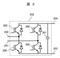
図3は、図2におけるAC/DCコンバータ部202の一例を示す回路図である。
Figure 3 is a circuit diagram showing an example of the AC/
AC/DCコンバータ部202は、半導体スイッチング素子(図3では、IGBT)とダイオードが逆並列に接続された半導体装置300が用いられる単相フルブリッジ回路と、単相フルブリッジ回路に並列に接続される直流リンクキャパシタ301とからなる。各ハーフブリッジ回路における2個の半導体装置300の直列接続点を交流入力200,201とする。二つのハーフブリッジ回路並びに直流リンクキャパシタ301の並列接続点が、直流出力として、直流バス203,204に接続される。
The AC/
交流入力200,201に入力される交流電力が、ダイオードにより整流されて、直流電力に変換される。直流電力は、直流リンクキャパシタ301を充電するとともに、直流バス203,204に出力される。
The AC power input to the
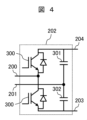
図4は、図2におけるAC/DCコンバータ部202の他の例を示す回路図である。
Figure 4 is a circuit diagram showing another example of the AC/
AC/DCコンバータ部202は、半導体スイッチング素子(図4では、IGBT)とダイオードが逆並列に接続された半導体装置300が用いられるハーフブリッジ回路と、直流リンクキャパシタ301,302の直列接続回路との、並列接続からなる。ハーフブリッジ回路における2個の半導体装置300の直列接続点、および二つの直流リンクキャパシタ301,302の直列接続点を、それぞれ、交流入力200および201とする。ハーフブリッジ回路の両端、すなわち直流リンクキャパシタ301,302の直列接続回路の両端が、直流バス203,203に接続される。
The AC/
交流入力200,201に入力されるAC電力が、ダイオードにより整流されて、直流電力に変換される。直流電力は、交流入力電圧の極性に応じて、直流リンクキャパシタ301,302を交互に充電する。
The AC power input to the
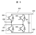
図5は、図2におけるDC/ACコンバータ部205の一例を示す回路図である。
Figure 5 is a circuit diagram showing an example of the DC/
DC/ACコンバータ部205は、半導体スイッチング素子(図5では、IGBT)とダイオードが逆並列に接続された半導体装置300が用いられる単相フルブリッジ回路と、単相フルブリッジ回路に並列に接続される直流リンクキャパシタ301とからなる。各ハーフブリッジ回路における2個の半導体装置300の直列接続点を交流出力206,207とする。二つのハーフブリッジ回路並びに直流リンクキャパシタ301の並列接続点が、直流入力として、直流バス203,204に接続される。
The DC/
直流バス203,204から入力される直流電力が、半導体装置300のスイッチング動作により、交流電力に変換される。交流電力は、交流出力206,207から出力される。
The DC power input from the
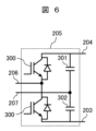
図6は、図2におけるDC/ACコンバータ部205の他の例を示す回路図である。
Figure 6 is a circuit diagram showing another example of the DC/
DC/ACコンバータ部205は、半導体スイッチング素子(図6では、IGBT)とダイオードが逆並列に接続された半導体装置300が用いられるハーフブリッジ回路と、直流リンクキャパシタ301,302の直列接続回路との、並列接続からなる。ハーフブリッジ回路における2個の半導体装置300の直列接続点、および二つの直流リンクキャパシタ301,302の直列接続点を、それぞれ、交流出力206および207とする。ハーフブリッジ回路の両端、すなわち直流リンクキャパシタ301,302の直列接続回路の両端が、直流バス203,204に接続される。
The DC/
直流バス203,204から入力される直流電力が、半導体装置300のスイッチング動作により、交流電力に変換される。交流電力は、交流出力206,207から出力される。
The DC power input from the
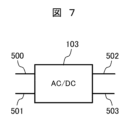
図7は、図1における変換器ユニット103の構成を示すブロック図である。
Figure 7 is a block diagram showing the configuration of the
変換器ユニット103は、AC/DCコンバータ部からなる。AC/DCコンバータ部の直流出力が、直流バス502,503に接続されている。なお、直流バス502,503は、それぞれ、正の直流バスおよび負の直流バスである。AC/DCコンバータ部の交流入力が、変換器ユニット103の交流入力500,501である。
The
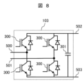
図8は、図7におけるAC/DCコンバータ部の一例を示す回路図である。 Figure 8 is a circuit diagram showing an example of the AC/DC converter section in Figure 7.
AC/DCコンバータ部は、半導体スイッチング素子(図8では、IGBT)とダイオードが逆並列に接続された半導体装置300が用いられる単相フルブリッジ回路と、単相フルブリッジ回路に並列に接続される直流リンクキャパシタ301とからなる。各ハーフブリッジ回路における2個の半導体装置300の直列接続点を交流入力500,501とする。二つのハーフブリッジ回路並びに直流リンクキャパシタ301の並列接続点が、直流出力として、直流バス502,503に接続される。
The AC/DC converter section is composed of a single-phase full-bridge circuit using a
交流入力500,501に入力される交流電力が、ダイオードにより整流されて、直流電力に変換される。直流電力は、直流リンクキャパシタ301を充電するとともに、直流バス502,503に出力される。
The AC power input to the
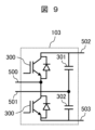
図9は、図7におけるAC/DCコンバータ部の他の例を示す回路図である。 Figure 9 is a circuit diagram showing another example of the AC/DC converter section in Figure 7.
AC/DCコンバータ部は、半導体スイッチング素子(図9では、IGBT)とダイオードが逆並列に接続された半導体装置300が用いられるハーフブリッジ回路と、直流リンクキャパシタ301,302の直列接続回路との、並列接続からなる。ハーフブリッジ回路における2個の半導体装置300の直列接続点、および二つの直流リンクキャパシタ301,302の直列接続点を、それぞれ、交流入力500および501とする。ハーフブリッジ回路の両端、すなわち直流リンクキャパシタ301,302の直列接続回路の両端が、直流バス502,503に接続される。
The AC/DC converter section is composed of a half-bridge circuit using a
交流入力500,501に入力される交流電力が、ダイオードにより整流されて、直流電力に変換される。直流電力は、交流入力電圧の極性に応じて、直流リンクキャパシタ301,302を交互に充電する。
The AC power input to the
図10は、図1における変換器ユニット104が一次巻線100へ出力するPWMパルス電圧の一部を示す波形図である。
Figure 10 is a waveform diagram showing a portion of the PWM pulse voltage that the
多巻線変圧器における磁性体コアのm個の脚部102に対して、図1において左端の脚部102から右方向に向かって、順に、1,2,3,…,mと、番号付けする。i番目(i=1~m)の脚部102に巻かれるn個の一次巻線100に接続されるn個の変換器ユニット104の出力電圧を、図1において脚部102の上端部から下方に向かって、順に、Vpi1,Vpi2,…,Vpinとする。
The m
図10に示すように、Vp11とVp1nは、電圧の大きさが等しく、かつ位相差が零、すなわち同相である。Vp11とVp1nだけでなく、Vp1i(i=1~m)は電圧の大きさが等しく、かつ同相である。同様に、i番目(i=1~m)の脚部102に巻かれるn個の一次巻線100に接続されるn個の変換器ユニット104の出力電圧Vpij(j=1~n)は電圧の大きさが等しく、かつ同相である。
10, V p11 and V p1n have the same voltage magnitude and zero phase difference, i.e., they are in phase. Not only V p11 and V p1n , but also V p1i (i=1 to m) have the same voltage magnitude and are in phase. Similarly, the output voltages V pij (j=1 to n) of the
図10に示すように、Vp11とVpm1は、電圧の大きさが等しく、かつ位相差がΦである。ここで、Φ=(360°/m)×(m-1)である。Vp11とVpm1だけでなく、Vp11とVpi1(i=2~m)は、電圧の大きさが等しく、かつ位相差がΦ(=(360°/m)×(m-1))である。同様に、i番目(i=2~m)の脚部102に巻かれるn個の一次巻線100に接続されるn個の変換器ユニット104の出力電圧Vpij(j=1~n)は、Vp1j(j=1~n)に対して、位相差Φ(=(360°/m)×(i-1))を有する。
As shown in FIG. 10, V p11 and V pm1 have the same voltage magnitude and a phase difference of Φ, where Φ=(360°/m)×(m−1). Not only V p11 and V pm1 , but also V p11 and V pi1 (i=2 to m) have the same voltage magnitude and a phase difference of Φ(=(360°/m)×(m−1)). Similarly, the output voltages V pij (j=1 to n) of the
上述のように位相差を設定すると、隣り合う脚部102(i番目とi+1番目)に巻かれる一次巻線に接続される変換器ユニット104の出力電圧Vpij,Vpij+1は、位相差は360°/mである。したがって、実施例1では、各脚部102に巻かれるn個の一次巻線100に接続されるn個の変換器ユニット104の各出力電圧は同相である。また、実施例1では、m個の脚部102の内、任意の隣接する二つの脚部102に巻かれる一次巻線に接続される変換器ユニット104の出力電圧は等しい位相差(=360°/m)を有する。なお、実施例1においては、Vpij(i=1~m,j=1~n)の大きさは等しい。
When the phase difference is set as described above, the output voltages V pij , V pij+1 of the
例えば、脚部102が3個である場合、Vp1jとVp2jの位相差は120°(=360°/3)であり、Vp2jとVp3jの位相差は120°(=360°/3)である。
For example, when there are three
m個の脚部102の内、任意の隣接する二つの脚部102に巻かれる一次巻線に接続される変換器ユニット104の出力電圧は等しい位相差(=360°/m)を有する。これにより、多巻線変圧器の複数の異なる脚部102に巻かれる複数の一次巻線に接続される複数の変換器ユニット104が相互に干渉(例えば、横流)し合うことにより、各脚部102に巻かれる複数の一次巻線に接続される複数の変換器ユニット104が受けるもしくは与える干渉が低減される。したがって、複数多巻線変圧器における複数(m×n個)の一次巻線に接続される複数(m×n個)の変換器ユニット104の動作のバランスが向上する。
The output voltages of the
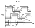
図11は、多巻線変圧器の磁性体コアが3個の脚部102を有する場合における、各一次巻線100に接続される変換器ユニット104の出力電圧と、各二次巻線101に接続される変換器ユニット103の入力電圧と、各脚部102における磁束を示す波形図である。なお、横軸は、位相を示す。
Figure 11 is a waveform diagram showing the output voltage of the
変換器ユニット104の出力電圧1300,1304,1307は、それぞれ、図1に示すVp11~Vp1n,Vp21~Vp2n,Vp31~Vp3nに対応する。
The
変換器ユニット103の入力電圧1301,1305,1308は、それぞれ、図1に示すVs11~Vs1n,Vs21~Vs2n,Vs31~Vs3nに対応する。
なお、図1においては、変換器ユニット104の出力電圧と同様に、i番目(i=1~m)の脚部102に巻かれるn個の二次巻線101に接続されるn個の変換器ユニット103の出力電圧を、図1において脚部102の下端部に向かって、順に、Vsi1,Vsi2,…,Vsinとする。
In addition, in FIG. 1, similar to the output voltage of
磁束1302,1306,1309は、それぞれ、1番目、2番目、3番目の脚部102における磁束に対応する。
図11に示すように、出力電圧1300,1304間の位相差は120°である。出力電圧1300,1307間の位相差は240度であり、したがって、出力電圧1304,1307間の位相差は120度である。なお、変換器ユニット104の出力電圧1307,1300間の位相差も120°である。これにより、複数の変換器ユニット104の動作がバランスするので、磁束1302,1306,1309の大きさ(振幅)が均一になる。
As shown in FIG. 11, the phase difference between
図11に示すように、入力電圧1301は、出力電圧1300に対して、位相がδだけ遅れている。同様に、入力電圧1305は、出力電圧1304に対して、位相がδだけ遅れ、入力電圧1308は、出力電圧1307に対して、位相がδだけ遅れている。ここで、対応する変換器ユニット103では、出力電圧に対して入力電圧の位相遅れがδになるように、図示しない制御装置によって半導体スイッチング素子のスイッチングが制御される。
As shown in FIG. 11,
位相遅れδに応じて、変換器ユニット104から、多巻線変圧器を介して、変換器ユニット103へ電力が伝送される。
Power is transmitted from
上述のように、実施例1によれば、多巻線変圧器が、一次巻線100および二次巻線101が分割巻きによって巻かれる脚部102を複数備え、異なる脚部に巻かれる一次巻線には、変換器ユニット104から位相が互いに異なる電圧が入力される。これにより、複数の脚部における磁束の大きさのバランスが向上するとともに、複数の変換器ユニット104の動作のバランスが向上する。
As described above, according to the first embodiment, the multi-winding transformer has a plurality of
したがって、絶縁型の電力変換装置の電力損失が低減できたり、絶縁型の電力変換装置を大容量化できたりする。 This allows the power loss of an isolated power conversion device to be reduced and the capacity of the isolated power conversion device to be increased.
なお、各脚部102におけるにおける一次巻線および二次巻線は、少なくとも1個ずつあればよい。
Note that there should be at least one primary winding and one secondary winding in each
また、実施例1によれば、各脚部102において、各巻線(100,101,800,801)が分割巻きによって巻かれている。これにより、巻線間の電気的絶縁性が向上する。したがって、多巻線変圧器を備える絶縁型の電力変換装置を高電圧化もしくは大容量化することができる。
Furthermore, according to the first embodiment, in each
また、実施例1によれば、巻線を含めて同じ構成の脚部102の個数によって絶縁型で多出力の電力変換装置の電力容量や出力数を容易に設定できる。
Furthermore, according to the first embodiment, the power capacity and number of outputs of an insulated, multi-output power conversion device can be easily set by changing the number of
このように、実施例1によれば、絶縁型の電力変換装置を高電圧化もしくは大容量化することができる。 In this way, according to the first embodiment, it is possible to increase the voltage or capacity of an insulated power conversion device.
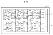
図12は、本発明の実施例2である絶縁型の電力変換装置を示す概略構成図である。 Figure 12 is a schematic diagram showing an isolated power conversion device according to a second embodiment of the present invention.
以下、実施例1と異なる点について説明する。 The differences from Example 1 are explained below.
図12に示すように、各脚部102に巻かれる複数(図12ではn個(n≧2))の一次巻線100に交流出力が接続される複数(図12ではn個(n≧2))の変換器ユニット104の交流入力が互いに直列に接続される。交流入力の直列接続の両端、すなわち、接続端子1101,902に単相交流電源1100が接続される。これにより、単相交流電源1100の電源電圧を増大することができる。
As shown in FIG. 12, the AC inputs of a plurality (n (n≧2) in FIG. 12) of
図12に示すように、各脚部102に巻かれる複数(図12ではn個(n≧2))の二次巻線101に交流入力が接続される複数(図12ではn個(n≧2))の変換器ユニット103の直流出力が電気自動車1103もしくは電池1104のいずれかに接続される。
As shown in FIG. 12, multiple (n (n≧2) in FIG. 12))
このように、実施例2である絶縁型の電力変換装置によれば、複数の電池1104または複数の電気自動車1103、もしくは、電池1104および電気自動車1103を、同時に充電することができる。
In this way, according to the isolated power conversion device of the second embodiment,
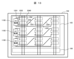
図13は、本発明の実施例3である絶縁型の電力変換装置を示す概略構成図である。 Figure 13 is a schematic diagram showing an isolated power conversion device according to a third embodiment of the present invention.
以下、実施例1と異なる点について説明する。 The differences from Example 1 are explained below.
複数(図13では3個)の脚部102の各々においては、複数(図13では6個)の一次巻線が、複数個(図13では2個)の一次巻線からなる複数(図13では3個)個の一次巻線セット2040に分けられる。
In each of the multiple (three in FIG. 13)
ここで、3個の一次巻線セット2040を、図12中で上から、第1の一次巻線セット、第2の一次巻線セット、第3の一次巻線セットと称する。
Here, the three primary winding
第1の一次巻線セットに接続される2台の変換器ユニット204(変換器ユニット104に相当)の交流入力が、接続導体部1202によって、直列に接続される。3個の脚部102における、このような変換器ユニット204の交流入力の直列接続が、接続導体部1203,1204によって直列に接続される。すなわち、3個の脚部102に巻かれる3個の第1の一次巻線セットに接続される6台の変換器ユニット204の交流入力が直列接続される。6台の変換器ユニット204の交流入力の直列接続の両端、すなわち、接続端子1201,1205に単相交流電源1100が接続される。
The AC inputs of two converter units 204 (corresponding to converter units 104) connected to the first primary winding set are connected in series by the connecting
第2の一次巻線セットおよび第3の一次巻線セットについても同様に、6台の変換器ユニットの交流入力の直列接続の両端が接続される。 Similarly, both ends of the series connection of the AC inputs of the six converter units are connected for the second and third primary winding sets.
実施例3によれば、単相交流電源1100の電源電圧を増大することができる。
According to the third embodiment, the power supply voltage of the single-phase
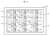
図14は、本発明の実施例4である絶縁型の電力変換装置を示す概略構成図である。 Figure 14 is a schematic diagram showing an isolated power conversion device according to a fourth embodiment of the present invention.
以下、実施例1と異なる点について説明する。 The differences from Example 1 are explained below.
図14に示すように、各脚部102に巻かれる複数の二次巻線101の接続端子701,702が一台の変換器ユニット103の交流入力に接続される。
As shown in FIG. 14, the
実施例4によれば、絶縁型の電力変換装置の総電力容量を保持しながら、変換器ユニット103の台数を低減することができる。
According to the fourth embodiment, the number of
図15は、本発明の実施例5である絶縁型の電力変換装置を示す概略構成図である。 Figure 15 is a schematic diagram showing an isolated power conversion device according to a fifth embodiment of the present invention.
以下、実施例1と異なる点について説明する。 The differences from Example 1 are explained below.
実施例5である絶縁型の電力変換装置は、多巻線変圧器の磁性体コアが枠体部109を有する第1の絶縁型AC/DCコンバータと、多巻線変圧器の磁性体コアが枠体部804を有する第2の絶縁型AC/DCコンバータと、を備えている。なお、第1の絶縁型AC/DCコンバータおよび第2の絶縁型AC/DCコンバータは、ともに、実施例1の絶縁型AC/DCコンバータ(図1)と同じ構成を有している。
The isolated power conversion device of Example 5 includes a first isolated AC/DC converter in which the magnetic core of the multi-winding transformer has a
第1の絶縁型AC/DCコンバータの多巻線変圧器の磁性体コアの各脚部には、三次巻線800が巻かれる。第2の絶縁型AC/DCコンバータの多巻線変圧器の磁性体コアの各脚部には、三次巻線801が分割巻きによって巻かれる。 A tertiary winding 800 is wound around each leg of the magnetic core of the multi-winding transformer of the first isolated AC/DC converter. A tertiary winding 801 is wound by split winding around each leg of the magnetic core of the multi-winding transformer of the second isolated AC/DC converter.
第1の絶縁型AC/DCコンバータの多巻線変圧器の磁性体コアのi番目の脚部に巻かれる三次巻線800と、第2の絶縁型AC/DCコンバータの多巻線変圧器の磁性体コアのi番目の脚部に巻かれる三次巻線801とが、接続導体部802,803によって接続されて、ループ回路を構成する。
A tertiary winding 800 wound around the i-th leg of the magnetic core of the multi-winding transformer of the first isolated AC/DC converter and a tertiary winding 801 wound around the i-th leg of the magnetic core of the multi-winding transformer of the second isolated AC/DC converter are connected by connecting
第1の絶縁型AC/DCコンバータの多巻線変圧器の磁性体コアのi番目の脚部における磁束と、第2の絶縁型AC/DCコンバータの多巻線変圧器の磁性体コアのi番目の脚部における磁束に、アンバランスが生じると、三次巻線800,801からなるループ回路に流れる誘導電流によって発生する磁束によって、アンバランスが抑制される。これにより、複数の変換器ユニット104の動作がバランスする。
When an imbalance occurs between the magnetic flux in the i-th leg of the magnetic core of the multi-winding transformer of the first isolated AC/DC converter and the magnetic flux in the i-th leg of the magnetic core of the multi-winding transformer of the second isolated AC/DC converter, the imbalance is suppressed by the magnetic flux generated by the induced current flowing in the loop circuit consisting of the
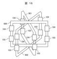
図16は、本発明の実施例6である絶縁型の電力変換装置を示す概略構成図である。 Figure 16 is a schematic diagram showing an isolated power conversion device according to a sixth embodiment of the present invention.
以下、実施例1と異なる点について説明する。 The differences from Example 1 are explained below.
実施例6における多巻線変圧器は、二つの脚部を備える磁性体コアを複数(図16では3個)有している。二つの脚部は、連結部によって連結される。これにより、磁性体コアは、四角いフレーム状である。各脚部には、実施例1と同様に一次巻線と二次巻線が分割巻きによって巻かれている。実施例1と同様に、一次巻線および二次巻線には、それぞれ、変換器ユニット104および103が接続される。
The multi-winding transformer in Example 6 has multiple magnetic cores (three in FIG. 16) with two legs. The two legs are connected by a connecting part. This makes the magnetic core a square frame. As in Example 1, a primary winding and a secondary winding are wound around each leg by split winding. As in Example 1,
3個の磁性体コア900,901,902は、連結部が互いに同じ角度をなすように、磁気的に結合されている。これにより、6個の脚部を備える多巻線変圧器が構成される。
The three
実施例6によれば、多巻線変圧器を立体的に構成することにより、多巻線変圧器の設置面積を低減できる。 According to the sixth embodiment, the installation area of the multi-winding transformer can be reduced by constructing the multi-winding transformer three-dimensionally.
なお、本発明は前述した実施例に限定されるものではなく、様々な変形例が含まれる。例えば、前述した実施例は本発明を分かりやすく説明するために詳細に説明したものであり、必ずしも説明した全ての構成を備えるものに限定されるものではない。また、各実施例の構成の一部について、他の構成の追加・削除・置き換えをすることが可能である。 The present invention is not limited to the above-described embodiments, but includes various modifications. For example, the above-described embodiments have been described in detail to clearly explain the present invention, and the present invention is not necessarily limited to those having all of the configurations described. In addition, it is possible to add, delete, or replace part of the configuration of each embodiment with other configurations.
例えば、変換器ユニット103,104において用いられる半導体スイッチング素子は、IGBTに限らず、MOSFETや接合型バイポーラトランジスタなどでもよい。
For example, the semiconductor switching elements used in
100…一次巻線、101…二次巻線、102…脚部、103…変換器ユニット、104…変換器ユニット、105…一次巻線群、106…二次巻線群、107…一次巻線セット、108…二次巻線セット、109…枠体部、200,201…交流入力、202…AC/DCコンバータ部、203,204…直流バス、205…DC/ACコンバータ部、206,207…交流出力、300…半導体装置、301,302…直流リンクキャパシタ、500,501…交流入力、502,503…直流バス、701,702…接続端子、800,801…三次巻線、802,803…接続導体部、804…枠体部、900,901,902…磁性体コア、1100…単相交流電源、1101…接続端子、1103…電気自動車、1104…電池、1201…接続端子、1202,1203,1204…接続導体部、1205…接続端子、1300…出力電圧、1301…入力電圧、1302…磁束、1304…出力電圧、1305…入力電圧、1306…磁束、1307…出力電圧、1308…入力電圧、1309…磁束、2040…一次巻線セット、 100...primary winding, 101...secondary winding, 102...legs, 103...converter unit, 104...converter unit, 105...primary winding group, 106...secondary winding group, 107...primary winding set, 108...secondary winding set, 109...frame, 200, 201...AC input, 202...AC/DC converter section, 203, 204...DC bus, 205...DC/AC converter section, 206, 207...AC output, 300...semiconductor device, 301, 302...DC link capacitor, 500, 501...AC input, 502, 503...DC bus, 701, 702...connection Connection terminal, 800, 801... tertiary winding, 802, 803... connecting conductor portion, 804... frame portion, 900, 901, 902... magnetic core, 1100... single-phase AC power source, 1101... connection terminal, 1103... electric vehicle, 1104... battery, 1201... connection terminal, 1202, 1203, 1204... connecting conductor portion, 1205... connection terminal, 1300... output voltage, 1301... input voltage, 1302... magnetic flux, 1304... output voltage, 1305... input voltage, 1306... magnetic flux, 1307... output voltage, 1308... input voltage, 1309... magnetic flux, 2040... primary winding set,
Claims (12)
複数の脚部を有する磁性体コアと、
前記複数の前記脚部の各々に巻かれる一次巻線および二次巻線を有し、
前記複数の前記脚部の内の異なる二つの前記脚部に巻かれる前記一次巻線には、電力変換器から互いに位相が異なる電圧が入力されることを特徴とする多巻線変圧器。 In multi-winding transformers for insulation,
a magnetic core having a plurality of legs;
a primary winding and a secondary winding wound around each of the plurality of legs;
A multi-winding transformer, characterized in that voltages of different phases are input from a power converter to the primary windings wound around two different legs among the plurality of legs.
前記磁性体コアにおいて、前記複数の前記脚部は並置されるとともに、磁気的に結合し、
前記複数の前記脚部の内、任意の前記脚部に巻かれる前記一次巻線に入力される前記電圧と、前記任意の前記脚部に隣接する前記脚部に巻かれる前記一次巻線に入力される前記電圧との位相差が、前記複数の前記脚部の個数をm個とするとき、360°/mであることを特徴とする多巻線変圧器。 2. The multi-winding transformer according to claim 1,
In the magnetic core, the legs are arranged in parallel and magnetically coupled to each other,
a phase difference between the voltage input to the primary winding wound on any one of the plurality of legs and the voltage input to the primary winding wound on the leg adjacent to the any one of the plurality of legs is 360°/m, where m is the number of the plurality of legs.
前記一次巻線および前記二次巻線は、分割巻きによって巻かれていることを特徴とする多巻線変圧器。 2. The multi-winding transformer according to claim 1,
A multi-winding transformer, wherein the primary winding and the secondary winding are wound by split winding.
前記一次巻線および前記二次巻線を各々複数個ずつ有し、
複数の前記一次巻線は、分割巻きによって巻かれ、かつ複数の前記二次巻線は分割巻きによって巻かれていることを特徴とする多巻線変圧器。 4. The multi-winding transformer according to claim 3,
The primary winding and the secondary winding are each provided in a plurality of pieces,
1. A multi-winding transformer, comprising: a first winding connected to a first terminal of the first transformer; a second winding connected to a second terminal of the second transformer;
前記複数の前記二次巻線は並列に接続されることを特徴とする多巻線変圧器。 5. The multi-winding transformer according to claim 4,
A multi-winding transformer, wherein the plurality of secondary windings are connected in parallel.
前記多巻線変圧器は、複数の脚部を有する磁性体コアと、前記複数の前記脚部に巻かれる複数の一次巻線および複数の二次巻線を有し、
前記複数の前記一次巻線に交流電圧を入力する複数の第1電力変換器と、
前記複数の前記二次巻線から交流電圧を入力する複数の第2電力変換器と、
を備え、
前記複数の前記脚部の内の異なる二つの前記脚部に巻かれる前記一次巻線に接続される二台の前記第1電力変換器は、互いに位相が異なる電圧を出力することを特徴とする電力変換装置。 In a power conversion device having an insulating multi-winding transformer,
The multi-winding transformer includes a magnetic core having a plurality of legs, and a plurality of primary windings and a plurality of secondary windings wound around the plurality of legs,
a plurality of first power converters that input AC voltages to the plurality of primary windings;
a plurality of second power converters receiving AC voltages from the plurality of secondary windings;
Equipped with
A power conversion device characterized in that the two first power converters connected to the primary windings wound around two different legs among the plurality of legs output voltages with different phases from each other.
前記磁性体コアにおいて、前記複数の前記脚部は並置されるとともに、磁気的に結合し、
前記複数の前記脚部の内、任意の前記脚部に巻かれる前記一次巻線に前記第1電力変換器が入力する前記交流電圧と、前記任意の前記脚部に隣接する前記脚部に巻かれる前記一次巻線に前記第1電力変換器が入力する前記交流電圧との位相差が、前記複数の前記脚部の個数をm個とするとき、360°/mであることを特徴とする電力変換装置。 7. The power conversion device according to claim 6,
In the magnetic core, the legs are arranged in parallel and magnetically coupled to each other,
a phase difference between the AC voltage input by the first power converter to the primary winding wound around any one of the plurality of legs and the AC voltage input by the first power converter to the primary winding wound around the leg adjacent to the any one of the plurality of legs is 360°/m, where m is the number of the plurality of legs.
前記複数の前記一次巻線および前記複数の前記二次巻線は、分割巻きによって巻かれていることを特徴とする電力変換装置。 7. The power conversion device according to claim 6,
A power conversion device, characterized in that the plurality of primary windings and the plurality of secondary windings are wound by split winding.
前記複数の前記第1電力変換器の複数の交流入力が互いに直列に接続され、
直列に接続された前記複数の前記交流入力が、交流電源に接続されることを特徴とする電力変換装置。 7. The power conversion device according to claim 6,
the plurality of AC inputs of the plurality of first power converters are connected in series with each other;
A power conversion device, characterized in that the plurality of AC inputs connected in series are connected to an AC power source.
前記複数の前記脚部の各々には、前記一次巻線および前記二次巻線が各々複数個ずつ巻かれ、
複数の前記一次巻線は、分割巻きによって巻かれ、かつ複数の前記二次巻線は分割巻きによって巻かれていることを特徴とする電力変換装置。 7. The power conversion device according to claim 6,
a plurality of the primary windings and a plurality of the secondary windings are wound around each of the plurality of legs;
A power conversion device, characterized in that the plurality of primary windings are wound by split winding, and the plurality of secondary windings are wound by split winding.
前記複数の前記二次巻線は並列に接続されることを特徴とする電力変換装置。 The power converter according to claim 10,
The power conversion device, wherein the plurality of secondary windings are connected in parallel.
前記第1多巻線変圧器および前記第2多巻線変圧器の各々は、
複数の脚部を有する磁性体コアと、前記複数の前記脚部に巻かれる複数の一次巻線および複数の二次巻線を有し、
前記複数の前記一次巻線に交流電圧を入力する複数の第1電力変換器と、
前記複数の前記二次巻線から交流電圧を入力する複数の第2電力変換器と、
を備え、
前記複数の前記脚部の内の異なる二つの前記脚部に巻かれる前記一次巻線に接続される二台の前記第1電力変換器は、互いに位相が異なる電圧を出力し、
前記第1多巻線変圧器が備える前記磁性体コアの前記複数の前記脚部の各々に巻かれる三次巻線と、前記第2多巻線変圧器が備える前記磁性体コアの前記複数の前記脚部の各々に巻かれる前記三次巻線とがループ回路を構成していることを特徴とする電力変換装置。 A power conversion device including a first multi-winding transformer and a second multi-winding transformer for insulation,
Each of the first multi-winding transformer and the second multi-winding transformer comprises:
a magnetic core having a plurality of legs, and a plurality of primary windings and a plurality of secondary windings wound around the plurality of legs;
a plurality of first power converters that input AC voltages to the plurality of primary windings;
a plurality of second power converters receiving AC voltages from the plurality of secondary windings;
Equipped with
the two first power converters connected to the primary windings wound around two different legs among the plurality of legs output voltages having different phases from each other;
A power conversion device characterized in that a tertiary winding wound around each of the multiple legs of the magnetic core of the first multi-winding transformer and a tertiary winding wound around each of the multiple legs of the magnetic core of the second multi-winding transformer form a loop circuit.
Priority Applications (3)
| Application Number | Priority Date | Filing Date | Title |
|---|---|---|---|
| JP2023148420A JP2025041244A (en) | 2023-09-13 | 2023-09-13 | Multi-winding transformer and power conversion device |
| US18/814,745 US20250087416A1 (en) | 2023-09-13 | 2024-08-26 | Multi-Winding Transformer and Power Conversion Device |
| DE102024124449.6A DE102024124449A1 (en) | 2023-09-13 | 2024-08-27 | Multiwinding transformer and power conversion device |
Applications Claiming Priority (1)
| Application Number | Priority Date | Filing Date | Title |
|---|---|---|---|
| JP2023148420A JP2025041244A (en) | 2023-09-13 | 2023-09-13 | Multi-winding transformer and power conversion device |
Publications (1)
| Publication Number | Publication Date |
|---|---|
| JP2025041244A true JP2025041244A (en) | 2025-03-26 |
Family
ID=94691707
Family Applications (1)
| Application Number | Title | Priority Date | Filing Date |
|---|---|---|---|
| JP2023148420A Pending JP2025041244A (en) | 2023-09-13 | 2023-09-13 | Multi-winding transformer and power conversion device |
Country Status (3)
| Country | Link |
|---|---|
| US (1) | US20250087416A1 (en) |
| JP (1) | JP2025041244A (en) |
| DE (1) | DE102024124449A1 (en) |
Family Cites Families (1)
| Publication number | Priority date | Publication date | Assignee | Title |
|---|---|---|---|---|
| JP7307583B2 (en) | 2019-04-23 | 2023-07-12 | 株式会社日立製作所 | power supply |
-
2023
- 2023-09-13 JP JP2023148420A patent/JP2025041244A/en active Pending
-
2024
- 2024-08-26 US US18/814,745 patent/US20250087416A1/en active Pending
- 2024-08-27 DE DE102024124449.6A patent/DE102024124449A1/en active Pending
Also Published As
| Publication number | Publication date |
|---|---|
| DE102024124449A1 (en) | 2025-03-13 |
| US20250087416A1 (en) | 2025-03-13 |
Similar Documents
| Publication | Publication Date | Title |
|---|---|---|
| CN103959624B (en) | DC-DC converter assembly | |
| US8243481B2 (en) | Power transformer and power converter incorporating same | |
| JP6181132B2 (en) | Power converter | |
| EP3238315B1 (en) | Modular multi-level converter with thyristor valves | |
| CN108574420B (en) | Power electronic conversion unit and system | |
| EP3223419B1 (en) | Direct ac-ac converter assembly and conversion system using same | |
| US8339820B2 (en) | Thirty-six pulse power transformer and power converter incorporating same | |
| US20130170255A1 (en) | Apparatus for controlling the electric power transmission in a hvdc power transmission system | |
| CN101795072A (en) | High-voltage direct-current direct-current (HVDC-DC) power electronic converter transformer | |
| CN105379090A (en) | Modular Multilevel DC/DC Converter for High Voltage DC Applications | |
| KR102235397B1 (en) | Power converting apparatus having scott transformer | |
| CN114094576B (en) | Flexible loop-closing switch, power supply network and control method | |
| US8248828B2 (en) | Medium voltage inverter system | |
| CN109980948A (en) | A kind of five port electric power electric transformer of three Coupling Between Phases | |
| CN110247416B (en) | Multi-port DC flexible multi-state switch device based on bifurcated bridge arm structure | |
| CN102904420A (en) | multiport converter | |
| WO2024183640A1 (en) | High-voltage direct-mounted flexible alternating current loop closing device | |
| JP6833131B1 (en) | Power converter | |
| KR20210004589A (en) | Multi-level converter | |
| JP2025041244A (en) | Multi-winding transformer and power conversion device | |
| CN102084585B (en) | Arrangement for voltage conversion | |
| CN108923664B (en) | Three-phase input single-phase output frequency converter and control method | |
| JP7230633B2 (en) | power converter | |
| KR20230147418A (en) | Dc-dc converter in power transform system | |
| WO2018145748A1 (en) | Parallel connecting of cell modules in a modular multilevel converter by means of interphase transformers |
Legal Events
| Date | Code | Title | Description |
|---|---|---|---|
| A621 | Written request for application examination |
Free format text: JAPANESE INTERMEDIATE CODE: A621 Effective date: 20260206 |