JP7307583B2 - power supply - Google Patents
power supply Download PDFInfo
- Publication number
- JP7307583B2 JP7307583B2 JP2019081628A JP2019081628A JP7307583B2 JP 7307583 B2 JP7307583 B2 JP 7307583B2 JP 2019081628 A JP2019081628 A JP 2019081628A JP 2019081628 A JP2019081628 A JP 2019081628A JP 7307583 B2 JP7307583 B2 JP 7307583B2
- Authority
- JP
- Japan
- Prior art keywords
- power
- converter
- winding
- power converter
- converters
- Prior art date
- Legal status (The legal status is an assumption and is not a legal conclusion. Google has not performed a legal analysis and makes no representation as to the accuracy of the status listed.)
- Active
Links
Images


Classifications
-
- B—PERFORMING OPERATIONS; TRANSPORTING
- B60—VEHICLES IN GENERAL
- B60L—PROPULSION OF ELECTRICALLY-PROPELLED VEHICLES; SUPPLYING ELECTRIC POWER FOR AUXILIARY EQUIPMENT OF ELECTRICALLY-PROPELLED VEHICLES; ELECTRODYNAMIC BRAKE SYSTEMS FOR VEHICLES IN GENERAL; MAGNETIC SUSPENSION OR LEVITATION FOR VEHICLES; MONITORING OPERATING VARIABLES OF ELECTRICALLY-PROPELLED VEHICLES; ELECTRIC SAFETY DEVICES FOR ELECTRICALLY-PROPELLED VEHICLES
- B60L53/00—Methods of charging batteries, specially adapted for electric vehicles; Charging stations or on-board charging equipment therefor; Exchange of energy storage elements in electric vehicles
- B60L53/30—Constructional details of charging stations
-
- H—ELECTRICITY
- H02—GENERATION; CONVERSION OR DISTRIBUTION OF ELECTRIC POWER
- H02J—CIRCUIT ARRANGEMENTS OR SYSTEMS FOR SUPPLYING OR DISTRIBUTING ELECTRIC POWER; SYSTEMS FOR STORING ELECTRIC ENERGY
- H02J7/00—Circuit arrangements for charging or depolarising batteries or for supplying loads from batteries
- H02J7/0013—Circuit arrangements for charging or depolarising batteries or for supplying loads from batteries acting upon several batteries simultaneously or sequentially
-
- H—ELECTRICITY
- H02—GENERATION; CONVERSION OR DISTRIBUTION OF ELECTRIC POWER
- H02J—CIRCUIT ARRANGEMENTS OR SYSTEMS FOR SUPPLYING OR DISTRIBUTING ELECTRIC POWER; SYSTEMS FOR STORING ELECTRIC ENERGY
- H02J7/00—Circuit arrangements for charging or depolarising batteries or for supplying loads from batteries
- H02J7/007—Regulation of charging or discharging current or voltage
-
- H—ELECTRICITY
- H02—GENERATION; CONVERSION OR DISTRIBUTION OF ELECTRIC POWER
- H02J—CIRCUIT ARRANGEMENTS OR SYSTEMS FOR SUPPLYING OR DISTRIBUTING ELECTRIC POWER; SYSTEMS FOR STORING ELECTRIC ENERGY
- H02J7/00—Circuit arrangements for charging or depolarising batteries or for supplying loads from batteries
- H02J7/02—Circuit arrangements for charging or depolarising batteries or for supplying loads from batteries for charging batteries from ac mains by converters
-
- B—PERFORMING OPERATIONS; TRANSPORTING
- B60—VEHICLES IN GENERAL
- B60L—PROPULSION OF ELECTRICALLY-PROPELLED VEHICLES; SUPPLYING ELECTRIC POWER FOR AUXILIARY EQUIPMENT OF ELECTRICALLY-PROPELLED VEHICLES; ELECTRODYNAMIC BRAKE SYSTEMS FOR VEHICLES IN GENERAL; MAGNETIC SUSPENSION OR LEVITATION FOR VEHICLES; MONITORING OPERATING VARIABLES OF ELECTRICALLY-PROPELLED VEHICLES; ELECTRIC SAFETY DEVICES FOR ELECTRICALLY-PROPELLED VEHICLES
- B60L2210/00—Converter types
- B60L2210/10—DC to DC converters
-
- B—PERFORMING OPERATIONS; TRANSPORTING
- B60—VEHICLES IN GENERAL
- B60L—PROPULSION OF ELECTRICALLY-PROPELLED VEHICLES; SUPPLYING ELECTRIC POWER FOR AUXILIARY EQUIPMENT OF ELECTRICALLY-PROPELLED VEHICLES; ELECTRODYNAMIC BRAKE SYSTEMS FOR VEHICLES IN GENERAL; MAGNETIC SUSPENSION OR LEVITATION FOR VEHICLES; MONITORING OPERATING VARIABLES OF ELECTRICALLY-PROPELLED VEHICLES; ELECTRIC SAFETY DEVICES FOR ELECTRICALLY-PROPELLED VEHICLES
- B60L2210/00—Converter types
- B60L2210/30—AC to DC converters
-
- H—ELECTRICITY
- H02—GENERATION; CONVERSION OR DISTRIBUTION OF ELECTRIC POWER
- H02J—CIRCUIT ARRANGEMENTS OR SYSTEMS FOR SUPPLYING OR DISTRIBUTING ELECTRIC POWER; SYSTEMS FOR STORING ELECTRIC ENERGY
- H02J2207/00—Indexing scheme relating to details of circuit arrangements for charging or depolarising batteries or for supplying loads from batteries
- H02J2207/20—Charging or discharging characterised by the power electronics converter
-
- H—ELECTRICITY
- H02—GENERATION; CONVERSION OR DISTRIBUTION OF ELECTRIC POWER
- H02J—CIRCUIT ARRANGEMENTS OR SYSTEMS FOR SUPPLYING OR DISTRIBUTING ELECTRIC POWER; SYSTEMS FOR STORING ELECTRIC ENERGY
- H02J2310/00—The network for supplying or distributing electric power characterised by its spatial reach or by the load
- H02J2310/40—The network being an on-board power network, i.e. within a vehicle
- H02J2310/48—The network being an on-board power network, i.e. within a vehicle for electric vehicles [EV] or hybrid vehicles [HEV]
-
- H—ELECTRICITY
- H02—GENERATION; CONVERSION OR DISTRIBUTION OF ELECTRIC POWER
- H02J—CIRCUIT ARRANGEMENTS OR SYSTEMS FOR SUPPLYING OR DISTRIBUTING ELECTRIC POWER; SYSTEMS FOR STORING ELECTRIC ENERGY
- H02J7/00—Circuit arrangements for charging or depolarising batteries or for supplying loads from batteries
- H02J7/34—Parallel operation in networks using both storage and other dc sources, e.g. providing buffering
- H02J7/342—The other DC source being a battery actively interacting with the first one, i.e. battery to battery charging
-
- Y—GENERAL TAGGING OF NEW TECHNOLOGICAL DEVELOPMENTS; GENERAL TAGGING OF CROSS-SECTIONAL TECHNOLOGIES SPANNING OVER SEVERAL SECTIONS OF THE IPC; TECHNICAL SUBJECTS COVERED BY FORMER USPC CROSS-REFERENCE ART COLLECTIONS [XRACs] AND DIGESTS
- Y02—TECHNOLOGIES OR APPLICATIONS FOR MITIGATION OR ADAPTATION AGAINST CLIMATE CHANGE
- Y02T—CLIMATE CHANGE MITIGATION TECHNOLOGIES RELATED TO TRANSPORTATION
- Y02T10/00—Road transport of goods or passengers
- Y02T10/60—Other road transportation technologies with climate change mitigation effect
- Y02T10/70—Energy storage systems for electromobility, e.g. batteries
-
- Y—GENERAL TAGGING OF NEW TECHNOLOGICAL DEVELOPMENTS; GENERAL TAGGING OF CROSS-SECTIONAL TECHNOLOGIES SPANNING OVER SEVERAL SECTIONS OF THE IPC; TECHNICAL SUBJECTS COVERED BY FORMER USPC CROSS-REFERENCE ART COLLECTIONS [XRACs] AND DIGESTS
- Y02—TECHNOLOGIES OR APPLICATIONS FOR MITIGATION OR ADAPTATION AGAINST CLIMATE CHANGE
- Y02T—CLIMATE CHANGE MITIGATION TECHNOLOGIES RELATED TO TRANSPORTATION
- Y02T10/00—Road transport of goods or passengers
- Y02T10/60—Other road transportation technologies with climate change mitigation effect
- Y02T10/7072—Electromobility specific charging systems or methods for batteries, ultracapacitors, supercapacitors or double-layer capacitors
-
- Y—GENERAL TAGGING OF NEW TECHNOLOGICAL DEVELOPMENTS; GENERAL TAGGING OF CROSS-SECTIONAL TECHNOLOGIES SPANNING OVER SEVERAL SECTIONS OF THE IPC; TECHNICAL SUBJECTS COVERED BY FORMER USPC CROSS-REFERENCE ART COLLECTIONS [XRACs] AND DIGESTS
- Y02—TECHNOLOGIES OR APPLICATIONS FOR MITIGATION OR ADAPTATION AGAINST CLIMATE CHANGE
- Y02T—CLIMATE CHANGE MITIGATION TECHNOLOGIES RELATED TO TRANSPORTATION
- Y02T10/00—Road transport of goods or passengers
- Y02T10/60—Other road transportation technologies with climate change mitigation effect
- Y02T10/72—Electric energy management in electromobility
-
- Y—GENERAL TAGGING OF NEW TECHNOLOGICAL DEVELOPMENTS; GENERAL TAGGING OF CROSS-SECTIONAL TECHNOLOGIES SPANNING OVER SEVERAL SECTIONS OF THE IPC; TECHNICAL SUBJECTS COVERED BY FORMER USPC CROSS-REFERENCE ART COLLECTIONS [XRACs] AND DIGESTS
- Y02—TECHNOLOGIES OR APPLICATIONS FOR MITIGATION OR ADAPTATION AGAINST CLIMATE CHANGE
- Y02T—CLIMATE CHANGE MITIGATION TECHNOLOGIES RELATED TO TRANSPORTATION
- Y02T90/00—Enabling technologies or technologies with a potential or indirect contribution to GHG emissions mitigation
- Y02T90/10—Technologies relating to charging of electric vehicles
- Y02T90/12—Electric charging stations
Description
本発明は、外部系統および蓄電装置に接続され、受電機器に電力を供給する電源装置に関する。 The present invention relates to a power supply device that is connected to an external system and a power storage device and that supplies power to a power receiving device.
再生可能エネルギー発電や電気自動車の普及、蓄電装置の利用拡大に伴い、高品質の電力制御が可能でかつ小型の電源装置が要求されている。 With the spread of renewable energy power generation, the spread of electric vehicles, and the expansion of the use of power storage devices, there is a demand for compact power supply devices that are capable of high-quality power control.
これに対し、非特許文献1(Fig.1(c))および特許文献1(Fig.1)に記載の従来技術が知られている。 On the other hand, conventional techniques described in Non-Patent Document 1 (Fig. 1(c)) and Patent Document 1 (Fig. 1) are known.
本従来技術では、モーターを駆動する電源装置において、トランスの複数の一次巻線の各々に、複数台の一次側電力変換器の内の一台の出力側が接続されるとともに、複数の一次側電力変換器の入力側が直列接続される。さらに、トランスの二次巻線には二次側電力変換器の入力側が接続される。 In this prior art, in a power supply device for driving a motor, one output side of a plurality of primary side power converters is connected to each of a plurality of primary windings of a transformer, and a plurality of primary side power converters is connected to each of the plurality of primary side power converters. The input side of the converter is connected in series. Furthermore, the input side of the secondary side power converter is connected to the secondary winding of the transformer.
上記従来技術では、一次側電力変換器および二次側電力変換器を備えることにより、トランスを小型化することができるとともに、トランスの一次側および二次側で電力を制御することができる。しかし、上記従来技術では、商用交流電源のような外部系統や、蓄電池のような蓄電装置など、多様な電力源からの電力フローをフレキシブルに制御することについては、なんら考慮されていない。 In the conventional technology described above, by providing the primary side power converter and the secondary side power converter, the size of the transformer can be reduced, and power can be controlled on the primary side and the secondary side of the transformer. However, in the conventional technology described above, no consideration is given to flexibly controlling the power flow from various power sources such as an external system such as a commercial AC power supply and a power storage device such as a storage battery.
そこで、本発明は、多様な電力源からの電力フローをフレキシブルに制御可能であるとともに小型化が可能な電源装置を提供する。 Accordingly, the present invention provides a power supply device that can flexibly control the power flow from various power sources and that can be miniaturized.
上記課題を解決するために、本発明による電源装置は、多巻線トランスと、多巻線トランスに接続される複数の電力変換器と、を備えるものであって、多巻線トランスが有する複数の第1巻線には、複数の電力変換器の内、複数の第1電力変換器が接続され、第1電力変換器は、整流器部と、整流器部に接続され、直流電力を交流電力に変換する変換器部と、を備え、複数の整流器部の交流側は、互いに直列接続されるとともに、外部交流系統に接続され、整流器部の直流側は、変換器部の直流側に接続され、変換器部の交流側は、第1巻線に接続され、多巻線トランスの第2巻線には、複数の電力変換器の内、第2電力変換器が接続され、第2電力変換器の交流側が第2巻線に接続され、第2電力変換器の直流側には蓄電装置が接続され、多巻線トランスの第3巻線には、複数の電力変換器の内、第3電力変換器が接続され、第3電力変換器の交流側が第3巻線に接続され、第3電力変換器の直流側には受電機器が接続され、外部交流系統の平常時には、複数の第1電力変換器および第2電力変換器を制御することにより、複数の第1電力変換器と、複数の第1巻線と、第2巻線と、第2電力変換器とを介して、外部交流系統からの電力が蓄電装置に伝送され、外部交流系統の平常時には、複数の第1電力変換器および第3電力変換器を制御することにより、複数の第1電力変換器と、複数の第1巻線と、第3巻線と、第3電力変換器とを介して、外部交流系統からの電力が受電機器に伝送され、外部交流系統の停電時には、第2電力変換器および第3電力変換器を制御することにより、第2電力変換器と、第2巻線と、第3巻線と、第3電力変換器とを介して、蓄電装置からの電力が受電機器に伝送され、さらに以下の第1~第3の手段の内のいずれかを備える。
第1の手段は、外部交流系統の停電時には、第1電力変換器の変換器部を動作させることである。
第2の手段は、第1電力変換器の変換器部と第2電力変換器および第3電力変換器の各交流側の電圧は方形波交流電圧であり、外部交流系統の平常時には、第2電力変換器が、第1電力変換器の方形波交流電圧と第2電力変換器の方形波交流電圧との間に位相差を設定するように制御され、外部交流系統の平常時には、第3電力変換器が、第1電力変換器の方形波交流電圧と第3電力変換器の方形波交流電圧との間に位相差を設定するように制御され、外部交流系統の停電時には、第3電力変換器が、第2電力変換器の方形波交流電圧と第3電力変換器の方形波交流電圧との間に位相差を設定するように制御されることである。
第3の手段は、多巻線トランスの第4巻線には、複数の電力変換器の内、第4電力変換器が接続され、第4電力変換器の交流側が第4巻線に接続され、第4電力変換器の直流側には発電装置が接続され、外部交流系統の平常時には、第4電力変換器および第2電力変換器を制御することにより、第4電力変換器と、第4巻線と、第2巻線と、第2電力変換器とを介して、発電装置からの電力が蓄電装置に伝送され、外部交流系統の平常時には、第4電力変換器および第3電力変換器を制御することにより、第4電力変換器と、第4巻線と、第3巻線と、第3電力変換器とを介して、発電装置からの電力が受電機器に伝送され、外部交流系統の停電時には、第4電力変換器および第3電力変換器を制御することにより、第4電力変換器と、第4巻線と、第3巻線と、第3電力変換器とを介して、発電装置からの電力が受電機器に伝送されることである。
In order to solve the above problems, a power supply device according to the present invention includes a multi-winding transformer and a plurality of power converters connected to the multi-winding transformer. A plurality of first power converters among a plurality of power converters are connected to the first winding of the, the first power converter is connected to the rectifier section and the rectifier section, and converts DC power to AC power a converter section for conversion, wherein the AC sides of the plurality of rectifier sections are connected in series with each other and connected to an external AC system, the DC side of the rectifier section is connected to the DC side of the converter section, The AC side of the converter section is connected to the first winding, and the second winding of the multi-winding transformer is connected to the second power converter among the plurality of power converters. is connected to the second winding, the power storage device is connected to the DC side of the second power converter, and the third winding of the multi-winding transformer is connected to the third power converter among the plurality of power converters. A converter is connected, the AC side of the third power converter is connected to the third winding, the power receiving device is connected to the DC side of the third power converter, and when the external AC system is normal, a plurality of first power By controlling the converter and the second power converter, the external AC system is supplied via the plurality of first power converters, the plurality of first windings, the second windings, and the second power converter. is transmitted to the power storage device, and when the external AC system is normal, by controlling the plurality of first power converters and the third power converters, the plurality of first power converters and the plurality of first windings Power from the external AC system is transmitted to the power receiving device via the line, the third winding, and the third power converter. By controlling the power from the power storage device is transmitted to the power receiving device via the second power converter, the second winding, the third winding, and the third power converter. any one of the first to third means of
A first means is to operate the converter section of the first power converter when the external AC system fails.
A second means is that the voltage on each AC side of the converter section of the first power converter, the second power converter, and the third power converter is a square wave AC voltage, and when the external AC system is normal, the second The power converter is controlled to set a phase difference between the square wave AC voltage of the first power converter and the square wave AC voltage of the second power converter, and when the external AC system is normal, the third power A converter is controlled to set a phase difference between the square wave AC voltage of the first power converter and the square wave AC voltage of the third power converter, and when the external AC system fails, the third power converter is controlled to set a phase difference between the square wave AC voltage of the second power converter and the square wave AC voltage of the third power converter.
A third means is that the fourth winding of the multi-winding transformer is connected to the fourth power converter among the plurality of power converters, and the AC side of the fourth power converter is connected to the fourth winding. , a power generator is connected to the DC side of the fourth power converter, and when the external AC system is normal, the fourth power converter and the fourth power converter are controlled by controlling the fourth power converter and the second power converter. Electric power from the power generation device is transmitted to the power storage device via the winding, the second winding, and the second power converter, and when the external AC system is normal, the fourth power converter and the third power converter By controlling the power from the power generator is transmitted to the power receiving device via the fourth power converter, the fourth winding, the third winding, and the third power converter, and the external AC system In the event of a power failure, by controlling the fourth power converter and the third power converter, via the fourth power converter, the fourth winding, the third winding, and the third power converter, The power from the generator is transmitted to the power receiving device.
本発明によれば、電源装置を小型化できるとともに、外部交流系統と蓄電装置と受電機器との間で、電力フローをフレキシブルに制御できる。 ADVANTAGE OF THE INVENTION According to this invention, a power supply device can be reduced in size, and a power flow can be flexibly controlled between an external AC system, a power storage device, and a power receiving device.
上記した以外の課題、構成および効果は、以下の実施形態の説明により明らかにされる。 Problems, configurations, and effects other than those described above will be clarified by the following description of the embodiments.
以下、本発明の実施形態について、下記の実施例1~2により、図面を用いながら説明する。各図において、参照番号が同一のものは同一の構成要件あるいは類似の機能を備えた構成要件を示している。 BEST MODE FOR CARRYING OUT THE INVENTION Embodiments of the present invention will be described below with reference to the drawings according to Examples 1 and 2 below. In each figure, the same reference numbers denote the same components or components with similar functions.
図1は、本発明の実施例1である電源装置の回路構成図である。 Embodiment 1 FIG. 1 is a circuit configuration diagram of a power supply device that is Embodiment 1 of the present invention.
図1に示すように、本実施例1の電源装置は、複数の巻線(図1では6巻線)を備える多巻線トランス20と、多巻線トランス20の複数の巻線(n11~n23)に接続される複数の電力変換器を備えている。
As shown in FIG. 1, the power supply device of the first embodiment includes a
多巻線トランス20においては、一個の磁性体コアに6個の独立した巻線(n11~n23)が巻装されている。
In the
巻線n11には、単位変換器1と単位変換器11とからなる電力変換器が接続される。単位変換器1の直流側と単位変換器11の直流側が平滑コンデンサを介して接続される。また、単位変換器11の交流側が巻線n11に接続される。
A power converter comprising a unit converter 1 and a
巻線n12には、単位変換器2と単位変換器12とからなる電力変換器が接続される。単位変換器2の直流側と単位変換器12の直流側が平滑コンデンサを介して接続される。また、単位変換器12の交流側が巻線n12に接続される。
A power converter comprising a
巻線n13には、単位変換器3と単位変換器13とからなる電力変換器が接続される。単位変換器3の直流側と単位変換器13の直流側が平滑コンデンサを介して接続される。また、単位変換器13の交流側が巻線n13に接続される。
A power converter comprising a
単位変換器1~3の各交流側は、互いに直列接続され、高調波抑制用のリアクトル10を介して、外部交流系統100(例えば、商用交流電源)に接続される。本実施例1においては、このように、複数の単位変換器(1~3)の各交流側が互いに直列接続されるので、トランスを介することなく、外部交流系統100からの電力を受電できる。また、複数の単位変換器(1~3)で、外部交流系統100の電圧を分担するので、各単位変換器の主回路を構成する半導体素子の耐圧を低減できる。これらにより、電源装置が小型化できる。
The AC sides of unit converters 1 to 3 are connected in series with each other and connected to an external AC system 100 (for example, a commercial AC power supply) via a
単位変換器1,2および3は、外部交流系統100からの交流電力を直流電力に変換する。単位変換器11,12,13は、それぞれ単位変換器1,2および3が出力する直流電力を、所定周波数および所定電圧の交流電力に変換して、それぞれ巻線n11,n12,n13に出力する。
巻線n21には、単位変換器21からなる電力変換器の交流側が接続される。単位変換器21の直流側は、平滑コンデンサを備え、平滑コンデンサを介して、発電装置31に接続される。発電装置31は、太陽光発電装置や風力発電装置などの分散電源装置である。
The AC side of a power converter comprising unit converter 21 is connected to winding n21. A DC side of the
巻線n22には、単位変換器22からなる電力変換器の交流側が接続される。単位変換器22の直流側は、平滑コンデンサを備え、平滑コンデンサを介して、蓄電装置32に接続される。蓄電装置32は、蓄電器および充放電制御回路などを備える。蓄電器としては、蓄電池やキャパシタなどが適用される。
Winding n 22 is connected to the AC side of a power converter comprising
巻線n23には、単位変換器23からなる電力変換器の交流側が接続される。単位変換器23の直流側は、平滑コンデンサを備え、平滑コンデンサを介して、受電機器である負荷装置33に接続される。
Winding n 23 is connected to the AC side of a power converter comprising
単位変換器21は、発電装置31からの直流電力を交流電力に変換して、この交流電力を巻線n21に出力する。
The
単位変換器22は、巻線n22が出力する交流電力を直流電力に変換して、この直流電力を蓄電装置32の受電電力として出力する。また、単位変換器22は、蓄電装置32からの直流電力を交流電力に変換して、この交流電力を蓄電装置32から給電される電力として巻線n22に出力する。すなわち、単位変換器22は、双方向変換器として動作する。
単位変換器23は、巻線n23が出力する交流電力を直流電力に変換して、この直流電力を負荷装置33が受電する電力として出力する。
The
本実施例1では、多巻線トランス20の複数の巻線の各々に電力変換器が接続されるので、電力変換器を制御することにより、給電側(外部交流系統100、発電装置31、蓄電装置32(放電時))と受電側(負荷装置33、蓄電装置32(充電時))の間の電力伝送を制御できる。後述するように、本実施例1では、単位変換器11~12,21~23の交流側の電圧V11~V13,V21~V23、すなわち巻線n11~n23の端子電圧の位相を制御することにより、給電側と受電側の間の電力伝送が制御される。これにより、本実施例1の電源装置は、給電側と受電側の間の電力フローをフレキシブルに制御できる
また、多巻線トランス20の複数の巻線の各々に電力変換器が接続されるので、電力変換器におけるスイッチング周波数に応じて、多巻線トランス20を高周波化(例えば、1kH以上)することができる。したがって、多巻線トランス20が小型化できるので、電源装置を小型化できる。
In the first embodiment, since a power converter is connected to each of the plurality of windings of the
制御装置200は、単位変換器の直流側電圧(V1~V6)の検出値、単位変換器の交流側の電圧すなわち巻線の端子間電圧(V11~V23)の検出値、単位変換器の交流側の電流すなわち巻線に流れる電流(i11~i23)の検出値に基づいて、単位変換器の交流側の電圧すなわち巻線の端子間電圧(V11~V23)の指令値(V11
*~V23
*)を作成する。これらの検出値は、図示されない電圧センサおよび電流センサによって検出される。なお、指令値(V11
*~V23
*)は、単位変換器(11~23)に与えられる。
The
なお、図1では、制御装置200への入力として、便宜上、これら検出値のすべてが記載されているが、制御装置200は、制御装置200において動作する制御手段に応じた検出値を入力する。また、制御装置200は、電流・電圧の検出値に代えて、演算によって求められる推定値を用いてもよい。
In FIG. 1, all of these detected values are shown as inputs to the
図2は、単位変換器1~3,11~13,21~23の主回路部の構成例を示す回路図である。 FIG. 2 is a circuit diagram showing a configuration example of the main circuit section of unit converters 1-3, 11-13, and 21-23.
図2に示す構成例では、一つの半導体スイッチング素子(例えば、S1)および一つのダイオード(例えば、D1)が逆並列に接続され、一つのアームが構成される。二つのアームが直列に接続されて、一つのレグ(ハーフブリッジ回路)が構成される。さらに、二つのレグが並列に接続されて、単位変換器の主回路部となる単相フルブリッジ回路が構成される。各レグにおける二つのアームの直列接続点が単位変換器の交流側に位置し、二つのレグの並列接続の両端が単位変換器の直流側に位置する。 In the configuration example shown in FIG. 2, one semiconductor switching element (eg, S 1 ) and one diode (eg, D 1 ) are connected in anti-parallel to form one arm. Two arms are connected in series to form one leg (half bridge circuit). Furthermore, the two legs are connected in parallel to form a single-phase full-bridge circuit that serves as the main circuit section of the unit converter. The series connection point of the two arms in each leg is located on the AC side of the unit converter, and both ends of the parallel connection of the two legs are located on the DC side of the unit converter.
半導体スイッチング素子S1~S4として、図2の構成例では、IGBT(Insulated Gate Bipolar Transistor)が適用されているが、これに限らず、MOSFET(Metal Oxide Semiconductor Field Effect Transistor)や接合型バイポーラトランジスタが適用されてもよい。 In the configuration example of FIG. 2, IGBTs (Insulated Gate Bipolar Transistors) are applied as the semiconductor switching elements S 1 to S 4 . may apply.
複数の単位変換器の内、単位変換器1~3は、整流器として動作する。すなわち、単位変換器1~3において、ダイオードD1~D4は整流ダイオードとして動作する。なお、単位変換器1~3における半導体スイッチング素子S1~S4を動作することにより、高調波が低減されるとともに、力率が向上される。 Among the plurality of unit converters, unit converters 1 to 3 operate as rectifiers. That is, in unit converters 1-3, diodes D 1 -D 4 operate as rectifying diodes. By operating the semiconductor switching elements S 1 to S 4 in the unit converters 1 to 3, harmonics are reduced and the power factor is improved.
なお、単位変換器1~3として、図2における半導体スイッチング素子S1~S4が用いられない、単相のダイオード整流回路を適用してもよい。 As the unit converters 1 to 3, single-phase diode rectifier circuits may be applied in which the semiconductor switching elements S 1 to S 4 in FIG. 2 are not used.
多巻線トランスを介して電力伝送を行う二つの単位変換器、すなわち給電側となる単位変換器11~13および21並びに単位変換器22(ただし蓄電装置32の放電時)の内の一つの単位変換器と、受電側となる単位変換器22(ただし蓄電装置32の充電時)および単位変換器23の内の一つの単位変換器とは、多巻線トランス20とともに、いわゆるDAB(Dual Active Bridge)方式のDC/DCコンバータと同様の回路構成を備えている。このため、このような二つの単位変換器の交流側の電圧の位相差を制御することにより、二つの単位変換器間で伝送される電力を制御することができる。
One unit out of two unit converters that transmit power via a multi-winding transformer, that is,
なお、単位変換器11~23の各々が備える駆動制御装置(図示せず)によって、制御装置200が作成する電圧指令値V11
*~V23
*に応じて、各単位変換器における半導体スイッチング素子S1~S4がオン・オフ制御される。これにより、単位変換器11~23は、交流側の電圧V11~V23を、制御装置200が作成する電圧指令値V11
*~V23
*になるように制御する。
In addition, according to the voltage command values V 11 * to V 23 * created by the
次に、本実施例1の電源装置の動作の概略について説明する。 Next, the outline of the operation of the power supply device of the first embodiment will be described.
電源装置の動作は、外部交流系統100の平常時と停電時では異なる。そこで、以下の説明において、平常時および停電時における動作を、それぞれ、第1モードおよび第2モードと記す。
The operation of the power supply device is different between when the
第1モードでは、外部交流系統100側および発電装置31側から給電される電力が、蓄電装置32側(充電状態)および負荷装置33側で受電される。この場合、単位変換器11~13の各々は、出力電圧(V11,V12,V13)を所定電圧(例えば、定格電圧)に制御し、単位変換器21は、出力電圧V21を所定電圧(例えば、定格電圧)の付近に制御する。また、単位変換器22は、交流側の電圧V22を所定電圧(例えば、定格電圧)の付近に制御するとともにV22の位相を制御して、蓄電装置32に充電する電力を出力する。単位変換器23は、交流側の電圧V23の位相を制御して、負荷装置33側で用いられる電力を出力する。
In the first mode, electric power supplied from the
第2モードでは、発電装置31側および蓄電装置32側(放電状態)から給電される電力が、負荷装置33側で受電される。この場合、単位変換器22は、交流側の電圧V22を所定電圧(例えば、定格電圧)に制御し、単位変換器21は、交流側の電圧V21を定格電圧の付近に制御する。また、単位変換器23は、交流側の電圧V23の位相を制御して、負荷装置で用いられる電力を出力する。
In the second mode, power supplied from the
ここで、単位変換器11~13の各々は、交流側の電圧(V11,V12,V13)を所定電圧(例えば、定格電圧)の付近に制御する。
Here, each of the
これにより、単位変換器11~13の直流側の電圧V1,V2,V3が、略一定値に制御される。このため、外部交流系統100の停電時に、蓄電装置32側からの電力の流入によるV1,V2,V3の増大が抑制される。したがって、単位変換器11~13を構成する半導体スイッチング素子やダイオードに過電圧がかかることが防止されるので、電源装置の信頼性が向上する。また、半導体スイッチング素子やダイオードの耐圧を大きくする必要がないので、電源装置の電力損失や電源装置の大きさを低減できる。
As a result, the voltages V 1 , V 2 , and V 3 on the DC side of the
次に、第1モードおよび第2モードの各々について、本実施例1の電源装置の動作を具体的に説明する。 Next, the operation of the power supply device of the first embodiment will be specifically described for each of the first mode and the second mode.
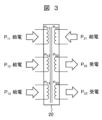
図3は、第1モード、すなわち外部交流系統100の平常時における、本実施例1の電源装置における電力伝送の状態を示す図である。
FIG. 3 is a diagram showing the state of power transmission in the power supply device of the first embodiment in the first mode, that is, when the
図3に示すように、外部交流系統100側から給電される電力P11,P12,P13が、それぞれ多巻線トランス20の巻線n11,n12,n13に入力される。また、発電装置31側から給電される電力P21が、多巻線トランス20の巻線n21に入力される。電力P11~P13およびP21は、巻線n22およびn23に伝送され、巻線n22およびn23から出力される。線n22およびn23からそれぞれ出力される電力P22およびP23は、それぞれ蓄電装置32および負荷装置33によって受電される。なお、電力P22によって、蓄電装置32が充電される。
As shown in FIG. 3, electric powers P 11 , P 12 and P 13 supplied from the
なお、本実施例1においては、多巻線トランス20の効率がほぼ100%であり、多巻線トランス20への総入力電力(P11+P12+P13+P21)と、多巻線トランス20からの総出力電力(P22+P23)は実質等しい。
In the first embodiment, the efficiency of the
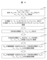
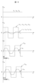
図4は、第1モード、すなわち外部交流系統100の平常時における、本実施例1の電源装置における制御の流れを示すフローチャートである。また、図5は、第1モードにおける本実施例1の電源装置における電流および電圧を示す動作波形図である。
FIG. 4 is a flow chart showing the flow of control in the power supply device of the first embodiment in the first mode, that is, when the
以下、図4に示す制御の流れについて、適宜、図5を参照しながら説明する。 Hereinafter, the flow of control shown in FIG. 4 will be described with reference to FIG. 5 as appropriate.
まず、ステップS11において、制御装置200(図1)は、発電装置31側から給電され多巻線トランス20の巻線n21へ入力される電力P21、および多巻線トランス20の巻線n23から出力され負荷装置33が受電する電力P23に応じて、外部交流系統100側からそれぞれ多巻線トランス20の巻線n11,n12,n13へ入力される電力P11,P12,P13、並びに多巻線トランス20から蓄電装置32側へ出力される電力P22を、式(1)の条件(P11+P12+P13+P21(多巻線トランス20への入力)=P22+P23(多巻線トランス20からの出力)から導出される)のもとで設定する。
First, in step S11, the control device 200 (FIG. 1) controls the power P 21 supplied from the
P22=P11+P12+P13+P21-P23 …(1)
P22は、蓄電装置32の状態(SOCなど)や充電速さなどに応じて変化するが、制御装置200は、例えば、巻線n22の両端電圧および巻線n22の両端に流れる電流i22の検出値に基づいて、P22を算出する。また、制御装置200は、巻線n23の両端電圧(V23)および巻線n23に流れる電流i23の検出値に基づいて、P23を算出する。また、制御装置200は、巻線n21の両端電圧(V21)および巻線n21に流れる電流i21の検出値に基づいて、P21を算出する。さらに、制御装置200は、式(1)に基づいて、P11,P12,P13を設定する。なお、本実施例1では、単位変換器11,12,13は電力容量が同じであり、P11=P12=P13である。
P22 = P11 + P12 + P13 + P21 - P23 (1)
P22 varies depending on the state (SOC, etc.) of the
次に、ステップS12において、制御装置200は、単位変換器1,2,3(整流器として動作)の直流出力電圧、すなわち単位変換器11,12,13の直流側電圧V1,V2,V3がバランスするように、すなわちV1=V2=V3となるように(図5)、単位変換器11,12,13を制御する。なお、本実施例1では、単位変換器1,2,3の回路構成は同じであり(図2)、単位変換器1,2,3の各入力電圧は、外部交流系統100の系統電圧の1/3である。したがって、単位変換器1,2,3の各直流出力電圧は、単位変換器1,2,3の交流入力電圧の1/3の整流後の電圧となる。
Next, in step S12, the
また、本実施例1では、V4,V5,V6が所定値となり、かつV4=V5=V6となるように、単位変換器21,22,23が制御される。これにより、本実施例1の電源装置を用いて、直流給電系統を構築できる。この場合、V4=V5=V6=直流母線電圧となる。なお、外部交流系統の系統電圧や直流母線電圧に応じて、もしくは制御の簡単化のために、V1=V2=V3=V4=V5=V6としてもよい。
In the first embodiment, the
次に、ステップS13において、制御装置200は、単位変換器11,12,13が、V4,V5,V6に応じた一定電圧(定格電圧)で、かつ一定周波数の方形波交流電圧である電圧V11,V12,V13(図5)を出力するように、単位変換器11,12,13を制御する。
Next, in step S13, the
本実施例では、単位変換器11,12,13は、V11,V12,V13として、通流率50%で半導体スイッチング素子をオン・オフ制御して定電圧(定格電圧)・定周波数の方形波交流電圧を出力する。
In this embodiment, the
なお、V11,V12,V13は、相互に位相差はなく、後述するように位相の基準電圧として用いられる。 Note that V 11 , V 12 , and V 13 have no phase difference with each other, and are used as phase reference voltages as will be described later.
次に、ステップS14において、制御装置200は、単位変換器21が、所定電圧(定格電圧)付近であり、かつV11,V12,V13と同相である電圧V21を出力するように、単位変換器21を制御する。なお、本実施例1では、V21は、V11,V12,V13と同様に、定電圧(定格電圧)・定周波数の方形波交流電圧であるとともに、V11,V12,V13と同相である(図5)。これにより、外部交流系統100側および発電装置31側から、蓄電装置32側および負荷装置33側へ電力(P11+P12+P13+P21)を給電することができる。なお、V11,V12,V13は互いに同相であるから、いずれかを位相の基準とすればよい(以下のステップでも同様)。
Next, in step S14, the
次に、ステップS15において、制御装置200は、単位変換器22の交流側の電圧V22が、所定電圧(定格電圧)付近であり、かつV11,V12,V13に対し位相差(図5における「δ2」)を有するように、単位変換器22を制御する。なお、本実施例1では、V22は、V11,V12,V13と同様に、定電圧(定格電圧)・定周波数の方形波交流電圧であるとともに、V11,V12,V13に対して位相が遅れている(図5)。これにより、ステップS11で設定されたP22が、外部交流系統100側および発電装置31側より蓄電装置32側へ伝送される。
Next, in step S15, the
次に、ステップS16において、制御装置200は、単位変換器23の交流側の電圧V23が、所定電圧(定格電圧)付近であり、かつV11,V12,V13に対し位相差(図5における「δ3」)を有するように、単位変換器23を制御する。なお、本実施例1では、V23は、V11,V12,V13と同様に、定電圧(定格電圧)・定周波数の方形波交流電圧であるとともに、V11,V12,V13に対して位相が遅れている(図5)。これにより、ステップS11で設定されたP23が、外部交流系統100側および発電装置31側より負荷装置33側へ伝送される。
Next, in step S16, the
ここで、V22の位相差(δ2)、V23の位相差(δ3)は、例えば、次のような手段で設定される(第2モードにおいても同様)。 Here, the phase difference (δ 2 ) of V 22 and the phase difference (δ 3 ) of V 23 are set by, for example, the following means (the same applies to the second mode).
ステップS15,S16のように、給電側の方形波交流電圧(V11,V12,V13,V21)と受電側の方形波交流電圧(V22,V23)との間に位相差を設定することによる電力伝送は、いわゆるDAB(Dual Active Bridge)コンバータの動作原理である。公知のDABコンバータの回路動作を考慮すると、P11,P12,P13,P21,P22,P23は、V1~V6、V22の位相差(δ2)、V23の位相差(δ3)、多巻線トランス20の回路定数(漏れインダクタンスなど)を用いて数式で表される。これらの数式および式(1)に基づいて、ステップS11で設定された各電力値に応じて、位相差δ2,δ3が、制御装置200において算出される。
As in steps S15 and S16, a phase difference is created between the square wave AC voltages ( V11 , V12 , V13 , V21 ) on the power supply side and the square wave AC voltages ( V22 , V23 ) on the power receiving side. Power transmission by setting is the operating principle of so-called DAB (Dual Active Bridge) converters. Considering the circuit operation of a known DAB converter, P 11 , P 12 , P 13 , P 21 , P 22 , P 23 are V 1 to V 6 , the phase difference (δ 2 ) of V 22 , the phase of V 23 It is represented by a mathematical formula using the phase difference (δ 3 ) and circuit constants (leakage inductance, etc.) of the
図6は、第2モード、すなわち外部交流系統100の停電時における、本実施例1の電源装置における電力伝送の状態を示す図である。
FIG. 6 is a diagram showing the state of power transmission in the power supply device of the first embodiment in the second mode, that is, when the
図6に示すように、外部交流系統100側からは電力は給電されない。また、発電装置31側から給電される電力P21が、多巻線トランス20の巻線n21に入力される。また、蓄電装置32側から給電される電力P22(蓄電装置32の放電電力)が、多巻線トランス20の巻線n22に入力される。電力P21およびP22は、巻線n23に伝送され、巻線n23から出力される。巻線n23から出力される電力P23は、負荷装置33によって受電される。
As shown in FIG. 6, power is not supplied from the
なお、本実施例1においては、多巻線トランス20の効率がほぼ100%であり、多巻線トランス20への総入力電力(P21+P22)と、多巻線トランス20からの総出力電力(P23)は実質等しい。
In the first embodiment, the efficiency of the
図7は、第2モード、すなわち外部交流系統100の停電時における、本実施例1の電源装置における制御の流れを示すフローチャートである。また、図8は、第2モードにおける本実施例1の電源装置における電流および電圧を示す動作波形図である。
FIG. 7 is a flow chart showing the flow of control in the power supply device of the first embodiment in the second mode, that is, when the
以下、図7に示す制御の流れについて、適宜、図8を参照しながら説明する。 Hereinafter, the flow of control shown in FIG. 7 will be described with reference to FIG. 8 as appropriate.
まず、ステップS21において、制御装置200(図1)は、発電装置31側から給電され多巻線トランス20の巻線n21へ入力される電力P21、および多巻線トランス20の巻線n23から出力され負荷装置33が受電する電力P23に応じて、蓄電装置32側から多巻線トランス20の巻線n22へ入力される電力P22を、式(2)の条件(P21+P22(多巻線トランス20への入力)=P23(多巻線トランス20からの出力)から導出される)のもとで設定する。
First, in step S21, the control device 200 (FIG. 1) controls the power P 21 supplied from the
P22=P23-P21 …(2)
次に、ステップS22において、制御装置200は、V4,V5,V6が所定値となり、かつV4=V5=V6となるように(図8)、単位変換器21,22,23を制御する。これにより、単位変換器21,22,23に対して、第1モードにおけるステップS12(図5)と同様の制御が継続して実行される。
P22 = P23 - P21 (2)
Next, in step S22 , the
ここで、V1,V2,V3は、蓄電装置32の放電などにより、単位変換器11,12,13側へ電力が流入すると、停電直後から上昇する(図8)。このため、第1モードにおいて、V1=V2=V3=V4=V5=V6となるように制御されている場合には、停電時は、V1=V2=V3>V4=V5=V6となる(図8)。
Here, V 1 , V 2 , and V 3 rise immediately after a power outage when electric power flows into the
次に、ステップS23において、制御装置200は、単位変換器21が、一定電圧(定格電圧付近)で一定周波数の電圧V21を出力するように、単位変換器21を制御する。本実施例1では、単位変換器21は、V21として、通流率50%で半導体スイッチング素子をオン・オフ制御して定電圧(定格電圧)・定周波数の方形波交流電圧(図8)を出力する。すなわち、単位変換器21は、第1モードにおける動作を継続する。
Next, in step S23, the
なお、停電時において、V21は、位相の基準電圧として用いられる。 Note that V21 is used as a phase reference voltage during a power failure.
次に、ステップS24において、制御装置200は、単位変換器22の交流側の電圧V22が、第1モードから継続して一定電圧(定格電圧付近)で一定周波数(V21と同じ周波数)の方形波交流電圧になるように、かつV21と同相になるように(図8)、単位変換器22を制御する。これにより、発電装置31側および蓄電装置32側から電力(P21+P22)を給電できる。
Next, in step S24, the
次に、ステップS25において、制御装置200は、単位変換器23の交流側の電圧V23が、所定電圧(定格電圧)付近であり、かつV21に対し位相差(図8における「δ3」)を有するように、単位変換器23を制御する。なお、本実施例1では、制御装置200は、V23が、V21と同様に、定電圧(定格電圧)・定周波数の方形波交流電圧になるように、かつ、V21に対して位相が遅れるように(図8)、単位変換器23を制御する。これにより、負荷装置33側へ電力P23が伝送される。
Next, in step S25, the
ここで、V23の位相差(δ3)は、前述の第1モードと同様に、公知のDABコンバータの回路動作を考慮して設定できる。すなわち、P23は、V4~V6、V23の位相差(δ3)、多巻線トランス20の回路定数(漏れインダクタンスなど)を用いて数式で表される。これらの数式および式(2)に基づいて、位相差δ3が、制御装置200において算出される。
Here, the phase difference (δ 3 ) of V 23 can be set in consideration of circuit operation of a known DAB converter, as in the first mode described above. That is, P 23 is represented by a formula using V 4 to V 6 , the phase difference (δ 3 ) of V 23 , and circuit constants (leakage inductance, etc.) of the
次に、ステップS26において、制御装置200は、停電時に、単位変換器11,12,13の交流側の電圧が定格電圧付近になるように、単位変換器11,12,13を制御する。このとき、制御装置200は、単位変換器11,12,13の交流側の電圧V11,V12,V13が、定電圧・定周波数の方形波交流電圧になるように、かつV11,V12,V13の位相をV21に合わせるように、単位変換器11,12,13を制御する。また、制御装置200は、V11,V12,V13が、定格電圧付近で、V11=V12=V13となるように単位変換器11,12,13を制御するとともに、単位変換器11,12,13の直流側電圧V1,V2,V3がバランスするように、すなわちV1=V2=V3となるように単位変換器11,12,13を制御する。
Next, in step S26, the
これにより、単位変換器11,12,13が動作して電力を出力するので、停電直後からのV1,V2,V3の増大が抑制される。このため、単位変換器11,12,13を構成する半導体スイッチング素子に過電圧がかかることが防止される。また、電圧バランス制御により、単位変換器11,12,13において、局所的に過電圧がかかることが防止される。したがって、半導体スイッチング素子の耐圧の設定にあたって、停電時における電圧上昇を見込む必要がなくなり、半導体スイッチング素子の耐圧を低減することができる。
As a result,
以下、本発明の実施例2について、図9~12を用いて説明する。なお、主に、実施例1と異なる点について説明する。 A second embodiment of the present invention will be described below with reference to FIGS. Note that differences from the first embodiment will be mainly described.
図9は、本発明の実施例2である電源装置の回路構成図である。
FIG. 9 is a circuit configuration diagram of a power supply device that is
図9に示すように、本実施例2においては、単位変換器21,22,23の直流側には、それぞれ電気自動車61,62,63(EV)が接続される。すなわち、本実施例2の電源装置は、複数の電気自動車を充電する充電装置用の電源として機能する。なお、電気自動車61,62,63の各々は、蓄電器を備える蓄電装置を搭載しており、この蓄電装置の蓄電器が、本実施例2の電源装置によって充電される。
As shown in FIG. 9, in the second embodiment,
給電対象が電気自動車であるため、電源装置側でアースが取られる。なお、本実施例2では、図9に示すように、多巻線トランス20の巻線n21,n22,n23の両端の内の一方が接地される。
Since the power supply target is an electric vehicle, the power supply is grounded. In the second embodiment, as shown in FIG. 9, one of both ends of the windings n21 , n22 , n23 of the
他の回路構成は、各単位変換器の構成(図2)を含め、前述の実施例1と同様である。 Other circuit configurations, including the configuration of each unit converter (FIG. 2), are the same as those of the first embodiment.
次に、本実施例2の電源装置の動作の概略について説明する。 Next, the outline of the operation of the power supply device of the second embodiment will be described.
電源装置の動作は、外部交流系統100の平常時と停電時では異なる。そこで、以下の説明において、平常時および停電時における動作を、それぞれ、第1モードおよび第2モードと記す。
The operation of the power supply device is different between when the
第1モードでは、外部交流系統100側から給電される電力が、電気自動車61,62,63側(充電状態)で受電される。この場合、V11,V12,V13を互いに同相とし、これらの電圧と、V21,V22,V23との各位相差を調整することにより、電気自動車ごとに充電電力を設定できる。したがって、電気自動車の蓄電池の容量や所望の充電スピードなどに応じて、充電電力を調整することができる。
In the first mode, the electric power supplied from the
第2モードでは、電気自動車61,62,63間で電力を伝送することができる。例えば、外部交流系統100が停電した場合、充電の優先度が高い電気自動車や、充電を急ぐ電気自動車に対して、他の電気自動車に蓄電されている電力によって充電が可能である。さらに、実施例1と同様に、単位変換器11~13を動作させる。これにより、外部交流系統100の停電時に、電気自動車61~62側からの電力の流入によるV1,V2,V3の増大が抑制される。
In the second mode, power can be transmitted between the
次に、第1モードおよび第2モードの各々について、本実施例2の電源装置の動作を具体的に説明する。 Next, the operation of the power supply device of the second embodiment will be specifically described for each of the first mode and the second mode.
図10は、第1モード、すなわち外部交流系統100の平常時における、本実施例2の電源装置における電力伝送の状態を示す図である。
FIG. 10 is a diagram showing the state of power transmission in the power supply device of the second embodiment in the first mode, that is, when the
図10に示すように、外部交流系統100側から給電される電力P11,P12,P13が、それぞれ多巻線トランス20の巻線n11,n12,n13に入力される。電力P11~P13は、巻線n21~n23に伝送され、巻線n22~n23から出力される。巻線n21,n22,n23からそれぞれ出力される電力P21,P22およびP23は、それぞれ電気自動車61,62および63によって受電される。
As shown in FIG. 10, electric powers P 11 , P 12 and P 13 supplied from the
なお、本実施例2においては、多巻線トランス20の効率がほぼ100%であり、多巻線トランス20への総入力電力(P11+P12+P13)と、多巻線トランス20からの総出力電力(P21+P22+P23)は実質等しい。
In the second embodiment, the efficiency of the
図11は、第1モード、すなわち外部交流系統100の平常時における、本実施例2の電源装置における制御の流れを示すフローチャートである。また、図12は、第1モードにおける本実施例2の電源装置における電流および電圧を示す動作波形図である。
FIG. 11 is a flow chart showing the flow of control in the power supply device of the second embodiment in the first mode, that is, when the
以下、図11に示す制御の流れについて、適宜、図12を参照しながら説明する。 Hereinafter, the flow of control shown in FIG. 11 will be described with reference to FIG. 12 as appropriate.
まず、ステップS31において、制御装置200は、電気自動車61,62,63への電力の配分P21,P22,P23を設定する。P21~P23は、電気自動車61~63に搭載される蓄電装置の状態(SOCなど)や所望の充電スピードなどに応じて変化するが、制御装置200は、例えば、巻線n21の両端電圧V21および巻線n21に流れる電流i21の検出値に基づいて、P21を算出する。また、制御装置200は、巻線n22の両端電圧V22)および巻線n22に流れる電流i22の検出値に基づいてP22を算出し、巻線n23の両端電圧V23および巻線n23に流れる電流i23の検出値に基づいてP23を算出する。
First, in step S<b>31 , the
次に、ステップS32において、制御装置200は、単位変換器11,12,13の直流側電圧V1,V2,V3がバランスするように、すなわちV1=V2=V3となるように、単位変換器11,12,13を制御する。また、制御装置200は、単位変換器21,22,23の直流側電圧V4,V5,V6がバランスするように、すなわちV4=V5=V6となるように、単位変換器21,22,23を制御する。
Next, in step S32, the
次に、ステップS33において、制御装置200は、単位変換器11,12,13の交流側の電圧V11,V12,V13が、一定電圧(定格電圧)で一定周波数の方形波交流電圧(図12)となるように、単位変換器11,12,13を制御する。本実施例2では、単位変換器11,12,13は、V11,V12,V13として、通流率50%で半導体スイッチング素子をオン・オフ制御して定電圧(定格電圧)・定周波数の方形波交流電圧を出力する。なお、V11,V12,V13は、相互に位相差はなく、後述するように位相の基準電圧として用いられる。なお、V11,V12,V13のいずれかを位相の基準電圧とすればよい。
Next, in step S33, the
次に、ステップS34において、制御装置200は、単位変換器21の交流側の電圧V21が、所定電圧(定格電圧)付近であり、かつV11,V12,V13に対し位相差(図12における「δ1」)を有するように、単位変換器21を制御する。なお、本実施例2では、制御装置200は、V21が、定電圧(定格電圧)・定周波数の方形波交流電圧になるように、かつ、V11,V12,V13に対して位相が遅れるように(図12)、単位変換器21を制御する。これにより、電気自動車61側へ電力P21が伝送される。
Next, in step S34 , the
次に、ステップS35において、制御装置200は、単位変換器22の交流側の電圧V22が、所定電圧(定格電圧)付近であり、かつV11,V12,V13に対し位相差(図12における「δ2」)を有するように、単位変換器22を制御する。なお、本実施例2では、制御装置200は、V22が、定電圧(定格電圧)・定周波数の方形波交流電圧になるように、かつ、V11,V12,V13に対して位相が遅れるように(図12)、単位変換器22を制御する。これにより、電気自動車62側へ電力P22が伝送される。
Next, in step S35 , the
次に、ステップS36において、制御装置200は、単位変換器23の交流側の電圧V23が、所定電圧(定格電圧)付近であり、かつV11,V12,V13に対し位相差(図12における「δ3」)を有するように、単位変換器23を制御する。なお、本実施例2では、制御装置200は、V23が、定電圧(定格電圧)・定周波数の方形波交流電圧になるように、かつ、V11,V12,V13に対して位相が遅れるように(図12)、単位変換器23を制御する。これにより、電気自動車63側へ電力P23が伝送される。
Next, in step S36, the
なお、図12においては、P21>P22>P23であり、δ1>δ2>δ3となる。 In FIG. 12, P 21 >P 22 >P 23 and δ 1 >δ 2 >δ 3 .
位相差δ1,δ2,δ3は、前述の実施例1と同様に、公知のDABコンバータの動作を考慮して設定できる。たとえば、P11,P12,P13,P21,P22,P23を、V1~V6、V21の位相差(δ1)V22の位相差(δ2)、V23の位相差(δ3)、多巻線トランス20の回路定数(漏れインダクタンスなど)を用いて数式で表し、これらの数式および「多巻線トランスへの入力電力(P11+P12+P13)=多巻線トランスからの出力電力(P21+P22+P23)」という条件に基づいて、制御装置200において算出される。
Phase differences δ 1 , δ 2 , δ 3 can be set in consideration of the operation of a known DAB converter, as in the first embodiment. For example, let P 11 , P 12 , P 13 , P 21 , P 22 , P 23 be V 1 to V 6 , the phase difference (δ 1 ) of V 21 , the phase difference (δ 2 ) of V 22 , the phase difference of V 23 The phase difference (δ 3 ) and the circuit constants (leakage inductance, etc.) of the
なお、本実施例2の電源装置の第2モードの動作は、実施例1(図1)における発電装置31、蓄電装置32、負荷装置33を、それぞれ電気自動車61、電気自動車62、電気自動車63に置き換えれば、実施例1と同様の動作となる。この場合、外部交流系統100の停電時に、電気自動車61および電気自動車62からの給電電力が、電気自動車63によって受電され、電気自動車63に搭載された蓄電池が充電される。
The operation of the power supply device of the second embodiment in the second mode is performed by replacing the
なお、本発明は前述した実施例に限定されるものではなく、様々な変形例が含まれる。例えば、前述した実施例は本発明を分かりやすく説明するために詳細に説明したものであり、必ずしも説明した全ての構成を備えるものに限定されるものではない。また、各実施例の構成の一部について、他の構成の追加・削除・置き換えをすることが可能である。 It should be noted that the present invention is not limited to the above-described embodiments, and includes various modifications. For example, the above-described embodiments have been described in detail in order to explain the present invention in an easy-to-understand manner, and are not necessarily limited to those having all the described configurations. Moreover, it is possible to add, delete, or replace a part of the configuration of each embodiment with another configuration.
例えば、多巻線トランスが備える巻線数は、6巻線に限らず、交流側が直列接続される単位変換器(整流器)の個数(2以上)や、発電装置や蓄電装置および負荷装置の個数に応じて、適宜設定される。なお、上述の実施例の電源装置と同様に、少なくとも蓄電装置および受電機器(負荷装置、蓄電装置(放電時))が少なくとも1台ずつ接続される場合、巻線数は少なくとも4巻線となる(単位変換器の直列数を2以上とする)。 For example, the number of windings provided in a multi-winding transformer is not limited to six, but the number of unit converters (rectifiers) connected in series on the AC side (two or more), the number of generators, power storage devices, and load devices. is set as appropriate. As in the power supply device of the above embodiment, when at least one power storage device and at least one power receiving device (load device, power storage device (during discharging)) are connected, the number of windings is at least four. (The number of units converters in series is 2 or more).
また、外部交流系統100からの電力は、単相交流電力に限らず、三相交流電力でもよい。この場合、単位変換器1~3(整流器)として、三相フルブリッジ回路が適用される。
Moreover, the power from the
1,2,3 単位変換器
10 リアクトル
20 多巻線トランス
11,12,13,21,22,23 単位変換器
31 発電装置
32 蓄電装置
33 負荷装置
61,62,63 電気自動車
100 外部交流系統
200 制御装置
1, 2, 3
Claims (9)
前記多巻線トランスに接続される複数の電力変換器と、
を備える電源装置において、
前記多巻線トランスが有する複数の第1巻線には、前記複数の電力変換器の内、複数の第1電力変換器が接続され、
前記第1電力変換器は、整流器部と、前記整流器部に接続され、直流電力を交流電力に変換する変換器部と、を備え、
複数の前記整流器部の交流側は、互いに直列接続されるとともに、外部交流系統に接続され、
前記整流器部の直流側は、前記変換器部の直流側に接続され、
前記変換器部の交流側は、前記第1巻線に接続され、
前記多巻線トランスの第2巻線には、前記複数の電力変換器の内、第2電力変換器が接続され、
前記第2電力変換器の交流側が前記第2巻線に接続され、
前記第2電力変換器の直流側には蓄電装置が接続され、
前記多巻線トランスの第3巻線には、前記複数の電力変換器の内、第3電力変換器が接続され、
前記第3電力変換器の交流側が前記第3巻線に接続され、
前記第3電力変換器の直流側には受電機器が接続され、
前記外部交流系統の平常時には、複数の前記第1電力変換器および前記第2電力変換器を制御することにより、複数の前記第1電力変換器と、前記複数の第1巻線と、前記第2巻線と、前記第2電力変換器とを介して、前記外部交流系統からの電力が前記蓄電装置に伝送され、
前記外部交流系統の平常時には、複数の前記第1電力変換器および前記第3電力変換器を制御することにより、複数の前記第1電力変換器と、前記複数の第1巻線と、前記第3巻線と、前記第3電力変換器とを介して、前記外部交流系統からの電力が前記受電機器に伝送され、
前記外部交流系統の停電時には、前記第2電力変換器および前記第3電力変換器を制御することにより、前記第2電力変換器と、前記第2巻線と、前記第3巻線と、前記第3電力変換器とを介して、前記蓄電装置からの電力が前記受電機器に伝送され、
前記外部交流系統の停電時には、前記第1電力変換器の前記変換器部を動作させることを特徴とする電源装置。 a multi-winding transformer;
a plurality of power converters connected to the multi-winding transformer;
A power supply comprising:
A plurality of first power converters among the plurality of power converters are connected to the plurality of first windings of the multi-winding transformer,
The first power converter includes a rectifier section and a converter section connected to the rectifier section for converting DC power to AC power,
AC sides of the plurality of rectifier units are connected in series with each other and connected to an external AC system,
the DC side of the rectifier section is connected to the DC side of the converter section;
The AC side of the converter section is connected to the first winding,
A second power converter among the plurality of power converters is connected to the second winding of the multi-winding transformer,
an AC side of the second power converter is connected to the second winding;
A power storage device is connected to the DC side of the second power converter,
A third power converter among the plurality of power converters is connected to the third winding of the multi-winding transformer,
an AC side of the third power converter is connected to the third winding;
A power receiving device is connected to the DC side of the third power converter,
During normal operation of the external AC system, by controlling the plurality of first power converters and the second power converters, the plurality of first power converters, the plurality of first windings, and the power from the external AC system is transmitted to the power storage device via the second winding and the second power converter;
During normal operation of the external AC system, by controlling the plurality of first power converters and the third power converter, the plurality of first power converters, the plurality of first windings, and the third power from the external AC system is transmitted to the power receiving device via three windings and the third power converter;
During a power outage in the external AC system, by controlling the second power converter and the third power converter, the second power converter, the second winding, the third winding, and the power from the power storage device is transmitted to the power receiving device via a third power converter;
A power supply device , characterized in that the converter section of the first power converter is operated during a power failure of the external AC system .
複数の前記第1電力変換器における複数の前記変換器部は、直流側電圧がバランスするように制御されることを特徴とする電源装置。 The power supply device according to claim 1,
A power supply device , wherein the plurality of converter units in the plurality of first power converters are controlled so that DC side voltages are balanced.
複数の前記第1電力変換器における複数の前記変換器部は、交流側の電圧がバランスするように制御されることを特徴とする電源装置。 The power supply device according to claim 1 ,
A power supply device , wherein the plurality of converter units in the plurality of first power converters are controlled so that the voltages on the AC side are balanced.
前記多巻線トランスに接続される複数の電力変換器と、
を備える電源装置において、
前記多巻線トランスが有する複数の第1巻線には、前記複数の電力変換器の内、複数の第1電力変換器が接続され、
前記第1電力変換器は、整流器部と、前記整流器部に接続され、直流電力を交流電力に変換する変換器部と、を備え、
複数の前記整流器部の交流側は、互いに直列接続されるとともに、外部交流系統に接続され、
前記整流器部の直流側は、前記変換器部の直流側に接続され、
前記変換器部の交流側は、前記第1巻線に接続され、
前記多巻線トランスの第2巻線には、前記複数の電力変換器の内、第2電力変換器が接続され、
前記第2電力変換器の交流側が前記第2巻線に接続され、
前記第2電力変換器の直流側には蓄電装置が接続され、
前記多巻線トランスの第3巻線には、前記複数の電力変換器の内、第3電力変換器が接続され、
前記第3電力変換器の交流側が前記第3巻線に接続され、
前記第3電力変換器の直流側には受電機器が接続され、
前記外部交流系統の平常時には、複数の前記第1電力変換器および前記第2電力変換器を制御することにより、複数の前記第1電力変換器と、前記複数の第1巻線と、前記第2巻線と、前記第2電力変換器とを介して、前記外部交流系統からの電力が前記蓄電装置に伝送され、
前記外部交流系統の平常時には、複数の前記第1電力変換器および前記第3電力変換器を制御することにより、複数の前記第1電力変換器と、前記複数の第1巻線と、前記第3巻線と、前記第3電力変換器とを介して、前記外部交流系統からの電力が前記受電機器に伝送され、
前記外部交流系統の停電時には、前記第2電力変換器および前記第3電力変換器を制御することにより、前記第2電力変換器と、前記第2巻線と、前記第3巻線と、前記第3電力変換器とを介して、前記蓄電装置からの電力が前記受電機器に伝送され、
前記第1電力変換器の前記変換器部と前記第2電力変換器および前記第3電力変換器の各交流側の電圧は方形波交流電圧であり、
前記外部交流系統の平常時には、前記第2電力変換器が、前記第1電力変換器の前記方形波交流電圧と前記第2電力変換器の前記方形波交流電圧との間に位相差を設定するように制御され、
前記外部交流系統の平常時には、前記第3電力変換器が、前記第1電力変換器の前記方形波交流電圧と前記第3電力変換器の前記方形波交流電圧との間に位相差を設定するように制御され、
前記外部交流系統の停電時には、前記第3電力変換器が、前記第2電力変換器の前記方形波交流電圧と前記第3電力変換器の前記方形波交流電圧との間に位相差を設定するように制御されることを特徴とする電源装置。 a multi-winding transformer;
a plurality of power converters connected to the multi-winding transformer;
A power supply comprising:
A plurality of first power converters among the plurality of power converters are connected to the plurality of first windings of the multi-winding transformer,
The first power converter includes a rectifier section and a converter section connected to the rectifier section for converting DC power to AC power,
AC sides of the plurality of rectifier units are connected in series with each other and connected to an external AC system,
the DC side of the rectifier section is connected to the DC side of the converter section;
The AC side of the converter section is connected to the first winding,
A second power converter among the plurality of power converters is connected to the second winding of the multi-winding transformer,
an AC side of the second power converter is connected to the second winding;
A power storage device is connected to the DC side of the second power converter,
A third power converter among the plurality of power converters is connected to the third winding of the multi-winding transformer,
an AC side of the third power converter is connected to the third winding;
A power receiving device is connected to the DC side of the third power converter,
During normal operation of the external AC system, by controlling the plurality of first power converters and the second power converters, the plurality of first power converters, the plurality of first windings, and the power from the external AC system is transmitted to the power storage device via the second winding and the second power converter;
During normal operation of the external AC system, by controlling the plurality of first power converters and the third power converter, the plurality of first power converters, the plurality of first windings, and the third power from the external AC system is transmitted to the power receiving device via three windings and the third power converter;
During a power outage in the external AC system, by controlling the second power converter and the third power converter, the second power converter, the second winding, the third winding, and the power from the power storage device is transmitted to the power receiving device via a third power converter;
The voltage on each AC side of the converter section of the first power converter, the second power converter, and the third power converter is a square wave AC voltage,
When the external AC system is normal, the second power converter sets a phase difference between the square wave AC voltage of the first power converter and the square wave AC voltage of the second power converter. is controlled as
When the external AC system is normal, the third power converter sets a phase difference between the square wave AC voltage of the first power converter and the square wave AC voltage of the third power converter. is controlled as
During a power failure of the external AC system, the third power converter sets a phase difference between the square wave AC voltage of the second power converter and the square wave AC voltage of the third power converter. A power supply device characterized by being controlled as follows .
前記多巻線トランスに接続される複数の電力変換器と、
を備える電源装置において、
前記多巻線トランスが有する複数の第1巻線には、前記複数の電力変換器の内、複数の第1電力変換器が接続され、
前記第1電力変換器は、整流器部と、前記整流器部に接続され、直流電力を交流電力に変換する変換器部と、を備え、
複数の前記整流器部の交流側は、互いに直列接続されるとともに、外部交流系統に接続され、
前記整流器部の直流側は、前記変換器部の直流側に接続され、
前記変換器部の交流側は、前記第1巻線に接続され、
前記多巻線トランスの第2巻線には、前記複数の電力変換器の内、第2電力変換器が接続され、
前記第2電力変換器の交流側が前記第2巻線に接続され、
前記第2電力変換器の直流側には蓄電装置が接続され、
前記多巻線トランスの第3巻線には、前記複数の電力変換器の内、第3電力変換器が接続され、
前記第3電力変換器の交流側が前記第3巻線に接続され、
前記第3電力変換器の直流側には受電機器が接続され、
前記外部交流系統の平常時には、複数の前記第1電力変換器および前記第2電力変換器を制御することにより、複数の前記第1電力変換器と、前記複数の第1巻線と、前記第2巻線と、前記第2電力変換器とを介して、前記外部交流系統からの電力が前記蓄電装置に伝送され、
前記外部交流系統の平常時には、複数の前記第1電力変換器および前記第3電力変換器を制御することにより、複数の前記第1電力変換器と、前記複数の第1巻線と、前記第3巻線と、前記第3電力変換器とを介して、前記外部交流系統からの電力が前記受電機器に伝送され、
前記外部交流系統の停電時には、前記第2電力変換器および前記第3電力変換器を制御することにより、前記第2電力変換器と、前記第2巻線と、前記第3巻線と、前記第3電力変換器とを介して、前記蓄電装置からの電力が前記受電機器に伝送され、
前記多巻線トランスの第4巻線には、前記複数の電力変換器の内、第4電力変換器が接続され、
前記第4電力変換器の交流側が前記第4巻線に接続され、
前記第4電力変換器の直流側には発電装置が接続され、
前記外部交流系統の平常時には、前記第4電力変換器および前記第2電力変換器を制御することにより、前記第4電力変換器と、前記第4巻線と、前記第2巻線と、前記第2電力変換器とを介して、前記発電装置からの電力が前記蓄電装置に伝送され、
前記外部交流系統の平常時には、前記第4電力変換器および前記第3電力変換器を制御することにより、前記第4電力変換器と、前記第4巻線と、前記第3巻線と、前記第3電力変換器とを介して、前記発電装置からの電力が前記受電機器に伝送され、
前記外部交流系統の停電時には、前記第4電力変換器および前記第3電力変換器を制御することにより、前記第4電力変換器と、前記第4巻線と、前記第3巻線と、前記第3電力変換器とを介して、前記発電装置からの電力が前記受電機器に伝送されることを特徴とする電源装置。 a multi-winding transformer;
a plurality of power converters connected to the multi-winding transformer;
A power supply comprising:
A plurality of first power converters among the plurality of power converters are connected to the plurality of first windings of the multi-winding transformer,
The first power converter includes a rectifier section and a converter section connected to the rectifier section for converting DC power to AC power,
AC sides of the plurality of rectifier units are connected in series with each other and connected to an external AC system,
the DC side of the rectifier section is connected to the DC side of the converter section;
The AC side of the converter section is connected to the first winding,
A second power converter among the plurality of power converters is connected to the second winding of the multi-winding transformer,
an AC side of the second power converter is connected to the second winding;
A power storage device is connected to the DC side of the second power converter,
A third power converter among the plurality of power converters is connected to the third winding of the multi-winding transformer,
an AC side of the third power converter is connected to the third winding;
A power receiving device is connected to the DC side of the third power converter,
During normal operation of the external AC system, by controlling the plurality of first power converters and the second power converters, the plurality of first power converters, the plurality of first windings, and the power from the external AC system is transmitted to the power storage device via the second winding and the second power converter;
During normal operation of the external AC system, by controlling the plurality of first power converters and the third power converter, the plurality of first power converters, the plurality of first windings, and the third power from the external AC system is transmitted to the power receiving device via three windings and the third power converter;
During a power outage in the external AC system, by controlling the second power converter and the third power converter, the second power converter, the second winding, the third winding, and the power from the power storage device is transmitted to the power receiving device via a third power converter;
A fourth power converter among the plurality of power converters is connected to a fourth winding of the multi-winding transformer,
an AC side of the fourth power converter is connected to the fourth winding;
A power generation device is connected to the DC side of the fourth power converter,
During normal operation of the external AC system, by controlling the fourth power converter and the second power converter, the fourth power converter, the fourth winding, the second winding, and the Electric power from the power generation device is transmitted to the power storage device via the second power converter,
During normal operation of the external AC system, by controlling the fourth power converter and the third power converter, the fourth power converter, the fourth winding, the third winding, and the Power from the power generation device is transmitted to the power receiving device via a third power converter,
During a power outage in the external AC system, by controlling the fourth power converter and the third power converter, the fourth power converter, the fourth winding, the third winding, and the A power supply device , wherein power from the power generation device is transmitted to the power receiving device via a third power converter .
前記受電機器が、負荷装置であることを特徴とする電源装置。 In the power supply device according to any one of claims 1, 4 and 5 ,
A power supply device, wherein the power receiving device is a load device .
前記受電機器が、前記蓄電装置とは別の蓄電装置であることを特徴とする電源装置。 In the power supply device according to any one of claims 1, 4 and 5 ,
A power supply device, wherein the power receiving device is a power storage device different from the power storage device .
前記蓄電装置は電気自動車に搭載されることを特徴とする電源装置。 In the power supply device according to any one of claims 1, 4 and 5 ,
A power supply device, wherein the power storage device is mounted on an electric vehicle .
前記別の蓄電装置は電気自動車に搭載されることを特徴とする電源装置。 In the power supply device according to claim 7 ,
The power supply device, wherein the another power storage device is mounted on an electric vehicle .
Priority Applications (3)
| Application Number | Priority Date | Filing Date | Title |
|---|---|---|---|
| JP2019081628A JP7307583B2 (en) | 2019-04-23 | 2019-04-23 | power supply |
| PCT/JP2020/009065 WO2020217721A1 (en) | 2019-04-23 | 2020-03-04 | Power supply device |
| EP20795222.7A EP3961847A4 (en) | 2019-04-23 | 2020-03-04 | Power supply device |
Applications Claiming Priority (1)
| Application Number | Priority Date | Filing Date | Title |
|---|---|---|---|
| JP2019081628A JP7307583B2 (en) | 2019-04-23 | 2019-04-23 | power supply |
Publications (2)
| Publication Number | Publication Date |
|---|---|
| JP2020182257A JP2020182257A (en) | 2020-11-05 |
| JP7307583B2 true JP7307583B2 (en) | 2023-07-12 |
Family
ID=72942492
Family Applications (1)
| Application Number | Title | Priority Date | Filing Date |
|---|---|---|---|
| JP2019081628A Active JP7307583B2 (en) | 2019-04-23 | 2019-04-23 | power supply |
Country Status (3)
| Country | Link |
|---|---|
| EP (1) | EP3961847A4 (en) |
| JP (1) | JP7307583B2 (en) |
| WO (1) | WO2020217721A1 (en) |
Families Citing this family (1)
| Publication number | Priority date | Publication date | Assignee | Title |
|---|---|---|---|---|
| JP2022185478A (en) * | 2021-06-02 | 2022-12-14 | 株式会社日立製作所 | Power converter, power conversion system, and power converter control method |
Citations (1)
| Publication number | Priority date | Publication date | Assignee | Title |
|---|---|---|---|---|
| US20020101747A1 (en) | 2001-01-27 | 2002-08-01 | Andreas Falk | Medium frequency energy supply for rail vehicles |
Family Cites Families (1)
| Publication number | Priority date | Publication date | Assignee | Title |
|---|---|---|---|---|
| JPH04251532A (en) * | 1991-01-09 | 1992-09-07 | Sanyo Electric Works Ltd | Uninterruptible dc power supply |
-
2019
- 2019-04-23 JP JP2019081628A patent/JP7307583B2/en active Active
-
2020
- 2020-03-04 WO PCT/JP2020/009065 patent/WO2020217721A1/en unknown
- 2020-03-04 EP EP20795222.7A patent/EP3961847A4/en active Pending
Patent Citations (1)
| Publication number | Priority date | Publication date | Assignee | Title |
|---|---|---|---|---|
| US20020101747A1 (en) | 2001-01-27 | 2002-08-01 | Andreas Falk | Medium frequency energy supply for rail vehicles |
Also Published As
| Publication number | Publication date |
|---|---|
| EP3961847A1 (en) | 2022-03-02 |
| JP2020182257A (en) | 2020-11-05 |
| EP3961847A4 (en) | 2023-02-22 |
| WO2020217721A1 (en) | 2020-10-29 |
Similar Documents
| Publication | Publication Date | Title |
|---|---|---|
| US9893633B1 (en) | Modular multilevel DC-DC converter and associated method of use | |
| US10998824B2 (en) | Electric power conversion device | |
| US8824179B2 (en) | Soft-switching high voltage power converter | |
| RU2473159C1 (en) | Electric capacity converter | |
| JP5279797B2 (en) | Power converter | |
| US8737097B1 (en) | Electronically isolated method for an auto transformer 12-pulse rectification scheme suitable for use with variable frequency drives | |
| JP6552739B2 (en) | Parallel power supply | |
| US20200091831A1 (en) | Power Conversion Device and Three-Phase Power Conversion Device | |
| US20100102762A1 (en) | Power converter | |
| JP2017526331A (en) | DC-DC converter having a transformer | |
| WO2012168983A1 (en) | Charging device | |
| US11664737B2 (en) | DC transformation system | |
| JP7209868B2 (en) | DC/DC converter and power converter | |
| KR101027988B1 (en) | Serial type compensating rectifier and Uninterruptible Power Supply having that | |
| JP7307583B2 (en) | power supply | |
| JP2010119239A (en) | Smes apparatus, interface device for smes, and driving method therefor | |
| JP5047210B2 (en) | Power converter | |
| JP2022124673A (en) | DC-DC converter and vehicle | |
| JP6642014B2 (en) | Power system | |
| JP2007043770A (en) | Serial electric double layer capacitor device | |
| US11515778B2 (en) | Power conversion device | |
| JP2016146681A (en) | Power conversion device | |
| WO2018235455A1 (en) | Three-phase ac insulated switching power supply | |
| JP6941185B2 (en) | Power conversion system | |
| JP7366076B2 (en) | Three-phase inverter and uninterruptible power supply system |
Legal Events
| Date | Code | Title | Description |
|---|---|---|---|
| A621 | Written request for application examination |
Free format text: JAPANESE INTERMEDIATE CODE: A621 Effective date: 20211208 |
|
| A131 | Notification of reasons for refusal |
Free format text: JAPANESE INTERMEDIATE CODE: A131 Effective date: 20230221 |
|
| A521 | Request for written amendment filed |
Free format text: JAPANESE INTERMEDIATE CODE: A523 Effective date: 20230328 |
|
| TRDD | Decision of grant or rejection written | ||
| A01 | Written decision to grant a patent or to grant a registration (utility model) |
Free format text: JAPANESE INTERMEDIATE CODE: A01 Effective date: 20230627 |
|
| A61 | First payment of annual fees (during grant procedure) |
Free format text: JAPANESE INTERMEDIATE CODE: A61 Effective date: 20230630 |
|
| R150 | Certificate of patent or registration of utility model |
Ref document number: 7307583 Country of ref document: JP Free format text: JAPANESE INTERMEDIATE CODE: R150 |