JP2025041234A - Food and beverage container transport equipment - Google Patents

Food and beverage container transport equipment Download PDF

Info

Publication number
JP2025041234A
JP2025041234A JP2023148408A JP2023148408A JP2025041234A JP 2025041234 A JP2025041234 A JP 2025041234A JP 2023148408 A JP2023148408 A JP 2023148408A JP 2023148408 A JP2023148408 A JP 2023148408A JP 2025041234 A JP2025041234 A JP 2025041234A
Authority
JP
Japan
Prior art keywords
food
door
conveying
opening
beverage
Prior art date
Legal status (The legal status is an assumption and is not a legal conclusion. Google has not performed a legal analysis and makes no representation as to the accuracy of the status listed.)
Pending
Application number
JP2023148408A
Other languages
Japanese (ja)
Inventor
晴紀 石野
Harunori Ishino
智史 松井
Satoshi Matsui
鉄治 北村
Tetsuji Kitamura
Current Assignee (The listed assignees may be inaccurate. Google has not performed a legal analysis and makes no representation or warranty as to the accuracy of the list.)
Ishino Seisakusho Co Ltd
Original Assignee
Ishino Seisakusho Co Ltd
Priority date (The priority date is an assumption and is not a legal conclusion. Google has not performed a legal analysis and makes no representation as to the accuracy of the date listed.)
Filing date
Publication date
Application filed by Ishino Seisakusho Co Ltd filed Critical Ishino Seisakusho Co Ltd
Priority to JP2023148408A priority Critical patent/JP2025041234A/en
Publication of JP2025041234A publication Critical patent/JP2025041234A/en
Pending legal-status Critical Current

Links

Images

Landscapes

  • Table Equipment (AREA)

Abstract

To provide a food and drink conveying apparatus enabling a customer to comfortably eat and drink.SOLUTION: A food and drink conveying apparatus 1 includes: an order conveying pathway 5 providing and conveying a food and drink container from a kitchen area C to a drinking and eating customer area Al and a collection conveying pathway 13 collecting and conveying used food and drink containers from the drinking and eating customer area A to the kitchen area C. The food and drink conveying apparatus 1 includes a customer seat counter 6 disposed along the order conveying pathway 5, and a charge port 10 accessible to the collection conveying pathway 13 and a door 11 opening/closing the charge port 10 are provided for a wall part 20 below the customer seat counter 6.SELECTED DRAWING: Figure 4

Description

新規性喪失の例外適用申請有り Application for exception to loss of novelty has been filed

本発明は、使用済みの飲食物容器を回収し搬送することができる飲食物容器搬送装置に関する。 The present invention relates to a food and beverage container transport device that can collect and transport used food and beverage containers.

回転寿司や焼肉店等の省人化を推進した飲食店には、クレセントチェーンコンベアによって飲食物が載置された飲食物容器を循環搬送するための循環搬送路や、個別に注文された飲食物が載置された飲食物容器を搬送するための注文搬送路等が設置され、飲食物の提供つまり配膳が自動化されている。対して飲食客が飲食を終えた後の使用済みの飲食物容器は、客の入替え時や閉店後等において、店員が洗い場まで下げ膳を行う必要があるが、近年では、循環搬送路や注文搬送路等の下方に飲食物容器を回収搬送する回収搬送路が設置され、下げ膳についても自動化が実現している(例えば、特許文献1参照)。 In restaurants that have promoted labor-saving measures, such as conveyor-belt sushi restaurants and yakiniku restaurants, a circulation path for circulating and transporting food and drink containers containing food and drink using a crescent chain conveyor, and an order transport path for transporting food and drink containers containing individually ordered food and drink are installed, and the serving of food and drink, i.e., serving, is automated. On the other hand, after diners have finished eating, used food and drink containers must be cleared by staff to the washing area when a new customer is replaced or after closing time, but in recent years, collection transport paths for collecting and transporting food and drink containers have been installed below the circulation transport path and order transport path, and the clearing of tables has also been automated (see Patent Document 1, for example).

特開2005-287651公報(第4頁、第3図)JP 2005-287651 A (page 4, figure 3)

特許文献1に記載されている飲食物搬送装置において回収搬送路は、飲食物搬送装置を構成する中空のベース構造の内部に敷設されており、ベース構造の側面パネルには、回収搬送路に飲食物容器を投入可能な開口が形成され、この投入口が扉により開閉可能になっている。このように、回収搬送路にアクセス可能な投入口は扉で閉めることができる。しかしながら、特許文献1では、投入口が飲食台の上方に位置していることから、多くの使用済みの飲食物容器が投入される回収搬送路内の臭気が、扉を開いた際に飲食台の上方に溢れ出てしまい、周囲の客席における快適な飲食を阻害する虞があった。 In the food and beverage conveying device described in Patent Document 1, the collection and conveying path is laid inside a hollow base structure that constitutes the food and beverage conveying device, and an opening through which food and beverage containers can be inserted into the collection and conveying path is formed in a side panel of the base structure, and this insertion port can be opened and closed by a door. In this way, the insertion port that provides access to the collection and conveying path can be closed by a door. However, in Patent Document 1, because the insertion port is located above the dining table, there is a risk that the odor inside the collection and conveying path, where many used food and beverage containers are inserted, will overflow above the dining table when the door is opened, preventing comfortable eating and drinking for surrounding customers.

本発明は、このような問題点に着目してなされたもので、快適に飲食を行うことができるようにした飲食物搬送装置を提供することを目的とする。 The present invention was developed to address these problems, and aims to provide a food and drink conveying device that allows people to eat and drink comfortably.

前記課題を解決するために、本発明の飲食物搬送装置は、
厨房エリアから飲食客エリアへ飲食物容器を提供搬送する提供搬送路と、使用済みの前記飲食物容器を前記飲食客エリアから前記厨房エリアに回収搬送する回収搬送路と、を備えた飲食物搬送装置であって、
前記飲食物搬送装置は、前記提供搬送路に沿って配設された飲食台を備え、かつ前記飲食台の下方の壁部に前記回収搬送路にアクセス可能な投入口と、該投入口を開閉する扉とを備えることを特徴としている。
この特徴によれば、回収搬送路に連通する投入口は飲食台の下方に配されることから、飲食中の飲食客には回収搬送路の存在を隠蔽することができ、衛生管理を行いやすく、かつ美観に優れる。更に、回収搬送路にアクセス可能な投入口は扉により閉じられ、かつ飲食台に阻まれることで、回収搬送路内の臭気が飲食台の上方まで上り難く、快適に飲食を行うことができる。
In order to solve the above problems, the food and drink conveying device of the present invention is
A food and beverage conveying device comprising: a supply conveying path for supplying and conveying food and beverage containers from a kitchen area to a dining customer area; and a recovery conveying path for recovering and conveying the used food and beverage containers from the dining customer area to the kitchen area,
The food and beverage conveying device is characterized by having an eating and beverage stand arranged along the serving conveying path, and an input port in a wall below the eating and beverage stand through which food can be accessed by the collection conveying path, and a door for opening and closing the input port.
According to this feature, since the input port that communicates with the collection and conveying path is located below the dining table, the existence of the collection and conveying path can be hidden from diners while they are eating and drinking, making it easy to maintain hygiene and providing an aesthetically pleasing appearance. Furthermore, since the input port that can access the collection and conveying path is closed by a door and blocked by the dining table, odors in the collection and conveying path are unlikely to rise above the dining table, allowing diners to eat and drink comfortably.

前記飲食台は、少なくとも一部が退避動作することで、前記投入口の上方に隙間を形成可能であることを特徴としている。
この特徴によれば、飲食台の下に潜り込まずとも、隙間から飲食台の下方の壁部に形成された投入口にアクセスでき、片付け作業の作業性に優れる。
The dining table is characterized in that at least a portion of it can be retracted to form a gap above the insertion port.
According to this feature, the insertion opening formed in the wall below the dining table can be accessed through the gap without having to crawl under the dining table, improving the workability of tidying up.

前記飲食台には該飲食台を上下に貫通する開口部が形成されており、該開口部は前記飲食台を構成する蓋部材により開閉されることを特徴としている。
この特徴によれば、飲食台の下に潜り込まずとも、飲食台を上下に貫通する開口部から飲食台の下方の壁部に形成された投入口にアクセスでき、片付け作業の作業性に優れる。
The dining table is formed with an opening that passes through the table from top to bottom, and the opening is opened and closed by a lid member that constitutes the dining table.
According to this feature, the insertion port formed in the wall below the dining table can be accessed through an opening that penetrates the dining table from top to bottom without having to crawl under the dining table, improving the workability of tidying up.

前記扉は、アームにより荷重が支持される外倒し扉であることを特徴としている。
この特徴によれば、扉の上に使用済みの飲食物容器または飲食物容器を入れた箱体などを仮置きでき、作業性に優れる。
The door is characterized in that it is an outward tilt door in which the load is supported by an arm.
According to this feature, used food and beverage containers or boxes containing food and beverage containers can be temporarily placed on the door, which provides excellent workability.

前記蓋部材は、前記開口部を閉じた状態で、閉状態の前記扉に係止されて該扉の開方向の動作を規制する規制部を有することを特徴としている。
この特徴によれば、蓋部材の有する規制部が扉の開方向の動作を規制するため、飲食中に扉が開かれることがなく、快適に飲食を行うことができるばかりか、特に客による回収搬送路へのアクセスが防止されるため安全性に優れる。
The cover member has a restricting portion that, when the opening is closed, is engaged with the door in the closed state to restrict the movement of the door in the opening direction.
According to this feature, the regulating portion of the lid member regulates the movement of the door in the opening direction, so that the door will not be opened while eating or drinking, allowing customers to eat and drink comfortably, and also providing excellent safety, as it prevents customers from accessing the collection and transport path.

前記蓋部材は前記開口部を閉じた状態で、閉状態の前記扉の操作部に重合される重合部を備えることを特徴としている。
この特徴によれば、蓋部材の有する重合部が扉の操作部に重合されることで、扉を開く操作が不能となり、快適に飲食を行うことができるばかりか、特に客による回収搬送路へのアクセスが防止されるため安全性に優れる。
The cover member is characterized by having an overlapping portion that overlaps with the operating portion of the door in the closed state when the opening is closed.
According to this feature, the overlapping portion of the lid member overlaps with the operating portion of the door, making it impossible to open the door, allowing customers to eat and drink comfortably, and also providing excellent safety, as it prevents customers from accessing the collection and transport path.

前記飲食台には、前記蓋部材により前記開口部を閉じた状態を維持できる施錠装置を備え、該施錠装置は前記飲食台に内蔵された近距離無線の通信部を用いた電子錠であることを特徴としている。
この特徴によれば、施錠装置が飲食台に内蔵された近距離無線通信の通信部を用いた電子錠であることから、飲食台の表面上に施錠装置を設けたことによる凹凸が生じず、飲食台としての機能を損なわず、加えて施錠装置の存在が意識されにくく、客が飲食に集中できる。
The dining table is equipped with a locking device that can keep the opening closed with the lid member, and the locking device is characterized in that it is an electronic lock that uses a short-range wireless communication unit built into the dining table.
According to this feature, since the locking device is an electronic lock that uses a short-range wireless communication unit built into the dining table, there are no irregularities caused by the locking device being installed on the surface of the dining table, and the function of the table as a dining table is not impaired. In addition, the presence of the locking device is hardly noticeable, allowing customers to concentrate on eating and drinking.

本発明の実施例に係る飲食物搬送装置を示す平面図である。1 is a plan view showing a food and beverage conveying device according to an embodiment of the present invention. 注文搬送装置を示す平面図である。FIG. 回収搬送装置を示す平面図である。FIG. (a)は客席カウンタを構成する基台の壁部に形成された投入口が扉によって閉じられた状態を示す一部拡大斜視図であり、(b)は同じく投入口が開かれた状態を示す図である。1A is a partially enlarged oblique view showing a state in which a slot formed in the wall of the base that constitutes the customer seating counter is closed by a door, and FIG. 1B is a diagram showing the same slot in an open state. 飲食客エリアにおける循環搬送路、注文搬送装置、回収搬送装置の上下位置関係を示す断面図である。A cross-sectional view showing the vertical positional relationship of the circulating conveying path, the order conveying device, and the collection conveying device in the dining customer area. (a)は客席カウンタの天板に形成された開口が蓋部材によって閉じられた状態を示す一部拡大斜視図であり、(b)は同じく開口が開かれた状態を示す図である。1A is a partially enlarged perspective view showing an opening formed in a top plate of a customer seating counter when the opening is closed by a lid member, and FIG. 1B is a diagram showing the same opening when open. (a)は蓋部材を取り外した状態を示す断面図であり、(b)は扉に回収ボックスを仮置きした状態を示す図である。1A is a cross-sectional view showing the state where the cover member has been removed, and FIG. 1B is a view showing the state where the collection box has been temporarily placed on the door. 飲食テーブルを示す斜視図である。FIG. 変形例1における飲食テーブルを示す斜視図である。FIG. 13 is a perspective view showing a dining table in the first modified example. 変形例2における飲食テーブルを示す斜視図である。13 is a perspective view showing a dining table in the second modified example. FIG.

本発明に係る飲食物搬送装置を実施するための形態を実施例に基づいて以下に説明する。 The following describes the embodiment of the food and beverage conveying device according to the present invention.

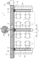
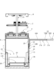
実施例に係る飲食物搬送装置につき、図1から図8を参照して説明する。図1は、本発明の飲食物搬送装置1が設置された飲食店設備を示すイメージ図である。飲食物搬送装置1は、例えば店員H1が飲食物を調理したり、店員H2が食器の洗い作業を行う厨房エリア(厨房側)Cと客が飲食を行う飲食客エリア(飲食客側)Aとに亘って設けられる循環搬送路2、注文搬送装置4(図2参照)、同様に厨房エリアCと飲食客エリアAとに亘って設けられる回収搬送装置7(図3参照)、を備えている。尚、図1では、飲食客エリアAにて循環搬送路2の形状に沿って上方に配されるルーフR(図5参照)を省略して図示してある。 The food and drink conveying device according to the embodiment will be described with reference to Figs. 1 to 8. Fig. 1 is an image diagram showing a restaurant facility in which the food and drink conveying device 1 of the present invention is installed. The food and drink conveying device 1 includes a circulating conveying path 2 that is provided between a kitchen area (kitchen side) C where, for example, a waiter H1 prepares food and drink and a waiter H2 washes dishes, and a dining area (diner side) A where customers eat and drink, an order conveying device 4 (see Fig. 2), and a collection conveying device 7 (see Fig. 3) that is similarly provided between the kitchen area C and the dining area A. Note that Fig. 1 omits the roof R (see Fig. 5) that is arranged above the circulating conveying path 2 in the dining area A along the shape of the circulating conveying path 2.

厨房エリアCと飲食客エリアAは、隔壁3により仕切られている。飲食客エリアAには、隔壁3を貫通して配置されるクレセントチェーンコンベアより成る提供搬送路である循環搬送路2が無端状に設けられている。本実施例において循環搬送路2は平面視E型を成している。 The kitchen area C and the customer area A are separated by a partition wall 3. In the customer area A, an endless circulating conveying path 2, which is a serving conveying path consisting of a crescent chain conveyor arranged to pass through the partition wall 3, is provided. In this embodiment, the circulating conveying path 2 is E-shaped when viewed from above.

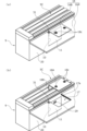
また、図2に示されるように、飲食客エリアAには、互いに並設される提供搬送路である3列の注文搬送路5(5A、5B、5C)が、厨房エリアCから所定間隔離間して隔壁3を貫通して配置され、これら注文搬送路5A、5B、5Cに直交して、客席を構成する飲食テーブル8が設けられている。このうち注文搬送路5Bには、その幅方向の両側に飲食テーブル8が設けられている。また、このうち注文搬送路5A、5Cの幅方向の一方側には、これら注文搬送路5A、5Cに沿って客席カウンタ6が設けられている。 As shown in FIG. 2, in the dining customer area A, three rows of order conveying paths 5 (5A, 5B, 5C), which are serving conveying paths arranged parallel to each other, are arranged at a predetermined distance from the kitchen area C and penetrate the partition wall 3, and dining tables 8 constituting customer seats are provided perpendicular to these order conveying paths 5A, 5B, 5C. Of these, the order conveying path 5B has dining tables 8 on both sides in the width direction. In addition, a customer seating counter 6 is provided along the order conveying paths 5A, 5C on one side in the width direction of these order conveying paths 5A, 5C.

循環搬送路2には、厨房エリアC側で皿などの飲食容器が載置され、飲食客エリアA側にて各客席(飲食テーブル8,客席カウンタ6の各席)に亘って飲食物が循環される。注文搬送路5A、5B、5Cは、厨房エリアC側で互いの端部が近接して配置されており、厨房側の店員(例えばH1)によって、飲食物が載せられた皿やコップなどが走行体(図示せず)に載置されて各客席まで搬送されるようになっている。尚、注文搬送装置4は、例えば走行体を用いずに、注文搬送路をベルトで構成し、このベルトに飲食物が載せられた皿やコップなどを直接載置させて搬送するものであってもよい。 On the circulating conveying path 2, plates and other food and drink containers are placed on the kitchen area C side, and food and drink are circulated to each customer seat (dining tables 8, each seat at the customer counter 6) on the dining customer area A side. The order conveying paths 5A, 5B, and 5C are arranged with their ends close to each other on the kitchen area C side, and a kitchen staff member (e.g. H1) places plates, cups, etc. on which food and drink are placed on a running body (not shown) and conveyed to each customer seat. Note that the order conveying device 4 may be configured, for example, without using a running body, by forming the order conveying path with a belt, and plates, cups, etc. on which food and drink are placed directly on this belt for conveyance.

また、飲食客エリアAの客席から飲食物の注文を受けると、飲食物は厨房エリアCにおいて調理された後、走行体に載置され注文搬送装置4により当該客席まで搬送される。 When an order for food or drink is received from a customer seat in dining area A, the food or drink is cooked in kitchen area C, then placed on a traveling vehicle and transported to the customer seat by order transport device 4.

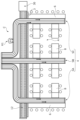
図3に示されるように、厨房エリアCと飲食客エリアAとに亘って設けられる回収搬送装置7は、飲食テーブル8と客席カウンタ6とに沿って平面視E型を成している。 As shown in FIG. 3, the collection and transport device 7, which is installed between the kitchen area C and the dining area A, forms an E-shape in plan view along the dining tables 8 and the customer counter 6.

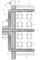
図4と図5に示されるように、回収搬送装置7は、循環搬送路2及び注文搬送装置4の下方に、これらの形状に沿って配設されている。尚、図5では、注文搬送路5Aの部分の一部断面図であり、注文搬送路5B、5Cについても循環搬送路2及び注文搬送装置4と回収搬送装置7との位置関係は同様である。 As shown in Figures 4 and 5, the collection and transport device 7 is disposed below the circulating transport path 2 and the ordered food transport device 4, following their shapes. Note that Figure 5 is a partial cross-sectional view of the ordered food transport path 5A, and the positional relationship between the circulating transport path 2 and the ordered food transport device 4 and the collection and transport device 7 is the same for the ordered food transport paths 5B and 5C.

注文搬送路5A、5B、5Cは、箱型に構成された基台9の上面に敷設されており、また図4、6、8では図示を省略しているが、基台9の上面から起立する支持フレーム21には、注文搬送路5A、5B、5Cの上方に所定間隔離間して循環搬送路2が敷設されている。 The order transport paths 5A, 5B, and 5C are laid on the top surface of the box-shaped base 9, and although not shown in Figures 4, 6, and 8, a circulating transport path 2 is laid on a support frame 21 that stands up from the top surface of the base 9 at a specified distance above the order transport paths 5A, 5B, and 5C.

そして、注文搬送路5Cが敷設される基台9の内部空間S1に回収搬送装置7を構成する回収搬送路13Cが敷設されている。同様に、注文搬送路5A、5Bの下方における基台9の内部空間S1には回収搬送路13A,13Bがそれぞれ敷設されている。このように、飲食物搬送装置1では、基礎構造を成す基台9に、循環搬送路2、注文搬送路5、回収搬送路13がそれぞれ支持されている。 The recovery conveying path 13C constituting the recovery conveying device 7 is laid in the internal space S1 of the base 9 in which the order conveying path 5C is laid. Similarly, the recovery conveying paths 13A and 13B are respectively laid in the internal space S1 of the base 9 below the order conveying paths 5A and 5B. In this way, in the food and beverage conveying device 1, the circulating conveying path 2, the order conveying path 5, and the recovery conveying path 13 are each supported on the base 9 which forms the basic structure.

図4と図5に示されるように、基台9は、構造の支持枠19と、支持枠19に取り付けられた側面パネル(壁部)20とにより主に構成されている。そして、飲食客エリアAにおける基台9の側面パネル20には、客席カウンタ6と飲食テーブル8がそれぞれ突き合わせられて設置されている。 As shown in Figures 4 and 5, the base 9 is mainly composed of a structural support frame 19 and a side panel (wall portion) 20 attached to the support frame 19. The customer seating counter 6 and dining tables 8 are installed against the side panel 20 of the base 9 in the dining area A.

回収搬送路13(13A,13B,13C)は、厨房エリアC側から延びて回収ボックス22を往復移動可能なコンベアである。図3に示されるように、回収搬送装置7は回収搬送路13A,13B,13Cと、厨房エリアC側にて循環搬送路2の下方にて隔壁3に沿うように延設される回収搬送路12とで構成されている。これら回収搬送路13と回収搬送路12は、それぞれ複数の使用後の容器を収容可能な回収ボックス(箱体)22の幅よりも若干大きな幅を有しており、これら回収搬送路13と回収搬送路12の長手方向に長手が沿うように載置された回収ボックス22を回収場所30まで搬送可能となっている。 The collection conveying path 13 (13A, 13B, 13C) is a conveyor that extends from the kitchen area C side and can move the collection box 22 back and forth. As shown in FIG. 3, the collection conveying device 7 is composed of the collection conveying paths 13A, 13B, 13C and the collection conveying path 12 that extends along the partition wall 3 below the circulating conveying path 2 on the kitchen area C side. These collection conveying paths 13 and 12 each have a width slightly larger than the width of the collection box (box body) 22 that can store multiple used containers, and the collection box 22 placed so that its length is aligned with the length of the collection conveying path 13 and collection conveying path 12 can be transported to the collection location 30.

回収搬送路12は、基本的に一方向に駆動され、長手方向における一方側(下流側)先端近傍に配設された洗浄のための回収場所30に回収ボックス22を搬送するようになっている。 The recovery transport path 12 is basically driven in one direction to transport the recovery box 22 to a recovery location 30 for cleaning located near the end of one side (downstream side) in the longitudinal direction.

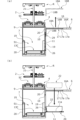
図4と図5に示されるように、基台9の側面パネル20には複数箇所に投入口10が形成されており、この投入口10を介して外部と基台9の内部空間S1つまり回収搬送路13とが連通可能となっている。また投入口10は扉11により開閉できるようになっている。 As shown in Figures 4 and 5, the side panel 20 of the base 9 has multiple input ports 10 formed therein, and these input ports 10 allow communication between the outside and the internal space S1 of the base 9, i.e., the recovery transport path 13. The input ports 10 can also be opened and closed by doors 11.

詳しくは、基台9の側面パネル20に形成された矩形状の貫通孔(図示略)に扉装置23が取り付けられている。扉装置23は、貫通孔と同形の矩形状のフレーム(図示略)と、フレーム(図示略)の内側に形成された投入口10を塞ぐ扉11と、扉11を支持する支持機構24とヒンジ25とを備えている。扉11は下辺部が左右複数のヒンジ25によりフレームに接続されている。投入口10は、回収ボックス22の長さ寸法と高さ寸法よりも大きな開口断面積を有している。 More specifically, the door device 23 is attached to a rectangular through-hole (not shown) formed in the side panel 20 of the base 9. The door device 23 includes a rectangular frame (not shown) of the same shape as the through-hole, a door 11 that closes the drop-in opening 10 formed inside the frame (not shown), and a support mechanism 24 and hinges 25 that support the door 11. The bottom edge of the door 11 is connected to the frame by multiple hinges 25 on the left and right. The drop-in opening 10 has an opening cross-sectional area larger than the length and height dimensions of the collection box 22.

本実施例において扉装置23は、扉11が下辺部を軸として上辺部が基台9の外側内に倒れる形で開閉する、外倒し型である。支持機構24は、一方端が扉11に、他方端が支持枠19にそれぞれ枢着された伸縮アーム26を有している。伸縮アーム26は2つの杆部材がスライド可能に連結されて構成され、図示しないストッパにより最長の伸長時の長さが規定されている。尚、本実施例において支持機構24は、回収ボックス22との干渉を最小限にするために扉11の左右一方側にのみ伸縮アーム26を備えているが、両側に一対の伸縮アームを備えていてもよい。 In this embodiment, the door device 23 is an outward tilt type in which the door 11 opens and closes by pivoting the lower edge and tilting the upper edge inward toward the outside of the base 9. The support mechanism 24 has a telescopic arm 26 pivoted at one end to the door 11 and at the other end to the support frame 19. The telescopic arm 26 is composed of two rod members slidably connected, and the maximum extended length is determined by a stopper (not shown). In this embodiment, the support mechanism 24 has a telescopic arm 26 only on one side of the door 11, either left or right, to minimize interference with the collection box 22, but a pair of telescopic arms may be provided on both sides.

また、扉11の内面における上端には磁性体27が設けられており、フレームに設けられた磁石28と磁着することで、扉11の閉状態が維持されるようになっている。扉11の外面における上端には、手を掛ける把持部(操作部)29が形成されている。把持部29は扉11の外面と面一になるように埋設されている。 A magnetic body 27 is provided at the top end of the inner surface of the door 11, and is magnetically attached to a magnet 28 provided on the frame, thereby keeping the door 11 closed. A grip (operating part) 29 for holding onto is formed at the top end of the outer surface of the door 11. The grip 29 is embedded so that it is flush with the outer surface of the door 11.

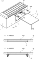
投入口10は客席カウンタ6の天板16及び飲食テーブル8の天板の下方に僅かに離間して、側面パネルの左右方向に複数配されている。図5と図6に示されるように、客席カウンタ6の天板16には、投入口10の長手位置に対応する位置に上下方向に貫通する開口部17が形成されている。 The slots 10 are arranged in multiple locations on the left and right side of the side panel, spaced slightly below the top plate 16 of the customer counter 6 and the top plate of the dining table 8. As shown in Figures 5 and 6, the top plate 16 of the customer counter 6 has an opening 17 that penetrates vertically at a position corresponding to the longitudinal position of the slots 10.

開口部17は、客席カウンタ6の天板16の天板本体部16Aにおける基台9の側面パネル20との対向縁部に形成されており、少なくとも回収ボックス22の長さ寸法と幅寸法よりも大きな開口断面積を有している。開口部17は蓋部材16Bにより開閉可能となっており、これら天板本体部16Aと蓋部材16Bとにより天板16が構成されている。 The opening 17 is formed in the edge of the tabletop body 16A of the tabletop 16 of the customer counter 6 facing the side panel 20 of the base 9, and has an opening cross-sectional area at least larger than the length and width of the collection box 22. The opening 17 can be opened and closed by a lid member 16B, and the tabletop 16 is composed of the tabletop body 16A and the lid member 16B.

蓋部材16Bは、開口部17と略同形かつ略同寸法の平面部18Aと、平面部18Aの前方端から下方に垂下する突出部18Bを備えている。開口部17の内側の縁部下方からは内側に凸部17aが張り出しており、支持可能になっている。蓋部材16Bの平面部18Aには、操作部18cが埋設されている。 The lid member 16B has a flat portion 18A that is approximately the same shape and dimensions as the opening 17, and a protruding portion 18B that hangs down from the front end of the flat portion 18A. A convex portion 17a protrudes inward from the lower inner edge of the opening 17, allowing it to be supported. An operating portion 18c is embedded in the flat portion 18A of the lid member 16B.

蓋部材16Bの突出部18Bは、開口部17の閉状態において基台9の側面パネル20の前方に重なるように配されている。尚、開口部17の凸部17aは基台9の側面パネル20との対向縁部には形成されていない。蓋部材16Bが開口部17の凸部17aに支持された状態において、平面部18Aが客席カウンタ6の天板本体部16Aと面一となり、突出部18Bが扉11の上端部の手前に重なるように配置される(図5参照)。 The protruding portion 18B of the lid member 16B is arranged so as to overlap the front of the side panel 20 of the base 9 when the opening 17 is in the closed state. The convex portion 17a of the opening 17 is not formed on the edge facing the side panel 20 of the base 9. When the lid member 16B is supported by the convex portion 17a of the opening 17, the flat portion 18A is flush with the top body portion 16A of the customer counter 6, and the protruding portion 18B is arranged so as to overlap in front of the upper end of the door 11 (see Figure 5).

詳しくは、突出部18Bは蓋部材16Bが凸部17aに支持された状態で、扉11の外面における上端の把持部29に対して、把持部29の上下方向寸法の少なくとも半分以上に重なる上下寸法で平面部18Aの下方に延設されている。そのため、蓋部材16Bにより開口部17が閉じられた状態において、突出部18Bは把持部29に重なる重合部として機能し、突出部18Bが前方に重なることで把持部29の把持が不能になり、客による不用意な開操作を防止することができる。また、突出部18Bは扉11の上端部側に張り出し、扉11の開方向への回動そのものを規制する規制部としても機能する。 In more detail, when the lid member 16B is supported by the convex portion 17a, the protrusion 18B extends below the flat portion 18A with a vertical dimension that overlaps with at least half of the vertical dimension of the gripping portion 29 at the upper end of the outer surface of the door 11. Therefore, when the opening 17 is closed by the lid member 16B, the protrusion 18B functions as an overlapping portion that overlaps with the gripping portion 29, and the forward overlap of the protrusion 18B makes it impossible to grasp the gripping portion 29, preventing customers from accidentally opening the door. The protrusion 18B also protrudes toward the upper end of the door 11 and functions as a restricting portion that restricts the rotation of the door 11 in the opening direction itself.

客席カウンタ6は、開口部17から蓋部材16Bが意図せず離脱すること防止する施錠装置を備えている。施錠装置は客席カウンタ6の天板本体部16Aに内蔵された近距離無線通信を用いた電子錠である。近距離無線通信を用いた電子錠については、従前の技術を用いているため、詳しくは説明しないが、図6に示されるように、天板本体部16Aの特定の箇所に内蔵した通信部31に、例えばRFIDタグを備えたカードをかざすことで、施錠装置の解錠及び施錠が可能になっている。 The seating counter 6 is equipped with a locking device that prevents the cover member 16B from unintentionally coming off the opening 17. The locking device is an electronic lock that uses short-range wireless communication and is built into the tabletop main body 16A of the seating counter 6. The electronic lock that uses short-range wireless communication uses conventional technology and will not be described in detail, but as shown in Figure 6, the locking device can be unlocked and locked by holding a card equipped with, for example, an RFID tag over the communication unit 31 built into a specific location of the tabletop main body 16A.

次いで、飲食後のバッシング作業つまり客席の片付け作業について、客席カウンタ6の1席を例に取り説明する。まず、店員は回収ボックス22を客席カウンタ6の当該席まで持参する。そして、この席の使用済みの食器を回収ボックス22内に入れる。 Next, the cleaning work after eating and drinking, that is, the work of clearing away a seat, will be explained using one seat at the customer counter 6 as an example. First, the waiter brings the collection box 22 to the relevant seat at the customer counter 6. Then, the used tableware from this seat is placed in the collection box 22.

店員は、RFIDタグを備えたカードを通信部(図示略)にかざして施錠装置を解錠し、操作部18cを持って蓋部材16Bを引き上げ、開口部17を開く(図7(a)参照)。 The store clerk holds a card equipped with an RFID tag over the communication unit (not shown) to unlock the locking device, and then holds the operating unit 18c to pull up the cover member 16B and open the opening 17 (see Figure 7(a)).

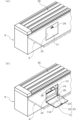
店員は回収搬送路13に繋がる投入口10を開く前に、各扉11の近傍に配設された操作ボタン(図示する)を押すことで、回収搬送路13を停止させる。店員は回収搬送路13の停止を確認した後、把持部29を持って扉11を開操作する。 Before opening the input port 10 connected to the collection and transport path 13, the store clerk presses an operation button (shown) located near each door 11 to stop the collection and transport path 13. After confirming that the collection and transport path 13 has stopped, the store clerk holds the grip 29 and opens the door 11.

開操作された扉11は、支持機構24により基台9の側面パネル20に対して直角に支持される。言い換えると、側面パネル20の外側に開かれた扉11は、客席カウンタ6の天板16に形成された開口部17の下方に展開される。そのため、店員が手作業で開口部17を通して客席カウンタ6の下に向けて下ろされた回収ボックス22は、扉11の内面11aの上に載置される。このように、回収ボックス22は扉11の上に仮置きすることができる(図7(b)参照)。 When the door 11 is opened, it is supported at a right angle to the side panel 20 of the base 9 by the support mechanism 24. In other words, the door 11 opened outward from the side panel 20 is deployed below the opening 17 formed in the top plate 16 of the customer counter 6. Therefore, the collection box 22 that is manually lowered by a store clerk through the opening 17 toward under the customer counter 6 is placed on the inner surface 11a of the door 11. In this way, the collection box 22 can be temporarily placed on the door 11 (see Figure 7 (b)).

図7(b)に示されるように、開操作された扉11の内面11aは、回収搬送路13Cの搬送面よりも高い位置にあるため、扉11の内面11a上を滑らせ、投入口10から回収ボックス22を回収搬送路13C内に押し込んだ際に、扉11の内面11aから回収搬送路13C上に回収ボックス22を容易に移載させることができる。 As shown in FIG. 7(b), the inner surface 11a of the opened door 11 is higher than the conveying surface of the recovery conveying path 13C, so that when the recovery box 22 is pushed into the recovery conveying path 13C from the input port 10 by sliding it over the inner surface 11a of the door 11, the recovery box 22 can be easily transferred from the inner surface 11a of the door 11 onto the recovery conveying path 13C.

店員は扉11を閉操作した後、操作ボタンを再度押して回収搬送路13Cを再度駆動させ、回収ボックス22を厨房エリアCの回収場所30に搬送させる。最後に、蓋部材16Bにより開口部17を閉じ、施錠機構を施錠操作し、片付け作業を完了させる。尚、使用済みの食器は、回収ボックス22の代わりのトレー等に載置されて回収搬送路13Cにより厨房エリアCの回収場所30に搬送されてもよい。 After closing the door 11, the store clerk presses the operating button again to operate the collection and transport path 13C again and transport the collection box 22 to the collection location 30 in the kitchen area C. Finally, the opening 17 is closed with the lid member 16B, the locking mechanism is operated, and the cleanup work is completed. Note that the used tableware may be placed on a tray or the like instead of the collection box 22 and transported to the collection location 30 in the kitchen area C by the collection and transport path 13C.

また、図8に示されるように、飲食テーブル8にも同様の開口37が形成され、開口37から回収ボックス22を回収搬送装置7に移載させることで、それぞれの飲食テーブル8毎に片付けを行うことができる。 Also, as shown in FIG. 8, a similar opening 37 is formed on the dining table 8, and the collection box 22 can be transferred to the collection and transport device 7 through the opening 37, allowing each dining table 8 to be cleaned up separately.

以上説明したように、本実施例における飲食物搬送装置1は、注文搬送路5及び循環搬送路2に沿って配設された飲食台である客席カウンタ6と飲食テーブル8とを備え、客席カウンタ6には天板16の下方の側面パネル(壁部)20に回収搬送路13にアクセス可能な投入口10と、投入口10を開閉する扉11とを備える。これによれば、回収搬送路13に連通する投入口10は天板16の下方に配されることから、飲食中の飲食客には回収搬送路13の存在を外観上、隠蔽することができ、また衛生管理を行いやすい。更に、回収搬送路13にアクセス可能な投入口10は扉11により閉じられ、かつ天板16に阻まれることで、回収搬送路13内の臭気が客席カウンタ6の上方まで上り難く、快適に飲食を行うことができる。 As described above, the food and beverage conveying device 1 in this embodiment is equipped with a customer counter 6 and a dining table 8, which are dining tables arranged along the order conveying path 5 and the circulation conveying path 2, and the customer counter 6 is equipped with an input port 10 that can access the recovery conveying path 13 on the side panel (wall portion) 20 below the top plate 16, and a door 11 that opens and closes the input port 10. Since the input port 10 that communicates with the recovery conveying path 13 is arranged below the top plate 16, the existence of the recovery conveying path 13 can be concealed from customers who are eating and drinking, and hygiene management is also easy. Furthermore, since the input port 10 that can access the recovery conveying path 13 is closed by the door 11 and blocked by the top plate 16, odors in the recovery conveying path 13 are unlikely to rise up to the top of the customer counter 6, allowing for comfortable eating and drinking.

また、飲食台である客席カウンタ6には、天板16を上下に貫通する開口部17が形成されており、この開口部17は天板本体部16Aとともに客席カウンタ6を構成する蓋部材16Bにより開閉されるようになっている。そのため、客席カウンタ6の下に潜り込まずとも、天板16を上下に貫通する開口部17から客席カウンタ6下方の側面パネル20に形成された投入口10にアクセスでき、片付け作業の作業性に優れる。加えて、蓋部材16Bは客席カウンタ6を構成する隠し扉であるため、客による投入口10へのアクセスが防止されるため安全性に優れる。 In addition, the customer counter 6, which serves as a dining table, has an opening 17 that passes vertically through the top plate 16, and this opening 17 is opened and closed by a lid member 16B that, together with the top plate main body 16A, constitutes the customer counter 6. Therefore, the insertion port 10 formed in the side panel 20 below the customer counter 6 can be accessed from the opening 17 that passes vertically through the top plate 16 without having to crawl under the customer counter 6, which improves workability when tidying up. In addition, because the lid member 16B is a hidden door that constitutes the customer counter 6, access to the insertion port 10 by customers is prevented, which improves safety.

また、蓋部材16Bの規制部である突出部18Bが扉11の開方向の動作を規制するため、飲食中に扉11が開かれることがなく、快適に飲食を行うことができるばかりか、特に客による回収搬送路13へのアクセスが防止されるため安全性に優れる。 In addition, the protrusion 18B, which is the restricting part of the lid member 16B, restricts the movement of the door 11 in the opening direction, so the door 11 will not be opened while eating and drinking, allowing customers to eat and drink comfortably, and is particularly safe because it prevents customers from accessing the collection and transport path 13.

また、蓋部材16Bの重合部である突出部18Bが扉11の把持部29に重合されることで、扉11を開く操作が不能となる。 In addition, the protruding portion 18B, which is the overlapping portion of the lid member 16B, overlaps with the gripping portion 29 of the door 11, making it impossible to open the door 11.

また、蓋部材16Bの閉状態を維持できる施錠装置が客席カウンタ6の天板16に内蔵された近距離無線通信の通信部31を用いた電子錠であることから、客席カウンタ6の天板16の表面上に施錠装置を設けたことによる凹凸が生じず、飲食台としての機能を損なわず、加えて施錠装置の存在が意識されにくく、客が飲食に集中することができる。 In addition, the locking device that can keep the lid member 16B closed is an electronic lock that uses a short-range wireless communication unit 31 built into the top plate 16 of the customer counter 6, so there are no irregularities on the surface of the top plate 16 of the customer counter 6 due to the locking device, and the function as a dining table is not impaired. In addition, the presence of the locking device is hardly noticeable, allowing customers to concentrate on eating and drinking.

以上、本発明の実施例を図面に基づいて説明してきたが、具体的な構成はこれら実施例に限られるものではなく、本発明の要旨を逸脱しない範囲内における追加や変更があっても、本発明に含まれる。 Although the embodiments of the present invention have been described above with reference to the drawings, the specific configuration is not limited to these embodiments, and additions and modifications that do not deviate from the gist of the present invention are also included in the present invention.

例えば、前記実施例において蓋部材16Bは、天板16に形成された開口部17に対して着脱されることで開口部17を開閉できる構成であったが、これに限らず、例えば天板16に対して軸支されて水平方向または上下方向に回転することで開口部17を開閉できる構成であってもよい。 For example, in the above embodiment, the cover member 16B is configured to be attached to and detached from the opening 17 formed in the top plate 16 to open and close the opening 17, but this is not limited thereto. For example, the cover member 16B may be pivoted relative to the top plate 16 and rotated horizontally or vertically to open and close the opening 17.

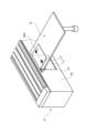
また、蓋部材の代わりに、例えば図9に示される変形例1のように、天板46側に設けられたスライド機構40により、閉塞部材46Bが水平方向にスライドされることで開口部47を開閉できる構成であってもよい。なお、このような構成を採用する場合には、開口部47を跨いで天板46の前後方向に架設された補強部材41を備えることが強度確保の観点から好ましい。また、図のように閉塞部材46Bを2つ備えた両開き構造とすることで、開作業を容易に行なえ、かつ天板46の左右への張り出し量を小さくできる。 Instead of a lid member, as in variant 1 shown in FIG. 9, a sliding mechanism 40 provided on the top plate 46 side may be used to slide a blocking member 46B horizontally to open and close the opening 47. When adopting such a configuration, it is preferable to provide a reinforcing member 41 that is installed in the front-to-rear direction of the top plate 46 across the opening 47 in order to ensure strength. Also, by using a double-opening structure with two blocking members 46B as shown in the figure, opening can be performed easily and the amount of protrusion of the top plate 46 to the left and right can be reduced.

また、投入口10を開閉する扉11は、前記実施例のような外倒し型に限らず、例えば左右にスライドする引き戸構造であってもよい。 The door 11 that opens and closes the insertion port 10 is not limited to the outward tilt type as in the above embodiment, but may be, for example, a sliding door structure that slides left and right.

また、前記実施例の飲食物搬送装置1は提供搬送路として、循環搬送路2と注文搬送路5とのいずれも備えているが、これに限らずこれらのうち一方だけを備える構成であってもよい。 In addition, the food and beverage conveying device 1 in the above embodiment has both a circulation conveying path 2 and an order conveying path 5 as the serving conveying path, but this is not limited to this and it may be configured to have only one of these.

また、回収ボックス22は回収搬送路13内に常設されて厨房エリアCと飲食客エリアAとの間で行き来する構成とし、店員は食器のみを投入口から回収コンベア上の回収ボックスに投入するという使い方を選択することもできる。 The collection box 22 is permanently installed within the collection conveyor path 13 and moves between the kitchen area C and the dining area A, and the staff can choose to insert only the tableware from the insertion opening into the collection box on the collection conveyor.

また、投入口10を開閉する扉11の内面11aは平坦面に限らず、例えば扉11の上下方向に延びる複数のレールを有する構成としてもよく、これによれば扉11の内面側に載置されて仮置きされた回収ボックス22をレールに沿って回収搬送路13内までよりスムーズにスライド移動させることができる。 In addition, the inner surface 11a of the door 11 that opens and closes the input port 10 is not limited to a flat surface, and may be configured, for example, to have multiple rails extending in the vertical direction of the door 11. In this way, the collection box 22 that is temporarily placed on the inner surface of the door 11 can be slid more smoothly along the rails into the collection transport path 13.

また、図10に示される変形例2のように、基台9の側面パネル20側に設けられたスライド機構44及び脚部材43側に設けられたスライド機構42により、飲食テーブル80自体を側面パネル20に対して相対的に前後にスライド移動可能とし、側面パネル20と飲食テーブル80の端部との間に投入口10にアクセス可能な隙間(開口部に相当)81を形成する構成であってもよい。 Also, as shown in modified example 2 in FIG. 10, a sliding mechanism 44 provided on the side panel 20 side of the base 9 and a sliding mechanism 42 provided on the leg member 43 side may be used to allow the eating and drinking table 80 itself to slide back and forth relative to the side panel 20, forming a gap (corresponding to an opening) 81 between the side panel 20 and the end of the eating and drinking table 80 that allows access to the insertion port 10.

1 飲食物搬送装置
2 循環搬送路
4 注文搬送装置
5 注文搬送路
6 客席カウンタ
7 回収搬送装置
8 飲食テーブル
9 基台
10 投入口
11 扉
11a 内面
12,13 回収搬送路
16 天板
16A 天板本体部
17 開口部
18A 平面部
18B 突出部
19 支持枠
20 側面パネル(壁部)
22 回収ボックス
24 支持機構
29 把持部
30 回収場所
31 通信部
37 開口
A 飲食客エリア
C 厨房エリア
1 Food and drink conveying device 2 Circulation conveying path 4 Order conveying device 5 Order conveying path 6 Customer seat counter 7 Collection conveying device 8 Food and drink table 9 Base 10 Insertion port 11 Door 11a Inner surface 12, 13 Collection conveying path 16 Top plate 16A Top plate main body 17 Opening 18A Flat surface 18B Protruding portion 19 Support frame 20 Side panel (wall portion)
22 Collection box 24 Support mechanism 29 Grip portion 30 Collection location 31 Communication portion 37 Opening A Dining customer area C Kitchen area

Claims (7)

厨房エリアから飲食客エリアへ飲食物容器を提供搬送する提供搬送路と、使用済みの前記飲食物容器を前記飲食客エリアから前記厨房エリアに回収搬送する回収搬送路と、を備えた飲食物搬送装置であって、
前記飲食物搬送装置は、前記提供搬送路に沿って配設された飲食台を備え、かつ前記飲食台の下方の壁部に前記回収搬送路にアクセス可能な投入口と、該投入口を開閉する扉とを備えることを特徴とする飲食物搬送装置。
A food and beverage conveying device comprising: a supply conveying path for supplying and conveying food and beverage containers from a kitchen area to a dining customer area; and a recovery conveying path for recovering and conveying the used food and beverage containers from the dining customer area to the kitchen area,
The food and beverage conveying device is characterized in that it comprises an eating and beverage counter arranged along the serving conveying path, and has an input port in a wall below the eating and beverage counter through which the food and beverage can be accessed by the collection conveying path, and a door for opening and closing the input port.
前記飲食台は、少なくとも一部が退避動作することで、前記投入口の上方に隙間を形成可能であることを特徴とする請求項1に記載の飲食物搬送装置。 The food and beverage conveying device according to claim 1, characterized in that the eating and drinking table can form a gap above the inlet by at least partially retracting. 前記飲食台には該飲食台を上下に貫通する開口部が形成されており、該開口部は前記飲食台を構成する蓋部材により開閉されることを特徴とする請求項1に記載の飲食物搬送装置。 The food and drink conveying device according to claim 1, characterized in that the table has an opening that penetrates the table from top to bottom, and the opening is opened and closed by a lid member that constitutes the table. 前記扉は、アームにより荷重が支持される外倒し扉であることを特徴とする請求項1に記載の飲食物搬送装置。 The food and beverage conveying device according to claim 1, characterized in that the door is an outward-tilting door whose load is supported by an arm. 前記蓋部材は、前記開口部を閉じた状態で、閉状態の前記扉に係止されて該扉の開方向の動作を規制する規制部を有することを特徴とする請求項3に記載の飲食物搬送装置。 The food and beverage conveying device according to claim 3, characterized in that the lid member has a restricting portion that, when the opening is closed, engages with the door in the closed state and restricts the movement of the door in the opening direction. 前記蓋部材は前記開口部を閉じた状態で、閉状態の前記扉の操作部に重合される重合部を備えることを特徴とする請求項3に記載の飲食物搬送装置。 The food and beverage conveying device according to claim 3, characterized in that the lid member has a polymerization part that is polymerized with the operating part of the door in the closed state when the opening is closed. 前記飲食台には、前記蓋部材により前記開口部を閉じた状態を維持できる施錠装置を備え、該施錠装置は前記飲食台に内蔵された近距離無線の通信部を用いた電子錠であることを特徴とする請求項3に記載の飲食物搬送装置。 The food and drink conveying device according to claim 3, characterized in that the dining table is equipped with a locking device that can keep the opening closed with the lid member, and the locking device is an electronic lock that uses a short-range wireless communication unit built into the dining table.
JP2023148408A 2023-09-13 2023-09-13 Food and beverage container transport equipment Pending JP2025041234A (en)

Priority Applications (1)

Application Number Priority Date Filing Date Title
JP2023148408A JP2025041234A (en) 2023-09-13 2023-09-13 Food and beverage container transport equipment

Applications Claiming Priority (1)

Application Number Priority Date Filing Date Title
JP2023148408A JP2025041234A (en) 2023-09-13 2023-09-13 Food and beverage container transport equipment

Publications (1)

Publication Number Publication Date
JP2025041234A true JP2025041234A (en) 2025-03-26

Family

ID=95105115

Family Applications (1)

Application Number Title Priority Date Filing Date
JP2023148408A Pending JP2025041234A (en) 2023-09-13 2023-09-13 Food and beverage container transport equipment

Country Status (1)

Country Link
JP (1) JP2025041234A (en)

Similar Documents

Publication Publication Date Title
US20080072802A1 (en) Portable folding table
JP4173188B1 (en) Sushi counter
US1478371A (en) Camping cabinet
KR20220007328A (en) Camping storage box with an integral cover with a table function
JP2008110104A (en) Kitchen module
JP2025041234A (en) Food and beverage container transport equipment
JP4596545B2 (en) Collected food container transport equipment
JP6966819B1 (en) Eating and drinking table
JP2004049565A (en) Island kitchen
JP4763433B2 (en) Kitchen table with dishwasher
KR101283236B1 (en) Food carrier bag
JP3600327B2 (en) Pull-out auxiliary counter
JP3035304U (en) Tray
NL1038223C2 (en) Trolley.
KR200435736Y1 (en) Locker with document slot and security desk
KR100712446B1 (en) Cooker Carrier for Multi-layer Steamer
JP2024126312A (en) Container providing tool and container providing unit
US1170711A (en) Serving-wagon.
KR100282654B1 (en) A movale cooking table
JP2023146241A (en) Food handling equipment
JP3145753U (en) Cooking table unit
JPH0427418Y2 (en)
KR101308796B1 (en) Bed with sliding compartments
JP2025137183A (en) Storage device
KR200201141Y1 (en) Table with variable upper plate

Legal Events

Date Code Title Description
A80 Written request to apply exceptions to lack of novelty of invention

Free format text: JAPANESE INTERMEDIATE CODE: A80

Effective date: 20230928