JP2025041217A - Tablet printing device and tablet printing method - Google Patents

Tablet printing device and tablet printing method Download PDF

Info

Publication number
JP2025041217A
JP2025041217A JP2023148379A JP2023148379A JP2025041217A JP 2025041217 A JP2025041217 A JP 2025041217A JP 2023148379 A JP2023148379 A JP 2023148379A JP 2023148379 A JP2023148379 A JP 2023148379A JP 2025041217 A JP2025041217 A JP 2025041217A
Authority
JP
Japan
Prior art keywords
tablet
conveying
unit
correction value
inkjet head
Prior art date
Legal status (The legal status is an assumption and is not a legal conclusion. Google has not performed a legal analysis and makes no representation as to the accuracy of the status listed.)
Pending
Application number
JP2023148379A
Other languages
Japanese (ja)
Other versions
JP2025041217A5 (en
Inventor
貴弘 山崎
Takahiro Yamazaki
亮 生田
Akira Ikuta
由孝 岡部
Yoshitaka Okabe
Current Assignee (The listed assignees may be inaccurate. Google has not performed a legal analysis and makes no representation or warranty as to the accuracy of the list.)
Shibaura Mechatronics Corp
Original Assignee
Shibaura Mechatronics Corp
Priority date (The priority date is an assumption and is not a legal conclusion. Google has not performed a legal analysis and makes no representation as to the accuracy of the date listed.)
Filing date
Publication date
Application filed by Shibaura Mechatronics Corp filed Critical Shibaura Mechatronics Corp
Priority to JP2023148379A priority Critical patent/JP2025041217A/en
Priority to KR1020240100455A priority patent/KR20250039272A/en
Priority to CN202411083550.4A priority patent/CN119610902A/en
Priority to TW113129839A priority patent/TWI907007B/en
Publication of JP2025041217A publication Critical patent/JP2025041217A/en
Publication of JP2025041217A5 publication Critical patent/JP2025041217A5/ja
Pending legal-status Critical Current

Links

Images

Classifications

    • BPERFORMING OPERATIONS; TRANSPORTING
    • B41PRINTING; LINING MACHINES; TYPEWRITERS; STAMPS
    • B41JTYPEWRITERS; SELECTIVE PRINTING MECHANISMS, i.e. MECHANISMS PRINTING OTHERWISE THAN FROM A FORME; CORRECTION OF TYPOGRAPHICAL ERRORS
    • B41J3/00Typewriters or selective printing or marking mechanisms characterised by the purpose for which they are constructed
    • B41J3/407Typewriters or selective printing or marking mechanisms characterised by the purpose for which they are constructed for marking on special material
    • B41J3/4073Printing on three-dimensional objects not being in sheet or web form, e.g. spherical or cubic objects
    • AHUMAN NECESSITIES
    • A61MEDICAL OR VETERINARY SCIENCE; HYGIENE
    • A61JCONTAINERS SPECIALLY ADAPTED FOR MEDICAL OR PHARMACEUTICAL PURPOSES; DEVICES OR METHODS SPECIALLY ADAPTED FOR BRINGING PHARMACEUTICAL PRODUCTS INTO PARTICULAR PHYSICAL OR ADMINISTERING FORMS; DEVICES FOR ADMINISTERING FOOD OR MEDICINES ORALLY; BABY COMFORTERS; DEVICES FOR RECEIVING SPITTLE
    • A61J3/00Devices or methods specially adapted for bringing pharmaceutical products into particular physical or administering forms
    • A61J3/007Marking tablets or the like
    • BPERFORMING OPERATIONS; TRANSPORTING
    • B41PRINTING; LINING MACHINES; TYPEWRITERS; STAMPS
    • B41JTYPEWRITERS; SELECTIVE PRINTING MECHANISMS, i.e. MECHANISMS PRINTING OTHERWISE THAN FROM A FORME; CORRECTION OF TYPOGRAPHICAL ERRORS
    • B41J11/00Devices or arrangements  of selective printing mechanisms, e.g. ink-jet printers or thermal printers, for supporting or handling copy material in sheet or web form
    • B41J11/20Platen adjustments for varying the strength of impression, for a varying number of papers, for wear or for alignment, or for print gap adjustment
    • BPERFORMING OPERATIONS; TRANSPORTING
    • B41PRINTING; LINING MACHINES; TYPEWRITERS; STAMPS
    • B41JTYPEWRITERS; SELECTIVE PRINTING MECHANISMS, i.e. MECHANISMS PRINTING OTHERWISE THAN FROM A FORME; CORRECTION OF TYPOGRAPHICAL ERRORS
    • B41J13/00Devices or arrangements of selective printing mechanisms, e.g. ink-jet printers or thermal printers, specially adapted for supporting or handling copy material in short lengths, e.g. sheets
    • B41J13/08Conveyor bands or like feeding devices
    • BPERFORMING OPERATIONS; TRANSPORTING
    • B41PRINTING; LINING MACHINES; TYPEWRITERS; STAMPS
    • B41JTYPEWRITERS; SELECTIVE PRINTING MECHANISMS, i.e. MECHANISMS PRINTING OTHERWISE THAN FROM A FORME; CORRECTION OF TYPOGRAPHICAL ERRORS
    • B41J2/00Typewriters or selective printing mechanisms characterised by the printing or marking process for which they are designed
    • B41J2/005Typewriters or selective printing mechanisms characterised by the printing or marking process for which they are designed characterised by bringing liquid or particles selectively into contact with a printing material
    • B41J2/01Ink jet
    • BPERFORMING OPERATIONS; TRANSPORTING
    • B41PRINTING; LINING MACHINES; TYPEWRITERS; STAMPS
    • B41JTYPEWRITERS; SELECTIVE PRINTING MECHANISMS, i.e. MECHANISMS PRINTING OTHERWISE THAN FROM A FORME; CORRECTION OF TYPOGRAPHICAL ERRORS
    • B41J25/00Actions or mechanisms not otherwise provided for
    • B41J25/304Bodily-movable mechanisms for print heads or carriages movable towards or from paper surface
    • B41J25/308Bodily-movable mechanisms for print heads or carriages movable towards or from paper surface with print gap adjustment mechanisms
    • BPERFORMING OPERATIONS; TRANSPORTING
    • B41PRINTING; LINING MACHINES; TYPEWRITERS; STAMPS
    • B41JTYPEWRITERS; SELECTIVE PRINTING MECHANISMS, i.e. MECHANISMS PRINTING OTHERWISE THAN FROM A FORME; CORRECTION OF TYPOGRAPHICAL ERRORS
    • B41J29/00Details of, or accessories for, typewriters or selective printing mechanisms not otherwise provided for
    • B41J29/38Drives, motors, controls or automatic cut-off devices for the entire printing mechanism
    • B41J29/393Devices for controlling or analysing the entire machine ; Controlling or analysing mechanical parameters involving printing of test patterns
    • BPERFORMING OPERATIONS; TRANSPORTING
    • B41PRINTING; LINING MACHINES; TYPEWRITERS; STAMPS
    • B41JTYPEWRITERS; SELECTIVE PRINTING MECHANISMS, i.e. MECHANISMS PRINTING OTHERWISE THAN FROM A FORME; CORRECTION OF TYPOGRAPHICAL ERRORS
    • B41J3/00Typewriters or selective printing or marking mechanisms characterised by the purpose for which they are constructed
    • B41J3/54Typewriters or selective printing or marking mechanisms characterised by the purpose for which they are constructed with two or more sets of type or printing elements
    • B41J3/543Typewriters or selective printing or marking mechanisms characterised by the purpose for which they are constructed with two or more sets of type or printing elements with multiple inkjet print heads
    • BPERFORMING OPERATIONS; TRANSPORTING
    • B41PRINTING; LINING MACHINES; TYPEWRITERS; STAMPS
    • B41MPRINTING, DUPLICATING, MARKING, OR COPYING PROCESSES; COLOUR PRINTING
    • B41M5/00Duplicating or marking methods; Sheet materials for use therein
    • B41M5/0041Digital printing on surfaces other than ordinary paper
    • B41M5/0047Digital printing on surfaces other than ordinary paper by ink-jet printing
    • BPERFORMING OPERATIONS; TRANSPORTING
    • B41PRINTING; LINING MACHINES; TYPEWRITERS; STAMPS
    • B41MPRINTING, DUPLICATING, MARKING, OR COPYING PROCESSES; COLOUR PRINTING
    • B41M5/00Duplicating or marking methods; Sheet materials for use therein
    • B41M5/0082Digital printing on bodies of particular shapes
    • B41M5/0088Digital printing on bodies of particular shapes by ink-jet printing
    • AHUMAN NECESSITIES
    • A61MEDICAL OR VETERINARY SCIENCE; HYGIENE
    • A61JCONTAINERS SPECIALLY ADAPTED FOR MEDICAL OR PHARMACEUTICAL PURPOSES; DEVICES OR METHODS SPECIALLY ADAPTED FOR BRINGING PHARMACEUTICAL PRODUCTS INTO PARTICULAR PHYSICAL OR ADMINISTERING FORMS; DEVICES FOR ADMINISTERING FOOD OR MEDICINES ORALLY; BABY COMFORTERS; DEVICES FOR RECEIVING SPITTLE
    • A61J2205/00General identification or selection means
    • A61J2205/40General identification or selection means by shape or form, e.g. by using shape recognition

Landscapes

  • Health & Medical Sciences (AREA)
  • Engineering & Computer Science (AREA)
  • Manufacturing & Machinery (AREA)
  • Life Sciences & Earth Sciences (AREA)
  • Medicinal Chemistry (AREA)
  • Pharmacology & Pharmacy (AREA)
  • Chemical & Material Sciences (AREA)
  • Animal Behavior & Ethology (AREA)
  • General Health & Medical Sciences (AREA)
  • Public Health (AREA)
  • Veterinary Medicine (AREA)
  • Medical Preparation Storing Or Oral Administration Devices (AREA)
  • Ink Jet (AREA)
  • Printing Methods (AREA)

Abstract

To provide a tablet printer and a tablet printing method capable of suppressing printing failure.SOLUTION: A tablet printer in an embodiment comprises: a transport device (for example, transport part 21) for transporting a tablet; a first inkjet head (for example, inkjet head 24) for printing to the tablet; a movement mechanism (for example, second movement mechanism 24A) for moving the transport device or the first inkjet head in a height direction; and a control device 40 controlling the movement mechanism. The control device 40 generates a first correction value on the basis of a difference between a height position of the transport device and a first reference height position (for example, reference height position Ba), generates a second correction value on the basis of tablet kind information related to a kind of the tablet, and then controls the movement mechanism on the basis of the first and second correction values.SELECTED DRAWING: Figure 3

Description

本発明の実施形態は、錠剤印刷装置及び錠剤印刷方法に関する。 Embodiments of the present invention relate to a tablet printing device and a tablet printing method.

インクジェットヘッドにより錠剤に印刷を行う錠剤印刷装置が存在する。この錠剤印刷装置では、搬送ベルトを複数のプーリにまわしかけ、この搬送ベルトに錠剤を載置して搬送する搬送機構が開発されている。通常、搬送ベルトには吸引孔が設けられ、搬送ベルトの内側に設けられた吸引チャンバの吸引力により錠剤が吸引孔を介して吸引保持される。 There are tablet printing devices that use inkjet heads to print on tablets. In these tablet printing devices, a conveying mechanism has been developed in which a conveyor belt is looped around multiple pulleys and tablets are placed on the conveyor belt for conveyance. Typically, the conveyor belt has suction holes, and the tablets are sucked and held through the suction holes by the suction force of a suction chamber provided inside the conveyor belt.

搬送ベルトは、経年劣化による摩耗などが生じた場合に交換を要するものである。搬送ベルトを交換すると、搬送ベルトの個体差によってわずかに搬送ベルトからインクジェットヘッドまでの距離が変化することがあり(前者)、また、錠剤が複数の搬送機構を乗り移るように搬送される場合には、乗り移る前後の搬送ベルト間の距離が変化することがある(後者)。 The conveyor belt needs to be replaced when it wears out due to aging. When the conveyor belt is replaced, the distance from the conveyor belt to the inkjet head may change slightly due to individual differences in the conveyor belt (the former case). Also, if the tablets are transported by transferring between multiple conveyor mechanisms, the distance between the conveyor belts before and after the transfer may change (the latter case).

前者の場合には、インクジェットヘッドから吐出されたインクがうまく搬送ベルト上の錠剤に着弾しなかったり、搬送ベルト上の錠剤がインクジェットヘッドに衝突したりすることで、印刷不良が発生することがある。また、後者の場合には、各搬送機構の間で錠剤の受け渡しがうまくできず錠剤が落下したり、錠剤の受け渡しによって錠剤の位置ずれが起こったりすることで、搬送ベルトに設けられた吸引孔と錠剤との位置関係が変化し、錠剤が安定して搬送されず(例えば、錠剤の姿勢が安定せずに揺れたりする)、印刷不良が発生することがある。 In the former case, printing defects may occur when the ink ejected from the inkjet head does not land properly on the tablets on the conveyor belt, or when the tablets on the conveyor belt collide with the inkjet head. In the latter case, the tablets may not be transferred properly between the conveyor mechanisms, causing them to fall, or the tablets may become misaligned when they are transferred, causing the positional relationship between the suction holes in the conveyor belt and the tablets to change, resulting in unstable conveyance of the tablets (for example, the tablets may become unstable and shake), resulting in printing defects.

特開2019-58220号公報JP 2019-58220 A

本発明が解決しようとする課題は、印刷不良を抑えることができる錠剤印刷装置及び錠剤印刷方法を提供することである。 The problem that this invention aims to solve is to provide a tablet printing device and tablet printing method that can reduce printing defects.

本発明の実施形態に係る錠剤印刷装置は、錠剤を搬送する搬送装置と、前記錠剤に印刷を行う第1のインクジェットヘッドと、前記搬送装置又は前記第1のインクジェットヘッドを高さ方向に移動させる移動機構と、前記移動機構を制御する制御装置と、を備え、前記制御装置は、前記搬送装置の高さ位置と第1の基準高さ位置との差に基づいて第1の補正値を生成し、前記錠剤の品種に関する錠剤品種情報に基づいて第2の補正値を生成し、前記第1の補正値及び前記第2の補正値に基づいて前記移動機構を制御する。 A tablet printing device according to an embodiment of the present invention includes a conveying device that conveys tablets, a first inkjet head that prints on the tablets, a movement mechanism that moves the conveying device or the first inkjet head in a height direction, and a control device that controls the movement mechanism, and the control device generates a first correction value based on the difference between the height position of the conveying device and a first reference height position, generates a second correction value based on tablet variety information related to the variety of the tablets, and controls the movement mechanism based on the first correction value and the second correction value.

本発明の実施形態に係る錠剤印刷方法は、制御装置が、錠剤を搬送する搬送装置の高さ位置と第1の基準高さ位置との差に基づいて第1の補正値を生成することと、前記錠剤の品種に関する錠剤品種情報に基づいて第2の補正値を生成することと、前記第1の補正値及び前記第2の補正値に基づいて、前記搬送装置、又は、前記錠剤に印刷を行う第1のインクジェットヘッドを高さ方向に移動させる移動機構を制御することと、を含む。 A tablet printing method according to an embodiment of the present invention includes a control device generating a first correction value based on the difference between the height position of a conveying device that conveys tablets and a first reference height position, generating a second correction value based on tablet variety information related to the variety of the tablets, and controlling a movement mechanism that moves the conveying device or a first inkjet head that prints on the tablets in the height direction based on the first correction value and the second correction value.

本発明の実施形態によれば、印刷不良を抑えることができる。 According to an embodiment of the present invention, printing defects can be reduced.

本発明の実施形態に係る錠剤印刷装置の概略構成の一例を示す図である。1 is a diagram illustrating an example of a schematic configuration of a tablet printing device according to an embodiment of the present invention. 本発明の実施形態に係る印刷装置の概略構成の一例を示す平面図である。1 is a plan view illustrating an example of a schematic configuration of a printing device according to an embodiment of the present invention. 本発明の実施形態に係る移動機構の概略構成の一例を示す図である。FIG. 2 is a diagram illustrating an example of a schematic configuration of a moving mechanism according to an embodiment of the present invention. 本発明の実施形態に係る制御装置の概略構成の一例を示す図である。FIG. 1 is a diagram illustrating an example of a schematic configuration of a control device according to an embodiment of the present invention. 本発明の実施形態に係る位置調整工程の流れの一例を示すフローチャートである。10 is a flowchart showing an example of a flow of a position adjustment process according to the embodiment of the present invention. 本発明の実施形態に係る補正テーブルの一例を示す図である。FIG. 4 is a diagram illustrating an example of a correction table according to the embodiment of the present invention. 本発明の実施形態に係る検出部の構成の変形例1を示す平面図である。FIG. 11 is a plan view showing a first modified example of the configuration of the detection unit according to the embodiment of the present invention. 本発明の実施形態に係る検出部の構成の変形例2を示す平面図である。FIG. 11 is a plan view showing a second modified example of the configuration of the detection unit according to the embodiment of the present invention. 本発明の実施形態に係る検出部の構成の変形例3を示す平面図である。FIG. 11 is a plan view showing a third modified example of the configuration of the detection unit according to the embodiment of the present invention.

<実施形態>
本実施形態について図1から図9を参照して説明する。
<Embodiment>
The present embodiment will be described with reference to FIGS.

(錠剤印刷装置の構成例)
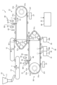
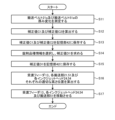
図1に示すように、本実施形態に係る錠剤印刷装置1は、供給装置10と、第1の印刷装置20と、第2の印刷装置50と、回収装置30と、制御装置40とを備える。
(Example of configuration of tablet printing device)
As shown in FIG. 1 , the tablet printing device 1 according to this embodiment includes a supplying device 10 , a first printing device 20 , a second printing device 50 , a collecting device 30 , and a control device 40 .

供給装置10は、ホッパ11、整列フィーダ12及び受渡フィーダ13を有する。この供給装置10は、第1の印刷装置20の一端側に位置付けられ、印刷対象物である錠剤Tを第1の印刷装置20に供給することが可能に構成されている。受渡フィーダ13は、供給搬送部(搬送装置)として機能する。 The supply device 10 has a hopper 11, an alignment feeder 12, and a delivery feeder 13. The supply device 10 is positioned at one end of the first printing device 20 and is configured to be able to supply tablets T, which are the objects to be printed, to the first printing device 20. The delivery feeder 13 functions as a supply transport section (transport device).

ホッパ11は、多数の錠剤Tを収容し、収容した錠剤Tを整列フィーダ12に順次供給する。整列フィーダ12は、供給された錠剤Tを一列に整列し、受渡フィーダ13に向けて搬送方向A1(時計回り方向)に搬送する。整列フィーダ12としては、例えば、ベルト搬送機構や振動フィーダが用いられる。受渡フィーダ13は、整列フィーダ12上に一列に並ぶ各錠剤Tを錠剤Tの上側から順次吸引して保持し、保持した各錠剤Tを第1の印刷装置20まで一列で搬送して第1の印刷装置20に渡す。受渡フィーダ13としては、例えば、ベルト搬送機構が用いられる。受渡フィーダ13のベルト搬送機構は、搬送方向A2(反時計回り方向)に回転する。供給装置10は制御装置40に電気的に接続されており、その駆動が制御装置40により制御される。 The hopper 11 stores a large number of tablets T and sequentially supplies the stored tablets T to the alignment feeder 12. The alignment feeder 12 aligns the supplied tablets T in a line and transports them in the transport direction A1 (clockwise direction) toward the transfer feeder 13. For example, a belt transport mechanism or a vibration feeder is used as the alignment feeder 12. The transfer feeder 13 sequentially sucks in and holds each tablet T lined up on the alignment feeder 12 from the upper side of the tablet T, transports each held tablet T in a line to the first printing device 20, and delivers it to the first printing device 20. For example, a belt transport mechanism is used as the transfer feeder 13. The belt transport mechanism of the transfer feeder 13 rotates in the transport direction A2 (counterclockwise direction). The supply device 10 is electrically connected to the control device 40, and its drive is controlled by the control device 40.

第1の印刷装置20は、搬送部21と、検出部22と、第1の撮像部23と、インクジェットヘッド24と、第2の撮像部25と、乾燥部27とを備える。搬送部21は、第1の搬送部(搬送装置)として機能する。インクジェットヘッド24は、第1のインクジェットヘッドとして機能する。 The first printing device 20 includes a transport unit 21, a detection unit 22, a first imaging unit 23, an inkjet head 24, a second imaging unit 25, and a drying unit 27. The transport unit 21 functions as a first transport unit (transport device). The inkjet head 24 functions as a first inkjet head.

搬送部21は、搬送ベルト21a、駆動プーリ21b、複数の従動プーリ21c、モータ21d、位置検出器21e及び吸引チャンバ21fを有する。搬送ベルト21aは、無端状のベルトであり、駆動プーリ21b及び各従動プーリ21cに架け渡されている。駆動プーリ21b及び各従動プーリ21cは装置本体(図示せず)に回転可能に設けられており、駆動プーリ21bはモータ21dに連結されている。モータ21dは制御装置40に電気的に接続されており、その駆動が制御装置40により制御される。位置検出器21eは、エンコーダなどの機器であり、モータ21dに取り付けられている。この位置検出器21eは電気的に制御装置40に接続されており、検出信号を制御装置40に送信する。搬送部21は、モータ21dによる駆動プーリ21bの回転によって各従動プーリ21cと共に搬送ベルト21aを走行させ、搬送ベルト21a上の錠剤Tを搬送方向A1(時計回り方向)に搬送する。 The conveying section 21 has a conveying belt 21a, a driving pulley 21b, a plurality of driven pulleys 21c, a motor 21d, a position detector 21e, and a suction chamber 21f. The conveying belt 21a is an endless belt and is stretched across the driving pulley 21b and each driven pulley 21c. The driving pulley 21b and each driven pulley 21c are rotatably mounted on the device body (not shown), and the driving pulley 21b is connected to the motor 21d. The motor 21d is electrically connected to the control device 40, and its drive is controlled by the control device 40. The position detector 21e is a device such as an encoder and is attached to the motor 21d. This position detector 21e is electrically connected to the control device 40, and transmits a detection signal to the control device 40. The conveying unit 21 moves the conveying belt 21a together with each driven pulley 21c by rotating the driving pulley 21b by the motor 21d, and conveys the tablets T on the conveying belt 21a in the conveying direction A1 (clockwise direction).

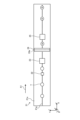
搬送ベルト21aには、図2に示すように、円形状の吸引孔21gが複数形成されている。これらの吸引孔21gは、それぞれ錠剤Tを吸着する貫通孔であり、一本の搬送路を形成するように搬送方向A1に沿って一列に並べられている。各吸引孔21gは、吸引チャンバ21f(図1参照)に形成された吸引路(図示せず)を介して吸引チャンバ21f内に接続されており、吸引チャンバ21fにより吸引力を得ることが可能になっている。吸引チャンバ21fには、ポンプが吸引管(いずれも図示せず)を介して接続されており、ポンプの作動により吸引チャンバ21f内が減圧される。吸引管は、吸引チャンバ21fの側面(搬送方向A1と平行な面)の略中央に接続されている。また、ポンプは制御装置40に電気的に接続されており、その駆動が制御装置40により制御される。吸引チャンバ21f内が減圧されると、搬送ベルト21aの各吸引孔21g上に置かれた錠剤Tは吸引孔21gから吸引され、搬送ベルト21a上に保持される。 As shown in FIG. 2, a plurality of circular suction holes 21g are formed in the conveyor belt 21a. Each of these suction holes 21g is a through hole that adsorbs the tablet T, and is arranged in a row along the conveying direction A1 to form a single conveying path. Each suction hole 21g is connected to the inside of the suction chamber 21f (see FIG. 1) through a suction path (not shown) formed in the suction chamber 21f, and suction force can be obtained by the suction chamber 21f. A pump is connected to the suction chamber 21f through a suction pipe (not shown), and the inside of the suction chamber 21f is depressurized by the operation of the pump. The suction pipe is connected to approximately the center of the side surface (plane parallel to the conveying direction A1) of the suction chamber 21f. The pump is also electrically connected to the control device 40, and its drive is controlled by the control device 40. When the inside of the suction chamber 21f is depressurized, the tablet T placed on each suction hole 21g of the conveyor belt 21a is sucked through the suction hole 21g and held on the conveyor belt 21a.

検出部22は、供給装置10が設けられた位置よりも搬送方向A1の下流側に位置付けられ、各吸引孔21gが並ぶ搬送路の上方に設けられている。この検出部22は、レーザ光の投受光によって検出部22の直下の検出位置に到達した錠剤T(錠剤Tの到来)、すなわち搬送ベルト21a上の錠剤Tの搬送方向A1の位置を検出する。検出部22としては、例えば、変位センサが用いられる。また、変位センサとしては、反射型レーザセンサなどの各種のレーザセンサが用いられる。検出部22は制御装置40に電気的に接続されており、制御装置40に検出信号を送信する。 The detection unit 22 is positioned downstream in the conveying direction A1 from the position where the supply device 10 is provided, and is provided above the conveying path where each suction hole 21g is lined up. This detection unit 22 detects the tablet T that has reached the detection position directly below the detection unit 22 (arrival of tablet T), i.e., the position of the tablet T on the conveying belt 21a in the conveying direction A1, by projecting and receiving laser light. For example, a displacement sensor is used as the detection unit 22. Also, various types of laser sensors, such as a reflective laser sensor, are used as the displacement sensor. The detection unit 22 is electrically connected to the control device 40, and transmits a detection signal to the control device 40.

第1の撮像部23は、検出部22が設けられた位置よりも搬送方向A1の下流側に位置付けられ、各吸引孔21gが並ぶ搬送路の上方に設けられている。この第1の撮像部23は、検出部22により検出された錠剤Tの搬送方向A1の位置情報に基づき、錠剤Tが第1の撮像部23の直下の撮像位置に到達した第1の撮像タイミングで撮像を行い、錠剤Tの上面を含む第1の画像を取得し、取得した第1の画像を制御装置40に送信する。第1の画像は、錠剤TのX方向、Y方向及びθ方向(図2参照)の位置を検出するために用いられる。第1の撮像部23としては、CCD(電荷結合素子)やCMOS(相補型金属酸化膜半導体)などの撮像素子を有する各種のカメラが用いられる。第1の撮像部23は制御装置40に電気的に接続されており、その駆動が制御装置40により制御される。なお、必要に応じて撮像用の照明も設けられる。 The first imaging unit 23 is positioned downstream in the conveying direction A1 from the position where the detection unit 22 is provided, and is provided above the conveying path where each suction hole 21g is lined up. Based on the position information of the tablet T in the conveying direction A1 detected by the detection unit 22, the first imaging unit 23 performs imaging at the first imaging timing when the tablet T reaches the imaging position directly below the first imaging unit 23, obtains a first image including the upper surface of the tablet T, and transmits the obtained first image to the control device 40. The first image is used to detect the position of the tablet T in the X direction, Y direction, and θ direction (see FIG. 2). As the first imaging unit 23, various cameras having imaging elements such as a CCD (charge-coupled device) or a CMOS (complementary metal oxide semiconductor) are used. The first imaging unit 23 is electrically connected to the control device 40, and its drive is controlled by the control device 40. In addition, illumination for imaging is also provided as necessary.

ここで、錠剤TのX方向及びY方向の位置は、例えば、第1の撮像部23の撮像領域の中心(基準位置)に対するXY座標系の位置である。また、θ方向の位置は、例えば、第1の撮像部23の撮像領域のXY平面に沿った水平面内での錠剤Tの回転度合いを示す位置である。このθ方向の位置は、錠剤Tに割線が設けられている場合や錠剤Tが楕円形や長円形、三角形、四角形などに成型されている場合など、錠剤Tが方向性を有する形状である場合に検出される。なお、X方向およびY方向は、水平方向における位置である。 Here, the positions of the tablet T in the X and Y directions are, for example, positions in the XY coordinate system relative to the center (reference position) of the imaging area of the first imaging unit 23. The position in the θ direction is, for example, a position indicating the degree of rotation of the tablet T in a horizontal plane along the XY plane of the imaging area of the first imaging unit 23. This position in the θ direction is detected when the tablet T has a directional shape, such as when a score line is provided on the tablet T or when the tablet T is molded into an oval, elliptical, triangular, rectangular, or other shape. The X and Y directions are positions in the horizontal direction.

インクジェットヘッド24は、第1の撮像部23が設けられた位置よりも搬送方向A1の下流側に位置付けられ、各吸引孔21gが並ぶ搬送路の上方に設けられている。インクジェットヘッド24は、複数(例えば数百個から数千個)のノズル24a(図2参照)を有し、ノズル24aが一列に並ぶ方向(ノズル列)が水平面内で搬送方向A1と交差、例えば、直交するように設けられている。インクジェットヘッド24は、ノズル24aごとの駆動素子の動作によって各ノズル24aから個別にインクを吐出する。このインクジェットヘッド24としては、圧電素子、発熱素子又は磁歪素子などの駆動素子を有する各種のインクジェット方式の印刷ヘッドが用いられる。インクジェットヘッド24は制御装置40に電気的に接続されており、その駆動が制御装置40により制御される。 The inkjet head 24 is positioned downstream in the transport direction A1 from the position where the first imaging unit 23 is provided, and is provided above the transport path in which the suction holes 21g are lined up. The inkjet head 24 has a plurality of nozzles 24a (e.g., hundreds to thousands) (see FIG. 2), and is provided so that the direction in which the nozzles 24a are lined up (nozzle row) intersects, for example, perpendicular to the transport direction A1 in a horizontal plane. The inkjet head 24 ejects ink from each nozzle 24a individually by the operation of a drive element for each nozzle 24a. As the inkjet head 24, various inkjet type print heads having drive elements such as piezoelectric elements, heat elements, or magnetostrictive elements are used. The inkjet head 24 is electrically connected to a control device 40, and its drive is controlled by the control device 40.

第2の撮像部25は、インクジェットヘッド24が設けられた位置よりも搬送方向A1の下流側に位置付けられ、各吸引孔21gが並ぶ搬送路の上方に設けられている。この第2の撮像部25は、検出部22により検出された錠剤Tの搬送方向A1の位置情報に基づき、錠剤Tが第2の撮像部25の直下の撮像位置に到達した第2の撮像タイミングで撮像を行い、錠剤Tの上面を含む第2の画像を取得し、取得した第2の画像を制御装置40に送信する。第2の画像は、錠剤Tに印刷された印刷パターンを検査するために用いられる。第2の撮像部25としては、前述の第1の撮像部23と同様、CCDやCMOSなどの撮像素子を有する各種のカメラが用いられる。第2の撮像部25は制御装置40に電気的に接続されており、その駆動が制御装置40により制御される。必要に応じて撮像用の照明も設けられる。 The second imaging unit 25 is positioned downstream in the conveying direction A1 from the position where the inkjet head 24 is provided, and is provided above the conveying path where each suction hole 21g is lined up. Based on the position information of the tablet T in the conveying direction A1 detected by the detection unit 22, the second imaging unit 25 performs imaging at the second imaging timing when the tablet T reaches the imaging position directly below the second imaging unit 25, obtains a second image including the upper surface of the tablet T, and transmits the obtained second image to the control device 40. The second image is used to inspect the print pattern printed on the tablet T. As with the first imaging unit 23 described above, various cameras having imaging elements such as CCD and CMOS are used as the second imaging unit 25. The second imaging unit 25 is electrically connected to the control device 40, and its drive is controlled by the control device 40. Illumination for imaging is also provided as necessary.

乾燥部27は、搬送ベルト21aに対向する位置に配置されており、例えば、搬送部21の下方に設けられている。この乾燥部27は、搬送ベルト21a上の各錠剤Tに塗布されたインクを乾燥させる。乾燥部27としては、エアなどの気体により乾燥を行う送風機、放射熱により乾燥を行うヒータ、あるいは、気体及びヒータを併用して温風や熱風により乾燥を行う送風機などの各種の乾燥機が用いられる。乾燥部27は制御装置40に電気的に接続されており、その駆動が制御装置40により制御される。 The drying unit 27 is disposed opposite the conveyor belt 21a, and is provided, for example, below the conveyor unit 21. This drying unit 27 dries the ink applied to each tablet T on the conveyor belt 21a. As the drying unit 27, various types of dryers are used, such as a blower that dries with a gas such as air, a heater that dries with radiant heat, or a blower that dries with warm or hot air using both gas and a heater. The drying unit 27 is electrically connected to the control device 40, and its operation is controlled by the control device 40.

ここで、第1の印刷装置20及び第2の印刷装置50は、上下に搬送部21及び搬送部51の個々の一部が重なるように配置されており、上側の第1の印刷装置20で印刷された錠剤Tが下側の第2の印刷装置50に受け渡され、錠剤Tの両面が印刷される。例えば、第1の印刷装置20から第2の印刷装置50への錠剤Tのスムーズな受け渡しのため、第1の印刷装置20の搬送速度と第2の印刷装置50の搬送速度は常に同一である。 Here, the first printing device 20 and the second printing device 50 are arranged so that the individual transport units 21 and 51 overlap vertically, and the tablets T printed by the upper first printing device 20 are transferred to the lower second printing device 50, and both sides of the tablets T are printed. For example, to ensure smooth transfer of the tablets T from the first printing device 20 to the second printing device 50, the transport speed of the first printing device 20 and the transport speed of the second printing device 50 are always the same.

第2の印刷装置50は、第1の印刷装置20と同じ構造を有する。すなわち、第2の印刷装置50は、搬送部51、検出部52、第1の撮像部53、インクジェットヘッド54、第2の撮像部55及び乾燥部57を備える。搬送部51は、搬送ベルト51a、駆動プーリ51b、複数の従動プーリ51c、モータ51d、位置検出器51e及び吸引チャンバ51fを有する。この搬送部51は、搬送ベルト51a上の錠剤Tを搬送方向A2(反時計回り方向)に搬送する。搬送部51は、第2の搬送部(搬送装置)として機能する。インクジェットヘッド54は、第1のインクジェットヘッド又は第2のインクジェットヘッドとして機能する。なお、第2の印刷装置50を構成する各要素は、第1の印刷装置20を構成する各要素と基本的に同じ構造であるため、その説明を省略する。 The second printing device 50 has the same structure as the first printing device 20. That is, the second printing device 50 includes a conveying unit 51, a detecting unit 52, a first imaging unit 53, an inkjet head 54, a second imaging unit 55, and a drying unit 57. The conveying unit 51 includes a conveying belt 51a, a driving pulley 51b, a plurality of driven pulleys 51c, a motor 51d, a position detector 51e, and a suction chamber 51f. This conveying unit 51 conveys the tablets T on the conveying belt 51a in the conveying direction A2 (counterclockwise direction). The conveying unit 51 functions as a second conveying unit (conveying device). The inkjet head 54 functions as a first inkjet head or a second inkjet head. Note that each element constituting the second printing device 50 has basically the same structure as each element constituting the first printing device 20, and therefore the description thereof will be omitted.

回収装置30は、乾燥部57が設けられた位置よりも搬送方向A2の下流側に位置付けられ、搬送部51の下方に設けられている。この回収装置30は、再利用品回収部31、不良品回収部32及び良品回収部33を有する。回収装置30は、再利用品回収部31により再利用品の錠剤Tを回収し、不良品回収部32により不良品の錠剤Tを回収し、良品回収部33により良品の錠剤Tを回収する。例えば、再利用品は再利用可能な錠剤であり、無損傷及び異物未付着の非印刷錠である。また、不良品は異物付着の非印刷錠や無損傷及び異物未付着の印刷不合格錠(印刷済錠)などであり、良品は無損傷及び異物未付着の印刷合格錠(印刷済錠)である。なお、再利用品回収部31、不良品回収部32及び良品回収部33における搬送方向A2への並び順は、図1に示す並び順に限定されるものではなく、適宜変更されてもよい。回収装置30は制御装置40に電気的に接続されており、その駆動が制御装置40により制御される。 The recovery device 30 is positioned downstream in the conveying direction A2 from the position where the drying section 57 is provided, and is provided below the conveying section 51. This recovery device 30 has a reused product recovery section 31, a defective product recovery section 32, and a good product recovery section 33. The recovery device 30 recovers reused tablets T by the reused product recovery section 31, recovers defective tablets T by the defective product recovery section 32, and recovers good tablets T by the good product recovery section 33. For example, the reused products are reusable tablets and non-printed tablets that are undamaged and have no foreign matter attached. In addition, the defective products are non-printed tablets with foreign matter attached, and tablets that fail printing (printed tablets) that are undamaged and have no foreign matter attached, and the good products are tablets that pass printing (printed tablets) that are undamaged and have no foreign matter attached. The order of arrangement in the conveying direction A2 in the reused product recovery section 31, the defective product recovery section 32, and the good product recovery section 33 is not limited to the order shown in FIG. 1, and may be changed as appropriate. The recovery device 30 is electrically connected to the control device 40, and its operation is controlled by the control device 40.

再利用品回収部31は、噴射ノズル31a及び回収ボックス31bを有する。また、不良品回収部32は、噴射ノズル32a及び回収ボックス32bを有する。良品回収部33は、噴射ノズル33a及び回収ボックス33bを有する。これらの噴射ノズル31a、32a、33aは基本的に同じ構造を有し、各回収ボックス31b、32b、33bも基本的に同じ構造を有する。このため、代表として噴射ノズル31a及び回収ボックス31bについて説明する。 The reusable product collection section 31 has a spray nozzle 31a and a collection box 31b. The defective product collection section 32 has a spray nozzle 32a and a collection box 32b. The non-defective product collection section 33 has a spray nozzle 33a and a collection box 33b. These spray nozzles 31a, 32a, and 33a basically have the same structure, and each of the collection boxes 31b, 32b, and 33b also basically have the same structure. For this reason, spray nozzle 31a and collection box 31b will be described as representative.

噴射ノズル31a及び回収ボックス31bは、搬送ベルト51aの各吸引孔(各吸引孔21gに相当)が並ぶ搬送路を挟んで互いに対向する位置に設けられている。噴射ノズル31aは、吸引チャンバ51f内に配置されており、例えば、搬送ベルト51aに向けて気体(例えばエア)を噴射し、搬送ベルト51aから錠剤Tを落下させる。このとき、噴射ノズル31aから噴射された気体は、搬送ベルト51aの吸引孔を通過して錠剤Tに当たる。噴射ノズル31aは制御装置40に電気的に接続されており、その駆動が制御装置40により制御される。回収ボックス31bは、噴射ノズル31aの直下であって搬送部51の下方に設けられている。この回収ボックス31bは、噴射ノズル31aから噴射された気体により搬送ベルト51aから落下した錠剤Tを受け取って収容する。 The injection nozzle 31a and the collection box 31b are provided at positions facing each other across the conveying path where the suction holes (corresponding to the suction holes 21g) of the conveying belt 51a are lined up. The injection nozzle 31a is arranged in the suction chamber 51f, and for example, injects gas (e.g., air) toward the conveying belt 51a to cause the tablets T to fall from the conveying belt 51a. At this time, the gas injected from the injection nozzle 31a passes through the suction holes of the conveying belt 51a and hits the tablets T. The injection nozzle 31a is electrically connected to the control device 40, and its drive is controlled by the control device 40. The collection box 31b is provided directly below the injection nozzle 31a and below the conveying section 51. This collection box 31b receives and stores the tablets T that have fallen from the conveying belt 51a due to the gas injected from the injection nozzle 31a.

ここで、再利用品回収部31及び不良品回収部32を通過した錠剤Tは、搬送ベルト51aの移動に伴って搬送され、搬送ベルト51aにおける各従動プーリ51c側の端部付近の位置に到達する。この位置で吸引作用が錠剤Tに働かなくなるが、噴射ノズル33aによって錠剤Tの上方から錠剤Tに気体が吹き付けられ、錠剤Tは搬送ベルト51aから落下する。したがって、噴射ノズル33aを設けることで、搬送ベルト51aから錠剤Tを確実に落下させることができる。回収ボックス33bは、噴射ノズル33aから噴射された気体により搬送ベルト51aから落下した錠剤Tを受け取って収容する。 Here, the tablets T that have passed through the reusable product recovery section 31 and the defective product recovery section 32 are transported along with the movement of the conveyor belt 51a, and reach a position near the end of the conveyor belt 51a on the driven pulley 51c side. At this position, the suction effect on the tablets T ceases, but gas is sprayed onto the tablets T from above by the injection nozzle 33a, causing the tablets T to fall from the conveyor belt 51a. Therefore, by providing the injection nozzle 33a, it is possible to reliably cause the tablets T to fall from the conveyor belt 51a. The collection box 33b receives and stores the tablets T that have fallen from the conveyor belt 51a due to the gas sprayed from the injection nozzle 33a.

制御装置40は、各種情報及び各種プログラムに基づいて錠剤印刷装置1の各部、例えば、供給装置10や第1の印刷装置20、第2の印刷装置50、回収装置30などを制御する。また、制御装置40は、搬送部21の位置検出器21eや検出部22、搬送部51の位置検出器51eや検出部52からそれぞれ送信される検出データ(例えば検出信号)などを受信し、また、第1の撮像部23や第2の撮像部25、第1の撮像部53、第2の撮像部55からそれぞれ送信される画像データなどを受信する。制御装置40は、例えば、集積回路などの電子回路又はコンピュータなどにより実現される。 The control device 40 controls each part of the tablet printing device 1, such as the supply device 10, the first printing device 20, the second printing device 50, and the recovery device 30, based on various information and various programs. The control device 40 also receives detection data (e.g., detection signals) transmitted from the position detector 21e and the detection unit 22 of the conveying unit 21, and the position detector 51e and the detection unit 52 of the conveying unit 51, and also receives image data transmitted from the first imaging unit 23, the second imaging unit 25, the first imaging unit 53, and the second imaging unit 55. The control device 40 is realized, for example, by an electronic circuit such as an integrated circuit or a computer.

(錠剤印刷装置の移動機構の構成例)
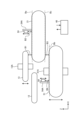
次に、錠剤印刷装置1の移動機構(第1の移動機構13A、第2の移動機構24A、第3の移動機構51A及び第4の移動機構54A)の構成例について図3を参照して説明する。
(Configuration example of the moving mechanism of the tablet printing device)
Next, a configuration example of the moving mechanisms (the first moving mechanism 13A, the second moving mechanism 24A, the third moving mechanism 51A, and the fourth moving mechanism 54A) of the tablet printing device 1 will be described with reference to FIG.

図3に示すように、本実施形態に係る錠剤印刷装置1は、第1の移動機構13Aと、第2の移動機構24Aと、第3の移動機構51Aと、第4の移動機構54Aとを備える。これらの移動機構13A、24A、51A、54Aは、制御装置40に電気的に接続されており、それらの駆動が制御装置40により制御される。 As shown in FIG. 3, the tablet printing device 1 according to this embodiment includes a first moving mechanism 13A, a second moving mechanism 24A, a third moving mechanism 51A, and a fourth moving mechanism 54A. These moving mechanisms 13A, 24A, 51A, and 54A are electrically connected to the control device 40, and their drive is controlled by the control device 40.

第1の移動機構13Aは、受渡フィーダ13を高さ方向に移動させる機構である。第2の移動機構24Aは、インクジェットヘッド24を高さ方向に移動させる機構である。第3の移動機構51Aは、搬送部51を高さ方向に移動させる機構である。第4の移動機構54Aは、インクジェットヘッド54を高さ方向に移動させる機構である。高さ方向とは昇降方向であり、図3の例ではZ軸方向である。 The first moving mechanism 13A is a mechanism that moves the delivery feeder 13 in the height direction. The second moving mechanism 24A is a mechanism that moves the inkjet head 24 in the height direction. The third moving mechanism 51A is a mechanism that moves the transport section 51 in the height direction. The fourth moving mechanism 54A is a mechanism that moves the inkjet head 54 in the height direction. The height direction is the lifting direction, which is the Z-axis direction in the example of Figure 3.

各移動機構13A、24A、51A、54Aとしては、例えば、駆動源にモータを用い、ガイドにボールねじ又はリニアガイドを用いる移動機構が用いられるが、その他の移動機構が用いられてもよい。また、各移動機構13A、24A、51A、54Aのそれぞれは、同じ構成であっても、異なる構成であってもよい。 Each of the moving mechanisms 13A, 24A, 51A, and 54A may be, for example, a moving mechanism using a motor as a drive source and a ball screw or linear guide as a guide, but other moving mechanisms may also be used. Also, each of the moving mechanisms 13A, 24A, 51A, and 54A may have the same configuration or different configurations.

搬送部21は、固定されており(移動機構が設けられていない)、本実施形態においては高さ方向の移動を行わない。図3の例では、基準高さ位置Baおよび基準高さ位置Bcは、例えば、搬送部21の高さ方向の初期位置であり、固定値である。基準高さ位置Bbは、例えば、搬送部51の高さ方向の初期位置であり、固定値である。これらの基準高さ位置Ba、基準高さ位置Bcおよび基準高さ位置Bbは、例えば、予め把握されて記憶部42に保存されている。より具体的には、基準高さ位置Baは搬送部21に最初にセットされた搬送ベルト21aの上側の搬送面の高さ位置であり、基準高さ位置Bcは搬送部21に最初にセットされた搬送ベルト21aの下側の搬送面の高さ位置であり、基準高さ位置Bbは搬送部51に最初にセットされた搬送ベルト51aの上側の搬送面の高さ位置である。基準高さ位置Ba(および基準高さ位置Bc)は、第1の基準高さ位置として機能する。基準高さ位置Bbは、第2の基準高さ位置として機能する。 The conveying unit 21 is fixed (no moving mechanism is provided) and does not move in the height direction in this embodiment. In the example of FIG. 3, the reference height position Ba and the reference height position Bc are, for example, the initial position in the height direction of the conveying unit 21 and are fixed values. The reference height position Bb is, for example, the initial position in the height direction of the conveying unit 51 and is a fixed value. These reference height positions Ba, Bc, and Bb are, for example, grasped in advance and stored in the memory unit 42. More specifically, the reference height position Ba is the height position of the upper conveying surface of the conveying belt 21a initially set in the conveying unit 21, the reference height position Bc is the height position of the lower conveying surface of the conveying belt 21a initially set in the conveying unit 21, and the reference height position Bb is the height position of the upper conveying surface of the conveying belt 51a initially set in the conveying unit 51. The reference height position Ba (and the reference height position Bc) function as the first reference height position. The reference height position Bb functions as the second reference height position.

なお、整列フィーダ12は、搬送部21と同じように固定されており(移動機構が設けられていない)、本実施形態においては高さ方向の移動を行わない。整列フィーダ12の高さ位置は、整列フィーダ12の搬送面の高さ位置が搬送部21の搬送面の高さ位置と同じになるように調整された状態で固定されている(基準高さ位置Baと一致するように調整される)。なお、受渡フィーダ13およびインクジェットヘッド24、インクジェットヘッド54にも、基準高さ位置が設定される。 The alignment feeder 12 is fixed in the same manner as the conveying unit 21 (no moving mechanism is provided), and in this embodiment does not move in the height direction. The height position of the alignment feeder 12 is fixed in a state where it is adjusted so that the height position of the conveying surface of the alignment feeder 12 is the same as the height position of the conveying surface of the conveying unit 21 (adjusted to match the reference height position Ba). Reference height positions are also set for the delivery feeder 13 and the inkjet head 24 and inkjet head 54.

受渡フィーダ13と搬送部21との高さ方向の離間距離B1は、第1の移動機構13Aにより受渡フィーダ13が高さ方向に移動することで調整される。搬送部21とインクジェットヘッド24との高さ方向の離間距離B2は、第2の移動機構24Aによりインクジェットヘッド24が高さ方向に移動することで調整される。搬送部21と搬送部51との高さ方向の離間距離B3は、第3の移動機構51Aにより搬送部51が高さ方向に移動することで調整される。搬送部51とインクジェットヘッド54との高さ方向の離間距離B4は、第4の移動機構54Aによりインクジェットヘッド54が高さ方向に移動することで調整される。例えば、第4の移動機構54Aが搬送部51に一体に設けられている場合、第4の移動機構54Aは搬送部51の移動と共に移動することになる。本実施形態においては、インクジェットヘッド54および第4の移動機構54Aは搬送部51と一体に設けられるものとして説明する。 The heightwise separation distance B1 between the delivery feeder 13 and the conveying unit 21 is adjusted by moving the delivery feeder 13 in the height direction by the first moving mechanism 13A. The heightwise separation distance B2 between the conveying unit 21 and the inkjet head 24 is adjusted by moving the inkjet head 24 in the height direction by the second moving mechanism 24A. The heightwise separation distance B3 between the conveying unit 21 and the conveying unit 51 is adjusted by moving the conveying unit 51 in the height direction by the third moving mechanism 51A. The heightwise separation distance B4 between the conveying unit 51 and the inkjet head 54 is adjusted by moving the inkjet head 54 in the height direction by the fourth moving mechanism 54A. For example, if the fourth moving mechanism 54A is integrally provided with the conveying unit 51, the fourth moving mechanism 54A will move together with the movement of the conveying unit 51. In this embodiment, the inkjet head 54 and the fourth moving mechanism 54A will be described as being integrally provided with the conveying unit 51.

詳しくは、離間距離B1は、受渡フィーダ13の下側の搬送面と搬送部21の上側の搬送面との高さ方向の離間距離である。この離間距離B1は、例えば、受渡フィーダ13と搬送部21との間で錠剤Tの受け渡しがうまくいくように調整される。離間距離B2は、搬送部21の上側の搬送面とインクジェットヘッド24の吐出面との高さ方向の離間距離である。この離間距離B2は、インクジェットヘッド24から吐出されたインクがうまく搬送部21上の錠剤Tに着弾し、また、搬送部21上の錠剤Tがインクジェットヘッド24に衝突しないように調整される。なお、気流などの影響を抑え、インクジェットヘッド24から吐出されたインクがうまく搬送部21上の錠剤Tに着弾するためには、インクジェットヘッド24の吐出面を搬送部21上の錠剤Tの上面に近づけること、すなわち離間距離B2を短くすることが望ましい。 More specifically, the separation distance B1 is the heightwise separation distance between the lower conveying surface of the delivery feeder 13 and the upper conveying surface of the conveying unit 21. This separation distance B1 is adjusted, for example, so that the transfer of tablets T between the delivery feeder 13 and the conveying unit 21 goes well. The separation distance B2 is the heightwise separation distance between the upper conveying surface of the conveying unit 21 and the ejection surface of the inkjet head 24. This separation distance B2 is adjusted so that the ink ejected from the inkjet head 24 lands well on the tablets T on the conveying unit 21 and so that the tablets T on the conveying unit 21 do not collide with the inkjet head 24. Note that, in order to suppress the influence of air currents and so that the ink ejected from the inkjet head 24 lands well on the tablets T on the conveying unit 21, it is desirable to bring the ejection surface of the inkjet head 24 closer to the upper surface of the tablets T on the conveying unit 21, i.e., to shorten the separation distance B2.

離間距離B3は、搬送部21の下側の搬送面と搬送部51の上側の搬送面との高さ方向の離間距離である。この離間距離B3は、例えば、搬送部21と搬送部51との間で錠剤Tの受け渡しがうまくいくように調整される。離間距離B4は、搬送部51の上側の搬送面とインクジェットヘッド54の吐出面との高さ方向の離間距離である。この離間距離B4は、インクジェットヘッド54から吐出されたインクがうまく搬送部51上の錠剤Tに着弾し、また、搬送部51上の錠剤Tがインクジェットヘッド54に衝突しないように調整される。なお、前述の離間距離B2と同様、離間距離B4を短くすることが望ましい。 The separation distance B3 is the heightwise separation distance between the lower conveying surface of the conveying unit 21 and the upper conveying surface of the conveying unit 51. This separation distance B3 is adjusted, for example, so that the transfer of tablets T between the conveying unit 21 and the conveying unit 51 goes smoothly. The separation distance B4 is the heightwise separation distance between the upper conveying surface of the conveying unit 51 and the ejection surface of the inkjet head 54. This separation distance B4 is adjusted so that the ink ejected from the inkjet head 54 lands smoothly on the tablets T on the conveying unit 51 and so that the tablets T on the conveying unit 51 do not collide with the inkjet head 54. As with the above-mentioned separation distance B2, it is desirable to shorten the separation distance B4.

前述の受渡フィーダ13の搬送面は、受渡フィーダ13において錠剤Tを搬送する面であって、受渡フィーダ13の下側の面(受渡フィーダ13の搬送部21側の面)である。搬送部21の搬送面は、搬送部21(搬送ベルト21a)において錠剤Tを搬送する面であって、搬送部21の上側の搬送面は、搬送部21のインクジェットヘッド24側の面であり、搬送部21の下側の搬送面は、搬送部21の搬送部51側の面である。同様に、搬送部51の搬送面は、搬送部51(搬送ベルト51a)において錠剤Tを搬送する面であって、搬送部51の上側の搬送面は、搬送部51のインクジェットヘッド54側の面である。また、インクジェットヘッド24の吐出面は、インクジェットヘッド24においてノズル24aが形成されている面であって、インクジェットヘッド24の搬送部21側の面である。同様に、インクジェットヘッド54の吐出面は、インクジェットヘッド54においてノズル(ノズル24aに相当)が形成されている面であって、インクジェットヘッド54の搬送部51側の面である。 The conveying surface of the aforementioned delivery feeder 13 is a surface that conveys the tablet T in the delivery feeder 13, and is the lower surface of the delivery feeder 13 (the surface of the delivery feeder 13 on the conveying section 21 side). The conveying surface of the conveying section 21 is a surface that conveys the tablet T in the conveying section 21 (conveyor belt 21a), and the upper conveying surface of the conveying section 21 is the surface of the conveying section 21 on the inkjet head 24 side, and the lower conveying surface of the conveying section 21 is the surface of the conveying section 51 side. Similarly, the conveying surface of the conveying section 51 is a surface that conveys the tablet T in the conveying section 51 (conveyor belt 51a), and the upper conveying surface of the conveying section 51 is the surface of the conveying section 51 on the inkjet head 54 side. In addition, the ejection surface of the inkjet head 24 is a surface on which the nozzle 24a is formed in the inkjet head 24, and is the surface of the inkjet head 24 on the conveying section 21 side. Similarly, the ejection surface of the inkjet head 54 is the surface of the inkjet head 54 on which the nozzles (corresponding to the nozzles 24a) are formed, and is the surface of the inkjet head 54 facing the transport section 51.

なお、図3の例では、搬送部21は固定されているが、搬送部51と同様に移動機構により移動可能に構成されてもよい。また、整列フィーダ12も固定されているが、受渡フィーダ13と同様に移動機構により移動可能に構成されてもよい。ただし、整列フィーダ12、受渡フィーダ13、搬送部21及び搬送部51のいずれかが固定されることが望ましい。本実施形態のようにZ方向における中央に位置する搬送部21と整列フィーダ12が固定される場合、高さ位置の調整においてはその上下に位置する受渡フィーダ13および搬送部51を移動させればよく、受渡フィーダ13のみが固定されている場合、あるいは搬送部51のみが固定されている場合と比較すると移動すべき部材が少ないため好適である。また、例えば、移動機構の簡略化やサイズ抑制のためには、整列フィーダ12又は受渡フィーダ13が固定される場合に比べ、吸引管を介してポンプが接続される吸引チャンバ21fを含む搬送部21又は吸引チャンバ51fを含む搬送部51が固定されることが望ましい。つまり、搬送部21または搬送部51のいずれかを固定とすることが望ましく、なかでもZ方向において中央に位置する搬送部21を固定することがより望ましい。 3, the conveying unit 21 is fixed, but may be configured to be movable by a moving mechanism like the conveying unit 51. The alignment feeder 12 is also fixed, but may be configured to be movable by a moving mechanism like the delivery feeder 13. However, it is preferable that any of the alignment feeder 12, the delivery feeder 13, the conveying unit 21, and the conveying unit 51 is fixed. When the conveying unit 21 and the alignment feeder 12 located at the center in the Z direction are fixed as in this embodiment, the delivery feeder 13 and the conveying unit 51 located above and below them can be moved to adjust the height position, which is preferable because there are fewer members to be moved compared to when only the delivery feeder 13 is fixed or when only the conveying unit 51 is fixed. In addition, for example, in order to simplify the moving mechanism and reduce the size, it is preferable that the conveying unit 21 including the suction chamber 21f to which the pump is connected via a suction pipe or the conveying unit 51 including the suction chamber 51f is fixed, compared to when the alignment feeder 12 or the delivery feeder 13 is fixed. In other words, it is preferable to fix either the conveying unit 21 or the conveying unit 51, and it is even more preferable to fix the conveying unit 21, which is located in the center in the Z direction.

また、図3の例では、インクジェットヘッド24は、第2の移動機構24Aにより高さ方向に移動可能に構成されているが、例えば、検出部22、第1の撮像部23、インクジェットヘッド24及び第2の撮像部25(図1参照)が筐体などに内蔵されている場合には、その筐体が第2の移動機構24Aにより高さ方向に移動可能に構成されてもよい。このような構成は、インクジェットヘッド54にも適用可能である。 In the example of FIG. 3, the inkjet head 24 is configured to be movable in the height direction by the second moving mechanism 24A, but for example, if the detection unit 22, the first imaging unit 23, the inkjet head 24, and the second imaging unit 25 (see FIG. 1) are built into a housing or the like, the housing may be configured to be movable in the height direction by the second moving mechanism 24A. Such a configuration can also be applied to the inkjet head 54.

(制御装置の構成例)
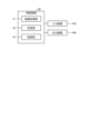
次に、制御装置40の構成例について図4を参照して説明する。
(Example of control device configuration)
Next, an example of the configuration of the control device 40 will be described with reference to FIG.

図4に示すように、制御装置40は、画像処理部41と、記憶部42と、制御部43とを有する。この制御装置40には、入力装置40a及び出力装置40bが接続されている。入力装置40aは、例えば、スイッチやタッチパネル、キーボード、マウスなどにより実現される。また、出力装置40bは、例えば、ディスプレイやランプ、メータなどにより実現される。 As shown in FIG. 4, the control device 40 has an image processing unit 41, a storage unit 42, and a control unit 43. An input device 40a and an output device 40b are connected to the control device 40. The input device 40a is realized, for example, by a switch, a touch panel, a keyboard, a mouse, etc. The output device 40b is realized, for example, by a display, a lamp, a meter, etc.

画像処理部41は、第1の撮像部23又は第1の撮像部53により撮像された第1の画像及び第2の撮像部25又は第2の撮像部55によって撮像された第2の画像を取り込み、公知の画像処理技術を用いて画像を処理する。例えば、画像処理部41は、第1の撮像部23から得られた第1の画像を処理し、錠剤Tの損傷や異物付着の有無、また、錠剤TのX方向、Y方向及びθ方向の位置を取得する。また、画像処理部41は、第2の撮像部25から得られた第2の画像を処理し、錠剤Tに印刷された印刷パターンの画像情報を取得する。画像処理部41は、取得した錠剤Tの損傷や異物付着の有無情報、各錠剤TのX方向、Y方向及びθ方向の位置情報、さらに、各錠剤Tに印刷された印刷パターンの画像情報を制御部43に送信する。 The image processing unit 41 captures the first image captured by the first imaging unit 23 or the first imaging unit 53 and the second image captured by the second imaging unit 25 or the second imaging unit 55, and processes the images using a known image processing technique. For example, the image processing unit 41 processes the first image obtained from the first imaging unit 23 to obtain information on the presence or absence of damage or foreign matter adhering to the tablet T, as well as the positions of the tablet T in the X direction, Y direction, and θ direction. The image processing unit 41 also processes the second image obtained from the second imaging unit 25 to obtain image information on the printed pattern printed on the tablet T. The image processing unit 41 transmits the obtained information on the presence or absence of damage or foreign matter adhering to the tablet T, the position information of each tablet T in the X direction, Y direction, and θ direction, and the image information of the printed pattern printed on each tablet T to the control unit 43.

記憶部42は、各種プログラムや各種情報などを記憶する。この記憶部42は、例えば、RAM(Random Access Memory)、フラッシュメモリ(Flash Memory)等の半導体メモリ素子、または、ハードディスク、光ディスクなどの記憶装置によって実現される。記憶部42には、生産データ(生産情報)、印刷に関する印刷データ、搬送速度データなどが記憶される。生産データとは、印刷された錠剤Tの生産(製造)に伴い、変わるデータのことを指す。生産データとしては、例えば、ロット番号が挙げられる。生産データは、ユーザが入力装置40aを用いて入力した情報に基づいて生成されてもよく、また、制御部43によって自動的に生成されてもよい。 The memory unit 42 stores various programs and various information. The memory unit 42 is realized by, for example, a semiconductor memory element such as a RAM (Random Access Memory) or a flash memory, or a storage device such as a hard disk or an optical disk. The memory unit 42 stores production data (production information), print data related to printing, conveying speed data, and the like. Production data refers to data that changes with the production (manufacturing) of the printed tablets T. An example of the production data is a lot number. The production data may be generated based on information input by the user using the input device 40a, or may be automatically generated by the control unit 43.

制御部43は、例えば、CPU(Central Processing Unit)やMCU(Micro Control Unit)、MPU(Micro Processing Unit)などのコンピュータであり、各部を制御する。この制御部43は、例えば、ハードウェア及びソフトウェアの一方又は両方により実現されてもよい。例えば、制御部43は、記憶部42に記憶された各種情報や各種プログラムに基づいて、供給装置10や第1の印刷装置20、第2の印刷装置50、回収装置30、画像処理部41、記憶部42、各移動機構13A、24A、51A、54Aなどを制御する。また、制御部43は、搬送部21の位置検出器21eや検出部22、搬送部51の位置検出器51eや検出部52からそれぞれ送信される検出信号などを受信する。 The control unit 43 is, for example, a computer such as a CPU (Central Processing Unit), MCU (Micro Control Unit), or MPU (Micro Processing Unit), and controls each unit. The control unit 43 may be realized, for example, by one or both of hardware and software. For example, the control unit 43 controls the supply device 10, the first printing device 20, the second printing device 50, the collection device 30, the image processing unit 41, the memory unit 42, and each of the moving mechanisms 13A, 24A, 51A, and 54A based on various information and various programs stored in the memory unit 42. The control unit 43 also receives detection signals transmitted from the position detector 21e and the detection unit 22 of the conveying unit 21, and the position detector 51e and the detection unit 52 of the conveying unit 51.

ここで、制御部43は、第1の印刷装置20において、検出部22から送信された検出情報、すなわち搬送ベルト21a上の錠剤Tが検出されたタイミングに基づき、搬送ベルト21aにおいて錠剤Tの搬送方向A1の位置を取得し、この錠剤Tの搬送方向A1の位置を示す位置情報に基づき、第1の撮像部23の第1の撮像タイミング、インクジェットヘッド24の印刷開始タイミング、第2の撮像部25の第2の撮像タイミングを設定し、それらのタイミングを示すタイミング情報を生成して記憶部42に保存する。印刷開始タイミングとは、インクジェットヘッド24の直下の印刷位置に到達した錠剤Tに対して印刷を開始するタイミングである。なお、制御部43は、位置検出器21eから送信された検出情報に基づき、搬送ベルト21aの移動量(回転量)や速度などの情報を取得することが可能である。 Here, the control unit 43 acquires the position of the tablet T in the conveying direction A1 on the conveying belt 21a based on the detection information transmitted from the detection unit 22 in the first printing device 20, i.e., the timing at which the tablet T on the conveying belt 21a is detected, and based on the position information indicating the position of the tablet T in the conveying direction A1, sets the first imaging timing of the first imaging unit 23, the print start timing of the inkjet head 24, and the second imaging timing of the second imaging unit 25, generates timing information indicating these timings, and stores it in the memory unit 42. The print start timing is the timing at which printing starts on the tablet T that has reached the printing position directly below the inkjet head 24. The control unit 43 can acquire information such as the movement amount (rotation amount) and speed of the conveying belt 21a based on the detection information transmitted from the position detector 21e.

また、制御部43は、第1の印刷装置20において、画像処理部41から送信された錠剤Tの損傷や異物付着の有無情報(この情報は第1の画像に基づく情報である)に基づいて、その結果データが得られた錠剤Tに対する印刷可否を印刷可否情報として設定する。そして、制御部43は、印刷可に設定された錠剤Tに対して印刷条件を印刷条件情報として設定する。このとき、制御部43は、画像処理部41から送信された錠剤TのX方向、Y方向及びθ方向の位置情報(この情報は第1の画像に基づく情報である)に基づいて、その位置情報が得られた錠剤Tに対して印刷条件を設定する。 In addition, in the first printing device 20, the control unit 43 sets printability information for the tablets T for which the result data has been obtained, based on the information on the presence or absence of damage or foreign matter on the tablets T transmitted from the image processing unit 41 (this information is based on the first image). Then, the control unit 43 sets printing conditions as printing condition information for the tablets T for which printability has been set. At this time, the control unit 43 sets printing conditions for the tablets T for which position information has been obtained, based on the position information in the X direction, Y direction, and θ direction of the tablets T transmitted from the image processing unit 41 (this information is based on the first image).

例えば、制御部43は、第1の印刷装置20において、印刷パターンに基づいてインクジェットヘッド24を制御するための印刷条件を設定する。具体的には、制御部43が、錠剤TのY方向の位置情報や印刷パターンに基づいて、インクジェットヘッド24において対象の錠剤Tの印刷に使用するノズル24aの範囲、すなわち使用ノズル範囲を決定し、その使用ノズル範囲や印刷開始タイミングなどを含む印刷条件を設定する。なお、錠剤Tが方向性を有する形状である場合、制御部43は、錠剤Tのθ方向の位置情報に基づいて、錠剤Tのθ方向の位置に対応させて印刷条件を設定する。一例として、制御部43は、印刷パターンの向きを0度から179度の範囲で1度ずつ回転させた180通りの印刷パターンを記憶部42に登録しておき、それらの印刷パターンの中から、錠剤Tのθ方向の位置に適合する角度の印刷パターンを選択して印刷条件を設定する。 For example, the control unit 43 sets printing conditions for controlling the inkjet head 24 based on the printing pattern in the first printing device 20. Specifically, the control unit 43 determines the range of the nozzles 24a to be used for printing the target tablet T in the inkjet head 24, i.e., the nozzle range to be used, based on the position information of the tablet T in the Y direction and the printing pattern, and sets printing conditions including the nozzle range to be used and the printing start timing. In addition, if the tablet T has a directional shape, the control unit 43 sets printing conditions corresponding to the position of the tablet T in the θ direction based on the position information of the tablet T in the θ direction. As an example, the control unit 43 registers 180 printing patterns in the memory unit 42, in which the orientation of the printing pattern is rotated by 1 degree in the range from 0 degrees to 179 degrees, and selects a printing pattern with an angle that matches the position of the tablet T in the θ direction from among the printing patterns, and sets the printing conditions.

また、制御部43は、第1の印刷装置20において、画像処理部41から送信された、錠剤Tに印刷された印刷パターンの印刷位置情報、形状情報及びサイズ情報(これらの情報は第2の画像に基づく情報である)に基づいて、印刷パターンが所定形状及び所定サイズで錠剤Tの所定位置に印刷されたか否か、すなわち印刷パターンが錠剤Tに正常に印刷されたか否かを判断し、錠剤Tの印刷良否情報を設定する(印刷状態検査)。例えば、制御部43は、印刷パターンの形状及びサイズ判断において、検査用の印刷パターンを記憶部42に登録しておき、その検査用の印刷パターンと実際の印刷後の錠剤T上の印刷パターン(錠剤Tに印刷された印刷パターン)とを比較する。 In addition, the control unit 43 in the first printing device 20 determines whether the printing pattern has been printed in a predetermined shape and size at a predetermined position on the tablet T, i.e., whether the printing pattern has been printed normally on the tablet T, based on the printing position information, shape information, and size information of the printing pattern printed on the tablet T (this information is based on the second image) transmitted from the image processing unit 41, and sets the printing quality information of the tablet T (printing status inspection). For example, in determining the shape and size of the printing pattern, the control unit 43 registers a printing pattern for inspection in the memory unit 42, and compares the printing pattern for inspection with the printing pattern on the tablet T after actual printing (the printing pattern printed on the tablet T).

その後、制御部43は、検査用の印刷パターンと実際の印刷後の錠剤T上の印刷パターンとが許容範囲内で一致すると判定した場合、錠剤Tの印刷結果が良い(合格)と判断する。一方、制御部43は、検査用の印刷パターンと実際の印刷後の錠剤T上の印刷パターンとが許容範囲内で一致しないと判定した場合、錠剤Tの印刷結果が悪い(不合格)と判断する。印刷結果が悪いと判断された錠剤Tは、不良品回収部32(不良排出装置)によって排出される。 Then, if the control unit 43 determines that the printing pattern for inspection and the printing pattern on the tablet T after actual printing match within the tolerance range, it determines that the printing result of the tablet T is good (passes). On the other hand, if the control unit 43 determines that the printing pattern for inspection and the printing pattern on the tablet T after actual printing do not match within the tolerance range, it determines that the printing result of the tablet T is bad (fails). Tablets T that are determined to have a bad printing result are ejected by the defective product collection unit 32 (defective product ejection device).

前述のような第1の印刷装置20における各種処理は、第2の印刷装置50でも同様に制御部43により実行される。なお、制御部43は、適宜各種情報(例えば、錠剤Tの位置情報、タイミング情報、印刷可否情報、印刷条件情報、印刷良否情報など)を記憶部42に保存するが、対象の錠剤Tが回収装置30により回収されると、例えば、搬送部51における搬送方向A2の下流側の端部から落下して所定時間(例えば数秒)が経過した時点で、記憶部42から各種情報を削除する。ただし、それらの情報が後工程などで必要となる場合には、錠剤Tごとの各種情報を消去せずに残しておいたり、装置外の保存用メディア(外部ストレージ)に保存しておいたりすることも可能である。錠剤Tごとの各種情報を保存しておく場合には、この情報と製造日時やロット番号などと紐づけて保存しておき、印刷後の錠剤Tについて出荷後に不良品が発生した場合などに遡って原因を追及することができるようにしてもよい。 The various processes in the first printing device 20 as described above are also executed by the control unit 43 in the second printing device 50. The control unit 43 appropriately stores various information (e.g., position information of the tablet T, timing information, printability information, printing condition information, print quality information, etc.) in the storage unit 42. When the target tablet T is collected by the collection device 30, for example, when it falls from the downstream end of the conveying unit 51 in the conveying direction A2 and a predetermined time (e.g., several seconds) has passed, the various information is deleted from the storage unit 42. However, if such information is required in a later process, it is possible to leave the various information for each tablet T without erasing it, or to store it in a storage medium (external storage) outside the device. When storing the various information for each tablet T, this information may be linked to the manufacturing date and time, lot number, etc. and stored, so that when a defective product occurs after shipping of the printed tablet T, the cause can be traced back.

(位置調整工程)
次に、前述の錠剤印刷装置1が行う位置調整工程について図5を参照して説明する。この位置調整工程が実行された後に、印刷工程(検査工程を含む)が実行される。なお、位置調整や印刷、検査に要するデータなどの各種情報は、記憶部42に予め記憶されている。
(Position adjustment process)
Next, the position adjustment process performed by the tablet printing device 1 will be described with reference to Fig. 5. After this position adjustment process is performed, the printing process (including the inspection process) is performed. Note that various information such as data required for position adjustment, printing, and inspection is stored in the storage unit 42 in advance.

位置調整工程は、搬送部21の搬送ベルト21a及び搬送部51の搬送ベルト51aのどちらか一方又は両方がユーザにより交換された場合に実行される。例えば、ユーザは、搬送ベルト21a及び搬送ベルト51aのどちらか一方又は両方を交換し、入力装置40aを入力操作して位置調整工程を実行する旨を制御部43に指示する。なお、通常、搬送ベルトの厚さには個体差があるため、交換前後の搬送ベルトの厚さは±1mm程度異なることが多い。 The position adjustment process is executed when either or both of the conveyor belt 21a of the conveyor unit 21 and the conveyor belt 51a of the conveyor unit 51 are replaced by the user. For example, the user replaces either or both of the conveyor belt 21a and the conveyor belt 51a, and instructs the control unit 43 to execute the position adjustment process by inputting information into the input device 40a. Note that, since there are individual differences in the thickness of conveyor belts, the thickness of the conveyor belt before and after replacement often differs by about ±1 mm.

ここから、入力装置40aを介して入力された情報に基づき、制御部43が実行する内容を説明する。 From here, we will explain what the control unit 43 executes based on the information input via the input device 40a.

図5に示すように、ステップS11において、制御部43は、検出部22により搬送ベルト21aの厚み変化を測定し、検出部52により搬送ベルト51aの厚み変化を測定する。例えば、検出部22は、搬送ベルト21aの一周分の搬送面の高さ変化を検出することで、搬送ベルト21aの一周分の厚み変化を測定する。同様に、検出部52は、搬送ベルト51aの一周分の搬送面の高さ変化を検出することで、搬送ベルト51aの一周分の厚み変化を測定する。このような測定のため、搬送ベルト21a及び搬送ベルト51aが少なくとも一周分回転する間、検出部22は搬送ベルト21aの搬送面の高さを検出し、検出部52は搬送ベルト51aの搬送面の高さを検出する。 As shown in FIG. 5, in step S11, the control unit 43 measures the thickness change of the conveyor belt 21a by the detection unit 22, and measures the thickness change of the conveyor belt 51a by the detection unit 52. For example, the detection unit 22 measures the thickness change of one revolution of the conveyor belt 21a by detecting the height change of the conveying surface of one revolution of the conveyor belt 21a. Similarly, the detection unit 52 measures the thickness change of one revolution of the conveyor belt 51a by detecting the height change of the conveying surface of one revolution of the conveyor belt 51a. For such measurements, while the conveyor belt 21a and the conveyor belt 51a rotate for at least one revolution, the detection unit 22 detects the height of the conveying surface of the conveyor belt 21a, and the detection unit 52 detects the height of the conveying surface of the conveyor belt 51a.

なお、搬送ベルト21a又は搬送ベルト51aにおいて、一周分の搬送面の高さ変化を検出しなくてもよく、例えば、数か所や一か所の搬送面の高さを検出するようにしてもよい。ただし、検出箇所が多いほど、測定精度は向上する。また、搬送ベルト21aおよび搬送ベルト51aのうち、交換を行ったベルトについてのみ、検出部22または検出部52による厚み変化を測定すればよい。また、基準高さ位置Ba、基準高さ位置Bcおよび基準高さ位置Bbについては予め同様の方法で測定され、記憶部42に保存されている。 It is not necessary to detect the height change of the conveying surface of the conveying belt 21a or the conveying belt 51a for one revolution. For example, the height of the conveying surface may be detected at several locations or at one location. However, the more detection locations there are, the higher the measurement accuracy. Also, it is sufficient to measure the thickness change by the detection unit 22 or the detection unit 52 only for the belt that has been replaced among the conveying belts 21a and 51a. Also, the reference height position Ba, the reference height position Bc, and the reference height position Bb are measured in advance by a similar method and stored in the memory unit 42.

検出部22は、例えば、レーザセンサである。レーザセンサは、投光部分から搬送ベルト21aの搬送面までの距離を検出し、順次検出値(検出信号)を出力している。レーザセンサは、その検出値の変化により錠剤Tの到来を検知するセンサとして機能するが、ステップS11では、搬送ベルト21aの搬送面の高さを検出するセンサとして機能する。これは、検出部52も同様である。位置調整工程では、錠剤Tがホッパ11に供給される前に、すなわち、ホッパ11が空である状態で、検出部22及び検出部52は、ON状態にされ、搬送ベルト21a及び搬送ベルト51aの個々の搬送面の高さ位置を計測するために用いられる。 The detection unit 22 is, for example, a laser sensor. The laser sensor detects the distance from the light projecting portion to the conveying surface of the conveyor belt 21a and sequentially outputs detection values (detection signals). The laser sensor functions as a sensor that detects the arrival of tablets T by changes in the detection value, but in step S11, it functions as a sensor that detects the height of the conveying surface of the conveyor belt 21a. This is also the case with the detection unit 52. In the position adjustment process, before tablets T are supplied to the hopper 11, i.e., when the hopper 11 is empty, the detection units 22 and 52 are turned on and are used to measure the height positions of the individual conveying surfaces of the conveyor belt 21a and the conveyor belt 51a.

なお、ホッパ11と整列フィーダ12との間に錠剤Tの通過を妨げるシャッターなどの機構を設け、錠剤Tが整列フィーダ12以降に供給されないようにした状態で、検出部22及び検出部52による高さ位置の測定を行うようにしてもよい。要するに、搬送ベルト21a及び搬送ベルト51aの、検出部22及び検出部52による検出対象領域に錠剤Tが存在しない状態で、検出部22及び検出部52による高さ位置の計測が行われればよい。 In addition, a mechanism such as a shutter that prevents the passage of tablets T between the hopper 11 and the alignment feeder 12 may be provided to prevent tablets T from being fed beyond the alignment feeder 12, and the height position may be measured by the detection unit 22 and the detection unit 52 in this state. In short, the height position may be measured by the detection unit 22 and the detection unit 52 in a state in which tablets T are not present in the detection target area of the conveyor belt 21a and the conveyor belt 51a that is detected by the detection unit 22 and the detection unit 52.

ステップS12において、制御部43は、搬送ベルト21a及び搬送ベルト51aのそれぞれ一周分の厚み変化(搬送面の一周分の高さ変化)に関する情報を用いて、補正値C1及び補正値C2を算出する。補正値C1は第1の補正値として機能し、補正値C2は第1の補正値又は第3の補正値として機能する。 In step S12, the control unit 43 calculates the correction value C1 and the correction value C2 using information on the thickness change (height change of the conveying surface for one revolution) of each of the conveying belts 21a and 51a. The correction value C1 functions as the first correction value, and the correction value C2 functions as the first correction value or the third correction value.

補正値C1は、受渡フィーダ13と搬送部21との高さ方向の離間距離B1、搬送部21とインクジェットヘッド24との高さ方向の離間距離B2、搬送部21と搬送部51との高さ方向の離間距離B3、及び、搬送部51とインクジェットヘッド54との高さ方向の離間距離B4を調整するための補正値である。また、補正値C2は、搬送部21と搬送部51との高さ方向の離間距離B3、及び、搬送部51とインクジェットヘッド54との高さ方向の離間距離B4を調整するための補正値である。 The correction value C1 is a correction value for adjusting the height distance B1 between the delivery feeder 13 and the conveying unit 21, the height distance B2 between the conveying unit 21 and the inkjet head 24, the height distance B3 between the conveying unit 21 and the conveying unit 51, and the height distance B4 between the conveying unit 51 and the inkjet head 54. The correction value C2 is also a correction value for adjusting the height distance B3 between the conveying unit 21 and the conveying unit 51, and the height distance B4 between the conveying unit 51 and the inkjet head 54.

例えば、制御部43は、搬送ベルト21aの一周分の厚み変化(搬送面の一周分の高さ変化)に関する情報を用い、搬送ベルト21aの一周分の厚みを平均して平均値を求め、求めた平均値に基づいて搬送ベルト21aの高さ位置(搬送部21の高さ位置)を算出する。そして、制御部43は、搬送ベルト21aの高さ位置と基準高さ位置Baとの比較を行い、搬送ベルト21aの高さ位置と基準高さ位置Baとの差分を基に補正値C1を算出する。搬送ベルト21aの高さ位置は基準高さ位置Baに対して増加するとプラスであり、減少するとマイナスである。補正値がプラスの場合には、基準高さ位置Ba(基準高さ位置Bb)から上方への移動を行い、補正値がマイナスの場合には、基準高さ位置Ba(基準高さ位置Bb)から下方への移動を行う。なお、搬送ベルト21aの実際の高さ位置と基準高さ位置Baとの差分を補正値C1として用いるようにしてもよい。 For example, the control unit 43 uses information on the thickness change of the conveyor belt 21a over one revolution (height change over one revolution of the conveying surface), averages the thickness of the conveyor belt 21a over one revolution to obtain an average value, and calculates the height position of the conveyor belt 21a (height position of the conveyor unit 21) based on the obtained average value. Then, the control unit 43 compares the height position of the conveyor belt 21a with the reference height position Ba, and calculates a correction value C1 based on the difference between the height position of the conveyor belt 21a and the reference height position Ba. If the height position of the conveyor belt 21a increases with respect to the reference height position Ba, it is positive, and if it decreases, it is negative. If the correction value is positive, the conveyor belt 21a moves upward from the reference height position Ba (reference height position Bb), and if the correction value is negative, the conveyor belt 21a moves downward from the reference height position Ba (reference height position Bb). Note that the difference between the actual height position of the conveyor belt 21a and the reference height position Ba may be used as the correction value C1.

また、例えば、制御部43は、搬送ベルト51aの一周分の厚み変化(搬送面の一周分の高さ変化)に関する情報を用い、搬送ベルト51aの一周分の厚みを平均して平均値を求め、求めた平均値に基づいて搬送ベルト51aの高さ位置(搬送部51の高さ位置)を算出する。そして、制御部43は、搬送ベルト51aの高さ位置と基準高さ位置Bbとの比較を行い、搬送ベルト51aの高さ位置と基準高さ位置Bbとの差分を基に補正値C2を算出する。搬送ベルト51aの高さ位置は基準高さ位置Bbに対して増加するとプラスであり、減少するとマイナスである。補正値C1および補正値C2は、求めた差分に基づいて、補正値C1、補正値C2の値のプラス、マイナスが適切に(動かす必要のある方向に応じて)変換され、適用される(詳しくは後述する)。なお、搬送ベルト51aの実際の高さ位置と基準高さ位置Bbとの差分を補正値C2として用いるようにしてもよい。 For example, the control unit 43 uses information about the thickness change of the conveyor belt 51a over one revolution (height change over one revolution of the conveyor surface), averages the thickness of the conveyor belt 51a over one revolution to obtain an average value, and calculates the height position of the conveyor belt 51a (height position of the conveyor unit 51) based on the obtained average value. Then, the control unit 43 compares the height position of the conveyor belt 51a with the reference height position Bb, and calculates a correction value C2 based on the difference between the height position of the conveyor belt 51a and the reference height position Bb. If the height position of the conveyor belt 51a increases with respect to the reference height position Bb, it is positive, and if it decreases, it is negative. The correction values C1 and C2 are appropriately converted (depending on the direction in which the belt needs to be moved) and applied based on the obtained difference (described in detail later). The difference between the actual height position of the conveyor belt 51a and the reference height position Bb may be used as the correction value C2.

また、搬送ベルト21a及び搬送ベルト51aのどちらか一方又は両方の交換前には、例えば、搬送部21の高さ位置、すなわち搬送ベルト21aの上側の搬送面の高さ位置は基準高さ位置Baとして予め把握されて記憶部42に保存されており、搬送ベルト21aの下側の搬送面の高さ位置は基準高さ位置Bcとして予め把握されて記憶部42に保存されている。同様に、搬送部51の高さ位置、すなわち搬送部51の上側の搬送面の高さ位置は、基準高さ位置Bbとして予め把握されて記憶部42に保存されている。 In addition, before replacing either or both of the conveying belts 21a and 51a, for example, the height position of the conveying unit 21, i.e., the height position of the upper conveying surface of the conveying belt 21a, is grasped in advance as the reference height position Ba and stored in the memory unit 42, and the height position of the lower conveying surface of the conveying belt 21a is grasped in advance as the reference height position Bc and stored in the memory unit 42. Similarly, the height position of the conveying unit 51, i.e., the height position of the upper conveying surface of the conveying unit 51, is grasped in advance as the reference height position Bb and stored in the memory unit 42.

ステップS13において、制御部43は、算出した補正値C1及び補正値C2を記憶部42に保存する。 In step S13, the control unit 43 stores the calculated correction values C1 and C2 in the memory unit 42.

ステップS14において、制御部43は、これから印刷する錠剤Tの品種情報、すなわち錠剤品種情報を選択し、補正値D1を求める。補正値D1は、第2の補正値として機能する。 In step S14, the control unit 43 selects the type information of the tablet T to be printed, i.e., the tablet type information, and calculates the correction value D1. The correction value D1 functions as a second correction value.

補正値D1は、受渡フィーダ13と搬送部21との高さ方向の離間距離B1、搬送部21とインクジェットヘッド24との高さ方向の離間距離B2、搬送部21と搬送部51との高さ方向の離間距離B3、及び、搬送部51とインクジェットヘッド54との高さ方向の離間距離B4を調整するための補正値である。この補正値D1は、各離間距離B1~B4を錠剤Tの品種にとって最適なものとするための値である。 The correction value D1 is a correction value for adjusting the height distance B1 between the delivery feeder 13 and the conveying unit 21, the height distance B2 between the conveying unit 21 and the inkjet head 24, the height distance B3 between the conveying unit 21 and the conveying unit 51, and the height distance B4 between the conveying unit 51 and the inkjet head 54. This correction value D1 is a value for optimizing each of the distances B1 to B4 for the type of tablet T.

例えば、制御部43は、入力装置40aに対するユーザの入力操作に応じて錠剤品種情報を選択する。錠剤品種情報は、例えば、錠剤識別情報、錠剤厚み情報及び錠剤形状情報のいずれか又は全てを含む。錠剤識別情報は、例えば、錠剤Tの名称及び番号の一方又は両方を含む。錠剤厚み情報は、例えば、数mmなどの錠剤Tの厚みの情報を含む。錠剤形状情報は、例えば、円板や三角板、楕円板、紡錘形、レンズ形などの錠剤Tの形状の情報を含む。このような錠剤品種情報は、例えば、予め記憶部42に保存されている。 For example, the control unit 43 selects tablet variety information in response to an input operation by a user on the input device 40a. The tablet variety information includes, for example, any or all of tablet identification information, tablet thickness information, and tablet shape information. The tablet identification information includes, for example, one or both of the name and number of the tablet T. The tablet thickness information includes, for example, information on the thickness of the tablet T, such as a few mm. The tablet shape information includes, for example, information on the shape of the tablet T, such as a disk, triangular plate, oval plate, spindle shape, lens shape, etc. Such tablet variety information is, for example, stored in advance in the memory unit 42.

なお、制御部43は、外部装置から送信された、次に生産する錠剤品種情報を受け取ることで、錠剤品種情報を選択してもよい。外部装置としては、例えば、パーソナルコンピュータやサーバなどが用いられ、また、バーコードリーダが用いられる。バーコードリーダは、例えば、錠剤Tが収容されているボトルに貼り付けられたバーコードから錠剤品種情報を読み取る。 The control unit 43 may select tablet variety information by receiving information on the next tablet variety to be produced, transmitted from an external device. The external device may be, for example, a personal computer or a server, or a barcode reader. The barcode reader reads tablet variety information from, for example, a barcode affixed to a bottle containing the tablets T.

次に、制御部43は、選択された錠剤品種情報に基づいて、図6に示すような補正テーブルT1から補正値D1を求める。この補正テーブルT1は、例えば、記憶部42に予め保存されている。図6の例では、補正テーブルT1は、錠剤品種情報ごとに補正値D1を有している。錠剤品種情報としてはa1、b1及びc1・・・があり、補正値D1としてはa2、b2、c2・・・がある。この補正値D1は、錠剤Tの品種によって最適な条件となるように設定されている。a1、b1及びc1・・・のそれぞれは、例えば、錠剤識別情報、錠剤厚み情報及び錠剤形状情報のいずれか又は全てを含む。つまり、補正値D1は、識別情報ごとに設定されていても、錠剤厚み情報ごとに設定されていても、錠剤形状情報ごとに設定されていてもよく、また、それらの錠剤識別情報、錠剤厚み情報及び錠剤形状情報のいずれか二つ又は全てを含む情報ごとに設定されていてもよい。 Next, the control unit 43 obtains a correction value D1 from a correction table T1 as shown in FIG. 6 based on the selected tablet variety information. This correction table T1 is, for example, stored in advance in the storage unit 42. In the example of FIG. 6, the correction table T1 has a correction value D1 for each tablet variety information. Tablet variety information includes a1, b1, and c1, and correction values D1 include a2, b2, c2, and so on. This correction value D1 is set so as to be the optimal condition depending on the variety of tablet T. Each of a1, b1, and c1 includes, for example, any one or all of tablet identification information, tablet thickness information, and tablet shape information. In other words, the correction value D1 may be set for each identification information, tablet thickness information, or tablet shape information, and may be set for information including any two or all of the tablet identification information, tablet thickness information, and tablet shape information.

錠剤Tは、品種によって厚みが異なる。また、厚みのばらつきも異なる。例えば、錠剤Tが糖衣錠である場合には、その厚みには±0.5mmの差が生じる。搬送ベルト21a上の錠剤Tの上面からインクジェットヘッド24の吐出面までの距離は約1~1.5mm程度であるため、錠剤Tが厚みの個体差が大きい品種の錠剤である場合、搬送ベルト21aとインクジェットヘッド24との高さ方向の離間距離B2は、錠剤Tが厚みの個体差の小さい品種の錠剤である場合よりも大きく設定される必要がある。これは、錠剤Tが厚みの個体差が大きい品種の錠剤である場合、搬送ベルト21aとインクジェットヘッド24との高さ方向の離間距離B2が、錠剤Tが厚みの個体差の小さい品種の錠剤である場合と同様に設定されると、錠剤Tがインクジェットヘッド24に衝突する恐れがあるためである。このようなことが考慮され、補正値D1は、錠剤Tの品種によって最適な条件となるように設定されている。 The thickness of the tablet T varies depending on the type. The thickness also varies. For example, when the tablet T is a sugar-coated tablet, the thickness varies by ±0.5 mm. Since the distance from the upper surface of the tablet T on the conveyor belt 21a to the discharge surface of the inkjet head 24 is about 1 to 1.5 mm, when the tablet T is a type of tablet with a large individual difference in thickness, the heightwise separation distance B2 between the conveyor belt 21a and the inkjet head 24 needs to be set larger than when the tablet T is a type of tablet with a small individual difference in thickness. This is because when the tablet T is a type of tablet with a large individual difference in thickness, if the heightwise separation distance B2 between the conveyor belt 21a and the inkjet head 24 is set in the same way as when the tablet T is a type of tablet with a small individual difference in thickness, the tablet T may collide with the inkjet head 24. Taking this into consideration, the correction value D1 is set to be the optimal condition depending on the type of tablet T.

また、錠剤Tの品種の差には厚みの差のみならず、形状の差もある。平錠と呼ばれる扁平な錠剤Tや、糖衣錠のように搬送ベルト21aに接する面にアールを有する錠剤Tが存在し、様々な形状の錠剤Tがある。アールを有する錠剤Tは、受渡フィーダ13と搬送部21との高さ方向の離間距離B1、あるいは、搬送部21と搬送部51との高さ方向の離間距離B3を狭くしすぎると、錠剤Tの曲面が上下から強く挟み込まれた結果、錠剤Tが揺れ、錠剤Tの姿勢が変更されたり、錠剤Tが揺れ続けたりする。これは印刷不良につながる。このようなことが考慮され、補正値D1は、錠剤Tの品種によって最適な条件となるように設定されている。 In addition, the differences in types of tablets T include not only differences in thickness but also differences in shape. There are flat tablets T called flat tablets, and tablets T with a curved surface that contacts the conveyor belt 21a, such as sugar-coated tablets, and there are tablets T of various shapes. For tablets T with a curve, if the vertical separation distance B1 between the delivery feeder 13 and the conveyor unit 21, or the vertical separation distance B3 between the conveyor unit 21 and the conveyor unit 51, is made too narrow, the curved surface of the tablet T is pinched tightly from above and below, causing the tablet T to shake, change its position, or continue to shake. This leads to printing defects. Taking these factors into consideration, the correction value D1 is set to provide optimal conditions for the type of tablet T.

ステップS15において、制御部43は、求めた補正値D1を記憶部42に保存する。 In step S15, the control unit 43 stores the calculated correction value D1 in the memory unit 42.

ステップS16において、制御部43は、記憶部42に保存された補正値C1及び補正値D1に基づき、受渡フィーダ13及びインクジェットヘッド24のそれぞれの適切な高さ位置を算出し、記憶部42に保存された補正値C1、補正値C2及び補正値D1に基づき、搬送部51の適切な高さ位置を算出する。なお、本実施形態では、移動機構54Aが搬送部51に固定されているため、インクジェットヘッド54の高さ位置の調整においては、補正値C1を用いない。 In step S16, the control unit 43 calculates the appropriate height positions of the transfer feeder 13 and the inkjet head 24 based on the correction values C1 and D1 stored in the memory unit 42, and calculates the appropriate height position of the conveying unit 51 based on the correction values C1, C2, and D1 stored in the memory unit 42. In this embodiment, since the movement mechanism 54A is fixed to the conveying unit 51, the correction value C1 is not used in adjusting the height position of the inkjet head 54.

例えば、搬送部21の高さ位置の基準高さ位置Baとの差分が+1.0mmであり、補正値D1が+0.5mmである場合、補正値C1は+1.0mmとなり、受渡フィーダ13及びインクジェットヘッド24のそれぞれの適切な高さ位置は、それぞれの初期位置+1.5mm(=1.0+0.5mm)の位置となる。したがって、この場合には、受渡フィーダ13の移動機構13Aおよびインクジェットヘッド24の移動機構24Aは、予め記憶部42に保存されたそれぞれの初期位置から+1.5mmの位置(初期位置から1.5mm上昇した位置)となるように、受渡フィーダ13およびインクジェットヘッド24を移動させる。 For example, if the difference between the height position of the conveying unit 21 and the reference height position Ba is +1.0 mm and the correction value D1 is +0.5 mm, the correction value C1 becomes +1.0 mm, and the appropriate height positions of the transfer feeder 13 and the inkjet head 24 are their initial positions +1.5 mm (=1.0 + 0.5 mm). Therefore, in this case, the movement mechanism 13A of the transfer feeder 13 and the movement mechanism 24A of the inkjet head 24 move the transfer feeder 13 and the inkjet head 24 to a position +1.5 mm from their initial positions (positions 1.5 mm higher than the initial positions) previously stored in the memory unit 42.

このとき搬送部51に適用される補正値C1について説明する。搬送部21の差分が+1.0mmであるから、搬送ベルト21aの厚み変化の平均値は+1.0mmである。そうすると、搬送部21の搬送ベルト21aの搬送部51側(搬送ベルト21aの下側の搬送面)の高さ位置は、基準高さ位置Bc-1.0mmに位置していることになる。つまり、搬送部51に適用される補正値C1は-1.0mmということになる。これに加え、補正値D1を適用することになる。補正値D1の+0.5mmは、各離間距離B1~B4を所定の間隔に加えて0.5mmさらに離間させるということを表す。そうすると、搬送部21と搬送部51との離間距離B3をさらに0.5mm離間させるためには搬送部51を下降させる必要があるので、補正値D1の符号はマイナスにされ、-0.5mmとなる。したがって、移動機構51Aは、搬送部51の位置を、基準高さ位置Bbから-1.5mmの位置となるように移動させる。 The correction value C1 applied to the conveying unit 51 at this time will be explained. Since the difference in the conveying unit 21 is +1.0 mm, the average thickness change of the conveying belt 21a is +1.0 mm. Then, the height position of the conveying unit 51 side (the conveying surface below the conveying belt 21a) of the conveying unit 21 is located at the reference height position Bc-1.0 mm. In other words, the correction value C1 applied to the conveying unit 51 is -1.0 mm. In addition to this, the correction value D1 is applied. The correction value D1 of +0.5 mm indicates that each of the separation distances B1 to B4 is further separated by 0.5 mm in addition to the predetermined interval. Then, in order to further separate the separation distance B3 between the conveying unit 21 and the conveying unit 51 by 0.5 mm, it is necessary to lower the conveying unit 51, so the sign of the correction value D1 is made negative, resulting in -0.5 mm. Therefore, the movement mechanism 51A moves the position of the transport unit 51 to a position that is -1.5 mm from the reference height position Bb.

また、例えば、搬送部21の差分が+1.0mmに加え、搬送部51の差分が+1.5mmである場合で、かつ補正値D1が+0.5mmである場合の、補正値C2、補正値D1の算出方法(つまり、搬送部51を移動させる量)について例示する。 Furthermore, for example, the calculation method of the correction value C2 and the correction value D1 (i.e., the amount by which the conveying unit 51 is moved) when the difference of the conveying unit 21 is +1.0 mm and the difference of the conveying unit 51 is +1.5 mm, and the correction value D1 is +0.5 mm, is illustrated.

搬送部51の差分は、+1.5mmである。これは、搬送ベルト51aの厚み変化の平均が+1.5mmであることを表す。つまり、搬送ベルト51aの上側の搬送面が1.5mm分だけ上昇したことに対応する必要から、補正値C2の符号はマイナスにされ、補正値C2は、-1.5mmとされる。これに加え、補正値D1を適用することになる。補正値D1の+0.5mmは、離間距離B1~B4を所定の間隔に加えて0.5mmさらに離間させるということを表す。そうすると、搬送部21と搬送部51との離間距離B3をさらに0.5mm離間させるためには搬送部51を下降させる必要があるので、補正値D1の符号はマイナスにされ、-0.5mmとなる。したがって、搬送部51の適切な高さ位置は、基準高さ位置Bb-3mm(=-1.0-1.5-0.5mm)の位置となる。インクジェットヘッド54は、先に述べたとおり搬送部51と一体に設けられている。したがって、補正値C1については考慮することなく、補正値C2および補正値D1についてのみ適用することとなる。すなわち、搬送部51の差分が+1.5mmであることから離間距離B4を確保するためにインクジェットヘッド54を上昇させる必要があるので、補正値C2は+1.5mmとなる。加えて補正値D1の+0.5mmを適用するので、インクジェットヘッド54の初期位置(例えば、前回位置)+2mm(=1.5mm+0.5mm)が適切な高さ位置となる。 The difference in the conveying section 51 is +1.5 mm. This indicates that the average thickness change of the conveying belt 51a is +1.5 mm. In other words, the sign of the correction value C2 is made negative, and the correction value C2 is set to -1.5 mm, in order to accommodate the fact that the upper conveying surface of the conveying belt 51a has risen by 1.5 mm. In addition to this, the correction value D1 is applied. The correction value D1 of +0.5 mm indicates that the separation distances B1 to B4 are further separated by 0.5 mm in addition to the predetermined interval. Then, in order to further separate the separation distance B3 between the conveying section 21 and the conveying section 51 by 0.5 mm, the conveying section 51 needs to be lowered, so the sign of the correction value D1 is made negative, and becomes -0.5 mm. Therefore, the appropriate height position of the conveying section 51 is the reference height position Bb-3 mm (=-1.0-1.5-0.5 mm). As mentioned above, the inkjet head 54 is provided integrally with the transport unit 51. Therefore, only the correction values C2 and D1 are applied without considering the correction value C1. That is, since the difference in the transport unit 51 is +1.5 mm, it is necessary to raise the inkjet head 54 to ensure the separation distance B4, so the correction value C2 is +1.5 mm. In addition, the correction value D1 of +0.5 mm is applied, so the appropriate height position for the inkjet head 54 is the initial position (e.g., previous position) +2 mm (=1.5 mm + 0.5 mm).

なお、搬送ベルト21aが交換されていない場合には、補正値C1は0となる。また、搬送ベルト51aが交換されていない場合には、補正値C2は0となる。詳しくは、搬送ベルト21aが交換された場合には、通常、搬送部21の高さ位置と基準高さ位置Baがずれるため、補正値C1が設定されるが、搬送ベルト21aが交換されない場合には、搬送部21の高さ位置と基準高さ位置Baがずれないため、補正値C1は0に設定される。同様に、搬送ベルト51aが交換された場合には、通常、搬送部51の高さ位置と基準高さ位置Bbがずれるため、補正値C2が設定されるが、搬送ベルト51aが交換されない場合には、搬送部51の高さ位置と基準高さ位置Baがずれないため、補正値C2は0に設定される。なお、このように搬送ベルト21a、51aが交換されない場合においても、補正値D1は適用される。 If the conveyor belt 21a has not been replaced, the correction value C1 is set to 0. If the conveyor belt 51a has not been replaced, the correction value C2 is set to 0. In detail, if the conveyor belt 21a has been replaced, the height position of the conveyor unit 21 is usually misaligned with the reference height position Ba, so the correction value C1 is set. However, if the conveyor belt 21a has not been replaced, the height position of the conveyor unit 21 is not misaligned with the reference height position Ba, so the correction value C1 is set to 0. Similarly, if the conveyor belt 51a has been replaced, the height position of the conveyor unit 51 is usually misaligned with the reference height position Bb, so the correction value C2 is set. However, if the conveyor belt 51a has not been replaced, the height position of the conveyor unit 51 is not misaligned with the reference height position Ba, so the correction value C2 is set to 0. Note that even if the conveyor belts 21a and 51a are not replaced, the correction value D1 is applied.

ステップS17において、制御部43は、算出した適切な高さ位置までの個々の移動量を求め、それらの移動量だけ受渡フィーダ13、各インクジェットヘッド24、54及び搬送部51を移動させる。 In step S17, the control unit 43 determines the individual movement amounts to the calculated appropriate height position, and moves the transfer feeder 13, each inkjet head 24, 54, and the conveying unit 51 by those movement amounts.

このような位置調整工程によれば、受渡フィーダ13と搬送部21との高さ方向の離間距離B1、搬送部21とインクジェットヘッド24との高さ方向の離間距離B2、搬送部21と搬送部51との高さ方向の離間距離B3、及び、搬送部51とインクジェットヘッド54との高さ方向の離間距離B4が適切に調整される。したがって、インクジェットヘッド24(又はインクジェットヘッド54)から吐出されたインクがうまく搬送ベルト21a(又は搬送ベルト51a)上の錠剤Tに着弾しなかったり、搬送ベルト21a(又は搬送ベルト51a)上の錠剤Tがインクジェットヘッド24(又はインクジェットヘッド54)に衝突したりすることを抑えることが可能になる。また、受渡フィーダ13や搬送部21、搬送部51などの各搬送機構の間で錠剤Tの受け渡しがうまくできず錠剤Tが落下したり、錠剤Tの受け渡しによって錠剤の位置ずれが起こったりすることを抑えることが可能になる。これらのことから、印刷不良を抑えることができる。 According to this position adjustment process, the heightwise separation distance B1 between the delivery feeder 13 and the conveying unit 21, the heightwise separation distance B2 between the conveying unit 21 and the inkjet head 24, the heightwise separation distance B3 between the conveying unit 21 and the conveying unit 51, and the heightwise separation distance B4 between the conveying unit 51 and the inkjet head 54 are appropriately adjusted. Therefore, it is possible to prevent the ink ejected from the inkjet head 24 (or the inkjet head 54) from landing properly on the tablet T on the conveying belt 21a (or the conveying belt 51a), or the tablet T on the conveying belt 21a (or the conveying belt 51a) from colliding with the inkjet head 24 (or the inkjet head 54). In addition, it is possible to prevent the tablet T from falling due to poor transfer of the tablet T between each conveying mechanism such as the delivery feeder 13, the conveying unit 21, and the conveying unit 51, or the tablet T from being misaligned due to transfer of the tablet T. From these factors, printing defects can be suppressed.

なお、受渡フィーダ13と搬送部21との高さ方向の離間距離B1を調整した結果、整列フィーダ12と受渡フィーダ13との離間距離が適正でなくなる可能性がある。例えば、離間距離B1を確保するために受渡フィーダ13の高さ位置を上昇させた場合、整列フィーダ12の高さ位置は固定であるため、整列フィーダ12と受渡フィーダ13との離間距離は適正な離間距離よりも大きくなりすぎることがある。このような場合には、受渡フィーダ13の、整列フィーダ12側の端部の高さ位置を整列フィーダ12との適正な離間距離に保ったまま、搬送部21側の端部の高さ位置のみを上昇させるようにしてもよい。すなわち、受渡フィーダ13が傾斜するように設けられることになる。反対に、整列フィーダ12と受渡フィーダ13との離間距離が小さくなりすぎるときには、受渡フィーダ13の、整列フィーダ12側の端部の方が搬送部21側の端部よりも上になるように、受渡フィーダ13が傾斜するように設けられてもよい。 In addition, as a result of adjusting the heightwise separation distance B1 between the transfer feeder 13 and the conveying section 21, the separation distance between the alignment feeder 12 and the transfer feeder 13 may become inappropriate. For example, when the height position of the transfer feeder 13 is raised to ensure the separation distance B1, the separation distance between the alignment feeder 12 and the transfer feeder 13 may become too large compared to the appropriate separation distance because the height position of the alignment feeder 12 is fixed. In such a case, it is possible to raise only the height position of the end of the transfer feeder 13 on the conveying section 21 side while keeping the height position of the end of the transfer feeder 13 on the alignment feeder 12 side at the appropriate separation distance from the alignment feeder 12. In other words, the transfer feeder 13 is provided so as to be inclined. On the other hand, when the separation distance between the alignment feeder 12 and the transfer feeder 13 becomes too small, the transfer feeder 13 may be provided so as to be inclined so that the end of the transfer feeder 13 on the alignment feeder 12 side is higher than the end on the conveying section 21 side.

(印刷工程)
前述の位置調整工程が完了すると、多数の錠剤Tがホッパ11に供給され、印刷工程が開始される。印刷工程では、供給装置10のホッパ11に印刷対象の錠剤Tが多数投入されると、錠剤Tはホッパ11から整列フィーダ12に順次供給され始め、整列フィーダ12により一列に並べられて移動する。この一列で移動する錠剤Tは受渡フィーダ13により第1の印刷装置20の搬送ベルト21aに順次供給される。搬送ベルト21aは、モータ21dによる駆動プーリ21b及び各従動プーリ21cの回転によって搬送方向A1に回転している。ランダムな間隔で搬送ベルト21a上に供給された錠剤Tは搬送ベルト21a上で一列に並んで所定の搬送速度で搬送されていく。
(Printing process)
When the position adjustment process is completed, a large number of tablets T are supplied to the hopper 11, and the printing process is started. In the printing process, when a large number of tablets T to be printed are input into the hopper 11 of the supply device 10, the tablets T begin to be sequentially supplied from the hopper 11 to the alignment feeder 12, and are arranged in a line by the alignment feeder 12 and moved. The tablets T moving in a line are sequentially supplied to the conveyor belt 21a of the first printing device 20 by the delivery feeder 13. The conveyor belt 21a rotates in the conveying direction A1 by the rotation of the drive pulley 21b and each driven pulley 21c by the motor 21d. The tablets T supplied on the conveyor belt 21a at random intervals are lined up on the conveyor belt 21a and conveyed at a predetermined conveying speed.

搬送ベルト21a上の錠剤Tは、検出部22によって検出される。詳しくは、搬送ベルト21a上の錠剤Tが、検出部22の直下の検出位置(例えば、レーザ光の照射位置)に到達すると検出部22によって検出され、その錠剤Tが検出されたタイミングに基づき、搬送ベルト21aにおいて錠剤Tの搬送方向A1の位置が制御部43によって認識される。そして、その錠剤Tの搬送方向A1の位置を示す位置情報が制御部43により生成され、記憶部42に保存される。 The tablets T on the conveyor belt 21a are detected by the detection unit 22. More specifically, when the tablets T on the conveyor belt 21a reach a detection position (e.g., the position irradiated with laser light) directly below the detection unit 22, they are detected by the detection unit 22, and based on the timing at which the tablets T are detected, the position of the tablets T in the conveyor belt 21a in the conveyor direction A1 is recognized by the control unit 43. Then, position information indicating the position of the tablets T in the conveyor direction A1 is generated by the control unit 43 and stored in the memory unit 42.

次に、搬送ベルト21a上の錠剤Tが第1の撮像部23によって撮像される。詳しくは、搬送ベルト21a上の錠剤Tが、第1の撮像部23の直下の撮像位置に到達した第1の撮像タイミングで第1の撮像部23によって撮像され、その第1の撮像部23による撮像により得られた第1の画像が制御装置40に送信される。この第1の画像は、制御装置40の画像処理部41によって処理される。詳しくは、第1の画像が画像処理部41により処理され、その第1の画像に基づいて、錠剤Tの損傷や異物付着の有無情報、また、錠剤TのX方向、Y方向及びθ方向の位置情報が生成されて、記憶部42に保存される。 Next, the tablet T on the conveyor belt 21a is imaged by the first imaging unit 23. More specifically, the tablet T on the conveyor belt 21a is imaged by the first imaging unit 23 at the first imaging timing when the tablet T on the conveyor belt 21a reaches the imaging position directly below the first imaging unit 23, and the first image obtained by imaging by the first imaging unit 23 is transmitted to the control device 40. This first image is processed by the image processing unit 41 of the control device 40. More specifically, the first image is processed by the image processing unit 41, and based on the first image, information on the presence or absence of damage or foreign matter on the tablet T, as well as position information of the tablet T in the X direction, Y direction, and θ direction are generated and stored in the memory unit 42.

錠剤Tの損傷や異物付着の有無情報に基づき、対象の錠剤Tへの印刷可否が制御部43により判断される。対象の錠剤Tへの印刷が可であると判断されると、印刷がインクジェットヘッド24により実行される。なお、錠剤TのX方向、Y方向及びθ方向の位置情報や印刷パターンなどの情報に基づき、印刷可に設定された錠剤T(印刷可の錠剤T)に対する使用ノズル範囲や印刷開始タイミングなどを含む印刷条件が記憶部42に設定される。前述の印刷開始タイミング(錠剤Tに対して印刷を開始するタイミング)に基づいて、錠剤Tに対する吐出タイミング(錠剤Tに対してインクを吐出するタイミング)が決定される。一方、対象の錠剤Tへの印刷が否であると判断されると、対象の錠剤Tに対する印刷や検査に関する動作が制限される。なお、錠剤Tの印刷可否情報は、適宜記憶部42に保存される。なお、印刷や検査に関する動作の「制限」とは、少なくとも対象となる錠剤Tに対する印刷および検査に関する処理を行わないことを意味する。 The control unit 43 judges whether printing on the target tablet T is possible based on the information on the damage and foreign matter on the tablet T. If it is judged that printing on the target tablet T is possible, printing is performed by the inkjet head 24. In addition, based on the position information of the tablet T in the X direction, Y direction, and θ direction, and the printing pattern, printing conditions including the nozzle range to be used and the printing start timing for the tablet T set as printable (printable tablet T) are set in the memory unit 42. Based on the above-mentioned printing start timing (timing to start printing on the tablet T), the ejection timing for the tablet T (timing to eject ink onto the tablet T) is determined. On the other hand, if it is judged that printing on the target tablet T is not possible, the operation related to printing and inspection on the target tablet T is restricted. In addition, the printing possibility information of the tablet T is appropriately stored in the memory unit 42. In addition, "restriction" of the operation related to printing and inspection means that at least the processing related to printing and inspection on the target tablet T is not performed.

上記の印刷条件に基づいて印刷がインクジェットヘッド24により実行される場合にはインクジェットヘッド24が、搬送ベルト21a上の印刷可の錠剤Tに所定の印刷パターンを印刷するように制御部43により制御される。詳しくは、第1の撮像部23の下方を通過した搬送ベルト21a上の印刷可の錠剤Tは、インクジェットヘッド24の直下の印刷位置に到達した印刷開始タイミングで、前述の印刷条件に基づいてインクジェットヘッド24によって印刷される。インクジェットヘッド24では、各ノズル24aからインクが適宜吐出され、錠剤Tの上面である被印刷面に印刷パターンが印刷される。 When printing is performed by the inkjet head 24 based on the above printing conditions, the control unit 43 controls the inkjet head 24 to print a predetermined printing pattern on the printable tablets T on the conveyor belt 21a. In detail, the printable tablets T on the conveyor belt 21a that have passed under the first imaging unit 23 are printed by the inkjet head 24 based on the above printing conditions at the printing start timing when they reach the printing position directly below the inkjet head 24. In the inkjet head 24, ink is appropriately ejected from each nozzle 24a, and the printing pattern is printed on the printing surface, which is the upper surface of the tablet T.

次に、搬送ベルト21a上の印刷済の錠剤Tが第2の撮像部25によって撮像される。詳しくは、搬送ベルト21a上の印刷済の錠剤Tは、第2の撮像部25の直下の撮像位置に到達した第2の撮像タイミングで第2の撮像部25によって撮像され、その第2の撮像部25による撮像により得られた第2の画像が制御装置40に送信される。この第2の画像は、制御装置40の画像処理部41によって処理される。詳しくは、第2の画像が画像処理部41によって処理され、錠剤Tにおいて印刷済の印刷パターンの印刷位置や形状、サイズを示す検査情報が生成され、記憶部42に保存される。 Next, the printed tablet T on the conveyor belt 21a is imaged by the second imaging unit 25. More specifically, the printed tablet T on the conveyor belt 21a is imaged by the second imaging unit 25 at the second imaging timing when the tablet T reaches the imaging position directly below the second imaging unit 25, and the second image obtained by imaging by the second imaging unit 25 is transmitted to the control device 40. This second image is processed by the image processing unit 41 of the control device 40. More specifically, the second image is processed by the image processing unit 41, and inspection information indicating the printing position, shape, and size of the printed pattern on the tablet T is generated and stored in the memory unit 42.

次いで、上記の検査情報に基づいて印刷状態検査が制御部43により実行される。詳しくは、記憶部42に保存された前述の印刷位置や形状、サイズに係る検査情報に基づき、印刷パターンが錠剤Tに正常に印刷されたか否かが制御部43により判断され、錠剤Tの印刷良否を示す印刷良否情報が生成されて記憶部42に保存される。例えば、印刷状態検査では、印刷に使用した印刷パターンが検査用の印刷パターンとして記憶部42に保存され、検査用の印刷パターンの所定の印刷位置や形状、サイズに関する良品情報と、記憶部42に保存された実際の印刷済の印刷パターンの印刷位置や形状、サイズに関する検査情報とが比較され、印刷パターンが錠剤Tに正常に印刷されたか否か(合格又は不合格)が判断される。 Then, the control unit 43 performs a print status inspection based on the above inspection information. In detail, the control unit 43 judges whether the print pattern has been printed normally on the tablet T based on the inspection information related to the print position, shape, and size stored in the memory unit 42, and print quality information indicating whether the tablet T has been printed properly is generated and stored in the memory unit 42. For example, in the print status inspection, the print pattern used for printing is stored in the memory unit 42 as a print pattern for inspection, and quality information related to the specified print position, shape, and size of the print pattern for inspection is compared with inspection information related to the print position, shape, and size of the actually printed print pattern stored in the memory unit 42, and it is judged whether the print pattern has been printed normally on the tablet T (pass or fail).

第2の印刷装置50でも前述の印刷及び検査が繰り返される。なお、第1の印刷装置20で印刷された錠剤Tは、反転されて下側の第2の印刷装置50に受け渡され、第2の印刷装置50において前述の印刷及び検査が実行される。これにより、錠剤Tに対する両面印刷が実現される。なお、搬送ベルト51aは、モータ51dによる駆動プーリ51b及び各従動プーリ51cの回転によって搬送方向A2に回転している。このため、搬送ベルト51a上に受け渡された錠剤Tは搬送ベルト51a上で一列に並んで所定の搬送速度で搬送されていく。 The above-mentioned printing and inspection are repeated in the second printing device 50. The tablets T printed in the first printing device 20 are inverted and transferred to the second printing device 50 below, where the above-mentioned printing and inspection are carried out. This allows double-sided printing on the tablets T. The conveyor belt 51a rotates in the conveying direction A2 by the rotation of the drive pulley 51b and each driven pulley 51c by the motor 51d. Therefore, the tablets T transferred onto the conveyor belt 51a are lined up in a row on the conveyor belt 51a and conveyed at a predetermined conveying speed.

その後、第2の印刷装置50の搬送ベルト51a上の錠剤Tが回収装置30により回収される。詳しくは、再利用品の錠剤Tが搬送ベルト51aの移動に伴って再利用品回収部31に到達すると、噴射ノズル31aによって錠剤Tの上方から錠剤Tに気体が吹き付けられ、錠剤Tは搬送ベルト51aから落下して回収ボックス31bにより収容される。同様に、不良品の錠剤Tが搬送ベルト21aの移動に伴って不良品回収部32に到達すると、噴射ノズル32aによって錠剤Tの上方から錠剤Tに気体が吹き付けられ、錠剤Tは搬送ベルト51aから落下して回収ボックス32bにより収容される。また、良品の錠剤Tが搬送ベルト51aにおける各従動プーリ51c側の端部付近の位置に到達すると、錠剤Tに吸引作用が働かなくなり、噴射ノズル33aによって錠剤Tの上方から錠剤Tに気体が吹き付けられ、錠剤Tは搬送ベルト51aから落下して回収ボックス33bにより収容される。このような気体の吹き付けに関する制御は、例えば、錠剤Tの位置情報、印刷可否情報、印刷良否情報(印刷状態検査の結果情報)などの各種の情報に基づいて制御部43により実行される。 Then, the tablets T on the conveyor belt 51a of the second printing device 50 are collected by the collection device 30. In detail, when the recycled tablets T reach the recycled product collection section 31 along with the movement of the conveyor belt 51a, gas is blown onto the tablets T from above by the injection nozzle 31a, and the tablets T fall from the conveyor belt 51a and are stored in the collection box 31b. Similarly, when the defective tablets T reach the defective product collection section 32 along with the movement of the conveyor belt 21a, gas is blown onto the tablets T from above by the injection nozzle 32a, and the tablets T fall from the conveyor belt 51a and are stored in the collection box 32b. Also, when the non-defective tablets T reach a position near the end of the conveyor belt 51a on the side of each driven pulley 51c, the suction action on the tablets T no longer works, and gas is blown onto the tablets T from above by the injection nozzle 33a, and the tablets T fall from the conveyor belt 51a and are stored in the collection box 33b. Such control of the gas blowing is performed by the control unit 43 based on various information, such as the position information of the tablets T, printability information, and print quality information (print status inspection result information).

最後に、印刷が終了したか否かが制御部43により判断される。例えば、印刷済の錠剤Tの数がカウントされ、その数が所定の生産数に達すると、印刷が終了したと判断され、処理が終了する。一方、印刷が終了していないと判断されると、前述の印刷及び検査が繰り返される。なお、印刷終了の判断に関して、入力装置40aに対するユーザの入力操作に応じて、例えば、ユーザが印刷終了ボタンを押下することに応じて、印刷が終了したと判断されてもよい。 Finally, the control unit 43 determines whether printing has finished. For example, the number of printed tablets T is counted, and when that number reaches a predetermined production number, it is determined that printing has finished, and the process ends. On the other hand, if it is determined that printing has not finished, the above-mentioned printing and inspection are repeated. Regarding the determination of printing completion, it may be determined that printing has finished in response to a user's input operation on the input device 40a, for example, when the user presses a print completion button.

以上説明したように、本実施形態によれば、錠剤印刷装置1は、錠剤を搬送する搬送装置(例えば、受渡フィーダ13、搬送部21又は搬送部51)と、錠剤に印刷を行う第1のインクジェットヘッド(例えば、インクジェットヘッド24又はインクジェットヘッド54)と、搬送装置又は第1のインクジェットヘッドを高さ方向に移動させる移動機構(例えば、第1の移動機構13A、第2の移動機構24A、第3の移動機構51A、第4の移動機構54A)と、移動機構を制御する制御装置40と、を備え、制御装置40は、搬送装置の高さ位置と第1の基準高さ位置(例えば、基準高さ位置Ba又は基準高さ位置Bb)との差に基づいて第1の補正値(例えば、補正値C1又は補正値C2)を生成し、錠剤の品種に関する錠剤品種情報に基づいて第2の補正値(例えば、補正値D1)を生成し、第1の補正値及び第2の補正値に基づいて移動機構を制御する。 As described above, according to this embodiment, the tablet printing device 1 includes a conveying device (e.g., the delivery feeder 13, the conveying unit 21, or the conveying unit 51) that conveys tablets, a first inkjet head (e.g., the inkjet head 24 or the inkjet head 54) that prints on the tablets, a moving mechanism (e.g., the first moving mechanism 13A, the second moving mechanism 24A, the third moving mechanism 51A, the fourth moving mechanism 54A) that moves the conveying device or the first inkjet head in the height direction, and a control device 40 that controls the moving mechanism. The control device 40 generates a first correction value (e.g., the correction value C1 or the correction value C2) based on the difference between the height position of the conveying device and the first reference height position (e.g., the reference height position Ba or the reference height position Bb), generates a second correction value (e.g., the correction value D1) based on tablet variety information related to the tablet variety, and controls the moving mechanism based on the first correction value and the second correction value.

これにより、搬送装置と第1のインクジェットヘッドとの離間距離(例えば、搬送部21とインクジェットヘッド24との高さ方向の離間距離B2、又は、搬送部51とインクジェットヘッド54との高さ方向の離間距離B4)が適切に調整されるので、例えば、第1のインクジェットヘッドから吐出されたインクがうまく搬送装置上の錠剤Tに着弾しなかったり、搬送装置上の錠剤Tが第1のインクジェットヘッドに衝突したりすることを抑えることが可能になる。したがって、印刷不良を抑えることができる。 This allows the distance between the conveying device and the first inkjet head (for example, the heightwise distance B2 between the conveying unit 21 and the inkjet head 24, or the heightwise distance B4 between the conveying unit 51 and the inkjet head 54) to be appropriately adjusted, making it possible to prevent, for example, the ink ejected from the first inkjet head from landing poorly on the tablet T on the conveying device, or the tablet T on the conveying device from colliding with the first inkjet head. This makes it possible to reduce printing defects.

また、搬送装置と他の搬送装置との離間距離(例えば、受渡フィーダ13と搬送部21との高さ方向の離間距離B1、又は、搬送部21と搬送部51との高さ方向の離間距離B3)が適切に調整されるので、例えば、受渡フィーダ13や搬送部21、搬送部51などの各搬送機構の間で錠剤Tの受け渡しがうまくできず錠剤Tが落下したり、錠剤Tの受け渡しによって錠剤の位置ずれが起こったりすることを抑えることが可能になる。したがって、印刷不良を抑えることができる。 In addition, the distance between the conveying device and other conveying devices (for example, the vertical distance B1 between the delivery feeder 13 and the conveying unit 21, or the vertical distance B3 between the conveying unit 21 and the conveying unit 51) is appropriately adjusted, so it is possible to prevent, for example, tablets T from being dropped due to poor transfer between each conveying mechanism such as the delivery feeder 13, the conveying unit 21, and the conveying unit 51, or the tablets from being misaligned due to the transfer of tablets T. This makes it possible to reduce printing defects.

なお、前述の搬送装置と他の搬送装置との離間距離、すなわち搬送部21と搬送部51との高さ方向の離間距離B3が、補正値C2及び補正値D1に基づいて適切に調整される状況は、搬送部21の高さ位置が変化せず、搬送部51の高さ位置が変化した場合、すなわち搬送ベルト21aが交換されず、搬送ベルト51aが交換された場合である(補正値C1=0)。搬送ベルト21a及び搬送ベルト51aの両方が交換された場合には、補正値C2及び補正値D1に加え、搬送ベルト21aの交換に対応する補正値C1も必要となる。 The situation in which the separation distance between the aforementioned conveying device and the other conveying device, i.e., the separation distance B3 in the height direction between the conveying unit 21 and the conveying unit 51, is appropriately adjusted based on the correction value C2 and the correction value D1 is when the height position of the conveying unit 21 does not change and the height position of the conveying unit 51 changes, i.e., when the conveying belt 21a is not replaced and the conveying belt 51a is replaced (correction value C1 = 0). When both the conveying belt 21a and the conveying belt 51a are replaced, in addition to the correction value C2 and the correction value D1, the correction value C1 corresponding to the replacement of the conveying belt 21a is also required.

<他の実施形態>
前述の説明においては、実施形態に係る錠剤印刷装置1(錠剤印刷方法)を用いて錠剤Tに印刷を行うが、これは、実施形態に係る錠剤印刷装置1(錠剤印刷方法)を用いて錠剤Tに印刷を行い、印刷済の錠剤Tを製造すると言い換えることも可能である。すなわち、錠剤印刷装置1を錠剤製造装置に、錠剤印刷方法を錠剤製造方法に言い換えることができる。
<Other embodiments>
In the above description, the tablet printing device 1 (tablet printing method) according to the embodiment is used to print on the tablets T, but this can also be rephrased as printing on the tablets T using the tablet printing device 1 (tablet printing method) according to the embodiment to manufacture printed tablets T. In other words, the tablet printing device 1 can be rephrased as a tablet manufacturing device, and the tablet printing method can be rephrased as a tablet manufacturing method.

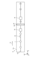
前述の説明においては、検出部22は、図2に示すように、搬送ベルト21aの各吸引孔21gが並ぶライン上の位置に光を照射するように設けられているが、例えば、図7に示すように、そのラインからY軸方向に所定距離だけずれた位置に光を照射するように設けられてもよい。つまり、検出部22は、平面視で各吸引孔21gが並ぶラインから所定距離(例えば、数mm)ずらして設けられてもよい。これにより、検出部22は、各吸引孔21gが並ぶライン上の位置に光を照射する場合に比べ、各吸引孔21gによる光の散乱などの影響を抑えることが可能になるので、例えば、搬送ベルト21aの一周分の高さを精度よく検出することができる。ただし、所定距離は、検出部22が錠剤Tの到来を正確に検出することが可能に設定される。図7の例のような構成は、検出部52にも適用可能である。 In the above description, the detection unit 22 is arranged to irradiate light onto a position on the line on which the suction holes 21g of the conveyor belt 21a are arranged, as shown in FIG. 2, but may be arranged to irradiate light onto a position shifted from that line by a predetermined distance in the Y-axis direction, as shown in FIG. 7, for example. That is, the detection unit 22 may be arranged to be shifted by a predetermined distance (e.g., several mm) from the line on which the suction holes 21g are arranged in a plan view. This makes it possible for the detection unit 22 to suppress the influence of light scattering by the suction holes 21g compared to the case where light is irradiated onto a position on the line on which the suction holes 21g are arranged, and therefore, for example, the height of one circumference of the conveyor belt 21a can be detected with high accuracy. However, the predetermined distance is set so that the detection unit 22 can accurately detect the arrival of the tablet T. The configuration as shown in the example of FIG. 7 can also be applied to the detection unit 52.

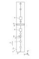
また、図8に示すように、検出部22Aが、検出部22に加えて新たに設けられてもよい。この検出部22Aは、例えば、搬送ベルト21aの一周分の高さを検出する。この場合、検出部22は、錠剤Tの到来を検出するためだけに用いられる。検出部22Aは、検出部22と同じ構成を有してもよく、あるいは、検出部22と異なる構成を有してもよい。図8の例でも、図7の例と同様、各吸引孔21gが並ぶライン上の位置に光を照射する場合に比べ、各吸引孔21gによる光の散乱などの影響を抑えることが可能になるので、例えば、搬送ベルト21aの一周分の高さを精度よく検出することができる。図8の例のような構成は、検出部52にも適用可能である。 As shown in FIG. 8, a detection unit 22A may be provided in addition to the detection unit 22. This detection unit 22A detects, for example, the height of one circumference of the conveyor belt 21a. In this case, the detection unit 22 is used only to detect the arrival of tablets T. The detection unit 22A may have the same configuration as the detection unit 22, or may have a different configuration from the detection unit 22. In the example of FIG. 8, as in the example of FIG. 7, it is possible to suppress the influence of light scattering by each suction hole 21g compared to the case where light is irradiated to a position on a line where each suction hole 21g is lined up, so that, for example, the height of one circumference of the conveyor belt 21a can be detected with high accuracy. The configuration of the example of FIG. 8 can also be applied to the detection unit 52.

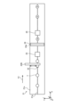
また、図9に示すように、検出部22が移動機構22Bにより平面方向、例えばY軸方向に移動するように構成されてもよい。移動機構22Bは、例えば、Y軸方向に検出部22を移動させる機構である。この移動機構22Bは、制御装置40に電気的に接続されており、それらの駆動が制御装置40により制御される。例えば、制御装置40は、位置調整工程において、検出部22を各吸引孔21gが並ぶライン上の位置に光を照射する位置(初期位置)から、そのラインからY軸方向に所定距離だけずれた位置に光を照射する位置(検出位置)に移動させる。位置調整工程後、制御装置40は、検出部22を検出位置から初期位置に移動させる。検出位置は、検出部22から照射される光が搬送ベルト21aの搬送面における錠剤Tが実際に搬送される搬送範囲内に当たる位置であることが好ましい。図9の例でも、図7や図8の例と同様、各吸引孔21gが並ぶライン上の位置に光を照射する場合に比べ、各吸引孔21gによる光の散乱などの影響を抑えることが可能になるので、例えば、搬送ベルト21aの一周分の高さを精度よく検出することができる。図9の例のような構成は、検出部52にも適用可能である。 Also, as shown in FIG. 9, the detection unit 22 may be configured to move in a planar direction, for example, in the Y-axis direction, by the moving mechanism 22B. The moving mechanism 22B is, for example, a mechanism for moving the detection unit 22 in the Y-axis direction. This moving mechanism 22B is electrically connected to the control device 40, and the driving thereof is controlled by the control device 40. For example, in the position adjustment process, the control device 40 moves the detection unit 22 from a position (initial position) where light is irradiated to a position on the line where each suction hole 21g is lined up to a position (detection position) where light is irradiated to a position shifted by a predetermined distance in the Y-axis direction from the line. After the position adjustment process, the control device 40 moves the detection unit 22 from the detection position to the initial position. It is preferable that the detection position is a position where the light irradiated from the detection unit 22 hits within the conveying range where the tablet T on the conveying surface of the conveyor belt 21a is actually conveyed. In the example of FIG. 9, as in the examples of FIG. 7 and FIG. 8, the influence of light scattering by each suction hole 21g can be suppressed compared to when light is irradiated to positions on a line where each suction hole 21g is aligned, so that, for example, the height of one circumference of the conveyor belt 21a can be detected with high accuracy. The configuration of the example of FIG. 9 can also be applied to the detection unit 52.

また、前述の説明においては、錠剤Tを一列で搬送することを例示したが、これに限るものではなく、その列数は二列以上の複数列であってもよく、特に限定されるものではなく、搬送ベルト21aの本数も二本以上であってもよく、特に限定されるものではない。このような構成は、搬送ベルト51aにも適用可能である。また、インクジェットヘッド24の個数も二個以上であってもよく、特に限定されるものではない。このような構成は、インクジェットヘッド54にも適用可能である。 In addition, in the above explanation, an example was given of transporting the tablets T in a single row, but this is not limited to this, and the number of rows may be two or more rows, and is not particularly limited, and the number of conveyor belts 21a may be two or more, and is not particularly limited. This configuration is also applicable to the conveyor belt 51a. In addition, the number of inkjet heads 24 may be two or more, and is not particularly limited. This configuration is also applicable to the inkjet head 54.

また、前述の説明においては、インクジェットヘッド24として、ノズル24aが一列に並ぶインクジェットヘッドを例示したが、これに限るものではなく、例えば、ノズル24aが複数列に並ぶインクジェットヘッドを用いるようにしてもよい。また、水平面内において搬送方向A1と直交する方向にインクジェットヘッド24を複数並べて用いるようにしてもよい。これらのような構成は、インクジェットヘッド54にも適用可能である。 In the above description, an inkjet head in which the nozzles 24a are arranged in a single row has been exemplified as the inkjet head 24, but this is not limited thereto, and for example, an inkjet head in which the nozzles 24a are arranged in multiple rows may be used. Also, multiple inkjet heads 24 may be arranged in a direction perpendicular to the transport direction A1 in a horizontal plane. Such configurations are also applicable to the inkjet head 54.

また、前述の説明においては、インクジェットヘッド24をノズル24aが並ぶ方向が水平面内において搬送方向A1と直交する方向になるように設けることを例示したが、これに限るものではなく、例えば、ノズル24aが並ぶ方向が水平面内において搬送方向A1と斜めに交差する方向になるように設けるようにしてもよい。このような構成は、インクジェットヘッド54にも適用可能である。 In the above description, the inkjet head 24 is illustrated as being arranged so that the direction in which the nozzles 24a are arranged is perpendicular to the transport direction A1 in a horizontal plane, but this is not limited thereto. For example, the nozzles 24a may be arranged so that the direction in which the nozzles 24a are arranged is diagonally intersecting the transport direction A1 in a horizontal plane. This type of configuration can also be applied to the inkjet head 54.

また、前述の説明においては、インクジェットヘッド54および第4の移動機構54Aは搬送部51と一体に設けられるものを例示したが、これに限るものではなく、例えば、インクジェットヘッド54単体で、搬送部51とは別に、移動機構54Aを備えるようにしてもよい。この場合には、前述のステップS16においてインクジェットヘッド54の高さ位置を算出する際に、補正値C1を用いて算出を行う。 In the above description, the inkjet head 54 and the fourth moving mechanism 54A are provided integrally with the transport unit 51, but this is not limiting. For example, the inkjet head 54 alone may be provided with the moving mechanism 54A separate from the transport unit 51. In this case, the correction value C1 is used when calculating the height position of the inkjet head 54 in step S16 described above.

また、前述の説明においては、錠剤Tが搬送ベルト21a上に一定間隔ではなくランダムに供給されるとしたが、これに限られるものではなく、一定間隔で供給されてもよい。また、前述の説明においては、搬送ベルト21a上に形成された吸引孔21gによって錠剤Tが吸引保持されるとしたが、これに限るものではなく、ポケットなどに収容保持され搬送されるようにしてもよく、あるいは、搬送ベルト21a上に自重により保持され搬送されるようにしてもよい。これらのような構成は、搬送ベルト51aにも適用可能である。 In the above description, the tablets T are supplied randomly, not at regular intervals, onto the conveyor belt 21a, but this is not limited to this and they may be supplied at regular intervals. In the above description, the tablets T are suction-held by the suction holes 21g formed on the conveyor belt 21a, but this is not limited to this and they may be stored and held in a pocket or the like and transported, or they may be held and transported by their own weight on the conveyor belt 21a. Such configurations can also be applied to the conveyor belt 51a.

ここで、前述の錠剤Tとしては、医薬用、飲食用、洗浄用、工業用あるいは芳香用として使用される錠剤を含めることができる。また、錠剤Tとしては、裸錠(素錠)や糖衣錠、フィルムコーティング錠、腸溶錠、ゼラチン被包錠、多層錠、有核錠などがあり、硬カプセルや軟カプセルなど各種のカプセル錠も錠剤Tに含めることができる。さらに、錠剤Tの形状としては、円盤形やレンズ形、三角形、楕円形など各種の形状がある。また、印刷対象の錠剤Tが医薬用や飲食用である場合には、使用するインクとして可食性インクが好適である。この可食性インクとしては、合成色素インク、天然色素インク、染料インク、顔料インクのいずれを使用しても良い。 Here, the aforementioned tablets T can include tablets used for medicine, food, cleaning, industrial or aromatic purposes. Tablets T can be plain tablets, sugar-coated tablets, film-coated tablets, enteric-coated tablets, gelatin-coated tablets, multi-layer tablets, dry-coated tablets, and various capsule tablets such as hard capsules and soft capsules. Tablets T can have various shapes such as disks, lenses, triangles, and ellipses. When the tablet T to be printed is for medicine or food, edible ink is preferably used. As the edible ink, any of synthetic dye ink, natural dye ink, dye ink, and pigment ink can be used.

以上、本発明のいくつかの実施形態を説明したが、これらの実施形態は、例として提示したものであり、発明の範囲を限定することは意図していない。これら新規な実施形態は、その他の様々な形態で実施されることが可能であり、発明の要旨を逸脱しない範囲で、種々の省略、置き換え、変更、組み合わせを行うことができる。これら実施形態やその変形は、発明の範囲や要旨に含まれるとともに、特許請求の範囲に記載された発明とその均等の範囲に含まれる。 Although several embodiments of the present invention have been described above, these embodiments are presented as examples and are not intended to limit the scope of the invention. These novel embodiments can be implemented in various other forms, and various omissions, substitutions, modifications, and combinations can be made without departing from the gist of the invention. These embodiments and their modifications are included in the scope and gist of the invention, and are included in the scope of the invention and its equivalents described in the claims.

1 錠剤印刷装置
10 供給装置
11 ホッパ
12 整列フィーダ
13 受渡フィーダ
13A 第1の移動機構
20 第1の印刷装置
21 搬送部
21a 搬送ベルト
21b 駆動プーリ
21c 従動プーリ
21d モータ
21e 位置検出器
21f 吸引チャンバ
21g 吸引孔
22 検出部
22A 検出部
22B 移動機構
23 第1の撮像部
24 インクジェットヘッド
24A 第2の移動機構
24a ノズル
25 第2の撮像部
27 乾燥部
30 回収装置
31 再利用品回収部
31a 噴射ノズル
31b 回収ボックス
32 不良品回収部
32a 噴射ノズル
32b 回収ボックス
33 良品回収部
33b 回収ボックス
33a 噴射ノズル
40 制御装置
40a 入力装置
40b 出力装置
41 画像処理部
42 記憶部
43 制御部
50 第2の印刷装置
51 搬送部
51A 第3の移動機構
51a 搬送ベルト
51b 駆動プーリ
51c 従動プーリ
51d モータ
51e 位置検出器
51f 吸引チャンバ
52 検出部
53 第1の撮像部
54 インクジェットヘッド
54A 第4の移動機構
55 第2の撮像部
57 乾燥部
A1 搬送方向
A2 搬送方向
Ba 基準高さ位置
Bb 基準高さ位置
Bc 基準高さ位置
B1 離間距離
B2 離間距離
B3 離間距離
B4 離間距離
T 錠剤
LIST OF SYMBOLS 1 Tablet printing device 10 Feeding device 11 Hopper 12 Alignment feeder 13 Delivery feeder 13A First moving mechanism 20 First printing device 21 Conveying section 21a Conveying belt 21b Driving pulley 21c Driven pulley 21d Motor 21e Position detector 21f Suction chamber 21g Suction hole 22 Detection section 22A Detection section 22B Moving mechanism 23 First imaging section 24 Inkjet head 24A Second moving mechanism 24a Nozzle 25 Second imaging section 27 Drying section 30 Recovery device 31 Reusable product recovery section 31a Spray nozzle 31b Recovery box 32 Defective product recovery section 32a Spray nozzle 32b Recovery box 33 Good product recovery section 33b Recovery box 33a Spray nozzle 40 Control device 40a Input device 40b Output device 41 Image processing unit 42 Memory unit 43 Control unit 50 Second printing device 51 Conveying unit 51A Third moving mechanism 51a Conveying belt 51b Driving pulley 51c Driven pulley 51d Motor 51e Position detector 51f Suction chamber 52 Detection unit 53 First imaging unit 54 Inkjet head 54A Fourth moving mechanism 55 Second imaging unit 57 Drying unit A1 Conveying direction A2 Conveying direction Ba Reference height position Bb Reference height position Bc Reference height position B1 Separation distance B2 Separation distance B3 Separation distance B4 Separation distance T Tablet

本発明の実施形態に係る錠剤印刷装置は、錠剤を搬送する搬送装置と、前記搬送装置により搬送される前記錠剤に印刷を行う第1のインクジェットヘッドと、前記搬送装置および前記第1のインクジェットヘッドの少なくとも一方を高さ方向に移動させる移動機構と、前記移動機構を制御する制御装置と、を備え、前記制御装置は、前記搬送装置の高さ位置と第1の基準高さ位置との差に基づいて第1の補正値を生成し、前記錠剤の品種に関する錠剤品種情報に基づいて第2の補正値を生成し、前記第1の補正値及び前記第2の補正値に基づいて前記移動機構を制御する。 A tablet printing device according to an embodiment of the present invention comprises a conveying device for conveying tablets, a first inkjet head for printing on the tablets conveyed by the conveying device , a moving mechanism for moving at least one of the conveying device and the first inkjet head in a vertical direction, and a control device for controlling the moving mechanism, wherein the control device generates a first correction value based on the difference between the height position of the conveying device and a first reference height position, generates a second correction value based on tablet variety information relating to the variety of the tablet, and controls the moving mechanism based on the first correction value and the second correction value.

本発明の実施形態に係る錠剤印刷方法は、制御装置が、錠剤を搬送する搬送装置の高さ位置と第1の基準高さ位置との差に基づいて第1の補正値を生成することと、前記錠剤の品種に関する錠剤品種情報に基づいて第2の補正値を生成することと、前記第1の補正値及び前記第2の補正値に基づいて、前記錠剤に印刷を行う第1のインクジェットヘッドおよび前記搬送装置の少なくとも一方を高さ方向に移動させる移動機構を制御することと、を含む。
A tablet printing method according to an embodiment of the present invention includes a control device generating a first correction value based on the difference between the height position of a conveying device that conveys a tablet and a first reference height position, generating a second correction value based on tablet variety information relating to the variety of the tablet, and controlling a movement mechanism that moves in a vertical direction at least one of a first inkjet head that prints on the tablet and the conveying device based on the first correction value and the second correction value.

Claims (6)

錠剤を搬送する搬送装置と、
前記錠剤に印刷を行う第1のインクジェットヘッドと、
前記搬送装置又は前記第1のインクジェットヘッドを高さ方向に移動させる移動機構と、
前記移動機構を制御する制御装置と、
を備え、
前記制御装置は、
前記搬送装置の高さ位置と第1の基準高さ位置との差に基づいて第1の補正値を生成し、
前記錠剤の品種に関する錠剤品種情報に基づいて第2の補正値を生成し、
前記第1の補正値及び前記第2の補正値に基づいて前記移動機構を制御する、
錠剤印刷装置。
A conveying device for conveying tablets;
A first inkjet head for printing on the tablet;
a moving mechanism that moves the conveying device or the first inkjet head in a height direction;
A control device for controlling the movement mechanism;
Equipped with
The control device includes:
generating a first correction value based on a difference between a height position of the transport device and a first reference height position;
generating a second correction value based on tablet variety information relating to the tablet variety;
controlling the moving mechanism based on the first correction value and the second correction value;
Tablet printing equipment.
前記搬送装置は、
前記第1のインクジェットヘッドにより印刷される前記錠剤を搬送する第1の搬送部と、
前記第1の搬送部に前記錠剤を渡す供給搬送部と、
を有し、
前記移動機構は、前記第1の搬送部又は前記供給搬送部を高さ方向に移動させる機構であり、
前記制御装置は、前記第1の搬送部の高さ位置と前記第1の基準高さ位置との差に基づいて前記第1の補正値を生成する、
請求項1に記載の錠剤印刷装置。
The conveying device is
a first conveying unit that conveys the tablet printed by the first inkjet head;
a supply conveying section that delivers the tablet to the first conveying section;
having
the moving mechanism is a mechanism for moving the first conveying unit or the supply conveying unit in a height direction,
the control device generates the first correction value based on a difference between a height position of the first transport unit and the first reference height position.
The tablet printing apparatus according to claim 1.
前記錠剤に印刷を行う第2のインクジェットヘッドをさらに備え、
前記搬送装置は、
前記第1のインクジェットヘッドにより印刷される前記錠剤を搬送する第1の搬送部と、
前記第2のインクジェットヘッドにより印刷される前記錠剤を搬送する第2の搬送部と、
を有し、
前記移動機構は、前記第2のインクジェットヘッド、前記第1の搬送部又は前記第2の搬送部を高さ方向に移動させる機構であり、
前記制御装置は、
前記第1の搬送部の高さ位置と前記第1の基準高さ位置との差に基づいて前記第1の補正値を生成し、
前記第2の搬送部の高さ位置と第2の基準高さ位置との差に基づいて第3の補正値を生成し、
前記第1の補正値、前記第2の補正値及び前記第3の補正値に基づいて前記移動機構を制御する、
請求項1に記載の錠剤印刷装置。
Further comprising a second inkjet head for printing on the tablet;
The conveying device is
a first conveying unit that conveys the tablet printed by the first inkjet head;
a second conveying unit that conveys the tablet printed by the second inkjet head;
having
the moving mechanism is a mechanism for moving the second inkjet head, the first transport unit, or the second transport unit in a height direction,
The control device includes:
generating the first correction value based on a difference between a height position of the first transport unit and the first reference height position;
generating a third correction value based on a difference between a height position of the second transport unit and a second reference height position;
controlling the moving mechanism based on the first correction value, the second correction value, and the third correction value;
The tablet printing apparatus according to claim 1.
前記錠剤の到来を検出する検出部をさらに備え、
前記制御装置は、前記検出部の検出結果に基づいて前記搬送装置の高さ位置を測定する、
請求項1から3のいずれか一項に記載の錠剤印刷装置。
A detection unit for detecting the arrival of the tablet is further provided,
The control device measures a height position of the conveying device based on a detection result of the detection unit.
The tablet printing apparatus according to any one of claims 1 to 3.
前記錠剤品種情報は、前記錠剤の識別情報、前記錠剤の厚み情報及び前記錠剤の形状情報のいずれか又は全てを含む、
請求項1から3のいずれか一項に記載の錠剤印刷装置。
The tablet variety information includes any one or all of the tablet identification information, the tablet thickness information, and the tablet shape information.
The tablet printing apparatus according to any one of claims 1 to 3.
制御装置が、
錠剤を搬送する搬送装置の高さ位置と第1の基準高さ位置との差に基づいて第1の補正値を生成することと、
前記錠剤の品種に関する錠剤品種情報に基づいて第2の補正値を生成することと、
前記第1の補正値及び前記第2の補正値に基づいて、前記錠剤に印刷を行う第1のインクジェットヘッド又は前記搬送装置を高さ方向に移動させる移動機構を制御することと、
を含む、
錠剤印刷方法。
The control device,
generating a first correction value based on a difference between a height position of a conveying device that conveys the tablet and a first reference height position;
generating a second correction value based on tablet variety information relating to the tablet variety;
Controlling a movement mechanism that moves a first inkjet head that prints on the tablet or the conveying device in a height direction based on the first correction value and the second correction value;
Including,
Tablet printing method.
JP2023148379A 2023-09-13 2023-09-13 Tablet printing device and tablet printing method Pending JP2025041217A (en)

Priority Applications (4)

Application Number Priority Date Filing Date Title
JP2023148379A JP2025041217A (en) 2023-09-13 2023-09-13 Tablet printing device and tablet printing method
KR1020240100455A KR20250039272A (en) 2023-09-13 2024-07-29 Tablet printing apparatus and tablet printing method
CN202411083550.4A CN119610902A (en) 2023-09-13 2024-08-08 Tablet printing apparatus and tablet printing method
TW113129839A TWI907007B (en) 2023-09-13 2024-08-09 Tablet printing device and tablet printing method

Applications Claiming Priority (1)

Application Number Priority Date Filing Date Title
JP2023148379A JP2025041217A (en) 2023-09-13 2023-09-13 Tablet printing device and tablet printing method

Publications (2)

Publication Number Publication Date
JP2025041217A true JP2025041217A (en) 2025-03-26
JP2025041217A5 JP2025041217A5 (en) 2025-05-01

Family

ID=94893560

Family Applications (1)

Application Number Title Priority Date Filing Date
JP2023148379A Pending JP2025041217A (en) 2023-09-13 2023-09-13 Tablet printing device and tablet printing method

Country Status (3)

Country Link
JP (1) JP2025041217A (en)
KR (1) KR20250039272A (en)
CN (1) CN119610902A (en)

Family Cites Families (1)

* Cited by examiner, † Cited by third party
Publication number Priority date Publication date Assignee Title
JP2019058220A (en) 2017-09-24 2019-04-18 株式会社京都製作所 Tablet printing device

Also Published As

Publication number Publication date
CN119610902A (en) 2025-03-14
TW202511091A (en) 2025-03-16
KR20250039272A (en) 2025-03-20

Similar Documents

Publication Publication Date Title
US10709639B2 (en) Tablet printing apparatus and tablet printing method
US10486440B2 (en) Tablet printing apparatus
TWI871239B (en) Tablet printing device and tablet printing method
JP6745670B2 (en) Tablet printing device, tablet and tablet manufacturing method
US10772801B2 (en) Tablet printing apparatus and tablet printing method
JP7714735B2 (en) Tablet printing device and tablet printing method
JP2025041217A (en) Tablet printing device and tablet printing method
TWI907007B (en) Tablet printing device and tablet printing method
JP7394681B2 (en) Tablet printing device and tablet manufacturing method
JP7473525B2 (en) Tablet printing device and tablet printing method
JP2023050476A (en) Tablet printing device and tablet printing method
JP7280704B2 (en) Tablet printing device and tablet printing method
CN116429778B (en) Tablet inspection device and tablet printing device
JP7397132B2 (en) Tablet printing device and tablet printing method
JP7402298B2 (en) Tablet inspection equipment and tablet printing equipment
TWI836559B (en) Tablet printing device and tablet printing method
JP7377137B2 (en) Tablet printing device and tablet printing method
JP2023104884A (en) Information processing device, information processing method, and tablet printing device
JP2023046679A (en) Tablet printing device and tablet printing method

Legal Events

Date Code Title Description
A521 Request for written amendment filed

Free format text: JAPANESE INTERMEDIATE CODE: A523

Effective date: 20240626

A521 Request for written amendment filed

Free format text: JAPANESE INTERMEDIATE CODE: A523

Effective date: 20250422

A621 Written request for application examination

Free format text: JAPANESE INTERMEDIATE CODE: A621

Effective date: 20250422