JP2024136397A - Gaming Machines - Google Patents
Gaming Machines Download PDFInfo
- Publication number
- JP2024136397A JP2024136397A JP2023047507A JP2023047507A JP2024136397A JP 2024136397 A JP2024136397 A JP 2024136397A JP 2023047507 A JP2023047507 A JP 2023047507A JP 2023047507 A JP2023047507 A JP 2023047507A JP 2024136397 A JP2024136397 A JP 2024136397A
- Authority
- JP
- Japan
- Prior art keywords
- game
- state
- mode
- gaming machine
- player
- Prior art date
- Legal status (The legal status is an assumption and is not a legal conclusion. Google has not performed a legal analysis and makes no representation as to the accuracy of the status listed.)
- Pending
Links
Images


Landscapes
- Slot Machines And Peripheral Devices (AREA)
- Game Rules And Presentations Of Slot Machines (AREA)
Abstract
Description
本発明は、パチスロ機やパチンコ機等の遊技機に関する。 The present invention relates to gaming machines such as pachislot machines and pachinko machines.
従来の遊技機において、ビッグボーナスなどの大当り中に所定条件が成立することにより、遊技機に対する操作を受け付けない打ち止め状態とし、以降における遊技の続行を規制するものがあった(例えば、特許文献1参照)。 In conventional gaming machines, when a certain condition is met during a big bonus or other jackpot, the machine enters a stop state in which no operations can be performed, and any further play is restricted (see, for example, Patent Document 1).
しかしながら、このような遊技機では、例えば、突然遊技不能となったことへの苛立ちを遊技者に抱かせてしまう虞や、打ち止め状態となっていることに気付いていない遊技者に対して遊技機が故障したのではといった誤解を抱かせてしまう虞があった。また、遊技店の店員にとっても、打ち止め状態となるタイミングが近づいていることを把握し難いために打ち止め状態となった遊技者に対するサポートを十分に行うことができない虞があった。 However, with such gaming machines, for example, there is a risk that players will become frustrated when they are suddenly unable to play, or that players who are unaware that they have reached a limit may mistakenly believe that the gaming machine is broken. In addition, there is a risk that game store staff will not be able to provide sufficient support to players who have reached a limit, since it is difficult for them to grasp that the limit is approaching.
本発明は、このような点に鑑みてなされたものであり、遊技者や遊技店の双方にとってユーザフレンドリーとなる遊技機を提供することを目的とする。 The present invention was made in consideration of these points, and aims to provide a gaming machine that is user-friendly for both players and gaming facilities.
上記目的を達成するために、本実施形態では以下のような構成の遊技機を提供することができる。 To achieve the above objective, this embodiment provides a gaming machine with the following configuration:
遊技価値(例えば、メダル、遊技球、クレジット、特典など)を消費して遊技を進行し、当該遊技の進行に応じて遊技価値を付与可能な遊技機(例えば、パチスロ機、パチンコ機、メダルレス遊技機など)において、
消費した遊技価値(例えば、ベットに用いたメダル、発射した遊技球など)と付与された遊技価値(例えば、払い出されたメダル・遊技球など)とに基づく差数を累計した累計数を特定する累計数特定手段(例えば、図61のSA03~SA05、CMP_MYカウンタ、基準値カウンタなど)と、
所定期間(例えば、電源投入されてからの期間)における前記累計数の最下値を基点とし、当該基点からの累計数が上限数(例えば、パチスロ機:19000、パチンコ機:95000など)に到達することにより、遊技の進行を不能化する遊技不能化手段(例えば、遊技を進行するための操作・検出が無効化、始動口・作動口・ゲートなどが無効化、大入賞口・電チューなどが閉鎖状態など)と、
制御されている間において付与される遊技価値よりも消費する遊技価値の方が大きくなる所定状態(例えば、通常状態)と、制御されている間において消費する遊技価値よりも付与される遊技価値の方が大きくなる有利状態(例えば、パチスロ機:ATやボーナスなどの遊技者がメダルを増加させることができる状態、パチンコ機:大当り遊技状態、小当り遊技状態、確変遊技状態、時短遊技状態など)とを含む複数種類の状態のいずれかに制御可能な状態制御手段(例えば、主制御回路により遊技状態を制御するための処理)と、
前記状態制御手段により前記所定状態に制御されているか前記有利状態に制御されているかにかかわらず前記基点からの累計数が前記上限数に到達することにより、前記遊技不能化手段により遊技の進行が不能化される旨の不能化報知を行う不能化報知手段(例えば、図60(a)、図60(b)、図62のSA24、SA28、図63のSA41~SA44など)と、
前記状態制御手段により前記所定状態に制御されているか前記有利状態に制御されているかにかかわらず、前記基点からの累計数が前記上限数よりも小さい所定数(例えば、パチスロ機:18500、パチンコ機:90000など)に到達することにより、前記上限数までの残り数に応じた数値情報を特定可能とする事前報知を行うことが可能な事前報知手段(例えば、図60(c)、図60(d)、図70、図71、図62のSA21、図63のSA45~SA48など)と、
前記基点からの累計数が前記上限数よりも小さい数であって前記所定数とは異なる特定数(例えば、パチスロ機:18000、18750、パチンコ機:85000、92500などに到達することにより、前記数値情報とは異なる特定情報(例えば、第1報知、第2報知など)を報知可能な特定報知手段(例えば、図63のSA49~SA51、SA63~SA65など)と、
開始条件が成立することにより有利区間に制御し、当該有利区間における累計数(例えば、有利区間払出数カウンタ)が区間上限数に到達することにより当該有利区間を終了する有利区間制御手段(例えば、有利区間に制御するための処理など)と、を備え、
前記所定期間における前記基点からの累計数に関する情報は、報知条件が成立することにより前記所定数に到達しているか否かにかかわらず報知可能である一方、前記有利区間における累計数に関する情報は、前記報知条件が成立したときであっても報知不可能である(例えば、特定の操作などにより、CMP_MYカウンタの値に関する情報については報知可能である一方、有利区間払出数カウンタの値については報知不可能)。
In a gaming machine (e.g., a slot machine, a pachinko machine, a medal-less gaming machine, etc.) in which a game is played by consuming a game value (e.g., a medal, a game ball, a credit, a bonus, etc.) and a game value can be awarded according to the progress of the game,
an accumulated number specifying means (e.g., SA03 to SA05 in FIG. 61, a CMP_MY counter, a reference value counter, etc.) for specifying an accumulated number obtained by accumulating a difference between a game value consumed (e.g., medals used for betting, game balls launched, etc.) and a game value awarded (e.g., medals, game balls paid out, etc.);
a game disabling means for disabling the progress of a game when the lowest value of the cumulative number in a predetermined period (e.g., the period from when the power is turned on) is set as a base point and the cumulative number from the base point reaches an upper limit number (e.g., 19,000 for a pachislot machine, 95,000 for a pachinko machine, etc.) (e.g., disabling the operation and detection required to progress the game, disabling the start port, operation port, gate, etc., closing the jackpot port, electric chute, etc.);
a state control means (e.g., a process for controlling the game state by a main control circuit) capable of controlling the game state to one of a plurality of states including a predetermined state (e.g., a normal state) in which the game value consumed during the control period is greater than the game value awarded, and an advantageous state in which the game value awarded during the control period is greater than the game value consumed (e.g., a pachislot machine: a state in which a player can increase medals, such as an AT or a bonus; a pachinko machine: a big win game state, a small win game state, a probability variation game state, a time-saving game state, etc.);
a disabling notification means (e.g., SA24 and SA28 in Fig. 62, SA41 to SA44 in Fig. 63, etc.) for notifying that progress of a game will be disabled by the game disabling means when the cumulative number from the base point reaches the upper limit number regardless of whether the state is controlled to the predetermined state or the advantageous state by the state control means;
Regardless of whether the state control means controls the state to be the predetermined state or the advantageous state, when the cumulative number from the base point reaches a predetermined number smaller than the upper limit number (e.g., slot machine: 18,500, pachinko machine: 90,000, etc.), advance notification means (e.g., SA21 in Fig. 60(c), Fig. 60(d), Fig. 70, Fig. 71, Fig. 62, SA45 to SA48 in Fig. 63, etc.) capable of performing advance notification to enable identification of numerical information corresponding to the remaining number up to the upper limit number;
A specific notification means (e.g., SA49 to SA51, SA63 to SA65 in FIG. 63 ) capable of notifying specific information (e.g., first notification, second notification, etc.) different from the numerical information when the cumulative number from the base point reaches a specific number smaller than the upper limit number and different from the predetermined number (e.g., pachislot machine: 18,000, 18,750, pachinko machine: 85,000, 92,500, etc.);
A favorable zone control means (e.g., a process for controlling to the favorable zone) is provided, which controls to the favorable zone when a start condition is satisfied, and ends the favorable zone when a cumulative number in the favorable zone (e.g., a favorable zone payout number counter) reaches a zone upper limit number,
Information regarding the cumulative number from the base point during the specified period can be reported regardless of whether the specified number has been reached by the notification condition being met, while information regarding the cumulative number in the favorable zone cannot be reported even when the notification condition is met (for example, information regarding the value of the CMP_MY counter can be reported by a specific operation, but the value of the favorable zone payout number counter cannot be reported).
上記構成によれば、制御されている遊技状態にかかわらず遊技の進行が不能化されるまでの残り数に応じた数値情報が報知されて、遊技者および店員双方が把握可能となる。このため、急に遊技の進行が不能化されてしまう場合よりも、遊技者の苛立ちを例えば事前報知が行われている期間に亘って分散させつつ遊技機が故障したのではといった誤解をまねくことも防止できる。また、残り数に応じて店員がサポート対応の段取りを前もって検討等することができるために、遊技の進行が不能化された遊技機で遊技していた遊技者に対するサポート力を高めることができる。 With the above configuration, regardless of the controlled game state, numerical information according to the number of remaining balls until game progress is disabled is notified, allowing both the player and the store clerk to grasp the situation. This allows the player's frustration to be spread out over the period during which advance notification is being given, for example, rather than when game progress is suddenly disabled, and also prevents the player from misunderstanding that the gaming machine has broken down. In addition, since the store clerk can consider in advance how to respond to support requests depending on the remaining number, it is possible to increase support for players who were playing on a gaming machine whose game progress has been disabled.
[第1実施形態]
以下、図面を参照して、本実施形態に係る遊技機について説明する。なお、本実施形態では、遊技機としてパチスロ機を例に挙げて説明する。
[First embodiment]
Hereinafter, a gaming machine according to the present embodiment will be described with reference to the drawings. Note that in this embodiment, a pachislot machine will be described as an example of the gaming machine.
[1.パチスロ機の構造]
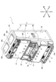
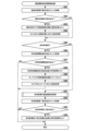
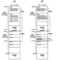
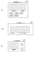
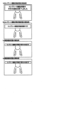
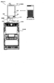
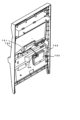
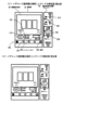
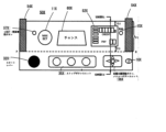
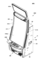
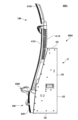
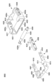
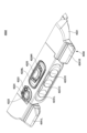
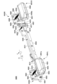
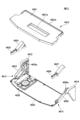
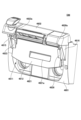
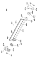
まず、図1及び図2を参照して、パチスロ機1の構造について説明する。なお、図1は、パチスロ機1の外部構造を示す図であり、図2は、パチスロ機1の内部構造を示す図である。また、説明の便宜上、以下の外部構造の説明において、内部構造の一部を説明する場合があり、内部構造の説明において、外部構造の一部を説明する場合がある。
[1. Structure of a Pachislot Machine]
First, the structure of the
[1-1.外部構造]
[1-1-1.筐体]
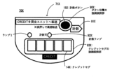
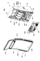
パチスロ機1は、矩形箱状の筐体2により構成されている。また、筐体2は、遊技機本体として前面側に矩形状の開口を有する金属製のキャビネットGと、キャビネットGの前面上部に配置された上ドア機構UDと、キャビネットGの前面下部に配置された下ドア機構DDとを有している。
[1-1. External structure]
[1-1-1. Housing]
The
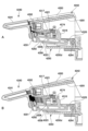
キャビネットGは、中間支持板G1と、左右一対の側面壁G2と、背面壁G3と、上面壁G4と、底面壁G5とを有している。なお、図1及び図2においては、背面壁G3及び底面壁G5の図示を省略している。また、キャビネットGの上面壁G4には、左右方向に所定の間隔を空けて、上下方向に貫通する2つの開口G4aが形成されている。そして、この2つの開口G4aそれぞれを塞ぐように木製の板部材G4bが上面壁G4に取付けられている。 The cabinet G has an intermediate support plate G1, a pair of left and right side walls G2, a rear wall G3, a top wall G4, and a bottom wall G5. Note that the rear wall G3 and bottom wall G5 are not shown in Figures 1 and 2. The top wall G4 of the cabinet G has two openings G4a that penetrate in the vertical direction and are spaced a certain distance apart in the horizontal direction. Wooden plate members G4b are attached to the top wall G4 so as to close each of the two openings G4a.
なお、板部材G4bは、パチスロ機1を遊技店に設置する際に遊技島(不図示)に固定するために用いられるが、このような固定の方法が確保される限り、金属材や樹脂材で構成することもできるし、上面壁G4と一体に形成することもできる。また、キャビネットGについて一定の強度が確保される限り、各構成部材の一部又は全部を木材や樹脂材で構成することもできる。
The plate member G4b is used to secure the
また、キャビネットGは、その内部において、中間支持板G1を挟んで上側に、前方に開口する上側開口部G101が形成されており、中間支持板G1を挟んで下側に、前方に開口する下側開口部G102が形成されている。すなわち、キャビネットG内は、中間支持板G1を挟んで上部空間と下部空間とに仕切られており、中間支持板G1は、キャビネットG内を上部空間と下部空間とに仕切る仕切板として機能している。上部空間は、キャビネットG内の上ドア機構UDの後側となる空間であり、後述のメイン表示装置210等が収容される。また、下部空間は、キャビネットG内の下ドア機構DDの後側となる空間であり、後述のリールユニットRUや主制御基板71等が収容される。
Inside the cabinet G, an upper opening G101 that opens forward is formed on the upper side across the intermediate support plate G1, and a lower opening G102 that opens forward is formed on the lower side across the intermediate support plate G1. That is, the inside of the cabinet G is divided into an upper space and a lower space across the intermediate support plate G1, which functions as a partition plate that divides the inside of the cabinet G into the upper space and the lower space. The upper space is the space behind the upper door mechanism UD in the cabinet G, and contains the
なお、キャビネットGは、必ずしも中間支持板G1を含んで構成されていなくともよい。すなわち、キャビネットG内において各装置等が適切に収容される限り、上部空間と下部空間を仕切らない構成としてもよい。また、キャビネットGは、単に「箱体」や「本体」と称することもできるし、上ドア機構UD及び下ドア機構DDを支持、あるいは固定する枠体として機能するため、「本体枠」、「支持体」、「支持枠」、あるいは「固定枠」等と称することもできる。 The cabinet G does not necessarily have to include the intermediate support plate G1. In other words, as long as each device etc. can be appropriately accommodated within the cabinet G, the cabinet G may not have a partition between the upper and lower spaces. The cabinet G may simply be referred to as a "box" or "main body", or, since it functions as a frame that supports or fixes the upper door mechanism UD and the lower door mechanism DD, it may also be referred to as a "main body frame", "support body", "support frame", "fixing frame", etc.
[1-1-2.前面扉]
上ドア機構UD及び下ドア機構DDは、キャビネットGの開口の形状及び大きさに対応するように形成され、キャビネットGにおける開口の上部空間及び下部空間を閉塞可能に設けられている。すなわち、上ドア機構UD及び下ドア機構DDは、パチスロ機1の前面側に設けられた前面扉(フロントドア)として機能している。
[1-1-2. Front door]
The upper door mechanism UD and the lower door mechanism DD are formed to correspond to the shape and size of the opening of the cabinet G, and are provided so as to be able to close the upper and lower spaces of the opening in the cabinet G. In other words, the upper door mechanism UD and the lower door mechanism DD function as a front door provided on the front side of the
また、上ドア機構UD及び下ドア機構DDのそれぞれは、例えば、左側の側面壁G2に設けられたヒンジ等の開閉機構(不図示)によって、キャビネットGに対して開閉自在に取付けられている。なお、上ドア機構UD及び下ドア機構DDのいずれか一方については上述の開閉機構によって開閉自在とし、他方については一方のドア機構が開放状態となったときにのみ着脱可能となるように構成することもできる。 The upper door mechanism UD and the lower door mechanism DD are each attached to the cabinet G so as to be freely opened and closed, for example, by an opening and closing mechanism (not shown) such as a hinge provided on the left side wall G2. Note that it is also possible to configure either the upper door mechanism UD or the lower door mechanism DD to be openable and closable by the above-mentioned opening and closing mechanism, while the other can be attached and detached only when one of the door mechanisms is in the open state.
上ドア機構UDは、その中央部に設けられた演出表示窓UD1と、演出表示窓UD1の上部に設けられた上部ランプ23とを有している。演出表示窓UD1は、例えば、樹脂製の透明パネルとして構成され、その背面側に設けられた後述のメイン表示装置210を構成するスクリーン装置Cに表示された演出画像を視認可能としている。なお、本実施形態では、演出表示窓UD1を介して演出表示を行うメイン表示装置210を、メイン演出表示部21として説明する場合がある。
The upper door mechanism UD has a performance display window UD1 provided in the center, and an
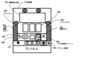
下ドア機構DDは、その上部の略中央部に設けられたメイン表示窓4と、メイン表示窓4の背面側であって、キャビネットGの内部側に取付けられたリールユニットRUとを有している。
The lower door mechanism DD has a
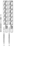
リールユニットRUは、3個のリール3L(左リール),3C(中リール),3R(右リール)を主体に構成されている。各リール3L,3C,3Rは、例えば、円筒状に形成されたリール本体と、リール本体の周面に装着された透光性のリール帯から構成され、リール帯には、複数(例えば、20個)の図柄がリールの回転方向に沿って所定の間隔を空けて描かれている。また、各リール3L,3C,3Rは、それぞれが縦方向に一定の速度で回転できるように並列状態(横一列)に配設される。メイン表示窓4は、例えば、樹脂製の透明パネルとして構成され、各リール3L,3C,3Rの周面上の図柄について少なくとも一部(例えば、3個)を視認可能としている。また、各リール3L,3C,3Rの内部には、少なくともメイン表示窓4から図柄が視認される位置に光源(後述のランプ・LED類に含まれるリールランプ)が設けられ、少なくとも各リール3L,3C,3Rが回転中であるときにはこれらを内部から一定の輝度で照明することで、図柄の視認性を確保している。
The reel unit RU is mainly composed of three reels: 3L (left reel), 3C (middle reel), and 3R (right reel). Each
また、下ドア機構DDは、メイン表示窓4の左側に設けられたサブ演出表示部22と、メイン表示窓4の右側に設けられた演出用ボタン10bとを有している。サブ演出表示部22は、後述のサブ表示装置220に表示された演出画像を表示する。なお、サブ演出表示部22をタッチパネルとして構成し、演出表示を行う機能のみならず、演出用ボタンの1つとして機能させることもできる。演出用ボタン10bは、遊技者の演出用の操作(演出操作)を受付ける操作部である。
The lower door mechanism DD also has a
また、下ドア機構DDは、メイン表示窓4の下方に形成された略水平面の台座部において、左側に設けられたMAXベットボタン6a,1ベットボタン6b,精算ボタン9と、略中央部に設けられた演出用ボタン10aと、右側に設けられたメダル投入口5とを有している。
The lower door mechanism DD has a roughly horizontal base formed below the
MAXベットボタン6a及び1ベットボタン6bは、パチスロ機1の内部に預けられている(クレジットされている)メダルを使用するための遊技者の遊技操作(ベット操作。「投入操作」や「掛け操作」等と称することもできる)を受付ける操作部である。MAXベットボタン6aが操作された場合、現在のベット数が最大ベット数(例えば、3枚)未満であり、クレジットされているメダルがその差分以上ある場合には、最大ベット数のメダルがベットされる。一方、クレジットされているメダルがその差分以上ない場合には、メダルはベットされない。また、1ベットボタン6bが操作された場合、現在のベット数が最大ベット数未満であり、クレジットされているメダルが1枚以上ある場合には、1枚のメダルがベットされる。
The
精算ボタン9は、クレジットされているメダルを返却(精算)するための遊技者の遊技操作(精算操作)を受付ける操作部である。なお、クレジットされているメダルがない状態で精算ボタン9が操作された場合、投入され、あるいは払出されるメダルに関し、クレジット可能数(例えば、50枚)の範囲内において、当該メダルをクレジットするクレジットモード(Cモード)と、当該メダルをクレジットしないペイモード(Pモード)とのいずれかのモードを選択可能とするための遊技者の遊技操作(C/Pモード選択操作)を受付可能としてもよい。すなわち、精算ボタン9をいわゆるC/Pボタンとして機能させることもできる。演出用ボタン10aは、遊技者の演出用の操作(演出操作)を受付ける操作部である。
The
メダル投入口5は、遊技者によって外部からパチスロ機1に投入されるメダルを受入れる。受入れたメダルは、後述のセレクタ31によって検出されるとともに、適正なメダルであるか否かが判定される。受入れた1枚のメダルが適正なものでない場合、受入れたメダルが後述のメダル払出口11から返却される。また、受入れた1枚のメダルが適正なものである場合、現在のベット数が最大ベット数未満である場合には、1枚のメダルがベットされる。現在のベット数が最大ベット数であり、クレジットされているメダルがクレジット可能数に到達していない場合には、1枚のメダルがクレジットされる。一方、クレジットされているメダルがクレジット可能数に到達している場合には、受入れたメダルが後述のメダル払出口11から返却される。
The
また、下ドア機構DDは、メイン表示窓4と上述の台座部との間に設けられた情報表示装置14を有している。情報表示装置14は、複数のランプ(LED)や7セグメントLEDを含んで構成され、その点灯態様により遊技に関する情報を表示する。
The lower door mechanism DD also has an
また、下ドア機構DDは、上述の台座部の下方において、左側に設けられたスタートレバー7と、略中央部に設けられた3個のストップボタン8L,8C,8Rと、右側に設けられた施錠機構15とを有している。スタートレバー7は、所定の角度範囲で傾動自在に取付けられ、遊技を開始させるための遊技者の遊技操作(開始操作)を受付ける操作部である。各ストップボタン8L,8C,8Rは、各リール3L,3C,3Rに対応して設けられ、それぞれの回転を停止させるための遊技者の遊技操作(停止操作)を受付ける操作部である。
The lower door mechanism DD has a
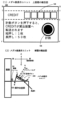
施錠機構15は、例えば、キーシリンダー錠から構成され、下ドア機構DDが閉鎖状態であるとき、遊技店側の管理者(例えば、遊技店の店員等。以下同じ)が鍵穴にドアキー(不図示)を挿入した状態で右に回すと解錠し、下ドア機構DDが開放状態となる。なお、施錠機構15には、ドア機構の開閉を管理する機能のみならず、リセットスイッチとしての機能をもたせてもよい。例えば、遊技店側の管理者が鍵穴にドアキーを挿入した状態で左に回した場合には、後述のリセットスイッチ53と同様のリセット操作を検出可能としてもよい。また、本実施形態では、下ドア機構DDが開放状態となったとき、これに連動して上ドア機構UDも開放状態となるように構成することもできるし、上ドア機構UDに対応する施錠機構を別途設けるようにし、それぞれ独立して開閉を管理可能とすることもできる。
The
また、下ドア機構DDは、その下部の中央部に設けられた腰部パネル13と、腰部パネル13の下方に設けられたメダル受皿12と、メダル受皿12の上方に設けられたメダル払出口11と、メダル払出口11の左右に設けられた透音孔24a,24bとを有している。
The lower door mechanism DD also has a
腰部パネル13は、例えば、機種の名称を表すロゴやモチーフを表すキャラクタ等の機種情報が描かれた装飾パネルと、この装飾パネルを背面側から照明するための光源(後述のランプ・LED類に含まれる腰部ランプ)から構成される。メダル受皿12は、メダル払出口11から払出されたメダルを貯留する。メダル払出口11は、パチスロ機1の内部から払出される(あるいは返却される)メダルを外部に排出する。なお、メダル払出口11から排出されるメダルは、後述のホッパー装置32から払出されたものと、後述のセレクタ31からキャンセルシュート(不図示)を通って返却されたものとがある。透音孔24a,24bは、それぞれの背面側であって、キャビネットGの内部側に取付けられたスピーカ35a,35b(スピーカ35aは図2において符号省略)から出力される効果音やBGM等の音声をパチスロ機1の前面側に向かって透過する。
The
なお、本実施形態では、キャビネットG内が上部空間と下部空間とに仕切られていることに対応して上ドア機構UD及び下ドア機構DDを設けることとしているが、キャビネットGにおける開口を適切に開閉可能とする限り、単一のドア機構として構成することもできるし、3つ以上のドア機構として構成することもできる。また、前後方向に二重に構成されたドア機構(例えば、外扉と内扉等)として構成することもできる。また、上ドア機構UD及び下ドア機構DDは、単に「扉」や「ドア」と称することもできるし、キャビネットGにおける開口を開閉可能とする部材として機能するため、「開閉部材」、「扉部材」、あるいは「ドア部材」等と称することもできる。 In this embodiment, the upper door mechanism UD and the lower door mechanism DD are provided in response to the interior of the cabinet G being divided into an upper space and a lower space, but as long as the opening in the cabinet G can be opened and closed appropriately, they can be configured as a single door mechanism or as three or more door mechanisms. They can also be configured as a double door mechanism in the front-to-rear direction (for example, an outer door and an inner door). The upper door mechanism UD and the lower door mechanism DD can be simply referred to as "doors" or "doors," or can be referred to as "opening and closing members," "door members," or "door members" because they function as members that can open and close the opening in the cabinet G.
[1-1-3.変動表示部]
上述のとおり、パチスロ機1は、各リール3L,3C,3R及びメイン表示窓4を備える。各リール3L,3C,3Rは、スタートレバー7が操作されると(遊技者によって開始操作が行われると)、後述のステッピングモータ51L,51C,51Rが駆動制御されることにより回転を開始する。これにより、メイン表示窓4に表示される図柄が変動表示される。また、各リール3L,3C,3Rは、各ストップボタン8L,8C,8Rが操作されると(遊技者によって停止操作が行われると)、後述のステッピングモータ51L,51C,51Rが駆動制御されることによりそれぞれの回転を停止する。これにより、メイン表示窓4に表示される図柄が停止表示される。
[1-1-3. Variable display section]
As described above, the
すなわち、各リール3L,3C,3R及びメイン表示窓4は、複数の図柄を複数列に変動表示(及び停止表示)可能な変動表示部(手段)、あるいは複数の図柄を変動表示(及び停止表示)可能な複数の変動表示部(手段)を構成する。なお、変動表示部(手段)は、「図柄表示部(手段)」や「可変表示部(手段)」等と称することもできる。また、図柄は、「絵柄」や「柄」等と称することもできるし、遊技者が視認により識別可能な情報であればよいことから、その意味において「識別情報」等と称することもできる。
In other words, each of the
また、メイン表示窓4は、各リール3L,3C,3Rの回転が停止されたとき、それぞれについて連続して配置された3個の図柄がその枠内に表示されるように構成されている。すなわち、メイン表示窓4は、各列において上段、中段及び下段の各領域にそれぞれ1個の図柄(合計で3個)を表示する(メイン表示窓4の枠内には、3行×3列の態様で図柄が表示される)。なお、メイン表示窓4は、「図柄表示領域」や「窓部」等と称されることがある。
The
また、メイン表示窓4には、有効ラインが定義される。有効ラインは、遊技者の停止操作に応じて全ての列の図柄が停止表示されたときに、規定された図柄の組合せが表示されたか否かを判定するためのラインである。その意味において、有効ラインは、「入賞ライン」や「判定ライン」等と称することもできる。また、有効ラインは、各列の各領域のいずれかを結ぶラインとして構成される。すなわち、メイン表示窓4が3行×3列の態様で図柄を表示するように構成される場合、最大27通りの有効ラインを定義することが可能である。もっとも、実際には、そのうちの一又は複数通りのラインを有効ラインとして定義し、他のラインは有効ラインではない無効ラインとして定義することができる。
In addition, a winning line is defined in the
なお、例えば、リール3Lの中段領域、リール3Cの中段領域、及びリール3Rの中段領域を結ぶラインは「センターライン」、リール3Lの上段領域、リール3Cの上段領域、及びリール3Rの上段領域を結ぶラインは「トップライン」、リール3Lの下段領域、リール3Cの下段領域、及びリール3Rの下段領域を結ぶラインは「ボトムライン」、リール3Lの下段領域、リール3Cの中段領域、及びリール3Rの上段領域を結ぶラインは「クロスアップライン」、リール3Lの上段領域、リール3Cの中段領域、及びリール3Rの下段領域を結ぶラインは「クロスダウンライン」等と称され、これらは各列の各領域を一直線で結ぶラインであることから、これらのうちの一又は複数通りのラインが有効ラインとして定義されることが多い。もっとも、上述のとおり、各列の各領域を折れ線で結ぶ、いわゆる変則ラインを有効ラインとして定義することもできる。
For example, the line connecting the middle area of
また、有効ラインが有効化されるためには、遊技者の開始操作に先立って、今回の遊技に必要な分の(遊技開始可能枚数分の)メダルがベットされている必要があるが、有効化される有効ライン数は、ベット数にかかわらず同じであってもよいし、ベット数に応じて変動してもよい。例えば、上述の「センターライン」、「トップライン」、及び「ボトムライン」の3通りのラインが有効ラインとして定義されているとした場合、前者の場合には、ベット数が1~3のいずれであっても「センターライン」、「トップライン」、及び「ボトムライン」が有効化されるようにする。一方、後者の場合には、ベット数が1であれば「センターライン」のみが有効化され、ベット数が2であれば「センターライン」及び「トップライン」が有効化され、ベット数が3(最大ベット数)であれば「センターライン」、「トップライン」、及び「ボトムライン」が有効化されるようにする。 In order for the active lines to be activated, the player must bet the number of medals required for the current game (the number of medals that can be used to start the game) before starting the game. The number of active lines that are activated may be the same regardless of the number of bets, or may vary depending on the number of bets. For example, if the above-mentioned three lines, the "center line", "top line", and "bottom line", are defined as active lines, in the former case, the "center line", "top line", and "bottom line" are activated regardless of the number of bets, from 1 to 3. On the other hand, in the latter case, if the number of bets is 1, only the "center line" is activated, if the number of bets is 2, the "center line" and "top line" are activated, and if the number of bets is 3 (the maximum number of bets), the "center line", "top line", and "bottom line" are activated.
なお、本実施形態では、変動表示部が、3個のリール3L,3C,3Rと、各列において3個ずつの図柄を表示可能とするメイン表示窓4とを有することで、3行×3列の態様で図柄を表示するものとしていたが、変動表示部における図柄表示態様はこれに限られない。例えば、リール数を1個、2個、あるいは4個以上とし、また、例えば、各列における図柄の表示数を1個、2個、あるいは4個以上とすることで上述の態様とは異なる態様で図柄を表示することもできる。また、この場合、定義可能な有効ライン数も適宜増減する。
In this embodiment, the variable display unit has three
また、本実施形態では、変動表示部が、各リール3L,3C,3Rを回転させることによって図柄を変動表示するものとしていたが、変動表示部の構成はこれに限られない。例えば、後述のメイン表示装置210やサブ表示装置220と同様の画像表示装置を用いた構成としてもよいし、その他の表示装置(例えば、有機ELや7セグメントLED等)を用いた構成としてもよい。また、例えば、その他の物理的装置(例えば、ベルト等)を用いた構成としてもよい。また、変動表示部の配置や大きさ等は適宜変更可能である。
In addition, in this embodiment, the variable display unit displays the patterns by rotating each of the
また、本実施形態では、変動表示部が、後述の主制御回路100によって制御される、遊技に直接関連するメイン側表示部として機能とするものとしていたが、これとともに、後述の副制御回路200によって制御される、遊技に直接関連しない演出に関連するサブ側表示部としての変動表示部を設けるようにしてもよい。なお、サブ側表示部は、例えば、メイン表示装置210やサブ表示装置220を用いた構成とすることができる。すなわち、遊技者の開始操作(あるいは、その他開始条件の成立)に応じて図柄を変動表示させ、遊技者の停止操作(あるいは、その他停止条件の成立)に応じて図柄を停止表示させる変動表示部として、メイン側表示部のみならず、サブ側表示部を設けるようにしてもよい。なお、この場合、遊技者が変動表示部について遊技に直接関連するものであるか否かを識別可能とするため、メイン側表示部の近傍には、「回胴」ないし「メインリール」といった文字が表示された識別表示を付しておき、当該変動表示部がメイン側表示部であることを識別可能とすればよい。なお、このような識別表示は、メイン表示装置210やサブ表示装置220において表示されるようにしてもよい。
In addition, in this embodiment, the variable display unit functions as a main display unit directly related to the game, controlled by the
[1-1-4.メダル投入口]
上述のとおり、パチスロ機1は、遊技者によって外部からパチスロ機1に投入されるメダルを受け入れるメダル投入口5を備える。なお、メダル投入口5及び後述のセレクタ31は、MAXベットボタン6aや1ベットボタン6bと同様に、1回の遊技に必要なメダル数をベットする機能を有することから、このような投入動作は、例えば、ベット操作と換言することもできる。したがって、メダル投入口5は、遊技者のベット操作を検出可能なベット操作検出部(手段)であるともいえる。なお、メダル投入口の形状、配置及び大きさ等は適宜変更可能である。また、パチスロ機1が、後述のメダルレス遊技機として構成される場合には、必ずしも必須の構成とはならない。
[1-1-4. Medal slot]
As described above, the
なお、本実施形態では、遊技に使用し、あるいは遊技結果に応じて付与される遊技価値として、遊技媒体としてのメダルを用いることを一例として説明しているが、このように用いられる遊技価値はこれに限られない。例えば、コイン、遊技球、遊技用のポイントデータ又はトークン等を用いることもできる。また、遊技価値は、単に「価値」、あるいは「遊技用価値」等と称することもできる。 In this embodiment, the use of medals as gaming media is described as an example of gaming value that is used in games or awarded according to game results, but the gaming value used in this manner is not limited to this. For example, coins, gaming balls, gaming point data or tokens, etc. can also be used. Furthermore, gaming value can also be simply referred to as "value" or "game value", etc.
[1-1-5.操作部]
パチスロ機1は、遊技者が操作可能な操作部として、例えば、以下に示す各操作部を備える。なお、以下に示す各操作部はあくまで一例であって、これらとは異なる操作部を備える構成としてもよいし、これらのうち必ずしも必須のものでない操作部については、これを備えない構成としてもよい。
[1-1-5. Operation section]
The
[1-1-5-1.ベットボタン]
上述のとおり、パチスロ機1は、その内部に預けられている(クレジットされている)メダルを使用するための遊技者のベット操作を受付けるMAXベットボタン6a及び1ベットボタン6bを備える。また、このようなベット操作は、後述のベットスイッチ6Sによって検出される。したがって、MAXベットボタン6a及び1ベットボタン6b、並びにベットスイッチ6Sは、遊技者のベット操作を検出可能なベット操作検出部(手段)を構成する。なお、ベットボタンは、あくまで遊技者のベット操作を検出可能であればよく、その形状、配置及び大きさ等は適宜変更可能である。また、本実施形態では、MAXベットボタン6a及び1ベットボタン6bを設けているが、1ベットボタン6bを設けることなくMAXベットボタン6aのみを設けるようにしてもよい。また、2枚のメダルがベットされる2ベットボタンを別途設けるようにしてもよい。
[1-1-5-1. Bet button]
As described above, the
[1-1-5-2.スタートレバー]
上述のとおり、パチスロ機1は、遊技を開始させるための遊技者の開始操作を受付けるスタートレバー7を備える。また、このような開始操作は、後述のスタートスイッチ7Sによって検出される。したがって、スタートレバー7及びスタートスイッチ7Sは、遊技者の開始操作を検出可能な開始操作検出部(手段)を構成する。なお、スタートレバーは、あくまで遊技者の開始操作を検出可能であればよく、その形状、配置及び大きさ等は適宜変更可能である。
[1-1-5-2. Start lever]
As described above, the
[1-1-5-3.ストップボタン]
上述のとおり、パチスロ機1は、各リール3L,3C,3Rに対応して設けられ、それぞれの回転を停止させるための遊技者の停止操作を受付ける各ストップボタン8L,8C,8Rを備える。また、このような停止操作は、後述のストップスイッチ8Sによって検出される。したがって、各ストップボタン8L,8C,8R及びストップスイッチ8Sは、遊技者の停止操作を検出可能な停止操作検出部(手段)を構成する。なお、ストップボタンは、あくまで遊技者の停止操作を検出可能であればよく、その形状、配置及び大きさ等は適宜変更可能である。
[1-1-5-3. Stop button]
As described above, the
[1-1-5-4.精算ボタン]
上述のとおり、パチスロ機1は、クレジットされているメダルを返却(精算)するための遊技者の精算操作(返却操作)を受付ける精算ボタン9を備える。また、このような精算操作は、後述の精算スイッチ9Sによって検出される。したがって、精算ボタン9及び精算スイッチ9Sは、遊技者の精算操作を検出可能な精算操作検出部(手段)を構成するなお、精算ボタンは、あくまで遊技者の精算操作を検出可能であればよく、その形状、配置及び大きさ等は適宜変更可能である。
[1-1-5-4. Settlement button]
As described above, the
[1-1-5-5.演出用ボタン]
上述のとおり、パチスロ機1は、遊技者の演出操作を受付ける演出用ボタン10a,10bを備える。なお、このような演出操作は、それぞれの演出用ボタンに対応して設けられた検出スイッチ(不図示)によって検出される。したがって、演出用ボタン10a,10b及び当該検出スイッチは、遊技者の演出操作を検出可能な演出操作検出部(手段)を構成する。なお、演出用ボタンは、あくまで遊技者の演出操作を検出可能であればよく、その形状、配置及び大きさ等は適宜変更可能である。また、本実施形態では、2個の演出用ボタン10a,10bを設けているが、これらのいずれも設けることなく構成することもできるし、これらのうちいずれかのみを設けるように構成することもできる。また、3個以上の演出用ボタンを設けるように構成することもできる。
[1-1-5-5. Performance buttons]
As described above, the
なお、演出用ボタンの主な用途としては、特定の演出(例えば、後述の操作連動演出)実行時に演出態様を変化させること、後述のユーザーメニューにおいて選択・決定操作を行うこと等である。したがって、用途に応じた演出用ボタンを設けるように構成することもできる。例えば、前者の用途では演出用ボタン10a,10bが使用されるものとし、後者の用途では上述のタッチパネルを使用するように構成することもできる。なお、後者の用途で用いるために、別の演出用ボタンとして、選択・決定操作を受付可能なジョグダイヤルや十字キー等を設けるように構成することもできる。
The main uses of the performance buttons are to change the performance mode when a specific performance (for example, an operation-linked performance described below) is executed, and to perform selection and confirmation operations in a user menu described below. Therefore, it is possible to configure the system so that performance buttons are provided according to the purpose. For example, the
[1-1-6.メダル払出口]
上述のとおり、パチスロ機1は、パチスロ機1の内部から払出される(あるいは返却される)メダルを外部に排出するメダル払出口11を備える。なお、入賞が発生してメダルを払出す場合、メダル払出口11は、後述のホッパー装置32から払出されたメダルを遊技者に付与するものであることから、遊技者に特典を付与する特典付与手段の一部であるともいえる。また、メダル払出口の形状、配置及び大きさ等は適宜変更可能である。また、パチスロ機1が、後述のメダルレス遊技機として構成される場合には、必ずしも必須の構成とはならない。
[1-1-6. Medal payout outlet]
As described above, the
[1-1-7.メダル受皿]
上述のとおり、パチスロ機1は、メダル払出口11から払出されたメダルを貯留するメダル受皿12を備える。すなわち、メダル受皿12は、付与された遊技価値を貯留可能な貯留部(手段)を構成する。なお、メダル受皿の形状、配置及び大きさ等は適宜変更可能である。また、パチスロ機1が、後述のメダルレス遊技機として構成される場合には、必ずしも必須の構成とはならない。
[1-1-7. Medal tray]
As described above, the
[1-1-8.腰部パネル]
上述のとおり、パチスロ機1は、例えば、機種情報が描かれた装飾パネルと、この装飾パネルを背面側から照明するための腰部ランプから構成される腰部パネル13を備える。なお、腰部パネル13は、基本的にはそのパチスロ機1がどういった機種であるかを遊技者にわかりやすく示すものであるが、例えば、腰部ランプの点灯態様により、あるいは、腰部パネル13そのものを画像表示装置等で構成することにより演出を実行可能な演出実行手段の1つとして構成することもできる。
[1-1-8. Waist panel]
As described above, the
[1-1-9.情報表示部]
上述のとおり、パチスロ機1は、その点灯態様により遊技に関する情報を表示する情報表示装置14を備える。すなわち、情報表示装置14は、遊技に関する情報を表示可能な情報表示部(手段)を構成する。
[1-1-9. Information display]
As described above, the
情報表示装置14は、例えば、インサートランプと、スタートランプと、リプレイランプと、ベット数ランプと、クレジットランプと、払出数ランプと、指示モニタと、リミットランプ等を含んで構成される。
The
インサートランプは、点灯することでメダルの投入が可能であることを表示する。スタートランプは、点灯することでスタートレバー7の操作にともなって遊技の開始が可能であることを表示する。リプレイランプは、点灯することで再遊技の作動によりメダルが自動投入されたことを表示する。ベット数ランプは、点灯することでベットされたメダル数を表示する。クレジットランプは、その点灯態様によりクレジットされているメダル数を表示する。払出数ランプは、その点灯態様により遊技結果に応じて払出されたメダル数(払出数)を表示する。
The insert lamp lights up to indicate that medals can be inserted. The start lamp lights up to indicate that play can be started by operating the
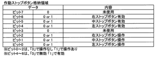
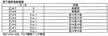
また、指示モニタは、報知ランプ(停止操作表示部)と、区間ランプ(状態表示部)と、を含んで構成される。報知ランプは、遊技者に対して停止操作の情報が報知される状況下(例えば、AT状態)において、報知する停止操作の情報と一義的に対応する態様で点灯することで、停止操作の情報を表示する。なお、「報知する停止操作の情報と一義的に対応する態様」とは、例えば、押し順(本実施形態では、これを「打順」として説明する場合がある)「1st(第1停止操作をリール3Lに対して行うこと)」を報知する場合には指示モニタに数値「1」を表示し、押し順「2nd(第1停止操作をリール3Cに対して行うこと)」を報知する場合には指示モニタに数値「2」を表示し、押し順「3rd(第1停止操作をリール3Rに対して行うこと)」を報知する場合には指示モニタに数値「3」を表示する等の態様のことである。なお、報知ランプは、クレジットランプや払出数ランプとは必ずしも別に設けられていなくともよい。例えば、クレジットランプ又は払出数ランプのいずれかを用いて、停止操作の情報を表示してもよい。
The instruction monitor is also configured to include a notification lamp (stop operation display section) and a section lamp (state display section). The notification lamp displays information on the stop operation by lighting in a manner that uniquely corresponds to the information on the stop operation to be notified in a situation where the information on the stop operation is notified to the player (for example, in an AT state). Note that the "mode that uniquely corresponds to the information on the stop operation to be notified" refers to, for example, a manner in which the number "1" is displayed on the instruction monitor when notifying the push order (which may be described as the "hitting order" in this embodiment) "1st (performing the first stop operation on
このように、本実施形態では、遊技者に対して停止操作の情報が報知される状況下においては、後述の副制御回路200によって制御されるサブ側報知手段(例えば、メイン演出表示部21)のみならず、後述の主制御回路100によって制御されるメイン側報知手段としての指示モニタにおいても停止操作の情報が報知される。なお、メイン側報知手段における報知の態様と、サブ側報知手段における報知の態様とは、互いに異なる態様であってもよい。すなわち、メイン側報知手段では、報知する停止操作の情報と一義的に対応する態様で報知すればよく、必ずしも、停止操作の情報を直接的に報知する必要はない。例えば、押し順「1st」を報知する場合、指示モニタにおいて数値「1」が表示されたとしても、遊技者によっては報知内容を特定できない可能性もある。一方、サブ側報知手段では、停止操作の情報を直接的に報知すればよい。例えば、押し順「1st」を報知する場合、メイン演出表示部21では、リール3Lに対して第1停止操作を行わせるための指示情報を直接的に報知すればよい。
In this way, in this embodiment, in a situation where information on a stop operation is notified to a player, not only the sub-side notification means (for example, the main performance display unit 21) controlled by the
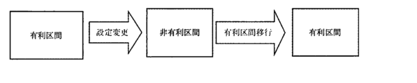
また、区間ランプは、点灯することで現在の状態が後述の有利区間中であることを表示する。区間ランプは、例えば、後述の非有利区間から有利区間に移行するとき、当該有利区間の遊技が開始されるまでの任意のタイミングで点灯し、当該有利区間が終了して非有利区間に移行するとき、当該非有利区間の遊技が開始されるまでの任意のタイミングで消灯する。なお、区間ランプの点灯タイミングはこれに限られない。例えば、非有利区間又は有利区間における後述の演出区間(通常有利区間)から最初に有利区間における後述の増加区間(AT状態)に移行するとき、当該増加区間の遊技が開始されるまでの任意のタイミングで点灯するものとしてもよい。すなわち、区間ランプは、演出区間であるか増加区間であるかを問わず有利区間中であることを報せるものであってもよいし、少なくとも最初の増加区間の開始からこれを含めた有利区間が終了するまでの期間を報せるものであってもよい。 In addition, the section lamp, when lit, indicates that the current state is in the advantageous section, described below. For example, when transitioning from a non-advantageous section to an advantageous section, described below, the section lamp lights up at any timing before play in the advantageous section begins, and when the advantageous section ends and transitions to a non-advantageous section, it goes out at any timing before play in the non-advantageous section begins. Note that the timing of lighting the section lamp is not limited to this. For example, when transitioning from a performance section (normal advantageous section) described below in a non-advantageous section or advantageous section to an increase section (AT state) described below in an advantageous section for the first time, the section lamp may light up at any timing before play in the increase section begins. In other words, the section lamp may indicate that the section is in an advantageous section regardless of whether it is a performance section or an increase section, or may indicate at least the period from the start of the first increase section to the end of the advantageous section, including this.
また、リミットランプは、その点灯態様により後述のリミット処理が実行されたこと、あるいはその可能性を表示する。例えば、リミット処理が実行された場合に点灯することで遊技者に有利な状態(例えば、AT状態)がリミット処理の実行によって強制的に終了されたことを報せる。また、例えば、リミット処理の実行が近い場合に点滅することで当該有利な状態がリミット処理の実行によって強制的に終了される可能性が高いことを報せる。なお、これら以外にも点灯、点滅又は消灯の契機を設けることで、リミット処理に関するその他の情報を適宜報せることもできる。 The limit lamp also indicates, depending on the lighting state, whether or not a limit process described below has been executed. For example, by lighting up when a limit process has been executed, it notifies the player that a favorable state (e.g., AT state) has been forcibly ended by the execution of the limit process. Also, by flashing when the execution of the limit process is imminent, it notifies the player that there is a high possibility that the favorable state will be forcibly ended by the execution of the limit process. In addition to these, by providing triggers for lighting, flashing, or going off, it is also possible to appropriately notify other information regarding the limit process.
[1-1-10.演出表示部]
上述のとおり、パチスロ機1は、演出画像を表示するメイン演出表示部21及びサブ演出表示部22を備える。メイン演出表示部21及びサブ演出表示部22は、演出表示を行うことが可能な演出表示部(手段)を構成する。また、遊技者に対し視覚的な観点での演出を実行可能な演出実行手段の1つとして構成される。
[1-1-10. Performance display]
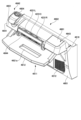
As described above, the
メイン演出表示部21は、演出表示窓UD1を介して演出表示を行うメイン表示装置210を含んで構成される。また、メイン表示装置210は、キャビネットG内の中間支持板G1上に交換可能に載置された表示ユニットAとして構成される。表示ユニットAは、画像表示用の照射光を出射する照射ユニットBと、照射ユニットBからの照射光が照射されることにより画像を出現させるスクリーン装置Cとを有するいわゆるプロジェクションマッピング装置である。なお、本実施形態では、メイン表示装置210をこのように構成することで、高度で、かつ迫力のある演出表示を可能としているが、メイン表示装置210の構成はこれに限られない。すなわち、遊技者に対し視覚的な観点での演出を実行可能であればよく、液晶表示装置や有機EL等の画像表示装置や7セグメントLED等の表示装置として構成することもできるし、サブリール等の変動表示装置やドット表示装置として構成することもできる。また、このような観点より、その形状、配置及び大きさ等も適宜変更可能である。また、パチスロ機1が、例えば、いわゆる出目によって楽しませることを主体とする遊技性である等の場合には、メイン演出表示部21を設けないように構成することもできる(サブ演出表示部22も同様)。
The
サブ演出表示部22は、サブ表示装置220を含んで構成される。また、サブ表示装置220は、液晶表示装置として構成される。なお、サブ表示装置220もメイン表示装置210と同様に、他の画像表示装置や表示装置として構成することができるし、変動表示装置やドット表示装置として構成することもできる。また、このような観点より、その形状、配置及び大きさ等も適宜変更可能である。また、メイン演出表示部21は、大画面で構成されていることから、押し順の報知や当り報知、あるいは連続演出等といった今回の遊技と密接に関連する演出を主として表示し、サブ演出表示部22は、小画面で構成されていることから、遊技履歴等といった今回の遊技とはそこまで密接に関連しない演出を主として表示するといったように、目的に応じて表示内容を分けて表示することが可能である。また、本実施形態では、メイン演出表示部21及びサブ演出表示部22の2個の演出表示部を設けるように構成しているが、これらのいずれも設けることなく構成することもできるし、これらのうちいずれかのみを設けるように構成することもできる。また、3個以上の演出表示部を設けるように構成することもできる。
The
[1-1-11.ランプ]
上述のとおり、パチスロ機1は、一例として挙げた上部ランプ23のように、その発光態様(点灯、点滅、あるいは消灯のみならず、フルカラーLEDとして構成される場合にはその輝度や発光色を含む)によって演出を行うことが可能な一又は複数のランプ(発光手段)を備える。また、このような発光手段は、遊技者に対し視覚的な観点での演出を実行可能な演出実行手段の1つとして構成される。なお、このような観点より、その数、形状、配置及び大きさ等も適宜変更可能である。
[1-1-11. Lamp]
As described above, the
なお、後述のランプ・LED類に含まれるその他のランプとしては、例えば、上ドア機構UDの両側端面や下ドア機構DDの両側端面に設けられたサイドランプや各操作部内に設けられた操作部ランプ等を挙げることができる。なお、後者は、それぞれの操作部が操作可能であるか否かを遊技者に報せる機能を含むことから、このような機能を発揮させる場合には演出内容に応じて発光態様を変動させず、一義的な発光態様によって発光するように制御することができる。 Other lamps included in the lamps and LEDs described below include, for example, side lamps provided on both end faces of the upper door mechanism UD and the lower door mechanism DD, and operation unit lamps provided within each operation unit. The latter include a function to inform the player whether or not each operation unit can be operated, so when this function is exercised, the light emission pattern does not change depending on the performance content, but can be controlled to emit light in a unique light emission pattern.
[1-1-12.スピーカ]
上述のとおり、パチスロ機1は、効果音やBGM等の音声を出力するスピーカ35a,35bを備える。スピーカ35a,35bは、音声の出力によって演出を行うことが可能な音声出力手段を構成する。また、遊技者に対し聴覚的な観点での演出を実行可能な演出実行手段の1つとして構成される。なお、このような観点より、その数、形状、配置及び大きさ等も適宜変更可能である。
[1-1-12. Speaker]
As described above, the
[1-1-13.その他演出装置]
なお、パチスロ機1では、上述の各種演出装置(演出実行手段)以外の演出装置を設けることもできる。例えば、いわゆる役物といった可動演出装置、振動により演出を行う振動演出装置、あるいは空気を噴射することで演出を行うエアー演出装置等の演出装置を設け、演出を実行することも可能である。すなわち、遊技者の五感(視覚、聴覚、触覚、味覚、嗅覚)のいずれかに訴えかけることができる(遊技者に演出が実行されていることを認識可能とさせる)演出を実行可能な演出装置であれば、それらのうちいずれを用いることもできる。したがって、本実施形態において「演出を実行する」とは、特段の説明がない限り、上述の各種演出装置(演出実行手段)のうち、一又は複数の演出装置のいずれの演出装置を用いて演出を実行してもよいこと示している。
[1-1-13. Other production devices]
In addition, in the
[1-2.内部構造]
[1-2-1.セレクタ]
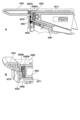
セレクタ31(図2において符号省略)は、メダル投入口5から投入されたメダルの流下路であって、下ドア機構DDの背面側に設けられている。セレクタ31は、例えば、後述のメダルセンサ31Sと、振分装置とを有している。
[1-2. Internal structure]
[1-2-1. Selector]
The selector 31 (reference numeral omitted in FIG. 2) is a passage through which medals inserted through the
メダルセンサ31Sは、メダル投入口5から投入されたメダルを検出するとともに、検出されたメダルが適切なメダルであるか否かを判定する。振分装置は、メダルセンサ31Sにより、検出されたメダルが適切なメダルであると判定された場合であって、メダルの受入れが可能な状態である場合、当該メダルが後述のホッパー装置32側に案内されるように駆動制御される。なお、この場合、ベット数あるいはクレジット数が1加算される。一方、振分装置は、メダルセンサ31Sにより、検出されたメダルが適切なメダルでないと判定された場合、及びメダルの受入れが可能な状態でない場合、当該メダルがキャンセルシュートを通ってメダル払出口11から返却されるように駆動制御される。メダルセンサ31Sによるメダルの検出に異常が発生した場合にはセレクタエラーが発生する。なお、この場合、異常の発生要因(例えば、メダル詰まり)を解消した上で、リセット操作が行われると当該エラー状態が解除される。
The medal sensor 31S detects medals inserted through the
すなわち、セレクタ31は、投入された遊技媒体を検出可能な遊技媒体検出部(手段)を構成する。また、セレクタ31は、投入された遊技媒体が適正であるか否かを判定可能な判定手段を構成する。また、セレクタ31は、投入された遊技媒体が適正である場合には内部に貯留する一方、投入された遊技媒体が適正でない場合には外部に排出する振分手段を構成する。また、セレクタ31の構成、配置及び大きさ等は適宜変更可能である。また、パチスロ機1が、後述のメダルレス遊技機として構成される場合には、必ずしも必須の構成とはならない。
In other words, the
[1-2-2.ホッパー装置]
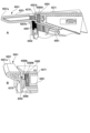
ホッパー装置32は、キャビネットG内の下部空間に設けられている。ホッパー装置32は、例えば、メダル投入口5から投入され、セレクタ31によって案内されたメダルを貯留するバケット部と、バケット部の底部に設けられ、バケット部に貯留されたメダルを撹拌するとともに、1枚ずつ排出部に案内するディスク部と、ディスク部によって案内されたメダルを1枚ずつ排出する排出部と、排出部から排出されたメダルをカウントするカウントセンサとを有している。
[1-2-2. Hopper device]
The
バケット部は、一定数のメダルを貯留可能に構成される。一定数を超えたメダルは、上面側に設けられた案内通路を通って後述のメダル補助収納庫33に案内される。なお、バケット部に貯留されたメダルが空となった場合にはホッパーエンプティエラーが発生する。なお、この場合、メダルを補充した上で、リセット操作が行われると当該エラー状態が解除される。 The bucket is configured to be able to store a certain number of medals. Any medals exceeding this number are guided through a guide passage provided on the top side to the auxiliary medal storage 33 (described below). If the medals stored in the bucket become empty, a hopper empty error occurs. In this case, the error state will be cleared if medals are refilled and a reset operation is performed.
ディスク部は、中心から放射状にメダル形状のくり抜き部が複数形成され、駆動信号にしたがって中心軸が回転駆動されることで、くり抜き部に嵌ったメダルを1枚ずつ排出部に案内する。なお、ディスク部が回転することでバケット部に貯留されたメダルが撹拌される。また、ディスク部の回転に異常が発生した場合にはホッパージャムエラーが発生する。なお、この場合、異常の発生要因(例えば、メダル詰まり)を解消した上で、リセット操作が行われると当該エラー状態が解除される。 The disk unit has multiple medal-shaped cutouts formed radially from the center, and the central shaft is rotated in response to a drive signal to guide medals that fit into the cutouts one by one to the discharge unit. The rotation of the disk unit agitates the medals stored in the bucket unit. If an abnormality occurs in the rotation of the disk unit, a hopper jam error occurs. In this case, the error state is cleared by performing a reset operation after eliminating the cause of the abnormality (for example, a medal jam).
カウントセンサは、排出部から排出されたメダルを検出するとともに、その枚数をカウントする。例えば、1枚のメダルを払出す場合、ディスク部が回転を開始し、続いてカウントセンサが1枚のメダルの払出をカウントしたことに応じてディスク部の回転が停止する。このようにして、適正枚数のメダルが払出されるようにしている。 The count sensor detects medals discharged from the discharge section and counts the number of medals. For example, when one medal is to be paid out, the disk section starts to rotate, and then the disk section stops rotating when the count sensor counts that one medal has been paid out. In this way, the correct number of medals is paid out.
すなわち、ホッパー装置32は、遊技媒体を払出可能な遊技媒体払出部(手段)を構成する。また、上述のとおり、遊技者に特典を付与する特典付与手段の一部であるともいえる。また、ホッパー装置32の構成、配置及び大きさ等は適宜変更可能である。また、パチスロ機1が、後述のメダルレス遊技機として構成される場合には、必ずしも必須の構成とはならない。
In other words, the
[1-2-3.メダル補助収納庫]
メダル補助収納庫33は、キャビネットG内の下部空間に設けられている。メダル補助収納庫33は、例えば、ホッパー装置32のバケット部から案内されたメダルを収納する収納部と、収納部の近傍に設けられ、収納部に収納されたメダルの容量を検出するメダル補助収納庫スイッチ33Sとを有している。
[1-2-3. Auxiliary Medal Storage]
The
収納部は、一定数のメダルを収納可能に構成される。メダル補助収納庫スイッチ33Sにより、当該一定数以上のメダルが収納されたと判定された場合にはメダル補助収納庫エラーが発生する。なお、この場合、収納部に収納されたメダルを少なくとも一定数未満に減らした上で、リセット操作が行われると当該エラー状態が解除される。
The storage section is configured to be able to store a certain number of medals. If the auxiliary
すなわち、メダル補助収納庫33は、余剰の遊技媒体を貯留可能な余剰遊技媒体貯留部(手段)を構成する。なお、メダル補助収納庫33の構成、配置及び大きさ等は適宜変更可能である。また、パチスロ機1が、後述のメダルレス遊技機として構成される場合には、必ずしも必須の構成とはならない。
In other words, the
[1-2-4.電源装置]
電源装置34は、キャビネットG内の下部空間に設けられている。電源装置34は、例えば、電源基板34aと、電源スイッチ34bとを有しており、電源スイッチ34bがオンされることに応じてパチスロ機1に電力を供給する。なお、電源装置34は、家庭用電気製品等と同じく電源ケーブル(不図示)から供給された交流電圧100Vの電力を各部で必要な直流電圧の電力に変換して、変換した電力を各部へ供給する。すなわち、電源装置34は、必要な電力を遊技機に供給可能な電源部(手段)を構成する。なお、電源装置34の構成、配置及び大きさ等は適宜変更可能である。
[1-2-4. Power supply]
The
なお、本実施形態では、後述の設定用鍵型スイッチ52やリセットスイッチ53が主制御基板71(より詳細には後述の主制御基板ケース上)に設けられるように構成しているが、これらのスイッチを電源装置34に設けるように構成することもできる。
In this embodiment, the setting
[1-2-5.基板]
パチスロ機1は、各種制御に必要な基板として、例えば、以下に示す各基板を備える。なお、以下に示す各基板はあくまで一例であって、これらとは異なる基板を備える構成としてもよいし、これらのうち必ずしも必須のものでない基板については、これを備えない構成としてもよい。
[1-2-5. Substrate]
The
[1-2-5-1.主制御基板]
主制御基板71は、キャビネットG内において、リールユニットRUの背面側に取付けられている。なお、主制御基板71は、遊技に関する制御を行う遊技制御基板であり、その状態が視認可能となるように透明(あるいは略透明)に構成された樹脂製の主制御基板ケース(不図示)内に収容されている。主制御基板71の電気的構成については後述する。
[1-2-5-1. Main control board]
The
なお、主制御基板71の仕様には種々の制約があり、基本的に各種電子部品がDIP実装されて構成されるものとなっているが、各種電子部品の一部又は全部についてSMT実装(表面実装)されて構成されるものとしてもよい。また、この場合、テスターやオシロスコープを用いて動作確認を行うためのテストポイントを設けるようにしてもよい。また、各種電子部品の一部又は全部について6平方mmを超えない小さい電子部品を使用してもよい。また、主制御基板71の基板面を多層化して構成してもよい。
The specifications of the
[1-2-5-2.副制御基板]
副制御基板72は、キャビネットG内において、中間支持板G1の裏面側に取付けられている。なお、副制御基板72は、演出に関する制御を行う演出制御基板であり、樹脂製の副制御基板ケース(不図示)内に収容されている。なお、副制御基板ケースは、主制御基板ケースと同様に透明(あるいは略透明)に構成された樹脂製のケースとして構成することもできるし、不透明(あるいは略不透明)に構成された他の材料を用いたケースとして構成することもできる。副制御基板72の電気的構成については後述する。
[1-2-5-2. Sub-control board]
The
[1-2-5-3.その他基板]
(主中継基板)
主中継基板73(図2において符号省略)は、キャビネットG内の特定位置(例えば、下ドア機構DDの背面側)に取付けられており、主中継基板73に接続された各種デバイス等と主制御基板71との間、及び主制御基板71と副制御基板72との間を中継するための中間制御基板である。なお、主中継基板73は、制御効率や配線効率の便宜から主制御基板71とは別の基板として構成されたものであるため、特段の支障がなければ主中継基板73の機能を全て主制御基板71にもたせ、主中継基板73を設けない構成とすることもできる。また、このような観点より、主中継基板73をさらに複数の中継基板に分割し、制御効率や配線効率の向上を図るようにしてもよい。すなわち、主中継基板として複数の基板を設けるようにしてもよい。
[1-2-5-3. Other substrates]
(Main relay board)
The main relay board 73 (reference numeral omitted in FIG. 2) is attached to a specific position (for example, the rear side of the lower door mechanism DD) in the cabinet G, and is an intermediate control board for relaying between the
(副中継基板)
副中継基板74は、キャビネットG内の特定位置(例えば、下ドア機構DDの背面側)に取付けられており、副中継基板74に接続された各種デバイス等と副制御基板72との間、及び主制御基板71と副制御基板72との間を中継するための中間制御基板である。なお、副中継基板74は、制御効率や配線効率の便宜から副制御基板72とは別の基板として構成されたものであるため、特段の支障がなければ副中継基板74の機能を全て副制御基板72にもたせ、副中継基板74を設けない構成とすることもできる。また、このような観点より、副中継基板74をさらに複数の中継基板に分割し、制御効率や配線効率の向上を図るようにしてもよい。すなわち、副中継基板として複数の基板を設けるようにしてもよい。
(Sub-relay board)
The
(外部集中端子板)
外部集中端子板55は、キャビネットG内の特定位置(例えば、下部空間の奥側)に取付けられており、例えば、メダル投入信号、メダル払出信号、外部信号1~4及びセキュリティ信号等の信号をパチスロ機1の外部へ出力する。なお、外部信号1~4は、その出力開始条件及び出力終了条件を適宜設定可能であり、その遊技性に応じてパチスロ機1の内部状態(例えば、ボーナス状態やAT状態)の遷移を外部に報せることを可能としている。そして、外部集中端子板55は、通常、外部のデータ表示機やホールコンピュータに接続されることから、これらの機器においても、パチスロ機1におけるメダルの投入・払出状況やエラーの発生状況のみならず、そのような内部状態の遷移状況が認識可能となっている。
(External common terminal board)
The external centralized
(試験機用インターフェースボード)
試験機用第1インターフェースボード301及び試験機用第2インターフェースボード302は、ともにパチスロ機1の検定試験(試射試験)において、遊技に関する各種信号を試験機に出力する際に用いられる中継基板である(なお、販売用のリリース製品としてのパチスロ機1にはこれらの中継基板は搭載されていないので、販売用の主制御基板71には、試験機用第1インターフェースボード301及び試験機用第2インターフェースボード302に接続するために必要な各種電子部品もまた実装されていない)。例えば、遊技に係る主要な動作(例えば、内部抽籤、リール停止制御等)を制御するための試験信号は、試験機用第1インターフェースボード301を介して出力され、また、主制御基板71で決定された押し順ナビに係る試験信号等は、試験機用第2インターフェースボード302を介して出力される。
(Test machine interface board)
The
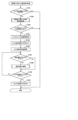
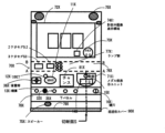
[2.パチスロ機の電気的構成]
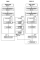
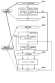
続いて、図3を参照して、パチスロ機1の電気的構成について説明する。なお、図3は、パチスロ機1の電気的構成を示すブロック図である。
[2. Electrical configuration of the pachislot machine]
Next, the electrical configuration of the
上述のとおり、パチスロ機1は、主制御基板71と、副制御基板72と、主中継基板73と、副中継基板74とを有している。主制御基板71と主中継基板73、主中継基板73と副中継基板74、及び副中継基板74と副制御基板72は、それぞれ電気的に接続されている。また、主制御基板71と副制御基板72は、主中継基板73及び副中継基板74を介して、主制御基板71から副制御基板72に対して一方向のシリアル通信が可能となるように電気的に接続されている。
As described above, the
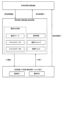
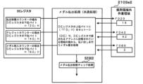
主制御基板71には、遊技に関する制御を行う遊技制御部としての主制御回路100が実装されている。主制御回路100は、例えば、メインCPU101、メインROM102、メインRAM103、クロックパルス発生回路(不図示)、乱数回路(不図示)等を含んで構成される。メインROM102には、メインCPU101により実行される各種制御プログラム、各種データテーブル、副制御回路200に対して各種制御指令(コマンド)を送信するためのデータ等が記憶される。メインRAM103には、制御プログラムの実行により決定された内部当籤役等の各種データを格納する格納領域が設けられる。クロックパルス発生回路は、メインCPU101作動用のクロックパルス信号を生成する。乱数回路は、予め定められた範囲の乱数(例えば、0~65535又は0~255等)を発生させる。メインCPU101は、生成されたクロックパルス信号に基づいて各種制御プログラムを実行する。また、発生された乱数の中から必要に応じて一又は複数の値を乱数値として抽出する。このようにして、遊技動作全般に係る制御を行う。
The
副制御基板72には、演出に関する制御を行う演出制御部としての副制御回路200が実装されている。副制御回路200は、例えば、サブCPU201、サブRAM203等を含んで構成される。また、副制御基板72には、ロムカートリッジ基板202が接続されている。ロムカートリッジ基板202には、サブCPU201により実行される各種制御プログラム、各種データテーブル、各種演出データ(例えば、メイン表示装置210に係る映像データや駆動データ、サブ表示装置220に係る映像データ、ランプ・LED群に係るランプデータ、スピーカ群に係るサウンドデータ等)等が記憶される。サブRAM203には、制御プログラムの実行により決定された演出内容や各種演出データを登録する格納領域や、主制御基板71から送信される各種制御指令(コマンド)に係るデータを格納する格納領域等が設けられる。なお、演出に係る演出用乱数値については、予め定められた範囲の乱数(例えば、0~32767等)の中から、サブCPU201内で発生及び抽出が行われるようにしてもよいし、主制御回路100と同様に乱数回路を設けることでその発生及び抽出が行われるようにしてもよい。また、ロムカートリッジ基板202ではなく、副制御回路200内にサブROMが含まれるようにし、各種制御プログラム等はサブROMに記憶されるように構成してもよい。また、ロムカートリッジ基板202に各種演出データを記憶させ、副制御回路200内のサブROMに各種制御プログラム及び各種データテーブルを記憶させるように構成してもよい。また、副制御回路200には、GPU等の画像専用のマイクロプロセッサ(例えば、「VDP」とも称される)が含まれるようにし、これによってメイン表示装置210やサブ表示装置220で表示される映像を生成(編集)するように構成してもよい。
The
主制御基板71には、ステッピングモータ51L,51C,51R、設定用鍵型スイッチ52、リセットスイッチ53、役比モニタ装置54、外部集中端子板55、ホッパー装置32、メダル補助収納庫スイッチ33S、電源装置34が電気的に接続されている。また、主制御基板71には、主中継基板73を介して、ドア開閉監視スイッチ56、メダルセンサ31S、ベットスイッチ6S、スタートスイッチ7S、ストップスイッチ8S、精算スイッチ9S、情報表示装置14が電気的に接続されている。なお、仮に試験機用第1インターフェースボード301及び試験機用第2インターフェースボード302が搭載される場合には、例えば、主中継基板73を介して主制御基板71に電気的に接続される。
The stepping
なお、外部集中端子板55、ホッパー装置32、メダル補助収納庫スイッチ33S、電源装置34、メダルセンサ31S、ベットスイッチ6S、スタートスイッチ7S、ストップスイッチ8S、精算スイッチ9S、情報表示装置14、試験機用第1インターフェースボード301及び試験機用第2インターフェースボード302についてはすでに説明したため、ここでの説明は省略する。
Note that the external centralized
各ステッピングモータ51L,51C,51Rは、それぞれ所定の減速比をもったギアを介して各リール3L,3C,3Rに接続され、その駆動により各リール3L,3C,3Rを回転及び停止させる。なお、各ステッピングモータ51L,51C,51Rに対して1回のパルスが出力されるごとに、各リール3L,3C,3Rが一定の角度で回転することから、メインCPU101は、各ステッピングモータ51L,51C,51Rに対してパルスを出力した回数をカウントし、このカウント結果に基づいて各リール3L,3C,3Rの図柄位置を管理する。また、各リール3L,3C,3Rには、このような管理を行うための初期位置を定めるリールインデックス(不図示)と、リールインデックスの位置を検出するためのインデックスセンサ(不図示)が設けられる。
Each stepping
設定用鍵型スイッチ52は、パチスロ機1の設定値(例えば、6段階の設定1~設定6)を変更するとき(設定変更)、もしくは、パチスロ機1の設定を確認するとき(設定確認)に使用される。ここで、設定値は、遊技に関する遊技者の有利さの度合いを示すものであり、通常は、設定値が低いほど(例えば、設定1に近いほど)遊技者の有利さの度合いが相対的に低くなり、設定値が高いほど(例えば、設定6に近いほど)遊技者の有利さの度合いが相対的に高くなる。設定用鍵型スイッチ52は、例えば、遊技店側の管理者が鍵穴に設定キー(不図示)を挿入して初期位置から左に回すとオン状態となり、左に回した状態から初期位置に戻すとオフ状態となる。なお、パチスロ機1の電源がオフ状態のとき、設定用鍵型スイッチ52をオン状態としてから電源をオン状態とすると設定変更が可能な状態となり、パチスロ機1の電源がオン状態のままで設定用鍵型スイッチ52をオン状態とすると設定確認が可能な状態となる。
The setting
リセットスイッチ53は、遊技店側の管理者によるリセット操作を検出可能としている。リセット操作は、各種のエラー状態を解除するための操作である。また、リセットスイッチ53は、設定変更が可能な状態において、遊技店側の管理者による設定値決定操作を検出可能としている。なお、設定変更が可能な状態においてリセットスイッチ53が操作されると、操作される度に設定値が順次1ずつ増加する(設定6まで到達すると次は設定1に戻る)。このようにして、設定値決定操作が行えるようになっている。また、このように決定された設定値は、その後スタートレバー7が1回操作されると確定する。すなわち、スタートスイッチ7Sは、遊技店側の管理者による設定値確定操作を検出可能としている。このように、設定変更を行う場合には、設定用鍵型スイッチ52をオン状態とし、リセットスイッチ53を操作して設定値を選択し、スタートレバー7を操作して選択した設定値を確定させた後、設定用鍵型スイッチ52をオフ状態とするといった設定変更操作が必要となっている。なお、これは、設定変更操作の一例であり、他の操作によって設定変更を行い得るように構成することもできる。また、設定変更や設定確認に際しては、例えば、上述のクレジットランプあるいは払出数ランプにおいて現在の設定値が表示されるものすればよい。
The
役比モニタ装置54は、例えば、4桁の7セグメントLEDにより構成され、主制御基板ケースの内部に設けられる。役比モニタ装置54は、メインCPU101によって集計・算出された遊技に関する各種割合情報を順次表示する。これらの割合情報は、遊技店の管理者がパチスロ機1に不正改造がないかを確認する際等に使用される。なお、役比モニタ装置54は、主制御基板71上に実装されるようにしてもよいし、主制御基板71に接続された他の基板(例えば、割合表示基板)上に実装されるようにしてもよい。また、キャビネットG内であれば、他の場所に設けられるようにしてもよい。例えば、主制御基板ケース上に設けられるようにしてもよい。また、役比モニタ装置54における表示を開始させ、あるいはその内容を切替えるための管理スイッチをキャビネットG内に設けるようにし、これが操作された場合に上述の各種割合情報が表示されるようにしてもよい。また、このような管理スイッチを使用することを前提として、例えば、情報表示装置14を役比モニタ装置54と兼用して用いる構成としてもよい。また、電源投入直後又は電源投入から所定時間(例えば、10秒程度。主制御回路100及び副制御回路200の立ち上げに要する時間を考慮したバッファとなる時間)の経過後に、役比モニタ装置54の4桁の7セグメントLEDが正常に機能していることを確認可能とするため、例えば、「8.8.」といったようなテストパターン(全てのセグ及びデシマルのLEDが点灯するパターン)で所定期間点灯(ないし点滅)させる構成とすることが望ましい。
The role
役比モニタ装置54では、例えば、上位2桁にはその割合情報の種類が表示され、下位2桁にはその割合情報を示す値(%)が表示される。ここで、役比モニタ装置54に表示される各種割合情報には、例えば、累計の特定区間割合情報、直近6000ゲーム間の連続役物割合情報及び役物割合情報、累計の連続役物割合情報及び役物割合情報等がある。
In the role
特定区間割合情報とは、対象の遊技数(例えば、「累計」であれば175000ゲーム。「直近6000ゲーム」であれば6000ゲーム。以下同じ)の遊技区間のうち、遊技者に有利な停止操作の情報の報知が行われていた遊技区間(例えば、AT状態)の遊技数(あるいは、単に有利区間中の遊技数であってもよい)の割合を示す情報である。また、連続役物割合情報とは、対象の遊技数の遊技区間において払出されたメダル数のうち、第一種特別役物(RB)の作動中(第一種特別役物に係る役物連続作動装置(BB)が作動している状態における第一種特別役物(RB)の作動中を含む)に払出されたメダル数の割合を示す情報である。また、役物割合情報は、対象の遊技数の遊技区間において払出されたメダル数のうち、第一種特別役物(RB)、第二種特別役物(CB)、及び普通役物(SB)の作動中に払出されたメダル数の割合を示す情報であり、ここでの第一種特別役物(RB)の作動中とは、第一種特別役物に係る役物連続作動装置(BB)が作動している状態における第一種特別役物(RB)の作動中を含む概念であり、また、第二種特別役物(CB)の作動中とは、第二種特別役物に係る役物連続作動装置(MB)が作動している状態における第二種特別役物(CB)の作動中を含む概念である。 The specific section ratio information is information that indicates the ratio of the number of plays in a play section (for example, AT state) in which information on a stop operation advantageous to the player was notified (or it may simply be the number of plays in an advantageous section) among the play sections of the target number of plays (for example, 175,000 games for "cumulative", 6,000 games for "last 6,000 games", the same below). In addition, the continuous feature ratio information is information that indicates the ratio of the number of medals paid out during the operation of the first type special feature (RB) (including the operation of the first type special feature (RB) when the feature continuous operation device (BB) related to the first type special feature is in operation) among the number of medals paid out in the play section of the target number of plays. The feature ratio information is information that indicates the ratio of the number of medals paid out during the operation of the first type special feature (RB), the second type special feature (CB), and the normal feature (SB) to the number of medals paid out in the play section of the target number of plays. Here, the operation of the first type special feature (RB) includes the operation of the first type special feature (RB) in a state in which the feature continuous operation device (BB) related to the first type special feature is in operation, and the operation of the second type special feature (CB) includes the operation of the second type special feature (CB) in a state in which the feature continuous operation device (MB) related to the second type special feature is in operation.
なお、遊技者に有利な停止操作の情報の報知が行われていた遊技区間(例えば、AT状態)を役物の作動中、あるいは役物連続作動装置の作動中としてとらえ、それぞれの割合情報において集計・算出の対象とすることもできる。すなわち、役比モニタ装置54は、必要な割合情報を適切に表示するものであればよく、表示可能な各種割合情報はこれらに限定されない。また、例えば、第一種特別役物(RB)が搭載されていない機種において連続役物割合情報を表示する場合、あるいは有利区間機能(AT機能)が搭載されていない機種において特定区間割合情報を表示する場合等、該当する数値情報(対応情報)が存在しない機種においては、当該項目の表示時に、4桁の7セグメントLEDのうちの数値情報(割合を示す%情報)を表示する下2桁の7セグメントLEDにおいて、例えば、「- -」といったように、中央の縦棒2本を点灯表示させる等の非対応情報用識別表示を行うことで、対応情報が存在しない機種である点を確認者が一目で認識可能とすることが望ましい。
In addition, the game section (for example, AT state) in which the information of the stop operation advantageous to the player was notified can be regarded as the operation of the role or the operation of the role continuous operation device, and can be the subject of aggregation and calculation in the respective ratio information. In other words, the role
ドア開閉監視スイッチ56は、例えば、下ドア機構DDの開閉側(右側)に設けられる。なお、下ドア機構DDの背面側に設けられるように構成してもよいし、キャビネットG側に設けられるように構成してもよい。また、上ドア機構UDにも同様のドア開閉監視スイッチが設けられるように構成してもよい。ドア開閉監視スイッチ56は、下ドア機構DDが開放状態となったときにオン状態となり、閉鎖状態となったときにオフ状態となることで、下ドア機構DDの開閉を監視する。なお、ドア開閉監視スイッチ56がオン状態となるとドア開放エラーが発生する。この場合、下ドア機構DDを閉鎖状態とすると当該エラー状態が解除される。
The door open/
副制御基板72には、ロムカートリッジ基板202、メイン表示装置210、サブ表示装置220が電気的に接続されている。また、副制御基板72には、副中継基板74を介して、24hドア監視ユニット61、演出用ボタン10a,10b等の演出用ボタン群、上部ランプ23等のランプ・LED類、スピーカ35a,35b等のスピーカ群が電気的に接続されている。
The
なお、ロムカートリッジ基板202、メイン表示装置210、サブ表示装置220、演出用ボタン群、ランプ・LED類及びスピーカ群についてはすでに説明したため、ここでの説明は省略する。
Note that the
24hドア監視ユニット61は、ドア開閉監視スイッチ56と同様に、例えば、下ドア機構DDの開閉側(右側)に設けられる。なお、下ドア機構DDの開閉を監視するという機能を有する点においてはドア開閉監視スイッチ56と同じであるが、このような監視を副制御回路200側でも行い得るようにすることで、さらに下ドア機構DDの開閉履歴を一定期間保存することができるようにしている。なお、この開閉履歴は、後述のホールメニューから確認することができる。したがって、例えば、営業時間外であって、遊技店の管理者が退出した後に開放履歴があった場合や、営業時間内において長時間にわたって開放された開閉履歴があった場合には、これにより不正行為が行われた可能性が高いことを認識できるようになっている。
The 24-hour
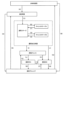
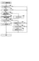
[3.パチスロ機の機能フロー]
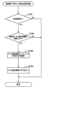
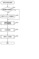
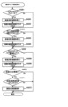
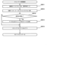
続いて、図4を参照して、パチスロ機1の機能フローについて説明する。なお、図4は、パチスロ機1の機能フローを説明するための図である。
[3. Functional flow of the Pachislot machine]
Next, a functional flow of the
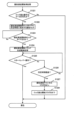
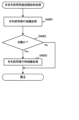
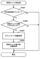
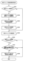
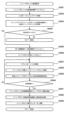
遊技者によりパチスロ機1にメダルが投入され(ベット操作が行われ)、スタートレバー7が操作される(開始操作が行われる)と、予め定められた範囲(例えば、0~65535)の乱数から1つの乱数値(本実施形態では、これを「内部抽籤用乱数値」として説明する場合がある)が抽出される。 When a player inserts a medal into the pachislot machine 1 (a bet operation is performed) and operates the start lever 7 (a start operation is performed), a random number value (in this embodiment, this may be described as an "internal lottery random number value") is extracted from a predetermined range of random numbers (for example, 0 to 65535).
内部抽籤手段(後述の内部抽籤処理を行うメインCPU101)は、抽出された乱数値に基づいて抽籤を行い、内部当籤役を決定する。内部当籤役の決定により、有効ライン上に表示されることが許可される図柄の組合せが事前に決定される。なお、図柄の組合せの種別としては、メダルの払い出し、再遊技(リプレイ)の作動、ボーナスの作動等といった特典が遊技者に与えられる「入賞」に係るものと、それ以外のいわゆる「はずれ」に係るものとが設けられる。なお、メダルの払い出しに係る役を「小役」と称し、再遊技(リプレイ)の作動に係る役を「リプレイ役」と称し、ボーナス(ボーナス状態)の作動に係る役を「ボーナス役」と称する。また、内部当籤し得る役(すなわち、成立が許可される図柄の組合せ)は、単に「役」と称されることがある。また、内部当籤役は、「当籤役」、「事前決定結果」、あるいは「導出許容条件」等と称されることがある。また、内部抽籤手段は、「役決定手段」、「当籤役決定手段」、「事前決定手段」、あるいは「導出許容条件決定手段」等と称されることがある。
The internal lottery means (
また、スタートレバー7が操作される(開始操作が行われる)と、複数のリールの回転が行われる。その後、遊技者によりリール(各リール3L,3C,3R)に対応するストップボタン(各ストップボタン8L,8C,8R)が操作される(停止操作が行われる)と、リール停止制御手段(後述のリール停止制御処理を行うメインCPU101)は、内部当籤役とストップボタンが押されたタイミング(あるいはその押し順を含む)とに基づいて、該当するリールの回転を停止する制御を行う。なお、開始操作を行うための操作手段は、スタートレバー7のようにレバー形状をしたものに限られず、遊技者が開始操作を行うことが可能であれば、どのような操作手段であってもよい。また、停止操作を行うための操作手段は、各ストップボタン8L,8C,8Rのようにボタン形状をしたものに限られず、遊技者が停止操作を行うことが可能であれば、どのような操作手段であってもよい。
When the
パチスロ機1では、基本的に、ストップボタンが押されたときから規定時間(190msec)内に、該当するリールの回転を停止する制御が行われる。本実施形態では、この規定時間内にリールの回転にともなって移動する図柄の数を「滑り駒数」という。そして、本実施形態では、規定期間が190msecである場合には、滑り駒数の最大数(最大滑り駒数)を図柄4個分に定める。
In the
リール停止制御手段は、入賞に係る図柄の組合せの表示を許可する内部当籤役が決定されているときは、通常、190msec(図柄4駒分)の規定時間内に、その図柄の組合せが有効ライン上に極力表示されるようにリールの回転を停止させる。また、リール停止制御手段は、規定時間を利用して、内部当籤役によってその表示が許可されていない図柄の組合せが有効ライン上に表示されないようにリールの回転を停止させる。なお、リールの回転が停止したときに表示された図柄は、「停止表示」、あるいは「表示結果」等と称されることがある。また、リールの回転が停止したときに図柄が表示されることは、「停止表示の導出」、あるいは「表示結果の導出」等と称されることがある。 When an internal winning role that allows the display of a winning symbol combination has been determined, the reel stop control means stops the rotation of the reels within a specified time of usually 190 msec (four symbols) so that the symbol combination is displayed on the winning line as much as possible. The reel stop control means also uses the specified time to stop the rotation of the reels so that symbol combinations not permitted to be displayed by the internal winning role are not displayed on the winning line. The symbols displayed when the reels stop spinning are sometimes referred to as "stop display" or "display result". The display of symbols when the reels stop spinning is sometimes referred to as "deriving the stop display" or "deriving the display result".
また、リール停止制御手段は、リールが回転してから、予め定められた自動停止時間が経過した場合には、遊技者が停止操作を行っていない場合でも、自動的に各リールを停止させる自動停止制御を行うようにしてもよい。この場合には、遊技者の停止操作を介さずにリールが停止することとなるため、いずれかの内部当籤役が決定されている場合であっても、いずれの入賞に係る図柄の組合せも有効ラインに沿って表示されていないようにリールの回転を停止させることが望ましい。 The reel stop control means may also be configured to perform automatic stop control to automatically stop each reel when a predetermined automatic stop time has elapsed since the reels started spinning, even if the player has not performed a stop operation. In this case, since the reels will stop without the player's stopping operation, it is desirable to stop the spinning of the reels so that no winning combinations are displayed along the pay line, even if any internal winning combinations have been determined.
このようにして、複数のリールの回転が全て停止されると、入賞判定手段(後述の入賞作動判定処理を行うメインCPU101)は、有効ライン上に表示された図柄の組合せが、入賞に係るもの(あるいは、その他予め定められたもの)であるか否かの判定を行う。すなわち、入賞に係る図柄の組合せ(あるいは、その他予め定められた図柄の組合せ)が成立したか否かの判定を行う。そして、表示された図柄の組合せが、入賞判定手段により入賞に係るもの(あるいは、その他予め定められたもの)である(すなわち、入賞に係る図柄の組合せ(あるいは、その他予め定められた図柄の組合せ)が成立した)と判定されると、メダルの払い出し等の特典が遊技者に与えられ、あるいは、それを契機として各種の制御が行われる。パチスロ機1では、一例として、以上のような一連の流れで1回の遊技(単位遊技)として行われる。
When all the reels have stopped spinning in this way, the winning determination means (
なお、入賞判定手段は、有効ライン上に表示された図柄の組合せが、単に予め定められた複数の図柄の組合せのうちのいずれかの図柄の組合せに該当するか否かを判定するものであってもよいし、内部抽籤手段によって決定された内部当籤役に係る図柄の組合せに該当するか否かを判定するものであってもよい。すなわち、前者では、内部当籤役と切り離して、入賞に係る図柄の組合せであるか否かを判定するものであってもよい。この場合、リール停止制御手段によって適切に停止制御が行われる限り、誤入賞の発生の防止は十分に担保され得ることから、誤入賞検知に係る制御負担を低減させることが可能となる。一方、後者では、入賞に係る図柄の組合せが、入賞が許可されていた図柄の組合せであるか否かも判定可能とすることで、リールの不具合等により誤入賞が発生した場合に、その誤入賞を検知することができるため、セキュリティ性を向上させることが可能となる。 The winning determination means may simply determine whether the combination of symbols displayed on the pay line corresponds to any of a plurality of predetermined combinations of symbols, or may determine whether the combination corresponds to a combination of symbols related to an internal lottery role determined by the internal lottery means. In other words, in the former case, it may determine whether the combination of symbols related to a winning role is separate from the internal lottery role. In this case, as long as the reel stop control means appropriately controls the reels to stop, the prevention of erroneous winning can be sufficiently guaranteed, and the control burden related to erroneous winning detection can be reduced. On the other hand, in the latter case, by making it possible to determine whether the combination of symbols related to a winning role is a combination of symbols that was permitted to win, if an erroneous winning occurs due to a reel malfunction, the erroneous winning can be detected, and security can be improved.
また、パチスロでは、前述した一連の遊技動作の流れの中で、表示装置(例えば、メイン表示装置210やサブ表示装置220等)による映像の表示、各種ランプ(例えば、上部ランプ23等)による光の出力、スピーカ(例えば、スピーカ35a,35b等)による音の出力、或いは、これらの組合せを利用して様々な演出が行われる。すなわち、これらは演出を実行する演出実行手段である。なお、演出実行手段により実行される演出の内容は、主制御回路100側(メイン側)で決定される場合もあれば、副制御回路200側(サブ側)で決定される場合もある。すなわち、これらはそのいずれもが演出内容決定手段となり得る。
In addition, in pachislots, during the sequence of game operations described above, various effects are produced using the display devices (e.g.,
例えば、スタートレバー7が操作される(開始操作が行われる)と、内部抽籤用乱数値とは別に、演出用乱数値が抽出される。演出用乱数値が抽出されると、演出内容決定手段は、内部当籤役に対応付けられた複数種類の演出内容の中から今回実行する演出を抽籤によって(あるいは予め定められた決定条件にしたがって)決定する。
For example, when the
次いで、演出内容決定手段により演出内容が決定されると、演出実行手段は、リールの回転開始時、各リールの回転停止時、入賞の有無の判定時等の各契機に連動させて対応する演出を実行する。このように、パチスロ機1では、例えば、内部当籤役に対応付けられた演出内容を実行することによって、決定された内部当籤役(狙うべき図柄の組合せや操作すべき押し順等と換言することもできる)を知る機会又は予想する機会が遊技者に提供され、遊技者の興味の向上を図ることができる。
Next, when the presentation content is determined by the presentation content determination means, the presentation execution means executes the corresponding presentation in conjunction with each trigger, such as when the reels start to spin, when each reel stops spinning, and when it is determined whether or not a prize has been won. In this way, in the
[4.パチスロ機の遊技性に関する基本仕様]
続いて、パチスロ機1の遊技性に関する基本仕様について説明する。
[4. Basic specifications regarding the playability of Pachislot machines]
Next, the basic specifications regarding the playability of the
[4-1.図柄配置]
上述のとおり、パチスロ機1では、複数の図柄が変動表示及び停止表示されることで遊技が行われる仕様となっている。したがって、主制御回路100は、各リール3L,3C,3Rにおいて、どの図柄がどの位置に配置されているかを把握可能に構成されている必要がある。このため、メインROM102には、少なくとも各リール3L,3C,3Rそれぞれの各図柄位置にある図柄の種類を識別するためのデータが記憶されている。なお、このような目的が達成される限り、そのデータ構成は種々の構成を採用することができるが、本実施形態では、その一例として後述の図柄配置テーブル(図9参照)を用いている。
[4-1. Design arrangement]
As described above, the
図柄配置テーブルには、各リール3L,3C,3Rそれぞれの回転方向における各図柄位置を示す図柄位置データ(例えば、「0」~「19」)が規定されている。また、各図柄位置データに対して図柄の種類を特定するためのデータ(例えば、図柄コード)が対応付けられている。また、図柄配置テーブルでは、リールインデックスが検出されたときにメイン表示窓4の枠内における各リールの中段領域に位置する図柄の位置を「0」と規定している。なお、各列の図柄数、図柄の種類数、あるいは最大滑り駒数等は適宜変更して規定可能である。
The symbol arrangement table specifies symbol position data (e.g., "0" to "19") indicating the position of each symbol in the rotation direction of each of the
[4-2.図柄組合せ]
上述のとおり、パチスロ機1では、表示された図柄の組合せが遊技結果に影響を与える仕様となっている。すなわち、パチスロ機1は、表示された図柄の組合せに応じて、各種特典を付与したり、現在の状態から相対的に有利な状態に移行させたり、現在の状態から相対的に不利な状態に移行させたりすることを可能としている。したがって、主制御回路100は、このような図柄の組合せについて把握可能に構成されている必要がある。このため、メインROM102には、このような図柄の組合せを特定するためのデータが規定されている。なお、このような目的が達成される限り、そのデータ構成は種々の構成を採用することができるが、本実施形態では、その一例として後述の図柄組合せテーブル(図11~図14参照)を用いている。
[4-2. Design Combinations]
As described above, the
図柄組合せテーブルには、有効ライン上に表示され得る図柄の組合せのうちで予め定められた複数の図柄の組合せの種類を示すデータ(例えば、「表示役」あるいは「入賞作動フラグ」)が規定されている。なお、それぞれの図柄の組合せを構成する図柄は、例えば、上述の図柄コード等を用いて特定することができる。また、各図柄の組合せに対して特典等の種類を示すデータ(例えば、「払出等」)が対応付けられている。また、図柄組合せテーブルは、基本的に後述の当籤フラグ格納領域、入賞作動フラグ格納領域、及び図柄コード格納領域(図17参照)と対応するデータ構成となっている。なお、図柄の組合せの種類数、あるいは特典の付与内容等は適宜変更して規定可能である。 The symbol combination table specifies data (e.g., "display role" or "win activation flag") indicating the type of combination of multiple predefined symbols among the symbol combinations that can be displayed on the winning line. The symbols that make up each symbol combination can be specified, for example, using the symbol code described above. Each symbol combination is also associated with data indicating the type of bonus (e.g., "payout, etc."). The symbol combination table basically has a data structure that corresponds to the winning flag storage area, the winning activation flag storage area, and the symbol code storage area (see FIG. 17), which will be described later. The number of types of symbol combinations, or the content of the bonus, can be changed and specified as appropriate.
[4-3.内部当籤役]
上述のとおり、パチスロ機1では、いずれの図柄の組合せが表示されることが許可されるか(事前に決定されるか)が遊技結果に影響を与える仕様となっている。すなわち、パチスロ機1は、遊技者の停止操作に先立って(事前に)、内部当籤役(すなわち、表示され得る図柄の組合せの種類(あるいは、付与され得る特典の種類))を決定することを可能としている。したがって、主制御回路100は、このような内部当籤役について把握可能に構成されている必要がある。このため、メインROM102には、このような内部当籤役を特定するためのデータが規定されている。なお、このような目的が達成される限り、そのデータ構成は種々の構成を採用することができるが、本実施形態では、その一例として後述の内部抽籤テーブル(図10参照)を用いている。
[4-3. Internal lottery]
As described above, the
内部抽籤テーブルには、予め定められた複数の内部当籤役の種類を示すデータ(例えば、「No.」あるいは「当籤番号」)と、各遊技状態において各内部当籤役が決定される抽籤値とが規定される。なお、抽籤値は、設定された設定値によっても変動する場合がある。また、各内部当籤役に対して表示が許可される(対応する)図柄の組合せの種類が対応付けられている。なお、パチスロ機1では、1つの内部当籤役に対して複数の図柄の組合せを対応付けることを可能としており、このような内部当籤役が決定された場合、いずれの図柄の組合せが表示されるかは停止制御によって決定されるものとなっている。
The internal lottery table specifies data indicating the types of multiple predefined internal winning roles (for example, "No." or "winning number") and lottery values that determine each internal winning role in each game state. The lottery values may vary depending on the set value. Each internal winning role is also associated with a type of (corresponding) pattern combination that is permitted to be displayed. In addition, the
ここで、例えば、本実施形態の後述の内部抽籤処理(図26参照。より詳細には、S64の内部当籤役決定処理)では、まず、乱数回路によって予め定められた数値の範囲(例えば、0~65535)から抽出された乱数値を、各内部当籤役に対応して規定された抽籤値で順次加算更新する。次いで、抽籤結果(抽籤値+乱数値)が65535を超えたか否か(抽籤結果がオーバーフローしたか否か)の判定を行う。そして、所定の内部当籤役において、当該判定の結果が65535を超えた場合、当該内部当籤役に当籤させる(当該内部当籤役を決定する)。もっとも、全ての内部当籤役について当該判定を行っても65535を超えるものがなかった場合、今回の遊技における内部当籤役は「はずれ」となる。なお、これはあくまで内部抽籤処理の一例であり、抽籤値(当籤確率)に応じて適切な抽籤が行われる限り、その抽籤処理の手法は種々の手法を採用することができる。例えば、抽出された乱数値を、各内部当籤役に対応して規定された抽籤値で順次減算更新し、次いで、減算結果(抽籤結果)が0を下回ったか否か(抽籤結果がアンダーフローしたか否か)を判定して、内部当籤役を決定してもよい。 Here, for example, in the internal lottery process of this embodiment described later (see FIG. 26; more specifically, the internal winning combination determination process of S64), first, a random number value extracted from a predetermined numerical range (e.g., 0 to 65535) by a random number circuit is sequentially added and updated with a lottery value specified corresponding to each internal winning combination. Next, a determination is made as to whether or not the lottery result (lottery value + random number value) exceeds 65535 (whether or not the lottery result has overflowed). Then, if the result of this determination exceeds 65535 for a given internal winning combination, the internal winning combination is made to win (the internal winning combination is determined). However, if none of the internal winning combinations exceeds 65535 even after this determination has been made for all internal winning combinations, the internal winning combination for this game will be a "lose". Note that this is merely one example of the internal lottery process, and various methods can be used for the lottery process as long as an appropriate lottery is performed according to the lottery value (winning probability). For example, the extracted random number value may be sequentially subtracted and updated by the lottery value specified for each internal winning combination, and then the internal winning combination may be determined by determining whether the subtraction result (lottery result) is below 0 (whether the lottery result has underflowed).
このように、内部抽籤テーブルにおいては、規定されている抽籤値の数値が大きい内部当籤役ほど決定される確率(当籤確率)が高くなる。なお、各内部当籤役の当籤確率は、「各当籤番号に規定された抽籤値/抽出される可能性のある全ての乱数値の個数(乱数分母:65536)」によって表すことができる。 In this way, in the internal lottery table, the larger the lottery value specified for an internal winning role, the higher the probability of it being determined (winning probability). The winning probability of each internal winning role can be expressed as "lottery value specified for each winning number / number of all random number values that can be drawn (random number denominator: 65536)".
[4-4.停止制御]
上述のとおり、パチスロ機1では、内部当籤役の決定によって表示されることが許可された図柄の組合せのうち、遊技者の停止操作によって最終的にいずれの図柄の組合せを表示させるかが遊技結果に影響を与える仕様となっている。すなわち、パチスロ機1は、決定された内部当籤役の種類のみならず、遊技者の停止操作タイミングや押し順(「停止操作態様」や「停止操作手順」とも称される)によって最終的に表示される図柄の組合せの種類を変動させる(決定する)制御(停止制御)を行うことを可能としている。したがって、主制御回路100は、各内部当籤役に対して、遊技者の停止操作態様に応じてどのような態様で停止制御を行うかを把握可能に構成されている必要がある。このため、メインROM102には、このような停止制御の態様を特定するためのデータが規定されている。なお、このような目的が達成される限り、そのデータ構成は種々の構成を採用することができるが、本実施形態では、その一例として停止テーブルや引込優先順位テーブル(不図示)等を用いている。
[4-4. Stop control]
As described above, the
停止テーブルには、各リール3L,3C,3Rの各図柄位置データに対して、図柄の移動量を示すデータ(例えば、「滑り駒数」)が規定されている。例えば、所定の内部当籤役が決定された遊技において所定の停止テーブルが選択されたとする。次いで、回転中のリール3Lに対して停止操作が行われたとする。このとき、停止開始位置(停止操作が行われたときのリール3Lの中段領域の図柄位置データ)が「0」であったとする。そして、所定の停止テーブルにおいて、図柄位置データ「0」に規定された滑り駒数が「4」であったとする。そうすると、主制御回路100は、4図柄分移動した図柄位置(図柄位置データ「4」の位置)でリール3Lを停止させる(停止予定位置が「4」となる)ように制御を行う。このように、停止テーブルには、停止させる位置を直接的に決定することを可能とするデータ(滑り駒数)が規定されている。なお、このようなデータ構成もあくまで一例である。また、このような停止テーブルを用いて停止制御を行うことは、一般的に「テーブル制御」と称される。
In the stop table, data indicating the amount of movement of the symbols (for example, the "number of sliding pieces") is specified for each symbol position data of the
引込優先順位テーブルには、表示されることが許可された図柄の組合せが複数ある場合に、いずれの図柄の組合せを優先的に表示させるか(引込むか)を示すデータ(例えば、「引込優先順位」)が規定されている。例えば、所定の内部当籤役が決定された遊技において所定の引込優先順位テーブルが選択されたとする。ここで、所定の内部当籤役は、図柄組合せAと図柄組合せBの表示を許可するものとし、所定の引込優先順位テーブルは、図柄組合せAよりも図柄組合せBを優先的に表示させるように引込優先順位が規定されているものとする。次いで、回転中のリール3Lに対して停止操作が行われたとする。このとき、停止開始位置が「0」であったとする。
The pull-in priority table specifies data (e.g., "pull-in priority order") that indicates which symbol combination is to be preferentially displayed (pulled in) when there are multiple symbol combinations permitted to be displayed. For example, assume that a specified pull-in priority order table is selected in a game in which a specified internal winning combination is determined. Here, the specified internal winning combination permits the display of symbol combination A and symbol combination B, and the specified pull-in priority order table specifies a pull-in priority order that gives priority to the display of symbol combination B over symbol combination A. Next, assume that a stop operation is performed on
そうすると、主制御回路100は、停止開始位置を含めた最大滑り駒数(例えば、「4」)の範囲内の各図柄位置について、図柄組合せAを構成する図柄と図柄組合せBを構成する図柄があるかどうかを検索する。双方の図柄がなければ、予め定められたルール(例えば、より近い位置で停止させる、より遠い位置で停止させる等)にしたがって停止させる位置を決定する。図柄組合せAを構成する図柄のみがあれば、当該図柄に対応する位置で停止させることを決定する。図柄組合せBを構成する図柄のみがあれば、当該図柄に対応する位置で停止させることを決定する。双方の図柄があれば、図柄組合せAよりも図柄組合せBを優先的に表示させるのであるから、図柄組合せBを構成する図柄に対応する位置で停止させることを決定する。なお、引込優先順位は、選択された引込優先順位テーブルにしたがって、対象となるリールの回転中に全図柄位置について格納されるようにしてもよいし、対象となるリールに対して停止操作が行われたときに、停止開始位置を含めた最大滑り駒数の範囲内の各図柄位置について格納されるようにしてもよい。また、このようなデータ構成もあくまで一例である。また、このような引込優先順位テーブルを用いて停止制御を行うことは、一般的に「コントロール制御」と称される。
Then, the
なお、本実施形態では、「テーブル制御」のみを行うことによって停止制御を実行する構成とすることもできるし、「コントロール制御」のみを行うことによって停止制御を実行する構成とすることもできる。あるいは、まず「テーブル制御」を行うことによって停止させる位置を仮決定し、次に「コントロール制御」を行うことによってより適切な停止位置があるかを検索し、検索結果によっては停止させる位置を変更することを可能とする停止制御を実行する構成とすることもできる。 In this embodiment, the configuration may be such that stop control is executed by performing only "table control" or by performing only "control control". Alternatively, the configuration may be such that the stopping position is tentatively determined by performing "table control", and then a more appropriate stopping position is searched for by performing "control control", and the stopping position can be changed depending on the search results.
このように、パチスロ機1では、最終的に有効ライン上に表示される図柄の組合せがどの図柄の組合せとなるかは、例えば、以下の3つの要素に基づいて決定される。
In this way, in the
第1の要素は、決定された内部当籤役(内部抽籤処理の抽籤結果)である。例えば、内部抽籤処理の結果が「はずれ」であった場合、いずれかのリプレイ役に係る図柄の組合せ、小役に係る図柄の組合せ又はボーナス役に係る図柄の組合せが最終的に有効ライン上に表示されることはない。なお、「はずれ」は、内部当籤役の1つであると捉えることもできるし、内部当籤役が決定されなかった抽籤結果であると捉えることもできる。 The first element is the determined internal winning role (lottery result of the internal lottery process). For example, if the result of the internal lottery process is a "miss," then none of the combinations of symbols related to any replay role, combinations of symbols related to minor roles, or combinations of symbols related to bonus roles will ultimately be displayed on the winning line. Note that a "miss" can be considered to be one of the internal winning roles, or it can be considered to be a lottery result in which no internal winning role has been determined.
第2の要素は、遊技者の停止操作タイミング(遊技者がいずれかのストップボタンを操作したときの図柄の位置(押下位置))である。例えば、本実施形態においては、最大滑り駒数として図柄4個分が定められているため、内部抽籤処理の結果、いずれかの内部当籤役に当籤していたとしても、表示が許可されている図柄の組合せを構成する図柄が有効ライン(複数ある場合には各有効ライン)に対して図柄4個分を超えて配置されていた場合には、遊技者の停止操作タイミングによっては当該図柄の組合せが表示されない場合がある。これをいわゆる「取りこぼし」という。 The second element is the timing of the player's stop operation (the position of the symbols (pressed position) when the player operates one of the stop buttons). For example, in this embodiment, the maximum number of sliding pieces is set to four symbols, so even if one of the internal winning roles is won as a result of the internal lottery process, if the symbols that make up a combination of symbols that are allowed to be displayed are positioned on an active line (or each active line if there are multiple), the combination of symbols may not be displayed depending on the timing of the player's stop operation. This is known as a "miss."
第3の要素は、遊技者の押し順(遊技者がストップボタンを操作した順番)である。例えば、本実施形態においては、複数の図柄の組合せが対応付けられた内部当籤役が決定される場合があり、この場合には、遊技者の押し順に応じて最終的に有効ライン上に表示される図柄の組合せが変動する場合がある。なお、このような内部当籤役を「押し順役」といい、それがリプレイ役の場合には「押し順リプレイ」と称されることがあり、小役の場合には「押し順小役」と称されることがある。 The third element is the player's push order (the order in which the player operates the stop button). For example, in this embodiment, an internal winning role associated with a combination of multiple symbols may be determined, and in this case, the combination of symbols that is ultimately displayed on the winning line may vary depending on the player's push order. Such an internal winning role is called a "push order role", and if it is a replay role, it may be called a "push order replay", and if it is a minor role, it may be called a "push order minor role".
[4-5.遊技状態]
パチスロ機1では、遊技者の有利度合いを変動させるため、あるいは企図した遊技性とするために、遊技を行う状態として種々の遊技状態を設けることが可能となっている。以下、その遊技状態の一例について説明する。
[4-5. Game Status]
In the
[4-5-1.ボーナス状態]
パチスロ機1では、ボーナス役に当籤し、当該ボーナス役に係る図柄の組合せが有効ライン上に表示された場合に、ボーナス状態に移行させる(ボーナス状態を作動させる)ことが可能となっている。なお、このようなボーナス状態を設けないように構成することもできる。また、複数種類のボーナス役を設けることで、複数のボーナス状態を設けるように構成することもできる。ボーナス役に当籤すると、当該ボーナス役に係る図柄の組合せが有効ライン上に表示されるまで複数回の遊技にわたって当該ボーナス役が内部当籤役として持越された状態(持越状態)が発生する。このようなボーナス役は「持越役」と称されることがある。また、このような持越状態は「(ボーナス)フラグ間」や「(ボーナス)内部中」等と称されることがある。
[4-5-1. Bonus state]
In the
ボーナス状態は、ボーナス状態が作動していない状態(非ボーナス状態)に対して小役の抽籤態様(当籤確率やその内容、あるいは停止制御の態様等も含む。以下同じ)を変動させることが可能な状態となっている(リプレイ役の抽籤態様を変動させることが可能な状態ともなっているため、ボーナス状態を後述のRT状態の一態様として捉えることもできる)。したがって、このような抽籤態様が遊技者に相対的に有利な抽籤態様となる場合には、ボーナス状態は非ボーナス状態よりも有利な遊技状態となる。一方、このような抽籤態様が遊技者に相対的に不利な抽籤態様となる場合には、ボーナス状態は非ボーナス状態よりも不利な遊技状態となる。 The bonus state is a state in which it is possible to vary the lottery mode of the minor role (including the probability of winning and its contents, or the mode of stop control, etc.; the same applies below) compared to a state in which the bonus state is not activated (non-bonus state) (since it is also a state in which it is possible to vary the lottery mode of the replay role, the bonus state can also be considered as one mode of the RT state described below). Therefore, if such a lottery mode is a lottery mode that is relatively advantageous to the player, the bonus state is a more advantageous gaming state than the non-bonus state. On the other hand, if such a lottery mode is a lottery mode that is relatively disadvantageous to the player, the bonus state is a less advantageous gaming state than the non-bonus state.
ボーナス役としては、例えば、第一種特別役物(RB)、第一種特別役物に係る役物連続作動装置(BB)、第二種特別役物(CB)(ただし持越役ではない)、第二種特別役物に係る役物連続作動装置(MB)、及び普通役物(SB)(ただし持越役ではない)等を挙げることができる。また、例えば、各ボーナス役に対応するボーナス状態は以下のように構成される。RB状態は、予め定められた任意の入賞回数(例えば、上限は8回)又は予め定められた任意の遊技回数(例えば、上限は12回)の遊技が行われた場合に終了する遊技状態として構成される。BB状態は、予め定められた任意の払出数(例えば、上限は285枚)を超えるメダルの払出があった場合に終了する遊技状態として構成される。 Examples of bonus roles include a first type special role (RB), a role continuous operation device (BB) related to a first type special role, a second type special role (CB) (but not a carryover role), a role continuous operation device (MB) related to a second type special role, and a normal role (SB) (but not a carryover role). For example, the bonus states corresponding to each bonus role are configured as follows. The RB state is configured as a game state that ends when a predetermined arbitrary number of winnings (e.g., the upper limit is 8 times) or a predetermined arbitrary number of games (e.g., the upper limit is 12 times) have been played. The BB state is configured as a game state that ends when a predetermined arbitrary number of payouts (e.g., the upper limit is 285 coins) has been paid out.
CB状態は、1回の遊技が行われた場合に終了する遊技状態として構成される。MB状態は、予め定められた任意の払出数(例えば、上限は153枚)を超えるメダルの払出があった場合、あるいはMB状態中にRBやSBに当籤した場合に終了する遊技状態として構成される。SB状態は、1回の遊技が行われた場合に終了する遊技状態として構成される。 The CB state is configured as a game state that ends when one game has been played. The MB state is configured as a game state that ends when more than a predetermined number of medals have been paid out (for example, the upper limit is 153 medals) or when RB or SB is won during the MB state. The SB state is configured as a game state that ends when one game has been played.
なお、ボーナス状態の作動条件は、ボーナス役に係る図柄の組合せが有効ライン上に表示されたことのみに限られない。例えば、第一種特別役物に係る役物連続作動装置(BB)の作動中においては、第一種特別役物に係る役物連続作動装置(BB)の作動開始時、第一種特別役物の作動中ではない場合の遊技開始時、あるいは第一種特別役物の作動終了時等において自動的に第一種特別役物(RB)を作動させるように構成することもできる。すなわち、RBに係る図柄の組合せを規定することなく、BBの作動中は常にRBの作動中となるように制御することもできる。ここで、BB作動中のRBは「JAC」等と称されることがあり、このように自動的にBB作動中のRBが作動する仕様は「オートJAC」等と称されることがある。また、BBの作動中においては、規定されたRBに係る図柄の組合せが有効ライン上に表示されたことをもってRBの作動中となるように制御することもできる。このように対応する図柄の組合せの表示に基づいてRBが作動する仕様は「マニュアルJAC」等と称されることがある。また、第二種特別役物に係る役物連続作動装置(MB)と、第二種特別役物(CB)との関係も同様である。すなわち、CBに係る図柄の組合せを規定することなく、MBの作動中は常にCBの作動中となるように制御することもできるし、MBの作動中においては、規定されたCBに係る図柄の組合せが有効ライン上に表示されたことをもってCBの作動中となるように制御することもできる。 The condition for the bonus state to be activated is not limited to the display of a combination of symbols related to the bonus role on the pay line. For example, during the operation of the consecutive activation device (BB) related to the first type special role, the first type special role (RB) can be automatically activated when the consecutive activation device (BB) related to the first type special role starts to operate, when the game starts when the first type special role is not in operation, or when the operation of the first type special role ends. In other words, it is possible to control the RB to always be in operation during the operation of the BB without specifying the combination of symbols related to the RB. Here, the RB during the operation of the BB is sometimes called "JAC" and the like, and the specification in which the RB automatically operates during the operation of the BB is sometimes called "auto JAC". Also, during the operation of the BB, it is possible to control the RB to be in operation when the combination of symbols related to the specified RB is displayed on the pay line. The specification in which the RB operates based on the display of the corresponding combination of symbols in this way is sometimes called "manual JAC". The same applies to the relationship between the special device continuous operation device (MB) for the second type special device and the second type special device (CB). In other words, it is possible to control the CB to be in operation at all times while the MB is in operation without specifying the combination of symbols related to the CB, and it is also possible to control the CB to be in operation when the specified combination of symbols related to the CB is displayed on the winning line while the MB is in operation.
[4-5-2.RT状態]
パチスロ機1では、予め定められた移行条件が成立した場合に、RT状態に移行させる(RT状態を作動させる)ことが可能となっている。なお、このようなRT状態を設けないように構成することもできる。また、複数のRT状態を設けるように構成することもできる。RT状態は、RT状態が作動していない状態(非RT状態)に対してリプレイ役の抽籤態様を変動させることが可能な状態となっている。したがって、このような抽籤態様が遊技者に相対的に有利な抽籤態様となる場合には、RT状態は非RT状態よりも有利な遊技状態となる。一方、このような抽籤態様が遊技者に相対的に不利な抽籤態様となる場合には、RT状態は非RT状態よりも不利な遊技状態となる。また、複数のRT状態を設ける場合、当該複数のRT状態間についても同様である。なお、この場合、リプレイ役の抽籤態様(特に、当籤確率)が遊技者に相対的に有利なRT状態は「高RT状態」や「高確率再遊技状態」等と称され、リプレイ役の抽籤態様(特に、当籤確率)が遊技者に相対的に不利なRT状態は「低RT状態」や「低確率再遊技状態」等と称されることがある。
[4-5-2. RT state]
In the
RT状態は、例えば、以下のいずれの移行条件の成立によって移行させることができる。また、複数のRT状態を設ける場合、当該複数のRT状態間についても同様である。 The RT state can be transitioned, for example, when any of the following transition conditions are met. In addition, if multiple RT states are provided, the same applies to transitions between the multiple RT states.
(1)RB、BB又はMBに当籤したとき
(2)RB、BB又はMBに係る図柄の組合せが表示されたとき
(3)RB状態、BB状態又はMB状態が終了したとき
(4)RB、BB又はMBに当籤しておらず(持越されておらず)、RB状態、BB状態又はMB状態中でもない場合において、特定の図柄の組合せが表示されたとき
(5)(3)又は(4)の移行条件成立後に予め定められた回数の遊技が行われたとき
(1) When RB, BB or MB is won; (2) When a combination of symbols related to RB, BB or MB is displayed; (3) When the RB state, BB state or MB state ends; (4) When a specific combination of symbols is displayed when RB, BB or MB has not been won (not carried over) and the player is not in the RB state, BB state or MB state; (5) When a predetermined number of plays have been played after the transition condition of (3) or (4) is met.
[4-5-3.AT状態]
パチスロ機1では、予め定められた移行条件が成立した場合に、AT状態に移行させる(AT状態を作動させる)ことが可能となっている。なお、このようなAT状態を設けないように構成することもできる。また、複数のAT状態を設けるように構成することもできる。AT状態は、例えば、上述の押し順役に当籤したときに、遊技者に有利な停止操作の情報が報知されることにより、AT状態が作動していない状態(非AT状態)よりも有利な状態として構成される遊技状態である。
[4-5-3. AT state]
In the
なお、複数のAT状態を設ける場合、それぞれのAT状態の遊技期間(当該期間の延長(あるいは「上乗せ」ともいう。以下同じ)を可能とする場合には延長のされやすさ等を含む)、停止操作の情報が報知される報知対象役の種類、あるいは停止操作の情報の報知が発生する発生確率等をそれぞれ異なるものとすることで、遊技者の有利度合いを変動させることができる。また、AT状態の移行条件及び終了条件は、遊技性に応じて適宜設定可能である(ただし後述のリミット処理の実行による終了を除く)。また、AT状態は、あたかも上述のボーナス状態と同様に扱われる場合があり、この場合には「疑似ボーナス状態」等と称されることがある。 When multiple AT states are provided, the degree of advantage to the player can be varied by making the play period for each AT state (including the ease of extension if the period can be extended (or "topped up"; the same applies below)), the type of role for which information on a stop operation is notified, or the occurrence probability of notification of information on a stop operation different from each other. In addition, the transition conditions and end conditions for the AT state can be set appropriately according to the gameplay (excluding end due to execution of the limit process described below). In addition, the AT state may be treated as if it were the bonus state described above, in which case it may be called a "pseudo bonus state", etc.
また、AT状態の遊技期間は、当該期間が適切に管理される限り、ゲーム数(遊技回数)によって管理されるようにしてもよく(ゲーム数管理)、所定ゲーム数を1セットとし、セット数によって管理されるようにしてもよい(セット数管理)。また、AT状態中の払出数や純増数(差枚数)によって管理されるようにしてもよい(払出数管理、差枚数管理)。また、AT状態においてメダルの払出に影響を与える報知(例えば、押し順小役当籤時の押し順ナビ)を行った回数(ナビ回数)によって管理されるようにしてもよい(ナビ回数管理)。また、AT状態が延長される場合も同様である。また、AT状態に移行したときに付与される遊技期間と、AT状態が延長されるときに付与される遊技期間とは異なる管理手法によって管理されるようにしてもよい。また、複数のAT状態を設ける場合、同じ管理手法によって管理されるようにしてもよく、異なる管理手法によって管理されるようにしてもよい。 In addition, the play period of the AT state may be managed by the number of games (play count) as long as the period is appropriately managed (game count management), or may be managed by the number of sets with a predetermined number of games as one set (set count management). It may also be managed by the number of payouts or net increase (difference in number of coins) during the AT state (payout number management, difference in number of coins management). It may also be managed by the number of notifications (number of navigations) that affect the payout of medals in the AT state (for example, push order navigation when a push order minor role is won) (navigation count management). The same applies when the AT state is extended. The play period granted when transitioning to the AT state and the play period granted when the AT state is extended may be managed by different management methods. In addition, when multiple AT states are provided, they may be managed by the same management method or different management methods.
[4-5-4.ART状態]
パチスロ機1では、予め定められた移行条件が成立した場合に、上述の高RT状態とAT状態を組合せたART状態に移行させる(ART状態を作動させる)ことが可能となっている。すなわち、ART状態とは、高RT状態において行われるAT状態を意味するものであるから、RT状態として少なくとも低RT状態と高RT状態とを設け、高RT状態に移行させる(あるいは低RT状態に移行することが回避される)制御が行われる点でAT状態と相違するものの、基本的な制御はAT状態と同様である(遊技者に有利な停止操作の情報が報知される結果として高RT状態に移行する(あるいは低RT状態に移行することが回避される)ものであれば、AT状態と同義であるともいえる)。なお、ART状態の移行条件が成立した場合、まずAT状態に移行し、その後高RT状態に移行することでART状態に移行するものであってもよいし、高RT状態及びAT状態に同時(あるいは略同時)に移行することでART状態に移行するものであってもよい。
[4-5-4. ART state]
In the
[4-5-5.その他遊技状態]
なお、パチスロ機1では、上述の各種遊技状態以外の遊技状態を設けることもできる。例えば、後述の有利区間中の各モード(図5及び図6参照)であるが、これらも遊技者が遊技を行う状態であって、疑似ボーナス状態としてのAT状態に移行するか否かの有利度合いを変動させ得るものであることから、これらを遊技状態として捉えることができる。また、同様の観点より、例えば、ボーナス状態に移行するか否かの有利度合いを変動させ得る遊技状態を設けることができる。例えば、ボーナス役に当籤している(持越されている)場合に、停止制御によってボーナス役に係る図柄の組合せが表示されやすい遊技状態と、これよりも当該ボーナス役に係る図柄の組合せが相対的に表示されにくい遊技状態とを設けることで、遊技者の有利度合いを変動させ得るように構成することもできる。また、例えば、ボーナス役が所定の確率で当籤する(当籤しやすい)遊技状態と、当該ボーナス役が当該所定の確率よりも低い確率で当籤する(相対的に当籤しにくい)遊技状態とを設けることで、遊技者の有利度合いを変動させ得るように構成することもできる。
[4-5-5. Other game states]
In addition, the
また、AT状態に移行するか否か(AT状態において当該AT状態の遊技期間を延長するか否かも含み得る。以下同じ)の有利度合いを変動させ得る手法としては、以下のような手法を採用することもできる。例えば、内部当籤役として「特定役」が決定され得るようにする。当該特定役は、遊技者の停止操作態様(停止操作タイミングであってもよいし、押し順であってもよいし、これらの組合せであってもよい)に応じて付与されるメダル数が変動するものとする(例えば、停止操作態様が適切(正解)であれば8枚の払出、不適切(不正解)であれば1枚の払出又は払出なし)。 In addition, the following methods can be adopted as a method for varying the degree of advantage of whether or not to transition to the AT state (which may also include whether or not to extend the play period of the AT state while in the AT state; the same applies below). For example, a "special role" can be determined as an internal winning role. The number of medals awarded for the special role varies depending on the player's stop operation mode (which may be the timing of the stop operation, the order in which the buttons are pressed, or a combination of these) (for example, if the stop operation mode is appropriate (correct), eight medals are paid out, and if the stop operation mode is inappropriate (incorrect), one medal or none is paid out).
そして、特定の遊技状態において当該特定役に当籤した場合、8枚の払出があった場合には今回の遊技においてAT状態に移行するか否かの有利度合いを有利なものに変動させるか否かの決定(直接AT状態に移行させるか否か、あるいは直接当該AT状態の遊技期間を延長するか否かの決定も含み得る。以下「有利決定」として説明する)を行わない。一方、8枚の払出がなかった場合には今回の遊技において当該有利決定を行う。あるいは、上述の特定の遊技状態において当該特定役に当籤した場合、8枚の払出があった場合には今回の遊技において当該有利決定を行う。一方、8枚の払出がなかった場合には今回の遊技において当該有利決定を行わない。 If the specific combination is won in a specific game state, and eight coins are paid out, then no decision is made as to whether or not to change the degree of advantage of transitioning to an AT state in the current game to a more favorable one (this may also include a decision as to whether or not to transition directly to the AT state, or whether or not to directly extend the game period of the AT state; hereafter referred to as "advantage decision"). On the other hand, if eight coins are not paid out, then that advantage decision is made in the current game. Alternatively, if the specific combination is won in the above-mentioned specific game state, and eight coins are paid out, then that advantage decision is made in the current game. On the other hand, if eight coins are not paid out, then that advantage decision is not made in the current game.
このように、遊技者が特定の遊技方法で遊技を行った場合に、その遊技結果として今回の遊技において有利決定が行われる場合と、当該有利決定が行わない(有利決定が行われることが制限される)場合とがあるように構成することもできる。なお、今回の遊技と次回の遊技で遊技者が替わる場合もあり、このような制限が次回の遊技以降も継続する場合には、(次の)遊技者が著しい不利益を被るおそれがあることから、このような制限は今回の遊技限りとし、次回の遊技以降には継続しないものとすることが望ましい。また、このような制限は「ペナルティ」と称されることがある。 In this way, when a player plays using a specific game method, it is possible to configure the system so that, as a result of the game, an advantageous decision is made in the current game, or the advantageous decision is not made (the advantageous decision is restricted). Note that the player may change between the current game and the next game, and if such restrictions continue into the next game and beyond, there is a risk that the (next) player may suffer a significant disadvantage. Therefore, it is desirable that such restrictions only apply to the current game and not continue into the next game and beyond. Such restrictions are also sometimes referred to as "penalties."
[4-6.遊技区間]
パチスロ機1では、射幸性が過度に高くなってしまうことを抑制するために、上述の遊技状態とは異なる概念で遊技を行う状態として種々の遊技区間を設けることが可能となっている。以下、その遊技区間の一例について説明する。なお、遊技区間は、大別すると非有利区間と有利区間から構成される。
[4-6. Playing area]
In the
(非有利区間)
非有利区間は、遊技者に有利な停止操作態様の報知が可能でない遊技期間として構成され、以下の要件を備える。なお、以下の要件はあくまで一例であり、少なくともいずれかの要件について緩和ないし厳格化される場合には、それにともなって適宜変更可能である。
(Non-advantageous section)
The non-advantageous section is configured as a game period during which it is not possible to notify the player of an advantageous stop operation mode, and has the following requirements. Note that the following requirements are merely examples, and if at least one of the requirements is relaxed or tightened, the requirements can be appropriately changed accordingly.
(1)遊技者に対して有利な停止操作態様の報知(例えば、押し順ナビ等)を行うことはできない。したがって、上述のAT状態やART状態に制御することはできない。 (1) It is not possible to inform the player of advantageous stopping operation modes (for example, push order navigation, etc.). Therefore, it is not possible to control to the above-mentioned AT state or ART state.
(2)設定値が変更(設定変更)された場合、あるいは後述の「RAM異常」等の初期化条件が成立した場合、初期状態として非有利区間が設定される。 (2) If the setting value is changed (settings are changed), or if an initialization condition such as a "RAM abnormality" described below is met, the non-advantageous zone is set as the initial state.
(3)有利区間において後述のリミット処理が実行された場合(すなわち、有利区間中の遊技の進行にともなって更新される所定値(例えば、後述の有利区間ゲーム数カウンタや有利区間払出数カウンタの値)が規定値(例えば、1500ゲームや2400枚)となった場合)、初期状態として非有利区間が設定される。なお、当該所定値を参照し、当該所定値が規定値となる前であっても特定の更新値となっている場合にはそれを条件として非有利区間が設定されるようにしてもよい。また、有利区間中に所定終了条件が成立して終了決定された場合(例えば、有利区間終了抽籤が行われるように構成した場合であって、これに当籤した場合等)にはそれを条件として非有利区間が設定されるようにしてもよい。 (3) When the limit process described below is executed in the favorable zone (i.e., when a predetermined value updated as play progresses during the favorable zone (e.g., the value of the favorable zone game count counter or favorable zone payout counter described below) becomes a specified value (e.g., 1500 games or 2400 coins)), a non-favorable zone is set as the initial state. Note that the predetermined value may be referenced, and if the predetermined value becomes a specific updated value even before it becomes a specified value, the non-favorable zone may be set using that as a condition. Also, if a predetermined end condition is met during the favorable zone and the zone is determined to end (e.g., if a lottery for the end of the favorable zone is held and the lottery is won), the non-favorable zone may be set using that as a condition.
(4)非有利区間では、有利区間に関する処理(例えば、有利区間に移行させるか否かの判定処理等)は、決定された内部当籤役を参照した処理のみが可能であって、導出された結果表示(図柄の組合せ)や非有利区間(あるいは移行前の有利区間)中のゲーム数等の内部当籤役以外の各種パラメータを参照した処理を行うことはできない。なお、いずれの内部当籤役が決定されたかは、当籤番号等の直接的に内部当籤役を示すデータを参照することもできるし、内部当籤役のデータから生成あるいは変換されたサブフラグ(複数の役を1つの判定対象データとしたもの)等の間接的に内部当籤役を示すデータを参照することもできる。 (4) In non-advantageous zones, processing related to the advantageous zone (for example, processing to determine whether or not to transition to an advantageous zone) can only be performed by referencing the determined internal winning role, and cannot be performed by referencing various parameters other than the internal winning role, such as the derived result display (combination of symbols) or the number of games played in the non-advantageous zone (or the advantageous zone before the transition). Note that which internal winning role has been determined can be determined by referencing data that directly indicates the internal winning role, such as the winning number, or by referencing data that indirectly indicates the internal winning role, such as a sub-flag (where multiple roles are treated as one data item to be determined) generated or converted from the data on the internal winning role.
(5)非有利区間は基本的に1の状態であり、非有利区間内で複数の状態を設定することはできない。例えば、有利区間終了後の非有利区間を非有利区間A、設定変更後の非有利区間を非有利区間Bというように異なる状態として設定することはできない。
(5) A non-advantageous zone is basically in
(有利区間)
有利区間は、遊技者に有利な停止操作態様の報知が可能である遊技期間として構成され、以下の要件を備える。なお、以下の要件はあくまで一例であり、少なくともいずれかの要件について緩和ないし厳格化される場合には、それにともなって適宜変更可能である。
(Advantageous area)
The advantageous section is configured as a game period during which the player can be notified of advantageous stop operation modes, and has the following requirements. Note that the following requirements are merely examples, and if at least one of the requirements is relaxed or tightened, the requirements can be appropriately changed accordingly.
(1)遊技者に対して有利な停止操作態様の報知(例えば、押し順ナビ等)を行うことができる。したがって、上述のAT状態やART状態に制御することができる。 (1) It is possible to notify the player of advantageous stopping operation modes (e.g., push order navigation, etc.). Therefore, it is possible to control to the above-mentioned AT state or ART state.
(2)設定値が変更(設定変更)された場合、あるいは後述の「RAM異常」等の初期化条件が成立した場合、その初期状態として有利区間を設定することはできない。 (2) If the setting value is changed (settings are changed), or if an initialization condition such as a "RAM abnormality" described below is met, the advantageous zone cannot be set as the initial state.
(3)有利区間において後述のリミット処理が実行された場合、当該有利区間を終了させる必要がある。 (3) If the limit processing described below is executed in a favorable zone, the favorable zone must be terminated.
(4)有利区間では、有利区間に関する処理(例えば、有利区間中に遊技状態(モード)を移行させるか否か、あるいは特定の遊技状態(モード)を延長させるか否かの判定処理等)は、決定された内部当籤役を参照した処理のみならず、導出された結果表示(図柄の組合せ)や有利区間中のゲーム数等の内部当籤役以外の各種パラメータを参照した処理を行うことができる。なお、参照可能な各種パラメータの他の例としては、例えば、上述の各種パラメータに応じて付与可能なポイント等の特典情報、ボーナス状態の種類、RT状態の種類、いずれかのリールの停止操作タイミング、あるいは押し順等を挙げることができる。 (4) In the advantageous zone, processing related to the advantageous zone (for example, processing to determine whether or not to shift the game state (mode) during the advantageous zone, or whether or not to extend a specific game state (mode)) can be performed not only by referring to the determined internal winning role, but also by referring to various parameters other than the internal winning role, such as the derived result display (combination of symbols) and the number of games played during the advantageous zone. Other examples of the various parameters that can be referred to include, for example, bonus information such as points that can be awarded according to the various parameters described above, the type of bonus state, the type of RT state, the timing of the stop operation of any of the reels, or the push order.
(5)有利区間内で複数の状態を設定することができる。例えば、遊技者にとって不利な通常状態、AT状態へ移行しやすいCZ状態、あるいは報知にしたがって停止操作を行った場合にメダル増加の期待値がプラスとなるAT状態等の状態を設定可能である。また、例えば、通常状態においてCZ状態移行が決定されたことに応じ、実際にCZ状態に移行するまでの待機状態として設定され、CZ状態への移行が示唆される前兆演出が行われ得るCZ前兆状態、あるいは通常状態若しくはCZ状態においてAT状態移行が決定されたことに応じ、実際にAT状態に移行するまでの待機状態として設定され、AT状態への移行が示唆される前兆演出が行われ得るAT前兆状態等の状態も遊技性に応じて設定可能である。 (5) Multiple states can be set within the advantageous zone. For example, states such as a normal state that is disadvantageous to the player, a CZ state that is easy to transition to an AT state, or an AT state in which the expected value of medal increase is positive when a stop operation is performed in response to a notification can be set. In addition, states such as a CZ premonition state that is set as a standby state until the actual transition to the CZ state in response to a decision to transition to the CZ state in the normal state and in which a premonition effect suggesting a transition to the CZ state may be performed, or an AT premonition state that is set as a standby state until the actual transition to the AT state in response to a decision to transition to the AT state in the normal state or CZ state and in which a premonition effect suggesting a transition to the AT state may be performed, can also be set according to gameplay.
(6)非有利区間及び有利区間のいずれの区間であるかを報知可能な区間ランプ(状態表示部)の点灯により、有利区間中であることを報知することができる(区間ランプが消灯していれば非有利区間中であることを報知することができる)。なお、区間ランプの点灯開始タイミングについては、上述のとおり、ある程度任意のタイミングに設定することが可能である。基本的に非有利区間から有利区間に移行したときに点灯を開始し、非有利区間に移行するまで点灯を継続するものとしてもよいし、非有利区間から有利区間に移行した(有利区間が開始された)が、移行した有利区間が通常状態であれば点灯を開始せず、最初にAT状態となったときから点灯を開始するものとしてもよい。なお、移行した有利区間がAT状態であれば、そのときから点灯を開始すればよい。 (6) The fact that the vehicle is in a favorable zone can be notified by lighting up the zone lamp (status display unit), which can notify whether the zone is a non-favorable zone or a favorable zone (if the zone lamp is off, it can notify that the vehicle is in a non-favorable zone). As described above, the timing at which the zone lamp starts to light can be set to any timing. Basically, the lamp may start to light up when the vehicle moves from a non-favorable zone to a favorable zone and continue to light up until the vehicle moves to a non-favorable zone, or the lamp may not start to light up if the vehicle moves from a non-favorable zone to a favorable zone (the favorable zone has started) and the favorable zone to which the vehicle has moved is in a normal state, but may start to light up when the vehicle first enters an AT state. If the favorable zone to which the vehicle has moved is in an AT state, the lamp may start to light up from that point on.
[4-7.リミッタ]
パチスロ機1では、有利区間が長く継続し過ぎることに起因して射幸性が過度に高くなってしまうことを抑制するために、有利区間が連続して継続する期間について上限(制限)を設けることが可能となっている。このような上限は「リミッタ」と称される。また、本実施形態では、このようなリミッタにより有利区間を終了することを、リミット処理の実行、あるいはリミッタの作動として説明している。以下、そのリミッタの一例について説明する。
[4-7. Limiter]
In the
(ゲーム数リミッタ)
ゲーム数リミッタは、有利区間中のゲーム数(遊技回数)が「1500」回となったときにリミット処理が実行されるリミッタとして構成されている。例えば、後述の有利区間ゲーム数カウンタは、有利区間が開始されたときからカウントを開始し、1回の遊技が消化される度に1ずつカウントを加算していく。そして、有利区間ゲーム数カウンタの値が規定値(例えば、「1500」以上)となったことに基づいて(例えば、AT状態の遊技期間が残存する場合であっても)有利区間を強制的に終了させ、非有利区間に移行させる。なお、ゲーム数リミッタが作動するゲーム数は、上限である「1500」回以下のゲーム数であれば任意のゲーム数を設定可能である。また、このようなゲーム数リミッタの要件について緩和ないし厳格化される場合には、それにともなって適宜変更可能である。また、有利区間中のゲーム数に応じて段階的に射幸性を抑制していくものであってもよい。
(Game number limiter)
The game number limiter is configured as a limiter that executes a limit process when the number of games (number of plays) in the advantageous zone reaches "1500". For example, the advantageous zone game number counter described later starts counting when the advantageous zone starts, and increments the count by one each time one play is played. Then, based on the value of the advantageous zone game number counter reaching a specified value (for example, "1500" or more), the advantageous zone is forcibly ended (for example, even if the play period of the AT state remains) and a transition is made to a non-advantageous zone. Note that the number of games that activates the game number limiter can be set to any number of games as long as it is equal to or less than the upper limit of "1500". In addition, when the requirements of such a game number limiter are relaxed or tightened, it can be appropriately changed accordingly. In addition, it may be a type that gradually suppresses gambling according to the number of games in the advantageous zone.
(払出数リミッタ)
払出数リミッタは、有利区間中のメダルの払出数が「2400」枚となったときにリミット処理が実行されるリミッタとして構成されている。例えば、後述の有利区間払出数カウンタは、有利区間が開始されたときからカウントを開始し、メダルの払出がある度に対応する枚数分(より詳細には、払出数からベット数を減じた純増数分)カウントを加算していく。そして、有利区間払出数カウンタの値が規定値(例えば、「2400」以上)となったことに基づいて(例えば、AT状態の遊技期間が残存する場合であっても)有利区間を強制的に終了させ、非有利区間に移行させる。なお、払出数リミッタが作動する払出数は、上限である「2400」枚以下の払出数であれば任意の払出数を設定可能である。また、このような払出数リミッタの要件について緩和ないし厳格化される場合には、それにともなって適宜変更可能である。また、有利区間中のメダルの払出数に応じて段階的に射幸性を抑制していくものであってもよい。
(Payout limiter)
The payout number limiter is configured as a limiter that executes a limit process when the number of medals paid out during the favorable zone reaches "2400". For example, the favorable zone payout number counter described later starts counting when the favorable zone starts, and adds the corresponding number of medals each time a medal is paid out (more specifically, the net increase obtained by subtracting the number of bets from the number of payouts). Then, based on the value of the favorable zone payout number counter reaching a specified value (e.g., "2400" or more), the favorable zone is forcibly ended (e.g., even if the game period in the AT state remains), and the zone is shifted to a non-favorable zone. Note that the payout number at which the payout number limiter operates can be set to any payout number as long as it is equal to or less than the upper limit of "2400". In addition, when the requirements for such a payout number limiter are relaxed or tightened, it can be appropriately changed accordingly. In addition, it may be a type that gradually suppresses gambling according to the number of medals paid out during the favorable zone.
また、例えば、後述の有利区間払出数カウンタは、有利区間の開始時から最もメダル数の絶対値が減った地点を最下点(起点)として、直近の最下点からのプラス分をカウントする(すなわち、払出がなかった場合にはカウントを減算していく等)ように構成してもよい。すなわち、払出数リミッタは、有利区間中においてメダルが増加することとなったとき(例えば、AT状態が開始されたとき)から最大「2400」枚のメダルの払出があったときにリミット処理が実行されるリミッタとして構成することもできる。また、例えば、後述の有利区間払出数カウンタは、上述の純増数ではなく、単に実払出数(すなわち、払出数からベット数を減じないもの)をカウントするものであってもよい。 Also, for example, the advantageous zone payout number counter described below may be configured to count the positive amount from the most recent lowest point, with the point where the absolute value of the number of medals has decreased the most since the start of the advantageous zone as the lowest point (starting point) (i.e., the count is subtracted if there is no payout). In other words, the payout number limiter may be configured as a limiter that executes limit processing when a maximum of "2400" medals have been paid out since the medals increase during the advantageous zone (for example, when the AT state begins). Also, for example, the advantageous zone payout number counter described below may simply count the actual payout number (i.e., the number of medals paid out without subtracting the number of bets from the number of medals), rather than the net increase mentioned above.
なお、パチスロ機1は、ゲーム数リミッタのみを用いて有利区間のリミット処理を実行してもよく、払出数リミッタのみを用いて有利区間のリミット処理を実行してもよく、ゲーム数リミッタと払出数リミッタの双方を用いて有利区間のリミット処理を実行してもよい。なお、双方のリミッタを用いる場合、有利区間が開始してから何れか一方のリミッタの作動条件を満たした場合に、有利区間を終了させることが望ましい。
The
また、リミッタの種類も、上述のゲーム数リミッタ及び払出数リミッタのみに限られない。例えば、AT状態中の押し順小役のナビ回数(すなわち、メダルの払出に係る役について遊技者に有利な停止操作の情報が報知された回数)が所定回数(例えば、「400」回)となったときにリミット処理が実行されるナビ回数リミッタを設けるようにしてもよい。すなわち、射幸性を適切に抑制することができる限り、遊技に関する各種の条件を用いてリミット処理を実行することが可能である。 The types of limiters are not limited to the game number limiter and payout number limiter described above. For example, a navigation count limiter may be provided that executes limit processing when the number of times push order minor roles are navigated during the AT state (i.e., the number of times information on stop operations advantageous to the player is notified for roles related to the payout of medals) reaches a predetermined number (e.g., "400" times). In other words, as long as gambling can be appropriately suppressed, it is possible to execute limit processing using various conditions related to the game.
[4-8.外部信号]
上述のとおり、パチスロ機1では、複数種類の外部信号を外部に出力可能な仕様となっている。例えば、ボーナス状態が開始されたことに基づいて外部信号1をオン状態とし、ボーナス状態が終了されたことに基づいて当該外部信号1をオフ状態とすれば、外部のデータ表示機においてもこれに連動したボーナス状態中演出を行うことができる。また、例えば、BB状態が開始されたことに基づいて外部信号1をオン状態とし、BB状態が終了されたことに基づいて当該外部信号1をオフ状態とし、MB状態が開始されたことに基づいて外部信号2をオン状態とし、MB状態が終了されたことに基づいて当該外部信号2をオフ状態とすれば、外部のデータ表示機においても上述のボーナス状態中演出を行うのみならず、ボーナス回数をその種類別にカウントすることができる。
[4-8. External Signals]
As described above, the
また、例えば、AT状態が開始されたことに基づいて外部信号1をオン状態とし、AT状態が終了されたことに基づいて当該外部信号1をオフ状態とすれば、外部のデータ表示機においてもこれに連動したAT状態中演出を行うことができる。また、例えば、所定のAT状態が開始されたことに基づいて外部信号1をオン状態とし、所定のAT状態が終了されたことに基づいて当該外部信号1をオフ状態とし、特定のAT状態が開始されたことに基づいて外部信号2をオン状態とし、特定のAT状態が終了されたことに基づいて当該外部信号2をオフ状態とすれば、外部のデータ表示機においても上述のAT状態中演出を行うのみならず、AT回数をその種類別にカウントすることができる。
Furthermore, for example, if
また、例えば、AT状態をセット数管理のAT状態として構成し、最初の1セット目のAT状態が開始されたことに基づいて外部信号1をオン状態とし、2セット目以降は当該セットが開始される度に外部信号2をオン状態とすれば、外部のデータ表示機においてもAT状態の初当り回数と、AT状態の延長回数とをカウントすることができる。なお、各外部信号についてオン状態とするタイミングとオフ状態とするタイミングは適宜設定可能である。すなわち、外部のデータ表示機やホールコンピュータ等によって状況が適切に認識される限り、各外部信号の出力態様は適宜設定可能である。例えば、オフ状態からオン状態となって再度オフ状態なるまでの期間は、所定時間、1回の遊技の間、状態が変化するまで等の種々の条件を採用することができる。
For example, if the AT state is configured as an AT state managed by the number of sets, and
[4-9.コマンド]
上述のとおり、パチスロ機1では、複数種類のコマンドを主制御回路100から副制御回路200に送信可能な仕様となっている。なお、パチスロ機1では、主制御回路100と副制御回路200とが相互に通信を行うことはできず、主制御回路100から副制御回路200の一方向にのみ通信を行うことが要件となっている。したがって、主制御回路100は、パチスロ機1における状態の変化等を報せるための情報(コマンド)を適時副制御回路200に送信する必要がある。以下にこのようなコマンドの一例について説明する。
[4-9. Commands]
As described above, the
主制御回路100は、副制御回路200に対し、例えば、設定変更操作が行われたときには初期化コマンドを送信する。初期化コマンドは、設定値や遊技状態等を特定するパラメータを含んで構成される。また、例えば、ベット操作が行われたときにはメダル投入コマンドを送信する。メダル投入コマンドは、ベット数等を特定するためのパラメータを含んで構成される。また、例えば、開始操作が行われたときにはスタートコマンドを送信する。スタートコマンドは、内部当籤役や遊技状態等を特定するパラメータを含んで構成される。また、例えば、ロック演出が行われるときにはロックコマンドを送信する。ロックコマンドは、ロック演出の内容等を特定するパラメータを含んで構成される。また、例えば、各リール3L,3C,3Rの回転が開始するときにはリール回転開始コマンドを送信する。リール回転開始コマンドは、リールの回転が開始されたこと等を特定するパラメータを含んで構成される。
The
また、例えば、停止操作が行われたときにはリール停止コマンドを送信する。リール停止コマンドは、停止されるリールや当該リールが停止される位置等を特定するパラメータを含んで構成される。また、例えば、全てのリールが停止され、表示役(入賞作動フラグ)が確定したときには入賞作動コマンドを送信する。入賞作動コマンドは、表示役の種類や付与される特典の内容等を特定するパラメータを含んで構成される。また、例えば、有利区間を開始するときには有利区間開始コマンドを送信する。有利区間開始コマンドは、有利区間を開始することやモード(遊技状態)等を特定するパラメータを含んで構成される。また、例えば、有利区間を終了するときには有利区間終了コマンドを送信する。有利区間終了コマンドは、有利区間を終了することやその終了要因等を特定するパラメータを含んで構成される。また、例えば、精算操作が行われたときには精算コマンドを送信する。精算コマンドは、返却数等を特定するためのパラメータを含んで構成される。なお、これらはあくまで一例であり、これら以外のコマンドを必要に応じて送信することもできるし、これらのうち不要なコマンドについては送信しないようにすることもできる。 Also, for example, when a stop operation is performed, a reel stop command is sent. The reel stop command is configured to include parameters that specify the reel to be stopped and the position where the reel is stopped. Also, for example, when all reels are stopped and the displayed role (winning activation flag) is confirmed, a winning activation command is sent. The winning activation command is configured to include parameters that specify the type of displayed role and the content of the bonus to be granted. Also, for example, when a favorable zone is started, a favorable zone start command is sent. The favorable zone start command is configured to include parameters that specify the start of the favorable zone and the mode (game state), etc. Also, for example, when a favorable zone is ended, a favorable zone end command is sent. The favorable zone end command is configured to include parameters that specify the end of the favorable zone and the cause of the end. Also, for example, when a settlement operation is performed, a settlement command is sent. The settlement command is configured to include parameters for specifying the number of returns, etc. Note that these are merely examples, and commands other than these can be sent as necessary, and unnecessary commands among these can be not sent.
[4-10.演出]
上述のとおり、パチスロ機1では、遊技の興趣を高めるため、有益な情報を遊技者に報せるため、あるいは企図した遊技性とするために、種々の演出を種々の演出装置を用いて実行することが可能となっている。以下、そのような演出の一例について説明する。
[4-10. Direction]
As described above, in the
[4-10-1.メイン側演出]
パチスロ機1では、主制御回路100側(メイン側)の制御により、例えば、以下のような演出を行い得る。なお、上述のとおり、パチスロ機1では、指示モニタによって停止操作の情報の報知を行うことを可能としているが、これも広義の意味において演出に含まれる。
[4-10-1. Main side production]
In the
(ロック演出)
パチスロ機1では、予め定められた実行条件が成立した場合に、遊技の進行を所定期間停止させる(遊技者の遊技操作を所定期間無効にする)演出を行い得る。このような演出は、「ロック演出(あるいは単に「ロック」)」と称される他、「フリーズ演出(あるいは単に「フリーズ」)」等とも称される。なお、このようなロック演出が行われないように構成することもできるし、複数種類のロック演出を行い得るように構成することもできる。
(Rock performance)
In the
また、無効とする対象の遊技操作は、例えば、開始操作であってもよいし、停止操作であってもよいし、他の操作であってもよい。例えば、開始操作が所定期間無効にされる場合には、全ての停止操作が行われた後の所定期間において遊技の進行が停止される。また、例えば、停止操作が所定期間無効にされる場合には、開始操作が行われた後の所定期間において遊技の進行が停止される。また、複数種類のロック演出を設ける場合には、ロック演出ごとに、遊技の進行が停止される期間(遊技者の遊技操作を無効にする期間)や無効とする遊技操作の種類等が設定されるようにすればよい。 The gaming operation to be invalidated may be, for example, a start operation, a stop operation, or another operation. For example, if a start operation is invalidated for a specified period of time, the progress of the game is stopped for a specified period of time after all stop operations have been performed. For example, if a stop operation is invalidated for a specified period of time, the progress of the game is stopped for a specified period of time after a start operation has been performed. If multiple types of lock effects are provided, the period during which the game progress is stopped (the period during which the player's gaming operation is invalidated) and the type of gaming operation to be invalidated may be set for each lock effect.
(リール演出)
パチスロ機1では、予め定められた実行条件が成立した場合に、上述のロック演出の実行中において各リール3L,3C,3Rの演出表示態様(変動表示態様のみならず、停止表示態様との組合せを含む)による演出を行い得る。このような演出は、「リール演出」と称される他、「図柄演出」等とも称される。なお、このようなリール演出が行われないように構成することもできるし、複数種類のリール演出を行い得るように構成することもできる。また、「ロック演出を行う(実行する)」という場合には、これに加えてリール演出が行われる場合と行われない場合のいずれもが含まれるものとする。
(Reel production)
In the
リール演出は、要するに、遊技者の遊技操作を無効とした期間中において、遊技者の遊技操作によらずして各リール3L,3C,3Rを回転させたり、停止(仮停止)させたりすることで演出を行うものである。したがって、回転速度や最大滑り駒数等を考慮することなく、このような演出動作を行わせる動作パターンを設定することができる。また、動作パターンを複数設定すれば、複数種類のリール演出を設けることができる。また、複数種類のリール演出と複数種類のロック演出との組合せによって、さらに多岐にわたる演出パターンを設定することができる。なお、リール演出に用いられるのは、各リール3L,3C,3Rのうちの任意の1個のみでもよいし、任意の2個であってもよいし、3個全てであってもよい。
In short, the reel effects are produced by spinning or stopping (temporarily stopping) each of the
(疑似遊技)
パチスロ機1では、予め定められた実行条件が成立した場合に、上述のロック演出の実行中において疑似的な遊技を行わせる演出を行い得る。このような演出は、「疑似遊技」と称される。なお、このような疑似遊技が行われないように構成することもできるし、複数種類の疑似遊技を行い得るように構成することもできる。また、「ロック演出を行う(実行する)」という場合には、これに加えて疑似遊技が行われる場合と行われない場合のいずれもが含まれる。
(Pseudo-game)
In the
疑似遊技は、要するに、遊技者の遊技操作を無効とした期間中において、遊技者の遊技操作を疑似的に受付け、これによって各リール3L,3C,3Rを回転させたり、停止(仮停止)させたりすることで演出を行うものである。すなわち、上述のリール演出について、さらに遊技者の遊技操作を介在させて演出を行うものである。なお、例えば、MAXベットボタン6a、1ベットボタン6b、スタートレバー7、各ストップボタン8L,8C,8R、及び精算ボタン9等は、基本的に遊技操作に使用されること目的として設けられるものであることから、これ以外の目的で使用されることは本来的には望ましくない。しかしながら、疑似遊技においては、実際の遊技中であると遊技者が誤認しないための措置がなされることを前提として、これらの操作を受付けることを可能としている。
In short, pseudo-games accept the player's game operations in a simulated manner during a period in which the player's game operations are invalid, and perform effects by spinning or stopping (temporarily stopping) the
ここで、疑似遊技の流れについて、一例を挙げて説明する。疑似遊技は、例えば、以下のような流れで行われる。 Here, we will explain the flow of the pseudo game with an example. For example, the pseudo game is carried out as follows.
(1)遊技者の実際の開始操作(ここで実行条件が成立して疑似遊技開始)
(2)疑似的に各リールが回転(疑似遊技中)
(3)疑似的に停止操作を受付け、これによって各リールが仮停止(疑似遊技中)
(4)ランダム遅延処理を経てから実際に各リールが回転開始(疑似遊技が終了して実際の遊技開始)
なお、ランダム遅延処理とは、例えば、上述の(3)の状況で特定の図柄が並んで表示された状態となり、そのまま上述の(4)の状況で各リールが通常回転を開始すると、遊技者が特定の図柄を目印として停止操作しやすくなってしまう(いわゆる「目押し」の補助となってしまう)場合があることから、これを是正するために各リールそれぞれに対してランダムに遅延期間を発生させてから回転を開始させるための処理である(このような遅延期間は「再配置期間」とも称される)。また、上述の(3)及び(4)の状況で各リールが仮停止している場合には、完全に停止していると誤認されないように、各ステッピングモータの励磁制御における位相信号は必ず所定時間(例えば、500ms)未満としてリールを順方向と逆方向とに交互に変化させるようにすることが望ましい。
(1) The player's actual start operation (when the execution conditions are met, the pseudo game begins)
(2) Each reel rotates in a simulated manner (during simulated play)
(3) Accepts a pseudo-stop operation, which temporarily stops each reel (during pseudo play)
(4) After a random delay process, the reels actually start spinning (the simulated game ends and the actual game begins).
In addition, the random delay process is a process for randomly generating a delay period for each reel before starting rotation (such a delay period is also called a "rearrangement period"), which may occur when, for example, specific symbols are displayed in a line in the above-mentioned (3) situation and the reels start normal rotation in the above-mentioned (4) situation, making it easier for the player to stop the reels using the specific symbols as a marker (assisting in the so-called "eye-pushing"). In addition, when the reels are temporarily stopped in the above-mentioned (3) and (4) situations, it is desirable to ensure that the phase signal in the excitation control of each stepping motor is always less than a predetermined time (for example, 500 ms) so that the reels are alternately changed between forward and reverse directions, so that they are not mistaken for being completely stopped.
上述の措置の1つとしては、例えば、上述の(3)の状況で任意の図柄の組合せが仮停止した場合(3個目のリールが仮停止して全てのリールが仮停止した場合)、上述の(4)の状況でランダム遅延処理が開始されるまでの間、各リールを上下に微振動させる(揺動させる)ことが挙げられる。なお、位相信号が上述の所定時間未満で変化するものである限り、1個目のリールが仮停止したとき、2個目のリールが仮停止したときには、このような揺動は行われないようにしてもよい。 One of the measures mentioned above is, for example, to slightly vibrate (swing) each reel up and down when any combination of symbols is temporarily stopped in the above-mentioned situation (3) (when the third reel is temporarily stopped and then all reels are temporarily stopped) until the random delay process is started in the above-mentioned situation (4). Note that, as long as the phase signal changes within the above-mentioned predetermined time, such swinging may not be performed when the first reel is temporarily stopped and when the second reel is temporarily stopped.
また、上述の措置の1つとしては、例えば、疑似遊技中であることを報せるための疑似遊技ランプを設け、上述の(1)の状況で疑似遊技が開始されてから、上述の(4)の状況でランダム遅延処理が開始されるまでの間、当該疑似遊技ランプを点灯させることが挙げられる。なお、疑似遊技ランプは、遊技者の遊技操作を受付ける操作部よりも上方、かつ遊技中に視認可能な位置に設置されることが望ましい。また、疑似遊技ランプは、他の用途に使用しない独立したランプであり、当該疑似遊技ランプの表示部全体は単色の縁で覆われていることが望ましい。また、疑似遊技ランプは、当該疑似遊技ランプの説明部分を含めた表示範囲が一定の表面積(例えば、1辺が10mmを超え、かつ表面積が642平方mmを超えること等)を有することが望ましい。また、疑似遊技ランプの説明部分は、当該疑似遊技ランプが疑似遊技中であることを報せるためのランプであることが認識できる記載(例えば、「FREEPLAY」、「疑似遊技演出中」、あるいは「リール自動演出中」等の記載)であることが望ましく、また、このような記載部分は、表面積の1/3以上を占めることが望ましい。なお、疑似遊技ランプを制御するのは、主制御回路100であってもよいし、副制御回路200であってもよい。
As one of the above-mentioned measures, for example, a pseudo game lamp is provided to notify the player that a pseudo game is being played, and the pseudo game lamp is turned on from when the pseudo game starts in the above-mentioned (1) situation until the random delay process starts in the above-mentioned (4) situation. The pseudo game lamp is preferably installed above the operation unit that accepts the player's game operation and in a position that is visible during play. The pseudo game lamp is preferably an independent lamp that is not used for other purposes, and the entire display unit of the pseudo game lamp is preferably covered with a monochromatic border. The pseudo game lamp is preferably such that the display range, including the explanatory portion of the pseudo game lamp, has a certain surface area (for example, one side is more than 10 mm and the surface area is more than 642 square mm, etc.). In addition, it is preferable that the description of the pseudo game lamp is written so that it can be recognized that the pseudo game lamp is a lamp to notify that a pseudo game is in progress (for example, "FREE PLAY", "pseudo game performance in progress", or "automatic reel performance in progress"), and it is preferable that such description occupies at least 1/3 of the surface area. Note that the pseudo game lamp may be controlled by the
また、上述の措置の1つとしては、例えば、疑似遊技中であることを報せるための疑似遊技中表示を、上述の(1)の状況で疑似遊技が開始されてから、上述の(4)の状況でランダム遅延処理が開始されるまでの間、メイン表示装置210又はサブ表示装置220(あるいはその双方)で行うことが挙げられる。なお、疑似遊技中表示は、遊技者の遊技操作を受付ける操作部よりも上方、かつ遊技中に視認可能な位置に表示されることが望ましい(本実施形態では、メイン表示装置210及びサブ表示装置220のいずれもが操作部よりも上方となっているため、いずれを使用してもよい)。また、疑似遊技中表示は、その説明部分を含めた表示範囲が一定の表面積(例えば、1辺が10mmを超えること、表示画面が7インチ未満である場合には表面積が642平方mmを超えること、表示画面が7インチ以上である場合には表面積が画面全体の8.2%以上となること等)を有することが望ましい。また、疑似遊技中表示の説明部分は、当該疑似遊技中表示が疑似遊技中であることを報せるための表示であることが認識できる記載(例えば、「FREEPLAY」、「疑似遊技演出中」、あるいは「リール自動演出中」等の記載)であることが望ましく、また、隠蔽等されることなく遊技者が読み取れる大きさであることが望ましい。
As one of the above-mentioned measures, for example, a pseudo-game display to inform the player that a pseudo-game is being played may be displayed on the
また、例えば、疑似遊技中(例えば、上述の(1)の状況で疑似遊技が開始されてから、上述の(4)の状況でランダム遅延処理が開始されるまでの間)は、指示モニタにおいて停止操作の情報が報知されないように構成する(当該遊技で指示モニタに停止操作の情報を表示する必要がある場合には、ランダム遅延処理が開始されるタイミングで表示を開始する)ことが望ましい。このようにすれば、疑似遊技中において実際の遊技中であると遊技者が誤認してしまうことをさらに抑制することができる。なお、上述のいずれかの措置がなされていれば、疑似遊技中において、サブ側の演出装置(例えば、メイン表示装置210やサブ表示装置220)では停止操作の情報が報知されるようにしてもよい。また、同様に、疑似遊技中において、サブ側の演出装置では疑似遊技の遊技結果にしたがった(疑似的な遊技操作に連動した)演出が行われるようにしてもよい。
Also, for example, during the pseudo game (for example, from the start of the pseudo game in the above-mentioned situation (1) to the start of the random delay processing in the above-mentioned situation (4)), it is desirable to configure so that information on the stop operation is not notified on the instruction monitor (if it is necessary to display information on the stop operation on the instruction monitor in the game, the display is started at the timing when the random delay processing is started). In this way, it is possible to further prevent the player from misunderstanding that an actual game is being played during the pseudo game. Note that, if any of the above measures are taken, during the pseudo game, information on the stop operation may be notified on the sub-side presentation device (for example, the
また、実際の遊技では、試験機用第1インターフェースボード301を介して遊技者の遊技操作、あるいは当該遊技操作が可能な状態となったことに対応する試験信号が出力されるが、疑似遊技中は、遊技者の疑似的な遊技操作あるいは当該疑似的な遊技操作が可能な状態となったことに対応する試験信号は出力されない。したがって、疑似遊技中は、試験機側で疑似遊技中であることを認識可能とするための試験信号(疑似遊技信号)が出力されるようにしてもよい。なお、試験機用第1インターフェースボード301は、主制御基板71から疑似遊技信号を受信した場合、疑似遊技進行制御用の信号を主制御基板71に出力することで、主制御基板71側で疑似遊技が進行されるようにしてもよい(すなわち、試験機用第1インターフェースボード301に疑似遊技進行機能をもたせてもよい)。また、試験機用第1インターフェースボード301にこのような疑似遊技進行機能をもたせる場合、当該機能のオン・オフを切替え可能な切替スイッチを設けるようにしてもよい。これにより、パチスロ機1の検定試験(試射試験)において、疑似遊技の演出内容を確認するか否かを任意に設定することが可能となる。
In addition, in an actual game, a test signal corresponding to the player's game operation or the state in which the game operation is possible is output through the
[4-10-2.サブ側演出]
パチスロ機1では、副制御回路200側(サブ側)の制御により、例えば、以下のような演出を行い得る。なお、上述のとおり、パチスロ機1では、メイン表示装置210等によって停止操作の情報の報知を行うことを可能としているが、これも広義の意味において演出に含まれる。
[4-10-2. Sub-side production]
In the
(通常演出)
パチスロ機1では、予め定められた実行条件が成立した場合に、今回の遊技において完結する(すなわち、1ゲームで終了する)演出を行い得る。このような演出は、「通常演出」と称される他、「単発演出」等とも称される。なお、このような通常演出が行われないように構成することもできるし、複数種類の通常演出を行い得るように構成することもできる。
(Normal performance)
In the
(連続演出)
パチスロ機1では、予め定められた実行条件が成立した場合に、複数回の遊技にわたって連続する(すなわち、複数ゲームの間継続する)演出を行い得る。このような演出は、「連読演出」と称される他、「継続演出」等とも称される。なお、このような連続演出が行われないように構成することもできるし、複数種類の連続演出を行い得るように構成することもできる。
(Continuous performance)
In the
(操作連動演出)
パチスロ機1では、予め定められた実行条件が成立した場合に、遊技者の演出操作に応じて演出内容を変化させることが可能な演出を行い得る。このような演出は、「操作連動演出」と称される他、「ボタン演出」等とも称される。なお、このような操作連動演出が行われないように構成することもできるし、複数種類の操作連動演出を行い得るように構成することもできる。また、操作連動演出は、通常演出として構成することもできるし、連続演出として構成することもできる。また、演出操作は、演出用ボタン群に対する操作のみならず、各種遊技操作を含むものとすることができる。
(Operation-linked effects)
In the
なお、上述の各種演出は、種々の用途に用いることができる。例えば、設定値、内部当籤役、遊技状態、遊技区間、特典の付与内容、特典が付与されるまでの期間等の示唆ないし報知を行うために用いることができる。また、これらの有利度合いの示唆ないし報知を行うために用いることができる。また、これらの用途もあくまで一例である。 The various effects described above can be used for various purposes. For example, they can be used to suggest or notify the set value, internal lottery role, game status, game section, bonus content, and the period until the bonus is granted. They can also be used to suggest or notify the degree of advantage of these. These uses are merely examples.
(その他演出)
パチスロ機1では、上述の各種演出以外の演出を行うこともできる。例えば、上述の用途以外に用いられるものとして、遊技者又は遊技店に対する各種の報知(例えば、のめり込み防止報知や忘れ物防止報知、エラー状態報知、デモ状態報知等)も広義の意味において演出に含まれる。なお、のめり込み防止報知は、例えば、有利区間が終了したときに、その旨を示す警告等が報知されるものとすることができる。また、忘れ物防止報知は、例えば、有利区間が終了したときや精算操作が行われたときに、その旨を示す警告等が報知されるものとすることができる。また、エラー状態報知は、エラーが発生してから解消されるまで、その旨を示す警告等が報知されるものとすることができる。また、デモ状態報知は、遊技されていない期間が所定期間となったときや精算操作が行われたときに、空き台であること等が報知されるものとすることができる。
(Other performances)
In the
[5.第1の遊技機]
続いて、図5~図22を参照して、パチスロ機1の遊技性に関する仕様の一具体例について、これを「第1の遊技機」として説明する。なお、本実施形態において第1の遊技機として説明する各種の仕様や機能等については、その一部又は全部を、本実施形態において他の遊技機として説明するものに適用可能であり、また、本実施形態において他の遊技機として説明する各種の仕様や機能等については、その一部又は全部を、本実施形態において第1の遊技機として説明するものに適用可能である。すなわち、これらを適宜組合せたものを本実施形態に係る発明とすることができる。
[5. First gaming machine]
Next, referring to Figures 5 to 22, a specific example of the specifications related to the playability of the
まず、第1の遊技機では、有効ラインが、上述の「センターライン」の1ラインのみと定義される。また、第1の遊技機では、遊技状態として、非ボーナス状態と、ボーナス状態とが設けられる。また、非ボーナス状態は、後述の「F_2BB」(2枚ベット状態でのみ当籤可能なボーナス役。以下、単に「2BB」として説明する場合がある)が持越されている2BBフラグ間と、後述の「F_3BB」(3枚ベット状態でのみ当籤可能なボーナス役。以下、単に「3BB」として説明する場合がある)が持越されている3BBフラグ間と、いずれのボーナス役も当籤していない(持越されていない)非フラグ間とを含んで構成される。また、ボーナス状態は、2BBに係る図柄の組合せが表示されたことに応じて移行する2BB状態と、3BBに係る図柄の組合せが表示されたことに応じて移行する3BB状態とを含んで構成される。 First, in the first gaming machine, the active line is defined as only one line, the "center line" mentioned above. In addition, in the first gaming machine, a non-bonus state and a bonus state are provided as gaming states. In addition, the non-bonus state includes a 2BB flag interval in which "F_2BB" (a bonus role that can only be won in a two-coin bet state; hereinafter, it may be simply referred to as "2BB") is carried over, a 3BB flag interval in which "F_3BB" (a bonus role that can only be won in a three-coin bet state; hereinafter, it may be simply referred to as "3BB") is carried over, and a non-flag interval in which no bonus role has been won (not carried over). In addition, the bonus state includes a 2BB state to which a transition occurs in response to the display of a combination of symbols related to 2BB, and a 3BB state to which a transition occurs in response to the display of a combination of symbols related to 3BB.
また、第1の遊技機では、2枚のメダルをベットした状態(2枚ベット状態)と、3枚のメダルをベットした状態(3枚ベット状態)とで遊技を行うことが可能となっている。なお、「ベット」とは、遊技に供するため、遊技者が2枚又は3枚のメダルをメダル投入口5に対して投入すること、遊技者がMAXベットボタン6a又は1ベットボタン6bを操作してクレジットから2枚又は3枚分のメダルを掛けること、及びリプレイ役の入賞によって自動的に2枚又は3枚分のメダルが掛けられることのいずれもが含まれる。
The first gaming machine allows players to play with two medals bet (two-bet state) and three medals bet (three-bet state). Note that "betting" includes the player inserting two or three medals into the
[5-1.第1の遊技機の遊技性]
続いて、図5~図8を参照して、第1の遊技機における遊技の流れについて説明する。なお、図5は、第1の遊技機における非有利区間及び有利区間における遊技状態の遷移フローの一例を示す図であり、図6は、第1の遊技機における各モードの一例を説明するための図であり、図7及び図8は、第1の遊技機における各種テーブルの一例を示す図である。
[5-1. Gaming Characteristics of the First Gaming Machine]
Next, the flow of the game in the first gaming machine will be described with reference to Figures 5 to 8. Note that Figure 5 is a diagram showing an example of the transition flow of the game state in the non-advantageous zone and the advantageous zone in the first gaming machine, Figure 6 is a diagram for explaining an example of each mode in the first gaming machine, and Figures 7 and 8 are diagrams showing an example of various tables in the first gaming machine.
図5に示すように、第1の遊技機では、遊技者が遊技を行う状態として、非有利区間及び有利区間に大別され、有利区間には、さらに演出区間(有利区間・通常遊技)及び増加区間(有利区間・疑似ボーナス)が設けられる。非有利区間は、遊技者にとって有利な停止操作の情報が報知されない遊技状態(非AT状態)であり、遊技者にとって不利な遊技状態である。演出区間は、遊技者にとって有利な停止操作の情報が報知されない遊技状態(非AT状態)であり、遊技者にとって不利な遊技状態である点は非有利区間と同様であるが、後述するように、モード移行が行われる点において非有利区間とは異なる。 As shown in FIG. 5, in the first gaming machine, the states in which the player plays are broadly divided into non-advantageous zones and advantageous zones, and the advantageous zones are further divided into presentation zones (advantageous zones, normal play) and increase zones (advantageous zones, pseudo bonus). The non-advantageous zones are game states (non-AT states) in which information on stop operations that are advantageous to the player is not notified, and are game states that are disadvantageous to the player. The presentation zones are game states (non-AT states) in which information on stop operations that are advantageous to the player is not notified, and are game states that are disadvantageous to the player, similar to the non-advantageous zones, but differ from the non-advantageous zones in that mode transitions are performed, as described below.
すなわち、非有利区間は、有利区間での遊技が終了したとき、設定変更操作が行われたとき、その他の初期化条件が成立したとき、あるいは工場出荷時等の場合に制御される初期状態としての制御状態であり、演出区間は、モード移行等によって増加区間移行(付与)の期待度を変動可能とし、遊技者が通常遊技を行う通常状態としての制御状態である。 In other words, the non-advantageous zone is the control state in the initial state that is controlled when play in the advantageous zone ends, when a setting change operation is performed, when other initialization conditions are met, or when the machine is shipped from the factory, etc., and the performance zone is the control state in the normal state in which the player plays normally, making it possible to vary the expectation of a transition to an increased zone (award) by mode transitions, etc.
一方、増加区間は、遊技者にとって有利な停止操作の情報が報知される遊技状態(AT状態)であり、遊技者にとって有利な遊技状態である。すなわち、増加区間は、遊技者がメダルを増加させることができる有利状態としての制御状態である。なお、演出区間と増加区間とはともに有利区間であり、これらの区間を相互に移行することで一連の有利区間として構成されるものである。 On the other hand, the increase section is a game state (AT state) in which information about a stop operation that is advantageous to the player is notified, and is an advantageous game state for the player. In other words, the increase section is a control state that is an advantageous state in which the player can increase the number of medals. Note that both the performance section and the increase section are advantageous sections, and by transitioning between these sections, a series of advantageous sections are formed.
なお、第1の遊技機では、図7の(a)に示すように、非有利区間において、内部当籤役(後述の図10参照)に応じた二次情報(サブフラグ)としての非有利区間サブフラグが決定される。なお、サブフラグは、主制御回路100による遊技性に関する各種抽籤(有利区間に関連する各種処理)において、同様の役割(抽籤対象役であるか否かやその当籤確率等)を担う内部当籤役をグループ化して同じ情報を割り当てることで、そのグループを識別可能とするための情報である。これにより、内部当籤役ごとに各種データテーブルを設ける必要がなくなることから、データ量を圧縮することができ、メインROM102の容量の圧迫を回避することができる。非有利区間では、この非有利区間サブフラグを用いた抽籤が行われる。
In the first gaming machine, as shown in FIG. 7(a), in the non-advantageous zone, a non-advantageous zone sub-flag is determined as secondary information (sub-flag) according to the internal winning role (see FIG. 10 described later). The sub-flag is information for grouping internal winning roles that play similar roles (whether or not they are lottery-eligible roles and their winning probability, etc.) in various lotteries related to playability by the main control circuit 100 (various processes related to the advantageous zone) and assigning the same information to the group, making it possible to identify the group. This eliminates the need to provide various data tables for each internal winning role, making it possible to compress the amount of data and avoid straining the capacity of the
非有利区間サブフラグ「リプベル」は、内部当籤役が「F_リプレイA」(No.「3」)、「F_リプレイB」(No.「4」)、及び「F_ベル123A1」~「F_ベル321B2」(No.「10」~No.「33」)のいずれかであるときに決定される。非有利区間サブフラグ「弱チェ」は、内部当籤役が「F_チェリー」(No.「5」)であるときに決定される。非有利区間サブフラグ「スイカ」は、内部当籤役が「F_スイカ」(No.「9」)であるときに決定される。非有利区間サブフラグ「確定役」は、内部当籤役が「F_確定チェリー」(No.「6」)及び「F_リーチ目」(No.「8」)のいずれかであるときに決定される。非有利区間サブフラグ「中チェ」は、内部当籤役が「F_中段チェリー」(No.「7」)であるときに決定される。なお、非有利区間においても、有利区間と同様に、当籤時サブフラグと入賞時サブフラグが決定され得るように構成することもできる。また、これらの対応関係も上述のものに限られない。 The non-advantageous zone sub-flag "Rip Bell" is determined when the internal winning role is any of "F_Replay A" (No. "3"), "F_Replay B" (No. "4"), and "F_Bell 123A1" to "F_Bell 321B2" (No. "10" to "33"). The non-advantageous zone sub-flag "Weak Cherry" is determined when the internal winning role is "F_Cherry" (No. "5"). The non-advantageous zone sub-flag "Watermelon" is determined when the internal winning role is "F_Watermelon" (No. "9"). The non-advantageous zone sub-flag "Determined Role" is determined when the internal winning role is any of "F_Determined Cherry" (No. "6") and "F_Reach Eye" (No. "8"). The non-advantageous zone sub-flag "middle cherry" is determined when the internal winning role is "F_middle Cherry" (No. "7"). Note that the non-advantageous zone can also be configured so that the winning sub-flag and the winning sub-flag can be determined, just like the advantageous zone. Furthermore, the correspondence between these is not limited to the above.
また、第1の遊技機では、図7の(a)に示すように、有利区間において、内部当籤役(後述の図10参照)に応じた二次情報(サブフラグ)としての有利区間当籤時サブフラグが決定される。さらに、有利区間においては、表示された図柄の組合せに応じた二次情報(サブフラグ)としての有利区間入賞時サブフラグが決定される。有利区間では、これらの有利区間当籤時サブフラグ及び有利区間入賞時サブフラグを用いた抽籤が行われる。 In addition, in the first gaming machine, as shown in FIG. 7(a), in the advantageous zone, a sub-flag at the time of winning the advantageous zone is determined as secondary information (sub-flag) corresponding to the internal winning role (see FIG. 10 described below). Furthermore, in the advantageous zone, a sub-flag at the time of winning the advantageous zone is determined as secondary information (sub-flag) corresponding to the combination of symbols displayed. In the advantageous zone, a lottery is held using these sub-flags at the time of winning the advantageous zone and the sub-flag at the time of winning the advantageous zone.
有利区間当籤時サブフラグ「ベル」は、内部当籤役が「F_ベル123A1」~「F_ベル321B2」(No.「10」~No.「33」)のいずれかであるときに決定される。有利区間当籤時サブフラグ「弱チェ」は、内部当籤役が「F_チェリー」(No.「5」)であるときに決定される。有利区間当籤時サブフラグ「スイカ」は、内部当籤役が「F_スイカ」(No.「9」)であるときに決定される。有利区間当籤時サブフラグ「確定役」は、内部当籤役が「F_確定チェリー」(No.「6」)及び「F_リーチ目」(No.「8」)のいずれかであるときに決定される。有利区間当籤時サブフラグ「中チェ」は、内部当籤役が「F_中段チェリー」(No.「7」)であるときに決定される。 The sub-flag "Bell" when the advantageous zone is won is determined when the internal winning role is any of "F_Bell 123A1" to "F_Bell 321B2" (No. "10" to No. "33"). The sub-flag "Weak Cherry" when the advantageous zone is won is determined when the internal winning role is "F_Cherry" (No. "5"). The sub-flag "Watermelon" when the advantageous zone is won is determined when the internal winning role is "F_Watermelon" (No. "9"). The sub-flag "Definite Role" when the advantageous zone is won is determined when the internal winning role is either "F_Definite Cherry" (No. "6") or "F_Reach Eye" (No. "8"). When the advantageous zone is won, the sub-flag "Middle Cherry" is determined when the internal winning role is "F_Middle Cherry" (No. "7").
有利区間入賞時サブフラグ「通リプ1」は、内部当籤役が「F_リプレイA」(No.「3」)及び「F_リプレイB」(No.「4」)のいずれかであるとき、「右上がりリプ」の図柄の組合せが表示された場合(すなわち、入賞役が「右上がりリプ」である場合)に決定される。有利区間入賞時サブフラグ「通リプ2」は、内部当籤役が「F_リプレイA」(No.「3」)及び「F_リプレイB」(No.「4」)のいずれかであるとき、「平行リプ」の図柄の組合せが表示された場合(すなわち、入賞役が「平行リプ」である場合)に決定される。
The sub-flag "Tsu-
ここで、第1の遊技機では、後述するように、内部当籤役が「F_リプレイA」(No.「3」)であるとき、3BBフラグ間では、「右上がりリプ」の図柄の組合せが表示され、2BBフラグ間及び非フラグ間では、「平行リプ」の図柄の組合せが表示されるようになっている。 Here, in the first gaming machine, as described below, when the internal winning combination is "F_Replay A" (No. "3"), a "Right-Rising Replay" symbol combination is displayed between 3BB flags, and a "Parallel Replay" symbol combination is displayed between 2BB flags and non-flags.
すなわち、内部当籤役が「F_リプレイA」(No.「3」)であるとき、3BBフラグ間では有利区間入賞時サブフラグとして「通リプ1」が決定され、2BBフラグ間及び非フラグ間では有利区間入賞時サブフラグとして「通リプ2」が決定されるようになっている。そして、第1の遊技機では、このように有利区間入賞時サブフラグが異なる場合、後述する各種抽籤(例えば、図7の(c)に示す疑似ボーナス移行抽籤テーブルを用いた疑似ボーナス移行抽籤や図8(f)に示すモード移行抽籤テーブルを用いたモード移行抽籤)における有利度合いを変動させるようにしている。
In other words, when the internal winning combination is "F_Replay A" (No. "3"), "
なお、第1の遊技機では、例えば、3BBフラグ間であるか、あるいは2BBフラグ間であるかに応じて、有利区間入賞時サブフラグが変動する役として「F_リプレイA」(No.「3」)を例に挙げて説明しているが、有利区間入賞時サブフラグが変動する態様はこれに限られない。例えば、後述するように、内部当籤役が「F_ベル123B1」(No.「12」)であるとき、3BBフラグ間である場合と、2BBフラグ間である場合とで停止制御を異ならせることにしているので、このような役に当籤した場合、メダルの払出数を変動させず(あるいは変動させるようにしてもよい)、表示される図柄の組合せが異なるようにし、これによって異なる有利区間入賞時サブフラグが決定されるようにしてもよい。そして、有利区間入賞時サブフラグが異なることに応じて、後述する各種抽籤における有利度合いを変動させるようにすればよい。 In the first gaming machine, for example, "F_Replay A" (No. "3") is used as an example of a role in which the sub-flag changes when the player enters a favorable zone depending on whether the player is between 3BB flags or 2BB flags, but the manner in which the sub-flag changes when the player enters a favorable zone is not limited to this. For example, as described below, when the internal winning role is "F_Bell 123B1" (No. "12"), the stop control is different between the 3BB flag and the 2BB flag. Therefore, when such a role is won, the number of medals paid out may not change (or may change), but the combination of the displayed symbols may be different, and a different sub-flag may be determined when the player enters a favorable zone. Then, the degree of advantage in the various lotteries described below may be changed depending on the difference in the sub-flag when the player enters a favorable zone.
また、例えば、後述するように、内部当籤役が「F_スイカ」(No.「9」)であるとき、いずれのフラグ間(非フラグ間)であるかにかかわらず、押下位置(停止操作タイミング)が適切であれば「スイカ」の図柄の組合せが表示され、押下位置が適切でなければ取りこぼしが発生して「スイカこぼし」の図柄の組合せが表示されるようにしているので、このような役に当籤した場合、取りこぼしが発生することなく入賞させることができた場合と、取りこぼしが発生した場合とで異なる有利区間入賞時サブフラグが決定されるようにしてもよい。そして、有利区間入賞時サブフラグが異なることに応じて、後述する各種抽籤における有利度合いを変動させるようにすればよい。 Also, for example, as described below, when the internal winning role is "F_watermelon" (No. "9"), regardless of which flag interval (non-flag interval) it is, if the pressing position (stop operation timing) is appropriate, the "watermelon" symbol combination is displayed, and if the pressing position is not appropriate, a miss occurs and the "watermelon spill" symbol combination is displayed. Therefore, when such a role is won, different sub-flags for winning the advantageous zone may be determined depending on whether a win is achieved without a miss or whether a miss occurs. Then, the degree of advantage in the various lotteries described below may be changed depending on whether the sub-flag for winning the advantageous zone is different.
また、例えば、内部当籤役が「F_リプレイA」(No.「3」)であるとき、3BBフラグ間では、停止操作が特定の態様(この特定の態様は、例えば、停止操作が予め定義された打順(正解押し順)で行われる態様、押下位置(停止操作のタイミング)が適切である態様、及びこれらの組合せの態様、いずれの態様であってもよい)で行われた場合には「平行リプ」の図柄の組合せが表示され、特定の態様で行われなかった場合には「右上がりリプ」の図柄の組合せが表示されるようにし、これにより異なる有利区間入賞時サブフラグが決定されるようにしてもよい。そして、有利区間入賞時サブフラグが異なることに応じて、後述する各種抽籤における有利度合いを変動させるようにすればよい。 Also, for example, when the internal winning role is "F_Replay A" (No. "3"), if the stopping operation is performed in a specific manner (this specific manner may be, for example, a manner in which the stopping operation is performed in a predefined hitting order (correct pressing order), a manner in which the pressing position (timing of the stopping operation) is appropriate, or a manner in which a combination of these is performed) between the 3BB flags, a combination of symbols of "parallel replay" is displayed, and if the stopping operation is not performed in the specific manner, a combination of symbols of "right-up replay" is displayed, and different sub-flags for when the player enters the advantageous zone may be determined based on this. Then, the degree of advantage in the various lotteries described below may be varied depending on the different sub-flags for when the player enters the advantageous zone.
すなわち、第1の遊技機では、特定役に関し、ベット数、遊技状態、停止操作の態様、あるいはこれらのうちいずれかの組合せによって、最終的な停止表示態様が異なる場合があることを可能とし、異なった停止表示態様に応じて異なる二次情報を決定可能とし、それによって有利度合いを変動可能とする態様全てを適用することができる。 In other words, the first gaming machine allows the final stop display mode for a specific combination to differ depending on the number of bets, the game state, the mode of the stop operation, or any combination of these, and allows different secondary information to be determined according to different stop display modes, thereby applying all the modes that allow the degree of advantage to be changed.
第1の遊技機の遊技性の説明に戻る。非有利区間では、遊技毎に、有利区間移行抽籤が行われる。具体的には、図7の(b)に示す有利区間移行抽籤テーブルが参照され、内部当籤役が決定され、当該内部当籤役に応じて非有利区間サブフラグが決定された以降の当該遊技中の所定のタイミングで、非遊技区間サブフラグに応じて、移行先モード等が決定される。なお、この決定に際しては、有利区間に移行した際のモードの種別のみが決定される場合(図5中、「有利区間開始」)と、当該モードの種別のみならず疑似ボーナスに移行することも決定される場合(図5中、「有利区間開始+疑似ボーナス開始」)とがある。もっとも、非有利区間においては、疑似ボーナスに移行することが決定されない仕様とすることもできる。 Returning to the description of the playability of the first gaming machine, in the non-advantageous zone, a lottery for transition to the advantageous zone is held for each game. Specifically, the advantageous zone transition lottery table shown in FIG. 7(b) is referenced, an internal winning combination is determined, and at a predetermined timing during the game after the non-advantageous zone sub-flag is determined according to the internal winning combination, the transition mode, etc. is determined according to the non-play zone sub-flag. Note that, when making this determination, there are cases where only the type of mode when transitioning to the advantageous zone is determined (in FIG. 5, "Advantageous Zone Start"), and cases where not only the type of mode but also a transition to a pseudo bonus is determined (in FIG. 5, "Advantageous Zone Start + Pseudo Bonus Start"). However, it is also possible to configure the specification so that a transition to a pseudo bonus is not determined in the non-advantageous zone.
ここで、図6を参照して、第1の遊技機における各モードについて説明する。第1の遊技機において、モードは、演出区間(通常遊技)における増加区間(疑似ボーナス)移行(付与)の期待度を変動させるための制御情報(遊技状態や制御状態と言い換えてもよい)であり、演出区間(通常遊技)においては、このモードにしたがって、疑似ボーナス移行の有無が決定されたり、有利区間を維持させたり、有利区間を終了させて非有利区間に移行させることが決定されたりするようになっている。 Now, referring to FIG. 6, the various modes in the first gaming machine will be described. In the first gaming machine, the mode is control information (which may also be referred to as the game state or control state) for varying the expectation of a transition (award) to an increase zone (pseudo bonus) in the presentation zone (normal play), and in the presentation zone (normal play), it is according to this mode that a decision is made as to whether or not a pseudo bonus transition will occur, whether an advantageous zone will be maintained, or whether the advantageous zone will end and a transition will be made to a non-advantageous zone.
スタートモードは、非有利区間から有利区間(演出区間)に移行するときに滞在しやすく、相対的に不利なモードとなっており、疑似ボーナスに移行する期待度は相対的に低く(後述の図7の(c)参照)、また、より有利なモードに移行する期待度も相対的に低い(後述の図8の(f)参照)。なお、図示は省略しているが、スタートモードでは、天井ゲーム数が「965ゲーム」に設定される。天井ゲーム数は、疑似ボーナスに移行しない期間が一定期間となったとき、強制的に疑似ボーナスに移行させるために用いられる。それゆえ、天井ゲーム数が少ないほど遊技者に有利であり、天井ゲーム数が多いほど遊技者に不利となる。 The start mode is a relatively disadvantageous mode in which a player is likely to stay when transitioning from a non-advantageous zone to an advantageous zone (performance zone), and the expectation of transitioning to a pseudo bonus is relatively low (see FIG. 7(c) below), and the expectation of transitioning to a more advantageous mode is also relatively low (see FIG. 8(f) below). Although not shown in the figure, in the start mode, the ceiling game number is set to "965 games." The ceiling game number is used to forcibly transition to a pseudo bonus when a certain period of time has elapsed without transitioning to a pseudo bonus. Therefore, the smaller the ceiling game number, the more advantageous it is for the player, and the higher the ceiling game number, the more disadvantageous it is for the player.
通常Aモードは、遊技者が遊技を行う上で最も滞在しやすく、相対的に不利なモードとなっており、疑似ボーナスに移行する期待度は相対的に低く(後述の図7の(c)参照)、また、より有利なモードに移行する期待度も相対的に低い(後述の図8の(f)参照)。なお、通常Aモードでは、天井ゲーム数が「965ゲーム」に設定される。また、図6中、「疑似ボーナス後約999G」とあるのは、疑似ボーナス終了後に、後述の終了Aモード又は終了Bモードに移行し、当該モードにて疑似ボーナスに移行することなく32ゲームの遊技が行われ、一度非有利区間に移行した後、非有利区間から有利区間に移行する際にこの通常Aモードが選択された場合、見かけ上の天井ゲーム数は、「965ゲーム」+終了Aモード又は終了Bモードでの遊技期間「32ゲーム」+非有利区間から有利区間に移行するのに要したゲーム数となるため、これを表現したものである。以下、通常Bモード、天国準備モード、チャンスモードにおいても同様である。 The normal A mode is the mode in which players are most likely to stay when playing, and is a relatively disadvantageous mode, so the expectation of transitioning to a pseudo bonus is relatively low (see FIG. 7 (c) described below), and the expectation of transitioning to a more advantageous mode is also relatively low (see FIG. 8 (f) described below). In the normal A mode, the ceiling game number is set to "965 games". In addition, in FIG. 6, "approximately 999G after pseudo bonus" means that after the pseudo bonus ends, the game transitions to the end A mode or end B mode described below, and 32 games are played in that mode without transitioning to a pseudo bonus, and after transitioning to a non-advantageous zone once, if the normal A mode is selected when transitioning from the non-advantageous zone to the advantageous zone, the apparent ceiling game number is "965 games" + the play period "32 games" in the end A mode or end B mode + the number of games required to transition from the non-advantageous zone to the advantageous zone, so this is expressed. The same applies to the normal B mode, the heaven preparation mode, and the chance mode.
通常Bモードは、遊技者が遊技を行う上で比較的滞在しやすく、相対的に不利なモードではあるが、通常Aモードよりは有利なモードとなっており、疑似ボーナスに移行する期待度は相対的に低く(後述の図7の(c)参照)、また、より有利なモードに移行する期待度も相対的に低い(後述の図8の(f)参照)。なお、通常Bモードでは、天井ゲーム数が「965ゲーム」に設定される。 Normal B mode is a mode in which players tend to stay relatively easily while playing, and although it is a relatively disadvantageous mode, it is more advantageous than normal A mode, and the expectation of transitioning to a pseudo bonus is relatively low (see FIG. 7(c) below), and the expectation of transitioning to a more advantageous mode is also relatively low (see FIG. 8(f) below). In normal B mode, the ceiling number of games is set to "965 games."
天国準備モードは、疑似ボーナスに移行する期待度は相対的に低い(後述の図7の(c)参照)ものの、天井ゲーム数は「466ゲーム」に設定され、また、疑似ボーナスに移行した場合、その終了後は天国モードに移行することが確定するため(後述の図8の(f)参照)、その意味において相対的に有利なモードとなっている。 In the Heaven Preparation Mode, the likelihood of transitioning to a pseudo bonus is relatively low (see Figure 7 (c) below), but the ceiling number of games is set at 466 games, and if a transition is made to a pseudo bonus, it is guaranteed that the mode will transition to Heaven Mode after the end of the pseudo bonus (see Figure 8 (f) below), making it a relatively advantageous mode in that sense.
チャンスモードは、疑似ボーナスに移行する期待度は相対的に高く(後述の図7の(c)参照)、天井ゲーム数は「222ゲーム」に設定されているため、その意味において相対的に有利なモードとなっている。もっとも、天国モードに移行する期待度は高いものとはなっていない(後述の図8の(f)参照)。 In Chance mode, the expectation of moving to the pseudo bonus is relatively high (see Figure 7 (c) below), and the ceiling number of games is set to "222 games," so in that sense it is a relatively advantageous mode. However, the expectation of moving to Heaven mode is not high (see Figure 8 (f) below).
終了Aモードは、疑似ボーナスに移行した場合、その終了後に天国モード(天国準備モードを含む)に移行しない場合に滞在しやすく、相対的に不利なモードとなっており、疑似ボーナスに移行する期待度は最も低く(後述の図7の(c)参照)、また、より有利なモードに移行する期待度も相対的に低い(後述の図8の(f)参照)。当該終了Aモードでは、疑似ボーナス終了後に疑似ボーナスに移行することなく32ゲームの遊技が行われると、有利区間そのものが終了し、非有利区間に移行する。 End A mode is a relatively unfavorable mode in which players are likely to remain if they transition to a pseudo bonus and do not transition to heaven mode (including heaven preparation mode) after the pseudo bonus ends, and the expected probability of transitioning to a pseudo bonus is the lowest (see FIG. 7(c) below), and the expected probability of transitioning to a more favorable mode is also relatively low (see FIG. 8(f) below). In End A mode, if 32 games are played after the pseudo bonus ends without transitioning to a pseudo bonus, the favorable zone itself ends and a transition occurs to a non-favorable zone.
終了Bモードは、疑似ボーナスに移行した場合、その終了後に天国モード(天国準備モードを含む)に移行しない場合に滞在しやすく、相対的に不利なモードではあるが、終了Aモードよりは有利なモードとなっており、疑似ボーナスに移行する期待度は相対的に低く(後述の図7の(c)参照)、また、より有利なモードに移行する期待度も相対的に低い(後述の図8の(f)参照)。当該終了Bモードでは、終了Aモードと同様、疑似ボーナス終了後に疑似ボーナスに移行することなく32ゲームの遊技が行われると、有利区間そのものが終了し、非有利区間に移行する。なお、終了Aモード及び終了Bモードは、「終了モード」と総称することもできる。 End B mode is a relatively unfavorable mode in which players are likely to stay if they transition to a pseudo bonus and do not transition to heaven mode (including heaven preparation mode) after the pseudo bonus ends, but it is more favorable than end A mode, and the expectation of transitioning to a pseudo bonus is relatively low (see FIG. 7(c) below), and the expectation of transitioning to a more favorable mode is also relatively low (see FIG. 8(f) below). In end B mode, like end A mode, if 32 games are played after the pseudo bonus ends without transitioning to a pseudo bonus, the favorable zone itself ends and the player transitions to a non-favorable zone. End A mode and end B mode can also be collectively referred to as "end modes".
保障モードは、天国Cモードが終了した場合に滞在するモードであり、疑似ボーナスに移行する期待度は相対的に高く(後述の図7の(c)参照)、天井ゲーム数は「32ゲーム」に設定されているため、その意味において相対的に有利なモードとなっている。もっとも、天国モードに移行する期待度は高いものとはなっていない(後述の図8の(f)参照)。すなわち、天国Cモードが終了したとき、それによる興趣の低下を防止するため、一定期間は相対的に有利な状態を維持(保障)しようするモードとして位置付けられる。 The guaranteed mode is the mode in which you stay when Heaven C mode ends, and since the expectation of moving to a pseudo bonus is relatively high (see FIG. 7(c) below), and the ceiling number of games is set to "32 games," in that sense it is a relatively advantageous mode. However, the expectation of moving to Heaven mode is not high (see FIG. 8(f) below). In other words, in order to prevent a drop in interest when Heaven C mode ends, the guaranteed mode is positioned as one that aims to maintain (guarantee) a relatively advantageous state for a certain period of time.
天国Aモードは、疑似ボーナスが連荘する(AT状態が、AT状態中に延長(上乗せ)の決定が行われることによって継続する仕様の場合には、当該延長(上乗せ)することも含み得る。以下同じ)ことが期待できるモードであり、疑似ボーナスに移行する期待度は相対的に高く(後述の図7の(c)参照)、天井ゲーム数は「32ゲーム」に設定され、また、天井モードが維持される確率(天国モードループ率)が中程度に設定された相対的に有利なモードとなっている。なお、図6においては図示を省略しているが、例えば、この天井モードループ率には設定差を設けるようにすることもできる。例えば、設定値が奇数(1,3,5)であるとき、天井モードループ率が75%程度となり、設定値が偶数(2,4,6)であるとき、天井モードループ率が67%程度となるように抽籤値を設定することもできるし、単に設定値が高いほど天井モードループ率も高くなるように抽籤値を設定することもできる。後述の天国Bモード及び天国Cモードにおいても同様であり、天井モードループ率に設定差を設けることもできる。 Heaven A mode is a mode in which pseudo bonuses can be expected to be consecutive (if the AT state is designed to continue by deciding to extend (add) during the AT state, this may also include the extension (addition) of the AT state; the same applies below), and the expectation of transitioning to a pseudo bonus is relatively high (see FIG. 7(c) described below), the ceiling number of games is set to "32 games," and the probability of maintaining the ceiling mode (heaven mode loop rate) is set to a moderate level, making it a relatively advantageous mode. Although not shown in FIG. 6, for example, it is possible to set a difference in the ceiling mode loop rate. For example, when the set value is an odd number (1, 3, 5), the ceiling mode loop rate is about 75%, and when the set value is an even number (2, 4, 6), the lottery value can be set so that the ceiling mode loop rate is about 67%, or the lottery value can be set so that the higher the set value, the higher the ceiling mode loop rate. The same applies to Heaven B mode and Heaven C mode, which will be described later, and it is also possible to set different ceiling mode loop rates.
天国Bモードは、疑似ボーナスが連荘することが期待できるモードであり、疑似ボーナスに移行する期待度は相対的に高く(後述の図7の(c)参照)、天井ゲーム数は「32ゲーム」に設定され、また、天井モードが維持される確率(天国モードループ率)が高く設定された相対的に有利なモードとなっている。すなわち、天井モードループ率の点で、天国Aモードよりもさらに有利なモードとなっている。 Heaven B mode is a mode in which pseudo bonuses can be expected to appear consecutively, the expectation of transitioning to a pseudo bonus is relatively high (see FIG. 7(c) below), the ceiling number of games is set to "32 games", and the probability of maintaining the ceiling mode (heaven mode loop rate) is set high, making it a relatively advantageous mode. In other words, in terms of the ceiling mode loop rate, it is an even more advantageous mode than Heaven A mode.
天国Cモードは、疑似ボーナスが連荘することが期待できるモードであり、疑似ボーナスに移行する期待度は相対的に高く(後述の図7の(c)参照)、天井ゲーム数は「32ゲーム」に設定され、また、天井モードが維持される確率(天国モードループ率)がかなり高く設定された相対的に有利なモードとなっている。すなわち、天井モードループ率の点で、天国Aモード及び天国Bモードよりもさらに有利なモードとなっている。なお、天国Aモード、天国Bモード、及び天国Cモードは、「天国モード」と総称することができる。 Heaven C mode is a mode in which pseudo bonuses can be expected to appear consecutively, and the expectation of transitioning to a pseudo bonus is relatively high (see FIG. 7(c) below). The ceiling number of games is set to "32 games." Also, it is a relatively advantageous mode in which the probability of maintaining the ceiling mode (heaven mode loop rate) is set quite high. In other words, in terms of the ceiling mode loop rate, it is a more advantageous mode than heaven A mode and heaven B mode. Heaven A mode, heaven B mode, and heaven C mode can be collectively referred to as "heaven mode."
なお、上述の各モードは、あくまでも一例を示すものであり、モードの構成はこれに限られない。上述の各モード以外のモードを設定することもできるし、上述の各モードのうち一部のモードを設定しないようにすることもできる。 Note that the above modes are merely examples, and the mode configuration is not limited to these. Modes other than the above modes can be set, and some of the above modes can be chosen not to be set.
また、ここまで、非有利区間は有利区間に比べて相対的に有利度が低い状態として説明したが、非有利区間と有利区間との関係はこのような態様に限定されない。例えば、非有利区間である場合のほうが、有利区間において少なくとも1つ以上のモードが設定されている場合よりも増加区間への移行割合が高かったり、増加区間への移行に要する平均ゲーム数が短くしたりする等の仕様、あるいは非有利区間が最も増加区間にしやすい仕様とすることもできる。このようにすることで、設定変更後等の非有利区間であることが確定する状態においても遊技を行うインセンティブが生まれるため、開店時からでも遊技を開始する動機づけとなる。また、疑似ボーナス終了後32ゲームを経過したときに区間ランプの点灯が終了した場合であっても、最も不利な状態となることが確定しないため、このようなときでも遊技が継続される動機づけとなる。また、ここまで、演出区間は遊技者にとって有利な停止操作の情報が報知されない遊技状態であるとして説明したが、増加区間と比べて不利な態様(例えば、報知の頻度を下げたり、報知の対象となる役を変更したりする等)であれば、停止操作の情報が報知される遊技状態とすることもできる。 Up to this point, the non-advantageous zone has been described as being in a state where the degree of advantage is relatively low compared to the advantageous zone, but the relationship between the non-advantageous zone and the advantageous zone is not limited to this. For example, the non-advantageous zone may have a higher transition rate to the increasing zone than the advantageous zone when at least one mode is set, or the average number of games required to transition to the increasing zone may be shorter, or the non-advantageous zone may be the zone that is most likely to become the increasing zone. By doing this, an incentive to play is created even in a state where it is confirmed that the zone is a non-advantageous zone after a setting change, etc., so that it is a motivation to start playing even from the time the store opens. Even if the zone lamp stops lighting when 32 games have passed after the pseudo bonus ends, it is not confirmed that the zone is in the most disadvantageous state, so that it is a motivation to continue playing even in such a case. Up to this point, the performance zone has been described as a game state in which information on a stop operation that is advantageous to the player is not notified, but if it is in a state that is disadvantageous compared to the increasing zone (for example, by lowering the frequency of notification or changing the role that is the subject of notification), it can also be a game state in which information on a stop operation is notified.
第1の遊技機の遊技性の説明に戻る。演出区間(通常遊技)では、まず、遊技毎に、有利区間当籤時サブフラグを参照して、疑似ボーナス移行抽籤(当籤時)が行われる。具体的には、図7の(c)に示す疑似ボーナス移行抽籤テーブルが参照され、内部当籤役が決定され、当該内部当籤役に応じて有利区間当籤時サブフラグが決定された以降の当該遊技中の所定のタイミングで、有利区間当籤時サブフラグに応じて、疑似ボーナスに移行させるか否かが決定される。なお、図7の(c)中、「非当籤」は、疑似ボーナスに移行させないことを意味し、「当籤(今回遊技)」は、今回の遊技から疑似ボーナスに移行させることを意味し、「当籤(次回遊技)」は、次回の遊技から疑似ボーナスに移行させることを意味する。 Returning to the description of the playability of the first gaming machine, in the performance section (normal play), first, for each play, a pseudo bonus transition lottery (at the time of winning) is performed by referring to the sub-flag at the time of winning the advantageous section. Specifically, the pseudo bonus transition lottery table shown in FIG. 7(c) is referred to, an internal winning role is determined, and at a predetermined timing during the play after the sub-flag at the time of winning the advantageous section is determined according to the internal winning role, it is determined whether or not to transition to a pseudo bonus according to the sub-flag at the time of winning the advantageous section. In FIG. 7(c), "non-winning" means that there is no transition to a pseudo bonus, "winning (current play)" means that there is a transition to a pseudo bonus from the current play, and "winning (next play)" means that there is a transition to a pseudo bonus from the next play.
なお、第1の遊技機では、「当籤(今回遊技)」が決定された場合には今回遊技の開始時に、「当籤(次回遊技)」が決定された場合には次回遊技の開始時に、遊技操作(停止操作)が一定期間無効とされるとともに、当該無効期間において、メイン表示窓4に「赤7」図柄が揃って表示されるリール演出(「赤7揃い」演出)が行われた後、疑似ボーナスが開始され、「赤7揃い」演出が行われた遊技で、停止操作の情報を報知する必要がある場合には、少なくとも当該無効期間が終了して遊技操作(停止操作)が有効となるとき(それ以前でもよいが、上述のランダム遅延処理が開始されるよりも前のタイミングではないとき)に、停止操作の情報の報知が行われるようになっている。 In the first gaming machine, if a "winning lottery (current game)" is determined, game operations (stop operations) are invalidated for a certain period of time at the start of the current game, and if a "winning lottery (next game)" is determined, at the start of the next game. During this invalid period, a reel effect in which "red 7" symbols are displayed in the main display window 4 (a "red 7s aligned" effect) is produced, and then a pseudo bonus is started. In a game in which a "red 7s aligned" effect is produced, if it is necessary to notify information about the stop operation, the information about the stop operation is notified at least when the invalid period ends and game operations (stop operations) become valid (it may be before that, but not before the timing when the random delay process described above is started).
演出区間(通常遊技)において、疑似ボーナス移行抽籤(当籤時)の結果、疑似ボーナスに移行させることが決定された場合、モード移行抽籤(当籤時)が行われる。具体的には、図8の(f)に示すモード移行抽籤テーブルが参照され、現在のモード及び有利区間当籤時サブフラグに応じて、移行先モードが決定される。なお、この移行先モードは、疑似ボーナス中を含めたモードであってもよいし、疑似ボーナス終了後のモードであってもよい。また、疑似ボーナス移行抽籤(当籤時)の結果、疑似ボーナスに移行させることが決定され、モード移行抽籤(当籤時)が行われた場合、後述の疑似ボーナス移行抽籤(入賞時)、モード移行抽籤(入賞時)、及びモード移行抽籤(天井時)は行われない。 If the pseudo bonus transition lottery (when drawn) in the performance section (normal play) determines that a transition to a pseudo bonus will occur, a mode transition lottery (when drawn) is held. Specifically, the mode transition lottery table shown in FIG. 8(f) is referenced, and the transition mode is determined according to the current mode and the sub-flag when the advantageous section is drawn. Note that this transition mode may be a mode including the pseudo bonus, or may be a mode after the pseudo bonus ends. Also, if the pseudo bonus transition lottery (when drawn) determines that a transition to a pseudo bonus will occur and a mode transition lottery (when drawn) is held, the pseudo bonus transition lottery (when winning), mode transition lottery (when winning), and mode transition lottery (when reaching the ceiling) described below are not held.
演出区間(通常遊技)において、疑似ボーナス移行抽籤(当籤時)の結果、疑似ボーナスに移行させることが決定されなかった場合、遊技ごとに(より詳細には、「F_リプレイA」又は「F_リプレイB」に当籤した遊技において)、有利区間入賞時サブフラグを参照して、疑似ボーナス移行抽籤(入賞時)が行われる。具体的には、図7の(c)に示す疑似ボーナス移行抽籤テーブルが参照され、入賞役が決定され、当該入賞役に応じて有利区間入賞時サブフラグが決定された以降の当該遊技中(次回遊技開始前)の所定のタイミングで、有利区間入賞時サブフラグに応じて、疑似ボーナスに移行させるか否かが決定される。 If the pseudo bonus transition lottery (when drawn) does not determine a transition to a pseudo bonus in the presentation section (normal play), then for each play (more specifically, in a play in which "F_Replay A" or "F_Replay B" is drawn), a pseudo bonus transition lottery (when a win occurs) is held by referring to the sub-flag when entering the favorable zone. Specifically, the pseudo bonus transition lottery table shown in FIG. 7(c) is referenced to determine the winning combination, and at a predetermined timing during the play (before the start of the next play) after the sub-flag when entering the favorable zone is determined according to the winning combination, it is determined whether or not to transition to a pseudo bonus according to the sub-flag when entering the favorable zone.
なお、図7の(c)に示す疑似ボーナス移行抽籤テーブルでは、有利区間入賞時サブフラグとして「通リプ1」が決定された場合よりも、有利区間入賞時サブフラグとして「通リプ2」が決定された場合のほうが、疑似ボーナスに移行させることが決定される割合が高くなっている。もっとも、「通リプ2」を「通リプ1」よりも優遇させる態様はこれに限られない。例えば、有利区間入賞時サブフラグとして「通リプ2」が決定された場合には、所定確率で疑似ボーナスに移行させることが決定され得るが、有利区間入賞時サブフラグとして「通リプ1」が決定された場合には、疑似ボーナスに移行させることが決定され得ないようにしてもよい。
In the pseudo bonus transition lottery table shown in FIG. 7(c), the probability of deciding to transition to a pseudo bonus is higher when "
演出区間(通常遊技)において、疑似ボーナス移行抽籤(入賞時)の結果、疑似ボーナスに移行させることが決定された場合、モード移行抽籤(入賞時)が行われる。具体的には、図8の(f)に示すモード移行抽籤テーブルが参照され、現在のモード及び有利区間入賞時サブフラグに応じて、移行先モードが決定される。なお、この移行先モードは、疑似ボーナス中を含めたモードであってもよいし、疑似ボーナス終了後のモードであってもよい。また、疑似ボーナス移行抽籤(入賞時)の結果、疑似ボーナスに移行させることが決定され、モード移行抽籤(入賞時)が行われた場合、後述のモード移行抽籤(天井時)は行われない。 If the pseudo bonus transition lottery (when winning) in the performance section (normal play) determines that a transition to a pseudo bonus will occur, a mode transition lottery (when winning) is held. Specifically, the mode transition lottery table shown in FIG. 8(f) is referenced, and the transition mode is determined according to the current mode and the sub-flag when winning the advantageous section. Note that this transition mode may be a mode including the mode during the pseudo bonus, or may be a mode after the pseudo bonus ends. Also, if the pseudo bonus transition lottery (when winning) determines that a transition to a pseudo bonus will occur and a mode transition lottery (when winning) is held, the mode transition lottery (when ceiling) described below is not held.
なお、図8の(f)に示すモード移行抽籤テーブルでは、有利区間入賞時サブフラグとして「通リプ1」が決定された場合よりも、有利区間入賞時サブフラグとして「通リプ2」が決定された場合のほうが、遊技者に相対的に有利なモードに移行させることが決定される割合が高くなっている。もっとも、「通リプ2」を「通リプ1」よりも優遇させる態様はこれに限られない。例えば、有利区間入賞時サブフラグとして「通リプ2」が決定された場合には、所定確率で遊技者に相対的に有利なモードに移行させることが決定され得るが、有利区間入賞時サブフラグとして「通リプ1」が決定された場合には、遊技者に相対的に有利なモードに移行させることが決定され得ないようにしてもよい。
In the mode transition lottery table shown in FIG. 8(f), the probability of deciding to transition to a mode that is relatively advantageous to the player is higher when "
演出区間(通常遊技)において、疑似ボーナス移行抽籤(入賞時)の結果、疑似ボーナスに移行させることが決定されなかった場合、天井ゲーム数を更新し(加算方式でも減算方式でもよい)、天井ゲーム数が現在のモードに対応付けられた(あるいは、有利区間移行時等において予め決定された)天井ゲーム数に達した場合には、疑似ボーナスに移行させることが決定される。この場合、必ず「当籤(今回遊技)」が決定されるようにすることもできるし、必ず「当籤(次回遊技)」が決定されるようにすることもできる。また、抽籤によりこれらのいずれが決定されるようにすることもできる。 If the pseudo bonus transition lottery (when a prize is won) does not determine a transition to a pseudo bonus in the presentation section (normal play), the ceiling game number is updated (this can be by addition or subtraction), and if the ceiling game number reaches the ceiling game number associated with the current mode (or determined in advance when transitioning to a favorable section, etc.), a transition to a pseudo bonus is determined. In this case, it is possible to always determine a "winning lottery (current play)" or to always determine a "winning lottery (next play)." It is also possible to have either of these be determined by lottery.
演出区間(通常遊技)において、天井ゲーム数の到達により、疑似ボーナスに移行させることが決定された場合、モード移行抽籤(天井時)が行われる。具体的には、図8の(f)に示すモード移行抽籤テーブルが参照され、現在のモードに応じて、移行先モードが決定される。なお、この移行先モードは、疑似ボーナス中を含めたモードであってもよいし、疑似ボーナス終了後のモードであってもよい。 When the ceiling number of games is reached during the presentation section (normal play) and it is decided to transition to a pseudo bonus, a mode transition lottery (at the ceiling) is held. Specifically, the mode transition lottery table shown in FIG. 8 (f) is referenced, and the destination mode is determined according to the current mode. This destination mode may be a mode including the mode during the pseudo bonus, or it may be a mode after the pseudo bonus ends.
なお、疑似ボーナス移行抽籤(当籤時)及び疑似ボーナス移行抽籤(入賞時)に係る処理は、サブフラグの種類が異なるだけで、あとは同一の処理内容であることから、同一の抽籤テーブルや制御フローを用いて制御することができる。また、モード移行抽籤(当籤時)及びモード移行抽籤(入賞時)に係る処理は、サブフラグの種類が異なるだけで、あとは同一の処理内容であることから、同一の抽籤テーブルや制御フローを用いて制御することができる。 The processing related to the pseudo bonus transition lottery (when a prize is won) and the pseudo bonus transition lottery (when a prize is won) differs only in the type of sub-flag, and the rest of the processing is the same, so they can be controlled using the same lottery table and control flow.The processing related to the mode transition lottery (when a prize is won) and the mode transition lottery (when a prize is won) differs only in the type of sub-flag, and the rest of the processing is the same, so they can be controlled using the same lottery table and control flow.
また、仮に、疑似ボーナスの当籤の種類として「当籤(今回遊技)」を設けないのであれば、有利区間入賞時サブフラグが決定されるタイミングでは、有利区間当籤時サブフラグも決定済みであり、また、天井ゲーム数も更新済みとすることができるため、疑似ボーナス移行抽籤(当籤時)、疑似ボーナス移行抽籤(入賞時)及び天井到達時の疑似ボーナス移行処理を1回の処理でまとめて行うこともできる。また、同様に、モード移行抽籤(当籤時)、モード移行抽籤(入賞時)及びモード移行抽籤(天井時)を1回の処理でまとめて行うこともできる。 Also, if "Winning lottery (played this time)" is not set as a type of pseudo bonus winning lottery, then at the time the sub-flag for winning the advantageous zone is determined, the sub-flag for winning the advantageous zone has already been determined, and the ceiling game number can also be updated, so the pseudo bonus transition lottery (when winning), pseudo bonus transition lottery (when winning), and pseudo bonus transition processing when the ceiling is reached can be performed together in a single process. Similarly, the mode transition lottery (when winning), mode transition lottery (when winning), and mode transition lottery (when the ceiling is reached) can also be performed together in a single process.
第1の遊技機の遊技性の説明に戻る。上述のとおり、演出区間(通常遊技)において、疑似ボーナスに移行させることが決定され、疑似ボーナスが開始された場合(図5中、「疑似ボーナス開始」)、増加区間(疑似ボーナス)に移行する。また、上述のとおり、演出区間(通常遊技)において、終了Aモード又は終了Bモードに制御され、疑似ボーナスに移行することなく32ゲームの遊技が消化された場合(図5中、「有利区間終了(終了A・B経由)」)、非有利区間に移行する。また、後述の図16に示すリミット処理の条件が成立した場合には、有利区間は強制的に終了されることになり(図5中、「有利区間終了(リミット処理)」)、その結果、非有利区間に移行する。 Returning to the explanation of the playability of the first gaming machine, as described above, in the presentation section (normal play), if it is decided to transition to a pseudo bonus and the pseudo bonus starts (in FIG. 5, "pseudo bonus start"), the game transitions to the increase section (pseudo bonus). Also, as described above, in the presentation section (normal play), if it is controlled to end A mode or end B mode and 32 games are played without transitioning to a pseudo bonus (in FIG. 5, "end of advantageous section (via ends A and B)"), the game transitions to a non-advantageous section. Also, if the conditions for the limit processing shown in FIG. 16 described below are met, the advantageous section will be forcibly ended (in FIG. 5, "end of advantageous section (limit processing)"), resulting in a transition to a non-advantageous section.
増加区間(疑似ボーナス)では、当該疑似ボーナスが開始されるときに、天井短縮抽籤が行われる。具体的には、図8の(e)に示す天井短縮抽籤テーブルが参照され、現在のモードに応じて、当該疑似ボーナス終了後の天井ゲーム数を短縮するか否かが決定される。なお、図8の(e)中、「非当籤」は、天井ゲーム数を短縮させないことを意味し、「当籤(天井ゲーム数=0更新)」は、当該疑似ボーナス終了後、モードにかかわらず、セットされる天井ゲーム数を「0」とする(短縮させる)ことを意味する。なお、天井短縮抽籤は、疑似ボーナスが開始されるときのみならず、疑似ボーナス中は毎遊技行われるようにすることもできる。 In the increase section (pseudo bonus), a ceiling shortening lottery is held when the pseudo bonus starts. Specifically, the ceiling shortening lottery table shown in FIG. 8(e) is referenced, and it is determined whether or not to shorten the ceiling number of games after the pseudo bonus ends depending on the current mode. In FIG. 8(e), "non-winning" means that the ceiling number of games will not be shortened, and "winning (updated ceiling number of games = 0)" means that the ceiling number of games set will be set to "0" (shortened) after the pseudo bonus ends, regardless of the mode. The ceiling shortening lottery can be held not only when the pseudo bonus starts, but also every time the pseudo bonus is played.
天井短縮抽籤の結果、天井ゲーム数を短縮させないことが決定された場合、疑似ボーナスが終了したときに、後述の1G連ストックも保有していない場合には、現在のモードに応じて天井ゲーム数がセットされ(終了モードの場合には、32ゲーム経過後に有利区間が終了する(これにともなってクリアされる)ためセットされないが、ここで天井ゲーム数が仮セットされるようにしてもよい)、疑似ボーナスが終了し(図5中、「疑似ボーナス終了」)、演出区間(通常遊技)に移行する。一方、天井短縮抽籤の結果、天井ゲーム数を短縮させることが決定された場合、疑似ボーナスが終了したときに、天井ゲーム数として「0ゲーム」がセットされる。これにより、疑似ボーナス終了後の次回遊技から再度疑似ボーナスが開始されることとなる。なお、この場合、天井ゲーム数の到達により疑似ボーナスが開始されたことになるため、上述のモード移行抽籤(天井時)が行われる。 If the result of the ceiling shortening lottery is that the ceiling game number will not be shortened, and if the player does not have a 1G consecutive stock (described below) when the pseudo bonus ends, the ceiling game number will be set according to the current mode (in the end mode, the advantageous zone ends after 32 games (and is cleared accordingly), so the ceiling game number is not set, but the ceiling game number may be provisionally set here), the pseudo bonus ends (in FIG. 5, "pseudo bonus end"), and the player moves to the performance zone (normal play). On the other hand, if the result of the ceiling shortening lottery is that the ceiling game number will be shortened, the ceiling game number will be set to "0 games" when the pseudo bonus ends. This means that the pseudo bonus will start again from the next play after the pseudo bonus ends. In this case, the pseudo bonus will start when the ceiling game number is reached, so the mode transition lottery (at ceiling) described above will be performed.
増加区間(疑似ボーナス)では、遊技ごとに(より詳細には、有利区間当籤時サブフラグとして「確定役」又は「中チェ」が決定された遊技において)、モード移行抽籤(当籤時)が行われる。具体的には、図8の(f)に示すモード移行抽籤テーブルが参照され、現在のモード及び有利区間当籤時サブフラグに応じて、移行先モードが決定される。なお、上記以外の有利区間当籤時サブフラグが決定された場合にも、移行先モードが決定されるようにしてもよいが、この場合、原則として現在のモードよりも相対的に不利なモードが移行先モードとして決定されないようにするため、図8の(f)に示すモード移行抽籤テーブルとは抽籤値が異なる別のモード移行抽籤テーブルが参照されるようにしてもよい。 In the increase section (pseudo bonus), a mode transition lottery (when drawn) is held for each game (more specifically, in a game in which the sub-flag when the advantageous section is drawn is determined to be "guaranteed role" or "medium chain"). Specifically, the mode transition lottery table shown in FIG. 8(f) is referenced, and the transition mode is determined according to the current mode and the sub-flag when the advantageous section is drawn. Note that the transition mode may also be determined when a sub-flag when the advantageous section is drawn other than the above. In this case, in principle, in order to prevent a mode that is relatively less favorable than the current mode from being determined as the transition mode, a different mode transition lottery table with a different lottery value from the mode transition lottery table shown in FIG. 8(f) may be referenced.
増加区間(疑似ボーナス)では、遊技ごとに(より詳細には、「F_リプレイA」又は「F_リプレイB」に当籤した遊技において)、モード移行抽籤(入賞時)が行われる。具体的には、図8の(f)に示すモード移行抽籤テーブルが参照され、現在のモード及び有利区間入賞時サブフラグに応じて、移行先モードが決定される。なお、この場合、上記と同様、原則として現在のモードよりも相対的に不利なモードが移行先モードとして決定されないようにするため、図8の(f)に示すモード移行抽籤テーブルとは抽籤値が異なる別のモード移行抽籤テーブルが参照されるようにしてもよい。 In the increase zone (pseudo bonus), a mode transition lottery (when a win is won) is held for each game (more specifically, in a game in which "F_Replay A" or "F_Replay B" is won). Specifically, the mode transition lottery table shown in FIG. 8(f) is referenced, and the mode to transition to is determined according to the current mode and the sub-flag when the advantageous zone is won. In this case, as with the above, in order to prevent a mode that is relatively less favorable than the current mode from being determined as the mode to transition to, a different mode transition lottery table with a different lottery value from the mode transition lottery table shown in FIG. 8(f) may be referenced.
増加区間(疑似ボーナス)では、遊技ごとに、1G連抽籤が行われる。具体的には、図7の(d)に示す1G連抽籤テーブルが参照され、現在のモード及び有利区間当籤時サブフラグ又は有利区間入賞時サブフラグに応じて、1G連を発生させるか否かが決定される。なお、図7の(d)中、「非当籤」は、1G連を発生させないことを意味し、「当籤(1G連+1)」は、1G連を発生させる権利(1G連ストック)が1個付与される(1G連ストックカウンタが1加算される)ことを意味する。なお、1G連ストックは、1G連ストックカウンタによって複数個(最大255個)ストック(貯留)されることが可能となっている。したがって、1回の疑似ボーナス中に複数個の1G連ストックが付与される場合もある。また、1回の1G連抽籤で、複数個の1G連ストックが付与され得るように、1G連抽籤テーブルを構成することもできる。 In the increase section (pseudo bonus), a 1G consecutive draw is performed for each game. Specifically, the 1G consecutive draw table shown in FIG. 7(d) is referenced, and whether or not a 1G consecutive draw will occur is determined according to the current mode and the sub-flag when the advantageous section is drawn or the sub-flag when the advantageous section is won. In FIG. 7(d), "non-win" means that a 1G consecutive draw will not occur, and "win (1G consecutive + 1)" means that one right to generate a 1G consecutive draw (1G consecutive stock) is granted (the 1G consecutive stock counter is incremented by 1). Note that multiple 1G consecutive stocks (up to 255) can be stocked (accumulated) by the 1G consecutive stock counter. Therefore, multiple 1G consecutive stocks may be granted during one pseudo bonus. The 1G consecutive draw table can also be configured so that multiple 1G consecutive stocks can be granted in one 1G consecutive draw.
疑似ボーナスが終了したときに、1G連ストックカウンタの値が1以上である場合(すなわち、1G連ストックを保有している場合)には、1G連ストックが1つ消化され(1G連ストックカウンタが1減算され)、疑似ボーナス終了後の次回遊技から再度疑似ボーナスが開始されることとなる。なお、この場合、1G連ストックという権利に応じた疑似ボーナスの開始となるため、上述のモード移行抽籤は行われない。一方、疑似ボーナスが終了したときに、1G連ストックカウンタの値が1以上でない場合(すなわち、1G連ストックを保有していない場合)、上述の天井短縮抽籤にも当籤していない場合には、現在のモードに応じて天井ゲーム数がセットされ(終了モードの場合には、32ゲーム経過後に有利区間が終了する(これにともなってクリアされる)ためセットされないが、ここで天井ゲーム数が仮セットされるようにしてもよい)、疑似ボーナスが終了し(図5中、「疑似ボーナス終了」)、演出区間(通常遊技)に移行する。 When the pseudo bonus ends, if the value of the 1G consecutive stock counter is 1 or more (i.e., if you have 1G consecutive stock), one 1G consecutive stock is consumed (the 1G consecutive stock counter is decremented by 1), and the pseudo bonus will start again from the next game after the pseudo bonus ends. In this case, since the pseudo bonus starts according to the right of 1G consecutive stock, the above-mentioned mode transition lottery is not held. On the other hand, when the pseudo bonus ends, if the value of the 1G consecutive stock counter is not 1 or more (i.e., if you do not have 1G consecutive stock), and if you have not won the above-mentioned ceiling shortening lottery, the ceiling game number is set according to the current mode (in the end mode, the advantageous period ends after 32 games (and is cleared accordingly), so it is not set, but the ceiling game number may be provisionally set here), the pseudo bonus ends (in FIG. 5, "pseudo bonus end"), and the game moves to the performance period (normal game).
なお、天井短縮抽籤に当籤し、1G連ストックも保有している場合、天井短縮抽籤の結果が優先され、天井短縮に応じた疑似ボーナスが実行された後、1G連ストックに応じた疑似ボーナスが実行されるようにしてもよいし、1G連ストックが優先され、1G連ストックに応じた疑似ボーナスが実行された後、天井短縮に応じた疑似ボーナスが実行されるようにしてもよい。後者の場合、天井短縮があることを持越せる情報を別途記憶しておけばよい。 In addition, if a player wins the ceiling shortening lottery and also has 1G consecutive stocks, the result of the ceiling shortening lottery may be prioritized and a pseudo bonus corresponding to the ceiling shortening may be executed after the pseudo bonus corresponding to the 1G consecutive stocks, or the 1G consecutive stocks may be prioritized and a pseudo bonus corresponding to the 1G consecutive stocks may be executed after the pseudo bonus corresponding to the ceiling shortening. In the latter case, information that allows the existence of a ceiling shortening to be carried over may be stored separately.
第1の遊技機では、増加区間(疑似ボーナス)の構成として、「55ゲーム」間継続し、最大275枚獲得可能としたものを一例として挙げているが、疑似ボーナスの構成はこれに限られない。例えば、当該疑似ボーナスを「疑似BB(ビッグボーナス)」として構成し、他に「22ゲーム」間継続し、最大110枚獲得可能とした疑似ボーナスである「疑似RB(レギュラーボーナス)」を搭載するようにしてもよい。この場合、上述の疑似ボーナス移行抽籤、天井到達時、1G連抽籤において、疑似ボーナスに移行させること(権利を付与すること)が決定される際には、その種類(例えば、「疑似BB」とするのか、「疑似RB」とするのか)が所定確率(例えば、50%ずつ)で決定されるようにすればよい。なお、「疑似RB」は、「疑似BB」との間で価値が異なる(より詳細には、「疑似BB」よりも価値が低い)ものとすればよいため、例えば、継続ゲーム数は「疑似BB」と同じであるが、ベルナビ率(停止操作の情報が報知される報知確率)を低いものとすることで、最大獲得可能枚数に差をつけ、価値が異なるようにすることもできる。また、「疑似RB」を開始させる際には、メイン表示窓4に「BAR」図柄が揃って表示されるリール演出、あるいは「赤7-赤7-BAR」が表示されるリール演出が行われるようにすればよい。さらに、増加区間は疑似ボーナスとして構成されるものに限られない。例えば、継続する遊技数(遊技期間)を変化させることが可能なAT状態やART状態として構成することもできる。
In the first gaming machine, the configuration of the increase section (pseudo bonus) is given as an example in which it continues for "55 games" and a maximum of 275 coins can be obtained, but the configuration of the pseudo bonus is not limited to this. For example, the pseudo bonus may be configured as a "pseudo BB (big bonus)" and a "pseudo RB (regular bonus)" that continues for "22 games" and allows a maximum of 110 coins to be obtained may be installed. In this case, when it is decided to transition to a pseudo bonus (to grant the right) in the pseudo bonus transition lottery, when the ceiling is reached, and in the 1G consecutive lottery, the type (e.g., whether to select "pseudo BB" or "pseudo RB") may be determined with a predetermined probability (e.g., 50% each). In addition, the "pseudo RB" may have a different value from the "pseudo BB" (more specifically, a lower value than the "pseudo BB"). For example, the number of continuing games may be the same as the "pseudo BB", but the maximum number of coins that can be won may be different by lowering the Bernavi rate (probability of announcing information on a stop operation). When the "pseudo RB" is started, a reel effect may be performed in which the "BAR" symbols are aligned in the
また、疑似ボーナス中に、後述の図16に示すリミット処理の実行条件が成立した場合には、有利区間は強制的に終了されることになり(図5中、「リミット処理による有利区間終了」)、その結果、非有利区間に移行する。 In addition, if the conditions for executing the limit processing shown in FIG. 16 described below are met during the pseudo bonus, the advantageous zone will be forcibly ended ("End of advantageous zone due to limit processing" in FIG. 5), resulting in a transition to a non-advantageous zone.
なお、第1の遊技機において、上述の遊技の流れは、基本的に3枚ベット状態で遊技が行われることを前提としたものである。したがって、2枚ベット状態で遊技が行われる場合には、例えば、図7の(a)~(d)、図8の(e)及び(f)等を用いた各種抽籤は行われず、また、天井ゲーム数も更新されない。また、疑似ボーナス中に2枚ベット状態で遊技が行われた場合、2枚ベット状態ではメダルが増加しないように構成されていることから、疑似ボーナス中が増加区間とはならない。すなわち、第1の遊技機では、2枚ベット状態で遊技を行うと基本的に遊技者は不利となるように構成されている。 In the first gaming machine, the above-mentioned game flow is based on the premise that the game is basically played with three coins bet. Therefore, when playing with two coins bet, for example, various lotteries using (a)-(d) in FIG. 7 and (e) and (f) in FIG. 8 are not conducted, and the ceiling number of games is not updated. In addition, when playing with two coins bet during a pseudo bonus, the pseudo bonus is not an increase period because the machine is configured so that medals do not increase when two coins are bet. In other words, the first gaming machine is basically configured so that the player is at a disadvantage when playing with two coins bet.
ここで、2枚ベット状態で遊技が行われる場合には、有利区間(AT)に関する抽籤(例えば、図7の(a)~(d)、図8の(e)及び(f)等を用いた各種抽籤)や処理(例えば、天井ゲーム数の更新等)は行われないものの、上述のゲーム数リミッタ用の有利区間ゲーム数カウンタや、上述の払出数リミッタ用の有利区間払出数カウンタの更新は行われるものとすることが望ましい。これらのリミッタは、有利区間の滞在ゲーム数や獲得枚数の上限を制限することで射幸性を適切に抑制する機能を有するものであることから、仮に、2枚ベット状態ではこれらのカウンタが更新されないものとすると、2枚ベット状態での遊技が介在することで設定された有利区間の滞在ゲーム数や獲得枚数の上限を超えてしまう場合が生じ、その結果適切に射幸性を抑制できない場合が生じ得るためである。それゆえ、リミッタ用のカウンタは、ベット数不問で毎ゲーム更新可能に構成されることが望ましい。 Here, when playing in the two-coin bet state, no lottery (for example, various lotteries using (a) to (d) in FIG. 7, (e) and (f) in FIG. 8, etc.) or processing (for example, updating of the ceiling number of games, etc.) is performed for the advantageous zone (AT), but it is desirable to update the advantageous zone game number counter for the game number limiter described above and the advantageous zone payout number counter for the payout number limiter described above. These limiters have the function of appropriately suppressing gambling by limiting the number of games stayed in the advantageous zone and the upper limit of the number of coins won. If these counters were not updated in the two-coin bet state, there may be cases where the upper limit of the number of games stayed in the advantageous zone or the number of coins won set by the intervention of play in the two-coin bet state, and as a result, gambling may not be appropriately suppressed. Therefore, it is desirable to configure the limiter counter so that it can be updated every game regardless of the number of coins bet.
また、第1の遊技機において、上述の遊技の流れは、基本的に非ボーナス状態で遊技が行われることを前提としたものである。したがって、ボーナス状態(2BB状態及び3BB状態)で遊技が行われる場合には、例えば、図7の(a)~(d)、図8の(e)及び(f)等を用いた各種抽籤は行われず、また、天井ゲーム数も更新されない。また、疑似ボーナス中にボーナス状態となった場合、ボーナス状態は非ボーナス状態(より詳細には非ボーナス状態の3枚ベット状態)よりもメダルの増加期待値が低い状態として構成されていることから、疑似ボーナス中が増加区間とはならない場合もある。すなわち、第1の遊技機では、ボーナス状態で遊技を行うと遊技者は不利となる場合があるように構成されている。 In addition, in the first gaming machine, the above-mentioned game flow is basically premised on the premise that the game is played in a non-bonus state. Therefore, when the game is played in a bonus state (2BB state and 3BB state), for example, various lotteries using (a) to (d) in FIG. 7, (e) and (f) in FIG. 8, etc. are not conducted, and the ceiling number of games is not updated. In addition, when the bonus state is entered during a pseudo bonus, the bonus state is configured as a state in which the expected increase in medals is lower than in a non-bonus state (more specifically, a non-bonus state with 3 medals bet), so the pseudo bonus may not be an increase period. In other words, the first gaming machine is configured so that playing in a bonus state may put the player at a disadvantage.
それゆえ、第1の遊技機では、2BBフラグ間の3枚ベット状態で遊技を行うことが推奨される構成となっている(本実施形態では、2BBフラグ間の3枚ベット状態を「推奨遊技状態」として説明し、その他の状態を「非推奨遊技状態」として説明する場合がある)。すなわち、第1の遊技機では、2BBは2枚ベット状態でのみ当籤するボーナス役であり、2BBフラグ間において2BBに係る図柄の組合せは2枚ベット状態でのみ入賞し、3枚ベット状態では入賞しない構成となっている。また、3BBは3枚ベット状態でのみ当籤するボーナス役であり、3BBフラグ間において3BBに係る図柄の組合せは3枚ベット状態でのみ入賞し、2枚ベット状態では入賞しない構成となっている。また、2BBフラグ間では3BBが当籤する場合はなく、3BBフラグ間では2BBが当籤する場合はない構成となっている。 Therefore, the first gaming machine is configured to recommend playing in the 3-coin bet state between 2BB flags (in this embodiment, the 3-coin bet state between 2BB flags may be described as the "recommended gaming state", and other states may be described as the "non-recommended gaming state"). That is, in the first gaming machine, 2BB is a bonus role that can only be won in the 2-coin bet state, and the combination of symbols related to 2BB between 2BB flags only wins in the 2-coin bet state, and does not win in the 3-coin bet state. Also, 3BB is a bonus role that can only be won in the 3-coin bet state, and the combination of symbols related to 3BB between 3BB flags only wins in the 3-coin bet state, and does not win in the 2-coin bet state. Also, 3BB does not win between 2BB flags, and 2BB does not win between 3BB flags.
そして、第1の遊技機では、これらの構成を用いて、例えば、非フラグ間の2枚ベット状態で2BBを当籤させて(2BBを入賞させず)2BBフラグ間とした後、3枚ベット状態で遊技を行えば、ボーナス役を入賞させるか否かを気にすることなく、上述の推奨遊技状態で遊技を行うことが可能となっている。 The first gaming machine uses these configurations to, for example, win 2BB (without winning 2BB) in a 2-coin bet state with no flags, resulting in a 2BB flag, and then play in a 3-coin bet state, making it possible to play in the recommended game state described above without worrying about winning a bonus role.
上述のとおり、第1の遊技機では、疑似ボーナス中において、天井短縮抽籤が行われる。ここで、図8の(e)に示す天井短縮抽籤テーブルをみると、現在のモードが、保障モード、天国Aモード、天国Bモード、及び天国Cモードのいずかのモードであるとき、1/8(32/256)の確率で天井短縮抽籤に当籤する一方、その他のモードであるときには天井短縮抽籤に当籤しないようになっている。すなわち、天井ゲーム数が「32ゲーム」であるモードの場合には、その「32ゲーム」が「0ゲーム」に短縮される場合があり、天井ゲーム数がそれよりも多いモードの場合には、天井ゲーム数が短縮される場合がないようになっている。 As described above, in the first gaming machine, a ceiling shortening lottery is held during the pseudo bonus. Looking at the ceiling shortening lottery table shown in FIG. 8(e), when the current mode is either the guaranteed mode, the heaven A mode, the heaven B mode, or the heaven C mode, there is a probability of 1/8 (32/256) of winning the ceiling shortening lottery, whereas in other modes, there is no winning the ceiling shortening lottery. In other words, in a mode where the ceiling game count is "32 games," the "32 games" may be shortened to "0 games," and in a mode where the ceiling game count is greater than that, the ceiling game count is never shortened.
なお、天井ゲーム数が「32ゲーム」よりも多いモードの場合であっても、天井ゲーム数が「32ゲーム」であるモードの場合よりも低い確率(例えば、1/64)で、天井ゲーム数が短縮されることが決定されるようにしてもよい。 Even in the case of a mode in which the ceiling number of games is greater than "32 games," it may be determined that the ceiling number of games will be shortened with a lower probability (e.g., 1/64) than in the case of a mode in which the ceiling number of games is "32 games."
また、天井ゲーム数を短縮する態様も上述のものに限られない。例えば、「32ゲーム」をそれより少ない所定ゲーム(0~31ゲーム)に短縮すれば、同様の作用効果を発揮できることから、天井短縮抽籤に当籤したときに短縮するゲーム数がさらに決定されるようにしてもよいし、天井短縮抽籤において、何ゲーム分短縮するのかを予め決定するようにしてもよい。 Furthermore, the manner in which the ceiling number of games is shortened is not limited to the above. For example, the same effect can be achieved by shortening "32 games" to a fewer number of games (0-31 games). Therefore, the number of games to be shortened when the ceiling shortening lottery is won may be determined, or the number of games to be shortened in the ceiling shortening lottery may be determined in advance.
また、天井短縮抽籤が行われる契機も上述のものに限られない。例えば、疑似ボーナス中には、遊技ごとに天井短縮抽籤が行われるようにしてもよい。また、有利区間(通常遊技)において、現在のモードが、保障モード、天国Aモード、天国Bモード、及び天国Cモードのいずかのモードであるときには、遊技ごとに天井短縮抽籤が行われるようにしてもよい。これらの場合には、有利区間当籤時サブフラグや有利区間入賞時サブフラグが参照されて、天井短縮抽籤に当籤するか否かが決定されるようにすればよい。 The trigger for the ceiling shortening lottery is not limited to the above. For example, during a pseudo bonus, the ceiling shortening lottery may be performed for each game. Also, in the advantageous zone (normal play), when the current mode is any of the guaranteed mode, heaven A mode, heaven B mode, and heaven C mode, the ceiling shortening lottery may be performed for each game. In these cases, the advantageous zone winning sub-flag and advantageous zone winning sub-flag are referenced to determine whether or not to win the ceiling shortening lottery.
また、上述のとおり、第1の遊技機では、疑似ボーナス中において、1G連抽籤が行われる。ここで、図7の(d)に示す1G連抽籤テーブルをみると、現在のモードがいずれのモードであっても、1G連ストックが付与される場合があるようになっている。すなわち、天井ゲーム数が「32ゲーム」であるモードであるか否かにかかわらず、疑似ボーナスを継続させるための権利が付与可能となっている。 As mentioned above, in the first gaming machine, a 1G consecutive lottery is held during the pseudo bonus. Looking at the 1G consecutive lottery table shown in FIG. 7(d), it can be seen that a 1G consecutive stock may be awarded regardless of the current mode. In other words, the right to continue the pseudo bonus can be awarded regardless of whether the mode has a ceiling game count of "32 games" or not.
なお、当該権利を付与する態様は上述のものに限られない。例えば、天井ゲーム数が「32ゲーム」であるモードであるときには、天井短縮抽籤が行われることを考慮して1G連抽籤が行われないようにし、天井ゲーム数が「32ゲーム」よりも多いモードであるときに1G連抽籤が行われるようにすることで、遊技の射幸性が過度に高くなってしまうことを抑制してもよい。 The manner in which the right is granted is not limited to the above. For example, in a mode in which the ceiling game number is "32 games," a 1G consecutive lottery may not be conducted in consideration of the fact that a ceiling shortening lottery will be conducted, and in a mode in which the ceiling game number is greater than "32 games," a 1G consecutive lottery may be conducted to prevent the game from becoming excessively gambling-like.
また、1G連抽籤が行われる契機も上述のものに限られない。例えば、疑似ボーナス以外の有利区間(演出区間)においても、1G連抽籤が行われるようにし、その結果ストックされた1G連ストックは、次の疑似ボーナスにおいて消化されるようにしてもよい。 The trigger for the 1G consecutive lottery is not limited to the above. For example, the 1G consecutive lottery may be conducted in advantageous zones (performance zones) other than the pseudo bonus, and the 1G consecutive stocks accumulated as a result may be consumed in the next pseudo bonus.
なお、図5~図8においては図示を省略しているが、第1の遊技機では、疑似ボーナスの開始時、あるいは疑似ボーナス中において、現在のモードが天国モードであるとき、有利な状態であることを示唆するための特別ボーナス中演出が所定確率で実行されるようになっている。したがって、特別ボーナス中演出が実行された場合、天井短縮抽籤が実行されることを期待させることができる。また、この特別ボーナス中演出は、天井短縮抽籤に当籤したときには100%の確率で実行されるようにしてもよい。このようにすれば、例えば、疑似ボーナスの開始時に特別ボーナス中演出が実行された場合、少なくとも天国モードに滞在していることが示唆され、さらに天井短縮抽籤にも当籤したかもしれないとの期待感を抱かせることができる。また、この特別ボーナス中演出は、疑似ボーナス中に1G連抽籤に当籤したときにも、所定確率であるいは100%の確率で実行されるようにしてもよい。このようにすれば、(1)天国モードのみ、(2)天国モード+天井短縮当籤、(3)天国モード+1G連当籤、(4)天国モード+天井短縮当籤+1G連当籤、(5)1G連当籤のみ、等の様々な可能性を示唆することでき、遊技の興趣を向上させることができる。 Although not shown in Figures 5 to 8, in the first gaming machine, when the pseudo bonus starts or during the pseudo bonus, a special bonus performance is executed with a predetermined probability to suggest that the current mode is the heaven mode and that the player is in an advantageous state. Therefore, when the special bonus performance is executed, the player can expect that the ceiling shortening lottery will be executed. This special bonus performance may be executed with a 100% probability when the ceiling shortening lottery is won. In this way, for example, when the special bonus performance is executed at the start of the pseudo bonus, it is suggested that the player is at least in the heaven mode, and the player can be made to have a sense of expectation that the ceiling shortening lottery may also be won. This special bonus performance may also be executed with a predetermined probability or 100% probability when the 1G consecutive lottery is won during the pseudo bonus. In this way, various possibilities can be suggested, such as (1) Heaven mode only, (2) Heaven mode + ceiling shortening lottery, (3) Heaven mode + 1G consecutive lottery, (4) Heaven mode + ceiling shortening lottery + 1G consecutive lottery, (5) 1G consecutive lottery only, etc., which can increase the interest of the game.
このように、第1の遊技機では、有利状態(例えば、疑似ボーナス)が終了してから所定期間(例えば、32ゲーム)内に再度有利状態に制御されることが確定している場合(例えば、天国モードの場合)、その期間をさらに短縮できる場合があることから、一連の有利区間の遊技期間が制限される場合(例えば、リミット処理が実行される場合)であっても、遊技者がなるべく有利度合いの高い状態で遊技を行えるようにして遊技の興趣の低下を防止することができる。 In this way, in the first gaming machine, if it is determined that the advantageous state (e.g., pseudo bonus) will be controlled back to an advantageous state within a predetermined period (e.g., 32 games) after the end of the advantageous state (e.g., in the case of heaven mode), this period may be further shortened, so that even if the playing period of a series of advantageous zones is limited (e.g., when limit processing is executed), it is possible to prevent a decline in the interest of the game by allowing the player to play in as advantageous a state as possible.
また、第1の遊技機では、有利状態が終了してから所定期間内に再度有利状態に制御されることが確定していない場合(例えば、終了モードの場合)であっても、権利(例えば、1G連ストック)の付与によって再度有利状態が開始される場合があることから、遊技者の期待感を高めて遊技の興趣を向上させることができる。 In addition, in the first gaming machine, even if it is not certain that the advantageous state will be restored within a predetermined period of time after the advantageous state ends (for example, in the case of end mode), the advantageous state may be restored by granting a right (for example, 1G consecutive stock), which can heighten the player's expectations and increase the enjoyment of the game.
また、図5~図8においては図示を省略しているが、第1の遊技機では、有利区間当籤時サブフラグとして「確定役」が決定された場合(すなわち、「F_確定チェリー」又は「F_リーチ目」が内部当籤役として決定された場合)であって、上述のモード移行抽籤の結果、天国Cモードに移行することが決定された場合には、1/2の確率(この確率は任意である)で特別ロック演出が実行可能となっている。なお、遊技者は、有利区間当籤時サブフラグ「中チェ」が決定された場合(すなわち、「F_中段チェリー」が内部当籤役として決定された場合)にも、有利区間当籤時サブフラグとして「確定役」が決定された場合と同様の恩恵を受けることができることから、有利区間当籤時サブフラグ「中チェ」が決定された場合には、有利区間当籤時サブフラグとして「確定役」が決定された場合と同様に、特別ロック演出を実行可能としてもよい。 Although not shown in Figures 5 to 8, in the first gaming machine, when the sub-flag "Determined Role" is determined as the sub-flag when the advantageous zone is won (i.e., when "F_Determined Cherry" or "F_Reach Eye" is determined as the internal winning role), and when the result of the mode transition lottery described above is that the mode transition to Heaven C mode is decided, a special lock effect can be executed with a probability of 1/2 (this probability is arbitrary). Note that, even when the sub-flag "Middle Cherry" is determined as the sub-flag when the advantageous zone is won (i.e., when "F_Middle Cherry" is determined as the internal winning role), the player can receive the same benefit as when the sub-flag "Determined Role" is determined as the sub-flag when the advantageous zone is won, so when the sub-flag "Middle Cherry" is determined as the sub-flag when the advantageous zone is won, the special lock effect may be executed in the same way as when the sub-flag "Determined Role" is determined as the sub-flag when the advantageous zone is won.
ここで、「確定役」は、疑似ボーナス移行も確定する役であることから(図7の(c)参照)、遊技者は特別ロック演出が実行されると、疑似ボーナス移行及び天国Cモード移行があったことが認識できるようになっており、遊技者にとって非常に興趣が高まるようになっている。特別ロック演出は、例えば、遊技開始時に約20秒間にわたって遊技操作(停止操作)が無効とされる演出として構成される。なお、この間には、各リールが振動したり、逆回転したりする特別リール演出が行われるようにしてもよいし、メイン演出表示部21において、通常は表示されない特別映像等が表示されるようにしてもよい。また、通常は出力されない特別楽曲が出力されるようにしてもよい。むろん、これらの組合せによって演出を行うこともできる。また、遊技操作は無効とされないが、遊技者が次の遊技操作を行うまで、これらの演出が行われるようにすることもできる(すなわち、演出を最後まで実行させるか、あるいは中途でキャンセルして遊技を進行させるかの決定を遊技者に委ねることもできる)。
Here, since the "fixed combination" is a combination that also determines the transition to the pseudo bonus (see FIG. 7(c)), when the special lock effect is executed, the player can recognize that the transition to the pseudo bonus and the transition to the Heaven C mode have occurred, which is very interesting for the player. The special lock effect is configured as an effect in which the game operation (stop operation) is invalid for about 20 seconds at the start of the game, for example. During this time, a special reel effect may be performed in which each reel vibrates or rotates in reverse, or a special video that is not normally displayed may be displayed on the main
ただし、第1の遊技機では、後述の図16に示すように、例えば、天国Cモードに滞在していたとしても、リミット処理の実行によって有利区間が強制的に終了される場合があることから、上述の特別ロック演出を何度も実行することが望ましくない場合もある。 However, in the first gaming machine, as shown in FIG. 16 described below, even if the player is in Heaven C mode, the advantageous zone may be forcibly terminated by the execution of the limit process, so it may not be desirable to execute the above-mentioned special lock effect multiple times.
そこで、第1の遊技機では、同じ一連の有利区間内では、特別ロック演出は一度しか実行されないようになっている。具体的には、一連の有利区間内において、最初に特別ロック演出を実行することが決定された場合には特別ロック演出が実行されるが、それ以降同じ一連の有利区間内では、同じ条件が成立した場合であっても特別ロック演出が実行されないように制御する。なお、手法としては、一度特別ロック演出が実行された場合、その旨を示す情報を格納しておき、それ以降同じ一連の有利区間内において当該情報が格納されている場合には、そもそも特別ロック演出を実行するか否かの決定が行われないようにしてもよいし、当該決定は行われるが、当該情報が格納されている場合にはその決定結果が実行することを示すものであっても、実行しないことを示すものに書き換えるようにしてもよい。そして、格納された当該情報は、有利区間が終了するときにクリアされるようにすればよい。 Therefore, in the first gaming machine, the special lock effect is executed only once within the same series of advantageous zones. Specifically, when it is decided to execute the special lock effect for the first time within a series of advantageous zones, the special lock effect is executed, but thereafter, even if the same conditions are met within the same series of advantageous zones, the special lock effect is controlled not to be executed. As a method, when the special lock effect is executed once, information indicating that is stored, and when the information is stored within the same series of advantageous zones thereafter, the decision on whether or not to execute the special lock effect may not be made in the first place, or the decision may be made, but when the information is stored, even if the decision result indicates execution, it may be rewritten to indicate no execution. Then, the stored information may be cleared when the advantageous zone ends.
なお、特別ロック演出の実行が制限される態様は上述のものに限られない。例えば、特別ロック演出の実行が制限される上限の回数を「1回」ではなく、「2回」や「3回」として定めてもよい。すなわち、特別ロック演出の実行は制限されるが、その上限は複数回として定めてもよい。これは、特別ロック演出1回あたりの出玉の期待値に応じて適宜設定することができる。 The manner in which the execution of the special lock effect is restricted is not limited to the above. For example, the upper limit on the number of times the special lock effect can be executed may be set to "two times" or "three times" rather than "one time." In other words, the execution of the special lock effect is limited, but the upper limit may be set to multiple times. This can be set appropriately depending on the expected number of balls per special lock effect.
また、特別ロック演出が実行されるか否かの決定が行われる条件も上述のものに限られない。すなわち、上記では、「確定役」の当籤を契機として、モード移行が行われ、当該モードが天国Cモードであったことを条件として、特別ロック演出が実行されるか否かの決定を行うようにしているが、例えば、「確定役」の当籤以外の契機によっても天国Cモードに移行する場合があることから(図8の(f)参照)、これらの場合にも特別ロック演出が実行されるか否かの決定が行われるものとし、所定確率(「確定役」の当籤を契機とする場合と同じ確率であってもよいし、異なる確率であってもよい)で特別ロック演出が実行されることが決定されるようにしてもよい。 The conditions for determining whether or not to execute the special lock effect are not limited to those described above. In other words, in the above, a mode transition is triggered by the winning of a "fixed role", and a determination is made as to whether or not to execute the special lock effect on the condition that the mode is Heaven C mode. However, since there may be cases where a transition to Heaven C mode is triggered by something other than the winning of a "fixed role" (see (f) in FIG. 8), a determination may be made as to whether or not to execute the special lock effect in these cases as well, and it may be determined that the special lock effect is executed with a predetermined probability (which may be the same probability as when the winning of a "fixed role" is the trigger, or may be a different probability).
また、例えば、「確定役」の当籤を契機として、まず、特別ロック演出が実行されるか否かの決定が行われるものとし、特別ロック演出が実行されることが決定された場合に、天国Cモードに移行させるようにしてもよい。すなわち、天国Cモードに移行することが決定されたことに応じて特別ロック演出が実行されるようにしてもよいし、特別ロック演出が実行されることが決定されたことに応じて天国Cモードに移行させるようにしてもよい。 For example, when a "guaranteed role" is won, a decision may first be made as to whether or not a special lock effect will be executed, and if it is decided that a special lock effect will be executed, a transition to Heaven C mode may occur. In other words, the special lock effect may be executed in response to a decision to transition to Heaven C mode, or a transition to Heaven C mode may be initiated in response to a decision to execute a special lock effect.
また、例えば、特別ロック演出が実行されるか否かの決定が行われる条件として、有利区間中の遊技の進行度合いを採用してもよい。例えば、後述の有利区間ゲーム数カウンタないし制御用ゲーム数カウンタの値が「750」未満であるとき、あるいは後述の有利区間払出数カウンタないし制御用払出数カウンタの値が「1201」未満であるときには、上記のように特別ロック演出が実行されるか否かの決定が行われ、後述の有利区間ゲーム数カウンタないし制御用ゲーム数カウンタの値が「750」以上となったとき、あるいは後述の有利区間払出数カウンタないし制御用払出数カウンタの値が「1201」以上となったときには、以降同じ一連の有利区間においては、特別ロック演出が実行されるか否かの決定が行われないようにすることもできる。 In addition, for example, the degree of progress of the game in the favorable zone may be used as a condition for determining whether or not the special lock effect is executed. For example, when the value of the favorable zone game number counter or the control game number counter described below is less than "750", or when the value of the favorable zone payout counter or the control payout number counter described below is less than "1201", the determination of whether or not the special lock effect is executed is made as described above, and when the value of the favorable zone game number counter or the control game number counter described below becomes "750" or more, or when the value of the favorable zone payout counter or the control payout number counter described below becomes "1201" or more, it is possible to prevent the determination of whether or not the special lock effect is executed in the same series of favorable zones thereafter.
このように、第1の遊技機では、一連の有利区間の遊技期間が一定期間に制限される(後述の図16参照)。そして、同じ一連の有利区間内においては、遊技者にとって有利度合いの高い制御情報(例えば、天国Cモード)が複数回設定される場合であっても、その都度特別演出(例えば、特別ロック演出)が行われることがないように制御される。したがって、遊技の射幸性が過度に高くなってしまうことを抑制しつつも、遊技の興趣の低下を防止することができる。 In this way, in the first gaming machine, the play period of a series of advantageous zones is limited to a fixed period (see FIG. 16 described below). Furthermore, even if control information that is highly advantageous to the player (e.g., Heaven C mode) is set multiple times within the same series of advantageous zones, control is performed so that special effects (e.g., special lock effects) are not performed each time. Therefore, it is possible to prevent a decline in interest in the game while preventing the game from becoming excessively gambling-like.
また、第1の遊技機では、一連の有利区間内においては、特定役(例えば、「確定役」)の当籤を契機として、有利状態(例えば、疑似ボーナス)に制御されることが確定するとともに、遊技者にとって有利度合いの高い制御情報(例えば、天国Cモード)が設定される場合がある。そして、同じ一連の有利区間内においては、このような場合が複数回発生する場合であっても、その都度特別演出(例えば、特別ロック演出)が行われることがないように制御される。したがって、遊技の射幸性が過度に高くなってしまうことを抑制しつつも、遊技の興趣の低下を防止することができる。 In addition, in the first gaming machine, within a series of advantageous zones, the winning of a specific role (e.g., a "fixed role") may trigger control to be established in an advantageous state (e.g., a pseudo bonus), and control information that is highly advantageous to the player (e.g., Heaven C mode) may be set. Even if such an event occurs multiple times within the same series of advantageous zones, control is performed so that a special effect (e.g., a special lock effect) is not performed each time. This makes it possible to prevent a decline in interest in the game while preventing the game from becoming excessively gambling-like.
また、第1の遊技機では、決定された内部当籤役に応じた二次情報(例えば、有利区間当籤時サブフラグ)を決定可能であるとともに、表示される図柄の組合せに応じた二次情報(例えば、有利区間入賞時サブフラグ)を決定可能とし、それぞれ決定された二次情報に応じて、遊技者の停止操作に関する情報が報知される有利状態(例えば、疑似ボーナス)を付与するか否かを決定可能としている。 The first gaming machine is also capable of determining secondary information (e.g., a sub-flag when a favorable zone is won) according to the determined internal winning role, and is also capable of determining secondary information (e.g., a sub-flag when a favorable zone is entered) according to the combination of symbols displayed, and is capable of determining whether or not to grant a favorable state (e.g., a pseudo bonus) in which information regarding the player's stopping operation is notified, according to the secondary information determined for each.
このように、第1の遊技機では、内部当籤役が決定された際のみならず、図柄の組合せが表示された際にも有利状態の付与に関する期待感を与えることができるため、有利状態の付与に関する遊技性を多様化することができる。 In this way, the first gaming machine can provide a sense of expectation regarding the award of an advantageous state not only when an internal winning combination is determined, but also when a combination of symbols is displayed, thereby diversifying the gameplay regarding the award of an advantageous state.
また、第1の遊技機では、決定された内部当籤役に対応する情報と、表示された図柄の組合せに対応する情報と、をともに共通の二次情報として管理しているため、有利状態の付与に関する制御負荷や情報量が増大してしまうことを抑制することができる。 In addition, in the first gaming machine, both the information corresponding to the determined internal winning combination and the information corresponding to the displayed symbol combination are managed as common secondary information, so that it is possible to suppress an increase in the control load and amount of information related to the granting of an advantageous state.
また、第1の遊技機では、ベットされた遊技価値が第1の量(例えば、3枚)である場合、第1特別役(例えば3BB)を当籤可能とする一方、第2特別役(例えば、2BB)を当籤可能としない。また、ベットされた遊技価値が第2の量(例えば、2枚)である場合、第2特別役を当籤可能とする一方、第1特別役を当籤可能としない。また、特定役(例えば、「F_リプレイA」)に当籤した場合、第1特別許可状態(例えば3BBフラグ間)であれば所定図柄の組合せ(例えば、「右上がりリプ」)を表示させ、第2特別許可状態(例えば2BBフラグ間)であれば特定図柄の組合せ(例えば、「平行リプ」)を表示させることを可能としている(後述の図15参照)。 In addition, in the first gaming machine, when the gaming value bet is a first amount (e.g., 3 coins), the first special role (e.g., 3BB) can be won, but the second special role (e.g., 2BB) cannot be won. In addition, when the gaming value bet is a second amount (e.g., 2 coins), the second special role can be won, but the first special role cannot be won. In addition, when a specific role (e.g., "F_Replay A") is won, if the first special permission state (e.g., between 3BB flags) is in effect, a combination of predetermined symbols (e.g., "Right-up replay") can be displayed, and if the second special permission state (e.g., between 2BB flags) is in effect, a combination of specific symbols (e.g., "Parallel replay") can be displayed (see FIG. 15 described below).
そして、第1の遊技機では、所定図柄の組合せが表示された場合と、特定図柄の組合せが表示された場合と、で異なる二次情報を決定可能としている。すなわち、第1の遊技機では、いずれの特別許可状態となっているかに応じて、同じ特定役が決定された場合であっても有利状態の付与に関する決定内容を変動させることができるため、有利状態の付与に関する制御負荷や情報量が増大してしまうことを抑制しつつ、その遊技性をさらに多様化することができる。 The first gaming machine is capable of determining different secondary information when a combination of predetermined symbols is displayed and when a combination of specific symbols is displayed. In other words, the first gaming machine can vary the content of the determination regarding the granting of an advantageous state depending on which special permission state is in effect, even when the same specific role is determined, and therefore can further diversify the gameplay while preventing an increase in the control load and amount of information regarding the granting of an advantageous state.
また、第1の遊技機では、少なくとも特定役に当籤した場合であって特定図柄の組合せが表示された場合に、有利状態を付与するか否かを決定可能とする。 In addition, in the first gaming machine, it is possible to determine whether or not to grant an advantageous state at least when a specific combination of symbols is displayed when a specific winning combination is won.
ここで、第1の遊技機では、所定図柄の組合せと特定図柄の組合せとは、ともに再遊技に係る図柄の組合せであることから、いずれが表示された場合であっても再遊技の作動という同じ特典が付与されることとなる。 Here, in the first gaming machine, since the combination of the predetermined symbols and the combination of the specific symbols are both combinations of symbols related to replay, the same privilege of activating replay is awarded regardless of which one is displayed.
なお、同じ特典を付与する態様は上述のものに限られない。例えば、特定役を遊技価値の付与に係る特定小役として構成する。そして、特定小役に当籤した場合、例えば、第1特別許可状態であれば、1枚(この値は任意であり、ベットされた遊技価値以下の他の値であってもよいし、ベットされた遊技価値を超える値であってもよい)の遊技価値が付与される所定図柄の組合せ(「右上がりリプ」に相当する遊技価値の付与に係る図柄の組合せ)を表示させ、第2特別許可状態であれば、所定図柄の組合せが表示された場合と同数の遊技価値が付与される特定図柄の組合せ(「平行リプ」に相当する遊技価値の付与に係る図柄の組合せ)を表示させるようにしてもよい。 The manner in which the same benefit is awarded is not limited to the above. For example, the specific role is configured as a specific minor role related to the award of game value. Then, when the specific minor role is won, for example, in the first special permission state, a combination of predetermined patterns (a combination of patterns related to the award of game value equivalent to a "right-up lip") that awards a game value of one coin (this value is arbitrary and may be another value less than the bet game value, or may be a value exceeding the bet game value) is displayed, and in the second special permission state, a combination of specific patterns (a combination of patterns related to the award of game value equivalent to a "parallel lip") that awards the same number of game values as when the combination of predetermined patterns is displayed is displayed.
また、所定図柄の組合せと特定図柄の組合せとをともに「はずれ」の図柄の組合せ(もっとも、有利状態を付与するか否かを決定可能とするため、純粋な「はずれ」の場合とは異なる図柄の組合せであることは識別可能な図柄の組合せとする)として構成するようにしてもよい。この場合であっても、価値が同じである点にかわりはない。 In addition, both the combination of the predetermined symbols and the combination of the specific symbols may be configured as "miss" symbol combinations (however, in order to be able to determine whether or not to grant an advantageous state, the combination of symbols must be identifiable as being different from a pure "miss" combination). Even in this case, the value remains the same.
このように、第1の遊技機では、いずれの特別許可状態となっているかに応じて、同じ特定役が決定された場合であっても有利状態の付与に関する決定内容を変動させることができるため、有利状態の付与に関する制御負荷や情報量が増大してしまうことを抑制しつつ、その遊技性を多様化することができる。また、特定役が決定された遊技では、いずれの特別許可状態となっていても同じ特典が付与されることから、遊技性を変動させる場合であっても、遊技者が直接的な不利益を被ってしまうこと防止することができる。 In this way, in the first gaming machine, the decision content regarding the granting of an advantageous state can be varied depending on which special permission state is in place, even when the same specific role is determined, so that the gameplay can be diversified while suppressing an increase in the control load and amount of information regarding the granting of an advantageous state. Furthermore, in a game in which a specific role has been determined, the same benefit is granted regardless of which special permission state is in place, so that even when the gameplay is varied, it is possible to prevent the player from suffering a direct disadvantage.
また、第1の遊技機では、特定役に当籤した場合、第2特別許可状態である場合に、特定の態様で停止操作が行われるときには特定図柄の組合せを表示させることを可能とし、特定の態様で停止操作が行われないときには特定図柄の組合せを表示させることを可能しないように構成してもよい。 In addition, in the first gaming machine, when a specific combination is won and the second special permission state is in effect, it may be configured so that it is possible to display a combination of specific symbols when a stop operation is performed in a specific manner, and not possible to display a combination of specific symbols when a stop operation is not performed in the specific manner.
そして、少なくとも特定役に当籤した場合であって特定図柄の組合せが表示された場合に、有利状態を付与するか否かを決定可能としてもよい。特定役が内部当籤役として決定された場合、特定図柄の組合せが表示されたときと、特定図柄の組合せが表示されなかったときとで有利状態の付与に関する有利度を異ならせることを可能としてもよい。 In addition, it may be possible to determine whether or not to grant an advantageous state at least when a specific combination is won and a specific symbol combination is displayed. When a specific combination is determined as an internal winning role, it may be possible to make the degree of advantage regarding the granting of an advantageous state different between when a specific symbol combination is displayed and when a specific symbol combination is not displayed.
また、特定役に当籤した場合、第1特別許可状態である場合には、停止操作態様にかかわらず所定図柄の組合せを表示させ、第2特別許可状態である場合に、特定の態様で停止操作が行われるときには特定図柄の組合せを表示させ、特定の態様で停止操作が行われないときには所定図柄の組合せを表示させるようにしてもよい。 In addition, when a specific combination is won, if the first special permission state is in effect, a combination of specific symbols may be displayed regardless of the manner of the stop operation, and if the second special permission state is in effect, a combination of specific symbols may be displayed when the stop operation is performed in a specific manner, and a combination of specific symbols may be displayed when the stop operation is not performed in a specific manner.
この場合、特定役は、少なくとも1つのリールにおいて、停止操作のタイミングが適切である場合(本実施形態では、これを「押下位置○」や「押下位置正解」等として説明する場合がある)に特定図柄の組合せが表示され、停止操作のタイミングが適切でない場合(本実施形態では、これを「押下位置×」や「押下位置不正解」等として説明する場合がある)に所定図柄の組合せが表示されるものとして構成することができる。これにより、遊技者の停止操作(のタイミング)に起因して有利状態の付与に関する有利度を変動させることができるため、遊技者はより遊技に集中することとなり、遊技の興趣を向上させることができる。 In this case, the specific combination can be configured so that, on at least one reel, a specific symbol combination is displayed when the timing of the stopping operation is appropriate (in this embodiment, this may be described as "press position O" or "correct press position", etc.), and a predetermined symbol combination is displayed when the timing of the stopping operation is inappropriate (in this embodiment, this may be described as "press position X" or "incorrect press position", etc.). This allows the degree of advantage regarding the granting of an advantageous state to vary depending on the player's stopping operation (the timing), which allows the player to concentrate more on the game and increases the enjoyment of the game.
また、上述のとおり、特定役は特定小役として構成することも可能であり、この場合、少なくとも1つのリールにおいて、停止操作のタイミングが適切である場合(押下位置○の場合)に特定図柄の組合せが表示されて所定数の遊技価値が付与され、停止操作のタイミングが適切でない場合(押下位置×の場合)に所定図柄の組合せが表示されて特定数の遊技価値が付与されるものとして構成することができる。なお、この場合、所定数は特定数と同じ(すなわち、同じ特典)としてもよい。また、所定数のほうが特定数よりも多い遊技価値が付与されるものとしてもよい。また、所定数のほうが特定数よりも少ない遊技価値が付与されるものとしてもよい。また、特定図柄の組合せ及び所定図柄の組合せの少なくともいずれかを取りこぼしが発生したときの図柄の組合せとしてもよい。すなわち、所定数及び特定数のいずれかを「0」に設定するようにしてもよい。これにより、遊技者の停止操作(のタイミング)に起因して有利状態の付与に関する有利度を変動させることができるのみならず、直接的な特典の内容も変動させることができるため、遊技者はより遊技に集中することとなり、また遊技性をさらに多様化させることができ、遊技の興趣を向上させることができる。 As described above, the specific role can also be configured as a specific minor role. In this case, when the timing of the stop operation is appropriate (when the pressing position is ○), a specific combination of symbols is displayed and a specific number of game values is awarded on at least one reel, and when the timing of the stop operation is not appropriate (when the pressing position is ×), a specific combination of symbols is displayed and a specific number of game values is awarded. In this case, the specific number may be the same as the specific number (i.e., the same benefit). Also, the specific number may be awarded with a game value that is greater than the specific number. Also, the specific number may be awarded with a game value that is less than the specific number. Also, at least one of the specific combination of symbols and the specific combination of symbols may be the combination of symbols when a miss occurs. In other words, either the specific number or the specific number may be set to "0". This not only makes it possible to vary the degree of advantage in terms of granting an advantageous state based on the player's stopping operation (or the timing of that operation), but also makes it possible to vary the direct content of the bonus, allowing the player to concentrate more on the game, and further diversifying the gameplay, thereby increasing the interest of the game.
また、特定役が1種類であると、停止操作のタイミングが適切となるタイミングも限定されてしまうため、停止操作のタイミングが適切となるタイミングが異なる複数の特定役を設けることが望ましい。例えば、1つのリールにおいて、停止操作のタイミングが第1のタイミングであるとき、適切な停止操作となって特定図柄の組合せが表示され、第1のタイミング以外のタイミングであるとき、適切な停止操作とならずに特定図柄の組合せは表示されない第1特定役と、停止操作のタイミングが第1のタイミングとは異なる第2のタイミングであるとき、適切な停止操作となって特定図柄の組合せが表示され、第2のタイミング以外のタイミングであるとき、適切な停止操作とならずに特定図柄の組合せは表示されない第2特定役と、停止操作のタイミングが第1のタイミング及び第2のタイミングとは異なる第3のタイミングであるとき、適切な停止操作となって特定図柄の組合せが表示され、第3のタイミング以外のタイミングであるとき、適切な停止操作とならずに特定図柄の組合せは表示されない第3特定役と、が設けられ、これらが同じ当籤確率で当籤するようにすればよい。 In addition, if there is only one type of specific role, the timing at which the timing of the stop operation is appropriate is also limited, so it is desirable to provide multiple specific roles with different timings at which the timing of the stop operation is appropriate. For example, in one reel, a first specific role is provided in which, when the timing of the stop operation is a first timing, the appropriate stop operation is performed and a combination of specific symbols is displayed, and when the timing is other than the first timing, the appropriate stop operation is not performed and the combination of specific symbols is not displayed; a second specific role is provided in which, when the timing of the stop operation is a second timing different from the first timing, the appropriate stop operation is performed and the combination of specific symbols is displayed, and when the timing is other than the second timing, the appropriate stop operation is not performed and the combination of specific symbols is not displayed; and a third specific role is provided in which, when the timing of the stop operation is a third timing different from the first timing and the second timing, the appropriate stop operation is performed and the combination of specific symbols is displayed, and when the timing is other than the third timing, the appropriate stop operation is not performed and the combination of specific symbols is not displayed, and these roles are set to win with the same probability of winning.
また、この場合、特定役は、打順が適切である場合(正解押し順の場合)に特定図柄の組合せが表示され、打順が適切でない場合(不正解押し順の場合)に所定図柄の組合せが表示されるものとして構成することができる。これにより、遊技者の停止操作(の手順)に起因して有利状態の付与に関する有利度を変動させることができるため、遊技者はより遊技に集中することとなり、遊技の興趣を向上させることができる。 In this case, the special role can be configured so that a combination of specific symbols is displayed when the batting order is appropriate (when the button press order is correct), and a combination of predetermined symbols is displayed when the batting order is inappropriate (when the button press order is incorrect). This allows the degree of advantage in terms of the granting of an advantageous state to vary depending on the player's stopping operation (procedure), allowing the player to concentrate more on the game, and increasing the player's interest in the game.
また、特定役は、上述のとおり特定小役として構成することも可能であり、この場合、打順が適切である場合(正解押し順の場合)に特定図柄の組合せが表示されて所定数の遊技価値が付与され、打順が適切でない場合(不正解押し順の場合)に所定図柄の組合せが表示されて特定数の遊技価値が付与されるものとして構成することができる。なお、この場合、所定数は特定数と同じ(すなわち、同じ特典)としてもよい。また、所定数のほうが特定数よりも多い遊技価値が付与されるものとしてもよい。また、所定数のほうが特定数よりも少ない遊技価値が付与されるものとしてもよい。また、特定図柄の組合せ及び所定図柄の組合せの少なくともいずれかを、取りこぼしが発生したときの図柄の組合せとしてもよい。すなわち、所定数及び特定数のいずれかを「0」に設定するようにしてもよい。これにより、遊技者の停止操作(の手順)に起因して有利状態の付与に関する有利度を変動させることができるのみならず、直接的な特典の内容も変動させることができるため、遊技者はより遊技に集中することとなり、また遊技性をさらに多様化させることができ、遊技の興趣を向上させることができる。 The specific role can also be configured as a specific minor role as described above. In this case, when the batting order is appropriate (when the button press is correct), a specific combination of symbols is displayed and a specific number of game values is awarded, and when the batting order is not appropriate (when the button press is incorrect), a specific combination of symbols is displayed and a specific number of game values is awarded. In this case, the specific number may be the same as the specific number (i.e., the same benefit). The specific number may be awarded with a greater game value than the specific number. The specific number may be awarded with a lesser game value than the specific number. At least one of the specific combination of symbols and the specific combination of symbols may be the combination of symbols when a miss occurs. In other words, either the specific number or the specific number may be set to "0". This not only makes it possible to vary the degree of advantage in terms of the granting of an advantageous state based on the player's stopping operation (procedure), but also makes it possible to vary the direct content of the bonus, allowing the player to concentrate more on the game, and further diversifying the gameplay, thereby increasing the interest of the game.
また、特定役が1種類であると、適切となる打順も限定されてしまうため、適切となる打順が異なる複数の特定役を設けることが望ましい。例えば、左第1停止であるとき、適切な停止操作となって特定図柄の組合せが表示され、中・右第1停止であるとき、適切な停止操作とならずに特定図柄の組合せは表示されない第1特定役と、中第1停止であるとき、適切な停止操作となって特定図柄の組合せが表示され、左・右第1停止であるとき、適切な停止操作とならずに特定図柄の組合せは表示されない第2特定役と、右第1停止であるとき、適切な停止操作となって特定図柄の組合せが表示され、左・中第1停止であるとき、適切な停止操作とならずに特定図柄の組合せは表示されない第3特定役とが設けられ、これらが同じ当籤確率で当籤するようにすればよい。 Also, if there is only one type of specific role, the appropriate batting order is also limited, so it is desirable to provide multiple specific roles with different appropriate batting orders. For example, a first specific role is provided in which, when the first stop is on the left, an appropriate stop operation is performed and a combination of specific symbols is displayed, and when the first stop is on the center or right, an appropriate stop operation is not performed and a combination of specific symbols is not displayed; a second specific role is provided in which, when the first stop is on the center, an appropriate stop operation is performed and a combination of specific symbols is displayed, and when the first stop is on the left or right, an appropriate stop operation is not performed and a combination of specific symbols is not displayed; and a third specific role is provided in which, when the first stop is on the right, an appropriate stop operation is performed and a combination of specific symbols is displayed, and when the first stop is on the left or center, an appropriate stop operation is not performed and a combination of specific symbols is not displayed, and these roles are set to win with the same probability of winning.
ここまで、特定役に当籤した単位遊技において、停止操作態様(停止操作のタイミングや打順のうち、少なくとも一方又は両方)に起因して、非有利区間における有利区間への移行判定処理や、有利区間における有利状態の付与に関する判定処理(疑似ボーナス移行抽籤やモード移行抽籤、その他有利区間における遊技状況の有利度を変化させるための処理を含む)を変化させることを述べたが、このような変化のうち、遊技者に相対的に不利となる(結果的に不利となる場合がある)変化は上述のペナルティと捉えることができる。したがって、そのような変化が発生した場合には、注意喚起をするための任意の演出(警告報知)を発生可能な構成としてもよい。 So far, we have mentioned that in a unit game in which a specific combination has been won, the process of determining whether a non-advantageous zone will transition to an advantageous zone and the process of determining whether an advantageous state will be granted in an advantageous zone (including pseudo bonus transition lotteries, mode transition lotteries, and other processes for changing the degree of advantage of the game situation in an advantageous zone) change due to the stop operation mode (at least one or both of the timing of the stop operation and the batting order). However, among such changes, any change that is relatively disadvantageous to the player (which may ultimately result in an disadvantage) can be considered as the above-mentioned penalty. Therefore, when such a change occurs, the configuration may be such that any presentation (warning announcement) can be generated to call the player's attention.
また、第1の遊技機では、特定役に当籤した場合、所定図柄の組合せが表示された場合よりも、特定図柄の組合せが表示された場合のほうが、有利状態が付与される可能性が高くなっている。すなわち、3枚ベットすることを前提とすれば、第2特別許可状態(例えば、2BBフラグ間)は、第1特別許可状態(例えば、3BBフラグ間)よりも有利状態の付与が優遇される状態である。 In addition, in the first gaming machine, when a specific combination is won, the possibility of an advantageous state being awarded is higher when a combination of specific symbols is displayed than when a combination of predetermined symbols is displayed. In other words, assuming that three coins are bet, the second special permission state (e.g., between 2BB flags) is a state in which the award of an advantageous state is favored more than the first special permission state (e.g., between 3BB flags).
また、第1の遊技機では、所定役(例えば、後述の「押し順ベルB」)に当籤した場合、第1特別許可状態であれば打順不問で付与図柄の組合せ(例えば、8枚の払出となる図柄の組合せ)が表示される一方、第2特別許可状態であれば、打順が予め定義された正解押し順であった場合には付与図柄の組合せが表示されるが、打順が予め定義された正解押し順でなかった場合には付与図柄の組合せは表示されず、遊技価値が付与されない取りこぼしとなるか、又は付与図柄の組合せが表示された場合よりも少ない量の遊技価値しか付与されない図柄の組合せ(例えば、1枚の払出となる図柄の組合せ)が表示されるように構成されている。すなわち、有利状態の作動を考慮しなければ、第1特別許可状態は、第2特別許可状態よりも遊技価値の付与が優遇される状態である。 In addition, in the first gaming machine, when a predetermined role (for example, the "push order bell B" described below) is won, if the first special permission state is selected, the combination of symbols to be awarded (for example, a combination of symbols that will pay out 8 coins) is displayed regardless of the batting order, while if the second special permission state is selected, if the batting order is the predefined correct push order, the combination of symbols to be awarded is displayed, but if the batting order is not the predefined correct push order, the combination of symbols to be awarded is not displayed, resulting in a miss where no game value is awarded, or a combination of symbols to which less game value is awarded than when the combination of symbols to be awarded is displayed (for example, a combination of symbols that will pay out 1 coin) is displayed. In other words, if the operation of the advantageous state is not taken into consideration, the first special permission state is a state in which the award of game value is favored more than the second special permission state.
すなわち、遊技者が、非推奨遊技状態であっても3BBフラグ間の3枚ベット状態で遊技を行えば、有利状態の付与確率は優遇されないものの、有利状態が作動していないときの遊技価値の付与確率は優遇されるため、有利状態が作動しているときと作動していないときとの傾斜値の差が相対的に少ない状態で遊技を進めることができる。このように、遊技者が急激に遊技価値を増加させることができる可能性は少なくなるものの、遊技者の遊技価値が減りにくいといった状態は、例えば、「安定状態」と定義することができる。 In other words, if a player plays in a 3-coin bet state between 3BB flags even in a non-recommended play state, the probability of obtaining an advantageous state is not favored, but the probability of obtaining a play value when an advantageous state is not activated is favored, so the player can play in a state where the difference in the slope value between when an advantageous state is activated and when it is not activated is relatively small. In this way, a state in which the player's play value is unlikely to decrease, although the possibility of the player being able to suddenly increase the play value, is reduced, can be defined as, for example, a "stable state."
一方、遊技者が、推奨遊技状態で遊技を行えば、有利状態の付与確率は優遇されるものの、有利状態が作動していないときの遊技価値の付与確率は優遇されないため、有利状態が作動しているときと作動していないときとの傾斜値の差が相対的に多い状態で遊技を進めることができる。このように、遊技者が急激に遊技価値を増加させることができる可能性は高くなるものの、遊技者の遊技価値が減りやすいといった状態は、例えば、「荒波状態」と定義することができる。 On the other hand, if a player plays in the recommended game state, the probability of obtaining an advantageous state is favored, but the probability of obtaining game value when the advantageous state is not activated is not favored, so the player can play in a state where the difference in the slope value between when the advantageous state is activated and when it is not activated is relatively large. In this way, a state in which the player is more likely to be able to rapidly increase his or her game value, but in which the player's game value is likely to decrease, can be defined as, for example, a "rough seas state."
ここで、安定状態と荒波状態の2つの状態を創出する手法は上述のものに限られない。例えば、「安定状態」では、上述の疑似ボーナス移行抽籤において、疑似ボーナスの移行確率を「荒波状態」よりも高める一方、上述のモード移行抽籤において、天国モードの移行確率を「荒波状態」よりも低める。また、「荒波状態」では、上述の疑似ボーナス移行抽籤において、疑似ボーナスの移行確率を「安定状態」よりも低める一方、上述のモード移行抽籤において、天国モードの移行確率を「安定状態」よりも高める。このようにすれば、「安定状態」では、疑似ボーナスに初当りしやすいが、連荘しにくいという状態を創出でき、「荒波状態」では、疑似ボーナスに初当りしにくいが、連荘しやすいという状態を創出できる。なお、所定役の停止制御については、上述のとおり、2BBフラグ間と3BBフラグ間とで変動するものとしてもよいし、これとは異なる(すなわち、3BBフラグ間で優遇しない)ものとしてもよい。 Here, the method of creating the two states, the stable state and the rough sea state, is not limited to the above. For example, in the "stable state", the transition probability of the pseudo bonus is increased in the pseudo bonus transition lottery described above compared to the "rough sea state", while the transition probability of the heaven mode is decreased in the mode transition lottery described above compared to the "rough sea state". Also, in the "rough sea state", the transition probability of the pseudo bonus is decreased in the pseudo bonus transition lottery described above compared to the "stable state", while the transition probability of the heaven mode is increased in the mode transition lottery described above compared to the "stable state". In this way, in the "stable state", a state can be created in which it is easy to hit the pseudo bonus for the first time, but difficult to win consecutive wins, and in the "rough sea state", a state can be created in which it is difficult to hit the pseudo bonus for the first time, but easy to win consecutive wins. As described above, the stop control of the predetermined role may vary between the 2BB flag and the 3BB flag, or may be different from this (i.e., not favoring the 3BB flag).
[5-2.第1の遊技機の図柄配置構成]
続いて、図9を参照して、第1の遊技機の図柄配置構成について説明する。図9は、第1の遊技機の図柄配置テーブルの一例を示す図である。図9に示すように、第1の遊技機では、「赤7」、「BAR」、「リプレイ」、「ベル」、「スイカ」、「チェリー」、「赤ブランク」、「黄ブランク」、「白ブランク1」及び「白ブランク2」の10種類の図柄が、各リール3L,3C,3Rそれぞれにおいて図9に示す位置に配置されている。また、図柄コード表に示すように、各図柄には図柄コード1~10が割り当てられている。
[5-2. Symbol Arrangement Configuration of First Gaming Machine]
Next, the symbol arrangement configuration of the first gaming machine will be described with reference to Fig. 9. Fig. 9 is a diagram showing an example of a symbol arrangement table of the first gaming machine. As shown in Fig. 9, in the first gaming machine, ten types of symbols, "red 7", "BAR", "replay", "bell", "watermelon", "cherry", "red blank", "yellow blank", "white blank 1" and "white blank 2", are arranged in the positions shown in Fig. 9 on each of the
[5-3.第1の遊技機の内部当籤役構成]
続いて、図10~図15を参照して、第1の遊技機の内部当籤役構成について説明する。図10は、第1の遊技機の内部抽籤テーブルの一例を示す図である。また、図11~図14は、第1の遊技機の図柄組合せテーブルの一例を示す図である。また、図15は、第1の遊技機の内部当籤役と停止操作態様と表示役等との対応関係の一例を示す図である。すなわち、以下では、第1の遊技機において抽籤される内部当籤役の種類や、それぞれの内部当籤役に当籤した場合に停止操作態様(すなわち、打順や停止操作タイミング等)に応じていずれの図柄の組合せ(表示役、入賞役、停止表示態様、表示結果等と換言することもできる)が表示されるのか等について説明する。
[5-3. Internal lottery winning combination configuration of the first gaming machine]
Next, the internal winning combination configuration of the first gaming machine will be described with reference to Figs. 10 to 15. Fig. 10 is a diagram showing an example of an internal lottery table of the first gaming machine. Figs. 11 to 14 are diagrams showing an example of a symbol combination table of the first gaming machine. Fig. 15 is a diagram showing an example of a correspondence relationship between the internal winning combination, the stop operation mode, and the display combination of the first gaming machine. That is, the following will explain the type of internal winning combination drawn in the first gaming machine, and which symbol combination (which can also be referred to as a display combination, a winning combination, a stop display mode, a display result, etc.) is displayed according to the stop operation mode (i.e., the hitting order, the stop operation timing, etc.) when each internal winning combination is won.
まず、第1の遊技機では、後述の内部抽籤処理(図26参照)において、図10に示す各内部当籤役が、図10に示す確率(抽籤値/確率分母:65536)で当籤する。なお、それぞれの内部当籤役に当籤した場合に表示が許可される図柄の組合せは、図10中、「対応する図柄組合せ」に示したとおりである。また、図11~図14中、「BB」はボーナス役に係る図柄の組合せを示し、「REP」は、リプレイ役に係る図柄の組合せを示し、「FRU」は、小役に係る図柄の組合せを示している。 First, in the first gaming machine, in the internal lottery process (see FIG. 26) described below, each internal winning combination shown in FIG. 10 is won with the probability shown in FIG. 10 (lottery value/probability denominator: 65536). The symbol combinations permitted to be displayed when each internal winning combination is won are as shown in "Corresponding symbol combinations" in FIG. 10. Also, in FIGS. 11 to 14, "BB" indicates a symbol combination related to a bonus role, "REP" indicates a symbol combination related to a replay role, and "FRU" indicates a symbol combination related to a minor role.
「F_2BB」は、非ボーナス状態(より詳細には、非フラグ間)において、2枚ベット状態で遊技が行われた場合に内部当籤役として決定可能である一方、3枚ベット状態で遊技が行われた場合には内部当籤役として決定されないように構成されている。2枚ベット状態で、「F_2BB」が当籤した遊技、あるいは2BBフラグ間で「はずれ」となった遊技において、各リールについて押下位置○であれば「BB01」が表示され、2BB状態(2BBに基づくボーナス状態)に移行する。一方、2BBフラグ間であっても3枚ベット状態では「BB01」が表示される場合はない。 "F_2BB" can be determined as an internal winning role when playing in a non-bonus state (more specifically, between non-flags) with 2 bets, but is configured not to be determined as an internal winning role when playing in a 3 bet state. In a game in which "F_2BB" wins in a 2 bet state, or in a game in which it is a "lose" between 2BB flags, if the pressed position for each reel is ○, "BB01" is displayed and the state transitions to 2BB state (bonus state based on 2BB). On the other hand, in a 3 bet state, even between 2BB flags, "BB01" is not displayed.
「F_3BB」は、非ボーナス状態(より詳細には、非フラグ間)において、3枚ベット状態で遊技が行われた場合に内部当籤役として決定可能である一方、2枚ベット状態で遊技が行われた場合には内部当籤役として決定されないように構成されている。3枚ベット状態で、「F_3BB」が当籤した遊技、あるいは3BBフラグ間で「はずれ」となった遊技において、各リールについて押下位置○であれば「BB02」が表示され、3BB状態(3BBに基づくボーナス状態)に移行する。一方、3BBフラグ間であっても2枚ベット状態では「BB02」が表示される場合はない。 "F_3BB" can be determined as an internal winning role when a game is played in a non-bonus state (more specifically, between non-flags) with 3 bets, but is configured not to be determined as an internal winning role when a game is played in a 2 bet state. In a game in which "F_3BB" wins in a 3 bet state, or in a game in which a "lose" occurs between 3BB flags, if the pressed position is ○ for each reel, "BB02" is displayed and the game transitions to the 3BB state (bonus state based on 3BB). On the other hand, in a 2 bet state, even between 3BB flags, "BB02" is not displayed.
なお、2BB状態及び3BB状態では、図10中、「ボーナス状態」の列の抽籤値が参照され、内部当籤役が決定される(遊技開始可能枚数は3枚ベットのみ)。2BB状態及び3BB状態中は、常に第一種特別役物であるRBが作動している状態(RB状態)に制御される。なお、RB状態は、作動してから2回の入賞が発生又は2回の遊技が行われた場合に一旦終了して再び作動するといった制御が繰り返される。また、第1の遊技機において、2BB状態の終了条件は、2BB状態において1枚を超えるメダルが払出されたことと規定されており、3BB状態の終了条件は、3BB状態において176枚を超えるメダルが払出されたことと規定されている。 In the 2BB and 3BB states, the lottery value in the "bonus state" column in FIG. 10 is referenced to determine the internal winning combination (only three coins can be bet to start playing). In the 2BB and 3BB states, the RB, which is a first-class special combination, is always in operation (RB state). The RB state is repeatedly controlled to end once and then activate again if two wins occur or two games are played after it is activated. In the first gaming machine, the end condition for the 2BB state is stipulated as more than one medal being paid out in the 2BB state, and the end condition for the 3BB state is stipulated as more than 176 medals being paid out in the 3BB state.
ここで、2BB状態又は3BB状態が終了したときには、特殊モード移行処理が行われる。例えば、ボーナス状態に移行したとき(ボーナス状態中は、モード移行が行われないため、ボーナス状態が終了したときと同義)のモード、すなわち、現在のモードが「スタートモード」であれば、移行先のモードは「スタートモード」となる。また、現在のモードが「通常Aモード」「通常Bモード」「天国準備モード」「チャンスモード」のいずれかであれば、移行先のモードは「通常Aモード」となる。また、現在のモードが「終了Aモード」「終了Bモード」のいずれかであれば、移行先のモードは「終了Aモード」となる。また、現在のモードが「保障モード」「天国Aモード」「天国Bモード」「天国Cモード」のいずれかであれば、移行先のモードは「保障モード」となる。 Here, when the 2BB state or 3BB state ends, a special mode transition process is performed. For example, if the mode when transitioning to the bonus state (same as when the bonus state ends, since no mode transition occurs during the bonus state), i.e. the current mode, is "start mode", the mode to transition to will be "start mode". Also, if the current mode is either "normal A mode", "normal B mode", "heaven preparation mode", or "chance mode", the mode to transition to will be "normal A mode". Also, if the current mode is either "end A mode" or "end B mode", the mode to transition to will be "end A mode". Also, if the current mode is either "guaranteed mode", "heaven A mode", "heaven B mode", or "heaven C mode", the mode to transition to will be "guaranteed mode".
「F_リプレイA」は、非ボーナス状態において、ベット数にかかわらず内部当籤役として決定可能に構成されている。内部当籤役として決定された場合、非フラグ間及び2BBフラグ間では、停止操作態様にかかわらず「REP64」~「REP72」のいずれか(これらは、「リプレイ」図柄を下段一直線、あるいは中段一直線に表示させるものであることから、これらを「平行リプ」と総称することができる。また、「REP64」~「REP71」は、「下段リプ」と総称することができ、「REP72」は、「中段リプ」と称することができる)が表示され、再遊技が付与される。一方、3BBフラグ間では、停止操作態様にかかわらず「REP73」(これは、「リプレイ」図柄を右上がりに表示させるものであることから、これを「右上がりリプ」と称することができる)が表示され、再遊技が付与される。 "F_Replay A" is configured to be determined as an internal winning combination regardless of the number of bets in a non-bonus state. When determined as an internal winning combination, between non-flags and 2BB flags, regardless of the stopping operation mode, any of "REP64" to "REP72" (these are collectively called "parallel reps" because they display the "replay" symbols in a straight line in the lower row or in the middle row. Also, "REP64" to "REP71" can be collectively called "lower row reps" and "REP72" can be called "middle row reps") is displayed, and a replay is awarded. On the other hand, between 3BB flags, regardless of the stopping operation mode, "REP73" (this is a replay symbol that displays the "replay" symbols in a straight line in the upper right direction, so it can be called a "right-up reps") is displayed, and a replay is awarded.
「F_リプレイB」は、非ボーナス状態において、ベット数にかかわらず内部当籤役として決定可能に構成されている。なお、3枚ベット状態では内部当籤役として決定可能であるが、2枚ベット状態では内部当籤役として決定されないように構成することもできる。内部当籤役として決定された場合、いずれの状態であっても停止操作態様にかかわらず「平行リプ」が表示され、再遊技が付与される。 "F_Replay B" is configured to be determined as an internal winning role regardless of the number of bets in a non-bonus state. Note that while it can be determined as an internal winning role in a three-coin bet state, it can also be configured not to be determined as an internal winning role in a two-coin bet state. If it is determined as an internal winning role, a "parallel replay" is displayed and a replay is granted regardless of the stop operation mode in either state.
「F_チェリー」は、非ボーナス状態において、ベット数にかかわらず内部当籤役として決定可能に構成されている。なお、3枚ベット状態では内部当籤役として決定可能であるが、2枚ベット状態では内部当籤役として決定されないように構成することもできる。内部当籤役として決定された場合、2枚ベット状態では停止操作態様にかかわらず「中段リプ」が表示され、再遊技が付与される。3枚ベット状態では、少なくとも左リール3Lについて押下位置○であれば「REP28」、「REP60」~「REP63」のいずれか(これらは、左リール3Lにおいて「チェリー」図柄を下段に表示させるものであることから、これらを「チェリーリプ」と総称することができる)が表示され、再遊技が付与される。一方、押下位置×であれば、その他リプ(例えば、「REP57」~「REP59」)が表示され、再遊技が付与される。
In the non-bonus state, "F_Cherry" is configured to be determined as an internal winning role regardless of the number of bets. Note that while it can be determined as an internal winning role in the three-coin bet state, it can also be configured not to be determined as an internal winning role in the two-coin bet state. If it is determined as an internal winning role, in the two-coin bet state, a "middle row replay" is displayed regardless of the stop operation mode, and a replay is awarded. In the three-coin bet state, if the push position is ○ on at least the
「F_確定チェリー」は、非ボーナス状態において、ベット数にかかわらず内部当籤役として決定可能に構成されている。なお、3枚ベット状態では内部当籤役として決定可能であるが、2枚ベット状態では内部当籤役として決定されないように構成することもできる。内部当籤役として決定された場合、2枚ベット状態では停止操作態様にかかわらず「中段リプ」が表示され、再遊技が付与される。3枚ベット状態では、押し順が「打順1」~「打順4」のいずれかである場合、少なくとも左リール3Lについて押下位置○であれば「REP42」~「REP56」のいずれか(これらは、左リール3Lにおいて「チェリー」図柄を下段に表示させるものであって、例えば、「REP42」のように、他のリールにおいて遊技者が期待を高めることができる図柄も表示されることから、これらを「確定チェリーリプ」と総称することができる)が表示され、再遊技が付与される。一方、押下位置×であれば、その他リプ(例えば、上述の「チェリーリプ」や「REP29」~「REP41」)が表示され、再遊技が付与される。また、押し順が「打順5」及び「打順6」のいずれかである場合、停止操作態様にかかわらず「中段リプ」が表示され、再遊技が付与される。
"F_Definite Cherry" is configured to be determined as an internal winning role regardless of the number of bets in a non-bonus state. It can be determined as an internal winning role in a three-coin bet state, but can be configured not to be determined as an internal winning role in a two-coin bet state. If it is determined as an internal winning role, a "middle row replay" is displayed in a two-coin bet state regardless of the stop operation mode, and a replay is awarded. In a three-coin bet state, if the push order is any of "
「F_中段チェリー」は、非ボーナス状態において、ベット数にかかわらず内部当籤役として決定可能に構成されている。なお、3枚ベット状態では内部当籤役として決定可能であるが、2枚ベット状態では内部当籤役として決定されないように構成することもできる。内部当籤役として決定された場合、2枚ベット状態では停止操作態様にかかわらず「中段リプ」が表示され、再遊技が付与される。3枚ベット状態では、押し順が「打順1」~「打順4」のいずれかである場合、少なくとも左リール3Lについて押下位置○であれば「REP15」~「REP19」のいずれか(これらは、左リール3Lにおいて「チェリー」図柄を中段に表示させるものであることから、これらを「中段チェリーリプ」と総称することができる)が表示され、再遊技が付与される。一方、押下位置×であれば、その他リプ(例えば、「REP20」~「REP27」)が表示され、再遊技が付与される。また、押し順が「打順5」及び「打順6」のいずれかである場合、停止操作態様にかかわらず「中段リプ」が表示され、再遊技が付与される。
In the non-bonus state, "F_middle cherry" is configured to be determined as an internal winning role regardless of the number of bets. It can be configured so that it can be determined as an internal winning role in the three-coin bet state, but not determined as an internal winning role in the two-coin bet state. If it is determined as an internal winning role, in the two-coin bet state, a "middle lip" is displayed regardless of the stop operation mode, and a replay is awarded. In the three-coin bet state, if the push order is any of "
「F_リーチ目」は、非ボーナス状態において、ベット数にかかわらず内部当籤役として決定可能に構成されている。なお、3枚ベット状態では内部当籤役として決定可能であるが、2枚ベット状態では内部当籤役として決定されないように構成することもできる。内部当籤役として決定された場合、2枚ベット状態では停止操作態様にかかわらず「中段リプ」が表示され、再遊技が付与される。3枚ベット状態では、押し順が「打順1」~「打順4」のいずれかである場合、停止操作態様にかかわらず「REP01」~「REP14」のいずれか(これらは、慣習上、遊技者にとって有利な状態への移行を確定報知する(ないし示唆する)ことが可能な図柄の組合せとして構成されており、これらを「リーチ目リプ」を総称することができる)が表示され、再遊技が付与される。また、押し順が「打順5」及び「打順6」のいずれかである場合、停止操作態様にかかわらず「中段リプ」が表示され、再遊技が付与される。
In the non-bonus state, "F_Reach Eye" is configured to be determined as an internal winning role regardless of the number of bets. Note that while it can be determined as an internal winning role in the three-coin bet state, it can also be configured not to be determined as an internal winning role in the two-coin bet state. If it is determined as an internal winning role, in the two-coin bet state, a "middle lip" is displayed regardless of the stopping operation mode in the two-coin bet state, and a replay is awarded. In the three-coin bet state, if the push order is any of "
「F_スイカ」は、非ボーナス状態において、ベット数にかかわらず内部当籤役として決定可能に構成されている。内部当籤役として決定された場合、各リールについて押下位置○であれば、「FRU10」~「FRU12」のいずれか(これらは、「スイカ」図柄を並んで表示させるものであることから、これらを「スイカ」と総称することができる)が表示され、3枚ベット状態であれば3枚のメダルが払出され、2枚ベット状態であれば2枚のメダルが払出される。一方、押下位置×であれば、「FRU08」及び「FRU09」のいずれか(これらは、「スイカ」図柄を並んで表示されるものでないため、これらを「スイカこぼし」と総称することができる)が表示され、1枚のメダルが払出される。なお、押下位置×の場合、取りこぼしを発生させてメダルの払出が0枚となるように構成することもできる。 In a non-bonus state, "F_watermelon" is configured to be determined as an internal winning combination regardless of the number of bets. When determined as an internal winning combination, if the push position for each reel is ○, one of "FRU10" to "FRU12" (these are collectively called "watermelon" because they display "watermelon" symbols side by side) is displayed, and if three coins are bet, three medals are paid out, and if two coins are bet, two medals are paid out. On the other hand, if the push position is ×, one of "FRU08" and "FRU09" (these are collectively called "watermelon spill" because they do not display "watermelon" symbols side by side) is displayed, and one medal is paid out. Note that if the push position is ×, it can also be configured so that a spill occurs and zero medals are paid out.
「F_ベル123A1」、「F_ベル123A2」、「F_ベル132A1」、「F_ベル132A2」、「F_ベル213A1」、「F_ベル213A2」、「F_ベル231A1」、「F_ベル231A2」、「F_ベル312A1」、「F_ベル312A2」、「F_ベル321A1」、及び「F_ベル321A2」は、非ボーナス状態において、ベット数にかかわらず内部当籤役として決定可能に構成されている。なお、これらは、「押し順ベルA」と総称することができる。 "F_Bell 123A1", "F_Bell 123A2", "F_Bell 132A1", "F_Bell 132A2", "F_Bell 213A1", "F_Bell 213A2", "F_Bell 231A1", "F_Bell 231A2", "F_Bell 312A1", "F_Bell 312A2", "F_Bell 321A1", and "F_Bell 321A2" are configured to be determined as internal winning roles in a non-bonus state regardless of the number of bets. These can be collectively referred to as "Push Order Bell A".
図15に示すように、「押し順ベルA」は6択(「打順1」~「打順6」のうちいずれか1つの打順が正解押し順となっている)の押し順小役となっており、内部当籤役として決定された場合、対応する正解押し順で停止操作が行われた場合には、「右下がりベル」(「FRU03」)、「上段ベル」(「FRU01」及び「FRU02」)、「中段ベル」(「FRU04」)、「右上がりベル」(「FRU05」)、「小山ベル」(「FRU06」)、及び「下段ベル」(「FRU07」)のいずれかの「ベル」が表示され、3枚ベット状態であれば8枚のメダルが払出され、2枚ベット状態であれば2枚のメダルが払出される。一方、対応する正解押し順で停止操作が行われなかった場合には、第1停止操作が正解していれば、残りの停止操作において1/2の確率で押下位置○となり、押下位置○であれば当籤している「1枚役」(「FRU13」~「FRU116」)のうちいずれが表示され、1枚のメダルが払出される。一方、押下位置×であれば取りこぼしが発生してメダルは払出されない。また、第1停止操作が正解していなければ、残りの停止操作において1/8の確率で押下位置○となり、押下位置○であれば当籤している「1枚役」のうちいずれが表示され、1枚のメダルが払出される。一方、押下位置×であれば取りこぼしが発生してメダルは払出されない。
As shown in FIG. 15, "Push Order Bell A" is a push order minor role with six options (one of "
「F_ベル123B1」、「F_ベル123B2」、「F_ベル132B1」、「F_ベル132B2」、「F_ベル213B1」、「F_ベル213B2」、「F_ベル231B1」、「F_ベル231B2」、「F_ベル312B1」、「F_ベル312B2」、「F_ベル321B1」、及び「F_ベル321B2」は、非ボーナス状態において、ベット数にかかわらず内部当籤役として決定可能に構成されている。なお、これらは、「押し順ベルB」と総称することができる。 "F_Bell 123B1", "F_Bell 123B2", "F_Bell 132B1", "F_Bell 132B2", "F_Bell 213B1", "F_Bell 213B2", "F_Bell 231B1", "F_Bell 231B2", "F_Bell 312B1", "F_Bell 312B2", "F_Bell 321B1", and "F_Bell 321B2" are configured to be determined as internal winning roles in a non-bonus state regardless of the number of bets. These can be collectively referred to as "Push Order Bell B".
図15に示すように、「押し順ベルB」は、2枚ベット状態、及び3枚ベット状態の3BBフラグ間においては押し順小役となっていない。内部当籤役として決定された場合、停止操作態様にかかわらず上述のいずれかの「ベル」が表示され、3枚ベット状態であれば8枚のメダルが払出され、2枚ベット状態であれば2枚のメダルが払出される。 As shown in FIG. 15, the "Push Order Bell B" is not a push order minor role between the 3BB flags in the 2-coin bet state and the 3-coin bet state. If it is determined to be an internal winning role, one of the above-mentioned "bells" is displayed regardless of the stop operation mode, and 8 medals are paid out in the 3-coin bet state, and 2 medals are paid out in the 2-coin bet state.
また、図15に示すように、「押し順ベルB」は、3枚ベット状態の3BBフラグ間以外の状態(3枚ベット状態の非フラグ間、3枚ベット状態の2BBフラグ間)においては押し順小役となっており、内部当籤役として決定された場合、対応する正解押し順で停止操作が行われた場合には、上述のいずれかの「ベル」が表示され、8枚のメダルが払出される。一方、対応する正解押し順で停止操作が行われなかった場合には、第1停止操作が正解していれば、残りの停止操作において1/2の確率で押下位置○となり、押下位置○であれば当籤している「1枚役」のうちいずれが表示され、1枚のメダルが払出される。一方、押下位置×であれば取りこぼしが発生してメダルは払出されない。また、第1停止操作が正解していなければ、残りの停止操作において1/8の確率で押下位置○となり、押下位置○であれば当籤している「1枚役」のうちいずれが表示され、1枚のメダルが払出される。一方、押下位置×であれば取りこぼしが発生してメダルは払出されない。 Also, as shown in FIG. 15, the "Push Order Bell B" is a push order minor role in states other than between 3BB flags in the 3-coin bet state (between non-flags in the 3-coin bet state, between 2BB flags in the 3-coin bet state), and when it is determined as an internal winning role, if the stop operation is performed in the corresponding correct push order, one of the above-mentioned "bells" is displayed and 8 medals are paid out. On the other hand, if the stop operation is not performed in the corresponding correct push order, if the first stop operation is correct, the remaining stop operation will have a 1/2 probability of being a push position ○, and if the push position is ○, one of the winning "1-coin roles" will be displayed and one medal will be paid out. On the other hand, if the push position is ×, a miss will occur and no medal will be paid out. Also, if the first stop operation is incorrect, the remaining stop operation will have a 1/8 probability of being a push position ○, and if the push position is ○, one of the winning "1-coin roles" will be displayed and one medal will be paid out. On the other hand, if the pressed position is an X, a miss will occur and no medals will be paid out.
「F_RB役8枚」は、ボーナス状態において、内部当籤役として決定可能に構成されている。内部当籤役として決定された場合、停止操作態様にかかわらず上述のいずれかの「ベル」が表示され、8枚のメダルが払出される。 The "8 F_RB" is configured to be determined as an internal winning role in the bonus state. If it is determined as an internal winning role, one of the "bells" described above will be displayed regardless of the stopping operation mode, and 8 medals will be paid out.
「F_RB役1枚」は、ボーナス状態において、内部当籤役として決定可能に構成されている。内部当籤役として決定された場合、停止操作態様にかかわらず上述のいずれかの「1枚役」(より詳細には、「FRU117」~「FRU120」が追加されている)が表示され、1枚のメダルが払出される。
The "
なお、図10に示す内部抽籤テーブル、図11~図14に示す図柄組合せテーブル、及び図15に示す内部当籤役と停止操作態様と表示役等との対応関係はあくまで一例であり、これらに示した態様に限定されるものではない。 Note that the internal lottery table shown in FIG. 10, the symbol combination tables shown in FIG. 11 to FIG. 14, and the correspondence between the internal winning combinations, stop operation modes, and display combinations shown in FIG. 15 are merely examples, and are not limited to the modes shown here.
例えば、第1の遊技機では、純粋な「はずれ」のとき、「BB01」が表示可能な2ベット状態において、「BB01」を取りこぼして「はずれ」となったとき、「BB02」が表示可能な3ベット状態において、「BB02」を取りこぼして「はずれ」となったとき、2BBフラグ間において3ベット状態であることに起因して「はずれ」となったとき、3BBフラグ間において2ベット状態であることに起因して「はずれ」となったとき、「押し順小役」を取りこぼして「はずれ」となったとき等、様々な状態で「はずれ」が発生することがある。そこで、これらのうち一部又は全部の場合にそれぞれ「はずれ」として表示される図柄の組合せを異ならせるため、これら異なる図柄の組合せを図柄組合せテーブルにおいて予め規定しておき、決定された内部当籤役に応じてこれらも「対応する図柄の組合せ」として表示が許可されるようにすることで、状態等に応じて表示される「はずれ」に係る図柄の組合せを異ならせるようにすることもできる。 For example, in the first gaming machine, a "miss" may occur in various situations, such as when there is a pure "miss"; when in a 2-bet state where "BB01" can be displayed, "BB01" is missed and becomes a "miss"; when in a 3-bet state where "BB02" can be displayed, "miss" occurs when "BB02" is missed and becomes a "miss"; when there is a 3-bet state between 2BB flags; when there is a 2-bet state between 3BB flags; when there is a "miss" when "push order minor role" is missed and becomes a "miss". Therefore, in order to change the combination of symbols displayed as a "miss" in some or all of these cases, these different combinations of symbols are specified in advance in a symbol combination table, and these are allowed to be displayed as "corresponding symbol combinations" depending on the determined internal winning role, so that the combination of symbols related to the "miss" displayed can be changed depending on the situation, etc.
[5-4.第1の遊技機のリミット処理構成]
続いて、図16を参照して、第1の遊技機のリミット処理構成について説明する。図16は、第1の遊技機における各リミット処理の一例を説明するための図である。図16に示すように、第1の遊技機では、通常リミット処理(ゲーム数)、通常リミット処理(払出数)、特殊リミット処理(ゲーム数)、特殊リミット処理(払出数)、準リミット処理(ゲーム数)、及び準リミット処理(払出数)の各リミット処理が実行されるようになっている。なお、これは、実行可能なリミット処理の一例であり、これらの各リミット処理以外のリミット処理が実行されるようにすることもできるし、これらの各リミット処理のうち一部のリミット処理は実行されないようにすることもできる。
[5-4. Limit processing configuration of the first gaming machine]
Next, the limit processing configuration of the first gaming machine will be described with reference to FIG. 16. FIG. 16 is a diagram for explaining an example of each limit processing in the first gaming machine. As shown in FIG. 16, in the first gaming machine, each limit processing of normal limit processing (number of games), normal limit processing (number of payouts), special limit processing (number of games), special limit processing (number of payouts), semi-limit processing (number of games), and semi-limit processing (number of payouts) is executed. Note that this is an example of executable limit processing, and limit processing other than each of these limit processings can be executed, or some of these limit processings can be prevented from being executed.
通常リミット処理(ゲーム数)は、有利区間ゲーム数カウンタの値が「1500」以上となったとき(すなわち、有利区間中の遊技が連続して1500回行われたとき)に実行される。なお、有利区間ゲーム数カウンタは、有利区間(演出区間を含む)が開始されたときから遊技回数の計数を開始し、有利区間が終了されたとき(当該リミット処理の作動による終了を含む)にその計数を終了してクリア(初期化)されるようになっている。また、有利区間ゲーム数カウンタは、ベット数が2枚及び3枚のいずれの場合にもその計数を行う。また、有利区間ゲーム数カウンタは、2BB状態及び3BB状態においてもその
計数を行う。
The normal limit process (number of games) is executed when the value of the advantageous zone game number counter becomes "1500" or more (i.e., when 1500 consecutive plays have been played during the advantageous zone). The advantageous zone game number counter starts counting the number of plays when the advantageous zone (including the presentation zone) starts, and ends and is cleared (initialized) when the advantageous zone ends (including the end due to the operation of the limit process). The advantageous zone game number counter also counts when the number of bets is either 2 or 3 coins. The advantageous zone game number counter also counts in the 2BB state and the 3BB state.
通常リミット処理(ゲーム数)が実行される(作動する)と、演出区間中であるか、増加区間(疑似ボーナス)中であるかにかかわらず、有利区間を強制的に終了させ、非有利区間に移行させる。また、このとき、有利区間に関する情報(例えば、演出区間や増加区間に制御するための情報、現在のモードに係る情報、疑似ボーナスの遊技期間に係る情報、天井ゲーム数や天井短縮の有無に係る情報、1G連ストックカウンタの値等の当該有利区間中に得られた各種情報や当該有利区間を制御するために必要であった各種情報)も全てクリア(初期化)される。 When the normal limit process (number of games) is executed (activated), regardless of whether it is during the presentation period or the increase period (pseudo bonus), the advantageous period is forcibly ended and transitioned to a non-advantageous period. At this time, all information related to the advantageous period (for example, information for controlling the presentation period or increase period, information related to the current mode, information related to the play period of the pseudo bonus, information related to the ceiling game number and whether the ceiling has been shortened, the value of the 1G consecutive stock counter, and various information obtained during the advantageous period and various information required to control the advantageous period) is also cleared (initialized).
通常リミット処理(払出数)は、有利区間払出数カウンタの値が「2401」以上となったとき(すなわち、有利区間中に払出されたメダル数が2400枚を超えたとき)に実行される。なお、有利区間払出数カウンタは、有利区間(演出区間を含む)が開始されたときから払出されたメダル数(ここでは、例えば、「純増数(差枚数)」)の計数を開始し、有利区間が終了されたとき(当該リミット処理の作動による終了を含む)にその計数を終了してクリア(初期化)されるようになっている。また、有利区間払出数カウンタは、ベット数が2枚及び3枚いずれの場合にもその計数を行う。また、有利区間払出数カウンタは、2BB状態及び3BB状態においてもその計数を行う。また、有利区間払出数カウンタは、例えば、有利区間中に「はずれ」や「取りこぼし」が発生した際、実払出数(例えば、「-2枚」又は「-3枚」等)にしたがって適宜計数する値が減算される。したがって、有利区間が開始してからメダルが増加せず減少していった等の場合には、負の値となることもある(あるいは、負の値となる場合には常に「0」が維持されるように構成することもできる)。すなわち、有利区間払出数カウンタは、有利区間中の払出されたメダル数の最下点から定義された最高点(差枚数:2400枚)までを計数することが可能となっている。 Normal limit processing (number of payouts) is executed when the value of the favorable zone payout counter becomes "2401" or more (i.e., when the number of medals paid out during the favorable zone exceeds 2400). The favorable zone payout counter starts counting the number of medals paid out (here, for example, the "net increase (number of medals difference)") when the favorable zone (including the performance zone) starts, and ends the counting and is cleared (initialized) when the favorable zone ends (including the end due to the operation of the limit processing). The favorable zone payout counter also counts when the number of bets is 2 or 3. The favorable zone payout counter also counts in the 2BB state and the 3BB state. The favorable zone payout counter also subtracts a value that is appropriately counted according to the actual payout number (for example, "-2 medals" or "-3 medals") when a "miss" or "miss" occurs during the favorable zone. Therefore, if the number of medals does not increase but decreases after the start of the favorable zone, the value may become negative (or it may be configured to always remain "0" if the value becomes negative). In other words, the favorable zone payout number counter is capable of counting from the lowest point of the number of medals paid out during the favorable zone to the defined highest point (difference in number of medals: 2400 medals).
通常リミット処理(払出数)が実行される(作動する)と、演出区間中であるか、増加区間(疑似ボーナス)中であるかにかかわらず、有利区間を強制的に終了させ、非有利区間に移行させる。また、このとき、上述の有利区間に関する情報も全てクリア(初期化)される。 When the normal limit process (payout amount) is executed (activated), regardless of whether the player is in the performance period or the increase period (pseudo bonus), the advantageous period is forcibly ended and the player transitions to a non-advantageous period. At this time, all information related to the advantageous period mentioned above is also cleared (initialized).
特殊リミット処理(ゲーム数)は、制御用ゲーム数カウンタの値が「1445」以上となったとき(すなわち、有利区間中の遊技が連続して1445回行われたとき)に実行される。なお、制御用ゲーム数カウンタは、有利区間(演出区間を含む)が開始されたときから遊技回数の計数を開始し、有利区間が終了されたとき(当該リミット処理の作動による終了を含む)にその計数を終了してクリア(初期化)されるようになっている。また、制御用ゲーム数カウンタは、ベット数が3枚であるときにその計数を行い、ベット数が2枚であるときにはその計数を行わない。また、制御用ゲーム数カウンタは、非ボーナス状態であるときにその計数を行い、2BB状態及び3BB状態であるときにはその計数を行わない。もっとも、制御用ゲーム数カウンタを、有利区間ゲーム数カウンタと同様の構成とすることもできる。 The special limit process (number of games) is executed when the value of the control game number counter becomes "1445" or more (i.e., when 1445 consecutive plays have been played during the favorable zone). The control game number counter starts counting the number of plays when the favorable zone (including the presentation zone) starts, and ends and is cleared (initialized) when the favorable zone ends (including the end due to the operation of the limit process). The control game number counter counts when the number of bets is three coins, and does not count when the number of bets is two coins. The control game number counter counts when in a non-bonus state, and does not count when in a 2BB state or a 3BB state. However, the control game number counter can also be configured in the same way as the favorable zone game number counter.
特殊リミット処理(ゲーム数)が実行される(作動する)と、疑似ボーナス中であれば(すなわち、増加区間中であれば)、当該疑似ボーナスを途中で強制的に終了させることなく、疑似ボーナスが終了されたときにそれにしたがって有利区間を強制的に終了させ、非有利区間に移行させる。また、このとき、上述の有利区間に関する情報も全てクリア(初期化)される。 When the special limit process (number of games) is executed (activated), if the pseudo bonus is in progress (i.e., during an increase period), the pseudo bonus is not forcibly ended midway, but when the pseudo bonus ends, the advantageous period is forcibly ended accordingly and a transition is made to a non-advantageous period. At this time, all information related to the aforementioned advantageous period is also cleared (initialized).
一方、疑似ボーナス中でなければ(すなわち、演出区間中であれば)、まず、疑似ボーナスに強制的に移行させる。すなわち、疑似ボーナス移行抽籤に当籤しなくとも、この特殊リミット処理(ゲーム数)の実行によって疑似ボーナスに移行させる。そして、移行させた疑似ボーナスが終了されたときにそれにしたがって有利区間を強制的に終了させ、非有利区間に移行させる。また、このとき、上述の有利区間に関する情報も全てクリア(初期化)される。 On the other hand, if the player is not in a pseudo bonus (i.e., during the presentation period), the game will first forcibly transition to the pseudo bonus. In other words, even if the pseudo bonus transition lottery is not won, the game will transition to the pseudo bonus by executing this special limit process (number of games). Then, when the pseudo bonus to which the player has transitioned ends, the advantageous period will be forcibly ended accordingly, and the game will transition to a non-advantageous period. At this time, all information regarding the advantageous period described above will also be cleared (initialized).
ここで、通常リミット処理(ゲーム数)が実行される(作動する)有利区間ゲーム数カウンタの値は「1500」であるのに対し、特殊リミット処理(ゲーム数)が実行される(作動する)制御用ゲーム数カウンタの値は「1445」である点に着目すると、第1の遊技機では、疑似ボーナス中の最大遊技数(継続可能期間)は「55ゲーム」となっていることから(図5参照)、この差は、疑似ボーナス中の遊技可能期間が考慮されたものとなっている。 Note here that the value of the advantageous zone game number counter where normal limit processing (number of games) is executed (activated) is "1500", while the value of the control game number counter where special limit processing (number of games) is executed (activated) is "1445". Since the maximum number of games played (continuation period) during a pseudo bonus is "55 games" in the first gaming machine (see Figure 5), this difference takes into account the playable period during a pseudo bonus.
すなわち、通常リミット処理(ゲーム数)は、遊技の射幸性が過度に高くなってしまう抑制するため、有利区間において予め定められた規制期間分の遊技が行われた場合に実行されるものであるが、例えば、疑似ボーナスが開始された直後やその途中にこの通常リミット処理(ゲーム数)が実行されてしまうと、遊技者は不信感や喪失感等を抱き、遊技の興趣を低下させてしまう場合がある。そこで、第1の遊技機では、通常リミット処理(ゲーム数)が実行される遊技よりも、増加区間1回あたりの継続可能期間(55ゲーム)分手前の遊技で特殊リミット処理(ゲーム数)を実行することで、疑似ボーナスが途中で終了して遊技者が不信感や喪失感等を抱いてしまうことを防止している。 In other words, the normal limit process (number of games) is executed when a predetermined restricted period of play has been played in the advantageous zone in order to prevent the gambling nature of the game from becoming excessively high. However, for example, if this normal limit process (number of games) is executed immediately after the pseudo bonus starts or during it, the player may feel distrust or a sense of loss, which may reduce interest in the game. Therefore, in the first gaming machine, the special limit process (number of games) is executed in a game that is one possible continuation period (55 games) per increased zone before the game in which the normal limit process (number of games) is executed, thereby preventing the pseudo bonus from ending prematurely and causing the player to feel distrust or a sense of loss.
なお、このような観点からは、特殊リミット処理(ゲーム数)が実行される(作動する)タイミングは上述のものに限られない。例えば、通常リミット処理(ゲーム数)が実行される遊技よりも、増加区間2回あたりの継続可能期間(55ゲーム×2セット=110ゲーム)分手前の遊技で特殊リミット処理(ゲーム数)が実行されるようにしてもよい。また、例えば、若干の猶予期間を与えるために、通常リミット処理(ゲーム数)が実行される遊技よりも、増加区間1回あたりの継続可能期間(55ゲーム)+猶予期間(2ゲーム)分手前の遊技で特殊リミット処理(ゲーム数)が実行されるようにしてもよい。また、例えば、疑似ボーナスに移行する前に前兆状態を経由する等の仕様の場合であって、この前兆状態の最大遊技数が「4ゲーム」である場合、通常リミット処理(ゲーム数)が実行される遊技よりも、増加区間1回あたりの継続可能期間(55ゲーム)+最大前兆期間(4ゲーム)分手前の遊技で特殊リミット処理(ゲーム数)が実行されるようにしてもよい。すなわち、特殊リミット処理(ゲーム数)が実行される(作動する)タイミングは、通常リミット処理(ゲーム数)が実行されるタイミングよりも前のタイミングであればいずれのタイミングであってもよく、個別の遊技仕様等に応じて適宜設定可能であるものとする。 From this perspective, the timing at which the special limit process (number of games) is executed (operated) is not limited to the above. For example, the special limit process (number of games) may be executed in a game that is a continuation possible period per two increase sections (55 games x 2 sets = 110 games) before the game in which the normal limit process (number of games) is executed. Also, for example, in order to provide a slight grace period, the special limit process (number of games) may be executed in a game that is a continuation possible period per one increase section (55 games) + grace period (2 games) before the game in which the normal limit process (number of games) is executed. Also, for example, in the case of a specification in which a premonition state is passed through before transitioning to a pseudo bonus, and the maximum number of games in this premonition state is "4 games," the special limit process (number of games) may be executed in a game that is a continuation possible period per one increase section (55 games) + maximum premonition period (4 games) before the game in which the normal limit process (number of games) is executed. In other words, the timing at which the special limit process (number of games) is executed (activated) can be any time before the timing at which the normal limit process (number of games) is executed, and can be set appropriately according to individual game specifications, etc.
特殊リミット処理(払出数)は、制御用払出数カウンタの値が「2126」以上となったとき(すなわち、有利区間中に払出されたメダル数が2125枚を超えたとき)に実行される。なお、制御用払出数カウンタは、有利区間(演出区間を含む)が開始されたときから払出されたメダル数(ここでは、例えば、「純増数(差枚数)」)の計数を開始し、有利区間が終了されたとき(当該リミット処理の作動による終了を含む)にその計数を終了してクリア(初期化)されるようになっている。また、制御用払出数カウンタは、ベット数が3枚であるときにその計数を行い、ベット数が2枚であるときにはその計数を行わない。また、制御用払出数カウンタは、非ボーナス状態であるときにその計数を行い、2BB状態及び3BB状態であるときにはその計数を行わない。 The special limit process (payout number) is executed when the value of the control payout number counter becomes "2126" or more (i.e., when the number of medals paid out during the favorable period exceeds 2125). The control payout number counter starts counting the number of medals paid out (here, for example, "net increase (difference in number of medals)") from the start of the favorable period (including the performance period), and ends the counting and is cleared (initialized) when the favorable period ends (including the end due to the operation of the limit process). The control payout number counter also counts when the number of bets is 3, and does not count when the number of bets is 2. The control payout number counter also counts when in a non-bonus state, and does not count when in a 2BB state or a 3BB state.
また、制御用払出数カウンタは、有利区間中に「はずれ」が発生した際、実払出数(例えば、「-3枚」等)にしたがって適宜計数する値が減算される。もっとも、制御用払出数カウンタは、有利区間中に「取りこぼし」発生した際(少なくとも、メダルの払出数の最大値から差分が発生した際)には、「取りこぼし」(あるいは、差分)が生じなかったものとして、メダルの払出数を計数する。具体的には、例えば、3枚ベットで「押し順ベルA」に当籤した遊技において、打順が適切である場合にはメダルの払出数(最大値)は「8枚」(差枚数としては「+5枚」)となる一方、打順が適切でない場合、押下位置が適切であればメダルの払出数は「1枚」(差枚数としては「-2枚」)となり、押下位置が適切でなければ取りこぼしが発生してメダルの払出数は「0枚」(差枚数としては「-3枚」)となるが、制御用払出数カウンタは、当該遊技においていずれの場合であっても、差枚数「+5枚」を計数する。 In addition, when a "miss" occurs during a favorable zone, the control payout counter subtracts an appropriate count value according to the actual number of medals paid out (for example, "-3 medals"). However, when a "miss" occurs during a favorable zone (at least when a difference occurs from the maximum number of medals paid out), the control payout counter counts the number of medals paid out as if no "miss" (or difference) occurred. Specifically, for example, in a game where you bet three coins and win "Push Order Bell A," if the stroke order is correct, the number of medals paid out (maximum) will be "8 medals" (the difference in number is "+5 medals"), but if the stroke order is not correct and the pressing position is correct, the number of medals paid out will be "1 medal" (the difference in number is "-2 medals"), and if the pressing position is not correct, a missed medal will occur and the number of medals paid out will be "0 medals" (the difference in number is "-3 medals"); however, the control payout counter will count the difference in number of medals as "+5 medals" in either case in that game.
また、例えば、2BB状態や3BB状態が作動する等して、有利区間払出数カウンタの値が制御用払出数カウンタの値よりも大きくなった場合には、制御用払出数カウンタの値は、有利区間払出数カウンタの値に補正される。なお、制御用払出数カウンタを、有利区間払出数カウンタと同様の構成とすることもできる。 In addition, for example, if the value of the advantageous zone payout number counter becomes greater than the value of the control payout number counter due to the activation of the 2BB state or 3BB state, the value of the control payout number counter is corrected to the value of the advantageous zone payout number counter. The control payout number counter can also be configured in the same way as the advantageous zone payout number counter.
特殊リミット処理(払出数)が実行される(作動する)と、疑似ボーナス中であれば(すなわち、増加区間中であれば)、当該疑似ボーナスを途中で強制的に終了させることなく、疑似ボーナスが終了されたときにそれにしたがって有利区間を強制的に終了させ、非有利区間に移行させる。また、このとき、上述の有利区間に関する情報も全てクリア(初期化)される。 When the special limit process (payout amount) is executed (activated), if the pseudo bonus is in progress (i.e., during an increase period), the pseudo bonus is not forcibly ended midway, but when the pseudo bonus ends, the advantageous period is forcibly ended accordingly and a transition is made to a non-advantageous period. At this time, all information related to the aforementioned advantageous period is also cleared (initialized).
一方、疑似ボーナス中でなければ(すなわち、演出区間中であれば)、まず、疑似ボーナスに強制的に移行させる。すなわち、疑似ボーナス移行抽籤に当籤しなくとも、この特殊リミット処理(払出数)の実行によって疑似ボーナスに移行させる。そして、移行させた疑似ボーナスが終了されたときにそれにしたがって有利区間を強制的に終了させ、非有利区間に移行させる。また、このとき、上述の有利区間に関する情報も全てクリア(初期化)される。 On the other hand, if the player is not in a pseudo bonus (i.e., during the presentation period), the game will first forcibly transition to the pseudo bonus. In other words, even if the pseudo bonus transition lottery is not won, the game will transition to the pseudo bonus by executing this special limit process (payout number). Then, when the pseudo bonus to which the game has been transitioned ends, the advantageous period will be forcibly ended accordingly, and the game will transition to a non-advantageous period. At this time, all information relating to the advantageous period described above will also be cleared (initialized).
ここで、通常リミット処理(払出数)が実行される(作動する)有利区間払出数カウンタの値は「2401」であるのに対し、特殊リミット処理(払出数)が実行される(作動する)制御用ゲーム数カウンタの値は「2126」である点に着目すると、第1の遊技機では、疑似ボーナス中の最大獲得枚数(付与可能遊技価値量)は「275枚」となっていることから(図5参照)、この差は、疑似ボーナス中の付与可能遊技価値量が考慮されたものとなっている。 Note that the value of the advantageous zone payout counter where normal limit processing (payout amount) is executed (activated) is "2401", while the value of the control game number counter where special limit processing (payout amount) is executed (activated) is "2126". Since the maximum number of coins that can be won during a pseudo bonus (amount of game value that can be awarded) in the first gaming machine is "275 coins" (see Figure 5), this difference takes into account the amount of game value that can be awarded during a pseudo bonus.
すなわち、通常リミット処理(払出数)は、遊技の射幸性が過度に高くなってしまう抑制するため、有利区間において予め定められた規制遊技価値量分の遊技価値が付与された場合に実行されるものであるが、例えば、疑似ボーナスが開始された直後やその途中にこの通常リミット処理(払出数)が実行されてしまうと、遊技者は不信感や喪失感を抱き、遊技の興趣が低下してしまう場合がある。そこで、第1の遊技機では、通常リミット処理(払出数)が実行される遊技価値量よりも、増加区間1回あたりの付与可能遊技価値量(275枚)分少ない遊技価値量が付与されたときに特殊リミット処理(払出数)を実行することで、疑似ボーナスが途中で終了して遊技者が不信感や喪失感を抱いてしまうことを防止している。 In other words, the normal limit process (payout number) is executed when a game value equivalent to a predetermined regulated game value amount is awarded in the advantageous zone in order to prevent the game from becoming too gambling-like. However, for example, if this normal limit process (payout number) is executed immediately after the start of a pseudo bonus or during it, the player may feel distrustful or lose interest in the game. Therefore, in the first gaming machine, the special limit process (payout number) is executed when a game value amount that is less than the game value amount at which the normal limit process (payout number) is executed by the amount of game value that can be awarded per increased zone (275 coins) is awarded, thereby preventing the pseudo bonus from ending midway and causing the player to feel distrustful or lose a sense of loss.
なお、このような観点からは、特殊リミット処理(払出数)が実行される(作動する)タイミングは上述のものに限られない。例えば、通常リミット処理(払出数)が実行される遊技価値量よりも、増加区間2回あたりの付与可能遊技価値量(275枚×2セット=550枚)分少ない遊技価値量が付与されたときに特殊リミット処理(払出数)が実行されるようにしてもよい。また、例えば、若干の猶予期間を与えるために、通常リミット処理(払出数)が実行される遊技価値量よりも、増加区間1回あたりの付与可能遊技価値量(275枚)+猶予期間に相当する遊技価値量(8枚)分少ない遊技価値量が付与されたときに特殊リミット処理(ゲーム数)が実行されるようにしてもよい。すなわち、特殊リミット処理(払出数)が実行される(作動する)タイミングは、通常リミット処理(払出数)が実行されるタイミングよりも前のタイミングであればいずれのタイミングであってもよく、個別の遊技仕様等に応じて適宜設定可能であるものとする。 From this perspective, the timing at which the special limit process (payout number) is executed (operated) is not limited to the above. For example, the special limit process (payout number) may be executed when a game value amount that is less than the game value amount at which the normal limit process (payout number) is executed is awarded by the amount of game value that can be awarded per two increase sections (275 pieces x 2 sets = 550 pieces). Also, for example, in order to provide a slight grace period, the special limit process (number of games) may be executed when a game value amount that is less than the game value amount at which the normal limit process (payout number) is executed is awarded by the amount of game value that can be awarded per one increase section (275 pieces) + the amount of game value equivalent to the grace period (8 pieces). In other words, the timing at which the special limit process (payout number) is executed (operated) may be any timing before the timing at which the normal limit process (payout number) is executed, and can be set appropriately according to individual game specifications, etc.
準リミット処理(ゲーム数)は、制御用ゲーム数カウンタの値に、1G連カウンタの値(天井短縮抽籤に当籤して「天井短縮あり」となっている場合にはさらに「1」を加算する)に「55」(すなわち、疑似ボーナスの継続可能期間)を乗じた値を加算し、加算結果が「1390」以上となったときに実行される。例えば、1G連カウンタの値が「1」であり、「天井短縮あり」となっている場合、後者の値は「55×2=110」となるから、制御用ゲーム数カウンタの値が「1280」となったときに準リミット処理(ゲーム数)が実行される(作動する)こととなる。 The semi-limit process (number of games) is executed when the value of the control game number counter is added to the value of the 1G consecutive counter (if the ceiling shortening lottery is won and the result is "ceiling shortening enabled", then "1" is added) multiplied by "55" (i.e., the period during which the pseudo bonus can continue), and the result of the addition is "1390" or more. For example, if the value of the 1G consecutive counter is "1" and "ceiling shortening enabled", then the latter value is "55 x 2 = 110", so the semi-limit process (number of games) is executed (activated) when the value of the control game number counter is "1280".
準リミット処理(払出数)は、制御用払出数カウンタの値に、1G連カウンタの値(天井短縮抽籤に当籤して「天井短縮あり」となっている場合にはさらに「1」を加算する)に「275」(すなわち、疑似ボーナスの付与可能遊技価値量)を乗じた値を加算し、加算結果が「1851」以上となったときに実行される。例えば、1G連カウンタの値が「1」であり、「天井短縮あり」となっている場合、後者の値は「275×2=550」となるから、制御用払出数カウンタの値が「1301」となったときに準リミット処理(払出数)が実行される(作動する)こととなる。なお、準リミット処理(ゲーム数)と準リミット処理(払出数)とは、ともに同じ内容の規制を行うものであるから、一方の作動条件が成立して作動した後は、もう一方の作動条件が成立したとしても重複して作動する必要ないものとなっている。 The semi-limit process (payout number) is executed when the value of the control payout number counter is added to the value of the 1G consecutive counter (if the ceiling shortening lottery is won and the ceiling shortening lottery is set to "ceiling shortening enabled", then "1" is added) multiplied by "275" (i.e., the amount of game value that can be awarded with the pseudo bonus), and the result of the addition is "1851" or more. For example, if the value of the 1G consecutive counter is "1" and the ceiling shortening is enabled, then the latter value is "275 x 2 = 550", so the semi-limit process (payout number) is executed (operated) when the value of the control payout number counter is "1301". Note that since the semi-limit process (number of games) and the semi-limit process (payout number) both perform the same restriction, once the operating condition of one is met and activated, there is no need to operate it redundantly even if the operating condition of the other is met.
準リミット処理(ゲーム数)、又は準備リミット処理(払出数)が実行される(作動する)と、以後の一連の有利区間において、疑似ボーナス中は、上述の1G連抽籤及び天井短縮抽籤が実行されなくなる。すなわち、増加区間における遊技期間の延長が抑制される。なお、増加区間における遊技期間の延長が抑制される手法はこれに限られない。例えば、上述の1G連抽籤において、1G連の当籤確率が通常よりも低くなるようにしてもよいし、上述の天井短縮抽籤において、天井短縮の当籤確率が通常よりも低くなるようにしてもよい。すなわち、上述の1G連抽籤及び天井短縮抽籤そのものは実行されるが、これらの抽籤に当籤しにくくなるようにしてもよい。また、例えば、準リミット処理(ゲーム数)の実行後の演出区間では、疑似ボーナス移行抽籤において当籤となる抽籤値を低くして、疑似ボーナスに移行しにくくしてもよい。あるいは、モード移行抽籤において遊技者に有利なモード移行が決定される抽籤値を低くして、疑似ボーナスが連荘しにくくしてもよい。 When the semi-limit process (number of games) or the preparation limit process (number of payouts) is executed (activated), the above-mentioned 1G consecutive lottery and ceiling shortening lottery are not executed during the pseudo bonus in the subsequent series of advantageous zones. In other words, the extension of the play period in the increase zone is suppressed. Note that the method of suppressing the extension of the play period in the increase zone is not limited to this. For example, in the above-mentioned 1G consecutive lottery, the winning probability of 1G consecutive may be made lower than normal, and in the above-mentioned ceiling shortening lottery, the winning probability of ceiling shortening may be made lower than normal. In other words, the above-mentioned 1G consecutive lottery and ceiling shortening lottery themselves are executed, but it may be made difficult to win these lotteries. Also, for example, in the performance zone after the execution of the semi-limit process (number of games), the lottery value that will be a winning lottery in the pseudo bonus transition lottery may be lowered to make it difficult to transition to the pseudo bonus. Alternatively, the lottery value that determines a mode transition that is advantageous to the player in the mode transition lottery may be lowered, making it more difficult for the pseudo bonus to be consecutive.
また、準リミット処理(ゲーム数)、又は準リミット処理(払出数)が実行される(作動する)と、以後の一連の有利区間において、演出区間中は、「確定役」(図7の(a)参照)の当籤時に特殊処理が行われるようになっている。以下、この特殊処理について、「確定役」が「F_確定チェリー」(以下、単に「確定チェリー」として説明する場合がある)である場合を例に挙げて説明する。 In addition, when the semi-limit process (number of games) or semi-limit process (number of payouts) is executed (activated), in the series of subsequent advantageous periods, during the presentation period, special processing is performed when a "fixed role" (see FIG. 7(a)) is drawn. Below, this special processing is explained using the example of the case where the "fixed role" is "F_fixed cherry" (hereinafter, sometimes simply referred to as "fixed cherry").
準リミット処理(ゲーム数)及び準リミット処理(払出数)のいずれも作動していないとき、演出区間中(増加区間中であってもよい)に「確定チェリー」が当籤すると、疑似ボーナス移行抽籤において「当籤(次回遊技)」が決定される(図7の(c)参照)。また、第1の遊技機では、左リール3Lの「チェリー」図柄が遊技者にとって期待度の高い図柄となっているので、停止操作の情報が報知されない遊技にあっては、遊技者は左第1停止で、かつ「チェリー」図柄を狙って(目安として「BAR」図柄を狙って)して停止操作を行うことが一般的な手順となっている。したがって、一般的な手順で遊技が行われる場合、「確定チェリー」当籤時には、まず、左第1停止で左リール3Lの下段に「チェリー」図柄が停止される。なお、準リミット処理(ゲーム数)及び準リミット処理(払出数)のいずれも作動していないとき、「確定チェリー」が当籤した場合には、左第1停止(「打順1」及び「打順2」)をすべき旨の報知が行われるようにしてもよい。また、「当籤(次回遊技)」は、次回遊技から疑似ボーナスが開始されるものに限られず、次回遊技以降の遊技から疑似ボーナスが開始されるものであってもよい。
When neither the semi-limit process (number of games) nor the semi-limit process (number of payouts) is in operation, if a "Definite Cherry" is drawn during the presentation period (or during the increase period), the "Winning Lottery (next game)" is determined in the pseudo-bonus transition lottery (see FIG. 7(c)). In addition, in the first gaming machine, the "cherry" symbol on the
ここで、技量のある遊技者は、さらに「弱チェ」であるか「確定チェリー」であるかを判別するために、例えば、中リール3C及び右リール3Rにおいても「BAR」図柄を狙って停止操作を行う。その結果、各リールの中段に「BAR」図柄が揃い、「確定チェリー」に当籤したことが認識できる(例えば、図11中、「REP42」参照)。一方、技量のない遊技者は、例えば、中リール3C及び右リール3Rにおいて「BAR」図柄を狙って停止操作を行わない、あるいは行えないことにより、停止表示態様からは「弱チェ」であるか「確定チェリー」であるかを判別できない場合がある(例えば、図11中、「REP28」参照)。
Here, a skilled player will perform a stopping operation, for example, aiming for the "BAR" symbol on the
なお、第1の遊技機では、準リミット処理(ゲーム数)及び準リミット処理(払出数)のいずれも作動していないとき、「確定チェリー」に当籤した場合であって、「確定チェリーリプ」の図柄の組合せが表示された場合、特別入賞音が出力されるようになっている。また、「確定チェリー」に当籤した場合であって、「確定チェリーリプ」の図柄の組合せは表示されなかったが、「チェリーリプ」の図柄の組合せが表示された場合にも、特別入賞音が出力されるようになっている。なお、特別入賞音の出力は、100%の確率で行われるようにしてもよいし、所定確率(例えば、50%の確率)で行われるようにしてもよい。 In the first gaming machine, when neither the semi-limit process (number of games) nor the semi-limit process (number of payouts) is operating, if a "determined cherry" is won and the symbol combination of a "determined cherry replay" is displayed, a special winning sound is output. Also, if a "determined cherry" is won and the symbol combination of a "determined cherry replay" is not displayed, but the symbol combination of a "cherry replay" is displayed, a special winning sound is output. Note that the special winning sound may be output with a probability of 100% or with a predetermined probability (for example, a probability of 50%).
いずれにしても、準リミット処理(ゲーム数)及び準リミット処理(払出数)のいずれも作動していないとき、「確定チェリー」に当籤した場合には、次回遊技の開始時において「赤7揃い」演出が行われて疑似ボーナスが開始されることが報知され、疑似ボーナスが開始されることとなる。 In any case, if you win a "Confirmed Cherry" when neither the semi-limit process (number of games) nor the semi-limit process (number of payouts) is in operation, you will be notified that a pseudo bonus will begin when the next game starts with a "Red 7s lined up" effect, and the pseudo bonus will begin.
一方、準リミット処理(ゲーム数)及び準リミット処理(払出数)のいずれかが作動した後、演出区間中(増加区間中であってもよい)に「確定チェリー」が当籤すると、疑似ボーナス移行抽籤において一旦、「当籤(次回遊技)」は決定されるものの(図7の(c)参照)、特殊処理の実行により、この決定結果が「当籤(今回遊技)」に書き換えられる。そして、今回遊技の開始時において「赤7揃い」演出が行われて疑似ボーナスが開始されることが報知され、疑似ボーナスが開始されることとなる。 On the other hand, if a "confirmed cherry" is drawn during the presentation period (or during the increase period) after either the semi-limit process (number of games) or the semi-limit process (number of payouts) has been activated, the pseudo-bonus transition lottery will initially determine "winning lottery (next game)" (see FIG. 7(c)), but this determination result will be rewritten to "winning lottery (current game)" by executing a special process. Then, at the start of the current game, a "red 7s line up" presentation will be performed to announce that a pseudo-bonus will begin, and the pseudo-bonus will begin.
このとき、今回遊技においては、「確定チェリーリプ」の図柄の組合せ(「チェリーリプ」の図柄の組合せを含む)を表示させず、「中段リプ」の図柄の組合せを表示させるための停止操作の情報の報知(特殊報知)が行われる。例えば、第1の遊技機では、右第1停止(「打順5」及び「打順6」)をすべき旨の特殊報知が行われる(図15参照)。これにより、準リミット処理(ゲーム数)及び準リミット処理(払出数)のいずれも作動していないときには、「確定チェリーリプ」表示→次回遊技から疑似ボーナス開始といった遊技の流れであったものが、準リミット処理(ゲーム数)及び準リミット処理(払出数)のいずれかの作動後にあっては、今回遊技から疑似ボーナス開始→特殊報知にしたがって停止操作が行われることにより「中段リプ」表示という遊技の流れに変更される。なお、特殊報知は、メイン(主制御基板71)側の制御によって行われるようにしてもよいし、結果として疑似ボーナスに移行することにかわりなく遊技者が不利益を被らないという観点から、サブ(副制御基板72)側のみの制御によって行われるようにしてもよい。
At this time, in the current game, the symbol combination of "Determined Cherry Lip" (including the symbol combination of "Cherry Lip") is not displayed, and a notification (special notification) of information on the stop operation to display the symbol combination of "Middle Lip" is made. For example, in the first gaming machine, a special notification is made to the effect that the first right stop ("
なお、準リミット処理(ゲーム数)及び準リミット処理(払出数)のいずれかが作動した後、「確定チェリー」に当籤した場合であって、特殊報知が行われたにもかかわらず、「確定チェリーリプ」の図柄の組合せが表示された場合には、特別入賞音は出力さない。 In addition, if a "Definite Cherry" is won after either the semi-limit process (number of games) or the semi-limit process (number of payouts) has been activated, and the symbol combination for the "Definite Cherry Rep" is displayed despite a special notification being issued, the special winning sound will not be output.
また、第1の遊技機では、「F_リプレイA」又は「F_リプレイB」が内部当籤役として決定された場合、基本的には停止操作の手順が報知されない。このため、停止操作の手順が報知されて「中段リプ」が表示されるのが上述の特殊報知が行われた場合のみであるとすると、このような状態が発生した場合には、いずれかの準リミット処理が作動したことを遊技者に明確に認識されてしまい、その結果遊技の興趣を低下させてしまう可能性もある。したがって、有利区間中においては、いずれかの準リミット処理が作動しているか否かにかかわらず(あるいは、いずれかの準リミット処理の作動後からであってもよい)、「F_リプレイA」又は「F_リプレイB」が内部当籤役として決定された場合に、所定確率で特殊報知と同様の報知が行われるようにしてもよい。このようにすれば、特殊報知が行われることに対して遊技者が不自然に感じてしまうこと防止することができる。また、「F_リプレイA」又は「F_リプレイB」が内部当籤役として決定された場合に特殊報知と同様の報知が行われるのは、疑似ボーナス移行抽籤に当籤した場合としてもよい。また、この場合、「F_リプレイA」又は「F_リプレイB」が内部当籤役として決定された場合の疑似ボーナス移行抽籤では、所定確率で「当籤(今回遊技)」が決定され得るようにしてもよい。 In addition, in the first gaming machine, when "F_Replay A" or "F_Replay B" is determined as the internal winning role, the procedure for the stop operation is not basically notified. For this reason, if the procedure for the stop operation is notified and the "middle replay" is displayed only when the above-mentioned special notification is performed, when such a state occurs, the player will clearly recognize that one of the semi-limit processes has been activated, which may result in a decrease in interest in the game. Therefore, during the advantageous zone, regardless of whether or not one of the semi-limit processes is activated (or even after the activation of one of the semi-limit processes), if "F_Replay A" or "F_Replay B" is determined as the internal winning role, a notification similar to the special notification may be made with a predetermined probability. In this way, it is possible to prevent the player from feeling that the special notification is unnatural. Also, when "F_Replay A" or "F_Replay B" is determined as the internal winning combination, a notification similar to the special notification may be made when the pseudo bonus transition lottery is won. Also, in this case, in the pseudo bonus transition lottery when "F_Replay A" or "F_Replay B" is determined as the internal winning combination, a "winning lottery (current game)" may be determined with a predetermined probability.
ここまで、通常リミット処理、特殊リミット処理、及び準リミット処理を作動させるため、「ゲーム数」及び「払出数」を用いて有利区間の遊技期間を監視することを例に挙げて説明したが、各リミット処理が実行される条件は上述のものに限られず、適宜変更可能であるものとする。例えば、各リミット処理が実行されるとした、有利区間ゲーム数カウンタの値、有利区間払出数カウンタの値、制御用ゲーム数カウンタの値、制御用払出数カウンタの値、並びに1G連カウンタの値及び天井短縮の有無(すなわち、準リミット処理を作動させるための変数)等は、遊技仕様や市場動向等に応じて適宜変更可能である。 So far, we have used the example of monitoring the play period in the favorable zone using the "number of games" and "number of payouts" to activate the normal limit process, special limit process, and semi-limit process, but the conditions for executing each limit process are not limited to those described above and can be changed as appropriate. For example, the value of the favorable zone game number counter, the value of the favorable zone payout counter, the value of the control game number counter, the value of the control payout counter, as well as the value of the 1G consecutive counter and the presence or absence of ceiling shortening (i.e., variables for activating the semi-limit process), etc., when each limit process is executed, can be changed as appropriate depending on the game specifications, market trends, etc.
また、有利区間の遊技期間を監視するための手法も上述のものに限られない。例えば、有利区間の遊技期間を監視するために「ナビ回数」を用いるとしたならば、上記と同様に、通常リミット処理(ナビ回数)や特殊リミット処理(ナビ回数)、あるいは準リミット処理(ナビ回数)が実行されるようにすることもできる。すなわち、有利区間の遊技期間を監視するために値を計数可能な要素(パラメータ)であればどのような要素も採用することができ、採用した要素に対して、通常リミット処理が実行される値と、特殊リミット処理が実行される値と、準リミット処理が実行される値と、を規定することで、上述のものと同様に、各リミット処理が実行されるものとすることができる。 Furthermore, the method for monitoring the play period of the advantageous zone is not limited to the above. For example, if the "number of navigations" is used to monitor the play period of the advantageous zone, normal limit processing (number of navigations), special limit processing (number of navigations), or semi-limit processing (number of navigations) can be executed in the same manner as described above. In other words, any element (parameter) whose value can be counted can be adopted to monitor the play period of the advantageous zone, and by specifying the value at which normal limit processing is executed, the value at which special limit processing is executed, and the value at which semi-limit processing is executed for the adopted element, each limit processing can be executed in the same manner as described above.
上述のとおり、第1の遊技機では、有利状態(例えば、疑似ボーナス)及び特定状態(例えば、演出区間)は一連の有利区間として制御され、この一連の有利区間における遊技期間が所定期間(例えば、有利区間ゲーム数カウンタの値が「1500」以上)となったとき、又はこの一連の有利区間において付与された遊技価値量が所定量(例えば、有利区間払出数カウンタの値が「2401」以上)となったときには、この一連の有利区間が強制的に終了されるが、この一連の有利区間における遊技期間が所定期間よりも短い特定期間(例えば、制御用ゲーム数カウンタの値が「1445」以上)となったとき、又はこの一連の有利区間において付与された遊技価値量が所定量よりも少ない特定量(例えば、制御用払出数カウンタの値が「2126」以上)となったときに、有利状態である場合には、特定状態に移行するときに、一連の有利区間を終了させるようにしている。 As described above, in the first gaming machine, the advantageous state (e.g., pseudo bonus) and the specific state (e.g., presentation zone) are controlled as a series of advantageous zones, and when the play period in the series of advantageous zones becomes a predetermined period (e.g., the value of the advantageous zone game number counter is "1500" or more), or when the amount of game value granted in the series of advantageous zones becomes a predetermined amount (e.g., the value of the advantageous zone payout number counter is "2401" or more), the series of advantageous zones are forcibly ended. However, when the play period in the series of advantageous zones becomes a specific period shorter than the predetermined period (e.g., the value of the control game number counter is "1445" or more), or when the amount of game value granted in the series of advantageous zones becomes a specific amount less than the predetermined amount (e.g., the value of the control payout number counter is "2126" or more), if the advantageous state exists, the series of advantageous zones are ended when transitioning to the specific state.
すなわち、第1の遊技機では、有利状態の途中で一連の有利区間が強制的に終了されることがなく、有利状態の終了にともなった自然な流れで一連の有利区間を一定期間内に終了させることを可能としている。これにより、射幸性が過度に高くなってしまうことを抑制しつつも、遊技者が不信感や喪失感等を抱くことを防止することができるので、遊技者の感情にも配慮することを可能としている。 In other words, in the first gaming machine, a series of advantageous periods is not forcibly ended in the middle of an advantageous state, but rather it is possible for a series of advantageous periods to end within a certain period in a natural flow that accompanies the end of an advantageous state. This makes it possible to prevent the player from feeling distrust or a sense of loss while suppressing excessive gambling, and therefore makes it possible to take into consideration the feelings of the player.
また、第1の遊技機では、有利状態(例えば、疑似ボーナス)及び特定状態(例えば、演出区間)は一連の有利区間として制御され、この一連の有利区間における遊技期間が所定期間(例えば、有利区間ゲーム数カウンタの値が「1500」以上)となったとき、又はこの一連の有利区間において付与された遊技価値量が所定量(例えば、有利区間払出数カウンタの値が「2401」以上)となったときには、この一連の有利区間が強制的に終了されるが、この一連の有利区間における遊技期間が所定期間よりも短い特定期間(例えば、制御用ゲーム数カウンタの値が「1445」以上)となったとき、又はこの一連の有利区間において付与された遊技価値量が所定量よりも少ない特定量(例えば、制御用払出数カウンタの値が「2126」以上)となったときに、有利状態でない場合には有利状態に移行させ、移行させた有利状態が終了して特定状態に移行するときに、一連の有利区間を終了させるようにしている。 In addition, in the first gaming machine, the advantageous state (e.g., pseudo bonus) and the specific state (e.g., presentation zone) are controlled as a series of advantageous zones, and when the play period in this series of advantageous zones becomes a predetermined period (e.g., the value of the advantageous zone game number counter is "1500" or more), or when the amount of game value granted in this series of advantageous zones becomes a predetermined amount (e.g., the value of the advantageous zone payout counter is "2401" or more), this series of advantageous zones is forcibly ended, but when the play period in this series of advantageous zones becomes a specific period shorter than the predetermined period (e.g., the value of the control game number counter is "1445" or more), or when the amount of game value granted in this series of advantageous zones becomes a specific amount less than the predetermined amount (e.g., the value of the control payout counter is "2126" or more), if the advantageous state is not in effect, the advantageous state is transitioned to, and when the transitioned advantageous state ends and transition occurs to the specific state, the series of advantageous zones is terminated.
すなわち、第1の遊技機では、有利状態の途中で一連の有利区間が強制的に終了されることがなく、有利状態の終了にともなった自然な流れで一連の有利区間を一定期間内に終了させることを可能としている。また、このようにして一連の有利区間を終了させる際には、有利状態でなければ有利状態に移行させた上で終了させるようにしている。これにより、射幸性が過度に高くなってしまうことを抑制しつつも、遊技者が不信感や喪失感等を抱くことを防止することができるので、遊技者の感情にも配慮することを可能としている。 In other words, in the first gaming machine, a series of advantageous zones are not forcibly ended in the middle of an advantageous state, and it is possible to end a series of advantageous zones within a certain period of time in a natural flow that accompanies the end of an advantageous state. Furthermore, when ending a series of advantageous zones in this way, if the state is not advantageous, the system transitions to an advantageous state before ending the series. This makes it possible to prevent the player from feeling distrust or a sense of loss while suppressing excessive gambling, and therefore makes it possible to take into consideration the feelings of the player.
また、第1の遊技機では、特定期間又は特定量は、有利状態の継続可能期間(例えば、「55ゲーム」)又は付与可能遊技価値量(例えば、「275枚」)を考慮して設定されているため、遊技者の感情に配慮しつつも、遊技者に付与される遊技価値量が極端に規制されることを防止することができる。 In addition, in the first gaming machine, the specific period or specific amount is set taking into consideration the period during which the advantageous state can continue (e.g., "55 games") or the amount of gaming value that can be awarded (e.g., "275 coins"), so that it is possible to prevent the amount of gaming value awarded to the player from being excessively restricted while still taking into consideration the feelings of the player.
また、第1の遊技機では、有利状態は付与された権利(例えば、「1G連ストック」及び「天井短縮」)によって延長される場合があるが、一連の有利区間における遊技期間が、特定期間よりも短く、付与された権利数に応じて設定された特別期間となったとき(例えば、制御用ゲーム数カウンタの値が準リミット処理(ゲーム数)が実行される値となったとき)、又は一連の有利区間において付与された遊技価値量が、特定量よりも少なく、付与された権利数に応じて設定された特別量となったとき(例えば、制御用払出数カウンタの値が準リミット処理(払出数)が実行される値となったとき)には、以後の一連の有利区間において権利の付与が抑制されるようになっている。これにより、例えば、遊技者が消費しきれないほどの権利が付与され、このような状態で一連の有利区間が強制的に終了される結果、遊技者が不信感や喪失感等を抱いてしまうことを防止できるので、射幸性が過度に高くなってしまうことを抑制しつつも、遊技者の感情にも配慮することを可能としている。 In addition, in the first gaming machine, the advantageous state may be extended by the granted rights (for example, "1G consecutive stock" and "ceiling shortening"), but when the play period in a series of advantageous zones is shorter than the specific period and becomes a special period set according to the number of granted rights (for example, when the value of the control game number counter becomes a value at which the semi-limit process (number of games) is executed), or when the amount of game value granted in a series of advantageous zones is less than the specific amount and becomes a special amount set according to the number of granted rights (for example, when the value of the control payout number counter becomes a value at which the semi-limit process (payout number) is executed), the granting of rights is suppressed in the series of subsequent advantageous zones. This prevents, for example, a player from being granted more rights than he or she can consume, which would result in the series of advantageous zones being forcibly ended in such a state, causing the player to feel distrustful or have a sense of loss, and thus makes it possible to suppress excessive gambling while also taking into consideration the player's feelings.
また、第1の遊技機では、上述の「特定量」や「特別量」を計数する上では、例えば、遊技者の操作ミスや指示の無視等に起因して、本来付与されるはずであった遊技価値量と実際に付与された遊技価値量との間で差分が生じた場合であっても、この差分を考慮せず、本来付与されるはずであった遊技価値量を基準として計数が行われるようになっている。これにより、このような遊技者の行為によって一連の有利区間が必要以上に延長されてしまうことや、このような行為を行った遊技者と行っていない遊技者との間で不公平が生じてしまうことを防止することができるので、射幸性が過度に高くなってしまうことを抑制しつつも、遊技者の感情にも配慮することを可能としている。 In addition, in the first gaming machine, when counting the above-mentioned "specific amount" and "special amount," even if a difference occurs between the amount of game value that should have been awarded and the amount of game value that has actually been awarded due to, for example, a player's operating error or ignoring instructions, this difference is not taken into consideration, and the calculation is performed based on the amount of game value that should have been awarded. This makes it possible to prevent a series of advantageous zones from being unnecessarily extended due to such player actions, and to prevent unfairness from occurring between players who have performed such actions and players who have not, making it possible to take into consideration the feelings of the player while preventing excessive speculation.
また、第1の遊技機では、権利の付与が抑制されている状態(例えば、準リミット処理作動後の状態)において有利状態への移行が確定する確定役(例えば、「確定チェリー」)に当籤したときには、この確定役の当籤が明確に認識できる特別図柄の組合せ(例えば、「確定チェリーリプ」)を表示させないための特殊報知が行われるようになっている。これにより、例えば、確定役の当籤が無駄な当籤であった等といった感情を遊技者が抱いてしまうことを防止できる。すなわち、権利の付与が抑制されている状態では有利状態が開始された契機を遊技者に明確に認識させないようにすることで、射幸性が過度に高くなってしまうことを抑制しつつも、遊技者の感情にも配慮することを可能としている。なお、特殊報知を行うのはいずれの演出実行手段を用いてもよい。 In addition, in the first gaming machine, when a fixed combination (e.g., "fixed cherry") that confirms a transition to an advantageous state is won in a state in which the granting of rights is suppressed (e.g., a state after the semi-limit processing has been activated), a special notification is made to prevent the display of a special pattern combination (e.g., "fixed cherry replay") that clearly indicates the winning of this fixed combination. This makes it possible to prevent the player from feeling that the winning of the fixed combination was a wasted win, for example. In other words, by not allowing the player to clearly recognize the trigger that started the advantageous state in a state in which the granting of rights is suppressed, it is possible to prevent excessive gambling while also taking into consideration the player's feelings. Note that any presentation execution means may be used to make the special notification.
また、第1の遊技機では、特殊報知が行われる場合、本来次回遊技から開始されるはずであった有利状態を、今回遊技から開始するようにしている。これにより、遊技者に自然な流れで特殊報知にしたがった停止操作を行わせることができるので、このような特殊報知を行う場合であっても、遊技者が違和感等を抱いてしまうことを防止できる。 In addition, in the first gaming machine, when a special notification is made, the advantageous state that would have started from the next game is started from the current game. This allows the player to perform the stopping operation in accordance with the special notification in a natural flow, so that even when such a special notification is made, it is possible to prevent the player from feeling uncomfortable.
また、第1の遊技機では、権利の付与が抑制されていない状態で、確定役に当籤して特別図柄の組合せが表示された場合には特別報知(例えば、特別入賞音の出力)を行うことを可能とする一方、権利の付与が抑制されている状態で、確定役に当籤して特別図柄の組合せが表示された場合には特別報知を行うことを可能としないようになっている。これにより、例えば、確定役の当籤が無駄な当籤であった等といった感情を遊技者が抱いてしまうことを防止できる。すなわち、権利の付与が抑制されている状態では有利状態が開始された契機を遊技者に明確に認識させないようにすることで、射幸性が過度に高くなってしまうことを抑制しつつも、遊技者の感情にも配慮することを可能としている。なお、特別報知を行うのはいずれの演出実行手段を用いてもよい。 In addition, in the first gaming machine, when the granting of rights is not suppressed, if a fixed combination is won and a combination of special symbols is displayed, it is possible to issue a special notification (for example, output of a special winning sound), but when the granting of rights is suppressed, if a fixed combination is won and a combination of special symbols is displayed, it is not possible to issue a special notification. This makes it possible to prevent the player from feeling that the winning of the fixed combination was a wasted win, for example. In other words, by not allowing the player to clearly recognize the trigger that started the advantageous state when the granting of rights is suppressed, it is possible to prevent excessive gambling while also taking into consideration the player's feelings. Note that any performance execution means may be used to issue the special notification.
また、第1の遊技機では、確定役に当籤したか否か、特別図柄の組合せが表示されたか否か、及び特殊報知が行われたか否かに応じて、特別報知を行うか否かを決定するようにしている。これにより、特別報知が行われる状況をより適切に管理することができる。 In addition, in the first gaming machine, the decision as to whether or not to issue a special notification is made depending on whether or not a fixed combination has been drawn, whether or not a special symbol combination has been displayed, and whether or not a special notification has been issued. This allows for more appropriate management of the circumstances under which a special notification is issued.
また、第1の遊技機では、有利区間ゲーム数カウンタ及び有利区間払出数カウンタは、ベットされた遊技価値量にかかわらず計数を行う結果、3枚ベット状態のみならず2枚ベット状態においても、通常リミット処理(ゲーム数)及び通常リミット処理(払出数)が実行されることを可能としている。 In addition, in the first gaming machine, the advantageous zone game number counter and advantageous zone payout number counter count regardless of the amount of gaming value bet, making it possible to execute normal limit processing (number of games) and normal limit processing (number of payouts) not only in the three-coin bet state but also in the two-coin bet state.
また、第1の遊技機では、制御用ゲーム数カウンタ及び制御用払出数カウンタは、3枚ベット状態では計数を行うが、2枚ベット状態では計数を行わない。したがって、3枚ベット状態では、特殊リミット処理(ゲーム数)及び特殊リミット処理(払出数)が実行されることを可能としているが、2枚ベット状態では、特殊リミット処理(ゲーム数)及び特殊リミット処理(払出数)が実行されることを可能としていない。したがって、2枚ベット状態では、通常リミット処理(ゲーム数)又は通常リミット処理(払出数)の実行によって、疑似ボーナス中であっても一連の有利区間が強制的に終了してしまう場合がある。 In addition, in the first gaming machine, the control game number counter and the control payout number counter perform counting in the three-coin bet state, but do not perform counting in the two-coin bet state. Therefore, in the three-coin bet state, it is possible for the special limit process (number of games) and special limit process (number of payouts) to be executed, but in the two-coin bet state, it is not possible for the special limit process (number of games) and special limit process (number of payouts) to be executed. Therefore, in the two-coin bet state, the execution of the normal limit process (number of games) or normal limit process (number of payouts) may forcibly end a series of advantageous periods even during a pseudo bonus.
なお、第1の遊技機では、3枚ベット状態と2枚ベット状態とでは、例えば、小役の当籤確率、及びメダルの払出数が異なる結果(図10~図15参照)、3枚ベット状態で遊技を行う場合よりも2枚ベット状態で遊技を行う場合のほうが、遊技者に不利となっている。もっとも、このように、2枚ベット状態で遊技を行う場合のほうが遊技者に不利となる手法はこれに限られない。例えば、疑似ボーナス中に2枚ベット状態で遊技が行われた場合には、停止操作の手順が報知されないようすることで、遊技者に不利となるように構成してもよい。 In the first gaming machine, for example, the probability of winning the minor prize and the number of medals paid out differ between the three-coin bet state and the two-coin bet state (see Figures 10 to 15), so playing in the two-coin bet state is more disadvantageous to the player than playing in the three-coin bet state. However, the method of making playing in the two-coin bet state more disadvantageous to the player is not limited to this. For example, if playing in the two-coin bet state during a pseudo bonus is played, the stopping operation procedure may be notified, making it more disadvantageous to the player.
このように、第1の遊技機では、第1の量(例えば、「3枚」)の遊技価値がベットされて遊技が行われた場合には、有利状態の途中で一連の有利区間が強制的に終了されることがなく、有利状態の終了にともなった自然な流れで一連の有利区間を一定期間内に終了させることを可能としている。これにより、射幸性が過度に高くなってしまうことを抑制しつつも、遊技者が不信感や喪失感等を抱くことを防止することができるので、遊技者の感情にも配慮することを可能としている。一方、第2の量(例えば、「2枚」)の遊技価値がベットされて遊技が行われた場合には、有利状態の途中で一連の有利区間が強制的に終了される場合があることから、これによって遊技者に企図された遊技方法で遊技を行わなかったことを気付かせることができるので、遊技者に対して企図された遊技方法で遊技を行うことを促すことができる。 In this way, in the first gaming machine, when a first amount (e.g., "3 coins") of gaming value is bet and play is performed, a series of advantageous periods are not forcibly ended in the middle of an advantageous state, and it is possible to end a series of advantageous periods within a certain period in a natural flow accompanying the end of an advantageous state. This makes it possible to prevent the player from feeling distrust or a sense of loss while suppressing excessively high gambling tendency, and therefore makes it possible to take into consideration the emotions of the player. On the other hand, when a second amount (e.g., "2 coins") of gaming value is bet and play is performed, a series of advantageous periods may be forcibly ended in the middle of an advantageous state, which makes it possible to make the player realize that he or she has not played in the intended playing method, and therefore encourages the player to play in the intended playing method.
なお、一連の有利区間において、第1の量の遊技価値がベットされて遊技が行われる場合よりも、第2の量の遊技価値がベットされて遊技が行われる場合のほうが、遊技者にとって不利となっているので、このような注意喚起を可能にすることで、遊技者により有利な状態で遊技を行うべきであることも促すことができ、遊技者が企図しない遊技方法で遊技を行うことに起因して遊技の興趣が低下してしまうことを防止することができる。 In addition, since in a series of advantageous zones, when the second amount of game value is bet and play is performed, it is more disadvantageous for the player than when the first amount of game value is bet and play is performed, by making it possible to issue such a warning, it is possible to encourage the player to play in a more advantageous state, and it is possible to prevent a decrease in the interest of the game due to playing in a way that the player did not intend.
[5-5.第1の遊技機の格納領域構成]
続いて、図17~図22を参照して、第1の遊技機の格納領域構成について説明する。図17は、第1の遊技機の当籤フラグ格納領域、入賞作動フラグ格納領域、及び図柄コード格納領域の一例を示す図である。また、図18は、第1の遊技機の持越役格納領域の一例を示す図である。また、図19は、第1の遊技機の遊技状態フラグ格納領域の一例を示す図である。また、図20は、第1の遊技機のモードフラグ格納領域の一例を示す図である。また、図21は、第1の遊技機の作動ストップボタン格納領域の一例を示す図である。また、図22は、第1の遊技機の押下順序格納領域の一例を示す図である。
[5-5. Storage Area Configuration of First Gaming Machine]
Next, the configuration of the storage areas of the first gaming machine will be described with reference to Figs. 17 to 22. Fig. 17 is a diagram showing an example of a winning flag storage area, a winning activation flag storage area, and a symbol code storage area of the first gaming machine. Fig. 18 is a diagram showing an example of a carryover role storage area of the first gaming machine. Fig. 19 is a diagram showing an example of a game status flag storage area of the first gaming machine. Fig. 20 is a diagram showing an example of a mode flag storage area of the first gaming machine. Fig. 21 is a diagram showing an example of an activation stop button storage area of the first gaming machine. Fig. 22 is a diagram showing an example of a pressing order storage area of the first gaming machine.
(当籤フラグ格納領域、入賞作動フラグ格納領域、及び図柄コード格納領域)
まず、図17を参照して、当籤フラグ格納領域(内部当籤役格納領域)、入賞作動フラグ格納領域(表示役格納領域)、及び図柄コード格納領域の構成について説明する。なお、第1の遊技機では、当籤フラグ格納領域と、入賞作動フラグ格納領域と、図柄コード格納領域とが同じデータ構成となっている。
(Winning lottery flag storage area, winning activation flag storage area, and pattern code storage area)
First, the configurations of the winning flag storage area (internal winning combination storage area), the winning activation flag storage area (display combination storage area), and the symbol code storage area will be described with reference to Fig. 17. In the first gaming machine, the winning flag storage area, the winning activation flag storage area, and the symbol code storage area have the same data configuration.
上述の各格納領域は、それぞれ1バイトのデータにより表される格納領域1~26で構成される。なお、各格納領域に格納されるデータは、図17中の「データ」欄の1バイトデータのみであるが、図17では、説明の便宜上、各格納領域のビットに対応付けられた図柄組合せを示す「コンビネーション」(図17中では、リール3Lの図柄、リール3Cの図柄及びリール3Rの図柄の順で記載)及びその内容(図11~図14参照)も併せて記載する。
Each of the above-mentioned storage areas is composed of
当籤フラグ格納領域に格納されるデータは、メインCPU101が、内部当籤役に対応する図柄の組合せの種類(すなわち、今回の遊技において表示されることが許可された図柄の組合せの種類)を識別可能とするために用いられる。例えば、今回の遊技において2BBに当籤した場合(持越されている場合)、格納領域1のビット0に「1」が格納される。
The data stored in the winning flag storage area is used to enable the
入賞作動フラグ格納領域に格納されるデータは、メインCPU101が、表示役に対応する図柄の組合せの種類(すなわち、今回の遊技において有効ライン上に表示された図柄の組合せの種類)を識別可能とするために用いられる。例えば、今回の遊技において2BBに係る図柄の組合せが有効ライン上に表示された場合、格納領域1のビット0に「1」が格納される。
The data stored in the winning activation flag storage area is used by the
図柄コード格納領域に格納されるデータは、メインCPU101が、少なくともいずれかのリールの回転中において、今回の遊技において未だ有効ライン上に表示可能となっている図柄の組合せの種類を識別可能とするために用いられる。例えば、今回の遊技において少なくともいずれかのリールが回転しているときに、2BBに係る図柄の組合せが有効ライン上に表示され得るものとなっている場合、格納領域1のビット0に「1」が格納される。
The data stored in the symbol code storage area is used by the
(持越役格納領域)
続いて、図18を参照して、持越役格納領域の構成について説明する。持越役格納領域は、1バイトのデータにより表される格納領域で構成される。
(Carryover role storage area)
Next, the configuration of the carryover combination storage area will be described with reference to Fig. 18. The carryover combination storage area is configured with a storage area represented by 1-byte data.
内部抽籤処理の結果、「F_2BB」(2BB)又は「F_3BB」(3BB)のボーナス役が内部当籤役として決定されたときには、これらのボーナス役は、持越役として持越役格納領域に格納される(対応するビットに「1」が格納される)。持越役格納領域に格納された持越役は、対応する図柄の組合せが有効ライン上に表示されるまでクリアされずに保持される。また、持越役格納領域に持越役が格納されている間、内部抽籤処理によって決定された内部当籤役(小役・リプレイ役)に加えて、持越役(ボーナス役)が当籤フラグ格納領域に格納される。 When the internal lottery process determines that the bonus role of "F_2BB" (2BB) or "F_3BB" (3BB) is the internal winning role, these bonus roles are stored in the carryover role storage area as carryover roles ("1" is stored in the corresponding bit). The carryover roles stored in the carryover role storage area are retained and not cleared until the corresponding symbol combination is displayed on the winning line. Also, while the carryover role is stored in the carryover role storage area, the carryover role (bonus role) is stored in the winning flag storage area in addition to the internal winning role (minor role/replay role) determined by the internal lottery process.
(遊技状態フラグ格納領域)
続いて、図19を参照して、遊技状態フラグ格納領域の構成について説明する。遊技状態フラグ格納領域は、1バイトのデータにより表される格納領域で構成される。例えば、現在の遊技状態が2BB状態である場合、格納領域のビット0に「1」が格納される。
(Game Status Flag Storage Area)
Next, the configuration of the game status flag storage area will be described with reference to Fig. 19. The game status flag storage area is configured as a storage area represented by 1 byte of data. For example, when the current game status is 2BB, "1" is stored in
なお、第1の遊技機では、RT状態が設けられていないので、図19に示す遊技状態フラグ格納領域にはRT状態の種類を示す領域は設けられていないが、例えば、RT状態が設けられている場合には、現在のRT状態に対応する格納領域のビットに「1」が格納される。なお、第1の遊技機では、有利区間中の遊技状態(モード)の種類を示すデータを別途後述のモードフラグ格納領域に格納するものとしているが、この遊技状態フラグ格納領域において格納して管理することもできる。また、非有利区間及び有利区間の遊技区間についても同様である。図示しない有利区間フラグ格納領域を設けて管理することもできるし、この遊技状態フラグ格納領域において格納して管理することもできる。また、AT状態やART状態等の遊技状態についても同様である。図示しないAT状態(ART状態)フラグ格納領域を設けて管理することもできるし、この遊技状態フラグ格納領域において格納して管理することもできる。 In the first gaming machine, since the RT state is not provided, the gaming state flag storage area shown in FIG. 19 does not have an area indicating the type of RT state. However, for example, if the RT state is provided, "1" is stored in the bit of the storage area corresponding to the current RT state. In the first gaming machine, data indicating the type of gaming state (mode) in the advantageous zone is stored in a mode flag storage area described later, but it can also be stored and managed in this gaming state flag storage area. The same applies to the gaming zones of the non-advantageous zone and the advantageous zone. It can be managed by providing an advantageous zone flag storage area (not shown), or it can be stored and managed in this gaming state flag storage area. The same applies to gaming states such as the AT state and the ART state. It can be managed by providing an AT state (ART state) flag storage area (not shown), or it can be stored and managed in this gaming state flag storage area.
(モードフラグ格納領域)
続いて、図20を参照して、モードフラグ格納領域の構成について説明する。モードフラグ格納領域は、それぞれ1バイトのデータにより表される格納領域1及び格納領域2で構成される。例えば、現在のモードがスタートモードである場合、格納領域1のビット0に「1」が格納される。また、例えば、現在のモードが天国Aモードである場合、格納領域2のビット0に「1」が格納される。なお、第1の遊技機では、疑似ボーナス状態もモードの1つとして管理している。
(Mode flag storage area)
Next, the configuration of the mode flag storage area will be described with reference to Fig. 20. The mode flag storage area is composed of
(作動ストップボタン格納領域)
次に、図21を参照して、作動ストップボタン格納領域の構成について説明する。作動ストップボタン格納領域は、1バイトのデータにより表される格納領域で構成される。なお、作動ストップボタン格納領域のビット0~2は、すでに操作されたストップボタンの種類(停止したリールの種類)を示すデータを格納し、ビット4~6は、未だ操作されていないストップボタンの種類(回転中のリールの種類)を示すデータを格納する。
(Operation stop button storage area)
Next, the configuration of the activated stop button storage area will be described with reference to Fig. 21. The activated stop button storage area is configured as a storage area represented by 1 byte of data.
例えば、ストップボタン8Lが今回押されたストップボタン、すなわち、作動ストップボタンである場合には、作動ストップボタン格納領域のビット0に「1」が格納される。また、例えば、ストップボタン8Lが未だ押されていないストップボタン、すなわち、有効ストップボタンである場合には、ビット4に「1」が格納される。メインCPU101は、作動ストップボタン格納領域に格納されているデータに基づいて、今回押されたストップボタンと未だ押されていないストップボタンとを識別する。
For example, if the
(押下順序格納領域)
次に、図22を参照して、押下順序格納領域の構成について説明する。押下順序格納領域は、1バイトのデータにより表される格納領域で構成される。なお、押下順序は、ストップボタンが押された順序、すなわち、押し順(打順)を示すものである。
(Pressing order storage area)
Next, the configuration of the pressing order storage area will be described with reference to Fig. 22. The pressing order storage area is configured as a storage area represented by 1-byte data. Note that the pressing order indicates the order in which the stop buttons were pressed, i.e., the pressing order (batting order).
例えば、全てのリールが回転中であるときには、押下順序格納領域のビット0~5に「1」が格納される。次いで、ストップボタン8Lが押されたときには(「左」第1停止であるから)、ビット0及び1には「1」が格納されたままとなるが、ビット2~5には「0」が格納されるようになる。次いで、ストップボタン8Cが押されたときには(「左」第1停止、「中」第2停止であることから)、ビット0には「1」が格納されたままとなるが、ビット1には「0」が格納されるようになる。メインCPU101は、押下順序格納領域に格納されているデータに基づいて、今回の遊技の押し順を識別する。
For example, when all reels are spinning, a "1" is stored in
[6.主制御回路による処理]
続いて、図23~図32を参照して、主制御回路100のメインCPU101が各プログラムを用いて実行する各種処理の内容について説明する。なお、以下に示す各種処理の説明では、第1の遊技機の仕様を用いてその処理内容の一具体例を説明する場合があるが、以下に示す各種処理の処理内容はこれに限定されるものではない。
[6. Processing by the main control circuit]
Next, the contents of various processes executed by the
[6-1.メイン処理]
まず、図23を参照して、主制御回路100のメインCPU101により実行されるメイン処理(主要動作処理)について説明する。なお、図23は、メイン処理の手順の一例を示すフローチャートである。また、図23においては、メイン処理の開始に先立って実行される電源投入時処理についても併せて示している。
[6-1. Main Processing]
First, the main processing (main operation processing) executed by the
まず、メインCPU101は、パチスロ機1に電力が供給されると(電源が投入されると)、電源投入時処理を行う(S1)。この処理では、電源投入時に必要な各種処理を行う。なお、電源投入時処理の詳細については後述する。
First, when power is supplied to the pachislot machine 1 (when the power is turned on), the
続いて、メインCPU101は、一遊技終了時の初期化処理を行う(S2)。この処理では、メインRAM103における指定格納領域のデータをクリアする。なお、ここでの指定格納領域は、例えば、当籤フラグ格納領域や入賞作動フラグ格納領域等の1回の単位遊技(ゲーム)ごとにデータの消去が必要な格納領域である。
Then, the
続いて、メインCPU101は、メダル受付・スタートチェック処理を行う(S3)。この処理では、例えば、メダルセンサ31S、ベットスイッチ6S、及びスタートスイッチ7S等の入力状態をチェックし、遊技開始時に必要な各種処理を行う。なお、メダル受付・スタートチェック処理の詳細については後述する。
Then, the
続いて、メインCPU101は、乱数値取得処理を行う(S4)。この処理では、内部抽籤用乱数値(例えば、0~65535の範囲)や遊技性に関する各種抽籤で用いられる演出用乱数値(その他抽籤用乱数値)(例えば、0~65535の範囲、あるいは0~255の範囲)等を抽出し、抽出した各種乱数値をメインRAM103に設けられた乱数値格納領域(不図示)に格納する。なお、各種乱数値の取得態様は上述のものに限られない。それぞれ予め定められた数値範囲(例えば、0~65535の範囲、0~32767の範囲、0~255の範囲、あるいは0~127の範囲等)から必要な個数の乱数値を適宜取得することができる。
Then, the
続いて、メインCPU101は、内部抽籤処理を行う(S5)。この処理では、現在の遊技状態等に応じた内部抽籤テーブルや内部抽籤用乱数値に基づいて内部当籤役を決定するために必要な各種処理を行う。なお、内部抽籤処理の詳細については後述する。
Then, the
続いて、メインCPU101は、遊技開始時状態制御処理を行う(S6)。この処理では、各種遊技状態について、遊技を開始するときに、(例えば、決定された内部当籤役等に基づいて)移行条件が成立する場合には成立した移行条件にしたがって遊技状態を移行させるため、あるいは現在の遊技状態の遊技期間を管理するために必要な各種処理を行う。なお、遊技開始時状態制御処理の詳細については後述する。
Then, the
続いて、メインCPU101は、スタートコマンド生成格納処理を行う(S7)。この処理では、副制御回路200に送信するスタートコマンドのデータを生成し、生成したデータをメインRAM103に設けられた通信データ格納領域(不図示)に格納する。なお、通信データ格納領域に格納されたデータは、後述の通信データ送信処理(図32のS204参照)において主制御回路100から副制御回路200に送信される。また、その他のコマンドのデータの生成、格納、及び送信手法も基本的に同様である。
Then, the
続いて、メインCPU101は、遊技開始時メイン側演出制御処理を行う(S8)。この処理では、遊技を開始するときに、主制御回路100側(メイン側)の制御による各種演出を行う場合、当該演出を行うために必要な各種処理を行う。例えば、遊技開始時にロック演出が行われる場合には当該ロック演出の実行を制御する。また、これが疑似遊技を含むものであれば当該疑似遊技の進行(あるいは疑似遊技に関する報知)を制御する。また、例えば、AT状態であって指示モニタによって停止操作の情報を報知する場合にはその報知態様を制御する。また、詳細は省略するが、ロック演出が行われる場合には、この処理においてロックコマンド生成格納処理が行われる。
Next, the
続いて、メインCPU101は、リール停止初期設定処理を行う(S9)。この処理では、内部当籤役や遊技状態等に基づいて、今回の遊技で使用する停止テーブルの種類や引込優先順位テーブルの種類等の停止制御に必要な各種情報を設定する。
Next, the
続いて、メインCPU101は、リール回転開始処理を行う(S10)。この処理では、全てのリールの回転開始を要求する。そして、全てのリールの回転開始が要求されると、後述のリール制御処理(図32のS203参照)により、各ステッピングモータ51L,51C,51Rの駆動が制御され、各リール3L,3C,3Rの回転が開始される。回転を開始した各リールは、その回転速度が一定速度に達するまで加速制御され、その後、当該一定速度が維持される。また、詳細は省略するが、この処理においてはリール回転開始コマンド生成格納処理が行われる。
Next, the
続いて、メインCPU101は、引込優先順位格納処理を行う(S11)。この処理では、回転中のリール(この場合は全てのリール)の各図柄(図柄位置)に対して、設定された内部当籤役と設定された引込優先順位テーブルとを参照して引込優先順位を示すデータを取得し、引込優先順位データ格納領域(不図示)に格納する。なお、図示は省略するが、この処理に先立って後述の図柄コード格納処理が行われる。
Next, the
続いて、メインCPU101は、リール停止制御処理を行う(S12)。この処理では、決定された内部当籤役(あるいはこれに応じて設定された各種停止制御に係る情報)と各ストップボタン8L,8C,8Rの停止操作態様と基づいて該当するリールの回転を停止させるために必要な各種処理を行う。なお、リール停止制御処理の詳細については後述する。
Then, the
続いて、メインCPU101は、入賞作動判定処理を行う(S13)。この処理では、有効ライン上に表示された図柄の組合せが、図柄組合せテーブルに規定されたいずれかの図柄の組合せであるか否かを判定する。例えば、入賞作動フラグ格納領域において「1」が格納されているビットがあるか否かを判定する。また、詳細は省略するが、この処理においては入賞作動コマンド生成格納処理が行われる。
Then, the
続いて、メインCPU101は、メダル払出・再遊技作動処理を行う(S14)。この処理では、上述の入賞作動判定処理において判定された図柄の組合せが、小役に係る図柄の組合せであればこれに対応するメダル数を払出し、リプレイ役に係る図柄の組合せであれば次回の遊技において再遊技を作動させるために必要な各種処理を行う。なお、例えば、上述の入賞作動判定処理において判定された図柄の組合せがリプレイ役に係る図柄の組合せである場合には、今回の遊技におけるベット数と同数の値を後述の自動投入メダルカウンタにセットする処理を行う。また、この処理では、払出すメダル数に応じたメダル払出信号を外部集中端子板55から出力する。
Then, the
続いて、メインCPU101は、遊技終了時状態制御処理を行う(S15)。この処理では、各種遊技状態について、遊技が終了するときに、(例えば、表示された図柄の組合せ等に基づいて)移行条件が成立する場合には成立した移行条件にしたがって遊技状態を移行させるため、あるいは現在の遊技状態の遊技期間を管理するために必要な各種処理を行う。なお、遊技終了時状態制御処理の詳細については後述する。
Next, the
続いて、メインCPU101は、遊技終了時メイン側演出制御処理を行う(S16)。この処理では、遊技が終了するときに、主制御回路100側(メイン側)の制御による各種演出を行う場合、当該演出を行うために必要な各種処理を行う。例えば、遊技終了時にロック演出が行われる場合には当該ロック演出の実行を制御する。また、これが疑似遊技を含むものであれば当該疑似遊技の進行(あるいは疑似遊技に関する報知)を制御する。また、詳細は省略するが、ロック演出が行われる場合には、この処理においてロックコマンド生成格納処理が行われる。
Next, the
このように、パチスロ機1では、上述のS2~S16の処理が行われることで1回の単位遊技が制御され、また、これらの処理が繰り返されることで遊技の進行が制御される。なお、必要に応じてこれらの処理以外の処理が適宜行われるように構成することもできるし、これらの処理のうち一部の処理については行われないように構成することもできる。すなわち、上述の各種処理はあくまで一例である。
In this way, in the
(電源投入時処理)
続いて、図24を参照して、上述のメイン処理のS1において行われる電源投入時処理について説明する。なお、図24は、電源投入時処理の手順の一例を示すフローチャートである。
(Power-on processing)
Next, the power-on process carried out in S1 of the above-mentioned main process will be described with reference to Fig. 24. Fig. 24 is a flow chart showing an example of the procedure of the power-on process.
まず、メインCPU101は、図示しない電源投入時の初期化処理を行った後、メインRAM103の書込みテストを行い、当該テストの結果、メインRAM103への書込みが正常に行われたか否かを判定する(S21)。すなわち、メインCPU101は、メインRAM103に異常が発生していないか否かを判定する。
First, the
メインCPU101は、メインRAM103への書込みが正常に行われたと判定した場合(S21がYES)、設定用鍵型スイッチ52がオン状態であるか否かを判定する(S22)。すなわち、メインCPU101は、設定変更が可能な状態であるか否かを判定する。
When the
メインCPU101は、設定用鍵型スイッチ52がオン状態であると判定した場合(S22がYES)、設定変更時の初期化処理を行う(S23)。この処理では、メインRAM103における指定格納領域のデータをクリアする。なお、ここでの指定格納領域は、例えば、持越役格納領域、遊技状態フラグ格納領域やモードフラグ格納領域等の設定変更時にデータの消去が必要な格納領域である。
When the
続いて、メインCPU101は、初期化コマンド生成格納処理を行う(S24)。この処理では、副制御回路200に送信する設定変更処理が開始されたことを示す初期化コマンドのデータを生成し、生成したデータを通信データ格納領域に格納する。
Then, the
続いて、メインCPU101は、設定変更処理を行う(S25)。この処理では、上述の設定値決定操作や設定値確定操作を受付けることにより、メインRAM103が初期化された後、新たな設定値がメインRAM103の設定値格納領域(不図示)に設定(格納)される。続いて、メインCPU101は、設定用鍵型スイッチ52がオフ状態となったか否かを判定する(S26)。すなわち、メインCPU101は、新たに設定値が設定された後、設定変更が可能な状態が終了したか否かを判定する。
Then, the
メインCPU101は、設定用鍵型スイッチ52がオフ状態となっていないと判定した場合(S26がNO)、設定用鍵型スイッチ52がオフ状態となるまで処理を待機する。一方、設定用鍵型スイッチ52がオフ状態となったと判定した場合(S26がYES)、初期化コマンド生成格納処理を行う(S27)。この処理では、副制御回路200に送信する設定変更処理が終了したことを示す初期化コマンドのデータを生成し、生成したデータを通信データ格納領域に格納する。そして、メインCPU101は、この処理の後、電源投入時処理を終了する。
If the
メインCPU101は、S22において、設定用鍵型スイッチ52がオン状態でないと判定した場合(S22がNO)、バックアップデータが正常であるか否かを判定する(S28)。すなわち、メインCPU101は、パチスロ機1への電力の供給が断たれたとき(電断時)にバックアップされた各種情報が正常であるか否かを判定する。
When the
メインCPU101は、バックアップデータが正常であると判定した場合(S28がYES)、遊技復帰処理を行う(S29)。この処理では、パチスロ機1を電断前の状態に復帰させる処理を行う。そして、メインCPU101は、この処理の後、電源投入時処理を終了する。
When the
メインCPU101は、S21において、メインRAM103への書込みが正常に行わなかったと判定した場合(S21がNO)、及びS28において、バックアップデータが正常でないと判定した場合(S28がNO)、電源投入時エラー処理を行う(S30)。なお、この電源投入時エラー処理によって発生したエラーは、上述のリセット操作によっては解消されず、新たに設定値が設定されたことに応じて解消するものとなっている。したがって、メインCPU101は、電源投入時エラー処理の後、一度パチスロ機1の電源がオフとなり、その後、新たに設定値が設定されるまで(上述のS22~S26の処理が行われるまで)通常の処理(図23のS2以降)に移行しない。
If the
(メダル受付・スタートチェック処理)
続いて、図25を参照して、上述のメイン処理のS3において行われるメダル受付・スタートチェック処理について説明する。なお、図25は、メダル受付・スタートチェック処理の手順の一例を示すフローチャートである。
(Medal reception and start check processing)
Next, the medal acceptance/start check process performed in S3 of the above-mentioned main process will be described with reference to Fig. 25. Fig. 25 is a flow chart showing an example of the procedure of the medal acceptance/start check process.
まず、メインCPU101は、自動投入メダルカウンタの値が「0」であるか否かを判定する(S41)。すなわち、メインCPU101は、前回の単位遊技でリプレイ役に入賞したか(再遊技が作動したか)否かを判定する。
First, the
メインCPU101は、自動投入メダルカウンタの値が「0」でないと判定した場合(S41がNO)、自動投入処理を行う(S42)。この処理では、前回の単位遊技で投入されたメダルと同数のメダルが自動投入される。また、詳細は省略するが、自動投入が行われる場合には、この処理においてメダル投入コマンド生成格納処理が行われる。また、この処理では、メダル投入信号を外部集中端子板55から出力する。
When the
メインCPU101は、S41において、自動投入メダルカウンタの値が「0」であると判定した場合(S41がYES)、及びS42の処理の後、メダル補助収納庫スイッチチェック処理を行う(S43)。この処理では、メダル補助収納庫スイッチ33Sがオン状態となっているか(すなわち、メダル補助収納庫33に一定数以上のメダルが収納されているか)否かを判定し、メダル補助収納庫スイッチ33Sがオン状態となっていると判定した場合にはメダル補助収納庫エラーを発生させる。この場合、当該エラーが解消されるまで処理が待機される。また、メダル補助収納庫スイッチ33Sがオン状態となっていないと判定した場合には、この処理を終了する。
When the
続いて、メインCPU101は、メダル投入状態チェック処理を行う(S44)。この処理では、現在のベット数やクレジット数のチェックを行うとともに、メダルの受付が禁止されているか、あるいはセレクタエラーが発生しているか等も判定し、メダルの受付が可能であれば、メダルの受付が可能な状態(ベット操作を受付可能な状態)とする(メダルの受付を許可する)。なお、セレクタエラーが発生している場合には、当該エラーが解消されるまで処理が待機される。
Next, the
続いて、メインCPU101は、メダルの受付が可能な状態であるか否かを判定する(S45)。メインCPU101は、メダルの受付が可能な状態であると判定した場合(S45がYES)、メダル投入チェック処理を行う(S46)。この処理では、メダルセンサ31Sの検出結果やベットスイッチ6Sの検出結果に基づいてベット数やクレジット数を更新する。また、詳細は省略するが、ベット操作が行われた場合には、この処理においてメダル投入コマンド生成格納処理が行われる。また、この処理では、メダル投入信号を外部集中端子板55から出力する。
Then, the
続いて、メインCPU101は、メダルの投入又はクレジットが可能な状態であるか否かを判定する(S47)。すなわち、メインCPU101は、ベット数が「3」枚であって、かつクレジット数も「50」枚となっていないか否かを判定する。メインCPU101は、メダルの投入又はクレジットが可能な状態でない(すなわち、ベット数が「3」枚であって、かつクレジット数も「50」枚となっている)と判定した場合(S49がNO)、メダルの受付を禁止する(S48)。すなわち、メインCPU101は、メダルの受付が可能でない状態(ベット操作を受付可能としない状態)とする。
Then, the
メインCPU101は、S45において、メダルの受付が可能な状態でないと判定した場合(S45がNO)、S47において、メダルの投入又はクレジットが可能な状態であると判定した場合(S47がYES)、及びS48の処理の後、投入枚数が遊技開始可能枚数であるか否かを判定する(S49)。なお、第1の遊技機の場合、この処理では、例えば、現在のベット数が「2」又は「3」枚であるか否かが判定される。
If the
メインCPU101は、投入枚数が遊技開始可能枚数であると判定した場合(S49がYES)、スタートスイッチ7Sがオン状態となったか否かを判定する(S50)。すなわち、メインCPU101は、遊技者によって開始操作が行われたか否かを判定する。
When the
メインCPU101は、スタートスイッチ7Sがオン状態となったと判定した場合(S50がYES)、メダルの受付を禁止する(S51)。そして、メインCPU101は、この処理の後、メダル受付・スタートチェック処理を終了する。
When the
メインCPU101は、S49において、投入枚数が遊技開始可能枚数でないと判定し
た場合(S49がNO)、及びS50において、スタートスイッチ7Sがオン状態となっていないと判定した場合(S50がNO)、処理をS44に戻す。
If the
(内部抽籤処理)
続いて、図26を参照して、上述のメイン処理のS5において行われる内部抽籤処理について説明する。なお、図26は、内部抽籤処理の手順の一例を示すフローチャートである。
(Internal lottery processing)
Next, the internal lottery process performed in S5 of the above-mentioned main process will be described with reference to Fig. 26. Note that Fig. 26 is a flowchart showing an example of the procedure of the internal lottery process.
まず、メインCPU101は、設定値・メダル投入枚数チェック処理を行う(S61)。この処理では、今回の単位遊技における設定値及びベット数のチェックを行う。続いて、メインCPU101は、設定値、ベット数及び遊技状態等に応じた内部抽籤テーブルをセットする(S62)。続いて、メインCPU101は、乱数値格納領域から内部抽籤用乱数値を取得する(S63)。すなわち、メインCPU101は、上述のメイン処理のS4で取得した内部抽籤用乱数値のデータを取得する。なお、この処理において、設定値が「1」~「6」以外又はベット数が「1」~「3」以外であると判定された場合には、メインCPU101は、重篤なエラーが発生したと判断し、上述の電源投入時エラー処理(図24のS30参照)を実行する。
First, the
続いて、メインCPU101は、内部当籤役決定処理を行う(S64)。この処理では、取得した内部抽籤用乱数値を、セットされた内部抽籤テーブルに規定された各内部当籤役の抽籤値を用いて順次更新(例えば、加算更新)し、更新結果が所定結果となったか(例えば、オーバーフローしたか)否かを判定する。所定結果となった場合にはその内部当籤役を今回の単位遊技の内部当籤役として決定する。なお、全ての内部当籤役について判定しても所定結果とならなかった場合には、今回の単位遊技の結果は「はずれ」となる(内部当籤役として「はずれ」が決定される)。
Then, the
続いて、メインCPU101は、内部当籤役が決定されたか否かを判定する(S65)。メインCPU101は、内部当籤役が決定されなかったと判定した場合(S65がNO)、処理をS64に戻す。すなわち、メインCPU101は、判定対象となる内部当籤役を順次更新し(内部抽籤用乱数値も順次更新し)、全ての内部当籤役について判定が行われるまで(あるいは、その中途で内部当籤役が決定されるまで)S64の処理を繰り返す。
Then, the
メインCPU101は、内部当籤役が決定されたと判定した場合(S65がYES)、決定された内部当籤役が持越非対象役であるか(すなわち、持越役であるボーナス役でなく、小役又はリプレイ役であるか)否かを判定する(S66)。メインCPU101は、決定された内部当籤役が持越非対象役であると判定した場合(S66がYES)、当籤フラグ格納領域を更新する(S67)。この処理では、S64の処理で決定された内部当籤役に基づいて当籤フラグ格納領域のデータを更新する。すなわち、メインCPU101は、当籤フラグ格納領域において、決定された内部当籤役に対応して表示が許可される図柄の組合せに対応するデータにビットに「1」を格納する。
When the
メインCPU101は、S66において、決定された内部当籤役が持越非対象役でないと判定した場合(S66がNO)、及びS67の処理の後、決定された内部当籤役が持越対象役であるか(すなわち、持越役であるボーナス役であるか)否かを判定する(S68)。
If the
メインCPU101は、決定された内部当籤役が持越対象役であると判定した場合(S68がYES)、持越役格納領域のデータが「0」であるか否かを判定する(S69)。すなわち、メインCPU101は、未だいずれのボーナス役も持越されていないか否かを判定する。メインCPU101は、持越役格納領域のデータが「0」であると判定した場合(S69がYES)、持越役格納領域を更新する(S70)。この処理では、S64の処理で決定された内部当籤役に基づいて持越役格納領域のデータを更新する。すなわち、メインCPU101は、持越役格納領域において、決定された内部当籤役に対応して表示が許可される図柄の組合せに対応するデータにビットに「1」を格納する。
When the
メインCPU101は、S68において、決定された内部当籤役が持越対象役でないと判定した場合(S68がNO)、S69において、持越役格納領域のデータが「0」でないと判定した場合(S69がNO)、及びS70の処理の後、再度、持越役格納領域のデータが「0」であるか否かを判定する(S71)。
If the
メインCPU101は、持越役格納領域のデータが「0」でないと判定した場合(S71がNO)、当籤フラグ格納領域を更新する(S72)。この処理では、持越役格納領域に格納されているデータを当籤フラグ格納領域のデータに反映させる。すなわち、メインCPU101は、ボーナス役が持越されている(あるいは今回の単位遊技で当籤した)場合、当籤フラグ格納領域において、当該ボーナス役に対応して表示が許可される図柄の組合せに対応するデータにビットに「1」を格納する。
When the
メインCPU101は、S71において、持越役格納領域のデータが「0」であると判定した場合(S71がYES)、及びS72の処理の後、サブフラグ等設定処理を行う(S73)。なお、第1の遊技機の場合、この処理では、例えば、内部当籤役に基づいて非有利区間サブフラグや有利区間当籤時サブフラグが設定される。なお、この処理では、例えば、AT状態であるとき、指示モニタによって報知される停止操作の情報に対応する情報等が設定されるようにしてもよい。そして、メインCPU101は、この処理の後、内部抽籤処理を終了する。
If the
(遊技開始時状態制御処理)
続いて、図27を参照して、上述のメイン処理のS6において行われる遊技開始時状態制御処理について説明する。なお、図27は、遊技開始時状態制御処理の手順の一例を示すフローチャートである。
(Game start state control process)
Next, the game start state control process performed in S6 of the above-mentioned main process will be described with reference to Fig. 27. Fig. 27 is a flow chart showing an example of the procedure of the game start state control process.
まず、メインCPU101は、遊技状態移行条件成立チェック処理を行う(S81)。この処理では、遊技を開始するときに、いずれかの遊技状態からいずれかの遊技状態に移行させるための移行条件が成立したか否かのチェックを行う。例えば、所定のボーナス役に当籤したことに基づいて所定のRT状態としてのフラグ間に移行させる場合、この処理において所定のボーナス役に当籤したか否かのチェックを行う。なお、第1の遊技機の場合、フラグ間はRT状態として(すなわち、遊技状態フラグ格納領域に格納される遊技状態として)構成されていないため、ここでのチェックは不要となる。また、例えば、特定の移行条件の成立から特定の遊技数の遊技を行ったことにより開始又は終了する特定のRT状態がある場合、この処理においてこの特定の遊技数を管理することもできる。
First, the
続いて、メインCPU101は、いずれかの遊技状態に移行させるための移行条件が成立したか否かを判定する(S82)。メインCPU101は、いずれかの遊技状態に移行させるための移行条件が成立したと判定した場合(S82がYES)、遊技状態フラグ格納領域を更新する(S83)。すなわち、メインCPU101は、成立した移行条件にしたがって遊技状態をセットする。続いて、メインCPU101は、セットされた遊技状態に応じた設定処理を行う(S84)。この処理では、遊技状態が移行したことに応じて、例えば、当該遊技状態の遊技期間を設定したり、内部抽籤処理以外の各種抽籤処理における抽籤値(抽籤テーブル)を設定したりする必要がある場合に、このような設定処理を適宜行う。
Then, the
メインCPU101は、S82において、いずれかの遊技状態に移行させるための移行条件が成立していないと判定した場合(S82がNO)、及びS84の処理の後、現在の遊技区間が非有利区間であるか否かを判定する(S85)。メインCPU101は、現在の遊技区間が非有利区間であると判定した場合(S85がYES)、有利区間開始条件成立チェック処理を行う(S86)。この処理では、遊技を開始するときに、非有利区間から有利区間に移行させるための移行条件(有利区間の開始条件)が成立したか否かのチェックを行う。なお、第1の遊技機の場合、この処理では、例えば、上述の有利区間移行抽籤を行い、この抽籤結果が有利区間を開始させるものであるか否かがチェックされる。
When the
続いて、メインCPU101は、有利区間の開始条件が成立したか否かを判定する(S87)。メインCPU101は、有利区間の開始条件が成立していないと判定した場合(S87がNO)、遊技開始時状態制御処理を終了する。また、メインCPU101は、有利区間の開始条件が成立したと判定した場合(S87がYES)、有利区間開始時の設定処理を行う(S88)。すなわち、メインCPU101は、有利区間を開始させる(セットする)。この処理では、有利区間が開始したことに応じて、例えば、各種リミット処理に係る各種カウンタ(図16参照)のカウントを開始する(すなわち、一連の有利区間の遊技期間の監視を開始する)等の設定処理を適宜行う。
Then, the
続いて、メインCPU101は、モードフラグ格納領域を更新する(S89)。すなわち、メインCPU101は、開始された有利区間中のモード(遊技状態)をセットする。なお、第1の遊技機の場合、この処理では、例えば、上述の有利区間移行抽籤の抽籤結果にしたがって決定された移行先モードがセットされる。
Then, the
続いて、メインCPU101は、セットされたモードに応じた設定処理を行う(S90)。この処理では、セットされたモードに応じて、当該モードの遊技期間(天井ゲーム数等も含む)を設定したり、内部抽籤処理以外の各種抽籤処理における抽籤値(抽籤テーブル)を設定したりする必要がある場合に、このような設定処理を適宜行う。なお、第1の遊技機の場合、この処理では、例えば、セットされた移行先モードにしたがい、疑似ボーナスに移行する場合にはその遊技期間として「55ゲーム」が設定され、終了モードに移行する場合にはその遊技期間として「32ゲーム」が設定され、それ以外のモードに移行する場合にはそれぞれに対応する天井ゲーム数が設定される。また、各種抽籤(図7及び図8等参照)における抽籤値(抽籤テーブル)が設定される。そして、メインCPU101は、この処理の後、遊技開始時状態制御処理を終了する。
Next, the
メインCPU101は、S85において、現在の遊技区間が非有利区間でない(すなわち、有利区間である)と判定した場合(S85がNO)、有利区間中遊技開始時処理を行う(S91)。なお、有利区間中遊技開始時処理の詳細については後述する。
When the
続いて、メインCPU101は、有利区間終了条件成立チェック処理を行う(S92)。この処理では、遊技を開始するときに、有利区間から非有利区間に移行させるための移行条件(有利区間の終了条件)が成立したか否かのチェックを行う。なお、第1の遊技機の場合、この処理では、例えば、有利区間中のゲーム数に基づいて各種リミット処理の作動条件を満たしたか(図16参照)、あるいは現在のモードが終了モードである場合において32ゲームが経過したか等がチェックされる。
Then, the
続いて、メインCPU101は、有利区間の終了条件が成立したか否かを判定する(S93)。メインCPU101は、有利区間の終了条件が成立したと判定した場合(S93がYES)、有利区間終了時の初期化処理を行う(S94)。すなわち、メインCPU101は、有利区間を終了させて非有利区間をセットする。この処理では、有利区間が終了したことに応じて、例えば、各種リミット処理に係る各種カウンタ(図16参照)、有利区間中のモード(遊技状態)、及び当該モードの遊技期間(天井ゲーム数等も含む)等に関する情報(すなわち、有利区間に関する情報)を全てクリアする初期化処理を行う。そして、メインCPU101は、この処理の後、遊技開始時状態制御処理を終了する。また、メインCPU101は、有利区間の終了条件が成立していないと判定した場合(S93がNO)、遊技開始時状態制御処理を終了する。
Next, the
(有利区間中遊技開始時処理)
続いて、図28を参照して、上述の遊技開始時状態制御処理のS91において行われる有利区間中遊技開始時処理について説明する。なお、図28は、有利区間中遊技開始時処理の手順の一例を示すフローチャートである。
(Processing at the start of play during advantageous period)
Next, the game start processing during the advantageous period performed in S91 of the game start state control processing described above will be described with reference to Fig. 28. Fig. 28 is a flow chart showing an example of the procedure of the game start processing during the advantageous period.
まず、メインCPU101は、各種カウンタ更新処理(遊技開始時)を行う(S101)。この処理では、例えば、有利区間中のゲーム数に基づいて各種リミット処理に係る各種カウンタ(図16参照)、有利区間中の各種モード(遊技状態)等の遊技期間を管理する各種カウンタ、あるいはその他有利度合いを管理する各種カウンタを所定の更新条件(例えば、1ゲームにつき1ずつ減算(加算)する等)にしたがって更新する。
First, the
続いて、メインCPU101は、特定モード(AT状態)中であるか否かを判定する(S102)。メインCPU101は、特定モード中であると判定した場合(S102がYES)、AT期間管理処理(遊技開始時)を行う(S103)。この処理では、例えば、遊技開始時において、AT状態の遊技期間の延長(例えば、ゲーム数延長やセット数上乗せ等)を可能とする場合に、このような延長の実行条件が成立するか否かを判定したり、この判定結果に基づいて当該遊技期間を延長したりする等の処理を行う(仮に、AT状態の遊技期間短縮を可能とする場合には当該短縮に関する処理を行う)。また、この処理では、延長されるか否かにかかわらずAT状態の遊技期間を管理してもよいし、AT状態の遊技期間は上述のS101の処理において管理し、この処理では延長に関する処理のみが行われるようにしてもよい。なお、第1の遊技機の場合、この処理では、例えば、有利区間当籤時サブフラグに基づいて上述の1G連抽籤が行われ、1G連抽籤が行われ、この抽籤結果にしたがって疑似ボーナスを延長させるための処理が行われる。
Next, the
続いて、メインCPU101は、ナビ設定処理を行う(S104)。この処理では、指示モニタによって報知される停止操作の情報に対応する情報やスタートコマンドに含ませる停止操作の情報に対応する情報等を設定する。なお、この処理では、ナビを発生させるか否かを決定可能としてもよい。すなわち、AT状態において報知対象役が当籤した場合に、必ずしもナビが発生しない場合があってもよく、この処理においてナビ発生の可否を所定条件(例えば、報知対象役の種類や予め定められたナビ発生確率)にしたがって決定するようにしてもよい。
Then, the
メインCPU101は、S102において、特定モード中でないと判定した場合(S102がNO)、及びS104の後、モード移行条件が成立したか否かを判定する(S105)。なお、第1の遊技機の場合、この処理では、例えば、有利区間当籤時サブフラグに基づく上述のモード移行抽籤の抽籤結果にしたがって移行先モードが決定されたか否かを判定する。
When the
メインCPU101は、モード移行条件が成立したと判定した場合(S105がYES)、モードフラグ格納領域を更新する(S106)。すなわち、メインCPU101は、移行した有利区間中のモード(遊技状態)をセットする。なお、第1の遊技機の場合、この処理では、例えば、有利区間当籤時サブフラグに基づく上述のモード移行抽籤の抽籤結果にしたがって決定された移行先モードがセットされる。
When the
続いて、メインCPU101は、セットされたモードに応じた設定処理を行う(S107)。この処理では、セットされたモードに応じて、当該モードの遊技期間(天井ゲーム数等も含む)を設定したり、内部抽籤処理以外の各種抽籤処理における抽籤値(抽籤テーブル)を設定したりする必要がある場合に、このような設定処理を適宜行う。なお、第1の遊技機の場合、この処理では、例えば、上述のS90の処理と同様の処理が行われる。そして、メインCPU101は、この処理の後、有利区間中遊技開始時処理を終了する。また、メインCPU101は、モード移行条件が成立していないと判定した場合(S105がNO)、有利区間中遊技開始時処理を終了する。
Then, the
なお、図27に示す遊技開始時状態制御処理と図30に示す遊技終了時状態制御処理、及び図28に示す有利区間中遊技開始時処理と図31に示す有利区間中遊技終了時処理は、基本的にほとんど同様の処理構成となっている。これは、遊技を開始するとき、又は遊技が終了するときのいずれで処理を行ってもよいもの(例えば、遊技状態やモードの移行等、決定された内部当籤役を参照する処理であるが、処理結果が今回の遊技が終了するまで(あるいは、次回の遊技が開始されるまで)に反映されればよい処理等)については、いずれか一方で行われればよいことを意味し、双方で同様の処理が重複して行われることを意味するものではない。したがって、このような処理については、遊技を開始するとき、又は遊技が終了するときのいずれで行われるようにしてもよい。 The state control process at the start of play shown in FIG. 27 and the state control process at the end of play shown in FIG. 30, as well as the process at the start of play during the favorable zone shown in FIG. 28 and the process at the end of play during the favorable zone shown in FIG. 31, are basically almost the same processing configuration. This means that for processes that may be performed either when play starts or when play ends (for example, processes that refer to a determined internal lottery role, such as a game state or mode transition, but the processing result only needs to be reflected by the time the current game ends (or the time the next game starts)), they may be performed in either one of them, and do not mean that similar processes are performed in both cases in duplicate. Therefore, such processes may be performed either when play starts or when play ends.
これに対し、遊技を開始するときに処理が行われる必要があるもの(例えば、上述のナビ設定処理等)については、遊技を開始するときに行われるものとし、また、遊技が終了するときに処理が行われる必要があるもの(例えば、表示された図柄の組合せを参照する処理等)については、遊技が終了するときに行われるものとすればよい。また、例えば、遊技開始後であって遊技終了前の所定時期に処理が行われる必要があるもの、あるいは処理を行ったほうがよいもの(例えば、第1停止操作の停止操作態様を参照する処理等)については、そのときに行われるものとすればよい。 In contrast, processing that needs to be performed when game play begins (such as the navigation setting processing described above) may be performed when game play begins, and processing that needs to be performed when game play ends (such as processing that references the combination of displayed symbols) may be performed when game play ends. Also, for example, processing that needs to be performed at a specified time after game play begins and before game play ends, or processing where it is better to perform processing (such as processing that references the stop operation mode of the first stop operation) may be performed at that time.
(リール停止制御処理)
続いて、図29を参照して、上述のメイン処理のS12において行われるリール停止制御処理について説明する。なお、図29は、リール停止制御処理の手順の一例を示すフローチャートである。
(Reel stop control process)
Next, the reel stop control process performed in S12 of the above-mentioned main process will be described with reference to Fig. 29. Note that Fig. 29 is a flowchart showing an example of the procedure of the reel stop control process.
まず、メインCPU101は、全てのリールの回転速度が所定の一定速度(例えば、80回転/1分)に到達したか(すなわち、定速回転しているか)否かを判定する(S111)。メインCPU101は、全てのリールが定速回転していないと判定した場合(S111がNO)、全てのリールが定速回転するまで処理を待機する。一方、全てのリールが定速回転していると判定した場合(S111がYES)、各リールの停止を許可する(S112)。すなわち、メインCPU101は、各ストップボタンを有効化する。また、これにともなって作動ストップボタン格納領域が更新される(第1の遊技機の場合、例えば、作動ストップボタン格納領域のビット4~6に「1」が格納される)。
First, the
続いて、メインCPU101は、有効なストップボタンが操作されたか否かを判定する(S113)。メインCPU101は、有効なストップボタンが操作されていないと判定した場合(S113がNO)、有効なストップボタンが操作されるまで処理を待機する。なお、自動停止制御を行う場合には、この待機時間を計測し、計測結果が所定時間となったときに自動停止制御を行うように構成することができる。
Then, the
メインCPU101は、有効なストップボタンが操作されたと判定した場合(S113がYES)、作動ストップボタン格納領域及び押下順序格納領域を更新する(S114)。なお、第1の遊技機の場合、例えば、リール3Lに対して第1停止操作が行われた場合(ストップボタン8Lが押された場合)には、この処理では、作動ストップボタン格納領域のビット0に「1」が格納され、ビット4が「0」に更新される。また、押下順序格納領域のビット2~5が「0」に更新される。
When the
続いて、メインCPU101は、作動ストップボタンから制御対象リールを決定する(S115)。この処理では、例えば、ストップボタン8Lが押された場合、リール3Lを制御対象リールとして決定する。
Then, the
続いて、メインCPU101は、図柄カウンタから停止開始位置を格納する(S116)。図柄カウンタは、図柄位置データ(例えば、「0」~「19」)を把握するためのカウンタとして構成される。この処理では、例えば、ストップボタン8Lが押された場合、ストップボタン8Lが押されたときのリール3Lの中段領域の図柄位置データを停止開始位置として格納する。
Then, the
続いて、メインCPU101は、滑り駒数決定処理を行う(S117)。この処理では、例えば、上述の停止テーブルに規定された滑り駒数や上述の引込優先順位データ格納領域のデータ等を参照し、最も適切な滑り駒数(図柄の移動量)を決定する。
Then, the
続いて、メインCPU101は、停止開始位置及び滑り駒数から停止予定位置を格納する(S118)。この処理では、上述のS116の処理で格納された停止開始位置と、上述のS117の処理で決定された滑り駒数から最終的に図柄が停止する位置の図柄位置データを停止予定位置として格納する。
Then, the
続いて、メインCPU101は、リール停止コマンド生成格納処理を行う(S119)。この処理では、副制御回路200に送信するリール停止コマンドコマンドのデータを生成し、生成したデータをメインRAM103に設けられた通信データ格納領域に格納する。なお、リール停止コマンドは、停止予定位置のみならず、停止開始位置や滑り駒数が特定できるパラメータを含んで構成することができる。
Then, the
続いて、メインCPU101は、図柄コード格納処理を行う(S120)。この処理では、すでに停止予定位置が決定されたリールにおける停止予定位置の図柄の種類(図柄コード)も参照しながら、図柄コード格納領域を更新する。続いて、メインCPU101は、有効なストップボタンがあるか否かを判定する(S121)。すなわち、メインCPU101は、未だ回転中のリールがあるか(全てのリールに対して停止操作が行われていないか)否かを判定する。
Next, the
メインCPU101は、有効なストップボタンがあると判定した場合(S121がYES)、制御変更処理を行う(S122)。この処理では、ここまでの遊技者の停止操作態様に応じて、例えば、上述のリール停止初期設定処理で設定された停止テーブルや引込優先順位テーブル等の変更が必要である場合に、このような停止制御に必要な各種情報を再設定する。
When the
続いて、メインCPU101は、引込優先順位格納処理を行う(S123)。この処理では、回転中のリールの各図柄(図柄位置)に対して、すでに停止予定位置が決定されたリールにおける停止予定位置の図柄の種類も参照しながら、設定された内部当籤役と設定された引込優先順位テーブルとを参照して引込優先順位を示すデータを取得し、引込優先順位データ格納領域に格納する。そして、メインCPU101は、この処理の後、処理をS113に戻す。また、メインCPU101は、有効なストップボタンがないと判定した場合(S121がNO)、リール停止制御処理を終了する。
Then, the
(遊技終了時状態制御処理)
続いて、図30を参照して、上述のメイン処理のS15において行われる遊技終了時状態制御処理について説明する。なお、図30は、遊技終了時状態制御処理の手順の一例を示すフローチャートである。
(Game End State Control Processing)
Next, the game end state control process performed in S15 of the above-mentioned main process will be described with reference to Fig. 30. Fig. 30 is a flow chart showing an example of the procedure of the game end state control process.
まず、メインCPU101は、遊技状態移行条件成立チェック処理を行う(S131)。この処理では、遊技が終了するときに、いずれかの遊技状態からいずれかの遊技状態に移行させるための移行条件が成立したか否かのチェックを行う。例えば、所定の図柄の組合せが表示されたことに基づいて所定のRT状態や所定のボーナス状態に移行させる場合、この処理において所定の図柄の組合せが表示されたか否かのチェックを行う。また、所定のRT状態や所定のボーナス状態である場合、この処理においてこれらの遊技状態の終了条件が成立したか否かのチェックを行う。なお、第1の遊技機の場合、この処理では、例えば、2BB又は3BBに係る図柄の組合せが表示されたか否かのチェックを行う。また、例えば、2BB状態又は3BB状態である場合、メダルの払出によってこれらの遊技状態の終了条件が成立したか否かのチェックを行う。
First, the
続いて、メインCPU101は、いずれかの遊技状態に移行させるための移行条件が成立したか否かを判定する(S132)。メインCPU101は、いずれかの遊技状態に移行させるための移行条件が成立したと判定した場合(S132がYES)、遊技状態フラグ格納領域を更新する(S133)。すなわち、メインCPU101は、成立した移行条件にしたがって遊技状態をセットする。なお、第1の遊技機の場合、この処理では、例えば、2BB又は3BBに係る図柄の組合せが表示された場合、遊技状態フラグ格納領域のビット0又はビット1に「1」を格納し、2BB状態又は3BB状態をセットする。また、例えば、2BB状態又は3BB状態である場合に、これらの遊技状態の終了条件が成立した場合には、遊技状態フラグ格納領域のビット0又はビット1を「0」に更新する。
Next, the
続いて、メインCPU101は、セットされた遊技状態に応じた設定処理を行う(S134)。この処理では、遊技状態が移行したことに応じて、例えば、当該遊技状態の遊技期間を設定したり、内部抽籤処理以外の各種抽籤処理における抽籤値(抽籤テーブル)を設定したりする必要がある場合に、このような設定処理を適宜行う。なお、第1の遊技機の場合、この処理では、例えば、2BB状態がセットされた場合であればその終了条件としての払出数に「1」を設定し、3BB状態がセットされた場合であればその終了条件としての払出数に「176」を設定する。
Then, the
メインCPU101は、S132において、いずれかの遊技状態に移行させるための移行条件が成立していないと判定した場合(S132がNO)、及びS134の処理の後、現在の遊技区間が非有利区間であるか否かを判定する(S135)。メインCPU101は、現在の遊技区間が非有利区間であると判定した場合(S135がYES)、有利区間開始条件成立チェック処理を行う(S136)。なお、上述のとおり、非有利区間では決定された内部当籤役を参照した処理のみが可能となっているため、この処理は上述のS86の処理(遊技開始時状態制御処理)と同様となる。
When the
続いて、メインCPU101は、有利区間の開始条件が成立したか否かを判定する(S137)。メインCPU101は、有利区間の開始条件が成立していないと判定した場合(S137がNO)、遊技終了時状態制御処理を終了する。また、メインCPU101は、有利区間の開始条件が成立したと判定した場合(S137がYES)、有利区間開始時の設定処理を行う(S138)。なお、上述のとおり、非有利区間では決定された内部当籤役を参照した処理のみが可能となっているため、この処理は上述のS88の処理(遊技開始時状態制御処理)と同様となる。
Then, the
続いて、メインCPU101は、モードフラグ格納領域を更新する(S139)。すなわち、メインCPU101は、開始された有利区間中のモード(遊技状態)をセットする。なお、上述のとおり、非有利区間では決定された内部当籤役を参照した処理のみが可能となっているため、この処理は上述のS89の処理(遊技開始時状態制御処理)と同様となる。
Then, the
続いて、メインCPU101は、セットされたモードに応じた設定処理を行う(S140)。この処理では、セットされたモードに応じて、当該モードの遊技期間(天井ゲーム数等も含む)を設定したり、内部抽籤処理以外の各種抽籤処理における抽籤値(抽籤テーブル)を設定したりする必要がある場合に、このような設定処理を適宜行う。なお、上述のとおり、非有利区間では決定された内部当籤役を参照した処理のみが可能となっているため、この処理は上述のS90の処理(遊技開始時状態制御処理)と同様となる。
Next, the
メインCPU101は、S135において、現在の遊技区間が非有利区間でない(すなわち、有利区間である)と判定した場合(S135がNO)、有利区間中遊技終了時処理を行う(S141)。なお、有利区間中遊技終了時処理の詳細については後述する。
When the
続いて、メインCPU101は、有利区間終了条件成立チェック処理を行う(S142)。この処理では、遊技が終了するときに、有利区間から非有利区間に移行させるための移行条件(有利区間の終了条件)が成立したか否かのチェックを行う。なお、第1の遊技機の場合、この処理では、例えば、有利区間中の払出数に基づいて各種リミット処理の作動条件を満たしたか(図16参照)、あるいは現在のモードが終了モードである場合において32ゲームが経過したか等がチェックされる。
Then, the
続いて、メインCPU101は、有利区間の終了条件が成立したか否かを判定する(S143)。メインCPU101は、有利区間の終了条件が成立したと判定した場合(S143がYES)、有利区間終了時の初期化処理を行う(S144)。すなわち、メインCPU101は、有利区間を終了させて非有利区間をセットする。この処理では、有利区間が終了したことに応じて、例えば、各種リミット処理に係る各種カウンタ(図16参照)、有利区間中のモード(遊技状態)、及び当該モードの遊技期間(天井ゲーム数等も含む)等に関する情報(すなわち、有利区間に関する情報)を全てクリアする初期化処理を行う。そして、メインCPU101は、この処理の後、遊技終了時状態制御処理を終了する。また、メインCPU101は、有利区間の終了条件が成立していないと判定した場合(S143がNO)、遊技終了時状態制御処理を終了する。
Next, the
(有利区間中遊技終了時処理)
続いて、図31を参照して、上述の遊技終了時状態制御処理のS141において行われる有利区間中遊技終了時処理について説明する。なお、図31は、有利区間中遊技終了時処理の手順の一例を示すフローチャートである。
(Processing at the end of play during advantageous period)
Next, the game end processing during the advantageous period performed in S141 of the game end state control processing described above will be described with reference to Fig. 31. Fig. 31 is a flow chart showing an example of the procedure of the game end processing during the advantageous period.
まず、メインCPU101は、各種カウンタ更新処理(遊技終了時)を行う(S151)。この処理では、例えば、有利区間中の払出数に基づいて各種リミット処理に係る各種カウンタ(図16参照)、有利区間中の各種モード(遊技状態)等の遊技期間を管理する各種カウンタ、あるいはその他有利度合いを管理する各種カウンタを所定の更新条件(例えば、払出数、所定の図柄の組合せの表示回数や停止操作態様等)にしたがって更新する。
First, the
続いて、メインCPU101は、特定モード(AT状態)中であるか否かを判定する(S152)。メインCPU101は、特定モード中であると判定した場合(S152がYES)、AT期間管理処理(遊技終了時)を行う(S153)。この処理では、例えば、遊技終了時において、AT状態の遊技期間の延長(例えば、ゲーム数延長やセット数上乗せ等)を可能とする場合に、このような延長の実行条件が成立するか否かを判定したり、この判定結果に基づいて当該遊技期間を延長したりする等の処理を行う(仮に、AT状態の遊技期間短縮を可能とする場合には当該短縮に関する処理を行う)。また、この処理では、延長されるか否かにかかわらずAT状態の遊技期間を管理してもよいし、AT状態の遊技期間は上述のS151の処理において管理し、この処理では延長に関する処理のみが行われるようにしてもよい。なお、第1の遊技機の場合、この処理では、例えば、有利区間入賞時サブフラグに基づいて上述の1G連抽籤が行われ、この抽籤結果にしたがって疑似ボーナスを延長させるための処理が行われる。
Next, the
メインCPU101は、特定モード中でないと判定した場合(S152がNO)、及びS153の後、モード移行条件が成立したか否かを判定する(S154)。なお、第1の遊技機の場合、この処理では、例えば、有利区間入賞時サブフラグに基づく上述のモード移行抽籤の抽籤結果にしたがって移行先モードが決定されたか否かを判定する。
When the
メインCPU101は、モード移行条件が成立したと判定した場合(S154がYES)、モードフラグ格納領域を更新する(S155)。すなわち、メインCPU101は、移行した有利区間中のモード(遊技状態)をセットする。なお、第1の遊技機の場合、この処理では、例えば、有利区間入賞時サブフラグに基づく上述のモード移行抽籤の抽籤結果にしたがって決定された移行先モードがセットされる。
When the
続いて、メインCPU101は、セットされたモードに応じた設定処理を行う(S156)。この処理では、セットされたモードに応じて、当該モードの遊技期間(天井ゲーム数等も含む)を設定したり、内部抽籤処理以外の各種抽籤処理における抽籤値(抽籤テーブル)を設定したりする必要がある場合に、このような設定処理を適宜行う。なお、第1の遊技機の場合、この処理では、例えば、上述のS140の処理と同様の処理が行われる。そして、メインCPU101は、この処理の後、有利区間中遊技終了時処理を終了する。また、メインCPU101は、モード移行条件が成立していないと判定した場合(S154がNO)、有利区間中遊技終了時処理を終了する。
Then, the
[6-2.定期割込処理]
まず、図32を参照して、主制御回路100のメインCPU101により実行される定期割込処理について説明する。なお、図32は、定期割込処理の手順の一例を示すフローチャートである。
[6-2. Periodic interrupt processing]
First, the periodic interrupt process executed by the
ここで、本実施形態では、定期割込処理の周期(1割込時間)を「1.1172ms」としている。もっとも、定期割込処理の周期はこれに限られない。例えば、これとは異なる周期で定期割込処理が実行されるようにしてもよいし、あるいは、これと同じ周期が設定されていても、一部又は全部の処理について実際に処理が行われる割込回数を「2」以上とすることにより、結果的にこれとは異なる周期で定期割込処理が実行されるようにしてもよい。 In this embodiment, the period (one interrupt time) of the periodic interrupt processing is set to "1.1172 ms". However, the period of the periodic interrupt processing is not limited to this. For example, the periodic interrupt processing may be executed at a different period, or even if the same period is set, the number of interrupts actually executed for some or all of the processing may be set to "2" or more, so that the periodic interrupt processing is executed at a different period.
まず、メインCPU101は、レジスタの退避処理を行う(S201)。続いて、メインCPU101は、入力ポートチェック処理を行う(S202)。この処理では、主制御基板71に接続された(主中継基板73を介して接続されたものを含む)各種センサやスイッチの入力状態(オン状態又はオフ状態)のチェックを行う。例えば、前回の割込時の入力状態と今回の割込時の入力状態とを比較し、入力状態に変化があったか否かのチェックを行い、入力状態に変化があった場合、メインRAM103の入力ポート格納領域0(不図示)にその変化を格納し、変化にかかわらない入力状態についてはそのままメインRAM103の入力ポート格納領域1(不図示)に格納する。
First, the
続いて、メインCPU101は、リール制御処理を行う(S203)。この処理では、各ステッピングモータ51L,51C,51Rの駆動を制御し、各リール3L,3C,3Rの回転及び停止を制御する。続いて、メインCPU101は、通信データ送信処理を行う(S204)。この処理では、通信データ格納領域に格納された各コマンドの各パラメータを副制御回路200に送信する。なお、この処理では、通信データ格納領域にコマンドデータが格納されていない場合、入力ポート格納領域0及び入力ポート格納領域1に格納されているデータを入力状態コマンドとして副制御回路200に送信する。
Next, the
なお、本実施形態では、各種コマンドデータが一旦通信データ格納領域に格納された後、定期割込処理において副制御回路200に送信する構成としているが、例えば、各種コマンドデータを通信データ格納領域に格納することなく、主制御回路100内に設けられた通信回路(不図示)に直接格納して副制御回路200に送信する構成としてもよい。また、本実施形態では、詳細な説明は省略しているが、各種コマンドデータがシリアル通信によって副制御回路200に送信される構成としているが、例えば、各種コマンドデータがパラレル通信によって副制御回路200に送信される構成としてもよい。
In this embodiment, the various command data is temporarily stored in the communication data storage area and then transmitted to the
続いて、メインCPU101は、7セグLED駆動処理を行う(S205)。この処理では、主制御基板71に接続された(主中継基板73を介して接続されたものを含む)、例えば、情報表示装置14等の表示内容を制御する。続いて、メインCPU101は、タイマ更新処理を行う(S206)。この処理では、主制御回路100で管理される各種タイマを更新する。
Then, the
続いて、メインCPU101は、エラー検知処理を行う(S207)。この処理では、上述のS202でチェックされた入力状態等に基づいて、各種エラー状態が発生しているか否かを検知する。続いて、メインCPU101は、ドア開閉チェック処理を行う(S208)。この処理では、例えば、ドア開閉監視スイッチ56の入力状態に基づいて、下ドア機構DD開閉状態のチェックを行う。なお、各種エラー状態が発生している場合、及びドア開閉監視スイッチ56の入力状態が開状態(オフ状態)の場合、外部集中端子板55からセキュリティ信号が出力される。
Then, the
続いて、メインCPU101は、レジスタの復帰処理を行う(S209)。そして、メインCPU101は、この処理の後、定期割込処理を終了する。
Then, the
[7.副制御回路による処理]
続いて、図33を参照して、副制御回路200のサブCPU201が各プログラムを用いて実行するサブ側制御処理の概要について説明する。図33は、サブ側制御処理の概要の一例を示すフローチャートである。
[7. Processing by the Sub-Control Circuit]
Next, an overview of the sub-side control processing executed by the
なお、パチスロ機1では、不正行為や不正改造防止の観点より、主制御回路100側(主制御基板71及び主制御基板ケースを含む)には種々の制約が設けられているが、副制御回路200側(副制御基板72及び副制御基板ケースを含む)にはそれほどの制約は設けられていない。したがって、副制御基板72(及び副制御回路200)は、接続される演出装置の種類、その数、あるいはその演出装置によって行われる演出の種類等と、製造コスト等との兼ね合いに応じて種々の構成を用いることが可能となっている。図33において「概要」としているのはそのためである。
In addition, in the
まず、サブCPU201は、電源投入時にはメインCPU101と同様、電源投入時処理を行う(S301及びS302)。この処理では、電源投入時に異常が発生しているか否かを検知したり、サブRAM203に格納されているデータを初期化したり、また、後述の各種演出実行制御処理を行うために必要な各種タスクを起動させたりする等の処理が行われる。
First, when the power is turned on, the
また、サブCPU201は、主制御回路100から送信されたコマンドを受信した場合、コマンド受信時演出実行制御処理を行う(S303及びS304)。この処理では、例えば、初期化コマンドを受信した場合、受信した初期化コマンドのパラメータの情報を参照し、設定変更がされていればサブ側でも適宜初期化処理が実行され、設定変更されていなければサブ側でも電断前の状態に復帰させる処理が実行される。
When the
また、例えば、スタートコマンドを受信した場合、受信したスタートコマンドのパラメータの情報を参照し、非AT状態であれば、内部当籤役や遊技状態等を示唆ないし報知する演出の内容を(必要に応じて抽籤により)決定し、決定した内容の演出が実行されるように各種演出装置を制御する。また、AT状態であれば、これに加え、有利な停止操作態様を報知する演出の内容を決定し、決定した内容の演出が実行されるように各種演出装置を制御する。 For example, when a start command is received, the parameter information of the received start command is referenced, and if the state is not AT, the content of the presentation that suggests or notifies the internal winning combination or game state, etc. is determined (by lottery if necessary), and various presentation devices are controlled so that the presentation of the determined content is executed. Also, if the state is AT, in addition to this, the content of the presentation that notifies the advantageous stop operation mode is determined, and various presentation devices are controlled so that the presentation of the determined content is executed.
また、例えば、ロックコマンドを受信した場合、受信したロックコマンドのパラメータの情報を参照し、ロック演出の内容と連動する演出の内容を決定し、決定した内容の演出が実行されるように各種演出装置を制御する。また、例えば、リール停止コマンドを受信した場合、受信したリール停止コマンドのパラメータの情報を参照し、停止開始位置や停止予定位置(あるいは、単に何番目の停止操作が行われたか等)と連動する演出の内容を決定し、決定した内容の演出が実行されるように各種演出装置を制御する。また、例えば、入賞作動コマンドを受信した場合、受信した入賞作動コマンドのパラメータの情報を参照し、特典が付与される場合に、付与される特典と連動する演出の内容を決定し、決定した内容の演出が実行されるように各種演出装置を制御する。 For example, when a lock command is received, the parameter information of the received lock command is referenced, the content of the effect linked to the content of the lock effect is determined, and various effect devices are controlled so that the effect of the determined content is executed.For example, when a reel stop command is received, the parameter information of the received reel stop command is referenced, the content of the effect linked to the stop start position or the planned stop position (or simply the number of stop operations performed, etc.) is determined, and various effect devices are controlled so that the effect of the determined content is executed.For example, when a winning activation command is received, the parameter information of the received winning activation command is referenced, and if a bonus is awarded, the content of the effect linked to the bonus to be awarded is determined, and various effect devices are controlled so that the effect of the determined content is executed.
また、サブCPU201は、副制御基板72に接続された(副中継基板74を介して接続されたものを含む)、例えば、演出用ボタン10a,10bが操作された場合、演出ボタン操作時演出実行制御処理を行う(S305及びS306)。この処理では、例えば、操作連動演出の実行中に、当該演出に沿った演出用ボタンが操作された場合、操作連動演出の内容が変化するように各種演出装置を制御する。また、例えば、非遊技中に、後述のユーザーメニュー呼出のために演出用ボタンが操作された場合、ユーザーメニューを表示するための制御を行う。また、ユーザーメニューの表示中に、選択・決定操作のために演出用ボタンが操作された場合、これらの操作にしたがった制御を行う。
The sub-CPU 201 also performs processing for controlling the execution of effects when
また、サブCPU201は、上述の契機以外の契機が成立した場合、その他演出実行制御処理を行う(S307)。この処理では、例えば、遊技に関する操作及びユーザーメニューに関する操作が行われていない非操作期間が所定期間(例えば、30秒程度)となった場合、デモ状態報知に係る演出の内容を決定し、決定した内容の演出が実行されるように各種演出装置を制御する。
In addition, when a trigger other than the above-mentioned trigger occurs, the
[8.パチスロ機のその他の機能]
上述のとおり、パチスロ機1は、遊技を制御する各種機能及び演出を制御する各種機能、並びにこれらの機能を実現するための各種構成を備えるものであるが、例えば、以下に示すようなその他の機能を備えることもできる。なお、以下では、遊技者側のその他の機能の一例と、遊技店側のその他の機能の一例について説明する。
[8. Other functions of Pachislot machines]
As described above, the
[8-1.遊技者側]
例えば、遊技者の演出操作によってユーザーメニューが表示され、当該ユーザーメニューにおいて所望のメニューが選択され、さらに、選択されたメニューについて適宜選択・決定操作が行われると、遊技者は各種情報を得たり、各種設定を行ったりすることが可能となっている。
[8-1. Player side]
For example, a user menu is displayed by the player's presentation operation, a desired menu is selected from the user menu, and then the player performs an appropriate selection and decision operation for the selected menu, enabling the player to obtain various information and make various settings.
例えば、「配列・配当表」が選択・決定された場合には、パチスロ機1における図柄配列と、規定された図柄組合せ及びその入賞時の配当(特典の内容)等を示す遊技情報が確認可能となる情報画面が演出表示部において表示される。
For example, when the "arrangement and payout table" is selected and confirmed, an information screen is displayed on the performance display section, which allows the player to check the pattern arrangement on the
また、例えば、「音量・光量調整」が選択・決定された場合には、パチスロ機1における各種表示装置の輝度、スピーカ群から出力される音の音量、あるいはランプ・LED群の光量等が設定可能となる設定画面が演出表示部において表示される。なお、このような設定時においては、より詳細な設定を可能とするため、あるいはより簡単に設定に係る操作の受付を可能とするため、遊技者の遊技操作を受付ける各種操作部を、当該設定に係る操作を受付ける操作部(すなわち、演出操作を受付ける操作部)の一部として使用することができるものとする。
For example, when "Volume/Light Adjustment" is selected and confirmed, a setting screen is displayed on the performance display unit, which allows the brightness of the various display devices in the
また、例えば、「カスタム」が選択・決定された場合には、パチスロ機1における演出態様(例えば、演出に用いられるキャラクタの種類(当該キャラクタ(表示態様)自体の種類、当該キャラクタに対応する音声の種類、あるいは当該キャラクタに係る衣装やアイテム(個別表示態様)の種類等も含む)、演出発生確率(演出発生時の期待度の種類等も含む)、あるいは示唆ないし報知の態様(演出実行タイミング等も含む)等)が設定可能となる設定画面が演出表示部において表示される。なお、このような設定時においては、より詳細な設定を可能とするため、あるいはより簡単に設定に係る操作の受付を可能とするため、遊技者の遊技操作を受付ける各種操作部を、当該設定に係る操作を受付ける操作部(すなわち、演出操作を受付ける操作部)の一部として使用することができるものとする。 For example, when "Custom" is selected and confirmed, a setting screen is displayed on the performance display unit that allows the setting of the performance mode in the pachislot machine 1 (for example, the type of character used in the performance (including the type of the character (display mode) itself, the type of voice corresponding to the character, or the type of costume or item (individual display mode) related to the character, etc.), the probability of the performance occurring (including the type of expectation when the performance occurs, etc.), or the mode of suggestion or notification (including the timing of performance execution, etc.)). Note that when setting in this manner, in order to allow for more detailed settings or to make it easier to accept operations related to the settings, the various operation units that accept the player's game operations can be used as part of the operation unit that accepts operations related to the settings (i.e., the operation unit that accepts performance operations).
また、例えば、「ユニメモ」が選択・決定された場合には、遊技者の携帯端末(例えば、携帯電話やスマートフォン等)を利用した情報提供サービスを受けること可能となっている。このような情報提供サービスでは、例えば、遊技者がログイン操作して遊技を開始し(ログイン操作なしに遊技を開始させた場合でもよい)、遊技終了時にログアウト操作することで、遊技履歴情報(例えば、累計何ゲーム遊技したか、有利な遊技状態を何回発生させたか、最高獲得枚数は何枚かなど種々の遊技の結果に応じた情報)を確認、あるいは取得できる。 For example, when "UniMemo" is selected and confirmed, it becomes possible to receive an information provision service using the player's mobile terminal (e.g., a mobile phone, smartphone, etc.). With such an information provision service, for example, the player can log in to start playing (play can also be started without logging in), and log out when the game is over, to confirm or obtain game history information (e.g., information according to various game results, such as the total number of games played, the number of times an advantageous game state occurred, and the maximum number of coins won).
また、例えば、遊技履歴情報には、遊技の結果(開放条件の成立)に応じて、遊技中に表示可能となったキャラクタの種類や出力可能となった楽曲の種類を示す情報、遊技者の携帯端末上で表示可能となったキャラクタの種類や出力可能となった楽曲の種類を示す情報など、付帯する特典に関する情報も含まれる。 In addition, for example, the game history information also includes information regarding associated benefits, such as information indicating the type of character that can be displayed during play and the type of music that can be output depending on the game result (achievement of the unlocking conditions), and information indicating the type of character that can be displayed on the player's mobile terminal and the type of music that can be output.
なお、このような情報提供サービスにおけるログイン・ログアウトの手法は種々の手法を採用することができる。例えば、遊技者の端末を利用し、遊技者に演出表示部上に表示される二次元コードを読み取らせることでログイン・ログアウトが行われるようにしてもよいし、また、遊技者にパスワードを入力させ、あるいはパスワードを記憶させる(具体的には、例えば、遊技終了時のログアウト時には、二次元コードにかえて、4ケタ~10ケタ程度の文字列を次回入力用パスワードとして表示可能とし、それを遊技者が紙媒体でメモしたり、携帯端末で写真として撮影したり等によって取得可能とし、次回の遊技開始前のログイン時には、このようにして取得されたパスワードを入力可能とする)ことでログイン・ログアウトが行われるようにしてもよい。また、これらの手法を適宜組み合わせてログイン・ログアウトが行われるようにすることもできる。 Note that various methods can be used for logging in and out of such information provision services. For example, the player may use his/her terminal to read a two-dimensional code displayed on the display screen to log in and out, or the player may enter a password or memorize a password (specifically, for example, when logging out at the end of a game, instead of the two-dimensional code, a four- to ten-digit character string may be displayed as a password to be entered next time, which the player may obtain by writing it down on paper or taking a photo of it on a mobile device, and the password obtained in this way may be entered when logging in before the start of the next game). These methods may also be combined as appropriate to log in and out.
[8-2.遊技店側]
例えば、遊技店側の管理者の設定確認操作(設定変更操作、あるいは遊技店側の管理者によるその他の操作であってもよい)によってホールメニューが表示され、当該ホールメニューにおいて所望のメニューが選択され、さらに、選択されたメニューについて適宜選択・決定操作が行われると、遊技店側の管理者は各種情報を得たり、各種設定を行ったりすることが可能となっている。
[8-2. Amusement store side]
For example, a hall menu is displayed by a setting confirmation operation (which may be a setting change operation or other operation by the amusement facility's administrator) by the amusement facility's administrator, a desired menu is selected from the hall menu, and then an appropriate selection/determination operation is performed for the selected menu, allowing the amusement facility's administrator to obtain various information and make various settings.
例えば、「時刻設定」が選択・決定された場合には、パチスロ機1における日時等が設定可能となる設定画面が演出表示部において表示される。なお、日時は、例えば、上述のサブ側電源投入時処理(図33のS302参照)において自動的に更新されるように構成することもできる。
For example, when "Time Setting" is selected and confirmed, a setting screen that allows the date and time, etc. of the
また、例えば、「トータルメダル情報」が選択・決定された場合には、パチスロ機1における所定期間内(例えば、7営業日分の各営業日)の投入枚数及び払出枚数等を示す履歴情報が確認可能となる情報画面が演出表示部において表示される。なお、このようなメニューは、ユーザーメニューにおけるメニューとして構成することもできる。
For example, when "Total Medal Information" is selected and confirmed, an information screen is displayed on the performance display section, which allows the user to check historical information showing the number of coins inserted and paid out during a specified period (for example, each business day for seven business days) on the
また、例えば、「設定変更・確認履歴」が選択・決定された場合には、パチスロ機1における所定期間内(例えば、7営業日分の各営業日)の設定変更操作及び設定確認操作回数等を示す履歴情報が確認可能となる情報画面が演出表示部において表示される。また、例えば、「エラー情報履歴」が選択・決定された場合には、パチスロ機1における所定期間内(例えば、7営業日分の各営業日)のエラー発生日時やその内容等を示す履歴情報が確認可能となる情報画面が演出表示部において表示される。
For example, when "setting change/confirmation history" is selected and confirmed, an information screen is displayed on the display section, which allows the user to check history information showing the number of setting change operations and setting confirmation operations within a specified period (for example, each business day of seven business days) on the
また、例えば、「監視履歴」が選択・決定された場合には、パチスロ機1における所定期間内(例えば、7営業日分の各営業日)のドア開放日時やその期間等を示す履歴情報が確認可能となる情報画面が演出表示部において表示される。また、例えば、「警告設定」が選択・決定された場合には、パチスロ機1における各種警告報知の態様や頻度等が設定可能となる設定画面が演出表示部において表示される。
For example, when "Monitoring History" is selected and confirmed, an information screen is displayed on the display section, which allows the user to check historical information showing the door opening date and time within a specified period (for example, each business day for seven business days) on the
また、例えば、「省電力モード設定」が選択・決定された場合には、パチスロ機1における省電力機能を作動させるか否か等が設定可能となる設定画面が演出表示部において表示される。なお、このようなメニューは、ユーザーメニューにおけるメニューとして構成することもできる。また、このような設定時においては、より詳細な設定を可能とするため、あるいはより簡単に設定に係る操作の受付を可能とするため、遊技者の遊技操作を受付ける各種操作部を、当該設定に係る操作を受付ける操作部(すなわち、演出操作を受付ける操作部)の一部として使用することができるものとする。
For example, when "power saving mode setting" is selected and confirmed, a setting screen is displayed on the effect display section, which allows the user to set whether or not to activate the power saving function of the
また、例えば、「打ち止め設定」が選択・決定された場合には、パチスロ機1における打ち止め機能を作動させるか否か等が設定可能となる設定画面が演出表示部において表示される。なお、打ち止め機能は、所定の作動条件が成立した場合に、遊技店の管理者の解除操作(例えば、リセット操作)がなされるまで遊技不能状態とする機能をいう。また、所定の作動条件は、例えば、有利区間が上述のリミット処理の実行によって強制的に終了したときに成立するようにしてもよいし、特定の状態(例えば、ボーナス状態や増加区間、あるいは有利区間(演出区間を含む)のいずれか)が終了したときに成立するようにしてもよい。また、打ち止め機能がオン状態に設定された場合、これに連動して後述の自動精算機能もオン状態に設定されるようにしてもよい。
For example, when the "limit setting" is selected and confirmed, a setting screen is displayed on the display section, which allows the user to set whether or not to activate the limit function in the
また、例えば、「自動精算設定」が選択・決定された場合には、パチスロ機1における自動精算機能を作動させるか否か等が設定可能となる設定画面が演出表示部において表示される。なお、自動精算機能は、所定の作動条件が成立した場合に、自動的にクレジットが精算される(すなわち、クレジットされていた遊技価値全てが自動的に返却される)機能をいう。また、所定の作動条件は、例えば、有利区間が上述のリミット処理の実行によって強制的に終了したときに成立するようにしてもよいし、特定の状態(例えば、ボーナス状態や増加区間、あるいは有利区間(演出区間を含む)のいずれか)が終了したときに成立するようにしてもよい。また、自動精算機能がオン状態に設定された場合、これに連動して上述の打ち止め機能もオン状態に設定されるようにしてもよい。
For example, when "automatic settlement setting" is selected and confirmed, a setting screen is displayed on the effect display section, which allows the user to set whether or not to activate the automatic settlement function of the
なお、打ち止め機能や自動精算機能の設定時においては、より詳細な設定を可能とするため、あるいはより簡単に設定に係る操作の受付を可能とするため、遊技者の遊技操作を受付ける各種操作部を、当該設定に係る操作を受付ける操作部(すなわち、演出操作を受付ける操作部)の一部として使用することができるものとする。もっとも、この場合、いたずらに受付可能とする操作部を増加させることも望ましくないので、特定の操作部(例えば、ストップボタン)のみを当該設定に係る操作を受付ける操作部の一部として使用することができるものとしてもよい。 When setting the limit function or automatic settlement function, in order to allow for more detailed settings or to make it easier to accept settings-related operations, various operation units that accept the player's game operations can be used as part of the operation unit that accepts operations related to the settings (i.e., the operation unit that accepts presentation operations). However, in this case, since it is not desirable to unnecessarily increase the number of operation units that can accept operations, it is also possible to use only a specific operation unit (e.g., a stop button) as part of the operation unit that accepts operations related to the settings.
[9.拡張例]
ここまで、本実施形態に係る発明が適用可能な遊技機として、パチスロ機1を一例に挙げて説明したが、本実施形態に係る発明が適用可能な遊技機はこれに限定されない。例えば、いわゆる「パチンコ機」や「スロットマシン」等と称される遊技機にも適用可能であり、同様の作用効果が得られる。すなわち、本実施形態に係る発明は、遊技者の遊技動作(操作)に応じて遊技を行う(遊技制御を行う)ことが可能な遊技機であれば、その全てに適用することができる。また、パチスロ機1を含む遊技機について、その構成やその機能等も上述のものに限定されず、種々の変更・拡張が可能である。以下、あくまで一例であるが、このような拡張例について説明する。
[9. Extension Example]
Up to this point, the
(パチンコ機)
パチンコ機は、例えば、遊技球が転動流下可能な遊技領域を有する遊技盤、遊技領域を外部から視認可能としつつ保護する保護ガラスを含むガラスドア、遊技領域の所定領域に設けられる演出表示装置(遊技領域外に設けられるものであってもよい)、遊技球を払出す払出ユニット、及び、遊技や演出に関する各種制御を行う各種制御基板を含む基板ユニット等を有し、これらは枠体(単に「枠」等と称される場合もある)によって支持される。
(Pachinko machine)
A pachinko machine has, for example, a game board with a game area in which game balls can roll and flow down, a glass door including protective glass that protects the game area while making it visible from the outside, a performance display device provided in a specified area of the game area (which may be provided outside the game area), a payout unit that pays out game balls, and a board unit including various control boards that perform various controls related to the game and performance, and these are supported by a frame body (which may be simply referred to as a "frame" or the like).
また、パチンコ機の前面側には、例えば、遊技者の操作手段の一つとしての発射ハンドル、遊技に供する遊技球を貯留可能な上皿、及び、払出された遊技球を貯留可能な下皿等が設けられている。なお、上述した演出用ボタンや可動演出装置が設けられているものも多い。また、遊技領域には、例えば、遊技球が通過可能な始動領域(「始動口」等と称される場合もある)や特定領域(「V入賞口」等と称される場合もある)、遊技球が入賞しやすい状態と入賞しにくい状態との間で変移可能な可変入賞装置(「大入賞口」等と称される場合もある)、及び、識別情報(「図柄」等と称される場合があり、「特別図柄」と「普通図柄」を含む)を可変表示可能な可変表示装置等が設けられる。 In addition, the front side of the pachinko machine is provided with, for example, a launch handle as one of the operation means for the player, an upper tray in which game balls to be used in the game can be stored, and a lower tray in which paid-out game balls can be stored. Many pachinko machines are also provided with the above-mentioned performance buttons and movable performance devices. In addition, the game area is provided with, for example, a starting area (sometimes called a "starting hole") or a specific area (sometimes called a "V winning hole") through which the game ball can pass, a variable winning device (sometimes called a "big winning hole") that can shift between a state in which it is easy for the game ball to win and a state in which it is difficult for the game ball to win, and a variable display device that can variably display identification information (sometimes called a "design" or the like, including "special designs" and "normal designs").
そして、パチンコ機では、遊技者は発射ハンドルを操作し、遊技球を遊技領域に発射することで遊技を行う。例えば、発射された遊技球が始動領域を通過すると、可変表示が開始される。また、このとき、現在の状態(例えば、当り確率が相対的に高い確変遊技状態であるか等)や始動領域の種類等に応じた確率で、遊技状態を移行させるか否か(例えば、遊技者に有利な大当り遊技状態や小当り遊技状態に移行させるか否か)が決定される(すなわち、遊技状態を移行させるか否かが抽籤(あるいは、判定)される)。その後、可変表示の停止条件(例えば、設定された変動時間が終了したこと)が成立すると、上記決定結果に応じた停止態様で可変表示が停止する。このとき、上記決定結果が遊技状態を移行させるもの(当り)であれば、停止される停止態様も当該当りに対応する表示結果となり、当該表示結果が表示されたことに応じて当該当りに対応する遊技状態に移行する。一方、上記決定結果が遊技状態を移行させないもの(はずれ)であれば、停止される停止態様もはずれに対応する表示結果となり、遊技状態は移行しない。なお、例えば、発射された遊技球が特定領域を通過すると(特定領域は、通常は遊技球の通過が困難な状態におかれていることが多い)、可変表示装置によらず、遊技状態を移行させることが決定される。 In a pachinko machine, a player operates a launch handle to launch a game ball into a game area to play. For example, when a launched game ball passes through a starting area, a variable display is started. At this time, whether or not to transition the game state (for example, whether or not to transition to a big win game state or a small win game state that is advantageous to the player) is determined based on a probability according to the current state (for example, whether or not the game state is in a certain probability game state with a relatively high probability of winning) and the type of starting area (that is, whether or not to transition the game state is determined by lottery (or judgment)). After that, when a stop condition for the variable display (for example, the set variable time has ended) is established, the variable display stops in a stop mode according to the above-mentioned determination result. At this time, if the above-mentioned determination result is one that transitions the game state (a win), the stop mode that is stopped also becomes a display result corresponding to the win, and the game state corresponding to the win is transitioned in response to the display result being displayed. On the other hand, if the above decision result is one that does not change the game state (miss), the display result for the stop mode also corresponds to a miss, and the game state does not change. For example, when the launched game ball passes through a specific area (specific areas are usually placed in a state where it is difficult for the game ball to pass through), it is decided to change the game state regardless of the variable display device.
すなわち、パチスロ機1は、必要なメダルをベットし、遊技者が開始操作することを開始契機として遊技が開始されるのに対し、パチンコ機は、遊技者が必要な遊技球を発射ハンドルの操作によって発射し、例えば、これによって始動領域を遊技球が通過したことを開始契機として遊技が開始される点においては異なるものの、ともに遊技者の遊技動作によって遊技が開始される点においては共通する。また、パチスロ機1とパチンコ機とは、その開始契機が成立したときに、最終的に表示が許可される停止態様(換言すれば、付与される特典の内容)が決定される点において共通する。
In other words, in a
また、パチスロ機1は、基本的には遊技者の停止操作によって可変表示が停止されるのに対し、パチンコ機は、停止条件が成立したことによって(遊技者の停止操作によらずして)可変表示が停止される点においては異なるものの、ともに事前の決定結果にしたがって可変表示を停止させ、停止した停止態様に応じた特典を付与する点においては共通する。また、パチスロ機1とパチンコ機とは、遊技に関連する演出を実行可能な点において共通する。例えば、上記演出表示装置は、上述した演出表示部や情報表示部として機能する。また、パチンコ機においても、上述したランプ、スピーカ、あるいはその他演出装置等の演出実行手段を設け、これらによって演出を実行してもよいことはもちろんである。
Furthermore, the
なお、パチンコ機では、上記演出表示装置において、装飾図柄(これも「識別情報」等と称される場合がある)が変動表示されるものが多い。上述のとおり、本来の遊技結果は上記可変表示装置にて表示されるものであるが、上記可変表示装置は小型に構成され、また、その表示結果も複数個のLEDの点灯パターンで表示されるため、遊技者が遊技結果を認識し難くなっているものが多い。このため、パチンコ機では、上記可変表示装置の可変表示に連動するように、上記演出表示装置上で装飾図柄を変動表示(及び停止表示)させることで遊技を行うようにしたものが主流である。そして、このような装飾図柄の変動表示は、(演出上、開始契機が成立したときに一定期間遅延してから変動表示を開始したり、あるいは停止条件の成立前に仮停止したりする場合もあるが)基本的には上記可変表装置と同様、遊技の進行にしたがって識別情報を変動表示あるいは停止表示するものである(例えば、当りの場合には装飾図柄が特別停止態様(例えば、図柄揃い)で停止表示される一方、はずれの場合には装飾図柄が非特別停止態様(例えば、バラケ目)で停止表示される)ことから、これを上述した変動表示部の一態様であるとして、本実施形態に係る発明を適用することも可能である。 In many pachinko machines, the decorative symbols (which are sometimes also referred to as "identification information") are displayed in a variable manner on the performance display device. As mentioned above, the actual game results are displayed on the variable display device, but since the variable display device is small and the display results are shown as lighting patterns of multiple LEDs, it is often difficult for the player to recognize the game results. For this reason, the mainstream pachinko machines are designed to play by varying (and stopping) decorative symbols on the performance display device in conjunction with the variable display of the variable display device. And, the variable display of such decorative symbols (for presentation purposes, the variable display may start after a certain delay when the start trigger is established, or may temporarily stop before the stop condition is established) is basically the same as the variable table device described above, and displays the identification information variably or statically as the game progresses (for example, in the case of a win, the decorative symbols are displayed statically in a special stop mode (for example, matching symbols), while in the case of a loss, the decorative symbols are displayed statically in a non-special stop mode (for example, scattered symbols)). Therefore, it is possible to apply the invention according to this embodiment to this as one aspect of the variable display unit described above.
すなわち、本実施形態において、パチスロ機1の外部構造あるいは内部構造の構成として説明する各種事項は、パチスロ機1独特の性質があるもの(例えば、メダルを必須とし、遊技球には置き換えできないもの等)を除き、パチンコ機の外部構造あるいは内部構造の構成として適用することができる。
In other words, in this embodiment, the various items described as the configuration of the external structure or internal structure of the
また、パチンコ機においても、遊技に関する各種制御は、主制御基板に実装された遊技制御部としての主制御回路によって行われ(一部、払出に関する制御は、主制御基板に電気的に接続された払出制御基板に実装された払出制御回路によって行われる場合があるが、これを含む)、演出に関する各種制御は、副制御基板に実装された演出制御部としての副制御回路によって行われることから、パチスロ機1の電気的構成として説明する各種事項は、パチスロ機1独特の性質があるもの(例えば、停止操作に関するもの等)を除き、パチンコ機の電気的構成として適用することができる。
In pachinko machines, various controls related to the game are performed by a main control circuit acting as a game control unit implemented on a main control board (including some payout-related controls that may be performed by a payout control circuit implemented on a payout control board electrically connected to the main control board), and various controls related to the presentation are performed by a sub-control circuit acting as a presentation control unit implemented on a sub-control board. Therefore, the various items described as the electrical configuration of
また、パチスロ機1においては、上述のとおり、遊技者に相対的に有利な(あるいは、その構成内容によっては不利となる場合もあり得るが)遊技状態として、ボーナス状態、RT状態、AT状態、これらを組み合わせたART状態等を設けることが可能となっている。例えば、ボーナス状態では、小役の抽籤態様を非ボーナス状態よりも有利とすることで、メダルが付与されやすい(増加する)状態を一定期間継続させることを可能とし、RT状態では、リプレイ役の抽籤態様を非RT状態よりも有利とすることで、はずれが発生しにくい(結果として、メダルが減少しにくい)状態を一定期間継続させることを可能とし、AT状態では、有利な停止操作態様が報知されることで、メダルが付与されやすい(増加する)状態を一定期間継続させることを可能としている。
As described above, the
これに対し、パチンコ機においても、これらと同様の性質を有する各種遊技状態を設けることが可能となっている。例えば、大当り遊技状態や小当り遊技状態では、上記可変入賞装置について通常とは異なる制御が行われることで、遊技球が入賞しやすい状態に変移することを可能とし、これによって遊技球が付与されやすい(増加する)状態を一定期間継続させることを可能としている。また、例えば、時短遊技状態(「電サポ状態」等と称される場合がある)では、普通図柄について通常とは異なる制御が行われることで、始動領域を遊技球が通過しやすい状態とすることを可能とし、これによって上記可変表示装置による抽籤頻度を高めるとともに、遊技球が減少しにくい状態を一定期間継続させることを可能としている。また、例えば、確変遊技状態では、特別図柄について通常とは異なる制御が行われることで、上記可変表示装置による当籤確率が高まる(結果として、遊技球が増加しやすい)状態を一定期間継続させることを可能としている。 In contrast, pachinko machines can also provide various game states with similar characteristics. For example, in a big win game state or a small win game state, the variable winning device is controlled differently from the normal state, making it possible to transition to a state in which game balls are more likely to win, and thus making it possible to continue a state in which game balls are more likely to be awarded (increased) for a certain period of time. Also, for example, in a time-saving game state (sometimes called an "electric support state"), normal symbols are controlled differently from the normal state, making it possible to create a state in which game balls are more likely to pass through the starting area, thereby increasing the frequency of lottery draws by the variable display device and making it possible to continue a state in which game balls are less likely to decrease for a certain period of time. Also, for example, in a probability-variation game state, special symbols are controlled differently from the normal state, making it possible to continue a state in which the variable display device has a higher probability of winning (as a result, game balls are more likely to increase) for a certain period of time.
すなわち、本実施形態において、パチスロ機1の遊技性として、遊技状態の遷移(あるいは、移行)に関する制御の構成として説明する各種事項は、パチスロ機1独特の性質があるもの(例えば、遊技区間の移行をともなうもの等)を除き、パチンコ機の遊技状態の遷移(あるいは、移行)に関する制御の構成として適用することができる。また、パチスロ機1の遊技性として他に説明する各種事項についても同様である。
In other words, in this embodiment, the various matters described as the configuration of control related to the transition (or shift) of the game state as the playability of the
なお、時短遊技状態であるが、パチンコ機においても、非時短遊技状態(通常遊技状態)中の遊技回数が規定回数となったことに応じて、時短遊技状態に移行することが可能となっている。すなわち、パチンコ機においても、天井機能(有利状態(例えば、大当り遊技状態)に移行することなく不利状態(例えば、通常遊技状態)が所定期間(例えば、900ゲーム(回転))継続した場合に、ハマリ救済として有利状態(例えば、時短遊技状態)に移行させることができる機能)を搭載することができるため、パチスロ機1の天井機能に関する構成として説明する各種事項は、パチンコ機の天井機能に関する構成として適用することができる。
In addition, in pachinko machines, it is possible to switch to the time-saving game state when the number of plays in the non-time-saving game state (normal game state) reaches a specified number. In other words, pachinko machines can also be equipped with a ceiling function (a function that can switch to a favorable state (e.g., time-saving game state) as a relief from being stuck if an unfavorable state (e.g., normal game state) continues for a predetermined period (e.g., 900 games (spins)) without switching to a favorable state (e.g., jackpot game state)). Therefore, the various matters described as the configuration related to the ceiling function of
また、時短遊技状態であるが、パチンコ機においても、非時短遊技状態(通常遊技状態)中において、上記可変表示装置の停止態様が特定のはずれに対応する表示結果となった場合には、これを契機として時短遊技状態に移行することが可能となっている。すなわち、パチンコ機においても、特定の表示結果(特定の図柄の組合せ)の表示による(大当り遊技状態等への移行を契機としない)遊技状態の遷移(移行)が可能となっているため、例えば、パチスロ機1の特定の図柄の組合せの表示によるRT状態の遷移(移行)に関する構成として説明する各種事項は、パチンコ機の特定の表示結果の表示による時短遊技状態の遷移(移行)に関する構成として適用することができる。
In addition, in a pachinko machine, when the stop state of the variable display device during a non-time-saving game state (normal game state) corresponds to a specific miss, this can trigger a transition to a time-saving game state. In other words, a transition (not triggered by a transition to a jackpot game state, etc.) is possible in a pachinko machine as well, due to the display of a specific display result (specific combination of symbols). Therefore, for example, the various matters described as configurations related to a transition (transition) to an RT state due to the display of a specific combination of symbols in a
(メダルレス遊技機)
本実施形態のパチスロ機1では、遊技者のベット操作(すなわち、手持ちのメダルをメダル投入口5に対して投入してベットする操作、あるいは、クレジットされたメダルをMAXベットボタン6a又は1ベットボタン6bを操作してベットする操作)があることを開始条件の1つとして遊技を開始し、遊技が終了したときにメダルの払出がある場合には、ホッパー装置32を駆動させてメダル払出口11からメダルを払出し、あるいは、クレジットされる形態について説明したが、パチスロ機1の構成はこれに限られない。
(Medalless gaming machine)
In the
例えば、遊技者によって遊技に必要な遊技価値がベットされ、それに基づいて遊技が行われ、その遊技の結果に基づいて特典が付与(例えば、遊技価値が付与される)形態全てについて、本実施形態に係る発明を適用可能である。すなわち、遊技者の動作によって物理的にメダルが投入され(掛けられ)、メダルが払出される形態のみならず、パチスロ機1の内部で、遊技者が保有する遊技価値を電磁的に管理し(あるいは、電磁的でなくとも、少なくとも遊技者が遊技価値に直接接触できない態様で管理し)、メダルレスで遊技を可能とするものにも適用可能である。ここでは、このようなパチスロ機1を「メダルレス遊技機」と称する。なお、メダルレス遊技機は、「管理遊技機」や「封入式遊技機」等と称されることがある。
For example, the invention according to this embodiment can be applied to all forms in which a player bets the gaming value required for a game, plays the game based on that bet, and a bonus is awarded (e.g., gaming value is awarded) based on the results of the game. In other words, the invention can be applied not only to forms in which medals are physically inserted (bet) and medals are paid out by the player's actions, but also to those in which the gaming value held by the player is electromagnetically managed inside the pachislot machine 1 (or, even if not electromagnetically, at least managed in a manner in which the player cannot directly touch the gaming value), allowing for medal-free play. Here, such a
なお、遊技者が保有する遊技価値を電磁的に管理するのは、主制御回路100(主制御基板71)自体であってもよいし、主制御回路100(主制御基板71)に装着される(接続される)遊技価値管理装置(以下では、このような管理装置を「メダル数制御基板」として説明する場合がある)であってもよい。以下では、この遊技価値管理装置が設けられる一例を説明する。 The game value held by the player may be electromagnetically managed by the main control circuit 100 (main control board 71) itself, or by a game value management device (hereinafter, such a management device may be described as a "medal count control board") that is attached (connected) to the main control circuit 100 (main control board 71). An example of the installation of this game value management device is described below.
遊技価値管理装置は、少なくともROM及びRWM(あるいは、RAM)を備え、パチスロ機1に設けられる装置であって、通信装置(以下では、このような通信装置を「接続端子板」として説明する場合がある)を介して外部の遊技価値提供装置(以下では、このような遊技価値提供装置を「通信専用ユニット」として説明する場合がある)と双方向通信可能に接続される。遊技価値管理装置は、外部の遊技価値提供装置との間で必要な通信を行うことにより、遊技価値の貸出動作(すなわち、遊技者が遊技価値のベット操作を行う上で必要な遊技価値を提供する動作)、遊技価値の付与動作(すなわち、遊技価値の付与に係る役に入賞(当該役が成立)した等の場合に遊技者に対して付与に係る遊技価値を提供する動作)、及びこれらの動作によって提供された遊技価値を電磁的に記録する動作等を行い得るものとする。なお、遊技価値提供装置は、「遊技価値(遊技媒体)取扱装置」、「遊技価値(遊技媒体)貸出装置」あるいは「サンド」等と称されることがある。
The game value management device is a device equipped with at least a ROM and a RWM (or a RAM) and installed in the
また、外部の遊技価値提供装置は、外部の出玉管理装置(出玉管理サーバ)に接続されており、遊技価値管理装置は、外部の出玉管理装置に対し、通信装置及び外部の遊技価値提供装置を介して出玉管理情報を送信可能に構成される。ここで、出玉管理情報は、外部の出玉管理装置が出玉の管理を可能とするために必要な各種の情報で構成される。なお、出玉管理情報の一例については後述する。また、外部の遊技価値提供装置と外部の出玉管理装置との間は、例えば、インターネット回線によって接続される。 The external gaming value providing device is also connected to an external ball dispensing management device (ball dispensing management server), and the gaming value management device is configured to be able to transmit ball dispensing management information to the external ball dispensing management device via a communication device and the external gaming value providing device. Here, the ball dispensing management information is composed of various pieces of information necessary to enable the external ball dispensing management device to manage dispensing balls. An example of ball dispensing management information will be described later. The external gaming value providing device and the external ball dispensing management device are connected, for example, by an internet line.
ここで、「出玉」とは、直接的には払出された遊技媒体数を意味するものであるが、本実施形態では、例えば、払出数からベット数を減じた差枚数(純増数)等の遊技者に対する特典の付与度合い(例えば、遊技者がどの程度プラスとなったか(遊技店がどの程度マイナスとなったか)、あるいは遊技者がどの程度マイナスとなったか(遊技店がどの程度プラスとなったか等))や、有利状態(例えば、ボーナス状態、AT状態、あるいは一連の有利区間等)の継続度合い、あるいはこれらの組合せによって想定される射幸性の程度等も含む概念となっている。 Here, "balls paid out" directly means the number of gaming media paid out, but in this embodiment, the concept also includes the degree of benefit given to the player, such as the difference in number of coins (net increase) obtained by subtracting the number of bets from the number of payouts (for example, how much the player made a profit (how much the gaming establishment made a loss) or how much the player made a loss (how much the gaming establishment made a profit, etc.), the continuation of an advantageous state (for example, a bonus state, an AT state, or a series of advantageous periods, etc.), or the degree of gambling assumed by a combination of these, etc.
また、例えば、パチスロ機1の前面側に、保有する遊技価値数を表示する保有遊技価値数表示装置(不図示)を設けることとし、遊技価値管理装置は、その遊技価値数の管理結果に基づいてこの保有遊技価値数表示装置に表示される遊技価値数を管理するようにしてもよい。すなわち、遊技価値管理装置は、遊技者が遊技の用に供することができる遊技価値の総数を電磁的方法により記録するのみならず、当該記録結果の表示を制御可能なものとして構成してもよい。なお、この場合、遊技価値管理装置は、遊技者が、記録された遊技価値数を示す信号を外部の遊技価値提供装置に対して自由に送信させることできる性能を有し、また、遊技者が直接操作する場合以外には記録された遊技価値数を減ずることができない性能を有し、また、記録された遊技価値数を示す信号は、通信装置を介してでなければ送信できない性能を有することが望ましい。
Also, for example, a retained game value number display device (not shown) that displays the number of retained game values may be provided on the front side of the
なお、遊技価値管理装置は、外部の遊技価値提供装置を用いて遊技者の遊技価値を電磁的に管理する機能のみならず、遊技者の物理的動作によってベットされる遊技価値数やパチスロ機1の物理的動作によって払出される遊技価値数を管理する機能を有していてもよい。すなわち、従来のパチスロ機1における実際のメダルの投入や払出の管理をも可能とするものであってもよい。このようにすれば、パチスロ機1を従来の手法によって制御することもできるし、上述のメダルレス遊技機のような手法によって制御することもできるため、パチスロ機1がいずれの仕様となった場合であっても共通の構成とすることができる。また、この場合、遊技価値管理装置が、上述のセレクタ31やホッパー装置32を直接的に制御する方式を採用することもできるし、これらが主制御回路100(主制御基板71)によって制御され、その制御結果が送信されることにより間接的に制御する方式を採用することもできる。
The gaming value management device may have not only a function of electromagnetically managing the gaming value of the player using an external gaming value providing device, but also a function of managing the number of gaming values bet by the physical action of the player and the number of gaming values paid out by the physical action of the
また、パチスロ機1には上記の他、遊技者が操作可能な貸出操作手段や返却(精算)操作手段等のメダルレス遊技機の動作に必要な各種操作手段が設けられるものとすればよい。また、遊技価値提供装置には、紙幣等の有価価値の投入口、記録媒体(例えばICカード)の挿入口、携帯端末から電子マネー等の入金を行うための非接触通信アンテナ等の各種装置に加え、遊技者が操作可能な貸出操作手段や返却操作手段等のメダルレス遊技機の動作に必要な各種操作手段が設けられるものとすればよい(いずれも不図示)。なお、挿入可能な記録媒体には、遊技店で当日発行される非会員記録媒体のみならず、遊技店の会員が保有する会員記録媒体も含まれる。非会員記録媒体に記録された遊技価値は当日限り有効となる(翌日以降は無効となる)が、会員記録媒体に記録された遊技価値は翌日以降も有効となる。
In addition to the above, the
この場合の遊技の流れの一例を説明する。例えば、まず、遊技者は遊技価値提供装置に対しいずれかの方法で有価価値を入金する。遊技価値提供装置は、遊技者のいずれかの貸出操作手段への操作に応じて、所定数の有価価値を減算し、減算した有価価値に対応する遊技価値をパチスロ機1に提供する。そして、遊技者は遊技を行い、さらに遊技価値が必要となった場合には上記操作を繰り返し行う。その後、遊技の結果によって所定数の遊技価値を獲得してから遊技を終了する際には、遊技者はいずれかの返却操作手段を操作する。遊技価値管理装置は、遊技者のいずれかの返却操作手段への操作に応じて、遊技価値提供装置に対し遊技価値数を送信する。遊技価値提供装置は、送信された遊技価値数を記録した記録媒体を排出する。遊技価値管理装置は、遊技価値数を送信したときに自身が記憶する遊技価値数をクリアする。遊技者は、排出された記録媒体を景品に交換するために景品交換所等に持っていくこともできるし、また、排出された記録媒体を他のパチスロ機1に対応する遊技価値提供装置に挿入することで、台移動して遊技を続けることもできる。また、排出された記録媒体が会員記録媒体であれば、翌日以降も有効であるため、ここで遊技をやめることもできる。
An example of the flow of the game in this case will be described below. For example, first, the player deposits a valuable amount into the game value providing device by any method. The game value providing device subtracts a predetermined amount of valuable amount in response to the player's operation on any of the lending operation means, and provides the game value corresponding to the subtracted valuable amount to the
なお、上記の一例では、遊技者の返却操作に応じて、遊技価値管理装置が遊技価値提供装置に対して全遊技価値数を送信するものとしていたが、遊技者の返却操作の態様により、遊技者が所望する遊技価値数のみを送信可能に構成してもよい。すなわち、遊技者が保有する遊技価値を分割できるようにしてもよい。また、遊技価値提供装置は、送信された遊技価値数を記録媒体に記録して排出するものとしていたが、上述の非接触通信アンテナ等を用いて遊技者の携帯端末にこれと同様の価値となる情報を送信してもよいし、また、同等の価値となるものを遊技者に提供するものである限り、例えば、現金又は現金等価物を排出するようにしてもよい。 In the above example, the game value management device transmits the total number of game values to the game value providing device in response to the player's return operation, but it may be configured to transmit only the number of game values desired by the player depending on the manner of the player's return operation. In other words, it may be possible to divide the game value held by the player. Also, the game value providing device records the transmitted number of game values on a recording medium and discharges it, but it may transmit information of a similar value to the player's mobile terminal using the above-mentioned non-contact communication antenna, etc., and may also discharge, for example, cash or a cash equivalent, as long as it provides the player with something of equivalent value.
また、パチスロ機1又は遊技価値提供装置において、遊技者が操作可能なロック操作手段を設け、このロック操作手段への操作に応じて、遊技価値管理装置と遊技価値提供装置との間で通信できない状態(ロック状態)に制御可能としてもよい。なお、この場合、パチスロ機1又は遊技価値提供装置において、例えば、暗証番号の設定(及び設定した暗証番号の入力)、ワンタイムパスワードの発行(及び発行したワンタイムパスワードの入力)、あるいは生体認証等の認証処理が行い得るようにし、当該認証処理の結果が正常である場合に当該ロック状態が解除されるように構成すればよい。
In addition, the
ここまで説明したメダルレス遊技機によれば、遊技媒体が物理的に遊技に供される場合と比べて、例えば、メダル投入口5やメダル払出口11等の一部の外部構造、あるいはセレクタ31やホッパー装置32等の一部の内部構造についてはこれを設ける必要がなくなることから、遊技機の原価や製造コストを削減することができるのみならず、遊技機の消費電力を減らすことができる。また、遊技機の内部にアクセスすることがより困難となることから、遊技機に対する不正行為を防止することができる。さらに、遊技者が遊技媒体に直接的に接触しないことから、遊技環境が改善し、騒音も減らすことができる。すなわち、遊技機をとりまく種々の環境を改善することができる遊技機を提供することが可能となる。
The medal-less gaming machine described so far, compared to when gaming media are physically provided for play, does not require some external structures such as the
(メダルレス遊技機の構成例)
続いて、図34を参照して、パチスロ機1をメダルレス遊技機として構成した場合の構成例について説明する。図34は、メダルレス遊技機の構成の一例を示す図である。なお、以下では、主として、メダル数制御基板(遊技価値管理装置)が設けられた場合の構成例について説明する。
(Example of configuration of medal-less gaming machine)
Next, a configuration example of the
上述のとおり、メダル数制御基板は、主制御基板71に接続され、遊技者が保有するメダル数(遊技価値数)を管理する。また、メダル数制御基板は、接続端子板(通信装置)を介して通信専用ユニット(遊技価値提供装置)に接続される。また、メダル数制御基板は、接続端子板及び通信専用ユニットを介し、出玉管理装置に対して出玉管理情報を送信する。また、メダル数制御基板には、メダル数制御回路(不図示)が搭載される。また、メダル数制御回路は、例えば、メダル数制御CPU(不図示)と、メダル数制御ROM(不図示)と、メダル数制御RWM(不図示)とを含んで構成される。
As described above, the medal count control board is connected to the
なお、出玉管理装置は、例えば、遊技機メーカが加入する組合(の情報センタ)が管理する出玉管理用のサーバであり、送信された出玉管理情報が出玉管理装置に蓄積されることで、各遊技機の射幸性が適切なものであるか否か(出玉性能)を監視可能にする目的で設けられるものである。 The ball output management device is, for example, a server for managing ball output managed by an association (information center) to which the gaming machine manufacturer belongs, and the transmitted ball output management information is stored in the ball output management device, which is provided for the purpose of making it possible to monitor whether the gambling characteristics of each gaming machine are appropriate (ball output performance).
したがって、このような観点より、メダル数制御基板及び接続端子板は、主制御基板71と同様にパチスロ機1において重要な機能を担うものであることから、不正行為や不正改造を防止できる態様でパチスロ機1の内部に設けられている必要がある。図34に示す構成例1及び構成例2は、そのような態様の一例を示している。
From this perspective, the medal count control board and the connection terminal board, like the
<構成例1>
図34に示す構成例1は、メダル数制御基板及び接続端子板が、主制御基板71と同様に、主制御基板ケース内に収容されていることを示している。ここで、主制御基板ケースには、通常、その開放(あるいは取り外し)を困難とするため、あるいは開放された痕跡(あるいは開放された回数)を認識できるようにするための種々の封印処理が施されている(例えば、かしめによる封印や封印シールの貼付、あるいはかしめを切断した記録を記載するかしめシールの貼付等)。
<Configuration Example 1>
Configuration example 1 shown in Fig. 34 shows that the medal count control board and the connection terminal board are housed in the main control board case, similar to the
したがって、メダル数制御基板及び接続端子板を主制御基板ケース内に収容すれば、主制御基板71と同様のセキュリティ効果を得ることができ、不正行為や不正改造を適切に防止できる。
Therefore, by housing the medal count control board and the connection terminal board inside the main control board case, the same security effect as the
<構成例2>
図34に示す構成例2は、メダル数制御基板及び接続端子板が、上述の構成例1とは異なり、主制御基板ケースとは別体に設けられたメダル数制御基板ケース内に収容されていることを示している。なお、メダル数制御基板ケースは、主制御基板ケースと同様に透明(あるいは略透明)に構成された樹脂製のケースとして構成されるものとし、その内部に収容されたメダル数制御基板及び接続端子板が、容易に視認可能な状態で収容されるものとする。
<Configuration Example 2>
Configuration example 2 shown in Fig. 34 shows that the medal count control board and the connection terminal board are housed in a medal count control board case provided separately from the main control board case, unlike the above-mentioned configuration example 1. Note that the medal count control board case is configured as a resin case that is transparent (or nearly transparent) like the main control board case, and the medal count control board and the connection terminal board housed therein are housed in a state where they can be easily seen.
ここで、構成例2のメダル数制御基板ケースでは、主制御基板ケースと同様の封印処理が施される構成とすることもできるし、少なくともその一部の封印処理のみが施される構成とすることもできる。例えば、メダル数制御基板ケースでは、主制御基板ケースと同様にかしめによる封印は行われるが、封印シールは貼付されないといった構成としてもよい。また、例えば、主制御基板ケースでは、予め定められたかしめシールを使用することが義務付けられるが、メダル数制御基板ケースでは、かしめシールとして任意のシールを使用することができるようにしてもよい。 Here, the medal count control board case of configuration example 2 can be configured to undergo the same sealing process as the main control board case, or can be configured to undergo at least a portion of the sealing process. For example, the medal count control board case can be configured to be sealed by crimping like the main control board case, but without a sealing sticker. Also, for example, the main control board case may be required to use a predetermined crimp sticker, but the medal count control board case may be configured to allow the use of any sticker as the crimp sticker.
<蓄積データ例>
図34に示す蓄積データ例は、出玉管理装置に蓄積される各種データの一例を示している。すなわち、メダル数制御基板が、接続端子板及び通信専用ユニットを介して出玉管理装置に送信する出玉管理情報の一例を示している。なお、これはあくまで一例であり、図34に示す各種の情報のうち、その一部を送信しない構成とすることもできるし、図34に示す各種の情報以外の情報を送信する構成とすることもできる。
<Example of accumulated data>
The example of stored data shown in FIG. 34 shows an example of various data stored in the ball management device. That is, it shows an example of ball management information that the medal count control board transmits to the ball management device via the connection terminal board and the communication unit. Note that this is only an example, and it is possible to configure the device so that some of the various information shown in FIG. 34 is not transmitted, or to transmit information other than the various information shown in FIG. 34.
また、メダル数制御基板が通信専用ユニットに情報を送信するタイミングも任意であるし、通信専用ユニットが出玉管理装置に情報を送信するタイミングも任意である。出玉管理装置により、少なくとも一単位(例えば、遊技店の1営業日)ごとに各遊技機の出玉性能を監視可能とする態様であれば、いずれのタイミングで送信されるようにしてもよい。例えば、メダル数制御基板が通信専用ユニットに情報を送信するタイミングと、通信専用ユニットが出玉管理装置に情報を送信するタイミングとは異なるタイミングであってもよい。また、例えば、メダル数制御基板が通信専用ユニットに情報を送信するタイミングは、情報の種類に応じて異なるタイミングであってもよい。 The timing at which the medal count control board transmits information to the communication-only unit may also be arbitrary, and the timing at which the communication-only unit transmits information to the ball payout management device may also be arbitrary. As long as the ball payout management device is capable of monitoring the ball payout performance of each gaming machine at least for each unit (e.g., each business day of an amusement facility), the information may be transmitted at any timing. For example, the timing at which the medal count control board transmits information to the communication-only unit may be different from the timing at which the communication-only unit transmits information to the ball payout management device. Also, for example, the timing at which the medal count control board transmits information to the communication-only unit may differ depending on the type of information.
蓄積データ「総投入枚数」は、各遊技機の電源が投入されてからの一単位あたりの累積投入枚数である。例えば、メダル数制御基板は、再遊技の作動によってベットされたものを除き、遊技者のベット操作によってベットされた遊技価値数の情報を所定のタイミング(例えば、単位遊技ごと)で通信専用ユニットに送信し、通信専用ユニットは、当該情報の累計を所定のタイミング(例えば、遊技店の営業終了時点)で出玉管理装置に送信する。 The accumulated data "total number of coins inserted" is the cumulative number of coins inserted per unit since each gaming machine was powered on. For example, the medal count control board transmits information on the number of game values bet by the player's betting operation, excluding those bets made by the replay operation, to the communication-only unit at a predetermined timing (e.g., for each unit of play), and the communication-only unit transmits the cumulative total of that information to the ball-out management device at a predetermined timing (e.g., when the gaming establishment closes for business).
蓄積データ「総払出枚数」は、各遊技機の電源が投入されてからの一単位あたりの累積払出枚数である。例えば、メダル数制御基板は、再遊技の作動によって付与されたものを除き、遊技機の払出処理によって付与された遊技価値数の情報を所定のタイミング(例えば、単位遊技ごと)で通信専用ユニットに送信し、通信専用ユニットは、当該情報の累計を所定のタイミング(例えば、遊技店の営業終了時点)で出玉管理装置に送信する。 The accumulated data "total number of paid out coins" is the cumulative number of paid out coins per unit since each gaming machine was powered on. For example, the medal count control board transmits information on the number of game values granted by the payout process of the gaming machine, excluding those granted by the replay operation, to the communication-only unit at a predetermined timing (e.g., for each unit of play), and the communication-only unit transmits the cumulative total of that information to the ball payout management device at a predetermined timing (e.g., when the gaming establishment closes for business).
蓄積データ「MY」は、各遊技機の電源が投入されてからの一単位中に発生した最大差枚数(要するに、一単位中において最も遊技価値が増加した期間で得られた差枚数。これを「MY」と称する)である。例えば、メダル数制御基板は、このような最大差枚数を算出し、算出した情報を所定のタイミング(例えば、遊技店の営業終了時点)で通信専用ユニットに送信し、通信専用ユニットは、当該情報を所定のタイミング(例えば、遊技店の営業終了時点)で出玉管理装置に送信する。 The accumulated data "MY" is the maximum difference in number of coins that occurred during one unit after each gaming machine was powered on (in other words, the difference in number of coins obtained during the period in which the gaming value increased the most during one unit. This is referred to as "MY"). For example, the medal count control board calculates such a maximum difference in number of coins and transmits the calculated information to the communication-only unit at a predetermined timing (for example, when the gaming establishment closes), and the communication-only unit transmits the information to the ball-out management device at a predetermined timing (for example, when the gaming establishment closes).
蓄積データ「役物総払出枚数」は、各遊技機の電源が投入されてからの一単位あたりの累積払出枚数であって、かつ、各種役物の作動中に払出された累積払出枚数である。例えば、メダル数制御基板は、各種役物の作動中に遊技機の払出処理によって付与された遊技価値数の情報を所定のタイミング(例えば、各種役物の作動中の単位遊技ごと)で通信専用ユニットに送信し、通信専用ユニットは、当該情報の累計を所定のタイミング(例えば、遊技店の営業終了時点)で出玉管理装置に送信する。 The accumulated data "total number of coins paid out from game devices" is the cumulative number of coins paid out per unit since the power of each gaming machine was turned on, and is also the cumulative number of coins paid out while the various game devices are in operation. For example, the medal count control board transmits information on the number of game values awarded by the payout process of the gaming machine while the various game devices are in operation to the communication-only unit at a predetermined timing (for example, for each unit of play while the various game devices are in operation), and the communication-only unit transmits the cumulative total of that information to the ball-out management device at a predetermined timing (for example, at the closing time of the gaming establishment).
蓄積データ「連続役物総払出枚数」は、各遊技機の電源が投入されてからの一単位あたりの累積払出枚数であって、かつ、連続役物(RB。BB作動中のRBを含む)の作動中に払出された累積払出枚数である。例えば、メダル数制御基板は、連続役物の作動中に遊技機の払出処理によって付与された遊技価値数の情報を所定のタイミング(例えば、連続役物の作動中の単位遊技ごと)で通信専用ユニットに送信し、通信専用ユニットは、当該情報の累計を所定のタイミング(例えば、遊技店の営業終了時点)で出玉管理装置に送信する。 The accumulated data "total number of consecutive feature payouts" is the cumulative number of payouts per unit since each gaming machine was powered on, and is also the cumulative number of payouts paid out while the consecutive feature (RB, including RB when BB is in operation) is in operation. For example, the medal count control board transmits information on the number of game value awarded by the payout process of the gaming machine while the consecutive feature is in operation to the communication-only unit at a predetermined timing (for example, for each unit of play while the consecutive feature is in operation), and the communication-only unit transmits the cumulative total of that information to the ball payout management device at a predetermined timing (for example, at the end of business hours of the gaming establishment).
また、メダル数制御基板は、役比モニタ装置54に表示可能な各種の情報を所定のタイミング(例えば、役比モニタ装置54での算出時点)で通信専用ユニットに送信し、通信専用ユニットは、当該情報を所定のタイミング(例えば、メダル数制御基板からの送信時点)で出玉管理装置に送信する。なお、蓄積データ「役物比率」は、例えば、上述の役物割合情報に相当し、蓄積データ「連続役物比率」は、例えば、上述の連続役物割合情報に相当し、蓄積データ「有利区間比率」は、例えば、上述の特定区間割合情報に相当し、蓄積データ「指示込役物比率」は、例えば、AT状態中も集計・算出の対象とした上述の役物割合情報に相当し、蓄積データ「役物等状態比率」は、例えば、各種役物の作動中も集計・算出の対象とした上述の特定区間割合情報に相当するものである。
The medal count control board transmits various information that can be displayed on the role
蓄積データ「遊技回数」は、各遊技機の電源が投入されてからの一単位あたりの累積遊技回数である。例えば、メダル数制御基板は、遊技が行われた遊技数の情報を所定のタイミング(例えば、単位遊技ごと)で通信専用ユニットに送信し、通信専用ユニットは、当該情報の累計を所定のタイミング(例えば、遊技店の営業終了時点)で出玉管理装置に送信する。 The accumulated data "number of plays" is the cumulative number of plays per unit since each gaming machine was powered on. For example, the medal count control board transmits information on the number of plays played to the communication-only unit at a predetermined timing (e.g., for each unit of play), and the communication-only unit transmits the cumulative total of that information to the ball payout management device at a predetermined timing (e.g., when the gaming establishment closes for business).
蓄積データ「主制御チップID番号」は、各遊技機の主制御回路100の個体識別番号(「CPUID」ともいう。これを「チップID番号」と称する)である。例えば、メダル数制御基板は、通信専用ユニットに各種情報を送信する際、この個体識別番号を含む情報を送信し、通信専用ユニットは、出玉管理装置に各種情報を送信する際、送信されたこの個体識別番号を含む情報を送信する。
The stored data "main control chip ID number" is the individual identification number (also called "CPU ID", hereafter referred to as the "chip ID number") of the
蓄積データ「主制御チップメーカコード」は、各遊技機の主制御回路100のメインROM102の管理エリアに記録されたメーカコードである。例えば、メダル数制御基板は、通信専用ユニットに各種情報を送信する際、このメーカコードを含む情報を送信し、通信専用ユニットは、出玉管理装置に各種情報を送信する際、送信されたこのメーカコードを含む情報を送信する。
The stored data "main control chip manufacturer code" is a manufacturer code recorded in the management area of the
蓄積データ「主制御チップ製品コード」は、各遊技機の主制御回路100のメインROM102の管理エリアに記録された製品コードである。例えば、メダル数制御基板は、通信専用ユニットに各種情報を送信する際、この製品コードを含む情報を送信し、通信専用ユニットは、出玉管理装置に各種情報を送信する際、送信されたこの製品コードを含む情報を送信する。
The stored data "main control chip product code" is a product code recorded in the management area of the
蓄積データ「メダル数制御チップID番号」は、各遊技機のメダル数制御回路の個体識別番号である。例えば、メダル数制御基板は、通信専用ユニットに各種情報を送信する際、この個体識別番号を含む情報を送信し、通信専用ユニットは、出玉管理装置に各種情報を送信する際、送信されたこの個体識別番号を含む情報を送信する。なお、メダル数制御基板を設けることなく、主制御基板71によって各種情報が通信専用ユニットに送信されるように構成した場合、当該情報は「0」となる。
The stored data "medal count control chip ID number" is the individual identification number of the medal count control circuit of each gaming machine. For example, when the medal count control board sends various information to the communication-only unit, it sends information including this individual identification number, and when the communication-only unit sends various information to the ball management device, it sends information including the individual identification number that was sent. Note that if there is no medal count control board and the
蓄積データ「メダル数制御チップメーカコード」は、各遊技機のメダル数制御回路のメダル数制御ROMの管理エリアに記録されたメーカコードである。例えば、メダル数制御基板は、通信専用ユニットに各種情報を送信する際、このメーカコードを含む情報を送信し、通信専用ユニットは、出玉管理装置に各種情報を送信する際、送信されたこのメーカコードを含む情報を送信する。なお、メダル数制御基板を設けることなく、主制御基板71によって各種情報が通信専用ユニットに送信されるように構成した場合、当該情報は「0」となる。
The stored data "medal count control chip manufacturer code" is a manufacturer code recorded in the management area of the medal count control ROM of the medal count control circuit of each gaming machine. For example, when the medal count control board sends various information to the communication-only unit, it sends information including this manufacturer code, and when the communication-only unit sends various information to the ball management device, it sends information including the manufacturer code that was sent. Note that if a medal count control board is not provided and various information is sent to the communication-only unit by the
蓄積データ「メダル数制御チップ製品コード」は、各遊技機のメダル数制御回路のメダル数制御ROMの管理エリアに記録された製品コードである。例えば、メダル数制御基板は、通信専用ユニットに各種情報を送信する際、この製品コードを含む情報を送信し、通信専用ユニットは、出玉管理装置に各種情報を送信する際、送信されたこの製品コードを含む情報を送信する。なお、メダル数制御基板を設けることなく、主制御基板71によって各種情報が通信専用ユニットに送信されるように構成した場合、当該情報は「0」となる。
The stored data "medal count control chip product code" is a product code recorded in the management area of the medal count control ROM of the medal count control circuit of each gaming machine. For example, when the medal count control board sends various information to the communication-only unit, it sends information including this product code, and when the communication-only unit sends various information to the ball output management device, it sends information including the transmitted product code. Note that if there is no medal count control board and the
このように、出玉管理装置は、遊技機から送信された各種の情報(出玉管理情報)を蓄積可能としている。また、出玉管理情報には、遊技機の個体を識別可能な複数の個体識別情報(例えば、上述の「主制御チップID番号」~「メダル数制御チップ製品コード」)が含まれる。したがって、出玉管理装置は、これらの個体識別情報によって送信元の遊技機を特定することができるとともに、例えば、あるときから、「主制御チップID番号」と「メダル数制御チップID番号」との対応関係が異なるものとなった場合には、いずれかの制御基板が交換された可能性(すなわち、不正行為や不正改造が行われた可能性)を認識することができる。 In this way, the ball dispensing management device is capable of storing various information (ball dispensing management information) transmitted from gaming machines. The ball dispensing management information also includes multiple individual identification information (for example, the above-mentioned "main control chip ID number" to "medal count control chip product code") that can identify individual gaming machines. Therefore, the ball dispensing management device can identify the gaming machine that sent the information by these individual identification information, and if, for example, the correspondence between the "main control chip ID number" and the "medal count control chip ID number" changes from a certain point in time, it can recognize the possibility that one of the control boards has been replaced (i.e., the possibility that fraud or unauthorized modification has occurred).
また、出玉管理情報には、一単位あたりの出玉性能を識別可能な複数の出玉情報(例えば、上述の「総投入枚数」~「遊技回数」)が含まれる。したがって、出玉管理装置は、これらの出玉情報によって送信元の遊技機の射幸性が適切な範囲のものとなっているかを認識することができる。例えば、あるときから、「総払出枚数」や「指示込役物比率」が著しく高い値となった場合には、不正行為や不正改造が行われた可能性、あるいはそもそもの仕様設計に何らかの不備があった可能性等を認識することができる。 The ball output management information also includes multiple pieces of ball output information (for example, the above-mentioned "total number of coins inserted" to "number of games played") that can identify the ball output performance per unit. Therefore, the ball output management device can use these pieces of ball output information to determine whether the gambling nature of the gaming machine that sent the information is within an appropriate range. For example, if the "total number of coins paid out" or the "ratio of instructed features" becomes significantly high from a certain point in time, it can determine the possibility that fraud or tampering has occurred, or that there was some kind of flaw in the original design specifications.
そして、出玉管理装置によって上述のような可能性が認識された場合には、遊技店あるいは遊技機メーカ等にその結果が知らされ、適切な対処が行われることが期待できる。すなわち、複数の管理遊技機と、管理遊技機から送信された出玉管理情報を出玉管理装置に送信する遊技価値提供装置(通信専用ユニット)と、送信された出玉管理情報に基づいて各管理遊技機の出玉性能を管理する出玉管理装置とを含む管理システムが構築されることで、管理下にある全ての管理遊技機を適切に管理することを可能としている。 If the ball output management device recognizes the above-mentioned possibility, it is expected that the result will be notified to the gaming facility or gaming machine manufacturer, etc., and appropriate measures will be taken. In other words, by constructing a management system that includes multiple managed gaming machines, a gaming value providing device (a communication-only unit) that transmits ball output management information transmitted from the managed gaming machines to the ball output management device, and a ball output management device that manages the ball output performance of each managed gaming machine based on the transmitted ball output management information, it becomes possible to appropriately manage all managed gaming machines under management.
<変形例1>
上述のとおり、メダルレス遊技機では、メダル数制御基板によって、遊技者の保有する遊技価値数が管理されるように構成することができる。したがって、このような管理状況、あるいはその他の情報を遊技店の管理者が把握できるように、メダル数制御基板には、メダル数モニタ装置(不図示)が設けられるようにしてもよい。
<
As described above, in a medalless gaming machine, the medal count control board can be configured to manage the number of game values owned by a player. Therefore, in order to allow the manager of the gaming facility to grasp such management status or other information, a medal count monitor device (not shown) may be provided on the medal count control board.
メダル数モニタ装置は、例えば、4桁の7セグメントLEDにより構成され、メダル数制御基板ケースの内部に設けられる。メダル数モニタ装置は、メダル数制御CPU(あるいは、メインCPU101であってもよい)によって集計・算出された遊技価値数に関する各種の情報(例えば、上述の出玉管理情報の一部又は全部)を順次表示する。なお、メダル数モニタ装置によって役比モニタ装置54の表示内容が全て表示されるのであれば、役比モニタ装置54を設けないようにしてもよい。あるいは、役比モニタ装置54をメダル数モニタ装置と兼用して用いる構成としてもよい。
The medal count monitor device is, for example, configured with a four-digit seven-segment LED, and is provided inside the medal count control board case. The medal count monitor device sequentially displays various information (for example, part or all of the above-mentioned ball payout management information) related to the game value number tallied and calculated by the medal count control CPU (or it may be the main CPU 101). Note that if the display contents of the role
また、メダル数モニタ装置は、メダル数制御基板上に実装されるようにしてもよいし、メダル数制御基板に接続された他の基板(例えば、接続端子板)上に実装されるようにしてもよい。また、キャビネットG内であれば、他の場所に設けられるようにしてもよい。例えば、メダル数制御基板ケース上に設けられるようにしてもよい。また、メダル数モニタ装置における表示を開始させ、あるいはその内容を切替えるための管理スイッチをキャビネットG内に設けるようにし、これが操作された場合に各種の情報が表示されるようにしてもよい。また、このような管理スイッチを使用することを前提として、例えば、情報表示装置14をメダル数モニタ装置と兼用して用いる構成としてもよい。
The medal count monitor device may be mounted on the medal count control board, or on another board (e.g., a connection terminal board) connected to the medal count control board. It may also be provided in another location within the cabinet G. For example, it may be provided on the medal count control board case. A management switch for starting the display on the medal count monitor device or for switching its contents may be provided within the cabinet G, and various information may be displayed when this switch is operated. Assuming that such a management switch is used, for example, the
なお、メダル数モニタ装置は、自身に関連する各種エラー状態が発生したとき、発生したエラー状態の種類を表示するものとしてもよい。例えば、主制御基板71との通信エラーが発生した場合、接続端子板との通信エラーが発生した場合、遊技価値提供装置との通信エラーが発生した場合、あるいはメダル数制御RWMに異常が発生した場合等の場合には、これに対応する数値を表示するものとしてもよい。なお、この場合、表示された数値がいずれのエラー状態に対応するものであるかを遊技店の管理者が容易に認識可能とするため、メダル数制御基板ケース又はその近傍に、その対応関係を示す説明部(シールの貼付や印字等)を設けるようにすればよい。
The medal count monitor device may display the type of error state that has occurred when any of the various error states related to the device occur. For example, if a communication error occurs with the
<変形例2>
上述のとおり、メダルレス遊技機では、メダル数制御基板は接続端子板を介して外部に出玉管理情報を送信するように構成することができる。ここで、本実施形態では、外部に情報を送信するものとして他に外部集中端子板55が設けられている。したがって、接続端子板と外部集中端子板55とを、例えば、以下のように構成することができる。
<
As described above, in a medalless gaming machine, the medal count control board can be configured to transmit ball management information to the outside via the connection terminal board. Here, in this embodiment, an external centralized
例えば、接続端子板と外部集中端子板55とを共通の端子板として構成する。これにより、部品点数を削減することができるのみならず、外部に向けた配線も削減することができるため、セキュリティ効果を高めることができる。
For example, the connection terminal board and the external centralized
また、例えば、接続端子板と外部集中端子板55とを1つのユニットとして構成する。また、例えば、接続端子板と外部集中端子板55とを少なくともキャビネットG内において近傍に配置する。これにより、接続時の作業効率を高めることができる。また、配線の長さを一定のものとすることができ、また、配線箇所を限定することもできるため、セキュリティ効果を高めることができる。
For example, the connection terminal board and the external centralized
<変形例3>
上述のとおり、メダルレス遊技機では、出玉管理装置に対して出玉管理情報が送信されるように構成することができる。また、出玉管理装置では、送信された出玉管理情報によって各メダルレス遊技機の出玉性能を適切に管理することができる。したがって、このようにして出玉性能が適切に管理され得ることを前提として、上述のリミッタを設けないようにしてもよい。すなわち、一定の規制条件が成立したことに基づいて有利区間を強制的に終了させる機能を有しないものとしてもよい。
<
As described above, the medalless gaming machine can be configured to transmit ball-discharge management information to the ball-discharge management device. The ball-discharge management device can appropriately manage the ball-discharge performance of each medalless gaming machine by the transmitted ball-discharge management information. Therefore, on the premise that the ball-discharge performance can be appropriately managed in this manner, the above-mentioned limiter may not be provided. In other words, the function of forcibly terminating the advantageous zone based on the establishment of a certain regulation condition may not be provided.
また、出玉性能を適切に管理する機能をメダル数制御基板にもたせるようにし、このようにして出玉性能が適切に管理され得ることを前提として、上述のリミッタを設けないようにしてもよい。すなわち、一定の規制条件が成立したことに基づいて有利区間を強制的に終了させる機能を有しないものとしてもよい。 In addition, the medal count control board may be provided with a function for appropriately managing the ball output performance, and on the assumption that the ball output performance can be appropriately managed in this way, the above-mentioned limiter may not be provided. In other words, it may not have the function of forcibly ending the advantageous zone based on the establishment of certain regulatory conditions.
例えば、メダル数制御基板が、出玉監視用RWM(上述のメダル数制御RWMであってもよいし、別のRWMであってもよい)を含んで構成されるようにする。出玉監視用RWMは、例えば、設定変更時には初期化されるが、有利区間終了時には初期化されないようにして出玉を監視する。そして、監視した出玉が一定の閾値を超えた場合には、例えば、有利区間自体は強制的に終了させないが、ナビ発生確率を低下させたり、AT状態が延長される確率を低下させたり、あるいはAT状態自体は終了させたりして出玉性能を低下させる制御を行い得るものとする。このようにしても、出玉性能を適切に管理することが可能となる。なお、この場合、このような制御結果を出玉管理情報として出玉管理装置に送信可能としてもよい。すなわち、メダル数制御基板と出玉管理装置との双方において、各メダルレス遊技機の出玉性能を管理し得る構成としてもよい。 For example, the medal count control board is configured to include a ball output monitoring RWM (which may be the medal count control RWM described above or a different RWM). The ball output monitoring RWM is initialized, for example, when the setting is changed, but is not initialized when the favorable zone ends, so as to monitor the ball output. When the monitored ball output exceeds a certain threshold, for example, the favorable zone itself is not forcibly ended, but the control may be performed to reduce the ball output performance by lowering the probability of navigation occurrence, lowering the probability that the AT state is extended, or ending the AT state itself. In this way, it is possible to appropriately manage the ball output performance. In this case, such control results may be transmitted to the ball output management device as ball output management information. In other words, the ball output performance of each medal-less gaming machine may be managed in both the medal count control board and the ball output management device.
(パチスロ機の主制御基板の構成例)
続いて、図35を参照して、パチスロ機1の主制御基板71の構成例について説明する。図35は、主制御基板71の構成の一例を示す図である。なお、以下では、主として、主制御基板71のリユース(再利用)の構成例について説明する。
(Example of the main control board configuration of a pachinko slot machine)
Next, a configuration example of the
上述のとおり、パチスロ機1では、主制御基板71の仕様には種々の制約があり、その1つとして、主制御基板71上には、製造業者名及び基板管理番号を印字することが必要となっている。製造業者名は、パチスロ機1を製造する遊技機メーカ名であり、管理番号は、主制御基板71の型式を特定するための番号である。
As mentioned above, there are various restrictions on the specifications of the
<構成例1>
図35に示す構成例1は、主制御基板71において、製造業者名及び基板管理番号を従来のように文字にて印字していることを示している。ここで、図35に示す構成例1では、まず、株式会社BBによって当該主制御基板71が搭載されたパチスロ機1(以下、「機種A」として説明する)が製造されたものとする。このとき、当初は、下段の製造業者名「株式会社BB」及び基板管理番号「BB-00-11-22」しか印字されていない。その後、機種Aが遊技店から撤去され、例えば、株式会社AAが当該主制御基板71をリユースして異なるパチスロ機1(以下、「機種B」として説明する)を製造しようとした場合、株式会社AAは、印字されていた下段の製造業者名及び基板管理番号をレーザー刻印で削除し、違うスペースに自社に係る製造番号及び基板管理番号(例えば、図35に示す構成例1の上段の製造業者名「株式会社AA」及び基板管理番号「AA-00-11-22」)を新たに印字しなければならない。
<Configuration Example 1>
Configuration example 1 shown in FIG. 35 shows that the manufacturer name and the board management number are printed in characters on the
そして、その後、機種Bが遊技店から撤去され、仮に、例えば、株式会社BBが当該主制御基板71をリユースして異なるパチスロ機1(以下、「機種C」として説明する)を製造しようとした場合、株式会社BBは、印字されていた上段の製造業者名及び基板管理番号をレーザー刻印で削除し、違うスペースに自社に係る製造番号及び基板管理番号を新たに印字しなければならないわけであるが、図35に示す構成例1ではもう空きスペースがないため、ハードウェア的にはまだ十分にリユースが可能であるにもかかわらず、上述のような制約のために当該主制御基板71をリユースできない場合があるという問題があった。
Then, if model B is subsequently removed from the gaming establishment, and, for example, BB Co., Ltd. were to reuse the
なお、これは、当初から複数の製造業者名及び基板管理番号を印字していた場合であっても同様である。例えば、株式会社AAと株式会社BBの双方に係る製造番号及び基板管理番号が予め印字されていたとしても、機種Aを製造する時点で株式会社AAに係る製造番号及び基板管理番号はレーザー刻印で削除されてしまうからである。よって、株式会社BBではリユースできる可能性はあるものの、株式会社AAではリユースできなくなってしまう。これに対し、以下の構成例2及び構成例3では上述のような問題を解消することが期待できる。すなわち、主制御基板71のような遊技の制御に用いる基板について、そのリユース性を高めることができる。
This is also true in cases where multiple manufacturer names and board control numbers have been printed on the machine from the beginning. For example, even if the serial numbers and board control numbers for both AA Co., Ltd. and BB Co., Ltd. are printed on the machine in advance, the serial numbers and board control numbers for AA Co., Ltd. are erased by laser engraving when Model A is manufactured. Therefore, while BB Co., Ltd. may be able to reuse the machine, AA Co., Ltd. will not be able to reuse it. In contrast, the following configuration examples 2 and 3 are expected to solve the above-mentioned problems. In other words, the reusability of boards used to control games, such as the
<構成例2>
図35に示す構成例2は、製造業者名及び基板管理番号を含む符号を印刷することを示している。なお、図35に示す構成例2では、製造業者名及び基板管理番号を含む符号の一例として、二次元コードであるQRコード(登録商標)を用いているが、JANコード(バーコード)や他のコードを用いることができる。すなわち、符号(コード)は、確認者が何らかの手段(例えば、携帯端末等)によって一義的に製造業者名及び基板管理番号を特定可能な情報を含むものであれば、どのようなものであってもよい。
<Configuration Example 2>
Configuration example 2 shown in Fig. 35 shows printing a code including the manufacturer's name and the board control number. Note that in configuration example 2 shown in Fig. 35, a QR code (registered trademark), which is a two-dimensional code, is used as an example of the code including the manufacturer's name and the board control number, but a JAN code (bar code) or other code can be used. In other words, the code may be any code as long as it includes information that allows a checker to uniquely identify the manufacturer's name and the board control number by some means (for example, a mobile terminal, etc.).
図35に示す構成例2では、まず、株式会社BBによって機種Aが製造されたものとしたとき、右から1番目の符号が印刷される。右から1番目の符号には、株式会社BBに係る製造番号及び基板管理番号を特定可能な情報が含まれる。その後、機種Aが遊技店から撤去され、例えば、株式会社AAが機種Bを製造しようとしたとき、右から2番目の符号が印刷され、右から1番目の符号はレーザー刻印で削除される。右から2番目の符号には、株式会社AAに係る製造番号及び基板管理番号を特定可能な情報が含まれる。 In configuration example 2 shown in FIG. 35, first, when model A is assumed to have been manufactured by BB Co., Ltd., the first code from the right is printed. The first code from the right contains information that can identify the manufacturing number and board management number related to BB Co., Ltd. After that, when model A is removed from the gaming facility and, for example, AA Co., Ltd. attempts to manufacture model B, the second code from the right is printed and the first code from the right is erased by laser engraving. The second code from the right contains information that can identify the manufacturing number and board management number related to AA Co., Ltd.
その後、機種Bが遊技店から撤去され、例えば、株式会社BBが機種Cを製造しようとしたとき、右から3番目の符号が印刷され、右から2番目の符号はレーザー刻印で削除される。右から3番目の符号には、株式会社BBに係る製造番号及び基板管理番号を特定可能な情報が含まれる。その後、機種Cが遊技店から撤去され、例えば、株式会社AAが当該主制御基板71をリユースして異なるパチスロ機1を製造しようとしたときであっても、株式会社AAは、右から3番目の符号をレーザー刻印で削除し、右から4番目の符号を印刷し、右から4番目の符号には、株式会社AAに係る製造番号及び基板管理番号を特定可能な情報が含まれるようにすれば、さらに新たなパチスロ機1に当該主制御基板71をリユースすることが可能となる。
After that, when model B is removed from the gaming establishment and, for example, BB Co., Ltd. attempts to manufacture model C, the third code from the right is printed and the second code from the right is erased by laser engraving. The third code from the right contains information that can identify the manufacturing number and board management number of BB Co., Ltd. After that, even when model C is removed from the gaming establishment and, for example, AA Co., Ltd. attempts to reuse the
すなわち、図35に示す構成例2では、製造業者名及び基板管理番号を含む符号を印刷することで、主制御基板71の表面において、製造業者名及び基板管理番号の1個あたりの印字(印刷)スペースを節約することができるので、図35に示す構成例1と比べて、そのリユース性を高めることが可能となっている。
In other words, in configuration example 2 shown in FIG. 35, by printing a code including the manufacturer's name and board control number, it is possible to save the printing space for each manufacturer's name and board control number on the surface of the
<構成例3>
図35に示す構成例3は、上述の構成例2と同様に、製造業者名及び基板管理番号を含む符号を印刷することを示している。なお、図35に示す構成例3では、当初から複数(例えば、4個)の符号が印刷されている。例えば、株式会社AA分及び株式会社BB分がそれぞれ2個ずつ印刷されているものとする。また、主制御基板71の表面(あるいは、これに対応する主制御基板ケース上であってもよい)において、各符号に対応する箇所を、例えば、帯状部材等によってかしめることにより、符号を読み取り不可能な状態に固定することを可能としている。また、例えば、帯状部材等を切断することにより、固定を解除して符号を読み取り可能な状態とすることを可能としている。
<Configuration Example 3>
Configuration example 3 shown in FIG. 35 shows that a code including a manufacturer name and a board management number is printed, similarly to configuration example 2 described above. Note that in configuration example 3 shown in FIG. 35, multiple codes (for example, four) are printed from the beginning. For example, two codes are printed for each of AA Co., Ltd. and BB Co., Ltd. In addition, on the surface of the main control board 71 (or on the corresponding main control board case), the parts corresponding to each code are crimped with, for example, a strip-shaped member, etc., so that the codes can be fixed in an unreadable state. In addition, for example, by cutting the strip-shaped member, etc., the fixation can be released to make the codes readable.
図35に示す構成例3では、まず、株式会社BBによって機種Aが製造されたものとしたとき、右から1番目の符号のみが読み取り可能な状態とされ、右から2番目~4番目の符号は読み取り不可能な状態とされる。右から1番目の符号には、株式会社BBに係る製造番号及び基板管理番号を特定可能な情報が含まれる。その後、機種Aが遊技店から撤去され、例えば、株式会社AAが機種Bを製造しようとしたとき、右から2番目の符号のみが読み取り可能な状態とされ、右から1番目、3番目及び4番目の符号は読み取り不可能な状態とされる。右から2番目の符号には、株式会社AAに係る製造番号及び基板管理番号を特定可能な情報が含まれる。 In configuration example 3 shown in FIG. 35, first, when model A is manufactured by BB Co., Ltd., only the first code from the right is made readable, and the second to fourth codes from the right are made unreadable. The first code from the right contains information that can identify the manufacturing number and board management number related to BB Co., Ltd. After that, when model A is removed from the gaming facility and, for example, AA Co., Ltd. attempts to manufacture model B, only the second code from the right is made readable, and the first, third, and fourth codes from the right are made unreadable. The second code from the right contains information that can identify the manufacturing number and board management number related to AA Co., Ltd.
その後、機種Bが遊技店から撤去され、例えば、株式会社BBが機種Cを製造しようとしたとき、右から3番目の符号のみが読み取り可能な状態とされ、右から1番目、2番目及び4番目の符号は読み取り不可能な状態とされる。右から3番目の符号には、株式会社BBに係る製造番号及び基板管理番号を特定可能な情報が含まれる。その後、機種Cが遊技店から撤去され、例えば、株式会社AAが当該主制御基板71をリユースして異なるパチスロ機1を製造しようとしたときであっても、株式会社AAは、右から4番目の符号のみを読み取り可能な状態とし、右から1番目~3番目の符号を読み取り不可能な状態とすれば、さらに新たなパチスロ機1に当該主制御基板71をリユースすることが可能となる。
After that, when model B is removed from the gaming establishment and, for example, BB Co., Ltd. attempts to manufacture model C, only the third code from the right is made readable, and the first, second, and fourth codes from the right are made unreadable. The third code from the right contains information that can identify the manufacturing number and board management number of BB Co., Ltd. After that, when model C is removed from the gaming establishment and, for example, AA Co., Ltd. attempts to reuse the
また、図35に示す構成例3では、少なくとも1つの符号を読み取り可能な状態とし、それ以外の符号読み取り不可能な状態とすればよいのであるから、さらなるリユースも可能であり、また、より多くの遊技機メーカでリユースすることも可能である。なお、図35に示す構成例3においても、かしめ穴だけを設けておき、リユースの度にかしめ穴に対応する箇所に符号を印刷していくように構成することもできる。 In addition, in configuration example 3 shown in FIG. 35, since it is sufficient to make at least one code readable and the other codes unreadable, further reuse is possible, and it is also possible for the machine to be reused by a greater number of gaming machine manufacturers. Note that configuration example 3 shown in FIG. 35 can also be configured so that only crimping holes are provided, and the code is printed in the location corresponding to the crimping hole each time the machine is reused.
[第2実施形態]
以上、第1実施形態について説明した。以下、第2実施形態について説明する。第2実施形態に係るパチスロ機1の基本的な構成は、第1実施形態に係るパチスロ機1と同じである。以下においては、第1実施形態に係るパチスロ機1の構成要素と同一の構成要素には、同一の符号を付して説明することとする。また、第1実施形態における説明が第2実施形態においても当てはまる部分については、説明を省略することとする。
[Second embodiment]
The first embodiment has been described above. The second embodiment will be described below. The basic configuration of the
なお、以上の説明において、例えば、「第1実施形態では、~」や「第1実施形態のパチスロ機1では、~」のように、第1実施形態に係るパチスロ機1に限定されるような記載であったとしても、第2実施形態における趣旨を逸脱しない範囲で、第2実施形態に係るパチスロ機1にも適用することができる。従って、第1実施形態に示した各構成(変形例で示した各構成及び拡張例で示した各構成も含む)を、第2実施形態で示した構成と部分的に置換したり組み合わせたりすることが可能である。
In the above explanation, even if there is a statement that is limited to the
また、第1実施形態に係るパチスロ機1と異なる形状であったとしても、同様の機能を有する構成については、便宜上、同じ符号を付している場合がある。また、第1実施形態に係るパチスロ機1と同じ形状や同じ処理であったとしても、便宜上、異なる符合やステップ番号を付している場合もある。
In addition, even if the shape is different from that of the
<ロック演出>
図36は、ロック演出の例を示す図である。図37は、ロック演出番号「1」に対応するロック演出の具体的態様を示す図である。図38は、ロック演出番号「2」に対応するロック演出の具体的態様を示す図である。図39は、ロック演出番号「3」に対応するロック演出の具体的態様を示す図である。図40は、ロック演出番号「4」に対応するロック演出の具体的態様を示す図である。図41は、ロック演出番号「5」に対応するロック演出の具体的態様を示す図である。図42は、ロック演出番号「6」に対応するロック演出の具体的態様を示す図である。
<Rock performance>
FIG. 36 is a diagram showing an example of a lock effect. FIG. 37 is a diagram showing a specific aspect of a lock effect corresponding to lock effect number "1". FIG. 38 is a diagram showing a specific aspect of a lock effect corresponding to lock effect number "2". FIG. 39 is a diagram showing a specific aspect of a lock effect corresponding to lock effect number "3". FIG. 40 is a diagram showing a specific aspect of a lock effect corresponding to lock effect number "4". FIG. 41 is a diagram showing a specific aspect of a lock effect corresponding to lock effect number "5". FIG. 42 is a diagram showing a specific aspect of a lock effect corresponding to lock effect number "6".
第1実施形態で説明したように、ロック演出は、遊技の進行を所定期間停止させる(遊技者の遊技操作を所定期間無効にする)演出である。本実施形態では、第1実施形態と同様に、ロック演出の実行中にリール演出乃至疑似遊技を実行することが可能なように構成されている。 As explained in the first embodiment, the lock effect is an effect that stops the progress of the game for a predetermined period of time (disables the player's game operation for a predetermined period of time). In this embodiment, as in the first embodiment, it is configured so that a reel effect or a pseudo game can be executed while the lock effect is being executed.
第1実施形態で説明したように、リール演出は、遊技者の遊技操作を無効とした期間中において、遊技者の遊技操作によらずして各リール3L,3C,3Rを回転させたり、停止(仮停止)させたりすることで演出を行うものである。また、疑似遊技は、遊技者の遊技操作を無効とした期間中において、遊技者の遊技操作を疑似的に受け付け、これによって各リール3L,3C,3Rを回転させたり、停止(仮停止)させたりすることで演出を行うものである。
As explained in the first embodiment, the reel effects are produced by spinning or stopping (temporarily stopping) each of the
なお、ロック演出(リール演出乃至疑似遊技)においては、図柄の組合せが停止表示されることがあるが、当該図柄の組合せが停止表示されたことに基づいて遊技者に特典が付与されることはない。例えば、リール演出乃至疑似遊技において停止表示された図柄の組合せが図柄組合せテーブル(図11~図14参照)に規定された図柄の組合せと一致する場合であっても、当該図柄の組合せに応じたメダルの払出は行われない。 In addition, in a lock effect (reel effect or pseudo game), a combination of symbols may be displayed as stopped, but the player will not be given any special benefits based on the stopped display of that combination of symbols. For example, even if the combination of symbols displayed as stopped in a reel effect or pseudo game matches a combination of symbols specified in the symbol combination table (see Figures 11 to 14), no medals will be paid out according to that combination of symbols.
また、例えば、本実施形態では、リール演出乃至疑似遊技において特定の図柄組合せ(例えば、「赤7」図柄揃い)が停止表示される場合に、AT状態に移行することがあるが、これは、AT状態に移行させることが既に決定されている状態において、特定の図柄組合せ(例えば、「赤7」図柄揃い)を介して、AT状態に移行させることが決定されたことを報知(示唆)しているにすぎず、特定の図柄組合せ(例えば、「赤7」図柄揃い)が停止表示されたことを受けて、AT状態に移行させることが決定されるものではない。 In addition, for example, in this embodiment, when a specific symbol combination (e.g., a line of "red 7" symbols) is stopped and displayed in the reel presentation or simulated game, a transition to the AT state may occur; however, this merely notifies (suggests) that a decision to transition to the AT state has been made via a specific symbol combination (e.g., a line of "red 7" symbols) in a state where a transition to the AT state has already been decided, and does not mean that a transition to the AT state is decided in response to a specific symbol combination (e.g., a line of "red 7" symbols) being stopped and displayed.
本実施形態では、このようなロック演出として、図36に示すようなロック演出(ロック演出番号「1」~「6」に対応するロック演出)が設けられている。ロック演出番号「1」~「6」に対応するロック演出は、それぞれ、下記(i)~(iv)のロック演出のうちの一のロック演出、又は、これらのロック演出のうちの2つのロック演出の組合せにより構成されている。 In this embodiment, as such lock effects, the lock effects shown in FIG. 36 (lock effects corresponding to lock effect numbers "1" to "6") are provided. The lock effects corresponding to lock effect numbers "1" to "6" are each composed of one of the lock effects (i) to (iv) below, or a combination of two of these lock effects.
(i)リール演出において「赤7」図柄が揃う
(ii)リール演出において「赤7」図柄が揃わない
(iii)疑似遊技において「赤7」図柄が揃う
(iv)疑似遊技において「赤7」図柄が揃わない
ロック演出番号「1」に対応するロック演出においては、上記(i)の演出が行われる。ロック演出番号「2」に対応するロック演出においては、上記(ii)の演出が行われる。ロック演出番号「3」に対応するロック演出においては、上記(iii)の演出が行われる。ロック演出番号「4」に対応するロック演出においては、上記(iv)の演出が行われる。ロック演出番号「5」に対応するロック演出においては、上記(iv)の演出が行われた後、上記(i)の演出が行われる。ロック演出番号「6」に対応するロック演出においては、上記(ii)の演出が行われた後、上記(iii)の演出が行われる。
(i) "
なお、本実施形態では、第1実施形態と同様の図柄配置テーブル(図9参照)が用いられており、「赤7」は、図柄位置「0」に配置されている。図37~図42では、停止表示される図柄に対応する図柄位置を示す数字を併せて示している。 In this embodiment, the same symbol arrangement table (see FIG. 9) as in the first embodiment is used, and the "red 7" is arranged at symbol position "0." In FIG. 37 to FIG. 42, numbers indicating the symbol positions corresponding to the symbols that are stopped and displayed are also shown.
具体的に、図37に示すように、ロック演出番号「1」に対応するロック演出においては、各リール3L,3C,3Rの回転が開始した後(図37(a)参照)、遊技者の停止操作によらずして(自動的に)右リール3Rの回転が停止し、右リール3Rの中段領域に「赤7」が停止表示される(図37(b)参照)。続いて、遊技者の停止操作によらずして(自動的に)中リール3Cの回転が停止し、中リール3Cの中段領域に「赤7」が停止表示される(図37(c)参照)。そして、遊技者の停止操作によらずして(自動的に)左リール3Lの回転が停止し、左リール3Lの中段領域に「赤7」が停止表示される(図37(d)参照)。
Specifically, as shown in FIG. 37, in the lock effect corresponding to the lock effect number "1", after the
図38に示すように、ロック演出番号「2」に対応するロック演出においては、各リール3L,3C,3Rの回転が開始した後(図38(a)参照)、遊技者の停止操作によらずして(自動的に)右リール3Rの回転が停止し、右リール3Rの中段領域に「赤7」が停止表示される(図38(b)参照)。続いて、遊技者の停止操作によらずして(自動的に)中リール3Cの回転が停止し、中リール3Cの中段領域に「赤7」が停止表示される(図38(c)参照)。そして、遊技者の停止操作によらずして(自動的に)左リール3Lの回転が停止し、左リール3Lの中段領域に「赤7」以外の図柄(この例では、「白ブランク1」)が停止表示される(図38(d)参照)。
As shown in FIG. 38, in the lock effect corresponding to the lock effect number "2", after each of the
図39に示すように、ロック演出番号「3」に対応するロック演出においては、各リール3L,3C,3Rの回転が開始した後(図39(a)参照)、右リール3Rに対する停止操作に応じて右リール3Rの回転が停止し、右リール3Rの中段領域に「赤7」が停止表示される(図39(b)参照)。この状態において、右リール3Rは、所定のタイミングで揺動している。続いて、中リール3Cに対する停止操作に応じて中リール3Cの回転が停止し、中リール3Cの中段領域に「赤7」が停止表示される(図39(c)参照)。この状態において、中リール3Cは、所定のタイミングで揺動しており、右リール3Rの揺動も継続している。そして、左リール3Lに対する停止操作に応じて左リール3Lの回転が停止し、左リール3Lの中段領域に「赤7」が停止表示される(図39(d)参照)。この状態において、左リール3Lは、所定のタイミングで揺動しており、右リール3R及び中リール3Cの揺動も継続している。
As shown in FIG. 39, in the lock effect corresponding to the lock effect number "3", after each
図40に示すように、ロック演出番号「4」に対応するロック演出においては、各リール3L,3C,3Rの回転が開始した後(図40(a)参照)、右リール3Rに対する停止操作に応じて右リール3Rの回転が停止し、右リール3Rの中段領域に「赤7」が停止表示される(図40(b)参照)。この状態において、右リール3Rは、所定のタイミングで揺動している。続いて、中リール3Cに対する停止操作に応じて中リール3Cの回転が停止し、中リール3Cの中段領域に「赤7」が停止表示される(図40(c)参照)。この状態において、中リール3Cは、所定のタイミングで揺動しており、右リール3Rの揺動も継続している。そして、左リール3Lに対する停止操作に応じて左リール3Lの回転が停止し、左リール3Lの中段領域に「赤7」以外の図柄(この例では、「白ブランク1」)が停止表示される(図40(d)参照)。この状態において、左リール3Lは、所定のタイミングで揺動しており、右リール3R及び中リール3Cの揺動も継続している。
As shown in FIG. 40, in the lock effect corresponding to the lock effect number "4", after each
図41に示すように、ロック演出番号「5」に対応するロック演出においては、各リール3L,3C,3Rの回転が開始した後(図41(a)参照)、右リール3Rに対する停止操作に応じて右リール3Rの回転が停止し、右リール3Rの中段領域に「赤7」が停止表示される(図41(b)参照)。この状態において、右リール3Rは、所定のタイミングで揺動している。続いて、中リール3Cに対する停止操作に応じて中リール3Cの回転が停止し、中リール3Cの中段領域に「赤7」が停止表示される(図41(c)参照)。この状態において、中リール3Cは、所定のタイミングで揺動しており、右リール3Rの揺動も継続している。そして、左リール3Lに対する停止操作に応じて左リール3Lの回転が停止し、左リール3Lの中段領域に「赤7」以外の図柄(この例では、「白ブランク1」)が停止表示される(図41(d)参照)。この状態において、左リール3Lは、所定のタイミングで揺動しており、右リール3R及び中リール3Cの揺動も継続している。その後、左リール3Lが再度回転し(図41(e)参照)、遊技者の停止操作によらずして(自動的に)左リール3Lの回転が停止し、左リール3Lの中段領域に「赤7」が停止表示される(図41(f)参照)。この状態において、左リール3Lは、所定のタイミングで揺動しており、右リール3R及び中リール3Cの揺動も継続している。
As shown in FIG. 41, in the lock effect corresponding to the lock effect number "5", after each
図42に示すように、ロック演出番号「6」に対応するロック演出においては、各リール3L,3C,3Rの回転が開始した後(図42(a)参照)、遊技者の停止操作によらずして(自動的に)右リール3Rの回転が停止し、右リール3Rの中段領域に「赤7」が停止表示される(図42(b)参照)。続いて、遊技者の停止操作によらずして(自動的に)中リール3Cの回転が停止し、中リール3Cの中段領域に「赤7」が停止表示される(図42(c)参照)。そして、遊技者の停止操作によらずして(自動的に)左リール3Lの回転が停止し、左リール3Lの中段領域に「赤7」以外の図柄(この例では、「白ブランク1」)が停止表示される(図42(d)参照)。その後、左リール3Lが再度回転し(図42(e)参照)、左リール3Lに対する停止操作に応じて左リール3Lの回転が停止し、左リール3Lの中段領域に「赤7」が停止表示される(図42(f)参照)。この状態において、左リール3Lは、所定のタイミングで揺動している一方、右リール3R及び中リール3Cは揺動していない。なお、左リール3Lの中段領域に「赤7」が停止表示された後に、左リール3Lと同様に、右リール3R及び中リール3Cが所定のタイミングで揺動するようにしてもよい。
As shown in FIG. 42, in the lock effect corresponding to the lock effect number "6", after each of the
<ロック演出決定処理>
図43は、主制御回路において行われるロック演出決定処理を示すフローチャートである。
<Lock effect determination process>
FIG. 43 is a flowchart showing the lock effect determination process carried out in the main control circuit.
図43に示すロック演出決定処理は、図23(メイン処理)のステップS6の処理(遊技開始時状態制御処理)が実行された後に、主制御回路100において行われる処理である。
The lock effect determination process shown in FIG. 43 is a process performed in the
ロック演出決定処理において、まず、メインCPU101は、現在の遊技区間が有利区間であるか否かを判断する(ステップS1001)。第1実施形態で説明したように、有利区間は、遊技者にとって有利な停止操作の情報が報知される遊技状態(AT状態)に制御可能な遊技期間であり、有利区間としては、演出区間(有利区間・通常遊技)及び増加区間(有利区間・疑似ボーナス)が設けられている(図5参照)。演出区間は、遊技者にとって有利な停止操作の情報が報知されない遊技状態(非AT状態)であり、遊技者にとって不利な遊技状態である点においては非有利区間と同様であるが、モード移行が行われる点において非有利区間と異なっている。増加区間は、AT状態(遊技者にとって有利な遊技状態)である。
In the lock effect determination process, first, the
現在の遊技区間が有利区間ではないと判断した場合、メインCPU101は、本サブルーチンを終了する。一方、現在の遊技区間が有利区間であると判断した場合、メインCPU101は、疑似ボーナス中であるか否かを判断する(ステップS1002)。第1実施形態で説明したように、疑似ボーナスは、遊技者にとって有利な停止操作の情報が報知される遊技状態(AT状態)である。メインCPU101は、メインRAM103のモードフラグ格納領域(図20参照)を参照することにより、疑似ボーナス中であるか否かを判断することができる。
If the
疑似ボーナス中であると判断した場合、メインCPU101は、疑似ボーナスに移行したのが今回遊技であるか否かを判断する(ステップS1003)。第1実施形態で説明したように、内部抽籤処理(図23のステップS5参照)により内部当籤役が決定されると、当該内部当籤役に応じた二次情報(サブフラグ)としての有利区間当籤時サブフラグ(図7(a)参照)が決定される。そして、演出区間(有利区間・通常遊技)においては、疑似ボーナス移行抽籤テーブル(図7(c)参照)が参照され、乱数値及び有利区間当籤時サブフラグに基づく抽籤(疑似ボーナス移行抽籤)が行われることにより、疑似ボーナス移行抽籤の結果として「当籤」又は「非当籤」が決定される。「当籤」としては、「当籤(今回遊技)」及び「当籤(次回遊技)」が設けられている。
If it is determined that the pseudo bonus is in progress, the
「当籤(今回遊技)」が決定された場合には、例えば、今回の遊技(当該疑似ボーナス移行抽籤が行われた遊技)における有利区間中遊技開始時処理(図28参照)のステップS106において、モードフラグ格納領域(図20参照)における「疑似ボーナス」に対応するビットが「1」にセットされる。これにより、「当籤(今回遊技)」が決定された場合には、今回の遊技から疑似ボーナスに移行する。同様に、「当籤(次回遊技)」が決定された場合には、例えば、次回の遊技(当該疑似ボーナス移行抽籤が行われた遊技の次回の遊技)における有利区間中遊技開始時処理(図28参照)のステップS106において、モードフラグ格納領域(図20参照)における「疑似ボーナス」に対応するビットが「1」にセットされる。これにより、「当籤(次回遊技)」が決定された場合には、次回の遊技から疑似ボーナスに移行する。 When "Winning lottery (current game)" is determined, for example, in step S106 of the processing at the start of the game during the favorable zone in the current game (the game in which the pseudo bonus transition lottery was performed) (see FIG. 28), the bit corresponding to "pseudo bonus" in the mode flag storage area (see FIG. 20) is set to "1". As a result, when "Winning lottery (current game)" is determined, a transition is made from the current game to the pseudo bonus. Similarly, when "Winning lottery (next game)" is determined, for example, in step S106 of the processing at the start of the game during the favorable zone in the next game (the game following the game in which the pseudo bonus transition lottery was performed), the bit corresponding to "pseudo bonus" in the mode flag storage area (see FIG. 20) is set to "1". As a result, when "Winning lottery (next game)" is determined, a transition is made from the next game to the pseudo bonus.
疑似ボーナスに移行したのが今回遊技ではないと判断した場合、メインCPU101は、1G連抽籤に当籤したか否かを判断する(ステップS1004)。第1実施形態で説明したように、疑似ボーナスにおいては、1G連抽籤テーブル(図7(d)参照)が参照され、乱数値及び有利区間当籤時サブフラグに基づく抽籤(1G連抽籤)が行われることにより、1G連抽籤の結果として「当籤」又は「非当籤」が決定される。「当籤」としては、「当籤(1G連+1)」が設けられている。
When it is determined that the current game did not transition to the pseudo bonus, the
「当籤(1G連+1)」が決定された場合には、例えば、有利区間中遊技開始時処理(図28参照)のステップS103において、1G連を発生させる権利(1G連ストック)が1個付与される(1G連ストックカウンタが1加算される)。疑似ボーナスが終了したときに、1G連ストックカウンタの値が1以上である場合(すなわち、1G連ストックを保有している場合)には、1G連ストックが1つ消化され(1G連ストックカウンタが1減算され)、疑似ボーナス終了後の次回遊技から再度疑似ボーナスが開始されることになる。 When "Winning (1G consecutive +1)" is determined, for example, in step S103 of the processing at the start of play during the favorable zone (see FIG. 28), the right to generate a 1G consecutive (1G consecutive stock) is granted (the 1G consecutive stock counter is incremented by 1). When the pseudo bonus ends, if the value of the 1G consecutive stock counter is 1 or more (i.e., if a 1G consecutive stock is held), one 1G consecutive stock is consumed (the 1G consecutive stock counter is decremented by 1), and the pseudo bonus will start again from the next play after the pseudo bonus ends.
ステップS1003において疑似ボーナスに移行したのが今回遊技であると判断した場合、又は、ステップS1004において1G連抽籤に当籤したと判断した場合、メインCPU101は、ロック演出番号「1」及び「6」(図36参照)のうちの何れかを抽籤により選択する(ステップS1005)。そして、メインCPU101は、ロック演出開始フラグをオンにセットし(ステップS1006)、本サブルーチンを終了する。これにより、ロック演出番号「1」又は「6」に対応するロック演出が行われることになる。ロック演出番号「1」又は「6」に対応するロック演出は、第1実施形態で説明した「赤7揃い」演出に相当する演出である。なお、1G連抽籤に当籤した場合には、疑似ボーナスに移行した場合に行われるロック演出(「赤7揃い」演出)とは異なるロック演出(例えば、第1実施形態で説明した特別ボーナス中演出)が行われるように構成してもよい。
If it is determined in step S1003 that the current game has transitioned to the pseudo bonus, or if it is determined in step S1004 that the 1G consecutive lottery has been won, the
ステップS1002において疑似ボーナス中ではないと判断した場合、メインCPU101は、特別ロック演出発生条件が成立したか否かを判断する(ステップS1007)。第1実施形態で説明したように、特別ロック演出は、有利区間当籤時サブフラグとして「確定役」(図7(a)参照)が決定され、且つ、モード移行抽籤(図8(f)参照)により天国Cモード(図6参照)に移行することが決定された場合に、所定の確率で実行可能な演出である。すなわち、特別ロック演出発生条件は、有利区間当籤時サブフラグとして「確定役」が決定され、モード移行抽籤により天国Cモードに移行することが決定され、且つ、所定の確率で当籤可能な特別ロック演出発生抽籤に当籤すること、である。
If it is determined in step S1002 that the pseudo bonus is not in progress, the
なお、有利区間当籤時サブフラグとして「確定役」が決定された場合には、疑似ボーナス移行抽籤の結果として、必ず「当籤(次回遊技)」が決定され(図7(c)参照)、疑似ボーナスへの移行が確定する。また、天国Cモードは、疑似ボーナスが連荘することが期待できるモードとなっている。疑似ボーナスが開始するとき、天井短縮抽籤テーブル(図8(e)参照)が参照され、乱数値に基づく抽籤(天井短縮抽籤)が行われることにより、天井短縮抽籤の結果として「当籤」又は「非当籤」が決定される。「当籤」が決定された場合には、疑似ボーナスが終了するときに、天井ゲーム数として「0ゲーム」がセットされる。これにより、疑似ボーナス終了後の次回遊技から再度疑似ボーナスが開始されることになる。天国Cモードは、天井短縮抽籤に当籤可能なモード(天国モード)であり、且つ、天国モードが維持されやすいモード(遊技者にとって有利なモード)となっている。 When the sub-flag is set as "guaranteed role" when the advantageous zone is won, the pseudo bonus transition lottery result is always set as "winning lottery (next game)" (see FIG. 7(c)), and the transition to the pseudo bonus is confirmed. Heaven C mode is a mode in which pseudo bonuses can be expected to be played consecutively. When the pseudo bonus starts, the ceiling shortening lottery table (see FIG. 8(e)) is referenced, and a lottery based on a random number value (ceiling shortening lottery) is performed, and a "winning lottery" or "non-winning lottery" is determined as the result of the ceiling shortening lottery. If a "winning lottery" is determined, the ceiling game number is set to "0 games" when the pseudo bonus ends. This means that the pseudo bonus will start again from the next game after the pseudo bonus ends. Heaven C mode is a mode (heaven mode) in which it is possible to win the ceiling shortened lottery, and is also a mode in which heaven mode is likely to be maintained (a mode that is advantageous to the player).
ステップS1004において1G連抽籤に当籤していないと判断した場合、又は、ステップS1007において特別ロック演出発生条件が成立していないと判断した場合、メインCPU101は、ロック演出抽籤を実行する(ステップS1008)。この処理において、メインCPU101は、乱数値に基づく抽籤を行うことにより、「当籤」又は「非当籤」を決定する。続いて、メインCPU101は、ロック演出抽籤に当籤したか否かを判断する(ステップS1009)。ロック演出抽籤に当籤していないと判断した場合、メインCPU101は、本サブルーチンを終了する。
If it is determined in step S1004 that the 1G consecutive lottery has not been won, or if it is determined in step S1007 that the conditions for the special lock effect generation have not been met, the
一方、ロック演出抽籤に当籤したと判断した場合、メインCPU101は、ロック演出番号「2」及び「4」(図36参照)のうちの何れかを抽籤により選択する(ステップS1010)。そして、メインCPU101は、ロック演出開始フラグをオンにセットし(ステップS1011)、本サブルーチンを終了する。これにより、ロック演出番号「2」又は「4」に対応するロック演出(所謂ガセ演出)が行われることになる。
On the other hand, if it is determined that the lock effect lottery has been won, the
ステップS1007において特別ロック演出発生条件が成立したと判断した場合、メインCPU101は、ロック演出番号「3」及び「5」(図36参照)のうちの何れかを抽籤により選択する(ステップS1012)。そして、メインCPU101は、ロック演出開始フラグをオンにセットし(ステップS1013)、本サブルーチンを終了する。これにより、ロック演出番号「3」又は「5」に対応するロック演出が行われることになる。
If it is determined in step S1007 that the special lock effect occurrence condition is met, the
ロック演出番号「3」又は「5」に対応するロック演出は、第1実施形態で説明した特別ロック演出に相当する演出となっている。第1実施形態と同様に、特別ロック演出は、有利区間中における遊技の進行度合い(遊技履歴)が所定の条件を満たす場合には実行されないように構成することが可能である。このような遊技履歴としては、有利区間ゲーム数カウンタの値、制御用ゲーム数カウンタの値、有利区間払出数カウンタの値、制御用払出数カウンタの値等(リミット処理において参照される値)を採用することができる。有利区間が継続する期間には上限(リミッタ)が設けられており、リミット処理は、当該リミッタに到達したことより有利区間を終了させるための処理である(図16参照)。 The lock effect corresponding to the lock effect number "3" or "5" is equivalent to the special lock effect described in the first embodiment. As in the first embodiment, the special lock effect can be configured not to be executed if the degree of progress of the game during the advantageous zone (game history) satisfies a predetermined condition. As such a game history, the value of the advantageous zone game number counter, the value of the control game number counter, the value of the advantageous zone payout number counter, the value of the control payout number counter, etc. (values referenced in the limit process) can be used. An upper limit (limiter) is set for the period during which the advantageous zone continues, and the limit process is a process for ending the advantageous zone when the limiter is reached (see FIG. 16).
なお、図43に示すロック演出決定処理では、疑似ボーナス移行抽籤乃至1G連抽籤に当籤した場合にロック演出番号「1」又は「6」に対応するロック演出が行われる(ロック演出番号「3」及び「5」に対応するロック演出は行われない)こととして説明した。もっとも、本実施形態においては、疑似ボーナス移行抽籤乃至1G連抽籤に当籤した場合にロック演出番号「3」又は「5」に対応するロック演出(特別ロック演出)が行われ得ることとしてもよい。第1実施形態で説明したように、準リミット処理(ゲーム数)又は準リミット処理(払出数)が作動すると、1G連抽籤が実行されなくなる(図16参照)。また、準リミット処理(ゲーム数)又は準リミット処理(払出数)が作動すると、疑似ボーナス移行抽籤が実行されなくなるようにしてもよい。疑似ボーナス移行抽籤及び1G連抽籤が実行されなくなると、図43のステップS1003、ステップS1004、及び、ステップS1007における判断結果が全て「NO」となり、ロック演出は実行されなくなる。本実施形態においては、例えば、有利区間中の変数(有利区間ゲーム数カウンタの値、制御用ゲーム数カウンタの値、有利区間払出数カウンタの値、若しくは、制御用払出数カウンタの値、又は、これらの値と1G連ストックカウンタの値とに基づいて算出される値等)が所定の値以上となった場合に、ロック演出(特別ロック演出としての疑似遊技)が実行されなくなるように構成することが可能である。 In the lock effect determination process shown in FIG. 43, it has been explained that when the pseudo bonus transition lottery or the 1G consecutive lottery is won, a lock effect corresponding to the lock effect number "1" or "6" is performed (lock effects corresponding to the lock effect numbers "3" and "5" are not performed). However, in this embodiment, when the pseudo bonus transition lottery or the 1G consecutive lottery is won, a lock effect (special lock effect) corresponding to the lock effect number "3" or "5" may be performed. As explained in the first embodiment, when the semi-limit process (number of games) or the semi-limit process (number of payouts) is activated, the 1G consecutive lottery is not executed (see FIG. 16). Also, when the semi-limit process (number of games) or the semi-limit process (number of payouts) is activated, the pseudo bonus transition lottery may not be executed. When the pseudo bonus transition lottery and the 1G consecutive lottery are no longer executed, the judgment results in steps S1003, S1004, and S1007 in FIG. 43 all become "NO", and the lock effect is no longer executed. In this embodiment, for example, when a variable in the favorable zone (the value of the favorable zone game number counter, the value of the control game number counter, the value of the favorable zone payout counter, or the value of the control payout counter, or a value calculated based on these values and the value of the 1G consecutive stock counter, etc.) becomes equal to or greater than a predetermined value, it is possible to configure the lock effect (pseudo game as a special lock effect) to be no longer executed.
<ロック演出実行処理>
図44は、主制御回路において行われるロック演出実行処理を示すフローチャートである。図45は、疑似遊技においてメイン表示装置に表示される画像の一例を示す図である。
<Lock effect execution process>
Fig. 44 is a flow chart showing a lock effect execution process carried out in the main control circuit Fig. 45 is a diagram showing an example of an image displayed on the main display device in a pseudo game.
図44に示すロック演出実行処理は、主制御回路100において図23(メイン処理)のステップS8(遊技開始時メイン側演出制御処理)で行われる処理である。
The lock effect execution process shown in FIG. 44 is a process performed by the
ロック演出実行処理において、まず、メインCPU101は、ロック演出開始フラグ(図43のステップS1006、ステップS1011、及び、ステップS1013参照)がオンにセットされているか否かを判断する(ステップS1021)。ロック演出開始フラグがオンにセットされていないと判断した場合、メインCPU101は、本サブルーチンを終了する。
In the lock effect execution process, first, the
一方、ロック演出開始フラグがオンにセットされていると判断した場合、メインCPU101は、ロックコマンド生成格納処理を実行する(ステップS1022)。この処理において、メインCPU101は、ロックコマンドデータを生成し、生成したロックコマンドデータをメインRAM103の通信データ格納領域に格納する。通信データ格納領域に格納されたロックコマンドデータは、通信データ送信処理(図32のステップS204参照)において主制御回路100から副制御回路200へ送信される。これにより、副制御回路200では、リールのロックが開始されたことを認識することができるようになり、各種の演出を実行するタイミング等を決定することができる。
On the other hand, if it is determined that the lock effect start flag is set to on, the
具体的に、ロックコマンドデータを受信したことを契機として、副制御回路200では、各種ロック演出に対応する演出データがセットされる。これにより、例えば、ロック演出決定処理(図43参照)においてロック演出番号「3」~「5」のうちの何れかに対応するロック演出が選択されている場合には、図45に示す「7を狙え」演出画像1100がメイン表示装置210に表示される。「7を狙え」演出画像1100は、「右リール3R→中リール3C→左リール3L」の順序、及び、各リール3L,3C,3Rにおいて「赤7」図柄が停止表示され得るタイミングで停止操作を行うことを示唆する画像である。「7を狙え」演出画像1100を表示することによって、示唆される順序で遊技者にストップボタン8L,8C,8Rを操作させることが可能であり、その結果、遊技者を疑似遊技に参加させることができる。
Specifically, upon receiving the lock command data, the
次に、メインCPU101は、ロック演出開始フラグをオフにセットする(ステップS1023)。続いて、メインCPU101は、ロック演出用加速処理を実行する(ステップS1024)。この処理において、メインCPU101は、リール3L,3C,3Rの回転の開始を要求する。リール3L,3C,3Rの回転開始が要求されると、リール制御処理(図32のステップS203参照)によってステッピングモータの駆動が制御され、各リール3L,3C,3Rの回転が開始される。そして、各リール3L,3C,3Rは、その回転が定速に達するまで加速が行われ、その後、定速が維持されるように制御される。なお、当該定速に達するまでの各リール3L,3C,3Rの回転態様は、通常の回転(順回転)に限定されず、スロー回転、高速回転、逆回転、これらの組合せ等のリールアクションを含むものであってもよい。また、各リール3L,3C,3Rは、定速での回転状態を維持せずに、所定速度に達した後、すぐに減速させることとしてもよい。
Next, the
リール制御処理(図32のステップS203参照)において、メインCPU101は、励磁相の励磁パターンを経時的に切り換えることによって、各リール3L,3C,3Rが図37~図42に示すような態様で回転し停止するように、各ステッピングモータ51L,51C,51Rを制御する。リール3L,3C,3Rの回転を加速させる場合、メインCPU101は、加速用の励磁パターンに基づいて励磁相が励磁されるようにパルス信号を出力する。リール3L,3C,3Rを定速で回転させる場合、メインCPU101は、定速用の励磁パターンに基づいて励磁相が励磁されるようにパルス信号を出力する。リール3L,3C,3Rの回転を減速させる場合、メインCPU101は、減速用の励磁パターンに基づいて励磁相が励磁されるようにパルス信号を出力する。リール3L,3C,3Rを停止させた状態で維持する場合、メインCPU101は、停止用の励磁パターンに基づいて励磁相が励磁されるようにパルス信号を出力する。リール3L,3C,3Rを揺動させる場合、メインCPU101は、揺動用の励磁パターンに基づいて励磁相が励磁されるようにパルス信号を出力する。各励磁パターンは、予め定められた時間に亘って保持される。当該時間は、タイマ更新処理(図32のステップS206参照)によって管理される。なお、励磁方式は、特に限定されず、2相励磁乃至1-2相励磁等を適宜採用することが可能である。また、ステッピングモータ51L,51C,51Rは、PM型のステッピングモータであってもよいし、HB型のステッピングモータであってもよい。駆動方式は、バイポーラ方式であってもよいし、ユニポーラ方式であってもよい。
In the reel control process (see step S203 in FIG. 32), the
ステップS1024の処理を実行した後、メインCPU101は、疑似遊技中フラグがオンにセットされているか否かを判断する(ステップS1025)。疑似遊技中フラグは、疑似遊技が実行されている状態であることを示すフラグである。図示しないが、ロック演出番号「3」~「5」のうちの何れかに対応するロック演出が選択されている場合、メインCPU101は、ステップS1024の処理において、疑似遊技中フラグをオンにセットする処理を併せて行う。また、ロック演出番号「6」に対応するロック演出が選択されている場合、メインCPU101は、リール演出において左リール3Lを停止させた状態で維持する制御(図42(d)参照)を開始するとき(各リール3L,3C,3Rの回転が開始してから所定時間が経過したとき)に、疑似遊技中フラグをオンにセットする。
After executing the process of step S1024, the
疑似遊技中フラグがオンにセットされていると判断した場合、メインCPU101は、疑似遊技中処理を実行する(ステップS1026)。疑似遊技中処理については、後に図46を用いて説明する。
If it is determined that the pseudo-play flag is set to ON, the
ステップS1025において疑似遊技中フラグがオンにセットされていないと判断した場合、又は、ステップS1026の処理を実行した後、メインCPU101は、ロック演出終了フラグがオンにセットされているか否かを判断する(ステップS1027)。ロック演出終了フラグは、ロック演出が終了したことを示すフラグである。図示しないが、ロック演出番号「1」又は「2」に対応するロック演出が選択されている場合、メインCPU101は、左リール3Lを停止させた状態で維持する制御(図37(d)及び図38(d)参照)を開始するとき(各リール3L,3C,3Rの回転が開始してから所定時間が経過したとき)に、ロック演出終了フラグをオンにセットする。また、ロック演出番号「3」又は「4」に対応するロック演出が選択されている場合、メインCPU101は、左リール3Lを揺動させる制御(図39(d)及び図40(d)参照)を開始するとき(疑似遊技における各リール3L,3C,3Rに対する停止操作が全て完了したとき)に、ロック演出終了フラグをオンにセットする(図47のステップS1073参照)。また、ロック演出番号「5」に対応するロック演出が選択されている場合、メインCPU101は、再回転後に停止した左リール3Lを揺動させる制御(図41(f)参照)を開始するとき(左リール3Lの再回転が開始してから所定時間が経過したとき)に、ロック演出終了フラグをオンにセットする(図48のステップS1084参照)。また、ロック演出番号「6」に対応するロック演出が選択されている場合、メインCPU101は、再回転後に停止した左リール3Lを揺動させる制御(図42(f)参照)を開始するとき(再回転後の疑似遊技における左リール3Lに対する停止操作が完了したとき)に、ロック演出終了フラグをオンにセットする(図49のステップS1112参照)。
If it is determined in step S1025 that the pseudo-play flag is not set to ON, or after executing the process of step S1026, the
ロック演出終了フラグがオンにセットされていないと判断した場合、メインCPU101は、ステップS1025に処理を戻す。一方、ロック演出終了フラグがオンにセットされていると判断した場合、メインCPU101は、ランダム遅延フラグをオンにセットし(ステップS1028)、本サブルーチンを終了する。ランダム遅延フラグは、ランダム遅延処理を行うために用いられるフラグである。第1実施形態で説明したように、ランダム遅延処理は、ロック演出の後、各リール3L,3C,3Rに対してランダムに遅延期間を発生させてから回転を開始させるための処理であり、ロック演出の結果として遊技者が「目押し」を行いやすくなってしまうことを防止するために行われる。ランダム遅延処理の詳細については、後に図51を用いて説明する。
If the
<疑似遊技中処理>
図46は、主制御回路において行われる疑似遊技中処理を示すフローチャートである。
<Processing during pseudo game play>
FIG. 46 is a flowchart showing the processing during pseudo-play carried out in the main control circuit.
図46に示す疑似遊技中処理は、主制御回路100において図44(ロック演出実行処理)のステップS1026で行われる処理である。
The pseudo-game processing shown in FIG. 46 is processing carried out by the
疑似遊技中処理において、まず、メインCPU101は、ロック演出決定処理(図43参照)において選択されたロック演出番号がロック演出番号「6」であるか否かを判断する(ステップS1041)。
In the pseudo game processing, first, the
選択されたロック演出番号がロック演出番号「6」ではないと判断した場合、メインCPU101は、通常疑似遊技中処理を実行する(ステップS1042)。通常疑似遊技中処理については、後に図47を用いて説明する。ステップS1042の処理を実行した後、メインCPU101は、本サブルーチンを終了する。
If it is determined that the selected lock effect number is not lock effect number "6", the
一方、選択されたロック演出番号がロック演出番号「6」であると判断した場合、メインCPU101は、リール演出後疑似遊技中処理を実行する(ステップS1043)。リール演出後疑似遊技中処理については、後に図49を用いて説明する。ステップS1043の処理を実行した後、メインCPU101は、本サブルーチンを終了する。
On the other hand, if the
<通常疑似遊技中処理>
図47は、主制御回路において行われる通常疑似遊技中処理を示すフローチャートである。
<Normal pseudo-game processing>
FIG. 47 is a flowchart showing normal pseudo-game processing carried out in the main control circuit.
図47に示す通常疑似遊技中処理は、主制御回路100において図46(疑似遊技中処理)のステップS1042で行われる処理である。
The normal pseudo-game processing shown in FIG. 47 is processing performed by the
通常疑似遊技中処理において、まず、メインCPU101は、ステップS1061~ステップS1068の処理を実行するが、これらの処理は、図29(リール停止制御処理)のステップS111~ステップS120の処理と基本的に同様の処理である。
In normal pseudo-game processing, the
ここで、図47に示す通常疑似遊技中処理では、図29のステップS116及びステップS117に相当する処理が行われないこととしている。すなわち、滑り駒数(ステップS117参照)は決定されず、ステップS1066の処理において、メインCPU101は、停止開始位置(ステップS116参照)にかかわらず、最終的に図柄が停止する位置として予め定められた位置を停止予定位置として決定し格納する。これにより、図39(b)~(d)、図40(b)~(d)、及び、図41(b)~(d)に示すような態様で、各リール3L,3C,3Rが停止する。疑似遊技においては、このように、停止開始位置及び滑り駒数とは無関係に予め定められた図柄が停止表示されることとしてもよいし、図29に示す(メイン遊技における)リール停止制御処理と同様に、停止開始位置及び滑り駒数に基づいて各リール3L,3C,3Rを停止させる制御を行うこととしてもよい。この場合には、例えば、ロック演出番号「3」又は「5」に対応するロック演出が選択されていても、停止操作のタイミングが適切でなかった場合には、「赤7」図柄が揃わないことになる。なお、停止開始位置及び滑り駒数に基づいて各リール3L,3C,3Rを停止させる場合、疑似遊技における最大滑り駒数は、メイン遊技における最大滑り駒数と同じであることとしてもよいし、メイン遊技における最大滑り駒数よりも多いこととしてもよいし、メイン遊技における最大滑り駒数よりも少ないこととしてもよい。
Here, in the normal pseudo game process shown in FIG. 47, the process corresponding to step S116 and step S117 in FIG. 29 is not performed. That is, the number of sliding pieces (see step S117) is not determined, and in the process of step S1066, the
また、図29のステップS111では、各リール3L,3C,3Rが定速で回転しているときの速度(定速回転速度)の例として、80回転/1分を挙げて説明した。疑似遊技における定速回転速度は、メイン遊技における定速回転速度と同じである(例えば、80回転/1分)こととしてもよいし、メイン遊技における定速回転速度よりも速い(例えば、90~180回転/1分、あるいは、120~160回転/1分)こととしてもよいし、メイン遊技における定速回転速度よりも遅い(例えば、10~60回転/1分、あるいは、30~45回転/1分)こととしてもよい。また、図47に示す通常疑似遊技中処理では、疑似遊技においても、メイン遊技と同様に、各リール3L,3C,3Rの回転速度が定速回転速度に達するのを待って、各ストップボタン8L,8C,8Rを有効化することとしている(ステップS1062参照)。しかし、疑似遊技においては、各リール3L,3C,3Rの回転速度が定速回転速度に達する前に、各ストップボタン8L,8C,8Rを有効化することとしてもよい。
In step S111 of FIG. 29, 80 rotations per minute was given as an example of the speed (constant rotation speed) when each
ステップS1068の処理を実行した後、メインCPU101は、制御対象リール(ステップS1065参照)が停止したか否かを判断する(ステップS1069)。この処理において、メインCPU101は、制御対象リールの回転を減速させる制御が終了したか否かを判断する。メインCPU101は、減速用の励磁パターンの保持時間が満了したとき(制御対象リールの回転を停止させるのに要する時間が経過したとき)に、制御対象リールの回転を減速させる制御が終了した(制御対象リールが停止した)ことを認識するこ
After executing the process of step S1068, the
制御対象リールが停止していないと判断した場合、メインCPU101は、再度ステップS1069の処理を実行する。一方、制御対象リールが停止したと判断した場合、メインCPU101は、制御対象リールを揺動させる制御を実行する(ステップS1070)。この処理において、メインCPU101は、制御対象リールを揺動させるための揺動用の励磁パターンに対応するデータをセットする。これにより、制御対象リールに対応するステッピングモータ51が駆動制御され、制御対象リールが所定の態様で揺動する。揺動用の励磁パターンは、特に限定されないが、以下のように励磁パターンIと励磁パターンIIとを繰り返すように2相励磁を行う構成を採用することが可能である。
If it is determined that the controlled reel has not stopped, the
図示しないが、各ステッピングモータ51L,51C,51Rには、4つの励磁相(A相、B相、C相、及び、D相)が時計回りに順次配置されており、1-2相励磁のパターンとして、8つの励磁パターン(A相-B相、B相、B相-C相、C相、C相-D相、D相、D相-A相、及び、A相)が設けられている。例えば、上記励磁パターンIとして基準となる励磁パターンからのオフセット値が2となる励磁パターン(例えば、B相-C相)を時間T1 (例えば、3割込時間)に亘って保持し、上記励磁パターンIIとして基準となる励磁パターンからのオフセット値が0となる励磁パターン(例えば、A相-B相)を時間T2 (例えば、300割込時間)に亘って保持するような構成を採用することが可能である。T2 は500ms未満とすることが望ましく、また、T1 とT2 との合計時間も500ms未満とすることが望ましく、例えば、T1 を1~20ms(あるいは、2~10ms)程度の時間とし、T2 を100~490ms(あるいは、200~450ms)程度の時間とすることが可能である。また、揺動用の励磁パターンに基づく励磁制御が行われる際のステッピングモータ51の使用電流は、停止用の励磁パターンに基づく励磁制御が行われる際のステッピングモータ51の使用電流よりも多くなるように構成し、定速用の励磁パターンに基づく励磁制御が行われる際のステッピングモータ51の使用電流と同程度としてもよい。例えば、揺動用の励磁パターンに基づく励磁制御が行われる際のステッピングモータ51の使用電流は、加速用の励磁パターン乃至減速用の励磁パターンに基づく励磁制御が行われる際のステッピングモータ51の使用電流の60%程度(例えば、40~80%、あるいは、50~70%程度)としてもよい。
Although not shown, each stepping
以上のようにステッピングモータ51を駆動制御することにより、リール3を上下に揺動させることができる(図39(b)~(d)、図40(b)~(d)、及び、図41(b)~(d)参照)。リール3の揺動態様は、遊技者が認識可能な程度にリール3が動いている限り、特に限定されない。もっとも、「揺動」とは、微振動であり、「仮停止」とも言い得るものであるため、振動の幅は、1図柄分(あるいは、1/2図柄分、1/4図柄分、1/8図柄分、又は、1/16図柄分)を超えないことが望ましい。なお、「揺動」は、リール3が一定の周期で動作する場合だけでなく、リール3が非周期的に動作する場合を含む概念である。また、リール3が略完全に停止している期間が含まれる場合も、「揺動」に含まれるが、当該期間は、500ms未満(例えば、100~490ms、あるいは、200~450ms)であることが望ましい。すなわち、500ms未満の範囲でリール3が何らかの動作を行う場合には、「揺動」と呼ぶことが可能である。
By controlling the driving of the stepping
ステップS1070の処理を実行した後、メインCPU101は、有効なストップボタン8L,8C,8Rが存在するか否かを判断する(ステップS1071)。この処理は、図29(リール停止制御処理)のステップS121の処理と同様の処理である。メインCPU101は、作動ストップボタン格納領域(図21参照)を参照することにより、ストップボタン8L,8C,8Rの操作状況を認識することができる。
After executing the process of step S1070, the
有効なストップボタン8L,8C,8Rが存在すると判断した場合、メインCPU101は、ステップS1063に処理を移す。一方、有効なストップボタン8L,8C,8Rが存在しないと判断した場合、メインCPU101は、ロック演出決定処理(図43参照)において選択されたロック演出番号がロック演出番号「5」であるか否かを判断する(ステップS1072)。
If it is determined that
選択されたロック演出番号がロック演出番号「5」ではないと判断した場合、メインCPU101は、ロック演出終了フラグをオンにセットし(ステップS1073)、本サブルーチンを終了する。一方、選択されたロック演出番号がロック演出番号「5」であると判断した場合、メインCPU101は、疑似遊技後リール演出処理を実行する(ステップS1074)。疑似遊技後リール演出処理については、後に図48を用いて説明する。ステップS1074の処理を実行した後、メインCPU101は、本サブルーチンを終了する。
If the
<疑似遊技後リール演出処理>
図48は、主制御回路において行われる疑似遊技後リール演出処理を示すフローチャートである。
<Reel effect processing after pseudo game>
FIG. 48 is a flowchart showing the post-pseudo game reel effect processing carried out in the main control circuit.
図48に示す疑似遊技後リール演出処理は、主制御回路100において図47(通常疑似遊技中処理)のステップS1074で行われる処理である。
The post-pseudo-game reel presentation process shown in FIG. 48 is a process performed by the
疑似遊技後リール演出処理において、まず、メインCPU101は、再加速処理を実行する(ステップS1081)。この処理は、図44(ロック演出実行処理)のステップS1024の処理と同様の処理である。ステップS1024の処理において、メインCPU101は、リール3L,3C,3Rの回転の開始を要求するが、ステップS1081の処理において、メインCPU101は、左リール3Lの回転の開始のみを要求する。これ以外の点については、ステップS1024において説明した通りである。ステップS1081の処理が実行されることにより、ステッピングモータ51Lの駆動が制御され、左リール3Lの回転が開始される(図41(e)参照)。
In the post-pseudo-game reel effect processing, first, the
次に、メインCPU101は、左リール3Lが停止したか否かを判断する(ステップS1082)。この処理は、図47(通常疑似遊技中処理)のステップS1069の処理と同様の処理である。メインCPU101は、左リール3Lの再回転が開始してから所定時間が経過したときに、左リール3Lが停止したことを認識することができる。
Next, the
左リール3Lが停止していないと判断した場合、メインCPU101は、再度ステップS1082の処理を実行する。一方、左リール3Lが停止したと判断した場合、メインCPU101は、左リール3Lを揺動させる制御を実行する(ステップS1083)。この処理は、図47(通常疑似遊技中処理)のステップS1070の処理と同様の処理である。これにより、ステッピングモータ51Lの駆動が制御され、左リール3Lを上下に揺動させることができる(図41(f)参照)。
If it is determined that the
その後、メインCPU101は、ロック演出終了フラグをオンにセットし(ステップS1084)、本サブルーチンを終了する。
Then, the
<リール演出後疑似遊技中処理>
図49は、主制御回路において行われるリール演出後疑似遊技中処理を示すフローチャートである。
<Processing during pseudo gameplay after reel performance>
FIG. 49 is a flowchart showing the processing during pseudo-game after reel presentation carried out in the main control circuit.
図49に示すリール演出後疑似遊技中処理は、主制御回路100において図46(疑似遊技中処理)のステップS1043で行われる処理である。上述したように、ロック演出番号「6」に対応するロック演出が選択されている場合、各リール3L,3C,3Rの回転(図44のステップS1024参照)が開始してから所定時間が経過したときに、疑似遊技中フラグがオンにセットされる。これにより、図44のステップS1025の判断結果が「YES」となり、図49に示すリール演出後疑似遊技中処理が開始されることになる。
The pseudo-play processing after reel effect shown in FIG. 49 is processing performed in step S1043 of FIG. 46 (pseudo-play processing) by the
リール演出後疑似遊技中処理において、まず、メインCPU101は、リール演出後疑似遊技開始コマンド生成格納処理を実行する(ステップS1101)。この処理において、メインCPU101は、リール演出後疑似遊技開始コマンドデータを生成し、生成したリール演出後疑似遊技開始コマンドデータをメインRAM103の通信データ格納領域に格納する。通信データ格納領域に格納されたリール演出後疑似遊技開始コマンドデータは、通信データ送信処理(図32のステップS204参照)において主制御回路100から副制御回路200へ送信される。これにより、副制御回路200では、上記(ii)のリール演出が終了して上記(iii)の疑似遊技が開始されること(図36参照)を認識することができるようになり、各種の演出を実行するタイミング等を決定することができる。具体的に、リール演出後疑似遊技開始コマンドデータを受信したことを契機として、副制御回路200では、リール演出が終了して疑似遊技が開始されることに対応する演出データがセットされる。これにより、例えば、図示しないが、「レバーを叩け」といった内容の文字画像(「レバーを叩け」画像)がメイン表示装置210に表示され、遊技者に対してスタートレバー7を操作することを促すことができる。
In the pseudo-game processing after the reel performance, first, the
次に、メインCPU101は、スタートレバー7が操作されたか否かを判断する(ステップS1102)。この処理において、メインCPU101は、スタートスイッチ7Sがオン状態(図25のステップS50参照)となったか否かを判断する。スタートレバー7が操作されていないと判断した場合、メインCPU101は、再度ステップS1102の処理を実行する。一方、スタートレバー7が操作されたと判断した場合、メインCPU101は、再加速処理を実行する(ステップS1103)。この処理は、図48(疑似遊技後リール演出処理)のステップS1081の処理と同様の処理である。これにより、ステッピングモータ51Lの駆動が制御され、左リール3Lの回転が開始される(図42(e)参照)。このように、図49に示すリール演出後疑似遊技中処理では、リール演出の終了後、スタートレバー7が操作されることを条件として左リール3Lの再回転が行われることとして説明している。しかし、左リール3Lの再回転は、リール演出の終了後自動的に(リール演出において全てのリール3L,3C,3Rの回転が停止してから所定時間が
経過したときに)行われることとしてもよい。
Next, the
次に、メインCPU101は、左リール3Lの回転速度が定速回転速度に到達したか否かを判断する(ステップS1104)。上述したように、疑似遊技における定速回転速度は、メイン遊技における定速回転速度(80回転/1分)と異なっていてもよい(図47のステップS1061参照)。左リール3Lの回転速度が定速回転速度に到達していないと判断した場合、メインCPU101は、再度ステップS1104の処理を実行する。一方、左リール3Lの回転速度が定速回転速度に到達したと判断した場合、メインCPU101は、左リール3Lの停止を許可する(ステップS1105)。この処理において、メインCPU101は、作動ストップボタン格納領域(図21参照)のビット4に「1」を格納する。これにより、左ストップボタン8Lが有効化される。なお、上述したように、左リール3Lの回転速度が定速回転速度に達する前に、左ストップボタン8Lを有効化することとしてもよい(図47のステップS1062参照)。
Next, the
続いて、メインCPU101は、ステップS1106~ステップS1111の処理を実行するが、これらの処理は、図47のステップS1063~ステップS1070の処理と基本的に同様の処理である。図47に示す通常疑似遊技中処理では、操作されたストップボタン8L,8C,8Rに対応するリール3L,3C,3Rが制御対象リールとして決定されるが、図49に示すリール演出後疑似遊技中処理では、左リール3Lが制御対象リールとなっている。ステップS1111の処理が実行されることにより、ステッピングモータ51Lの駆動が制御され、左リール3Lを上下に揺動させることができる(図42(f)参照)。その後、メインCPU101は、ロック演出終了フラグをオンにセットし(ステップS1112)、本サブルーチンを終了する。
Then, the
<リール回転開始処理>
図50は、主制御回路において行われるリール回転開始処理を示すフローチャートである。
<Reel spin start process>
FIG. 50 is a flow chart showing the reel spin start process carried out in the main control circuit.
図50に示すリール回転開始処理は、主制御回路100において図23(メイン処理)のステップS10で行われる処理である。
The reel spin start process shown in Figure 50 is a process performed by the
リール回転開始処理において、まず、メインCPU101は、ランダム遅延フラグ(図44のステップS1028参照)がオンにセットされているか否かを判断する(ステップS1121)。
In the reel spin start process, the
ランダム遅延フラグがオンにセットされていると判断した場合、メインCPU101は、ランダム遅延フラグがオンにセットされてから(ロック演出が終了してから)所定時間が経過したか否かを判断する(ステップS1122)。所定時間が経過していないと判断した場合、メインCPU101は、再度ステップS1122の処理を実行する。一方、所定時間が経過したと判断した場合、メインCPU101は、ランダム遅延処理を実行する(ステップS1123)。上述したように、ランダム遅延処理は、ロック演出の後、各リール3L,3C,3Rに対してランダムに遅延期間を発生させてから回転を開始させるための処理である。ランダム遅延処理の詳細については、後に図51を用いて説明する。ステップS1123の処理を実行した後、メインCPU101は、ランダム遅延フラグをオフにセットし(ステップS1124)、本サブルーチンを終了する。
When it is determined that the random delay flag is set to ON, the
一方、ステップS1121においてランダム遅延フラグがオンにセットされていないと判断した場合、メインCPU101は、通常時加速処理を実行する(ステップS1125)。この処理は、図23(メイン処理)のステップS10で説明した通りの処理である。ステップS1125の処理において、メインCPU101は、ランダム遅延処理とは異なり、各リール3L,3C,3Rの回転の開始を同時に要求する。これにより、各リール3L,3C,3Rにおける回転の開始及び加速が同時に行われ、同時に定速に達する。ステップS1125の処理を実行した後、メインCPU101は、本サブルーチンを終了する。
On the other hand, if it is determined in step S1121 that the random delay flag is not set to on, the
図50に示すリール回転開始処理では、ロック演出が終了すると、遊技者による操作を要することなく自動的にランダム遅延処理が実行されることとして説明している。しかし、ロック演出の終了後、遊技者による操作(例えば、スタートレバー7操作)が行われることを条件として、ランダム遅延処理が実行されることとしてもよい。この場合には、例えば、ステップS1122の判断結果が「YES」となったときに、上述した「レバーを叩け」画像(図49のステップS1101参照)をメイン表示装置210に表示させるとよい。その後、スタートレバー7が操作されると、スタートレバー7が操作されたタイミングでランダム遅延処理(ステップS1123の処理)を開始するように構成することが可能である。一方、「レバーを叩け」画像が表示された後、所定時間以内にスタートレバー7が操作されなかった場合には、所定時間が経過したタイミングでランダム遅延処理を開始するようにしてもよい。
In the reel spin start process shown in FIG. 50, it is described that when the lock effect ends, the random delay process is automatically executed without requiring any operation by the player. However, the random delay process may be executed on the condition that the player performs an operation (for example, operation of the start lever 7) after the lock effect ends. In this case, for example, when the determination result of step S1122 is "YES", the above-mentioned "hit the lever" image (see step S1101 of FIG. 49) may be displayed on the
<ランダム遅延処理>
図51は、主制御回路において行われるランダム遅延処理を示すフローチャートである。
<Random Delay Processing>
FIG. 51 is a flow chart showing the random delay process carried out in the main control circuit.
図51に示すランダム遅延処理は、主制御回路100において図50(リール回転開始処理)のステップS1123で行われる処理である。
The random delay process shown in Figure 51 is a process performed by the
ランダム遅延処理において、まず、メインCPU101は、左リール用乱数値、中リール用乱数値、及び、右リール用乱数値をそれぞれ取得する(ステップS1141)。左リール用乱数値、中リール用乱数値、及び、右リール用乱数値は、それぞれ、各リール3L,3C,3Rの回転開始タイミングをランダムに決定するための乱数値である。ステップS1141の処理において、メインCPU101は、左リール用乱数値として0~20のうちの一の数値を取得し、中リール用乱数値として0~20のうちの一の数値を取得し、右リール用乱数値として0~20のうちの一の数値を取得する。
In the random delay process, first, the
次に、メインCPU101は、左リール用乱数値、中リール用乱数値、及び、右リール用乱数値に対応する値を、それぞれ、左リール加速用タイマ、中リール加速用タイマ、及び、右リール加速用タイマにセットする(ステップS1142)。この処理において、メインCPU101は、左リール用乱数値に所定数(例えば、32)を乗じて得られる値を左リール加速用タイマにセットし、中リール用乱数値に所定数(例えば、32)を乗じて得られる値を中リール加速用タイマにセットし、右リール用乱数値に所定数(例えば、32)を乗じて得られる値を右リール加速用タイマにセットする。例えば、左リール用乱数値が5であれば、左リール加速用タイマに「160」をセットし、中リール用乱数値が10であれば、左リール加速用タイマに「320」をセットし、右リール用乱数値が15であれば、右リール加速用タイマに「480」をセットする。左リール加速用タイマ、中リール加速用タイマ、及び、右リール加速用タイマは、それぞれ、タイマ更新処理(図32のステップS206参照)により更新される。すなわち、左リール加速用タイマ、中リール加速用タイマ、及び、右リール加速用タイマは、それぞれ、定期割込処理(図32参照)が1回行われるごとに1減少する。
Next, the
次に、メインCPU101は、左リール3Lが加速済みであるか否かを判断する(ステップS1143)。メインCPU101は、左リール加速済フラグ(ステップS1146参照)がオンにセットされている場合に、左リール3Lが加速済みであることを認識することができる。左リール3Lが加速済みではないと判断した場合、メインCPU101は、左リール加速用タイマが0であるか否かを判断する(ステップS1144)。左リール加速用タイマが0であると判断した場合、メインCPU101は、左リール加速処理を実行する(ステップS1145)。この処理において、メインCPU101は、通常時加速処理(図50のステップS1124参照)において左リール3Lを加速させる際に用いられる励磁パターンと同じ励磁パターンに基づいて励磁相が励磁されるように制御を行う。そして、メインCPU101は、左リール加速済フラグをオンにセットする(ステップS1146)。
Next, the
ステップS1143において左リール3Lが加速済みであると判断した場合、ステップS1144において左リール加速用タイマが0ではないと判断した場合、又は、ステップS1146の処理を実行した後、メインCPU101は、中リール3Cが加速済みであるか否かを判断する(ステップS1147)。メインCPU101は、中リール加速済フラグ(ステップS1150参照)がオンにセットされている場合に、中リール3Cが加速済みであることを認識することができる。中リール3Cが加速済みではないと判断した場合、メインCPU101は、中リール加速用タイマが0であるか否かを判断する(ステップS1148)。中リール加速用タイマが0であると判断した場合、メインCPU101は、中リール加速処理を実行する(ステップS1149)。この処理において、メインCPU101は、通常時加速処理(図50のステップS1124参照)において中リール3Cを加速させる際に用いられる励磁パターンと同じ励磁パターンに基づいて励磁相が励磁されるように制御を行う。そして、メインCPU101は、中リール加速済フラグをオンにセットする(ステップS1150)。
If the
ステップS1147において中リール3Cが加速済みであると判断した場合、ステップS1148において中リール加速用タイマが0ではないと判断した場合、又は、ステップS1150の処理を実行した後、メインCPU101は、右リール3Rが加速済みであるか否かを判断する(ステップS1151)。メインCPU101は、右リール加速済フラグ(ステップS1154参照)がオンにセットされている場合に、右リール3Rが加速済みであることを認識することができる。右リール3Rが加速済みではないと判断した場合、メインCPU101は、右リール加速用タイマが0であるか否かを判断する(ステップS1152)。右リール加速用タイマが0であると判断した場合、メインCPU101は、右リール加速処理を実行する(ステップS1153)。この処理において、メインCPU101は、通常時加速処理(図50のステップS1124参照)において右リール3Rを加速させる際に用いられる励磁パターンと同じ励磁パターンに基づいて励磁相が励磁されるように制御を行う。そして、メインCPU101は、右リール加速済フラグをオンにセットする(ステップS1154)。
If the
ステップS1151において右リール3Rが加速済みであると判断した場合、ステップS1152において右リール加速用タイマが0ではないと判断した場合、又は、ステップS1154の処理を実行した後、メインCPU101は、全てのリール3L,3C,3Rが加速済みであるか否かを判断する(ステップS1155)。メインCPU101は、左リール加速済フラグ、中リール加速済フラグ、及び、右リール加速済フラグが全てオンにセットされている場合に、全てのリール3L,3C,3Rが加速済みであることを認識することができる。少なくとも一のリール3が加速済みではないと判断した場合、メインCPU101は、ステップS1143に処理を戻す。一方、全てのリール3L,3C,3Rが加速済みであると判断した場合、メインCPU101は、本サブルーチンを終了する。
If the
以上より、各リール3L,3C,3Rの回転開始タイミングは、ランダムに決定され、この点において、ランダム遅延処理(ロック演出が行われた場合におけるリール3L,3C,3Rの加速処理)は、通常時加速処理(ロック演出が行われなかった場合におけるリール3L,3C,3Rの加速処理)と異なっている。もっとも、回転後の各リール3L,3C,3Rの挙動(各リール3L,3C,3Rの回転が開始してから定速に達するまでの時間)は、ロック演出が行われた場合とロック演出が行われなかった場合とで同じとなっている。
As described above, the timing at which each
<疑似遊技におけるリール制御状態>
図52~図54は、疑似遊技が行われる場合におけるリール制御状態の時間的変化の一例を示す図である。
<Reel control state in pseudo game>
52 to 54 are diagrams showing an example of a change in reel control state over time when a pseudo game is being played.
図52及び図53では、ロック演出番号「3」(図36参照)に対応するロック演出が行われる場合における遊技者による操作とリール制御状態との関係性を示している。図54では、ロック演出番号「6」(図36参照)に対応するロック演出が行われる場合における遊技者による操作とリール制御状態との関係性を示している。図中、「加速」は、リール制御状態が加速制御状態であることを示し、「定速」は、リール制御状態が定速制御状態であることを示し、「減速」は、リール制御状態が減速制御状態であることを示し、「停止」は、リール制御状態が停止制御状態であることを示し、「揺動」は、リール制御状態が揺動制御状態であることを示す。 Figures 52 and 53 show the relationship between the player's operation and the reel control state when a lock effect corresponding to lock effect number "3" (see Figure 36) is performed. Figure 54 shows the relationship between the player's operation and the reel control state when a lock effect corresponding to lock effect number "6" (see Figure 36) is performed. In the figures, "acceleration" indicates that the reel control state is an acceleration control state, "constant speed" indicates that the reel control state is a constant speed control state, "deceleration" indicates that the reel control state is a deceleration control state, "stop" indicates that the reel control state is a stop control state, and "swing" indicates that the reel control state is a swing control state.
加速制御状態は、加速用の励磁パターンに基づいて励磁相が励磁される状態であり、定速制御状態は、定速用の励磁パターンに基づいて励磁相が励磁される状態であり、減速制御状態は、減速用の励磁パターンに基づいて励磁相が励磁される状態であり、停止制御状態は、停止用の励磁パターンに基づいて励磁相が励磁される状態であり、揺動制御状態は、揺動用の励磁パターンに基づいて励磁相が励磁される状態である。リール制御状態を示す情報(リール制御状態フラグ)は、メインRAM103のリール制御状態フラグ格納領域(図示せず)に格納されている。メインCPU101は、リール制御状態フラグ格納領域を参照することにより、現在のリール制御状態を認識し、リール制御処理(図32のステップS203参照)において、当該リール制御状態に応じた励磁パターンに基づいて励磁相が励磁されるように、各ステッピングモータ51L,51C,51Rを制御する。
The acceleration control state is a state in which the excitation phase is excited based on the excitation pattern for acceleration, the constant speed control state is a state in which the excitation phase is excited based on the excitation pattern for constant speed, the deceleration control state is a state in which the excitation phase is excited based on the excitation pattern for deceleration, the stop control state is a state in which the excitation phase is excited based on the excitation pattern for stop, and the swing control state is a state in which the excitation phase is excited based on the excitation pattern for swing. Information indicating the reel control state (reel control state flag) is stored in a reel control state flag storage area (not shown) of the
図52に示す例では、スタートレバー7が操作されると、各リール3L,3C,3Rに対するリール制御状態が加速制御状態となり、所定時間が経過すると、各リール3L,3C,3Rに対するリール制御状態は、定速制御状態となる。その後、第1停止操作として何れかのストップボタン8が操作されると、当該停止操作の対象となったリール3(第1停止リール)に対するリール制御状態が減速制御状態となり、当該第1停止リールの回転が停止すると、当該第1停止リールのリール制御状態は、揺動制御状態となる。同様に、第2停止操作として何れかのストップボタン8が操作されると、当該停止操作の対象となったリール3(第2停止リール)に対するリール制御状態が減速制御状態となり、当該第2停止リールの回転が停止すると、当該第2停止リールのリール制御状態は、揺動制御状態となる。同様に、第3停止操作として何れかのストップボタン8が操作されると、当該停止操作の対象となったリール3(第3停止リール)に対するリール制御状態が減速制御状態となり、当該第3停止リールの回転が停止すると、当該第3停止リールのリール制御状態は、揺動制御状態となる。そして、全てのリール3L,3C,3Rに対するリール制御状態が揺動制御状態となった後、ランダム遅延処理が行われると、ランダムなタイミングで、各リール3L,3C,3Rに対するリール制御状態が加速制御状態となり、その後、各リール3L,3C,3Rに対するリール制御状態は、定速制御状態となる。
In the example shown in FIG. 52, when the
図53に示す例では、スタートレバー7が操作されると、各リール3L,3C,3Rに対するリール制御状態が加速制御状態となり、所定時間が経過すると、各リール3L,3C,3Rに対するリール制御状態は、定速制御状態となる。その後、第1停止操作として何れかのストップボタン8が操作されると、当該停止操作の対象となったリール3(第1停止リール)に対するリール制御状態が減速制御状態となり、当該第1停止リールの回転が停止すると、当該第1停止リールのリール制御状態は、揺動制御状態となる。同様に、第2停止操作として何れかのストップボタン8が操作されると、当該停止操作の対象となったリール3(第2停止リール)に対するリール制御状態が減速制御状態となり、当該第2停止リールの回転が停止すると、当該第2停止リールのリール制御状態は、揺動制御状態となる。同様に、第3停止操作として何れかのストップボタン8が操作されると、当該停止操作の対象となったリール3(第3停止リール)に対するリール制御状態が減速制御状態となり、当該第3停止リールの回転が停止すると、当該第3停止リールのリール制御状態は、揺動制御状態となる。そして、全てのリール3L,3C,3Rに対するリール制御状態が揺動制御状態となってから所定時間が経過したときに、各リール3L,3C,3Rに対するリール制御状態が停止制御状態となる。その後、ランダム遅延処理が行われると、ランダムなタイミングで、各リール3L,3C,3Rに対するリール制御状態が加速制御状態となり、その後、各リール3L,3C,3Rに対するリール制御状態は、定速制御状態となる。
In the example shown in FIG. 53, when the
以上のように、ランダム遅延処理が行われるとき、図52に示す例では、揺動制御状態から加速制御状態に直接移行させることとしているのに対し、図53に示す例では、揺動制御状態からいったん停止制御状態に移行させ、その後、停止制御状態から加速制御状態に移行させることとしている。本実施形態では、このように、揺動制御状態と加速制御状態との間に停止制御状態を介在させてもよいし介在させなくてもよい。停止制御状態を介在させる場合、揺動制御状態から停止制御状態に移行させるタイミングは、特に限定されない。例えば、図50のステップS1122の判断結果が「YES」となったときに、全てのリール3L,3C,3Rに対するリール制御状態を揺動制御状態から停止制御状態に移行させることとしてもよい。また、疑似遊技からメイン遊技に移行させる際に(例えば、図50のステップS1122の判断結果が「YES」となったときに)、上述した「レバーを叩け」画像(図49のステップS1101参照)をメイン表示装置210に表示させることとし、スタートレバー7が操作されたときに、全てのリール3L,3C,3Rに対するリール制御状態を揺動制御状態から停止制御状態に移行させることとしてもよい。これらの場合には、停止制御状態に移行するタイミングで、各リール3L,3C,3Rの揺動が同時に終了することになる。当該タイミングは、ランダム遅延処理(図50のステップS1123参照)が開始される前であってもよいし、ランダム遅延処理が開始された後であってもよい。一方で、本実施形態では、リール3ごとに異なるタイミングで(停止操作が行われた順序で)、揺動を終了させることとしてもよい。例えば、それぞれのリール3について、リール制御状態が揺動制御状態に移行してから(回転が停止してから)所定時間が経過したときに、揺動制御状態から停止制御状態に移行させることとしてもよい。
As described above, when the random delay process is performed, in the example shown in FIG. 52, the swing control state is directly transitioned to the acceleration control state, whereas in the example shown in FIG. 53, the swing control state is first transitioned to the stop control state, and then transitioned from the stop control state to the acceleration control state. In this embodiment, the stop control state may or may not be interposed between the swing control state and the acceleration control state. When the stop control state is interposed, the timing of transition from the swing control state to the stop control state is not particularly limited. For example, when the determination result of step S1122 in FIG. 50 is "YES", the reel control state for all
図54に示す例では、スタートレバー7が操作されると、各リール3L,3C,3Rに対するリール制御状態が加速制御状態となり、所定時間が経過すると、各リール3L,3C,3Rに対するリール制御状態は、定速制御状態となる。その後、所定時間が経過すると、遊技者の停止操作によらずして(自動的に)、第1停止リール(例えば、右リール3R)に対するリール制御状態が減速制御状態を経て停止制御状態となる。同様に、遊技者の停止操作によらずして(自動的に)、第2停止リール(例えば、中リール3C)に対するリール制御状態が減速制御状態を経て停止制御状態となる。同様に、遊技者の停止操作によらずして(自動的に)、第3停止リール(例えば、左リール3L)に対するリール制御状態が減速制御状態を経て停止制御状態となる。その後、上述した「レバーを叩け」画像(図49のステップS1101参照)がメイン表示装置210に表示され、スタートレバー7が操作されると、第3停止リール(例えば、左リール3L)に対するリール制御状態が加速制御状態を経て定速制御状態となる。そして、第3停止リールに対応するストップボタン8(例えば、左ストップボタン8L)が操作されると、当該停止操作の対象となったリール3(第3停止リール)に対するリール制御状態が減速制御状態となり、当該第3停止リールの回転が停止すると、当該第3停止リールのリール制御状態は、揺動制御状態となる。その後、ランダム遅延処理が行われると、ランダムなタイミングで、各リール3L,3C,3Rに対するリール制御状態が加速制御状態となり、その後、各リール3L,3C,3Rに対するリール制御状態は、定速制御状態となる。
In the example shown in FIG. 54, when the
以上のように、図54に示す例では、第1停止リール(例えば、右リール3R)及び第2停止リール(例えば、中リール3C)の回転が自動的に停止されるところ、これらのリールについては、停止後にリール制御状態が揺動制御状態とならないこととしている。このように、本実施形態においては、遊技者の停止操作によらずして一のリール3が停止する場合、当該リール3を揺動させないように構成することが可能である。例えば、第1停止リール(例えば、右リール3R)及び第2停止リール(例えば、中リール3C)の回転が自動的に停止された後、遊技者の停止操作に応じて第3停止リール(例えば、左リール3L)の回転が停止される場合、第1停止リール(例えば、右リール3R)及び第2停止リール(例えば、中リール3C)が停止したときにはこれらのリール3を揺動させない一方、第3停止リール(例えば、左リール3L)が停止したときには当該リール3を揺動させることとしてもよい。この場合、図54に示す例のように、第3停止リール(例えば、左リール3L)をいったん自動的に停止させ、再回転後に行われる停止操作に応じて当該第3停止リールを再度停止させてもよいし、第3停止リール(例えば、左リール3L)をいったん自動的に停止させることなく、(再回転を経由することなく最初から)停止操作に応じて第3停止リール(例えば、左リール3L)を停止させることとしてもよい。同様に、第1停止リール(例えば、右リール3R)の回転が自動的に停止された後、遊技者の停止操作に応じて第2停止リール(例えば、中リール3C)及び第3停止リール(例えば、左リール3L)の回転が停止される場合、第1停止リール(例えば、右リール3R)が停止したときには当該リール3を揺動させない一方、第2停止リール(例えば、中リール3C)及び第3停止リール(例えば、左リール3L)が停止したときにはこれらのリール3を揺動させることとしてもよい。以上では、先に停止されるリール3が自動的に停止され、後で停止されるリール3が遊技者の停止操作に応じて停止されることとして説明したが、逆に、先に停止されるリール3が遊技者の停止操作に応じて停止され、後で停止されるリール3が自動的に停止されることとしてもよい。
As described above, in the example shown in FIG. 54, the rotation of the first stop reel (e.g.,
なお、本実施形態においては、遊技者の停止操作によらずして一のリール3が停止する場合であっても、当該リール3を揺動させるように構成することも可能である。例えば、図54に示すような態様で第1停止リール(例えば、右リール3R)~第3停止リール(例えば、左リール3L)の回転が自動的に停止される場合、第1停止リール(例えば、右リール3R)が停止したときに第1停止リール(例えば、右リール3R)を揺動させ、第2停止リール(例えば、中リール3C)が停止したときに第2停止リール(例えば、中リール3C)を揺動させ、第3停止リール(例えば、左リール3L)が停止したときに第3停止リール(例えば、左リール3L)を揺動させることとしてもよい。
In this embodiment, even if one
図52~図54では、遊技者が一のストップボタン8を操作し、当該ストップボタン8が操作状態から非操作状態に変化した(ストップスイッチ8Sがオン状態からオフ状態に変化した、すなわち、オフエッジとなった)後、当該ストップボタン8に対応するリール3に対するリール制御状態が揺動制御状態となるものとして図示した。本実施形態では、ストップボタン8が操作状態から非操作状態に変化した(オフエッジとなった)ときに当該ストップボタン8に対応するリール3の揺動を開始してもよいし、ストップボタン8が非操作状態から操作状態に変化した(ストップスイッチ8Sがオフ状態からオン状態に変化した、すなわち、オンエッジとなった)ときに当該ストップボタン8に対応するリール3の揺動を開始してもよい。例えば、第1停止操作のオンエッジ時(第1停止リールの揺動無し)→第1停止操作のオフエッジ時(第1停止リールの揺動開始)→第2停止操作のオンエッジ時(第2停止リールの揺動無し)→第2停止操作のオフエッジ時(第2停止リールの揺動開始)→第3停止操作のオンエッジ時(第3停止リールの揺動無し)→第3停止操作のオフエッジ時(第3停止リールの揺動開始)となるように構成してもよい。
In Figures 52 to 54, the player operates one
また、本実施形態では、遊技者の停止操作に応じて第1停止リール(例えば、右リール3R)~第3停止リール(例えば、左リール3L)の回転が停止される場合(図52及び図53参照)、第1停止リール(例えば、右リール3R)及び第2停止リール(例えば、中リール3C)が停止したときにはこれらのリール3を揺動させず、第3停止リール(例えば、左リール3L)が停止したときに全てのリール3を揺動させることとしてもよい。例えば、第3停止リール(例えば、左リール3L)に対応するストップスイッチ8Sのオフエッジが検出されたときに、全てのリール3を揺動させることとしてもよい。あるいは、このとき、第1停止リール(例えば、右リール3R)及び第2停止リール(例えば、中リール3C)は揺動させず、第3停止リール(例えば、左リール3L)のみを揺動させることとしてもよい。例えば、第1停止操作のオンエッジ時(第1停止リールの揺動無し)→第1停止操作のオフエッジ時(第1停止リールの揺動無し)→第2停止操作のオンエッジ時(第2停止リールの揺動無し)→第2停止操作のオフエッジ時(第2停止リールの揺動無し)→第3停止操作のオンエッジ時(第3停止リールの揺動無し)→第3停止操作のオフエッジ時(全てのリールの揺動開始)となるように構成してもよい。
In addition, in this embodiment, when the rotation of the first stop reel (e.g.,
以上、本発明の一実施形態として、第2実施形態に係るパチスロ機1について説明した。
The above describes the
[第3実施形態]
以上、第1、第2実施形態について説明した。以下、第3実施形態について説明する。第3実施形態に係るパチスロ機1の基本的な構成は、第1、第2実施形態に係るパチスロ機1と同じである。以下においては、第1、第2実施形態に係るパチスロ機1の構成要素と同一の構成要素には、同一の符号を付して説明することとする。また、第1、第2実施形態における説明が第3実施形態においても当てはまる部分については、説明を省略することとする。
[Third embodiment]
The first and second embodiments have been described above. The third embodiment will be described below. The basic configuration of the
なお、以上の説明において、例えば、「第1実施形態では、~」や「第1実施形態のパチスロ機1では、~」のように、第1実施形態に係るパチスロ機1に限定されるような記載であったとしても、第3実施形態における趣旨を逸脱しない範囲で、第3実施形態に係るパチスロ機1にも適用することができる。同様に、以上の説明において、第2実施形態に係るパチスロ機1に限定するような記載についても、第3実施形態における趣旨を逸脱しない範囲で、第3実施形態に係るパチスロ機1にも適用することができる。従って、第1、第2実施形態に示した各構成(変形例で示した各構成及び拡張例で示した各構成も含む)を、第3実施形態で示した構成と部分的に置換したり組み合わせたりすることが可能である。
In the above description, even if there is a description that is limited to the
また、第1、第2実施形態に係るパチスロ機1と異なる形状であったとしても、同様の機能を有する構成については、便宜上、同じ符号を付している場合がある。また、第1、第2実施形態に係るパチスロ機1と同じ形状や同じ処理であったとしても、便宜上、異なる符合やステップ番号を付している場合もある。
In addition, even if the shape is different from the
<ロック演出実行処理>
図55は、主制御回路において行われるロック演出実行処理を示すフローチャートである。図56は、主制御回路において行われる疑似遊技開始用処理を示すフローチャートである。
<Lock effect execution process>
Fig. 55 is a flow chart showing the lock effect execution process carried out in the main control circuit Fig. 56 is a flow chart showing the pseudo game start process carried out in the main control circuit.
図55に示すロック演出実行処理は、主制御回路100において図23(メイン処理)のステップS8(遊技開始時メイン側演出制御処理)で行われる処理である。第3実施形態では、図23(メイン処理)のステップS8(遊技開始時メイン側演出制御処理)で行われる処理として、図44に示すロック演出実行処理が行われることとして説明した。本実施形態では、図23(メイン処理)のステップS8(遊技開始時メイン側演出制御処理)で行われる処理として、図44に示すロック演出実行処理が行われることとしてもよいし、図55に示すロック演出実行処理が行われることとしてもよい。
The lock effect execution process shown in FIG. 55 is a process performed by the
ロック演出実行処理において、まず、メインCPU101は、ロック演出開始フラグ(図43のステップS1006、ステップS1011、及び、ステップS1013参照)がオンにセットされているか否かを判断する(ステップS1201)。ロック演出開始フラグがオンにセットされていないと判断した場合、メインCPU101は、本サブルーチンを終了する。
In the lock effect execution process, the
一方、ロック演出開始フラグがオンにセットされていると判断した場合、メインCPU101は、疑似遊技開始用処理を実行する(ステップS1202)。ここで、図56を用いて、疑似遊技開始用処理について説明する。
On the other hand, if it is determined that the lock effect start flag is set to ON, the
疑似遊技開始用処理において、まず、メインCPU101は、ロック演出決定処理(図43参照)において選択されたロック演出番号がロック演出番号「3」、「4」、及び、「5」のうちの何れかであるか否かを判断する(ステップS1221)。選択されたロック演出番号がロック演出番号「3」、「4」、及び、「5」のうちの何れでもないと判断した場合、メインCPU101は、本サブルーチンを終了する。
In the pseudo game start process, the
一方、選択されたロック演出番号がロック演出番号「3」、「4」、及び、「5」のうちの何れかであると判断した場合、メインCPU101は、所定時間(例えば、5秒)に対応する値を疑似遊技開始時ロックタイマにセットする(ステップS1222)。疑似遊技開始時ロックタイマは、タイマ更新処理(図32のステップS206参照)により更新される。すなわち、疑似遊技開始時ロックタイマは、定期割込処理(図32参照)が1回行われるごとに1減少する。
On the other hand, if the
次に、メインCPU101は、疑似遊技開始時ロックタイマが0であるか否かを判断する(ステップS1223)。疑似遊技開始時ロックタイマが0ではないと判断した場合、メインCPU101は、再度ステップS1223の処理を実行する。これにより、所定時間(例えば、5秒)に亘って疑似遊技開始時ロックが行われることになる。疑似遊技開始時ロックは、リール演出及び疑似遊技を伴わないロック演出(フリーズ)であってもよいし、リール演出(スロー回転、高速回転、逆回転等のリールアクション)を伴うロック演出であってもよい。疑似遊技開始時ロックが行われている間、リール3L,3C,3Rは、停止した状態が維持されており、遊技者が何らかの操作を行ったとしても、当該操作は無効となる。
Next, the
一方、疑似遊技開始時ロックタイマが0であると判断した場合、メインCPU101は、疑似遊技開始コマンド生成格納処理を実行する(ステップS1224)。この処理において、メインCPU101は、疑似遊技開始コマンドデータを生成し、生成した疑似遊技開始コマンドデータをメインRAM103の通信データ格納領域に格納する。通信データ格納領域に格納された疑似遊技開始コマンドデータは、通信データ送信処理(図32のステップS204参照)において主制御回路100から副制御回路200へ送信される。これにより、副制御回路200では、疑似遊技が開始するタイミングであることを認識することができるようになり、各種の演出を実行するタイミング等を決定することができる。
On the other hand, if the
具体的に、疑似遊技開始コマンドデータを受信したことを契機として、副制御回路200では、疑似遊技が開始されることに対応する演出データがセットされる。これにより、例えば、図示しないが、「レバーを叩け」といった内容の文字画像(「レバーを叩け」画像)がメイン表示装置210に表示され、遊技者に対してスタートレバー7を操作することを促すことができる。
Specifically, when the pseudo game start command data is received, the
次に、メインCPU101は、スタートレバー7が操作されたか否かを判断する(ステップS1225)。この処理において、メインCPU101は、スタートスイッチ7Sがオン状態(図25のステップS50参照)となったか否かを判断する。スタートレバー7が操作されたと判断した場合、メインCPU101は、本サブルーチンを終了する。
Next, the
一方、スタートレバー7が操作されていないと判断した場合、メインCPU101は、疑似遊技開始コマンド生成格納処理を実行してから(「レバーを叩け」画像が表示されてから)所定時間が経過したか否かを判断する(ステップS1226)。所定時間が経過していないと判断した場合、メインCPU101は、ステップS1225に処理を戻す。一方、所定時間が経過したと判断した場合、メインCPU101は、疑似遊技キャンセルフラグをオンにセットする(ステップS1227)。疑似遊技キャンセルフラグは、疑似遊技をキャンセルするために用いられるフラグである。その後、メインCPU101は、ロック演出開始フラグをオフにセットし(ステップS1228)、本サブルーチンを終了する。
On the other hand, if it is determined that the
以上、図56を用いて、図55のステップS1202で行われる疑似遊技開始用処理について説明した。図55に説明を戻す。 The pseudo-game start process performed in step S1202 of FIG. 55 has been explained above using FIG. 56. Let's return to the explanation of FIG. 55.
ステップS1202の処理を実行した後、メインCPU101は、疑似遊技キャンセルフラグがオンにセットされているか否かを判断する(ステップS1203)。疑似遊技キャンセルフラグがオンにセットされていると判断した場合、メインCPU101は、本サブルーチンを終了する。
After executing the process of step S1202, the
一方、疑似遊技キャンセルフラグがオンにセットされていないと判断した場合、メインCPU101は、ステップS1204~ステップS1210の処理を実行するが、これらの処理は、図44のステップS1022~ステップS1028の処理と同様の処理であるため、ここでの説明は省略する。その後、メインCPU101は、本サブルーチンを終了する。
On the other hand, if it is determined that the pseudo-game cancel flag is not set to ON, the
以上より、ロック演出決定処理(図43参照)においてロック演出番号「3」~「5」のうちの何れかに対応するロック演出が選択された場合には、疑似遊技開始時ロックが行われる。その後、スタートレバー7が操作された場合には、疑似遊技用にリール3L,3C,3Rの回転が開始されて疑似遊技が行われ(図55のステップS1206及びステップS1208参照)、ランダム遅延処理(図50のステップS1123参照)を経て、リール3L,3C,3Rの回転がメイン遊技用の定速回転となる。一方、「レバーを叩け」画像が表示されてから所定時間以内にスタートレバー7が操作されなかった場合には、疑似遊技(疑似遊技用のリール3L,3C,3Rの回転)が行われずに、通常時加速処理(図50のステップS1125参照)を経て、リール3L,3C,3Rの回転がメイン遊技用の定速回転となる。
As described above, when a lock effect corresponding to any of the lock effect numbers "3" to "5" is selected in the lock effect determination process (see FIG. 43), a lock is performed at the start of the pseudo game. After that, when the
このように、図55に示すロック演出実行処理では、スタートレバー7が操作されることを条件として、疑似遊技が開始されることとして説明した。しかし、第2実施形態で説明したように、疑似遊技が開始されるための条件は、スタートレバー7の操作に限定されず、任意の操作部(例えば、スタートレバー7、MAXベットボタン6a、1ベットボタン6b、精算ボタン9等)の操作を適宜採用することが可能である。また、疑似遊技がキャンセルされる(疑似遊技キャンセルフラグがオンにセットされる)ための条件は、所定時間の経過に限定されず、任意の操作部(例えば、スタートレバー7、MAXベットボタン6a、1ベットボタン6b、精算ボタン9等)の操作を適宜採用することが可能である。
In this way, in the lock effect execution process shown in FIG. 55, it has been explained that the pseudo game starts on the condition that the
<通常疑似遊技中処理>
図57は、主制御回路において行われる通常疑似遊技中処理を示すフローチャートである。図58は、主制御回路において行われるストップボタン操作受付処理を示すフローチャートである。図59は、主制御回路において行われる揺動制御処理を示すフローチャートである。図60は、主制御回路において行われる疑似遊技終了用処理を示すフローチャートである。
<Normal pseudo-game processing>
Fig. 57 is a flow chart showing normal pseudo game processing carried out in the main control circuit. Fig. 58 is a flow chart showing stop button operation acceptance processing carried out in the main control circuit. Fig. 59 is a flow chart showing swing control processing carried out in the main control circuit. Fig. 60 is a flow chart showing pseudo game termination processing carried out in the main control circuit.
図57に示す通常疑似遊技中処理は、主制御回路100において図46(疑似遊技中処理)のステップS1042で行われる処理である。第2実施形態では、図46(疑似遊技中処理)のステップS1042で行われる処理として、図47に示す通常疑似遊技中処理が行われることとして説明した。本実施形態では、図46(疑似遊技中処理)のステップS1042で行われる処理として、図47に示す通常疑似遊技中処理が行われることとしてもよいし、図57に示す通常疑似遊技中処理が行われることとしてもよい。
The normal pseudo-game processing shown in FIG. 57 is processing performed in step S1042 of FIG. 46 (pseudo-game processing) by the
通常疑似遊技中処理において、まず、メインCPU101は、ステップS1241及びステップS1242の処理を実行するが、これらの処理は、図47のステップS1061及びステップS1062の処理と同様の処理であるため、ここでの説明は省略する。
In normal pseudo-game processing, the
ステップS1242の処理を実行した後、メインCPU101は、ストップボタン操作受付処理を実行する(ステップS1243)。ここで、図58を用いて、ストップボタン操作受付処理について説明する。
After executing the process of step S1242, the
ストップボタン操作受付処理において、まず、メインCPU101は、ストップボタン操作キャンセルフラグがオンにセットされているか否かを判断する(ステップS1261)。ストップボタン操作キャンセルフラグは、疑似遊技においてMAXベットボタン6aが操作された場合にセットされるフラグである(ステップS1264参照)。ストップボタン操作キャンセルフラグがオンにセットされていると判断した場合、メインCPU101は、本サブルーチンを終了する。
In the stop button operation reception process, first, the
一方、ストップボタン操作キャンセルフラグがオンにセットされていないと判断した場合、メインCPU101は、有効なストップボタン8L,8C,8Rが操作されたか否かを判断する(ステップS1262)。この処理は、図47のステップS1063の処理と同様の処理である。メインCPU101は、作動ストップボタン格納領域(図21参照)を参照することにより、有効なストップボタン8L,8C,8Rを認識することができる。
On the other hand, if it is determined that the stop button operation cancel flag is not set to ON, the
有効なストップボタン8L,8C,8Rが操作されたと判断した場合、メインCPU101は、本サブルーチンを終了する。一方、有効なストップボタン8L,8C,8Rが操作されていないと判断した場合、メインCPU101は、MAXベットボタン6aが操作されたか否かを判断する(ステップS1263)。この処理において、メインCPU101は、ベットスイッチ6Sがオン状態となったか否かを判断する。
If it is determined that a
MAXベットボタン6aが操作されたと判断した場合、メインCPU101は、ストップボタン操作キャンセルフラグをオンにセットする(ステップS1264)。ストップボタン操作キャンセルフラグは、残っているストップボタン操作を全て省略することを示すフラグである。ステップS1264の処理を実行した後、メインCPU101は、本サブルーチンを終了する。
If it is determined that the
一方、MAXベットボタン6aが操作されていないと判断した場合、メインCPU101は、図58に示すストップボタン操作受付処理を開始してから所定時間が経過したか否かを判断する(ステップS1265)。所定時間が経過していないと判断した場合、メインCPU101は、ステップS1262に処理を戻す。一方、所定時間が経過したと判断した場合、メインCPU101は、ストップボタン操作省略フラグをオンにセットする(ステップS1266)。ストップボタン操作省略フラグは、今回のストップボタン操作を省略することを示すフラグである。ステップS1266の処理を実行した後、メインCPU101は、本サブルーチンを終了する。
On the other hand, if it is determined that the
以上、図58を用いて、図57のステップS1243で行われるストップボタン操作受付処理について説明した。図57に説明を戻す。 Above, the stop button operation acceptance process performed in step S1243 of FIG. 57 has been explained using FIG. 58. Let's return to the explanation of FIG. 57.
ステップS1243の処理を実行した後、メインCPU101は、作動ストップボタン格納領域及び押下順序格納領域を更新し(ステップS1244)、制御対象リールを決定する(ステップS1245)。これらの処理において、メインCPU101は、ストップボタン操作キャンセルフラグ及びストップボタン操作省略フラグが何れもオンにセットされていない場合、図47のステップS1064及びステップS1065の処理と同様の処理を行う。一方、メインCPU101は、ストップボタン操作キャンセルフラグ又はストップボタン操作省略フラグがオンにセットされている場合、有効なストップボタン8L,8C,8Rのうち最も左に位置するストップボタン8が操作されたものとして、作動ストップボタン格納領域を更新するととともに、制御対象リールを決定する。
After executing the process of step S1243, the
例えば、全てのストップボタン8L,8C,8Rが有効である場合、メインCPU101は、左ストップボタン8Lが操作されたときと同様に、作動ストップボタン格納領域のビット0に「1」を格納し、ビット4を「0」に更新するとともに、左リール3Lを制御対象リールとして決定する。また、中ストップボタン8C及び右ストップボタン8Rが有効である場合、メインCPU101は、中ストップボタン8Cが操作されたときと同様に、作動ストップボタン格納領域のビット1に「1」を格納し、ビット5を「0」に更新するとともに、中リール3Cを制御対象リールとして決定する。また、左ストップボタン8L及び中ストップボタン8Cが有効である場合、メインCPU101は、左ストップボタン8Lが操作されたときと同様に、作動ストップボタン格納領域のビット0に「1」を格納し、ビット4を「0」に更新するとともに、左リール3Lを制御対象リールとして決定する。また、右ストップボタン8Rのみが有効である場合、メインCPU101は、右ストップボタン8Rが操作されたときと同様に、作動ストップボタン格納領域のビット2に「1」を格納し、ビット6を「0」に更新するとともに、右リール3Rを制御対象リールとして決定する。
For example, when all stop
続いて、メインCPU101は、ステップS1246~ステップS1249の処理を実行するが、これらの処理は、図47のステップS1066~ステップS1069の処理と基本的に同様の処理である。ステップS1246の処理において、ステップS1066の処理と同様に、メインCPU101は、停止開始位置(ステップS116参照)にかかわらず、最終的に図柄が停止する位置として予め定められた位置を停止予定位置として決定し格納する。これにより、ストップボタン操作キャンセルフラグ乃至ストップボタン操作省略フラグがオンにセットされているか否かにかかわらず、図39(b)~(d)、図40(b)~(d)、及び、図41(b)~(d)に示すような態様で、各リール3L,3C,3Rが停止する。
Then, the
ここで、ストップボタン操作キャンセルフラグ乃至ストップボタン操作省略フラグがオンにセットされている場合には、ストップボタン操作キャンセルフラグ及びストップボタン操作省略フラグがオンにセットされていない場合と比較して、制御対象リールが停止するまでの回転態様を異ならせることとしてもよい。例えば、ストップボタン操作キャンセルフラグがオンにセットされている場合(MAXベットボタン6aが操作された場合)には、ストップボタン操作キャンセルフラグ及びストップボタン操作省略フラグが何れもオンにセットされていない場合(ストップボタン8が操作された場合)と比較して、当該ボタンが操作されてから制御対象リールが停止するまでの時間が長くなるようにしてもよい(例えば、制御対象リールを1回余分に回転させた上で停止させることとしてもよい)。ただ、回転態様に差異があったとしても、最終的に停止表示される図柄は、ストップボタン操作キャンセルフラグ乃至ストップボタン操作省略フラグがオンにセットされているか否かにかかわらず同じ図柄となっている。
Here, when the stop button operation cancel flag or the stop button operation omission flag is set to ON, the rotation pattern until the controlled reel stops may be different compared to when the stop button operation cancel flag and the stop button operation omission flag are not set to ON. For example, when the stop button operation cancel flag is set to ON (when the
ステップS1249において制御対象リールが停止したと判断した場合、メインCPU101は、揺動制御処理を実行する(ステップS1250)。ここで、図59を用いて、揺動制御処理について説明する。
If it is determined in step S1249 that the controlled reel has stopped, the
揺動制御処理において、まず、メインCPU101は、ストップボタン操作キャンセルフラグがオンにセットされているか否かを判断する(ステップS1281)。ストップボタン操作キャンセルフラグがオンにセットされていないと判断した場合、メインCPU101は、ストップボタン操作省略フラグがオンにセットされているか否かを判断する(ステップS1282)。ストップボタン操作省略フラグがオンにセットされていると判断した場合、メインCPU101は、ストップボタン操作省略フラグをオフにセットする(ステップS1283)。
In the swing control process, first, the
ステップS1281においてストップボタン操作キャンセルフラグがオンにセットされていると判断した場合、又は、ステップS1283の処理を実行した後、メインCPU101は、制御対象リールを停止させる制御を実行する(ステップS1284)。この処理において、メインCPU101は、制御対象リールを停止させるための停止用の励磁パターンに対応するデータをセットする。これにより、図39(b)~(d)、図40(b)~(d)、及び、図41(b)~(d)に示すような態様で制御対象リールが停止した状態が維持される(図示とは異なり、揺動は発生しない)。
If it is determined in step S1281 that the stop button operation cancel flag is set to ON, or after executing the process of step S1283, the
ステップS1282においてストップボタン操作省略フラグがオンにセットされていないと判断した場合、メインCPU101は、制御対象リールを揺動させる制御を実行する(ステップS1285)。この処理は、図47のステップS1070の処理と同様の処理である。これにより、図39(b)~(d)、図40(b)~(d)、及び、図41(b)~(d)に示すような態様で制御対象リールが揺動する。
If it is determined in step S1282 that the stop button operation omission flag is not set to ON, the
ステップS1284又はステップS1285の処理を実行した後、メインCPU101は、本サブルーチンを終了する。
After executing the processing of step S1284 or step S1285, the
以上、図59を用いて、図57のステップS1250で行われる揺動制御処理について説明した。図57に説明を戻す。 The above describes the swing control process performed in step S1250 of FIG. 57 using FIG. 59. Let's return to the explanation of FIG. 57.
ステップS1250の処理を実行した後、メインCPU101は、有効なストップボタン8L,8C,8Rが存在するか否かを判断する(ステップS1251)。この処理は、図47のステップS1071の処理と同様の処理である。有効なストップボタン8L,8C,8Rが存在しないと判断した場合、メインCPU101は、疑似遊技終了用処理を実行する(ステップS1252)。ここで、図60を用いて、疑似遊技終了用処理について説明する。
After executing the process of step S1250, the
疑似遊技終了用処理において、まず、メインCPU101は、ロック演出決定処理(図43参照)において選択されたロック演出番号がロック演出番号「3」であるか否かを判断する(ステップS1301)。選択されたロック演出番号がロック演出番号「3」であると判断した場合、メインCPU101は、外部集中端子板55を介してAT相当信号を出力する(ステップS1302)。第1実施形態で説明したように、外部集中端子板55は、パチスロ機1外部のデータ表示機やホールコンピュータに接続されており、これらの機器においても、パチスロ機1におけるメダルの投入状況や遊技状態の遷移状況が認識可能となっている。
In the pseudo game ending process, first, the
AT相当信号は、AT状態が開始されることに基づいてオン状態とされ、AT状態が終了されることに基づいてオフ状態とされる外部信号である。ステップS1302の処理において、メインCPU101は、当該外部信号をオン状態とする。同様に、図示しないが、メインCPU101は、図48のステップS1083の処理を実行した後、当該外部信号をオン状態とする。これにより、データ表示機やホールコンピュータでは、AT状態が開始されたと認識されることになる。
The AT-equivalent signal is an external signal that is turned on when the AT state starts and turned off when the AT state ends. In the processing of step S1302, the
このように、本実施形態では、ロック演出番号「3」又は「5」に対応するロック演出が終了する際(「赤7」図柄揃いが停止表示されたとき)に、AT相当信号をオン状態とするように構成されている。また、第1実施形態で説明したように、複数のAT状態(所定のAT状態及び特定のAT状態)を設け、各AT状態は、遊技者にとっての有利度が互いに異なるようにしてもよい。このようなAT状態としては、例えば、第1実施形態で説明した疑似BB(ビッグボーナス)及び疑似RB(レギュラーボーナス)を採用することができる。そして、疑似BBに移行させることが決定された場合及び疑似RBに移行させることが決定された場合の双方において、疑似遊技で同一の図柄組合せ(例えば、「赤7」図柄揃い)が停止表示されるようにしてもよい。さらに、疑似BBに移行させることが決定された場合に疑似遊技で特定の図柄組合せ(例えば、「赤7」図柄揃い)が停止表示されたときと、疑似RBに移行させることが決定された場合に疑似遊技で特定の図柄組合せ(例えば、「赤7」図柄揃い)が停止表示されたときとで、同一のAT相当信号をオン状態とするようにしてもよい。これにより、疑似遊技で特定の図柄組合せ(例えば、「赤7」図柄揃い)が停止表示された時点では、疑似BBと疑似RBとのうち何れの疑似ボーナスに移行させることが決定されたのかを分からなくすることが可能であり、遊技者に対して期待感を抱かせることができる。なお、実際に疑似BB乃至疑似RBが開始するタイミングは、特に限定されないが、疑似遊技で特定の図柄組合せ(例えば、「赤7」図柄揃い)が停止表示された後(当該疑似遊技が行われた単位遊技、又は、当該単位遊技よりも所定回数後に行われる単位遊技)とすることが可能である。例えば、メイン遊技において「赤7」図柄揃いが有効ラインに沿って停止表示されたことを契機として疑似BBが開始され、メイン遊技において「BAR」図柄揃いが有効ラインに沿って停止表示されたことを契機として疑似RBが開始されるようにしてもよい。 In this way, in this embodiment, when the lock effect corresponding to the lock effect number "3" or "5" ends (when the "red 7" pattern is stopped and displayed), the AT-equivalent signal is turned on. Also, as described in the first embodiment, multiple AT states (predetermined AT state and specific AT state) may be provided, and each AT state may have a different degree of advantage for the player. For example, the pseudo BB (big bonus) and pseudo RB (regular bonus) described in the first embodiment may be adopted as such an AT state. Then, in both cases where it is decided to shift to the pseudo BB and where it is decided to shift to the pseudo RB, the same pattern combination (for example, the "red 7" pattern) may be stopped and displayed in the pseudo game. Furthermore, the same AT-equivalent signal may be turned on when a specific symbol combination (e.g., "red 7" pattern alignment) is stopped and displayed in the pseudo game when it is determined to shift to the pseudo BB, and when a specific symbol combination (e.g., "red 7" pattern alignment) is stopped and displayed in the pseudo game when it is determined to shift to the pseudo RB. This makes it possible to make it unclear which pseudo bonus, pseudo BB or pseudo RB, has been decided to shift to at the time when a specific symbol combination (e.g., "red 7" pattern alignment) is stopped and displayed in the pseudo game, and can make the player feel a sense of expectation. The timing at which the pseudo BB or pseudo RB actually starts is not particularly limited, but it can be after a specific symbol combination (e.g., "red 7" pattern alignment) is stopped and displayed in the pseudo game (the unit game in which the pseudo game is performed, or the unit game performed a predetermined number of times after the unit game). For example, a pseudo BB may be started when a "red 7" pattern is displayed stopped along an active line during main play, and a pseudo RB may be started when a "BAR" pattern is displayed stopped along an active line during main play.
以上では、疑似遊技において特定の図柄組合せ(例えば、「赤7」図柄揃い)が停止表示されたとき(ランダム遅延処理が開始される前)にAT相当信号をオン状態とすることとして説明したが、同様に、リール演出において特定の図柄組合せ(例えば、「赤7」図柄揃い)が停止表示されたとき(ランダム遅延処理が開始される前)にAT相当信号をオン状態とすることとしてもよい。また、実際に疑似ボーナスが開始するタイミング(例えば、図28のステップS106)でAT相当信号をオン状態とすることとしてもよい。また、AT相当信号をオフ状態とするタイミングも、特に限定されないが、実際に疑似ボーナスが終了するタイミング(例えば、図31のステップS155)でAT相当信号をオフ状態とすることが可能である。なお、第1実施形態で説明したように、最初の1セット目のAT状態が開始されたことに基づいて外部信号1(上記AT相当信号)をオン状態とし、2セット目以降は当該セットが開始される度に外部信号2をオン状態としてもよい。この観点から、疑似遊技は、最初の1セット目のAT状態に移行させることが決定された場合にのみ行われる(例えば、1G連抽籤に当籤した場合には行われない)こととしてもよい。また、AT相当信号をオン状態とするときには、第1実施形態で説明した区間ランプが点灯した状態となっている。
In the above, it has been described that the AT-equivalent signal is turned on when a specific symbol combination (for example, a "red 7" pattern) is stopped and displayed in the pseudo game (before the random delay process is started). Similarly, the AT-equivalent signal may be turned on when a specific symbol combination (for example, a "red 7" pattern) is stopped and displayed in the reel performance (before the random delay process is started). The AT-equivalent signal may be turned on when the pseudo bonus actually starts (for example, step S106 in FIG. 28). The timing of turning off the AT-equivalent signal is not particularly limited, but it is possible to turn off the AT-equivalent signal when the pseudo bonus actually ends (for example, step S155 in FIG. 31). As described in the first embodiment, the external signal 1 (the above-mentioned AT-equivalent signal) may be turned on based on the start of the AT state of the first set, and the
ステップS1301においてロック演出番号がロック演出番号「3」ではないと判断した場合、メインCPU101は、ロック演出決定処理(図43参照)において選択されたロック演出番号がロック演出番号「5」であるか否かを判断する(ステップS1303)。ステップS1302の処理を実行した後、又は、ステップS1303においてロック演出番号がロック演出番号「5」ではない(すなわち、ロック演出番号「4」である)と判断した場合、メインCPU101は、外部集中端子板55を介してメダル投入信号を出力する(ステップS1304)。
If it is determined in step S1301 that the lock effect number is not "3", the
第1実施形態で説明したように、メダル投入信号は、メダルが投入された場合に外部集中端子板55から出力される信号である(図25のステップS42及びステップS46参照)。すなわち、メダル投入信号は、メイン遊技が1回行われるごとに出力され、メダル投入信号を介して、データ表示機やホールコンピュータにおいてパチスロ機1で行われた遊技の回数を認識することができるようになっている。本実施形態では、疑似遊技においてもメダル投入信号を出力することにより、当該遊技の回数は、疑似遊技も含めた回数(メイン遊技の回数と疑似遊技の回数との合計回数)となっている。これにより、疑似遊技が行われた場合においても遊技回数がカウントアップされる仕様となっている。図示しないが、メインCPU101は、図48のステップS1083の処理を実行した後においても、メダル投入信号を出力する。
As explained in the first embodiment, the medal insertion signal is a signal output from the external centralized
メダル投入信号は、疑似遊技が開始するタイミング又は疑似遊技が終了するタイミングで出力することが可能である。疑似遊技が開始するタイミングとしては、例えば、スタートレバー7が操作されたとき(例えば、図56のステップS1225の判断結果が「YES」となったとき)や、疑似遊技用のリール3L,3C,3Rの回転が開始するとき(例えば、図55のステップS1206の処理が行われるタイミング)を挙げることができる。疑似遊技が終了するタイミングとしては、例えば、疑似遊技用のリール3L,3C,3Rの回転が停止したとき(例えば、図60の処理が行われるタイミング)や、メイン遊技用のリール3L,3C,3Rの回転が開始するとき(例えば、図50のステップS1122の判断結果が「YES」となったときや、ランダム遅延処理により1つ目のリールが回転を開始するタイミング)を挙げることができる。なお、疑似遊技においてメダル投入信号が出力される場合、当該疑似遊技の行われる単位遊技においては、メダルが投入された際にメダル投入信号が出力されないように構成してもよい。
The coin insertion signal can be output at the timing when the pseudo game starts or ends. Examples of the timing when the pseudo game starts include when the
ステップS1304の処理を実行した後、メインCPU101は、ロック演出終了フラグをオンにセットし(ステップS1305)、本サブルーチンを終了する。一方、ステップS1303においてロック演出番号がロック演出番号「5」であると判断した場合、メインCPU101は、疑似遊技後リール演出処理を実行する(ステップS1306)。疑似遊技後リール演出処理については、図48を用いて説明した通りであるため、ここでの説明は省略する。ステップS1306の処理を実行した後、メインCPU101は、本サブルーチンを終了する。
After executing the process of step S1304, the
以上、図60を用いて、図57のステップS1252で行われる疑似遊技終了用処理について説明した。図57に説明を戻す。ステップS1252の処理を実行した後、メインCPU101は、本サブルーチンを終了する。
The pseudo-game ending process performed in step S1252 of FIG. 57 has been explained above using FIG. 60. Returning to the explanation of FIG. 57, after executing the process of step S1252, the
<疑似遊技チャレンジ操作受付処理>
図61は、主制御回路において行われる疑似遊技チャレンジ操作受付処理を示すフローチャートである。
<Pseudo Game Challenge Operation Acceptance Processing>
FIG. 61 is a flowchart showing the pseudo-game challenge operation acceptance process carried out in the main control circuit.
図61に示す疑似遊技チャレンジ操作受付処理は、主制御回路100において図57(通常疑似遊技中処理)のステップS1243で行われる処理である。以上では、図57(通常疑似遊技中処理)のステップS1243で行われる処理として、図58に示すストップボタン操作受付処理が行われることとして説明した。本実施形態では、図57(通常疑似遊技中処理)のステップS1243で行われる処理として、図61に示す疑似遊技チャレンジ操作受付処理が行われる場合があることとしてもよい。
The pseudo game challenge operation acceptance process shown in FIG. 61 is a process performed in step S1243 of FIG. 57 (normal pseudo game processing) in the
具体的に、全てのストップボタン8が有効である場合(ストップボタン8がまだ1つも操作されていない場合)、すなわち、今回の停止操作が第1停止操作である場合には、図61に示す疑似遊技チャレンジ操作受付処理が行われることとし、無効なストップボタン8が存在する場合(少なくとも一のストップボタン8が操作済みである場合)、すなわち、今回の停止操作が第2停止操作又は第3停止操作である場合には、図58に示すストップボタン操作受付処理が行われることとしてもよい。メインCPU101は、作動ストップボタン格納領域(図21参照)を参照することにより、有効なストップボタン8L,8C,8R及び無効なストップボタン8L,8C,8Rを認識することができる。
Specifically, if all stop
疑似遊技チャレンジ操作受付処理において、まず、メインCPU101は、疑似遊技進行用ストップボタンを決定する(ステップS1321)。この処理において、メインCPU101は、乱数値に基づく抽籤を行うことにより、左ストップボタン8L、中ストップボタン8C、及び、右ストップボタン8Rのうちの一のストップボタン8を疑似遊技進行用ストップボタンとして決定する。
In the pseudo game challenge operation reception process, first, the
次に、メインCPU101は、疑似遊技開始コマンド生成格納処理を実行する(ステップS1322)。この処理において、メインCPU101は、疑似遊技開始コマンドデータを生成し、生成した疑似遊技開始コマンドデータをメインRAM103の通信データ格納領域に格納する。通信データ格納領域に格納された疑似遊技開始コマンドデータは、通信データ送信処理(図32のステップS204参照)において主制御回路100から副制御回路200へ送信される。これにより、副制御回路200では、疑似遊技が開始するタイミングであることを認識することができるようになり、各種の演出を実行するタイミング等を決定することができる。
Next, the
具体的に、疑似遊技開始コマンドデータを受信したことを契機として、副制御回路200では、疑似遊技が開始されることに対応する演出データがセットされる。これにより、例えば、図示しないが、「ストップボタンの3択正解で疑似遊技スタート」といった内容の文字画像がメイン表示装置210に表示され、遊技者に対してストップボタン8を操作することを促すことができる。
Specifically, when the pseudo game start command data is received, the
次に、メインCPU101は、有効なストップボタン8L,8C,8Rが操作されたか否かを判断する(ステップS1323)。この処理は、図47のステップS1063の処理と同様の処理である。有効なストップボタン8L,8C,8Rが操作されたと判断した場合、メインCPU101は、操作されたストップボタン8がステップS1321で決定した疑似遊技進行用ストップボタンと一致するか否かを判断する(ステップS1324)。
Next, the
操作されたストップボタン8が疑似遊技進行用ストップボタンと一致すると判断した場合、メインCPU101は、本サブルーチンを終了し、図57のステップS1244に処理を移す。一方、操作されたストップボタン8が疑似遊技進行用ストップボタンと一致しないと判断した場合、メインCPU101は、疑似遊技キャンセルフラグをオンにセットし(ステップS1325)、本サブルーチンを終了する。
If the
図示しないが、疑似遊技キャンセルフラグがオンにセットされている場合、メインCPU101は、図61に示す疑似遊技チャレンジ操作受付処理を終了した後、図57のステップS1244~ステップS1252の処理を行うことなく、図57に示す通常疑似遊技中処理を終了し、さらに、図55のステップS1209及びステップS1210の処理を行うことなく、図55に示すロック演出実行処理を終了する。
Although not shown, if the pseudo-game cancel flag is set to ON, the
ステップS1323において有効なストップボタン8L,8C,8Rが操作されていないと判断した場合、メインCPU101は、ステップS1326~ステップS1329の処理を実行するが、これらの処理は、図58のステップS1263~ステップS1266の処理と同様の処理であるため、ここでの説明は省略する。その後、メインCPU101は、本サブルーチンを終了する。
If it is determined in step S1323 that the
以上より、第1停止操作として疑似遊技進行用ストップボタン(例えば、左ストップボタン8L)が操作された場合(ストップボタンの3択に正解した場合)には、疑似遊技が続行し、ランダム遅延処理(図50のステップS1123参照)を経て、リール3L,3C,3Rの回転がメイン遊技用の定速回転となる。一方、第1停止操作として疑似遊技進行用ストップボタン以外のストップボタン8(例えば、中ストップボタン8C又は右ストップボタン8R)が操作された場合(ストップボタンの3択に失敗した場合)には、その時点で疑似遊技が終了し、通常時加速処理(図50のステップS1125参照)を経て、リール3L,3C,3Rの回転がメイン遊技用の定速回転となる。
As described above, when a pseudo game progress stop button (e.g., left
このように、本実施形態では、疑似遊技用のリール3L,3C,3Rの回転が開始された後、適切なストップボタン8が操作されたことを条件として疑似遊技が進行するように構成することが可能である。一方、このような適切なストップボタン8の操作は、疑似遊技が開始されるための条件として採用してもよい。例えば、図56では、スタートレバー7が操作されることを条件として疑似遊技が開始されることとして説明したが、スタートレバー7の操作に代えて、適切なストップボタン8(例えば、左ストップボタン8L)が操作されることを条件として疑似遊技(疑似遊技用のリール3L,3C,3Rの回転)が開始されることとしてもよい。そして、不適切なストップボタン8(例えば、中ストップボタン8C又は右ストップボタン8R)が操作された場合には、疑似遊技がキャンセルされる(そもそも、疑似遊技用のリール3L,3C,3Rの回転も行われない)ようにしてもよい。
In this way, in this embodiment, it is possible to configure the pseudo game to proceed on the condition that the
<フリーズ種別の決定>
図62は、メイン表示装置に表示される画像の一例を示す図である。
<Determining the freeze type>
FIG. 62 is a diagram showing an example of an image displayed on the main display device.
図62では、メイン表示装置210においてフリーズ種別決定画面が表示されている様子を示している。本実施形態では、複数種類のフリーズ(フリーズA、フリーズB、及び、フリーズC)が設けられている。フリーズAは、リール演出及び疑似遊技を伴わないロック演出である。フリーズBは、順回転のリール演出を伴うロック演出である。フリーズCは、逆回転のリール演出を伴うロック演出である。フリーズ種別決定画面は、フリーズA、フリーズB、及び、フリーズCのなかから一のフリーズを決定するための画面である。決定されたフリーズは、例えば、疑似遊技開始時ロック(図56のステップS1223参照)として実行されることになる。
Figure 62 shows the freeze type determination screen displayed on the
具体的に、図62では、フリーズ種別決定画面として、フリーズA画像1201、フリーズB画像1202、フリーズC画像1203、及び、矢印画像1204が表示されている様子を示している。矢印画像1204は、フリーズA画像1201、フリーズB画像1202、及び、フリーズC画像1203のうちの何れの画像が選択されているのかを示すための画像である。図62に示す例では、矢印画像1204がフリーズA画像1201の横に近接して表示されており、フリーズA画像1201が選択されていることを示している。
Specifically, FIG. 62 shows a freeze type determination screen in which freeze A
このように、フリーズA画像1201が選択されている状態(フリーズA選択状態)においては、矢印画像1204がフリーズA画像1201の横に表示される。同様に、フリーズB画像1202が選択されている状態(フリーズB選択状態)においては、矢印画像1204がフリーズB画像1202の横に表示される。フリーズC画像1203が選択されている状態(フリーズC選択状態)においては、矢印画像1204がフリーズC画像1203の横に表示される。
In this way, when
矢印画像1204の位置は、下記(a)~(c)のうちの何れかの方法で、切り替えることが可能である。例えば、ホールメニューにおいて、これらの方法のうちの一の方法が設定されるようになっている。
The position of the
(a)ストップボタン8L,8C,8Rの操作
(b)MAXベットボタン6aの操作
(c)タイマ管理
上記(a)が設定されている場合、遊技者は、フリーズ種別決定画面がメイン表示装置210に表示されているときに、ストップボタン8L,8C,8Rを操作することにより、矢印画像1204の位置を切り替えることが可能であり、MAXベットボタン6aを操作することにより、フリーズの種別を決定することができる。具体的に、フリーズA選択状態においてMAXベットボタン6aが操作された場合にはフリーズAが決定され、フリーズB選択状態においてMAXベットボタン6aが操作された場合にはフリーズBが決定され、フリーズC選択状態においてMAXベットボタン6aが操作された場合にはフリーズCが決定される。
(a) Operation of the
上記(b)が設定されている場合、遊技者は、フリーズ種別決定画面がメイン表示装置210に表示されているときに、MAXベットボタン6aを操作することにより、矢印画像1204の位置を切り替えることが可能であり、スタートレバー7を操作することにより、フリーズの種別を決定することができる。具体的に、フリーズA選択状態においてスタートレバー7が操作された場合にはフリーズAが決定され、フリーズB選択状態においてスタートレバー7が操作された場合にはフリーズBが決定され、フリーズC選択状態においてスタートレバー7が操作された場合にはフリーズCが決定される。
When the above (b) is set, the player can switch the position of the
上記(c)が設定されている場合には、フリーズ種別決定画面がメイン表示装置210に表示されているときに、フリーズA選択状態、フリーズB選択状態、フリーズC選択状態にうちの一の状態から他の状態へと(例えば、フリーズA選択状態→フリーズB選択状態→フリーズC選択状態→フリーズA選択状態・・・といったように)、所定時間ごとに切り替わる。このとき、遊技者は、MAXベットボタン6aを操作することにより、フリーズの種別を決定することができる。具体的に、フリーズA選択状態においてMAXベットボタン6aが操作された場合にはフリーズAが決定され、フリーズB選択状態においてMAXベットボタン6aが操作された場合にはフリーズBが決定され、フリーズC選択状態においてMAXベットボタン6aが操作された場合にはフリーズCが決定される。なお、予め定められた時間以内にMAXベットボタン6aが操作されなかった場合には、当該時間が経過したときの状態に応じた種別のフリーズが決定される。あるいは、抽籤により選択された種別のフリーズが決定されることとしてもよい。
When the above (c) is set, when the freeze type determination screen is displayed on the
フリーズ種別決定画面がメイン表示装置210に表示されるタイミングは、特に限定されないが、例えば、BBに係る図柄の組合せが有効ラインに沿って停止表示された(BBが入賞した)場合にフリーズ種別決定画面が表示されるように構成することが可能である。例えば、一の単位遊技においてBBが入賞し、次の単位遊技におけるスタートレバー7操作が行われたときに、フリーズ種別決定画面が表示されるようにしてもよい。あるいは、一の単位遊技においてBBが入賞したとき、次の単位遊技におけるスタートレバー7操作が行われるまでの間に、フリーズ種別決定画面が表示されるようにしてもよい。
The timing at which the freeze type determination screen is displayed on the
以上では、フリーズの種別が決定される場合について説明したが、同様の方法により、疑似ボーナス移行抽籤に当籤した場合や1G連抽籤に当籤した場合に行われるロック演出の種別を決定することとしてもよい。例えば、図62と同様の画面において、上記(a)~(c)のような方法で、ロック演出A(例えば、リール演出及び疑似遊技を伴わないロック演出)、ロック演出B(例えば、リール演出を伴うロック演出)、及び、ロック演出C(例えば、疑似遊技を伴うロック演出)のうちの一のロック演出を決定することができるように構成してもよい。図43のステップS1005、ステップS1010、及び、ステップS1012においては、このようにして決定されたロック演出を選択することとしてもよい。また、同様の方法により、揺動パターンの種別(例えば、第2実施形態で説明した揺動パターンA、揺動パターンB、及び、揺動パターンCのうちの一の揺動パターン)を決定することができるように構成してもよい。なお、このようにして決定される演出は、主制御回路100により制御される演出に限定されず、副制御回路200により制御される演出であってもよい。
The above describes the case where the type of freeze is determined, but the type of lock effect to be performed when the pseudo bonus transition lottery is won or the 1G consecutive lottery is won may be determined by a similar method. For example, on a screen similar to that of FIG. 62, the method (a) to (c) may be used to determine one of lock effects A (e.g., a lock effect without reel effects and pseudo play), lock effect B (e.g., a lock effect with reel effects), and lock effect C (e.g., a lock effect with pseudo play). In steps S1005, S1010, and S1012 of FIG. 43, the lock effect determined in this manner may be selected. The same method may also be used to determine the type of rocking pattern (e.g., one of rocking patterns A, B, and C described in the second embodiment). The effect determined in this manner is not limited to the effect controlled by the
<ボーナス当籤時処理>
図63は、主制御回路において行われるボーナス当籤時処理を示すフローチャートである。
<Processing when a bonus is won>
FIG. 63 is a flowchart showing the process performed in the main control circuit when a bonus is won.
図63に示すボーナス当籤時処理は、図26(内部抽籤処理)のステップS70の処理が実行された後に、主制御回路100において行われる処理である。すなわち、ボーナス当籤時処理は、ボーナス当籤ゲーム(ボーナス役が内部当籤役として決定されることにより、非ボーナス状態(ボーナス状態でなく持越状態でもない状態)から持越状態(フラグ間)へと移行した単位遊技)において、各リール3L,3C,3Rの回転が開始する前に行われる処理である。
The bonus winning process shown in FIG. 63 is a process that is performed in the
ボーナス当籤時処理において、まず、メインCPU101は、BBが内部当籤役として決定されているか(今回の単位遊技がBB当籤ゲームであるか)否かを判断する(ステップS1341)。BBが内部当籤役として決定されていないと判断した場合、メインCPU101は、本サブルーチンを終了する。
In the bonus winning process, the
一方、BBが内部当籤役として決定されていると判断した場合、メインCPU101は、ロック演出番号「1」、「3」、「5」、及び、「6」(図36参照)のうちの何れかを抽籤により選択する(ステップS1342)。そして、メインCPU101は、ロック演出開始フラグをオンにセットし(ステップS1343)、本サブルーチンを終了する。これにより、ロック演出番号「1」、「3」、「5」、又は、「6」に対応するロック演出が行われることになる。
On the other hand, if it is determined that BB has been determined as the internal winning role, the
第2実施形態では、疑似遊技に対応するロック演出番号が選択された場合、「7を狙え」演出画像1100(図45参照)がメイン表示装置210に表示される(図44のステップS1022参照)こととして説明した。これにより、疑似遊技中、各リール3L,3C,3Rにおいて「赤7」図柄が停止表示され得るタイミングで停止操作を行うことを遊技者に促すことができる。本実施形態においても、同様に、「7を狙え」演出画像1100がメイン表示装置210に表示されることとしてもよいが、ここでは、「BARを狙え」演出画像(図示せず)がメイン表示装置210に表示されることとする。これにより、疑似遊技中、各リール3L,3C,3Rにおいて「BAR」図柄が停止表示され得るタイミングで停止操作を行うことを遊技者に促すことができる。
In the second embodiment, when a lock effect number corresponding to a pseudo game is selected, the "Aim for 7" effect image 1100 (see FIG. 45) is displayed on the main display device 210 (see step S1022 in FIG. 44). This makes it possible to prompt the player to perform a stop operation at a timing when the "red 7" symbol can be stopped and displayed on each of the
また、ここでは、BBが内部当籤役として決定された後、メイン遊技において「赤7」図柄揃いが有効ラインに沿って停止表示された(「赤7」図柄揃いが成立した)場合にBB状態が開始され、MBが内部当籤役として決定された後、メイン遊技において「BAR」図柄揃いが有効ラインに沿って停止表示された(「BAR」図柄揃いが成立した)場合にMB状態が開始されることとする。この場合、BB当籤ゲーム(メイン遊技)において、遊技者は、各ストップボタン8L,8C,8Rを操作するに当たって、「赤7」図柄を狙うべきであると言える。
Here, the BB state is started when a BB is determined as the internal winning role and a "red 7" pattern is displayed stopped along the winning line in the main game (the "red 7" pattern is achieved), and the MB state is started when a BAR pattern is displayed stopped along the winning line in the main game (the "BAR" pattern is achieved) after the MB is determined as the internal winning role. In this case, it can be said that in the BB winning game (main game), the player should aim for the "red 7" pattern when operating each of the
しかしながら、上記のように、疑似遊技において「BARを狙え」演出画像が表示される場合、仮に、疑似遊技が終了しメイン遊技に移行した後も、「BARを狙え」演出画像が継続的に表示されるとすると、遊技者に対して、本来狙うべき図柄(「赤7」図柄)とは異なる図柄(「BAR」図柄)を狙わせることになる。そうすると、「赤7」図柄揃いが有効ラインに沿って停止表示されない(BBが入賞しない)可能性が高くなってしまう。 However, as described above, when the "Aim for the BAR" effect image is displayed in the pseudo game, if the "Aim for the BAR" effect image continues to be displayed even after the pseudo game ends and the main game starts, the player will be forced to aim for a different symbol (the "BAR" symbol) than the symbol (the "red 7" symbol) that they should actually aim for. This increases the chance that the "red 7" symbols will not stop along the winning line (BB will not win).
とりわけ、各リール3L,3C,3Rにおいて「赤7」図柄と「BAR」図柄とが離間して配置されている場合には、その蓋然性が非常に高い。例えば、図9に示すように、少なくとも一のリール3(中リール3C)において、「赤7」図柄に対応する図柄位置(「0」)が「BAR」図柄に対応する図柄位置(「9」)に対して最大滑り駒数(4図柄)の範囲内に存在しない場合、当該リール3(中リール3C)に対して、「BAR」図柄が有効ライン上に表示されるタイミングで停止操作が行われたとすると、BBが入賞することは不可能となる。この意味において、当該「BARを狙え」演出画像は、BBを入賞させないようにするための示唆となってしまう。
In particular, this is highly likely when the "red 7" symbol and the "BAR" symbol are arranged apart on each of the
何れにしても、疑似遊技において表示された「BARを狙え」演出画像は、遊技者が狙うべき図柄(内部当籤役)を誤認してしまうことを抑制することができるように、所定のタイミングで表示を終了することが望ましい。当該タイミングは、ランダム遅延処理(図50のステップS1123参照)が開始される前であってもよいし、ランダム遅延処理が開始された後であってもよい。具体的に、当該タイミングとしては、例えば、疑似遊技において第2停止リールが停止した後第3停止リールが停止するまでの間(例えば、図58のステップS1262の判断結果が「YES」となり当該ストップボタン8の操作が第3停止操作であるときや、図58のステップS1265の判断結果が「YES」となり第3停止操作が省略されるとき)、残っているストップボタン操作が全て省略されたとき(例えば、図58のステップS1263の判断結果が「YES」となったとき)、第3停止リールが停止した後当該第3停止リールが揺動を開始するまでの間(例えば、図57のステップS1249の判断結果が「YES」となり当該制御対象リールが第3停止リールであるとき)、疑似遊技において全てのリール3L,3C,3Rが停止したタイミング(例えば、図57のステップS1251の判断結果が「YES」となった後、ステップS1252の処理が行われる前)、メイン遊技用のリール3L,3C,3Rの回転が開始するとき(例えば、図50のステップS1122の判断結果が「YES」となったときや、ランダム遅延処理により1つ目のリールが回転を開始するタイミング)、メイン遊技用に各リール3L,3C,3Rの回転が開始した後全てのリール3L,3C,3Rの回転が定速に達するまでの間等を挙げることができる。
In any case, it is desirable to end the display of the "Aim for the BAR" effect image displayed in the simulated game at a predetermined timing so as to prevent the player from misidentifying the symbol to be aimed for (internal winning role). The timing may be before the random delay process (see step S1123 in FIG. 50) is started, or after the random delay process is started. Specifically, the timing may be, for example, the period from when the second stop reel stops in the pseudo game until the third stop reel stops (for example, when the determination result of step S1262 in FIG. 58 is "YES" and the operation of the
また、「BARを狙え」演出画像の表示を終了するタイミングで、他に疑似遊技用の演出(例えば、揺動制御)が行われていれば、当該演出も終了するとよい。さらに、当該タイミングで、BBが内部当籤役として決定されたことに対応する演出(BB示唆演出)を開始する(BBが内部当籤役として決定されたことを示唆する画像(例えば、「7を狙え」演出画像1100)を表示する)こととしてもよい。これにより、遊技者が狙うべき図柄(内部当籤役)を誤認してしまうことを効果的に防止するとともに、「赤7」図柄を狙うべき示唆を与えることができる。 In addition, if another pseudo-game effect (e.g., swing control) is being performed at the same time that the display of the "Aim for BAR" effect image ends, that effect should also end. Furthermore, at that same time, an effect (BB suggestion effect) corresponding to BB being determined as the internal winning role may be started (an image suggesting that BB has been determined as the internal winning role (e.g., "Aim for 7" effect image 1100) may be displayed). This effectively prevents the player from mistaking the pattern they should aim for (internal winning role), and also gives the player a hint to aim for the "red 7" pattern.
なお、第2実施形態で説明したように、疑似遊技においては、停止開始位置及び滑り駒数とは無関係に予め定められた図柄が停止表示されるように構成することが可能である。そこで、疑似遊技では、各ストップボタン8L,8C,8Rを操作するに当たって、遊技者が「BAR」図柄を狙ったとしても(各リール3L,3C,3Rにおいて「BAR」図柄が停止表示され得るタイミングで停止操作が行われたとしても)、「赤7」図柄揃いが成立するようにしてもよい。これにより、当該「赤7」図柄揃いを介して、BBが内部当籤役として決定されたことを示唆することができる。疑似遊技で「赤7」図柄揃いが成立した場合には、メイン遊技において上記BB示唆演出を行わないこととしてもよい。
As explained in the second embodiment, in the pseudo game, it is possible to configure the game so that a predetermined symbol is stopped and displayed regardless of the stop start position and the number of sliding pieces. Therefore, in the pseudo game, even if the player aims for the "BAR" symbol when operating each
あるいは、疑似遊技では、各リール3L,3C,3Rにおいて「BAR」図柄が停止表示され得るタイミングで停止操作が行われたことに応じて「BAR」図柄揃いが成立する(適切なタイミングで停止操作が行われなかった場合には、「BAR」図柄揃いが成立しない)ように構成してもよい。また、疑似遊技では、停止開始位置及び滑り駒数とは無関係に「BAR」図柄揃いが成立するようにしてもよい。あるいは、疑似遊技では、「BAR」図柄がテンパイするものの、「BAR」図柄揃いが成立しない(残り1つの「BAR」図柄が停止表示されない)ようにしてもよい。疑似遊技で「赤7」図柄揃いが成立しなかった場合には、メイン遊技において上記BB示唆演出を行うことが望ましい。
Alternatively, the pseudo game may be configured so that the "BAR" pattern is aligned when the
このように、各リール3L,3C,3Rにおいて「赤7」図柄乃至「BAR」図柄が停止表示されるごとに、各リール3L,3C,3Rに対して揺動制御(図59のステップS1285参照)が行われる。第2実施形態で説明したように、当該揺動制御は、各リール3L,3C,3Rが振動の中心に位置している状態乃至各リール3L,3C,3Rが略完全に停止している状態において、「赤7」図柄乃至「BAR」図柄が有効ライン上に位置付けられるように行われる。
In this way, each time the "red 7" symbol or the "BAR" symbol is stopped and displayed on each of the
以上、図63に示すボーナス当籤時処理が行われる場合には、図43に示すロック演出決定処理が行われないこととしてもよいし、図63に示すボーナス当籤時処理と併せて、図43に示すロック演出決定処理も行われることとしてもよい。また、図示しないが、BBが内部当籤役として決定されていない場合に、ロック演出番号「2」又は「4」に対応するロック演出(所謂ガセ演出)が行われることとしてもよい。 As described above, when the bonus winning process shown in FIG. 63 is performed, the lock effect determination process shown in FIG. 43 may not be performed, or the lock effect determination process shown in FIG. 43 may be performed in conjunction with the bonus winning process shown in FIG. 63. Also, although not shown, when BB is not determined as the internal winning role, a lock effect (a so-called false effect) corresponding to lock effect number "2" or "4" may be performed.
<遊技終了時ロック演出決定処理>
図64は、主制御回路において行われる遊技終了時ロック演出決定処理を示すフローチャートである。
<Lock effect determination process at the end of game>
FIG. 64 is a flowchart showing the process of determining the lock effect at the end of a game, which is carried out in the main control circuit.
図64に示す遊技終了時ロック演出決定処理は、図31(有利区間中遊技終了時処理)のステップS156の処理が実行された後に、主制御回路100において行われる処理である。
The process of determining the lock effect at the end of play shown in FIG. 64 is a process performed in the
遊技終了時ロック演出決定処理において、まず、メインCPU101は、現在の遊技区間が有利区間であるか否かを判断する(ステップS1361)。この処理は、図43のステップS1001の処理と同様の処理である。現在の遊技区間が有利区間ではないと判断した場合、メインCPU101は、本サブルーチンを終了する。
In the process of determining the lock effect at the end of play, the
一方、現在の遊技区間が有利区間であると判断した場合、メインCPU101は、疑似ボーナス移行抽籤に当籤したか否かを判断する(ステップS1362)。第1実施形態で説明したように、メイン遊技におけるリール3L,3C,3Rの回転が停止すると、停止表示された図柄の組合せに応じた二次情報(サブフラグ)としての有利区間入賞時サブフラグ(図7(a)参照)が決定される。そして、演出区間(有利区間・通常遊技)においては、疑似ボーナス移行抽籤テーブル(図7(c)参照)が参照され、乱数値及び有利区間入賞時サブフラグに基づく抽籤(疑似ボーナス移行抽籤)が行われることにより、疑似ボーナス移行抽籤の結果として「当籤」又は「非当籤」が決定される。なお、「当籤」としては、「当籤(今回遊技)」及び「当籤(次回遊技)」が設けられているが、ここでは、これらを区別しないこととする。
On the other hand, if it is determined that the current play area is a favorable area, the
疑似ボーナス移行抽籤に当籤していないと判断した場合、メインCPU101は、本サブルーチンを終了する。一方、疑似ボーナス移行抽籤に当籤したと判断した場合、メインCPU101は、ロック演出番号「1」、「3」、「5」、及び、「6」(図36参照)のうちの何れかを抽籤により選択する(ステップS1363)。そして、メインCPU101は、ロック演出開始フラグをオンにセットし(ステップS1364)、本サブルーチンを終了する。これにより、ロック演出番号「1」、「3」、「5」、又は、「6」に対応するロック演出が行われることになる。
If it is determined that the pseudo bonus transition lottery has not been won, the
なお、図示しないが、1G連抽籤(図7(d)参照)に当籤した場合においても、ロック演出番号「1」、「3」、「5」、及び、「6」のうちの何れかが選択される(ロック演出番号「1」、「3」、「5」、又は、「6」に対応するロック演出が行われる)ようにしてもよい。また、疑似ボーナス移行抽籤(及び1G連抽籤)に当籤していない場合に、ロック演出番号「2」及び「4」のうちの何れかが選択される(ロック演出番号「2」又は「4」に対応するロック演出が行われる)ようにしてもよい。 Although not shown, even if the 1G consecutive lottery (see FIG. 7(d)) is won, one of the lock effect numbers "1", "3", "5", and "6" may be selected (a lock effect corresponding to the lock effect number "1", "3", "5", or "6" is performed). Also, if the pseudo bonus transition lottery (and the 1G consecutive lottery) is not won, one of the lock effect numbers "2" and "4" may be selected (a lock effect corresponding to the lock effect number "2" or "4" is performed).
<遊技終了時ロック演出実行処理>
図65は、主制御回路において行われる遊技終了時ロック演出実行処理を示すフローチャートである。図66は、主制御回路において行われる遊技終了時ロック演出開始用処理を示すフローチャートである。
<Lock effect execution process at the end of game>
Fig. 65 is a flow chart showing the process for executing the lock effect at the end of a game, which is carried out in the main control circuit. Fig. 66 is a flow chart showing the process for starting the lock effect at the end of a game, which is carried out in the main control circuit.
図65に示す遊技終了時ロック演出実行処理は、主制御回路100において図23(メイン処理)のステップS16(遊技終了時メイン側演出制御処理)で行われる処理である。
The end-of-game lock effect execution process shown in FIG. 65 is a process performed by the
遊技終了時ロック演出実行処理において、まず、メインCPU101は、ロック演出開始フラグ(図64のステップS1364参照)がオンにセットされているか否かを判断する(ステップS1381)。ロック演出開始フラグがオンにセットされていないと判断した場合、メインCPU101は、本サブルーチンを終了する。
In the game end lock effect execution process, the
一方、ロック演出開始フラグがオンにセットされていると判断した場合、メインCPU101は、遊技終了時ロック演出開始用処理を実行する(ステップS1382)。ここで、図66を用いて、遊技終了時ロック演出開始用処理について説明する。
On the other hand, if it is determined that the lock effect start flag is set to ON, the
遊技終了時ロック演出開始用処理において、まず、メインCPU101は、リプレイが入賞したか否かを判断する(ステップS1401)。この処理において、メインCPU101は、有効ラインに沿って停止表示された図柄の組合せがリプレイ役に係る図柄の組合せ(図11~図14参照)であるか否かを判断する。
In the process for starting the lock effect at the end of a game, the
リプレイが入賞したと判断した場合、メインCPU101は、リプレイ入賞時ロック演出開始コマンド生成格納処理を実行する(ステップS1402)。この処理において、メインCPU101は、リプレイ入賞時ロック演出開始コマンドデータを生成し、生成したリプレイ入賞時ロック演出開始コマンドデータをメインRAM103の通信データ格納領域に格納する。通信データ格納領域に格納されたリプレイ入賞時ロック演出開始コマンドデータは、通信データ送信処理(図32のステップS204参照)において主制御回路100から副制御回路200へ送信される。これにより、副制御回路200では、リプレイが入賞してロック演出が開始されるタイミングであることを認識することができるようになり、各種の演出を実行するタイミング等を決定することができる。
When it is determined that a replay has been won, the
具体的に、リプレイ入賞時ロック演出開始コマンドデータを受信したことを契機として、副制御回路200では、リプレイが入賞してロック演出が開始されることに対応する演出データがセットされる。これにより、例えば、図示しないが、「ベットして下さい」といった内容の文字画像(ベット要求画像)がメイン表示装置210に表示され、遊技者に対してベットボタン(MAXベットボタン6a又は1ベットボタン6b)を操作することを促すことができる。リプレイが入賞した場合には、ベットボタンの操作は不要であるはずところ、ベット要求画像を通じて、遊技者を意外に感じさせることができる。
Specifically, upon receiving the command data to start the lock effect when a replay is won, the
次に、メインCPU101は、ベットボタン(MAXベットボタン6a又は1ベットボタン6b)が操作されたか否かを判断する(ステップS1403)。この処理において、メインCPU101は、ベットスイッチ6Sがオン状態となったか否かを判断する。MAXベットボタン6aと1ベットボタン6bとのうちの何れかが操作されたと判断した場合、メインCPU101は、本サブルーチンを終了する。
Next, the
一方、MAXベットボタン6a及び1ベットボタン6bが何れも操作されていないと判断した場合、メインCPU101は、スタートレバー7が操作されたか否かを判断する(ステップS1404)。この処理において、メインCPU101は、スタートスイッチ7Sがオン状態(図25のステップS50参照)となったか否かを判断する。スタートレバー7が操作されていないと判断した場合、メインCPU101は、リプレイ入賞時ロック演出開始コマンド生成格納処理を実行してから(ベット要求画像が表示されてから)所定時間(例えば、30秒)が経過したか否かを判断する(ステップS1405)。
On the other hand, if it is determined that neither the
所定時間が経過していないと判断した場合、メインCPU101は、ステップS1403に処理を戻す。ステップS1404においてスタートレバー7が操作されたと判断した場合、又は、ステップS1405において所定時間が経過したと判断した場合、メインCPU101は、ロック演出キャンセルフラグをオンにセットする(ステップS1406)。ロック演出キャンセルフラグは、ロック演出をキャンセルするために用いられるフラグである。その後、メインCPU101は、ロック演出開始フラグをオフにセットし(ステップS1407)、本サブルーチンを終了する。
If it is determined that the predetermined time has not elapsed, the
ステップS1401においてリプレイが入賞していないと判断した場合、メインCPU101は、リプレイ以外入賞時ロック演出開始コマンド生成格納処理を実行する(ステップS1408)。この処理において、メインCPU101は、リプレイ以外入賞時ロック演出開始コマンドデータを生成し、生成したリプレイ以外入賞時ロック演出開始コマンドデータをメインRAM103の通信データ格納領域に格納する。通信データ格納領域に格納されたリプレイ以外入賞時ロック演出開始コマンドデータは、通信データ送信処理(図32のステップS204参照)において主制御回路100から副制御回路200へ送信される。これにより、副制御回路200では、リプレイ以外の役が入賞してロック演出が開始されるタイミングであることを認識することができるようになり、各種の演出を実行するタイミング等を決定することができる。
If it is determined in step S1401 that a replay has not been won, the
具体的に、リプレイ以外入賞時ロック演出開始コマンドデータを受信したことを契機として、副制御回路200では、リプレイ以外の役が入賞してロック演出が開始されることに対応する演出データがセットされる。これにより、例えば、図示しないが、「レバーを叩け」といった内容の文字画像(「レバーを叩け」画像)がメイン表示装置210に表示され、遊技者に対してスタートレバー7を操作することを促すことができる。リプレイ以外の役が入賞した場合には、スタートレバー7を操作する前に、ベットボタンの操作が必要であるはずところ、「レバーを叩け」画像を通じて、遊技者を意外に感じさせることができる。
Specifically, upon receiving the command data to start the lock effect when a combination other than Replay is won, the
次に、メインCPU101は、スタートレバー7が操作されたか否かを判断する(ステップS1409)。この処理において、メインCPU101は、スタートスイッチ7Sがオン状態(図25のステップS50参照)となったか否かを判断する。スタートレバー7が操作されたと判断した場合、メインCPU101は、本サブルーチンを終了する。
Next, the
一方、スタートレバー7が操作されていないと判断した場合、メインCPU101は、リプレイ以外入賞時ロック演出開始コマンド生成格納処理を実行してから(「レバーを叩け」画像が表示されてから)所定時間(例えば、30秒)が経過したか否かを判断する(ステップS1410)。所定時間が経過していないと判断した場合、メインCPU101は、ステップS1409に処理を戻す。一方、所定時間が経過したと判断した場合、メインCPU101は、ロック演出キャンセルフラグをオンにセットする(ステップS1411)。ロック演出キャンセルフラグは、ロック演出をキャンセルするために用いられるフラグである。その後、メインCPU101は、ロック演出開始フラグをオフにセットし(ステップS1412)、本サブルーチンを終了する。
On the other hand, if it is determined that the
以上、図66を用いて、図65のステップS1382で行われる遊技終了時ロック演出開始用処理について説明した。図65に説明を戻す。 Above, we have used Figure 66 to explain the process for starting the lock effect at the end of play, which is performed in step S1382 of Figure 65. Let's return to the explanation of Figure 65.
ステップS1382の処理を実行した後、メインCPU101は、ロック演出キャンセルフラグがオンにセットされているか否かを判断する(ステップS1383)。ロック演出キャンセルフラグがオンにセットされていると判断した場合、メインCPU101は、本サブルーチンを終了する。
After executing the process of step S1382, the
一方、ロック演出キャンセルフラグがオンにセットされていないと判断した場合、メインCPU101は、ステップS1384~ステップS1390の処理を実行するが、これらの処理は、図44のステップS1022~ステップS1028の処理と同様の処理であるため、ここでの説明は省略する。その後、メインCPU101は、本サブルーチンを終了する。
On the other hand, if it is determined that the lock effect cancel flag is not set to ON, the
以上より、リプレイが入賞した単位遊技においてロック演出が行われる旨決定された場合には、ベットボタン(MAXベットボタン6a又は1ベットボタン6b)が操作されることにより、ロック演出用にリール3L,3C,3Rの回転が開始されてロック演出が行われ(図65のステップS1386及びステップS1388参照)、次回の単位遊技において、ランダム遅延処理(図50のステップS1123参照)を経て、リール3L,3C,3Rの回転がメイン遊技用の定速回転となる。一方、リプレイが入賞した単位遊技においてロック演出が行われる旨決定されたが、ベット要求画像が表示されてから所定時間以内にベットボタン(MAXベットボタン6a又は1ベットボタン6b)が操作されなかった場合、又は、スタートレバー7が操作された場合には、ロック演出(ロック演出用のリール3L,3C,3Rの回転)が行われずに、次回の単位遊技において、通常時加速処理(図50のステップS1125参照)を経て、リール3L,3C,3Rの回転がメイン遊技用の定速回転となる。
From the above, when it is determined that a lock effect will be performed in a unit game in which a replay has been won, the bet button (
なお、図66に示す遊技終了時ロック演出開始用処理では、ベットボタン(MAXベットボタン6a又は1ベットボタン6b)が操作されずにスタートレバー7が操作された場合には、次回の単位遊技へと進行することとしている。この場合、次回の単位遊技におけるスタートレバー7操作を省略することとしてもよい。すなわち、図66のステップS1404の判断結果が「YES」となった場合には、次回の単位遊技においてスタートレバー7が操作されるのを待つことなく、図25のステップS50の判断結果が「YES」となるように構成してもよい。もっとも、図66に示す遊技終了時ロック演出開始用処理とは異なり、ベットボタン(MAXベットボタン6a又は1ベットボタン6b)が操作されない限り次回の単位遊技へと進行しないように構成してもよい。また、ベットボタン(MAXベットボタン6a又は1ベットボタン6b)が操作されない場合であっても次回の単位遊技へと進行するとしても、相当長い時間(例えば、1分)に亘ってベットボタン(MAXベットボタン6a又は1ベットボタン6b)が操作されない場合にようやく次回の単位遊技へと進行するように構成してもよい。
In the process for starting the lock effect at the end of a game shown in FIG. 66, if the
また、リプレイ以外の役が入賞した単位遊技においてロック演出が行われる旨決定された場合には、スタートレバー7が操作されることにより、ロック演出用にリール3L,3C,3Rの回転が開始されてロック演出が行われ(図65のステップS1386及びステップS1388参照)、次回の単位遊技において、ランダム遅延処理(図50のステップS1123参照)を経て、リール3L,3C,3Rの回転がメイン遊技用の定速回転となる。一方、リプレイ以外の役が入賞した単位遊技においてロック演出が行われる旨決定されたが、「レバーを叩け」画像が表示されてから所定時間以内にスタートレバー7が操作されなかった場合には、ロック演出(ロック演出用のリール3L,3C,3Rの回転)が行われずに、次回の単位遊技において、通常時加速処理(図50のステップS1125参照)を経て、リール3L,3C,3Rの回転がメイン遊技用の定速回転となる。なお、スタートレバー7が操作されない限り次回の単位遊技へと進行しないように構成してもよいし、相当長い時間(例えば、1分)に亘ってスタートレバー7が操作されない場合にようやく次回の単位遊技へと進行するように構成してもよい。
In addition, if it is determined that a lock effect will be performed in a unit game in which a combination other than a replay has been won, the
<疑似遊技中ストップボタン発光制御処理>
図示しないが、主制御回路100では、疑似遊技中に疑似遊技中ストップボタン発光制御処理が行われる。具体的に、メインCPU101は、図57のステップS1243の処理を実行した後、疑似遊技中ストップボタン発光制御処理を実行する。これにより、例えば、各ストップボタン8L,8C,8Rの点灯態様が変化する。以下、詳細に説明する。
<Stop button illumination control process during pseudo game>
Although not shown, the
各ストップボタン8L,8C,8Rは、それぞれ、同様の構成を有しており、遊技者が接触可能な押圧部分を有するストップボタンカバーと、ストップボタンカバーよりも奥まった箇所に配設されたストップボタン用LEDと、を備えている。ストップボタン用LEDは、フルカラーLEDであり、赤色、青色、及び、緑色を含む複数種類の色を発することが可能となっている。ストップボタンカバーは、透光性を有する素材により形成されており、ストップボタン用LEDから出射された光は、ストップボタンカバーを透過して、パチスロ機1の外部へと放出され、遊技者から視認可能となっている。
Each of the
本実施形態では、疑似遊技において、有効なストップボタン8L,8C,8Rのストップボタン用LEDを発光させるように構成されている。具体的に、図57のステップS1242において、メインCPU101は、全てのストップボタン8L,8C,8Rのストップボタン用LEDが点灯するように制御する。また、図57のステップS1244において、メインCPU101は、今回操作されたストップボタン8(又は、ストップボタン操作が省略され、操作されたと見做されたストップボタン8)のストップボタン用LEDが消灯するように制御する。あるいは、ステップS1244ではなく、ステップS1249において制御対象リールが停止したと判断した場合に、今回操作されたストップボタン8(又は、ストップボタン操作が省略され、操作されたと見做されたストップボタン8)のストップボタン用LEDが消灯するように制御してもよい。
In this embodiment, the LEDs for the
また、メインCPU101は、有効なストップボタン8L,8C,8Rのストップボタン用LEDを点灯させるとき、当該ストップボタン用LEDの発光色が特定の色(例えば、赤色)となるように制御してもよい。また、メインCPU101は、今回操作されたストップボタン8(又は、ストップボタン操作が省略され、操作されたと見做されたストップボタン8)のストップボタン用LEDが特定の色(例えば、赤色)で発光するように制御してもよい。
The
このとき、遊技者に対して特典を付与することが決定されている場合(例えば、疑似ボーナス移行抽籤(AT抽籤)に当籤している場合)に、当該特典を付与することが決定されていない場合(例えば、疑似ボーナス移行抽籤(AT抽籤)に当籤していない場合)と比較して、高い確率でストップボタン用LEDが特定の色(例えば、赤色)で発光するように制御してもよい。また、遊技者に対して特典を付与することが決定されている場合(例えば、疑似ボーナス移行抽籤(AT抽籤)に当籤している場合)には、ストップボタン用LEDの発光色が所定の色(例えば、青色)となる確率よりも、ストップボタン用LEDの発光色が特定の色(例えば、赤色)となる確率が高くなるように制御してもよい。 At this time, when it has been decided that a special benefit will be given to the player (for example, when the player has won the pseudo bonus transition lottery (AT lottery)), the LED for the stop button may be controlled to emit a specific color (for example, red) with a higher probability than when it has not been decided that the special benefit will be given (for example, when the player has not won the pseudo bonus transition lottery (AT lottery)). Also, when it has been decided that a special benefit will be given to the player (for example, when the player has won the pseudo bonus transition lottery (AT lottery)), the LED for the stop button may be controlled to emit a specific color (for example, red) with a higher probability than when the LED for the stop button emits a predetermined color (for example, blue).
これにより、ストップボタン用LEDの発光色を通じて、遊技者に対して当該疑似遊技の期待度を示唆することができる。このような制御は、3つのストップボタン8L,8C,8Rに対して個別に行うことが可能である。例えば、ストップボタン8が3つとも特定の色(例えば、赤色)で点灯した場合には遊技者を大いに期待させ、1つのストップボタン8のみが特定の色(例えば、赤色)で点灯した場合には遊技者の期待感を相対的に低下させるといったこともできる。
This makes it possible to indicate to the player the degree of expectation of the simulated game through the light color of the stop button LED. This type of control can be performed individually for the three
以上では、各ストップボタン8L,8C,8Rの点灯態様が変化する演出について説明したが、スタートレバー7やベットボタン(MAXベットボタン6a及び1ベットボタン6b)の点灯態様を変化させることとしてもよい。例えば、スタートレバー7、並びに、MAXベットボタン6a及び1ベットボタン6bは、それぞれ、ストップボタン8と同様に、透光性を有するカバー及びLEDを備えることとする。スタートレバー7のカバーは、遊技者が把持可能な球状部分とすることが可能である。例えば、上述した「レバーを叩け」画像がメイン表示装置210に表示されたときにスタートレバー7のLEDを点灯させることとしてもよいし、上述したベット要求画像がメイン表示装置210に表示されたときにMAXベットボタン6a乃至1ベットボタン6bのLEDを点灯させることとしてもよい。
The above describes the effect in which the lighting state of each
また、このとき、スタートレバー7乃至ベットボタンにおけるLEDの発光色を通じて、遊技者に対して当該疑似遊技の期待度を示唆することとしてもよい。例えば、遊技者に対して特典を付与することが決定されている場合(例えば、疑似ボーナス移行抽籤(AT抽籤)に当籤している場合)に、当該特典を付与することが決定されていない場合(例えば、疑似ボーナス移行抽籤(AT抽籤)に当籤していない場合)と比較して、高い確率でスタートレバー7乃至ベットボタンのLEDが特定の色(例えば、赤色)で発光するように制御してもよい。また、遊技者に対して特典を付与することが決定されている場合(例えば、疑似ボーナス移行抽籤(AT抽籤)に当籤している場合)には、スタートレバー7乃至ベットボタンにおけるLEDの発光色が所定の色(例えば、青色)となる確率よりも、スタートレバー7乃至ベットボタンにおけるLEDの発光色が特定の色(例えば、赤色)となる確率が高くなるように制御してもよい。
At this time, the player may be suggested the degree of expectation of the pseudo game through the light color of the LED on the
ストップボタン8、スタートレバー7、MAXベットボタン6a、及び、1ベットボタン6bに設けられたLEDは、主制御回路100により制御されることとしてもよいし、副制御回路200により制御されることとしてもよい。当該LEDが副制御回路200により制御されるように構成されている場合、メインCPU101は、当該LEDの点灯態様を変化させるとき、当該点灯態様の変化に対応するコマンドデータを生成し、生成したコマンドデータを副制御回路200へと送信するようにすればよい。なお、メイン遊技においても、疑似遊技と同様に、当該LEDの点灯態様を変化させる演出を行うこととしてもよい。
The LEDs provided on the
<バックライト演出>
第1実施形態で説明したように、各リール3L,3C,3Rの内部には、少なくともメイン表示窓4から図柄が視認される位置に光源(リールランプ)が設けられ、少なくとも各リール3L,3C,3Rが回転中であるときにはこれらを内部から一定の輝度で照明することで、図柄の視認性を確保している。
<Backlight effect>
As explained in the first embodiment, a light source (reel lamp) is provided inside each of the
本実施形態では、このようなリールランプ(リールバックライト)を用いた演出(バックライト演出)が行われる。図示しないが、各リール3L,3C,3Rには、リールバックライトとしてLED(リール照明用LED)が複数配設されている。これらのリール照明用LEDは、メイン表示窓4の枠内に停止表示された9個の図柄を1個ずつ個別に照射することができるように、各リール3L,3C,3Rにおけるリール本体の内側に配置されている。
In this embodiment, an effect (backlight effect) is performed using such reel lamps (reel backlights). Although not shown, multiple LEDs (reel illumination LEDs) are arranged on each of the
以下では、左リール3Lの上段領域を照射可能なリール照明用LEDを左上リール照明用LEDと呼び、左リール3Lの中段領域を照射可能なリール照明用LEDを左中リール照明用LEDと呼び、左リール3Lの下段領域を照射可能なリール照明用LEDを左下リール照明用LEDと呼び、中リール3Cの上段領域を照射可能なリール照明用LEDを中上リール照明用LEDと呼び、中リール3Cの中段領域を照射可能なリール照明用LEDを中中リール照明用LEDと呼び、中リール3Cの下段領域を照射可能なリール照明用LEDを中下リール照明用LEDと呼び、右リール3Rの上段領域を照射可能なリール照明用LEDを右上リール照明用LEDと呼び、右リール3Rの中段領域を照射可能なリール照明用LEDを右中リール照明用LEDと呼び、右リール3Rの下段領域を照射可能なリール照明用LEDを右下リール照明用LEDと呼ぶこととする。
In the following, the reel illumination LED capable of illuminating the upper area of the
左上リール照明用LED、左中リール照明用LED、左下リール照明用LED、中上リール照明用LED、中中リール照明用LED、中下リール照明用LED、右上リール照明用LED、右中リール照明用LED、及び、右下リール照明用LEDとしては、それぞれ、複数のLEDが設けられており、各リール3L,3C,3Rにおいて複雑な点灯パターンを有するバックライト演出を実現することができるようになっている。
Multiple LEDs are provided for each of the LEDs for illuminating the top left reel, the LED for illuminating the center left reel, the LED for illuminating the bottom left reel, the LED for illuminating the top middle reel, the LED for illuminating the center middle reel, the LED for illuminating the bottom middle reel, the LED for illuminating the top right reel, the LED for illuminating the center right reel, and the LED for illuminating the bottom right reel, making it possible to realize backlight effects with complex lighting patterns on each of the
バックライト演出は、疑似遊技において、各リール3L,3C,3Rが停止するのに伴って、点灯中のリール照明用LEDを消灯させることにより行われる。具体的に、メインCPU101は、疑似遊技において各リール3L,3C,3Rの回転を開始させるとき(図55のステップS1206及び図65のステップS1386参照)、左上リール照明用LED、左中リール照明用LED、左下リール照明用LED、中上リール照明用LED、中中リール照明用LED、中下リール照明用LED、右上リール照明用LED、右中リール照明用LED、及び、右下リール照明用LEDが全て点灯するように制御する。
The backlight effect is achieved by turning off the reel illumination LEDs that are currently lit as the
そして、メインCPU101は、図57のステップS1249において制御対象リールが停止したと判断した場合に、制御対象リールの上段領域を照射可能なリール照明用LED、制御対象リールの中段領域を照射可能なリール照明用LED、及び、制御対象リールの下段領域を照射可能なリール照明用LEDのうち、有効ライン上に位置しない領域を照射可能なリール照明用LEDが消灯するように制御する。例えば、有効ラインがセンターラインであり、制御対象リールが左リール3Lであるとする。この場合、メインCPU101は、左上リール照明用LED及び左下リール照明用LEDが消灯する一方、左中リール照明用LEDは点灯した状態が維持されるように制御する。有効ライン上に位置しない領域を照射可能なリール照明用LEDを消灯させる際、当該リール照明用LEDとして設けられた複数のLEDを全て消灯させることとしてもよいし、当該複数のLEDのうちの一部のLEDを消灯させることとしてもよい。
When the
これにより、有効ライン上に位置しない領域に停止表示された図柄の視認性は低下するが、有効ライン上に位置する領域に停止表示された図柄の視認性は確保される。例えば、ロック演出番号「3」に対応するロック演出(図36参照)において、図39(b)に示す状態では、右リール3Rに関し、「BAR」及び「リプレイ」の視認性が低下する一方、「赤7」の視認性は確保される。図39(c)に示す状態では、右リール3Rに関しては図39(b)に示す状態と同じであり、中リール3Cに関しては、「スイカ」及び「黄ブランク」の視認性が低下する一方、「赤7」の視認性は確保される。図39(d)に示す状態では、右リール3R及び中リール3Cに関しては図39(c)に示す状態と同じであり、左リール3Lに関しては、「白ブランク1」及び「スイカ」の視認性が低下する一方、「赤7」の視認性は確保される。従って、一部のリール照明用LEDが消灯したとしても、「赤7」図柄が揃ったことを遊技者に対して明確に認識させることができる。
As a result, the visibility of the symbols stopped and displayed in the area not on the pay line is reduced, but the visibility of the symbols stopped and displayed in the area on the pay line is ensured. For example, in the lock effect corresponding to the lock effect number "3" (see FIG. 36), in the state shown in FIG. 39(b), the visibility of "BAR" and "replay" is reduced for the
なお、有効ライン上に位置しない領域を照射可能なリール照明用LEDを消灯させる場合、当該リール照明用LEDが消灯することにより、有効ライン上に位置する領域における図柄の視認性が低下しないように構成することが望ましい。例えば、各領域における図柄の視認性が他の領域におけるリール照明用LEDの点灯態様によって干渉されないように、隣接する領域間に仕切り板等を設けた構造にするとよい。 When turning off the reel illumination LEDs capable of illuminating areas not located on the pay lines, it is desirable to configure the reel illumination LEDs so that turning them off does not reduce the visibility of the symbols in the areas located on the pay lines. For example, it is advisable to provide a structure in which a partition or the like is provided between adjacent areas so that the visibility of the symbols in each area is not interfered with by the lighting state of the reel illumination LEDs in other areas.
また、有効ライン上に位置しない領域を照射可能なリール照明用LEDを消灯させた後、当該LEDを再度点灯させたり消灯させたりすることとしてもよい。その際、当該LEDの点灯パターンを通じて、遊技者に対して当該疑似遊技の期待度を示唆することとしてもよい。例えば、遊技者に対して特典を付与することが決定されている場合(例えば、疑似ボーナス移行抽籤(AT抽籤)に当籤している場合)に、当該特典を付与することが決定されていない場合(例えば、疑似ボーナス移行抽籤(AT抽籤)に当籤していない場合)と比較して、高い確率で特定のパターンで当該LEDが点灯するように制御してもよい。また、遊技者に対して特典を付与することが決定されている場合(例えば、疑似ボーナス移行抽籤(AT抽籤)に当籤している場合)には、所定のパターンで当該LEDが点灯する確率よりも、特定のパターンで当該LEDが点灯する確率が高くなるように制御してもよい。 In addition, after turning off the reel illumination LEDs capable of illuminating areas not located on the pay line, the LEDs may be turned on and off again. In this case, the degree of expectation of the pseudo game may be suggested to the player through the lighting pattern of the LEDs. For example, when it has been decided that a special benefit will be given to the player (for example, when the player has won the pseudo bonus transition lottery (AT lottery)), the LEDs may be controlled to light up in a specific pattern with a higher probability than when it has not been decided that the special benefit will be given (for example, when the player has not won the pseudo bonus transition lottery (AT lottery)). In addition, when it has been decided that a special benefit will be given to the player (for example, when the player has won the pseudo bonus transition lottery (AT lottery)), the LEDs may be controlled to light up in a specific pattern with a higher probability than when it has been decided that the LEDs will light up in a predetermined pattern.
リール照明用LEDは、主制御回路100により制御されることとしてもよいし、副制御回路200により制御されることとしてもよい。リール照明用LEDが副制御回路200により制御されるように構成されている場合、メインCPU101は、リール照明用LEDの点灯態様を変化させるとき、当該点灯態様の変化に対応するコマンドデータを生成し、生成したコマンドデータを副制御回路200へと送信するようにすればよい。なお、メイン遊技においても、疑似遊技と同様に、リール照明用LEDの点灯態様を変化させる演出を行うこととしてもよい。
The reel illumination LEDs may be controlled by the
<メインROM及びメインRAMの内部構成(メモリマップ)>
次に、図67A~図67Cを参照しながら、主制御回路100に含まれるメインROM102及びメインRAM103の内部構成(以下「メモリマップ」という)について説明する。なお、図67Aは、メモリ全体のメモリマップを示す図であり、図67Bは、メインROM102のメモリマップを示す図であり、図67Cは、メインRAM103のメモリマップを示す図である。
<Internal structure of main ROM and main RAM (memory map)>
Next, the internal configurations (hereinafter referred to as "memory maps") of the
主制御回路100が備えるメモリ全体のメモリマップでは、図67Aに示すように、アドレスの先頭(0000H)側から、メインROM102のメモリ領域、メインRAM103のメモリ領域、内蔵レジスタエリア及びXCSデコードエリアが、不使用領域を間に
挟んでこの順で、それぞれ所定のアドレスに配置される。
In the memory map of the entire memory provided in the
メインROM102のメモリマップでは、図67Bに示すように、メインROM102のアドレスの先頭(0000H)側から、プログラムエリア、データエリア、規定外エリア、商標記録エリア、プログラム管理エリア及びセキュリティ設定エリアが、この順で、それぞれ所定のアドレスに配置される。
As shown in FIG. 67B, in the memory map of
なお、プログラムエリアには、遊技者により実施される遊技の遊技性に関連する各種制御処理において、メインCPU101により実行される各種処理の制御プログラムが記憶される。データエリアには、遊技者により実施される遊技の遊技性に関連する各種制御処理において、メインCPU101により使用される各種データ(例えば、内部抽籤テーブル等のデータテーブル、副制御回路42に対して各種制御指令(コマンド)を送信するためのデータ等)が記憶される。すなわち、プログラムエリアとデータエリアとからなる遊技用ROM領域(遊技用記憶領域)には、遊技店で遊技者が実際に行う遊技の遊技性に関連する制御処理(遊技性に関する処理)に必要な各種プログラム及び各種データが格納される。
The program area stores control programs for various processes executed by the
また、規定外エリアには、遊技者により実施される遊技の遊技性に直接関与しない各種処理(遊技性に影響を与えない処理)の制御プログラム及びデータが記憶される。例えば、パチスロ1の検定試験(試射試験)で使用されるプログラム及びデータ、電断時のチェックサム生成処理や電源復帰時のサムチェック処理などで使用される制御プログラム及びデータ、並びに、不正対策プログラム及びそれに必要なデータ等が、規定外エリアに格納される。
The non-regular area also stores control programs and data for various processes that are not directly related to the playability of the game played by the player (processing that does not affect playability). For example, the non-regular area stores programs and data used in the certification test (test firing test) of the
メインRAM103のメモリマップでは、図67Cに示すように、メインRAM103のアドレスの先頭(F000H)側から、遊技用RAM領域(所定格納領域、遊技用一時記憶領域)及び規定外RAM領域(規定外一時記憶領域)が、この順で、それぞれ所定のアドレスに配置される。
In the memory map of
遊技用RAM領域には、遊技者により実施される遊技の遊技性に関連する制御プログラムの実行により決定された例えば内部当籤役等の各種データを一時的に格納する作業領域及びスタックエリアが設けられる。そして、各種データのそれぞれは、遊技用RAM領域内の所定アドレスの作業領域に格納される。 The gaming RAM area is provided with a working area and a stack area for temporarily storing various data, such as internal winning combinations, determined by the execution of a control program related to the playability of the game played by the player. Each of the various data is then stored in the working area at a specified address within the gaming RAM area.
また、規定外RAM領域には、遊技者により実施される遊技の遊技性に直接関与しない各種処理の作業領域となる規定外作業領域と、規定外スタックとが設けられる。本実施形態では、この規定外RAM領域を使用して、例えばサムチェック処理等の遊技者により実施される遊技の遊技性に直接関与しない各種処理が実行される。 The non-regular RAM area also includes a non-regular work area, which serves as a work area for various processes that are not directly related to the playability of the game played by the player, and a non-regular stack. In this embodiment, this non-regular RAM area is used to execute various processes that are not directly related to the playability of the game played by the player, such as a sum check process.
上述のように、本実施形態のパチスロ機1では、メインROM102内において、遊技者により実施される遊技の遊技性に直接関与しない各種処理に使用される各種プログラム及び各種データ(テーブル)を、遊技用ROM領域とは異なるアドレスに配置された規定外ROM領域(規定外記憶領域)に格納する。また、そのような遊技者により実施される遊技の遊技性に直接関与しない各種処理は、メインRAM103内において、遊技用RAM領域とは異なるアドレスに配置された規定外RAM領域を使用して行われる。
As described above, in the
このようなメインROM102の構成では、従来の規則上においてプログラム等の配置不可とされていたROM領域(規定外ROM領域)に、遊技者が実際に行う遊技そのものには不要なプログラム及びデータを配置することができる。それゆえ、本実施形態では、遊技用ROM領域の容量の圧迫を回避することができる。
In this configuration of the
<試射試験信号制御処理(規定外)>
図示しないが、主制御回路100では、定期割込処理(図32参照)において試射試験信号制御処理(規定外)が行われる。メインCPU101は、図32のステップS208の処理を実行した後、試射試験信号制御処理(規定外)を実行する。この処理において、メインCPU101は、試験機用第1インターフェースボード301及び試験機用第2インターフェースボード302(図3参照)を介して試験機に各種試験信号を出力する際の制御処理を行う。
<Test firing signal control processing (non-regulation)>
Although not shown, the
具体的に、メインCPU101は、メインRAM103のスタックエリアのアドレスを退避させ、スタックポインタ(SP)に規定外スタックエリアのアドレスをセットし、全レジスタのデータを退避させる。そして、メインCPU101は、試験機用第1インターフェースボード301乃至試験機用第2インターフェースボード302を介して試験機に出力される信号に関する処理として、各リールの回転制御信号(駆動信号)、ボーナス(特賞)のON/OFF信号(試験信号)、条件装置信号制御フラグの状態に対応する制御信号等を出力するための処理を行う。そして、メインCPU101は、退避させた全レジスタのデータの復帰処理を行い、退避させたスタックエリアのアドレスをスタックポインタ(SP)にセットする。
Specifically, the
このような試射試験信号制御処理(規定外)は、メインRAM103の規定外作業領域(図67C参照)を用いて実行される。なお、試射試験信号制御処理(規定外)は、試射試験時以外のとき(パチスロ機1が遊技店に設置された後)にも行われるが、このときには、主制御基板71が試験機用第1インターフェースボード301乃至試験機用第2インターフェースボード302を介して試験機に接続されていないので、各種試験信号は生成されても出力されない。
Such test firing test signal control processing (non-standard) is executed using the non-standard working area (see FIG. 67C) of the
ここで、第1実施形態で説明したように、疑似遊技中は、試験機側で疑似遊技中であることを認識可能とするための試験信号(疑似遊技信号)が出力されるように構成することが可能である。疑似遊技信号を出力する際の制御処理は、試射試験信号制御処理(規定外)において行われることとしてもよい。この場合、疑似遊技信号を出力する際の制御処理は、メインRAM103の規定外作業領域(図67C参照)を用いて実行されることになる。 As explained in the first embodiment, it is possible to configure the device so that during pseudo play, a test signal (pseudo play signal) is output to enable the test machine to recognize that pseudo play is in progress. The control process for outputting the pseudo play signal may be performed in the test firing test signal control process (non-regular). In this case, the control process for outputting the pseudo play signal is executed using the non-regular work area of the main RAM 103 (see FIG. 67C).
また、第1実施形態で説明したように、試験機用第1インターフェースボード301は、疑似遊技信号を受信した場合、疑似遊技進行制御用の信号を主制御基板71に出力することで、主制御基板71側で疑似遊技が進行されるようにしてもよい(すなわち、試験機用第1インターフェースボード301に疑似遊技進行機能をもたせてもよい)。この場合、主制御基板71から試験機用第2インターフェースボード302に疑似遊技信号を入力し、試験機用第2インターフェースボード302から試験機用第1インターフェースボード301に疑似遊技信号を入力するように構成してもよい。その上で、試験機用第1インターフェースボード301から主制御基板71に疑似遊技進行制御用の信号(停止信号)を送信することで、疑似遊技において各リール3L,3C,3Rが停止(疑似停止)されるように構成することが可能である。これにより、試射試験をスムーズに進めることができる。
As described in the first embodiment, when the
また、リプレイが入賞して疑似遊技が行われる場合には(図66参照)、リプレイが入賞したことをキャンセルする旨を試験機側で認識可能とするための試験信号(キャンセル信号)が出力されるように構成することが可能である。この場合、試験機用第1インターフェースボード301(試験機用第2インターフェースボード302)を介して主制御基板71から試験機にキャンセル信号(ベットボタンの操作を催促する旨の信号)を出力することとしてもよいし、主制御基板71から試験機用第1インターフェースボード301(試験機用第2インターフェースボード302)に、リプレイが入賞して疑似遊技が行われることを示す信号を入力した上で、試験機用第1インターフェースボード301(試験機用第2インターフェースボード302)から試験機にキャンセル信号を出力することとしてもよい。その後、ベットが行われたことに対応する信号(ベット信号)を試験機に出力することにより、次の遊技が開始されるようにすることが可能であり、試射試験を円滑に進めることができる。このような信号を出力する際の制御処理も、試射試験信号制御処理(規定外)において行われるように構成することが可能である。なお、リプレイが入賞して疑似遊技が行われる場合としては、有効ライン外において各リール3L,3C,3Rに停止表示された図柄の組合せが「ベル」-「ベル」-「ベル」となっているが入賞役がリプレイであるような場合を採用することができる。
In addition, when a replay wins and a pseudo game is played (see FIG. 66), it is possible to configure the test machine to output a test signal (cancellation signal) to enable the test machine to recognize that the replay wins and that the winning is to be cancelled. In this case, a cancel signal (a signal to urge the operation of the bet button) may be output from the
以上、本発明の一実施形態として、第3実施形態に係るパチスロ機1について説明した。
The above describes the
[第1の遊技機の変形例]
続いて、図68~図80を参照して、第1実施形態において第1の遊技機として説明したものについて、さらなる変形例(拡張例)を説明する。なお、本実施形態において第1の遊技機の変形例として説明する各種の仕様や機能等については、その一部又は全部を、本実施形態において他の遊技機として説明するものに適用可能であり、また、本実施形態において他の遊技機として説明する各種の仕様や機能等については、その一部又は全部を、本実施形態において第1の遊技機の変形例として説明するものに適用可能である。すなわち、これらを適宜組合せたものを本実施形態に係る発明とすることができる。
[Modification of the first gaming machine]
Next, with reference to Figures 68 to 80, further modified examples (extended examples) of what has been described as the first gaming machine in the first embodiment will be described. Note that, with respect to various specifications, functions, etc. described as modified examples of the first gaming machine in this embodiment, a part or all of them can be applied to what is described as other gaming machines in this embodiment, and further, with respect to various specifications, functions, etc. described as other gaming machines in this embodiment, a part or all of them can be applied to what is described as modified examples of the first gaming machine in this embodiment. In other words, an appropriate combination of these can be the invention according to this embodiment.
上述の第1の遊技機では、所定役(例えば、押し順ベル)が当籤役として決定されたときに、特定態様(例えば、左第1停止)にて停止操作が行われた場合にはAT関連処理を有利とし、当該特定態様にて停止操作が行われなかった場合には当該AT関連処理を不利とする仕様を採用してもよい。 The first gaming machine described above may employ a specification that, when a predetermined role (e.g., push order bell) is determined as the winning role, if a stop operation is performed in a specific manner (e.g., first left stop), the AT-related processing is favorable, and if a stop operation is not performed in the specific manner, the AT-related processing is unfavorable.
そして、上述の第1の遊技機では、その仕様を適用した一例として、所定役が当籤役として決定されたときに、特定態様にて停止操作が行われた場合にはSR情報としてSR1が設定される一方、当該特定態様にて停止操作が行われなかった場合にはSR情報としてSR2が設定され、SR1が設定された場合には天井ポイントが必ず1減算されるのに対し、SR2が設定された場合には天井ポイントが1減算されない場合があるように構成することで、AT関連処理を有利・不利とするように構成してもよい。 In the first gaming machine described above, as an example of applying this specification, when a predetermined role is determined to be the winning role, if a stop operation is performed in a specific manner, SR1 is set as the SR information, whereas if a stop operation is not performed in that specific manner, SR2 is set as the SR information, and while if SR1 is set, the ceiling points are always deducted by 1, if SR2 is set, there are cases where the ceiling points are not deducted by 1, thereby making the AT-related processing advantageous or disadvantageous.
SR情報は、遊技者が特定の遊技方法で遊技を行ったかを識別するための情報として構成される。具体的には、押し順ベルに当籤した遊技において、左第1停止で停止操作が行われたか(第1リールに対して最初に停止操作が行われたか)を識別する。押し順ベルに当籤した遊技において、左第1停止で停止操作が行われた場合には、SR情報として「SR1」が設定される。一方、押し順ベルに当籤した遊技において、左第1停止以外で停止操作が行われた場合には、SR情報として「SR2」が設定される。また、押し順ベル以外の役に当籤した遊技においては、押し順にかかわらず「SR0」が設定される。 The SR information is configured as information for identifying whether a player has played using a specific game method. Specifically, in a game in which the push order bell is won, it identifies whether the stop operation was performed on the first left stop (whether the first stop operation was performed on the first reel). In a game in which the push order bell is won, if the stop operation is performed on the first left stop, the SR information is set to "SR1". On the other hand, in a game in which the push order bell is won, if the stop operation is performed on a stop other than the first left stop, the SR information is set to "SR2". In addition, in a game in which a role other than the push order bell is won, "SR0" is set regardless of the push order.
もっとも、このような仕様は、上述のものとは異なる遊技性においても適用可能であるし、また、上述の第1の遊技機の項で説明した点以外にも、さらに種々の工夫をなす余地もあると考えられることから、本変形例ではそれらについて説明する。 However, such specifications can also be applied to gameplay that is different from that described above, and it is believed that there is room for further improvements beyond those described in the section on the first gaming machine above, so these will be explained in this modified example.
なお、このような仕様では、所定役が、特定態様にて停止操作が行われた場合には付与される遊技価値の期待値が低くなる一方、特定態様にて停止操作が行われなかった場合には付与される遊技価値の期待値が高くなるように構成されることで、結果として、その遊技機全体の特性としても、特定態様にて停止操作が行われた場合には遊技価値の付与が不利となる一方、特定態様にて停止操作が行われなかった場合には遊技価値の付与が一方的に有利となるように構成されるものとなる。 In addition, with this specification, the predetermined role is configured so that when the stop operation is performed in a specific manner, the expected value of the game value to be awarded is low, whereas when the stop operation is not performed in a specific manner, the expected value of the game value to be awarded is high. As a result, the characteristics of the gaming machine as a whole are configured so that when the stop operation is performed in a specific manner, the awarding of game value is unfavorable, whereas when the stop operation is not performed in a specific manner, the awarding of game value is unilaterally favorable.
したがって、本変形例では、基本的に、所定役が当籤役として決定されたか否かにかかわらず、所定の制御条件が満たされるときには、特定態様にて停止操作が行われた場合にはATに関連する決定(AT関連処理)が優遇され得る制御が行われ、特定態様にて停止操作が行われなかった場合にはATに関連する決定(AT関連処理)が優遇され得る制御が行われないものとして説明する。 Therefore, in this modified example, basically, regardless of whether a predetermined role is determined as the winning role, when a predetermined control condition is met, if a stop operation is performed in a specific manner, control is performed to favor decisions related to the AT (AT-related processing), and if a stop operation is not performed in a specific manner, control is not performed to favor decisions related to the AT (AT-related processing).
<第1の遊技機(変形例)の遊技性>
まず、図68を参照して、本変形例における遊技の流れについて説明する。図68は、本変形例における非有利区間及び有利区間における遊技状態の遷移フローの一例を示す図である。
<Gameplay of the first gaming machine (modification)>
First, the flow of the game in this modified example will be described with reference to Fig. 68. Fig. 68 is a diagram showing an example of the transition flow of the game state in the non-advantageous zone and the advantageous zone in this modified example.
遊技者が遊技を行う状態(遊技区間)として、非有利区間及び有利区間が設けられている点は上述の第1の遊技機と同様である。また、上述の第1の遊技機では、非有利区間の遊技性に係る遊技状態として、通常中(非有利区間)が設けられていたが、この点は本変形例も同様である。上述の第1の遊技機と異なる点は、有利区間の遊技性に係る遊技状態として、CZ中、ST中、第1ボーナス中及び第2ボーナス中が設けられている点である。 As with the first gaming machine described above, a non-advantageous zone and an advantageous zone are provided as states in which the player can play (play zones). In addition, in the first gaming machine described above, a normal zone (non-advantageous zone) is provided as a play state related to the playability of the non-advantageous zone, and this is also the case with this modified example. What differs from the first gaming machine described above is that during CZ, during ST, during first bonus, and during second bonus are provided as play states related to the playability of the advantageous zone.
CZ中及びST中は、通常有利区間(演出区間)として構成される状態であるが、通常中(有利区間)よりもAT状態に移行しやすい(あるいは、通常中(有利区間)とは異なる条件でAT状態に移行するか否かを決定可能とする)点で、通常中(有利区間)よりも有利な遊技状態となっている。また、第1ボーナス中及び第2ボーナス中は、増加区間(AT状態)として構成される状態であり、基本的には、上述の第1の遊技機における疑似ボーナス中と同様の遊技状態となっている。また、本変形例では、ST中及び第2ボーナス中は、双方の遊技状態で連チャンゾーンを構成している。これについては後述する。 During CZ and ST, the state is configured as a normal advantageous zone (presentation zone), but it is a more advantageous gaming state than during normal times (advantageous zone) in that it is easier to transition to the AT state than during normal times (advantageous zone) (or it is possible to determine whether or not to transition to the AT state under conditions different from those during normal times (advantageous zone)). Also, during the first bonus and second bonus, the state is configured as an increase zone (AT state), and it is basically the same gaming state as during the pseudo bonus in the first gaming machine described above. Also, in this modified example, during ST and second bonus, both gaming states constitute consecutive win zones. This will be described later.
通常中(非有利区間)において、有利区間に移行することが決定される(有利区間移行抽籤に当籤する)と、通常中(有利区間)に移行する(有利区間移行)。すなわち、有利区間が開始される。なお、有利区間移行抽籤の結果として、CZ中や第1ボーナス中に移行することが決定され得るようにし、当該決定結果となった場合には直接該当の状態に移行する場合があるようにしてもよい。 When it is decided to move to a favorable zone during normal play (non-favorable zone), (the favorable zone transition lottery is won), the game will move to the normal play (favorable zone) (transition to favorable zone). In other words, the favorable zone will begin. It is also possible that the result of the favorable zone transition lottery can determine that the game will move to a CZ or the first bonus, and when this decision is made, the game may move directly to the corresponding state.
通常中(有利区間)において遊技が行われ、CZ移行条件が成立すると、CZ中に移行する(CZ移行条件成立)。なお、CZ移行条件は、例えば、当籤役に応じて設定された当籤確率でCZ移行抽籤が行われ、当該抽籤に当籤した場合に成立するように構成してもよいし、当籤役(あるいは、遊技期間の進行)に応じてポイントが付与されるようにし、付与されたポイントが規定値となった(周期到達となった)場合に成立する(あるいは、周期到達となったときにCZ移行抽籤が行われ、当該抽籤に当籤した場合に成立する)ように構成してもよい。すなわち、CZ中に移行させるか否かが所定契機ごとに決定され得るようにすればよく、上述のものもあくまで一例である。 When the game is played during normal play (advantageous zone), and the CZ transition condition is met, a transition to the CZ occurs (CZ transition condition met). The CZ transition condition may be configured, for example, so that a CZ transition lottery is held with a winning probability set according to the winning role, and is met when the lottery is won, or points are awarded according to the winning role (or the progress of the game period), and the condition is met when the awarded points reach a specified value (when the cycle is reached) (or a CZ transition lottery is held when the cycle is reached, and the condition is met when the lottery is won). In other words, it is sufficient to be able to determine whether or not to transition to the CZ for each predetermined trigger, and the above is merely one example.
また、通常中(有利区間)において遊技が行われ、AT移行条件が成立すると、第1ボーナス中に移行する(AT移行条件成立)。なお、AT移行条件は、例えば、当籤役に応じて設定された当籤確率でAT移行抽籤が行われ、当該抽籤に当籤した場合に成立するように構成してもよいし、上述の周期到達となったときにAT移行抽籤が行われ、当該抽籤に当籤した場合に成立する(あるいは、CZ移行抽籤の一部の決定結果としてAT当籤が決定される)ように構成してもよい。また、例えば、設定された天井ゲーム数やCZ失敗回数が規定値となった場合に成立するように構成してもよい。すなわち、第1ボーナス中に移行させるか否かが所定契機ごとに決定され得るようにすればよく、上述のものもあくまで一例である。 In addition, when the game is played during normal play (advantageous zone) and the AT transition condition is met, a transition occurs during the first bonus (AT transition condition met). The AT transition condition may be configured to be met, for example, when an AT transition lottery is held with a winning probability set according to the winning role and the lottery is won, or when the above-mentioned cycle is reached and an AT transition lottery is held and the lottery is won (or the AT win is determined as a partial result of the CZ transition lottery). In addition, for example, the AT transition condition may be configured to be met when the set ceiling game number or the number of CZ failures reaches a specified value. In other words, it is sufficient to be able to determine whether or not to transition during the first bonus for each predetermined trigger, and the above is merely one example.
なお、本変形例では、基本的に、通常中(有利区間)からCZ中に移行し、CZ中にAT移行条件が成立して第1ボーナス中に移行するというルートが遊技性のメインルートとなっているため、通常中(有利区間)から直接第1ボーナス中に移行する確率は必ずしも高いものではない。また、AT移行条件が成立した場合、その一部では第2ボーナス中に移行することが決定され得るように構成してもよい。 In addition, in this modified example, the main route for gameplay is basically to transition from normal mode (advantageous zone) to CZ, and then transition to the first bonus when the AT transition conditions are met during the CZ, so the probability of transitioning directly from normal mode (advantageous zone) to the first bonus is not necessarily high. Also, it may be configured so that when the AT transition conditions are met, it may be decided to transition to the second bonus in some cases.
なお、通常中(有利区間)では、例えば、CZ移行条件が成立するか否かに関連する決定、あるいは、AT移行条件が成立するか否かに関連する決定においては、現在の状態が優遇状態であるか、あるいは非優遇状態であるかによってその決定確率に差異が生じるように構成されている。具体的には、現在の状態が優遇状態であれば、上述の決定が優遇され、現在の状態が非優遇状態であれば、上述の決定が優遇されないものとなっている。 In addition, during normal play (advantageous zone), for example, in decisions related to whether or not a CZ transition condition is met, or decisions related to whether or not an AT transition condition is met, the decision probability is configured to differ depending on whether the current state is a favorable state or a non-favorable state. Specifically, if the current state is a favorable state, the above-mentioned decision is favored, and if the current state is a non-favorable state, the above-mentioned decision is not favored.
例えば、通常中(有利区間)において、現在の状態が優遇状態であるときは、少なくとも非優遇状態と比べてCZ移行抽籤に当籤しやすくし、現在の状態が非優遇状態であるときは、少なくとも優遇状態と比べてCZ移行抽籤に当籤しにくくする。なお、「当籤しにくくする」ことには、当該抽籤自体が行われなくなる(あるいは、当該抽籤は行われるが、当籤の抽籤値に「0」が設定されることによって実質的に当籤しなくなる(若しくは、当籤の抽籤値に極めて小さい値(例えば「1」など)が設定されることによって現実的にほぼ当籤しなくなる))ことが含まれるものとする。 For example, during normal play (advantageous zone), when the current state is a favorable state, it is made easier to win the CZ transition lottery at least compared to a non-favorable state, and when the current state is a non-favorable state, it is made harder to win the CZ transition lottery at least compared to a favorable state. Note that "making it harder to win" includes the lottery not being held at all (or the lottery being held, but the lottery value for the winning lottery being set to "0", making it effectively unwinnable (or the lottery value for the winning lottery being set to an extremely small value (such as "1"), making it virtually unwinnable)).
また、例えば、通常中(有利区間)において、現在の状態が優遇状態であるときは、少なくとも非優遇状態と比べてポイントが付与されやすくし、現在の状態が非優遇状態であるときは、少なくとも優遇状態と比べてポイントが付与されにくくする。なお、「付与されにくくする」ことには、当該付与決定自体が行われなくなる(あるいは、当該付与決定は行われるが、決定結果が必ず「0」となることによって実質的に付与されなくなる(若しくは、決定結果が「1」以上となる確率が極めて低くなることによって現実的にほぼ付与されなくなる))ことが含まれるものとする。むろん、例えば、「スイカ」に当籤したときに、優遇状態であれば「5」ポイントが付与されるが、非優遇状態であれば「1」ポイントしか付与されないといった態様で差異を生じさせることも可能である。また、例えば、1ゲームにつき1ポイント付与されるものである場合、優遇状態であれば当該付与処理が行われるが、非優遇状態であれば当該付与処理は行われないといった態様で差異を生じさせることも可能である。 For example, during normal play (advantageous section), when the current state is a favorable state, points are made easier to award than in a non-favorable state, and when the current state is a non-favorable state, points are made harder to award than in a favorable state. Note that "making it harder to award" includes the case where the award decision is not made at all (or the award decision is made, but the decision result is always "0", so that points are not actually awarded (or the probability of the decision result being "1" or higher is extremely low, so that points are practically almost not awarded)). Of course, it is also possible to create a difference, for example, when a "watermelon" is drawn, "5" points are awarded in the favorable state, but only "1" point is awarded in the non-favorable state. Also, for example, if one point is awarded per game, the award process is performed in the favorable state, but the award process is not performed in the non-favorable state.
また、例えば、通常中(有利区間)において、現在の状態が優遇状態であるときは、少なくとも非優遇状態と比べてAT移行抽籤に当籤しやすくし、現在の状態が非優遇状態であるときは、少なくとも優遇状態と比べてAT移行抽籤に当籤しにくくする。なお、「当籤しにくくする」ことには、当該抽籤自体が行われなくなる(あるいは、当該抽籤は行われるが、当籤の抽籤値に「0」が設定されることによって実質的に当籤しなくなる(若しくは、当籤の抽籤値に極めて小さい値(例えば「1」など)が設定されることによって現実的にほぼ当籤しなくなる))ことが含まれるものとする。 In addition, for example, during normal play (advantageous zone), when the current state is a favorable state, it is made easier to win the AT transition lottery compared to at least a non-favorable state, and when the current state is a non-favorable state, it is made harder to win the AT transition lottery compared to at least a favorable state. Note that "making it harder to win" includes the lottery itself not being held (or the lottery being held, but the lottery value for the winning lottery being set to "0", making it effectively unwinnable (or the lottery value for the winning lottery being set to an extremely small value (such as "1"), making it virtually unwinnable)).
また、例えば、通常中(有利区間)において、現在の状態が優遇状態であるときは、CZ移行条件が成立するか否かに関連する決定については非優遇状態よりも優遇するが、AT移行条件が成立するか否かに関連する決定については非優遇状態と同様とする(すなわち、優遇しない)といった態様を採用することもできるし、通常中(有利区間)において、現在の状態が優遇状態であるときは、AT移行条件が成立するか否かに関連する決定については非優遇状態よりも優遇するが、CZ移行条件が成立するか否かに関連する決定については非優遇状態と同様とする(すなわち、優遇しない)といった態様を採用することもできる。 In addition, for example, when in normal mode (advantageous zone), when the current state is a favorable state, decisions related to whether or not the CZ transition condition is met are more favorable than in a non-favorable state, but decisions related to whether or not the AT transition condition is met are the same as in a non-favorable state (i.e., no favoring is given). In addition, when in normal mode (advantageous zone), when the current state is a favorable state, decisions related to whether or not the AT transition condition is met are more favorable than in a non-favorable state, but decisions related to whether or not the CZ transition condition is met are the same as in a non-favorable state (i.e., no favoring is given).
CZ中は、例えば、規定期間(例えば、16ゲーム)継続可能に構成され、その間にAT移行条件が成立した場合に第1ボーナス中に移行するものとなっている(CZ成功・AT当籤)。一方、その間にAT移行条件が成立しなかった場合には通常中(有利区間)に移行するものとなっている(CZ失敗・AT非当籤)。なお、CZ中のAT移行条件は、例えば、通常中(有利区間)におけるものと同様のものを採用することもできるし、後述のST中におけるものと同様のものを採用することもできる。 The CZ is configured to be able to continue for a set period (e.g., 16 games), and if the AT transition conditions are met during that time, a transition to the first bonus occurs (CZ successful/AT wins). On the other hand, if the AT transition conditions are not met during that time, a transition to normal (advantageous zone) occurs (CZ failed/AT not won). The AT transition conditions during the CZ can be, for example, the same as those during normal (advantageous zone), or the same as those during the ST described below.
また、後述の優遇制御に関し、例えば、CZ中において、通常中(有利区間)におけるものと同様のAT移行条件を採用する場合(あるいは、少なくともST中におけるものとは異なるAT移行条件を採用する場合)には、通常中(有利区間)と同様の優遇制御が行われるものとすることができるし、ST中におけるものと同様のAT移行条件を採用する場合(あるいは、少なくとも通常中(有利区間)におけるものとは異なるAT移行条件を採用する場合)には、ST中と同様の優遇制御が行われるものとすることができる。 In addition, with regard to the preferential control described below, for example, if AT transition conditions similar to those during normal play (advantageous zone) are adopted during a CZ (or if AT transition conditions different from those during ST are adopted at least), preferential control similar to that during normal play (advantageous zone) can be performed, and if AT transition conditions similar to those during ST are adopted (or if AT transition conditions different from those during normal play (advantageous zone) are adopted at least), preferential control similar to that during ST can be performed.
また、CZ中のAT移行条件は、これらとは異なるものを採用することもできる。例えば、CZ中においては、その前半期間(例えば、1~10ゲーム)で所定契機ごと(例えば、特定役に当籤するごと、あるいは一遊技ごと)にAT当籤期待度を決定する(あるいは、昇格させる)ための期待度抽籤が行われ、その後半期間(例えば、11~15ゲーム)で決定されたAT当籤期待度を用いたAT抽籤が所定契機ごと(例えば、特定役に当籤するごと、あるいは一遊技ごと)に行われ、これに当籤した場合には最終ゲーム(例えば、16ゲーム目)でAT当籤(CZ成功)が告知された上で次ゲームから第1ボーナス中に移行し、これに当籤しなかった場合には最終ゲーム(例えば、16ゲーム目)でAT非当籤(CZ失敗)が告知された上で次ゲームから通常中(有利区間)に戻るなどといった遊技性を採用することができる。
In addition, the AT transition conditions during the CZ can be different from these. For example, during the CZ, a lottery is held in the first half of the CZ (for example,
この場合、例えば、前半期間において、現在の状態が優遇状態であるときは、少なくとも非優遇状態と比べて期待度抽籤に当籤しやすくし、現在の状態が非優遇状態であるときは、少なくとも優遇状態と比べて期待度抽籤に当籤しにくくするようにすればよい。また、後半期間において、現在の状態が優遇状態であるときは、少なくとも非優遇状態と比べてAT抽籤に当籤しやすくし、現在の状態が非優遇状態であるときは、少なくとも優遇状態と比べてAT抽籤に当籤しにくくするようにすればよい。なお、「当籤しにくくする」の態様は上述のものと同様である。 In this case, for example, in the first half period, when the current state is a preferential state, it is made easier to win the expectation lottery at least compared to a non-preferential state, and when the current state is a non-preferential state, it is made harder to win the expectation lottery at least compared to a preferential state. Also, in the second half period, when the current state is a preferential state, it is made easier to win the AT lottery at least compared to a non-preferential state, and when the current state is a non-preferential state, it is made harder to win the AT lottery at least compared to a preferential state. Note that the manner of "making it harder to win" is the same as that described above.
なお、CZ中の規定期間はあくまで例示であり、その期間は上述のものに限られない。例えば、ゲーム数管理とする場合、その期間は変動しない他の期間(例えば、32ゲーム)であってもよいし、変動し得る他の期間(例えば、16~32ゲームのうちで抽籤により決定されたもの)であってもよい。また、例えば、AT抽籤が行われる回数が規定されている(あるいは、抽籤によって決定される)ものとし、この規定回数(例えば、3回)のAT抽籤が行われるまでは継続するものとしてもよい。また、例えば、規定回数(例えば、3回)の継続抽籤が行われるものとし、途中の継続抽籤で非当籤となった場合にはCZ失敗となって終了し、全ての継続抽籤で当籤となった場合にはCZ成功となって終了するものとしてもよい。 Note that the specified period during the CZ is merely an example, and the period is not limited to the above. For example, if the number of games is managed, the period may be another period that does not change (e.g., 32 games), or another period that can change (e.g., one determined by lottery among 16 to 32 games). Also, for example, the number of times the AT lottery is performed may be specified (or determined by lottery), and the AT lottery may continue until the specified number of times (e.g., three times) have been performed. Also, for example, the continuation lottery may be performed a specified number of times (e.g., three times), and if a continuation lottery during the process results in a non-winning lottery, the CZ will fail and end, and if all continuation lotteries result in winning lots, the CZ will be successful and end.
また、CZ中においては、一又は複数の抽籤や決定結果にしたがい、第1ボーナス中に移行させるか否かが最終的に決定され得るようにすればよく、その態様も上述のものに限られない。また、CZ中から第1ボーナス中に移行させる時期も上述のものに限られない。例えば、最終ゲームを待つことなく、AT移行条件が成立したゲームの次ゲームから第1ボーナス中に移行させるようにしてもよい。 In addition, during the CZ, it is sufficient that the final decision as to whether or not to transition to the first bonus can be made according to one or more lottery or decision results, and the manner in which this is done is not limited to the above. Furthermore, the timing of transition from the CZ to the first bonus is not limited to the above. For example, the transition to the first bonus may be made from the game following the game in which the AT transition condition is met, without waiting for the final game.
また、CZ中は、基本的に非AT状態である通常有利区間として構成されるものとしているが、少なくとも一部の期間(例えば、開始から押し順ベルが3回当籤するまでなど)においてはAT状態(増加区間)となるようにしてもよいし、あるいは、全期間をAT状態である増加区間として構成してもよい。 In addition, during the CZ, it is basically configured as a normal advantageous zone in a non-AT state, but it may be configured to be in an AT state (increasing zone) for at least a portion of the period (for example, from the start until the push order bell is drawn three times), or the entire period may be configured as an increasing zone in an AT state.
第1ボーナス中は、例えば、規定期間(例えば、20ゲーム)継続可能に構成されるAT状態(増加区間)であり、規定期間の遊技が消化されると連チャンゾーンに移行する(第1ボーナス終了条件成立)。なお、第1ボーナス中は、少なくとも所定契機ごと(例えば、特定役に当籤するごと、あるいは一遊技ごと)に第2ボーナスストック抽籤が行われ、これに当籤した場合には第2ボーナスカウンタの値が1加算される。そして、規定期間の遊技が消化されたときに、第2ボーナスカウンタの値が1以上である場合には第2ボーナスカウンタの値を1減算した上で第2ボーナス中に移行し、第2ボーナスカウンタの値が0である場合にはST中に移行するものとなっている。 During the first bonus, for example, the AT state (increasing section) is configured to be able to continue for a specified period (e.g., 20 games), and when the specified period of play is exhausted, the game transitions to the consecutive win zone (the first bonus end condition is met). During the first bonus, a second bonus stock lottery is held at least for each specified trigger (e.g., each time a specific combination is won, or each time a game is played), and when this lottery is won, the value of the second bonus counter is incremented by 1. When the specified period of play is exhausted, if the value of the second bonus counter is 1 or more, the value of the second bonus counter is decremented by 1 and the game transitions to the second bonus, and if the value of the second bonus counter is 0, the game transitions to the ST.
なお、第1ボーナス中の規定期間はあくまで例示であり、その期間は上述のものに限られない。例えば、ゲーム数管理とする場合、その期間は変動しない他の期間(例えば、25ゲーム)であってもよいし、変動し得る他の期間(例えば、20・25・30ゲームのうちで抽籤により決定されたもの)であってもよい。また、押し順ベル当籤時にナビが発生する回数(ナビ回数)によって管理されるもの(例えば、ナビ回数が「10」回となったときに終了するなど)であってもよいし、差枚数によって管理されるもの(例えば、差枚数が「100」枚を超えるものとなったときに終了するなど)であってもよい。 The specified period during the first bonus is merely an example, and the period is not limited to the above. For example, if the number of games is managed, the period may be another period that does not change (e.g., 25 games), or another period that can change (e.g., 20, 25, or 30 games determined by lottery). It may also be managed by the number of times that navigation occurs when the push order bell is drawn (navigation count) (e.g., ending when the navigation count reaches "10"), or by the difference in the number of coins (e.g., ending when the difference in the number of coins exceeds "100").
第2ボーナス中は、例えば、規定期間(例えば、10ゲーム)継続可能に構成されるAT状態(増加区間)であり、規定期間の遊技が消化されると1セットが終了する。また、第2ボーナス中は、少なくとも所定契機ごと(例えば、特定役に当籤するごと、あるいは一遊技ごと)に第2ボーナスストック抽籤が行われ、これに当籤した場合には第2ボーナスカウンタの値が1加算される。そして、規定期間の遊技が消化されたとき(1セットが終了したとき)に、第2ボーナスカウンタの値が1以上である場合(第1ボーナス中やST中で加算されていたものも含む)には第2ボーナスカウンタの値を1減算した上で第2ボーナス中の次セットが開始されるものとなっている。なお、このとき(第1ボーナス中から最初に移行するとき、ST中から移行するときを含む)、規定期間を抽籤し(例えば、10・20・40ゲームのうちから一のゲーム数を決定し)、当該抽籤結果にしたがった規定期間が設定されるようにしてもよい。 During the second bonus, for example, the AT state (increasing section) is configured to be able to continue for a prescribed period (for example, 10 games), and one set ends when the prescribed period of play is exhausted. During the second bonus, a second bonus stock lottery is held at least for each prescribed opportunity (for example, each time a specific combination is won, or each time play is played), and if the lottery is won, the value of the second bonus counter is incremented by one. When the prescribed period of play is exhausted (when one set ends), if the value of the second bonus counter is 1 or more (including the value that was incremented during the first bonus or ST), the value of the second bonus counter is decremented by one and the next set during the second bonus begins. At this time (including the first transition from the first bonus and the transition from ST), the prescribed period may be determined by lottery (for example, a number of games may be determined from 10, 20, or 40 games), and the prescribed period may be set according to the lottery result.
また、第2ボーナス中において、規定期間の遊技が消化されたとき(1セットが終了したとき)に、第2ボーナスカウンタの値が0である場合にはST中に移行するものとなっている(第2ボーナス終了条件成立)。なお、第2ボーナス中の規定期間の管理手法は、第1ボーナス中の説明で述べたものと同様、種々の管理手法を採用することができる。 In addition, during the second bonus, when the specified period of play has been played (when one set has ended), if the value of the second bonus counter is 0, the game will transition to ST (the second bonus end condition is met). Note that various management methods can be used to manage the specified period during the second bonus, similar to those described in the explanation for the first bonus.
ST中は、例えば、規定期間(例えば、16ゲーム)継続可能に構成され、その間に第2ボーナス移行条件が成立した場合には第2ボーナス中に移行するものとなっている(第2ボーナス移行条件成立)。一方、その間に第2ボーナス移行条件が成立しなかった場合には、連チャンゾーンの終了(すなわち、有利区間の終了)となり、有利区間終了時の初期化処理が行われるとともに、通常中(非有利区間)に移行するものとなっている(連チャンゾーン終了)。 During ST, for example, it is configured to be able to continue for a set period (e.g., 16 games), and if the second bonus transition condition is met during that time, a transition to the second bonus occurs (second bonus transition condition met). On the other hand, if the second bonus transition condition is not met during that time, the consecutive win zone ends (i.e., the advantageous period ends), and an initialization process is performed at the end of the advantageous period, and a transition occurs to normal time (non-advantageous period) (end of consecutive win zone).
ST中は、基本的に非AT状態である通常有利区間として構成され、所定契機ごと(例えば、特定役に当籤するごと、あるいは一遊技ごと)に、当籤役と後述の抽籤MAPの種類とに応じて設定された当籤確率でAT移行抽籤(第2ボーナス移行抽籤)が行われるとともに、所定契機ごと(例えば、特定役に当籤するごと、あるいは一遊技ごと)に第2ボーナスストック抽籤が行われる。また、これらの抽籤(決定)に際しては、現在の状態が優遇状態であるか、あるいは非優遇状態であるかによってその決定確率に差異が生じるように構成されている。具体的には、現在の状態が優遇状態であれば、上述の決定が優遇され、現在の状態が非優遇状態であれば、上述の決定が優遇されないものとなっている。なお、これについては、図70を用いて後で詳述する。 During ST, the game is basically configured as a normal advantageous zone in a non-AT state, and an AT transition lottery (second bonus transition lottery) is held for each predetermined trigger (for example, each time a specific role is won, or each time a game is played), with a winning probability set according to the winning role and the type of lottery map described below, and a second bonus stock lottery is held for each predetermined trigger (for example, each time a specific role is won, or each time a game is played). In addition, when these lotteries (determinations) are made, the determination probability is configured to differ depending on whether the current state is a favorable state or a non-favorable state. Specifically, if the current state is a favorable state, the above-mentioned determination is favored, and if the current state is a non-favorable state, the above-mentioned determination is not favored. This will be described in detail later using FIG. 70.
ST中において、第2ボーナス移行抽籤に当籤した場合には次ゲームから(規定期間の遊技が消化されたときとしてもよい)第2ボーナス中に移行する(第2ボーナス移行条件成立)。また、第2ボーナス移行抽籤に当籤することなく規定期間の遊技が消化されたときに、第2ボーナスカウンタの値が1以上である場合には第2ボーナスカウンタの値を1減算した上で第2ボーナス中に移行する(第2ボーナス移行条件成立)。一方、第2ボーナス移行抽籤に当籤することなく規定期間の遊技が消化されたときに、第2ボーナスカウンタの値も0である場合には上述のとおり連チャンゾーンが終了し、通常中(非有利区間)に移行する(連チャンゾーン終了)。なお、ST中の規定期間の管理手法は、CZ中の説明で述べたものと同様、種々の管理手法を採用することができる。 During ST, if the second bonus transition lottery is won, the game will transition to the second bonus from the next game (or when the specified period of play is exhausted) (the second bonus transition condition is met). Also, when the specified period of play is exhausted without winning the second bonus transition lottery, if the value of the second bonus counter is 1 or more, the value of the second bonus counter is decremented by 1 and the game will transition to the second bonus (the second bonus transition condition is met). On the other hand, when the specified period of play is exhausted without winning the second bonus transition lottery, if the value of the second bonus counter is also 0, the consecutive win zone ends as described above, and the game will transition to normal (non-advantageous zone) (consecutive win zone end). Note that various management methods can be adopted for the management method of the specified period during ST, as described in the explanation of CZ.
このように、本変形例では、第1ボーナス中の終了後は、第2ボーナス中とST中とを相互に行き来(ループ)可能とし、ST中自体は増加区間として構成されていないが、第2ボーナス中に移行する期待度が高い(第2ボーナスが連チャンしやすい)状態として構成することで、遊技者にとって興趣の高い遊技期間である連チャンゾーンとして構成することを可能としている。また、第2ボーナス中はそれ単体で連チャンする(延長される)場合もあることから、これによっても興趣を高めることを可能としている。 In this way, in this modified example, after the end of the first bonus, it is possible to go back and forth (loop) between the second bonus and ST, and although ST itself is not configured as an increasing section, by configuring it as a state in which there is a high expectation of moving into the second bonus (the second bonus is more likely to win consecutively), it is possible to configure it as a consecutive win zone, which is a highly exciting play period for the player. Also, since there may be cases in which the second bonus alone will result in a consecutive win (be extended), this also makes it possible to increase interest.
なお、このような連チャンゾーンをさらに複数設けるようにしてもよい。例えば、上述の連チャンゾーンを第1連チャンゾーンとし、この第1連チャンゾーンにおいて、特定の移行条件が成立した場合にはこれよりも有利な第2連チャンゾーンに移行させるようにしてもよい。この場合、特定の移行条件は、例えば、第1連チャンゾーンにおいて、規定回数(例えば、累計5セット)の第2ボーナスが実行された場合に成立するなどとすればよい。また、例えば、第1連チャンゾーンにおいて、規定期間(例えば、累計100ゲーム)の第2ボーナスが実行された場合に成立するなどとしてもよい。むろんこれらも一例であり、遊技者の遊技結果によって成立し得る各種の条件を採用することができる。 It is also possible to provide a plurality of such consecutive win zones. For example, the above-mentioned consecutive win zone may be the first consecutive win zone, and when a specific transition condition is met in this first consecutive win zone, a transition to a more advantageous second consecutive win zone may occur. In this case, the specific transition condition may be met, for example, when the second bonus is executed a specified number of times (e.g., a total of 5 sets) in the first consecutive win zone. Also, for example, the transition condition may be met when the second bonus is executed for a specified period (e.g., a total of 100 games) in the first consecutive win zone. Of course, these are only examples, and various conditions that may be met depending on the player's game results may be adopted.
また、第2連チャンゾーンを有利とする態様であるが、例えば、第1連チャンゾーンにおいては、第2ボーナスが連チャンする(ループする)確率がトータル50~75%程度に設定されるのに対し、第2連チャンゾーンにおいては、当該確率がトータル85%程度に設定されるものとして、相対的に第2ボーナス中に移行しやすくなる(連チャンゾーンが終了しにくくなる)といった態様を採用することもできるし、また、例えば、第1連チャンゾーンにおいては、第2ボーナス中の規定期間として40ゲームが所定確率で決定されるのに対し、第2連チャンゾーンにおいては、これによりも40ゲームが決定されやすくなる、あるいは、第1連チャンゾーンにおいては、第2ボーナスストック抽籤の当籤確率が所定確率であるのに対し、第2連チャンゾーンにおいては、これによりも当籤しやすくなることで、一回あたりの第2ボーナス中の継続度合いが有利となるといった態様を採用することもできる。むろんこれらも一例であり、結果として遊技者に有利となるのであればどのような態様も採用することができる。 As an example of a mode that makes the second consecutive win zone more advantageous, the probability of the second bonus winning (looping) in the first consecutive win zone is set to about 50-75% in total, while in the second consecutive win zone, this probability is set to about 85% in total, making it relatively easier to transition into the second bonus (making it harder for the consecutive win zone to end). Also, for example, in the first consecutive win zone, 40 games are determined as the specified period during the second bonus with a predetermined probability, while in the second consecutive win zone, 40 games are more likely to be determined as a result. Alternatively, in the first consecutive win zone, the probability of winning the second bonus stock lottery is a predetermined probability, while in the second consecutive win zone, this makes it easier to win, making the degree of continuity during each second bonus more advantageous. Of course, these are just examples, and any mode can be adopted as long as it is advantageous to the player as a result.
なお、図示は省略しているが、本変形例においても、各種リミット処理が作動するものとなっており、例えば、第1ボーナス中、第2ボーナス中及びST中のいずれかの状態において、有利区間ゲーム数カウンタの値が「1420」以上となった場合、又は有利区間払出数カウンタの値が「2064」以上となった場合にはエンディング状態に移行する。エンディング状態は、払出数リミッタが作動するまで、又は、ゲーム数リミッタが作動するまで、押し順ベルについてナビが発生し得る状態として構成される。エンディング状態において、これらのうちいずれかのリミッタが作動した場合には、有利区間が強制的に終了され、通常中(非有利区間)に移行する。 Although not shown in the figures, various limit processes are also activated in this modified example. For example, during the first bonus, second bonus, or ST, if the value of the advantageous zone game number counter becomes "1420" or more, or the value of the advantageous zone payout number counter becomes "2064" or more, the game transitions to the ending state. The ending state is configured as a state in which navigation can occur for the push order bell until the payout number limiter is activated or the game number limiter is activated. If any of these limiters are activated during the ending state, the advantageous zone is forcibly ended and the game transitions to normal mode (non-advantageous zone).
また、いずれの状態であっても、有利区間ゲーム数カウンタの値が「1500」以上となった場合にはゲーム数リミッタが作動し、有利区間払出数カウンタの値が「2400」以上となった場合には払出数リミッタが作動する。この場合には、上述の如く、有利区間は強制的に終了となり、有利区間終了時の初期化処理が行われるとともに、通常中(非有利区間)に移行することとなる。 In either state, if the value of the advantageous zone game count counter is 1500 or more, the game count limiter is activated, and if the value of the advantageous zone payout counter is 2400 or more, the payout limiter is activated. In this case, as described above, the advantageous zone is forcibly ended, initialization processing is performed at the end of the advantageous zone, and the zone transitions to normal (non-advantageous zone).
なお、ゲーム数リミッタは、ゲーム数の消化のみによって作動し得るものであるため、例えば、作動直前から遊技を開始した遊技者が(すぐにリミッタが作動して)興趣を低下させてしまう可能性があり、また、有利区間移行抽籤の抽籤内容などによっては、一度有利区間を終了させて非有利区間に移行させたときのほうが遊技者に有利となる場合があることから、有利区間を頻繁に終了させることがかえって射幸性の適切な管理に資することとならない可能性もある。したがって、このような観点より、リミッタとしては払出数リミッタのみを搭載し、ゲーム数リミッタについては搭載しないように構成してもよい。 Note that since the game count limiter can only be activated by the number of games played, there is a possibility that a player who starts playing just before the activation will lose interest (as the limiter will be activated immediately). Also, depending on the contents of the advantageous zone transition lottery, it may be more advantageous for the player to end the advantageous zone once and transition to a non-advantageous zone, so frequently ending the advantageous zone may not contribute to the appropriate management of gambling nature. From this perspective, it is possible to configure the machine to only include a payout number limiter as a limiter, and not include a game count limiter.
<第1の遊技機(変形例)の優遇制御例(通常中)>
続いて、図69を参照して、本変形例における通常中(有利区間)の優遇制御例について説明する。なお、図69では、通常中(有利区間)の優遇制御例を説明するために、当該処理の一例を示す概要的なフローチャートを示している。したがって、当該優遇制御における具体的な制御処理は必ずしも図69に示すものに限られない。
<Example of preferential control of the first gaming machine (modified example) (normal mode)>
Next, referring to Fig. 69, an example of preferential control during normal times (advantageous zone) in this modified example will be described. In Fig. 69, a schematic flow chart showing an example of the preferential control during normal times (advantageous zone) is shown in order to explain the preferential control example. Therefore, the specific control process in the preferential control is not necessarily limited to that shown in Fig. 69.
まず、メインCPU101は、遊技が開始されるとき(例えば、開始操作が行われたとき)に、優遇カウンタは1以上であるか否かを判定する(S4001)。優遇カウンタは、当該遊技を優遇状態とするか、非優遇状態とするかを管理するためのカウンタであり、遊技開始時に、優遇カウンタが1以上であれば当該遊技は優遇状態に制御され、優遇カウンタが0であれば当該遊技は非優遇状態に制御されるものとなっている。
First, when a game is started (for example, when a start operation is performed), the
メインCPU101は、優遇カウンタは1以上であると判定した場合(S4001がYES)、当該遊技の状態を優遇状態にセットする(S4002)。次いで、優遇カウンタを1減算する(S4003)。その後、処理をS4005に移す。
When the
一方、メインCPU101は、優遇カウンタは1以上でない(すなわち、0である)と判定した場合(S4001がNO)、当該遊技の状態を非優遇状態にセットする(S4004)。その後、処理をS4005に移す。
On the other hand, if the
なお、図69では図示を省略しているが、S4001~S4004の処理によって、当該遊技の状態として優遇状態又は非優遇状態が設定されると、メインCPU101は、当該設定結果を参照して、CZ移行条件が成立するか否かに関連する決定やAT移行条件が成立するか否かに関連する決定などのAT状態(例えば、第1ボーナス中)に関連する決定を行う。
Although not shown in FIG. 69, when the game state is set to the preferential state or non-preferential state by the processing of S4001 to S4004, the
例えば、メインCPU101は、優遇状態が設定されていれば、当該遊技においてCZ移行抽籤を行ったり、AT移行抽籤を行ったりするなどの処理を行う。また、当該遊技において、ポイントを付与したり、天井ゲーム数を進行させたりするなどの処理を行う。一方、メインCPU101は、非優遇状態が設定されていれば、当該遊技においてCZ移行抽籤を行ったり、AT移行抽籤を行ったりするなどの処理を行わない。また、当該遊技において、ポイントを付与したり、天井ゲーム数を進行させたりするなどの処理を行わない。なお、優遇状態を非優遇状態と比べてどのように有利とするかの態様、あるいは、非優遇状態を優遇状態と比べてどのように不利とするかの態様については、これらに限られないことは上述のとおりである。
For example, if the preferential state is set, the
次いで、メインCPU101は、当該遊技の停止操作が左第1停止であるか否かを判定する(S4005)。すなわち、メインCPU101は、当該遊技において特定態様にて停止操作が行われたかを判定する。なお、この判定は、第1停止操作が行われたときに実行されるものであってもよいし、第3停止操作後に実行されるものであってもよい。
Next, the
メインCPU101は、当該遊技の停止操作が左第1停止であると判定した場合(S4005がYES)、優遇カウンタ加算抽籤を行い、当該抽籤に当籤なら優遇カウンタを1加算する(S4006)。その後、当該処理を終了させる。一方、メインCPU101は、当該遊技の停止操作が左第1停止でないと判定した場合(S4005がNO)、そのまま当該処理を終了させる。
When the
優遇カウンタ加算抽籤では、例えば、確率分母を「65536」とし、「優遇カウンタ1加算」の抽籤結果が決定される抽籤値に「65535」が割り当てられ、「優遇カウンタ加算せず」の抽籤結果が決定される抽籤値に「1」が割り当てられた優遇カウンタ加算抽籤テーブルが参照され、抽出された乱数値に基づいて当該抽籤が行われる。この場合、「65535/65536」の確率で優遇カウンタが1加算されることが決定され、「1/65536」の確率で優遇カウンタは加算されないことが決定される。すなわち、本変形例では、優遇状態の遊技において、左第1停止にて停止操作が行われた場合であっても優遇カウンタの値を1加算しないときがあるように構成されている。 In the preferential counter addition lottery, for example, the probability denominator is "65536", "65535" is assigned to the lottery value that determines the lottery result of "add preferential counter by 1", and "1" is assigned to the lottery value that determines the lottery result of "not adding preferential counter", and a preferential counter addition lottery table is referenced and the lottery is performed based on the extracted random number value. In this case, it is determined that the preferential counter will be incremented by 1 with a probability of "65535/65536", and that the preferential counter will not be incremented with a probability of "1/65536". In other words, in this modified example, it is configured so that in play in the preferential state, even if a stop operation is performed at the first left stop, the preferential counter value may not be incremented by 1.
なお、上記の優遇カウンタ加算抽籤テーブルの構成はあくまで一例である。例えば、確率分母を「256」とし、「優遇カウンタ1加算」の抽籤結果が決定される抽籤値に「255」が割り当てられ、「優遇カウンタ加算せず」の抽籤結果が決定される抽籤値に「1」が割り当てられるものであってもよい。すなわち、2バイト乱数でなく、1バイト乱数を用いて当該抽籤が行われるものとしてもよい。
The configuration of the preferential counter addition lottery table described above is merely an example. For example, the probability denominator may be "256," the lottery value that determines the lottery result of "add
また、例えば、「優遇カウンタ加算せず」が決定される確率を上記のものよりも増加させてもよい。例えば、1バイト乱数の例で説明すると、「優遇カウンタ1加算」の抽籤結果が決定される抽籤値に「192」や「128」が割り当てられるものとし、「優遇カウンタ加算せず」の抽籤結果が決定される抽籤値に「64」や「128」が割り当てられるものとしてもよい。すなわち、優遇状態の有利の程度(あるいは、非優遇状態の不利の程度)などに応じて、適宜確率が設定されるようにすればよい。これは、他の例についても同様である。 In addition, for example, the probability that "preferential counter not incremented" is determined may be increased from the above. For example, in the example of a 1-byte random number, "192" or "128" may be assigned to the lottery value that determines the lottery result of "preferential counter incremented by 1", and "64" or "128" may be assigned to the lottery value that determines the lottery result of "preferential counter not incremented". In other words, the probability may be set appropriately depending on the degree of advantage of the preferential state (or the degree of disadvantage of the non-preferential state). This is similar for the other examples.
また、例えば、確率分母を「65536」とし、「優遇カウンタ1加算」の抽籤結果が決定される抽籤値に「65536」が割り当てられ、「優遇カウンタ加算せず」の抽籤結果が決定される抽籤値に「0」が割り当てられるものであってもよい。すなわち、抽籤処理自体は行われるが、当該遊技の停止操作が左第1停止である場合には実質的に必ず優遇カウンタが1加算されるものとしてもよい。なお、これに付随して、例えば、S4005の処理において、メインCPU101が当該遊技の停止操作が左第1停止であると判定した場合には、S4006の処理においては単に優遇カウンタを1加算する処理が行われるものとし、抽籤は行われないものとしてもよい。
For example, the probability denominator may be "65536", the lottery value for determining the lottery result of "increase the preferential counter by 1" may be assigned "65536", and the lottery value for determining the lottery result of "not incrementing the preferential counter" may be assigned "0". In other words, the lottery process itself may be performed, but if the stop operation of the game is the first left stop, the preferential counter may be essentially always incremented by 1. In addition, for example, if the
また、S4005の処理において、メインCPU101が当該遊技の停止操作が左第1停止であると判定した場合には、S4006の処理において次遊技を対象として優遇状態がセットされる処理が行われるものとし、メインCPU101が当該遊技の停止操作が左第1停止以外であると判定した場合には、その後の処理(仮にS4007とする)において次遊技を対象として非優遇状態がセットされる処理が行われるものとして、優遇カウンタを用いることなくこのような制御が行われ得るものとしてもよい。
In addition, if the
また、例えば、確率分母を「65536」とし、「優遇カウンタ1加算」の抽籤結果が決定される抽籤値に「65534」が割り当てられ、「優遇カウンタ2加算」の抽籤結果が決定される抽籤値に「1」が割り当てられ、「優遇カウンタ加算せず」の抽籤結果が決定される抽籤値に「1」が割り当てられるものであってもよい。すなわち、一回の遊技で優遇カウンタの値が2以上加算される場合があるものとして、一回の遊技の結果に応じて複数の遊技分、優遇状態が継続することが決定され得るものとしてもよい。 For example, the probability denominator may be "65536", the lottery value that determines the lottery result of "adding the preferential counter by 1" may be assigned "65534", the lottery value that determines the lottery result of "adding the preferential counter by 2" may be assigned "1", and the lottery value that determines the lottery result of "not adding the preferential counter" may be assigned "1". In other words, it may be possible that the preferential counter value may be added by 2 or more in one play, and it may be determined that the preferential state will continue for multiple plays depending on the result of one play.
このように、メインCPU101は、S4005及びS4006の処理によって、当該遊技の停止操作が左第1停止である場合には、原則として優遇カウンタを1加算する。そうすると、次遊技においては優遇状態が設定されることとなる(S4001及びS4002参照)。一方、当該遊技の停止操作が左第1停止でない場合には、原則として優遇カウンタを加算しない。そうすると、次遊技においては非優遇状態が設定されることとなる(S4001、S4003及びS4004参照)。
In this way, the
すなわち、本変形例では、上述のような優遇制御が行われることで、遊技者が左第1停止で遊技を行うと、少なくともその次遊技は優遇状態となることから、遊技者がずっと左第1停止で遊技を行えば、基本的にずっと優遇状態で遊技が行われることとなる。一方、遊技者が左第1停止以外で遊技を行うと、少なくともその次遊技は非優遇状態となることから、遊技者がずっと左第1停止以外で遊技を行えば、基本的にずっと非優遇状態で遊技が行われることとなる。 In other words, in this modified example, by performing preferential control as described above, if a player plays at the first left stop, at least the next play will be in the preferential state, so if the player plays at the first left stop all the time, the game will basically be played in the preferential state all the time. On the other hand, if a player plays at any stop other than the first left stop, at least the next play will be in the non-preferential state, so if the player plays at any stop other than the first left stop all the time, the game will basically be played in the non-preferential state all the time.
なお、上述の一例では、特定態様にて停止操作が行われた場合、S4006の処理において優遇カウンタが加算更新されることで、次遊技が優遇状態とされるようにしていたが、優遇カウンタの制御手法はこれに限られない。例えば、S4003又はS4004の処理後、S4005の処理前に、優遇カウンタを1加算する処理が行われるものとし、S4005がYESの場合にはそのまま処理を終了する一方、S4005がNOの場合には優遇カウンタ減算抽籤を行い、当該抽籤に当籤なら優遇カウンタを1減算し、当該処理を終了させるようにしてもよい。この場合、例えば、「優遇カウンタ1減算」の抽籤結果が決定される抽籤値に「65535」が割り当てられ、「優遇カウンタ減算せず」の抽籤結果が決定される抽籤値に「1」が割り当てられた優遇カウンタ減算抽籤テーブルが参照され、抽出された乱数値に基づいて当該抽籤が行われるものとすればよい。 In the above example, when a stop operation is performed in a specific mode, the preferential counter is incremented and updated in the process of S4006 so that the next game is in the preferential state, but the control method of the preferential counter is not limited to this. For example, after the process of S4003 or S4004, a process of incrementing the preferential counter by 1 is performed before the process of S4005. If S4005 is YES, the process is terminated as is, while if S4005 is NO, a preferential counter decrement lottery is performed, and if the lottery is a winning lottery, the preferential counter is decremented by 1 and the process is terminated. In this case, for example, a preferential counter decrement lottery table in which "65535" is assigned to the lottery value that determines the lottery result of "decrement the preferential counter by 1" and "1" is assigned to the lottery value that determines the lottery result of "not decrementing the preferential counter" is referenced, and the lottery is performed based on the extracted random number value.
また、この場合、優遇カウンタ減算抽籤テーブルは、例えば、確率分母を「65536」とし、「優遇カウンタ1減算」の抽籤結果が決定される抽籤値に「65534」が割り当てられ、「優遇カウンタ2減算」の抽籤結果が決定される抽籤値に「1」が割り当てられ、「優遇カウンタ減算せず」の抽籤結果が決定される抽籤値に「1」が割り当てられるものであってもよい。すなわち、一回の遊技で優遇カウンタの値が実質的に2以上減算される場合があるものとして、一回の遊技の結果に応じて複数の遊技分、非優遇状態が継続することが決定され得るものとしてもよい。
In this case, the preferential counter subtraction lottery table may have, for example, a probability denominator of "65536", a lottery value that determines the lottery result of "subtract
なお、本変形例では、上述のような優遇制御は、少なくとも通常中(有利区間)においてはいずれの当籤役が決定されたとしても行われ得るように構成されている。すなわち、本変形例では、通常中(有利区間)における全ての遊技で上述のような優遇制御を実行可能であるものとしている。また、これは、CZ中も同様の優遇制御を行うように構成する場合には当該CZ中も同様であるし、ST中も同様の優遇制御を行うように構成する場合には当該ST中も同様である。すなわち、本変形例では、少なくともAT状態(第1ボーナス中又は第2ボーナス中)に制御されていないときには、上述のような優遇制御を実行可能である。 In addition, in this modified example, the preferential control as described above is configured to be performed at least during normal play (advantageous zone) regardless of which winning role is determined. In other words, in this modified example, the preferential control as described above can be performed in all games during normal play (advantageous zone). This also applies to CZs if the configuration is such that similar preferential control is performed during the CZ, and to STs if the configuration is such that similar preferential control is performed during the ST. In other words, in this modified example, the preferential control as described above can be performed at least when not controlled in the AT state (during the first bonus or second bonus).
もっとも、AT状態においても上述のような優先制御を実行可能としてもよい。例えば、AT状態であるか否かで処理が分岐することで制御負荷が増加する可能性がある場合には、上述のような優先制御は常に実行されることとしてもよい。この場合、例えば、AT状態である場合には優遇カウンタの値を参照することなく各種の決定や抽籤が行われるようにすればよい。あるいは、AT状態では固有の処理として、遊技ごとに優遇カウンタを1加算する処理が行われるものとし、これによってAT状態中は優遇カウンタの値が常に1以上となるようにしてもよい。なお、この場合には、ST中に移行することとなったときに、優遇カウンタの値の初期値として「1」がセットされるようにすればよい。 However, priority control as described above may also be executable in the AT state. For example, if there is a possibility that the control load will increase due to processing branching depending on whether or not the game is in the AT state, priority control as described above may always be executed. In this case, for example, in the AT state, various decisions and lotteries may be performed without referring to the value of the preferential counter. Alternatively, a process that adds 1 to the preferential counter for each game may be performed as a unique process in the AT state, so that the value of the preferential counter is always 1 or greater during the AT state. In this case, the initial value of the preferential counter may be set to "1" when the game transitions to ST.
ここで、上述の第1の遊技機では、例えば「押し順ベル」のように、停止操作態様(打順)によって付与される遊技価値の期待値が変動する押し順小役と、この押し順小役以外の停止操作態様(打順)によって付与される遊技価値の期待値は変動しない不問役(例えば各リプレイ役やその他の各小役)とを有し、押し順小役が当籤役として決定された遊技で、特定態様(例えば左第1停止)にて停止操作が行われた場合を、AT関連処理は有利となるが、付与される遊技価値の期待値は低くなるAT優遇打順とし、特定態様とは異なる態様(例えば左第1停止以外)にて停止操作が行われた場合を、AT関連処理は不利となるが、付与される遊技価値の期待値は高くなる獲得優遇打順(換言すれば、AT非優遇打順)としてもよい。本変形例では、これとは異なる態様にてこれらの打順を構成するものとしている。 Here, the first gaming machine described above has a push order minor role, such as the "push order bell," in which the expected value of the game value granted varies depending on the stop operation mode (batting order), and a non-question role (for example, each replay role and each other minor role) in which the expected value of the game value granted by a stop operation mode (batting order) other than this push order minor role does not vary. In a game in which the push order minor role is determined as the winning role, if the stop operation is performed in a specific mode (for example, the first stop on the left), the AT-related processing is favorable, but the expected value of the granted game value is low, and if the stop operation is performed in a mode other than the specific mode (for example, other than the first stop on the left), the AT-related processing is unfavorable, but the expected value of the granted game value is high, which may be an acquisition preferential batting order (in other words, an AT non-preferential batting order). In this modified example, these batting orders are configured in a different manner.
具体的には、上述の如く、遊技機全体の特性として、特定態様にて停止操作が行われた場合には遊技価値の付与が不利となる一方、特定態様にて停止操作が行われなかった場合には遊技価値の付与が一方的に有利となると捉え、遊技ごとの当籤役にかかわらず、特定態様にて停止操作が行われた場合には、これをAT優遇打順とし(すなわち、優遇状態に制御可能とし)、特定態様とは異なる態様にて停止操作が行われた場合には、これをAT非優遇打順とする(すなわち、非優遇状態に制御可能とする)ものとしている。換言すれば、全ての役をこのような優遇制御の対象としているのである。 Specifically, as described above, it is understood that the overall characteristics of the gaming machine are such that when a stop operation is performed in a specific mode, the awarding of gaming value is unfavorable, whereas when a stop operation is not performed in a specific mode, the awarding of gaming value is unilaterally favorable. Regardless of the winning combination for each game, when a stop operation is performed in a specific mode, this is treated as a preferential AT batting order (i.e., it can be controlled to a preferential state), and when a stop operation is performed in a mode different from the specific mode, this is treated as a non-preferential AT batting order (i.e., it can be controlled to a non-preferential state). In other words, all combinations are subject to this preferential control.
もっとも、このような優遇制御は、基本的に推奨遊技状態で遊技が行われることを前提としていることから、例えば、推奨遊技状態では原則として当籤することがないボーナス役(例えば、「F_BB」など)については対象外としてもよい。 However, since this preferential control is based on the premise that the game is basically played in the recommended game state, it may not apply to bonus roles (such as "F_BB") that, as a rule, will not be won in the recommended game state.
また、例えば、「F_チェリー」や「F_スイカ」など、当籤確率は低いが遊技者にとって期待度の高い態様にて各種の抽籤や決定が行われ得る、いわゆるレア役については対象外としてもよい。なお、レア役を対象外とする態様であるが、例えば、現在の状態が優遇状態でレア役が当籤役として決定された場合には対象外とする一方、現在の状態が非優遇状態でレア役が当籤役として決定された場合には対象外とはしないといった態様を採用することもできる。 Also, for example, so-called rare roles such as "F_Cherry" and "F_Watermelon" may be excluded, which have a low probability of winning but are likely to be selected or determined in a manner that gives players high expectations. In addition, while rare roles are excluded from the scope of the selection, it is also possible to adopt a mode in which, for example, if the current state is a favorable state and a rare role is determined as the winning role, the rare role is excluded from the scope of the selection, whereas if the current state is a non-favorable state and a rare role is determined as the winning role, the rare role is not excluded from the scope of the selection.
また、例えば、現在の状態が優遇状態でレア役が当籤役として決定された場合に、例えば、CZ移行抽籤やAT移行抽籤に当籤するなどして有利状態に移行することが決定された場合には対象外とする一方、有利状態に移行することが決定されなかった場合には対象外とはしないといった態様を採用することもできる。 In addition, for example, if the current state is a favorable state and a rare role is determined to be the winning role, it can be made ineligible if it is determined that a transition to an advantageous state will occur, for example by winning a CZ transition lottery or an AT transition lottery, but it can be made ineligible if a transition to an advantageous state is not determined.
また、通常役のみを優遇制御の対象とするように構成してもよい。なお、ここでいう「通常役」は、例えば、上述の如く、ボーナス役を除く全ての役として定義することもできるし、ボーナス役及びレア役を除く全ての役として定義することもできる。また、ボーナス役の持越状態(フラグ間)で遊技が進行する場合においては、フラグ間におけるレア役以外の役として定義することもできる。例えば、押し順ベル等の小役とフラグ間のボーナス役との重複役や、リプレイ役とフラグ間のボーナス役との重複役をまとめて「通常役」として扱うものとしてもよい。また、これらとは異なる捉え方によって定義することもできる。例えば、全ての役のうちで、優遇制御の対象とする役と、優遇制御の対象外としない役とを予め定めておき(役種は問わない)、優遇制御の対象とする役は全て通常役であるとして定義することもできる。なお、このように、優遇制御の対象とする役は「ペナルティくじ」等と称されることがある。 Also, the configuration may be such that only normal roles are the target of preferential control. Note that the "normal role" here can be defined as, for example, all roles except bonus roles, as described above, or all roles except bonus roles and rare roles. Also, when the game progresses in a carryover state (between flags) of the bonus role, it can be defined as a role other than a rare role between flags. For example, overlapping roles of a minor role such as a push order bell and a bonus role between flags, or overlapping roles of a replay role and a bonus role between flags, may be collectively treated as "normal roles". Also, it is possible to define in a different way from these. For example, among all roles, roles that are the target of preferential control and roles that are not excluded from preferential control are previously determined (regardless of role type), and all roles that are the target of preferential control can be defined as normal roles. Note that roles that are the target of preferential control in this way are sometimes called "penalty lottery" or the like.
また、例えば、リプレイ役について、押し順リプレイを設けるようにし、当該押し順リプレイは、特定態様にて停止操作が行われた場合には特定の図柄組合せが表示される一方、特定態様にて停止操作が行われなかった場合には当該特定の図柄組合せが表示されないように構成し(ただし、最終的に付与されるのはともに再遊技である)、この押し順リプレイと押し順小役とを通常役として定義し、その他の不問役は対象外とするとして定義することもできる。 For example, a push order replay can be provided for the replay role, and the push order replay can be configured to display a specific symbol combination when the stop operation is performed in a specific manner, but not to display the specific symbol combination when the stop operation is not performed in the specific manner (however, both are ultimately awarded as a replay), and the push order replay and push order minor role can be defined as normal roles, with other non-question roles being excluded.
<第1の遊技機(変形例)の優遇制御例(ST中)>
続いて、図70を参照して、本変形例におけるST中の優遇制御例について説明する。図70では、ST中の優遇制御例を説明するために、ST中の遊技の流れの一部の概要を示している。なお、各遊技を優遇状態又は非優遇状態のいずれに制御するかは、図69を用いて説明したものと同様の手法を採用することもできるし、これとは異なる手法を採用することもできる。
<Example of preferential control of the first gaming machine (modification) (during ST)>
Next, an example of preferential control during ST in this modified example will be described with reference to Fig. 70. Fig. 70 shows an outline of a part of the game flow during ST in order to explain an example of preferential control during ST. Note that the same method as that described using Fig. 69 can be adopted to control each game to either the preferential state or the non-preferential state, or a different method can be adopted.
(ST中の仕様例)
まず、ST中の仕様例について説明する。上述のとおり、また、図70に示すように、ST中は、例えば、規定期間(例えば、16ゲーム)継続可能に構成される。この規定期間は、期間管理情報であるSTゲーム数カウンタによって管理される。STゲーム数カウンタの値は、その遊技における停止操作態様が順押し(左第1停止)であるか、変則押し(左第1停止以外)であるかにかかわらず(換言すれば、優遇状態に制御されるか、非優遇状態に制御されるかにかかわらず)、1ゲームにつき1ずつ加算される。すなわち、ST状態の遊技期間(期間管理情報)は、打順不問で進行する。なお、STゲーム数カウンタは減算更新によって対応する情報を管理するものであってもよい。
(Example of ST specifications)
First, an example of the specifications during ST will be described. As described above and as shown in FIG. 70, during ST, for example, it is configured to be able to continue for a prescribed period (for example, 16 games). This prescribed period is managed by the ST game number counter, which is period management information. The value of the ST game number counter is incremented by one per game, regardless of whether the stop operation mode in the game is a regular push (first left stop) or an irregular push (other than the first left stop) (in other words, regardless of whether it is controlled to a preferential state or a non-preferential state). That is, the game period (period management information) of the ST state proceeds regardless of the batting order. The ST game number counter may be one that manages the corresponding information by subtractive update.
また、例えば、変動表示部を3つのリール(左リール3L,中リール3C,右リール3R)で構成する場合、より詳細には、「左→中→右」の順に停止操作を行う場合は「順押し」、「左→右→中」の順に停止操作を行う場合は「ハサミ打ち」などともいうが、図70の説明(他において左第1停止を「順押し」と説明している場合も同様)においては、左第1停止(左→中→右、及び、左→右→中の両方)を含めて「順押し」と表記している。そして、少なくとも本例では、左第1停止の場合は、左→中→右の順で停止操作する場合と、左→右→中の順で停止操作する場合とで特に差を設けない(処理の上でも同じ扱い)として、第1停止時点で優遇状態に関する処理を可能としている。もっとも、左→中→右の順で停止操作する場合と、左→右→中の順で停止操作する場合とで優遇状態とするか否かの処理に関して差を設けるものとしてもよく、例えば、左→中→右の順で停止操作した場合は優遇状態となる推奨打法(特定態様となる停止操作)がなされたとして扱い、左→右→中の順で停止操作した場合は第2停止の時点で、変則押し(中第1停止、右第1停止)と同じく非推奨打法(特定態様とならない停止操作)がなされたと扱うものとしてもよい。
For example, when the variable display section is composed of three reels (left
また、ST中の有利度合いを管理する抽籤管理情報であるMAPゲーム数カウンタが設けられる。MAPゲーム数カウンタの値は、その遊技における停止操作態様が順押しである場合には1加算され、変則押しである場合には加算されないように構成される。なお、MAPゲーム数カウンタの値は、抽籤MAPを設定するために用いられ、基本的にその値が大きいほど、第2ボーナス移行抽籤に当籤する確率が高くなるように構成される。すなわち、ST中の有利度合い(抽籤管理情報)は、順押しの場合には有利なものに変動し(進行し)、変則押しの場合には有利なものに変動しない(進行しない)。なお、MAPゲーム数カウンタは減算更新によって対応する情報を管理するものであってもよい。 In addition, a MAP game number counter is provided, which is lottery management information that manages the degree of advantage during ST. The value of the MAP game number counter is configured to increment by 1 when the stop operation mode in that game is sequential push, and not increment when it is irregular push. The value of the MAP game number counter is used to set the lottery MAP, and is basically configured so that the larger the value, the higher the probability of winning the second bonus transition lottery. In other words, the degree of advantage during ST (lottery management information) changes (progresses) to an advantageous one when sequential push is used, and does not change (progress) to an advantageous one when irregular push is used. The MAP game number counter may manage the corresponding information by subtracting updates.
また、少なくとも変則押しの場合よりも確率は低いが、順押しの場合にもMAPゲーム数カウンタの値が加算されない場合があるようにしてもよい。この場合、例えば、確率分母を「65536」とし、「MAPゲーム数カウンタ1加算」の抽籤結果が決定される抽籤値に「65535」が割り当てられ、「MAPゲーム数カウンタ加算せず」の抽籤結果が決定される抽籤値に「1」が割り当てられたMAPゲーム数カウンタ加算抽籤テーブルが参照され、抽出された乱数値に基づいて当該抽籤が行われるものとすればよい。 Also, although the probability is at least lower than in the case of irregular button presses, there may be cases where the value of the MAP game number counter is not incremented even in the case of normal button presses. In this case, for example, the probability denominator is set to "65536", the lottery value that determines the lottery result of "increment the MAP game number counter by 1" is assigned "65535", and the lottery value that determines the lottery result of "not incrementing the MAP game number counter" is assigned "1", and a MAP game number counter increment lottery table is referenced, and the lottery is performed based on the extracted random value.
また、少なくとも順押しの場合よりも確率は低いが、変則押しの場合にもMAPゲーム数カウンタの値が加算される場合があるようにしてもよい。この場合、例えば、「MAPゲーム数カウンタ加算せず」の抽籤結果が決定される抽籤値に「65535」が割り当てられ、「MAPゲーム数カウンタ1加算」の抽籤結果が決定される抽籤値に「1」が割り当てられたMAPゲーム数カウンタ加算抽籤テーブルが参照され、抽出された乱数値に基づいて当該抽籤が行われるものとすればよい。 In addition, the value of the MAP game number counter may be incremented even when pressing buttons in an irregular order, although the probability is at least lower than when pressing buttons in the normal order. In this case, for example, a MAP game number counter increment lottery table in which "65535" is assigned to the lottery value that determines the lottery result of "not incrementing the MAP game number counter" and "1" is assigned to the lottery value that determines the lottery result of "incrementing the MAP game number counter by 1" is referenced, and the lottery is performed based on the extracted random number value.
また、MAPゲーム数カウンタの値と抽籤MAPとの関係であるが、MAPゲーム数カウンタの値が大きいほど抽籤MAPが有利となるという基本的な関係性はそのままに、例えば、MAPゲーム数カウンタの値と抽籤MAPとが一義的に対応するものとして、MAPゲーム数カウンタの値に応じた抽籤MAPが設定されるものとしてもよいし、MAPゲーム数カウンタの値に応じた抽籤値で複数の抽籤MAPの中から一の抽籤MAPが抽籤によって決定されるものとしてもよい。 As for the relationship between the value of the MAP game number counter and the lottery MAP, the basic relationship that the larger the value of the MAP game number counter, the more advantageous the lottery MAP is remains the same. For example, the value of the MAP game number counter and the lottery MAP may uniquely correspond to each other, and a lottery MAP may be set according to the value of the MAP game number counter, or one lottery MAP may be determined by lottery from among multiple lottery MAPs using a lottery value according to the value of the MAP game number counter.
また、抽籤MAPであるが、例えば、単に第2ボーナス移行抽籤に当籤する確率が進行するのに応じて高くなる(当籤が決定される抽籤値が大きくなる)といった態様で有利度合いを有利なものに変動可能とするものであってもよいし、第2ボーナス移行抽籤が行われる対象役が進行するのに応じて増加する(結果として当籤確率が高くなる)といった態様で有利度合いを有利なものに変動可能とするものであってもよい。また、これらを組み合わせて有利度合いを有利なものに変動可能とするものであってもよい。なお、これらもあくまで一例であり、これら以外の態様にて有利度合いを有利なものに変動可能とするものであってもよい。 In addition, the lottery map may be one that can change the degree of advantage to a more favorable one, for example, by simply increasing the probability of winning the second bonus transition lottery as the game progresses (the lottery value that determines the winning lottery becomes larger), or it may be one that can change the degree of advantage to a more favorable one by increasing the probability of the target role for which the second bonus transition lottery is performed as the game progresses (resulting in a higher probability of winning). It may also be one that can change the degree of advantage to a more favorable one by combining these. Note that these are merely examples, and the degree of advantage may be changed to a more favorable one in other ways.
図70に示すもので例示すると、例えば、抽籤MAP「A」であるときは、抽籤対象役は「スイカ」及び「チェリー」であり、確率分母を「256」とし、それぞれで当籤が決定される抽籤値に「1」が割り当てられ、非当籤が決定される抽籤値に「255」が割り当てられるものとする。また、抽籤MAP「B」であるときは、抽籤対象役は「スイカ」及び「チェリー」であり、確率分母を「256」とし、それぞれで当籤が決定される抽籤値に「2」が割り当てられ、非当籤が決定される抽籤値に「254」が割り当てられるものとする。また、抽籤MAP「C」であるときは、抽籤対象役は「スイカ」及び「チェリー」であり、確率分母を「256」とし、それぞれで当籤が決定される抽籤値に「3」が割り当てられ、非当籤が決定される抽籤値に「253」が割り当てられるものとする。 For example, in the example shown in Figure 70, when the lottery map is "A", the roles to be drawn are "watermelon" and "cherry", the probability denominator is "256", the lottery value for each determining a winning lottery is assigned a "1", and the lottery value for each determining a non-winning lottery is assigned a "255". When the lottery map is "B", the roles to be drawn are "watermelon" and "cherry", the probability denominator is "256", the lottery value for each determining a winning lottery is assigned a "2", and the lottery value for each determining a non-winning lottery is assigned a "254". Furthermore, when the lottery map is "C", the roles to be lotteryed are "watermelon" and "cherry", the probability denominator is "256", and the lottery value that determines a winning lottery is assigned "3", and the lottery value that determines a non-winning lottery is assigned "253".
また、抽籤MAP「D」であるときは、抽籤対象役は「スイカ」、「チェリー」及び「特殊役」であり、確率分母を「256」とし、それぞれで当籤が決定される抽籤値に「1」が割り当てられ、非当籤が決定される抽籤値に「255」が割り当てられるものとする。また、抽籤MAP「E」であるときは、抽籤対象役は「スイカ」、「チェリー」及び「特殊役」であり、確率分母を「256」とし、それぞれで当籤が決定される抽籤値に「2」が割り当てられ、非当籤が決定される抽籤値に「254」が割り当てられるものとする。また、抽籤MAP「F」であるときは、抽籤対象役は「スイカ」、「チェリー」及び「特殊役」であり、確率分母を「256」とし、それぞれで当籤が決定される抽籤値に「3」が割り当てられ、非当籤が決定される抽籤値に「253」が割り当てられるものとする。例えば、このようにして順次有利度合いが高めるように構成することができる。 When the lottery map is "D", the roles to be drawn are "watermelon", "cherry" and "special role", the probability denominator is "256", the lottery value for each determining a winning lottery is assigned "1", and the lottery value for each determining a non-winning lottery is assigned "255". When the lottery map is "E", the roles to be drawn are "watermelon", "cherry" and "special role", the probability denominator is "256", the lottery value for each determining a winning lottery is assigned "2", and the lottery value for each determining a non-winning lottery is assigned "254". Also, when the lottery map is "F", the roles to be lotteryed are "watermelon", "cherry" and "special role", the probability denominator is "256", the lottery value that determines a winning lottery is assigned "3", and the lottery value that determines a losing lottery is assigned "253". For example, it can be configured in this way so that the degree of advantage increases successively.
(制御例1)
続いて、ST中の1~6ゲーム目において、全て順押しで遊技を行った場合を制御例1として説明する(図70の(a)参照)。
(Control Example 1)
Next, a case where the first to sixth games during ST are all played in sequential order will be described as control example 1 (see FIG. 70(a)).
1ゲーム目においては、まず、STゲーム数カウンタの値が1加算される。また、順押しで遊技が行われたので、MAPゲーム数カウンタの値も1加算される。また、当該遊技は優遇状態に制御されるため、当籤役と抽籤MAP「A」とに応じて第2ボーナス移行抽籤が行われるとともに、第2ボーナスストック抽籤が行われる。 In the first game, first, the value of the ST game number counter is incremented by 1. Also, since the game was played in sequential order, the value of the MAP game number counter is also incremented by 1. Also, since the game is controlled in a preferential state, a second bonus transition lottery is held according to the winning combination and lottery MAP "A", and a second bonus stock lottery is held.
2ゲーム目においては、まず、STゲーム数カウンタの値が1加算される。また、順押しで遊技が行われたので、MAPゲーム数カウンタの値も1加算される。また、当該遊技は優遇状態に制御されるため、当籤役と抽籤MAP「B」とに応じて第2ボーナス移行抽籤が行われるとともに、第2ボーナスストック抽籤が行われる。 In the second game, first, the value of the ST game number counter is incremented by 1. Also, since the game was played in sequential order, the value of the MAP game number counter is also incremented by 1. Also, since the game is controlled in a preferential state, a second bonus transition lottery is held according to the winning combination and lottery MAP "B", and a second bonus stock lottery is held.
3ゲーム目においては、まず、STゲーム数カウンタの値が1加算される。また、順押しで遊技が行われたので、MAPゲーム数カウンタの値も1加算される。また、当該遊技は優遇状態に制御されるため、当籤役と抽籤MAP「C」とに応じて第2ボーナス移行抽籤が行われるとともに、第2ボーナスストック抽籤が行われる。 In the third game, first, the value of the ST game number counter is incremented by 1. Also, since the game was played in sequential order, the value of the MAP game number counter is also incremented by 1. Also, since the game is controlled in a preferential state, a second bonus transition lottery is held according to the winning combination and lottery MAP "C", and a second bonus stock lottery is held.
4ゲーム目においては、まず、STゲーム数カウンタの値が1加算される。また、順押しで遊技が行われたので、MAPゲーム数カウンタの値も1加算される。また、当該遊技は優遇状態に制御されるため、当籤役と抽籤MAP「D」とに応じて第2ボーナス移行抽籤が行われるとともに、第2ボーナスストック抽籤が行われる。 In the fourth game, first, the value of the ST game number counter is incremented by 1. Also, since the game was played in sequential order, the value of the MAP game number counter is also incremented by 1. Also, since the game is controlled in a preferential state, a second bonus transition lottery is held according to the winning combination and lottery MAP "D", and a second bonus stock lottery is held.
5ゲーム目においては、まず、STゲーム数カウンタの値が1加算される。また、順押しで遊技が行われたので、MAPゲーム数カウンタの値も1加算される。また、当該遊技は優遇状態に制御されるため、当籤役と抽籤MAP「E」とに応じて第2ボーナス移行抽籤が行われるとともに、第2ボーナスストック抽籤が行われる。 In the fifth game, first, the value of the ST game number counter is incremented by 1. Also, since the game was played in sequential order, the value of the MAP game number counter is also incremented by 1. Also, since the game is controlled in a preferential state, a second bonus transition lottery is held according to the winning combination and lottery MAP "E", and a second bonus stock lottery is held.
6ゲーム目においては、まず、STゲーム数カウンタの値が1加算される。また、順押しで遊技が行われたので、MAPゲーム数カウンタの値も1加算される。また、当該遊技は優遇状態に制御されるため、当籤役と抽籤MAP「F」とに応じて第2ボーナス移行抽籤が行われるとともに、第2ボーナスストック抽籤が行われる。 In the sixth game, first, the value of the ST game number counter is incremented by 1. Also, since the game was played in sequential order, the value of the MAP game number counter is also incremented by 1. Also, since the game is controlled in a preferential state, a second bonus transition lottery is held according to the winning combination and lottery MAP "F", and a second bonus stock lottery is held.
(制御例2)
続いて、ST中の1~6ゲーム目において、1ゲーム目に変則押しで遊技を行い、残りを順押しで遊技を行った場合を制御例2として説明する(図70の(b)参照)。
(Control Example 2)
Next, a case where the first game is played using irregular button presses and the remaining games are played using normal button presses during the first to sixth games in ST will be described as control example 2 (see FIG. 70(b)).
1ゲーム目においては、まず、STゲーム数カウンタの値が1加算される。一方、変則押しで遊技が行われたので、MAPゲーム数カウンタの値は1加算されない。また、当該遊技は優遇状態に制御されるため、当籤役と抽籤MAP「A」とに応じて第2ボーナス移行抽籤が行われるとともに、第2ボーナスストック抽籤が行われる。 In the first game, the value of the ST game number counter is first incremented by 1. However, since the game was played using irregular button presses, the value of the MAP game number counter is not incremented by 1. In addition, since the game is controlled to a preferential state, a second bonus transition lottery is held according to the winning combination and lottery MAP "A", and a second bonus stock lottery is also held.
2ゲーム目においては、まず、STゲーム数カウンタの値が1加算される。また、順押しで遊技が行われたので、MAPゲーム数カウンタの値も1加算される。なお、当該遊技は非優遇状態に制御されるため、第2ボーナス移行抽籤は行われず、第2ボーナスストック抽籤も行われない。 In the second game, first, the value of the ST game number counter is incremented by 1. Also, since the game was played in sequential order, the value of the MAP game number counter is also incremented by 1. Note that since this game is controlled in a non-preferential state, the second bonus transition lottery is not performed, and the second bonus stock lottery is not performed either.
3ゲーム目においては、まず、STゲーム数カウンタの値が1加算される。また、順押しで遊技が行われたので、MAPゲーム数カウンタの値も1加算される。また、当該遊技は優遇状態に制御されるため、当籤役と抽籤MAP「B」とに応じて第2ボーナス移行抽籤が行われるとともに、第2ボーナスストック抽籤が行われる。 In the third game, first, the value of the ST game number counter is incremented by 1. Also, since the game was played in sequential order, the value of the MAP game number counter is also incremented by 1. Also, since the game is controlled in a preferential state, a second bonus transition lottery is held according to the winning combination and lottery MAP "B", and a second bonus stock lottery is held.
4ゲーム目においては、まず、STゲーム数カウンタの値が1加算される。また、順押しで遊技が行われたので、MAPゲーム数カウンタの値も1加算される。また、当該遊技は優遇状態に制御されるため、当籤役と抽籤MAP「C」とに応じて第2ボーナス移行抽籤が行われるとともに、第2ボーナスストック抽籤が行われる。 In the fourth game, first, the value of the ST game number counter is incremented by 1. Also, since the game was played in sequential order, the value of the MAP game number counter is also incremented by 1. Also, since the game is controlled in a preferential state, a second bonus transition lottery is held according to the winning combination and lottery MAP "C", and a second bonus stock lottery is held.
5ゲーム目においては、まず、STゲーム数カウンタの値が1加算される。また、順押しで遊技が行われたので、MAPゲーム数カウンタの値も1加算される。また、当該遊技は優遇状態に制御されるため、当籤役と抽籤MAP「D」とに応じて第2ボーナス移行抽籤が行われるとともに、第2ボーナスストック抽籤が行われる。 In the fifth game, first, the value of the ST game number counter is incremented by 1. Also, since the game was played in sequential order, the value of the MAP game number counter is also incremented by 1. Also, since the game is controlled in a preferential state, a second bonus transition lottery is held according to the winning combination and lottery MAP "D", and a second bonus stock lottery is held.
6ゲーム目においては、まず、STゲーム数カウンタの値が1加算される。また、順押しで遊技が行われたので、MAPゲーム数カウンタの値も1加算される。また、当該遊技は優遇状態に制御されるため、当籤役と抽籤MAP「E」とに応じて第2ボーナス移行抽籤が行われるとともに、第2ボーナスストック抽籤が行われる。 In the sixth game, first, the value of the ST game number counter is incremented by 1. Also, since the game was played in sequential order, the value of the MAP game number counter is also incremented by 1. Also, since the game is controlled in a preferential state, a second bonus transition lottery is held according to the winning combination and lottery MAP "E", and a second bonus stock lottery is held.
ここで、制御例1と比較してみると、制御例1では、6ゲーム目において抽籤MAPが「F」まで進行しているのに対し、制御例2では、6ゲーム目において抽籤MAPが「E」までしか進行していない。また、制御例2では、2ゲーム目が非優遇状態に制御されたため、当該遊技では第2ボーナス移行抽籤や第2ボーナスストック抽籤が行われていない(一例として、無抽籤としている)。すなわち、制御例2では、1ゲーム目において、例えば、「押し順ベル」に当籤し、偶々正解打順となって多くの遊技価値が付与される場合があったとしても、少なくともAT関連処理は制御例1よりも不利となっており、しかも、ST中の遊技期間が延長されるわけでもないため、全体としてみれば、制御例1よりも遊技者に不利となり得るものとなっている。 Compared to Control Example 1, in Control Example 1, the lottery map has progressed to "F" in the sixth game, whereas in Control Example 2, the lottery map has only progressed to "E" in the sixth game. In addition, in Control Example 2, since the second game is controlled to a non-preferential state, the second bonus transition lottery and the second bonus stock lottery are not conducted in that game (as an example, no lottery is conducted). In other words, in Control Example 2, even if, for example, the "push order bell" is drawn in the first game and the correct hitting order is reached by chance, and a lot of play value is awarded, at least the AT-related processing is less favorable than Control Example 1, and the play period during ST is not extended, so overall it may be less favorable to the player than Control Example 1.
(制御例3)
続いて、ST中の1~6ゲーム目において、1~4ゲーム目に変則押しで遊技を行い、残りを順押しで遊技を行った場合を制御例3として説明する(図70の(c)参照)。
(Control Example 3)
Next, a case where, among the 1st to 6th games during ST, the 1st to 4th games are played using irregular button presses and the remaining games are played using normal button presses will be described as control example 3 (see (c) of Figure 70).
1ゲーム目においては、まず、STゲーム数カウンタの値が1加算される。一方、変則押しで遊技が行われたので、MAPゲーム数カウンタの値は1加算されない。また、当該遊技は優遇状態に制御されるため、当籤役と抽籤MAP「A」とに応じて第2ボーナス移行抽籤が行われるとともに、第2ボーナスストック抽籤が行われる。 In the first game, the value of the ST game number counter is first incremented by 1. However, since the game was played using irregular button presses, the value of the MAP game number counter is not incremented by 1. In addition, since the game is controlled to a preferential state, a second bonus transition lottery is held according to the winning combination and lottery MAP "A", and a second bonus stock lottery is also held.
2ゲーム目においては、まず、STゲーム数カウンタの値が1加算される。一方、変則押しで遊技が行われたので、MAPゲーム数カウンタの値は1加算されない。なお、当該遊技は非優遇状態に制御されるため、第2ボーナス移行抽籤は行われず、第2ボーナスストック抽籤も行われない。 In the second game, first, the value of the ST game number counter is incremented by 1. On the other hand, since the game was played using irregular button presses, the value of the MAP game number counter is not incremented by 1. Note that since the game is controlled to a non-preferential state, the second bonus transition lottery is not held, and the second bonus stock lottery is not held either.
3ゲーム目においては、まず、STゲーム数カウンタの値が1加算される。一方、変則押しで遊技が行われたので、MAPゲーム数カウンタの値は1加算されない。なお、当該遊技は非優遇状態に制御されるため、第2ボーナス移行抽籤は行われず、第2ボーナスストック抽籤も行われない。 In the third game, first, the value of the ST game number counter is incremented by 1. On the other hand, since the game was played using irregular button presses, the value of the MAP game number counter is not incremented by 1. Note that since the game is controlled to a non-preferential state, the second bonus transition lottery is not held, and the second bonus stock lottery is not held either.
4ゲーム目においては、まず、STゲーム数カウンタの値が1加算される。一方、変則押しで遊技が行われたので、MAPゲーム数カウンタの値は1加算されない。なお、当該遊技は非優遇状態に制御されるため、第2ボーナス移行抽籤は行われず、第2ボーナスストック抽籤も行われない。 In the fourth game, first, the value of the ST game number counter is incremented by 1. On the other hand, since the game was played using irregular button presses, the value of the MAP game number counter is not incremented by 1. Note that since the game is controlled to a non-preferential state, the second bonus transition lottery is not performed, and the second bonus stock lottery is not performed either.
5ゲーム目においては、まず、STゲーム数カウンタの値が1加算される。また、順押しで遊技が行われたので、MAPゲーム数カウンタの値も1加算される。なお、当該遊技は非優遇状態に制御されるため、第2ボーナス移行抽籤は行われず、第2ボーナスストック抽籤も行われない。 In the fifth game, first, the value of the ST game number counter is incremented by 1. Also, since the game was played in sequential order, the value of the MAP game number counter is also incremented by 1. Note that since this game is controlled to a non-preferential state, the second bonus transition lottery is not performed, and the second bonus stock lottery is not performed either.
6ゲーム目においては、まず、STゲーム数カウンタの値が1加算される。また、順押しで遊技が行われたので、MAPゲーム数カウンタの値も1加算される。また、当該遊技は優遇状態に制御されるため、当籤役と抽籤MAP「B」とに応じて第2ボーナス移行抽籤が行われるとともに、第2ボーナスストック抽籤が行われる。 In the sixth game, first, the value of the ST game number counter is incremented by 1. Also, since the game was played in sequential order, the value of the MAP game number counter is also incremented by 1. Also, since the game is controlled in a preferential state, a second bonus transition lottery is held according to the winning combination and lottery MAP "B", and a second bonus stock lottery is held.
ここで、制御例1と比較してみると、制御例1では、6ゲーム目において抽籤MAPが「F」まで進行しているのに対し、制御例3では、6ゲーム目において抽籤MAPが「B」までしか進行していない。また、制御例3では、2~5ゲーム目が非優遇状態に制御されたため、当該遊技では第2ボーナス移行抽籤や第2ボーナスストック抽籤が行われていない(一例として、無抽籤としている)。すなわち、制御例3では、1~4ゲーム目において、例えば、「押し順ベル」に当籤し、偶々正解打順となって多くの遊技価値が付与される場合があったとしても、少なくともAT関連処理は制御例1よりも不利となっており、しかも、ST中の遊技期間が延長されるわけでもないため、全体としてみれば、制御例1よりも遊技者に不利となり得るものとなっている。 Compared to Control Example 1, in Control Example 1, the lottery map has progressed to "F" in the sixth game, whereas in Control Example 3, the lottery map has only progressed to "B" in the sixth game. In addition, in Control Example 3, since the second to fifth games are controlled to a non-preferential state, the second bonus transition lottery and the second bonus stock lottery are not conducted in that game (as an example, no lottery is conducted). In other words, in Control Example 3, even if, for example, the "push order bell" is drawn in the first to fourth games and the correct hitting order is accidentally obtained and a lot of play value is awarded, at least the AT-related processing is less favorable than Control Example 1, and the play period during ST is not extended, so overall it may be less favorable to the player than Control Example 1.
(制御例4)
続いて、ST中の1~6ゲーム目において、全て変則押しで遊技を行った場合を制御例4として説明する(図70の(d)参照)。
(Control Example 4)
Next, a case where the first to sixth games during ST are all played using irregular button presses will be described as control example 4 (see (d) of Figure 70).
1ゲーム目においては、まず、STゲーム数カウンタの値が1加算される。一方、変則押しで遊技が行われたので、MAPゲーム数カウンタの値は1加算されない。また、当該遊技は優遇状態に制御されるため、当籤役と抽籤MAP「A」とに応じて第2ボーナス移行抽籤が行われるとともに、第2ボーナスストック抽籤が行われる。 In the first game, the value of the ST game number counter is first incremented by 1. However, since the game was played using irregular button presses, the value of the MAP game number counter is not incremented by 1. In addition, since the game is controlled to a preferential state, a second bonus transition lottery is held according to the winning combination and lottery MAP "A", and a second bonus stock lottery is also held.
2ゲーム目においては、まず、STゲーム数カウンタの値が1加算される。一方、変則押しで遊技が行われたので、MAPゲーム数カウンタの値は1加算されない。なお、当該遊技は非優遇状態に制御されるため、第2ボーナス移行抽籤は行われず、第2ボーナスストック抽籤も行われない。 In the second game, first, the value of the ST game number counter is incremented by 1. On the other hand, since the game was played using irregular button presses, the value of the MAP game number counter is not incremented by 1. Note that since the game is controlled to a non-preferential state, the second bonus transition lottery is not held, and the second bonus stock lottery is not held either.
3ゲーム目においては、まず、STゲーム数カウンタの値が1加算される。一方、変則押しで遊技が行われたので、MAPゲーム数カウンタの値は1加算されない。なお、当該遊技は非優遇状態に制御されるため、第2ボーナス移行抽籤は行われず、第2ボーナスストック抽籤も行われない。 In the third game, first, the value of the ST game number counter is incremented by 1. On the other hand, since the game was played using irregular button presses, the value of the MAP game number counter is not incremented by 1. Note that since the game is controlled to a non-preferential state, the second bonus transition lottery is not held, and the second bonus stock lottery is not held either.
4ゲーム目においては、まず、STゲーム数カウンタの値が1加算される。一方、変則押しで遊技が行われたので、MAPゲーム数カウンタの値は1加算されない。なお、当該遊技は非優遇状態に制御されるため、第2ボーナス移行抽籤は行われず、第2ボーナスストック抽籤も行われない。 In the fourth game, first, the value of the ST game number counter is incremented by 1. On the other hand, since the game was played using irregular button presses, the value of the MAP game number counter is not incremented by 1. Note that since the game is controlled to a non-preferential state, the second bonus transition lottery is not performed, and the second bonus stock lottery is not performed either.
5ゲーム目においては、まず、STゲーム数カウンタの値が1加算される。一方、変則押しで遊技が行われたので、MAPゲーム数カウンタの値は1加算されない。なお、当該遊技は非優遇状態に制御されるため、第2ボーナス移行抽籤は行われず、第2ボーナスストック抽籤も行われない。 In the fifth game, first, the value of the ST game number counter is incremented by 1. On the other hand, since the game was played using irregular button presses, the value of the MAP game number counter is not incremented by 1. Note that since the game is controlled to a non-preferential state, the second bonus transition lottery is not performed, and the second bonus stock lottery is not performed either.
6ゲーム目においては、まず、STゲーム数カウンタの値が1加算される。一方、変則押しで遊技が行われたので、MAPゲーム数カウンタの値は1加算されない。なお、当該遊技は非優遇状態に制御されるため、第2ボーナス移行抽籤は行われず、第2ボーナスストック抽籤も行われない。 In the sixth game, first, the value of the ST game number counter is incremented by 1. On the other hand, since the game was played using irregular button presses, the value of the MAP game number counter is not incremented by 1. Note that since the game is controlled to a non-preferential state, the second bonus transition lottery is not performed, and the second bonus stock lottery is not performed either.
なお、このような制御例4において、仮にST中の全期間において変則押しで遊技が行われたとした場合、7~15ゲーム目までは同様の制御が行われる。そして、16ゲーム目においては、当該遊技がST中に第2ボーナスが付与されるか否かが決定され得る最終ゲームとなるが、当該遊技も非優遇状態に制御されるため、第2ボーナス移行抽籤は行われず、第2ボーナスストック抽籤も行われない。 In this case, in control example 4, if the game is played with irregular button presses for the entire ST period, the same control is performed from the 7th to the 15th games. Then, in the 16th game, this game becomes the final game in which it can be determined whether or not the second bonus will be awarded during ST, but since this game is also controlled to a non-preferential state, the second bonus transition lottery is not performed, and the second bonus stock lottery is not performed either.
そして、次ゲームでは(例えば、1ゲーム目で第2ボーナスストック抽籤に当籤していれば第2ボーナス中に移行する場合はあるとしても)、基本的に第2ボーナスが付与されるか否かの決定は行われず、連チャンゾーンの結果表示(例えば、連チャンゾーン中に、第2ボーナスが何セット実行されたかや何枚獲得できたか等)を行うための1ゲームのST終了準備状態に制御され、当該遊技でST中が終了し、また、これによって連チャンゾーンも終了する(すなわち、有利区間が終了する)こととなる。 Then, in the next game (although for example, if the second bonus stock lottery was won in the first game, there may be a transition to the second bonus), basically no decision is made as to whether or not the second bonus will be awarded, and the game is controlled to a ST end preparation state for one game in order to display the results of the consecutive win zone (for example, how many sets of the second bonus were executed during the consecutive win zone, how many coins were won, etc.), and the ST ends for that game, which also ends the consecutive win zone (i.e., the advantageous period ends).
<第1の遊技機(変形例)の期待感演出の制御例>
続いて、図71~図78を参照して、本変形例の期待感演出の制御例について説明する。なお、図71及び図72は、演出データ1が決定された場合の制御例(制御例1)を示す図であり、図73及び図74は、演出データ2が決定された場合の制御例(制御例2)を示す図であり、図75~図78は、演出データ3が決定された場合の制御例(制御例3)を示す図である。また、この制御例においては説明をわかりやすくするため、本実施形態のとおり、変動表示部が3つのリール(左リール3L,中リール3C,右リール3R)を具備するものとして説明する。
<Example of control of anticipation presentation in the first gaming machine (variation example)>
Next, a control example of the expectation effect of this modified example will be described with reference to Fig. 71 to Fig. 78. Fig. 71 and Fig. 72 are diagrams showing a control example (control example 1) when
また、ここでいう「期待感演出」は、遊技者に何らかの期待感を与えることが可能な演出を意味するものであり、例えば、通常中(有利区間)において、レア役に当籤した遊技で実行され得る(レア役でない役に当籤した遊技でも実行され得る)演出や、CZ中(あるいは、第1ボーナス中)に移行することが決定されているが未だCZ中(あるいは、第1ボーナス中)に移行していない前兆状態で実行され得る(いわゆるガセ前兆状態でも実行され得る)演出である。 The "sense of expectation" mentioned here means a performance that can give the player some sense of expectation, such as a performance that can be executed in a game in which a rare role is won during normal play (advantageous zone) (it can also be executed in a game in which a non-rare role is won), or a performance that can be executed in a premonition state where it has been decided that a transition will occur into the CZ (or into the first bonus) but the transition has not yet occurred into the CZ (or into the first bonus) (it can also be executed in a so-called false premonition state).
すなわち、遊技者に有利な状況が発生すること(あるいは、発生しないこと)を報知したり、遊技者に有利な状況が発生し得る可能性(例えば、その高低ないし期待度など)を示唆したりすることを可能とする演出として定義することもできる。また、そのような報知ないし示唆は、遊技の進行に応じて演出内容が変化する(演出が進行する)ことによって行われるものとなっている。 In other words, it can be defined as a presentation that can notify the player that a favorable situation will occur (or not occur), or suggest the possibility that a favorable situation may occur (for example, the likelihood or expectation). In addition, such notifications or suggestions are made by changing the presentation content (the presentation progresses) according to the progress of the game.
なお、上述の用途はあくまで一例であり、むろん他の用途で用いることもできる。例えば、CZ中やST中に、AT状態移行の期待感を報知ないし示唆するものであってもよいし、第1ボーナス中や第2ボーナス中に、AT状態延長の期待感を報知ないし示唆するものであってもよい。また、この例では、期待感演出の一例として、メイン演出表示部21における表示内容の変化(表示内容の進行)によって報知ないし示唆を行うものとしているが、これに限られず、例えば、ランプやスピーカ等の他の演出実行手段の演出態様によって演出を進行させ、そのような報知ないし示唆を行うものであってもよい。
The above-mentioned uses are merely examples, and it can of course be used for other purposes. For example, it may be to notify or suggest the expectation of a transition to the AT state during a CZ or ST, or to notify or suggest the expectation of an extension of the AT state during a first bonus or a second bonus. Also, in this example, as an example of an expectation effect, the notification or suggestion is given by a change in the display content (progression of the display content) in the main
(制御例1)
まず、図71及び図72を参照して、期待感演出の一例として演出データ1が決定された場合の制御例(制御例1)を説明する。なお、図71は、この例において、順押し(左第1停止)で停止操作が行われて遊技が進行した場合の表示内容の進行を模式的に示した図であり、図72は、この例において、順押し以外(左第1停止以外)で停止操作が行わ
れて遊技が進行した場合の表示内容の進行を模式的に示した図である。
(Control Example 1)
First, a control example (control example 1) in which
この例では、最初に、開始操作時において、演出内容や期待度を示す導入表示(図71及び図72中、「宝を見つけろ!」の表示画面)が行われた後、演出の進行が開始されている(図71及び図72中、「どこだ?」の表示画面)。 In this example, when the start operation is performed, an introductory display is first displayed showing the content of the performance and the expected level (the "Find the treasure!" display screen in Figures 71 and 72), and then the performance begins to progress (the "Where is it?" display screen in Figures 71 and 72).
このとき、図71に示すように、左第1停止で停止操作が行われたとする。この場合には、第1停止操作が行われて遊技が進行したのにともない、演出がさらに進行する(図71中、「どこだ?どこだ?」の表示画面)。 At this time, as shown in FIG. 71, assume that a stop operation is performed at the first left stop. In this case, as the first stop operation is performed and the game progresses, the presentation progresses further (the "Where is it? Where is it?" display screen in FIG. 71).
次いで、残りのストップボタンに対して第2停止操作が行われた場合、第2停止操作が行われて遊技が進行したのにともない、演出がさらに進行する(図71中、「どこだ?どこだ?どこだ?」の表示画面)。 Next, if a second stop operation is performed on the remaining stop button, the presentation will progress further as the second stop operation is performed and the game progresses (in Figure 71, the display screen shows "Where is it? Where is it? Where is it?").
次いで、残りのストップボタンに対して第3停止操作が行われた場合、第3停止操作が行われて遊技が進行したのにともない、演出がさらに進行する。この場合、有利な状況の発生を報知ないし示唆する場合には、有利結果表示を行う(図71中、「GET!CHANCE!」の表示画面)。一方、有利な状況の発生を報知ないし示唆しない場合には、不利結果表示を行う(図71中、「残念・・・」の表示画面)。このように、順押しである場合には、最終的な表示内容(あるいは、中途の表示内容によって予測可能な場合があってもよい)によって、遊技者に所定の期待感が示されるものとなっている。 Next, when a third stop operation is performed on the remaining stop button, the presentation progresses further as the game progresses after the third stop operation. In this case, if the occurrence of an advantageous situation is notified or suggested, an advantageous result is displayed (the display screen of "GET! CHANCE!" in FIG. 71). On the other hand, if the occurrence of an advantageous situation is not notified or suggested, an unfavorable result is displayed (the display screen of "Too bad..." in FIG. 71). In this way, when pressing in order, the final display content (or it may be predictable from the intermediate display content) gives the player a certain sense of expectation.
一方、演出の進行が開始された後、図72に示すように、左第1停止以外で停止操作が行われたとする。この場合には、演出の進行が停止され、その後は、当該演出に対応する待機表示が行われるものとなっている(図72中、「宝ステージ待機中」の表示画面)。この待機表示は、第2停止操作や第3停止操作が行われて遊技が進行した場合にも継続して行われるものとなっている。すなわち、左第1停止以外で停止操作が行われた場合には、以後当該演出が進行しないものとなり、遊技者に所定の期待感は示されなくなる。 On the other hand, suppose that after the presentation has started, a stop operation is performed on any stop other than the first left stop, as shown in Figure 72. In this case, the presentation stops, and then a standby display corresponding to that presentation is displayed (the "Waiting for Treasure Stage" display screen in Figure 72). This standby display continues even if the second or third stop operation is performed and the game progresses. In other words, if a stop operation is performed on any stop other than the first left stop, the presentation will no longer progress, and the player will no longer be shown the specified sense of expectation.
このように左第1停止以外で停止操作が行われるとATに関する処理が不利となることのある遊技機において、左第1停止以外で停止操作が行われた場合には、「変則押しをしています」「中リールを最初に止めています」「右リールを最初に止めています」など、状況説明を行う音声や文字表示などの状況説明演出を行うものとすると良い。左第一停止で操作した場合は、このような状況説明演出は発生しないため、変則押しをした遊技者にそれとなく違和感を抱かせて、左リールを最初に止めようという気持ちを喚起することができる。 In gaming machines where a stop operation performed on any reel other than the first left stop can put AT processing at a disadvantage, it is advisable to provide a situation explanation such as audio or text display explaining the situation when a stop operation is performed on any reel other than the first left stop. If the operation is performed on the first left stop, no situation explanation is provided, so this can subtly make the player who performed the irregular press feel uncomfortable, and stimulate the desire to stop the left reel first.
このような状況説明演出は、待機表示の発生とともに発生させるものであってもよい。また、このような状況説明演出は、変則押しによってATに関する処理が不利となる遊技に限り発生させるものであってもよいし、打順ナビ非発生のいわゆる通常遊技において変則押しが行われた場合でATに関する処理が不利とならない遊技においても発生可能としてもよい。状況説明演出の発生タイミングは、ストップボタン押下時点でも良いし、ストップボタンを離したタイミングでも良いし、停止操作したリールが停止した時点でもよい
。
Such a situation explanation effect may be generated together with the occurrence of a standby display. Also, such a situation explanation effect may be generated only in a game in which irregular pressing causes a disadvantage in the processing related to the AT, or may be generated in a game in which irregular pressing is performed in a so-called normal game in which the batting order navigation does not occur and the processing related to the AT is not disadvantageous. The timing of the occurrence of the situation explanation effect may be when the stop button is pressed, when the stop button is released, or when the reel that has been stopped is stopped.
また、状況説明演出は、第一停止時点でのみ発生させてもよいし、第二停止以降の時点で重ねて発生されるものとしてもよい。例えば、中→右→左の順に停止操作した場合は、第一停止時点で「中リールを最初に止めています」、第二停止時点で「右リールを止めています」、第三停止時点で「左リールを止めています」との音声などの状況説明演出を行っても良い。 The situation explanation may be generated only at the first stop, or may be generated multiple times at the second stop and after. For example, if the stop operation is performed in the order of center → right → left, a situation explanation such as a voice saying "The center reel is stopping first" at the first stop, "The right reel is stopping" at the second stop, and "The left reel is stopping" at the third stop may be generated.
また、状況説明演出は、例えば、下パネル(腰部パネル13)やリール周辺ランプ、リールバックライトなどの装飾ランプを消灯や点滅など通常の点灯状態と異なる特別態様とするものでもよい。例えば、左から停止した場合は下パネルは点灯したままであり、中や右から停止した場合は下パネルが消灯するといった仕様とすることができ、このような態様となれば、中又は右から停止させるという操作態様が何らかの不利益を生じさせるものであると遊技者に推認させることが可能となる。 The situation explanation presentation may also be a special mode that differs from the normal lighting state, such as turning off or blinking the decorative lamps on the lower panel (waist panel 13), around the reels, and on the reel backlights. For example, the lower panel may remain lit when the reel is stopped from the left, and turn off when the reel is stopped from the middle or right. In this way, it is possible for the player to infer that stopping from the middle or right will result in some kind of disadvantage.
このような状況説明演出を行うことで、偶然操作ミスで中リールや右リールを停止させてしまった遊技者に対して、直接的な警告表現で不快感を与えることなく、左第一停止などの推奨遊技態様での遊技を促すことができる。 By providing this type of situation explanation, players who accidentally stop the middle or right reel due to an operating error can be encouraged to play in the recommended game mode, such as stopping the left reel first, without causing discomfort through a direct warning message.
(制御例2)
まず、図73及び図74を参照して、期待感演出の一例として演出データ2が決定された場合の制御例(制御例2)を説明する。なお、図73は、この例において、順押し(左第1停止)で停止操作が行われて遊技が進行した場合の表示内容の進行を模式的に示した図であり、図74は、この例において、順押し以外(左第1停止以外)で停止操作が行われて遊技が進行した場合の表示内容の進行を模式的に示した図である。
(Control Example 2)
First, a control example (control example 2) in which the
この例では、最初に、開始操作時において、演出内容や期待度を示す導入表示(図73及び図74中、「敵から逃げろ!」の表示画面)が行われた後、演出の進行が開始されている(図73及び図74中、「急げ!」の表示画面)。 In this example, when the start operation is performed, an introductory display is first displayed indicating the content of the performance and the expected level (the display screen "Run away from the enemy!" in Figs. 73 and 74), and then the performance begins to progress (the display screen "Hurry!" in Figs. 73 and 74).
このとき、図73に示すように、左第1停止で停止操作が行われたとする。この場合には、第1停止操作が行われて遊技が進行したのにともない、演出がさらに進行する(図73中、「急げ!急げ!」の表示画面)。 At this time, as shown in FIG. 73, assume that a stop operation is performed at the first left stop. In this case, as the first stop operation is performed and the game progresses, the presentation progresses further (the display screen in FIG. 73 reads "Hurry! Hurry!").
次いで、残りのストップボタンに対して第2停止操作が行われた場合、第2停止操作が行われて遊技が進行したのにともない、演出がさらに進行する(図73中、「急げ!急げ!急げ!」の表示画面)。 Next, if a second stop operation is performed on the remaining stop button, the presentation will progress further as the second stop operation is performed and the game progresses (the display screen in Figure 73 shows "Hurry! Hurry! Hurry!").
次いで、残りのストップボタンに対して第3停止操作が行われた場合、第3停止操作が行われて遊技が進行したのにともない、演出がさらに進行する。この場合、有利な状況の発生を報知ないし示唆する場合には、有利結果表示を行う(図73中、「成功!」の表示画面)。一方、有利な状況の発生を報知ないし示唆しない場合には、不利結果表示を行う(図73中、「失敗・・・」の表示画面)。このように、順押しである場合には、最終的な表示内容(あるいは、中途の表示内容によって予測可能な場合があってもよい)によって、遊技者に所定の期待感が示されるものとなっている。 Next, when a third stop operation is performed on the remaining stop button, the presentation progresses further as the game progresses after the third stop operation. In this case, if the occurrence of an advantageous situation is notified or suggested, an advantageous result is displayed (the "Success!" display screen in FIG. 73). On the other hand, if the occurrence of an advantageous situation is not notified or suggested, an unfavorable result is displayed (the "Failure..." display screen in FIG. 73). In this way, when pressing in order, the final display content (or it may be predictable from the intermediate display content) gives the player a certain sense of expectation.
一方、演出の進行が開始された後、図74に示すように、左第1停止以外で停止操作が行われたとする。この場合には、演出の進行が停止され、その後は、当該演出に対応する待機表示が行われるものとなっている(図74中、斜線で示す表示画面。なお、これは、制御例1とは異なる待機表示が行われることを示したものに過ぎず、例えば、「逃亡ステージ待機中」といったように当該演出に対応することが認識しやすい表示画面が表示されるものとしてもよい)。この待機表示は、第2停止操作や第3停止操作が行われて遊技が進行した場合にも継続して行われるものとなっている。すなわち、左第1停止以外で停止操作が行われた場合には、以後当該演出が進行しないものとなり、遊技者に所定の期待感は示されなくなる。 On the other hand, after the performance has started, as shown in FIG. 74, a stop operation is performed on a stop other than the first left stop. In this case, the performance stops, and a standby display corresponding to the performance is displayed afterwards (the display screen shown by diagonal lines in FIG. 74. Note that this merely indicates that a standby display different from that in control example 1 is displayed, and a display screen that is easy to recognize as corresponding to the performance, such as "Waiting for escape stage", may be displayed). This standby display continues even if the second or third stop operation is performed and the game progresses. In other words, if a stop operation is performed on a stop other than the first left stop, the performance will not proceed, and the player will no longer be shown the specified sense of expectation.
なお、上述の制御例1及び制御例2では、それぞれにおいて、第1停止操作が左第1停止以外であった場合、そのときからそれぞれの演出に対応する待機表示が行われるものとしていたが、待機表示が開始される時期はこれに限られない。例えば、第2停止操作が行われたときとしてもよいし、第3停止操作が行われたときとしてもよい。また、それぞれで待機表示が開始される時期が異なるものであってもよい。これは、後述の制御例3についても同様である。 In the above-mentioned control example 1 and control example 2, if the first stop operation is other than the left first stop, the standby display corresponding to the respective effect is performed from that point on, but the time when the standby display starts is not limited to this. For example, it may be when the second stop operation is performed, or when the third stop operation is performed. Also, the time when the standby display starts may be different for each. This is also the same for control example 3 described below.
また、上述の制御例1及び制御例2では、異なる種類の期待感演出が複数あることを例示するために、制御例1における期待感演出と、制御例2における期待感演出とがあることを説明したが、むろん、このような演出の種類は2種類に限られない。少なくとも一部の表示内容が異なるそれ以上の種類があるように構成することが可能である。また、この場合、それぞれの演出に対応する待機表示が設けられるようにすればよい。また、後述の制御例3では、上述の制御例1が連続演出の一部である場合を例示するために、制御例3における期待感演出があることを説明したが、むろん、このような演出の種類は1種類に限られない。少なくとも一部の表示内容が異なるそれ以上の種類があるように構成することが可能である。また、この場合、それぞれの演出に対応する待機表示が設けられるようにすればよい。 In addition, in the above-mentioned control example 1 and control example 2, in order to illustrate that there are multiple different types of anticipation effects, it has been explained that there is an anticipation effect in control example 1 and an anticipation effect in control example 2, but of course, the types of such effects are not limited to two. It is possible to configure so that there are more than two types in which at least some of the display content differs. In this case, it is sufficient to provide a standby display corresponding to each effect. In addition, in the below-mentioned control example 3, in order to illustrate the case where the above-mentioned control example 1 is part of a continuous effect, it has been explained that there is an anticipation effect in control example 3, but of course, the types of such effects are not limited to one type. It is possible to configure so that there are more than two types in which at least some of the display content differs. In this case, it is sufficient to provide a standby display corresponding to each effect.
また、上述の制御例1及び制御例2では、待機表示を行う場合に、それぞれの演出の演出内容とできる限り齟齬が生じないように、それぞれの演出に対応する固有の待機表示が行われるものとしていたが、例えば、データ量の削減等を図るために共通の待機表示が行われるものとしてもよい。これは、後述の制御例3についても同様である。 In addition, in the above-mentioned control example 1 and control example 2, when a standby display is performed, a unique standby display corresponding to each performance is performed so as to avoid discrepancies as much as possible with the performance content of each performance, but for example, a common standby display may be performed in order to reduce the amount of data, etc. This is also the case with control example 3 described below.
また、上述の制御例1及び制御例2では、第1停止操作が左第1停止以外であるときは一律に待機表示が行われるものとしていたが、例えば、実行される演出が最終的に有利結果表示を行うものである場合には待機表示を行わず、最終的に不利結果表示を行うものである場合に待機表示を行うものとしてもよい。すなわち、左第1停止以外で遊技が行われ、非優遇状態に制御される場合であっても、それが遊技状況に影響を与えない(あるいは、与えにくい)場合(例えば、すでにAT抽籤に当籤していて、次遊技からAT状態に移行することが予定されている場合など)には、待機表示を行わないものとしてもよい。これは、後述の制御例3についても同様である。 In addition, in the above-mentioned control example 1 and control example 2, the standby display is always displayed when the first stop operation is other than the first left stop, but, for example, if the effect to be executed is one that will ultimately display a favorable result, the standby display may not be displayed, and if the effect is one that will ultimately display an unfavorable result, the standby display may be displayed. In other words, even if a game is played at a stop other than the first left stop and is controlled to a non-favorable state, if this does not affect (or is unlikely to affect) the game situation (for example, if the AT lottery has already been won and the game is scheduled to transition to the AT state from the next game), the standby display may not be displayed. This is also true for control example 3 described below.
一方、例えば、実行される演出が最終的に不利結果表示を行うものである場合には待機表示を行わず、最終的に有利結果表示を行うものである場合に待機表示を行うものとしてもよい。すなわち、当該演出がもともとガセ演出であり、最終的な結果表示を行わなくとも、それが必ずしも遊技者にとって不利とならない場合には、待機表示を行わないものとしてもよい。これは、後述の制御例3についても同様である。 On the other hand, for example, if the effect being executed is one that will ultimately display an unfavorable result, then the standby display may not be displayed, and if the effect is one that will ultimately display an advantageous result, then the standby display may be displayed. In other words, if the effect is originally a false effect, and not displaying the final result is not necessarily disadvantageous to the player, then the standby display may not be displayed. This also applies to control example 3 described below.
また、上述の制御例1及び制御例2における期待感演出は、単発演出として構成されるものであってもよいし、連続演出の一部として構成されるものであってもよい。例えば、単発演出として構成されるものである場合、当該演出が行われ、待機表示が行われた当該遊技の次遊技においては、当該演出と同じ演出が再度実行されるものとしてもよい。あるいは、当該演出が行われ、待機表示が行われた当該遊技の次遊技においては、演出抽籤は実行されず、演出無し(基本的な表示画面は除く)となるようにしてもよい。また、待機表示は、その表示が開始された後、次遊技を開始するための開始操作が行われたときにその表示が終了されるものとしてもよい。この場合、待機表示の表示が終了すると、予定されていた演出の表示が開始ないし再開されるものとすればよい。なお、待機表示の表示が終了するのは、開始操作が行われたときではなく、次遊技のためのベット操作が行われたときとしてもよい。 The anticipation effects in the above-mentioned control examples 1 and 2 may be configured as single effects or as part of a continuous effect. For example, if configured as single effects, the same effect as the effect may be executed again in the next game of the game in which the effect was executed and the standby display was displayed. Alternatively, the effect lottery may not be executed in the next game of the game in which the effect was executed and the standby display was displayed, and there may be no effect (excluding the basic display screen). Furthermore, the standby display may end when a start operation is performed to start the next game after the display has started. In this case, when the display of the standby display ends, the display of the scheduled effect may start or resume. The display of the standby display may end not when a start operation is performed, but when a bet operation for the next game is performed.
また、あるいは、当該演出が行われ、待機表示が行われた当該遊技の次遊技においては、当該遊技で表示された待機表示がそのまま継続して行われるものとしてもよい。この場合、当該次遊技において順押しで停止操作が行われた場合には、その次の遊技(最初に待機表示が行われた遊技の2ゲーム後の遊技)において、当該演出と同じ演出が再度実行されるものとしてもよいし、特段の制御を行うことなく、通常のルールにしたがって演出が決定され得るものとしてもよい。また、当該演出が行われ、待機表示が行われた当該遊技の次遊技においては、特段の制御を行うことなく、通常のルールにしたがって演出が決定され得るものとしてもよい。 Alternatively, in the next game after the game in which the effect was performed and the standby display was displayed, the standby display displayed in the previous game may continue to be displayed as is. In this case, if a stop operation is performed by pressing the buttons in order in the next game, the same effect as the previous game may be executed again in the next game (the game two games after the game in which the standby display was initially displayed), or the effect may be determined according to normal rules without special control. In the next game after the game in which the effect was performed and the standby display was displayed, the effect may be determined according to normal rules without special control.
また、例えば、連続演出として構成されるものである場合、当該演出が行われ、待機表示が行われた当該遊技の次遊技においては、待機表示が行われた遊技で実行されたものと同じ演出が再度実行されるものとすればよい。例えば、連続演出が、1ゲーム目で第1演出が実行され、2ゲーム目で第2演出が実行され得る2ゲーム構成であったとする。このとき、全ての遊技が順押しで行われた場合には、1ゲーム目で第1演出が実行され、2ゲーム目で第2演出が実行される。 In addition, for example, if the consecutive effects are configured, the same effect as that executed in the game in which the standby display was performed may be executed again in the game following the game in which the effect was performed and the standby display was displayed. For example, suppose the consecutive effects are configured as two games in which the first effect is executed in the first game and the second effect is executed in the second game. In this case, if all games are played in order, the first effect is executed in the first game and the second effect is executed in the second game.
一方、例えば、1ゲーム目が変則押しで行われた場合、当該遊技では第1演出の途中から待機表示が行われることとなる。このとき、2ゲーム目では第1演出が再度実行されるようにし、2ゲーム目が順押しで行われた場合、当該遊技では第1演出が最後まで実行され、3ゲーム目で第2演出が実行されるようにする。また、このとき、2ゲーム目が変則押しで行われた場合、当該遊技では1ゲーム目と同様の制御が行われるものとすればよい。すなわち、2ゲーム目では第1演出の途中から待機表示が行われ、3ゲーム目では第1演出が再度実行されるようにし、3ゲーム目が順押しで行われた場合、当該遊技では第1演出が最後まで実行され、4ゲーム目で第2演出が実行されるようにすればよい。 On the other hand, for example, if the first game is played with irregular button presses, a standby display will be displayed halfway through the first effect in that game. In this case, the first effect will be executed again in the second game, and if the second game is played with normal button presses, the first effect will be executed to the end in that game, and the second effect will be executed in the third game. Also, in this case, if the second game is played with irregular button presses, the game may be controlled in the same way as the first game. That is, a standby display will be displayed halfway through the first effect in the second game, and the first effect will be executed again in the third game, and if the third game is played with normal button presses, the first effect will be executed to the end in that game, and the second effect will be executed in the fourth game.
また、例えば、1ゲーム目は順押しで行われ、2ゲーム目が変則押しで行われた場合、当該遊技では第2演出の途中から待機表示が行われることとなる。このとき、3ゲーム目では第2演出が再度実行されるようにし、3ゲーム目が順押しで行われた場合、当該遊技では第2演出が最後まで実行されるようにする。また、このとき、3ゲーム目が変則押しで行われた場合、当該遊技では2ゲーム目と同様の制御が行われるものとすればよい。すなわち、3ゲーム目では第2演出の途中から待機表示が行われ、4ゲーム目では第2演出が再度実行されるようにし、4ゲーム目が順押しで行われた場合、当該遊技では第2演出が最後まで実行されるようにすればよい。 For example, if the first game is played by pressing buttons in order and the second game is played by pressing buttons in an irregular order, a standby display will be displayed from the middle of the second performance in that game. At this time, the second performance will be executed again in the third game, and if the third game is played by pressing buttons in order, the second performance will be executed to the end in that game. At this time, if the third game is played by pressing buttons in an irregular order, the same control as for the second game may be performed in that game. That is, a standby display will be displayed from the middle of the second performance in the third game, and the second performance will be executed again in the fourth game, and if the fourth game is played by pressing buttons in order, the second performance will be executed to the end in that game.
もっとも、ずっと変則押しが行われることで、同じ演出がずっと繰り返されることに支障がある場合には、そのような制御が行われ得る遊技数に上限(例えば、10ゲームなど)を設けるようにし、上限の遊技数が消化されても演出が完結していなかった場合には、演出が途中で終了する制御が行われるようにしてもよい。なお、連続演出として構成される場合の制御例は、後述の制御例3を用いて後で詳述する。 However, if irregular button presses are constantly being performed, causing problems with the same effect being repeated over and over, an upper limit (e.g., 10 games) can be set for the number of games that such control can be performed on, and if the effect is not completed even after the upper limit of games has been played, control can be performed to end the effect midway. Note that a control example for when it is configured as a continuous effect will be described in detail later using Control Example 3 below.
また、順押しで遊技が行われなかった場合に待機表示を行う制御は、期待感演出とは異なる演出が実行される場合にも行われるようにしてもよい。すなわち、このような制御が行われる対象となる演出は期待感演出に限られない。例えば、演出がその後も継続するか(発展するか)否かを報知ないし示唆可能な発展演出が実行される場合にもこのような制御が行われ得るものとしてもよい。また、例えば、CZ中やST中において、AT状態に移行するか否かを報知ないし示唆可能なバトル演出が実行される場合にもこのような制御が行われ得るものとしてもよい。また、例えば、当籤役や状態などを報知ないし示唆可能な一般演出が実行される場合にもこのような制御が行われ得るものとしてもよい。すなわち、このような制御が行われる対象となる演出は、全ての演出のうちの任意の演出とすることができる。 The control of displaying the standby screen when play is not performed by pressing the buttons in order may also be performed when an effect other than an anticipation effect is executed. In other words, the effects for which such control is performed are not limited to anticipation effects. For example, such control may also be performed when a development effect is executed that can notify or suggest whether the effect will continue (develop) thereafter. Also, for example, such control may also be performed when a battle effect is executed that can notify or suggest whether or not to transition to an AT state during a CZ or ST. Also, for example, such control may also be performed when a general effect is executed that can notify or suggest a winning role or state. In other words, the effect for which such control is performed may be any of all effects.
(制御例3)
続いて、図75~図78を参照して、期待感演出の一例として演出データ3が決定された場合の制御例(制御例3)を説明する。なお、図75及び図76は、この例において、1ゲーム目及び2ゲーム目に順押し(左第1停止)で停止操作が行われて遊技が進行した場合の表示内容の進行を模式的に示した図であり、図77及び図78は、この例において、1ゲーム目に順押し以外(左第1停止以外)で停止操作が行われて遊技が進行し、2ゲーム目に順押し(左第1停止)で停止操作が行われて遊技が進行した場合の表示内容の進行を模式的に示した図である。
(Control Example 3)
Next, a control example (control example 3) in which the
この例では、1ゲーム目の開始操作時において、演出内容や期待度を示す導入表示(図75及び図77中、「宝を見つけろ!」の表示画面)が行われた後、演出の進行が開始されている(図75及び図77中、「どこだ?」の表示画面)。 In this example, when the first game is started, an introductory display is displayed showing the content of the presentation and the expected level (the "Find the treasure!" display screen in Figures 75 and 77), and then the presentation begins (the "Where is it?" display screen in Figures 75 and 77).
このとき、図75に示すように、左第1停止で停止操作が行われたとする。この場合には、第1停止操作が行われて遊技が進行したのにともない、演出がさらに進行する(図75中、「どこだ?どこだ?」の表示画面)。 At this time, as shown in FIG. 75, assume that a stop operation is performed at the first left stop. In this case, as the first stop operation is performed and the game progresses, the presentation progresses further (the "Where is it? Where is it?" display screen in FIG. 75).
次いで、残りのストップボタンに対して第2停止操作が行われた場合、第2停止操作が行われて遊技が進行したのにともない、演出がさらに進行する(図75中、「どこだ?どこだ?どこだ?」の表示画面)。 Next, if a second stop operation is performed on the remaining stop button, the presentation will progress further as the second stop operation is performed and the game progresses (the "Where is it? Where is it? Where is it?" display screen in Figure 75).
次いで、残りのストップボタンに対して第3停止操作が行われた場合、第3停止操作が行われて遊技が進行したのにともない、演出がさらに進行する(図75中、「NEXT・・・」の表示画面)。すなわち、当該演出が1ゲーム目では終了せず、2ゲーム目に継続することが示される。 Next, when a third stop operation is performed on the remaining stop button, the presentation progresses further as the third stop operation is performed and the game progresses (the display screen in FIG. 75 shows "NEXT..."). In other words, it indicates that the presentation will not end in the first game, but will continue into the second game.
次いで、2ゲーム目の開始操作が行われた場合、開始操作が行われて遊技が進行したのにともない、演出がさらに進行する(図76中、「どこだー!?」の表示画面)。 Next, when the start operation for the second game is performed, the presentation progresses further as the start operation is performed and the game progresses (in Figure 76, the display screen for "Where is it?!").
このとき、図76に示すように、左第1停止で停止操作が行われたとする。この場合には、第1停止操作が行われて遊技が進行したのにともない、演出がさらに進行する(図76中、「どこだー!?どこだー!?」の表示画面)。 At this time, as shown in FIG. 76, assume that a stop operation is performed at the first left stop. In this case, as the first stop operation is performed and the game progresses, the presentation progresses further (the display screen in FIG. 76 reads "Where is it? Where is it?").
次いで、残りのストップボタンに対して第2停止操作が行われた場合、第2停止操作が行われて遊技が進行したのにともない、演出がさらに進行する(図76中、「どこだー!?どこだー!?どこだー!?」の表示画面)。 Next, if a second stop operation is performed on the remaining stop button, the presentation will progress further as the second stop operation is performed and the game progresses (in Figure 76, the display screen shows "Where is it?! Where is it?! Where is it?").
次いで、残りのストップボタンに対して第3停止操作が行われた場合、第3停止操作が行われて遊技が進行したのにともない、演出がさらに進行する。この場合、有利な状況の発生を報知ないし示唆する場合には、有利結果表示を行う(図76中、「GET!CHANCE!」の表示画面)。一方、有利な状況の発生を報知ないし示唆しない場合には、不利結果表示を行う(図76中、「残念・・・」の表示画面)。このように、1ゲーム目、2ゲーム目ともに順押しである場合には、2ゲーム目の最終的な表示内容(あるいは、中途の表示内容によって予測可能な場合があってもよい)によって、遊技者に所定の期待感が示されるものとなっている。 Next, when a third stop operation is performed on the remaining stop button, the presentation progresses further as the game progresses after the third stop operation. In this case, if the occurrence of an advantageous situation is notified or suggested, an advantageous result is displayed (the display screen "GET! CHANCE!" in FIG. 76). On the other hand, if the occurrence of an advantageous situation is not notified or suggested, an unfavorable result is displayed (the display screen "Too bad..." in FIG. 76). In this way, when both the first and second games are pressed in order, the final display content of the second game (or it may be predictable from the display content during the game) gives the player a certain sense of expectation.
一方、1ゲーム目で演出の進行が開始された後、図77に示すように、左第1停止以外で停止操作が行われたとする。この場合には、演出の進行が停止され、その後は、1ゲーム目では当該演出に対応する待機表示が行われるものとなっている(図77中、「宝ステージ待機中」の表示画面)。この待機表示は、第2停止操作や第3停止操作が行われて遊技が進行した場合にも継続して行われるものとなっている。すなわち、左第1停止以外で停止操作が行われた遊技では、以後当該演出が進行しないものとなる。 On the other hand, suppose that after the presentation has started in the first game, a stop operation is performed on any stop other than the first left stop, as shown in Figure 77. In this case, the presentation stops, and thereafter, in the first game, a standby display corresponding to that presentation is displayed (the "Treasure stage standby" display screen in Figure 77). This standby display continues even if the second or third stop operation is performed and the game progresses. In other words, in a game in which a stop operation is performed on any stop other than the first left stop, that presentation will no longer progress.
もっとも、2ゲーム目が開始されると、図78に示すように、当該2ゲーム目においては、1ゲーム目の演出が再度実行されるものとなっている。具体的には、2ゲーム目の開始操作が行われた場合、開始操作が行われて遊技が進行したのにともない、演出の進行が開始(再開)される(図78中、「どこだ?」の表示画面)。なお、図78においては、導入表示は行われないものとなっているが、導入表示も含めて演出が最初から再度実行されるように構成することも可能である。 However, when the second game is started, as shown in FIG. 78, the presentation of the first game is executed again in the second game. Specifically, when the start operation of the second game is performed, the presentation starts (resumes) as the start operation is performed and the game progresses (the "Where is it?" display screen in FIG. 78). Note that, although no introductory display is performed in FIG. 78, it is also possible to configure the presentation to be executed again from the beginning, including the introductory display.
このとき、図78に示すように、左第1停止で停止操作が行われたとする。この場合には、第1停止操作が行われて遊技が進行したのにともない、演出がさらに進行する(図78中、「どこだ?どこだ?」の表示画面)。 At this time, as shown in FIG. 78, assume that a stop operation is performed at the first left stop. In this case, as the first stop operation is performed and the game progresses, the presentation progresses further (the "Where is it? Where is it?" display screen in FIG. 78).
次いで、残りのストップボタンに対して第2停止操作が行われた場合、第2停止操作が行われて遊技が進行したのにともない、演出がさらに進行する(図78中、「どこだ?どこだ?どこだ?」の表示画面)。 Next, if a second stop operation is performed on the remaining stop button, the presentation will progress further as the second stop operation is performed and the game progresses (in Figure 78, the display screen shows "Where is it? Where is it? Where is it?").
次いで、残りのストップボタンに対して第3停止操作が行われた場合、第3停止操作が行われて遊技が進行したのにともない、演出がさらに進行する(図78中、「NEXT・・・」の表示画面)。すなわち、当該演出が2ゲーム目では終了せず、3ゲーム目に継続することが示される。 Next, when a third stop operation is performed on the remaining stop button, the presentation progresses further as the third stop operation is performed and the game progresses (the display screen in FIG. 78 shows "NEXT..."). In other words, it indicates that the presentation will not end in the second game, but will continue into the third game.
その後、3ゲーム目において、左第1停止で停止操作が行われた場合には、図76に示したものと同様に演出を進行させる制御が行われる一方、左第1停止以外で停止操作が行われた場合には、図76に示した開始操作までの演出が再度実行されたのち、図77に示したものと同様に演出の進行を待機させる制御が行われることとなる。 After that, in the third game, if a stop operation is performed at the first left stop, control is performed to progress the presentation in the same manner as shown in FIG. 76, whereas if a stop operation is performed at any stop other than the first left stop, control is performed to wait for the presentation to progress after the presentation up to the start operation shown in FIG. 76 is executed again, similar to that shown in FIG. 77.
なお、2ゲーム目において、仮に左第1停止以外で停止操作が行われたとした場合には、再度1ゲーム目(図77参照)と同様の制御が行われ、3ゲーム目において、再度2ゲーム目(図78参照)と同様の制御が行われることとなる。 In the second game, if a stop operation is performed at any position other than the first left stop, the same control as in the first game (see Figure 77) will be performed again, and in the third game, the same control as in the second game (see Figure 78) will be performed again.
(電断復帰時の制御例)
電源装置34の電源スイッチ(不図示)がオフにされる(電源がオフ状態とされる)か、停電などのその他の要因の発生によってパチスロ機1への電力の供給が断たれて電断が発生し、その後、電力の供給が再開されて当該電断状態から復帰する場合、基本的に遊技状態及び演出状態は電断前の状態に復帰することとなる。ここで、電断時に上述の待機表示が行われていた場合、その復帰の態様としては以下の態様を挙げることができる。
(Example of control when power is restored)
When a power interruption occurs when the power switch (not shown) of the
第1の態様は、電断復帰時にはそのまま待機表示が行われる(再開される)という態様である。例えば、待機表示が行われたまま遊技店が閉店して電源がオフ状態とされ、設定変更が行われることなく翌日の開店に合わせて電断がオン状態とされた場合、待機表示が解除されるとすると、最初に遊技を行う遊技者は、最初の遊技が非優遇状態に制御であることを知らないまま遊技を行うことになり、遊技者が不測の不利益を被ってしまう場合がある。この第1の態様によれば、このような問題が生じることを抑制できる。 In the first mode, the standby display is displayed (resumed) when the power is restored after a power outage. For example, if an arcade closes and the power is turned off while the standby display is displayed, and the power is then turned on when the arcade opens the next day without any changes to the settings, if the standby display is released, the first player to play will play without knowing that the first game is controlled to a non-preferential state, and the player may suffer an unexpected disadvantage. This first mode can prevent such problems from occurring.
第2の態様は、電断復帰時には待機表示ではなく、他の表示(例えば、初期画面を表示する)が行われるという態様である。例えば、待機表示が行われたまま遊技店が閉店して電源がオフ状態とされ、設定変更が行われることなく翌日の開店に合わせて電断がオン状態とされた場合には待機表示が再開されるが、設定変更が行われた場合には初期画面が表示されるものとした場合、開店時に待機表示が表示されているか否かで設定変更が行われたか否かが簡単に見抜けるようになってしまい、遊技店が不測の不利益を被ってしまう場合がある。この第2の態様によれば、このような問題が生じることを抑制できる。なお、上述の第1の態様の場合も同様であるが、少なくとも、電断復帰時の表示態様と後述の設定変更時の表示態様とが同じ表示態様となるように表示制御を行うことが望ましいと考えられる。このようにすれば、いずれの態様であっても上述の問題が生じることを抑制できる。また、ここでいう初期画面とは、例えば、いわゆる通常時の滞在ステージを表示する画面などが該当する。なお、非有利区間専用の表示画面を設け、これを初期画面としてもよいし、非有利区間と有利区間のいずれでも表示され得るステージ表示画面などを設け、これを初期画面としてもよい。 The second aspect is an aspect in which, when the power is restored after a power outage, a different display (for example, an initial screen) is displayed instead of the standby display. For example, if the game arcade closes with the standby display displayed and the power is turned off, and the power is turned on the next day when the game arcade opens without changing the settings, the standby display is resumed. However, if the initial screen is displayed when the settings are changed, it becomes easy to tell whether the settings have been changed by whether the standby display is displayed at the time of opening, and the game arcade may suffer an unexpected disadvantage. According to this second aspect, it is possible to prevent such problems from occurring. The same is true for the first aspect described above, but it is considered desirable to perform display control so that at least the display mode when the power is restored after a power outage and the display mode when the settings are changed, which will be described later, are the same display mode. In this way, it is possible to prevent the above-mentioned problems from occurring in either aspect. The initial screen referred to here is, for example, a screen that displays the so-called normal stay stage. It is also possible to provide a display screen specifically for non-advantageous zones and use this as the initial screen, or to provide a stage display screen that can be displayed in both non-advantageous zones and advantageous zones and use this as the initial screen.
(設定変更時の制御例)
設定用鍵型スイッチ52などへの操作によって、パチスロ機1の設定値が変更されたとき(設定変更が行われたとき)、設定変更前の遊技において上述の待機表示が行われていた場合、その復帰の態様としては以下の態様を挙げることができる。
(Example of control when changing settings)
When the setting value of the
第1の態様は、設定変更後もあえてそのまま待機表示が行われるという態様である。上述のとおり、設定変更が行われることなく電断のオフ・オンがされた場合には待機表示が再開されるが、設定変更が行われた場合には初期画面が表示されるものとした場合、開店時に待機表示が表示されているか否かで設定変更が行われたか否かが簡単に見抜けるようになってしまい、遊技店が不測の不利益を被ってしまう場合がある。この第1の態様によれば、このような問題が生じることを抑制できる。 The first aspect is one in which the standby display is intentionally left on even after the settings have been changed. As mentioned above, if the power is turned off and on without changing the settings, the standby display resumes, but if the initial screen is displayed when the settings are changed, it becomes easy to tell whether the settings have been changed based on whether the standby display is displayed when the store opens, which can cause unexpected disadvantages for the gaming store. This first aspect makes it possible to prevent such problems from occurring.
第2の態様は、設定変更後は待機表示ではなく、他の表示(例えば、初期画面を表示する)が行われるという態様である。直前の遊技において変則押しで停止操作が行われたとしても、設定変更時の初期化処理によって、設定変更後の最初の遊技が非優遇状態となることはなく(この場合、最初の遊技では固定処理で優遇カウンタが1加算されることとすればよい)、また、そもそも演出データも初期化されるため、最初に遊技を行う遊技者が不利益を被る可能性はないからである。 In the second mode, after the setting is changed, instead of the standby display, another display (for example, the initial screen is displayed) is performed. Even if a stop operation was performed by pressing the irregular buttons in the previous game, the initialization process performed when the setting is changed will not cause the first game after the setting is changed to be in a non-preferential state (in this case, the preferential counter can be incremented by 1 in a fixed process in the first game), and since the presentation data is also initialized in the first place, there is no possibility that the first player will suffer a disadvantage.
また、例えば、パチスロ機1を、設定用鍵型スイッチ52などを用いた設定変更手順と異なる初期化手順として、電源オフ状態において、主制御基板71に設けられたリセットボタン(不図示)を押しながら(すなわち、初期化操作手段に対して所定の初期化操作を行い)、電源オン状態とする(すなわち、所定の電源投入操作を行う)と、設定値はそのままで有利区間がリセット(初期化される)される(すなわち、有利区間が終了し、有利区間終了時の初期化処理が行われた上で非有利区間に移行する)といった特別リセット操作が可能となるように構成することもできるが、この場合、特別リセット操作が行われる前に上述の待機表示が行われていた場合には、特別リセット操作後(有利区間のリセット後)は待機表示でなく、例えば、上述のものと同様の初期画面が表示されるものとすればよい。むろん、このような特別リセット操作が行われたことを見抜かれにくくするため、特別リセット操作後(有利区間のリセット後)もあえてそのまま待機表示が行われるものとしてもよい。なお、特別リセット操作が行われると、有利区間に関する状態が初期化され、初期状態としての非有利区間が設定されるが、ボーナス役の持越状態が推奨遊技状態となる仕様の場合には、持越中のボーナス役に関する情報(持越役格納領域の情報)は維持されるものとすればよい。
In addition, for example, the
(その他の制御例)
開始操作が行われた後に、所定の演出用操作を伴う操作演出(例えば、上述の操作連動演出)を行う場合がある。チャンスボタン(例えば、上述の演出用ボタン10a,10b)やタッチパネル(例えば、上述のサブ演出表示部22)など所定の演出用操作手段に対する操作に応じて期待度示唆などの応答演出が発生する演出である。この場合、演出用操作の受付開始後に対象となる演出用操作手段に対する操作を行わない場合は、操作待ち状態となるが、この操作待ち状態でも変則押しが行われた場合は待機表示へと切り替わり、演出用操作の操作待ち状態も終了し、それ以後に演出用操作手段を操作しても当該操作演出で予定されていた応答演出は発生しないものとすることが望ましい。このようにすることで、待機表示中に期待度示唆などの役割を持つ応答演出が発生するという遊技者にとって分かりにくい状況の発生を抑制できる。
(Other control examples)
After the start operation, an operation performance (for example, the above-mentioned operation-linked performance) accompanied by a predetermined performance operation may be performed. This is a performance in which a response performance such as an expectation suggestion occurs in response to an operation on a predetermined performance operation means such as a chance button (for example, the above-mentioned
また、リール回転中及びリール停止中のいずれであっても演出状態設定(例えば、音量調整、光量調整等の)が可能な仕様の場合は、変則押しに伴う待機表示の表示中であっても適時演出状態設定ができるものとしてもよい。また、リール回転中は演出状態設定ができないが、リール停止中は演出状態設定(音量調整、光量調整等)が可能な仕様の場合には、変則押しに伴う待機表示の表示中であってもリール停止中であれば演出状態設定ができるものとしてもよい。また、遊技履歴の表示、携帯連動メニューの表示、一部の配当表の表示、ゲームフローの表示などが可能となるユーザーメニュー画面の表示についても同様であり、変則押しに伴う待機表示の表示中であっても、仕様上、これらを表示可能な状態であれば通常時と同じく所定操作にしたがってこれらを表示可能としてもよい。また、演出状態設定は、例えば、上述の操作演出における操作待ち状態においても、仕様上、これを設定可能な状態であれば適時行えるものとすることができる。 In addition, in the case of a specification that allows the setting of the presentation state (for example, volume adjustment, light adjustment, etc.) whether the reel is rotating or stopped, the presentation state may be set at any time even when the standby display associated with irregular pressing is displayed. In addition, in the case of a specification that allows the setting of the presentation state (for example, volume adjustment, light adjustment, etc.) while the reel is stopped, but does not allow the setting of the presentation state while the reel is rotating, the presentation state may be set while the reel is stopped even when the standby display associated with irregular pressing is displayed. The same applies to the display of a user menu screen that allows the display of the game history, the display of the mobile linked menu, the display of some payout tables, the display of the game flow, etc., and even when the standby display associated with irregular pressing is displayed, if it is in a state where it is possible to display these items according to the specifications, it may be possible to display these items according to the specified operations as in normal times. In addition, the presentation state setting may be set at any time, for example, even in the operation waiting state in the above-mentioned operation presentation, if it is in a state where it is possible to set this item according to the specifications.
また、開始操作が行われた後に、リールの回転開始から定速回転に至るまでの期間において、リール回転動作を行いストップボタン押下に基づいてリールを仮停止させるといった上述の疑似遊技を行う場合がある。このような疑似遊技においては、変則押しで停止操作が行われたとしても非推奨打法とはならないため、待機表示は行われず、AT関連処理が不利とならないようにすればよい。また、疑似遊技中は、上述の如く、疑似遊技中であることを明確にするために「FREEPLAY」等の疑似遊技中表示が行われるとすることが望ましい。なお、仮に、待機表示の表示中において疑似遊技が行われるものとなったときは、待機表示とともに疑似遊技中表示が行われるものとすればよい。 In addition, after the start operation is performed, in the period from when the reels start to rotate until they reach constant speed rotation, the above-mentioned pseudo game may be performed, in which the reels are rotated and the reels are temporarily stopped by pressing the stop button. In such pseudo game, even if the stop operation is performed by pressing the buttons in an irregular manner, this is not considered an unrecommended playing method, so the standby display is not displayed and AT-related processing is not disadvantageous. Also, during pseudo game, as described above, it is desirable to display a pseudo game display such as "FREE PLAY" to make it clear that a pseudo game is being played. If a pseudo game is to be played while the standby display is displayed, the pseudo game display may be displayed along with the standby display.
<第1の遊技機(変形例)の押し順ベルの変形例及び送信情報制御例>
続いて、図79及び図80を参照して、本変形例の押し順ベルの変形例の構成、及びサブ側に送信する送信情報の制御例について説明する。本変形例の送信情報の制御例は、そのまま第1の遊技機の送信情報の制御例であるともいい得る。もっとも、本変形例では、図79に示すものを送信情報制御例1として説明し、図80に示すものを送信情報制御例2として説明している。
<Modification of the push order bell of the first gaming machine (modification) and an example of transmission information control>
Next, referring to Figures 79 and 80, the configuration of the modified push order bell of this modified example and a control example of the transmission information to be transmitted to the sub side will be described. The control example of the transmission information of this modified example can be said to be the control example of the transmission information of the first gaming machine as it is. However, in this modified example, the one shown in Figure 79 is described as a transmission information control example 1, and the one shown in Figure 80 is described as a transmission information control example 2.
また、本変形例において変動表示部が3つのリール(左リール3L,中リール3C,右リール3R)を具備するものとして説明する。また、押し順ベルの変形例においては、押し順ベル以外の役についてもこれと同様にグルーピングされる場合を説明するため、第1の遊技機とは一部の役構成を変更している。これについては後で詳述する。
In addition, in this modified example, the variable display unit will be described as having three reels (left
(押し順ベルの変形例の役構成)
図79に示す変形例では、例えば、内部当籤役として、リプレイ役である「F_通常リプ」及び「F_チェリー」と、小役である「F_共通ベル」、「F_押し順ベルA_123」~「F_押し順ベルA_321」(変形例の「押し順ベルA」)、「F_押し順ベルB_213」~「F_押し順ベルB_321」(変形例の「押し順ベルB」)、「F_2択1枚役A」、「F_2択1枚役B」、「F_共通1枚役A」、「F_共通1枚役B」、及び「F_スイカ」とを含んで構成される。
(Variations of the push order bell)
In the modified example shown in FIG. 79, for example, the internal winning roles include the replay roles "F_Normal Replay" and "F_Cherry", and the minor roles "F_Common Bell", "F_Push Order Bell A_123" to "F_Push Order Bell A_321" (the modified example "Push Order Bell A"), "F_Push Order Bell B_213" to "F_Push Order Bell B_321" (the modified example "Push Order Bell B"), "
「F_通常リプ」は、リプレイ役であり、打順及び押下位置不問で対応する図柄組合せが表示されて再遊技が付与されるものとなっている。また、「F_チェリー」は、リプレイ役であり、打順及び押下位置不問で対応する図柄組合せが表示されて再遊技が付与されるものとなっている。 "F_Normal Replay" is a replay role, and regardless of the batting order or the position pressed, the corresponding symbol combination is displayed and a replay is awarded. Also, "F_Cherry" is a replay role, and regardless of the batting order or the position pressed, the corresponding symbol combination is displayed and a replay is awarded.
「F_共通ベル」は、小役であり、打順及び押下位置不問で対応する図柄組合せが表示されて13枚入賞が発生するものとなっている。 The "F_Common Bell" is a minor symbol combination that will be displayed regardless of the batting order or the position where it is pressed, resulting in a 13-coin win.
変形例の「押し順ベルA」は、6択の押し順小役となっており、正解打順で停止操作が行われた場合には対応する図柄組合せが表示されて13枚入賞が発生し、不正解打順で停止操作が行われた場合であって、第1停止操作は正解打順であった場合には、押下位置不問で対応する図柄組合せが表示されて1枚入賞が発生し、不正解打順で停止操作が行われた場合であって、第1停止操作も不正解打順であった場合には、所定のリールに対する押下位置が適切であれば(1/2のタイミングで押下位置正解となる)、対応する図柄組合せが表示されて1枚入賞が発生し、所定のリールに対する押下位置が適切でなければ(残りの1/2のタイミングで押下位置不正解となる)、取りこぼしが発生して入賞は発生しない(0枚となる)ものとなっている。 The modified "Push Order Bell A" has six options for the push order minor feature, and if the stop operation is performed in the correct hitting order, the corresponding symbol combination is displayed and 13 coins are won, if the stop operation is performed in an incorrect hitting order and the first stopping operation is the correct hitting order, the corresponding symbol combination is displayed regardless of the pressing position and 1 coin is won, if the stop operation is performed in an incorrect hitting order and the first stopping operation is also incorrect, if the pressing position for the specified reel is appropriate (the pressing position is correct 1/2 of the time), the corresponding symbol combination is displayed and 1 coin is won, if the pressing position for the specified reel is not appropriate (the pressing position is incorrect the remaining 1/2 of the time), a miss occurs and no winning occurs (0 coins are won).
変形例の「押し順ベルB」は、左第1停止が正解打順として規定されない4択の押し順小役となっており、正解打順で停止操作が行われた場合には対応する図柄組合せが表示されて13枚入賞が発生し、不正解打順で停止操作が行われた場合であって、第1停止操作は正解打順であった場合には、押下位置不問で対応する図柄組合せが表示されて1枚入賞が発生し、不正解打順で停止操作が行われた場合であって、第1停止操作も不正解打順であった場合には、所定のリールに対する押下位置が適切であれば(1/2のタイミングで押下位置正解となる)、対応する図柄組合せが表示されて1枚入賞が発生し、所定のリールに対する押下位置が適切でなければ(残りの1/2のタイミングで押下位置不正解となる)、取りこぼしが発生して入賞は発生しない(0枚となる)ものとなっている。 The modified "Push Order Bell B" has a push order minor feature with four options, where the first stop on the left is not stipulated as the correct hitting order, and if the stop operation is performed in the correct hitting order, the corresponding symbol combination is displayed and 13 coins are won, if the stop operation is performed in the incorrect hitting order and the first stopping operation is the correct hitting order, the corresponding symbol combination is displayed regardless of the pressing position and 1 coin is won, if the stop operation is performed in the incorrect hitting order and the first stopping operation is also incorrect, if the pressing position for the specified reel is appropriate (the pressing position is correct in 1/2 of the time), the corresponding symbol combination is displayed and 1 coin is won, and if the pressing position for the specified reel is not appropriate (the pressing position is incorrect in the remaining 1/2 of the time), a miss occurs and no winning occurs (0 coins are won).
なお、変形例の「押し順ベルB」は、左第1停止では正解打順となる場合がなく、左第1停止以外で正解打順となる場合があるように構成されたものであり、左第1停止が遊技価値の付与が不利となる打順として規定され、左第1停止以外が遊技価値の付与に関し一方的に有利となる打順として規定された、偏りベルを構成する押し順小役となっている。 The modified "Push Order Bell B" is configured so that the first stop on the left will never result in the correct batting order, but any stop other than the first stop on the left may result in the correct batting order. The first stop on the left is defined as a batting order that is unfavorable in terms of the award of game value, and any stop other than the first stop on the left is defined as a batting order that is unilaterally favorable in terms of the award of game value, making it a push order minor role that constitutes a biased bell.
また、図79に示すとおり、変形例の「押し順ベルB」がこのように構成されることで、遊技機全体としてみた場合も、打順「123」又は「132」で停止操作が行われたと仮定した場合の獲得期待値が「1.1612」枚となるのに対し、打順「213」、「231」、「312」又は「321」で停止操作が行われたと仮定した場合の獲得期待値は「2.716」枚となる。すなわち、左第1停止で停止操作が行われた場合、左第1停止以外で停止操作が行われた場合よりも付与される遊技価値の期待値が低くなるように構成されている。 Also, as shown in FIG. 79, by configuring the modified "Push Order Bell B" in this way, when viewed as a whole gaming machine, if the stopping operation is performed at batting order "123" or "132", the expected winning value is "1.1612", whereas if the stopping operation is performed at batting order "213", "231", "312" or "321", the expected winning value is "2.716". In other words, if the stopping operation is performed at the first left stop, the expected value of the game value awarded is lower than if the stopping operation is performed at any stop other than the first left stop.
もっとも、上述の獲得期待値は、非AT状態(すなわち、有利な停止操作態様が報知されない状況下)における1ゲームあたりの獲得期待値であり、また、1ゲームを行うために必要なベット数は3枚であることから、非AT状態ではいずれの打順で遊技を行ったとしても獲得期待値が「3」を超えない(換言すれば、出玉率が「1」を超えない)ように構成されている。したがって、例えば、非AT状態において、ずっと左第1停止以外で停止操作を行っていたとしても、それによって、少なくとも確率上は、遊技者が遊技価値を増加させ続けることが可能となるようには構成されていない。 However, the expected winning value mentioned above is the expected winning value per game in a non-AT state (i.e., in a situation where a favorable stop operation mode is not notified), and since the number of bets required to play one game is three, the expected winning value is configured so that in a non-AT state, no matter what batting order is used, the expected winning value will not exceed "3" (in other words, the payout rate will not exceed "1"). Therefore, for example, even if the player continues to perform the stop operation on anything other than the first left stop in a non-AT state, it is not configured so that, at least probabilistically, the player will be able to continue to increase the game value.
「F_2択1枚役A」及び「F_2択1枚役B」は、打順ではなく、押下位置2択の小役となっており、例えば、「F_2択1枚役A」が当籤役として決定された場合、所定のリールに対する押下位置が適切であれば(1/2のタイミング(第1のタイミング)で押下位置正解となる)、対応する図柄組合せが表示されて1枚入賞が発生し、所定のリールに対する押下位置が適切でなければ(残りの1/2のタイミング(第2のタイミング)で押下位置不正解となる)、取りこぼしが発生して入賞は発生せず(0枚となる)、また、「F_2択1枚役B」が当籤役として決定された場合、所定のリールに対する押下位置が適切であれば(1/2のタイミング(第2のタイミング)で押下位置正解となる)、対応する図柄組合せが表示されて1枚入賞が発生し、所定のリールに対する押下位置が適切でなければ(残りの1/2のタイミング(第1のタイミング)で押下位置不正解となる)、取りこぼしが発生して入賞は発生しない(0枚となる)ものとなっている。
"
「F_共通1枚役A」及び「F_共通1枚役B」は、小役であり、打順及び押下位置不問で対応する図柄組合せが表示されて1枚入賞が発生するものとなっている。 "F_Common 1-piece Role A" and "F_Common 1-piece Role B" are minor roles, and regardless of the batting order or the pressed position, the corresponding symbol combination is displayed and a 1-piece win occurs.
「F_スイカ」は、小役であり、打順及び押下位置不問で対応する図柄組合せが表示されて5枚入賞が発生するものとなっている。なお、この「F_スイカ」については、所定のリールに対する押下位置が適切であれば5枚入賞が発生する一方、所定のリールに対する押下位置が適切でなければ1枚入賞が発生するものとして構成してもよい。 "F_Watermelon" is a minor winning combination that will display the corresponding symbol combination regardless of the batting order or the pressing position, resulting in a 5-coin win. Note that this "F_Watermelon" can also be configured so that if the pressing position on a specific reel is appropriate, a 5-coin win will occur, but if the pressing position on a specific reel is inappropriate, a 1-coin win will occur.
(押し順ベルの変形例の送信情報制御例(その1))
続いて、図79を参照して、押し順ベルの変形例を用いた内部当籤情報及び指示情報の設定態様を説明する。なお、これを送信情報制御例(その1)としているのは、図80を参照して後で説明する送信情報制御例(その2)と区別するためである。
(Example of transmission information control for a variation of the push order bell (part 1))
Next, referring to Fig. 79, the setting mode of the internal lottery information and instruction information using the modified push order bell will be described. Note that this is called the transmission information control example (part 1) in order to distinguish it from the transmission information control example (part 2) described later with reference to Fig. 80.
送信情報制御例(その1)は、非AT状態であっても、遊技ごとに、内部当籤役に関する何らかの情報をサブ側に送信するものとして構成された制御例である。これに対し、送信情報制御例(その2)は、非AT状態であるときには、基本的にサブ側には内部当籤役に関する情報を送信しないものとして構成された制御例である。 Transmission information control example (part 1) is a control example configured to transmit some information regarding the internal winning combination to the sub side for each game even in a non-AT state. In contrast, transmission information control example (part 2) is a control example configured to not transmit information regarding the internal winning combination to the sub side basically when in a non-AT state.
(非AT状態(有利区間)における設定態様1)
図79に示す態様1は、有利区間の非AT状態(通常有利区間)における内部当籤情報及び指示情報の設定態様の一例を示したものである。
(
この態様1では、「F_通常リプ」、「F_チェリー」、「F_共通1枚役A」、「F_共通1枚役B」、又は「F_スイカ」に当籤した場合、それぞれの当籤がサブ側で特定可能となる内部当籤情報(「1」、「2」、「16」、「17」、又は「18」)が設定される。
In this
また、「F_共通ベル」及び変形例の「押し順ベルA」に当籤した場合、このうちのいずれかに当籤したことはサブ側で特定可能となるが、いずれに当籤したかはサブ側で特定可能とならない内部当籤情報(「99」)が設定される。すなわち、「F_共通ベル」及び変形例の「押し順ベルA」がグルーピングされた内部当籤情報が設定される。 In addition, if the "F_Common Bell" or the modified "Push Order Bell A" is won, the sub side will be able to identify which of these has been won, but internal winning information ("99") will be set that will not allow the sub side to identify which has been won. In other words, internal winning information is set that groups "F_Common Bell" and the modified "Push Order Bell A".
また、変形例の「押し順ベルB」、「F_2択1枚役A」、又は「F_2択1枚役B」に当籤した場合、このうちのいずれかに当籤したことはサブ側で特定可能となるが、いずれに当籤したかはサブ側で特定可能とならない内部当籤情報(「98」)が設定される。すなわち、変形例の「押し順ベルB」、「F_2択1枚役A」、及び「F_2択1枚役B」がグルーピングされた内部当籤情報が設定される。
In addition, if the modified "Push Order Bell B", "
また、いずれの役に当籤した場合であっても、打順がサブ側で特定可能とならない指示情報(「99」)が設定される。すなわち、全ての役がグルーピングされた指示情報が設定される。 In addition, no matter which role is won, instruction information ("99") is set so that the batting order cannot be determined on the sub side. In other words, instruction information that groups all roles is set.
(非AT状態(有利区間)における設定態様2)
図79に示す態様2は、有利区間の非AT状態(通常有利区間)における内部当籤情報及び指示情報の設定態様の他の例を示したものである。
(
この態様2では、「F_通常リプ」、「F_チェリー」、「F_共通ベル」、「F_共通1枚役A」、「F_共通1枚役B」、又は「F_スイカ」に当籤した場合、それぞれの当籤がサブ側で特定可能となる内部当籤情報(「1」、「2」、「3」、「16」、「17」、又は「18」)が設定される。
In this
また、変形例の「押し順ベルA」に当籤した場合、このうちのいずれかに当籤したことはサブ側で特定可能となるが、いずれに当籤したかはサブ側で特定可能とならない内部当籤情報(「80」)が設定される。すなわち、変形例の「押し順ベルA」がグルーピングされた内部当籤情報が設定される。 In addition, if the modified "Push Order Bell A" is won, the sub-side will be able to identify which of these the user has won, but internal winning information ("80") will be set that will not allow the sub-side to identify which one the user has won. In other words, internal winning information is set that groups the modified "Push Order Bell A".
また、変形例の「押し順ベルB」、「F_2択1枚役A」、又は「F_2択1枚役B」に当籤した場合、このうちのいずれかに当籤したことはサブ側で特定可能となるが、いずれに当籤したかはサブ側で特定可能とならない内部当籤情報(「98」)が設定される。すなわち、変形例の「押し順ベルB」、「F_2択1枚役A」、及び「F_2択1枚役B」がグルーピングされた内部当籤情報が設定される。
In addition, if the modified "Push Order Bell B", "
また、いずれの役に当籤した場合であっても、打順がサブ側で特定可能とならない指示情報(「指示なし」となる指示情報)が設定される点は上述の態様1と同様であるが、この態様2では、変形例の「押し順ベルB」、「F_2択1枚役A」、又は「F_2択1枚役B」に当籤した場合には指示情報として「99」が設定され、その他の役に当籤した場合には指示情報として「0」が設定される。
As with the above-mentioned
なお、この態様2では、変形例の「押し順ベルA」に当籤した場合に、内部当籤情報に「80」が設定され、指示情報に「99」ではなく、「0」が設定されることで、例えば、サブ側で「押し順チャレンジ演出」(例えば、表示画面で「?-?-?」といったような表示がなされ、少なくとも押し順役に当籤していることが示唆される演出)を行うこと可能となっている。これについては後で詳述する。
In this
(非AT状態(有利区間)における設定態様3)
図79に示す態様3は、有利区間の非AT状態(通常有利区間)における内部当籤情報及び指示情報の設定態様の他の例を示したものである。
(
この態様3では、「F_チェリー」、「F_共通1枚役B」、又は「F_スイカ」に当籤した場合、それぞれの当籤がサブ側で特定可能となる内部当籤情報(「2」、「17」、又は「18」)が設定される。
In this
また、「F_通常リプ」、「F_共通ベル」、変形例の「押し順ベルA」、変形例の「押し順ベルB」、「F_2択1枚役A」、「F_2択1枚役B」、又は「F_共通1枚役A」に当籤した場合、このうちのいずれかに当籤したことはサブ側で特定可能となるが、いずれに当籤したかはサブ側で特定可能とならない内部当籤情報(「97」)が設定される。すなわち、「F_通常リプ」、「F_共通ベル」、変形例の「押し順ベルA」、変形例の「押し順ベルB」、「F_2択1枚役A」、「F_2択1枚役B」、及び「F_共通1枚役A」がグルーピングされた内部当籤情報が設定される。
In addition, if "F_Normal Rip", "F_Common Bell", modified "Push Order Bell A", modified "Push Order Bell B", "
また、いずれの役に当籤した場合であっても、打順がサブ側で特定可能とならない指示情報(「指示なし」となる指示情報)が設定される点は上述の態様1と同様であるが、この態様3では、「F_チェリー」、「F_共通1枚役B」、又は「F_スイカ」に当籤した場合には指示情報として「0」が設定され、その他の役に当籤した場合には指示情報として「99」が設定される。
As with the above-mentioned
なお、上述の態様1~態様3のいずれについても、その目的とするところは、変形例の「押し順ベルB」のような偏りベルが内部当籤役に含まれるように構成する場合に、非AT状態にあっては、サブ側での演出を含め、その当籤を遊技者に認識可能な状態としないことにある。
The purpose of all of the above-mentioned
例えば、非AT状態であるから正解打順自体は報知されないとしても、変形例の「押し順ベルB」のような偏りベルが当籤したことを遊技者が認識可能となれば、遊技者が、このような認識をした遊技では、(遊技性が左第1停止を行ってAT関連処理を有利としていくものであったとしても)意図的に左第1停止以外で停止操作を行う場合も出てくることになる。この場合、当初企図していた出玉率と乖離する出玉率となる可能性が高まり、結果として遊技の公平性を害するおそれが生じることになる。 For example, even if the correct hitting order itself is not announced because it is not in an AT state, if the player is able to recognize that a biased bell such as the modified "Push Order Bell B" has been drawn, then in a game where the player has recognized this, there may be cases where the player intentionally performs a stopping operation other than the first left stop (even if the gameplay is such that performing the first left stop gives an advantage in the AT-related processing). In this case, there is a high possibility that the payout rate will deviate from the originally intended payout rate, which may result in a loss of fairness in the game.
また、変形例の「押し順ベルB」のような偏りベルが当籤したことを遊技者が認識可能となるということは、実質的に遊技価値の付与に関し有利な打順の絞り込みが可能となるのと同じであることから、換言すれば、このように認識可能となる状態にすることはAT状態の一態様であるともいい得る。してみると、現状の規則上は、例えば、上述の指示モニタにおいてもこれと対応する指示情報を表示する必要が生じ、また、このような状態で得られた出玉は、上述の「指示込役物比率」(例えば、AT状態中も集計・算出の対象とした役物割合情報)に算入される必要が生じることとなる。 In addition, the fact that the player is able to recognize that a biased bell such as the modified "Push Order Bell B" has been drawn is essentially the same as being able to narrow down the advantageous hitting order in terms of the awarding of game value, so in other words, making it possible to recognize in this way can be said to be one aspect of the AT state. In this light, under the current rules, for example, it becomes necessary to display corresponding instruction information on the instruction monitor mentioned above, and the balls obtained in this state will need to be included in the above-mentioned "instruction-included role ratio" (for example, role ratio information that is also subject to calculation and compilation during the AT state).
そして、このような必要が生じるとすれば、出玉設計が困難を極め、また、非AT状態からAT状態に移行させることで飛躍的に出玉を増加させることができるようになるといった遊技性を担保し得なくなり、遊技者の興趣も著しく低下させてしまうことになる。 If such a need were to arise, it would make ball output design extremely difficult, and it would be impossible to guarantee gameplay that allows for a dramatic increase in ball output by transitioning from a non-AT state to an AT state, resulting in a significant decrease in player interest.
そこで、本変形例では、以下の要件を満たすことを前提として、上述の態様1~態様3のように各情報を設定することで、AT状態と解釈される余地がなくなるようにしている。
In this modified example, the information is set as in
例えば、第1の要件は、内部当籤情報に関し、変形例の「押し順ベルB」のような偏りベルが含まれる(グルーピングされる)内部当籤情報が設定される遊技では、左第1停止以外(変則押し)のいずれの打順で停止操作が行われた場合あっても出玉率が1未満(あるいは、1以下)とするというものである。 For example, the first requirement is that in a game in which the internal lottery information is set to include (grouped with) biased bells such as the modified example "Push Order Bell B," the payout rate is less than 1 (or 1 or less) even if the stopping operation is performed in any hitting order other than the first stop on the left (irregular pressing).
例えば、上述の態様1及び態様2では、変形例の「押し順ベルB」、「F_2択1枚役A」、及び「F_2択1枚役B」がグルーピングされ、内部当籤情報「98」が設定されている。そして、内部当籤情報「98」が設定された遊技(換言すれば、当該グループ役に当籤した遊技)では、打順「123」又は「132」で停止操作が行われたと仮定した場合の獲得期待値が「0.500」枚となるのに対し、打順「213」、「231」、「312」又は「321」で停止操作が行われたと仮定した場合の獲得期待値は「2.702」枚となるように構成されている。すなわち、いずれの打順で停止操作を行ったとしても、獲得期待値が「3」を超えない(換言すれば、出玉率が「1」を超えない)ものとなっている。
For example, in the above-mentioned
また、例えば、上述の態様3では、「F_通常リプ」、「F_共通ベル」、変形例の「押し順ベルA」、変形例の「押し順ベルB」、「F_2択1枚役A」、「F_2択1枚役B」、及び「F_共通1枚役A」がグルーピングされ、内部当籤情報「97」が設定されている。そして、内部当籤情報「97」が設定された遊技(換言すれば、当該グループ役に当籤した遊技)では、打順「123」又は「132」で停止操作が行われたと仮定した場合の獲得期待値が「1.601」枚となるのに対し、打順「213」、「231」、「312」又は「321」で停止操作が行われたと仮定した場合の獲得期待値は「2.708」枚となるように構成されている。すなわち、いずれの打順で停止操作を行ったとしても、獲得期待値が「3」を超えない(換言すれば、出玉率が「1」を超えない)ものとなっている。
For example, in the above-mentioned
このようにすることで、例えば、仮に、内部当籤役情報「98」や「97」が設定されたことを遊技者が認識可能となり、変則押しで遊技が行われたとしても、それによって、遊技者が遊技価値を増加させることができるようになるといった攻略の余地が生じることはなくなる。なお、グルーピングの手法しだいでは、獲得期待値が「3」を超える場合も出てくると思われるが、遊技の公平性を害さないことが担保される限り、このような場合があっても差し支えない。もっとも、上述の観点からすれば、やはり獲得期待値が「3」を超えないように構成することが望ましい。 By doing this, for example, even if the player is able to recognize that the internal winning role information "98" or "97" has been set and the game is played by pressing irregular buttons, there will be no room for the player to increase the game value through strategy. Depending on the grouping method, it is thought that there may be cases where the expected value of winning exceeds "3", but as long as it is guaranteed that the fairness of the game is not compromised, there is no problem with such cases. However, from the above perspective, it is still desirable to configure the expected value of winning so that it does not exceed "3".
例えば、第2の要件は、変形例の「押し順ベルB」のような偏りベルが含まれる(グルーピングされる)内部当籤情報が設定される遊技では、サブ側において、例えば、上述の「押し順チャレンジ演出」のように、押し順役に当籤したことが認識可能な(あるいは、遊技者が打順ナビと認識してしまう可能性がある)演出(打順関連演出)を行わないというものである。 For example, the second requirement is that in a game in which internal winning information is set that includes (groups with) biased bells such as the modified example "Push Order Bell B," the sub side will not perform any effects (batting order related effects) that would allow the player to recognize that they have won the push order role (or that the player may recognize as batting order navigation), such as the above-mentioned "push order challenge effect."
そこで、例えば、上述の態様1では、全ての役について指示情報「99」が設定されている。また、例えば、上述の態様2では、内部当籤情報「98」が設定される遊技では指示情報「99」が設定されている。また、例えば、上述の態様3では、内部当籤情報「97」が設定される遊技では指示情報「99」が設定されている。すなわち、サブ側では、指示情報「0」を受信した遊技では、上述の打順関連演出を行い得るように制御することが可能となる一方で、指示情報「99」を受信した遊技では、上述の打順関連演出を行い得ないように制御することが可能となる。
For example, in the above-mentioned
なお、サブ側が指示情報「99」を受信した遊技においても、例えば、白ナビや黄色ナビなどの色ナビで小役の当籤を示唆する演出や、左第1停止で停止操作が行われた場合にチャンス予告を行う演出など、少なくとも打順と関連しない演出であれば、これを行うことは差し支えない。また、例えば、上述の態様1の場合に、内部当籤情報「99」の場合と、内部当籤情報「98」の場合と、内部当籤情報「0」(はずれ)の場合とで、同じ演出が行われるようにしてもよいし、異なる演出が行われるようにしてもよい。
In addition, even in a game in which the sub side receives the instruction information "99", it is permissible to perform this as long as the effect is at least unrelated to the batting order, such as an effect that suggests a small winning combination with a color navigation such as a white navigation or a yellow navigation, or an effect that notifies of a chance when a stop operation is performed on the first left stop. Also, for example, in the case of the above-mentioned
このようにすることで、遊技者が偏りベルの当籤を意識せず、AT関連処理が有利となる特定態様(左第1停止)で遊技を行いやすくなる。また、上述のように内部当籤情報や指示情報が設定されることで、偏りベルを含んで構成されるグルーピング情報がサブ側に送信されたとしても、これによって有利な打順の絞り込みが可能とはならないため、そのような遊技での払出は、指示による払出には該当せず、また、上述の「指示込役物比率」に算入される必要もなくなるものと考えられる。そして、これにより、AT状態及び役物作動中の実質的な有利状態の払出を正確にカウントすることが可能となり、遊技店側も上述の役比モニタ装置54で当該遊技機の挙動を把握しやすくなると考えられる。
By doing this, it becomes easier for players to play in a specific mode (first left stop) where AT-related processing is advantageous, without being aware of the biased bell winnings. Also, by setting the internal winning information and instruction information as described above, even if grouping information consisting of biased bells is sent to the sub side, this does not make it possible to narrow down the advantageous batting order, so the payout in such a game does not fall under the payout by instruction, and it is also thought that there is no need to include it in the above-mentioned "instruction-included role ratio". This makes it possible to accurately count the payouts in the AT state and in the substantially advantageous state when the role is operating, and it is thought that the gaming facility side can also easily grasp the behavior of the gaming machine in question using the above-mentioned role
なお、さらに以下の要件(第3の要件)を追加することも考えられる。例えば、第3の要件は、指示情報「99」が設定される遊技では、メイン側で制御される報知手段によってその旨が報知されるようにするというものである。 It is also possible to add the following requirement (third requirement). For example, the third requirement is that in a game in which the instruction information "99" is set, the fact is notified by a notification means controlled by the main side.
例えば、情報表示装置14において、特別ランプを新たに設けるようにし、指示情報「99」が設定される遊技では、この特別ランプを点灯させる(あるいは、所定の表示態様を表示させる)ようにする。あるいは、指示情報「99」が設定される遊技では、指示モニタで「-」などの指示非発生を示唆する表示を行うようにする。なお、これらはあくまで一例であって、何らかの表示態様で遊技者に指示非発生を示唆することが可能であれば、別の報知手段を用いることもできる。
For example, a special lamp can be newly provided on the
このようにすることで、例えば、特別ランプが点灯した(あるいは、指示モニタに「-」が表示された)遊技では、ナビが発生しない(停止操作態様が報知されない、指示が行われない)ことを遊技者に報知ないし示唆できるため、遊技者が偏りベルの当籤を意識せず、AT関連処理が有利となる特定態様(左第1停止)で遊技を行いやすくなる。また、このように推奨される遊技方法にて遊技を行うように促すことができる。 By doing this, for example, in a game where the special lamp is lit (or "-" is displayed on the instruction monitor), the player can be notified or hinted that navigation will not occur (the stop operation mode will not be notified, no instruction will be given), so the player will be less conscious of winning the biased bell and will be more likely to play in a specific mode (first stop on the left) that is advantageous for AT-related processing. Also, in this way, it is possible to encourage the player to play using the recommended playing method.
なお、特別ランプを用いる場合、サブ側に対して、特別ランプの点灯/非点灯の情報をさらに送信するようにしてもよい。そして、サブ側では、当該情報を参照して、特別ランプの点灯を認識した場合には上述の打順関連演出を行わない制御が実行されるものとしてもよい。もっとも、このような情報を送信することなく、内部当籤情報及び指示情報を総合的に判断して(あるいは、指示情報「99」が送信されたかを判断して)、上述の打順関連演出を行わない制御が実行されるものとしてもよい。 When a special lamp is used, information on whether the special lamp is on or off may be further transmitted to the sub side. The sub side may then refer to this information and, if it recognizes that the special lamp is on, control may be executed to not perform the batting order-related effects described above. However, without transmitting such information, the control may be executed to not perform the batting order-related effects described above by comprehensively judging the internal lottery information and the instruction information (or by judging whether the instruction information "99" has been transmitted).
また、指示モニタを用いる場合、例えば、指示情報「0」が設定される場合には、指示モニタには「0」が表示されるようにしてもよいし、あるいは、指示モニタには何らの情報も表示されない(非表示となる)ようにしてもよい。いずれの場合であってもメイン側での指示は発生しないものとなる。もっとも、この場合、サブ側では、上述の打順関連演出を行うことが許容されるものとする。一方、指示情報「99」が設定される場合には、指示モニタに「-」(あるいは、少なくとも上述の「0」や非表示とは異なる態様であって、かつ、各指示とも異なる態様となる別の識別情報)が表示されるようにすればよい。この場合にも同様に、メイン側での指示は発生しないものとなる。もっとも、この場合、サブ側では、上述の打順関連演出を行うことが禁止されるものとする。 In addition, when an instruction monitor is used, for example, when instruction information "0" is set, the instruction monitor may display "0", or may display no information (become hidden). In either case, no instruction is generated on the main side. However, in this case, the sub side is permitted to perform the batting order-related effects described above. On the other hand, when instruction information "99" is set, the instruction monitor may display "-" (or another identification information that is at least different from the above-mentioned "0" or non-display and is different from each instruction). In this case as well, no instruction is generated on the main side. However, in this case, the sub side is prohibited from performing the batting order-related effects described above.
指示モニタに「0」が表示される(あるいは、非表示となる)場合には、例えば、押し順リプレイなどに当籤したときに、上乗せ報知として7を揃わせるための7揃いナビ(ナビにしたがわなくとも出玉に影響を与えない)のような演出用の打順関連演出がサブ側で行われるようにすることは可能となる。もっとも、このような演出用の打順関連演出は行われず、打順に関連しない期待感演出を行うことは当然ながら可能である。 When "0" is displayed (or hidden) on the instruction monitor, for example, when a push order replay is won, it is possible to have the sub side perform a batting order-related effect for special effects, such as a 7-matching navigation to match 7s as an additional notification (this does not affect the number of balls dispensed even if the navigation is not followed). However, it is of course possible to perform an anticipation effect that is not related to the batting order without performing such batting order-related effects for special effects.
また、指示モニタに「1」~「6」が表示される場合には、それぞれに対応する打順ナビがサブ側で行われるようにすればよい。例えば、指示モニタが「1」なら左、中、右の順にリールを停止させる打順「123」を指示し、指示モニタが「2」なら左、右、中の順にリールを停止させる打順「132」を指示し、指示モニタが「3」なら中、左、右の順にリールを停止させる打順「213」を指示し、指示モニタが「4」なら中、右、左の順にリールを停止させる打順「312」を指示し、指示モニタが「5」なら右、左、中の順にリールを停止させる打順「231」を指示し、指示モニタが「6」なら右、中、左の順にリールを停止させる打順「321」を指示すればよい。また、指示モニタに「-」が表示される場合には、上述のとおり、サブ側で打順関連演出が行われないようにすればよい。 Also, when "1" to "6" are displayed on the instruction monitor, the corresponding batting order navigation may be performed on the sub side. For example, if the instruction monitor is "1", it may indicate the batting order "123" in which the reels are stopped in the order of left, center, and right; if the instruction monitor is "2", it may indicate the batting order "132" in which the reels are stopped in the order of left, right, and center; if the instruction monitor is "3", it may indicate the batting order "213" in which the reels are stopped in the order of center, left, and right; if the instruction monitor is "4", it may indicate the batting order "312" in which the reels are stopped in the order of center, right, and left; if the instruction monitor is "5", it may indicate the batting order "231" in which the reels are stopped in the order of right, left, and center; and if the instruction monitor is "6", it may indicate the batting order "321" in which the reels are stopped in the order of right, center, and left. Also, if "-" is displayed on the instruction monitor, as described above, it may be possible to prevent the batting order-related performance from being performed on the sub side.
続いて、AT状態における内部当籤情報及び指示情報の設定態様、並びに非有利区間における内部当籤情報及び指示情報の設定態様についても説明する。 Next, we will explain how the internal winning information and instruction information are set in the AT state, as well as how the internal winning information and instruction information are set in the non-advantageous zone.
(AT状態(有利区間)における設定態様1)
図79に示す態様1は、有利区間のAT状態(増加区間)における内部当籤情報及び指示情報の設定態様の一例を示したものである。
(
この態様1では、「F_通常リプ」、「F_チェリー」、「F_共通ベル」、「F_共通1枚役A」、「F_共通1枚役B」、又は「F_スイカ」に当籤した場合、それぞれの当籤がサブ側で特定可能となる内部当籤情報(「1」、「2」、「3」、「16」、「17」、又は「18」)が設定される。
In this
また、変形例の「押し順ベルA」に当籤した場合、このうちのいずれかに当籤したことはサブ側で特定可能となるが、いずれに当籤したかはサブ側で特定可能とならない内部当籤情報(「80」)が設定される。すなわち、変形例の「押し順ベルA」がグルーピングされた内部当籤情報が設定される。もっとも、それぞれの正解打順がサブ側で特定可能となる指示情報「1」~「6」が設定されるため、このように構成されていても有利な停止操作態様の報知を行うことが可能になる。 In addition, if the modified "Push Order Bell A" is won, the sub side will be able to identify which of these has been won, but internal winning information ("80") will be set which will not allow the sub side to identify which has been won. In other words, internal winning information is set in which the modified "Push Order Bell A" is grouped. However, because instruction information "1" to "6" is set which allows the sub side to identify each correct hitting order, it is possible to notify of advantageous stop operation modes even with this configuration.
また、変形例の「押し順ベルB」に当籤した場合、このうちのいずれかに当籤したことはサブ側で特定可能となるが、いずれに当籤したかはサブ側で特定可能とならない内部当籤情報(「81」)が設定される。すなわち、変形例の「押し順ベルB」がグルーピングされた内部当籤情報が設定される。もっとも、それぞれの正解打順がサブ側で特定可能となる指示情報「3」~「6」が設定されるため、このように構成されていても有利な停止操作態様の報知を行うことが可能になる。 In addition, if the modified "Push Order Bell B" is won, the sub side will be able to identify which of these has been won, but internal winning information ("81") will be set which will not allow the sub side to identify which has been won. In other words, internal winning information is set in which the modified "Push Order Bell B" is grouped. However, because instruction information "3" to "6" is set which allows the sub side to identify each correct hitting order, it is possible to notify of advantageous stop operation modes even with this configuration.
また、「F_2択1枚役A」又は「F_2択1枚役B」に当籤した場合、このうちのいずれかに当籤したことはサブ側で特定可能となるが、いずれに当籤したかはサブ側で特定可能とならない内部当籤情報(「82」)が設定される。すなわち、「F_2択1枚役A」及び「F_2択1枚役B」がグルーピングされた内部当籤情報が設定される。もっとも、これらは押し順小役でないため、このように構成されていてもAT状態に影響は与えない。なお、それぞれで異なる指示情報が設定されるようにし、正解となる押下位置が報知され得るものとしてもよい。
In addition, if "
(AT状態(有利区間)における設定態様2)
図79に示す態様2は、有利区間のAT状態(増加区間)における内部当籤情報及び指示情報の設定態様の他の例を示したものである。
(
この態様2では、「F_通常リプ」、「F_チェリー」、「F_共通ベル」、「F_共通1枚役A」、「F_共通1枚役B」、又は「F_スイカ」に当籤した場合、それぞれの当籤がサブ側で特定可能となる内部当籤情報(「1」、「2」、「3」、「16」、「17」、又は「18」)が設定される。
In this
また、変形例の「押し順ベルA」に当籤した場合、このうちのいずれかに当籤したことはサブ側で特定可能となるが、いずれに当籤したかはサブ側で特定可能とならない内部当籤情報(「80」)が設定される。すなわち、変形例の「押し順ベルA」がグルーピングされた内部当籤情報が設定される。なお、この態様2では、「F_押し順ベルA_123」及び「F_押し順ベルA_132」に当籤した場合には指示情報「10」が設定されるものとなっている。この指示情報「10」は、例えば、「1-?-?」といったように、第1停止操作(左第1停止)のみ正解打順が報知される指示情報として構成される。すなわち、この態様2では、変形例の「押し順ベルA」に当籤した場合に、第2停止操作の2択チャレンジ演出が行われるものなっている。これはあくまで一例である。
In addition, if the modified "Push Order Bell A" is won, the sub side can specify which of these has been won, but internal winning information ("80") is set that does not specify which has been won. In other words, internal winning information is set in which the modified "Push Order Bell A" is grouped. In addition, in this
また、同様に、指示情報「20」は、例えば、「?-1-?」といったように、第1停止操作(中第1停止)のみ正解打順が報知される指示情報として構成され、指示情報「30」は、例えば、「?-?-1」といったように、第1停止操作(右第1停止)のみ正解打順が報知される指示情報として構成される。 Similarly, instruction information "20" is configured as instruction information such as "?-1-?", which indicates the correct batting order only for the first stopping operation (first stop in the middle), and instruction information "30" is configured as instruction information such as "?-?-1", which indicates the correct batting order only for the first stopping operation (first stop on the right).
また、変形例の「押し順ベルB」に当籤した場合、このうちのいずれかに当籤したことはサブ側で特定可能となるが、いずれに当籤したかはサブ側で特定可能とならない内部当籤情報(「81」)が設定される。すなわち、変形例の「押し順ベルB」がグルーピングされた内部当籤情報が設定される。もっとも、それぞれの正解打順がサブ側で特定可能となる指示情報「3」~「6」が設定されるため、このように構成されていても有利な停止操作態様の報知を行うことが可能になる。 In addition, if the modified "Push Order Bell B" is won, the sub side will be able to identify which of these has been won, but internal winning information ("81") will be set which will not allow the sub side to identify which has been won. In other words, internal winning information is set in which the modified "Push Order Bell B" is grouped. However, because instruction information "3" to "6" is set which allows the sub side to identify each correct hitting order, it is possible to notify of advantageous stop operation modes even with this configuration.
また、「F_2択1枚役A」又は「F_2択1枚役B」に当籤した場合、このうちのいずれかに当籤したことはサブ側で特定可能となるが、いずれに当籤したかはサブ側で特定可能とならない内部当籤情報(「82」)が設定される。すなわち、「F_2択1枚役A」及び「F_2択1枚役B」がグルーピングされた内部当籤情報が設定される。もっとも、これらは押し順小役でないため、このように構成されていてもAT状態に影響は与えない。なお、それぞれで異なる指示情報が設定されるようにし、正解となる押下位置が報知され得るものとしてもよい。
In addition, if "
(非有利区間における設定態様)
図79に示す態様は、非有利区間(非AT状態)における内部当籤情報及び指示情報の設定態様の一例を示したものである。
(Settings in non-advantageous areas)
The mode shown in Figure 79 shows an example of the setting mode of internal lottery information and instruction information in a non-advantageous zone (non-AT state).
この態様では、「F_通常リプ」、「F_チェリー」、「F_共通ベル」、「F_共通1枚役A」、「F_共通1枚役B」、又は「F_スイカ」に当籤した場合、それぞれの当籤がサブ側で特定可能となる内部当籤情報(「1」、「2」、「3」、「16」、「17」、又は「18」)が設定される。 In this embodiment, if "F_Normal Lip", "F_Cherry", "F_Common Bell", "F_Common 1-Coin Role A", "F_Common 1-Coin Role B", or "F_Watermelon" is won, internal winning information ("1", "2", "3", "16", "17", or "18") that allows each winning lottery to be identified on the sub side is set.
また、変形例の「押し順ベルA」に当籤した場合、このうちのいずれかに当籤したことはサブ側で特定可能となるが、いずれに当籤したかはサブ側で特定可能とならない内部当籤情報(「80」)が設定される。 In addition, if the modified "Push Order Bell A" is won, the sub-side will be able to determine which of these the user has won, but internal winning information ("80") will be set which does not allow the sub-side to determine which one has won.
また、変形例の「押し順ベルB」、「F_2択1枚役A」、又は「F_2択1枚役B」に当籤した場合、このうちのいずれかに当籤したことはサブ側で特定可能となるが、いずれに当籤したかはサブ側で特定可能とならない内部当籤情報(「98」)が設定される。すなわち、変形例の「押し順ベルB」、「F_2択1枚役A」、及び「F_2択1枚役B」がグルーピングされた内部当籤情報が設定される。
In addition, if the modified "Push Order Bell B", "
また、この態様では、変形例の「押し順ベルB」、「F_2択1枚役A」、又は「F_2択1枚役B」に当籤した場合には指示情報として「99」が設定され、その他の役に当籤した場合には指示情報として「0」が設定される。
In addition, in this embodiment, if the modified "Push Order Bell B", "
(押し順ベルの変形例の送信情報制御例(その2))
続いて、図80を参照して、押し順ベルの変形例を用いた送信情報制御例(その2)を説明する。なお、上述のとおり、この送信情報制御例(その2)は、非AT状態であるときには、基本的にサブ側には内部当籤役に関する情報を送信しないものとして構成された制御例である。また、図80では、この送信情報制御例(その2)を説明するために、当該処理の一例を示す概要的なフローチャートを示している。したがって、当該送信情報制御における具体的な制御処理は必ずしも図80に示すものに限られない。
(Example of transmission information control for a variation of the push order bell (part 2))
Next, referring to FIG. 80, a transmission information control example (part 2) using a modified version of the push order bell will be described. As described above, this transmission information control example (part 2) is a control example configured to not transmit information about the internal lottery role to the sub side when in a non-AT state. Also, in FIG. 80, a schematic flow chart showing an example of the process is shown to explain this transmission information control example (part 2). Therefore, the specific control process in the transmission information control is not necessarily limited to that shown in FIG. 80.
まず、メインCPU101は、遊技が開始されるとき(例えば、開始操作が行われたとき)に、AT中であるか否かを判定する(S4011)。すなわち、メインCPU101は、現在の状態がAT状態であるか否かを判定する。メインCPU101は、AT中であると判定した場合(S4011がYES)、処理をS4013に移す。
First, when a game is started (for example, when a start operation is performed), the
一方、メインCPU101は、AT中でないと判定した場合(S4011がNO)、レア役に当籤したか否かを判定する(S4012)。メインCPU101は、レア役に当籤していないと判定した場合(S4012がNO)、そのまま当該処理を終了させる。
On the other hand, if the
一方、メインCPU101は、レア役に当籤したと判定した場合(S4012がYES)、処理をS4013に移す。メインCPU101は、S4011がYESの場合、又はS4012がYESの場合、送信情報設定処理を行う(S4013)。その後、当該処理を終了させる。
On the other hand, if the
なお、送信情報設定処理では、AT状態である場合(S4011がYESの場合)、例えば、図79に示したAT状態のいずれかの設定態様により、内部当籤情報及び指示情報を送信する。また、非AT状態であるが(S4011がNOであるが)、レア役に当籤した場合(S4012がYESの場合)、例外的に当籤したレア役に対応する内部当籤情報を送信する。また、この場合、当籤したレア役に対応する指示情報が「0」であれば、指示情報も送信されるようにしてもよい。 In the transmission information setting process, if the state is AT (if S4011 is YES), the internal winning information and instruction information are transmitted, for example, by one of the setting modes of the AT state shown in FIG. 79. Also, if the state is not AT (if S4011 is NO) but a rare role is won (if S4012 is YES), the internal winning information corresponding to the won rare role is exceptionally transmitted. Also, in this case, if the instruction information corresponding to the won rare role is "0", the instruction information may also be transmitted.
一方、非AT状態であり(S4011がNOであり)、レア役にも当籤していない場合(S4012もNOである場合)には、そもそも内部当籤役に関連する情報が設定されず(S4013の処理が行われないようにし)、いずれの情報もサブ側に送信されないようにしている。なお、ここでいう「レア役」は、例えば、「F_チェリー」や「F_スイカ」等の役を示すものである。 On the other hand, if the state is not AT (S4011 is NO) and no rare role has been won (S4012 is also NO), no information related to the internal winning role is set in the first place (the processing of S4013 is not performed), and no information is sent to the sub side. Note that the "rare role" referred to here refers to roles such as "F_Cherry" and "F_Watermelon", for example.
このようにすれば、例えば、変形例の「押し順ベルB」のような偏りベルが含まれるものとしても、AT状態以外では、この当籤をサブ側で認識することはできなくなるので、遊技者が偏りベルの当籤を意識せず、AT関連処理が有利となる特定態様(左第1停止)で遊技を行いやすくなる。しかも、非AT状態の内部当籤情報や指示情報をどのような構成するかを考慮する必要がなくなることから、制御負荷やデータ量を少なくすることができるとともに、遊技機の設計のしやすさも向上させることができる。 In this way, even if a biased bell such as the modified "Push Order Bell B" is included, the sub side will not be able to recognize this winning lottery unless the player is in the AT state, so the player will not be aware of the biased bell winning lottery and will be able to play in a specific mode (first stop on the left) that is advantageous for AT-related processing. Furthermore, since there is no need to consider how to configure the internal winning lottery information and instruction information in the non-AT state, the control load and data volume can be reduced, and the ease of designing the gaming machine can be improved.
もっとも、いかなる役についても内部当籤役に関連する情報が送信されないとすれば、サブ側では内部当籤役の種類に応じた期待感演出などの演出が何ら行われなくことから、遊技の興趣が著しく低下するおそれがある。そこで、この例においては、レア役に当籤したときは、非AT状態であっても例外的に送信情報設定処理が行われるものとしている。 However, if information related to the internal winning role is not transmitted for any role, the sub side will not perform any effects such as anticipation effects according to the type of internal winning role, which may significantly reduce interest in the game. Therefore, in this example, when a rare role is won, the transmission information setting process is exceptionally performed even in a non-AT state.
なお、上述の趣旨からすれば、S4012の処理を設けることなく、S4011でAT状態であると判定された場合にはS4013の処理を行うが、S4011でAT状態でない(非AT状態である)と判定された場合にはそのまま当該処理を終了させるようにし、レア役についても例外とせずに送信情報設定処理が行われないようにしてもよい。 In accordance with the above-mentioned intent, the process of S4012 may not be provided, and if it is determined in S4011 that the reel is in an AT state, the process of S4013 may be performed. However, if it is determined in S4011 that the reel is not in an AT state (it is in a non-AT state), the process may be terminated as is, and the transmission information setting process may not be performed, with rare roles being treated as an exception.
また、このような構成とした上で、例えば、レア役、あるいは少なくとも偏りベル以外(あるいは、偏りベルが含まれるグループ以外)の他の役について、これに当籤した場合には、それぞれ異なる種別のロック演出が実行されるようにし、ロック演出の種別がロックコマンドでサブ側に送信されるようにして、偏りベルについて打順関連演出が行われないことを担保しつつ、これと関連しない役については、内部当籤役に関連する演出が行われ得るようにしてもよい。 Furthermore, with this configuration, for example, when a rare role or at least a role other than the biased bell (or a role other than a group that includes the biased bell) is won, a different type of lock effect can be executed, and the type of lock effect can be sent to the sub-side by a lock command, ensuring that batting order-related effects are not executed for the biased bell, while for roles that are not related to it, effects related to the internal winning role can be executed.
<第1の遊技機(変形例)の仕様を用いた遊技機>
第1の遊技機(変形例)によれば、その仕様を用いることで、例えば、以下のような構成の遊技機を提供することができる。
<Gaming machine using the specifications of the first gaming machine (variation example)>
According to the first gaming machine (variation), by using the specifications, it is possible to provide a gaming machine having the following configuration, for example.
例えば、AT状態に関連する決定が優遇される優遇状態と、当該優遇状態でない非優遇状態とを有し、少なくともAT状態に制御されていないときに、いずれかの状態に制御可能であり、特定態様(例えば、左第1停止)にて停止操作が行われた場合、当該特定態様にて停止操作が行われなかった場合よりも付与される遊技価値の期待値が低くなるように構成され、当該特定態様にて停止操作が行われた場合に少なくとも次遊技を優遇状態に制御可能とし、当該特定態様にて停止操作が行われなかった場合に少なくとも次遊技を非優遇状態に制御可能とする優遇制御を実行可能であり、遊技の進行に応じて表示内容が進行する特定演出(例えば、期待感演出)において、優遇状態の遊技において当該特定態様にて停止操作が行われなかった場合には、実行されている特定演出の種類に応じた特定待機表示(例えば、待機表示)を行うことが可能である遊技機である。 For example, this gaming machine has a preferential state in which decisions related to the AT state are favored, and a non-preferential state that is not the preferential state, and is controllable to either state at least when not controlled to the AT state, and is configured so that when a stop operation is performed in a specific mode (e.g., first left stop), the expected value of the game value awarded is lower than when a stop operation is not performed in the specific mode, and is capable of executing preferential control that can control at least the next game to a preferential state when a stop operation is performed in the specific mode, and can control at least the next game to a non-preferential state when a stop operation is not performed in the specific mode, and is capable of performing a specific standby display (e.g., a standby display) according to the type of specific performance being performed in a specific performance (e.g., an anticipation performance) in which the display content progresses according to the progress of the game, if a stop operation is not performed in the specific mode during a game in the preferential state.
なお、特定態様となる停止操作は、打順が左第1停止である態様に限られない。例えば、その他のリールに対して第1停止操作を行うことが特定態様の停止操作となるように構成してもよい。また、例えば、変動表示部を4つのリールで構成する場合、そのうちの二つの特定のリールに対して特定の順番にて停止操作を行うことが特定態様の停止操作となるように構成してもよい。また、特定のリール(例えば、左リール)に対して特定の押下位置で停止操作を行うことが特定態様の停止操作となるように構成してもよい。 The stop operation that results in a specific mode is not limited to the mode in which the left reel is the first stop in the hitting order. For example, the first stop operation may be performed on the other reels to result in a stop operation in a specific mode. Also, for example, if the variable display unit is configured with four reels, the stop operation may be performed on two specific reels in a specific order to result in a stop operation in a specific mode. Also, the stop operation may be performed on a specific reel (for example, the left reel) at a specific pressed position to result in a stop operation in a specific mode.
また、優遇状態に制御される停止操作態様は、非優遇状態に制御される停止操作態様よりも付与される遊技価値の期待値が低くなるように構成されるものしているが、遊技価値の期待値が同じであってもこのような優遇制御が行われるものとしてもよい。すなわち、偏りベルが含まれないように役構成した場合であっても、優遇状態に制御され得る停止操作の特定態様を定め、当該特定態様にて停止操作が行われた場合には優遇状態に制御可能とし、当該特定態様にて停止操作が行われなかった場合には非優遇状態に制御可能とするように構成してもよい。 The stop operation mode controlled to the preferential state is configured so that the expected value of the game value to be awarded is lower than the stop operation mode controlled to the non-preferential state, but such preferential control may be performed even if the expected value of the game value is the same. In other words, even if the hand is configured so that it does not include biased bells, a specific mode of the stop operation that can be controlled to the preferential state may be defined, and if the stop operation is performed in that specific mode, it may be controlled to the preferential state, and if the stop operation is not performed in that specific mode, it may be controlled to the non-preferential state.
また、特定待機表示は、種々の用途に用いることができる。例えば、演出の進行が待機されることを報知ないし示唆するために用いることができるし、非優遇状態に制御されることを報知ないし示唆するために用いることができる。また、例えば、演出が中途で終了したことを報知ないし示唆するために用いることができる。また、例えば、特定態様にて停止操作が行われないことによって遊技者に不利となったことを報知ないし示唆するために用いることができる。また、推奨される遊技方法で遊技を行う(例えば、特定態様にて停止操作を行う)べきことを報知ないし示唆するために用いることができる。すなわち、優遇制御に関連する種々の情報、あるいは演出の進行に関連する種々の情報を報知ないし示唆するために用いることができる。 The specific waiting display can be used for various purposes. For example, it can be used to notify or suggest that the progress of the presentation is on hold, or to notify or suggest that it is controlled to a non-preferential state. It can also be used, for example, to notify or suggest that the presentation has ended midway. It can also be used, for example, to notify or suggest that the player has been put at a disadvantage because a stop operation was not performed in a specific mode. It can also be used to notify or suggest that the player should play using a recommended playing method (for example, performing a stop operation in a specific mode). In other words, it can be used to notify or suggest various information related to preferential control or various information related to the progress of the presentation.
また、例えば、優遇制御は、通常役を当籤役として決定した場合に実行可能である遊技機である。 In addition, for example, the preferential control is executable in a gaming machine when a normal role is determined as the winning role.
また、例えば、優遇制御は、いずれの役を当籤役として決定した場合にも実行可能である遊技機である。 In addition, for example, the preferential control is executable in this gaming machine regardless of which role is determined to be the winning role.
優遇制御が行われ得る遊技は、所定の制御条件にしたがって任意に設定可能である。例えば、通常中(有利区間)と、CZ中と、ST中とでそれぞれ異なる条件で優遇制御が行われ得るものとしてもよい。例えば、これらのうちいずかの状態では、いずれの役を当籤役として決定した場合にも実行されるものとし、その他の状態では、通常役を当籤役として決定した場合に実行されるものとしてもよい。また、例えば、同じ状態であっても、ある遊技期間ではいずれの役を当籤役として決定した場合にも実行されるものとし、他の遊技期間では通常役を当籤役として決定した場合に実行されるものとしてもよい。 The games in which preferential control can be performed can be arbitrarily set according to predetermined control conditions. For example, preferential control may be performed under different conditions during normal play (advantageous zone), during CZ, and during ST. For example, in any of these states, preferential control may be performed regardless of which role is determined as the winning role, and in other states, preferential control may be performed when the normal role is determined as the winning role. Also, for example, even in the same state, preferential control may be performed regardless of which role is determined as the winning role in one play period, and when the normal role is determined as the winning role in another play period.
また、例えば、優遇状態又は非優遇状態のいずれとするかを一遊技単位で制御可能である遊技機である。もっとも、上述の如く、複数遊技単位でそのような優遇制御を行う場合があるようにしてもよいし、一遊技の中の、停止操作単位でもそのような優遇制御を行う場合があるようにしてもよい。 In addition, for example, this is a gaming machine that can control whether the state is in a preferential or non-preferential state on a per-game basis. However, as described above, such preferential control may be performed on a multiple-game basis, or on a stop operation basis within a single game.
例えば、優遇状態の遊技において、特定態様にて第1停止操作が行われた場合には優遇状態に制御することを決定可能とするが、第2停止操作においてさらに優遇状態に制御するか否かを決定可能とし、ここで優遇状態に制御しないことが決定された場合には非優遇状態に制御されるものとしてもよい。また、例えば、優遇状態の遊技において、特定態様にて第1停止操作が行われなかった場合には非優遇状態に制御することを決定可能とするが、第2停止操作において、例えば、獲得優遇打順とならなかったなどの所定の条件を満たす場合には、優遇状態に制御することを決定可能とし、ここで優遇状態に制御することが決定された場合には優遇状態に制御されるものとしてもよい。 For example, in a game in a preferential state, if a first stop operation is performed in a specific mode, it may be possible to decide to control to the preferential state, but in the second stop operation, it may be possible to decide whether to further control to the preferential state, and if it is decided here not to control to the preferential state, it may be possible to control to the non-preferential state. Also, for example, in a game in a preferential state, if a first stop operation is not performed in a specific mode, it may be possible to decide to control to the non-preferential state, but if a predetermined condition is met in the second stop operation, for example, if the preferred batting order is not obtained, it may be possible to decide to control to the preferential state, and if it is decided here to control to the preferential state, it may be possible to control to the preferential state.
また、例えば、優遇状態の遊技において優遇カウンタの値を1減算し、当該遊技において、特定態様にて停止操作が行われた場合には優遇カウンタの値を1加算する一方、特定態様にて停止操作が行われなかった場合には優遇カウンタの値を1加算せず、優遇カウンタの値が1以上である遊技を優遇状態に制御する遊技機である。 In addition, for example, the gaming machine decrements the value of the preferential counter by 1 during a game in a preferential state, and increments the value of the preferential counter by 1 if a stop operation is performed in a specific manner during that game, but does not increment the value of the preferential counter by 1 if a stop operation is not performed in the specific manner, thereby controlling a game in which the preferential counter value is 1 or more to be in the preferential state.
また、例えば、優遇状態の遊技において、特定態様にて停止操作が行われた場合であっても優遇カウンタの値を1加算しないときがある遊技機である。 In addition, for example, this is a gaming machine in which, during play in a preferential state, the value of the preferential counter may not be incremented by 1 even if a stop operation is performed in a specific manner.
なお、優遇カウンタに替えて、非優遇状態の遊技期間を管理する非優遇カウンタを設けるようにし、優遇状態の遊技において非優遇カウンタの値を1加算し、当該遊技において、特定態様にて停止操作が行われた場合には非優遇カウンタの値を1減算する一方、特定態様にて停止操作が行われなかった場合には非優遇カウンタの値を1減算せず、非優遇カウンタの値が1以上である遊技を非優遇状態に制御するように構成してもよい。 In addition, instead of the preferential counter, a non-preferential counter that manages the play period in the non-preferential state may be provided, and the value of the non-preferential counter may be incremented by 1 during play in the preferential state, and the value of the non-preferential counter may be decremented by 1 if a stop operation is performed in a specific mode during that play, while the value of the non-preferential counter is not decremented by 1 if a stop operation is not performed in the specific mode, and play in which the value of the non-preferential counter is 1 or more may be controlled to the non-preferential state.
また、この場合、優遇状態の遊技において、特定態様にて停止操作が行われた場合であっても非優遇カウンタの値を1減算しないときがあるように構成してもよい。 In this case, the system may be configured so that, in a game in a preferential state, the value of the non-preferential counter is not decremented by 1 even if a stop operation is performed in a specific manner.
また、例えば、特定待機表示が行われているときに電断が発生した場合、当該電断からの復帰後も特定待機表示を行うことが可能である遊技機である。 In addition, for example, if a power outage occurs while a specific standby display is being displayed, this gaming machine is capable of displaying the specific standby display even after power is restored from the power outage.
また、例えば、特定待機表示が行われているときに設定変更が行われた場合、当該設定変更後も特定待機表示を行うことが可能である遊技機である。 In addition, for example, if a setting change is made while a specific waiting display is being displayed, the gaming machine is capable of displaying the specific waiting display even after the setting change.
なお、一の状況から他の状況に遷移した場合に特定待機表示を継続させる態様は上述のものに限られない。例えば、遊技が終了され、そのまま所定時間(例えば、30秒)が経過して非遊技状態であると判定された場合、通常であればデモンストレーション画面が表示されることとなるが、特定待機表示が行われていた場合には、デモンストレーション画面に替えて、特定待機表示が継続して表示されるように構成してもよい。また、この場合、例えば、非遊技状態であると判定されてからさらに所定時間(例えば、2時間)が経過した場合には、特定待機表示を行うことを終了し、通常のデモンストレーション画面が表示されるようにしてもよい。 Note that the manner in which the specific waiting display is continued when a transition occurs from one state to another is not limited to the above. For example, when a game ends and a predetermined time (e.g., 30 seconds) has passed and it is determined that the game is in a non-playing state, a demonstration screen would normally be displayed, but if the specific waiting display was being displayed, the specific waiting display may be configured to continue to be displayed instead of the demonstration screen. Also, in this case, for example, if a further predetermined time (e.g., 2 hours) has passed since it was determined that the game is in a non-playing state, the specific waiting display may be terminated and a normal demonstration screen may be displayed.
また、例えば、特定演出は、複数遊技にわたって実行される連続演出を含み、優遇状態の遊技において連続演出が実行されているときに、特定態様にて停止操作が行われなかった場合には、当該遊技において特定待機表示を行った後、当該遊技における表示内容の演出を次遊技において再度実行可能である遊技機である。 In addition, for example, the specific effects include continuous effects that are executed over multiple games, and if a stop operation is not performed in a specific manner when a continuous effect is being executed in a game in a preferential state, the gaming machine is capable of executing the effect of the display content of that game again in the next game after a specific standby display is performed in that game.
なお、再度実行するとは、最初から全て実行することのみならず、一部を実行することも含む。また、再度実行する際に調整が必要な場合には、演出の全体構成は変えずに実行時間のみを変えて調整することもできるし、一部について演出内容を省略するあるいは追加するなどして調整することもできる。すなわち、遊技者に違和感を与えることなく、同じ演出が再度実行されたと認識される演出が実行されればよく、必ずしも全く同じ演出でなくともよい。 Note that "re-executing" does not only mean executing everything from the beginning, but also includes executing only part of it. Furthermore, if adjustments are required when re-executing, adjustments can be made by changing only the execution time without changing the overall composition of the presentation, or adjustments can be made by omitting or adding some content to the presentation. In other words, as long as the presentation is recognized as the same presentation being executed again without causing the player to feel uncomfortable, it does not necessarily have to be the exact same presentation.
また、連続演出は、少なくとも関連する演出が複数遊技にわたって実行されるものであればよく、複数遊技を1セットとして所定の情報が報知ないし示唆されるもののみならず、一遊技ごとに所定の情報が報知ないし示唆される演出が複数遊技にわたって実行され得るものを含む。また、必ずしも連続する遊技で実行されるものでなくともよく、例えば、前兆状態などの特定の遊技期間では演出傾向を制御するための演出シナリオ(演出制御状態)が決定され得るものとし、連続しない遊技間においても関連する演出が実行され得るようにした場合には、連続しない遊技間であっても、ある遊技で実行された演出を、その後の遊技で再度実行され得るようにすることもできる。 Furthermore, consecutive presentations are sufficient as long as at least related presentations are executed across multiple games, and include not only presentations in which predetermined information is announced or suggested for multiple games as a set, but also presentations in which predetermined information is announced or suggested for each game and executed across multiple games. Also, they do not necessarily have to be executed across consecutive games; for example, a presentation scenario (presentation control state) for controlling presentation tendencies can be determined during a specific play period, such as a premonition state, and if related presentations can be executed even between non-consecutive games, a presentation executed in one game can be executed again in a subsequent game, even between non-consecutive games.
また、例えば、最初に停止操作が検出されたときに、当該停止操作が特定の表示列(例えば、左リール)に対するものである場合には特定態様となり、当該停止操作が特定の表示列に対するものでない場合には特定態様とならないように構成され、特定演出は、遊技が開始されるときから実行される期待感演出であり、優遇状態の遊技において特定演出が実行される場合に、最初の停止操作が特定の表示列に対するものでなかったときは、そのときから特定待機表示を行う遊技機である。 In addition, for example, when a stop operation is first detected, if the stop operation is for a specific display column (e.g., the left reel), a specific mode is achieved, and if the stop operation is not for a specific display column, the specific mode is not achieved. The specific effect is an anticipation effect that is executed from the start of play, and when a specific effect is executed during play in a preferential state, if the first stop operation is not for a specific display column, the gaming machine performs a specific standby display from that point on.
なお、最初に停止操作が検出されたときとは、第1停止操作が行われたまさにそのとき(ストップボタンが操作されてオン状態となったとき、あるいはストップボタンが操作された後、これがオフ状態となったとき)であってもよいし、第1停止操作後、第2停止操作前の任意のタイミングであってもよい。 The time when the stop operation is first detected may be the exact moment when the first stop operation is performed (when the stop button is operated to turn on, or when the stop button is operated and then turns off), or it may be any timing after the first stop operation and before the second stop operation.
また、例えば、AT状態に関連する決定が優遇される優遇状態と、当該優遇状態でない非優遇状態とを有し、少なくともAT状態に制御されていないときに、いずれかの状態に制御可能であり、特定態様(例えば、左第1停止)にて停止操作が行われた場合、当該特定態様にて停止操作が行われなかった場合よりも付与される遊技価値の期待値が低くなるように構成され、非AT状態であるST中は、通常中(有利区間)よりも遊技者にとって有利であり、かつ、規定期間(例えば、16ゲーム)は継続されるように構成され、当該特定態様にて停止操作が行われた場合に少なくとも次遊技を優遇状態に制御可能とし、当該特定態様にて停止操作が行われなかった場合に少なくとも次遊技を非優遇状態に制御可能とする優遇制御を実行可能であり、規定期間は、優遇状態であるか否かにかかわらず、1回の遊技が行われることに応じて進行し、ST中の有利度合いは、優遇状態での遊技が行われた場合には有利なものに変動する場合がある一方、非優遇状態での遊技が行われた場合には有利なものに変動する場合はない遊技機である。 Also, for example, the gaming machine has a favorable state in which the decision related to the AT state is favored and a non-favorable state that is not the favorable state, and can be controlled to either state at least when not controlled to the AT state, and is configured so that when a stop operation is performed in a specific mode (for example, the first left stop), the expected value of the game value awarded is lower than when the stop operation is not performed in the specific mode, and is configured so that the ST in the non-AT state is more favorable for the player than during normal play (advantageous period) and continues for a specified period (for example, 16 games), and is capable of executing favorable control that can control at least the next game to a favorable state when a stop operation is performed in the specific mode, and can control at least the next game to a non-favorable state when a stop operation is not performed in the specific mode, and the specified period progresses according to the execution of one game regardless of whether or not it is in the favorable state, and the degree of advantage during the ST may change to an advantageous one when a game is played in the favorable state, but does not change to an advantageous one when a game is played in the non-favorable state.
なお、ST中は、必ずしも通常中(有利区間)よりも有利な状態でなくともよい。また、このような制御は、通常中(有利区間)やCZ中において行われるものであってもよい。また、この遊技機においても、むろん、上述のものと同様に特定待機表示を行うことが可能であるし、これに関連する種々の制御を行うことが可能である。また、例えば、通常中(有利区間)とST中とで同じ期待感演出が実行され得るように構成したときに、特定待機表示を行う場合には、通常中(有利区間)とST中とで異なる内容の特定待機表示を行うように構成してもよい。 Note that ST does not necessarily have to be in a more favorable state than normal (advantageous zone). Furthermore, such control may be performed during normal (advantageous zone) or CZ. Furthermore, this gaming machine can of course perform specific waiting displays similar to those described above, and various controls related to this can be performed. Furthermore, for example, when the machine is configured so that the same anticipation presentation can be performed during normal (advantageous zone) and ST, when a specific waiting display is performed, it may be configured so that a specific waiting display with different content is performed during normal (advantageous zone) and ST.
[第4実施形態]
以上、第1実施形態~第3実施形態について説明した。以下、第4実施形態について説明する。第4実施形態に係るパチスロ機1の基本的な構成は、第1実施形態~第3実施形態に係るパチスロ機1と同じである。以下においては、第1実施形態~第3実施形態に係るパチスロ機1の構成要素と同一の構成要素には、同一の符号を付して説明することとする。また、第1実施形態~第3実施形態における説明が第4実施形態においても当てはまる部分については、説明を省略することとする。
[Fourth embodiment]
The first to third embodiments have been described above. The fourth embodiment will be described below. The basic configuration of the
なお、以上の説明において、例えば、「第1実施形態では、~」や「第1実施形態のパチスロ機1では、~」のように、第1実施形態に係るパチスロ機1に限定されるような記載であったとしても、第4実施形態における趣旨を逸脱しない範囲で、第4実施形態に係るパチスロ機1にも適用することができる。同様に、以上の説明において、第2、第3実施形態に係るパチスロ機1に限定するような記載についても、第4実施形態における趣旨を逸脱しない範囲で、第4実施形態に係るパチスロ機1にも適用することができる。従って、第1実施形態~第3実施形態に示した各構成(変形例で示した各構成及び拡張例で示した各構成も含む)を、第4実施形態で示した構成と部分的に置換したり組み合わせたりすることが可能である。
In the above description, even if there is a description that is limited to the
また、第1実施形態~第3実施形態に係るパチスロ機1と異なる形状であったとしても、同様の機能を有する構成については、便宜上、同じ符号を付している場合がある。また、第1実施形態~第3実施形態に係るパチスロ機1と同じ形状や同じ処理であったとしても、便宜上、異なる符合やステップ番号を付している場合もある。
In addition, even if the shape is different from the
<遊技状態の遷移フロー>
図81(a)は、本発明の第4実施形態に係る遊技状態の移行遷移を示す図である。図81(b)は、本発明の第4実施形態に係る遊技状態の移行条件をまとめた表である。
<Game state transition flow>
Fig. 81(a) is a diagram showing a transition of a game state according to the fourth embodiment of the present invention. Fig. 81(b) is a table summarizing transition conditions of the game state according to the fourth embodiment of the present invention.
第1実施形態で説明したように、パチスロ機1では、遊技者の有利度合いを変動させるため、あるいは企図した遊技性とするために、遊技を行う状態として種々の遊技状態を設けることが可能となっている。本実施形態では、図81(a)に示すような遊技状態が主制御回路100によって管理されている。このような遊技状態としては、ボーナス非当籤状態、フラグ間状態、及び、ボーナス状態が設けられている。
As explained in the first embodiment, in the
ボーナス非当籤状態は、ボーナスに非当籤であり、かつ、ボーナスが作動(入賞)していない状態である。フラグ間状態は、ボーナス役が内部当籤役として持ち越されている状態、すなわち、ボーナス役が当籤し、かつ、ボーナスが作動していない状態である。ボーナス状態は、ボーナスが作動している状態である。第1実施形態で説明したように、フラグ間状態は、持越状態、(ボーナス)フラグ間、(ボーナス)内部中等と称されることもある。ボーナス役に当籤し、当該ボーナス役に係る図柄の組合せが有効ライン上に表示された場合に、ボーナス状態に移行させる(ボーナス状態を作動させる)ことが可能となっている。 The bonus non-winning state is a state in which the bonus has not been won and the bonus has not been activated (awarded). The flag-between state is a state in which the bonus role is carried over as an internal winning role, that is, a bonus role has been won and the bonus has not been activated. The bonus state is a state in which the bonus is activated. As explained in the first embodiment, the flag-between state is also called a carryover state, (bonus) flag-between, (bonus) internal intermediate, etc. When a bonus role is won and the symbol combination associated with the bonus role is displayed on an active line, it is possible to transition to the bonus state (activate the bonus state).
本実施形態では、ボーナス状態として、3BB遊技状態が設けられている。3BB遊技状態に対応するボーナス役としては、「F_3BB」が設けられている(図85~図89参照)。また、フラグ間状態として、3BBフラグ間状態が設けられている。 In this embodiment, a 3BB gaming state is provided as a bonus state. "F_3BB" is provided as a bonus role corresponding to the 3BB gaming state (see Figures 85 to 89). In addition, a 3BB flag-interval state is provided as a flag-interval state.
3BBフラグ間状態は、RT状態(RT1遊技状態)として構成されている。第1実施形態で説明したように、RT状態は、RT状態が作動していない状態(非RT状態)に対してリプレイ役の抽籤態様を変動させることが可能な状態となっている。ボーナス非当籤状態は、非RT状態(RT0遊技状態)として構成されている。 The 3BB flag interval state is configured as an RT state (RT1 gaming state). As explained in the first embodiment, the RT state is a state in which it is possible to vary the lottery mode of the replay role compared to a state in which the RT state is not operating (non-RT state). The bonus non-winning state is configured as a non-RT state (RT0 gaming state).
図81(a)及び図81(b)を参照して具体的に説明すると、ボーナス非当籤状態において、「F_3BB」が内部当籤役として決定されると(内部当籤すると)、主制御回路100は、ボーナス非当籤状態から3BBフラグ間状態へと遊技状態を移行させる(移行条件(1)参照)。
To explain this in more detail with reference to Figures 81(a) and 81(b), when "F_3BB" is determined as the internal winning combination (internal winning) in the bonus non-winning state, the
「F_3BB」(3BB)は、持越役である(図18参照)。3BBが内部当籤すると、3BBに対応する図柄の組合せ(図83に示す「C_3BB」)が有効ラインに沿って停止表示されるまで(3BBが入賞するまで)、3BBが内部当籤した状態が持ち越される。3BBフラグ間状態は、3BBが内部当籤した状態が持ち越されている状態である。 "F_3BB" (3BB) is a carryover role (see Figure 18). When 3BB is internally won, the state of 3BB being internally won is carried over until the symbol combination corresponding to 3BB ("C_3BB" shown in Figure 83) is stopped and displayed along the winning line (until 3BB wins). The 3BB flag state is a state in which the state of 3BB being internally won is carried over.
3BBフラグ間状態において、「C_3BB」に係る図柄の組合せが有効ラインに沿って停止表示されると(3BBが入賞すると)、主制御回路100は、3BBフラグ間状態から3BB遊技状態へと遊技状態を移行させる(移行条件(2)参照)。3BB遊技状態において規定枚数(55枚)を超えるメダルが払い出されると、主制御回路100は、3BB遊技状態からボーナス非当籤状態へと遊技状態を移行させる(移行条件(3)参照)。
When the symbol combination related to "C_3BB" is displayed stopped along the pay line in the 3BB flag interval state (when 3BB wins), the
<図柄配置テーブル>
図82(a)は、図柄配置テーブルを示す図である。
<Pattern arrangement table>
FIG. 82(a) is a diagram showing a symbol arrangement table.
図82(a)に示す図柄配置テーブルは、左リール3L、中リール3C、及び、右リール3Rの各々の表面に配されている図柄の配列を表している。図柄配置テーブルは、20個の図柄位置「0」~「19」と、これらの図柄位置の各々に対応する図柄との対応関係を規定する。
The symbol arrangement table shown in Figure 82(a) represents the arrangement of symbols arranged on the surface of each of the
図柄位置「0」~「19」は、左リール3L、中リール3C、及び、右リール3Rの各々において回転方向に沿って配されている図柄の位置を示す。図柄位置「0」~「19」に対応する図柄は、図柄カウンタの値を用いて図柄配置テーブルを参照することによって特定することができる。図柄の種類としては、「ブイ」、「セブン」、「バー」、「スイカ」、「チェリー」、「ベルA」、「ベルB」、「リプA」、「リプB」、及び、「ブランク」を含んでいる。
The symbol positions "0" to "19" indicate the positions of the symbols arranged in the direction of rotation on each of the
<図柄コード表>
図82(b)は、図柄コード表を示す図である。
<Pattern code table>
FIG. 82(b) is a diagram showing a pattern code table.
図82(b)に示すように、各リール3L,3C,3Rに配された各図柄は、図柄コード表によって特定され、本実施形態においては、1バイト(8ビット)のデータによって区別される。図82(b)に示す図柄コード表は、3つのリール3L,3C,3Rの表面に配された図柄を特定するためのデータとしての図柄コードを表している。
As shown in FIG. 82(b), each symbol arranged on each
例えば、図82(a)に示した図柄配置テーブルは、左リール3L、中リール3C、及び、右リール3Rの各々の表面に配されている図柄の配列を表すものとして説明したが、実際にメインROM102に記憶されている図柄配置テーブルは、左リール3L、中リール3C、及び、右リール3Rの各々の表面に配されている図柄を特定する図柄コードの配列を表している。
For example, the symbol arrangement table shown in FIG. 82(a) has been described as representing the arrangement of symbols arranged on the surface of each of the
本実施形態において、パチスロ機1で用いる図柄は、上述のように、「ブイ」、「セブン」、「バー」、「スイカ」、「チェリー」、「ベルA」、「ベルB」、「リプA」、「リプB」、及び、「ブランク」の10種類である。図柄コード表では、「ブイ」、「セブン」、「バー」、「スイカ」、「チェリー」、「ベルA」、「ベルB」、「リプA」、「リプB」、及び、「ブランク」の各図柄に対する図柄コードとして「1」から「10」が割り当てられている。
In this embodiment, the symbols used in the
<図柄組合せテーブル>
図83及び図84は、図柄組合せテーブルを示す図である。
<Pattern combination table>
83 and 84 are diagrams showing the symbol combination table.
図柄組合せテーブルは、有効ライン上に停止表示可能な図柄組合せ(コンビネーション)と、当該図柄組合せが有効ライン上に停止表示された場合に払い出されるメダルの枚数(払出枚数)との対応関係を規定している。図柄組合せ(コンビネーション)については、左リール3Lにおける図柄、中リール3Cにおける図柄、及び、右リール3Rにおける図柄を、左から順に示している。各コンビネーションに対して付された名称も併せて示している。
The symbol combination table specifies the correspondence between symbol combinations that can be stopped and displayed on an active line, and the number of medals that are paid out (number of medals paid out) when that symbol combination is stopped and displayed on an active line. For the symbol combinations, the symbols on the
メダルの払出枚数については、1枚掛け遊技が行われた場合における払出枚数(1枚掛け時の払出)、2枚掛け遊技が行われた場合における払出枚数(2枚掛け時の払出)、及び、3枚掛け遊技が行われた場合における払出枚数(3枚掛け時の払出)をそれぞれ示している。本明細書では、1枚のメダルが投入されることにより行われる単位遊技を1枚掛け遊技と呼び、2枚のメダルが投入されることにより行われる単位遊技を2枚掛け遊技と呼び、3枚のメダルが投入されることにより行われる単位遊技を3枚掛け遊技と呼ぶ場合がある。本実施形態では、各遊技状態において投入可能なメダルの枚数が3枚として設定されている。 The number of medals paid out is shown for the number of medals paid out when a single medal game is played (payout for single medal game), the number of medals paid out when a double medal game is played (payout for double medal game), and the number of medals paid out when a triple medal game is played (payout for triple medal game). In this specification, a unit game played by inserting one medal may be called a single medal game, a unit game played by inserting two medals may be called a double medal game, and a unit game played by inserting three medals may be called a triple medal game. In this embodiment, the number of medals that can be inserted in each game state is set to three.
有効ラインとしては、左リール3Lの上段領域、中リール3Cの中段領域、及び、右リール3Rの下段領域を結ぶ擬似的なライン(上段-中段-下段)が設定されている。第1実施形態で説明したように、有効ラインは、今回の遊技に必要な分の(遊技開始可能枚数分の)メダルがベットされた場合に有効化される。
The active line is a pseudo line (upper-middle-lower) that connects the upper area of the
図83及び図84に示す図柄組合せテーブルは、13バイトで表される格納領域識別データによって識別される図柄の組合せ(「コンビネーション」)と、1枚掛け、2枚掛け、乃至、3枚掛け時に有効ライン上にコンビネーションが表示された場合におけるメダルの各払出枚数とが対応付けられている。 The symbol combination table shown in Figures 83 and 84 associates symbol combinations ("combinations") identified by storage area identification data represented by 13 bytes with the number of medals paid out when the combination is displayed on a winning line when one, two, or three medals are bet.
図中、複数のコンビネーションを纏めて示しているものがある。例えば、「C_外しリプB_01~02」は、「C_外しリプB_01」及び「C_外しリプB_02」という2つのコンビネーションにより構成されている。「C_外しリプB_01」と呼ばれるコンビネーションは、「ブイ-リプA-バー」という図柄組合せに対応しており、「C_外しリプB_02」と呼ばれるコンビネーションは、「ブイ-リプA-チェリー」という図柄組合せに対応している。これらのコンビネーションが有効ラインに沿って表示された場合、メダルの払出はないが、再遊技が作動する。 In the diagram, some combinations are shown together. For example, "C_remove lip B_01-02" is made up of two combinations, "C_remove lip B_01" and "C_remove lip B_02". The combination called "C_remove lip B_01" corresponds to the symbol combination "V-lip A-bar", and the combination called "C_remove lip B_02" corresponds to the symbol combination "V-lip A-cherry". When these combinations are displayed along a winning line, no medals are paid out, but a replay is activated.
同様に、「C_321ベルB_01~06」は、「C_321ベルB_01」~「C_321ベルB_06」という6つのコンビネーションにより構成されている。図中、「C_321ベルB_01~06」に対しては、左リール3Lにおける図柄として3種類の図柄(「セブン」、「ブイ」、及び、「チェリー」)が規定され、中リール3Cにおける図柄として2種類の図柄(「ベルB」及び「ベルA」)が規定され、右リール3Rにおける図柄として1種類の図柄(「ベルA」)が規定されている。これにより、「C_321ベルB_01~06」は、3×2×1=6つのコンビネーションを含むことになる。これらのコンビネーションが有効ラインに沿って表示された場合には、15枚のメダルが払い出される。
Similarly, "C_321 Bell B_01-06" is made up of six combinations, "C_321 Bell B_01" through "C_321 Bell B_06". In the diagram, for "C_321 Bell B_01-06", three types of symbols ("Seven", "V", and "Cherry") are specified as symbols on the
また、「C_3BB」と呼ばれる「ブイ-リプB-ブイ」のコンビネーションが有効ラインに沿って表示された場合には、メダルの払出はないが、遊技状態が3BB遊技状態に移行する。 In addition, when the "V-RIP B-V" combination known as "C_3BB" is displayed along an active line, no medals are paid out, but the game state transitions to the 3BB game state.
なお、図中、「REP」は、入賞時にリプレイ(再遊技)を作動させるコンビネーションを示し、「FRU」は、入賞時にメダルが払い出されるコンビネーションを示し、「BB」は、入賞時にBB遊技状態(3BB遊技状態)を作動させるコンビネーションを示している(図11~図14参照)。 In the diagram, "REP" indicates a combination that activates a replay (replay) when a win is won, "FRU" indicates a combination that pays out medals when a win is won, and "BB" indicates a combination that activates the BB game state (3BB game state) when a win is won (see Figures 11 to 14).
<フラグ別コンビネーションテーブル>
図85~図89は、フラグ別コンビネーションテーブルを示す図である。
<Flag Combination Table>
85 to 89 are diagrams showing combination tables by flag.
フラグ別コンビネーションテーブルは、各種内部当籤役と有効ライン上に停止表示可能な図柄組合せ(コンビネーション)との対応関係を規定している。これにより、内部当籤役が決定されると、有効ライン上に停止表示可能な図柄組合せの種別(入賞可能な表示役の種別)が一義的に決定されることになる。 The flag combination table specifies the correspondence between various internal winning roles and the symbol combinations that can be stopped and displayed on the winning line. As a result, when an internal winning role is determined, the type of symbol combination that can be stopped and displayed on the winning line (type of winning display role) is uniquely determined.
具体的に、図85~図89に示すフラグ別コンビネーションテーブルは、内部当籤役に対応して有効ライン上に表示させることが許可されるコンビネーションを示している。本実施形態における内部当籤役としては、「F_3BB」、「F_リプレイA」、「F_リプレイB」、「F_213ベルA」、「F_213ベルB」、「F_213ベルC」、「F_213ベルD」、「F_231ベルA」、「F_231ベルB」、「F_231ベルC」、「F_231ベルD」、「F_312ベルA」、「F_312ベルB」、「F_312ベルC」、「F_312ベルD」、「F_321ベルA」、「F_321ベルB」、「F_321ベルC」、「F_321ベルD」、「F_共通ベルA」、「F_共通ベルB」、「F_1枚役A」、「F_1枚役B」、「F_チェリー」、「F_平行スイカ」、「F_斜めスイカ」、「F_リーチ目役A」、「F_リーチ目役B」、「F_リーチ目役C」、「F_BB確定役A」、「F_BB確定役B」、「F_共通1枚役」、及び、「F_共通15枚役」がある。
Specifically, the combination tables by flag shown in Figures 85 to 89 show combinations that are permitted to be displayed on the pay lines corresponding to the internal winning roles. In this embodiment, the internal winning roles are "F_3BB", "F_Replay A", "F_Replay B", "F_213 Bell A", "F_213 Bell B", "F_213 Bell C", "F_213 Bell D", "F_231 Bell A", "F_231 Bell B", "F_231 Bell C", "F_231 Bell D", "F_312 Bell A", "F_312 Bell B", "F_312 Bell C", "F_312 Bell D", "F_321 Bell A", "F_312 Bell B", "F_312 Bell C", "F_312 Bell D", "F_321 Bell B", "F_321 Bell C", "F_321 Bell D ... There are "F_bell A", "F_321 Bell B", "F_321 Bell C", "F_321 Bell D", "F_Common Bell A", "F_Common Bell B", "F_1 Piece Role A", "F_1 Piece Role B", "F_Cherry", "F_Parallel Watermelon", "F_Diagonal Watermelon", "F_Reach Eye Role A", "F_Reach Eye Role B", "F_Reach Eye Role C", "F_BB Confirmed Role A", "F_BB Confirmed Role B", "
例えば、内部当籤役が「F_3BB」である場合には、「C_3BB」を有効ライン上に表示させることが許可される。すなわち、内部当籤役が「F_3BB」である場合には、BB(3BB)に内部当籤していることを表す。 For example, if the internal winning combination is "F_3BB", then "C_3BB" is permitted to be displayed on the winning line. In other words, if the internal winning combination is "F_3BB", this indicates that the internal winning combination is BB (3BB).
また、内部当籤役が「F_リプレイB」である場合には、「C_外しリプB_01~02」、「C_外しリプA_01~02」、「C_中段リプA_01~04」、「C_下段リプA_01~06」、「C_CUリプ_01~03」、「C_上段リプB_01~06」、「C_上段リプA_01~03」、及び、「C_CDリプ_01~04」を有効ライン上に表示させることが許可される。 In addition, if the internal winning role is "F_Replay B", then "C_Replay B_01-02", "C_Replay A_01-02", "C_Middle row Replay A_01-04", "C_Lower row Replay A_01-06", "C_CU Replay_01-03", "C_Upper row Replay B_01-06", "C_Upper row Replay A_01-03", and "C_CD Replay_01-04" are permitted to be displayed on the active line.
また、内部当籤役が「F_213ベルA」である場合には、「C_一枚役C6_01~02」、「C_一枚役C2_01~02」、「C_一枚役C1_01~02」、「C_中右一枚B_01~04」、「C_中右一枚A_01~04」、「C_制御役E1_01~02」、「C_制御役D6_01~02」、「C_制御役D5_01~02」、「C_制御役D1_01~02」、「C_制御役B3_01~02」、「C_制御役B2_01~02」、「C_制御役B1_01~02」、「C_制御役A4_01~02」、「C_制御役A2_01~02」、「C_制御役A1_01~02」、及び、「C_213ベルA_01~03」を有効ライン上に表示させることが許可される。 In addition, if the internal winning role is "F_213 Bell A", "C_One Piece Role C6_01-02", "C_One Piece Role C2_01-02", "C_One Piece Role C1_01-02", "C_Middle Right One Piece B_01-04", "C_Middle Right One Piece A_01-04", "C_Controller E1_01-02", "C_Controller D6_01-02", "C_Controller D5_01-02", "C_Controller D1_01-02", "C_Controller B3_01-02", "C_Controller B2_01-02", "C_Controller B1_01-02", "C_Controller A4_01-02", "C_Controller A2_01-02", "C_Controller A1_01-02", and "C_213 Bell A_01-03" are allowed to be displayed on the active line.
<内部抽籤テーブル>
本実施形態に係る内部抽籤テーブルとしては、ボーナス非当籤状態(RT0遊技状態)において参照される内部抽籤テーブル(図90参照)と、3BBフラグ間状態(RT1遊技状態)において参照される内部抽籤テーブル(図91(a)参照)と、BB遊技状態(3BB遊技状態)において参照される内部抽籤テーブル(図91(b)参照)と、が設けられている。
<Internal lottery table>
The internal lottery tables in this embodiment include an internal lottery table (see Figure 90) referenced in a bonus non-winning state (RT0 gaming state), an internal lottery table (see Figure 91(a)) referenced in a 3BB flag interval state (RT1 gaming state), and an internal lottery table (see Figure 91(b)) referenced in a BB gaming state (3BB gaming state).
図90は、RT0遊技状態用内部抽籤テーブルを示す図である。図91(a)は、RT1遊技状態用内部抽籤テーブルを示す図である。図91(b)は、BB遊技状態用内部抽籤テーブルを示す図である。 Figure 90 shows an internal lottery table for the RT0 gaming state. Figure 91 (a) shows an internal lottery table for the RT1 gaming state. Figure 91 (b) shows an internal lottery table for the BB gaming state.
図90及び図91に示す複数の内部抽籤テーブルは、各遊技状態及び各投入枚数に対応してメインROM102に記憶され、設定1~6ごとに分母を65536とした各フラグの当籤確率を示している。例えば、図90では、「F_213ベルA」に抽籤値「4308」が規定されている。これにより、「F_213ベルA」が内部当籤する確率は「4308/65536」となっている。
The multiple internal lottery tables shown in Figures 90 and 91 are stored in the
「F_3BB」が内部当籤する場合としては、「F_3BB」が単独で内部当籤する場合と、「F_3BB」が他の内部当籤役と重複して内部当籤する場合と、が設けられている。図90及び図91では、「F_3BB」が単独で内部当籤する場合を「F_3BB」と表記し、「F_3BB」が他の内部当籤役と重複して内部当籤する場合を「F_3BB+(他の内部当籤役)」と表記している。 When "F_3BB" is an internal win, there are two cases: when "F_3BB" is an internal win by itself, and when "F_3BB" is an internal win by overlapping with another internal win. In Figs. 90 and 91, when "F_3BB" is an internal win by itself, it is written as "F_3BB", and when "F_3BB" is an internal win by overlapping with another internal win, it is written as "F_3BB + (another internal win)".
図90に示すように、RT0遊技状態において、「F_共通ベルB」、「F_1枚役A」、「F_1枚役B」、「F_チェリー」、「F_平行スイカ」、「F_斜めスイカ」、「F_リーチ目役A」、「F_リーチ目役B」、「F_リーチ目役C」、「F_BB確定役A」、及び、「F_BB確定役B」は、「F_3BB」と重複して内部当籤することが可能となっている。また、「F_共通ベルB」、「F_1枚役A」、「F_1枚役B」、「F_チェリー」、「F_平行スイカ」、「F_斜めスイカ」、「F_リーチ目役A」、「F_リーチ目役B」、「F_リーチ目役C」、「F_BB確定役A」、及び、「F_BB確定役B」が内部当籤した場合には、必ず、「F_3BB」が内部当籤している。 As shown in FIG. 90, in the RT0 gaming state, "F_Common Bell B", "F_1 Piece A", "F_1 Piece B", "F_Cherry", "F_Parallel Watermelon", "F_Diagonal Watermelon", "F_Reach Eye A", "F_Reach Eye B", "F_Reach Eye C", "F_BB Confirmed A", and "F_BB Confirmed B" can overlap with "F_3BB" and be internally won. Also, when "F_Common Bell B", "F_1 Piece A", "F_1 Piece B", "F_Cherry", "F_Parallel Watermelon", "F_Diagonal Watermelon", "F_Reach Eye A", "F_Reach Eye B", "F_Reach Eye C", "F_BB Confirmed A", and "F_BB Confirmed B" are internally won, "F_3BB" is always internally won.
上述したように、RT1遊技状態では、「F_3BB」が既に内部当籤している。従って、図91(a)に示すように、RT1遊技状態においては、「F_共通ベルB」、「F_1枚役A」、「F_1枚役B」、「F_チェリー」、「F_平行スイカ」、「F_斜めスイカ」、「F_リーチ目役A」、「F_リーチ目役B」、「F_リーチ目役C」、「F_BB確定役A」、及び、「F_BB確定役B」以外の内部当籤役についても、「F_3BB」と重複して内部当籤することとされている。なお、RT1遊技状態では、「はずれ」のみが当籤することはないので、「はずれ」には抽籤値「0」が規定されている。 As described above, in the RT1 gaming state, "F_3BB" has already been internally won. Therefore, as shown in FIG. 91(a), in the RT1 gaming state, the internal winning roles other than "F_Common Bell B", "F_1 Piece Role A", "F_1 Piece Role B", "F_Cherry", "F_Parallel Watermelon", "F_Diagonal Watermelon", "F_Reach Eye Role A", "F_Reach Eye Role B", "F_Reach Eye Role C", "F_BB Confirmed Role A", and "F_BB Confirmed Role B" are also internally won in addition to "F_3BB". Note that in the RT1 gaming state, since only "Loss" cannot be won, the lottery value "0" is specified for "Loss".
なお、図90及び図91に示した各当籤役の抽籤値は、全設定で共通の値となっているが、一部又は全部の当籤役について設定差を設けても良い。 Note that the lottery values for each winning role shown in Figures 90 and 91 are common values for all settings, but setting differences may be set for some or all of the winning roles.
<内部当籤役と停止操作態様と表示役等との対応関係>
図92は、内部当籤役と停止操作態様と表示役等との対応関係の一例を示す図である。
<Correspondence between internal winning combinations, stop operation modes, and display combinations, etc.>
FIG. 92 is a diagram showing an example of the correspondence between internal winning combinations, stop operation modes, and display combinations, etc.
第1実施形態では、各内部当籤役に当籤した場合に停止操作態様に応じていずれの図柄の組合せ(表示役、入賞役、停止表示態様、表示結果等と換言することもできる)が表示されるのか等について説明した(図15参照)。本実施形態では、内部当籤役と停止操作態様と表示役等との対応関係が図92に示すように構成されている。 In the first embodiment, it was explained which combination of symbols (which can also be expressed as a display role, a winning role, a stop display mode, a display result, etc.) is displayed depending on the stop operation mode when each internal winning role is won (see FIG. 15). In this embodiment, the correspondence between the internal winning role, the stop operation mode, and the display role, etc. is configured as shown in FIG. 92.
図中、「1→2→3」は、左リール3Lに対する停止操作が第1停止操作として行われ、中リール3Cに対する停止操作が第2停止操作として行われ、右リール3Rに対する停止操作が第3停止操作として行われる場合(打順1)を示している。「1→3→2」は、左リール3Lに対する停止操作が第1停止操作として行われ、右リール3Rに対する停止操作が第2停止操作として行われ、中リール3Cに対する停止操作が第3停止操作として行われる場合(打順2)を示している。
In the diagram, "1→2→3" indicates a case where the stopping operation for the
「2→1→3」は、中リール3Cに対する停止操作が第1停止操作として行われ、左リール3Lに対する停止操作が第2停止操作として行われ、右リール3Rに対する停止操作が第3停止操作として行われる場合(打順3)を示している。「2→3→1」は、中リール3Cに対する停止操作が第1停止操作として行われ、右リール3Rに対する停止操作が第2停止操作として行われ、左リール3Lに対する停止操作が第3停止操作として行われる場合(打順4)を示している。
"2 → 1 → 3" indicates a case where the stopping operation for the
「3→1→2」は、右リール3Rに対する停止操作が第1停止操作として行われ、左リール3Lに対する停止操作が第2停止操作として行われ、中リール3Cに対する停止操作が第3停止操作として行われる場合(打順5)を示している。「3→2→1」は、右リール3Rに対する停止操作が第1停止操作として行われ、中リール3Cに対する停止操作が第2停止操作として行われ、左リール3Lに対する停止操作が第3停止操作として行われる場合(打順6)を示している。
"3 → 1 → 2" indicates a case where the stop operation for the
具体的に、「F_リプレイA」が内部当籤役として決定された場合には、打順1又は打順2により停止操作が行われると、「通常リプ」が有効ラインに沿って表示され、打順3~打順6のうちの何れかにより停止操作が行われると、目押し成功で「外しリプ」が有効ラインに沿って表示され、目押し失敗で「通常リプ」が有効ラインに沿って表示される。同様に、「F_リプレイB」が内部当籤役として決定された場合には、打順1又は打順2により停止操作が行われると、「通常リプ」が有効ラインに沿って表示され、打順3~打順6のうちの何れかにより停止操作が行われると、目押し成功で「外しリプ」が有効ラインに沿って表示され、目押し失敗で「通常リプ」が有効ラインに沿って表示される。
Specifically, if "F_Replay A" is determined as the internal winning role, when the stop operation is performed by
「通常リプ」は、「C_中段リプA_01~04」、「C_下段リプA_01~06」、「C_CUリプ_01~03」、「C_上段リプB_01~06」、「C_上段リプA_01~03」、及び、「C_CDリプ_01~04」(図83参照)の総称である。「外しリプ」は、「C_外しリプB_01~02」及び「C_外しリプA_01~02」(図83参照)の総称である。 "Normal replies" is a general term for "C_middle replies A_01-04", "C_lower replies A_01-06", "C_CU replies_01-03", "C_upper replies B_01-06", "C_upper replies A_01-03", and "C_CD replies_01-04" (see Figure 83). "Removed replies" is a general term for "C_removed replies B_01-02" and "C_removed replies A_01-02" (see Figure 83).
図89に示すように、内部当籤役が「F_リプレイA」である場合と内部当籤役が「F_リプレイB」である場合とでは、有効ライン上に表示させることが許可される「外しリプ」の内容が異なっている。具体的に、上述したように、内部当籤役が「F_リプレイB」である場合には、「外しリプ」として、「C_外しリプB_01~02」及び「C_外しリプA_01~02」を有効ライン上に表示させることが許可される。これに対し、内部当籤役が「F_リプレイA」である場合には、「外しリプ」として、「C_外しリプA_01~02」を有効ライン上に表示させることが許可されるが、「C_外しリプB_01~02」を有効ライン上に表示させることは許可されない。このことが疑似BIG(図93参照)の遊技性に関わっている。詳細については後述する。 As shown in FIG. 89, the content of the "miss replies" permitted to be displayed on the active line differs between when the internal winning role is "F_Replay A" and when the internal winning role is "F_Replay B". Specifically, as described above, when the internal winning role is "F_Replay B", "C_miss replies B_01-02" and "C_miss replies A_01-02" are permitted to be displayed on the active line as "miss replies". In contrast, when the internal winning role is "F_Replay A", "C_miss replies A_01-02" are permitted to be displayed on the active line as "miss replies", but "C_miss replies B_01-02" are not permitted to be displayed on the active line. This is related to the playability of the pseudo BIG (see FIG. 93). Details will be described later.
また、「F_213ベルA」、「F_213ベルB」、「F_213ベルC」、及び、「F_213ベルD」のうちの何れかが内部当籤役として決定された場合には、打順3により停止操作が行われると、目押し成功で15枚のメダルが払い出されるコンビネーションが有効ラインに沿って表示され、目押し失敗で1枚のメダルが払い出されるコンビネーションが有効ラインに沿って表示され、打順3以外の打順により停止操作が行われると、目押しにかかわらず1枚のメダルが払い出されるコンビネーションが有効ラインに沿って表示される。
In addition, if any of "F_213 Bell A", "F_213 Bell B", "F_213 Bell C", and "F_213 Bell D" is determined as the internal winning combination, when the stopping operation is performed in
また、「F_231ベルA」、「F_231ベルB」、「F_231ベルC」、及び、「F_231ベルD」のうちの何れかが内部当籤役として決定された場合には、打順4により停止操作が行われると、目押し成功で15枚のメダルが払い出されるコンビネーションが有効ラインに沿って表示され、目押し失敗で1枚のメダルが払い出されるコンビネーションが有効ラインに沿って表示され、打順4以外の打順により停止操作が行われると、目押しにかかわらず1枚のメダルが払い出されるコンビネーションが有効ラインに沿って表示される。
In addition, if any of "F_231 Bell A", "F_231 Bell B", "F_231 Bell C", and "F_231 Bell D" is determined as the internal winning combination, when the stopping operation is performed in
また、「F_312ベルA」、「F_312ベルB」、「F_312ベルC」、及び、「F_312ベルD」のうちの何れかが内部当籤役として決定された場合には、打順5により停止操作が行われると、目押し成功で15枚のメダルが払い出されるコンビネーションが有効ラインに沿って表示され、目押し失敗で1枚のメダルが払い出されるコンビネーションが有効ラインに沿って表示され、打順5以外の打順により停止操作が行われると、目押しにかかわらず1枚のメダルが払い出されるコンビネーションが有効ラインに沿って表示される。
In addition, if any of "F_312 Bell A", "F_312 Bell B", "F_312 Bell C", and "F_312 Bell D" is determined as the internal winning combination, when the stopping operation is performed with
また、「F_321ベルA」、「F_321ベルB」、「F_321ベルC」、及び、「F_321ベルD」のうちの何れかが内部当籤役として決定された場合には、打順6により停止操作が行われると、目押し成功で15枚のメダルが払い出されるコンビネーションが有効ラインに沿って表示され、目押し失敗で1枚のメダルが払い出されるコンビネーションが有効ラインに沿って表示され、打順6以外の打順により停止操作が行われると、目押しにかかわらず1枚のメダルが払い出されるコンビネーションが有効ラインに沿って表示される。
In addition, if any of "F_321 Bell A", "F_321 Bell B", "F_321 Bell C", and "F_321 Bell D" is determined as the internal winning combination, when the stopping operation is performed in
このように、「F_213ベルA」、「F_213ベルB」、「F_213ベルC」、「F_213ベルD」、「F_231ベルA」、「F_231ベルB」、「F_231ベルC」、「F_231ベルD」、「F_312ベルA」、「F_312ベルB」、「F_312ベルC」、「F_312ベルD」、「F_321ベルA」、「F_321ベルB」、「F_321ベルC」、及び、「F_321ベルD」は、各リール3L,3C,3Rに対する停止操作の順序(押し順)に応じて、有効ラインに沿って停止表示されるコンビネーション(図柄の組合せ)が異なる内部当籤役(押し順ベル)となっている。押し順ベルが内部当籤役として決定された場合には、押し順が正解であり、且つ、目押しが成功であれば、15枚のメダルが払い出されることになる。
In this way, "F_213 Bell A", "F_213 Bell B", "F_213 Bell C", "F_213 Bell D", "F_231 Bell A", "F_231 Bell B", "F_231 Bell C", "F_231 Bell D", "F_312 Bell A", "F_312 Bell B", "F_312 Bell C", "F_312 Bell D", "F_321 Bell A", "F_321 Bell B", "F_321 Bell C", and "F_321 Bell D" are internal winning roles (push order bells) that have different combinations (combinations of symbols) that are stopped and displayed along the winning line depending on the order (push order) of the stopping operations for each
なお、「F_平行スイカ」、「F_斜めスイカ」、「F_チェリー」、「F_リーチ目役A」、「F_リーチ目役B」、「F_リーチ目役C」、「F_BB確定役A」、及び、「F_BB確定役B」のうちの何れかが内部当籤役として決定された場合には、打順1又は打順2により停止操作が行われた場合と、打順3~打順6のうちの何れかにより停止操作が行われた場合とで、有効ラインに沿って停止表示されるコンビネーションが異なっている。
When any of "F_Parallel Watermelon", "F_Diagonal Watermelon", "F_Cherry", "F_Reach Eye Role A", "F_Reach Eye Role B", "F_Reach Eye Role C", "F_BB Confirmed Role A", and "F_BB Confirmed Role B" is determined as the internal winning role, the combination displayed along the winning line will be different depending on whether the stopping operation is performed by
例えば、「F_リーチ目役A」、「F_リーチ目役B」、及び、「F_リーチ目役C」のうちの何れかが内部当籤役として決定された場合には、打順1又は打順2により停止操作が行われると、「リーチ目一枚」が有効ラインに沿って表示され、打順3~打順6のうちの何れかにより停止操作が行われると、「通常出目一枚」が有効ラインに沿って表示される。「リーチ目一枚」は、図83及び図84に示す図柄組合せのうち「リーチ目」という単語を含むものの総称である。「リーチ目一枚」は、「F_リーチ目役A」、「F_リーチ目役B」、及び、「F_リーチ目役C」のうちの何れかが内部当籤役として決定された場合にのみ有効ラインに沿って表示され得る図柄組合せとなっている。
For example, if any of "F_reach eye role A", "F_reach eye role B", and "F_reach eye role C" is determined as the internal winning role, when the stopping operation is performed by
また、「F_BB確定役A」及び「F_BB確定役B」のうちの何れかが内部当籤役として決定された場合には、打順1又は打順2により停止操作が行われると、「BB確定リーチ一枚」が有効ラインに沿って表示され、打順3~打順6のうちの何れかにより停止操作が行われると、「通常出目一枚」が有効ラインに沿って表示される。「BB確定リーチ一枚」は、図83及び図84に示す図柄組合せのうち「BB確定役」という単語を含むものの総称である。「BB確定リーチ一枚」は、「F_BB確定役A」及び「F_BB確定役B」のうちの何れかが内部当籤役として決定された場合にのみ有効ラインに沿って表示され得る図柄組合せとなっている。
In addition, if either "F_BB fixed role A" or "F_BB fixed role B" is determined as the internal winning role, when the stopping operation is performed by
<遊技性>
図93は、本発明の第4実施形態に係る非有利区間及び有利区間における遊技状態の遷移フローの一例を示す図である。図94は、本発明の第4実施形態に係る出玉状態の移行遷移を示す図である。図95は、本発明の第4実施形態に係る出玉状態の移行条件をまとめた表である。
<Gameplay>
Fig. 93 is a diagram showing an example of a transition flow of a game state in a non-favorable zone and a favorable zone according to the fourth embodiment of the present invention. Fig. 94 is a diagram showing the transition of a ball output state according to the fourth embodiment of the present invention. Fig. 95 is a table summarizing the transition conditions of the ball output state according to the fourth embodiment of the present invention.
第4実施形態に係るパチスロ機1では、主制御回路100において、図81に示す遊技状態とは別途、図93に示す遊技状態(出玉状態)が管理されている。図93に示すように、出玉状態は、非有利区間及び有利区間に大別される。
In the
第1実施形態で説明したように、有利区間は、遊技者にとって有利な停止操作の情報が報知される遊技状態(AT状態)に制御可能な遊技期間である(図5参照)。有利区間としては、演出区間(有利区間・通常遊技)及び増加区間(有利区間・AT状態)が設けられている。演出区間は、基本的には遊技者にとって有利な停止操作の情報が報知されない遊技状態(非AT状態)であり、AT状態と比較して遊技者にとって不利な遊技状態である点においては非有利区間と同様であるが、出玉状態の移行が行われる点において非有利区間と異なっている。増加区間は、AT状態(遊技者にとって有利な遊技状態)である。 As explained in the first embodiment, the advantageous zone is a game period that can be controlled to a game state (AT state) in which information on a stop operation that is advantageous to the player is notified (see FIG. 5). The advantageous zone includes a presentation zone (advantageous zone, normal game) and an increase zone (advantageous zone, AT state). The presentation zone is basically a game state (non-AT state) in which information on a stop operation that is advantageous to the player is not notified, and is similar to a non-advantageous zone in that it is a game state that is disadvantageous to the player compared to the AT state, but differs from the non-advantageous zone in that a transition in the ball output state occurs. The increase zone is an AT state (a game state that is advantageous to the player).
演出区間においては、通常ステージ、チャンスステージA、チャンスステージB、連荘準備、連荘チャレンジ、及び、昇格チャンスのうちの何れかの出玉状態に制御可能となっている。通常ステージ、チャンスステージA、及び、チャンスステージBを総称して、通常出玉状態と表記することとする。また、増加区間においては、疑似BIG及び疑似REGのうちの何れかの出玉状態に制御可能となっている。各出玉状態の特徴については、以下で詳述する。 In the performance section, the ball output state can be controlled to one of the following states: normal stage, chance stage A, chance stage B, consecutive win preparation, consecutive win challenge, and promotion chance. The normal stage, chance stage A, and chance stage B are collectively referred to as the normal ball output state. In addition, in the increase section, the ball output state can be controlled to one of the following states: pseudo BIG and pseudo REG. The characteristics of each ball output state are described in detail below.
図94及び図95に示すように、非有利区間において、有利区間移行抽籤(図98のステップS4001参照)に当籤し、有利区間移行時抽籤(図98のステップS4003参照)の結果、連荘準備に移行させることが決定されると、主制御回路100は、非有利区間から連荘準備へと出玉状態を移行させる(移行条件(A)参照)。また、非有利区間において、有利区間移行抽籤(図98のステップS4001参照)に当籤し、有利区間移行時抽籤(図98のステップS4003参照)の結果、連荘チャレンジに移行させることが決定されると、主制御回路100は、非有利区間から連荘チャレンジへと出玉状態を移行させる(移行条件(B)参照)。
As shown in Figures 94 and 95, when a lottery for transition to a favorable zone (see step S4001 in Figure 98) is won in a non-favorable zone and the result of the lottery at the time of transition to a favorable zone (see step S4003 in Figure 98) determines that a transition to consecutive win preparation should be made, the
連荘準備において連荘準備転落抽籤(図100のステップS4031参照)に当籤すると、主制御回路100は、連荘準備から通常ステージへと出玉状態を移行させる(移行条件(C)参照)。連荘準備において連荘チャレンジ移行抽籤(図100のステップS4027参照)に当籤すると、主制御回路100は、連荘準備から連荘チャレンジへと出玉状態を移行させる(移行条件(D)参照)。
When the consecutive win preparation drop lottery (see step S4031 in FIG. 100) is won during consecutive win preparation, the
通常ステージにおいて、通常ステージ中移行フラグ・当籤フラグ抽籤(図108のステップS4082参照)の結果、チャンスステージAに移行させることが決定されると、主制御回路100は、前兆状態を経由して、通常ステージからチャンスステージAへと出玉状態を移行させる(移行条件(E)参照)。チャンスステージAにおいて、チャンスステージ開始時チャンスステージ保障遊技数抽籤(図134のステップS4303参照)により決定された回数の単位遊技が行われると、主制御回路100は、チャンスステージAから通常ステージへと出玉状態を移行させる(移行条件(F)参照)。
When it is determined in the normal stage that a transition to chance stage A should be made as a result of the normal stage transition flag/winning flag lottery (see step S4082 in FIG. 108), the
通常ステージにおいて、通常ステージ中移行フラグ・当籤フラグ抽籤(図108のステップS4082参照)の結果、チャンスステージBに移行させることが決定されると、主制御回路100は、前兆状態を経由して、通常ステージからチャンスステージBへと出玉状態を移行させる(移行条件(G)参照)。チャンスステージBにおいて、チャンスステージ開始時チャンスステージ保障遊技数抽籤(図134のステップS4303参照)により決定された回数の単位遊技が行われると、主制御回路100は、チャンスステージBから通常ステージへと出玉状態を移行させる(移行条件(H)参照)。
When it is determined in the normal stage that a transition to the chance stage B should be made as a result of the normal stage transition flag/winning flag lottery (see step S4082 in FIG. 108), the
通常ステージにおいて、通常ステージ中移行フラグ・当籤フラグ抽籤(図108のステップS4082参照)の結果、昇格チャンスに移行させることが決定されると、主制御回路100は、前兆状態を経由して、通常ステージから昇格チャンスへと出玉状態を移行させる(移行条件(I)参照)。また、チャンスステージAにおいて、チャンスステージ中疑似BIG・昇格チャンス抽籤(図134のステップS4306参照)の結果、昇格チャンスに移行させることが決定されると、主制御回路100は、前兆状態を経由して、チャンスステージAから昇格チャンスへと出玉状態を移行させる(移行条件(I)参照)。また、チャンスステージBにおいて、チャンスステージ中疑似BIG・昇格チャンス抽籤(図134のステップS4306参照)の結果、昇格チャンスに移行させることが決定されると、主制御回路100は、前兆状態を経由して、チャンスステージBから昇格チャンスへと出玉状態を移行させる(移行条件(I)参照)。
In the normal stage, when it is determined to transition to the promotion chance as a result of the normal stage transition flag/winning lottery flag lottery (see step S4082 in FIG. 108), the
また、通常ステージにおいて、通常ステージ中移行フラグ・当籤フラグ抽籤(図108のステップS4082参照)の結果、疑似BIGに移行させることが決定されると、主制御回路100は、前兆状態を経由して、通常ステージから疑似BIGへと出玉状態を移行させる(移行条件(J)参照)。また、チャンスステージAにおいて、チャンスステージ中疑似BIG・昇格チャンス抽籤(図134のステップS4306参照)の結果、疑似BIGに移行させることが決定されると、主制御回路100は、前兆状態を経由して、チャンスステージAから疑似BIGへと出玉状態を移行させる(移行条件(J)参照)。また、チャンスステージBにおいて、チャンスステージ中疑似BIG・昇格チャンス抽籤(図134のステップS4306参照)の結果、疑似BIGに移行させることが決定されると、主制御回路100は、前兆状態を経由して、チャンスステージBから疑似BIGへと出玉状態を移行させる(移行条件(J)参照)。
In addition, in the normal stage, as a result of the normal stage transition flag/winning lottery flag lottery (see step S4082 in FIG. 108), when it is decided to transition to pseudo BIG, the
昇格チャンスにおいて、昇格チャンス中抽籤(図141のステップS4366参照)の結果、疑似BIGに移行させることが決定されると、主制御回路100は、昇格チャンスから疑似BIGへと出玉状態を移行させる(移行条件(K)参照)。昇格チャンスにおいて、疑似BIGに移行させることが決定されずに、単位遊技が所定回数(4回)行われると、主制御回路100は、昇格チャンスから疑似REGへと出玉状態を移行させる(移行条件(L)参照)。
During the promotion chance, if the result of the promotion chance lottery (see step S4366 in FIG. 141) determines that a transition to pseudo BIG will occur, the
疑似BIGにおいて、連荘チャレンジ抽籤(図153のステップS4408参照)に当籤すると、疑似BIGの終了条件が成立したときに、主制御回路100は、疑似BIGから連荘チャレンジへと出玉状態を移行させる(移行条件(M)参照)。疑似REGにおいて、連荘チャレンジ抽籤(図161のステップS4483参照)に当籤すると、疑似REGの終了条件が成立したときに、主制御回路100は、疑似REGから連荘チャレンジへと出玉状態を移行させる(移行条件(M)参照)。疑似BIGの終了条件及び疑似REGの終了条件については、後に図96を用いて説明する。
When the consecutive win challenge lottery (see step S4408 in FIG. 153) is won in the pseudo BIG, the
疑似REGにおいて、1G連抽籤(図161のステップS4484参照)に当籤すると、疑似REGの終了条件が成立したときに、主制御回路100は、疑似REGから疑似BIGへと出玉状態を移行させる(移行条件(N)参照)。なお、疑似BIGにおいて、1G連抽籤(図152のステップS4384参照)に当籤すると、疑似BIGの終了条件が成立したときに、主制御回路100は、出玉状態を再度疑似BIGに制御する。
When a 1G consecutive lottery (see step S4484 in FIG. 161) is won in the pseudo REG, the
連荘チャレンジにおいて、連荘チャレンジ中抽籤(図165のステップS4525参照)の結果、昇格チャンスに移行させることが決定されると、連荘チャレンジ開始時遊技数抽籤(図165のステップS4523参照)により決定された回数の単位遊技が行われたときに、主制御回路100は、連荘チャレンジから昇格チャンスへと出玉状態を移行させる(移行条件(O)参照)。連荘チャレンジにおいて、連荘チャレンジ中抽籤(図165のステップS4525参照)の結果、疑似BIGに移行させることが決定されると、連荘チャレンジ開始時遊技数抽籤(図165のステップS4523参照)により決定された回数の単位遊技が行われたときに、主制御回路100は、連荘チャレンジから疑似BIGへと出玉状態を移行させる(移行条件(P)参照)。
In the consecutive challenge, when the result of the consecutive challenge lottery (see step S4525 in FIG. 165) determines that the game should be moved to the promotion chance, the
連荘チャレンジにおいて、連荘チャレンジ終了時通常移行抽籤(図165のステップS4528参照)の結果、非有利区間に移行させることが決定されると、主制御回路100は、連荘チャレンジから非有利区間へと出玉状態を移行させる(移行条件(Q)参照)。連荘チャレンジにおいて、連荘チャレンジ終了時通常移行抽籤(図165のステップS4528参照)の結果、連荘準備に移行させることが決定されると、主制御回路100は、連荘チャレンジから連荘準備へと出玉状態を移行させる(移行条件(R)参照)。
In a consecutive game challenge, when the result of the normal transition lottery at the end of the consecutive game challenge (see step S4528 in FIG. 165) determines that a transition to a non-advantageous zone will occur, the
以上では、各出玉状態の移行ルートとして代表的なものについて説明した。本実施形態では、出玉状態の移行条件として、上記移行条件(A)~(R)以外の条件も設けられており、各移行条件が成立した場合に、一の出玉状態から他の出玉状態へと移行するようになっている。以下、より詳細に説明する。 The above describes typical transition routes for each ball output state. In this embodiment, conditions other than the above transition conditions (A) to (R) are also set as transition conditions for the ball output state, and when each transition condition is met, a transition occurs from one ball output state to another. A more detailed explanation is provided below.
なお、演出区間は、遊技者にとって不利な状態(メダル等の遊技価値が減少する状態)とすることが可能であるが、遊技者に有利な停止操作の情報の一部(例えば、特定の打順役の正解打順や揃えるべきボーナス図柄組合せなど)を報知可能な状態としてもよい。 The presentation section can be in a state that is unfavorable to the player (a state in which the gaming value of medals, etc. is reduced), but it can also be in a state in which some of the information about the stopping operation that is favorable to the player can be notified (for example, the correct batting order for a specific batting order role or the bonus symbol combination that should be achieved).
<AT状態(疑似BIG及び疑似REG)>
図96(a)は、疑似BIG及び疑似REGにおいて指示モニタに表示される数値を示す図である。図96(b)は、指示モニタに表示される数値に対応する内容を示す図である。
<AT status (pseudo BIG and pseudo REG)>
96(a) is a diagram showing numerical values displayed on the indication monitor in the pseudo BIG and pseudo REG, and FIG 96(b) is a diagram showing the contents corresponding to the numerical values displayed on the indication monitor.
第1実施形態で説明したように、遊技者に対して停止操作の情報が報知される状況下(AT状態)においては、副制御回路200によって制御されるサブ側報知手段(例えば、メイン演出表示部21)のみならず、主制御回路100によって制御されるメイン側報知手段としての指示モニタにおいても停止操作の情報が報知される。第1実施形態と同様に、指示モニタは、報知ランプ(停止操作表示部)を含んで構成される。報知ランプは、遊技者に対して停止操作の情報が報知される状況下(AT状態)において、報知する停止操作の情報と一義的に対応する態様で点灯することで、停止操作の情報を表示する。
As explained in the first embodiment, in a situation where information on a stop operation is notified to the player (AT state), the information on the stop operation is notified not only by the sub-side notification means (e.g., the main performance display unit 21) controlled by the
図96(a)に示すように、疑似BIG及び疑似REGにおいて、「F_213ベルA」が内部当籤役として決定された場合には、指示モニタに数値「1」が表示される。疑似BIG及び疑似REGにおいて、「F_213ベルB」が内部当籤役として決定された場合には、指示モニタに数値「5」が表示される。疑似BIG及び疑似REGにおいて、「F_213ベルC」が内部当籤役として決定された場合には、指示モニタに数値「1」が表示される。疑似BIG及び疑似REGにおいて、「F_213ベルD」が内部当籤役として決定された場合には、指示モニタに数値「5」が表示される。 As shown in FIG. 96(a), in the pseudo BIG and pseudo REG, when "F_213 Bell A" is determined as the internal winning role, the number "1" is displayed on the indication monitor. In the pseudo BIG and pseudo REG, when "F_213 Bell B" is determined as the internal winning role, the number "5" is displayed on the indication monitor. In the pseudo BIG and pseudo REG, when "F_213 Bell C" is determined as the internal winning role, the number "1" is displayed on the indication monitor. In the pseudo BIG and pseudo REG, when "F_213 Bell D" is determined as the internal winning role, the number "5" is displayed on the indication monitor.
また、疑似BIG及び疑似REGにおいて、「F_231ベルA」が内部当籤役として決定された場合には、指示モニタに数値「2」が表示される。疑似BIG及び疑似REGにおいて、「F_231ベルB」が内部当籤役として決定された場合には、指示モニタに数値「6」が表示される。疑似BIG及び疑似REGにおいて、「F_231ベルC」が内部当籤役として決定された場合には、指示モニタに数値「2」が表示される。疑似BIG及び疑似REGにおいて、「F_231ベルD」が内部当籤役として決定された場合には、指示モニタに数値「6」が表示される。 In addition, in the pseudo BIG and pseudo REG, if "F_231 Bell A" is determined as the internal winning role, the number "2" is displayed on the indication monitor. In the pseudo BIG and pseudo REG, if "F_231 Bell B" is determined as the internal winning role, the number "6" is displayed on the indication monitor. In the pseudo BIG and pseudo REG, if "F_231 Bell C" is determined as the internal winning role, the number "2" is displayed on the indication monitor. In the pseudo BIG and pseudo REG, if "F_231 Bell D" is determined as the internal winning role, the number "6" is displayed on the indication monitor.
また、疑似BIG及び疑似REGにおいて、「F_312ベルA」が内部当籤役として決定された場合には、指示モニタに数値「3」が表示される。疑似BIG及び疑似REGにおいて、「F_312ベルB」が内部当籤役として決定された場合には、指示モニタに数値「7」が表示される。疑似BIG及び疑似REGにおいて、「F_312ベルC」が内部当籤役として決定された場合には、指示モニタに数値「3」が表示される。疑似BIG及び疑似REGにおいて、「F_312ベルD」が内部当籤役として決定された場合には、指示モニタに数値「7」が表示される。 In addition, in the pseudo BIG and pseudo REG, if "F_312 Bell A" is determined as the internal winning role, the number "3" is displayed on the indication monitor. In the pseudo BIG and pseudo REG, if "F_312 Bell B" is determined as the internal winning role, the number "7" is displayed on the indication monitor. In the pseudo BIG and pseudo REG, if "F_312 Bell C" is determined as the internal winning role, the number "3" is displayed on the indication monitor. In the pseudo BIG and pseudo REG, if "F_312 Bell D" is determined as the internal winning role, the number "7" is displayed on the indication monitor.
また、疑似BIG及び疑似REGにおいて、「F_321ベルA」が内部当籤役として決定された場合には、指示モニタに数値「4」が表示される。疑似BIG及び疑似REGにおいて、「F_321ベルB」が内部当籤役として決定された場合には、指示モニタに数値「8」が表示される。疑似BIG及び疑似REGにおいて、「F_321ベルC」が内部当籤役として決定された場合には、指示モニタに数値「4」が表示される。疑似BIG及び疑似REGにおいて、「F_321ベルD」が内部当籤役として決定された場合には、指示モニタに数値「8」が表示される。 In addition, in the pseudo BIG and pseudo REG, if "F_321 Bell A" is determined as the internal winning role, the number "4" is displayed on the indication monitor. In the pseudo BIG and pseudo REG, if "F_321 Bell B" is determined as the internal winning role, the number "8" is displayed on the indication monitor. In the pseudo BIG and pseudo REG, if "F_321 Bell C" is determined as the internal winning role, the number "4" is displayed on the indication monitor. In the pseudo BIG and pseudo REG, if "F_321 Bell D" is determined as the internal winning role, the number "8" is displayed on the indication monitor.
図96(b)に示すように、指示モニタの数値「1」により、第1停止操作として中リール3Cに対する停止操作を「セブン」を狙った目押しで行い、第2停止操作として左リール3Lに対する停止操作を行い、第3停止操作として右リール3Rに対する停止操作を行うことが報知される。指示モニタの数値「2」により、第1停止操作として中リール3Cに対する停止操作を「セブン」を狙った目押しで行い、第2停止操作として右リール3Rに対する停止操作を行い、第3停止操作として左リール3Lに対する停止操作を行うことが報知される。
As shown in FIG. 96(b), a value of "1" on the instruction monitor indicates that as the first stopping operation, a stopping operation for the
指示モニタの数値「3」により、第1停止操作として右リール3Rに対する停止操作を「セブン」を狙った目押しで行い、第2停止操作として左リール3Lに対する停止操作を行い、第3停止操作として中リール3Cに対する停止操作を行うことが報知される。指示モニタの数値「4」により、第1停止操作として右リール3Rに対する停止操作を「セブン」を狙った目押しで行い、第2停止操作として中リール3Cに対する停止操作を行い、第3停止操作として左リール3Lに対する停止操作を行うことが報知される。
The number "3" on the instruction monitor notifies the player that as the first stopping operation, a stopping operation for the
指示モニタの数値「5」により、第1停止操作として中リール3Cに対する停止操作を「ブイ」を狙った目押しで行い、第2停止操作として左リール3Lに対する停止操作を行い、第3停止操作として右リール3Rに対する停止操作を行うことが報知される。指示モニタの数値「6」により、第1停止操作として中リール3Cに対する停止操作を「ブイ」を狙った目押しで行い、第2停止操作として右リール3Rに対する停止操作を行い、第3停止操作として左リール3Lに対する停止操作を行うことが報知される。
The number "5" on the instruction monitor notifies that as the first stopping operation, a stopping operation for the
指示モニタの数値「7」により、第1停止操作として右リール3Rに対する停止操作を「ブイ」を狙った目押しで行い、第2停止操作として左リール3Lに対する停止操作を行い、第3停止操作として中リール3Cに対する停止操作を行うことが報知される。指示モニタの数値「8」により、第1停止操作として右リール3Rに対する停止操作を「ブイ」を狙った目押しで行い、第2停止操作として中リール3Cに対する停止操作を行い、第3停止操作として左リール3Lに対する停止操作を行うことが報知される。
The number "7" on the instruction monitor notifies that as the first stopping operation, a stopping operation for the
以上のように、疑似BIG及び疑似REGにおいて、押し順ベルが内部当籤役として決定された場合には、指示モニタに「1」~「8」のうちの何れかの数値が表示される。指示モニタに「1」~「8」のうちの何れかの数値が表示されること(押し順ベルを入賞させるための停止操作の情報が報知されること)を「ベルナビ」とも呼ぶ。遊技者は、報知(ベルナビ)に従った停止操作を行うことで、15枚のメダルを獲得することができる(図92参照)。これにより、疑似BIG及び疑似REGは、遊技者にとって有利な遊技状態(AT状態)となっている。また、以下で説明するように、疑似BIGは、疑似REGと比較してベルナビが行われる回数が多く、疑似REGよりも有利な遊技状態となっている。 As described above, in the pseudo BIG and pseudo REG, when the push order bell is determined as the internal winning role, a number between "1" and "8" is displayed on the indication monitor. The display of a number between "1" and "8" on the indication monitor (announcement of information on the stopping operation to make the push order bell win) is also called "bell navi". The player can win 15 medals by performing the stopping operation according to the announcement (bell navi) (see FIG. 92). As a result, the pseudo BIG and pseudo REG are in a game state (AT state) that is advantageous to the player. Also, as will be explained below, the pseudo BIG has more bell navi occurrences than the pseudo REG, making it a more advantageous game state than the pseudo REG.
ここで、疑似BIGとしては、第1疑似BIG及び第2疑似BIGが設けられている。疑似BIGが開始するときには、第1疑似BIGに制御される。第1疑似BIGにおいて、「C_中段リプA_01~04」、「C_下段リプA_01~06」、「C_CUリプ_01~03」、「C_上段リプB_01~06」、「C_上段リプA_01~03」、及び、「C_CDリプ_01~04」のうちの何れか(通常リプ)が有効ラインに沿って表示されると、第1疑似BIGから第2疑似BIGへと移行する。 Here, the pseudo BIG includes a first pseudo BIG and a second pseudo BIG. When the pseudo BIG starts, it is controlled to the first pseudo BIG. In the first pseudo BIG, when any of "C_middle row reply A_01-04", "C_lower row reply A_01-06", "C_CU reply_01-03", "C_upper row reply B_01-06", "C_upper row reply A_01-03", and "C_CD reply_01-04" (normal replies) are displayed along the active line, the first pseudo BIG transitions to the second pseudo BIG.
1回の疑似BIGにおいて第1疑似BIGから第2疑似BIGへと移行可能な回数には上限が設けられており、当該上限回数は3回となっている。第1疑似BIGから第2疑似BIGへの移行回数(通常リプの入賞回数)が2回以下である場合、第2疑似BIGにおいて所定回数(9回)のベルナビが行われると、第2疑似BIGから第1疑似BIGへと移行する。一方、第1疑似BIGから第2疑似BIGへの移行回数(通常リプの入賞回数)が3回である場合、第2疑似BIGにおいて所定回数(9回)のベルナビが行われると、第2疑似BIGから第1疑似BIGに移行することなく、疑似BIGが終了する。 There is an upper limit to the number of times that a player can transition from the first pseudo BIG to the second pseudo BIG in one pseudo BIG, and this upper limit is three times. If the number of transitions from the first pseudo BIG to the second pseudo BIG (number of times that a regular lip is won) is two or less, the player will transition from the second pseudo BIG to the first pseudo BIG when Bell Navi is performed a predetermined number of times (nine times) in the second pseudo BIG. On the other hand, if the number of transitions from the first pseudo BIG to the second pseudo BIG (number of times that a regular lip is won) is three, the player will transition from the second pseudo BIG to the first pseudo BIG when Bell Navi is performed a predetermined number of times (nine times).
また、第1疑似BIGにおいて所定回数(30回)のベルナビが行われると、第1疑似BIGから第2疑似BIGへの移行回数(通常リプの入賞回数)にかかわらず、疑似BIGが終了する。また、疑似REGにおいて所定回数(5回)のベルナビが行われると、疑似REGが終了する。 In addition, when Bell Navi is performed a predetermined number of times (30 times) in the first pseudo BIG, the pseudo BIG ends, regardless of the number of transitions from the first pseudo BIG to the second pseudo BIG (the number of winning normal lip).In addition, when Bell Navi is performed a predetermined number of times (5 times) in the pseudo REG, the pseudo REG ends.
第1疑似BIGにおいて実行可能なベルナビの残り回数は、第1ベルナビ回数カウンタにより管理され、第2疑似BIGにおいて実行可能なベルナビの残り回数及び疑似REGにおいて実行可能なベルナビの残り回数は、第2ベルナビ回数カウンタにより管理される。また、第1疑似BIGから第2疑似BIGへと移行可能な残り回数は、通常リプ残り入賞回数カウンタにより管理される。 The remaining number of times that Bernavi can be executed in the first pseudo BIG is managed by the first Bernavi number counter, and the remaining number of times that Bernavi can be executed in the second pseudo BIG and the remaining number of times that Bernavi can be executed in the pseudo REG are managed by the second Bernavi number counter. Also, the remaining number of times that it is possible to move from the first pseudo BIG to the second pseudo BIG is managed by the normal remaining number of wins counter.
疑似BIGが開始するとき、第1ベルナビ回数カウンタに「30」がセットされ、通常リプ残り入賞回数カウンタに「3」がセットされる。第1ベルナビ回数カウンタの値は、第1疑似BIGにおいてベルナビが1回行われるごとに1減算される。通常リプ残り入賞回数カウンタの値は、第1疑似BIGから第2疑似BIGへと1回移行する(第1疑似BIGにおいて通常リプが入賞する)ごとに1減算される。 When the pseudo BIG starts, the first Bernavi count counter is set to "30", and the normal lip remaining winning count counter is set to "3". The value of the first Bernavi count counter is decremented by 1 each time a Bernavi is performed in the first pseudo BIG. The value of the normal lip remaining winning count counter is decremented by 1 each time there is a transition from the first pseudo BIG to the second pseudo BIG (each time a normal lip wins in the first pseudo BIG).
第1疑似BIGから第2疑似BIGへと移行するとき、第2ベルナビ回数カウンタに「9」がセットされる。第2ベルナビ回数カウンタの値は、第2疑似BIGにおいてベルナビが1回行われるごとに1減算される。また、疑似REGが開始するとき、第2ベルナビ回数カウンタに「5」がセットされる。第2ベルナビ回数カウンタの値は、疑似REGにおいてベルナビが1回行われるごとに1減算される。 When transitioning from the first pseudo BIG to the second pseudo BIG, the second Bernavi count counter is set to "9". The value of the second Bernavi count counter is decremented by 1 each time a Bernavi is performed in the second pseudo BIG. Also, when the pseudo REG starts, the second Bernavi count counter is set to "5". The value of the second Bernavi count counter is decremented by 1 each time a Bernavi is performed in the pseudo REG.
以上より、疑似BIGの終了条件は、下記(i)及び(ii)のうちの何れかが成立することであり、疑似REGの終了条件は、下記(iii)が成立することである。 From the above, the termination condition for the pseudo BIG is that either of the following (i) or (ii) is met, and the termination condition for the pseudo REG is that the following (iii) is met.
(i)第1ベルナビ回数カウンタの値が0であること
(ii)通常リプ残り入賞回数カウンタの値が0であり、且つ、第2ベルナビ回数カウンタの値が0であること
(iii)第2ベルナビ回数カウンタの値が0であること
従って、第1疑似BIGにおいて実行可能なベルナビの残り回数(第1ベルナビ回数カウンタの値)が多く残っている状況において、第1疑似BIGから第2疑似BIGへと移行可能な回数が上限に達すると、第1疑似BIGにおけるベルナビの恩恵を最大限享受することができないまま、疑似BIGが終了してしまうことになる。疑似BIGにおけるメダルの払出枚数を最大化するためには、第1疑似BIGにおいて実行可能なベルナビの残り回数(第1ベルナビ回数カウンタの値)がなるべく少なくなってから、最終(3回目)の第2疑似BIGへと移行させる必要がある。このような観点から、第1疑似BIGにおいて実行可能なベルナビの残り回数(第1ベルナビ回数カウンタの値)が多く残っており、且つ、第1疑似BIGから第2疑似BIGへと移行可能な残り回数(通常リプ残り入賞回数カウンタの値)が1回である状況においては、第1疑似BIGから第2疑似BIGへの移行(通常リプの入賞)を回避することが望ましい。
(i) The value of the first Bernavi count counter is 0; (ii) The value of the normal remaining winning count counter is 0, and the value of the second Bernavi count counter is 0; (iii) The value of the second Bernavi count counter is 0. Therefore, in a situation where there are many remaining Bernavis that can be executed in the first pseudo BIG (the value of the first Bernavi count counter), when the number of times that can be shifted from the first pseudo BIG to the second pseudo BIG reaches the upper limit, the pseudo BIG will end without being able to enjoy the maximum benefit of the Bernavis in the first pseudo BIG. In order to maximize the number of medals paid out in the pseudo BIG, it is necessary to shift to the final (third) second pseudo BIG after the remaining number of Bernavis that can be executed in the first pseudo BIG (the value of the first Bernavi count counter) becomes as small as possible. From this perspective, in a situation where there are many remaining Bernavis that can be executed in the first pseudo BIG (the value of the first Bernavi count counter) and the remaining number of times that it is possible to transition from the first pseudo BIG to the second pseudo BIG (the value of the normal lip remaining winning count counter) is one, it is desirable to avoid transitioning from the first pseudo BIG to the second pseudo BIG (winning a normal lip).
この点、本実施形態では、第1疑似BIGにおいて、「F_リプレイA」又は「F_リプレイB」が内部当籤役として決定された場合であっても、「C_外しリプB_01~02」及び「C_外しリプA_01~02」のうちの何れか(外しリプ)が有効ラインに沿って表示された場合には、第1疑似BIGから第2疑似BIGへと移行することはなく、通常リプ残り入賞回数カウンタの値は減算されない。すなわち、外しリプを入賞させることによって、第1疑似BIGから第2疑似BIGへの移行(通常リプの入賞)を回避することが可能である。 In this regard, in this embodiment, even if "F_Replay A" or "F_Replay B" is determined as the internal winning role in the first pseudo BIG, if either "C_Missed Replay B_01-02" or "C_Missed Replay A_01-02" (missed replays) are displayed along the active line, there is no transition from the first pseudo BIG to the second pseudo BIG, and the value of the normal replay remaining winning count counter is not decremented. In other words, by winning a miss replay, it is possible to avoid transitioning from the first pseudo BIG to the second pseudo BIG (winning a normal replay).
図96(a)に示すように、疑似BIGにおいて、「F_リプレイA」又は「F_リプレイB」が内部当籤役として決定された場合には、指示モニタに数値「9」又は「10」が表示される。具体的に、疑似BIGにおいて「F_リプレイA」が内部当籤役として決定されたとき、通常リプ残り入賞回数カウンタの値が2以上である場合、又は、第1ベルナビ回数カウンタの値が6以下である場合には、指示モニタに数値「9」が表示される。同様に、疑似BIGにおいて「F_リプレイB」が内部当籤役として決定されたとき、通常リプ残り入賞回数カウンタの値が2以上である場合、又は、第1ベルナビ回数カウンタの値が6以下である場合には、指示モニタに数値「9」が表示される。 As shown in FIG. 96(a), when "F_Replay A" or "F_Replay B" is determined as the internal winning role in the pseudo BIG, the number "9" or "10" is displayed on the indication monitor. Specifically, when "F_Replay A" is determined as the internal winning role in the pseudo BIG, if the value of the normal replay remaining winning count counter is 2 or more, or if the value of the first Bernavi count counter is 6 or less, the number "9" is displayed on the indication monitor. Similarly, when "F_Replay B" is determined as the internal winning role in the pseudo BIG, if the value of the normal replay remaining winning count counter is 2 or more, or if the value of the first Bernavi count counter is 6 or less, the number "9" is displayed on the indication monitor.
これに対し、疑似BIGにおいて「F_リプレイA」が内部当籤役として決定されたとき、通常リプ残り入賞回数カウンタの値が1であり、且つ、第1ベルナビ回数カウンタの値が7以上である場合には、指示モニタに数値「10」が表示される。同様に、疑似BIGにおいて「F_リプレイB」が内部当籤役として決定されたとき、通常リプ残り入賞回数カウンタの値が1であり、且つ、第1ベルナビ回数カウンタの値が7以上である場合には、指示モニタに数値「10」が表示される。 In contrast, when "F_Replay A" is determined as the internal winning role in the pseudo BIG, if the value of the normal replay remaining winning count counter is 1 and the value of the first Bernavi count counter is 7 or more, the number "10" is displayed on the indication monitor. Similarly, when "F_Replay B" is determined as the internal winning role in the pseudo BIG, if the value of the normal replay remaining winning count counter is 1 and the value of the first Bernavi count counter is 7 or more, the number "10" is displayed on the indication monitor.
図96(b)に示すように、指示モニタの数値「9」により、通常リプを入賞させるための停止操作を行うことが報知され、指示モニタの数値「10」により、外しリプを入賞させるための停止操作を行うことが報知される。通常リプ残り入賞回数カウンタの値が1であり、且つ、第1ベルナビ回数カウンタの値が7以上である場合において、「F_リプレイA」又は「F_リプレイB」が内部当籤役として決定されたとき、遊技者は、報知に従って、外しリプを入賞させるための停止操作を行うことで、第1疑似BIGから第2疑似BIGへの移行(通常リプの入賞)を回避することができる。これにより、第1疑似BIGにおいて実行可能なベルナビの残り回数(第1ベルナビ回数カウンタの値)が多く(7回以上)残っている状態で疑似BIGが終了してしまうことを防止することが可能であり、第1疑似BIGにおけるベルナビの恩恵を享受しながら、疑似BIGを継続することができる。 As shown in FIG. 96(b), the number "9" on the command monitor notifies the player to perform a stop operation to win a normal replay, and the number "10" on the command monitor notifies the player to perform a stop operation to win a miss replay. When the normal replay remaining winning count counter is 1 and the first Bernavi count counter is 7 or more, and "F_Replay A" or "F_Replay B" is determined as the internal winning combination, the player can avoid transitioning from the first pseudo BIG to the second pseudo BIG (winning a normal replay) by performing a stop operation to win a miss replay in accordance with the notification. This makes it possible to prevent the pseudo BIG from ending when there are many remaining Bernavis (7 or more) that can be executed in the first pseudo BIG (the value of the first Bernavi count counter), and the pseudo BIG can be continued while enjoying the benefits of Bernavi in the first pseudo BIG.
なお、上述したように、内部当籤役が「F_リプレイA」である場合には、「外しリプ」として「C_外しリプA_01~02」を有効ライン上に表示させることが許可され、内部当籤役が「F_リプレイB」である場合には、「外しリプ」として、「C_外しリプA_01~02」に加えて、「C_外しリプB_01~02」を有効ライン上に表示させることが許可される(図89参照)。 As mentioned above, when the internal winning role is "F_Replay A", "C_Missed Replay A_01-02" is permitted to be displayed on the active line as a "missed replay", and when the internal winning role is "F_Replay B", "C_Missed Replay B_01-02" is permitted to be displayed on the active line as a "missed replay" in addition to "C_Missed Replay A_01-02" (see Figure 89).
「C_外しリプA_01~02」を有効ライン上に表示させるためには、左リール3Lに対する停止操作が、図柄位置「6」の図柄(「バー」)が中段領域に表示されているタイミングで行われる(図柄位置「6」の「バー」がビタ押しされる)必要がある。内部当籤役が「F_リプレイA」である場合、及び、内部当籤役が「F_リプレイB」である場合の何れの場合においても、「C_外しリプA_01~02」を有効ライン上に表示させることが許可されているため、「バー」のビタ押しに成功することにより、「C_外しリプA_01~02」を入賞させる(通常リプの入賞を回避する)ことができる。
In order to display "C_Missed Replay A_01-02" on the winning line, the stopping operation on the
これに対し、「C_外しリプB_01~02」を有効ライン上に表示させるためには、左リール3Lに対する停止操作が、図柄位置「13」~「15」の何れかの図柄(何れも「ブイ」)が中段領域に表示されているタイミングで行われる(図柄位置「13」~「15」の「ブイ」が目押しされる)必要がある。内部当籤役が「F_リプレイB」である場合には、「C_外しリプB_01~02」を有効ライン上に表示させることが許可されているため、「ブイ」の目押しに成功することにより、「C_外しリプB_01~02」を入賞させる(通常リプの入賞を回避する)ことができる。一方、内部当籤役が「F_リプレイA」である場合には、「C_外しリプB_01~02」を有効ライン上に表示させることが許可されていないため、「ブイ」の目押しを行っても、「C_外しリプB_01~02」を入賞させることはできず、この場合には、通常リプが入賞することになる。
In contrast, to display "C_Missed Replay B_01-02" on an active line, the stopping operation on the
指示モニタに数値「10」が表示された場合、遊技者は、「F_リプレイA」及び「F_リプレイB」のうちの何れかが内部当籤役として決定されたことを認識することができる。しかし、内部当籤役が「F_リプレイA」である場合と、内部当籤役が「F_リプレイB」である場合とで、指示モニタに表示される数値は同じ(「10」)であり、メイン演出表示部21において行われる演出の内容も同じ(例えば、「外しチャレンジ」といった文字画像の表示)となっている。そのため、遊技者は、内部当籤役が「F_リプレイA」と「F_リプレイB」とのうちの何れであるのかを認識することができない。
When the number "10" is displayed on the instruction monitor, the player can recognize that either "F_Replay A" or "F_Replay B" has been determined as the internal winning role. However, when the internal winning role is "F_Replay A" and when the internal winning role is "F_Replay B", the number displayed on the instruction monitor is the same ("10"), and the content of the performance performed on the main
「バー」のビタ押しに成功することさえできれば、内部当籤役が「F_リプレイA」と「F_リプレイB」とのうちの何れであっても、外しリプを入賞させることができるため、内部当籤役が「F_リプレイA」と「F_リプレイB」とのうちの何れであるのかは、問題とならない。しかし、一般的に、ビタ押しには、高度な技術が求められ、成功させることは難しい。 As long as you can successfully press the "bar" button, you can make the missed replay win regardless of whether the internal winning role is "F_Replay A" or "F_Replay B," so it doesn't matter whether the internal winning role is "F_Replay A" or "F_Replay B." However, pressing the bar with perfection generally requires advanced technique and is difficult to achieve successfully.
「ブイ」の目押しに成功するための停止操作のタイミング(狙うべき図柄の範囲)は、「バー」のビタ押しに成功するための停止操作のタイミング(狙うべき図柄の範囲)よりも幅広くなっているため、「ブイ」の目押しは、「バー」のビタ押しよりも簡単と言える。しかし、内部当籤役が「F_リプレイA」と「F_リプレイB」とのうちの何れであるのかを認識することができない状況で、「ブイ」の目押しを行ったとき、内部当籤役が「F_リプレイB」であれば外しリプを入賞させることができるが、内部当籤役が「F_リプレイA」であれば外しリプを入賞させることはできない。 The timing of the stopping operation to successfully press the "buoy" (the range of symbols to aim for) is wider than the timing of the stopping operation to successfully press the "bar" (the range of symbols to aim for), so pressing the "buoy" is easier than pressing the "bar". However, when pressing the "buoy" in a situation where it is not possible to recognize whether the internal winning role is "F_Replay A" or "F_Replay B", if the internal winning role is "F_Replay B", a missed replay can be won, but if the internal winning role is "F_Replay A", a missed replay cannot be won.
「F_リプレイA」が内部当籤役として決定される確率と「F_リプレイB」が内部当籤役として決定される確率との割合は、約1:3である(図90及び図91参照)。従って、内部当籤役が「F_リプレイA」と「F_リプレイB」とのうちの何れであるのかを認識することができない状況で「ブイ」の目押しを行ったとき、(正確な目押しが行われることを前提とすれば)外しリプを入賞させることができる確率は約75%である。これに対し、「バー」のビタ押しを行ったときには、(正確なビタ押しが行われることを前提とすれば)外しリプを入賞させることができる確率は100%である。以上より、遊技者は、難易度が高いが成功すれば確実に外しリプを入賞させることが可能な「バー」のビタ押しと、難易度が低いが正確な操作を行っても外しリプを入賞させることができない可能性のある「ブイ」の目押しと、のうちの何れかを選択しながら、第1疑似BIGにおける遊技を行うことになる。 The ratio of the probability that "F_Replay A" is determined as the internal winning role to the probability that "F_Replay B" is determined as the internal winning role is about 1:3 (see Figures 90 and 91). Therefore, when the "V" is pressed with the eye in a situation where it is not possible to recognize whether the internal winning role is "F_Replay A" or "F_Replay B", the probability of winning a missed replay is about 75% (assuming that the eye is pressed accurately). In contrast, when the "Bar" is pressed with the perfect touch, the probability of winning a missed replay is 100% (assuming that the eye is pressed accurately). From the above, the player plays the first pseudo BIG while selecting either the perfect touch of the "Bar" which is difficult but can definitely win a missed replay if successful, or the eye touch of the "V" which is easy but may not be able to win a missed replay even if the player performs an accurate operation.
なお、図96(a)及び(b)に示すように、疑似BIG及び疑似REGにおいて、「F_共通ベルA」及び「F_共通ベルB」(図中、まとめて「F_共通ベル」と表記)、「F_平行スイカ」、並びに、「F_斜めスイカ」のうちの何れかが内部当籤役として決定された場合には、指示モニタに数値「11」が表示される。指示モニタの数値「11」により、第1停止操作として左リール3L以外(中リール3C又は右リール3R)に対する停止操作を行うことが報知される。指示モニタの構成は、適宜設計することが可能であり、例えば、指示モニタの数値「1」~「8」は、3BBフラグ間状態においてのみ表示し、指示モニタの数値「9」~「11」は、3BBフラグ間状態であるか否かにかかわらず表示することとしてもよい。
As shown in Fig. 96(a) and (b), in the pseudo BIG and pseudo REG, when any of "F_Common Bell A" and "F_Common Bell B" (collectively referred to as "F_Common Bell" in the figure), "F_Parallel Watermelon", and "F_Diagonal Watermelon" is determined as the internal winning combination, the number "11" is displayed on the instruction monitor. The number "11" on the instruction monitor notifies the player that a stopping operation on a reel other than the
<内部当籤役とサブフラグと出玉フラグとの対応関係>
図97は、内部当籤役とサブフラグと出玉フラグとの対応関係を示す図である。
<Correspondence between internal winning combinations, sub-flags, and payout flags>
FIG. 97 is a diagram showing the correspondence between the internal winning combination, the sub-flag, and the payout flag.
第1実施形態で説明したように、サブフラグは、主制御回路100による遊技性に関する各種抽籤(有利区間に関連する各種処理)において、同様の役割(抽籤対象役であるか否かやその当籤確率等)を担う内部当籤役をグループ化して同じ情報を割り当てることで、そのグループを識別可能とするための情報である。
As explained in the first embodiment, the sub-flag is information that allows the group to be identified by grouping internal winning roles that play similar roles (whether or not they are the target role for the lottery and their winning probability, etc.) in various lotteries related to playability (various processes related to advantageous zones) by the
図97には、内部当籤役とサブフラグとの対応関係が示されている。具体的に、内部当籤役「F_213ベルA」、「F_213ベルB」、「F_213ベルC」、「F_213ベルD」、「F_231ベルA」、「F_231ベルB」、「F_231ベルC」、「F_231ベルD」、「F_312ベルA」、「F_312ベルB」、「F_312ベルC」、「F_312ベルD」、「F_321ベルA」、「F_321ベルB」、「F_321ベルC」、「F_321ベルD」、「F_1枚役B」、「F_共通1枚役」、及び、「F_共通15枚役」に対しては、サブフラグ番号「0」(「はずれ」)が設定されている。 Figure 97 shows the correspondence between the internal winning roles and the sub-flags. Specifically, the sub-flag number "0" ("miss") is set for the internal winning roles "F_213 Bell A", "F_213 Bell B", "F_213 Bell C", "F_213 Bell D", "F_231 Bell A", "F_231 Bell B", "F_231 Bell C", "F_231 Bell D", "F_312 Bell A", "F_312 Bell B", "F_312 Bell C", "F_312 Bell D", "F_321 Bell A", "F_321 Bell B", "F_321 Bell C", "F_321 Bell D", "F_1-piece role B", "F_common 1-piece role", and "F_common 15-piece role".
内部当籤役「F_リプレイA」及び「F_リプレイB」に対しては、サブフラグ番号「1」(「リプレイ」)が設定されている。内部当籤役「F_共通ベルA」及び「F_共通ベルB」に対しては、サブフラグ番号「2」(「共通ベル」)が設定されている。内部当籤役「F_平行スイカ」に対しては、サブフラグ番号「3」(「平行スイカ」)が設定されている。内部当籤役「F_斜めスイカ」に対しては、サブフラグ番号「4」(「斜めスイカ」)が設定されている。 For the internal winning roles "F_Replay A" and "F_Replay B", the sub-flag number "1" ("Replay") is set. For the internal winning roles "F_Common Bell A" and "F_Common Bell B", the sub-flag number "2" ("Common Bell") is set. For the internal winning role "F_Parallel Watermelon", the sub-flag number "3" ("Parallel Watermelon") is set. For the internal winning role "F_Diagonal Watermelon", the sub-flag number "4" ("Diagonal Watermelon") is set.
内部当籤役「F_チェリー」に対しては、サブフラグ番号「5」(「チェリー」)が設定されている。内部当籤役「F_リーチ目役A」、「F_リーチ目役B」、及び、「F_リーチ目役C」に対しては、サブフラグ番号「6」(「リーチ目役」)が設定されている。内部当籤役「F_BB確定役A」に対しては、サブフラグ番号「7」(「BB確定役A」)が設定されている。内部当籤役「F_BB確定役B」に対しては、サブフラグ番号「8」(「BB確定役B」)が設定されている。内部当籤役「F_1枚役A」に対しては、サブフラグ番号「9」(「1枚役」)が設定されている。内部当籤役「はずれ」に対しては、サブフラグ番号「10」(「はずれ(単独BB)」)が設定されている。 For the internal winning role "F_Cherry", sub-flag number "5" ("Cherry") is set. For the internal winning roles "F_Reach Eye Role A", "F_Reach Eye Role B", and "F_Reach Eye Role C", sub-flag number "6" ("Reach Eye Role") is set. For the internal winning role "F_BB Fixed Role A", sub-flag number "7" ("BB Fixed Role A") is set. For the internal winning role "F_BB Fixed Role B", sub-flag number "8" ("BB Fixed Role B") is set. For the internal winning role "F_1 Piece Role A", sub-flag number "9" ("1 Piece Role") is set. For the internal winning role "Loss", sub-flag number "10" ("Loss (Single BB)") is set.
これにより、内部当籤役が「F_213ベルA」、「F_213ベルB」、「F_213ベルC」、「F_213ベルD」、「F_231ベルA」、「F_231ベルB」、「F_231ベルC」、「F_231ベルD」、「F_312ベルA」、「F_312ベルB」、「F_312ベルC」、「F_312ベルD」、「F_321ベルA」、「F_321ベルB」、「F_321ベルC」、「F_321ベルD」、「F_1枚役B」、「F_共通1枚役」、及び、「F_共通15枚役」のうちの何れかである場合には、サブフラグ「はずれ」が決定される。
As a result, if the internal winning role is any of "F_213 Bell A", "F_213 Bell B", "F_213 Bell C", "F_213 Bell D", "F_231 Bell A", "F_231 Bell B", "F_231 Bell C", "F_231 Bell D", "F_312 Bell A", "F_312 Bell B", "F_312 Bell C", "F_312 Bell D", "F_321 Bell A", "F_321 Bell B", "F_321 Bell C", "F_321 Bell D", "F_1 Piece Role B", "
内部当籤役が「F_リプレイA」及び「F_リプレイB」のうちの何れかである場合には、サブフラグ「リプレイ」が決定される。内部当籤役が「F_共通ベルA」及び「F_共通ベルB」のうちの何れかである場合には、サブフラグ「共通ベル」が決定される。内部当籤役が「F_平行スイカ」である場合には、サブフラグ「平行スイカ」が決定される。内部当籤役が「F_斜めスイカ」である場合には、サブフラグ「斜めスイカ」が決定される。 If the internal winning role is either "F_Replay A" or "F_Replay B", the sub-flag "Replay" is determined. If the internal winning role is either "F_Common Bell A" or "F_Common Bell B", the sub-flag "Common Bell" is determined. If the internal winning role is "F_Parallel Watermelon", the sub-flag "Parallel Watermelon" is determined. If the internal winning role is "F_Diagonal Watermelon", the sub-flag "Diagonal Watermelon" is determined.
内部当籤役が「F_チェリー」である場合には、サブフラグ「チェリー」が決定される。内部当籤役が「F_リーチ目役A」、「F_リーチ目役B」、及び、「F_リーチ目役C」のうちの何れかである場合には、サブフラグ「リーチ目役」が決定される。内部当籤役が「F_BB確定役A」である場合には、サブフラグ「BB確定役A」が決定される。内部当籤役が「F_BB確定役B」である場合には、サブフラグ「BB確定役B」が決定される。内部当籤役が「F_1枚役A」である場合には、サブフラグ「1枚役」が決定される。内部当籤役が「はずれ」である場合には、サブフラグ「はずれ(単独BB)」が決定される。 If the internal winning role is "F_Cherry", the sub-flag "Cherry" is determined. If the internal winning role is any of "F_Reach Eye Role A", "F_Reach Eye Role B", and "F_Reach Eye Role C", the sub-flag "Reach Eye Role" is determined. If the internal winning role is "F_BB Fixed Role A", the sub-flag "BB Fixed Role A" is determined. If the internal winning role is "F_BB Fixed Role B", the sub-flag "BB Fixed Role B" is determined. If the internal winning role is "F_1 Piece Role A", the sub-flag "1 Piece Role" is determined. If the internal winning role is "Loss", the sub-flag "Loss (Single BB)" is determined.
以上のサブフラグは、主制御回路100において、第1実施形態で説明したサブフラグ等設定処理(図26のステップS73参照)で決定される。そして、決定されたサブフラグを示す情報は、基本的に、スタートコマンドデータ(図23のステップS7参照)に含まれることで、副制御回路200へと送信される。これにより、副制御回路200では、決定されたサブフラグを認識することが可能であり、当該サブフラグに応じた演出を行うことができる。
The above sub-flags are determined in the
ただし、本実施形態では、非AT状態であり、指示モニタにおいて停止操作の情報が報知されない場合において、内部当籤役が「F_213ベルA」、「F_213ベルB」、「F_213ベルC」、「F_213ベルD」、「F_231ベルA」、「F_231ベルB」、「F_231ベルC」、「F_231ベルD」、「F_312ベルA」、「F_312ベルB」、「F_312ベルC」、「F_312ベルD」、「F_321ベルA」、「F_321ベルB」、「F_321ベルC」、及び、「F_321ベルD」のうちの何れか(押し順ベル)である場合には、サブフラグを示す情報が副制御回路200に送信されないようになっている。
However, in this embodiment, when the non-AT state is present and the instruction monitor does not notify the user of the stop operation, if the internal winning combination is any of "F_213 Bell A", "F_213 Bell B", "F_213 Bell C", "F_213 Bell D", "F_231 Bell A", "F_231 Bell B", "F_231 Bell C", "F_231 Bell D", "F_312 Bell A", "F_312 Bell B", "F_312 Bell C", "F_312 Bell D", "F_321 Bell A", "F_321 Bell B", "F_321 Bell C", and "F_321 Bell D" (push order bells), information indicating the sub-flag is not sent to the
これらの押し順ベルは、第1停止操作として左リール3Lに対する停止操作を行った場合には押し順が不正解であり、第1停止操作として中リール3C又は右リール3Rに対する停止操作を行った場合に押し順が正解となり得る偏りベルを構成している。このような偏りベルが内部当籤役として決定された場合に、サブフラグを示す情報が副制御回路200に送信されないようにすることで、非AT状態において偏りベルを入賞させることを狙った停止操作(変則押し)が行われてしまうことを防止することができる。もっとも、偏りベルが内部当籤役として決定された場合においても、サブフラグを示す情報が副制御回路200に送信されるように構成してもよい。
These push order bells constitute biased bells where the push order is incorrect if a stop operation is performed on the
なお、偏りベルの構成は、特に限定されず、第1停止操作として左リール3Lに対する停止操作を行った場合に押し順が正解となり得る内部当籤役がそもそも設けられていなくてもよいし(図90及び図91参照)、第1停止操作として左リール3Lに対する停止操作を行った場合に押し順が正解となり得る内部当籤役を設けつつ、当該内部当籤役が決定される確率が、第1停止操作として中リール3C又は右リール3Rに対する停止操作を行った場合に押し順が正解となり得る内部当籤役が決定される確率よりも低くなるように構成されていてもよい。
The configuration of the biased bell is not particularly limited, and it may not be necessary to have an internal winning role that can result in the correct push order when a stop operation is performed on the
また、図97には、内部当籤役と出玉フラグとの対応関係が示されている。内部当籤役と出玉フラグとの対応関係としては、6種類(出玉フラググループ1、出玉フラググループ2、出玉フラググループ3、出玉フラググループ4、出玉フラググループ5、及び、出玉フラググループ6)設けられている。遊技の状況に応じて、これらの出玉フラググループのうちの一の出玉フラググループにおける出玉フラグが決定される。
Figure 97 also shows the correspondence between the internal winning combination and the ball output flag. There are six types of correspondence between the internal winning combination and the ball output flag (ball
具体的に、内部当籤役が「はずれ」である場合には、出玉フラググループ1における出玉フラグとして「除外役」が決定され、出玉フラググループ2における出玉フラグとして「リーチ目BB」が決定され、出玉フラググループ3における出玉フラグとして「リーチ目BB」が決定され、出玉フラググループ4における出玉フラグとして「非転落役」が決定され、出玉フラググループ5における出玉フラグとして「その他」が決定され、出玉フラググループ6における出玉フラグとして「リーチ目BB」が決定される。
Specifically, if the internal winning role is a "miss," the ball output flag in ball
内部当籤役が「F_リプレイA」及び「F_リプレイB」のうちの何れかである場合には、出玉フラググループ1における出玉フラグとして「除外役」が決定され、出玉フラググループ2における出玉フラグとして「その他」が決定され、出玉フラググループ3における出玉フラグとして「リプベル」が決定され、出玉フラググループ4における出玉フラグとして「非転落役」が決定され、出玉フラググループ5における出玉フラグとして「その他」が決定され、出玉フラググループ6における出玉フラグとして「その他」が決定される。
If the internal winning role is either "F_Replay A" or "F_Replay B", the ball output flag in ball
内部当籤役が「F_213ベルA」、「F_213ベルB」、「F_213ベルC」、「F_213ベルD」、「F_231ベルA」、「F_231ベルB」、「F_231ベルC」、「F_231ベルD」、「F_312ベルA」、「F_312ベルB」、「F_312ベルC」、「F_312ベルD」、「F_321ベルA」、「F_321ベルB」、「F_321ベルC」、及び、「F_321ベルD」のうちの何れかである場合には、出玉フラググループ1における出玉フラグとして「移行役」が決定され、出玉フラググループ2における出玉フラグとして「その他」が決定され、出玉フラググループ3における出玉フラグとして「その他」が決定され、出玉フラググループ4における出玉フラグとして「その他」が決定され、出玉フラググループ5における出玉フラグとして「その他」が決定され、出玉フラググループ6における出玉フラグとして「その他」が決定される。
If the internal winning role is any of "F_213 Bell A", "F_213 Bell B", "F_213 Bell C", "F_213 Bell D", "F_231 Bell A", "F_231 Bell B", "F_231 Bell C", "F_231 Bell D", "F_312 Bell A", "F_312 Bell B", "F_312 Bell C", "F_312 Bell D", "F_321 Bell A", "F_321 Bell B", "F_321 Bell C", and "F_321 Bell D", "Transition role" is determined as the ball output flag in ball
内部当籤役が「F_共通ベルA」及び「F_共通ベルB」のうちの何れかである場合には、出玉フラググループ1における出玉フラグとして「移行役」が決定され、出玉フラググループ2における出玉フラグとして「その他」が決定され、出玉フラググループ3における出玉フラグとして「リプベル」が決定され、出玉フラググループ4における出玉フラグとして「非転落役」が決定され、出玉フラググループ5における出玉フラグとして「その他」が決定され、出玉フラググループ6における出玉フラグとして「その他」が決定される。
If the internal winning role is either "F_Common Bell A" or "F_Common Bell B", the "Transition Role" is determined as the ball output flag in ball
内部当籤役が「F_平行スイカ」である場合には、出玉フラググループ1における出玉フラグとして「移行役」が決定され、出玉フラググループ2における出玉フラグとして「弱レア役」が決定され、出玉フラググループ3における出玉フラグとして「弱レア役」が決定され、出玉フラググループ4における出玉フラグとして「非転落役」が決定され、出玉フラググループ5における出玉フラグとして「平行スイカ」が決定され、出玉フラググループ6における出玉フラグとして「その他」が決定される。
When the internal winning role is "F_Parallel Watermelon", the ball output flag in ball
内部当籤役が「F_斜めスイカ」である場合には、出玉フラググループ1における出玉フラグとして「移行役」が決定され、出玉フラググループ2における出玉フラグとして「斜めスイカ」が決定され、出玉フラググループ3における出玉フラグとして「斜めスイカ」が決定され、出玉フラググループ4における出玉フラグとして「非転落役」が決定され、出玉フラググループ5における出玉フラグとして「斜めスイカ」が決定され、出玉フラググループ6における出玉フラグとして「その他」が決定される。
When the internal winning role is "F_diagonal watermelon", the ball output flag in ball
内部当籤役が「F_チェリー」である場合には、出玉フラググループ1における出玉フラグとして「移行役」が決定され、出玉フラググループ2における出玉フラグとして「弱レア役」が決定され、出玉フラググループ3における出玉フラグとして「弱レア役」が決定され、出玉フラググループ4における出玉フラグとして「非転落役」が決定され、出玉フラググループ5における出玉フラグとして「チェリー」が決定され、出玉フラググループ6における出玉フラグとして「その他」が決定される。
When the internal winning role is "F_Cherry", the ball output flag in ball
内部当籤役が「F_リーチ目役A」、「F_リーチ目役B」、及び、「F_リーチ目役C」のうちの何れかである場合には、出玉フラググループ1における出玉フラグとして「移行役」が決定され、出玉フラググループ2における出玉フラグとして「リーチ目」が決定され、出玉フラググループ3における出玉フラグとして「リーチ目」又は「リーチ目BB」が決定され、出玉フラググループ4における出玉フラグとして「非転落役」が決定され、出玉フラググループ5における出玉フラグとして「その他」が決定され、出玉フラググループ6における出玉フラグとして「リーチ目」が決定される。
If the internal winning role is any of "F_Reach Eye Role A", "F_Reach Eye Role B", and "F_Reach Eye Role C", the "Transition Role" is determined as the ball output flag in ball
内部当籤役が「F_BB確定役A」及び「F_BB確定役B」のうちの何れかである場合には、出玉フラググループ1における出玉フラグとして「移行役」が決定され、出玉フラググループ2における出玉フラグとして「リーチ目BB」が決定され、出玉フラググループ3における出玉フラグとして「リーチ目」又は「リーチ目BB」が決定され、出玉フラググループ4における出玉フラグとして「非転落役」が決定され、出玉フラググループ5における出玉フラグとして「その他」が決定され、出玉フラググループ6における出玉フラグとして「リーチ目BB」が決定される。
If the internal winning role is either "F_BB confirmed role A" or "F_BB confirmed role B", the "transition role" is determined as the ball output flag in ball
内部当籤役が「F_1枚役A」及び「F_1枚役B」のうちの何れかである場合には、出玉フラググループ1における出玉フラグとして「移行役」が決定され、出玉フラググループ2における出玉フラグとして「その他」が決定され、出玉フラググループ3における出玉フラグとして「その他」が決定され、出玉フラググループ4における出玉フラグとして「その他」が決定され、出玉フラググループ5における出玉フラグとして「その他」が決定され、出玉フラググループ6における出玉フラグとして「1枚役」が決定される。
If the internal winning role is either "F_1 coin role A" or "F_1 coin role B", the ball output flag in ball
内部当籤役が「F_共通1枚役」及び「F_共通15枚役」のうちの何れかである場合には、出玉フラググループ1における出玉フラグとして「除外役」が決定され、出玉フラググループ2における出玉フラグとして「その他」が決定され、出玉フラググループ3における出玉フラグとして「その他」が決定され、出玉フラググループ4における出玉フラグとして「その他」が決定され、出玉フラググループ5における出玉フラグとして「その他」が決定され、出玉フラググループ6における出玉フラグとして「その他」が決定される。
If the internal winning role is either "F_Common 1-coin role" or "F_Common 15-coin role", "Exclusion role" is determined as the ball output flag in ball
以上のようにして決定された出玉フラグは、以下で説明する各種抽籤において用いられることになる。 The payout flag determined in the above manner will be used in the various lotteries described below.
<非有利区間用遊技開始時処理>
図98は、主制御回路において行われる非有利区間用遊技開始時処理を示すフローチャートである。図99(a)は、有利区間移行抽籤テーブルを示す図である。図99(b)は、有利区間移行時抽籤テーブルを示す図である。
<Processing at the start of play in non-advantageous zone>
Fig. 98 is a flow chart showing the process for starting a game in a non-advantageous zone performed in the main control circuit. Fig. 99(a) is a diagram showing a lottery table for transition to an advantageous zone. Fig. 99(b) is a diagram showing a lottery table for transition to an advantageous zone.
図98に示す非有利区間用遊技開始時処理は、現在の遊技区間が非有利区間(図93参照)であるときに、主制御回路100において図23(メイン処理)のステップS6の処理(遊技開始時状態制御処理)で(例えば、図27のステップS85の判断結果が「YES」となった場合に)行われる処理である。メインCPU101は、メインRAM103の出玉状態フラグ格納領域(図20参照)を参照することにより、現在の遊技区間が非有利区間であることを認識することができる。
The game start processing for the non-advantageous zone shown in FIG. 98 is processing performed by the
非有利区間用遊技開始時処理において、まず、メインCPU101は、有利区間移行抽籤処理を実行する(ステップS4001)。この処理において、メインCPU101は、有利区間移行抽籤テーブル(図99(a)参照)を参照して、出玉フラググループ1における出玉フラグ(図97参照)及び乱数値に基づく抽籤を行うことにより、有利区間移行抽籤の結果として、「非当籤」及び「当籤」のうちの何れかを決定する。
In the game start processing for the non-favorable zone, first, the
図99(a)に示す有利区間移行抽籤テーブルにおいては、出玉フラググループ1における出玉フラグ(「除外役」及び「移行役」)ごとに、有利区間移行抽籤の結果(「非当籤」及び「当籤」)に対応する抽籤値が規定されている。有利区間移行抽籤の各結果が決定される確率は、「当該結果に対して規定された抽籤値/抽出される可能性のある全ての乱数値の個数(乱数分母:256)」によって表すことができる。これにより、出玉フラググループ1における出玉フラグが「除外役」である場合には、0/256の確率で有利区間移行抽籤に当籤し、出玉フラググループ1における出玉フラグが「移行役」である場合には、256/256の確率で有利区間移行抽籤に当籤する。
In the advantageous zone transition lottery table shown in FIG. 99(a), a lottery value corresponding to the outcome of the advantageous zone transition lottery ("non-winning" and "winning") is specified for each payout flag in payout flag group 1 ("exclusion role" and "transition role"). The probability of each outcome of the advantageous zone transition lottery being determined can be expressed as "lottery value specified for that outcome / number of all random number values that can be drawn (random number numerator: 256)". As a result, if the payout flag in
ステップS4001の処理を実行した後、メインCPU101は、有利区間移行抽籤に当籤したか否かを判断する(ステップS4002)。有利区間移行抽籤に当籤していないと判断した場合、メインCPU101は、本サブルーチンを終了する。
After executing the processing of step S4001, the
一方、有利区間移行抽籤に当籤したと判断した場合、メインCPU101は、有利区間移行時抽籤処理を実行する(ステップS4003)。この処理において、メインCPU101は、有利区間移行時抽籤テーブル(図99(b)参照)を参照して、出玉フラググループ2における出玉フラグ(図97参照)及び乱数値に基づく抽籤を行うことにより、有利区間移行時抽籤の結果として、「連荘準備」、「連荘チャレンジ」、及び、「確定連荘チャレンジ」のうちの何れかを決定する。
On the other hand, if it is determined that the advantageous zone transition lottery has been won, the
図99(b)に示す有利区間移行時抽籤テーブルにおいては、出玉フラググループ2における出玉フラグ(「その他」、「弱レア役」、「斜めスイカ」、「リーチ目」、及び、「リーチ目BB」)ごとに、有利区間移行時抽籤の結果(「連荘準備」、「連荘チャレンジ」、及び、「確定連荘チャレンジ」)に対応する抽籤値が規定されている。有利区間移行時抽籤の各結果が決定される確率は、「当該結果に対して規定された抽籤値/抽出される可能性のある全ての乱数値の個数(乱数分母:256)」によって表すことができる。 In the lottery table for the transition to the favorable zone shown in FIG. 99(b), lottery values corresponding to the results of the lottery for the transition to the favorable zone (preparation for consecutive wins, consecutive wins challenge, and confirmed consecutive wins challenge) are specified for each of the payout flags in payout flag group 2 ("Other", "Weak rare role", "Diagonal watermelon", "Reach mark", and "Reach mark BB") The probability of each result of the lottery for the transition to the favorable zone being determined can be expressed as "lottery value specified for that result / number of all random number values that can be drawn (random number denominator: 256)".
例えば、出玉フラググループ2における出玉フラグが「その他」である場合には、有利区間移行時抽籤の結果として、256/256の確率で「連荘準備」が決定され、出玉フラググループ2における出玉フラグが「斜めスイカ」である場合には、有利区間移行時抽籤の結果として、128/256の確率で「連荘チャレンジ」が決定され、128/256の確率で「確定連荘チャレンジ」が決定される。
For example, if the payout flag in
有利区間移行時抽籤の結果として「連荘準備」が決定された場合、メインCPU101は、連荘準備移行フラグをオンにセットする。連荘準備移行フラグは、連荘準備を開始するタイミングであることを示すフラグである。メインCPU101は、連荘準備移行フラグがオンにセットされた単位遊技の次の単位遊技における遊技開始時状態制御処理(図23のステップS6参照)で、出玉状態フラグ格納領域(図20参照)を更新する。これにより、連荘準備に移行する(図94及び図95の移行条件(A)参照)。
When "preparation for consecutive games" is determined as a result of the lottery at the time of transition to the advantageous zone, the
また、有利区間移行時抽籤の結果として「連荘チャレンジ」又は「確定連荘チャレンジ」が決定された(連荘チャレンジに当籤した)場合、メインCPU101は、連荘チャレンジ移行フラグをオンにセットする。連荘チャレンジ移行フラグは、連荘チャレンジを開始するタイミングであることを示すフラグである。メインCPU101は、連荘チャレンジ移行フラグがオンにセットされた単位遊技の次の単位遊技における遊技開始時状態制御処理(図23のステップS6参照)で、出玉状態フラグ格納領域(図20参照)を更新する。これにより、連荘チャレンジに移行する(図94及び図95の移行条件(B)参照)。また、有利区間移行時抽籤の結果として「確定連荘チャレンジ」が決定された場合、メインCPU101は、確定連荘チャレンジフラグをオンにセットする。確定連荘チャレンジフラグは、連荘チャレンジにおいて参照され、連荘チャレンジが有利に制御される。
In addition, when the "consecutive wins challenge" or "confirmed consecutive wins challenge" is determined as the result of the lottery when moving to the favorable zone (when the consecutive wins challenge is won), the
ステップS4003の処理を実行した後、メインCPU101は、本サブルーチンを終了する。
After executing the processing of step S4003, the
なお、本実施例では、出玉フラググループ1における出玉フラグが「移行役」である場合(移行役成立時)の有利区間移行抽籤は、必ず当籤となるものであるが、非当籤の係数を1以上として、必ずしも当籤しないものとしてもよい。また、非有利区間において移行役の成立を示唆する演出や、除外役の成立を示唆する演出などを発生可能として、有利区間への移行が行われるかどうかの期待感を高める仕様としてもよいし、連荘チャレンジ又は確定連荘チャレンジなど有利度合いの高い状態への移行期待度が高い当籤役(例えば、図99(b)に示す「その他」以外の出玉フラグ(弱レア役・斜めスイカ・リーチ目・リーチ目BB)に対応する当籤役など)の成立を示唆ないし報知する演出を発生可能としてもよい。
In this embodiment, when the payout flag in
<連荘準備用遊技開始時処理>
図100は、主制御回路において行われる連荘準備用遊技開始時処理を示すフローチャートである。図101(a)は、連荘準備モード抽籤テーブル(1)を示す図である。図101(b)は、連荘準備モード抽籤テーブル(2)を示す図である。図102は、連荘チャレンジ移行抽籤テーブルを示す図である。図103(a)は、連荘チャレンジ移行時確定抽籤テーブルを示す図である。図103(b)は、連荘準備転落抽籤テーブルを示す図である。
<Processing at the start of play for consecutive games preparation>
Fig. 100 is a flow chart showing the consecutive win preparation game start processing carried out in the main control circuit. Fig. 101(a) is a diagram showing a consecutive win preparation mode lottery table (1). Fig. 101(b) is a diagram showing a consecutive win preparation mode lottery table (2). Fig. 102 is a diagram showing a consecutive win challenge transition lottery table. Fig. 103(a) is a diagram showing a consecutive win challenge transition confirmation lottery table. Fig. 103(b) is a diagram showing a consecutive win preparation fall lottery table.
図100に示す連荘準備用遊技開始時処理は、現在の出玉状態が連荘準備(図93参照)であるときに、主制御回路100において図23(メイン処理)のステップS6の処理(遊技開始時状態制御処理)で(例えば、図27のステップS85の判断結果が「NO」となった場合に)行われる処理である。メインCPU101は、メインRAM103の出玉状態フラグ格納領域(図20参照)を参照することにより、現在の出玉状態を認識することができる。
The game start processing for consecutive win preparation shown in FIG. 100 is processing performed by the
連荘準備用遊技開始時処理において、まず、メインCPU101は、連荘準備開始時であるか否かを判断する(ステップS4021)。上述したように、連荘準備へは、連荘準備移行フラグ(図98のステップS4003参照)がオンにセットされた単位遊技の次の単位遊技における遊技開始時状態制御処理(図23のステップS6参照)において移行する。連荘準備に移行する単位遊技における遊技開始時状態制御処理では、出玉状態フラグ格納領域(図20参照)を更新することにより連荘準備に移行させた後、続けて、図100に示す連荘準備用遊技開始時処理が行われる。ステップS4021の処理において、メインCPU101は、今回の単位遊技において連荘準備に移行した場合(今回の単位遊技が連荘準備の1ゲーム目である場合)に、連荘準備開始時であると判断する。
In the game start processing for consecutive win preparation, the
連荘準備開始時であると判断した場合、メインCPU101は、現在の遊技状態が3BBフラグ間状態(図81参照)であるか否かを判断する(ステップS4022)。メインCPU101は、メインRAM103の持越役格納領域(図18参照)を参照することにより、現在の遊技状態が3BBフラグ間状態であることを認識することができる。
When it is determined that preparation for consecutive wins has begun, the
現在の遊技状態が3BBフラグ間状態であると判断した場合、メインCPU101は、連荘準備保障遊技数カウンタに「5」をセットする(ステップS4023)。連荘準備保障遊技数カウンタの値は、連荘準備に滞在することが保障される単位遊技の残り回数を示し、メインRAM103に記憶されている。連荘準備保障遊技数カウンタの値は、0よりも大きい場合に、連荘準備において単位遊技が1回行われるごとに1減算される。図示しないが、当該減算は、図23(メイン処理)のステップS15の処理(遊技終了時状態制御処理)で行われる。
When it is determined that the current game state is the 3BB flag interval state, the
次に、メインCPU101は、連荘準備モード抽籤処理(1)を実行する(ステップS4024)。この処理において、メインCPU101は、連荘準備モード抽籤テーブル(1)(図101(a)参照)を参照して、乱数値に基づく抽籤を行うことにより、連荘準備モード抽籤(1)の結果(連荘準備モード)として、「モード1」及び「モード2」のうちの何れかを決定する。
Next, the
図101(a)に示す連荘準備モード抽籤テーブル(1)においては、設定値(「設定1」、「設定2」、「設定3」、「設定4」、「設定5」、及び、「設定6」)ごとに、連荘準備モード抽籤(1)の結果(「モード1」及び「モード2」)に対応する抽籤値が規定されている。連荘準備モード抽籤(1)の各結果が決定される確率は、「当該結果に対して規定された抽籤値/抽出される可能性のある全ての乱数値の個数(乱数分母:256)」によって表すことができる。これにより、設定値にかかわらず、連荘準備モード抽籤(1)の結果(連荘準備モード)として、256/256の確率で「モード2」が決定される。
In the consecutive-game preparation mode lottery table (1) shown in FIG. 101(a), a lottery value corresponding to the result of the consecutive-game preparation mode lottery (1) ("
ステップS4022において現在の遊技状態が3BBフラグ間状態ではないと判断した場合、メインCPU101は、連荘準備保障遊技数カウンタに「0」をセットする(ステップS4025)。次に、メインCPU101は、連荘準備モード抽籤処理(2)を実行する(ステップS4026)。この処理において、メインCPU101は、連荘準備モード抽籤テーブル(2)(図101(b)参照)を参照して、乱数値に基づく抽籤を行うことにより、連荘準備モード抽籤(2)の結果(連荘準備モード)として、「モード1」及び「モード2」のうちの何れかを決定する。
If it is determined in step S4022 that the current game state is not the 3BB flag interval state, the
図101(b)に示す連荘準備モード抽籤テーブル(2)においては、設定値(「設定1」、「設定2」、「設定3」、「設定4」、「設定5」、及び、「設定6」)ごとに、連荘準備モード抽籤(2)の結果(「モード1」及び「モード2」)に対応する抽籤値が規定されている。連荘準備モード抽籤(2)の各結果が決定される確率は、「当該結果に対して規定された抽籤値/抽出される可能性のある全ての乱数値の個数(乱数分母:256)」によって表すことができる。これにより、設定値にかかわらず、連荘準備モード抽籤(2)の結果(連荘準備モード)として、256/256の確率で「モード1」が決定される。
In the consecutive-game preparation mode lottery table (2) shown in FIG. 101(b), a lottery value corresponding to the result of the consecutive-game preparation mode lottery (2) ("
ステップS4021において連荘準備開始時ではないと判断した場合、又は、ステップS4024若しくはステップS4026の処理を実行した後、メインCPU101は、連荘チャレンジ移行抽籤処理を実行する(ステップS4027)。この処理において、メインCPU101は、連荘チャレンジ移行抽籤テーブル(図102参照)を参照して、出玉フラググループ3における出玉フラグ(図97参照)及び乱数値に基づく抽籤を行うことにより、連荘チャレンジ移行抽籤の結果として、「非当籤」及び「当籤」のうちの何れかを決定する。
If it is determined in step S4021 that it is not the time to start preparation for consecutive wins, or after executing the processing of step S4024 or step S4026, the
図102に示す連荘チャレンジ移行抽籤テーブルは、出玉フラググループ3における出玉フラグ(「その他」、「リプベル」、「弱レア役」、「斜めスイカ」、及び、「リーチ目orリーチ目BB」)のそれぞれに対して設けられている。出玉フラググループ3における出玉フラグが「その他」である場合には、図102(a)に示す連荘チャレンジ移行抽籤テーブルが参照され、出玉フラググループ3における出玉フラグが「リプベル」である場合には、図102(b)に示す連荘チャレンジ移行抽籤テーブルが参照され、出玉フラググループ3における出玉フラグが「弱レア役」である場合には、図102(c)に示す連荘チャレンジ移行抽籤テーブルが参照され、出玉フラググループ3における出玉フラグが「斜めスイカ」である場合には、図102(d)に示す連荘チャレンジ移行抽籤テーブルが参照され、出玉フラググループ3における出玉フラグが「リーチ目」又は「リーチ目BB」である場合には、図102(e)に示す連荘チャレンジ移行抽籤テーブルが参照される。
The consecutive win challenge transition lottery table shown in Figure 102 is provided for each of the ball output flags in ball output flag group 3 ("Other", "Ripbell", "Weak rare role", "Diagonal watermelon", and "Reach eye or Reach eye BB"). If the ball output flag in the ball
各連荘チャレンジ移行抽籤テーブルにおいては、連荘準備モード(「モード1」及び「モード2」)ごとに、連荘チャレンジ移行抽籤の結果(「非当籤」及び「当籤」)に対応する抽籤値が規定されている。連荘チャレンジ移行抽籤の各結果が決定される確率は、「当該結果に対して規定された抽籤値/抽出される可能性のある全ての乱数値の個数(乱数分母:256)」によって表すことができる。
In each consecutive-game challenge transition lottery table, a lottery value corresponding to the outcome of the consecutive-game challenge transition lottery ("non-winning" and "winning") is specified for each consecutive-game preparation mode ("
例えば、出玉フラググループ3における出玉フラグが「リプベル」であり、連荘準備モード抽籤処理(1)(ステップS4024参照)又は連荘準備モード抽籤処理(2)(ステップS4026参照)で決定された連荘準備モードが「モード2」である場合には、32/256の確率で連荘チャレンジ移行抽籤に当籤する。また、連荘準備モード抽籤処理(1)(ステップS4024参照)又は連荘準備モード抽籤処理(2)(ステップS4026参照)で決定された連荘準備モードが「モード1」である場合には、出玉フラググループ3における出玉フラグにかかわらず、連荘チャレンジ移行抽籤に当籤しない。
For example, if the payout flag in
連荘チャレンジ移行抽籤に当籤した(連荘チャレンジに当籤した)場合、メインCPU101は、連荘チャレンジ移行フラグをオンにセットする。上述したように、連荘チャレンジ移行フラグは、連荘チャレンジを開始するタイミングであることを示すフラグである。メインCPU101は、連荘チャレンジ移行フラグがオンにセットされた単位遊技の次の単位遊技における遊技開始時状態制御処理(図23のステップS6参照)で、出玉状態フラグ格納領域(図20参照)を更新する。これにより、連荘チャレンジに移行する(図94及び図95の移行条件(D)参照)。後述するように、連荘チャレンジは、相対的に高い確率で疑似BIG乃至昇格チャンスに移行することが可能な出玉状態であり、連荘準備は、このような連荘チャレンジに移行することが可能な出玉状態となっている。
When the consecutive challenge transition lottery is won (the consecutive challenge is won), the
ステップS4027の処理を実行した後、メインCPU101は、連荘チャレンジ移行抽籤に当籤したか否かを判断する(ステップS4028)。連荘チャレンジ移行抽籤に当籤したと判断した場合、メインCPU101は、連荘チャレンジ移行時確定抽籤処理を実行する(ステップS4029)。この処理において、メインCPU101は、連荘チャレンジ移行時確定抽籤テーブル(図103(a)参照)を参照して、出玉フラググループ3における出玉フラグ(図97参照)及び乱数値に基づく抽籤を行うことにより、連荘チャレンジ移行時確定抽籤の結果として、「非当籤」及び「当籤」のうちの何れかを決定する。
After executing the process of step S4027, the
図103(a)に示す連荘チャレンジ移行時確定抽籤テーブルにおいては、出玉フラググループ3における出玉フラグ(「その他」、「リプベル」、「弱レア役」、「斜めスイカ」、及び、「リーチ目orリーチ目BB」)ごとに、連荘チャレンジ移行時確定抽籤の結果(「非当籤」及び「当籤」)に対応する抽籤値が規定されている。連荘チャレンジ移行時確定抽籤の各結果が決定される確率は、「当該結果に対して規定された抽籤値/抽出される可能性のある全ての乱数値の個数(乱数分母:256)」によって表すことができる。 In the lottery table for determining the transition to the consecutive win challenge shown in FIG. 103(a), a lottery value corresponding to the result of the lottery for determining the transition to the consecutive win challenge ("non-winning lottery" and "winning lottery") is specified for each ball output flag in ball output flag group 3 ("Other", "Ripbell", "Weak rare role", "Diagonal watermelon", and "Reach eye or Reach eye BB") The probability of each result of the lottery for determining the transition to the consecutive win challenge can be expressed as "lottery value specified for that result / number of all random number values that can be drawn (random number denominator: 256)".
例えば、出玉フラググループ3における出玉フラグが「斜めスイカ」である場合には、128/256の確率で連荘チャレンジ移行時確定抽籤に当籤し、出玉フラググループ3における出玉フラグが「リーチ目」又は「リーチ目BB」である場合には、連荘チャレンジ移行時確定抽籤に必ず非当籤となる。連荘チャレンジ移行時確定抽籤に当籤した場合、メインCPU101は、確定連荘チャレンジフラグをオンにセットする。上述したように、確定連荘チャレンジフラグは、連荘チャレンジにおいて参照され、連荘チャレンジが有利に制御される。なお、連荘チャレンジ当籤回数カウンタ(図171参照)の値が所定値(例えば、3)以上である場合には、連荘チャレンジ移行時確定抽籤に必ず当籤させることとしてもよい。
For example, if the payout flag in
ステップS4028において連荘チャレンジ移行抽籤に当籤していないと判断した場合、又は、ステップS4029の処理を実行した後、メインCPU101は、連荘準備保障遊技数カウンタ(ステップS4023及びステップS4025参照)の値が「0」であるか否かを判断する(ステップS4030)。連荘準備保障遊技数カウンタの値が「0」であると判断した場合、メインCPU101は、連荘準備転落抽籤処理を実行する(ステップS4031)。この処理において、メインCPU101は、連荘準備転落抽籤テーブル(図103(b)参照)を参照して、出玉フラググループ4における出玉フラグ(図97参照)及び乱数値に基づく抽籤を行うことにより、連荘準備転落抽籤の結果として、「非当籤」及び「当籤」のうちの何れかを決定する。
If it is determined in step S4028 that the consecutive win challenge transition lottery has not been won, or after executing the processing of step S4029, the
図103(b)に示す連荘準備転落抽籤テーブルにおいては、出玉フラググループ4における出玉フラグ(「その他」及び「非転落役」)ごとに、連荘準備転落抽籤の結果(「非当籤」及び「当籤」)に対応する抽籤値が規定されている。連荘準備転落抽籤の各結果が決定される確率は、「当該結果に対して規定された抽籤値/抽出される可能性のある全ての乱数値の個数(乱数分母:256)」によって表すことができる。これにより、出玉フラググループ4における出玉フラグが「その他」である場合には、192/256の確率で連荘準備転落抽籤に当籤し、出玉フラググループ4における出玉フラグが「非転落役」である場合には、連荘準備転落抽籤に必ず非当籤となる。
In the consecutive win preparation drop lottery table shown in FIG. 103(b), a lottery value corresponding to the result of the consecutive win preparation drop lottery ("non-winning" and "winning") is specified for each ball output flag in ball output flag group 4 ("other" and "non-dropping role"). The probability of each result of the consecutive win preparation drop lottery being determined can be expressed as "lottery value specified for that result / number of all random number values that can be drawn (random number numerator: 256)". As a result, if the ball output flag in ball
連荘準備転落抽籤に当籤した場合、メインCPU101は、通常ステージ移行フラグをオンにセットする。通常ステージ移行フラグは、通常ステージを開始するタイミングであることを示すフラグである。メインCPU101は、通常ステージ移行フラグがオンにセットされた単位遊技の次の単位遊技における遊技開始時状態制御処理(図23のステップS6参照)で、出玉状態フラグ格納領域(図20参照)を更新する。これにより、通常ステージに移行する(図94及び図95の移行条件(C)参照)。
If the consecutive win preparation drop lottery is won, the
ステップS4030において連荘準備保障遊技数カウンタの値が「0」ではないと判断した場合、又は、ステップS4031の処理を実行した後、メインCPU101は、本サブルーチンを終了する。
If it is determined in step S4030 that the value of the consecutive win preparation guarantee game count counter is not "0", or after executing the processing of step S4031, the
<通常ステージ用遊技開始時処理>
図104は、主制御回路において行われる通常ステージ用遊技開始時処理を示すフローチャートである。
<Normal stage game start processing>
FIG. 104 is a flowchart showing the processing carried out in the main control circuit at the start of normal stage play.
図104に示す通常ステージ用遊技開始時処理は、現在の出玉状態が通常ステージ(図93参照)であるときに、主制御回路100において図23(メイン処理)のステップS6の処理(遊技開始時状態制御処理)で(例えば、図27のステップS85の判断結果が「NO」となった場合に)行われる処理である。メインCPU101は、メインRAM103の出玉状態フラグ格納領域(図20参照)を参照することにより、現在の出玉状態を認識することができる。
The normal stage game start processing shown in FIG. 104 is processing performed by the
通常ステージ用遊技開始時処理において、まず、メインCPU101は、通常ステージ開始時であるか否かを判断する(ステップS4041)。上述したように、通常ステージへは、通常ステージ移行フラグ(図100のステップS4031参照)がオンにセットされた単位遊技の次の単位遊技における遊技開始時状態制御処理(図23のステップS6参照)において移行する。通常ステージに移行する単位遊技における遊技開始時状態制御処理では、出玉状態フラグ格納領域(図20参照)を更新することにより通常ステージに移行させた後、続けて、図104に示す通常ステージ用遊技開始時処理が行われる。ステップS4041の処理において、メインCPU101は、今回の単位遊技において通常ステージに移行した場合(今回の単位遊技が通常ステージの1ゲーム目である場合)に、通常ステージ開始時であると判断する。
In the game start processing for the normal stage, first, the
通常ステージ開始時であると判断した場合、メインCPU101は、通常ステージ開始時処理を実行する(ステップS4042)。通常ステージ開始時処理については、後に図105を用いて説明する。
If it is determined that it is time to start the normal stage, the
ステップS4041において通常ステージ開始時ではないと判断した場合、又は、ステップS4042の処理を実行した後、メインCPU101は、通常出玉状態共通処理を実行する(ステップS4043)。通常出玉状態共通処理については、後に図113を用いて説明する。
If it is determined in step S4041 that the normal stage has not started, or after executing the processing of step S4042, the
ステップS4043の処理を実行した後、メインCPU101は、通常ステージ専用処理を実行する(ステップS4044)。通常ステージ専用処理については、後に図108を用いて説明する。
After executing the process of step S4043, the
ステップS4044の処理を実行した後、メインCPU101は、本サブルーチンを終了する。
After executing the processing of step S4044, the
<通常ステージ開始時処理>
図105は、主制御回路において行われる通常ステージ開始時処理を示すフローチャートである。図106(a)は、通常移行時モード抽籤テーブルを示す図である。図106(b)は、通常移行時天井抽籤テーブルを示す図である。図107は、ポイントモード抽籤テーブルを示す図である。
<Normal stage start processing>
Fig. 105 is a flow chart showing the normal stage start process performed in the main control circuit. Fig. 106(a) is a diagram showing a normal transition mode lottery table. Fig. 106(b) is a diagram showing a normal transition ceiling lottery table. Fig. 107 is a diagram showing a point mode lottery table.
図105に示す通常ステージ開始時処理は、主制御回路100において図104(通常ステージ用遊技開始時処理)のステップS4042で行われる処理である。
The normal stage start processing shown in FIG. 105 is processing performed by the
通常ステージ開始時処理において、まず、メインCPU101は、通常移行時モード抽籤処理を実行する(ステップS4061)。この処理において、メインCPU101は、通常移行時モード抽籤テーブル(図106(a)参照)を参照して、乱数値に基づく抽籤を行うことにより、通常移行時モード抽籤の結果(通常モード)として、「モード1」、「モード2」、「モード3」、「モード4」、「モード5」、「モード6」、「モード7」、及び、「モード8」のうちの何れかを決定する。
In the normal stage start processing, first, the
図106(a)に示す通常移行時モード抽籤テーブルにおいては、設定値(「設定1」、「設定2」、「設定3」、「設定4」、「設定5」、及び、「設定6」)ごとに、通常移行時モード抽籤の結果(「モード1」、「モード2」、「モード3」、「モード4」、「モード5」、「モード6」、「モード7」、及び、「モード8」)に対応する抽籤値が規定されている。通常移行時モード抽籤の各結果が決定される確率は、「当該結果に対して規定された抽籤値/抽出される可能性のある全ての乱数値の個数(乱数分母:256)」によって表すことができる。
In the normal transition mode lottery table shown in FIG. 106(a), lottery values corresponding to the results of the normal transition mode lottery ("
例えば、設定値が設定1である場合には、通常移行時モード抽籤の結果(通常モード)として、98/256の確率で「モード1」が決定され、98/256の確率で「モード2」が決定され、24/256の確率で「モード3」が決定され、12/256の確率で「モード4」が決定され、12/256の確率で「モード5」が決定され、1/256の確率で「モード6」が決定され、3/256の確率で「モード7」が決定され、8/256の確率で「モード8」が決定される。
For example, when the setting value is setting 1, the results of the normal transition mode lottery (normal mode) are "
ステップS4061の処理を実行した後、メインCPU101は、通常移行時天井抽籤処理を実行する(ステップS4062)。この処理において、メインCPU101は、通常移行時天井抽籤テーブル(図106(b)参照)を参照して、乱数値に基づく抽籤を行うことにより、通常移行時天井抽籤の結果(天井ゲーム数)として、「1」、「51」、「101」、「151」、「201」、「251」、「301」、「351」、「401」、「451」、「501」、「551」、「601」、「651」、「701」、「801」、及び、「901」のうちの何れかを決定する。
After executing the process of step S4061, the
図106(b)に示す通常移行時天井抽籤テーブルにおいては、通常モード(「モード1」、「モード2」、「モード3」、「モード4」、「モード5」、「モード6」、「モード7」、及び、「モード8」)ごとに、通常移行時モード抽籤の結果(「1」、「51」、「101」、「151」、「201」、「251」、「301」、「351」、「401」、「451」、「501」、「551」、「601」、「651」、「701」、「801」、及び、「901」)に対応する抽籤値が規定されている。通常移行時天井抽籤の各結果が決定される確率は、「当該結果に対して規定された抽籤値/抽出される可能性のある全ての乱数値の個数(乱数分母:256)」によって表すことができる。
In the normal transition ceiling lottery table shown in FIG. 106(b), lottery values corresponding to the results of the normal transition mode lottery ("1", "51", "101", "151", "201", "251", "301", "351", "401", "451", "501", "551", "601", "651", "701", "801", and "901") are specified for each normal mode ("
例えば、通常移行時モード抽籤処理(ステップS4061参照)で決定された通常モードが「モード1」である場合には、通常移行時天井抽籤の結果(天井ゲーム数)として、16/256の確率で「201」が決定され、16/256の確率で「301」が決定され、48/256の確率で「401」が決定され、16/256の確率で「501」が決定され、48/256の確率で「601」が決定され、16/256の確率で「701」が決定され、40/256の確率で「801」が決定され、56/256の確率で「901」が決定される。
For example, if the normal mode determined in the normal transition mode lottery process (see step S4061) is "
ステップS4062の処理を実行した後、メインCPU101は、ポイントモード抽籤処理を実行する(ステップS4063)。この処理において、メインCPU101は、ポイントモード抽籤テーブル(図107参照)を参照して、乱数値に基づく抽籤を行うことにより、ポイントモード抽籤の結果(ポイントモード)として、「ポイントモード1」、「ポイントモード2」、及び、「ポイントモード3」のうちの何れかを決定する。
After executing the processing of step S4062, the
図107に示すポイントモード抽籤テーブルは、ポイント到達回数カウンタの値(「0~2」、「3~5」、「6~8」、及び、「9以上」)のそれぞれに対して設けられている。ポイント到達回数カウンタの値は、通常ポイント(図121参照)の値が所定値(100)に到達した回数を示す。ポイント到達回数カウンタの値が「0」~「2」の何れかである場合には、図107(a)に示すポイントモード抽籤テーブルが参照され、ポイント到達回数カウンタの値が「3」~「5」の何れかである場合には、図107(b)に示すポイントモード抽籤テーブルが参照され、ポイント到達回数カウンタの値が「6」~「8」の何れかである場合には、図107(c)に示すポイントモード抽籤テーブルが参照され、ポイント到達回数カウンタの値が「9」以上である場合には、図107(d)に示すポイントモード抽籤テーブルが参照される。 The point mode lottery table shown in FIG. 107 is provided for each of the values of the point reaching count counter ("0-2", "3-5", "6-8", and "9 or more"). The value of the point reaching count counter indicates the number of times the value of the normal points (see FIG. 121) has reached a predetermined value (100). When the value of the point reaching count counter is any of "0" to "2", the point mode lottery table shown in FIG. 107(a) is referenced, when the value of the point reaching count counter is any of "3" to "5", the point mode lottery table shown in FIG. 107(b) is referenced, when the value of the point reaching count counter is any of "6" to "8", the point mode lottery table shown in FIG. 107(c) is referenced, and when the value of the point reaching count counter is "9" or more, the point mode lottery table shown in FIG. 107(d) is referenced.
各ポイントモード抽籤テーブルにおいては、設定値(「設定1」、「設定2」、「設定3」、「設定4」、「設定5」、及び、「設定6」)ごとに、ポイントモード抽籤の結果(「ポイントモード1」、「ポイントモード2」、及び、「ポイントモード3」)に対応する抽籤値が規定されている。ポイントモード抽籤の各結果が決定される確率は、「当該結果に対して規定された抽籤値/抽出される可能性のある全ての乱数値の個数(乱数分母:256)」によって表すことができる。
In each point mode lottery table, a lottery value corresponding to the result of the point mode lottery ("
例えば、ポイント到達回数カウンタの値が「0」~「2」の何れかであり、設定値が設定6である場合には、253/256の確率で「ポイントモード1」が決定され、2/256の確率で「ポイントモード2」が決定され、1/256の確率で「ポイントモード3」が決定される。なお、今回のポイントモード抽籤で決定されたポイントモードの値(1~3の何れか)が既に決定されているポイントモードの値よりも小さな値である場合、今回のポイントモード抽籤で決定されたポイントモードの値は破棄される。
For example, if the value of the point reach counter is any value between "0" and "2" and the setting value is setting 6, then "
<通常ステージ専用処理>
図108は、主制御回路において行われる通常ステージ専用処理を示すフローチャートである。図109は、通常ステージ中フリーズ抽籤テーブルを示す図である。図110~図112は、通常ステージ中移行フラグ・当籤フラグ抽籤テーブルを示す図である。
<Normal stage exclusive processing>
Fig. 108 is a flow chart showing the normal stage-only process performed in the main control circuit. Fig. 109 is a diagram showing a freeze lottery table during the normal stage. Figs. 110 to 112 are diagrams showing a transition flag/winning flag lottery table during the normal stage.
図108に示す通常ステージ専用処理は、主制御回路100において図104(通常ステージ用遊技開始時処理)のステップS4044で行われる処理である。
The normal stage-specific processing shown in FIG. 108 is processing performed by the
通常ステージ専用処理において、まず、メインCPU101は、通常ステージ中フリーズ抽籤処理を実行する(ステップS4081)。この処理において、メインCPU101は、通常ステージ中フリーズ抽籤テーブル(図109参照)を参照して、出玉フラググループ6における出玉フラグ(図97参照)及び乱数値に基づく抽籤を行うことにより、通常ステージ中フリーズ抽籤の結果として、「非当籤」、「昇格チャンス」、及び、「疑似BIG」のうちの何れかを決定する。
In the normal stage-only process, first, the
図109に示す通常ステージ中フリーズ抽籤テーブルは、出玉フラググループ6における出玉フラグ(「その他」、「リーチ目」、「リーチ目BB」、及び、「1枚役」)のそれぞれに対して設けられている。出玉フラググループ6における出玉フラグが「その他」である場合には、図109(a)に示す通常ステージ中フリーズ抽籤テーブルが参照され、出玉フラググループ6における出玉フラグが「リーチ目」である場合には、図109(b)に示す通常ステージ中フリーズ抽籤テーブルが参照され、出玉フラググループ6における出玉フラグが「リーチ目BB」である場合には、図109(c)に示す通常ステージ中フリーズ抽籤テーブルが参照され、出玉フラググループ6における出玉フラグが「1枚役」である場合には、図109(d)に示す通常ステージ中フリーズ抽籤テーブルが参照される。
The normal stage freeze lottery table shown in FIG. 109 is provided for each of the ball output flags in the ball output flag group 6 ("Other", "Reach Eye", "Reach Eye BB", and "1 Piece Role"). When the ball output flag in the ball
各通常ステージ中フリーズ抽籤テーブルにおいては、設定値(「設定1」、「設定2」、「設定3」、「設定4」、「設定5」、及び、「設定6」)ごとに、通常ステージ中フリーズ抽籤の結果(「非当籤」、「昇格チャンス」、及び、「疑似BIG」)に対応する抽籤値が規定されている。通常ステージ中フリーズ抽籤の各結果が決定される確率は、「当該結果に対して規定された抽籤値/抽出される可能性のある全ての乱数値の個数(乱数分母:256)」によって表すことができる。 In each normal stage freeze lottery table, lottery values corresponding to the results of the normal stage freeze lottery ("No Win", "Promotion Chance", and "Pseudo BIG") are specified for each setting value ("Setting 1", "Setting 2", "Setting 3", "Setting 4", "Setting 5", and "Setting 6"). The probability of each result of the normal stage freeze lottery being determined can be expressed as "lottery value specified for that result / number of all random number values that can be drawn (random number denominator: 256)".
例えば、出玉フラググループ6における出玉フラグが「リーチ目」であり、設定値が設定1である場合には、通常ステージ中フリーズ抽籤の結果として、254/256の確率で「非当籤」が決定され、2/256の確率で「昇格チャンス」が決定される。また、出玉フラググループ6における出玉フラグが「リーチ目BB」である場合には、設定値にかかわらず、通常ステージ中フリーズ抽籤の結果として、255/256の確率で「非当籤」が決定され、1/256の確率で「疑似BIG」が決定される。
For example, if the payout flag in
通常ステージ中フリーズ抽籤の結果として「昇格チャンス」が決定された(昇格チャンスに当籤した)場合、メインCPU101は、当該通常ステージ中フリーズ抽籤が行われた単位遊技の次の単位遊技における遊技開始時状態制御処理(図23のステップS6参照)で、出玉状態フラグ格納領域(図20参照)を更新する。これにより、昇格チャンスに移行する。また、通常ステージ中フリーズ抽籤の結果として「疑似BIG」が決定された(疑似BIGに当籤した)場合、メインCPU101は、当該通常ステージ中フリーズ抽籤が行われた単位遊技の次の単位遊技における遊技開始時状態制御処理(図23のステップS6参照)で、出玉状態フラグ格納領域(図20参照)を更新する。これにより、疑似
BIGに移行する。
When the "promotion chance" is determined as a result of the normal stage freeze lottery (the promotion chance is won), the
また、通常ステージ中フリーズ抽籤の結果として「昇格チャンス」乃至「疑似BIG」が決定された(昇格チャンス又は疑似BIGに当籤した)場合、当該通常ステージ中フリーズ抽籤が行われた単位遊技が終了するときにフリーズが発生する。第1実施形態で説明したように、フリーズは、遊技の進行を所定期間停止させる(遊技者の遊技操作を所定期間無効にする)演出である。メインCPU101は、当該単位遊技における遊技終了時メイン側演出制御処理(図23のステップS16参照)で、フリーズの実行を制御する。これにより、当該単位遊技における第3停止操作が行われた後、所定期間に亘って遊技操作が無効となる。その後、次の単位遊技を開始させるためのスタートレバー7操作を契機として、昇格チャンス乃至疑似BIGに移行することになる。
In addition, if the "Promotion Chance" or "Pseudo BIG" is determined as a result of the normal stage freeze lottery (if the player wins the Promotion Chance or Pseudo BIG), a freeze occurs when the unit game in which the normal stage freeze lottery was performed ends. As explained in the first embodiment, a freeze is an effect that stops the progress of the game for a predetermined period of time (invalidates the player's game operations for a predetermined period of time). The
なお、当該フリーズの実行中は、フリーズに対応する演出として、画像、音声、ランプなどにより昇格チャンス又は疑似BIGの当籤を示唆ないし報知する演出が行われる。また、当該フリーズが行われる状況においてはメインリール(リール3L,3C,3R)にてリーチ目(疑似ボーナス等の当たりを示唆する出目)が停止していることが多いため、リールバックライト(例えば、メイン表示窓4の枠内に停止表示された9個の図柄を1個ずつ個別に照射することができるように、各リール3L,3C,3Rにおけるリール本体の内側に配置されたリール照明用LED)の点灯・点滅・消灯などによる演出を行ってリーチ目に着目させるものとしてもよい。後述するように、本実施形態では、「リーチ目一枚」及び「BB確定リーチ一枚」(図92参照)がリーチ目の役割を果たしている。このようなリーチ目は、フリーズが行われる状況において、所定の押し順(例えば、左第1停止)で停止操作が行われた場合に必ず停止させることとしてもよいし、停止操作のタイミングによっては停止されないことがあってもよい。
During the freeze, an effect corresponding to the freeze is performed, which suggests or notifies the player of a promotion chance or a pseudo BIG win by using images, sounds, lamps, etc. In addition, since a reach symbol (a winning number indicating a winning number such as a pseudo bonus) is often stopped on the main reels (
また、前兆状態中の一の単位遊技において、通常ステージ中フリーズ抽籤の結果として「昇格チャンス」乃至「疑似BIG」が決定された(昇格チャンス又は疑似BIGに当籤した)場合、メインCPU101は、前兆ゲーム数カウンタの値(ステップS4084参照)をクリアする。これにより、前兆状態は終了する。なお、ステップS4081の処理が実行される時点で、既に昇格チャンス又は疑似BIGに当籤している場合(昇格チャンス当籤フラグ又は疑似BIG当籤フラグがオンにセットされている場合)、メインCPU101は、通常ステージ中フリーズ抽籤を行わず、ステップS4082に処理を移す。
In addition, in one unit game during the premonition state, if a "promotion chance" or "pseudo BIG" is determined as a result of the normal stage freeze lottery (promotion chance or pseudo BIG is won), the
ステップS4081の処理を実行した後、メインCPU101は、通常ステージ中移行フラグ・当籤フラグ抽籤処理を実行する(ステップS4082)。この処理において、メインCPU101は、通常ステージ中移行フラグ・当籤フラグ抽籤テーブル(図110~図112参照)を参照して、出玉フラググループ5における出玉フラグ(図97参照)及び乱数値に基づく抽籤を行うことにより、通常ステージ中移行フラグ・当籤フラグ抽籤の結果として、「非当籤」、「チャンスステージA」、「チャンスステージB」、「昇格チャンス」、及び、「疑似BIG」のうちの何れかを決定する。
After executing the process of step S4081, the
通常ステージ中移行フラグ・当籤フラグ抽籤テーブルとしては、非高確において参照される通常ステージ中移行フラグ・当籤フラグ抽籤テーブル(図110参照)と、高確1乃至高確2において参照される通常ステージ中移行フラグ・当籤フラグ抽籤テーブル(図111参照)と、高確3において参照される通常ステージ中移行フラグ・当籤フラグ抽籤テーブル(図112参照)と、が設けられている。通常出玉状態においては、非高確、高確1、高確2、及び、高確3のうちの何れかの確率モードに制御される(ステップS4085参照)。通常ステージ中移行フラグ・当籤フラグ抽籤では、図110~図112の通常ステージ中移行フラグ・当籤フラグ抽籤テーブルのうち、現在の確率モードに応じた通常ステージ中移行フラグ・当籤フラグ抽籤テーブルが参照される。
The normal stage transition flag/winning lottery flag lottery table includes a normal stage transition flag/winning lottery flag lottery table (see FIG. 110) referenced in non-high probability, a normal stage transition flag/winning lottery flag lottery table (see FIG. 111) referenced in
図110~図112に示す通常ステージ中移行フラグ・当籤フラグ抽籤テーブルは、出玉フラググループ5における出玉フラグ(「その他」、「平行スイカ」、「斜めスイカ」、及び、「チェリー」)のそれぞれに対して設けられている。出玉フラググループ5における出玉フラグが「その他」である場合には、図110(a)、図111(a)、又は、図112(a)に示す通常ステージ中移行フラグ・当籤フラグ抽籤テーブルが参照され、出玉フラググループ5における出玉フラグが「平行スイカ」である場合には、図110(b)、図111(b)、又は、図112(b)に示す通常ステージ中移行フラグ・当籤フラグ抽籤テーブルが参照され、出玉フラググループ5における出玉フラグが「斜めスイカ」である場合には、図110(c)、図111(c)、又は、図112(c)に示す通常ステージ中移行フラグ・当籤フラグ抽籤テーブルが参照され、出玉フラググループ5における出玉フラグが「チェリー」である場合には、図110(d)、図111(d)、又は、図112(d)に示す通常ステージ中移行フラグ・当籤フラグ抽籤テーブルが参照される。
The normal stage transition flag/winning flag lottery tables shown in Figures 110 to 112 are provided for each of the ball output flags in ball output flag group 5 ("Other", "Parallel Watermelon", "Diagonal Watermelon", and "Cherry"). When the ball output flag in ball
各通常ステージ中移行フラグ・当籤フラグ抽籤テーブルにおいては、設定値(「設定1」、「設定2」、「設定3」、「設定4」、「設定5」、及び、「設定6」)ごとに、通常ステージ中移行フラグ・当籤フラグ抽籤の結果(「非当籤」、「チャンスステージA」、「チャンスステージB」、「昇格チャンス」、及び、「疑似BIG」)に対応する抽籤値が規定されている。通常ステージ中移行フラグ・当籤フラグ抽籤の各結果が決定される確率は、「当該結果に対して規定された抽籤値/抽出される可能性のある全ての乱数値の個数(乱数分母:256)」によって表すことができる。 In each normal stage transition flag/winning flag lottery table, lottery values corresponding to the results of the normal stage transition flag/winning flag lottery ("No Winning", "Chance Stage A", "Chance Stage B", "Promotion Chance", and "Pseudo BIG") are specified for each setting value ("Setting 1", "Setting 2", "Setting 3", "Setting 4", "Setting 5", and "Setting 6"). The probability of each result of the normal stage transition flag/winning flag lottery can be expressed as "lottery value specified for that result/number of all random number values that can be drawn (random number denominator: 256)".
例えば、現在の確率モードが高確1又は高確2であり、出玉フラググループ5における出玉フラグが「斜めスイカ」である場合には、設定値にかかわらず、通常ステージ中移行フラグ・当籤フラグ抽籤の結果として、1/256の確率で「チャンスステージA」が決定され、255/256の確率で「チャンスステージB」が決定される。また、現在の確率モードが高確3であり、出玉フラググループ5における出玉フラグが「平行スイカ」である場合には、設定値にかかわらず、通常ステージ中移行フラグ・当籤フラグ抽籤の結果として、128/256の確率で「非当籤」が決定され、112/256の確率で「昇格チャンス」が決定され、16/256の確率で「疑似BIG」が決定される。
For example, if the current probability mode is
非高確、高確1、及び、高確2においては、通常ステージ中移行フラグ・当籤フラグ抽籤の結果として「昇格チャンス」乃至「疑似BIG」の決定される確率が0であり、「昇格チャンス」乃至「疑似BIG」が決定され得るのは、高確3のみとなっている。これにより、高確3が最も有利な確率モードとなっている。高確1乃至高確2においては、通常ステージ中移行フラグ・当籤フラグ抽籤の結果として「チャンスステージA」乃至「チャンスステージB」の決定される確率が、非高確よりも高くなっている。これにより、高確1及び高確2は、非高確よりも有利な確率モードとなっている。
In non-high probability,
通常ステージ中移行フラグ・当籤フラグ抽籤の結果として「チャンスステージA」が決定された(チャンスステージAに当籤した)場合、メインCPU101は、チャンスステージA当籤回数カウンタの値に1を加算する。チャンスステージA当籤回数カウンタの値が1以上であることは、チャンスステージAに当籤していることを示す。詳細については後述するが、チャンスステージAに当籤すると、前兆状態を経由してチャンスステージAに移行する(図94及び図95の移行条件(E)参照)。チャンスステージA当籤回数カウンタの値は、チャンスステージAに当籤した回数を示す。チャンスステージAの当籤は、ストックすることができ、チャンスステージA当籤回数カウンタの値に相当する回数だけ、通常ステージからチャンスステージAへと移行することが可能となる。通常ステージからチャンスステージAに移行するとき、チャンスステージA当籤回数カウンタの値が1減算される。
When the "Chance Stage A" is determined as a result of the normal stage transition flag/winning lottery (a chance stage A is won), the
また、通常ステージ中移行フラグ・当籤フラグ抽籤の結果として「チャンスステージB」が決定された(チャンスステージBに当籤した)場合、メインCPU101は、チャンスステージB当籤回数カウンタの値に1を加算する。チャンスステージB当籤回数カウンタの値が1以上であることは、チャンスステージBに当籤していることを示す。詳細については後述するが、チャンスステージBに当籤すると、前兆状態を経由してチャンスステージBに移行する(図94及び図95の移行条件(G)参照)。チャンスステージB当籤回数カウンタの値は、チャンスステージBに当籤した回数を示す。チャンスステージBの当籤は、ストックすることができ、チャンスステージB当籤回数カウンタの値に相当する回数だけ、通常ステージからチャンスステージBへと移行することが可能となる。通常ステージからチャンスステージBに移行するとき、チャンスステージB当籤回数カウンタの値が1減算される。
In addition, when the "Chance Stage B" is determined as a result of the normal stage transition flag/winning lottery flag lottery (a chance stage B is won), the
また、通常ステージ中移行フラグ・当籤フラグ抽籤の結果として「昇格チャンス」が決定された(昇格チャンスに当籤した)場合、メインCPU101は、昇格チャンス当籤フラグをオンにセットする。昇格チャンス当籤フラグは、昇格チャンスに当籤したことを示すフラグである。詳細については後述するが、昇格チャンスに当籤すると、前兆状態を経由して昇格チャンスに移行する(図94及び図95の移行条件(I)参照)。
In addition, when a "promotion chance" is determined as a result of the normal stage transition flag/winning flag lottery (the promotion chance is won), the
また、通常ステージ中移行フラグ・当籤フラグ抽籤の結果として「疑似BIG」が決定された(疑似BIGに当籤した)場合、メインCPU101は、疑似BIG当籤フラグをオンにセットする。疑似BIG当籤フラグは、疑似BIGに当籤したことを示すフラグである。詳細については後述するが、疑似BIGに当籤すると、前兆状態を経由して疑似BIGに移行する(図94及び図95の移行条件(J)参照)。なお、昇格チャンス当籤フラグがオンにセットされている状態で、通常ステージ中移行フラグ・当籤フラグ抽籤の結果として「疑似BIG」が決定された(疑似BIGに当籤した)場合、メインCPU101は、昇格チャンス当籤フラグを破棄する(オフにセットする)。
In addition, if "pseudo BIG" is determined as a result of the normal stage transition flag/winning flag lottery (if a pseudo BIG is won), the
ステップS4082の処理を実行した後、メインCPU101は、ポイント関連処理を実行する(ステップS4083)。ポイント関連処理については、後に図121を用いて説明する。
After executing the process of step S4082, the
ステップS4083の処理を実行した後、メインCPU101は、通常ステージ中フラグ当籤時前兆遊技数抽籤処理を実行する(ステップS4084)。通常ステージ中フラグ当籤時前兆遊技数抽籤処理については、後に図124を用いて説明する。
After executing the process of step S4083, the
ステップS4084の処理を実行した後、メインCPU101は、確率モード関連処理を実行する(ステップS4085)。確率モード関連処理については、後に図130を用いて説明する。
After executing the process of step S4084, the
ステップS4085の処理を実行した後、メインCPU101は、本サブルーチンを終了する。
After executing the processing of step S4085, the
なお、詳細については後述するが、通常出玉状態(通常ステージ、チャンスステージA、及び、チャンスステージB)においては、非高確、高確1、高確2、及び、高確3のうちの何れかの確率モードに制御される。高確1~3は、基本的に通常ステージを前提としたモードとなっている。高確1は、通常出玉状態において行われた単位遊技の回数が所定値(「251」、「351」、「451」、「551」、「651」、及び、「751」のうちの何れか)に到達したとき(有利区間開始からの規定ハマりゲーム数到達時)に行われる抽籤(図114のステップS4123、並びに、図115及び図116参照)で移行する高確である。当該抽籤は、通常モード1~8に応じて行われる。
Details will be described later, but in the normal ball output state (normal stage, chance stage A, and chance stage B), the probability mode is controlled to one of non-high probability,
高確2は、通常ポイント(図121のステップS4163参照)の値が100ポイントに到達したとき(ポイント到達時)に行われる抽籤(図121のステップS4167、図123、図130のステップS4265、及び、図131(b)参照)やチェリー当籤時に行われる抽籤(図130のステップS4262及び図131(a)参照)などで移行する高確である。抽籤状態(確率モード)の有利度合いは、高確1と高確2とで同等となっている。高確3は、高確1中の高確2当籤又は高確2中の高確1当籤で移行する高確(いわゆる超高確)であり、高確1及び高確2よりもさらに有利度合いの高い状態となっている。
高確1~3は、このような関係性となっている。本遊技機では、いわゆる通常状態(図93での通常ステージ)から遊技者が当たりと認識する状態(「昇格チャンス」及び「疑似BIG」)への主な当籤ルートは、単位遊技の回数が天井ゲーム数(図106(b)参照)に到達したとき、リーチ目役などの当籤役(例えば、図109に示す「リーチ目」乃至「リーチ目BB」に対応する当籤役)による抽籤での当籤、通常ポイントの100ポイント到達毎の抽籤での当籤の3つである。当籤役による抽籤においては、通常ステージよりもチャンスステージA乃至チャンスステージBの方が、「昇格チャンス」乃至「疑似BIG」に当籤しやすくなっている。
そのため、通常ステージでは、まず非高確から高確1・2へ移行させ、高確1・2からチャンスステージ(チャンスステージA乃至チャンスステージB)に移行させて当たりを目指すというゲーム性となる。つまり、高確1・2はチャンスステージへの移行優遇状態として機能する。上述の通り、高確1はゲーム数消化を条件に移行可能なので、いわゆるレア役(スイカやチェリー)が引けない(当籤しない)場合でも高確移行が期待できるものとなっている。高確2は、ポイント到達時に行われる抽籤やチェリー当籤時に行われる抽籤に基づいて移行するため、当籤役によって移行が期待できるものとなっている。
Therefore, in the normal stage, the gameplay is such that you first move from non-high probability to
また、高確3は、高確1滞在中の高確2当籤、高確2滞在中の高確1当籤という高確状態の重複によって移行する状態であり、図112(後述)の通り、チャンスステージへの移行はなく、「昇格チャンス」「疑似BIG」の当籤が期待できる状態として機能する。高確3はチャンスステージよりも有利度合いが高いので、チャンスステージへの移行を抑制する仕様とすることにより、高確3の残りゲーム数が存在する状態においては、高確3よりも有利度合いが低い状態への移行によって高確3が終了することがないようになっている。
なお、高確3のような高確の重複で移行する特殊高確状態を持たずに、複数の高確状態が重なった場合(高確1の残りゲーム数と高確2の残りゲーム数の両方が1以上となった場合)に、例えば、高確1のゲーム数消化後に、高確2のゲーム数を消化させる(高確1の終了後に高確2へと移行させる)仕様としてもよい。また、本実施例では、高確1・2は有利度合いが同等の状態としているが、高確2の方が高確1よりも有利度合いが高いこととしてもよいし、その逆としてもよい。
In addition, instead of having a special high probability state such as
演出面では、非高確は主に昼ステージ、高確1・2は主に夕方ステージ、高確3は主に夜ステージなどとして滞在状態を示唆する演出などを行うとよい。また、特定演出(夜ステージへの移行や、赤文字セリフなど)が発生したときは、高確3への滞在が確定するなど、滞在している状態を確定的に報知する演出を実行可能としてもよい。また、高確1・2の両方で発生する演出や、高確1では発生するが高確2で発生しない演出などを設けて、高確移行の契機を推測可能なゲーム性としてもよい。
In terms of presentation, it is a good idea to have non-high probability stages be mainly daytime stages,
<通常出玉状態共通処理>
図113は、主制御回路において行われる通常出玉状態共通処理を示すフローチャートである。
<Normal ball output state common processing>
Figure 113 is a flowchart showing the common processing for normal ball output state performed in the main control circuit.
図113に示す通常出玉状態共通処理は、主制御回路100において図104(通常ステージ用遊技開始時処理)のステップS4043で行われる処理である。
The normal ball output state common processing shown in FIG. 113 is processing performed by the
通常出玉状態共通処理において、まず、メインCPU101は、内部当籤役決定処理(図26のステップS64参照)により「F_BB確定役A」(図90及び図91参照)が内部当籤役として決定されたか否かを判断する(ステップS4101)。
In the normal ball output state common processing, first, the
「F_BB確定役A」が内部当籤役として決定されたと判断した場合、メインCPU101は、通常中ロングフリーズ抽籤処理を実行する(ステップS4102)。この処理において、メインCPU101は、通常中ロングフリーズ抽籤テーブル(図示せず)を参照して、乱数値に基づく抽籤を行うことにより、通常中ロングフリーズ抽籤(1)の結果として、「非当籤」及び「当籤」のうちの何れかを決定し、通常中ロングフリーズ抽籤(1)の結果が「当籤」である場合に、通常中ロングフリーズ抽籤(2)の結果として、「非当籤」及び「当籤」のうちの何れかを決定する。これにより、通常中ロングフリーズ抽籤(1)には1/256の確率で当籤し、通常中ロングフリーズ抽籤(2)には64/256の確率で当籤する。
When it is determined that "F_BB fixed role A" is determined as the internal winning role, the
通常中ロングフリーズ抽籤(1)及び通常中ロングフリーズ抽籤(2)の双方に当籤した場合には、ロングフリーズが発生する。ロングフリーズは、フリーズの一態様であり、上述したフリーズ(図108のステップS4081参照)と比較して、遊技操作が無効にされる期間が長くなっている。通常中ロングフリーズ抽籤(1)及び通常中ロングフリーズ抽籤(2)の双方に当籤した場合、メインCPU101は、当該通常中ロングフリーズ抽籤(1)及び通常中ロングフリーズ抽籤(2)が行われた単位遊技における遊技開始時メイン側演出制御処理(図23のステップS8参照)で、ロングフリーズの実行を制御する。
If both the normal long freeze lottery (1) and the normal long freeze lottery (2) are won, a long freeze occurs. A long freeze is one type of freeze, and compared to the above-mentioned freeze (see step S4081 in FIG. 108), the period during which game operations are invalidated is longer. If both the normal long freeze lottery (1) and the normal long freeze lottery (2) are won, the
また、通常中ロングフリーズ抽籤(1)及び通常中ロングフリーズ抽籤(2)の双方に当籤した場合、メインCPU101は、当該通常中ロングフリーズ抽籤(1)及び通常中ロングフリーズ抽籤(2)が行われた単位遊技の次の単位遊技における遊技開始時メイン側演出制御処理(図23のステップS8参照)で、疑似遊技の実行を制御する。また、メインCPU101は、当該通常中ロングフリーズ抽籤(1)及び通常中ロングフリーズ抽籤(2)が行われた単位遊技の次の単位遊技における遊技開始時状態制御処理(図23のステップS6参照)で、出玉状態フラグ格納領域(図20参照)を更新する。これにより、ロングフリーズが発生した単位遊技が消化され、次の単位遊技を開始させるためのスタートレバー7操作を契機として、疑似遊技が行われ、疑似BIGに移行する。
In addition, if both the normal long freeze lottery (1) and the normal long freeze lottery (2) are won, the
また、通常中ロングフリーズ抽籤(1)及び通常中ロングフリーズ抽籤(2)の双方に当籤した場合、メインCPU101は、疑似BIG(ED)フラグをオンにセットする。疑似BIG(ED)フラグがオンにセットされた場合には、疑似BIGの終了条件が成立したときに再度疑似BIGに制御され、これにより、有利区間が終了するまで疑似BIGが継続することになる。第1実施形態で説明したように、有利区間においてリミット処理(図16参照)が実行された場合(すなわち、有利区間中の遊技の進行にともなって更新される所定値(例えば、有利区間ゲーム数カウンタや有利区間払出数カウンタの値)が規定値(例えば、3000ゲームや1999枚)となった場合)に、有利区間から非有利区間へと移行する。このとき、疑似BIGも終了することになる。なお、このようなリミット処理は行われないこととしてもよい。
In addition, if both the normal long freeze lottery (1) and the normal long freeze lottery (2) are won, the
なお、通常中ロングフリーズ抽籤(1)及び通常中ロングフリーズ抽籤(2)の双方に当籤した場合、メインCPU101は、チャンスステージA当籤回数カウンタの値、チャンスステージB当籤回数カウンタの値、昇格チャンス当籤フラグ、疑似BIG当籤フラグ、及び、前兆ゲーム数カウンタの値(図108のステップS4082及びステップS4084参照)を全てクリアする。
If both the normal long freeze lottery (1) and the normal long freeze lottery (2) are won, the
ステップS4101において「F_BB確定役A」が内部当籤役として決定されていないと判断した場合、又は、ステップS4102の処理を実行した後、メインCPU101は、通常規定遊技数カウンタ更新処理を実行する(ステップS4103)。通常規定遊技数カウンタ更新処理については、後に図114を用いて説明する。
If it is determined in step S4101 that the "F_BB fixed role A" has not been determined as the internal winning role, or after executing the process of step S4102, the
ステップS4103の処理を実行した後、メインCPU101は、天井関連処理を実行する(ステップS4104)。天井関連処理については、後に図118を用いて説明する。
After executing the process of step S4103, the
ステップS4104の処理を実行した後、メインCPU101は、昇格チャンス前処理を実行する(ステップS4105)。昇格チャンス前処理については、後に図132を用いて説明する。
After executing the processing of step S4104, the
ステップS4105の処理を実行した後、メインCPU101は、本サブルーチンを終了する。
After executing the processing of step S4105, the
<通常規定遊技数カウンタ更新処理>
図114は、主制御回路において行われる通常規定遊技数カウンタ更新処理を示すフローチャートである。図115及び図116は、通常規定遊技数高確1移行抽籤テーブルを示す図である。図117は、天井フェイク準備中抽籤テーブルを示す図である。
<Normal regulation number of games counter update process>
Fig. 114 is a flow chart showing the normal regulation number of plays counter update process performed in the main control circuit. Fig. 115 and Fig. 116 are diagrams showing a lottery table for the normal regulation number of plays to
図114に示す通常規定遊技数カウンタ更新処理は、主制御回路100において図113(通常出玉状態共通処理)のステップS4103で行われる処理である。
The normal prescribed number of plays counter update process shown in FIG. 114 is a process performed by the
通常規定遊技数カウンタ更新処理において、まず、メインCPU101は、通常規定遊技数カウンタの値に1加算する(ステップS4121)。通常規定遊技数カウンタの値は、通常出玉状態において行われた単位遊技の回数を示し、メインRAM103に記憶されている。通常規定遊技数カウンタの値は、通常出玉状態(通常ステージ、チャンスステージA、及び、チャンスステージB)においてのみ加算され、通常出玉状態以外の出玉状態に移行するときにクリアされる。
In the normal regulation number of plays counter update process, first, the
次に、メインCPU101は、通常規定遊技数カウンタの値が所定値(「251」、「351」、「451」、「551」、「651」、及び、「751」のうちの何れか)であるか否かを判断する(ステップS4122)。
Next, the
通常規定遊技数カウンタの値が「251」、「351」、「451」、「551」、「651」、及び、「751」のうちの何れかであると判断した場合、メインCPU101は、通常規定遊技数高確1移行抽籤処理を実行する(ステップS4123)。この処理において、メインCPU101は、通常規定遊技数高確1移行抽籤テーブル(図115及び図116参照)を参照して、乱数値に基づく抽籤を行うことにより、通常規定遊技数高確1移行抽籤の結果として、「非当籤」及び「高確1」のうちの何れかを決定する。
When the
図115及び図116に示す通常規定遊技数高確1移行抽籤テーブルは、通常移行時モード抽籤処理(図105のステップS4061参照)で決定された通常モード(「モード1」、「モード2」、「モード3」、「モード4」、「モード5」、「モード6」、「モード7」、及び、「モード8」)のそれぞれに対して設けられている。通常モードが「モード1」である場合には、図115(a)に示す通常規定遊技数高確1移行抽籤テーブルが参照され、通常モードが「モード2」である場合には、図115(b)に示す通常規定遊技数高確1移行抽籤テーブルが参照され、通常モードが「モード3」である場合には、図115(c)に示す通常規定遊技数高確1移行抽籤テーブルが参照され、通常モードが「モード4」である場合には、図115(d)に示す通常規定遊技数高確1移行抽籤テーブルが参照され、通常モードが「モード5」である場合には、図116(e)に示す通常規定遊技数高確1移行抽籤テーブルが参照され、通常モードが「モード6」である場合には、図116(f)に示す通常規定遊技数高確1移行抽籤テーブルが参照され、通常モードが「モード7」である場合には、図116(g)に示す通常規定遊技数高確1移行抽籤テーブルが参照され、通常モードが「モード8」である場合には、図116(h)に示す通常規定遊技数高確1移行抽籤テーブルが参照される。
The normal prescribed number of plays to
各通常規定遊技数高確1移行抽籤テーブルにおいては、通常規定遊技数カウンタの値(「251」、「351」、「451」、「551」、「651」、及び、「751」)ごとに、通常規定遊技数高確1移行抽籤の結果(「非当籤」及び「高確1」)に対応する抽籤値が規定されている。通常規定遊技数高確1移行抽籤の各結果が決定される確率は、「当該結果に対して規定された抽籤値/抽出される可能性のある全ての乱数値の個数(乱数分母:256)」によって表すことができる。例えば、通常モードが「モード1」であり、通常規定遊技数カウンタの値が「251」である場合には、通常規定遊技数高確1移行抽籤の結果として、240/256の確率で「非当籤」が決定され、16/256の確率で「高確1」が決定される。
In each normal number of plays to
通常規定遊技数高確1移行抽籤の結果として「高確1」が決定された(高確1に当籤した)場合、メインCPU101は、上述した確率モード(図108のステップS4082参照)として高確1をセットするとともに、高確1遊技数カウンタに「50」をセットする。高確1遊技数カウンタの値は、高確1に滞在可能な単位遊技の残り回数を示し、メインRAM103に記憶されている。高確1遊技数カウンタの値は、0よりも大きい場合に、単位遊技が1回行われるごとに1減算される。高確1遊技数カウンタの値が0になると、高確1から非高確へと移行する。図示しないが、当該減算は、図23(メイン処理)のステップS15の処理(遊技終了時状態制御処理)で行われる。
When "
なお、確率モードとして高確2がセットされている状態(図108のステップS4085参照)で、通常規定遊技数高確1移行抽籤の結果として「高確1」が決定された(高確1に当籤した)場合、メインCPU101は、確率モードとして高確3をセットするとともに、高確3遊技数カウンタに「20」をセットし、高確1遊技数カウンタの値及び後述する高確2保障遊技数カウンタの値をクリアする。高確3遊技数カウンタの値は、高確3に滞在可能な単位遊技の残り回数を示し、メインRAM103に記憶されている。高確3遊技数カウンタの値は、0よりも大きい場合に、単位遊技が1回行われるごとに1減算される。高確3遊技数カウンタの値が0になると、高確3から高確2へと移行する。図示しないが、当該減算は、図23(メイン処理)のステップS15の処理(遊技終了時状態制御処理)で行われる。
When the probability mode is set to high probability 2 (see step S4085 in FIG. 108), and "
ステップS4123の処理を実行した後、メインCPU101は、本サブルーチンを終了する。なお、ステップS4123の処理が実行される時点で、確率モードとして高確3がセットされている場合、メインCPU101は、通常規定遊技数高確1移行抽籤を行わず、本サブルーチンを終了する。
After executing the process of step S4123, the
ステップS4122において通常規定遊技数カウンタの値が「251」、「351」、「451」、「551」、「651」、及び、「751」のうちの何れでもないと判断した場合、メインCPU101は、通常規定遊技数カウンタの値が天井ゲーム数(通常移行時天井抽籤(図105のステップS4062参照)で決定された値)であるか否かを判断する(ステップS4124)。
If it is determined in step S4122 that the value of the normal specified number of plays counter is not one of "251", "351", "451", "551", "651", and "751", the
通常規定遊技数カウンタの値が天井ゲーム数であると判断した場合、メインCPU101は、天井準備中をセットする(ステップS4125)。天井準備中は、通常出玉状態において制御される状態であり、前兆状態(チャンスステージA、チャンスステージB、昇格チャンス、及び、疑似BIGの何れかに移行することを示唆する前兆演出が行われる状態)に移行するための準備期間となっている。ステップS4125の処理を実行した後、メインCPU101は、本サブルーチンを終了する。
When the
なお、ステップS4125の処理が実行される時点で、昇格チャンス又は疑似BIGに当籤している場合(昇格チャンス当籤フラグ又は疑似BIG当籤フラグがオンにセットされている場合)、メインCPU101は、天井準備中をセットせずに、本サブルーチンを終了する。また、天井準備中がセットされている状態で、昇格チャンス又は疑似BIGに当籤した場合、メインCPU101は、天井準備中をクリアする。
When the processing of step S4125 is executed, if the promotion chance or pseudo BIG has been won (if the promotion chance winning flag or pseudo BIG winning flag is set to ON), the
ステップS4124において通常規定遊技数カウンタの値が天井ゲーム数ではないと判断した場合、メインCPU101は、通常規定遊技数カウンタの値が特定値(「51」、「151」、「201」、「301」、「401」、「501」、「601」、「701」、及び、「801」のうちの何れか)であるか否かを判断する(ステップS4126)。
If it is determined in step S4124 that the value of the normal specified number of plays counter is not the ceiling number of games, the
通常規定遊技数カウンタの値が「51」、「151」、「201」、「301」、「401」、「501」、「601」、「701」、及び、「801」のうちの何れかであると判断した場合、メインCPU101は、天井フェイク準備中抽籤処理を実行する(ステップS4127)。この処理において、メインCPU101は、天井フェイク準備中抽籤テーブル(図117参照)を参照して、乱数値に基づく抽籤を行うことにより、天井フェイク準備中抽籤の結果として、「非当籤」及び「天井フェイク準備中」のうちの何れかを決定する。
When the
図117に示す天井フェイク準備中抽籤テーブルは、通常移行時モード抽籤処理(図105のステップS4061参照)で決定された通常モード(「モード1」、「モード2」、「モード3」、「モード4」、「モード5」、「モード6」、「モード7」、及び、「モード8」)のそれぞれに対して設けられている。通常モードが「モード1」である場合には、図117(a)に示す天井フェイク準備中抽籤テーブルが参照され、通常モードが「モード2」である場合には、図117(b)に示す天井フェイク準備中抽籤テーブルが参照され、通常モードが「モード3」である場合には、図117(c)に示す天井フェイク準備中抽籤テーブルが参照され、通常モードが「モード4」である場合には、図117(d)に示す天井フェイク準備中抽籤テーブルが参照され、通常モードが「モード5」である場合には、図117(e)に示す天井フェイク準備中抽籤テーブルが参照され、通常モードが「モード6」である場合には、図117(f)に示す天井フェイク準備中抽籤テーブルが参照され、通常モードが「モード7」である場合には、図117(g)に示す天井フェイク準備中抽籤テーブルが参照され、通常モードが「モード8」である場合には、図117(h)に示す天井フェイク準備中抽籤テーブルが参照される。
The ceiling fake preparation lottery table shown in FIG. 117 is provided for each of the normal modes ("
各天井フェイク準備中抽籤テーブルにおいては、通常規定遊技数カウンタの値(「51」、「151」、「201」、「301」、「401」、「501」、「601」、「701」、及び、「801」)ごとに、天井フェイク準備中抽籤の結果(「非当籤」及び「天井フェイク準備中」)に対応する抽籤値が規定されている。天井フェイク準備中抽籤の各結果が決定される確率は、「当該結果に対して規定された抽籤値/抽出される可能性のある全ての乱数値の個数(乱数分母:256)」によって表すことができる。例えば、通常モードが「モード1」であり、通常規定遊技数カウンタの値が「51」である場合には、天井フェイク準備中抽籤の結果として、192/256の確率で「非当籤」が決定され、64/256の確率で「天井フェイク準備中」が決定される。
In each ceiling fake preparation lottery table, a lottery value corresponding to the result of the ceiling fake preparation lottery ("non-winning" and "ceiling fake preparation") is specified for each value of the normal prescribed number of plays counter ("51", "151", "201", "301", "401", "501", "601", "701", and "801"). The probability of each result of the ceiling fake preparation lottery being determined can be expressed as "lottery value specified for that result / number of all random number values that can be extracted (random number numerator: 256)". For example, when the normal mode is "
天井フェイク準備中抽籤の結果として「天井フェイク準備中」が決定された(天井フェイク準備中に当籤した)場合、メインCPU101は、天井フェイク準備中をセットする。天井フェイク準備中は、通常出玉状態において制御される状態であり、ガセ前兆状態(チャンスステージA、チャンスステージB、昇格チャンス、及び、疑似BIGの何れにも当籤していないにもかかわらず前兆演出が行われる状態)に移行するための準備期間となっている。
When "Ceiling fake preparation in progress" is determined as the result of the ceiling fake preparation lottery (if a winning lottery is drawn during ceiling fake preparation), the
ステップS4126において通常規定遊技数カウンタの値が「51」、「151」、「201」、「301」、「401」、「501」、「601」、「701」、及び、「801」のうちの何れでもないと判断した場合、又は、ステップS4127の処理を実行した後、メインCPU101は、本サブルーチンを終了する。
If the
なお、ステップS4127の処理が実行される時点で、確率モードとして高確3がセットされている場合、乃至、昇格チャンス又は疑似BIGに当籤している場合(昇格チャンス当籤フラグ又は疑似BIG当籤フラグがオンにセットされている場合)、メインCPU101は、天井フェイク準備中抽籤を行わず、本サブルーチンを終了する。また、天井フェイク準備中がセットされている状態で、昇格チャンス又は疑似BIGに当籤した場合、メインCPU101は、天井フェイク準備中をクリアする。また、通常規定遊技数カウンタの値が「51」、「151」、「201」、「301」、「401」、「501」、「601」、「701」、及び、「801」のうちの何れかである場合であっても、当該値が天井ゲーム数である場合には、ステップS4124の判断結果が「YES」となるため、天井フェイク準備中抽籤は行われないことになる。
When the processing of step S4127 is executed, if the probability mode is set to
なお、本実施形態では、滞在している通常モード(モード1~8)に応じて、ガセ前兆が発生する契機となるゲーム数(発生ゲーム数)の割合に差異を持たせている(天井フェイク準備中抽籤に当籤しやすい通常規定遊技数カウンタの値が、通常モードごとに異なっている)。これにより、発生した前兆が結果として特典(チャンスステージ、昇格チャンス、疑似BIGへの移行)につながらないガセ前兆で終わったとしても、単にハズレであったと遊技者を落胆させるだけにはならず、ガセ前兆の発生ゲーム数に滞在中のモードを推測する手がかりとしての役割を担わせることができる。そのため、モード推測の楽しみや、モードからさらに設定値を推測する楽しみを遊技者に与えることができる。
In this embodiment, the ratio of the number of games (number of occurrence games) that trigger a false premonition varies depending on the normal mode (
<天井関連処理>
図118は、主制御回路において行われる天井関連処理を示すフローチャートである。図119及び図120は、天井到達時当籤種別抽籤テーブルを示す図である。
<Ceiling-related processing>
Fig. 118 is a flow chart showing the ceiling-related processing carried out in the main control circuit. Fig. 119 and Fig. 120 are diagrams showing a lottery table for lottery types when the ceiling is reached.
図118に示す天井関連処理は、主制御回路100において図113(通常出玉状態共通処理)のステップS4104で行われる処理である。
The ceiling-related processing shown in FIG. 118 is processing carried out by the
天井関連処理において、まず、メインCPU101は、天井準備中(図114のステップS4125参照)がセットされているか否かを判断する(ステップS4141)。
In the ceiling-related processing, the
天井準備中がセットされていると判断した場合、メインCPU101は、天井準備中フラグセット抽籤処理を実行する(ステップS4142)。この処理において、メインCPU101は、天井準備中フラグセット抽籤テーブル(図示せず)を参照して、乱数値に基づく抽籤を行うことにより、天井準備中フラグセット抽籤の結果として、「非当籤」及び「当籤」のうちの何れかを決定する。これにより、16/256の確率で天井準備中フラグセット抽籤に当籤する。
If it is determined that the ceiling preparation is set, the
なお、天井準備中遊技数カウンタの値が所定値(17)を超えている場合、メインCPU101は、天井準備中フラグセット抽籤の結果として必ず「当籤」を決定する。天井準備中遊技数カウンタの値は、天井準備中がセットされてから行われた単位遊技の回数を示し、メインRAM103に記憶されている。また、ステップS4142の処理が実行される時点で、昇格チャンス又は疑似BIGに当籤している場合(昇格チャンス当籤フラグ又は疑似BIG当籤フラグがオンにセットされている場合)、メインCPU101は、天井準備中フラグセット抽籤を行わず、ステップS4143に処理を移す。
When the value of the ceiling preparation play counter exceeds a predetermined value (17), the
ステップS4142の処理を実行した後、メインCPU101は、天井準備中フラグセット抽籤に当籤したか否かを判断する(ステップS4143)。天井準備中フラグセット抽籤に当籤したと判断した場合、メインCPU101は、天井到達時当籤種別抽籤処理を実行する(ステップS4144)。この処理において、メインCPU101は、天井到達時当籤種別抽籤テーブル(図119及び図120参照)を参照して、乱数値に基づく抽籤を行うことにより、天井到達時当籤種別抽籤の結果として、「非当籤」、「昇格チャンス」、及び、「疑似BIG」のうちの何れかを決定する。
After executing the process of step S4142, the
図119及び図120に示す天井到達時当籤種別抽籤テーブルは、通常移行時モード抽籤処理(図105のステップS4061参照)で決定された通常モード(「モード1」、「モード2」、「モード3」、「モード4」、「モード5」、「モード6」、「モード7」、及び、「モード8」)のそれぞれに対して設けられている。通常モードが「モード1」である場合には、図119(a)に示す天井到達時当籤種別抽籤テーブルが参照され、通常モードが「モード2」である場合には、図119(b)に示す天井到達時当籤種別抽籤テーブルが参照され、通常モードが「モード3」である場合には、図119(c)に示す天井到達時当籤種別抽籤テーブルが参照され、通常モードが「モード4」である場合には、図119(d)に示す天井到達時当籤種別抽籤テーブルが参照され、通常モードが「モード5」である場合には、図120(e)に示す天井到達時当籤種別抽籤テーブルが参照され、通常モードが「モード6」である場合には、図120(f)に示す天井到達時当籤種別抽籤テーブルが参照され、通常モードが「モード7」である場合には、図120(g)に示す天井到達時当籤種別抽籤テーブルが参照され、通常モードが「モード8」である場合には、図120(h)に示す天井到達時当籤種別抽籤テーブルが参照される。
The lottery table for the type of lottery when the ceiling is reached shown in FIG. 119 and FIG. 120 is provided for each of the normal modes ("
各天井到達時当籤種別抽籤テーブルにおいては、設定値(「設定1」、「設定2」、「設定3」、「設定4」、「設定5」、及び、「設定6」)ごとに、天井到達時当籤種別抽籤の結果(「非当籤」、「昇格チャンス」、及び、「疑似BIG」)に対応する抽籤値が規定されている。天井到達時当籤種別抽籤の各結果が決定される確率は、「当該結果に対して規定された抽籤値/抽出される可能性のある全ての乱数値の個数(乱数分母:256)」によって表すことができる。例えば、通常モードが「モード1」であり、設定値が設定1である場合には、天井到達時当籤種別抽籤の結果として、255/256の確率で「昇格チャンス」が決定され、1/256の確率で「疑似BIG」が決定される。
In each ceiling-reaching lottery type table, a lottery value corresponding to the result of the ceiling-reaching lottery type lottery ("No Winning Lottery", "Promotion Chance", and "Pseudo BIG") is specified for each setting value ("Setting 1", "Setting 2", "Setting 3", "Setting 4", "Setting 5", and "Setting 6"). The probability of each result of the ceiling-reaching lottery type lottery can be expressed as "lottery value specified for that result / number of all random numbers that can be drawn (random number numerator: 256)". For example, when the normal mode is "
天井到達時当籤種別抽籤の結果として「昇格チャンス」が決定された(昇格チャンスに当籤した)場合、メインCPU101は、昇格チャンス当籤フラグをオンにセットする。上述したように、昇格チャンス当籤フラグは、昇格チャンスに当籤したことを示すフラグである。詳細については後述するが、昇格チャンスに当籤すると、前兆状態を経由して昇格チャンスに移行する(図108のステップS4084参照)。また、天井到達時当籤種別抽籤の結果として「昇格チャンス」が決定された(昇格チャンスに当籤した)場合、メインCPU101は、天井到達時昇格チャンス当籤フラグをオンにセットする。天井到達時昇格チャンス当籤フラグは、天井到達時当籤種別抽籤により昇格チャンスに当籤したことを示すフラグである。
When "promotion chance" is determined as the result of the lottery for the lottery type when the ceiling is reached (the promotion chance is won), the
また、天井到達時当籤種別抽籤の結果として「疑似BIG」が決定された(疑似BIGに当籤した)場合、メインCPU101は、疑似BIG当籤フラグをオンにセットする。上述したように、疑似BIG当籤フラグは、疑似BIGに当籤したことを示すフラグである。詳細については後述するが、疑似BIGに当籤すると、前兆状態を経由して疑似BIGに移行する(図108のステップS4084参照)。また、天井到達時当籤種別抽籤の結果として「疑似BIG」が決定された(疑似BIGに当籤した)場合、メインCPU101は、天井到達時疑似BIG当籤フラグをオンにセットする。天井到達時疑似BIG当籤フラグは、天井到達時当籤種別抽籤により疑似BIGに当籤したことを示すフラグである。
In addition, if "Pseudo BIG" is determined as the result of the lottery for the winning type when the ceiling is reached (if a pseudo BIG is won), the
ステップS4143において天井準備中フラグセット抽籤に当籤していないと判断した場合、又は、ステップS4144の処理を実行した後、メインCPU101は、本サブルーチンを終了する。なお、ステップS4144の処理を実行した場合、メインCPU101は、天井準備中をクリアする。
If it is determined in step S4143 that the ceiling preparation flag set lottery has not been won, or after executing the processing of step S4144, the
ステップS4141において天井準備中がセットされていないと判断した場合、メインCPU101は、天井フェイク準備中(図114のステップS4127参照)がセットされているか否かを判断する(ステップS4145)。
If it is determined in step S4141 that ceiling preparation is not set, the
天井フェイク準備中がセットされていると判断した場合、メインCPU101は、天井フェイク準備中フラグセット抽籤処理を実行する(ステップS4146)。この処理において、メインCPU101は、天井フェイク準備中フラグセット抽籤テーブル(図示せず)を参照して、乱数値に基づく抽籤を行うことにより、天井フェイク準備中フラグセット抽籤の結果として、「非当籤」及び「当籤」のうちの何れかを決定する。これにより、20/256の確率で天井フェイク準備中フラグセット抽籤に当籤する。なお、天井フェイク準備中遊技数カウンタの値が所定値(17)を超えている場合、メインCPU101は、天井フェイク準備中フラグセット抽籤の結果として必ず「当籤」を決定する。天井フェイク準備中遊技数カウンタの値は、天井フェイク準備中がセットされてから行われた単位遊技の回数を示し、メインRAM103に記憶されている。
When it is determined that the ceiling fake preparation is set, the
天井フェイク準備中フラグセット抽籤に当籤した場合、メインCPU101は、天井フェイク当籤フラグをオンにセットする。天井フェイク当籤フラグは、天井フェイクに当籤したことを示すフラグである。詳細については後述するが、天井フェイクに当籤すると、前兆状態に移行する。もっとも、チャンスステージA、チャンスステージB、昇格チャンス、及び、疑似BIGのうちの何れかに当籤しない限り、前兆状態が終了しても、これらの出玉状態に移行することはない。すなわち、当該前兆状態は、ガセ前兆演出が行われる状態(ガセ前兆状態)である。また、天井フェイク準備中フラグセット抽籤に当籤した場合、メインCPU101は、天井フェイク準備中をクリアする。
If the ceiling fake preparation flag set lottery is won, the
ステップS4145において天井フェイク準備中がセットされていないと判断した場合、又は、ステップS4146の処理を実行した後、メインCPU101は、本サブルーチンを終了する。なお、ステップS4146の処理が実行される時点で、昇格チャンス又は疑似BIGに当籤している場合(昇格チャンス当籤フラグ又は疑似BIG当籤フラグがオンにセットされている場合)、メインCPU101は、天井フェイク準備中フラグセット抽籤を行わず、本サブルーチンを終了する。
If it is determined in step S4145 that the ceiling fake preparation is not set, or after executing the processing of step S4146, the
<ポイント関連処理>
図121は、主制御回路において行われるポイント関連処理を示すフローチャートである。図122は、ポイント獲得抽籤テーブルを示す図である。図123は、ポイント到達時抽籤テーブルを示す図である。
<Point-related processing>
Fig. 121 is a flow chart showing point-related processing carried out in the main control circuit. Fig. 122 is a diagram showing a point acquisition lottery table. Fig. 123 is a diagram showing a point attainment lottery table.
図121に示すポイント関連処理は、主制御回路100において図108(通常ステージ専用処理)のステップS4083で行われる処理である。
The point-related processing shown in FIG. 121 is processing performed by the
ポイント関連処理において、まず、メインCPU101は、内部当籤役決定処理(図26のステップS64参照)により「F_チェリー」(図90及び図91参照)が内部当籤役として決定されたか否かを判断する(ステップS4161)。「F_チェリー」が内部当籤役として決定されたと判断した場合、メインCPU101は、チェリーカウンタの値に1加算する(ステップS4162)。チェリーカウンタの値は、「F_チェリー」が内部当籤役として決定された回数を示し、メインRAM103に記憶されている。チェリーカウンタの値は、通常ステージにおいてのみ加算され、上限値は4となっている。
In the point-related processing, first, the
ステップS4161において「F_チェリー」が内部当籤役として決定されていないと判断した場合、又は、ステップS4162の処理を実行した後、メインCPU101は、ポイント獲得抽籤処理を実行する(ステップS4163)。この処理において、メインCPU101は、ポイント獲得抽籤テーブル(図122参照)を参照して、出玉フラググループ3における出玉フラグ(図97参照)及び乱数値に基づく抽籤を行うことにより、ポイント獲得抽籤の結果として、「非当籤」、「5」、「10」、「20」、「30」、「40」、「50」、及び、「100」のうちの何れかを決定する。
If it is determined in step S4161 that "F_Cherry" is not determined as the internal winning combination, or after executing the process of step S4162, the
図122に示すポイント獲得抽籤テーブルは、出玉フラググループ3における出玉フラグ(「その他」、「リプベル」、「弱レア役」、「斜めスイカ」、及び、「リーチ目orリーチ目BB」)のそれぞれに対して設けられている。出玉フラググループ3における出玉フラグが「その他」である場合には、図122(a)に示すポイント獲得抽籤テーブルが参照され、出玉フラググループ3における出玉フラグが「リプベル」である場合には、図122(b)に示すポイント獲得抽籤テーブルが参照され、出玉フラググループ3における出玉フラグが「弱レア役」である場合には、図122(c)に示すポイント獲得抽籤テーブルが参照され、出玉フラググループ3における出玉フラグが「斜めスイカ」である場合には、図122(d)に示すポイント獲得抽籤テーブルが参照され、出玉フラググループ3における出玉フラグが「リーチ目」又は「リーチ目BB」である場合には、図122(e)に示すポイント獲得抽籤テーブルが参照される。
The point acquisition lottery table shown in Figure 122 is provided for each of the ball output flags in ball output flag group 3 ("Other", "Ripbell", "Weak rare role", "Diagonal watermelon", and "Reach eye or Reach eye BB"). If the ball output flag in the ball
各ポイント獲得抽籤テーブルにおいては、チェリーカウンタの値(「0」、「1」、「2」、「3」、及び、「4」)ごとに、ポイント獲得抽籤の結果(「非当籤」、「5」、「10」、「20」、「30」、「40」、「50」、及び、「100」)に対応する抽籤値が規定されている。ポイント獲得抽籤の各結果が決定される確率は、「当該結果に対して規定された抽籤値/抽出される可能性のある全ての乱数値の個数(乱数分母:256)」によって表すことができる。例えば、出玉フラググループ3における出玉フラグが「リプベル」であり、チェリーカウンタの値が「4」である場合には、ポイント獲得抽籤の結果として、192/256の確率で「30」が決定され、32/256の確率で「50」が決定され、32/256の確率で「100」が決定される。
In each point acquisition lottery table, a lottery value corresponding to the result of the point acquisition lottery ("No Win", "5", "10", "20", "30", "40", "50", and "100") is specified for each value of the cherry counter ("0", "1", "2", "3", and "4"). The probability of each result of the point acquisition lottery being determined can be expressed as "lottery value specified for that result / number of all random numbers that can be drawn (random number numerator: 256)". For example, if the ball output flag in ball
ポイント獲得抽籤の結果として「0」よりも大きな値が決定された(ポイント獲得抽籤に当籤した)場合、メインCPU101は、当該値を通常ポイントの値に加算する。通常ポイントの値は、ポイント到達時抽籤(ステップS4165参照)において使用されるものであり、メインRAM103に記憶されている。サブ演出表示部22(図1参照)には、通常ポイントの値に対応する画像(例えば、メーター等)が表示されており、通常ポイントがどの程度溜まっているのかを遊技者が視認可能となっている。当該メーターが満タンになったとき、ポイント到達時抽籤が行われることになる。
If a value greater than "0" is determined as the result of the point acquisition lottery (if the point acquisition lottery is won), the
なお、通常ポイントの値が加算される際(ポイント獲得時)には、ポイント獲得を示す演出を行っても良い。本実施例では、図122(b)に示す「リプベル」に対応する内部当籤役(リプレイ乃至共通ベル)に応じて通常ポイントが加算されるため、例えば、全リール停止後にリプレイ乃至共通ベルが入賞した状態でリプレイ乃至共通ベルの入賞後エフェクト(画面又はリールバックライトなどから通常ポイントの値に対応する画像(メーター等)へ向けて光が流れるような演出)を行って、リプレイ乃至共通ベルの当籤によってメーターの値が増えるというゲーム性を遊技者に分かりやすいものとしてもよい。また、スタートレバー操作後から全リール停止より前のタイミングでポイントの獲得を示唆する演出やポイント獲得確定演出を発生可能としてもよい。このような構成とすることで、特にあと少しで100ポイントに到達するという局面での興趣が高まる。 When the value of normal points is added (when points are acquired), an effect indicating that points have been acquired may be performed. In this embodiment, normal points are added according to the internal winning combination (replay or common bell) corresponding to the "Rep Bell" shown in FIG. 122(b). For example, when a replay or common bell is won after all reels have stopped, a post-winning effect for the replay or common bell (an effect in which light flows from the screen or reel backlight toward an image (meter, etc.) corresponding to the value of the normal points) may be performed to make it easier for the player to understand the game nature of the meter increasing due to the winning of the replay or common bell. Also, an effect suggesting the acquisition of points or an effect confirming the acquisition of points may be generated at a timing between the operation of the start lever and the stop of all reels. This configuration increases the interest, especially in the situation where 100 points are about to be reached.
また、加算後の通常ポイントの値が100以上である場合、メインCPU101は、ポイント到達フラグをオンにセットする。ポイント到達フラグは、通常ポイントの値が100に到達したことを示すフラグである。一の単位遊技においてポイント到達フラグがオンにセットされた場合、当該単位遊技の次の単位遊技におけるポイント関連処理が開始するとき、メインCPU101は、ポイント到達フラグをオフにセットし、ポイント到達時抽籤フラグをオンにセットする。ポイント到達時抽籤フラグは、ポイント到達時抽籤が行われることを示すフラグである。
In addition, if the normal point value after the addition is 100 or more, the
ステップS4163の処理を実行した後、メインCPU101は、前回の単位遊技で通常ポイントの値が100に到達したか否かを判断する(ステップS4164)。メインCPU101は、ポイント到達時抽籤フラグを参照することにより、前回の単位遊技で通常ポイントの値が100に到達したことを認識することができる。
After executing the process of step S4163, the
前回の単位遊技で通常ポイントの値が100に到達したと判断した場合、メインCPU101は、ポイント到達回数カウンタの値に1加算する(ステップS4165)。上述したように、ポイント到達回数カウンタの値は、通常ポイントの値が100に到達した回数を示し、メインRAM103に記憶されている。ポイント到達回数カウンタの値は、通常ステージにおいてのみ加算され、通常出玉状態(通常ステージ、チャンスステージA、及び、チャンスステージB)以外の出玉状態に移行するときにクリアされる。
When it is determined that the normal point value has reached 100 in the previous unit game, the
そして、メインCPU101は、ポイントモード抽籤処理を実行する(ステップS4166)。この処理において、メインCPU101は、ポイントモード抽籤テーブル(図107参照)を参照して、乱数値に基づく抽籤を行うことにより、ポイントモード抽籤の結果(ポイントモード)として、「ポイントモード1」、「ポイントモード2」、及び、「ポイントモード3」のうちの何れかを決定する。この処理は、図105のステップS4063の処理と同様の処理であるため、ここでの説明は省略する。
Then, the
次に、メインCPU101は、ポイント到達時抽籤処理を実行する(ステップS4167)。この処理において、メインCPU101は、ポイント到達時抽籤テーブル(図123参照)を参照して、乱数値に基づく抽籤を行うことにより、ポイント到達時抽籤の結果として、「高確2」、「チャンスステージA」、「チャンスステージB」、「昇格チャンス」、及び、「疑似BIG」のうちの何れかを決定する。
Next, the
図123に示すポイント到達時抽籤テーブルは、『ポイント到達回数カウンタ「0」』、『ポイント到達回数カウンタ「1、3、5、7」』、『ポイント到達回数カウンタ「2、4、6、8」』、並びに、『ポイント到達回数カウンタ「9以上」or「ポイントモード3」』のそれぞれに対して設けられている。ポイント到達回数カウンタの値が「0」である場合には、図123(a)に示すポイント到達時抽籤テーブルが参照され、ポイント到達回数カウンタの値が「1」、「3」、「5」、及び、「7」のうちの何れか(奇数)である場合には、図123(b)に示すポイント到達時抽籤テーブルが参照され、ポイント到達回数カウンタの値が「2」、「4」、「6」、及び、「8」のうちの何れか(偶数)である場合には、図123(c)に示すポイント到達時抽籤テーブルが参照され、ポイント到達回数カウンタの値が「9」以上である場合、又は、ポイントモード(ステップS4166参照)が「ポイントモード3」である場合には、図123(d)に示すポイント到達時抽籤テーブルが参照される。
The point reaching lottery table shown in Figure 123 is provided for each of the following: "Point reaching count counter '0'", "Point reaching count counter '1, 3, 5, 7'", "Point reaching count counter '2, 4, 6, 8'", and "Point reaching count counter '9 or more' or "
各ポイント到達時抽籤テーブルにおいては、設定値(「設定1」、「設定2」、「設定3」、「設定4」、「設定5」、及び、「設定6」)ごとに、ポイント到達時抽籤の結果(「高確2」、「チャンスステージA」、「チャンスステージB」、「昇格チャンス」、及び、「疑似BIG」)に対応する抽籤値が規定されている。ポイント到達時抽籤の各結果が決定される確率は、「当該結果に対して規定された抽籤値/抽出される可能性のある全ての乱数値の個数(乱数分母:256)」によって表すことができる。
In each point-reaching lottery table, lottery values corresponding to the results of the point-reaching lottery (
例えば、ポイント到達回数カウンタの値が「1」、「3」、「5」、及び、「7」のうちの何れか(奇数)であり、設定値が設定6である場合には、ポイント到達時抽籤の結果として、170/256の確率で「高確2」が決定され、76/256の確率で「チャンスステージA」が決定され、2/256の確率で「チャンスステージB」が決定され、8/256の確率で「昇格チャンス」が決定される。また、ポイント到達回数カウンタの値が「9」以上である場合、又は、ポイントモードが「ポイントモード3」である場合には、設定値にかかわらず、256/256の確率で「疑似BIG」が決定される。
For example, if the value of the point arrival counter is any of "1", "3", "5", and "7" (an odd number) and the setting value is setting 6, the result of the lottery when the point is reached is determined to be "
ポイント到達時抽籤の結果として「高確2」が決定された場合、メインCPU101は、ポイント到達時高確2当籤フラグをオンにセットする。ポイント到達時高確2当籤フラグは、ポイント到達時抽籤の結果として「高確2」が決定されたことを示すフラグである。詳細については後述するが、ポイント到達時高確2当籤フラグがオンにセットされている場合には、非高確乃至高確1から高確2乃至高確3へと確率モードが移行する可能性がある(図108のステップS4085参照)。
When "
また、ポイント到達時抽籤の結果として「チャンスステージA」が決定された(チャンスステージAに当籤した)場合、メインCPU101は、チャンスステージA当籤回数カウンタの値に1を加算する。上述したように、チャンスステージA当籤回数カウンタの値が1以上であることは、チャンスステージAに当籤していることを示す。詳細については後述するが、チャンスステージAに当籤すると、前兆状態を経由してチャンスステージAに移行する(図108のステップS4084参照)。また、ポイント到達時抽籤の結果として「チャンスステージA」が決定された(チャンスステージAに当籤した)場合、メインCPU101は、ポイント到達時チャンスステージA当籤回数カウンタの値に1を加算する。ポイント到達時チャンスステージA当籤回数カウンタの値が1以上であることは、ポイント到達時抽籤によりチャンスステージAに当籤していることを示す。
In addition, when "Chance Stage A" is determined as a result of the lottery when the point is reached (a chance stage A is won), the
また、ポイント到達時抽籤の結果として「チャンスステージB」が決定された(チャンスステージBに当籤した)場合、メインCPU101は、チャンスステージB当籤回数カウンタの値に1を加算する。上述したように、チャンスステージB当籤回数カウンタの値が1以上であることは、チャンスステージBに当籤していることを示す。詳細については後述するが、チャンスステージBに当籤すると、前兆状態を経由してチャンスステージBに移行する(図108のステップS4084参照)。また、ポイント到達時抽籤の結果として「チャンスステージB」が決定された(チャンスステージBに当籤した)場合、メインCPU101は、ポイント到達時チャンスステージB当籤回数カウンタの値に1を加算する。ポイント到達時チャンスステージB当籤回数カウンタの値が1以上であることは、ポイント到達時抽籤によりチャンスステージBに当籤していることを示す。
In addition, when "Chance Stage B" is determined as a result of the lottery when the point is reached (a chance stage B is won), the
また、ポイント到達時抽籤の結果として「昇格チャンス」が決定された(昇格チャンスに当籤した)場合、メインCPU101は、昇格チャンス当籤フラグをオンにセットする。上述したように、昇格チャンス当籤フラグは、昇格チャンスに当籤したことを示すフラグである。詳細については後述するが、昇格チャンスに当籤すると、前兆状態を経由して昇格チャンスに移行する(図108のステップS4084参照)。また、ポイント到達時抽籤の結果として「昇格チャンス」が決定された(昇格チャンスに当籤した)場合、メインCPU101は、ポイント到達時昇格チャンス当籤フラグをオンにセットする。ポイント到達時昇格チャンス当籤フラグは、ポイント到達時抽籤により昇格チャンスに当籤したことを示すフラグである。
In addition, if a "promotion chance" is determined as a result of the lottery when the points are reached (the promotion chance is won), the
また、ポイント到達時抽籤の結果として「疑似BIG」が決定された(疑似BIGに当籤した)場合、メインCPU101は、疑似BIG当籤フラグをオンにセットする。上述したように、疑似BIG当籤フラグは、疑似BIGに当籤したことを示すフラグである。詳細については後述するが、疑似BIGに当籤すると、前兆状態を経由して疑似BIGに移行する(図108のステップS4084参照)。また、ポイント到達時抽籤の結果として「疑似BIG」が決定された(疑似BIGに当籤した)場合、メインCPU101は、ポイント到達時疑似BIG当籤フラグをオンにセットする。ポイント到達時疑似BIG当籤フラグは、ポイント到達時抽籤により疑似BIGに当籤したことを示すフラグである。
When "pseudo BIG" is determined as the result of the lottery when the point is reached (when the pseudo BIG is won), the
以上より、ポイント到達回数カウンタの値が「9」以上である場合、又は、ポイントモードとしてポイントモード3がセットされている場合において、ポイント到達時抽籤が行われた場合には、疑似BIGに移行することが確定する。上述した通常ポイントの値に対応する画像(例えば、メーター等)には、現在のポイントモードに応じた色が付されている。これにより、例えば、ポイントモードとしてポイントモード3がセットされている場合には、当該メーターの色が所定色(例えば、金色)となる。なお、ステップS4167の処理を実行したとき、メインCPU101は、通常ポイントの値から100を減算する。
As a result of the above, if the value of the point reach counter is "9" or more, or if
ステップS4164において前回の単位遊技で通常ポイントの値が100に到達していないと判断した場合、又は、ステップS4167の処理を実行した後、メインCPU101は、本サブルーチンを終了する。
If it is determined in step S4164 that the normal point value in the previous unit game has not reached 100, or after executing the processing of step S4167, the
なお、ステップS4164において前回の単位遊技で通常ポイントの値が100に到達したと判断した場合であっても、チャンスステージA、チャンスステージB、昇格チャンス、又は、疑似BIGに当籤している場合(チャンスステージA当籤回数カウンタの値若しくはチャンスステージB当籤回数カウンタの値が1以上である場合、又は、昇格チャンス当籤フラグ若しくは疑似BIG当籤フラグがオンにセットされている場合)、確率モードとして高確3がセットされている場合、乃至、前兆状態中である場合、メインCPU101は、ステップS4165~ステップS4167の処理を実行せずに、本サブルーチンを終了する。もっとも、これらの場合であっても、ポイントモードとしてポイントモード3がセットされている場合には、ステップS4165~ステップS4167の処理を実行することとしてもよい。
Even if it is determined in step S4164 that the normal point value has reached 100 in the previous unit game, if the chance stage A, chance stage B, promotion chance, or pseudo BIG has been won (if the value of the chance stage A winning count counter or the chance stage B winning count counter is 1 or more, or if the promotion chance winning flag or pseudo BIG winning flag is set on), if the probability mode is set to
ここで、前兆状態にはガセ前兆状態も含まれているところ、ガセ前兆状態中である場合においても、ステップS4165~ステップS4167の処理(ポイント到達時抽籤)は実行されない。上述したように、ポイント到達時抽籤が行われた場合には通常ポイントの値から100が減算されるところ、サブ演出表示部22に表示されている上記メーターを見ることで、遊技者は、ポイント到達時抽籤が行われたことを認識することができる。仮に、本前兆状態中にはポイント到達時抽籤を行わない一方、ガセ前兆状態中にはポイント到達時抽籤を行うこととすれば、当該メーターを通じて、現在行われている前兆演出がガセ前兆演出であることが遊技者に見抜かれてしまう可能性がある。この点、本実施形態では、本前兆状態と同様に、ガセ前兆状態も主制御回路100で管理しているため(図118のステップS4146参照)、ガセ前兆状態中においてポイント到達時抽籤を行わないように構成することが可能であり、これにより、本前兆演出とガセ前兆演出との区別を行うことを困難にし、前兆演出に対する遊技者の期待感を確保することができる。
Here, the premonition state includes a false premonition state, and even in the false premonition state, the processing of steps S4165 to S4167 (lottery when the point is reached) is not executed. As described above, when a lottery when the point is reached is executed, 100 is subtracted from the normal point value, but by looking at the meter displayed on the
なお、通常ポイントの値が規定値(100ポイント)に到達した場合(100ポイント到達時)には、100ポイント到達を示す到達演出を行っても良い。ここで、単にポイントによる抽籤(ポイント到達時抽籤)を受けられる旨を示すだけの演出でも良いが、滞在中のポイントモードや設定値、ポイント到達回数カウンタの値などを参照して、特典の当籤期待度や当たりやすい特典の種別を示唆するような演出を行うものとしてもよい。例えば、100ポイント到達時にメーターが点滅するパターンをデフォルト演出とし、メーターに雷が落ちるエフェクトが発生すれば特典(例えば、昇格チャンス乃至疑似BIG)の当籤期待度が高いなどとしても良い。また、通常ポイントの値に対応するメーター等の画像と関連のない画像などを表示する演出としてもよい。例えば、画面に登場するミニキャラの種別で期待度などを示唆するものとしてもよい。 When the value of the normal points reaches a specified value (100 points) (when 100 points are reached), an effect indicating that 100 points have been reached may be performed. Here, an effect may be used that simply indicates that a lottery based on points (lottery when points are reached) can be entered, but an effect may also be used that suggests the likelihood of winning a special prize or the type of special prize that is likely to be won by referring to the point mode or setting value during the stay, the value of the point reach counter, etc. For example, a pattern in which the meter flashes when 100 points are reached may be set as the default effect, and if a lightning strikes the meter, the likelihood of winning a special prize (for example, a promotion chance or pseudo BIG) may be high. In addition, an effect may be used in which an image unrelated to the image of the meter corresponding to the normal point value is displayed. For example, the type of mini character that appears on the screen may suggest the likelihood of winning.
また、本実施形態では、100ポイント到達の次の単位遊技でポイント到達時抽籤処理が実行されるため、以上のような特典の当籤期待度や当たりやすい特典の種別を示唆する演出などを、上述したリプレイ乃至共通ベルの入賞後エフェクトが発生した単位遊技の次の単位遊技中に発生させるように構成することが可能である。例えば、ポイント到達時抽籤が行われてから当該抽籤の結果の報知が行われるよりも前に(例えば、ポイント到達時抽籤が行われた単位遊技におけるスタートレバー操作後全リール停止前)に当該ポイント到達時抽籤の結果に応じて当該演出を行うこととしてもよい。この場合、ポイント到達時抽籤の結果は、当該抽籤が行われた単位遊技における全リール停止時に報知されることとしてもよい。 In addition, in this embodiment, since the lottery process is executed in the unit game following the one in which 100 points are reached, it is possible to configure the unit game following the one in which the replay or common bell winning effect described above occurs to generate effects suggesting the probability of winning the bonus or the type of bonus that is likely to be won, during the unit game following the one in which the replay or common bell winning effect described above occurs. For example, the effect may be performed according to the result of the lottery when the point is reached after the lottery is performed and before the result of the lottery is announced (for example, after the start lever is operated in the unit game in which the lottery when the point is reached is performed and before all reels stop). In this case, the result of the lottery when the point is reached may be announced when all reels stop in the unit game in which the lottery was performed.
また、前兆状態中のポイント関連処理については、以下のような構成を採用することが可能である。例えば、前兆状態中はガセ前兆・本前兆のいずれである場合においてもメーターを非表示として、前兆演出に遊技者が集中できるようにしてもよい(仕様例1)。また、ガセ前兆中に通常ポイントの値が100ポイントに到達し、ポイント到達時抽籤が行われた場合であっても結果は即座に報知せず、前兆終了後に、ポイント到達を示す演出やポイント到達時抽籤が行われた旨を示す演出を行ったり、抽籤結果の報知を行ったりするものとしてもよい(仕様例2)。また、仕様例1と仕様例2とを組み合わせてもよい。 In addition, the following configurations can be adopted for point-related processing during the premonition state. For example, during the premonition state, whether it is a false premonition or a real premonition, the meter may be hidden so that the player can concentrate on the premonition presentation (specification example 1). Also, even if the normal point value reaches 100 points during a false premonition and a lottery is held when the point is reached, the result may not be announced immediately, but after the premonition ends, a presentation may be presented indicating that the point has been reached or that a lottery has been held when the point is reached, or the lottery result may be announced (specification example 2). Specification example 1 and specification example 2 may also be combined.
ここで、非前兆状態においてポイント到達時抽籤が行われた場合、当該ポイント到達時抽籤の結果は、当該ポイント到達時抽籤が行われた単位遊技における全リール停止時に報知するように構成することが可能である。仕様例2は、前兆状態においてポイント到達時抽籤が行われた場合に、前兆終了後に当該結果を報知するのを原則としつつ、抽籤結果が昇格チャンスや疑似BIGの当籤である場合には、前兆中に当該結果を報知するものであることが望ましい。この場合は、ガセ前兆中の演出状態に対応する当り報知演出を出すものとして違和感なく演出を行うとよい。なお、上述したように、ガセ前兆が発生した場合には、設定値を推測することが可能であるところ、ガセ前兆中にポイント到達時抽籤により昇格チャンス乃至疑似BIGに当籤したことを報知する場合、当該前兆がガセであったのか否かが不明であるものとした方が、設定推測の難易度を高めることができる。 Here, when a lottery is performed when the point is reached in a non-premonition state, the result of the lottery can be configured to be notified when all reels stop in the unit game in which the lottery was performed. In the second specification example, when a lottery is performed when the point is reached in a premonition state, the result is notified after the premonition ends, and if the lottery result is a promotion chance or a pseudo BIG, it is desirable to notify the result during the premonition. In this case, it is preferable to perform the performance without feeling unnatural by issuing a winning notification performance corresponding to the performance state during the false premonition. As described above, when a false premonition occurs, it is possible to guess the setting value, and when announcing that a promotion chance or a pseudo BIG has been won by the lottery when the point is reached during a false premonition, it is better to make it unclear whether the premonition was false or not, in order to increase the difficulty of guessing the setting.
また、ガセ前兆中に通常ポイントの値が100ポイントに到達した場合は、ポイント到達時抽籤の実行を当該ガセ前兆の終了時、あるいは、ガセ前兆終了から1~3ゲーム後などまで先送りしてもよい(仕様例3)。この場合は、ポイント到達を示す演出やポイント到達時抽籤が行われた旨を示す演出、抽籤結果の報知等も合わせて先送りされる。このようにすることで、昇格チャンス乃至疑似BIGに当籤して移行する状況において、当該当籤を契機として前兆に移行したのか、あるいは、前兆中に行われたポイント到達時抽籤により昇格チャンス乃至疑似BIGに当籤したのかが、遊技者にとって分かりやすい仕様となる。 Also, if the normal point value reaches 100 points during a false premonition, the execution of the lottery when the point is reached may be postponed until the end of the false premonition, or until 1 to 3 games after the end of the false premonition (specification example 3). In this case, the effects indicating the point has been reached, the effects indicating that the lottery when the point has been reached, and the notification of the lottery results are also postponed. By doing this, in a situation where a transition to a promotion chance or pseudo BIG is made by winning the lottery, the specification becomes easy for the player to understand whether the transition to the premonition was triggered by the winning lottery, or whether the transition to the promotion chance or pseudo BIG was made by the lottery when the point has been reached during the premonition.
<通常ステージ中フラグ当籤時前兆遊技数抽籤処理>
図124は、主制御回路において行われる通常ステージ中フラグ当籤時前兆遊技数抽籤処理を示すフローチャートである。図125は、主制御回路において行われる通常ステージ中疑似BIG・昇格チャンス当籤時前兆遊技数抽籤処理を示すフローチャートである。図126は、主制御回路において行われる通常ステージ中チャンスステージ当籤時前兆遊技数抽籤処理を示すフローチャートである。図127(a)は、通常ステージ中(ポイント到達時)疑似BIG・昇格チャンス当籤時前兆遊技数抽籤テーブルを示す図である。図127(b)は、通常ステージ中(天井到達時)疑似BIG・昇格チャンス当籤時前兆遊技数抽籤テーブルを示す図である。図127(c)は、通常ステージ中(基本)疑似BIG・昇格チャンス当籤時前兆遊技数抽籤テーブルを示す図である。図128(d)は、通常ステージ中(ポイント到達時)チャンスステージ当籤時前兆遊技数抽籤テーブルを示す図である。図128(e)は、通常ステージ中(基本)チャンスステージ当籤時前兆遊技数抽籤テーブルを示す図である。図128(f)は、通常ステージ中天井フェイク当籤時前兆遊技数抽籤テーブルを示す図である。
<Lottery processing for the number of premonition games when a flag is drawn during the normal stage>
FIG. 124 is a flowchart showing a lottery process for the number of premonition games when a flag is drawn during the normal stage, which is performed in the main control circuit. FIG. 125 is a flowchart showing a lottery process for the number of premonition games when a pseudo BIG/promotion chance is drawn during the normal stage, which is performed in the main control circuit. FIG. 126 is a flowchart showing a lottery process for the number of premonition games when a chance stage is drawn during the normal stage, which is performed in the main control circuit. FIG. 127(a) is a diagram showing a lottery table for the number of premonition games when a pseudo BIG/promotion chance is drawn during the normal stage (when a point is reached). FIG. 127(b) is a diagram showing a lottery table for the number of premonition games when a pseudo BIG/promotion chance is drawn during the normal stage (when a ceiling is reached). FIG. 127(c) is a diagram showing a lottery table for the number of premonition games when a pseudo BIG/promotion chance is drawn during the normal stage (basic). Fig. 128(d) is a diagram showing a lottery table for the number of premonition plays when the chance stage is won during the normal stage (when the point is reached). Fig. 128(e) is a diagram showing a lottery table for the number of premonition plays when the chance stage is won during the normal stage (basic). Fig. 128(f) is a diagram showing a lottery table for the number of premonition plays when the ceiling fake is won during the normal stage.
図124に示す通常ステージ中フラグ当籤時前兆遊技数抽籤処理は、主制御回路100において図108(通常ステージ専用処理)のステップS4084で行われる処理である。
The process of determining the number of premonition plays when a flag is drawn during the normal stage shown in FIG. 124 is a process performed by the
通常ステージ中フラグ当籤時前兆遊技数抽籤処理において、まず、メインCPU101は、前兆遊技数カウンタの値が0であるか否かを判断する(ステップS4181)。前兆遊技数カウンタの値は、前兆状態に制御される単位遊技の残り回数を示し、メインRAM103に記憶されている。通常ステージ中の前兆状態においては、チャンスステージA、チャンスステージB、昇格チャンス、及び、疑似BIGのうちの何れかに移行することを示唆する前兆演出が行われる。前兆遊技数カウンタの値が0ではない(1以上である)ことは、前兆状態中であることを示している。
In the premonition play count lottery process when a flag is drawn during the normal stage, first, the
前兆遊技数カウンタの値が0ではないと判断した場合、メインCPU101は、本サブルーチンを終了する。一方、前兆遊技数カウンタの値が0であると判断した場合、メインCPU101は、疑似BIG当籤フラグがオンにセットされているか否かを判断する(ステップS4182)。上述したように、疑似BIG当籤フラグは、疑似BIGに当籤したことを示すフラグである(図108のステップS4082、図118のステップS4144、及び、図121のステップS4167参照)。
If the
疑似BIG当籤フラグがオンにセットされていないと判断した場合、メインCPU101は、昇格チャンス当籤フラグがオンにセットされているか否かを判断する(ステップS4183)。上述したように、昇格チャンス当籤フラグは、昇格チャンスに当籤したことを示すフラグである(図108のステップS4082、図118のステップS4144、及び、図121のステップS4167参照)。
If it is determined that the pseudo BIG winning flag is not set to ON, the
ステップS4182において疑似BIG当籤フラグがオンにセットされていると判断した場合、又は、ステップS4183において昇格チャンス当籤フラグがオンにセットされていると判断した場合、メインCPU101は、通常ステージ中疑似BIG・昇格チャンス当籤時前兆遊技数抽籤処理を実行する(ステップS4184)。ここで、図125を用いて、通常ステージ中疑似BIG・昇格チャンス当籤時前兆遊技数抽籤処理について説明する。
If it is determined in step S4182 that the pseudo BIG winning flag is set to ON, or if it is determined in step S4183 that the promotion chance winning flag is set to ON, the
通常ステージ中疑似BIG・昇格チャンス当籤時前兆遊技数抽籤処理において、まず、メインCPU101は、ポイント到達時疑似BIG当籤フラグ又はポイント到達時昇格チャンス当籤フラグがオンにセットされているか否かを判断する(ステップS4201)。上述したように、ポイント到達時疑似BIG当籤フラグは、ポイント到達時抽籤により疑似BIGに当籤したことを示すフラグであり、ポイント到達時昇格チャンス当籤フラグは、ポイント到達時抽籤により昇格チャンスに当籤したことを示すフラグである(図121のステップS4167参照)。
In the process of lottery for the number of premonition plays when a pseudo BIG or promotion chance is drawn during the normal stage, the
ポイント到達時疑似BIG当籤フラグ又はポイント到達時昇格チャンス当籤フラグがオンにセットされていると判断した場合、メインCPU101は、通常ステージ中(ポイント到達時)疑似BIG・昇格チャンス当籤時前兆遊技数抽籤を実行する(ステップS4202)。この処理において、メインCPU101は、通常ステージ中(ポイント到達時)疑似BIG・昇格チャンス当籤時前兆遊技数抽籤テーブル(図127(a)参照)を参照して、乱数値に基づく抽籤を行うことにより、通常ステージ中(ポイント到達時)疑似BIG・昇格チャンス当籤時前兆遊技数抽籤の結果(前兆遊技数候補)として、「0」、「1~4」、「5~8」、「9~12」、「13~16」、「17~20」、「21~24」、「25~28」、及び、「29~32」のうちの何れかを決定する。
When it is determined that the pseudo BIG winning flag when the point is reached or the promotion chance winning flag when the point is reached is set to ON, the
図127(a)に示す通常ステージ中(ポイント到達時)疑似BIG・昇格チャンス当籤時前兆遊技数抽籤テーブルにおいては、通常ステージ中(ポイント到達時)疑似BIG・昇格チャンス当籤時前兆遊技数抽籤の結果(「0」、「1~4」、「5~8」、「9~12」、「13~16」、「17~20」、「21~24」、「25~28」、及び、「29~32」)に対応する抽籤値が規定されている。通常ステージ中(ポイント到達時)疑似BIG・昇格チャンス当籤時前兆遊技数抽籤の各結果が決定される確率は、「当該結果に対して規定された抽籤値/抽出される可能性のある全ての乱数値の個数(乱数分母:256)」によって表すことができる。 In the lottery table for the number of premonition plays when the pseudo BIG/promotion chance is drawn during the normal stage (when the point is reached) shown in FIG. 127(a), lottery values corresponding to the results of the lottery for the number of premonition plays when the pseudo BIG/promotion chance is drawn during the normal stage (when the point is reached) ("0", "1-4", "5-8", "9-12", "13-16", "17-20", "21-24", "25-28", and "29-32") are specified. The probability of each result of the lottery for the number of premonition plays when the pseudo BIG/promotion chance is drawn during the normal stage (when the point is reached) can be expressed as "lottery value specified for the result / number of all random number values that can be drawn (random number denominator: 256)".
これにより、通常ステージ中(ポイント到達時)疑似BIG・昇格チャンス当籤時前兆遊技数抽籤の結果(前兆遊技数候補)として、64/256の確率で「0」が決定され、32/256の確率で「1~4」が決定され、128/256の確率で「5~8」が決定され、16/256の確率で「9~12」が決定され、16/256の確率で「13~16」が決定される。決定された前兆遊技数候補には、複数の数値が含まれる場合がある。この場合、メインCPU101は、さらに乱数値に基づく抽籤を行うことにより、当該複数の数値のうちの一の数値を決定する。メインCPU101は、このようにして決定された一の数値を前兆遊技数として決定する。なお、ポイントモードとしてポイントモード3がセットされている場合には、前兆遊技数として「0」を決定することとしてもよい。
As a result, when the pseudo BIG/promotion chance is drawn during the normal stage (when the point is reached), the result of the premonition play number lottery (premonition play number candidate) is determined to be "0" with a probability of 64/256, "1-4" with a probability of 32/256, "5-8" with a probability of 128/256, "9-12" with a probability of 16/256, and "13-16" with a probability of 16/256. The premonition play number candidate determined may include multiple values. In this case, the
そして、メインCPU101は、ステップS4202で決定された前兆遊技数に1を加えた数を前兆遊技数カウンタにセットし(ステップS4203)、本サブルーチンを終了する。
Then, the
ステップS4201においてポイント到達時疑似BIG当籤フラグ及びポイント到達時昇格チャンス当籤フラグが何れもオンにセットされていないと判断した場合、メインCPU101は、天井到達時疑似BIG当籤フラグ又は天井到達時昇格チャンス当籤フラグがオンにセットされているか否かを判断する(ステップS4204)。上述したように、天井到達時疑似BIG当籤フラグは、天井到達時当籤種別抽籤により疑似BIGに当籤したことを示すフラグであり、天井到達時昇格チャンス当籤フラグは、天井到達時当籤種別抽籤により昇格チャンスに当籤したことを示すフラグである(図118のステップS4144参照)。
When it is determined in step S4201 that neither the pseudo BIG lottery flag when the point is reached nor the promotion chance lottery flag when the point is reached is set to ON, the
天井到達時疑似BIG当籤フラグ又は天井到達時昇格チャンス当籤フラグがオンにセットされていると判断した場合、メインCPU101は、通常ステージ中(天井到達時)疑似BIG・昇格チャンス当籤時前兆遊技数抽籤を実行する(ステップS4205)。この処理において、メインCPU101は、通常ステージ中(天井到達時)疑似BIG・昇格チャンス当籤時前兆遊技数抽籤テーブル(図127(b)参照)を参照して、乱数値に基づく抽籤を行うことにより、通常ステージ中(天井到達時)疑似BIG・昇格チャンス当籤時前兆遊技数抽籤の結果(前兆遊技数候補)として、「0」、「1~4」、「5~8」、「9~12」、「13~16」、「17~20」、「21~24」、「25~28」、及び、「29~32」のうちの何れかを決定する。
When it is determined that the pseudo BIG winning flag when the ceiling is reached or the promotion chance winning flag when the ceiling is reached is set to ON, the
図127(b)に示す通常ステージ中(天井到達時)疑似BIG・昇格チャンス当籤時前兆遊技数抽籤テーブルの基本的な構成は、図127(a)に示す通常ステージ中(ポイント到達時)疑似BIG・昇格チャンス当籤時前兆遊技数抽籤テーブルと同様である。これにより、メインCPU101は、一の数値を前兆遊技数として決定する。
The basic structure of the lottery table for the number of premonition plays when the pseudo BIG/promotion chance is won during the normal stage (when the ceiling is reached) shown in FIG. 127(b) is the same as the lottery table for the number of premonition plays when the pseudo BIG/promotion chance is won during the normal stage (when the point is reached) shown in FIG. 127(a). As a result, the
そして、メインCPU101は、ステップS4205で決定された前兆遊技数に1を加えた数を前兆遊技数カウンタにセットし(ステップS4206)、本サブルーチンを終了する。
Then, the
ステップS4204において天井到達時疑似BIG当籤フラグ及び天井到達時昇格チャンス当籤フラグが何れもオンにセットされていないと判断した場合、メインCPU101は、通常ステージ中(基本)疑似BIG・昇格チャンス当籤時前兆遊技数抽籤を実行する(ステップS4207)。この処理において、メインCPU101は、通常ステージ中(基本)疑似BIG・昇格チャンス当籤時前兆遊技数抽籤テーブル(図127(c)参照)を参照して、乱数値に基づく抽籤を行うことにより、通常ステージ中(基本)疑似BIG・昇格チャンス当籤時前兆遊技数抽籤の結果(前兆遊技数候補)として、「0」、「1~4」、「5~8」、「9~12」、「13~16」、「17~20」、「21~24」、「25~28」、及び、「29~32」のうちの何れかを決定する。
If it is determined in step S4204 that neither the pseudo BIG winning flag when the ceiling is reached nor the promotion chance winning flag when the ceiling is reached is set to on, the
図127(c)に示す通常ステージ中(基本)疑似BIG・昇格チャンス当籤時前兆遊技数抽籤テーブルの基本的な構成は、図127(a)に示す通常ステージ中(ポイント到達時)疑似BIG・昇格チャンス当籤時前兆遊技数抽籤テーブルと同様である。これにより、メインCPU101は、一の数値を前兆遊技数として決定する。
The basic configuration of the lottery table for the number of premonition plays when the pseudo BIG/promotion chance is won during the normal stage (basic) shown in FIG. 127(c) is the same as the lottery table for the number of premonition plays when the pseudo BIG/promotion chance is won during the normal stage (when the point is reached) shown in FIG. 127(a). As a result, the
そして、メインCPU101は、ステップS4207で決定された前兆遊技数に1を加えた数を前兆遊技数カウンタにセットし(ステップS4208)、本サブルーチンを終了する。
Then, the
以上、図125を用いて、図124のステップS4184で行われる通常ステージ中疑似BIG・昇格チャンス当籤時前兆遊技数抽籤処理について説明した。図124に説明を戻す。ステップS4184の処理を実行した後、メインCPU101は、本サブルーチンを終了する。
The above has been explained using FIG. 125 regarding the process of determining the premonition play count when a pseudo BIG/promotion chance is won during the normal stage, which is performed in step S4184 of FIG. 124. Returning to the explanation of FIG. 124, after executing the process of step S4184, the
ステップS4183において昇格チャンス当籤フラグがオンにセットされていないと判断した場合、メインCPU101は、チャンスステージB当籤回数カウンタの値が1以上であるか否かを判断する(ステップS4185)。上述したように、チャンスステージB当籤回数カウンタの値が1以上であることは、チャンスステージBに当籤していることを示す(図108のステップS4082及び図121のステップS4167参照)。
If it is determined in step S4183 that the promotion chance winning flag is not set to ON, the
チャンスステージB当籤回数カウンタの値が1未満(0)であると判断した場合、メインCPU101は、チャンスステージA当籤回数カウンタの値が1以上であるか否かを判断する(ステップS4186)。上述したように、チャンスステージA当籤回数カウンタの値が1以上であることは、チャンスステージAに当籤していることを示す(図108のステップS4082及び図121のステップS4167参照)。
If the
ステップS4185においてチャンスステージB当籤回数カウンタの値が1以上であると判断した場合、又は、ステップS4186においてチャンスステージA当籤回数カウンタの値が1以上であると判断した場合、メインCPU101は、通常ステージ中チャンスステージ当籤時前兆遊技数抽籤処理を実行する(ステップS4187)。ここで、図126を用いて、通常ステージ中チャンスステージ当籤時前兆遊技数抽籤処理について説明する。
If it is determined in step S4185 that the value of the chance stage B winning count counter is 1 or more, or if it is determined in step S4186 that the value of the chance stage A winning count counter is 1 or more, the
通常ステージ中チャンスステージ当籤時前兆遊技数抽籤処理において、まず、メインCPU101は、ポイント到達時チャンスステージA当籤回数カウンタの値又はポイント到達時チャンスステージB当籤回数カウンタの値が1以上であるか否かを判断する(ステップS4221)。上述したように、ポイント到達時チャンスステージA当籤回数カウンタの値が1以上であることは、ポイント到達時抽籤によりチャンスステージAに当籤していることを示し、ポイント到達時チャンスステージB当籤回数カウンタの値が1以上であることは、ポイント到達時抽籤によりチャンスステージBに当籤していることを示す(図121のステップS4167参照)。
In the process of lottery for the number of premonition plays when a chance stage is won during the normal stage, the
ポイント到達時チャンスステージA当籤回数カウンタの値又はポイント到達時チャンスステージB当籤回数カウンタの値が1以上であると判断した場合、メインCPU101は、通常ステージ中(ポイント到達時)チャンスステージ当籤時前兆遊技数抽籤を実行する(ステップS4222)。この処理において、メインCPU101は、通常ステージ中(ポイント到達時)チャンスステージ当籤時前兆遊技数抽籤テーブル(図128(d)参照)を参照して、乱数値に基づく抽籤を行うことにより、通常ステージ中(ポイント到達時)チャンスステージ当籤時前兆遊技数抽籤の結果(前兆遊技数候補)として、「0」、「1~4」、「5~8」、「9~12」、「13~16」、「17~20」、「21~24」、「25~28」、及び、「29~32」のうちの何れかを決定する。
When the
図128(d)に示す通常ステージ中(ポイント到達時)チャンスステージ当籤時前兆遊技数抽籤テーブルの基本的な構成は、図127(a)に示す通常ステージ中(ポイント到達時)疑似BIG・昇格チャンス当籤時前兆遊技数抽籤テーブルと同様である。これにより、メインCPU101は、一の数値を前兆遊技数として決定する。
The basic structure of the lottery table for the number of premonition plays when the chance stage is won during the normal stage (when the point is reached) shown in FIG. 128(d) is the same as the lottery table for the number of premonition plays when the pseudo BIG/promotion chance is won during the normal stage (when the point is reached) shown in FIG. 127(a). As a result, the
そして、メインCPU101は、ステップS4222で決定された前兆遊技数に1を加えた数を前兆遊技数カウンタにセットし(ステップS4223)、本サブルーチンを終了する。
Then, the
ステップS4221においてポイント到達時チャンスステージA当籤回数カウンタの値及びポイント到達時チャンスステージB当籤回数カウンタの値が何れも1未満(0)であると判断した場合、メインCPU101は、通常ステージ中(基本)チャンスステージ当籤時前兆遊技数抽籤を実行する(ステップS4224)。この処理において、メインCPU101は、通常ステージ中(基本)チャンスステージ当籤時前兆遊技数抽籤テーブル(図128(e)参照)を参照して、乱数値に基づく抽籤を行うことにより、通常ステージ中(基本)チャンスステージ当籤時前兆遊技数抽籤の結果(前兆遊技数候補)として、「0」、「1~4」、「5~8」、「9~12」、「13~16」、「17~20」、「21~24」、「25~28」、及び、「29~32」のうちの何れかを決定する。
When it is determined in step S4221 that the value of the chance stage A winning count counter when the point is reached and the value of the chance stage B winning count counter when the point is reached are both less than 1 (0), the
図128(e)に示す通常ステージ中(基本)チャンスステージ当籤時前兆遊技数抽籤テーブルの基本的な構成は、図127(a)に示す通常ステージ中(ポイント到達時)疑似BIG・昇格チャンス当籤時前兆遊技数抽籤テーブルと同様である。これにより、メインCPU101は、一の数値を前兆遊技数として決定する。
The basic configuration of the premonition play number lottery table when the chance stage is won during the normal stage (basic) shown in FIG. 128(e) is the same as the premonition play number lottery table when the pseudo BIG/promotion chance is won during the normal stage (when the point is reached) shown in FIG. 127(a). As a result, the
そして、メインCPU101は、ステップS4224で決定された前兆遊技数に1を加えた数を前兆遊技数カウンタにセットし(ステップS4225)、本サブルーチンを終了する。
Then, the
以上、図126を用いて、図124のステップS4187で行われる通常ステージ中チャンスステージ当籤時前兆遊技数抽籤処理について説明した。図124に説明を戻す。ステップS4187の処理を実行した後、メインCPU101は、本サブルーチンを終了する。なお、チャンスステージAの当籤及びチャンスステージBの当籤がストックされている場合には、チャンスステージA乃至チャンスステージBから通常ステージへと移行した最初の単位遊技(通常ステージの1ゲーム目)においてステップS4187の処理が実行されることになる。
The premonition play number lottery process performed in step S4187 of FIG. 124 when a chance stage lottery is won during the normal stage has been explained using FIG. 126. Returning to the explanation, FIG. 124. After executing the process of step S4187, the
ステップS4186においてチャンスステージA当籤回数カウンタの値が1未満(0)であると判断した場合、メインCPU101は、天井フェイク当籤フラグがオンにセットされているか否かを判断する(ステップS4188)。上述したように、天井フェイク当籤フラグは、天井フェイクに当籤したことを示すフラグである(図118のステップS4146参照)。
If it is determined in step S4186 that the value of the chance stage A winning count counter is less than 1 (0), the
天井フェイク当籤フラグがオンにセットされていないと判断した場合、メインCPU101は、本サブルーチンを終了する。一方、天井フェイク当籤フラグがオンにセットされていると判断した場合、メインCPU101は、通常ステージ中天井フェイク当籤時前兆遊技数抽籤を実行する(ステップS4189)。この処理において、メインCPU101は、通常ステージ中天井フェイク当籤時前兆遊技数抽籤テーブル(図128(f)参照)を参照して、乱数値に基づく抽籤を行うことにより、通常ステージ中天井フェイク当籤時前兆遊技数抽籤の結果(前兆遊技数候補)として、「0」、「1~4」、「5~8」、「9~12」、「13~16」、「17~20」、「21~24」、「25~28」、及び、「29~32」のうちの何れかを決定する。
When it is determined that the ceiling fake winning flag is not set to ON, the
図128(f)に示す通常ステージ中天井フェイク当籤時前兆遊技数抽籤テーブルの基本的な構成は、図127(a)に示す通常ステージ中(ポイント到達時)疑似BIG・昇格チャンス当籤時前兆遊技数抽籤テーブルと同様である。これにより、メインCPU101は、一の数値を前兆遊技数として決定する。
The basic structure of the premonition play number lottery table when the ceiling fake wins during the normal stage shown in FIG. 128(f) is the same as the premonition play number lottery table when the pseudo BIG/promotion chance wins during the normal stage (when the point is reached) shown in FIG. 127(a). As a result, the
そして、メインCPU101は、ステップS4189で決定された前兆遊技数に1を加えた数を前兆遊技数カウンタにセットし(ステップS4190)、本サブルーチンを終了する。
Then, the
以上のように、図125のステップS4203、ステップS4206、若しくは、ステップS4208、図126のステップS4223若しくはステップS4225、又は、図124のステップS4190において、前兆遊技数カウンタに初期値がセットされた場合、メインCPU101は、前兆演出開始コマンドデータを生成し、生成した前兆演出開始コマンドデータをメインRAM103の通信データ格納領域に格納する。通信データ格納領域に格納された前兆演出開始コマンドデータは、通信データ送信処理(図32のステップS204参照)において主制御回路100から副制御回路200へ送信される。これにより、副制御回路200では、前兆演出を開始させるタイミングであることを認識することができるようになり、前兆演出のための画像の表示、音の出力、光の出力等を開始させる処理が行われる。その結果、前兆遊技数カウンタにセットされた値に相当する回数の単位遊技に亘って前兆演出が行われる(前兆状態に制御される)ことになる。
As described above, when the initial value is set in the premonition play count counter in step S4203, step S4206, or step S4208 in FIG. 125, step S4223 or step S4225 in FIG. 126, or step S4190 in FIG. 124, the
<通常ステージ用前兆遊技数カウンタ管理処理>
図129は、主制御回路において行われる通常ステージ用前兆遊技数カウンタ管理処理を示すフローチャートである。
<Management process of premonition game number counter for normal stage>
Figure 129 is a flowchart showing the premonition game number counter management process for the normal stage performed in the main control circuit.
図129に示す通常ステージ用前兆遊技数カウンタ管理処理は、現在の出玉状態が通常ステージ(図93参照)であるときに、主制御回路100において図23(メイン処理)のステップS15の処理(遊技終了時状態制御処理)で行われる処理である。メインCPU101は、メインRAM103の出玉状態フラグ格納領域(図20参照)を参照することにより、現在の出玉状態を認識することができる。
The normal stage premonition play counter management process shown in FIG. 129 is a process performed by the
通常ステージ用前兆遊技数カウンタ管理処理において、まず、メインCPU101は、前兆遊技数カウンタ(図125のステップS4203、ステップS4206、及び、ステップS4208、図126のステップS4223及びステップS4225、並びに、図124のステップS4190参照)の値が0よりも大きいか否かを判断する(ステップS4241)。前兆遊技数カウンタの値が0であると判断した場合、メインCPU101は、本サブルーチンを終了する。
In the normal stage premonition play counter management process, first, the
一方、前兆遊技数カウンタの値が0よりも大きいと判断した場合、メインCPU101は、前兆遊技数カウンタの値から1減算する(ステップS4242)。そして、メインCPU101は、前兆遊技数カウンタの値が0であるか否かを判断する(ステップS4243)。前兆遊技数カウンタの値が0ではないと判断した場合、メインCPU101は、本サブルーチンを終了する。
On the other hand, if the
一方、前兆遊技数カウンタの値が0であると判断した場合、メインCPU101は、前兆演出を終了する(ステップS4244)。この処理において、メインCPU101は、前兆演出終了コマンドデータを生成し、生成した前兆演出終了コマンドデータをメインRAM103の通信データ格納領域に格納する。通信データ格納領域に格納された前兆演出終了コマンドデータは、通信データ送信処理(図32のステップS204参照)において主制御回路100から副制御回路200へ送信される。これにより、副制御回路200では、前兆演出を終了させるタイミングであることを認識することができるようになり、前兆演出のために行っている画像の表示、音の出力、光の出力等を終了させる処理が行われる。
On the other hand, if the
次に、メインCPU101は、疑似BIG当籤フラグがオンにセットされているか否かを判断する(ステップS4245)。上述したように、疑似BIG当籤フラグは、疑似BIGに当籤したことを示すフラグである(図108のステップS4082、図118のステップS4144、及び、図121のステップS4167参照)。
Next, the
疑似BIG当籤フラグがオンにセットされていると判断した場合、メインCPU101は、疑似BIG移行フラグをオンにセットする(ステップS4246)。また、図示しないが、メインCPU101は、疑似BIG当籤フラグをオフにセットし、ポイント到達時疑似BIG当籤フラグ乃至天井到達時疑似BIG当籤フラグがオンにセットされている場合、メインCPU101は、これらのフラグもオフにセットする。その後、メインCPU101は、本サブルーチンを終了する。
If it is determined that the pseudo BIG winning flag is set to ON, the
疑似BIG移行フラグは、疑似BIGを開始するタイミングであることを示すフラグである。メインCPU101は、疑似BIG移行フラグがオンにセットされた単位遊技の次の単位遊技における遊技開始時状態制御処理(図23のステップS6参照)で、出玉状態フラグ格納領域(図20参照)を更新する。これにより、疑似BIGに移行する。
The pseudo BIG transition flag is a flag that indicates that it is time to start the pseudo BIG. The
ステップS4245において疑似BIG当籤フラグがオンにセットされていないと判断した場合、メインCPU101は、昇格チャンス当籤フラグがオンにセットされているか否かを判断する(ステップS4247)。上述したように、昇格チャンス当籤フラグは、昇格チャンスに当籤したことを示すフラグである(図108のステップS4082、図118のステップS4144、及び、図121のステップS4167参照)。
If it is determined in step S4245 that the pseudo BIG winning flag is not set to ON, the
昇格チャンス当籤フラグがオンにセットされていると判断した場合、メインCPU101は、昇格チャンス移行フラグをオンにセットする(ステップS4248)。また、図示しないが、メインCPU101は、昇格チャンス当籤フラグをオフにセットし、ポイント到達時昇格チャンス当籤フラグ乃至天井到達時昇格チャンス当籤フラグがオンにセットされている場合、メインCPU101は、これらのフラグもオフにセットする。その後、メインCPU101は、本サブルーチンを終了する。
If it is determined that the promotion chance winning flag is set to ON, the
昇格チャンス移行フラグは、昇格チャンスを開始するタイミングであることを示すフラグである。メインCPU101は、昇格チャンス移行フラグがオンにセットされた単位遊技の次の単位遊技における遊技開始時状態制御処理(図23のステップS6参照)で、出玉状態フラグ格納領域(図20参照)を更新する。これにより、昇格チャンスに移行する。
The promotion chance transition flag is a flag that indicates that it is time to start the promotion chance. The
ステップS4247において昇格チャンス当籤フラグがオンにセットされていないと判断した場合、メインCPU101は、チャンスステージB当籤回数カウンタの値が1以上であるか否かを判断する(ステップS4249)。上述したように、チャンスステージB当籤回数カウンタの値が1以上であることは、チャンスステージBに当籤していることを示す(図108のステップS4082、及び、図121のステップS4167参照)。
If it is determined in step S4247 that the promotion chance winning flag is not set to ON, the
チャンスステージB当籤回数カウンタの値が1以上であると判断した場合、メインCPU101は、チャンスステージB移行フラグをオンにセットする(ステップS4250)。また、図示しないが、メインCPU101は、チャンスステージB当籤回数カウンタの値から1減算する。また、今回終了する前兆状態が通常ステージ中(ポイント到達時)チャンスステージ当籤時前兆遊技数抽籤(図126のステップS4222参照)が行われることにより開始されたものである場合、メインCPU101は、ポイント到達時チャンスステージB当籤回数カウンタの値から1減算する。その後、メインCPU101は、本サブルーチンを終了する。
When the
チャンスステージB移行フラグは、チャンスステージBを開始するタイミングであることを示すフラグである。メインCPU101は、チャンスステージB移行フラグがオンにセットされた単位遊技の次の単位遊技における遊技開始時状態制御処理(図23のステップS6参照)で、出玉状態フラグ格納領域(図20参照)を更新する。これにより、チャンスステージBに移行する。
The chance stage B transition flag is a flag that indicates that it is time to start chance stage B. The
ステップS4249においてチャンスステージB当籤回数カウンタの値が1未満(0)であると判断した場合、メインCPU101は、チャンスステージA当籤回数カウンタの値が1以上であるか否かを判断する(ステップS4251)。上述したように、チャンスステージA当籤回数カウンタの値が1以上であることは、チャンスステージAに当籤していることを示す(図108のステップS4082、及び、図121のステップS4167参照)。チャンスステージA当籤回数カウンタの値が1未満(0)であると判断した場合、メインCPU101は、本サブルーチンを終了する。
If it is determined in step S4249 that the value of the chance stage B winning count counter is less than 1 (0), the
一方、チャンスステージA当籤回数カウンタの値が1以上であると判断した場合、メインCPU101は、チャンスステージA移行フラグをオンにセットする(ステップS4252)。また、図示しないが、メインCPU101は、チャンスステージA当籤回数カウンタの値から1減算する。また、今回終了する前兆状態が通常ステージ中(ポイント到達時)チャンスステージ当籤時前兆遊技数抽籤(図126のステップS4222参照)が行われることにより開始されたものである場合、メインCPU101は、ポイント到達時チャンスステージA当籤回数カウンタの値から1減算する。その後、メインCPU101は、本サブルーチンを終了する。
On the other hand, if the
チャンスステージA移行フラグは、チャンスステージAを開始するタイミングであることを示すフラグである。メインCPU101は、チャンスステージA移行フラグがオンにセットされた単位遊技の次の単位遊技における遊技開始時状態制御処理(図23のステップS6参照)で、出玉状態フラグ格納領域(図20参照)を更新する。これにより、チャンスステージAに移行する。
The chance stage A transition flag is a flag that indicates that it is time to start chance stage A. The
以上より、チャンスステージA、チャンスステージB、昇格チャンス、及び、疑似BIGのうちの何れかに当籤した場合には、前兆状態を経由して、チャンスステージA、チャンスステージB、昇格チャンス、又は、疑似BIGへと移行する。一方、天井フェイクに当籤しても、出玉状態の移行は行われない。また、チャンスステージA、チャンスステージB、昇格チャンス、及び、疑似BIGのうち、複数の出玉状態に当籤した場合には、疑似BIGへの移行が最も優先的に行われ、昇格チャンスへの移行が次に優先的に行われ、チャンスステージBへの移行が次に優先的に行われ、チャンスステージAへの移行が次に優先的に行われる。 As described above, if you win any of Chance Stage A, Chance Stage B, Promotion Chance, and Pseudo BIG, you will move through the premonition state and then to Chance Stage A, Chance Stage B, Promotion Chance, or Pseudo BIG. On the other hand, even if you win the Ceiling Fake, the ball output state will not change. Also, if you win multiple ball output states among Chance Stage A, Chance Stage B, Promotion Chance, and Pseudo BIG, the highest priority is to move to Pseudo BIG, followed by Promotion Chance, Chance Stage B, and Chance Stage A.
なお、天井フェイクに当籤することにより前兆状態に移行した場合において、前兆状態中に昇格チャンス又は疑似BIGに当籤した場合には、前兆状態が終了したとき、昇格チャンス又は疑似BIGへと移行させるようにしてもよい。また、チャンスステージA又はチャンスステージBに当籤することにより前兆状態に移行した場合において、前兆状態中に昇格チャンス又は疑似BIGに当籤した場合には、前兆状態が終了したとき、昇格チャンス又は疑似BIGへと移行させるようにしてもよいし、チャンスステージA又はチャンスステージBへと移行させるようにしてもよい。 In addition, if the premonition state is entered by winning the ceiling fake, and if a promotion chance or pseudo BIG is won during the premonition state, the premonition state may be entered into the promotion chance or pseudo BIG when the premonition state ends. Also, if the premonition state is entered by winning the chance stage A or chance stage B, and if a promotion chance or pseudo BIG is won during the premonition state, the premonition state may be entered into the promotion chance or pseudo BIG when the premonition state ends, or the premonition state may be entered into the chance stage A or chance stage B.
<確率モード関連処理>
図130は、主制御回路において行われる確率モード関連処理を示すフローチャートである。図131(a)は、高確2移行抽籤テーブル(1)を示す図である。図131(b)は、高確2移行抽籤テーブル(2)を示す図である。図131(c)は、高確2移行抽籤テーブル(3)を示す図である。図131(d)は、高確2転落抽籤テーブルを示す図である。
<Probability mode related processing>
Fig. 130 is a flow chart showing the probability mode related processing performed in the main control circuit. Fig. 131(a) is a diagram showing a
図130に示す確率モード関連処理は、主制御回路100において図108(通常ステージ専用処理)のステップS4085で行われる処理である。
The probability mode related processing shown in FIG. 130 is processing performed by the
確率モード関連処理において、まず、メインCPU101は、内部当籤役決定処理(図26のステップS64参照)により「F_チェリー」(図90及び図91参照)が内部当籤役として決定されたか否かを判断する(ステップS4261)。
In the probability mode related processing, first, the
「F_チェリー」が内部当籤役として決定されたと判断した場合、メインCPU101は、高確2移行抽籤処理(1)を実行する(ステップS4262)。この処理において、メインCPU101は、高確2移行抽籤テーブル(1)(図131(a)参照)を参照して、乱数値に基づく抽籤を行うことにより、高確2移行抽籤(1)の結果として、「0」、「10」、「20」、「30」、「40」、及び、「50」のうちの何れかを決定する。
When it is determined that "F_Cherry" is determined as the internal winning role, the
図131(a)に示す高確2移行抽籤テーブル(1)においては、設定値(「設定1」、「設定2」、「設定3」、「設定4」、「設定5」、及び、「設定6」)ごとに、高確2移行抽籤(1)の結果(「0」、「10」、「20」、「30」、「40」、及び、「50」)に対応する抽籤値が規定されている。高確2移行抽籤(1)の各結果が決定される確率は、「当該結果に対して規定された抽籤値/抽出される可能性のある全ての乱数値の個数(乱数分母:256)」によって表すことができる。例えば、設定値1が設定1である場合には、高確2移行抽籤(1)の結果として、170/256の確率で「0」が決定され、58/256の確率で「10」が決定され、28/256の確率で「20」が決定される。
In the
上述したように、通常出玉状態においては、非高確、高確1、高確2、及び、高確3のうちの何れかの確率モードに制御される。現在の確率モードが非高確である場合において、高確2移行抽籤(1)の結果として「0」よりも大きな値が決定された(高確2移行抽籤(1)に当籤した)場合、メインCPU101は、確率モードとして高確2をセットするとともに、高確2移行抽籤(1)の結果として決定された値を高確2保障遊技数カウンタにセットする(ステップS4263)。高確2保障遊技数カウンタの値は、高確2に滞在することが保障される単位遊技の残り回数を示し、メインRAM103に記憶されている。高確2保障遊技数カウンタの値は、0よりも大きい場合に、高確2において単位遊技が1回行われるごとに1減算される。図示しないが、当該減算は、図23(メイン処理)のステップS15の処理(遊技終了時状態制御処理)で行われる。
As described above, in the normal ball dispensing state, the probability mode is controlled to one of non-high probability,
また、現在の確率モードが高確2である場合において、高確2移行抽籤(1)の結果として「0」よりも大きな値が決定された(高確2移行抽籤(1)に当籤した)場合、メインCPU101は、高確2移行抽籤(1)の結果として決定された値が現在の高確2保障遊技数カウンタの値よりも大きな値である場合には、当該高確2移行抽籤(1)の結果として決定された値を高確2保障遊技数カウンタにセットする一方、高確2移行抽籤(1)の結果として決定された値が現在の高確2保障遊技数カウンタの値以下である場合には、当該高確2移行抽籤(1)の結果として決定された値を破棄する。
In addition, when the current probability mode is
また、現在の確率モードが高確1である場合において、高確2移行抽籤(1)の結果として「0」よりも大きな値が決定された(高確2移行抽籤(1)に当籤した)場合、メインCPU101は、確率モードとして高確3をセットして、高確3遊技数カウンタに「20」をセットするとともに、高確1遊技数カウンタの値をクリアし、高確2移行抽籤(1)の結果として決定された値を破棄する。なお、現在の確率モードが高確3である場合、メインCPU101は、ステップS4261の判断結果が「YES」でも、高確2移行抽籤(1)を実行しない。
In addition, when the current probability mode is
ステップS4261において「F_チェリー」が内部当籤役として決定されていないと判断した場合、又は、ステップS4263の処理を実行した後、メインCPU101は、ポイント到達時高確2当籤フラグがオンにセットされているか否かを判断する(ステップS4264)。上述したように、ポイント到達時高確2当籤フラグは、ポイント到達時抽籤(図121のステップS4167参照)の結果として「高確2」が決定されたことを示すフラグである。
If it is determined in step S4261 that "F_Cherry" has not been determined as the internal winning role, or after executing the processing of step S4263, the
ポイント到達時高確2当籤フラグがオンにセットされていると判断した場合、メインCPU101は、高確2移行抽籤処理(2)を実行する(ステップS4265)。この処理において、メインCPU101は、高確2移行抽籤テーブル(2)(図131(b)参照)を参照して、乱数値に基づく抽籤を行うことにより、高確2移行抽籤(2)の結果として、「0」、「10」、「20」、「30」、「40」、及び、「50」のうちの何れかを決定する。図131(b)に示す高確2移行抽籤テーブル(2)の基本的な構成は、図131(a)に示す高確2移行抽籤テーブル(1)と同様である。
When it is determined that the
ステップS4263の処理と同様に、現在の確率モードが非高確である場合において、高確2移行抽籤(2)の結果として「0」よりも大きな値が決定された(高確2移行抽籤(2)に当籤した)場合、メインCPU101は、確率モードとして高確2をセットするとともに、高確2移行抽籤(2)の結果として決定された値を高確2保障遊技数カウンタにセットする(ステップS4266)。
Similar to the processing of step S4263, when the current probability mode is not high probability, if a value greater than "0" is determined as the result of the
また、現在の確率モードが高確2である場合において、高確2移行抽籤(2)の結果として「0」よりも大きな値が決定された(高確2移行抽籤(2)に当籤した)場合、メインCPU101は、高確2移行抽籤(2)の結果として決定された値が現在の高確2保障遊技数カウンタの値よりも大きな値である場合には、当該高確2移行抽籤(2)の結果として決定された値を高確2保障遊技数カウンタにセットする一方、高確2移行抽籤(2)の結果として決定された値が現在の高確2保障遊技数カウンタの値以下である場合には、当該高確2移行抽籤(2)の結果として決定された値を破棄する。
In addition, when the current probability mode is
また、現在の確率モードが高確1である場合において、高確2移行抽籤(2)の結果として「0」よりも大きな値が決定された(高確2移行抽籤(2)に当籤した)場合、メインCPU101は、確率モードとして高確3をセットして、高確3遊技数カウンタに「20」をセットするとともに、高確1遊技数カウンタの値をクリアし、高確2移行抽籤(2)の結果として決定された値を破棄する。なお、現在の確率モードが高確3である場合、メインCPU101は、ステップS4264の判断結果が「YES」でも、高確2移行抽籤(2)を実行しない。
In addition, when the current probability mode is
ステップS4264においてポイント到達時高確2当籤フラグがオンにセットされていないと判断した場合、又は、ステップS4266の処理を実行した後、メインCPU101は、チャンスステージA乃至チャンスステージBから通常ステージへの移行時であるか否かを判断する(ステップS4267)。上述したように、通常ステージへは、通常ステージ移行フラグがオンにセットされた単位遊技の次の単位遊技における遊技開始時状態制御処理(図23のステップS6参照)において移行する。通常ステージに移行する単位遊技における遊技開始時状態制御処理では、出玉状態フラグ格納領域(図20参照)を更新することにより通常ステージに移行させた後、続けて、図104に示す通常ステージ用遊技開始時処理が行われる。ステップS4267の処理において、メインCPU101は、今回の単位遊技において通常ステージに移行した場合(今回の単位遊技が通常ステージの1ゲーム目である場合)において、移行元の出玉状態がチャンスステージA又はチャンスステージBである場合に、チャンスステージA乃至チャンスステージBから通常ステージへの移行時であると判断する。
If it is determined in step S4264 that the
チャンスステージA乃至チャンスステージBから通常ステージへの移行時であると判断した場合、メインCPU101は、高確2移行抽籤処理(3)を実行する(ステップS4268)。この処理において、メインCPU101は、高確2移行抽籤テーブル(3)(図131(c)参照)を参照して、乱数値に基づく抽籤を行うことにより、高確2移行抽籤(3)の結果として、「0」、「10」、「20」、「30」、「40」、及び、「50」のうちの何れかを決定する。図131(c)に示す高確2移行抽籤テーブル(3)の基本的な構成は、図131(a)に示す高確2移行抽籤テーブル(1)と同様である。
When it is determined that it is time to transition from Chance Stage A or Chance Stage B to the normal stage, the
ステップS4263の処理と同様に、現在の確率モードが非高確である場合において、高確2移行抽籤(3)の結果として「0」よりも大きな値が決定された(高確2移行抽籤(3)に当籤した)場合、メインCPU101は、確率モードとして高確2をセットするとともに、高確2移行抽籤(3)の結果として決定された値を高確2保障遊技数カウンタにセットする(ステップS4269)。
Similar to the processing of step S4263, when the current probability mode is not high probability, if a value greater than "0" is determined as the result of the
また、現在の確率モードが高確2である場合において、高確2移行抽籤(3)の結果として「0」よりも大きな値が決定された(高確2移行抽籤(3)に当籤した)場合、メインCPU101は、高確2移行抽籤(3)の結果として決定された値が現在の高確2保障遊技数カウンタの値よりも大きな値である場合には、当該高確2移行抽籤(3)の結果として決定された値を高確2保障遊技数カウンタにセットする一方、高確2移行抽籤(3)の結果として決定された値が現在の高確2保障遊技数カウンタの値以下である場合には、当該高確2移行抽籤(3)の結果として決定された値を破棄する。
In addition, when the current probability mode is
また、現在の確率モードが高確1である場合において、高確2移行抽籤(3)の結果として「0」よりも大きな値が決定された(高確2移行抽籤(3)に当籤した)場合、メインCPU101は、確率モードとして高確3をセットして、高確3遊技数カウンタに「20」をセットするとともに、高確1遊技数カウンタの値をクリアし、高確2移行抽籤(3)の結果として決定された値を破棄する。なお、現在の確率モードが高確3である場合、メインCPU101は、ステップS4267の判断結果が「YES」でも、高確2移行抽籤(3)を実行しない。
In addition, when the current probability mode is
ステップS4267においてチャンスステージA乃至チャンスステージBから通常ステージへの移行時ではないと判断した場合、又は、ステップS4269の処理を実行した後、メインCPU101は、現在の確率モードが高確2及び高確3のうちの何れかであるか否かを判断する(ステップS4270)。現在の確率モードが高確2及び高確3のうちの何れかであると判断した場合、メインCPU101は、高確2保障遊技数カウンタの値が「0」であるか否かを判断する(ステップS4271)。
If it is determined in step S4267 that it is not time to transition from chance stage A or chance stage B to the normal stage, or after executing the processing of step S4269, the
高確2保障遊技数カウンタの値が「0」であると判断した場合、メインCPU101は、高確2転落抽籤処理を実行する(ステップS4272)。この処理において、メインCPU101は、高確2転落抽籤テーブル(図131(d)参照)を参照して、出玉フラググループ4における出玉フラグ(図97参照)及び乱数値に基づく抽籤を行うことにより、高確2転落抽籤の結果として、「非当籤」及び「当籤」のうちの何れかを決定する。
When the
図131(d)に示す高確2転落抽籤テーブルにおいては、出玉フラググループ4における出玉フラグ(「その他」及び「非転落役」)ごとに、高確2転落抽籤の結果(「非当籤」及び「当籤」)に対応する抽籤値が規定されている。高確2転落抽籤の各結果が決定される確率は、「当該結果に対して規定された抽籤値/抽出される可能性のある全ての乱数値の個数(乱数分母:256)」によって表すことができる。これにより、出玉フラググループ4における出玉フラグが「その他」である場合には、192/256の確率で高確2転落抽籤に当籤し、出玉フラググループ4における出玉フラグが「非転落役」である場合には、高確2転落抽籤に必ず非当籤となる。高確2転落抽籤に当籤した場合、メインCPU101は、高確2乃至高確3から非高確へと確率モードを移行させる。
In the
ステップS4270において現在の確率モードが高確2及び高確3のうちの何れでもないと判断した場合、ステップS4271において高確2保障遊技数カウンタの値が「0」ではないと判断した場合、又は、ステップS4272の処理を実行した後、メインCPU101は、本サブルーチンを終了する。
If it is determined in step S4270 that the current probability mode is neither
<昇格チャンス前処理>
図132は、主制御回路において行われる昇格チャンス前処理を示すフローチャートである。図133は、昇格チャンス移行時抽籤テーブルを示す図である。
<Promotion chance pre-processing>
Fig. 132 is a flow chart showing a pre-promotion chance process carried out in the main control circuit, and Fig. 133 is a diagram showing a promotion chance transition lottery table.
図132に示す昇格チャンス前処理は、主制御回路100において図113(通常出玉状態共通処理)のステップS4105で行われる処理である。
The promotion chance pre-processing shown in FIG. 132 is processing performed by the
昇格チャンス前処理において、まず、メインCPU101は、前兆遊技数カウンタ(図125のステップS4203、ステップS4206、及び、ステップS4208、図126のステップS4223及びステップS4225、並びに、図124のステップS4190参照)の値が1であるか否かを判断する(ステップS4281)。前兆遊技数カウンタの値が1ではないと判断した場合、メインCPU101は、本サブルーチンを終了する。
In the promotion chance pre-processing, first, the
一方、前兆遊技数カウンタの値が1であると判断した場合、メインCPU101は、昇格チャンス当籤フラグがオンにセットされているか否かを判断する(ステップS4282)。上述したように、昇格チャンス当籤フラグは、昇格チャンスに当籤したことを示すフラグである(図108のステップS4082、図118のステップS4144、及び、図121のステップS4167参照)。
On the other hand, if the
なお、昇格チャンス当籤フラグがオンにセットされている状態で、疑似BIGに当籤した場合、昇格チャンス当籤フラグはオフにセットされるため、昇格チャンス当籤フラグがオンにセットされていることは、疑似BIGに当籤していないことを意味する。従って、ステップS4282の判断結果が「YES」となるのは、次回の単位遊技において昇格チャンスに移行することが予定されている場合であると言える。 If the promotion chance winning flag is set to on and a pseudo BIG is won, the promotion chance winning flag is set to off, so the promotion chance winning flag being set to on means that a pseudo BIG has not been won. Therefore, it can be said that the result of the determination in step S4282 is "YES" when a transition to a promotion chance is scheduled for the next unit game.
昇格チャンス当籤フラグがオンにセットされていないと判断した場合、メインCPU101は、本サブルーチンを終了する。一方、昇格チャンス当籤フラグがオンにセットされていると判断した場合、メインCPU101は、ポイントモード抽籤処理を実行する(ステップS4283)。この処理において、メインCPU101は、ポイントモード抽籤テーブル(図107参照)を参照して、乱数値に基づく抽籤を行うことにより、ポイントモード抽籤の結果(ポイントモード)として、「ポイントモード1」、「ポイントモード2」、及び、「ポイントモード3」のうちの何れかを決定する。
If it is determined that the promotion chance lottery flag is not set to ON, the
この処理は、図105のステップS4063の処理と同様の処理であるため、ここでの説明は省略する。なお、メインCPU101は、ステップS4283の処理を実行するに当たり、通常ポイント(図121参照)の値が100以上である場合、当該通常ポイントの値を100で割ったときの商をポイント到達回数カウンタの値に加算する。例えば、通常ポイントの値が250である場合、250÷100=2余り50であるところ、ポイント到達回数カウンタの値に2が加算され、余りの50ポイントは破棄される。
This process is similar to the process of step S4063 in FIG. 105, so a description thereof will be omitted here. When executing the process of step S4283, if the value of normal points (see FIG. 121) is 100 or more, the
ステップS4283の処理を実行した後、メインCPU101は、昇格チャンス移行時抽籤処理を実行する(ステップS4284)。この処理において、メインCPU101は、昇格チャンス移行時抽籤テーブル(図133参照)を参照して、乱数値に基づく抽籤を行うことにより、昇格チャンス移行時抽籤の結果として、「非当籤」、「疑似BIG」、及び、「疑似BIG(ED)」のうちの何れかを決定する。
After executing the processing of step S4283, the
図133に示す昇格チャンス移行時抽籤テーブルにおいては、「ポイントモード1」、「ポイントモード2」、並びに、「ポイントモード3、通常モード7又は通常モード8」のそれぞれについて、昇格チャンス移行時抽籤の結果(「非当籤」、「疑似BIG」、及び、「疑似BIG(ED)」)に対応する抽籤値が規定されている。昇格チャンス移行時抽籤の各結果が決定される確率は、「当該結果に対して規定された抽籤値/抽出される可能性のある全ての乱数値の個数(乱数分母:256)」によって表すことができる。
In the promotion chance transition lottery table shown in FIG. 133, lottery values corresponding to the results of the promotion chance transition lottery ("No Win", "Pseudo BIG", and "Pseudo BIG (ED)") are specified for each of "
これにより、ポイントモードとしてポイントモード1がセットされている場合には、昇格チャンス移行時抽籤の結果として、256/256の確率で「非当籤」が決定され、ポイントモードとしてポイントモード2がセットされている場合には、昇格チャンス移行時抽籤の結果として、256/256の確率で「非当籤」が決定される。また、ポイントモードとしてポイントモード3がセットされている場合、乃至、通常モードがモード7又はモード8である場合には、昇格チャンス移行時抽籤の結果として、256/256の確率で「疑似BIG」が決定される。
As a result, when
昇格チャンス移行時抽籤の結果として「疑似BIG」が決定された(疑似BIGに当籤した)場合、メインCPU101は、昇格チャンス当籤フラグをオフにセットする。そして、メインCPU101は、当該昇格チャンス移行時抽籤が行われた単位遊技の次の単位遊技における遊技開始時状態制御処理(図23のステップS6参照)で、出玉状態フラグ格納領域(図20参照)を更新する。これにより、疑似BIGに移行する。
When "Pseudo BIG" is determined as the result of the promotion chance transition lottery (when a pseudo BIG is won), the
ステップS4284の処理を実行した後、メインCPU101は、本サブルーチンを終了する。
After executing the processing of step S4284, the
以上では、図104~図133を用いて、通常ステージにおいて行われる各種抽籤処理(通常中ロングフリーズ抽籤処理、通常規定遊技数高確1移行抽籤処理、天井フェイク準備中抽籤処理、天井準備中フラグセット抽籤処理、天井到達時当籤種別抽籤処理、天井フェイク準備中フラグセット抽籤処理、昇格チャンス移行時抽籤処理、通常ステージ中フリーズ抽籤処理、通常ステージ中移行フラグ・当籤フラグ抽籤処理、ポイント獲得抽籤処理、ポイントモード抽籤処理、ポイント到達時抽籤処理、通常ステージ中フラグ当籤時前兆遊技数抽籤処理、高確2移行抽籤処理(1)~(3)、及び、高確2転落抽籤処理)について説明した。
In the above, various lottery processes performed in the normal stage (long freeze lottery process during normal, lottery process for transition to
これらの処理が行われる順序は特に限定されず、例えば、通常中ロングフリーズ抽籤処理、通常規定遊技数高確1移行抽籤処理、通常ステージ中フリーズ抽籤処理、天井フェイク準備中抽籤処理、天井準備中フラグセット抽籤処理、天井フェイク準備中フラグセット抽籤処理、天井到達時当籤種別抽籤処理、通常ステージ中移行フラグ・当籤フラグ抽籤処理、ポイント獲得抽籤処理、ポイントモード抽籤処理、ポイント到達時抽籤処理、通常ステージ中フラグ当籤時前兆遊技数抽籤処理、高確2移行抽籤処理(1)~(3)、高確2転落抽籤処理、及び、昇格チャンス移行時抽籤処理の順に実行されるように構成してもよい。
The order in which these processes are performed is not particularly limited, and may be configured to be executed in the following order, for example: normal long freeze lottery processing, normal specified number of plays transition lottery processing, normal stage freeze lottery processing, ceiling fake preparation lottery processing, ceiling preparation flag set lottery processing, ceiling fake preparation flag set lottery processing, winning lottery type lottery processing when ceiling is reached, normal stage transition flag/winning lottery flag lottery processing, point acquisition lottery processing, point mode lottery processing, point reaching lottery processing, premonition number of plays when flag is won during normal stage,
この場合において、通常中ロングフリーズ抽籤に当籤した場合(通常中ロングフリーズ抽籤(1)及び通常中ロングフリーズ抽籤(2)の双方に当籤した場合)には、以降の処理を実行しないようにしてもよい。また、通常ステージ中フリーズ抽籤に当籤した場合(通常ステージ中フリーズ抽籤の結果として「昇格チャンス」又は「疑似BIG」が決定された場合)には、以降の処理を実行しないようにしてもよい。 In this case, if the normal long freeze lottery is won (if both the normal long freeze lottery (1) and the normal long freeze lottery (2) are won), subsequent processing may not be executed. Also, if the normal stage freeze lottery is won (if the normal stage freeze lottery results in a "promotion chance" or "pseudo BIG"), subsequent processing may not be executed.
<チャンスステージ用遊技開始時処理>
図134は、主制御回路において行われるチャンスステージ用遊技開始時処理を示すフローチャートである。図135は、チャンスステージ開始時チャンスステージ保障遊技数抽籤テーブルを示す図である。図136は、チャンスステージ中疑似BIG・昇格チャンス抽籤テーブルを示す図である。図137は、チャンスステージ中遊技数上乗せ抽籤テーブルを示す図である。
<Chance Stage Game Start Processing>
Fig. 134 is a flow chart showing a game start process for the chance stage performed in the main control circuit. Fig. 135 is a diagram showing a lottery table for the guaranteed number of chance stage games at the start of the chance stage. Fig. 136 is a diagram showing a lottery table for pseudo BIG and promotion chance during the chance stage. Fig. 137 is a diagram showing a lottery table for adding the number of games during the chance stage.
図134に示すチャンスステージ用遊技開始時処理は、現在の出玉状態がチャンスステージA又はチャンスステージB(図93参照)であるときに、主制御回路100において図23(メイン処理)のステップS6の処理(遊技開始時状態制御処理)で(例えば、図27のステップS85の判断結果が「NO」となった場合に)行われる処理である。メインCPU101は、メインRAM103の出玉状態フラグ格納領域(図20参照)を参照することにより、現在の出玉状態を認識することができる。
The game start processing for the chance stage shown in FIG. 134 is processing performed by the
チャンスステージ用遊技開始時処理において、まず、メインCPU101は、チャンスステージA又はチャンスステージBの開始時であるか否かを判断する(ステップS4301)。上述したように、チャンスステージAへは、チャンスステージA移行フラグ(図129のステップS4252参照)がオンにセットされた単位遊技の次の単位遊技における遊技開始時状態制御処理(図23のステップS6参照)において移行する。チャンスステージAに移行する単位遊技における遊技開始時状態制御処理では、出玉状態フラグ格納領域(図20参照)を更新することによりチャンスステージAに移行させた後、続けて、図134に示すチャンスステージ用遊技開始時処理が行われる。同様に、チャンスステージBへは、チャンスステージB移行フラグ(図129のステップS4250参照)がオンにセットされた単位遊技の次の単位遊技における遊技開始時状態制御処理(図23のステップS6参照)において移行する。チャンスステージBに移行する単位遊技における遊技開始時状態制御処理では、出玉状態フラグ格納領域(図20参照)を更新することによりチャンスステージBに移行させた後、続けて、図134に示すチャンスステージ用遊技開始時処理が行われる。ステップS4301の処理において、メインCPU101は、今回の単位遊技においてチャンスステージA又はチャンスステージBに移行した場合(今回の単位遊技がチャンスステージA又はチャンスステージBの1ゲーム目である場合)に、チャンスステージA又はチャンスステージBの開始時であると判断する。
In the game start processing for the chance stage, first, the
チャンスステージA又はチャンスステージBの開始時であると判断した場合、メインCPU101は、高確2をクリアする(ステップS4302)。この処理において、メインCPU101は、確率モードとして高確2がセットされている場合、高確2保障遊技数カウンタの値をクリアするとともに、高確2から非高確へと確率モードを移行させる。
When it is determined that it is the start of chance stage A or chance stage B, the
次に、メインCPU101は、チャンスステージ開始時チャンスステージ保障遊技数抽籤処理を実行する(ステップS4303)。この処理において、メインCPU101は、チャンスステージ開始時チャンスステージ保障遊技数抽籤テーブル(図135参照)を参照して、乱数値に基づく抽籤を行うことにより、チャンスステージ開始時チャンスステージ保障遊技数抽籤の結果(チャンスステージ保障遊技数)として、「20」、「40」、「60」、「80」、及び、「100」のうちの何れかを決定する。
Next, the
図135に示すチャンスステージ開始時チャンスステージ保障遊技数抽籤テーブルにおいては、「チャンスステージA」及び「チャンスステージB」のそれぞれについて、チャンスステージ開始時チャンスステージ保障遊技数抽籤の結果(「20」、「40」、「60」、「80」、及び、「100」)に対応する抽籤値が規定されている。チャンスステージ開始時チャンスステージ保障遊技数抽籤の各結果が決定される確率は、「当該結果に対して規定された抽籤値/抽出される可能性のある全ての乱数値の個数(乱数分母:256)」によって表すことができる。 In the chance stage start chance stage guaranteed number of plays lottery table shown in FIG. 135, lottery values corresponding to the results of the chance stage start chance stage guaranteed number of plays lottery ("20", "40", "60", "80", and "100") are specified for each of "Chance Stage A" and "Chance Stage B". The probability of each result of the chance stage start chance stage guaranteed number of plays lottery being determined can be expressed as "lottery value specified for that result / number of all random number values that can be drawn (random number denominator: 256)".
これにより、チャンスステージAにおいては、チャンスステージ開始時チャンスステージ保障遊技数抽籤の結果(チャンスステージ保障遊技数)として、250/256の確率で「40」が決定され、5/256の確率で「60」が決定され、1/256の確率で「100」が決定される。また、チャンスステージBにおいては、チャンスステージ開始時チャンスステージ保障遊技数抽籤の結果(チャンスステージ保障遊技数)として、250/256の確率で「20」が決定され、5/256の確率で「40」が決定され、1/256の確率で「100」が決定される。チャンスステージBにおいては、チャンスステージAと比較して、チャンスステージ保障遊技数として、小さな値が決定されやすくなっている。 As a result, in chance stage A, the result of the chance stage guaranteed number of plays lottery at the start of the chance stage (chance stage guaranteed number of plays) is determined to be "40" with a probability of 250/256, "60" with a probability of 5/256, and "100" with a probability of 1/256. Also, in chance stage B, the result of the chance stage guaranteed number of plays lottery at the start of the chance stage (chance stage guaranteed number of plays) is determined to be "20" with a probability of 250/256, "40" with a probability of 5/256, and "100" with a probability of 1/256. In chance stage B, a smaller value is more likely to be determined as the chance stage guaranteed number of plays compared to chance stage A.
ステップS4303の処理を実行した後、メインCPU101は、ステップS4303で決定されたチャンスステージ保障遊技数をチャンスステージ保障遊技数カウンタにセットする(ステップS4304)。チャンスステージ保障遊技数カウンタの値は、チャンスステージA乃至チャンスステージBに滞在することが保障される単位遊技の残り回数を示し、メインRAM103に記憶されている。後述するように、チャンスステージ保障遊技数カウンタの値は、チャンスステージA又はチャンスステージBにおいて単位遊技が1回行われるごとに1減算される。
After executing the process of step S4303, the
ステップS4301においてチャンスステージA又はチャンスステージBの開始時ではないと判断した場合、又は、ステップS4304の処理を実行した後、メインCPU101は、通常出玉状態共通処理を実行する(ステップS4305)。この処理は、図104のステップS4043の処理と同様の処理であるため、ここでの説明は省略する。なお、チャンスステージA乃至チャンスステージBにおいては、天井フェイク準備中抽籤(図114のステップS4127参照)の結果として「天井フェイク準備中」が決定された(天井フェイク準備中に当籤した)場合であっても、天井フェイク準備中はセットされず、当該抽籤結果は破棄される。
If it is determined in step S4301 that it is not the start of chance stage A or chance stage B, or after executing the processing of step S4304, the
ステップS4305の処理を実行した後、メインCPU101は、チャンスステージ中疑似BIG・昇格チャンス抽籤処理を実行する(ステップS4306)。この処理において、メインCPU101は、チャンスステージ中疑似BIG・昇格チャンス抽籤テーブル(図136参照)を参照して、出玉フラググループ6における出玉フラグ(図97参照)及び乱数値に基づく抽籤を行うことにより、チャンスステージ中疑似BIG・昇格チャンス抽籤の結果として、「非当籤」、「昇格チャンス」、及び、「疑似BIG」のうちの何れかを決定する。
After executing the process of step S4305, the
図136に示すチャンスステージ中疑似BIG・昇格チャンス抽籤テーブルは、出玉フラググループ6における出玉フラグ(「その他」、「リーチ目」、「リーチ目BB」、及び、「1枚役」)のそれぞれに対して設けられている。出玉フラググループ6における出玉フラグが「その他」である場合には、図136(a)に示すチャンスステージ中疑似BIG・昇格チャンス抽籤テーブルが参照され、出玉フラググループ6における出玉フラグが「リーチ目」である場合には、図136(b)に示すチャンスステージ中疑似BIG・昇格チャンス抽籤テーブルが参照され、出玉フラググループ6における出玉フラグが「リーチ目BB」である場合には、図136(c)に示すチャンスステージ中疑似BIG・昇格チャンス抽籤テーブルが参照され、出玉フラググループ6における出玉フラグが「1枚役」である場合には、図136(d)に示すチャンスステージ中疑似BIG・昇格チャンス抽籤テーブルが参照される。
The pseudo BIG/promotion chance lottery table during the chance stage shown in Figure 136 is provided for each of the ball output flags in ball output flag group 6 ('Other', 'Reach Eye', 'Reach Eye BB', and '1 Coin Role'). If the ball output flag in the ball
各チャンスステージ中疑似BIG・昇格チャンス抽籤テーブルにおいては、「チャンスステージA」及び「チャンスステージB」のそれぞれについて、チャンスステージ中疑似BIG・昇格チャンス抽籤の結果(「非当籤」、「昇格チャンス」、及び、「疑似BIG」)に対応する抽籤値が規定されている。チャンスステージ中疑似BIG・昇格チャンス抽籤の各結果が決定される確率は、「当該結果に対して規定された抽籤値/抽出される可能性のある全ての乱数値の個数(乱数分母:256)」によって表すことができる。 In the pseudo BIG/promotion chance lottery table for each chance stage, lottery values corresponding to the results of the pseudo BIG/promotion chance lottery during the chance stage ('No win', 'Promotion chance', and 'Pseudo BIG') are specified for each of "Chance Stage A" and "Chance Stage B". The probability of each result of the pseudo BIG/promotion chance lottery during the chance stage being determined can be expressed as "lottery value specified for that result / number of all random number values that can be drawn (random number denominator: 256)".
これにより、チャンスステージAにおいては、チャンスステージ中疑似BIG・昇格チャンス抽籤の結果として、出玉フラググループ6における出玉フラグが「その他」である場合には、256/256の確率で「非当籤」が決定され、出玉フラググループ6における出玉フラグが「リーチ目」である場合には、256/256の確率で「昇格チャンス」が決定され、出玉フラググループ6における出玉フラグが「リーチ目BB」である場合には、256/256の確率で「疑似BIG」が決定され、出玉フラググループ6における出玉フラグが「1枚役」である場合には、256/256の確率で「非当籤」が決定される。
Therefore, in chance stage A, as a result of the pseudo BIG/promotion chance lottery during the chance stage, if the ball output flag in ball
また、チャンスステージBにおいては、チャンスステージ中疑似BIG・昇格チャンス抽籤の結果として、出玉フラググループ6における出玉フラグが「その他」である場合には、256/256の確率で「非当籤」が決定され、出玉フラググループ6における出玉フラグが「リーチ目」である場合には、256/256の確率で「昇格チャンス」が決定され、出玉フラググループ6における出玉フラグが「リーチ目BB」である場合には、256/256の確率で「疑似BIG」が決定され、出玉フラググループ6における出玉フラグが「1枚役」である場合には、192/256の確率で「非当籤」が決定され、58/256の確率で「昇格チャンス」が決定され、6/256の確率で「疑似BIG」が決定される。
In addition, in Chance Stage B, as a result of the pseudo BIG/promotion chance lottery during the chance stage, if the ball output flag in ball
このように、出玉フラググループ6における出玉フラグが「その他」、「リーチ目」、又は、「リーチ目BB」である場合、チャンスステージ中疑似BIG・昇格チャンス抽籤の各結果が決定される確率は、チャンスステージAとチャンスステージBとで同じになっている。一方、出玉フラググループ6における出玉フラグが「1枚役」である場合、チャンスステージAにおいては、チャンスステージ中疑似BIG・昇格チャンス抽籤の結果として、「昇格チャンス」乃至「疑似BIG」が決定され得ないのに対し、チャンスステージBにおいては、チャンスステージ中疑似BIG・昇格チャンス抽籤の結果として、「昇格チャンス」乃至「疑似BIG」が決定され得るようになっている。これにより、チャンスステージBは、チャンスステージAよりも有利な出玉状態となっている。
In this way, when the ball output flag in the ball
また、上述したように、通常ステージ中の非高確、高確1、及び、高確2においては、通常ステージ中移行フラグ・当籤フラグ抽籤(図108のステップS4082参照)の結果として「昇格チャンス」乃至「疑似BIG」の決定される確率が0となっている(図110及び図111参照)。これに対し、チャンスステージA乃至チャンスステージBにおいてチャンスステージ中疑似BIG・昇格チャンス抽籤の結果として「昇格チャンス」乃至「疑似BIG」が決定される確率は、相対的に高くなっている。これにより、チャンスステージA乃至チャンスステージBは、通常ステージよりも有利な出玉状態となっている。
As described above, in the normal stage, in the non-high probability,
チャンスステージ中疑似BIG・昇格チャンス抽籤の結果として「昇格チャンス」が決定された(昇格チャンスに当籤した)場合、メインCPU101は、昇格チャンス当籤フラグをオンにセットする。昇格チャンス当籤フラグは、昇格チャンスに当籤したことを示すフラグである。詳細については後述するが、昇格チャンスに当籤すると、前兆状態を経由して昇格チャンスに移行する(図94及び図95の移行条件(I)参照)。
When a "promotion chance" is determined as a result of the pseudo BIG/promotion chance lottery during the chance stage (the promotion chance is won), the
また、チャンスステージ中疑似BIG・昇格チャンス抽籤の結果として「疑似BIG」が決定された(疑似BIGに当籤した)場合、メインCPU101は、疑似BIG当籤フラグをオンにセットする。疑似BIG当籤フラグは、疑似BIGに当籤したことを示すフラグである。詳細については後述するが、疑似BIGに当籤すると、前兆状態を経由して疑似BIGに移行する(図94及び図95の移行条件(J)参照)。なお、昇格チャンス当籤フラグがオンにセットされている状態で、チャンスステージ中疑似BIG・昇格チャンス抽籤の結果として「疑似BIG」が決定された(疑似BIGに当籤した)場合、メインCPU101は、昇格チャンス当籤フラグを破棄する(オフにセットする)。
In addition, if "Pseudo BIG" is determined as the result of the pseudo BIG/promotion chance lottery during the chance stage (if a pseudo BIG is won), the
なお、チャンスステージA乃至チャンスステージBにおいて、出玉フラググループ6における出玉フラグが「リーチ目」である場合、すなわち、「F_リーチ目役A」、「F_リーチ目役B」、及び、「F_リーチ目役C」のうちの何れかが内部当籤役として決定された場合(図97参照)には、昇格チャンスに必ず当籤する。また、チャンスステージA乃至チャンスステージBにおいて、出玉フラググループ6における出玉フラグが「リーチ目BB」である場合、すなわち、「F_BB確定役A」及び「F_BB確定役B」のうちの何れかが内部当籤役として決定された場合(図97参照)には、疑似BIGに必ず当籤する。
In the chance stage A to the chance stage B, if the ball output flag in the ball
ここで、上述したように、「F_リーチ目役A」、「F_リーチ目役B」、及び、「F_リーチ目役C」のうちの何れかが内部当籤役として決定された場合、第1停止操作として左リール3Lに対する停止操作が行われると、「リーチ目一枚」が有効ラインに沿って停止表示される(図92参照)。「リーチ目一枚」は、「F_リーチ目役A」、「F_リーチ目役B」、及び、「F_リーチ目役C」のうちの何れかが内部当籤役として決定された場合にのみ入賞可能なコンビネーションである。従って、「リーチ目一枚」が有効ラインに沿って停止表示されることは、「F_リーチ目役A」、「F_リーチ目役B」、及び、「F_リーチ目役C」のうちの何れかが内部当籤役として決定されたことを意味しており、遊技者は、「リーチ目一枚」を視認することを通じて、昇格チャンスに当籤したことを把握することができる。
As described above, when any one of "F_reach eye role A", "F_reach eye role B", and "F_reach eye role C" is determined as the internal winning role, when a stop operation is performed on the
また、上述したように、「F_BB確定役A」及び「F_BB確定役B」のうちの何れかが内部当籤役として決定された場合、第1停止操作として左リール3Lに対する停止操作が行われると、「BB確定リーチ一枚」が有効ラインに沿って停止表示される(図92参照)。「BB確定リーチ一枚」は、「F_BB確定役A」及び「F_BB確定役B」のうちの何れかが内部当籤役として決定された場合にのみ入賞可能なコンビネーションである。従って、「BB確定リーチ一枚」が有効ラインに沿って停止表示されることは、「F_BB確定役A」及び「F_BB確定役B」のうちの何れかが内部当籤役として決定されたことを意味しており、遊技者は、「BB確定リーチ一枚」を視認することを通じて、疑似BIGに当籤したことを把握することができる。
As described above, when either "F_BB fixed role A" or "F_BB fixed role B" is determined as the internal winning role, when the first stopping operation is performed on the
このように、「リーチ目一枚」及び「BB確定リーチ一枚」は、昇格チャンス乃至疑似BIGに当籤したこと(AT状態への移行が確定したこと)を遊技者に報知する役割を担っている。なお、後述するように、本実施形態では、第1停止操作として中リール3C又は右リール3Rに対する停止操作(変則押し)が行われた場合にペナルティが発生する。従って、AT状態(疑似BIG及び疑似REG)以外の出玉状態において、遊技者は、基本的に、第1停止操作として左リール3Lに対する停止操作を行うことで遊技を行う。
In this way, the "one ball to reach" and "one ball to reach BB" serve to inform the player that they have won a promotion chance or pseudo BIG (the transition to the AT state has been confirmed). As described below, in this embodiment, a penalty occurs when a stop operation (irregular press) is performed on the
これに対し、通常ステージにおいては、「F_リーチ目役A」、「F_リーチ目役B」、「F_リーチ目役C」、「F_BB確定役A」、及び、「F_BB確定役B」のうちの何れかが内部当籤役として決定された場合、すなわち、出玉フラググループ5における出玉フラグが「その他」である場合(図97参照)に昇格チャンス乃至疑似BIGに当籤する確率は、非常に低くなっている(図110~図112参照)。「リーチ目一枚」及び「BB確定リーチ一枚」の上記役割に鑑みると、昇格チャンス及び疑似BIGの何れにも当籤していないにもかかわらず、「リーチ目一枚」乃至「BB確定リーチ一枚」を遊技者に見せることは妥当でない。
In contrast, in the normal stage, when any of "F_reach eye role A", "F_reach eye role B", "F_reach eye role C", "F_BB confirmed role A" and "F_BB confirmed role B" is determined as the internal winning role, i.e., when the ball output flag in ball
そこで、通常ステージにおいて、「F_リーチ目役A」、「F_リーチ目役B」、「F_リーチ目役C」、「F_BB確定役A」、及び、「F_BB確定役B」のうちの何れかが内部当籤役として決定された場合に、昇格チャンス及び疑似BIGの何れにも当籤していないときには、第1停止操作として中リール3C又は右リール3Rに対する停止操作(変則押し)を行うことが報知される。当該報知(変則押しナビ)は、第1停止操作として中リール3C又は右リール3Rに対する停止操作(変則押し)を行うことを示唆する画像がメイン表示装置210に表示されることによって行われる。変則押しナビに従った停止操作が行われることにより、「通常出目一枚」が有効ラインに沿って停止表示され、「リーチ目一枚」乃至「BB確定リーチ一枚」は出現しない。なお、この場合、指示モニタでの報知は行われないが、「F_リーチ目役A」、「F_リーチ目役B」、「F_リーチ目役C」、「F_BB確定役A」、及び、「F_BB確定役B」のうちの何れが内部当籤役として決定された場合においても、停止操作の態様によってメダルの払出枚数が異なることはないため(図92参照)、特に問題はない。
In the normal stage, when any of "F_reach eye role A", "F_reach eye role B", "F_reach eye role C", "F_BB confirmed role A" and "F_BB confirmed role B" is determined as the internal winning role, if neither the promotion chance nor the pseudo BIG is won, a notification is made to perform a stop operation (irregular press) on the
このように、チャンスステージA及びチャンスステージBは、「リーチ目一枚」乃至「BB確定リーチ一枚」を通じてAT状態への移行が報知されやすい出玉状態となっている。これに対し、通常ステージは、「リーチ目一枚」乃至「BB確定リーチ一枚」よりも、副制御回路200によって制御される演出を通じて、AT状態に移行する期待度が示唆される出玉状態となっている。通常ステージにおいては、確率モードやポイントモード等に応じた複数の演出モードが設けられており、各演出モードにおいては、メイン表示装置210に表示される背景画像が異なっている。これにより、何れの演出モードに滞在するのか(背景画像)によって、当該期待度が示唆されるようになっている。
In this way, chance stage A and chance stage B are in a ball output state where a transition to the AT state is more likely to be notified through "one ball in reach" or "one ball in BB confirmed reach". In contrast, the normal stage is in a ball output state where the expectation of a transition to the AT state is suggested through the presentation controlled by the
なお、通常ステージでは、「F_リーチ目役A」、「F_リーチ目役B」、「F_リーチ目役C」、「F_BB確定役A」、及び、「F_BB確定役B」のうちの何れかが内部当籤役として決定された場合に、通常ステージ中フリーズ抽籤(図108のステップS4081及び図109参照)乃至通常中ロングフリーズ抽籤(図113のステップS4102参照)において昇格チャンス乃至疑似BIGに当籤する可能性がある。通常ステージ中フリーズ抽籤乃至通常中ロングフリーズ抽籤において昇格チャンス乃至疑似BIGに当籤した場合に、第1停止操作として左リール3Lに対する停止操作が行われると、「リーチ目一枚」乃至「BB確定リーチ一枚」が有効ラインに沿って停止表示される。一方、通常ステージ中フリーズ抽籤乃至通常中ロングフリーズ抽籤において昇格チャンス乃至疑似BIGに当籤しなかった場合には、上記変則押しナビが行われ、変則押しナビに従った停止操作が行われることにより、「リーチ目一枚」乃至「BB確定リーチ一枚」は出現しない。
In the normal stage, if any of "F_reach eye role A", "F_reach eye role B", "F_reach eye role C", "F_BB confirmed role A" and "F_BB confirmed role B" is determined as the internal winning role, there is a possibility of winning a promotion chance or pseudo BIG in the normal stage freeze lottery (see step S4081 in FIG. 108 and FIG. 109) or normal long freeze lottery (see step S4102 in FIG. 113). If a promotion chance or pseudo BIG is won in the normal stage freeze lottery or normal long freeze lottery, when a stop operation is performed on the
ステップS4306の処理を実行した後、メインCPU101は、チャンスステージ中フラグ当籤時前兆遊技数抽籤処理を実行する(ステップS4307)。チャンスステージ中フラグ当籤時前兆遊技数抽籤処理については、後に図138を用いて説明する。
After executing the process of step S4306, the
ステップS4307の処理を実行した後、メインCPU101は、チャンスステージ中遊技数上乗せ抽籤処理を実行する(ステップS4308)。この処理において、メインCPU101は、チャンスステージ中遊技数上乗せ抽籤テーブル(図137参照)を参照して、出玉フラググループ5における出玉フラグ(図97参照)及び乱数値に基づく抽籤を行うことにより、チャンスステージ中遊技数上乗せ抽籤の結果として、「0」、「20」、「40」、「60」、「80」、及び、「100」のうちの何れかを決定する。
After executing the process of step S4307, the
図137に示すチャンスステージ中遊技数上乗せ抽籤テーブルは、出玉フラググループ5における出玉フラグ(「その他」、「平行スイカ」、「斜めスイカ」、及び、「チェリー」)のそれぞれに対して設けられている。出玉フラググループ5における出玉フラグが「その他」である場合には、図137(a)に示すチャンスステージ中遊技数上乗せ抽籤テーブルが参照され、出玉フラググループ5における出玉フラグが「平行スイカ」である場合には、図137(b)に示すチャンスステージ中遊技数上乗せ抽籤テーブルが参照され、出玉フラググループ5における出玉フラグが「斜めスイカ」である場合には、図137(c)に示すチャンスステージ中遊技数上乗せ抽籤テーブルが参照され、出玉フラググループ5における出玉フラグが「チェリー」である場合には、図137(d)に示すチャンスステージ中遊技数上乗せ抽籤テーブルが参照される。
The chance stage number of plays addition lottery table shown in FIG. 137 is provided for each of the ball output flags in the ball output flag group 5 ("other", "parallel watermelon", "diagonal watermelon", and "cherry"). When the ball output flag in the ball
各チャンスステージ中遊技数上乗せ抽籤テーブルにおいては、設定値(「設定1」、「設定2」、「設定3」、「設定4」、「設定5」、及び、「設定6」)ごとに、チャンスステージ中遊技数上乗せ抽籤の結果(「0」、「20」、「40」、「60」、「80」、及び、「100」)に対応する抽籤値が規定されている。チャンスステージ中遊技数上乗せ抽籤の各結果が決定される確率は、「当該結果に対して規定された抽籤値/抽出される可能性のある全ての乱数値の個数(乱数分母:256)」によって表すことができる。 In each chance stage play count addition lottery table, a lottery value corresponding to the outcome of the chance stage play count addition lottery ("0", "20", "40", "60", "80", and "100") is specified for each setting value ("Setting 1", "Setting 2", "Setting 3", "Setting 4", "Setting 5", and "Setting 6"). The probability of each outcome of the chance stage play count addition lottery being determined can be expressed as "lottery value specified for that outcome / number of all random number values that can be drawn (random number denominator: 256)".
例えば、出玉フラググループ5における出玉フラグが「斜めスイカ」であり、設定値が設定6である場合には、チャンスステージ中遊技数上乗せ抽籤の結果として、126/256の確率で「0」が決定され、128/256の確率で「20」が決定され、1/256の確率で「40」が決定され、1/256の確率で「60」が決定される。メインCPU101は、チャンスステージ中遊技数上乗せ抽籤の結果として決定された値をチャンスステージ保障遊技数カウンタの値に加算する。
For example, if the payout flag in
ステップS4308の処理を実行した後、メインCPU101は、本サブルーチンを終了する。
After executing the processing of step S4308, the
<チャンスステージ中フラグ当籤時前兆遊技数抽籤処理>
図138は、主制御回路において行われるチャンスステージ中フラグ当籤時前兆遊技数抽籤処理を示すフローチャートである。図139は、チャンスステージ中フラグ当籤時前兆遊技数抽籤テーブルを示す図である。
<Lottery processing for the number of premonition games when a flag is drawn during the chance stage>
Fig. 138 is a flowchart showing a process for randomly determining the number of premonition games when a flag is won during the chance stage, which is performed in the main control circuit. Fig. 139 is a diagram showing a randomly determining table for the number of premonition games when a flag is won during the chance stage.
図138に示すチャンスステージ中フラグ当籤時前兆遊技数抽籤処理は、主制御回路100において図134(チャンスステージ用遊技開始時処理)のステップS4307で行われる処理である。
The process of determining the number of premonition plays when a flag is drawn during the chance stage shown in FIG. 138 is a process performed by the
チャンスステージ中フラグ当籤時前兆遊技数抽籤処理において、まず、メインCPU101は、前兆遊技数カウンタの値が0であるか否かを判断する(ステップS4321)。前兆遊技数カウンタの値は、前兆状態に制御される単位遊技の残り回数を示し、メインRAM103に記憶されている。チャンスステージA乃至チャンスステージB中の前兆状態においては、昇格チャンス及び疑似BIGのうちの何れかに移行することを示唆する前兆演出が行われる。前兆遊技数カウンタの値が0ではない(1以上である)ことは、前兆状態中であることを示している。
In the premonition play number lottery process when the chance stage flag is drawn, first, the
前兆遊技数カウンタの値が0ではないと判断した場合、メインCPU101は、本サブルーチンを終了する。一方、前兆遊技数カウンタの値が0であると判断した場合、メインCPU101は、疑似BIG当籤フラグがオンにセットされているか否かを判断する(ステップS4322)。上述したように、疑似BIG当籤フラグは、疑似BIGに当籤したことを示すフラグである(図134のステップS4306及び図118のステップS4144参照)。
If it is determined that the value of the premonition play count counter is not 0, the
疑似BIG当籤フラグがオンにセットされていないと判断した場合、メインCPU101は、昇格チャンス当籤フラグがオンにセットされているか否かを判断する(ステップS4323)。上述したように、昇格チャンス当籤フラグは、昇格チャンスに当籤したことを示すフラグである(図134のステップS4306及び図118のステップS4144参照)。昇格チャンス当籤フラグがオンにセットされていないと判断した場合、メインCPU101は、本サブルーチンを終了する。
If it is determined that the pseudo BIG winning flag is not set on, the
ステップS4322において疑似BIG当籤フラグがオンにセットされていると判断した場合、又は、ステップS4323において昇格チャンス当籤フラグがオンにセットされていると判断した場合、メインCPU101は、チャンスステージ中フラグ当籤時前兆遊技数抽籤を実行する(ステップS4324)。この処理において、メインCPU101は、チャンスステージ中フラグ当籤時前兆遊技数抽籤テーブル(図139参照)を参照して、出玉フラググループ6における出玉フラグ(図97参照)及び乱数値に基づく抽籤を行うことにより、チャンスステージ中フラグ当籤時前兆遊技数抽籤の結果として、「0」、「1」、「2」、「3」、「4」、「5」、「6」、「7」、及び、「8」のうちの何れかを決定する。
When it is determined in step S4322 that the pseudo BIG winning flag is set to ON, or when it is determined in step S4323 that the promotion chance winning flag is set to ON, the
図139に示すチャンスステージ中フラグ当籤時前兆遊技数抽籤テーブルは、出玉フラググループ6における出玉フラグ(「その他」、「リーチ目」、「リーチ目BB」、及び、「1枚役」)のそれぞれに対して設けられている。出玉フラググループ6における出玉フラグが「その他」である場合には、図139(a)に示すチャンスステージ中フラグ当籤時前兆遊技数抽籤テーブルが参照され、出玉フラググループ6における出玉フラグが「リーチ目」である場合には、図139(b)に示すチャンスステージ中フラグ当籤時前兆遊技数抽籤テーブルが参照され、出玉フラググループ6における出玉フラグが「リーチ目BB」である場合には、図139(c)に示すチャンスステージ中フラグ当籤時前兆遊技数抽籤テーブルが参照され、出玉フラググループ6における出玉フラグが「1枚役」である場合には、図139(d)に示すチャンスステージ中フラグ当籤時前兆遊技数抽籤テーブルが参照される。
The premonition play number lottery table when a flag during the chance stage is won, as shown in Figure 139, is provided for each of the ball output flags in ball output flag group 6 ("Other", "Reach Eye", "Reach Eye BB", and "1 Coin Role"). If the payout flag in
各チャンスステージ中フラグ当籤時前兆遊技数抽籤テーブルにおいては、「チャンスステージA」及び「チャンスステージB」のそれぞれについて、チャンスステージ中フラグ当籤時前兆遊技数抽籤の結果(「0」、「1」、「2」、「3」、「4」、「5」、「6」、「7」、及び、「8」)に対応する抽籤値が規定されている。チャンスステージ中フラグ当籤時前兆遊技数抽籤の各結果が決定される確率は、「当該結果に対して規定された抽籤値/抽出される可能性のある全ての乱数値の個数(乱数分母:256)」によって表すことができる。 In the lottery table for the number of premonition plays when a flag is drawn during each chance stage, lottery values corresponding to the results of the lottery for the number of premonition plays when a flag is drawn during the chance stage ("0", "1", "2", "3", "4", "5", "6", "7", and "8") are specified for each of "Chance Stage A" and "Chance Stage B". The probability of each result of the lottery for the number of premonition plays when a flag is drawn during the chance stage can be expressed as "lottery value specified for that result / number of all random number values that can be drawn (random number denominator: 256)".
例えば、チャンスステージAにおいて、出玉フラググループ6における出玉フラグが「その他」である場合には、チャンスステージ中フラグ当籤時前兆遊技数抽籤の結果として、64/256の確率で「0」が決定され、192/256の確率で「1」が決定される。また、チャンスステージBにおいて、出玉フラググループ6における出玉フラグが「1枚役」である場合には、チャンスステージ中フラグ当籤時前兆遊技数抽籤の結果として、8/256の確率で「1」が決定され、192/256の確率で「2」が決定され、56/256の確率で「3」が決定される。
For example, in chance stage A, if the payout flag in
ステップS4325の処理を実行した後、メインCPU101は、チャンスステージ中フラグ当籤時前兆遊技数抽籤の結果として決定された値に1を加えた数を前兆遊技数カウンタにセットし(ステップS4325)、本サブルーチンを終了する。
After executing the processing of step S4325, the
このように、前兆遊技数カウンタに初期値がセットされた場合、メインCPU101は、前兆演出開始コマンドデータを生成し、生成した前兆演出開始コマンドデータをメインRAM103の通信データ格納領域に格納する。通信データ格納領域に格納された前兆演出開始コマンドデータは、通信データ送信処理(図32のステップS204参照)において主制御回路100から副制御回路200へ送信される。これにより、副制御回路200では、前兆演出を開始させるタイミングであることを認識することができるようになり、前兆演出のための画像の表示、音の出力、光の出力等を開始させる処理が行われる。その結果、前兆遊技数カウンタにセットされた値に相当する回数の単位遊技に亘って前兆演出が行われる(前兆状態に制御される)ことになる。
In this way, when the initial value is set in the premonition play count counter, the
<チャンスステージ用カウンタ管理処理>
図140は、主制御回路において行われるチャンスステージ用カウンタ管理処理を示すフローチャートである。
<Counter management process for chance stage>
FIG. 140 is a flowchart showing the chance stage counter management process carried out in the main control circuit.
図140に示すチャンスステージ用カウンタ管理処理は、現在の出玉状態がチャンスステージA又はチャンスステージB(図93参照)であるときに、主制御回路100において図23(メイン処理)のステップS15の処理(遊技終了時状態制御処理)で行われる処理である。メインCPU101は、メインRAM103の出玉状態フラグ格納領域(図20参照)を参照することにより、現在の出玉状態を認識することができる。
The chance stage counter management process shown in FIG. 140 is a process performed by the
チャンスステージ用カウンタ管理処理において、まず、メインCPU101は、前兆遊技数カウンタ(図138のステップS4325参照)の値が0よりも大きいか否かを判断する(ステップS4341)。前兆遊技数カウンタの値が0であると判断した場合、メインCPU101は、チャンスステージ保障遊技数カウンタの値から1減算する(ステップS4342)。そして、メインCPU101は、チャンスステージ保障遊技数カウンタの値が0であるか否かを判断する(ステップS4343)。チャンスステージ保障遊技数カウンタの値が0ではないと判断した場合、メインCPU101は、本サブルーチンを終了する。
In the chance stage counter management process, first, the
一方、チャンスステージ保障遊技数カウンタの値が0であると判断した場合、メインCPU101は、通常ステージ移行フラグをオンにセットし(ステップS4344)、本サブルーチンを終了する。上述したように、通常ステージ移行フラグは、通常ステージを開始するタイミングであることを示すフラグである。メインCPU101は、通常ステージ移行フラグがオンにセットされた単位遊技の次の単位遊技における遊技開始時状態制御処理(図23のステップS6参照)で、出玉状態フラグ格納領域(図20参照)を更新する。これにより、通常ステージに移行する(図94及び図95の移行条件(F)及び(H)参照)。
On the other hand, if the
ステップS4341において前兆遊技数カウンタの値が0よりも大きいと判断した場合、メインCPU101は、チャンスステージ保障遊技数カウンタの値が0よりも大きいか否かを判断する(ステップS4345)。チャンスステージ保障遊技数カウンタの値が0よりも大きいと判断した場合、メインCPU101は、チャンスステージ保障遊技数カウンタの値から1減算する(ステップS4346)。
If it is determined in step S4341 that the value of the premonition play count counter is greater than 0, the
ステップS4345においてチャンスステージ保障遊技数カウンタの値が0であると判断した場合、又は、ステップS4346の処理を実行した後、メインCPU101は、前兆遊技数カウンタの値から1減算する(ステップS4347)。そして、メインCPU101は、前兆遊技数カウンタの値が0であるか否かを判断する(ステップS4348)。前兆遊技数カウンタの値が0ではないと判断した場合、メインCPU101は、本サブルーチンを終了する。
If it is determined in step S4345 that the value of the chance stage guaranteed play count counter is 0, or after executing the processing of step S4346, the
一方、前兆遊技数カウンタの値が0であると判断した場合、メインCPU101は、前兆演出を終了する(ステップS4349)。この処理において、メインCPU101は、前兆演出終了コマンドデータを生成し、生成した前兆演出終了コマンドデータをメインRAM103の通信データ格納領域に格納する。通信データ格納領域に格納された前兆演出終了コマンドデータは、通信データ送信処理(図32のステップS204参照)において主制御回路100から副制御回路200へ送信される。これにより、副制御回路200では、前兆演出を終了させるタイミングであることを認識することができるようになり、前兆演出のために行っている画像の表示、音の出力、光の出力等を終了させる処理が行われる。
On the other hand, if the
次に、メインCPU101は、疑似BIG当籤フラグがオンにセットされているか否かを判断する(ステップS4350)。上述したように、疑似BIG当籤フラグは、疑似BIGに当籤したことを示すフラグである(図134のステップS4306及び図118のステップS4144参照)。
Next, the
疑似BIG当籤フラグがオンにセットされていると判断した場合、メインCPU101は、疑似BIG移行フラグをオンにセットする(ステップS4351)。また、図示しないが、メインCPU101は、疑似BIG当籤フラグをオフにセットし、天井到達時疑似BIG当籤フラグがオンにセットされている場合には、当該フラグもオフにセットする。その後、メインCPU101は、本サブルーチンを終了する。
If it is determined that the pseudo BIG winning flag is set to ON, the
上述したように、疑似BIG移行フラグは、疑似BIGを開始するタイミングであることを示すフラグである。メインCPU101は、疑似BIG移行フラグがオンにセットされた単位遊技の次の単位遊技における遊技開始時状態制御処理(図23のステップS6参照)で、出玉状態フラグ格納領域(図20参照)を更新する。これにより、疑似BIGに移行する。
As described above, the pseudo BIG transition flag is a flag that indicates the timing to start the pseudo BIG. The
ここで、チャンスステージA乃至チャンスステージBにおいては、疑似BIG又は昇格チャンスに当籤した場合にのみ前兆状態に移行する。従って、ステップS4350の判断結果が「NO」となる場合には、昇格チャンス当籤フラグがオンにセットされていることになる。そこで、ステップS4350において疑似BIG当籤フラグがオンにセットされていないと判断した場合、メインCPU101は、昇格チャンス移行フラグをオンにセットする(ステップS4352)。また、図示しないが、メインCPU101は、昇格チャンス当籤フラグをオフにセットし、天井到達時昇格チャンス当籤フラグがオンにセットされている場合には、当該フラグもオフにセットする。その後、メインCPU101は、本サブルーチンを終了する。
Here, in chance stage A or chance stage B, the premonition state is entered only if the pseudo BIG or promotion chance is won. Therefore, if the result of the determination in step S4350 is "NO", the promotion chance winning flag is set to ON. Therefore, if it is determined in step S4350 that the pseudo BIG winning flag is not set to ON, the
上述したように、昇格チャンス移行フラグは、昇格チャンスを開始するタイミングであることを示すフラグである。メインCPU101は、昇格チャンス移行フラグがオンにセットされた単位遊技の次の単位遊技における遊技開始時状態制御処理(図23のステップS6参照)で、出玉状態フラグ格納領域(図20参照)を更新する。これにより、昇格チャンスに移行する。
As described above, the promotion chance transition flag is a flag that indicates the timing to start the promotion chance. The
以上より、チャンスステージA乃至チャンスステージBにおいて、昇格チャンス及び疑似BIGのうちの何れかに当籤した場合には、前兆状態を経由して、昇格チャンス又は疑似BIGへと移行する。また、上述したように、通常ステージにおいて、チャンスステージA又はチャンスステージBに当籤することにより前兆状態に移行した場合において、当該前兆状態中に昇格チャンス又は疑似BIGに当籤した場合には、当該前兆状態が終了したときに、チャンスステージA又はチャンスステージBへと移行させるように構成することが可能である。この場合には、チャンスステージA乃至チャンスステージBの開始時(チャンスステージA乃至チャンスステージBの1ゲーム目)におけるチャンスステージ中フラグ当籤時前兆遊技数抽籤処理(図138参照)で、前兆遊技数カウンタに初期値がセットされることにより、前兆状態に移行し、当該前兆状態が終了したときに昇格チャンス又は疑似BIGへと移行することになる。 As described above, if either the promotion chance or the pseudo BIG is won in the chance stage A or chance stage B, the game will move to the promotion chance or the pseudo BIG via the premonition state. Also, as described above, if the game moves to the premonition state by winning the chance stage A or the chance stage B in the normal stage, and if the promotion chance or the pseudo BIG is won during the premonition state, the game can be configured to move to the chance stage A or the chance stage B when the premonition state ends. In this case, the premonition play count counter is set to an initial value in the premonition play count lottery process (see FIG. 138) when the chance stage flag is won during the chance stage at the start of the chance stage A or the chance stage B (the first game of the chance stage A or the chance stage B), and the game will move to the premonition state, and will move to the promotion chance or the pseudo BIG when the premonition state ends.
<昇格チャンス用遊技開始時処理>
図141は、主制御回路において行われる昇格チャンス用遊技開始時処理を示すフローチャートである。図142及び図143は、昇格チャンスモード抽籤テーブルを示す図である。図144は、昇格チャンス中抽籤テーブルを示す図である。図145は、次回疑似遊技抽籤テーブルを示す図である。図146は、規定遊技数消化時疑似BIG昇格抽籤テーブルを示す図である。図147は、今回疑似遊技抽籤テーブルを示す図である。図148は、疑似遊技の内容を示す図である。
<Promotion Chance Game Start Processing>
Fig. 141 is a flow chart showing the process at the start of a promotion chance game performed in the main control circuit. Figs. 142 and 143 are diagrams showing a promotion chance mode lottery table. Fig. 144 is a diagram showing a promotion chance lottery table. Fig. 145 is a diagram showing a next pseudo game lottery table. Fig. 146 is a diagram showing a pseudo BIG promotion lottery table when a specified number of games is played. Fig. 147 is a diagram showing a current pseudo game lottery table. Fig. 148 is a diagram showing the contents of a pseudo game.
図141に示す昇格チャンス用遊技開始時処理は、現在の出玉状態が昇格チャンス(図93参照)であるときに、主制御回路100において図23(メイン処理)のステップS6の処理(遊技開始時状態制御処理)で(例えば、図27のステップS85の判断結果が「NO」となった場合に)行われる処理である。メインCPU101は、メインRAM103の出玉状態フラグ格納領域(図20参照)を参照することにより、現在の出玉状態を認識することができる。
The game start processing for promotion chance shown in FIG. 141 is processing performed by the
昇格チャンス用遊技開始時処理において、まず、メインCPU101は、昇格チャンス開始時であるか否かを判断する(ステップS4361)。上述したように、昇格チャンスへは、昇格チャンス移行フラグ(図129のステップS4248及び図140のステップS4352参照)がオンにセットされた単位遊技の次の単位遊技における遊技開始時状態制御処理(図23のステップS6参照)において移行する。昇格チャンスに移行する単位遊技における遊技開始時状態制御処理では、出玉状態フラグ格納領域(図20参照)を更新することにより昇格チャンスに移行させた後、続けて、図141に示す昇格チャンス用遊技開始時処理が行われる。ステップS4361の処理において、メインCPU101は、今回の単位遊技において昇格チャンスに移行した場合(今回の単位遊技が昇格チャンスの1ゲーム目である場合)に、昇格チャンス開始時であると判断する。
In the game start processing for promotion chance, first, the
昇格チャンス開始時であると判断した場合、メインCPU101は、昇格チャンス遊技数カウンタに所定値をセットする(ステップS4362)。この処理において、メインCPU101は、基本的に、昇格チャンス遊技数カウンタに「3」をセットするが、ポイントモード(図132のステップS4283参照)としてポイントモード2がセットされている場合には、昇格チャンス遊技数カウンタに「5」をセットする。また、図示しないが、メインCPU101は、通常出玉状態においてセットした各種情報(カウンタ等)をクリアする。昇格チャンス遊技数カウンタの値は、昇格チャンスに滞在可能な単位遊技の残り回数を示し、メインRAM103に記憶されている。昇格チャンス遊技数カウンタの値は、単位遊技が1回行われるごとに1減算される。図示しないが、当該減算は、図23(メイン処理)のステップS15の処理(遊技終了時状態制御処理)で行われる。
When it is determined that it is the start of the promotion chance, the
次に、メインCPU101は、突入時ロングフリーズ抽籤処理を実行する(ステップS4363)。この処理において、メインCPU101は、突入時ロングフリーズ抽籤テーブル(図示せず)を参照して、乱数値に基づく抽籤を行うことにより、突入時ロングフリーズ抽籤(1)の結果として、「非当籤」及び「当籤」のうちの何れかを決定し、突入時ロングフリーズ抽籤(1)の結果が「当籤」である場合に、突入時ロングフリーズ抽籤(2)の結果として、「非当籤」及び「当籤」のうちの何れかを決定する。これにより、突入時ロングフリーズ抽籤(1)には1/256の確率で当籤し、突入時ロングフリーズ抽籤(2)には1/256の確率で当籤する。
Next, the
突入時ロングフリーズ抽籤(1)及び突入時ロングフリーズ抽籤(2)の双方に当籤した場合には、ロングフリーズが発生する。突入時ロングフリーズ抽籤(1)及び突入時ロングフリーズ抽籤(2)に当籤したときに発生するロングフリーズの期間は、通常中ロングフリーズ抽籤(1)及び通常中ロングフリーズ抽籤(2)(図113のステップS4102参照)に当籤したときに発生するロングフリーズの期間と同じである。突入時ロングフリーズ抽籤(1)及び突入時ロングフリーズ抽籤(2)の双方に当籤した場合、メインCPU101は、当該突入時ロングフリーズ抽籤(1)及び突入時ロングフリーズ抽籤(2)が行われた単位遊技における遊技開始時メイン側演出制御処理(図23のステップS8参照)で、ロングフリーズの実行を制御する。
If both the entry-time long freeze lottery (1) and the entry-time long freeze lottery (2) are won, a long freeze occurs. The period of the long freeze that occurs when the entry-time long freeze lottery (1) and the entry-time long freeze lottery (2) are won is the same as the period of the long freeze that occurs when the normal long freeze lottery (1) and the normal long freeze lottery (2) (see step S4102 in FIG. 113) are won. If both the entry-time long freeze lottery (1) and the entry-time long freeze lottery (2) are won, the
また、突入時ロングフリーズ抽籤(1)及び突入時ロングフリーズ抽籤(2)の双方に当籤した場合、メインCPU101は、当該突入時ロングフリーズ抽籤(1)及び突入時ロングフリーズ抽籤(2)が行われた単位遊技における遊技開始時メイン側演出制御処理(図23のステップS8参照)で、ロングフリーズの終了後、疑似遊技の実行を制御する。これにより、ロングフリーズに続いて疑似遊技が行われる。
In addition, if both the entry-time long freeze lottery (1) and the entry-time long freeze lottery (2) are won, the
また、突入時ロングフリーズ抽籤(1)及び突入時ロングフリーズ抽籤(2)の双方に当籤した場合、出玉状態フラグ格納領域(図20参照)を更新する。これにより、疑似BIGに移行する。また、メインCPU101は、疑似BIG(ED)フラグをオンにセットする。上述したように、疑似BIG(ED)フラグがオンにセットされた場合には、疑似BIGの終了条件が成立したときに再度疑似BIGに制御され、これにより、有利区間が終了するまで疑似BIGが継続することになる。
In addition, if the player wins both the entry-time long freeze lottery (1) and the entry-time long freeze lottery (2), the ball output status flag storage area (see FIG. 20) is updated. This transitions to pseudo BIG. The
なお、本実施例において、「有利区間が終了するまで継続する」とは、実質的に差枚数リミッタ(払出数リミッタ:例えば、2400枚到達)により有利区間終了となるということを意味する。後述するように、疑似BIG(ED)フラグがオンにセットされた(疑似BIG(ED)に移行した)場合には、疑似BIGストックカウンタの値に2が加算される。これにより、少なくとも3回疑似BIGに制御されることが保障され、この場合、3回の疑似BIGが終了する前に差枚数リミッタを作動させるように構成することが可能である。 In this embodiment, "continues until the favorable zone ends" essentially means that the favorable zone ends due to the difference in number limiter (payout number limiter: for example, reaching 2,400 coins). As described below, when the pseudo BIG (ED) flag is set to ON (transition to pseudo BIG (ED)), 2 is added to the value of the pseudo BIG stock counter. This ensures that the pseudo BIG will be controlled at least three times, and in this case, it is possible to configure it so that the difference in number limiter is activated before the three pseudo BIGs end.
もっとも、ロングフリーズの恩恵は、上記のような疑似BIG(ED)への移行以外のものとしてもよい。例えば、ロングフリーズ発生時は、少なくとも疑似BIG又は疑似BIG以上の特典が確定するものとしてもよい。疑似BIG以上の特典としては、例えば、疑似BIGへの移行が所定回数保証される(疑似BIG連荘保障)や、疑似BIGよりも価値が大きな所定の有利遊技(疑似ボーナスやAT)などを別途設けて移行させるものでもよい。また、差枚数や遊技回数のリミッタを搭載していない機種においては、所定期間(例えば、1000枚獲得や500ゲーム継続など)が経過するまで継続するロングフリーズ対応の特別疑似ボーナスを設けることとしてもよい。 However, the benefit of a long freeze may be something other than a transition to pseudo BIG (ED) as described above. For example, when a long freeze occurs, at least a pseudo BIG or a special bonus of pseudo BIG or higher may be guaranteed. Special bonuses of pseudo BIG or higher may include, for example, a guaranteed transition to pseudo BIG a certain number of times (guaranteed consecutive pseudo BIG), or a special advantageous game (pseudo bonus or AT) that is more valuable than pseudo BIG. In addition, for machines that do not have limiters for the difference in number of coins or the number of games, a special pseudo bonus for a long freeze that continues until a certain period of time has passed (for example, winning 1000 coins or continuing for 500 games) may be provided.
また、本実施形態では、ボーナス状態においてロングフリーズ抽籤は行われないが、メダルが増加するリアルボーナス(特別役物や役物連続作動装置)を搭載した機種においては、昇格チャンス開始ゲームや昇格チャンス中にリアルボーナス役を引いた(例えば、3BBが内部当籤した)場合にロングフリーズを発生させ、当該ボーナス作動中を上乗せ特化ゾーン(例えば、疑似BIGに当籤しやすい状態、すなわち、疑似BIGストックカウンタの値が加算されやすい状態)にするなどとしてもよい。 In addition, in this embodiment, a long freeze lottery is not performed in the bonus state, but in machines equipped with a real bonus (special role or role continuous operation device) that increases medals, a long freeze may be generated if a real bonus role is drawn in the promotion chance start game or during the promotion chance (for example, 3BB is internally drawn), and the bonus operation may be made into an add-on specialized zone (for example, a state in which it is easier to win a pseudo BIG, i.e., a state in which it is easier to add to the value of the pseudo BIG stock counter).
なお、疑似BIGの終了条件が成立したときに再度疑似BIGに制御される場合、疑似BIG終了画面を表示して一旦終了を示した後に、次のスタートレバー操作時に疑似BIG対応の疑似遊技(「ブイ」揃い等)を発生させる連荘風の演出としてもよいし、継続時に疑似遊技を発生させずに継続を示す演出(「まだまだ!」などの継続を意味する画像の表示や音声など)のみで疑似BIGを継続させるものとしてもよい。 When the Pseudo BIG end conditions are met and control is resumed to Pseudo BIG, a Pseudo BIG end screen may be displayed to indicate the end, and then a Pseudo BIG-compatible pseudo game (such as a "V" combination) may be generated the next time the start lever is operated, creating a consecutive-win style presentation, or the Pseudo BIG may continue without generating a pseudo game when it is continued, simply by showing a presentation indicating continuation (such as the display of an image or sound indicating continuation, such as "Not yet!").
ステップS4363の処理を実行した後、メインCPU101は、昇格チャンスモード抽籤処理を実行する(ステップS4364)。この処理において、メインCPU101は、昇格チャンスモード抽籤テーブル(図142及び図143参照)を参照して、乱数値に基づく抽籤を行うことにより、昇格チャンスモード抽籤の結果(昇格チャンスモード)として、「モード1」、「モード2」、「モード3」、及び、「モード4」のうちの何れかを決定する。
After executing the processing of step S4363, the
図142及び図143に示す昇格チャンスモード抽籤テーブルは、通常移行時モード抽籤処理(図105のステップS4061参照)で決定された通常モード(「モード1」、「モード2」、「モード3」、「モード4」、「モード5」、「モード6」、「モード7」、及び、「モード8」)、並びに、「連荘チャレンジ→昇格チャンス移行時」のそれぞれに対して設けられている。
The promotion chance mode lottery tables shown in Figures 142 and 143 are provided for each of the normal modes ("
昇格チャンスへの移行元の出玉状態が通常出玉状態(通常ステージ、チャンスステージA、又は、チャンスステージB)である場合には、図142及び図143(a)~(h)に示す昇格チャンスモード抽籤テーブルのうちの一の昇格チャンスモード抽籤テーブルが参照される。具体的に、通常モードが「モード1」である場合には、図142(a)に示す昇格チャンスモード抽籤テーブルが参照され、通常モードが「モード2」である場合には、図142(b)に示す昇格チャンスモード抽籤テーブルが参照され、通常モードが「モード3」である場合には、図142(c)に示す昇格チャンスモード抽籤テーブルが参照され、通常モードが「モード4」である場合には、図142(d)に示す昇格チャンスモード抽籤テーブルが参照され、通常モードが「モード5」である場合には、図142(e)に示す昇格チャンスモード抽籤テーブルが参照され、通常モードが「モード6」である場合には、図143(f)に示す昇格チャンスモード抽籤テーブルが参照され、通常モードが「モード7」である場合には、図143(g)に示す昇格チャンスモード抽籤テーブルが参照され、通常モードが「モード8」である場合には、図143(h)に示す昇格チャンスモード抽籤テーブルが参照される。また、昇格チャンスへの移行元の出玉状態が連荘チャレンジである場合には、図143(i)に示す昇格チャンスモード抽籤テーブルが参照される。
When the ball output state from which the transition to the promotion chance occurs is a normal ball output state (normal stage, chance stage A, or chance stage B), one of the promotion chance mode lottery tables shown in Figures 142 and 143 (a) to (h) is referenced. Specifically, when the normal mode is "
各昇格チャンスモード抽籤テーブルにおいては、設定値(「設定1」、「設定2」、「設定3」、「設定4」、「設定5」、及び、「設定6」)ごとに、昇格チャンスモード抽籤の結果(「モード1」、「モード2」、「モード3」、及び、「モード4」)に対応する抽籤値が規定されている。昇格チャンスモード抽籤の各結果が決定される確率は、「当該結果に対して規定された抽籤値/抽出される可能性のある全ての乱数値の個数(乱数分母:256)」によって表すことができる。
In each promotion chance mode lottery table, a lottery value corresponding to the result of the promotion chance mode lottery ("
例えば、昇格チャンスへの移行元の出玉状態が通常出玉状態であり、通常モードが「モード3」である場合には、設定値にかかわらず、昇格チャンスモード抽籤の結果(昇格チャンスモード)として、256/256の確率で「モード3」が決定される。また、昇格チャンスへの移行元の出玉状態が通常出玉状態であり、通常モードが「モード6」である場合には、設定値にかかわらず、昇格チャンスモード抽籤の結果(昇格チャンスモード)として、192/256の確率で「モード3」が決定され、64/256の確率で「モード4」が決定される。また、昇格チャンスへの移行元の出玉状態が連荘チャレンジである場合には、設定値にかかわらず、昇格チャンスモード抽籤の結果(昇格チャンスモード)として、256/256の確率で「モード2」が決定される。
For example, if the ball output state from which the promotion chance is started is the normal ball output state and the normal mode is "
ステップS4361において昇格チャンス開始時ではないと判断した場合、又は、ステップS4364の処理を実行した後、メインCPU101は、昇格チャンス遊技数カウンタ(ステップS4362参照)の値が1以上であるか否かを判断する(ステップS4365)。
If it is determined in step S4361 that the promotion chance has not yet started, or after executing the processing of step S4364, the
昇格チャンス遊技数カウンタの値が1以上であると判断した場合、メインCPU101は、昇格チャンス中抽籤処理を実行する(ステップS4366)。この処理において、メインCPU101は、昇格チャンス中抽籤テーブル(図144参照)を参照して、出玉フラググループ2における出玉フラグ(図97参照)及び乱数値に基づく抽籤を行うことにより、昇格チャンス中抽籤の結果として、「フェイク疑似遊技」、「疑似BIG」、及び、「疑似BIG(ED)」のうちの何れかを決定する。
When the
図144に示す昇格チャンス中抽籤テーブルは、出玉フラググループ2における出玉フラグ(「その他」、「弱レア役」、「斜めスイカ」、「リーチ目」、及び、「リーチ目BB」)のそれぞれに対して設けられている。出玉フラググループ2における出玉フラグが「その他」である場合には、図144(a)に示す昇格チャンス中抽籤テーブルが参照され、出玉フラググループ2における出玉フラグが「弱レア役」である場合には、図144(b)に示す昇格チャンス中抽籤テーブルが参照され、出玉フラググループ2における出玉フラグが「斜めスイカ」である場合には、図144(c)に示す昇格チャンス中抽籤テーブルが参照され、出玉フラググループ2における出玉フラグが「リーチ目」である場合には、図144(d)に示す昇格チャンス中抽籤テーブルが参照され、出玉フラググループ2における出玉フラグが「リーチ目BB」である場合には、図144(e)に示す昇格チャンス中抽籤テーブルが参照される。
The promotion chance lottery table shown in Figure 144 is provided for each of the ball output flags in ball output flag group 2 ("Other", "Weak rare role", "Diagonal watermelon", "Reach eye", and "Reach eye BB"). If the ball output flag in the ball
各昇格チャンス中抽籤テーブルにおいては、ステップS4364で決定された昇格チャンスモード(「モード1」、「モード2」、「モード3」、及び、「モード4」)ごとに、昇格チャンス中抽籤の結果(「フェイク疑似遊技」、「疑似BIG」、及び、「疑似BIG(ED)」)に対応する抽籤値が規定されている。昇格チャンス中抽籤の各結果が決定される確率は、「当該結果に対して規定された抽籤値/抽出される可能性のある全ての乱数値の個数(乱数分母:256)」によって表すことができる。
In each promotion chance lottery table, a lottery value corresponding to the result of the promotion chance lottery ("Fake Pseudo Game", "Pseudo BIG", and "Pseudo BIG (ED)") is specified for each promotion chance mode ("
例えば、出玉フラググループ2における出玉フラグが「その他」であり、昇格チャンスモードが「モード4」である場合には、昇格チャンス中抽籤の結果として、204/256の確率で「フェイク疑似遊技」が決定され、52/256の確率で「疑似BIG(ED)」が決定される。また、出玉フラググループ2における出玉フラグが「リーチ目BB」であり、昇格チャンスモードが「モード1」である場合には、昇格チャンス中抽籤の結果として、255/256の確率で「疑似BIG」が決定され、1/256の確率で「疑似BIG(ED)」が決定される。
For example, if the payout flag in
昇格チャンス中抽籤の結果として「疑似BIG」又は「疑似BIG(ED)」が決定された(疑似BIGに当籤した)場合、メインCPU101は、疑似BIG当籤フラグをオンにセットする。上述したように、疑似BIG当籤フラグは、疑似BIGに当籤したことを示すフラグである。
When "Pseudo BIG" or "Pseudo BIG (ED)" is determined as the result of the lottery during the promotion chance (if a Pseudo BIG is won), the
ステップS4366の処理を実行した後、メインCPU101は、次回疑似遊技抽籤処理を実行する(ステップS4367)。この処理において、メインCPU101は、次回疑似遊技抽籤テーブル(図145参照)を参照して、乱数値に基づく抽籤を行うことにより、疑似遊技抽籤の結果として、「疑似遊技1」、「疑似遊技2」、「疑似遊技3」、「疑似遊技4」、「疑似遊技5」、「疑似遊技6」、「疑似遊技7」、及び、「疑似遊技8」のうちの何れかを決定する。
After executing the process of step S4366, the
図145に示す次回疑似遊技抽籤テーブルは、昇格チャンス中抽籤の結果(「フェイク疑似遊技」、「疑似BIG」、及び、「疑似BIG(ED)」)のそれぞれに対して設けられている。ステップS4366において「フェイク疑似遊技」が決定された場合には、図145(a)に示す次回疑似遊技抽籤テーブルが参照され、ステップS4366において「疑似BIG」が決定された場合には、図145(b)に示す次回疑似遊技抽籤テーブルが参照され、ステップS4366において「疑似BIG(ED)」が決定された場合には、図145(c)に示す次回疑似遊技抽籤テーブルが参照される。 The next pseudo game lottery table shown in FIG. 145 is provided for each of the results of the promotion chance lottery ("Fake pseudo game", "Pseudo BIG", and "Pseudo BIG (ED)"). If "Fake pseudo game" is determined in step S4366, the next pseudo game lottery table shown in FIG. 145(a) is referenced, if "Pseudo BIG" is determined in step S4366, the next pseudo game lottery table shown in FIG. 145(b) is referenced, and if "Pseudo BIG (ED)" is determined in step S4366, the next pseudo game lottery table shown in FIG. 145(c) is referenced.
各次回疑似遊技抽籤テーブルにおいては、ステップS4364で決定された昇格チャンスモード(「モード1」、「モード2」、「モード3」、及び、「モード4」)ごとに、次回疑似遊技抽籤の結果(「疑似遊技1」、「疑似遊技2」、「疑似遊技3」、「疑似遊技4」、「疑似遊技5」、「疑似遊技6」、「疑似遊技7」、及び、「疑似遊技8」)に対応する抽籤値が規定されている。次回疑似遊技抽籤の各結果が決定される確率は、「当該結果に対して規定された抽籤値/抽出される可能性のある全ての乱数値の個数(乱数分母:256)」によって表すことができる。
In each next pseudo game lottery table, a lottery value corresponding to the result of the next pseudo game lottery ("
例えば、昇格チャンスモードが「モード1」であり、ステップS4366において「フェイク疑似遊技」が決定された場合には、次回疑似遊技抽籤の結果として、86/256の確率で「疑似遊技1」が決定され、170/256の確率で「疑似遊技2」が決定される。また、昇格チャンスモードが「モード1」であり、ステップS4366において「疑似BIG」が決定された場合には、次回疑似遊技抽籤の結果として、112/256の確率で「疑似遊技3」が決定され、112/256の確率で「疑似遊技4」が決定され、32/256の確率で「疑似遊技5」が決定される。また、昇格チャンスモードが「モード1」であり、ステップS4366において「疑似BIG(ED)」が決定された場合には、次回疑似遊技抽籤の結果として、32/256の確率で「疑似遊技3」が決定され、32/256の確率で「疑似遊技4」が決定され、32/256の確率で「疑似遊技5」が決定され、160/256の確率で「疑似遊技6」が決定される。
For example, if the promotion chance mode is "
メインCPU101は、次回疑似遊技抽籤により決定された疑似遊技をセットする。これにより、メインCPU101は、当該次回疑似遊技抽籤が行われた単位遊技の次の単位遊技における遊技開始時メイン側演出制御処理(図23のステップS8参照)で、当該疑似遊技の実行を制御する。また、昇格チャンス中抽籤の結果として「疑似BIG」又は「疑似BIG(ED)」が決定された(疑似BIG当籤フラグがオンにセットされている)場合、メインCPU101は、当該昇格チャンス中抽籤が行われた単位遊技の次の単位遊技における遊技開始時状態制御処理(図23のステップS6参照)で、出玉状態フラグ格納領域(図20参照)を更新する。これにより、疑似BIGに移行する(図94及び図95の移行条件(K)参照)。
The
また、昇格チャンス中抽籤の結果として「疑似BIG(ED)」が決定された(疑似BIG(ED)に当籤した)場合、メインCPU101は、疑似BIG(ED)フラグをオンにセットする。上述したように、疑似BIG(ED)フラグがオンにセットされた場合には、疑似BIGの終了条件が成立したときに再度疑似BIGに制御され、これにより、有利区間が終了するまで疑似BIGが継続することになる。
In addition, if "Pseudo BIG (ED)" is determined as a result of the lottery during the promotion chance (if Pseudo BIG (ED) is won), the
ステップS4367の処理を実行した後、メインCPU101は、本サブルーチンを終了する。
After executing the processing of step S4367, the
ステップS4365において昇格チャンス遊技数カウンタの値が1未満(0)であると判断した場合、メインCPU101は、疑似BIG当籤フラグがオンにセットされているか否かを判断する(ステップS4368)。疑似BIG当籤フラグがオンにセットされていると判断した場合、メインCPU101は、本サブルーチンを終了する。
If it is determined in step S4365 that the value of the promotion chance play count counter is less than 1 (0), the
一方、疑似BIG当籤フラグがオンにセットされていないと判断した場合、メインCPU101は、規定遊技数消化時疑似BIG昇格抽籤処理を実行する(ステップS4369)。この処理において、メインCPU101は、規定遊技数消化時疑似BIG昇格抽籤テーブル(図146参照)を参照して、乱数値に基づく抽籤を行うことにより、規定遊技数消化時疑似BIG昇格抽籤の結果として、「フェイク疑似遊技」、「疑似BIG」、及び、「疑似BIG(ED)」のうちの何れかを決定する。
On the other hand, if it is determined that the pseudo BIG winning flag is not set to ON, the
図146に示す規定遊技数消化時疑似BIG昇格抽籤テーブルにおいては、ステップS4364で決定された昇格チャンスモード(「モード1」、「モード2」、「モード3」、及び、「モード4」)ごとに、規定遊技数消化時疑似BIG昇格抽籤の結果(「フェイク疑似遊技」、「疑似BIG」、及び、「疑似BIG(ED)」)に対応する抽籤値が規定されている。規定遊技数消化時疑似BIG昇格抽籤の各結果が決定される確率は、「当該結果に対して規定された抽籤値/抽出される可能性のある全ての乱数値の個数(乱数分母:256)」によって表すことができる。
In the pseudo BIG promotion lottery table shown in FIG. 146, lottery values corresponding to the results of the pseudo BIG promotion lottery when the specified number of plays is played ("Fake pseudo play", "Pseudo BIG", and "Pseudo BIG (ED)") are specified for each promotion chance mode ("
例えば、昇格チャンスモードが「モード1」である場合には、規定遊技数消化時疑似BIG昇格抽籤の結果として、232/256の確率で「フェイク疑似遊技」が決定され、24/256の確率で「疑似BIG」が決定される。また、昇格チャンスモードが「モード4」である場合には、規定遊技数消化時疑似BIG昇格抽籤の結果として、224/256の確率で「疑似BIG」が決定され、32/256の確率で「疑似BIG(ED)」が決定される。
For example, when the promotion chance mode is "
ステップS4369の処理を実行した後、メインCPU101は、今回疑似遊技抽籤処理を実行する(ステップS4370)。この処理において、メインCPU101は、今回疑似遊技抽籤テーブル(図147参照)を参照して、乱数値に基づく抽籤を行うことにより、今回疑似遊技抽籤の結果として、「疑似遊技1」、「疑似遊技2」、「疑似遊技3」、「疑似遊技4」、「疑似遊技5」、「疑似遊技6」、「疑似遊技7」、及び、「疑似遊技8」のうちの何れかを決定する。
After executing the process of step S4369, the
図147に示す今回疑似遊技抽籤テーブルは、規定遊技数消化時疑似BIG昇格抽籤の結果(「疑似BIG」及び「疑似BIG(ED)」)のそれぞれに対して設けられている。ステップS4369において「疑似BIG」が決定された場合には、図147(a)に示す今回疑似遊技抽籤テーブルが参照され、ステップS4369において「疑似BIG(ED)」が決定された場合には、図147(b)に示す今回疑似遊技抽籤テーブルが参照される。 The current pseudo game lottery table shown in FIG. 147 is provided for each of the results of the pseudo BIG promotion lottery when the specified number of plays is played ("Pseudo BIG" and "Pseudo BIG (ED)"). If "Pseudo BIG" is determined in step S4369, the current pseudo game lottery table shown in FIG. 147(a) is referenced, and if "Pseudo BIG (ED)" is determined in step S4369, the current pseudo game lottery table shown in FIG. 147(b) is referenced.
各今回疑似遊技抽籤テーブルにおいては、ステップS4364で決定された昇格チャンスモード(「モード1」、「モード2」、「モード3」、及び、「モード4」)ごとに、今回疑似遊技抽籤の結果(「疑似遊技1」、「疑似遊技2」、「疑似遊技3」、「疑似遊技4」、「疑似遊技5」、「疑似遊技6」、「疑似遊技7」、及び、「疑似遊技8」)に対応する抽籤値が規定されている。今回疑似遊技抽籤の各結果が決定される確率は、「当該結果に対して規定された抽籤値/抽出される可能性のある全ての乱数値の個数(乱数分母:256)」によって表すことができる。
In each current pseudo game lottery table, a lottery value corresponding to the result of the current pseudo game lottery ("
例えば、昇格チャンスモードが「モード1」であり、ステップS4369において「疑似BIG」が決定された場合には、今回疑似遊技抽籤の結果として、128/256の確率で「疑似遊技7」が決定され、128/256の確率で「疑似遊技8」が決定される。また、昇格チャンスモードが「モード1」であり、ステップS4369において「疑似BIG(ED)」が決定された場合には、今回疑似遊技抽籤の結果として、256/256の確率で「疑似遊技6」が決定される。なお、ステップS4369において「フェイク疑似遊技」が決定された場合には「疑似遊技7」が決定される。
For example, if the promotion chance mode is "
メインCPU101は、今回疑似遊技抽籤により決定された疑似遊技をセットする。これにより、メインCPU101は、当該今回疑似遊技抽籤が行われた単位遊技における遊技開始時メイン側演出制御処理(図23のステップS8参照)で、当該疑似遊技の実行を制御する。その結果、ステップS4367で決定された疑似遊技に続いて、ステップS4369で決定された疑似遊技が実行されることになる。
The
また、規定遊技数消化時疑似BIG昇格抽籤の結果として「疑似BIG」又は「疑似BIG(ED)」が決定された(疑似BIGに当籤した)場合、メインCPU101は、出玉状態フラグ格納領域(図20参照)を更新し、これにより、疑似BIGに移行する。また、規定遊技数消化時疑似BIG昇格抽籤の結果として「フェイク疑似遊技」が決定された(疑似BIGに当籤しなかった)場合、メインCPU101は、出玉状態フラグ格納領域(図20参照)を更新し、これにより、疑似REGに移行する(図94及び図95の移行条件(L)参照)。
In addition, if "Pseudo BIG" or "Pseudo BIG (ED)" is determined as the result of the pseudo BIG promotion lottery when the specified number of plays is played (if Pseudo BIG is won), the
また、規定遊技数消化時疑似BIG昇格抽籤の結果として「疑似BIG(ED)」が決定された(疑似BIG(ED)に当籤した)場合、メインCPU101は、疑似BIG(ED)フラグをオンにセットする。上述したように、疑似BIG(ED)フラグがオンにセットされた場合には、疑似BIGの終了条件が成立したときに再度疑似BIGに制御され、これにより、有利区間が終了するまで疑似BIGが継続することになる。
In addition, if "Pseudo BIG (ED)" is determined as the result of the Pseudo BIG promotion lottery when the specified number of plays is played (if Pseudo BIG (ED) is won), the
ステップS4370の処理を実行した後、メインCPU101は、本サブルーチンを終了する。
After executing the processing of step S4370, the
以上では、8種類の疑似遊技(疑似遊技1、疑似遊技2、疑似遊技3、疑似遊技4、疑似遊技5、疑似遊技6、疑似遊技7、及び、疑似遊技8)が設けられていることとして説明した。第1実施形態で説明したように、疑似遊技は、ロック演出の実行中に実行することが可能なように構成されている。ロック演出(ロック)は、遊技の進行を所定期間停止させる(遊技者の遊技操作を所定期間無効にする)演出である。
In the above, it has been explained that eight types of pseudo games (
図148に示すように、疑似遊技1では、トップラインにおいて、「ブイ」、「セブン」、又は、「バー」がテンパイとなるが、センターライン、トップライン、ボトムライン、クロスアップライン、及び、クロスダウンラインの何れのラインにおいても、「ブイ」、「セブン」、及び、「バー」が揃わない。疑似遊技1は、ステップS4366において「フェイク疑似遊技」が決定された場合に実行され得る疑似遊技である。疑似遊技2では、ボトムラインにおいて、「ブイ」、「セブン」、又は、「バー」がテンパイとなるが、センターライン、トップライン、ボトムライン、クロスアップライン、及び、クロスダウンラインの何れのラインにおいても、「ブイ」、「セブン」、及び、「バー」が揃わない。疑似遊技2は、ステップS4366において「フェイク疑似遊技」が決定された場合に実行され得る疑似遊技である。
As shown in FIG. 148, in
疑似遊技3では、センターライン、トップライン、ボトムライン、クロスアップライン、及び、クロスダウンラインのうちの何れかのライン(左リール3Lに対する停止操作が第1停止操作として行われた場合にはトップライン)において「ブイ」が揃うか、センターラインにおいて「セブン」が揃う。疑似遊技3は、ステップS4366において「疑似BIG」又は「疑似BIG(ED)」が決定された場合に実行され得る疑似遊技である。疑似遊技4では、センターライン、トップライン、ボトムライン、クロスアップライン、及び、クロスダウンラインのうちの何れかのライン(左リール3Lに対する停止操作が第1停止操作として行われた場合にはボトムライン)において「ブイ」が揃うか、センターラインにおいて「セブン」が揃う。疑似遊技4は、ステップS4366において「疑似BIG」又は「疑似BIG(ED)」が決定された場合に実行され得る疑似遊技である。
In
疑似遊技5では、センターライン、トップライン、ボトムライン、クロスアップライン、及び、クロスダウンラインのうちの何れかのライン(左リール3Lに対する停止操作が第1停止操作として行われた場合にはクロスアップライン)において「ブイ」が揃うか、センターラインにおいて「セブン」が揃う。疑似遊技5は、ステップS4366において「疑似BIG」又は「疑似BIG(ED)」が決定された場合に実行され得る疑似遊技である。疑似遊技6では、センターライン、クロスアップライン、及び、クロスダウンラインにおいて「ブイ」がテンパイとなりセンターラインにおいて「ブイ」が揃うか、センターラインにおいて「セブン」が揃い、「バー」は何れのラインにおいても揃わない。疑似遊技6は、ステップS4366又はステップS4369において「疑似BIG(ED)」が決定された場合に実行され得る疑似遊技である。
In
また、疑似遊技6は、「疑似BIG(ED)」が決定された場合にのみ実行され得る疑似遊技である。すなわち、疑似遊技6が実行された場合には、疑似BIG(ED)(有利区間が終了するまで疑似BIGが継続すること)が確定する。例えば、通常中ロングフリーズ抽籤(1)及び通常中ロングフリーズ抽籤(2)(図113のステップS4102参照)に当籤した場合に行われる疑似遊技、並びに、突入時ロングフリーズ抽籤(1)及び突入時ロングフリーズ抽籤(2)(図141のステップS4363参照)に当籤した場合に行われる疑似遊技も、疑似遊技6となっている。
Furthermore,
疑似遊技7では、センターライン、トップライン、ボトムライン、クロスアップライン、及び、クロスダウンラインの何れのラインにおいても、「ブイ」及び「セブン」が揃わず、センターラインにおいて「バー」が揃う。疑似遊技7は、ステップS4369において「疑似BIG」又は「フェイク疑似遊技」が決定された場合に実行され得る疑似遊技である。なお、「疑似BIG」が決定された場合において、疑似遊技7が実行された場合には、疑似遊技7の終了後にリール演出(リールの再回転)が行われ、何れかのラインにおいて「ブイ」又は「セブン」が揃う。一方、「フェイク疑似遊技」が決定された場合において、疑似遊技7が実行された場合には、リールの再回転は行われない。
In
疑似遊技8では、センターライン、トップライン、ボトムライン、クロスアップライン、及び、クロスダウンラインの何れかのラインにおいて、「バー」がテンパイとなるが、何れのラインにおいても、「ブイ」、「セブン」、及び、「バー」が揃わない。疑似遊技8は、ステップS4369において「疑似BIG」が決定された場合に実行され得る疑似遊技である。なお、「疑似BIG」が決定された場合において、疑似遊技8が実行された場合には、疑似遊技8の終了後にリール演出(リールの再回転)が行われ、何れかのラインにおいて「ブイ」又は「セブン」が揃う。
In
<昇格チャンスにおける遊技の流れ>
図149は、昇格チャンスにおける遊技の流れを示す図である。
<Promotion Chance Game Flow>
FIG. 149 shows the flow of the game during a promotion chance.
図149に示すように、昇格チャンスの1ゲーム目(昇格チャンス遊技数カウンタの値:3)においては、ロングフリーズ(図141のステップS4363参照)が発生する場合がある。当該フリーズが発生した場合には、フリーズに続いてBB狙い疑似遊技(疑似遊技6)が発生し、疑似BB(疑似BIG)が開始する。一方、フリーズが発生しなかった場合には、当該昇格チャンスの1ゲーム目が消化され、スタートレバー7の操作を契機として、昇格チャンスの2ゲーム目に移行する。
As shown in FIG. 149, in the first game of the promotion chance (value of the promotion chance play count counter: 3), a long freeze (see step S4363 in FIG. 141) may occur. If the freeze occurs, a pseudo game aiming for a BB (pseudo game 6) occurs following the freeze, and a pseudo BB (pseudo BIG) begins. On the other hand, if a freeze does not occur, the first game of the promotion chance is consumed, and operation of the
昇格チャンスの2ゲーム目(昇格チャンス遊技数カウンタの値:2)においては、1ゲーム目で行われた昇格チャンス中抽籤(図141のステップS4366参照)の結果に基づいて決定された疑似遊技(図141のステップS4367参照)が発生する。当該疑似遊技(BB狙い疑似遊技1回目)において、疑似BIG移行図柄(「ブイ」又は「セブン」)が揃った場合には、疑似BB(疑似BIG)が開始する。一方、当該疑似遊技(BB狙い疑似遊技1回目)において、疑似BIG移行図柄(「ブイ」又は「セブン」)が揃わなかった場合には、当該昇格チャンスの2ゲーム目が消化され、スタートレバー7の操作を契機として、昇格チャンスの3ゲーム目に移行する。
In the second game of the promotion chance (value of the promotion chance game number counter: 2), a pseudo game (see step S4367 in FIG. 141) is generated that is determined based on the result of the promotion chance lottery (see step S4366 in FIG. 141) performed in the first game. In the pseudo game (first pseudo game aiming for BB), if the pseudo BIG transition symbols ("V" or "Seven") are lined up, a pseudo BB (pseudo BIG) starts. On the other hand, in the pseudo game (first pseudo game aiming for BB), if the pseudo BIG transition symbols ("V" or "Seven") are not lined up, the second game of the promotion chance is consumed, and the operation of the
昇格チャンスの3ゲーム目(昇格チャンス遊技数カウンタの値:1)においては、2ゲーム目で行われた昇格チャンス中抽籤(図141のステップS4366参照)の結果に基づいて決定された疑似遊技(図141のステップS4367参照)が発生する。当該疑似遊技(BB狙い疑似遊技2回目)において、疑似BIG移行図柄(「ブイ」又は「セブン」)が揃った場合には、疑似BB(疑似BIG)が開始する。一方、当該疑似遊技(BB狙い疑似遊技2回目)において、疑似BIG移行図柄(「ブイ」又は「セブン」)が揃わなかった場合には、当該昇格チャンスの3ゲーム目が消化され、スタートレバー7の操作を契機として、昇格チャンスの4ゲーム目に移行する。
In the third game of the promotion chance (value of the promotion chance game number counter: 1), a pseudo game (see step S4367 in FIG. 141) occurs that is determined based on the result of the promotion chance lottery (see step S4366 in FIG. 141) held in the second game. In the pseudo game (second pseudo game aiming for BB), if the pseudo BIG transition symbols ("V" or "Seven") line up, a pseudo BB (pseudo BIG) starts. On the other hand, in the pseudo game (second pseudo game aiming for BB), if the pseudo BIG transition symbols ("V" or "Seven") do not line up, the third game of the promotion chance is consumed, and the game transitions to the fourth game of the promotion chance is triggered by the operation of the
昇格チャンスの4ゲーム目(昇格チャンス遊技数カウンタの値:0)においては、3ゲーム目で行われた昇格チャンス中抽籤(図141のステップS4366参照)の結果に基づいて決定された疑似遊技(図141のステップS4367参照)が発生する。当該疑似遊技(BB狙い疑似遊技3回目)において、疑似BIG移行図柄(「ブイ」又は「セブン」)が揃った場合には、疑似BB(疑似BIG)が開始する。一方、当該疑似遊技(BB狙い疑似遊技3回目)において、疑似BIG移行図柄(「ブイ」又は「セブン」)が揃わなかった場合には、規定遊技数消化時疑似BIG昇格抽籤(図141のステップS4369参照)で疑似BIGに当籤しない限り、RB狙い疑似遊技(疑似遊技7)が発生し、疑似RB(疑似REG)が開始する。 In the fourth promotion chance game (value of the promotion chance play count counter: 0), a pseudo game (see step S4367 in FIG. 141) occurs that is determined based on the result of the promotion chance lottery held in the third game (see step S4366 in FIG. 141). In that pseudo game (third pseudo game aiming for BB), if the pseudo BIG transition symbols ("V" or "Seven") line up, a pseudo BB (pseudo BIG) starts. On the other hand, if the pseudo BIG transition symbols ("V" or "Seven") are not lined up in the pseudo game (third pseudo game aiming for BB), a pseudo game aiming for RB (pseudo game 7) will occur and a pseudo RB (pseudo REG) will start unless a pseudo BIG is won in the pseudo BIG promotion lottery when the specified number of plays is played (see step S4369 in FIG. 141).
なお、以上では、昇格チャンスの3ゲーム目で行われた昇格チャンス中抽籤(図141のステップS4366参照)の結果として「フェイク疑似遊技」が決定された場合には、当該結果に基づいてフェイク疑似遊技(疑似遊技1又は疑似遊技2)が決定され(図141のステップS4367参照)、昇格チャンスの4ゲーム目においては、規定遊技数消化時疑似BIG昇格抽籤(図141のステップS4369参照)の結果にかかわらず、BB狙い疑似遊技3回目として、当該フェイク疑似遊技が行われることとして説明した。しかし、昇格チャンスの3ゲーム目で行われた昇格チャンス中抽籤(図141のステップS4366参照)の結果として「フェイク疑似遊技」が決定され、昇格チャンスの4ゲーム目において規定遊技数消化時疑似BIG昇格抽籤(図141のステップS4369参照)で疑似BIGに当籤した場合には、当該フェイク疑似遊技を破棄し、当該規定遊技数消化時疑似BIG昇格抽籤の結果に基づいて決定された疑似遊技(図141のステップS4370参照)を、BB狙い疑似遊技3回目として行うこととしてもよい。
In the above, it has been explained that if a "fake pseudo game" is determined as a result of the promotion chance lottery (see step S4366 in FIG. 141) held in the third game of the promotion chance, a fake pseudo game (
また、図149では、疑似遊技(BB狙い疑似遊技乃至RB狙い疑似遊技)が行われた後に疑似BIG乃至疑似REGが開始するものとして示している。遊技者は、疑似遊技(BB狙い疑似遊技乃至RB狙い疑似遊技)において疑似BIG移行図柄(「ブイ」又は「セブン」)乃至疑似REG移行図柄(「バー」)が揃うことを通じて、疑似BIG乃至疑似REGが開始することを認識することができる。もっとも、実際に疑似BIG乃至疑似REGが開始するタイミング(出玉状態フラグ格納領域(図20参照)を更新するタイミング)は、疑似遊技(BB狙い疑似遊技乃至RB狙い疑似遊技)が行われた後(例えば、遊技開始時メイン側演出制御処理(図23のステップS8参照)中)であってもよいし、疑似遊技(BB狙い疑似遊技乃至RB狙い疑似遊技)が行われる前(例えば、遊技開始時状態制御処理(図23のステップS6参照)中)であってもよい。 Also, FIG. 149 shows that the pseudo BIG or pseudo REG starts after the pseudo game (the pseudo game aiming at BB or the pseudo game aiming at RB) is played. The player can recognize that the pseudo BIG or pseudo REG starts when the pseudo BIG transition symbol ("V" or "Seven") or the pseudo REG transition symbol ("Bar") is lined up in the pseudo game (the pseudo game aiming at BB or the pseudo game aiming at RB). However, the timing when the pseudo BIG or pseudo REG actually starts (the timing when the ball output status flag storage area (see FIG. 20) is updated) may be after the pseudo game (the BB-aiming pseudo game or the RB-aiming pseudo game) has been played (for example, during the main side presentation control process at the start of the game (see step S8 in FIG. 23)), or it may be before the pseudo game (the BB-aiming pseudo game or the RB-aiming pseudo game) has been played (for example, during the game start status control process (see step S6 in FIG. 23)).
<昇格チャンスにおける演出例(1ゲーム目で疑似BIG当籤時)>
図150は、昇格チャンスの1ゲーム目で疑似BIGに当籤した場合における演出例を示す図である。
<Example of promotion chance (when winning a pseudo BIG in the first game)>
FIG. 150 shows an example of a presentation when a pseudo BIG is won in the first game of the promotion chance.
図150に示す演出例として、図150(a)では、昇格チャンスに移行する単位遊技の1つ前の単位遊技(通常出玉状態から昇格チャンスに移行する場合においては通常出玉状態の最終ゲーム:当籤報知ゲーム)において、「WIN」という文字に対応する画像がメイン表示装置210に表示されている様子を示している。
As an example of the presentation shown in FIG. 150, FIG. 150(a) shows an image corresponding to the word "WIN" being displayed on the
図150(b)では、図150(a)に示す状態の後、昇格チャンスの1ゲーム目(昇格チャンス遊技数カウンタの値:3)において、昇格チャンス中抽籤(図141のステップS4366参照)が行われることに応じて、「ボーナス昇格抽選中」という文字に対応する画像がメイン表示装置210に表示されている様子を示している。ここでは、昇格チャンス中抽籤の結果として「疑似BIG」が決定されたものとする。なお、ロングフリーズ(図141のステップS4363参照)には非当籤となっている。
Figure 150 (b) shows how, following the state shown in Figure 150 (a), in the first game of the promotion chance (value of the promotion chance play count counter: 3), a promotion chance lottery (see step S4366 in Figure 141) is held, and an image corresponding to the words "Bonus promotion lottery in progress" is displayed on the
図150(c)では、図150(b)に示す状態の後、昇格チャンスの2ゲーム目(昇格チャンス遊技数カウンタの値:2)において、1ゲーム目で行われた昇格チャンス中抽籤(図141のステップS4366参照)の結果に基づいて決定された疑似遊技(図141のステップS4367参照)が開始するときに、「Vを狙え!」という文字に対応する画像がメイン表示装置210に表示されている様子を示している。当該画像は、疑似BIG移行図柄としての「ブイ」図柄が各リール3L,3C,3Rにおいて停止表示され得るタイミングで停止操作を行うことを示唆する画像である。これにより、「ブイ」を狙った停止操作を行うことを遊技者に促すことができる。
Figure 150(c) shows how an image corresponding to the words "Aim for V!" is displayed on the
図150(d)では、図150(c)に示す状態の後、昇格チャンスの2ゲーム目(昇格チャンス遊技数カウンタの値:2)で行われる疑似遊技において、全てのリール3L,3C,3Rの回転が停止したときに、「V・V・V」「ビッグボーナス!」という文字に対応する画像がメイン表示装置210に表示されている様子を示している。これにより、疑似BIG移行図柄としての「ブイ」が揃ったこと、及び、ビッグボーナス(疑似BIG)に移行することを遊技者に報知することができる。なお、疑似BIG移行図柄が揃ったとき(疑似BIGが開始するとき)、第1実施形態で説明した外部信号1がオン状態とされる。
Figure 150(d) shows how, in a pseudo game played in the second promotion chance game (promotion chance game number counter value: 2) after the state shown in Figure 150(c), when all
図150(d)に示す状態の後、昇格チャンスの2ゲーム目(昇格チャンス遊技数カウンタの値:2)においては、疑似遊技に続いて(各リール3L,3C,3Rの回転が停止している状態で)、ロックが発生し、遊技の進行がさらに所定期間停止する。図150(e)では、当該ロックが行われている期間中に、疑似BIGにおいて行われる演出(BB演出)を選択するための画面がメイン表示装置210に表示されている様子を示している。遊技者は、演出ボタンを操作することにより、演出A、演出B、及び、演出Cのうちの何れかの演出を、BB演出として選択することができる。
After the state shown in FIG. 150(d), in the second promotion chance game (promotion chance play count counter value: 2), following the pseudo play (with the rotation of each of the
図150(f)では、図150(e)に示す状態の後、昇格チャンスの2ゲーム目(昇格チャンス遊技数カウンタの値:2)において、BB演出として一の演出(ここでは、演出B)が決定されたときに、「レバーで遊技が進行します」「獲得0枚」「残りナビ30回」という文字に対応する画像がメイン表示装置210に表示されている様子を示している。これにより、スタートレバー7の操作を遊技者に促すことが可能であり、スタートレバー7が操作されたときに、ロックは終了する。また、スタートレバー7が操作されなくても、疑似遊技において全てのリール3L,3C,3Rの回転が停止してから所定時間(例えば、50秒)が経過したときに、ロックは終了する。「獲得0枚」は、疑似BIGにおいて遊技者が獲得したメダルの枚数(払出枚数と投入枚数との差)を示し、「残りナビ30回」は、上述した第1疑似BIG(図96参照)において実行可能なベルナビの残り回数(第1ベルナビ回数カウンタの値)を示している。
Figure 150(f) shows a state in which, after the state shown in Figure 150(e), in the second game of the promotion chance (promotion chance play count counter value: 2), when one effect (here, effect B) is determined as the BB effect, images corresponding to the words "Play proceeds with the lever", "0 coins won", and "30 navigations remaining" are displayed on the
図150(f)に示す状態の後、スタートレバー7が操作されると、実遊技(メイン遊技)用に各リール3L,3C,3Rの回転が開始する(ランダム遅延処理が行われて遊技が進行する)。図150(g)では、このときに押し順ナビ画像がメイン表示装置210に表示されている様子を示している。押し順ナビ画像は、押し順ベルにおける正解の押し順を報知(ベルナビ)するための画像である。ここでは、「F_321ベルD」が内部当籤役として決定されたことに伴い、第1停止操作として右リール3Rに対する停止操作を「ブイ」を狙った目押しで行い、第2停止操作として中リール3Cに対する停止操作を行い、第3停止操作として左リール3Lに対する停止操作を行うことが報知されている(図96参照)。また、ベルナビが1回行われたことに伴い、「残りナビ」の回数が1回減って「29回」となっている。
After the state shown in FIG. 150(f), when the
図150(h)では、図150(g)に示す状態の後、全てのリール3L,3C,3Rの回転が停止したときに、「GET 15枚」という文字に対応する画像がメイン表示装置210に表示されている様子を示している。ここでは、報知(ベルナビ)に従った停止操作が行われたことにより、押し順ベルが入賞したことに伴い、15枚のメダルが払い出されている(図92参照)。また、「獲得」枚数が、当該払出枚数(15枚)と投入枚数(3枚)との差(12枚)に更新されている。
Figure 150 (h) shows how, after the state shown in Figure 150 (g), when all
なお、図150(e)~(h)に示す状態においては、既に昇格チャンスから疑似BIGへと移行しており、疑似BIGの1ゲーム目について示すものであるが、便宜上、昇格チャンスの2ゲーム目であることとして説明している。 Note that in the state shown in Figures 150(e) to (h), the transition from promotion chance to pseudo BIG has already occurred, and the first game of the pseudo BIG is shown, but for convenience, it is described as the second game of the promotion chance.
<昇格チャンスにおける演出例(疑似BIG非当籤時)>
図151は、昇格チャンスの1ゲーム目~4ゲーム目で疑似BIGに全て非当籤となった場合における演出例を示す図である。
<Example of promotion chance (when pseudo BIG is not won)>
FIG. 151 shows an example of a presentation when all pseudo BIG prizes are not won in the first to fourth promotion chance games.
図151に示す演出例として、図151(a)では、昇格チャンスに移行する単位遊技の1つ前の単位遊技(通常出玉状態から昇格チャンスに移行する場合においては通常出玉状態の最終ゲーム:当籤報知ゲーム)において、「WIN」という文字に対応する画像がメイン表示装置210に表示されている様子を示している。
As an example of the presentation shown in FIG. 151, FIG. 151(a) shows an image corresponding to the word "WIN" being displayed on the
図151(b)では、図151(a)に示す状態の後、昇格チャンスの1ゲーム目(昇格チャンス遊技数カウンタの値:3)において、昇格チャンス中抽籤(図141のステップS4366参照)が行われることに応じて、「ボーナス昇格抽選中」という文字に対応する画像がメイン表示装置210に表示されている様子を示している。ここでは、昇格チャンス中抽籤の結果として「フェイク疑似遊技」が決定されたものとする。なお、ロングフリーズ(図141のステップS4363参照)には非当籤となっている。
Figure 151 (b) shows how, following the state shown in Figure 151 (a), in the first game of the promotion chance (value of the promotion chance play count counter: 3), a lottery during the promotion chance (see step S4366 in Figure 141) is held, and an image corresponding to the words "Bonus promotion lottery in progress" is displayed on the
図151(c)では、図151(b)に示す状態の後、昇格チャンスの2ゲーム目(昇格チャンス遊技数カウンタの値:2)において、1ゲーム目で行われた昇格チャンス中抽籤(図141のステップS4366参照)の結果に基づいて決定された疑似遊技(図141のステップS4367参照)が開始するときに、「Vを狙え!」という文字に対応する画像がメイン表示装置210に表示されている様子を示している。当該画像は、疑似BIG移行図柄としての「ブイ」図柄が各リール3L,3C,3Rにおいて停止表示され得るタイミングで停止操作を行うことを示唆する画像である。これにより、「ブイ」を狙った停止操作を行うことを遊技者に促すことができる。
Figure 151 (c) shows how an image corresponding to the words "Aim for V!" is displayed on the
図151(d)では、図151(c)に示す状態の後、昇格チャンスの2ゲーム目(昇格チャンス遊技数カウンタの値:2)で行われる疑似遊技において、全てのリール3L,3C,3Rの回転が停止したときに、「ざんねん」「レバーオンで遊技が進行します」という文字に対応する画像がメイン表示装置210に表示されている様子を示している。これにより、疑似BIG移行図柄としての「ブイ」が揃わなかった(疑似BIGに当籤しなかった)ことを遊技者に報知するとともに、スタートレバー7の操作を遊技者に促すことができる。
Figure 151 (d) shows how, in a pseudo game played in the second promotion chance game (promotion chance game number counter value: 2) after the state shown in Figure 151 (c), when all
図151(d)に示す状態の後、スタートレバー7が操作されると、実遊技(メイン遊技)用に各リール3L,3C,3Rの回転が開始する(ランダム遅延処理が行われて遊技が進行する)。図151(e)では、昇格チャンスの2ゲーム目(昇格チャンス遊技数カウンタの値:2)において、昇格チャンス中抽籤(図141のステップS4366参照)が行われることに応じて、「ボーナス昇格抽選中」という文字に対応する画像がメイン表示装置210に表示されている様子を示している。ここでは、昇格チャンス中抽籤の結果として「フェイク疑似遊技」が決定されたものとする。
After the state shown in FIG. 151(d), when the
図151(f)では、図151(e)に示す状態の後、昇格チャンスの3ゲーム目(昇格チャンス遊技数カウンタの値:1)において、2ゲーム目で行われた昇格チャンス中抽籤(図141のステップS4366参照)の結果に基づいて決定された疑似遊技(図141のステップS4367参照)が開始するときに、「Vを狙え!」という文字に対応する画像がメイン表示装置210に表示されている様子を示している。当該画像は、疑似BIG移行図柄としての「ブイ」図柄が各リール3L,3C,3Rにおいて停止表示され得るタイミングで停止操作を行うことを示唆する画像である。これにより、「ブイ」を狙った停止操作を行うことを遊技者に促すことができる。
Figure 151 (f) shows how an image corresponding to the words "Aim for V!" is displayed on the
図151(g)では、図151(f)に示す状態の後、昇格チャンスの3ゲーム目(昇格チャンス遊技数カウンタの値:1)で行われる疑似遊技において、全てのリール3L,3C,3Rの回転が停止したときに、「ざんねん」「レバーオンで遊技が進行します」という文字に対応する画像がメイン表示装置210に表示されている様子を示している。これにより、疑似BIG移行図柄としての「ブイ」が揃わなかった(疑似BIGに当籤しなかった)ことを遊技者に報知するとともに、スタートレバー7の操作を遊技者に促すことができる。
Figure 151 (g) shows how, in a pseudo game played in the third promotion chance game (promotion chance game number counter value: 1) after the state shown in Figure 151 (f), when all
図151(g)に示す状態の後、スタートレバー7が操作されると、実遊技(メイン遊技)用に各リール3L,3C,3Rの回転が開始する(ランダム遅延処理が行われて遊技が進行する)。図151(h)では、昇格チャンスの3ゲーム目(昇格チャンス遊技数カウンタの値:1)において、昇格チャンス中抽籤(図141のステップS4366参照)が行われることに応じて、「ボーナス昇格抽選中」という文字に対応する画像がメイン表示装置210に表示されている様子を示している。ここでは、昇格チャンス中抽籤の結果として「フェイク疑似遊技」が決定されたものとする。
After the state shown in FIG. 151(g), when the
図151(i)では、図151(h)に示す状態の後、昇格チャンスの4ゲーム目(昇格チャンス遊技数カウンタの値:0)において、3ゲーム目で行われた昇格チャンス中抽籤(図141のステップS4366参照)の結果に基づいて決定された疑似遊技(図141のステップS4367参照)が開始するときに、「Vを狙え!」という文字に対応する画像がメイン表示装置210に表示されている様子を示している。当該画像は、疑似BIG移行図柄としての「ブイ」図柄が各リール3L,3C,3Rにおいて停止表示され得るタイミングで停止操作を行うことを示唆する画像である。これにより、「ブイ」を狙った停止操作を行うことを遊技者に促すことができる。なお、ここでは、規定遊技数消化時疑似BIG昇格抽籤(図141のステップS4369参照)の結果として、「フェイク疑似遊技」が決定されたものとする。また、昇格チャンスの4ゲーム目(昇格チャンス遊技数カウンタの値:0)では、疑似遊技が2回行われるところ、3ゲーム目で行われた昇格チャンス中抽籤(図141のステップS4366参照)の結果に基づいて決定された疑似遊技(図141のステップS4367参照)を第1疑似遊技と表記することとする。
151(i) shows a state in which an image corresponding to the words "Aim for V!" is displayed on the
図151(j)では、図151(i)に示す状態の後、昇格チャンスの4ゲーム目(昇格チャンス遊技数カウンタの値:0)で行われる第1疑似遊技において、全てのリール3L,3C,3Rの回転が停止したときに、「ざんねん」「レバーオンで遊技が進行します」という文字に対応する画像がメイン表示装置210に表示されている様子を示している。これにより、疑似BIG移行図柄としての「ブイ」が揃わなかった(疑似BIGに当籤しなかった)ことを遊技者に報知するとともに、スタートレバー7の操作を遊技者に促すことができる。
Figure 151 (j) shows how, in the first pseudo game played in the fourth promotion chance game (promotion chance game number counter value: 0) after the state shown in Figure 151 (i), when all
図151(j)に示す状態の後、スタートレバー7が操作されると、規定遊技数消化時疑似BIG昇格抽籤(図141のステップS4369参照)の結果に基づいて決定された疑似遊技(図141のステップS4370参照)が開始する。当該疑似遊技を第2疑似遊技と表記することとする。図151(k)では、昇格チャンスの4ゲーム目(昇格チャンス遊技数カウンタの値:0)で行われる第2疑似遊技が開始するときに、「BARを狙え!」という文字に対応する画像がメイン表示装置210に表示されている様子を示している。当該画像は、疑似REG移行図柄としての「バー」図柄が各リール3L,3C,3Rにおいて停止表示され得るタイミングで停止操作を行うことを示唆する画像である。これにより、「バー」を狙った停止操作を行うことを遊技者に促すことができる。
After the state shown in FIG. 151(j), when the
図151(l)では、図151(k)に示す状態の後、昇格チャンスの4ゲーム目(昇格チャンス遊技数カウンタの値:0)で行われる第2疑似遊技において、全てのリール3L,3C,3Rの回転が停止したときに、「レギュラーボーナス!」「レバーオンで遊技が進行します」という文字に対応する画像がメイン表示装置210に表示されている様子を示している。これにより、レギュラーボーナス(疑似REG)に移行することを遊技者に報知するとともに、スタートレバー7の操作を遊技者に促すことができる。なお、疑似REG移行図柄が揃ったとき(疑似REGが開始するとき)、第1実施形態で説明した外部信号2がオン状態とされる。
Figure 151 (l) shows how, in the second pseudo game played in the fourth promotion chance game (promotion chance game number counter value: 0) after the state shown in Figure 151 (k), when all
図151(l)に示す状態の後、スタートレバー7が操作されると、実遊技(メイン遊技)用に各リール3L,3C,3Rの回転が開始する(ランダム遅延処理が行われて遊技が進行する)。図151(m)では、このときに押し順ナビ画像がメイン表示装置210に表示されている様子を示している。押し順ナビ画像は、押し順ベルにおける正解の押し順を報知(ベルナビ)するための画像である。ここでは、「F_231ベルA」乃至「F_231ベルC」が内部当籤役として決定されたことに伴い、第1停止操作として中リール3Cに対する停止操作を「セブン」を狙った目押しで行い、第2停止操作として右リール3Rに対する停止操作を行い、第3停止操作として左リール3Lに対する停止操作を行うことが報知されている(図96参照)。また、「残りナビ4回」は、疑似REGにおいて実行可能なベルナビの残り回数(第2ベルナビ回数カウンタの値)を示している。「残りナビ」の初期値は5回であるが、ベルナビが1回行われたことに伴い、「残りナビ」の回数が1回減って「4回」に更新されている。
After the state shown in FIG. 151(l), when the
図151(n)では、図151(m)に示す状態の後、全てのリール3L,3C,3Rの回転が停止したときに、「GET 15枚」という文字に対応する画像がメイン表示装置210に表示されている様子を示している。ここでは、報知(ベルナビ)に従った停止操作が行われたことにより、押し順ベルが入賞したことに伴い、15枚のメダルが払い出されている(図92参照)。
Figure 151 (n) shows how, after the state shown in Figure 151 (m), when all
なお、図151(m)及び(n)に示す状態においては、既に昇格チャンスから疑似REGへと移行しており、疑似REGの1ゲーム目について示すものであるが、便宜上、昇格チャンスの4ゲーム目であることとして説明している。 Note that in the state shown in Figure 151 (m) and (n), the transition from the promotion chance to the pseudo REG has already occurred, and the first game of the pseudo REG is shown, but for convenience, it is described as the fourth game of the promotion chance.
以上で説明したように、昇格チャンスに移行した場合には、疑似BIG及び疑似REGのうちの何れかのAT状態に必ず移行することになる。すなわち、昇格チャンスは、AT状態に移行することが確定した出玉状態である。そして、昇格チャンスでは、何れのAT状態に移行させるのかが決定されるとともに、疑似遊技を通じて、移行先のAT状態を報知する演出が行われる。1ゲーム目から最終ゲームまでの間に行われる疑似遊技において疑似BIG移行図柄(「ブイ」又は「セブン」)が揃った場合には、疑似BIGに移行する。最終ゲームで行われる第1疑似遊技において疑似BIG移行図柄(「ブイ」又は「セブン」)が揃わなかった場合には、第2疑似遊技において疑似REG移行図柄(「バー」)が揃い、疑似REGに移行する。疑似REGへは最終ゲームのみで移行可能であり、最終ゲーム以外のゲームにおいて疑似REGに移行することはない。 As explained above, when the game moves to the promotion chance, the game will definitely move to one of the AT states, pseudo BIG or pseudo REG. In other words, the promotion chance is a ball output state in which the game is confirmed to move to the AT state. In the promotion chance, it is decided which AT state the game will move to, and a presentation is made to notify the AT state to which the game will move to through the pseudo game. If the pseudo BIG transition symbols ("V" or "Seven") are lined up in the pseudo game played from the first game to the final game, the game will move to the pseudo BIG. If the pseudo BIG transition symbols ("V" or "Seven") are not lined up in the first pseudo game played in the final game, the pseudo REG transition symbols ("Bar") are lined up in the second pseudo game, and the game will move to the pseudo REG. The game can only move to the pseudo REG in the final game, and the game will not move to the pseudo REG in games other than the final game.
ここまで、遊技者が停止操作可能な疑似遊技により疑似ボーナス開始時等の図柄表示を行う仕様について説明したが、疑似遊技に代えて、あるいは疑似遊技と併用する形で、遊技者の停止操作を伴わずに自動的にリールが停止するリール演出を用いて、疑似ボーナス開始時等の図柄表示が行われることとしても良い。リール演出を用いることとした場合、演出効果は疑似遊技に劣るものの、疑似遊技と比べメインプログラムの容量を軽減することできる。 So far, we have explained the specifications for displaying symbols at the start of a pseudo bonus, etc., using a pseudo game that the player can stop. However, instead of or in combination with a pseudo game, it is also possible to use a reel effect in which the reels stop automatically without the player having to stop the game, to display symbols at the start of a pseudo bonus, etc. When using a reel effect, although the presentation effect is inferior to that of a pseudo game, it is possible to reduce the capacity of the main program compared to a pseudo game.
また、疑似遊技においても、疑似遊技用のリールの回転開始あるいは停止操作有効となったときから所定時間(例えば、30秒など)経過で自動的にリールが停止して疑似ボーナス開始時等の図柄表示が行われるものとなっている。そのため、広義では、疑似遊技もリール演出の1種とみることもできる。時間経過による自動停止の場合は、予定された図柄組合せ(ブイ揃い、セブン揃い、バー揃いなど)が止まるように制御してもよいし、時間経過時点で各リールに停止信号を入力して停止させるものとしてもよい。後者の場合は、たまたまタイミングが合えば予定された図柄組合せが揃うものの、当該図柄組合せが揃わない場合があることとしてもよい。 In pseudo games, the reels automatically stop after a predetermined time (e.g., 30 seconds) has elapsed since the pseudo game reels started spinning or the stop operation became effective, and symbols such as those displayed when a pseudo bonus begins are displayed. Therefore, in a broad sense, pseudo games can also be seen as a type of reel presentation. In the case of automatic stopping due to the passage of time, the reels may be controlled so that a planned symbol combination (such as a V line, a Seven line, or a Bar line) stops, or a stop signal may be input to each reel when the time has elapsed to stop them. In the latter case, if the timing happens to be right, the planned symbol combination will line up, but there may also be cases where the symbol combination does not line up.
疑似遊技のリール停止制御としては、上述した実施形態で説明した態様を適宜採用することが可能である。例えば、通常遊技(メイン遊技)と同様あるいは類似させる形で、滑りコマ数を最大4コマなどとして押下位置(停止操作タイミング)に応じて疑似停止出目が変化する仕様でもよいし、押下位置不問で疑似遊技の種別(疑似遊技1~8)により予め定められた位置まで図柄を滑らせて停止させるものでもよい。また、押下位置に応じて出目が変化するタイプでも、停止候補位置を2~3通り(例えば、疑似遊技3なら、ブイ揃いまたはセブン揃いのいずれかとなるように、押下位置によっては4コマ以上滑らせる)に限定するような停止制御を行って、遊技者に分かりやすい出目を停止させるものとしてもよい。なお、押下位置に応じて出目が変化するタイプである場合に、例えば、疑似BIG開始時にブイ揃い・セブン揃いのいずれも停止しなかった場合でも、疑似BIG開始時演出(例えば、図150(d)に示すブイ揃い対応演出)は、ブイ揃い時と同じ態様で行って遊技者が状況を把握できるようにすることが望ましい。
The reel stop control for the pseudo game can be appropriately adopted from the aspects described in the above-mentioned embodiment. For example, the pseudo stop result may be changed according to the pressing position (stop operation timing) with the number of sliding frames set to a maximum of four frames in the same or similar manner as in the normal game (main game), or the pseudo stop result may be slid to a position predetermined by the type of pseudo game (
なお、本実施例では、昇格チャンス中の最大遊技回数は4ゲーム(又は6ゲーム)であり、ゲーム数の加算は行われない仕様であるが、所定条件を満たした場合に昇格チャンスのゲーム数を延長可能な仕様としてもよい。例えば、レア役当籤かつ疑似BIG非当籤の場合に残りゲーム数を延長するといった仕様としてもよい。また、昇格チャンスを延長する場合、+1ゲーム、+5ゲームといったゲーム数の上乗せとしてもよいし、疑似BIGに当籤するまで継続する無限昇格チャンスといった状態を設けて移行させるものとしてもよい。 In this embodiment, the maximum number of games played during the promotion chance is 4 games (or 6 games), and the number of games is not added; however, the number of games during the promotion chance may be extended if a certain condition is met. For example, the remaining number of games may be extended if a rare combination is won but a pseudo-BIG is not won. When extending the promotion chance, the number of games may be increased by +1 game, +5 games, or a transition may be made to an infinite promotion chance state that continues until a pseudo-BIG is won.
<疑似BIG用遊技開始時処理>
図152は、主制御回路において行われる疑似BIG用遊技開始時処理を示すフローチャートである。図153は、主制御回路において行われる疑似BIG開始時処理を示すフローチャートである。図154は、疑似BIG開始時連荘チャレンジ抽籤テーブルを示す図である。図155は、疑似BIG中1G連抽籤テーブルを示す図である。
<Processing at the start of pseudo BIG game>
Fig. 152 is a flow chart showing the pseudo BIG game start processing carried out in the main control circuit. Fig. 153 is a flow chart showing the pseudo BIG start processing carried out in the main control circuit. Fig. 154 is a diagram showing a pseudo BIG start consecutive lottery challenge table. Fig. 155 is a diagram showing a pseudo BIG 1G consecutive lottery table.
図152に示す疑似BIG用遊技開始時処理は、現在の出玉状態が疑似BIG(図93参照)であるときに、主制御回路100において図23(メイン処理)のステップS6の処理(遊技開始時状態制御処理)で(例えば、図27のステップS85の判断結果が「NO」となった場合に)行われる処理である。メインCPU101は、メインRAM103の出玉状態フラグ格納領域(図20参照)を参照することにより、現在の出玉状態を認識することができる。
The pseudo BIG game start processing shown in FIG. 152 is processing performed by the
疑似BIG用遊技開始時処理において、まず、メインCPU101は、疑似BIG開始時であるか否かを判断する(ステップS4381)。上述したように、疑似BIGへは、疑似BIG移行フラグ(図129のステップS4246及び図140のステップS4351参照)がオンにセットされた単位遊技の次の単位遊技、又は、昇格チャンスにおいて昇格チャンス中抽籤(図141のステップS4366参照)で疑似BIGに当籤した単位遊技の次の単位遊技、若しくは、昇格チャンスにおいて規定遊技数消化時疑似BIG昇格抽籤(図141のステップS4369参照)で疑似BIGに当籤した単位遊技における遊技開始時状態制御処理(図23のステップS6参照)において移行する。疑似BIGに移行する単位遊技における遊技開始時状態制御処理では、出玉状態フラグ格納領域(図20参照)を更新することにより疑似BIGに移行させた後、続けて、図152に示す疑似BIG用遊技開始時処理が行われる。ステップS4381の処理において、メインCPU101は、今回の単位遊技において疑似BIGに移行した場合(今回の単位遊技が疑似BIGの1ゲーム目である場合)に、疑似BIG開始時であると判断する。
In the pseudo BIG game start processing, first, the
疑似BIG開始時であると判断した場合、メインCPU101は、疑似BIG開始時処理を実行する(ステップS4382)。ここで、図153を用いて、疑似BIG開始時処理について説明する。
If it is determined that it is time for the pseudo-BIG to start, the
疑似BIG開始時処理において、まず、メインCPU101は、昇格チャンスからの移行時であるか否かを判断する(ステップS4401)。この処理は、今回の単位遊技において疑似BIGに移行した場合(今回の単位遊技が疑似BIGの1ゲーム目である場合)に行われるところ、メインCPU101は、移行元の出玉状態が昇格チャンスである場合に、昇格チャンスからの移行時であると判断する。
In the pseudo BIG start processing, first, the
昇格チャンスからの移行時ではないと判断した場合、メインCPU101は、疑似遊技をセットする(ステップS4402)。この処理において、メインCPU101は、疑似BIG(ED)フラグ(図113のステップS4102、並びに、図141のステップS4363、ステップS4366、及び、ステップS4369参照)がオンにセットされている場合、疑似遊技6(図148参照)をセットし、疑似BIG(ED)フラグがオンにセットされていない場合、疑似遊技5(図148参照)をセットする。これにより、メインCPU101は、当該単位遊技における遊技開始時メイン側演出制御処理(図23のステップS8参照)で、セットされた疑似遊技の実行を制御する。また、図示しないが、メインCPU101は、通常出玉状態においてセットした各種情報(カウンタ等)をクリアする。
When it is determined that it is not the time of transition from the promotion chance, the
ステップS4401において昇格チャンスからの移行時であると判断した場合、又は、ステップS4402の処理を実行した後、メインCPU101は、第1疑似BIGをセットする(ステップS4403)。上述したように、疑似BIGとしては、第1疑似BIG及び第2疑似BIGが設けられているところ、疑似BIG開始時においては第1疑似BIGに制御される。
When it is determined in step S4401 that it is time to transition from the promotion chance, or after executing the processing of step S4402, the
次に、メインCPU101は、第1ベルナビ回数カウンタに「30」をセットする(ステップS4404)。上述したように、第1ベルナビ回数カウンタの値は、第1疑似BIGにおいて実行可能なベルナビの残り回数を示し、メインRAM103に記憶されている。第1ベルナビ回数カウンタの値は、第1疑似BIGにおいてベルナビが1回行われるごとに1減算される。
Next, the
次に、メインCPU101は、通常リプ残り入賞回数カウンタに「3」をセットする(ステップS4405)。上述したように、通常リプ残り入賞回数カウンタの値は、第1疑似BIGから第2疑似BIGへと移行可能な残り回数を示し、メインRAM103に記憶されている。通常リプ残り入賞回数カウンタの値は、第1疑似BIGから第2疑似BIGへと1回移行する(第1疑似BIGにおいて通常リプが入賞する)ごとに1減算される。
Next, the
次に、メインCPU101は、疑似BIG(ED)フラグ(図113のステップS4102、並びに、図141のステップS4363、ステップS4366、及び、ステップS4369参照)がオンにセットされているか否かを判断する(ステップS4406)。疑似BIG(ED)フラグがオンにセットされていると判断した場合、メインCPU101は、本サブルーチンを終了する。
Next, the
一方、疑似BIG(ED)フラグがオンにセットされていないと判断した場合、メインCPU101は、疑似BIGストックカウンタの値に2を加算する(ステップS4407)。疑似BIGストックカウンタの値は、疑似BIGの終了条件が成立したときに再度疑似BIGに制御可能な残り回数を示し、メインRAM103に記憶されている。
On the other hand, if it is determined that the pseudo BIG (ED) flag is not set to ON, the
次に、メインCPU101は、疑似BIG開始時連荘チャレンジ抽籤処理を実行する(ステップS4408)。この処理において、メインCPU101は、疑似BIG開始時連荘チャレンジ抽籤テーブル(図154参照)を参照して、乱数値に基づく抽籤を行うことにより、疑似BIG開始時連荘チャレンジ抽籤の結果として、「非当籤」及び「当籤」のうちの何れかを決定する。
Next, the
図154に示す疑似BIG開始時連荘チャレンジ抽籤テーブルにおいては、設定値(「設定1」、「設定2」、「設定3」、「設定4」、「設定5」、及び、「設定6」)ごとに、疑似BIG開始時連荘チャレンジ抽籤の結果(「非当籤」及び「当籤」)に対応する抽籤値が規定されている。疑似BIG開始時連荘チャレンジ抽籤の各結果が決定される確率は、「当該結果に対して規定された抽籤値/抽出される可能性のある全ての乱数値の個数(乱数分母:256)」によって表すことができる。これにより、設定値にかかわらず、1/256の確率で疑似BIG開始時連荘チャレンジ抽籤に当籤する。 In the Pseudo BIG Start Consecutive Chance Challenge Lottery Table shown in FIG. 154, a lottery value corresponding to the result of the Pseudo BIG Start Consecutive Chance Challenge Lottery ("Non-winning" and "Winning") is specified for each setting value ("Setting 1", "Setting 2", "Setting 3", "Setting 4", "Setting 5", and "Setting 6"). The probability of each result of the Pseudo BIG Start Consecutive Chance Challenge Lottery being determined can be expressed as "lottery value specified for that result / number of all random number values that can be drawn (random number numerator: 256)". As a result, regardless of the setting value, there is a 1/256 probability of winning the Pseudo BIG Start Consecutive Chance Challenge Lottery.
疑似BIG開始時連荘チャレンジ抽籤に当籤した場合、メインCPU101は、連荘チャレンジ当籤フラグをオンにセットする。連荘チャレンジ当籤フラグは、連荘チャレンジに当籤したことを示すフラグである。詳細については後述するが、連荘チャレンジに当籤すると、疑似BIGの終了条件が成立したときに、連荘チャレンジに移行する(図94及び図95の移行条件(M)参照)。
If the consecutive-chance challenge lottery at the start of the pseudo-BIG is won, the
ステップS4408の処理を実行した後、メインCPU101は、突入時ロングフリーズ抽籤処理を実行する(ステップS4409)。この処理は、図141のステップS4363の処理と同様の処理であるため、ここでの説明は省略する。ステップS4409の処理を実行した後、メインCPU101は、本サブルーチンを終了する。
After executing the processing of step S4408, the
以上、図153を用いて、図152のステップS4382で行われる疑似BIG開始時処理について説明した。図152に説明を戻す。 Above, we have used Figure 153 to explain the pseudo-BIG start processing that is performed in step S4382 of Figure 152. Let's return to the explanation of Figure 152.
ステップS4381において疑似BIG開始時ではないと判断した場合、又は、ステップS4382の処理を実行した後、メインCPU101は、疑似BIGストックカウンタの値が2以上であるか否かを判断する(ステップS4383)。疑似BIGストックカウンタの値が2以上であると判断した場合、メインCPU101は、本サブルーチンを終了する。
If it is determined in step S4381 that it is not the start time of the pseudo BIG, or after executing the processing of step S4382, the
疑似BIGストックカウンタの値が2未満であると判断した場合、メインCPU101は、疑似BIG中1G連抽籤処理を実行する(ステップS4384)。この処理において、メインCPU101は、疑似BIG中1G連抽籤テーブル(図155参照)を参照して、出玉フラググループ6における出玉フラグ(図97参照)及び乱数値に基づく抽籤を行うことにより、疑似BIG中1G連抽籤の結果として、「非当籤」、「疑似BIG」、及び、「疑似BIG(ED)」のうちの何れかを決定する。
When it is determined that the value of the pseudo BIG stock counter is less than 2, the
図155に示す疑似BIG中1G連抽籤テーブルは、出玉フラググループ6における出玉フラグ(「その他」、「リーチ目」、「リーチ目BB」、及び、「1枚役」)のそれぞれに対して設けられている。出玉フラググループ6における出玉フラグが「その他」である場合には、図155(a)に示す疑似BIG中1G連抽籤テーブルが参照され、出玉フラググループ6における出玉フラグが「リーチ目」である場合には、図155(b)に示す疑似BIG中1G連抽籤テーブルが参照され、出玉フラググループ6における出玉フラグが「リーチ目BB」である場合には、図155(c)に示す疑似BIG中1G連抽籤テーブルが参照され、出玉フラググループ6における出玉フラグが「1枚役」である場合には、図155(d)に示す疑似BIG中1G連抽籤テーブルが参照される。
The pseudo BIG 1G consecutive lottery table shown in FIG. 155 is provided for each of the ball output flags in the ball output flag group 6 ("Other", "Reach", "Reach BB", and "1 piece role"). When the ball output flag in the ball
各疑似BIG中1G連抽籤テーブルにおいては、「第1疑似BIG」及び「第2疑似BIG」のそれぞれについて、疑似BIG中1G連抽籤の結果(「非当籤」、「疑似BIG」、及び、「疑似BIG(ED)」)に対応する抽籤値が規定されている。疑似BIG中1G連抽籤の各結果が決定される確率は、「当該結果に対して規定された抽籤値/抽出される可能性のある全ての乱数値の個数(乱数分母:256)」によって表すことができる。 In each Pseudo BIG 1G consecutive lottery table, lottery values corresponding to the results of the Pseudo BIG 1G consecutive lottery ("Non-winning", "Pseudo BIG", and "Pseudo BIG (ED)") are specified for each of the "First Pseudo BIG" and "Second Pseudo BIG". The probability of each result of the Pseudo BIG 1G consecutive lottery can be expressed as "lottery value specified for that result / number of all random number values that can be drawn (random number denominator: 256)".
これにより、第1疑似BIGにおいては、疑似BIG中1G連抽籤の結果として、出玉フラググループ6における出玉フラグにかかわらず、256/256の確率で「非当籤」が決定される。また、第2疑似BIGにおいては、疑似BIG中1G連抽籤の結果として、出玉フラググループ6における出玉フラグが「その他」又は「1枚役」である場合には、256/256の確率で「非当籤」が決定され、出玉フラググループ6における出玉フラグが「リーチ目」又は「リーチ目BB」である場合には、255/256の確率で「非当籤」が決定され、1/256の確率で「疑似BIG」が決定される。疑似BIG中1G連抽籤の結果として「疑似BIG」が決定された(1G連抽籤に当籤した)場合、メインCPU101は、疑似BIGストックカウンタの値に1を加算する。
As a result, in the first pseudo BIG, as a result of the 1G consecutive lottery during the pseudo BIG, a "non-winning lottery" is determined with a probability of 256/256, regardless of the ball output flag in ball
ステップS4384の処理を実行した後、メインCPU101は、本サブルーチンを終了する。
After executing the processing of step S4384, the
<疑似BIG用カウンタ管理処理>
図156は、主制御回路において行われる疑似BIG用カウンタ管理処理を示すフローチャートである。
<Counter management process for pseudo BIG>
FIG. 156 is a flowchart showing the pseudo-BIG counter management process performed in the main control circuit.
図156に示す疑似BIG用カウンタ管理処理は、現在の出玉状態が疑似BIG(図93参照)であるときに、主制御回路100において図23(メイン処理)のステップS15の処理(遊技終了時状態制御処理)で行われる処理である。メインCPU101は、メインRAM103の出玉状態フラグ格納領域(図20参照)を参照することにより、現在の出玉状態を認識することができる。
The pseudo BIG counter management process shown in FIG. 156 is a process performed by the
疑似BIG用カウンタ管理処理において、まず、メインCPU101は、第1疑似BIGに制御されているか否かを判断する(ステップS4421)。第1疑似BIGに制御されていると判断した場合、メインCPU101は、内部当籤役決定処理(図26のステップS64参照)によりリプレイ(「F_リプレイA」又は「F_リプレイB」(図90及び図91参照))が内部当籤役として決定されたか否かを判断する(ステップS4422)。
In the pseudo BIG counter management process, the
リプレイが内部当籤役として決定されたと判断した場合、メインCPU101は、第1疑似BIG中成立リプカウンタの値に1加算する(ステップS4423)。第1疑似BIG中成立リプカウンタの値は、第1疑似BIG中にリプレイ(「F_リプレイA」又は「F_リプレイB」)が内部当籤役として決定された回数を示し、メインRAM103に記憶されている。
When it is determined that a replay has been determined as the internal winning role, the
次に、メインCPU101は、通常リプが入賞したか否かを判断する(ステップS4424)。この処理において、メインCPU101は、有効ラインに沿って停止表示された図柄の組合せが「通常リプ」(「C_中段リプA_01~04」、「C_下段リプA_01~06」、「C_CUリプ_01~03」、「C_上段リプB_01~06」、「C_上段リプA_01~03」、及び、「C_CDリプ_01~04」(図83参照)のうちの何れか)であるか否かを判断する。
Next, the
通常リプが入賞したと判断した場合、メインCPU101は、通常リプ残り入賞回数カウンタ(図153のステップS4405参照)の値から1減算する(ステップS4425)。そして、メインCPU101は、第2疑似BIGをセットする(ステップS4426)。これにより、第1疑似BIGから第2疑似BIGへと移行する。
If it is determined that a normal lip has won, the
次に、メインCPU101は、第2ベルナビ回数カウンタに「9」をセットする(ステップS4427)。上述したように、第2ベルナビ回数カウンタの値は、第2疑似BIGにおいて実行可能なベルナビの残り回数を示し、メインRAM103に記憶されている。第2ベルナビ回数カウンタの値は、第2疑似BIGにおいてベルナビが1回行われるごとに1減算される。
Next, the
ステップS4424において通常リプが入賞していないと判断した場合、又は、ステップS4427の処理を実行した後、メインCPU101は、本サブルーチンを終了する。
If it is determined in step S4424 that the normal lip has not been won, or after executing the processing of step S4427, the
ステップS4422においてリプレイが内部当籤役として決定されていないと判断した場合、メインCPU101は、ベルナビが発生したか否かを判断する(ステップS4428)。この処理において、メインCPU101は、押し順ベル(「F_213ベルA」、「F_213ベルB」、「F_213ベルC」、「F_213ベルD」、「F_231ベルA」、「F_231ベルB」、「F_231ベルC」、「F_231ベルD」、「F_312ベルA」、「F_312ベルB」、「F_312ベルC」、「F_312ベルD」、「F_321ベルA」、「F_321ベルB」、「F_321ベルC」、及び、「F_321ベルD」(図83及び図84参照)のうちの何れか)が内部当籤役として決定されたか否かを判断する。上述したように、疑似BIGにおいては、押し順ベルが内部当籤役として決定された場合に、押し順ベルを入賞させるための停止操作の情報が報知される(ベルナビが行われる)。
If it is determined in step S4422 that the replay is not determined as the internal winning role, the
ベルナビが発生したと判断した場合、メインCPU101は、第1ベルナビ回数カウンタ(図153のステップS4404参照)の値から1減算する(ステップS4429)。そして、メインCPU101は、第1ベルナビ回数カウンタの値が0であるか否かを判断する(ステップS4430)。第1ベルナビ回数カウンタの値が0であると判断した場合、メインCPU101は、疑似BIG終了時処理(1)を実行する(ステップS4431)。疑似BIG終了時処理(1)については、後に図157を用いて説明する。
If it is determined that a Bernavi has occurred, the
ステップS4428においてベルナビが発生していないと判断した場合、ステップS4430において第1ベルナビ回数カウンタの値が0ではないと判断した場合、又は、ステップS4431の処理を実行した後、メインCPU101は、本サブルーチンを終了する。
If it is determined in step S4428 that a Bernavi event has not occurred, if it is determined in step S4430 that the value of the first Bernavi event count counter is not 0, or after executing the processing of step S4431, the
ステップS4421において第1疑似BIGに制御されていない(第2疑似BIGに制御されている)と判断した場合、メインCPU101は、ベルナビが発生したか否かを判断する(ステップS4432)。この処理は、ステップS4428の処理と同様の処理である。ベルナビが発生していないと判断した場合、メインCPU101は、本サブルーチンを終了する。
If it is determined in step S4421 that the first pseudo BIG is not being controlled (the second pseudo BIG is being controlled), the
一方、ベルナビが発生したと判断した場合、メインCPU101は、第2ベルナビ回数カウンタ(ステップS4427参照)の値から1減算する(ステップS4433)。そして、メインCPU101は、第2ベルナビ回数カウンタの値が0であるか否かを判断する(ステップS4434)。第2ベルナビ回数カウンタの値が0ではないと判断した場合、
メインCPU101は、本サブルーチンを終了する。
On the other hand, if it is determined that a Bernavi event has occurred, the
The
一方、第2ベルナビ回数カウンタの値が0であると判断した場合、メインCPU101は、通常リプ残り入賞回数カウンタ(ステップS4425参照)の値が0であるか否かを判断する(ステップS4435)。通常リプ残り入賞回数カウンタの値が0であると判断した場合、メインCPU101は、疑似BIG終了時処理(2)を実行する(ステップS4436)。疑似BIG終了時処理(2)については、後に図159を用いて説明する。
On the other hand, if the
一方、通常リプ残り入賞回数カウンタの値が0ではないと判断した場合、メインCPU101は、第1疑似BIGをセットする(ステップS4437)。これにより、第2疑似BIGから第1疑似BIGへと移行する。
On the other hand, if the
ステップS4436又はステップS4437の処理を実行した後、メインCPU101は、本サブルーチンを終了する。
After executing the processing of step S4436 or step S4437, the
<疑似BIG終了時処理(1)>
図157は、主制御回路において行われる疑似BIG終了時処理(1)を示すフローチャートである。図158は、成立リプ数不足時抽籤テーブルを示す図である。
<Processing at the end of pseudo BIG (1)>
Fig. 157 is a flowchart showing the pseudo BIG end processing (1) performed in the main control circuit. Fig. 158 is a diagram showing a lottery table when the number of established reps is insufficient.
図157に示す疑似BIG終了時処理(1)は、主制御回路100において図156(疑似BIG用カウンタ管理処理)のステップS4431で行われる処理である。また、この処理は、疑似BIGの終了条件として、上述した「(i)第1ベルナビ回数カウンタの値が0であること」という条件が成立したときに行われる処理である。
The pseudo BIG termination process (1) shown in FIG. 157 is a process performed in step S4431 of FIG. 156 (pseudo BIG counter management process) in the
疑似BIG終了時処理(1)において、まず、メインCPU101は、疑似BIGストックカウンタ(図153のステップS4407参照)の値が2以上であるか否かを判断する(ステップS4441)。
In the pseudo BIG end processing (1), first, the
疑似BIGストックカウンタの値が2未満であると判断した場合、メインCPU101は、第1疑似BIG中成立リプカウンタ(図156のステップS4423参照)の値が2以下であるか否かを判断する(ステップS4442)。
If the
第1疑似BIG中成立リプカウンタの値が2以下であると判断した場合、メインCPU101は、成立リプ数不足時抽籤処理を実行する(ステップS4443)。この処理において、メインCPU101は、成立リプ数不足時抽籤テーブル(図158参照)を参照して、乱数値に基づく抽籤を行うことにより、成立リプ数不足時抽籤の結果として、「非当籤」、「疑似BIG」、及び、「疑似BIG(ED)」のうちの何れかを決定する。
When the
図158に示す成立リプ数不足時抽籤テーブルにおいては、第1疑似BIG中成立リプカウンタの値、すなわち、第1疑似BIG中にリプレイが内部当籤役として決定された回数(「0回」、「1回」、及び、「2回」)ごとに、成立リプ数不足時抽籤の結果(「非当籤」、「疑似BIG」、及び、「疑似BIG(ED)」)に対応する抽籤値が規定されている。成立リプ数不足時抽籤の各結果が決定される確率は、「当該結果に対して規定された抽籤値/抽出される可能性のある全ての乱数値の個数(乱数分母:256)」によって表すことができる。 In the lottery table when the number of successful replays is insufficient shown in FIG. 158, a lottery value corresponding to the result of the lottery when the number of successful replays is insufficient ("non-winning", "pseudo BIG", and "pseudo BIG (ED)") is specified for each value of the successful replay counter during the first pseudo BIG, i.e., the number of times a replay was determined as an internal winning role during the first pseudo BIG ("0 times", "1 time", and "2 times"). The probability of each result being determined in the lottery when the number of successful replays is insufficient can be expressed as "lottery value specified for that result / number of all random number values that can be drawn (random number denominator: 256)".
例えば、第1疑似BIG中成立リプカウンタの値が「1」である場合には、成立リプ数不足時抽籤の結果として、224/256の確率で「非当籤」が決定され、32/256の確率で「疑似BIG」が決定される。成立リプ数不足時抽籤の結果として「疑似BIG」が決定された(成立リプ数不足時抽籤に当籤した)場合、メインCPU101は、疑似BIGストックカウンタの値に1を加算する。
For example, if the value of the first pseudo-BIG successful rep counter is "1", the result of the lottery when the number of successful reps is insufficient will be a "no win" with a probability of 224/256, and a "pseudo-BIG" with a probability of 32/256. If a "pseudo-BIG" is determined as the result of the lottery when the number of successful reps is insufficient (if the lottery when the number of successful reps is insufficient is won), the
ステップS4442において第1疑似BIG中成立リプカウンタの値が3以上であると判断した場合、又は、ステップS4443の処理を実行した後、メインCPU101は、疑似BIGストックカウンタの値が1以上であるか否かを判断する(ステップS4444)。
If it is determined in step S4442 that the value of the first pseudo-BIG hit replay counter is 3 or greater, or after executing the processing of step S4443, the
ステップS4441において疑似BIGストックカウンタの値が2以上であると判断した場合、又は、ステップS4444において疑似BIGストックカウンタの値が1以上であると判断した場合、メインCPU101は、疑似BIG継続フラグをオンにセットする(ステップS4445)。疑似BIG継続フラグは、疑似BIGを継続することを示すフラグである。メインCPU101は、疑似BIG継続フラグがオンにセットされた単位遊技の次の単位遊技における遊技開始時状態制御処理(図23のステップS6参照)で、疑似BIG開始時処理(図153参照)を実行する。これにより、疑似BIGが継続する。
If it is determined in step S4441 that the value of the pseudo BIG stock counter is 2 or more, or if it is determined in step S4444 that the value of the pseudo BIG stock counter is 1 or more, the
また、メインCPU101は、ステップS4445の処理を実行したとき、疑似BIGストックカウンタの値から1減算する。なお、1回の有利区間中に疑似BIGに制御される(疑似BIG開始時処理が実行される)回数が3回以上となることが確定した場合には、疑似BIGストックカウンタの値から減算しないこととしてもよい。この場合には、疑似BIG(ED)(有利区間が終了するまで疑似BIGが継続すること)が確定する。
In addition, when the
ステップS4444において疑似BIGストックカウンタの値が1未満(0)であると判断した場合、メインCPU101は、連荘チャレンジ当籤フラグがオンにセットされているか否かを判断する(ステップS4446)。上述したように、連荘チャレンジ当籤フラグは、連荘チャレンジに当籤したことを示すフラグである(図153のステップS4408参照)。
If it is determined in step S4444 that the value of the pseudo BIG stock counter is less than 1 (0), the
連荘チャレンジ当籤フラグがオンにセットされていると判断した場合、メインCPU101は、連荘チャレンジ移行フラグをオンにセットする(ステップS4447)。上述したように、連荘チャレンジ移行フラグは、連荘チャレンジを開始するタイミングであることを示すフラグである。メインCPU101は、連荘チャレンジ移行フラグがオンにセットされた単位遊技の次の単位遊技における遊技開始時状態制御処理(図23のステップS6参照)で、出玉状態フラグ格納領域(図20参照)を更新する。これにより、連荘チャレンジに移行する。
When it is determined that the consecutive win challenge lottery flag is set to ON, the
一方、連荘チャレンジ当籤フラグがオンにセットされていないと判断した場合、メインCPU101は、非有利区間移行フラグをオンにセットする(ステップS4448)。非有利区間移行フラグは、非有利区間を開始するタイミングであることを示すフラグである。メインCPU101は、非有利区間移行フラグがオンにセットされた単位遊技の次の単位遊技における遊技開始時状態制御処理(図23のステップS6参照)で、出玉状態フラグ格納領域(図20参照)を更新する。これにより、非有利区間に移行する。
On the other hand, if it is determined that the consecutive win challenge lottery flag is not set on, the
ステップS4445、ステップS4447、又は、ステップS4448の処理を実行した後、メインCPU101は、連荘チャレンジ当籤フラグがオンにセットされている場合、当該フラグをオフにセットし、本サブルーチンを終了する。なお、疑似BIGが継続する場合には、連荘チャレンジ当籤フラグを持ち越すこととし、この場合には、疑似BIG開始時連荘チャレンジ抽籤処理(図153のステップS4408参照)を行わないこととしてもよい。
After executing the processing of step S4445, step S4447, or step S4448, if the consecutive win challenge lottery flag is set to ON, the
<疑似BIG終了時処理(2)>
図159は、主制御回路において行われる疑似BIG終了時処理(2)を示すフローチャートである。図160は、最終第2疑似BIG終了時連荘チャレンジ抽籤テーブルを示す図である。
<Processing at the end of pseudo BIG (2)>
Fig. 159 is a flow chart showing the pseudo BIG end time process (2) performed in the main control circuit. Fig. 160 is a diagram showing a consecutive chance challenge lottery table at the end of the final second pseudo BIG.
図159に示す疑似BIG終了時処理(2)は、主制御回路100において図156(疑似BIG用カウンタ管理処理)のステップS4436で行われる処理である。また、この処理は、疑似BIGの終了条件として、上述した「(ii)通常リプ残り入賞回数カウンタの値が0であり、且つ、第2ベルナビ回数カウンタの値が0であること」という条件が成立したときに行われる処理である。
The pseudo BIG end processing (2) shown in FIG. 159 is processing performed in step S4436 of FIG. 156 (pseudo BIG counter management processing) in the
疑似BIG終了時処理(2)において、まず、メインCPU101は、疑似BIGストックカウンタ(図153のステップS4407参照)の値が1以上であるか否かを判断する(ステップS4461)。
In the pseudo BIG end processing (2), first, the
疑似BIGストックカウンタの値が1以上であると判断した場合、メインCPU101は、疑似BIG継続フラグをオンにセットする(ステップS4462)。上述したように、疑似BIG継続フラグは、疑似BIGを継続することを示すフラグである。メインCPU101は、疑似BIG継続フラグがオンにセットされた単位遊技の次の単位遊技における遊技開始時状態制御処理(図23のステップS6参照)で、疑似BIG開始時処理(図153参照)を実行する。これにより、疑似BIGが継続する。
When the
また、メインCPU101は、ステップS4462の処理を実行したとき、疑似BIGストックカウンタの値から1減算する。なお、1回の有利区間中に疑似BIGに制御される(疑似BIG開始時処理が実行される)回数が3回以上となることが確定した場合には、疑似BIGストックカウンタの値から減算しないこととしてもよい。この場合には、疑似BIG(ED)(有利区間が終了するまで疑似BIGが継続すること)が確定する。
In addition, when the
一方、疑似BIGストックカウンタの値が1未満(0)であると判断した場合、メインCPU101は、連荘チャレンジ当籤フラグがオンにセットされているか否かを判断する(ステップS4463)。上述したように、連荘チャレンジ当籤フラグは、連荘チャレンジに当籤したことを示すフラグである(図153のステップS4408参照)。
On the other hand, if the
連荘チャレンジ当籤フラグがオンにセットされていないと判断した場合、メインCPU101は、最終第2疑似BIG終了時連荘チャレンジ抽籤処理を実行する(ステップS4464)。この処理において、メインCPU101は、最終第2疑似BIG終了時連荘チャレンジ抽籤テーブル(図160参照)を参照して、乱数値に基づく抽籤を行うことにより、最終第2疑似BIG終了時連荘チャレンジ抽籤の結果として、「非当籤」及び「当籤」のうちの何れかを決定する。
If it is determined that the consecutive win challenge winning flag is not set to ON, the
図160に示す最終第2疑似BIG終了時連荘チャレンジ抽籤テーブルは、最終第2疑似BIG突入時第1ベルナビ回数カウンタの値(「6未満」及び「6以上」)のそれぞれに対して設けられている。最終第2疑似BIG突入時第1ベルナビ回数カウンタの値は、最終(3回目)の第2疑似BIGに移行したとき(ステップS4425の処理が行われることにより通常リプ残り入賞回数カウンタの値が0となった状態で、ステップS4426の処理が行われたとき)の第1ベルナビ回数カウンタ(図156のステップS4429参照)の値である。最終第2疑似BIG突入時第1ベルナビ回数カウンタの値が「6」未満である場合には、図160(a)に示す最終第2疑似BIG終了時連荘チャレンジ抽籤テーブルが参照され、最終第2疑似BIG突入時第1ベルナビ回数カウンタの値が「6」以上である場合には、図160(b)に示す最終第2疑似BIG終了時連荘チャレンジ抽籤テーブルが参照される。 The consecutive win challenge lottery table at the end of the final second pseudo BIG shown in FIG. 160 is provided for each of the values of the first Bernavi count counter when the final second pseudo BIG is entered ("less than 6" and "6 or more"). The value of the first Bernavi count counter when the final second pseudo BIG is entered is the value of the first Bernavi count counter (see step S4429 in FIG. 156) when the final (third) second pseudo BIG is entered (when the processing of step S4426 is performed after the value of the normal lip remaining winning count counter has become 0 due to the processing of step S4425). If the value of the first Bernavi count counter when the final second pseudo BIG is entered is less than "6", the consecutive win challenge lottery table at the end of the final second pseudo BIG shown in FIG. 160(a) is referenced, and if the value of the first Bernavi count counter when the final second pseudo BIG is entered is "6" or more, the consecutive win challenge lottery table at the end of the final second pseudo BIG shown in FIG. 160(b) is referenced.
各最終第2疑似BIG終了時連荘チャレンジ抽籤テーブルにおいては、設定値(「設定1」、「設定2」、「設定3」、「設定4」、「設定5」、及び、「設定6」)ごとに、最終第2疑似BIG終了時連荘チャレンジ抽籤の結果(「非当籤」及び「当籤」)に対応する抽籤値が規定されている。最終第2疑似BIG終了時連荘チャレンジ抽籤の各結果が決定される確率は、「当該結果に対して規定された抽籤値/抽出される可能性のある全ての乱数値の個数(乱数分母:256)」によって表すことができる。 In each final second pseudo BIG end consecutive chant challenge lottery table, a lottery value corresponding to the outcome of the final second pseudo BIG end consecutive chant challenge lottery ("non-winning" and "winning") is specified for each setting value ("Setting 1", "Setting 2", "Setting 3", "Setting 4", "Setting 5", and "Setting 6"). The probability of each outcome of the final second pseudo BIG end consecutive chant challenge lottery being determined can be expressed as "lottery value specified for that outcome / number of all random number values that may be drawn (random number denominator: 256)".
これにより、最終第2疑似BIG突入時第1ベルナビ回数カウンタの値が「6」未満である場合には、設定値にかかわらず、256/256の確率で最終第2疑似BIG終了時連荘チャレンジ抽籤に非当籤となる。また、最終第2疑似BIG突入時第1ベルナビ回数カウンタの値が「6」以上である場合には、設定値にかかわらず、2/256の確率で最終第2疑似BIG終了時連荘チャレンジ抽籤に当籤する。ステップS4464の処理を実行した後、メインCPU101は、最終第2疑似BIG終了時連荘チャレンジ抽籤に当籤したか否かを判断する(ステップS4465)。
As a result, if the value of the first Bernavi count counter when the final second pseudo BIG is entered is less than "6", there is a 256/256 probability of not winning the consecutive wins challenge lottery at the end of the final second pseudo BIG, regardless of the set value. Also, if the value of the first Bernavi count counter when the final second pseudo BIG is entered is "6" or more, there is a 2/256 probability of winning the consecutive wins challenge lottery at the end of the final second pseudo BIG, regardless of the set value. After executing the processing of step S4464, the
ステップS4463において連荘チャレンジ当籤フラグがオンにセットされていると判断した場合、又は、ステップS4465において最終第2疑似BIG終了時連荘チャレンジ抽籤に当籤したと判断した場合、メインCPU101は、連荘チャレンジ移行フラグをオンにセットする(ステップS4466)。上述したように、連荘チャレンジ移行フラグは、連荘チャレンジを開始するタイミングであることを示すフラグである。メインCPU101は、連荘チャレンジ移行フラグがオンにセットされた単位遊技の次の単位遊技における遊技開始時状態制御処理(図23のステップS6参照)で、出玉状態フラグ格納領域(図20参照)を更新する。これにより、連荘チャレンジに移行する。
If it is determined in step S4463 that the consecutive win challenge lottery flag is set to ON, or if it is determined in step S4465 that the consecutive win challenge lottery at the end of the final second pseudo BIG has been won, the
ステップS4465において最終第2疑似BIG終了時連荘チャレンジ抽籤に当籤していないと判断した場合、メインCPU101は、非有利区間移行フラグをオンにセットする(ステップS4467)。上述したように、非有利区間移行フラグは、非有利区間を開始するタイミングであることを示すフラグである。メインCPU101は、非有利区間移行フラグがオンにセットされた単位遊技の次の単位遊技における遊技開始時状態制御処理(図23のステップS6参照)で、出玉状態フラグ格納領域(図20参照)を更新する。これにより、非有利区間に移行する。
If it is determined in step S4465 that the player has not won the consecutive win challenge lottery at the end of the final second pseudo BIG, the
なお、当該有利区間において点灯していた区間ランプ(状態表示部、有利区間ランプともいう)は、非有利区間への移行が決定された当該遊技の全リール停止後に点灯状態から消灯状態へと変化する。第1実施形態で説明したように、区間ランプは、点灯することで現在の状態が有利区間中であることを表示するものである。 The section lamp (also called the status indicator or advantageous section lamp) that was lit during the advantageous section will change from a lit state to an unlit state after all reels of the game have stopped and a transition to a non-advantageous section has been determined. As explained in the first embodiment, the section lamp lights up to indicate that the current state is within the advantageous section.
ステップS4462、ステップS4466、又は、ステップS4467の処理を実行した後、メインCPU101は、連荘チャレンジ当籤フラグがオンにセットされている場合、当該フラグをオフにセットし、本サブルーチンを終了する。なお、疑似BIGが継続する場合には、連荘チャレンジ当籤フラグを持ち越すこととし、この場合には、疑似BIG開始時連荘チャレンジ抽籤処理(図153のステップS4408参照)を行わないこととしてもよい。
After executing the processing of step S4462, step S4466, or step S4467, if the consecutive win challenge lottery flag is set to ON, the
<疑似REG用遊技開始時処理>
図161は、主制御回路において行われる疑似REG用遊技開始時処理を示すフローチャートである。図162は、疑似REG開始時連荘チャレンジ抽籤テーブルを示す図である。図163は、疑似REG中1G連抽籤テーブルを示す図である。
<Processing at the start of play for pseudo REG>
Fig. 161 is a flow chart showing a pseudo-REG game start process performed in the main control circuit. Fig. 162 is a diagram showing a pseudo-REG start consecutive-chance challenge lottery table. Fig. 163 is a diagram showing a pseudo-REG 1G consecutive lottery table.
図161に示す疑似REG用遊技開始時処理は、現在の出玉状態が疑似REG(図93参照)であるときに、主制御回路100において図23(メイン処理)のステップS6の処理(遊技開始時状態制御処理)で(例えば、図27のステップS85の判断結果が「NO」となった場合に)行われる処理である。メインCPU101は、メインRAM103の出玉状態フラグ格納領域(図20参照)を参照することにより、現在の出玉状態を認識することができる。
The pseudo REG game start processing shown in FIG. 161 is processing performed by the
疑似REG用遊技開始時処理において、まず、メインCPU101は、疑似REG開始時であるか否かを判断する(ステップS4481)。上述したように、疑似REGへは、昇格チャンスの最終ゲーム(昇格チャンス遊技数カウンタの値:0)における遊技開始時状態制御処理(図23のステップS6参照)において移行する。疑似REGに移行する単位遊技における遊技開始時状態制御処理では、出玉状態フラグ格納領域(図20参照)を更新することにより疑似REGに移行させた後、続けて、図161に示す疑似REG用遊技開始時処理が行われる。ステップS4481の処理において、メインCPU101は、今回の単位遊技において疑似REGに移行した場合(今回の単位遊技が疑似REGの1ゲーム目である場合)に、疑似REG開始時であると判断する。
In the pseudo REG game start processing, the
疑似REG開始時であると判断した場合、メインCPU101は、第2ベルナビ回数カウンタに「5」をセットする(ステップS4482)。上述したように、第2ベルナビ回数カウンタの値は、疑似REGにおいて実行可能なベルナビの残り回数を示し、メインRAM103に記憶されている。第2ベルナビ回数カウンタの値は、疑似REGにおいてベルナビが1回行われるごとに1減算される。
If it is determined that it is the start of the pseudo REG, the
次に、メインCPU101は、疑似REG開始時連荘チャレンジ抽籤処理を実行する(ステップS4483)。この処理において、メインCPU101は、疑似REG開始時連荘チャレンジ抽籤テーブル(図162参照)を参照して、乱数値に基づく抽籤を行うことにより、疑似REG開始時連荘チャレンジ抽籤の結果として、「非当籤」及び「当籤」のうちの何れかを決定する。
Next, the
図162に示す疑似REG開始時連荘チャレンジ抽籤テーブルは、出玉用有利区間遊技数カウンタの値(「199以下」及び「200以上」)のそれぞれに対して設けられている。出玉用有利区間遊技数カウンタは、上述した有利区間ゲーム数カウンタであり、出玉用有利区間遊技数カウンタの値は、有利区間において行われた単位遊技の回数を示し、メインRAM103に記憶されている。図示しないが、出玉用有利区間遊技数カウンタの値は、有利区間においてのみ加算され、非有利区間に移行するときにクリアされる。出玉用有利区間遊技数カウンタの値が「199」以下である場合には、図162(a)に示す疑似REG開始時連荘チャレンジ抽籤テーブルが参照され、出玉用有利区間遊技数カウンタの値が「200」以上である場合には、図162(b)に示す疑似REG開始時連荘チャレンジ抽籤テーブルが参照される。
The pseudo-REG start consecutive-win challenge lottery table shown in FIG. 162 is provided for each value of the advantageous zone play number counter for ball output ("199 or less" and "200 or more"). The advantageous zone play number counter for ball output is the advantageous zone game number counter described above, and the value of the advantageous zone play number counter for ball output indicates the number of unit plays performed in the advantageous zone, and is stored in the
各疑似REG開始時連荘チャレンジ抽籤テーブルにおいては、設定値(「設定1」、「設定2」、「設定3」、「設定4」、「設定5」、及び、「設定6」)ごとに、疑似REG開始時連荘チャレンジ抽籤の結果(「非当籤」及び「当籤」)に対応する抽籤値が規定されている。疑似REG開始時連荘チャレンジ抽籤の各結果が決定される確率は、「当該結果に対して規定された抽籤値/抽出される可能性のある全ての乱数値の個数(乱数分母:256)」によって表すことができる。これにより、出玉用有利区間遊技数カウンタの値が「199」以下である場合には、設定値にかかわらず、1/256の確率で疑似REG開始時連荘チャレンジ抽籤に当籤する。また、例えば、出玉用有利区間遊技数カウンタの値が「200」以上であり、設定値が設定6である場合には、40/256の確率で疑似REG開始時連荘チャレンジ抽籤に当籤する。 In each pseudo-REG start consecutive win challenge lottery table, a lottery value corresponding to the result of the pseudo-REG start consecutive win challenge lottery ('non-winning' and 'winning') is specified for each setting value ('Setting 1', 'Setting 2', 'Setting 3', 'Setting 4', 'Setting 5', and 'Setting 6'). The probability of each result of the pseudo-REG start consecutive win challenge lottery can be expressed as 'lottery value specified for that result / number of all random number values that can be drawn (random number numerator: 256)'. As a result, if the value of the advantageous zone play count counter for ball output is '199' or less, there is a 1/256 probability of winning the pseudo-REG start consecutive win challenge lottery, regardless of the setting value. Also, for example, if the value of the advantageous zone play count counter for ball output is 200 or more and the setting value is set to setting 6, there is a 40/256 probability of winning the consecutive win challenge lottery at the start of the pseudo REG.
疑似REG開始時連荘チャレンジ抽籤に当籤した場合、メインCPU101は、連荘チャレンジ当籤フラグをオンにセットする。上述したように、連荘チャレンジ当籤フラグは、連荘チャレンジに当籤したことを示すフラグである。詳細については後述するが、連荘チャレンジに当籤すると、疑似REGの終了条件が成立したときに、連荘チャレンジに移行する(図94及び図95の移行条件(M)参照)。
If the consecutive-game challenge lottery is won at the start of the pseudo-REG, the
ステップS4481において疑似REG開始時ではないと判断した場合、又は、ステップS4483の処理を実行した後、メインCPU101は、疑似REG中1G連抽籤処理を実行する(ステップS4484)。この処理において、メインCPU101は、疑似REG中1G連抽籤テーブル(図163参照)を参照して、出玉フラググループ6における出玉フラグ(図97参照)及び乱数値に基づく抽籤を行うことにより、疑似REG中1G連抽籤の結果として、「非当籤」、「疑似BIG」、及び、「疑似BIG(ED)」のうちの何れかを決定する。
If it is determined in step S4481 that it is not the start of the pseudo REG, or after executing the process of step S4483, the
図163に示す疑似REG中1G連抽籤テーブルは、出玉フラググループ6における出玉フラグ(「その他」、「リーチ目」、「リーチ目BB」、及び、「1枚役」)のそれぞれに対して設けられている。出玉フラググループ6における出玉フラグが「その他」である場合には、図163(a)に示す疑似REG中1G連抽籤テーブルが参照され、出玉フラググループ6における出玉フラグが「リーチ目」である場合には、図163(b)に示す疑似REG中1G連抽籤テーブルが参照され、出玉フラググループ6における出玉フラグが「リーチ目BB」である場合には、図163(c)に示す疑似REG中1G連抽籤テーブルが参照され、出玉フラググループ6における出玉フラグが「1枚役」である場合には、図163(d)に示す疑似REG中1G連抽籤テーブルが参照される。
The pseudo-REG 1G consecutive lottery table shown in FIG. 163 is provided for each of the ball output flags in the ball output flag group 6 ("Other", "Reach Eye", "Reach Eye BB", and "1 Piece Role"). When the ball output flag in the ball
各疑似REG中1G連抽籤テーブルにおいては、疑似REG中1G連抽籤の結果(「非当籤」、「疑似BIG」、及び、「疑似BIG(ED)」)に対応する抽籤値が規定されている。疑似REG中1G連抽籤の各結果が決定される確率は、「当該結果に対して規定された抽籤値/抽出される可能性のある全ての乱数値の個数(乱数分母:256)」によって表すことができる。例えば、出玉フラググループ6における出玉フラグが「リーチ目BB」である場合には、疑似REG中1G連抽籤の結果として、240/256の確率で「非当籤」が決定され、15/256の確率で「疑似BIG」が決定され、1/256の確率で「疑似BIG(ED)」が決定される。
In each pseudo REG 1G consecutive lottery table, lottery values corresponding to the results of the pseudo REG 1G consecutive lottery ("non-winning", "pseudo BIG", and "pseudo BIG (ED)") are specified. The probability of each result of the pseudo REG 1G consecutive lottery can be expressed as "lottery value specified for that result / number of all random numbers that can be drawn (random number numerator: 256)". For example, if the ball output flag in ball
疑似REG中1G連抽籤の結果として「疑似BIG」又は「疑似BIG(ED)」が決定された(1G連抽籤に当籤した)場合、メインCPU101は、疑似BIG当籤フラグをオンにセットする。上述したように、疑似BIG当籤フラグは、疑似BIGに当籤したことを示すフラグである。また、疑似REG中1G連抽籤の結果として「疑似BIG(ED)」が決定された(疑似BIG(ED)に当籤した)場合、メインCPU101は、疑似BIG(ED)フラグをオンにセットする。上述したように、疑似BIG(ED)フラグがオンにセットされた場合には、疑似BIGの終了条件が成立したときに再度疑似BIGに制御され、これにより、有利区間が終了するまで疑似BIGが継続することになる。
When "pseudo BIG" or "pseudo BIG (ED)" is determined as the result of the 1G consecutive lottery during the pseudo REG (when the 1G consecutive lottery is won), the
ステップS4484の処理を実行した後、メインCPU101は、本サブルーチンを終了する。
After executing the processing of step S4484, the
<疑似REG用カウンタ管理処理>
図164は、主制御回路において行われる疑似REG用カウンタ管理処理を示すフローチャートである。
<Pseudo REG Counter Management Processing>
FIG. 164 is a flowchart showing the pseudo REG counter management process performed in the main control circuit.
図164に示す疑似REG用カウンタ管理処理は、現在の出玉状態が疑似REG(図93参照)であるときに、主制御回路100において図23(メイン処理)のステップS15の処理(遊技終了時状態制御処理)で行われる処理である。メインCPU101は、メインRAM103の出玉状態フラグ格納領域(図20参照)を参照することにより、現在の出玉状態を認識することができる。
The pseudo-REG counter management process shown in FIG. 164 is a process performed by the
疑似REG用カウンタ管理処理において、まず、メインCPU101は、ベルナビが発生したか否かを判断する(ステップS4501)。この処理は、図156のステップS4428の処理と同様の処理であるため、ここでの説明は省略する。ベルナビが発生していないと判断した場合、メインCPU101は、本サブルーチンを終了する。
In the pseudo REG counter management process, the
一方、ベルナビが発生したと判断した場合、メインCPU101は、第2ベルナビ回数カウンタ(図161のステップS4482参照)の値から1減算する(ステップS4502)。そして、メインCPU101は、第2ベルナビ回数カウンタの値が0であるか否かを判断する(ステップS4503)。第2ベルナビ回数カウンタの値が0ではないと判断した場合、メインCPU101は、本サブルーチンを終了する。
On the other hand, if it is determined that a Bernavi event has occurred, the
一方、第2ベルナビ回数カウンタの値が0であると判断した場合、メインCPU101は、疑似BIG当籤フラグがオンにセットされているか否かを判断する(ステップS4504)。上述したように、疑似BIG当籤フラグは、疑似BIGに当籤したことを示すフラグである(図161のステップS4484参照)。
On the other hand, if the
疑似BIG当籤フラグがオンにセットされていると判断した場合、メインCPU101は、疑似BIG移行フラグをオンにセットする(ステップS4505)。上述したように、疑似BIG移行フラグは、疑似BIGを開始するタイミングであることを示すフラグである。メインCPU101は、疑似BIG移行フラグがオンにセットされた単位遊技の次の単位遊技における遊技開始時状態制御処理(図23のステップS6参照)で、出玉状態フラグ格納領域(図20参照)を更新する。これにより、疑似BIGに移行する(図94及び図95の移行条件(N)参照)。
When it is determined that the pseudo BIG winning flag is set to ON, the
一方、疑似BIG当籤フラグがオンにセットされていないと判断した場合、メインCPU101は、連荘チャレンジ当籤フラグがオンにセットされているか否かを判断する(ステップS4506)。上述したように、連荘チャレンジ当籤フラグは、連荘チャレンジに当籤したことを示すフラグである(図161のステップS4483参照)。
On the other hand, if it is determined that the pseudo BIG winning flag is not set to ON, the
連荘チャレンジ当籤フラグがオンにセットされていると判断した場合、メインCPU101は、連荘チャレンジ移行フラグをオンにセットする(ステップS4507)。上述したように、連荘チャレンジ移行フラグは、連荘チャレンジを開始するタイミングであることを示すフラグである。メインCPU101は、連荘チャレンジ移行フラグがオンにセットされた単位遊技の次の単位遊技における遊技開始時状態制御処理(図23のステップS6参照)で、出玉状態フラグ格納領域(図20参照)を更新する。これにより、連荘チャレンジに移行する。
When it is determined that the consecutive win challenge lottery flag is set to ON, the
一方、連荘チャレンジ当籤フラグがオンにセットされていないと判断した場合、メインCPU101は、非有利区間移行フラグをオンにセットする(ステップS4508)。非有利区間移行フラグは、非有利区間を開始するタイミングであることを示すフラグである。メインCPU101は、非有利区間移行フラグがオンにセットされた単位遊技の次の単位遊技における遊技開始時状態制御処理(図23のステップS6参照)で、出玉状態フラグ格納領域(図20参照)を更新する。これにより、非有利区間に移行する。
On the other hand, if it is determined that the consecutive win challenge lottery flag is not set on, the
ステップS4505、ステップS4507、又は、ステップS4508の処理を実行した後、メインCPU101は、疑似BIG当籤フラグ乃至連荘チャレンジ当籤フラグがオンにセットされている場合、これらのフラグをオフにセットし、本サブルーチンを終了する。なお、疑似BIGに移行する場合には、連荘チャレンジ当籤フラグを持ち越すこととし、この場合には、疑似BIG開始時連荘チャレンジ抽籤処理(図153のステップS4408参照)を行わないこととしてもよい。
After executing the processing of step S4505, step S4507, or step S4508, if the pseudo BIG winning flag or the consecutive win challenge winning flag are set to ON, the
ここまで、疑似REGに関する処理について説明を行ったが、前述の通り、疑似REGは疑似BIGと比べ出玉面での有利度合いが低い。そのため、疑似REG中又は疑似REG終了時などに、疑似BIG中には発生しない設定示唆演出などを実行可能なものとして、遊技者の興趣が低下することをなるべく抑制できるようにすることが望ましい。設定示唆演出としては、上述した実施形態で説明した態様を適宜採用することが可能である。 So far, we have explained the processing related to pseudo-REG, but as mentioned above, pseudo-REG has a lower advantage in terms of ball output compared to pseudo-BIG. Therefore, it is desirable to be able to execute setting suggestion effects that do not occur during pseudo-BIG during pseudo-REG or at the end of pseudo-REG, so as to prevent the player's interest from decreasing as much as possible. As setting suggestion effects, it is possible to adopt the aspects described in the above-mentioned embodiment as appropriate.
<連荘チャレンジ用遊技開始時処理>
図165は、主制御回路において行われる連荘チャレンジ用遊技開始時処理を示すフローチャートである。図166は、連荘チャレンジ開始時疑似ボーナス抽籤テーブルを示す図である。図167は、連荘チャレンジ開始時遊技数抽籤テーブルを示す図である。図168は、連荘チャレンジ中抽籤テーブルを示す図である。図169は、連荘チャレンジ終了時通常移行抽籤テーブルを示す図である。
<Processing at the start of play for consecutive challenge>
Fig. 165 is a flow chart showing the process at the start of consecutive games in the main control circuit. Fig. 166 is a diagram showing a pseudo bonus lottery table at the start of consecutive games. Fig. 167 is a diagram showing a game number lottery table at the start of consecutive games. Fig. 168 is a diagram showing a lottery table during consecutive games. Fig. 169 is a diagram showing a regular transition lottery table at the end of consecutive games.
図165に示す連荘チャレンジ用遊技開始時処理は、現在の出玉状態が連荘チャレンジ(図93参照)であるときに、主制御回路100において図23(メイン処理)のステップS6の処理(遊技開始時状態制御処理)で(例えば、図27のステップS85の判断結果が「NO」となった場合に)行われる処理である。メインCPU101は、メインRAM103の出玉状態フラグ格納領域(図20参照)を参照することにより、現在の出玉状態を認識することができる。
The game start processing for consecutive win challenge shown in FIG. 165 is processing performed by the
連荘チャレンジ用遊技開始時処理において、まず、メインCPU101は、連荘チャレンジ開始時であるか否かを判断する(ステップS4521)。上述したように、連荘チャレンジへは、連荘チャレンジ移行フラグ(図98のステップS4003、図100のステップS4027、図157のステップS4447、図159のステップS4466、及び、図164のステップS4507参照)がオンにセットされた単位遊技の次の単位遊技における遊技開始時状態制御処理(図23のステップS6参照)において移行する。連荘チャレンジに移行する単位遊技における遊技開始時状態制御処理では、出玉状態フラグ格納領域(図20参照)を更新することにより連荘チャレンジに移行させた後、続けて、図165に示す連荘チャレンジ用遊技開始時処理が行われる。ステップS4521の処理において、メインCPU101は、今回の単位遊技において連荘チャレンジに移行した場合(今回の単位遊技が連荘チャレンジの1ゲーム目である場合)に、連荘チャレンジ開始時であると判断する。
In the game start processing for consecutive win challenge, first, the
連荘チャレンジ開始時であると判断した場合、メインCPU101は、連荘チャレンジ開始時疑似ボーナス抽籤処理を実行する(ステップS4522)。この処理において、メインCPU101は、連荘チャレンジ開始時疑似ボーナス抽籤テーブル(図166参照)を参照して、乱数値に基づく抽籤を行うことにより、連荘チャレンジ開始時疑似ボーナス抽籤の結果として、「非当籤」、「昇格チャンス」、「疑似BIG」、及び、「疑似BIG(ED)」のうちの何れかを決定する。
When it is determined that it is the start of the consecutive-game challenge, the
図166に示す連荘チャレンジ開始時疑似ボーナス抽籤テーブルにおいては、設定値(「設定1」、「設定2」、「設定3」、「設定4」、「設定5」、及び、「設定6」)、並びに、「確定連荘チャレンジ」のそれぞれについて、連荘チャレンジ開始時疑似ボーナス抽籤の結果(「非当籤」、「昇格チャンス」、「疑似BIG」、及び、「疑似BIG(ED)」)に対応する抽籤値が規定されている。「確定連荘チャレンジ」は、確定連荘チャレンジフラグ(図98のステップS4003及び図100のステップS4029参照)がオンにセットされていることを指している。連荘チャレンジ開始時疑似ボーナス抽籤の各結果が決定される確率は、「当該結果に対して規定された抽籤値/抽出される可能性のある全ての乱数値の個数(乱数分母:256)」によって表すことができる。 In the consecutive-chance challenge start pseudo bonus lottery table shown in FIG. 166, lottery values corresponding to the results of the consecutive-chance challenge start pseudo bonus lottery ("No Win", "Promotion Chance", "Pseudo BIG", and "Pseudo BIG (ED)") are specified for each of the setting values ("Setting 1", "Setting 2", "Setting 3", "Setting 4", "Setting 5", and "Setting 6") and the "Definite consecutive-chance challenge". The "Definite consecutive-chance challenge" indicates that the confirmed consecutive-chance challenge flag (see step S4003 in FIG. 98 and step S4029 in FIG. 100) is set to on. The probability of each result of the consecutive-chance challenge start pseudo bonus lottery can be expressed as "lottery value specified for that result / number of all random numbers that can be drawn (random number denominator: 256)".
これにより、確定連荘チャレンジフラグがオンにセットされていない場合には、連荘チャレンジ開始時疑似ボーナス抽籤の結果として、設定値にかかわらず、178/256の確率で「非当籤」が決定され、77/256の確率で「昇格チャンス」が決定され、1/256の確率で「疑似BIG」が決定される。また、確定連荘チャレンジフラグがオンにセットされている場合には、連荘チャレンジ開始時疑似ボーナス抽籤の結果として、設定値にかかわらず、224/256の確率で「昇格チャンス」が決定され、31/256の確率で「疑似BIG」が決定され、1/256の確率で「疑似BIG(ED)」が決定される。すなわち、確定連荘チャレンジフラグがオンにセットされている場合には、疑似BIG乃至昇格チャンスに移行することが確定する。 As a result, if the confirmed consecutive challenge flag is not set on, the result of the pseudo bonus lottery at the start of the consecutive challenge is determined to be a "non-win" with a probability of 178/256, a "promotion chance" with a probability of 77/256, and a "pseudo BIG" with a probability of 1/256, regardless of the set value. Also, if the confirmed consecutive challenge flag is set on, the result of the pseudo bonus lottery at the start of the consecutive challenge is determined to be a "promotion chance" with a probability of 224/256, a "pseudo BIG" with a probability of 31/256, and a "pseudo BIG (ED)" with a probability of 1/256, regardless of the set value. In other words, if the confirmed consecutive challenge flag is set on, it is determined that the game will move to pseudo BIG or promotion chance.
連荘チャレンジ開始時疑似ボーナス抽籤の結果として「昇格チャンス」が決定された(昇格チャンスに当籤した)場合、メインCPU101は、昇格チャンス当籤フラグをオンにセットする。上述したように、昇格チャンス当籤フラグは、昇格チャンスに当籤したことを示すフラグである。また、連荘チャレンジ開始時疑似ボーナス抽籤の結果として「疑似BIG」又は「疑似BIG(ED)」が決定された(疑似BIGに当籤した)場合、メインCPU101は、疑似BIG当籤フラグをオンにセットする。上述したように、疑似BIG当籤フラグは、疑似BIGに当籤したことを示すフラグである。また、連荘チャレンジ開始時疑似ボーナス抽籤の結果として「疑似BIG(ED)」が決定された(疑似BIG(ED)に当籤した)場合、メインCPU101は、疑似BIG(ED)フラグをオンにセットする。上述したように、疑似BIG(ED)フラグがオンにセットされた場合には、疑似BIGの終了条件が成立したときに再度疑似BIGに制御され、これにより、有利区間が終了するまで疑似BIGが継続することになる。
When a "promotion chance" is determined as the result of the pseudo bonus lottery at the start of the consecutive games challenge (when the promotion chance is won), the
ステップS4522の処理を実行した後、メインCPU101は、連荘チャレンジ開始時遊技数抽籤処理を実行する(ステップS4523)。この処理において、メインCPU101は、連荘チャレンジ開始時遊技数抽籤テーブル(図167参照)を参照して、乱数値に基づく抽籤を行うことにより、連荘チャレンジ開始時遊技数抽籤の結果(連荘チャレンジ遊技数)として、「1」、「2」、「3」、及び、「4」のうちの何れかを決定する。
After executing the process of step S4522, the
図167に示す連荘チャレンジ開始時遊技数抽籤テーブルにおいては、連荘チャレンジ開始時疑似ボーナス抽籤(ステップS4522参照)の結果(「非当籤」、「昇格チャンス」、「疑似BIG」、及び、「疑似BIG(ED)」)ごとに、連荘チャレンジ開始時遊技数抽籤の結果(「1」、「2」、「3」、及び、「4」)に対応する抽籤値が規定されている。連荘チャレンジ開始時遊技数抽籤の各結果が決定される確率は、「当該結果に対して規定された抽籤値/抽出される可能性のある全ての乱数値の個数(乱数分母:256)」によって表すことができる。 In the consecutive-game challenge start play count lottery table shown in FIG. 167, a lottery value corresponding to the result of the consecutive-game challenge start play count lottery ("1", "2", "3", and "4") is specified for each result of the consecutive-game challenge start pseudo bonus lottery (see step S4522) ("No Win", "Promotion Chance", "Pseudo BIG", and "Pseudo BIG (ED)"). The probability of each result of the consecutive-game challenge start play count lottery being determined can be expressed as "lottery value specified for that result / number of all random number values that may be drawn (random number denominator: 256)".
これにより、連荘チャレンジ開始時疑似ボーナス抽籤の結果が「非当籤」である場合には、連荘チャレンジ開始時遊技数抽籤の結果(連荘チャレンジ遊技数)として、256/256の確率で「3」が決定される。また、連荘チャレンジ開始時疑似ボーナス抽籤の結果が「昇格チャンス」、「疑似BIG」、又は、「疑似BIG(ED)」である場合には、連荘チャレンジ開始時遊技数抽籤の結果(連荘チャレンジ遊技数)として、192/256の確率で「3」が決定され、64/256の確率で「4」が決定される。 As a result, if the result of the pseudo bonus lottery at the start of the consecutive challenge is "non-winning," the result of the lottery for the number of plays at the start of the consecutive challenge (number of plays in the consecutive challenge) will be determined to be "3" with a probability of 256/256. Also, if the result of the pseudo bonus lottery at the start of the consecutive challenge is "promotion chance," "pseudo BIG," or "pseudo BIG (ED)," the result of the lottery for the number of plays at the start of the consecutive challenge (number of plays in the consecutive challenge) will be determined to be "3" with a probability of 192/256, and "4" with a probability of 64/256.
ステップS4523の処理を実行した後、メインCPU101は、ステップS4523で決定された連荘チャレンジ遊技数を連荘チャレンジ遊技数カウンタにセットする(ステップS4524)。連荘チャレンジ遊技数カウンタの値は、連荘チャレンジに滞在可能な単位遊技の残り回数を示し、メインRAM103に記憶されている。後述するように、連荘チャレンジ遊技数カウンタの値は、単位遊技が1回行われるごとに1減算される。
After executing the process of step S4523, the
ステップS4521において連荘チャレンジ開始時ではないと判断した場合、又は、ステップS4524の処理を実行した後、メインCPU101は、連荘チャレンジ中抽籤処理を実行する(ステップS4525)。この処理において、メインCPU101は、連荘チャレンジ中抽籤テーブル(図168参照)を参照して、出玉フラググループ2における出玉フラグ(図97参照)及び乱数値に基づく抽籤を行うことにより、連荘チャレンジ中抽籤の結果として、「非当籤」、「昇格チャンス」、「疑似BIG」、及び、「疑似BIG(ED)」のうちの何れかを決定する。
If it is determined in step S4521 that it is not the start time of the consecutive-game challenge, or after executing the processing of step S4524, the
図168に示す連荘チャレンジ中抽籤テーブルにおいては、出玉フラググループ2における出玉フラグ(「その他」、「弱レア役」、「斜めスイカ」、「リーチ目」、及び、「リーチ目BB」)ごとに、連荘チャレンジ中抽籤の結果(「非当籤」、「昇格チャンス」、「疑似BIG」、及び、「疑似BIG(ED)」)に対応する抽籤値が規定されている。連荘チャレンジ中抽籤の各結果が決定される確率は、「当該結果に対して規定された抽籤値/抽出される可能性のある全ての乱数値の個数(乱数分母:256)」によって表すことができる。 In the lottery table during consecutive wins challenge shown in FIG. 168, lottery values corresponding to the results of the lottery during consecutive wins challenge ("No win", "Promotion chance", "Pseudo BIG", and "Pseudo BIG (ED)") are specified for each ball output flag in ball output flag group 2 ("Other", "Weak rare role", "Diagonal watermelon", "Reach mark", and "Reach mark BB"). The probability of each result of the lottery during consecutive wins challenge being determined can be expressed as "lottery value specified for that result / number of all random number values that can be drawn (random number denominator: 256)".
これにより、出玉フラググループ2における出玉フラグが「その他」である場合には、連荘チャレンジ中抽籤の結果として、256/256の確率で「非当籤」が決定される。また、出玉フラググループ2における出玉フラグが「弱レア役」である場合には、連荘チャレンジ中抽籤の結果として、256/256の確率で「昇格チャンス」が決定される。また、出玉フラググループ2における出玉フラグが「斜めスイカ」又は「リーチ目」である場合には、連荘チャレンジ中抽籤の結果として、256/256の確率で「疑似BIG」が決定される。また、出玉フラググループ2における出玉フラグが「リーチ目BB」である場合には、連荘チャレンジ中抽籤の結果として、255/256の確率で「疑似BIG」が決定され、1/256の確率で「疑似BIG(ED)」が決定される。
As a result, if the ball output flag in the ball
連荘チャレンジ中抽籤の結果として「昇格チャンス」が決定された(昇格チャンスに当籤した)場合、メインCPU101は、昇格チャンス当籤フラグをオンにセットする。上述したように、昇格チャンス当籤フラグは、昇格チャンスに当籤したことを示すフラグである。また、連荘チャレンジ中抽籤の結果として「疑似BIG」又は「疑似BIG(ED)」が決定された(疑似BIGに当籤した)場合、メインCPU101は、疑似BIG当籤フラグをオンにセットする。上述したように、疑似BIG当籤フラグは、疑似BIGに当籤したことを示すフラグである。また、連荘チャレンジ中抽籤の結果として「疑似BIG(ED)」が決定された(疑似BIG(ED)に当籤した)場合、メインCPU101は、疑似BIG(ED)フラグをオンにセットする。上述したように、疑似BIG(ED)フラグがオンにセットされた場合には、疑似BIGの終了条件が成立したときに再度疑似BIGに制御され、これにより、有利区間が終了するまで疑似BIGが継続することになる。
When a "promotion chance" is determined as a result of the lottery during the consecutive games challenge (when the promotion chance is won), the
なお、昇格チャンス当籤フラグがオンにセットされている状態で、連荘チャレンジ中抽籤の結果として「疑似BIG」又は「疑似BIG(ED)」が決定された(疑似BIGに当籤した)場合、メインCPU101は、昇格チャンス当籤フラグを破棄する(オフにセットする)。また、今回の連荘チャレンジ中抽籤で決定された結果が、それまでに行われた連荘チャレンジ中抽籤乃至連荘チャレンジ開始時疑似ボーナス抽籤(ステップS4522参照)で決定された結果よりも不利なものである場合、メインCPU101は、今回の連荘チャレンジ中抽籤で決定された結果を破棄する。
When the promotion chance lottery flag is set to ON and the result of the consecutive-game challenge lottery is determined to be "pseudo BIG" or "pseudo BIG (ED)" (pseudo BIG is won), the
ステップS4525の処理を実行した後、メインCPU101は、連荘チャレンジ遊技数カウンタ(ステップS4524参照)の値が1であるか否かを判断する(ステップS4526)。連荘チャレンジ遊技数カウンタの値が1であることは、当該単位遊技が連荘チャレンジの最終ゲームであることを意味する。連荘チャレンジ遊技数カウンタの値が1ではないと判断した場合、メインCPU101は、本サブルーチンを終了する。
After executing the processing of step S4525, the
一方、連荘チャレンジ遊技数カウンタの値が1であると判断した場合、メインCPU101は、昇格チャンス当籤フラグ又は疑似BIG当籤フラグがオンにセットされているか否かを判断する(ステップS4527)。昇格チャンス当籤フラグ又は疑似BIG当籤フラグがオンにセットされていると判断した場合、メインCPU101は、本サブルーチンを終了する。
On the other hand, if the
一方、昇格チャンス当籤フラグ及び疑似BIG当籤フラグが何れもオンにセットされていないと判断した場合、メインCPU101は、連荘チャレンジ終了時通常移行抽籤処理を実行する(ステップS4528)。この処理において、メインCPU101は、連荘チャレンジ終了時通常移行抽籤テーブル(図169参照)を参照して、乱数値に基づく抽籤を行うことにより、連荘チャレンジ終了時通常移行抽籤の結果として、「非有利区間」及び「連荘準備」のうちの何れかを決定する。
On the other hand, if it is determined that neither the promotion chance lottery flag nor the pseudo BIG lottery flag is set to ON, the
図169に示す連荘チャレンジ終了時通常移行抽籤テーブルにおいては、「その他」及び「疑似ボーナス→連荘チャレンジ」のそれぞれについて、連荘チャレンジ終了時通常移行抽籤の結果(「非有利区間」及び「連荘準備」)に対応する抽籤値が規定されている。「疑似ボーナス→連荘チャレンジ」は、現在滞在する連荘チャレンジへの移行元の出玉状態が疑似ボーナス(疑似BIG乃至疑似REG)であることを示している。「その他」は、現在滞在する連荘チャレンジへの移行元の出玉状態が疑似ボーナス(疑似BIG乃至疑似REG)以外の出玉状態であることを示している。連荘チャレンジ終了時通常移行抽籤の各結果が決定される確率は、「当該結果に対して規定された抽籤値/抽出される可能性のある全ての乱数値の個数(乱数分母:256)」によって表すことができる。 In the lottery table for transitioning to normal at the end of a consecutive chant challenge shown in FIG. 169, lottery values corresponding to the results of the lottery for transitioning to normal at the end of a consecutive chant challenge (non-favorable zone and consecutive chant preparation) are specified for each of "Other" and "Pseudo Bonus → Consecutive chant challenge". "Pseudo Bonus → Consecutive chant challenge" indicates that the ball output state of the current transition source to the consecutive chant challenge is a pseudo bonus (pseudo BIG or pseudo REG). "Other" indicates that the ball output state of the current transition source to the consecutive chant challenge is a ball output state other than pseudo bonus (pseudo BIG or pseudo REG). The probability of each result of the lottery for transitioning to normal at the end of a consecutive chant challenge being determined can be expressed as "lottery value specified for the result / number of all random number values that may be drawn (random number denominator: 256)".
これにより、現在滞在する連荘チャレンジへの移行元の出玉状態が疑似ボーナス(疑似BIG乃至疑似REG)である場合には、連荘チャレンジ終了時通常移行抽籤の結果として、256/256の確率で「非有利区間」が決定される。また、現在滞在する連荘チャレンジへの移行元の出玉状態が疑似ボーナス(疑似BIG乃至疑似REG)以外の出玉状態である場合には、連荘チャレンジ終了時通常移行抽籤の結果として、256/256の確率で「連荘準備」が決定される。 As a result, if the current ball output state from which the player transitions to the consecutive challenge is a pseudo bonus (pseudo BIG or pseudo REG), the result of the normal transition lottery at the end of the consecutive challenge will determine a "non-favorable zone" with a probability of 256/256. Also, if the current ball output state from which the player transitions to the consecutive challenge is a ball output state other than a pseudo bonus (pseudo BIG or pseudo REG), the result of the normal transition lottery at the end of the consecutive challenge will determine a "consecutive challenge preparation" with a probability of 256/256.
すなわち、疑似BIG乃至疑似REGから連荘チャレンジへと移行した場合(図157のステップS4447、図159のステップS4466、及び、図164のステップS4507参照)、当該連荘チャレンジの最終ゲームで行われる連荘チャレンジ終了時通常移行抽籤の結果としては、必ず「非有利区間」が決定される。また、非有利区間乃至連荘準備から連荘チャレンジへと移行した場合(図98のステップS4003及び図100のステップS4027参照)、当該連荘チャレンジの最終ゲームで行われる連荘チャレンジ終了時通常移行抽籤の結果としては、必ず「連荘準備」が決定される。 In other words, when a transition is made from a pseudo-BIG or pseudo-REG to a consecutive-game challenge (see step S4447 in FIG. 157, step S4466 in FIG. 159, and step S4507 in FIG. 164), the result of the regular transition lottery at the end of the consecutive-game challenge, which is performed in the final game of the consecutive-game challenge, is always determined to be a "non-advantageous zone." Also, when a transition is made from a non-advantageous zone or consecutive-game preparation to a consecutive-game challenge (see step S4003 in FIG. 98 and step S4027 in FIG. 100), the result of the regular transition lottery at the end of the consecutive-game challenge, which is performed in the final game of the consecutive-game challenge, is always determined to be a "consecutive-game preparation."
連荘チャレンジ終了時通常移行抽籤の結果として「非有利区間」が決定された場合、メインCPU101は、非有利区間移行予約フラグをオンにセットする。非有利区間移行予約フラグは、非有利区間を開始することが予約されていることを示すフラグである。また、連荘チャレンジ終了時通常移行抽籤の結果として「連荘準備」が決定された場合、メインCPU101は、連荘準備移行予約フラグをオンにセットする。連荘準備移行予約フラグは、連荘準備を開始することが予約されていることを示すフラグである。
When the "non-advantageous zone" is determined as a result of the normal transition lottery at the end of the consecutive game challenge, the
ステップS4528の処理を実行した後、メインCPU101は、本サブルーチンを終了する。
After executing the processing of step S4528, the
<連荘チャレンジ用カウンタ管理処理>
図170は、主制御回路において行われる連荘チャレンジ用カウンタ管理処理を示すフローチャートである。
<Counter management process for consecutive challenge>
FIG. 170 is a flowchart showing the consecutive win challenge counter management process performed in the main control circuit.
図170に示す連荘チャレンジ用カウンタ管理処理は、現在の出玉状態が連荘チャレンジ(図93参照)であるときに、主制御回路100において図23(メイン処理)のステップS15の処理(遊技終了時状態制御処理)で行われる処理である。メインCPU101は、メインRAM103の出玉状態フラグ格納領域(図20参照)を参照することにより、現在の出玉状態を認識することができる。
The counter management process for consecutive win challenge shown in FIG. 170 is a process performed by the
連荘チャレンジ用カウンタ管理処理において、まず、メインCPU101は、連荘チャレンジ遊技数カウンタ(図165のステップS4524参照)の値から1減算する(ステップS4541)。そして、メインCPU101は、連荘チャレンジ遊技数カウンタの値が0であるか否かを判断する(ステップS4542)。連荘チャレンジ遊技数カウンタの値が0ではないと判断した場合、メインCPU101は、本サブルーチンを終了する。
In the consecutive game challenge counter management process, first, the
一方、連荘チャレンジ遊技数カウンタの値が0であると判断した場合、メインCPU101は、疑似BIG当籤フラグがオンにセットされているか否かを判断する(ステップS4543)。上述したように、疑似BIG当籤フラグは、疑似BIGに当籤したことを示すフラグである(図165のステップS4522及びステップS4525参照)。
On the other hand, if the
疑似BIG当籤フラグがオンにセットされていると判断した場合、メインCPU101は、疑似BIG移行フラグをオンにセットする(ステップS4544)。上述したように、疑似BIG移行フラグは、疑似BIGを開始するタイミングであることを示すフラグである。メインCPU101は、疑似BIG移行フラグがオンにセットされた単位遊技の次の単位遊技における遊技開始時状態制御処理(図23のステップS6参照)で、出玉状態フラグ格納領域(図20参照)を更新する。これにより、疑似BIGに移行する(図94及び図95の移行条件(P)参照)。
When it is determined that the pseudo BIG winning flag is set to ON, the
一方、疑似BIG当籤フラグがオンにセットされていないと判断した場合、メインCPU101は、昇格チャンス当籤フラグがオンにセットされているか否かを判断する(ステップS4545)。上述したように、昇格チャンス当籤フラグは、昇格チャンスに当籤したことを示すフラグである(図165のステップS4522及びステップS4525参照)。
On the other hand, if it is determined that the pseudo BIG winning flag is not set to ON, the
昇格チャンス当籤フラグがオンにセットされていると判断した場合、メインCPU101は、昇格チャンス移行フラグをオンにセットする(ステップS4546)。上述したように、昇格チャンス移行フラグは、昇格チャンスを開始するタイミングであることを示すフラグである。メインCPU101は、昇格チャンス移行フラグがオンにセットされた単位遊技の次の単位遊技における遊技開始時状態制御処理(図23のステップS6参照)で、出玉状態フラグ格納領域(図20参照)を更新する。これにより、昇格チャンスに移行する(図94及び図95の移行条件(O)参照)。
When it is determined that the promotion chance winning flag is set to ON, the
一方、昇格チャンス当籤フラグがオンにセットされていないと判断した場合、メインCPU101は、連荘準備移行予約フラグ(図165のステップS4528参照)がオンにセットされているか否かを判断する(ステップS4547)。連荘準備移行予約フラグがオンにセットされていると判断した場合、メインCPU101は、連荘準備移行フラグをオンにセットする(ステップS4548)。上述したように、連荘準備移行フラグは、連荘準備を開始するタイミングであることを示すフラグである。メインCPU101は、連荘準備移行フラグがオンにセットされた単位遊技の次の単位遊技における遊技開始時状態制御処理(図23のステップS6参照)で、出玉状態フラグ格納領域(図20参照)を更新する。これにより、連荘準備に移行する(図94及び図95の移行条件(R)参照)。
On the other hand, if it is determined that the promotion chance lottery flag is not set on, the
ステップS4547の判断結果が「NO」となる場合には、非有利区間移行予約フラグ(図165のステップS4528参照)がオンにセットされていることになる。ステップS4547において連荘準備移行予約フラグがオンにセットされていないと判断した場合、メインCPU101は、非有利区間移行フラグをオンにセットする(ステップS4549)。上述したように、非有利区間移行フラグは、非有利区間を開始するタイミングであることを示すフラグである。メインCPU101は、非有利区間移行フラグがオンにセットされた単位遊技の次の単位遊技における遊技開始時状態制御処理(図23のステップS6参照)で、出玉状態フラグ格納領域(図20参照)を更新する。これにより、非有利区間に移行する(図94及び図95の移行条件(Q)参照)。
If the result of the determination in step S4547 is "NO", the non-advantageous zone transition reservation flag (see step S4528 in FIG. 165) is set to ON. If it is determined in step S4547 that the consecutive win preparation transition reservation flag is not set to ON, the
ステップS4544、ステップS4546、ステップS4548、又は、ステップS4549の処理を実行した後、メインCPU101は、本サブルーチンを終了する。
After executing the processing of step S4544, step S4546, step S4548, or step S4549, the
以上で説明したように、連荘チャレンジは、疑似BIG乃至疑似REGが終了したときに移行する可能性がある一方、相対的に高い確率で疑似BIG乃至昇格チャンスに当籤し得る出玉状態となっている。これにより、疑似BIG乃至疑似REGから連荘チャレンジへと移行した場合には、再度疑似BIG乃至疑似REGへと移行する(連荘する)ことを目指して遊技を行うことになる。 As explained above, while there is a possibility of transitioning to the consecutive win challenge when the pseudo BIG or pseudo REG ends, the ball output state is such that there is a relatively high probability of winning the pseudo BIG or promotion chance. As a result, when transitioning from the pseudo BIG or pseudo REG to the consecutive win challenge, the player will play with the aim of transitioning again to the pseudo BIG or pseudo REG (going for a consecutive win).
また、以上では、連荘チャレンジの最終ゲームにおいて、連荘チャレンジ中抽籤(図165のステップS4525参照)が行われた後に、連荘チャレンジ終了時通常移行抽籤(図165のステップS4528参照)が行われることとして説明した。しかし、以下で説明するように、連荘チャレンジの最終ゲームにおいては、連荘チャレンジ終了時通常移行抽籤が行われた後に、連荘チャレンジ中抽籤が行われることとしてもよい。この場合には、連荘チャレンジ終了時通常移行抽籤により連荘準備移行予約フラグ乃至非有利区間移行予約フラグがオンにセットされた後に、連荘チャレンジ中抽籤により疑似BIG当籤フラグ乃至昇格チャンス当籤フラグがオンにセットされる可能性がある。そして、この場合には、疑似BIG乃至昇格チャンスへと移行することになるところ(図170のステップS4544及びステップS4546参照)、ステップS4544又はステップS4546の処理を実行したとき、連荘準備移行予約フラグ乃至非有利区間移行予約フラグをオフにセットする(破棄する)こととしてもよい。 In the above, it has been explained that in the final game of the consecutive games challenge, a lottery during the consecutive games challenge (see step S4525 in FIG. 165) is conducted, and then a lottery for normal transition at the end of the consecutive games challenge (see step S4528 in FIG. 165) is conducted. However, as will be explained below, in the final game of the consecutive games challenge, a lottery during the consecutive games challenge may be conducted after a lottery for normal transition at the end of the consecutive games challenge is conducted. In this case, after the consecutive games challenge preparation transition reservation flag or the non-advantageous zone transition reservation flag are set to on by the lottery during the consecutive games challenge, there is a possibility that the pseudo-BIG lottery flag or the promotion chance lottery flag will be set to on by the lottery during the consecutive games challenge. In this case, the game will move to a pseudo-BIG or promotion chance (see steps S4544 and S4546 in FIG. 170), and when the processing of step S4544 or step S4546 is executed, the consecutive win preparation transition reservation flag or non-advantageous zone transition reservation flag may be set to off (discarded).
[第4実施形態の変形例(ペナルティ)]
以上では、第4実施形態に係るパチスロ機1の遊技性について説明した。当該遊技性は、図98~図170を用いて説明したような処理が行われることによって創出することが可能であるが、当該遊技性を実現するための処理は、以上の例に限定されない。以下で説明する変形例においては、遊技者が特定の遊技方法で遊技を行った場合にペナルティが発生する。
[Modification of the Fourth Embodiment (Penalty)]
The gameplay of the
ペナルティに関し、第1実施形態では、遊技者の停止操作態様(停止操作タイミングであってもよいし、押し順であってもよいし、これらの組合せであってもよい)に応じて付与されるメダル数が変動する(例えば、停止操作態様が適切(正解)であれば8枚の払出、不適切(不正解)であれば1枚の払出又は払出なし)特定役が設けられる場合について説明した。 Regarding penalties, in the first embodiment, a case was described in which a specific role is provided in which the number of medals awarded varies depending on the player's stop operation mode (which may be the timing of the stop operation, the order in which the buttons are pressed, or a combination of these) (for example, eight medals are paid out if the stop operation mode is appropriate (correct), and one medal or no medal is paid out if the stop operation mode is inappropriate (incorrect)).
そして、特定の遊技状態において当該特定役に当籤した場合、8枚の払出があった場合には今回の遊技においてAT状態に移行するか否かの有利度合いを有利なものに変動させるか否かの決定(直接AT状態に移行させるか否か、あるいは直接当該AT状態の遊技期間を延長するか否かの決定も含み得る。以下「有利決定」として説明する)を行わない一方、8枚の払出がなかった場合には今回の遊技において当該有利決定を行うことが可能であることとして説明した。本明細書では、このように有利決定が行われることが制限されることを「ペナルティ」と呼んでいる。 And, when a specific role is won in a specific game state, if eight coins are paid out, a decision is not made as to whether or not to change the degree of advantage of whether or not to transition to an AT state in the current game to a more favorable one (this may include a decision as to whether or not to transition directly to the AT state, or whether or not to directly extend the game period of the AT state; hereafter referred to as "advantage decision"). However, it was explained that if eight coins are not paid out, it is possible to make the advantage decision in the current game. In this specification, this restriction on making advantageous decisions is referred to as a "penalty."
このようなペナルティの例として、第1の遊技機の変形例(図68~図80参照)として、所定役(例えば、押し順ベル)が当籤役として決定されたときに、特定態様(例えば、左第1停止)にて停止操作が行われた場合にはAT関連処理を有利とし、当該特定態様にて停止操作が行われなかった場合には当該AT関連処理を不利とする仕様を採用する場合について説明した。第1の遊技機の変形例として説明した事項は、本実施形態に係るパチスロ機1の基本的な遊技性が損なわれない限り、本実施形態に係るパチスロ機1にも適用することができる。
As an example of such a penalty, a modified example of the first gaming machine (see Figures 68 to 80) has been described in which, when a predetermined role (for example, push order bell) is determined as the winning role, if a stop operation is performed in a specific mode (for example, first left stop), the AT-related processing is favored, and if a stop operation is not performed in that specific mode, the AT-related processing is disadvantaged. The matters described as modified examples of the first gaming machine can also be applied to the
ここで、本実施形態における押し順ベルは、第1の遊技機の変形例における押し順ベルと同様に、各リール3L,3C,3Rに対する停止操作の順序(押し順)に応じて、有効ラインに沿って停止表示されるコンビネーション(図柄の組合せ)が異なり、その結果、払い出されるメダルの枚数にも差異が生じるものである。また、当該押し順ベルは、上述した偏りベルを構成するものである。
Here, the push order bell in this embodiment, like the push order bell in the modified example of the first gaming machine, produces different combinations (combinations of symbols) that are stopped and displayed along the pay line depending on the order (push order) of the stopping operations for each of the
これにより、第1の遊技機の変形例と同様に、押し順ベル(偏りベル)が内部当籤役として決定された単位遊技において、特定態様(例えば、左第1停止)にて停止操作が行われた場合に払い出されるメダルの枚数の期待値は、当該特定態様にて停止操作が行われなかった場合に払い出されるメダルの枚数の期待値よりも小さくなっている。また、押し順ベル(偏りベル)が内部当籤役として決定されたか否かにかかわらず、一の単位遊技において、特定態様(例えば、左第1停止)にて停止操作が行われた場合に払い出されるメダルの枚数の期待値は、当該特定態様にて停止操作が行われなかった場合に払い出されるメダルの枚数の期待値よりも小さくなっている。また、非AT状態全体としても、非AT状態中の全ての単位遊技において特定態様(例えば、左第1停止)にて停止操作が行われた場合に払い出されるメダルの枚数の期待値は、非AT状態中の全ての単位遊技において当該特定態様にて停止操作が行われなかった場合に払い出されるメダルの枚数の期待値よりも小さくなっている。 As a result, in the same manner as the modified example of the first gaming machine, in a unit game in which the push order bell (biased bell) is determined as the internal winning role, the expected value of the number of medals paid out when a stop operation is performed in a specific mode (e.g., first left stop) is smaller than the expected value of the number of medals paid out when a stop operation is not performed in the specific mode. In addition, regardless of whether the push order bell (biased bell) is determined as the internal winning role, in one unit game, the expected value of the number of medals paid out when a stop operation is performed in a specific mode (e.g., first left stop) is smaller than the expected value of the number of medals paid out when a stop operation is not performed in the specific mode. In addition, in the non-AT state as a whole, the expected value of the number of medals paid out when a stop operation is performed in a specific mode (e.g., first left stop) in all unit games in the non-AT state is smaller than the expected value of the number of medals paid out when a stop operation is not performed in the specific mode in all unit games in the non-AT state.
以下では、第1の遊技機の変形例と同様に、特定態様(例えば、左第1停止)にて停止操作が行われた場合にはAT関連処理を有利とし、当該特定態様にて停止操作が行われなかった場合には当該AT関連処理を不利とする仕様を採用する場合について説明する。 The following describes a case where, like the modified example of the first gaming machine, a specification is adopted in which the AT-related processing is favorable when a stop operation is performed in a specific mode (for example, the first left stop), and the AT-related processing is unfavorable when a stop operation is not performed in that specific mode.
なお、「AT関連処理」は、AT状態に移行することを直接決定する(AT移行抽籤を行う)ための処理の他、CZ状態(CZ)に移行することを決定する(CZ移行抽籤を行う)ための処理、CZ状態が継続可能な期間(CZ期間)を設定する(CZ期間抽籤を行う)ための処理、複数種類のAT状態のうち相対的に有利なAT状態に移行すること(AT状態の有利度)を決定する(AT有利度抽籤を行う)ための処理、AT移行抽籤、CZ移行抽籤、又は、AT有利度抽籤において参照されるモード(参照モード)を設定する(参照モード抽籤を行う)ための処理、相対的に有利な状態(参照モード)が継続可能な期間を短縮するための処理、相対的に有利な状態(参照モード)の終了後に移行する状態(参照モード)を決定する(転落後移行先抽籤を行う)ための処理、AT状態又はCZ状態に移行するまでの期間に関する処理、AT移行抽籤又はCZ移行抽籤が行われるための条件に関する処理、AT状態への移行を報知する演出(AT確定演出)を行うための処理等を含む概念である。 In addition, "AT-related processing" includes processing for directly deciding to transition to the AT state (holding an AT transition lottery), processing for deciding to transition to the CZ state (CZ) (holding a CZ transition lottery), processing for setting the period during which the CZ state can continue (CZ period) (holding a CZ period lottery), processing for deciding to transition to a relatively advantageous AT state among multiple types of AT states (advantage of the AT state) (holding an AT advantage lottery), and processing for determining the mode referenced in the AT transition lottery, CZ transition lottery, or AT advantage lottery. The concept includes processing for setting the mode (reference mode) (holding a reference mode lottery), processing for shortening the period during which a relatively advantageous state (reference mode) can continue, processing for determining the state (reference mode) to transition to after the relatively advantageous state (reference mode) ends (holding a lottery for transition destination after a fall), processing related to the period until transition to the AT state or CZ state, processing related to the conditions for conducting an AT transition lottery or CZ transition lottery, and processing for performing an effect that notifies transition to the AT state (AT confirmation effect).
AT状態としては、疑似BIG(相対的に有利なAT状態)及び疑似REG(相対的に不利なAT状態)を挙げることができる。CZ状態は、通常中(有利区間)よりもAT状態に移行しやすい状態である。通常中(有利区間)としては、通常ステージを挙げることができ、CZ状態としては、チャンスステージA、チャンスステージB、及び、連荘チャレンジを挙げることができる。昇格チャンスは、AT状態に移行することが確定した状態であるところ、このような状態もCZ状態に含めることとしてもよい。 Examples of AT states include pseudo-BIG (a relatively advantageous AT state) and pseudo-REG (a relatively disadvantageous AT state). The CZ state is a state in which it is easier to transition to the AT state than during normal times (an advantageous zone). During normal times (an advantageous zone), an example may be the normal stage, and examples of the CZ state include chance stage A, chance stage B, and consecutive challenge. The promotion chance is a state in which transition to the AT state is confirmed, and such a state may also be included in the CZ state.
上記「AT移行抽籤」としては、例えば、通常ステージ中フリーズ抽籤(図108のステップS4081参照)、通常中ロングフリーズ抽籤(図113のステップS4102参照)、天井到達時当籤種別抽籤(図118のステップS4144参照)、チャンスステージ中疑似BIG・昇格チャンス抽籤(図134のステップS4306参照)、連荘チャレンジ開始時疑似ボーナス抽籤(図165のステップS4522参照)、連荘チャレンジ中抽籤(図165のステップS4525参照)等を挙げることができる。この例では、通常中(有利区間)とCZ状態とで、基本的に異なるAT移行抽籤が行われることとしているが、同じAT移行抽籤が行われることとしてもよい。 Examples of the "AT transition lottery" include a freeze lottery during the normal stage (see step S4081 in FIG. 108), a long freeze lottery during the normal stage (see step S4102 in FIG. 113), a lottery type lottery when the ceiling is reached (see step S4144 in FIG. 118), a pseudo BIG/promotion chance lottery during the chance stage (see step S4306 in FIG. 134), a pseudo bonus lottery at the start of a consecutive win challenge (see step S4522 in FIG. 165), a lottery during a consecutive win challenge (see step S4525 in FIG. 165), etc. In this example, a fundamentally different AT transition lottery is performed during the normal stage (advantageous zone) and the CZ state, but the same AT transition lottery may be performed.
上記「CZ移行抽籤」としては、例えば、連荘チャレンジ移行抽籤(図100のステップS4027参照)、通常ステージ中移行フラグ・当籤フラグ抽籤(図108のステップS4082参照)、ポイント到達時抽籤(図121のステップS4167参照)等を挙げることができる。通常ステージ中移行フラグ・当籤フラグ抽籤及びポイント到達時抽籤は、一部の抽籤結果がAT状態への移行が決定されるものであり、AT移行抽籤を兼ねている。 Examples of the "CZ transition lottery" include the consecutive win challenge transition lottery (see step S4027 in FIG. 100), the normal stage transition flag/winning flag lottery (see step S4082 in FIG. 108), and the lottery when a point is reached (see step S4167 in FIG. 121). Some lottery results for the normal stage transition flag/winning flag lottery and the lottery when a point is reached determine a transition to the AT state, and so they also serve as AT transition lotteries.
上記「CZ期間抽籤」としては、例えば、チャンスステージ開始時チャンスステージ保障遊技数抽籤(図134のステップS4303参照)、チャンスステージ中遊技数上乗せ抽籤(図134のステップS4308参照)、連荘チャレンジ開始時遊技数抽籤(図165のステップS4523参照)等を挙げることができる。CZ期間抽籤は、CZ期間の初期値を決定するための抽籤、及び、CZ期間を延長するための抽籤を含む。 Examples of the "CZ period lottery" include a lottery for the guaranteed number of chance stage plays at the start of the chance stage (see step S4303 in FIG. 134), a lottery for adding the number of plays during the chance stage (see step S4308 in FIG. 134), and a lottery for the number of plays at the start of a consecutive challenge (see step S4523 in FIG. 165). The CZ period lottery includes a lottery for determining the initial value of the CZ period, and a lottery for extending the CZ period.
上記「AT有利度抽籤」としては、例えば、昇格チャンス移行時抽籤(図132のステップS4284参照)、突入時ロングフリーズ抽籤(図141のステップS4363参照)、昇格チャンス中抽籤(図141のステップS4366参照)、規定遊技数消化時疑似BIG昇格抽籤(図141のステップS4369参照)等を挙げることができる。AT有利度抽籤は、AT状態に移行することが確定した状態において行うことが可能である。 Examples of the "AT advantage lottery" include a lottery at the time of transition to a promotion chance (see step S4284 in FIG. 132), a lottery for a long freeze when entering (see step S4363 in FIG. 141), a lottery during a promotion chance (see step S4366 in FIG. 141), and a lottery for a pseudo BIG promotion when a specified number of plays have been played (see step S4369 in FIG. 141). The AT advantage lottery can be performed when it has been confirmed that the game will transition to the AT state.
上記「参照モード抽籤」としては、例えば、連荘準備モード抽籤(図100のステップS4024及びステップS4026参照)、連荘チャレンジ移行時確定抽籤(図100のステップS4029参照)、通常移行時モード抽籤(図105のステップS4061参照)、ポイントモード抽籤(図105のステップS4063、図121のステップS4166、及び、図132のステップS4283参照)、通常規定遊技数高確1移行抽籤(図114のステップS4123参照)、高確2移行抽籤(図130のステップS4262、ステップS4265、及び、ステップS4268参照)、昇格チャンスモード抽籤(図141のステップS4364参照)等を挙げることができる。参照モード抽籤は、参照モードの初期値を決定するための抽籤、及び、参照モードを移行させるための抽籤を含む。
Examples of the above-mentioned "reference mode lottery" include a consecutive-game preparation mode lottery (see step S4024 and step S4026 in FIG. 100), a consecutive-game challenge transition confirmation lottery (see step S4029 in FIG. 100), a normal transition mode lottery (see step S4061 in FIG. 105), a point mode lottery (see step S4063 in FIG. 105, step S4166 in FIG. 121, and step S4283 in FIG. 132), a normal specified number of plays
上記「相対的に有利な状態(参照モード)が継続可能な期間を短縮するための処理」としては、相対的に有利な状態(参照モード)から不利な状態(参照モード)へと移行することを決定する(転落抽籤を行う)ための処理、及び、相対的に有利な状態(参照モード)が継続可能な残り期間を減少させるための処理を挙げることができる。転落抽籤としては、例えば、連荘準備転落抽籤(図100のステップS4031参照)、高確2転落抽籤(図130のステップS4272参照)等を挙げることができる。相対的に有利な状態(参照モード)が継続可能な残り期間を減少させるための処理としては、例えば、連荘準備保障遊技数カウンタ(図100のステップS4023参照)の値、高確2保障遊技数カウンタ(図130のステップS4263、ステップS4266、及び、ステップS4269参照)の値、チャンスステージ保障遊技数カウンタ(図134のステップS4304参照)の値、昇格チャンス遊技数カウンタ(図141のステップS4362参照)の値、連荘チャレンジ遊技数カウンタ(図165のステップS4524参照)の値等を減算する処理を挙げることができる。上記転落後移行先抽籤としては、例えば、連荘チャレンジ終了時通常移行抽籤(図165のステップS4528参照)を挙げることができる。
Examples of the "processing for shortening the period during which a relatively advantageous state (reference mode) can continue" include processing for deciding to transition from a relatively advantageous state (reference mode) to an unfavorable state (reference mode) (conducting a fall lottery), and processing for reducing the remaining period during which a relatively advantageous state (reference mode) can continue. Examples of fall lotteries include a consecutive-game preparation fall lottery (see step S4031 in FIG. 100) and a
上記「AT状態又はCZ状態に移行するまでの期間に関する処理」としては、AT状態又はCZ状態に移行するまでの期間を決定する(前兆期間抽籤を行う)ための処理、及び、AT状態又はCZ状態に移行するまでの残り期間を減少させるための処理を挙げることができる。上記前兆期間抽籤としては、例えば、通常ステージ中疑似BIG・昇格チャンス当籤時前兆遊技数抽籤(図125のステップS4202、ステップS4205、及び、ステップS4207参照)、通常ステージ中チャンスステージ当籤時前兆遊技数抽籤(図126のステップS4222及びステップS4224)、チャンスステージ中フラグ当籤時前兆遊技数抽籤(図138のステップS4324参照)等を挙げることができる。AT状態又はCZ状態に移行するまでの残り期間を減少させるための処理としては、例えば、前兆遊技数カウンタ(図125のステップS4203、ステップS4206、及び、ステップS4208、図126のステップS4223及びステップS4225、並びに、図138のステップS4325参照)の値を減算する処理等を挙げることができる。 The above-mentioned "processing related to the period until transition to the AT state or CZ state" can include processing for determining the period until transition to the AT state or CZ state (drawing a premonition period lottery), and processing for reducing the remaining period until transition to the AT state or CZ state. Examples of the premonition period lottery include a lottery for the number of premonition plays when a pseudo BIG/promotion chance is drawn during the normal stage (see steps S4202, S4205, and S4207 in FIG. 125), a lottery for the number of premonition plays when a chance stage is drawn during the normal stage (steps S4222 and S4224 in FIG. 126), and a lottery for the number of premonition plays when a flag is drawn during the chance stage (see step S4324 in FIG. 138). An example of a process for decreasing the remaining period until transition to the AT state or CZ state is to subtract the value of the premonition play count counter (see steps S4203, S4206, and S4208 in FIG. 125, steps S4223 and S4225 in FIG. 126, and step S4325 in FIG. 138).
上記「AT移行抽籤又はCZ移行抽籤が行われるための条件に関する処理」としては、当該条件として所定の抽籤に当籤することという条件を採用する場合においては、当該所定の抽籤を行うための処理を挙げることができ、当該条件として所定の変数が所定値に達することという条件を採用する場合においては、当該所定値を設定する(条件設定抽籤を行う)ための処理、及び、当該所定の変数を更新する処理を挙げることができる。当該所定の抽籤としては、例えば、天井準備中フラグセット抽籤(図118のステップS4142参照)等を挙げることができる。上記条件設定抽籤としては、例えば、通常移行時天井抽籤(図105のステップS4062参照)等を挙げることができる。当該所定の変数を更新する処理としては、例えば、通常規定遊技数カウンタの値を加算する処理(図114のステップS4121参照)、通常ポイントの値を加算する処理(図121のステップS4163参照)等を挙げることができる。 The above-mentioned "processing related to the condition for performing the AT transition lottery or the CZ transition lottery" may include a process for performing the predetermined lottery when the condition is that a predetermined lottery is won, and may include a process for setting the predetermined value (performing a condition setting lottery) and a process for updating the predetermined variable when the condition is that a predetermined variable reaches a predetermined value. The predetermined lottery may include, for example, a ceiling preparation flag set lottery (see step S4142 in FIG. 118). The above-mentioned condition setting lottery may include, for example, a normal transition ceiling lottery (see step S4062 in FIG. 105). The process for updating the predetermined variable may include, for example, a process for adding the value of the normal prescribed number of plays counter (see step S4121 in FIG. 114) and a process for adding the value of the normal points (see step S4163 in FIG. 121).
上記AT確定演出は、AT状態に移行することが決定された場合にのみ行われる演出であり、AT状態に移行する旨の事実を報知するものであってもよいし、複数種類のAT状態が設けられている場合において移行先のAT状態の種別(上記AT有利度抽籤の結果)を報知するものであってもよい。AT確定演出としては、上述したロック演出を採用することが可能であり、当該ロック演出は、疑似遊技を伴うロック演出であってもよいし、リール演出を伴うロック演出であってもよいし、リール演出及び疑似遊技を伴わないロック演出(フリーズ)であってもよい。AT確定演出として疑似遊技を行うための処理としては、例えば、次回疑似遊技抽籤処理(図141のステップS4367参照)、今回疑似遊技抽籤処理(図141のステップS4370参照)等を挙げることができる。AT確定演出としてフリーズを行うための処理としては、例えば、通常ステージ中フリーズ抽籤処理(図108のステップS4081参照)、通常中ロングフリーズ抽籤処理(図113のステップS4102参照)、突入時ロングフリーズ抽籤処理(図141のステップS4363参照)等を挙げることができる。 The AT confirmation effect is an effect that is performed only when it is determined that the game will be transferred to the AT state, and may be an effect that notifies the player of the fact that the game will be transferred to the AT state, or an effect that notifies the player of the type of the AT state to which the game will be transferred (the result of the AT advantage lottery) when multiple types of AT states are provided. The above-mentioned lock effect can be used as the AT confirmation effect, and the lock effect may be a lock effect accompanied by a pseudo game, a lock effect accompanied by a reel effect, or a lock effect (freeze) without a reel effect and a pseudo game. Examples of the process for performing a pseudo game as the AT confirmation effect include the next pseudo game lottery process (see step S4367 in FIG. 141), the current pseudo game lottery process (see step S4370 in FIG. 141), etc. Examples of processing for performing a freeze as an AT confirmation effect include freeze lottery processing during the normal stage (see step S4081 in FIG. 108), long freeze lottery processing during normal stages (see step S4102 in FIG. 113), and long freeze lottery processing upon entry (see step S4363 in FIG. 141).
なお、以上では、AT関連処理の例として、AT状態以外の状態で行われる処理を示したが、もちろん、AT状態において行われる処理もAT関連処理に含まれる。また、有利区間において行われる処理だけでなく、非有利区間において行われる処理も、以上で説明した態様に該当する限り、AT関連処理であると言える。 In the above, we have shown processing that is performed in states other than the AT state as examples of AT-related processing, but of course processing that is performed in the AT state is also included in AT-related processing. Furthermore, not only processing that is performed in advantageous zones, but also processing that is performed in non-advantageous zones can be said to be AT-related processing as long as it falls under the aspects described above.
AT状態において行われるAT関連処理としては、例えば、疑似BIG開始時連荘チャレンジ抽籤処理(図153のステップS4408参照)、1G連抽籤処理(図152のステップS4384及び図161のステップS4484参照)、最終第2疑似BIG終了時連荘チャレンジ抽籤処理(図159のステップS4464参照)、成立リプ数不足時抽籤処理(図157のステップS4443参照)等を挙げることができる。非有利区間において行われるAT関連処理としては、例えば、有利区間移行抽籤処理(例えば、図98のステップS4001参照)、有利区間移行時抽籤処理(図98のステップS4003参照)等を挙げることができる。 AT-related processes performed in the AT state include, for example, lottery processing for consecutive wins challenge at the start of a pseudo-BIG (see step S4408 in FIG. 153), lottery processing for 1G consecutive wins (see step S4384 in FIG. 152 and step S4484 in FIG. 161), lottery processing for consecutive wins challenge at the end of the final second pseudo-BIG (see step S4464 in FIG. 159), lottery processing when the number of completed rep is insufficient (see step S4443 in FIG. 157), etc. AT-related processes performed in a non-favorable zone include, for example, lottery processing for transition to a favorable zone (see step S4001 in FIG. 98), lottery processing at the transition to a favorable zone (see step S4003 in FIG. 98), etc.
<カウンタ一覧>
図171は、主制御回路において管理されるカウンタの一覧を示す図である。
<Counter list>
FIG. 171 is a diagram showing a list of counters managed in the main control circuit.
図171では、主制御回路100において管理される各カウンタの名称とクリアタイミングと加減算タイミングと数値範囲と副制御回路200への送信の有無とが対応付けて示されている。図中、「LEV」は、スタートレバー7が操作されたとき(遊技開始時状態制御処理(図23のステップS6参照)が行われるとき)を指し、「3OFF」は、全てのリール3L,3C,3Rの回転が停止したとき(遊技終了時状態制御処理(図23のステップS15参照)が行われるとき)を指し、「特賞作動中」は、ボーナス状態(図81に示す3BB遊技状態)を指している。なお、この例では、ボーナス状態においてAT関連処理を行わないこととしているが、ボーナス状態においてもAT関連処理を行うこととしてもよい。
In FIG. 171, the name of each counter managed by the
連荘準備保障遊技数カウンタは、連荘準備に滞在することが保障される単位遊技の残り回数を管理するカウンタである(図100のステップS4023及びステップS4025参照)。連荘準備保障遊技数カウンタの値は、特賞作動中を除く連荘準備における毎回の単位遊技で「3OFF」(遊技終了時)に1減算され、連荘準備以外の出玉状態に移行するときにクリアされる。また、連荘準備保障遊技数カウンタの値が0となった単位遊技の次の単位遊技から連荘準備転落抽籤(図100のステップS4031参照)が行われることになる。 The consecutive win preparation guarantee play count counter is a counter that manages the remaining number of unit games that are guaranteed to stay in consecutive win preparation (see steps S4023 and S4025 in FIG. 100). The value of the consecutive win preparation guarantee play count counter is decremented by 1 to "3OFF" (at the end of play) for each unit game during consecutive win preparation except when the special prize is in operation, and is cleared when the ball output state transitions to a state other than consecutive win preparation. In addition, a consecutive win preparation fall-out lottery (see step S4031 in FIG. 100) will be held from the unit game following the unit game in which the value of the consecutive win preparation guarantee play count counter has reached 0.
出玉用有利区間遊技数カウンタは、有利区間において行われた単位遊技の回数を管理するカウンタである(図162参照)。出玉用有利区間遊技数カウンタの値は、特賞作動中を除く有利区間における毎回の単位遊技で「3OFF」(遊技終了時)に1加算され、非有利区間に移行するときにクリアされる。 The advantageous zone play count counter for ball output is a counter that manages the number of unit plays that have been played in the advantageous zone (see Figure 162). The value of the advantageous zone play count counter for ball output is incremented by 1 (to "3OFF" (at the end of play) for each unit play in the advantageous zone except when the special prize is activated) and is cleared when moving to a non-advantageous zone.
通常規定遊技数カウンタは、通常出玉状態(通常ステージ、チャンスステージA、及び、チャンスステージB)において行われた単位遊技の回数を管理するカウンタである(図114のステップS4121参照)。通常規定遊技数カウンタの値は、特賞作動中を除く通常出玉状態における毎回の単位遊技で「LEV」(遊技開始時)に1加算され、通常出玉状態以外の出玉状態に移行するときにクリアされる。 The normal prescribed number of plays counter is a counter that manages the number of unit plays performed in the normal ball output state (normal stage, chance stage A, and chance stage B) (see step S4121 in FIG. 114). The value of the normal prescribed number of plays counter is incremented by 1 to "LEV" (at the start of play) for each unit play in the normal ball output state except when the special prize is activated, and is cleared when the state transitions to a ball output state other than the normal ball output state.
前兆遊技数カウンタは、前兆状態に制御される単位遊技の残り回数を管理するカウンタである(図125のステップS4203、ステップS4206、及び、ステップS4208、図126のステップS4223及びステップS4225、並びに、図138のステップS4325参照)。前兆遊技数カウンタの値は、特賞作動中を除く前兆状態における毎回の単位遊技で「3OFF」(遊技終了時)に1減算され、出玉状態が移行するときにクリアされる。 The premonition play count counter is a counter that manages the remaining number of unit plays controlled in the premonition state (see steps S4203, S4206, and S4208 in FIG. 125, steps S4223 and S4225 in FIG. 126, and step S4325 in FIG. 138). The value of the premonition play count counter is decremented by 1 to "3OFF" (at the end of play) for each unit play in the premonition state except when the special prize is activated, and is cleared when the ball output state transitions.
通常ポイントカウンタは、ポイント獲得抽籤(図121のステップS4163参照)で獲得したポイントを管理するカウンタである。ポイント獲得抽籤は、特賞作動中を除く通常ステージにおける毎回の単位遊技で行われる。通常ポイントカウンタの値は、ポイント到達時抽籤(図121のステップS4167参照)において使用され、ポイント到達時抽籤が行われたとき(「LEV」(遊技開始時))に100減算される。また、通常ポイントカウンタの値は、通常出玉状態(通常ステージ、チャンスステージA、及び、チャンスステージB)以外の出玉状態に移行するときにクリアされる。 The normal point counter is a counter that manages the points acquired in the point acquisition lottery (see step S4163 in FIG. 121). The point acquisition lottery is conducted for each unit game in the normal stage except when the special prize is in operation. The value of the normal point counter is used in the point arrival lottery (see step S4167 in FIG. 121), and is decremented by 100 when the point arrival lottery is conducted ("LEV" (at the start of gameplay)). In addition, the value of the normal point counter is cleared when transitioning to a ball output state other than the normal ball output state (normal stage, chance stage A, and chance stage B).
ポイント到達回数カウンタは、通常出玉状態(通常ステージ、チャンスステージA、及び、チャンスステージB)において通常ポイントの値が100に到達した回数を管理するカウンタである(図121のステップS4165参照)。ポイント到達回数カウンタの値は、特賞作動中を除く通常ステージにおいて、確率モードとして高確3がセットされておらず、前兆状態ではなく、ポイント獲得抽籤(図121のステップS4163参照)が行われる前の時点における通常ポイントの値が100以上である場合に、当該ポイント獲得抽籤が行われた後(「LEV」(遊技開始時))に1加算される。また、ポイント到達回数カウンタの値は、通常出玉状態以外の出玉状態に移行するときにクリアされる。
The point reach count counter is a counter that manages the number of times the normal point value reaches 100 in the normal ball output state (normal stage, chance stage A, and chance stage B) (see step S4165 in FIG. 121). In the normal stage except when the special prize is in operation, when the probability mode is not set to
チェリーカウンタは、通常ステージにおいて「F_チェリー」が内部当籤役として決定された回数を管理するカウンタである(図121のステップS4162参照)。チェリーカウンタの値は、特賞作動中を除く通常ステージにおいて「F_チェリー」が内部当籤役として決定された場合(「LEV」(遊技開始時))に1加算される。また、チェリーカウンタの値は、通常出玉状態(通常ステージ、チャンスステージA、及び、チャンスステージB)以外の出玉状態に移行するときにクリアされる。 The Cherry Counter is a counter that manages the number of times that "F_Cherry" is determined as the internal winning role in the normal stage (see step S4162 in FIG. 121). The value of the Cherry Counter is incremented by 1 when "F_Cherry" is determined as the internal winning role in the normal stage (except when the special prize is activated) ("LEV" (at the start of play)). In addition, the value of the Cherry Counter is cleared when transitioning to a ball output state other than the normal ball output state (normal stage, chance stage A, and chance stage B).
チャンスステージA当籤回数カウンタは、チャンスステージAに当籤した回数を管理するカウンタである(図108のステップS4082及び図121のステップS4167参照)。チャンスステージA当籤回数カウンタの値は、特賞作動中を除く通常ステージ中に行われる通常ステージ中移行フラグ・当籤フラグ抽籤(図108のステップS4082)乃至ポイント到達時抽籤(図121のステップS4167参照)においてチャンスステージAに当籤した場合(「LEV」(遊技開始時))に1加算される。また、チャンスステージA当籤回数カウンタの値は、チャンスステージAに移行するときに1減算され、通常出玉状態(通常ステージ、チャンスステージA、及び、チャンスステージB)以外の出玉状態に移行するときにクリアされる。 The chance stage A winning count counter is a counter that manages the number of times a winning lottery has been drawn in chance stage A (see step S4082 in FIG. 108 and step S4167 in FIG. 121). The value of the chance stage A winning count counter is incremented by 1 when a winning lottery is drawn in chance stage A ("LEV" (at the start of play)) in the normal stage transition flag/winning lottery flag lottery (step S4082 in FIG. 108) or the point arrival lottery (see step S4167 in FIG. 121) that is performed during the normal stage except when the special prize is in operation. The value of the chance stage A winning count counter is decremented by 1 when a winning lottery is entered in chance stage A, and is cleared when a winning lottery is entered in a ball output state other than the normal ball output state (normal stage, chance stage A, and chance stage B).
ポイント到達時チャンスステージA当籤回数カウンタは、ポイント到達時抽籤(図121のステップS4167参照)においてチャンスステージAに当籤した回数を管理するカウンタである。ポイント到達時チャンスステージA当籤回数カウンタの値は、特賞作動中を除く通常ステージ中に行われるポイント到達時抽籤においてチャンスステージAに当籤した場合(「LEV」(遊技開始時))に1加算される。また、ポイント到達時チャンスステージA当籤回数カウンタの値は、チャンスステージAに移行するときに1減算され、通常出玉状態(通常ステージ、チャンスステージA、及び、チャンスステージB)以外の出玉状態に移行するときにクリアされる。 The chance stage A win counter when the point is reached is a counter that manages the number of times a lottery has been won in chance stage A in the lottery when the point is reached (see step S4167 in FIG. 121). The value of the chance stage A win counter when the point is reached is incremented by 1 when a lottery has been won in chance stage A in the lottery when the point is reached, which is held during the normal stage except when the special prize is in operation ("LEV" (at the start of play)). The value of the chance stage A win counter when the point is reached is decremented by 1 when transitioning to chance stage A, and is cleared when transitioning to a ball output state other than the normal ball output state (normal stage, chance stage A, and chance stage B).
チャンスステージB当籤回数カウンタは、チャンスステージBに当籤した回数を管理するカウンタである(図108のステップS4082及び図121のステップS4167参照)。チャンスステージB当籤回数カウンタの値は、特賞作動中を除く通常ステージ中に行われる通常ステージ中移行フラグ・当籤フラグ抽籤(図108のステップS4082)乃至ポイント到達時抽籤(図121のステップS4167参照)においてチャンスステージBに当籤した場合(「LEV」(遊技開始時))に1加算される。また、チャンスステージB当籤回数カウンタの値は、チャンスステージBに移行するときに1減算され、通常出玉状態(通常ステージ、チャンスステージA、及び、チャンスステージB)以外の出玉状態に移行するときにクリアされる。 The chance stage B winning count counter is a counter that manages the number of times a winning lottery has been drawn in chance stage B (see step S4082 in FIG. 108 and step S4167 in FIG. 121). The value of the chance stage B winning count counter is incremented by 1 when a winning lottery is drawn in chance stage B ("LEV" (at the start of play)) in the normal stage transition flag/winning lottery flag lottery (step S4082 in FIG. 108) or the point arrival lottery (see step S4167 in FIG. 121) that is performed during the normal stage except when the special prize is activated. The value of the chance stage B winning count counter is decremented by 1 when a winning lottery is entered in chance stage B, and is cleared when a winning lottery is entered in a ball output state other than the normal ball output state (normal stage, chance stage A, and chance stage B).
ポイント到達時チャンスステージB当籤回数カウンタは、ポイント到達時抽籤(図121のステップS4167参照)においてチャンスステージBに当籤した回数を管理するカウンタである。ポイント到達時チャンスステージB当籤回数カウンタの値は、特賞作動中を除く通常ステージ中に行われるポイント到達時抽籤においてチャンスステージBに当籤した場合(「LEV」(遊技開始時))に1加算される。また、ポイント到達時チャンスステージB当籤回数カウンタの値は、チャンスステージBに移行するときに1減算され、通常出玉状態(通常ステージ、チャンスステージA、及び、チャンスステージB)以外の出玉状態に移行するときにクリアされる。 The point-reaching chance stage B winning count counter is a counter that manages the number of times a player has won chance stage B in the point-reaching lottery (see step S4167 in FIG. 121). The value of the point-reaching chance stage B winning count counter is incremented by 1 when a player wins chance stage B in the point-reaching lottery held during the normal stage excluding when the special prize is in operation ("LEV" (at the start of play)). The value of the point-reaching chance stage B winning count counter is decremented by 1 when the player transitions to chance stage B, and is cleared when the player transitions to a ball-dispensing state other than the normal ball-dispensing state (normal stage, chance stage A, and chance stage B).
チャンスステージ保障遊技数カウンタは、チャンスステージA乃至チャンスステージBに滞在することが保障される単位遊技の残り回数を管理するカウンタである(図134のステップS4304参照)。チャンスステージ保障遊技数カウンタの値は、特賞作動中を除くチャンスステージA乃至チャンスステージBにおける毎回の単位遊技で「3OFF」(遊技終了時)に1減算され、通常出玉状態(通常ステージ、チャンスステージA、及び、チャンスステージB)以外の出玉状態に移行するときにクリアされる。また、チャンスステージ保障遊技数カウンタの値が0となった単位遊技の次の単位遊技において通常ステージへと移行する。 The chance stage guaranteed play count counter is a counter that manages the remaining number of unit games that are guaranteed to stay in chance stage A or chance stage B (see step S4304 in FIG. 134). The value of the chance stage guaranteed play count counter is decremented by 1 to "3OFF" (at the end of the game) for each unit game in chance stage A or chance stage B except when the special prize is activated, and is cleared when the ball output state transitions to a state other than the normal ball output state (normal stage, chance stage A, and chance stage B). In addition, the ball output state transitions to the normal stage in the unit game following the unit game in which the value of the chance stage guaranteed play count counter becomes 0.
高確1遊技数カウンタは、高確1に滞在可能な単位遊技の残り回数を管理するカウンタであり、通常規定遊技数高確1移行抽籤(図114のステップS4123参照)において高確1に当籤したときに「50」がセットされる。高確1遊技数カウンタの値は、特賞作動中を除く通常出玉状態(通常ステージ、チャンスステージA、及び、チャンスステージB)において、高確1がセットされている状態における毎回の単位遊技で「3OFF」(遊技終了時)に1減算され、通常出玉状態(通常ステージ、チャンスステージA、及び、チャンスステージB)以外の出玉状態に移行するときにクリアされる。
The
高確2保障遊技数カウンタは、高確2に滞在することが保障される単位遊技の残り回数を管理するカウンタである(図130のステップS4263、ステップS4266、及び、ステップS4269参照)。高確2保障遊技数カウンタの値は、特賞作動中を除く通常ステージにおいて、高確2がセットされている状態における毎回の単位遊技で「3OFF」(遊技終了時)に1減算され、通常ステージ以外の出玉状態に移行するときにクリアされる。また、高確2保障遊技数カウンタの値が0となった単位遊技の次の単位遊技から高確2転落抽籤(図130のステップS4272参照)が行われることになる。
The
第1ベルナビ回数カウンタは、第1疑似BIGにおいて実行可能なベルナビの残り回数を管理するカウンタである(図153のステップS4404参照)。第1ベルナビ回数カウンタの値は、第1疑似BIGにおいてベルナビが行われた単位遊技で「3OFF」(遊技終了時)に1減算され、疑似BIGが終了するときにクリアされる。 The first Bernavi count counter is a counter that manages the remaining number of Bernavis that can be executed in the first pseudo BIG (see step S4404 in FIG. 153). The value of the first Bernavi count counter is decremented by 1 to "3OFF" (at the end of the game) in a unit game in which a Bernavi was executed in the first pseudo BIG, and is cleared when the pseudo BIG ends.
通常リプ残り入賞回数カウンタは、第1疑似BIGから第2疑似BIGへと移行可能な残り回数を管理するカウンタである(図153のステップS4405参照)。以上の説明において、通常リプ残り入賞回数カウンタの値は、第1疑似BIGから第2疑似BIGへと移行する(第1疑似BIGにおいて通常リプが入賞した)ときに1減算されることとしたが(図156のステップS4425参照)、ここでは、第1疑似BIGから第2疑似BIGに移行した後当該第2疑似BIGが終了するとき(「3OFF」(遊技終了時))、すなわち、図156のステップS4434の判断結果が「YES」となったときに1減算されることとする。また、通常リプ残り入賞回数カウンタの値は、疑似BIGが終了するときにクリアされる。 The normal lip remaining winning counter is a counter that manages the remaining number of times that the first pseudo BIG can be switched to the second pseudo BIG (see step S4405 in FIG. 153). In the above explanation, the value of the normal lip remaining winning counter is decremented by 1 when the first pseudo BIG is switched to the second pseudo BIG (when the normal lip wins in the first pseudo BIG) (see step S4425 in FIG. 156). Here, however, it is decremented by 1 when the second pseudo BIG ends after the first pseudo BIG is switched to the second pseudo BIG ("3OFF" (at the end of the game)), that is, when the result of the determination in step S4434 in FIG. 156 becomes "YES". In addition, the value of the normal lip remaining winning counter is cleared when the pseudo BIG ends.
第2ベルナビ回数カウンタは、第2疑似BIG乃至疑似REGにおいて実行可能なベルナビの残り回数を管理するカウンタであり、第2疑似BIGが開始するときに「9」がセットされ、疑似REGが開始するときに「5」がセットされる(図156のステップS4427及び図161のステップS4482参照)。第2ベルナビ回数カウンタの値は、第2疑似BIG乃至疑似REGにおいてベルナビが行われた単位遊技で「3OFF」(遊技終了時)に1減算され、疑似BIG乃至疑似REGが終了するときにクリアされる。 The second Bernavi count counter is a counter that manages the remaining number of Bernavis that can be executed in the second pseudo BIG or pseudo REG, and is set to "9" when the second pseudo BIG starts, and to "5" when the pseudo REG starts (see step S4427 in FIG. 156 and step S4482 in FIG. 161). The value of the second Bernavi count counter is decremented by 1 to "3OFF" (at the end of the game) during a unit game in which a Bernavi was executed in the second pseudo BIG or pseudo REG, and is cleared when the pseudo BIG or pseudo REG ends.
疑似BIGストックカウンタは、疑似BIG乃至疑似REGの終了条件が成立したときに疑似BIGに制御可能な残り回数を管理するカウンタである(図157のステップS4441及びステップS4444、並びに、図159のステップS4461参照)。以上の説明では、疑似REGの終了条件が成立したときに疑似BIGに制御するか否かは、疑似BIG当籤フラグにより管理することとしたが(図164のステップS4504参照)、ここでは、疑似REGにおいても、疑似BIGと同様に、疑似BIGストックカウンタにより管理することとしている。疑似BIGストックカウンタの値は、1G連抽籤(図152のステップS4384及び図161のステップS4484参照)において疑似BIGに当籤した場合(「LEV」(遊技開始時))に1加算され、疑似BIG乃至疑似REGが終了して新たな疑似BIGに移行するときに1減算される。また、疑似BIGストックカウンタの値は、疑似BIG(ED)(エンディングBB)に移行するときにクリアされる。 The pseudo BIG stock counter is a counter that manages the remaining number of times that control to the pseudo BIG is possible when the termination conditions of the pseudo BIG or pseudo REG are met (see steps S4441 and S4444 in FIG. 157, and step S4461 in FIG. 159). In the above explanation, whether or not to control to the pseudo BIG when the termination conditions of the pseudo REG are met is managed by the pseudo BIG winning flag (see step S4504 in FIG. 164), but here, in the pseudo REG, as in the pseudo BIG, it is managed by the pseudo BIG stock counter. The value of the pseudo BIG stock counter is incremented by 1 when a pseudo BIG is won ("LEV" (at the start of play)) in a 1G consecutive lottery (see step S4384 in FIG. 152 and step S4484 in FIG. 161), and is decremented by 1 when the pseudo BIG or pseudo REG ends and transitions to a new pseudo BIG. The value of the pseudo BIG stock counter is also cleared when transitioning to a pseudo BIG (ED) (ending BB).
なお、以上の説明では、疑似BIG(ED)フラグ(図153のステップS4406参照)を用いて、有利区間が終了するまで疑似BIGが継続することが制御されることとしたが、ここでは、疑似BIG(ED)が疑似BIGとは別の出玉状態として、出玉状態フラグ格納領域(図20参照)において管理されていることとする。これにより、1G連抽籤(図152のステップS4384及び図161のステップS4484参照)等において疑似BIG(ED)に当籤した場合には、出玉状態としての疑似BIG(ED)に移行することになる。疑似BIG(ED)は、有利区間が終了するまで疑似BIGが継続する出玉状態であってもよいし、疑似BIG開始時に疑似BIGストックカウンタの値に2が加算される点を除いて、通常の疑似BIGと同じ出玉状態であってもよい。 In the above explanation, the pseudo BIG (ED) flag (see step S4406 in FIG. 153) is used to control the continuation of the pseudo BIG until the end of the favorable zone, but here, the pseudo BIG (ED) is managed in the ball output state flag storage area (see FIG. 20) as a ball output state separate from the pseudo BIG. As a result, when the pseudo BIG (ED) is drawn in the 1G consecutive lottery (see step S4384 in FIG. 152 and step S4484 in FIG. 161), the ball output state will transition to the pseudo BIG (ED). The pseudo BIG (ED) may be a ball output state in which the pseudo BIG continues until the favorable zone ends, or may be the same ball output state as the normal pseudo BIG, except that 2 is added to the value of the pseudo BIG stock counter when the pseudo BIG starts.
第1疑似BIG中成立リプカウンタは、第1疑似BIG中にリプレイ(「F_リプレイA」又は「F_リプレイB」)が内部当籤役として決定された回数を管理するカウンタである(図156のステップS4423参照)。第1疑似BIG中成立リプカウンタの値は、第1疑似BIGにおいてリプレイが内部当籤役として決定された単位遊技で「3OFF」(遊技終了時)に1加算される。また、第1疑似BIG中成立リプカウンタの値は、疑似BIG若しくは疑似REGが終了するとき、又は、疑似BIG(ED)に移行するときにクリアされる。 The first pseudo BIG successful replay counter is a counter that manages the number of times a replay ("F_Replay A" or "F_Replay B") is determined as the internal winning role during the first pseudo BIG (see step S4423 in FIG. 156). The value of the first pseudo BIG successful replay counter is incremented by 1 to "3OFF" (at the end of the game) during a unit game in which a replay is determined as the internal winning role in the first pseudo BIG. The value of the first pseudo BIG successful replay counter is cleared when the pseudo BIG or pseudo REG ends, or when transitioning to pseudo BIG (ED).
通常モードカウンタは、通常モードを管理するカウンタであり、通常出玉状態(通常ステージ、チャンスステージA、及び、チャンスステージB)以外の出玉状態から通常出玉状態に移行したとき(「LEV」(遊技開始時))に、通常移行時モード抽籤(図105のステップS4061参照)において決定された値がセットされる。通常モードカウンタの値は、通常出玉状態及び昇格チャンス以外の出玉状態に移行するときにクリアされる。 The normal mode counter is a counter that manages the normal mode, and is set to a value determined in the normal transition mode lottery (see step S4061 in FIG. 105) when a transition occurs from a ball dispensing state other than the normal ball dispensing state (normal stage, chance stage A, and chance stage B) to the normal ball dispensing state ("LEV" (at the start of play)). The value of the normal mode counter is cleared when a transition occurs to a ball dispensing state other than the normal ball dispensing state or promotion chance.
ポイントモードカウンタは、ポイントモードを管理するカウンタであり、通常出玉状態(通常ステージ、チャンスステージA、及び、チャンスステージB)中(「LEV」(遊技開始時))に行われるポイントモード抽籤(図105のステップS4063、図121のステップS4166、及び、図132のステップS4283参照)において決定された値がセットされる。ポイントモードカウンタの値は、通常出玉状態及び昇格チャンス以外の出玉状態に移行するときにクリアされる。 The point mode counter is a counter that manages the point mode, and is set to a value determined in the point mode lottery (see step S4063 in FIG. 105, step S4166 in FIG. 121, and step S4283 in FIG. 132) held during the normal ball dispensing state (normal stage, chance stage A, and chance stage B) ("LEV" (at the start of play)). The value of the point mode counter is cleared when transitioning to a ball dispensing state other than the normal ball dispensing state or promotion chance state.
連荘チャレンジ当籤回数カウンタは、非有利区間乃至連荘準備において連荘チャレンジに当籤した回数を管理するカウンタである。連荘チャレンジ当籤回数カウンタの値は、有利区間移行時抽籤(図98のステップS4003参照)乃至連荘チャレンジ移行抽籤(図100のステップS4027参照)において連荘チャレンジに当籤した場合(「LEV」(遊技開始時))に1加算される。また、連荘チャレンジ当籤回数カウンタの値は、通常出玉状態(通常ステージ、チャンスステージA、及び、チャンスステージB)に移行するとき、並びに、疑似ボーナス(疑似BIG、疑似BIG(ED)、若しくは、疑似REG)が終了するときにクリアされる。 The consecutive chant challenge winning count counter is a counter that manages the number of times a consecutive chant challenge has been won in the non-favorable zone or in the consecutive chant preparation. The value of the consecutive chant challenge winning count counter is incremented by 1 when a consecutive chant challenge is won ("LEV" (at the start of play)) in the lottery at the time of transition to the favorable zone (see step S4003 in FIG. 98) or in the lottery for transition to the consecutive chant challenge (see step S4027 in FIG. 100). The value of the consecutive chant challenge winning count counter is cleared when transitioning to the normal ball output state (normal stage, chance stage A, and chance stage B) and when the pseudo bonus (pseudo BIG, pseudo BIG (ED), or pseudo REG) ends.
<レバーオン時AT関連処理>
図172は、主制御回路において行われるレバーオン時AT関連処理を示すフローチャートである。
<AT related processing when lever is on>
FIG. 172 is a flowchart showing the AT-related processing performed in the main control circuit when the lever is on.
図172に示すレバーオン時AT関連処理は、主制御回路100において図23(メイン処理)のステップS6の処理(遊技開始時状態制御処理)で行われる処理である。
The AT-related process when the lever is on shown in FIG. 172 is a process performed by the
レバーオン時AT関連処理において、まず、メインCPU101は、ペナルティの影響を受けない処理を実行する(ステップS4601)。この処理において、メインCPU101は、上述したAT関連処理のうちの一部の処理を実行し、当該AT関連処理の結果に基づいて各種情報(カウンタやフラグ等)を更新する。
In the AT-related processing when the lever is on, the
ステップS4601で行われる処理としては、遊技者にとって不利な処理、AT確定演出を行うための処理、一の出玉状態が開始するとき(今回の単位遊技が当該出玉状態の1ゲーム目である場合)に行われる処理、一の出玉状態が終了するとき(今回の単位遊技が当該出玉状態の最終ゲームである場合)に行われる処理等を挙げることができる。また、AT状態乃至非有利区間において行われるAT関連処理も、ステップS4601で行われる処理に含まれる。 The processing performed in step S4601 can include processing that is disadvantageous to the player, processing to perform an AT confirmation effect, processing performed when a ball-out state starts (if the current unit game is the first game in that ball-out state), processing performed when a ball-out state ends (if the current unit game is the final game in that ball-out state), etc. In addition, AT-related processing performed in the AT state or in a non-advantageous section is also included in the processing performed in step S4601.
上記「遊技者にとって不利な処理」としては、例えば、連荘準備転落抽籤処理(図100のステップS4031参照)や高確2転落抽籤処理(図130のステップS4272参照)等を挙げることができる。連荘準備転落抽籤処理及び高確2転落抽籤処理は、上述した「相対的に有利な状態(参照モード)から不利な状態(参照モード)へと移行することを決定する(転落抽籤を行う)ための処理」である。
Examples of the "processing that is disadvantageous to the player" include the consecutive win preparation fall lottery processing (see step S4031 in FIG. 100) and the
上記「AT確定演出を行うための処理」としては、例えば、通常中ロングフリーズ抽籤処理(図113のステップS4102参照)や突入時ロングフリーズ抽籤処理(図141のステップS4363参照)等を挙げることができる。通常中ロングフリーズ抽籤処理及び突入時ロングフリーズ抽籤処理は、上述した「AT確定演出としてフリーズを行うための処理」である。上述したように、一の単位遊技において通常中ロングフリーズ抽籤処理乃至突入時ロングフリーズ抽籤に当籤した場合には、当該単位遊技における遊技開始時メイン側演出制御処理(図23のステップS8参照)で、ロングフリーズの実行が制御される。これにより、各リール3L,3C,3Rの回転が開始する前(第1停止操作が行われる前)にロングフリーズが発生する。
The above-mentioned "processing for performing the AT confirmation effect" can be, for example, the normal long freeze lottery processing (see step S4102 in FIG. 113) and the entry long freeze lottery processing (see step S4363 in FIG. 141). The normal long freeze lottery processing and the entry long freeze lottery processing are the above-mentioned "processing for performing a freeze as the AT confirmation effect". As described above, when the normal long freeze lottery processing or the entry long freeze lottery is won in one unit game, the execution of the long freeze is controlled by the main side effect control processing at the start of the game in that unit game (see step S8 in FIG. 23). As a result, the long freeze occurs before the rotation of each
上記「一の出玉状態が開始するとき(今回の単位遊技が当該出玉状態の1ゲーム目である場合)に行われる処理」としては、例えば、連荘準備モード抽籤処理(図100のステップS4024及びステップS4026参照)、通常移行時モード抽籤処理(図105のステップS4061参照)、通常移行時天井抽籤処理(図105のステップS4062参照)、ポイントモード抽籤処理(図105のステップS4063参照)、チャンスステージ開始時チャンスステージ保障遊技数抽籤処理(図134のステップS4303参照)、昇格チャンスモード抽籤処理(図141のステップS4364参照)、連荘チャレンジ開始時疑似ボーナス抽籤処理(図165のステップS4522参照)、連荘チャレンジ開始時遊技数抽籤処理(図165のステップS4523参照)等を挙げることができる。 Examples of the "processing performed when a ball-dispensing state starts (when the current unit game is the first game in that ball-dispensing state)" include lottery processing for consecutive win preparation mode (see step S4024 and step S4026 in FIG. 100), lottery processing for normal transition mode (see step S4061 in FIG. 105), ceiling lottery processing for normal transition (see step S4062 in FIG. 105), lottery processing for point mode (see step S4063 in FIG. 105), lottery processing for the guaranteed number of chance stage plays at the start of the chance stage (see step S4303 in FIG. 134), lottery processing for promotion chance mode (see step S4364 in FIG. 141), lottery processing for pseudo bonus at the start of consecutive win challenge (see step S4522 in FIG. 165), lottery processing for the number of plays at the start of consecutive win challenge (see step S4523 in FIG. 165), etc.
これらの処理のうち、連荘準備モード抽籤処理、通常移行時モード抽籤処理、ポイントモード抽籤処理、及び、昇格チャンスモード抽籤処理は、上述した「AT移行抽籤、CZ移行抽籤、又は、AT有利度抽籤において参照されるモード(参照モード)を設定する(参照モード抽籤を行う)ための処理」である。なお、ポイントモード抽籤処理は、通常ステージが開始するとき(図105のステップS4063参照)、通常ポイントの値が100に到達したとき(図121のステップS4166参照)、及び、通常出玉状態から昇格チャンスに移行するとき(図132のステップS4283参照)に行われるところ、ここでは、これらのポイントモード抽籤処理のうち、通常ステージが開始するときに行われるポイントモード抽籤処理だけをステップS4601の処理対象とする。 Of these processes, the consecutive win preparation mode lottery process, the normal transition mode lottery process, the point mode lottery process, and the promotion chance mode lottery process are the above-mentioned "processes for setting the mode (reference mode) to be referenced in the AT transition lottery, CZ transition lottery, or AT advantage lottery (performing a reference mode lottery)". Note that the point mode lottery process is performed when the normal stage starts (see step S4063 in FIG. 105), when the normal point value reaches 100 (see step S4166 in FIG. 121), and when transitioning from the normal ball output state to the promotion chance (see step S4283 in FIG. 132). Here, of these point mode lottery processes, only the point mode lottery process performed when the normal stage starts is the subject of processing in step S4601.
また、チャンスステージ開始時チャンスステージ保障遊技数抽籤処理、及び、連荘チャレンジ開始時遊技数抽籤処理は、上述した「CZ状態が継続可能な期間(CZ期間)を設定する(CZ期間抽籤を行う)ための処理」である。また、通常移行時天井抽籤処理は、上述した「AT移行抽籤又はCZ移行抽籤が行われるための条件に関する処理」である。また、連荘チャレンジ開始時疑似ボーナス抽籤処理は、上述した「AT状態に移行することを直接決定する(AT移行抽籤を行う)ための処理」である。 The chance stage guaranteed number of plays lottery process at the start of the chance stage and the consecutive play challenge lottery process are the above-mentioned "processing for setting the period during which the CZ state can continue (CZ period) (carrying out a CZ period lottery)". The normal transition ceiling lottery process is the above-mentioned "processing related to the conditions for carrying out an AT transition lottery or CZ transition lottery". The consecutive play challenge pseudo bonus lottery process is the above-mentioned "processing for directly deciding to transition to the AT state (carrying out an AT transition lottery)".
上記「一の出玉状態が終了するとき(今回の単位遊技が当該出玉状態の最終ゲームである場合)に行われる処理」としては、例えば、連荘チャレンジ終了時通常移行抽籤(図165のステップS4528参照)等を挙げることができる。連荘チャレンジ終了時通常移行抽籤は、上述した「相対的に有利な状態(参照モード)の終了後に移行する状態(参照モード)を決定する(転落後移行先抽籤を行う)ための処理」である。 The above-mentioned "processing performed when one ball-dispensing state ends (when the current unit game is the final game of that ball-dispensing state)" can be, for example, a normal transition lottery at the end of a consecutive-game challenge (see step S4528 in FIG. 165). The normal transition lottery at the end of a consecutive-game challenge is the above-mentioned "processing for determining the state (reference mode) to transition to after the end of a relatively advantageous state (reference mode) (performing a lottery for transition destination after a fall)".
ステップS4601の処理を実行した後、メインCPU101は、バックアップ処理を実行する(ステップS4602)。この処理において、メインCPU101は、AT関連パラメータをメインRAM103の所定領域にバックアップデータとして記憶させる。AT関連パラメータとは、AT関連処理が行われた結果として更新され得る各種情報(カウンタやフラグ等)である。例えば、図171に示すカウンタや各種当籤フラグ等がAT関連パラメータに含まれる。当籤フラグは、AT移行抽籤乃至CZ移行抽籤に当籤したことを示すフラグ(例えば、疑似BIG当籤フラグ、昇格チャンス当籤フラグ、連荘チャレンジ当籤フラグ等)である。
After executing the process of step S4601, the
ステップS4602の処理が行われることにより、多くのAT関連パラメータは、バックアップデータとして記憶されることになるが、一部のAT関連パラメータは、バックアップデータとして記憶されないこととされている(バックアップの対象外となっている)。「ペナルティの影響を受けない処理」(ステップS4601及び図173のステップS4626参照)が行われることにより更新され得る情報については、基本的にバックアップの対象外とすることができる。 By performing the processing of step S4602, many AT-related parameters are stored as backup data, but some AT-related parameters are not stored as backup data (are not subject to backup). Information that may be updated by performing "processing not affected by penalties" (see step S4601 and step S4626 in FIG. 173) can basically be excluded from backup.
例えば、バックアップの対象外となっているAT関連パラメータとしては、上述した「相対的に有利な状態(参照モード)が継続可能な残り期間を減少させるための処理」が行われることにより更新され得る情報、AT状態において行われるAT関連処理により更新され得る情報、上述した「一の出玉状態が開始するとき(今回の単位遊技が当該出玉状態の1ゲーム目である場合)に行われる処理」が行われることにより更新され得る情報等を挙げることができる。 For example, AT-related parameters that are not subject to backup include information that can be updated by performing the above-mentioned "processing for reducing the remaining period during which a relatively advantageous state (reference mode) can continue," information that can be updated by AT-related processing performed in the AT state, and information that can be updated by performing the above-mentioned "processing performed when a ball-out state begins (when the current unit game is the first game in that ball-out state)."
上記「相対的に有利な状態(参照モード)が継続可能な残り期間を減少させるための処理が行われることにより更新され得る情報」としては、例えば、連荘準備保障遊技数カウンタ(図100のステップS4023参照)、高確2保障遊技数カウンタ(図130のステップS4263、ステップS4266、及び、ステップS4269参照)、チャンスステージ保障遊技数カウンタ(図134のステップS4304参照)、昇格チャンス遊技数カウンタ(図141のステップS4362参照)、連荘チャレンジ遊技数カウンタ(図165のステップS4524参照)、高確1遊技数カウンタ(図114のステップS4123参照)等を挙げることができる。
Examples of the "information that can be updated by performing a process to reduce the remaining period during which a relatively advantageous state (reference mode) can be continued" include a consecutive win preparation guaranteed play count counter (see step S4023 in FIG. 100), a
上記「AT状態において行われるAT関連処理により更新され得る情報」としては、例えば、第1ベルナビ回数カウンタ(図153のステップS4404参照)、通常リプ残り入賞回数カウンタ(図153のステップS4405参照)、第2ベルナビ回数カウンタ(図156のステップS4427及び図161のステップS4482参照)、第1疑似BIG中成立リプカウンタ(図156のステップS4423参照)、疑似ボーナス終了後連荘チャレンジ当籤フラグ(図153のステップS4408及び図161のステップS4483参照)、疑似BIGストックカウンタ(図157のステップS4441及びステップS4444、並びに、図159のステップS4461参照)、1G連抽籤(図152のステップS4384及び図161のステップS4484参照)において疑似BIG(ED)に当籤した場合にセットされるフラグ等を挙げることができる。なお、ここでは、AT状態においてオンにセットされる連荘チャレンジ当籤フラグを、AT状態以外の状態においてオンにセットされる連荘チャレンジ当籤フラグと区別して、疑似ボーナス終了後連荘チャレンジ当籤フラグと表記している。AT状態において確定連荘チャレンジフラグがセットされることがある場合には、当該フラグ(疑似ボーナス終了後確定連荘チャレンジフラグ)も、「AT状態において行われるAT関連処理により更新され得る情報」に含めることができる。 The above-mentioned "information that can be updated by AT-related processing performed in the AT state" includes, for example, the first Bernavi count counter (see step S4404 in FIG. 153), the normal remaining reel winning count counter (see step S4405 in FIG. 153), the second Bernavi count counter (see step S4427 in FIG. 156 and step S4482 in FIG. 161), the first pseudo BIG win counter (see step S4423 in FIG. 156), the pseudo bonus win counter (see step S4424 in FIG. 156), the first pseudo BIG win counter (see step S4425 in FIG. 156), the pseudo bonus win counter (see step S4426 in FIG. 156), the first pseudo BIG win counter (see step S4427 in FIG. 156), the pseudo bonus win counter (see step S4426 in FIG. 156), the pseudo bonus ... Examples of such flags include the consecutive win challenge lottery flag after the end of the bonus (see step S4408 in FIG. 153 and step S4483 in FIG. 161), the pseudo BIG stock counter (see step S4441 and step S4444 in FIG. 157, and step S4461 in FIG. 159), and a flag that is set when a pseudo BIG (ED) is won in the 1G consecutive lottery (see step S4384 in FIG. 152 and step S4484 in FIG. 161). Note that here, the consecutive win challenge lottery flag that is set to ON in the AT state is referred to as the consecutive win challenge lottery flag after the end of the pseudo bonus, in order to distinguish it from the consecutive win challenge lottery flag that is set to ON in a state other than the AT state. If the confirmed consecutive win challenge flag may be set in the AT state, the flag (confirmed consecutive win challenge flag after the end of the pseudo bonus) may also be included in the "information that may be updated by the AT-related processing performed in the AT state".
上記「一の出玉状態が開始するとき(今回の単位遊技が当該出玉状態の1ゲーム目である場合)に行われる処理が行われることにより更新され得る情報」としては、例えば、連荘準備モードカウンタ、通常モードカウンタ、昇格チャンスモードカウンタ等を挙げることができる。連荘準備モードカウンタ、通常モードカウンタ、及び、昇格チャンスモードカウンタは、それぞれ、連荘準備モード、通常モード、及び、昇格チャンスモードを管理するカウンタである。連荘準備モードカウンタ、通常モードカウンタ、及び、昇格チャンスモードカウンタは、それぞれ、連荘準備モード抽籤処理、通常移行時モード抽籤処理、及び、昇格チャンスモード抽籤処理が行われることにより更新され得る情報である。連荘準備モード抽籤処理、通常移行時モード抽籤処理、及び、昇格チャンスモード抽籤処理は、上述した「一の出玉状態が開始するとき(今回の単位遊技が当該出玉状態の1ゲーム目である場合)に行われる処理」である。なお、ポイントモード抽籤処理も、「一の出玉状態が開始するとき(今回の単位遊技が当該出玉状態の1ゲーム目である場合)に行われる処理」に含まれるが、当該処理は、通常ステージが開始するとき(図105のステップS4063参照)の他に、通常ポイントの値が100に到達したとき(図121のステップS4166参照)及び通常出玉状態から昇格チャンスに移行するとき(図132のステップS4283参照)にも行われる点に鑑み、ここでは、ポイントモードカウンタ(ポイントモードを管理するカウンタ)をバックアップの対象としている。 Examples of the "information that can be updated by the processing performed when a ball-out state starts (when the current unit game is the first game in that ball-out state)" include a consecutive-game preparation mode counter, a normal mode counter, and a promotion chance mode counter. The consecutive-game preparation mode counter, the normal mode counter, and the promotion chance mode counter are counters that manage the consecutive-game preparation mode, the normal mode, and the promotion chance mode, respectively. The consecutive-game preparation mode counter, the normal mode counter, and the promotion chance mode counter are information that can be updated by the consecutive-game preparation mode lottery processing, the normal transition mode lottery processing, and the promotion chance mode lottery processing, respectively. The consecutive-game preparation mode lottery processing, the normal transition mode lottery processing, and the promotion chance mode lottery processing are the above-mentioned "processing performed when a ball-out state starts (when the current unit game is the first game in that ball-out state)". The point mode lottery process is also included in the "processing performed when a ball-dispensing state begins (when the current unit game is the first game in that ball-dispensing state)", but considering that this process is also performed when the normal stage begins (see step S4063 in FIG. 105), when the normal point value reaches 100 (see step S4166 in FIG. 121), and when moving from the normal ball-dispensing state to the promotion chance (see step S4283 in FIG. 132), the point mode counter (the counter that manages the point mode) is the target of backup here.
以上で説明したバックアップの対象外となっているAT関連パラメータ以外のAT関連パラメータについては、バックアップの対象とすることができる。ここでは、ステップS4603の処理乃至図173のステップS4621の処理が行われることにより更新され得る情報については、バックアップの対象としている。 AT-related parameters other than the AT-related parameters not subject to backup as described above can be subject to backup. Here, information that can be updated by performing the processing of step S4603 through the processing of step S4621 in FIG. 173 is subject to backup.
例えば、バックアップの対象となっているAT関連パラメータとしては、上述した「AT状態に移行することを直接決定する(AT移行抽籤を行う)ための処理」乃至「CZ状態(CZ)に移行することを決定する(CZ移行抽籤を行う)ための処理」が行われることにより更新され得る情報、各種状態(参照モード)を示す情報等を挙げることができる。 For example, AT-related parameters that are the subject of backup include information that can be updated by performing the above-mentioned "processing for directly deciding to transition to the AT state (performing an AT transition lottery)" or "processing for deciding to transition to the CZ state (CZ) (performing a CZ transition lottery)," information indicating various states (reference modes), etc.
上記『「AT状態に移行することを直接決定する(AT移行抽籤を行う)ための処理」乃至「CZ状態(CZ)に移行することを決定する(CZ移行抽籤を行う)ための処理」が行われることにより更新され得る情報』としては、例えば、チャンスステージA当籤回数カウンタ、ポイント到達時チャンスステージA当籤回数カウンタ、チャンスステージB当籤回数カウンタ、ポイント到達時チャンスステージB当籤回数カウンタ、昇格チャンス当籤フラグ、ポイント到達時昇格チャンス当籤フラグ、疑似BIG当籤フラグ、ポイント到達時疑似BIG当籤フラグ等を挙げることができる。 Examples of information that can be updated by performing the above-mentioned "processing for directly deciding to transition to the AT state (performing an AT transition lottery)" or "processing for deciding to transition to the CZ state (CZ) (performing a CZ transition lottery)" include the chance stage A winning count counter, chance stage A winning count counter when a point is reached, chance stage B winning count counter, chance stage B winning count counter when a point is reached, promotion chance winning flag, promotion chance winning flag when a point is reached, pseudo BIG winning flag, pseudo BIG winning flag when a point is reached, etc.
上記「各種状態(参照モード)を示す情報」としては、例えば、図93に示す出玉状態(非有利区間、通常ステージ、チャンスステージA、チャンスステージB、連荘準備、連荘チャレンジ、昇格チャンス、疑似BIG、及び、疑似REG)を示す情報、確率モード(非高確、高確1、高確2、及び、高確3)を示す情報、出玉状態に対して補佐的な役割を果たすための情報等を挙げることができる。出玉状態を示す情報としては、現在の出玉状態(現在出玉状態)を示す情報、次回の出玉状態(次回出玉状態)を示す情報等を挙げることができる。現在出玉状態は、出玉状態フラグ格納領域(図20参照)において管理されており、次回出玉状態も同様に、次回出玉状態フラグ格納領域(図示せず)において管理されている。
The above-mentioned "information indicating various states (reference modes)" may, for example, be information indicating the ball output state (non-advantageous zone, normal stage, chance stage A, chance stage B, consecutive win preparation, consecutive win challenge, promotion chance, pseudo BIG, and pseudo REG) shown in FIG. 93, information indicating the probability mode (non-high probability,
次回出玉状態としては、「なし」、「次回非有利区間」、「次回通常ステージ」、「次回チャンスステージA」、「次回チャンスステージB」、「次回連荘準備」、「次回連荘チャレンジ」、「次回昇格チャンス」、「次回疑似BIG」、及び、「次回疑似REG」が設けられている。前兆状態に制御される場合には、次回出玉状態フラグ格納領域において、何れかの次回出玉状態に対応するビットに「1」が格納されることになる。例えば、現在出玉状態が「通常ステージ」であり、次回出玉状態が「次回チャンスステージA」である場合には、通常ステージにおいてチャンスステージAに当籤したことにより前兆状態に制御されていることを示す。前兆遊技数カウンタの値が0になったときに次回出玉状態が「なし」以外である場合には、当該次回出玉状態に対応する出玉状態に移行する。一方、前兆遊技数カウンタの値が0になったときに次回出玉状態が「なし」である場合には、現在出玉状態が継続する。 The next ball output state includes "none", "next non-advantageous zone", "next normal stage", "next chance stage A", "next chance stage B", "next consecutive preparation", "next consecutive challenge", "next promotion chance", "next pseudo BIG", and "next pseudo REG". When controlled to a premonition state, "1" is stored in the bit corresponding to one of the next ball output states in the next ball output state flag storage area. For example, when the current ball output state is "normal stage" and the next ball output state is "next chance stage A", it indicates that the ball output state is controlled to a premonition state due to winning the chance stage A in the normal stage. When the value of the premonition play counter becomes 0, if the next ball output state is other than "none", the ball output state corresponding to the next ball output state is shifted to. On the other hand, when the value of the premonition play counter becomes 0, if the next ball output state is "none", the current ball output state is continued.
出玉状態に対して補佐的な役割を果たすための情報としては、天井準備中(図114のステップS4125参照)であることを示す情報(天井到達状態フラグ)、天井フェイク準備中(図114のステップS4127参照)であることを示す情報(天井フェイク状態フラグ)、確定連荘チャレンジフラグ(図98のステップS4003及び図100のステップS4029参照)、連荘準備開始時において3BBフラグ間状態(図100のステップS4022参照)ではないことを示す情報(連荘準備開始時非内部中状態フラグ)等を挙げることができる。また、疑似BIG及び疑似REGについては、適宜フラグ(疑似BIG作動状態フラグ、疑似REG作動状態フラグ、第2疑似BIG開始状態フラグ、第2疑似BIG作動状態フラグ等)により管理することが可能であり、これらのフラグも、出玉状態に対して補佐的な役割を果たすための情報と言える。 Examples of information that plays a supporting role in the ball output state include information indicating that the ceiling is being prepared (see step S4125 in FIG. 114) (ceiling reached state flag), information indicating that the ceiling fake is being prepared (see step S4127 in FIG. 114) (ceiling fake state flag), a confirmed consecutive win challenge flag (see step S4003 in FIG. 98 and step S4029 in FIG. 100), and information indicating that the consecutive win preparation is not in a 3BB flag interval state (see step S4022 in FIG. 100) at the start of the consecutive win preparation (not in an internal state at the start of the consecutive win preparation flag). In addition, the pseudo BIG and pseudo REG can be managed by appropriate flags (pseudo BIG operation state flag, pseudo REG operation state flag, second pseudo BIG start state flag, second pseudo BIG operation state flag, etc.), and these flags can also be said to play a supporting role in the ball output state.
なお、出玉状態を示す情報としては、前回の出玉状態(前回出玉状態)を示す情報も管理されているが、当該情報については、バックアップの対象外となっている。前回出玉状態は、前回の単位遊技において滞在していた出玉状態であり、前回出玉状態と現在出玉状態とを比較することにより、出玉状態の遷移の有無をチェックすることができる。 In addition, information indicating the previous ball output state (previous ball output state) is also managed as information indicating the ball output state, but this information is not subject to backup. The previous ball output state is the ball output state in which the ball was output during the previous unit game, and by comparing the previous ball output state with the current ball output state, it is possible to check whether the ball output state has changed.
また、図171に示すカウンタのうち、バックアップの対象外として上述したカウンタ以外のカウンタ(出玉用有利区間遊技数カウンタ、通常規定遊技数カウンタ、前兆遊技数カウンタ、通常ポイントカウンタ、ポイント到達回数カウンタ、チェリーカウンタ、ポイントモードカウンタ、連荘チャレンジ当籤回数カウンタ等)については、バックアップの対象となっている。また、図171には示していないが、天井準備中遊技数カウンタ(図118のステップS4142参照)も、バックアップの対象となっている。 Of the counters shown in FIG. 171, counters other than the counters mentioned above that are not subject to backup (counters for number of plays in the advantageous zone for ball output, normal regulation number of plays, premonition number of plays, normal point counter, number of times a point has been reached counter, cherry counter, point mode counter, consecutive challenge winning number counter, etc.) are subject to backup. Although not shown in FIG. 171, the ceiling preparation number of plays counter (see step S4142 in FIG. 118) is also subject to backup.
ステップS4602の処理を実行した後、メインCPU101は、レバーオン時の各種AT関連処理を実行する(ステップS4603)。この処理において、メインCPU101は、スタートレバー7が操作されたとき(遊技開始時状態制御処理(図23のステップS6参照)が行われるとき)に行われるAT関連処理のうち、ステップS4601で行われる処理以外のAT関連処理を実行する。図98~図170を用いて遊技開始時状態制御処理(図23のステップS6参照)において行われるものとして説明した処理のうち、ステップS4601で行われない処理については、全てステップS4603乃至ステップS4604で行われることになる。
After executing the process of step S4602, the
具体的に、ステップS4603で行われる処理としては、連荘チャレンジ移行抽籤処理(図100のステップS4027参照)、連荘チャレンジ移行時確定処理抽籤(図100のステップS4029参照)、通常ステージ中フリーズ抽籤処理(図108のステップS4081参照)、通常ステージ中移行フラグ・当籤フラグ抽籤処理(図108のステップS4082参照)、通常規定遊技数高確1移行抽籤処理(図114のステップS4123参照)、天井準備中フラグセット抽籤処理(図118のステップS4142参照)、天井到達時当籤種別抽籤処理(図118のステップS4144参照)、ポイントモード抽籤処理(図121のステップS4166参照)、ポイント到達時抽籤処理(図121のステップS4167参照)、通常ステージ中疑似BIG・昇格チャンス当籤時前兆遊技数抽籤処理(図125のステップS4202、ステップS4205、及び、ステップS4207参照)、通常ステージ中チャンスステージ当籤時前兆遊技数抽籤処理(図126のステップS4222及びステップS4224参照)、高確2移行抽籤処理(図130のステップS4262、ステップS4265、及び、ステップS4268参照)、昇格チャンス移行時抽籤処理(図132のステップS4284参照)、チャンスステージ中疑似BIG・昇格チャンス抽籤処理(図134のステップS4306参照)、チャンスステージ中遊技数上乗せ抽籤処理(図134のステップS4308参照)、チャンスステージ中フラグ当籤時前兆遊技数抽籤処理(図138のステップS4324参照)、昇格チャンス中抽籤処理(図141のステップS4366参照)、次回疑似遊技抽籤処理(図141のステップS4367参照)、規定遊技数消化時疑似BIG昇格抽籤処理(図141のステップS4369参照)、今回疑似遊技抽籤処理(図141のステップS4370参照)、連荘チャレンジ中抽籤処理(図165のステップS4525参照)等を挙げることができる。 Specifically, the processing performed in step S4603 includes lottery processing for transition to consecutive challenge (see step S4027 in FIG. 100), lottery for determining the transition to consecutive challenge (see step S4029 in FIG. 100), lottery processing for freezing during the normal stage (see step S4081 in FIG. 108), lottery processing for transition flag/winning flag during the normal stage (see step S4082 in FIG. 108), lottery processing for transition to the normal specified number of plays with high probability 1 (see step S4123 in FIG. 114), lottery processing for the ceiling preparation freeze (see step S4081 in FIG. 108), lottery processing for the transition flag/winning flag during the normal stage (see step S4082 in FIG. 108), lottery processing for the transition flag/winning flag during the normal stage with high probability 1 (see step S4123 in FIG. 114 ... Rug set lottery processing (see step S4142 in FIG. 118), lottery processing for type of lottery when ceiling is reached (see step S4144 in FIG. 118), point mode lottery processing (see step S4166 in FIG. 121), lottery processing when point is reached (see step S4167 in FIG. 121), lottery processing for number of premonition plays when pseudo BIG/promotion chance is won during normal stage (see step S4202, step S4205, and step S4207 in FIG. 125), chance stage win during normal stage Lottery processing for the number of premonition plays at the time of drawing (see step S4222 and step S4224 in FIG. 126), lottery processing for transition to high probability 2 (see step S4262, step S4265, and step S4268 in FIG. 130), lottery processing for transition to promotion chance (see step S4284 in FIG. 132), lottery processing for pseudo BIG and promotion chance during chance stage (see step S4306 in FIG. 134), lottery processing for adding the number of plays during chance stage (see step S4308 in FIG. 134), chance Examples of such processes include lottery processing for the number of premonition plays when a flag is drawn during the first stage (see step S4324 in FIG. 138), lottery processing during promotion chance (see step S4366 in FIG. 141), lottery processing for the next pseudo play (see step S4367 in FIG. 141), lottery processing for pseudo BIG promotion when a specified number of plays is consumed (see step S4369 in FIG. 141), lottery processing for the current pseudo play (see step S4370 in FIG. 141), lottery processing during consecutive win challenge (see step S4525 in FIG. 165), etc.
これらの処理は、基本的に遊技者にとって有利な処理であり、上述した「有利決定」に相当するものである。本変形例では、後述するペナルティ条件(図173のステップS4623参照)が成立する場合に、このような有利決定が行われることが制限される(有利決定の結果がキャンセルされる)ことになる。 These processes are basically advantageous to the player, and correspond to the "advantage determination" described above. In this modified example, when the penalty condition described below (see step S4623 in FIG. 173) is met, such advantageous determinations are restricted from being made (the results of the advantageous determinations are cancelled).
なお、上述した「AT確定演出としてフリーズを行うための処理」のうち、通常中ロングフリーズ抽籤処理(図113のステップS4102参照)及び突入時ロングフリーズ抽籤処理(図141のステップS4363参照)については、ステップS4601で行われる。これに対し、通常ステージ中フリーズ抽籤処理(図108のステップS4081参照)は、ステップS4603で行われることとしている。上述したように、通常中ロングフリーズ抽籤乃至突入時ロングフリーズ抽籤の結果として制御されるロングフリーズは、各リール3L,3C,3Rの回転が開始する前(第1停止操作が行われる前)に発生する。これに対し、通常ステージ中フリーズ抽籤の結果として制御されるフリーズは、各リール3L,3C,3Rの回転が停止した後(第3停止操作が行われた後)に発生する。この点で、通常ステージ中フリーズ抽籤処理は、通常中ロングフリーズ抽籤処理及び突入時ロングフリーズ抽籤処理と異なっている。
Of the above-mentioned "processing for performing a freeze as an AT confirmation effect," the normal long freeze lottery processing (see step S4102 in FIG. 113) and the entry long freeze lottery processing (see step S4363 in FIG. 141) are performed in step S4601. In contrast, the normal stage freeze lottery processing (see step S4081 in FIG. 108) is performed in step S4603. As described above, the long freeze controlled as a result of the normal long freeze lottery or the entry long freeze lottery occurs before the rotation of each
ステップS4603の処理を実行した後、メインCPU101は、ステップS4603で行われたAT関連処理の結果に基づいて各種情報(カウンタやフラグ等)を更新する(ステップS4604)。また、この処理において、メインCPU101は、バックアップの対象となっているカウンタのうち、スタートレバー7が操作されたとき(図171に示す「LEV」)に加減算が実行され得るもの(例えば、通常規定遊技数カウンタ、通常ポイントカウンタ、ポイント到達回数カウンタ、チェリーカウンタ、ポイントモードカウンタ、連荘チャレンジ当籤回数カウンタ等)について、加減算のタイミングである場合には、その値を更新する。ステップS4604の処理を実行した後、メインCPU101は、本サブルーチンを終了する。
After executing the process of step S4603, the
<全停止時AT関連処理>
図173は、主制御回路において行われる全停止時AT関連処理を示すフローチャートである。
<AT related processing when completely stopped>
FIG. 173 is a flowchart showing the AT-related processing performed in the main control circuit when the engine is completely stopped.
図173に示す全停止時AT関連処理は、主制御回路100において図23(メイン処理)のステップS15の処理(遊技終了時状態制御処理)で行われる処理である。
The AT-related process at full stop shown in FIG. 173 is a process performed by the
全停止時AT関連処理において、まず、メインCPU101は、全停止時の各種AT関連処理を実行する(ステップS4621)。この処理において、メインCPU101は、全てのリール3L,3C,3Rの回転が停止したとき(遊技終了時状態制御処理(図23のステップS15参照)が行われるとき)に行われるAT関連処理のうち、ステップS4626で行われる処理以外のAT関連処理を実行する。図98~図170を用いて遊技終了時状態制御処理(図23のステップS15参照)において行われるものとして説明した処理のうち、ステップS4626で行われない処理については、全てステップS4621乃至ステップS4622で行われることになる。
In the AT-related processing at full stop, first, the
なお、以上では、昇格チャンス前処理(図113のステップS4105参照)、及び、高確2移行抽籤処理(3)(図130のステップS4267~ステップS4269参照)が遊技開始時状態制御処理(図23のステップS6参照)において行われることとして説明したが、ここでは、昇格チャンス前処理(図113のステップS4105参照)、及び、高確2移行抽籤処理(3)(図130のステップS4267~ステップS4269参照)が遊技終了時状態制御処理(図23のステップS15参照)において行われることとする。また、ステップS4621において、ペナルティ条件(ステップS4623参照)が成立するか否かを判断し、ペナルティ条件が成立すると判断した場合には、高確2移行抽籤処理(3)を実行しないこととしてもよい。
In the above, it has been explained that the promotion chance pre-processing (see step S4105 in FIG. 113) and the
ステップS4621の処理を実行した後、メインCPU101は、ステップS4621で行われたAT関連処理の結果に基づいて各種情報(カウンタやフラグ等)を更新する(ステップS4622)。また、この処理において、メインCPU101は、バックアップの対象となっているカウンタのうち、全てのリール3L,3C,3Rの回転が停止したとき(図171に示す「3OFF」)に加減算が実行され得るもの(例えば、出玉用有利区間遊技数カウンタ、前兆遊技数カウンタ等)について、加減算のタイミングである場合には、その値を更新する。
After executing the process of step S4621, the
ステップS4622の処理を実行した後、メインCPU101は、ペナルティ条件が成立するか否かを判断する(ステップS4623)。ここで、ペナルティ条件は、下記(a)~(g)の全てが成立することである。
After executing the processing of step S4622, the
(a)非有利区間中(有利区間に移行する単位遊技を含む)ではないこと
(b)第1停止操作として中リール3C又は右リール3Rに対する停止操作(変則押し)が行われること
(c)疑似BIG中ではないこと
(d)疑似REG中ではないこと
(e)疑似BIG(ED)中ではないこと
(f)通常ステージ中乃至連荘準備中である場合において、内部当籤役として、「はずれ」、「F_リーチ目役A」、「F_リーチ目役B」、「F_リーチ目役C」、「F_BB確定役A」、「F_BB確定役B」、「F_1枚役A」、及び、「F_1枚役B」が何れも決定されていないこと
(g)ボーナス状態(図81に示す3BB遊技状態)中ではないこと
上述したように、通常ステージにおいて、「F_リーチ目役A」、「F_リーチ目役B」、「F_リーチ目役C」、「F_BB確定役A」、及び、「F_BB確定役B」のうちの何れかが内部当籤役として決定された場合に、昇格チャンス及び疑似BIGの何れにも当籤していないときには、第1停止操作として中リール3C又は右リール3Rに対する停止操作を行うことが報知(変則押しナビ)される。この場合、変則押しナビに従った停止操作が行われたにもかかわらずペナルティを発生させることは妥当でない。そこで、通常ステージにおいて、「F_リーチ目役A」、「F_リーチ目役B」、「F_リーチ目役C」、「F_BB確定役A」、及び、「F_BB確定役B」のうちの何れかが内部当籤役として決定された場合には、ペナルティ条件が成立しないこととされている(上記(f))。
(a) It is not in a non-favorable zone (including a unit game that transitions to a favorable zone); (b) A stop operation (irregular press) is performed on the
また、通常ステージにおいて「はずれ」が内部当籤役として決定された場合においても、第1停止操作として左リール3Lに対する停止操作が行われると、遊技者に「リーチ目」と受け取られる可能性のある図柄組合せ(例えば、左リール3Lにおいて「ブイ」が3つ表示される出目)が出現する可能性があるため、同様に変則押しナビが行われることとしている。また、変則押しナビが発生する場面が限定されると、変則押しナビが発生したことに基づいて遊技者がAT関連処理の結果を推測することができてしまう可能性がある。そこで、通常ステージにおいて、「F_1枚役A」及び「F_1枚役B」のうちの何れかが内部当籤役として決定された場合にも、同様に変則押しナビが行われることとしている。これにより、通常ステージにおいて、「F_リーチ目役A」、「F_リーチ目役B」、「F_リーチ目役C」、「F_BB確定役A」、及び、「F_BB確定役B」に加え、「はずれ」、「F_1枚役A」、及び、「F_1枚役B」のうちの何れかが内部当籤役として決定された場合にも、ペナルティ条件が成立しないこととされている。連荘準備についても、同様に、これらの役が内部当籤役として決定された場合に、ペナルティ条件が成立しないこととされている(上記(f))。
Even if a "miss" is determined as the internal winning role in the normal stage, when a stop operation is performed on the
ステップS4623においてペナルティ条件が成立すると判断した場合、メインCPU101は、バックアップ情報を各種カウンタ/フラグに代入する(ステップS4624)。この処理において、メインCPU101は、図172のステップS4604乃至図173のステップS4622により更新した後の情報(カウンタやフラグ等)に、図172のステップS4602でバックアップデータとして記憶した情報(カウンタやフラグ等)を上書きする。これにより、当該更新した後の情報から、当該バックアップデータとして記憶した情報へと、AT関連パラメータが変更される。すなわち、当該AT関連パラメータは、前回の単位遊技の時点で記憶されていた情報に戻り、今回の単位遊技において行われたAT関連処理の結果がキャンセルされることになる。
If it is determined in step S4623 that the penalty condition is met, the
そして、メインCPU101は、次の単位遊技において疑似遊技を行うことが決定されている場合、当該疑似遊技情報を破棄する(ステップS4625)。この処理において、メインCPU101は、図172のステップS4604乃至図173のステップS4622の処理が行われることにより、次の単位遊技において疑似遊技を行うことを示す情報(疑似遊技情報)が記憶された場合に、当該疑似遊技情報を消去する。例えば、メインCPU101は、現在の出玉状態が昇格チャンスである場合に、次回疑似遊技抽籤(図141のステップS4367参照)により決定された疑似遊技がセットされたとき、当該疑似遊技を示す情報を消去する。これにより、当該次回疑似遊技抽籤が行われた単位遊技の次の単位遊技において行われる予定であった疑似遊技がキャンセルされることになる。
Then, if it is determined that a pseudo game will be played in the next unit game, the
ここで、ステップS4625の処理において破棄される疑似遊技情報は、図172のステップS4603乃至図173のステップS4621で行われたAT関連処理の結果に基づいて更新されるものである。この点、上述したように、次回疑似遊技抽籤処理(図141のステップS4367参照)は、図172のステップS4603で行われるのに対し、通常中ロングフリーズ抽籤処理(図113のステップS4102参照)は、図172のステップS4601で行われる。通常中ロングフリーズ抽籤に当籤した場合にも、次の単位遊技において疑似遊技を行うことが決定されることになるが、この場合には、ステップS4625の処理対象とならず、当該疑似遊技はキャンセルされない。 The pseudo game information discarded in the processing of step S4625 is updated based on the results of the AT-related processing performed in step S4603 of FIG. 172 to step S4621 of FIG. 173. As described above, the next pseudo game lottery processing (see step S4367 of FIG. 141) is performed in step S4603 of FIG. 172, whereas the normal long freeze lottery processing (see step S4102 of FIG. 113) is performed in step S4601 of FIG. 172. Even if the normal long freeze lottery is won, it is decided that a pseudo game will be played in the next unit game, but in this case, it is not subject to processing in step S4625 and the pseudo game is not canceled.
ステップS4623においてペナルティ条件が成立しないと判断した場合、又は、ステップS4625の処理を実行した後、メインCPU101は、ペナルティの影響を受けない処理を実行する(ステップS4626)。この処理において、メインCPU101は、上述したAT関連処理のうちの一部の処理を実行し、当該AT関連処理の結果に基づいて各種情報(カウンタやフラグ等)を更新する。ステップS4626で行われる処理としては、遊技者にとって不利な処理、AT状態において行われるAT関連処理等を挙げることができる。
If it is determined in step S4623 that the penalty condition is not met, or after executing the processing of step S4625, the
ステップS4626の処理において、メインCPU101は、上記「遊技者にとって不利な処理」として、例えば、連荘準備保障遊技数カウンタ(図100のステップS4023参照)、高確2保障遊技数カウンタ(図130のステップS4263、ステップS4266、及び、ステップS4269参照)、チャンスステージ保障遊技数カウンタ(図134のステップS4304参照)、昇格チャンス遊技数カウンタ(図141のステップS4362参照)、連荘チャレンジ遊技数カウンタ(図165のステップS4524参照)、高確1遊技数カウンタ(図114のステップS4123参照)について、その値を更新(1減算)する。また、メインCPU101は、チャンスステージ保障遊技数カウンタの値が0である場合に、通常ステージへと移行させる(図140のステップS4344参照)。
In the process of step S4626, the
上記「AT状態において行われるAT関連処理」としては、例えば、最終第2疑似BI
G終了時連荘チャレンジ抽籤処理(図159のステップS4464参照)、成立リプ数不
足時抽籤処理(図157のステップS4443参照)等を挙げることができる。また、メ
インCPU101は、上述した前回出玉状態を示す情報を更新する。
The above-mentioned "AT-related processing performed in the AT state" is, for example, the final second pseudo BI
Examples of such processes include a consecutive win challenge lottery process at the end of G (see step S4464 in FIG. 159), a lottery process when the number of completed reps is insufficient (see step S4443 in FIG. 157), etc. In addition, the
また、ステップS4626の処理において、メインCPU101は、連荘準備転落抽籤処理(図100のステップS4031参照)の補足例外処理を実行する。この処理は、図172のステップS4601で行われる連荘準備転落抽籤に当籤した場合において、図172のステップS4603で行われる連荘チャレンジ移行抽籤(図100のステップS4027参照)にも当籤し、連荘チャレンジ移行フラグがオンにセットされている場合、当該連荘準備転落抽籤の結果を破棄する処理である。これにより、当該補足例外処理が実行される結果として、次の単位遊技において連荘チャレンジに移行することになる。一方、連荘準備転落抽籤に当籤し、連荘チャレンジ移行抽籤にも当籤したが、ペナルティ条件が成立した場合には、ステップS4624で連荘チャレンジ移行フラグがオフにセットされる。従って、この場合には、当該補足例外処理が実行されず、次の単位遊技において通常ステージに移行することになる。
In addition, in the processing of step S4626, the
また、ステップS4626の処理において、メインCPU101は、連荘チャレンジ終了時通常移行抽籤処理(図165のステップS4528参照)の補足例外処理を実行する。この処理は、図172のステップS4601で行われる連荘チャレンジ終了時通常移行抽籤が行われた結果として、非有利区間乃至連荘準備に移行することが予約された場合において、図172のステップS4603で行われる連荘チャレンジ中抽籤処理(図165のステップS4525参照)で昇格チャンス乃至疑似BIGに当籤し、昇格チャンス当籤フラグ乃至疑似BIG当籤フラグがオンにセットされている場合、当該連荘チャレンジ終了時通常移行抽籤の結果を破棄する処理である。これにより、当該補足例外処理が実行される結果として、次の単位遊技において昇格チャンス乃至疑似BIGに移行することになる。一方、連荘チャレンジ終了時通常移行抽籤により非有利区間乃至連荘準備に移行することが予約され、連荘チャレンジ中抽籤において昇格チャンス乃至疑似BIGに当籤したが、ペナルティ条件が成立した場合には、ステップS4624で昇格チャンス当籤フラグ乃至疑似BIG当籤フラグがオフにセットされる。従って、この場合には、当該補足例外処理が実行されず、次の単位遊技において非有利区間乃至連荘準備に移行することになる。また、図165では、ステップS4527の判断結果が「NO」となった場合に連荘チャレンジ終了時通常移行抽籤処理を実行することとして説明したが、ステップS4527の処理を行わずに(昇格チャンス当籤フラグ乃至疑似BIG当籤フラグがオンにセットされているか否かにかかわらず)連荘チャレンジ終了時通常移行抽籤処理を実行することとしてもよい。この場合には、連荘チャレンジ開始時疑似ボーナス抽籤(図165のステップS4522参照)において昇格チャンス乃至疑似BIGに当籤した場合にも、当該補足例外処理を実行することとすればよい。なお、連荘チャレンジ開始時疑似ボーナス抽籤処理は、図172のステップS4601で行われるため、連荘チャレンジ開始時疑似ボーナス抽籤において昇格チャンス乃至疑似BIGに当籤した場合、ペナルティ条件が成立したとしても、ステップS4624で昇格チャンス当籤フラグ乃至疑似BIG当籤フラグがオフにセットされることはない。
In addition, in the processing of step S4626, the
また、ステップS4626の処理において、メインCPU101は、連荘準備転落抽籤処理(図100のステップS4031参照)の補足例外処理を実行する。この処理は、図172のステップS4601で行われる連荘準備転落抽籤に当籤した場合において、図172のステップS4603で行われる連荘チャレンジ移行抽籤(図100のステップS4027参照)にも当籤し、連荘チャレンジ移行フラグがオンにセットされている場合、当該連荘準備転落抽籤の結果を破棄する処理である。
In addition, in the processing of step S4626, the
ステップS4626の処理を実行した後、メインCPU101は、本サブルーチンを終了する。
After executing the processing of step S4626, the
以上より、例えば、通常ステージにおいては、図172のステップS4602で、現在のチャンスステージA当籤回数カウンタの値がバックアップデータとして記憶される。その後、ステップS4603で行われる通常ステージ中移行フラグ・当籤フラグ抽籤(図108のステップS4082参照)においてチャンスステージAに当籤した場合、ステップS4604でチャンスステージA当籤回数カウンタの値に1が加算される。その後、当該単位遊技においてペナルティ条件が成立した場合には、図173のステップS4624で、ステップS4604による加算後のチャンスステージA当籤回数カウンタの値に、ステップS4602でバックアップデータとして記憶されたチャンスステージA当籤回数カウンタの値が上書きされる。これにより、チャンスステージA当籤回数カウンタの値は、当該通常ステージ中移行フラグ・当籤フラグ抽籤が行われる前の時点における値に戻り、当該通常ステージ中移行フラグ・当籤フラグ抽籤の結果がキャンセルされたことになる。 For example, in the normal stage, the current value of the chance stage A winning count counter is stored as backup data in step S4602 of FIG. 172. If the chance stage A is won in the normal stage transition flag/winning flag lottery (see step S4082 of FIG. 108) performed in step S4603, 1 is added to the value of the chance stage A winning count counter in step S4604. If a penalty condition is then established in the unit game, the value of the chance stage A winning count counter stored as backup data in step S4602 is overwritten in step S4624 of FIG. 173 to the value of the chance stage A winning count counter after the increment in step S4604. As a result, the value of the Chance Stage A Winning Count Counter will return to the value it had before the normal stage transition flag/winning flag lottery was held, and the results of the normal stage transition flag/winning flag lottery will be canceled.
また、例えば、チャンスステージAにおいては、図172のステップS4602で、現在の疑似BIG当籤フラグを示す情報(ここでは「OFF」)がバックアップデータとして記憶される。その後、ステップS4603で行われるチャンスステージ中疑似BIG・昇格チャンス抽籤(図134のステップS4306参照)において疑似BIGに当籤した場合、ステップS4604で疑似BIG当籤フラグがオンにセットされる。その後、当該単位遊技においてペナルティ条件が成立した場合には、図173のステップS4624で、ステップS4604の処理後の疑似BIG当籤フラグを示す情報(「ON」)に、ステップS4602でバックアップデータとして記憶された疑似BIG当籤フラグを示す情報(「OFF」)が上書きされる。これにより、疑似BIG当籤フラグは、オフにセットされた状態に戻り、当該チャンスステージ中疑似BIG・昇格チャンス抽籤の結果がキャンセルされたことになる。なお、以上では、疑似BIGに当籤したことを示す情報をフラグにより管理する例について説明しているが、疑似BIGに当籤したことを示す情報についても、チャンスステージAに当籤したことを示す情報と同様に、カウンタにより管理することとしてもよい。 Also, for example, in the chance stage A, in step S4602 of FIG. 172, information indicating the current pseudo BIG winning flag (here, "OFF") is stored as backup data. Thereafter, if a pseudo BIG is won in the pseudo BIG/promotion chance lottery during the chance stage performed in step S4603 (see step S4306 of FIG. 134), the pseudo BIG winning flag is set to ON in step S4604. Thereafter, if a penalty condition is established in the unit game, in step S4624 of FIG. 173, the information indicating the pseudo BIG winning flag after processing in step S4604 ("ON") is overwritten with the information indicating the pseudo BIG winning flag stored as backup data in step S4602 ("OFF"). As a result, the pseudo BIG winning flag is set back to an off state, and the results of the pseudo BIG/promotion chance lottery during that chance stage are canceled. Note that, although the above describes an example in which information indicating that a pseudo BIG has been won is managed by a flag, information indicating that a pseudo BIG has been won may also be managed by a counter, in the same way as information indicating that a chance stage A has been won.
また、例えば、連荘準備においては、図172のステップS4601で行われる連荘準備転落抽籤(図100のステップS4031参照)に当籤した場合、通常ステージ移行フラグがオンにセットされる。ステップS4601が行われることにより更新され得る情報はバックアップの対象外となっているところ、ステップS4602で、当該フラグを示す情報はバックアップデータとして記憶されない。そして、図173のステップS4624の処理対象となるAT関連パラメータは、ステップS4603乃至ステップS4621で行われたAT関連処理の結果に基づいて更新される情報であるところ、連荘準備転落抽籤はステップS4601で行われるため、当該通常ステージ移行フラグは、ステップS4624の処理対象にならない。従って、当該単位遊技においてペナルティ条件が成立した場合においても、ステップS4601の処理後の通常ステージ移行フラグを示す情報(「ON」)が維持され、次の単位遊技において通常ステージへと移行することになる。 Also, for example, in consecutive win preparation, if the consecutive win preparation drop lottery (see step S4031 in FIG. 100) performed in step S4601 of FIG. 172 is won, the normal stage transition flag is set to ON. Information that may be updated by performing step S4601 is not subject to backup, and in step S4602, information indicating the flag is not stored as backup data. And, the AT-related parameters that are the subject of processing in step S4624 of FIG. 173 are information that is updated based on the results of the AT-related processing performed in steps S4603 to S4621, but since the consecutive win preparation drop lottery is performed in step S4601, the normal stage transition flag is not subject to processing in step S4624. Therefore, even if the penalty condition is established in the unit game, the information indicating the normal stage transition flag after processing in step S4601 ("ON") is maintained, and the next unit game will transition to the normal stage.
また、例えば、連荘準備保障遊技数カウンタ(図100のステップS4023参照)、高確2保障遊技数カウンタ(図130のステップS4263、ステップS4266、及び、ステップS4269参照)、チャンスステージ保障遊技数カウンタ(図134のステップS4304参照)、昇格チャンス遊技数カウンタ(図141のステップS4362参照)、連荘チャレンジ遊技数カウンタ(図165のステップS4524参照)、及び、高確1遊技数カウンタ(図114のステップS4123参照)については、バックアップの対象外となっている。そのため、図172のステップS4602において、これらのカウンタの値は、バックアップデータとして記憶されない。そして、バックアップの対象外となっているAT関連パラメータは、図173のステップS4624の処理対象にもならない。従って、ペナルティ条件が成立したか否かにかかわらず、その値が1以上である場合には、毎回の単位遊技において、ステップS4626でその値が1減算される。
In addition, for example, the consecutive win preparation guaranteed play count counter (see step S4023 in FIG. 100), the
また、例えば、前兆遊技数カウンタ(図125のステップS4203、ステップS4206、及び、ステップS4208、図126のステップS4223及びステップS4225、並びに、図138のステップS4325参照)については、バックアップの対象となっている。また、バックアップの対象となっているAT関連パラメータは、図173のステップS4624の処理対象になっている。従って、前兆状態に制御されている場合には、ステップS4602において、現在の前兆遊技数カウンタの値がバックアップデータとして記憶される。そして、ステップS4622で前兆遊技数カウンタの値から1減算される。その後、ペナルティ条件が成立している場合には、ステップS4624において、ステップS4622による減算後の前兆遊技数カウンタの値に、ステップS4602でバックアップデータとして記憶された前兆遊技数カウンタの値が上書きされる。これにより、前兆遊技数カウンタの値は、当該単位遊技が開始された時点における値に戻り、当該減算がキャンセルされたことになる。 For example, the premonition play count counter (see steps S4203, S4206, and S4208 in FIG. 125, steps S4223 and S4225 in FIG. 126, and step S4325 in FIG. 138) is the target of backup. The AT-related parameters that are the target of backup are the target of processing in step S4624 in FIG. 173. Therefore, when controlled in a premonition state, in step S4602, the current value of the premonition play count counter is stored as backup data. Then, in step S4622, 1 is subtracted from the value of the premonition play count counter. After that, in step S4624, when the penalty condition is met, the value of the premonition play count counter after subtraction in step S4622 is overwritten with the value of the premonition play count counter stored as backup data in step S4602. This causes the value of the premonition play counter to return to the value at the time the unit play started, and the subtraction is cancelled.
以上で説明したように、第4実施形態に係るパチスロ機1の遊技性を実現するためには、数多くのAT関連処理を実行する必要があるが、フローチャートにおいて、ペナルティの影響を受けない処理及びペナルティの影響を受ける処理について複雑な分岐を組むことなく、比較的簡便な処理によりペナルティ機能を導入することができる。これにより、ペナルティに係る処理に必要な容量を節約しつつ、適切にペナルティを実現することができる。その際、仮に、ペナルティ条件の成否を判断してからAT関連処理を実行することとすれば、AT関連処理のタイミングを第1停止操作以降とする必要があり、AT関連処理(AT移行抽籤等)の結果を演出に反映させ難くなる。この点、上記の例によれば、ペナルティ条件の成否を判断する前に(スタートレバー7が操作された時点で)AT関連処理を実行することが可能であるため、AT関連処理(AT移行抽籤等)の結果を即座に演出に反映させることができる。なお、AT関連処理の結果に基づいた演出を行うためには、AT関連処理の結果を示す情報をスタートコマンドデータ(図23のステップS7参照)に含めることとすればよい。
As described above, in order to realize the playability of the
また、以上では説明を省略したが、図172のステップS4601又は図173のステップS4626の処理において、メインCPU101は、各カウンタのクリアタイミング(図171参照)である場合に、当該カウンタをクリアする。また、図172のステップS4601の処理において、メインCPU101は、現在の出玉状態が昇格チャンスであり、昇格チャンス遊技数カウンタの値が1である場合、昇格チャンスが終了した後の移行先の出玉状態(疑似REG又は疑似BIG)を仮に設定する。この処理において、メインCPU101は、当該移行先の出玉状態として、昇格チャンスモードが「モード1」~「モード3」の何れかである場合には疑似REGを設定し、昇格チャンスモードが「モード4」である場合には疑似BIGを設定する。このようにして移行先の出玉状態を仮に設定することを「強制設定」と呼ぶことにする。
Although not explained above, in the process of step S4601 in FIG. 172 or step S4626 in FIG. 173, the
ここで、昇格チャンスの最終ゲーム(昇格チャンス遊技数カウンタの値:0)において、規定遊技数消化時疑似BIG昇格抽籤処理(図141のステップS4369参照)が行われた時点で、疑似BIG当籤フラグがオンにセットされていれば、メインCPU101は、当該疑似BIG当籤フラグに基づいて疑似BIGへと移行させることができる。しかし、当該時点で、疑似BIG当籤フラグがオンにセットされていなければ、メインCPU101は、疑似BIG当籤フラグに基づいて疑似BIGに移行させることができず、(この場合には疑似REG当籤フラグもオンにセットされていないため)疑似REG当籤フラグに基づいて疑似REGに移行させることもできない。この場合、メインCPU101は、上記強制設定した出玉状態を参照し、当該出玉状態へと移行させる。このような状況は、昇格チャンス中抽籤(図141のステップS4366参照)及び規定遊技数消化時疑似BIG昇格抽籤(図141のステップS4369参照)の結果として「疑似REG」が設けられていない(疑似REG当籤フラグがオンにセットされない)こと、及び、ペナルティ条件が成立することにより疑似BIG当籤フラグがオフにセットされる可能性があることに起因して発生し得る。
Here, in the final game of the promotion chance (value of the promotion chance play count counter: 0), if the pseudo BIG winning flag is set on at the time when the pseudo BIG promotion lottery process is performed when the specified number of plays is consumed (see step S4369 in FIG. 141), the
例えば、昇格チャンス遊技数カウンタの値が1である場合において、図172のステップS4603で行われる昇格チャンス中抽籤(図141のステップS4366参照)で疑似BIGに当籤し、疑似BIG当籤フラグがオンにセットされたが、ペナルティ条件が成立した場合には、図173のステップS4624で当該疑似BIG当籤フラグがオフにセットされる。その後、次の単位遊技(昇格チャンス遊技数カウンタの値:0)において、規定遊技数消化時疑似BIG昇格抽籤(図141のステップS4369参照)で疑似BIGに当籤しなかった場合には、疑似BIG当籤フラグも疑似REG当籤フラグもオンにセットされていないことになる。この場合、メインCPU101は、上記強制設定した出玉状態を参照し、当該出玉状態へと移行させる。
For example, when the value of the promotion chance play count counter is 1, a pseudo BIG is won in the promotion chance lottery (see step S4366 in FIG. 141) performed in step S4603 in FIG. 172, and the pseudo BIG winning flag is set to ON, but if a penalty condition is met, the pseudo BIG winning flag is set to OFF in step S4624 in FIG. 173. After that, in the next unit play (promotion chance play count counter value: 0), if a pseudo BIG is not won in the pseudo BIG promotion lottery when the specified number of plays is consumed (see step S4369 in FIG. 141), neither the pseudo BIG winning flag nor the pseudo REG winning flag is set to ON. In this case, the
また、昇格チャンス遊技数カウンタの値が1である場合において、図172のステップS4603で行われる昇格チャンス中抽籤(図141のステップS4366参照)で疑似BIGに当籤せず、次の単位遊技(昇格チャンス遊技数カウンタの値:0)においても、規定遊技数消化時疑似BIG昇格抽籤(図141のステップS4369参照)で疑似BIGに当籤しなかった場合、疑似BIG当籤フラグも疑似REG当籤フラグもオンにセットされていないことになる。この場合、メインCPU101は、上記強制設定した出玉状態を参照し、当該出玉状態へと移行させる。
In addition, when the value of the promotion chance play count counter is 1, if the pseudo BIG is not won in the promotion chance lottery (see step S4366 in FIG. 141) performed in step S4603 in FIG. 172, and if the pseudo BIG is not won in the pseudo BIG promotion lottery when the specified number of plays is consumed (see step S4369 in FIG. 141) in the next unit play (promotion chance play count counter value: 0), neither the pseudo BIG winning flag nor the pseudo REG winning flag will be set to ON. In this case, the
<昇格チャンスにおける演出例(ペナルティ発生時)>
図174は、昇格チャンスにおいてペナルティが発生した場合における演出例を示す図である。
<Example of promotion chance (when a penalty occurs)>
Figure 174 shows an example of a presentation when a penalty occurs during a promotion chance.
図174に示す演出例として、図174(a)では、昇格チャンスに移行する単位遊技の1つ前の単位遊技(通常出玉状態から昇格チャンスに移行する場合においては通常出玉状態の最終ゲーム:当籤報知ゲーム)において、「WIN」という文字に対応する画像がメイン表示装置210に表示されている様子を示している。
As an example of the presentation shown in FIG. 174, FIG. 174(a) shows an image corresponding to the word "WIN" being displayed on the
図174(b)では、図174(a)に示す状態の後、昇格チャンスの1ゲーム目(昇格チャンス遊技数カウンタの値:3)において、昇格チャンス中抽籤(図141のステップS4366参照)が行われることに応じて、「ボーナス昇格抽選中」という文字に対応する画像がメイン表示装置210に表示されている様子を示している。なお、ロングフリーズ(図141のステップS4363参照)には非当籤となっている。
Figure 174 (b) shows how, following the state shown in Figure 174 (a), in the first game of the promotion chance (promotion chance play count counter value: 3), a promotion chance lottery (see step S4366 in Figure 141) is held, and an image corresponding to the words "bonus promotion lottery in progress" is displayed on the
図174(c)では、図174(b)に示す状態の後、昇格チャンスの1ゲーム目(昇格チャンス遊技数カウンタの値:3)において、リール3L,3C,3Rの回転が開始した後、第1停止操作として中リール3C又は右リール3Rに対する停止操作(変則押し)が行われたときに、「変則押ししています」という文字に対応する画像がメイン表示装置210に表示されている様子を示している。「ボーナス昇格抽選中」という文字に対応する画像も引き続き表示されている。
Figure 174(c) shows how, following the state shown in Figure 174(b), in the first game of the promotion chance (promotion chance play count counter value: 3), when
図174(d)では、図174(c)に示す状態の後、昇格チャンスの2ゲーム目(昇格チャンス遊技数カウンタの値:2)において、昇格チャンス中抽籤(図141のステップS4366参照)が行われることに応じて、「ボーナス昇格抽選中」という文字に対応する画像がメイン表示装置210に表示されている様子を示している。1ゲーム目において変則押しが行われたことに伴い、ペナルティ条件が成立し、当該1ゲーム目で行われた昇格チャンス中抽籤(図141のステップS4366参照)の結果に基づいて決定された疑似遊技(図141のステップS4367参照)はキャンセルされている(図173のステップS4625参照)。
Figure 174 (d) shows a state in which, following the state shown in Figure 174 (c), in the second game of the promotion chance (value of the promotion chance play count counter: 2), an image corresponding to the words "bonus promotion lottery in progress" is displayed on the
図174(e)では、図174(d)に示す状態の後、昇格チャンスの2ゲーム目(昇格チャンス遊技数カウンタの値:2)において、リール3L,3C,3Rの回転が開始した後、第1停止操作として中リール3C又は右リール3Rに対する停止操作(変則押し)が行われたときに、「変則押ししています」という文字に対応する画像がメイン表示装置210に表示されている様子を示している。「ボーナス昇格抽選中」という文字に対応する画像も引き続き表示されている。
Figure 174 (e) shows how, after the state shown in Figure 174 (d), in the second promotion chance game (promotion chance play count counter value: 2), when
図174(f)では、図174(e)に示す状態の後、昇格チャンスの3ゲーム目(昇格チャンス遊技数カウンタの値:1)において、昇格チャンス中抽籤(図141のステップS4366参照)が行われることに応じて、「ボーナス昇格抽選中」という文字に対応する画像がメイン表示装置210に表示されている様子を示している。2ゲーム目において変則押しが行われたことに伴い、ペナルティ条件が成立し、当該2ゲーム目で行われた昇格チャンス中抽籤(図141のステップS4366参照)の結果に基づいて決定された疑似遊技(図141のステップS4367参照)はキャンセルされている(図173のステップS4625参照)。
Figure 174 (f) shows a state in which, following the state shown in Figure 174 (e), in the third game of the promotion chance (value of the promotion chance play count counter: 1), an image corresponding to the words "bonus promotion lottery in progress" is displayed on the
図174(g)では、図174(f)に示す状態の後、昇格チャンスの3ゲーム目(昇格チャンス遊技数カウンタの値:1)において、リール3L,3C,3Rの回転が開始した後、第1停止操作として中リール3C又は右リール3Rに対する停止操作(変則押し)が行われたときに、「変則押ししています」という文字に対応する画像がメイン表示装置210に表示されている様子を示している。「ボーナス昇格抽選中」という文字に対応する画像も引き続き表示されている。
Figure 174 (g) shows how, after the state shown in Figure 174 (f), in the third game of the promotion chance (promotion chance play count counter value: 1), when
図174(h)では、図174(g)に示す状態の後、昇格チャンスの4ゲーム目(昇格チャンス遊技数カウンタの値:0)において、規定遊技数消化時疑似BIG昇格抽籤(図141のステップS4369参照)の結果に基づいて決定された疑似遊技(図141のステップS4370参照)が開始するときに、「BARを狙え!」という文字に対応する画像がメイン表示装置210に表示されている様子を示している。当該画像は、疑似REG移行図柄としての「バー」図柄が各リール3L,3C,3Rにおいて停止表示され得るタイミングで停止操作を行うことを示唆する画像である。これにより、「バー」を狙った停止操作を行うことを遊技者に促すことができる。3ゲーム目において変則押しが行われたことに伴い、ペナルティ条件が成立し、当該3ゲーム目で行われた昇格チャンス中抽籤(図141のステップS4366参照)の結果に基づいて決定された疑似遊技(図141のステップS4367参照)はキャンセルされている(図173のステップS4625参照)。これに対し、規定遊技数消化時疑似BIG昇格抽籤(図141のステップS4369参照)の結果に基づいて決定された疑似遊技は、ペナルティの影響を受けずに発生している。
Figure 174 (h) shows an image corresponding to the words "Aim for the BAR!" being displayed on the
図174(i)では、図174(h)に示す状態の後、昇格チャンスの4ゲーム目(昇格チャンス遊技数カウンタの値:0)で行われる疑似遊技において、全てのリール3L,3C,3Rの回転が停止したときに、「レギュラーボーナス!」「レバーオンで遊技が進行します」という文字に対応する画像がメイン表示装置210に表示されている様子を示している。これにより、レギュラーボーナス(疑似REG)に移行することを遊技者に報知するとともに、スタートレバー7の操作を遊技者に促すことができる。
Figure 174(i) shows how, in a pseudo game played in the fourth promotion chance game (promotion chance game number counter value: 0) after the state shown in Figure 174(h), when all
図174(i)に示す状態の後、スタートレバー7が操作されると、実遊技(メイン遊技)用に各リール3L,3C,3Rの回転が開始する(ランダム遅延処理が行われて遊技が進行する)。図174(j)では、このときに押し順ナビ画像がメイン表示装置210に表示されている様子を示している。押し順ナビ画像は、押し順ベルにおける正解の押し順を報知(ベルナビ)するための画像である。ここでは、「F_231ベルA」乃至「F_231ベルC」が内部当籤役として決定されたことに伴い、第1停止操作として中リール3Cに対する停止操作を「セブン」を狙った目押しで行い、第2停止操作として右リール3Rに対する停止操作を行い、第3停止操作として左リール3Lに対する停止操作を行うことが報知されている(図96参照)。また、「残りナビ4回」は、疑似REGにおいて実行可能なベルナビの残り回数(第2ベルナビ回数カウンタの値)を示している。「残りナビ」の初期値は5回であるが、ベルナビが1回行われたことに伴い、「残りナビ」の回数が1回減って「4回」に更新されている。
After the state shown in FIG. 174(i), when the
以上では、規定遊技数消化時疑似BIG昇格抽籤(図141のステップS4369参照)の結果として「フェイク疑似遊技」が決定された場合について説明している。これにより、「BAR」狙いの疑似遊技が発生し(図174(h)参照)、疑似REGへと移行している(図174(i)及び(j)参照)。これに対し、規定遊技数消化時疑似BIG昇格抽籤(図141のステップS4369参照)の結果として「疑似BIG」又は「疑似BIG(ED)」が決定された場合には、図174(h)~(j)の演出に代えて、例えば、図150(c)~(h)のような演出が行われ、疑似BIGへと移行する。 The above describes the case where a "fake pseudo game" is determined as a result of the pseudo BIG promotion lottery when the specified number of plays is played (see step S4369 in FIG. 141). As a result, a pseudo game aiming for "BAR" occurs (see FIG. 174(h)), and the game transitions to a pseudo REG (see FIG. 174(i) and (j)). In contrast, if a "pseudo BIG" or "pseudo BIG (ED)" is determined as a result of the pseudo BIG promotion lottery when the specified number of plays is played (see step S4369 in FIG. 141), then instead of the presentation in FIG. 174(h)-(j), for example, the presentation in FIG. 150(c)-(h) is performed, and the game transitions to a pseudo BIG.
以上で説明したように、本実施形態では、一の単位遊技で行われるAT関連処理(例えば、昇格チャンス中抽籤)において疑似BIGに当籤し、疑似BIG当籤フラグがオンにセットされた場合であっても、当該単位遊技においてペナルティ条件が成立した場合には、当該疑似BIG当籤フラグがオフにセットされた状態に戻る(図173のステップS4624参照)。これにより、当該AT関連処理(例えば、昇格チャンス中抽籤)の結果が無効にされたことになる。一方で、バックアップの対象外となっているAT関連パラメータ(例えば、昇格チャンス遊技数カウンタ)については、ペナルティ条件が成立した場合であっても更新される(図173のステップS4626参照)。従って、昇格チャンスにおいてペナルティ条件が成立するごとに、結果的に疑似BIGへの昇格の機会を1回失うことになる。なお、前兆状態を経由して昇格チャンスに移行することが決定されている場合において、当籤報知ゲーム(図174(a)参照)でペナルティ条件が成立した場合には、前兆遊技数カウンタの値が更新されない(図173のステップS4624参照)ため、ペナルティ条件が成立する限り、昇格チャンスに移行しない。 As described above, in this embodiment, even if a pseudo BIG is won in an AT-related process (e.g., a lottery during a promotion chance) performed in one unit game and the pseudo BIG winning flag is set to ON, if a penalty condition is established in the unit game, the pseudo BIG winning flag is returned to a state where it is set to OFF (see step S4624 in FIG. 173). This invalidates the result of the AT-related process (e.g., a lottery during a promotion chance). On the other hand, AT-related parameters that are not subject to backup (e.g., a promotion chance play count counter) are updated even if a penalty condition is established (see step S4626 in FIG. 173). Therefore, each time a penalty condition is established in a promotion chance, one opportunity to be promoted to a pseudo BIG is lost. In addition, if it has been decided to move to the promotion chance via the premonition state, and a penalty condition is met in the winning lottery notification game (see FIG. 174(a)), the value of the premonition play count counter will not be updated (see step S4624 in FIG. 173), and therefore there will be no move to the promotion chance as long as the penalty condition is met.
また、本実施形態では、一の単位遊技においてペナルティ条件が成立した場合において、当該単位遊技において実行されたAT関連処理(例えば、昇格チャンス中抽籤)の結果として疑似遊技を行うことが決定された場合には、当該疑似遊技が破棄される。一方、一の単位遊技においてペナルティ条件が成立した場合において、当該単位遊技以外の単位遊技(例えば、次の単位遊技)において実行されたAT関連処理(例えば、規定遊技数消化時疑似BIG昇格抽籤)の結果として疑似遊技を行うことが決定された場合には、当該ペナルティ条件が成立したことに基づいて当該疑似遊技は破棄されない。もっとも、このような場合においても、当該疑似遊技を破棄することとしてもよい。なお、ここでは、遊技開始時に(遊技開始時状態制御処理(図23のステップS6参照)において)疑似遊技が行われることを前提に、ペナルティ条件が成立した単位遊技の次の単位遊技において行うことが予定されている疑似遊技が破棄されることとして説明している。しかし、疑似遊技は、遊技終了時に(遊技終了時状態制御処理(図23のステップS15参照)において)行われることとしてもよく、この場合には、ペナルティ条件が成立した当該単位遊技において行うことが予定されている疑似遊技が破棄されることとしてもよい。 In addition, in this embodiment, when a penalty condition is established in one unit game, if it is determined that a pseudo game is to be performed as a result of AT-related processing (e.g., lottery during promotion chance) executed in that unit game, the pseudo game is discarded. On the other hand, when a penalty condition is established in one unit game, if it is determined that a pseudo game is to be performed as a result of AT-related processing (e.g., pseudo BIG promotion lottery when a specified number of games is consumed) executed in a unit game other than that unit game (e.g., the next unit game), the pseudo game is not discarded based on the establishment of the penalty condition. However, even in such a case, the pseudo game may be discarded. Note that, here, it is explained that a pseudo game scheduled to be performed in the unit game next to the unit game in which the penalty condition is established is discarded, assuming that a pseudo game is performed at the start of the game (in the game start state control processing (see step S6 in FIG. 23)). However, the pseudo game may be performed at the end of the game (in the game end state control process (see step S15 in FIG. 23)), in which case the pseudo game scheduled to be performed in the unit game in which the penalty condition is met may be discarded.
なお、ペナルティ条件は、第1停止操作として中リール3C又は右リール3Rに対する停止操作(変則押し)が行われた場合に成立し得るところ、当該停止操作は、もちろん、実遊技(メイン遊技)における停止操作であって、疑似遊技における停止操作ではない。従って、昇格チャンスの4ゲーム目(昇格チャンス遊技数カウンタの値:0)で発生する疑似遊技において第1停止操作として中リール3C又は右リール3Rに対する停止操作が行われたとしても、当該単位遊技において疑似BIG乃至疑似REGが開始する。
The penalty condition can be met when a stop operation (irregular press) is performed on the
また、図174では、変則押しが行われた場合に、「変則押ししています」という文字に対応する画像がメイン表示装置210に表示されることとして説明した。第1の遊技機の変形例で説明したように、ペナルティ条件が成立し得る態様で停止操作が行われた場合には、文字表示や音声により「変則押ししています」という状況説明を行う演出を行うように構成することが可能である。
Also, in FIG. 174, it was explained that when irregular pressing is performed, an image corresponding to the words "irregular pressing is being performed" is displayed on the
また、ペナルティ条件が成立し得る態様で停止操作が行われた場合には、演出内容を変更する(実行中の演出を終了する)こととしてもよい。例えば、上述したように、通常ステージにおいては、複数の演出モードが設けられているところ、相対的に期待度の高い演出モード(特殊演出モード)に滞在しているときに変則押しが行われた場合には、第1停止操作が行われた時点で、最も期待度の低い演出モード(基本演出モード)へと画面を切り替えることとしてもよい。また、チャンスステージA、チャンスステージB、又は、連荘準備に滞在しているときには、通常ステージとは異なる演出モードに滞在しているところ、これらの出玉状態において変則押しが行われた場合にも、同様に、基本演出モードへと画面を切り替えることとしてもよい。一方、連荘チャレンジ又は昇格チャンスに滞在しているときにも、通常ステージとは異なる演出モードに滞在しているが、これらの出玉状態において変則押しが行われた場合には、演出モードを切り替えない(現在表示されている背景画像を維持する)こととしてもよい。 In addition, when a stop operation is performed in a manner that may satisfy the penalty condition, the content of the presentation may be changed (the presentation being performed may be terminated). For example, as described above, in the normal stage, multiple presentation modes are provided, and when an irregular button is pressed while staying in a presentation mode with a relatively high expectation (special presentation mode), the screen may be switched to the presentation mode with the lowest expectation (basic presentation mode) at the time of the first stop operation. In addition, when staying in the chance stage A, chance stage B, or consecutive win preparation, the screen may be switched to the basic presentation mode when an irregular button is pressed in these ball output states, while staying in a presentation mode different from the normal stage. On the other hand, when staying in the consecutive win challenge or promotion chance, the screen may be switched to the presentation mode not to be switched (the currently displayed background image may be maintained) when an irregular button is pressed in these ball output states.
[第5実施形態]
以上、第1実施形態~第4実施形態について説明した。以下、第5実施形態について説明する。第5実施形態に係るパチスロ機2001の基本的な構成は、第1実施形態~第4実施形態に係るパチスロ機1と同じである。以下においては、第1実施形態~第4実施形態に係るパチスロ機1の構成要素と同一の構成要素には、同一の符号を付して説明することとする。また、第1実施形態~第4実施形態における説明が第5実施形態においても当てはまる部分については、説明を省略することとする。
[Fifth embodiment]
The first to fourth embodiments have been described above. The fifth embodiment will be described below. The basic configuration of the slot machine 2001 according to the fifth embodiment is the same as that of the
なお、以上の説明において、例えば、「第1実施形態では、~」や「第1実施形態のパチスロ機1では、~」のように、第1実施形態に係るパチスロ機1に限定されるような記載であったとしても、第5実施形態における趣旨を逸脱しない範囲で、第5実施形態に係るパチスロ機1にも適用することができる。同様に、以上の説明において、第2実施形態~第4実施形態に係るパチスロ機1に限定するような記載についても、第5実施形態における趣旨を逸脱しない範囲で、第5実施形態に係るパチスロ機1にも適用することができる。従って、第1実施形態~第4実施形態に示した各構成(変形例で示した各構成及び拡張例で示した各構成も含む)を、第5実施形態で示した構成と部分的に置換したり組み合わせたりすることが可能である。
In the above description, even if there is a description that is limited to the
また、第1実施形態~第4実施形態に係るパチスロ機1と異なる形状であったとしても、同様の機能を有する構成については、便宜上、同じ符号を付している場合がある。また、第1実施形態~第4実施形態に係るパチスロ機1と同じ形状や同じ処理であったとしても、便宜上、異なる符合やステップ番号を付している場合もある。
In addition, even if the shape is different from the
(マイクロプロセッサ)
本実施形態のパチスロ機2001は、上述した第1実施形態のパチスロ機1と同様の構成を有しており、主制御基板2071は、第1実施形態の主制御基板71(図1参照)の構成に類似するものである。また、主制御基板2071に含まれるマイクロプロセッサ(主制御回路)2100に関して詳細に示せば、例えば、図175に示すような構成になっている。ここで、図175に示すマイクロプロセッサ2100は、図1に示す、第1実施形態の主制御回路100に対応し、図175に示す、メインCPU2101、メインROM2102、メインRAM2103は、図1に示す、第1実施形態のメインCPU101、メインROM102、メインRAM103に、それぞれ対応する。なお、図1には示されていないが、本実施形態では、上述のマイクロプロセッサ2100のほか、乱数回路2150、クロックパルス発生回路2160、及び電源管理回路2170が、主制御基板2071に含まれる。
(Microprocessor)
The slot machine 2001 of this embodiment has the same configuration as the
乱数回路2150は、内部抽籤処理に用いられる役抽籤用乱数値(第1実施形態の内部抽籤用乱数値に対応する乱数値)を発生し、クロックパルス発生回路2160は、メインCPU作動用のクロックパルス信号を生成して、該生成したクロックパルス信号をマイクロプロセッサ2100内の後述のクロック回路2105(EX)に出力する。マイクロプロセッサ2100は、入力されたクロックパルス信号に基づいて、制御プログラムを実行する。
The random number circuit 2150 generates a role lottery random number value (a random number value corresponding to the internal lottery random number value of the first embodiment) used in the internal lottery process, and the clock
電源管理回路2170は、電源基板から供給される直流12Vの電源電圧の変動を管理し、マイクロプロセッサ2100に直流5V(VCC)の電源を供給する。そして、電源管理回路2170は、例えば、電源が投入された際(電源電圧が0Vから起動電圧値(10V)を上回った際)には、リセット信号をマイクロプロセッサ2100内の後述のリセットコントローラ2106(XSRST)に出力し、電断が発生した際(電源電圧が12Vから停電電圧値(10.5V)を下回った際)には、電断検知信号をマイクロプロセッサ2100内の後述のパラレル入力ポート2111(XINT)に出力する。すなわち、電源管理回路2170は、電源投入時に、マイクロプロセッサ2100にリセット信号(起動信号)を出力する手段(起動手段)として機能し、さらに、電断発生時に、マイクロプロセッサ2100に電断検知信号(停電信号)を出力する手段(停電手段)として機能する。
The power management circuit 2170 manages fluctuations in the 12V DC power supply voltage supplied from the power supply board, and supplies 5V DC (VCC) power to the
さらに、マイクロプロセッサ2100は、XSRST端子に、リセット信号を入力すると、リセットコントローラ2106が、リセット割込みを発生させ、メインCPU2101は、アドレス「0000」Hから動作を開始する。アドレス「0000」Hは、後述する電源投入時処理(図180)が記憶されている開始アドレスであり、XSRST端子にリセット信号が入力されてアドレス「0000」Hから動作を開始することを「パワーオンリセット」とも称する。
Furthermore, when the
次に、図175を参照して、本実施形態のマイクロプロセッサ2100の構成例について説明する。マイクロプロセッサ2100は、遊技機用のセキュリティ機能付きマイクロプロセッサである。
Next, referring to FIG. 175, a configuration example of the
マイクロプロセッサ2100は、メインCPU2101、メインROM2102、メインRAM2103、外部バスインタフェース2104(信号バス2116(ローカルバス))、クロック回路2105、リセットコントローラ2106、演算回路2107、照合用ブロック2108、固有情報2109、乱数回路2110(乱数発生回路)、パラレル入力ポート2111、割込みコントローラ2112、タイマ回路2113、シリアル通信回路2114、及びパラレル出力ポート2115を有する。そして、マイクロプロセッサ2100を構成する信号バス2116以外の各部は信号バス2116を介して互いに接続されている。
The
メインCPU2101は、クロック回路2105で生成されたクロックパルスに基づいて、各種制御プログラムを実行して各種制御を行う。なお、メインCPU2101は、各種制御プログラムを実行して、遊技動作や、払出時及び精算時における遊技媒体(遊技価値)の計数動作に係る制御等を行う。
The
メインROM2102には、メインCPU2101により実行される各種制御プログラム、各種データテーブル等が記憶される。なお、メインROM2102の記憶容量は、例えば12キロバイトである。マイクロプロセッサ2100では、メインROM2102に、メインCPU2101により実行される各種制御プログラム、各種データテーブル、副制御基板72に対して各種制御指令(コマンド)を送信するためのデータ等が記憶される。
The
メインRAM2103には、メインCPU2101による各種制御プログラムの実行時に用いられる各種データ(パラメータ、フラグ等)が格納される各種格納領域が設けられる。なお、メインRAM2103の記憶容量は、例えば1キロバイトである。マイクロプロセッサ2100では、メインRAM2103に、制御プログラムの実行により決定された内部当籤役等の各種データを格納する格納領域や、払出制御等の実行時に用いられる各種カウンタ(例えば、メダルカウンタ、投入カウンタ等)、各種フラグ等を格納する格納領域等が設けられる。
The
外部バスインタフェース2104は、マイクロプロセッサ2100の外部に設けられた各種構成部が接続された外部信号バスと、マイクロプロセッサ2100とを電気的に接続するためのインタフェース回路である。
The
クロック回路2105は、例えば分周器(不図示)等を含んで構成され、クロックパルス発生回路から入力されたクロックパルス信号を、メインCPU作動用及びその他の構成部(例えば、タイマ回路2113)で使用される複数種類の周波数のクロックパルス信号に変換する。なお、クロック回路2105で生成された複数種類の周波数のクロックパルス信号は、マイクロプロセッサ2100内のクロック回路2105を除く全ての回路(メインCPU2101~外部バスインタフェース2104、及びリセットコントローラ2106~パラレル出力ポート2115)に、各回路の作動に応じた周波数で出力される。
The
リセットコントローラ2106は、電源管理回路から入力されたリセット信号に基づいて、IAT(Illeagal Address Trap)2106aやWDT(watchdog timer)2106bのリセットを行う。演算回路2107は、乗算回路2107a、除算回路2107b、及びCRC回路(巡回冗長検査(CRC16)回路)2107cを含んで構成される。照合用ブロック2108は、検査装置が接続された際に、接続された検査装置が正規のものであるかをその信号レベルで照合する。
The
固有情報2109には、マイクロプロセッサ2100の固有情報(識別情報)が記憶される。マイクロプロセッサ2100のチップ個別ナンバーは、4バイトのデータで構成され、チップ作製時に設定される。また、マイクロプロセッサMPのチップ個別ナンバーは、チップ毎に異なった番号が設定される。
なお、マイクロプロセッサ2100では、マイクロプロセッサ2100の固有情報(識別情報)が、固有情報2109に記憶される。また、メインROM2102のROMコードや、マイクロプロセッサ2100のチップ個別ナンバーなどが、固有情報2109に記憶される。メインROM2102のROMコードは、4バイト×4個のデータ、すなわち、16バイトのデータで構成される。なお、メインROM2102のROMコードを構成する4バイト毎の各データは、内蔵ROM(メインROM2102)のアドレス「0000h」~「2FBFh」の領域に格納されているデータから生成され、4バイトのデータ生成方法も4バイトのデータ毎に異なる。
In the
乱数回路2110は、予め定められた範囲の乱数(例えば、0~65535又は0~255)を発生させる。乱数回路2110は、複数の乱数レジスタで構成され、例えば、2バイトのハードラッチ乱数を得るための乱数レジスタ0と、2バイトのソフトラッチ乱数を得るための乱数レジスタ1~3と、1バイトのソフトラッチ乱数を得るための乱数レジスタ4~7とで構成することができる。なお、本実施形態のマイクロプロセッサ2100では、メインCPU2101は、乱数回路2110とは異なる外部の乱数回路2150で発生させた所定範囲の乱数の中から1つの値を、例えば役抽籤用乱数値(内部抽籤用の乱数値)として取得する。但し、乱数回路2150の替わりに、2バイトのハードラッチ乱数を得るための乱数レジスタ0を使用して内部抽籤用の乱数値を取得するようにしてもよい。
The
パラレル入力ポート2111は、マイクロプロセッサ2100の外部に設けられた各種回路(例えば、電源管理回路等)からマイクロプロセッサ2100に入力される信号の入力ポート(メモリーマップI/O)である。また、パラレル入力ポート2111は、乱数回路2110及び割込みコントローラ2112にも接続される。なお、マイクロプロセッサ2100では、パラレル入力ポート2111にスタートスイッチ(例えば、第1実施形態のスタートスイッチ7Sに対応するスタートスイッチ)が接続され、そのスタートスイッチがスタートレバー(例えば、第1実施形態のスタートレバー7S)の操作に応じてオン状態になったタイミング(オンエッジ)で、パラレル入力ポート2111から乱数回路2110の所定の乱数レジスタ(例えば、乱数レジスタ0)にラッチ信号が出力される。そして、乱数回路2110では、ラッチ信号が入力されることにより所定の乱数レジスタがラッチされ、2バイトのハードラッチ乱数が取得される。
The
割込みコントローラ2112は、パラレル入力ポート2111を介して電源管理回路から入力されるリセット信号、電断検知信号、又は、タイマ回路2113から所定周期で入力されるタイムアウト信号に基づいて、メインCPU2101による割込処理の実行タイミングを制御する。また、割込みコントローラ2112は、電源管理回路からリセット信号、電断検知信号が入力された場合、又は、タイマ回路2113からタイムアウト信号が入力された場合には、割込処理開始指令を示す割込要求信号をメインCPU2101に出力する。そして、メインCPU2101は、割込みコントローラ2112から入力される割込要求信号に基づいて、各種割込処理を行う。
The interrupt
具体的には、マイクロプロセッサ2100では、割込みコントローラ2112は、パラレル入力ポート2111を介して電源管理回路から入力されるリセット信号、電断検知信号、又は、タイマ回路2113から1.1172msec周期で入力されるタイムアウト信号に基づいて、メインCPU2101による割込処理(例えば、タイムアウト信号の場合には、図32に示す定期割込処理)の実行タイミングを制御する。そして、メインCPU2101は、タイマ回路2113からのタイムアウト信号に応じて割込みコントローラ2112から入力される割込要求信号に基づいて、定期割込処理(例えば、図32参照)内の各種処理を行う。なお、リセット信号に基づいて実行されるメインCPU2101による割込処理は、図23に示すメイン処理が該当する。すなわち、メインCPU2101が実行する全ての処理では、割込みコントローラ2112が発する割込要求信号が各処理開始の起点となる。
Specifically, in the
タイマ回路2113(PTC)は、クロック回路2105で生成されたクロックパルス信号(CPU作動用のクロックパルス信号を分周器(不図示)で分周された周波数のクロックパルス信号)で動作する(経過時間をカウントする)。そして、タイマ回路2113は、所定周期(マイクロプロセッサ2100では1.1172msecの周期)で割込みコントローラ2112にタイムアウト信号(トリガー信号)を出力する。
The timer circuit 2113 (PTC) operates (counts the elapsed time) with a clock pulse signal (a clock pulse signal having a frequency obtained by dividing the clock pulse signal for operating the CPU by a frequency divider (not shown)) generated by the
シリアル通信回路2114は、当該通信回路が実装されている制御基板と、当該制御基板の外部に設けられた各種基板との間で各種データをシリアル通信する際の制御を行う通信回路である。なお、マイクロプロセッサ2100では、シリアル通信回路2114は、主制御基板2071の外部に設けられた各種基板(例えば、副制御基板2072等)との間でデータ(各種制御指令(コマンド)、各種データ等)をシリアル通信する。また、シリアル通信回路2114は、例えば、5つの通信回路SCU0(上述した「非同期シリアル送受信0」)、SCU1(上述した「非同期シリアル送受信1」)、STU2~STU4で構成され、通信回路SCU0、SCU1が双方向シリアル通信回路で構成され、通信回路STU2~STU4は送信専用のシリアル通信回路で構成される。
The
例えば、本実施形態では、試射試験信号制御処理(送信処理)に関しては、送信専用のシリアル通信回路である通信回路STU2(インタフェース2(I/F2)への送信用)を使用する。また、主制御基板2071と副制御基板2072とをシリアル通信で接続する場合、送信専用のシリアル通信回路である通信回路STU3を使用する。なお、このような通信仕様は、ゴト対策(不正行為防止)の観点から定められたシリアル通信回路の使用方法である。なお、上述したインタフェース2(I/F2)は、図3の試験機用第2インターフェースボード302である。
For example, in this embodiment, for the test firing test signal control process (transmission process), a communication circuit STU2 (for transmission to interface 2 (I/F2)), which is a serial communication circuit dedicated to transmission, is used. Also, when connecting the main control board 2071 and the
パラレル出力ポート2115は、マイクロプロセッサ2100からその外部に設けられた各種回路に出力される信号の出力ポート(メモリーマップI/O)である。なお、本例では、例えば、FIFO(First In First Out)方式でデータ出力が行われる。
The
(メインCPUが有するレジスタ)
ここで、図176を参照して、メインCPU2101が有する各種レジスタについて説明する。なお、図176は、メインCPU2101に含まれる各種レジスタの概略構成図である。
(Registers in the main CPU)
Here, various registers of the
図176(A)に示すように、メインCPU2101は、メインレジスタとして、拡張レジスタ(Qレジスタ、Uレジスタ)、汎用レジスタ(Aレジスタ、Bレジスタ、Cレジスタ、Dレジスタ、Eレジスタ、Hレジスタ、Lレジスタ)、フラグレジスタ(Fレジスタ)、インデックスレジスタ(IXレジスタ、IYレジスタ)、及びスタックポインタ(スタックポインタSP)を有する。
As shown in FIG. 176(A), the
また、メインCPU2101は、サブレジスタとして、拡張レジスタ(Q’レジスタ)、汎用レジスタ(A’レジスタ、B’レジスタ、C’レジスタ、D’レジスタ、E’レジスタ、H’レジスタ、L’レジスタ)、フラグレジスタ(F’レジスタ)、及びインデックスレジスタ(IX’レジスタ、IY’レジスタ)を有する。なお、上述したメインレジスタ、サブレジスタのそれぞれは、1バイトのレジスタで構成される。
The
また、本実施形態では、BレジスタとCレジスタとをペアレジスタ(BCレジスタ)として用い、DレジスタとEレジスタとをペアレジスタ(DEレジスタ)として用いる。さらに、本実施形態では、HレジスタとLレジスタとをペアレジスタ(HLレジスタ)として用いる。 In this embodiment, the B register and the C register are used as a pair of registers (BC registers), and the D register and the E register are used as a pair of registers (DE registers). Furthermore, in this embodiment, the H register and the L register are used as a pair of registers (HL registers).
また、本実施形態では、2つのバンク(バンク0、バンク1)を切り替えて処理を行うように制御することができ、上述したメインレジスタとサブレジスタに関しても、バンク0のメインレジスタ、サブレジスタと、バンク1のメインレジスタ、サブレジスタとが用意され、バンクの切り替えによって、プログラムの命令が利用・参照するレジスタが、バンク0のレジスタ、及びバンク1のレジスタの間で切り替えられる。
In addition, in this embodiment, it is possible to control the processing to be performed by switching between two banks (
なお、本実施形態のプログラムでは、アドレスの上位側のアドレスデータ(アドレス値)がQレジスタに格納される。例えば、メインCPU2101がリセットされると、Qレジスタには、バンク0において利用されるメインRAM2103の先頭アドレス(上位側)「F0」Hがセットされ、バンクを切り替えてバンク1を利用する場合には、バンク1において利用されるメインRAM2103の先頭アドレス(上位側)「F2」HがQレジスタにセットされるように制御(処理)してもよい。
In the program of this embodiment, the address data (address value) on the upper side of the address is stored in the Q register. For example, when the
また、上位側のアドレスデータとしてQレジスタを使用する場合以外にも、Qレジスタ以外のレジスタ(例えば、Hレジスタ)に、メインRAM2103の先頭アドレス(上位側)「F0」Hをセットし、Qレジスタ以外のレジスタ(例えば、Dレジスタ)に、メインRAM2103の先頭アドレス(上位側)「F2」Hがセットされるように制御(処理)してもよい。
In addition, in cases other than when the Q register is used as the upper address data, the first address (upper side) of the
特に、メインRAM2103の遊技用エリア(後述する使用領域内RAMエリア)と領域外エリア(後述する使用領域外RAMエリア)を参照する場合に、遊技用エリアの上位側のアドレスを参照する場合はQレジスタ(特定のレジスタ)を使用する命令を使用して参照し、領域外エリアの上位側のアドレスを参照する場合はQレジスタ以外のレジスタを使用する命令を使用して参照するように制御してもよく、このとき、バンク1に切り替える前、または切り替えた後に、Qレジスタ以外のレジスタに先頭アドレス(上位側)「F2」Hが設定されるように制御(処理)してもよい。
In particular, when referencing the game area (RAM area within the used area, described below) and the outside area (RAM area outside the used area, described below) of the
なお、本実施形態のプログラムにおいて、メインRAM2103の遊技用エリアと領域外エリアを参照、及び書き込みを行う制御(処理)の過多に応じて、QレジスタにセットするメインRAM2103の先頭アドレス(上位側)を「F0」H、または「F2」Hをセットすることが望ましい。
In addition, in the program of this embodiment, depending on the amount of control (processing) that references and writes to the game area and outside area of the
例えば、メインRAM2103の先頭アドレス(上位側)が「F0」Hのエリアを参照、及び書き込みを行う処理回数が多い場合であれば、Qレジスタに「F0」Hをセットし、また、メインRAM2103の先頭アドレス(上位側)が「F2」Hのエリアを参照、及び書き込みを行う処理回数が多い場合であれば、Qレジスタに「F2」Hをセットする。
For example, if the number of processes in which the top address (upper side) of
さらに、本実施形態では、1バイトのレジスタで構成された、インタラプトページアドレスレジスタ(Iレジスタ)、メモリリフレッシュレジスタ(Rレジスタ)、プログラムカウンタ(PC)、割込み許可レジスタ1、及び割込み許可レジスタ2を、制御レジスタとして有する。
Furthermore, in this embodiment, the control registers include an interrupt page address register (I register), a memory refresh register (R register), a program counter (PC), an interrupt enable
また、図176(B)に示すように、フラグレジスタのFレジスタ、F′レジスタのそれぞれには、各ビットに演算処理の結果等を示す所定のフラグ情報がセットされる。例えばビット6(D6)には、演算結果の判定処理において演算結果が「0」であるか否かを示すデータ(ゼロ・フラグ)がセットされる。具体的には、演算結果が「0」である場合、ビット6にデータ「1」がセットされ、演算結果が「0」でない場合には、ビット6にデータ「0」がセットされる。そして、演算結果の判定処理では、メインCPU2101は、ビット6のデータ「0」/「1」を参照して演算結果の判定を行う。
As shown in FIG. 176 (B), in each of the flag registers, the F register and the F' register, predetermined flag information indicating the result of the arithmetic processing is set in each bit. For example, in bit 6 (D6), data (zero flag) indicating whether the arithmetic result is "0" or not in the arithmetic result determination process is set. Specifically, if the arithmetic result is "0", data "1" is set in
また、フラグレジスタのビット2(D2)には、パリティフラグ、またはオーバーフローフラグがセットされる。例えば、パリティフラグとして利用される場合、論理演算を実行した際に、演算結果が格納されるディスティネーション内のビット「1」の数をカウントし、合計が奇数であれば「0」をセットし、偶数であれば「1」をセットする。また、オーバーフローフラグとして利用される場合、符号付き算術演算を実行した際に、オーバーフローとなったときにオーバーフローフラグがセットされる。 In addition, a parity flag or an overflow flag is set in bit 2 (D2) of the flag register. For example, when used as a parity flag, it counts the number of "1" bits in the destination where the result of a logical operation is stored when a logical operation is performed, and sets "0" if the total is odd, or sets "1" if the total is even. When used as an overflow flag, the overflow flag is set if an overflow occurs when a signed arithmetic operation is performed.
また、所定の命令によって、フラグレジスタの各ビット(例えば、ビット2)に、他のレジスタの値をセットするように制御することもできる。 In addition, each bit of the flag register (e.g., bit 2) can be controlled to be set to the value of another register by using a specific command.
(メインROM及びメインRAMの内部構成(メモリマップ))
次に、図177を参照してマイクロプロセッサ2100に含まれるメインROM2102、及びメインRAM2103の内部構成(以下「メモリマップ」という)について説明する。なお、図177(A)が、メモリ全体のメモリマップを示しており、図177(B)が、当該メモリ全体の内蔵ROMの構成を示しており、図177(C)が、当該メモリ全体の内蔵RAMの構成を示している。図177(A)の内蔵ROMは、例えば、図175のメインROM2102に対応し、図177(A)の内蔵RAMは、図175のメインRAM2103に対応する。
(Internal structure of main ROM and main RAM (memory map))
Next, the internal configurations (hereinafter referred to as "memory map") of the
マイクロプロセッサ2100が備えるメモリ全体のメモリマップでは、図177(A)に示すように、アドレスの先頭(例えば、「0000」H)から、メインROM2102のメモリ領域、メインRAM2103のメモリ領域、機能レジスタのエリアが、未使用領域を間に挟んでこの順で配置される。ここで、機能レジスタは、例えば、各周辺機能の動作設定のために用いられる第1のレジスタと、モニタや制御のための第2のレジスタからなる2種類の内蔵レジスタを含む。
In the memory map of the entire memory provided in the
メインROM2102のメモリマップでは、図177(B)に示すように、メインROM2102のアドレスの先頭(「0000」H)から、使用領域内プログラム領域2102a、使用領域内データ領域2102b、未使用領域、使用領域外プログラム領域2102c、使用領域外データ領域2102d、未使用領域、商標記録エリア2102e、及びプログラム管理等エリア(例えば、プログラム管理やセキュリティ設定のためのエリア)2102fが、この順で、それぞれ所定のアドレスに配置される。また、使用領域内プログラム領域2102a、及び使用領域内データ領域2102bをまとめて使用領域内ROMエリア2202aとし、使用領域外プログラム領域2102c、及び使用領域外データ領域2102dをまとめて使用領域外ROMエリア2202bとする。
As shown in FIG. 177(B), in the memory map of the
本実施形態では、上記のように、使用領域内ROMエリア2202aと使用領域外ROMエリア2202bの間、及び使用領域外ROMエリア2202bと商標記録エリア2102eの間にそれぞれ、所定サイズ(例えば、16バイト)の未使用領域が設けられている。
In this embodiment, as described above, unused areas of a predetermined size (e.g., 16 bytes) are provided between the ROM area within the used
図177(B)の例では、使用領域内ROMエリア2202aは、アドレス「0000」Hからアドレス「1FF0」Hまでの領域であり、使用領域外ROMエリア2202bは、アドレス「2000」Hからアドレス「3DF0」Hまでの領域である。
In the example of FIG. 177(B), the ROM area within the used
なお、使用領域内プログラム領域2102aには、遊技の進行及び遊技性に関連する各種制御処理において、メインCPU2101により実行される各種処理の制御プログラムが記憶される。使用領域内データ領域2102bには、遊技の進行及び遊技性に関連する各種制御処理において、メインCPU2101により使用される各種データ(例えば、内部抽籤テーブル(図10参照)等のデータテーブル、副制御回路2200(第1実施形態の副制御回路200に対応)に対して各種制御指令(コマンド)を送信するためのデータ等)が記憶される。
The
すなわち、使用領域内プログラム領域2102aと使用領域内データ領域2102bとからなる使用領域内ROMエリア2202aには、遊技店で遊技者が実際に行う遊技に関連する制御処理(遊技性に関する処理)に必要な各種プログラム及び各種データが格納される。
In other words, the
また、使用領域外プログラム領域2102cと使用領域外データ領域2102dとからなる使用領域外ROMエリア2202bには、遊技者により実施される遊技(遊技の進行及び遊技性)に直接関与しない各種処理(遊技性に影響を与えない処理)の制御プログラム及びデータが記憶される。例えば、遊技機の検定試験(試射試験)で使用されるプログラム及びデータ、電断時のチェックサム生成処理や電断復帰時(電源復帰時)のサムチェック処理などで使用される制御プログラム及びデータ、並びに、不正対策プログラム及びそれに必要なデータ等が格納される。
The non-usage
メインRAM2103のメモリマップでは、図177(C)に示すように、メインRAM2103のアドレスの先頭(「F000」H)から、使用領域内作業領域2103a、使用領域内スタック領域2103b、未使用領域、使用領域外作業領域2103c、及び使用領域外スタック領域2103dが、この順で、それぞれ所定のアドレスに配置される。また、使用領域内作業領域2103a、及び使用領域内スタック領域2103bをまとめて使用領域内RAMエリア2203aとし、使用領域外作業領域2103c、及び使用領域外スタック領域2103dをまとめて使用領域外RAMエリア2203bとする。
As shown in FIG. 177(C), in the memory map of
本実施形態では、上記のように、使用領域内RAMエリア2203aと使用領域外RAMエリア2203bの間に、所定サイズ(例えば、16バイト)の未使用領域が設けられている。
In this embodiment, as described above, an unused area of a predetermined size (e.g., 16 bytes) is provided between the RAM area within the used
使用領域内作業領域2103a、及び使用領域内スタック領域2103bには、遊技者により実施される遊技(遊技の進行及び遊技性)に関連する制御プログラムの実行により決定された各種データ(各種乱数値、内部当籤役等)が一時的に格納される。
The working
また、使用領域外作業領域2103c、及び使用領域外スタック領域2103dは、遊技者により実施される遊技(遊技の進行及び遊技性)に直接関与しない各種処理の作業領域である。本実施形態では、この使用領域外RAMエリア2203bを使用して、例えばサムチェック処理等の遊技者により実施される遊技に直接関与しない各種処理が実行される。
The outside-
上述のように、本実施形態のパチスロ機2001では、メインROM2102内において、遊技者により実施される遊技に直接関与しない各種処理に使用される各種プログラム、及び各種データ(テーブル)を、使用領域内ROMエリア2202aとは異なるアドレスに配置された使用領域外ROMエリア2202bに格納する。また、そのような遊技者により実施される遊技に直接関与しない各種処理は、メインRAM2103内において、使用領域内RAMエリア2203aとは異なるアドレスに配置された使用領域外RAMエリア2203bを使用して行われる。
As described above, in the pachislot machine 2001 of this embodiment, various programs and various data (tables) used for various processes not directly related to the game performed by the player are stored in the outside-usage-
このようなメインROM2102の構成では、遊技者が実際に行う遊技そのものには不要なプログラム及びデータを他のエリア(使用領域外ROMエリア2202b)に配置することができ、そのために、遊技用エリアとして設定されている使用領域内ROMエリア2202aの容量の圧迫を回避することができる。
With such a
また、本実施形態では、上述のように、バンクの切り替えを行うことによって、バンク0に係る処理とバンク1に係る処理を切り替えることができるが、ここで、バンク0に係る処理は、メインROM2102の使用領域内ROMエリア2202aに記憶されているプログラムとデータを用いて、メインRAM2103の使用領域内RAMエリア2203aを一時的に利用しながら、遊技者により実施される遊技の動作を制御するための演算処理を行う。すなわち、バンク0に係る処理は、遊技用のエリア(使用領域内ROMエリア2202a、及び使用領域内RAMエリア2203a)に係る処理ということもできる。また、このときに用いられるメインレジスタとサブレジスタは、図176で説明した、バンク0のレジスタである。
In addition, in this embodiment, as described above, by switching the banks, the processing related to
一方、バンク1に係る処理は、メインROM2102の使用領域外ROMエリア2202bに記憶されているプログラムとデータを用いて、メインRAM2103の使用領域外RAMエリア2203bを一時的に利用しながら、遊技者により実施される遊技に直接関係しない処理(遊技以外の処理を行うための演算処理)を行う。すなわち、バンク1に係る処理は、領域外のエリア(使用領域外ROMエリア2202b、及び使用領域外RAMエリア2203b)に係る処理ということもできる。また、このときに用いられるメインレジスタとサブレジスタは、図176で説明した、バンク1のレジスタである。
On the other hand, processing related to
なお、バンク0に係る処理(遊技用のエリアに係る処理)は、メインROM2102の使用領域内プログラム領域2102aに記憶されているプログラムによって起動され、その処理において、メインROM2102の使用領域内データ領域2102bに記憶されているデータを参照し、さらに、メインRAM2103の使用領域内作業領域2103aを利用してデータの参照・更新を行うが、メインRAM2103の使用領域外作業領域2103c等に記憶されたデータの参照を行うこともある。
The processing related to bank 0 (processing related to the game area) is started by a program stored in the
同様に、バンク1に係る処理(領域外のエリアに係る処理)は、メインROM2102の使用領域外プログラム領域2102cに記憶されているプログラムによって起動され、その処理において、メインROM2102の使用領域外データ領域2102dに記憶されているデータを参照し、さらに、メインRAM2103の使用領域外作業領域2103cを利用してデータの参照・更新を行うが、メインRAM2103の使用領域内作業領域2103a等に記憶されたデータの参照を行うこともある。
Similarly, processing related to bank 1 (processing related to the area outside the area) is started by a program stored in the
バンク0の処理からバンク1の処理に切り替えるには、例えば、所定のサブプログラム(「サブルーチン」とも称す。)を特定の呼び出し命令(例えば、「CALLEX」)を実行することによって行われ、バンク1の処理からバンク0の処理に戻すには、例えば、上述した特定の呼び出し命令でコールされた所定のサブプログラムにおいて特定のリターン命令(例えば、「RETEX」)を実行することによって行われる。
Switching from processing
また、図177は、メモリ内の領域を模式的に示したものであり、本発明の構成が、例示したアドレスや、各領域の見た目のサイズ(容量)等に限定されるものではない。 Figure 177 also shows a schematic representation of areas in memory, and the configuration of the present invention is not limited to the addresses shown, the apparent size (capacity) of each area, etc.
(割込み許可レジスタ)
次に、図176に示した割込み許可レジスタ1、及び割込み許可レジスタ2について、より詳細に説明する。
(Interrupt enable register)
Next, the interrupt
割込み許可レジスタ1は、その値と割込み要因マスクによって、特定の割込み要因について割込み処理を行わないように制御可能なマスカブル割込みの許可/禁止が決定され、割込み許可レジスタ2は、特定の割込み要因について割込み処理を行わないように制御できないノンマスカブル割込み処理後に割込み許可レジスタ1の値を復帰させるために利用される。
The interrupt enable
また、割込み許可レジスタ2に関しては、上記のような、ノンマスカブル割込み処理からの復帰以外に、使用領域外エリア(例えば、使用領域外ROMエリア2202bや使用領域外RAMエリア2203b)に係る処理の呼び出し命令(以降、「使用領域外エリア処理呼出命令」と称する)を実行した後に、使用領域外エリアに係る処理から、使用領域内エリア(例えば、使用領域内ROMエリア2202aや使用領域内RAMエリア2203a)に係る処理に復帰する命令(以降、「使用領域内エリア処理復帰命令」とする)がされた場合に、それまで割込み許可レジスタ2に格納されていた値が、割込み許可レジスタ1にコピーされる(割込み許可レジスタ2の値を割込み許可レジスタ1に復帰させる)。
As for interrupt
また、ノンマスカブル割込みを受け付けた場合、または、使用領域外エリア処理呼出命令実行時には、割込み許可レジスタ1の値がクリアされ(値は「0」になる)、結果的に、その値が維持される間、マスカブル割込みが禁止される。
In addition, when a non-maskable interrupt is accepted or an outside area processing call command is executed, the value of interrupt
さらに、割込み許可レジスタ2の値は、所定の命令により、フラグレジスタ(Fレジスタ)のパリティ/オーバーフロー・フラグに格納され、割込み許可レジスタ2の値を参照したり、一時的に退避したりすることができる。
In addition, the value of the interrupt enable
また、割込み許可命令を実行すると、割込み許可レジスタ1の値は、割込み許可を表す値「1」となり、同時に割込み許可レジスタ2の値も、割込み許可を表す値「1」となる。このように、割込み許可命令が実行されると、マスカブル割込みが許可される。また、割込み禁止命令を実行すると、割込み許可レジスタ1の値は、割込み禁止を表す値「0」となり、同時に割込み許可レジスタ2の値も、割込み禁止を表す値「0」となる。
Furthermore, when an interrupt enable command is executed, the value of interrupt enable
(割込み処理)
次に、本実施形態における、電断を検知した際の外部マスカブル割込み処理の概要について、図178を参照して説明する。
(Interrupt processing)
Next, an overview of the external maskable interrupt processing when a power outage is detected in this embodiment will be described with reference to FIG. 178.
メインCPU2101は、パラレル入力ポート2111を経由して、外部端子(XINT端子)からの割込み要求信号を受信すると、この外部端子に対応付けられた設定領域のエントリアドレスを開始アドレスとするプログラムを開始する。このプログラムは、外部マスカブル割込み処理である。また、この設定領域には、割込み処理の優先順位を示すデータが含まれる。例えば、設定領域の上位ビット側にエントリアドレスが記憶され、下位ビット側に優先順位を示すデータが記憶され、エントリアドレスと優先順位を示すデータとの間には、少なくとも1ビットの「0」が配置される。
When the
また、本実施形態では、タイマ回路2113のタイマカウンタ(例えば、タイマカウンタPTC2)からタイマ割込みの信号を受信すると、このタイマカウンタに対応付けられた設定領域のエントリアドレスを開始アドレスとするプログラムを開始する。このプログラムは、システムタイマ割込み処理である。また、この設定領域には、割込み処理の優先順位を示すデータが含まれる。例えば、設定領域の上位ビット側にエントリアドレスが記憶され、下位ビット側に優先順位を示すデータが記憶され、エントリアドレスと優先順位を示すデータとの間には、少なくとも1ビットの「0」が配置される。
In addition, in this embodiment, when a timer interrupt signal is received from a timer counter (e.g., timer counter PTC2) of the
このように、外部端子(XINT端子)からの外部割込みや、タイマカウンタからのタイマ割込みといった割込み要因ごとに、上述した設定領域が設けられ、その対応する設定領域に記憶されたデータによって、割込みに応じて実行される処理プログラムのエントリアドレス、及び割込みの優先順位が規定される。 In this way, the above-mentioned setting area is provided for each interrupt cause, such as an external interrupt from an external terminal (XINT terminal) or a timer interrupt from a timer counter, and the entry address of the processing program executed in response to the interrupt and the priority of the interrupt are determined by the data stored in the corresponding setting area.
上述した外部マスカブル割込み処理が開始されると、メインCPU2101は、パラレル入力ポート2111の所定のアドレスをチェックして、電断信号を受信したか否かを判定する。この処理は、割込み要因が電断であるか否かを判定する処理であり、電断信号を受信した場合、図178(A)に示すような割込み要因マスクで割込みマスクレジスタを更新し、所定の割込み要因をマスクする。
When the above-mentioned external maskable interrupt processing is started, the
ここで、割込みマスクレジスタには、図178(A)に示す割込み要因マスクにより、電源投入後の初期設定において、例えば、タイマカウンタを割込みの要因とする割込み(タイマカウンタ割込み)と、電断を割込みの要因とする割込み(電断割込み)とを受け付けるように、対応するビット(例えば、ビット0~7において、ビット位置2とビット位置3)に「0」がセットされている。そして、上記の外部マスカブル割込み処理では、電断が生じた時点で、割込みマスクレジスタに対し、ビット位置2とビット位置3に、それぞれ「1」をセットする。
Here, in the interrupt mask register, the corresponding bits (for example,
このように、割込みマスクレジスタのビット位置2と、ビット位置3に、それぞれ「1」をセットすると、これ以降、メインCPU2101は、タイマカウンタ割込みと電断割込みを受け付けないように制御される(すなわち、外部マスカブル割込み処理と、システムタイマ割込み処理が新たに開始されないように制御される)。
In this way, by setting
次に、外部マスカブル割込み処理では、XINT検知フラグをセットし、電断が発生しているというステータスをセットする。その後、このXINT検知フラグの内容が参照され、電断が発生しているか否かを判定し、電断が発生していれば、電断割込み処理(図199参照)が実行される。 Next, in the external maskable interrupt process, the XINT detection flag is set, and a status indicating that a power interruption has occurred is set. After that, the contents of this XINT detection flag are referenced to determine whether or not a power interruption has occurred, and if a power interruption has occurred, the power interruption process (see FIG. 199) is executed.
図178(B)には、メインCPU2101がプログラムを実行するのに必要な情報を格納するプログラム管理エリアに記憶される割込み初期設定データが示されている。このデータには、割込み優先順の設定値が記憶されている。
Figure 178 (B) shows the interrupt initial setting data stored in the program management area, which stores information necessary for the
図178(C)には、割込み優先順の設定値が「01」の場合の、割込み要因ごとの優先順位が示されている。図178(B)に示したように、割込み優先順位の設定値がビット「01」である場合、タイマカウンタ割込(タイマカウンタPTC2の割込み)のほうが、電断割込(XINT端子からの信号による割込み)より割込の優先順位が高くなるように設定される。なお、この優先順位は、設定値を変えれば、それに応じて変更されるようになっている。また、本実施形態では、この優先順位の設定内容をプログラムで規定する必要はない。 Figure 178 (C) shows the priority order for each interrupt cause when the interrupt priority setting value is "01". As shown in Figure 178 (B), when the interrupt priority setting value is bit "01", the timer counter interrupt (interrupt from timer counter PTC2) is set to have a higher priority than the power interrupt (interrupt due to a signal from the XINT terminal). Note that this priority order is changed if the setting value is changed. Also, in this embodiment, it is not necessary to specify the priority order in the program.
また、図178(A)の割込みマスクレジスタは、各ビットがそれぞれ割込み要因に対応付けられるが、ここでは、ビット位置0からビット位置5に向かって、図178(C)に示す割込み要因が、優先順いの高い順に対応付けられている。すなわち、割込みマスクレジスタのビット位置0には、タイマカウンタPTC0の割込みが対応付けられ、ビット位置1には、タイマカウンタPTC1の割込みが対応付けられ、ビット位置2には、タイマカウンタPTC2の割込みが対応付けられ、ビット位置3には、外部端子(XINT端子)からの外部割込みが対応付けられ、ビット位置4には、非同期シリアル送受信0による割込みが対応付けられ、ビット位置5には、非同期シリアル送受信1による割込みが対応付けられる。なお、ビット位置7とビット位置6は未使用である。
In the interrupt mask register in FIG. 178(A), each bit is associated with an interrupt cause, but here, the interrupt causes shown in FIG. 178(C) are associated in descending order of priority from
上記のように、本実施形態では、タイマカウンタ割込みと電断割込みの発生を前提としているが、上記のように、少なくとも、複数のタイマカウンタによる割込み、複数の非同期シリアル送受信による割込み、及びXINT端子から入力する外部からの割込みに関する要因に対応することができる。 As described above, this embodiment is premised on the occurrence of timer counter interrupts and power interrupts, but as described above, it can handle at least interrupts caused by multiple timer counters, multiple interrupts caused by asynchronous serial transmission/reception, and external interrupts input from the XINT terminal.
このような、割込み要因マスクを利用した構成によって、電断が発生した後の他の割込みの発生を制限することができるため、当該他の割込みを想定した処理のために分岐命令を記載しなくて済み、結果的に、プログラムの構成を簡潔にできるとともに、サイズを小さくすることができる。 This configuration, which uses an interrupt cause mask, can limit the occurrence of other interrupts after a power outage occurs, eliminating the need to write branch instructions to process those other interrupts. As a result, the program structure can be simplified and the size can be reduced.
また、割込み要因マスクを利用した構成によって、電断が発生した後の他の割込みの発生を制限することができるため、電断の検知後、早急に電断に係る処理を実行することができ、また、当該他の割込みによる処理との実行タイミングや処理順を考慮する必要がなくなる。 In addition, by using an interrupt cause mask, it is possible to limit the occurrence of other interrupts after a power outage occurs, so that processing related to the power outage can be executed immediately after the power outage is detected, and there is no need to consider the execution timing or processing order of processing caused by the other interrupts.
このように、割込みマスクレジスタに「1」をセットするビット位置によって、割込み要因ごとに発生の検知を行うか否かを調整することができるため、例えば、電断の検知により外部マスカブル割込み処理が実行された後に、特定の割込み要因に係る割込み処理については、その処理を許容するように制御することも可能である。 In this way, depending on the bit position where "1" is set in the interrupt mask register, it is possible to adjust whether or not to detect the occurrence of each interrupt cause. For example, after an external maskable interrupt process is executed due to the detection of a power outage, it is possible to control the interrupt process related to a specific interrupt cause to be allowed.
(主制御回路による処理)
次に、図179~図201を参照して、主制御回路2100のメインCPU2101が各プログラムを用いて実行する各種処理の内容について説明する。なお、以下に示す各種処理の説明では、パチスロ機2001の仕様を用いてその処理内容の一具体例を説明するが、以下に示す各種処理の処理内容はこれに限定されるものではない。
(Processing by the main control circuit)
Next, the contents of various processes executed by the
まず、図179を参照して、主制御回路2100のメインCPU2101により実行されるメイン処理(主要動作処理)について説明する。なお、図179は、メイン処理の手順の一例を示すフローチャートであって、上述した第1実施形態の図23に示すフローに概ね対応するものであり、同様の処理については、適宜説明を省略する。また、図179においては、メイン処理の開始に先立って実行される電源投入時処理についても併せて示している。
First, referring to FIG. 179, the main processing (main operation processing) executed by the
まず、メインCPU2101は、パチスロ機1に電力が供給されると(電源が投入されると)、電源投入時処理を行う(ステップS2001)。この処理では、電源投入時に必要な各種処理を行う。なお、電源投入時処理の詳細については後述する。
First, when power is supplied to the pachislot machine 1 (when the power is turned on), the
続いて、メインCPU2101は、1遊技終了時の初期化処理を行う(ステップS2002)。この処理では、送信待機&RAM初期化処理のサブプログラムがコールされ、そこで、未送信データの取得とメインRAM2103における指定格納領域のクリア等が実行される。送信待機&RAM初期化処理のサブプログラムで実行される処理の詳細について後述する。
Next, the
続いて、メインCPU2101は、メダル受付・スタートチェック処理を行う(ステップS2003)。この処理では、メダルセンサ、ベットスイッチ、及びスタートスイッチ(例えば、第1実施形態のメダルセンサ31S、ベットスイッチ6S、及びスタートスイッチ7Sに対応する各構成要素)の入力状態等をチェックし、遊技開始時に必要な各種処理を行う。なお、このメダル受付・スタートチェック処理は、第1実施形態のメダル受付・スタートチェック処理(図23のステップS3、図25参照)と同様の処理である。
Then, the
続いて、メインCPU2101は、乱数値取得処理を行う(ステップS2004)。この処理では、役抽籤用乱数値(例えば、0~65535の範囲)や遊技性に関する各種抽籤で用いられる演出用乱数値(その他抽籤用乱数値)(例えば、0~65535の範囲、あるいは0~255の範囲)等を抽出し、抽出した各種乱数値をメインRAM2103に設けられた乱数値格納領域(不図示)に格納する。なお、各種乱数値の取得態様は上述のものに限られない。それぞれ予め定められた数値範囲(例えば、0~65535の範囲、0~32767の範囲、0~255の範囲、あるいは0~127の範囲等)から必要な個数の乱数値を適宜取得することができる。なお、この乱数値取得処理については後述する。
Then, the
続いて、メインCPU2101は、内部抽籤処理を行う(ステップS2005)。この処理では、現在の遊技状態等に応じた内部抽籤テーブルや役抽籤用乱数値に基づいて内部当籤役を決定するために必要な各種処理を行う。なお、内部抽籤処理の詳細については後述する。
Then, the
続いて、メインCPU2101は、遊技開始時状態制御処理を行う(ステップS2006)。この処理では、各種遊技状態について、遊技を開始するときに、(例えば、決定された内部当籤役等に基づいて)移行条件が成立する場合には成立した移行条件にしたがって遊技状態を移行させるため、あるいは現在の遊技状態の遊技期間を管理するために必要な各種処理を行う。なお、この遊技開始時状態制御処理は、第1実施形態の遊技開始時状態制御処理(図23のステップS6、図27参照)と同様の処理である。
Then, the
続いて、メインCPU2101は、スタートコマンド生成格納処理を行う(ステップS2007)。この処理では、副制御回路2200に送信するスタートコマンドのデータを生成し、生成したデータをメインRAM2103に設けられた通信データ格納領域(不図示)に格納する。なお、通信データ格納領域に格納されたデータは、後述の定期割込処理で実行される通信データ送信処理において、主制御回路2100から副制御回路2200に送信される。また、その他のコマンドのデータの生成、格納、及び送信手法も基本的に同様である。なお、このスタートコマンド生成格納処理は、第1実施形態のスタートコマンド生成格納処理(図23のステップS7)と同様の処理である。
Then, the
続いて、メインCPU2101は、インタフェース2出力処理を行う(ステップS2017)。この処理では、使用領域外プログラム領域2102cに記憶されたインタフェース出力処理が呼び出され、そこで送信データを生成した後、生成されたデータを、シリアル通信によりインタフェース2(I/F2)に出力する。なお、インタフェース2出力処理の詳細については後述する。
Then, the
続いて、メインCPU2101は、遊技開始時メイン側演出制御処理を行う(ステップS2008)。この処理では、遊技を開始するときに、主制御回路2100側(メイン側)の制御による各種演出を行う場合、当該演出を行うために必要な各種処理を行う。例えば、遊技開始時に所定の演出(例えば、「ロック演出」または「フリーズ演出」、「疑似遊技」と呼ばれる、リール3L、3C、3Rを使用したリールによる演出)が行われる場合には当該演出の実行を制御する。また、これが疑似遊技を含むものであれば当該疑似遊技の進行(あるいは疑似遊技に関する報知)を制御する。なお、この遊技開始時メイン側演出制御処理は、第1実施形態の遊技開始時メイン側演出制御処理(図23のステップS8)と同様の処理である。
Next, the
続いて、メインCPU2101は、回胴停止初期設定処理を行う(ステップS2009)。この処理では、内部当籤役や遊技状態等に基づいて、今回の遊技で使用する停止テーブルの種類や引込優先順位テーブルの種類等の停止制御に必要な各種情報を設定する。なお、この回胴停止初期設定処理は、第1実施形態のリール停止初期設定処理(図23のステップS9)と同様の処理である。
Next, the
続いて、メインCPU2101は、回胴回転開始処理を行う(ステップS2010)。この処理では、全てのリールの回転開始を要求する。そして、全てのリールの回転開始が要求されると、リール制御処理(例えば、第1実施形態の図32におけるステップS203の処理参照)により、各ステッピングモータ(例えば、第1実施形態の51L,51C,51Rに対応するステッピングモータ)の駆動が制御され、各リール(例えば、第1実施形態の3L,3C,3Rに対応するリール)の回転が開始される。回転を開始した各リールは、その回転速度が一定速度に達するまで加速制御され、その後、当該一定速度が維持される。また、詳細は省略するが、この処理においてはリール回転開始コマンド生成格納処理が行われる。なお、この回胴回転開始処理は、第1実施形態のリール回転開始処理(図23のステップS10)と同様の処理である。
Then, the
続いて、メインCPU2101は、引込優先順位格納処理を行う(ステップS2011)。この処理では、回転中のリール(この場合は全てのリール)の各図柄(図柄位置)に対して、設定された内部当籤役と設定された引込優先順位テーブルとを参照して引込優先順位を示すデータを取得し、引込優先順位データ格納領域(不図示)に格納する。なお、図示は省略するが、この処理に先立って、図柄コード格納処理が行われる。なお、この引込優先順位格納処理は、第1実施形態の引込優先順位格納処理(図23のステップS11)と同様の処理である。
Then, the
続いて、メインCPU2101は、回胴停止制御処理を行う(ステップS2012)。この処理では、決定された内部当籤役(あるいはこれに応じて設定された各種停止制御に係る情報)と各ストップボタン(例えば、第1実施形態の8L,8C,8Rに対応するストップボタン)の停止操作態様と基づいて該当するリールの回転を停止させるために必要な各種処理を行う。なお、この回胴停止制御処理は、第1実施形態のリール停止制御処理(図23のステップS12、図29参照)と同様の処理である。
Then, the
続いて、メインCPU2101は、入賞作動判定処理を行う(ステップS2013)。この処理では、有効ライン上に表示された図柄の組合せが、図柄組合せテーブルに規定されたいずれかの図柄の組合せであるか否かを判定する。例えば、入賞作動フラグ格納領域において「1」が格納されているビットがあるか否かを判定する。また、詳細は省略するが、この処理においては入賞作動コマンド生成格納処理が行われる。なお、この入賞作動判定処理は、第1実施形態の入賞作動判定処理(図23のステップS13)と同様の処理である。
Then, the
続いて、メインCPU2101は、メダル通過枚数異常判定処理を行う(ステップS2018)。この処理では、セレクタ(例えば、第1実施形態のセレクタ31に対応するセレクタ)の内部で検出されたメダルの数と、当該セレクタの出口でカウントされるメダルの枚数の差(差枚数)を算出し、その差枚数が許容範囲内か否かを判定する。なお、メダル通過枚数異常判定処理の詳細については後述する。
Then, the
続いて、メインCPU2101は、メダル払出・再遊技作動処理を行う(ステップS2014)。この処理では、上述の入賞作動判定処理において判定された図柄の組合せが、小役に係る図柄の組合せであればこれに対応するメダル数を払出し、リプレイ役に係る図柄の組合せであれば次回の遊技において再遊技を作動させるために必要な各種処理を行う。なお、例えば、上述の入賞作動判定処理において判定された図柄の組合せがリプレイ役に係る図柄の組合せである場合には、今回の遊技におけるベット数と同数の値を後述の自動投入メダルカウンターにセットする処理を行う。また、この処理では、払出すメダル数に応じたメダル払出信号を外部集中端子板(例えば、第1実施形態の外部集中端子板55に対応する外部集中端子板)から出力する。なお、メダル払出・再遊技作動処理の詳細については後述する。
Next, the
続いて、メインCPU2101は、役比モニタ集計開始処理を行う(ステップS2019)。この処理では、役比モニタ装置(例えば、第1実施形態の役比モニタ装置54に対応する役比モニタ装置)に表示される、遊技に関する各種割合情報を算出するためのデータを集計用格納装置に格納する。なお、役比モニタ集計開始処理の詳細については後述する。
Then, the
続いて、メインCPU2101は、遊技終了時状態制御処理を行う(ステップS2015)。この処理では、各種遊技状態について、遊技が終了するときに、(例えば、表示された図柄の組合せ等に基づいて)移行条件が成立する場合には成立した移行条件にしたがって遊技状態を移行させるため、あるいは現在の遊技状態の遊技期間を管理するために必要な各種処理を行う。なお、この遊技終了時状態制御処理は、第1実施形態の遊技終了時状態制御処理(図23のステップS15、図30参照)と同様の処理である。
Next, the
続いて、メインCPU2101は、BB(特賞)遊技数チェック処理を行う(ステップS2020)。この処理では、BB(特賞)の作動終了を判定して、RAM初期化アドレスに「BB(特賞)終了時クリアアドレス」をセットする。ここで、BB(特賞)遊技数は、例えば、第1実施形態におけるBB状態での遊技回数である。その後、ステップS2020では、続けて、送信待機&RAM初期化処理、及び指定RAM初期化処理を実行する。なお、BB(特賞)遊技数チェック処理、送信待機&RAM初期化処理、及び指定RAM初期化処理の詳細については後述する。
Then, the
続いて、メインCPU2101は、遊技終了時メイン側演出制御処理を行う(ステップS2016)。この処理では、遊技が終了するときに、主制御回路2100側(メイン側)の制御による各種演出を行う場合、当該演出を行うために必要な各種処理を行う。例えば、遊技終了時に所定の演出が行われる場合には当該所定の演出の実行を制御する。また、これが疑似遊技を含むものであれば当該疑似遊技の進行(あるいは疑似遊技に関する報知)を制御する。なお、この遊技終了時メイン側演出制御処理は、第1実施形態の遊技終了時メイン側演出制御処理(図23のステップS16)と同様の処理である。
Then, the
このように、パチスロ機2001では、上述のステップS2002~ステップS2020の処理が行われることで1回の単位遊技が制御され、また、これらの処理が繰り返されることで遊技の進行が制御される。なお、必要に応じてこれらの処理以外の処理が適宜行われるように構成することもできるし、これらの処理のうち一部の処理については行われないように構成することもできる。すなわち、上述の各種処理はあくまで一例である。 In this way, in the pachislot machine 2001, one unit game is controlled by performing the above-mentioned steps S2002 to S2020, and the progress of the game is controlled by repeating these steps. Note that the machine can be configured to perform other processes as needed, or to not perform some of these processes. In other words, the various processes described above are merely examples.
(電源投入時処理)
次に、図180を参照して、メインCPU2101によって実行される電源投入時処理について説明する。図180は、電源投入時処理の処理手順を示すフローチャートである。この電源投入時処理は、図179で説明したように、メインCPU2101におけるメイン処理の前、電源投入の直後に呼び出され、実行される(図179のステップS2001)。
(Power-on processing)
Next, referring to Fig. 180, the power-on processing executed by the
電源投入時処理では、最初に、CRC検査処理(使用領域外)を呼び出して、メインRAM2103のCRC検査を行う(ステップS2031)。なお、図180では、ステップS2031におけるこの処理を「CRC検査処理(使用領域外)」と表記しているが、括弧書きで示される「使用領域外」の意味は、「CRC検査処理」のプログラムが、メインROM2102の使用領域外プログラム領域2102cに記憶されていることを表している(以下、「・・・処理」の後の(使用領域外)の表記は、同じ意味で用いられる)。また、この処理を実行するサブプログラムは、図179のステップS2001において、使用領域内プログラム領域2102aに記憶されているプログラムから呼び出される場合、例えば、プログラム上、「CALLEX」で呼び出され、「RETEX」で、呼び出し元のプログラムに戻る。
In the power-on process, first, CRC check processing (outside the area in use) is called to perform a CRC check on the main RAM 2103 (step S2031). In FIG. 180, this processing in step S2031 is written as "CRC check processing (outside the area in use)", but the meaning of "outside the area in use" in parentheses means that the "CRC check processing" program is stored in the out-of-
また、このCRC検査処理の検査対象は、メインRAM2103の、使用領域内作業領域2103a、使用領域内スタック領域2103b、及び使用領域外作業領域2103cである。
The targets of this CRC check process are the working
CRC検査処理は、その検査の結果に応じて、3つの状態(遊技復帰不可能状態1(CRC異常)、遊技復帰不可能状態2(電断発生異常)、及び遊技復帰可能状態(正常))のうち1つの状態を示すデータを遊技復帰状態格納領域に格納する。なお、CRC検査処理の詳細は後述する。
Depending on the result of the CRC inspection process, data indicating one of three states (
次に、ステップS2032において、RAM初期化アドレスに、使用領域内RAMエリア2203aに係る「RAM異常発生時クリアアドレス」をセットする。ここで、遊技復帰状態格納領域に遊技復帰不可能状態(すなわち、遊技復帰不可能状態1、又は遊技復帰不可能状態2)を示すデータが格納されているか否か、及び、遊技復帰不可能エラーフラグに「復帰不可」がセットされているか否かを判定する(ステップS2033)。遊技復帰状態格納領域、及び遊技復帰不可能エラーフラグに遊技復帰不可能状態を示すデータが格納されていない場合(ステップS2033のNo)、ステップS2034において、RAM初期化アドレスに、使用領域内RAMエリア2203aに係る「設定変更時クリアアドレス」をセットし、ステップS2035に進む。
Next, in step S2032, the "address to be cleared when a RAM abnormality occurs" related to the
遊技復帰状態格納領域、又は遊技復帰不可能エラーフラグに遊技復帰不可能状態を示すデータが格納されている場合(ステップS2033のYes)、ステップS2034の処理をスキップしてステップS2035に進む。 If data indicating an impossible-to-return-to-play state is stored in the game return status storage area or the impossible-to-return-to-play error flag (Yes in step S2033), the process skips step S2034 and proceeds to step S2035.
次に、ステップS2035において、設定変更条件が成立しているか否か、すなわち、設定変更を行うための操作が行われているか否かを判定する。設定用鍵型スイッチ(例えば、第1実施形態の設定用鍵型スイッチ52に対応するスイッチ)を、遊技店の管理者が(設定変更処理を行うために)鍵穴に設定キーを挿入して(初期位置から)左に回すことでオン状態とし、かつ、ドア開閉監視スイッチ(例えば、第1実施形態のドア開閉監視スイッチ56に対応するスイッチ)が、下ドア機構(例えば、第1実施形態の下ドア機構DDに対応する下ドア機構)が開放状態になり、メインCPU2101がオン状態を検知できる状態で電源を投入すると(ステップS2035のYes)、ステップS2036で指定RAM初期化処理を呼び出して、メインRAM2103の初期化を行う。
Next, in step S2035, it is determined whether the setting change condition is satisfied, i.e., whether an operation for changing the setting has been performed. When the manager of the game arcade inserts a setting key into the keyhole of a setting key switch (e.g., a switch corresponding to the setting
一方、上述したステップS2035のYesの条件に該当せず、遊技復帰状態格納領域に遊技復帰不可能状態(すなわち、遊技復帰不可能状態1(CRC異常)や遊技復帰不可能状態2(電断発生異常))を示すデータが格納されている場合は(ステップS2035のNo_1)、使用領域外作業領域2103cの遊技復帰不可能エラーフラグに「復帰不可」を示すデータをセットし、遊技復帰不可能エラー処理を呼び出す。なお、遊技復帰不可能エラー処理の詳細については後述する。
On the other hand, if the condition of Yes in step S2035 described above is not met and data indicating a state where game return is not possible (i.e., game return not possible state 1 (CRC abnormality) or game return not possible state 2 (power interruption abnormality)) is stored in the game return status storage area (No_1 in step S2035), data indicating "return not possible" is set to the game return not possible error flag in the outside use
また、上述したステップS2035のYesの条件に該当せず、遊技復帰状態格納領域に遊技復帰可能状態(すなわち、遊技復帰可能状態(正常))を示すデータが格納されている場合は(ステップS2035のNo_2)、遊技復帰処理を呼び出す。遊技復帰処理は、例えば、第1実施形態の遊技復帰処理(図24のステップS29)に対応する処理であり、遊技の状態を電断検知前の状態に復帰させる処理を行う。 In addition, if the condition of Yes in step S2035 described above is not met and data indicating a state in which game play can be returned to (i.e., a state in which game play can be returned to (normal)) is stored in the game play return status storage area (No_2 in step S2035), game play return processing is called. The game play return processing corresponds to the game play return processing (step S29 in FIG. 24), for example, in the first embodiment, and performs processing to return the game play status to the status before power interruption was detected.
上述したステップS2035のYesの条件に該当した場合、ステップS2036において、指定RAM初期化処理を呼び出す。この場合、RAM初期化アドレスに「設定変更時クリアアドレス」がセットされた状態で指定RAM初期化処理が呼び出されることになり、当該指定RAM初期化処理により、メインRAM2103の、使用領域内作業領域2103aや使用領域外作業領域2103c等の初期化が行われる。なお、指定RAM初期化処理の詳細については後述する。
If the condition of Yes in step S2035 described above is met, the designated RAM initialization process is called in step S2036. In this case, the designated RAM initialization process is called with the "address to be cleared when settings are changed" set in the RAM initialization address, and the designated RAM initialization process initializes the in-use
次に、ステップS2037において、設定変更処理を実行する。設定変更処理では、例えば、上述した設定用鍵型スイッチを用いて、パチスロ機2001の設定値(例えば、6段階の設定1~設定6)を変更する。なお、このような設定変更処理は、第1実施形態のパチスロ機1で説明した設定変更と同様のものである。
Next, in step S2037, a setting change process is executed. In the setting change process, for example, the setting key switch described above is used to change the setting value of the slot machine 2001 (for example, six levels of setting 1 to setting 6). Note that this setting change process is similar to the setting change described for the
次に、ステップS2038において、RAM初期化アドレスに、使用領域内RAMエリア2203aに係る「設定変更時クリアアドレス」をセットし、ステップS2039において、送信待機&RAM初期化処理を呼び出す。なお、送信待機&RAM初期化処理の詳細については後述する。
Next, in step S2038, the "clear address when setting is changed" for the
(CRC検査処理(使用領域外))
次に、図181を参照して、メインCPU2101によって実行されるCRC検査処理(使用領域外)について説明する。図181は、CRC検査処理(使用領域外)の処理手順を示すフローチャートである。このCRC検査処理(使用領域外)は、前述した通り、図180のステップS2031で、プログラム上、「CALLEX」で呼び出される処理である。
(CRC check process (outside of used area))
Next, the CRC check process (outside the area in use) executed by the
CRC検査処理(使用領域外)では、最初に、ステップS2051において、スタックポインタに使用領域外スタック領域をセットし、その領域に、呼び出し元のプログラムカウンタを格納する。具体的には、バンク1のレジスタに備えられたスタックポインタ(SP)に使用領域外スタック領域2103dのスタック先頭アドレス(「F400」H)がセットされる。また、「CALLEX」で呼び出され、「RETEX」で呼び出し元に戻るまで、スタックポインタ(SP)は、バンク1のレジスタのSPが使用され、使用されるスタックエリアは、使用領域外スタック領域2103dとなる。
In the CRC check process (outside the used area), first in step S2051, the stack pointer is set to the outside used area stack area, and the program counter of the caller is stored in that area. Specifically, the stack top address ("F400"H) of the outside used
次に、ステップS2052において、CRC演算処理(使用領域外)を呼び出し、そこで、使用領域内作業領域2103aや使用領域外作業領域2103c等に関するCRC演算を行う。この処理は、「CRC演算処理(使用領域外)」と表記されているが、括弧書きで示される「使用領域外」の意味は、「CRC演算処理」のプログラムがメインROM2102の使用領域外プログラム領域2102cに記憶されていることを示している。また、この処理を実行するサブプログラムは、図181のステップS2052において、例えば、プログラム上、「CALL」等で呼び出され、「RET」で、呼び出し元のプログラムに戻る。
Next, in step S2052, CRC calculation processing (outside the area in use) is called, where CRC calculation is performed on the in-
上記のように、CRC演算処理(使用領域外)は、通常の「CALL」等により呼び出され、「CALLEX」は使用されないが、これは、呼び出し元のプログラム(CRC検査処理(使用領域外))と、この処理のプログラムがともに、メインROM2102の使用領域外プログラム領域2102cに記憶されており、バンクの切換がないためである。
As described above, the CRC calculation process (outside the area in use) is called by the usual "CALL" and "CALLEX" is not used, but this is because both the calling program (CRC check process (outside the area in use)) and the program for this process are stored in the out-of-
次に、ステップS2053において、所定領域に、遊技復帰不可能状態1を示すデータ(CRC異常を表すデータ)をセットし、ステップS2054において、電断発生時のCRC値を取得する。本実施形態では、電断が発生した場合に、上述したCRC演算処理(使用領域外)と同様の処理を行い、電源がオフになる直前のメインRAM2103に関するCRC値が記憶されている。なお、このCRC値は、使用領域外作業領域2103cのCRC値格納領域2103eから取得するものであり、電断発生時のCRC演算は、使用領域外作業領域2103cに関し、そのCRC値格納領域2103eを含まない範囲で行われる。
Next, in step S2053, data indicating game return impossible state 1 (data indicating a CRC abnormality) is set in a specified area, and in step S2054, the CRC value at the time of power interruption is obtained. In this embodiment, when a power interruption occurs, processing similar to the CRC calculation processing (outside the area in use) described above is performed, and the CRC value related to the
次に、ステップS2055において、CRC演算処理(使用領域外)で求められた演算結果(CRC16演算結果)と、ステップS2054で取得したCRC値の差を算出し、ステップS2056において、その算出結果が0か否かを判定する。 Next, in step S2055, the difference between the calculation result (CRC16 calculation result) obtained in the CRC calculation process (outside the used area) and the CRC value obtained in step S2054 is calculated, and in step S2056, it is determined whether the calculation result is 0 or not.
算出結果=0、すなわち、CRC演算処理(使用領域外)で求められた演算結果(CRC16演算結果)と、ステップS2054で取得したCRC値が一致した場合(ステップS2056のYes)、ステップS2057において、所定領域に、遊技復帰不可能状態2を示すデータ(電断発生異常を表すデータ)をセットし、一致しない場合は(ステップS2056のNo)、ステップS2060に進む。 If the calculation result is 0, i.e., if the calculation result (CRC16 calculation result) obtained by the CRC calculation process (outside the used area) matches the CRC value obtained in step S2054 (Yes in step S2056), data indicating an inability to return to play state 2 (data indicating an abnormality due to a power interruption) is set in a specified area in step S2057, and if they do not match (No in step S2056), proceed to step S2060.
次に、ステップS2058において、電断発生フラグがオンか否かを判定する。本実施形態では、電断が発生した場合に、電断割込み処理で呼び出されるCRC生成処理(使用領域外)(図199のステップS2455)のステップS2471において、電断発生フラグにオンをセットするように構成されている。電断発生フラグがオンの場合(ステップS2058のYes)、ステップS2059において、所定領域に、遊技復帰可能状態を示すデータ(正常を表すデータ)をセットする。電断発生フラグがオンでない場合(ステップS2058のNo)、すなわち、電断割込み処理において、上記のCRC生成処理(使用領域外)が行われていない場合は、ステップS2060に進むことで、最終的に、電断発生異常(遊技復帰不可能状態2)のセット内容が、遊技復帰状態格納領域に格納される。 Next, in step S2058, it is determined whether the power interruption occurrence flag is on. In this embodiment, when a power interruption occurs, the power interruption occurrence flag is set to on in step S2471 of the CRC generation process (outside the area of use) (step S2455 in FIG. 199) called by the power interruption interruption process. If the power interruption occurrence flag is on (Yes in step S2058), data indicating a state in which game play can be resumed (data indicating normality) is set in a specified area in step S2059. If the power interruption occurrence flag is not on (No in step S2058), that is, if the above-mentioned CRC generation process (outside the area of use) has not been performed in the power interruption interruption process, the process proceeds to step S2060, and the set contents of the power interruption occurrence abnormality (game return impossible state 2) are finally stored in the game return state storage area.
最後に、ステップS2060において、所定領域にセットしたデータ(状態)を、遊技復帰状態格納領域に格納する。また、ここで、電断発生フラグがオフに設定される。その後、「RETEX」により、使用領域外スタック領域にセーブした呼び出し元のプログラムカウンタの次のアドレスに戻り、元のプログラムの実行を継続する。 Finally, in step S2060, the data (status) set in the specified area is stored in the game return status storage area. Also, at this point, the power failure occurrence flag is set to OFF. After that, "RETEX" is used to return to the next address of the program counter of the caller saved in the stack area outside the use area, and execution of the original program continues.
このようなCRC検査処理(使用領域外)の結果、CRC演算結果が、電断発生時と電源投入時で一致しなければ、遊技復帰不可能状態1(CRC異常)となり、CRC演算結果が一致していても、電断発生フラグがオンでなければ、遊技復帰不可能状態2(電断発生異常)となり、その他の条件では、遊技復帰可能状態(正常)となる。 As a result of this CRC inspection process (outside the use area), if the CRC calculation results do not match when the power outage occurs and when the power is turned on, the game will be in a state where it is not possible to resume play 1 (CRC abnormality), and even if the CRC calculation results match, if the power outage occurrence flag is not on, the game will be in a state where it is not possible to resume play 2 (power outage abnormality), and under other conditions the game will be in a state where it is possible to resume play (normal).
(CRC演算処理(使用領域外))
次に、図182を参照して、メインCPU2101によって実行されるCRC演算処理(使用領域外)について説明する。図182は、CRC演算処理(使用領域外)の処理手順を示すフローチャートである。このCRC演算処理(使用領域外)は、前述した通り、図181のCRC検査処理(使用領域外)のステップS2052で、プログラム上、「CALL」等で呼び出される処理である。このCRC演算処理(使用領域外)を実行するプログラムは、使用領域外プログラム領域2102cに記憶されている「CRC検査処理(使用領域外)」から呼び出され、必ずそのCRC検査処理(使用領域外)に戻る「通常サブルーチン」である。この他、使用領域外プログラム領域2102cに記憶されているプログラムであって、同じく使用領域外プログラム領域2102cに記憶されているプログラムから呼び出され、必ずその呼び出したプログラムに戻るプログラムは、同様に「通常サブルーチン」である。
(CRC calculation process (outside of used area))
Next, the CRC calculation process (outside the area of use) executed by the
CRC演算処理(使用領域外)では、最初に、ステップS2081において、CRCレジスタポート(図177(A)の「機能レジスタ」に割り当てられたアドレス)がセットされる。例えば、CRC演算対象データを、CRC回路2107cに出力するためのポート番号を、例えば、Cレジスタにセットする。次に、ステップS2082において、使用領域内作業領域2103aのCRC演算バイト数を、例えば、Bレジスタにセットし、さらに、ステップS2083において、使用領域内作業領域2103aの先頭アドレスを、例えば、HLレジスタにセットする。ここで、BレジスタにセットされたCRC演算バイト数は、使用領域内作業領域2103aでの、CRC演算の対象となるデータサイズである。なお、本実施形態で使用しているマイクロプロセッサ2100において、マイクロプロセッサ2100に内蔵されている各回路への入出力ポートは、全て、図177(A)の「機能レジスタ」にアドレスが割り当てられている。
In the CRC calculation process (outside the used area), first, in step S2081, the CRC register port (address assigned to the "function register" in FIG. 177(A)) is set. For example, the port number for outputting the data to be CRC calculated to the
次に、メインCPU2101は、CRC回路2107cに、上記のCRC演算バイト数と先頭アドレスで特定されるデータを出力する(ステップS2084)。この処理は、例えば、OTIR命令により行われる。OTIR命令では、CレジスタとUレジスタ(メインCPU2101側の図177(A)の「機能レジスタ」に割り当てられたアドレス)により指定される入出力ポートに、HLレジスタで指定される領域の内容を書き込み、その後、Bレジスタの内容から1を減算し、HLレジスタの内容を1加算し、この処理を、Bレジスタが0になるまで繰り返し、CRC演算対象データを、CRC回路2107cに出力する。そして、CRC回路2107cは、受け取ったCRC演算対象データに対してCRC演算を行う。CRC演算対象のデータの出力が終了すると、Bレジスタは0となり、HLレジスタは、使用領域内スタック領域2103bの先頭アドレス(例えば、使用領域内作業領域2103aの最終アドレス+1のアドレス)になる。
Next, the
次に、メインCPU2101は、ステップS2085において、使用領域内スタック領域2103bのCRC演算バイト数をBレジスタにセットし、CRC回路2107cに、上記の先頭アドレスで特定されるデータを出力する(ステップS2086)。この出力処理は、上述した、OTIR命令による使用領域内作業領域2103aのCRC演算対象データを出力する処理と同様である。この処理によって、使用領域内スタック領域2103bのCRC対象データがCRC回路2107cに出力され、このデータに対してCRC演算が行われる。このとき、CRC回路2107cによるCRC演算は、使用領域内作業領域2103aのCRC演算対象データに関するCRC演算から継続して行われることになる。
Next, in step S2085, the
この後、同様に、使用領域外作業領域2103cのCRC演算を行う。すなわち、ステップS2087において、使用領域外作業領域2103cのCRC演算バイト数をBレジスタにセットし、ステップS2088において、使用領域外作業領域2103cの先頭アドレスをHLレジスタにセットし、ステップS2089において、CRC回路2107cに、上記のCRC演算バイト数と先頭アドレスで特定されるデータを、例えば、上述したOTIR命令により出力する。その後、このデータに対してCRC演算が行われる。このとき、CRC回路2107cによるCRC演算は、使用領域内スタック領域2103bのCRC演算対象データに関するCRC演算から継続して行われることになる。
Then, similarly, a CRC calculation is performed on the working area outside the used
なお、ここでは、CRC演算を行う使用領域外作業領域2103cの範囲には、電断発生時のCRC演算により求められたCRC値が記憶されるCRC値格納領域2103eは除かれるものとする。例えば、使用領域外作業領域2103cの最終アドレスにCRC値格納領域2103eを配置し、CRC演算対象データが、その最終アドレスの前までになるように、CRC演算バイト数を調整する。このような構成とする理由は、電断発生時に、使用領域外作業領域2103cを含めたCRC演算の演算結果が、そのCRC演算後に使用領域外作業領域2103cのCRC値格納領域2103eに格納されるからである。
Note that, here, the range of the working area outside the area in
その後、ステップS2090において、CRC回路2107cによる演算確定(1サイクル~5サイクル)を待ち、ステップS2091において、CRC回路2107cからCRC演算結果(CRC16の演算結果)を取得し、処理を終了する。ここで、CRC演算結果は、例えば、CRC回路2107cに係る所定のパラレル入力ポートから受信し、例えば、HLレジスタにセットする。
After that, in step S2090, the process waits for the calculation to be finalized by the
(遊技復帰不可能エラー処理(使用領域外))
次に、図183を参照して、メインCPU2101によって実行される遊技復帰不可能エラー処理(使用領域外)について説明する。図183は、遊技復帰不可能エラー処理(使用領域外)の処理手順を示すフローチャートである。この遊技復帰不可能エラー処理(使用領域外)は、前述した通り、図180のステップS2035でNo_1の判定であった場合、すなわち、電源投入時に設定変更の操作が行われず、かつ、遊技復帰状態格納領域に、遊技復帰不可能状態1(CRC異常)または、遊技復帰不可能状態2(電断発生異常)を示すデータが格納されている場合に(例えば、CALLEXにより)呼び出される。
(Error handling for game return not possible (outside of usage area))
Next, referring to Fig. 183, the game return impossible error processing (outside the use area) executed by the
なお、本実施形態では、遊技復帰不可能エラー処理(使用領域外)が、メインROM2102の使用領域外プログラム領域2102cに記憶されているプログラムによって実行されるが、使用領域内プログラム領域2102aに記憶されているプログラムによって実行されるように構成してもよい。
In this embodiment, the processing of an error that makes it impossible to return to play (outside the use area) is executed by a program stored in the outside use
また、遊技復帰不可能エラー処理(使用領域外)は、後述するメイン処理の内部抽選処理(ステップS2005)から(例えば、CALLEXによって)も呼び出される。 The processing for the game return impossible error (outside the use area) is also called (for example, by CALLEX) from the internal lottery processing (step S2005) of the main processing described below.
遊技復帰不可能エラーは、電源をオフにして、設定変更を行わなければ復旧しないエラーであり、設定変更の操作を行わずに電源をオンにした場合は、遊技復帰不可能エラー処理(使用領域外)によって、通信データの送信が持ち越しとなったまま待機状態となる。この処理は、第1実施形態の図24のステップS30に示される、電源投入時エラー処理と同様のものである。 The "unable to return to play" error is an error that cannot be recovered from unless the power is turned off and settings are changed. If the power is turned on without changing the settings, the "unable to return to play" error processing (outside of the area in use) will cause the device to enter a standby state with the transmission of communication data postponed. This processing is the same as the power-on error processing shown in step S30 of FIG. 24 in the first embodiment.
遊技復帰不可能エラー処理(使用領域外)では、最初に、ステップS2111において、割込み禁止の設定がされ、これによって、電断割込み処理等の発生が抑止される。次に、ステップS2112において、メダルの投入(及びベット操作)が禁止される。なお、メダルレス機の場合は、ベット操作のみ禁止となる。 In the processing of an error that makes it impossible to return to play (outside the use area), first, in step S2111, interrupt prohibition is set, which prevents the occurrence of power cut interruption processing, etc. Next, in step S2112, the insertion of medals (and betting operations) are prohibited. Note that in the case of medal-less machines, only betting operations are prohibited.
次に、ステップS2113において、遊技復帰不可能エラーが発生したことを、情報表示装置(例えば、第1実施形態の情報表示装置14の7セグLEDを用いた表示装置)に表示するよう設定する。
Next, in step S2113, the information display device (for example, a display device using a 7-segment LED such as the
次に、ステップS2114において、リセットコントローラ2106のWDT2106bのリセット(クリア)を行う。この処理によって、WDT2106bは、初期値に戻ってカウントを再開し、その後すぐにまたステップS2114によるリセットが行われるので、WDT2106bが所定のカウント値になったことを契機とする処理(リセットによる再起動)が開始されることはない。
Next, in step S2114, the
ステップS2115では、残り通信データの送信持ち越し制御を行う。残り通信データの送信持ち越し制御は、遊技復帰不可能エラーが検知された時点で、通信データ格納領域に通信データが格納されていた場合、その格納されている通信データを、電断復帰直後に副制御回路2200に送信させるための処理である。具体的には、送信間隔タイマーの値を1減算する処理が無限ループで繰り返され、すぐに、送信間隔タイマーの値が0になる(ただし、マイナスの値にまで減算されることはない)。 In step S2115, the remaining communication data is subjected to carry-over control. The carry-over control of the remaining communication data is a process for transmitting the stored communication data to the sub-control circuit 2200 immediately after power recovery if the communication data is stored in the communication data storage area at the time the game recovery impossible error is detected. Specifically, the process of subtracting 1 from the value of the transmission interval timer is repeated in an infinite loop, and the value of the transmission interval timer immediately becomes 0 (however, it is never subtracted to a negative value).
本実施形態では、後述する定期割込処理の通信データ送信処理において、副制御回路2200に通信データを一定周期(例えば、約8msec)で送信するため、送信間隔タイマーに所定値をセットした後、各周期でその送信間隔タイマーの値を1減算し、値が0になった場合に、未送信の通信データを送信する。 In this embodiment, in the communication data transmission process of the periodic interrupt process described below, communication data is transmitted to the sub-control circuit 2200 at regular intervals (e.g., approximately 8 msec). After a predetermined value is set in the transmission interval timer, the value of the transmission interval timer is decremented by 1 at each interval, and when the value becomes 0, untransmitted communication data is transmitted.
しかしながら、遊技復帰不可能エラーが検知されると、上述したように、ステップS2111で割込み禁止にされるために、定期割込処理において、通信データ格納領域に記憶されている通信データ送信処理は停止され、残りの通信データの送信は持ち越しになる。その後、電源のオフ・オンがされ、そこで設定変更処理がされると、送信間隔タイマーの値が0となっているため、即座に、未送信の通信データが副制御回路2200に送信される。ここで、副制御回路2200に送信する通信データには、例えば、遊技の演出に係る各種制御指令(コマンド)や、当該コマンドに係るデータが含まれる。 However, when an error preventing game return is detected, as described above, interrupts are prohibited in step S2111, so that in the periodic interrupt process, the communication data transmission process stored in the communication data storage area is stopped and the transmission of the remaining communication data is postponed. After that, when the power is turned off and on and a setting change process is performed, the value of the transmission interval timer is set to 0, so that the unsent communication data is immediately transmitted to the sub-control circuit 2200. Here, the communication data transmitted to the sub-control circuit 2200 includes, for example, various control commands (commands) related to the presentation of the game and data related to those commands.
また、遊技復帰不可能エラー処理(使用領域外)の無限ループの間(ステップS2114とステップS2115を無限に繰り返す処理)に電源をオフにしても、遊技復帰不可能エラー処理(使用領域外)のステップS2111で割込み禁止としているため、電断割込み処理が発生することがなく、設定キーの操作を行わずに、オフ状態(設定変更処理を行わない状態)とし、その後、電源を投入しても、遊技復帰状態格納領域に遊技復帰不可能状態(すなわち、遊技復帰不可能状態1(CRC異常)や遊技復帰不可能状態2(電断発生異常))を示すデータが格納されたままであり、電源を投入した直後に、ふたたび上記の無限ループが発生し、待機状態となる。 Even if the power is turned off during the infinite loop of the impossible-to-return-to-play error processing (outside the use area) (the process of infinitely repeating steps S2114 and S2115), the power interruption processing does not occur because interrupts are prohibited in step S2111 of the impossible-to-return-to-play error processing (outside the use area), and the device is set to the off state (no setting change processing is performed) without operating the setting key. Even if the power is then turned on, data indicating an impossible-to-return-to-play state (i.e., impossible-to-return-to-play state 1 (CRC abnormality) or impossible-to-return-to-play state 2 (power interruption abnormality)) remains stored in the game return state storage area, and the infinite loop described above occurs again immediately after the power is turned on, resulting in a standby state.
したがって、設定変更処理を行わなければ、正常な遊技機動作に移行することができず、設定変更処理を行えば、通信データ格納領域に記憶されている通信データがクリアされるため、遊技復帰不可能エラー発生前に通信データ格納領域に記憶されている未送信の通信データは破棄されることになる。このような、遊技復帰不可能エラー処理(使用領域外)によって、本実施形態のパチスロ機2001において、効果的な再起動の管理が行われる。 Therefore, unless the setting change process is performed, the game machine cannot transition to normal operation, and if the setting change process is performed, the communication data stored in the communication data storage area is cleared, and any unsent communication data stored in the communication data storage area before the occurrence of the game return impossible error is discarded. This game return impossible error process (outside the area in use) allows for effective restart management in the pachislot machine 2001 of this embodiment.
(BB(特賞)遊技数チェック処理、送信待機&RAM初期化処理、指定RAM初期化処理)
次に、図184、及び図185を参照して、メインCPU2101によって実行される3つの処理(すなわち、BB(特賞)遊技数チェック処理、送信待機&RAM初期化処理、指定RAM初期化処理)について説明する。
(BB (special prize) game count check process, transmission standby & RAM initialization process, designated RAM initialization process)
Next, with reference to Figures 184 and 185, three processes executed by the main CPU 2101 (i.e., BB (special prize) number of plays check process, transmission waiting & RAM initialization process, and designated RAM initialization process) will be described.
図184、図185は、上述の3つの処理の処理手順を示すフローチャートであり、一連の連続するプログラムコードからなる1つのサブプログラムである。また、このフローチャートでは、2つの終了記号(角丸四角形で「RET」の表記)と、3つの開始記号(それ以外の角丸四角形で「RET」以外の表記、すなわち、「BB(特賞)遊技数チェック処理」、「送信待機&RAM初期化処理」、及び「指定RAM初期化処理」の表記)が含まれており、終了記号は、フローがその終了記号に達した場合に、呼び出し元のプログラムにリターンする(戻る)ことを示しており、開始記号は、他の呼び出しプログラムが呼び出し可能なアドレス(エントリーポイント)を示している。 Figures 184 and 185 are flowcharts showing the processing procedures for the three processes mentioned above, which are one subprogram consisting of a series of consecutive program codes. This flowchart also includes two end symbols (rounded rectangles with the notation "RET") and three start symbols (other rounded rectangles with notations other than "RET", i.e., "BB (special prize) number of plays check process", "wait for transmission & RAM initialization process", and "specified RAM initialization process"). The end symbols indicate that when the flow reaches that end symbol, it will return to the program that called it, and the start symbols indicate the address (entry point) from which other calling programs can be called.
なお、ここでは、終了記号(リターン)、及び開始記号(エントリーポイント)のそれぞれについて、便宜上、ステップ番号を付すものとする。 For convenience, we will assign step numbers to the end symbol (return) and start symbol (entry point).
BB(特賞)遊技数チェック処理は、呼び出し元のプログラムから、エントリーポイントS2131のアドレス(使用領域内プログラム領域2102aに記憶されているプログラムのアドレス)や、そのアドレスに対応するラベルを指定することによって呼び出される。具体的には、図179に示したメイン処理から、このBB(特賞)遊技数チェック処理が呼び出される(ステップS2020)。
The BB (special prize) number of plays check process is called by the calling program specifying the address of the entry point S2131 (the address of the program stored in the
メインCPU2101は、図184に示すステップS2132において、BB(特賞)が作動中か否かを判定し、作動中でなければ(ステップS2132のNo)、リターンS2133に進み、呼び出し元のプログラムに戻る。作動中である場合(ステップS2132のYes)、ステップS2134に進み、そこで、BB(特賞)の作動が終了したか否かを判定する。
In step S2132 shown in FIG. 184, the
BB(特賞)の作動が終了していない場合(ステップS2134のNo)、ステップS2135において、RB遊技回数の減算を行い、ステップS2136において、RBが終了か否かを判定する。RBが終了していない場合(ステップS2136のNo)、リターンS2133に進み、呼び出し元のプログラムに戻る。 If the BB (special prize) operation has not ended (No in step S2134), the number of RB plays is subtracted in step S2135, and it is determined in step S2136 whether or not the RB has ended. If the RB has not ended (No in step S2136), the process proceeds to return S2133, and the program from which it was called is resumed.
BB(特賞)の作動が終了している場合(ステップS2134のYes)、またはRBが終了している場合(ステップS2136のYes)、ステップS2137において、RB差動信号オフ(試験信号)を設定し、ステップS2138において、2サイクル分、割込みを待機する。 If the operation of BB (special prize) has ended (Yes in step S2134) or RB has ended (Yes in step S2136), in step S2137, the RB differential signal is set to off (test signal), and in step S2138, the interrupt is waited for two cycles.
次に、ステップS2139において、BB(特賞)の作動が終了したか否かを判定し、BB(特賞)の作動が終了していない場合(ステップS2139のNo)、リターンS2133に進み、呼び出し元のプログラムに戻る。一方、BB(特賞)の作動が終了している場合(ステップS2139のYes)、ステップS2140において、RAM初期化アドレスに、使用領域内RAMエリア2203aに係る「BB(特賞)終了時クリアアドレス」をセットする。
Next, in step S2139, it is determined whether or not the operation of BB (special prize) has ended. If the operation of BB (special prize) has not ended (No in step S2139), the process proceeds to return S2133 and returns to the program from which it was called. On the other hand, if the operation of BB (special prize) has ended (Yes in step S2139), in step S2140, the RAM initialization address is set to the "BB (special prize) end clear address" related to the
次に、図185に示すエントリーポイントS2141に進み、そこから、送信待機&RAM初期化処理が開始される。また、送信待機&RAM初期化処理は、呼び出し元のプログラムから、エントリーポイントS2141のアドレス(使用領域内プログラム領域2102aに記憶されているプログラムのアドレス)や、そのアドレスに対応するラベルを指定することによって呼び出される。具体的には、図180に示したステップS2039の処理から、この送信待機&RAM初期化処理が呼び出され、ステップS2039の処理から呼び出された場合のRAM初期化アドレスには、ステップS2038でセットされたアドレスがセットされている。
Next, the process proceeds to entry point S2141 shown in FIG. 185, where the transmission standby and RAM initialization process begins. The transmission standby and RAM initialization process is called from the calling program by specifying the address of entry point S2141 (the address of the program stored in the
次に、ステップS2142において、割込み禁止の設定がされ、その後、ステップS2143において、通信データ格納領域に格納されている通信データを取得し、ステップS2144において、割込み許可の設定を行う。割込み禁止から割込み許可までの間は、定期割込み処理や電断割込み処理等の割込み処理の発生が抑止されることにより、定期割込み処理の通信データ送信処理(図195参照)が行われて通信データ格納領域に格納されている通信データが送信されてしまう不具合を抑止することもできる。 Next, in step S2142, interrupt prohibition is set, and then in step S2143, the communication data stored in the communication data storage area is obtained, and in step S2144, interrupt permission is set. Between the time when interrupt prohibition is performed and the time when interrupt permission is performed, the occurrence of interrupt processing such as periodic interrupt processing and power interruption processing is suppressed, thereby preventing a problem in which communication data stored in the communication data storage area is transmitted when communication data transmission processing of periodic interrupt processing (see FIG. 195) is performed.
次に、ステップS2145において、未送信の通信データがあるか否かを判定し、未送信の通信データがある場合(ステップS2145のYes)、ステップS2142~ステップS2144の処理を繰り返す。未送信の通信データがない場合(ステップS2145のNo)、エントリーポイントS2146に進み、そこから、指定RAM初期化処理が開始される。 Next, in step S2145, it is determined whether there is unsent communication data, and if there is unsent communication data (Yes in step S2145), the processing in steps S2142 to S2144 is repeated. If there is no unsent communication data (No in step S2145), the processing proceeds to entry point S2146, from which the designated RAM initialization processing is started.
また、指定RAM初期化処理は、呼び出し元のプログラムから、エントリーポイントS2146のアドレス(使用領域内プログラム領域2102aに記憶されているプログラムのアドレス)や、そのアドレスに対応するラベルを指定することによって呼び出される。具体的には、図180に示したステップS2036の処理から、この指定RAM初期化処理が呼び出され、ステップS2036の処理から呼び出された場合のRAM初期化アドレスは、ステップS2032またはステップS2034でセットされたアドレスがセットされている。
The designated RAM initialization process is called by the calling program specifying the address of the entry point S2146 (the address of the program stored in the program area in
次に、ステップS2147において、戻り番地の保護(スタック領域へのプログラムカウンタの格納)、RAM初期化アドレスのセット、初期化回数(=初期化を行うバイト数)のセットを行う。その後、ステップS2148において、割込み禁止の設定を行い、ステップS2149において、使用領域内RAMエリア2203aに係るクリアアドレスがセットされているRAM初期化アドレスの内容を開始アドレス格納領域に保存する。具体的には、RAM初期化アドレスのセットは、DEレジスタにセットされているアドレスをHLレジスタにセットする処理であり、初期化回数は、HLレジスタにセットされたアドレスから戻り番地の保護されているスタック領域がクリアされないアドレスまでを算出したバイト数であり、BCレジスタにセットされた値である。
Next, in step S2147, the return address is protected (storing the program counter in the stack area), the RAM initialization address is set, and the initialization count (= number of bytes to be initialized) is set. After that, in step S2148, interrupts are prohibited, and in step S2149, the contents of the RAM initialization address to which the clear address related to the
次に、ステップS2150において、使用領域外RAM初期化処理(使用領域外)を、(CALLEXにより)呼び出して、使用領域外RAMエリア2203bの初期化を行う。なお、使用領域外RAM初期化処理(使用領域外)の詳細については、後述する。
Next, in step S2150, the out-of-use RAM initialization process (outside the use area) is called (by CALLEX) to initialize the out-of-
その後、ステップS2151において、使用領域内RAM初期化、すなわち、使用領域内RAMエリア2203aに関する初期化を行い、ステップS2152において割込み許可の設定を行う。割込み禁止から割込み許可までの間は、定期割込み処理や電断割込み処理等の割込み処理の発生が抑止される。具体的には、使用領域内RAMエリア2203aに対して、ステップS2147でセットされたRAM初期化アドレスから初期化回数(=初期化を行うバイト数)が、0で上書きされる。ここでは図示されていないが、例えば、「CLRIR」命令を実行することで、ステップS2151における初期化が行われる。
After that, in step S2151, RAM in the used area is initialized, that is, the
この使用領域内RAM初期化の処理では、もともと、RAM初期化アドレスに、使用領域内RAMエリア2203aに係る初期化開始アドレスが記憶されているので、初期化開始アドレスとして、そのアドレスをそのまま用いる。また、本実施形態では、使用領域内RAMエリア2203aの初期化エンドアドレスは、固定的に設定されているが、初期化開始アドレスに応じて、異なるアドレスにセットされてもよい。
In this process of initializing the RAM in the used area, the initialization start address for the
処理は、その後、リターンS2153に進み、呼び出し元のプログラムに戻る。 Processing then proceeds to return S2153 and returns to the calling program.
(使用領域外RAM初期化処理(使用領域外))
次に、図186を参照して、メインCPU2101によって実行される使用領域外RAM初期化処理(使用領域外)について説明する。
(RAM initialization process outside the used area (outside the used area))
Next, with reference to FIG. 186, the out-of-use RAM initialization process (outside the use area) executed by the
図186は、上述の使用領域外RAM初期化処理(使用領域外)の処理手順を示すフローチャートである。図186では、使用領域外RAM初期化処理(使用領域外)と、使用領域外RAM初期化処理(継続)の2つ処理が示されているが、使用領域外RAM初期化処理(使用領域外)で、例えば、ジャンプ命令を実行することによって、その後、続けて、使用領域外RAM初期化処理(継続)が実行されるため、これらを一連のプログラムとして説明する。 Figure 186 is a flowchart showing the processing procedure for the above-mentioned out-of-use area RAM initialization process (outside of use area). In Figure 186, two processes are shown: out-of-use area RAM initialization process (outside of use area) and out-of-use area RAM initialization process (continuation). However, by executing, for example, a jump command in the out-of-use area RAM initialization process (outside of use area), the out-of-use area RAM initialization process (continuation) is subsequently executed, so these are described as a series of programs.
なお、ここでは、2つの開始記号(角丸四角形で「RETEX」以外の表記、すなわち「使用領域外RAM初期化処理(使用領域外)」と「使用領域外RAM初期化処理(継続)」の表記)のそれぞれについて、便宜上、ステップ番号を付すものとする。 For convenience, we will assign step numbers to each of the two start symbols (rounded rectangles other than "RETEX", i.e., "RAM initialization outside of used area (outside of used area)" and "RAM initialization outside of used area (continued)").
使用領域外RAM初期化処理(使用領域外)は、呼び出し元のプログラムから、エントリーポイントS2171のアドレス(使用領域内プログラム領域2102aに記憶されているプログラムのアドレス)や、そのアドレスに対応するラベルを指定することによって呼び出される。具体的には、図185のステップS2150から、この使用領域外RAM初期化処理(使用領域外)が(CALLEXにより)呼び出される。
The out-of-use area RAM initialization process (outside the area in use) is called by the calling program specifying the address of entry point S2171 (the address of the program stored in the in-use
メインCPU2101は、図186に示すステップS2172において、例えば、ジャンプ命令などで、エントリーポイントS2173のアドレス(使用領域外プログラム領域2102cに記憶されているプログラムのアドレス)や、そのアドレスに対応するラベルを指定することによって移動(ジャンプ)し、使用領域外RAM初期化処理(使用領域外)の制御を移動させる。移動後の処理は、便宜上、使用領域外RAM初期化処理(継続)と称する。また、ステップS2172が示す移動(ジャンプ)処理は、便宜上、台形の記号で表記されている。なお、このような移動(ジャンプ)処理は、ジャンプ命令を含む様々な方法で実現することができる。
In step S2172 shown in FIG. 186, the
使用領域外RAM初期化処理(継続)が開始されると、ステップS2174において、開始アドレス格納領域の下位アドレス(例えば、1バイト)を取得し、例えば、使用領域外作業領域2103cの所定領域(記憶判定領域)に格納する。ここで、開始アドレス格納領域には、RAM初期化アドレスにセットされた、例えば、2バイトの、使用領域内RAMエリア2203aに係るクリアアドレスが格納されており(図185のステップS2149)、状況に応じて、例えば、RAM異常発生時クリアアドレス、設定変更時クリアアドレス、BB(特賞)終了時クリアアドレス、及び1遊技終了時クリアアドレスのうちいずれかが格納される。これらのクリアアドレスは、使用領域内RAMエリア2203aに係るアドレスである。なお、1遊技終了時クリアアドレスは、例えば、図179に示す遊技終了時メイン側演出制御処理(ステップS2016)においてRAM初期化アドレスにセットされる。
When the RAM initialization process (continuation) outside the used area is started, in step S2174, the lower address (e.g., 1 byte) of the start address storage area is obtained and stored, for example, in a specified area (memory judgment area) of the working area outside the used
次に、ステップS2175において、使用領域外RAM初期化(ステップS2183)を行うために使用する初期化開始アドレスを、とりあえず、RAM異常発生時の使用領域外クリアアドレスにセットする。ここで、記憶判定領域のアドレスが、RAM異常発生時クリアアドレスでない場合(ステップS2176のNo)、次の候補として、初期化開始アドレスを、設定変更時の使用領域外クリアアドレスにセットする(ステップS2177)。 Next, in step S2175, the initialization start address used to initialize the RAM outside the used area (step S2183) is temporarily set to the address outside the used area cleared when a RAM abnormality occurs. If the address of the memory judgment area is not the address cleared when a RAM abnormality occurs (No in step S2176), the initialization start address is set as the next candidate to the address outside the used area cleared when the settings are changed (step S2177).
次に、記憶判定領域のアドレスが、設定変更時クリアアドレスでない場合(ステップS2178のNo)、次の候補として、初期化開始アドレスを、BB(特賞)終了時の使用領域外クリアアドレスにセットする(ステップS2179)。 Next, if the address of the memory judgment area is not the address cleared when the settings are changed (No in step S2178), the initialization start address is set as the next candidate to the address outside the used area that is cleared when BB (special prize) ends (step S2179).
さらにその後、記憶判定領域のアドレスが、BB(特賞)終了時クリアアドレスでない場合(ステップS2180のNo)、最終的に、初期化開始アドレスを、1遊技終了時の使用領域外クリアアドレスにセットし(ステップS2181)、その後、ステップS2182に進む。 Furthermore, if the address of the memory judgment area is not the clear address at the end of BB (special prize) (No in step S2180), the initialization start address is finally set to the clear address outside the used area at the end of one game (step S2181), and then the process proceeds to step S2182.
ステップS2176、ステップS2178、ステップS2180でYes判定となった場合はそれぞれ、初期化開始アドレスの内容を変更することなく、ステップS2182に進む。 If the answer is Yes in step S2176, step S2178, or step S2180, the process proceeds to step S2182 without changing the contents of the initialization start address.
以上の処理によって、使用領域内RAMエリア2203aに係るRAM初期化アドレスが保存されている開始アドレス格納領域の下位アドレス(記憶判定領域のアドレス)のみを参照することで、その下位アドレスに対応する、使用領域外RAMエリア2203bの初期化開始アドレスを指定することができる。
By performing the above process, it is possible to specify the initialization start address of the RAM area outside the used
次に、ステップS2182では、初期化回数(=初期化を行うバイト数)を算出して所定の領域にセットし、その後、上記処理でセットされた初期化開始アドレスを用いて、使用領域外RAMエリア2203bの初期化を行う(ステップS2183)。具体的には、HLレジスタにセットされている初期化開始アドレスと、使用領域外RAMエリア2203bの初期化エンドアドレスとで減算を行うことで、初期化回数がBCレジスタにセットされ、上述した「CLRIR」命令を実行することで、使用領域外RAMエリア2203bの指定された範囲が初期化される。なお、本実施形態では、使用領域外RAMエリア2203bの初期化エンドアドレスは、開始アドレス格納領域の下位アドレスがどのようなものであっても固定的にセットされるが、初期化開始アドレスと同様に、開始アドレス格納領域の下位アドレスに応じて、異なるアドレスにセットされてもよい。その後、「RETEX」により、呼び出し元のプログラムに戻る。
Next, in step S2182, the number of initializations (= number of bytes to be initialized) is calculated and set in a specified area, and then the initialization start address set in the above process is used to initialize the out-of-
使用領域外RAM初期化処理(継続)を実行するプログラムは、使用領域外プログラム領域2102cに記憶され、かつ、使用領域内プログラム領域2102aに記憶されている、図184、図185に示す処理のステップS2150から呼び出されて、当該処理に戻る「特定サブルーチン」である。
The program that executes the out-of-use RAM initialization process (continued) is a "specific subroutine" that is stored in the out-of-
(乱数値取得処理、内部抽籤処理)
次に、図187、図188を参照して、メインCPU2101によって実行される乱数値取得処理と内部抽籤処理について説明する。
(Random number acquisition process, internal lottery process)
Next, with reference to Figures 187 and 188, the random number acquisition process and internal lottery process executed by the
図187は、上述の乱数値取得処理の処理手順を示すフローチャートである。図188は、上述の内部抽籤処理の処理手順を示すフローチャートである。これら2つの処理は、一連の連続するプログラムコードからなる1つのサブプログラムである。また、このフローチャートでは、1つの終了記号(角丸四角形で「RET」の表記)と、2つの開始記号(それ以外の角丸四角形で「RET」以外の表記、すなわち、「乱数値取得処理」と「内部抽籤処理」の表記)が含まれており、終了記号は、フローがその終了記号に達した場合に、呼び出し元のプログラムにリターンする(戻る)ことを示しており、開始記号は、他の呼び出しプログラムが呼び出し可能なアドレス(エントリーポイント)を示している。 Figure 187 is a flowchart showing the processing steps of the random number acquisition process described above. Figure 188 is a flowchart showing the processing steps of the internal lottery process described above. These two processes are one subprogram consisting of a series of consecutive program codes. This flowchart also includes one end symbol (a rounded rectangle marked "RET") and two start symbols (other rounded rectangles marked other than "RET", i.e., "random number acquisition process" and "internal lottery process"). The end symbol indicates that the flow will return to the calling program when it reaches that end symbol, and the start symbol indicates an address (entry point) from which other calling programs can be called.
なお、ここでは、2つの開始記号(「乱数値取得処理」と「内部抽籤処理」の表記)のそれぞれについて、便宜上、ステップ番号を付すものとする。 For convenience, we will assign a step number to each of the two start symbols (representing "random number acquisition process" and "internal lottery process").
乱数値取得処理は、呼び出し元のプログラムから、エントリーポイントS2201のアドレス(使用領域内プログラム領域2102aに記憶されているプログラムのアドレス)や、そのアドレスに対応するラベルを指定することによって呼び出される。具体的には、図179のステップS2004から、この乱数値取得処理が呼び出される。
The random number value acquisition process is called by the calling program specifying the address of the entry point S2201 (the address of the program stored in the program area in
内部抽籤処理は、図187、図188からわかるように、上述の乱数値取得処理を呼び出すと、その後、処理は自動的に、内部抽籤処理のエントリーポイントS2205に進むようになっており、特段、呼び出し元のプログラムから呼び出す必要はない。図179においては、処理内容をわかりやすくするために、ステップS2004の後のステップS2005で内部抽籤処理を呼び出すように表現しているが、実際は、ステップS2004において、乱数値取得処理を呼び出すと、その乱数値取得処理が実行された後、自動的に、内部抽籤処理が実行されることになる。 As can be seen from Figures 187 and 188, when the internal lottery process calls the random number value acquisition process described above, the process automatically proceeds to the entry point S2205 of the internal lottery process, and there is no need to call it from the calling program. In Figure 179, to make the process easier to understand, the internal lottery process is shown as being called in step S2005 after step S2004, but in reality, when the random number value acquisition process is called in step S2004, the internal lottery process is executed automatically after the random number value acquisition process is executed.
最初に、乱数値取得処理が開始されると、メインCPU2101は、図187に示すステップS2202において、割込み禁止の設定を行い、次に、ステップS2203において、役抽籤用乱数値を取得し、取得した乱数値を役抽籤乱数値格納領域に保存する。本実施形態では、役抽籤用乱数値は、マイクロプロセッサ2100に接続された乱数回路2150によって生成される。
When the random number value acquisition process is first started, the
次に、ステップS2204において、割込み許可の設定が行われる。割込み禁止から割込み許可までの間は、定期割込み処理や電断割込み処理等の割込み処理の発生が抑止される。 Next, in step S2204, interrupt permission is set. Between the time when interrupts are prohibited and the time when they are permitted, interrupt processing such as periodic interrupt processing and power interruption processing is suppressed.
次に、内部抽籤処理が開始されると、メインCPU2101は、図188に示すステップS2206において、メダル投入枚数チェック処理を実行する。この処理では、メダルの受付が可能な期間において、メダルセンサ(例えば、第1実施形態のメダルセンサ31Sに対応するメダルセンサ)の検出結果や、ベットスイッチ(例えば、第1実施形態のベットスイッチ6Sに対応するベットスイッチ)の検出結果に基づいてメダル投入カウンターやクレジットカウンターに記憶されているメダル数を更新する。
Next, when the internal lottery process is started, the
次に、ステップS2207において、遊技復帰不可能エラーフラグからセット内容を取得する。例えば、図198に示す、後述する設定値チェック処理(使用領域外)や、乱数検査処理(使用領域外)により遊技復帰不可能状態(異常)と判定された場合、遊技復帰不可能エラーフラグに「復帰不可」を示すデータ(例えば、「0」以外の値)がセットされ、遊技復帰可能状態(正常)と判定された場合には、遊技復帰不可能エラーフラグに「復帰可」を示すデータ(例えば、「0」の値)がセットされた状態が維持される。 Next, in step S2207, the set contents are obtained from the impossible-to-return error flag. For example, if it is determined that the game is in an impossible-to-return state (abnormal) by the setting value check process (outside the range of use) or the random number inspection process (outside the range of use) shown in FIG. 198, described below, data indicating "unable to return" (e.g., a value other than "0") is set to the impossible-to-return error flag, and if it is determined that the game is in a possible-to-return state (normal), the impossible-to-return error flag is maintained set to data indicating "possible to return" (e.g., a value of "0").
ここで、遊技復帰不可能エラーフラグのセット内容が「復帰不可」か否かの判定が行われ(ステップS2208)、遊技復帰不可能エラーフラグのセット内容が「復帰不可」である場合は(ステップS2208のYes)、遊技復帰不可能エラー処理(図183参照)を呼び出す。なお、本実施形態では「遊技復帰不可能状態」としているが、正確には「遊技継続不可能状態」と表す場合もある。 Here, a determination is made as to whether the set content of the game return impossible error flag is "return impossible" (step S2208), and if the set content of the game return impossible error flag is "return impossible" (Yes in step S2208), the game return impossible error processing (see FIG. 183) is called. Note that although this embodiment refers to a "game return impossible state," it may more accurately be expressed as a "game continuation impossible state."
遊技復帰不可能エラーフラグのセット内容が「復帰不可」でない場合(ステップS2208のNo)、すなわち、遊技復帰可能状態(正常)である場合、ステップS2209において、内部抽籤処理に用いる内部抽籤テーブル(のアドレス)をセットする。 If the setting of the game return impossible error flag is not "return impossible" (No in step S2208), that is, if game return is possible (normal), in step S2209, the internal lottery table (address) used for the internal lottery processing is set.
以降の内部抽籤処理(ステップS2210~ステップS2220)は、第1実施形態の図26に示されているステップS62~ステップS73と同じであるため、説明は省略する。 The subsequent internal lottery processing (steps S2210 to S2220) is the same as steps S62 to S73 shown in FIG. 26 in the first embodiment, so a description thereof will be omitted.
(インタフェース2出力処理(使用領域外))
次に、図189を参照して、メインCPU2101によって実行されるインタフェース2出力処理(使用領域外)について説明する。なお、本処理は、図3の試験機用第2インターフェースボード302への送信専用のシリアル通信回路である通信回路STU2を使用して出力するためのサブプログラムである。
(
Next, with reference to Fig. 189, the
図189は、上述のインタフェース2出力処理(使用領域外)の処理手順を示すフローチャートである。図189では、インタフェース2出力処理(使用領域外)と、インタフェース2出力処理(継続)の2つ処理が示されているが、インタフェース2出力処理(使用領域外)でジャンプ命令を実行することによって、その後、続けて、インタフェース2出力処理(継続)が実行されるため、これらを一連のプログラムとして説明する。
Figure 189 is a flowchart showing the processing procedure for the above-mentioned
なお、ここでは、2つの開始記号(角丸四角形で「RETEX」以外の表記、すなわち、「インタフェース2出力処理(使用領域外)」と「インタフェース2出力処理(継続)」の表記)のそれぞれについて、便宜上、ステップ番号を付すものとする。
For the sake of convenience, we will assign step numbers to each of the two start symbols (rounded rectangles other than "RETEX", i.e., "
インタフェース2出力処理(使用領域外)は、呼び出し元のプログラムから、エントリーポイントS2241のアドレス(使用領域内プログラム領域2102aに記憶されているプログラムのアドレス)や、そのアドレスに対応するラベルを指定することによって呼び出される。具体的には、図179のステップS2017から、このインタフェース2出力処理(使用領域外)が(CALLEXにより)呼び出される。
The
メインCPU2101は、図189に示すステップS2242において、例えば、ジャンプ命令などで、エントリーポイントS2243のアドレス(使用領域外プログラム領域2102cに記憶されているプログラムのアドレス)や、そのアドレスに対応するラベルを指定することによって移動(ジャンプ)し、インタフェース2出力処理(使用領域外)の制御を移動させる。移動後の処理は、便宜上、インタフェース2出力処理(継続)と称する。また、ステップS2242が示す移動(ジャンプ)処理は、便宜上、台形の記号で表記されている。なお、この移動(ジャンプ処理)は、上記の通り、様々な方法で実現可能である。
In step S2242 shown in FIG. 189, the
インタフェース2出力処理(継続)が開始されると、ステップS2244において、現在、インタフェース2(I/F2)に送信中か否かの判定が行われる。インタフェース2は、主制御基板2071と副制御基板2072とをシリアル通信で接続するインタフェースを表し、例えば、上述したシリアル通信回路2114のうちの1つで、送信専用のシリアル通信回路であるSTU3が、この主制御基板2071と副制御基板2072の間の通信を制御する。
When
インタフェース2への送信中でないと判定された場合(ステップS2244のNo)、ステップS2245において、送信データの送信に用いる送信パラメータテーブル(のアドレス)をセットし、次に、ステップS2246において、セットした送信パラメータテーブルにより送信データを生成する。
If it is determined that transmission to
その後、ステップS2247において、生成された送信データをインタフェース2(副制御基板2072、副制御回路2200)に向けて送信し、その後、「RETEX」により、呼び出し元のプログラムに戻る。
Then, in step S2247, the generated transmission data is sent to interface 2 (
また、インタフェース2への送信中であると判定された場合は(ステップS2244のYes)、何も処理を行わずに、「RETEX」により、呼び出し元のプログラムに戻る。
Also, if it is determined that transmission to
インタフェース2出力処理(継続)を実行するプログラムは、使用領域外プログラム領域2102cに記憶され、かつ、使用領域内プログラム領域2102aに記憶されている、図179に示すメイン処理のステップS2017から「CALLEX」で呼び出されて、当該メイン処理に戻る「特定サブルーチン」である。
The program that executes the
(メダル通貨枚数異常判定処理(使用領域外))
次に、図190を参照して、メインCPU2101によって実行されるメダル通貨枚数異常判定処理(使用領域外)について説明する。図190は、メダル通貨枚数異常判定処理(使用領域外)の処理手順を示すフローチャートである。このメダル通貨枚数異常判定処理(使用領域外)は、前述した通り、図179のステップS2018で、プログラム上、「CALLEX」で呼び出される処理である。
(Medal currency number abnormality judgment processing (outside of usage area))
Next, the medal currency number abnormality determination process (outside the use area) executed by the
メダル通貨枚数異常判定処理(使用領域外)では、最初に、ステップS2261において、メダル投入カウンターをセットし、ステップS2262において、ガイドレールメダル通貨枚数をセットする。ここで、メダル投入カウンターは、セレクタ(例えば、第1実施形態のセレクタ31に対応するセレクタ)の出口に接続されているメダル排出ガイドを通過したメダルの枚数をカウントしたものであり、ガイドレールメダル通貨枚数は、当該セレクタの内部に設けられているガイドレールを通過したとして(メダル検出センサにより)検出されたメダルの枚数である。
In the medal/currency number abnormality determination process (outside the use area), first, in step S2261, the medal insertion counter is set, and in step S2262, the guide rail medal/currency number is set. Here, the medal insertion counter counts the number of medals that have passed through the medal discharge guide connected to the outlet of a selector (for example, a selector corresponding to
次に、ステップS2263において、メダル投入カウンターとガイドレールメダル通貨枚数との差枚数を算出し、ステップS2264において、その差枚数が許容範囲か否かを判定する。 Next, in step S2263, the difference between the medal insertion counter and the number of medals and coins in the guide rail is calculated, and in step S2264, it is determined whether the difference is within an acceptable range.
差枚数が許容範囲でないと判定された場合(ステップS2264のNo)、差枚数異常エラーを示すデータを、使用領域外エラーフラグにセットする(ステップS2265)。ステップS2265の後、または差枚数が許容範囲であると判定された場合(ステップS2264のYes)、「RETEX」により、呼び出し元のプログラムに戻る。 If it is determined that the difference in number of sheets is not within the allowable range (No in step S2264), data indicating an abnormal difference in number of sheets error is set in the out-of-use area error flag (step S2265). After step S2265, or if it is determined that the difference in number of sheets is within the allowable range (Yes in step S2264), the program returns to the calling program by "RETEX".
(メダル払出・再遊技作動処理、精算実行処理、メダル払出処理)
次に、図191、及び図192を参照して、メインCPU2101によって実行される3つの処理(すなわち、メダル払出・再遊技作動処理、精算実行処理、メダル払出処理)について説明する。
(Medal payout/replay operation processing, settlement execution processing, medal payout processing)
Next, with reference to Figures 191 and 192, three processes executed by the main CPU 2101 (i.e., medal payout/re-play operation process, settlement execution process, and medal payout process) will be described.
図191、図192は、上述の3つの処理の処理手順を示すフローチャートであり、一連の連続するプログラムコードからなる1つのサブプログラムである。また、このフローチャートでは、2つの終了記号(角丸四角形で「RET」の表記)と、3つの開始記号(それ以外の角丸四角形で「RET」以外の表記、すなわち、「メダル払出・再遊技作動処理」、「精算実行処理」、及び「メダル払出処理」の表記)が含まれており、終了記号は、フローがその終了記号に達した場合に、呼び出し元のプログラムにリターンする(戻る)ことを示しており、開始記号は、他の呼び出しプログラムが呼び出し可能なアドレス(エントリーポイント)を示している。 Figures 191 and 192 are flowcharts showing the processing procedures for the three processes mentioned above, which are one subprogram consisting of a series of consecutive program codes. This flowchart also includes two end symbols (rounded rectangles indicating "RET") and three start symbols (other rounded rectangles indicating other than "RET", i.e., "medal payout/replay operation process", "settlement execution process", and "medal payout process"). The end symbols indicate that when the flow reaches that end symbol, it will return to the program that called it, and the start symbols indicate the address (entry point) from which other calling programs can be called.
なお、ここでは、終了記号(リターン)、及び開始記号(エントリーポイント)のそれぞれについて、便宜上、ステップ番号を付すものとする。 For convenience, we will assign step numbers to the end symbol (return) and start symbol (entry point).
メダル払出・再遊技作動処理は、呼び出し元のプログラムから、エントリーポイントS2281のアドレス(使用領域内プログラム領域2102aに記憶されているプログラムのアドレス)や、そのアドレスに対応するラベルを指定することによって呼び出される。具体的には、図179に示したメイン処理から、このメダル払出・再遊技作動処理が呼び出される(ステップS2014)。なお、この処理は、第1実施形態では、図23に示すメダル払出・再遊技作動処理(ステップS14)に対応する。
The medal payout/replay operation process is called from the calling program by specifying the address of the entry point S2281 (the address of the program stored in the
メインCPU2101は、図191に示すステップS2282において、入賞が再遊技か否かを判定し、再遊技でなければ(ステップS2282のNo)、ステップS2284に進む。再遊技である場合(ステップS2282のYes)、ステップS2283に進み、そこで、自動投入メダルカウンターに、投入されたメダルの枚数を表すメダル投入カウンターの値をセットする。
In step S2282 shown in FIG. 191, the
次に、ステップS2284において、入賞作動コマンドを通信データ格納領域に格納し、ステップS2285において、入賞枚数カウンター=0か否かを判定する。入賞枚数カウンター=0の場合(ステップS2285のYes)、リターンS2292に進み、呼び出し元のプログラムに戻る。 Next, in step S2284, the winning activation command is stored in the communication data storage area, and in step S2285, it is determined whether the winning number counter = 0. If the winning number counter = 0 (Yes in step S2285), the process proceeds to return S2292 and returns to the calling program.
入賞枚数カウンター=0でない場合(ステップS2285のNo)、ステップS2286において、所定のレジスタに、払出枚数カウンター格納領域のアドレスをセットする。次に、ステップS2287において、クレジットのメダル枚数が上限(例えば、50枚)か否かを判定する。 If the winning medal counter is not equal to 0 (No in step S2285), in step S2286, the address of the payout medal counter storage area is set in a specified register. Next, in step S2287, it is determined whether the number of medals credited is at the upper limit (e.g., 50 medals).
クレジットのメダル枚数が上限でない場合(ステップS2287のNo)、ステップS2288において、クレジットカウンターに1を加算し、これによって、入賞によって払い出されたメダルが1枚ずつ、クレジットに貯留される。 If the number of medals in the credit is not at the upper limit (No in step S2287), in step S2288, 1 is added to the credit counter, and each medal paid out as a result of winning is stored in the credit.
ステップS2289において、メダル払出枚数チェック処理を実行する。このメダル払出枚数チェック処理は、払出枚数カウンターを1減算したり、外部集中端子板(例えば、第1実施形態の外部集中端子板55に対応する外部集中端子板)に出力するメダル払出信号のためのカウンター(メダルアウトカウンター)に1を加算したり、メダル投入カウンターの更新を行う。
In step S2289, a medal payout number check process is executed. This medal payout number check process subtracts 1 from the payout number counter, adds 1 to the counter (medal out counter) for the medal payout signal output to the external centralized terminal board (for example, the external centralized terminal board corresponding to the external centralized
次に、ステップS2291において、払出終了か否か、すなわち、メダル払出枚数が0になったか否かを判定し、払出終了と判定された場合は(ステップS2291のYes)、リターンS2292に進み、呼び出し元のプログラムに戻る。払出終了でないと判定された場合は(ステップS2291のNo)、ステップS2287に戻り、クレジットのメダル枚数が上限か否かを判定する。 Next, in step S2291, it is determined whether or not the payout has ended, i.e., whether or not the number of medals paid out has reached 0. If it is determined that the payout has ended (Yes in step S2291), the process proceeds to return S2292, and the program returns to the calling program. If it is determined that the payout has not ended (No in step S2291), the process returns to step S2287, and it is determined whether or not the number of medals credited is at the upper limit.
クレジットのメダル枚数が上限と判定された場合は(ステップS2287のYes)、図192のステップS2298に進み、そこで、払出枚数カウンターに係るメダル払出処理が開始される。メダル払出処理は、このように、図191に示すフローチャートで、クレジットのメダル枚数が上限と判定された場合に実行されるほか、後述するように、図192に示す精算実行処理(ステップS2293)が開始された場合に呼び出される(ステップS2295)。 If it is determined that the number of medals in the credit is at the upper limit (Yes in step S2287), the process proceeds to step S2298 in FIG. 192, where medal payout processing related to the payout number counter is started. The medal payout processing is executed when the number of medals in the credit is determined to be at the upper limit in the flowchart shown in FIG. 191, and is also called when the settlement execution processing (step S2293) shown in FIG. 192 is started (step S2295), as described below.
メダル払出処理では、払出枚数を入力パラメータとして受け取り、そこで把握される払出枚数について払出処理を行うようになっており、本実施形態では、この処理の呼び出し時に、払出枚数カウンター、クレジットカウンター、メダル投入カウンターのいずれかを入力パラメータとして受け取り、受け取ったカウンターの数を払出枚数とする。また、このとき、入力パラメータは、各カウンターを格納している(使用領域内作業領域2103aにおける)アドレスの下位アドレス(例えば、下位8ビット)である。
The medal payout process receives the number of medals to be paid out as an input parameter, and performs the payout process for the number of medals to be paid out determined therein. In this embodiment, when this process is called, either the payout number counter, credit counter, or medal insertion counter is received as an input parameter, and the number of the received counter is regarded as the number of medals to be paid out. In addition, at this time, the input parameter is the lower address (e.g., the lowest 8 bits) of the address (in the working
メダル払出処理が開始されると、ステップS2299において、メダルを払出すためのホッパー装置(例えば、第1実施形態のホッパー装置32と同様の構成の装置)を作動させるホッパードライブをオンにし、ステップS2300において、メダルがホッパカウントスイッチを通過したか否かを判定する。メダルがホッパカウントスイッチを通過していないと判定された場合は(ステップS2300のNo)、ステップS2301でホッパーエラーチェック処理を行う。
When the medal payout process is started, in step S2299, the hopper drive that operates the hopper device for paying out medals (for example, a device with a similar configuration to the
ホッパーエラーチェック処理は、ホッパジャムエラー、ホッパエンプティエラーの検知を行う。ホッパジャムエラーであれば、ホッパカウントスイッチがオンのまま一定時間経過したときに、エラーを検知したと判断し、ホッパエンプティエラーであれば、ホッパカウントスイッチがオフのまま一定時間経過したときに、エラーを検知したと判断する。これらのエラーを検知した場合、検知したエラーの種類を、情報表示装置(例えば、第1実施形態の情報表示装置14に対応する表示装置)の所定の7セグLEDに表示する。
The hopper error check process detects a hopper jam error and a hopper empty error. In the case of a hopper jam error, it is determined that an error has been detected when a certain time has passed with the hopper count switch remaining on, and in the case of a hopper empty error, it is determined that an error has been detected when a certain time has passed with the hopper count switch remaining off. When these errors are detected, the type of error detected is displayed on a specified 7-segment LED of the information display device (for example, a display device corresponding to the
その後、ステップS2300に進み、メダルがホッパカウントスイッチを通過したか否かの判定を繰り返す。メダルがホッパカウントスイッチを通過したと判定された場合は(ステップS2300のYes)、ステップS2302に進み、そこで、メダル払出枚数チェック処理を行う。このメダル払出枚数チェック処理は、図191で示したステップS2289のメダル払出枚数チェック処理と同様の処理である。 Then, the process proceeds to step S2300, where it is repeatedly determined whether a medal has passed the hopper count switch. If it is determined that a medal has passed the hopper count switch (Yes in step S2300), the process proceeds to step S2302, where a medal payout number check process is performed. This medal payout number check process is the same as the medal payout number check process in step S2289 shown in FIG. 191.
次に、ステップS2303において、払出終了か否か、すなわち、メダル払出枚数が0になったか否かを判定し、払出終了と判定された場合は(ステップS2303のYes)、リターンS2305に進み、呼び出し元のプログラムに戻る。払出終了でないと判定された場合は(ステップS2303のNo)、ステップS2300に進み、メダルがホッパカウントスイッチを通過したか否かの判定を繰り返す。 Next, in step S2303, it is determined whether or not the payout has ended, i.e., whether or not the number of medals paid out has reached 0. If it is determined that the payout has ended (Yes in step S2303), the process proceeds to return S2305, and the program returns to the calling program. If it is determined that the payout has not ended (No in step S2303), the process proceeds to step S2300, and the process repeats the determination of whether or not the medals have passed the hopper count switch.
払出終了と判定された場合は(ステップS2303のYes)、ステップS2304に進み、そこで、ホッパードライブをオフにし、その後、リターンS2305に進み、呼び出し元のプログラムに戻る。 If it is determined that dispensing has ended (Yes in step S2303), the process proceeds to step S2304, where the hopper drive is turned off, and then the process proceeds to return S2305, where the process returns to the calling program.
図192のフローチャートには、精算実行処理に係る別のエントリーポイントS2293が示されている。 The flowchart in Figure 192 shows another entry point S2293 related to the settlement execution process.
この精算実行処理は、遊技者が、図179のメイン処理におけるメダル受付・スタートチェック処理(ステップS2003)において、精算ボタン(例えば、第1実施形態の精算ボタン9に対応するボタン)を押下した場合に、所定のプログラムが起動され、そのプログラムが、エントリーポイントS2293のアドレス(使用領域内プログラム領域2102aに記憶されているプログラムのアドレス)や、そのアドレスに対応するラベルを指定して呼び出す処理である。なお、この処理は、第1実施形態では、図23に示すメダル受付・スタートチェック処理(ステップS3)において、精算ボタンを押下された場合に実行される処理に対応する。
This settlement execution process is a process in which a specified program is started when the player presses the settlement button (for example, a button corresponding to the
精算実行処理が開始されると、メインCPU2101は、図192に示すステップS2294において、所定のレジスタに、クレジットカウンター格納領域のアドレスをセットし、ステップS2295において、クレジットカウンターに係るメダル払出処理を実行する(呼び出す)。このメダル払出処理は、前述した、図192のステップS2298~ステップS2305までの処理である。
When the settlement execution process is started, the
このメダル払出処理が終了すると、ステップS2296に進み、そこで、再遊技中か否かを判定し、再遊技中であれば(ステップS2296のYes)、リターンS2305に進み、呼び出し元のプログラムに戻る。再遊技中でなければ(ステップS2296のNo)、メインCPU2101は、ステップS2297において、所定のレジスタに、メダル投入カウンター格納領域のアドレスをセットして次のステップに進み、そこで、メダル投入カウンターに係るメダル払出処理を実行する。このメダル払出処理は、前述した、図192のステップS2298~ステップS2305までの処理である。なお、図192のフローチャートでは、精算実行処理(ステップS2293~ステップS2297)が終了すると、リターンすることなく次の払出処理に進んでいるが、プログラム上もこうした連続的な記述になっており、払出処理に対するCALL命令を無くすことができ、さらに、RET命令を1つ少なくできるので、その分だけメインROM2102の使用領域内プログラム領域2102aの使用容量を節約することができる。
When this medal payout process is completed, the process proceeds to step S2296, where it is determined whether or not a game is being replayed. If a game is being replayed (Yes in step S2296), the process proceeds to return S2305, and the process returns to the program that called the program. If a game is not being replayed (No in step S2296), the
このメダル払出処理が終了すると、リターンS2305により、呼び出し元のプログラムに戻る。 When this medal payout process is completed, return S2305 returns to the calling program.
(メダル通過枚数計上処理(使用領域外))
次に、図193を参照して、メインCPU2101によって実行されるメダル通過枚数計上処理(使用領域外)について説明する。図193は、メダル通過枚数計上処理(使用領域外)の処理手順を示すフローチャートである。このメダル通過枚数計上処理(使用領域外)は、図191、図192に示したメダル払出数チェック処理(ステップS2289、ステップS2302)で、そのプログラムは、使用領域外プログラム領域2102cに記憶されており、呼び出し元のプログラムから、「CALLEX」で呼び出される処理である。
(Counting the number of medals passed (outside the area of use))
Next, referring to Fig. 193, the medal passing number counting process (outside the use area) executed by the
メダル通過枚数計上処理(使用領域外)では、ステップS2321において、メダル投入カウンターの更新を行う。その後、「RETEX」により、元のプログラムに戻る。 In the medal passing count calculation process (outside the use area), the medal insertion counter is updated in step S2321. After that, "RETEX" is used to return to the original program.
(役比モニタ集計開始処理(使用領域外))
次に、図194を参照して、メインCPU2101によって実行される役比モニタ集計開始処理(使用領域外)について説明する。図194は、役比モニタ集計開始処理(使用領域外)の処理手順を示すフローチャートである。この役比モニタ集計開始処理(使用領域外)は、呼び出し元のプログラムから、エントリーポイントのアドレス(使用領域外プログラム領域2102cに記憶されているプログラムのアドレス)や、そのアドレスに対応するラベルを指定することによって呼び出される。具体的には、図179のステップS2019から、この役比モニタ集計開始処理(使用領域外)が(CALLEXにより)呼び出される。
(Role ratio monitor aggregation start process (outside of usage area))
Next, referring to FIG. 194, the role ratio monitor tally start process (outside the use area) executed by the
役比モニタ集計開始処理(使用領域外)は、役比モニタ装置(例えば、第1実施形態の役比モニタ装置54に対応する役比モニタ装置)に、遊技に関する各種割合情報を表示するための集計開始処理であり、役比モニタ装置に表示するための当該情報の集計、算出、表示制御処理は、例えば、定期割込み処理のステップS2364において実行される。
The role ratio monitor tally start process (outside the use area) is a tally start process for displaying various ratio information related to the game on a role ratio monitor device (for example, a role ratio monitor device corresponding to role
役比モニタ集計開始処理(使用領域外)が開始されると、メインCPU2101は、ステップS2341において、役比集計開始フラグをセットし、ステップS2342において、特賞中信号(ボーナス(特賞)状態であることを示す信号)を役比集計用格納領域に格納する。
When the role ratio monitor tally start process (outside the use area) is started, the
次に、ステップS2343において、払出枚数を集計用格納領域に格納し、ステップS2344において、ナビデータを集計用格納領域に格納する。その後、「RETEX」により、元のプログラムに戻る。 Next, in step S2343, the number of dispensed coins is stored in the tally storage area, and in step S2344, the navigation data is stored in the tally storage area. After that, "RETEX" is used to return to the original program.
(定期割込み処理)
次に、図195を参照して、メインCPU2101によって実行される定期割込み処理について説明する。図195は、定期割込み処理の処理手順を示すフローチャートである。
(Periodic interrupt processing)
Next, a description will be given of periodic interrupt processing executed by the
本実施形態では、定期割込み処理の周期(1割込時間)を「1.1172ms」としているが、定期割込み処理の周期はこれに限られない。また、本実施形態の定期割込み処理は、ステップS2364の試射試験信号制御処理(使用領域外)と、ステップS2368のエラー検知処理(使用領域外)以外は、図32に示される第1実施形態の定期割込処理と同様の処理であるため、ここでは、試射試験信号制御処理(使用領域外)とエラー検知処理(使用領域外)のみについて説明を行う。 In this embodiment, the periodic interrupt processing cycle (one interrupt time) is "1.1172 ms", but the periodic interrupt processing cycle is not limited to this. In addition, the periodic interrupt processing of this embodiment is the same as the periodic interrupt processing of the first embodiment shown in FIG. 32, except for the test firing test signal control processing (outside the use area) in step S2364 and the error detection processing (outside the use area) in step S2368. Therefore, only the test firing test signal control processing (outside the use area) and the error detection processing (outside the use area) will be explained here.
ステップS2364では、試射試験信号制御処理(使用領域外)を行う。この試射試験信号制御処理(使用領域外)は、役比モニタ装置(例えば、第1実施形態の役比モニタ装置54に対応する役比モニタ装置)に、遊技に関する各種割合情報を表示するための集計、算出、表示制御処理を行う。なお、試射試験信号制御処理(使用領域外)の詳細については後述する。
In step S2364, a test firing signal control process (outside the use area) is performed. This test firing signal control process (outside the use area) performs aggregation, calculation, and display control processes to display various ratio information related to the game on a role ratio monitor device (for example, a role ratio monitor device corresponding to role
ステップS2368では、エラー検知処理(使用領域外)を行う。このエラー検知処理(使用領域外)は、第1実施形態のエラー検知処理(図32のステップS207)に対応するものであり、ステップS2362でチェックされた入力状態等に基づいて、各種エラー状態が発生しているか否かを検知する。本実施形態では、さらに、特徴的な構成によって、設定値チェック処理と乱数検査処理を実行している。なお、エラー検知処理(使用領域外)の詳細については後述する。 In step S2368, an error detection process (outside the area of use) is performed. This error detection process (outside the area of use) corresponds to the error detection process in the first embodiment (step S207 in FIG. 32), and detects whether or not various error conditions have occurred based on the input state, etc., checked in step S2362. In this embodiment, a setting value check process and a random number inspection process are also performed using a unique configuration. The error detection process (outside the area of use) will be described in detail later.
(試射試験信号制御処理(使用領域外))
次に、図196を参照して、メインCPU2101によって実行される試射試験信号制御処理(使用領域外)について説明する。図196は、試射試験信号制御処理(使用領域外)の処理手順を示すフローチャートである。この試射試験信号制御処理(使用領域外)は、前述した通り、図195のステップS2364で、「CALLEX」により呼び出される処理である。
(Test firing signal control processing (outside the operating range))
Next, the test-fire signal control process (outside the use area) executed by the
試射試験信号制御処理(使用領域外)では、最初に、ステップS2391において、試験信号生成処理を行う。次に、ステップS2392において、リールストップ可能信号出力処理を行う。 In the test firing test signal control process (outside the use area), first, in step S2391, a test signal generation process is performed. Next, in step S2392, a reel stop enable signal output process is performed.
次に、ステップS2393において、特賞信号制御処理を行い、ステップS2394において疑似遊技中信号制御処理を行い、ステップS2395において条件装置信号制御処理を行う。 Next, in step S2393, special prize signal control processing is performed, in step S2394, simulated game signal control processing is performed, and in step S2395, condition device signal control processing is performed.
次に、ステップS2396において、役比モニタ集計処理を行い、ステップS2397において、役比モニタ表示管理処理を行い、ステップS2398において、試験信号出力処理を行う。その後、「RETEX」により、呼び出し元のプログラムに戻る。主な機能として、役比モニタ表示管理処理は、役比モニタ装置54への表示制御を含む表示管理処理であり、試験信号出力処理は、試験機用第1インターフェースボード301への試験信号出力処理である。
Next, in step S2396, a role ratio monitor aggregation process is performed, in step S2397, a role ratio monitor display management process is performed, and in step S2398, a test signal output process is performed. After that, "RETEX" is used to return to the program that called it. The main functions are that the role ratio monitor display management process is a display management process that includes display control to the role
(エラー検知処理(使用領域外))
次に、図197を参照して、メインCPU2101によって実行されるエラー検知処理(使用領域外)について説明する。図197は、エラー検知処理(使用領域外)の処理手順を示すフローチャートである。このエラー検知処理(使用領域外)は、前述した通り、図195のステップS2368で、「CALLEX」により呼び出される処理である。
(Error detection process (out of use area))
Next, the error detection process (outside the area in use) executed by the
エラー検知処理(使用領域外)は、第1実施形態の定期割込処理で実行されるエラー検知処理(図32のステップS207)に対応するものである。最初に、ステップS2411において、設定値チェック処理(使用領域外)を呼び出す。この設定値チェック処理(使用領域外)は、設定値の値が正常か否かを判定する処理であり、詳細については後述する。 The error detection process (outside the area of use) corresponds to the error detection process (step S207 in FIG. 32) executed in the periodic interrupt process of the first embodiment. First, in step S2411, the setting value check process (outside the area of use) is called. This setting value check process (outside the area of use) is a process that determines whether the value of the setting value is normal or not, and will be described in detail later.
次に、ステップS2412において、メダル通過チェック処理を行い、ステップS2413において、ホッパーチェック処理を行う。なお、これらの処理は、メダルレス機の場合、不要となる。 Next, in step S2412, a medal passing check process is performed, and in step S2413, a hopper check process is performed. Note that these processes are not necessary in the case of medal-less machines.
次に、ステップS2414において、乱数検査処理(使用領域外)を呼び出す。この乱数検査処理(使用領域外)は、乱数回路が正常に動作しているか否かを判定する処理であり、詳細については後述する。その後、「RETEX」により、呼び出し元のプログラムに戻る。 Next, in step S2414, the random number check process (outside the area of use) is called. This random number check process (outside the area of use) is a process that determines whether the random number circuit is operating normally, and will be described in detail later. After that, "RETEX" is used to return to the program that called it.
(設定値チェック処理(使用領域外)、乱数検査処理(使用領域外))
次に、図198を参照して、メインCPU2101によって実行される2つの処理(すなわち、設定値チェック処理(使用領域外)と、乱数検査処理(使用領域外))について説明する。
(Setting value check process (outside of range), Random number check process (outside of range))
Next, with reference to FIG. 198, two processes executed by the main CPU 2101 (i.e., a setting value check process (outside the area of use) and a random number inspection process (outside the area of use)) will be described.
図198は、上述の2つの処理の処理手順を示すフローチャートであり、一連の連続するプログラムコードからなる1つのサブプログラムである。また、このフローチャートでは、3つの終了記号(角丸四角形で「戻る」の表記1つと、角丸四角形で「RET」の表記2つ)と、2つの開始記号(それ以外の角丸四角形で「RET」以外の表記、すなわち、「設定値チェック処理(使用領域外)」、及び「乱数検査処理(使用領域外)」の表記)が含まれており、終了記号は、フローがその終了記号に達した場合に、呼び出し元のプログラムにリターンする(戻る)ことを示しており、開始記号は、他の呼び出しプログラムが呼び出し可能なアドレス(エントリーポイント)を示している。 Figure 198 is a flowchart showing the processing procedure for the two processes mentioned above, which is one subprogram consisting of a series of consecutive program codes. This flowchart also includes three end symbols (one rounded rectangle notating "return" and two rounded rectangle notating "RET") and two start symbols (other rounded rectangle notations other than "RET", i.e., "setting value check processing (outside of area of use)" and "random number inspection processing (outside of area of use)"). The end symbols indicate that when the flow reaches that end symbol, it will return to the calling program, and the start symbols indicate the address (entry point) from which other calling programs can be called.
なお、ここでは、終了記号(リターン)、及び開始記号(エントリーポイント)のそれぞれについて、便宜上、ステップ番号を付すものとする。 For convenience, we will assign step numbers to the end symbol (return) and start symbol (entry point).
設定値チェック処理(使用領域外)は、呼び出し元のプログラムから、エントリーポイントS2431のアドレス(使用領域外プログラム領域2102cに記憶されているプログラムのアドレス)や、そのアドレスに対応するラベルを指定することによって呼び出される。具体的には、図197に示したエラー検知処理(使用領域外)から、この設定値チェック処理(使用領域外)が呼び出される(ステップS2411)。
The setting value check process (outside the area in use) is called by the calling program specifying the address of the entry point S2431 (the address of the program stored in the out-of-
設定値チェック処理(使用領域外)が開始されると、メインCPU2101は、ステップS2432において、設定値は正常値か否かを判定し、正常値でなければ(ステップS2432のNo)、ステップS2434に進み、そこで遊技復帰不可能エラーフラグに復帰不可を表すデータをセットし、ステップS2435の「RET」で呼び出し元のプログラムに戻る。
When the set value check process (outside the use area) is started, the
一方、設定値が正常値と判定された場合は(ステップS2432のYes)、呼び出し元のプログラムに戻る(ステップS2433)。なお、ここでは、ステップS2432の処理とステップS2433の処理は単一命令によって実行されているため、呼び出し元のプログラムに戻る終了記号には、「RET」ではなく「戻る」の表記がされている。なお、本実施形態において、設定値が正常値とは、使用領域内作業領域2103aに割り当てられた、設定値格納領域に記憶された値が0~5(設定1~設定6)であり、正常値とする値以外は、全て異常値となる。
On the other hand, if the setting value is determined to be normal (Yes in step S2432), the program returns to the calling program (step S2433). Note that since the processing in step S2432 and the processing in step S2433 are executed by a single command, the end symbol for returning to the calling program is written as "return" instead of "RET". Note that in this embodiment, a normal setting value is a value between 0 and 5 (setting 1 to setting 6) stored in the setting value storage area allocated to the working area within the used
上述した単一命令は、例えば、「opcode1 C,(Addr1),6」といった命令であり、ここで、opcode1は、所定の命令を表す記述であり、第1オペランドの「C」は、フラグレジスタF(図176(B)参照)のC(キャリー)ビットを表し、第2オペランドの「(Addr1)」は、アドレスAddr1に格納された値を表し、第3オペランドの「6」は、アドレスAddr1に格納された値の比較対象である。この単一命令を実行すると、アドレスAddr1に格納された値-6の計算を行った結果、フラグレジスタFのCビットが「1」であれば呼び出し元に戻り、「0」であれば次のステップに進む。 The above-mentioned single instruction is, for example, an instruction such as "opcode1 C, (Addr1), 6", where opcode1 is a description representing a specific instruction, the first operand "C" represents the C (carry) bit of flag register F (see FIG. 176 (B)), the second operand "(Addr1)" represents the value stored in address Addr1, and the third operand "6" is the value stored in address Addr1 to be compared with. When this single instruction is executed, if the result of the calculation of the value stored in address Addr1 - 6 is that the C bit of flag register F is "1", the program returns to the caller, and if it is "0", the program proceeds to the next step.
アドレスAddr1は、この場合、使用領域内作業領域2103aのなかの、設定値が格納されている場所を表しており、この命令により、格納されている設定値が6以上であれば、フラグレジスタFのCビットが「0」となって、上述するステップS2434に進み、5以下であれば、フラグレジスタFのCビットが「1」となって、設定値が正常と判断され、呼び出し元に戻る。なお、本実施形態では、設定変更処理により、設定値は「0」~「5」の範囲で変更される。
In this case, address Addr1 represents the location in working area within used
乱数検査処理(使用領域外)は、呼び出し元のプログラムから、エントリーポイントS2436のアドレス(使用領域外プログラム領域2102cに記憶されているプログラムのアドレス)や、そのアドレスに対応するラベルを指定することによって呼び出される。具体的には、図197に示したエラー検知処理(使用領域外)から、この乱数検査処理(使用領域外)が呼び出される(ステップS2414)。
The random number checking process (outside the area in use) is called by the calling program specifying the address of the entry point S2436 (the address of the program stored in the out-of-
乱数検査処理(使用領域外)が開始されると、メインCPU2101は、ステップS2437において、役抽籤用乱数回路(マイクロプロセッサ2100に接続された乱数回路2150)が正常か否かを判定する。この判定は、例えば、乱数回路2150のステータスを読み込むことによって行う。また、乱数回路2150から乱数値を複数回取得し、取得した複数の乱数値が一致したような場合に、乱数回路2150が乱数を更新しておらず、異常が発生したと判断することもできる。
When the random number inspection process (outside the use area) is started, the
役抽籤用乱数回路が正常である場合(ステップS437のYes)、別の乱数回路の検査を行うためにステップS2438に進み、正常でない場合は(ステップS437のNo)、ステップS2434に進み、そこで遊技復帰不可能エラーフラグに復帰不可を表すデータをセットし、ステップS2435の「RET」で呼び出し元のプログラムに戻る。 If the random number circuit for lottery winnings is normal (Yes in step S437), the program proceeds to step S2438 to check another random number circuit; if it is not normal (No in step S437), the program proceeds to step S2434, where the game return impossible error flag is set to data indicating that return is impossible, and the program returns to the calling program with "RET" in step S2435.
次に、ステップS2438において、マイクロプロセッサ2100の内部にある乱数回路2110について検査を行う。本実施形態では、乱数回路2110により、演出に係る乱数値や、AT状態に移行させるための乱数値などを生成する。ここでは、内部情報レジスタの乱数ステータスは正常か否かを判定する。
Next, in step S2438, the
マイクロプロセッサ2100が有する内部情報レジスタ(CIF)には、乱数更新の異常や乱数更新クロック周波数の異常を通知する領域があり、ここでは、これらの領域の値をチェックすることにより、乱数回路2110が正常か否かを判定している。内部情報レジスタの乱数ステータスが正常である(すなわち、乱数回路2110が正常である)場合(ステップS2438のYes)、ステップS2439の「RET」で呼び出し元のプログラムに戻る。
The internal information register (CIF) of the
内部情報レジスタの乱数ステータスが正常でない(すなわち、乱数回路2110が正常でない)場合(ステップS2438のNo)、乱数回路2150の場合と同様に、ステップS2434に進み、そこで遊技復帰不可能エラーフラグに復帰不可を表すデータをセットし、ステップS2435の「RET」で呼び出し元のプログラムに戻る。
If the random number status of the internal information register is not normal (i.e., the
(電断割込み処理)
次に、図199を参照して、メインCPU2101によって実行される電断割込み処理について説明する。図199は、電断割込み処理の処理手順を示すフローチャートである。なお、本実施形態では、上述したように、電断が発生した際には、パラレル入力ポート2111(XINT)に出力される電断検知信号により電断が検知され、その場合に、電断割込み処理が実行される。
(Power interruption processing)
Next, the power interruption interruption process executed by the
電断割込み処理では、最初に、メインCPU2101が、全レジスタをスタックエリアに退避する(ステップS2451)。本実施形態では、バンク0のメインレジスタ(汎用レジスタA、B、C、E、D、H、L、フラグレジスタF、インデックスレジスタIX、IY)、及びこれらのメインレジスタに対応するサブレジスタについて退避を行う。ただし、バンク1のレジスタについては退避を行わない。
In the power interruption process, first, the
次に、ステップS2452において、メダルの受付を禁止し、ステップS2453においてホッパモータをオフにする。その後、ステップS2454において、現在のスタックポインタSPを所定の格納領域に格納する。なお、現在のスタックポインタSPを保存しておくのは、図180の電源投入時処理で示した遊技復帰処理において、格納したスタックポインタSPに基づいて、処理を電断発生直前の処理に復帰させるためである。 Next, in step S2452, the acceptance of medals is prohibited, and in step S2453, the hopper motor is turned off. After that, in step S2454, the current stack pointer SP is stored in a specified storage area. Note that the reason why the current stack pointer SP is saved is so that in the game return process shown in the power-on process in FIG. 180, the process is returned to the process immediately before the power failure occurred, based on the stored stack pointer SP.
次に、ステップS2455において、CRC生成処理(使用領域外)を呼び出し、ステップS2456において、RAM(例えば、使用領域内RAMエリア2203aと使用領域外RAMエリア2203b)のアクセスを禁止するよう設定する。
Next, in step S2455, the CRC generation process (outside the area in use) is called, and in step S2456, settings are made to prohibit access to the RAM (e.g., the
(CRC生成処理(使用領域外))
次に、図200を参照して、メインCPU2101によって実行されるCRC生成処理(使用領域外)について説明する。図200は、CRC生成処理(使用領域外)の処理手順を示すフローチャートである。このCRC生成処理(使用領域外)は、前述した通り、図199のステップS2456で、「CALLEX」により呼び出される処理である。
(CRC generation process (outside used area))
Next, the CRC generation process (outside the area of use) executed by the
CRC生成処理(使用領域外)は、最初に、ステップS2471において、電断発生フラグをオンに設定する。次に、ステップS2472において、CRC演算処理(使用領域外)を呼び出し、そこで、使用領域内作業領域2103aや使用領域外作業領域2103c等に関するCRC演算を行う。なお、CRC演算処理(使用領域外)は、図182を参照して説明した処理と同じである。
The CRC generation process (outside the area in use) first sets the power interruption occurrence flag to ON in step S2471. Next, in step S2472, the CRC calculation process (outside the area in use) is called, where a CRC calculation is performed on the working area within the area in
次に、ステップS2473において、ステップS2472で呼び出したCRC演算処理(使用領域外)の結果(CRC値)を、所定の格納領域に格納する。こうして格納された電断割込み時のCRC値は、電源投入時のCRC検査処理(使用領域外)(図180のステップS2032)で取得され、電源投入時のCRC値と比較される(図181のステップS2054、ステップS2055)。 Next, in step S2473, the result (CRC value) of the CRC calculation process (outside the area in use) called in step S2472 is stored in a specified storage area. The CRC value at the time of the power interruption stored in this manner is obtained in the CRC inspection process (outside the area in use) at power-on (step S2032 in FIG. 180) and compared with the CRC value at power-on (steps S2054 and S2055 in FIG. 181).
CRC生成処理(使用領域外)は、その後、「RETEX」により、呼び出し元のプログラムに戻る。 The CRC generation process (outside the area of use) then returns to the calling program by "RETEX."
(使用領域外エラー要因クリア処理(使用領域外))
次に、図201を参照して、メインCPU2101によって実行される使用領域外エラー要因クリア処理(使用領域外)について説明する。図201は、使用領域外エラー要因クリア処理(使用領域外)の処理手順を示すフローチャートである。
(Out-of-area error cause clear processing (outside of area used))
Next, an outside-area error cause clearing process (outside the area in use) executed by the
使用領域外エラー要因クリア処理(使用領域外)は、図190のメダル通過枚数異常判定処理(使用領域外)で使用領域外エラーフラグにセットされた差枚数異常エラー等をクリアするための処理である。この処理は、例えば、ホッパジャムエラーやホッパエンプティエラーを含む何らかの遊技復帰可能エラーが発生しているときに、主制御基板2071に設けられたリセットボタン(第1実施形態に係る第1の遊技機の変形例に関連して説明された、主制御基板71に設けられたリセットボタンと同様のボタン)を押下することにより開始される。
The out-of-use area error cause clearing process (outside the use area) is a process for clearing the difference number abnormality error and the like that was set in the out-of-use area error flag in the medal passing number abnormality determination process (outside the use area) in FIG. 190. This process is started by pressing the reset button on the main control board 2071 (a button similar to the reset button on the
使用領域外エラー要因クリア処理(使用領域外)は、最初に、ステップS2491において、エラーフラグを取得し、ステップS2492において、そのエラーフラグ(のビット)を反転する。次に、ステップS2493において、使用領域外エラーフラグと反転データとの論理積を算出し、ステップS2494において、論理積の算出結果を使用領域外エラーフラグにセットする。 The out-of-area error cause clear process (outside area of use) first obtains the error flag in step S2491, and inverts the error flag (its bit) in step S2492. Next, in step S2493, the logical product of the out-of-area error flag and the inverted data is calculated, and in step S2494 the result of the logical product is set in the out-of-area error flag.
使用領域外エラー要因クリア処理(使用領域外)は、その後、「RETEX」により、呼び出し元のプログラムに戻る。 The out-of-area error cause clearing process (outside area of use) then returns to the calling program by "RETEX."
次に、本実施形態の特徴的な構成・機能について、これまで説明してきた図179~図201を参照して詳細に説明する。また、この説明に際して、さらに図202~図218を参照する。 Next, the characteristic configuration and functions of this embodiment will be described in detail with reference to Figures 179 to 201, which have been explained so far. In this explanation, further reference will be made to Figures 202 to 218.
[1.CALLEXの呼出先指定]
上述したように、メインROM2102内において、遊技者により実施される遊技に直接関与しない各種処理に使用される各種プログラム、及び各種データ(テーブル)を、使用領域内ROMエリア2202aとは異なるアドレスに配置された使用領域外ROMエリア2202bに格納して、その分、遊技用エリアとして設定されている使用領域内ROMエリア2202aの容量の圧迫を回避することができる。
[1. Specifying the call destination of a CALLEX]
As described above, within the
また、バンク0に係る処理は、メインROM2102の使用領域内ROMエリア2202aに記憶されているプログラムとデータを用いて、メインRAM2103の使用領域内RAMエリア2203aを一時的に利用しながら、遊技者により実施される遊技の動作を制御するための演算処理を行う。すなわち、バンク0に係る処理は、遊技用のエリア(使用領域内ROMエリア2202a、及び使用領域内RAMエリア2203a)に係る処理ということができる。
The processing related to
一方、バンク1に係る処理は、メインROM2102の使用領域外ROMエリア2202bに記憶されているプログラムとデータを用いて、メインRAM2103の使用領域外RAMエリア2203bを一時的に利用しながら、遊技者により実施される遊技に直接関係しない処理(遊技以外の処理を行うための演算処理)を行う。すなわち、バンク1に係る処理は、領域外のエリア(使用領域外ROMエリア2202b、及び使用領域外RAMエリア2203b)に係る処理ということができる。
On the other hand, the processing related to
メインROM2102の使用領域内ROMエリア2202aは、遊技者により実施される遊技の動作を制御するためのプログラムやデータを記憶する領域であるが、遊技機の処理の多様化・複雑化によって、規定されている使用領域内ROMエリア2202aの容量が年々切迫してきている。そのため、遊技者により実施される遊技に直接関係しない処理に関するプログラムやデータについて確実にメインROM2102の使用領域外ROMエリア2202bに記憶させるとともに、いかにメインROM2102の使用領域内ROMエリア2202aの容量を節約するかということが大きな課題となっている。
The
また、バンク0の処理において、バンク1の処理を実行するサブプログラムを呼び出すための命令は、例えば、「CALLEX」であり、さらに「RETEX」で呼び出し元のプログラムに戻る。ここで、こうした呼び出し命令(例えば、「CALLEX」)は、サブプログラムが、使用領域外ROMエリア2202bの所定アドレス(例えば、「2100」H)より前、すなわち、本実施形態の場合、「2000」H~「20FF」Hに記憶されていると2バイト命令になり、当該所定アドレス以降(すなわち、「2100」H~「24BF」H)に記憶されているサブプログラムを呼び出す場合は、4バイト命令になる、というメインCPU2101の特性を生かした設計になっている。
In addition, in processing
上記のように、「CALLEX」といった命令で呼び出すサブプログラムの記憶位置によって、その命令のサイズが異なるというのは、その命令が、呼び出すサブプログラムを特定するために、そのサブプログラムの呼出先アドレス(以下、「スタートポイント」と称す。)をアドレスで指定する場合に、「2000」H~「20FF」Hのアドレスについては、上位アドレスの「20」を省略して指定でき、アドレスについて1バイトを保持すればよいCPUの設計仕様となっており、一方、呼び出すサブプログラムのスタートポイントが「2100」H以降のアドレスである場合は、アドレスについて上位・下位アドレスで2バイトの容量を確保する必要があるからである。これは、メインCPU2101の設計者が、遊技機業界の制約を考慮し、使用領域内ROMエリアの容量を少しでも確保することを容易にするため行った工夫である。なお、上記のようなアドレスの保持に関する事情によれば、呼び出すサブプログラムのスタートポイントが「2100」H以降のアドレスである場合は、「CALLEX」の命令を3バイト命令とすることも考えられる。従って、「CALLEX」命令は、スタートポイントによって、マシン語(CPUが理解できる言語)が異なるため、遊技機のプログラム設計者は、「CALLEX」命令で指定するサブプログラムのスタートポイントを注意する必要がある。
As mentioned above, the size of the instruction differs depending on the storage location of the subprogram called by the instruction "CALLEX". When the instruction specifies the address of the subprogram to be called (hereinafter referred to as the "start point") by address, the address between "2000"H and "20FF"H can be specified by omitting the "20" in the upper address, and the CPU design specification requires only one byte for the address. On the other hand, if the start point of the subprogram to be called is an address after "2100"H, two bytes of capacity must be reserved for the upper and lower addresses. This was done by the designer of the
いずれにせよ、「CALLEX」といった命令で呼び出すサブプログラムの記憶位置を「2000」H~「20FF」Hのアドレスにとどめておくことで、使用領域内ROMエリア2202aにおいて、当該命令ごとに2バイトの節約が可能となる。なお、「CALLEX」において、呼び出すサブプログラムのスタートポイントが「2100」H以降のアドレスである場合に、3バイト命令になっていれば、節約可能なバイト数は1バイトとなる。
In any case, by keeping the storage location of a subprogram called by a command such as "CALLEX" at an address between "2000"H and "20FF"H, it is possible to save 2 bytes for each command in the ROM area in
上記のような状況に鑑み、本実施形態では、バンク0の処理において、バンク1の処理を実行するサブプログラムを呼び出すための命令(例えば、「CALLEX」)を用いる際に、少しでも使用領域内ROMエリア2202aの容量が抑えられるような構成をとるようにした。また、遊技機のプログラム設計者が「CALLEX」命令を使用する際に、スタートポイントを注意する必要が無くなる。
In consideration of the above situation, this embodiment is configured to reduce the capacity of the
図202(A)に示すメインROM2102は、図177(B)のメインROM2102の構成を部分的に抜き出したものであり、従来のCALLEXによるサブプログラムの呼び出しを概念的に表している。
The
図202(A)では、メインROM2102の使用領域内プログラム領域2102aにプログラムPRG1が記憶されており、PRG1は、呼び出し命令「CALLEX」でサブプログラムEX_Proc1とEX_Proc2を呼び出している状況が示されている。ここで、EX_Proc1とEX_Proc2は、メインROM2102の使用領域外プログラム領域2102cに記憶されており、さらに、そのスタートポイント(記憶位置の先頭アドレス)は、「2100」Hより前である。したがって、PRG1で使用している呼び出し命令「CALLEX」の命令サイズはいずれも2バイトである。図202(A)には、PRG1から、「CALLEX」により、EX_Proc1が呼び出されている状況が、点線で示されている。
Figure 202(A) shows a situation where program PRG1 is stored in the in-
さらに、図202(A)では、メインROM2102の使用領域内プログラム領域2102aにプログラムPRG2が記憶されており、PRG2は、呼び出し命令「CALLEX」でサブプログラムEX_Proc3、EX_Proc4、及びEX_Proc5を呼び出している状況が示されている。ここで、EX_Proc3は、メインROM2102の使用領域外プログラム領域2102cに記憶されており、さらに、そのスタートポイント(記憶位置の先頭アドレス)は、「2100」Hより前である。したがって、PRG2において、EX_Proc3を呼び出す命令「CALLEX」の命令サイズは2バイトである。また、EX_Proc4、EX_Proc5は、メインROM2102の使用領域外プログラム領域2102cに記憶されており、さらに、そのスタートポイント(記憶位置の先頭アドレス)は、「2100」H以降となっている。したがって、PRG2において、EX_Proc4、EX_Proc5を呼び出す命令「CALLEX」の命令サイズはそれぞれ4バイトとなる。図202(A)には、PRG2から、「CALLEX」により、EX_Proc4が呼び出されている状況が、点線で示されている。
Furthermore, FIG. 202(A) shows a situation in which program PRG2 is stored in the in-
このように、呼び出し命令「CALLEX」等の利用において、スタートポイントが「2100」H以降のサブプログラムを呼び出す場合には、各呼び出し命令ごとに、使用領域内プログラム領域2102aの容量を2バイト余計に消費していることになる。
In this way, when using a call instruction such as "CALLEX" to call a subprogram whose start point is "2100"H or later, each call instruction consumes an extra 2 bytes of the capacity of the
図202(B)に示すメインROM2102は、図202(A)と同様に、図177(B)のメインROM2102の構成を部分的に抜き出したものであり、本実施形態のCALLEXによるサブプログラムの呼び出しを概念的に表している。
The
図202(B)では、メインROM2102の使用領域内プログラム領域2102aにプログラムPRG3が記憶されており、PRG3は、呼び出し命令「CALLEX」でサブプログラムEX_Proc6とEX_Proc7を呼び出している状況が示されている。ここで、EX_Proc6とEX_Proc7は、メインROM2102の使用領域外プログラム領域2102cに記憶されており、さらに、そのスタートポイント(記憶位置の先頭アドレス)は、「2100」Hより前である。したがって、PRG3で使用している呼び出し命令「CALLEX」の命令サイズはいずれも2バイトである。このようなRPG3は、図202(A)で示したPRG1と同様の構成である。図202(B)には、PRG3から、「CALLEX」により、EX_Proc6が呼び出されている状況が、点線で示されている。
In FIG. 202(B), program PRG3 is stored in the in-
さらに、図202(B)では、メインROM2102の使用領域内プログラム領域2102aにプログラムPRG4が記憶されており、PRG4は、呼び出し命令「CALLEX」でサブプログラムEX_Proc8、アドレス(ラベル)EX_Proc9_JP、及びアドレス(ラベル)EX_Proc10_JPを指定して呼び出しを行っている状況が示されている。ここで、EX_Proc8は、メインROM2102の使用領域外プログラム領域2102cに記憶されており、さらに、そのスタートポイント(記憶位置の先頭アドレス)は、「2100」Hより前である。したがって、PRG4において、EX_Proc8を呼び出す命令「CALLEX」の命令サイズは2バイトである。
Furthermore, FIG. 202(B) shows a situation in which program PRG4 is stored in the in-
また、EX_Proc9_JR、EX_Proc10_JRは、メインROM2102の使用領域外プログラム領域2102cに記憶されており、そのスタートポイント(記憶位置の先頭アドレス)は、「2100」Hより前である。したがって、PRG4において、EX_Proc9_JR、EX_Proc10_JRを呼び出す命令「CALLEX」の命令サイズはそれぞれ2バイトとなる。そして、このEX_Proc9_JR、EX_Proc10_JRで示される「2100」Hより前のアドレスには、例えば、ジャンプ命令「JR」といったプログラムが配置されており、このジャンプ命令「JR」により、さらにサブプログラムEX_Proc9、EX_Proc10にジャンプし、そこで、これらのサブプログラムが実行される。
EX_Proc9_JR and EX_Proc10_JR are stored in the
EX_Proc9、EX_Proc10のアドレスは、図202(B)に示すように、「2100」H以降となっている。しかしながら、PRG4で、最終的にEX_Proc9、EX_Proc10を呼び出すための「CALLEX」の命令サイズは、上記のように2バイトとなっている。図202(B)には、PRG4から、「CALLEX」により、EX_Proc9_JRが呼び出され、さらに、継続して、EX_Proc9_JRがEX_Proc9にジャンプしている(呼び出している)状況が、点線で示されている。また、同様に、PRG4から、「CALLEX」により、EX_Proc10_JRが呼び出され、さらに、継続して、EX_Proc10_JRがEX_Proc10にジャンプする(呼び出す)。なお、このような、EX_Proc9とEX_Proc9_JRの関係、及びEX_Proc10とEX_Proc10_JRの関係は、後述するように、上述の図186に示す、使用領域外RAM初期化処理(継続)と使用領域外RAM初期化処理(使用領域外)の関係や、図187に示す、インタフェース2出力(継続)とインタフェース2出力(使用領域外)の関係に対応するものである。
As shown in FIG. 202(B), the addresses of EX_Proc9 and EX_Proc10 are "2100"H and onwards. However, the instruction size of the "CALLEX" in PRG4 to finally call EX_Proc9 and EX_Proc10 is 2 bytes as mentioned above. FIG. 202(B) shows with dotted lines the situation in which EX_Proc9_JR is called by "CALLEX" from PRG4, and then EX_Proc9_JR continues to jump to (call) EX_Proc9. Similarly, EX_Proc10_JR is called by "CALLEX" from PRG4, and then EX_Proc10_JR continues to jump to (call) EX_Proc10. As will be described later, the relationship between EX_Proc9 and EX_Proc9_JR, and the relationship between EX_Proc10 and EX_Proc10_JR, correspond to the relationship between out-of-use RAM initialization processing (continued) and out-of-use RAM initialization processing (outside of use area) shown in FIG. 186, and the relationship between
図202(B)に示す構成により、実質的に「2100」H以降に配置されるサブプログラムを呼び出すための「CALLEX」の命令サイズを2バイトとすることができる。ただし、そのために、使用領域外プログラム領域2102cの、アドレス「2100」Hより前の領域では、ジャンプ命令のための命令サイズ(例えば、2バイトまたは3バイト)が必要となり、トータルでは、+1バイト、または+2バイトとなる。しかしながら、このような構成によって、使用領域内プログラム領域2102aより比較的容量に余裕がある使用領域外プログラム領域2102cの容量を無駄にしたとしても、容量がより切迫している使用領域内プログラム領域2102aの容量を節約できる意味は大きい。
The configuration shown in FIG. 202(B) allows the instruction size of a "CALLEX" for calling a subprogram located after "2100"H to be 2 bytes. However, in order to do so, an instruction size (e.g., 2 or 3 bytes) for a jump instruction is required in the area before address "2100"H in outside used
また、本実施形態による上記の構成によって、使用領域外プログラム領域2102cの「2100」Hより前のアドレスに係る容量も切迫してきた場合には、その領域に記憶されているサブプログラム(例えば、図202(B)のEX_Proc6、EX_Proc7、EX_Proc8)についても、「2100」H以降のアドレスに移動させ、「2100」Hより前のアドレスにおいて、そのサブプログラムにジャンプするジャンプ命令を配置するようにできる。
Furthermore, with the above configuration according to this embodiment, when the capacity of the addresses before "2100"H in the outside used
なお、本実施形態に係る実行環境のジャンプ命令には、大きく分けて、JP系命令とJR系命令があり、JP系命令は、命令コード(コマンド)=1バイト+絶対番地アドレス=2バイトの計3バイトで構成される3バイト命令であり、JR系命令は、命令コード(コマンド)=1バイト+相対番地アドレス=1バイトの計2バイトで構成される2バイト命令である。したがって、使用領域外プログラム領域2102cの「2100」Hより前のアドレスに係る容量も節約しようとする場合は、JR系命令を用いることが好ましい。ただし、JR系命令では、上記のように、1バイトの相対番地アドレスを用いるので、相対位置で128バイト以内(又は、「未満」)に記憶されているサブプログラムにしかジャンプできない点に注意する必要がある。また、「CALLEX」で呼び出すサブプログラムはジャンプ命令に限定されるものではない。「CALLEX」による呼び出しにより、最終的に「2100」H以降に配置されるサブプログラムを呼び出すことができれば、どのようなプログラム(命令や他のステートメントを含む)でも構わない。
The jump instructions in the execution environment according to this embodiment are roughly divided into JP-type instructions and JR-type instructions. JP-type instructions are 3-byte instructions consisting of 3 bytes in total, 1 byte of instruction code (command) + 2 bytes of absolute address, and JR-type instructions are 2-byte instructions consisting of 2 bytes in total, 1 byte of instruction code (command) + 1 byte of relative address. Therefore, if you want to save the capacity related to the addresses before "2100"H in the program area outside the
本実施形態のこのような構成は、例えば、図186に示す、使用領域外RAM初期化処理(使用領域外)を実行するプログラムに適用されている。 This configuration of the present embodiment is applied, for example, to a program that executes out-of-area RAM initialization processing (outside of area in use) shown in FIG. 186.
まず、図184、図185の処理を実行するプログラムは、メインROM2102の使用領域内プログラム領域2102aに記憶されており、このプログラムは、例えば、図202(B)のPRG4に対応する。そして、このプログラムが、図184、図185に示すステップS2150において、図186に示す使用領域外RAM初期化処理(使用領域外)(ステップS2171、ステップS2172)を「CALLEX」により呼び出す。この呼び出しは、例えば、図202(B)の「CALLEX EX_Proc9_JR」に対応する。
First, the program that executes the processing in Figs. 184 and 185 is stored in the in-use
図186に示す使用領域外RAM初期化処理(使用領域外)は、図186に示す使用領域外RAM初期化処理(継続)にジャンプする(呼び出す)処理であり、このプログラムは、例えば、図202(B)の「EX_Proc9_JR」に対応する。そして、最終的に、図186に示す使用領域外RAM初期化処理(継続)が実行され、このプログラムは、例えば、図202(B)の「EX_Proc9」に対応する。 The out-of-use area RAM initialization process (outside of the use area) shown in FIG. 186 is a process that jumps (calls) to the out-of-use area RAM initialization process (continued) shown in FIG. 186, and this program corresponds, for example, to "EX_Proc9_JR" in FIG. 202(B). Then, finally, the out-of-use area RAM initialization process (continued) shown in FIG. 186 is executed, and this program corresponds, for example, to "EX_Proc9" in FIG. 202(B).
最後に、図186に示す使用領域外RAM初期化処理(継続)の最後の「RETEX」により、「CALLEX」によって呼び出しを行った呼び出し元のプログラムに戻り、処理は、図185のステップS2151に進む。 Finally, the final "RETEX" in the out-of-use RAM initialization process (continuation) shown in FIG. 186 returns to the program that was called by "CALLEX," and processing proceeds to step S2151 in FIG. 185.
また、この方法は、図189に示す、インタフェース2出力処理(使用領域外)を実行するプログラムにも適用されている。
This method is also applied to the program that executes
まず、図179のメイン処理を実行するプログラムは、メインROM2102の使用領域内プログラム領域2102aに記憶されており、このプログラムは、例えば、図202(B)のPRG4に対応する。そして、このプログラムが、図179に示すステップS2017において、図189に示すインタフェース2出力処理(使用領域外)(ステップS2241、ステップS2242)を「CALLEX」により呼び出す。この呼び出しは、例えば、図202(B)の「CALLEX EX_Proc9_JR」に対応する。
First, the program that executes the main processing in Fig. 179 is stored in the
図189に示すインタフェース2出力処理(使用領域外)は、図189に示すインタフェース2出力処理(継続)にジャンプする(呼び出す)処理であり、このプログラムは、例えば、図202(B)の「EX_Proc9_JR」に対応する。そして、最終的に、図189に示すインタフェース2出力処理(継続)が実行され、このプログラムは、例えば、図202(B)の「EX_Proc9」に対応する。
The
最後に、図186に示すインタフェース2出力処理(継続)の最後の「RETEX」により、「CALLEX」によって呼び出しを行った呼び出し元のプログラムに戻り、処理は、図179のステップS2008に進む。
Finally, the final "RETEX" in the
なお、規則上の制限として、使用領域内RAMエリア2203aへの書き込みは、使用領域内プログラム領域2102aに記憶されているプログラムでしか行うことができず、使用領域外RAMエリア2203bへの書き込みは、使用領域外プログラム領域2102cに記憶されているプログラムでしか行うことができない。したがって、本実施形態に係るフローチャートで「・・・格納する」との記載があれば、そのフローチャートが、使用領域内プログラム領域2102aに記憶されているプログラムか、使用領域外プログラム領域2102cに記憶されているプログラムかによって、格納領域が特定される。
As a rule restriction, writing to the in-
一方、使用領域内作業領域2103a、及び使用領域外作業領域2103cの読み込みに関しては、使用領域内プログラム領域2102aに記憶されているプログラムでも、使用領域外プログラム領域2102cに記憶されているプログラムでも行うことができる。
On the other hand, when reading the work area within the
[2.メインRAMのCRCチェック]
本実施形態におけるメインRAMチェックは、電断発生時に、メインRAMに関してCRC演算結果(CRC値)を取得し、電源投入時に、メインRAMに関してCRC演算結果(CRC値)を取得し、これら2つのCRC値を、電源投入時に比較し、差が0であった場合に、正常(遊技復帰可能状態)とし、その後、遊技復帰処理を行う。一方、差が0でなかった場合は、CRC異常(遊技復帰不可能状態1)とし、その後、(電源投入時に設定変更に係る操作がされていない限り)遊技復帰不可能処理に進む(図180、図181参照)。
2. CRC check of main RAM
In the present embodiment, the main RAM check is carried out by obtaining the CRC calculation result (CRC value) for the main RAM when a power outage occurs, obtaining the CRC calculation result (CRC value) for the main RAM when the power is turned on, comparing these two CRC values when the power is turned on, and if the difference is 0, it is determined to be normal (state where game return is possible), and then performing game return processing. On the other hand, if the difference is not 0, it is determined to be CRC abnormal (
また、本実施形態では、メインRAMチェックに関し、マイクロプロセッサ2100に含まれるCRC回路2107cを用いてCRC演算を行う。ここで、図203を参照して、本実施形態におけるメインRAMのCRCチェックの概念について説明する。図203には、左側に電断時の処理、右側に電源投入時の処理が表されている。
In addition, in this embodiment, the CRC calculation is performed for the main RAM check using the
(電断時の処理)
電断が発生すると、電断検知信号によって電断が検知(電断検知信号がパラレル入力ポート3111(XINT端子)に入力)され、その場合に、割込みコントローラ2112(図175、及び図178参照)により、図199に示す電断割込み処理が実行される。そうすると、電断割込み処理のなかで、メインRAM2103のCRC値を取得するため、ステップS2455において、CRC生成処理(使用領域外)が呼び出される。
(Processing in the event of power outage)
When a power interruption occurs, the power interruption is detected by a power interruption detection signal (the power interruption detection signal is input to the parallel input port 3111 (XINT terminal)), in which case the interruption interrupt process shown in Fig. 199 is executed by the interrupt controller 2112 (see Figs. 175 and 178). Then, in the power interruption process, a CRC generation process (outside the area in use) is called in step S2455 to obtain the CRC value of the
CRC生成処理(使用領域外)のフローは、図200に示されている。この処理において、電断発生フラグをオンにし(ステップS2471)、さらに、CRC演算処理(使用領域外)を呼び出す(ステップS2472)。そして、このCRC演算処理(使用領域外)で得られた演算結果は、電断発生時のCRC値2301として、使用領域外作業領域2103cに格納される(ステップS2473)。
The flow of the CRC generation process (outside the area of use) is shown in FIG. 200. In this process, the power interruption occurrence flag is turned on (step S2471), and then the CRC calculation process (outside the area of use) is called (step S2472). The calculation result obtained in this CRC calculation process (outside the area of use) is stored in the outside area of
このCRC演算処理(使用領域外)のフローは、図182に示されている。この処理において、図203に示すように、メインRAM2103の、使用領域内作業領域2103a、使用領域内スタック領域2103b、及び使用領域外作業領域2103cのそれぞれについて、領域の先頭アドレスと演算バイト数がセットされ、CRC回路2107cに、演算対象のデータが出力される。
The flow of this CRC calculation process (outside the used area) is shown in Figure 182. In this process, as shown in Figure 203, the start address of the area and the number of bytes to be calculated are set for each of the working area within the used
なお、CRC演算処理(使用領域外)では、上述したメインRAM2103内の3つの領域に係るデータが順次、CRC回路2107cに出力され、CRC回路2107cは、これらのデータをまとめて、1つのCRC演算結果を求めるようにしているが、それぞれの領域についてCRC演算結果を求め、3つのCRC演算結果を取得するようにしてもよい。
In the CRC calculation process (outside the area in use), data relating to the three areas in the
また、本実施形態では、CRC演算によるメインRAM2103のチェックは、上記のように、使用領域内作業領域2103a、使用領域内スタック領域2103b、及び使用領域外作業領域2103cの3つの領域に対して行っており、このように使用領域外スタック領域2103dを省略しているのは、遊技の進行に直接関与しないものであって、重要性が乏しいからである。ただし、メインRAM2103のチェック範囲として、使用領域外スタック領域2103dを含めるようにしてもよいし、本実施形態とは異なる領域や範囲とすることもできる。
In addition, in this embodiment, the
また、電断発生時におけるCRC演算結果(CRC値2301)は、図203に示すように、メインRAM2103の使用領域外作業領域2103cのCRC値格納領域2103eに格納されるので、CRC演算処理(使用領域外)におけるCRC演算は、使用領域外作業領域2103cに関し、CRC値格納領域2103eを除くように指定される。なお、本実施形態、及び他の実施形態において、電断が発生した場合の処理は、電断割込み処理で実行されているが、これに限られない。例えば、定期割込み処理(図195)内に電断検知信号を監視するサブプログラムを設け、電断検知信号を検出した場合に、図199の電断割込み処理を実行するようにしてもよい。この場合、電断検知信号が、2~4割込時間(1割込時間=1.1172ms)にわたって電断状態を示す状態(電断検知信号=ON状態)であることを確認した後に、図199の電断割込み処理を実行することが望ましく、電断検知信号に対する瞬停やノイズによる誤動作対策となる。
In addition, the CRC calculation result (CRC value 2301) at the time of power interruption is stored in the CRC
(電源投入時の処理)
電源が投入されると、図179に示すフローが開始され、最初に、図180に示す電源投入時処理が実行される。そうすると、電源投入時処理のなかで、メインRAM2103のCRC値を取得するため、ステップS2031において、CRC検査処理(使用領域外)が呼び出される。なお、電源投入時処理が実行される前に、メインCPU2101は、プログラム管理等エリア2102fに記憶されているセキュリティ設定、及び、割込み初期設定データ等の設定を行う。この設定を行うための処理は、使用領域内プログラム領域2102aに記憶されていないため、フローに表されることがない。これは、マイクロプロセッサ2100自身の機能であり、使用領域内プログラム領域2102aの容量を節約するために、マイクロプロセッサ2100に設けられた機能でもある。
(Processing when power is turned on)
When the power is turned on, the flow shown in Fig. 179 is started, and first, the power-on process shown in Fig. 180 is executed. Then, in the power-on process, a CRC check process (outside the use area) is called in step S2031 to obtain the CRC value of the
CRC検査処理(使用領域外)のフローは、図181に示されている。この処理において、CRC演算処理(使用領域外)を呼び出す(ステップS2052)。そして、求められたCRC演算結果(電源投入時のCRC値2302)を、電断発生時のCRC値2301と比較し、差が0で、かつ、電断発生フラグがオンであれば、遊技復帰状態は正常(遊技復帰可能状態)として、遊技復帰処理や設定変更処理に進む(図180のステップS2035)。なお、電断発生時のCRC値2301は、上述したように、メインRAM2103の使用領域外作業領域2103cのCRC値格納領域2103eに格納されており、CRC値2301は、そこから取得される。
The flow of the CRC inspection process (outside the area in use) is shown in FIG. 181. In this process, the CRC calculation process (outside the area in use) is called (step S2052). Then, the obtained CRC calculation result (
CRC検査処理(使用領域外)で呼び出されたCRC演算処理(使用領域外)のフローは、図182に示されており、電断時の処理で、CRC生成処理(使用領域外)により呼び出されるCRC演算処理(使用領域外)と同じである。なお、電断発生時には、CRC演算処理(使用領域外)におけるCRC演算は、使用領域外作業領域2103cに関し、CRC値格納領域2103eを除くように指定されるとしたが、(両者のCRC値を比較する必要があるため)電源投入時のCRC演算においても、同じ範囲についてCRC演算を行う。
The flow of the CRC calculation process (outside the area of use) called by the CRC inspection process (outside the area of use) is shown in FIG. 182, and is the same as the CRC calculation process (outside the area of use) called by the CRC generation process (outside the area of use) during power outage processing. Note that when a power outage occurs, the CRC calculation in the CRC calculation process (outside the area of use) is specified to exclude the CRC
上述したような本実施形態の構成により、メインRAMチェックが、電断時と電源投入時でそれぞれ、CRC回路2107cを用いたCRC演算により行われる。この処理では、図182を参照して上述したように、CRC演算対象を指定するための先頭アドレスとバイト数をCRC回路2107cに渡すように記述するだけで済む。一方、サム値の演算を行う場合は、メインRAMの演算対象エリアを1バイト(又は2バイト)ずつレジスタに読み込み、その値を別のレジスタに累積加算し、この処理を演算対象エリアのサイズだけ繰り返すようにメインプログラムで記述する必要がある。また、メインRAMにおいて、使用領域内に係る領域、及び使用領域外に係る領域といった複数の演算対象エリアについてサム値の演算を行う場合は、それらの演算対象エリアについてそれぞれ、上記のような累積加算を行うプログラムを記述する必要がある。
With the configuration of this embodiment as described above, the main RAM check is performed by CRC calculation using the
これに対し、本実施形態では、メインCPU2101で実行されるプログラムで、このような個別の処理を記載する必要がなくなる。そのため、当該プログラムにおいて、サム値の演算やサム値の比較に係るロジックを展開しなくてもよく、その分、プログラムのサイズを小さくすることができ、結果的にメインROM2102のプログラム領域を節約することができる。
In contrast, in this embodiment, there is no need to write such individual processes in the program executed by the
また、こうして節約できたプログラム領域は、遊技機に関する遊技の実現に費やすことができ、遊技者に対して、より充実し洗練された遊技を提供することにつながる。 Furthermore, the program space saved in this way can be used to realize the gameplay related to the gaming machine, leading to providing players with a more fulfilling and sophisticated gameplay.
また、メインRAMのチェックを、メインCPU2101とは異なる独立した回路である、CRC回路2107cで行うことになるので、サム値を求めるようなチェック方法と比べて、メインCPU2101の負荷が軽減される。さらに、メインCPU2101で実行されるプログラムにおいて、サム値の演算やサム値の比較に係るロジックを展開する必要がなくなるので、当該プログラムの単純化、簡素化、及び処理時間短縮を図ることができ、結果的に、プログラムの開発効率を向上させるとともに、当該プログラムに関するメンテナビリティーを向上させることができ、また、短時間でCRCチェックができるようになる。
In addition, because the main RAM is checked by the
[3.4ビットデータ取得処理]
次に、図204~図208を参照して、本実施形態における4ビットデータ取得処理について説明する。
[3. 4-bit data acquisition process]
Next, the 4-bit data acquisition process in this embodiment will be described with reference to FIGS.
メインROM2102の使用領域内データ領域2102bに記憶されるテーブルにデータを格納する場合、通常は、各データを、1バイト単位、または2バイト単位で記憶するようにプログラムが構成される。しかしながら、格納するデータが、例えば、0から15といった16通りの範囲であり、最大でも4ビットしか必要でない場合、1バイトの領域に、最大4ビットのデータを2つずつ格納するようにして、実質的に未使用となっている記憶領域を減らし、結果として、メインROM2102の容量を節約することが考えられる。
When storing data in a table stored in
また、異なる種類のデータ群が、それぞれこのような、最大4ビットのデータである場合、これらすべてを1つのテーブルに格納し、共通のプログラムで対象となる4ビットのデータを取得するようにすれば、データの種類ごとにプログラムを作成する必要がなく、この点でも、メインROM2102の容量を節約することにつながる。なお、異なる種類のデータ群を1つのテーブルに格納した場合でも、どのエントリー(相対アドレス位置)にどの種類のどのデータが配置されるかを把握していれば、共通のプログラムによって、所望のデータを取得するように指定することができる。
Furthermore, if different types of data groups are each a maximum of 4 bits of data like this, storing them all in one table and using a common program to retrieve the
図204には、1バイトの領域に最大4ビットのデータを2つ格納したテーブルから、指定したエントリーに応じて、そのデータを個別に取り出す共通サブプログラム(4ビットデータ取得処理)が示されている。 Figure 204 shows a common subprogram (4-bit data acquisition process) that extracts data individually from a table that stores two pieces of data, each of which is up to 4 bits, in a 1-byte area, according to a specified entry.
図204は、上記のような共通サブプログラム(4ビットデータ取得処理)の処理手順を示すフローチャートである。 Figure 204 is a flowchart showing the processing procedure of the common subprogram (4-bit data acquisition process) described above.
4ビットデータ取得処理では、最初に、ステップS2511において、選択値を2で割った商をオフセット値とし、余りを奇遇判定データとする。ここで、選択値は、テーブルに記憶されたデータが、そのテーブルで何番目のデータであるかを示す値であり、いわゆる「エントリー」と同じ意味である。次に、ステップS2512において、テーブル内の対象データを取得する。ここで、データは、テーブルに記憶されている1バイト単位のデータであり、対象データには、4ビットデータが2つ含まれ、そのうちの1つが、取得しようとする4ビットデータである。対象データは、テーブルの先頭アドレス+オフセット値の位置にある1バイトのデータである。 In the 4-bit data acquisition process, first, in step S2511, the quotient obtained by dividing the selection value by 2 is used as the offset value, and the remainder is used as the odd/even judgment data. Here, the selection value is a value that indicates the position of the data stored in the table in that table, and has the same meaning as a so-called "entry". Next, in step S2512, the target data in the table is acquired. Here, the data is data stored in units of 1 byte in the table, and the target data includes two 4-bit data pieces, one of which is the 4-bit data to be acquired. The target data is 1 byte of data located at the top address of the table + the offset value.
次に、ステップS2513において、奇遇判定データにより、選択値が偶数か奇数かを判定する。奇遇判定データが0である場合(ステップS2513のYes)、選択値は偶数であり、ステップS2514において、取得した対象データをスワップ命令で上位4ビットと下位4ビットを入れ換え、ステップS2515に進む。奇遇判定データが1である場合(ステップS2513のNo)、選択値は奇数であり、この場合は、入れ換えをせずに、ステップS2515に進む。 Next, in step S2513, the odd/even judgment data is used to judge whether the selected value is an even number or an odd number. If the odd/even judgment data is 0 (Yes in step S2513), the selected value is an even number, and in step S2514, the upper 4 bits and the lower 4 bits of the acquired target data are swapped using a swap command, and the process proceeds to step S2515. If the odd/even judgment data is 1 (No in step S2513), the selected value is an odd number, and in this case, no swapping is performed and the process proceeds to step S2515.
ステップS2515では、4ビットデータを求める。取得した対象データは、選択値が偶数であれば、上位4ビットと下位4ビットが入れ換えられている。このようなデータに対し、「0F」H(すなわち、ビット列では「00001111」)との論理積(AND)を取ることによって、取得しようとする4ビットデータが求められ、その後、呼び出し元のプログラムに戻る。求められた4ビットデータは、最終的に、メインRAM2103の使用領域内作業領域2103aや、使用領域外作業領域2103cの所定領域に格納される。なお、終了記号(角丸四角形)の「RET」の表記の右側の(「4ビットデータ」)の記載は、論理積によって求められた4ビットデータがAレジスタに格納(返値)されていることを意味し、呼び出し元のプログラムは、Aレジスタから4ビットデータを使用して参照/取得することができる。
In step S2515, 4-bit data is obtained. If the selected value is an even number, the upper 4 bits and the lower 4 bits of the obtained target data are swapped. The 4-bit data to be obtained is obtained by ANDing this data with "0F"H (i.e., "00001111" in bit string), and then the program returns to the calling program. The obtained 4-bit data is finally stored in a specified area of the in-use
次に、図204のフローチャートで説明した4ビットデータ取得処理を、図205に示す具体的な例を用いて説明する。 Next, the 4-bit data acquisition process described in the flowchart in FIG. 204 will be explained using a specific example shown in FIG. 205.
図205に示すように、対象のテーブルは、アドレス「1F00」Hから始まり、1バイトのデータ(データ1、データ2、データ3、・・・)を有する。この例では、データ1の上位4ビットは選択値(エントリー)=0で、値は2、下位4ビットはエントリー=1で、値は3である。データ2の上位4ビットはエントリー=2で、値は12、下位4ビットはエントリー=3で、値は8である。データ3の上位4ビットはエントリー=4で、値は15、下位4ビットはエントリー=5で、値は0である。
As shown in FIG. 205, the target table starts at address "1F00"H and has 1 byte of data (
また、データ1の先頭のアドレスは、テーブルの先頭と同じ「1F00」Hであり、データ2の先頭アドレスは、「1F01」Hであり、データ3の先頭アドレスは、「1F02」Hである。
The start address of
ここで、(1)に示すように、取得しようとする4ビットデータの選択値(エントリー)を「2」とする。そうすると、(2)で示すように、商(オフセット値)=1であり、余り(奇遇判定データ)=0である。 As shown in (1), the selection value (entry) of the 4-bit data to be obtained is set to "2". Then, as shown in (2), the quotient (offset value) = 1 and the remainder (even/odd determination data) = 0.
次に(3)では、対象のデータの先頭は、テーブルの先頭アドレス「1F00」+オフセット値「1」、すなわち、「1F01」Hであり、対象のテーブルにおいてデータ2が該当する。データ2は、上位4ビットはエントリー=2で、値は12、下位4ビットはエントリー=3で、値は8である。
Next, in (3), the start of the target data is the table start address "1F00" + offset value "1", i.e. "1F01"H, which corresponds to
次に、(4)では、奇遇判定データが0、すなわち偶数であるため、データ2の上位4ビットと下位4ビットを入れ換える。すなわち、上位4ビットを、エントリー=3の値8、下位ビットをエントリー=2の値12とする。そこで、入れ換え後のデータと、「0F」H(すなわち、ビット列「00001111」)との論理積をとると、ビット列「00001100」となり、エントリー=2に対応する右端の4ビットにおいてビット列「1100」(値「8」)が取得でき、これが取得した4ビットデータとなる。
Next, in (4), since the odd/even judgment data is 0, i.e. an even number, the upper 4 bits and the lower 4 bits of
このような、4ビットデータ取得処理によって、0~15の値をとるデータが複数のエントリーに亘って数多く存在する場合に、メインROM2102上で上記のようなデータ構成のテーブルを作成することで、これらのデータを効果的に記憶することができる。
When there is a large amount of data with values between 0 and 15 across multiple entries due to this 4-bit data acquisition process, this data can be effectively stored by creating a table with the above data structure on the
例えば、図205に示した各エントリーのデータは、図206(A)のようなテーブル(d4BITTBL)として定義することができる。上記のように、各エントリーのデータは、それぞれ0~15のうちいずれかの値をとる。なお、「DB」は1バイトのデータの内容を定義する疑似命令である。ここで、図205のデータ1は、例えば、図206(A)に示す、「DB 2 * 10H + 3」といった計算によって生成、定義される。「* 10H」は、エントリー=0の値2を、上位4ビットにシフトさせるための乗算である。図205のデータ2は、図206(A)では、「DB 12 * 10H +8」で生成、定義され、図205のデータ3は、図206(A)では、「DB 15* 10H + 0」で生成、定義される。なお、このような各1バイトデータを求める計算は事前に行われ、こうして求められた1バイトデータの集合であるテーブルデータは、例えば、メインROM2102の使用領域内データ領域2102b等に格納される。
For example, the data of each entry shown in FIG. 205 can be defined as a table (d4BITTBL) as shown in FIG. 206(A). As described above, the data of each entry takes a value between 0 and 15. Note that "DB" is a pseudo-instruction that defines the contents of 1 byte of data. Here,
なお、上述した「疑似命令」とは、CPUに対して、処理を実行させる命令(上述した「CALLEX」命令等)ではなく、プログラムソースファイルをROMに書き込む(遊技機の製造工程で記憶させる)ためのデータに変換する際に、使用される変換アプリケーション(通称「アセンブラ」、「コンパイラ」等と称す。)のための命令を意味する。 The above-mentioned "pseudo instruction" does not refer to an instruction to the CPU to execute a process (such as the above-mentioned "CALLEX" instruction), but rather to an instruction for a conversion application (commonly known as an "assembler" or "compiler" etc.) used when converting a program source file into data to be written to ROM (stored during the manufacturing process of the gaming machine).
また、例えば、第13実施形態で用いた、図82(a)の図柄配置テーブルに上記のような、4ビットデータ取得の仕組みを適用すると、当該テーブルは、図206(B)のように定義することができる。「dREEL_ZU1」のテーブルは、図柄配置テーブルの左リールに関するデータであり、「dREEL_ZU2」のテーブルは、図柄配置テーブルの中リールに関するデータであり、「dREEL_ZU3」のテーブルは、図柄配置テーブルの右リールに関するデータである。 For example, if the above-mentioned 4-bit data acquisition mechanism is applied to the symbol arrangement table of FIG. 82(a) used in the 13th embodiment, the table can be defined as shown in FIG. 206(B). The "dREEL_ZU1" table is data relating to the left reel of the symbol arrangement table, the "dREEL_ZU2" table is data relating to the middle reel of the symbol arrangement table, and the "dREEL_ZU3" table is data relating to the right reel of the symbol arrangement table.
また、「DB」で定義される各1ビットデータは、右端にコメントがされており、どの図柄位置の図柄コードに対応するかが示されている。もちろん、このデータを用いるプログラムでは、どのエントリーのデータが、どの図柄位置の図柄コードを記憶しているかが事前に把握されている。各「DB」の定義で、「10」Hを乗じることによって上位4ビットにシフトされるデータは、図柄位置が奇数の図柄コードであり、下位4ビットは、図柄位置が偶数の図柄コードを表している。 In addition, each 1-bit data defined by a "DB" has a comment on the right side indicating which pattern code of which pattern position it corresponds to. Of course, in a program that uses this data, it is known in advance which entry's data stores which pattern code of which pattern position. In each "DB" definition, the data that is shifted to the upper 4 bits by multiplying by "10"H is the pattern code for odd pattern positions, and the lower 4 bits represent the pattern code for even pattern positions.
図柄コードは、それぞれのテーブルの定義では、変数で示されているが、各変数の値(ビット列)は、テーブルの定義の下に示されている。これは、第13実施形態で用いた、図82(b)の図柄配置コード表(メインリール)に対応するものである。全部で10パターンであり、最大の値でも、10(ビット列で「1010」)であり、すべて4ビットデータとして表現できる。例えば、図柄「V」の図柄コードは1(ビット列で「0001」)、図柄「ベルB」の図柄コードは7(ビット列で「0111」)である。 In the definition of each table, the symbol codes are represented by variables, and the value (bit string) of each variable is shown below the table definition. This corresponds to the symbol arrangement code table (main reel) of Figure 82 (b) used in the thirteenth embodiment. There are ten patterns in total, and the maximum value is 10 (bit string "1010"), all of which can be expressed as four-bit data. For example, the symbol code for the "V" symbol is 1 (bit string "0001"), and the symbol code for the "Bell B" symbol is 7 (bit string "0111").
なお、図206(B)に示す例では、3つのテーブル「dREEL_ZU1」、「dREEL_ZU2」、「dREEL_ZU3」が示されているが、これらを(使用領域内データ領域2102b内で連続した記憶位置の)1つのテーブルとして定義し、共通のプログラムで実行される上述の4ビットデータ取得処理で(テーブルのアドレスと選択値を指定することによって)各4ビットデータを取り出すようにすることができる。また、これらのデータと、他の種類の4ビットデータをさらに結合して、1つのテーブルとして定義することもできる(図207、図208、図211で説明するテーブルについても同じ)。
In the example shown in FIG. 206(B), three tables "dREEL_ZU1", "dREEL_ZU2", and "dREEL_ZU3" are shown, but these can be defined as one table (at consecutive memory locations within the data area in
さらに、例えば、第13実施形態で用いた、図83、図84の図柄組合せ配置テーブルに上記のような、4ビットデータ取得の仕組みを適用すると、当該テーブルは、図207のように定義することができる。「dPayCnv」のテーブルは、図柄組合せテーブルにおける、13バイトの格納領域種別データごと(図柄の組合せごと)の払出枚数(3枚掛け時の払出枚数)のデータを表している。 Furthermore, for example, if the above-mentioned 4-bit data acquisition mechanism is applied to the symbol combination arrangement tables of Figures 83 and 84 used in the 13th embodiment, the table can be defined as shown in Figure 207. The "dPayCnv" table represents the data on the payout number (the payout number when 3 coins are bet) for each 13-byte storage area type data (for each symbol combination) in the symbol combination table.
また、「DB」で定義される各1ビットデータは、右端にコメントがされており、それぞれの払出枚数が、どの格納領域識別データに対応するかが示されている。もちろん、このデータを用いるプログラムでは、どのエントリーのデータが、どの格納領域識別データに対応する払出枚数を記憶しているかが事前に把握されている。各「DB」の定義で、「10」Hを乗じることによって上位4ビットにシフトされるデータは、格納領域識別データの奇数ビットで表される図柄の組合せに対応する払出枚数のデータであり、下位4ビットは、格納領域識別データの偶数ビットで表される図柄の組合せに対応する払出枚数のデータである。例えば、最初の「DB」で定義される1ビットデータでは、格納領域種別データの1バイト目のビット「B1」で表される図柄の組合せに対応する払出枚数を上位ビットに含み、格納領域種別データの1バイト目のビット「B0」で表される図柄の組合せに対応する払出枚数を下位ビットに含む。 In addition, each 1-bit data defined by "DB" has a comment on the right side, which indicates which storage area identification data corresponds to which payout number. Of course, in a program that uses this data, it is known in advance which entry data stores the payout number corresponding to which storage area identification data. In each "DB" definition, the data shifted to the upper 4 bits by multiplying by "10"H is the data of the payout number corresponding to the combination of symbols represented by the odd bits of the storage area identification data, and the lower 4 bits are the data of the payout number corresponding to the combination of symbols represented by the even bits of the storage area identification data. For example, in the 1-bit data defined by the first "DB", the upper bits contain the payout number corresponding to the combination of symbols represented by the bit "B1" of the first byte of the storage area type data, and the lower bits contain the payout number corresponding to the combination of symbols represented by the bit "B0" of the first byte of the storage area type data.
またさらに、例えば、第13実施形態で、疑似BIG及び疑似REGにおいて、指示モニタに数値を表示する場合に、図96(a)に示すような内部当籤役と数値との対応関係を、本実施形態の4ビットデータ取得の仕組みを適用して、新たなテーブル(指示モニタ決定テーブルとする)として定義することが考えられる。ここで、指示モニタ決定テーブルは、図208のように定義することができる。「dNaviTbl」のテーブルは、図96(a)に示す、内部当籤役と指示モニタに表示される数値との対応関係を示している。 Furthermore, for example, in the thirteenth embodiment, when displaying numerical values on the instruction monitor in the pseudo BIG and pseudo REG, it is conceivable to define the correspondence between the internal winning combination and numerical values as shown in FIG. 96(a) as a new table (referred to as the instruction monitor determination table) by applying the 4-bit data acquisition mechanism of this embodiment. Here, the instruction monitor determination table can be defined as shown in FIG. 208. The "dNaviTbl" table shows the correspondence between the internal winning combination and the numerical values displayed on the instruction monitor as shown in FIG. 96(a).
「DB」で定義される各1ビットデータは、右端にコメントがされており、どの内部当籤役に対応する数値であるかが示されている。もちろん、このデータを用いるプログラムでは、どのエントリーのデータが、どの内部当籤役に対応する数値を記憶しているかが事前に把握されている。各「DB」の定義で、「10」Hを乗じることによって上位4ビットにシフトされるデータは、疑似REGにおいて、対応する内部当籤役の場合に表示される数値であり、下位4ビットは、疑似BIGにおいて、対応する内部当籤役の場合に表示される数値である。なお、本実施形態では、上位4ビットを偶奇判定データの奇数とし、下位4ビットを偶奇判定データの偶数と定義したが、上位4ビットを偶奇判定データの偶数とし、下位4ビットを偶奇判定データの奇数と定義してもよい。その場合は、4ビットデータ取得処理のステップS2513の判断が逆になり、上述した各データの配置を考慮する必要がある。 Each 1-bit data defined by "DB" has a comment on the right side, which indicates which internal winning combination the value corresponds to. Of course, in a program that uses this data, it is known in advance which entry data stores a value corresponding to which internal winning combination. In each "DB" definition, the data shifted to the upper 4 bits by multiplying by "10"H is the value displayed in the pseudo REG when the corresponding internal winning combination occurs, and the lower 4 bits are the value displayed in the pseudo BIG when the corresponding internal winning combination occurs. In this embodiment, the upper 4 bits are defined as odd numbers in the even/odd judgment data, and the lower 4 bits are defined as even numbers in the even/odd judgment data, but the upper 4 bits may be defined as even numbers in the even/odd judgment data, and the lower 4 bits may be defined as odd numbers in the even/odd judgment data. In that case, the judgment in step S2513 of the 4-bit data acquisition process is reversed, and the arrangement of each data described above must be considered.
以上、ここまで4ビットデータ取得処理について説明してきたが、このような4ビットデータ取得処理によって、取りうるパターンが少ないために、より小さなサイズで済むようなデータを、例えば、1バイトの領域に2つ格納するような構成をとることができる。このような構成は、容量が切迫している使用領域内データ領域2102bに対して適用することが効果的であるが、プログラムの共通化に伴う開発効率の向上やメンテナビリティの向上を目的として、また、将来的に要請される可能性のある領域の節約を目的として、使用領域外データ領域2102dに記憶されているデータ対して適用することも可能である。
So far, we have explained the 4-bit data acquisition process, but this 4-bit data acquisition process allows for a configuration in which, since there are fewer possible patterns, smaller data can be stored in a 1-byte area, for example, two pieces of data. This configuration is effective when applied to the in-
[4.2ビットデータ取得処理]
次に、図209~図211を参照して、本実施形態における2ビットデータ取得処理について説明する。
[4. 2-bit data acquisition process]
Next, the 2-bit data acquisition process in this embodiment will be described with reference to FIGS.
メインROM2102の使用領域内データ領域2102bに記憶されるテーブルにデータを格納する場合、通常は、各データを、1バイト単位、または2バイト単位で記憶するようにプログラムが構成される。しかしながら、格納するデータが、例えば、0から3といった4通りの範囲であり、最大でも2ビットしか必要でない場合、1バイトの領域に、最大2ビットのデータを4つずつ格納するようにして、実質的に未使用となっている記憶領域を減らし、結果として、メインROM2102の容量を節約することが考えられる。
When storing data in a table stored in
また、異なる種類のデータ群が、それぞれこのような、最大2ビットのデータである場合、これらすべてを1つのテーブルに格納し、共通のプログラムで対象となる2ビットのデータを取得するようにすれば、データの種類ごとにプログラムを作成する必要がなく、この点でも、メインROM2102の容量を節約することにつながる。なお、異なる種類のデータ群を1つのテーブルに格納した場合でも、どのエントリー(相対アドレス位置)にどの種類のどのデータが配置されるかを把握していれば、共通のプログラムによって、所望のデータを取得するように指定することができる。
Furthermore, if different types of data groups are each a maximum of 2 bits like this, storing them all in one table and using a common program to retrieve the
図209には、1バイトの領域に最大2ビットのデータを4つ格納したテーブルから、指定したエントリーに応じて、そのデータを個別に取り出す共通サブプログラム(2ビットデータ取得処理)が示されている。 Figure 209 shows a common subprogram (2-bit data acquisition process) that extracts individual pieces of data, each of which is up to four bits long, from a table that stores four pieces of data of up to two bits each in a 1-byte area, according to a specified entry.
図209は、上記のような共通サブプログラム(2ビットデータ取得処理)の処理手順を示すフローチャートである。 Figure 209 is a flowchart showing the processing procedure of the common subprogram (2-bit data acquisition process) described above.
2ビットデータ取得処理では、最初に、ステップS2531において、選択値を4で割った商をオフセット値とし、余りをシフトカウンタとする。ここで、選択値は、テーブルに記憶されたデータが、そのテーブルで何番目のデータであるかを示す値であり、いわゆる「エントリー」と同じ意味である。次に、ステップS2532において、対象データを取得する。ここで、データは、テーブルに記憶されている1バイト単位のデータであり、対象データには、2ビットデータが4つ含まれ、そのうちの1つが、取得しようとする2ビットデータである。対象データは、テーブルの先頭アドレス+オフセット値の位置にある1バイトのデータである。 In the 2-bit data acquisition process, first, in step S2531, the quotient obtained by dividing the selection value by 4 is used as the offset value, and the remainder is used as the shift counter. Here, the selection value is a value that indicates the position of the data stored in the table in that table, and has the same meaning as a so-called "entry". Next, in step S2532, the target data is acquired. Here, the data is data stored in units of 1 byte in the table, and the target data includes four 2-bit data, one of which is the 2-bit data to be acquired. The target data is 1 byte of data located at the top address of the table + the offset value.
次に、ステップS2533において、シフトカウンタに1加算する。ただし、加算結果が4になった場合は、0とする。次に、ステップS2534において、シフトカウンタが0か否かを判定し、0であると判定された場合は(ステップS2534のYes)、ステップS2537に進む。 Next, in step S2533, the shift counter is incremented by 1. However, if the incremented result is 4, the shift counter is reset to 0. Next, in step S2534, it is determined whether the shift counter is 0, and if it is determined that the shift counter is 0 (Yes in step S2534), the process proceeds to step S2537.
一方、シフトカウンタが0でないと判定された場合は(ステップS2534のNo)、ステップS2535において、対象データを2ビット左にシフトする。この左シフト操作は、操作前に左端にあった2ビットを右端の2ビットとして対象データに戻すものである。 On the other hand, if it is determined that the shift counter is not 0 (No in step S2534), in step S2535, the target data is shifted two bits to the left. This left shift operation returns the two bits that were at the left end before the operation to the target data as the two rightmost bits.
次に、ステップS2536において、シフトカウンタを1減算した後、ステップS2534に戻り、シフトカウンタが0になるまで、2ビットの左シフトを繰り返す。このようなフローにより、選択値(エントリー)が3、7、11といった、データの右端に位置する2ビットデータについては、左シフト操作を1回もせずにステップS2537に進むことになる。 Next, in step S2536, the shift counter is decremented by 1, and then the process returns to step S2534, where the 2-bit left shift is repeated until the shift counter reaches 0. With this flow, for 2-bit data located at the right end of the data, such as selection values (entries) of 3, 7, and 11, the process proceeds to step S2537 without performing a single left shift operation.
ステップS2537では、2ビットデータを求める。取得した対象データは、上記の処理により、適宜、左シフト操作が行われている。このようなデータに対し、「03」H(すなわち、ビット列では「00000011」)との論理積(AND)を取ることによって、取得しようとする2ビットデータが求められ、その後、呼び出し元のプログラムに戻る。なお、終了記号(角丸四角形)の「RET」の表記の右側の「(2ビットデータ)」の記載は、求められた2ビットデータがAレジスタに格納(返値)されていることを意味し、呼び出し元のプログラムは、Aレジスタから2ビットデータを使用して参照/取得することができる。 In step S2537, the 2-bit data is obtained. The obtained target data is appropriately left-shifted by the above process. The desired 2-bit data is obtained by taking the logical product (AND) of this data with "03"H (i.e., "00000011" in bit string), and then the program returns to the calling program. Note that the notation "(2-bit data)" to the right of the "RET" notation in the end symbol (rounded rectangle) means that the obtained 2-bit data is stored (return value) in the A register, and the calling program can refer to/obtain it using the 2-bit data from the A register.
次に、図209のフローチャートで説明した2ビットデータ取得処理を、図210に示す具体的な例を用いて説明する。 Next, the 2-bit data acquisition process described in the flowchart of FIG. 209 will be explained using a specific example shown in FIG. 210.
図210に示すように、対象のテーブルは、アドレス「1F00」Hから始まり、1バイトのデータ(データ1、データ2、データ3、・・・)を有する。この例では、データ1の第1の2ビットは選択値(エントリー)=0で、値は1、第2の2ビットはエントリー=1で、値は1であり、第3の2ビットはエントリー=2で、値は0であり、第4の2ビットはエントリー=3で、値は3である。
As shown in FIG. 210, the target table starts at address "1F00"H and has one byte of data (
また、データ2の第1の2ビットは選択値(エントリー)=4で、値は2、第2の2ビットはエントリー=5で、値は1であり、第3の2ビットはエントリー=6で、値は2であり、第4の2ビットはエントリー=7で、値は3である。データ3の第1の2ビットは選択値(エントリー)=8で、値は1、第2の2ビットはエントリー=9で、値は1であり、第3の2ビットはエントリー=10で、値は3であり、第4の2ビットはエントリー=11で、値は0である。
Furthermore, the first two bits of
また、データ1の先頭のアドレスは、テーブルの先頭と同じ「1F00」Hであり、データ2の先頭アドレスは、「1F01」Hであり、データ3の先頭アドレスは、「1F02」Hである。
The start address of
ここで、(1)に示すように、取得しようとする2ビットデータの選択値(エントリー)を「5」とする。そうすると、(2)で示すように、商(オフセット値)=1であり、余り(シフトカウンタ)=1である。 As shown in (1), the selection value (entry) of the 2-bit data to be obtained is set to "5". Then, as shown in (2), the quotient (offset value) = 1 and the remainder (shift counter) = 1.
次に(3)では、対象のデータの先頭は、テーブルの先頭アドレス「1F00」+オフセット値「1」、すなわち、「1F01」Hであり、対象のテーブルにおいてデータ2が該当する。データ2は、エントリー=4~7の4つの2ビットデータを含んでいる。
Next, in (3), the start of the target data is the table start address "1F00" + offset value "1", i.e. "1F01"H, which corresponds to
次に、(4)では、シフトカウンター=1+1=2、であり、データ2について、左方向の2ビットシフトを2回繰り返す。このような左シフト操作により、データ2において当初、第2の2ビットの位置にあったエントリー=5の値1が、データ2の右端である第4の2ビットの位置にシフトされている。そこで、シフトした後のデータと、「03」H(すなわち、ビット列「00000011」)との論理積をとると、ビット列「00000001」となり、エントリー=5に対応する右端の2ビットにおいてビット列「01」(値「1」)が取得でき、これが取得した2ビットデータとなる。
Next, in (4), the shift counter = 1 + 1 = 2, and
このような、2ビットデータ取得処理によって、0~3の値をとるデータが複数のエントリーに亘って数多く存在する場合に、メインROM2102上で上記のようなデータ構成のテーブルを作成することで、これらのデータを効果的に記憶することができる。
When there is a large amount of data with values between 0 and 3 across multiple entries due to this 2-bit data acquisition process, this data can be effectively stored by creating a table with the above data structure on the
例えば、第13実施形態で用いた、図83、図84の図柄組合せ配置テーブルに上記のような、2ビットデータ取得の仕組みを適用すると、当該テーブルは、図211のように定義することができる。「dAttCnv」のテーブルは、図柄組合せテーブルにおける、13バイトの格納領域種別データごと(図柄の組合せごと)の属性のデータを表している。 For example, if the above-mentioned 2-bit data acquisition mechanism is applied to the symbol combination arrangement tables of Figures 83 and 84 used in the 13th embodiment, the table can be defined as shown in Figure 211. The "dAttCnv" table represents attribute data for each 13-byte storage area type data (each symbol combination) in the symbol combination table.
また、「DB」で定義される各1バイトデータは、右端にコメントがされており、それぞれの属性が、どの格納領域識別データに対応するかが示されている。もちろん、このデータを用いるプログラムでは、どのエントリーのデータが、どの格納領域識別データに対応する属性を記憶しているかが事前に把握されている。 In addition, each byte of data defined in "DB" has a comment on the right side indicating which storage area identification data each attribute corresponds to. Of course, a program that uses this data knows in advance which entry's data stores the attribute corresponding to which storage area identification data.
また各「DB」では、「40」Hを乗じることによって第1の2ビット(第1の2ビット~第4の2ビットについては、図210参照)にシフトされるデータは、格納領域識別データのビット「B7」、ビット「B3」で表される図柄の組合せに対応する属性のデータであり、「10」Hを乗じることによって第2の2ビットにシフトされるデータは、格納領域識別データのビット「B6」、ビット「B2」で表される図柄の組合せに対応する属性のデータであり、「4」Hを乗じることによって第3の2ビットにシフトされるデータは、格納領域識別データのビット「B5」、ビット「B1」で表される図柄の組合せに対応する属性のデータであり、下位2ビット(第4の2ビット)は、格納領域識別データのビット「B4」、ビット「B0」で表される図柄の組合せに対応する属性のデータである。なお、このような各1バイトデータは、例えば、上記のように、「40」H、「10」H、「4」Hを乗じたデータとそのままのデータの4つを加算することによって求められるが、このような計算は事前に行われ、こうして求められた1バイトデータの集合であるテーブルデータは、メインROM2102の使用領域内データ領域2102b等に格納されているものである。
In each "DB", the data shifted to the first 2 bits (see FIG. 210 for the first 2 bits to the fourth 2 bits) by multiplying by "40"H is data of attributes corresponding to the combination of patterns represented by bits "B7" and "B3" of the storage area identification data, the data shifted to the second 2 bits by multiplying by "10"H is data of attributes corresponding to the combination of patterns represented by bits "B6" and "B2" of the storage area identification data, the data shifted to the third 2 bits by multiplying by "4"H is data of attributes corresponding to the combination of patterns represented by bits "B5" and "B1" of the storage area identification data, and the lowest 2 bits (fourth 2 bits) are data of attributes corresponding to the combination of patterns represented by bits "B4" and "B0" of the storage area identification data. Each byte of data is calculated by adding together the data multiplied by "40"H, "10"H, and "4"H, as described above, and the raw data, but this calculation is performed in advance, and the table data, which is a collection of the byte data thus calculated, is stored in the
なお、図211は、1バイトを8ビット単位で記載した例であり、「40」H、「10」H、「4」Hを乗じた場合は、例えば、図211の「dAttCnv」のテーブルの2バイト目の「DB 00000011B」なら「DB 0*40H+0*10H+0*4H+3」となり、3バイト目の「DB 01010101B」なら「DB 1*40H+1*10H+1*4H+1」となる。
Note that Figure 211 is an example where 1 byte is written in 8-bit units, and when multiplied by "40"H, "10"H, and "4"H, for example, if the second byte of the "dAttCnv" table in Figure 211 is "
例えば、最初の「DB」で定義される1ビットデータでは、格納領域種別データの0バイト目のビット「B7」で表される図柄の組合せに対応する属性を第1の2ビットとし、格納領域種別データの0バイト目のビット「B6」で表される図柄の組合せに対応する属性を第2の2ビットとし、格納領域種別データの0バイト目のビット「B5」で表される図柄の組合せに対応する属性を第3の2ビットとし、格納領域種別データの0バイト目のビット「B4」で表される図柄の組合せに対応する属性を第4の2ビットとしている。 For example, in the 1-bit data defined by the first "DB", the first 2 bits are the attribute corresponding to the combination of symbols represented by bit "B7" in the 0th byte of the storage area type data, the second 2 bits are the attribute corresponding to the combination of symbols represented by bit "B6" in the 0th byte of the storage area type data, the third 2 bits are the attribute corresponding to the combination of symbols represented by bit "B5" in the 0th byte of the storage area type data, and the fourth 2 bits are the attribute corresponding to the combination of symbols represented by bit "B4" in the 0th byte of the storage area type data.
なお、ここで、属性は、「NON」、「REP」、「FRU」、「BB」の4パターンが設定されており、それぞれビット列では、「00」、「01」、「10」、「11」として表される。 Note that there are four attribute patterns: "NON", "REP", "FRU", and "BB", which are represented in bit strings as "00", "01", "10", and "11", respectively.
なお、本実施形態では、左方向へ2ビットシフトすることで2ビットデータを取得する方法を説明したが、右方向へ2ビットシフトする方法で同じように2ビットデータを取得するようにしてもよい。その場合は、2ビットデータ取得処理のステップS2535で「データを2ビット右シフト」とすることにともない、上述した各データの配置を考慮する必要がある。
In this embodiment, a method for acquiring 2-bit data by shifting 2 bits to the left has been described, but 2-bit data may also be acquired in a similar manner by shifting 2 bits to the right. In that case, the arrangement of each piece of data described above must be taken into consideration when "shifting
以上、ここまで2ビットデータ取得処理について説明してきたが、このような2ビットデータ取得処理によって、取りうるパターンが少ないために、より小さなサイズで済むようなデータを、例えば、1バイトの領域に4つ格納するような構成をとることができる。このような構成は、容量が切迫している使用領域内データ領域2102bに対して適用することが効果的であるが、プログラムの共通化に伴う開発効率の向上やメンテナビリティの向上を目的として、また、将来的に要請される可能性のある領域の節約を目的として、使用領域外データ領域2102dに記憶されているデータ対して適用することも可能である。
So far, we have explained the 2-bit data acquisition process, but this type of 2-bit data acquisition process allows for a configuration in which data that requires a smaller size due to the limited number of possible patterns can be stored, for example, four pieces in a 1-byte area. This type of configuration is effective when applied to the in-
[5.カウンタの下位アドレスを入力パラメータとした共通処理]
図212は、図191、及び図192に示した3つの処理(メダル払出・再遊技作動処理、精算実行処理、メダル払出処理)において、メダル払出処理を共通的に用いる処理の流れを概念的に表している。
[5. Common processing using the lower address of the counter as an input parameter]
Figure 212 conceptually shows the process flow in which the medal payout process is commonly used in the three processes shown in Figures 191 and 192 (medal payout/re-play operation process, settlement execution process, and medal payout process).
図212では、メダル払出・再遊技動作処理(ステップS2281)の開始記号と終了記号(ステップS2292、RET)が、詳細処理を省略した形で示されており、さらに、精算実行処理(ステップS2293)の開始記号と終了記号(ステップ2305、RET)が、これも詳細処理を省略した形で示されている。また、精算実行処理には、メダル払出処理(ステップS2298)の開始記号が含まれており、このメダル払出処理が呼び出された場合も、上記の終了記号(ステップ2305、RET)に進む。 In Figure 212, the start symbol and end symbol (step S2292, RET) of the medal payout/replay operation processing (step S2281) are shown with detailed processing omitted, and further, the start symbol and end symbol (step S2305, RET) of the settlement execution processing (step S2293) are shown with detailed processing also omitted. Also, the settlement execution processing includes the start symbol of the medal payout processing (step S2298), and when this medal payout processing is called, it also proceeds to the above-mentioned end symbol (step S2305, RET).
メダル払出・再遊技動作処理は、上記の通り、図179に示したメイン処理から呼び出され(ステップS2014)、より具体的には、単位遊技終了時のタイミングで、メダルの払い出しが行われるときに呼び出される。一方、精算実行処理は、遊技者が精算ボタンを押下した場合(メダルの受付が可能な単位遊技開始待ち状態)に、所定のプログラム(例えば、図179のメイン処理におけるメダル受付・スタートチェック処理(ステップS2003)の精算ボタン押下検出処理(精算ボタンの押下を検出するプログラム))から呼び出される。 As described above, the medal payout/replay operation process is called from the main process shown in FIG. 179 (step S2014), and more specifically, is called when medals are paid out at the end of a unit game. On the other hand, the settlement execution process is called from a specified program (for example, the settlement button press detection process (program that detects the pressing of the settlement button) in the medal acceptance/start check process (step S2003) in the main process in FIG. 179) when the player presses the settlement button (a state waiting for the start of a unit game in which medals can be accepted).
メダル払出処理は、3つのフローにおいて呼び出される。第1のフローでは、メダル払出・再遊技動作処理から、クレジットカウンターが上限に達した場合に、クレジットから溢れた分のメダルを払出すために呼び出され、第2のフローでは、精算実行処理から、精算指示により、クレジットカウンターに係るメダルを払い出す場合に呼び出され、第3のフローでは、同じく精算実行処理から、メダル投入カウンターに係るメダルを払出す場合に呼び出される。上記のように、精算実行処理においては、所定条件下で、メダル払出処理が2回呼び出されることになる。 The medal payout process is called in three flows. In the first flow, it is called from the medal payout/replay operation process to pay out medals overflowing from the credits when the credit counter reaches its upper limit. In the second flow, it is called from the settlement execution process when medals related to the credit counter are to be paid out in response to a settlement instruction. In the third flow, it is called from the settlement execution process when medals related to the medal insertion counter are to be paid out. As described above, in the settlement execution process, the medal payout process is called twice under specified conditions.
ここで、図212を参照して、上述した第1~第3のフローについて詳細に説明する。第1のフローは、太実線矢印で示されている。最初に、メイン処理が、メダル払出・再遊技作動処理(ステップS2281)を呼び出し、そこで、メダルの払い出し、再遊技作動に係る処理を実行し、払出枚数カウンター格納領域のアドレスを所定のレジスタにセットして、メダル払出処理(ステップS2298)を呼び出し、そこで、メダルの払い出しに係る処理を実行し、終了(ステップ2305、RET)により、呼び出し元のメイン処理に戻る。 Now, referring to FIG. 212, the first to third flows described above will be explained in detail. The first flow is indicated by a thick solid arrow. First, the main processing calls the medal payout/replay operation processing (step S2281), which executes processing related to the medal payout and replay operation, sets the address of the payout number counter storage area in a specified register, and calls the medal payout processing (step S2298), which executes processing related to the medal payout, and ends (step 2305, RET) to return to the main processing that called it.
ここで、メダル払出処理の呼び出しは、例えば、ジャンプ命令(JP)によって行われる。ジャンプ命令では、プログラムカウンタをスタック領域に保存せず、その後も、命令を実行するあいだプログラムカウンタが順次更新されるため、メダル払出処理が終了しても、呼び出し元(ジャンプ命令の次の命令)に戻ることはなく、メダル払出処理の終了(ステップS2305、RET)によって、メイン処理の、メダル払出・再遊技動作処理を呼び出した命令に戻り、その次の命令が実行されることになる。 Here, the medal payout process is called by, for example, a jump command (JP). With a jump command, the program counter is not saved in the stack area, and the program counter is updated sequentially while the command is being executed thereafter. Therefore, even when the medal payout process ends, there is no return to the caller (the command following the jump command). Instead, when the medal payout process ends (step S2305, RET), the process returns to the command that called the medal payout/replay operation process of the main process, and the next command is executed.
一方、コール命令(CALL)は、呼び出した命令のプログラムカウンタをスタック領域に保存し、呼び出した処理が終了した場合は、呼び出し元に戻り、スタック領域に保存したプログラムカウンタの次の命令が実行される。 On the other hand, the call instruction (CALL) saves the program counter of the called instruction in the stack area, and when the called process is completed, the program returns to the caller and the next instruction in the program counter saved in the stack area is executed.
第2のフローは、点線矢印で示されている。最初に、メイン処理におけるメダル受付・スタートチェック処理の精算ボタン押下検出処理が、精算ボタンの押下に応じて、精算実行処理(ステップS2293)を呼び出して、精算に係る処理を実行し、そこで、クレジットカウンター格納処理のアドレスを所定のレジスタにセットして、メダル払出処理(ステップS2298)をコール命令(CALL)で呼び出し、そこで、メダルの払い出しに係る処理を実行し、終了(ステップ2305、RET)により、呼び出し元に戻る。 The second flow is indicated by the dotted arrow. First, the settlement button press detection process of the medal acceptance/start check process in the main process calls the settlement execution process (step S2293) in response to pressing of the settlement button, and executes the process related to settlement. There, the address of the credit counter storage process is set in a specified register, and the medal payout process (step S2298) is called by a call command (CALL), which executes the process related to the medal payout, and then the process returns to the caller by ending (step 2305, RET).
第3のフローは、一点鎖線矢印で示されている。第2のフローで、呼び出し元に戻った後、次の命令に進み、そこで、メダル投入カウンター格納領域のアドレスを所定のレジスタにセットして、ふたたびメダル払出処理(ステップS2298)を実行し、そこで、メダルの払い出しに係る処理を実行し、終了(ステップ2305、RET)により、精算実行処理の呼び出し元の精算ボタン押下検出処理に戻る。 The third flow is indicated by a dashed line arrow. In the second flow, after returning to the caller, the process proceeds to the next command, where the address of the medal insertion counter storage area is set in a specified register and the medal payout process (step S2298) is executed again, where the process related to the medal payout is executed, and upon completion (step 2305, RET), the process returns to the settlement button press detection process that called the settlement execution process.
図212に示したように、メダル払出処理は、この処理が呼び出される直前に、3種類のメダルカウンターの格納領域が所定のレジスタにそれぞれセットされる。このような処理によって、メダル払出処理が、それぞれのメダルカウンターの数のメダルを払い出す処理として、共通的に用いることができ、その結果、メダルカウンターごとにメダル払出処理を記述する必要がなく、メインROM2102の使用領域内プログラム領域2102aの容量を節約することができる。
As shown in FIG. 212, immediately before the medal payout process is called, the storage areas for the three types of medal counters are set in respective specified registers. This allows the medal payout process to be used in common as a process for paying out medals for the number of medals for each medal counter, and as a result, there is no need to write the medal payout process for each medal counter, saving space in the
図213は、図212で説明したメダル払出処理を呼び出す際に、各メダルカウンターの格納領域がどのようにセットされ、その結果、どのように、各メダルカウンターの格納領域が参照されるかを示した図である。 Figure 213 shows how the storage area of each medal counter is set when calling the medal payout process described in Figure 212, and how the storage area of each medal counter is referenced as a result.
共通処理であるメダル払出処理は、例えば、DEレジスタ、又はHLレジスタに、各メダルカウンターの格納領域の下位アドレス(本実施形態では、2バイトアドレスのうち、下位1バイト)を呼び出し側のプログラムから受け取り、そのレジスタに所定の上位アドレスをセットして、各メダルカウンターの格納領域のアドレスを特定し、メインRAM2103の使用領域内作業領域2103aから、各メダルカウンターを参照して、それぞれのメダル数を取得し、取得したメダル数の払い出しを行う(メダル払出枚数チェック処理(ステップS2302)等の処理)。
The medal payout process, which is a common process, receives the lower address of the storage area of each medal counter (in this embodiment, the lowest byte of a 2-byte address) from the calling program into the DE register or HL register, sets a specified upper address in that register to identify the address of the storage area of each medal counter, references each medal counter from the working
例えば、呼び出し側では、払出枚数カウンターについての払出処理を行おうとする場合、DEレジスタに、払出枚数カウンターの格納領域の下位アドレス「20」Hを、入力パラメータとして設定し、メダル払出処理を呼び出す。そうすると、メダル払出処理では、払出枚数カウンターに係る払出処理であることが分かり、例えば、DEレジスタの上位バイトに「F0」Hをセットして「F020」Hとし、これをアドレスとして、使用領域内作業領域2103aで払出枚数カウンターを参照する(例えば、「(LD A,DE)」のコードで参照する)。この例では、「F020」Hのアドレス位置に記憶されている1バイトの払出枚数カウンターには、メダル枚数「15」が記憶されている。
For example, when the caller wishes to perform a payout process for the payout number counter, the lower address "20"H of the payout number counter's storage area is set as an input parameter in the DE register, and the medal payout process is called. The medal payout process then knows that it is a payout process related to the payout number counter, and for example, sets "F0"H in the upper byte of the DE register to "F020"H, and uses this as an address to reference the payout number counter in the working
なお、ここで、DEレジスタの上位ビットに「F0」Hをセットしたが、これは呼び出し側のプログラムと呼び出されるメダル払出処理のプログラムとの間で予め決められている設定である。このような設定によって、入力パラメータでは、「F0」Hの値を入力パラメータとしてメダル払出処理のプログラムに送らなくて済み、その分、呼び出し側プログラムでのロード命令等のサイズが小さくなり、ひいては、メインROM2102の使用領域内プログラム領域2102aの容量節約につながる。なお、ここでは、「F0」Hといった固定値を設定しているが、入力パラメータとして受け取った下位アドレスの値に応じて、上位アドレスを変化させてもよい。例えば、下位アドレスが「80」Hより小さい場合は、上位アドレスとして「F1」Hを用い、下位アドレスが「80」H以上の場合は、上位アドレスとして「F0」Hを用いるといった方法を採用することができる。
Here, "F0"H is set in the upper bits of the DE register, but this is a setting that is predetermined between the calling program and the called medal payout program. With this setting, the input parameter does not need to send the value of "F0"H as an input parameter to the medal payout program, which reduces the size of load commands in the calling program, and ultimately saves space in the
クレジットカウンターの場合も同様であり、まず、DEレジスタに、クレジットカウンターの格納領域の下位アドレス「40」Hを、入力パラメータとして設定し、メダル払出処理を呼び出す。そうすると、メダル払出処理では、クレジットカウンターに係る払出処理であることが分かり、例えば、DEレジスタの上位ビットに「F0」Hをセットして「F040」Hとし、これをアドレスとして、使用領域内作業領域2103aでクレジットカウンターを参照する(例えば、「(LD A,DE)」といったコードで値を参照する)。この例では、「F040」Hのアドレス位置に記憶されている1バイトのクレジットカウンターには、メダル枚数「42」が記憶されている。
The same is true for the credit counter. First, the lower address "40"H of the credit counter's storage area is set as an input parameter in the DE register, and the medal payout process is called. The medal payout process then knows that it is a payout process related to the credit counter, so for example, "F0"H is set in the upper bits of the DE register to make it "F040"H, and this is used as an address to reference the credit counter in the working area within the used
メダル投入カウンターの場合も同様である。まず、DEレジスタに、メダル投入カウンターの格納領域の下位アドレス「60」Hを、入力パラメータとして設定し、メダル払出処理を呼び出す。そうすると、メダル払出処理では、メダル投入カウンターに係る払出処理であることが分かり、例えば、DEレジスタの上位ビットに「F0」Hをセットして「F060」Hとし、これをアドレスとして、使用領域内作業領域2103aでメダル投入カウンターを参照する(例えば、「(LD A,DE)」のコードで参照する)。この例では、「F060」Hのアドレス位置に記憶されている1バイトのメダル投入カウンターには、メダル枚数「2」が記憶されている。
The same is true for the medal insertion counter. First, the lower address "60"H of the medal insertion counter's storage area is set as an input parameter in the DE register, and the medal payout process is called. The medal payout process then knows that it is a payout process related to the medal insertion counter, so for example, "F0"H is set in the upper bits of the DE register to make it "F060"H, and this is used as an address to reference the medal insertion counter in the working
上記のように、メダル払出処理では、払出枚数を入力パラメータとして受け取り、そこで把握される払出枚数について払出処理を行うようになっており、本実施形態では、この処理の呼び出し時に、払出枚数カウンター、クレジットカウンター、メダル投入カウンターのいずれかを入力パラメータとして受け取り、受け取ったカウンターの数を払出枚数とする。また、このとき、入力パラメータは、各メダルカウンターを格納している(使用領域内作業領域2103aにおける)アドレスの下位アドレス(例えば、2バイトで示されるアドレスの下位1バイト(8ビット))を用いるため、アドレスの上位、下位をすべて指定するよりも、ロード命令等のサイズを小さくすることができ、このことは、メインROM2102の使用領域内プログラム領域2102aの容量節約につながる。また、このようなパラメータの受け渡しで、メダル払出処理を共通処理として用いるために、メダルカウンターごとにメダルを払い出す処理を記述しなくてもよいので、この点でも、使用領域内プログラム領域2102aの容量を節約することができる。
As described above, the medal payout process receives the number of medals to be paid out as an input parameter, and performs the payout process for the number of medals to be paid out that is grasped there. In this embodiment, when this process is called, one of the payout number counter, credit counter, or medal insertion counter is received as an input parameter, and the number of the received counter is set as the number of medals to be paid out. In addition, at this time, the input parameter uses the lower address (for example, the lower 1 byte (8 bits) of an address indicated by 2 bytes) of the address in which each medal counter is stored (in the working
[6.使用領域外RAMエリアのクリア開始アドレス決定方法]
図181を参照するとわかるように、遊技機の電源が投入されてCRC検査処理(使用領域外)が行われ、そこで、CRC異常が検出された場合は、遊技復帰状態格納領域に「遊技復帰不可能状態1(CRC異常)」がセットされ、電断発生フラグがオンでない場合(すなわち、電断割込み処理が正常に行われていない場合)は、遊技復帰状態格納領域に「遊技復帰不可能状態2(電断発生異常)」がセットされ、それ以外の場合は、遊技復帰状態格納領域に「遊技復帰可能状態(正常)」がセットされる。
[6. Method for determining clear start address of RAM area outside used area]
As can be seen by referring to FIG. 181, when the power to the gaming machine is turned on, a CRC inspection process (outside the use area) is performed, and if a CRC abnormality is detected, "game return impossible state 1 (CRC abnormality)" is set in the game return status storage area, and if the power failure occurrence flag is not on (i.e., if the power failure interrupt process is not performed normally), "game return impossible state 2 (power failure abnormality)" is set in the game return status storage area, and otherwise "game return possible state (normal)" is set in the game return status storage area.
そして、図180を参照すると、設定変更を行うための操作が行われている場合のみ(ステップS2035のYes)、メインRAM2103の初期化が行われる(指定RAM初期化処理(ステップS2036))。また、この初期化が行われる前に、上述した遊技復帰状態格納領域が、「遊技復帰不可能状態1(CRC異常)」又は「遊技復帰不可能状態2(電断発生異常)」である場合、または、遊技復帰不可能エラーフラグに「復帰不可」を表すデータがセットされていた場合は、RAM初期化アドレスに、使用領域内RAMエリア2203aに係る「RAM異常発生時クリアアドレス」がセットされ、遊技復帰状態格納領域が、「遊技復帰可能状態(正常)」である場合、且つ、遊技復帰不可能エラーフラグに「復帰可」を表すデータがセットされていた場合は、RAM初期化アドレスに、使用領域内RAMエリア2203aに係る「設定変更時クリアアドレス」がセットされ、そこで、図185に示す指定RAM初期化(ステップS2146)に進むと、RAM初期化アドレスが開始アドレス格納領域に保存され、このアドレスに基づいて、まずは、使用領域外RAM初期化処理(使用領域外)(ステップS2150)が行われる。
Referring to FIG. 180, only when an operation to change settings is performed (Yes in step S2035), is the
図186には、使用領域外RAM初期化処理(使用領域外)のフローが記載されているが、このときは、RAM初期化アドレスに、使用領域内RAMエリア2203aに係る「RAM異常発生時クリアアドレス」か、使用領域内RAMエリア2203aに係る「設定変更時クリアアドレス」がセットされている。ここで、使用領域外RAM初期化処理(使用領域外)は、開始アドレス格納領域に保存されたRAM初期化アドレスの下位アドレス(例えば、全2バイトのうち、下位1バイト)を記憶判定領域に格納されている下位1バイトが、使用領域内RAMエリア2203aに係る「RAM異常発生時クリアアドレス」の下位アドレスの場合は、RAM異常発生時使用領域外クリアアドレスを初期化開始アドレスとして使用領域外RAM初期化を行う(ステップS2183)。すなわち、ここでは、使用領域内RAMエリア2203aに係るクリアアドレスがなにかを下位アドレスによって判定し、初期化開始アドレスを、使用領域外RAMエリア2203bのクリアアドレスに設定したのである。
Figure 186 shows the flow of the RAM initialization process outside the used area (outside the used area), where the "address to be cleared when a RAM abnormality occurs" for the used
同様に、記憶判定領域に格納されている下位1バイトが、使用領域内RAMエリア2203aに係る「設定変更時クリアアドレス」の下位アドレスの場合は、設定変更時クリアアドレスを初期化開始アドレスとして使用領域外RAM初期化を行い、記憶判定領域に格納されている下位1バイトが、使用領域内RAMエリア2203aに係る「BB(特賞)終了時クリアアドレス」の下位アドレスの場合は、設定変更時クリアアドレスを初期化開始アドレスとして使用領域外RAM初期化を行い、その他の場合は、1遊技終了時クリアアドレスを初期化開始アドレスとして使用領域外RAM初期化を行う。
Similarly, if the lowest byte stored in the memory determination area is the lower address of the "clear address when setting is changed" related to the
このような判定は、例えば、使用領域内RAMエリア2203aに係る初期化アドレス(RAM初期化アドレス)の下位1バイト(すなわち、記憶判定領域に格納される下位アドレス)と、使用領域外RAMエリア220bに係る初期化開始アドレスとを対応付けた対応データを参照することによって行うことができる。また、この場合、使用領域外RAMエリア2203bに係る初期化開始アドレスの上位1バイトが、「F2」といった固定値であれば、こちらアドレスについてもの下位1バイトを記憶するだけでよい。また、図186に示す例では、1遊技終了時使用領域クリアアドレスをセットするのは、それ以前にどのアドレスにも一致しなかった場合であるから、上記の対応データとして、1遊技終了時に係る使用領域クリアアドレスについての対応関係を保持しておく必要はない。対応データは、例えば、使用領域内データ領域2102bに記憶されている。
This determination can be made, for example, by referring to the correspondence data that associates the lowest byte (i.e., the lower address stored in the memory determination area) of the initialization address (RAM initialization address) for the in-
その後、図185に戻って、使用領域内RAM初期化(ステップS2151)を行うが、このときは、初期化開始アドレスとしてセットされている(RAM初期化アドレスである)使用領域内RAMエリア2203aに係る「RAM異常発生時クリアアドレス」か、使用領域内RAMエリア2203aに係る「設定変更時クリアアドレス」等が用いられる。
After that, returning to FIG. 185, RAM initialization within the used area (step S2151) is performed. In this case, the "address to be cleared when a RAM abnormality occurs" for the
その後、図180に戻って、設定変更処理(ステップS2037)を行うと、RAM初期化アドレスに、使用領域内RAMエリア2203aに係る「設定変更時クリアアドレス」がセットされ(ステップS2038)、その後、送信待機&RAM初期化処理(ステップS2039)を呼び出すと、図185の送信待機&RAM初期化処理(ステップS2141)から処理を開始し、最初に未送信データの取得(ステップS2142~ステップS2145)を行った後、再度、指定RAM初期化処理(ステップS2146)からの処理を開始する。今回は、RAM初期化アドレスに、使用領域内RAMエリア2203aに係る「設定変更時クリアアドレス」がセットされている場合しかないので、使用領域外RAM初期化処理(使用領域外)(ステップS2150)で、使用領域外に関しては、設定変更時クリアアドレスを初期化開始アドレスとして使用領域外RAM初期化を行い、使用領域内に関しては、(ステップS2151)、使用領域内RAMエリア2203aに係る「設定変更時クリアアドレス」が用いられる。
Then, returning to FIG. 180, when the setting change process (step S2037) is performed, the "clear address when setting is changed" relating to the
その他、図179に示したメイン処理から、BB(特賞)遊技数チェック処理(ステップS2131)が呼び出され、BB(特賞)作動終了と判定された場合に、RAM初期化アドレスにBB(特賞)終了時クリアアドレスがセットされ、その後、上記と同様に、そのアドレスの下位アドレスを記憶判定領域に格納し、この下位1バイトに基づいて、BB(特賞)終了時使用領域外クリアアドレスがセットされて、使用領域外RAM初期化が行われ、その後、RAM初期化アドレスのBB(特賞)終了時クリアアドレスを用いて、使用領域内RAM初期化が実行される。 In addition, the BB (special prize) number of plays check process (step S2131) is called from the main process shown in FIG. 179, and if it is determined that the BB (special prize) operation has ended, the BB (special prize) end clear address is set to the RAM initialization address, and then, as described above, the lower address of that address is stored in the memory determination area, and based on this lower byte, the BB (special prize) end outside use area clear address is set, and RAM initialization outside the use area is performed, and then RAM initialization within the use area is executed using the BB (special prize) end clear address of the RAM initialization address.
また、図179に示す遊技終了時メイン側演出制御処理(ステップS2016)においてRAM初期化アドレスに1遊技終了時クリアアドレスがセットされ、その後、上記と同様に、そのアドレスの下位アドレスを記憶判定領域に格納し、この下位1バイトに基づいて、1遊技終了時使用領域外クリアアドレスがセットされて、使用領域外RAM初期化が行われ、その後、RAM初期化アドレスの1遊技終了時クリアアドレスを用いて、使用領域内RAM初期化が実行される。 In addition, in the main side presentation control process at the end of one game (step S2016) shown in FIG. 179, the clear address at the end of one game is set to the RAM initialization address, and then, as described above, the lower address of that address is stored in the memory determination area, and based on this lower byte, the clear address outside the used area at the end of one game is set, and RAM initialization outside the used area is performed, and then RAM initialization within the used area is executed using the clear address at the end of one game of the RAM initialization address.
図214には、上述した各クリアアドレスの概要が示されている。メインRAM2103の使用領域内作業領域2103aに関しては、上記のように、RAM初期化アドレスにセットされる、「RAM異常発生時クリアアドレス」、「設定変更時クリアアドレス」、「BB(特賞)終了時クリアアドレス」、「1遊技終了時クリアアドレス」のアドレス位置が実線矢印により指示されている。また、使用領域内RAMエリア2203aに関しては、クリアエンドアドレスが固定的に設定されており、上記各クリアアドレスから、使用領域内スタック領域2103bを含み、このクリアエンドアドレスまでが初期化の範囲となる。
Figure 214 shows an overview of each of the clear addresses mentioned above. For the working
クリアエンドアドレスは、例えば、使用領域内スタック領域2103bの最初のアドレス(アドレス値としては最も大きい値、2バイト分)を初期化しないように設定される。ここには、呼び出し元のプログラムのプログラムカウンタが記憶されており、RAM初期化の後に、実行中のプログラムから呼び出し元のプログラムに戻る必要があるためである。
The clear end address is set, for example, so that the first address (the largest address value, 2 bytes) of the stack area in
メインRAM2103の使用領域外作業領域2103cに関しては、上記のように、RAM初期化アドレスの下位アドレスに基づいて変換された、「RAM異常発生時使用領域外クリアアドレス」、「設定変更時使用領域外クリアアドレス」、「BB(特賞)終了時使用領域外クリアアドレス」、「1遊技終了時使用領域外クリアアドレス」のアドレス位置が点線矢印により指示されている。なお、各クリアアドレスの名称は、使用領域内のクリアアドレスを代用し、表示を省略する。また、使用領域外RAMエリア2203bに関しても、クリアエンドアドレスが固定的に設定されており、上記各クリアアドレスから、このクリアエンドアドレスまでが初期化の範囲となる。なお、ここでは、使用領域外スタック領域2103dは、初期化の対象になっていないが、この領域をクリアの対象に含めるようにしてもよい。この領域は、遊技に関係するデータを記憶しておらず、本実施形態では、クリアの対象外としている。
As for the working
メインRAM2103の使用領域内作業領域2103aに係るクリアアドレスは、図214に示すように、それぞれ異なるアドレス位置に設定されている。一方、メインRAM2103の使用領域外作業領域2103cに係るクリアアドレスは、図214に示すように、一部で同じアドレス位置に設定されているが、すべて異なるアドレス位置にしてもよい。なお、本実施形態では、使用領域内作業領域2103aに係るクリアアドレスの下位アドレスに応じて、対応する使用領域外作業領域2103cに係るクリアアドレスを決定しているので、使用領域内作業領域2103aに係るクリアアドレスに同じアドレスが含まれていたり、下位アドレスが同じ値とならないように設定する必要がある。
The clear addresses for the working
また、メインRAM2103の使用領域内作業領域2103aの先頭や使用領域外作業領域2103cの先頭には、どの状況においても初期化されない、非クリア領域が設定される。この領域には、RAMが初期化される場合であっても保持すべきデータが格納される。
In addition, at the beginning of the in-
このような本実施形態の構成によって、使用領域内RAMエリア2203aに係るRAM初期化のクリアアドレス(クリア開始アドレス)を、使用領域外RAMエリア2203bに係るRAM初期化のクリアアドレス(クリア開始アドレス)の選択条件にしているので、使用領域外RAMエリア2203bに係るRAM初期化のクリアアドレスを、遊技機の状態に応じて選択する個々の処理条件プログラムを作成する必要がなくなり、結果的に、メインROM2102の容量の節約につながる。
With this configuration of the present embodiment, the clear address (clear start address) of the RAM initialization related to the
また、使用領域外RAMエリア2203bのクリア処理を完全に独立させることができるので、他の規格のためのプログラム作成やメンテナンスが容易になる。
In addition, the process of clearing the RAM area outside the area of
[7.実際の遊技、及び疑似遊技における回胴停止制御処理の共通化]
本実施形態では、第1実施形態と同様に、疑似遊技が行われるように構成されている。疑似遊技は、第1実施形態に関して説明したように、予め定められた実行条件が成立した場合に、演出の実行中において擬似的な遊技を行うようにした演出である。また、疑似遊技においては、ストップボタン(例えば、第1実施形態のストップボタン8L、8C、8Rに対応するストップボタン)を用いた停止操作も、通常の遊技と同様に受け付けられ、特に、ストップボタンの操作を監視する処理は、通常の遊技の場合と同じである。
[7. Standardization of reel stop control processing in actual games and simulated games]
In this embodiment, as in the first embodiment, a pseudo game is performed. As described in relation to the first embodiment, the pseudo game is a presentation in which a pseudo game is performed during the execution of a presentation when a predetermined execution condition is met. In addition, in the pseudo game, a stop operation using a stop button (for example, a stop button corresponding to the
そこで、本実施形態では、通常の遊技におけるストップボタン入力監視処理と、疑似遊技におけるストップボタン入力監視処理とを共通化する(すなわち、同一のサブルーチンで処理する)。これによって、プログラム全体の容量を小さくすることができ、結果的に、メインROMのプログラム領域を節約することができる。また、上記の共通処理をサブルーチンとすることで、プログラムの構成が簡潔になり、その結果、プログラムの開発効率や、メンテナビリティを向上させることができる。 Therefore, in this embodiment, the stop button input monitoring process in normal play and the stop button input monitoring process in pseudo play are made common (i.e., processed by the same subroutine). This makes it possible to reduce the overall program size, and as a result, it is possible to save program area in the main ROM. Furthermore, by making the above common processes subroutines, the program structure is simplified, which results in improved program development efficiency and maintainability.
本実施形態のストップボタン入力監視処理は、有効なストップボタンの押下があったか否かを判定し、有効な押下があった場合は、呼び出し元のプログラムに、有効な押下があったことを示すデータを提供し、また、ストップボタンの状態情報等を更新する。 The stop button input monitoring process of this embodiment determines whether or not a valid press of the stop button has occurred, and if a valid press has occurred, provides the calling program with data indicating that a valid press has occurred, and also updates the status information of the stop button, etc.
なお、このようなストップボタン入力監視処理は、通常の遊技においては、例えば、第1実施形態のメイン処理(図23)で呼び出されるリール停止制御処理(図29)のステップS113の判定処理に概ね対応するものであり、そこで、有効なストップボタンの押下があったか否かを判定する。本実施形態のストップボタン入力監視処理は、後で、フローチャートにより詳細に説明するが、本実施形態に適用した例を抜き出して示したものであるため、上述した、第1実施形態のリール停止制御処理の上記判定処理として、そのまま組み込むことができるとは限らない。後述する本実施形態のストップボタン入力監視処理は、本願の技術的思想を説明するために例示するものである。 In normal play, this type of stop button input monitoring process generally corresponds to the judgment process of step S113 of the reel stop control process (FIG. 29) called in the main process (FIG. 23) of the first embodiment, for example, where it is determined whether or not a valid stop button has been pressed. The stop button input monitoring process of this embodiment will be explained in detail later using a flowchart, but since this is an example of application to this embodiment, it is not necessarily possible to directly incorporate it as the judgment process of the reel stop control process of the first embodiment described above. The stop button input monitoring process of this embodiment described later is provided as an example to explain the technical concept of this application.
また、上述した本実施形態のストップボタン入力監視処理は、疑似遊技においては、例えば、第2実施形態の疑似遊技中処理(図46)で呼び出される通常疑似遊技中処理(図47)のステップS1063、S1064の各処理や、第2実施形態の疑似遊技中処理(図46)で呼び出されるリール演出後疑似遊技中処理(図49)のステップS1106の判定処理に概ね対応するものであり、また、第3実施形態の通常疑似遊技中処理(図57)のステップS1251の判定処理や、ストップボタン操作受付処理(図58)のステップS1262の判定処理に概ね対応するものであり、そこで、有効なストップボタンの押下があったか否かを判定する。本実施形態のストップボタン入力監視処理は、後で、フローチャートにより詳細に説明するが、本実施形態に適用した例を抜き出して示したものであるため、上述した、第2実施形態の通常疑似遊技中処理、リール演出後疑似遊技中処理や、第3実施形態の通常疑似遊技中処理のなかに、そのまま組み込むことができるとは限らない。後述する本実施形態のストップボタン入力監視処理は、本願の技術的思想を説明するために例示するものである。 In addition, the stop button input monitoring process of the present embodiment described above generally corresponds, in a pseudo-game, to, for example, the processes of steps S1063 and S1064 of the normal pseudo-game processing (FIG. 47) called by the pseudo-game processing (FIG. 46) of the second embodiment, and the judgment process of step S1106 of the post-reel-performance pseudo-game processing (FIG. 49) called by the pseudo-game processing (FIG. 46) of the second embodiment, and also generally corresponds to the judgment process of step S1251 of the normal pseudo-game processing (FIG. 57) of the third embodiment, and the judgment process of step S1262 of the stop button operation acceptance processing (FIG. 58), where it is determined whether or not a valid stop button has been pressed. The stop button input monitoring process of this embodiment will be explained in detail later using a flowchart, but because it is an example of application to this embodiment, it is not necessarily possible to directly incorporate it into the normal pseudo game processing of the second embodiment, the pseudo game processing after reel performance, or the normal pseudo game processing of the third embodiment. The stop button input monitoring process of this embodiment, which will be described later, is provided as an example to explain the technical concept of this application.
図215には、本実施形態のストップボタン入力監視処理のフローチャートが示されている。この処理では最初に、ステップS2551において、ストップボタン入力状態格納領域のアドレスを所定のレジスタにセットする。これは、図195の定期割込み処理の入力ポート処理(ステップS2362)で入力した、ストップボタンの入力ポートの状態を格納する入力ポート格納領域1(メインRAM2103内の領域)のアドレスを(例えば、HLレジスタ)にセットするものである。 Figure 215 shows a flowchart of the stop button input monitoring process of this embodiment. This process begins with step S2551, where the address of the stop button input status storage area is set in a specified register. This sets (for example, the HL register) the address of input port storage area 1 (an area in main RAM 2103) that stores the state of the input port for the stop button, which was entered in the input port process (step S2362) of the periodic interrupt process in Figure 195.
次に、ステップS2552において、入力ポートオンエッジデータを取得する。ここでは、図195の定期割込み処理の入力ポート処理(ステップS2362)で入力した、ストップボタンの入力ポートエッジ状態を格納する入力ポート格納領域0(メインRAM2103内の領域)のアドレスを(例えば、DEレジスタ)にセットする。 Next, in step S2552, the input port on edge data is acquired. Here, the address of input port storage area 0 (area in main RAM 2103) that stores the input port edge state of the stop button, which was input in the input port processing (step S2362) of the periodic interrupt processing in FIG. 195, is set (for example, in the DE register).
次に、ステップS2553において、ステップS2551で取得したデータとステップS2552で取得したデータに論理和演算を施し、その演算結果から、有効なストップボタン入力のデータを取得する。有効なストップボタン入力は、チャタリングでない押下があり、押下に対応する回胴が回転中であることが条件である。複数のストップボタンが同時に押下された場合は、左側のストップボタンを優先する(例えば、第1実施形態では、ストップボタン8L、8C、8Rの順で優先される)。また、第1回胴停止、かつ第2回胴回転中で、ストップボタン8L、8Cを同時に押下した場合、ストップボタン8Lが優先され、ストップボタン8Cは無効とされる。
Next, in step S2553, a logical OR operation is performed on the data acquired in step S2551 and the data acquired in step S2552, and valid stop button input data is acquired from the result of the operation. A valid stop button input is one in which there is a press that is not chattering and the reel corresponding to the press is currently rotating. If multiple stop buttons are pressed simultaneously, the stop button on the left is given priority (for example, in the first embodiment, stop
次に、ステップS2554において、有効な押下入力か否かを判定し、有効でない場合(ステップS2554のNo)、判定結果「無効」を示すデータを保持して処理を終了する。有効である場合(ステップS2554のYes)、以下で、取得した有効な押下のストップボタンに係る情報に対応するストップボタンの情報と、ストップボタンの動作状態情報を取得する。 Next, in step S2554, it is determined whether the press input is valid, and if it is not valid (No in step S2554), data indicating the determination result "invalid" is retained and the process ends. If it is valid (Yes in step S2554), the information on the stop button corresponding to the obtained information related to the valid press of the stop button and the operation status information of the stop button are obtained below.
すなわち、ステップS2555において、第1回胴制御データ格納領域アドレスを所定のレジスタにセットし、ステップS2556において、ストップボタン作動ビットを所定のレジスタにセットし、ステップS2557において、上記アドレスを1リール分更新し、ステップS2558において、ストップボタン作動ビットを1ストップボタン分更新し、ステップS2559において、取得したストップボタン入力から有効/無効情報を抽出する。 That is, in step S2555, the address of the first cylinder control data storage area is set in a specified register, in step S2556, the stop button activation bit is set in a specified register, in step S2557, the address is updated for one reel, in step S2558, the stop button activation bit is updated for one stop button, and in step S2559, valid/invalid information is extracted from the acquired stop button input.
次に、ステップS2560において、有効情報か否かを判定し、有効情報でなければ(ステップS2560のNo)、ステップS2557に戻り、有効情報であれば(ステップS2560のYes)、ストップボタンの状態情報等を更新する。 Next, in step S2560, it is determined whether the information is valid. If the information is not valid (No in step S2560), the process returns to step S2557. If the information is valid (Yes in step S2560), the state information of the stop button, etc. is updated.
すなわち、ステップS2561において、ストップボタン入力状態格納領域のストップボタン情報を更新し、ステップS2562において、ストップボタン作動状態格納領域に作動状態を格納し、ステップS2563において、ストップボタン作動カウンタを1減算する。その後、判定結果「有効」を示すデータを保持して処理を終了する。 That is, in step S2561, the stop button information in the stop button input status storage area is updated, in step S2562, the operation status is stored in the stop button operation status storage area, and in step S2563, the stop button operation counter is decremented by 1. Thereafter, data indicating the judgment result "valid" is retained, and the process ends.
このような構成のストップボタン入力監視処理は、通常の遊技、及び疑似遊技で個別に呼び出され、ストップボタン入力状態格納領域、ストップボタン作動状態格納領域、及びストップボタン作動カウンターは、通常の遊技、及び疑似遊技の両方で使用するため、処理を共有することができる。 The stop button input monitoring process configured in this way is called separately for normal play and pseudo play, and the stop button input status storage area, stop button operation status storage area, and stop button operation counter are used in both normal play and pseudo play, so the processes can be shared.
[8.バックアップ生成、及びバックアップ復帰における共通処理]
図216に示した共通情報バックアップ生成処理のうち、共通情報バックアップの生成に係る処理は、例えば、上述した第4実施形態のバックアップ処理(図172のステップS4602)に概ね該当する。なお、図216に示した共通情報バックアップの生成に係る処理は、本実施形態で実現される処理を示したものであるため、上述した、第4実施形態のバックアップ生成処理として、そのまま組み込むことができるとは限らない。ここで説明する共通情報バックアップ生成処理は、本願の技術的思想を説明するために例示するものである。
[8. Common processing for backup generation and backup restoration]
Of the common information backup generation process shown in Fig. 216, the process related to the generation of the common information backup generally corresponds to, for example, the backup process of the fourth embodiment described above (step S4602 in Fig. 172). Note that the process related to the generation of the common information backup shown in Fig. 216 shows the process realized in this embodiment, and therefore it is not necessarily possible to incorporate it as it is as the backup generation process of the fourth embodiment described above. The common information backup generation process described here is exemplified to explain the technical idea of the present application.
図216に示される、共通情報バックアップの生成に係る処理は、例えば、図172に示した第4実施形態のレバーオン時AT関連処理に対応する本実施形態の処理で実行される。レバーオン時AT関連処理では、最初にペナルティの影響を受けない処理を実行し、次に、ペナルティがあった場合に各種情報(AT関連パラメータのカウンタやフラグ)の更新をキャンセルするために、各種情報の元の情報を記憶しておくバックアップ処理を実行し、その後、レバーオン時AT関連処理では、レバーオン時の各種AT関連抽籤、及びレバーオン時のAT関連抽籤結果に応じた各種情報の更新を行う。ここで、各種情報は、後述する本実施形態の「共通情報格納領域」に記憶されたデータに対応し、バックアップ情報は、後述する本実施形態の「共通情報バックアップ格納領域」に記憶されたデータに対応する。 The process for generating a common information backup shown in FIG. 216 is executed, for example, in the process of this embodiment corresponding to the AT-related process when the lever is on in the fourth embodiment shown in FIG. 172. In the AT-related process when the lever is on, first a process that is not affected by a penalty is executed, then a backup process is executed to store the original information of the various information in order to cancel the update of the various information (counters and flags of AT-related parameters) in the event of a penalty, and then in the AT-related process when the lever is on, various AT-related lotteries when the lever is on and updates of the various information according to the results of the AT-related lottery when the lever is on are executed. Here, the various information corresponds to the data stored in the "common information storage area" of this embodiment described later, and the backup information corresponds to the data stored in the "common information backup storage area" of this embodiment described later.
なお、レバーオン時AT関連処理は、第1実施形態のメイン処理の遊技開始時状態制御処理(図23のステップS6)において実行される処理であり、この処理は、本実施形態におけるメイン処理の遊技開始時状態制御処理(図179のステップS2006)に対応する。遊技開始時状態制御処理では、スタートレバーが操作されたときに、(第4実施形態の)図172に示されるような「レバーオン時AT関連処理」が行われる。また、上述のように、AT状態では、有利な停止操作態様が報知手段(例えば、第1実施形態における報知モニタやメイン表示装置210に対応する装置)に報知される。
The AT-related process when the lever is on is a process executed in the game start state control process (step S6 in FIG. 23) of the main process of the first embodiment, and this process corresponds to the game start state control process (step S2006 in FIG. 179) of the main process of this embodiment. In the game start state control process, when the start lever is operated, the "AT-related process when the lever is on" as shown in FIG. 172 (of the fourth embodiment) is performed. Also, as described above, in the AT state, an advantageous stop operation mode is notified to the notification means (for example, a device corresponding to the notification monitor or
図216に示した共通情報バックアップ復帰処理、及び図217に示した共通情報復帰処理のうち、共通情報の復帰に係る処理は、例えば、上述した第4実施形態の処理(図173のステップS4624(バックアップされた情報を各種カウンタ、フラグに代入する処理、すなわち、共通情報バックアップ格納領域のデータを共通情報格納領域に戻す処理))に該当する。なお、図216、図217に示した共通情報バックアップの復帰に係る処理は、本実施形態で実現される処理を示したものであるため、上述した、第4実施形態のバックアップ復帰処理として、そのまま組み込むことができるとは限らない。ここで説明する共通情報復帰処理は、本願の技術的思想を説明するために例示するものである。 Of the common information backup restoration process shown in FIG. 216 and the common information restoration process shown in FIG. 217, the process related to the restoration of common information corresponds to, for example, the process of the fourth embodiment described above (step S4624 in FIG. 173 (process of substituting backed up information into various counters and flags, i.e., process of returning data in the common information backup storage area to the common information storage area)). Note that the process related to the restoration of the common information backup shown in FIG. 216 and FIG. 217 shows the process realized in this embodiment, and therefore it is not necessarily possible to incorporate it as it is as the backup restoration process of the fourth embodiment described above. The common information restoration process described here is provided as an example to explain the technical idea of the present application.
図217に示される、共通情報復帰処理は、例えば、図173に示した第4実施形態の全停止時AT関連処理に対応する本実施形態の処理で呼び出される。全停止時AT関連処理では、全リールが停止したときに、全停止時の各種AT関連抽籤を実行した後、全停止時のAT関連抽籤結果に応じた各種情報(カウンタやフラグ等)の更新を行い、ここで、所定のペナルティ条件が成立した場合に、更新された上述の各種情報がバックアップ情報のデータに書き戻され、各種情報の更新(すなわち、図172に示したレバーオン時のAT関連抽籤結果に応じた更新と、全停止時のAT関連抽籤結果に応じた更新)がキャンセルされる。ここで、各種情報は、後述する本実施形態の「共通情報格納領域」に記憶されたデータに対応し、バックアップ情報は、後述する本実施形態の「共通情報バックアップ格納領域」に記憶されたデータに対応する。 The common information restoration process shown in FIG. 217 is called, for example, in the process of this embodiment corresponding to the AT-related process at full stop of the fourth embodiment shown in FIG. 173. In the AT-related process at full stop, when all reels stop, various AT-related lotteries at full stop are executed, and then various information (counters, flags, etc.) is updated according to the AT-related lottery results at full stop. Here, if a predetermined penalty condition is established, the above-mentioned various updated information is written back to the backup information data, and the update of various information (i.e., the update according to the AT-related lottery results at lever on shown in FIG. 172 and the update according to the AT-related lottery results at full stop) is canceled. Here, the various information corresponds to the data stored in the "common information storage area" of this embodiment described later, and the backup information corresponds to the data stored in the "common information backup storage area" of this embodiment described later.
したがって、ここでは、各種情報のキャンセルは、図172に示したような、バックアップ処理(ステップS4602)以降に更新された各種情報の内容(すなわち、図172のステップS4603、ステップS4604、図173のステップS4622で更新された各種情報)が、ステップS4602でバックアップしたデータの状態に戻されることになる。 Therefore, in this case, the cancellation of the various information means that the contents of the various information updated after the backup process (step S4602) as shown in FIG. 172 (i.e., the various information updated in steps S4603 and S4604 in FIG. 172 and step S4622 in FIG. 173) are returned to the state of the data backed up in step S4602.
なお、第4実施形態の全停止時AT関連処理(図173)は、第4実施形態のメイン処理の遊技終了時状態制御処理(図23のステップS15)において実行される処理であり、この処理は、本実施形態におけるメイン処理の遊技終了時状態制御処理(図179のステップS2015)に対応する。 The AT-related process at full stop in the fourth embodiment (FIG. 173) is a process executed in the game end state control process of the main process in the fourth embodiment (step S15 in FIG. 23), and this process corresponds to the game end state control process of the main process in this embodiment (step S2015 in FIG. 179).
図216には、共通情報バックアップ生成処理の処理手順を説明するためにフローチャートが示されている。この処理では、最初に、共通情報バックアップ生成に関する設定を所定のレジスタにセットする(ステップS2581)。その後、ステップS2584において、次疑似遊技選択演出番号をクリアし、ステップS2585で、共通情報バックアップ格納領域のアドレス(すなわち、共通情報格納領域に記憶されているデータをバックアップする領域)を、例えば、HLレジスタにセットし、ステップS2586において、共通情報格納領域のアドレスを、例えば、DLレジスタにセットする。 Figure 216 shows a flowchart to explain the processing procedure of the common information backup generation process. In this process, first, settings related to the common information backup generation are set in a specified register (step S2581). Then, in step S2584, the next pseudo game selection performance number is cleared, and in step S2585, the address of the common information backup storage area (i.e., the area for backing up the data stored in the common information storage area) is set in, for example, the HL register, and in step S2586, the address of the common information storage area is set in, for example, the DL register.
共通情報格納領域は、この例ではバックアップ対象(データ復帰対象)であり、例えば、上述した第4実施形態と同様に、AT関連パラメータ(AT関連処理が行われた結果として更新され得る各種情報(カウンタやフラグ等))が含まれ、このAT関連パラメータの一部の例が、図171に示されている。 In this example, the common information storage area is the backup target (data recovery target), and includes, for example, AT-related parameters (various types of information (counters, flags, etc.) that can be updated as a result of AT-related processing being performed) as in the fourth embodiment described above, and some examples of these AT-related parameters are shown in FIG. 171.
次に、ステップS2587において、共通情報格納領域のデータ長を所定のレジスタにセットし、ステップS2588において、バックアップ復帰かバックアップかを判定する。バックアップ復帰でない(すなわち、バックアップ生成である)場合は(ステップS2588のNo)、ステップS2589で共通情報バックアップ格納領域と共通情報格納領域のアドレスを入れ替える。 Next, in step S2587, the data length of the common information storage area is set in a specified register, and in step S2588, it is determined whether to perform a backup restoration or a backup. If it is not a backup restoration (i.e., a backup is being created) (No in step S2588), the addresses of the common information backup storage area and the common information storage area are swapped in step S2589.
ステップS2589の後、及びステップS2588においてバックアップ復帰であると判定された場合は(ステップS2588のYes)、いずれも、ステップS2590に進み、そこで、転送元のアドレスで示される格納領域のデータを、転送先のアドレスで示される格納領域に転送する。 After step S2589, or if it is determined in step S2588 that a backup recovery is being performed (Yes in step S2588), the process proceeds to step S2590, where the data in the storage area indicated by the source address is transferred to the storage area indicated by the destination address.
ここでは、上記のように、メイン処理の遊技開始時状態制御処理(図179のステップS2006)で呼び出された共通情報バックアップ生成処理であるため、ステップS2588でのバックアップ復帰かバックアップかの判定はNoとなり、ステップS2589でアドレスの入れ換えが行われる。そして、ステップS2590の転送処理では、転送元のアドレスが共通情報格納領域のアドレス、転送先のアドレスが共通情報バックアップ格納領域のアドレスとなり、この処理によって、AT関連パラメータのバックアップが取得される。 As described above, this is the common information backup generation process called by the game start state control process (step S2006 in FIG. 179) of the main process, so the determination of whether to restore backup or back up in step S2588 is No, and addresses are swapped in step S2589. Then, in the transfer process of step S2590, the source address is the address of the common information storage area, and the destination address is the address of the common information backup storage area, and a backup of the AT-related parameters is obtained by this process.
また、後述する図217に示す共通情報復帰処理のステップS2617から共通情報バックアップ復帰処理がAレジスタを引数として呼び出されると、図216のステップS2582の処理が開始され、この処理は、復帰ありか否か(すなわち、バックアップ判定値(Aレジスタ)=0か否か)を判定する。この処理で、復帰あり(Aレジスタ=0)と判定された場合(ステップS2582のYes)、上述したステップS2583に進む。復帰なし(Aレジスタ≠0)と判定された場合(ステップS2582のNo)、処理を終了する。 Furthermore, when the common information backup restoration process is called from step S2617 of the common information restoration process shown in FIG. 217 described later with the A register as an argument, the process of step S2582 in FIG. 216 is started, and this process determines whether or not there has been restoration (i.e., whether or not the backup judgment value (A register) = 0). If this process determines that there has been restoration (A register = 0) (Yes in step S2582), the process proceeds to step S2583 described above. If it is determined that there has been no restoration (A register ≠ 0) (No in step S2582), the process ends.
ステップS2582でYesの判定となった場合、上述したステップS2583に進み、上記と同様の処理を行うが、今回は、共通情報復帰処理からの処理であるため、ステップS2588でのバックアップ復帰かバックアップかの判定はYesとなり、ステップS2589でアドレスの入れ換えは行われない。そして、ステップS2590の転送処理では、転送元のアドレスが共通情報バックアップ格納領域のアドレス、転送先のアドレスが共通情報格納領域のアドレスとなり、この処理によって、AT関連パラメータのバックアップ復帰が行われる。 If the determination in step S2582 is Yes, the process proceeds to step S2583 described above, where the same processing as above is performed, but since this is processing from the common information restoration processing, the determination in step S2588 as to whether to restore the backup or backup is Yes, and no address switching is performed in step S2589. Then, in the transfer processing in step S2590, the address of the transfer source is the address of the common information backup storage area, and the address of the transfer destination is the address of the common information storage area, and this processing performs backup restoration of the AT-related parameters.
図217には、共通情報復帰処理の処理手順を説明するためにフローチャートが示されている。この処理では、共通情報バックアップ復帰処理を行うか否か、すなわち、ペナルティ条件が成立するかしないかが判定される。なお、このような判定は、上述した第4実施形態で、図173のステップS4623に関連して説明した条件と同様のものである。 Figure 217 shows a flowchart to explain the procedure for the common information restoration process. In this process, it is determined whether or not to perform the common information backup restoration process, that is, whether or not the penalty condition is satisfied. Note that this determination is similar to the conditions described in relation to step S4623 in Figure 173 in the fourth embodiment described above.
最初に、ステップS2611において、有利区間中である(すなわち、非有利区間中でない)場合(ステップS2611のYes)、これが、ペナルティ条件の1つであり、ステップS2612に進む。有利区間中でなければ(ステップS2611のNo)、処理を終了する。次に、ステップS2612において、第1回胴が第1停止か否かを判定する。第1回胴(例えば、リール3L)が第1停止でない(すなわち、第1停止操作として、中リール3C、又は右リール3Rに対する停止操作(変則押し)が行われている)場合(ステップS2612のNo)、これが、ペナルティ条件の1つであり、ステップS2613に進む。第1回胴が第1停止である場合(ステップS2612のYes)、ステップS2617に進み、この場合、バックアップ判定値=出玉遊技状態フラグで、このとき出玉遊技状態フラグは取得されていないので、Aレジスタに0以外の値がセットされ、ステップS2617の共通情報バックアップ復帰処理に進むと、実質的なバックアップ復帰処理は行われずに処理は終了する。
First, in step S2611, if it is in a favorable zone (i.e., not in a non-favorable zone) (Yes in step S2611), this is one of the penalty conditions, and the process proceeds to step S2612. If it is not in a favorable zone (No in step S2611), the process ends. Next, in step S2612, it is determined whether the first reel is at the first stop. If the first reel (e.g., reel 3L) is not at the first stop (i.e., a stop operation (irregular press) is performed on the
ステップS2613では、出玉遊技状態フラグを取得する。出玉遊技状態フラグにより、どのような出玉状態であるかが把握できる。例えば、第4実施形態の例では、「疑似BIG」、「疑似REG」、「疑似BIG(ED)」といった疑似ボーナスや、図81に示す3BB遊技状態といった状態を把握することができる。ここで、ステップS2614において、取得した出玉遊技状態フラグが何れかのボーナス状態か否かを判定する。何れかのボーナス状態である場合は(ステップS2614のYes)、ステップS2617の共通情報バックアップ復帰処理に進むが、ここでは、例えば、出玉遊技状態フラグの値に応じて、バックアップ復帰処理が行われるか否かが決定される。例えば、Aレジスタに出玉遊技状態フラグの値がセットされ、その内容が0にセットされれば、ペナルティ条件が成立し、バックアップ復帰処理が行われる。 In step S2613, the ball output game state flag is acquired. The ball output game state flag allows the player to know what kind of ball output state the game is in. For example, in the fourth embodiment, the player can know pseudo bonuses such as "pseudo BIG", "pseudo REG", and "pseudo BIG (ED)" and the 3BB game state shown in FIG. 81. In step S2614, the player determines whether the acquired ball output game state flag is in any bonus state. If the game state is in any bonus state (Yes in step S2614), the game proceeds to common information backup return processing in step S2617. Here, whether or not the backup return processing is performed is determined according to, for example, the value of the ball output game state flag. For example, if the value of the ball output game state flag is set in the A register and the content is set to 0, the penalty condition is met and the backup return processing is performed.
何れのボーナス状態でもない場合は(ステップS2614のNo)、ステップS2615に進み、内部当籤役が判定対象役か否かを判定する。判定対象役でない場合は(ステップS2615のNo)、ステップS2617に進む。ここでは、Aレジスタに0以外の値がセットされ、ステップS2617で共通情報バックアップ復帰処理を呼び出した場合、実質的なバックアップ復帰処理は行われずに処理は終了する。 If it is not in any of the bonus states (No in step S2614), proceed to step S2615 to determine whether the internal winning role is the role to be judged. If it is not the role to be judged (No in step S2615), proceed to step S2617. Here, if a value other than 0 is set in the A register and the common information backup restoration process is called in step S2617, the process ends without actually performing the backup restoration process.
判定対象役である場合は(ステップS2615のYes)、ステップS2616において、内部当籤役に応じて、バックアップ判定値を取得する。すなわち、内部当籤役によって、ペナルティ条件を満たすか否かが判定される。なお、バックアップ判定値には、復帰あり(Aレジスタ=0)、または復帰なし(Aレジスタは0以外)を表すデータが記憶される。次に、ステップS2617に進み、そこで、図216の共通情報バックアップ復帰処理をAレジスタを引数として呼び出し、処理を終了する。また、図216の共通情報バックアップ復帰処理では、Aレジスタが0の場合に、バックアップ復帰処理を行う。 If it is a role to be judged (Yes in step S2615), in step S2616, a backup judgment value is obtained according to the internal winning role. In other words, whether or not the penalty condition is met is judged by the internal winning role. The backup judgment value stores data indicating whether or not there is a return (A register = 0) or not (A register is other than 0). Next, the process proceeds to step S2617, where the common information backup return process in FIG. 216 is called with the A register as an argument, and the process ends. In addition, in the common information backup return process in FIG. 216, if the A register is 0, the backup return process is performed.
ステップS2611~ステップS2615の判定は、ペナルティ条件に関するものであり、このペナルティ条件を満たす場合に、バックアップ復帰処理が行われ、各種情報の更新が元に戻される。上記のように、ペナルティ条件は、有利区間中か否か、第1回胴の停止態様、ボーナス状態、及び内部当籤役に応じて決定される。 The judgments in steps S2611 to S2615 are related to the penalty conditions, and if these penalty conditions are met, the backup restoration process is performed and the updates of various information are restored. As described above, the penalty conditions are determined according to whether or not the machine is in an advantageous zone, the stopping state of the first drum, the bonus state, and the internal winning combination.
ここで、図218を参照して、本実施形態における共通情報バックアップ生成処理と、共通情報バックアップ復帰処理について、概要を説明する。 Now, with reference to FIG. 218, we will provide an overview of the common information backup generation process and the common information backup restoration process in this embodiment.
図218(A)は、共通情報バックアップ復帰処理におけるバックアップ復帰処理(いわゆるリストア処理)の概要を示したものである。左側に示すメインRAM2103では、使用領域内作業領域2103aのアドレス「F020」Hから長さL1に亘って共通情報が記憶されており、左斜め下方向の斜線で網掛けされた領域が、共通情報格納領域である。また、アドレス「F020」Hは、DEレジスタに記憶される。一方、使用領域内作業領域2103aのアドレス「F030」Hから長さL1に亘っては、以前のバージョンの共通情報である、共通情報バックアップが記憶されており、右斜め下方向の斜線で網掛けされた領域が、共通情報バックアップ格納領域である。また、アドレス「F030」Hは、HLレジスタに記憶される。
Figure 218 (A) shows an overview of the backup restoration process (so-called restore process) in the common information backup restoration process. In the
このようなメインRAM2103の状況で(1)に示す転送命令を実行すると、HLレジスタに記憶されているアドレスから長さL1の領域が、DEレジスタに記憶されているアドレスを先頭とした領域に転送される。その結果、右側に示すようなメインRAM2103の状況になる。すなわち、共通情報のデータが、共通情報バックアップのデータに書き換えられる。
When the transfer command shown in (1) is executed in this state of
この転送命令は、例えば、図216に示すステップS2590の処理に対応する。 This transfer command corresponds, for example, to the processing of step S2590 shown in FIG. 216.
図218(B)は、共通情報バックアップ生成処理におけるバックアップ生成処理(いわゆるバックアップ処理)の概要を示したものである。左側に示すメインRAM2103では、使用領域内作業領域2103aのアドレス「F020」Hから長さL1に亘って共通情報が記憶されており、格子状の斜線で網掛けされた領域が、共通情報格納領域であり、図218(A)における状態から、データの更新がされたことを表している。
Figure 218 (B) shows an overview of the backup generation process (so-called backup process) in the common information backup generation process. In the
一方、使用領域内作業領域2103aのアドレス「F030」Hから長さL1に亘っては、図218(A)でバックアップ復帰に用いたバージョンの共通情報が記憶されており、右斜め下方向の斜線で網掛けされた領域が、共通情報バックアップ格納領域である。
On the other hand, the common information of the version used for the backup restoration in Figure 218 (A) is stored in the working
このようなメインRAM2103の状況で(1)に示すエクスチェンジ命令を実行すると、HLレジスタに記憶されているアドレスとDEレジスタに記憶されているアドレスの入れ換えが行われる。そうすると、図218(A)とは逆に、アドレス「F020」Hは、HLレジスタに記憶され、また、アドレス「F030」Hは、DEレジスタに記憶される。
When the exchange command shown in (1) is executed in this state of the
さらに、ここで、(2)の転送命令を実行すると、HLレジスタに記憶されているアドレスから長さL1の領域が、DEレジスタに記憶されているアドレスを先頭とした領域に転送される。その結果、右側に示すようなメインRAM2103の状況になる。すなわち、共通情報バックアップのデータが、共通情報のデータに書き換えられる。
Furthermore, when the transfer command (2) is executed, an area of length L1 from the address stored in the HL register is transferred to an area beginning with the address stored in the DE register. As a result, the
このエクスチェンジ命令は、例えば、図216に示すステップS2589の処理に対応し、転送命令は、例えば、図216に示すステップS2590の処理に対応する。転送命令は、図218(A)と図218(B)で、データの転送方向が逆であるが、図218(B)では、スエクスチェンジ命令によりレジスタの値入れ換えられているからであり、コード自体は同じである。 This exchange instruction corresponds to, for example, the processing of step S2589 shown in FIG. 216, and the transfer instruction corresponds to, for example, the processing of step S2590 shown in FIG. 216. The data transfer direction of the transfer instruction is opposite in FIG. 218(A) and FIG. 218(B), but this is because the register values are swapped by the exchange instruction in FIG. 218(B), and the code itself is the same.
上記のように、遊技開始時状態制御処理(ステップS2006)において実行される図216の共通情報バックアップ生成処理で、各種情報に関するバックアップが取得され、遊技終了時状態制御処理(ステップS2015)において実行される図217の共通情報復帰処理で、各種情報に関して取得されたバックアップにより、各種情報が遊技開始時の状態に戻される。ただし、各種情報は、上述したペナルティ条件が成立した場合に、遊技終了時において各種情報の更新をキャンセルすべく、バックアップ復帰処理を行う。 As described above, a backup of various information is acquired in the common information backup generation process of FIG. 216 executed in the game start state control process (step S2006), and the various information is restored to the state at the start of the game by the backup acquired for the various information in the common information restoration process of FIG. 217 executed in the game end state control process (step S2015). However, when the above-mentioned penalty condition is met, the backup restoration process is performed on the various information to cancel the update of the various information at the end of the game.
また、共通情報復帰処理は、ペナルティ条件の判定を除いたほとんどの処理を、共通情報バックアップ生成処理と共有しており、次の疑似遊技演出番号のクリア、各格納領域アドレスのセット、格納領域の長さのセット等は共通化されており、データの転送を行う際には、共通情報復帰処理と共通情報バックアップ生成処理とで、格納領域アドレスを入れ替えることによってデータの転送方向を逆にしている。 In addition, the common information restoration process shares most of its processing with the common information backup generation process, except for the judgment of penalty conditions, and processes such as clearing the next pseudo-game performance number, setting each storage area address, and setting the length of the storage area are common, and when transferring data, the storage area addresses are swapped between the common information restoration process and the common information backup generation process to reverse the data transfer direction.
こうしたプログラムの共通化によって、メインROMのプログラム領域の容量が圧迫されることを軽減することができる。また、このように、プログラムの共通化を進めることで、プログラムの構成や記述をより簡潔なものとすることができ、当該プログラムの開発効率やメンテナビリティを向上させることができる。 By standardizing programs in this way, it is possible to reduce pressure on the capacity of the program area in the main ROM. Furthermore, by standardizing programs in this way, it is possible to simplify the program structure and description, thereby improving the development efficiency and maintainability of the program.
[9.遊技復帰不可能エラーの検出]
図183に示されている遊技復帰不可能エラー処理(使用領域外)は、この処理が呼び出された場合に、割込み禁止の設定を行った後、メダル投入を禁止し、情報表示装置(7セグLED)に、遊技復帰不可能エラーである旨の表示を行い、その後、無限ループを開始する。この処理により、遊技復帰不可能エラーが検知されて遊技復帰不可能エラー処理(使用領域外)が呼び出された場合、パチスロ機2001は、無限ループにより待機状態となり、このときパチスロ機2001は、電源のオフ以外の操作を受け付けない、又は少なくとも、遊技を開始するための操作ができないようにすることができる。ここで、パチスロ機2001の電源をオフし、再び電源をオンするときに、設定キーを用いて設定変更を行うための操作をすると、設定変更の操作が可能となる(図180参照)。電源をオンする場合に設定変更を行うための操作をしないと、また同じ待機状態になる。
[9. Detection of error that makes it impossible to return to play]
When the game return impossible error processing (outside the use area) shown in FIG. 183 is called, it sets interrupt prohibition, prohibits insertion of medals, displays a message on the information display device (7-segment LED) indicating that the game return impossible error has occurred, and then starts an infinite loop. When the game return impossible error processing (outside the use area) is called after the game return impossible error is detected by this processing, the slot machine 2001 enters a standby state due to the infinite loop, and at this time, the slot machine 2001 does not accept any operations other than turning off the power, or at least, it is possible to make it impossible to perform operations to start a game. Here, if the power of the slot machine 2001 is turned off and then turned on again, an operation to change the settings using the setting key becomes possible (see FIG. 180). If no operation to change the settings is performed when turning on the power, the slot machine will enter the same standby state again.
また、遊技復帰不可能エラーとなる原因としては、(1)電源投入時に算出されたCRC値と、電断時に算出され、CRC値格納領域2103eに格納されたCRC値とを比較した結果、不一致となった場合(図180、図181参照)、上述したCRC値の比較結果が一致となった場合であって、電断割込み処理において、CRC値の演算が行われなかった(又は正常に行われなかった)場合(図181、図199、図200参照)、(3)定期割込み処理におけるエラー検知処理(使用領域外)において、設定値の異常、または乱数回路の異常が検知された場合(図195、図197、図198参照)である。
The causes of the game return impossible error are (1) a mismatch between the CRC value calculated when the power is turned on and the CRC value calculated when the power is cut and stored in the CRC
ここで、上記の原因(1)、(2)については、電源投入時、遊技復帰不可能エラーが検知されてすぐに、上述の遊技復帰不可能エラー処理(使用領域外)が実行されるが、原因(3)については、電源投入時に遊技復帰不可能エラー処理(使用領域外)が実行されることはなく、内部抽籤処理において遊技復帰不可能エラー処理(使用領域外)が実行される(図188参照)。 For the above causes (1) and (2), the above-mentioned impossible to return to play error processing (outside the area of use) is executed as soon as the impossible to return to play error is detected when the power is turned on. However, for cause (3), the impossible to return to play error processing (outside the area of use) is not executed when the power is turned on, and the impossible to return to play error processing (outside the area of use) is executed in the internal lottery processing (see Figure 188).
このような処理のために、原因(3)の場合には、遊技復帰不可能エラーフラグに「復帰不可」を表すデータをセットし、内部抽籤処理でこのフラグの内容を判定している。内部抽籤処理は、図179に示すように、メダル受付・スタートチェック処理の後で実行される処理であり、メダルが投入され(又はクレジットが利用可能であり)、スタートレバーの操作によってスタートスイッチがオンになった場合に(すなわち、遊技者によって遊技の始が指示された場合に)実行される処理である。 For this kind of processing, in the case of cause (3), data indicating "return not possible" is set in the game return impossible error flag, and the contents of this flag are determined by internal lottery processing. As shown in FIG. 179, the internal lottery processing is executed after the medal acceptance/start check processing, and is executed when medals are inserted (or credits are available) and the start switch is turned on by operating the start lever (i.e., when the player gives a command to start playing).
本実施形態のこのような構成により、設定値の異常、または乱数回路の異常が検知された場合は、検知がされた時点では、異常の表示や待機処理(無限ループ)が行われず、次に、スタートレバーが操作されて遊技が開始された時点で、異常が表示され、待機状態となる。 With this configuration of the present embodiment, if an abnormality in the setting value or the random number circuit is detected, the abnormality is not displayed and standby processing (infinite loop) is not performed at the time of detection, but the next time the start lever is operated to start playing, the abnormality is displayed and the machine goes into standby mode.
こうしたパチスロ機2001の振る舞いは、遊技店の閉店後に、不正行為(いわゆる、ゴト行為)を行い、次の日の、遊技店の開店直後に不正行為をした者(例えば、打ち子)が遊技を開始して、不正による利益を得ようとする状況を想定している。本実施形態による上記の仕組みにより、不正行為をした者は、開店直後に遊技を開始して初めて、その遊技台に異常が表示され、待機状態となるので、不正行為をした者をその場で特定することができる(その場で取り押さえることができなくても、遊技台を操作した遊技者の映像等を取得することができる)。このとき、不正行為をした者は、前日の不正行為が成功したと勘違いした状態で遊技を開始することになる。 This behavior of the pachislot machine 2001 assumes a situation in which a person commits fraud (so-called cheating) after the gaming establishment closes, and the person who committed the fraud (for example, a player) starts playing the next day just after the gaming establishment opens, in an attempt to obtain a profit through fraud. With the above-described mechanism according to this embodiment, it is only when the person who committed the fraud starts playing just after the establishment opens that an abnormality is displayed on the gaming machine and it goes into standby mode, making it possible to identify the person who committed the fraud on the spot (even if the person cannot be arrested on the spot, it is possible to obtain video footage of the player operating the gaming machine, etc.). At this time, the person who committed the fraud will start playing under the mistaken belief that the previous day's fraudulent act was successful.
一方、不正行為による異常が検出された時点で、遊技台に、その異常が表示され、待機状態になると、上記のように、前日の閉店後に不正行為がされた状況では、遊技店の開店前にスタッフが遊技台の電源をオンにした時点で異常が表示され、待機状態となるので、不正行為をした者がその場におらず、不正行為をした者を特定することができない。 On the other hand, if an abnormality caused by fraud is detected and the machine displays the abnormality and goes into standby mode, as described above, in a situation where fraud is committed after the amusement arcade has closed the previous day, the machine will display the abnormality and go into standby mode when the staff turns it on before the arcade opens, meaning that the person who committed the fraud will not be present and it will be impossible to identify the person who committed the fraud.
以上、本発明の第5実施形態について、図面を参照して説明してきたが、これらの構成や処理は例示に過ぎず、様々な他の構成・方法で本発明の技術的思想を実現することができる。また、上記では、本願の技術的思想を、主としてパチスロ機に適用する場合について説明しているが、パチンコ機や、後述する第6実施形態のメダルレス遊技機に対して適用することもできる。 The fifth embodiment of the present invention has been described above with reference to the drawings, but these configurations and processes are merely examples, and the technical ideas of the present invention can be realized with various other configurations and methods. In addition, while the above describes the application of the technical ideas of the present application primarily to pachislot machines, they can also be applied to pachinko machines and the medal-less gaming machine of the sixth embodiment described below.
[第6実施形態]
(メダルレス遊技機)
本実施形態のパチスロ機2501では、遊技者のベット操作(すなわち、手持ちのメダルをメダル投入口2505に対して投入してベットする操作、あるいは、クレジットされたメダルをMAXベットボタン2506a又は1ベットボタン2506bを操作してベットする操作)があることを開始条件の1つとして遊技を開始し、遊技が終了したときにメダルの払出がある場合には、ホッパー装置2532を駆動させてメダル払出口2511からメダルを払出し、あるいは、クレジットされる形態について説明したが、パチスロ機2501の構成はこれに限られない。
Sixth Embodiment
(Medalless gaming machine)
In the pachislot machine 2501 of this embodiment, play begins with a betting operation by the player (i.e., inserting held medals into the medal insertion slot 2505 to place a bet, or operating the
例えば、遊技者によって遊技に必要な遊技価値がベットされ、それに基づいて遊技が行われ、その遊技の結果に基づいて特典が付与される(例えば、遊技価値が付与される)形態全てについて、本実施形態に係る発明を適用可能である。すなわち、遊技者の動作によって物理的にメダルが投入され(掛けられ)、メダルが払出される形態のみならず、パチスロ機2501の内部で、遊技者が保有する遊技価値を電磁的に管理し(あるいは、電磁的でなくとも、少なくとも遊技者が遊技価値に直接接触できない態様で管理し)、メダルレスで遊技を可能とするものにも適用可能である。ここでは、このようなパチスロ機2501を「メダルレス遊技機」と称する。なお、メダルレス遊技機は、「管理遊技機」や「封入式遊技機」等と称されることがある。 For example, the invention according to this embodiment can be applied to all forms in which a player bets a gaming value required for a game, plays the game based on that bet, and a bonus is awarded based on the result of the game (e.g., gaming value is awarded). In other words, the invention can be applied not only to forms in which medals are physically inserted (bet) and medals are paid out by the player's actions, but also to those in which the gaming value held by the player is electromagnetically managed inside the pachislot machine 2501 (or, even if not electromagnetically, at least managed in a manner in which the player cannot directly touch the gaming value), allowing for medal-free play. Here, such a pachislot machine 2501 is referred to as a "medalless gaming machine." Note that medal-less gaming machines are sometimes referred to as "managed gaming machines" or "enclosed gaming machines," etc.
なお、遊技者が保有する遊技価値を電磁的に管理するのは、主制御回路2600(主制御基板2571)自体であってもよいし、主制御回路2600(主制御基板2571)に装着される(接続される)遊技価値管理装置(以下では、このような管理装置を「メダル数制御基板」として説明する場合がある)であってもよい。以下では、この遊技価値管理装置が設けられる一例を説明する。 The game value held by the player may be electromagnetically managed by the main control circuit 2600 (main control board 2571) itself, or by a game value management device (hereinafter, such a management device may be described as a "medal count control board") attached (connected) to the main control circuit 2600 (main control board 2571). An example of the installation of this game value management device is described below.
遊技価値管理装置は、少なくともROM及びRWM(あるいは、RAM)を備え、パチスロ機2501に設けられる装置であって、通信装置(以下では、このような通信装置を「接続端子板」として説明する場合がある)を介して外部の遊技価値提供装置(以下では、このような遊技価値提供装置を「通信専用ユニット」として説明する場合がある)と双方向通信可能に接続される。遊技価値管理装置は、外部の遊技価値提供装置との間で必要な通信を行うことにより、遊技価値の貸出動作(すなわち、遊技者が遊技価値のベット操作を行う上で必要な遊技価値を提供する動作)、遊技価値の付与動作(すなわち、遊技価値の付与に係る役に入賞(当該役が成立)した等の場合に遊技者に対して付与に係る遊技価値を提供する動作)、及びこれらの動作によって提供された遊技価値を電磁的に記録する動作等を行い得るものとする。なお、遊技価値提供装置は、「遊技価値(遊技媒体)取扱装置」、「遊技価値(遊技媒体)貸出装置」あるいは「サンド」等と称されることがある。 The game value management device is a device equipped with at least a ROM and a RWM (or a RAM) and installed in the slot machine 2501, and is connected to an external game value providing device (hereinafter, such a game value providing device may be described as a "communication-only unit") for two-way communication via a communication device (hereinafter, such a communication device may be described as a "connection terminal board"). The game value management device performs necessary communication with the external game value providing device, and thereby can perform a game value lending operation (i.e., an operation of providing game value required for a player to perform a game value betting operation), a game value granting operation (i.e., an operation of providing the game value related to granting to a player when a winning combination related to the grant of game value (the combination is established) is won, etc.), and an operation of electromagnetically recording the game value provided by these operations, etc. The game value providing device is sometimes called a "game value (game medium) handling device," a "game value (game medium) lending device," or a "sand."
また、外部の遊技価値提供装置は、外部の出玉管理装置(出玉管理サーバ)に接続されており、遊技価値管理装置は、外部の出玉管理装置に対し、通信装置及び外部の遊技価値提供装置を介して出玉管理情報を送信可能に構成される。ここで、出玉管理情報は、外部の出玉管理装置が出玉の管理を可能とするために必要な各種の情報で構成される。なお、出玉管理情報の一例については後述する。また、外部の遊技価値提供装置と外部の出玉管理装置との間は、例えば、インターネット回線によって接続される。 The external gaming value providing device is also connected to an external ball dispensing management device (ball dispensing management server), and the gaming value management device is configured to be able to transmit ball dispensing management information to the external ball dispensing management device via a communication device and the external gaming value providing device. Here, the ball dispensing management information is composed of various pieces of information necessary to enable the external ball dispensing management device to manage dispensing balls. An example of ball dispensing management information will be described later. The external gaming value providing device and the external ball dispensing management device are connected, for example, by an internet line.
ここで、「出玉」とは、直接的には払出された遊技媒体数を意味するものであるが、本実施形態では、例えば、払出数からベット数を減じた差枚数(純増数)等の遊技者に対する特典の付与度合い(例えば、遊技者がどの程度プラスとなったか(遊技店がどの程度マイナスとなったか)、あるいは遊技者がどの程度マイナスとなったか(遊技店がどの程度プラスとなったか等))や、有利状態(例えば、ボーナス状態、AT状態、あるいは一連の有利区間等)の継続度合い、あるいはこれらの組合せによって想定される射幸性の程度等も含む概念となっている。 Here, "balls paid out" directly means the number of gaming media paid out, but in this embodiment, the concept also includes the degree of benefit given to the player, such as the difference in number of coins (net increase) obtained by subtracting the number of bets from the number of payouts (for example, how much the player gained (how much the gaming establishment lost) or how much the player lost (how much the gaming establishment gained), etc.), the continuation of an advantageous state (for example, a bonus state, an AT state, or a series of advantageous periods, etc.), or the degree of gambling assumed by a combination of these, etc.
また、例えば、パチスロ機2501の前面側に、保有する遊技価値数を表示する保有遊技価値数表示装置(不図示)を設けることとし、遊技価値管理装置は、その遊技価値数の管理結果に基づいてこの保有遊技価値数表示装置に表示される遊技価値数を管理するようにしてもよい。すなわち、遊技価値管理装置は、遊技者が遊技の用に供することができる遊技価値の総数を電磁的方法により記録するのみならず、当該記録結果の表示を制御可能なものとして構成してもよい。なお、この場合、遊技価値管理装置は、遊技者が、記録された遊技価値数を示す信号を外部の遊技価値提供装置に対して自由に送信させることできる性能を有し、また、遊技者が直接操作する場合以外には記録された遊技価値数を減ずることができない性能を有し、また、記録された遊技価値数を示す信号は、通信装置を介してでなければ送信できない性能を有することが望ましい。 Also, for example, a retained game value number display device (not shown) that displays the number of retained game values may be provided on the front side of the pachislot machine 2501, and the game value management device may manage the number of game values displayed on this retained game value number display device based on the management results of the number of game values. In other words, the game value management device may not only record the total number of game values that a player can use for playing by electromagnetic means, but may also be configured to be able to control the display of the recorded results. In this case, it is desirable that the game value management device has the ability to allow a player to freely transmit a signal indicating the number of recorded game values to an external game value providing device, and also has the ability to prevent the number of recorded game values from being reduced except when the player directly operates it, and also has the ability to transmit the signal indicating the number of recorded game values only via a communication device.
なお、遊技価値管理装置は、外部の遊技価値提供装置を用いて遊技者の遊技価値を電磁的に管理する機能のみならず、遊技者の物理的動作によってベットされる遊技価値数やパチスロ機2501の物理的動作によって払出される遊技価値数を管理する機能を有していてもよい。すなわち、従来のパチスロ機2501における実際のメダルの投入や払出の管理をも可能とするものであってもよい。このようにすれば、パチスロ機2501を従来の手法によって制御することもできるし、上述のメダルレス遊技機のような手法によって制御することもできるため、パチスロ機2501がいずれの仕様となった場合であっても共通の構成とすることができる。また、この場合、遊技価値管理装置が、上述のセレクタ2531やホッパー装置2532を直接的に制御する方式を採用することもできるし、これらが主制御回路2600(主制御基板2571)によって制御され、その制御結果が送信されることにより間接的に制御する方式を採用することもできる。 The game value management device may have not only a function of electromagnetically managing the game value of the player using an external game value providing device, but also a function of managing the number of game values bet by the physical action of the player and the number of game values paid out by the physical action of the slot machine 2501. In other words, it may be capable of managing the actual insertion and payout of medals in a conventional slot machine 2501. In this way, the slot machine 2501 can be controlled by a conventional method, or by a method such as the medal-less gaming machine described above, so that the slot machine 2501 can have a common configuration regardless of the specifications. In this case, the game value management device can adopt a method of directly controlling the selector 2531 and the hopper device 2532 described above, or a method of indirectly controlling them by controlling them by the main control circuit 2600 (main control board 2571) and transmitting the control results.
また、パチスロ機2501には上記の他、遊技者が操作可能な貸出操作手段や返却(精算)操作手段等のメダルレス遊技機の動作に必要な各種操作手段が設けられるものとすればよい。また、遊技価値提供装置には、紙幣等の有価価値の投入口、記録媒体(例えばICカード)の挿入口、携帯端末から電子マネー等の入金を行うための非接触通信アンテナ等の各種装置に加え、遊技者が操作可能な貸出操作手段や返却操作手段等のメダルレス遊技機の動作に必要な各種操作手段が設けられるものとすればよい(いずれも不図示)。なお、挿入可能な記録媒体には、遊技店で当日発行される非会員記録媒体のみならず、遊技店の会員が保有する会員記録媒体も含まれる。非会員記録媒体に記録された遊技価値は当日限り有効となる(翌日以降は無効となる)が、会員記録媒体に記録された遊技価値は翌日以降も有効となる。 In addition to the above, the pachislot machine 2501 may be provided with various operation means necessary for the operation of the medal-less gaming machine, such as a lending operation means and a return (settlement) operation means that can be operated by the player. In addition, the gaming value providing device may be provided with various operation means necessary for the operation of the medal-less gaming machine, such as a lending operation means and a return operation means that can be operated by the player, in addition to various devices such as an insertion slot for valuables such as paper money, an insertion slot for recording media (e.g., IC cards), and a non-contact communication antenna for depositing electronic money from a mobile terminal (all not shown). Note that insertable recording media include not only non-member recording media issued on the day at a gaming establishment, but also member recording media held by members of the gaming establishment. The gaming value recorded on a non-member recording medium is valid only on the day (it becomes invalid from the next day onwards), but the gaming value recorded on a member recording medium is valid from the next day onwards.
この場合の遊技の流れの一例を説明する。例えば、まず、遊技者は遊技価値提供装置に対しいずれかの方法で有価価値を入金する。遊技価値提供装置は、遊技者のいずれかの貸出操作手段への操作に応じて、所定数の有価価値を減算し、減算した有価価値に対応する遊技価値をパチスロ機2501に提供する。そして、遊技者は遊技を行い、さらに遊技価値が必要となった場合には上記操作を繰り返し行う。その後、遊技の結果によって所定数の遊技価値を獲得してから遊技を終了する際には、遊技者はいずれかの返却操作手段を操作する。遊技価値管理装置は、遊技者のいずれかの返却操作手段への操作に応じて、遊技価値提供装置に対し遊技価値数を送信する。遊技価値提供装置は、送信された遊技価値数を記録した記録媒体を排出する。遊技価値管理装置は、遊技価値数を送信したときに自身が記憶する遊技価値数をクリアする。遊技者は、排出された記録媒体を景品に交換するために景品交換所等に持っていくこともできるし、また、排出された記録媒体を他のパチスロ機2501に対応する遊技価値提供装置に挿入することで、台移動して遊技を続けることもできる。また、排出された記録媒体が会員記録媒体であれば、翌日以降も有効であるため、ここで遊技をやめることもできる。 An example of the flow of the game in this case will be described. For example, first, the player deposits a valuable amount into the game value providing device by any method. The game value providing device subtracts a predetermined amount of valuable amount in response to the player's operation on any of the lending operation means, and provides the game value corresponding to the subtracted valuable amount to the pachislot machine 2501. The player then plays the game, and repeats the above operation if more game value is required. Thereafter, when the player has acquired a predetermined amount of game value as a result of the game and wishes to end the game, the player operates any of the return operation means. The game value management device transmits the number of game values to the game value providing device in response to the player's operation on any of the return operation means. The game value providing device ejects a recording medium on which the transmitted number of game values is recorded. The game value management device clears the number of game values stored in itself when the game value number is transmitted. The player can take the ejected recording medium to a prize exchange office or the like to exchange it for a prize, or can move to another pachislot machine 2501 and continue playing by inserting the ejected recording medium into a game value providing device corresponding to the other pachislot machine 2501. Also, if the ejected recording medium is a member recording medium, it will remain valid from the next day onwards, so the player can stop playing here.
なお、上記の一例では、遊技者の返却操作に応じて、遊技価値管理装置が遊技価値提供装置に対して全遊技価値数を送信するものとしていたが、遊技者の返却操作の態様により、遊技者が所望する遊技価値数のみを送信可能に構成してもよい。すなわち、遊技者が保有する遊技価値を分割できるようにしてもよい。また、遊技価値提供装置は、送信された遊技価値数を記録媒体に記録して排出するものとしていたが、上述の非接触通信アンテナ等を用いて遊技者の携帯端末にこれと同様の価値となる情報を送信してもよいし、また、同等の価値となるものを遊技者に提供するものである限り、例えば、現金又は現金等価物を排出するようにしてもよい。 In the above example, the game value management device transmits the total number of game values to the game value providing device in response to the player's return operation, but it may be configured to transmit only the number of game values desired by the player depending on the manner of the player's return operation. In other words, it may be possible to divide the game value held by the player. Also, the game value providing device records the transmitted number of game values on a recording medium and discharges it, but it may transmit information of a similar value to the player's mobile terminal using the above-mentioned non-contact communication antenna, etc., and may also discharge, for example, cash or a cash equivalent, as long as it provides the player with something of equivalent value.
また、パチスロ機2501が遊技価値提供装置(通信専用ユニット)と正常に接続されていない場合に、遊技者の返却操作に応じて遊技価値数に対応する情報が通信専用ユニットに送信されてしまうと、当該情報が消失してしまうおそれがある。そこで、主制御回路2600(主制御基板2571)は、通信専用ユニットと正常に接続されていない状態では、例えば、遊技が開始されるときにエラー状態に制御し、当該エラー状態では、遊技を行うことが不可能な状態(例えば、ベット操作、返却操作、開始操作等を受付不能とする状態)とすることで遊技が進行しないように制御し得るものとしてもよい。これにより、遊技価値数に対応する情報が消失してしまうことを未然に防止することが可能となる。 In addition, if the pachislot machine 2501 is not properly connected to the game value providing device (communication-only unit), and information corresponding to the number of game values is sent to the communication-only unit in response to the player's return operation, there is a risk that the information will be lost. Therefore, when the main control circuit 2600 (main control board 2571) is not properly connected to the communication-only unit, it may be possible to control the state to an error state when play is started, for example, and to control the state to prevent play from progressing by making it impossible to play in the error state (for example, a state in which betting operations, return operations, start operations, etc. cannot be accepted). This makes it possible to prevent information corresponding to the number of game values from being lost.
また、パチスロ機2501又は遊技価値提供装置において、遊技者が操作可能なロック操作手段を設け、このロック操作手段への操作に応じて、遊技価値管理装置と遊技価値提供装置との間で通信できない状態(ロック状態)に制御可能としてもよい。なお、この場合、パチスロ機2501又は遊技価値提供装置において、例えば、暗証番号の設定(及び設定した暗証番号の入力)、ワンタイムパスワードの発行(及び発行したワンタイムパスワードの入力)、あるいは生体認証等の認証処理が行い得るようにし、当該認証処理の結果が正常である場合に当該ロック状態が解除されるように構成すればよい。 In addition, the slot machine 2501 or the game value providing device may be provided with a lock operation means that can be operated by the player, and the game value management device and the game value providing device may be controlled to a state (locked state) in which communication between them is not possible in response to an operation on this lock operation means. In this case, the slot machine 2501 or the game value providing device may be configured to perform authentication processes such as setting a PIN (and inputting the set PIN), issuing a one-time password (and inputting the issued one-time password), or biometric authentication, and the locked state may be released if the result of the authentication process is normal.
ここまで説明したメダルレス遊技機によれば、遊技媒体が物理的に遊技に供される場合と比べて、例えば、メダル投入口2505やメダル払出口2511等の一部の外部構造、あるいはセレクタ2531やホッパー装置2532等の一部の内部構造についてはこれを設ける必要がなくなることから、遊技機の原価や製造コストを削減することができるのみならず、遊技機の消費電力を減らすことができる。また、遊技機の内部にアクセスすることがより困難となることから、遊技機に対する不正行為を防止することができる。さらに、遊技者が遊技媒体に直接的に接触しないことから、遊技環境が改善し、騒音も減らすことができる。すなわち、遊技機をとりまく種々の環境を改善することができる遊技機を提供することが可能となる。 The medal-less gaming machine described so far, compared to a case where the gaming medium is physically provided for playing, does not require some external structures such as the medal insertion port 2505 and the medal payout port 2511, or some internal structures such as the selector 2531 and the hopper device 2532, so not only can the cost and manufacturing costs of the gaming machine be reduced, but the power consumption of the gaming machine can also be reduced. In addition, since it is more difficult to access the inside of the gaming machine, fraudulent acts against the gaming machine can be prevented. Furthermore, since the player does not directly come into contact with the gaming medium, the gaming environment is improved and noise can also be reduced. In other words, it is possible to provide a gaming machine that can improve various environments surrounding the gaming machine.
(メダルレス遊技機の構成例)
次に、図219~図222を参照して、パチスロ機の主制御基板の別例(別構成例・変形例・拡張例)について説明する。なお、本実施形態において主制御基板の別例として説明する各種の仕様や機能等については、その一部又は全部を、本実施形態において他の遊技機(他の構成例)として説明するものに適用可能であり、また、本実施形態において他の遊技機(他の構成例)として説明する各種の仕様や機能等については、その一部又は全部を、本実施形態において主制御基板の別例として説明するものに適用可能である。すなわち、これらを適宜組合せたものを本実施形態に係る発明とすることができる。
(Example of configuration of medal-less gaming machine)
Next, with reference to Figures 219 to 222, other examples (other configuration examples, modified examples, and extended examples) of the main control board of a pachinko slot machine will be described. Note that, with respect to the various specifications and functions described as other examples of the main control board in this embodiment, a part or all of them can be applied to what is described as other gaming machines (other configuration examples) in this embodiment, and also, with respect to the various specifications and functions described as other gaming machines (other configuration examples) in this embodiment, a part or all of them can be applied to what is described as other examples of the main control board in this embodiment. In other words, an appropriate combination of these can be the invention according to this embodiment.
[別例に係る主制御基板が搭載されたパチスロ機]
まず、図219、及び図220を参照して、別例に係る主制御基板が搭載されたパチスロ機(これを本例ではパチスロ機3001とする)について説明する。図219は、主制御基板3011が搭載されたパチスロ機3001の電気的構成を示すブロック図であり、図220は、主制御基板3011が搭載されたパチスロ機3001に設けられた遊技情報表示ユニット3037、メダル数表示ユニット3041及びメダル貸表示ユニット3042の構成例を示す図である。なお、本例では、別例に係る主制御基板3011が搭載されたパチスロ機3001をメダルレス遊技機として構成しているが、これはあくまで一例であり、本例において説明する発明のうちでその構成を必須としないものは、当然ながら物理的な遊技価値を用いて遊技を行う遊技機(パチスロ機1、パチスロ機2001等)にも適用可能である。
[Pachislot machine equipped with main control board according to another example]
First, referring to Fig. 219 and Fig. 220, a slot machine (hereinafter, referred to as slot machine 3001 in this example) equipped with a main control board according to another example will be described. Fig. 219 is a block diagram showing the electrical configuration of slot machine 3001 equipped with
パチスロ機3001は、図219に示す各種構成を有することで遊技を実行可能に構成されている。また、パチスロ機3001は、遊技媒体貸出装置3002及びデータ表示器等周辺機器3003とともに、遊技に関する種々の動作を実行可能な遊技システムを構成している。なお、図示は省略しているが、遊技媒体貸出装置3002やデータ表示器等周辺機器3003は、遊技店の管理コンピュータ(ホールコンピュータ)と、例えばLAN回線によって接続され、管理コンピュータに対してデータを送信可能に構成されている。また、遊技媒体貸出装置3002は、上述の遊技価値提供装置(通信専用ユニット)と同様の機能を備えるものである。
The pachislot machine 3001 is configured to be able to execute games by having various components shown in FIG. 219. The pachislot machine 3001, together with the game
パチスロ機3001は、主制御基板3011と、副制御基板3012と、ドア中継基板3013と、副中継基板3014とを有する。主制御基板3011とドア中継基板3013、ドア中継基板3013と副中継基板3014、及び副中継基板3014と副制御基板3012は、それぞれ電気的に接続されている。また、主制御基板3011と副制御基板3012は、ドア中継基板3013及び副中継基板3014を介して、主制御基板3011から副制御基板3012に対して一方向のシリアル通信が可能となるように電気的に接続されている。
The slot machine 3001 has a
主制御基板3011は、遊技の進行を制御する遊技制御手段(遊技制御部)としての主制御部3011aと、遊技価値の管理に関する制御を行う遊技価値制御手段(遊技価値制御部)としてのメダル数制御部3011bとを有する。なお、主制御部3011aは、上述の主制御基板2571と同様の機能を備えるものであり、メダル数制御部3011bは、上述の遊技価値管理装置(メダル数制御基板)と同様の機能を備えるものである。
The
ここで、図219では、主制御部3011aと、メダル数制御部3011bとを、同じ主制御基板3011に搭載するものとしているが、これらをそれぞれ別の基板に搭載し(別基板として構成し)、これらが電気的に接続されることで、同様の機能が発揮されるように構成してもよい。
Here, in FIG. 219, the main control unit 3011a and the medal
副制御基板3012は、演出に関する制御を行う演出制御基板であり、樹脂製の副制御基板ケース(不図示)内に収容されている。また、ドア中継基板3013は、キャビネットG内の特定位置(例えば、下ドア機構DDの背面側)に取付けられており、各種デバイス等と主制御基板3011との間、及び主制御基板3011と副制御基板3012との間を中継するための中間制御基板である。また、副中継基板3014は、キャビネットG内の特定位置(例えば、下ドア機構DDの背面側)に取付けられており、副中継基板3014に接続された各種デバイス等と副制御基板3012との間等を中継するための中間制御基板である。
The
また、パチスロ機3001は、電源基板3015a、及び電源スイッチ3015bを含む電源ユニット3015を有する。
The pachislot machine 3001 also has a power supply unit 3015 that includes a
また、パチスロ機3001は、リールユニット3021と、リセットスイッチ3022と、設定用鍵型スイッチ3023と、精算スイッチ3024とを有しており、これらは主制御部3011aと電気的に接続されている。なお、これらはドア中継基板3013を介して主制御部3011aに接続されるものであってもよい。また、制御が円滑に行われる限り、メダル数制御部3011bに接続されるものであってもよい。
The slot machine 3001 also has a
リールユニット3021は、上述のリール3L,3C,3R(及びステッピングモータ51L,51C,51R)と同様の機能を備えるものである。また、リセットスイッチ3022は、上述のリセットスイッチ53と同様の機能を備えるものである。また、設定用鍵型スイッチ3023は、上述の設定用鍵型スイッチ52と同様の機能を備えるものである。また、精算スイッチ3024は、上述の精算スイッチ9Sと同様の機能を備えるものである。
The
もっとも、本例のパチスロ機3001はメダルレス遊技機として構成されているので、精算スイッチ3024により対応する精算ボタン(不図示)が押下されたことが検出された際には、クレジットされているメダル数が、後述の遊技球等接続端子板3043を介して後述の遊技媒体貸出装置3002に送信される(クレジット精算が行われる)。
However, since the pachislot machine 3001 in this example is configured as a medal-less gaming machine, when the
また、パチスロ機3001は、スタートスイッチ3031と、返却スイッチ3032と、1BETスイッチ3033と、MAXBETスイッチ3034と、ストップスイッチ基板3035と、ドア開閉スイッチ3036と、遊技情報表示ユニット3037とを有しており、これらはドア中継基板3013を介して主制御部3011aと電気的に接続されている。なお、これらはドア中継基板3013を介することなく主制御部3011aに直接接続されるものであってもよい。また、制御が円滑に行われる限り、メダル数制御部3011bに接続されるものであってもよい。
The slot machine 3001 also has a start switch 3031, a return switch 3032, a
スタートスイッチ3031は、上述のスタートスイッチ7Sと同様の機能を備えるものである。また、1BETスイッチ3033は、上述の1ベットボタン6bが押下された際のベットスイッチ6Sと同様の機能を備えるものである。また、MAXBETスイッチ3034は、上述のMAXベットボタン6aが押下された際のベットスイッチ6Sと同様の機能を備えるものである。また、ストップスイッチ基板3035は、上述のストップスイッチ8Sと同様の機能を備えるものである。また、ドア開閉スイッチ3036は、上述のドア開閉監視スイッチ56と同様の機能を備えるものである。
The start switch 3031 has the same function as the
ここで、返却スイッチ3032及びこれに対応する返却ボタン(不図示)は、遊技者の返却操作を検出可能な返却操作検出部(手段)として構成され、返却スイッチ3032により対応する返却ボタンが押下されたことが検出された際には、ベットされたメダル数がクレジットに返却される(ベット精算が行われる)。なお、遊技情報表示ユニット3037については、図220を参照しながら後で説明する。
The return switch 3032 and the corresponding return button (not shown) are configured as a return operation detection unit (means) capable of detecting the player's return operation, and when the return switch 3032 detects that the corresponding return button has been pressed, the number of medals bet is returned as credits (bet settlement is performed). The game
また、パチスロ機3001は、メダル数表示ユニット3041と、メダル貸操作基板3042a、貸出スイッチ3042b、及び返却スイッチ3042cを含むメダル貸表示ユニット3042と、遊技球等接続端子板3043と、メダル数クリアスイッチ3044とを有しており、これらはメダル数制御部3011bと電気的に接続されている。なお、これらはドア中継基板3013を介してメダル数制御部3011bに接続されるものであってもよい。また、制御が円滑に行われる限り、主制御部3011aに接続されるものであってもよい。なお、メダル数表示ユニット3041、及びメダル貸表示ユニット3042については、図220を参照しながら後で説明する。
The slot machine 3001 also has a medal
遊技球等接続端子板3043は、上述の外部集中端子板55と同様の機能を備えるものであるとともに、上述の通信装置(接続端子板)と同様の機能を備えるものである。なお、遊技球等接続端子板3043には、遊技媒体貸出装置3002とメダル数制御部3011bとを接続するため、及び、データ表示器等周辺機器3003とメダル貸操作基板3042aと接続するための接続機構部(不図示)が実装され、接続機構部3045aには、ハーネスを介して遊技媒体貸出装置3002と接続される複数の接続ピンで構成されたコネクタ(例えば、25ピンの接続コネクタ)が設けられる。
The game ball etc.
メダル数クリアスイッチ3044は、パチスロ機3001内にクレジットされたメダル数を遊技店側の管理者がクリアする(初期化する)際に、当該初期化操作(例えば、押下操作)を検出可能なスイッチであり、メダル数クリアスイッチ3044に対して押下操作が行われると、検出信号(メダル数クリア信号)をメダル数制御部3011bに出力する。この場合、メダル数制御部3011bは、当該メダル数クリア信号に基づいて、後述のメダル数表示ユニット3041に設けられたクレジット表示用の5桁の7セグLED(図220(B)参照)の表示が「00000」(クレジット数=0)となるように、メダル数表示ユニット3041を制御する。
The medal count
また、パチスロ機3001は、表示装置3051を有しており、これは副制御基板3012と電気的に接続されている。なお、表示装置3051は副中継基板3014を介して副制御基板3012に接続されるものであってもよい。ここで、表示装置3051は、上述のメイン表示装置210やサブ表示装置220と同様の機能を備えるものである。
The slot machine 3001 also has a display device 3051, which is electrically connected to the
また、パチスロ機3001は、スピーカ群3052と、LEDドライブ基板3053と、演出スイッチ3054と、操作スイッチ3055とを有しており、これらは副中継基板3014を介して副制御基板3012と電気的に接続されている。なお、これらは副中継基板3014を介することなく副制御基板3012に直接接続されるものであってもよい。
The slot machine 3001 also has a
スピーカ群3052は、上述のスピーカ群35a,35b等と同様の機能を備えるものである。また、LEDドライブ基板3053は、各LED基板3056の駆動回路が実装された基板であり、各LED基板3056は、上述のランプ・LED群23等と同様の機能を備えるものである。また、演出スイッチ3054、及び操作スイッチ3055は、上述の演出用ボタン群10a,10b等と同様の機能を備えるものである。
The
続いて、図220(A)を参照して、遊技情報表示ユニット3037の構成例について説明する。遊技情報表示ユニット3037は、各種遊技情報を表示可能に構成され、その表示動作は、主制御部3011a内の後述の主制御用マイクロプロセッサ3070(主制御回路)により制御される。なお、遊技情報表示ユニット3037は、遊技者が容易に視認できる位置であれば任意の位置に設けることが可能である。例えば、パチスロ機1における前面扉の台座部(図1において、メダル投入口5や演出用ボタン10aが設けられている位置、あるいはその近傍)に設けられるようにすればよい。
Next, referring to FIG. 220(A), an example of the configuration of the game
図220(A)に示すように、遊技情報表示ユニット3037には、遊技媒体の払出数(遊技価値の付与数)の情報を表示するための払出表示部が設けられる。払出表示部は、当該情報を遊技者に対してデジタル表示(報知)するための2桁の7セグLED(図220(A)中、「払出表示」)で構成される。
As shown in FIG. 220(A), the gaming
また、遊技情報表示ユニット3037には、遊技の動作情報を示すランプとして、図220(A)A中において「START」、「REPLAY」、「1BET」、「2BET」、「3BET」と表記されたベット数表示用のLED(以下、「ラインLED」という)が設けられる。
In addition, the game
例えば、遊技媒体のベット数(投入数)が0の状態(全てのラインLEDが消灯状態)において、1ベットボタン6bが押下されると「1BET」のラインLEDが点灯し、続けて、1ベットボタン6bが押下されると「1BET」及び「2BET」のラインLEDが点灯し、さらに続けて、1ベットボタン6bが押下されると「1BET」~「3BET」の全てのラインLEDが点灯するとともに、「START」のラインLEDが点灯する。この際、1ベットボタン6bが押下される度に、後述のメダル数表示ユニット3041内の5桁の7セグLEDで表示された遊技媒体の貯留数(クレジット数)の値が1減算される。
For example, when the number of gaming media bets (number of inserted coins) is 0 (all line LEDs are off), pressing the 1
また、例えば、遊技媒体のベット数(投入数)が0の状態(全てのラインLEDが消灯状態)において、MAXベットボタン6aが押下されると、「1BET」~「3BET」の全てのラインLEDが点灯するとともに、「START」のラインLEDが点灯する。この際、1回のベット操作で、後述のメダル数表示ユニット441内の5桁の7セグLEDで表示されている遊技媒体の貯留数(クレジット数)の値は3減算される。
For example, when the number of gaming media bets (number of inserted balls) is 0 (all line LEDs are off), pressing the
さらに、例えば、前回のゲームでリプレイ役が入賞した場合には、「START」及び「REPLAY」のラインLEDが点灯する。この際、後述のメダル数表示ユニット3041内の後述の5桁の7セグLEDで表示されている遊技媒体の貯留数(クレジット数)の値は減算されない。
Furthermore, for example, if a replay role is won in the previous game, the "START" and "REPLAY" line LEDs will light up. At this time, the value of the number of game media stored (number of credits) displayed on the 5-digit 7-segment LED described below in the medal
また、遊技情報表示ユニット3037には、遊技者に対して停止操作の情報が報知される状況下(例えば、AT状態)において、報知する停止操作の情報を表示するための指示表示部が設けられる。指示表示部は、当該情報を遊技者に対してデジタル表示(報知)するための3桁の7セグLED(図220(A)中、「指示表示」)で構成される。なお、指示表示部は、上述の指示モニタ(報知ランプ)と同様、報知する停止操作の情報と一義的に対応する情報を表示する(例えば、「左→中→右」の押し順を報知する場合には「1」を表示する)ものであってもよいし、報知する停止操作の情報を直接的に表示する(例えば、「左→中→右」の押し順を報知する場合には「123」を表示する)ものであってもよい。
In addition, the game
続いて、図220(B)を参照して、メダル数表示ユニット3041の構成例について説明する。メダル数表示ユニット3041は、パチスロ機3001の内部に預けられている遊技媒体の貯留数(遊技価値の保有数)に関する情報等を表示可能に構成され、その表示動作は、メダル数制御部3011b内の後述のメダル数制御用マイクロプロセッサ3080(遊技価値制御回路)により制御される。なお、メダル数表示ユニット3041は、遊技者が容易に視認できる位置であれば任意の位置に設けることが可能である。例えば、パチスロ機1における前面扉の台座部(図1において、メダル投入口5や演出用ボタン10aが設けられている位置、あるいはその近傍)に設けられるようにすればよい。また、メダル数表示ユニット3041は、上述の保有遊技価値数表示装置と同様の機能を備えるものである。
Next, referring to FIG. 220(B), an example of the configuration of the medal
図220(B)に示すように、メダル数表示ユニット3041には、遊技媒体の貯留数(遊技価値の保有数)の情報を表示するためのクレジット表示部が設けられる。クレジット表示部は、当該情報を遊技者に対してデジタル表示(報知)するための5桁の7セグLED(図220(B)中、「クレジット表示」)で構成される。なお、例えば、遊技媒体貸出装置3002において同様のクレジット表示が行われる場合には、パチスロ機3001においてはクレジット表示部を設けないようにしてもよいし、あるいは従来のパチスロ機1と同様、所定数(例えば、50枚)を上限とするクレジット表示が行われるものとしてもよい。
As shown in FIG. 220(B), the medal
また、メダル数表示ユニット3041には、メダル数制御部3011bで管理されるメダル数(クレジット数)の制御に係るエラーの情報を表示するためのエラー表示部が設けられる。エラー表示部は、当該情報を遊技者に対してデジタル表示(報知)するための1桁の7セグLED(図220(B)中、「エラー表示」)で構成される。メダル数制御部3011bで管理されるメダル数(クレジット数)の制御に係るエラーが発生した場合には、このエラー表示用の1桁の7セグLEDにより、エラー種別に対応するエラーコード(文字や数字等)が表示される。エラー表示部は、メダル数(遊技価値)の管理制御専用のエラー表示手段となるので、例えば、メダル数の管理制御に関するエラーと、その他のエラーとの混同が無くなり、メダル数の管理制御に関するエラーが発生していることが認識されやすくなる。
The medal
ここで、メダル数制御部3011bで管理されるメダル数(クレジット数)の制御に係るエラーとしては、例えば、上限超過エラー等が挙げられる。上限超過エラーは、メダル数制御部3011b内に設けられた、遊技媒体の貯留数を計数するためのクレジットカウンタに上限値(例えば、「16369」)が設定されている場合、クレジットカウンタに払出数を加算するとその上限値を超えてしまうと判断されたときに発生するエラーである。なお、上限超過エラーが発生した場合には、クレジット精算を行うことでこれを解消(解除)できる。
Here, examples of errors related to the control of the number of medals (number of credits) managed by the medal
続いて、図220(C)を参照して、メダル貸表示ユニット3042の構成例について説明する。メダル貸表示ユニット3042は、遊技媒体貸出装置3002内に挿入されている遊技用カード(不図示)に残っている遊技媒体(遊技価値)の数(これを「度数」とする)に関する情報等を表示可能に構成され、その表示動作は、メダル数制御部411b内の後述のメダル数制御用マイクロプロセッサ3080(遊技価値制御回路)により制御される。なお、メダル貸表示ユニット3042は、遊技者が容易に視認できる位置であれば任意の位置に設けることが可能である。例えば、パチスロ機1における前面扉の台座部(図1において、メダル投入口5や演出用ボタン10aが設けられている位置、あるいはその近傍)に設けられるようにすればよい。また、度数は、遊技媒体貸出装置3002に投入された金額に応じて貸出可能な遊技媒体(遊技価値)の数を含んでいてもよい。
Next, referring to FIG. 220(C), a configuration example of the medal
図220(C)に示すように、メダル貸表示ユニット3042には、残りの度数の情報を表示するための度数表示部が設けられる。度数表示部は、当該情報を遊技者に対してデジタル表示(報知)するための3桁の7セグLED(図220(C)中、「度数表示」)で構成される。
As shown in FIG. 220(C), the medal
また、メダル貸表示ユニット3042には、遊技媒体の貸出操作の可/不可の情報を示す、図220(C)中において「貸」と表記された貸出ランプが設けられる。貸出ランプは、遊技媒体の貸出操作が可能な状態(貸出操作前)では点灯し、遊技媒体の貸出操作が不可である状態(貸出中、精算中、返却中、異常発生中)では消灯する。なお、貸出ランプは押下操作が可能な貸出ボタンとしても機能するように構成されており、その押下操作(すなわち、貸出操作)は貸出スイッチ3042bにより検出される。
The medal
そして、貸出操作が検出されたときに、貸出ランプが点灯状態であれば(すなわち、貸出操作が可能な状態であれば)、遊技媒体貸出装置3002側で管理されている度数から、所定数の遊技媒体がパチスロ機3001側で管理されているクレジット数に加算される。また、これにともない、度数表示部では所定数の遊技媒体に対応する度数を減じた残りの度数の値が表示されるようになる。なお、本例では、貸出ランプが貸出ボタンとしても機能するように構成しているが、貸出ボタンを貸出ランプとは別に設けるようにし、貸出ランプは表示機能のみを担うように構成してもよい。
When a lending operation is detected, if the lending lamp is on (i.e., if a lending operation is possible), a predetermined number of gaming media is added to the number of credits managed by the pachislot machine 3001 from the number of points managed by the gaming
また、メダル貸表示ユニット3042には、遊技媒体の返却操作の可/不可の情報を示す、図220(C)中において「返」と表記された返却ランプが設けられる。返却ランプは、遊技媒体の返却操作が可能な状態(返却操作前)では点灯し、遊技媒体の返却操作が不可である状態(貸出中、精算中、返却中、異常発生中)では消灯する。なお、返却ランプは押下操作が可能な返却ボタンとしても機能するように構成されており、その押下操作(すなわち、返却操作)は返却スイッチ3042cにより検出される。
The medal
そして、返却操作が検出されたときに、返却ランプが点灯状態であれば(すなわち、返却操作が可能な状態であれば)、パチスロ機3001側で管理されているクレジット数やベット数が、遊技媒体貸出装置3002側で管理されている度数に加算され、その後、その度数が記憶された遊技用カード(遊技用カードでは度数自体は記憶されず、これに対応付けられた情報が記憶される態様も含む)が遊技媒体貸出装置3002から排出される。なお、本例では、返却ランプが返却ボタンとしても機能するように構成しているが、返却ボタンを返却ランプとは別に設けるようにし、返却ランプは表示機能のみを担うように構成してもよい。
If the return lamp is on when the return operation is detected (i.e., if the return operation is possible), the number of credits or bets managed by the slot machine 3001 is added to the number of points managed by the gaming
なお、本例では、遊技情報表示ユニット3037、メダル数表示ユニット3041、及びメダル貸表示ユニット3042に設けられた各種7セグLEDの制御方式として、ダイナミック点灯制御が採用されているが、これとは異なる制御方式(例えば、スタティック点灯制御)を採用してもよい。
In this example, dynamic lighting control is used as the control method for the various 7-segment LEDs provided in the game
[別例に係る主制御基板の主制御部及びメダル数制御部の構成例]
続いて、図221を参照して、別例に係る主制御基板の主制御部及びメダル数制御部の構成例について説明する。図221は、主制御基板3011の主制御用マイクロプロセッサ3070、及びメダル数制御用マイクロプロセッサ3080の構成例を示す図である。
[Configuration example of main control unit and medal count control unit of main control board according to another example]
Next, a configuration example of the main control unit and medal count control unit of the main control board according to another embodiment will be described with reference to Fig. 221. Fig. 221 is a diagram showing a configuration example of the main control microprocessor 3070 and medal count control microprocessor 3080 of the
上述のように、主制御基板3011には、主制御部3011aと、メダル数制御部3011bとが搭載されるとともに、メダル数クリアスイッチ3044が実装されている。なお、主制御部3011a、及びメダル数制御部3011bの詳細については後述する。主制御基板3011は、例えば、上述の主制御基板71と同様に、透明(あるいは略透明)な樹脂製の基板ケース(本例では、主制御基板ケース3060)に収容された状態でパチスロ機3001の内部に取り付けられる。
As described above, the
なお、図示は省略しているが、主制御基板ケース3060は、不正防止等の観点から、それが容易に開放されないように、あるいは開放された場合にもその痕跡が認識できるように種々の封印構造を有している。すなわち、主制御基板ケース3060は、基本的に、主制御基板3011の視認性は確保しながらも、主制御基板3011へのアクセスが困難となるように構成されている。
Although not shown in the figures, the main control board case 3060 has various sealing structures to prevent it from being easily opened, or to make it easier to identify if it is opened, from the standpoint of preventing tampering, etc. In other words, the main control board case 3060 is basically configured to make it difficult to access the
ここで、本例では、メダル数クリアスイッチ3044を主制御基板3011上に実装しているため、そのような安全性を確保しながらも(すなわち、主制御基板ケース3060が開放されないままで)、メダル数クリアスイッチ3044へのアクセス(メダル数クリアスイッチ3044への操作)を可能とする必要がある。
In this example, since the medal count
そこで、本例では、主制御基板ケース3060において、メダル数クリアスイッチ3044の配置場所に対応する位置に、主制御基板ケース3060の外部からメダル数クリアスイッチ3044を押下できるようにするための小穴3061aを形成している。
Therefore, in this example, a small hole 3061a is formed in the main control board case 3060 at a position corresponding to the location of the medal count
なお、メダル数クリアスイッチ3044が人の指等で簡単に操作されないように、小穴3061aのサイズを、例えば、直径が約2mm以下とすればよい。そして、遊技店の店員は、例えば、専用の器具を使用してこれを押下するようにすればよい。メダル数クリアスイッチ3044は、上述のとおり、パチスロ機3001内にクレジットされたメダル数を遊技店側の管理者がクリアする(初期化する)ために使用されるスイッチであることから、通常の状況では使用しないスイッチであり、遊技媒体の貯留数(クレジット数)の管理に係るメダル数制御(払出に関する制御等)に想定外の状態が発生した場合に使用することを目的として設けられたものである。それゆえ、このように構成しても問題は生じにくいし、メダル数クリアスイッチ3044が誤って押下操作が行われることも防止できる。
The size of the small hole 3061a may be, for example, about 2 mm in diameter so that the medal count
続いて、主制御部3011aの構成例について説明する。主制御部3011aは、主制御用マイクロプロセッサ3070(遊技制御回路)と、クロックパルス発生回路3071(不図示)と、電源管理回路3072(不図示)とを有する。なお、主制御用マイクロプロセッサ3070の詳細については後述する。 Next, an example of the configuration of the main control unit 3011a will be described. The main control unit 3011a has a main control microprocessor 3070 (game control circuit), a clock pulse generating circuit 3071 (not shown), and a power management circuit 3072 (not shown). Details of the main control microprocessor 3070 will be described later.
クロックパルス発生回路3071は、メインCPU作動用のクロックパルス信号を生成し、該生成したクロックパルス信号を主制御用マイクロプロセッサ3070内のクロック回路3105(EX)に出力する。主制御用マイクロプロセッサ3070は、入力されたクロックパルス信号に基づいて、制御プログラムを実行する。 The clock pulse generating circuit 3071 generates a clock pulse signal for operating the main CPU, and outputs the generated clock pulse signal to the clock circuit 3105 (EX) in the main control microprocessor 3070. The main control microprocessor 3070 executes a control program based on the input clock pulse signal.
電源管理回路3072は、電源基板3015a(図219参照)から供給される直流12Vの電源電圧の変動を管理し、主制御用マイクロプロセッサ3070に直流5V(VCC)の電源を供給する。そして、電源管理回路3072は、例えば、電源が投入された際(電源電圧が0Vから起動電圧値(10V)を上回った際)には、リセット信号を主制御用マイクロプロセッサ3070内の後述のリセットコントローラ3106(XSRST)に出力し、電断が発生した際(電源電圧が12Vから停電電圧値(10.5V)を下回った際)には、電断検知信号を主制御用マイクロプロセッサ3070内の後述のパラレル入力ポート3111(XINT)に出力する。すなわち、電源管理回路3072は、電源投入時に、主制御用マイクロプロセッサ3070にリセット信号(起動信号)を出力する手段(起動手段)、及び、電断発生時に、主制御用マイクロプロセッサ3070に電断検知信号(停電信号)を出力する手段(停電手段)も兼ねる。
The power management circuit 3072 manages fluctuations in the 12V DC power supply voltage supplied from the
続いて、メダル数制御部3011bの構成例について説明する。メダル数制御部3011bは、メダル数制御用マイクロプロセッサ3080(遊技価値制御回路)と、クロックパルス発生回路3081(不図示)と、電源管理回路3082(不図示)と、役比モニタ3083(不図示)とを有する。なお、メダル数制御用マイクロプロセッサ3080の詳細については後述する。
Next, an example of the configuration of the medal
また、主制御部3011aとメダル数制御部3011bの比較から明らかなように、メダル数制御部3011bは、主制御部3011aに役比モニタ3083を加えた構成であり、メダル数制御部3011bに設けられたクロックパルス発生回路3081、及び電源管理回路3082の構成、及び機能は、それぞれ、主制御部3011aに設けられたクロックパルス発生回路3071、及び電源管理回路3072の構成、及び機能と同様である。それゆえ、ここでは、クロックパルス発生回路3081、及び電源管理回路3082の構成及び機能の説明は省略する。
As is clear from a comparison between the main control unit 3011a and the medal
なお、本例では、主制御用マイクロプロセッサ3070とメダル数制御用マイクロプロセッサ3080は、同じ半導体メーカで設計製造された遊技機専用マイクロプロセッサであり、上述のとおり、クロックパルス発生回路(3071,3081)及び電源管理回路(3072,3082)の構成、及び機能は同様となっている。したがって、本例のように、主制御用マイクロプロセッサ3070とメダル数制御用マイクロプロセッサ3080が同一の制御基板(主制御基板3011)に実装される場合には、それぞれに対応するクロックパルス発生回路及び電源管理回路を個々に設けるのではなく、1つのクロックパルス発生回路及び電源管理回路が、2つのマイクロプロセッサで共用されるようにしてもよい。 In this example, the main control microprocessor 3070 and the medal count control microprocessor 3080 are gaming machine-specific microprocessors designed and manufactured by the same semiconductor manufacturer, and as described above, the clock pulse generating circuits (3071, 3081) and power management circuits (3072, 3082) have the same configurations and functions. Therefore, when the main control microprocessor 3070 and the medal count control microprocessor 3080 are mounted on the same control board (main control board 3011) as in this example, a single clock pulse generating circuit and power management circuit may be shared by the two microprocessors, rather than providing separate corresponding clock pulse generating circuits and power management circuits.
すなわち、クロックパルス発生回路3071とクロックパルス発生回路3081は、1つの同じクロックパルス発生回路として構成することができる。また、電源管理回路3072と電源管理回路3082は、1つの同じ電源管理回路として構成することができる。なお、クロックパルス発生回路は共用するが、電源管理回路は個々に設けるように構成することもできるし、電源管理回路は共用するが、クロックパルス発生回路は個々に設けるように構成することもできる。 That is, clock pulse generating circuit 3071 and clock pulse generating circuit 3081 can be configured as one and the same clock pulse generating circuit. Also, power supply management circuit 3072 and power supply management circuit 3082 can be configured as one and the same power supply management circuit. Note that it is also possible to configure the circuits so that the clock pulse generating circuit is shared but the power supply management circuits are provided individually, or to configure the power supply management circuit is shared but the clock pulse generating circuits are provided individually.
役比モニタ3083は、4桁の7セグメントLEDにより構成され、上述の役比モニタ装置54と同様の機能を備えるものである。本例では、役比モニタ3083が、主制御基板ケース3060内に設けられる点は上述の役比モニタ装置54と同様であるが、メダル数制御部3011bの一構成として主制御基板3011上に実装され、メダル数制御用マイクロプロセッサ3080によってその表示内容(各種割合情報)が制御される点で上述の役比モニタ装置54とは異なる。もっとも、主制御部3011aの一構成として主制御基板3011上に実装され、主制御用マイクロプロセッサ3070によってその表示内容(各種割合情報)が制御されるようにしてもよい。
The role ratio monitor 3083 is composed of a 4-digit 7-segment LED, and has the same functions as the above-mentioned role
また、主制御基板ケース3060内に設けられ、メダル数制御用マイクロプロセッサ3080によってその表示内容(各種割合情報)が制御されるが、メダル数制御部3011bに接続された他の基板(例えば、割合表示基板)上に実装されるように構成してもよいし、そのような表示ユニットが別途設けられ、これがメダル数制御部3011bに接続されるように構成してもよい。主制御基板3011が主制御基板ケース3060に収容され、パチスロ機3001の内部に取り付けられた状態において、役比モニタ3083の視認性が確保され得るのであれば、いずれの態様を採用することもできる。
The display contents (various ratio information) are controlled by the medal count control microprocessor 3080, which is provided inside the main control board case 3060, but may be configured to be mounted on another board (e.g., a ratio display board) connected to the medal
続いて、図221を参照して、主制御用マイクロプロセッサ3070、及びメダル数制御用マイクロプロセッサ3080の構成例について説明する。主制御用マイクロプロセッサ3070、及びメダル数制御用マイクロプロセッサ3080はともに、遊技機用のセキュリティ機能付きマイクロプロセッサであり、本例では、主制御用マイクロプロセッサ3070の構成と、メダル数制御用マイクロプロセッサ3080の構成とは同じである(むろん、異なる構成としてもよい)。 Next, referring to FIG. 221, an example of the configuration of the main control microprocessor 3070 and the medal count control microprocessor 3080 will be described. Both the main control microprocessor 3070 and the medal count control microprocessor 3080 are microprocessors with security functions for gaming machines, and in this example, the configuration of the main control microprocessor 3070 and the medal count control microprocessor 3080 are the same (although they may of course have different configurations).
したがって、ここでは、主制御用マイクロプロセッサ3070及びメダル数制御用マイクロプロセッサ3080を、単に、「マイクロプロセッサMP」と称して説明する。なお、主制御用マイクロプロセッサ3070とメダル数制御用マイクロプロセッサ3080との間で機能が異なる構成部については、その差異を適宜説明する。 Therefore, here, the main control microprocessor 3070 and the medal count control microprocessor 3080 will be simply referred to as "microprocessor MP" for explanation. Note that for components with different functions between the main control microprocessor 3070 and the medal count control microprocessor 3080, the differences will be explained as appropriate.
マイクロプロセッサMPは、CPU3101と、ROM3102と、RAM3103と、外部バスインタフェース3104(信号バス3116(ローカルバス))と、クロック回路3105と、リセットコントローラ3106と、演算回路3107と、照合用ブロック3108と、固有情報3109と、乱数回路3110(乱数発生回路)と、パラレル入力ポート3111と、割込みコントローラ3112と、タイマ回路3113と、シリアル通信回路3114と、パラレル出力ポート3115とを有する。そして、マイクロプロセッサMPを構成する信号バス3116以外の各部は信号バス3116を介して互いに接続されている。なお、後述のIC1のD0~D7端子やIC2のD0~D7端子が、外部バスインタフェース3104のための端子である(後述の図222参照)。
The microprocessor MP has a
CPU3101は、クロック回路3105で生成されたクロックパルスに基づいて、各種制御プログラムを実行して各種制御を行う。なお、主制御用マイクロプロセッサ3070では、CPU3101(以下、「メインCPU」ともいう)は、各種制御プログラムを実行して、遊技動作全般に係る制御を行う。一方、メダル数制御用マイクロプロセッサ3080では、CPU3101(以下、「メダル数制御CPU」ともいう)は、各種制御プログラムを実行して、主に、払出時及び精算時における遊技媒体(遊技価値)の計数動作に係る制御を行う。
The
ROM3102には、CPU3101により実行される各種制御プログラム、各種データテーブル等が記憶される。なお、ROM3102の記憶容量は12キロバイトである。主制御用マイクロプロセッサ3070では、ROM3102(以下、「メインROM」ともいう)に、メインCPU3101により実行される各種制御プログラム、各種データテーブル、副制御基板3012に対して各種制御指令(コマンド)を送信するためのデータ等が記憶される。一方、メダル数制御用マイクロプロセッサ3080では、ROM3102(以下、「メダル数制御ROM」ともいう)に、メダル数制御CPU3101により実行される各種制御プログラム、主制御部3011aや遊技球等接続端子板3043(遊技媒体貸出装置3002、データ表示器等周辺機器3003)との間で行われる信号及びデータの入出力動作で必要とされる各種データ等が記憶される。
The
RAM3103には、CPU3101による各種制御プログラムの実行時に用いられる各種データ(パラメータ、フラグ等)が格納される各種格納領域が設けられる。なお、RAM3103の記憶容量は1キロバイトである。主制御用マイクロプロセッサ3070では、RAM3103(以下、「メインRAM」ともいう)に、制御プログラムの実行により決定された内部当籤役等の各種データを格納する格納領域が設けられる。一方、メダル数制御用マイクロプロセッサ3080では、RAM3103(以下、「メダル数制御RAM」ともいう)に、払出制御等の実行時に用いられる各種カウンタ(例えば、メダルカウンタ、投入カウンタ等)、各種フラグ等を格納する格納領域が設けられる。
The
外部バスインタフェース3104は、マイクロプロセッサMPの外部に設けられた各種構成部が接続された外部信号バスと、マイクロプロセッサMPとを電気的に接続するためのインタフェース回路である。なお、主制御用マイクロプロセッサ3070及びメダル数制御用マイクロプロセッサ3080における接続構成例については、図222を参照しながら後で説明する。
The
クロック回路3105は、例えば分周器(不図示)等を含んで構成され、クロックパルス発生回路3071、3081から入力されたクロックパルス信号を、CPU作動用及びその他の構成部(例えば、タイマ回路3113)で使用される複数種類の周波数のクロックパルス信号に変換する。なお、クロック回路3105で生成された複数種類の周波数のクロックパルス信号は、マイクロプロセッサMP内のクロック回路3105を除く全ての回路(CPU3101~外部バスインタフェース3104、及びリセットコントローラ3106~パラレル出力ポート3115)に、各回路の作動に応じた周波数で出力される。
The
リセットコントローラ3106は、電源管理回路3072、3082から入力されたリセット信号に基づいて、IAT(Illegal Address Trap)やWDT(watchdog timer)のリセットを行う。演算回路3107は、乗算回路及び除算回路を含んで構成される。照合用ブロック3108は、検査装置が接続された際に、接続された検査装置が正規のものであるかをその信号レベルで照合する。
The
固有情報3109には、マイクロプロセッサMPの固有情報(識別情報)が記憶される。マイクロプロセッサMPのチップ個別ナンバーは、4バイトのデータで構成され、チップ作製時に設定される。また、マイクロプロセッサMPのチップ個別ナンバーは、チップ毎に異なった番号が設定される。
なお、主制御用マイクロプロセッサ3070では、主制御用マイクロプロセッサ3070の固有情報(識別情報)が、固有情報3109に記憶される。また、ROM3102のROMコードや、主制御用マイクロプロセッサ3070のチップ個別ナンバーなどが、固有情報3109に記憶される。ROM3102のROMコードは、4バイト×4個のデータ、すなわち、16バイトのデータで構成される。なお、ROM3102のROMコードを構成する4バイト毎の各データは、内蔵ROM(ROM3102)のアドレス「0000h」~「2FBFh」の領域に格納されているデータから生成され、4バイトのデータ生成方法も4バイトのデータ毎に異なる。
In the main control microprocessor 3070, the unique information (identification information) of the main control microprocessor 3070 is stored in
一方、メダル数制御用マイクロプロセッサ3080では、メダル数制御用マイクロプロセッサ3080の固有情報(識別情報)が、固有情報3109に記憶される。また、メダル数制御ROM3102のROMコードや、メダル数制御用マイクロプロセッサ3080のチップ個別ナンバーなどが、固有情報3109に記憶される。メダル数制御ROM3102のROMコードは、4バイト×4個のデータ、すなわち、16バイトのデータで構成される。なお、メダル数制御ROM3102のROMコードを構成する4バイト毎の各データは、内蔵ROM(メダル数制御ROM3102)のアドレス「0000h」~「0FBFh」の領域に格納されているデータから生成され、4バイトのデータ生成方法も4バイトのデータ毎に異なる。
Meanwhile, in the medal count control microprocessor 3080, the medal count control microprocessor 3080's unique information (identification information) is stored in the
乱数回路3110は、予め定められた範囲の乱数(例えば、0~65535又は0~255)を発生させる。乱数回路3110は、複数の乱数レジスタで構成され、例えば、2バイトのハードラッチ乱数を得るための乱数レジスタ0と、2バイトのソフトラッチ乱数を得るための乱数レジスタ1~3と、1バイトのソフトラッチ乱数を得るための乱数レジスタ4~7とで構成することができる。なお、主制御用マイクロプロセッサ3070では、メインCPU3101は、乱数回路3110で発生させた所定範囲の乱数の中から1つの値を、例えば内部抽籤用の乱数値として抽出する。
The
パラレル入力ポート3111は、マイクロプロセッサMPの外部に設けられた各種回路(例えば、電源管理回路3072、3082等)からマイクロプロセッサMPに入力される信号の入力ポート(メモリーマップI/O)である。また、パラレル入力ポート3111は、乱数回路3110及び割込みコントローラ3112にも接続される。なお、主制御用マイクロプロセッサ3070では、パラレル入力ポート3111にスタートスイッチ3031が接続され、スタートスイッチ3031がオン状態になったタイミング(オンエッジ)で、パラレル入力ポート3111から乱数回路3110の所定の乱数レジスタ(例えば、乱数レジスタ0)にラッチ信号が出力される。そして、乱数回路3110では、ラッチ信号が入力されることにより所定の乱数レジスタがラッチされ、2バイトのハードラッチ乱数が取得される。
The parallel input port 3111 is an input port (memory map I/O) for signals input to the microprocessor MP from various circuits (e.g., power management circuits 3072, 3082, etc.) provided outside the microprocessor MP. The parallel input port 3111 is also connected to the
割込みコントローラ3112は、パラレル入力ポート3111を介して電源管理回路3072、3082から入力されるリセット信号、電断検知信号、又は、タイマ回路3113から所定周期で入力されるタイムアウト信号に基づいて、CPU3101による割込処理の実行タイミングを制御する。また、割込みコントローラ3112は、電源管理回路3072、3082からリセット信号、電断検知信号が入力された場合、又は、タイマ回路3113からタイムアウト信号が入力された場合には、割込処理開始指令を示す割込要求信号をCPU3101に出力する。そして、CPU3101は、割込みコントローラ3112から入力される割込要求信号に基づいて、各種割込処理を行う。
The interrupt
具体的には、主制御用マイクロプロセッサ3070では、割込みコントローラ3112は、パラレル入力ポート3111を介して電源管理回路3072から入力されるリセット信号、電断検知信号、又は、タイマ回路3113から1.1172msec周期で入力されるタイムアウト信号に基づいて、メインCPU3101による割込処理(例えば、タイムアウト信号の場合には、図32に示す定期割込処理)の実行タイミングを制御する。そして、メインCPU3101は、タイマ回路3113からのタイムアウト信号に応じて割込みコントローラ3112から入力される割込要求信号に基づいて、定期割込処理(例えば、図32参照)内の各種処理を行う。なお、リセット信号に基づいて実行されるメインCPU3101による割込処理は、図23に示すメイン処理が該当する。すなわち、メインCPU3101が実行する全ての処理では、割込みコントローラ3112が発する割込要求信号が各処理開始の起点となる。
Specifically, in the main control microprocessor 3070, the interrupt
一方、メダル数制御用マイクロプロセッサ3080では、割込みコントローラ3112は、パラレル入力ポート3111を介して電源管理回路3082から入力されるリセット信号、電断検知信号、又は、タイマ回路3113から1msec周期で入力されるタイムアウト信号に基づいて、メダル数制御CPU3101による割込処理の実行タイミングを制御する。そして、メダル数制御CPU3101は、上記と同様、リセット信号、電断検知信号、又は、タイムアウト信号に応じて割込みコントローラ3112から入力される割込要求信号に基づいて、例えば、ポート入力処理、遊技情報受信時処理、主制御部3011aへのデータ送信処理、周辺機器へのデータ送信処理、周辺機器からのデータ受信処理、ポート出力処理等の各種処理を行う。すなわち、メダル数制御CPU3101が実行する全ての処理でも、割込みコントローラ3112が発する割込要求信号が各処理開始の起点となる。
On the other hand, in the medal count control microprocessor 3080, the interrupt
タイマ回路3113(PTC)は、クロック回路3105で生成されたクロックパルス信号(CPU作動用のクロックパルス信号を分周器(不図示)で分周された周波数のクロックパルス信号)で動作する(経過時間をカウントする)。そして、タイマ回路3113は、所定周期(主制御用マイクロプロセッサ3070では1.1172msecの周期、メダル数制御用マイクロプロセッサ3080では1msecの周期)で割込みコントローラ3112にタイムアウト信号(トリガー信号)を出力する。
The timer circuit 3113 (PTC) operates (counts the elapsed time) with the clock pulse signal (a clock pulse signal with a frequency obtained by dividing the clock pulse signal for operating the CPU by a frequency divider (not shown)) generated by the
シリアル通信回路3114は、当該通信回路が実装されている制御基板と、当該制御基板の外部に設けられた各種基板との間で各種データをシリアル通信する際の制御を行う通信回路である。なお、主制御用マイクロプロセッサ3070では、シリアル通信回路3114は、主制御部3011aと、主制御基板3011の外部に設けられた各種基板(例えば、副制御基板3012等)との間でデータ(各種制御指令(コマンド)、各種データ等)をシリアル通信する。また、シリアル通信回路3114は、4つの通信回路SCU0、SCU1、STU2~STU4で構成され、通信回路SCU0、SCU1が双方向シリアル通信回路で構成され、通信回路STU2~STU4は送信専用のシリアル通信回路で構成される。例えば、主制御基板3011(主制御部3011a)と副制御基板3012とをシリアル通信で接続する場合、送信専用のシリアル通信回路である通信回路STU2を使用し、主制御部3011aとメダル数制御部3011bとをシリアル通信で接続する場合、双方向シリアル通信回路である通信回路SCU0を使用する。なお、これは、ゴト対策(不正行為防止)の観点から定められたシリアル通信回路の使用方法である。
The
パラレル出力ポート3115は、マイクロプロセッサMPからその外部に設けられた各種回路に出力される信号の出力ポート(メモリーマップI/O)である。なお、本例では、例えば、FIFO(First In First Out)方式でデータ出力が行われる。
The
[別例に係る主制御基板の回路構成例]
続いて、図222を参照して、別例に係る主制御基板の回路構成例について説明する。図222は、主制御基板3011の回路構成例の概略図である。
[Example of circuit configuration of main control board according to another embodiment]
Next, an example of the circuit configuration of a main control board according to another embodiment will be described with reference to Fig. 222. Fig. 222 is a schematic diagram of an example of the circuit configuration of a
遊技機に用いられる制御基板は、プリント基板(PCB)として構成されることが一般的であり、本例においても主制御基板3011はプリント基板として構成される。プリント基板は、例えば、両面基板の場合、ガラス繊維や樹脂等を加工し、絶縁体として構成された基板本体(絶縁基板)の両面に銅箔が貼られた銅張積層板を必要なサイズにカットした後、スルーホールやVIAホール等を通電可能に形成し、必要な配線パターン(回路パターン)として残す部分の銅箔をマスキングし、マスキングした部分以外の銅箔を除去することで配線パターンを形成し、形成した配線パターンにおいて露出させる必要がある部分(後で半田付けをする部分等)以外は、インク材やフィルム材からなる絶縁性のソルダーレジストで被覆する(絶縁層を積層して保護する)といった工程を経て製造される。そして、このようにして製造された基板に、必要となる複数の電子部品が実装されて、特定の機能を担う制御基板となる。
The control board used in the gaming machine is generally configured as a printed circuit board (PCB), and in this example, the
ここで、このような制御基板に実装される電子部品には、制御基板の表面側(片面側)でその端子が半田付けされることで実装される表面実装部品(SMD)と、スルーホールに制御基板の表面側(一面側)からその端子を挿通させ、その裏面側(他面側)で(あるいは、表面側及び裏面側で)その端子が半田付けされるディップ実装部品(DIP)(以下、単に「ディップ部品」として説明する場合もある)とがある。 The electronic components mounted on such control boards include surface mounted devices (SMD), which are mounted by soldering their terminals to the front side (one side) of the control board, and dip mounted devices (DIP), which have their terminals inserted into through holes from the front side (one side) of the control board and soldered to the back side (the other side) (or to both the front and back sides) (hereinafter sometimes simply referred to as "dip components").
表面実装部品は、同等のディップ実装部品と比較すると部品自体も小型であり、また、実装するためのスルーホール等が不要になるため、実装面の省スペース化を図ることができるというメリットがある。また、近年はディップ実装部品よりも広く普及しているため、同等のディップ実装部品と比較すると入手しやすく安価となりやすいというメリットもある。反面、小型である分、例えばデジタルオシロスコープ等の測定器を用いた検査は行いにくく、また、同等のディップ実装部品と比較すると実装後の強度が劣るというデメリットもある。 Surface mount components are smaller than equivalent dip mount components, and do not require through holes for mounting, which has the advantage of saving space on the mounting surface. Also, in recent years they have become more widely used than dip mount components, so they have the advantage of being easier to obtain and less expensive than equivalent dip mount components. On the other hand, because they are small, they are difficult to inspect using measuring instruments such as digital oscilloscopes, and they also have the disadvantage of being weaker after mounting than equivalent dip mount components.
一方、ディップ実装部品は、同等の表面実装部品と比較すると実装面のスペースを確保しにくくなり、また、入手しにくく高価となりやすいというデメリットがある反面、同等の表面実装部品と比較すると取り扱いやすく、上記のような検査を容易に行えるとともに、実装後の強度も勝るといったメリットもある。 On the other hand, dip-mounted components have the disadvantages of being more difficult to secure mounting space for than comparable surface-mounted components, and being expensive and difficult to obtain. On the other hand, they have the advantages of being easier to handle than comparable surface-mounted components, making the above-mentioned inspections easier to carry out, and being stronger after mounting.
そこで、本例では、そのようなメリット・デメリットを考慮した上で一定の条件を定め、その条件を満たす場合には、対象の電子部品に表面実装部品を採用して主制御基板3011に実装し、満たさない場合には、対象の電子部品にディップ実装部品を採用して主制御基板3011に実装する構成としている。ここでは、その点に着目して主制御基板3011の回路構成例を説明する。
In this example, certain conditions are set after taking into consideration such advantages and disadvantages, and if the conditions are met, surface mount components are used for the target electronic components and mounted on the
(主制御基板3011の回路構成例の概略)
図222を参照して、主制御基板3011の回路構成例の概略について説明する。なお、図222は、主制御基板3011において、特定箇所(主制御用マイクロプロセッサ3070とメダル数制御用マイクロプロセッサ3080との間の接続経路)を抜き出してその一例の概略を示したものであり、主制御基板3011上の全ての回路構成を示したものではない。すなわち、所定の条件を満たす場合には、図222に示す以外の箇所においても表面実装部品を採用し、それら表面実装部品間の接続経路においてテストパターンを設けることが可能である。
(Outline of an example of a circuit configuration of the main control board 3011)
An outline of a circuit configuration example of the
図222において、IC1は、主制御用マイクロプロセッサ3070(図221参照)を示したものであり、IC2は、メダル数制御用マイクロプロセッサ3080(図40参照)を示したものである。また、IC3~IC6は、例えばバッファICとして構成された20ピンのICであり、表面実装部品である。 In Fig. 222, IC1 indicates the main control microprocessor 3070 (see Fig. 221), and IC2 indicates the medal count control microprocessor 3080 (see Fig. 40). Also, IC3 to IC6 are, for example, 20-pin ICs configured as buffer ICs, and are surface-mounted components.
図222に示すように、IC1とIC3は、IC1のD0~D7端子(データバス)と、IC3のY1~Y8端子(信号出力)との間が外部信号バスによって接続されている。すなわち、IC3は、主制御用マイクロプロセッサ3070の外部バスインタフェース3104に電気的に接続されている。また、IC1とIC4は、IC1のD0~D7端子(データバス)と、IC4のY1~Y8端子(信号出力)との間が外部信号バスによって接続されている。すなわち、IC4は、主制御用マイクロプロセッサ3070の外部バスインタフェース3104に電気的に接続されている。これにより、IC3又はIC4から、主制御用マイクロプロセッサ3070にデータの出力が可能となっている。
As shown in FIG. 222, IC1 and IC3 are connected by an external signal bus between the D0 to D7 terminals (data bus) of IC1 and the Y1 to Y8 terminals (signal output) of IC3. That is, IC3 is electrically connected to the
なお、IC3及びIC4のY1~Y8端子(信号出力)を、例えば、D0~D7端子(データバス)として構成することで、主制御用マイクロプロセッサ3070と、IC3又はIC4との間で、データの出入力が可能となるように構成してもよい。あるいは、主制御用マイクロプロセッサ3070から、IC3又はIC4にデータの出力が可能となるように構成してもよい。 The Y1 to Y8 terminals (signal output) of IC3 and IC4 may be configured as, for example, D0 to D7 terminals (data bus) to allow data to be input and output between the main control microprocessor 3070 and IC3 or IC4. Alternatively, data may be output from the main control microprocessor 3070 to IC3 or IC4.
ここで、「データバス」は、データを扱う(データ転送を行うための)信号バスである。すなわち、「データバス」とは、扱う信号の種類が「データ」である信号バスを意味している。また、本実施形態では使用していないが、アドレスを扱う(アドレス指定を行うための)「アドレスバス」といった信号バスも存在する。すなわち、「アドレスバス」は、扱う信号の種類が「アドレス」である信号バスを意味している。これに対し、「ローカルバス」は、「ローカル」とあるように、信号バスの中で比較的転送速度が遅い信号バスを意味するものである。したがって、例えば、「データバス」と表記した信号バスが「ローカルバス」に相当する場合もあるし、「ローカルバス」と表記した信号バスが「データバス」に相当する場合もあるが、これらには何ら矛盾が生じるものではない。 Here, a "data bus" is a signal bus that handles data (for data transfer). In other words, a "data bus" means a signal bus that handles the type of signal "data". Although not used in this embodiment, there is also a signal bus called an "address bus" that handles addresses (for address specification). In other words, an "address bus" means a signal bus that handles the type of signal "address". In contrast, a "local bus", as the word "local" suggests, means a signal bus with a relatively slow transfer speed among signal buses. Therefore, for example, a signal bus written as a "data bus" may be equivalent to a "local bus", and a signal bus written as a "local bus" may be equivalent to a "data bus", but there is no contradiction between these.
また、IC1とIC3は、IC1のXCS0端子(チップセレクト)と、IC3のG1・G2端子(ゲート入力)との間が信号線によって接続されている。また、IC1とIC4は、IC1のXCS1端子(チップセレクト)と、IC4のG1・G2端子(ゲート入力)との間が信号線によって接続されている。これにより、IC1側で、IC3又はIC4のいずれからデータが出力されるのかを切替可能となっている。なお、XCS0端子及びXCS1端子は、パラレル出力ポート3115(図221参照)からの出力端子である。 In addition, IC1 and IC3 are connected by a signal line between the XCS0 terminal (chip select) of IC1 and the G1 and G2 terminals (gate input) of IC3. In addition, IC1 and IC4 are connected by a signal line between the XCS1 terminal (chip select) of IC1 and the G1 and G2 terminals (gate input) of IC4. This makes it possible to switch on the IC1 side whether data is output from IC3 or IC4. The XCS0 and XCS1 terminals are output terminals from the parallel output port 3115 (see Figure 221).
また、図222に示すように、IC2とIC5は、IC2のD0~D7端子(データバス)と、IC5のD0~D7端子(データバス)との間が外部信号バスによって接続されている。すなわち、IC5は、メダル数制御用マイクロプロセッサ3080の外部バスインタフェース3104に電気的に接続されている。また、IC2とIC6は、IC2のD0~D7端子(データバス)と、IC6のD0~D7端子(データバス)との間が外部信号バスによって接続されている。すなわち、IC6は、メダル数制御用マイクロプロセッサ3080の外部バスインタフェース3104に電気的に接続されている。これにより、メダル数制御用マイクロプロセッサ3080と、IC5又はIC6との間で、データの出入力(あるいは、メダル数制御用マイクロプロセッサ3080から、IC5又はIC6へのデータ出力)が可能となっている。
As shown in FIG. 222, IC2 and IC5 are connected by an external signal bus between the D0 to D7 terminals (data bus) of IC2 and the D0 to D7 terminals (data bus) of IC5. That is, IC5 is electrically connected to the
なお、IC5及びIC6のD0~D7端子(データバス)を、例えば、Y1~Y8端子(信号出力)として構成することで、IC5又はIC6から、メダル数制御用マイクロプロセッサ3080にデータの出力が可能となるように構成してもよい。 In addition, by configuring the D0 to D7 terminals (data bus) of IC5 and IC6 as, for example, Y1 to Y8 terminals (signal output), it may be possible to output data from IC5 or IC6 to the medal count control microprocessor 3080.
また、IC2のD0~D7端子(データバス)は、役比モニタ3083の入力端子(出入力端子であってもよい。不図示)との間が外部信号バスによって接続されている。すなわち、役比モニタ3083は、メダル数制御用マイクロプロセッサ3080の外部バスインタフェース3104に電気的に接続されている。
In addition, the D0 to D7 terminals (data bus) of IC2 are connected to the input terminal (which may be an input/output terminal; not shown) of the role ratio monitor 3083 by an external signal bus. In other words, the role ratio monitor 3083 is electrically connected to the
また、IC2とIC5は、IC2のXCS2端子(チップセレクト)と、IC5のCP端子(クロック入力)との間が信号線によって接続されている。また、IC2とIC6は、IC2のXCS3端子(チップセレクト)と、IC6のCP端子(クロック入力)との間が信号線によって接続されている。これにより、IC2側で、IC5又はIC6のいずれにデータを出力するのかを切替可能となっている。なお、XCS2端子及びXCS3端子は、パラレル出力ポート3115(図221参照)からの出力端子である。 In addition, IC2 and IC5 are connected by a signal line between the XCS2 terminal (chip select) of IC2 and the CP terminal (clock input) of IC5. In addition, IC2 and IC6 are connected by a signal line between the XCS3 terminal (chip select) of IC2 and the CP terminal (clock input) of IC6. This makes it possible to switch on the IC2 side whether data is output to IC5 or IC6. The XCS2 and XCS3 terminals are output terminals from the parallel output port 3115 (see Figure 221).
また、IC3とIC5は、IC3のA1~A8端子(信号入力)と、IC5のQ0~Q7端子(信号出力)との間が信号線によって接続されている。これにより、IC5からIC3にデータの出力が可能となっている。すなわち、IC2から出力されたデータは、IC5(の入力→出力)及びIC3(の入力→出力)を介してIC1に出力されるように構成されている。換言すれば、IC1とIC2は、IC3及びIC5がその接続経路に実装される態様にて電気的に接続されるように構成されている。 In addition, IC3 and IC5 are connected by signal lines between the A1 to A8 terminals (signal input) of IC3 and the Q0 to Q7 terminals (signal output) of IC5. This allows data to be output from IC5 to IC3. In other words, data output from IC2 is configured to be output to IC1 via IC5 (input → output) and IC3 (input → output). In other words, IC1 and IC2 are configured to be electrically connected in a manner in which IC3 and IC5 are mounted on the connection path.
また、IC4とIC6は、IC4のA1~A8端子(信号入力)と、IC6のQ0~Q7端子(信号出力)との間が信号線によって接続されている。これにより、IC6からIC4にデータの出力が可能となっている。すなわち、IC2から出力されたデータは、IC6(の入力→出力)及びIC4(の入力→出力)を介してIC1に出力されるように構成されている。換言すれば、IC1とIC2は、IC4及びIC6がその接続経路に実装される態様にて電気的に接続されるように構成されている。 In addition, IC4 and IC6 are connected by signal lines between the A1 to A8 terminals (signal input) of IC4 and the Q0 to Q7 terminals (signal output) of IC6. This allows data to be output from IC6 to IC4. In other words, data output from IC2 is configured to be output to IC1 via IC6 (input → output) and IC4 (input → output). In other words, IC1 and IC2 are configured to be electrically connected in a manner in which IC4 and IC6 are mounted on the connection path.
なお、これらはあくまで一例であり、IC1とIC2との接続態様は上述のものに限られない。例えば、IC3とIC5の配置を入れ替え、IC1・IC2間において、IC3及びIC5が実装される接続経路では、IC1から出力されたデータは、IC5(の入力→出力)及びIC3(の入力→出力)を介してIC2に出力されるように構成してもよい。また、例えば、IC4とIC6の配置を入れ替え、IC1・IC2間において、IC4及びIC6が実装される接続経路では、IC1から出力されたデータは、IC6(の入力→出力)及びIC4(の入力→出力)を介してIC2に出力されるように構成してもよい。 Note that these are merely examples, and the connection between IC1 and IC2 is not limited to the above. For example, the positions of IC3 and IC5 may be swapped, and in a connection path between IC1 and IC2 where IC3 and IC5 are implemented, data output from IC1 may be configured to be output to IC2 via IC5 (input → output) and IC3 (input → output). Also, for example, the positions of IC4 and IC6 may be swapped, and in a connection path between IC1 and IC2 where IC4 and IC6 are implemented, data output from IC1 may be configured to be output to IC2 via IC6 (input → output) and IC4 (input → output).
また、例えば、IC3のY1~Y8端子(信号出力)、A1~A8端子(信号入力)、及びIC5のQ0~Q7端子(信号出力)を全て出入力端子(例えば、データバス)とし、IC1・IC2間において、IC3及びIC5が実装される接続経路では、相互にデータの出入力が可能となるように構成してもよい。また、例えば、IC4のY1~Y8端子(信号出力)、A1~A8端子(信号入力)、及びIC6のQ0~Q7端子(信号出力)を全て出入力端子(例えば、データバス)とし、IC1・IC2間において、IC4及びIC6が実装される接続経路では、相互にデータの出入力が可能となるように構成してもよい。 Also, for example, the Y1 to Y8 terminals (signal output), A1 to A8 terminals (signal input) of IC3, and the Q0 to Q7 terminals (signal output) of IC5 may all be configured as input/output terminals (e.g., data buses), and the connection path between IC1 and IC2 where IC3 and IC5 are implemented may be configured to allow mutual input/output of data.Also, for example, the Y1 to Y8 terminals (signal output), A1 to A8 terminals (signal input) of IC4, and the Q0 to Q7 terminals (signal output) of IC6 may all be configured as input/output terminals (e.g., data buses), and the connection path between IC1 and IC2 where IC4 and IC6 are implemented may be configured to allow mutual input/output of data.
なお、図222においては符号を省略しているが、IC3のA1~A8端子(信号入力)と、IC5のQ0~Q7端子(信号出力)との接続経路には、それぞれの信号線に接続される8個のテストポイント(後述のTP1~TP8)が設けられている。また、IC4のA1~A8端子(信号入力)と、IC6のQ0~Q7端子(信号出力)との接続経路には、それぞれの信号線に接続される8個のテストポイント(後述のTP9~TP16)が設けられている。 Note that although reference numerals are omitted in FIG. 222, the connection path between the A1 to A8 terminals (signal input) of IC3 and the Q0 to Q7 terminals (signal output) of IC5 has eight test points (TP1 to TP8 described below) connected to the respective signal lines. Also, the connection path between the A1 to A8 terminals (signal input) of IC4 and the Q0 to Q7 terminals (signal output) of IC6 has eight test points (TP9 to TP16 described below) connected to the respective signal lines.
以下、本発明に係る遊技機の構成とその効果について付記する。 The following describes the configuration and effects of the gaming machine according to the present invention.
<付記A-1>
従来、複数の図柄が夫々の周面に配された複数のリールと、各リールに対応するように設けられ、各リールの周面に配された複数の図柄のうちの一部の図柄を遊技者が視認可能なように表示する複数の表示窓と、メダルが投入されていることを条件に、遊技者による操作(以下「開始操作」という)を検出すると、各リールの回転の開始を要求する信号を出力するスタートスイッチと、遊技者による操作(以下「停止操作」という)を検出すると、リールの種別に応じて当該リールの回転の停止を要求する信号を出力するストップスイッチと、スタートスイッチ及びストップスイッチにより出力された信号に基づいて、ステッピングモータの動作を制御し、各リールの回転及びその停止を行う制御部と、を備えたパチスロ機からなる遊技機が知られている。通常、このようなパチスロ機では、複数の表示窓により表示される図柄の組合せに基づいて、入賞か否かが判別され、入賞と判別されるとメダルがホッパーから払い出されてメダル受け部に貯留される。
<Appendix A-1>
Conventionally, there is known a gaming machine that is a pachislot machine that includes a plurality of reels with a plurality of symbols arranged on the periphery of each reel, a plurality of display windows that are provided corresponding to each reel and display some of the symbols arranged on the periphery of each reel so that the player can see them, a start switch that outputs a signal requesting the start of rotation of each reel when it detects an operation by the player (hereinafter referred to as a "start operation"), provided that a medal is inserted, a stop switch that outputs a signal requesting the stop of rotation of the reel according to the type of reel when it detects an operation by the player (hereinafter referred to as a "stop operation"), and a control unit that controls the operation of a stepping motor based on the signals output by the start switch and the stop switch to rotate and stop each reel. Usually, in such a pachislot machine, whether or not a prize is won is determined based on the combination of symbols displayed by the plurality of display windows, and when it is determined that a prize is won, medals are paid out from a hopper and stored in a medal receiving unit.
このような遊技機では、制御領域1(主制御ROM領域)のプログラムから制御領域2(遊技媒体数制限ROM領域)のプログラムを呼び出す際に、CALLEX命令を用いるプログラム技術が開示されている(例えば、特開2022-001223号公報)。 In such gaming machines, a programming technique has been disclosed that uses the CALLEX command when calling a program in control area 2 (game media number limiting ROM area) from a program in control area 1 (main control ROM area) (for example, JP 2022-001223 A).
上記のような遊技機のように、使用領域内ROMエリアに記憶されたプログラムから、使用領域外ROMエリアに記憶されたプログラムを「CALLEX」命令で呼び出す場合、呼び出し先のプログラムが、使用領域外ROMエリアの第1アドレス範囲(「2000」H~「20FF」H)に存在すれば、「CALLEX」命令は2バイト命令となるが、第2アドレス範囲(「2100」H~)に存在する場合、「CALLEX」命令は4バイト命令となってしまい、このような状況では、「CALLEX」命令を用いるたびに、使用領域内ROMエリアの容量を圧迫してしまう。 As in the gaming machine described above, when a program stored in the ROM area within the used area is called from a program stored in the ROM area outside the used area with a "CALLEX" command, if the called program is in the first address range of the ROM area outside the used area (2000H to 20FFH), the "CALLEX" command will be a two-byte command. However, if the called program is in the second address range (2100H and above), the "CALLEX" command will be a four-byte command. In such a situation, every time the "CALLEX" command is used, the capacity of the ROM area within the used area is strained.
本発明は、上記のような点に鑑みてなされたものであり、メインROMの特定のプログラム記憶領域に関し、その使用容量を効果的に節約することが可能な遊技機を提供することを目的とする。 The present invention has been made in consideration of the above-mentioned points, and aims to provide a gaming machine that can effectively save the capacity used in a specific program storage area of the main ROM.
また、本発明は、開発やメンテナンスが容易な、簡潔で見やすいプログラムコードを有する遊技機を提供することを目的とする。 The present invention also aims to provide a gaming machine with simple, easy-to-read program code that is easy to develop and maintain.
上記目的を達成するため、本発明は、以下の遊技機を提供する。
(A-1-1)本発明の第1の実施態様に係る発明は、下記の構成を有する。
In order to achieve the above object, the present invention provides the following gaming machine.
(A-1-1) The invention according to the first embodiment of the present invention has the following configuration.
演算回路(例えば、メインCPU2101)、リードメモリ(例えば、メインROM2102)、及びリードライトメモリ(例えば、メインRAM2103)を含んだマイクロプロセッサ(例えば、マイクロプロセッサ2100)を実装して遊技の進行を制御する遊技機(例えば、パチスロ機2001)であって、
前記リードメモリは、遊技の進行に直接関与するプログラム、及びデータが記憶された第1記憶手段(例えば、使用領域内ROMエリア2202a)と、遊技の進行に直接関与しないプログラム、及びデータが記憶された第2記憶手段(例えば、使用領域外ROMエリア2202b)で構成され、
前記第2記憶手段に記憶されたプログラムには、前記第1記憶手段に記憶されたプログラムより呼び出されて処理を実行した後、必ず、呼び出した前記第1記憶手段のプログラムに戻る特定サブルーチン(例えば、図186に示した使用領域外RAM初期化処理(継続)を実行するサブプログラムや、図189に示したインタフェース2出力処理(継続)を実行するサブプログラム)と、前記第2記憶手段に記憶されたプログラムより呼び出されて処理を実行した後、必ず、呼び出した前記第2記憶手段のプログラムに戻る通常サブルーチン(例えば、図182に示したCRC演算処理(使用領域外))とがあり、
前記演算回路は、前記特定サブルーチンを呼び出す場合に使用する特定コール命令(例えば、「CALLEX」)を実行して前記特定サブルーチンを呼び出し、
前記特定コール命令は、呼び出す特定サブルーチンが、前記第2記憶手段の特定アドレス(例えば、「2100」H)より前に記憶されたプログラムを呼び出す場合と、前記特定アドレス以降のアドレスに記憶されたプログラムを呼び出す場合とでは、前記第1記憶手段に記憶される命令容量が異なり(例えば、特定アドレスより前のプログラムを呼び出す場合は2バイト命令、特定アドレス以降のプログラムを呼び出す場合は4バイト命令)、
前記命令容量は、前記特定アドレスより前に記憶されたプログラムを呼び出す場合より、前記特定アドレス以降のアドレスに記憶されたプログラムを呼び出す場合の方が多く必要であり、
前記特定サブルーチンのプログラム本体が前記特定アドレス以降のアドレスに記憶されている場合に、前記命令容量を少なくするため、前記特定コール命令が、前記特定アドレスより前のアドレスに記憶されているプログラム(例えば、「JR」や「JP」命令)の呼び出しを経由して、前記特定サブルーチンのプログラム本体を実行することを特徴とする遊技機。
A gaming machine (e.g., a slot machine 2001) that controls the progress of a game by implementing a microprocessor (e.g., a microprocessor 2100) including an arithmetic circuit (e.g., a main CPU 2101), a read memory (e.g., a main ROM 2102), and a read/write memory (e.g., a main RAM 2103),
The read memory is composed of a first storage means (e.g., a
The programs stored in the second storage means include specific subroutines which are called by the programs stored in the first storage means, execute processing, and then always return to the program of the first storage means which called them (for example, a subprogram which executes RAM initialization processing (continuation) outside the area in use shown in FIG. 186 and a subprogram which executes
the arithmetic circuit executes a specific call instruction (e.g., "CALLEX") used when calling the specific subroutine to call the specific subroutine;
The specific call instruction has a different instruction capacity stored in the first storage means depending on whether the specific subroutine to be called is a program stored before a specific address (e.g., "2100"H) in the second storage means or a program stored at an address after the specific address (e.g., a 2-byte instruction when calling a program before the specific address, and a 4-byte instruction when calling a program after the specific address).
the instruction capacity is required to be larger when calling a program stored at an address after the specific address than when calling a program stored before the specific address,
A gaming machine characterized in that, when the program body of the specific subroutine is stored at an address subsequent to the specific address, in order to reduce the instruction capacity, the specific call instruction executes the program body of the specific subroutine via calling a program (e.g., a "JR" or "JP" instruction) stored at an address prior to the specific address.
このような本発明の構成によれば、メインROMの使用領域内プログラム領域に記憶さ
れるプログラムにおいて、呼び出し先のサブプログラムの実質的な記憶位置を所定アドレ
スより前に設定することで、本来4バイト長の命令を2バイト長の命令とすることができ
、当該メインROMの使用領域内プログラム領域に関し、その使用容量を効果的に節約することができる。
According to the configuration of the present invention, in a program stored in the program area within the used area of the main ROM, the actual storage location of the called subprogram can be set before a specified address, so that an instruction which is normally 4 bytes long can be made into an instruction which is 2 bytes long, thereby effectively saving capacity used in the program area within the used area of the main ROM.
(A-1-2)本発明の第2の実施態様に係る発明は、第1の実施態様において下記の構成を有する。 (A-1-2) The invention according to the second embodiment of the present invention has the following configuration in the first embodiment.
前記特定サブルーチンのプログラム本体が前記特定アドレス以降のアドレスに記憶されている場合に、前記特定アドレスより前のアドレスには、当該特定サブルーチンのプログラム本体を実行するための処理コード(例えば、メインCPU2101が解釈可能なコード)を記憶し、
前記特定コール命令は、前記処理コードを実行することによって、前記特定サブルーチンのプログラム本体を実行するように構成される。
When the program body of the specific subroutine is stored at an address subsequent to the specific address, a processing code (e.g., a code that can be interpreted by the main CPU 2101) for executing the program body of the specific subroutine is stored at an address prior to the specific address,
The specific call instruction is configured to execute the program body of the specific subroutine by executing the processing code.
このような本発明の構成によれば、メインROMの使用領域内プログラム領域に記憶されるプログラムにおいて、呼び出し先のサブプログラムの実質的な記憶位置を所定アドレスより前に設定することで、本来4バイト長の命令を2バイト長の命令とすることができ、当該メインROMの使用領域内プログラム領域に関し、その使用容量を効果的に節約することができる。 According to this configuration of the present invention, in a program stored in the program area in the main ROM's usage area, the actual storage location of the called subprogram can be set before a specified address, making it possible to make an instruction that is originally 4 bytes long into an instruction that is 2 bytes long, thereby effectively saving capacity in the program area in the main ROM's usage area.
(A-1-3)本発明の第3の実施態様に係る発明は、第2の実施態様において下記の構成を有する。 (A-1-3) The invention according to the third embodiment of the present invention has the following configuration in the second embodiment.
前記処理コードは、前記特定サブルーチンのプログラム本体にジャンプするためのジャンプ命令(例えば、「JR」や「JP」命令)であるように構成される。 The processing code is configured to be a jump instruction (e.g., a "JR" or "JP" instruction) for jumping to the program body of the specific subroutine.
このような本発明の構成によれば、メインROMの使用領域内プログラム領域に記憶されるプログラムにおいて、呼び出し先のサブプログラムの実質的な記憶位置を所定アドレスより前に設定することで、本来4バイト長の命令を2バイト長の命令とすることができ、当該メインROMの使用領域内プログラム領域に関し、その使用容量を効果的に節約することができる。 According to this configuration of the present invention, in a program stored in the program area in the main ROM's usage area, the actual storage location of the called subprogram can be set before a specified address, making it possible to make an instruction that is originally 4 bytes long into an instruction that is 2 bytes long, thereby effectively saving capacity in the program area in the main ROM's usage area.
(A-1-4)本発明の第4の実施態様に係る発明は、第3の実施態様において下記の構成を有する。 (A-1-4) The invention according to the fourth embodiment of the present invention has the following configuration in the third embodiment.
前記ジャンプ命令は、前記特定サブルーチンのプログラム本体を、相対アドレスによって特定する命令(例えば、「JR」命令)であるように構成される。 The jump instruction is configured to be an instruction (e.g., a "JR" instruction) that identifies the program body of the specific subroutine by a relative address.
このような本発明の構成によれば、メインROMの使用領域内プログラム領域に記憶されるプログラムにおいて、呼び出し先のサブプログラムの実質的な記憶位置を所定アドレスより前に設定することで、本来4バイト長の命令を2バイト長の命令とすることができ、さらに、ジャンプ命令を相対アドレスで設定することにより、その命令サイズも小さくするこができ、結果的に、当該メインROMの使用領域内プログラム領域に関し、その使用容量を効果的に節約することができる。 According to this configuration of the present invention, in a program stored in the program area in the main ROM's used area, by setting the actual storage location of the called subprogram before a specified address, an instruction that is normally 4 bytes long can be made into an instruction that is 2 bytes long. Furthermore, by setting a jump instruction with a relative address, the instruction size can be reduced, resulting in effective savings in the capacity of the program area in the main ROM's used area.
(A-1-5)本発明の第5の実施態様に係る発明は、第1の実施態様において下記の構成を有する。 (A-1-5) The invention according to the fifth embodiment of the present invention has the following configuration in the first embodiment.
前記特定コール命令が、前記第2記憶手段の特定アドレスより前に記憶されたプログラムを呼び出す場合、当該プログラムが記憶されているアドレスの下位アドレスを用いてそのプログラムを特定するように構成される。 When the specific call instruction calls a program stored before the specific address in the second storage means, the program is identified using a lower address of the address at which the program is stored.
このような本発明の構成によれば、メインROMの使用領域内プログラム領域に記憶されるプログラムにおいて、呼び出し先のサブプログラムの実質的な記憶位置を所定アドレスより前に設定することで、本来4バイト長の命令を2バイト長の命令とすることができ、当該メインROMの使用領域内プログラム領域に関し、その使用容量を効果的に節約することができる。 According to this configuration of the present invention, in a program stored in the program area in the main ROM's usage area, the actual storage location of the called subprogram can be set before a specified address, making it possible to make an instruction that is originally 4 bytes long into an instruction that is 2 bytes long, thereby effectively saving capacity in the program area in the main ROM's usage area.
(A-1-6)本発明の第6の実施態様に係る発明は、第1の実施態様において下記の構成を有する。 (A-1-6) The sixth embodiment of the present invention has the following configuration in the first embodiment.
前記演算回路は、遊技の進行を制御する遊技制御手段として機能し、
遊技の進行に応じて遊技媒体を払出す払出手段(例えば、ホッパ装置)と、
精算動作を行わせるために遊技者が押下することのできる精算手段(例えば、精算ボタ
ン)と、を備え、
前記遊技制御手段は、
前記遊技媒体を検知しその遊技価値を入力する遊技価値入力手段(例えば、メダルを投入してベットする操作を検知する処理や、クレジットされたメダルをベットボタンの操作によりベットする操作を検知する処理を実行するメインCPU2101)と、
入賞役に応じて、前記払出手段から遊技媒体を払出すための入賞払出処理を行う入賞払出手段(例えば、図191に示すメダル払出・再遊技作動処理を実行するメインCPU2101)と、
前記精算手段の押下に基づいて、前記払出手段から遊技媒体を払出すための精算処理を行う精算処理手段(例えば、図192に示す精算実行処理を実行するメインCPU2101)と、
前記払出手段に払出動作を行わせて払出処理を行う払出処理手段(例えば、図191に示すメダル払出・再遊技作動処理を実行するメインCPU2101)と、を有し、
前記遊技価値入力手段は、第1の期間(例えば、単位遊技開始待ち状態(メダルの受付やベットが可能な期間で、スタートレバーによる開始操作前))において遊技価値の入力が可能であり、
前記入賞払出手段は、前記第1の期間と重複しない第2の期間(例えば、単位遊技の終了時で、払出が完了するまでの期間)において前記入賞払出処理を行うことが可能であり、
前記精算処理手段は、前記第1の期間において前記精算手段が押下された場合に、前記精算処理を行うことが可能であり、
前記払出処理手段は、
前記入賞払出手段により前記入賞払出処理が行われた場合、及び前記精算処理手段により前記精算処理が行われた場合に、前記払出処理を実行可能であり、
前記入賞払出手段により前記入賞払出処理が行われた場合と、前記精算処理手段により前記精算処理が行われた場合とでは、前記払出処理の実行に際して異なるパラメータ(例えば、それぞれ対応するメダルカウンターのアドレス)が付与されるように構成される。
The arithmetic circuit functions as a game control means for controlling the progress of a game,
A payout means (e.g., a hopper device) that pays out game media according to the progress of a game;
a settlement means (e.g., a settlement button) that can be pressed by a player to perform a settlement operation;
The game control means includes:
a game value input means for detecting the game medium and inputting the game value (for example, a
A winning payout means for performing a winning payout process for paying out game media from the payout means in accordance with a winning combination (for example, a
a settlement processing means (for example, the
A payout processing means for performing a payout process by causing the payout means to perform a payout operation (for example, a
The game value input means is capable of inputting a game value during a first period (for example, a unit game start waiting state (a period during which medals can be accepted and bets can be made, and before a start operation is performed using a start lever)),
The winning payout means is capable of performing the winning payout process during a second period not overlapping with the first period (for example, a period until the payout is completed at the end of a unit game),
the settlement processing means is capable of performing the settlement processing when the settlement means is pressed during the first period,
The payout processing means includes:
The payout process can be executed when the winning payout process is performed by the winning payout means and when the settlement process is performed by the settlement process means,
When the winning payout process is performed by the winning payout means and when the settlement process is performed by the settlement processing means, different parameters (for example, the address of the corresponding medal counter) are assigned when the payout process is executed.
このような本発明の構成によれば、入賞払出処理が行われた場合や、精算処理が行われた場合に、共通の払出処理が使用されるので、メインROMのプログラム領域の容量が圧迫されることを軽減することができる。また、このような、共通の払出処理が使用されることにより、プログラムの構成や記述をより簡潔なものとすることができ、当該プログラムの開発効率やメンテナビリティを向上させることができる。 According to the configuration of the present invention, when the winning payout process is performed or when the settlement process is performed, a common payout process is used, which reduces pressure on the capacity of the program area of the main ROM. Furthermore, by using such a common payout process, the program structure and description can be made simpler, improving the development efficiency and maintainability of the program.
(A-1-7)本発明の第7の実施態様に係る発明は、第6の実施態様において下記の構成を有する。 (A-1-7) The seventh embodiment of the present invention has the following configuration in the sixth embodiment.
前記入賞払出処理により前記入賞払出処理が行われた場合に、前記払出処理の実行に際して付与されるパラメータは、入賞役に応じた遊技媒体の払出数に基づく値が記憶されている払出数記憶領域(例えば、払出枚数カウンター格納領域)のアドレスに係る情報であるように構成される。 When the winning payout process is performed by the winning payout process, the parameters assigned when the payout process is executed are configured to be information related to the address of a payout number storage area (e.g., a payout number counter storage area) in which a value based on the number of gaming media paid out according to the winning combination is stored.
このような本発明の構成よれば、入賞払出処理が行われた場合や、精算処理が行われた場合に、共通の払出処理が使用されるので、メインROMのプログラム領域の容量が圧迫されることを軽減することができる。また、このような、共通の払出処理が使用されることにより、プログラムの構成や記述をより簡潔なものとすることができ、当該プログラムの開発効率やメンテナビリティを向上させることができる。 With this configuration of the present invention, a common payout process is used when the winning payout process is performed or when the settlement process is performed, which reduces pressure on the capacity of the program area of the main ROM. Furthermore, by using such a common payout process, the program structure and description can be made simpler, improving the development efficiency and maintainability of the program.
(A-1-8)本発明の第8の実施態様に係る発明は、第1の実施態様において下記の構成を有する。 (A-1-8) The eighth embodiment of the present invention has the following configuration in the first embodiment.
前記演算回路は、遊技の進行を制御する遊技制御手段として機能し、
遊技者による開始操作を検出する開始操作検出手段(例えば、スタートレバー)と、
前記開始操作検出手段による開始操作の検出に基づいて、予め定められた確率で内部当籤役を決定する内部当籤役決定手段(図179に示すメイン処理で呼び出される内部抽籤処理を実行するメインCPU2101)と、
複数の表示列を含み、各表示列に設けられた図柄を変動表示する変動表示手段と(図179に示すメイン処理で呼び出される回胴回転開始処理を実行するメインCPU2101)、
遊技者による停止操作(例えば、ストップボタンを押下する操作)の検出を行う停止操作検出手段(図179に示すメイン処理で呼び出される回胴停止制御処理を実行するメインCPU2101)と、
前記内部当籤役決定手段の決定結果と、前記停止操作検出手段による停止操作の検出とに基づいて、前記図柄の変動表示を停止させる停止制御手段(図179に示すメイン処理で呼び出される回胴停止制御処理を実行するメインCPU2101)と、を備え、
前記変動表示手段の変動表示は、遊技価値を付与するための遊技変動(通常の遊技)と、遊技価値を付与することが無い疑似変動(疑似遊技)とがあり、
前記停止制御手段は、前記遊技変動のために前記図柄の変動表示を停止させるための制御処理を実行し、
前記遊技制御手段は、
前記疑似変動での前記図柄の変動表示を停止させるための制御処理を実行する疑似停止制御手段と、
前記停止操作検出手段による停止操作の検出が有効か否かを判断するための停止操作検出入力監視手段(例えば、図215に示すストップボタン入力監視処理を実行するメインCPU2101)と、を更に有し、
前記停止制御手段、及び前記疑似停止制御手段はそれぞれ、前記停止操作検出入力監視手段を実行して前記停止操作が有効か否かを判定する(通常の遊技と疑似遊技において、共通の処理(すなわち、例えば、図215に示すストップボタン入力監視処理)を実行する)ように構成される。
The arithmetic circuit functions as a game control means for controlling the progress of a game,
A start operation detection means (e.g., a start lever) for detecting a start operation by a player;
An internal lottery combination determination means (
A variable display means includes a plurality of display columns and displays the symbols provided in each display column in a variable manner (a
A stop operation detection means (
A stop control means (
The variation display of the variation display means includes a game variation (normal game) for awarding a game value and a pseudo variation (pseudo game) without awarding a game value,
The stop control means executes a control process for stopping the variable display of the symbols due to the game variation,
The game control means includes:
A pseudo stop control means for executing a control process for stopping the display of the pattern in the pseudo change;
a stop operation detection input monitoring means (for example, a
The stop control means and the pseudo stop control means are each configured to execute the stop operation detection input monitoring means to determine whether or not the stop operation is valid (executing a process common to normal play and pseudo play (i.e., for example, the stop button input monitoring process shown in FIG. 215)).
このような本発明の構成によれば、通常の遊技と疑似遊技の処理に関し、一部を共通化するため、メインROMのプログラム領域の容量が圧迫されることを軽減することができる。また、本発明によれば、通常の遊技と疑似遊技の処理を一部共通化することにより、プログラムの構成や記述をより簡潔なものとすることができ、当該プログラムの開発効率やメンテナビリティを向上させることができる。 According to the configuration of the present invention, since some of the processing for normal games and pseudo games is shared, it is possible to reduce pressure on the capacity of the program area of the main ROM. Furthermore, according to the present invention, by sharing some of the processing for normal games and pseudo games, it is possible to simplify the program structure and description, thereby improving the development efficiency and maintainability of the program.
(A-1-9)本発明の第9の実施態様に係る発明は、第1の実施態様において下記の構成を有する。 (A-1-9) The invention according to the ninth embodiment of the present invention has the following configuration in the first embodiment.
前記演算回路は、遊技の進行を制御する遊技制御手段として機能し、
前記リードライトメモリは、遊技に関する情報群を格納するための第1格納領域(共通情報格納領域)と、前記第1格納領域とは異なる位置にある第2格納領域(共通情報バックアップ格納領域)と、を有し、
前記遊技制御手段は、
所定の条件が成立している場合に、前記第1格納領域に記憶された情報の全てを前記第2格納領域に退避する退避手段(例えば、図216の共通情報バックアップ生成処理を実行するメインCPU2101)と、
前記所定の条件の成立、及び、特定の条件(例えば、ペナルティ条件)が成立している場合に、前記第2格納領域に退避してある情報を、前記第1格納領域に復帰させる復帰手段(例えば、図217の共通情報復帰処理を実行するメインCPU2101)と、を有し、
前記退避手段、及び前記復帰手段は、一部の処理を除き共通のプログラムであり、前記退避手段、及び前記復帰手段は、前記第1格納領域の先頭アドレスを、2バイトのデータをセット可能な第1のレジスタ(例えば、DEレジスタ、HLレジスタ)にセットし、前記第2格納領域の先頭アドレスを、2バイトのデータをセット可能な第2のレジスタ(例えば、HLレジスタ、DEレジスタ)にセットし、
前記第1のレジスタにセットされた転送元アドレスから前記第2のレジスタにセットされた転送先アドレスに転送命令で前記転送元アドレスに格納された情報を転送し、
前記復帰手段による処理が実行される場合は、前記転送命令を実行する前に、前記第1のレジスタにセットされた前記転送元アドレスと、前記第2のレジスタにセットされた前記転送先アドレスを入れ替えるように構成される。
The arithmetic circuit functions as a game control means for controlling the progress of a game,
the read/write memory has a first storage area (common information storage area) for storing a group of information relating to a game, and a second storage area (common information backup storage area) located at a position different from that of the first storage area,
The game control means includes:
a save means (e.g., a
a restoration means (e.g., a
the saving means and the restoring means are a common program except for some processes, the saving means and the restoring means set a top address of the first storage area in a first register (e.g., a DE register, an HL register) capable of setting 2 bytes of data, and set a top address of the second storage area in a second register (e.g., an HL register, a DE register) capable of setting 2 bytes of data,
Transferring information stored in the source address set in the first register from the source address set in the second register to the destination address set in the second register in response to a transfer command;
When processing by the return means is executed, the source address set in the first register and the destination address set in the second register are swapped before the transfer command is executed.
このような本発明の構成によれば、所定の情報を遊技前の情報に戻すバックアップ復帰処理と、当該所定の情報をバックアップするバックアップ処理を一部共通化し、メインROMのプログラム領域の容量が圧迫されることを軽減することができる。また、このように、プログラムの共通化を進めることで、プログラムの構成や記述をより簡潔なものとすることができ、当該プログラムの開発効率やメンテナビリティを向上させることができる。 According to the configuration of the present invention, the backup restoration process that returns the specified information to the information before the game and the backup process that backs up the specified information can be partially standardized, thereby reducing pressure on the capacity of the program area of the main ROM. Furthermore, by standardizing the programs in this way, the program structure and description can be made simpler, improving the development efficiency and maintainability of the programs.
(A-1-10)本発明の第10の実施態様に係る発明は、第9の実施態様において下記の構成を有する。 (A-1-10) The invention according to the tenth embodiment of the present invention has the following configuration in the ninth embodiment.
遊技者が遊技の開始を指示する遊技開始指示手段(例えば、スタートレバー)と、
前記遊技開始指示手段の操作に応じて複数の識別情報を変動表示可能な可変表示手段(例えば、各リール)と、
当籤役を決定可能な役決定手段(例えば、図188に示す内部抽籤処理を実行するメインCPU2101)と、
前記可変表示手段の変動表示を停止させる停止操作を検出可能な停止操作検出手段(例えば、ストップボタン、及びストップスイッチ)と、
前記役決定手段により決定された当籤役と、前記停止操作検出手段により検出された停止操作態様とに基づいて、前記可変表示手段の変動表示を停止させて停止表示を導出可能な停止制御手段(例えば、図179に示す回胴停止制御処理を実行するメインCPU2101)と、
前記停止表示に応じた入賞を発生可能な入賞手段(例えば、図179のステップS2013等の処理を実行するメインCPU2101)と、
有利な停止操作態様を報知可能な報知手段(例えば、指示モニタやメイン表示装置)と、をさらに備え、
前記遊技者によって前記遊技開始指示手段が操作された場合に、
前記退避手段は、前記第1格納領域に記憶されている情報であって、前記報知手段による報知を実行可能な有利状態(例えば、AT状態)に関する情報(例えば、各種情報)を、前記第2格納領域に退避し(例えば、図172のステップS4602に対応する処理)、
前記有利状態に関する情報を更新する遊技状態関連処理手段は、前記第1格納領域に記憶されている情報を更新し(例えば、図172のステップS4603、ステップS4604、図173のステップS4622等に対応する処理)、
前記遊技者によって前記遊技開始指示手段が操作された場合であって、所定のペナルティ条件が成立する場合に、前記復帰手段は、前記第2格納領域に退避してある情報を、前記第1格納領域に復帰させる(例えば、図173のステップS4624に対応する処理)ように構成される。
A game start instruction means (e.g., a start lever) by which a player instructs the start of a game;
a variable display means (e.g., each reel) capable of variably displaying a plurality of pieces of identification information in response to an operation of the game start instruction means;
A role determination means capable of determining a winning role (for example, a
A stop operation detection means (e.g., a stop button and a stop switch) capable of detecting a stop operation for stopping the variable display of the variable display means;
A stop control means (for example, a
A winning means (for example, a
Further comprising a notification means (e.g., an indication monitor or a main display device) capable of notifying an advantageous stop operation mode,
When the game start instruction means is operated by the player,
The saving means saves information (e.g., various information) stored in the first storage area and related to an advantageous state (e.g., an AT state) in which the notification by the notification means can be executed, into the second storage area (e.g., a process corresponding to step S4602 in FIG. 172 ),
The game state related processing means for updating the information related to the advantageous state updates the information stored in the first storage area (for example, processing corresponding to step S4603, step S4604 in FIG. 172, step S4622 in FIG. 173, etc.),
When the game start instruction means is operated by the player and a specified penalty condition is met, the return means is configured to return the information saved in the second storage area to the first storage area (for example, processing corresponding to step S4624 in FIG. 173).
このような本発明の構成によれば、所定の情報を遊技前の情報に戻すバックアップ復帰処理と、当該所定の情報をバックアップするバックアップ処理を一部共通化し、メインROMのプログラム領域の容量が圧迫されることを軽減することができる。また、このように、プログラムの共通化を進めることで、プログラムの構成や記述をより簡潔なものとすることができ、当該プログラムの開発効率やメンテナビリティを向上させることができる。 According to the configuration of the present invention, the backup restoration process that returns the specified information to the information before the game and the backup process that backs up the specified information can be partially standardized, reducing pressure on the capacity of the program area of the main ROM. Furthermore, by standardizing the programs in this way, the program structure and description can be made simpler, improving the development efficiency and maintainability of the programs.
(A-1-11)本発明の第11の実施態様に係る発明は、第9の実施態様において下記の構成を有する。 (A-1-11) The invention according to the eleventh embodiment of the present invention has the following configuration in the ninth embodiment.
前記特定の条件は、所定の有利な遊技状態をキャンセルするペナルティ条件であり、前記ペナルティ条件は、遊技状態、及び遊技者における所定操作に基づく条件であるように構成される。 The specific condition is a penalty condition that cancels a predetermined advantageous game state, and the penalty condition is configured to be a condition based on the game state and a predetermined operation by the player.
このような本発明の構成によれば、所定の情報を遊技前の情報に戻すバックアップ復帰処理と、当該所定の情報をバックアップするバックアップ処理を一部共通化し、メインROMのプログラム領域の容量が圧迫されることを軽減することができる。また、このように、プログラムの共通化を進めることで、プログラムの構成や記述をより簡潔なものとすることができ、当該プログラムの開発効率やメンテナビリティを向上させることができる。 According to the configuration of the present invention, the backup restoration process that returns the specified information to the information before the game and the backup process that backs up the specified information can be partially standardized, reducing pressure on the capacity of the program area of the main ROM. Furthermore, by standardizing the programs in this way, the program structure and description can be made simpler, improving the development efficiency and maintainability of the programs.
本発明によれば、メインROMの特定領域(使用領域内プログラム領域)に記憶されるプログラムのサイズを小さくすることで、その特定領域の使用容量を効果的に節約することができる。また、本発明によれば、メインROMの特定領域に記憶されるプログラムにおいて、呼び出し先のサブプログラムの実質的な記憶位置を所定アドレスより前に設定するように構成することによって、簡潔で見やすいプログラムコードが実現され、結果的に、開発効率やメンテナビリティを向上させることができる。 According to the present invention, by reducing the size of the program stored in a specific area of the main ROM (the program area in the used area), it is possible to effectively save the capacity used in that specific area. Furthermore, according to the present invention, by configuring a program stored in a specific area of the main ROM so that the actual storage location of a called subprogram is set before a specified address, it is possible to realize concise and easy-to-read program code, which ultimately improves development efficiency and maintainability.
また、本発明によれば、通常の遊技と疑似遊技の処理に関し、一部を共通化するため、メインROMのプログラム領域の容量が圧迫されることを軽減することができる。また、本発明によれば、通常の遊技と疑似遊技の処理を一部共通化することにより、プログラムの構成や記述をより簡潔なものとすることができ、当該プログラムの開発効率やメンテナビリティを向上させることができる。 In addition, according to the present invention, since some of the processing for normal games and pseudo games is shared, it is possible to reduce pressure on the capacity of the program area of the main ROM. In addition, according to the present invention, by sharing some of the processing for normal games and pseudo games, it is possible to simplify the program structure and description, thereby improving the development efficiency and maintainability of the program.
また、本発明によれば、所定の情報を遊技前の情報に戻すバックアップ復帰処理と、当該所定の情報をバックアップするバックアップ処理を一部共通化し、メインROMのプログラム領域の容量が圧迫されることを軽減することができる。また、このように、プログラムの共通化を進めることで、プログラムの構成や記述をより簡潔なものとすることができ、当該プログラムの開発効率やメンテナビリティを向上させることができる。 In addition, according to the present invention, the backup restoration process that returns specified information to the information before playing, and the backup process that backs up the specified information can be partially standardized, thereby reducing pressure on the capacity of the program area of the main ROM. Furthermore, by standardizing programs in this way, the program structure and description can be made simpler, improving the development efficiency and maintainability of the programs.
<付記A-2>
従来、複数の図柄が夫々の周面に配された複数のリールと、各リールに対応するように設けられ、各リールの周面に配された複数の図柄のうちの一部の図柄を遊技者が視認可能なように表示する複数の表示窓と、メダルが投入されていることを条件に、遊技者による操作(以下「開始操作」という)を検出すると、各リールの回転の開始を要求する信号を出力するスタートスイッチと、遊技者による操作(以下「停止操作」という)を検出すると、リールの種別に応じて当該リールの回転の停止を要求する信号を出力するストップスイッチと、スタートスイッチ及びストップスイッチにより出力された信号に基づいて、ステッピングモータの動作を制御し、各リールの回転及びその停止を行う制御部と、を備えたパチスロ機からなる遊技機が知られている。通常、このようなパチスロ機では、複数の表示窓により表示される図柄の組合せに基づいて、入賞か否かが判別され、入賞と判別されるとメダルがホッパーから払い出されてメダル受け部に貯留される。
<Appendix A-2>
Conventionally, there is known a gaming machine that is a pachislot machine that includes a plurality of reels with a plurality of symbols arranged on the periphery of each reel, a plurality of display windows that are provided corresponding to each reel and display some of the symbols arranged on the periphery of each reel so that the player can see them, a start switch that outputs a signal requesting the start of rotation of each reel when it detects an operation by the player (hereinafter referred to as a "start operation"), provided that a medal is inserted, a stop switch that outputs a signal requesting the stop of rotation of the reel according to the type of reel when it detects an operation by the player (hereinafter referred to as a "stop operation"), and a control unit that controls the operation of a stepping motor based on the signals output by the start switch and the stop switch to rotate and stop each reel. Usually, in such a pachislot machine, whether or not a prize is won is determined based on the combination of symbols displayed by the plurality of display windows, and when it is determined that a prize is won, medals are paid out from a hopper and stored in a medal receiving unit.
このような遊技機に関し、メインプログラ厶において、電断発生時にメインRAMのサム値を算出して記憶しておき、電断復帰時に、メインプログラムにおいて、記憶したおいた電断発生時のサム値と電断復帰時に求めたメインRAMのサム値を比較して、メインRAMに異常がないか否かをチェックする遊技機が開示されている(例えば、特開2018-027107号公報)。なお、サム値は、例えば、検査対象の領域のデータ列を整数値の列とみなして総和を求め、これを所定の定数で割った余りである。 Regarding such gaming machines, a gaming machine has been disclosed in which the main program calculates and stores a sum value of the main RAM when a power outage occurs, and when power is restored, the main program compares the stored sum value at the time of the power outage with the main RAM sum value calculated when power is restored to check whether there is an abnormality in the main RAM (for example, JP 2018-027107 A). Note that the sum value is, for example, the remainder when the data string in the area to be inspected is treated as a string of integer values, the sum is calculated, and this is divided by a predetermined constant.
このようなメインRAMのチェック処理は、遊技機においては最も重要な処理の1つであるが、サム値の算出処理や、求めたサム値を使ってメインRAMの異常を判定する処理等を、すべてメインプログラムで実行する必要があり、このことが、メインプログラムが記憶されるメインROMのプログラム領域を圧迫している。また、このような処理を実行するために、メインプログラムの構成や記述はより複雑なものとなり、そのメインプログラムを実行するメインCPUの負荷も大きい。 This type of main RAM check process is one of the most important processes in an gaming machine, but the process of calculating the sum value and the process of using the calculated sum value to determine whether there is an abnormality in the main RAM must all be executed by the main program, which puts pressure on the program area of the main ROM in which the main program is stored. Furthermore, in order to execute such processes, the structure and description of the main program become more complex, which places a heavy load on the main CPU that executes the main program.
本発明は、上記のような点に鑑みてなされたものであり、メインRAMのチェックに係る処理プログラムのサイズを小さくし、メインROMのプログラム領域を圧迫しないように構成された遊技機を提供することを目的とする。 The present invention was made in consideration of the above-mentioned points, and aims to provide a gaming machine that reduces the size of the processing program related to checking the main RAM and is configured so as not to put pressure on the program area of the main ROM.
また、本発明は、メインRAMのチェックに係る計算処理をメインCPU以外で行うことで、メインプログラムの構成や記述をより簡潔なものとし、当該プログラムの開発効率やメンテナビリティを向上させ、またさらに、メインCPUの負荷を低減させ、処理時間を短縮することを目的とする。 The present invention also aims to simplify the structure and description of the main program by performing calculations related to checking the main RAM outside the main CPU, thereby improving the development efficiency and maintainability of the program, and further reducing the load on the main CPU and shortening processing time.
また、本発明は、メインCPUによる計算を用いずに演算したCRC値に基づいて、効果的な再起動を管理することを目的とする。 The present invention also aims to manage effective restarts based on a CRC value calculated without using calculations by the main CPU.
上記目的を達成するため、本発明は、以下の遊技機を提供する。
(A-2-1)本発明の第1の実施態様に係る発明は、下記の構成を有する。
In order to achieve the above object, the present invention provides the following gaming machine.
(A-2-1) The invention according to the first embodiment of the present invention has the following configuration.
演算回路(例えば、メインCPU2101)、リードメモリ(例えば、メインROM2102)、リードライトメモリ(例えば、メインRAM2103)、及び巡回冗長検査回路(例えば、CRC回路2017c)を含んだマイクロプロセッサ(例えば、マイクロプロセッサ2100)を実装して遊技の進行を制御する遊技機(例えば、パチスロ機2001)であって、
前記マイクロプロセッサは、
電源電圧の低下を検出すると電源断絶処理を実行する電源断絶手段(例えば、図199に示す電断割込み処理を実行するメインCPU2101)と、
電源投入時に電源投入に伴う電源投入処理を実行する電源投入手段(例えば、図180に示す電源投入時処理を実行するメインCPU2101)と、を有し、
前記電源断絶手段は、前記巡回冗長検査回路を使用して前記リードライトメモリの特定アドレス範囲内(例えば、メインRAM2103の一部)の演算を行い、演算結果(例えば、CRC値)を前記リードライトメモリの前記特定アドレス範囲以外の演算結果格納領域(例えば、CRC値格納領域2103e)に記憶し、
前記電源投入手段は、前記巡回冗長検査回路を使用して前記リードライトメモリの前記特定アドレス範囲内の演算を行い、演算結果と前記演算結果格納領域に記憶された演算結果との照合を行うことを特徴とする遊技機。
A gaming machine (e.g., a slot machine 2001) that controls the progress of a game by implementing a microprocessor (e.g., a microprocessor 2100) including an arithmetic circuit (e.g., a main CPU 2101), a read memory (e.g., a main ROM 2102), a read/write memory (e.g., a main RAM 2103), and a cyclic redundancy check circuit (e.g., a CRC circuit 2017c),
The microprocessor includes:
A power cutoff means (for example, a
A power-on means (e.g., a
The power supply interruption means performs an operation within a specific address range of the read-write memory (e.g., a part of the main RAM 2103) using the cyclic redundancy check circuit, and stores the operation result (e.g., a CRC value) in an operation result storage area (e.g., a CRC
The power-on means uses the cyclic redundancy check circuit to perform calculations within the specific address range of the read-write memory, and compares the calculation results with the calculation results stored in the calculation result storage area.
このような本発明の構成によれば、メインプログラムで計算していたメインRAMチェックを、マイクロプロセッサ内に設けられたCRC回路を用いることで、サム値の計算処理が不要になり、メインプログラムで当該計算処理を記述する必要がなくなり、メインROMのプログラム領域の空きを広げることができる。また、サム値の計算処理を削除することで、メインプログラムの構成や記述をより簡潔なものとすることができる。またさらに、メインプログラムでサム値の計算処理を含むメインRAMチェックに係る計算処理を行わないことにより、そのメインプログラムを実行するメインCPUの負荷も低減させることができる。 According to the configuration of the present invention, by using a CRC circuit provided in the microprocessor for the main RAM check that was previously calculated in the main program, the calculation process of the sum value is no longer necessary, and there is no need to write this calculation process in the main program, making it possible to increase the free space in the program area of the main ROM. Furthermore, by eliminating the calculation process of the sum value, the configuration and writing of the main program can be made simpler. Furthermore, by not performing calculation processes related to the main RAM check, including the calculation process of the sum value, in the main program, the load on the main CPU that executes the main program can also be reduced.
(A-2-2)本発明の第2の実施態様に係る発明は、第1の実施態様において下記の構成を有する。 (A-2-2) The invention according to the second embodiment of the present invention has the following configuration in the first embodiment.
前記マイクロプロセッサは、前記特定アドレス範囲内の演算を前記巡回冗長検査回路に行わせるために、前記巡回冗長検査回路に対して前記特定アドレス範囲内のデータを送信し、前記巡回冗長検査回路から、当該演算の演算結果を受信するように構成される。 The microprocessor is configured to transmit data within the specific address range to the cyclic redundancy check circuit and receive the result of the operation from the cyclic redundancy check circuit in order to cause the cyclic redundancy check circuit to perform an operation within the specific address range.
このような本発明の構成によれば、メインプログラムで計算していたメインRAMチェックを、マイクロプロセッサ内に設けられたCRC回路を用いることで、サム値の計算処理が不要になり、メインプログラムで当該計算処理を記述する必要がなくなり、メインROMのプログラム領域の空きを広げることができる。また、サム値の計算処理を削除することで、メインプログラムの構成や記述をより簡潔なものとすることができる。またさらに、メインプログラムでサム値の計算処理を含むメインRAMチェックに係る計算処理を行わないことにより、そのメインプログラムを実行するメインCPUの負荷も低減させることができる。 According to the configuration of the present invention, by using a CRC circuit provided in the microprocessor for the main RAM check that was previously calculated in the main program, the calculation process of the sum value is no longer necessary, and there is no need to write this calculation process in the main program, making it possible to increase the free space in the program area of the main ROM. Furthermore, by eliminating the calculation process of the sum value, the configuration and writing of the main program can be made simpler. Furthermore, by not performing calculation processes related to the main RAM check, including the calculation process of the sum value, in the main program, the load on the main CPU that executes the main program can also be reduced.
(A-2-3)本発明の第3の実施態様に係る発明は、第2の実施態様において下記の構成を有する。 (A-2-3) The invention according to the third embodiment of the present invention has the following configuration in the second embodiment.
前記巡回冗長検査回路に対して送信される前記特定アドレス範囲内のデータは、前記リードライトメモリにおいて連続しない複数の領域のデータを含み、
前記巡回冗長検査回路から受信する前記演算結果は、単一のデータであるように構成される。
the data in the specific address range transmitted to the cyclic redundancy check circuit includes data in a plurality of non-contiguous areas in the read/write memory;
The calculation result received from the cyclic redundancy check circuit is configured to be a single piece of data.
このような本発明の構成によれば、メインプログラムで計算していたメインRAMチェックを、マイクロプロセッサ内に設けられたCRC回路を用いることで、サム値の計算処理が不要になり、メインプログラムで当該計算処理を記述する必要がなくなり、メインROMのプログラム領域の空きを広げることができる。また、サム値の計算処理を削除することで、メインプログラムの構成や記述をより簡潔なものとすることができる。またさらに、メインプログラムでサム値の計算処理を含むメインRAMチェックに係る計算処理を行わないことにより、そのメインプログラムを実行するメインCPUの負荷も低減させることができる。 According to the configuration of the present invention, by using a CRC circuit provided in the microprocessor for the main RAM check that was previously calculated in the main program, the calculation process of the sum value is no longer necessary, and there is no need to write this calculation process in the main program, making it possible to increase the free space in the program area of the main ROM. Furthermore, by eliminating the calculation process of the sum value, the configuration and writing of the main program can be made simpler. Furthermore, by not performing calculation processes related to the main RAM check, including the calculation process of the sum value, in the main program, the load on the main CPU that executes the main program can also be reduced.
(A-2-4)本発明の第4の実施態様に係る発明は、第1の実施態様において下記の構成を有する。 (A-2-4) The invention according to the fourth embodiment of the present invention has the following configuration in the first embodiment.
前記電源投入手段による演算の演算結果と、前記演算結果格納領域に記憶された演算結果との照合結果が一致しない場合は(例えば、照合結果が一致しない場合、図181においてCRC異常(遊技復帰不可能状態1)をセットし(ステップS2053)、図180において遊技復帰不可能状態であり、所定の条件を満たす場合に、遊技復帰不可能エラー処理を実行し(ステップS2035のN0_1)、割込み禁止を設定したあとループする)、前記遊技機の電源をオフにするまで待機する待機処理を実行するように構成される。 If the result of the calculation by the power-on means does not match the result of the calculation stored in the calculation result storage area (for example, if the result of the comparison does not match, a CRC abnormality (unable to return to play state 1) is set in FIG. 181 (step S2053), and if the state is unable to return to play in FIG. 180 and a predetermined condition is satisfied, an unable to return to play error process is executed (NO_1 in step S2035), and an interrupt prohibition is set and then looped), a standby process is executed to wait until the power of the gaming machine is turned off.
このような本発明の構成によれば、メインプログラムで計算していたメインRAMチェックを、マイクロプロセッサ内に設けられたCRC回路を用いることで、サム値の計算処理が不要になり、メインプログラムで当該計算処理を記述する必要がなくなり、メインROMのプログラム領域の空きを広げることができる。また、サム値の計算処理を削除することで、メインプログラムの構成や記述をより簡潔なものとすることができる。またさらに、メインプログラムでサム値の計算処理を含むメインRAMチェックに係る計算処理を行わないことにより、そのメインプログラムを実行するメインCPUの負荷も低減させることができる。 According to the configuration of the present invention, by using a CRC circuit provided in the microprocessor for the main RAM check that was previously calculated in the main program, the calculation process of the sum value is no longer necessary, and there is no need to write this calculation process in the main program, making it possible to increase the free space in the program area of the main ROM. Furthermore, by eliminating the calculation process of the sum value, the configuration and writing of the main program can be made simpler. Furthermore, by not performing calculation processes related to the main RAM check, including the calculation process of the sum value, in the main program, the load on the main CPU that executes the main program can also be reduced.
(A-2-5)本発明の第5の実施態様に係る発明は、第1の実施態様において下記の構成を有する。 (A-2-5) The fifth embodiment of the present invention has the following configuration in the first embodiment.
前記電源断絶手段により前記特定アドレス範囲内の演算が行われていないと判定された場合は、前記遊技機の電源をオフにするまで待機する待機処理を実行するように構成される。 If the power cutoff means determines that no calculations are being performed within the specific address range, the device is configured to execute a standby process that waits until the gaming machine is powered off.
このような本発明の構成によれば、メインプログラムで計算していたメインRAMチェックを、マイクロプロセッサ内に設けられたCRC回路を用いることで、サム値の計算処理が不要になり、メインプログラムで当該計算処理を記述する必要がなくなり、メインROMのプログラム領域の空きを広げることができる。また、メインCPUによる計算を用いずに演算したCRC値に基づいて、メインRAMの異常を適切に検出でき、効果的な再起動を管理することができる。 According to the configuration of the present invention, the main RAM check that was previously calculated by the main program is replaced by a CRC circuit provided within the microprocessor, eliminating the need to calculate the sum value and the need to write this calculation in the main program, making it possible to increase the free space in the program area of the main ROM. Furthermore, anomalies in the main RAM can be properly detected based on the CRC value calculated without calculations by the main CPU, and effective restart management can be achieved.
(A-2-6)本発明の第6の実施態様に係る発明は、第4または第5の実施態様において下記の構成を有する。 (A-2-6) The sixth embodiment of the present invention has the following configuration in the fourth or fifth embodiment.
前記待機処理が実行されているあいだは、前記電源断絶処理が実行されることがないように制御されるように構成される。 The system is configured to control the power cutoff process so that it is not executed while the standby process is being executed.
このような本発明の構成によれば、メインプログラムで計算していたメインRAMチェックを、マイクロプロセッサ内に設けられたCRC回路を用いることで、サム値の計算処理が不要になり、メインプログラムで当該計算処理を記述する必要がなくなり、メインROMのプログラム領域の空きを広げることができる。また、メインCPUによる計算を用いずに演算したCRC値に基づいて、メインRAMの異常を適切に検出でき、効果的な再起動を管理することができる。 According to the configuration of the present invention, the main RAM check that was previously calculated by the main program is replaced by a CRC circuit provided within the microprocessor, eliminating the need to calculate the sum value and the need to write this calculation in the main program, making it possible to increase the free space in the program area of the main ROM. Furthermore, anomalies in the main RAM can be properly detected based on the CRC value calculated without calculations by the main CPU, and effective restart management can be achieved.
(A-2-7)本発明の第7の実施態様に係る発明は、第4または第5の実施態様において下記の構成を有する。 (A-2-7) The seventh embodiment of the present invention has the following configuration in the fourth or fifth embodiment.
前記電源投入手段は、
前記電源投入手段による演算の演算結果と、前記演算結果格納領域に記憶された演算結果との照合結果が一致しない場合であっても、前記遊技機の電源を投入する際に所定の操作を行うことにより、前記待機処理を実行しないように制御するように構成される。
The power-on means is
Even if the result of the comparison between the calculation result by the power-on means and the calculation result stored in the calculation result storage area does not match, the gaming machine is configured to control so that the standby process is not executed by performing a specified operation when the gaming machine is powered on.
このような本発明の構成によれば、メインプログラムで計算していたメインRAMチェックを、マイクロプロセッサ内に設けられたCRC回路を用いることで、サム値の計算処理が不要になり、メインプログラムで当該計算処理を記述する必要がなくなり、メインROMのプログラム領域の空きを広げることができる。また、メインCPUによる計算を用いずに演算したCRC値に基づいて、メインRAMの異常を適切に検出でき、効果的な再起動を管理することができる。 According to the configuration of the present invention, the main RAM check that was previously calculated by the main program is replaced by a CRC circuit provided within the microprocessor, eliminating the need to calculate the sum value and the need to write this calculation in the main program, making it possible to increase the free space in the program area of the main ROM. Furthermore, anomalies in the main RAM can be properly detected based on the CRC value calculated without calculations by the main CPU, and effective restart management can be achieved.
(A-2-8)本発明の第8の実施態様に係る発明は、第4または第5の実施態様において下記の構成を有する。 (A-2-8) The eighth embodiment of the present invention has the following configuration in the fourth or fifth embodiment.
前記待機処理が実行されている場合に、
遊技の復帰が不可能であることを示す復帰不可能表示がなされ、
前記遊技機の電源をオフし、その後、前記遊技機の電源を投入した場合、再度、前記待機処理が実行され、前記復帰不可能表示がなされるように構成される。
When the standby process is being executed,
A display indicating that the game cannot be resumed is displayed.
When the power supply to the gaming machine is turned off and then turned on, the standby process is executed again and the "impossible to return" display is displayed.
このような本発明の構成によれば、メインプログラムで計算していたメインRAMチェックを、マイクロプロセッサ内に設けられたCRC回路を用いることで、サム値の計算処理が不要になり、メインプログラムで当該計算処理を記述する必要がなくなり、メインROMのプログラム領域の空きを広げることができる。また、メインCPUによる計算を用いずに演算したCRC値に基づいて、メインRAMの異常を適切に検出でき、効果的な再起動を管理することができる。 According to the configuration of the present invention, the main RAM check that was previously calculated by the main program is replaced by a CRC circuit provided within the microprocessor, eliminating the need to calculate the sum value and the need to write this calculation in the main program, making it possible to increase the free space in the program area of the main ROM. Furthermore, anomalies in the main RAM can be properly detected based on the CRC value calculated without calculations by the main CPU, and effective restart management can be achieved.
(A-2-9)本発明の第9の実施態様に係る発明は、第8の実施態様において下記の構成を有する。 (A-2-9) The invention according to the ninth embodiment of the present invention has the following configuration in the eighth embodiment.
前記待機処理が実行されている場合に、前記遊技機の電源をオフした場合であっても、その後、前記遊技機の電源を投入する際に所定の操作を行うことにより、再度の前記待機処理が実行されないように制御されるように構成される。 Even if the power supply to the gaming machine is turned off while the standby process is being executed, the gaming machine is configured to be controlled so that the standby process is not executed again by performing a predetermined operation when the power supply to the gaming machine is turned on thereafter.
このような本発明の構成によれば、メインプログラムで計算していたメインRAMチェックを、マイクロプロセッサ内に設けられたCRC回路を用いることで、サム値の計算処理が不要になり、メインプログラムで当該計算処理を記述する必要がなくなり、メインROMのプログラム領域の空きを広げることができる。また、メインCPUによる計算を用いずに演算したCRC値に基づいて、メインRAMの異常を適切に検出でき、効果的な再起動を管理することができる。 According to the configuration of the present invention, the main RAM check that was previously calculated by the main program is replaced by a CRC circuit provided within the microprocessor, eliminating the need to calculate the sum value and the need to write this calculation in the main program, making it possible to increase the free space in the program area of the main ROM. Furthermore, anomalies in the main RAM can be properly detected based on the CRC value calculated without calculations by the main CPU, and effective restart management can be achieved.
(A-2-10)本発明の第10の実施態様に係る発明は、第4または第5の実施態様において下記の構成を有する。 (A-2-10) The invention according to the tenth embodiment of the present invention has the following configuration in the fourth or fifth embodiment.
前記マイクロプロセッサに接続された、前記遊技の演出に係る制御を行う制御部に、一定周期で通信データを送信する通信データ送信処理を実行する通信制御手段をさらに有し、前記待機処理が実行されているあいだは、前記通信データ送信処理が停止されるように構成される。 The device further includes a communication control means for executing a communication data transmission process for transmitting communication data at regular intervals to a control unit connected to the microprocessor, which controls the presentation of the game, and is configured such that the communication data transmission process is stopped while the standby process is being executed.
このような本発明の構成によれば、メインプログラムで計算していたメインRAMチェックを、マイクロプロセッサ内に設けられたCRC回路を用いることで、サム値の計算処理が不要になり、メインプログラムで当該計算処理を記述する必要がなくなり、メインROMのプログラム領域の空きを広げることができる。また、メインCPUによる計算を用いずに演算したCRC値に基づいて、メインRAMの異常を適切に検出でき、効果的な再起動を管理することができる。 According to the configuration of the present invention, the main RAM check that was previously calculated by the main program is replaced by a CRC circuit provided within the microprocessor, eliminating the need to calculate the sum value and the need to write this calculation in the main program, making it possible to increase the free space in the program area of the main ROM. Furthermore, anomalies in the main RAM can be properly detected based on the CRC value calculated without calculations by the main CPU, and effective restart management can be achieved.
(A-2-11)本発明の第11の実施態様に係る発明は、第10の実施態様において下記の構成を有する。 (A-2-11) The invention according to the eleventh embodiment of the present invention has the following configuration in the tenth embodiment.
前記通信制御手段は、
前記通信データを一定周期で前記制御部に送信するために、送信間隔タイマーを有し、
前記送信間隔タイマーの値が、所定値になった場合に、前記通信データを前記制御部に送信するよう制御し、
前記待機処理が実行されているあいだは、前記送信間隔タイマーのタイマー値が前記所定値になるよう、繰り返し前記タイマー値を更新し、
前記通信制御手段は、前記通信データ送信処理の停止によって、未送信の通信データが残っている場合に、前記遊技機の電源が再び投入され、前記通信データ送信処理が開始されるとすぐに、前記通信データを前記制御部に送信するよう制御するように構成される。
The communication control means
a transmission interval timer for transmitting the communication data to the control unit at a constant interval;
When the value of the transmission interval timer reaches a predetermined value, the communication data is transmitted to the control unit.
while the standby process is being performed, repeatedly updating the timer value of the transmission interval timer so that the timer value becomes the predetermined value;
The communication control means is configured to control, when untransmitted communication data remains due to the halt of the communication data transmission process, the communication data to be transmitted to the control unit as soon as the power of the gaming machine is turned on again and the communication data transmission process is started.
このような本発明の構成によれば、メインプログラムで計算していたメインRAMチェックを、マイクロプロセッサ内に設けられたCRC回路を用いることで、サム値の計算処理が不要になり、メインプログラムで当該計算処理を記述する必要がなくなり、メインROMのプログラム領域の空きを広げることができる。また、メインCPUによる計算を用いずに演算したCRC値に基づいて、メインRAMの異常を適切に検出でき、効果的な再起動を管理することができる。 According to the configuration of the present invention, the main RAM check that was previously calculated by the main program is replaced by a CRC circuit provided within the microprocessor, eliminating the need to calculate the sum value and the need to write this calculation in the main program, making it possible to increase the free space in the program area of the main ROM. Furthermore, anomalies in the main RAM can be properly detected based on the CRC value calculated without calculations by the main CPU, and effective restart management can be achieved.
本発明によれば、メインプログラムでサム値の計算処理を記述する必要がなくなり、メインROMのプログラム領域の空きを広げることができ、結果として、その空いたプログラム領域を、遊技性を充実させるためのロジック等に使用することができる。また、サム値の計算処理を削除することで、メインプログラムの構成や記述をより簡潔なものとすることができ、当該プログラムの開発効率やメンテナビリティを向上させることができる。またさらに、メインプログラムでサム値の計算処理を含むメインRAMチェックに係る計算処理を行わないことにより、そのメインプログラムを実行するメインCPUの負荷も低減させることができ、また、短時間でのCRCチェックが可能となる。 According to the present invention, there is no longer a need to write the sum value calculation process in the main program, which makes it possible to free up more space in the program area of the main ROM, and as a result, this freed up program area can be used for logic and the like to enhance gameplay. Furthermore, by eliminating the sum value calculation process, the structure and writing of the main program can be made simpler, improving the development efficiency and maintainability of the program. Furthermore, by not performing calculation processes related to the main RAM check, including the sum value calculation process, in the main program, the load on the main CPU that executes the main program can be reduced, and CRC checks can be performed in a short time.
また、本発明によれば、メインCPUによる計算を用いずに演算したCRC値に基づいて、メインRAMの異常を適切に検出でき、効果的な再起動を管理することができる。 In addition, according to the present invention, abnormalities in the main RAM can be properly detected based on a CRC value calculated without using calculations by the main CPU, and effective restart management can be achieved.
<付記A-3>
従来、複数の図柄が夫々の周面に配された複数のリールと、各リールに対応するように設けられ、各リールの周面に配された複数の図柄のうちの一部の図柄を遊技者が視認可能なように表示する複数の表示窓と、メダルが投入されていることを条件に、遊技者による操作(以下「開始操作」という)を検出すると、各リールの回転の開始を要求する信号を出力するスタートスイッチと、遊技者による操作(以下「停止操作」という)を検出すると、リールの種別に応じて当該リールの回転の停止を要求する信号を出力するストップスイッチと、スタートスイッチ及びストップスイッチにより出力された信号に基づいて、ステッピングモータの動作を制御し、各リールの回転及びその停止を行う制御部と、を備えたパチスロ機からなる遊技機が知られている。通常、このようなパチスロ機では、複数の表示窓により表示される図柄の組合せに基づいて、入賞か否かが判別され、入賞と判別されるとメダルがホッパーから払い出されてメダル受け部に貯留される。
<Appendix A-3>
Conventionally, there is known a gaming machine that is a pachislot machine that includes a plurality of reels with a plurality of symbols arranged on the periphery of each reel, a plurality of display windows that are provided corresponding to each reel and display some of the symbols arranged on the periphery of each reel so that the player can see them, a start switch that outputs a signal requesting the start of rotation of each reel when it detects an operation by the player (hereinafter referred to as a "start operation"), provided that a medal is inserted, a stop switch that outputs a signal requesting the stop of rotation of the reel according to the type of reel when it detects an operation by the player (hereinafter referred to as a "stop operation"), and a control unit that controls the operation of a stepping motor based on the signals output by the start switch and the stop switch to rotate and stop each reel. Usually, in such a pachislot machine, whether or not a prize is won is determined based on the combination of symbols displayed by the plurality of display windows, and when it is determined that a prize is won, medals are paid out from a hopper and stored in a medal receiving unit.
このような遊技機では、メインROMに複数のテーブルを記憶し、制御処理プログラムが、そのテーブルからデータを取得する技術が開示されている(例えば、特開2021-079129号公報)。 In such gaming machines, a technique has been disclosed in which multiple tables are stored in the main ROM and the control processing program acquires data from the tables (for example, JP 2021-079129 A).
しかしながら、主制御部の各制御処理プログラムにおいて、それぞれに応じたテーブルからデータを取得する場合、データを取得する処理をそれぞれ設けることが一般的であるが、制御処理とテーブルの種類が増えると同時に、データを取得するための処理も増え、そのために、制御処理プログラムを記憶するメインROMの容量が圧迫されることになる。 However, when each control processing program in the main control unit acquires data from the corresponding table, it is common to provide a process for acquiring the data for each program. However, as the number of control processes and types of tables increases, the number of processes for acquiring data also increases, which puts pressure on the capacity of the main ROM that stores the control processing programs.
また、テーブルに、1バイト単位でデータを格納することが一般的であるが、データのパターンが少なく、テーブルに格納する場合に、実際には1バイトの容量が必要でない場合も多く、その場合は、実質的に未使用の領域が多く存在することになり、このことがメインROMの容量を圧迫する。 In addition, data is typically stored in tables in units of one byte, but there are often few data patterns and one byte of capacity is not actually required when storing data in a table. In such cases, there is a lot of unused space, which puts pressure on the capacity of the main ROM.
本発明は、上記のような点に鑑みてなされたものであり、データの種類ごとにデータ取得処理を設ける必要がなく、共通のデータ取得処理を使用して、メインROMのプログラム記憶領域を効率的に使用することでメインROMの容量の圧迫を軽減することが可能な遊技機を提供することを目的とする。 The present invention has been made in consideration of the above points, and aims to provide a gaming machine that does not require a separate data acquisition process for each type of data, but instead uses a common data acquisition process, making efficient use of the program storage area of the main ROM and reducing pressure on the main ROM capacity.
また、本発明は、テーブルのデータ格納単位に複数のデータを格納して、未使用となる領域を減らし、メインROMの容量の圧迫を軽減することが可能な遊技機を提供することを目的とする。また、上述した共通のデータ取得処理は、テーブルのデータ格納単位に複数のデータが格納されている場合に、これらのデータを展開することができる。 The present invention also aims to provide a gaming machine that can store multiple data in the data storage unit of the table, reducing unused area and reducing pressure on the capacity of the main ROM. Furthermore, the above-mentioned common data acquisition process can expand multiple data when multiple data are stored in the data storage unit of the table.
また、本発明は、領域ごとにRAM初期化範囲を決定する必要がなく、使用領域内作業領域、使用領域外作業領域のそれぞれに関してメインRAMの初期化を行うことができる、より小さなサイズのプログラムを備える遊技機を提供することを目的とする。 The present invention also aims to provide a gaming machine with a smaller program that can initialize the main RAM for both the working area within the used area and the working area outside the used area, without the need to determine the RAM initialization range for each area.
また、本発明は、メインプログラムの構成や記述をより簡潔なものとすることができ、当該プログラムの開発効率やメンテナビリティを向上させることを目的とする。 The present invention also aims to simplify the structure and description of the main program, thereby improving the development efficiency and maintainability of the program.
また、本発明は、使用領域外作業領域のRAMクリア処理を、使用領域内作業領域のRAMクリア処理等とは完全に独立したものとし、他の規格に応じたプログラムの作成や変更を容易にすることを目的とする。 The present invention also aims to make the RAM clearing process for work areas outside the used area completely independent of the RAM clearing process for work areas within the used area, making it easier to create and modify programs that comply with other standards.
上記目的を達成するため、本発明は、以下の遊技機を提供する。
(A-3-1)本発明の第1の実施態様に係る発明は、下記の構成を有する。
In order to achieve the above object, the present invention provides the following gaming machine.
(A-3-1) The invention according to the first embodiment of the present invention has the following configuration.
遊技の進行を制御する遊技制御手段(例えば、メインCPU2101)と、
プログラム、及びテーブルデータが記憶された第1記憶手段と(例えば、メインROM2102)、
前記プログラムの実行に伴いデータを記憶する第2記憶手段と(例えば、メインRAM2103)、を備え、
前記テーブルデータには、複数のテーブルデータがあり、
前記複数のテーブルデータの内の所定のテーブルデータは、1バイトデータが複数バイト集まったデータ群であり、
前記データ群の前記1バイトデータは、上位4ビットと下位4ビットのデータで構成された4ビットデータテーブルであり、
前記遊技制御手段は、前記4ビットデータテーブルの前記1バイトデータから前記上位4ビット、又は下位4ビットのデータのみの4ビットデータを取得し、その4ビットデータを前記第2記憶手段の所定領域に格納する4ビットデータ取得手段を有し、
前記4ビットデータ取得手段は、
前記4ビットデータテーブルから前記1バイトデータを取得した後、所定の条件に応じて、前記1バイトデータに含まれる上位4ビットのデータと下位4ビットのデータを入れ替えることで前記4ビットデータを取得することを特徴とする遊技機。
A game control means (e.g., a main CPU 2101) for controlling the progress of a game;
A first storage means (e.g., a main ROM 2102) in which programs and table data are stored;
A second storage means (e.g., a main RAM 2103) for storing data associated with the execution of the program;
The table data includes a plurality of table data,
The predetermined table data among the plurality of table data is a data group of one-byte data collected by a plurality of bytes,
the 1-byte data of the data group is a 4-bit data table composed of upper 4 bits and lower 4 bits of data,
the game control means has a 4-bit data acquisition means for acquiring 4-bit data consisting of only the upper 4 bits or the lower 4 bits from the 1-byte data of the 4-bit data table, and storing the 4-bit data in a predetermined area of the second storage means;
The 4-bit data acquisition means
This gaming machine is characterized in that after obtaining the 1 byte of data from the 4-bit data table, the 4-bit data is obtained by swapping the upper 4 bits of data and the lower 4 bits of data contained in the 1 byte of data according to a predetermined condition.
このような本発明の構成によれば、異なる種類のデータ群であっても、データの最大サイズが同じ(例えば、4ビット単位)であれば、共通のデータ取得処理(データ展開処理)を使用できるので、データの種類ごとにデータ取得処理を設ける必要がなく、メインROMのプログラム記憶領域を効率的に使用して、メインROMの容量の圧迫を軽減することができる。また、テーブルデータの各1バイトデータに2つの4ビットデータを格納できるため、未使用となる領域を減らし、メインROMの容量を節約することができる。さらに、こうした共通の4ビットデータ取得処理により、1バイトデータに2つの4ビットデータを格納している特殊な状況でも、容易に所望の4ビットデータを取得することができる。 According to the configuration of the present invention, even if the data groups are of different types, as long as the maximum data size is the same (for example, in 4-bit units), a common data acquisition process (data expansion process) can be used, so there is no need to provide a data acquisition process for each type of data, and the program storage area of the main ROM can be used efficiently, reducing pressure on the main ROM capacity. In addition, since two 4-bit data can be stored in each byte of table data, unused area can be reduced, and main ROM capacity can be saved. Furthermore, this common 4-bit data acquisition process makes it easy to acquire the desired 4-bit data even in special situations where two 4-bit data are stored in 1 byte of data.
(A-3-2)本発明の第2の実施態様に係る発明は、第1の実施態様において下記の構成を有する。 (A-3-2) The invention according to the second embodiment of the present invention has the following configuration in the first embodiment.
前記4ビットデータ取得手段を実行させる処理によって、前記所定のテーブルデータの位置(例えば、テーブルデータの先頭アドレス)、及び選択値(例えば、取得するデータの相対位置を示すエントリー)がセットされ、
前記4ビットデータ取得手段は、前記選択値を特定数で除算した結果に基き、前記所定のテーブルデータから取得する1バイトデータが記憶された位置、及び、前記上位4ビットのデータと前記下位4ビットのデータを入れ替えるか否かの値を求める(例えば、選択値を2で除算し、商と余りに基づいて判断する)ように構成される。
The process of executing the 4-bit data acquisition means sets the position of the predetermined table data (e.g., the top address of the table data) and a selection value (e.g., an entry indicating the relative position of the data to be acquired);
The 4-bit data acquisition means is configured to determine, based on the result of dividing the selected value by a specific number, the location where 1 byte data to be acquired from the specified table data is stored, and a value indicating whether or not to swap the upper 4 bits of data with the lower 4 bits of data (for example, by dividing the selected value by 2 and making a determination based on the quotient and remainder).
このような本発明の構成によれば、異なる種類のデータ群であっても、データの最大サイズが同じ(例えば、4ビット単位)であれば、共通のデータ取得処理(データ展開処理)を使用できるので、データの種類ごとにデータ取得処理を設ける必要がなく、メインROMのプログラム記憶領域を効率的に使用して、メインROMの容量の圧迫を軽減することができる。また、テーブルデータの各1バイトデータに2つの4ビットデータを格納できるため、未使用となる領域を減らし、メインROMの容量を節約することができる。さらに、こうした共通の4ビットデータ取得処理により、1バイトデータに2つの4ビットデータを格納している特殊な状況でも、テーブルデータの位置と、取得するデータの相対位置を示す選択値を指定することで、容易に所望の4ビットデータを取得することができる。 According to the configuration of the present invention, even if the data groups are of different types, as long as the maximum data size is the same (for example, in 4-bit units), a common data acquisition process (data expansion process) can be used, so there is no need to provide a data acquisition process for each type of data, and the program storage area of the main ROM can be used efficiently, reducing the pressure on the main ROM capacity. In addition, since two 4-bit data can be stored in each byte of table data, unused area can be reduced, and main ROM capacity can be saved. Furthermore, with this common 4-bit data acquisition process, even in special situations where two 4-bit data are stored in 1 byte of data, the desired 4-bit data can be easily acquired by specifying the position of the table data and a selection value indicating the relative position of the data to be acquired.
(A-3-3)本発明の第3の実施態様に係る発明は、第2の実施態様において下記の構成を有する。 (A-3-3) The invention according to the third embodiment of the present invention has the following configuration in the second embodiment.
前記4ビットデータ取得手段は、前記選択値を2で除算して商と余りを算出し、前記所定のテーブルデータの位置に、前記商に基づく相対位置を加算することによって、前記取得する1バイトデータに係る位置を求め、前記余りが奇数か偶数かによって、前記上位4ビットのデータと前記下位4ビットのデータを入れ替えるか否かを判定するように構成される。 The 4-bit data acquisition means is configured to divide the selected value by 2 to calculate a quotient and remainder, and to determine the position of the 1-byte data to be acquired by adding a relative position based on the quotient to the position of the specified table data, and to determine whether to swap the upper 4 bits of data and the lower 4 bits of data depending on whether the remainder is an odd number or an even number.
このような本発明の構成によれば、異なる種類のデータ群であっても、データの最大サイズが同じ(例えば、4ビット単位)であれば、共通のデータ取得処理(データ展開処理)を使用できるので、データの種類ごとにデータ取得処理を設ける必要がなく、メインROMのプログラム記憶領域を効率的に使用して、メインROMの容量の圧迫を軽減することができる。また、テーブルデータの各1バイトデータに2つの4ビットデータを格納できるため、未使用となる領域を減らし、メインROMの容量を節約することができる。さらに、こうした共通の4ビットデータ取得処理により、1バイトデータに2つの4ビットデータを格納している特殊な状況でも、テーブルデータの位置と、取得するデータの相対位置を示す選択値を指定することで、容易に所望の4ビットデータを取得することができる。 According to the configuration of the present invention, even if the data groups are of different types, as long as the maximum data size is the same (for example, in 4-bit units), a common data acquisition process (data expansion process) can be used, so there is no need to provide a data acquisition process for each type of data, and the program storage area of the main ROM can be used efficiently, reducing the pressure on the main ROM capacity. In addition, since two 4-bit data can be stored in each byte of table data, unused area can be reduced, and main ROM capacity can be saved. Furthermore, with this common 4-bit data acquisition process, even in special situations where two 4-bit data are stored in 1 byte of data, the desired 4-bit data can be easily acquired by specifying the position of the table data and a selection value indicating the relative position of the data to be acquired.
(A-3-4)本発明の第4の実施態様に係る発明は、第1の実施態様において下記の構成を有する。 (A-3-4) The invention according to the fourth embodiment of the present invention has the following configuration in the first embodiment.
前記4ビットデータテーブルのなかの1バイトデータは、上位4ビットに格納する4ビ
ットデータに「10」Hを乗じて4ビットシフトしてから下位4ビットに格納する4ビッ
トデータと加算することによって生成されているように構成される。
One byte of data in the 4-bit data table is generated by multiplying the 4-bit data stored in the upper 4 bits by "10"H, shifting it by 4 bits, and then adding it to the 4-bit data stored in the lower 4 bits.
このような本発明の構成によれば、異なる種類のデータ群であっても、データの最大サイズが同じ(例えば、4ビット単位)であれば、共通のデータ取得処理(データ展開処理)を使用できるので、データの種類ごとにデータ取得処理を設ける必要がなく、メインROMのプログラム記憶領域を効率的に使用して、メインROMの容量の圧迫を軽減することができる。また、テーブルデータの各1バイトデータに2つの4ビットデータを格納できるため、未使用となる領域を減らし、メインROMの容量を節約することができる。さらに、こうした共通の4ビットデータ取得処理により、1バイトデータに2つの4ビットデータを格納している特殊な状況でも、テーブルデータの位置と、取得するデータの相対位置を示す選択値を指定することで、容易に所望の4ビットデータを取得することができる。 According to the configuration of the present invention, even if the data groups are of different types, as long as the maximum data size is the same (for example, in 4-bit units), a common data acquisition process (data expansion process) can be used, so there is no need to provide a data acquisition process for each type of data, and the program storage area of the main ROM can be used efficiently, reducing the pressure on the main ROM capacity. In addition, since two 4-bit data can be stored in each byte of table data, unused area can be reduced, and main ROM capacity can be saved. Furthermore, with this common 4-bit data acquisition process, even in special situations where two 4-bit data are stored in 1 byte of data, the desired 4-bit data can be easily acquired by specifying the position of the table data and a selection value indicating the relative position of the data to be acquired.
(A-3-5)本発明の第5の実施態様に係る発明は、第1の実施態様において下記の構成を有する。 (A-3-5) The fifth embodiment of the present invention has the following configuration in the first embodiment.
前記データ群の前記1バイトデータは、2ビット単位のデータで構成された2ビットデ
ータテーブルであり、
前記遊技制御手段は、前記2ビットデータテーブルの前記1バイトデータから2ビットデータを取得し、その2ビットデータを前記第2記憶手段の所定領域に格納する2ビットデータ取得手段を有し、
前記2ビットデータ取得手段は、
前記2ビットデータテーブルから1バイトデータを取得した後、所定の条件に応じて、取得したデータに対して2ビット単位のシフトを実行することで前記2ビットデータを取得するように構成される。
the 1-byte data of the data group is a 2-bit data table composed of data in 2-bit units,
the game control means has a 2-bit data acquisition means for acquiring 2-bit data from the 1-byte data of the 2-bit data table and storing the 2-bit data in a predetermined area of the second storage means;
The 2-bit data acquisition means
After acquiring one byte of data from the 2-bit data table, the 2-bit data is acquired by shifting the acquired data by 2 bits in units according to a predetermined condition.
このような本発明の構成によれば、異なる種類のデータ群であっても、データの最大サイズが同じ(例えば、2ビット単位)であれば、共通のデータ取得処理(データ展開処理)を使用できるので、データの種類ごとにデータ取得処理を設ける必要がなく、メインROMのプログラム記憶領域を効率的に使用して、メインROMの容量の圧迫を軽減することができる。また、テーブルデータの各1バイトデータに4つの2ビットデータを格納できるため、未使用となる領域を減らし、メインROMの容量を節約することができる。さらに、こうした共通の2ビットデータ取得処理により、1バイトデータに4つの2ビットデータを格納している特殊な状況でも、テーブルデータの位置と、取得するデータの相対位置を示す選択値を指定することで、容易に所望の2ビットデータを取得することができる。 According to the configuration of the present invention, even if the data groups are of different types, as long as the maximum data size is the same (for example, in 2-bit units), a common data acquisition process (data expansion process) can be used, so there is no need to provide a data acquisition process for each type of data, and the program storage area of the main ROM can be used efficiently, reducing the pressure on the main ROM capacity. In addition, since four 2-bit data can be stored in each byte of table data, unused area can be reduced, and main ROM capacity can be saved. Furthermore, with this common 2-bit data acquisition process, even in special situations where four 2-bit data are stored in 1 byte of data, the desired 2-bit data can be easily acquired by specifying the position of the table data and a selection value indicating the relative position of the data to be acquired.
(A-3-6)本発明の第6の実施態様に係る発明は、第5の実施態様において下記の構成を有する。 (A-3-6) The sixth embodiment of the present invention has the following configuration in the fifth embodiment.
前記2ビットデータ取得手段を実行させる処理によって、前記所定のテーブルデータの位置、及び選択値がセットされ、
前記2ビットデータ取得手段は、前記選択値を特定数で除算した結果に基き、前記所定のテーブルデータから取得する1バイトデータが記憶された位置と、前記2ビット単位のシフトの回数を求めるように構成される。
The position and selection value of the predetermined table data are set by the process of executing the 2-bit data acquisition means,
The 2-bit data acquisition means is configured to obtain the location where the 1-byte data to be acquired from the specified table data is stored and the number of 2-bit shifts based on the result of dividing the selected value by a specific number.
このような本発明の構成によれば、異なる種類のデータ群であっても、データの最大サイズが同じ(例えば、2ビット単位)であれば、共通のデータ取得処理(データ展開処理)を使用できるので、データの種類ごとにデータ取得処理を設ける必要がなく、メインROMのプログラム記憶領域を効率的に使用して、メインROMの容量の圧迫を軽減することができる。また、テーブルデータの各1バイトデータに4つの2ビットデータを格納できるため、未使用となる領域を減らし、メインROMの容量を節約することができる。さらに、こうした共通の2ビットデータ取得処理により、1バイトデータに4つの2ビットデータを格納している特殊な状況でも、テーブルデータの位置と、取得するデータの相対位置を示す選択値を指定することで、容易に所望の2ビットデータを取得することができる。 According to the configuration of the present invention, even if the data groups are of different types, as long as the maximum data size is the same (for example, in 2-bit units), a common data acquisition process (data expansion process) can be used, so there is no need to provide a data acquisition process for each type of data, and the program storage area of the main ROM can be used efficiently, reducing the pressure on the main ROM capacity. In addition, since four 2-bit data can be stored in each byte of table data, unused area can be reduced, and main ROM capacity can be saved. Furthermore, with this common 2-bit data acquisition process, even in special situations where four 2-bit data are stored in 1 byte of data, the desired 2-bit data can be easily acquired by specifying the position of the table data and a selection value indicating the relative position of the data to be acquired.
(A-3-7)本発明の第7の実施態様に係る発明は、第6の実施態様において下記の構成を有する。 (A-3-7) The seventh embodiment of the present invention has the following configuration in the sixth embodiment.
前記2ビットデータ取得手段は、前記選択値を4で除算して商と余りを算出し、前記所定のテーブルデータの位置に、前記商に基づく相対位置をを加算することによって、前記取得する1バイトデータに係る位置を求め、前記余りに基づいて、前記2ビット単位のシフトの回数を求めるように構成される。 The 2-bit data acquisition means is configured to divide the selected value by 4 to calculate a quotient and a remainder, and to obtain the position of the 1-byte data to be acquired by adding a relative position based on the quotient to the position of the specified table data, and to obtain the number of 2-bit shifts based on the remainder.
このような本発明の構成によれば、異なる種類のデータ群であっても、データの最大サイズが同じ(例えば、2ビット単位)であれば、共通のデータ取得処理(データ展開処理)を使用できるので、データの種類ごとにデータ取得処理を設ける必要がなく、メインROMのプログラム記憶領域を効率的に使用して、メインROMの容量の圧迫を軽減することができる。また、テーブルデータの各1バイトデータに4つの2ビットデータを格納できるため、未使用となる領域を減らし、メインROMの容量を節約することができる。さらに、こうした共通の2ビットデータ取得処理により、1バイトデータに4つの2ビットデータを格納している特殊な状況でも、テーブルデータの位置と、取得するデータの相対位置を示す選択値を指定することで、容易に所望の2ビットデータを取得することができる。 According to the configuration of the present invention, even if the data groups are of different types, as long as the maximum data size is the same (for example, in 2-bit units), a common data acquisition process (data expansion process) can be used, so there is no need to provide a data acquisition process for each type of data, and the program storage area of the main ROM can be used efficiently, reducing the pressure on the main ROM capacity. In addition, since four 2-bit data can be stored in each byte of table data, unused area can be reduced, and main ROM capacity can be saved. Furthermore, with this common 2-bit data acquisition process, even in special situations where four 2-bit data are stored in 1 byte of data, the desired 2-bit data can be easily acquired by specifying the position of the table data and a selection value indicating the relative position of the data to be acquired.
(A-3-8)本発明の第8の実施態様に係る発明は、第5の実施態様において下記の構成を有する。 (A-3-8) The eighth embodiment of the present invention has the following configuration in the fifth embodiment.
前記2ビットデータテーブルのなかの1バイトデータは、第1の2ビットに格納する2ビットデータに「40」Hを乗じ、第2の2ビットに格納する2ビットデータに「10」Hを乗じ、第3の2ビットデータに「4」Hを乗じてそれぞれの2ビットデータをシフトさせ、こうしてシフトされた2ビットデータと第4の2ビットに格納する2ビットデータを加算することによって生成されているように構成される。 The 1-byte data in the 2-bit data table is configured to be generated by multiplying the 2-bit data stored in the first 2 bits by "40"H, multiplying the 2-bit data stored in the second 2 bits by "10"H, and multiplying the third 2-bit data by "4"H to shift each of the 2-bit data, and then adding the 2-bit data thus shifted to the 2-bit data stored in the fourth 2 bits.
このような本発明の構成によれば、異なる種類のデータ群であっても、データの最大サイズが同じ(例えば、2ビット単位)であれば、共通のデータ取得処理(データ展開処理)を使用できるので、データの種類ごとにデータ取得処理を設ける必要がなく、メインROMのプログラム記憶領域を効率的に使用して、メインROMの容量の圧迫を軽減することができる。また、テーブルデータの各1バイトデータに4つの2ビットデータを格納できるため、未使用となる領域を減らし、メインROMの容量を節約することができる。さらに、こうした共通の2ビットデータ取得処理により、1バイトデータに4つの2ビットデータを格納している特殊な状況でも、テーブルデータの位置と、取得するデータの相対位置を示す選択値を指定することで、容易に所望の2ビットデータを取得することができる。 According to the configuration of the present invention, even if the data groups are of different types, as long as the maximum data size is the same (for example, in 2-bit units), a common data acquisition process (data expansion process) can be used, so there is no need to provide a data acquisition process for each type of data, and the program storage area of the main ROM can be used efficiently, reducing the pressure on the main ROM capacity. In addition, since four 2-bit data can be stored in each byte of table data, unused area can be reduced, and main ROM capacity can be saved. Furthermore, with this common 2-bit data acquisition process, even in special situations where four 2-bit data are stored in 1 byte of data, the desired 2-bit data can be easily acquired by specifying the position of the table data and a selection value indicating the relative position of the data to be acquired.
(A-3-9)本発明の第9の実施態様に係る発明は、第1の実施態様において下記の構成を有する。 (A-3-9) The invention according to the ninth embodiment of the present invention has the following configuration in the first embodiment.
設定値を変更、又は確認するために設けられた設定スイッチ(例えば、設定用鍵型スイッチ)をさらに備え、
前記第2記憶手段は、遊技の進行に直接関与するデータを記憶するための第3記憶手段(例えば、使用領域内RAMエリア2203a)と、遊技の進行に直接関与しないデータを記憶するための第4記憶手段(例えば、使用領域外RAMエリア2203b)で構成され、
前記遊技制御手段は、
前記第2記憶手段の特定アドレス範囲内の演算を行い、演算結果を演算結果格納領域に記憶する範囲演算手段(例えば、図199に示す電断割込み処理で呼び出されるCRC生成処理(使用領域外)でCRC演算処理を行うCRC回路2107cと、演算結果のCRC値をCRC値格納領域2103eに格納するメインCPU2101)と、
前記第2記憶手段の特定アドレス範囲内の演算を行い、演算結果と、前記演算結果格納領域に記憶された演算結果との照合を行う範囲照合手段(例えば、図181に示すCRC検査処理(使用領域外)で、CRC値の比較を行うメインCPU2101)と、
前記第2記憶手段を初期化する初期化手段(例えば、図185に示す指定RAM初期化処理等の初期化処理を実行するメインCPU2101)と、を有し、
前記遊技制御手段は、
電源投入時の前記設定スイッチの状態と、前記範囲照合手段の照合結果に応じて、前記第3記憶手段の開始位置を決定し、
前記決定された前記第3記憶手段の開始位置に基づいて、前記第4記憶手段の開始位置を決定し、
前記初期化手段は、前記決定された前記第3記憶手段の開始位置に基づいて前記第3記憶手段の初期化を行い、前記決定された前記第4記憶手段の開始位置に基づいて前記第4記憶手段の初期化を行うように構成される。
Further comprising a setting switch (e.g., a setting key switch) for changing or confirming a setting value;
The second storage means is composed of a third storage means (e.g., a
The game control means includes:
A range calculation means for performing calculation within a specific address range of the second storage means and storing the calculation result in a calculation result storage area (for example, a
A range comparison means (e.g., a
An initialization means for initializing the second storage means (for example, a
The game control means includes:
determining a start position of the third storage means according to a state of the setting switch at the time of power-on and a comparison result of the range comparison means;
determining a start position of the fourth storage means based on the determined start position of the third storage means;
The initialization means is configured to initialize the third storage means based on the determined start position of the third storage means, and to initialize the fourth storage means based on the determined start position of the fourth storage means.
このような本発明の構成によれば、使用領域外作業領域のRAM初期化範囲を決定する際に、遊技機の状態等を判定しないので、その分プログラムサイズを小さくすることができ、メインROMのプログラム領域の容量が圧迫されることを軽減することができる。また、上記のような構成によって、メインプログラムの構成や記述をより簡潔なものとすることができるため、当該プログラムの開発効率やメンテナビリティを向上させることができる。 According to the configuration of the present invention, the state of the gaming machine is not judged when determining the RAM initialization range of the working area outside the used area, so the program size can be reduced accordingly, and pressure on the capacity of the program area of the main ROM can be alleviated. Furthermore, the above-mentioned configuration can make the structure and description of the main program simpler, improving the development efficiency and maintainability of the program.
(A-3-10)本発明の第10の実施態様に係る発明は、第9の実施態様において下記の構成を有する。 (A-3-10) The invention according to the tenth embodiment of the present invention has the following configuration in the ninth embodiment.
初期化する最終位置(例えば、図214に示すクリアエンドアドレス)は、前記第3記憶手段の開始位置、及び第4記憶手段の開始位置に拘わらず、前記第3記憶手段、前記第4記憶手段に関して1つずつ設定されているように構成される。 The final position to be initialized (for example, the clear end address shown in FIG. 214) is configured to be set one each for the third storage means and the fourth storage means, regardless of the start position of the third storage means and the start position of the fourth storage means.
このような本発明の構成によれば、使用領域外作業領域のRAM初期化範囲を決定する際に、遊技機の状態等を判定しないので、その分プログラムサイズを小さくすることができ、メインROMのプログラム領域の容量が圧迫されることを軽減することができる。また、上記のような構成によって、メインプログラムの構成や記述をより簡潔なものとすることができるため、当該プログラムの開発効率やメンテナビリティを向上させることができる。 According to the configuration of the present invention, the state of the gaming machine is not judged when determining the RAM initialization range of the working area outside the used area, so the program size can be reduced accordingly, and pressure on the capacity of the program area of the main ROM can be alleviated. Furthermore, the above-mentioned configuration can make the structure and description of the main program simpler, improving the development efficiency and maintainability of the program.
(A-3-11)本発明の第11の実施態様に係る発明は、第9の実施態様において下記の構成を有する。 (A-3-11) The invention according to the eleventh embodiment of the present invention has the following configuration in the ninth embodiment.
前記初期化手段は、前記第3記憶手段の開始位置に係る下位アドレスと、前記第4記憶手段の開始位置に係るアドレスとの対応関係を示す対応データを用いて、前記第4記憶手段の開始位置を決定するように構成される。 The initialization means is configured to determine the start position of the fourth storage means using correspondence data indicating the correspondence between a lower address related to the start position of the third storage means and an address related to the start position of the fourth storage means.
このような本発明の構成によれば、使用領域外作業領域のRAM初期化範囲を決定する際に、遊技機の状態等を判定しないので、その分プログラムサイズを小さくすることができ、メインROMのプログラム領域の容量が圧迫されることを軽減することができる。また、上記のような構成によって、メインプログラムの構成や記述をより簡潔なものとすることができるため、当該プログラムの開発効率やメンテナビリティを向上させることができる。さらに、使用領域外作業領域のRAM初期化範囲を、使用領域内作業領域のRAM初期化開始アドレスの一部に基づいて決定しているため、使用領域外作業領域のRAMクリア処理を完全に独立させることができ、そのために、他の規格に応じたプログラムの作成や変更を容易に行うことができる。 According to the configuration of the present invention, the state of the gaming machine is not judged when determining the RAM initialization range of the working area outside the used area, so the program size can be reduced accordingly, and the pressure on the capacity of the program area of the main ROM can be reduced. Furthermore, the above configuration can make the structure and description of the main program simpler, improving the development efficiency and maintainability of the program. Furthermore, because the RAM initialization range of the working area outside the used area is determined based on part of the RAM initialization start address of the working area within the used area, the RAM clearing process of the working area outside the used area can be completely independent, which makes it easy to create and modify programs that comply with other standards.
本発明によれば、異なる種類のデータ群であっても、データの最大サイズが同じ(例えば、4ビット単位や2ビット単位)であれば、共通のデータ取得処理(データ展開処理)を使用できるので、データの種類ごとにデータ取得処理を設ける必要がなく、メインROMのプログラム記憶領域を効率的に使用して、メインROMの容量の圧迫を軽減することができる。 According to the present invention, even if the data groups are of different types, as long as the maximum data size is the same (for example, 4-bit units or 2-bit units), a common data acquisition process (data expansion process) can be used, so there is no need to provide a data acquisition process for each type of data, and the program storage area of the main ROM can be used efficiently, reducing pressure on the capacity of the main ROM.
た、本発明によれば、テーブルのデータ格納単位に複数のデータを格納できるため、未使用となる領域を減らし、メインROMの容量の節約することができる。さらに、こうした共通のデータ取得処理により、テーブルのデータ格納単位(例えば、1バイトデータ)に複数のデータを格納している特殊な状況でも、容易に所望のデータを取得することができる。 In addition, according to the present invention, since multiple data can be stored in the data storage unit of the table, unused area can be reduced, and the capacity of the main ROM can be saved. Furthermore, this common data acquisition process makes it easy to acquire desired data even in special situations where multiple data are stored in the data storage unit of the table (e.g., 1 byte data).
た、本発明によれば、使用領域内作業領域のRAM初期化範囲に基づいて使用領域外作業領域のRAM初期化範囲を決定するので、領域ごとにRAM初期化範囲を決定する必要がなく、その分プログラムサイズを小さくすることができ、メインROMのプログラム領域の容量が圧迫されることを軽減することができる。また、上記のような構成によって、メインプログラムの構成や記述をより簡潔なものとすることができるため、当該プログラムの開発効率やメンテナビリティを向上させることができる。さらに、使用領域外作業領域のRAM初期化範囲を、使用領域内作業領域のRAM初期化開始アドレスの一部に基づいて決定しているため、使用領域外作業領域のRAMクリア処理を完全に独立させることができ、そのために、他の規格に応じたプログラムの作成や変更を容易に行うことができる。 In addition, according to the present invention, the RAM initialization range of the working area outside the used area is determined based on the RAM initialization range of the working area within the used area, so there is no need to determine the RAM initialization range for each area, which makes it possible to reduce the program size and reduce pressure on the capacity of the program area of the main ROM. Furthermore, with the above-mentioned configuration, the configuration and description of the main program can be made simpler, improving the development efficiency and maintainability of the program. Furthermore, since the RAM initialization range of the working area outside the used area is determined based on a part of the RAM initialization start address of the working area within the used area, the RAM clearing process for the working area outside the used area can be completely independent, which makes it easy to create and modify programs that comply with other standards.
<付記A-4>
来、複数の図柄が夫々の周面に配された複数のリールと、各リールに対応するように設けられ、各リールの周面に配された複数の図柄のうちの一部の図柄を遊技者が視認可能なように表示する複数の表示窓と、メダルが投入されていることを条件に、遊技者による操作(以下「開始操作」という)を検出すると、各リールの回転の開始を要求する信号を出力するスタートスイッチと、遊技者による操作(以下「停止操作」という)を検出すると、リールの種別に応じて当該リールの回転の停止を要求する信号を出力するストップスイッチと、スタートスイッチ及びストップスイッチにより出力された信号に基づいて、ステッピングモータの動作を制御し、各リールの回転及びその停止を行う制御部と、を備えたパチスロ機からなる遊技機が知られている。通常、このようなパチスロ機では、複数の表示窓により表示される図柄の組合せに基づいて、入賞か否かが判別され、入賞と判別されるとメダルがホッパーから払い出されてメダル受け部に貯留される。
<Appendix A-4>
Conventionally, a gaming machine has been known that is a slot machine that includes a plurality of reels with a plurality of symbols arranged on the periphery of each reel, a plurality of display windows that are provided corresponding to each reel and display some of the symbols arranged on the periphery of each reel so that the player can see them, a start switch that outputs a signal requesting the start of rotation of each reel when it detects an operation by the player (hereinafter referred to as a "start operation"), provided that a medal is inserted, a stop switch that outputs a signal requesting the stop of rotation of the reel according to the type of reel when it detects an operation by the player (hereinafter referred to as a "stop operation"), and a control unit that controls the operation of a stepping motor based on the signals output by the start switch and the stop switch to rotate and stop each reel. Usually, in such a slot machine, whether or not a prize is won is determined based on the combination of symbols displayed by the plurality of display windows, and when it is determined that a prize is won, medals are paid out from a hopper and stored in a medal receiving unit.
のような遊技機では、メインROMに複数のテーブルを記憶し、制御処理プログラムが、そのテーブルからデータを取得する技術が開示されている(例えば、特開2021-079129号公報)。 In gaming machines such as this, a technique has been disclosed in which multiple tables are stored in the main ROM and the control processing program acquires data from the tables (for example, JP 2021-079129 A).
かしながら、主制御部の各制御処理プログラムにおいて、それぞれに応じたテーブルからデータを取得する場合、データを取得する処理をそれぞれ設けることが一般的であるが、制御処理とテーブルの種類が増えると同時に、データを取得するための処理も増え、そのために、制御処理プログラムを記憶するメインROMの容量が圧迫されることになる。 However, when each control processing program in the main control unit acquires data from a corresponding table, it is common to provide a process for acquiring the data for each program. However, as the number of control processes and types of tables increases, the number of processes for acquiring data also increases, which puts pressure on the capacity of the main ROM that stores the control processing programs.
また、テーブルに、1バイト単位でデータを格納することが一般的であるが、データのパターンが少なく、テーブルに格納する場合に、実際には1バイトの容量が必要でない場合も多く、その場合は、実質的に未使用の領域が多く存在することになり、このことがメインROMの容量を圧迫する。 In addition, data is typically stored in tables in units of one byte, but there are often few data patterns and one byte of capacity is not actually required when storing data in a table. In such cases, there is a lot of unused space, which puts pressure on the capacity of the main ROM.
本発明は、上記のような点に鑑みてなされたものであり、データの種類ごとにデータ取得処理を設ける必要がなく、共通のデータ取得処理を使用して、メインROMのプログラム記憶領域を効率的に使用することでメインROMの容量の圧迫を軽減することが可能な遊技機を提供することを目的とする。 The present invention has been made in consideration of the above points, and aims to provide a gaming machine that does not require a separate data acquisition process for each type of data, but instead uses a common data acquisition process, making efficient use of the program storage area of the main ROM and reducing pressure on the main ROM capacity.
また、本発明は、テーブルのデータ格納単位に複数のデータを格納して、未使用となる領域を減らし、メインROMの容量の圧迫を軽減することが可能な遊技機を提供することを目的とする。また、上述した共通のデータ取得処理は、テーブルのデータ格納単位に複数のデータが格納されている場合に、これらのデータを展開することができる。 The present invention also aims to provide a gaming machine that can store multiple data in the data storage unit of the table, reducing unused area and reducing pressure on the capacity of the main ROM. Furthermore, the above-mentioned common data acquisition process can expand multiple data when multiple data are stored in the data storage unit of the table.
上記目的を達成するため、本発明は、以下の遊技機を提供する。
(A-4-1)本発明の第1の実施態様に係る発明は、下記の構成を有する。
In order to achieve the above object, the present invention provides the following gaming machine.
(A-4-1) The invention according to the first embodiment of the present invention has the following configuration.
遊技の進行を制御する遊技制御手段(例えば、メインCPU2101)と、
プログラム、及びテーブルデータが記憶された第1記憶手段と(例えば、メインROM2102)、
前記プログラムの実行に伴いデータを記憶する第2記憶手段と(例えば、メインRAM2103)、を備え、
前記テーブルデータには、複数のテーブルデータがあり、
前記複数のテーブルデータの内の所定のテーブルデータは、1バイトデータが複数バイト集まったデータ群であり、
前記データ群の前記1バイトデータは、2ビット単位のデータで構成された2ビットデータテーブルであり、
前記遊技制御手段は、前記2ビットデータテーブルの前記1バイトデータから2ビットデータを取得し、その2ビットデータを前記第2記憶手段の所定領域に格納する2ビットデータ取得手段を有し、
前記2ビットデータ取得手段は、
前記2ビットデータテーブルから1バイトのデータを取得した後、所定の条件に応じて、取得したデータに対して2ビット単位のシフトを実行することで前記2ビットデータを取得することを特徴とする遊技機。
A game control means (e.g., a main CPU 2101) for controlling the progress of a game;
A first storage means (e.g., a main ROM 2102) in which programs and table data are stored;
A second storage means (e.g., a main RAM 2103) for storing data associated with the execution of the program;
The table data includes a plurality of table data,
The predetermined table data among the plurality of table data is a data group of one-byte data collected by a plurality of bytes,
the 1-byte data of the data group is a 2-bit data table composed of data in 2-bit units,
the game control means has a 2-bit data acquisition means for acquiring 2-bit data from the 1-byte data of the 2-bit data table and storing the 2-bit data in a predetermined area of the second storage means;
The 2-bit data acquisition means
This gaming machine is characterized in that after obtaining one byte of data from the 2-bit data table, the 2-bit data is obtained by shifting the obtained data by 2 bits in units according to predetermined conditions.
このような本発明の構成によれば、異なる種類のデータ群であっても、データの最大サイズが同じ(例えば、2ビット単位)であれば、共通のデータ取得処理(データ展開処理)を使用できるので、データの種類ごとにデータ取得処理を設ける必要がなく、メインROMのプログラム記憶領域を効率的に使用して、メインROMの容量の圧迫を軽減することができる。また、テーブルデータの各1バイトデータに4つの2ビットデータを格納できるため、未使用となる領域を減らし、メインROMの容量を節約することができる。さらに、こうした共通の2ビットデータ取得処理により、1バイトデータに4つの2ビットデータを格納している特殊な状況でも、容易に所望の2ビットデータを取得することができる。 According to the configuration of the present invention, even if the data groups are of different types, as long as the maximum data size is the same (for example, in 2-bit units), a common data acquisition process (data expansion process) can be used, so there is no need to provide a data acquisition process for each type of data, and the program storage area of the main ROM can be used efficiently, reducing pressure on the main ROM capacity. In addition, since four 2-bit data can be stored in each byte of table data, unused area can be reduced, and main ROM capacity can be saved. Furthermore, this common 2-bit data acquisition process makes it easy to acquire the desired 2-bit data even in special situations where four 2-bit data are stored in 1 byte of data.
(A-4-2)本発明の第2の実施態様に係る発明は、第1の実施態様において下記の構成を有する。 (A-4-2) The invention according to the second embodiment of the present invention has the following configuration in the first embodiment.
前記2ビットデータ取得手段を実行させる処理によって、前記所定のテーブルデータの位置(例えば、テーブルデータの先頭アドレス)、及び選択値(例えば、取得するデータの相対位置を示すエントリー)がセットされ、
前記2ビットデータ取得手段は、前記選択値を特定数で除算した結果に基き、前記所定のテーブルデータから取得する1バイトデータが記憶された位置と、前記2ビット単位のシフトの回数を求める(例えば、選択値を4で除算し、商と余りに基づいて求める)ように構成される。
The process of executing the 2-bit data acquisition means sets the position of the predetermined table data (e.g., the top address of the table data) and the selection value (e.g., an entry indicating the relative position of the data to be acquired);
The 2-bit data acquisition means is configured to determine the location where the 1-byte data to be acquired from the specified table data is stored and the number of 2-bit shifts based on the result of dividing the selected value by a specific number (for example, by dividing the selected value by 4 and determining based on the quotient and remainder).
このような本発明の構成によれば、異なる種類のデータ群であっても、データの最大サイズが同じ(例えば、2ビット単位)であれば、共通のデータ取得処理(データ展開処理)を使用できるので、データの種類ごとにデータ取得処理を設ける必要がなく、メインROMのプログラム記憶領域を効率的に使用して、メインROMの容量の圧迫を軽減することができる。また、テーブルデータの各1バイトデータに4つの2ビットデータを格納できるため、未使用となる領域を減らし、メインROMの容量を節約することができる。さらに、こうした共通の2ビットデータ取得処理により、1バイトデータに4つの2ビットデータを格納している特殊な状況でも、テーブルデータの位置と、取得するデータの相対位置を示す選択値を指定することで、容易に所望の2ビットデータを取得することができる。 According to the configuration of the present invention, even if the data groups are of different types, as long as the maximum data size is the same (for example, in 2-bit units), a common data acquisition process (data expansion process) can be used, so there is no need to provide a data acquisition process for each type of data, and the program storage area of the main ROM can be used efficiently, reducing the pressure on the main ROM capacity. In addition, since four 2-bit data can be stored in each byte of table data, unused area can be reduced, and main ROM capacity can be saved. Furthermore, with this common 2-bit data acquisition process, even in special situations where four 2-bit data are stored in 1 byte of data, the desired 2-bit data can be easily acquired by specifying the position of the table data and a selection value indicating the relative position of the data to be acquired.
(A-4-3)本発明の第3の実施態様に係る発明は、第2の実施態様において下記の構成を有する。 (A-4-3) The invention according to the third embodiment of the present invention has the following configuration in the second embodiment.
前記2ビットデータ取得手段は、前記選択値を4で除算して商と余りを算出し、前記所定のテーブルデータの位置に、前記商に基づく相対位置を加算することによって、前記取得する1バイトデータに係る位置を求め、前記余りに基づいて、前記2ビット単位のシフトの回数を求めるように構成される。 The 2-bit data acquisition means is configured to divide the selected value by 4 to calculate a quotient and a remainder, and to obtain the position of the 1-byte data to be acquired by adding a relative position based on the quotient to the position of the specified table data, and to obtain the number of 2-bit shifts based on the remainder.
このような本発明の構成によれば、異なる種類のデータ群であっても、データの最大サイズが同じ(例えば、2ビット単位)であれば、共通のデータ取得処理(データ展開処理)を使用できるので、データの種類ごとにデータ取得処理を設ける必要がなく、メインROMのプログラム記憶領域を効率的に使用して、メインROMの容量の圧迫を軽減することができる。また、テーブルデータの各1バイトデータに4つの2ビットデータを格納できるため、未使用となる領域を減らし、メインROMの容量を節約することができる。さらに、こうした共通の2ビットデータ取得処理により、1バイトデータに4つの2ビットデータを格納している特殊な状況でも、テーブルデータの位置と、取得するデータの相対位置を示す選択値を指定することで、容易に所望の2ビットデータを取得することができる。 According to the configuration of the present invention, even if the data groups are of different types, as long as the maximum data size is the same (for example, in 2-bit units), a common data acquisition process (data expansion process) can be used, so there is no need to provide a data acquisition process for each type of data, and the program storage area of the main ROM can be used efficiently, reducing the pressure on the main ROM capacity. In addition, since four 2-bit data can be stored in each byte of table data, unused area can be reduced, and main ROM capacity can be saved. Furthermore, with this common 2-bit data acquisition process, even in special situations where four 2-bit data are stored in 1 byte of data, the desired 2-bit data can be easily acquired by specifying the position of the table data and a selection value indicating the relative position of the data to be acquired.
(A-4-4)本発明の第4の実施態様に係る発明は、第1の実施態様において下記の構成を有する。 (A-4-4) The fourth embodiment of the present invention has the following configuration in the first embodiment.
前記2ビットデータテーブルのなかの1バイトデータは、第1の2ビットに格納する2ビットデータに「40」Hを乗じ、第2の2ビットに格納する2ビットデータに「10」Hを乗じ、第3の2ビットデータに「4」Hを乗じてそれぞれの2ビットデータをシフトさせ、こうしてシフトされた2ビットデータと第4の2ビットに格納する2ビットデータを加算することによって生成されているように構成される。 The 1-byte data in the 2-bit data table is configured to be generated by multiplying the 2-bit data to be stored in the first 2 bits by "40"H, multiplying the 2-bit data to be stored in the second 2 bits by "10"H, and multiplying the third 2-bit data by "4"H to shift each of the 2-bit data, and then adding the 2-bit data thus shifted to the 2-bit data to be stored in the fourth 2 bits.
このような本発明の構成によれば、異なる種類のデータ群であっても、データの最大サイズが同じ(例えば、2ビット単位)であれば、共通のデータ取得処理(データ展開処理)を使用できるので、データの種類ごとにデータ取得処理を設ける必要がなく、メインROMのプログラム記憶領域を効率的に使用して、メインROMの容量の圧迫を軽減することができる。また、テーブルデータの各1バイトデータに4つの2ビットデータを格納できるため、未使用となる領域を減らし、メインROMの容量を節約することができる。さらに、こうした共通の2ビットデータ取得処理により、1バイトデータに4つの2ビットデータを格納している特殊な状況でも、テーブルデータの位置と、取得するデータの相対位置を示す選択値を指定することで、容易に所望の2ビットデータを取得することができる。 According to the configuration of the present invention, even if the data groups are of different types, as long as the maximum data size is the same (for example, in 2-bit units), a common data acquisition process (data expansion process) can be used, so there is no need to provide a data acquisition process for each type of data, and the program storage area of the main ROM can be used efficiently, reducing the pressure on the main ROM capacity. In addition, since four 2-bit data can be stored in each byte of table data, unused area can be reduced, and main ROM capacity can be saved. Furthermore, with this common 2-bit data acquisition process, even in special situations where four 2-bit data are stored in 1 byte of data, the desired 2-bit data can be easily acquired by specifying the position of the table data and a selection value indicating the relative position of the data to be acquired.
(A-4-5)本発明の第5の実施態様に係る発明は、第1の実施態様において下記の構成を有する。 (A-4-5) The fifth embodiment of the present invention has the following configuration in the first embodiment.
遊技の進行に応じて遊技媒体を払出す払出手段(例えば、ホッパ装置)と、
精算動作を行わせるために遊技者が押下することのできる精算手段(例えば、精算ボタン)と、を備え、
前記遊技制御手段は、
前記遊技媒体を検知しその遊技価値を入力する遊技価値入力手段(例えば、メダルを投入してベットする操作を検知する処理や、クレジットされたメダルをベットボタンの操作によりベットする操作を検知する処理を実行するメインCPU2101)と、
入賞役に応じて、前記払出手段から遊技媒体を払出すための入賞払出処理を行う入賞払出手段(例えば、図191に示すメダル払出・再遊技作動処理を実行するメインCPU2101)と、
前記精算手段の押下に基づいて、前記払出手段から遊技媒体を払出すための精算処理を行う精算処理手段(例えば、図192に示す精算実行処理を実行するメインCPU2101)と、
前記払出手段に払出動作を行わせて払出処理を行う払出処理手段(例えば、図191に示すメダル払出・再遊技作動処理を実行するメインCPU2101)と、を有し、
前記遊技価値入力手段は、第1の期間(例えば、単位遊技開始待ち状態(メダルの受付やベットが可能な期間で、スタートレバーによる開始操作前))において遊技価値の入力が可能であり、
前記入賞払出手段は、前記第1の期間と重複しない第2の期間(例えば、単位遊技の終了時で、払出が完了するまでの期間)において前記入賞払出処理を行うことが可能であり、
前記精算処理手段は、前記第1の期間において前記精算手段が押下された場合に、前記精算処理を行うことが可能であり、
前記払出処理手段は、
前記入賞払出手段により前記入賞払出処理が行われた場合、及び前記精算処理手段により前記精算処理が行われた場合に、前記払出処理を実行可能であり、
前記入賞払出手段により前記入賞払出処理が行われた場合と、前記精算処理手段により前記精算処理が行われた場合とでは、前記払出処理の実行に際して異なるパラメータ(例えば、それぞれ対応するメダルカウンターのアドレス)が付与されるように構成される。
A payout means (e.g., a hopper device) that pays out game media according to the progress of a game;
a settlement means (e.g., a settlement button) that can be pressed by a player to perform a settlement operation;
The game control means includes:
a game value input unit that detects the game medium and inputs the game value (for example, a
A winning payout means for performing a winning payout process for paying out game media from the payout means in accordance with a winning combination (for example, a
a settlement processing means for performing a settlement process for paying out game media from the payout means based on the depression of the settlement means (for example, the
A payout processing means for performing a payout process by causing the payout means to perform a payout operation (for example, a
The game value input means is capable of inputting a game value during a first period (for example, a unit game start waiting state (a period during which medals can be accepted and bets can be made, and before a start operation is performed using a start lever)),
The winning payout means is capable of performing the winning payout process during a second period not overlapping with the first period (for example, a period until the payout is completed at the end of a unit game),
the settlement processing means is capable of performing the settlement processing when the settlement means is pressed during the first period,
The payout processing means includes:
The payout process can be executed when the winning payout process is performed by the winning payout means and when the settlement process is performed by the settlement process means,
When the winning payout process is performed by the winning payout means and when the settlement process is performed by the settlement processing means, different parameters (for example, the address of the corresponding medal counter) are assigned when the payout process is executed.
このような本発明の構成によれば、入賞払出処理が行われた場合や、精算処理が行われた場合に、共通の払出処理が使用されるので、メインROMのプログラム領域の容量が圧迫されることを軽減することができる。また、このような、共通の払出処理が使用されることにより、プログラムの構成や記述をより簡潔なものとすることができ、当該プログラムの開発効率やメンテナビリティを向上させることができる。 According to the configuration of the present invention, when the winning payout process is performed or when the settlement process is performed, a common payout process is used, which reduces pressure on the capacity of the program area of the main ROM. Furthermore, by using such a common payout process, the program structure and description can be made simpler, improving the development efficiency and maintainability of the program.
(A-4-6)本発明の第6の実施態様に係る発明は、第5の実施態様において下記の構成を有する。 (A-4-6) The sixth embodiment of the present invention has the following configuration in the fifth embodiment.
前記入賞払出処理により前記入賞払出処理が行われた場合に、前記払出処理の実行に際して付与されるパラメータは、入賞役に応じた遊技媒体の払出数に基づく値が記憶されている払出数記憶領域(例えば、払出枚数カウンター格納領域)のアドレスに係る情報であるように構成される。 When the winning payout process is performed by the winning payout process, the parameters assigned when the payout process is executed are configured to be information relating to the address of a payout number storage area (e.g., a payout number counter storage area) in which a value based on the number of gaming media paid out according to the winning combination is stored.
このような本発明の構成よれば、入賞払出処理が行われた場合や、精算処理が行われた場合に、共通の払出処理が使用されるので、メインROMのプログラム領域の容量が圧迫されることを軽減することができる。また、このような、共通の払出処理が使用されることにより、プログラムの構成や記述をより簡潔なものとすることができ、当該プログラムの開発効率やメンテナビリティを向上させることができる。 According to the configuration of the present invention, when the winning payout process is performed or when the settlement process is performed, a common payout process is used, which reduces pressure on the capacity of the program area of the main ROM. Furthermore, by using such a common payout process, the program structure and description can be made simpler, improving the development efficiency and maintainability of the program.
(A-4-7)本発明の第7の実施態様に係る発明は、第1の実施態様において下記の構成を有する。 (A-4-7) The seventh embodiment of the present invention has the following configuration in the first embodiment.
設定値を変更、又は確認するために設けられた設定スイッチ(例えば、設定用鍵型スイッチ)をさらに備え、
前記第2記憶手段は、遊技の進行に直接関与するデータを記憶するための第3記憶手段(例えば、使用領域内RAMエリア2203a)と、遊技の進行に直接関与しないデータを記憶するための第4記憶手段(例えば、使用領域外RAMエリア2203b)で構成され、
前記遊技制御手段は、
前記第2記憶手段の特定アドレス範囲内の演算を行い、演算結果を演算結果格納領域に記憶する範囲演算手段(例えば、図199に示す電断割込み処理で呼び出されるCRC生成処理(使用領域外)でCRC演算処理を行うCRC回路2107cと、演算結果のCRC値をCRC値格納領域2103eに格納するメインCPU2101)と、
前記第2記憶手段の特定アドレス範囲内の演算を行い、演算結果と、前記演算結果格納領域に記憶された演算結果との照合を行う範囲照合手段(例えば、図181に示すCRC検査処理(使用領域外)で、CRC値の比較を行うメインCPU2101)と、
前記第2記憶手段を初期化する初期化手段(例えば、図185に示す指定RAM初期化処理等の初期化処理を実行するメインCPU2101)と、を有し、
前記遊技制御手段は、
電源投入時の前記設定スイッチの状態と、前記範囲照合手段の照合結果に応じて、前記第3記憶手段の開始位置を決定し、
前記決定された前記第3記憶手段の開始位置に基づいて、前記第4記憶手段の開始位置を決定し、
前記初期化手段は、前記決定された前記第3記憶手段の開始位置に基づいて前記第3記憶手段の初期化を行い、前記決定された前記第4記憶手段の開始位置に基づいて前記第4記憶手段の初期化を行うように構成される。
Further comprising a setting switch (e.g., a setting key switch) for changing or confirming a setting value;
The second storage means is composed of a third storage means (e.g., a
The game control means includes:
A range calculation means for performing calculation within a specific address range of the second storage means and storing the calculation result in a calculation result storage area (for example, a
A range comparison means (e.g., a
An initialization means for initializing the second storage means (for example, a
The game control means includes:
determining a start position of the third storage means according to a state of the setting switch at the time of power-on and a comparison result of the range comparison means;
determining a start position of the fourth storage means based on the determined start position of the third storage means;
The initialization means is configured to initialize the third storage means based on the determined start position of the third storage means, and to initialize the fourth storage means based on the determined start position of the fourth storage means.
このような本発明の構成によれば、使用領域外作業領域のRAM初期化範囲を決定する際に、遊技機の状態等を判定しないので、その分プログラムサイズを小さくすることができ、メインROMのプログラム領域の容量が圧迫されることを軽減することができる。また、上記のような構成によって、メインプログラムの構成や記述をより簡潔なものとすることができるため、当該プログラムの開発効率やメンテナビリティを向上させることができる。 According to the configuration of the present invention, the state of the gaming machine is not judged when determining the RAM initialization range of the working area outside the used area, so the program size can be reduced accordingly, and pressure on the capacity of the program area of the main ROM can be alleviated. Furthermore, the above-mentioned configuration can make the structure and description of the main program simpler, improving the development efficiency and maintainability of the program.
(A-4-8)本発明の第8の実施態様に係る発明は、第1の実施態様において下記の構成を有する。 (A-4-8) The eighth embodiment of the present invention has the following configuration in the first embodiment.
遊技者による開始操作を検出する開始操作検出手段(例えば、スタートレバー)と、
前記開始操作検出手段による開始操作の検出に基づいて、予め定められた確率で内部当籤役を決定する内部当籤役決定手段(図179に示すメイン処理で呼び出される内部抽籤処理を実行するメインCPU2101)と、
複数の表示列を含み、各表示列に設けられた図柄を変動表示する変動表示手段と(図179に示すメイン処理で呼び出される回胴回転開始処理を実行するメインCPU2101)、
遊技者による停止操作(例えば、ストップボタンを押下する操作)の検出を行う停止操検出手段(図179に示すメイン処理で呼び出される回胴停止制御処理を実行するメイ
ンCPU2101)と、
前記内部当籤役決定手段の決定結果と、前記停止操作検出手段による停止操作の検出とに基づいて、前記図柄の変動表示を停止させる停止制御手段(図179に示すメイン処理で呼び出される回胴停止制御処理を実行するメインCPU2101)と、を備え、
前記変動表示手段の変動表示は、遊技価値を付与するための遊技変動(通常の遊技)と、遊技価値を付与することが無い疑似変動(疑似遊技)とがあり、
前記停止制御手段は、前記遊技変動のために前記図柄の変動表示を停止させるための制御処理を実行し、
前記遊技制御手段は、
前記疑似変動での前記図柄の変動表示を停止させるための制御処理を実行する疑似停止制御手段と、
前記停止操作検出手段による停止操作の検出が有効か否かを判断するための停止操作検出入力監視手段(例えば、図215に示すストップボタン入力監視処理を実行するメインCPU2101)と、を更に有し、
前記停止制御手段、及び前記疑似停止制御手段はそれぞれ、前記停止操作検出入力監視手段を実行して前記停止操作が有効か否かを判定する(通常の遊技と疑似遊技において、共通の処理(すなわち、例えば、図215に示すストップボタン入力監視処理)を実行する)ように構成される。
A start operation detection means (e.g., a start lever) for detecting a start operation by a player;
An internal lottery combination determination means (
A variable display means includes a plurality of display columns and displays the symbols provided in each display column in a variable manner (a
A stop operation detection means (
A stop control means (
The variation display of the variation display means includes a game variation (normal game) for awarding a game value and a pseudo variation (pseudo game) without awarding a game value,
The stop control means executes a control process for stopping the variable display of the symbols due to the game variation,
The game control means includes:
A pseudo stop control means for executing a control process for stopping the display of the pattern in the pseudo change;
a stop operation detection input monitoring means (for example, a
The stop control means and the pseudo stop control means are each configured to execute the stop operation detection input monitoring means to determine whether or not the stop operation is valid (executing a process common to normal play and pseudo play (i.e., for example, the stop button input monitoring process shown in FIG. 215)).
このような本発明の構成によれば、通常の遊技と疑似遊技の処理に関し、一部を共通化するため、メインROMのプログラム領域の容量が圧迫されることを軽減することができる。また、本発明によれば、通常の遊技と疑似遊技の処理を一部共通化することにより、プログラムの構成や記述をより簡潔なものとすることができ、当該プログラムの開発効率やメンテナビリティを向上させることができる。 According to the configuration of the present invention, since some of the processing for normal games and pseudo games is shared, it is possible to reduce pressure on the capacity of the program area of the main ROM. Furthermore, according to the present invention, by sharing some of the processing for normal games and pseudo games, it is possible to simplify the program structure and description, thereby improving the development efficiency and maintainability of the program.
(A-4-9)本発明の第9の実施態様に係る発明は、第1の実施態様において下記の構成を有する。 (A-4-9) The invention according to the ninth embodiment of the present invention has the following configuration in the first embodiment.
前記第2記憶手段は、遊技に関する情報群を格納するための第1格納領域(共通情報格納領域)と、前記第1格納領域とは異なる位置にある第2格納領域(共通情報バックアップ格納領域)と、を有し、
前記遊技制御手段は、
所定の条件が成立している場合に、前記第1格納領域に記憶された情報の全てを前記第2格納領域に退避する退避手段(例えば、図216の共通情報バックアップ生成処理を実行するメインCPU2101)と、
前記所定の条件の成立、及び、特定の条件(例えば、ペナルティ条件)が成立している場合に、前記第2格納領域に退避してある情報を、前記第1格納領域に復帰させる復帰手段(例えば、図217の共通情報復帰処理を実行するメインCPU2101)と、を有し、
前記退避手段、及び前記復帰手段は、一部の処理を除き共通のプログラムであり、
前記退避手段、及び前記復帰手段は、前記第1格納領域の先頭アドレスを、2バイトのデータをセット可能な第1のレジスタ(例えば、DEレジスタ、HLレジスタ)にセットし、前記第2格納領域の先頭アドレスを、2バイトのデータをセット可能な第2のレジスタ(例えば、HLレジスタ、DEレジスタ)にセットし、
前記第1のレジスタにセットされた転送元アドレスから前記第2のレジスタにセットされた転送先アドレスに転送命令で前記転送元アドレスに格納された情報を転送し、
前記復帰手段による処理が実行される場合は、前記転送命令を実行する前に、前記第1のレジスタにセットされた前記転送元アドレスと、前記第2のレジスタにセットされた前記転送先アドレスを入れ替えるように構成される。
the second storage means has a first storage area (common information storage area) for storing a group of information relating to a game, and a second storage area (common information backup storage area) located at a position different from that of the first storage area,
The game control means includes:
a save means (e.g., a
a restoration means (e.g., a
the saving means and the restoring means are a common program except for some processing,
the saving means and the restoring means set a leading address of the first storage area in a first register (e.g., a DE register, an HL register) capable of setting 2 bytes of data, and set a leading address of the second storage area in a second register (e.g., a HL register, a DE register) capable of setting 2 bytes of data;
Transferring information stored in the source address set in the first register from the source address set in the second register to the destination address set in the second register in response to a transfer command;
When processing by the return means is executed, the source address set in the first register and the destination address set in the second register are swapped before the transfer command is executed.
このような本発明の構成によれば、所定の情報を遊技前の情報に戻すバックアップ復帰処理と、当該所定の情報をバックアップするバックアップ処理を一部共通化し、メインROMのプログラム領域の容量が圧迫されることを軽減することができる。また、このように、プログラムの共通化を進めることで、プログラムの構成や記述をより簡潔なものとすることができ、当該プログラムの開発効率やメンテナビリティを向上させることができる。 According to the configuration of the present invention, the backup restoration process that returns the specified information to the information before the game and the backup process that backs up the specified information can be partially standardized, reducing pressure on the capacity of the program area of the main ROM. Furthermore, by standardizing the programs in this way, the program structure and description can be made simpler, improving the development efficiency and maintainability of the programs.
(A-4-10)本発明の第10の実施態様に係る発明は、第9の実施態様において下記の構成を有する。 (A-4-10) The invention according to the tenth embodiment of the present invention has the following configuration in the ninth embodiment.
遊技者が遊技の開始を指示する遊技開始指示手段(例えば、スタートレバー)と、
前記遊技開始指示手段の操作に応じて複数の識別情報を変動表示可能な可変表示手段(例えば、各リール)と、
当籤役を決定可能な役決定手段(例えば、図188に示す内部抽籤処理を実行するメインCPU2101)と、
前記可変表示手段の変動表示を停止させる停止操作を検出可能な停止操作検出手段(例えば、ストップボタン、及びストップスイッチ)と、
前記役決定手段により決定された当籤役と、前記停止操作検出手段により検出された停止操作態様とに基づいて、前記可変表示手段の変動表示を停止させて停止表示を導出可能な停止制御手段(例えば、図179に示す回胴停止制御処理を実行するメインCPU2101)と、
前記停止表示に応じた入賞を発生可能な入賞手段(例えば、図179のステップS2013等の処理を実行するメインCPU2101)と、
有利な停止操作態様を報知可能な報知手段(例えば、指示モニタやメイン表示装置)と、をさらに備え、
前記遊技者によって前記遊技開始指示手段が操作された場合に、
前記退避手段は、前記第1格納領域に記憶されている情報であって、前記報知手段による報知を実行可能な有利状態(例えば、AT状態)に関する情報(例えば、各種情報)を、前記第2格納領域に退避し(例えば、図172のステップS4602に対応する処理)、
前記有利状態に関する情報を更新する遊技状態関連処理手段は、前記第1格納領域に記憶されている情報を更新し(例えば、図172のステップS4603、ステップS4604、図173のステップS4622等に対応する処理)、
前記遊技者によって前記遊技開始指示手段が操作された場合であって、所定のペナルティ条件が成立する場合に、前記復帰手段は、前記第2格納領域に退避してある情報を、前記第1格納領域に復帰させる(例えば、図173のステップS4624に対応する処理)ように構成される。
A game start instruction means (e.g., a start lever) by which a player instructs the start of a game;
a variable display means (e.g., each reel) capable of variably displaying a plurality of pieces of identification information in response to an operation of the game start instruction means;
A role determination means capable of determining a winning role (for example, a
A stop operation detection means (e.g., a stop button and a stop switch) capable of detecting a stop operation for stopping the variable display of the variable display means;
A stop control means (for example, a
A winning means (for example, a
Further comprising a notification means (e.g., an indication monitor or a main display device) capable of notifying an advantageous stop operation mode,
When the game start instruction means is operated by the player,
The saving means saves information (e.g., various information) stored in the first storage area and related to an advantageous state (e.g., an AT state) in which the notification by the notification means can be executed, into the second storage area (e.g., a process corresponding to step S4602 in FIG. 172 ),
The game state related processing means for updating the information related to the advantageous state updates the information stored in the first storage area (for example, processing corresponding to step S4603, step S4604 in FIG. 172, step S4622 in FIG. 173, etc.),
When the game start instruction means is operated by the player and a specified penalty condition is met, the return means is configured to return the information saved in the second storage area to the first storage area (for example, processing corresponding to step S4624 in FIG. 173).
このような本発明の構成によれば、所定の情報を遊技前の情報に戻すバックアップ復帰処理と、当該所定の情報をバックアップするバックアップ処理を一部共通化し、メインROMのプログラム領域の容量が圧迫されることを軽減することができる。また、このように、プログラムの共通化を進めることで、プログラムの構成や記述をより簡潔なものとすることができ、当該プログラムの開発効率やメンテナビリティを向上させることができる。 According to the configuration of the present invention, the backup restoration process that returns the specified information to the information before the game and the backup process that backs up the specified information can be partially standardized, reducing pressure on the capacity of the program area of the main ROM. Furthermore, by standardizing the programs in this way, the program structure and description can be made simpler, improving the development efficiency and maintainability of the programs.
(A-4-11)本発明の第11の実施態様に係る発明は、第9の実施態様において下記の構成を有する。 (A-4-11) The invention according to the eleventh embodiment of the present invention has the following configuration in the ninth embodiment.
前記特定の条件は、所定の有利な遊技状態をキャンセルするペナルティ条件であり、
前記ペナルティ条件は、遊技状態、及び遊技者における所定操作に基づく条件であるように構成される。
The specific condition is a penalty condition that cancels a predetermined advantageous gaming state,
The penalty conditions are configured to be conditions based on a game state and a predetermined operation by a player.
このような本発明の構成によれば、所定の情報を遊技前の情報に戻すバックアップ復帰処理と、当該所定の情報をバックアップするバックアップ処理を一部共通化し、メインROMのプログラム領域の容量が圧迫されることを軽減することができる。また、このように、プログラムの共通化を進めることで、プログラムの構成や記述をより簡潔なものとすることができ、当該プログラムの開発効率やメンテナビリティを向上させることができる。 According to the configuration of the present invention, the backup restoration process that returns the specified information to the information before the game and the backup process that backs up the specified information can be partially standardized, reducing pressure on the capacity of the program area of the main ROM. Furthermore, by standardizing the programs in this way, the program structure and description can be made simpler, improving the development efficiency and maintainability of the programs.
本発明によれば、異なる種類のデータ群であっても、データの最大サイズが同じ(例えば、2ビット単位)であれば、共通のデータ取得処理(データ展開処理)を使用できるので、データの種類ごとにデータ取得処理を設ける必要がなく、メインROMのプログラム記憶領域を効率的に使用して、メインROMの容量の圧迫を軽減することができる。 According to the present invention, even if the data groups are of different types, as long as the maximum data size is the same (e.g., 2-bit units), a common data acquisition process (data expansion process) can be used, so there is no need to provide a data acquisition process for each type of data, and the program storage area of the main ROM can be used efficiently, reducing pressure on the capacity of the main ROM.
また、本発明によれば、テーブルのデータ格納単位に複数のデータを格納できるため、未使用となる領域を減らし、メインROMの容量の節約することができる。さらに、こうした共通のデータ取得処理により、テーブルのデータ格納単位(例えば、1バイトデータ)に複数のデータを格納している特殊な状況でも、容易に所望のデータを取得することができる。 In addition, according to the present invention, since multiple data can be stored in the data storage unit of the table, unused area can be reduced, and the capacity of the main ROM can be saved. Furthermore, this common data acquisition process makes it possible to easily acquire desired data even in special situations where multiple data are stored in the data storage unit of the table (e.g., 1 byte data).
このような本発明の構成よれば、入賞払出処理が行われた場合や、精算処理が行われた場合に、共通の払出処理が使用されるので、メインROMのプログラム領域の容量が圧迫されることを軽減することができる。また、このような、共通の払出処理が使用されることにより、プログラムの構成や記述をより簡潔なものとすることができ、当該プログラムの開発効率やメンテナビリティを向上させることができる。 With this configuration of the present invention, a common payout process is used when the winning payout process is performed or when the settlement process is performed, which reduces pressure on the capacity of the program area of the main ROM. Furthermore, by using such a common payout process, the program structure and description can be made simpler, improving the development efficiency and maintainability of the program.
このような本発明の構成によれば、使用領域外作業領域のRAM初期化範囲を決定する際に、遊技機の状態等を判定しないので、その分プログラムサイズを小さくすることができ、メインROMのプログラム領域の容量が圧迫されることを軽減することができる。また、上記のような構成によって、メインプログラムの構成や記述をより簡潔なものとすることができるため、当該プログラムの開発効率やメンテナビリティを向上させることができる。 According to the configuration of the present invention, the state of the gaming machine is not judged when determining the RAM initialization range of the working area outside the used area, so the program size can be reduced accordingly, and pressure on the capacity of the program area of the main ROM can be alleviated. Furthermore, the above-mentioned configuration can make the structure and description of the main program simpler, improving the development efficiency and maintainability of the program.
このような本発明の構成によれば、通常の遊技と疑似遊技の処理に関し、一部を共通化するため、メインROMのプログラム領域の容量が圧迫されることを軽減することができる。また、本発明によれば、通常の遊技と疑似遊技の処理を一部共通化することにより、プログラムの構成や記述をより簡潔なものとすることができ、当該プログラムの開発効率やメンテナビリティを向上させることができる。 According to the configuration of the present invention, since some of the processing for normal games and pseudo games is shared, it is possible to reduce pressure on the capacity of the program area of the main ROM. Furthermore, according to the present invention, by sharing some of the processing for normal games and pseudo games, it is possible to simplify the program structure and description, thereby improving the development efficiency and maintainability of the program.
このような本発明の構成によれば、所定の情報を遊技前の情報に戻すバックアップ復帰処理と、当該所定の情報をバックアップするバックアップ処理を一部共通化し、メインROMのプログラム領域の容量が圧迫されることを軽減することができる。また、このように、プログラムの共通化を進めることで、プログラムの構成や記述をより簡潔なものとすることができ、当該プログラムの開発効率やメンテナビリティを向上させることができる。 According to the configuration of the present invention, the backup restoration process that returns the specified information to the information before the game and the backup process that backs up the specified information can be partially standardized, reducing pressure on the capacity of the program area of the main ROM. Furthermore, by standardizing the programs in this way, the program structure and description can be made simpler, improving the development efficiency and maintainability of the programs.
<付記A-5>
従来、複数の図柄が夫々の周面に配された複数のリールと、各リールに対応するように設けられ、各リールの周面に配された複数の図柄のうちの一部の図柄を遊技者が視認可能なように表示する複数の表示窓と、メダルが投入されていることを条件に、遊技者による操作(以下「開始操作」という)を検出すると、各リールの回転の開始を要求する信号を出力するスタートスイッチと、遊技者による操作(以下「停止操作」という)を検出すると、リールの種別に応じて当該リールの回転の停止を要求する信号を出力するストップスイッチと、スタートスイッチ及びストップスイッチにより出力された信号に基づいて、ステッピングモータの動作を制御し、各リールの回転及びその停止を行う制御部と、を備えたパチスロ機からなる遊技機が知られている。通常、このようなパチスロ機では、複数の表示窓により表示される図柄の組合せに基づいて、入賞か否かが判別され、入賞と判別されるとメダルがホッパーから払い出されてメダル受け部に貯留される。
<Appendix A-5>
Conventionally, there is known a gaming machine that is a pachislot machine that includes a plurality of reels with a plurality of symbols arranged on the periphery of each reel, a plurality of display windows that are provided corresponding to each reel and display some of the symbols arranged on the periphery of each reel so that the player can see them, a start switch that outputs a signal requesting the start of rotation of each reel when it detects an operation by the player (hereinafter referred to as a "start operation"), provided that a medal is inserted, a stop switch that outputs a signal requesting the stop of rotation of the reel according to the type of reel when it detects an operation by the player (hereinafter referred to as a "stop operation"), and a control unit that controls the operation of a stepping motor based on the signals output by the start switch and the stop switch to rotate and stop each reel. Usually, in such a pachislot machine, whether or not a prize is won is determined based on the combination of symbols displayed by the plurality of display windows, and when it is determined that a prize is won, medals are paid out from a hopper and stored in a medal receiving unit.
このような遊技機のなかには、単位遊技開始待ち状態で精算ボタンが押下された際に実行される精算処理と、単位遊技の終了時で実行される払出処理が、別処理で実行される遊技機が開示されている(例えば、特開2019-170605号公報)。 Among such gaming machines, there is a gaming machine disclosed in which the settlement process, which is executed when the settlement button is pressed while waiting for the start of a unit game, and the payout process, which is executed when the unit game ends, are executed as separate processes (for example, JP 2019-170605 A).
遊技媒体を払い出すことに関しては、精算処理と払出処理で違いはなく、共通処理部分が存在するものの、上記の遊技機のように、精算処理と払出処理が別処理となっていることは一般的であり、このような共通処理部分を有した別処理がそれぞれ記述されていることが、メインROMのプログラム領域を圧迫する要因の1つとなっている。 Regarding the payment of gaming media, there is no difference between the settlement process and the payout process, and although there are common processing parts, it is common for the settlement process and the payout process to be separate processes, as in the gaming machine described above, and the fact that each of these separate processes with common processing parts is written is one of the factors that put pressure on the program area of the main ROM.
本発明は、上記のような点に鑑みてなされたものであり、単位遊技開始待ち状態での精算ボタンの押下や、単位遊技の終了時で実行される遊技媒体の払出処理を共通化し、メインROMのプログラム領域の容量が圧迫されることを軽減することが可能な遊技機を提供することを目的とする。 The present invention was made in consideration of the above points, and aims to provide a gaming machine that can reduce pressure on the program area of the main ROM by standardizing the pressing of the settlement button while waiting for the start of a unit game and the payout process of gaming media that is executed when a unit game ends.
また、本発明は、精算ボタンの押下や単位遊技の終了時で実行される遊技媒体の払出処理を実行する際に、対象のカウンタの下位アドレスをセットすることで、メインROMのプログラム領域の容量が圧迫されることを軽減することが可能な遊技機を提供することを目的とする。 The present invention also aims to provide a gaming machine that can reduce pressure on the capacity of the program area of the main ROM by setting the lower address of the target counter when executing the payout process of gaming media, which is executed when the settlement button is pressed or when a unit game ends.
さらに、本発明は、払出処理の共通化を行うことにより、プログラムの構成や記述をより簡潔なものとすることができ、当該プログラムの開発効率やメンテナビリティを向上させることを目的とする。 Furthermore, the present invention aims to simplify the program structure and description by standardizing the payout process, thereby improving the development efficiency and maintainability of the program.
上記目的を達成するため、本発明は、以下の遊技機を提供する。
(A-5-1)本発明の第1の実施態様に係る発明は、下記の構成を有する。
In order to achieve the above object, the present invention provides the following gaming machine.
(A-5-1) The invention according to the first embodiment of the present invention has the following configuration.
遊技の進行を制御する遊技制御手段(例えば、メインCPU2101)と、
遊技の進行に応じて遊技媒体を払出す払出手段(例えば、ホッパ装置)と、
精算動作を行わせるために遊技者が押下することのできる精算手段(例えば、精算ボタン)と、を備え、
前記遊技制御手段は、
前記遊技媒体を検知しその遊技価値を入力する遊技価値入力手段(例えば、メダルを投入してベットする操作を検知する処理や、クレジットされたメダルをベットボタンの操作によりベットする操作を検知する処理を実行するメインCPU2101)と、
入賞役に応じて、前記払出手段から遊技媒体を払出すための入賞払出処理を行う入賞払出手段(例えば、図191に示すメダル払出・再遊技作動処理を実行するメインCPU2101)と、
前記精算手段の押下に基づいて、前記払出手段から遊技媒体を払出すための精算処理
を行う精算処理手段(例えば、図192に示す精算実行処理を実行するメインCPU2101)と、
前記払出手段に払出動作を行わせて払出処理を行う払出処理手段(例えば、図191に示すメダル払出・再遊技作動処理を実行するメインCPU2101)と、を有し、
前記遊技価値入力手段は、第1の期間(例えば、単位遊技開始待ち状態(メダルの受付やベットが可能な期間で、スタートレバーによる開始操作前))において遊技価値の入力が可能であり、
前記入賞払出手段は、前記第1の期間と重複しない第2の期間(例えば、単位遊技の終了時で、払出が完了するまでの期間)において前記入賞払出処理を行うことが可能であり、
前記精算処理手段は、前記第1の期間において前記精算手段が押下された場合に、前記精算処理を行うことが可能であり、
前記払出処理手段は、
前記入賞払出手段により前記入賞払出処理が行われた場合、及び前記精算処理手段により前記精算処理が行われた場合に、前記払出処理を実行可能であり、
前記入賞払出手段により前記入賞払出処理が行われた場合と、前記精算処理手段により前記精算処理が行われた場合とでは、前記払出処理の実行に際して異なるパラメータ(例えば、それぞれ対応するメダルカウンターのアドレス)が付与されることを特徴とする遊技機。
A game control means (e.g., a main CPU 2101) for controlling the progress of a game;
A payout means (e.g., a hopper device) that pays out game media according to the progress of a game;
a settlement means (e.g., a settlement button) that can be pressed by a player to perform a settlement operation;
The game control means includes:
a game value input means for detecting the game medium and inputting the game value (for example, a
A winning payout means for performing a winning payout process for paying out game media from the payout means in accordance with a winning combination (for example, a
a settlement processing means (for example, the
A payout processing means for performing a payout process by causing the payout means to perform a payout operation (for example, a
The game value input means is capable of inputting a game value during a first period (for example, a unit game start waiting state (a period during which medals can be accepted and bets can be made, and before a start operation is performed using a start lever)),
The winning payout means is capable of performing the winning payout process during a second period not overlapping with the first period (for example, a period until the payout is completed at the end of a unit game),
the settlement processing means is capable of performing the settlement processing when the settlement means is pressed during the first period,
The payout processing means includes:
The payout process can be executed when the winning payout process is performed by the winning payout means and when the settlement process is performed by the settlement process means,
A gaming machine characterized in that different parameters (e.g., the addresses of corresponding medal counters) are assigned when the payout process is executed when the winning payout process is performed by the winning payout means and when the settlement process is performed by the settlement processing means.
このような本発明の構成によれば、入賞払出処理が行われた場合や、精算処理が行われた場合に、共通の払出処理が使用されるので、メインROMのプログラム領域の容量が圧迫されることを軽減することができる。また、このような、共通の払出処理が使用されることにより、プログラムの構成や記述をより簡潔なものとすることができ、当該プログラムの開発効率やメンテナビリティを向上させることができる。 According to the configuration of the present invention, when the winning payout process is performed or when the settlement process is performed, a common payout process is used, which reduces pressure on the capacity of the program area of the main ROM. Furthermore, by using such a common payout process, the program structure and description can be made simpler, improving the development efficiency and maintainability of the program.
(A-5-2)本発明の第2の実施態様に係る発明は、第1の実施態様において下記の構成を有する。 (A-5-2) The invention according to the second embodiment of the present invention has the following configuration in the first embodiment.
前記入賞払出処理により前記入賞払出処理が行われた場合に、前記払出処理の実行に際して付与されるパラメータは、入賞役に応じた遊技媒体の払出数に基づく値が記憶されている払出数記憶領域(例えば、払出枚数カウンター格納領域)のアドレスに係る情報であるように構成される。 When the winning payout process is performed by the winning payout process, the parameters assigned when the payout process is executed are configured to be information related to the address of a payout number storage area (e.g., a payout number counter storage area) in which a value based on the number of gaming media paid out according to the winning combination is stored.
このような本発明の構成よれば、入賞払出処理が行われた場合や、精算処理が行われた場合に、共通の払出処理が使用されるので、メインROMのプログラム領域の容量が圧迫されることを軽減することができる。また、このような、共通の払出処理が使用されることにより、プログラムの構成や記述をより簡潔なものとすることができ、当該プログラムの開発効率やメンテナビリティを向上させることができる。 With this configuration of the present invention, a common payout process is used when the winning payout process is performed or when the settlement process is performed, which reduces pressure on the capacity of the program area of the main ROM. Furthermore, by using such a common payout process, the program structure and description can be made simpler, improving the development efficiency and maintainability of the program.
(A-5-3)本発明の第3の実施態様に係る発明は、第1の実施態様において下記の構成を有する。 (A-5-3) The invention according to the third embodiment of the present invention has the following configuration in the first embodiment.
前記精算処理手段により前記精算処理が行われた場合、前記払出処理は、異なる払出動作に対して2回実行され得るように構成される。 When the settlement process is performed by the settlement processing means, the payout process is configured to be executed twice for different payout operations.
このような本発明の構成よれば、入賞払出処理が行われた場合や、精算処理が行われた場合に、共通の払出処理が使用されるので、メインROMのプログラム領域の容量が圧迫されることを軽減することができる。また、このような、共通の払出処理が使用されることにより、プログラムの構成や記述をより簡潔なものとすることができ、当該プログラムの開発効率やメンテナビリティを向上させることができる。 With this configuration of the present invention, a common payout process is used when the winning payout process is performed or when the settlement process is performed, which reduces pressure on the capacity of the program area of the main ROM. Furthermore, by using such a common payout process, the program structure and description can be made simpler, improving the development efficiency and maintainability of the program.
(A-5-4)本発明の第4の実施態様に係る発明は、第3の実施態様において下記の構成を有する。 (A-5-4) The invention according to the fourth embodiment of the present invention has the following configuration in the third embodiment.
前記精算処理手段により前記精算処理が行われた場合であって、前記払出処理が2回実行される場合、
第1の払出処理の実行に際して付与されるパラメータは、前記入賞役に応じた遊技媒体の払出数から移動された数が記憶されている貯留数記憶領域(例えば、クレジットカウンター格納領域)のアドレスに係る情報であり、
第2の払出処理の実行に際して付与されるパラメータは、前記遊技価値入力手段によって検知された遊技媒体の遊技価値が記憶されている入力数記憶領域(例えば、メダル投入カウンター格納領域)のアドレスに係る情報であるように構成される。
When the settlement process is performed by the settlement process means and the payout process is executed twice,
The parameter to be assigned when the first payout process is executed is information related to the address of a reserved number storage area (e.g., a credit counter storage area) in which the number of game media transferred from the number of payouts of the game media corresponding to the winning combination is stored,
The parameter assigned when executing the second payout process is configured to be information relating to the address of an input number memory area (e.g., a medal insertion counter storage area) in which the game value of the game medium detected by the game value input means is stored.
このような本発明の構成よれば、入賞払出処理が行われた場合や、精算処理が行われた
場合に、共通の払出処理が使用されるので、メインROMのプログラム領域の容量が圧迫されることを軽減することができる。また、このような、共通の払出処理が使用されるこ
とにより、プログラムの構成や記述をより簡潔なものとすることができ、当該プログラム
の開発効率やメンテナビリティを向上させることができる。
According to the configuration of the present invention, when the winning payout process or the settlement process is performed, a common payout process is used, so that the capacity of the program area of the main ROM can be reduced. Also, by using such a common payout process, the program configuration and description can be made simpler, and the development efficiency and maintainability of the program can be improved.
(A-5-5)本発明の第5の実施態様に係る発明は、第2または第4の実施態様において下記の構成を有する。 (A-5-5) The fifth embodiment of the present invention has the following configuration in the second or fourth embodiment.
前記アドレスに係る情報は、対応する記憶領域のアドレスの一部(例えば、記憶領域の記憶位置を表す2バイトのアドレスデータのうち、下位1バイトのアドレス)であるように構成される。 The address information is configured to be part of the address of the corresponding storage area (e.g., the address of the lowest byte of the 2-byte address data indicating the storage location of the storage area).
このような本発明の構成よれば、入賞払出処理が行われた場合や、精算処理が行われた場合に、共通の払出処理が使用されるので、メインROMのプログラム領域の容量が圧迫されることを軽減することができる。また、このような、共通の払出処理が使用されることにより、プログラムの構成や記述をより簡潔なものとすることができ、当該プログラムの開発効率やメンテナビリティを向上させることができる。また、対応する記憶領域のアドレスの一部をセットするため、その分、呼び出し側のプログラムサイズを小さくすることができ、メインROMのプログラム領域の容量が圧迫されることを軽減することができる。 According to the configuration of the present invention, when the winning payout process is performed or the settlement process is performed, a common payout process is used, which reduces pressure on the capacity of the program area of the main ROM. Furthermore, by using such a common payout process, the program structure and description can be made simpler, improving the development efficiency and maintainability of the program. Furthermore, because only a portion of the address of the corresponding memory area is set, the size of the calling program can be reduced accordingly, which reduces pressure on the capacity of the program area of the main ROM.
(A-5-6)本発明の第6の実施態様に係る発明は、第4の実施態様において下記の構成を有する。 (A-5-6) The sixth embodiment of the present invention has the following configuration in the fourth embodiment.
前記入賞払出処理により前記入賞払出処理が行われた場合に、前記払出処理を実行させる命令(例えば、ジャンプ(JP)命令)と、前記精算処理手段により前記精算処理が行われた場合に、前記第1の払出処理を実行させる命令(例えば、コール(CALL)命令)は、異なる種類の命令(処理を終了した場合に、呼び出し元のプログラムに戻るか否かが異なる)であるように構成される。 The command (e.g., a jump (JP) command) that executes the payout process when the winning payout process is performed by the winning payout process, and the command (e.g., a call (CALL) command) that executes the first payout process when the settlement process is performed by the settlement process means are configured to be different types of commands (which differ in whether or not the program returns to the calling program when the process is completed).
このような本発明の構成よれば、入賞払出処理が行われた場合や、精算処理が行われた場合に、共通の払出処理が使用されるので、メインROMのプログラム領域の容量が圧迫されることを軽減することができる。また、このような、共通の払出処理が使用されることにより、プログラムの構成や記述をより簡潔なものとすることができ、当該プログラムの開発効率やメンテナビリティを向上させることができる。 With this configuration of the present invention, a common payout process is used when the winning payout process is performed or when the settlement process is performed, which reduces pressure on the capacity of the program area of the main ROM. Furthermore, by using such a common payout process, the program structure and description can be made simpler, improving the development efficiency and maintainability of the program.
(A-5-7)本発明の第7の実施態様に係る発明は、第6の実施態様において下記の構成を有する。 (A-5-7) The seventh embodiment of the present invention has the following configuration in the sixth embodiment.
前記入賞払出処理により前記入賞払出処理が行われた場合に、前記払出処理を実行させる呼び出し命令は、前記払出処理を呼び出した前記呼び出し命令の次のステップに戻らない命令であり(例えば、ジャンプ(JP)命令)、
前記精算処理手段により前記精算処理が行われた場合に、前記第1の払出処理を実行させる命令は、前記払出処理を呼び出した前記呼び出し命令の次のステップに戻る命令(例えば、コール(CALL)命令)であるように構成される。
When the winning payout process is performed by the winning payout process, the call command for executing the payout process is a command that does not return to the next step of the call command that called the payout process (e.g., a jump (JP) command),
When the settlement process is performed by the settlement processing means, the instruction to execute the first payout process is configured to be an instruction (e.g., a CALL instruction) to return to the next step of the call instruction that called the payout process.
このような本発明の構成よれば、入賞払出処理が行われた場合や、精算処理が行われた場合に、共通の払出処理が使用されるので、メインROMのプログラム領域の容量が圧迫されることを軽減することができる。また、このような、共通の払出処理が使用されることにより、プログラムの構成や記述をより簡潔なものとすることができ、当該プログラムの開発効率やメンテナビリティを向上させることができる。 According to the configuration of the present invention, when the winning payout process is performed or when the settlement process is performed, a common payout process is used, which reduces pressure on the capacity of the program area of the main ROM. Furthermore, by using such a common payout process, the program structure and description can be made simpler, improving the development efficiency and maintainability of the program.
(A-5-8)本発明の第8の実施態様に係る発明は、第3の実施態様において下記の構成を有する。 (A-5-8) The eighth embodiment of the present invention has the following configuration in the third embodiment.
前記精算処理手段により前記精算処理が行われた場合であって、前記払出処理が2回実行される場合、
前記払出処理の実行に際して、それぞれ異なるパラメータが付与されるように構成される(例えば、第1の払出処理では、クレジットカウンター格納領域のアドレス情報、第2の払出処理では、メダル投入カウンター格納領域のアドレス情報が付与される)。
When the settlement process is performed by the settlement process means and the payout process is executed twice,
When executing the payout processes, different parameters are assigned (for example, in the first payout process, address information of a credit counter storage area is assigned, and in the second payout process, address information of a medal insertion counter storage area is assigned).
このような本発明の構成よれば、精算処理が行われた場合に、共通の払出処理が使用されるので、メインROMのプログラム領域の容量が圧迫されることを軽減することができる。また、このような、共通の払出処理が使用されることにより、プログラムの構成や記述をより簡潔なものとすることができ、当該プログラムの開発効率やメンテナビリティを向上させることができる。 According to the configuration of the present invention, when settlement processing is performed, a common payout process is used, which reduces pressure on the capacity of the program area of the main ROM. Furthermore, by using such a common payout process, the program configuration and description can be made simpler, improving the development efficiency and maintainability of the program.
(A-5-9)本発明の第9の実施態様に係る発明は、第5の実施態様において下記の構成を有する。 (A-5-9) The invention according to the ninth embodiment of the present invention has the following configuration in the fifth embodiment.
前記払出処理手段は、パラメータで受け取った下位アドレスに所定の上位アドレスを結合して格納領域を特定し、前記格納領域に記憶されている払出数に基づいた払出処理を行うように構成される。 The payout processing means is configured to identify a storage area by combining a lower address received in a parameter with a predetermined upper address, and to perform payout processing based on the payout number stored in the storage area.
このような本発明の構成よれば、入賞払出処理が行われた場合や、精算処理が行われた場合に、共通の払出処理が使用されるので、メインROMのプログラム領域の容量が圧迫されることを軽減することができる。また、このような、共通の払出処理が使用されることにより、プログラムの構成や記述をより簡潔なものとすることができ、当該プログラムの開発効率やメンテナビリティを向上させることができる。 According to the configuration of the present invention, when the winning payout process is performed or when the settlement process is performed, a common payout process is used, which reduces pressure on the capacity of the program area of the main ROM. Furthermore, by using such a common payout process, the program structure and description can be made simpler, improving the development efficiency and maintainability of the program.
(A-5-10)本発明の第10の実施態様に係る発明は、第8の実施態様において下記の構成を有する。 (A-5-10) The invention according to the tenth embodiment of the present invention has the following configuration in the eighth embodiment.
前記精算処理手段を実行するプログラムは、前記払出処理を実行するプログラムを含み、
前記払出処理を2回実行する場合は、同じ前記払出処理に係るプログラム範囲を呼び出すように制御されるように構成される。
The program for executing the settlement processing means includes a program for executing the payout processing,
When the payout process is executed twice, the program range relating to the same payout process is controlled to be called.
このような本発明の構成よれば、入賞払出処理が行われた場合や、精算処理が行われた場合に、共通の払出処理が使用されるので、メインROMのプログラム領域の容量が圧迫されることを軽減することができる。また、このような、共通の払出処理が使用されることにより、プログラムの構成や記述をより簡潔なものとすることができ、当該プログラムの開発効率やメンテナビリティを向上させることができる。 With this configuration of the present invention, a common payout process is used when the winning payout process is performed or when the settlement process is performed, which reduces pressure on the capacity of the program area of the main ROM. Furthermore, by using such a common payout process, the program structure and description can be made simpler, improving the development efficiency and maintainability of the program.
(A-5-11)本発明の第11の実施態様に係る発明は、第10の実施態様において下記の構成を有する。 (A-5-11) The invention according to the eleventh embodiment of the present invention has the following configuration in the tenth embodiment.
前記入賞払出処理は、前記払出処理を実行させる場合、前記払出処理に係るプログラム範囲を呼び出すように制御されるように構成される。 The winning payout process is configured to be controlled so that when the payout process is executed, the program range related to the payout process is called up.
このような本発明の構成よれば、入賞払出処理が行われた場合や、精算処理が行われた場合に、共通の払出処理が使用されるので、メインROMのプログラム領域の容量が圧迫されることを軽減することができる。また、このような、共通の払出処理が使用されることにより、プログラムの構成や記述をより簡潔なものとすることができ、当該プログラムの開発効率やメンテナビリティを向上させることができる。 With this configuration of the present invention, a common payout process is used when the winning payout process is performed or when the settlement process is performed, which reduces pressure on the capacity of the program area of the main ROM. Furthermore, by using such a common payout process, the program structure and description can be made simpler, improving the development efficiency and maintainability of the program.
本発明によれば、精算ボタンの押下や単位遊技の終了時で実行される遊技媒体の払出処理を共通化することにより、メインROMのプログラム領域の容量が圧迫されることを軽減することができる。 According to the present invention, by standardizing the payout process of gaming media executed when the settlement button is pressed or when a unit game ends, it is possible to reduce pressure on the capacity of the program area of the main ROM.
また、本発明によれば、精算ボタンの押下や単位遊技の終了時で実行される遊技媒体の払出処理を実行する際に、対象のカウンタの下位アドレスをセットするため、その分、呼び出し側のプログラムサイズを小さくすることができ、メインROMのプログラム領域の容量が圧迫されることを軽減することができる。 In addition, according to the present invention, when the game media payout process is executed when the settlement button is pressed or when a unit game ends, the lower address of the target counter is set, so the size of the calling program can be reduced accordingly, and pressure on the capacity of the program area of the main ROM can be alleviated.
さらに、本発明によれば、払出処理の共通化を行うことにより、プログラムの構成や記述をより簡潔なものとすることができ、当該プログラムの開発効率やメンテナビリティを向上させることができる。 Furthermore, according to the present invention, by standardizing the payout process, the program structure and description can be made simpler, improving the development efficiency and maintainability of the program.
<付記A-6>
従来、複数の図柄が夫々の周面に配された複数のリールと、各リールに対応するように設けられ、各リールの周面に配された複数の図柄のうちの一部の図柄を遊技者が視認可能なように表示する複数の表示窓と、メダルが投入されていることを条件に、遊技者による操作(以下「開始操作」という)を検出すると、各リールの回転の開始を要求する信号を出力するスタートスイッチと、遊技者による操作(以下「停止操作」という)を検出すると、リールの種別に応じて当該リールの回転の停止を要求する信号を出力するストップスイッチと、スタートスイッチ及びストップスイッチにより出力された信号に基づいて、ステッピングモータの動作を制御し、各リールの回転及びその停止を行う制御部と、を備えたパチスロ機からなる遊技機が知られている。通常、このようなパチスロ機では、複数の表示窓により表示される図柄の組合せに基づいて、入賞か否かが判別され、入賞と判別されるとメダルがホッパーから払い出されてメダル受け部に貯留される。
<Appendix A-6>
Conventionally, there is known a gaming machine that is a pachislot machine that includes a plurality of reels with a plurality of symbols arranged on the periphery of each reel, a plurality of display windows that are provided corresponding to each reel and display some of the symbols arranged on the periphery of each reel so that the player can see them, a start switch that outputs a signal requesting the start of rotation of each reel when it detects an operation by the player (hereinafter referred to as a "start operation"), provided that a medal is inserted, a stop switch that outputs a signal requesting the stop of rotation of the reel according to the type of reel when it detects an operation by the player (hereinafter referred to as a "stop operation"), and a control unit that controls the operation of a stepping motor based on the signals output by the start switch and the stop switch to rotate and stop each reel. Usually, in such a pachislot machine, whether or not a prize is won is determined based on the combination of symbols displayed by the plurality of display windows, and when it is determined that a prize is won, medals are paid out from a hopper and stored in a medal receiving unit.
このような遊技機のなかには、遊技制御作業領域の条件に応じて、複数の先頭アドレスから初期化を行う遊技機が開示されている(例えば、特開2019-141455号公報)。 Among such gaming machines, there is one that is disclosed that performs initialization from multiple starting addresses depending on the conditions of the game control working area (for example, JP 2019-141455 A).
上記のような遊技機では、遊技制御作業領域のみを初期化しているが、現在では、遊技制御作業領域であるメインRAMの使用領域内の領域と、遊技制御作業領域ではないメインRAMの使用領域外の領域とを同じ条件で初期化する必要があり、遊技機業界特有の規則により、使用領域内、使用領域外のそれぞれで、条件に応じたプログラムを作成してメインROMに記憶しておかなければならない。しかしながら、このようなプログラムをそれぞれ用意することは、メインROMのプログラム領域を圧迫する要因の1つとなり、また、メインプログラムの煩雑化にもつながる。 In gaming machines like the one described above, only the game control work area is initialized, but nowadays, it is necessary to initialize the area within the main RAM's used area, which is the game control work area, and the area outside the main RAM's used area, which is not the game control work area, under the same conditions, and due to rules unique to the gaming machine industry, programs according to the conditions must be created for both the used area and the outside of the used area and stored in the main ROM. However, preparing such programs for each of these is one of the factors that puts pressure on the program area of the main ROM and also leads to the main program becoming more complicated.
本発明は、上記のような点に鑑みてなされたものであり、使用領域内作業領域、使用領域外作業領域のそれぞれに関してメインRAMの初期化を行うことができる、より小さなサイズのプログラムを備える遊技機を提供することを目的とする。 The present invention has been made in consideration of the above points, and aims to provide a gaming machine equipped with a smaller program that can initialize the main RAM for both the working area within the used area and the working area outside the used area.
また、本発明は、メインプログラムの構成や記述をより簡潔なものとすることができ、当該プログラムの開発効率やメンテナビリティを向上させることを目的とする。 The present invention also aims to simplify the structure and description of the main program, thereby improving the development efficiency and maintainability of the program.
また、本発明は、使用領域外作業領域のRAMクリア処理を、使用領域内作業領域のRAMクリア処理等とは完全に独立したものとし、他の規格に応じたプログラムの作成や変更を容易にすることを目的とする。 The present invention also aims to make the RAM clearing process for work areas outside the used area completely independent of the RAM clearing process for work areas within the used area, making it easier to create and modify programs that comply with other standards.
上記目的を達成するため、本発明は、以下の遊技機を提供する。
(A-6-1)本発明の第1の実施態様に係る発明は、下記の構成を有する。
In order to achieve the above object, the present invention provides the following gaming machine.
(A-6-1) The invention according to the first embodiment of the present invention has the following configuration.
演算回路(例えば、メインCPU2101)、リードメモリ(例えば、メインROM2102)、及びリードライトメモリ(例えば、メインRAM2103)を含んだマイクロプロセッサ(例えば、マイクロプロセッサ2100)を実装して遊技の進行を制御する遊技制御手段と、
設定値を変更、又は確認するために設けられた設定スイッチ(例えば、設定用鍵型スイッチ)と、を備え、
前記遊技制御手段は、
前記リードライトメモリの特定アドレス範囲内の演算を行い、演算結果を前記リードライトメモリの前記特定アドレス範囲以外の演算結果格納領域に記憶する範囲演算手段(例えば、図199に示す電断割込み処理で呼び出されるCRC生成処理(使用領域外)でCRC演算処理を行うCRC回路2107cと、演算結果のCRC値をCRC値格納領域2103eに格納するメインCPU2101)と、
前記リードライトメモリの特定アドレス範囲内の演算を行い、演算結果と、前記演算結果格納領域に記憶された演算結果との照合を行う範囲照合手段(例えば、図181に示すCRC検査処理(使用領域外)で、CRC値の比較を行うメインCPU2101)と、
前記リードライトメモリを初期化する初期化手段(例えば、図185に示す指定RAM初期化処理等の初期化処理を実行するメインCPU2101)と、
遊技の進行に伴うメイン処理を行うメイン処理手段(例えば、図179に示すメイン処理を実行するメインCPU2101)と、を有し、
前記リードライトメモリは、遊技の進行に直接関与するデータを記憶するための第1記憶手段(例えば、使用領域内RAMエリア2203a)と、遊技の進行に直接関与しないデータを記憶するための第2記憶手段(例えば、使用領域外RAMエリア2203b)で構成され、
前記複数の範囲は、
電源投入時に前記設定スイッチがオン状態であり、且つ、前記範囲照合手段により照合不一致が検出されていた場合の前記第1記憶手段の第1開始位置(例えば、RAM異常発生時クリアアドレス)と、
電源投入時に前記設定スイッチがオン状態であり、且つ、前記範囲照合手段により照
合不一致が検出されていない場合の前記第1記憶手段の第2開始位置(例えば、設定変更
時クリアアドレス)と、
前記メイン処理手段の単位遊技終了後であり、且つ、次の単位遊技が開始する前の場合の前記第1記憶手段の第3開始位置(例えば、1遊技終了時クリアアドレス)と、が設定され、
前記第1開始位置、前記第2開始位置、及び前記第3開始位置を含む第1記憶手段の初期化開始位置は、2バイトのアドレスで表され、
前記初期化手段は、
前記第1開始位置、前記第2開始位置、又は前記第3開始位置のなかから選択した1つの開始位置に関する2バイトのアドレスの値を記憶判定領域に格納し、
前記記憶判定領域に格納されたアドレスの下位アドレスの値に応じて、前記第2記憶手段の初期化開始位置を決定し、
前記第1記憶手段に関して、前記第1開始位置、前記第2開始位置、及び前記第3開始位置のいずれかの前記第1記憶手段の初期化開始位置から初期化を行い(例えば、図185に示すステップS2151の使用領域内RAM初期化)、
前記第2記憶手段に関して、決定された前記第2記憶手段の初期化開始位置から初期化を行う(例えば、図185に示すステップS2150の使用領域外RAM初期化処理(使用領域外))ことを特徴とする遊技機(例えば、パチスロ機2001)。
a game control means that implements a microprocessor (e.g., a microprocessor 2100) including an arithmetic circuit (e.g., a main CPU 2101), a read memory (e.g., a main ROM 2102), and a read/write memory (e.g., a main RAM 2103) and controls the progress of the game;
A setting switch (e.g., a key switch) for changing or confirming a setting value;
The game control means includes:
A range calculation means for performing calculation within a specific address range of the read-write memory and storing the calculation result in a calculation result storage area outside the specific address range of the read-write memory (for example, a
A range comparison means (e.g., a
An initialization means for initializing the read/write memory (for example, a
A main processing means for performing main processing associated with the progress of a game (for example, a
The read/write memory is composed of a first storage means (e.g., a
The plurality of ranges are:
a first start address (e.g., a clear address when a RAM abnormality occurs) of the first storage means when the setting switch is in an on state at power-on and a collation mismatch is detected by the range collation means;
a second start address (e.g., a clear address at the time of setting change) of the first storage means when the setting switch is in an on state at power-on and no matching mismatch is detected by the range matching means;
A third start position (for example, a clear address at the end of one game) of the first storage means when the unit game of the main processing means is ended and the next unit game is not yet started is set;
an initialization start position of the first storage means including the first start position, the second start position, and the third start position is represented by a 2-byte address;
The initialization means includes:
storing a 2-byte address value relating to one start position selected from the first start position, the second start position, or the third start position in a storage determination area;
determining an initialization start position of the second storage means according to a value of a lower address of the address stored in the storage determination area;
With respect to the first storage means, initialization is performed from an initialization start position of the first storage means, which is any one of the first start position, the second start position, and the third start position (for example, initialization of RAM in the used area in step S2151 shown in FIG. 185 );
A gaming machine (e.g., a pachislot machine 2001) characterized in that initialization is performed from the determined initialization start position of the second storage means (e.g., out-of-use area RAM initialization processing (outside the use area) of step S2150 shown in FIG. 185) with respect to the second storage means.
このような本発明の構成によれば、使用領域外作業領域のRAM初期化範囲を決定する際に、遊技機の状態等を判定しないので、その分プログラムサイズを小さくすることができ、メインROMのプログラム領域の容量が圧迫されることを軽減することができる。また、上記のような構成によって、メインプログラムの構成や記述をより簡潔なものとすることができるため、当該プログラムの開発効率やメンテナビリティを向上させることができる。さらに、使用領域外作業領域のRAM初期化範囲を、使用領域内作業領域のRAM初期化開始アドレスの一部に基づいて決定しているため、使用領域外作業領域のRAMクリア処理を完全に独立させることができ、そのために、他の規格に応じたプログラムの作成や変更を容易に行うことができる。 According to the configuration of the present invention, the state of the gaming machine is not judged when determining the RAM initialization range of the working area outside the used area, so the program size can be reduced accordingly, and pressure on the capacity of the program area of the main ROM can be alleviated. Furthermore, the above-mentioned configuration can make the structure and description of the main program simpler, improving the development efficiency and maintainability of the program. Furthermore, because the RAM initialization range of the working area outside the used area is determined based on part of the RAM initialization start address of the working area within the used area, the RAM clearing process of the working area outside the used area can be completely independent, which makes it easy to create and modify programs that comply with other standards.
(A-6-2)本発明の第2の実施態様に係る発明は、第1の実施態様において下記の構成を有する。 (A-6-2) The invention according to the second embodiment of the present invention has the following configuration in the first embodiment.
初期化する最終位置(例えば、図214に示すクリアエンドアドレス)は、前記第1記憶手段の初期化開始位置、及び第2記憶手段の初期化開始位置に拘わらず、前記第1記憶手段、前記第2記憶手段に関して1つずつ設定されているように構成される。 The final position to be initialized (for example, the clear end address shown in FIG. 214) is configured to be set one for each of the first storage means and the second storage means, regardless of the initialization start position of the first storage means and the initialization start position of the second storage means.
このような本発明の構成によれば、使用領域外作業領域のRAM初期化範囲を決定する際に、遊技機の状態等を判定しないので、その分プログラムサイズを小さくすることができ、メインROMのプログラム領域の容量が圧迫されることを軽減することができる。また、上記のような構成によって、メインプログラムの構成や記述をより簡潔なものとすることができるため、当該プログラムの開発効率やメンテナビリティを向上させることができる。さらに、使用領域外作業領域のRAM初期化範囲を、使用領域内作業領域のRAM初期化開始アドレスの一部に基づいて決定しているため、使用領域外作業領域のRAMクリア処理を完全に独立させることができ、そのために、他の規格に応じたプログラムの作成や変更を容易に行うことができる。 According to the configuration of the present invention, the state of the gaming machine is not judged when determining the RAM initialization range of the working area outside the used area, so the program size can be reduced accordingly, and pressure on the capacity of the program area of the main ROM can be alleviated. Furthermore, the above-mentioned configuration can make the structure and description of the main program simpler, improving the development efficiency and maintainability of the program. Furthermore, because the RAM initialization range of the working area outside the used area is determined based on part of the RAM initialization start address of the working area within the used area, the RAM clearing process of the working area outside the used area can be completely independent, which makes it easy to create and modify programs that comply with other standards.
(A-6-3)本発明の第3の実施態様に係る発明は、第1の実施態様において下記の構成を有する。 (A-6-3) The invention according to the third embodiment of the present invention has the following configuration in the first embodiment.
前記第2記憶手段には、前記第1記憶手段の初期化開始位置に係る下位アドレスと、前記第2記憶手段の初期化開始位置に係るアドレスとの対応関係を示す対応データが記憶され、
前記初期化手段は、前記対応データを用いて、前記記憶判定領域に格納された前記下位アドレスの値に対応する前記第2記憶手段の初期化開始位置を決定するように構成される。
the second storage means stores correspondence data indicating a correspondence relationship between a lower address of an initialization start position of the first storage means and an address of an initialization start position of the second storage means;
The initialization means is configured to use the correspondence data to determine an initialization start position of the second storage means that corresponds to the value of the lower address stored in the storage determination area.
このような本発明の構成によれば、使用領域外作業領域のRAM初期化範囲を決定する際に、遊技機の状態等を判定しないので、その分プログラムサイズを小さくすることができ、メインROMのプログラム領域の容量が圧迫されることを軽減することができる。また、上記のような構成によって、メインプログラムの構成や記述をより簡潔なものとすることができるため、当該プログラムの開発効率やメンテナビリティを向上させることができる。さらに、使用領域外作業領域のRAM初期化範囲を、使用領域内作業領域のRAM初期化開始アドレスの一部に基づいて決定しているため、使用領域外作業領域のRAMクリア処理を完全に独立させることができ、そのために、他の規格に応じたプログラムの作成や変更を容易に行うことができる。 According to the configuration of the present invention, the state of the gaming machine is not judged when determining the RAM initialization range of the working area outside the used area, so the program size can be reduced accordingly, and pressure on the capacity of the program area of the main ROM can be alleviated. Furthermore, the above-mentioned configuration can make the structure and description of the main program simpler, improving the development efficiency and maintainability of the program. Furthermore, because the RAM initialization range of the working area outside the used area is determined based on part of the RAM initialization start address of the working area within the used area, the RAM clearing process of the working area outside the used area can be completely independent, which makes it easy to create and modify programs that comply with other standards.
(A-6-4)本発明の第4の実施態様に係る発明は、第1の実施態様において下記の構成を有する。 (A-6-4) The invention according to the fourth embodiment of the present invention has the following configuration in the first embodiment.
前記演算回路は、遊技の進行を制御する遊技制御手段として機能し、
遊技の進行に応じて遊技媒体を払出す払出手段(例えば、ホッパ装置)と、
精算動作を行わせるために遊技者が押下することのできる精算手段(例えば、精算ボタン)と、を備え、
前記遊技制御手段は、
前記遊技媒体を検知しその遊技価値を入力する遊技価値入力手段(例えば、メダルを投入してベットする操作を検知する処理や、クレジットされたメダルをベットボタンの操作によりベットする操作を検知する処理を実行するメインCPU2101)と、
入賞役に応じて、前記払出手段から遊技媒体を払出すための入賞払出処理を行う入賞払出手段(例えば、図191に示すメダル払出・再遊技作動処理を実行するメインCPU2101)と、
前記精算手段の押下に基づいて、前記払出手段から遊技媒体を払出すための精算処理を行う精算処理手段(例えば、図192に示す精算実行処理を実行するメインCPU2101)と、
前記払出手段に払出動作を行わせて払出処理を行う払出処理手段(例えば、図191に示すメダル払出・再遊技作動処理を実行するメインCPU2101)と、を有し、
前記遊技価値入力手段は、第1の期間(例えば、単位遊技開始待ち状態(メダルの受付やベットが可能な期間で、スタートレバーによる開始操作前))において遊技価値の入力が可能であり、
前記入賞払出手段は、前記第1の期間と重複しない第2の期間(例えば、単位遊技の終了時で、払出が完了するまでの期間)において前記入賞払出処理を行うことが可能であり、
前記精算処理手段は、前記第1の期間において前記精算手段が押下された場合に、前記精算処理を行うことが可能であり、
前記払出処理手段は、
前記入賞払出手段により前記入賞払出処理が行われた場合、及び前記精算処理手段により前記精算処理が行われた場合に、前記払出処理を実行可能であり、
前記入賞払出手段により前記入賞払出処理が行われた場合と、前記精算処理手段により前記精算処理が行われた場合とでは、前記払出処理の実行に際して異なるパラメータ(例えば、それぞれ対応するメダルカウンターのアドレス)が付与されるように構成される。
The arithmetic circuit functions as a game control means for controlling the progress of a game,
A payout means (e.g., a hopper device) that pays out game media according to the progress of a game;
a settlement means (e.g., a settlement button) that can be pressed by a player to perform a settlement operation;
The game control means includes:
a game value input unit that detects the game medium and inputs the game value (for example, a
A winning payout means for performing a winning payout process for paying out game media from the payout means in accordance with a winning combination (for example, a
a settlement processing means for performing a settlement process for paying out game media from the payout means based on the depression of the settlement means (for example, the
A payout processing means for performing a payout process by causing the payout means to perform a payout operation (for example, a
The game value input means is capable of inputting a game value during a first period (for example, a unit game start waiting state (a period during which medals can be accepted and bets can be made, and before a start operation is performed using a start lever)),
The winning payout means is capable of performing the winning payout process during a second period not overlapping with the first period (for example, a period until the payout is completed at the end of a unit game),
the settlement processing means is capable of performing the settlement processing when the settlement means is pressed during the first period,
The payout processing means includes:
The payout process can be executed when the winning payout process is performed by the winning payout means and when the settlement process is performed by the settlement process means,
When the winning payout process is performed by the winning payout means and when the settlement process is performed by the settlement processing means, different parameters (for example, the address of the corresponding medal counter) are assigned when the payout process is executed.
このような本発明の構成によれば、入賞払出処理が行われた場合や、精算処理が行われた場合に、共通の払出処理が使用されるので、メインROMのプログラム領域の容量が圧迫されることを軽減することができる。また、このような、共通の払出処理が使用されることにより、プログラムの構成や記述をより簡潔なものとすることができ、当該プログラムの開発効率やメンテナビリティを向上させることができる。 According to the configuration of the present invention, when the winning payout process is performed or when the settlement process is performed, a common payout process is used, which reduces pressure on the capacity of the program area of the main ROM. Furthermore, by using such a common payout process, the program structure and description can be made simpler, improving the development efficiency and maintainability of the program.
(A-6-5)本発明の第5の実施態様に係る発明は、第4の実施態様において下記の構成を有する。 (A-6-5) The invention according to the fifth embodiment of the present invention has the following configuration in the fourth embodiment.
前記入賞払出処理により前記入賞払出処理が行われた場合に、前記払出処理の実行に際して付与されるパラメータは、入賞役に応じた遊技媒体の払出数に基づく値が記憶されている払出数記憶領域(例えば、払出枚数カウンター格納領域)のアドレスに係る情報であるように構成される。 When the winning payout process is performed by the winning payout process, the parameters assigned when the payout process is executed are configured to be information relating to the address of a payout number storage area (e.g., a payout number counter storage area) in which a value based on the number of gaming media paid out according to the winning combination is stored.
このような本発明の構成よれば、入賞払出処理が行われた場合や、精算処理が行われた場合に、共通の払出処理が使用されるので、メインROMのプログラム領域の容量が圧迫されることを軽減することができる。また、このような、共通の払出処理が使用されることにより、プログラムの構成や記述をより簡潔なものとすることができ、当該プログラムの開発効率やメンテナビリティを向上させることができる。 With this configuration of the present invention, a common payout process is used when the winning payout process is performed or when the settlement process is performed, which reduces pressure on the capacity of the program area of the main ROM. Furthermore, by using such a common payout process, the program structure and description can be made simpler, improving the development efficiency and maintainability of the program.
(A-6-6)本発明の第6の実施態様に係る発明は、第4の実施態様において下記の構成を有する。 (A-6-6) The sixth embodiment of the present invention has the following configuration in the fourth embodiment.
前記精算処理手段により前記精算処理が行われた場合、前記払出処理は、異なる払出動作に対して2回実行され得るように構成される。 When the settlement process is performed by the settlement processing means, the payout process is configured to be executed twice for different payout operations.
このような本発明の構成よれば、入賞払出処理が行われた場合や、精算処理が行われた場合に、共通の払出処理が使用されるので、メインROMのプログラム領域の容量が圧迫されることを軽減することができる。また、このような、共通の払出処理が使用されることにより、プログラムの構成や記述をより簡潔なものとすることができ、当該プログラムの開発効率やメンテナビリティを向上させることができる。 With this configuration of the present invention, a common payout process is used when the winning payout process is performed or when the settlement process is performed, which reduces pressure on the capacity of the program area of the main ROM. Furthermore, by using such a common payout process, the program structure and description can be made simpler, improving the development efficiency and maintainability of the program.
(A-6-7)本発明の第7の実施態様に係る発明は、第6の実施態様において下記の構成を有する。 (A-6-7) The seventh embodiment of the present invention has the following configuration in the sixth embodiment.
前記精算処理手段により前記精算処理が行われた場合であって、前記払出処理が2回実行される場合、
第1の払出処理の実行に際して付与されるパラメータは、前記入賞役に応じた遊技媒体の払出数から移動された数が記憶されている貯留数記憶領域(例えば、クレジットカウンター格納領域)のアドレスに係る情報であり、
第2の払出処理の実行に際して付与されるパラメータは、前記遊技価値入力手段によって検知された遊技媒体の遊技価値が記憶されている入力数記憶領域(例えば、メダル投入カウンター格納領域)のアドレスに係る情報であるように構成される。
When the settlement process is performed by the settlement process means and the payout process is executed twice,
The parameter to be assigned when the first payout process is executed is information related to the address of a reserved number storage area (e.g., a credit counter storage area) in which the number of game media transferred from the number of payouts of the game media corresponding to the winning combination is stored,
The parameter assigned when executing the second payout process is configured to be information relating to the address of an input number memory area (e.g., a medal insertion counter storage area) in which the game value of the game medium detected by the game value input means is stored.
このような本発明の構成よれば、入賞払出処理が行われた場合や、精算処理が行われた場合に、共通の払出処理が使用されるので、メインROMのプログラム領域の容量が圧迫されることを軽減することができる。また、このような、共通の払出処理が使用されることにより、プログラムの構成や記述をより簡潔なものとすることができ、当該プログラムの開発効率やメンテナビリティを向上させることができる。 According to the configuration of the present invention, when the winning payout process is performed or when the settlement process is performed, a common payout process is used, which reduces pressure on the capacity of the program area of the main ROM. Furthermore, by using such a common payout process, the program structure and description can be made simpler, improving the development efficiency and maintainability of the program.
(A-6-8)本発明の第8の実施態様に係る発明は、第1の実施態様において下記の構成を有する。 (A-6-8) The eighth embodiment of the present invention has the following configuration in the first embodiment.
前記演算回路は、遊技の進行を制御する遊技制御手段として機能し、
遊技者による開始操作を検出する開始操作検出手段(例えば、スタートレバー)と、
前記開始操作検出手段による開始操作の検出に基づいて、予め定められた確率で内部当籤役を決定する内部当籤役決定手段(図179に示すメイン処理で呼び出される内部抽籤処理を実行するメインCPU2101)と、
複数の表示列を含み、各表示列に設けられた図柄を変動表示する変動表示手段と(図179に示すメイン処理で呼び出される回胴回転開始処理を実行するメインCPU2101)、
遊技者による停止操作(例えば、ストップボタンを押下する操作)の検出を行う停止操作検出手段(図179に示すメイン処理で呼び出される回胴停止制御処理を実行するメインCPU2101)と、
前記内部当籤役決定手段の決定結果と、前記停止操作検出手段による停止操作の検出とに基づいて、前記図柄の変動表示を停止させる停止制御手段(図179に示すメイン処理で呼び出される回胴停止制御処理を実行するメインCPU2101)と、を備え、
前記変動表示手段の変動表示は、遊技価値を付与するための遊技変動(通常の遊技)と、遊技価値を付与することが無い疑似変動(疑似遊技)とがあり、
前記停止制御手段は、前記遊技変動のために前記図柄の変動表示を停止させるための制御処理を実行し、
前記遊技制御手段は、
前記疑似変動での前記図柄の変動表示を停止させるための制御処理を実行する疑似停止制御手段と、
前記停止操作検出手段による停止操作の検出が有効か否かを判断するための停止操作検出入力監視手段(例えば、図215に示すストップボタン入力監視処理を実行するメインCPU2101)と、を更に有し、
前記停止制御手段、及び前記疑似停止制御手段はそれぞれ、前記停止操作検出入力監視手段を実行して前記停止操作が有効か否かを判定する(通常の遊技と疑似遊技において、共通の処理(すなわち、例えば、図215に示すストップボタン入力監視処理)を実行する)ように構成される。
The arithmetic circuit functions as a game control means for controlling the progress of a game,
A start operation detection means (e.g., a start lever) for detecting a start operation by a player;
An internal lottery combination determination means (
A variable display means includes a plurality of display columns and displays the symbols provided in each display column in a variable manner (a
A stop operation detection means (
A stop control means (
The variation display of the variation display means includes a game variation (normal game) for awarding a game value and a pseudo variation (pseudo game) without awarding a game value,
The stop control means executes a control process for stopping the variable display of the symbols due to the game variation,
The game control means includes:
A pseudo stop control means for executing a control process for stopping the display of the pattern in the pseudo change;
a stop operation detection input monitoring means (for example, a
The stop control means and the pseudo stop control means are each configured to execute the stop operation detection input monitoring means to determine whether or not the stop operation is valid (executing a process common to normal play and pseudo play (i.e., for example, the stop button input monitoring process shown in FIG. 215)).
このような本発明の構成によれば、通常の遊技と疑似遊技の処理に関し、一部を共通化するため、メインROMのプログラム領域の容量が圧迫されることを軽減することができる。また、本発明によれば、通常の遊技と疑似遊技の処理を一部共通化することにより、プログラムの構成や記述をより簡潔なものとすることができ、当該プログラムの開発効率やメンテナビリティを向上させることができる。 According to the configuration of the present invention, since some of the processing for normal games and pseudo games is shared, it is possible to reduce pressure on the capacity of the program area of the main ROM. Furthermore, according to the present invention, by sharing some of the processing for normal games and pseudo games, it is possible to simplify the program structure and description, thereby improving the development efficiency and maintainability of the program.
(A-6-9)本発明の第9の実施態様に係る発明は、第1の実施態様において下記の構成を有する。 (A-6-9) The invention according to the ninth embodiment of the present invention has the following configuration in the first embodiment.
前記演算回路は、遊技の進行を制御する遊技制御手段として機能し、
プログラム、及びテーブルデータが記憶された第3記憶手段(例えば、メインROM2102)と、
前記プログラムの実行に伴い、データを記憶する第4記憶手段(例えば、メインRAM2103)と、を備え、
前記第4記憶手段は、遊技に関する情報群を格納するための第1格納領域(共通情報格納領域)と、前記第1格納領域とは異なる位置にある第2格納領域(共通情報バックアップ格納領域)と、を有し、
前記遊技制御手段は、
所定の条件が成立している場合に、前記第1格納領域に記憶された情報の全てを前記第2格納領域に退避する退避手段(例えば、図216の共通情報バックアップ生成処理を実行するメインCPU2101)と、
前記所定の条件の成立、及び、特定の条件(例えば、ペナルティ条件)が成立している場合に、前記第2格納領域に退避してある情報を、前記第1格納領域に復帰させる復帰手段(例えば、図217の共通情報復帰処理を実行するメインCPU2101)と、を有し、
前記退避手段、及び前記復帰手段は、一部の処理を除き共通のプログラムであり、
前記退避手段、及び前記復帰手段は、前記第1格納領域の先頭アドレスを、2バイトのデータをセット可能な第1のレジスタ(例えば、DEレジスタ、HLレジスタ)にセットし、前記第2格納領域の先頭アドレスを、2バイトのデータをセット可能な第2のレジスタ(例えば、HLレジスタ、DEレジスタ)にセットし、
前記第1のレジスタにセットされた転送元アドレスから前記第2のレジスタにセットされた転送先アドレスに転送命令で前記転送元アドレスに格納された情報を転送し、
前記復帰手段による処理が実行される場合は、前記転送命令を実行する前に、前記第1のレジスタにセットされた前記転送元アドレスと、前記第2のレジスタにセットされた前記転送先アドレスを入れ替えるように構成される。
The arithmetic circuit functions as a game control means for controlling the progress of a game,
A third storage means (e.g., a main ROM 2102) in which programs and table data are stored;
a fourth storage means (e.g., a main RAM 2103) for storing data in association with the execution of the program;
the fourth storage means has a first storage area (common information storage area) for storing a group of information relating to a game, and a second storage area (common information backup storage area) located at a position different from that of the first storage area,
The game control means includes:
a save means (e.g., a
a restoration means (e.g., a
the saving means and the restoring means are a common program except for some processing,
the saving means and the restoring means set a leading address of the first storage area in a first register (e.g., a DE register, a HL register) capable of setting 2 bytes of data, and set a leading address of the second storage area in a second register (e.g., a HL register, a DE register) capable of setting 2 bytes of data;
Transferring information stored in the source address set in the first register from the source address set in the second register to the destination address set in the second register in response to a transfer command;
When processing by the return means is executed, the source address set in the first register and the destination address set in the second register are swapped before the transfer command is executed.
このような本発明の構成によれば、所定の情報を遊技前の情報に戻すバックアップ復帰処理と、当該所定の情報をバックアップするバックアップ処理を一部共通化し、メインROMのプログラム領域の容量が圧迫されることを軽減することができる。また、このように、プログラムの共通化を進めることで、プログラムの構成や記述をより簡潔なものとすることができ、当該プログラムの開発効率やメンテナビリティを向上させることができる。 According to the configuration of the present invention, the backup restoration process that returns the specified information to the information before the game and the backup process that backs up the specified information can be partially standardized, thereby reducing pressure on the capacity of the program area of the main ROM. Furthermore, by standardizing the programs in this way, the program structure and description can be made simpler, improving the development efficiency and maintainability of the programs.
(A-6-10)本発明の第10の実施態様に係る発明は、第9の実施態様において下記の構成を有する。 (A-6-10) The invention according to the tenth embodiment of the present invention has the following configuration in the ninth embodiment.
遊技者が遊技の開始を指示する遊技開始指示手段(例えば、スタートレバー)と、
前記遊技開始指示手段の操作に応じて複数の識別情報を変動表示可能な可変表示手段(例えば、各リール)と、
当籤役を決定可能な役決定手段(例えば、図188に示す内部抽籤処理を実行するメインCPU2101)と、
前記可変表示手段の変動表示を停止させる停止操作を検出可能な停止操作検出手段(例えば、ストップボタン、及びストップスイッチ)と、
前記役決定手段により決定された当籤役と、前記停止操作検出手段により検出された停止操作態様とに基づいて、前記可変表示手段の変動表示を停止させて停止表示を導出可能な停止制御手段(例えば、図179に示す回胴停止制御処理を実行するメインCPU2101)と、
前記停止表示に応じた入賞を発生可能な入賞手段(例えば、図179のステップS2013等の処理を実行するメインCPU2101)と、
有利な停止操作態様を報知可能な報知手段(例えば、指示モニタやメイン表示装置)と、をさらに備え、
前記遊技者によって前記遊技開始指示手段が操作された場合に、
前記退避手段は、前記第1格納領域に記憶されている情報であって、前記報知手段による報知を実行可能な有利状態(例えば、AT状態)に関する情報(例えば、各種情報)を、前記第2格納領域に退避し(例えば、図172のステップS4602に対応する処理)、
前記有利状態に関する情報を更新する遊技状態関連処理手段は、前記第1格納領域に記憶されている情報を更新し(例えば、図172のステップS4603、ステップS4604、図173のステップS4622等に対応する処理)、
前記遊技者によって前記遊技開始指示手段が操作された場合であって、所定のペナルティ条件が成立する場合に、前記復帰手段は、前記第2格納領域に退避してある情報を、前記第1格納領域に復帰させる(例えば、図173のステップS4624に対応する処理)ように構成される。
A game start instruction means (e.g., a start lever) by which a player instructs the start of a game;
a variable display means (e.g., each reel) capable of variably displaying a plurality of pieces of identification information in response to an operation of the game start instruction means;
A role determination means capable of determining a winning role (for example, a
A stop operation detection means (e.g., a stop button and a stop switch) capable of detecting a stop operation for stopping the variable display of the variable display means;
A stop control means (for example, a
A winning means (for example, a
Further comprising a notification means (e.g., an indication monitor or a main display device) capable of notifying an advantageous stop operation mode,
When the game start instruction means is operated by the player,
The saving means saves information (e.g., various information) stored in the first storage area and related to an advantageous state (e.g., an AT state) in which the notification by the notification means can be executed, into the second storage area (e.g., a process corresponding to step S4602 in FIG. 172 ),
The game state related processing means for updating the information related to the advantageous state updates the information stored in the first storage area (for example, processing corresponding to step S4603, step S4604 in FIG. 172, step S4622 in FIG. 173, etc.),
When the game start instruction means is operated by the player and a specified penalty condition is met, the return means is configured to return the information saved in the second storage area to the first storage area (for example, processing corresponding to step S4624 in FIG. 173).
このような本発明の構成によれば、所定の情報を遊技前の情報に戻すバックアップ復帰処理と、当該所定の情報をバックアップするバックアップ処理を一部共通化し、メインROMのプログラム領域の容量が圧迫されることを軽減することができる。また、このように、プログラムの共通化を進めることで、プログラムの構成や記述をより簡潔なものとすることができ、当該プログラムの開発効率やメンテナビリティを向上させることができる。 According to the configuration of the present invention, the backup restoration process that returns the specified information to the information before the game and the backup process that backs up the specified information can be partially standardized, thereby reducing pressure on the capacity of the program area of the main ROM. Furthermore, by standardizing the programs in this way, the program structure and description can be made simpler, improving the development efficiency and maintainability of the programs.
(A-6-11)本発明の第11の実施態様に係る発明は、第9の実施態様において下記の構成を有する。 (A-6-11) The invention according to the eleventh embodiment of the present invention has the following configuration in the ninth embodiment.
前記特定の条件は、所定の有利な遊技状態をキャンセルするペナルティ条件であり、
前記ペナルティ条件は、遊技状態、及び遊技者における所定操作に基づく条件であるように構成される。
The specific condition is a penalty condition that cancels a predetermined advantageous gaming state,
The penalty conditions are configured to be conditions based on a game state and a predetermined operation by a player.
このような本発明の構成によれば、所定の情報を遊技前の情報に戻すバックアップ復帰処理と、当該所定の情報をバックアップするバックアップ処理を一部共通化し、メインROMのプログラム領域の容量が圧迫されることを軽減することができる。また、このように、プログラムの共通化を進めることで、プログラムの構成や記述をより簡潔なものとすることができ、当該プログラムの開発効率やメンテナビリティを向上させることができる。 According to the configuration of the present invention, the backup restoration process that returns the specified information to the information before the game and the backup process that backs up the specified information can be partially standardized, thereby reducing pressure on the capacity of the program area of the main ROM. Furthermore, by standardizing the programs in this way, the program structure and description can be made simpler, improving the development efficiency and maintainability of the programs.
本発明によれば、使用領域内作業領域、使用領域外作業領域のそれぞれに関してメインRAMの初期化を行うことができる、より小さなサイズのプログラムを備えることにより、メインROMのプログラム領域の容量が圧迫されることを軽減することができる。 According to the present invention, by providing a smaller-sized program that can initialize the main RAM for both the in-use area work area and the out-of-use area work area, it is possible to reduce pressure on the capacity of the program area of the main ROM.
また、本発明によれば、メインプログラムの構成や記述をより簡潔なものとすることができ、当該プログラムの開発効率やメンテナビリティを向上させることができ、さらに、使用領域外作業領域のRAMクリア処理を完全に独立させることができるので、他の規格に応じたプログラムの作成や変更が容易になる。 In addition, according to the present invention, the structure and description of the main program can be simplified, improving the development efficiency and maintainability of the program. Furthermore, the RAM clearing process for the working area outside the area of use can be completely separated, making it easier to create and modify programs that comply with other standards.
また、本発明によれば、入賞払出処理が行われた場合や、精算処理が行われた場合に、共通の払出処理が使用されるので、メインROMのプログラム領域の容量が圧迫されることを軽減することができる。また、このような、共通の払出処理が使用されることにより、プログラムの構成や記述をより簡潔なものとすることができ、当該プログラムの開発効率やメンテナビリティを向上させることができる。 In addition, according to the present invention, a common payout process is used when the winning payout process is performed or when the settlement process is performed, which reduces pressure on the capacity of the program area of the main ROM. Furthermore, by using such a common payout process, the program structure and description can be made simpler, improving the development efficiency and maintainability of the program.
またさらに、本発明によれば、通常の遊技と疑似遊技の処理に関し、一部を共通化するため、メインROMのプログラム領域の容量が圧迫されることを軽減することができる。また、本発明によれば、通常の遊技と疑似遊技の処理を一部共通化することにより、プログラムの構成や記述をより簡潔なものとすることができ、当該プログラムの開発効率やメンテナビリティを向上させることができる。 Furthermore, according to the present invention, since the processing of normal games and pseudo games is partially common, it is possible to reduce the pressure on the capacity of the program area of the main ROM. Furthermore, according to the present invention, by making the processing of normal games and pseudo games partially common, it is possible to make the program structure and description simpler, thereby improving the development efficiency and maintainability of the program.
またさらに、本発明によれば、所定の情報を遊技前の情報に戻すバックアップ復帰処理と、当該所定の情報をバックアップするバックアップ処理を一部共通化し、メインROMのプログラム領域の容量が圧迫されることを軽減することができる。また、このように、プログラムの共通化を進めることで、プログラムの構成や記述をより簡潔なものとすることができ、当該プログラムの開発効率やメンテナビリティを向上させることができる。 Furthermore, according to the present invention, the backup restoration process that returns the specified information to the information before playing, and the backup process that backs up the specified information can be partially standardized, thereby reducing pressure on the capacity of the program area of the main ROM. Furthermore, by standardizing programs in this way, the program structure and description can be made simpler, improving the development efficiency and maintainability of the programs.
<付記A-7>
従来、複数の図柄が夫々の周面に配された複数のリールと、各リールに対応するように設けられ、各リールの周面に配された複数の図柄のうちの一部の図柄を遊技者が視認可能なように表示する複数の表示窓と、メダルが投入されていることを条件に、遊技者による操作(以下「開始操作」という)を検出すると、各リールの回転の開始を要求する信号を出力するスタートスイッチと、遊技者による操作(以下「停止操作」という)を検出すると、リールの種別に応じて当該リールの回転の停止を要求する信号を出力するストップスイッチと、スタートスイッチ及びストップスイッチにより出力された信号に基づいて、ステッピングモータの動作を制御し、各リールの回転及びその停止を行う制御部と、を備えたパチスロ機からなる遊技機が知られている。通常、このようなパチスロ機では、複数の表示窓により表示される図柄の組合せに基づいて、入賞か否かが判別され、入賞と判別されるとメダルがホッパーから払い出されてメダル受け部に貯留される。
<Appendix A-7>
Conventionally, there is known a gaming machine that is a pachislot machine that includes a plurality of reels with a plurality of symbols arranged on the periphery of each reel, a plurality of display windows that are provided corresponding to each reel and display some of the symbols arranged on the periphery of each reel so that the player can see them, a start switch that outputs a signal requesting the start of rotation of each reel when it detects an operation by the player (hereinafter referred to as a "start operation"), provided that a medal is inserted, a stop switch that outputs a signal requesting the stop of rotation of the reel according to the type of reel when it detects an operation by the player (hereinafter referred to as a "stop operation"), and a control unit that controls the operation of a stepping motor based on the signals output by the start switch and the stop switch to rotate and stop each reel. Usually, in such a pachislot machine, whether or not a prize is won is determined based on the combination of symbols displayed by the plurality of display windows, and when it is determined that a prize is won, medals are paid out from a hopper and stored in a medal receiving unit.
このような遊技機においては、図柄の停止制限に係る回胴停止の処理が通常の遊技と、疑似遊技とで別々の処理になっているのが一般的である(例えば、特開2022-067988号公報)。 In such gaming machines, the process of stopping the reels related to the stoppage limit of the symbols is generally separate for normal play and pseudo play (for example, JP 2022-067988 A).
上記の遊技機のように、通常の遊技と、疑似遊技とを別々の処理とし、それぞれ対応するプログラムを作成すると、その分プログラムサイズが大きくない、メインROMのプログラム領域を圧迫することになる。 As in the gaming machine described above, if normal play and simulated play were processed separately and corresponding programs were created for each, the program size would be small, but it would take up space in the program area of the main ROM.
本発明は、上記のような点に鑑みてなされたものであり、通常の遊技と疑似遊技の処理に関し、一部を共通化し、メインROMのプログラム領域の容量が圧迫されることを軽減することが可能な遊技機を提供することを目的とする。 The present invention was made in consideration of the above points, and aims to provide a gaming machine that shares some of the processing between normal games and simulated games, and can reduce pressure on the capacity of the program area of the main ROM.
また、本発明は、通常の遊技と疑似遊技の処理を一部共通化することにより、プログラムの構成や記述をより簡潔なものとすることができ、当該プログラムの開発効率やメンテナビリティを向上させることを目的とする。 The present invention also aims to simplify the program structure and description by sharing some of the processing between normal play and simulated play, thereby improving the development efficiency and maintainability of the program.
上記目的を達成するため、本発明は、以下の遊技機を提供する。
(A-7-1)本発明の第1の実施態様に係る発明は、下記の構成を有する。
In order to achieve the above object, the present invention provides the following gaming machine.
(A-7-1) The invention according to the first embodiment of the present invention has the following configuration.
遊技の進行に関する制御を行う遊技制御手段(例えば、メインCPU2101)と、
遊技者による開始操作を検出する開始操作検出手段(例えば、スタートレバー)と、
前記開始操作検出手段による開始操作の検出に基づいて、予め定められた確率で内部当籤役を決定する内部当籤役決定手段(図179に示すメイン処理で呼び出される内部抽籤処理を実行するメインCPU2101)と、
複数の表示列を含み、各表示列に設けられた図柄を変動表示する変動表示手段と(図179に示すメイン処理で呼び出される回胴回転開始処理を実行するメインCPU2101)、
遊技者による停止操作(例えば、ストップボタンを押下する操作)の検出を行う停止操作検出手段(図179に示すメイン処理で呼び出される回胴停止制御処理を実行するメインCPU2101)と、
前記内部当籤役決定手段の決定結果と、前記停止操作検出手段による停止操作の検出とに基づいて、前記図柄の変動表示を停止させる停止制御手段(図179に示すメイン処理で呼び出される回胴停止制御処理を実行するメインCPU2101)と、を備え、
前記変動表示手段の変動表示は、遊技価値を付与するための遊技変動(通常の遊技)と、遊技価値を付与することが無い疑似変動(疑似遊技)とがあり、
前記停止制御手段は、前記遊技変動のために前記図柄の変動表示を停止させるための制御処理を実行し、
前記遊技制御手段は、
前記疑似変動での前記図柄の変動表示を停止させるための制御処理を実行する疑似停止制御手段と、
前記停止操作検出手段による停止操作の検出が有効か否かを判断するための停止操作検出入力監視手段(例えば、図215に示すストップボタン入力監視処理を実行するメインCPU2101)と、を更に有し、
前記停止制御手段、及び前記疑似停止制御手段はそれぞれ、前記停止操作検出入力監視手段を実行して前記停止操作が有効か否かを判定する(通常の遊技と疑似遊技において、共通の処理(すなわち、例えば、図215に示すストップボタン入力監視処理))を実行することを特徴とする遊技機(例えば、パチスロ機2001)。
A game control means (e.g., a main CPU 2101) that controls the progress of a game;
A start operation detection means (e.g., a start lever) for detecting a start operation by a player;
An internal lottery combination determination means (
A variable display means includes a plurality of display columns and displays the symbols provided in each display column in a variable manner (a
A stop operation detection means (
A stop control means (
The variation display of the variation display means includes a game variation (normal game) for awarding a game value and a pseudo variation (pseudo game) without awarding a game value,
The stop control means executes a control process for stopping the variable display of the symbols due to the game variation,
The game control means includes:
A pseudo stop control means for executing a control process for stopping the display of the pattern in the pseudo change;
a stop operation detection input monitoring means (for example, a
The stop control means and the pseudo stop control means each execute the stop operation detection input monitoring means to determine whether or not the stop operation is valid (a gaming machine (e.g., a pachislot machine 2001) that executes a process common to normal gaming and pseudo gaming (i.e., the stop button input monitoring process shown in FIG. 215).
このような本発明の構成によれば、通常の遊技と疑似遊技の処理に関し、一部を共通化するため、メインROMのプログラム領域の容量が圧迫されることを軽減することができる。また、本発明によれば、通常の遊技と疑似遊技の処理を一部共通化することにより、プログラムの構成や記述をより簡潔なものとすることができ、当該プログラムの開発効率やメンテナビリティを向上させることができる。 According to the configuration of the present invention, since some of the processing for normal games and pseudo games is shared, it is possible to reduce pressure on the capacity of the program area of the main ROM. Furthermore, according to the present invention, by sharing some of the processing for normal games and pseudo games, it is possible to simplify the program structure and description, thereby improving the development efficiency and maintainability of the program.
(A-7-2)本発明の第2の実施態様に係る発明は、第1の実施態様において下記の構成を有する。 (A-7-2) The invention according to the second embodiment of the present invention has the following configuration in the first embodiment.
遊技の進行に応じて遊技媒体を払出す払出手段(例えば、ホッパ装置)と、
精算動作を行わせるために遊技者が押下することのできる精算手段(例えば、精算ボタン)と、を備え、
前記遊技制御手段は、
前記遊技媒体を検知しその遊技価値を入力する遊技価値入力手段(例えば、メダルを投入してベットする操作を検知する処理や、クレジットされたメダルをベットボタンの操作によりベットする操作を検知する処理を実行するメインCPU2101)と、
入賞役に応じて、前記払出手段から遊技媒体を払出すための入賞払出処理を行う入賞払出手段(例えば、図191に示すメダル払出・再遊技作動処理を実行するメインCPU2101)と、
前記精算手段の押下に基づいて、前記払出手段から遊技媒体を払出すための精算処理を行う精算処理手段(例えば、図192に示す精算実行処理を実行するメインCPU2101)と、
前記払出手段に払出動作を行わせて払出処理を行う払出処理手段(例えば、図191に示すメダル払出・再遊技作動処理を実行するメインCPU2101)と、を有し、
前記遊技価値入力手段は、第1の期間(例えば、単位遊技開始待ち状態(メダルの受付やベットが可能な期間で、スタートレバーによる開始操作前))において遊技価値の入力が可能であり、
前記入賞払出手段は、前記第1の期間と重複しない第2の期間(例えば、単位遊技の終了時で、払出が完了するまでの期間)において前記入賞払出処理を行うことが可能であり、
前記精算処理手段は、前記第1の期間において前記精算手段が押下された場合に、前記精算処理を行うことが可能であり、
前記払出処理手段は、
前記入賞払出手段により前記入賞払出処理が行われた場合、及び前記精算処理手段により前記精算処理が行われた場合に、前記払出処理を実行可能であり、
前記入賞払出手段により前記入賞払出処理が行われた場合と、前記精算処理手段により前記精算処理が行われた場合とでは、前記払出処理の実行に際して異なるパラメータ(例えば、それぞれ対応するメダルカウンターのアドレス)が付与されるように構成される。
A payout means (e.g., a hopper device) that pays out game media according to the progress of a game;
a settlement means (e.g., a settlement button) that can be pressed by a player to perform a settlement operation;
The game control means includes:
a game value input means for detecting the game medium and inputting the game value (for example, a
A winning payout means for performing a winning payout process for paying out game media from the payout means in accordance with a winning combination (for example, a
a settlement processing means (for example, the
A payout processing means for performing a payout process by causing the payout means to perform a payout operation (for example, a
The game value input means is capable of inputting a game value during a first period (for example, a unit game start waiting state (a period during which medals can be accepted and bets can be made, and before a start operation is performed using a start lever)),
The winning payout means is capable of performing the winning payout process during a second period not overlapping with the first period (for example, a period until the payout is completed at the end of a unit game),
the settlement processing means is capable of performing the settlement processing when the settlement means is pressed during the first period,
The payout processing means includes:
The payout process can be executed when the winning payout process is performed by the winning payout means and when the settlement process is performed by the settlement process means,
When the winning payout process is performed by the winning payout means and when the settlement process is performed by the settlement processing means, different parameters (for example, the address of the corresponding medal counter) are assigned when the payout process is executed.
このような本発明の構成によれば、入賞払出処理が行われた場合や、精算処理が行われた場合に、共通の払出処理が使用されるので、メインROMのプログラム領域の容量が圧迫されることを軽減することができる。また、このような、共通の払出処理が使用されることにより、プログラムの構成や記述をより簡潔なものとすることができ、当該プログラムの開発効率やメンテナビリティを向上させることができる。 According to the configuration of the present invention, when the winning payout process is performed or when the settlement process is performed, a common payout process is used, which reduces pressure on the capacity of the program area of the main ROM. Furthermore, by using such a common payout process, the program structure and description can be made simpler, improving the development efficiency and maintainability of the program.
(A-7-3)本発明の第3の実施態様に係る発明は、第2の実施態様において下記の構成を有する。 (A-7-3) The invention according to the third embodiment of the present invention has the following configuration in the second embodiment.
前記入賞払出処理により前記入賞払出処理が行われた場合に、前記払出処理の実行に際して付与されるパラメータは、入賞役に応じた遊技媒体の払出数に基づく値が記憶されている払出数記憶領域(例えば、払出枚数カウンター格納領域)のアドレスに係る情報であるように構成される。 When the winning payout process is performed by the winning payout process, the parameters assigned when the payout process is executed are configured to be information relating to the address of a payout number storage area (e.g., a payout number counter storage area) in which a value based on the number of gaming media paid out according to the winning combination is stored.
このような本発明の構成よれば、入賞払出処理が行われた場合や、精算処理が行われた場合に、共通の払出処理が使用されるので、メインROMのプログラム領域の容量が圧迫されることを軽減することができる。また、このような、共通の払出処理が使用されることにより、プログラムの構成や記述をより簡潔なものとすることができ、当該プログラムの開発効率やメンテナビリティを向上させることができる。 According to the configuration of the present invention, when the winning payout process is performed or when the settlement process is performed, a common payout process is used, which reduces pressure on the capacity of the program area of the main ROM. Furthermore, by using such a common payout process, the program structure and description can be made simpler, improving the development efficiency and maintainability of the program.
(A-7-4)本発明の第4の実施態様に係る発明は、第2の実施態様において下記の構成を有する。 (A-7-4) The invention according to the fourth embodiment of the present invention has the following configuration in the second embodiment.
前記精算処理手段により前記精算処理が行われた場合、前記払出処理は、異なる払出動作に対して2回実行され得るように構成される。 When the settlement process is performed by the settlement processing means, the payout process is configured to be executed twice for different payout operations.
このような本発明の構成よれば、入賞払出処理が行われた場合や、精算処理が行われた場合に、共通の払出処理が使用されるので、メインROMのプログラム領域の容量が圧迫されることを軽減することができる。また、このような、共通の払出処理が使用されることにより、プログラムの構成や記述をより簡潔なものとすることができ、当該プログラムの開発効率やメンテナビリティを向上させることができる。 With this configuration of the present invention, a common payout process is used when the winning payout process is performed or when the settlement process is performed, which reduces pressure on the capacity of the program area of the main ROM. Furthermore, by using such a common payout process, the program structure and description can be made simpler, improving the development efficiency and maintainability of the program.
(A-7-5)本発明の第5の実施態様に係る発明は、第4の実施態様において下記の構成を有する。 (A-7-5) The invention according to the fifth embodiment of the present invention has the following configuration in the fourth embodiment.
前記精算処理手段により前記精算処理が行われた場合であって、前記払出処理が2回実行される場合、
第1の払出処理の実行に際して付与されるパラメータは、前記入賞役に応じた遊技媒体の払出数から移動された数が記憶されている貯留数記憶領域(例えば、クレジットカウンター格納領域)のアドレスに係る情報であり、
第2の払出処理の実行に際して付与されるパラメータは、前記遊技価値入力手段によって検知された遊技媒体の遊技価値が記憶されている入力数記憶領域(例えば、メダル投入カウンター格納領域)のアドレスに係る情報であるように構成される。
When the settlement process is performed by the settlement process means and the payout process is executed twice,
The parameter to be assigned when the first payout process is executed is information related to the address of a reserved number storage area (e.g., a credit counter storage area) in which the number of game media transferred from the number of payouts of the game media corresponding to the winning combination is stored,
The parameter assigned when executing the second payout process is configured to be information relating to the address of an input number memory area (e.g., a medal insertion counter storage area) in which the game value of the game medium detected by the game value input means is stored.
このような本発明の構成よれば、入賞払出処理が行われた場合や、精算処理が行われた場合に、共通の払出処理が使用されるので、メインROMのプログラム領域の容量が圧迫されることを軽減することができる。また、このような、共通の払出処理が使用されることにより、プログラムの構成や記述をより簡潔なものとすることができ、当該プログラムの開発効率やメンテナビリティを向上させることができる。 With this configuration of the present invention, a common payout process is used when the winning payout process is performed or when the settlement process is performed, which reduces pressure on the capacity of the program area of the main ROM. Furthermore, by using such a common payout process, the program structure and description can be made simpler, improving the development efficiency and maintainability of the program.
(A-7-6)本発明の第6の実施態様に係る発明は、第1の実施態様において下記の構成を有する。 (A-7-6) The sixth embodiment of the present invention has the following configuration in the first embodiment.
演算回路(例えば、メインCPU2101)、リードメモリ(例えば、メインROM2102)、及びリードライトメモリ(例えば、メインRAM2103)を含んだマイクロプロセッサ(例えば、マイクロプロセッサ2100)を実装して遊技の進行を制御する遊技制御手段と、
設定値を変更、又は確認するために設けられた設定スイッチ(例えば、設定用鍵型スイッチ)と、を備え、
前記遊技制御手段は、
前記リードライトメモリの特定アドレス範囲内の演算を行い、演算結果を前記リードライトメモリの前記特定アドレス範囲以外の演算結果格納領域に記憶する範囲演算手段(例えば、図199に示す電断割込み処理で呼び出されるCRC生成処理(使用領域外)でCRC演算処理を行うCRC回路2107cと、演算結果のCRC値をCRC値格納領域2103eに格納するメインCPU2101)と、
前記リードライトメモリの特定アドレス範囲内の演算を行い、演算結果と、前記演算結果格納領域に記憶された演算結果との照合を行う範囲照合手段(例えば、図181に示すCRC検査処理(使用領域外)で、CRC値の比較を行うメインCPU2101)と、
前記リードライトメモリを初期化する初期化手段(例えば、図185に示す指定RAM初期化処理等の初期化処理を実行するメインCPU2101)と、
遊技の進行に伴うメイン処理を行うメイン処理手段(例えば、図179に示すメイン処理を実行するメインCPU2101)と、を有し、
前記リードライトメモリは、遊技の進行に直接関与するデータを記憶するための第1記憶手段(例えば、使用領域内RAMエリア2203a)と、遊技の進行に直接関与しないデータを記憶するための第2記憶手段(例えば、使用領域外RAMエリア2203b)で構成され、
前記複数の範囲は、
電源投入時に前記設定スイッチがオン状態であり、且つ、前記範囲照合手段により照合不一致が検出されていた場合の前記第1記憶手段の第1開始位置(例えば、RAM異常発生時クリアアドレス)と、
電源投入時に前記設定スイッチがオン状態であり、且つ、前記範囲照合手段により照合不一致が検出されていない場合の前記第1記憶手段の第2開始位置(例えば、設定変更時クリアアドレス)と、
前記メイン処理手段の単位遊技終了後であり、且つ、次の単位遊技が開始する前の場合の前記第1記憶手段の第3開始位置(例えば、1遊技終了時クリアアドレス)と、が設定され、
前記第1開始位置、前記第2開始位置、及び前記第3開始位置を含む第1記憶手段の初期化開始位置は、2バイトのアドレスで表され、
前記初期化手段は、
前記第1開始位置、前記第2開始位置、又は前記第3開始位置のなかから選択した1つの開始位置に関する2バイトのアドレスの値を記憶判定領域に格納し、
前記記憶判定領域に格納されたアドレスの下位アドレスの値に応じて、前記第2記憶手段の初期化開始位置を決定し、
前記第1記憶手段に関して、前記第1開始位置、前記第2開始位置、及び前記第3開始位置のいずれかの前記第1記憶手段の初期化開始位置から初期化を行い(例えば、図185に示すステップS2151の使用領域内RAM初期化)、
前記第2記憶手段に関して、決定された前記第2記憶手段の初期化開始位置から初期化を行う(例えば、図185に示すステップS2150の使用領域外RAM初期化処理(使用領域外))ように構成される。
a game control means that implements a microprocessor (e.g., a microprocessor 2100) including an arithmetic circuit (e.g., a main CPU 2101), a read memory (e.g., a main ROM 2102), and a read/write memory (e.g., a main RAM 2103) and controls the progress of the game;
A setting switch (e.g., a key switch) for changing or confirming a setting value;
The game control means includes:
A range calculation means for performing calculation within a specific address range of the read-write memory and storing the calculation result in a calculation result storage area outside the specific address range of the read-write memory (for example, a
A range comparison means (e.g., a
An initialization means for initializing the read/write memory (for example, a
A main processing means for performing main processing associated with the progress of a game (for example, a
The read/write memory is composed of a first storage means (e.g., a
The plurality of ranges are:
a first start address (e.g., a clear address when a RAM abnormality occurs) of the first storage means when the setting switch is in an on state at power-on and a collation mismatch is detected by the range collation means;
a second start address (e.g., a clear address at the time of changing a setting) of the first storage means when the setting switch is in an on state at the time of power-on and a matching mismatch is not detected by the range matching means;
A third start position (for example, a clear address at the end of one game) of the first storage means when the unit game of the main processing means is ended and the next unit game is not yet started is set;
an initialization start position of the first storage means including the first start position, the second start position, and the third start position is represented by a 2-byte address;
The initialization means includes:
storing a 2-byte address value relating to one start position selected from the first start position, the second start position, or the third start position in a storage determination area;
determining an initialization start position of the second storage means according to a value of a lower address of the address stored in the storage determination area;
With respect to the first storage means, initialization is performed from an initialization start position of the first storage means, which is any one of the first start position, the second start position, and the third start position (for example, initialization of RAM in the used area in step S2151 shown in FIG. 185 );
The second storage means is configured to be initialized from the determined initialization start position of the second storage means (for example, the out-of-use area RAM initialization process (outside the use area) in step S2150 shown in FIG. 185).
このような本発明の構成によれば、使用領域外作業領域のRAM初期化範囲を決定する際に、遊技機の状態等を判定しないので、その分プログラムサイズを小さくすることができ、メインROMのプログラム領域の容量が圧迫されることを軽減することができる。また、上記のような構成によって、メインプログラムの構成や記述をより簡潔なものとすることができるため、当該プログラムの開発効率やメンテナビリティを向上させることができる。さらに、使用領域外作業領域のRAM初期化範囲を、使用領域内作業領域のRAM初期化開始アドレスの一部に基づいて決定しているため、使用領域外作業領域のRAMクリア処理を完全に独立させることができ、そのために、他の規格に応じたプログラムの作成や変更を容易に行うことができる。 According to the configuration of the present invention, the state of the gaming machine is not judged when determining the RAM initialization range of the working area outside the used area, so the program size can be reduced accordingly, and pressure on the capacity of the program area of the main ROM can be alleviated. Furthermore, the above-mentioned configuration can make the structure and description of the main program simpler, improving the development efficiency and maintainability of the program. Furthermore, because the RAM initialization range of the working area outside the used area is determined based on part of the RAM initialization start address of the working area within the used area, the RAM clearing process of the working area outside the used area can be completely independent, which makes it easy to create and modify programs that comply with other standards.
(A-7-7)本発明の第7の実施態様に係る発明は、第6の実施態様において下記の構成を有する。 (A-7-7) The seventh embodiment of the present invention has the following configuration in the sixth embodiment.
初期化する最終位置(例えば、図214に示すクリアエンドアドレス)は、前記第1記憶手段の初期化開始位置、及び第2記憶手段の初期化開始位置に拘わらず、前記第1記憶手段、前記第2記憶手段に関して1つずつ設定されているように構成される。 The final position to be initialized (for example, the clear end address shown in FIG. 214) is configured to be set one for each of the first storage means and the second storage means, regardless of the initialization start position of the first storage means and the initialization start position of the second storage means.
このような本発明の構成によれば、使用領域外作業領域のRAM初期化範囲を決定する際に、遊技機の状態等を判定しないので、その分プログラムサイズを小さくすることができ、メインROMのプログラム領域の容量が圧迫されることを軽減することができる。また、上記のような構成によって、メインプログラムの構成や記述をより簡潔なものとすることができるため、当該プログラムの開発効率やメンテナビリティを向上させることができる。さらに、使用領域外作業領域のRAM初期化範囲を、使用領域内作業領域のRAM初期化開始アドレスの一部に基づいて決定しているため、使用領域外作業領域のRAMクリア処理を完全に独立させることができ、そのために、他の規格に応じたプログラムの作成や変更を容易に行うことができる。 According to the configuration of the present invention, the state of the gaming machine is not judged when determining the RAM initialization range of the working area outside the used area, so the program size can be reduced accordingly, and pressure on the capacity of the program area of the main ROM can be alleviated. Furthermore, the above-mentioned configuration can make the structure and description of the main program simpler, improving the development efficiency and maintainability of the program. Furthermore, because the RAM initialization range of the working area outside the used area is determined based on part of the RAM initialization start address of the working area within the used area, the RAM clearing process of the working area outside the used area can be completely independent, which makes it easy to create and modify programs that comply with other standards.
(A-7-8)本発明の第8の実施態様に係る発明は、第6の実施態様において下記の構成を有する。 (A-7-8) The eighth embodiment of the present invention has the following configuration in the sixth embodiment.
前記第2記憶手段には、前記第1記憶手段の初期化開始位置に係る下位アドレスと、前記第2記憶手段の初期化開始位置に係るアドレスとの対応関係を示す対応データが記憶され、
前記初期化手段は、前記対応データを用いて、前記記憶判定領域に格納された前記下位アドレスの値に対応する前記第2記憶手段の初期化開始位置を決定するように構成される。
the second storage means stores correspondence data indicating a correspondence relationship between a lower address of an initialization start position of the first storage means and an address of an initialization start position of the second storage means;
The initialization means is configured to use the correspondence data to determine an initialization start position of the second storage means that corresponds to the value of the lower address stored in the storage determination area.
このような本発明の構成によれば、使用領域外作業領域のRAM初期化範囲を決定する際に、遊技機の状態等を判定しないので、その分プログラムサイズを小さくすることができ、メインROMのプログラム領域の容量が圧迫されることを軽減することができる。また、上記のような構成によって、メインプログラムの構成や記述をより簡潔なものとすることができるため、当該プログラムの開発効率やメンテナビリティを向上させることができる。さらに、使用領域外作業領域のRAM初期化範囲を、使用領域内作業領域のRAM初期化開始アドレスの一部に基づいて決定しているため、使用領域外作業領域のRAMクリア処理を完全に独立させることができ、そのために、他の規格に応じたプログラムの作成や変更を容易に行うことができる。 According to the configuration of the present invention, the state of the gaming machine is not judged when determining the RAM initialization range of the working area outside the used area, so the program size can be reduced accordingly, and pressure on the capacity of the program area of the main ROM can be alleviated. Furthermore, the above-mentioned configuration can make the structure and description of the main program simpler, improving the development efficiency and maintainability of the program. Furthermore, because the RAM initialization range of the working area outside the used area is determined based on part of the RAM initialization start address of the working area within the used area, the RAM clearing process of the working area outside the used area can be completely independent, which makes it easy to create and modify programs that comply with other standards.
(A-7-9)本発明の第9の実施態様に係る発明は、第1の実施態様において下記の構成を有する。 (A-7-9) The invention according to the ninth embodiment of the present invention has the following configuration in the first embodiment.
プログラム、及びテーブルデータが記憶された第3記憶手段(例えば、メインROM2102)と、
前記プログラムの実行に伴い、データを記憶する第4記憶手段(例えば、メインRAM2103)と、を備え、
前記第4記憶手段は、遊技に関する情報群を格納するための第1格納領域(共通情報格納領域)と、前記第1格納領域とは異なる位置にある第2格納領域(共通情報バックアップ格納領域)と、を有し、
前記遊技制御手段は、
所定の条件が成立している場合に、前記第1格納領域に記憶された情報の全てを前記第2格納領域に退避する退避手段(例えば、図216の共通情報バックアップ生成処理を実行するメインCPU2101)と、
前記所定の条件の成立、及び、特定の条件(例えば、ペナルティ条件)が成立している場合に、前記第2格納領域に退避してある情報を、前記第1格納領域に復帰させる復帰手段(例えば、図217の共通情報復帰処理を実行するメインCPU2101)と、を有し、
前記退避手段、及び前記復帰手段は、一部の処理を除き共通のプログラムであり、
前記退避手段、及び前記復帰手段は、前記第1格納領域の先頭アドレスを、2バイトのデータをセット可能な第1のレジスタ(例えば、DEレジスタ、HLレジスタ)にセットし、前記第2格納領域の先頭アドレスを、2バイトのデータをセット可能な第2のレジスタ(例えば、HLレジスタ、DEレジスタ)にセットし、
前記第1のレジスタにセットされた転送元アドレスから前記第2のレジスタにセットされた転送先アドレスに転送命令で前記転送元アドレスに格納された情報を転送し、
前記復帰手段による処理が実行される場合は、前記転送命令を実行する前に、前記第1のレジスタにセットされた前記転送元アドレスと、前記第2のレジスタにセットされた前記転送先アドレスを入れ替えるように構成される。
A third storage means (e.g., a main ROM 2102) in which programs and table data are stored;
a fourth storage means (e.g., a main RAM 2103) for storing data in association with the execution of the program;
the fourth storage means has a first storage area (common information storage area) for storing a group of information relating to a game, and a second storage area (common information backup storage area) located at a position different from that of the first storage area,
The game control means includes:
a save means (e.g., a
a restoration means (e.g., a
the saving means and the restoring means are a common program except for some processing,
the saving means and the restoring means set a leading address of the first storage area in a first register (e.g., a DE register, a HL register) capable of setting 2 bytes of data, and set a leading address of the second storage area in a second register (e.g., a HL register, a DE register) capable of setting 2 bytes of data;
Transferring information stored in the source address set in the first register from the source address set in the second register to the destination address set in the second register in response to a transfer command;
When processing by the return means is executed, the source address set in the first register and the destination address set in the second register are swapped before the transfer command is executed.
このような本発明の構成によれば、所定の情報を遊技前の情報に戻すバックアップ復帰処理と、当該所定の情報をバックアップするバックアップ処理を一部共通化し、メインROMのプログラム領域の容量が圧迫されることを軽減することができる。また、このように、プログラムの共通化を進めることで、プログラムの構成や記述をより簡潔なものとすることができ、当該プログラムの開発効率やメンテナビリティを向上させることができる。 According to the configuration of the present invention, the backup restoration process that returns the specified information to the information before the game and the backup process that backs up the specified information can be partially standardized, reducing pressure on the capacity of the program area of the main ROM. Furthermore, by standardizing the programs in this way, the program structure and description can be made simpler, improving the development efficiency and maintainability of the programs.
(A-7-10)本発明の第10の実施態様に係る発明は、第9の実施態様において下記の構成を有する。 (A-7-10) The invention according to the tenth embodiment of the present invention has the following configuration in the ninth embodiment.
遊技者が遊技の開始を指示する遊技開始指示手段(例えば、スタートレバー)と、
前記遊技開始指示手段の操作に応じて複数の識別情報を変動表示可能な可変表示手段(例えば、各リール)と、
当籤役を決定可能な役決定手段(例えば、図188に示す内部抽籤処理を実行するメインCPU2101)と、
前記可変表示手段の変動表示を停止させる停止操作を検出可能な停止操作検出手段(例えば、ストップボタン、及びストップスイッチ)と、
前記役決定手段により決定された当籤役と、前記停止操作検出手段により検出された停止操作態様とに基づいて、前記可変表示手段の変動表示を停止させて停止表示を導出可能な停止制御手段(例えば、図179に示す回胴停止制御処理を実行するメインCPU2101)と、
前記停止表示に応じた入賞を発生可能な入賞手段(例えば、図179のステップS2013等の処理を実行するメインCPU2101)と、
有利な停止操作態様を報知可能な報知手段(例えば、指示モニタやメイン表示装置)と、をさらに備え、
前記遊技者によって前記遊技開始指示手段が操作された場合に、
前記退避手段は、前記第1格納領域に記憶されている情報であって、前記報知手段による報知を実行可能な有利状態(例えば、AT状態)に関する情報(例えば、各種情報)を、前記第2格納領域に退避し(例えば、図172のステップS4602に対応する処理)、
前記有利状態に関する情報を更新する遊技状態関連処理手段は、前記第1格納領域に記憶されている情報を更新し(例えば、図172のステップS4603、ステップS4604、図173のステップS4622等に対応する処理)、
前記遊技者によって前記遊技開始指示手段が操作された場合であって、所定のペナルティ条件が成立する場合に、前記復帰手段は、前記第2格納領域に退避してある情報を、前記第1格納領域に復帰させる(例えば、図173のステップS4624に対応する処理)ように構成される。
A game start instruction means (e.g., a start lever) by which a player instructs the start of a game;
a variable display means (e.g., each reel) capable of variably displaying a plurality of pieces of identification information in response to an operation of the game start instruction means;
A role determination means capable of determining a winning role (for example, a
A stop operation detection means (e.g., a stop button and a stop switch) capable of detecting a stop operation for stopping the variable display of the variable display means;
A stop control means (for example, a
A winning means (for example, a
Further comprising a notification means (e.g., an indication monitor or a main display device) capable of notifying an advantageous stop operation mode,
When the game start instruction means is operated by the player,
The saving means saves information (e.g., various information) stored in the first storage area and related to an advantageous state (e.g., an AT state) in which the notification by the notification means can be executed, into the second storage area (e.g., a process corresponding to step S4602 in FIG. 172 ),
The game state related processing means for updating the information related to the advantageous state updates the information stored in the first storage area (for example, processing corresponding to step S4603, step S4604 in FIG. 172, step S4622 in FIG. 173, etc.),
When the game start instruction means is operated by the player and a specified penalty condition is met, the return means is configured to return the information saved in the second storage area to the first storage area (for example, processing corresponding to step S4624 in FIG. 173).
このような本発明の構成によれば、所定の情報を遊技前の情報に戻すバックアップ復帰処理と、当該所定の情報をバックアップするバックアップ処理を一部共通化し、メインROMのプログラム領域の容量が圧迫されることを軽減することができる。また、このように、プログラムの共通化を進めることで、プログラムの構成や記述をより簡潔なものとすることができ、当該プログラムの開発効率やメンテナビリティを向上させることができる。 According to the configuration of the present invention, the backup restoration process that returns the specified information to the information before the game and the backup process that backs up the specified information can be partially standardized, reducing pressure on the capacity of the program area of the main ROM. Furthermore, by standardizing the programs in this way, the program structure and description can be made simpler, improving the development efficiency and maintainability of the programs.
(A-7-11)本発明の第11の実施態様に係る発明は、第9の実施態様において下記の構成を有する。 (A-7-11) The invention according to the eleventh embodiment of the present invention has the following configuration in the ninth embodiment.
前記特定の条件は、所定の有利な遊技状態をキャンセルするペナルティ条件であり、
前記ペナルティ条件は、遊技状態、及び遊技者における所定操作に基づく条件であるように構成される。
The specific condition is a penalty condition that cancels a predetermined advantageous gaming state,
The penalty conditions are configured to be conditions based on a game state and a predetermined operation by a player.
このような本発明の構成によれば、所定の情報を遊技前の情報に戻すバックアップ復帰処理と、当該所定の情報をバックアップするバックアップ処理を一部共通化し、メインROMのプログラム領域の容量が圧迫されることを軽減することができる。また、このように、プログラムの共通化を進めることで、プログラムの構成や記述をより簡潔なものとすることができ、当該プログラムの開発効率やメンテナビリティを向上させることができる。 According to the configuration of the present invention, the backup restoration process that returns the specified information to the information before the game and the backup process that backs up the specified information can be partially standardized, reducing pressure on the capacity of the program area of the main ROM. Furthermore, by standardizing the programs in this way, the program structure and description can be made simpler, improving the development efficiency and maintainability of the programs.
本発明によれば、通常の遊技と疑似遊技の処理に関し、一部を共通化するため、メインROMのプログラム領域の容量が圧迫されることを軽減することができる。また、本発明によれば、通常の遊技と疑似遊技の処理を一部共通化することにより、プログラムの構成や記述をより簡潔なものとすることができ、当該プログラムの開発効率やメンテナビリティを向上させることができる。 According to the present invention, since the processing of normal games and pseudo games is partially common, it is possible to reduce the pressure on the capacity of the program area of the main ROM. Furthermore, according to the present invention, by sharing some of the processing of normal games and pseudo games, it is possible to simplify the program structure and description, thereby improving the development efficiency and maintainability of the program.
また、本発明によれば、入賞払出処理が行われた場合や、精算処理が行われた場合に、共通の払出処理が使用されるので、メインROMのプログラム領域の容量が圧迫されることを軽減することができる。また、このような、共通の払出処理が使用されることにより、プログラムの構成や記述をより簡潔なものとすることができ、当該プログラムの開発効率やメンテナビリティを向上させることができる。 In addition, according to the present invention, a common payout process is used when the winning payout process is performed or when the settlement process is performed, which reduces pressure on the capacity of the program area of the main ROM. Furthermore, by using such a common payout process, the program structure and description can be made simpler, improving the development efficiency and maintainability of the program.
また、本発明によれば、使用領域外作業領域のRAM初期化範囲を決定する際に、遊技機の状態等を判定しないので、その分プログラムサイズを小さくすることができ、メインROMのプログラム領域の容量が圧迫されることを軽減することができる。また、上記のような構成によって、メインプログラムの構成や記述をより簡潔なものとすることができるため、当該プログラムの開発効率やメンテナビリティを向上させることができる。さらに、使用領域外作業領域のRAM初期化範囲を、使用領域内作業領域のRAM初期化開始アドレスの一部に基づいて決定しているため、使用領域外作業領域のRAMクリア処理を完全に独立させることができ、そのために、他の規格に応じたプログラムの作成や変更を容易に行うことができる。 In addition, according to the present invention, since the state of the gaming machine is not judged when determining the RAM initialization range of the working area outside the used area, the program size can be reduced accordingly, and the pressure on the capacity of the program area of the main ROM can be reduced. Furthermore, the above-mentioned configuration can make the configuration and description of the main program simpler, improving the development efficiency and maintainability of the program. Furthermore, since the RAM initialization range of the working area outside the used area is determined based on part of the RAM initialization start address of the working area within the used area, the RAM clearing process of the working area outside the used area can be completely independent, which makes it easy to create and modify programs that comply with other standards.
またさらに、本発明によれば、所定の情報を遊技前の情報に戻すバックアップ復帰処理と、当該所定の情報をバックアップするバックアップ処理を一部共通化し、メインROMのプログラム領域の容量が圧迫されることを軽減することができる。また、このように、プログラムの共通化を進めることで、プログラムの構成や記述をより簡潔なものとすることができ、当該プログラムの開発効率やメンテナビリティを向上させることができる。 Furthermore, according to the present invention, the backup restoration process that returns the specified information to the information before playing, and the backup process that backs up the specified information can be partially standardized, thereby reducing pressure on the capacity of the program area of the main ROM. Furthermore, by standardizing programs in this way, the program structure and description can be made simpler, improving the development efficiency and maintainability of the programs.
<付記A-8>
従来、複数の図柄が夫々の周面に配された複数のリールと、各リールに対応するように設けられ、各リールの周面に配された複数の図柄のうちの一部の図柄を遊技者が視認可能なように表示する複数の表示窓と、メダルが投入されていることを条件に、遊技者による操作(以下「開始操作」という)を検出すると、各リールの回転の開始を要求する信号を出力するスタートスイッチと、遊技者による操作(以下「停止操作」という)を検出すると、リールの種別に応じて当該リールの回転の停止を要求する信号を出力するストップスイッチと、スタートスイッチ及びストップスイッチにより出力された信号に基づいて、ステッピングモータの動作を制御し、各リールの回転及びその停止を行う制御部と、を備えたパチスロ機からなる遊技機が知られている。通常、このようなパチスロ機では、複数の表示窓により表示される図柄の組合せに基づいて、入賞か否かが判別され、入賞と判別されるとメダルがホッパーから払い出されてメダル受け部に貯留される。
<Appendix A-8>
Conventionally, there is known a gaming machine that is a pachislot machine that includes a plurality of reels with a plurality of symbols arranged on the periphery of each reel, a plurality of display windows that are provided corresponding to each reel and display some of the symbols arranged on the periphery of each reel so that the player can see them, a start switch that outputs a signal requesting the start of rotation of each reel when it detects an operation by the player (hereinafter referred to as a "start operation"), provided that a medal is inserted, a stop switch that outputs a signal requesting the stop of rotation of the reel according to the type of reel when it detects an operation by the player (hereinafter referred to as a "stop operation"), and a control unit that controls the operation of a stepping motor based on the signals output by the start switch and the stop switch to rotate and stop each reel. Usually, in such a pachislot machine, whether or not a prize is won is determined based on the combination of symbols displayed by the plurality of display windows, and when it is determined that a prize is won, medals are paid out from a hopper and stored in a medal receiving unit.
このような遊技機において、総合状態情報を生成する技術が記載された遊技機が開示されている(例えば、特開2019-198435号公報)。 For such gaming machines, a gaming machine that describes technology for generating overall status information has been disclosed (for example, JP 2019-198435 A).
近年の遊技機では、開始時に複数の抽籤処理で、上記の遊技機のような総合状態情報を生成するが、遊技者の遊技によって、生成した総合状態情報を次の遊技で適用しない場合があり、この場合、当該総合状態情報を遊技前の状態に戻す必要があり、このような処理を実行するプログラムを作成することが、メインRAMのプログラム領域を圧迫する要因の1つになっている。 In recent gaming machines, multiple lottery processes are used at the start of the game to generate overall status information like the gaming machine described above. However, depending on the player's play, the generated overall status information may not be applied to the next game. In this case, the overall status information must be restored to the state it was in before the game. Creating a program to execute such processing is one of the factors that puts pressure on the program area of the main RAM.
本発明は、上記のような点に鑑みてなされたものであり、所定の情報を遊技前の情報に戻すバックアップ復帰処理と、当該所定の情報をバックアップするバックアップ処理を一部共通化し、メインROMのプログラム領域の容量が圧迫されることを軽減することが可能な遊技機を提供することを目的とする。 The present invention was made in consideration of the above points, and aims to provide a gaming machine that can reduce pressure on the program area capacity of the main ROM by partially sharing the backup restoration process that returns specified information to the information before the game and the backup process that backs up the specified information.
また、本発明は、プログラムの共通化を進めることで、プログラムの構成や記述をより簡潔なものとすることができ、当該プログラムの開発効率やメンテナビリティを向上させることを目的とする。 The present invention also aims to simplify the structure and description of programs by promoting program standardization, thereby improving the development efficiency and maintainability of the programs.
上記目的を達成するため、本発明は、以下の遊技機を提供する。
(A-8-1)本発明の第1の実施態様に係る発明は、下記の構成を有する。
In order to achieve the above object, the present invention provides the following gaming machine.
(A-8-1) The invention according to the first embodiment of the present invention has the following configuration.
遊技の進行、及び遊技に関する状態を制御する遊技制御手段(例えば、マイクロプロセッサ2100)と、
プログラム、及びテーブルデータが記憶された第1記憶手段(例えば、メインROM2102)と、
前記プログラムの実行に伴い、データを記憶する第2記憶手段(例えば、メインRAM2103)と、を備え、
前記第2記憶手段は、遊技に関する情報群を格納するための第1格納領域(共通情報格納領域)と、前記第1格納領域とは異なる位置にある第2格納領域(共通情報バックアップ格納領域)と、を有し、
前記遊技制御手段は、
所定の条件が成立している場合に、前記第1格納領域に記憶された情報の全てを前記第2格納領域に退避する退避手段(例えば、図216の共通情報バックアップ生成処理を実行するメインCPU2101)と、
前記所定の条件の成立、及び、特定の条件(例えば、ペナルティ条件)が成立している場合に、前記第2格納領域に退避してある情報を、前記第1格納領域に復帰させる復帰手段(例えば、図217の共通情報復帰処理を実行するメインCPU2101)と、を有し、
前記退避手段、及び前記復帰手段は、一部の処理を除き共通のプログラムであり、
前記退避手段、及び前記復帰手段は、前記第1格納領域の先頭アドレスを、2バイトのデータをセット可能な第1のレジスタ(例えば、DEレジスタ、HLレジスタ)にセットし、前記第2格納領域の先頭アドレスを、2バイトのデータをセット可能な第2のレジスタ(例えば、HLレジスタ、DEレジスタ)にセットし、
前記第1のレジスタにセットされた転送元アドレスから前記第2のレジスタにセットされた転送先アドレスに転送命令で前記転送元アドレスに格納された情報を転送し、
前記復帰手段による処理が実行される場合は、前記転送命令を実行する前に、前記第1のレジスタにセットされた前記転送元アドレスと、前記第2のレジスタにセットされた前記転送先アドレスを入れ替えることを特徴とする遊技機。
A game control means (e.g., a microprocessor 2100) for controlling the progress of the game and the state related to the game;
A first storage means (e.g., a main ROM 2102) in which programs and table data are stored;
A second storage means (e.g., a main RAM 2103) for storing data in association with the execution of the program,
the second storage means has a first storage area (common information storage area) for storing a group of information relating to a game, and a second storage area (common information backup storage area) located at a position different from that of the first storage area,
The game control means includes:
a save means (e.g., a
a restoration means (e.g., a
the saving means and the restoring means are a common program except for some processing,
the saving means and the restoring means set a leading address of the first storage area in a first register (e.g., a DE register, a HL register) capable of setting 2 bytes of data, and set a leading address of the second storage area in a second register (e.g., a HL register, a DE register) capable of setting 2 bytes of data;
Transferring information stored in the source address set in the first register to the destination address set in the second register in response to a transfer command;
A gaming machine characterized in that, when processing is executed by the return means, the source address set in the first register and the destination address set in the second register are swapped before executing the transfer command.
このような本発明の構成によれば、所定の情報を遊技前の情報に戻すバックアップ復帰処理と、当該所定の情報をバックアップするバックアップ処理を一部共通化し、メインROMのプログラム領域の容量が圧迫されることを軽減することができる。また、このように、プログラムの共通化を進めることで、プログラムの構成や記述をより簡潔なものとすることができ、当該プログラムの開発効率やメンテナビリティを向上させることができる。 According to the configuration of the present invention, the backup restoration process that returns the specified information to the information before the game and the backup process that backs up the specified information can be partially standardized, thereby reducing pressure on the capacity of the program area of the main ROM. Furthermore, by standardizing the programs in this way, the program structure and description can be made simpler, improving the development efficiency and maintainability of the programs.
(A-8-2)本発明の第2の実施態様に係る発明は、第1の実施態様において下記の構成を有する。 (A-8-2) The invention according to the second embodiment of the present invention has the following configuration in the first embodiment.
遊技者が遊技の開始を指示する遊技開始指示手段(例えば、スタートレバー)と、
前記遊技開始指示手段の操作に応じて複数の識別情報を変動表示可能な可変表示手段(例えば、各リール)と、
当籤役を決定可能な役決定手段(例えば、図188に示す内部抽籤処理を実行するメインCPU2101)と、
前記可変表示手段の変動表示を停止させる停止操作を検出可能な停止操作検出手段(例えば、ストップボタン、及びストップスイッチ)と、
前記役決定手段により決定された当籤役と、前記停止操作検出手段により検出された停止操作態様とに基づいて、前記可変表示手段の変動表示を停止させて停止表示を導出可能な停止制御手段(例えば、図179に示す回胴停止制御処理を実行するメインCPU2101)と、
前記停止表示に応じた入賞を発生可能な入賞手段(例えば、図179のステップS2013等の処理を実行するメインCPU2101)と、
有利な停止操作態様を報知可能な報知手段(例えば、指示モニタやメイン表示装置)と、をさらに備え、
前記遊技者によって前記遊技開始指示手段が操作された場合に、
前記退避手段は、前記第1格納領域に記憶されている情報であって、前記報知手段による報知を実行可能な有利状態(例えば、AT状態)に関する情報(例えば、各種情報)を、前記第2格納領域に退避し(例えば、図172のステップS4602に対応する処理)、
前記有利状態に関する情報を更新する遊技状態関連処理手段は、前記第1格納領域に記憶されている情報を更新し(例えば、図172のステップS4603、ステップS4604、図173のステップS4622等に対応する処理)、
前記遊技者によって前記遊技開始指示手段が操作された場合であって、所定のペナルティ条件が成立する場合に、前記復帰手段は、前記第2格納領域に退避してある情報を、前記第1格納領域に復帰させる(例えば、図173のステップS4624に対応する処理)ように構成される。
A game start instruction means (e.g., a start lever) by which a player instructs the start of a game;
a variable display means (e.g., each reel) capable of variably displaying a plurality of pieces of identification information in response to an operation of the game start instruction means;
A role determination means capable of determining a winning role (for example, a
A stop operation detection means (e.g., a stop button and a stop switch) capable of detecting a stop operation for stopping the variable display of the variable display means;
A stop control means (for example, a
A winning means (for example, a
Further comprising a notification means (e.g., an indication monitor or a main display device) capable of notifying an advantageous stop operation mode,
When the game start instruction means is operated by the player,
The saving means saves information (e.g., various information) stored in the first storage area and related to an advantageous state (e.g., an AT state) in which the notification by the notification means can be executed, into the second storage area (e.g., a process corresponding to step S4602 in FIG. 172 ),
The game state related processing means for updating the information related to the advantageous state updates the information stored in the first storage area (for example, processing corresponding to step S4603, step S4604 in FIG. 172, step S4622 in FIG. 173, etc.),
When the game start instruction means is operated by the player and a specified penalty condition is met, the return means is configured to return the information saved in the second storage area to the first storage area (for example, processing corresponding to step S4624 in FIG. 173).
このような本発明の構成によれば、所定の情報を遊技前の情報に戻すバックアップ復帰処理と、当該所定の情報をバックアップするバックアップ処理を一部共通化し、メインROMのプログラム領域の容量が圧迫されることを軽減することができる。また、このように、プログラムの共通化を進めることで、プログラムの構成や記述をより簡潔なものとすることができ、当該プログラムの開発効率やメンテナビリティを向上させることができる。 According to the configuration of the present invention, the backup restoration process that returns the specified information to the information before the game and the backup process that backs up the specified information can be partially standardized, thereby reducing pressure on the capacity of the program area of the main ROM. Furthermore, by standardizing the programs in this way, the program structure and description can be made simpler, improving the development efficiency and maintainability of the programs.
(A-8-3)本発明の第3の実施態様に係る発明は、第1の実施態様において下記の構成を有する。 (A-8-3) The invention according to the third embodiment of the present invention has the following configuration in the first embodiment.
前記特定の条件は、所定の有利な遊技状態をキャンセルするペナルティ条件であり、
前記ペナルティ条件は、遊技状態、及び遊技者における所定操作に基づく条件であるように構成される。
The specific condition is a penalty condition that cancels a predetermined advantageous gaming state,
The penalty conditions are configured to be conditions based on a game state and a predetermined operation by a player.
このような本発明の構成によれば、所定の情報を遊技前の情報に戻すバックアップ復帰処理と、当該所定の情報をバックアップするバックアップ処理を一部共通化し、メインROMのプログラム領域の容量が圧迫されることを軽減することができる。また、このように、プログラムの共通化を進めることで、プログラムの構成や記述をより簡潔なものとすることができ、当該プログラムの開発効率やメンテナビリティを向上させることができる。 According to the configuration of the present invention, the backup restoration process that returns the specified information to the information before the game and the backup process that backs up the specified information can be partially standardized, reducing pressure on the capacity of the program area of the main ROM. Furthermore, by standardizing the programs in this way, the program structure and description can be made simpler, improving the development efficiency and maintainability of the programs.
(A-8-4)本発明の第4の実施態様に係る発明は、第2の実施態様において下記の構成を有する。 (A-8-4) The invention according to the fourth embodiment of the present invention has the following configuration in the second embodiment.
前記所定のペナルティ条件は、遊技状態が、特定の遊技状態であるか否か(例えば、有利区間中か否か)に基づく条件であるように構成される。 The predetermined penalty condition is configured to be a condition based on whether the game state is a specific game state (e.g., whether the game is in an advantageous zone or not).
このような本発明の構成によれば、所定の情報を遊技前の情報に戻すバックアップ復帰処理と、当該所定の情報をバックアップするバックアップ処理を一部共通化し、メインROMのプログラム領域の容量が圧迫されることを軽減することができる。また、このように、プログラムの共通化を進めることで、プログラムの構成や記述をより簡潔なものとすることができ、当該プログラムの開発効率やメンテナビリティを向上させることができる。 According to the configuration of the present invention, the backup restoration process that returns the specified information to the information before the game and the backup process that backs up the specified information can be partially standardized, reducing pressure on the capacity of the program area of the main ROM. Furthermore, by standardizing the programs in this way, the program structure and description can be made simpler, improving the development efficiency and maintainability of the programs.
(A-8-5)本発明の第5の実施態様に係る発明は、第2の実施態様において下記の構成を有する。 (A-8-5) The invention according to the fifth embodiment of the present invention has the following configuration in the second embodiment.
前記所定のペナルティ条件は、前記遊技者における前記停止操作が、特定の態様で行われたか否か(例えば、第1回胴が第1停止か否か)に基づく条件であるように構成される。 The predetermined penalty condition is configured to be a condition based on whether or not the player's stopping operation is performed in a specific manner (for example, whether or not the first reel is the first stop).
このような本発明の構成によれば、所定の情報を遊技前の情報に戻すバックアップ復帰処理と、当該所定の情報をバックアップするバックアップ処理を一部共通化し、メインROMのプログラム領域の容量が圧迫されることを軽減することができる。また、このように、プログラムの共通化を進めることで、プログラムの構成や記述をより簡潔なものとすることができ、当該プログラムの開発効率やメンテナビリティを向上させることができる。 According to the configuration of the present invention, the backup restoration process that returns the specified information to the information before the game and the backup process that backs up the specified information can be partially standardized, reducing pressure on the capacity of the program area of the main ROM. Furthermore, by standardizing the programs in this way, the program structure and description can be made simpler, improving the development efficiency and maintainability of the programs.
(A-8-6)本発明の第6の実施態様に係る発明は、第2の実施態様において下記の構成を有する。 (A-8-6) The sixth embodiment of the present invention has the following configuration in the second embodiment.
前記所定のペナルティ条件は、遊技状態が、特定のボーナス状態か否か(例えば、疑似BIGや疑似REGといったボーなる状態であるか否か)に基づく条件であるように構成される。 The predetermined penalty condition is configured to be a condition based on whether the gaming state is a specific bonus state (for example, whether the gaming state is a bonus state such as pseudo BIG or pseudo REG).
このような本発明の構成によれば、所定の情報を遊技前の情報に戻すバックアップ復帰処理と、当該所定の情報をバックアップするバックアップ処理を一部共通化し、メインROMのプログラム領域の容量が圧迫されることを軽減することができる。また、このように、プログラムの共通化を進めることで、プログラムの構成や記述をより簡潔なものとすることができ、当該プログラムの開発効率やメンテナビリティを向上させることができる。 According to the configuration of the present invention, the backup restoration process that returns the specified information to the information before the game and the backup process that backs up the specified information can be partially standardized, reducing pressure on the capacity of the program area of the main ROM. Furthermore, by standardizing the programs in this way, the program structure and description can be made simpler, improving the development efficiency and maintainability of the programs.
(A-8-7)本発明の第7の実施態様に係る発明は、第2の実施態様において下記の構成を有する。 (A-8-7) The seventh embodiment of the present invention has the following configuration in the second embodiment.
前記所定のペナルティ条件は、役決定手段で決定された当籤役が所定の当籤役か否かに基づく条件であるように構成される。 The predetermined penalty condition is configured to be a condition based on whether the winning role determined by the role determination means is a predetermined winning role or not.
このような本発明の構成によれば、所定の情報を遊技前の情報に戻すバックアップ復帰処理と、当該所定の情報をバックアップするバックアップ処理を一部共通化し、メインROMのプログラム領域の容量が圧迫されることを軽減することができる。また、このように、プログラムの共通化を進めることで、プログラムの構成や記述をより簡潔なものとすることができ、当該プログラムの開発効率やメンテナビリティを向上させることができる。 According to the configuration of the present invention, the backup restoration process that returns the specified information to the information before the game and the backup process that backs up the specified information can be partially standardized, reducing pressure on the capacity of the program area of the main ROM. Furthermore, by standardizing the programs in this way, the program structure and description can be made simpler, improving the development efficiency and maintainability of the programs.
(A-8-8)本発明の第8の実施態様に係る発明は、第1の実施態様において下記の構成を有する。 (A-8-8) The eighth embodiment of the present invention has the following configuration in the first embodiment.
遊技の進行に応じて遊技媒体を払出す払出手段(例えば、ホッパ装置)と、
精算動作を行わせるために遊技者が押下することのできる精算手段(例えば、精算ボタン)と、を備え、
前記遊技制御手段は、
前記遊技媒体を検知しその遊技価値を入力する遊技価値入力手段(例えば、メダルを投入してベットする操作を検知する処理や、クレジットされたメダルをベットボタンの操作によりベットする操作を検知する処理を実行するメインCPU2101)と、
入賞役に応じて、前記払出手段から遊技媒体を払出すための入賞払出処理を行う入賞払出手段(例えば、図191に示すメダル払出・再遊技作動処理を実行するメインCPU2101)と、
前記精算手段の押下に基づいて、前記払出手段から遊技媒体を払出すための精算処理を行う精算処理手段(例えば、図192に示す精算実行処理を実行するメインCPU2101)と、
前記払出手段に払出動作を行わせて払出処理を行う払出処理手段(例えば、図191に示すメダル払出・再遊技作動処理を実行するメインCPU2101)と、を有し、
前記遊技価値入力手段は、第1の期間(例えば、単位遊技開始待ち状態(メダルの受付やベットが可能な期間で、スタートレバーによる開始操作前))において遊技価値の入力が可能であり、
前記入賞払出手段は、前記第1の期間と重複しない第2の期間(例えば、単位遊技の終了時で、払出が完了するまでの期間)において前記入賞払出処理を行うことが可能であり、
前記精算処理手段は、前記第1の期間において前記精算手段が押下された場合に、前記精算処理を行うことが可能であり、
前記払出処理手段は、
前記入賞払出手段により前記入賞払出処理が行われた場合、及び前記精算処理手段により前記精算処理が行われた場合に、前記払出処理を実行可能であり、
前記入賞払出手段により前記入賞払出処理が行われた場合と、前記精算処理手段により前記精算処理が行われた場合とでは、前記払出処理の実行に際して異なるパラメータ(例えば、それぞれ対応するメダルカウンターのアドレス)が付与されるように構成される。
A payout means (e.g., a hopper device) that pays out game media according to the progress of a game;
a settlement means (e.g., a settlement button) that can be pressed by a player to perform a settlement operation;
The game control means includes:
a game value input unit that detects the game medium and inputs the game value (for example, a
A winning payout means for performing a winning payout process for paying out game media from the payout means in accordance with a winning combination (for example, a
a settlement processing means for performing a settlement process for paying out game media from the payout means based on the depression of the settlement means (for example, the
A payout processing means for performing a payout process by causing the payout means to perform a payout operation (for example, a
The game value input means is capable of inputting a game value during a first period (for example, a unit game start waiting state (a period during which medals can be accepted and bets can be made, and before a start operation is performed using a start lever)),
The winning payout means is capable of performing the winning payout process during a second period not overlapping with the first period (for example, a period until the payout is completed at the end of a unit game),
the settlement processing means is capable of performing the settlement processing when the settlement means is pressed during the first period,
The payout processing means includes:
The payout process can be executed when the winning payout process is performed by the winning payout means and when the settlement process is performed by the settlement process means,
When the winning payout process is performed by the winning payout means and when the settlement process is performed by the settlement processing means, different parameters (for example, the address of the corresponding medal counter) are assigned when the payout process is executed.
このような本発明の構成によれば、入賞払出処理が行われた場合や、精算処理が行われた場合に、共通の払出処理が使用されるので、メインROMのプログラム領域の容量が圧迫されることを軽減することができる。また、このような、共通の払出処理が使用されることにより、プログラムの構成や記述をより簡潔なものとすることができ、当該プログラムの開発効率やメンテナビリティを向上させることができる。 According to the configuration of the present invention, when the winning payout process is performed or when the settlement process is performed, a common payout process is used, which reduces pressure on the capacity of the program area of the main ROM. Furthermore, by using such a common payout process, the program structure and description can be made simpler, improving the development efficiency and maintainability of the program.
(A-8-9)本発明の第9の実施態様に係る発明は、第8の実施態様において下記の構成を有する。 (A-8-9) The invention according to the ninth embodiment of the present invention has the following configuration in the eighth embodiment.
前記入賞払出処理により前記入賞払出処理が行われた場合に、前記払出処理の実行に際して付与されるパラメータは、入賞役に応じた遊技媒体の払出数に基づく値が記憶されている払出数記憶領域(例えば、払出枚数カウンター格納領域)のアドレスに係る情報であるように構成される。 When the winning payout process is performed by the winning payout process, the parameters assigned when the payout process is executed are configured to be information related to the address of a payout number storage area (e.g., a payout number counter storage area) in which a value based on the number of gaming media paid out according to the winning combination is stored.
このような本発明の構成よれば、入賞払出処理が行われた場合や、精算処理が行われた場合に、共通の払出処理が使用されるので、メインROMのプログラム領域の容量が圧迫されることを軽減することができる。また、このような、共通の払出処理が使用されることにより、プログラムの構成や記述をより簡潔なものとすることができ、当該プログラムの開発効率やメンテナビリティを向上させることができる。 With this configuration of the present invention, a common payout process is used when the winning payout process is performed or when the settlement process is performed, which reduces pressure on the capacity of the program area of the main ROM. Furthermore, by using such a common payout process, the program structure and description can be made simpler, improving the development efficiency and maintainability of the program.
(A-8-10)本発明の第10の実施態様に係る発明は、第1の実施態様において下記の構成を有する。 (A-8-10) The invention according to the tenth embodiment of the present invention has the following configuration in the first embodiment.
設定値を変更、又は確認するために設けられた設定スイッチ(例えば、設定用鍵型スイッチ)をさらに備え、
前記第2記憶手段は、遊技の進行に直接関与するデータを記憶するための第3記憶手段(例えば、使用領域内RAMエリア2203a)と、遊技の進行に直接関与しないデータを記憶するための第4記憶手段(例えば、使用領域外RAMエリア2203b)で構成され、
前記遊技制御手段は、
前記第2記憶手段の特定アドレス範囲内の演算を行い、演算結果を演算結果格納領域に記憶する範囲演算手段(例えば、図199に示す電断割込み処理で呼び出されるCRC生成処理(使用領域外)でCRC演算処理を行うCRC回路2107cと、演算結果のCRC値をCRC値格納領域2103eに格納するメインCPU2101)と、
前記第2記憶手段の特定アドレス範囲内の演算を行い、演算結果と、前記演算結果格納領域に記憶された演算結果との照合を行う範囲照合手段(例えば、図181に示すCRC検査処理(使用領域外)で、CRC値の比較を行うメインCPU2101)と、
前記第2記憶手段を初期化する初期化手段(例えば、図185に示す指定RAM初期化処理等の初期化処理を実行するメインCPU2101)と、を有し、
前記遊技制御手段は、
電源投入時の前記設定スイッチの状態と、前記範囲照合手段の照合結果に応じて、前記第3記憶手段の開始位置を決定し、
前記決定された前記第3記憶手段の開始位置に基づいて、前記第4記憶手段の開始位置を決定し、
前記初期化手段は、前記決定された前記第3記憶手段の開始位置に基づいて前記第3記憶手段の初期化を行い、前記決定された前記第4記憶手段の開始位置に基づいて前記第4記憶手段の初期化を行うように構成される。
Further comprising a setting switch (e.g., a setting key switch) for changing or confirming a setting value;
The second storage means is composed of a third storage means (e.g., a
The game control means includes:
A range calculation means for performing calculation within a specific address range of the second storage means and storing the calculation result in a calculation result storage area (for example, a
A range comparison means (e.g., a
An initialization means for initializing the second storage means (for example, a
The game control means includes:
determining a start position of the third storage means according to a state of the setting switch at the time of power-on and a comparison result of the range comparison means;
determining a start position of the fourth storage means based on the determined start position of the third storage means;
The initialization means is configured to initialize the third storage means based on the determined start position of the third storage means, and to initialize the fourth storage means based on the determined start position of the fourth storage means.
このような本発明の構成によれば、使用領域外作業領域のRAM初期化範囲を決定する際に、遊技機の状態等を判定しないので、その分プログラムサイズを小さくすることができ、メインROMのプログラム領域の容量が圧迫されることを軽減することができる。また、上記のような構成によって、メインプログラムの構成や記述をより簡潔なものとすることができるため、当該プログラムの開発効率やメンテナビリティを向上させることができる。 According to the configuration of the present invention, the state of the gaming machine is not judged when determining the RAM initialization range of the working area outside the used area, so the program size can be reduced accordingly, and pressure on the capacity of the program area of the main ROM can be alleviated. Furthermore, the above-mentioned configuration can make the structure and description of the main program simpler, improving the development efficiency and maintainability of the program.
(A-8-11)本発明の第11の実施態様に係る発明は、第1の実施態様において下記の構成を有する。 (A-8-11) The invention according to the eleventh embodiment of the present invention has the following configuration in the first embodiment.
遊技者による開始操作を検出する開始操作検出手段(例えば、スタートレバー)と、
前記開始操作検出手段による開始操作の検出に基づいて、予め定められた確率で内部当籤役を決定する内部当籤役決定手段(図179に示すメイン処理で呼び出される内部抽籤処理を実行するメインCPU2101)と、
複数の表示列を含み、各表示列に設けられた図柄を変動表示する変動表示手段と(図10に示すメイン処理で呼び出される回胴回転開始処理を実行するメインCPU2101)、
遊技者による停止操作(例えば、ストップボタンを押下する操作)の検出を行う停止操作検出手段(図179に示すメイン処理で呼び出される回胴停止制御処理を実行するメインCPU2101)と、
前記内部当籤役決定手段の決定結果と、前記停止操作検出手段による停止操作の検出とに基づいて、前記図柄の変動表示を停止させる停止制御手段(図179に示すメイン処理で呼び出される回胴停止制御処理を実行するメインCPU2101)と、を備え、
前記変動表示手段の変動表示は、遊技価値を付与するための遊技変動(通常の遊技)と、遊技価値を付与することが無い疑似変動(疑似遊技)とがあり、
前記停止制御手段は、前記遊技変動のために前記図柄の変動表示を停止させるための制御処理を実行し、
前記遊技制御手段は、
前記疑似変動での前記図柄の変動表示を停止させるための制御処理を実行する疑似停止制御手段と、
前記停止操作検出手段による停止操作の検出が有効か否かを判断するための停止操作検出入力監視手段(例えば、図215に示すストップボタン入力監視処理を実行するメインCPU2101)と、を更に有し、
前記停止制御手段、及び前記疑似停止制御手段はそれぞれ、前記停止操作検出入力監視手段を実行して前記停止操作が有効か否かを判定する(通常の遊技と疑似遊技において、共通の処理(すなわち、例えば、図215に示すストップボタン入力監視処理)を実行する)ように構成される。
A start operation detection means (e.g., a start lever) for detecting a start operation by a player;
An internal lottery combination determination means (
A variable display means includes a plurality of display columns and displays the symbols provided in each display column in a variable manner (a
A stop operation detection means (
A stop control means (
The variation display of the variation display means includes a game variation (normal game) for awarding a game value and a pseudo variation (pseudo game) without awarding a game value,
The stop control means executes a control process for stopping the variable display of the symbols due to the game variation,
The game control means includes:
A pseudo stop control means for executing a control process for stopping the display of the pattern in the pseudo change;
a stop operation detection input monitoring means (for example, a
The stop control means and the pseudo stop control means are each configured to execute the stop operation detection input monitoring means to determine whether or not the stop operation is valid (executing a process common to normal play and pseudo play (i.e., for example, the stop button input monitoring process shown in FIG. 215)).
このような本発明の構成によれば、通常の遊技と疑似遊技の処理に関し、一部を共通化するため、メインROMのプログラム領域の容量が圧迫されることを軽減することができる。また、本発明によれば、通常の遊技と疑似遊技の処理を一部共通化することにより、プログラムの構成や記述をより簡潔なものとすることができ、当該プログラムの開発効率やメンテナビリティを向上させることができる。 According to the configuration of the present invention, since some of the processing for normal games and pseudo games is shared, it is possible to reduce pressure on the capacity of the program area of the main ROM. Furthermore, according to the present invention, by sharing some of the processing for normal games and pseudo games, it is possible to simplify the program structure and description, thereby improving the development efficiency and maintainability of the program.
本発明によれば、所定の情報を遊技前の情報に戻すバックアップ復帰処理と、当該所定の情報をバックアップするバックアップ処理を一部共通化し、メインROMのプログラム領域の容量が圧迫されることを軽減することができる。また、このように、プログラムの共通化を進めることで、プログラムの構成や記述をより簡潔なものとすることができ、当該プログラムの開発効率やメンテナビリティを向上させることができる。 According to the present invention, the backup restoration process that returns specified information to the information before playing and the backup process that backs up the specified information can be partially standardized, thereby reducing pressure on the capacity of the program area of the main ROM. Furthermore, by standardizing programs in this way, the program structure and description can be made simpler, improving the development efficiency and maintainability of the programs.
また、本発明によれば、入賞払出処理が行われた場合や、精算処理が行われた場合に、共通の払出処理が使用されるので、メインROMのプログラム領域の容量が圧迫されることを軽減することができる。また、このような、共通の払出処理が使用されることにより、プログラムの構成や記述をより簡潔なものとすることができ、当該プログラムの開発効率やメンテナビリティを向上させることができる。 In addition, according to the present invention, a common payout process is used when the winning payout process is performed or when the settlement process is performed, which reduces pressure on the capacity of the program area of the main ROM. Furthermore, by using such a common payout process, the program structure and description can be made simpler, improving the development efficiency and maintainability of the program.
また、本発明によれば、使用領域外作業領域のRAM初期化範囲を決定する際に、遊技機の状態等を判定しないので、その分プログラムサイズを小さくすることができ、メインROMのプログラム領域の容量が圧迫されることを軽減することができる。また、上記のような構成によって、メインプログラムの構成や記述をより簡潔なものとすることができるため、当該プログラムの開発効率やメンテナビリティを向上させることができる。 In addition, according to the present invention, the state of the gaming machine is not judged when determining the RAM initialization range of the working area outside the used area, so the program size can be reduced accordingly, and pressure on the capacity of the program area of the main ROM can be alleviated. Furthermore, the above-mentioned configuration can make the structure and description of the main program simpler, improving the development efficiency and maintainability of the program.
またさらに、本発明によれば、通常の遊技と疑似遊技の処理に関し、一部を共通化するため、メインROMのプログラム領域の容量が圧迫されることを軽減することができる。また、本発明によれば、通常の遊技と疑似遊技の処理を一部共通化することにより、プログラムの構成や記述をより簡潔なものとすることができ、当該プログラムの開発効率やメンテナビリティを向上させることができる。 Furthermore, according to the present invention, since the processing of normal games and pseudo games is partially common, it is possible to reduce the pressure on the capacity of the program area of the main ROM. Furthermore, according to the present invention, by making the processing of normal games and pseudo games partially common, it is possible to make the program structure and description simpler, thereby improving the development efficiency and maintainability of the program.
<付記A-9>
従来、複数の図柄が夫々の周面に配された複数のリールと、各リールに対応するように設けられ、各リールの周面に配された複数の図柄のうちの一部の図柄を遊技者が視認可能なように表示する複数の表示窓と、メダルが投入されていることを条件に、遊技者による操作(以下「開始操作」という)を検出すると、各リールの回転の開始を要求する信号を出力するスタートスイッチと、遊技者による操作(以下「停止操作」という)を検出すると、リールの種別に応じて当該リールの回転の停止を要求する信号を出力するストップスイッチと、スタートスイッチ及びストップスイッチにより出力された信号に基づいて、ステッピングモータの動作を制御し、各リールの回転及びその停止を行う制御部と、を備えたパチスロ機からなる遊技機が知られている。通常、このようなパチスロ機では、複数の表示窓により表示される図柄の組合せに基づいて、入賞か否かが判別され、入賞と判別されるとメダルがホッパーから払い出されてメダル受け部に貯留される。
<Appendix A-9>
Conventionally, there is known a gaming machine that is a pachislot machine that includes a plurality of reels with a plurality of symbols arranged on the periphery of each reel, a plurality of display windows that are provided corresponding to each reel and display some of the symbols arranged on the periphery of each reel so that the player can see them, a start switch that outputs a signal requesting the start of rotation of each reel when it detects an operation by the player (hereinafter referred to as a "start operation"), provided that a medal is inserted, a stop switch that outputs a signal requesting the stop of rotation of the reel according to the type of reel when it detects an operation by the player (hereinafter referred to as a "stop operation"), and a control unit that controls the operation of a stepping motor based on the signals output by the start switch and the stop switch to rotate and stop each reel. Usually, in such a pachislot machine, whether or not a prize is won is determined based on the combination of symbols displayed by the plurality of display windows, and when it is determined that a prize is won, medals are paid out from a hopper and stored in a medal receiving unit.
また、電源投入時に、RAMのチェックを行い、RAMの異常を検出した場合に、その異常の解除を促す報知を行う遊技機が開示されている(例えば、特開2006-326203号公報)。 A gaming machine has also been disclosed that checks the RAM when the power is turned on, and if an abnormality is detected in the RAM, issues a notification urging the player to resolve the abnormality (for example, JP 2006-326203 A).
しかしながら、上記のような遊技機では、ホール店舗のスタッフが遊技機の電源をオンすると、即座に異常があることを報知するため、不正行為(いわゆる、ゴト行為)が行われた場合でも、すぐに異常が解除されてしまうため、当該不正行為を行った者がこの遊技機を使用することがなく、不正行為を行う者を発見できない。 However, with gaming machines like the one above, when the hall staff turns on the power to the machine, it immediately announces that there is an abnormality, so even if fraudulent activity (so-called cheating) is committed, the abnormality is immediately cleared, so the person who committed the fraud never uses the gaming machine and the fraudster goes unnoticed.
本発明は、上記のような点に鑑みてなされたものであり、不正行為の対象となった遊技機で、その不正行為を行った者が遊技を開始できるようにした遊技機を提供することを目的とする。 The present invention was made in consideration of the above-mentioned points, and aims to provide a gaming machine that allows the perpetrator of fraudulent activity to start playing on the gaming machine that has been the subject of fraudulent activity.
また、本発明は、メインRAMのチェックに係る処理プログラムのサイズを小さくし、メインROMのプログラム領域を圧迫しないように構成された遊技機を提供することを目的とする。また、メインRAMのチェックに係る計算処理をメインCPU以外で行うことで、メインプログラムの構成や記述をより簡潔なものとし、当該プログラムの開発効率やメンテナビリティを向上させ、またさらに、メインCPUの負荷を低減させることを目的とする。 The present invention also aims to provide a gaming machine that reduces the size of the processing program related to checking the main RAM, and is configured so as not to overwhelm the program area of the main ROM. The present invention also aims to simplify the structure and description of the main program by performing the calculation processing related to checking the main RAM outside the main CPU, thereby improving the development efficiency and maintainability of the program, and further reducing the load on the main CPU.
上記目的を達成するため、本発明は、以下の遊技機を提供する。
(A-9-1)本発明の第1の実施態様に係る発明は、下記の構成を有する。
In order to achieve the above object, the present invention provides the following gaming machine.
(A-9-1) The invention according to the first embodiment of the present invention has the following configuration.
演算回路(例えば、メインCPU2101)、リードメモリ(例えば、メインROM2102)、リードライトメモリ(例えば、メインRAM2103)、及び乱数値を発生させる乱数回路(例えば、乱数回路2110、乱数回路2150)を有して遊技の進行を制御する遊技制御手段(例えば、主制御基板2071)と、
設定値を変更、又は確認するために設けられた設定スイッチ(例えば、設定用鍵型スイッチ)と、を備え、
前記遊技制御手段は、
遊技の進行に伴うメイン処理を行うメイン処理手段(例えば、図179に示すメイン処理を実行するメインCPU2101)と、
一定周期で処理を実行する定期処理手段(例えば、図195に示す定期割込み処理を実行するメインCPU2101)と、
前記リードライトメモリの特定アドレス範囲内(メインRAM2103の所定領域)の演算を行い、演算結果を前記リードライトメモリの前記特定アドレス範囲以外の演算結果格納領域(CRC値格納領域2103e)に記憶する範囲演算手段(例えば、図199の電断割込み処理で呼び出される、図200のCRC生成処理(使用領域外)を実行するメインCPU2101)と、
前記リードライトメモリの特定アドレス範囲内の演算を行い、演算結果と前記演算結果格納領域に記憶された演算結果との照合を行う範囲照合手段(例えば、図181に示すCRC検査処理(使用領域外)を実行するメインCPU2101)と、
前記設定値が格納された設定値格納領域と、
前記遊技制御手段のエラーを検出するエラー検出手段(例えば、図181に示すCRC検査処理(使用領域外)、及び図198に示す設定値チェック処理(使用領域外)を実行するメインCPU2101)と、
前記エラー検出手段がエラーを検出した場合に、エラー処理を行うエラー処理手段(例えば、図183に示す遊技復帰不可能エラー処理(使用領域外)を実行するメインCPU2101)と、を有し、
前記エラー検出手段は、前記乱数回路の異常を検出した場合、又は、前記設定値格納領域に格納された設定値が予め定められた値とは異なる値の場合に、エラーフラグ(例えば、遊技復帰不可能エラーフラグ)にエラー(「復帰不可」を表すデータ)をセットし、
前記遊技制御手段は、
前記範囲照合手段により照合不一致が検出された場合に、前記エラー処理手段を実行し(例えば、図180に示す電源投入時処理で遊技復帰不可能エラー処理を呼び出し)、
前記メイン処理(例えば、内部抽籤処理のなか)で、前記エラーフラグにエラーがセットされていた場合に前記エラー処理手段(例えば、図180に示す電源投入時処理で遊技復帰不可能エラー処理を呼び出し)を実行することを特徴とする遊技機。
A game control means (e.g., a main control board 2071) having an arithmetic circuit (e.g., a main CPU 2101), a read memory (e.g., a main ROM 2102), a read/write memory (e.g., a main RAM 2103), and a random number circuit (e.g., a
A setting switch (e.g., a key switch) for changing or confirming a setting value;
The game control means includes:
A main processing means for performing main processing associated with the progress of a game (for example, a
A periodic processing means for executing processing at a fixed cycle (for example, a
A range calculation means (for example, the
A range comparison means (e.g., a
a setting value storage area in which the setting value is stored;
An error detection means for detecting an error in the game control means (for example, a
and an error processing means for performing error processing when the error detection means detects an error (for example, a
When the error detection means detects an abnormality in the random number circuit, or when the set value stored in the set value storage area is different from a predetermined value, the error detection means sets an error (data representing "unreturnable") in an error flag (e.g., a game return impossible error flag);
The game control means includes:
When the range comparison means detects a mismatch, the error processing means is executed (for example, the power-on processing shown in FIG. 180 calls the game return impossible error processing),
A gaming machine characterized in that when an error is set in the error flag during the main processing (e.g., during the internal lottery processing), the error processing means (e.g., calling up the error processing for making it impossible to return to play during the power-on processing shown in Figure 180) is executed.
このような本発明の構成によれば、不正行為が行われた場合に、当該不正行為を実行した時点で遊技復帰不可能エラーが発生することがなく、その後の、単位遊技の開始時に遊技復帰不可能エラーが発生するので、不正行為を行った者が、当該不正行為が成功したと勘違いした状態で遊技機を開始し、その結果、不正行為を行った者をその場で特定することができる。 With this configuration of the present invention, when fraudulent conduct is committed, a game return impossible error does not occur at the time the fraudulent conduct is committed. Instead, a game return impossible error occurs at the start of a unit game thereafter. This allows the person who committed the fraud to start the gaming machine under the mistaken belief that the fraudulent conduct was successful, and as a result, the person who committed the fraud can be identified on the spot.
(A-9-2)本発明の第2の実施態様に係る発明は、第1の実施態様において下記の構成を有する。 (A-9-2) The invention according to the second embodiment of the present invention has the following configuration in the first embodiment.
前記遊技制御手段は、電源投入時に電源投入に伴う電源投入処理を実行する電源投入手段をさらに有し、
前記範囲照合手段は、前記電源投入手段によって実行するよう制御され(例えば、図180に示す電源投入時処理で実行され)、
前記遊技制御手段は、
前記範囲照合手段により照合不一致が検出された場合に、前記メイン処理手段が前記メイン処理を行う前に、前記エラー処理手段を実行するよう制御する(例えば、図180に示す電源投入時処理で、CRC異常の場合に遊技復帰不可能エラー処理を呼び出す)ように構成される。
The game control means further includes a power-on means for executing a power-on process associated with power-on when the power is turned on,
The range comparison means is controlled to be executed by the power-on means (for example, executed in the power-on process shown in FIG. 180 ),
The game control means includes:
When a mismatch is detected by the range comparison means, the main processing means is controlled to execute the error processing means before performing the main processing (for example, in the power-on processing shown in FIG. 180, in the event of a CRC abnormality, a game return impossible error processing is called).
このような本発明の構成によれば、不正行為が行われた場合に、当該不正行為を実行した時点で遊技復帰不可能エラーが発生することがなく、その後の、単位遊技の開始時に遊技復帰不可能エラーが発生するので、不正行為を行った者が、当該不正行為が成功したと勘違いした状態で遊技機を開始し、その結果、不正行為を行った者をその場で特定することができる。 With this configuration of the present invention, when fraudulent conduct is committed, a game return impossible error does not occur at the time the fraudulent conduct is committed. Instead, a game return impossible error occurs at the start of a unit game thereafter. This allows the person who committed the fraud to start the gaming machine under the mistaken belief that the fraudulent conduct was successful, and as a result, the person who committed the fraud can be identified on the spot.
(A-9-3)本発明の第3の実施態様に係る発明は、第1の実施態様において下記の構成を有する。 (A-9-3) The invention according to the third embodiment of the present invention has the following configuration in the first embodiment.
前記エラー検出手段は、前記定期処理手段によって一定周期で実行され(例えば、図195に示す定期割込み処理で実行され)、
前記遊技制御手段は、
前記エラーフラグにエラーがセットされた場合に、遊技者によって遊技の開始が指示された後で(例えば、遊技者がスタートレバーを操作した後で)、前記エラー処理手段を実行するよう制御する(例えば、図188に示す内部抽籤処理で、遊技復帰不可能エラー処理を呼び出す)ように構成される。
The error detection means is executed at a fixed cycle by the periodic processing means (for example, executed by the periodic interrupt processing shown in FIG. 195 ),
The game control means includes:
When an error is set in the error flag, the error processing means is controlled to be executed (for example, calling up the game return impossible error processing in the internal lottery processing shown in FIG. 188) after the player instructs the start of the game (for example, after the player operates the start lever).
このような本発明の構成によれば、不正行為が行われた場合に、当該不正行為を実行した時点で遊技復帰不可能エラーが発生することがなく、その後の、単位遊技の開始時に遊技復帰不可能エラーが発生するので、不正行為を行った者が、当該不正行為が成功したと勘違いした状態で遊技機を開始し、その結果、不正行為を行った者をその場で特定することができる。 With this configuration of the present invention, when fraudulent conduct is committed, a game return impossible error does not occur at the time the fraudulent conduct is committed. Instead, a game return impossible error occurs at the start of a unit game thereafter. This allows the person who committed the fraud to start the gaming machine under the mistaken belief that the fraudulent conduct was successful, and as a result, the person who committed the fraud can be identified on the spot.
(A-9-4)本発明の第4の実施態様に係る発明は、第1の実施態様において下記の構成を有する。 (A-9-4) The invention according to the fourth embodiment of the present invention has the following configuration in the first embodiment.
前記遊技制御手段のマイクロプロセッサ(例えば、マイクロプロセッサ2100)が、前記演算回路、前記リードメモリ、及び前記リードライトメモリを備え、
前記乱数回路は、前記マイクロプロセッサに備えられた第1乱数回路と、前記マイクロプロセッサの外部に配置された第2乱数回路を含み、
前記エラー検出手段は、前記第1乱数回路と前記第2乱数回路のどちらかに異常を検出した場合に、前記エラーフラグにエラーをセットするように構成される。
The microprocessor (e.g., microprocessor 2100) of the game control means includes the arithmetic circuit, the read memory, and the read/write memory;
the random number circuit includes a first random number circuit provided in the microprocessor and a second random number circuit disposed outside the microprocessor;
The error detection means is configured to set an error in the error flag when an abnormality is detected in either the first random number circuit or the second random number circuit.
このような本発明の構成によれば、不正行為が行われた場合に、当該不正行為を実行した時点で遊技復帰不可能エラーが発生することがなく、その後の、単位遊技の開始時に遊技復帰不可能エラーが発生するので、不正行為を行った者が、当該不正行為が成功したと勘違いした状態で遊技機を開始し、その結果、不正行為を行った者をその場で特定することができる。 With this configuration of the present invention, when fraudulent conduct is committed, a game return impossible error does not occur at the time the fraudulent conduct is committed. Instead, a game return impossible error occurs at the start of a unit game thereafter. This allows the person who committed the fraud to start the gaming machine under the mistaken belief that the fraudulent conduct was successful, and as a result, the person who committed the fraud can be identified on the spot.
(A-9-5)本発明の第5の実施態様に係る発明は、第4の実施態様において下記の構成を有する。 (A-9-5) The invention according to the fifth embodiment of the present invention has the following configuration in the fourth embodiment.
前記エラー検出手段は、前記第1乱数回路と前記第2乱数回路に対し、それぞれ異なる方法で異常を検出するように構成される。 The error detection means is configured to detect abnormalities in the first random number circuit and the second random number circuit using different methods.
このような本発明の構成によれば、不正行為が行われた場合に、当該不正行為を実行した時点で遊技復帰不可能エラーが発生することがなく、その後の、単位遊技の開始時に遊技復帰不可能エラーが発生するので、不正行為を行った者が、当該不正行為が成功したと勘違いした状態で遊技機を開始し、その結果、不正行為を行った者をその場で特定することができる。 With this configuration of the present invention, when fraudulent conduct is committed, a game return impossible error does not occur at the time the fraudulent conduct is committed. Instead, a game return impossible error occurs at the start of a unit game thereafter. This allows the person who committed the fraud to start the gaming machine under the mistaken belief that the fraudulent conduct was successful, and as a result, the person who committed the fraud can be identified on the spot.
(A-9-6)本発明の第6の実施態様に係る発明は、第1の実施態様において下記の構成を有する。 (A-9-6) The sixth embodiment of the present invention has the following configuration in the first embodiment.
前記遊技制御手段は、電源電圧の低下を検出すると電源断絶処理を実行する電源断絶手段をさらに有し、
前記範囲演算手段は、前記電源断絶手段によって実行するよう制御され、
前記遊技制御手段は、前記範囲照合手段により照合不一致が検出されていない場合であっても、前記範囲演算手段が実行されていないと判定された場合は(例えば、電断発生フラグがオフになっている場合)、前記エラー処理手段を実行する(例えば、図180に示す電源投入時処理で遊技復帰不可能エラー処理を呼び出す)ように構成される。
The game control means further includes a power supply cut-off means for executing a power supply cut-off process when a drop in the power supply voltage is detected,
the range calculation means is controlled to be executed by the power supply interruption means;
The game control means is configured to execute the error processing means (for example, calling the game return impossible error processing in the power-on processing shown in FIG. 180) when it is determined that the range calculation means is not being executed (for example, when the power outage occurrence flag is turned off) even if the range comparison means has not detected a comparison mismatch.
このような本発明の構成によれば、不正行為が行われた場合に、当該不正行為を実行した時点で遊技復帰不可能エラーが発生することがなく、その後の、単位遊技の開始時に遊技復帰不可能エラーが発生するので、不正行為を行った者が、当該不正行為が成功したと勘違いした状態で遊技機を開始し、その結果、不正行為を行った者をその場で特定することができる。 With this configuration of the present invention, when fraudulent conduct is committed, a game return impossible error does not occur at the time the fraudulent conduct is committed. Instead, a game return impossible error occurs at the start of a unit game thereafter. This allows the person who committed the fraud to start the gaming machine under the mistaken belief that the fraudulent conduct was successful, and as a result, the person who committed the fraud can be identified on the spot.
(A-9-7)本発明の第7の実施態様に係る発明は、第1の実施態様において下記の構成を有する。 (A-9-7) The seventh embodiment of the present invention has the following configuration in the first embodiment.
前記エラー処理手段が行うエラー処理は、
エラーの内容を表示部に表示し、
前記遊技を開始させる操作を受け付けない待機状態を維持するように構成される。
The error processing performed by the error processing means is
The error content is displayed on the display.
The device is configured to maintain a standby state in which no operation to start the game is accepted.
このような本発明の構成によれば、不正行為が行われた場合に、当該不正行為を実行した時点で遊技復帰不可能エラーが発生することがなく、その後の、単位遊技の開始時に遊技復帰不可能エラーが発生するので、不正行為を行った者が、当該不正行為が成功したと勘違いした状態で遊技機を開始し、その結果、不正行為を行った者をその場で特定することができる。 With this configuration of the present invention, when fraudulent conduct is committed, a game return impossible error does not occur at the time the fraudulent conduct is committed. Instead, a game return impossible error occurs at the start of a unit game thereafter. This allows the person who committed the fraud to start the gaming machine under the mistaken belief that the fraudulent conduct was successful, and as a result, the person who committed the fraud can be identified on the spot.
(A-9-8)本発明の第8の実施態様に係る発明は、第7の実施態様において下記の構成を有する。 (A-9-8) The eighth embodiment of the present invention has the following configuration in the seventh embodiment.
前記待機状態において、電源をオフにした後、電源をオンにする際に前記設定スイッチで所定の操作を行うと、設定値を変更、又は確認する処理が実行され、前記メイン処理が実行されるように構成される。 In the standby state, when the power is turned off and then a predetermined operation is performed with the setting switch when turning the power on, a process is executed to change or confirm the setting value, and the main process is executed.
このような本発明の構成によれば、不正行為が行われた場合に、当該不正行為を実行した時点で遊技復帰不可能エラーが発生することがなく、その後の、単位遊技の開始時に遊技復帰不可能エラーが発生するので、不正行為を行った者が、当該不正行為が成功したと勘違いした状態で遊技機を開始し、その結果、不正行為を行った者をその場で特定することができる。 With this configuration of the present invention, when fraudulent conduct is committed, a game return impossible error does not occur at the time the fraudulent conduct is committed. Instead, a game return impossible error occurs at the start of a unit game thereafter. This allows the person who committed the fraud to start the gaming machine under the mistaken belief that the fraudulent conduct was successful, and as a result, the person who committed the fraud can be identified on the spot.
(A-9-9)本発明の第9の実施態様に係る発明は、第8の実施態様において下記の構成を有する。 (A-9-9) The invention according to the ninth embodiment of the present invention has the following configuration in the eighth embodiment.
前記待機状態において、電源をオフにした後、電源をオンにする際に前記設定スイッチで所定の操作を行わないと、再び前記待機状態になるように構成される。 In the standby state, if the specified operation is not performed with the setting switch when the power is turned on after being turned off, the device is configured to return to the standby state.
このような本発明の構成によれば、不正行為が行われた場合に、当該不正行為を実行した時点で遊技復帰不可能エラーが発生することがなく、その後の、単位遊技の開始時に遊技復帰不可能エラーが発生するので、不正行為を行った者が、当該不正行為が成功したと勘違いした状態で遊技機を開始し、その結果、不正行為を行った者をその場で特定することができる。 With this configuration of the present invention, when fraudulent conduct is committed, a game return impossible error does not occur at the time the fraudulent conduct is committed. Instead, a game return impossible error occurs at the start of a unit game thereafter. This allows the person who committed the fraud to start the gaming machine under the mistaken belief that the fraudulent conduct was successful, and as a result, the person who committed the fraud can be identified on the spot.
(A-9-10)本発明の第10の実施態様に係る発明は、第4の実施態様において下記の構成を有する。 (A-9-10) The invention according to the tenth embodiment of the present invention has the following configuration in the fourth embodiment.
前記マイクロプロセッサは、巡回冗長検査回路をさらに有し、
前記マイクロプロセッサは、前記特定アドレス範囲内の演算を前記巡回冗長検査回路に行わせるために、前記巡回冗長検査回路に対して前記特定アドレス範囲内のデータを送信し、前記巡回冗長検査回路から、当該演算の演算結果を受信するように構成される。
the microprocessor further comprises a cyclic redundancy check circuit;
The microprocessor is configured to transmit data within the specific address range to the cyclic redundancy check circuit to cause the cyclic redundancy check circuit to perform an operation within the specific address range, and to receive an operation result of the operation from the cyclic redundancy check circuit.
このような本発明の構成によれば、メインRAMのチェックに係る計算処理をメインCPU以外で行うことで、メインRAMのチェックに係る処理プログラムのサイズを小さくし、メインROMのプログラム領域を圧迫しないようにすることができる。また、メインプログラムの構成や記述をより簡潔なものとし、当該プログラムの開発効率やメンテナビリティを向上させ、またさらに、メインCPUの負荷を低減させることができる。 According to the configuration of the present invention, by performing the calculation processing related to the check of the main RAM outside the main CPU, it is possible to reduce the size of the processing program related to the check of the main RAM and prevent it from taking up space in the program area of the main ROM. In addition, it is possible to simplify the configuration and description of the main program, improve the development efficiency and maintainability of the program, and further reduce the load on the main CPU.
(A-9-11)本発明の第11の実施態様に係る発明は、第10の実施態様において下記の構成を有する。 (A-9-11) The invention according to the eleventh embodiment of the present invention has the following configuration in the tenth embodiment.
前記巡回冗長検査回路に対して送信される前記特定アドレス範囲内のデータは、前記リードライトメモリにおいて連続しない複数の領域のデータを含み、
前記巡回冗長検査回路から受信する前記演算結果は、単一のデータであるように構成される。
the data in the specific address range transmitted to the cyclic redundancy check circuit includes data in a plurality of non-contiguous areas in the read/write memory;
The calculation result received from the cyclic redundancy check circuit is configured to be a single piece of data.
このような本発明の構成によれば、メインRAMのチェックに係る計算処理をメインCPU以外で行うことで、メインRAMのチェックに係る処理プログラムのサイズを小さくし、メインROMのプログラム領域を圧迫しないようにすることができる。また、メインプログラムの構成や記述をより簡潔なものとし、当該プログラムの開発効率やメンテナビリティを向上させ、またさらに、メインCPUの負荷を低減させることができる。 According to the configuration of the present invention, by performing the calculation processing related to the check of the main RAM outside the main CPU, it is possible to reduce the size of the processing program related to the check of the main RAM and prevent it from taking up space in the program area of the main ROM. In addition, it is possible to simplify the configuration and description of the main program, improve the development efficiency and maintainability of the program, and further reduce the load on the main CPU.
本発明によれば、不正行為が行われた場合に、当該不正行為を実行した時点で遊技復帰不可能エラーが発生することがなく、その後の、単位遊技の開始時に遊技復帰不可能エラーが発生するので、不正行為を行った者が、当該不正行為が成功したと勘違いした状態で遊技機を開始し、その結果、不正行為を行った者をその場で特定することができる。 According to the present invention, when fraudulent conduct is committed, a game unreturnable error does not occur at the time the fraudulent conduct is committed, but occurs at the start of a unit game thereafter. This allows the person who committed the fraud to start the gaming machine under the mistaken belief that the fraudulent conduct was successful, and as a result, the person who committed the fraud can be identified on the spot.
また、本発明によれば、メインRAMのチェックに係る計算処理をメインCPU以外で行うことで、メインRAMのチェックに係る処理プログラムのサイズを小さくし、メインROMのプログラム領域を圧迫しないようにすることができる。また、メインプログラムの構成や記述をより簡潔なものとし、当該プログラムの開発効率やメンテナビリティを向上させ、またさらに、メインCPUの負荷を低減させることができる。 In addition, according to the present invention, by performing the calculation processing related to the check of the main RAM outside the main CPU, it is possible to reduce the size of the processing program related to the check of the main RAM and prevent it from taking up space in the program area of the main ROM. In addition, it is possible to simplify the structure and description of the main program, improve the development efficiency and maintainability of the program, and further reduce the load on the main CPU.
[10.遊技性等に関するその他の拡張例]
上述のとおり、本実施形態では、遊技機(例えば第1の遊技機など)の仕様や機能等を例示して遊技性についての説明を行ったが、その遊技性に関する仕様や機能等は上述のものに限定されず、種々の変更・拡張が可能である。以下、あくまで一例であるが、そのような拡張例について説明する。なお、この項において説明する各種の仕様や機能等については、その一部又は全部を、本実施形態において他の遊技機として説明するものに適用可能である。すなわち、これらを適宜組合せたものを本実施形態に係る発明とすることができる。
[10. Other examples of expansion related to gameplay, etc.]
As described above, in this embodiment, the specifications and functions of the gaming machine (for example, the first gaming machine) are exemplified to explain the gameplay, but the specifications and functions of the gameplay are not limited to those described above, and various changes and extensions are possible. Below, such an extension example is explained, although it is only an example. Note that the various specifications and functions explained in this section can be applied in part or in whole to the other gaming machines explained in this embodiment. In other words, an appropriate combination of these can be the invention according to this embodiment.
(拡張例1:有利区間払出数カウンタの初期値について)
上述のとおり、本実施形態では、有利区間中のメダル枚数の増減に応じて有利区間払出数カウンタのカウンタ値が更新される(例えば、図28のステップS101、図31のステップS151など)。また、有利区間払出数カウンタのカウンタ値に基づき、有利区間の開始時から最もメダル数の絶対値が減った地点を最下点として、直近の最下点からのプラス分が規定値(例えば、「2400」枚など)となったときには、有利区間を強制的に終了させて非有利区間に移行させる(AT状態の遊技期間が残存する場合であってもAT状態を終了させる)制御が行われ得る払出数リミッタ(例えば、図30のステップS143、S144など)を搭載した遊技機を例示した。しかし、払出数リミッタとしては、これに限らず、例えば有利区間の開始時を起点(±0)とし、遊技の進行(メダルの増減)に応じてカウントされた有利区間払出数カウンタの値が規定値となったときに、有利区間を強制的に終了させて非有利区間に移行させる制御が行われ得るものであってもよい。
(Extended example 1: Initial value of the advantageous zone payout counter)
As described above, in this embodiment, the counter value of the advantageous zone payout number counter is updated according to the increase or decrease in the number of medals in the advantageous zone (for example, step S101 in FIG. 28, step S151 in FIG. 31, etc.). In addition, based on the counter value of the advantageous zone payout number counter, the lowest point is set as the point where the absolute value of the medal number has decreased the most since the start of the advantageous zone, and when the positive amount from the most recent lowest point reaches a specified value (for example, "2400", etc.), the advantageous zone is forcibly terminated and the AT state is terminated even if the game period of the AT state remains. A gaming machine equipped with a payout number limiter (for example, steps S143, S144, etc. in FIG. 30) that can perform control is shown. However, the payout number limiter is not limited to this, and for example, when the value of the advantageous zone payout number counter counted according to the progress of the game (increase or decrease in medals) becomes a specified value with the start time of the advantageous zone as the starting point (±0), the advantageous zone may be forcibly terminated and the zone may be shifted to a non-advantageous zone.
このように構成した場合において、有利区間が開始してからメダルが増加せず減少したときには、有利区間払出数カウンタのカウンタ値が負の値となるが、遊技機としては当該負の値を正確に管理・特定する必要がある。しかし、一般的に、負の値を管理・特定するためには、正の値のみを管理する場合と比較して、より多くのデータ量を要することとなる。また、特定種別の遊技機(例えばメダルレス遊技機などの機種)について、例えばゲーム数リミットを搭載せずにゲーム数によっては有利区間を終了させないようにした場合には、長期間(例えば、1週間~2週間)に亘り1度も有利区間が終了せずに維持されて負の値(吸い込み枚数)が大きくなることが想定される。このため、有利区間払出数カウンタとしては、データ量を抑制しつつも極力広い範囲でカウント可能とすることにより、メダルの減少数である吸い込み枚数(遊技者側の負け枚数)を極力多くカウントできるように設計することが望ましい。そこで、有利区間払出数カウンタとして、例えば、2バイトカウンタを用いて、吸い込み枚数を含む差枚数を0~65535の範囲の正の値によりカウントする例を示す。なお、規定値として「2400」枚が設定されている例を示すが、前述したように規定値は、「2400」枚以下の払出数であれば任意の払出数を設定可能である。 In this configuration, when the number of medals decreases instead of increasing after the start of the favorable zone, the counter value of the favorable zone payout number counter becomes a negative value, but the gaming machine needs to accurately manage and identify the negative value. However, in general, a larger amount of data is required to manage and identify negative values compared to managing only positive values. In addition, for a certain type of gaming machine (such as a medal-less gaming machine), if a game number limit is not installed and the favorable zone is not terminated depending on the number of games, it is expected that the favorable zone will not end even once for a long period of time (for example, one to two weeks) and the negative value (number of medals absorbed) will become large. For this reason, it is desirable to design the favorable zone payout number counter so that it can count the number of medals absorbed (number of medals lost by the player) as much as possible by suppressing the amount of data while being able to count in as wide a range as possible. Therefore, an example is shown in which a 2-byte counter is used as the favorable zone payout number counter to count the difference number including the number of medals absorbed as a positive value in the range of 0 to 65535. In this example, the default value is set to "2400", but as mentioned above, the default value can be set to any number of coins that is less than "2400".
図223は、有利区間払出数カウンタの初期値として複数種類の値を設定した場合の差枚数の推移例を説明するための図である。縦軸は、差枚数である有利区間払出数カウンタのカウンタ値を示しており、横軸は、遊技の進行(時間軸)を示している。図223(a)は、有利区間が開始されるときの初期値として1000を設定した場合の推移例であり、図223(b)は、初期値として65000を設定した場合の推移例であり、図223(c)は、初期値として63135を設定した場合の推移例であり、図223(d)は、初期値として2400を設定した場合の推移例である。なお、図223(a)~図223(c)では、有利区間払出数カウンタを、投入で減算カウントし払出で加算カウントする例を示し、図223(d)では、有利区間払出数カウンタを、投入で加算カウントし払出で減算カウントする例を示している。 Figure 223 is a diagram for explaining an example of the transition of the difference in number of coins when multiple values are set as the initial value of the favorable zone payout number counter. The vertical axis shows the counter value of the favorable zone payout number counter, which is the difference in number of coins, and the horizontal axis shows the progress of the game (time axis). Figure 223 (a) is an example of the transition when the initial value when the favorable zone starts is set to 1000, Figure 223 (b) is an example of the transition when the initial value is set to 65000, Figure 223 (c) is an example of the transition when the initial value is set to 63135, and Figure 223 (d) is an example of the transition when the initial value is set to 2400. Note that Figures 223 (a) to 223 (c) show an example of the favorable zone payout number counter counting down when a coin is inserted and counting up when a coin is paid out, and Figure 223 (d) shows an example of the favorable zone payout number counter counting up when a coin is inserted and counting down when a coin is paid out.
有利区間払出数カウンタは、前述したとおり0~65535の範囲でカウントできる。図223(a)に示すように、初期値として1000を設定した場合、3400を越えたときに払出数リミッタの制御が行われる。一方、遊技が進行してメダルが増加せず減少したときには、有利区間払出数カウンタのカウンタ値が減少するため、図223(a)に示すように右下がりとなる。しかし、有利区間払出数カウンタは、0までしかカウントできない。このため、仮に図223(a)に示すように、有利区間払出数カウンタのカウンタ値が0に達してから以降においてもメダルが減少した後に、AT状態などの有利状態に制御されたとしても、獲得可能となる最大数が3400枚となり、図223(a)に示すA分(遊技者が投入したがカウントされなかった枚数分)について遊技者に還元されることはない。このため、有利区間払出数カウンタの初期値として1000が設定された場合には、遊技者にとっては不利となる一方、遊技場にとっては有利となる。 As mentioned above, the favorable zone payout number counter can count in the range of 0 to 65535. As shown in FIG. 223(a), if the initial value is set to 1000, the payout number limiter is controlled when it exceeds 3400. On the other hand, when the game progresses and the number of medals does not increase but decreases, the counter value of the favorable zone payout number counter decreases, so it drops to the right as shown in FIG. 223(a). However, the favorable zone payout number counter can only count up to 0. Therefore, even if the medals decrease after the counter value of the favorable zone payout number counter reaches 0 as shown in FIG. 223(a), and the game is controlled to an advantageous state such as an AT state after the medals decrease, the maximum number that can be acquired is 3400, and the A portion shown in FIG. 223(a) (the number of medals inserted by the player but not counted) is not returned to the player. Therefore, if the initial value of the favorable zone payout number counter is set to 1000, it is disadvantageous for the player, but advantageous for the game center.
次に、図223(b)に示すように、有利区間払出数カウンタの初期値として65000が設定された場合、遊技が進行してメダルが増加せず減少したときで図223(b)に示すように右下がりとなっても、有利区間払出数カウンタのカウンタ値が0に達するまで差枚数をカウント可能となり、図223(a)と比較して、吸い込み枚数分を還元できる範囲が広くなり、AT状態などの有利状態に制御されることにより獲得可能となる最大数が65535枚となる。しかし、有利区間払出数カウンタは、65535までしかカウントできず、65535に達したときに払出数リミッタの制御が行われる。このため、仮に有利区間の開始直後にAT状態などの有利状態に制御されるとすぐに(純増535枚で)有利区間が終了することになる。 Next, as shown in FIG. 223(b), if the initial value of the favorable zone payout number counter is set to 65,000, even if the game progresses and the number of medals does not increase but decreases, and the counter value of the favorable zone payout number counter drops to the right as shown in FIG. 223(b), the difference in the number of medals can be counted until it reaches 0, and compared to FIG. 223(a), the range in which the number of medals absorbed can be returned is wider, and the maximum number that can be acquired by controlling the game to a favorable state such as an AT state is 65,535 medals. However, the favorable zone payout number counter can only count up to 65,535, and when it reaches 65,535, the payout number limiter is controlled. For this reason, if the game is controlled to a favorable state such as an AT state immediately after the start of the favorable zone, the favorable zone will end immediately (with a net increase of 535 medals).
そこで、純増数が規定値である2400となったときに65535となる値、すなわち63135(=65535-2400)を有利区間払出数カウンタの初期値に設定した場合、仮に有利区間の開始直後にAT状態などの有利状態に制御されたときであっても、純増数が規定値である2400に達するまでに有利区間が終了することはない。 So, if the initial value of the favorable zone payout counter is set to 63135 (=65535-2400), which is the value that becomes 65535 when the net increase reaches the specified value of 2400, the favorable zone will not end before the net increase reaches the specified value of 2400, even if the player is controlled to a favorable state such as an AT state immediately after the start of the favorable zone.
また、遊技が進行してメダルが増加せず減少したときで図223(c)に示すように右下がりとなっても、図223(c)に示すようにタイミングXにおいてAT状態などの有利状態に制御されたときには、獲得可能となる最大数が、規定値である2400とタイミングXまでの吸い込み枚数の合計Yとなり、タイミングXまでの吸い込み枚数について遊技者に還元可能となる。
In addition, even if the number of medals decreases rather than increases as the game progresses, and the trend declines to the right as shown in FIG. 223(c), when the game is controlled to an advantageous state such as an AT state at time X as shown in FIG. 223(c), the maximum number that can be acquired will be the sum Y of the specified
さらに、有利区間払出数カウンタのカウンタ値が0に達するまで差枚数をカウント可能となり、図223(a)と比較して、吸い込み枚数分を還元できる範囲が広くなり、AT状態などの有利状態に制御されることにより獲得可能となる最大数が65535枚となる。一方で、有利区間払出数カウンタは、0までしかカウントできない。このため、仮に図223(c)に示すように、有利区間払出数カウンタのカウンタ値が0に達してから以降においてもメダルが減少した後に、AT状態などの有利状態に制御されたとしても、獲得可能となる最大数は65535枚のままとなり、図223(c)に示すA枚(遊技者が投入したがカウントされなかった枚数分)について遊技者に還元されない。しかし、有利区間払出数カウンタのカウンタ値が0に達する吸い込み枚数である63135枚とは、一般的な遊技場における営業期間内において、当該遊技機において常に遊技が行われた状態(フル稼働状態)で1週間以上AT状態などの有利状態に制御されなかったときに到達し得るような極めて到達し難い枚数である。このため、一般的な遊技場を想定した場合において、吸い込み枚数が63135枚に達することは現実的に起こり得ず実害はない。その結果、63135が有利区間払出数カウンタの初期値に設定された場合、遊技者および遊技場のいずれか一方のみが有利あるいは不利になることを防止でき、遊技者および遊技場間におけるバランスの均衡を図ることができる。 Furthermore, the difference number can be counted until the counter value of the favorable zone payout number counter reaches 0, and the range in which the number of absorbed coins can be returned is wider than in FIG. 223(a), and the maximum number that can be acquired by controlling the machine to a favorable state such as an AT state is 65,535 coins. On the other hand, the favorable zone payout number counter can only count up to 0. For this reason, even if the number of medals decreases after the counter value of the favorable zone payout number counter reaches 0 and the machine is controlled to a favorable state such as an AT state as shown in FIG. 223(c), the maximum number that can be acquired remains 65,535 coins, and the A coins (the number of coins inserted by the player but not counted) shown in FIG. 223(c) are not returned to the player. However, 63,135 coins, which is the number of absorbed coins at which the counter value of the favorable zone payout number counter reaches 0, is a number that is extremely difficult to reach during the business period of a typical gaming facility when the gaming machine is constantly being played on the gaming machine (full operation state) and is not controlled to a favorable state such as an AT state for more than one week. For this reason, assuming a typical gaming facility, it is not realistic for the number of coins absorbed to reach 63,135, and no real harm will occur. As a result, if 63,135 is set as the initial value of the advantageous zone payout number counter, it is possible to prevent either the player or the gaming facility from being at an advantage or disadvantage, and it is possible to achieve a balance between the player and the gaming facility.
図223(c)では、有利区間払出数カウンタを、投入で減算カウントし払出で加算カウントする場合に初期値として最も好ましい値を例示した。これに対して、図223(d)では、有利区間払出数カウンタを、投入で加算カウントし払出で減算カウントする場合に初期値として最も好ましい値を例示する。図223(d)では、純増数が規定値である2400となったときに0となる値、すなわち2400(=0+2400)が有利区間払出数カウンタの初期値に設定された場合を示している。この場合においても、仮に有利区間の開始直後にAT状態などの有利状態に制御されたときであっても、純増数が規定値である2400に達するまでに有利区間が終了することはない。 Figure 223(c) shows an example of the most preferable initial value when the advantageous zone payout number counter is counted down on insertion and counted up on payout. In contrast, Figure 223(d) shows an example of the most preferable initial value when the advantageous zone payout number counter is counted up on insertion and counted down on payout. Figure 223(d) shows a case where the advantageous zone payout number counter is set to the initial value of 2400 (=0+2400), which is the value that becomes 0 when the net increase reaches the specified value of 2400. Even in this case, even if the advantageous zone is controlled to a favorable state such as an AT state immediately after the start of the advantageous zone, the advantageous zone will not end before the net increase reaches the specified value of 2400.
また、遊技が進行してメダルが増加せず減少したときで図223(d)に示すように右上がりとなっても、図223(d)に示すようにタイミングXにおいてAT状態などの有利状態に制御されたときには、獲得可能となる最大数が、規定値である2400とタイミングXまでの吸い込み枚数の合計Yとなり、タイミングXまでの吸い込み枚数について遊技者に還元可能となる。
In addition, even if the number of medals decreases rather than increases as the game progresses and the trend rises to the right as shown in FIG. 223(d), when the game is controlled to an advantageous state such as an AT state at timing X as shown in FIG. 223(d), the maximum number that can be acquired will be the sum Y of the specified
さらに、有利区間払出数カウンタのカウンタ値が0に達するまで差枚数をカウント可能となり、図223(a)と比較して、吸い込み枚数分を還元できる範囲が広くなり、AT状態などの有利状態に制御されることにより獲得可能となる最大数が65535枚となる。一方で、有利区間払出数カウンタは、65535までしかカウントできず、65535に達する吸い込み枚数を超える枚数については遊技者に還元されないこととなる。しかし、図223(c)で説明したように、一般的な遊技場を想定した場合において、吸い込み枚数が63135枚に達することは現実的に起こり得ず実害はない。その結果、2400が有利区間払出数カウンタの初期値に設定された場合、遊技者および遊技場のいずれか一方のみが有利あるいは不利になることを防止でき、遊技者および遊技場間におけるバランスの均衡を図ることができる。 Furthermore, the difference number can be counted until the counter value of the advantageous zone payout number counter reaches 0, and compared to FIG. 223(a), the range in which the number of absorbed coins can be returned is wider, and the maximum number that can be acquired by controlling to an advantageous state such as an AT state is 65,535 coins. On the other hand, the advantageous zone payout number counter can only count up to 65,535, and any number exceeding the absorbed number that reaches 65,535 will not be returned to the player. However, as explained in FIG. 223(c), assuming a typical gaming facility, it is not realistic for the absorbed number to reach 63,135 coins, and no real harm will be caused. As a result, if 2400 is set as the initial value of the advantageous zone payout number counter, it is possible to prevent only the player or the gaming facility from being advantageous or disadvantageous, and it is possible to achieve a balance between the player and the gaming facility.
図223(c)および図223(d)では、有利区間払出数カウンタとして2バイトカウンタを用いて、少なくとも払出数リミッタの規定値分について遊技者に還元可能でありかつ吸い込み枚数についても最大限に還元可能となる有利区間払出数カウンタの初期値を例示した。しかし、有利区間払出数カウンタの初期値は、払出数リミッタの規定値などを考慮して設定されるものであればこれに限らず、払出数リミッタの規定値に加えて遊技機の仕様(例えば出玉性能など)を考慮して設定されるものであってもよい。図224では、遊技機の出玉性能のうちAT状態における1遊技当りの平均純増枚数を考慮して有利区間払出数カウンタの初期値を設定する場合を例示する。 223(c) and 223(d) use a 2-byte counter as the favorable zone payout counter, and show an example of an initial value of the favorable zone payout counter that can return at least the specified value of the payout limiter to the player and can also return the maximum number of coins absorbed. However, the initial value of the favorable zone payout counter is not limited to this as long as it is set taking into account the specified value of the payout limiter, and may be set taking into account the specifications of the gaming machine (e.g., ball output performance) in addition to the specified value of the payout limiter. FIG. 224 shows an example of setting the initial value of the favorable zone payout counter taking into account the average net increase in the number of coins per game in the AT state, which is part of the ball output performance of the gaming machine.
図224では、遊技機の仕様として、払出数リミッタの規定値が2326に設定され、有利区間において遊技可能となる上限ゲーム数が4000に設定され、有利区間払出数カウンタのカウント範囲が4384~18790に設定され、AT状態における1遊技当りの平均純増枚数が2.2枚となるように設定されている場合を例示する。このような仕様の遊技機では、理論上、1回の有利区間の全期間においてAT状態であったとしても、平均8800枚(=4000×2.2)となる。また、実際には当籤確率や入賞確率などにある程度のブレが生じることを考慮し、1回の有利区間の全期間においてAT状態であった場合の枚数として、約1.5倍となる12000枚と見積ることができる。 Figure 224 shows an example of a gaming machine with the following specifications: the payout limiter is set to 2326, the upper limit number of games that can be played in the favorable zone is set to 4000, the count range of the favorable zone payout counter is set to 4384-18790, and the average net increase in coins per game in the AT state is set to 2.2 coins. In theory, with a gaming machine with such specifications, even if the AT state is in place for the entire period of one favorable zone, the average number of coins will be 8800 (= 4000 x 2.2). Also, taking into account that there is a certain degree of variation in the probability of winning and the probability of winning, the number of coins that can be gained in the AT state for the entire period of one favorable zone can be estimated to be 12000 coins, which is about 1.5 times the amount.
図224に示すような仕様の遊技機において、有利区間払出数カウンタを投入で減算カウントし払出で加算カウントする場合、有利区間払出数カウンタの初期値を、例えば有利区間払出数カウンタのカウント範囲の上限値から払出数リミッタの規定値を差し引いた16464(=18790-2326)に設定するものであってもよい。これにより、仮に有利区間の開始直後にAT状態などの有利状態に制御されたときであっても、純増数が規定値である2326に達するまでに有利区間が終了することはない。また、吸い込み枚数としては、12080(=16464-4384)まで管理でき最大数として還元できる。一方で、遊技が進行してメダルが増加せず減少して有利区間払出数カウンタのカウント値が下限値の4384に達したときには、12080以上(実際の吸い込み枚数)の還元はできない。しかし、有利区間払出数カウンタのカウント値が下限値に達している時点から有利状態(例えば、AT状態やボーナス作動中などメダルが増加する遊技状態)が開始されて全期間においてAT状態となったとしても、規定値に達することなく(払出数リミットの制御が開始されることなく)前述のように1回の有利区間において最大純増数として見積もった12000枚を獲得することが可能となる。これにより、遊技者は吸い込み枚数などの限界値を気にすることなく遊技できる。 In a gaming machine with specifications as shown in FIG. 224, when the advantageous zone payout number counter counts down when a coin is inserted and counts up when a coin is paid out, the initial value of the advantageous zone payout number counter may be set to, for example, 16464 (=18790-2326), which is the upper limit of the count range of the advantageous zone payout number counter minus the specified value of the payout number limiter. This means that even if the advantageous zone is controlled to an advantageous state such as an AT state immediately after the start of the advantageous zone, the advantageous zone will not end before the net increase reaches the specified value of 2326. In addition, the number of coins absorbed can be managed up to 12080 (=16464-4384), which is the maximum number that can be returned. On the other hand, when the game progresses and the number of medals decreases rather than increases, and the count value of the advantageous zone payout number counter reaches the lower limit of 4384, it is not possible to return more than 12080 (the actual number of coins absorbed). However, even if a favorable state (for example, a game state in which medals increase, such as an AT state or a bonus being activated) begins when the count value of the favorable zone payout counter reaches its lower limit and the AT state continues for the entire period, it is possible to win 12,000 medals, the estimated maximum net increase in one favorable zone as mentioned above, without reaching the specified value (without starting payout limit control). This allows players to play without worrying about limits such as the number of medals absorbed.
なお、ゲーム数リミットを搭載していない特定種別の遊技機の場合には、AT状態が極めて長いゲーム数に亘り続くこともあり得る。このため、有利区間払出数カウンタのカウント範囲を広げるとともに、より多くの吸い込み枚数を還元可能となるように、有利区間払出数カウンタの初期値を設定してもよい。例えば、有利区間払出数カウンタのカウント範囲を0~65535とし、規定値を2326とした場合、有利区間払出数カウンタの初期値を63209(=65535-2326)に設定することにより、吸い込み枚数として63209まで還元可能となるようにしてもよい。 In the case of certain types of gaming machines that do not have a game count limit, the AT state may continue for an extremely long number of games. For this reason, the count range of the advantageous zone payout number counter may be widened, and the initial value of the advantageous zone payout number counter may be set so that a larger number of coins can be withdrawn. For example, if the count range of the advantageous zone payout number counter is 0 to 65535 and the specified value is 2326, the initial value of the advantageous zone payout number counter may be set to 63209 (= 65535 - 2326), so that up to 63209 coins can be withdrawn.
また、電源投入時からの所定期間における毎ゲーム終了時のメダルが最も減少したとき(ベットしたメダルと払い出されたメダルとに基づく差数を累計した累計数の最下値)を基準(基点)として、当該基準からのメダルの増加数(基点からの累計数、これを以下では「CMP_MY」と称する)が上限数(例えば、19000)に達したときに、遊技の進行を不能化するコンプリート機能(詳細については後述する)を備える遊技機の場合には、払出数リミットの規定値と吸い込み枚数との合計が上限数(例えば、19000)以上であったとしても、払出数リミットの制御が行われるまでにコンプリート機能が作動し得ることとなる。このため、有利区間払出数カウンタのカウント範囲を例えば0~19000とし、規定値を2400とした場合、有利区間払出数カウンタの初期値を16600(=19000-2400)に設定することにより、下限値MAXを-16600枚とし、吸い込み枚数として16600まで還元可能となる。その結果、コンプリート機能による打止によってATなどで獲得できるはずの枚数が獲得できないといった事象を抑制しつつ、コンプリート機能によって還元できない吸い込み枚数の範囲まで無駄に有利区間払出数カウンタのカウンタ値を更新させてしまうことを防止できる。 In addition, in the case of a gaming machine that is equipped with a complete function (details will be described later) that disables game progress when the increase in the number of medals from a reference (base point) (the cumulative number from the base point, hereinafter referred to as "CMP_MY") reaches an upper limit (for example, 19,000) based on the time when the number of medals at the end of each game during a specified period from when the power is turned on is at its lowest (the lowest total number obtained by adding up the difference between the medals bet and the medals paid out) as the reference (base point), the complete function may be activated before the control of the payout number limit is performed, even if the sum of the specified value of the payout number limit and the number of medals absorbed is equal to or greater than the upper limit (for example, 19,000). For this reason, if the count range of the advantageous zone payout number counter is, for example, 0 to 19000 and the default value is 2400, by setting the initial value of the advantageous zone payout number counter to 16600 (= 19000 - 2400), the lower limit MAX is set to -16600 coins, and the number of coins absorbed can be reduced up to 16600. As a result, it is possible to prevent the counter value of the advantageous zone payout number counter from being updated unnecessarily to the range of the number of coins absorbed that cannot be reduced by the complete function, while suppressing the occurrence of an event in which the number of coins that could have been obtained by the AT, etc., cannot be obtained due to a stoppage caused by the complete function.
また、払出数リミッタは、規定値(例えば2326や2400、以下、第1の規定値ともいう)に達したときに行われるもの(有利区間終了)に限らず、これに加えて、特定の状態(例えばメイン遊技状態が低RTであってなおかつボーナス非作動中の場合など)においては、第1の規定値とは異なる第2の規定値に達したときに行われる(有利区間終了)ようにしてもよい。第2の規定値は、例えば、第1の規定値(2326)よりも小さい値(例えば2285など)が定められているものであってもよい。これは、有利区間中の通常時において例えばボーナス(純増120枚程)とAT状態とを行き来する機種において、ボーナス中に指示機能にかかる抽籤(例えば、AT抽籤など)も行うため、あと少しの純増で払出数リミッタが作動するという状況でボーナスを引いてしまうと遊技者にとって損となり不満感を抱かせてしまう虞がある。これを回避するために、特定の状態(例えばメイン遊技状態が低RTであってなおかつボーナス非作動中の場合など)の場合には、第1の規定値よりも少し早めのタイミングとなる第2の規定値に達することにより有利区間を打ち切ることができる。 In addition, the payout limiter is not limited to being executed (end of favorable zone) when a specified value (for example, 2326 or 2400, hereinafter also referred to as the first specified value) is reached, and in addition, in a specific state (for example, when the main game state is a low RT and the bonus is not activated), it may be executed (end of favorable zone) when a second specified value different from the first specified value is reached. The second specified value may be, for example, a value (for example, 2285, etc.) smaller than the first specified value (2326). This is because, in a machine that goes back and forth between a bonus (net increase of about 120 coins) and an AT state during normal times during a favorable zone, a lottery (for example, an AT lottery) related to the instruction function is also performed during the bonus, so if the player draws a bonus in a situation where the payout limiter is activated with a little more net increase, there is a risk that the player will suffer a loss and feel dissatisfied. To avoid this, in certain conditions (for example, when the main game state is a low RT and the bonus is not activated), the advantageous period can be terminated by reaching a second specified value, which is slightly earlier than the first specified value.
また、有利区間払出数カウンタのカウント値が規定値まで所定数となる所定値に達したときには、払出数リミッタの制御が開始されるまでの間において、予め定められているエンディング状態に移行(エンディング演出実行)するようにしてもよい。この場合の所定値は、例えば初期値+2176に定められているものなどであってもよい。また、有利区間において遊技されたゲーム数が上限ゲーム数(4000)まで特定数となる特定値に達したときには、ゲーム数リミッタの制御が開始されるまでの間において、予め定められているエンディング状態に移行(エンディング演出実行)するようにしてもよい。この場合の特定値は、例えば3868に定められているものなどであってもよい。 In addition, when the count value of the advantageous zone payout number counter reaches a predetermined value that is a predetermined number up to a specified value, a transition to a predetermined ending state (ending performance execution) may be made until control of the payout number limiter is started. In this case, the predetermined value may be set to, for example, the initial value + 2176. In addition, when the number of games played in the advantageous zone reaches a specific value that is a specific number up to the upper limit number of games (4000), a transition to a predetermined ending state (ending performance execution) may be made until control of the game number limiter is started. In this case, the specific value may be set to, for example, 3868.
(拡張例2:有利区間払出数カウンタの初期化について)
上述のとおり、前述の実施形態(拡張例1を含むすべての実施形態)では、設定変更時に例えば図24のS23や図180のS2036などで示したとおり初期化処理が行われて、メインRAM103における指定格納領域のデータ(有利区間払出数カウンタのカウンタ値を含む)がクリア(初期化)される例について説明した。しかし、有利区間払出数カウンタのカウンタ値が、初期値から減少方向に更新されており吸い込まれている状態においてクリアされると、最大払出数が減少するため遊技者にとって不利となるとともに、吸い込み枚数が還元されることに対する期待を抱くことができないために設定変更後の稼働率を低下させてしまう虞がある。遊技者が使用(消費)したメダル数(差枚数)によって指示機能に係る性能が変動する遊技機においては、例えば、ATが当選しないまま遊技場における営業が終了した場合であっても、設定変更が行われてクリアされてしまう可能性があるために、次の日に使用したメダル数が還元されることに対する期待感を遊技者に抱かせることができないか半減させてしまう虞がある。また、遊技場における営業が終了したときの遊技機の状態(差枚数)に応じて設定変更を行うことが可能となることから、遊技場の管理者などが意図的もしくは意図せずに遊技者側が不利となる状態に設定できてしまう虞がある。
(Extended example 2: Initialization of the advantageous zone payout counter)
As described above, in the above-mentioned embodiment (all embodiments including the extended example 1), an example was described in which an initialization process is performed when the setting is changed, for example, as shown in S23 of FIG. 24 or S2036 of FIG. 180, and the data in the designated storage area in the main RAM 103 (including the counter value of the advantageous zone payout counter) is cleared (initialized). However, if the counter value of the advantageous zone payout counter is updated from the initial value in a decreasing direction and is cleared in a state in which it is being sucked in, the maximum payout number decreases, which is disadvantageous to the player, and there is a risk that the operation rate after the setting change will be reduced because the player cannot have hope for the number of medals sucked in being returned. In a gaming machine in which the performance related to the instruction function varies depending on the number of medals (number of medals difference) used (consumed) by the player, for example, even if the business at the gaming facility ends without the AT winning, there is a possibility that the setting is changed and cleared, so that the player cannot have hope for the number of medals used the next day being returned, or the expectation is reduced by half. In addition, since it is possible to change the settings depending on the state of the gaming machines (the difference in number of coins) when the amusement arcade closes, there is a risk that the amusement arcade manager or others may intentionally or unintentionally set the machines to a disadvantageous state for players.
このような不具合を解消するために、有利区間払出数カウンタのカウンタ値については、設定変更によってはクリアせずに、その後も維持されるようにしてもよい。具体的には、有利区間払出数カウンタのカウンタ値を、例えばメインRAM103における指定格納領域以外の設定変更時にクリアされない領域において格納・更新するようにしてもよい。これにより、遊技者が不利となることや、稼働率を低下させてしまうことを防止できる。例えば、遊技者が使用(消費)したメダル数(差枚数)によって指示機能に係る性能が変わる遊技機においては、ATが当選しないまま遊技場における営業が終了した場合であっても、次の日は使用したメダル数のATを期待して遊技者は遊技に臨むことができることに加えて、設定変更が行われた場合であっても指示機能に係る性能の変化にも期待できるため、稼働率の向上に大きく寄与する。また、遊技場の管理者などが意図的もしくは意図せずに客が不利となる状態に設定できてしまうことを防止できる。これに対して、有利区間払出数カウンタに関連するパラメータ以外のAT関連パラメータは、設定変更によってクリアされる。
To eliminate such a problem, the counter value of the advantageous zone payout number counter may be maintained after the setting change without being cleared. Specifically, the counter value of the advantageous zone payout number counter may be stored and updated in an area that is not cleared when the setting is changed, other than the designated storage area in the
ここで、図225を参照して、契機毎の有利区間払出数カウンタの処理にかかわる可否の具体例1~3を説明する。図225では、有利区間払出数カウンタの処理として、有利区間払出数カウンタの初期化(初期値設定)の可否、メダルの増減に応じて有利区間払出数カウンタのカウンタ値を更新するカウンタ更新処理の可否、AT抽籤などにおける有利区間払出数カウンタのカウンタ値参照の可否、および、有利区間払出数カウンタのカウンタ値を特定するためのカウンタ情報送信の可否が例示されている。また、契機としては、RWMクリア後の起動時、遊技場管理者による操作のうち特定ボタン等への操作時、遊技場管理者による設定変更時、遊技中のうち通常区間中(非有利区間中)、通常区間(非有利区間)から有利区間への移行時、遊技中のうち有利区間中、有利区間において規定値である2400枚到達による有利区間終了時、および、有利区間において任意の契機成立(AT状態終了など)による有利区間終了時が例示されている。 Now, referring to Figure 225, specific examples 1 to 3 of whether or not the advantageous zone payout number counter processing for each trigger is possible will be explained. Figure 225 illustrates, as examples of advantageous zone payout number counter processing, whether or not the advantageous zone payout number counter can be initialized (initial value setting), whether or not counter update processing is possible to update the counter value of the advantageous zone payout number counter depending on an increase or decrease in medals, whether or not the counter value of the advantageous zone payout number counter can be referenced in an AT lottery, etc., and whether or not counter information can be transmitted to identify the counter value of the advantageous zone payout number counter. Examples of triggers include when the game is started after the RWM is cleared, when a specific button is operated by the game center manager, when the game center manager changes the settings, during the normal period (non-favorable period) during play, when moving from the normal period (non-favorable period) to the favorable period, during the favorable period during play, when the favorable period ends due to reaching the set value of 2,400 coins in the favorable period, and when the favorable period ends due to the establishment of any trigger during the favorable period (such as the end of the AT state).
「RWMクリア後の起動時」とは、いわゆるラムクリア手順(例えばリセットボタン押下したまま電源投入で設定値維持のまま設定変更時と同様の領域を初期化)を搭載している遊技機における当該ラムクリア手順によるラムクリア後ではなく、工場出荷時やRWMエラー後の電源投入時などにおけるRWMを初期化して起動させたときである。また、「特定ボタン等への操作時」とは、設定変更操作以外の特定の操作部が操作されたとき(例えばラムクリア手順など)であり、遊技場管理者などが意図して初期化に加担できるようにするものである。 "At startup after clearing the RWM" does not mean after the RAM is cleared by a so-called RAM clear procedure in a gaming machine that is equipped with such a procedure (for example, turning on the power while holding down the reset button initializes the same areas as when changing settings while maintaining the settings), but when the RWM is initialized and started up, such as when it is shipped from the factory or when the power is turned on after an RWM error. Also, "when a specific button, etc. is operated" means when a specific operation unit other than a setting change operation is operated (for example, a RAM clear procedure), allowing the gaming facility manager, etc. to intentionally take part in the initialization.
図225(a)~図225(c)に示す具体例1~3では、各々、有利区間払出数カウンタの処理の種類と、契機の種類とが交差する欄内において、当該契機において当該処理を行うことが必須である場合に「必須」が示され、当該契機において当該処理を行うことができる場合に「可」が示され、当該契機において当該処理を行うことができない場合に「不可」が示されるとともに、※により特記事項が示されている。具体例1~3では、いずれも、設定変更時における有利区間払出数カウンタの初期化が「不可」に定められているが、その他の事項について具体例1~3毎に以下説明する。 In each of the specific examples 1 to 3 shown in Figures 225(a) to 225(c), in the column where the type of processing of the advantageous zone payout counter and the type of trigger intersect, "Required" is displayed if the processing is required at that trigger, "Yes" is displayed if the processing can be performed at that trigger, and "No" is displayed if the processing cannot be performed at that trigger, with a * indicating any special notes. In all of the specific examples 1 to 3, the initialization of the advantageous zone payout counter when the settings are changed is set to "No," but other details are explained below for each of the specific examples 1 to 3.
まず、図225(a)に示す具体例1では、有利区間払出数カウンタの初期化が、設定変更時のみならず特定ボタン等への操作時においても不可に定められているのに対して、通常区間から有利区間への移行時や、任意の契機成立による有利区間終了時においても可に定められている。このため、有利区間移行時と終了時に有利区間払出数カウンタを初期化するか否かが定まる(判定させる)ため、遊技者に不利かどうかの判断を機械側で管理させることができる。また、通常区間から有利区間への移行時や、任意の契機成立による有利区間終了時において有利区間払出数カウンタの初期化をしないようにすることにより、有利区間払出数カウンタのカウンタ値を次の有利区間に持ち越す(維持)させることができる。さらに、RWMクリア後の起動時においては有利区間払出数カウンタの初期化が必須に定められている。 First, in the specific example 1 shown in FIG. 225(a), initialization of the advantageous zone payout number counter is set to be impossible not only when changing the setting but also when operating a specific button, etc., whereas it is set to be possible when transitioning from the normal zone to the advantageous zone and when the advantageous zone ends due to the establishment of any trigger. Therefore, whether or not to initialize the advantageous zone payout number counter is determined (determined) when transitioning from the advantageous zone to the end, and the machine can manage the judgment of whether or not it is disadvantageous to the player. Also, by not initializing the advantageous zone payout number counter when transitioning from the normal zone to the advantageous zone and when the advantageous zone ends due to the establishment of any trigger, the counter value of the advantageous zone payout number counter can be carried over (maintained) to the next advantageous zone. Furthermore, initialization of the advantageous zone payout number counter is set to be mandatory when starting up after clearing the RWM.
また、具体例1では、遊技中の通常区間中におけるカウンタ更新処理が「必須」に定められており、非有利区間においても遊技の進行に応じて有利区間払出数カウンタが更新可能となる。つまり、具体例1では、通常区間(非有利区間)であるか有利区間であるかを問わず、常時、有利区間払出数カウンタのカウンタ値が更新される。これにより、実際の吸い込み枚数をより正確に特定することができる。 In addition, in Specific Example 1, the counter update process during normal periods during play is set as "mandatory," and the favorable period payout number counter can be updated as play progresses even in non-favorable periods. In other words, in Specific Example 1, the counter value of the favorable period payout number counter is always updated regardless of whether the period is a normal period (non-favorable period) or a favorable period. This makes it possible to more accurately determine the actual number of coins absorbed.
また、遊技中の通常区間中におけるカウンタ更新処理を「必須」とすることにより、例えば、指示機能に係る性能に設定差を設けず、有利区間中のゲーム数が全体のゲーム数の7割未満(有利区間滞在比率70%未満)となるように定められた遊技機(いわゆる7Uタイプの遊技機)の設計幅を広げることができ、遊技性を多様化できる。その理由を以下に説明する。 In addition, by making the counter update process "mandatory" during normal play, it is possible to broaden the design possibilities for gaming machines (so-called 7U type gaming machines) that do not have any set differences in performance related to instruction functions and that are set so that the number of games played during advantageous zones is less than 70% of the total number of games (advantage zone stay ratio less than 70%), thereby diversifying gameplay. The reasons for this are explained below.
7Uタイプの遊技機では、有利区間滞在比率70%未満という制限が課せられるため、非有利区間に30%以上滞在させるように設計する必要がある。一方で、非有利区間においては、内部当籤役を参照した有利区間移行抽籤以外のAT関連処理を行うことができず、押し順を参照してペナルティを課すことができない。このため、非有利区間においては、変則押しで遊技を進行させたとしてもペナルティが課されることがない。その結果、いわゆる偏りベル(例えば正解押し順が中第一停止あるいは右第一停止となるベルの当籤確率が高い)などを搭載してしまうと非有利区間における出玉率が高まるため、低ベース化を図ることができない。 7U type gaming machines are limited to a favorable zone stay ratio of less than 70%, so they need to be designed to stay in non-favorable zones for 30% or more. On the other hand, in non-favorable zones, no AT-related processing can be performed other than the favorable zone transition lottery that references the internal winning role, and penalties cannot be imposed by referring to the push order. For this reason, in non-favorable zones, no penalties are imposed even if the game is played by pressing buttons in an irregular order. As a result, if the machine is equipped with so-called biased bells (for example, bells that have a high winning probability when the correct push order is the first stop in the middle or first stop on the right), the payout rate in non-favorable zones increases, making it impossible to achieve a low base.
しかし、前述したように遊技中の通常区間中におけるカウンタ更新処理を行うことができ、非有利区間における吸い込み枚数を更新できるように構成した場合、7Uタイプの遊技機においても、非有利区間で吸い込ませた方がその後の有利区間移行後に結果的にATの恩恵が大きくなるように設計することにより、いわゆる偏りベルを搭載させたとしても、非有利区間中でも低ベースとなる左第一停止を順守させることができ、非有利区間中でも遊技者に低ベースの打ち方を促すことができる。つまり、通常区間において例えば設計段階において意図せぬ押し順で停止操作されてしまうような不都合の発生を抑止あるいは防止できる。その結果、指示込役物比率による制約を取っ払って設計することができる7Uタイプの遊技機の設計幅を広げることができ、遊技性を多様化できる。 However, as mentioned above, if the counter update process can be performed during the normal zone during play and the number of coins sucked in during the non-advantageous zone can be updated, then even in a 7U type gaming machine, by designing it so that sucking in during the non-advantageous zone results in greater benefits from the AT after the transition to the favorable zone, it is possible to make the player adhere to the left first stop, which is a low base, even during the non-advantageous zone, even if the machine is equipped with a so-called biased bell, and to encourage the player to play in a low base even during the non-advantageous zone. In other words, it is possible to suppress or prevent the occurrence of inconveniences such as the stop operation being performed in an unintended push order during the design stage, for example, during the normal zone. As a result, it is possible to expand the design scope of 7U type gaming machines that can be designed without the constraints imposed by the ratio of instructed features, and to diversify the gameplay.
次に、図225(b)に示す具体例2は、有利区間払出数カウンタの初期化と、有利区間の初期化とが同じとなるように一対一に対応させた例である。このため、有利区間払出数カウンタの初期化は、通常区間から有利区間への移行時に不可に定められ、任意の契機成立による有利区間終了時においては必須に定められている。また、有利区間払出数カウンタの初期化は、特定ボタン等への操作時や設定変更時のいずれにおいても不可に定められているが、設定変更時の※に示すように有利区間にかかわる情報についての初期化も不可となるように定められている。これにより、有利区間中に設定変更が行われた場合でも、有利区間払出数カウンタとともに有利区間にかかわる情報を維持できる。なお、有利区間中に設定変更が行われた場合には、有利区間にかかわる情報を維持するが、仮にAT状態中であった場合にはAT状態中の演出から開始されることを防止するための情報に更新等する処理や、AT状態にかかわるAT情報を初期化する処理などを行うようにしてもよい。 Next, the specific example 2 shown in FIG. 225(b) is an example in which the initialization of the advantageous zone payout number counter and the initialization of the advantageous zone correspond one-to-one so that they are the same. For this reason, the initialization of the advantageous zone payout number counter is set to be impossible when the normal zone transitions to the advantageous zone, and is set to be mandatory when the advantageous zone ends due to the establishment of any trigger. In addition, the initialization of the advantageous zone payout number counter is set to be impossible either when operating a specific button or when changing the setting, but the initialization of the information related to the advantageous zone is also set to be impossible as shown by * when changing the setting. This makes it possible to maintain the information related to the advantageous zone along with the advantageous zone payout number counter even if the setting is changed during the advantageous zone. Note that if the setting is changed during the advantageous zone, the information related to the advantageous zone is maintained, but if the setting is changed during the AT state, a process of updating the information to prevent the performance from starting during the AT state, or a process of initializing the AT information related to the AT state may be performed.
また、具体例2では、有利区間中における設定変更時において、有利区間払出数カウンタのカウンタ値参照が可に定められている。これにより、有利区間中における設定変更時において、有利区間払出数カウンタのカウンタ値を参照してAT抽籤などを行うことができる。その結果、例えば、有利区間中における設定変更時において、有利区間払出数カウンタのカウンタ値を参照して、規定値までの残り数や吸い込み枚数などに応じた態様(有利度合いが異なる態様)でAT抽籤(天井ゲーム数抽籤など)を行うことができ、設定変更後の遊技者が極力損をしないように(不利にならないように)設計することができる。 In addition, in specific example 2, it is specified that the counter value of the advantageous zone payout number counter can be referenced when the setting is changed during an advantageous zone. This allows AT lotteries and the like to be performed by referring to the counter value of the advantageous zone payout number counter when the setting is changed during an advantageous zone. As a result, for example, when the setting is changed during an advantageous zone, the counter value of the advantageous zone payout number counter can be referenced to perform AT lotteries (ceiling game number lotteries, etc.) in a manner (a manner with different degrees of advantage) according to the number remaining until a specified value, the number of coins absorbed, etc., and it is possible to design so that the player after the setting is changed will not suffer losses (will not be at a disadvantage) as much as possible.
図225(c)に示す具体例3は、有利区間払出数カウンタの初期化が、特定ボタン等への操作時や設定変更時のいずれにおいても不可に定められているが、具体例2と異なり設定変更時の※に示すように有利区間にかかわる情報についての初期化は必須となるように定められている。これにより、有利区間中に設定変更が行われた場合には、有利区間払出数カウンタを維持する一方で、有利区間払出数カウンタ以外の有利区間にかかわる情報(AT関連パラメータ)については初期化できる。 Specific example 3 shown in Figure 225 (c) specifies that the favorable zone payout number counter cannot be initialized either when a specific button is operated or when the settings are changed, but unlike specific example 2, it specifies that initialization of information related to the favorable zone is mandatory when the settings are changed, as indicated by the *. As a result, when a setting change is made during a favorable zone, the favorable zone payout number counter is maintained, while information related to the favorable zone other than the favorable zone payout number counter (AT-related parameters) can be initialized.
なお、遊技機は、契機毎の有利区間払出数カウンタの処理にかかわる可否について、具体例1~3のいずれかに定められているものであってもよく、有利区間払出数カウンタの処理毎に具体例1~3のいずれか(任意の組合せ)となるように定められているものであってもよく、契機後に具体例1~3のいずれか(任意の組合せ)となるように定められているものであってもよく、具体例1~3に示されていない組合せに定められているものであってもよい。 The gaming machine may be one that is determined to be one of specific examples 1 to 3 with respect to whether or not the favorable zone payout number counter is processed for each trigger, may be one that is determined to be one of specific examples 1 to 3 (any combination) for each processing of the favorable zone payout number counter, may be one that is determined to be one of specific examples 1 to 3 (any combination) after the trigger, or may be one that is determined to be a combination not shown in specific examples 1 to 3.
図225では、有利区間払出数カウンタの初期化などについて説明したが、有利区間払出数カウンタ以外のデータのうち、クリアの契機毎に当該クリアの対象外となるデータを例示する。図226は、契機毎にクリアの対象外となるデータ(保持されるデータ)の一例を説明するための図である。図226では、クリアの契機として、有利区間終了時などの初期化時と、設定変更時とを示している。有利区間終了時などの初期化時における遊技者に不利とならないように保持する必要のあるデータには、例えば、ボーナス役の当籤フラグなどの役物及び役物連続作動装置に係る条件装置作動状態を特定するためのデータや、ボーナス中などの役物及び役物連続作動状態を特定するためのデータ、RTなどの再遊技確率抽せん状態を特定するためのデータ、クレジットなどの貯留枚数を特定するためのデータが含まれる。また、有利区間終了時などの初期化時における動作不良を起こさないようにハード構成上保持する必要のあるデータには、例えば、ステッピングモータの励磁制御などに用いる回胴励磁情報や、発生しているエラーなどを特定するためのエラーに係る情報、役比モニタ装置54に表示する各種の情報を特定するための役比等表示モニタに係る情報が含まれる。
In FIG. 225, the initialization of the advantageous zone payout counter and the like are explained, but among the data other than the advantageous zone payout counter, data that is not subject to clearing for each trigger is illustrated. FIG. 226 is a diagram for explaining an example of data that is not subject to clearing for each trigger (retained data). In FIG. 226, as the trigger for clearing, initialization such as the end of the advantageous zone and setting change are shown. Data that needs to be retained so as not to be disadvantageous to the player at the time of initialization such as the end of the advantageous zone includes, for example, data for specifying the condition device operation state related to the bonus role winning flag and the role continuous operation device, data for specifying the role and role continuous operation state such as during a bonus, data for specifying the replay probability lottery state such as RT, and data for specifying the number of credits and the like that are stored. In addition, data that needs to be retained in the hardware configuration to prevent malfunctions during initialization, such as when a favorable zone ends, includes, for example, reel excitation information used for stepping motor excitation control, error-related information for identifying errors that have occurred, and information related to the role ratio display monitor for identifying various information to be displayed on the role
これに対して、設定変更時における遊技者に不利とならないように保持してもよいデータには、例えば、役物及び役物連続作動装置に係る条件装置作動状態を特定するためのデータや、役物及び役物連続作動状態を特定するためのデータ、再遊技確率抽せん状態を特定するためのデータが含まれる。なお、図示していないが、図225などで説明済のとおり、設定変更時における遊技者に不利とならないように保持してもよいデータには、有利区間払出数カウンタのカウント値が含まれる。また、設定変更時におけるハード構成上保持してもよいデータには、例えば、回胴励磁情報や、役比等表示モニタに係る情報が含まれる。 In contrast, data that may be retained so as not to put the player at a disadvantage when changing settings includes, for example, data for identifying the condition device operation state related to the reel and reel continuous operation device, data for identifying the reel and reel continuous operation state, and data for identifying the replay probability lottery state. Although not shown, as explained in FIG. 225 and elsewhere, data that may be retained so as not to put the player at a disadvantage when changing settings includes the count value of the advantageous zone payout number counter. In addition, data that may be retained in terms of the hardware configuration when changing settings includes, for example, reel excitation information and information related to the display monitor for the reel ratio, etc.
(拡張例3:有利区間払出数カウンタ維持の場合における設定変更時の挙動例について)
上述のとおり、前述の実施形態(拡張例1および2を含むすべての実施形態)では、有利区間払出数カウンタのカウンタ値を、設定変更によってはクリアせずに、その後も維持される例として具体例1~3を例示した。このうち、例えば具体例3の場合における設定変更時の挙動について説明する。図227は、具体例3の場合における設定変更時の状態遷移を示す図である。
(Extended example 3: Example of behavior when changing settings while maintaining the advantageous zone payout counter)
As described above, in the above-mentioned embodiments (all embodiments including extended examples 1 and 2), specific examples 1 to 3 were given as examples in which the counter value of the advantageous zone payout counter is not cleared by changing the settings, but is maintained thereafter. Among these, the behavior when changing the settings in specific example 3 will be described. Figure 227 is a diagram showing the state transition when changing the settings in specific example 3.
図227に示すように、有利区間中であるときに設定変更が行われたときには、図225(C)の設定変更時の※に示す有利区間にかかわる情報(例えば、有利区間払出数カウンタ以外のAT関連パラメータ)についての初期化が必須に定められているため、非有利区間に遷移し、その後有利区間移行条件が成立することにより有利区間に移行する。一方、設定変更時には、図225(C)の設定変更時および通常区間中(非有利区間中)の有利区間移行時に示すように有利区間払出数カウンタの初期化が不可に定められている。また、通常区間中におけるカウンタ更新処理は不可に定められている。このため、設定変更時の有利区間払出数カウンタのカウンタ値が、非有利区間から移行された有利区間に引き継がれることとなる。 As shown in FIG. 227, when the setting is changed during a favorable zone, initialization of the information related to the favorable zone (e.g., AT-related parameters other than the favorable zone payout number counter) indicated by * at the time of the setting change in FIG. 225(C) is required, so the zone transitions to a non-favorable zone, and then the favorable zone transition condition is met, resulting in a transition to the favorable zone. On the other hand, at the time of the setting change, initialization of the favorable zone payout number counter is not allowed, as shown at the time of the setting change in FIG. 225(C) and at the time of transition to the favorable zone during the normal zone (non-favorable zone). In addition, counter update processing during the normal zone is not allowed. For this reason, the counter value of the favorable zone payout number counter at the time of the setting change is carried over to the favorable zone transitioned from the non-favorable zone.
なお、図225に示す具体例1~3における設定変更時には、有利区間払出数カウンタの初期化が不可に定められており、有利区間払出数カウンタのカウンタ値を維持する例を示したが、これに限らず、有利区間払出数カウンタのカウンタ値を参照して当該カウンタ値を維持するか初期値を設定するかを判定するようにしてもよい。 Note that when changing the settings in specific examples 1 to 3 shown in FIG. 225, initialization of the favorable zone payout number counter is disabled, and an example has been shown in which the counter value of the favorable zone payout number counter is maintained, but this is not limiting, and it is also possible to refer to the counter value of the favorable zone payout number counter to determine whether to maintain the counter value or set the initial value.
第1の例として、設定変更時には、有利区間払出数カウンタのカウンタ値を参照して当該カウンタ値が初期値であるか否かを判定して、初期値であるときにはカウンタ値に改めて初期値を格納(あるいは初期値を維持)する一方、初期値でないときには現在のカウンタ値が初期値よりも大きい値であるか小さい値であるかにかかわらず当該カウンタ値を維持するようにしてもよい。 As a first example, when changing the settings, the counter value of the advantageous zone payout number counter is referenced to determine whether the counter value is the initial value or not, and if it is the initial value, the initial value is stored in the counter value again (or the initial value is maintained), whereas if it is not the initial value, the counter value is maintained regardless of whether the current counter value is greater or smaller than the initial value.
第2の例として、設定変更時には、有利区間払出数カウンタのカウンタ値を参照して当該カウンタ値が初期値よりも減少方向の値であって吸い込み枚数が生じているか否かを判定して、初期値よりも減少方向の値ではなく吸い込み枚数が生じていないときにはカウンタ値に改めて初期値を格納する一方、初期値よりも減少方向の値であって吸い込み枚数が生じているときには現在のカウンタ値を維持するようにしてもよい。これにより、設定変更後において獲得可能となる最大数が規定値に満たないといった遊技者にとって不利となる状況を回避できる。 As a second example, when changing the settings, the counter value of the advantageous zone payout counter is referenced to determine whether the counter value is a value decreasing from the initial value and a number of coins are being absorbed. If the counter value is not a value decreasing from the initial value and no coins are being absorbed, the initial value is stored in the counter value again, whereas if the counter value is a value decreasing from the initial value and a number of coins are being absorbed, the current counter value can be maintained. This can avoid situations that are disadvantageous to the player, such as the maximum number of coins that can be won after the settings are changed not reaching a specified value.
第3の例として、設定変更時には、有利区間払出数カウンタのカウンタ値を参照して当該カウンタ値が初期値よりも増加方向の値であって吸い込み枚数が生じていないか否かを判定して、初期値よりも増加方向の値であって吸い込み枚数が生じていないときにはカウンタ値に改めて初期値を格納する一方、初期値よりも増加方向の値ではなく吸い込み枚数が生じているときおよび初期値であるときには現在のカウンタ値を維持するようにしてもよい。これにより、設定変更後において獲得可能となる最大数が規定値に満たないといった遊技者にとって不利となる状況を回避できる。 As a third example, when changing the settings, the counter value of the advantageous zone payout number counter is referenced to determine whether the counter value is an increasing value from the initial value and no coins are being absorbed, and if the counter value is an increasing value from the initial value and no coins are being absorbed, the initial value is stored in the counter value again, whereas if the counter value is not an increasing value from the initial value and no coins are being absorbed or if the counter value is the initial value, the current counter value can be maintained. This can avoid situations that are disadvantageous to the player, such as the maximum number that can be won after the settings are changed not reaching a specified value.
第4の例として、上記第1~第3の例などに加えて、設定変更時において有利区間払出数カウンタのカウンタ値が維持などされた結果、設定変更後の吸い込み枚数が所定枚数以上となる場合に、当該カウンタ値として初期値から減少方向に所定枚数分となる値を設定(補正)するようにしてもよい。所定枚数は、例えば、還元可能となる最大枚数として許容し得る範囲内の枚数であり、設定変更後に還元可能とする枚数を1万枚とする場合には、7600(=10000-2400)となる。例えば、設定変更の際に有利区間払出数カウンタのカウンタ値が吸い込み枚数2万となる値であった場合には、吸い込み枚数が7600となる値(初期値が63135のときには55535)に補正されることとなる。また、所定枚数は、例えば、設定変更後に還元可能とする枚数をコンプリート機能(詳細については後述する)作動となる上限数の19000枚とする場合には、16600(=19000-2400)となる。例えば、設定変更の際に有利区間払出数カウンタのカウンタ値が吸い込み枚数2万となる値であった場合には、吸い込み枚数が16600となる値(初期値が63135のときには46535)に補正されることとなる。これにより、ひとつの目安として規定値に所定枚数を加えた合計枚数を還元できる状態からスタートさせることである程度の出玉を許容することができる一方、還元可能となる枚数が極端に多くなり過ぎてしまうことを防止できる。 As a fourth example, in addition to the first to third examples, when the counter value of the advantageous zone payout counter is maintained at the time of the setting change, and the number of coins absorbed after the setting change is equal to or greater than a predetermined number, the counter value may be set (corrected) to a value that is a predetermined number of coins decreasing from the initial value. The predetermined number is, for example, a number within a range that is acceptable as the maximum number of coins that can be returned, and if the number of coins that can be returned after the setting change is 10,000 coins, it is 7600 (=10,000-2400). For example, if the counter value of the advantageous zone payout counter at the time of the setting change is a value that results in a number of coins absorbed of 20,000 coins, the number of coins absorbed is corrected to a value that results in a number of coins absorbed of 7600 (55,535 when the initial value is 63,135). In addition, the predetermined number is, for example, 16,600 (=19,000-2400) if the number of coins that can be returned after the setting change is 19,000 coins, the upper limit for activating the complete function (details to be described later). For example, if the counter value of the advantageous zone payout counter is a value that results in an absorption of 20,000 coins when the settings are changed, the absorption number will be corrected to a value that results in an absorption of 16,600 coins (46,535 when the initial value is 63,135). This allows a certain amount of payout to be allowed by starting from a state in which the total number of coins that can be returned is the specified value plus a specified number as a guideline, while preventing the number of coins that can be returned from becoming extremely large.
なお、有利区間払出数カウンタのカウンタ値を参照して当該カウンタ値を維持するか初期値を設定するかを設定変更時に判定して維持・設定等する例を示したが、これに限らず、設定変更時に判定して、初期値を設定すると判定されたときには設定フラグをオン状態とし、有利区間移行時に設定フラグがオン状態であるか否かを判定して、オン状態であるときに初期値を格納し、オン状態でないときにはカウンタ値が維持されるようにしてもよい。 In the above example, the counter value of the advantageous zone payout counter is referenced to determine whether to maintain the counter value or set the initial value when the settings are changed, and the counter value is maintained or set, but the present invention is not limited to this. If a determination is made when the settings are changed and it is determined that the initial value should be set, the setting flag is set to the ON state, and if the advantageous zone is transitioned to, it is determined whether the setting flag is ON, and if it is ON, the initial value is stored, and if it is not ON, the counter value is maintained.
(拡張例4:仕様例について)
前述の実施形態(拡張例1~3を含み得るすべての実施形態、以下では単に実施形態ともいう)で説明した遊技機についての仕様例を以下に列挙する。なお、実施形態で説明した遊技機に対して、以下に記載する仕様例のいずれかを適用するものであってもよく、2つ以上の仕様例を適用するものであってもよい。
(Extension example 4: Specification example)
Examples of specifications for the gaming machines described in the above embodiments (all embodiments that may include extended examples 1 to 3, hereinafter simply referred to as embodiments) are listed below. Note that any of the specification examples described below may be applied to the gaming machines described in the embodiments, or two or more of the specification examples may be applied.
(1ゲームにおけるAT付与の一撃抑制仕様)
上記実施形態のように構成した場合、例えば、AT状態開始の起点において、カウントされた値がマイナス5000枚であれば、差枚数が「5000枚+2400枚」を超える(すなわち、「7401」枚以上となる)まで払出数リミッタは作動しない。このため、払出数リミッタ以外のリミッタを搭載しないことを前提とすると、このような状況でAT状態の開始が決定された場合であって、例えば、有利区間の終了までAT状態が継続すること(断続的に継続する態様を含む)が決定された場合には、事実上、遊技者にはAT差枚数7400枚という特典が付与されることになる。このとき、例えば、「AT差枚数7400枚GET」などと演出して大量獲得をアピールする仕様とすることも可能である。しかしながら、1ゲームの契機であまりにも大量のメダルを獲得できる仕様とした場合は、射幸性を適切に抑制できないおそれがある。
(AT granting one-hit suppression specification in one game)
In the case of the above embodiment, for example, if the counted value is minus 5000 at the start of the AT state, the payout limiter will not operate until the difference exceeds "5000 + 2400" (i.e., becomes "7401" or more). Therefore, assuming that no limiter other than the payout limiter is installed, if the start of the AT state is decided in such a situation, and, for example, if it is decided that the AT state will continue until the end of the advantageous zone (including the mode of continuing intermittently), the player will be granted a privilege of 7400 AT difference. At this time, it is possible to make a specification that appeals to a large amount of winning by producing, for example, "AT difference 7400 sheets GET". However, if it is made possible to win too many medals at the opportunity of one game, there is a risk that gambling nature cannot be appropriately suppressed.
そこで、1ゲームにおけるAT付与処理(AT状態を付与する(初当りさせる)ことを決定する処理のみならず、AT状態を延長する(上乗せする)ことを決定する処理も含む)において付与しうるAT期待値(差枚数)が特定値を超えないように制限した(いわゆる「一撃」で特定値を超えるAT差枚数が付与されることを抑制する)設計とすることが望ましい。例えば、1ゲームにおけるAT付与処理で付与しうるAT期待値は3000枚以下とするなどとして設計することが望ましい。なお、特定値の値はあくまで一例であり、出玉率や射幸性の度合い等を総合して任意の値に設定することができる。例えば、規定値と同じ2400枚としてもよいし、規定値を超える他の任意の値(3600枚や4800枚)としてもよい。また、付与の態様は種々の態様を採用することができる。 Therefore, it is desirable to design the AT expected value (number of pieces) that can be granted in the AT granting process in one game (including not only the process that decides to grant the AT state (first hit) but also the process that decides to extend the AT state (addition)) so as not to exceed a specific value (suppressing the granting of an AT difference number that exceeds a specific value in a so-called "one shot"). For example, it is desirable to design the AT expected value that can be granted in the AT granting process in one game to be 3000 pieces or less. Note that the value of the specific value is merely an example, and can be set to any value taking into account the ball payout rate, the degree of gambling, etc. For example, it may be set to 2400 pieces, the same as the specified value, or any other value that exceeds the specified value (3600 pieces or 4800 pieces). In addition, various modes of granting can be adopted.
例えば、AT状態を差枚数で管理する場合(差枚数管理の場合)には、そのまま3000枚を超えるAT差枚数が付与されないようにすればよいし、AT状態をゲーム数で管理する場合(ゲーム数管理の場合)には、1ゲームあたりの純増枚数の期待値を考慮し、これが例えば1ゲームあたり3枚であれば、1000ゲームを超えるATゲーム数が付与されないようにすればよい。また、例えば、AT状態をセット数で管理する場合(セット数管理の場合)には、1セットあたりのゲーム数も考慮し、これが例えば1セットあたり100ゲーム(上述の如く、1ゲームあたりの純増枚数の期待値は3枚)であれば、10セットを超えるセット数が付与されないようにすればよい。 For example, when the AT state is managed by the difference in number of coins (when managing the difference in number of coins), an AT difference of more than 3000 coins can be prevented from being awarded. When the AT state is managed by the number of games (when managing the number of games), the expected value of the net increase in number of coins per game is taken into consideration, and if this is, for example, 3 coins per game, an AT game number of more than 1000 games can be prevented from being awarded. Also, when the AT state is managed by the number of sets (when managing the number of sets), the number of games per set is also taken into consideration, and if this is, for example, 100 games per set (as mentioned above, the expected value of the net increase in number of coins per game is 3 coins), an AT game number of more than 10 sets can be prevented from being awarded.
この技術思想は、例えば以下のように整理することができる。 This technical concept can be summarized as follows, for example:
有利区間開始時を起点として規定値(例えば、2400枚)を超える遊技価値が増加したときに当該有利区間を終了させる差数リミッタ(例えば、払出数リミッタ)を備える遊技機において、前記差数リミッタに用いられる差数カウンタ(例えば、有利区間払出数カウンタ)により計数された遊技価値の減少数(例えば、有利区間開始からの吸い込み枚数(遊技者側の負け枚数))が所定値(例えば、5000枚)であっても、1ゲームのAT付与処理において付与し得るAT状態中の遊技価値の付与期待値は、前記所定値よりも少ない特定値(例えば、3000枚)以下となるように構成され、前記所定値と前記規定値を加算した値(例えば、7400枚)は、前記特定値を上回る場合がある遊技機である。 In a gaming machine equipped with a difference limiter (e.g., a payout limiter) that ends a favorable zone when the game value increases beyond a specified value (e.g., 2,400 coins) starting from the start of the favorable zone, even if the decrease in game value (e.g., the number of coins absorbed from the start of the favorable zone (the number of coins lost by the player)) counted by a difference counter (e.g., a favorable zone payout counter) used in the difference limiter is a specified value (e.g., 5,000 coins), the expected value of the game value during the AT state that can be awarded in the AT awarding process for one game is configured to be equal to or less than a specific value (e.g., 3,000 coins) that is less than the specified value, and the value obtained by adding the specified value to the specified value (e.g., 7,400 coins) may exceed the specific value.
上記構成の遊技機によれば、射幸性を適切に抑制できるという効果を奏する。 The gaming machine with the above configuration has the effect of appropriately suppressing gambling.
(一撃抑制に関連する表現規制仕様)
上記実施形態のように構成した場合、上述のとおり、射幸性抑制の観点から、1ゲームで付与されるAT期待値(ここでは一例のAT差枚数)は特定値(ここでは一例の3000枚)を超えないようにすることが望ましく、また、同様の観点から、1ゲームで3000枚を超えるAT差枚数が付与された旨が報知される演出(例えば、上述の「AT差枚数7400枚GET」といったような演出。以下「一撃演出」とする)も行われないようにすることが望ましい。
(Specifications for restricting expression related to one-hit suppression)
When configured as in the above embodiment, as mentioned above, from the viewpoint of suppressing gambling, it is desirable that the AT expected value (here, an example of the AT difference in sheets) awarded in one game does not exceed a specific value (here, an example of 3000 sheets), and from the same viewpoint, it is also desirable to avoid a presentation that notifies the fact that an AT difference in sheets exceeding 3000 sheets has been awarded in one game (for example, a presentation such as the above-mentioned "GET AT difference of 7400 sheets"; hereinafter referred to as a "one-hit presentation").
ところで、このような制限下でも、実際には1ゲームで付与されたものではないが(例えば、数ゲームの累積結果として付与されたものであるが)、演出の表現上、結果的に1ゲームで3000枚を超えるAT差枚数が付与されたかのようにみえる報知は行われる可能性がある。しかしながら、そのような報知により、遊技者が1ゲームで3000枚を超えるAT差枚数が付与されたと誤認してしまうことがあるとすれば、そのような報知は一撃演出に該当するおそれがある。そこで、上述の制限を適切に機能させる(射幸性を適切に抑制する)ためには、そのような一撃演出に該当するおそれのある演出表現も制限される(実行されない)ことが望ましい。 However, even under such restrictions, it is possible that a notification may be made that gives the impression that an AT difference of more than 3,000 coins has been awarded in one game, even if the coins have not actually been awarded in one game (for example, they have been awarded as a cumulative result over several games). However, if such a notification could lead a player to mistakenly believe that an AT difference of more than 3,000 coins has been awarded in one game, then such a notification may constitute a one-hit effect. Therefore, in order for the above-mentioned restrictions to function properly (to appropriately suppress gambling), it is desirable to also restrict (not execute) presentation expressions that may constitute such one-hit effects.
ここで、一撃演出に該当するおそれがある演出表現の一例を以下に説明する。ここでは、例えば、AT差枚数が付与される3ゲーム間の付与期間があり、1~3ゲーム目のそれぞれでAT差枚数が付与され(例えば、それぞれのゲームで1200枚ずつAT差枚数が付与されたものとする)、3ゲーム目で3000枚を超えるAT差枚数(例えば、3600枚)が付与された旨が報知されるものとする。 Here, an example of a presentation that may correspond to a one-hit presentation is explained below. Here, for example, there is a period of three games during which the AT difference is awarded, and the AT difference is awarded in each of the first to third games (for example, an AT difference of 1200 is awarded in each game), and in the third game, it is announced that an AT difference of more than 3000 (for example, 3600) has been awarded.
第1の演出例は、1ゲーム目・2ゲーム目では、付与期間に滞在している旨のみ(あるいは、AT差枚数が付与された旨のみ)が報知され、3ゲーム目で、同様の報知が行われた後、付与期間で付与されたAT差枚数が3600枚であった旨が報知される(結果報知が行われる)演出表現である。この場合、結果報知以外では付与されたAT差枚数について具体的な報知が行われていないため、最終的な結果報知をみると、一撃で3600枚のAT差枚数が付与されたと誤認してしまうおそれがある。したがって、この場合の結果報知は一撃演出に該当するおそれがあることから、このような演出表現は制限されることが望ましい。 In the first presentation example, in the first and second games, only the fact that the player is in the awarding period (or only that the AT difference has been awarded) is notified, and in the third game, after a similar notification, it is notified that the AT difference awarded during the awarding period was 3600 (a result notification is made). In this case, since no specific notification of the AT difference awarded is made except in the result notification, when looking at the final result notification, there is a risk that the player will mistakenly believe that an AT difference of 3600 has been awarded in one shot. Therefore, since the result notification in this case may constitute a one-shot presentation, it is desirable to limit such presentation expressions.
なお、同様の演出表現であっても、例えば、上記の結果報知において、「1ゲーム目:プラス1200枚、2ゲーム目:プラス1200枚、3ゲーム目:プラス1200枚、合計:プラス3600枚」といったように、付与期間のそれぞれのゲームで付与されたAT差枚数について具体的な報知が行われ、当該ゲームの結果報知はその累計を示すものに過ぎないと十分に認識され得る演出表現であれば、これは一撃演出に該当するおそれはないものとし、制限しなくともよいと考えられる。 In addition, even if the presentation expression is similar, for example, in the above result notification, if a specific notification is given about the AT difference number awarded in each game during the awarding period, such as "1st game: plus 1200 coins, 2nd game: plus 1200 coins, 3rd game: plus 1200 coins, total: plus 3600 coins," and the presentation expression can be fully recognized as the result notification of that game merely showing the cumulative total, then this is not considered to be a risk of falling under the one-hit presentation and does not need to be restricted.
第2の演出例は、1ゲーム目・2ゲーム目では、それぞれのゲームで1200枚のAT差枚数が付与された旨が報知され(経過報知が行われ)、3ゲーム目で、同様の経過報知が行われた後、付与期間で付与されたAT差枚数が3600枚であった旨が報知される(結果報知が行われる)演出表現である。この場合、経過報知により付与されたAT差枚数について具体的な報知が行われているため、最終的な結果報知をみても、一撃で3600枚のAT差枚数が付与されたと誤認してしまうおそれはないと考えられる。したがって、このような演出表現は制限しなくともよいと考えられる。 In the second presentation example, in the first and second games, it is notified (a progress notification is made) that an AT difference of 1,200 sheets has been awarded in each game, and in the third game, after a similar progress notification is made, it is notified (a result notification is made) that the AT difference awarded during the award period was 3,600 sheets. In this case, because the progress notification specifically notifies the player of the awarded AT difference, it is thought that there is no risk of the player mistakingly believing that an AT difference of 3,600 sheets has been awarded in one shot, even when looking at the final result notification. Therefore, it is thought that there is no need to restrict such presentation.
第2の演出例に示すように、例えば、各ゲームで付与されたATに関する特典が特定量未満(例えば、AT期待値が3000枚未満の値であるAT差枚数1200枚)であることが各ゲームで報知された後に、一連の上乗せ期間(付与期間)での特典の合計量が特定量を超える旨が報知される(例えば、AT期待値3000枚を超えるTOTAL3600枚GETといった表示がなされる)といった演出表現を行うことで、1ゲームで特定量を超える特典が付与されたと遊技者が誤認することを抑制して過度の射幸性を適切に抑制しつつ、発生した特典の量を適切に遊技者に理解させることができるという効果を奏する。なお、これは、この項において制限しなくともよいとして説明した他の演出表現の一例についても同様である。
As shown in the second presentation example, for example, after announcing in each game that the AT-related bonus awarded in each game is less than a specific amount (for example, an AT difference of 1200 coins, which is a value of less than 3000 coins for the AT expected value), announcing that the total amount of bonuses in a series of added periods (awarding periods) will exceed a specific amount (for example, displaying "
なお、例えば、上記の経過報知において、付与されたAT差枚数について具体的な報知はなくとも、付与されたAT差枚数が段階的に増加していることを示唆可能な報知(例えば、宝玉の数が追加されていく、あるいはメーターが増加していく等)は行われ、結果報知がそれに基づいて行われるもの(例えば、異なる単位遊技で獲得した宝玉が一個ずつ割れてAT差枚数が加算されていく、あるいはメーターの目盛に順次AT差枚数を表す数字が表記されていく等)であれば、これは一撃演出に該当するおそれはないものとし、制限しなくともよいと考えられる。 For example, in the above-mentioned progress notification, even if there is no specific notification of the AT difference number that has been granted, a notification that can suggest that the AT difference number that has been granted is gradually increasing (for example, the number of jewels is added, or the meter increases, etc.) is made, and the result notification is made based on that (for example, jewels acquired in different unit games are broken one by one and the AT difference number is added, or numbers representing the AT difference number are displayed in sequence on the meter scale, etc.), then this is not considered to be at risk of falling under the one-hit effect, and it is thought that there is no need to restrict it.
(吸い込み枚数を参照したAT付与性能の変化仕様)
上記実施形態のように構成した場合、上述のとおり、例えば、AT状態開始の起点において、カウントされた値がマイナス1000枚であるとき(吸い込み枚数(例えば、有利区間払出数カウンタの初期値よりも減少したメダル枚数、遊技者側の負け枚数など)が1000枚であるとき)には、差枚数が「1000枚+2400枚」を超える(すなわち、「3401」枚以上となる)まで払出数リミッタは作動しない。また、例えば、AT状態開始の起点において、カウントされた値がマイナス5000枚であるとき(吸い込み枚数が5000枚であるとき)には、差枚数が「5000枚+2400枚」を超える(すなわち、「7401」枚以上となる)まで払出数リミッタは作動しない。
(AT application performance change specifications based on the number of sheets sucked)
When configured as in the above embodiment, as described above, for example, when the counted value is minus 1000 at the start of the AT state (when the number of medals absorbed (for example, the number of medals reduced from the initial value of the advantageous zone payout number counter, the number of medals lost by the player, etc.) is 1000), the payout number limiter will not operate until the difference in the number of medals exceeds "1000 + 2400" (i.e., becomes "3401" or more). Also, for example, when the counted value is minus 5000 at the start of the AT state (when the number of medals absorbed is 5000), the payout number limiter will not operate until the difference in the number of medals exceeds "5000 + 2400" (i.e., becomes "7401" or more).
すなわち、払出数リミッタ以外のリミッタを搭載しないことを前提とすると、AT状態開始の起点において、より多くの枚数を吸い込んでいたとき(カウントされた値のマイナスがより大きいとき)のほうが、払出数リミッタの作動が遠のくことになり、同じ有利区間中に獲得できる遊技価値の数は多くなる。そのため、そのような吸い込み枚数に応じて、AT付与性能を変化させる構成としてもよい。なお、払出数リミッタ以外に有利区間開始からの経過ゲーム数に応じて有利区間を終了させるゲーム数リミッタ(例えば、3000ゲームや4000ゲーム経過でリミッタを作動させるもの等)を搭載する遊技機であっても、同様に吸い込み枚数に応じてAT付与性能を変化させる構成としてもよい。AT状態における1ゲームあたりの純増枚数とゲーム数リミッタによる有利区間終了までの残りゲーム数を考慮した結果、AT状態が途中で打ち切られることが無い程度に有利区間終了までの残りゲーム数が確保されている場合は、吸い込み枚数が多い状況ほど遊技者にとって払出数リミッタの作動が遠のくといえるためである。 In other words, assuming that no limiters other than the payout number limiter are installed, the more coins are absorbed at the start of the AT state (the more negative the counted value is), the further away the payout number limiter will be, and the more game value can be acquired during the same favorable zone. Therefore, the AT granting performance may be changed according to the number of coins absorbed. Note that even if the gaming machine is equipped with a game number limiter (for example, one that activates the limiter after 3000 or 4000 games have elapsed) that ends the favorable zone depending on the number of games that have elapsed since the start of the favorable zone other than the payout number limiter, the AT granting performance may be changed according to the number of coins absorbed. Taking into consideration the net increase in coins per game in the AT state and the number of games remaining until the end of the advantageous zone due to the game count limiter, if there is enough remaining games until the end of the advantageous zone so that the AT state will not be terminated midway, then the more coins are absorbed, the less likely the payout limiter will be activated for the player.
例えば、吸い込み枚数が相対的に多いときのほうが、吸い込み枚数が相対的に少ないときよりも、(イ)AT当籤確率が高くなる、(ロ)ATの有利度合い(例えば、獲得期待値や継続期待値)が高くなるといったように、特典の一例であるATについてのAT付与処理における有利度合いが高まるようにしてもよい。具体的には、吸い込み枚数が特定の閾値・特定枚数以上であるときには、吸い込み枚数が特定の閾値・特定枚数未満であるときよりもAT付与処理における有利度合いが高まるようにしてもよい。また、吸い込み枚数が特定範囲であるときには、吸い込み枚数が特定範囲と異なる範囲(例えば、特定範囲未満となる範囲、特定範囲を超える範囲など)であるときよりもAT付与処理における有利度合いが高まるようにしてもよい。 For example, when the number of absorbed coins is relatively large, the degree of advantage in the AT granting process for the AT, which is an example of a benefit, may be increased such that (a) the probability of winning the AT is higher, and (b) the degree of advantage of the AT (e.g., expected acquisition value and expected continuation value) is higher, compared to when the number of absorbed coins is relatively small. Specifically, when the number of absorbed coins is equal to or greater than a specific threshold/specific number, the degree of advantage in the AT granting process may be increased compared to when the number of absorbed coins is less than a specific threshold/specific number. Also, when the number of absorbed coins is within a specific range, the degree of advantage in the AT granting process may be increased compared to when the number of absorbed coins is in a range different from the specific range (e.g., a range less than the specific range, a range exceeding the specific range, etc.).
例えば、吸い込み枚数が5000枚であるときのほうが、吸い込み枚数が1000枚であるときよりもAT付与処理における有利度合いが高まるようにすればよい。すなわち、吸い込み枚数が5000枚などの所定数以上であるときには、吸い込み枚数が5000枚などの所定数未満のときよりも、AT付与処理における有利度合いが高まるようにしてもよい。また、有利度合いを高める態様は種々の態様を採用できる。例えば、(イ)のみを採用することもできるし、(ロ)のみを採用することもできる。また、(イ)及び(ロ)の両方を採用することもできる。なお、吸い込み枚数が相対的に少ないときのほうが、吸い込み枚数が相対的に多いときよりもAT付与処理における有利度合いが高まるようにして、吸い込み枚数が極端に多くなることを抑制してもよい。 For example, the degree of advantage in the AT granting process may be higher when the number of sheets sucked is 5,000 than when the number of sheets sucked is 1,000. In other words, when the number of sheets sucked is equal to or greater than a predetermined number such as 5,000, the degree of advantage in the AT granting process may be higher than when the number of sheets sucked is less than a predetermined number such as 5,000. In addition, various modes for increasing the degree of advantage may be adopted. For example, only (a) may be adopted, or only (b) may be adopted. In addition, both (a) and (b) may be adopted. In addition, the degree of advantage in the AT granting process may be higher when the number of sheets sucked is relatively small than when the number of sheets sucked is relatively large, thereby preventing the number of sheets sucked from becoming extremely large.
また、吸い込み枚数が特定の枚数以上である場合に限って移行し得る特別AT状態を設けてもよい。例えば、600枚以上の吸い込みがある場合に限り期待値3000枚の特別AT状態に当籤可能になる等の仕様としてもよい。すなわち、吸い込み枚数が600枚などの特定数未満のときにはAT抽籤対象に含まれない遊技者にとって有利な特別AT状態への移行を、吸い込み枚数が600枚などの特定数以上であるときにはAT抽籤対象に含めることにより、吸い込み枚数が600枚などの特定数以上であるときの有利度合いが高まるようにAT付与処理を行うようにしてもよい。なお、特別AT状態とは必ず払出数リミッタ(差枚数リミッタ)到達までの枚数(例えば、600枚+2400枚=3000枚)が獲得できるATであってもよいし、期待値が3000枚となるATであって3000枚以下の純増で終了することがあり得るATであってもよい。また、特別AT状態であっても当該特別AT状態中の展開(例えば、上乗せに成功したかなど)により2400枚以下の獲得で終了することがあり得るものであってもよい。また、特別AT状態の期待値は、吸い込み枚数に応じて可変(変動)し得るものであってもよい。例えば、600枚吸い込んだ状態であれば期待値3000枚、1600枚吸い込んだ状態であれば期待値4000枚などとなるように、特別AT状態の期待値が吸い込み枚数に応じて可変(変動)し得るものであってもよい。また、有利区間払出数カウンタの値を直接1枚単位で期待値に反映させてもよいし、第1の閾値は600~1599枚、第2の閾値は1600~2599枚などといったように、複数の閾値を設けて有利区間払出数カウンタの値によって把握される吸い込み枚数がどの閾値に合致するかを判定して特別AT状態の期待値(有利度合い)を決定可能としてもよい。また、吸い込み枚数が600枚以上という条件を満たせばそれ以上の吸い込み枚数に関係なく特別AT状態は期待値3000枚などとして一撃の出玉性能を適切に抑えるものでもよい。さらに、このような特別AT状態を複数種類設けて、吸い込み枚数に応じて期待値が変化する特別AT状態と、吸い込み枚数に応じて期待値が変化しない特別AT状態とを含む複数種類の特別AT状態のいずれかに制御可能となるもの(例えば、移行条件に応じた種類の特別AT状態に制御するものや、移行条件に応じたテーブルを参照して抽籤で決定された種類の特別AT状態に制御するものなど)であってもよい。 In addition, a special AT state may be provided to which a transition can be made only when the number of absorbed sheets is equal to or greater than a specific number. For example, a specification may be made such that a special AT state with an expected value of 3000 sheets can be entered only when 600 sheets or more are absorbed. In other words, when the number of absorbed sheets is less than a specific number such as 600 sheets, the transition to a special AT state that is advantageous for a player who is not included in the AT lottery is made to the AT lottery when the number of absorbed sheets is equal to or greater than a specific number such as 600 sheets, and the AT grant processing may be performed so that the degree of advantage when the number of absorbed sheets is equal to or greater than a specific number such as 600 sheets is increased. Note that the special AT state may be an AT that always allows the player to obtain the number of sheets (for example, 600 sheets + 2400 sheets = 3000 sheets) up to the payout number limiter (difference number limiter) to be reached, or an AT with an expected value of 3000 sheets that may end with a net increase of 3000 sheets or less. In addition, even in the special AT state, it may be possible to end with an acquisition of 2400 or less depending on the development during the special AT state (for example, whether the addition was successful, etc.). In addition, the expected value of the special AT state may be variable (variable) depending on the number of absorbed sheets. For example, the expected value of the special AT state may be variable (variable) depending on the number of absorbed sheets, such as 3000 sheets when 600 sheets are absorbed, and 4000 sheets when 1600 sheets are absorbed. In addition, the value of the advantageous zone payout number counter may be directly reflected in the expected value on a per-sheet basis, or multiple thresholds may be set, such as a first threshold of 600 to 1599 sheets and a second threshold of 1600 to 2599 sheets, and the expected value (degree of advantage) of the special AT state may be determined by determining which threshold the number of absorbed sheets grasped by the value of the advantageous zone payout number counter matches. Also, if the condition that the number of absorbed coins is 600 or more is satisfied, the special AT state may be set to an expected value of 3000 coins, etc., regardless of the number of absorbed coins above that, and the ball output performance in one shot may be appropriately suppressed. Furthermore, by providing multiple types of such special AT states, it may be possible to control the special AT state to one of multiple types, including a special AT state in which the expected value changes according to the number of absorbed coins, and a special AT state in which the expected value does not change according to the number of absorbed coins (for example, a special AT state that controls to a type of special AT state according to the transition conditions, or a special AT state that controls to a type of special AT state determined by lottery by referring to a table according to the transition conditions, etc.).
また、吸い込み枚数が特定の枚数以上である場合に限って当籤し得るATゲーム数を設けてもよい。例えば、600枚以上の吸い込みがある場合に限りATゲーム数として3000ゲームが当籤可能になる等の仕様としてもよい。すなわち、吸い込み枚数が600枚などの特定数未満のときにはAT抽籤対象に含まれない遊技者にとって有利なATゲーム数を、吸い込み枚数が600枚などの特定数以上であるときにはAT抽籤対象に含めることにより、吸い込み枚数が600枚などの特定数以上であるときの有利度合いが高まるようにAT付与処理を行うようにしてもよい。 It is also possible to set a number of AT games that can be won only when the number of absorbed coins is a specific number or more. For example, a specification may be made such that 3000 AT games can be won only when 600 or more coins are absorbed. In other words, the number of AT games that is advantageous to the player, which is not included in the AT lottery when the number of absorbed coins is less than a specific number such as 600 coins, can be included in the AT lottery when the number of absorbed coins is a specific number such as 600 coins or more, so that the AT awarding process is performed to increase the degree of advantage when the number of absorbed coins is a specific number such as 600 coins or more.
また、吸い込み枚数に応じてAT付与性能を変化させる場合、例えば、吸い込み枚数0~500枚、501~1000枚、1001~2000枚、2001~3000枚、3000枚以上といったように吸い込み枚数の閾値(範囲)に応じて異なるAT抽籤テーブルが参照されることで、AT付与処理の有利度合いを変化させるようにすればよい。例えば、吸い込み枚数が大きい範囲である程、AT付与処理の有利度合いが高まるように、吸い込み枚数の範囲に応じたAT抽籤テーブルが定められているものであってもよい。また、この場合、有利区間開始を起点としたカウント値がプラスである(吸い込み枚数が逆にマイナスとなる)ときにも、その純増枚数(あるいは負の値となる吸い込み枚数)の閾値(範囲)に応じて異なるAT抽籤テーブル(例えば、純増枚数0~500枚、501~1000枚、1001~2400枚で異なるテーブル)が参照されることで、AT付与処理の有利度合いを変化させるようにしてもよい。なお、この場合には、純増枚数が相対的に少ないときのほうが、純増枚数が相対的に多いときよりもAT付与処理における有利度合いが高まるようにすればよい。 In addition, when changing the AT granting performance according to the number of absorbed sheets, the degree of advantage of the AT granting process can be changed by referring to a different AT lottery table according to the threshold (range) of the number of absorbed sheets, such as 0-500 sheets, 501-1000 sheets, 1001-2000 sheets, 2001-3000 sheets, or 3000 sheets or more. For example, an AT lottery table corresponding to the range of the number of absorbed sheets may be determined so that the degree of advantage of the AT granting process increases as the range of the number of absorbed sheets becomes larger. In this case, even when the count value starting from the start of the advantageous zone is positive (the number of coins absorbed is negative), the degree of advantage in the AT granting process may be changed by referring to a different AT lottery table (for example, different tables for net increases of 0 to 500 coins, 501 to 1000 coins, and 1001 to 2400 coins) depending on the threshold (range) of the net increase (or the number of coins absorbed that is a negative value). In this case, the degree of advantage in the AT granting process may be higher when the net increase is relatively small than when the net increase is relatively large.
また、吸い込み枚数に応じてAT付与性能を変化させる場合、例えば、吸い込み枚数0~500枚(以下では第1範囲という)、501~600枚(以下では第2範囲という)、601~1000枚(以下では第3範囲という)、1001~1100枚(以下では第4範囲という)、1101~1500枚(以下では第5範囲という)、1501~1600枚(以下では第6範囲という)・・・といったように吸い込み枚数の範囲に応じて異なるAT抽籤テーブルが参照されることで、AT付与処理の有利度合いを変化させるようにすればよい。例えば、吸い込み枚数が第1範囲よりも大きい第2範囲では、第1範囲よりもAT付与処理の有利度合いが高まり、吸い込み枚数が第3範囲よりも大きい第4範囲では、第3範囲よりもAT付与処理の有利度合いが高まり、吸い込み枚数が第5範囲よりも大きい第6範囲では、第5範囲よりもAT付与処理の有利度合いが高まるようにAT抽籤テーブルが定められているものであってもよい。この場合に、吸い込み枚数が大きい範囲である程、AT付与処理の有利度合いが高まるように、第3範囲では、第2範囲よりもAT付与処理の有利度合いが高まり、第5範囲では、第4範囲よりもAT付与処理の有利度合いが高まるようにAT抽籤テーブルが定められているものであってもよい。つまり、AT付与処理の有利度合いは、吸い込み枚数が大きい範囲である程大きく、例えば、第6範囲>第5範囲>第4範囲>第3範囲>第2範囲>第1範囲となるものであってもよい。また、これに限らず、、AT付与処理の有利度合いは、AT付与処理の有利度合いは、例えば、第6範囲>第4範囲>第2範囲>第1範囲=第3範囲=第5範囲となるものであってもよく、第6範囲=第4範囲=第2範囲>第1範囲=第3範囲=第5範囲となるものなどであってもよい。 In addition, when changing the AT granting performance according to the number of coins sucked in, for example, a different AT lottery table can be referenced depending on the range of the number of coins sucked in, such as 0 to 500 coins (hereinafter referred to as the first range), 501 to 600 coins (hereinafter referred to as the second range), 601 to 1000 coins (hereinafter referred to as the third range), 1001 to 1100 coins (hereinafter referred to as the fourth range), 1101 to 1500 coins (hereinafter referred to as the fifth range), 1501 to 1600 coins (hereinafter referred to as the sixth range), etc., in order to change the degree of advantage of the AT granting process. For example, the AT lottery table may be determined so that the degree of advantage of the AT granting process is higher in the second range where the number of absorbed sheets is larger than the first range than the first range, the degree of advantage of the AT granting process is higher in the fourth range where the number of absorbed sheets is larger than the third range than the third range, and the degree of advantage of the AT granting process is higher in the sixth range where the number of absorbed sheets is larger than the fifth range than the fifth range. In this case, the AT lottery table may be determined so that the degree of advantage of the AT granting process is higher in the third range than the second range, and the degree of advantage of the AT granting process is higher in the fifth range than the fourth range, so that the degree of advantage of the AT granting process is higher in the third range than the second range, and the degree of advantage of the AT granting process is higher in the fifth range than the fourth range. In other words, the degree of advantage of the AT granting process is higher in the range where the number of absorbed sheets is larger, for example, the sixth range > the fifth range > the fourth range > the third range > the second range > the first range. Furthermore, without being limited to this, the degree of advantage of the AT granting process may be, for example, 6th range > 4th range > 2nd range > 1st range = 3rd range = 5th range, or 6th range = 4th range = 2nd range > 1st range = 3rd range = 5th range, etc.
また、拡張例1~3に示したように有利区間払出数カウンタが設定変更で初期化されないようにした場合には、設定変更で初期化される場合と比較して、吸い込み枚数が大きくなりやすくなる。このため、上記のように有利区間払出数カウンタのカウンタ値(差枚数)に応じて所定条件(例えば、所定数あるいは特定数以上であるか否か、吸い込み枚数が大きい範囲であるか否かなど)を満たすときに、AT付与処理の有利度合いを変化させる仕様を採用した場合には、有利区間払出数カウンタが設定変更で初期化されないことによる恩恵(優遇措置)を遊技者が受けやすくなる。例えば、1000枚以上の吸い込みでAT付与抽籤が優遇される場合に、1000枚以上吸い込んだ値に更新されている有利区間払出数カウンタが設計変更時においても初期化されないため、設定変更後においても優遇状態のままで遊技者は遊技できる。 In addition, as shown in the extended examples 1 to 3, if the advantageous zone payout number counter is not initialized by a setting change, the number of coins absorbed is more likely to be large compared to when it is initialized by a setting change. For this reason, if a specification is adopted that changes the degree of advantage of the AT granting process when a predetermined condition (for example, whether or not it is a predetermined number or a specific number or more, whether or not the number of coins absorbed is in a large range) is met according to the counter value (difference number) of the advantageous zone payout number counter as described above, the player is more likely to receive the benefit (preferential treatment) of the advantageous zone payout number counter not being initialized by a setting change. For example, if the AT granting lottery is favored when 1000 or more coins are absorbed, the advantageous zone payout number counter that has been updated to a value of 1000 or more coins is not initialized even when the design is changed, so the player can play in the favorable state even after the setting is changed.
また、AT付与処理は、有利区間払出数カウンタのカウンタ値に加えて、他のパラメータの値に基づいて、有利度合いを変化させる(異ならせる)ようにしてもよい。他のパラメータとしては、有利区間中における遊技の進行に応じて更新可能なものであればよく、例えば以下のものであってもよい。
1:AT抽籤に係る有利度合いに関する状態(低確・高確・超高確)やモード
2:RT状態
3:ボーナスの作動に関する遊技状態。非持越中、ボーナス持越中、ボーナス作動中やボーナスの種別など
4:CZ当籤回数やCZに当籤したもののCZでAT当籤しなかったというCZ連続失敗回数
5:前回(直近)の当り(ATやボーナス)終了からの消化ゲーム数
6:有利区間中の遊技の進行に応じて更新されるポイント。ハマリゲーム数に応じたポイントや所定小役の当選回数や入賞回数、あるいは取りこぼし回数などに応じて付与/更新されるポイント、当籤役に応じて付与/更新されるポイントなど。ポイントとは例えばAT抽籤やCZ抽籤などにおいて参照されるポイントであって多い程有利な態様で抽籤されることになるポイントなど。
7:直近に消化した所定ゲーム数(例えば、500、1000ゲームなど)における吸い込み枚数。有利区間払出数カウンタに基づく吸い込み枚数のうち直近に消化した所定ゲーム数(例えば、1000ゲームなど)における吸い込み枚数が占める割合。
8:今回の有利区間開始時を起点とする差枚数(純増枚数、吸い込み枚数)。なお、1回目の有利区間の場合には有利区間払出数カウンタと同じとなるため除く。
9:AT中の場合には今回のAT開始時を起点とする純増枚数。今回の有利区間開始時を起点とする差枚数(純増枚数、吸い込み枚数)のうち今回のAT開始時を起点とする純増枚数が占める割合。有利区間払出数カウンタに基づく吸い込み枚数のうち今回のAT開始時を起点とする純増枚数が占める割合。
In addition, the AT granting process may change (make different) the degree of advantage based on the value of other parameters in addition to the counter value of the advantageous zone payout number counter. The other parameters may be any parameters that can be updated according to the progress of the game in the advantageous zone, and may be, for example, the following:
1: Status (low probability, high probability, super high probability) or mode related to the degree of advantage in AT lottery 2: RT state 3: Game status related to the operation of bonus. Not carried over, bonus carried over, bonus operation, bonus type, etc. 4: Number of CZ wins or number of consecutive CZ failures where a CZ win was won but an AT was not won in CZ 5: Number of games played since the end of the previous (most recent) win (AT or bonus) 6: Points updated according to the progress of play during the advantageous zone. Points according to the number of games stuck, points given/updated according to the number of wins or prizes of a specified small role, or the number of misses, points given/updated according to the winning role, etc. Points are, for example, points referenced in AT lottery and CZ lottery, and the more points there are, the more advantageous the lottery will be.
7: The number of coins absorbed in the most recent predetermined number of games (e.g., 500, 1000, etc.). The percentage of coins absorbed in the most recent predetermined number of games (e.g., 1000, etc.) based on the advantageous zone payout counter.
8: The difference in number of coins from the start of the current advantageous period (net increase in number of coins, number of coins absorbed). Note that this does not include the first advantageous period, since it is the same as the advantageous period payout number counter.
9: If in AT, the net increase in number of sheets starting from the start of the current AT. The percentage of the difference in number of sheets (net increase in number of sheets, number of sheets absorbed) starting from the start of the current favorable zone that is the net increase in number of sheets starting from the start of the current AT. The percentage of the number of sheets absorbed based on the favorable zone payout number counter that is the net increase in number of sheets starting from the start of the current AT.
また、AT付与処理の有利度合いを変化させる手法はこれに限られない。例えば、異なるAT抽籤テーブルを設けるのでなく、吸い込み枚数(あるいは、増加枚数)に応じた変数(例えば、抽籤値そのものであってもよいし、基準の抽籤値に対して所定の演算を行うための値であってもよい)を規定し、その値を参照してAT付与処理を行うことで、AT付与性能を変化させるものとしてよい。AT付与処理の手法自体は任意であり、吸い込み状況に応じてAT付与性能を変化させ、多彩な遊技性が実現可能となるものであれば上記以外の手法も採用することができる。また、AT付与処理の有利度合いを有利区間払出数カウンタのカウンタ値から特定される吸い込み枚数に応じて変化させる例を示したが、これに限らず、有利区間払出数カウンタのカウンタ値に準ずる所定カウンタのカウンタ値から特定される吸い込み枚数(負け数)に応じてAT付与処理の有利度合いを変化させるものであってもよい。所定カウンタとしては、例えば投入時と払出時とにおいて基本的に有利区間払出数カウンタと同じ態様で更新されるが、押し順ナビが行われたゲームにおいては、実際の操作態様にかかわらず(操作ミスした場合であっても)、払い出されることが想定されていた枚数分を更新するものであってもよい。なお、所定カウンタのカウンタ値についても、有利区間払出数カウンタと同様に設定変更時に初期化しないものであってもよく、設定変更時に有利区間払出数カウンタのカウンタ値と同じ値を設定する(同期させる)ものなどであってもよい。 In addition, the method of changing the degree of advantage of the AT granting process is not limited to this. For example, instead of providing a different AT lottery table, a variable (for example, it may be the lottery value itself, or it may be a value for performing a predetermined calculation on a reference lottery value) according to the number of absorbed sheets (or the number of increased sheets) may be specified, and the AT granting process may be performed by referring to the value, thereby changing the AT granting performance. The method of the AT granting process itself is arbitrary, and methods other than those described above can be adopted as long as the AT granting performance is changed according to the absorbed state and a variety of playability can be realized. In addition, an example has been shown in which the degree of advantage of the AT granting process is changed according to the number of absorbed sheets specified from the counter value of the advantageous zone payout number counter, but this is not limited to this, and the degree of advantage of the AT granting process may be changed according to the number of absorbed sheets (number of losses) specified from the counter value of a predetermined counter equivalent to the counter value of the advantageous zone payout number counter. The specified counter is updated in the same manner as the advantageous zone payout counter when inserting and paying out, for example, but in games where push order navigation is performed, the number of coins expected to be paid out may be updated regardless of the actual operation mode (even in the case of an operation error). The counter value of the specified counter may not be initialized when the settings are changed, like the advantageous zone payout counter, or may be set to the same value (synchronized) as the advantageous zone payout counter when the settings are changed.
(吸い込み枚数に関連する演出仕様)
有利区間中の任意の時期(例えば、非AT状態で一定の周期ごと、CZ状態でCZ失敗となったとき、連続演出でAT非移行が示されたとき、AT状態が終了したとき、上述の吸い込み枚数の閾値(範囲)が変動したとき等)において、現在の吸い込み枚数を示唆ないし報知可能な演出が実行されるようにしてもよい。なお、当該演出では、現在の吸い込み枚数(その範囲や、何枚以上(あるいは何枚以下)であるといったものを含む)が確定的に報知されるものとしてもよいし、確定的な報知ではないが、出現頻度や態様によって現在の吸い込み枚数を予測可能とするものであってもよい。また、当該演出は、遊技者が事前に特有の情報を持ち合わせている場合に現在の吸い込み枚数(報知内容)を理解でき、当該特有の情報を持ち合わせていない場合には現在の吸い込み枚数(報知内容)を理解できない演出であってもよく、遊技者が持ち合わせている情報にかかわらず現在の吸い込み枚数(報知内容)を理解である演出であってもよい。
(Performance specifications related to the number of sheets sucked)
At any time during the favorable zone (for example, at regular intervals in a non-AT state, when a CZ fails in a CZ state, when a non-AT transition is indicated in a continuous performance, when the AT state ends, when the threshold (range) of the above-mentioned number of absorbed coins changes, etc.), a performance that can suggest or notify the current number of absorbed coins may be executed. In addition, in this performance, the current number of absorbed coins (including the range, or how many more (or less) coins) may be definitively notified, or it may be a performance that makes it possible to predict the current number of absorbed coins based on the frequency of appearance or the manner, although it is not a definitive notification. In addition, the performance may be a performance in which the player can understand the current number of absorbed coins (notification content) if he has specific information in advance, and the current number of absorbed coins (notification content) cannot be understood if he does not have the specific information, or a performance in which the player can understand the current number of absorbed coins (notification content) regardless of the information he has.
例えば、上記の拡張例1~3のように構成した場合、有利区間払出数カウンタのカウンタ値に応じて演出を実行するようにしてもよい。有利区間払出数カウンタのカウンタ値に応じた演出としては、例えば、有利区間払出数カウンタのカウンタ値が初期値よりも減少方向の値であって吸い込まれている場合に、初期値よりも吸い込まれている状態であることを示唆する示唆演出を実行するようにしてもよい。当該示唆演出が実行されることにより、初期値よりも増えておらず少なくとも最大数として2400枚以上還元されることを遊技者が把握可能となる。 For example, when configured as in the above extended examples 1 to 3, an effect may be executed according to the counter value of the advantageous zone payout number counter. As an effect according to the counter value of the advantageous zone payout number counter, for example, when the counter value of the advantageous zone payout number counter is a value decreasing from the initial value and is being sucked in, a suggestive effect may be executed that suggests that the counter value is being sucked in more than the initial value. By executing this suggestive effect, the player can understand that the value has not increased from the initial value and that at least the maximum number of 2,400 coins will be returned.
また、有利区間払出数カウンタのカウンタ値に応じた演出としては、有利区間払出数カウンタのカウンタ値が特定の閾値である場合に、特定の閾値である旨(可能性)を示唆する示唆演出を実行するようにしてもよい。具体的には、有利区間払出数カウンタのカウンタ値に基づいて吸い込み枚数が特定枚数(例えば、1000枚)以上である場合に、特定枚数以上である場合に対応する示唆演出を実行し得るようにしてもよい。これにより、吸い込み枚数が特定枚数以上であることを遊技者が把握可能となる。なお、有利区間払出数カウンタのカウンタ値に基づいて吸い込み枚数が特定枚数(例えば、1000枚)以上である場合には、特定枚数未満であるときよりも高い割合で、特定枚数である旨(可能性)を示唆する示唆演出を実行し得るものであってもよい。また、有利区間払出数カウンタのカウンタ値に基づいて吸い込み枚数が特定範囲(例えば、1000枚~3000枚)内である場合に、特定範囲(例えば、1000枚~3000枚)内である場合に対応する示唆演出を実行し得るようにしてもよい。これにより、吸い込み枚数が特定範囲内であることを遊技者が把握可能となる。なお、有利区間払出数カウンタのカウンタ値に基づいて吸い込み枚数が特定範囲(例えば、1000枚~3000枚)内である場合には、特定範囲(例えば、1000枚~3000枚)未満であるときよりも高い割合で、特定範囲である旨(可能性)を示唆する示唆演出を実行し得るものであってもよい。この場合における特定の閾値、特定枚数、および、特定範囲は、“(吸い込み枚数を参照したAT付与性能の変化仕様)”欄で例示したように、AT付与処理の有利度合いが高まる吸い込み枚数に定められているものであってもよい。 In addition, as an effect according to the counter value of the advantageous zone payout number counter, when the counter value of the advantageous zone payout number counter is a specific threshold, a suggestive effect suggesting that it is a specific threshold (possibility) may be executed. Specifically, when the number of absorbed coins is a specific number (e.g., 1000 coins) or more based on the counter value of the advantageous zone payout number counter, a suggestive effect corresponding to the case where the number is a specific number or more may be executed. This allows the player to understand that the number of absorbed coins is a specific number or more. In addition, when the number of absorbed coins is a specific number (e.g., 1000 coins) or more based on the counter value of the advantageous zone payout number counter, a suggestive effect suggesting that it is a specific number (possibility) may be executed at a higher rate than when it is less than the specific number. In addition, when the number of absorbed coins is within a specific range (e.g., 1000 coins to 3000 coins) based on the counter value of the advantageous zone payout number counter, a suggestive effect corresponding to the case where the number is within the specific range (e.g., 1000 coins to 3000 coins) may be executed. This allows the player to know that the number of absorbed coins is within a specific range. If the number of absorbed coins is within a specific range (e.g., 1000 to 3000 coins) based on the counter value of the advantageous zone payout number counter, a suggestion effect may be executed that suggests (possibly) that the number is within the specific range at a higher rate than when the number is below the specific range (e.g., 1000 to 3000 coins). In this case, the specific threshold, specific number, and specific range may be set to the number of absorbed coins that increases the advantage of the AT granting process, as exemplified in the "(Specifications for changing AT granting performance based on the number of absorbed coins)" column.
例えば、特定の閾値である場合には、特定の閾値とは異なる値であるときよりもAT付与処理の有利度合いが高まるように定められているものであってもよい。また、特定枚数(例えば、1000枚)以上である場合には、特定枚数未満であるときよりもAT付与処理の有利度合いが高まるように定められているものであってもよい。また、特定範囲(例えば、1000枚~3000枚)内である場合には、特定範囲未満であるときよりもAT付与処理の有利度合いが高まるように定められているものであってもよい。 For example, when it is a specific threshold, it may be set so that the degree of advantage of the AT granting process is higher than when it is a value different from the specific threshold. Also, when it is a specific number (e.g., 1000 sheets) or more, it may be set so that the degree of advantage of the AT granting process is higher than when it is less than the specific number. Also, when it is within a specific range (e.g., 1000 sheets to 3000 sheets), it may be set so that the degree of advantage of the AT granting process is higher than when it is less than the specific range.
また、有利区間払出数カウンタのカウンタ値に応じた演出としては、有利区間払出数カウンタのカウンタ値のみならず、設定されている設定値とに基づいて実行され得る演出、すなわち、有利区間払出数カウンタのカウンタ値と設定値とに応じた示唆演出であってもよい。具体的には、例えば、AT状態終了時に示唆演出としてGOLDアイコンが出現することにより、設定値が4以上でありなおかつ吸い込み枚数が3000枚以上である旨を示唆するようにしてもよい。 In addition, the effect according to the counter value of the advantageous zone payout number counter may be an effect that can be executed based not only on the counter value of the advantageous zone payout number counter but also on the set value that has been set, that is, a suggestive effect according to the counter value of the advantageous zone payout number counter and the set value. Specifically, for example, a GOLD icon may appear as a suggestive effect at the end of the AT state, suggesting that the set value is 4 or more and the number of coins absorbed is 3,000 or more.
このような演出が実行され得るものとすれば、仮に非AT状態での滞在が長くなったとしても、吸い込み枚数が多いことが示唆ないし報知されれば、AT付与性能が高まることを予測し得ることから、遊技の興趣を低下させず、遊技意欲や期待感を高めることができるという効果を奏する。一方で、吸い込み枚数が少ないことが示唆ないし報知された場合には、遊技をやめるという選択肢を遊技者に与えることもできるため、遊技ののめり込みを防止することもできるという効果を奏する。 If such a presentation could be implemented, even if the player stayed in the non-AT state for a long time, if it was suggested or notified that the number of coins absorbed was large, it would be possible to predict that the AT granting performance would improve, which would have the effect of increasing the player's motivation and anticipation to play without reducing interest in the game. On the other hand, if it was suggested or notified that the number of coins absorbed was small, it would be possible to give the player the option of quitting the game, which would have the effect of preventing the player from becoming addicted to the game.
なお、遊技性を高めるという観点から、上記演出においては、吸い込み枚数に替え、あるいはこれとともに、当該有利区間中の滞在ゲーム数(滞在期間)を示唆ないし報知するようにしてもよい。また、当該有利区間中において非AT状態であったゲーム数(非AT期間)、若しくは当該有利区間中においてAT状態であったゲーム数(AT期間)を示唆ないし報知するようにしてもよい。このようにすれば、例えば、遊技店に設置されたデータ表示器に表示される遊技データや、遊技店がそのサイトで公開している遊技データ等も加味しながら、現在の吸い込み枚数を予測するという楽しみを与えることができるという
効果を奏する。
In addition, from the viewpoint of enhancing the playability, in the above-mentioned presentation, instead of or together with the number of absorbed coins, the number of games stayed in the advantageous zone (staying period) may be suggested or notified. Also, the number of games in the non-AT state in the advantageous zone (non-AT period) or the number of games in the AT state in the advantageous zone (AT period) may be suggested or notified. In this way, for example, it is possible to provide the enjoyment of predicting the current number of absorbed coins while taking into account the game data displayed on the data display device installed in the game arcade and the game data published by the game arcade on its website.
遊技店の開店後の任意の時期(例えば、遊技店の開店直後(最初の1ゲーム目や100ゲーム目等)、最初のCZ状態でCZ失敗となったとき、最初の連続演出でAT非移行が示されたとき、最初のAT状態が終了したとき、上述の吸い込み枚数の閾値(範囲)が最初に変動したとき等。なるべく、遊技店の開店後から早期に到来する時期であることが望ましい)において、設定変更が行われたか否かを示唆ないし報知可能な演出が実行されるようにしてもよい。なお、当該演出では、設定変更が行われたことを確定的に報知するものとしてもよいし、確定的な報知ではないが、出現頻度や態様によって設定変更が行われたか否かを予測可能とするものであってもよい。 At any time after the opening of the amusement store (for example, immediately after the opening of the amusement store (the first game, the 100th game, etc.), when the CZ fails in the first CZ state, when the first consecutive effect indicates that the AT will not be transferred, when the first AT state ends, when the threshold (range) of the number of coins absorbed changes for the first time, etc.; it is preferable that this time arrives as early as possible after the opening of the amusement store), a performance that can suggest or notify whether a setting change has been made may be executed. Note that this performance may be one that definitively notifies that a setting change has been made, or it may be one that does not definitively notify but makes it possible to predict whether a setting change has been made based on the frequency of appearance or the manner in which it appears.
例えば、設定変更が行われた場合、有利区間が終了して非有利区間に移行し、吸い込み枚数も初期化されることを前提とすると、このような演出が実行され、設定変更が行われたことが示唆ないし報知されれば、前日の吸い込み枚数は引き継がれていないことが予測できるし、設定変更は行われていないことが示唆ないし報知されれば、前日の吸い込み枚数が引き継がれていないことが予測できるため、上述の如く、現在の吸い込み枚数を予測するという楽しみを与えることができ、また、戦略性に富んだ遊技性を提供することが可能となる。これにより、稼働の促進を図ることができるという効果を奏する。なお、そのような演出が実行されるか否かを、遊技店側がホールメニュー等で設定できるようにしてもよい。そのような演出(例えば、これを「設定据え置き示唆演出」とする)を実行不可に設定した場合は、遊技者に設定変更を見抜かれにくくするという効果を奏する。一方、設定据え置き示唆演出を実行可に設定した場合は、遊技者は有益な情報(勝ちにつながるヒント)を得られることから、その遊技店が優良店であるといったイメージを遊技者に与えることとなるため、集客力を高め得るという効果を奏する。 For example, assuming that when a setting change is made, the advantageous zone ends and transitions to a non-advantageous zone, and the number of coins absorbed is also initialized, if such an effect is executed and a setting change is suggested or notified, it can be predicted that the number of coins absorbed from the previous day has not been carried over, and if a setting change is not suggested or notified, it can be predicted that the number of coins absorbed from the previous day has not been carried over. Therefore, as described above, it is possible to provide the enjoyment of predicting the current number of coins absorbed, and it is also possible to provide a game with a rich strategic element. This has the effect of promoting operation. In addition, it is also possible for the gaming establishment to set whether or not such an effect is executed in the hall menu, etc. If such an effect (for example, this is called a "setting fixed suggestion effect") is set to be unexecutable, it has the effect of making it difficult for players to notice the setting change. On the other hand, if the setting-fixed suggestion effect is set to be executable, players can obtain useful information (hints that lead to winning), which gives players the impression that the gaming facility is a good one, which has the effect of attracting more customers.
有利区間が終了し得る(終了する可能性がある)時期(例えば、AT状態が終了するとき、AT状態終了後32ゲームを消化したとき等)において、当該有利区間が終了する(あるいは終了した)か否かを示唆ないし報知可能な演出が実行されるようにしてもよい。なお、当該演出では、当該有利区間が終了する(あるいは終了した)ことを確定的に報知するものとしてもよいし、確定的な報知ではないが、出現頻度や態様によって当該有利区間が終了する(あるいは終了した)か否かを予測可能とするものであってもよい。 At a time when the advantageous zone may end (has the potential to end) (for example, when the AT state ends, when 32 games have been played since the end of the AT state, etc.), a presentation may be executed that suggests or notifies the player whether the advantageous zone will end (or has ended). Note that the presentation may definitively notify the player that the advantageous zone will end (or has ended), or, although it is not a definitive notification, it may make it possible to predict whether the advantageous zone will end (or has ended) based on the frequency of appearance or the manner in which it appears.
例えば、上述の区間ランプ(状態表示部)が設けられていない仕様を前提とすると、このような演出が実行され、当該有利区間が終了する(あるいは終了した)ことが示唆ないし報知されれば、その後の遊技で吸い込み枚数が引き継がれていないことが予測できるし、当該有利区間は終了していないことが示唆ないし報知されれば、その後の遊技で吸い込み枚数が引き継がれていることが予測できるようになる。 For example, assuming a specification that does not include the above-mentioned section lamp (status display unit), if such an effect is executed and it is suggested or notified that the advantageous section is ending (or has ended), it can be predicted that the number of coins absorbed will not be carried over to the subsequent game, and if it is suggested or notified that the advantageous section has not ended, it can be predicted that the number of coins absorbed will be carried over to the subsequent game.
そのため、仮に非AT状態での滞在が長くなった後、ようやくAT状態に移行したがこれがすぐに終了してしまった等の場合に、当該有利区間は終了していないことが示唆ないし報知されれば、AT付与性能が高まっていることを予測し得ることから、遊技の興趣を低下させず、遊技意欲や期待感を高めることができるという効果を奏する。一方で、仮にAT状態で一定の遊技価値が獲得できたときに、当該有利区間が終了する(あるいは終了した)ことが示唆ないし報知されれば、吸い込み枚数によってはAT付与性能が高まらないことを予測し得ることから、この場合には、遊技をやめるという選択肢を遊技者に与えることもできるため、遊技ののめり込みを防止することもできるという効果を奏する。 Therefore, if a player stays in a non-AT state for a long time and then finally transitions to an AT state, but this soon ends, if it is suggested or notified that the advantageous period has not ended, it is possible to predict that the AT granting performance is increasing, which has the effect of not reducing interest in the game and increasing motivation and expectations to play. On the other hand, if a player achieves a certain amount of game value in the AT state and is suggested or notified that the advantageous period is ending (or has ended), it is possible to predict that the AT granting performance will not increase depending on the number of coins absorbed, and in this case the player can be given the option of quitting the game, which has the effect of preventing the player from becoming addicted to the game.
なお、上述の如く、メイン側で制御する区間ランプ(状態表示部)を設けない構成とした場合であっても、上記のような演出を行い得ることを目的として、サブ側で制御するサブ側区間ランプ(サブ側状態表示部)を設ける構成としてもよい。なお、サブ側区間ランプは、非有利区間から有利区間に移行するとき、あるいは、有利区間において最初にAT状態が開始されるときから点灯が開始され、有利区間が終了して非有利区間に移行するときに消灯するといったように、メイン側で制御する区間ランプと同様の態様で制御されるものであってもよいし、これとは異なる態様で制御されるものであってもよい。これにより、メイン側で区間ランプの制御に係るプログラムを不要としてメイン側のデータの空き容量を増大させることができるという効果を奏する。また、有利区間の滞在に関して遊技者に適切な示唆ないし報知を行うことで吸い込み枚数や有利区間のリセット状況の推測を取り入れた多彩なゲーム性を実現できるという効果を奏する。 As described above, even if the configuration does not include a section lamp (status display unit) controlled by the main side, a sub-side section lamp (sub-side status display unit) controlled by the sub side may be provided in order to perform the above-mentioned effects. The sub-side section lamp may be controlled in the same manner as the section lamp controlled by the main side, such as turning on when moving from a non-favorable section to a favorable section, or when the AT state is first started in the favorable section, and turning off when the favorable section ends and moves to a non-favorable section, or it may be controlled in a different manner. This has the effect of making the program related to the control of the section lamp unnecessary on the main side, and increasing the free space of data on the main side. In addition, by giving appropriate suggestions or notifications to the player regarding their stay in the favorable section, it has the effect of realizing a variety of game characteristics that incorporates guesses about the number of coins absorbed and the reset status of the favorable section.
例えば、AT状態が終了するとき、有利区間は終了しない場合であっても消灯させるか否かについて抽籤が行われ、これに当籤した場合には消灯する、あるいは、AT状態が終了するとき、有利区間が終了する場合であっても点灯させたままとするか否かについて抽籤が行われ、これに当籤した場合には点灯させたままとするといったように、従来設けられていたメイン側の区間ランプとは異なる挙動をとり得るものとして、遊技性がより多様化するものとしてもよい。なお、上記のような演出は、そのようなサブ側区間ランプを設けることなく、既存の各種演出装置によって行うことができる。すなわち、この項において説明した各種の演出は、遊技者に対して適切に示唆ないし報知が行われ得る限りどのような演出実行手段でも実行され得る。 For example, when the AT state ends, a lottery may be held as to whether or not to turn off the light even if the advantageous zone does not end, and if the lottery is won, the light will be turned off. Alternatively, when the AT state ends, a lottery may be held as to whether or not to leave the light on even if the advantageous zone ends, and if the lottery is won, the light will be left on. In this way, the game play may be made more diverse by making the light behave differently from the main zone lamp that was previously installed. Note that the above-mentioned effects can be performed by various existing performance devices without providing such sub-side zone lamps. In other words, the various effects described in this section can be performed by any performance execution means as long as the player can be appropriately suggested or notified.
(吸い込み枚数として初期値以外の値をセットする仕様)
上記の拡張例1~3のように構成し、さらに吸い込み枚数に応じてAT抽籤の有利度合いが変化する仕様の場合、遊技場で数週間以上の稼働を続けて数万枚吸い込んだ状態と、試験機関おいて初期値から出玉試験を行う場合とで、出玉性能の乖離が生じる虞がある。また、遊技機を稼働させて設計値通りの出玉率となっているか遊技機の製造メーカの社内でテストする場合においても、吸い込み状態での出玉率を把握することが困難となる虞がある。
(The number of sheets to be sucked can be set to a value other than the initial value.)
In the case of the above-mentioned extended examples 1 to 3, and further in the case of a specification in which the degree of advantage of the AT lottery changes according to the number of coins sucked in, there is a risk that a discrepancy in the ball-out performance will occur between a state in which tens of thousands of coins have been sucked in after operation at an amusement facility for several weeks or more, and a ball-out test conducted at a testing facility from the initial value. Also, even when the gaming machine is operated and tested in-house by the gaming machine manufacturer to check whether the ball-out rate is as designed, there is a risk that it will be difficult to grasp the ball-out rate in the sucked-in state.
そこで、差枚数が大きくマイナスの状況をセットする方法を備えることが望ましい。例えば、ラムクリア手順(例えばリセットスイッチを押下したまま、電源を立ち上げる等)を行った場合は、有利区間払出数カウンタに吸い込み枚数として最大数となる値(マックス値)を設定するなど、吸い込み状態を強制的にセットする機能を持たせるようにしてもよい。 Therefore, it is desirable to have a method for setting a situation where the difference in number of coins is large and negative. For example, when a RAM clear procedure is performed (such as turning on the power while holding down the reset switch), a function for forcibly setting the suck-in state may be provided, such as by setting the advantageous zone payout number counter to the maximum number of coins to be sucked in (max value).
有利区間払出数カウンタに吸い込み枚数として最大数となる値(マックス値)とは、例えば有利区間払出数カウンタのカウンタ上限値=65535、初期値=63135(65535から払出数リミッタを作動させる規定値である2400を差し引いた値)とし、投入で減算カウントし払出で加算カウントする場合、有利区間払出数カウンタのカウンタ値=0を意味する。つまり、これ以上の有利区間払出数カウンタを吸い込み枚数の増加方向であるマイナス方向(負け方向)に更新できない値である。 The maximum value (max value) for the number of coins absorbed into the favorable zone payout counter is, for example, the upper limit of the favorable zone payout counter = 65535, the initial value = 63135 (65535 minus 2400, the default value that activates the payout limiter), and when counting is decreased on insertion and increased on payout, the counter value of the favorable zone payout counter = 0. In other words, this is the value at which the favorable zone payout counter cannot be updated any further in the negative direction (losing direction), which is the direction in which the number of coins absorbed increases.
なお、吸い込み枚数を設定する操作手順は、遊技場管理者などにより操作可能な手順であればラムクリア手順に限らず、例えば、設定キー、リセットスイッチ、電源投入スイッチなどに対する操作による任意の手順(組合せ)を用いてもよい。 The operating procedure for setting the number of coins to be sucked is not limited to the RAM clearing procedure, and any procedure (combination) may be used, for example, by operating a setting key, reset switch, power-on switch, etc., as long as it is a procedure that can be operated by an arcade manager, etc.
また、操作により設定可能となる吸い込み枚数は、吸い込み状態となる値であれば吸い込み枚数として最大数となる値に限らず、予め定められている値(例えば、マイナス10000枚となる53135、マイナス20000枚となる43135、第4の例で示した所定枚数:設定変更後に還元可能とする枚数を1万枚とする7600、設定変更後に還元可能とする枚数をコンプリート機能(詳細については後述する)作動となる上限数の19000枚とする16600(=19000-2400)など)であってもよく、また、予め定められている複数種類の値(例えば、53135、43135…3135、0など)のうちから操作(例えば、設定可能な状態にしてリセットスイッチへの操作で選択、スタートレバー7への操作で設定)に応じて決定された値、操作(例えば、設定可能な状態にしてストップボタン8Lへの操作で増加、ストップボタン8Rへの操作で減少、スタートレバー7への操作で設定)に応じてその都度入力される任意の値などであってもよい。このような吸い込み枚数を設定可能とする機能により、所望の状態(例えば、吸い込み枚数として最大数が設定されている状態、所定のマイナス状態など)から出玉試験や開発中の遊技機による出玉性能の確認を容易に行えるようになるとともに、効率を向上させることができる。 In addition, the number of sheets to be sucked in that can be set by operation is not limited to a value that is the maximum number of sheets to be sucked in as long as it is a value that results in a sucking state, but may be a predetermined value (for example, 53,135, which is minus 10,000 sheets, 43,135, which is minus 20,000 sheets, the predetermined number shown in the fourth example: 7,600, which means that the number of sheets that can be refunded after the setting is changed is 10,000 sheets, and 16,600 (=19,000-2,400), which means that the number of sheets that can be refunded after the setting is changed is the upper limit of 19,000 sheets that activates the complete function (details of which will be described later), etc.), or may be a value determined in accordance with operation (for example, by making it possible to set and selecting it by operating the reset switch, or by operating the start lever 7) from among a number of predetermined values (for example, 53,135, 43,135...3,135, 0, etc.), or an arbitrary value input each time in accordance with operation (for example, by making it possible to set and increasing it by operating the stop button 8L, decreasing it by operating the stop button 8R, or setting it by operating the start lever 7). This function of being able to set the number of coins to be sucked in makes it easy to carry out ball-out tests or to check the ball-out performance of gaming machines under development from a desired state (e.g., a state in which the maximum number of coins is set as the number to be sucked in, a specified negative state, etc.), and also improves efficiency.
また、設定変更時であっても有利区間払出数カウンタのカウンタ値を維持する場合において、上記のように操作により吸い込み枚数を設定可能とする場合は、設定前の有利区間払出数カウンタのカウンタ値をクリア又は上書きする形で、設定用の吸い込み枚数を設定する。操作により吸い込み枚数を設定可能とする場合であって、例えば吸い込み枚数として最大数となる値以外の値が設定される場合であっても、設定される値として吸い込み枚数がある程度大きいマイナスの値(例えば、初期値から見てマイナス10000枚、マイナス20000枚など)とすることにより、それ以前の値が消されたとしても遊技者の不利益は必ずしも大きいものとはならない。 In addition, when the counter value of the advantageous zone payout number counter is maintained even when the setting is changed, if the number of coins to be sucked in can be set by operation as described above, the counter value of the advantageous zone payout number counter before setting is cleared or overwritten to set the number of coins to be sucked in for setting. Even if the number of coins to be sucked in can be set by operation and, for example, a value other than the maximum number is set as the number of coins to be sucked in, by setting the number of coins to a relatively large negative value (for example, minus 10,000 coins or minus 20,000 coins from the initial value) as the set value, the player will not necessarily be disadvantaged greatly even if the previous value is erased.
なお、操作により設定用の吸い込み枚数を設定可能とする場合であっても、設定用の吸い込み枚数が、現在の有利区間払出数カウンタのカウンタ値から特定される吸い込み枚数よりも小さい場合であって、設定用の吸い込み枚数を設定すると吸い込み枚数が小さくなってしまう場合には、吸い込み枚数を設定できないようにし、設定用の吸い込み枚数が、現在の有利区間払出数カウンタのカウンタ値から特定される吸い込み枚数よりも大きい場合であって吸い込み枚数が大きく小さくなってしまう場合に限って、設定用の吸い込み枚数を設定可能となるようにしてもよい。 Even if the setting number of coins to be sucked in can be set by operation, if the setting number of coins to be sucked in is smaller than the number of coins to be sucked in specified from the counter value of the current advantageous zone payout number counter and setting the setting number of coins would result in a smaller number of coins, the number of coins to be sucked in cannot be set, and the setting number of coins to be sucked in can be set only if the setting number of coins to be sucked in is larger than the number of coins to be sucked in specified from the counter value of the current advantageous zone payout number counter and would result in a significantly smaller number of coins.
(特殊低設定を設ける仕様)
上記の拡張例1~3のように構成し、設定変更時であっても有利区間払出数カウンタのカウンタ値を維持する遊技機が遊技場に設置された場合、有利区間払出数カウンタのカウント値が初期値から約マイナス60000~30000程度のある程度吸い込んだ範囲で増減する挙動となることが想定される。このため、製造メーカ側は、このような遊技機を出荷する際に多少打ち込みを行い、有利区間払出数カウンタのカウンタ値をマイナスの値としてある程度吸い込ませてから出荷することも想定される。このようにある程度吸い込ませる作業の効率を向上させるために、例えば、吸い込みが早い出玉性能が低い特殊設定値を設けて、当該特殊設定値に設定して出荷前の打ち込みを行うようにしてもよい。
(Special low setting available)
When a gaming machine configured as in the above-mentioned extended examples 1 to 3 and maintaining the counter value of the advantageous zone payout number counter even when the setting is changed is installed in a gaming facility, it is assumed that the count value of the advantageous zone payout number counter will increase or decrease within a certain range of about minus 60,000 to 30,000 from the initial value. For this reason, it is assumed that the manufacturer will perform some input when shipping such a gaming machine, and the counter value of the advantageous zone payout number counter will be absorbed to a certain extent as a negative value before shipping. In order to improve the efficiency of the operation of absorbing to a certain extent in this way, for example, a special setting value with a low ball output performance that absorbs quickly may be set, and the input before shipping may be performed by setting the special setting value.
特殊設定値は、出玉率が例えば80%前後となるように定められており、設定可能となる設定値のうちで型式試験用の最低出玉率となるように定められている設定値である。遊技機において特殊設定値が設定されているときには、例えば遊技が行われているか否かにかかわらず腰部パネル13を常時消灯させる制御や、客待ち状態であるときには腰部パネル13を常時消灯させる制御など、少なくとも遊技者による遊技がされていない非遊技状態において特殊設定値以外の設定値が設定されているときと異なる態様(区別できる態様)で設定報知演出が実行される。これにより、例えば、実際の遊技場において、特殊設定値が誤って設定されて一般遊技者により遊技が行われてしまうことや、特殊設定値が誤って設定されている遊技機については遊技者が遊技を開始する前に気付くことができる。
The special setting value is set so that the payout rate is, for example, around 80%, and is the setting value that is set so that it is the minimum payout rate for type testing among the possible setting values. When a special setting value is set in a gaming machine, the setting notification performance is executed in a manner (distinguishable manner) different from when a setting value other than the special setting value is set, at least in a non-playing state where a player is not playing, such as control to keep the
(型式試験時における有利区間払出数カウンタの初期化仕様)
遊技機の型式試験時には、複数の設定値各々において試射試験が行われる。一方、上記の拡張例1~3のように構成し、設定変更時であっても有利区間払出数カウンタのカウンタ値を維持する遊技機について、型式試験する際にも有利区間払出数カウンタのカウンタ値を初期化できないこととなる。この場合、例えば、製造メーカから試験機関に持ち込まれた試験用の遊技機について、最初に有利区間払出数カウンタのカウンタ値=初期値のところから、設定値1で試射試験を開始し、次に設定値6に設定値を変更して試射試験を行うような場合には、設定値1の試験で遊技が進行したことによる有利区間払出数カウンタのカウンタ値が、その後の設定値6の試射試験の開始時点の値となってしまう。このため、には、設定値毎に公平な試験開始条件で試験を行うことができず、試験開始条件を統一することが困難となってしまう虞がある。
(Initialization specifications for the advantageous zone payout counter during model testing)
During the model test of the gaming machine, a test firing test is performed at each of a plurality of setting values. On the other hand, for a gaming machine configured as in the above-mentioned extended examples 1 to 3, which maintains the counter value of the advantageous zone payout number counter even when the setting is changed, the counter value of the advantageous zone payout number counter cannot be initialized even when the model test is performed. In this case, for example, for a test gaming machine brought to a testing institution by a manufacturer, if a test firing test is first started with the counter value of the advantageous zone payout number counter = the initial value at setting
このような不具合の発生を防止するために、試験機関において有利区間払出数カウンタのカウンタ値を初期化できる機能を搭載することが望ましい。例えば、電源投入後の設定変更処理において、試験用端子とIF基板との接続を検出していることを条件として(つまり試験機接続状態であると判定していることを条件として)、有利区間払出数カウンタのカウンタ値を初期化可能とするようにしてもよい。 To prevent such problems from occurring, it is desirable to equip the testing facility with a function that allows the counter value of the advantageous zone payout number counter to be initialized. For example, in the setting change process after power is turned on, the counter value of the advantageous zone payout number counter may be initialized on the condition that a connection between the test terminal and the IF board is detected (i.e., on the condition that it is determined that the test machine is in a connected state).
第1の例として、試験用端子とIF基板との接続を検出していないときには、設定変更時であっても有利区間払出数カウンタのカウンタ値を初期化しない一方で、試験用端子とIF基板との接続を検出している状態での設定変更時には、有利区間払出数カウンタのカウンタ値を初期化するようにしてもよい。 As a first example, when a connection between the test terminal and the IF board is not detected, the counter value of the advantageous zone payout number counter may not be initialized even when the settings are changed, whereas when a connection between the test terminal and the IF board is detected and the settings are changed, the counter value of the advantageous zone payout number counter may be initialized.
第2の例として、試験用端子とIF基板との接続を検出している状態での設定変更時であっても、当該設定変更が通常手順での設定変更時であるときには有利区間払出数カウンタのカウンタ値を初期化しない一方で、当該設定変更が特別な手順での設定変更時であるときには有利区間払出数カウンタのカウンタ値を初期化するようにしてもよい。特別な手順は、通常手順とは異なる手順であればよく、例えば、設定用鍵型スイッチ52をオン状態としてから特定のボタン(リセットスイッチなど)をオン状態としながら電源をオン状態とする操作などであってもよい。これにより、試験機関が行ないたい試験内容に応じて有利区間払出数カウンタのカウンタ値を初期化したりしなかったりすることができる。
As a second example, even when a setting change is made while a connection between the test terminal and the IF board is being detected, if the setting change is made according to the normal procedure, the counter value of the advantageous zone payout number counter may not be initialized, whereas if the setting change is made according to a special procedure, the counter value of the advantageous zone payout number counter may be initialized. The special procedure may be any procedure that is different from the normal procedure, and may be, for example, an operation in which the setting
第3の例として、試験用端子とIF基板との接続を検出していないときには、ラムクリア(同一設定のまま有利区間払出数カウンタを除くAT関連パラメータを初期化する)時であっても有利区間払出数カウンタのカウンタ値を初期化しない一方で、試験用端子とIF基板との接続を検出している状態でのラムクリア時には、有利区間払出数カウンタのカウンタ値を初期化するようにしてもよい。 As a third example, when a connection between the test terminal and the IF board is not detected, the counter value of the advantageous zone payout number counter is not initialized even when the RAM is cleared (initializing AT-related parameters other than the advantageous zone payout number counter while keeping the same settings), whereas when a connection between the test terminal and the IF board is detected and the RAM is cleared, the counter value of the advantageous zone payout number counter is initialized.
第4の例として、試験用端子とIF基板との接続を検出している状態でのラムクリア時であっても、当該ラムクリアが通常手順でのラムクリア時であるときには有利区間払出数カウンタのカウンタ値を初期化しない一方で、当該ラムクリアが特別な手順でのラムクリア時であるときには有利区間払出数カウンタのカウンタ値を初期化するようにしてもよい。特別な手順は、通常手順とは異なる手順であればよく、例えば、電源投入をした後もリセットボタン押下を所定時間(例えば3秒)以上に亘って維持した後に押下を解除する操作などであってもよい。これにより、試験機関が行ないたい試験内容に応じて有利区間払出数カウンタのカウンタ値を初期化したりしなかったりすることができる。 As a fourth example, even when the RAM is cleared while the connection between the test terminal and the IF board is detected, if the RAM is cleared according to the normal procedure, the counter value of the advantageous zone payout number counter may not be initialized, whereas if the RAM is cleared according to the special procedure, the counter value of the advantageous zone payout number counter may be initialized. The special procedure may be any procedure different from the normal procedure, and may be, for example, an operation in which the reset button is held down for a predetermined time (e.g., 3 seconds) or more after the power is turned on and then released. This allows the test facility to initialize or not initialize the counter value of the advantageous zone payout number counter depending on the test content they wish to perform.
(吸い込み枚数で天井を設ける仕様)
上述の実施形態においては、有利区間中において前回AT状態終了から次のAT状態に制御されることなく、前回AT状態終了から消化したゲーム数が所定の天井ゲーム数(例えば500ゲームなど。予め定められているゲーム数であってもよく、抽籤で決定されたゲーム数であってもよい。)に到達することによりAT状態に制御する例について説明した。しかし、これに替えてあるいは加えて、有利区間中において前回AT状態終了から次のAT状態に制御されることなく、有利区間払出数カウンタに基づく前回AT状態終了からの吸い込み枚数が所定の天井枚数(例えば1000枚など。予め定められている枚数であってもよく、抽籤で決定された枚数であってもよい。)に到達することによりAT状態に制御するようにしてもよい。また、上記の拡張例1~3のように構成し、設定変更時であっても有利区間払出数カウンタのカウンタ値を維持する遊技機において、前回AT状態終了からの吸い込み枚数が所定の天井枚数に到達することによりAT状態に制御するようにしてもよい。これにより、例えば、遊技場における遊技者の立ち回りとして、前日の吸い込み枚数をスランプグラフなどで確認して、天井枚数に近いか否かを予測して、実際に遊技する遊技機を選別するといった面白さを提供することが可能となる。以下に、このような遊技機の一例を説明する。
(Ceiling is set based on the number of suction sheets)
In the above embodiment, an example was described in which the AT state is controlled by the number of games consumed since the end of the previous AT state reaching a predetermined ceiling number of games (e.g., 500 games, etc., which may be a predetermined number of games or a number of games determined by lottery) without being controlled to the next AT state from the end of the previous AT state during the favorable zone. However, instead of or in addition to this, the AT state may be controlled by the number of coins absorbed since the end of the previous AT state based on the favorable zone payout number counter reaching a predetermined ceiling number (e.g., 1000 coins, etc., which may be a predetermined number or a number determined by lottery) without being controlled to the next AT state from the end of the previous AT state during the favorable zone. In addition, in a gaming machine configured as in the above extension examples 1 to 3 and which maintains the counter value of the favorable zone payout number counter even when the setting is changed, the AT state may be controlled by the number of coins absorbed since the end of the previous AT state reaching a predetermined ceiling number. This allows, for example, a player at an amusement facility to check the number of coins drawn on the previous day using a slump graph, predict whether the number is close to the ceiling number, and select a gaming machine to actually play on, providing an interesting experience. An example of such a gaming machine will be described below.
図228は、設定変更前後における有利区間払出数カウンタの更新例を天井枚数との関係で説明するための図である。図228では、有利区間払出数カウンタとして0~65535の範囲において投入で減算カウントし払出で加算カウントするカウンタを用い、初期値として63135を設定し、天井枚数が所定範囲(例えば100~5000)から抽籤で決定される場合を例示する。なお、図228では、有利区間払出数カウンタに初期値である63135が設定され、初回の天井枚数として1000に決定されて、次回天井特定値として62135(=63135-1000)が設定されているものとする。 Figure 228 is a diagram for explaining an example of updating the advantageous zone payout number counter before and after a setting change in relation to the ceiling number. In Figure 228, a counter that counts down on insertion and counts up on payout within the range of 0 to 65535 is used as the advantageous zone payout number counter, and an example is shown in which 63135 is set as the initial value and the ceiling number is determined by lottery from a predetermined range (for example, 100 to 5000). Note that in Figure 228, the advantageous zone payout number counter is set to an initial value of 63135, the initial ceiling number is determined to be 1000, and 62135 (= 63135 - 1000) is set as the next ceiling specific value.
図228(a)は、有利区間払出数カウンタに初期値が設定されていた状態から、吸い込み枚数が天井枚数である1000になったときの遷移が示されている。吸い込み枚数が1000となったことにより、有利区間払出数カウンタのカウンタ値は、62135(=63135-1000)になっている。また、有利区間払出数カウンタのカウンタ値が次回天井特定値以下となったことにより天井枚数に達したと判定されることにより、AT状態に制御されて吸い込まれたメダルが遊技者に還元されることとなる。
Figure 228 (a) shows the transition from when the initial value is set in the advantageous zone payout number counter to when the number of coins sucked in reaches the ceiling number of 1000. As the number of coins sucked in
図228(b)は、図228(a)において制御されたAT状態において例えば865枚純増して当該AT状態が終了したときの遷移が示されている。865枚純増したことにより、有利区間払出数カウンタのカウンタ値は、63000(=62135+865)になっている。 Figure 228 (b) shows the transition when the AT state controlled in Figure 228 (a) ends with a net increase of, for example, 865 coins. Due to the net increase of 865 coins, the counter value of the advantageous zone payout number counter becomes 63,000 (= 62,135 + 865).
図228(c)は、AT状態終了後も有利区間が継続され、次回の天井枚数として再度1000に決定されて、次回天井特定値として62000(=63000-1000)が設定された状態を示している。なお、次回の天井枚数は、例えば、所定範囲(例えば100~5000)の数値に対して当籤確率が振り分けられているテーブルを参照して抽籤により決定されるものであってもよく、また、有利度合いが異なる複数種類のテーブルを設けて現在の有利区間払出数カウンタのカウンタ値に応じたテーブル(有利区間払出数カウンタのカウンタ値に基づく吸い込み枚数が特定カウンタ値(例えば、5000など)以上であるときに特定カウンタ値未満であるときよりも高い割合で少ない枚数に決定されるテーブル参照)を参照して抽籤により決定されるものであってもよい。また、次回の天井枚数は、例えば、予め定められた枚数であってもよく、有利区間払出数カウンタのカウンタ値に応じて予め定められている枚数(有利区間払出数カウンタのカウンタ値に基づく吸い込み枚数が特定カウンタ値(例えば、5000など)以上であるときに特定カウンタ値未満であるときよりも少ない枚数が定められている)であってもよい。 Figure 228 (c) shows a state in which the advantageous zone continues even after the AT state ends, the next ceiling number is again determined to be 1000, and the next ceiling specific value is set to 62000 (= 63000 - 1000). The next ceiling number may be determined by lottery, for example, by referring to a table in which the winning probability is allocated to values in a predetermined range (e.g., 100 to 5000), or by referring to a table according to the counter value of the current advantageous zone payout number counter by providing multiple types of tables with different degrees of advantageousness (see the table in which the number of coins absorbed based on the counter value of the advantageous zone payout number counter is determined to be a smaller number at a higher rate when the counter value is equal to or greater than a specific counter value (e.g., 5000) than when the counter value is less than the specific counter value). In addition, the next ceiling number may be, for example, a predetermined number, or a number that is predetermined according to the counter value of the favorable zone payout number counter (a number that is set to be less when the number of coins absorbed based on the counter value of the favorable zone payout number counter is equal to or greater than a specific counter value (e.g., 5,000) than when the number is less than the specific counter value).
図228(d)は、図228(c)に示す状態から、吸い込み枚数が500になったときの遷移が示されている。吸い込み枚数が500となったことにより、有利区間払出数カウンタのカウンタ値は、62500(=63000-500)になっている。この状態において、遊技機が設置されている遊技場における営業が終了したものとする。また、営業終了後において、当該遊技機について設定変更されたものとする。設定変更時であっても有利区間払出数カウンタについては初期化されず維持される。また、次回天井特定値についても、有利区間払出数カウンタに準ずる値であるため設定変更時であっても初期化されず維持されるものとする。 Figure 228 (d) shows the transition from the state shown in Figure 228 (c) when the number of coins absorbed reaches 500. As the number of coins absorbed reaches 500, the counter value of the advantageous zone payout number counter becomes 62,500 (= 63,000 - 500). In this state, it is assumed that the amusement facility in which the gaming machine is installed has closed its business. In addition, it is assumed that the settings of the gaming machine have been changed after the business has closed. The advantageous zone payout number counter is not initialized and is maintained even when the settings are changed. In addition, since the next ceiling specific value is a value equivalent to the advantageous zone payout number counter, it is also not initialized and is maintained even when the settings are changed.
図228(e)は、翌営業日における当該遊技機についての状態が示されている。前述したとおり、有利区間払出数カウンタのカウンタ値は、図228(d)と同じ62500が維持されている。また、次回天井特定値である62000についても維持されている。これにより、例えば翌営業日などであっても天井到達による恩恵を引き継ぐことができ、当該翌営業日における吸い込み枚数が500に達することで天井枚数に達したと判定されることにより、AT状態に制御させて前日を含めて吸い込まれたメダルが遊技者に還元可能となる。その結果、前述したとおり、遊技場における遊技者の立ち回りとして、前日の吸い込み枚数をスランプグラフなどで確認して、天井枚数に近いか否かを予測して、実際に遊技する遊技機を選別するといった面白さを提供することが可能となる。 Figure 228 (e) shows the state of the gaming machine on the next business day. As mentioned above, the counter value of the advantageous zone payout counter is maintained at 62,500, the same as in Figure 228 (d). The counter value is also maintained at 62,000, which is the next ceiling specific value. This allows the benefit of reaching the ceiling to be inherited, for example, even on the next business day, and when the number of coins absorbed on the next business day reaches 500, it is determined that the ceiling number has been reached, and the coins absorbed including the previous day can be controlled to the AT state and returned to the player. As a result, as mentioned above, it is possible to provide the fun of players in the game center, such as checking the number of coins absorbed on the previous day using a slump graph, predicting whether it is close to the ceiling number, and selecting the gaming machine to actually play.
なお、図228では、設定変更時であっても有利区間払出数カウンタとともに初期化されず維持されるデータとして、次回天井特定値を例示したが、これに替えて、例えば、前回AT終了時における有利区間払出数カウンタのカウンタ値であってもよい。天井枚数が予め定められた枚数である場合には、前回AT終了時における有利区間払出数カウンタのカウンタ値に基づき改めて次回天井特定値を設定することができる。また、天井枚数を抽籤で決定する場合には、改めて抽籤を行って枚数を決定して次回天井特定値を設定することができる。なお、設定変更時であっても有利区間払出数カウンタとともに初期化されず維持されるデータは、有利区間払出数カウンタに準ずる値であれば上記のものに限るものではなく、また、次回天井特定値および前回AT終了時における有利区間払出数カウンタのカウンタ値のいずれも初期化せず維持されるようにしてもよい。 In FIG. 228, the next ceiling specific value is exemplified as data that is not initialized and maintained together with the advantageous zone payout number counter even when the setting is changed, but instead, for example, the counter value of the advantageous zone payout number counter at the end of the previous AT may be used. If the ceiling number is a predetermined number, the next ceiling specific value can be set again based on the counter value of the advantageous zone payout number counter at the end of the previous AT. In addition, if the ceiling number is determined by lottery, a lottery can be performed again to determine the number and set the next ceiling specific value. In addition, the data that is not initialized and maintained together with the advantageous zone payout number counter even when the setting is changed is not limited to the above as long as it is a value equivalent to the advantageous zone payout number counter, and both the next ceiling specific value and the counter value of the advantageous zone payout number counter at the end of the previous AT may be maintained without being initialized.
なお、ここまでは、吸い込み枚数で天井を設ける仕様について有利区間払出数カウンタの吸い込み枚数を直接参照して天井の特典(恩恵)を付与する仕様を説明したが、吸い込み枚数と相関関係を有する他のパラメータを参照して、間接的に吸い込み枚数を参照する形で天井の特典を付与するようにしてもよい。例えば、変則押しでペナルティが生じ得る機種において非AT中に左第一停止で遊技された回数やその回数に通常遊技での1ゲームあたりの減算期待値(例えば、1ゲームにつき2枚)などを乗じた値などを、間接的に吸い込み枚数(差枚数)を参照するためのパラメータとして用いてもよい。また、所定役(例えば、共通1枚役などメダルが確実に減る当籤役や押し順ベル(打順ベル)など非AT中で期待値がマイナスとなる役など)の成立回数を、間接的に吸い込み枚数(差枚数)を参照するためのパラメータとして用いてもよい。このように間接的に吸い込み枚数(差枚数)を参照することで、実際の吸い込み枚数と天井の発動条件との間にゆらぎが生まれることとなり、例えばデータ表示器などから厳密に吸い込み枚数を把握できる遊技者であってもいつ天井の恩恵が発動するか分かり難くなることで、決まりきった天井を目指す場合と比べて天井待ち遊技での興趣が低下しにくくなる。 So far, we have described a specification that sets a ceiling based on the number of coins sucked in, in which the number of coins sucked in by the advantageous zone payout counter is directly referenced to grant a ceiling bonus (benefit). However, it is also possible to indirectly reference the number of coins sucked in by referencing other parameters that are correlated with the number of coins sucked in, and grant a ceiling bonus. For example, in a machine where irregular pressing can cause a penalty, the number of times the machine is played with the first left stop during non-AT, or the value obtained by multiplying that number by the expected subtraction value per game during normal play (for example, 2 coins per game), etc., may be used as a parameter for indirectly referencing the number of coins sucked in (the difference). In addition, the number of times a predetermined role (for example, a winning role that definitely reduces medals, such as a common 1-coin role, or a role with a negative expected value during non-AT, such as a push order bell (batting order bell)) is established may be used as a parameter for indirectly referencing the number of coins sucked in (the difference). By indirectly referencing the number of coins sucked in (the difference in number of coins) in this way, there is a fluctuation between the actual number of coins sucked in and the conditions for activating the ceiling, and even for players who can accurately grasp the number of coins sucked in from a data display, for example, it becomes difficult to know when the benefit of the ceiling will be activated, which makes it less interesting to wait for the ceiling compared to when aiming for a fixed ceiling.
(有利区間払出数カウンタのカウンタ値を表示する仕様)
上述の実施形態において、有利区間払出数カウンタのカウンタ値を表示する差枚数モニタ装置を搭載するようにしてもよい。差枚数モニタ装置は、例えば、4桁の7セグメントLEDにより構成されて主制御基板ケースの内部に設けられるもの(例えば、主制御基板71上に実装されるものや、主制御基板71に接続された他の基板(例えば、割合表示基板)上に実装されるものなどであってもよい)や、役比モニタ装置54を兼用するものであってもよい。差枚数モニタ装置は、有利区間払出数カウンタのカウンタ値を常に表示するものであってもよく、役比モニタ装置54を兼用する場合には有利区間払出数カウンタのカウンタ値を含む各種割合情報を順次表示するものであってもよい。これにより、差枚数の状況を遊技場の管理者などが把握できる。
(Specifications for displaying the counter value of the advantageous zone payout counter)
In the above embodiment, a difference number monitor device that displays the counter value of the advantageous zone payout number counter may be installed. The difference number monitor device may be, for example, a device that is configured with a 4-digit 7-segment LED and is provided inside the main control board case (for example, it may be mounted on the
また、有利区間払出数カウンタのカウンタ値は、100枚単位で表示されるようにしてもよい。例えば、4桁の7セグメントLEDのうち、4桁目(千の位に相当)に差枚数の頭文字となる「S」を表示し、3桁目(百の位に相当)に有利区間払出数カウンタのカウンタ値の万の位の値を表示し、2桁目(十の位に相当)に有利区間払出数カウンタのカウンタ値の千の位の値を表示し、1桁目(一の位に相当)に有利区間払出数カウンタのカウンタ値の百の位の値を表示するようにしてもよい。よって、有利区間払出数カウンタのカウンタ値が、例えば65500~65535のいずれかである場合には、「S655」と表示され、当該値が最大値となる。 The counter value of the advantageous zone payout number counter may be displayed in units of 100 coins. For example, in a 4-digit 7-segment LED, the fourth digit (corresponding to the thousands digit) may display "S", which is the initial letter of the difference in coins, the third digit (corresponding to the hundreds digit) may display the ten thousandths digit of the counter value of the advantageous zone payout number counter, the second digit (corresponding to the tens digit) may display the thousands digit of the counter value of the advantageous zone payout number counter, and the first digit (corresponding to the ones digit) may display the hundreds digit of the counter value of the advantageous zone payout number counter. Therefore, if the counter value of the advantageous zone payout number counter is, for example, any of 65500 to 65535, "S655" is displayed, and that value is the maximum value.
以下に有利区間払出数カウンタに関する工夫を列記する。いずれか1つを採用してもよく、矛盾しない範囲で複数を組み合わせて採用してもよい。 The following are some ideas for the advantageous zone payout counter. You may use any one of them, or you may use a combination of several of them as long as they do not contradict each other.
(有利区間払出数カウンタに関する工夫1:再遊技作動時の枚数更新なし)
再遊技に係る図柄組合せが有効ラインに停止表示され、再遊技が作動した時に、有利区間払出枚数カウンタは、加算減算処理を行わずにその時点での値を維持するものとしてもよい。技術的思想として整理すると以下のように表現できる。
「再遊技作動時に差数カウンタ(有利区間払出枚数カウンタ)の更新処理を行わないことを特徴とする遊技機」
このようにすることで、差枚数の変化が生じない再遊技時に処理を行わないことで、メインプログラムを簡素化できる。また、2枚掛け専用で消化する第一種特別役物(例えば、8回の小役入賞又は12ゲーム消化で終了)があり、通常遊技が3枚掛け専用の場合、12ゲーム目に再遊技が作動した場合は、次のゲームは通常遊技となるため強制的に3枚掛けとして扱われる。つまり、12ゲーム目の遊技開始時に2枚ベットして再遊技により3枚が自動ベットされることとなる。このような場合に差枚を更新すると処理が複雑化するといった問題についても、再遊技作動時は有利区間払出枚数カウンタの値を一律で更新しないとすることで、解決を図ることができるという効果を奏する。
(
When the symbol combination related to the replay is stopped and displayed on the pay line and the replay is activated, the advantageous zone payout number counter may maintain the value at that time without performing an addition/subtraction process. The technical concept can be expressed as follows.
"A gaming machine characterized in that the difference counter (counter for number of coins paid out in advantageous zone) is not updated when the replay is activated"
In this way, the main program can be simplified by not performing processing during replay when the difference in number of coins does not change. Also, if there is a first-class special role (for example, it ends when 8 small roles are won or 12 games are played) that is consumed only for 2 coins and the normal play is only for 3 coins, if replay is activated in the 12th game, the next game will be a normal play and will be forcibly treated as 3 coins. In other words, 2 coins will be bet at the start of the 12th game and 3 coins will be automatically bet by replay. In such a case, the problem of processing becoming complicated when the difference in number is updated can be solved by not updating the value of the advantageous zone payout number counter uniformly when replay is activated.
(有利区間払出数カウンタに関する工夫2:超過判定は再遊技や純ハズレでも行う)
リミッタによる有利区間終了となる閾値(有利区間開始から差枚数で+2400枚を超過した値)となったかを判定する超過判定は、小役(払出役、遊技価値付与役)の入賞が発生した場合のみ行うものではなく、再遊技役作動時やハズレ時(払出なし、役物、再遊技の作動もなしのハズレ目が有効ライン上に停止)の場合でも全リール停止後に行われるものとすることが望ましい。技術的思想として整理すると以下のように表現できる。
「当籤役を決定可能な役決定手段と、
遊技価値数の増減を認識可能な差数カウンタ(有利区間払出枚数カウンタ)と、
前記差数カウンタが所定の閾値に達したときに有利区間を終了させるリミット手段(2400枚リミッタ)と、
備え、
前記役決定手段により決定可能な当籤役として、遊技価値の付与にかかる付与役(払出有の小役)と、再遊技の作動に係る再遊技役と、が少なくとも含まれ、
前記差数カウンタが所定の閾値(有利区間開始から差枚数で+2400枚を超過した値。)に達したか否かの到達判定は、再遊技が作動した場合においても行われることを特徴と
する遊技機。
前記遊技機であって、前記到達判定は、いずれの特典も付与されないハズレ時であっても行われることを特徴とする遊技機」
このようにカウンタの値がリミッタ作動に近づく方向での更新がされない遊技(払出をプラスで計算する方式であれば加算処理が行われない遊技。払出をマイナスで計算する方式であれば減算処理が行われない遊技。)であっても、到達判定を行うことで、処理を画一的にすることでメインプログラムの容量を削減できるという効果を奏する。
(
The exceedance judgment, which judges whether the threshold value at which the advantageous zone ends due to the limiter (a value exceeding +2400 in difference in number from the start of the advantageous zone) has been reached, is not only performed when a small role (a payout role, a role that gives game value) is won, but is desirably performed after all reels have stopped even in the case of a replay role or a miss (a miss with no payout, no role, and no replay role stopped on an active line). The technical concept can be summarized as follows.
"A role determination means capable of determining the winning role,
A difference counter (profitable zone payout number counter) capable of recognizing an increase or decrease in the number of game values;
A limiting means (2400-sheet limiter) for ending a favorable period when the difference counter reaches a predetermined threshold value;
Preparation,
The winning combination that can be determined by the combination determination means includes at least an award combination (a small combination with a payout) for awarding a game value and a replay combination for operating a replay;
A gaming machine characterized in that the determination of whether the difference number counter has reached a predetermined threshold value (a value exceeding +2,400 coins in difference number from the start of the advantageous zone) is made even when a replay is activated.
The gaming machine is characterized in that the achievement determination is performed even when the winning combination is a miss and no special benefit is awarded.
In this way, even in games where the counter value is not updated in the direction approaching the limiter activation (games where addition processing is not performed if the payout is calculated as a plus, and games where subtraction processing is not performed if the payout is calculated as a minus), by making an arrival determination, the processing can be standardized, thereby reducing the capacity of the main program.
(有利区間払出数カウンタに関する工夫3:リミッタ用と出玉処理用で別の差枚数カウンタを設ける)
差数カウンタ(有利区間払出数カウンタ)を複数持ち、1つはリミッタ作動による有利区間管理用カウンタとして、もう1つはAT関連の判定、抽せんなどに用いる出玉処理用としてもよい。なお、出玉処理用の差数カウンタは複数設けてもよい。技術的思想として整理すると以下のように表現できる。
「遊技価値数の増減を認識可能な第1差数カウンタ(リミッタ用カウンタ)と第2差数カウンタ(出玉用カウンタ)と、
前記第1差数カウンタが所定の閾値に達したときに有利区間を終了させるリミット手段(2400枚リミッタ)と、
遊技者に有利な停止操作態様を報知可能な特別遊技状態(AT状態)を制御可能な状態制御手段と、
前記第2差数カウンタの値を参照して前記特別遊技状態に関する特別処理(AT抽籤等)を実行可能な特別処理手段と、
を備えることを特徴とする遊技機。」
リミッタ処理は機種により共通であるため、メインプログラムにおいて機種共通のモジュールに記憶し、機種により相違する特別処理を機種固有のモジュールに記憶することで、開発の効率を高めることができるという効果を奏する。
(
It is also possible to have multiple difference counters (advantageous zone payout counters), one as a counter for managing the advantageous zone by activating the limiter, and the other for processing the payout balls used for AT-related judgments, lotteries, etc. Note that multiple difference counters for processing the payout balls may be provided. The technical concept can be expressed as follows:
"A first difference counter (a limiter counter) and a second difference counter (a payout counter) capable of recognizing an increase or decrease in the number of game values,
A limiting means (2400-sheet limiter) for ending a favorable period when the first difference counter reaches a predetermined threshold value;
A state control means capable of controlling a special game state (AT state) capable of informing a player of a stop operation mode advantageous to the player;
A special processing means capable of executing a special process (AT lottery, etc.) related to the special game state by referring to the value of the second difference counter;
A gaming machine characterized by being equipped with the following.
Since the limiter processing is common to all models, it is stored in a module common to all models in the main program, and special processing that differs depending on the model is stored in a module specific to the model, which has the effect of improving development efficiency.
特別処理は、AT抽籤やAT判定以外にも、AT関連の抽籤状態移行(低確、高確状態の移行やモード移行)の抽籤やAT関連のポイントの付与や、利益の大きなAT状態への移行の許容判定など種々のAT関連判定が挙げられる。 In addition to AT lotteries and AT judgments, special processing also includes lotteries for AT-related lottery state transitions (transitions between low probability and high probability states and mode transitions), the awarding of AT-related points, and various other AT-related judgments, such as the approval judgment for transitions to more profitable AT states.
また、リミッタ用カウンタは、3枚掛け推奨遊技機での2枚掛け遊技、ゲームフロー上作動しないことが推奨されるボーナスを遊技者が押し順ミスなどで揃えてしまった場合のボーナス作動中、変則押しペナルティ機における変則打ち時などイレギュラーな状態であっても更新されるが、出玉用カウンタはイレギュラーな状態では更新しないものとすることで、仕様上想定していない吸い込みをAT関連の判定に反映させるといった攻略を抑制することができるという効果も奏する。 The limiter counter is updated even in irregular situations, such as when playing with two coins on a gaming machine that recommends three coins, when a bonus is activated when the player presses the buttons incorrectly and a bonus that is not recommended to be activated according to the game flow is activated, or when playing in an irregular manner on a machine with an irregular button press penalty. However, by not updating the payout counter in irregular situations, it has the effect of suppressing strategies such as reflecting the intake that is not anticipated in the specifications in the AT-related judgment.
なお、差枚数を参照する処理のうちリミッタ処理以外の全ての判定において出玉用カウンタを参照してもよいが、一部の判定についてはリミッタ用カウンタを参照することとしてもよい。出玉処理の内容に応じて参照先のカウンタを適宜設定してもよい。 The ball output counter may be referenced in all judgments other than the limiter processing among the processes that refer to the difference in number of balls, but the limiter counter may be referenced for some judgments. The counter to be referenced may be set appropriately depending on the contents of the ball output processing.
(有利区間払出数カウンタに関する工夫4:リミッタ用は差枚数カウンタとし、別にMYカウンタを設けて出玉判定用に用いる)
前述の工夫3のように複数の差枚カウンタを設ける場合において、出玉用カウンタを差枚数カウンタ(有利区間開始時を基準点として遊技価値の増減を計数可能なカウンタ)に代えてMYカウンタ(有利区間開始から最も遊技価値が減った地点を基準点としてそこからの増加遊技価値数を把握するカウンタ)を採用してもよい。技術的思想として整理すると以下のように表現できる。
「遊技価値数の増減を認識可能な第1差数カウンタ(リミッタ用カウンタ)と第2差数カウンタ(出玉用カウンタ)と、
遊技者に有利な停止操作態様の報知を可能な有利区間と、該報知が行われない非有利区間を制御する有利区間制御手段と、
前記第1差数カウンタが所定の閾値に達したときに前記有利区間を終了させるリミット手段(2400枚リミッタ)と、
遊技者に有利な特別遊技状態(AT状態)を制御可能な状態制御手段と、
前記第2差数カウンタの値を参照して前記特別遊技状態に関する特別処理(AT抽籤等)を実行可能な特別処理手段と、
を備え、
前記第1差数カウンタは前記有利区間開始時を基準点として遊技価値数の差数を計数可能であり、
前記第2差数カウンタは前記有利区間中の最も遊技価値が減少したところを基準点として遊技価値数の差数を計数可能である
ことを特徴とする遊技機。」
このような仕様とすることで、例えば、もっとも吸い込んだところから1000枚で特別遊技状態(AT)を一旦終了させるといった、射幸性を抑制する仕様についての開発が行いやすくなるといった効果を奏する。
(
In the case of providing multiple difference counters as in the above-mentioned
"A first difference counter (a limiter counter) and a second difference counter (a payout counter) capable of recognizing an increase or decrease in the number of game values,
A beneficial zone control means for controlling a beneficial zone in which a player can be notified of a beneficial stop operation mode and a non-beneficial zone in which the notification is not performed;
A limiting means (2400-sheet limiter) for terminating the advantageous period when the first difference counter reaches a predetermined threshold value;
A state control means capable of controlling a special game state (AT state) advantageous to a player;
A special processing means capable of executing a special process (AT lottery, etc.) related to the special game state by referring to the value of the second difference counter;
Equipped with
The first difference counter is capable of counting the difference in the number of game values with the start time of the advantageous period as a reference point,
The second difference counter is capable of counting the difference in the game value number with the point where the game value has decreased the most during the advantageous period as a reference point.
Such specifications have the effect of making it easier to develop specifications that suppress gambling, such as temporarily ending the special gaming state (AT) when the most 1,000 coins have been drawn in.
(有利区間払出数カウンタに関する工夫5:差枚カウンタの値を有利区間終了判定に用いる)
例えば、リミッタ作動以外の状況で、AT終了時やCZ終了時、AT等の終了から所定ゲーム数経過時等の有利区間の終了候補となる所定の条件を満たす場合に、差数カウンタ(有利区間払出数カウンタ)の値を参照して、値が1000枚以上なら有利区間終了、1000枚未満なら有利区間継続などとして、リミッタ発動までの残り獲得可能枚数が少ない状態にならないようにして、リミッタによりATが打ち切られる頻度を低減させてもよい。この場合に参照するカウンタは工夫3で述べたリミッタ用カウンタの値でも、出玉用カウンタの値のどちらとしてもよい。以下、出玉用カウンタを有利区間終了判定のために参照する仕様例について技術的思想として整理した記載である。
「遊技価値数の増減を認識可能な第1差数カウンタ(リミッタ用カウンタ)と第2差数カウンタ(出玉用カウンタ)と、
遊技者に有利な停止操作態様の報知を可能な有利区間と、該報知が行われない非有利区間を制御する有利区間制御手段と、
前記第1差数カウンタが所定の閾値に達したときに前記有利区間を終了させるリミット手段(2400枚リミッタ)と、
所定条件を満たした場合(AT等終了時やAT後所定ゲーム数経過などリミッタ到達以外で有利区間終了となりえる条件を満たした場合)に現在滞在している有利区間を終了させる旨を決定可能な有利区間終了決定手段と、
を備え、
前記有利区間終了決定手段は、前記第2差数カウンタの値を参照し、所定の閾値に該当する場合(例えば、差枚1000以上のプラスである場合)に現在滞在している有利区間を終了させる旨を決定可能である
ことを特徴とする遊技機。」
このようにすることで、当該有利区間で獲得可能な枚数が少ない状況で遊技が進行し、AT等に当たったとしてもあまりメダルを獲得できずにリミッタが作動してしまうといった遊技者のストレスを高める事象を抑制できる。
(
For example, in a situation other than the operation of the limiter, when a predetermined condition that is a candidate for the end of the favorable zone, such as the end of the AT, the end of the CZ, or the passage of a predetermined number of games from the end of the AT, is met, the value of the difference counter (favorable zone payout number counter) is referenced, and if the value is 1000 or more, the favorable zone ends, and if it is less than 1000, the favorable zone continues, etc., so that the remaining number of winnable coins until the limiter is activated is not small, and the frequency of the AT being terminated by the limiter can be reduced. In this case, the counter referenced may be either the value of the limiter counter described in
"A first difference counter (a limiter counter) and a second difference counter (a payout counter) capable of recognizing an increase or decrease in the number of game values,
A beneficial zone control means for controlling a beneficial zone in which a player can be notified of a beneficial stop operation mode and a non-beneficial zone in which the notification is not performed;
A limiting means (2400-sheet limiter) for terminating the advantageous period when the first difference counter reaches a predetermined threshold value;
A means for determining the end of an advantageous zone that can determine to end the currently existing advantageous zone when a predetermined condition is satisfied (when a condition that may result in the end of the advantageous zone other than reaching a limiter, such as the end of an AT or the passage of a predetermined number of games after an AT, is satisfied);
Equipped with
The advantageous zone end determination means refers to the value of the second difference counter, and when it corresponds to a predetermined threshold value (for example, when the difference is a plus of 1000 or more), it is possible to determine that the currently remaining advantageous zone is to end.
By doing this, it is possible to prevent situations that increase stress for the player, such as when the game progresses with a small number of coins that can be won in the advantageous zone, and even if the player hits an AT or the like, they are unable to win many coins and the limiter is activated.
また、有利区間開始からのプラス差枚が1~999枚など第1の閾値の場合は50%で有利区間終了、1000枚以上など第2の閾値の場合は100%で有利区間終了などとして有利区間の終了タイミングが分かりにくくなるものとしてもよい。 In addition, if the positive difference from the start of the favorable zone is a first threshold such as 1 to 999 coins, the favorable zone may end at 50%, and if the positive difference from the start of the favorable zone is a second threshold such as 1,000 coins or more, the favorable zone may end at 100%, making it difficult to determine when the favorable zone ends.
また、マイナス差枚の場合は、リミッタ発動までの獲得可能枚数が増加しない状況なので、前記所定条件を満たした場合でも有利区間が終了する確率がプラス差枚の状況よりも低い(0%=終了する旨の決定がされない場合含む)ものとすることが望ましい。 In addition, in the case of a negative difference in number of coins, the number of coins that can be won before the limiter is activated does not increase, so it is desirable to make the probability of the advantageous zone ending lower (0% = including cases where no decision is made to end) than in a positive difference in number of coins, even if the above-mentioned specified conditions are met.
なお、有利区間終了後については、有利区間移行確率が1分の1~5分の1程度と非常に高確率とし、さらに非有利区間から有利区間へ移行した直後が有利度合いの高いチャンス状態(ATの引き戻し当籤した場合に獲得期待値の大きい上位ATとなる、あるいは、ATの引き戻し当籤率が高いなど)となる仕様として、有利区間が終了した直後に遊技の興趣がそがれることがないものとするとよい。仮にこのような有利区間終了直後(非有利区間、有利区間開始直後)が有利度合いの高い状態とする場合は、有利区間移行時にボーナス持越中なら有利度合いの高い状態にするという仕様で、設定変更でボーナスを消す、かつ、非有利区間では1G目に必ず有利区間移行とすることで、設定変更後1GでCZには入らないようして設定変更直後だけが狙い打たれるようにしないものするとよい。 After the end of the favorable zone, the probability of transitioning to the favorable zone should be very high, about 1 in 1 to 1 in 5, and the specification should be such that immediately after transitioning from a non-favorable zone to a favorable zone, there will be a chance state with a high degree of favorability (such as a higher AT with a high expected value if the AT is retracted, or a high rate of AT retraction), so that interest in the game will not be diminished immediately after the favorable zone ends. If such a state of high favorability is to be established immediately after the end of the favorable zone (non-favorable zone, immediately after the start of the favorable zone), the specification should be such that if a bonus is being carried over when transitioning to the favorable zone, the state of high favorability will be established, the bonus will be erased by changing the settings, and in the non-favorable zone, the transition to the favorable zone will always be made in the first game, so that the CZ will not be entered in the first game after the setting change, and only immediately after the setting change will be targeted.
(有利区間払出数カウンタに関する工夫6:差枚カウンタのクリアを示唆/報知)
有利区間が終了した際に、「差枚数カウンタをクリアしました」などの表記を行ったり、「0/2400」などといった表示を行ったりして遊技者に差枚数カウンタがクリアされたことを報知する演出を行ってもよい。また、報知に限らずクリアを示唆する演出を行ってもよい。例えば、AT終了画面にキャラA(青ドンちゃん)が出現した場合は、差枚数クリアの可能性低、キャラB(緑ドンちゃん)出現で、差枚数クリアの可能性中、キャラC(赤ドンちゃん)出現で差枚数クリア確定などとして、状況を推測させるものでもよい。技術的思想として整理すると以下のようになる。
「遊技価値数の増減を認識可能な差数カウンタ(リミッタ用カウンタ)と、
遊技者に有利な停止操作態様の報知を可能な有利区間と、該報知が行われない非有利区間を制御する有利区間制御手段と、
前記差数カウンタが所定の閾値に達したときに前記有利区間を終了させるリミット手段(2400枚リミッタ)と、
を備え、
所定条件を満たした場合(AT等終了時やAT後所定ゲーム数経過などリミッタ到達以外で有利区間終了となりえる条件を満たした場合)に現在滞在している有利区間を終了させることがあり、
前記所定条件を満たした場合に所定のタイミング(当該ゲーム又は有利区間終了後の任意のゲーム)で前記有利区間が終了した旨を示唆ないし報知の少なくともいずれか一方の役割を果たす演出(示唆演出又は報知演出、どちらか一方でも両方でもよい)を有する
ことを特徴とする遊技機。」
このようにすることで、仮に多くのメダルを獲得した場合でも、差枚数カウンタがリセットされてまた多くのメダルを獲得しうる状況であることを遊技者に推測させることができるという効果を奏する。
(
When the advantageous zone ends, a display such as "The difference number counter has been cleared" or "0/2400" may be displayed to inform the player that the difference number counter has been cleared. In addition, a display suggesting the clearing may be performed without being limited to a notification. For example, if character A (blue Don-chan) appears on the AT end screen, the possibility of clearing the difference number is low, if character B (green Don-chan) appears, the possibility of clearing the difference number is medium, and if character C (red Don-chan) appears, the difference number is definitely cleared, and the like, allowing the player to guess the situation. The technical concept is summarized as follows.
"A difference counter (limiter counter) that can recognize the increase or decrease of the game value number,
A beneficial zone control means for controlling a beneficial zone in which a player can be notified of a beneficial stop operation mode and a non-beneficial zone in which the notification is not performed;
A limiting means (2400-sheet limiter) for ending the advantageous period when the difference counter reaches a predetermined threshold value;
Equipped with
If a certain condition is met (when a condition that may result in the end of the advantageous zone other than reaching the limiter, such as the end of the AT or the passage of a certain number of games after the AT), the advantageous zone in which you are currently staying may end.
A gaming machine characterized by having an effect (a suggestive effect or an informing effect, either one or both) that suggests or notifies the player that the advantageous zone has ended at a predetermined timing (the game or any game after the advantageous zone has ended) when the predetermined condition is satisfied.
By doing so, even if a large number of medals are won, the difference number counter is reset, and the player can infer that he or she is in a situation in which he or she can win more medals again.
なお、このような示唆等の演出は以下のようなタイミングのいずれかで発生させるものとするとよい。
・有利区間の最終ゲーム
・有利区間終了直後の非有利区間のゲーム
・有利区間終了後から任意の条件を満たしたゲーム(例えば、有利区間終了から32ゲーム、100ゲーム経過などゲーム数に関する条件や、レア役1回成立など任意の当籤役の成立に関する条件、示唆演出の発生抽籤に当籤した場合など)
また、これらの発生条件を満たした場合において、演出用操作手段を遊技者が操作した場合にのみ発生可能として、有利区間終了の推測したい遊技者は演出用ボタンを押下するといったゲーム性にしてもよい。
It is advisable to provide such suggestions at any of the following times:
・The final game in the favorable zone ・A game in the non-favorable zone immediately after the favorable zone ends ・A game that satisfies any condition after the favorable zone ends (for example, a condition related to the number of games, such as 32 games or 100 games since the end of the favorable zone, a condition related to the formation of any winning role, such as the formation of a rare role once, or a winning lottery for the occurrence of a suggestive performance, etc.)
In addition, when these occurrence conditions are met, the effect can only occur when the player operates the effect operation means, and the game can be designed in such a way that a player who wants to guess the end of the advantageous zone can press the effect button.
(離席表示機能について)
上記の遊技機においては、遊技途中で遊技者が離席した際に、他の客がよく確認せずに空き台であると認識してしまい遊技してしまうといったトラブルや、私物を置いて離席することで盗難が起きるといったトラブルなどが発生する虞がある。このようなトラブルは、いずれの遊技機においても起こり得るが、特にメダルの受け皿を備えていない特定種別の遊技機(例えばメダルレス遊技機などの機種)において頻発することが予想される。
(About the absence display function)
In the above gaming machines, when a player leaves the machine in the middle of playing, other customers may not check carefully and may assume that the machine is vacant and continue playing, or the player may leave his/her personal belongings behind and leave the machine, resulting in theft. Such problems can occur with any gaming machine, but are expected to occur more frequently with certain types of gaming machines that do not have a medal tray (such as medal-less gaming machines).
このようなトラブルが発生することを未然に防止するために、例えば、遊技中の遊技者が一時的に離席する状況(トイレ休憩、たばこ休憩、電話対応など)が発生した際に、当該遊技者が遊技機のメニュー画面を操作し、遊技機の液晶表示器などに「休憩中」や「離席中」といった画像などを表示することにより、離席中である旨を報知できるようにしてもよい。これにより、当該遊技機が遊技中であることを他の遊技者や遊技場管理者などに対して明確に報知できる。例えば、以下の第1の機能~第3の機能などを備えるものであってもよい。 To prevent such trouble from occurring, for example, when a player temporarily leaves his/her seat while playing (to take a toilet break, smoke a cigarette, answer a phone call, etc.), the player may operate the menu screen of the gaming machine to display an image such as "Taking a break" or "Away from his/her seat" on the gaming machine's LCD display, thereby notifying other players and the amusement facility manager that the gaming machine is in use. For example, the following first to third functions may be provided.
第1の機能としては、メダルを投入可能な状態やスタートレバーを操作してリール回転を開始可能な状態において、遊技者が演出用ボタンを操作することにより、液晶表示器に「休憩中」や「離席中」といった画像などを表示するものであってもよい。また、当該画像は、遊技者による所定の操作(メダル投入、スタートレバー操作、演出ボタン操作など)により終了するようにしてもよい。 The first function may be to display an image such as "Taking a break" or "Away" on the LCD display by the player operating a special effect button when a medal can be inserted or the start lever can be operated to start the reel spinning. The image may also be terminated by a specific operation by the player (inserting a medal, operating the start lever, operating a special effect button, etc.).
第2の機能としては、上記第1の例で表示する画像に、当該画像の表示開始からの経過時間(例えば、「10分経過」など)を表示するようにしてもよい。これにより、遊技場管理者が遊技機の状況(特に離席してからどの程度時間が経過している状況など)を把握することができる。 As a second function, the image displayed in the first example above may display the amount of time that has elapsed since the image began to be displayed (for example, "10 minutes have elapsed"). This allows the arcade manager to grasp the status of the gaming machine (especially how much time has passed since the user left the machine, etc.).
第3の機能としては、第1の機能などを利用できるようにするか否かを設定できるようにしてもよい。具体的には、設定確認中に「離席機能の設定」画面を表示するとともに「ON」および「OFF」の選択アイコンを表示し、遊技場管理者が演出用ボタンなどを操作することにより、第1の機能および第2の機能を有効(利用可能)または無効(利用不可能)のいずれかに設定できるようにしてもよい。これにより、必要に応じて、遊技場毎に有効または無効を選択することができる。 As a third function, it may be possible to set whether or not the first function etc. can be used. Specifically, while checking the settings, an "Away Function Settings" screen may be displayed along with selection icons for "ON" and "OFF", and the amusement facility manager may operate a presentation button or the like to set the first function and the second function to either enabled (available) or disabled (unavailable). This allows the selection of enablement or disablement for each amusement facility as necessary.
(外部信号出力を示すランプ)
上述のとおり、本実施形態では、外部端子板(図3に示す外部集中端子板55、あるいは図36に示す遊技球等接続端子板443)を介し、複数種類の外部信号を外部に出力可能な仕様となっているが、外部信号が出力される場合には、主制御基板(主制御基板71、あるいは主制御基板411)で制御されるいずれかのランプを外部信号出力ランプとして点灯させることにより、外部信号出力に誤りがないかを外部から視認可能とすることが望ましい。
(Lamp indicating external signal output)
As described above, in this embodiment, the specifications are such that multiple types of external signals can be output to the outside via an external terminal board (external centralized
そこで、本実施形態の如く、メイン側で制御する区間ランプを設ける構成とした場合は、例えばAT状態を示す信号を外部端子板から出力するときには当該区間ランプを外部信号出力ランプとして兼用し、当該区間ランプの点灯により外部信号の出力を視認可能な構成としてもよい。一方、上述の如く、メイン側で制御する区間ランプ(状態表示部)を設けない構成とした場合は、外部信号の出力を視認可能とする外部信号出力ランプを別途設ける構成としてもよい。 Therefore, in the case of a configuration in which a section lamp controlled by the main side is provided as in this embodiment, when a signal indicating the AT state is output from the external terminal board, the section lamp may also be used as an external signal output lamp, and the output of the external signal may be made visible by lighting the section lamp. On the other hand, in the case of a configuration in which a section lamp (status display unit) controlled by the main side is not provided as described above, a configuration in which an external signal output lamp that makes the output of the external signal visible may be provided separately.
いずれの構成においても、外部信号出力が行われていることを所定のランプの点灯態様から確認可能となるため、遊技機から適切に信号が出力されているか、店舗側(例えば、ホールコンピュータなど)で遊技機からの信号を適切に受信できているか等を作業者が確認する場合の利便性が向上するという効果を奏する。例えば、当該所定のランプが点灯している場合において、ホールコンピュータ側でその台からの外部信号出力が検出できていない場合には、外部信号の受信に係るハーネス(例えば、遊技機とホールコンピュータを繋ぐハーネスや、メダルレス遊技機のサンドと通信装置とホールコンピュータを繋ぐハーネスなど)が正しく接続されていなかったり、内部で断線していたり、といったトラブルを察知することが可能となる。 In either configuration, the fact that an external signal is being output can be confirmed from the lighting state of a specific lamp, which has the effect of improving convenience when an operator checks whether a signal is being output properly from the gaming machine, and whether the store (e.g., the hall computer) is properly receiving the signal from the gaming machine. For example, if the specific lamp is lit and the hall computer cannot detect an external signal output from the machine, it becomes possible to detect a problem such as an improper connection of the harness related to receiving the external signal (e.g., a harness connecting the gaming machine and the hall computer, or a harness connecting the sandwich of a medalless gaming machine, the communication device, and the hall computer) or an internal break.
[有利区間払出数カウンタに関する拡張例1~4を含むすべての実施形態における遊技機に係る発明のまとめ(付記)]
従来の遊技機において、遊技者にとって有利となる打順を報知するAT状態などに滞在させることが可能な有利区間に制御可能であり、当該有利区間におけるメダルの投入数とメダルの払出数との差数がしきい値に達したことに基づいて有利区間を終了するものがあった(例えば、特開2017-189215号公報参照)。
[Summary of the invention relating to gaming machines in all embodiments including extension examples 1 to 4 relating to the advantageous zone payout number counter (Appendix)]
In conventional gaming machines, it is possible to control a favorable zone in which the player can remain in an AT state that notifies the player of a batting order that is advantageous to the player, and some advantageous zones end when the difference between the number of medals inserted and the number of medals paid out in the favorable zone reaches a threshold value (see, for example, JP 2017-189215 A).
しかしながら、このような遊技機では、AT状態などの有利状態に関する抽籤に差数が考慮されていない。このため、例えば、遊技者が投入した投入数が多くなった場合であっても有利状態に関する抽籤におけるメリットがなく、遊技を継続することへのモチベーションを低下させ、ひいては稼働率を低下させてしまう虞があった。 However, in these gaming machines, the difference in numbers is not taken into consideration when drawing lots for advantageous states such as the AT state. For this reason, for example, even if a player puts in a large number of coins, there is no benefit in the drawing lots for advantageous states, which can reduce the player's motivation to continue playing and ultimately reduce the operating rate.
本発明は、このような点に鑑みてなされたものであり、稼働率の低下を抑止できる遊技機を提供することを目的とする。 The present invention was made in consideration of these points, and aims to provide a gaming machine that can prevent a decline in operating rate.
上記目的を達成するために、本実施形態では以下のような構成の遊技機を提供することができる。 To achieve the above objective, this embodiment provides a gaming machine with the following configuration:
(1) 遊技価値(例えば、メダル、遊技球、クレジット、特典など)を消費して遊技を進行し、当該遊技の進行に応じて遊技価値を付与可能な遊技機(例えば、パチスロ機、パチンコ機、メダルレス遊技機など)において、
所定カウンタ(例えば、有利区間払出数カウンタなど)のカウンタ値を初期値(例えば、63135など)から遊技価値の増減(消費した遊技価値(例えば、ベットに用いたメダルなど)と付与された遊技価値(例えば、払い出されたメダルなど))に応じて更新するカウンタ更新手段(例えば、図28のステップS101、図31のステップS151。図225におけるカウンタ更新処理など)と、
前記カウンタ値が前記初期値よりも遊技価値が減少している状況となる減少範囲のうちの特定カウンタ値であるときに(例えば、吸い込み枚数が5000枚などの所定数以上となる特定の閾値・特定枚数・特定範囲であるとき)、当該特定カウンタ値でないときよりも遊技者にとって有利度合いが高くなるように特典を付与可能とする特典付与手段(例えば、AT付与処理における有利度合いが高まる。“(吸い込み枚数を参照したAT付与性能の変化仕様)”欄参照)と、
前記カウンタ値が特定カウンタ値である可能性を示唆する示唆演出を実行する示唆演出実行手段(例えば、特定の閾値である場合に特定の閾値である旨(可能性)を示唆する示唆演出を実行。“(吸い込み枚数に関連する演出仕様)”欄参照)とを備える。
(1) In a gaming machine (e.g., a slot machine, a pachinko machine, a medal-less gaming machine, etc.) in which a game is played by consuming a game value (e.g., a medal, a game ball, a credit, a bonus, etc.) and game value can be awarded according to the progress of the game,
A counter updating means (e.g., step S101 in FIG. 28, step S151 in FIG. 31, counter update process in FIG. 225, etc.) for updating the counter value of a predetermined counter (e.g., advantageous zone payout counter, etc.) from an initial value (e.g., 63135, etc.) according to an increase or decrease in game value (consumed game value (e.g., medals used for betting, etc.) and awarded game value (e.g., medals paid out, etc.));
When the counter value is a specific counter value within a decreasing range in which the game value is decreased from the initial value (for example, when the number of absorbed coins is a specific threshold value, a specific number, or a specific range that is equal to or greater than a predetermined number such as 5,000 coins), a bonus granting means is provided that grants a bonus to a player in a manner that is more advantageous to the player than when the counter value is not the specific counter value (for example, the degree of advantage in the AT granting process is increased; see the "(Specifications for changing AT granting performance with reference to the number of absorbed coins)"column);
and a suggestion effect execution means for executing a suggestion effect suggesting the possibility that the counter value is a specific counter value (for example, when the counter value is a specific threshold value, executing a suggestion effect suggesting that the counter value is a specific threshold value (possibility); see the "(Performance specifications related to the number of sheets absorbed)" column).
このような構成によれば、遊技者にとって有利度合いが高くなるように特典が付与可能となる特定カウンタ値である可能性を示唆する示唆演出が実行され得る。これにより、カウンタ値が特定カウンタ値であることを遊技者が推測し易くなるとともに、遊技者にとって有利度合いが高くなるように特典が付与され得ることに対する期待感を抱かせることができ、遊技の興趣を向上させるとともに稼働率の低下を抑止できる。 With this configuration, a suggestion effect can be executed that suggests the possibility that the counter value is a specific counter value at which a bonus can be awarded to increase the player's advantage. This makes it easier for the player to guess that the counter value is a specific counter value, and creates anticipation that a bonus may be awarded to increase the player's advantage, improving the player's interest in the game and preventing a decrease in the utilization rate.
(2) 上記(1)の遊技機において、
遊技者にとって有利な操作態様(例えば、押し順ナビなど)を報知可能な区間である有利区間を制御可能とする有利区間制御手段(例えば、図27のステップS88など)を備え、
前記カウンタ更新手段は、
所定条件が成立することにより前記カウンタ値に前記初期値を設定し(例えば、図225において有利区間払出数カウンタの初期化が「可」に定められている契機成立時に初期値を設定)、
前記初期値よりも遊技価値が減少する方向における減少限界値(例えば、0)から、前記初期値よりも遊技価値が増加する方向における増加限界値(例えば、65535)までの間でカウンタ値を更新可能であり(例えば、図223(c)など)、
前記初期値と前記減少限界値との差(例えば、63135-0)は、前記初期値と前記増加限界値との差(例えば、65535-63135)よりも大きく、
前記有利区間制御手段は、前記カウンタ値が前記増加限界値に達することにより、前記有利区間を終了する(例えば、図27のステップS93、S94。図225において有利区間中に2400枚などの規定値到達により有利区間終了)。
(2) In the gaming machine of (1) above,
The apparatus is provided with an advantageous zone control means (e.g., step S88 in FIG. 27 ) for controlling an advantageous zone, which is a zone capable of informing a player of an advantageous operation mode (e.g., push order navigation, etc.),
The counter updating means
When a predetermined condition is satisfied, the counter value is set to the initial value (for example, the initial value is set when a trigger is satisfied in which the initialization of the advantageous zone payout number counter is set to "OK" in FIG. 225),
The counter value can be updated between a decrease limit value (e.g., 0) in a direction in which the game value decreases from the initial value and an increase limit value (e.g., 65535) in a direction in which the game value increases from the initial value (e.g., FIG. 223(c) and the like).
the difference between the initial value and the decrease limit value (e.g., 63135-0) is greater than the difference between the initial value and the increase limit value (e.g., 65535-63135);
The advantageous zone control means ends the advantageous zone when the counter value reaches the increase limit value (for example, steps S93 and S94 in Figure 27. In Figure 225, the advantageous zone ends when a predetermined value such as 2,400 coins is reached during the advantageous zone).
このような構成によれば、初期値から減少方向の方が増加方向よりも広い範囲で更新可能となるとともに、最大で初期値からの減少分と増加限界値までの分との合計を還元可能となる。このため、減少分がただの損になるだけでなく、将来的に還元される許容量を増大させることとなる。その結果、減少している状況であってもひとまず特典などが付与されるまで遊技を継続しようという遊技意欲を高めることができる。 With this configuration, the amount can be updated in a wider range in the decreasing direction from the initial value than in the increasing direction, and it is possible to refund up to the total of the amount that has decreased from the initial value and the amount up to the increase limit value. Therefore, the amount that has been decreased does not just become a loss, but it also increases the allowable amount that can be refunded in the future. As a result, it is possible to increase the player's motivation to continue playing even in a decreasing situation until a bonus or the like is awarded.
(3) 上記(2)の遊技機において、
前記特典付与手段は、前記カウンタ値と、前記有利区間中における遊技の進行に応じて更新可能な所定のパラメータ(例えば、有利区間中における遊技の進行に応じて更新可能なパラメータ。“(吸い込み枚数を参照したAT付与性能の変化仕様)”欄における1~9などのパラメータ)とに基づいて、前記特典の付与に関する処理を実行可能である。
(3) In the gaming machine of (2) above,
The bonus granting means is capable of executing processing related to the granting of the bonus based on the counter value and a predetermined parameter that can be updated according to the progress of play during the advantageous zone (for example, a parameter that can be updated according to the progress of play during the advantageous zone, such as a parameter such as 1 to 9 in the ``(Specifications for changing AT granting performance based on the number of coins absorbed)'' column).
このような構成によれば、特典の付与面における遊技性の多様化を図ることができ、遊技の興趣を向上させることができる。 This configuration allows for greater diversity in the way rewards are awarded, making the game more interesting.
(4) 上記(1)~(3)のいずれかの遊技機において、
遊技の有利度合いに影響する設定値を変更可能な設定値変更手段(例えば、図24のステップS25など)を備え、
前記カウンタ更新手段は、有利区間を終了する終了条件が成立することに応じて前記カウンタ値に前記初期値を設定する一方、前記設定値変更手段により設定値が変更されたときであっても前記カウンタ値を維持可能である(例えば、図225の有利区間の終了時に初期化する一方、設定変更時に初期化不可など)。
(4) In any of the gaming machines described above in (1) to (3),
A setting value changing means (e.g., step S25 in FIG. 24) capable of changing a setting value that affects the advantageous degree of a game is provided;
The counter update means sets the counter value to the initial value when an end condition for terminating the favorable zone is satisfied, while being capable of maintaining the counter value even when the set value is changed by the set value change means (for example, initializing the counter value at the end of the favorable zone in FIG. 225, but not allowing initialization when the setting is changed).
このような構成によれば、設定値が変更された後であってもカウンタ値が維持されるため、例えば初期値からの減少分を還元可能となり、設定値が変更される可能性のあるタイミング以降における遊技機の稼働率を向上させることができる。 With this configuration, the counter value is maintained even after the set value is changed, so it is possible to refund the amount that has decreased from the initial value, for example, and improve the operating rate of the gaming machine after the timing when the set value may be changed.
(4) 上記(1)~(3)のいずれかの遊技機において、
前記特定カウンタ値でないカウンタ値は、前記特定カウンタ値よりも遊技価値が増加している状況となる減少範囲のカウンタ値を含む(例えば、吸い込み枚数が特定の閾値・特定枚数以上であるときには、吸い込み枚数が特定の閾値・特定枚数未満であるときよりもAT付与処理における有利度合いが高まる)。
(4) In any of the gaming machines described above in (1) to (3),
Counter values that are not the specific counter value include counter values in a decreasing range in which the game value is increased more than the specific counter value (for example, when the number of absorbed coins is equal to or greater than a specific threshold/specific number, the degree of advantage in the AT granting process is higher than when the number of absorbed coins is less than the specific threshold/specific number).
このような構成によれば、初期値からの減少分が多くなる程、遊技者にとって有利度合いが高くなるように特典が付与され得ることに対する期待感を抱かせることができ、遊技の興趣を向上させることができる。 With this configuration, the greater the decrease from the initial value, the greater the player's anticipation that a bonus will be awarded that will give the player a greater advantage, which can increase the player's interest in the game.
また、上記構成の遊技機によれば、稼働率の低下を抑止できる遊技機を提供できる。 In addition, with the gaming machine configured as described above, it is possible to provide a gaming machine that can prevent a decline in operating rate.
[コンプリート機能関連について]
(電源投入時からのMY数を参照したコンプリート機能について)
上述のとおり、本実施形態では、所定の作動条件が成立した場合に、遊技店の管理者の解除操作(例えば、設定変更)やRAM異常による初期化がなされるまで遊技不能状態とする打ち止め機能を搭載可能であるが、このような打ち止め機能として、射幸性を適切に抑制するため、例えば、以下に示すコンプリート機能を搭載することもできる。
[About the complete function]
(About the complete function that references the number of MY since power-on)
As described above, in this embodiment, a stop function can be installed that, when a certain operating condition is met, renders the game unplayable until the amusement facility manager cancels the operation (e.g., changes the settings) or the RAM is initialized due to an abnormality. As such a stop function, for example, the complete function described below can also be installed in order to appropriately suppress gambling.
コンプリート機能は、電源投入時からの所定期間における毎ゲーム終了時のメダルが最も減少したとき(ベットしたメダルと払い出されたメダルとに基づく差数を累計した累計数の最下値)を基準(基点)として、当該基準からのメダルの増加数(基点からの累計数、これを以下では「CMP_MY」と称する)が上限数に達したときにコンプリート機能が作動して遊技の進行が不能化されるコンプリート機能作動状態に制御するものである。コンプリート機能作動状態においては、メダルの投入や、ベット操作・スタートレバー操作の受付などの遊技を進行するための操作・検出が無効化(不能化)される。上限数としては、例えば、19000を例示するが、予め定められた値であれば19000に限るものではない。 The complete function controls the game to a complete function operating state in which the game is disabled when the number of medals at the end of each game during a specified period from when the power is turned on is the lowest (the lowest cumulative number calculated by accumulating the difference between the medals bet and the medals paid out) is set as a reference (base point), and when the number of medals increased from the reference (the cumulative number from the base point, hereafter referred to as "CMP_MY") reaches an upper limit, the complete function is activated and game progress is disabled. In the complete function operating state, operations and detections for progressing the game, such as inserting medals and accepting bet operations and start lever operations, are disabled (disabled). An example of the upper limit number is 19,000, but it is not limited to 19,000 as long as it is a predetermined value.
コンプリート機能作動状態においては、遊技を続行できないこと(遊技の進行が不能化される旨)が遊技者や遊技店に対して報知される。図229は、コンプリート機能に関連して行われる報知例を説明するための図である。図229では、報知例として、メイン演出表示部21における表示画像が示されている。なお、図229におけるメイン演出表示部21の表示領域の中央においては、遊技の進行に応じた演出画像あるいは背景画像(ここではキャラクタなどが動作している画像)が表示されている例が示されている。
When the complete function is activated, the player and the gaming facility are notified that they cannot continue playing (that progress in the game has been disabled). Figure 229 is a diagram for explaining an example of a notification made in relation to the complete function. In Figure 229, a display image on the main
図229(a)は、コンプリート機能作動状態中における報知例を示している。コンプリート機能作動状態中においては、コンプリート機能作動状態に対応する報知パターンとして、例えば、メイン演出表示部21の表示領域内の所定の上方領域において、四角い枠内に「コンプリート機能作動中 本日の遊技は終了しました」といったコンプリート機能が作動した旨(不能化される旨ともいえる)を示すメッセージ画像が継続して表示される。コンプリート機能が作動した旨を示すメッセージ画像は、いずれの演出画像あるいは背景画像よりも優先して(上位レイヤにおいて)表示される。このような報知を行うことで、遊技者や店員に遊技停止となった理由や状況などを分かりやすく伝えることができるため、遊技者と遊技店との間でトラブルが発生することを抑制できるという効果を奏する。なお、コンプリート機能作動状態の画面には、例えばコンプリート時の日時や「称号」など、著しく射幸心をそそるおそれがある要素を含めるべきではない。これにより、コンプリート機能の作動によって射幸性を適切に抑制しようとする効果をより高めることができる。
Figure 229 (a) shows an example of a notification during the complete function operation state. During the complete function operation state, as a notification pattern corresponding to the complete function operation state, for example, a message image indicating that the complete function is activated (or disabled) such as "Complete function is activated, today's game has ended" is continuously displayed in a square frame in a predetermined upper area of the display area of the main
図229(a)では、コンプリート機能作動状態に対応する報知パターンとして、メイン演出表示部21における報知例を示しているが、これに加えて、スピーカからの音や、ランプの発光によっても報知するようにしてもよい。例えば、スピーカから「ピコーン♪コンプリート機能作動中 本日の遊技は終了しました」との音声が第1回数(例えば、3回)あるいは第1時間(例えば、1分程度)出音され、ランプ(例えば、上ドア機構UDの上部に配置される枠ランプなど)が第1態様(例えば、全点灯)で発光されるものであってもよい。なお、コンプリート機能の作動を示唆ないし報知する音(効果音やボイス等)は、音量調整機能の影響を受けずに特定の音量(例えば、85db以上となるある程度大きな音量、エラー発生時と同じ音量など)で出音されることが望ましい。
229(a) shows an example of a notification pattern in the
また、CMP_MYが19000に達した場合であっても、いわゆる役物連続作動装置(いわゆる、ビッグボーナス、BB)や第一種特別役物(いわゆる、レギュラーボーナス、RB)の作動中である場合には、当該役物連続作動装置や第一種特別役物(以下ではまとめて役物等とも称する)の作動終了時までコンプリート機能の作動を待機させるコンプリート機能作動待機状態に制御し、役物等の作動終了時にコンプリート機能作動状態に制御する。コンプリート機能作動待機状態に制御されたときには、その後のCMP_MYの値にかかわらず(仮に19000未満となった場合でも)、役物等の作動終了時にコンプリート機能作動状態に制御する。このような仕様とすることにより、例えば、ボーナス作動中にCMP_MYが19000に達した後に、意図的に小役を取りこぼすなどのメダルを減らす打ち方でCMP_MYを18999以下に調整してから当該ボーナスを終了させて、次のボーナスを待つなどといった攻略打ちを抑制することができる。 Even if CMP_MY reaches 19000, if a so-called consecutive operation device of a reel (so-called big bonus, BB) or a first-class special reel (so-called regular bonus, RB) is in operation, the reel is controlled to a complete function operation standby state in which the operation of the complete function is on standby until the operation of the consecutive operation device of the reel or the first-class special reel (collectively referred to as reels, etc. below) ends, and the complete function is controlled to an operation state when the operation of the reels, etc. ends. When the complete function operation standby state is set, the complete function is controlled to an operation state when the operation of the reels, etc. ends, regardless of the value of CMP_MY thereafter (even if it becomes less than 19000). By adopting such specifications, for example, after CMP_MY reaches 19000 during the operation of a bonus, it is possible to suppress attacking plays such as intentionally missing out on small reels, etc., to adjust CMP_MY to 18999 or less by a play method that reduces medals, and then ending the bonus and waiting for the next bonus.
図229(b)は、コンプリート機能作動待機状態中における報知例を示している。コンプリート機能作動待機状態中においては、遊技を続行できない状態となることが確定しており当該状態となることを待機していること(遊技の進行が不能化される旨)が遊技者や遊技店に対して報知される。コンプリート機能作動待機状態に対応する報知パターンとしては、例えば、メイン演出表示部21の表示領域内の所定の上方領域において、四角い枠内に「コンプリート機能作動待機中です」といったコンプリート機能作動が確定しておりその作動を待機している旨を示すメッセージ画像がメイン演出表示部21に継続して表示される。コンプリート機能作動待機状態に対応する報知は、コンプリート機能作動が確定している旨を報知するため、遊技の進行が不能化される旨の不能化報知であるといえる。
Figure 229 (b) shows an example of a notification during a complete function activation standby state. During a complete function activation standby state, a notification is given to the player or the gaming establishment that it has been confirmed that the game will not be able to continue and that this state is being waited for (game progress will be disabled). As a notification pattern corresponding to the complete function activation standby state, for example, a message image such as "Complete function activation standby" is continuously displayed on the main
コンプリート機能作動が確定しておりその作動を待機している旨を示すメッセージ画像は、いずれの演出画像あるいは背景画像よりも優先して(上位レイヤにおいて)表示される。このような報知を行うことで、遊技者や店員に遊技停止となることが確定しており待機している状況であることを分かりやすく伝えることができる。なお、図229(a)および図229(b)では、図229(a)のコンプリート機能が作動した旨を示すメッセージ画像の方が、図229(b)のコンプリート機能作動が確定しておりその作動を待機している旨を示すメッセージ画像よりも視認性が高い態様(例えば、文字サイズが大きい、四角い枠が大きいなど)で表示される例について示しているが、これに限らず、視認性が同じ態様(例えば、文字サイズが同じなど)で表示されるものであってもよい。 The message image indicating that the complete function has been activated and that activation is pending is displayed (in a higher layer) with priority over any effect images or background images. By making such a notification, it is possible to clearly inform the player and store staff that the game has been stopped and that activation is pending. Note that in Fig. 229(a) and Fig. 229(b), an example is shown in which the message image indicating that the complete function has been activated in Fig. 229(a) is displayed in a manner that is more visible (e.g., larger character size, larger square frame, etc.) than the message image indicating that the complete function has been activated in Fig. 229(b) that is waiting for activation, but this is not limiting and the message images may be displayed in a manner that has the same visibility (e.g., the same character size, etc.).
また、コンプリート機能作動が確定しておりその作動を待機している旨を示すメッセージ画像を表示する場合には、作動中の役物等の作動終了条件を合わせて表示してもよい。例えば、作動中の役物が第一種役物連続作動装置又は第二種役物連続作動装置である場合には、当該役物の作動終了条件として「残り100枚の払出でボーナスが終了します。ボーナス終了で遊技終了となります。」などと表示するものであってもよい。また、例えば、作動中の役物が第一種特別役物である場合には、当該役物の作動終了条件として「残り12ゲーム又は8回の入賞でボーナスが終了します。ボーナス終了で遊技終了となります。」などと表示するものであってもよい。 In addition, when displaying a message image indicating that the complete function has been confirmed to be activated and that activation is pending, the activation end condition of the currently operating reel, etc. may also be displayed. For example, if the currently operating reel is a first type reel continuous activation device or a second type reel continuous activation device, the activation end condition of the reel may be displayed as "The bonus will end when 100 coins remain to be paid out. Play will end when the bonus ends." In addition, for example, if the currently operating reel is a first type special reel, the activation end condition of the reel may be displayed as "The bonus will end when 12 games or 8 wins remain. Play will end when the bonus ends."
また、これらの役物等の作動終了条件を示す表示は、図229(b)に示す「コンプリート機能作動待機中です」の表示領域や、押し順ナビ画像の表示領域などと重畳しない位置あるいは一部が重畳したとしても「コンプリート機能作動待機中です」や押し順ナビ画像の視認性を極端に低下させることのない態様(例えば、端部が少し重畳したり、重畳する部分では表示を半透明にしたりするなど)で表示させることが好ましい。 In addition, it is preferable that the display showing the conditions for terminating the operation of these reels, etc., be displayed in a position that does not overlap with the display area for "Waiting for complete function to be activated" shown in Figure 229 (b) or the display area for the push order navigation image, or in a manner that does not excessively reduce the visibility of "Waiting for complete function to be activated" or the push order navigation image even if there is partial overlap (for example, by slightly overlapping the ends or making the display semi-transparent in the overlapping areas).
なお、コンプリート機能と表示(報知)されても遊技者によっては分からない場合もあるため、「遊技終了」や「打ち止め」など平易な表現での説明も「コンプリート機能作動待機中です」の表示と合わせて表示するものであってもよい。後述の音声によるコンプリート機能報知の場合も同様に平易な表現での説明を合せて行うことが好ましい。 Note that, since some players may not understand even if the complete function is displayed (announced), a simple explanation such as "game finished" or "stop" may be displayed along with the message "Waiting for complete function to be activated." Similarly, when announcing the complete function by voice, as described below, it is preferable to also provide a simple explanation.
図229(b)では、コンプリート機能作動待機状態に対応する報知パターンとして、メイン演出表示部21における報知例を示しているが、これに加えて、スピーカからの音や、ランプの発光によっても報知するようにしてもよい。例えば、スピーカから「ピコーン♪ コンプリート機能作動待機中です」との音声が第2回数(例えば、1回)あるいは第2時間(例えば、30秒程度)出音され、ランプ(例えば、上ドア機構UDの上部に配置される枠ランプなど)が第2態様(例えば、音声再生中において点滅)で発光されるものであってもよい。なお、コンプリート機能作動の待機を示唆ないし報知する音(効果音やボイス等)は、音量調整機能の影響を受けずに特定の音量(例えば、85db以上となるある程度大きな音量、エラー発生時と同じ音量など)で出音されることが望ましいが、これに限らず、遊技進行中であることを考慮して通常の音量(音量調整機能で設定されている音量など)で出音されるものであってもよい。
229(b) shows an example of a notification pattern in the main
CMP_MYについては、毎ゲーム、全リール停止からメダル投入(ベット操作)が可能となるまでの間に更新される。図230は、CMP_MYの更新などを行うためのコンプリート機能算出処理を示すフローチャートである。コンプリート機能算出処理は、図23で示したメインCPU101により実行されるメイン処理に含まれる処理であって、例えばS12が終了してからS2に移行するまでの間に実行される処理である。コンプリート機能算出処理の制御プログラム及びデータは、メインROM102の規定外エリアに記憶されている。
CMP_MY is updated for each game between the time when all reels stop and the time when it becomes possible to insert medals (betting operation). Figure 230 is a flowchart showing the complete function calculation process for updating CMP_MY, etc. The complete function calculation process is included in the main process executed by the
SA01では、コンプリート機能作動状態中であるか否かを特定するためのコンプリート機能作動フラグの値がFFhであるか否かが判定される。コンプリート機能作動フラグの値がFFhであると判定されなかったときには、コンプリート機能作動状態中でもコンプリート機能作動待機状態中でもないため、SA02に移行して、終了した遊技においてリプレイ役に入賞して再遊技作動中であるか否かが判定される。コンプリート機能作動フラグの値は、メインRAM103の規定外RAM領域であってコンプリート機能作動フラグ専用として確保された1Byteの領域において記憶・更新される。
In SA01, it is determined whether the value of the complete function activation flag, which is used to determine whether the complete function is activated, is FFh. If it is not determined that the value of the complete function activation flag is FFh, the complete function is neither activated nor in a standby state for activation of the complete function, so the process moves to SA02, where it is determined whether a replay role has been won in the completed game and a replay is in progress. The value of the complete function activation flag is stored and updated in a 1-byte area that is a non-standard RAM area of the
SA02において再遊技作動中であると判定されなかったときには、SA03において現在のCMP_MYを特定するためのCMP_MYカウンタから、終了した遊技にベットされていたメダルの数である規定数(1遊技の賭数)を差し引くとともに、終了した遊技において払い出された(付与された)メダルの数である払出枚数を加算した値が0未満であるか否かが判定される。つまり、SA03では、終了した遊技の結果を踏まえた差数を累計した累計数が0未満であるか否かが判定される。CMP_MYカウンタの値は、メインRAM103の規定外RAM領域であってCMP_MY専用として確保された2Byte以上の領域において記憶・更新される。
When it is not determined in SA02 that a replay is in progress, in SA03, the CMP_MY counter for identifying the current CMP_MY is subtracted by a specified number (the number of medals bet on one game), which is the number of medals bet on the finished game, and the number of medals paid out, which is the number of medals paid out (awarded) in the finished game, and a determination is made as to whether this value is less than 0. In other words, in SA03, a determination is made as to whether the cumulative number obtained by accumulating the difference number based on the results of the finished game is less than 0. The value of the CMP_MY counter is stored and updated in an area of 2 bytes or more that is a non-specified RAM area of the
SA03において0未満であると判定されなかったときには、SA04において現在のCMP_MYカウンタから、終了した遊技にベットされていたメダルの数である規定数を差し引くとともに、終了した遊技において払い出された(付与された)メダルの数である払出枚数を加算した値を、CMP_MYカウンタの値として設定する。つまり、SA04では、終了した遊技の結果を踏まえた差数を累計した累計数がCMP_MYカウンタの値として設定(更新)される。 If it is not determined in SA03 that the counter is less than 0, then in SA04, a specified number, which is the number of medals bet on the finished game, is subtracted from the current CMP_MY counter, and the payout number, which is the number of medals paid out (awarded) in the finished game, is added to the current CMP_MY counter, and the result is set as the CMP_MY counter value. In other words, in SA04, the cumulative number obtained by accumulating the difference number based on the results of the finished game is set (updated) as the CMP_MY counter value.
一方、SA03において0未満であると判定されたときには、SA05においてCMP_MYカウンタの値として0を設定(更新)する。なお、CMP_MYカウンタの値は、図23のS1などの電源投入時(RAM異常時や設定変更時を含む)においてのみ初期化(0が設定)される。これにより、電源投入時からベットしたメダルと払い出されたメダルとに基づく差数を累計した累計数の最下値を基点として、当該基点からのメダルの累計数(増加数)をCMP_MYカウンタの値から特定可能となる。 On the other hand, when it is determined in SA03 that the value is less than 0, the CMP_MY counter is set (updated) to 0 in SA05. The CMP_MY counter value is initialized (set to 0) only when the power is turned on (including when the RAM is abnormal or settings are changed) such as at S1 in FIG. 23. This makes it possible to determine the cumulative number of medals (increase) from the lowest cumulative number calculated by accumulating the difference between the medals bet and the medals paid out since power was turned on, from the value of the CMP_MY counter.
CMP_MYカウンタの値がSA04またはSA05において更新された後は、SA06においてCMP_MYカウンタが19000以上であるか否か(19000に達したか否か)が判定される。CMP_MYカウンタが19000以上であると判定されたときには、制御されている遊技状態がATやボーナスなどの遊技者がメダルを増加させることができる有利状態(メダル増加区間)であるか、通常状態などの遊技者がメダルを増加させることができない所定状態であるかにかかわらず、SA07においてコンプリート機能作動フラグの値としてFFhを設定してコンプリート機能算出処理を終了する。 After the value of the CMP_MY counter is updated in SA04 or SA05, it is determined in SA06 whether the CMP_MY counter is 19,000 or greater (whether it has reached 19,000). When it is determined that the CMP_MY counter is 19,000 or greater, the complete function operation flag is set to FFh in SA07 and the complete function calculation process is terminated, regardless of whether the controlled game state is an advantageous state (medal increase section) in which the player can increase medals, such as an AT or bonus, or a predetermined state in which the player cannot increase medals, such as a normal state.
コンプリート機能作動フラグの値は、RAM異常時や設定変更時においてのみ初期化(00h設定)される。例えばリセットボタンを押下した状態で電源投入することによってRAMクリアとともに同じ設定値を再設定する処理を実行可能であっても、リセットボタンを押下した状態で電源投入することによっては、コンプリート機能作動フラグの値を初期化することはできないように構成されている。 The value of the complete function activation flag is initialized (set to 00h) only when there is a RAM abnormality or when the settings are changed. For example, even if it is possible to execute a process of clearing the RAM and resetting the same settings by turning on the power while holding down the reset button, the value of the complete function activation flag cannot be initialized by turning on the power while holding down the reset button.
一方、CMP_MYカウンタが19000以上であると判定されなかったときには、SA08において遊技中断出力フラグの値がFFhであるか否かが判定される。遊技中断出力フラグとは、遊技中断信号を出力することを特定するためのフラグである。遊技中断信号は、試験機用第2インターフェースボード302(以下ではIF2とも称する)を介して出力される試験信号であって、試験が実施されているときに試験上の遊技を一度中断したほうがよい事象が発生した場合に出力される信号である。 On the other hand, when it is not determined that the CMP_MY counter is 19,000 or more, SA08 determines whether the value of the game interruption output flag is FFh or not. The game interruption output flag is a flag for specifying that a game interruption signal is to be output. The game interruption signal is a test signal that is output via the second test machine interface board 302 (hereinafter also referred to as IF2), and is a signal that is output when an event occurs during testing that requires the test game to be interrupted for a moment.
SA08において遊技中断出力フラグの値がFFhであると判定されなかったときには、遊技中断信号が出力されていないときであり、SA09においてCMP_MYカウンタが所定値(例えば、18500)に達したか否かが判定される。所定値は、上限数よりも小さい数であれば、例えば18500に限るものではない。SA09においてCMP_MYカウンタが18500に達していると判定されなかったときには、そのままコンプリート機能算出処理を終了する。 When it is not determined in SA08 that the value of the game interruption output flag is FFh, a game interruption signal has not been output, and it is determined in SA09 whether the CMP_MY counter has reached a predetermined value (e.g., 18,500). The predetermined value is not limited to, for example, 18,500, as long as it is a number smaller than the upper limit number. When it is not determined in SA09 that the CMP_MY counter has reached 18,500, the complete function calculation process is terminated.
一方、SA09においてCMP_MYカウンタが18500に達していると判定されたときには、制御されている遊技状態が有利状態であるか所定状態であるかにかかわらず、SA10において遊技中断出力フラグの値としてFFhを設定してコンプリート機能算出処理を終了する。なお、SA08において遊技中断出力フラグの値がFFhであると判定されたときには、すでに遊技中断信号が出力されているため、そのままコンプリート機能算出処理を終了する。 On the other hand, when it is determined in SA09 that the CMP_MY counter has reached 18,500, regardless of whether the controlled game state is an advantageous state or a predetermined state, the game interruption output flag is set to FFh in SA10 and the complete function calculation process is terminated. Note that when it is determined in SA08 that the value of the game interruption output flag is FFh, the game interruption signal has already been output, so the complete function calculation process is terminated.
これに対して、SA01においてコンプリート機能作動フラグの値がFFhであると判定されたときや、SA02において再遊技作動中であると判定されたときには、CMP_MYカウンタを更新する処理などを行うことなく、コンプリート機能算出処理を終了する。このように、すでにコンプリート機能を作動させることが確定しているときや再遊技作動中であって累計数に変動が生じないときには、制御されている遊技状態が有利状態であるか所定状態であるかにかかわらず、CMP_MYカウンタを更新する処理などが行われないのに対し、コンプリート機能を作動させることが確定しておらずかつ再遊技作動中でないときには、制御されている遊技状態が有利状態であるか所定状態であるかにかかわらず、CMP_MYカウンタを更新する処理やCMP_MYカウンタが19000以上であるか否かの判定処理などが行われる。このため、適切なタイミングでCMP_MYカウンタやコンプリート機能作動フラグを確実に更新でき、無駄(必要のないとき)にSA03~SA10を行うことによりメインCPU101による処理負担を増大させてしまうことを未然に防止できる。
In contrast, when it is determined in SA01 that the value of the complete function activation flag is FFh, or when it is determined in SA02 that replay is in operation, the complete function calculation process is terminated without performing any process such as updating the CMP_MY counter. In this way, when it has already been determined that the complete function will be activated or when replay is in operation and there is no change in the cumulative number, regardless of whether the controlled game state is in an advantageous state or a predetermined state, no process such as updating the CMP_MY counter is performed. On the other hand, when it has not been determined that the complete function will be activated and replay is not in operation, regardless of whether the controlled game state is in an advantageous state or a predetermined state, a process such as updating the CMP_MY counter and a process of determining whether the CMP_MY counter is 19000 or more are performed. This makes it possible to reliably update the CMP_MY counter and the complete function activation flag at the appropriate time, and to prevent an increase in the processing burden on the
コンプリート機能作動フラグの値に基づくコンプリート機能の作動に関する処理は、図23で示したメインCPU101により実行されるメイン処理のうちの、例えばS2などの1遊技を開始する際に行われる処理(メダルが投入可能となるまでに行われる処理)などに含まれている。より具体的には、S2などの1遊技を開始する際に行われる処理のうち、例えば、遊技機においてエラーが発生しているか否かを判定し、エラーが発生している場合には当該エラーに対応する処理(エラー監視、エラー停止処理などを含む)を行うエラー処理中において、コンプリート機能の作動に関する処理が行われる。
The process related to the operation of the complete function based on the value of the complete function activation flag is included in the main process executed by the
図231は、エラー処理のうちコンプリート機能の作動に関する処理を主として部分的に説明するためのフローチャートである。エラー処理の制御プログラム及びデータは、メインROM102の規定内エリア(プログラムエリア、データエリアなどのエリア、規定外エリアとは異なるエリア)に記憶されている。 Figure 231 is a flowchart that mainly explains part of the error processing, that is, the processing related to the operation of the complete function. The control program and data for the error processing are stored in a specified area of the main ROM 102 (an area different from areas such as the program area and data area, and non-specified areas).
SA21では、図230のSA04やSA05において更新されたCMP_MYカウンタの値を特定可能とするためのCMP_MYコマンドを副制御回路200に出力するための処理が行われる。これにより、副制御回路200側において1遊技毎に現在のCMP_MYを特定可能となり、CMP_MYに基づく各種報知が実行可能となる。
In SA21, processing is performed to output a CMP_MY command to the
SA22においては、コンプリート機能作動フラグの値がFFhであるか否かが判定される。SA22においてコンプリート機能作動フラグの値がFFhであると判定されたときには、SA23において役物等が作動中であるか否かが判定される。役物等作動中であると判定されなかったときには、コンプリート機能作動状態に制御されて遊技の進行が不能化されるときであるため、制御されている遊技状態が有利状態であるか所定状態であるかにかかわらず(例えば役物等が終了した後において本来であればATに制御されていたのか通常状態に制御されていたのかなどにかかわらず)、SA24においてコンプリート機能作動状態中である旨を特定可能とするコンプリート機能作動コマンドを副制御回路200に出力するための処理が行われる。これにより、副制御回路200側において図229(a)で例示したコンプリート機能作動状態中における報知が実行可能となる。
In SA22, it is determined whether the value of the complete function activation flag is FFh. When it is determined in SA22 that the value of the complete function activation flag is FFh, it is determined in SA23 whether the role or the like is in operation. When it is not determined that the role or the like is in operation, the game is controlled to the complete function activation state and the progress of the game is disabled, so regardless of whether the controlled game state is an advantageous state or a predetermined state (for example, regardless of whether it was originally controlled by the AT or the normal state after the role or the like has ended), a process is performed to output a complete function activation command to the
SA25においては、自動精算処理が行われる。これにより、クレジットされているメダルが自動返却(自動精算)される。なお、SA25の自動精算処理を行うか否かについては、任意であり、例えば、精算ボタン9への操作(遊技を進行させるための操作ではないため受付可能)により精算処理を行うものであってもよく、遊技店により自動精算処理を行うか操作により精算処理を行うかを設定できるものであってもよい。 In SA25, automatic settlement processing is performed. As a result, credited medals are automatically returned (automatic settlement). Note that whether or not automatic settlement processing in SA25 is performed is optional, and for example, settlement processing may be performed by operating the settlement button 9 (which is acceptable as it is not an operation for progressing the game), and it may be possible for the gaming establishment to set whether automatic settlement processing or settlement processing is performed by operation.
SA26においては、外部端子板から外部信号としてセキュリティ信号を一定時間(例えば、30秒)に亘って出力するための処理が行われる。これにより、外部のデータ表示器やホールコンピュータ等においてもセキュリティ関連の事象が発生した旨を把握できる。なお、遊技機が前述したメダルレス遊技機である場合、SA26では、セキュリティ信号の出力に加えて、例えば遊技価値提供装置(通信専用ユニット)などに対してコンプリート信号を一定時間(例えば、30秒)に亘って出力する。 In SA26, processing is performed to output a security signal as an external signal from the external terminal board for a certain period of time (e.g., 30 seconds). This allows external data displays, hall computers, etc. to know that a security-related event has occurred. Note that if the gaming machine is the medal-less gaming machine described above, in addition to outputting the security signal, SA26 outputs a complete signal to, for example, a gaming value providing device (communication-only unit) for a certain period of time (e.g., 30 seconds).
SA26が行われた後においては、図231に示されるようにループ処理に移行することにより、遊技の進行が不能化されてコンプリート機能作動状態に制御される。コンプリート機能作動フラグの値は、RAM異常時や設定変更時においてのみ初期化(00h設定)される。遊技店では、基本的に、営業時間中に設定変更作業や電断復帰作業を行うことはない。このため、1営業日中でコンプリート機能が作動した場合は、その台は閉店までコンプリート機能作動状態となる。そのため、コンプリート機能作動状態に制御された場合、遊技者はその台での遊技を終了することとなる。これにより、極めてまれなケースとして大量のメダル(ここでは19000枚)が獲得された場合には遊技を停止することができるため、射幸性を抑制できるという効果を奏する。 After SA26 is performed, the process transitions to a loop as shown in FIG. 231, disabling game progress and controlling the machine to the complete function operation state. The value of the complete function operation flag is initialized (set to 00h) only when there is a RAM abnormality or when the settings are changed. Basically, gaming establishments do not change settings or perform power outage recovery operations during business hours. Therefore, if the complete function is activated during a business day, the machine will remain in the complete function operation state until closing time. Therefore, when the machine is controlled to the complete function operation state, the player will end play on that machine. This has the effect of suppressing gambling, since in the extremely rare case that a large number of medals (19,000 in this case) are won, the game can be stopped.
一方、SA23において役物等作動中であると判定されたときには、コンプリート機能作動フラグの値がFFhであるが役物等作動中のため、コンプリート機能作動待機状態となる。SA27においては、コンプリート機能作動待機状態中である旨を特定可能とするコンプリート機能作動待機コマンドを副制御回路200に出力済であるか否かが判定される。SA27においてコンプリート機能作動待機コマンドを副制御回路200に出力済であると判定されなかったときには、SA28においてコンプリート機能作動待機コマンドを副制御回路200に出力するための処理が行われる。これにより、副制御回路200側において図229(b)で例示したコンプリート機能作動待機状態中における報知が実行可能となる。なお、SA23において役物等作動中であるか否かを判定しているが、SA22においてコンプリート機能作動フラグの値がFFhでありコンプリート機能が作動するときあるいは確定しているときには、SA24においてコンプリート機能作動コマンドが出力されるか、あるいはSA28においてコンプリート機能作動待機コマンドが出力されるため、結果的に、制御されている遊技状態が有利状態であるか所定状態であるかにかかわらず図229(a)および(b)で示した遊技の進行が不能化される旨が報知されることとなる。
On the other hand, when it is determined in SA23 that the reels are in operation, the complete function operation standby state is entered because the value of the complete function operation flag is FFh but the reels are in operation. In SA27, it is determined whether a complete function operation standby command that can identify that the complete function operation standby state is in progress has been output to the
コンプリート機能作動待機コマンドを出力済あるいは出力するための処理が行われたときには、SA32に移行して各種のエラー(例えば、ホッパーエンプティエラーやドア開放エラーなど)についてのエラー処理(エラー監視、エラー停止処理など)が行われる。 When the complete function activation standby command has been output or processing to output it has been performed, the process transitions to SA32, where error processing (error monitoring, error stop processing, etc.) is performed for various errors (e.g., hopper empty error, door open error, etc.).
SA22においてコンプリート機能作動フラグの値がFFhであると判定されなかったときには、SA29において遊技中断出力フラグの値がFFhであるか否かが判定される。SA29において遊技中断出力フラグの値がFFhであると判定されなかったときには、そのままSA32へ移行する。 If it is not determined in SA22 that the value of the complete function activation flag is FFh, then in SA29 it is determined whether the value of the game interruption output flag is FFh. If it is not determined in SA29 that the value of the game interruption output flag is FFh, then the process proceeds directly to SA32.
一方、SA29において遊技中断出力フラグの値がFFhであると判定されたときには、SA30において試験信号として遊技中断信号をIF2に出力済であるか否かが判定される。SA30において遊技中断信号をIF2に出力済であると判定されなかったときには、SA31において遊技中断信号をIF2に出力するための処理が行われる。これにより、パチスロ機1の検定試験(試射試験)中においてもコンプリート機能の作動が近づいていることを報知可能となりコンプリート機能が作動する前に一旦中断できるため、実際にコンプリート機能が作動してしまい当該作動を解除(初期化)する手間を生じさせてしまうことを未然に防止できる。遊技中断信号を出力済あるいは出力するための処理が行われたときには、SA32に移行して各種のエラーについてのエラー処理が行われる。
On the other hand, when it is determined in SA29 that the value of the game interruption output flag is FFh, it is determined in SA30 whether or not a game interruption signal has been output to IF2 as a test signal. When it is not determined in SA30 that a game interruption signal has been output to IF2, processing is performed in SA31 to output a game interruption signal to IF2. This makes it possible to notify that the complete function is about to be activated even during a certification test (test firing test) of the
なお、CMP_MYが18500に達することにより遊技中断信号を出力するタイミングは、エラー処理において出力されるため、メダルが投入可能となるまでのタイミングとなるが、これに限らず、例えば、メダルが投入可能となったタイミングや、スタートレバー7が操作されたタイミング、スタートレバー7操作後であってリール回転中のタイミングなどであってもよい。また、遊技中断信号の送信情報生成処理や、ポートへの送信処理、送信判定処理などの制御プログラム及びデータは、メインROM102の規定外エリアに記憶されているものであってもよい。
The timing of outputting the game interruption signal when CMP_MY reaches 18,500 is output during error processing, so it is the timing until medals can be inserted, but it is not limited to this and may be, for example, the timing when medals can be inserted, the timing when the
(コンプリート機能作動前の事前報知)
ところで、何らの前触れもなく急にコンプリート機能が作動してコンプリート機能作動状態あるいはコンプリート機能作動待機状態に制御させてしまった場合、仮にAT差枚数等が残存していてもその時点で遊技が続行できなくなるため遊技者に対して突然遊技不能となったことへの苛立ちを抱かせてしまうとともに遊技意欲を低下させてしまう虞や、コンプリート機能が作動していることに気付いていないあるいは把握できていない遊技者に対して遊技機が故障したのではといった誤解を抱かせてしまう虞がある。また、コンプリート機能が作動するタイミングが近づいている遊技機を遊技店の店員が事前に把握し難いために、コンプリート機能が作動した遊技者に対するサポートを十分に行うことができない虞がある。そこで、コンプリート機能作動状態あるいはコンプリート機能作動待機状態となるまでに遊技者や店員に事前に認識させるため、コンプリート機能が作動する前に遊技者や店員への事前報知を行う事前報知状態に制御する。
(Advance notification before the complete function is activated)
However, if the complete function is suddenly activated without any warning and the machine is controlled to the complete function activation state or the complete function activation standby state, the player will be annoyed that he/she is suddenly unable to play because the game cannot be continued at that point even if the AT difference number remains, and there is a possibility that the player will lose motivation to play, and a player who does not notice or cannot understand that the complete function is activated may mistakenly think that the gaming machine is broken. In addition, since it is difficult for a store clerk to know in advance which gaming machine is approaching the timing of the complete function activation, there is a possibility that the support for the player who has activated the complete function cannot be fully provided. Therefore, in order to make the player and the store clerk aware in advance before the complete function activation state or the complete function activation standby state, the machine is controlled to a pre-notification state in which a pre-notification is given to the player and the store clerk before the complete function is activated.
事前報知状態には、例えば、コンプリート機能用のCMP_MYが上限数(例えば、19000枚)よりも小さい所定数(例えば、18500枚)に達することにより、そのときに制御されている遊技状態が有利状態であるか所定状態であるかにかかわらず制御される。事前報知状態においては、制御されてからコンプリート機能が作動するまでのCMP_MYについての定量的な変化(例えば、19000枚までの残り枚数)を視覚的に、かつ、途中で遊技者が交替しても認識可能とするために継続的に報知する。 The advance notification state is entered, for example, when CMP_MY for the complete function reaches a predetermined number (e.g., 18,500 coins) that is smaller than the upper limit (e.g., 19,000 coins), regardless of whether the game state being controlled at that time is advantageous or a predetermined state. In the advance notification state, the quantitative change in CMP_MY from when it is controlled until the complete function is activated (e.g., the number of coins remaining up to 19,000 coins) is visually notified and is continuously notified so that it can be recognized even if the player is changed midway.
事前報知状態に制御する契機となる所定数としては、例えば、18500を例示するが、上限数よりも小さい値であって予め一律に定められた値であれば18500に限るものではなく、また遊技中断出力フラグの値をFFhとして遊技中断信号を出力する契機となる所定数と異なる値(例えば、遊技中断信号を出力する契機となる値よりも小さい値(例えば18400等))であってもよい。 The predetermined number that triggers control to the advance warning state is, for example, 18,500, but is not limited to 18,500 as long as it is a value smaller than the upper limit number and is a uniformly determined value in advance, and may be a value different from the predetermined number that triggers the value of the game interruption output flag to be set to FFh and the game interruption signal to be output (for example, a value smaller than the value that triggers the output of the game interruption signal (e.g., 18,400, etc.)).
図229(c)および(d)は、事前報知状態中における事前報知例を示している。図229(c)は、例えば小役入賞によるメダル払出に伴ってCMP_MYが18504枚に達したときの事前報知例であり、メイン演出表示部21の表示領域内の所定の上方領域において、四角い枠内に「コンプリート機能の作動まで 残り496枚です」といった旨を示すメッセージ画像が表示される。事前報知状態中においては、原則としてコンプリート機能が作動するまで、遊技の結果に応じて更新されるCMP_MYを上限数(19000)から差し引いた残り枚数が継続的に表示されることとなる。事前報知のメッセージ画像についても、いずれの演出画像あるいは背景画像よりも優先して(上位レイヤにおいて)表示される。
Figures 229(c) and (d) show examples of advance notification during advance notification state. Figure 229(c) is an example of advance notification when CMP_MY reaches 18,504 coins due to the payout of medals due to winning a small prize, for example. In a specified upper area of the display area of the main
図229(c)では、事前報知状態に制御されたときの報知パターンとして、メイン演出表示部21における報知例を示しているが、これに加えて、スピーカからの音や、ランプの発光によっても報知するようにしてもよい。例えば、スピーカから「ピコーン♪ コンプリート機能作動まで、残り500枚以下になりました」との音声が第2回数(例えば、1回)あるいは第2時間(例えば、30秒程度)出音され、ランプ(例えば、上ドア機構UDの上部に配置される枠ランプなど)が第2態様(例えば、音声再生中において点滅)で発光されるものであってもよい。事前報知状態に制御されたときのスピーカからの音やランプの発光の回数・時間・発光態様などについては、コンプリート機能作動待機状態に制御されたときと同じであってもよく、異なるものであってもよい。
229(c) shows an example of a notification pattern in the main
なお、事前報知状態に制御された旨を示唆ないし報知する音(効果音やボイス等)は、遊技進行中であることを考慮して通常の音量(音量調整機能で設定されている音量など)で出音されるものであるが、これに限らず、音量調整機能の影響を受けずに特定の音量(例えば、85db以上となるある程度大きな音量、エラー発生時と同じ音量など)で出音されるものであってもよい。また、事前報知状態中における音声による報知は、例えば、残り枚数が予め定められた枚数だけ減る毎(例えば、50枚、あるいは100枚減る毎)に段階的な残り枚数(残り400枚以下となったときには、スピーカから「ピコーン♪コンプリート機能作動まで、残り400枚以下になりました」)を特定するための音声を出力することにより行われるものであってもよい。 The sound (sound effect, voice, etc.) that indicates or notifies that the game has been controlled to the pre-alarm state is output at a normal volume (such as the volume set by the volume adjustment function) taking into consideration that a game is in progress, but it may be output at a specific volume (for example, a relatively high volume of 85 dB or more, the same volume as when an error occurs, etc.) without being affected by the volume adjustment function. Also, the audio notification during the pre-alarm state may be performed, for example, by outputting a sound from the speaker to specify the number of remaining coins in stages (when the number of remaining coins is 400 or less, "Pikon ♪ There are less than 400 coins remaining until the complete function is activated") every time the number of remaining coins decreases by a predetermined number (for example, every time the number of remaining coins decreases by 50 or 100 coins).
図229(d)は、CMP_MYが18757枚に達したときの事前報知例であり、メイン演出表示部21の表示領域内の所定の上方領域において、四角い枠内に「コンプリート機能の作動まで 残り243枚です」といった旨を示すメッセージ画像が表示されている。これにより、コンプリート機能が作動するまでの残り枚数を遊技者および店員双方が把握可能となるため、急にコンプリート機能を作動させる場合よりも、遊技者の苛立ちを事前報知状態中の期間に亘って分散させつつ遊技機が故障したのではといった誤解をまねくことも防止でき、また残り枚数に応じて店員がサポート対応の段取りを前もって検討等することができるためにコンプリート機能が作動した遊技者に対するサポート力を高めることができる。
Figure 229 (d) is an example of a pre-alert when CMP_MY reaches 18,757 coins, and a message image stating "243 coins remaining until the complete function is activated" is displayed in a square frame in a specified upper area of the display area of the main
なお、図229(c)および図229(d)に示すメッセージ画像は、図229(a)や図229(b)において示すメッセージ画像よりも視認性が低い態様(例えば、文字サイズが小さい、四角い枠が小さいなど)で表示される例について示している。これにより、事前報知状態中に遊技の進行に応じてメイン演出表示部21に表示される演出画像のうち、事前報知のメッセージ画像によって視認できなくなる部分(領域)を小さくできる。なお、図229(c)および図229(d)に示すメッセージ画像と、図229(a)や図229(b)において示すメッセージ画像とは、視認性が同じ態様(例えば、文字サイズが同じなど)で表示されるものであってもよい。また、事前報知により報知するメッセージは、図229(c)および図229(d)で示したものに限らず、例えば「コンプリート機能作動まで496枚 (※コンプリート機能作動で本日の遊技は終了となります)」といったように、「本日」「終了」の文言を入れて誤認遊技を抑止するようにしてもよい。
Note that the message images shown in Figures 229(c) and 229(d) show examples in which they are displayed in a manner that is less visible (e.g., smaller character size, smaller square frame, etc.) than the message images shown in Figures 229(a) and 229(b). This makes it possible to reduce the portion (area) of the performance image displayed on the main
また、図229(c)および図229(d)では、コンプリートまでの残り枚数を1枚刻みで数字により報知する例について説明したが、これに限らず、残り枚数を100枚刻みで変化するメーター表示のような態様(例えば、残り枚数が少なくなる毎にメーターのメモリが増えるような態様、図240(c1)として後述するものを画像で表示するようなバージョンなど)で事前報知を行うものであってもよく、また、残り枚数を100枚単位で切り替えて表示するような態様(例えば、「残り約500枚でコンプリート機能が作動します」~「残り約100枚でコンプリート機能が作動します」など)で事前報知を行うものや、「19000枚に到達するとコンプリート機能が作動します。作動まで残り約xxx枚」や「コンプリート機能が作動する上限が近づいています。作動まで残り約xxx枚」といったメッセージを表示するものであってもよい。 229(c) and 229(d) show an example of notifying the remaining number of sheets to be completed in numerical increments of one sheet, but the present invention is not limited to this. Advance notification may be made in a manner such as a meter display in which the remaining number changes in increments of 100 sheets (for example, a manner in which the meter memory increases as the remaining number decreases, or a version in which the image shown in FIG. 240(c1) is displayed as an example), or the remaining number may be displayed in increments of 100 sheets (for example, "The complete function will be activated when there are approximately 500 sheets remaining" to "The complete function will be activated when there are approximately 100 sheets remaining"), or a message such as "The complete function will be activated when it reaches 19,000 sheets. Approximately xxx sheets remaining until activation" or "The upper limit for the complete function activation is approaching. Approximately xxx sheets remaining until activation" may be displayed.
また、図229(c)および図229(d)では、メッセージ画像を原則として常時表示する例について説明したが、これに限らず、遊技者への報知が自明となる範囲で、例えば、メッセージ画像を所定期間(例えば、2,3秒)間隔で点滅表示(じんわり消えて、じんわり表示)させるものであってもよい。 In addition, in Figures 229(c) and 229(d), examples have been described in which the message image is in principle always displayed, but this is not limited thereto. For example, the message image may be displayed flashing (fading gradually and then appearing gradually) at intervals of a predetermined period (e.g., 2 or 3 seconds) as long as the notification to the player is self-evident.
図229では、CMP_MYに基づく各種報知をメイン演出表示部21で行う例について説明したが、複数の画像表示装置を搭載している場合(パチスロ機1のようにメイン演出表示部21に加えてサブ表示装置220を搭載している場合)には、いずれかの画像表示装置においてCMP_MYに基づく各種報知が行われているものであればよく、また、CMP_MYに基づく各種報知をまず表示領域が広いメイン演出表示部21において一定時間行った後に、当該各種報知を表示領域がメイン演出表示部21よりも狭いサブ表示装置220に移動させるものであってもよい。
In FIG. 229, an example was described in which various notifications based on CMP_MY are made on the main
図232は、CMP_MYに基づいて各種報知を行うためのコンプリート関連報知処理を説明するためのフローチャートである。コンプリート関連報知処理は、サブCPU201により実行される処理(例えば、図33のS304など)に含まれる処理であって、例えば図231で示した各種コマンドを受信したときに実行される。このため、コンプリート関連報知処理は、実質的に、全リール停止からメダル投入(ベット操作)が可能となるまでの間に実行されることになる。 Figure 232 is a flowchart for explaining the completion-related notification process for making various notifications based on CMP_MY. The completion-related notification process is included in the processes executed by the sub-CPU 201 (e.g., S304 in Figure 33, etc.), and is executed, for example, when the various commands shown in Figure 231 are received. Therefore, the completion-related notification process is essentially executed from when all the reels have stopped until it becomes possible to insert medals (bet operation).
SA41では、コンプリート機能作動状態中であるか否かが判定される。具体的には、コンプリート機能作動コマンドを受信することによりコンプリート機能作動状態中であると判定される。SA41において、コンプリート機能作動状態中であると判定されたときには、制御されている遊技状態が有利状態であるか所定状態であるかにかかわらず、図229(a)で例示したようにコンプリート機能作動状態である旨を報知するための処理が行われる。 In SA41, it is determined whether or not the complete function is in operation. Specifically, it is determined that the complete function is in operation by receiving a complete function operation command. When it is determined in SA41 that the complete function is in operation, processing is performed to notify the user that the complete function is in operation, as shown in FIG. 229(a) as an example, regardless of whether the game state being controlled is an advantageous state or a specified state.
SA41においてコンプリート機能作動状態中であると判定されなかったときには、SA43においてコンプリート機能作動待機状態中であるか否かが判定される。具体的には、コンプリート機能作動待機コマンドを受信することによりコンプリート機能作動待機状態中であると判定される。SA43において、コンプリート機能作動待機状態中であると判定されたときには、制御されている遊技状態が有利状態であるか所定状態であるかにかかわらず、図229(b)で例示したようにコンプリート機能作動待機状態である旨を報知するための処理が行われる。 When it is not determined in SA41 that the complete function is in operation, it is determined in SA43 whether or not the complete function is in standby for operation. Specifically, it is determined that the complete function is in standby for operation by receiving a complete function standby command. When it is determined in SA43 that the complete function is in standby for operation, regardless of whether the game state being controlled is an advantageous state or a specified state, processing is performed to notify the player that the complete function is in standby for operation, as shown in FIG. 229(b) as an example.
SA43においてコンプリート機能作動待機状態中であると判定されなかったときには、SA45においてCMP_MYコマンドから特定されるCMP_MYが所定数である18500以上であるか否か(達しているか否か)が判定される。つまり、事前報知状態中か否かが判定される。 If it is not determined in SA43 that the complete function is in standby, then in SA45 it is determined whether the CMP_MY specified by the CMP_MY command is equal to or greater than (has reached) a predetermined number of 18,500. In other words, it is determined whether the advance warning state is in effect.
SA45においてCMP_MYが18500以上であると判定されたときには、SA46において事前報知状態であるか否かを特定するための事前報知作動フラグの値がFFhであるか否かが判定される。事前報知作動フラグの値がFFhであると判定されたときには、SA48に移行する一方、事前報知作動フラグの値がFFhであると判定されなかったときには、SA47において事前報知作動フラグの値としてFFhを設定してSA48に移行する。これにより、CMP_MYが18500に達したときには、制御されている遊技状態が有利状態であるか所定状態であるかにかかわらず、事前報知作動フラグの値としてFFhが設定されて事前報知状態となる。 When it is determined in SA45 that CMP_MY is 18,500 or more, it is determined in SA46 whether the value of the pre-alarm activation flag, which is used to determine whether or not the game is in a pre-alarm state, is FFh. When it is determined that the value of the pre-alarm activation flag is FFh, the process proceeds to SA48. On the other hand, when it is not determined that the value of the pre-alarm activation flag is FFh, the process sets the value of the pre-alarm activation flag to FFh in SA47 and proceeds to SA48. As a result, when CMP_MY reaches 18,500, the value of the pre-alarm activation flag is set to FFh and the game enters the pre-alarm state, regardless of whether the game state being controlled is an advantageous state or a predetermined state.
SA48においては、CMP_MYの値に応じた態様で事前報知するための処理が行われる。これにより、事前報知状態中においては、制御されている遊技状態が有利状態であるか所定状態であるかにかかわらず、図229(c)などで例示したように、CMP_MYの値に応じて上限数(19000)までの残り枚数などが報知される。 In SA48, processing is performed to provide advance notification in a manner that corresponds to the value of CMP_MY. As a result, during the advance notification state, regardless of whether the controlled game state is an advantageous state or a specified state, the number of remaining coins up to the upper limit (19,000) and other information are notified according to the value of CMP_MY, as exemplified in Figure 229 (c) and other figures.
SA45に戻り、CMP_MYが18500以上であると判定されなかったときには、SA60において事前報知作動フラグの値がFFhであるか否かが判定される。つまり、CMP_MYが一旦18500以上となったが、その後の遊技結果の影響で、18500未満となっている状況であるか否かが判定される。SA60において事前報知作動フラグの値がFFhであると判定されたときには、SA61において制御されている遊技状態が有利状態中であるか否かが判定される。つまり、有利状態が継続しているために、以降においてCMP_MYが再び18500以上となる可能性が高いか否かが判定される。SA61において制御されている遊技状態が有利状態中であると判定されたときには、SA48に移行する。なお、この場合も、CMP_MYの値に応じて上限数(19000)までの残り枚数が報知されるため、500を越える残り枚数が報知されることとなる。 Returning to SA45, if it is not determined that CMP_MY is 18,500 or more, SA60 determines whether the value of the advance notification activation flag is FFh. In other words, it determines whether CMP_MY was once 18,500 or more, but has since become less than 18,500 due to the influence of the game results. If it is determined in SA60 that the value of the advance notification activation flag is FFh, SA61 determines whether the game state controlled is in an advantageous state. In other words, it determines whether there is a high possibility that CMP_MY will again become 18,500 or more in the future because the advantageous state continues. If it is determined in SA61 that the game state controlled is in an advantageous state, it transitions to SA48. Note that in this case as well, the remaining number up to the upper limit (19,000) is notified according to the value of CMP_MY, so the remaining number exceeding 500 will be notified.
一方、SA61において制御されている遊技状態が有利状態中であると判定されなかったときには、SA62において事前報知を終了するとともに、事前報知作動フラグの値として初期値である00hが設定されて、コンプリート関連報知処理を終了する。これにより、事前報知状態中におけるCMP_MYが18500未満(18499以下)となった場合において、制御されている遊技状態が有利状態中である場合には小役に当籤しなかったことなどが原因で一時的に18500未満となった状況であると判定してCMP_MYの値に応じた態様で事前報知を継続するのに対し、有利状態中ではない場合には再び18500以上となる可能性が低い状況であると判定してCMP_MYが18500未満(18499以下)となったときに即座に事前報知を終了させることができる。その結果、事前報知が非表示となった直後において事前報知が再開されることや、CMP_MYが低下して19000までの残り枚数が増えていく傾向にあるにもかかわらずいつまでも事前報知が行われてしまうことを極力防止できる。 On the other hand, when it is not determined that the game state controlled in SA61 is in an advantageous state, the advance notification is terminated in SA62, and the advance notification operation flag is set to the initial value of 00h, and the completion-related notification process is terminated. As a result, when CMP_MY becomes less than 18500 (18499 or less) during the advance notification state, if the game state controlled is in an advantageous state, it is determined that the situation is temporarily less than 18500 due to a failure to win a small role, etc., and the advance notification is continued in a manner according to the value of CMP_MY, whereas if the game state is not in an advantageous state, it is determined that the situation is unlikely to become 18500 or more again, and the advance notification can be immediately terminated when CMP_MY becomes less than 18500 (18499 or less). As a result, it is possible to prevent advance notification from being resumed immediately after the advance notification is hidden, or from being continued indefinitely despite the tendency for CMP_MY to decrease and the number of remaining coins to 19000 to increase.
以上のように、コンプリート機能が作動される前から事前報知が行われることにより、コンプリート機能が作動するまでの残り枚数を遊技者および店員双方が把握可能となるため、遊技者の苛立ちを分散させつつ遊技機が故障したのではといった誤解をまねくことも防止でき、またコンプリート機能が作動した遊技者に対する店員のサポート力を高めることができるといった一定の効果が見込まれる。また、CMP_MYは、電源投入時(RAM異常時や設定変更時を含む)においてのみ初期化され、当該CMP_MYに基づく事前報知は、基本的に電源が遮断されるまで継続して行われる。このため、事前報知中において遊技者が当該遊技機での遊技を終了した場合でも、別の遊技者(例えば、これから当該遊技機を打とうかと検討している遊技者)にもコンプリート機能の作動が近いことを認識させることができるため、別の遊技者に対する不測の損害を発生させてしまうことを抑制することができるという効果も奏する。 As described above, by providing an advance warning before the complete function is activated, both the player and the store clerk can know the number of coins remaining before the complete function is activated, which can reduce the player's frustration while preventing the player from misunderstanding that the gaming machine has broken down, and is expected to have certain effects such as increasing the support provided by the store clerk to players whose complete function has been activated. In addition, CMP_MY is initialized only when the power is turned on (including when there is a RAM abnormality or when the settings are changed), and advance warning based on CMP_MY basically continues until the power is cut off. Therefore, even if a player finishes playing the gaming machine during an advance warning, other players (for example, players who are considering playing the gaming machine) can be made aware that the complete function is about to be activated, which has the effect of preventing unexpected damage to other players.
しかし、一般的に遊技店には多数の遊技機が設置されているために事前報知が行われたとしても、例えば店員が事前報知を見逃していたり失念してしまっていたり、あるいは店員間の連携・調整が上手くとれておらず他の遊技者へのサポートタイミングと重なってしまうなどにより、コンプリート機能が作動した遊技者に対するサポートを確実に行うことができない虞がある。また、このような場合には、遊技者の苛立ちを倍増させてしまうとともに、当該遊技店に対して遊技者が抱く印象を悪化させてしまい、遊技店の評価を低下させてしまうことに繋がってしまう。このような不都合の発生を未然に防止するために、パチスロ機1では、事前報知とは別個にCMP_MYに基づく報知を行うように構成されている。具体的には、CMP_MYが所定数(18500)に達するまでの第1タイミングにおいて第1報知を実行可能とし、CMP_MYが所定数(18500)に達した後であってより上限数(19000)に近づく第2タイミングにおいて第2報知を実行可能としている。
However, since a gaming establishment generally has many gaming machines, even if an advance warning is given, for example, the store staff may miss or forget the advance warning, or the staff may not be able to cooperate or coordinate well with each other, causing the timing of support for other players to overlap, and it may be impossible to reliably support the player who has activated the complete function. In such a case, the player's frustration may be doubled, and the player's impression of the gaming establishment may be worsened, which may lead to a lower evaluation of the gaming establishment. In order to prevent such inconveniences from occurring, the
図232に示すコンプリート関連報知処理では、SA45においてCMP_MYが18500以上であると判定されず、かつSA60において事前報知作動フラグの値がFFhであると判定されなかったときに、SA63~SA65に示す処理を行うことにより第1報知を実行可能としている。SA63においては、CMP_MYが第1特定数である18000に達したタイミング(第1タイミング)であるか否かが判定される。SA63においてCMP_MYが18000に達したタイミングであると判定されたときには、SA64において有利状態中であるか否かが判定される。SA64において有利状態中であると判定されたときには、SA65において第1報知を行うための第1報知処理を行ってコンプリート関連報知処理を終了する。これにより、CMP_MYが18000に達しておりCMP_MYがその後も増加する可能性が高いときに第1報知が実行可能となる。一方、SA63においてCMP_MYが18000に達したタイミングであると判定されなかったときや、SA64において有利状態中であると判定されずCMP_MYがその後も増加する可能性が低いときには第1報知処理を行うことなくコンプリート関連報知処理を終了する。なお、SA63においてYESと判定されたときには一律にSA65に移行させて第1報知処理を行うようにしてもよい。 In the completion-related notification process shown in FIG. 232, when it is not determined in SA45 that CMP_MY is 18,500 or more, and when it is not determined in SA60 that the value of the advance notification activation flag is FFh, the processes shown in SA63 to SA65 are performed to enable the first notification to be executed. In SA63, it is determined whether or not it is the timing (first timing) when CMP_MY has reached the first specific number of 18,000. When it is determined in SA63 that it is the timing when CMP_MY has reached 18,000, it is determined in SA64 whether or not it is in an advantageous state. When it is determined in SA64 that it is in an advantageous state, the first notification process for issuing the first notification is executed in SA65, and the completion-related notification process is terminated. This enables the first notification to be executed when CMP_MY has reached 18,000 and there is a high possibility that CMP_MY will continue to increase thereafter. On the other hand, if it is not determined in SA63 that CMP_MY has reached 18,000, or if it is not determined in SA64 that the game is in an advantageous state and CMP_MY is unlikely to continue to increase, the completion-related notification process ends without performing the first notification process. Note that when the determination in SA63 is YES, the process may be made to uniformly proceed to SA65 and perform the first notification process.
第1報知としては、例えば、「あと約500枚で事前報知が開始されます」といったメッセージ画像をメイン演出表示部21に所定期間(例えば、1分、新たな遊技が開始されるまでの期間、新たな遊技が開始されて終了するまでの期間、事前報知が開始されるまでの期間など)に亘って表示するものであってもよい。第1報知としてのメッセージ画像には、上限数である19000までの残り枚数に関する情報を含まない例について説明したが、これに限らず、19000までの残り枚数に関する情報を含むもの(例えば、コンプリートまで約1000枚です)であってもよい。
The first notification may be, for example, a message image such as "The advance notification will begin in about 500 coins" displayed on the
また、第1報知としては、メッセージ画像を所定時間に亘って表示させた後において、さらに第1報知済である旨を示す画像(例えば、銅色のトロフィーを模した画像など)を少なくとも事前報知が開始されるまで表示するようにしてもよい。また、第1報知は、コンプリートまでの残り枚数が予め定められた枚数だけ減る毎(例えば、100枚減る毎)に、残り枚数を段階的に切り替えたメッセージ画像(例えば、残り900以下となったときに、コンプリートまで約900枚です)を表示するものであってもよい(そのタイミングで所定期間に亘り表示するものや、そのタイミング以降継続的に表示するものを含む)。また、第1報知は、事前報知と同じ態様で残り枚数(例えば、残り1000枚~501枚までの間)を更新表示し、その後の事前報知に繋げるものであってもよい。 As the first notification, after displaying a message image for a predetermined time, an image indicating that the first notification has been completed (e.g., an image resembling a bronze-colored trophy) may be displayed at least until the advance notification is started. The first notification may be a message image that changes the remaining number stepwise (e.g., when the remaining number is 900 or less, there are about 900 remaining) every time the remaining number until completion is reduced by a predetermined number (e.g., every time it is reduced by 100), including a message image that is displayed for a predetermined period at that time and a message that is displayed continuously from that time on. The first notification may be a message image that updates and displays the remaining number (e.g., between 1000 and 501 remaining) in the same manner as the advance notification, leading to the subsequent advance notification.
また、第1報知としては、例えば、遊技機に搭載されている特定のLEDを点灯させるものなどであってもよい。特定のLEDは、第1報知専用のLEDであってもよく、他の情報を報知するLEDを兼用するものであってもよく、さらに、下ドア機構DDなどの前面扉を閉じた状態において視認可能となるLEDであってもよく、筐体2内に搭載されており下ドア機構DDなどの前面扉を開いた状態において視認可能となるLEDであってもよい。さらに、第1報知としては、前述したものに替えてあるいは加えて、スピーカからの音やランプで発光(例えば、上ドア機構UDの上部に配置される枠ランプを所定期間(10分など)に亘って点滅)されるものであってもよい。
The first notification may be, for example, turning on a specific LED mounted on the gaming machine. The specific LED may be an LED dedicated to the first notification, or may also serve as an LED to notify other information. Furthermore, the specific LED may be an LED that is visible when a front door such as the lower door mechanism DD is closed, or an LED mounted inside the
このように、事前報知が開始されるまでのタイミングにおいて第1報知が行われるため、事前報知の開始タイミングやコンプリート機能の作動タイミングが近づいてきていることを遊技者や店員に把握させることができるため、遊技者に対してはコンプリート機能が作動して遊技が継続できなくなることに対する苛立ちをより時間をかけて分散させることができ、また、店員に対してはサポートが必要となる可能性を有している遊技機を特定でき当該遊技機の遊技状況などへの注目度・注意力を高めることができる。 In this way, the first notification is issued at a timing before the advance notification begins, allowing the player and store clerk to know that the advance notification start timing and the activation timing of the complete function are approaching. This allows the player to spend more time dissipating the frustration of being unable to continue playing due to the activation of the complete function, and also allows store clerks to identify gaming machines that may require support, thereby increasing their attention and focus on the playing status of those gaming machines.
なお、遊技店としては、開店前に電源投入し閉店後に電源遮断するのが一般的であるところ、開店・閉店に伴って電源投入・電源遮断という作業を行わない遊技店も存在し得る。このような遊技店のある営業日において事前報知や第1報知(少なくとも事前報知が開始されるまで継続する第1報知)が行われたパチスロ機については、CMP_MYカウンタが初期化されないために、翌営業日の開店当初から事前報知や第1報知が行われた状態が維持される。ここで、事前報知については、上限数まで残り500枚以下というコンプリート機能の作動が間近に迫っている状況であるため確実に報知して遊技者に不利益を生じさせないようにすべきである。その一方で、第1報知については、上限数まで残り1000枚以下(少なくとも500枚を超える枚数が残っている)であり、実際にコンプリート機能が作動する可能性が事前報知されているときよりも低い状況であるといえる。このような状況において開店当初から第1報知が行われてしまうと、当該パチスロ機で遊技することを検討している遊技者に対して必要以上に警戒感を抱かせてしまい、その結果当該パチスロ機の稼働率を低下させてしまう虞がある。そこで、CMP_MYカウンタが初期化されないときであっても、日を跨ぐことなどにより成立し得る特定条件が成立することにより、第1報知については終了させ、事前報知については継続して行うようにしてもよい。以下に具体例を説明する。 It should be noted that while it is common for gaming establishments to turn on the power before opening and turn off the power after closing, there may be gaming establishments that do not turn on and off the power when opening and closing. For a slot machine that has been notified in advance or the first notification (the first notification continues at least until the start of the advance notification) on a business day of such an establishment, the CMP_MY counter is not initialized, so the state in which the advance notification or the first notification has been made is maintained from the beginning of the opening of the next business day. Here, the advance notification should be made reliably so as not to cause any disadvantage to the player, since the activation of the complete function is imminent, with 500 or less coins remaining until the upper limit. On the other hand, the first notification is made when 1000 or less coins remain until the upper limit (at least more than 500 coins remain), and it can be said that the possibility of the complete function actually being activated is lower than when an advance notification is made. In such a situation, if the first notification is given from the opening of the store, it may make players who are considering playing on the pachislot machine more wary than necessary, which may result in a decrease in the operating rate of the pachislot machine. Therefore, even if the CMP_MY counter is not initialized, the first notification may be terminated and the advance notification may continue when a specific condition that may be met by crossing over a day is met. A specific example is described below.
副制御回路200には、サブCPU201やサブRAM203などの他に、サブRTC(Real Time Clock)が搭載されている。サブRTCは、パチスロ機1への電源が投入されているか否かにかかわらず、搭載されているバッテリーにより常に日時を計時する計時回路であり、サブCPU201のリクエストに応じて現在日時を示す情報、すなわち年、月、日、時、分、秒そして曜日を示す情報を出力する。
The
副制御回路200は、パチスロ機1への電源が投入されている状態において、サブRTCからの日時情報に基づき所定時刻(例えば、深夜2時など)を経過したときに特定処理(例えば、割り込み処理など)を実行する。特定処理では、少なくとも事前報知が開始されるまで継続する第1報知が実行されているか否かが判定され、当該第1報知が実行されていないと判定されたときにはそのまま特定処理を終了する一方、当該第1報知が実行されていると判定されたときには、CMP_MYの値や、制御されている遊技状態が有利状態であるか所定状態であるかにかかわらず、当該第1報知を終了するための処理を行って特定処理を終了する。つまり、所定時刻(例えば、深夜2時など)を経過したときに第1報知が実行されているときには、当該第1報知を終了するための処理が行われる。
When the power to the
これにより、開店・閉店に伴って電源投入・電源遮断という作業を行わない遊技店において、前日の営業中に行われた第1報知が、翌営業日の開店当初から継続して行われてしまうことを防止できる。その結果、当該パチスロ機で遊技することを検討している遊技者に対して必要以上に警戒感を抱かせてしまうことを回避でき、当該パチスロ機の稼働率を低下させてしまうことを防止できる。これに対して、特定処理では、事前報知が行われている場合であっても、所定時刻が経過することによって当該事前報知を終了させるような処理などを行わないため、当該事前報知が継続して行われる。これにより、上限数まで残り500枚以下というコンプリート機能の作動まで迫っている状況であることを確実に報知して遊技者に不利益を生じさせてしまうことを防止できる。 In this way, in gaming establishments that do not turn the power on and off when opening and closing, it is possible to prevent the first notification made during business hours the previous day from continuing from the beginning of the opening of the next business day. As a result, it is possible to avoid making players who are considering playing on the pachislot machine feel unnecessarily wary, and to prevent a decrease in the operating rate of the pachislot machine. In contrast, in the specific processing, even if an advance notification is made, the advance notification continues because no processing is performed to end the advance notification when a specified time has passed. This makes it possible to prevent a player from being disadvantaged by being reliably notified that the completion function is about to be activated when there are 500 or less coins remaining until the upper limit.
図232に戻り、コンプリート関連報知処理では、SA45においてCMP_MYが18500以上であると判定されたときなどであって、SA48において既に事前報知が行われているときに、SA49~SA51に示す処理を行うことにより第2報知を実行可能としている。 Returning to FIG. 232, in the completion-related notification process, when it is determined in SA45 that CMP_MY is 18,500 or greater, and a prior notification has already been issued in SA48, the processes shown in SA49 to SA51 are performed to enable a second notification to be issued.
SA49においては、CMP_MYが第2特定数である18750に達したタイミング(第2タイミング)であるか否かが判定される。SA49においてCMP_MYが18750に達したタイミングであると判定されたときには、SA50において有利状態中であるか否かが判定される。SA50において有利状態中であると判定されたときには、SA51において第2報知を行うための第2報知処理を行ってコンプリート関連報知処理を終了する。これにより、CMP_MYが18750に達しておりCMP_MYがその後も増加する可能性が高いときに第2報知が実行可能となる。一方、SA49においてCMP_MYが18750に達したタイミングであると判定されなかったときや、SA50において有利状態中であると判定されずCMP_MYがその後増加する可能性が低いときには第2報知処理を行うことなくコンプリート関連報知処理を終了する。なお、SA49においてYESと判定されたときには一律にSA51に移行させて第2報知処理を行うようにしてもよい。 In SA49, it is determined whether or not it is the timing (second timing) when CMP_MY has reached the second specific number, 18750. When it is determined in SA49 that it is the timing when CMP_MY has reached 18750, it is determined in SA50 whether or not it is in an advantageous state. When it is determined in SA50 that it is in an advantageous state, the second notification process for making the second notification is performed in SA51, and the completion-related notification process is terminated. This makes it possible to execute the second notification when CMP_MY has reached 18750 and there is a high possibility that CMP_MY will continue to increase thereafter. On the other hand, when it is not determined in SA49 that it is the timing when CMP_MY has reached 18750, or when it is not determined in SA50 that it is in an advantageous state and there is a low possibility that CMP_MY will increase thereafter, the completion-related notification process is terminated without performing the second notification process. Note that if SA49 returns YES, the system may simply transition to SA51 and perform the second notification process.
なお、SA50およびSA64における判定対象となる有利状態には、ATやボーナスなどの遊技者がメダルを増加させることができる状態をすべて含むが、リプレイの当選確率が高まるリプレイタイムなどをも含むものであってもよい。逆に、例えば、押し順ナビを行い得るが押し順ナビの発生頻度が低いなどによりメダルが増加しないあるいは減少するATや、小役の当選確率は通常時よりも向上するが小役当選が重複することにより合算した場合の当選確率が低いためにメダルが増加しないあるいは減少するボーナスなどについては、SA50およびSA64における判定対象となる有利状態に含まず、通常状態などの遊技者がメダルを増加させることができない所定状態に含まれるものとする。 The advantageous states to be judged in SA50 and SA64 include all states in which the player can increase medals, such as ATs and bonuses, but may also include replay times that increase the probability of winning a replay. Conversely, for example, ATs in which push order navigation can be performed but medals do not increase or decrease because push order navigation occurs infrequently, and bonuses in which medals do not increase or decrease because the probability of winning a small prize is higher than usual but the winning probability is low when combined due to overlapping small prize wins, are not included in the advantageous states to be judged in SA50 and SA64, but are included in predetermined states in which the player cannot increase medals, such as normal states.
また、SA50およびSA64における判定対象となる有利状態には、例えばボーナスを含まずにATだけとしてもよく、逆にATを含まずにボーナスだけとしてもよい。また、ATには、1遊技当りの純増数が高い高純増ATや、1遊技当りの純増数が低い低純増ATなどが存在するところ、SA50およびSA64における判定対象となる有利状態には、高純増ATおよび低純増ATのいずれをも含むものであってもよく、高純増ATのみ含むものとし、低純増ATを含まないものであってもよい。また、ボーナスには、終了となる払出枚数が比較的多いボーナスや、終了となる払出枚数が比較的少ないボーナスなどが存在するところ、SA50およびSA64における判定対象となる有利状態には、払出枚数が比較的多いボーナスおよび払出枚数が比較的少ないボーナスのいずれをも含むものであってもよく、払出枚数が比較的多いボーナスのみ含むものとし、払出枚数が比較的少ないボーナスを含まないものであってもよい。 Furthermore, the advantageous state to be judged in SA50 and SA64 may be, for example, only the AT without the bonus, or conversely, only the bonus without the AT. In addition, there are ATs such as high pure increase ATs with a high net increase per game and low pure increase ATs with a low net increase per game, and the advantageous state to be judged in SA50 and SA64 may include both high pure increase ATs and low pure increase ATs, or may include only the high pure increase ATs and not include the low pure increase ATs. In addition, there are bonuses with a relatively large number of payouts at the end and bonuses with a relatively small number of payouts at the end, and the advantageous state to be judged in SA50 and SA64 may include both bonuses with a relatively large number of payouts and bonuses with a relatively small number of payouts, or may include only bonuses with a relatively large number of payouts and not include bonuses with a relatively small number of payouts.
第2報知としては、例えば、「コンプリート機能作動が迫ってきました」といったメッセージ画像をメイン演出表示部21に所定期間(例えば、1分、新たな遊技が開始されるまでの期間、新たな遊技が開始されて終了するまでの期間など)に亘って表示するものであってもよい。第2報知としてのメッセージ画像には、上限数である19000までの残り枚数に関する情報を含まない例について説明したが、これに限らず、19000までの残り枚数に関する情報を含むもの(例えば、事前報知の画像の周辺を強調させて事前報知の残り枚数を目立たせる画像を表示するものなど)であってもよい。また、第2報知としては、さらに、メッセージ画像を所定時間に亘って表示させた後において、第2報知済である旨を示す画像(例えば、トロフィーを模した画像の色を金色に更新など)をコンプリート機能が作動するまで表示するようにしてもよい。
The second notification may be, for example, a message image such as "The completion function is about to be activated" displayed on the
また、第2報知としては、例えば、第1報知に用いられる特定のLEDを点滅させるものや、第1報知に用いられるLEDとは別のLEDを点灯させるものなどであってもよい。また、第2報知に用いられるLEDは、専用のLED(第1報知に用いられるLEDを兼用する場合を含む)であってもよく、他の情報を報知するLEDを兼用するものであってもよく、さらに、下ドア機構DDなどの前面扉を閉じた状態において視認可能となるLEDであってもよく、筐体2内に搭載されており下ドア機構DDなどの前面扉を開いた状態において視認可能となるLEDであってもよい。さらに、第2報知としては、前述したものに替えてあるいは加えて、スピーカからの音やランプの発光(例えば、上ドア機構UDの上部に配置される枠ランプを常時点灯)によって報知するものであってもよい。
The second notification may be, for example, a flashing of a specific LED used for the first notification, or lighting of an LED other than the LED used for the first notification. The LED used for the second notification may be a dedicated LED (including a case where the LED used for the first notification is also used), or may be an LED that is also used to notify other information, or may be an LED that is visible when a front door such as the lower door mechanism DD is closed, or may be an LED mounted in the
このように、事前報知が行われてから時間が経過することにより事前報知への注目度が低下してきたタイミングで第2報知が行われるため、コンプリート機能の作動タイミングが迫ってきていることを遊技者や店員に再度把握させることができる。また、各店員の状況を加味して、店員間の連携・調整を行うことができるため、コンプリート機能が作動した際に迅速にサポート対応でき、その結果、遊技店に対して遊技者が抱く印象を悪化させてしまうことを回避でき、遊技店の評価・印象を向上させることができる。 In this way, the second notification is issued at a time when attention to the advance notification has decreased as time has passed since the advance notification, so players and store staff can be reminded that the time to activate the complete function is approaching. Also, because store staff can cooperate and coordinate with each other taking into account the situation of each staff member, support can be provided quickly when the complete function is activated. As a result, it is possible to avoid worsening players' impressions of the gaming establishment, and improve the evaluation and impression of the gaming establishment.
なお、日を跨ぐことなどにより成立し得る特定条件(例えば、深夜2時を経過など)が成立することにより、第1報知については終了させてその後(例えば、翌営業日の開店開始時など)に継続して行われないようにする例を示したが、第2報知については、事前報知が行われているために特定条件が成立しても終了させずにその後も継続して行うようにしてもよく、あるいは、第1報知と同様に特定条件が成立することにより終了させてその後(例えば、翌営業日の開店開始時など)に継続して行われないようにしてもよい。 In the above example, the first notification is terminated and not continued thereafter (for example, when the store opens on the next business day) when a specific condition (for example, after 2 a.m.) is met, which can occur over the course of a day. However, the second notification may be continued even when a specific condition is met without being terminated because a prior notification has been made, or may be terminated when a specific condition is met, as with the first notification, and not continued thereafter (for example, when the store opens on the next business day).
(コンプリート機能関連報知を周辺機器で報知する場合について)
図232では、パチスロ機1に搭載されている機器において、第1報知、第2報知、事前報知状態中(この場合は19000までの残り枚数を含む)、コンプリート機能作動待機状態中、および、コンプリート機能作動状態中に関するコンプリート機能関連報知を行う例について説明したが、これに加えてあるいは替えて、パチスロ機1とは異なるデータ表示器等などの周辺機器においてコンプリート機能関連報知を行うようにしてもよい。以下では、例えば、パチスロ機1の上部に配置されたデータ表示器においてコンプリート機能関連報知を行う例について説明する。
(When notifying the completion function via peripheral devices)
232, an example was described in which a device mounted on the
遊技システムは、図233に示すように、パチスロ機1と、パチスロ機1の上部に配置されたデータ表示器2001と、ホールコンピュータとを含むものである。パチスロ機1は、その上部に、演出パターン等のデータを送信するためのランプ3305aおよびランプ3305b(以下ではまとめてランプ3305ともいう)を備え、データ表示器2001は、パチスロ機1のランプ3305からの光を受信することによって、パチスロ機1から、遊技状態や演出パターン等のデータを受信する。このように、パチスロ機1のランプ3305からの光が、データ表示器2001で受信されることによって遊技状態や演出パターン等のデータが、パチスロ機1からデータ表示器2001に送信されることになるので、多くの情報を効率的かつ高精度に伝達することができる。なお、このような通信は、データ表示器2001にとっては外部装置であるパチスロ機1から、データ表示器2001への、一方向の非接触通信ということができる。
As shown in FIG. 233, the gaming system includes a
図233に示すデータ表示器2001は、例えば、サイネージと呼ばれるデータ表示器である。このデータ表示器2001は、液晶ディスプレイ2002、LED2003、スピーカ2004、コールボタン2005、及びイメージセンサユニット2311を備える。なお、コールボタン2005は、遊技店の店員を呼び出すためのボタンであり、コールボタン2005の押下をタッチセンサが検知すると、液晶ディスプレイ2002、LED2003、スピーカ2004等に対して、当該検知に応じた出力が行われるよう制御される。
The data display 2001 shown in FIG. 233 is, for example, a data display called signage. This data display 2001 includes a
データ表示器2001は、パチスロ機1のランプ3305からの光をイメージセンサユニット2311で検知し、検知結果に基づいて、パチスロ機1の遊技状態や演出パターン等を把握し、把握された遊技状態や演出パターンに応じて、液晶ディスプレイ2002に、対応する画像を表示するよう制御する。また、必要に応じて、スピーカーから演出パターンに対応する音声を出力したり、LED2003を点灯させたりするよう制御する。
The data display 2001 detects light from the lamp 3305 of the
イメージセンサユニット2311は、例えば、所定の時間間隔でパチスロ機1のランプ3305を含む映像を撮像するCMOSイメージセンサを備える。このCMOSイメージセンサは、例えば、220fps、又は440fpsでランプ3305の撮像を行うように構成される。
The
また、このCMOSイメージセンサは、所定の画角(例えば、30°以下の画角)と光源距離(即ち、CMOSイメージセンサとランプ3305との距離であって、例えば、30mm~300mm)により、パチスロ機1のランプ3305とその周辺の画像を撮影するようになっている。そのため、CMOSイメージセンサにより取得された撮影画像には、パチスロ機1のランプ3305だけでなく、パチスロ機1の演出用ランプ(例えば、パチスロ機1のトップランプ、枠ランプ)や、隣のパチスロ機1からの光、遊技店の照明器具からの光、それらの光の反射光などが含まれることになる。
The CMOS image sensor also captures an image of the lamp 3305 of the
なお、パチスロ機1のランプ3305は、パチスロ機1の遊技状態や演出パターン等のデータを送信するための専用の光出力装置として機能することも、パチスロ機1の演出表現を実施するとともに、遊技状態や演出パターン等のデータを送信する、兼用の光出力装置として機能することもできる。
The lamp 3305 of the
ランプ3305a及びランプ3305bは、それぞれ、フルカラーLEDを有して構成されており、白色、赤色、黄色、黄緑色、緑色、青緑色、青色、紫色、赤紫色、及び、桃色を含む複数種類の色を発することが可能である。
パチスロ機1は、ランプ3305a及びランプ3305bをそれぞれ、パチスロ機1の状態に応じた色で点灯させることが可能なように構成されている。すなわち、ランプ3305aの発光色とランプ3305bの発光色との組合せがパチスロ機1の状態と対応することとなる(図234参照)。本明細書では、「ランプ3305aの発光色とランプ3305bの発光色との組合せ」をランプ3305の点灯パターンとも表記する。
The
データ表示器2001は、CMOSイメージセンサでランプ3305a及びランプ3305bを撮像することにより、ランプ3305aの発光色及びランプ3305bの発光色を認識することができる。これにより、データ表示器2001は、パチスロ機1におけるランプ3305の点灯パターン(パチスロ機1の状態)に応じた態様で、液晶ディスプレイ2002、LED2003、スピーカ2004等を制御したり、ホールコンピュータと通信を行ったりする。
The data display 2001 can recognize the light color of the lamp 3305a and the light color of the
また、データ表示器2001は、遊技媒体貸出装置402とハーネスにより接点出入力方式で接続されており、双方向通信が可能となっている。また、データ表示器2001とホールコンピュータとは、同軸ケーブルにより有線LAN方式で接続されるとともに、ハーネスにより接点出力方式で接続されており、双方向通信が可能となっている。 The data display 2001 is also connected to the game media lending device 402 by a harness using a contact input/output method, allowing two-way communication. The data display 2001 and the hall computer are also connected by a coaxial cable using a wired LAN method, and are also connected by a harness using a contact output method, allowing two-way communication.
また、データ表示器2001は、RAMを備えており、パチスロ機1の遊技状態や演出パターン等を判定するためのデータテーブル(遊技状態判定テーブル)や、遊技状態や演出パターン等に応じた演出を実行するためのデータテーブル(演出パターンテーブル)を格納している。
The data display 2001 also has a RAM and stores a data table (game state determination table) for determining the game state and presentation pattern of the
データ表示器2001は、遊技状態判定テーブルや、演出パターンテーブル(演出に用いる映像データ、及び音声データ等を含む)を、通信インターフェースを介して、ホールコンピュータからダウンロードすることができる。 The data display 2001 can download game status determination tables and presentation pattern tables (including video data and audio data used for presentation) from the hall computer via the communication interface.
なお、パチスロ機1の遊技状態や演出パターン等を判定するためのデータテーブルや、遊技状態や演出パターン等に応じた演出を実行するためのデータテーブルは、通信インターフェースのUSB接続端子を経由して、外部記憶装置等からRAMに転送されてもよく、その他、様々な方法・ルートにより、上記データテーブルを転送することができる。
The data tables for determining the game status and presentation pattern of the
図234は、ランプの点灯パターンについて説明するための図である。ランプ3305の点灯パターンとしては、多数の点灯パターンが設けられているが、図234では、一部の点灯パターンについて示している。図中、「LED左」は、ランプ3305aを示し、「LED右」は、ランプ3305bを示している。
Figure 234 is a diagram for explaining the lighting patterns of the lamps. There are many lighting patterns for the lamp 3305, but Figure 234 shows only some of the lighting patterns. In the figure, "LED Left" indicates lamp 3305a, and "LED Right" indicates
「パターン1」においては、ランプ3305aが赤色に発光し、ランプ3305bが青緑色に発光する。「パターン1」は、電源がOFFとなっている状態で前扉が開けられたことが検知された場合に出現する点灯パターンである。パチスロ機1の前扉は、上ドア62a又は下ドア62b(図2参照)である。なお、電源がOFFのときにはランプ3305a及びランプ3305bを点灯させることができないところ、電源が投入されたときに常時監視の(ドアの開閉状態を常時監視している)ドア監視ユニットにより上記検知が行われた旨の情報を受けた場合に、電源投入後の所定のタイミングにて、ランプ3305a及びランプ3305bが当該パターンにより点灯することとなる。
In "
「パターン2」においては、ランプ3305aが赤色に発光し、ランプ3305bが緑色に発光する。「パターン2」は、前扉が閉じられた状態で設定変更又は設定確認が行われた可能性が検知された場合に出現する点灯パターンである。
In "
「パターン3」においては、ランプ3305aが赤色に発光し、ランプ3305bが赤紫色に発光する。「パターン3」は、ホッパーエンプティが発生したことが検知された場合に出現する点灯パターンである。
In "
「パターン4」においては、ランプ3305aが赤色に発光し、ランプ3305bが黄緑色に発光する。「パターン4」は、メダルオーバーフローが発生したことが検知された場合に出現する点灯パターンである。
In "
「パターン1」~「パターン4」は、それぞれ、「エラー用パターン」の一例である。エラー用パターンは、パチスロ機1において異常(エラー)が検知された場合に出現する点灯パターンである。
"
「パターン10」においては、ランプ3305aが黄色に発光し、ランプ3305bが赤色に発光する。「パターン10」は、キャラクタAによるカスタム遊技が開始された場合に出現する点灯パターンである。「パターン11」においては、ランプ3305aが黄色に発光し、ランプ3305bが黄緑色に発光する。「パターン11」は、キャラクタBによるカスタム遊技が開始された場合に出現する点灯パターンである。「パターン12」においては、ランプ3305aが黄色に発光し、ランプ3305bが緑色に発光する。「パターン12」は、キャラクタCによるカスタム遊技が開始された場合に出現する点灯パターンである。
In "
「パターン10」~「パターン12」は、それぞれ、「カスタム開始用パターン」の一例である。カスタム開始用パターンは、カスタム遊技が開始された(カスタム開始操作が行われた)場合に出現する点灯パターンである。
"
「パターン20」においては、ランプ3305aが黄色に発光し、ランプ3305bが桃色に発光する。「パターン20」は、カスタム遊技が終了された(カスタム終了操作が行われた)場合に出現する点灯パターン(カスタム終了用パターン)である。
In "
「パターン30」においては、ランプ3305aが黄緑色に発光し、ランプ3305bが桃色に発光する。「パターン30」は、AT中且つカスタム遊技が行われていない状態において出現する点灯パターンである。「パターン31」においては、ランプ3305aが黄緑色に発光し、ランプ3305bが緑色に発光する。「パターン31」は、AT中且つキャラクタAによるカスタム遊技が行われている状態において出現する点灯パターンである。「パターン32」においては、ランプ3305aが黄緑色に発光し、ランプ3305bが青緑色に発光する。「パターン32」は、AT中且つキャラクタBによるカスタム遊技が行われている状態において出現する点灯パターンである。「パターン33」においては、ランプ3305aが黄緑色に発光し、ランプ3305bが青色に発光する。「パターン33」は、AT中且つキャラクタCによるカスタム遊技が行われている状態において出現する点灯パターンである。
In "
「パターン30」~「パターン33」は、それぞれ、「AT中用パターン」の一例である。AT中用パターンは、AT中に出現する点灯パターンである。AT中用パターンは、遊技中演出用パターン(遊技中に行われる演出に応じた点灯パターン)の一例である。なお、AT中には、液晶表示装置やスピーカ等により所定の演出が行われるため、AT中用パターンは、該所定の演出が行われるときに出現する点灯パターンであると言うこともできる。
"
「パターン40」においては、ランプ3305aが緑色に発光し、ランプ3305bが桃色に発光する。「パターン40」は、カスタム遊技が行われていない状態でATが開始されるときに出現する点灯パターンである。「パターン41」においては、ランプ3305aが緑色に発光し、ランプ3305bが赤色に発光する。「パターン41」は、キャラクタAによるカスタム遊技が行われている状態でATが開始されるときに出現する点灯パターンである。「パターン42」においては、ランプ3305aが緑色に発光し、ランプ3305bが黄色に発光する。「パターン42」は、キャラクタBによるカスタム遊技が行われている状態でATが開始されるときに出現する点灯パターンである。「パターン43」においては、ランプ3305aが緑色に発光し、ランプ3305bが黄緑色に発光する。「パターン43」は、キャラクタCによるカスタム遊技が行われている状態でATが開始されるときに出現する点灯パターンである。
In "
「パターン40」~「パターン43」は、それぞれ、「AT開始用パターン」の一例である。AT開始用パターンは、ATが開始される(ATに突入する)ときに出現する点灯パターンである。AT開始用パターンは、遊技中演出用パターンの一例である。なお、ATが開始されるときには、液晶表示装置やスピーカ等により所定の演出が行われるため、AT開始用パターンは、該所定の演出が行われるときに出現する点灯パターンであると言うこともできる。
"
「パターン50」においては、ランプ3305aが赤紫色に発光し、ランプ3305bが赤色に発光する。「パターン50」は、演出Aが行われるときに出現する点灯パターンである。「パターン51」においては、ランプ3305aが赤紫色に発光し、ランプ3305bが黄色に発光する。「パターン51」は、演出Bが行われるときに出現する点灯パターンである。「パターン52」においては、ランプ3305aが赤紫色に発光し、ランプ3305bが黄緑色に発光する。「パターン52」は、演出Cが行われるときに出現する点灯パターンである。
In "
「パターン50」~「パターン52」は、それぞれ、「遊技中演出用パターン」の一例である。演出A~Cは、スタートレバーが操作されたときに内部当籤役の種別に基づいて行われる演出である。演出A~Cとしては、例えば、ATへの移行が確定する役やレア役、ボーナス役等が内部当籤役として決定されたときに行われる演出を採用することができる。
"
「パターン60」においては、ランプ3305aが青緑色に発光し、ランプ3305bが赤色に発光する。「パターン60」は、SA65における第1報知処理にて第1報知が行われるときに出現する点灯パターンである。「パターン61」においては、ランプ3305aが青緑色に発光し、ランプ3305bが黄色に発光する。「パターン61」は、SA51における第2報知処理にて第2報知が行われるときに出現する点灯パターンである。「パターン62」においては、ランプ3305aが青緑色に発光し、ランプ3305bが黄緑色に発光する。「パターン62」は、事前報知状態中であってSA48における事前報知処理にて事前報知が行われるときに出現する点灯パターンである。
In "
「パターン63」においては、ランプ3305aが青緑色に発光し、ランプ3305bが緑色に発光する。「パターン63」は、コンプリート機能作動待機状態中であってSA44におけるコンプリート機能作動待機状態報知処理にてコンプリート機能作動待機状態報知が行われるときに出現する点灯パターンである。「パターン64」においては、ランプ3305aが青緑色に発光し、ランプ3305bが青色に発光する。「パターン64」は、コンプリート機能作動状態中であってSA42におけるコンプリート機能作動状態報知処理にてコンプリート機能作動状態報知が行われるときに出現する点灯パターンである。なお、事前報知状態中であるときに出現する点灯パターンについては、残り500未満となったときの点灯パターン、残り400未満となったときの点灯パターン、・・・残り100未満となったときの点灯パターンといったように、残り枚数100枚単位毎に5種類の点灯パターンを設けて、19000までの残り枚数に応じて異なる点灯パターンで発光させるようにしてもよい。
In "Pattern 63", lamp 3305a emits blue-green light, and
「パターン60」~「パターン64」は、それぞれ、「コンプリート機能関連用パターン」の一例である。コンプリート機能関連用パターンは、前述のとおり図232のSA42、SA44、SA48、SA51、および、SA65における処理が実行された場合に出現する点灯パターンである。
"
以上で説明したように、遊技中演出用パターンとしては、所定の遊技状態(例えば、AT、ART、BB等)中に出現する点灯パターン、所定の遊技状態(例えば、AT、ART、BB等)が開始するときに出現する点灯パターン、スタートレバーが操作されたときに出現する点灯パターンの他、所定の遊技状態(例えば、AT、ART、BB等)が終了するときに出現する点灯パターンや、有効ラインに沿って図柄の組合せが停止表示されたときに出現する点灯パターン等が設けられている。 As explained above, the in-game presentation patterns include lighting patterns that appear during a specific game state (e.g., AT, ART, BB, etc.), lighting patterns that appear when a specific game state (e.g., AT, ART, BB, etc.) starts, lighting patterns that appear when the start lever is operated, lighting patterns that appear when a specific game state (e.g., AT, ART, BB, etc.) ends, lighting patterns that appear when a combination of symbols is displayed stationary along an active line, etc.
また、遊技中演出用パターンには、ランプ3305a及びランプ3305bが所定の色で点灯した状態が1回の単位遊技のなかで発生する(当該状態が次回の単位遊技に持ち越されない)点灯パターン、及び、ランプ3305a及びランプ3305bが所定の色で点灯した状態が複数の単位遊技に亘って継続する点灯パターンが含まれる。例えば、「パターン50」~「パターン52」は、ランプ3305a及びランプ3305bが所定の色で点灯した状態が1回の単位遊技のなかで発生する点灯パターンであり、「パターン50」においては、スタートレバーが操作されたことを契機としてランプ3305aが赤紫色に発光しランプ3305bが赤色に発光した後、当該単位遊技が終了するまでに、ランプ3305aの赤紫色での発光及びランプ3305bの赤色での発光は終了する。また、「パターン30」~「パターン33」は、ランプ3305a及びランプ3305bが所定の色で点灯した状態が複数回の単位遊技に亘って継続する点灯パターンであり、「パターン30」においては、ランプ3305aの黄緑色での発光及びランプ3305bの桃色での発光が、ATが終了するまで継続する。
The in-play performance patterns include a lighting pattern in which the state in which
なお、図示しないが、デモ画面の表示中や、非カスタム時の通常中(キャラクタのカスタマイズが行われておらず、且つ、特定の演出が発生しない場合)には、ランプ3305a及びランプ3305bがともに白色に発光する。特定の演出は、図234に示すようなパターンでランプ3305a及びランプ3305bを点灯させる契機(点灯パターンの変更要因)となる演出である。すなわち、カスタム遊技が行われていない状態においては、基本的に、ランプ3305a及びランプ3305bがともに白色に点灯することとなる。
Although not shown, when a demo screen is displayed or during normal non-customization (when character customization is not performed and no special effects occur),
図235は、機種識別用パターンについて説明するための図である。ランプ3305の点灯パターンとしては、図234を用いて説明した点灯パターン以外に、図235に示す機種識別用パターンが設けられている。機種識別用パターンは、パチスロ機1の属する機種に応じた点灯パターンであり、データ表示器2001又はホールコンピュータに当該機種を認識させるために用いられる。
Figure 235 is a diagram for explaining the model identification patterns. In addition to the lighting patterns explained using Figure 234, the lamp 3305 is provided with the model identification patterns shown in Figure 235 as lighting patterns. The model identification patterns are lighting patterns that correspond to the model to which the
パチスロ機1において電源が投入され、所定の初期化処理が実行された後、図235に示すパターンでランプ3305a及びランプ3305bが点灯することとなる。通常、ホール(遊技店)においては、島単位で遊技機及び周辺機器を一斉に立ち上げる方法を採るのが一般的である。これにより、周辺機器(データ表示器2001)側の初期化処理は、遊技機(パチスロ機1)側の初期化処理よりも先に完了し、ランプ3305a及びランプ3305bが点灯する時点で、データ表示器2001のカメラ(CMOSイメージセンサ)は、立ち上がった状態となっている。従って、データ表示器2001は、図235に示す機種識別用パターンを取りこぼすことなく認識することができる。
When the power is turned on in the
具体的に、機種識別用パターンにおいては、まず、第1ステップとして、ランプ3305aが白色に発光するとともにランプ3305bが白色に発光し、その状態が10秒間継続する。続いて、第2ステップとして、ランプ3305aが青緑色に発光するとともにランプ3305bが青緑色に発光した状態が1秒間継続し、同様に、第3ステップとして、ランプ3305aが桃色に発光するとともにランプ3305bが桃色に発光した状態が1秒間継続し、第4ステップとして、ランプ3305aが緑色に発光するとともにランプ3305bが緑色に発光した状態が1秒間継続し、第5ステップとして、ランプ3305aが赤紫色に発光するとともにランプ3305bが赤紫色に発光した状態が1秒間継続し、第6ステップとして、ランプ3305aが黄緑色に発光するとともにランプ3305bが黄緑色に発光した状態が1秒間継続し、第7ステップとして、ランプ3305aが紫色に発光するとともにランプ3305bが紫色に発光した状態が1秒間継続し、第8ステップとして、ランプ3305aが黄色に発光するとともにランプ3305bが黄色に発光した状態が1秒間継続し、第9ステップとして、ランプ3305aが青色に発光するとともにランプ3305bが青色に発光した状態が1秒間継続し、第10ステップとして、ランプ3305aが赤色に発光するとともにランプ3305bが赤色に発光した状態が1秒間継続する。
Specifically, in the model identification pattern, first, as a first step, lamp 3305a emits white light and
続いて、第11ステップとして、ランプ3305aが青色に発光するとともにランプ3305bが青色に発光した状態が1秒間継続し、第12ステップとして、ランプ3305aが赤色に発光するとともにランプ3305bが青色に発光した状態が1秒間継続し、第13ステップとして、ランプ3305aが青色に発光するとともにランプ3305bが赤色に発光した状態が1秒間継続する。
Next, in the 11th step, lamp 3305a emits blue light and
第11ステップにおける点灯パターンは、パチスロ機1を製造したメーカー(メーカー情報)に対応しており、例えば、第11ステップとしてランプ3305aが青色に発光するとともにランプ3305bが青色に発光することは、パチスロ機1が遊技機メーカーX社の製品であることを示している。また、第12ステップ及び第13ステップにおける点灯パターンは、パチスロ機1の属する機種(機種情報)に対応しており、例えば、第12ステップとしてランプ3305aが赤色に発光するとともにランプ3305bが青色に発光し、第13ステップとしてランプ3305aが青色に発光するとともにランプ3305bが赤色に発光することは、パチスロ機1が機種Aに属することを示している。
The lighting pattern in the 11th step corresponds to the manufacturer (manufacturer information) that produced the
なお、ランプ3305a及びランプ3305bは、第11ステップ~第13ステップにおいてメーカー情報及び機種情報に応じたパターンで点灯する前に、第1ステップ~第10ステップにおいて所定のパターン(学習用パターン)で点灯するように構成されている。
In addition,
図236は、データ表示器において行われる点灯パターン検出処理を示すフローチャートである。図236に示す点灯パターン検出処理は、データ表示器2001の制御部において所定のタイミングで繰り返し行われる処理である。イメージセンサユニット231は、外乱光の影響を除去しつつ、光源(ランプ3305a及びランプ3305bの位置)を探査することが可能であり、これにより、データ表示器2001の制御部は、ランプ3305aの発光色及びランプ3305bの発光色を特定する(ランプ3305の点灯パターンを検出する)ことができる。
Figure 236 is a flowchart showing the lighting pattern detection process performed in the data display. The lighting pattern detection process shown in Figure 236 is a process that is repeatedly performed at a predetermined timing in the control unit of the data display 2001. The
点灯パターン検出処理において、まず、データ表示器2001の制御部は、ランプ3305aの発光色とランプ3305bの発光色との組合せが機種識別用パターンに相当する点灯パターンであるか否かを判断する(ステップS1101)。具体的に、データ表示器2001の制御部は、ランプ3305aの発光色とランプ3305bの発光色との組合せとして、図235に示す第11ステップ~第13ステップにおける点灯パターンが検出されたか否かを判断する。
In the lighting pattern detection process, first, the control unit of the data display 2001 determines whether or not the combination of the light color of the lamp 3305a and the light color of the
機種識別用パターンのうち第11ステップ~第13ステップにおける点灯パターンが検出されたと判断した場合、データ表示器2001の制御部は、ランプ3305aの発光色とランプ3305bの発光色との組合せとして、学習用パターンに相当する点灯パターンが検出されたか否かを判断する(ステップS1102)。上述したように、学習用パターンは、ランプ3305a及びランプ3305bがメーカー情報及び機種情報に応じたパターンで点灯する前に出現する点灯パターン(図235に示す第1ステップ~第10ステップにおける点灯パターン)である。ステップS1102の処理において、データ表示器2001の制御部は、第11ステップにおける点灯パターンが検出される前の所定時間(19秒間)に亘って第1ステップ~第10ステップにおける点灯パターンが検出されたか否かを判断する。なお、機種識別用パターン(第1ステップ~第13ステップにおける各点灯パターン)におけるランプ3305aの発光色とランプ3305bの発光色との組合せは、図234に示す点灯パターンのうちの何れかの点灯パターンにおけるランプ3305aの発光色とランプ3305bの発光色との組合せと同じであってもよい。これらの組合せが同じであったとしても、点灯時間を異ならせることにより、データ表示器2001の制御部は、発光色の組合せと点灯時間とを検出することによって、点灯パターンの種別を判別し、機種識別用パターンを認識することができる。
If it is determined that the lighting patterns in the 11th to 13th steps of the model identification pattern have been detected, the control unit of the data display 2001 determines whether or not a lighting pattern equivalent to the learning pattern has been detected as a combination of the light color of the lamp 3305a and the light color of the
学習用パターンに相当する点灯パターンが検出されていないと判断した場合、データ表示器2001の制御部は、本サブルーチンを終了する。 If it is determined that a lighting pattern corresponding to the learning pattern has not been detected, the control unit of the data display 2001 ends this subroutine.
一方、学習用パターンに相当する点灯パターンが検出されたと判断した場合、データ表示器2001の制御部は、第11ステップ~第13ステップにおける点灯パターンに対応する機種用のデータが記憶されているか否かを判断する(ステップS1103)。
On the other hand, if it is determined that a lighting pattern corresponding to the learning pattern has been detected, the control unit of the data display 2001 determines whether data for the model corresponding to the lighting patterns in
ステップS1103の処理を行うのに先立ち、データ表示器2001の制御部は、第11ステップ~第13ステップにおける点灯パターンを検出している。データ表示器2001の制御部は、ROM等の記憶装置に記憶されている機種識別テーブルを参照することにより、第11ステップ~第13ステップにおける点灯パターンに対応する機種を特定する。
Prior to performing the processing of step S1103, the control unit of the data display 2001 detects the lighting pattern in
機種識別テーブルにおいては、3つの点灯パターン(図中、「11」、「12」、及び、「13」)に対して、1つの機種及び1つのメーカーが対応付けて規定されている。「11」、「12」、及び、「13」は、それぞれ、機種識別用パターンにおける第11ステップ、第12ステップ、及び、第13ステップを示している。データ表示器2001の制御部は、検出された3つの点灯パターン(第11ステップ~第13ステップ)と、機種識別テーブルとに基づいて、当該3つの点灯パターンに対応する機種を特定する。例えば、データ表示器2001の制御部は、直近で検出された3つの点灯パターンが、ランプ3305aが青色に発光するとともにランプ3305bが青色に発光するパターン、ランプ3305aが赤色に発光するとともにランプ3305bが青色に発光するパターン、及び、ランプ3305aが青色に発光するとともにランプ3305bが赤色に発光するパターンである場合、機種Aを特定する。
In the model identification table, three lighting patterns (in the figure, "11", "12", and "13") are associated with one model and one manufacturer. "11", "12", and "13" respectively indicate the 11th, 12th, and 13th steps in the model identification pattern. The control unit of the data display 2001 identifies the model corresponding to the three detected lighting patterns (
ステップS1103の処理において、データ表示器2001の制御部は、特定された機種(第11ステップ~第13ステップにおける点灯パターンに対応する機種)用のデータがRAM等の記憶装置に記憶されているか否かを判断する。「機種用のデータ」とは、特定された機種に応じた演出を行うための演出データである。後述するように、当該演出データは、ホールコンピュータからダウンロードされるように構成されているため、ステップS1103の処理は、特定された機種に応じた演出データがダウンロード済みであるか否かを判断する処理と言い換えることもできる。
In the process of step S1103, the control unit of the data display 2001 determines whether data for the identified model (the model corresponding to the lighting patterns in
特定された機種に応じた演出データがダウンロード済みであると判断した場合、データ表示器2001の制御部は、本サブルーチンを終了する。 If it is determined that the performance data for the identified model has already been downloaded, the control unit of the data display device 2001 ends this subroutine.
一方、特定された機種に応じた演出データがダウンロード済みではないと判断した場合、データ表示器2001の制御部は、当該機種に応じた演出データの送信をホールコンピュータに対して要求する(ステップS1104)。そして、データ表示器2001の制御部は、当該機種に応じた演出データをホールコンピュータから受信する(ステップS1105)。 On the other hand, if it is determined that the performance data corresponding to the identified machine type has not been downloaded, the control unit of the data display 2001 requests the hall computer to transmit the performance data corresponding to that machine type (step S1104). Then, the control unit of the data display 2001 receives the performance data corresponding to that machine type from the hall computer (step S1105).
ステップS1104の処理において、データ表示器2001の制御部は、特定された機種を示す情報(機種情報)を含む演出データ要求信号をホールコンピュータに送信する。ホールコンピュータにおいては、機種A~機種Fを含む複数の機種に応じた演出データが、ハードディスクドライブ等の記憶装置に記憶されている。演出データ要求信号を受信すると、ホールコンピュータは、演出データ要求信号に含まれる機種情報によって示される一の機種に応じた演出データをデータ表示器2001に送信する。これにより、データ表示器2001は、パチスロ機1の属する機種に応じた演出データをホールコンピュータからダウンロードすることができる。ステップS1105の処理において、データ表示器2001の制御部は、ダウンロードした演出データをRAM等の記憶装置に記憶させる。
In the processing of step S1104, the control unit of the data display 2001 sends a performance data request signal including information (model information) indicating the identified model to the hall computer. In the hall computer, performance data corresponding to a number of models including models A to F are stored in a storage device such as a hard disk drive. Upon receiving the performance data request signal, the hall computer sends performance data corresponding to one model indicated by the model information included in the performance data request signal to the data display 2001. This allows the data display 2001 to download performance data corresponding to the model to which the
ステップS1105の処理を実行した後、データ表示器2001の制御部は、本サブルーチンを終了する 。 After executing the processing of step S1105, the control unit of the data display device 2001 ends this subroutine.
なお、ここでは、データ表示器2001により機種の特定が行われることとして説明したが、機種の特定は、ホールコンピュータにより行われることとしてもよい。この場合には、例えば、ホールコンピュータに機種識別テーブルを記憶させておき、データ表示器2001で検出された機種識別用パターンを示す情報をホールコンピュータに送信するように構成するとよい。 In the above description, the model is identified by the data display 2001, but the model may be identified by the hall computer. In this case, for example, a model identification table may be stored in the hall computer, and information indicating the model identification pattern detected by the data display 2001 may be transmitted to the hall computer.
また、機種に応じた演出データは、ホールコンピュータに記憶されていることとして説明したが、当該演出データは、ホールコンピュータに記憶しないこととしてもよい。この場合、演出データ要求信号を受信する毎にホールコンピュータが外部から演出データをダウンロードし、ダウンロードした演出データをデータ表示器2001に送信するように構成してもよい。また、データ表示器2001においては、ホールコンピュータから演出データをダウンロードする毎に、記憶装置に記憶される演出データとして、古い演出データを削除して新しい演出データに入れ替えることとしてもよいし、所定数の機種に対応する演出データ(例えば、直近にダウンロードした3機種分の演出データ)を記憶することとしてもよい。 Although it has been described that the performance data corresponding to each machine type is stored in the hall computer, the performance data may not be stored in the hall computer. In this case, the hall computer may be configured to download performance data from the outside each time a performance data request signal is received, and transmit the downloaded performance data to the data display 2001. Furthermore, in the data display 2001, each time performance data is downloaded from the hall computer, the old performance data may be deleted and replaced with new performance data as the performance data stored in the storage device, or performance data corresponding to a predetermined number of machines (for example, the performance data for the three most recently downloaded machines) may be stored.
ステップS1101において第11ステップ~第13ステップにおける点灯パターンが検出されていないと判断した場合、データ表示器2001の制御部は、ランプ3305aの発光色とランプ3305bの発光色との組合せとして、エラー用パターンに相当する点灯パターンが検出されたか否かを判断する(ステップS1106)。上述したように、エラー用パターンは、パチスロ機1において異常(エラー)が検知された場合に出現する点灯パターンである(図234参照)。なお、点灯パターンとパターン種別(エラー用パターン、カスタム開始用パターン、カスタム終了用パターン、遊技中演出用パターン、コンプリート機能関連用パターン等)とが対応付けられたデータテーブル(図234に対応するテーブル)がROM等の記憶装置に格納されており、データ表示器2001の制御部は、当該データテーブルを参照することにより、パターン種別を認識することができる。
If it is determined in step S1101 that the lighting pattern in
エラー用パターンに相当する点灯パターンが検出されたと判断した場合、データ表示器2001の制御部は、エラーが発生したことを報知する(ステップS1107)。具体的に、データ表示器2001の制御部は、映像表示部や音声出力部を制御することにより、エラーが発生したことを報知する画像を液晶ディスプレイ2002に表示させたり、エラーが発生したことを報知する音をスピーカ2004から出力させたりする。その際、データ表示器2001の制御部は、検出されたエラー用パターンに対応するエラーの種別に応じて、報知態様を異ならせる。
When it is determined that a lighting pattern corresponding to an error pattern has been detected, the control unit of the data display 2001 notifies the occurrence of an error (step S1107). Specifically, the control unit of the data display 2001 controls the video display unit and audio output unit to display an image notifying the occurrence of an error on the
そして、データ表示器2001の制御部は、エラーが発生したことを示すエラー信号をホールコンピュータに対して送信する(ステップS1108)。エラー信号には、エラーの種別を示す情報が含まれる。ステップS1108の処理を実行した後、データ表示器2001の制御部は、本サブルーチンを終了する。 Then, the control unit of the data display 2001 sends an error signal to the hall computer indicating that an error has occurred (step S1108). The error signal includes information indicating the type of error. After executing the process of step S1108, the control unit of the data display 2001 ends this subroutine.
ステップS1106においてエラー用パターンに相当する点灯パターンが検出されていないと判断した場合、データ表示器2001の制御部は、ランプ3305aの発光色とランプ3305bの発光色との組合せとして、カスタム開始用パターンに相当する点灯パターンが検出されたか否かを判断する(ステップS1109)。上述したように、カスタム開始用パターンは、カスタム遊技が開始された(カスタム開始操作が行われた)場合に出現する点灯パターンである(図234参照)。
If it is determined in step S1106 that a lighting pattern corresponding to an error pattern has not been detected, the control unit of the data display 2001 determines whether or not a lighting pattern corresponding to a custom start pattern has been detected as a combination of the light color of lamp 3305a and the light color of
カスタム開始用パターンに相当する点灯パターンが検出されたと判断した場合、データ表示器2001の制御部は、カスタム開始用演出を実行する(ステップS1110)。カスタム開始用演出は、カスタム遊技が開始することを示す演出であり、検出されたカスタム開始用パターンに対応するキャラクタの種別に応じた演出である。これにより、カスタム開始操作により選択されたキャラクタに対応する画像が液晶ディスプレイ2002に表示されたり、当該キャラクタに対応する音声がスピーカ2004から出力されたりする。ステップS1110の処理を実行した後、データ表示器2001の制御部は、本サブルーチンを終了する。
If it is determined that a lighting pattern corresponding to a custom start pattern has been detected, the control unit of the data display 2001 executes a custom start effect (step S1110). The custom start effect is an effect indicating that custom play is about to begin, and is an effect according to the type of character corresponding to the detected custom start pattern. As a result, an image corresponding to the character selected by the custom start operation is displayed on the
ステップS1109においてカスタム開始用パターンに相当する点灯パターンが検出されていないと判断した場合、データ表示器2001の制御部は、ランプ3305aの発光色とランプ3305bの発光色との組合せとして、カスタム終了用パターンに相当する点灯パターンが検出されたか否かを判断する(ステップS1111)。上述したように、カスタム終了用パターンは、カスタム遊技が終了された(カスタム終了操作が行われた)場合に出現する点灯パターンである(図234参照)。すなわち、カスタム終了操作が行われたことを契機として、ランプ3305a及びランプ3305bは、図234に示す点灯パターン20(カスタム終了用パターン)により発光する。
If it is determined in step S1109 that a lighting pattern corresponding to the custom start pattern has not been detected, the control unit of the data display 2001 determines whether or not a lighting pattern corresponding to the custom end pattern has been detected as a combination of the light color of lamp 3305a and the light color of
カスタム終了用パターンに相当する点灯パターンが検出されたと判断した場合、データ表示器2001の制御部は、カスタム終了用演出を実行する(ステップS1112)。カスタム終了用演出は、カスタム遊技が終了することを示す演出であり、カスタムにより選択されていたキャラクタに対応する画像が液晶ディスプレイ2002に表示されたり、当該キャラクタに対応する音声がスピーカ2004から出力されたりする。ステップS1112の処理を実行した後、データ表示器2001の制御部は、本サブルーチンを終了する。
If it is determined that a lighting pattern corresponding to a custom end pattern has been detected, the control unit of the data display 2001 executes a custom end effect (step S1112). The custom end effect is an effect that indicates the end of custom play, and an image corresponding to the character selected by customization is displayed on the
ステップS1111においてカスタム終了用パターンに相当する点灯パターンが検出されていないと判断した場合、データ表示器2001の制御部は、ランプ3305aの発光色とランプ3305bの発光色との組合せとして、遊技中演出用パターンに相当する点灯パターンが検出されたか否かを判断する(ステップS1113)。上述したように、遊技中演出用パターンは、遊技中に行われる演出(パチスロ機において一般的に行われる演出)に応じた点灯パターンである(図234参照)。
If it is determined in step S1111 that a lighting pattern corresponding to a custom end pattern has not been detected, the control unit of the data display 2001 determines whether or not a lighting pattern corresponding to a pattern for during play has been detected as a combination of the light color of lamp 3305a and the light color of
遊技中演出用パターンに相当する点灯パターンが検出されたと判断した場合、データ表示器2001の制御部は、遊技中演出を実行する(ステップS1114)。遊技中演出は、検出された遊技中演出用パターンの種別に応じた演出(パチスロ機1において遊技中に行われる演出に対応する演出)であり、遊技の状況に応じた画像が液晶ディスプレイ2002に表示されたり、遊技の状況に応じた音声がスピーカ2004から出力されたりする。これにより、パチスロ機1で行われる演出とデータ表示器2001で行われる演出とを連動させることができる。また、カスタム遊技が行われている期間中(カスタム開始操作が行われてからカスタム終了操作が行われるまでの間)であれば、カスタマイズの内容及び遊技の状況に応じた演出が行われることもある。
When it is determined that a lighting pattern corresponding to an in-play performance pattern has been detected, the control unit of the data display 2001 executes an in-play performance (step S1114). The in-play performance is a performance according to the type of the detected in-play performance pattern (performance corresponding to the performance performed during play on the pachinko slot machine 1), and an image according to the game status is displayed on the
ステップS1113において遊技中演出用パターンに相当する点灯パターンが検出されていないと判断した場合、データ表示器2001の制御部は、ランプ3305aの発光色とランプ3305bの発光色との組合せとして、コンプリート機能関連用パターンに相当する点灯パターンが検出されたか否かを判断する(ステップS1115)。上述したように、コンプリート機能関連用パターンは、図232のSA42、SA44、SA48、SA51、および、SA65における処理が実行された場合に出現する点灯パターンである(図234参照)。
If it is determined in step S1113 that a lighting pattern corresponding to a pattern for in-game effects has not been detected, the control unit of the data display 2001 determines whether or not a lighting pattern corresponding to a pattern related to the complete function has been detected as a combination of the light color of lamp 3305a and the light color of
コンプリート機能関連用パターンに相当する点灯パターンが検出されたと判断した場合、データ表示器2001の制御部は、コンプリート機能に関連する報知を行う(ステップS1116)。具体的に、データ表示器2001の制御部は、映像表示部や音声出力部を制御することにより、第1報知、第2報知、事前報知状態中、コンプリート機能作動待機状態中、および、コンプリート機能作動状態中のいずれかを報知する画像を液晶ディスプレイ2002に表示させたり、対応する報知する音をスピーカ2004から出力させたりする。
When it is determined that a lighting pattern corresponding to a pattern related to the complete function has been detected, the control unit of the data display 2001 issues a notification related to the complete function (step S1116). Specifically, the control unit of the data display 2001 controls the video display unit and audio output unit to display an image notifying any of the first notification, second notification, advance notification state, complete function activation standby state, and complete function activation state on the
例えば、第1報知の場合には、「あと1000でコンプリート」といったメッセージ画像を所定期間(例えば、10分、あるいは、事前報知が開始されるまで残り枚数あるいは100枚単位の数値などを表示)に亘って液晶ディスプレイ2002に表示させる。また、事前報知状態中の場合には、「あと500でコンプリート」といったメッセージ画像を所定期間(例えば、10分、第2報知あるいはコンプリート機能作動まで残り枚数あるいは100枚単位の数値などを表示)に亘って液晶ディスプレイ2002に表示させる。
For example, in the case of the first notification, a message image such as "1000 more to complete" is displayed on the
なお、事前報知状態中であって、前述したように残り枚数100枚単位毎に5種類の点灯パターンが設けられている場合には、当該点灯パターンに応じた残り枚数を報知するようにしてもよい。例えば、残り枚数が300未満の点灯パターンであった場合には、「あと300でコンプリート」といったメッセージ画像を所定期間に亘って液晶ディスプレイ2002に表示させる。第2報知の場合には、「まもなくコンプリート」といったメッセージ画像を所定期間(例えば、10分、あるいは、コンプリート作動まで)に亘って液晶ディスプレイ2002に表示させる。コンプリート機能作動状態中の場合には、「コンプリート作動」といったメッセージ画像をパチスロ機1あるいはデータ表示器2001の電源が遮断されるまで液晶ディスプレイ2002に表示させる。
When in the advance notification state, and five types of lighting patterns are provided for each 100 remaining coins as described above, the remaining number corresponding to the lighting pattern may be notified. For example, when the lighting pattern indicates that the remaining number is less than 300 coins, a message image such as "300 more to complete" is displayed on the
また、データ表示器2001の制御部は、第1報知、第2報知、事前報知状態中(この場合は19000までの残り枚数を含むものであってもよい)、コンプリート機能作動待機状態中、および、コンプリート機能作動状態中のいずれであるかを特定可能なコンプリート機能関連信号をホールコンピュータに対して送信する(ステップS1117)。ステップS1115においてNOと判定されるか、又は、ステップS1117の処理を実行した後、データ表示器2001の制御部は、本サブルーチンを終了する。 The control unit of the data display 2001 also transmits a completion function-related signal to the hall computer that can identify whether the state is the first notification, the second notification, or the advance notification state (which may include the remaining number up to 19,000 in this case), the completion function is waiting to be activated, or the completion function is activated (step S1117). If step S1115 returns NO, or after the processing of step S1117 is executed, the control unit of the data display 2001 ends this subroutine.
これにより、パチスロ機1の上方に設置されているデータ表示器2001の表示状態から、第1報知、第2報知、事前報知状態中(この場合は19000までの残り枚数を含むものであってもよい)、コンプリート機能作動待機状態中、および、コンプリート機能作動状態中のいずれであるかを、店員が把握できるとともに、ホールコンピュータを管理する管理者が把握できる。このため、店員に対してサポートが必要となる可能性を有している遊技機を特定でき当該遊技機の遊技状況などへの注目度・注意力を高めることにより、迅速かつ的確なサポートを提供できる。
This allows the store clerk and the manager in charge of the hall computer to know from the display state of the data display 2001 installed above the
なお、図236で示す点灯パターン検出処理では、ステップS1115においてコンプリート機能関連用パターンが検出されたと判断した場合、ステップS1116において点灯パターンに対応するコンプリート機能関連報知が行われるとともに、ステップS1117において点灯パターンに対応するコンプリート機能関連信号がホールコンピュータに送信される例について説明したが、これに限らず、ステップS1116およびステップS1117のうちのいずれか一方のみを実行するものであってもよい。 In the lighting pattern detection process shown in FIG. 236, if it is determined in step S1115 that a pattern related to the complete function has been detected, a complete function related notification corresponding to the lighting pattern is made in step S1116, and a complete function related signal corresponding to the lighting pattern is sent to the hall computer in step S1117. However, this is not limiting, and only one of steps S1116 and S1117 may be executed.
(有利状態中の報知内容と事前報知との関係について)
パチスロ機1においては、ATやボーナスなどの有利状態中において、当該有利状態に関連する所定の有利関連情報がメイン演出表示部21に表示される。所定の有利関連情報には、例えば、有利状態への制御が開始されてから当該有利状態中や、当該有利状態からの一連の有利状態中(特定期間)における純増数(純増枚数、累計数)や、当該有利状態に継続して制御可能な残り数(AT中はAT終了となるまでの残りゲーム数、ボーナス中はボーナス終了となるまでの残りメダル枚数など)、AT中においては押し順ナビなどが含まれる。図237および図238は、所定の有利関連情報および事前報知の表示例を説明するための図である。
(Relationship between notifications during advantageous states and advance notifications)
In the
図237(a)は、有利状態中(ここではAT中)のメイン演出表示部21における表示例を示している。メイン演出表示部21の表示領域の左上においては、ATの残りゲーム数(本例ではLAST:303G)が表示され、表示領域の右上においては、当該ATを含む一連の有利状態中における純増数(本例ではTOTAL:673。以下では有利中純増報知ともいう)が表示される。なお、ボーナス中であるときには、メイン演出表示部21の表示領域の左上においてボーナスが終了となるまでの残りメダル枚数(LAST:100枚など)が表示される。
Figure 237 (a) shows an example of the display on the main
また、メイン演出表示部21の表示領域の中央においては、遊技の進行に応じた演出画像あるいは背景画像(ここではキャラクタなどが動作している画像)が表示されるとともに、押し順ナビを行うときには当該背景画像に重畳(優先)させて押し順ナビ画像が表示される。なお、一連の有利状態中には、連続して有利状態に制御されている期間のみならず、一時的に通常状態に制御されたときであっても所定期間内(例えば32ゲーム以内など)に再び制御された有利状態も含まれる。このように、一時的に通常状態に制御されたときには、残り数や有利中純増報知は非表示となるが、当該通常状態中の遊技の進行・結果に応じて純増数が内部的にカウント更新され、再び有利状態に制御されたときには、当該カウント更新された純増数(通常状態中の差数が反映された純増数)を特定可能な数値画像が表示されることとなる。
In addition, in the center of the display area of the main
有利状態中に表示される残り数(LAST)や純増数(TOTAL)は、遊技の進行に応じて更新表示される。このうち、有利中純増報知である純増数(TOTAL)は、遊技の結果に応じて小役入賞したときには払出枚数を加算した値に達するまで1ずつインクリメント表示(加算更新)され、ベットしてスタートレバー7を操作して新たな遊技を開始したときには、ベット分を減算更新される。具体的に、例えば、図237(a)の状態において遊技の結果に応じて8枚払出の小役に入賞したときには、当該8枚を加算した「681」に達するまで1ずつインクリメント表示(加算更新)して、最終的に図237(b)に示すように「TOTAL:681」に更新表示される。その後、3枚ベットしてスタートレバー7を操作して新たな遊技を開始したときには、3枚分を一時(一気)に減算して図237(c)に示すように「TOTAL:678」に更新表示される。なお、残り数(LAST)については、遊技終了時において更新表示される(図237(b)に示されるようにAT中においては1減算。ボーナス中においては払出枚数分減算など)。
The remaining number (LAST) and the net increase (TOTAL) displayed during the advantageous state are updated as the game progresses. Of these, the net increase (TOTAL), which is the net increase notification during the advantageous state, is incremented (updated) by one until it reaches a value obtained by adding the number of payouts when a small role is won according to the result of the game, and is updated by subtracting the bet amount when a new game is started by betting and operating the
一方、事前報知は、前述したとおり電源投入時からの所定期間における純増数の累計数が18500に達したことにより、コンプリート機能が作動する上限数である19000までの残り枚数を報知するものである。有利状態中において事前報知を行う場合には、事前報知のメッセージ画像と、所定の有利関連情報とが重畳しないように表示される。有利状態中において事前報知を行う場合、図237(d)に示すように、事前報知のメッセージ画像を、所定の有利関連情報と重畳しない領域に表示する。なお、この場合には、事前報知のメッセージ画像が背景画像や遊技の進行に応じた演出画像と重畳し得る。このため、事前報知を行っていないときに所定の有利関連情報を表示する位置にかかわらず、図237(e)に示すように、事前報知のメッセージ画像を所定領域(演出画像などへの影響が最も少ない領域、例えばメイン演出表示部21の上方)に表示するとともに、所定の有利関連情報を表示する位置(ここでは、残り数(LAST)や純増数(TOTAL)の表示位置)を事前報知と重畳しない位置に移動表示するものであってもよい。 On the other hand, as mentioned above, the advance notification notifies the player of the remaining number of coins up to the upper limit of 19,000, which is the upper limit at which the complete function is activated, when the cumulative total of the net increase in the number of coins during a specified period from when the power was turned on has reached 18,500. When an advance notification is made during an advantageous state, the advance notification message image is displayed so that it does not overlap with the specified advantageous-related information. When an advance notification is made during an advantageous state, the advance notification message image is displayed in an area that does not overlap with the specified advantageous-related information, as shown in Figure 237 (d). In this case, the advance notification message image may be superimposed on the background image or a presentation image that corresponds to the progress of the game. Therefore, regardless of the position at which the specified advantage-related information is displayed when no advance notification is being given, as shown in FIG. 237(e), the advance notification message image may be displayed in a specified area (an area that has the least impact on the performance image, for example, above the main performance display section 21), and the position at which the specified advantage-related information is displayed (here, the display position of the remaining number (LAST) and net increase number (TOTAL)) may be moved to a position where it does not overlap with the advance notification.
ここで、報知対象となる数値が、事前報知は19000までの残り枚数であるのに対し、有利中純増報知は一連の有利状態中における純増数である点で報知内容が異なっている。しかし、事前報知と有利中純増報知とは遊技の進行・結果に応じた差数分が遊技毎に更新される点で共通しているため、両者を同じ態様で更新表示してしまうと、遊技者を混乱させてしまう虞がある。このため、パチスロ機1では、事前報知における残り枚数を第1態様で更新表示し、有利中純増報知における純増数を第1態様とは異なる第2態様で更新表示する。これにより、両者の区別がつきやすくなるようにして遊技者を混乱させてしまうことを防止できる。以下では、事前報知における第1態様と、有利中純増報知における第2態様との具体例について説明する。
The contents of the notifications differ in that the numerical value to be notified is the number of remaining coins up to 19,000 in the advance notification, whereas the number of net increases during a series of favorable states is the net increase in the number of coins during a series of favorable states. However, advance notifications and favorable net increases notifications have in common that the difference in the number of coins depending on the progress and results of the game is updated for each game, so if both notifications were updated and displayed in the same manner, there is a risk of confusing the player. For this reason, in the
第1の例:事前報知の第1態様としては、残り枚数を、遊技開始時には更新表示せず、遊技終了時には小役入賞していない場合でも更新表示するのに対して、有利中純増報知の第2態様としては、純増数を、遊技開始時に更新表示し、遊技終了時には小役入賞しているときにのみ更新表示するものであってもよい。図238(a)は、図237(d)の状態において遊技が開始されたときの表示例を示し、図238(b)は、当該遊技が終了して小役に入賞して8枚払出が開始されたときの表示例を示し、図238(c)は、8枚払出が完了したときの表示例を示している。遊技開始時においては、図238(a)に示されるように、事前報知の残り枚数については更新表示されないのに対し、有利中純増報知の純増数についてはベット分が減算更新表示されている。また、遊技終了時においては、図238(c)に示されるように、事前報知の残り枚数については差数分(ここでは、8枚払出-3ベット=5)が更新表示され、有利中純増報知の純増数については8枚払出分が更新表示されている。なお、遊技終了時において、小役入賞が発生せずにメダル払出がない場合でも事前報知の残り枚数については差数分(ベット分)が更新表示され、有利中純増報知の純増数については更新表示されない。これは、事前報知に用いられるCMP_MYカウンタの値を更新するための処理が、図230で説明したとおり、全リール停止からメダル投入可能となるまでの間にのみ行われることに起因している。このために、事前報知における残り枚数は、遊技終了時にのみ更新表示し、ベットしてスタートレバー7を操作して新たな遊技を開始したときには更新表示しない態様を採用している。これにより、事前報知を行うにあたり、遊技開始時においてCMP_MYカウンタの値からベット分を減算する処理や減算した値に更新表示する処理などを行う必要がなく処理負担を増大させてしまうことを防止しつつ、更新表示の態様からも有利中純増報知との区別がつきやすくなるようにして遊技者を混乱させてしまうことを防止できる。本例においては、遊技開始時においてCMP_MYカウンタの値からベット分を減算する処理や減算した値に更新表示する処理などを行わないことにより、報知する枚数とコンプリート作動までの実質差枚数に最大3枚の差異が発生するが、「約」といった文言も表示することなく遊技終了時の残り枚数を維持することにより、処理負担を増大させないことを優先している。
First example: In the first mode of advance notification, the remaining number is not updated at the start of the game, and is updated and displayed at the end of the game even if a small win has not been won, whereas in the second mode of favorable net increase notification, the net increase may be updated and displayed at the start of the game, and updated and displayed only when a small win has been won at the end of the game. Figure 238(a) shows an example of the display when the game is started in the state of Figure 237(d), Figure 238(b) shows an example of the display when the game ends, a small win is won, and the payout of 8 coins has begun, and Figure 238(c) shows an example of the display when the payout of 8 coins has been completed. At the start of the game, as shown in Figure 238(a), the remaining number of advance notification is not updated, whereas the net increase in favorable net increase notification is updated and displayed by subtracting the amount of the bet. Also, at the end of the game, as shown in FIG. 238(c), the remaining number of pre-announcement is updated and displayed by the difference (here, 8 payouts-3 bets=5), and the net increase in the favorable net increase notification is updated and displayed by 8 payouts. Even if a small winning combination does not occur and there is no medal payout at the end of the game, the remaining number of pre-announcement is updated and displayed by the difference (bet amount), and the net increase in the favorable net increase notification is not updated and displayed. This is because, as explained in FIG. 230, the process for updating the value of the CMP_MY counter used for pre-announcement is performed only between the time when all reels stop and when medals can be inserted. For this reason, the remaining number in the pre-announcement is updated and displayed only at the end of the game, and is not updated and displayed when a new game is started by betting and operating the
第2の例:事前報知の第1態様としては、1ずつインクリメントあるいはデクリメントして残り枚数に更新表示するのではなく、一時(一気)に残り枚数に切り替えて更新表示するのに対して、有利中純増報知の第2態様としては、少なくとも遊技終了時であって小役入賞しているときに、前述したとおり、払出枚数を加算した純増数に達するまで1ずつインクリメント表示することにより純増数まで更新表示するものであってもよい。具体的には、図238(b)に示されるように、事前報知の残り枚数については、遊技終了時において一時(一気)に更新後の残り枚数である「491」に切り替えて更新表示されている。これに対して、有利中純増報知の純増数については、1ずつインクリメント表示(図238(b)では下向き矢印により1ずつインクリメント表示されていることを示している)された結果、図238(c)に示すように払出枚数を加算した純増数まで更新表示される。 Second example: The first mode of advance notification is not to increment or decrement the remaining number by one, but to switch to the remaining number all at once (all at once) and update the display, whereas the second mode of favorable net increase notification may be to update the display to the net increase by incrementing the display by one at a time until it reaches the net increase by adding the number of coins paid out, at least at the end of the game when a small win has been won, as described above. Specifically, as shown in FIG. 238(b), the remaining number of advance notification is updated by switching to the updated remaining number of "491" at a time (all at once) at the end of the game. In contrast, the net increase of favorable net increase notification is incremented by one (in FIG. 238(b) the downward arrow indicates that it is incremented by one), and as a result, is updated to the net increase by adding the number of coins paid out, as shown in FIG. 238(c).
第3の例:事前報知の第1態様と、有利中純増報知の第2態様とは、更新表示を開始するタイミングが異なるものであってもよい。事前報知における更新表示を開始するタイミングの方が有利中純増報知において更新表示を開始するタイミングよりも先となるように定められているものであってもよく、例えば、図238(b)に示すように事前報知における更新表示を完了した後に、有利中純増報知における更新表示を開始するものであってもよい。また、有利中純増報知において更新表示を開始するタイミングの方が事前報知における更新表示を開始するタイミングよりも先となるように定められているものであってもよく、例えば、有利中純増報知における更新表示を完了した後に、事前報知における更新表示を開始するものであってもよい。 Third example: The first aspect of the advance notification and the second aspect of the favorable net increase notification may have different timings for starting the update display. The timing for starting the update display in the advance notification may be set to occur earlier than the timing for starting the update display in the favorable net increase notification, and for example, as shown in FIG. 238(b), the update display in the favorable net increase notification may start after the update display in the advance notification is completed. Also, the timing for starting the update display in the favorable net increase notification may be set to occur earlier than the timing for starting the update display in the advance notification, and for example, the update display in the favorable net increase notification may start after the update display in the advance notification is completed.
第4の例:事前報知においても、有利中純増報知と同様に、インクリメントあるいはデクリメントして残り枚数に更新表示するようにした場合であっても、事前報知と有利中純増報知とで、1回にインクリメントあるいはデクリメントする数(第1態様では3であるのに対し、第2態様では1であるなど)が異なるように定められているものであってもよく、1回のインクリメントあるいはデクリメントをしてから次のインクリメントあるいはデクリメントするまでの時間的な間隔(第1態様では0.1秒であるのに対し、第2態様では0.3秒であるなど)が異なるように定められているものであってもよい。 Fourth example: In advance notifications, like notifications of net increase in favorable conditions, the number of remaining coins is incremented or decremented and updated to the display, but the number incremented or decremented each time (e.g., 3 in the first embodiment and 1 in the second embodiment) may be different between advance notifications and notifications of net increase in favorable conditions, and the time interval between one increment or decrement and the next increment or decrement (e.g., 0.1 seconds in the first embodiment and 0.3 seconds in the second embodiment) may be different.
なお、事前報知における第1態様と、有利中純増報知における第2態様とは、異なる態様であれば、第1の例~第4の例のいずれかに限るものではなく、また、第1の例~第4の例を任意に組み合わせた態様としてもよい。 Note that the first aspect of the advance notification and the second aspect of the notification of net increase in favorable conditions are not limited to any of the first to fourth examples, as long as they are different aspects, and may be any combination of the first to fourth examples.
また、パチスロ機1では、遊技の進行に応じて各種の演出が実行可能であり、実行される演出に応じた演出画像がメイン演出表示部21に表示される。また、各種演出のうち、例えばAT当籤あるいはボーナス当籤している可能性が高いことを報知するような演出などを含む特定演出(プレミア演出などを含む)が実行されるときには、メイン演出表示部21の表示領域全域において迫力のある演出画像が表示される。また、有利状態中であって有利中純増報知が行われているときに特定演出が実行されたときには、特定演出の演出画像により遊技者の期待感を高めるために、有利中純増報知を中断する制御(純増数を非表示とする制御)を行い、特定演出が終了した後に有利中純増報知を再開する制御を行う。
In addition, in the
一方、有利状態中であって事前報知が行われているときに特定演出が実行されたときには、事前報知について維持する。これは、事前報知によりすでにコンプリート機能の作動が近づいていることが報知されているために特定演出により遊技者の期待感を高めることが難しく、そのような状況においてわざわざ事前報知を中断等させてまで特定演出を実行してしまうと、意図的(積極的)に特定演出を遊技者に視認させているような印象を与えてしまう結果、かえって遊技者の心情を逆なでしてしまう虞があるためである。 On the other hand, if a specific effect is executed while the player is in an advantageous state and an advance notification is being given, the advance notification will be maintained. This is because it is difficult to heighten the player's sense of anticipation through a specific effect, since the advance notification has already notified the player that the completion function is approaching activation, and if the player were to go to the trouble of interrupting the advance notification in such a situation in order to execute a specific effect, it would give the impression that the player is being intentionally (actively) made to view the specific effect, which could end up upsetting the player.
図238(d)は、図238(c)の状態において遊技が開始されたときに特定演出が実行されたときの表示例を示している。図238(d)では、特定演出の演出画像として、メイン演出表示部21の表示領域全域において大きなキャラクタが3体と、爆発したかのような画像とが表示されている。図238(d)に示されるように、特定演出が実行されたときであっても、事前報知のメッセージ画像については、特定演出実行前と同じ態様で、特定演出の演出画像に重畳させて(優先して)表示される。これに対して、有利中純増報知については、中断されて純増数が非表示となっている。これにより、特定演出の演出画像を極力遊技者が視認可能としつつも、事前報知については維持されるため、当該事前報知を中断等するものと比較して、遊技者の心情を逆なでしてしまうことを極力防止できる。
Figure 238 (d) shows an example of the display when a special effect is executed when the game is started in the state of Figure 238 (c). In Figure 238 (d), three large characters and an image that looks like an explosion are displayed as the special effect image over the entire display area of the main
なお、図238(d)では、特定演出が実行されたときに有利中純増報知を中断する制御を行い、特定演出が終了した後に有利中純増報知を再開する制御を行う例について説明したが、これに限らず、特定演出が実行されたときに有利中純増報知の視認性を低下させる制御を行い、特定演出が終了した後に有利中純増報知の視認性を元に(通常時に)戻す制御を行うものであってもよい。 Note that in FIG. 238(d), an example is described in which control is performed to suspend the notification of favorable net gain when a specific performance is executed, and control is performed to resume the notification of favorable net gain after the specific performance ends, but the present invention is not limited to this. Control may also be performed to reduce the visibility of the notification of favorable net gain when a specific performance is executed, and control is performed to return the visibility of the notification of favorable net gain to the original state (normal state) after the specific performance ends.
図238(e)は、有利中純増報知の視認性を低下させる例として、有利中純増報知である「TOTAL:686」という画像の表示サイズを残り数の「LAST:301」という画像とともに小さくするとともに、メイン演出表示部21の表示領域の左上隅の領域に移動表示する例を示している。なお、有利中純増報知の視認性を低下させる例としては、表示サイズを小さくするものに替えてあるいは加えて、例えば、有利中純増報知の透過率を高めて半透明とするものや、メイン演出表示部21において非表示とする一方でサブ表示装置220において表示するものなどであってもよい。
Figure 238 (e) shows an example of reducing the visibility of the advantageous net increase notification by reducing the display size of the advantageous net increase notification image "TOTAL: 686" along with the remaining number image "LAST: 301" and moving the display to the upper left corner of the display area of the main
(CMP_MYカウンタおよび有利区間払出数カウンタの初期化について)
CMP_MYカウンタは、電源投入時からの所定期間におけるメダルの差数の累計数に応じて事前報知やコンプリート機能を作動させるか否かを判定するためのカウンタであり、基本的には電源投入時から電源が遮断されるまでの所定期間であって開店前に電源投入し閉店後に電源遮断する一般的な遊技店の1営業日中における射幸性が過度に高くなってしまうことを抑制するものである。このため、CMP_MYカウンタは、前述したとおり、RAM異常時や設定変更時のみならず、開店前に行われるであろう電源投入時においても初期化される。
(Initialization of the CMP_MY counter and the advantageous zone payout counter)
The CMP_MY counter is a counter for determining whether or not to activate the advance notification or complete function depending on the cumulative number of medal differences during a predetermined period from when the power is turned on, and is basically a predetermined period from when the power is turned on until the power is cut off, and is intended to prevent excessive gambling during one business day of a typical gaming establishment, where the power is turned on before opening and cut off after closing. For this reason, as mentioned above, the CMP_MY counter is initialized not only when the RAM is abnormal or the settings are changed, but also when the power is turned on, which would be done before opening.
しかし、電源投入時において一律にCMP_MYカウンタを初期化する場合、例えば、1営業日中においてRAM異常以外のエラーが発生したときに当該エラー解除に併せて電源遮断して電源投入する方が望ましい状況となることも考えられるが、CMP_MYカウンタを初期化せずに電源投入することができない。また、1営業日中であるにもかかわらず、CMP_MYカウンタを初期化することを意図して電源遮断して電源投入するといった不正行為が行われることも予想される。 However, if the CMP_MY counter is uniformly initialized when the power is turned on, there may be situations where, for example, when an error other than a RAM abnormality occurs during a business day, it would be desirable to shut off the power and turn it on in conjunction with clearing the error, but the power cannot be turned on without initializing the CMP_MY counter. It is also anticipated that fraudulent activity such as shutting down the power and turning it on with the intention of initializing the CMP_MY counter may occur even during a business day.
このように、電源投入時において一律にCMP_MYカウンタを初期化することによる不具合を未然に防止するために、パチスロ機1では、電源投入時に特定条件が成立していないときにCMP_MYカウンタを初期化し、電源投入時であっても特定条件が成立しているときにはCMP_MYカウンタを初期化しないようにしてもよい。特定条件として、以下に具体例を例示するが、これに限らず、能動的に店員などから操作・設定を受け付けることにより成立するものであってもよく、能動的な操作・設定を要することなく所定事象が起こっていることにより成立するものであってもよく、2つ以上の条件がAND条件あるいはOR条件として組み合わされるものであってもよい。
In this way, in order to prevent malfunctions caused by uniformly initializing the CMP_MY counter when the power is turned on, the
(ア) パチスロ機1においてRAM異常以外のエラー(例えば、いずれかのエラー、あるいは、エラーのうち特定種類のエラー(例えば、ホッパーエンプティエラーなど))が発生している状況下において電源遮断された後の電源投入であることにより成立する条件
(イ) 特定の操作部への操作(例えば、設定用鍵型スイッチ52やリセットスイッチ53への操作など)を受け付けている状況下において電源遮断された後の電源投入であることにより成立する条件
なお、特定の操作部は、電源投入時においてCMP_MYの初期化を回避するためだけの専用の操作部であってもよく、遊技の管理・進行に応じて操作され得る操作部を兼用するものであってもよい
(ウ) 電源遮断時から経過した時間を内部的に計時し(所定のカウンタの値を定期的にカウントアップするなど)、電源投入時において当該電源投入されるまでに計時された時間(カウントアップされた値)が所定時間(比較的長い時間、例えば6時間に相当する値など)に満たないことにより成立する条件
(エ) 有利状態中において電源遮断された後の電源投入であることにより成立する条件
(オ) 1つ以上のリールが回転中であるときに電源遮断された後の電源投入であることにより成立する条件
(カ) 1ベット以上されている状況下において電源遮断された後の電源投入であることにより成立する条件
(キ) 再遊技作動中であるときに電源遮断された後の電源投入であることにより成立する条件
また、パチスロ機1においては、一の有利区間中におけるメダルの差数の累計数に応じて払出数リミッタを作動させるか否かを判定するための有利区間払出数カウンタが搭載されている。有利区間払出数カウンタは、射幸性が過度に高くなってしまうことを抑制するためのカウンタである点でCMP_MYカウンタと共通する。このため、有利区間払出数カウンタについても、CMP_MYカウンタと同様に、電源投入時に特定条件が成立していないときに有利区間払出数カウンタを初期化し、電源投入時であっても特定条件が成立しているときには有利区間払出数カウンタを初期化しないようにすることが考えられる。
(A) A condition that is met when the power is turned on after being cut off in a situation in which an error other than a RAM abnormality (for example, any error, or a specific type of error among errors (for example, a hopper empty error)) has occurred in the
しかし、有利区間払出数カウンタは、遊技店の1営業日中における射幸性を抑制することを目的とするCMP_MYカウンタとは異なり、一の有利区間中における射幸性を抑制することを目的としている。また、一の有利区間は、メダルの差数のみならず有利区間において遊技可能となるゲーム数として上限ゲーム数(4000等)が定められており、上限ゲーム数に到達することにより当該一の有利区間が終了するため有利区間払出数カウンタも初期化される。 However, unlike the CMP_MY counter, which is intended to suppress gambling during one business day of an arcade, the advantageous zone payout number counter is intended to suppress gambling during one advantageous zone. Also, an advantageous zone has a maximum number of games (4000, etc.) set as the number of games that can be played in the advantageous zone, in addition to the difference in medals, and when the maximum number of games is reached, the advantageous zone ends, and the advantageous zone payout number counter is also initialized.
なお、有利区間の上限ゲーム数への到達による有利区間終了リミッタを備えず、メダルの差数が上限枚数に到達した場合及び遊技機の仕様に応じた有利区間終了条件(例えば、AT終了時など)を満たしたときに、当該一の有利区間が終了するものとしてもよい。以下、上限ゲーム数とのバランスについての説明は、上限ゲーム数を備える遊技機を前提とした説明である。 In addition, instead of having a limiter for ending the advantageous zone when the upper limit number of games is reached, the advantageous zone may end when the difference in the number of medals reaches the upper limit number or when the advantageous zone ending condition according to the specifications of the gaming machine (for example, when the AT ends) is met. The following explanation of the balance with the upper limit number of games is based on the assumption that the gaming machine has the upper limit number of games.
このため、電源投入されたときであって特定条件が成立していないときに有利区間払出数カウンタを初期化してしまうと、有利区間払出数カウンタが初期化され過ぎてしまう虞や、一の有利区間における上限ゲーム数とのバランスが崩れてしまい一の有利区間中における射幸性を適正に抑制できない虞がある。 For this reason, if the advantageous zone payout number counter is initialized when the power is turned on and a specific condition is not met, there is a risk that the advantageous zone payout number counter will be initialized too much, or the balance with the upper limit game number in one advantageous zone will be lost, and gambling in one advantageous zone will not be properly suppressed.
そこで、パチスロ機1では、CMP_MYカウンタについて、電源投入時に特定条件が成立していないときに初期化し、電源投入時であっても特定条件が成立しているときには初期化しないようにした場合であっても、有利区間払出数カウンタについては、電源遮断された後に電源投入されることのみによっては特定条件が成立しているときのみならず特定条件が成立していないときであっても初期化しないようにしてもよい。これにより、CMP_MYカウンタについては電源投入されたときであっても特定条件が成立しているか否かにより初期化するか否かを異ならせることができるため、利便性を向上させることができる。これに対して、有利区間払出数カウンタについては電源投入されることのみによっては特定条件が成立しているときのみならず特定条件が成立していないときであっても初期化されないため、処理を複雑化することなくかつ有利区間における上限ゲーム数とのバランスを担保することにより一の有利区間中における射幸性を適正に抑制できる。
Therefore, in the
(CMP_MYカウンタ初期化の変形例)
前述の通り、1営業日中であるにもかかわらず、CMP_MYカウンタを初期化することを意図して、あるいは意図せずに操作ミスなどで電源遮断して電源投入するといった事態が生じることも考えられる。営業時間中にCMP_MYカウンタが初期化されることを抑制する仕様としてここまでに例示した以外の仕様例を以下で説明する。なお、有利区間払出数カウンタの初期化については、前述と同様であるため説明を割愛する。
(Modification of CMP_MY Counter Initialization)
As mentioned above, even during a business day, it is possible that the power is turned off and turned on due to an operation error, either intentionally or unintentionally, to initialize the CMP_MY counter. Below, we will explain examples of specifications other than those exemplified above as specifications for preventing the CMP_MY counter from being initialized during business hours. Note that the initialization of the advantageous zone payout number counter is the same as described above, so we will omit the explanation.
仕様1:メインプログラムのソフトウェアタイマ(以下「クリア時間用タイマ」ということがある)で、電源投入後から電源オン状態が維持された時間を計時可能とする。電源オフ状態でも計測された時間値情報は維持されるが、更新は行われない。
仕様2:電源投入時にCMP_MYカウンタが初期化されてからの電源オン状態で経過した累計時間(以下「累計経過時間」ともいう)が特定時間値(例えば、12時間)に至るよりも前の電断復帰時ではCMP_MYカウンタを初期化しない。
仕様3:「累計経過時間」が特定時間値以上(例えば、12時間以上)に至った後の電断復帰時ではCMP_MYカウンタを初期化する。
仕様4:「累計経過時間」が特定時間値に達したか否かに関わらず、設定変更操作を行った場合はCMP_MYカウンタが初期化される。
仕様5:「累計経過時間」が特定時間値に達したか否かに関わらず、ラムクリア操作(RWMクリア操作、RAMクリア操作と記載する場合もある。主制御基板2071に設けられたリセットボタンを押しながら電源を投入する操作。)を行った場合はCMP_MYカウンタが初期化される。
仕様6:電源投入時にRWMエラー(RWM異常、RWMメモリエラー、RAM異常などともいう)となった場合は、CMP_MYカウンタが初期化される。
Specification 1: The software timer of the main program (hereinafter sometimes called the "clear time timer") can measure the time that the power-on state is maintained after the power is turned on. The measured time value information is maintained even when the power is turned off, but is not updated.
Specification 2: The CMP_MY counter is not initialized when power is restored after a power outage before the cumulative time that has elapsed in the power-on state since the CMP_MY counter was initialized when the power was turned on (hereinafter also referred to as the "cumulative elapsed time") reaches a specific time value (e.g., 12 hours).
Specification 3: When power is restored after the "cumulative elapsed time" reaches or exceeds a specific time value (e.g., 12 hours or more), the CMP_MY counter is initialized.
Specification 4: Regardless of whether the "cumulative elapsed time" has reached a specific time value, the CMP_MY counter is initialized when a setting change operation is performed.
Specification 5: Regardless of whether the "cumulative elapsed time" has reached a specific time value, when a RAM clear operation (sometimes referred to as an RWM clear operation or a RAM clear operation; an operation in which the power is turned on while pressing the reset button on the main control board 2071) is performed, the CMP_MY counter is initialized.
Specification 6: If an RWM error (also called an RWM abnormality, an RWM memory error, a RAM abnormality, etc.) occurs when the power is turned on, the CMP_MY counter is initialized.
このような仕様1~6を備える遊技機とすることで、店舗運営時の店員の負担をなるべく増やすことなく、電源投入後12時間以内の電断復帰時にCMP_MYカウンタが初期化されることを抑制できる。なお、ラムクリア手順非搭載の遊技機においては、仕様5を搭載しないものとしてもよい。また設定1段階のパチスロ機や設定値概念のないパチンコ機の場合は、仕様4を搭載しないものとしてもよい。つまり、仕様4又は5は少なくともいずれか一方を搭載していればよい。なお、特定時間値は12時間として例示したがそれ以外の時間値でもよい。
By providing gaming machines with
一例として、10時開店、23時閉店。遊技可能時間は、会員カードを持つ客なら22時50分。会員カードを持たない客なら22時45分まで、という営業時間の店で、特定時間値が12時間の遊技機を前提として説明する。電源投入は、開店の1時間前から概ね10分くらい前までに行われることが多いためここでは9時30分に電源が投入されるものとする。9時30分の電源投入時にCMP_MYカウンタが初期化される。そして電源投入直後から仕様1に記載したソフトウェアタイマによる経過時間の計時が行われる。その後、開店した10時から当該遊技機で遊技が行われる。9時50分から「累計経過時間」が12時間に到達する21時30分までの間は、電断復帰が行われてもCMP_MYカウンタが初期化されない。21時30分以降に、電断復帰が行われた場合には、CMP_MYカウンタが初期化されることとなるが、残りの遊技可能時間は会員カードを持つ客でも1時間20分ほどである。その遊技機の仕様にもよるが、1時間20分で獲得できる遊技価値の量には限界があるため、仮に21時30分以降に電断復帰が行われたとしても1日に獲得できる遊技価値のMY値が青天井となることは防止することができる。
As an example, the store opens at 10:00 and closes at 23:00. The playable time is 22:50 for customers with membership cards and 22:45 for customers without membership cards. The explanation is based on the premise that the store has business hours and the specific time value is 12 hours for the gaming machine. The power is usually turned on between 1 hour and 10 minutes before opening, so it is assumed here that the power is turned on at 9:30. When the power is turned on at 9:30, the CMP_MY counter is initialized. Then, immediately after the power is turned on, the software timer described in
上記のような13時間営業の店を想定した場合は、特定時間値が13時間と営業時間の長さと合致する遊技機の方が、営業時間中のCMP_MYカウンタの初期化を完全に抑制できるため、そのような仕様としてもよい。
しかし、特定時間値を営業時間と同じ時間(13時間)とした場合は以下のような問題点がある。9時50分に電源投入を行った場合、電断復帰でCMP_MYカウンタの初期化可能となる時刻は22時50分以降となる。閉店間際まで遊技していた客が会員カードを持たない客だけで22時45分までに全ての客が遊技終了し、退店していた場合、22時50分を待たずに電断作業を開始する可能性がある。ここで、初期化可能時刻より前である22時46分に電源を落とし、翌日電源投入された場合、CMP_MYカウンタは維持されてしまうことになる。仮にその台が当日にMY18000枚であった場合、翌日MYがプラス1000となった時点で打止となってしまい遊技客はすぐに打止になったことで損失感を抱き、店側はその台の稼働がすぐに止まってしまう(原則、営業時間中の設定変更やラムクリアは行わない運用が一般的であるため)という損害を被ることとなる。このような場合を想定して主な営業時間の尺である13時間よりも短い時間値を特定時間値とすることが望ましい。
Assuming a store that is open 13 hours a day as described above, a gaming machine whose specific time value matches the length of business hours, 13 hours, can completely suppress the initialization of the CMP_MY counter during business hours, so such a specification may be used.
However, if the specific time value is set to the same time as the business hours (13 hours), the following problems arise. If the power is turned on at 9:50, the time when the CMP_MY counter can be initialized by power recovery will be after 22:50. If the customers who played until the store was about to close were only those without a membership card, and all the customers finished playing and left by 22:45, there is a possibility that the power cut operation will start before 22:50. Here, if the power is turned off at 22:46, which is before the initialization time, and the power is turned on the next day, the CMP_MY counter will be maintained. If the MY of the machine is 18,000 on the day, the machine will stop playing when the MY reaches plus 1,000 the next day, and the customer will feel a loss because the machine has stopped playing immediately, and the store will suffer a loss because the machine will stop operating immediately (because in principle, it is common to operate without changing settings or clearing the RAM during business hours). In anticipation of such a case, it is desirable to set the specific time value to a time value shorter than 13 hours, which is the scale of most business hours.
新台入れ替えの作業などの都合により、17時から23時までなど短縮営業を行う場合もある。このような場合は、翌日に設定変更又はラムクリア手順で解除すればCMP_MYカウンタがクリアされるため、前日の獲得枚数の影響でその次の日に早めにコンプリート機能が作動してしまうということが抑制できる。一般的に短縮営業はまれに行うものなので、当該遊技機の全台について、設定変更又はラムクリア手順を行うとしても店側の負担はそこまで大きなものとならない。 In some cases, shortened business hours may be implemented, such as from 5pm to 11pm, due to the need to replace new machines. In such cases, the CMP_MY counter can be cleared by changing the settings or clearing the RAM the next day, preventing the complete function from being activated early the following day due to the number of coins won the previous day. Generally, shortened business hours are implemented rarely, so changing the settings or clearing the RAM for all of the gaming machines in question does not impose a significant burden on the store.
特定時間値を一般的な営業時間尺(例えば13時間)以上として、営業時間中のCMP_MYカウンタを強く抑制する仕様としてもよいが、通常営業の場合でも全台に対して設定変更又はラムクリア手順を行う運用にしてもらうか、電源投入から13時間以上が経過した深夜に電断を行ってもらう運用としてもらう必要があり、店舗側の負担が大きいというデメリットもある。そのため、上述の通り一般的な営業時間尺よりも短い特定時間値とした方が店舗側の負担は軽減できる。 The specific time value could be set to a standard business hours scale (e.g. 13 hours) or longer to strongly suppress the CMP_MY counter during business hours, but this would require operations to change the settings or perform RAM clear procedures on all machines even during normal business hours, or to have the power cut off in the middle of the night more than 13 hours after it was turned on, which has the disadvantage of imposing a heavy burden on the store. For this reason, the burden on the store can be reduced by setting the specific time value to a shorter standard business hours scale as described above.
なお、クリア時間用タイマの更新処理やCMP_MYカウンタの初期化処理、コンプリート機能に関する処理は、ROMの使用領域外の記憶領域に記憶され、RAMの使用領域外作業領域を使って処理が行われるものとするとよい。領域外を使うことで、メイン側の領域内プログラム及び領域内作業領域のリソースを節約できる。もっともメイン容量に余裕がある場合は、領域内を用いてこれらの処理を行うものとしてもよい。 The process of updating the clear time timer, the process of initializing the CMP_MY counter, and the process related to the complete function are preferably stored in a memory area outside the used area of the ROM, and the process is performed using the outside used work area of the RAM. By using the outside area, it is possible to conserve resources for the main in-area program and the in-area work area. However, if there is room in the main capacity, these processes may be performed using the inside area.
(CMP_MYカウンタ初期化の変形例 クリア可能状態の報知等)
電断復帰でCMP_MYカウンタがクリアされる状態(以下、「クリア可能状態」ともいう。直近のCMP_MYカウンタが行われた電源投入から特定時間値の経過以降)なのか、クリアされない状態(以下、「クリア不能状態」ともいう。直近のCMP_MYカウンタが行われた電源投入から特定時間値の経過より前)なのか店側の作業担当者が認識可能とすることが望ましい。以下のような仕様が考えられる。
(Modification of CMP_MY counter initialization, notification of clearable state, etc.)
It is desirable for the store's staff to be able to recognize whether the CMP_MY counter is in a state where it is cleared when power is restored (hereinafter also referred to as a "clearable state"; after a specific time value has elapsed since the most recent CMP_MY counter was turned on) or not (hereinafter also referred to as an "unclearable state"; before a specific time value has elapsed since the most recent CMP_MY counter was turned on). The following specifications are possible:
仕様A:所定操作時に、クリア可能状態である旨の報知または示唆の少なくともいずれか1つが行われる。クリア不能状態での所定操作時には、クリア不能状態である旨の報知または示唆の少なくともいずれか1つが行われる。
仕様B:所定操作時に、クリア可能状態である旨の報知または示唆の少なくともいずれか1つが行われる。クリア不能状態では所定操作時でも特にその状態である旨の報知/示唆は行われない。
仕様C:所定操作時に、クリア可能状態である旨の報知/示唆は行われない。クリア不能状態での所定操作時には、クリア不能状態である旨の報知または示唆の少なくともいずれか1つが行われる。
仕様A、B、Cのいずれかを採用することができる。
Specification A: When a predetermined operation is performed, at least one of a notification or a suggestion is given that the game is in a clearable state. When a predetermined operation is performed in an unclearable state, at least one of a notification or a suggestion is given that the game is in an unclearable state.
Specification B: At least one of a notification or a suggestion is given that the game is in a clearable state when a specific operation is performed. In an unclearable state, no notification or suggestion is given that the game is in that state even when a specific operation is performed.
Specification C: When a predetermined operation is performed, there is no notification/indication that the game is in a clearable state. When a predetermined operation is performed in an unclearable state, there is at least one notification or indication that the game is in an unclearable state.
Any of specifications A, B, or C can be adopted.
ここで所定操作とは前扉の開放、ドアキーを左に回す簡易的なエラー解除操作、前扉を開放した状態でリセットスイッチを押下するなど、遊技者が行うことが困難か不可能な操作であり店員が行うことができる操作であればどの操作を報知等の前提条件としてもよい。クリア可能状態で報知/示唆が行われるための所定操作と、クリア不能状態で報知/示唆が行われるための所定操作は、同じ操作としてもよいし、異なる操作としてもよい。
“報知”とは、画面に「電断を行った場合にコンプリート機能用カウンタがリセットされます」と表示されたり、そのような趣旨のガイド音声が出音されたりして明瞭に状態と分かる場合である。
“示唆”とは、所定操作時の画面表示の背景色をクリア可能状態と不能状態で異ならせる、クリア不能状態と可能状態で任意のランプ(装飾ランプの一部であっても、当該機能専用ランプでも、セグのドットなどでもよい)の点灯態様を異ならせるなど、そのルールを知っている者であれば理解できる態様での通知という意味である。
“報知または示唆の少なくともいずれか1つ”とは、報知と示唆の両方の機能をもっていてそのうちの1つ以上を行う場合であっても、報知機能のみ、あるいは示唆機能のみのいずれかのみをもっていてもそのうちの1つ以上を行うものであってもよい。以下、“報知または示唆の少なくともいずれか1つ”を指す場合に「報知等」と略記することがある。
Here, the predetermined operation refers to opening the front door, turning the door key to the left as a simple error release operation, pressing the reset switch with the front door open, etc. Any operation that is difficult or impossible for a player to perform but can be performed by a store clerk may be a prerequisite for notification, etc. The predetermined operation for notifying/suggesting in a clearable state and the predetermined operation for notifying/suggesting in an unclearable state may be the same operation or different operations.
An "alert" is when the state is clearly indicated by a message on the screen saying "If power is cut off, the counter for the complete function will be reset" or by a voice guide to that effect being played.
"Suggestion" means to notify in a manner that can be understood by anyone who knows the rules, such as by changing the background color of the screen display during a specified operation depending on whether the game can be cleared or not, or by changing the lighting mode of an arbitrary lamp (which may be part of a decorative lamp, a lamp dedicated to that function, or a dot on a segment) depending on whether the game can be cleared or not.
"At least one of notification or suggestion" may mean a device that has both notification and suggestion functions and performs one or more of them, or a device that has only a notification function or only a suggestion function and performs one or more of them. Hereinafter, when referring to "at least one of notification or suggestion," it may be abbreviated to "notification, etc."
仕様Aは、クリア可能状態とクリア不能状態のいずれについても報知等が行われるため、状態が分かり易いというメリットがある。
仕様Bは、クリア可能状態でのみ状態について報知等が行われる。クリア不能状態ではその旨の報知等が行われないが、クリア可能状態で発生する報知等が発生しないことで間接的にクリア不能状態であることは察知可能な態様であると言える。
仕様Cは、クリア不能状態でのみ状態について報知等が行われる。クリア可能状態ではその旨の報知等が行われないが、クリア不能状態で発生する報知等が発生しないことで間接的にクリア可能状態であることは察知可能な態様であると言える。
Specification A has the advantage that notifications are given for both clearable and non-clearable states, making it easy to understand the state.
In the specification B, a notification is given only when the state is clearable. When the state is not clearable, a notification is not given. However, since a notification is not given when the state is clearable, it can be said that the state is not clearable indirectly.
In the specification C, a notification is given only in the clearable state. In the clearable state, a notification is not given, but it can be said that the clearable state can be indirectly sensed by the absence of a notification that occurs in the clearable state.
(CMP_MYカウンタ初期化の変形例 CMP_MYカウンタ初期化に関する報知)
クリア可能状態で電断復帰が行われることで、CMP_MYカウンタが初期化された場合は、その旨を報知することが望ましい。CMP_MYカウンタの初期化を目的として電断復帰を行った店員に、初期化が完了した旨を認識させることができるからである。報知は、画像、セグ等の表示、音声などのいずれか又は複数で行うとよい。
例えば、電源投入後に「コンプリート機能用枚数カウンタがクリアされました」などの画像が表示される、音声が出音される、払出セグやクレジットセグなど所定のセグメントにクリアされた旨を示す識別子「CC」(complete clearの頭文字)を表示してもよい。あるいは電源投入時に所定のセグにてドットだけ点灯するなどといったカウンタクリアに対応する専用発光態様で光らせることでクリアを報知してもよい。
(Modification of CMP_MY counter initialization: Notification regarding CMP_MY counter initialization)
When the CMP_MY counter is initialized by performing power recovery in the clearable state, it is desirable to notify the fact. This is because the store clerk who performed power recovery for the purpose of initializing the CMP_MY counter can be made aware that the initialization has been completed. The notification can be made by one or more of images, segment display, audio, etc.
For example, after power is turned on, an image such as "The number counter for the complete function has been cleared" may be displayed, a sound may be generated, or an identifier "CC" (initials of complete clear) indicating that the counter has been cleared may be displayed in a predetermined segment such as a payout segment or a credit segment. Alternatively, the clearing may be notified by lighting a dot in a specific segment when the power is turned on in a dedicated light emission mode corresponding to the counter clear.
クリア不能状態で電断復帰が行われた場合は、CMP_MYカウンタが初期化されなかった旨を報知するものとしてもよいし、特にその旨を報知しないものとしてもよい。報知する仕様の場合は、「コンプリート機能用枚数カウンタは維持されています」といった内容の画像や音声などの報知を行ってもよいし、「コンプリート機能用枚数カウンタは維持されています。ラムクリアか設定変更を行うとカウンタはクリアされます。」というように、クリア手順を案内する内容も含めた報知を行って、作業者の利便性を図るものとしてもよい。 If power is restored when the counter cannot be cleared, the system may notify the user that the CMP_MY counter was not initialized, or may not notify the user of this fact. If the system is designed to notify the user, the system may notify the user with an image or sound such as "The number counter for the complete function is being maintained," or may notify the user with information on how to clear the counter, such as "The number counter for the complete function is being maintained. The counter will be cleared by clearing the RAM or changing the settings," for the convenience of the user.
設定変更操作に伴ってCMP_MYカウンタが初期化された場合は、CMP_MYカウンタが初期化された旨を報知するものとしてもよいし、しないものとしてもよい。報知する場合は、設定変更処理の完了時に「設定変更が完了しました。コンプリート機能用枚数カウンタをクリアしました。」といった画像表示や音声の出音が行われる。報知しない場合は、設定変更処理の完了時に「設定変更が完了しました。」といった画像表示や音声の出音が行われる。また、第1の報知手段(例えば、画面)ではカウンタ初期化の報知を行うが、第2の報知手段(例えば、スピーカー)ではカウンタ初期化の報知を行わないといったものとしてもよい。例えば、設定操作完了時の音声が冗長であるといった印象を抑制したい場合などにこのような仕様としてもよい。また、画面が小さい場合などは第1の報知手段をスピーカー、第2の報知手段を画面として音声では報知を行うが、画面ではカウンタ初期化の報知を行わないといった仕様でもよい。ところで、設定変更作業はスロットであれば前扉を開いた状態、パチンコであれば本体枠を外枠に対して開いた状態で行われ、いずれにせよドアオープンエラーの状態に該当する。ドアオープンエラーの状態では「扉が開いています」などのエラー報知音声が出音されるが、上述の「設定変更完了」や「カウンタ初期化」の音声と同じタイミングで出音されると聞き取りにくい。そのため、「設定変更完了」や「カウンタ初期化」の音声の出音が終了してから、「扉が開いています」といったエラー報知音声を出音することが望ましい。もっとも、出音処理を簡素したい場合は、「設定変更完了」等の音とエラー報知音の出音タイミングが少なくとも一部において重なってしまっても差し支えない。 When the CMP_MY counter is initialized as a result of the setting change operation, the CMP_MY counter may or may not be notified of its initialization. When the CMP_MY counter is notified, an image is displayed and a sound is output such as "The setting change is complete. The number counter for the complete function has been cleared" when the setting change process is completed. When the CMP_MY counter is not notified, an image is displayed and a sound is output such as "The setting change is complete" when the setting change process is completed. In addition, the first notification means (e.g., a screen) may notify the counter initialization, but the second notification means (e.g., a speaker) may not notify the counter initialization. For example, such a specification may be used when it is desired to suppress the impression that the sound at the completion of the setting operation is redundant. In addition, when the screen is small, the first notification means may be a speaker and the second notification means may be a screen, and the notification may be made by sound, but the notification of the counter initialization may not be made on the screen. Incidentally, the setting change operation is performed with the front door open in the case of slot machines, and with the main body frame open relative to the outer frame in the case of pachinko machines, and in either case, this corresponds to a door open error state. In a door open error state, an error notification sound such as "Door is open" is emitted, but if it is emitted at the same timing as the above-mentioned "Setting change completed" and "Counter initialization" sounds, it is difficult to hear. For this reason, it is desirable to emit the error notification sound such as "Door is open" after the sound of "Setting change completed" and "Counter initialization" has finished being emitted. However, if it is desired to simplify the sound output process, it is acceptable for the timing of the sound output of "Setting change completed" and the like and the error notification sound to overlap at least partially.
ラムクリア操作に伴ってCMP_MYカウンタが初期化された場合は、CMP_MYカウンタが初期化された旨を報知するものとしてもよいし、しないものとしてもよい。報知態様としては設定変更時と同様の仕様を適宜採用できる。カウンタの初期化を報知するか否かは以下の4通りの仕様が考えられる。いずれの仕様としてもよい。
また、報知手段(画面、スピーカー等)により異なる報知ルールを採用してもよい。
・設定変更時:報知する ラムクリア時:報知する
・設定変更時:報知する ラムクリア時:報知しない
・設定変更時:報知しない ラムクリア時:報知する
・設定変更時:報知しない ラムクリア時:報知しない
When the CMP_MY counter is initialized as a result of the RAM clear operation, the fact that the CMP_MY counter has been initialized may or may not be notified. The notification method may be appropriately the same as that used when changing settings. The following four specifications are considered as to whether or not to notify the initialization of the counter. Any of the specifications may be used.
Also, different notification rules may be adopted depending on the notification means (screen, speaker, etc.).
・When settings are changed: Notify When RAM is cleared: Notify ・When settings are changed: Notify When RAM is cleared: Notify ・When settings are changed: Notify When RAM is cleared: Notify ・When settings are changed: Notify When RAM is cleared: Notify
クリア可能状態であるか、クリア不能状態であるかはあくまでCMP_MYカウンタが電断復帰時に初期化されうるかどうかといったものであり、設定変更やラムクリアの場合は、こうしたクリア可能/不能状態に関係なく操作後にCMP_MYカウンタが初期化される。そのため、設定変更時やラムクリア時にCMP_MYカウンタが初期化された旨を報知する仕様の場合は、クリア可能状態での初期化であってもクリア不能状態の初期化であっても同様の報知態様(例えば、報知音声が同じ内容)とすることが望ましい。店員は、少なくとも初期化されたことだけを把握できれば十分であり、クリア前の状態がどういった状態であったかは不要な状態であるため、余計な情報を伝えないことでCMP_MYカウンタ初期化の作業者が混乱することを防止できる。 Whether the CMP_MY counter is in a clearable or non-clearable state depends solely on whether it can be initialized when power is restored; in the case of a setting change or RAM clear, the CMP_MY counter is initialized after the operation regardless of whether it is clearable or not. For this reason, if the specification notifies the user that the CMP_MY counter has been initialized when the setting is changed or the RAM is cleared, it is desirable to have a similar notification mode (for example, the same notification voice) whether the counter is initialized in a clearable state or in an non-clearable state. It is sufficient for the store clerk to at least understand that the counter has been initialized, and it is not necessary to know what the state was before the counter was cleared, so by not conveying unnecessary information, confusion can be prevented for the operator initializing the CMP_MY counter.
ところで、遊技機の電源投入時においては、サブ側の画像制御系などの起動に数十秒~1分ほど時間がかかる場合があり、この間は画面に「起動中です」「NOW LOADING」といった画像(ローディング画面)を表示して、起動待ちであることを分かり易くするよい。起動完了後に、ローディング画面の表示を終了し、ただの電断復帰であれば、通常画面へ、設定変更、ラムクリアであればその旨を示す画面表示に切り替わるものとなる。
CMP_MYカウンタ初期化を示す画像もローディング画面の表示終了後に表示するとよい。CMP_MYカウンタ初期化を示す画像は、対応画像(画面全体の1枚絵や黒背景にシステムフォントでの表示等)としてもよいし、通常の電断復帰時に初期化が行われた場合は、通常ステージ背景の手前に「コンプリート機能用枚数カウンタがクリアされました」との画像を表示してもよい。いずれの場合も所定時間の経過(数秒程度)で初期化を示す画像の表示を終了することが望ましい。当該画像の表示を終了させるために、何らかの操作が必要とすると作業者の負荷が増大するからである。
Incidentally, when the power of the gaming machine is turned on, it may take several tens of seconds to a minute for the sub-side image control system to start up, and during this time, an image (loading screen) such as "Starting up" or "NOW LOADING" may be displayed on the screen to make it easy to understand that the machine is waiting to start up. After the start-up is complete, the display of the loading screen ends, and if the power has simply been restored, the normal screen appears, or if the settings have been changed or the RAM has been cleared, a screen display indicating that will be displayed.
It is also advisable to display an image indicating the initialization of the CMP_MY counter after the loading screen has finished displaying. The image indicating the initialization of the CMP_MY counter may be a corresponding image (such as a single image on the entire screen or a display in system font on a black background), or, if the initialization is performed normally when the power is restored after a power outage, an image stating "The number counter for the complete function has been cleared" may be displayed in front of the normal stage background. In either case, it is desirable to end the display of the image indicating the initialization after a predetermined time has elapsed (approximately a few seconds). This is because if some operation is required to end the display of the image, the burden on the operator increases.
(CMP_MYカウンタ初期化の変形例 CMP_MYカウンタ初期化と履歴画面)
例えば、電源投入状態のまま設定キーを左にひねるなどの所定の操作を行った場合に、ホール向けのメニュー画面を表示する機能を有してもよい。この中で設定変更、設定確認、ラムクリア、エラー発生、ドア開放、ドア閉鎖、電源断、電源投入などのイベントの発生及び、発生時刻または日時を履歴として表示するものとしてもよい。
例えば、以下のような表示となる。履歴番号、イベント、日付、時間(何時何分何秒)という記載である。
履歴番号が若いほど現時点(履歴表示時点)に時間的に近いイベントとなっている。
履歴番号1 設定確認 2023/01/01 23:10:00
履歴番号2 ドア開放 2023/01/01 23:09:00
履歴番号3 ドア閉鎖 2023/01/01 09:50:00
履歴番号4 設定変更 2023/01/01 09:49:00
履歴番号5 ドア開放 2023/01/01 09:48:00
履歴番号6 電源投入 2023/01/01 09:48:00
この例では、9時48分に電源投入し、電源投入時点でドア開放状態であるため同時刻にドア開放が記録され、その後設定変更、ドア閉鎖が行われている。営業時間中は特にイベントなく営業を終了し、閉店後の23時9分に店員がドアを開放して設定確認操作を行うことで履歴を閲覧しているといった状況である。この例では、CMP_MYカウンタ初期化は履歴に表示していないが、表示するものとしてもよい。
履歴番号1 設定確認 2023/01/02 09:50:00
履歴番号2 コンプリートカウンタ初期化 2023/01/02 09:48:00
履歴番号3 ドア開放 2023/01/02 09:48:00
履歴番号4 電源投入 2023/01/02 09:48:00
といったように電源投入時に初期化が行われたかどうかを履歴で表示する。これにより店員が直近や過去の電源投入時にカウンタ初期化が行われた時間を把握することが可能となる。コンプリートカウンタ初期化の履歴項目は電源投入後の初期化のみを表示対象としてもよいし、設定変更時やラムクリア後のコンプリートカウンタ初期化も含めて表示の対象としてもよい。
仮に、上記の状況で電源投入時に初期化が行われない場合は以下のような表示となり、カウンタ初期化が発生していないことを作業者は認識することが可能となる。
履歴番号1 設定確認 2023/01/02 09:50:00
履歴番号2 ドア開放 2023/01/02 09:48:00
履歴番号3 電源投入 2023/01/02 09:48:00
(Modification of CMP_MY counter initialization: CMP_MY counter initialization and history screen)
For example, a function may be provided to display a menu screen for the hall when a specific operation such as turning the setting key to the left is performed while the power is on. The occurrence of events such as setting change, setting confirmation, RAM clear, error occurrence, door opening, door closing, power off, and power on, as well as the occurrence time or date and time may be displayed as a history.
For example, it will be displayed as follows: History number, event, date, time (hour, minute, second).
The lower the history number, the closer the event is to the present time (the time of displaying the history).
History No. 6 Power on 2023/01/01 09:48:00
In this example, the power is turned on at 9:48, and since the door is open at the time, the door opening is recorded at the same time, and then the settings are changed and the door is closed. There are no particular events during business hours, and the store closes at 11:09 p.m. after closing time, a store clerk opens the door and performs a setting confirmation operation, thereby viewing the history. In this example, the CMP_MY counter initialization is not displayed in the history, but it may be displayed.
In this way, the history will display whether or not initialization was performed when the power was turned on. This allows store staff to know when the counter was initialized the most recent or past time the power was turned on. The history item for complete counter initialization may display only the initialization after the power was turned on, or may also display complete counter initialization when settings are changed or after the RAM is cleared.
If initialization is not performed when the power is turned on in the above situation, the following display will be displayed, allowing the operator to recognize that counter initialization has not occurred.
なお、コンプリートカウンタ初期化以外の種々の項目については、表示すべきイベントの種別は任意である。
シンプルに「設定変更・設定確認・RAMクリア」をといった少ない種類のイベントを表示対象としてもよいし、さらに、エラー種別やドア開放、ドア閉鎖などを表示対象としてもよい。表示時刻も、日付と何時何分だけで秒数は表示しないものとしてもよい。また、ホールメニューの中で日時設定(現在が何年何日何時何分何秒かを入力する項目)ができるものとするとして、時間のずれなどを調整できるものとするとよい。
Incidentally, for various items other than the complete counter initialization, the type of event to be displayed is arbitrary.
It may be possible to simply display a few types of events such as "setting change, setting confirmation, RAM clear", or it may further display types of errors, door open, door closed, etc. The displayed time may be the date and hour and minute only, without seconds. It may also be possible to set the date and time in the hall menu (an item for inputting the current year, day, hour, minute and second), and to adjust the time difference, etc.
また、電源投入からの経過時間を時刻に代えて表示してもよい。以下の履歴表示で説明する。この例では設定変更、設定確認、ラムクリア、カウンタクリア、電源投入等は表記するがドア開放、閉鎖は表示項目としていない。
履歴番号1 設定確認 00:01:00
履歴番号2 コンプリートカウンタ初期化 00:00:02
履歴番号3 電源投入 00:00:00
履歴番号4 電断 13:20:00
履歴番号5 コンプリートカウンタ初期化 00:00:02
履歴番号6 ラムクリア 00:00:02
履歴番号7 電源投入 00:00:00
1日目は9時50分にラムクリア操作しつつ(リセットスイッチを押下しながら)電源投入し、それに伴いカウンタ初期化した場合である。履歴番号7、6、5である。なお、電源投入の時刻は経過時間タイプの履歴からは読み取れないので、必要であれば電源投入時刻を別途メモしておくとよい。
初期化は電源投入後の2秒後に完了しているため経過時間の値は「00:00:02(0時間0分2秒)」と表示されている。ここまで厳密に表示せず電源投入などに合わせて行われる処理については電源投入と同時刻「00:00:00」という経過時間表示でもよい。
1日目は13時間20分が経過した閉店後の23時10分に電断を行っている。履歴番号4である。
電断の時刻は不明であるが、少なくとも電源投入からの13時間20分後(特定時間値である12時間経過以降)に電断されたことが分かり、次の電源投入時にCMP_MYカウンタが初期化されるという流れが事後的に履歴で確認できる。
翌日、9時50分に電源投入を行っている。履歴番号3である。この履歴では電源投入からの経過時間が記録されるため、履歴の経過時間は0:00:00となっている。電源投入に伴いCMP_MYカウンタが初期化される。履歴番号2である。電源投入の1分後に念のため、設定確認操作(電源オンのまま設定キーをひねる)を行い設定変更などの履歴画面を閲覧しているという状況が履歴番号1に相当する。このように履歴画面においてイベント種別と電源投入からの経過時間を対応した表示態様としてもカウンタの初期化が適切に行われたことが把握でき、また電源投入からの経過時間が見えるという点では特定時間値の経過が認識しやすいというメリットもある。
Also, the time elapsed since power-on may be displayed instead of the time. This will be explained in the history display below. In this example, setting changes, setting confirmations, RAM clears, counter clears, power-on, etc. are displayed, but door opening and closing are not displayed items.
On the first day, the power was turned on at 9:50 while clearing the RAM (while pressing the reset switch), and the counter was initialized accordingly. The history numbers are 7, 6, and 5. Note that the power-on time cannot be read from the elapsed time type history, so it is a good idea to make a note of the power-on time separately if necessary.
Since the initialization is completed two seconds after the power is turned on, the elapsed time is displayed as "00:00:02 (0 hours, 0 minutes, 2 seconds)." For processes that are performed in conjunction with power-on, the elapsed time may be displayed as "00:00:00," the same time as power-on.
On the first day, the power was cut off at 11:10 p.m., after 13 hours and 20 minutes had passed and the store closed. This is
Although the time of the power outage is unknown, it is known that the power was cut off at least 13 hours and 20 minutes after power was turned on (after the specific time value of 12 hours had elapsed), and it can be confirmed from the history after the fact that the CMP_MY counter was initialized the next time power was turned on.
The next day, the power is turned on at 9:50. This is
履歴表示のために電源投入を示す信号が電源投入時に主制御回路(例えば、主制御回路100)から副制御回路(例えば、副制御回路200)へ送信される。また、設定変更や、ラムクリアを行った場合も同様に対応する信号が主制御回路から副制御回路へ送信される。電源投入に伴いCMP_MYカウンタが初期化された場合も主制御回路から副制御回路へ初期化されたことに対応する信号が送信されることとするとよい。もっとも、主制御回路から副制御回路へ初期化されたことに対応する信号を送信することなく、副制御回路側で、前回の電源投入からの経過時刻が12時間以上経過してからの電断復帰である場合を判断して、履歴表示画面でCMP_MYカウンタが初期化された旨の表示を出すこととしてもよい。なお、設定変更や、ラムクリアが行われた場合はその旨の信号を主制御回路から受信できるため、CMP_MYカウンタが初期化された旨の信号を、設定変更などを示す信号とは別に受信することがない仕様であっても副制御回路はCMP_MYカウンタが初期化された旨を把握して、履歴表示を行うことができる。 When the power is turned on, a signal indicating that the power has been turned on is sent from the main control circuit (e.g., the main control circuit 100) to the sub-control circuit (e.g., the sub-control circuit 200) to display the history. In addition, when a setting change or RAM clear is performed, a corresponding signal is also sent from the main control circuit to the sub-control circuit. When the CMP_MY counter is initialized upon power-on, a signal corresponding to the initialization may be sent from the main control circuit to the sub-control circuit. However, without sending a signal corresponding to the initialization from the main control circuit to the sub-control circuit, the sub-control circuit may determine that the power has been restored after 12 hours or more have elapsed since the last power-on, and display a message indicating that the CMP_MY counter has been initialized on the history display screen. Note that when a setting change or RAM clear is performed, a signal to that effect can be received from the main control circuit, so even if the specification does not allow a signal indicating that the CMP_MY counter has been initialized to be received separately from a signal indicating a setting change, the sub-control circuit can grasp that the CMP_MY counter has been initialized and display the history.
なお、CMP_MYカウンタが初期化された場合に、外部信号を出力してもよい。外部信号としては、試験用信号、外部端子板から出力される外端信号、遊技球等貸出端子板からスマート遊技機用のサンドへ向けて出力される外部出力信号などが挙げられる。試験用信号は、試験機関の試験機で受信されることで遊技機の状況を適切に把握でき円滑な試験の進行が可能となる。外端信号、外部出力信号は、直接、あるいは他の中継機器を経由して、最終的にホールコンピュータに送信され、CMP_MYカウンタが初期化されたことを店舗側が認識することが可能となり、適切な状況の把握が可能となる。 When the CMP_MY counter is initialized, an external signal may be output. Examples of external signals include a test signal, an outer end signal output from an external terminal board, and an external output signal output from the game ball lending terminal board to the sand for smart gaming machines. The test signal is received by a testing machine at the testing facility, allowing the status of the gaming machine to be properly understood and the test to proceed smoothly. The outer end signal and external output signal are ultimately sent to the hall computer directly or via other relay devices, allowing the store to recognize that the CMP_MY counter has been initialized and to properly understand the situation.
(CMP_MYカウンタ初期化の変形例 CMP_MYカウンタ初期化に関する説明)
ところで、市場においては特定時間値を持たずにいつ電断復帰してもCMP_MYカウンタが初期化される遊技機と、特定時間値(例えば、12時間)も持ち、電源投入から特定時間値が経過するまでは電断復帰でCMP_MYカウンタが初期化されない遊技機がともに存在する状況も考えられ、CMP_MYカウンタが初期化の作業をする際に店員が混乱をきたす可能性がある。そこで、特定時間値を有する機種においては、特定時間値を有する機種であることを少なくとも店員が認識可能な態様で説明する表示を有することが望ましい。
例えば、設定確認中に表示されるホールメニューで特定時間値を有するので電断復帰時に注意して欲しい旨の説明を表示するものとするとよい。画面を有しない機種の場合は、腰部パネルや遊技機筐体内の電源スイッチの近傍など任意の位置に「特定時間値以内の電断復帰ではMP_MYカウンタが初期化されない」「特定時間値経過後の電断復帰ではMP_MYカウンタが初期化される」「特定時間値以内でもラムクリアや設定変更では、MP_MYカウンタが初期化される点」などの説明に関する記載部を有するものとしてもよい。また、特定時間値以内の電断復帰ではカウンタが初期化されないということをロゴ化したマークなどを例えば、特定時間値を示す12という数字を○で囲んでデザイン化したマークなどを遊技機の外観部の任意の位置に有するものとしてもよい。
(Modification of CMP_MY counter initialization Explanation of CMP_MY counter initialization)
Incidentally, it is conceivable that there exist on the market gaming machines that do not have a specific time value and whose CMP_MY counter is initialized whenever power is restored, and gaming machines that also have a specific time value (e.g., 12 hours) and whose CMP_MY counter is not initialized when power is restored until the specific time value has elapsed since power was turned on, which may confuse store clerks when they perform the work of initializing the CMP_MY counter. Therefore, it is desirable for a machine type that has a specific time value to have a display that explains that it is a machine type that has a specific time value in a manner that allows at least store clerks to recognize it.
For example, a hall menu displayed during setting confirmation may display an explanation that a specific time value is present and caution should be exercised when power is restored. In the case of a machine without a screen, an explanatory section such as "the MP_MY counter is not initialized when power is restored within a specific time value,""the MP_MY counter is initialized when power is restored after a specific time value has elapsed," or "the MP_MY counter is initialized when the RAM is cleared or the settings are changed even within the specific time value" may be provided at an arbitrary position on the exterior of the machine, such as a logo indicating that the counter is not initialized when power is restored within the specific time value, for example, a design mark with the
(CMP_MYカウンタ初期化の変形例 ソフトウェアタイマ以外を用いた経過時間管理方法)
上述の例では、ソフトウェアタイマで電源投入からの経過時間を計時したが、他の計時手段を用いてもよい。
例えば、主制御基板あるいはメインCPUにRTC機能を搭載することとしてもよい。
また、電源オン状態が維持された累積時間ではなく、電源オフ状態で経過した時間を監視可能な別途の基板などをハード的に用意して、短時間での電源入り切り(電断から電源投入までが4時間以内等)ではCMP_MYカウンタは初期化されないなどとして、営業時間中にCMP_MYカウンタが初期化されることを抑制することとしてもよい。
(Modification of CMP_MY counter initialization: Method of managing elapsed time using a timer other than a software timer)
In the above example, the time elapsed since power-on was measured using a software timer, but other time measuring means may also be used.
For example, the RTC function may be provided on the main control board or the main CPU.
In addition, a separate board or other hardware can be provided that can monitor the time elapsed with the power off, rather than the cumulative time that the power is on, so that the CMP_MY counter will not be initialized if the power is turned on and off within a short period of time (for example, within four hours of power off and on), thereby preventing the CMP_MY counter from being initialized during business hours.
(CMP_MYカウンタおよび有利区間払出数カウンタの報知について)
CMP_MYカウンタは、遊技店における営業の開始時において電源投入し、営業の終了時に電源遮断する一般的な遊技店の1営業日中における射幸性が過度に高くなってしまうことを抑制するものである。しかし、遊技店の運営方針によっては、射幸性をより細かく・厳しく抑制するため、あるいは、電源遮断・電源投入に要する作業量を低減させるために、CMP_MYカウンタの値が18500などに達していなくても18500などに迫る値となっている遊技機についてのみ電源遮断・電源投入したいといったニーズが存在することも想定される。このため、CMP_MYカウンタの値に関する情報は、報知条件が成立することにより18500などに達しているか否かにかかわらず報知して、報知された情報に基づいて遊技店側において電源遮断・電源投入するか否かを選別できるようにしてもよい。
(Regarding notification of CMP_MY counter and advantageous zone payout number counter)
The CMP_MY counter is intended to prevent excessive gambling during one business day of a typical gaming establishment, which turns on the power at the start of business and turns off the power at the end of business. However, depending on the management policy of the gaming establishment, it is assumed that there is a need to turn off and on only gaming machines whose CMP_MY counter value is close to 18500 or the like, even if it has not reached 18500 or the like, in order to more precisely and strictly suppress gambling, or to reduce the amount of work required for turning off and on the power. For this reason, information on the value of the CMP_MY counter may be notified regardless of whether it has reached 18500 or the like when a notification condition is satisfied, and the gaming establishment may select whether to turn off and on the power based on the notified information.
報知条件は、遊技店の店員などによる特定の操作により成立する条件であってもよい。例えば、設定確認操作により報知条件が成立したものとし、所定の表示部に、CMP_MYカウンタの値に関する情報として、当該CMP_MYカウンタの値を報知するものであってもよい。また、CMP_MYカウンタの値に関する情報としては、当該CMP_MYカウンタの値に限らず、CMP_MYカウンタの値をコンプリート機能作動となる上限数から差し引いた残り枚数そのものであってもよく、また、おおよその残り枚数(例えば、百の位以下の数値を切り捨てて千の位以上の数値のみ報知するものであってCMP_MYカウンタの値が12551の場合には「12000」を報知するもの)であってもよい。 The notification condition may be a condition that is met by a specific operation by a staff member of an arcade or the like. For example, the notification condition may be met by a setting confirmation operation, and the value of the CMP_MY counter may be notified on a specified display unit as information regarding the value of the CMP_MY counter. Furthermore, the information regarding the value of the CMP_MY counter is not limited to the value of the CMP_MY counter, but may be the number of remaining coins obtained by subtracting the value of the CMP_MY counter from the upper limit number at which the complete function is activated, or may be an approximate number of remaining coins (for example, the number after the hundreds digit is rounded down and only the number after the thousands digit is notified, so that if the value of the CMP_MY counter is 12551, "12000" is notified).
所定の表示部は、メイン演出表示部21や、筐体2内に搭載されており下ドア機構DDなどの前面扉を開いた状態において視認可能となる7セグLED、下ドア機構DDなどの前面扉を閉じた状態において視認可能となる7セグLEDなどであってもよい。
The specified display unit may be the main
また、CMP_MYカウンタの値をコンプリート機能作動となる上限数から差し引いた残り枚数が予め定められた数未満(例えば、2000未満)となっているパチスロ機については、報知条件が成立した場合に、所定のランプを特定態様で発光させる(例えば、下ドア機構DDの下部の中央部に設けられた腰部パネル13を裏面側から照射可能なランプを点滅態様で発光させるなど)ことにより残り枚数が予め定められた数未満であることを報知するようにしてもよい。
In addition, for pachislot machines in which the number of remaining coins, calculated by subtracting the value of the CMP_MY counter from the upper limit number at which the complete function is activated, is less than a predetermined number (e.g., less than 2000), when the notification conditions are met, a specific lamp may be illuminated in a specific manner (e.g., a lamp that can be illuminated from the back side of the
このようにCMP_MYカウンタの値に関する情報を報知することにより、報知された内容を踏まえて、遊技店の店員は、電源遮断して電源投入することによりCMP_MYカウンタを初期化すべきか否かを判断可能となり、利便性を向上させることができる。このように、報知条件が成立することによりCMP_MYカウンタの値に関する情報を報知可能とした場合であっても、CMP_MYの値に基づき事前報知やコンプリート機能作動の報知などが行われるものとする。 By notifying information about the value of the CMP_MY counter in this way, the amusement store staff can decide whether or not to initialize the CMP_MY counter by turning the power off and then on, based on the notified content, thereby improving convenience. Even if information about the value of the CMP_MY counter can be notified when the notification conditions are met, advance notification and notification of the operation of the complete function will be performed based on the value of CMP_MY.
なお、報知条件は、設定確認操作によってホールメニューが表示されることにより成立する条件であってもよく、また、ホールメニューに「CMP_MY情報」というメニューを含めて、当該「CMP_MY情報」が選択・決定されることにより成立する条件であってもよい。ホールメニューを経由する場合には、例えば、メイン演出表示部21に電源投入からのスランプグラフとともにCMP_MYカウンタの値を表示するものや、これらを表示する際に設定値なども合せて表示するものであってもよい。これにより、稼働データの概況を店員が把握しやすくなる。
The notification condition may be a condition that is met when the hall menu is displayed by a setting confirmation operation, or a condition that is met when the hall menu includes a menu called "CMP_MY information" and the "CMP_MY information" is selected and confirmed. When going through the hall menu, for example, the main
また、報知条件として、ホールメニューに含まれる「CMP_MY情報」が選択・決定されることにより成立する条件を採用した場合には、設定確認操作などによって表示され得るホールメニューのトップ画面や「CMP_MY情報」が選択可能となるまでに至る画面において「電断復帰でCMP_MYカウンタの値は初期化されます」といったCMP_MYに関する参考情報を表示するものであってもよい。 In addition, if the notification condition is one that is met when "CMP_MY information" included in the hall menu is selected and confirmed, reference information regarding CMP_MY, such as "The value of the CMP_MY counter will be initialized when power is restored," may be displayed on the hall menu top screen, which may be displayed by a setting confirmation operation, or on the screen leading up to where "CMP_MY information" can be selected.
一方、有利区間払出数カウンタの値については、報知条件が成立したときであっても報知されることはない。これは、有利区間払出数カウンタの値が、電源投入という遊技店の売り上げへの影響が小さい事項によっては初期化されず、設定変更という遊技店の売り上げへの影響が大きくなる可能性を有する事項によって初期化されることに起因している。すなわち、有利区間払出数カウンタの値を遊技店の経営者が把握したところで、その値の大小に応じて、わざわざ遊技店の売り上げへの影響が大きくなる可能性を有する設定変更を行うか否かの判断に直結し難いために、有利区間払出数カウンタの値を把握したいというニーズが存在しないことが想定されるためである。 On the other hand, the value of the advantageous zone payout number counter is not notified even when the notification condition is met. This is because the value of the advantageous zone payout number counter is not initialized by something like turning on the power, which has little impact on the sales of the amusement arcade, but is initialized by something like changing the settings, which has the potential to have a large impact on the sales of the amusement arcade. In other words, even if the manager of the amusement arcade knew the value of the advantageous zone payout number counter, it would be difficult to directly link that value to a decision on whether or not to make a setting change that could have a large impact on the sales of the amusement arcade, so it is assumed that there is no need to know the value of the advantageous zone payout number counter.
このため、CMP_MYカウンタの値に関する情報については、報知条件が成立することにより18500などに達しているか否かにかかわらず報知して、報知された情報に基づいて遊技店側において電源遮断・電源投入するか否かを選別できるようにしつつも、有利区間払出数カウンタの値については、たとえ報知条件が成立したときであっても報知されることはない。これにより、有利区間払出数カウンタの値に関する情報を報知するための処理を無駄に行うことがなく、処理負担が増大してしまうことを未然に防止できる。 For this reason, information regarding the value of the CMP_MY counter is notified regardless of whether it has reached 18,500 or the like when the notification conditions are met, allowing the gaming establishment to decide whether to turn the power off or on based on the notified information, but the value of the advantageous zone payout number counter is not notified even when the notification conditions are met. This prevents unnecessary processing to notify information regarding the value of the advantageous zone payout number counter, and prevents an increase in the processing burden.
(CMP_MYに基づく各種報知を行う報知器について)
図229などにおいては、CMP_MYに基づく各種報知を、メイン演出表示部21であるメイン表示装置210(画像を表示可能な画像表示装置)において行う例について説明したが、これに限らず、サブ表示装置220において行うものであってもよい。また、CMP_MYに基づく各種報知は、パチスロ機に搭載されているLEDにおいて行うものであってもよい。これにより、例えば、画像表示装置を搭載していないパチスロ機においてもCMP_MYに基づく各種報知を行うことができる。以下に、CMP_MYに基づく各種報知をLEDにおいて行う場合の具体例について説明する。
(Regarding alarms that issue various notifications based on CMP_MY)
In FIG. 229 and other figures, an example has been described in which various notifications based on CMP_MY are made on the main display device 210 (an image display device capable of displaying images), which is the main
図239は、遊技の進行・結果に応じた情報を遊技者に対してデジタル表示(報知)するための2桁の7セグLEDにおいて、CMP_MYに基づく各種報知を行う場合の具体例を示している。図239では、主制御回路100により制御される7セグLEDであって、例えば遊技結果に応じて払出されたメダル数を表示するとともに、AT中においては押し順ナビを表示する払出表示部(払出数ランプ)を兼用する例について説明するが、その他の情報を表示する7セグLED(例えば、情報表示装置14に含まれる7セグLED、副制御回路200により制御される7セグLEDなど)であってもよい。CMP_MYに基づく各種報知は、遊技者が認識できることが必須であるため、当該各種報知を行う7セグLEDは、大きさや配置などを含め、見えやすい態様であることや、LEDによる表示に加えて音声や効果音、ランプなどによる報知を加えることが好ましい。
Figure 239 shows a specific example of a two-digit seven-segment LED for digitally displaying (informing) information according to the progress and results of a game to a player, when various notifications based on CMP_MY are made. In Figure 239, an example is described in which a seven-segment LED controlled by the
なお、主制御回路100により制御される7セグLEDにおいてCMP_MYに基づく各種報知を行う場合、図232で示したコンプリート関連報知処理は、主制御回路100のメインCPU101により実行されるものとする。この場合、例えば、図231のSA23でYESと判定されることにより図232のSA41でYESと判定され、図231のSA23でNOと判定されることにより図232のSA43においてYESと判定される。また、図232のSA45、SA48、SA49、SA63などにおいては、CMP_MYカウンタの値を参照するものとする。また、コンプリート関連報知処理がメインCPU101により実行される場合、当該コンプリート関連報知処理の制御プログラム及びデータは、メインROM102の規定外エリアに記憶されることとなる。
When various notifications based on CMP_MY are made on the 7-segment LED controlled by the
図239(a)は、CMP_MYが18500に達している事前報知状態中の表示例であって、AT中であり押し順ナビが実行されて小役が入賞して8枚払出されたときの表示状態の遷移を示している。図239(a1)は、コンプリート(19000)までの残り枚数が401枚以上であって500枚以下であるときの表示例であり、LASTの頭文字である「L」と、500枚以下のうちの百の位である「5」とが表示される。 Figure 239 (a) is a display example during a pre-announcement state where CMP_MY has reached 18,500, and shows the transition of the display state when the AT is in progress and push order navigation is executed, resulting in a minor win and eight coins being paid out. Figure 239 (a1) is a display example when the number of coins remaining until completion (19,000) is between 401 and 500, and the initial letter "L" of LAST and the hundreds digit of the number of coins less than 500 are displayed.
事前報知状態中におけるCMP_MYについての定量的な変化を2桁の7セグLEDで報知する場合には、予め定められた枚数(100枚)単位で区切られた複数の範囲(1枚~100枚、101枚~200枚、…401枚~500枚)のうち、コンプリートまでの残り枚数が属する範囲に応じた数値を1桁目に表示することにより行われる。 When a quantitative change in CMP_MY during the advance warning state is notified using a two-digit seven-segment LED, the first digit shows a number corresponding to the range of the remaining number of sheets to be completed, out of multiple ranges (1-100 sheets, 101-200 sheets, ... 401-500 sheets) divided into predetermined units of the number of sheets (100 sheets).
コンプリートまでの残り枚数が属する範囲に応じた数値としては、各範囲内における最大枚数の百の位の数値である。このため、残り枚数が401枚~500枚のときには「L5」と表示され、残り枚数が301枚~400枚のときには「L4」と表示され、残り枚数が201枚~300枚のときには「L3」と表示され、残り枚数が101枚~200枚のときには「L2」と表示され、残り枚数が1枚~100枚のときには「L1」と表示される。 The number corresponding to the range of the number of remaining pieces until completion is the hundreds place of the maximum number within that range. For this reason, when the number of remaining pieces is between 401 and 500, it is displayed as "L5", when the number of remaining pieces is between 301 and 400, it is displayed as "L4", when the number of remaining pieces is between 201 and 300, it is displayed as "L3", when the number of remaining pieces is between 101 and 200, it is displayed as "L2", and when the number of remaining pieces is between 1 and 100, it is displayed as "L1".
また、事前報知状態中におけるCMP_MYについての定量的な変化は、遊技が終了(払出時には当該払出終了)してからスタートレバー7が操作されるまでのメダル投入可能時に表示される。スタートレバー7が操作されてリール回転開始されるときには、図239(a2)に示すように、事前報知が一旦非表示となる。その後、押し順ナビが行われる場合、リールの回転速度が定速に達したときに当該押し順ナビが表示される。図239(a3)では、押し順ナビとして前述した「打順1」に対応する数値として1桁目に「1」が表示されている。全リールが停止されて遊技が終了したときには、再び図239(a1)の表示状態に切り替えられる。なお、全リールが停止されてメダル払出が行われるときには、払出枚数が表示された後に図239(a1)の表示状態に切り替えられる。
The quantitative change in CMP_MY during the advance notification state is displayed when coins can be inserted from the end of the game (the end of the payout in the case of a payout) until the
図239(a4)では、8枚払出されたときの例であり、1桁目に「8」が表示されている。メダル払出に伴いコンプリートまでの残り枚数が属する範囲に変化が生じたときには、メダル投入可能となったときに当該属する範囲に応じた数値が1桁目に表示されることとなる。図239(a)では、スタートレバー操作から遊技終了までの間において事前報知を非表示としている。これは、リール回転開始から遊技の結果が得られるまでの間において遊技者が入れ替わる蓋然性が低いためである。しかし、スタートレバー操作から遊技終了までの間においても、他の報知器などを用いて視覚的に認識できる態様で事前報知を行うものであってもよい。 Figure 239 (a4) shows an example when eight coins have been paid out, with "8" displayed in the first digit. When the range of the number of coins remaining until completion changes due to the payment of medals, the number corresponding to that range will be displayed in the first digit when it becomes possible to insert medals. In Figure 239 (a), advance notification is not displayed from the time the start lever is operated until the end of the game. This is because there is a low probability that the player will change between the start of the reels spinning and the result of the game being obtained. However, advance notification may also be given in a visually recognizable manner using other annunciators, etc., from the time the start lever is operated until the end of the game.
図239(b)は、コンプリートまでの残り枚数が1枚以上であって100枚以下であるときの表示例であって、押し順ナビが実行されず、リプレイに入賞して再遊技が作動したときの表示状態の遷移を示している。メダル投入可能時においては、図239(b1)に示すように、コンプリートまでの残り枚数が属する範囲に応じて「L1」が表示される。 Figure 239 (b) is an example of the display when the number of remaining coins to complete is 1 or more and 100 or less, and shows the transition of the display state when push order navigation is not executed, a replay is won, and a replay is activated. When coins can be inserted, "L1" is displayed according to the range of the number of remaining coins to complete, as shown in Figure 239 (b1).
スタートレバー7が操作されてリール回転開始されるときには、図239(b2)に示すように、事前報知が一旦非表示となり、押し順ナビもされない場合であるためにリールの回転速度が定速に達したときも非表示の状態が維持される。その後、全リールが停止されて遊技が終了(リプレイ入賞して再遊技作動)したときにも、メダル払出を伴わないため図239(b4)に示すように非表示となる。また、再遊技作動中においては、メダル投入可能となっても図239(b1)に示す表示状態には遷移せず、スタートレバー7が操作されるまで図239(b4)の表示状態が維持される。
When the
図239(b)では、再遊技作動中においてはメダル投入可能となっても事前報知を非表示としている。これは、大半の遊技機においてリプレイ入賞したことを演出やLEDランプ等で遊技者に報知することから、事前報知を非表示としている間に遊技者が入れ替わる蓋然性は低く、入れ替わったとしても次の遊技者が不利益とならないためである。しかし、再遊技作動中におけるメダル投入可能な間においても、他の報知器などを用いて視覚的に認識できる態様で事前報知を行うものであってもよい。 In FIG. 239(b), the advance notification is hidden during replay operation, even if it is possible to insert a medal. This is because most gaming machines notify the player of a replay win using effects or LED lamps, etc., so the likelihood of a player changing places while the advance notification is hidden is low, and even if a player does change places, the next player will not be at a disadvantage. However, even during the period during which it is possible to insert a medal during replay operation, the advance notification may be given in a visually recognizable manner using another alarm, etc.
図239(c)は、コンプリート機能作動待機状態中の表示例である。コンプリート機能作動待機状態中においては、遊技が終了(払出時には当該払出終了)してからスタートレバー7が操作されるまでのメダル投入可能時に、図239(c)に示すように「L0」が表示される。図239(d)は、コンプリート機能作動状態中の表示例である。コンプリート機能作動状態中においては、図239(d)に示すように「CP」が表示される。なお、コンプリート機能作動状態中である旨を報知する識別子として、「CP」を例示したが、専用の識別子であればこれに限らず、例えば「Ed」などであってもよい。
Figure 239(c) is an example of a display when the complete function is in a standby state. When the complete function is in a standby state, "L0" is displayed as shown in Figure 239(c) when it is possible to insert medals after the game has ended (or after the payout has ended in the case of a payout) and before the
CMP_MYに基づく各種報知をLEDにおいて行う例について説明したが、2桁の7セグLEDの表示のみからでは報知している内容を理解・把握できないことも想定される。このため、CMP_MYに基づく各種報知をLEDにおいて行う場合には、例えば腰部パネル13などの遊技機のパネルに、報知内容を説明するための説明表示を記載するのが好ましい。図239(e)は、腰部パネル13に記載される説明表示例を示す図である。これにより、予備知識などを有していない遊技者であってもCMP_MYに基づく各種報知の意味内容を理解・把握できる。
Although an example has been described in which various notifications based on CMP_MY are made via LED, it is conceivable that the content of the notification may not be understood or grasped from the display of a two-digit seven-segment LED alone. For this reason, when various notifications based on CMP_MY are made via LED, it is preferable to display an explanatory display explaining the content of the notification on a panel of the gaming machine, such as the
説明表示は、各種報知の意味内容を理解・把握できる態様であれば、報知内容すべての態様について説明表示(図239(e)ではL3、L2についての説明表示)がされていないものであってもよい。また、文字数を減らすために「PAYOUT表示器に表示される記号の意味 L5/L4/L3/L2/L1:コンプリートまで残り500/400/300/200/100枚以下 CP:コンプリート(打ち止め)」といった説明表示であってもよい。 The explanatory display may not necessarily be for all aspects of the notification content (explanatory display for L3 and L2 in FIG. 239(e)) so long as the meaning and content of the various notifications can be understood and grasped. Also, to reduce the number of characters, the explanatory display may be something like "Meaning of symbols displayed on PAYOUT display L5/L4/L3/L2/L1: Less than 500/400/300/200/100 coins remaining until completion CP: Complete (cap)."
説明表示は、LEDの表示から報知している内容を遊技者が理解・把握できるようなサイズでパネルに記載されるとともに、CMP_MYの値にかかわらず常時遊技者が認識可能となる態様であることが好ましい。例えば、サイズが小さくて認識できないものや、通常時はランプを消灯させて見えないような態様とし、事前報知を開始すると同時にランプを点灯させてはっきりと見えるような態様とする仕様は避けるべきである。 The explanatory display should be written on the panel in a size that allows the player to understand and grasp the content being notified from the LED display, and it is preferable that the display be in a form that the player can always see regardless of the value of CMP_MY. For example, specifications that are too small to be recognized, or that have the lamp turned off and not visible under normal circumstances, but turn on the lamp at the same time as the advance notification begins so that it is clearly visible, should be avoided.
図239では、主制御回路100により制御される7セグLEDを兼用してCMP_MYに基づく各種報知を行う例について説明したが、これに限らず、副制御回路200により制御される7セグLEDにおいてCMP_MYに基づく各種報知を行うものであってもよく、CMP_MYに基づく各種報知専用のLEDを用いるものであってもよい。
In FIG. 239, an example is described in which a 7-segment LED controlled by the
図240は、CMP_MYに基づく各種報知を行うためのLEDの例を示す図である。副制御回路200により制御されるランプ・LED類には、例えば、演出や有利状態中の純増数の報知などに用いられる4桁の7セグLEDが含まれ、遊技者が視認可能となる位置に設けられているものとする。
Figure 240 shows an example of an LED for various notifications based on CMP_MY. The lamps and LEDs controlled by the
図240(a1)は、副制御回路200により制御される4桁の7セグLEDを兼用した場合の表示例であり、図240(a2)は、腰部パネル13に記載される説明表示例を示している。4桁の7セグLEDでは、事前報知状態となるまでは演出や有利状態中の純増数の報知が行われ、事前報知状態となった後においてはCMP_MYに基づく各種報知を行う専用の報知器として用いられる。4桁の7セグLEDにおいて事前報知する場合には、4桁の7セグLEDのうち最上位桁(最も左の桁)において「L」が表示され、下位3桁においてコンプリートまでの残り枚数が常時表示される。
Figure 240 (a1) shows an example of a display when a four-digit seven-segment LED controlled by the
図240(a1)では、「L500」と表示されており、コンプリートまでの残り枚数が「500」枚であることが報知されている。残り枚数は、1枚単位で更新表示される。なお、残り枚数が100未満となったときには百の位の数値として「0」を表示あるいは非表示(例えば99の場合は「L099」あるいは「L_99」と表示)とされ、10未満となったときには百の位と十の位の数値として「0」を表示あるいは非表示(例えば9の場合は「L009」あるいは「L__9」と表示)とされる。 In FIG. 240 (a1), "L500" is displayed, and the number of remaining pieces until completion is reported as "500". The remaining number is updated in increments of one piece. When the remaining number is less than 100, "0" is displayed or hidden as the number in the hundreds digit (for example, if the number is 99, "L099" or "L_99" is displayed), and when the remaining number is less than 10, "0" is displayed or hidden as the number in the hundreds and tens digits (for example, if the number is 9, "L009" or "L__9" is displayed).
また。コンプリート機能作動状態中においては、上位2桁は非表示となり下位2桁において「__CP」が常時表示される。コンプリート機能作動待機状態中においては、「L000」が常時表示されるなど、予め定められた表示状態となるものであればよい。なお、各種報知を常時表示するものに限らず、例えば、遊技が終了(払出時には当該払出終了)してからスタートレバー7が操作されるまでのメダル投入可能時にCMP_MYに基づく各種報知を行い、その他の間においては本来の報知(例えば、演出や有利状態中の純増数の報知)を行うようにしてもよい。
In addition, while the complete function is in operation, the top two digits are hidden and the bottom two digits always display "_CP". While the complete function is in standby, any predetermined display state may be used, such as always displaying "L000". Note that the display is not limited to always displaying various notifications, and may be configured to, for example, display various notifications based on CMP_MY when coins can be inserted from the end of a game (end of payout in the case of a payout) until the
図240(b1)は、CMP_MYに基づく各種報知専用のLEDとして3桁の7セグLEDを設けた場合の表示例であり、図240(b2)は、腰部パネル13に記載される説明表示例を示している。3桁の7セグLEDは、遊技者が視認可能となる位置に設けられているものとする。3桁の7セグLEDにおいて事前報知する場合には、当該3桁においてコンプリートまでの残り枚数が常時表示される。
Figure 240 (b1) shows an example of a display when a three-digit seven-segment LED is provided as an LED dedicated to various notifications based on CMP_MY, and Figure 240 (b2) shows an example of an explanatory display written on the
図240(b1)では、「500」と表示されており、コンプリートまでの残り枚数が「500」枚であることが報知されている。残り枚数は、1枚単位で更新表示される。なお、残り枚数が100未満となったときには百の位の数値として「0」を表示あるいは非表示(例えば99の場合は「099」あるいは「_99」と表示)とされ、10未満となったときには百の位と十の位の数値として「0」を表示あるいは非表示(例えば9の場合は「009」あるいは「__9」と表示)とされる。 In FIG. 240 (b1), "500" is displayed, indicating that there are "500" coins remaining until completion. The remaining number is updated in increments of one coin. When the remaining number is less than 100, a "0" is displayed or hidden in the hundreds digit (for example, if the number is 99, "099" or "_99" is displayed), and when the remaining number is less than 10, "0" is displayed or hidden in the hundreds and tens digits (for example, if the number is 9, "009" or "__9" is displayed).
また。コンプリート機能作動状態中においては、下位2桁において「CP」が常時表示される。なお、コンプリート機能作動待機状態中においては、「000」が常時表示されるなど、予め定められた表示状態となるものであればよい。 In addition, when the complete function is activated, the lowest two digits will always display "CP." However, when the complete function is in standby mode, any predetermined display state may be used, such as always displaying "000."
図240(c1)は、CMP_MYに基づく各種報知専用のLEDとして5個のLEDからなる報知器を設けた場合の表示例であり、図240(c2)は、腰部パネル13に記載される説明表示例を示している。5個のLEDからなる報知器は、遊技者が視認可能となる位置に設けられているものとする。
Figure 240 (c1) shows an example of a display in which an alarm consisting of five LEDs is provided as an LED dedicated to various notifications based on CMP_MY, and Figure 240 (c2) shows an example of an explanatory display written on the
5個のLEDからなる報知器において事前報知する場合には、予め定められた枚数(100枚)単位で区切られた複数の範囲(1枚~100枚、101枚~200枚、…401枚~500枚)のうち、コンプリートまでの残り枚数が属する範囲に応じたLEDを点灯させることにより行われる。図240(c1)に示されるように、5個のLEDが横に並べて配置されており、左側のLEDから順に第1LED、第2LED、第3LED、第4LEDとし、最も右側に位置するLEDを第5LEDと称した場合、コンプリートまでの残り枚数が属する範囲に応じたLEDとしては、残り枚数が401枚~500枚のときには第1LEDのみが点灯し、残り枚数が301枚~400枚のときには第1LEDと第2LEDとが点灯し、残り枚数が201枚~300枚のときには第1LED~第3LEDが点灯し、残り枚数が101枚~200枚のときには第1LED~第4LEDが点灯し、残り枚数が1枚~100枚のときには第1LED~第5LEDのすべてが点灯するように定められている。 When using an alarm consisting of five LEDs to give an advance warning, this is done by lighting up the LED that corresponds to the range of the number of sheets remaining to complete, out of multiple ranges (1-100 sheets, 101-200 sheets, ... 401-500 sheets) divided into predetermined units of 100 sheets. As shown in FIG. 240(c1), five LEDs are arranged horizontally, and starting from the left, they are called the first LED, the second LED, the third LED, and the fourth LED, and the LED located at the far right is called the fifth LED. The LEDs corresponding to the range of the remaining number of sheets until completion are as follows: when the remaining number is 401 to 500 sheets, only the first LED is lit; when the remaining number is 301 to 400 sheets, the first and second LEDs are lit; when the remaining number is 201 to 300 sheets, the first to third LEDs are lit; when the remaining number is 101 to 200 sheets, the first to fourth LEDs are lit; and when the remaining number is 1 to 100 sheets, all of the first to fifth LEDs are lit.
また。コンプリート機能作動状態中においては、第1LED~第5LEDのすべてが点滅するように定められている。なお、コンプリート機能作動待機状態中においては、第1LEDと第5LEDのみを点灯させるなど、予め定められた状態となるものであればよい。 In addition, when the complete function is activated, all of the first through fifth LEDs are set to flash. However, when the complete function is in standby mode, it is sufficient that the first and fifth LEDs are set to a predetermined state, such as only being lit.
図239および図240においては、CMP_MYに基づく各種報知をLEDで行う例を説明したが、図229での説明と同様に、当該LEDにおける報知に加えて、スピーカからの音(効果音+音声、音声を伴わず効果音のみ)や、ランプの発光によっても報知するようにしてもよい。また、図239および図240においては、CMP_MYに基づく各種報知のうち、事前報知、コンプリート機能作動待機状態・コンプリート機能作動状態における報知の態様について説明したが、第1報知や第2報知についても遊技者や店員が理解し把握できる態様で行われるものとする。 In Fig. 239 and Fig. 240, an example is described in which various notifications based on CMP_MY are made by LED, but as in the explanation in Fig. 229, in addition to the notification by the LED, the notification may also be made by sound from a speaker (sound effect + voice, or sound effect only without voice) or by the illumination of a lamp. Also, in Fig. 239 and Fig. 240, among the various notifications based on CMP_MY, the notification modes in advance, the complete function activation standby state, and the complete function activation state are explained, but the first and second notifications are also made in a manner that can be understood and grasped by players and store staff.
また、メイン演出表示部21などの画像表示装置を搭載している遊技機については、CMP_MYに基づく各種報知を、図229などで示したように当該画像表示装置で行うことを必須とし、画像表示装置を搭載していない遊技機に限りCMP_MYに基づく各種報知をLEDで行うようにしてもよい。なお、メイン演出表示部21などの画像表示装置を搭載している遊技機において、CMP_MYに基づく各種報知を図229などで示したように当該画像表示装置で行うものであれば、これに加えて図239および図240で例示したようにLEDでも行ってもよい。
In addition, for gaming machines equipped with an image display device such as the main
また、図239および図240(c1)などでは、事前報知を残り枚数が500枚から100枚単位で報知する例について説明したが、単位数は、100枚に限らず、50枚や、200枚などであってもよいが、より小さな値を設定することが好ましい。
(CMP_MYに基づく各種報知に関するその他の例および変形例)
● 図229で例示したCMP_MYに基づく各種報知のための報知画像は、優先的(最上位レイヤ)かつ継続的に常駐表示されるが、予め定められた条件が成立したときには、非表示とするようにしてもよい。予め定められた条件としては、例えば、遊技機にエラーが発生している旨を報知するエラー報知画面が表示されることや、設定確認操作によってホールメニュー画面が表示されること、遊技者の演出操作によってユーザーメニュー画面が表示されることなどにより成立するものであってもよい。この場合において、エラー解除やホールメニュー終了となった後においては、CMP_MYに基づく各種報知のための報知画像を再び表示するようにしてもよい。
In addition, in Figures 239 and 240 (c1), an example has been described in which advance notification is given in units of 100 sheets from the remaining number of 500 sheets, but the unit number is not limited to 100 sheets and may be 50 sheets, 200 sheets, etc., although it is preferable to set a smaller value.
(Other Examples and Modifications of Various Notifications Based on CMP_MY)
● The notification images for various notifications based on CMP_MY shown in FIG. 229 are preferentially (top layer) and continuously displayed, but may be hidden when a predetermined condition is met. The predetermined condition may be met, for example, when an error notification screen is displayed to notify the user that an error has occurred in the gaming machine, when a hall menu screen is displayed by a setting confirmation operation, or when a user menu screen is displayed by a player's presentation operation. In this case, after the error is cleared or the hall menu is completed, the notification images for various notifications based on CMP_MY may be displayed again.
また、予め定められた条件は、「ユニメモ」などの情報提供サービスにログインしているときにおいて遊技終了時にログアウトするための二次元コードを表示することなどにより成立するものであってもよい。これに関連して、情報提供サービスにログインしているときにおいて例えば強制的に遊技終了となるコンプリート機能作動状態に制御されたときには、情報提供サービスにログインしているときと異なり、図229(a)のメッセージ画像に加えて、例えば「CHANCEボタンで終了時2次元コードを表示可能です」といったメッセージ画像を表示するようにしてもよい。また、当該画面が表示されているときに、CHANCEボタンが操作されることにより、コンプリート機能作動状態中である旨を報知するメッセージ画像が非表示となり、2次元コードが表示されるとともに例えば「CHANCEボタンで表示終了」といったメッセージ画像を表示するようにしてもよい。また、2次元コードが表示されている画面でCHANCEボタンが操作されることにより、コンプリート機能作動状態中である旨を報知するメッセージ画像を含む元の画面が再表示されるようにしてもよい。 The predetermined condition may be satisfied by displaying a two-dimensional code for logging out at the end of a game when logged in to an information providing service such as "Unimemo". In relation to this, when logged in to an information providing service, for example, when the game is forcibly ended and the complete function is activated, a message image such as "You can display the two-dimensional code at the end by pressing the CHANCE button" may be displayed in addition to the message image of FIG. 229(a) unlike when logged in to an information providing service. Also, when the CHANCE button is operated while the screen is displayed, the message image notifying that the complete function is activated is hidden, and the two-dimensional code is displayed and a message image such as "Press the CHANCE button to end the display" may be displayed. Also, when the CHANCE button is operated on the screen displaying the two-dimensional code, the original screen including the message image notifying that the complete function is activated may be redisplayed.
コンプリート機能作動状態に制御されたときに限らず、CMP_MYに基づく各種報知が行われているときに、ログアウトするための二次元コードが表示されるときには、CMP_MYに基づく各種報知を非表示とし、2次元コードが表示されるようにし、CHANCEボタンが操作されることによりCMP_MYに基づく各種報知を再表示されるようにしてもよい。また、ログアウトするための二次元コードを表示する画面においても、CMP_MYに基づく各種報知を継続して表示するものであってもよく、この場合、二次元コードをCMP_MYに基づく各種報知よりも優先して(重畳させて)表示するものであってもよい。 Not only when the complete function is controlled to be in an active state, but also when various notifications based on CMP_MY are being made and a two-dimensional code for logging out is displayed, the various notifications based on CMP_MY may be hidden and the two-dimensional code may be displayed, and the various notifications based on CMP_MY may be re-displayed by operating the CHANCE button. Also, the screen that displays the two-dimensional code for logging out may continue to display the various notifications based on CMP_MY, in which case the two-dimensional code may be displayed in priority over (superimposed on) the various notifications based on CMP_MY.
● 役物として複数種類のボーナスに制御可能な遊技機において、ボーナス中にCMP_MYが19000に達したときには、当該ボーナスの種類にかかわらず一律に当該ボーナスが終了するまでコンプリート機能作動待機状態に制御する例について説明した。しかし、ボーナス中にCMP_MYが19000に達したときには、当該ボーナスの種類にかかわらず一律にコンプリート機能作動待機状態に制御せずに即座にコンプリート機能作動状態に制御するものであってもよい。ボーナス中にCMP_MYが19000に達したときに当該ボーナスが終了するまでコンプリート機能作動待機状態に制御するか、即座にコンプリート機能作動状態に制御するかについては任意に定めることができる。 ● In a gaming machine that can be controlled to multiple types of bonuses as a reel, an example has been described in which when CMP_MY reaches 19,000 during a bonus, the reel is uniformly controlled to a complete function activation standby state until the bonus ends regardless of the type of bonus. However, when CMP_MY reaches 19,000 during a bonus, the reel may be immediately controlled to a complete function activation state without being uniformly controlled to a complete function activation standby state regardless of the type of bonus. It can be freely determined whether when CMP_MY reaches 19,000 during a bonus, the reel is controlled to a complete function activation standby state until the bonus ends or immediately controlled to a complete function activation state.
また、ボーナス中にCMP_MYが19000に達したときには、当該ボーナスの種類に応じてコンプリート機能作動待機状態に制御するか即座にコンプリート機能作動状態に制御するかが予め定められているもの(具体的には、第1種類のボーナス中に19000に達したときには当該第1種類のボーナスが終了するまでコンプリート機能作動待機状態に制御し、第2種類のボーナス中に19000に達したときにはコンプリート機能作動待機状態に制御せずに即座にコンプリート機能作動状態に制御するように一律に定められているもの)であってもよい。これにより、遊技機の設計の自由度を向上させることができる。 Also, when CMP_MY reaches 19000 during a bonus, it may be predetermined whether to control to a complete function activation standby state or to immediately control to the complete function activation state depending on the type of bonus (specifically, it may be uniformly determined that when CMP_MY reaches 19000 during a first type of bonus, it will be controlled to a complete function activation standby state until the end of the first type of bonus, and when CMP_MY reaches 19000 during a second type of bonus, it will be controlled to an immediate complete function activation state without being controlled to a complete function activation standby state). This allows for greater freedom in the design of gaming machines.
例えば、有利度合いの高い所定ボーナス(例えば、ボーナス作動中に遊技価値が増加するボーナス)を第1種類のボーナスとし、有利度合いの低い特定ボーナス(例えば、所定ボーナスよりも作動中の遊技価値の増加数が少ないものや、ボーナス作動中に遊技価値が微増程度や現状維持程度あるいは遊技価値が減少するもの)を第2種類のボーナスとして、作動したとしてもあまり有利ではない、あるいは不利なボーナス(第2種類のボーナス)の作動中の場合はすぐにコンプリート機能を作動(発動)させるのに対し、遊技者にとって有利度合いが高いボーナス(第1種類のボーナス)の作動中の場合に当該ボーナスが終了するまでコンプリート機能作動待機状態に制御してコンプリート機能の作動を待機するようにしてもよい。 For example, a predetermined bonus with a high degree of advantage (e.g., a bonus whose game value increases while the bonus is activated) may be the first type of bonus, and a specific bonus with a low degree of advantage (e.g., a bonus whose game value increases less than the predetermined bonus while activated, or whose game value increases slightly, remains at the current level, or decreases while the bonus is activated) may be the second type of bonus. If a bonus that is not particularly advantageous or disadvantageous even if activated (second type of bonus) is activated, the complete function may be activated (triggered) immediately, whereas if a bonus that is highly advantageous to the player (first type of bonus) is activated, the complete function may be controlled to a standby state to wait for activation of the complete function until the bonus ends, and activation of the complete function may be put on hold.
なお、ボーナス中にCMP_MYが19000に達したときに即座にコンプリート機能作動状態に制御する場合、遊技機の動作を停止するのみであり、コンプリート機能作動がボーナスの終了条件に含まれるものではない。 Note that if the complete function is activated immediately when CMP_MY reaches 19,000 during a bonus, the game machine will simply stop operating, and activation of the complete function is not included in the conditions for ending the bonus.
● ボーナスには、消化したゲーム数が特定のゲーム数に達することを終了条件に含み、最終ゲームにおいてリプレイに当選して再遊技が作動した状態で終了し得るボーナス(例えば、第一種特別役物)が含まれる。このようなボーナス中において19000に達したときにコンプリート機能作動待機状態に制御するように定められている場合には、当該ボーナスの最終ゲームにおいてリプレイに当選して再遊技が作動した状態で終了し、実質的に再遊技を行うことができない状況が発生し得るものであってもよい。これにより、再遊技作動中か否かで処理を異ならせる必要がなく、コンプリート機能作動待機状態中にボーナスが終了したときに一律にコンプリート機能作動状態に制御することができるため、処理を複雑化させてしまうことを防止できる。 ● Bonuses include bonuses (e.g., first-class special features) that have an ending condition that the number of games played reaches a specific number, and that may end with a replay being selected in the final game and replay being activated (e.g., first-class special features). If it is specified that such a bonus is controlled to a complete function activation standby state when it reaches 19,000, a situation may occur in which the final game of the bonus ends with a replay being selected and replay being activated, making it virtually impossible to replay. This eliminates the need to process differently depending on whether replay is in operation or not, and can uniformly control to the complete function activation state when a bonus ends while in the complete function activation standby state, thereby preventing processing from becoming complicated.
● コンプリート機能作動状態に制御されるときには、図231のSA26で示したとおり、所定時間(例えば、30秒)に亘りセキュリティ信号が出力される。なお、セキュリティ信号出力中に設定変更等が行われてコンプリート機能作動状態が初期化されたときには、セキュリティ信号が所定時間に亘って出力されていなかったときでも、初期化後においてセキュリティ信号を再び出力する処理を行わないように構成されている。これは、セキュリティ信号が出力されることにより所定時間に満たないときであっても外部においてコンプリート機能作動状態に制御されたことを特定できるためである。これにより、コンプリート機能作動状態の初期化後においてセキュリティ信号を再び出力するといった処理が無駄に行われることや、処理が複雑化してしまうことを防止できる。 ● When controlled to the complete function operating state, as shown in SA26 in FIG. 231, a security signal is output for a predetermined time (e.g., 30 seconds). Note that when a setting change is made while the security signal is being output and the complete function operating state is initialized, the system is configured not to perform processing to output the security signal again after initialization even if the security signal has not been output for the predetermined time. This is because it is possible to identify that the complete function operating state has been controlled from the outside by outputting a security signal even if the predetermined time has not been reached. This makes it possible to prevent unnecessary processing such as outputting a security signal again after initialization of the complete function operating state and to prevent the processing from becoming complicated.
● セキュリティ信号は、遊技機においてエラーが発生したときなどの他の要因によっても出力され得る信号である。このため、他の要因によりセキュリティ信号が既に出力されている最中に、コンプリート機能作動状態に制御されることも生じ得る。例えば、小役入賞に伴うメダルが払い出されていた場合には19000に達してコンプリート機能作動状態に制御される状況下において、ホッパーエンプティエラーが発生した(このタイミングからセキュリティ信号出力)ことによりドアを開状態としメダルを補給してエラー解除することによりメダルが払い出されてコンプリート機能作動状態に制御されることとなる。しかし、このタイミングではドアが未だ開状態であることに伴ってセキュリティ信号の出力が維持されているために、コンプリート機能作動状態に制御されるときに既にセキュリティ信号が出力されている状況が発生し得る。この場合、コンプリート機能作動状態に制御されてから所定時間(例えば、30秒)に亘るセキュリティ信号の出力が担保されているものであれば、所定時間経過後においてもドアの開状態に伴ってセキュリティ信号の出力が継続されるものであってもよい。 ● The security signal is a signal that can be output due to other factors, such as when an error occurs in the gaming machine. Therefore, it may occur that the complete function is activated while the security signal is already being output due to other factors. For example, when medals have been paid out due to a small winning combination, the number of medals reaches 19,000 and the complete function is activated under the condition that the number of medals is controlled to be in the activated state, and then, when a hopper empty error occurs (at this timing, the security signal is output), the door is opened, medals are replenished, and the error is released, and the medals are paid out and the complete function is activated. However, since the security signal is still output at this timing due to the door still being open, a situation may occur in which the security signal has already been output when the complete function is activated. In this case, as long as the output of the security signal is guaranteed for a predetermined time (e.g., 30 seconds) after the complete function is activated, the security signal may continue to be output due to the door being open even after the predetermined time has elapsed.
● 図231では、SA23においてYESと判定されてコンプリート機能作動状態に制御された後においては、SA26以降においてループ処理が行われる例について説明したが、コンプリート機能作動状態においては、遊技の進行が不能化されるものであればよく、例えば、エラーの発生の有無を監視するエラー監視処理や、設定確認するための設定確認処理などの遊技の進行に関連しない処理が有効に実行されるものとする。このため、コンプリート機能作動状態に制御されてセキュリティ信号が所定時間に亘って出力された後に、他の要因(エラー発生など)が生じた場合には、セキュリティ信号が出力される。この場合には、他の要因に応じた解除条件が成立するまでセキュリティ信号が出力されるため、所定時間以上に亘って出力されることもあり得ることとなる。 ● In FIG. 231, an example was described in which a loop process is performed from SA26 onwards after SA23 is judged as YES and control is made to the complete function operating state, but in the complete function operating state, any process that disables game progress may be effectively executed, such as an error monitoring process that monitors whether an error has occurred or a setting confirmation process that checks the settings. For this reason, if another factor (such as an error) occurs after the complete function is controlled to operate and a security signal is output for a predetermined time, a security signal will be output. In this case, the security signal will be output until a release condition corresponding to the other factor is met, and so it may be output for more than the predetermined time.
● コンプリート機能作動状態に制御されてセキュリティ信号が出力されている最中に、電源が遮断されて再び電源投入された場合には、i)所定時間までの残り時間に亘ってセキュリティ信号を出力するものであってもよく、ii)再び所定時間に亘ってセキュリティ信号を出力するものであってもよく、iii)セキュリティ信号を出力しない(所定時間を計時するタイマをクリアする)ものであってもよい。 ● If the power is cut off and then turned on again while the complete function is in an active state and a security signal is being output, i) the security signal may be output for the remaining time up to the specified time, ii) the security signal may be output again for the specified time, or iii) no security signal may be output (the timer that counts the specified time may be cleared).
● ボーナス中においては、ボーナス状態の遷移を外部に報せるために外部信号を出力するが、例えば、ボーナス中にCMP_MYが19000に達したときにコンプリート機能作動待機状態に制御せずに即座にコンプリート機能作動状態に制御する場合には、ボーナスの終了条件が成立せずとも当該ボーナス中の外部信号の出力を停止するようにしてもよい。これにより、ボーナス状態の遷移を外部に報せるために外部信号が長時間にわたり出力され続けてしまうことにより遊技機の電源が遮断されてしまうことを未然に防止できる。これに対して、ボーナス中に関連して出力される試験信号については、コンプリート機能作動状態に制御された場合であっても出力を維持するものであってもよい。 ● During a bonus, an external signal is output to notify the outside of the transition of the bonus state. For example, if CMP_MY reaches 19000 during a bonus and the complete function is not immediately controlled to the standby state but to the active state, the output of the external signal during the bonus may be stopped even if the bonus end condition is not met. This prevents the power supply to the gaming machine from being cut off due to the external signal being continuously output for a long period of time to notify the outside of the transition of the bonus state. In contrast, the test signal output during the bonus may be maintained as an output even when the complete function is controlled to the active state.
● 図231のSA26で示したように、セキュリティ信号は、SA22においてコンプリート機能作動フラグがFFhであり、SA23において役物等作動中であると判定されず、実際にコンプリート機能作動状態に制御されるときに出力されるものであればよく、コンプリート機能作動フラグがFFhに設定されたが役物等作動中であるコンプリート機能作動待機状態中に出力する必要はない。 ● As shown in SA26 in FIG. 231, the security signal only needs to be output when the complete function activation flag is FFh in SA22, it is not determined that the reels are in operation in SA23, and the device is actually controlled to the complete function activation state, and it does not need to be output during the complete function activation standby state in which the complete function activation flag is set to FFh but the reels are in operation.
● コンプリート機能を作動させるタイミングは、図231で示したとおり、遊技の結果が得られた後、メダルが投入可能となるまでの間であればよく、例えば、遊技の結果が得られた後、次回遊技までの待機時間が設けられている遊技機においても、メダルが投入可能となるまでの間であれば当該待機時間が経過した後のタイミングであってもよい。なお、ここで待機時間とは、例えば、全リール停止後や払出終了後などに発生する操作無効化状態(ロックやフリーズなどともいう)の時間のことなどであってもよい。 ● As shown in FIG. 231, the timing for activating the complete function may be any time between when the game result is obtained and when medals can be inserted. For example, even in a gaming machine that has a waiting time until the next game after the game result is obtained, the timing may be after the waiting time has elapsed so long as it is within the time until medals can be inserted. Note that the waiting time here may refer to, for example, the time during which operations are disabled (also known as locked or frozen) after all reels have stopped or after a payout has been completed.
● エラー発生中のエラー音の音量は、不正に強い遊技機づくりのために、例えば85dB以上となるように定められている。これに対して、コンプリート機能作動報知の音量は、85dB未満の音量であってもよいが、エラー音と同様に前述したように85dB以上となるように定められているものであってもよい。 ● The volume of the error sound when an error occurs is set to, for example, 85 dB or higher in order to make the gaming machine more resistant to cheating. In contrast, the volume of the complete function activation notification may be less than 85 dB, but may also be set to 85 dB or higher, as described above, just like the error sound.
● 事前報知の開始タイミングとして、CMP_MYが18500に達したタイミングを例示したが、CMP_MYが18500に達したタイミングにおいて事前報知されているものであれば、例えば、CMP_MYが18000に達したタイミングに定められているものであってもよい。例えば、前述した第1報知を、コンプリートまで残り1000枚となったときに開始される事前報知として実行するものであってもよい。この場合には、事前報知と同じ態様で残り枚数(例えば、残り1000枚~501枚までの間)を更新表示し、その後の事前報知に繋げるような態様で実行するものであってもよい。 ● The timing when CMP_MY reaches 18,500 has been exemplified as the timing when the advance notification starts, but as long as the advance notification is given when CMP_MY reaches 18,500, it may be set to, for example, when CMP_MY reaches 18,000. For example, the first notification described above may be executed as an advance notification that starts when there are 1,000 sheets remaining until completion. In this case, the remaining number (for example, between 1,000 and 501 sheets remaining) may be updated and displayed in the same manner as the advance notification, and may be executed in a manner that leads to a subsequent advance notification.
なお、CMP_MYが18500に達するまでに事前報知を開始した場合であっても、遊技中断信号については、CMP_MYが18500に達したときにIF2から出力することが好ましい。 Even if advance notification is started before CMP_MY reaches 18,500, it is preferable for the game interruption signal to be output from IF2 when CMP_MY reaches 18,500.
● 事前報知は、CMP_MYが18500に達して表示した後は、制御されている遊技状態やCMP_MYの値にかかわらず、継続して行うようにしてもよい。ただし、コンプリート機能作動状態となるまでに電源遮断・投入されたときには、CMP_MYが初期化されるため、事前報知されることはない。なお、CMP_MYが18500未満となった場合、18500に達しているときと同じ数値情報を事前報知してしまうと、継続的な変化が視覚化できないため、CMP_MYの値に応じて数値情報(例えば、500以上の残り枚数そのものを表示、100枚単位で表示(例えば、残り約600枚、残り約700枚など))を更新して事前報知することが好ましい。 ● Once CMP_MY has reached 18,500 and been displayed, advance notification may continue regardless of the game state being controlled or the value of CMP_MY. However, if the power is turned off and on before the complete function is activated, CMP_MY is initialized, so no advance notification will be given. Note that if CMP_MY falls below 18,500, if the same numerical information as when it reached 18,500 was displayed in advance, it would be difficult to visualize the continuous change, so it is preferable to update the numerical information (for example, displaying the number of remaining coins itself when it is 500 or more, or displaying it in increments of 100 coins (for example, approximately 600 coins remaining, approximately 700 coins remaining, etc.)) according to the value of CMP_MY and provide an advance notification.
● 主制御回路100は、CMP_MYの値に基づいて演出抽籤の割合や抽籤対象となる演出の種類など演出抽籤態様を異ならせるといった制御(演出管理)を行うことはなく、例えば、コンプリート機能の作動が近づいてきたときに前述したロック演出や、リール演出、疑似遊技などを発生させない、あるいは実行確率を低下させるようにするといった制御を行うことはない。これにより、CMP_MYの値が遊技機の遊技性に影響を与えることを防止できる。
● The
なお、主制御回路100は、コンプリート機能の作動にかかわるCMP_MYカウンタとは別個の演出用MYカウンタ(メインRAM103の規定外RAM領域で更新されるカウンタ)を設けて、演出用MYカウンタをCMP_MYカウンタと同じカウント条件にしたがって更新させ、当該演出用MYカウンタの値に基づいて演出抽籤態様を異ならせるといった制御(演出管理)を行うようにしてもよい。主制御回路100は、例えば、演出用MYカウンタの値が18000(実質的にCMP_MYの値も18000)に達している場合には、特定演出(ロック演出や、リール演出、疑似遊技など)が実行されない、あるいは実行確率を低下させるように制御してもよい。規制される対象となる特定演出は、演出用MYカウンタの値が18000に達している場合、例えば、期待値が2000枚となるロングフリーズなど、当たったとしても2000枚を獲得する前にコンプリート機能が作動してしまい、結果的に遊技者に対して損失感を抱かせてしまう虞のある演出としてもよい。
The
また、CMP_MYの値に基づいて演出抽籤態様を異ならせるといった制御(演出管理)を行う対象となる特定演出が、副制御回路200側の抽籤によって管理される演出である場合、副制御回路200は、図231のSA21において出力されるCMP_MYコマンドに基づき特定される値を参照することにより、CMP_MYの値が18000に達している場合には、特定演出(例えば、期待値が2000枚となる大量ストックの報知演出)が実行されないように制御してもよい。この場合には、ある程度のストックを未報知状態で潜伏させることにより、結果的に遊技者に対して損失感を抱かせてしまうことを防止できる。
In addition, if the specific effect that is the subject of control (effect management) such as changing the effect lottery mode based on the value of CMP_MY is an effect managed by lottery on the
● コンプリート機能を搭載する場合には、指示機能(AT)が搭載されていない遊技機(いわゆるノーマルタイプ)であっても、検定試験(試射試験)中においてコンプリート機能が作動する前に一旦中断できるようにするために、IF2から遊技中断信号を出力可能とすることが好ましい。また、IF2が遊技中断信号を出力するか判断するための情報は、毎遊技終了時に主制御回路100からメインROM102の規定内エリアの制御プログラムおよびデータを用いた処理で出力しているが、送信データの作成はメインROM102の規定外エリアの制御プログラムおよびデータを用いた処理で行うものであってもよい。
● When the complete function is installed, even in gaming machines (so-called normal types) that are not equipped with an instruction function (AT), it is preferable to be able to output a game interruption signal from IF2 so that the game can be interrupted once before the complete function is activated during a certification test (test firing test). Also, the information for IF2 to determine whether to output a game interruption signal is output from the
● 図232のSA60~SA62では、CMP_MYが18500未満(CMP_MYが18499以下)となった場合に、有利状態中でないときには即座に事前報知を終了し、有利状態中であるときには事前報知を終了しない例について説明したが、これに限らず、CMP_MYが18500未満となった場合で、有利状態中でないときには例えばCMP_MYが18480以下となった場合に事前報知を終了し、有利状態中であるときには事前報知を終了しないかあるいはCMP_MYが18480よりも小さい18400以下となった場合に事前報知を終了するようにしてもよい。 ● In SA60 to SA62 of FIG. 232, an example was described in which when CMP_MY becomes less than 18,500 (CMP_MY is 18,499 or less), the advance warning is immediately terminated if the player is not in an advantageous state, and the advance warning is not terminated if the player is in an advantageous state. However, this is not limited to the above. When CMP_MY becomes less than 18,500, the advance warning may be terminated if the player is not in an advantageous state, for example, when CMP_MY becomes 18,480 or less, and the advance warning may not be terminated if the player is in an advantageous state, or the advance warning may be terminated if CMP_MY becomes 18,400 or less, which is smaller than 18,480.
また、図232のSA60~SA62では、有利状態中であるか否かで事前報知を終了するタイミングを異ならせる例について説明したが、これに限らず、SA61の処理を行わす、一律にSA62の処理を行って事前報知を終了させるようにしてもよく、また、一律にCMP_MYが予め定められた数(例えば18450)以下となったときにSA62の処理を行って事前報知を終了させるようにしてもよい。 In addition, in SA60 to SA62 in FIG. 232, an example is described in which the timing for ending the advance notification is changed depending on whether or not the player is in an advantageous state. However, the present invention is not limited to this. Instead of performing SA61, advance notification may be ended by performing SA62 instead. Also, advance notification may be ended by performing SA62 when CMP_MY becomes equal to or less than a predetermined number (e.g., 18,450).
また、CMP_MYが18500に達して事前報知が開始された後に18500未満となり事前報知を終了した後において、再びCMP_MYが18500に達したときには、その都度、画像やLEDなどによる事前報知を開始するが、音声や効果音については出力するものであってもよく、出力しないものであってもよい。 In addition, after CMP_MY reaches 18,500 and advance warning is started, it falls below 18,500 and advance warning is terminated, and when CMP_MY reaches 18,500 again, advance warning using images, LEDs, etc. will be started each time, but audio and sound effects may or may not be output.
例えば、CMP_MYが18500に達して事前報知が開始された後に18500未満となり事前報知を終了した後において、再びCMP_MYが18500に達したときであっても、事前報知を終了後から再び18500に達するまでの間においてCMP_MYが予め定められた値(例えば18400)以下となっていた場合には、画像やLEDなどとともに音声や効果音を出力する事前報知を開始する一方、事前報知を終了後から再び18500に達するまでの間においてCMP_MYが予め定められた値(例えば18400)以下となっていない場合には、画像やLEDなどによる事前報知を開始するが音声や効果音については出力しないものであってもよい。これにより、有利状態中でありながら一時的に18500未満となって再び18500に達する度に音声や効果音が出力されることに対して遊技者に煩わしさを抱かせてしまうことを防止できる。 For example, even if CMP_MY reaches 18,500 and starts an advance notification, and then falls below 18,500 and ends the advance notification, and CMP_MY reaches 18,500 again, if CMP_MY is below a predetermined value (e.g., 18,400) between the end of the advance notification and when it reaches 18,500 again, an advance notification that outputs audio and sound effects along with images and LEDs may be started, whereas if CMP_MY is not below a predetermined value (e.g., 18,400) between the end of the advance notification and when it reaches 18,500 again, an advance notification using images and LEDs may be started but audio and sound effects may not be output. This prevents the player from feeling annoyed by audio and sound effects being output every time CMP_MY temporarily falls below 18,500 and reaches 18,500 again while in an advantageous state.
● コンプリート機能の事前報知中に客待ちデモムービー表示をする場合、例えば、客待ちデモムービー中の間は事前報知を消去(非表示)とし、客待ちデモムービー終了後に待機画面に戻った際に事前報知を復帰(表示)させるようにしてもよい。また、待機画面で所定期間に亘り操作が無い場合において、再度客待ちデモムービーを表示する(事前報知を非表示)場合には、客待ちデモムービーを表示する期間(事前報知が非表示となる期間)よりも待機画面を表示する所定期間(事前報知が表示される期間)の方が長く定められていることが好ましい。また、客待ちデモムービー中も事前報知を継続するが、客待ちデモムービーにおいて例えばメーカーロゴ表示や、のめり込み防止表示が行われる間のみ事前報知を消去するものであってもよい。遊技者が交替してもコンプリートまでの残り枚数などを継続的に認識できるものとなるように、事前報知を非表示とする期間などについて設計することが好ましい。 ● When displaying a waiting demo movie during a pre-notification of the complete function, for example, the pre-notification may be erased (hidden) during the waiting demo movie, and restored (displayed) when returning to the standby screen after the waiting demo movie ends. Also, if there is no operation on the standby screen for a predetermined period and the waiting demo movie is to be displayed again (pre-notification is not displayed), it is preferable that the predetermined period during which the standby screen is displayed (period during which the pre-notification is displayed) is longer than the period during which the waiting demo movie is displayed (period during which the pre-notification is not displayed). Also, the pre-notification may be continued during the waiting demo movie, but the pre-notification may be erased only while, for example, the manufacturer's logo or an anti-addiction display is displayed in the waiting demo movie. It is preferable to design the period during which the pre-notification is not displayed so that the number of remaining coins until completion can be continuously recognized even if the player is changed.
以下では、事前報知中に音量調整・光量調整など(以下、音量等)の演出調整を行える場合について説明する。メニュー画面から該当項目を選択することで、あるいは、十字キーや左右キーなどを操作した場合に音量等を調整できるものとする。ここで音量等の調整操作をした場合に、音量の大きさを示すサンプル音を出音したり、音量の大きさを示す画像(以下、音量等表示)を表示したりすることが好ましい。 Below, we will explain the cases where performance adjustments such as volume adjustment and light intensity adjustment (hereinafter referred to as volume, etc.) can be made during advance notification. The volume, etc. can be adjusted by selecting the relevant item from the menu screen, or by operating the directional pad or left/right keys, etc. Here, when adjusting the volume, etc., it is preferable to play a sample sound indicating the volume level or to display an image indicating the volume level (hereinafter referred to as volume, etc. display).
音量等表示の表示態様としては、例えば以下の5タイプが考えられる。タイプ1:現在の画面表示の上に音量等表示をかぶせて出す(重畳させて表示)タイプ2:音量等調整専用画面に切り替えるタイプ3:サブ画面(サブ液晶等)に表示するタイプ4:音量等を示す画像を表示しないタイプ5:画面なしの非液晶機で7セグに音量等の値を表示 まず、タイプ1の仕様では、音量等調整中も事前報知を継続して、事前報知の画像とは重畳しない位置に音量等表示を表示させてもよいし、事前報知の両像と音量等表示の少なくとも一部が重畳する態様で表示してもよい。また、音量等調整中は、一時的に事前報知の表示を中断してもよい。
There are five possible display types for the volume, etc. display: Type 1: The volume, etc. display is overlaid on the current screen display (superimposed display) Type 2: Switches to a screen dedicated to adjusting volume, etc. Type 3: Displayed on a sub-screen (sub-LCD, etc.) Type 4: No image showing the volume, etc. is displayed Type 5: Volume, etc. values are displayed on a 7-segment display on a non-LCD device without a screen First, in the specifications for
タイプ2の仕様では、音量等調整専用画面において事前報知を表示しないこととしてもよい。音量等の調整をする遊技者は、概ね遊技を続行する意思があることが多いからである。もっとも、音量等調整専用画面では事前報知を表示するものとしてもよく、この場合は前述のタイプ1の通り事前報知の画像と音量等表示は重畳しなくてもよいし、少なくとも一部が重畳してもよいし、音量等調整中は事前報知を中断してもよい。
In the
タイプ3の仕様では、メイン画面(メイン演出表示部21など)に事前報知が表示されている場合、サブ画面(サブ表示装置220など)では事前報知によるレイアウト上の影響はないため、事前報知前と同様の態様でサブ画面に音量等表示を表示すればよい。仮にサブ画面に事前報知が出る場合は、タイプ1と同じく音量等表示が事前報知と重畳しない、一部が重畳する、音量等表示が出る間は一時的に事前報知を中断するといった仕様のいずれかとすればよい。
In the
タイプ4の仕様では、調整操作後の音量をサンプル音の出音から判断することとなり、また、調整操作後の光量を発光手段の光り方から判断することになるため、タイプ1~3と比べるとやや不親切ではあるものの、レイアウト上の間題が発生しないというメリットもある。
With
タイプ5の仕様では、そもそも画面がないため、画像レイアウトに関する間題は生じないが、音量等の値を示す7セグが事前報知用の7セグと兼用である場合は、音量等調整操作時は、事前報知を一時的に中断し、音量等の値を表示することが好ましい。なお、事前報知中は、音量等を示す数値を表示せず事前報知の表示を維持してもよい。
In the
● 図237(d)では、事前報知のメッセージ画像が、押し順ナビなどを含む所定の有利関連情報と重畳しない領域に表示される例について説明したが、これに限らず、事前報知のメッセージ画像を、押し順ナビなどを含む所定の有利関連情報と重畳し得る領域に表示されるものであってもよい。この場合は、例えば、事前報知のメッセージ画像を押し順ナビよりも優先して表示するものであってもよく、遊技者が交替しても継続的にコンプリートまでの残り枚数を認識できるものであれば押し順ナビを事前報知のメッセージ画像よりも優先して表示するものであってもよい。 ● In FIG. 237(d), an example is described in which the advance notification message image is displayed in an area that does not overlap with predetermined advantage-related information including push order navigation, but the present invention is not limited to this, and the advance notification message image may be displayed in an area that may overlap with predetermined advantage-related information including push order navigation. In this case, for example, the advance notification message image may be displayed in preference to the push order navigation, and the push order navigation may be displayed in preference to the advance notification message image as long as the player can continuously recognize the number of coins remaining until completion even when the player is changed.
また、図238(d)では、事前報知のメッセージ画像が、特定演出よりも優先して表示される例について説明したが、遊技者が交替しても継続的にコンプリートまでの残り枚数を認識できるものであれば特定演出を事前報知のメッセージ画像よりも優先して表示するものであってもよい。 In addition, in FIG. 238(d), an example is described in which the advance notification message image is displayed in priority over the specific effects, but the specific effects may be displayed in priority over the advance notification message image as long as the player can continue to recognize the number of coins remaining until completion even when the player is changed.
● コンプリート機能作動フラグの値が設定変更により初期化されたときには、メイン演出表示部21などにおいて「コンプリート機能を解除しました。」といったメッセージ画像を表示するようにしてもよい。また、メッセージ画像とともに、「コンプリート機能を解除しました。」という音声も合わせて出力するようにしてもよい。これに対して、電源投入時に、例えば「コンプリート機能作動用のカウンタ(CMP_MYカウンタ)をクリアしました。」といったメッセージ画像については表示しないようにしてもよい。これにより、コンプリート機能作動の解除については明確に報知されるため操作者を安心させる一方で、CMP_MYカウンタの初期化について明確に報知しないことにより、電源遮断・電源投入を行うことで同日営業日において基準となる増加数を超えても稼働させることなどを助長するおそれを極力払拭できる。
● When the value of the complete function activation flag is initialized by changing the settings, a message image such as "The complete function has been deactivated" may be displayed on the main
● メインRAM103には、ボーナス中や有利区間中に使用する領域が設けられているが、コンプリート機能作動状態に制御されることを契機としては、当該ボーナス中や有利区間中に使用する領域をクリアする処理が行われるものではない。
● The
● 図231に示すエラー処理の制御プログラム及びデータは、メインROM102の規定内エリア(プログラムエリア、データエリアなどのエリア、規定外エリアとは異なるエリア)に記憶されている例について説明した。しかし、SA23における役物作動中か否かの判定処理は、メインROM102の規定外エリアに記憶されている制御プログラム及びデータを用いるものであってもよい。
● The control program and data for error processing shown in FIG. 231 have been described as being stored in a specified area (an area other than the program area, data area, and non-specified area) of the
また、図231に示すエラー処理は、主制御回路100により実行される例について説明したが、これに限らず、例えばメダル数制御回路により実行されるものであってもよい。また、この場合、CMP_MYカウンタの更新処理は、規定外エリアに記憶されている制御プログラム及びデータを用いるものであってもよい。
The error processing shown in FIG. 231 has been described as being executed by the
(その他)
払出数リミッタについても、同様の事前報知が行われ得るものとしてもよい。例えば、払出数リミッタのカウンタが特定枚数(例えば、2300枚)となった場合に、「払出数リミッタ作動まで残り100枚です」といった表示を演出表示部に表示することで、払出数リミッタの作動が近い旨の事前報知を行うものとすればよい。また、コンプリート機能と払出数リミッタの両方が搭載されている場合には、両方について事前報知が行われ得るものとしてもよい。例えば、上記のMYカウンタが特定枚数(例えば、18500枚)となるとともに、払出数リミッタのカウンタが特定枚数(例えば、2300枚)となった場合には、「コンプリート機能作動まで残り500枚です」といった表示とともに、「払出数リミッタ作動まで残り100枚です」といった表示を演出表示部に表示するものとすればよい。
(others)
A similar advance notification may be made for the payout number limiter. For example, when the payout number limiter counter reaches a specific number (e.g., 2300), a display such as "100 coins remaining until the payout number limiter is activated" may be displayed on the performance display unit to provide an advance notification that the payout number limiter is about to be activated. In addition, when both the complete function and the payout number limiter are installed, advance notification may be made for both. For example, when the MY counter reaches a specific number (e.g., 18500 coins) and the payout number limiter counter reaches a specific number (e.g., 2300 coins), a display such as "500 coins remaining until the complete function is activated" and "100 coins remaining until the payout number limiter is activated" may be displayed on the performance display unit.
なお、この場合、そのまま遊技を続行すると、払出数リミッタが先に作動してAT状態が終了することとなるが、払出数リミッタの作動によって上記のMYカウンタは初期化(クリア)されないため、コンプリート機能作動まで残り400枚という状況は継続することになる。したがって、そのような場合には、「払出数リミッタ作動まで残り100枚です」といった表示は終了させるが、「コンプリート機能作動まで残り400枚です」といった表示は引き続き継続されるものとすればよい。この場合、上述のとおり、上記のMYカウンタの値が18500枚を下回った場合(事前報知終了の条件が事前報知開始の条件とは異なるようにした場合には、事前報知終了の条件である枚数となった場合)は事前報知が終了され得る構成としてもよいし、一度事前報知が開始された以後は、コンプリート機能作動まで事前報知を継続するものとしてもよい。 In this case, if the game is continued, the payout limiter will be activated first and the AT state will end, but since the payout limiter is not initialized (cleared), the MY counter will continue to show that there are 400 coins remaining until the complete function is activated. Therefore, in such a case, the display such as "100 coins remaining until the payout limiter is activated" will end, but the display such as "400 coins remaining until the complete function is activated" will continue. In this case, as described above, the pre-notification may be terminated when the value of the MY counter falls below 18,500 coins (when the condition for terminating the pre-notification is different from the condition for starting the pre-notification, when the number of coins that is the condition for terminating the pre-notification is reached), or once the pre-notification has started, it may be continued until the complete function is activated.
ところで、コンプリート機能作動まで残り50枚、払出数リミッタ作動まで残り100枚といったように、払出数リミッタの作動よりも前にコンプリート機能が作動することが確定している状況もある。ここで、少なくともAT状態が残り50枚分以上のメダル増加が確定していることを前提として、コンプリート機能作動の事前報知条件となる獲得枚数(例えば、電源投入時からの最下点を起点として18500枚以上等)及び払出数リミッタ作動の事前報知条件となる獲得枚数(例えば、有利区間開始時を起点として2300枚以上等)の両方を満たしているとする。このような状況においては、コンプリート機能作動の事前報知及び払出数リミッタ作動の事前報知の両方を表示する構成としてもよい。これにより、遊技者が正確に状況把握できるという効果を奏する。 However, there are situations where it is confirmed that the complete function will be activated before the payout limiter is activated, such as when there are 50 medals remaining until the complete function is activated and 100 medals remaining until the payout limiter is activated. Here, it is assumed that the AT state is confirmed to have an increase of at least 50 medals remaining, and both the number of medals acquired that is the advance notification condition for the activation of the complete function (e.g., 18,500 medals or more starting from the lowest point since the power was turned on) and the number of medals acquired that is the advance notification condition for the activation of the payout limiter (e.g., 2,300 medals or more starting from the start of the advantageous zone) are met. In such a situation, it is possible to configure the device to display both an advance notification of the activation of the complete function and an advance notification of the activation of the payout limiter. This has the effect of allowing the player to accurately grasp the situation.
また、このような状況においては、コンプリート機能が先に作動することにより払出数リミッタが作動することはないので、コンプリート機能作動の事前報知のみを行い、払出数リミッタ作動の事前報知は行わないものとしてもよい。作動することがないリミッタに関する情報は、必ずしも遊技者にとって必要な情報ではなく、特にAT状態では押し順ナビなどの報知が頻繁に行われる状況であることを考慮すると、あまり表示項目を増やさないほうが遊技者にとって快適にAT状態を消化できるともいえるからである。すなわち、情報過多となることを抑制し得るという効果を奏する。なお、後述の演出表示部非搭載機においても同様にコンプリート機能作動の事前報知と払出数リミッタ作動の事前報知の両方を表示しうる状況において、作動することがないリミッタに関する情報は非表示としてもよい。 In addition, in such a situation, since the complete function is activated first and the payout limiter is not activated, it is possible to only notify the player of the activation of the complete function in advance, and not to notify the player of the activation of the payout limiter in advance. Information about limiters that will not be activated is not necessarily necessary for the player, and considering that notifications such as push order navigation are frequently performed especially in the AT state, it can be said that not increasing the number of displayed items too much allows the player to comfortably enjoy the AT state. In other words, this has the effect of preventing information overload. Note that in machines without a performance display unit, described below, in a situation where both advance notifications of the activation of the complete function and advance notifications of the activation of the payout limiter can be displayed, information about limiters that will not be activated may be hidden.
(演出表示部非搭載機でコンプリート機能作動の事前報知と、払出数リミッタ作動の事前報知を行う場合)
上述のとおり、コンプリート機能と払出数リミッタの両方が搭載される場合、演出表示部(例えば、液晶表示装置等)を設ける遊技機では、その表示画面上で、(イ)コンプリート機能作動の事前報知と、(ロ)払出数リミッタ作動の事前報知の両方を表示可能に構成することができる。
(When performing advance notification of the completion function activation and the payout number limiter activation on a machine without a performance display unit)
As described above, when both a complete function and a payout number limiter are installed, a gaming machine having a performance display unit (e.g., a liquid crystal display device, etc.) can be configured to display both (i) an advance notification of the operation of the complete function, and (ii) an advance notification of the operation of the payout number limiter on its display screen.
ここで、演出表示部非搭載機でコンプリート機能が搭載された場合に、(イ)の事前報知を行うための工夫については上述のとおりであるが、演出表示部非搭載機においてもコンプリート機能と払出数リミッタの両方が搭載され得ることから、その場合にはさらに(ロ)の事前報知を行うための工夫をなす必要があると考えられる。以下ではそのような手法の一例について説明する。なお、上記と同様、演出表示部を設ける遊技機であっても以下の手法による事前報知が行われるものとしてもよい。 The above is a description of the method for providing advance notification (a) when a machine without a display unit is equipped with a complete function. However, since machines without a display unit may also be equipped with both a complete function and a payout limiter, it is considered necessary to provide further advance notification (b) in that case. An example of such a method is described below. As above, advance notification using the following method may also be provided for gaming machines equipped with a display unit.
まず、演出表示部非搭載機であっても、例えば、第1表示部(2~4桁程度の7セグメントLED)と、これとは異なる第2表示部(2~4桁程度の7セグメントLED)を備え、それぞれで事前報知を表示可能とする場合は、(イ)の事前報知を第1表示部に表示し、(ロ)の事前報知を第2表示部に表示するなどして、(イ)及び(ロ)を同時に表示可能とすることができる。なお、第1表示部や第2表示部としては、例えば、上記の表示手段のいずれかをそれぞれ用いることができる。また、この場合、後述の如く、識別子や表示態様を異なるものとすることができる。 First, even if a machine does not have a performance display unit, if it has, for example, a first display unit (a 7-segment LED with about 2-4 digits) and a different second display unit (a 7-segment LED with about 2-4 digits), and each is capable of displaying an advance notification, it is possible to simultaneously display (a) and (b), for example, by displaying the advance notification of (a) on the first display unit and the advance notification of (b) on the second display unit. Note that, for example, any of the display means described above can be used as the first display unit and the second display unit, respectively. In this case, the identifiers and display modes can be different, as described below.
一方、演出表示部非搭載機において、複数の表示部は備えるが事前報知に用いることができる表示部は一つと定める場合や、一つの表示部しか備えていない場合、コンプリート機能作動の事前報知条件及び払出数リミッタ作動の事前報知条件の両方を満たしている状態では、(イ)又は(ロ)のどちらをどのように表示するかについて工夫が必要となる。 On the other hand, in a machine that does not have a performance display unit, if it has multiple display units but only one display unit can be used for advance notification, or if it has only one display unit, when both the advance notification conditions for the complete function activation and the advance notification conditions for the payout number limiter activation are met, it will be necessary to devise a way to decide how to display either (a) or (b).
いずれか一方を表示する場合、例えば、上述の如く、先に作動するほうの事前報知を優先して行うように構成することができる。すなわち、コンプリート機能が払出数リミッタよりも先に作動する状況下であれば(イ)の事前報知を行い、また、払出数リミッタがコンプリート機能よりも先に作動する状況下であれば(ロ)の事前報知を行うといった構成としてもよい。これにより、より好適な情報を報知し得るという効果を奏する。 When displaying one of them, for example, as described above, it is possible to configure it so that the advance notification of the one that activates first is given priority. In other words, if the situation is such that the complete function activates before the payout number limiter, advance notification (a) is given, and if the payout number limiter activates before the complete function, advance notification (b) is given. This has the effect of being able to notify more appropriate information.
また、例えば、所定時間(例えば、10秒など)経過ごとに、表示内容を(イ)→(ロ)、(ロ)→(イ)と切り替えるものとして、遊技者が操作することなく自然と両方の表示が視認できるものとしてもよい。なお、切り替えが発生するのは、遊技待機中(例えば、払出終了後~次遊技開始操作時まで)のみとしてもよいし、遊技中(例えば、開始操作後~払出終了時まで)としてもよいし、その両方としてもよい。また、遊技待機中は、遊技者の入れ替わりが生じ得るため、遊技待機中は(イ)の表示を(ロ)の表示よりも優先的に行い((ロ)は表示されない)、遊技中は(ロ)の表示を(イ)の表示よりも優先的に行う((イ)は表示されない)ものとしてもよい。あるいはその逆であってもよい。あるいは、いずれか一方の期間では、(イ)及び(ロ)の両方が上記のように切り替えられて表示されるものとしてもよい。 Also, for example, the display contents may be switched from (A) to (B) and from (B) to (A) every time a predetermined time (e.g., 10 seconds) has elapsed, so that both displays can be seen naturally without the player having to operate the device. The switching may occur only while the game is in standby (e.g., from the end of payout to the time of the next game start operation), or during the game (e.g., from the start operation to the end of payout), or both. Also, since players may change during the standby period, the display of (A) may be given priority over the display of (B) during the standby period ((B) is not displayed), and the display of (B) may be given priority over the display of (A) during the game ((A) is not displayed). Or the opposite may be true. Alternatively, during either period, both (A) and (B) may be switched and displayed as described above.
また、例えば、時間経過ではなく遊技者の切り替え操作に基づいて(イ)と(ロ)の表示を切り替え可能としてもよい。この場合、表示部がメイン側で制御されるものであれば、例えば、遊技中のベット操作(例えば、MAXベットボタン6a押下)など遊技の進行に影響を与えない任意の操作手段への操作に基づいて表示が切り替わるものとすればよい。
In addition, for example, the display of (a) and (b) may be switched based on the player's switching operation rather than the passage of time. In this case, if the display unit is controlled by the main side, the display may be switched based on an operation on any operating means that does not affect the progress of the game, such as a bet operation during play (for example, pressing the
また、表示部がサブ側で制御されるものであれば、例えば、演出用の操作部(例えば、演出用ボタン)への操作に基づいて表示が切り替わるものとすればよい。もっとも、演出用の操作部を設けない遊技機の場合は、メイン側で操作を検出可能な操作手段への操作(例えば、遊技中のベット操作や、リール回転中の開始操作、あるいはリール停止後の停止操作など。遊技の進行に影響を与えない操作)に基づいて、(これに対応する情報をサブ側で受信したときに)表示が切り替わるものとすればよい。 Also, if the display unit is controlled by the sub side, the display may be switched based on, for example, an operation on an operation unit for effects (e.g., an effect button). However, in the case of a gaming machine that does not have an operation unit for effects, the display may be switched based on an operation on an operation means that can be detected on the main side (e.g., a bet operation during play, a start operation while the reels are spinning, or a stop operation after the reels have stopped; an operation that does not affect the progress of the game) (when the corresponding information is received on the sub side).
なお、表示を切り替え可能な操作は、遊技の進行に影響を与えない操作に限られない。遊技の進行に影響を与える操作(例えば、未ベット時のベット操作、リール回転前の開始操作、あるいはリール停止前の停止操作など)に基づいて表示が切り替わるものとしてもよい。すなわち、遊技の進行に影響を与えない操作によって表示を切り替え可能とし、遊技者に任意のタイミングで表示を切り替えることができるようにしてもよいし、遊技の進行に影響を与える操作によって表示を切り替え可能とし、別操作を必要とすることなく表示を切り替えることができるようにしてもよい。いずれによっても、利便性を高め得るという効果を奏する。 Note that the operations that can switch the display are not limited to operations that do not affect the progress of the game. The display may also be switched based on an operation that affects the progress of the game (for example, a bet operation when no bet has been placed, a start operation before the reels spin, or a stop operation before the reels stop). In other words, the display may be switched by an operation that does not affect the progress of the game, allowing the player to switch the display at any time, or the display may be switched by an operation that affects the progress of the game, allowing the player to switch the display without requiring a separate operation. Either method has the effect of increasing convenience.
また、別の報知態様としては、例えば、(イ)の事前報知は表示部で行うが、(ロ)の事前報知は、例えば、スピーカから「リミッタ作動まであと500枚です。」や「リミッタ作動まであとわずかです。」といった音声を出音することで報知されるものとしてもよい。あるいは、その逆であってもよい。あるいは、上述の如く、優先されるほうの事前報知を表示部で行う、優先されないほうの事前報知をスピーカで行うようにしてもよい。また、スピーカによって事前報知を行う場合、これに替えて、あるいはこれとともにランプを用いることも可能である。これにより、事前報知に用いることができる表示部が一つであってもより多くの情報を提供できるという効果を奏する。なお、これは、事前報知の内容を切り替え可能とする場合も同様である。 As another notification mode, for example, the advance notification in (a) may be given by the display unit, while the advance notification in (b) may be given by, for example, emitting a sound from a speaker, such as "500 more sheets until the limiter activates" or "Only a few more sheets until the limiter activates." Or the reverse may be possible. Alternatively, as described above, the advance notification that is given priority may be given by the display unit, and the advance notification that is not given priority may be given by the speaker. Also, when giving an advance notification by a speaker, it is possible to use a lamp instead of or in addition to the speaker. This has the effect of providing more information even with only one display unit that can be used for the advance notification. This also applies when the content of the advance notification is switchable.
なお、(イ)の事前報知と(ロ)の事前報知とで異なる識別子を表示するようにしてもよい。これにより、いずれの事前報知が行われているかをわかりやすく示すことができるという効果を奏する。例えば、(イ)の事前報知において、コンプリート機能作動まで残り500枚である場合には「L500」と表示する。一方、(ロ)の事前報知において、払出数リミッタ作動まで残り500枚である場合には「H500」と表示する。すなわち、7セグメントLEDの先頭桁に表示する「L」や「H」が識別子となり、同じ残り枚数を表示する場合でもこれらが異なる事前報知であることを認識可能とする。なお、これらの識別子はあくまで一例である。例えば、7セグメントLEDで表示可能であって、その表示態様から異なる事前報知が行われていることを認識可能とするものであれば、任意の文字、数字、記号及びドットパターンなどを識別子として用いることができる。 Note that different identifiers may be displayed for the advance notification (a) and the advance notification (b). This has the effect of making it easier to understand which advance notification is being issued. For example, in the advance notification (a), if there are 500 coins remaining until the complete function is activated, "L500" is displayed. On the other hand, in the advance notification (b), if there are 500 coins remaining until the payout number limiter is activated, "H500" is displayed. In other words, the "L" or "H" displayed in the first digit of the 7-segment LED becomes an identifier, and even if the same number of coins is displayed, it is possible to recognize that these are different advance notifications. Note that these identifiers are merely examples. For example, any letters, numbers, symbols, dot patterns, etc. can be used as identifiers as long as they can be displayed on a 7-segment LED and the display form makes it possible to recognize that different advance notifications are being issued. Note that these identifiers are merely examples. For example, any letters, numbers, symbols, dot patterns, etc. can be used as identifiers as long as they can be displayed on a 7-segment LED and the display form makes it possible to recognize that different advance notifications are being issued.
また、桁数に余裕があれば2桁又はそれ以上の桁で構成された識別子を用いることもできる。例えば、「LM」や「SHL」などいった識別子を用いてもよい。なお、1桁の識別子を用いる場合、例えば、エラー報知と勘違いしやすい「E(イー)」、セグ表示では数字と区別できない「S(エス)」(セグ表示では「5」と同じになる)、あるいは「O(オー)」(セグでは「0」と同じになる)などは、識別子として用いないようにすることが望ましい。 If there is sufficient space, an identifier consisting of two or more digits can be used. For example, identifiers such as "LM" or "SHL" may be used. When using a single-digit identifier, it is preferable not to use identifiers such as "E" which can easily be mistaken for an error notification, "S" which cannot be distinguished from a number in the segment display (which is the same as "5" in the segment display), or "O" (which is the same as "0" in the segment).
また、(イ)の事前報知と(ロ)の事前報知とで異なる表示態様(ここでは、例えば色とする)を表示してもよい。これにより、いずれの事前報知が行われているかをわかりやすく示すことができるという効果を奏する。例えば、セグ表示が複数の色で表示可能な場合、(イ)の事前報知は赤色で表示し、(ロ)の事前報知は青色で表示するなどとすればよい。なお、上述の識別子を異ならせる手法と、この表示態様を異ならせる手法を組み合わせて採用することもできるし、いずれかの手法のみを採用することもできる。また、例えば、一方は点灯、他方は点滅(あるいはそのパターンが異なる)といった態様にて表示態様を異ならせることも可能である。 The advance warning (a) and the advance warning (b) may be displayed in different display modes (here, for example, colors). This has the effect of making it easy to see which advance warning is being given. For example, if the segment display can be displayed in multiple colors, the advance warning (a) may be displayed in red, and the advance warning (b) may be displayed in blue. Note that the above-mentioned method of making the identifiers different and the method of making the display modes different may be combined, or only one of the methods may be used. For example, the display modes may be different, such as one being lit and the other flashing (or in a different pattern).
(イ)の事前報知と(ロ)の事前報知とを異なる識別子や表示態様で表示可能とする場合(いずれか一方のみの事前報知を行う場合であって、識別子や表示態様を特定のものとする場合を含む)には、事前報知に関する表示の見方を遊技者が確認できる構成としてもよい。例えば、(イ)の事前報知を一例とした場合、前面扉の表面の任意の位置(例えば、台座部や腰部パネル13の一部など)に、「『L〇〇〇』はコンプリート機能までの残り枚数を意味します。」といった説明が表示されるものとすればよい。これにより、事前報知の内容がよりわかりやすくなるという効果を奏する。 When the advance notification of (a) and the advance notification of (b) can be displayed with different identifiers or display formats (including cases where only one of the advance notifications is given and the identifier or display format is specific), the configuration may be such that the player can confirm how to read the display regarding the advance notification. For example, in the case of the advance notification of (a), an explanation such as "'L000' means the number of coins remaining until the complete function is activated" may be displayed at any position on the surface of the front door (e.g., part of the base or waist panel 13). This has the effect of making the content of the advance notification easier to understand.
ここまで説明した事前報知のいずれかを行いうる遊技機においては、例えば、遊技を開始して急に打ち止めになるといった、打ち止めによる不測の損害発生を抑制できるという効果を奏する。 A gaming machine that can provide any of the advance warnings described above has the effect of reducing the occurrence of unforeseen losses due to a sudden halt in play, for example, when play begins and then comes to a sudden halt.
(CMP_MYに基づく各種報知をパチンコ機で行う場合について)
パチスロ機においてCMP_MYに基づく各種報知を行う例について説明したが、前述したパチンコ機においてもMYに基づく各種報知を行うとともに当該各種報知に関連する技術事項(例えば、図229~図240などを参照して説明した技術事項)を適用するようにしてもよい。パチンコ機におけるコンプリート機能は、電源投入時からの所定期間における遊技の結果が得られたときの遊技球が最も減少したときを基準として、当該基準からの遊技球の増加数(基点からの累計数、「基準値カウンタ」)が上限数に達したときにコンプリート機能が作動して遊技の進行が不能化されるコンプリート機能作動状態に制御するものである。
(Regarding the case where various notifications based on CMP_MY are made by pachinko machines)
Although an example of various notifications based on CMP_MY in a pachinko slot machine has been described, various notifications based on MY may also be made in the pachinko machine described above, and technical matters related to the various notifications (for example, the technical matters described with reference to Figs. 229 to 240, etc.) may be applied. The complete function in a pachinko machine is a function that controls the completion function to a complete function operation state in which the completion function is activated and the progress of the game is disabled when the increase in the number of game balls from the reference (the cumulative number from the base point, the "reference value counter") reaches an upper limit, based on the time when the number of game balls has decreased the most when the game result is obtained in a predetermined period from the time the power is turned on.
コンプリート機能作動状態においては、いわゆる始動口、作動口、および、ゲートなどが無効化され、大入賞口・電チューなどが閉鎖状態となる。なお、遊技球を発射するための制御は、不能となるものであっても、不能とはならないものであってもよい。また、払い出すべき遊技球がある場合、コンプリート機能作動状態中においても遊技球の払い出しが継続される。上限数としては、例えば、95000を例示するが、予め定められた値であれば95000に限るものではない。 When the complete function is activated, the so-called starting port, operating port, and gate are disabled, and the big prize port and electric chute are closed. The control for launching the game balls may or may not be disabled. Also, if there are game balls to be paid out, the game balls will continue to be paid out even when the complete function is activated. An example of the upper limit number is 95,000, but it is not limited to 95,000 as long as it is a predetermined value.
パチンコ機におけるコンプリート機能作動状態においては、制御されている遊技状態が有利状態(例えば、大当り遊技状態、小当り遊技状態、確変遊技状態、時短遊技状態など)であるか所定状態(例えば、通常状態)であるかにかかわらず(例えば、大当り遊技状態が終了した後において本来であれば確変遊技状態に制御されていたのか通常状態に制御されていたのかなどにかかわらず)、遊技を続行できないことが遊技者や遊技店に対して報知される。パチンコ機におけるコンプリート機能作動状態においては、例えば、図柄変動表示を行う画像表示装置などにおいて「コンプリート機能作動中 1日に払出可能な上限に達しました 本日は遊技終了です」といったメッセージ画像が表示される。また、パチンコ機におけるコンプリート機能作動状態においては、スピーカから一定時間(例えば10秒)以上に亘って所定の効果音や音声が出力され、電飾LED(枠ランプ)などが所定態様で発光される。これにより、パチンコ機においてコンプリート機能作動状態に制御されたことが報知される。 In the complete function operation state of a pachinko machine, regardless of whether the controlled game state is a favorable state (e.g., a big win game state, a small win game state, a probability game state, a time-saving game state, etc.) or a predetermined state (e.g., a normal state) (e.g., regardless of whether the game state was originally controlled to a probability game state or a normal state after the big win game state ended), the player and the game establishment are notified that the game cannot be continued. In the complete function operation state of a pachinko machine, for example, a message image such as "Complete function is operating. The upper limit that can be paid out in one day has been reached. Today's game is over" is displayed on an image display device that displays the pattern variation. In addition, in the complete function operation state of a pachinko machine, a predetermined sound effect or voice is output from the speaker for a certain period of time (e.g., 10 seconds) or more, and an electric LED (frame lamp) or the like is illuminated in a predetermined manner. This notifies the pachinko machine that it has been controlled to the complete function operation state.
また、パチンコ機においてコンプリート機能作動状態に制御されたときには、外部信号としてセキュリティ信号を一定時間(例えば、30秒)に亘って出力するための処理が行われる。なお、パチンコ機がスマートパチンコ機である場合、セキュリティ信号の出力に加えて、例えば遊技価値提供装置などに対してコンプリート信号を一定時間(例えば、30秒)に亘って出力する。コンプリート機能作動状態は、設定変更を伴うRAMクリアか、設定変更を伴わないRAMクリアのいずれか一方のクリアで初期化されるものであってもよく、いずれのRAMクリアでも初期化されるものであってもよい。 When the pachinko machine is controlled to the complete function operating state, a process is performed to output a security signal as an external signal for a certain period of time (e.g., 30 seconds). If the pachinko machine is a smart pachinko machine, in addition to outputting the security signal, a complete signal is output for a certain period of time (e.g., 30 seconds) to, for example, a gaming value providing device. The complete function operating state may be initialized by either a RAM clear involving a setting change or a RAM clear without a setting change, or may be initialized by either RAM clear.
また、基準値カウンタが95000に達した場合であっても、いわゆる特別電動役物または条件装置(例えば、大当り遊技状態や小当り遊技状態など)の作動中である場合には、作動終了時までコンプリート機能の作動を待機させるコンプリート機能作動待機状態に制御し、作動終了時にコンプリート機能作動状態に制御する。コンプリート機能作動待機状態に制御されたときには、その後の基準値カウンタの値にかかわらず(仮に一時的に95000未満となった場合でも)、作動終了時にコンプリート機能作動状態に制御する。なお、基準値カウンタが95000に達した場合には、特別電動役物等の作動中であっても即座にコンプリート機能作動状態に制御するようにしてもよい。 In addition, even if the reference value counter reaches 95,000, if a so-called special electric role or condition device (for example, a big win game state or a small win game state, etc.) is in operation, the system is controlled to a complete function operation standby state in which the operation of the complete function is on standby until the operation ends, and is then controlled to the complete function operation state when the operation ends. When the system is controlled to the complete function operation standby state, the system is controlled to the complete function operation state when the operation ends, regardless of the value of the reference value counter thereafter (even if it temporarily becomes less than 95,000). Note that when the reference value counter reaches 95,000, the system may be immediately controlled to the complete function operation state even if a special electric role or the like is in operation.
パチンコ機におけるコンプリート機能作動待機状態中においては、制御されている遊技状態が有利状態(例えば、確変遊技状態など)であるか所定状態(例えば、通常状態など)であるかにかかわらず、例えば装飾図柄を変動表示させる演出表示装置などにおいて「当り終了後にコンプリート機能が作動します」などといったメッセージ画像が表示される。なお、コンプリート機能作動待機状態中に表示されるメッセージ画像は、これに限らず、例えば、「コンプリートカウンター 95000/95000」といった画像や、「まもなくコンプリート機能が作動します」といった画像、「コンプリート機能 作動直前!!」といった画像、「大当り中です。遊技を継続してください。当り終了後コンプリート機能が作動します 作動した場合、本日の遊技は終了になります。」といった画像であってもよい。また、パチンコ機におけるコンプリート機能作動待機状態においては、スピーカから一定時間(例えば10秒)以上に亘って所定の効果音や音声が出力され、電飾LED(枠ランプ)などが所定態様で発光されるようにしてもよい。これにより、パチンコ機においてコンプリート機能作動待機状態に制御されたことが報知される。 During the complete function activation standby state in a pachinko machine, regardless of whether the controlled game state is an advantageous state (e.g., a sure-win game state) or a predetermined state (e.g., a normal state), a message image such as "The complete function will be activated after the win ends" is displayed on a performance display device that displays decorative patterns in a variable manner. Note that the message image displayed during the complete function activation standby state is not limited to this, and may be, for example, an image such as "Complete counter 95000/95000", an image such as "The complete function will be activated soon", an image such as "Complete function is about to be activated!!", or an image such as "You are hitting the jackpot. Please continue playing. The complete function will be activated after the win ends. If it is activated, today's game will end." Also, during the complete function activation standby state in a pachinko machine, a predetermined sound effect or voice may be output from the speaker for a certain period of time (e.g., 10 seconds) or more, and an electric LED (frame lamp) or the like may be illuminated in a predetermined manner. This notifies the user that the pachinko machine has been controlled to a standby state for the complete function to be activated.
パチンコ機における基準値カウンタ(MY)は、セーフ数(払出遊技球数)からアウト数(発射遊技球数)を減算した値となる。すなわち、現在の基準値カウンタの値からアウト数を減算しセーフ数を加算することにより更新される。基準値カウンタが0の場合、アウトがあっても減算しない。基準値カウンタの値は、電源投入時においてのみ初期化(0が設定)される。これにより、電源投入時からの所定期間における差数を累計した累計数の最下値を基点として、当該基点からの累計数(増加数)を基準値カウンタの値から特定可能となる。なお、基準値カウンタの値は、電源投入時においても特定条件が成立しているときには初期化されないようにしてもよい。特定条件としては、例えば、エラー発生時の電断復帰時や特定の操作部への操作などにより成立する条件であってもよい。 The reference value counter (MY) in a pachinko machine is the value obtained by subtracting the number of outs (number of game balls fired) from the number of safes (number of paid-out game balls). In other words, it is updated by subtracting the number of outs from the current value of the reference value counter and adding the number of safes. If the reference value counter is 0, it is not subtracted even if there is an out. The value of the reference value counter is initialized (set to 0) only when the power is turned on. This makes it possible to determine the cumulative number (increase) from the lowest value of the cumulative number obtained by accumulating the difference numbers over a specified period from the time the power is turned on from the value of the reference value counter. Note that the value of the reference value counter may not be initialized when a specific condition is met even when the power is turned on. The specific condition may be, for example, a condition that is met when the power is restored after an error occurs or by operating a specific operation unit.
パチンコ機における基準値カウンタの値に関する情報は、特定の操作(例えば、設定確認操作など)により報知条件が成立したときに、所定の表示部において表示可能である。パチンコ機における基準値カウンタは、パチスロ機のCMP_MYカウンタに相当するものであり、当該値に基づいて各種報知が行われることとなる。 Information regarding the value of the reference value counter in a pachinko machine can be displayed on a specified display unit when a notification condition is met by a specific operation (such as a setting confirmation operation). The reference value counter in a pachinko machine corresponds to the CMP_MY counter in a pachislot machine, and various notifications are made based on this value.
パチンコ機の場合、実際に払い出された数(実払出)をカウントに用いるセーフ数とするとコンプリートによる遊技停止タイミングが遅れる可能性があるため、基準値カウンタ更新処理は、払出制御回路ではなく主制御回路にて行われ、賞球予定数をセーフ数として用いる。一方、スマートパチンコ機の場合には、基準値カウンタ更新処理を、主制御回路および払出制御回路のいずれで行うものであってもよく、払出制御回路で行う場合には「賞球予定数=実払出」となる。基準値カウンタの減算は、アウト検出を契機として行うものであってもよく、また、発射検出を契機として行うものであってもよい。なお、発射検出を契機として基準値カウンタの減算を行う場合には、戻り球について加算を行うことにより、実際の差数とずれが生じないようにする。 In the case of pachinko machines, if the number actually paid out (actual payout) is used as the safe number for counting, there is a possibility that the timing of stopping the game due to completion may be delayed, so the reference value counter update process is performed in the main control circuit rather than the payout control circuit, and the planned number of winning balls is used as the safe number. On the other hand, in the case of smart pachinko machines, the reference value counter update process may be performed in either the main control circuit or the payout control circuit, and if it is performed in the payout control circuit, "planned number of winning balls = actual payout". The reference value counter may be decremented when an out is detected, or when a launch is detected. When the reference value counter is decremented when a launch is detected, an addition is made to the returned balls to prevent any discrepancy from the actual difference number.
また、基準値カウンタが75000に達しているときには、制御されている遊技状態が有利状態であるか所定状態であるかにかかわらず、試験信号としてコンプリート機能作動前信号を出力する。これにより、型式試験中にコンプリート機能が作動することにより試験続行不能となることを防止できる。 In addition, when the reference value counter reaches 75,000, a complete function pre-activation signal is output as a test signal regardless of whether the controlled game state is an advantageous state or a specified state. This makes it possible to prevent the complete function from activating during a type test, making it impossible to continue the test.
また、パチンコ機においては、基準値カウンタが90000に達することにより、そのときに制御されている遊技状態が有利状態であるか所定状態であるかにかかわらず、事前報知状態に制御される。なお、事前報知状態に制御する基準値カウンタの値は、90000を例示するが、上限数である95000よりも小さい値であって予め一律に定められた値であれば90000に限るものではなく、より小さい85000などであってもよい。 In addition, in pachinko machines, when the reference value counter reaches 90,000, the machine is controlled to the pre-alert state regardless of whether the game state being controlled at that time is an advantageous state or a predetermined state. Note that the value of the reference value counter controlled to the pre-alert state is 90,000 as an example, but it is not limited to 90,000 as long as it is a value smaller than the upper limit of 95,000 and is a uniformly determined value in advance, and may be a smaller value such as 85,000.
パチンコ機における事前報知状態中においては、制御されている遊技状態が有利状態であるか所定状態であるかにかかわらず、例えば、演出表示装置などにおいて「コンプリート機能作動まで残り約5000発です」などといったメッセージ画像が表示される。なお、事前報知状態中に表示されるメッセージ画像は、これに限らず、例えば、「コンプリートカウンター 90012/95000」といったように上限数を分母とし現在の基準値カウンタの値を分子とする画像(ただし、基準値カウンタの値が95000を上回ったとしても分子は表示上95000を上回らない)や、所定数単位(例えば、500単位、あるいは1000単位)で残り数が変化する画像(例えば90000に達することにより「コンプリート作動まで残り約5000個」を表示した後、89500に達することにより「コンプリート作動まで残り約4500個」を表示するものなど)、所定数単位(例えば、500単位、あるいは1000単位)で区切られた範囲のうち残り数が属する範囲を表示する画像(例えば、90000に達することにより「コンプリート機能作動まで残り約4001個~5000個」を表示した後、89000に達することにより「コンプリート機能作動まで残り約3001個~4000個」を表示するものなど)、残り数が所定数単位(例えば、500単位、あるいは1000単位)で少なくなる毎にメーターのメモリが増えるような画像であってもよい。 During the advance notification state in a pachinko machine, regardless of whether the controlled game state is an advantageous state or a predetermined state, a message image such as "Approximately 5,000 shots remaining until the complete function is activated" is displayed on the performance display device, etc. Note that the message image displayed during the advance notification state is not limited to this, and may be, for example, an image such as "Complete counter 90012/95,000" in which the upper limit number is the denominator and the current reference value counter value is the numerator (however, even if the reference value counter value exceeds 95,000, the numerator will not exceed 95,000 on the display), an image in which the remaining number changes in predetermined units (for example, in units of 500 or 1,000) (for example, an image that displays "Approximately 5,000 shots remaining until the complete function is activated" when it reaches 90,000, and then displays "Approximately 4,500 shots remaining until the complete function is activated" when it reaches 89,500), or a predetermined number of shots. It may be an image that displays the range to which the remaining number belongs within a range divided by constant units (e.g., in units of 500 or 1000) (for example, an image that displays "Approximately 4001 to 5000 remaining until the complete function is activated" when it reaches 90,000, and then displays "Approximately 3001 to 4000 remaining until the complete function is activated" when it reaches 89,000), or an image in which the memory of the meter increases each time the remaining number decreases by a predetermined number unit (e.g., in units of 500 or 1000).
また、パチンコ機における事前報知状態においては、スピーカから一定時間(例えば10秒)以上に亘って所定の効果音や音声が出力され、電飾LED(枠ランプ)などが所定態様で発光されるようにしてもよい。これにより、パチンコ機において事前報知状態に制御されたことが報知される。なお、パチンコ機において事前報知状態に制御されたときには、所定の試験信号やセキュリティ信号などを出力するようにしてもよい。 In addition, when the pachinko machine is in the advance warning state, a predetermined sound effect or voice may be output from the speaker for a certain period of time (e.g., 10 seconds) or more, and an illuminated LED (frame lamp) or the like may be illuminated in a predetermined manner. This notifies the user that the pachinko machine has been controlled to the advance warning state. When the pachinko machine is controlled to the advance warning state, a predetermined test signal, security signal, or the like may be output.
また、パチンコ機においても以下の構成を備えるものであってもよい。基準値カウンタの値が上限数である95000に到達することにより、制御されている遊技状態が有利状態であるか所定状態であるかにかかわらず、コンプリート機能作動状態あるいはコンプリート機能作動待機状態となり遊技の進行が不能化される旨が報知される。また、基準値カウンタの値が上限数よりも小さい所定数である90000に到達することにより、制御されている遊技状態が有利状態であるか所定状態であるかにかかわらず、95000までの残り数あるいは残り数に応じたメッセージ画像等を表示する事前報知が行われる。 Pachinko machines may also have the following configuration. When the reference value counter value reaches the upper limit of 95,000, a notification is issued that the complete function is activated or the complete function is waiting to be activated, disabling game progress, regardless of whether the controlled game state is favorable or a specified state. Also, when the reference value counter value reaches 90,000, a specified number smaller than the upper limit, a prior notification is issued that displays the number remaining up to 95,000 or a message image or the like corresponding to the remaining number, regardless of whether the controlled game state is favorable or a specified state.
また、図232のSA49~SA51やSA63~SA65と同様に、基準値カウンタの値が上限数よりも小さい数であって所定数とは異なる特定数である85000や92500などに到達することにより、所定数である90000到達により表示されるメッセージ画像とは異なる報知(例えば、第1報知や、第2報知参照)を行うようにしてもよい。この場合、第1報知や第2報知は、特定数である85000や92500などに到達したときに、制御されている遊技状態が有利状態であることを条件として行われるようにしてもよい。 Also, similar to SA49 to SA51 and SA63 to SA65 in FIG. 232, when the value of the reference value counter reaches a specific number, such as 85,000 or 92,500, which is smaller than the upper limit and different from the predetermined number, a notification (see, for example, the first notification or the second notification) different from the message image displayed when the predetermined number, 90,000, is reached may be issued. In this case, the first notification or the second notification may be issued on the condition that the controlled game state is in an advantageous state when the specific number, such as 85,000 or 92,500, is reached.
さらに、基準値カウンタの値が特定数である85000に到達して第1報知が行われているが、未だ所定数である90000に到達しておらず事前報知が行われていないときにおいて、日時を計時する計時回路からの日時情報に基づき所定時刻(例えば、深夜2時など)を経過したと判定された場合には、基準値カウンタの値や、制御されている遊技状態が有利状態であるか所定状態であるかにかかわらず、当該第1報知を終了させるようにしてもよい。つまり、所定時刻(例えば、深夜2時など)を経過したときに第1報知が実行されているときには、当該第1報知を終了するための処理が行われるようにしてもよい。これに対して、事前報知について、所定時刻(例えば、深夜2時など)を経過したことによって当該事前報知を終了させるための処理などが行われることはない。 Furthermore, when the value of the reference value counter has reached a specific number of 85,000 and the first notification has been issued, but has not yet reached the predetermined number of 90,000 and no advance notification has been issued, if it is determined that a predetermined time (e.g., 2 a.m.) has passed based on the date and time information from the timing circuit that measures the date and time, the first notification may be terminated regardless of the value of the reference value counter or whether the controlled game state is an advantageous state or a predetermined state. In other words, when the first notification is being executed when the predetermined time (e.g., 2 a.m.) has passed, processing may be performed to terminate the first notification. In contrast, with regard to the advance notification, processing is not performed to terminate the advance notification when the predetermined time (e.g., 2 a.m.) has passed.
また、パチンコ機においては、例えば、大当り遊技状態中や、大当り遊技状態に制御されたことを契機として確変遊技状態や時短遊技状態に制御されて再び大当り遊技状態に制御されることなどにより有利状態が連なる特定期間(一連の有利状態)中において計数された純増数が報知(例えば、「TOTAL:2300」等表示)されるとともに、事前報知状態中においても基準値カウンタの値に基づくコンプリート機能作動までの残り数に応じた情報が報知される。これらの報知に関して、パチンコ機においても、事前報知における残り数を第1態様で更新表示し、特定期間における純増数を第1態様とは異なる第2態様で更新表示するようにしてもよい。例えば、事前報知の第1態様としては、例えば1000単位で残り数を変化させるのに対して、特定期間における第2態様としては、計数された純増数そのものを表示するものや、100単位で純増数を変化させるものであってもよく、逆に、事前報知の第1態様としては、例えば基準値カウンタの値に基づくコンプリートまでの残り数そのものを表示するものや、100単位で残り数を変化させるのに対して、特定期間における第2態様としては、1000単位で純増数を変化させるものであってもよい。 In addition, in pachinko machines, for example, the net increase in the number of balls counted during a specific period (a series of advantageous states) in which advantageous states are consecutively generated by, for example, being controlled to a jackpot game state, being controlled to a probability variable game state or a time-limited game state after being controlled to a jackpot game state, and then being controlled to a jackpot game state again, is notified (for example, displaying "TOTAL: 2300"), and information according to the number of balls remaining until the completion function is activated based on the value of the reference value counter is also notified during the advance notification state. With regard to these notifications, in pachinko machines, the remaining number in the advance notification may be updated and displayed in a first manner, and the net increase in the number of balls during the specific period may be updated and displayed in a second manner different from the first manner. For example, the first mode of advance notification may be to change the remaining number in units of 1000, while the second mode during the specific period may display the counted net increase itself, or change the net increase in units of 100; conversely, the first mode of advance notification may be to display the remaining number until completion based on the value of the reference value counter, or change the remaining number in units of 100, while the second mode during the specific period may change the net increase in units of 1000.
また、演出表示装置において実行される各種演出のうち、例えば大当り当籤している可能性が高いことを報知するような特定演出(プレミア演出などを含む)に関して、前述した特定期間(一連の有利状態)における純増数が表示されているときに当該特定演出が実行されるときには、当該純増数の表示を中断する制御または純増数画像の視認性を低下させる制御を行う一方、事前報知における残り数については特定演出が実行されるときであっても当該残り数画像の表示態様を維持したまま表示するようにしてもよい。 In addition, among the various effects executed by the effect display device, for example, with regard to a specific effect (including a premium effect, etc.) that notifies the player that there is a high possibility of winning a jackpot, when the specific effect is executed while the net increase in the aforementioned specific period (series of advantageous states) is being displayed, control is performed to suspend the display of the net increase or to reduce the visibility of the net increase image, while the remaining number in the advance notification may be displayed while maintaining the display mode of the remaining number image even when the specific effect is executed.
また、基準値カウンタの値が所定数である90000に到達して事前報知が開始された後であっても、その後の遊技の進行に応じて基準値カウンタの値が所定数未満となることにより成立し得る表示終了条件が成立したときには当該事前報知を終了するようにしてもよい。また、この場合における表示終了条件は、制御されている遊技状態に応じて異なり、例えば、所定状態であるときの表示終了条件は、基準値カウンタの値が所定数未満の予め定められた数(例えば89999、89000など)となることにより成立する。一方、有利状態であるときの表示終了条件は、基準値カウンタの値が前記予め定められた数(例えば89999、89000など)となっても成立しないように構成してもよく、例えば、基準値カウンタの値にかかわらず成立しないものであってもよく、また、前記予め定められた数(例えば89999、89000など)よりも小さい数(例えば、88000など)となることにより成立するものであってもよい。 Even after the value of the reference value counter reaches a predetermined number of 90,000 and the advance notification is started, the advance notification may be terminated when a display end condition that can be established by the value of the reference value counter becoming less than the predetermined number as the game progresses thereafter is established. In this case, the display end condition differs depending on the game state being controlled. For example, the display end condition in a predetermined state is established when the value of the reference value counter becomes a predetermined number (e.g., 89,999, 89,000, etc.) that is less than the predetermined number. On the other hand, the display end condition in an advantageous state may be configured not to be established even if the value of the reference value counter becomes the predetermined number (e.g., 89,999, 89,000, etc.), for example, it may not be established regardless of the value of the reference value counter, or it may be established when the value becomes a number (e.g., 88,000, etc.) that is smaller than the predetermined number (e.g., 89,999, 89,000, etc.).
[コンプリート機能の仕様を用いた遊技機に係る発明のまとめ(付記)]
以上説明したように、コンプリート機能の仕様を用いた遊技機では以下のような構成の遊技機を提供することができる。
[Summary of inventions relating to gaming machines using specifications of the complete function (Appendix)]
As described above, a gaming machine using the complete function specifications can be provided with the following configuration.
従来の遊技機において、ビッグボーナスなどの大当り中に所定条件が成立することにより、遊技機に対する操作を受け付けない打ち止め状態とし、以降における遊技の続行を規制するものがあった(例えば、特開2004-147874号公報参照)。 In conventional gaming machines, when a certain condition is met during a big bonus or other jackpot, the machine enters a stop state in which no operations can be performed on the machine, and any further play is restricted (see, for example, JP 2004-147874 A).
しかしながら、このような遊技機では、例えば、突然遊技不能となったことへの苛立ちを遊技者に抱かせてしまう虞や、打ち止め状態となっていることに気付いていない遊技者に対して遊技機が故障したのではといった誤解を抱かせてしまう虞があった。また、遊技店の店員にとっても、打ち止め状態となるタイミングが近づいていることを把握し難いために打ち止め状態となった遊技者に対するサポートを十分に行うことができない虞があった。 However, with such gaming machines, for example, there is a risk that players will become frustrated when they are suddenly unable to play, or that players who are unaware that they have reached a limit may mistakenly believe that the gaming machine is broken. In addition, there is a risk that game store staff will not be able to provide sufficient support to players who have reached a limit, since it is difficult for them to grasp that the limit is approaching.
本発明は、このような点に鑑みてなされたものであり、遊技者や遊技店の双方にとってユーザフレンドリーとなる遊技機を提供することを目的とする。 The present invention was made in consideration of these points, and aims to provide a gaming machine that is user-friendly for both players and gaming facilities.
上記目的を達成するために、本実施形態では以下のような構成の遊技機を提供することができる。 To achieve the above objective, this embodiment provides a gaming machine with the following configuration:
(1) 遊技価値(例えば、メダル、遊技球、クレジット、特典など)を消費して遊技を進行し、当該遊技の進行に応じて遊技価値を付与可能な遊技機(例えば、パチスロ機、パチンコ機、メダルレス遊技機など)において、
消費した遊技価値(例えば、ベットに用いたメダル、発射した遊技球など)と付与された遊技価値(例えば、払い出されたメダル・遊技球など)とに基づく差数を累計した累計数を特定する累計数特定手段(例えば、図230のSA03~SA05、CMP_MYカウンタ、基準値カウンタなど)と、
所定期間(例えば、電源投入されてからの期間)における前記累計数の最下値を基点とし、当該基点からの累計数が上限数(例えば、パチスロ機:19000、パチンコ機:95000など)に到達することにより、遊技の進行を不能化する遊技不能化手段(例えば、遊技を進行するための操作・検出が無効化、始動口・作動口・ゲートなどが無効化、大入賞口・電チューなどが閉鎖状態など)と、
制御されている間において付与される遊技価値よりも消費する遊技価値の方が大きくなる所定状態(例えば、通常状態)と、制御されている間において消費する遊技価値よりも付与される遊技価値の方が大きくなる有利状態(例えば、パチスロ機:ATやボーナスなどの遊技者がメダルを増加させることができる状態、パチンコ機:大当り遊技状態、小当り遊技状態、確変遊技状態、時短遊技状態など)とを含む複数種類の状態のいずれかに御可能な状態制御手段(例えば、主制御回路により遊技状態を制御するための処理)と、
前記状態制御手段により前記所定状態に制御されているか前記有利状態に制御されているかにかかわらず前記基点からの累計数が前記上限数に到達することにより、前記遊技不能化手段により遊技の進行が不能化される旨の不能化報知を行う不能化報知手段(例えば、図229(a)、図229(b)、図231のSA24、SA28、図232のSA41~SA44など)と、
前記状態制御手段により前記所定状態に制御されているか前記有利状態に制御されているかにかかわらず、前記基点からの累計数が前記上限数よりも小さい所定数(例えば、パチスロ機:18500、パチンコ機:90000など)に到達することにより、前記上限数までの残り数に応じた数値情報を特定可能とする事前報知を行うことが可能な事前報知手段(例えば、図229(c)、図229(d)、図239、図240、図231のSA21、図232のSA45~SA48など)とを備える。
(1) In a gaming machine (e.g., a slot machine, a pachinko machine, a medal-less gaming machine, etc.) in which a game is played by consuming a game value (e.g., a medal, a game ball, a credit, a bonus, etc.) and game value can be awarded according to the progress of the game,
A cumulative number determination means (e.g., SA03 to SA05 in FIG. 230, a CMP_MY counter, a reference value counter, etc.) for determining a cumulative number obtained by accumulating a difference between a game value consumed (e.g., medals used for betting, game balls launched, etc.) and a game value awarded (e.g., medals, game balls paid out, etc.);
a game disabling means for disabling the progress of a game when the lowest value of the cumulative number in a predetermined period (e.g., the period from when the power is turned on) is set as a base point and the cumulative number from the base point reaches an upper limit number (e.g., 19,000 for a pachislot machine, 95,000 for a pachinko machine, etc.) (e.g., disabling the operation and detection required to progress the game, disabling the start port, operation port, gate, etc., closing the jackpot port, electric chute, etc.);
a state control means (e.g., a process for controlling the game state by a main control circuit) capable of controlling the game state to one of a plurality of states including a predetermined state (e.g., a normal state) in which the game value consumed during the control period is greater than the game value awarded, and an advantageous state (e.g., a pachislot machine: a state in which a player can increase medals, such as an AT or a bonus; a pachinko machine: a big win game state, a small win game state, a probability variation game state, a time-saving game state, etc.) in which the game state is greater than the game value awarded during the control period;
a disabling notification means (e.g., FIG. 229(a), FIG. 229(b), SA24, SA28 in FIG. 231, SA41 to SA44 in FIG. 232, etc.) for notifying that progress of a game will be disabled by the game disabling means when the cumulative number from the base point reaches the upper limit number regardless of whether the state is controlled to the predetermined state or the advantageous state by the state control means;
Regardless of whether the state control means controls the state to the predetermined state or the advantageous state, the state control means is provided with an advance notification means (e.g., Figures 229(c), 229(d), 239, 240, SA21 in Figure 231, SA45 to SA48 in Figure 232, etc.) that can issue an advance notification that enables identification of numerical information corresponding to the remaining number up to the upper limit number when the cumulative number from the base point reaches a predetermined number smaller than the upper limit number (e.g., pachislot machine: 18,500, pachinko machine: 90,000, etc.).
このような構成によれば、制御されている遊技状態にかかわらず遊技の進行が不能化されるまでの残り数に応じた数値情報が報知されて、遊技者および店員双方が把握可能となる。このため、急に遊技の進行が不能化されてしまう場合よりも、遊技者の苛立ちを例えば事前報知が行われている期間に亘って分散させつつ遊技機が故障したのではといった誤解をまねくことも防止できる。また、残り数に応じて店員がサポート対応の段取りを前もって検討等することができるために、遊技の進行が不能化された遊技機で遊技していた遊技者に対するサポート力を高めることができる。 With this configuration, regardless of the controlled game state, numerical information according to the number of remaining balls until game progress is disabled is notified, allowing both the player and the store clerk to grasp the situation. This allows the player's frustration to be spread out over the period during which advance notification is being given, for example, rather than when game progress is suddenly disabled, and also prevents the player from misunderstanding that the gaming machine has broken down. In addition, since the store clerk can consider in advance how to respond to support requests depending on the remaining number, it is possible to increase support for players who were playing on a gaming machine whose game progress has been disabled.
(2) 上記(1)の遊技機において、
前記基点からの累計数が前記上限数よりも小さい数であって前記所定数とは異なる特定数(例えば、パチスロ機:18000、18750、パチンコ機:85000、92500などに到達することにより、前記数値情報とは異なる特定情報(例えば、第1報知、第2報知など)を報知可能な特定報知手段(例えば、図232のSA49~SA51、SA63~SA65など)を備える。
(2) In the gaming machine of (1) above,
The device is provided with a specific notification means (e.g., SA49 to SA51, SA63 to SA65 in FIG. 232) that can notify specific information (e.g., first notification, second notification, etc.) different from the numerical information when the cumulative number from the base point reaches a specific number that is smaller than the upper limit number and different from the predetermined number (e.g., pachislot machine: 18,000, 18,750, pachinko machine: 85,000, 92,500, etc.).
このような構成によれば、遊技店に多数の遊技機が設置されていることなどに起因して、店員が事前報知を見逃したり失念してしまったりすることや店員間の連携・調整の不足により、遊技の進行が不能化された遊技機で遊技していた遊技者に対するサポートを行うことができない、あるいは遅れてしまうことを極力防止できる。 This configuration can prevent as much as possible the situation where, due to the large number of gaming machines installed in a gaming establishment, a store employee misses or forgets to notify the advance notice, or there is a lack of cooperation and coordination between store employees, resulting in the inability to provide support to a player who was playing on a gaming machine whose progress has been disabled, or where support is delayed.
(3) 上記(2)の遊技機において、
前記特定報知手段は、前記基点からの累計数が前記特定数に到達したときには、前記有利状態に制御されていることを条件として前記特定情報を報知可能である(例えば、図232のSA50、SA64など)。
(3) In the gaming machine of (2) above,
When the cumulative number from the base point reaches the specific number, the specific notification means is capable of notifying the specific information on the condition that the advantageous state is controlled (for example, SA50, SA64 in Figure 232).
このような構成によれば、基点からの累計数がその後も増加する可能性が高いときに絞って特定情報を効率的に報知できる。 This configuration allows specific information to be efficiently reported when the cumulative number from the base point is likely to continue to increase.
(4) 上記(2)または(3)の遊技機において、
前記基点からの累計数が前記特定数に到達したときではなく前記所定数に到達したときに遊技中断信号を外部に出力可能な信号出力手段(例えば、図230のSA08~SA10、図231のSA29~SA31など)を備える。
(4) In the gaming machine described in (2) or (3) above,
The device is equipped with a signal output means (e.g., SA08 to SA10 in FIG. 230, SA29 to SA31 in FIG. 231, etc.) that can output a game interruption signal to the outside when the cumulative number from the base point reaches the predetermined number, not when it reaches the specific number.
このような構成によれば、基点からの累計数が所定数に到達していることを外部において特定可能となる。その結果、例えば遊技中断信号を試験信号として出力する場合には、試射試験中においても遊技の進行が不能化されるタイミングが近づいていることを報知可能となり不能化される前に一旦中断できるため、実際に遊技の進行が不能化されてしまい当該不能化を解除(初期化)する手間を生じさせてしまうことを未然に防止できる。 With this configuration, it is possible to externally determine whether the cumulative number from the base point has reached a predetermined number. As a result, for example, when a game interruption signal is output as a test signal, it is possible to notify the player that the time when the game will be disabled is approaching even during a test firing test, and the game can be interrupted before it is disabled, thereby preventing the game from actually being disabled and causing the trouble of canceling (initializing) the disablement.
(5) 上記(2)または(3)の遊技機において、
日時を計時する計時手段(例えば、サブRTCなど)を備え、
前記特定報知手段は、前記特定情報を報知しているときにおいて前記計時手段が計時する日時に基づいて特定条件が成立したときに、当該特定情報の報知を終了し(例えば、電源投入されたまま深夜2時を経過したときに第1報知を終了する処理など)、
前記事前報知手段は、前記事前報知を行っているときには、前記計時手段が計時する日時に基づいて前記特定条件が成立したときであっても当該事前報知を継続して行う(例えば、電源投入されたまま深夜2時を経過したときであっても事前報知知を継続する処理)。
(5) In the gaming machine described in (2) or (3) above,
A clock means (e.g., a sub-RTC) is provided for clocking the date and time;
The specific notification means, when a specific condition is satisfied based on the date and time measured by the clock means while the specific information is being notified, ends the notification of the specific information (for example, a process of ending a first notification when 2:00 a.m. has passed while the power is still on, etc.),
When the advance warning means is providing the advance warning, it continues to provide the advance warning even when the specific condition is met based on the date and time measured by the timing means (for example, a process of continuing the advance warning even after 2:00 a.m. has passed while the power is still on).
このような構成によれば、基点からの累計数が初期化されないときであっても、計時される日時に基づいて特定条件が成立したときには特定情報の報知について終了させる一方、事前報知については継続される。このため、特定情報が報知されることにより遊技者に対して必要以上に警戒感を抱かせてしまい当該遊技機の稼働率を低下させてしまうことを防止しつつ、事前報知が行われているときには当該事前報知が継続されることより遊技の進行の不能化が間近に迫っている状況であることを確実に報知して遊技者に不利益を生じさせてしまうことを防止できる。 With this configuration, even if the cumulative number from the base point is not initialized, when a specific condition is met based on the clocked date and time, the notification of specific information is terminated, while the advance notification is continued. This prevents the notification of specific information from making the player feel unnecessarily cautious and lowering the operating rate of the gaming machine, while continuing the advance notification when it is being given to reliably notify the player that the game is about to become impossible to progress, thereby preventing the player from being disadvantaged.
(6) 上記(1)の遊技機において、
前記有利状態に制御されてからの特定期間(例えば、ボーナス、AT、ボーナスやATを含む一連の期間など)における累計数を報知する特定期間累計数画像を表示可能な特定期間累計数表示手段(例えば、図237(a)のTOTALを表示するための処理など)を備え、
前記事前報知手段は、前記数値情報として、前記上限数までの残り数を報知する残り数画像を表示可能であり、当該残り数画像を遊技の進行に応じて第1態様で更新表示し、
前記特定期間累計数表示手段は、前記特定期間累計数画像を遊技の進行に応じて前記第1態様とは異なる第2態様で更新表示する(例えば、図237(d)、図238(a)~(c)など)。
(6) In the gaming machine of (1) above,
A specific period cumulative number display means (e.g., a process for displaying TOTAL in FIG. 237(a)) capable of displaying a specific period cumulative number image that notifies the cumulative number in a specific period (e.g., a bonus, an AT, a series of periods including a bonus and an AT) since the advantageous state is controlled,
the advance notification means is capable of displaying, as the numerical information, a remaining number image notifying the remaining number up to the upper limit number, and updating and displaying the remaining number image in a first manner in accordance with the progress of the game;
The specific period cumulative number display means updates and displays the specific period cumulative number image in a second mode different from the first mode according to the progress of the game (for example, Figure 237 (d), Figures 238 (a) to (c), etc.).
このような構成によれば、残り数画像と特定期間累計数画像とについて、ともに累計数であり遊技の進行・結果などに応じて更新される点で共通しているものの、更新表示の態様を異ならせることによって、両者の区別がつきやすくなり遊技者を混乱させてしまうことを防止できる。 With this configuration, the remaining number image and the specific period cumulative number image are the same in that they are both cumulative numbers and are updated according to the progress and results of the game, but by making the update display different, it is easier to distinguish between the two and it is possible to prevent confusion for the player.
(7) 上記(6)の遊技機において、
遊技の進行に応じて特定演出を実行可能な特定演出実行手段(例えば、特定演出を実行するための処理)を備え、
前記特定期間累計数表示手段は、前記特定演出が実行されるときに前記特定期間累計数画像の表示を中断する制御または前記特定期間累計数画像の視認性を低下させる制御を行う一方、前記事前報知手段は、前記特定演出が実行されるときであっても前記残り数画像の表示態様を維持したまま表示する(例えば、図238(d)、図238(e)など)。
(7) In the gaming machine of (6) above,
A specific effect execution means (e.g., a process for executing a specific effect) capable of executing a specific effect according to the progress of a game is provided;
The specific period cumulative number display means performs control to interrupt the display of the specific period cumulative number image or to reduce the visibility of the specific period cumulative number image when the specific performance is executed, while the advance notification means displays the remaining number image while maintaining the display mode even when the specific performance is executed (for example, Figure 238 (d), Figure 238 (e), etc.).
このような構成によれば、特定演出が実行されるときに、特定期間累計数画像の表示を中断する制御または特定期間累計数画像の視認性を低下させる制御が行われることにより、特定演出を遊技者が極力視認できるようにしつつも、残り数画像については表示態様を維持したまま表示されるため、当該残り数画像を非表示にするものなどと比較して、遊技者の心情を逆なでしてしまうことを極力防止できる。 With this configuration, when a specific effect is executed, control is performed to suspend the display of the specific period cumulative number image or to reduce the visibility of the specific period cumulative number image, so that the specific effect can be made as visible as possible to the player, while the remaining number image is displayed in the same display mode, which makes it possible to prevent the player from being upset as much as possible, compared to a system that hides the remaining number image.
(8) 上記(1)の遊技機において、
前記事前報知手段は、前記基点からの累計数が前記所定数に到達して前記事前報知が開始された後であっても前記累計数が前記所定数未満となることにより成立し得る表示終了条件が成立したときには前記事前報知を終了し(例えば、図232のSA62など)、
前記所定状態であるときの表示終了条件は、前記基点からの累計数が前記所定数未満の予め定められた数となることにより成立する一方、前記有利状態であるときの表示終了条件は、前記基点からの累計数が前記予め定められた数となっても成立しない(例えば、図232のSA61など)。
(8) In the gaming machine of (1) above,
The advance notification means terminates the advance notification when a display termination condition is satisfied, which may be satisfied when the cumulative number from the base point becomes less than the predetermined number even after the advance notification has been started by the cumulative number reaching the predetermined number (for example, SA62 in FIG. 232 ),
The display termination condition when in the specified state is met when the cumulative number from the base point becomes a predetermined number less than the specified number, while the display termination condition when in the advantageous state is not met even if the cumulative number from the base point becomes the predetermined number (for example, SA61 in Figure 232).
このような構成によれば、基点からの累計数が所定数未満となった場合において、制御されている遊技状態が有利状態である場合には一時的に所定数未満となった状況であるとして事前報知を継続するのに対し、所定状態である場合には再び所定数に到達する可能性が低い状況であるとして累計数が所定数未満の予め定められた数となることにより事前報知を終了することができる。その結果、事前報知の終了直後において再び所定数に到達して事前報知が再開されることや、基点からの累計数が低下して上限数までの残り数が増えていく傾向にあるにもかかわらずいつまでも事前報知が継続して行われることを極力防止できる。 According to this configuration, when the cumulative number from the base point falls below a predetermined number, if the controlled game state is favorable, the advance notification continues as it is a situation where the number has temporarily fallen below the predetermined number, whereas if the game state is in a predetermined state, the advance notification can be terminated as the cumulative number is unlikely to reach the predetermined number again and becomes a predetermined number less than the predetermined number. As a result, it is possible to prevent as much as possible a situation where the predetermined number is reached again immediately after the advance notification has ended and the advance notification is resumed, or where the advance notification continues indefinitely despite a tendency for the cumulative number from the base point to decrease and the remaining number up to the upper limit to increase.
(9) 上記(1)の遊技機において、
開始条件が成立することにより有利区間に制御し、当該有利区間における累計数(例えば、有利区間払出数カウンタ)が区間上限数に到達することにより当該有利区間を終了する有利区間制御手段(例えば、有利区間に制御するための処理など)を備え、
前記所定期間における前記基点からの累計数は、電源が遮断された後に電源投入されたときに、特定条件が成立していないときには初期化される一方で特定条件が成立しているときには初期化されないのに対し(例えば、RAM異常以外のエラー発生時、特定の操作部への操作時など予め定められた条件が成立しているときにはCMP_MYカウンタが初期化されない)、前記有利区間における累計数は、電源が遮断された後に電源投入されることのみによっては前記特定条件が成立していないときであっても初期化されない(例えば、有利区間払出数カウンタは電源が遮断された後に電源投入されることのみによっては初期化されない)。
(9) In the gaming machine of (1) above,
A favorable zone control means (e.g., a process for controlling to the favorable zone) is provided, which controls to the favorable zone when a start condition is satisfied, and terminates the favorable zone when a cumulative number in the favorable zone (e.g., a favorable zone payout counter) reaches a zone upper limit number,
The cumulative number from the base point during the specified period is initialized when the power is turned on after being cut off if certain conditions are not met, but is not initialized when the certain conditions are met (for example, the CMP_MY counter is not initialized when predetermined conditions are met, such as when an error other than a RAM abnormality occurs or when a specific operation unit is operated), whereas the cumulative number in the favorable zone is not initialized even if the certain conditions are not met simply by turning the power on after being cut off (for example, the favorable zone payout number counter is not initialized simply by turning the power on after being cut off).
このような構成によれば、所定期間における基点からの累計数については電源投入されたときであっても特定条件が成立しているか否かにより初期化するか否かを異ならせることができるため、利便性を向上させることができる。これに対して、有利区間における累計数については電源投入されることのみによっては特定条件が成立しているときのみならず特定条件が成立していないときであっても初期化されないため、処理を複雑化することなくかつ有利区間における上限ゲーム数とのバランスを担保することにより一の有利区間中における射幸性を適正に抑制できる。 With this configuration, the cumulative number from the base point in a specified period can be initialized or not depending on whether a specific condition is met even when the power is turned on, improving convenience. In contrast, the cumulative number in an advantageous zone is not initialized just by turning on the power, not only when a specific condition is met, but also when the specific condition is not met, so that gambling in an advantageous zone can be appropriately suppressed by ensuring a balance with the upper limit game number in the advantageous zone without complicating processing.
(10) 上記(9)の遊技機において、
前記特定条件は、電源が遮断されたときにエラーが発生していたことにより成立する条件を含む。
(10) In the gaming machine of (9) above,
The specific condition includes a condition that is met when an error occurs when the power supply is cut off.
このような構成によれば、エラーが発生したときに当該エラー解除に併せて電源遮断して電源投入する方が望ましい状況となった場合であっても、所定期間における基点からの累計数を初期化せずに電源投入できるため、利便性を向上させることができる。 With this configuration, even if an error occurs and it becomes desirable to turn the power off and then on in conjunction with clearing the error, the power can be turned on without initializing the cumulative count from the base point for a specified period, improving convenience.
(11) 上記(1)の遊技機において、
開始条件が成立することにより有利区間に制御し、当該有利区間における累計数(例えば、有利区間払出数カウンタ)が区間上限数に到達することにより当該有利区間を終了する有利区間制御手段(例えば、有利区間に制御するための処理など)を備え、
前記所定期間における前記基点からの累計数に関する情報は、報知条件が成立することにより前記所定数に到達しているか否かにかかわらず報知可能である一方、前記有利区間における累計数に関する情報は、前記報知条件が成立したときであっても報知不可能である(例えば、特定の操作などにより、CMP_MYカウンタの値に関する情報については報知可能である一方、有利区間払出数カウンタの値については報知不可能)。
(11) In the gaming machine of (1) above,
A favorable zone control means (e.g., a process for controlling to the favorable zone) is provided, which controls to the favorable zone when a start condition is satisfied, and terminates the favorable zone when a cumulative number in the favorable zone (e.g., a favorable zone payout counter) reaches a zone upper limit number,
Information regarding the cumulative number from the base point during the specified period can be reported regardless of whether the specified number has been reached by the notification condition being met, while information regarding the cumulative number in the favorable zone cannot be reported even when the notification condition is met (for example, information regarding the value of the CMP_MY counter can be reported by a specific operation, but the value of the favorable zone payout number counter cannot be reported).
このような構成によれば、報知条件が成立することによって報知される基点からの累計数に関する情報に基づいて遊技店側において電源遮断・電源投入するか否かを選別できるようにして利便性を向上させことができる。これに対して、有利区間における累計数に関する情報については、たとえ報知条件が成立したときであっても報知されることはないため、有利区間における累計数に関する情報を報知するための処理を無駄(不必要)に行うことがなく、処理負担が増大してしまうことを未然に防止できる。 This configuration allows the gaming establishment to select whether to turn the power off or on based on information about the cumulative number from the base point that is notified when the notification condition is met, improving convenience. On the other hand, information about the cumulative number in the advantageous zone is not notified even when the notification condition is met, so there is no waste (unnecessary) processing to notify information about the cumulative number in the advantageous zone, and an increase in the processing burden can be prevented.
(音量調整について)
上述のとおり、本実施形態では、少なくとも遊技者によるユーザーメニュー上の操作によってスピーカ群から出力される音の音量を調整可能としていたが、これに加え、遊技店側でも音量調整を可能にする構成としてもよい。例えば、遊技店側のメニュー画面であるホールメニューで「音量設定」が選択できるようにし、ここで音量レベルを選択できるようにする。そして、選択可能な音量レベルのうち少なくとも1つは、仮に遊技者がユーザーメニュー上の操作で最大音量を設定したとしても概ね所定の音量値(例えば、85db)を超えない音量とすることが可能な音量レベルとする。
(Regarding volume adjustment)
As described above, in this embodiment, the volume of the sound output from the speaker group can be adjusted at least by the player operating the user menu, but in addition to this, a configuration may be adopted in which the game arcade can also adjust the volume. For example, a "volume setting" can be selected in the hall menu, which is the game arcade's menu screen, and the volume level can be selected here. At least one of the selectable volume levels is set to a volume level that does not exceed a predetermined volume value (e.g., 85 db) even if the player sets the maximum volume by operating the user menu.
このようにすれば、大きな音を好む遊技者が最大音量で遊技したとしても、近くの遊技者の遊技環境のみならず、遊技店の店員や近隣の住民等の生活環境にも配慮した遊技機を提供することができるという効果を奏する。なお、遊技店側が音量レベルを設定可能な態様はこれに限られない。例えば、筐体内部や背面にスライドスイッチやボリュームスイッチ等の物理的なスイッチを設け、そのスイッチを操作することにより、所望の音量レベルが選択され得るようにしてもよい。 In this way, even if a player who likes loud sounds plays at maximum volume, it is possible to provide a gaming machine that takes into consideration not only the gaming environment of nearby players, but also the living environment of gaming establishment staff and local residents. Note that the manner in which the gaming establishment can set the volume level is not limited to this. For example, a physical switch such as a slide switch or volume switch may be provided inside or on the back of the cabinet, and the desired volume level may be selected by operating the switch.
[11.第2の遊技機]
続いて、図241~図284を参照して、パチスロ機1の別仕様について、これを「第2の遊技機」として説明する。なお、図241~図284の各図の説明にないパチスロ機1の構成の全ては、図1~図240の各図で説明された実施形態が適用される。
[11. Second gaming machine]
Next, with reference to Figures 241 to 284, another specification of the
第2の遊技機であるパチスロ機1では、メイン表示窓4の枠内に表示される3行×3列の図柄を結ぶラインのうち、左リール3Lの中段、中リール3Cの下段、右リール3Rの下段を結ぶラインを有効ラインとして用い、その他のラインを疑似ラインとして用いる。すなわち、パチスロ機1は、メイン表示窓4において各リールの一つの図柄を表示する3行×3列の単位図柄表示領域のうちの、左リール3Lの中段の単位図柄表示領域、中リール3Cの下段の単位図柄表示領域、及びリール3Rの下段の単位図柄表示領域を夫々結ぶことにより形成されるラインを有効ラインとして用い、それ以外の単位図柄表示領域を結ぶことにより形成されるラインを疑似ラインとして用いる。また、第2の遊技機であるパチスロ機1では、3枚掛けのみ対象となっている。
In the
[12-1.遊技状態の遷移フロー]
初めに、図241を参照しながら、第2の遊技機であるパチスロ機1の主制御回路100(メインCPU101)により管理される各種遊技状態及びその遷移フローについて説明する。
[12-1. Game state transition flow]
First, with reference to FIG. 241, we will explain the various game states and their transition flows managed by the main control circuit 100 (main CPU 101) of the
[11-1-1.基本的な遊技状態の遷移フロー]
第2の遊技機であるパチスロ機1では、ボーナスゲームの種類として、ビッグボーナス(以下、「BB」と記す場合がある。)が設けられる。BBは、第1種特別役物と呼ばれるレギュラーボーナス(以下、「RB」と記す場合がある。)に係る役物連続作動装置であり、RBを連続して作動させる。それゆえ、第2の遊技機であるパチスロ機1では、ビッグボーナス役の当籤/作動(入賞)の有無などに基づいて遊技状態を管理する。
[11-1-1. Basic game state transition flow]
In the second gaming machine, the
具体的には、図241に示すように、主制御回路100は、ビッグボーナス役(後述の当籤役名「F_択1枚役A」+「F_BB」,「F_択1枚役B」+「F_BB」,「F_択1枚役C」+「F_BB」,「F_択1枚役D」+「F_BB」,「F_目押し役」+「F_BB」,「F_リーチ目役」+「F_BB」,「F_BB」の当籤役を構成する図柄組合せ名「C_BB」の図柄組合せ)の当籤/作動(入賞)の有無などに基づいて、「RT0」、「RT1」、「RT2」と称する3種類の遊技状態を管理する。
Specifically, as shown in FIG. 241, the
なお、RT0は、ビッグボーナス役に非当籤であり、かつ、ビッグボーナスが作動していない状態である。また、RT2は、ビッグボーナスが作動している状態である。また、本実施形態では、ビッグボーナス役が内部当籤役として決定されると、ビッグボーナス役が入賞するまで複数回の遊技に渡りビッグボーナス役が内部当籤役として持ち越された状態が発生する。RT1は、ビッグボーナス役が内部当籤役として持ち越されている状態、すなわち、ビッグボーナス役が当籤し、かつ、ビッグボーナスが作動していない状態である。RT0,RT1,RT2は、遊技に係る当籤役の種別及びその当籤確率が互いに異なり、第2の遊技機であるパチスロ機1では、RT0の再遊技確率は8978/65536であり、RT1の再遊技確率は8982/65536であり、RT2の再遊技確率は0/65536である(図251参照)。
RT0 is a state in which the big bonus role is not won and the big bonus is not activated. RT2 is a state in which the big bonus is activated. In this embodiment, when the big bonus role is determined as the internal winning role, a state occurs in which the big bonus role is carried over as the internal winning role over multiple games until the big bonus role is won. RT1 is a state in which the big bonus role is carried over as the internal winning role, that is, a state in which the big bonus role is won and the big bonus is not activated. RT0, RT1, and RT2 differ from each other in the type of winning role and the winning probability for the game, and in the second gaming machine,
設定変更がされると(移行条件(0)が成立すると)、主制御回路100は、遊技状態をRT0~RT2からRT0に移行させる。第4の遊技機であるパチスロ機1では、RT0,RT1,RT2は、他のRT状態への移行契機として遊技回数を用いることのないRT状態、つまり、無限RT状態であり、RT状態間の移行は次のように制御される。
When the setting is changed (when transition condition (0) is met), the
RT0においてビッグボーナス役が当籤役として決定され、決定された当該遊技でビッグボーナス役が非表示であると、主制御回路100は、遊技状態をRT0からRT1に移行させる。具体的には、後述する当籤役名「F_択1枚役A」+「F_BB」,「F_択1枚役B」+「F_BB」,「F_択1枚役C」+「F_BB」,「F_択1枚役D」+「F_BB」,「F_目押し役」+「F_BB」,「F_リーチ目役」+「F_BB」,「F_BB」の当籤役のいずれかに当籤し、当籤した当該遊技で後述する図柄組合せ名「C_BB」の図柄組合せが有効ラインに揃わないと(移行条件(1)が成立すると)、主制御回路100は、遊技状態をRT0からRT1に移行させる。
When a big bonus role is determined as the winning role in RT0 and the big bonus role is not displayed in the determined game, the
第2の遊技機であるパチスロ機1では、引き込み優先順位は、再遊技役(優先順位1)、入賞役(優先順位2)、ボーナス役(優先順位3)の順となっている。第2の遊技機であるパチスロ機1では、RT1において、各リール3L,3C,3Rの図柄配列、当該遊技で有効ラインに揃うことが許容される当該遊技で当選した当選役や持越し中の「C_BB」などの図柄組合せ、引き込み優先順位などにより、持越し中の図柄組合せ名「C_BB」の図柄組合せが有効ラインに揃うことがないように設計されている。このため、一旦遊技状態がRT1になると、設定変更が行われない限り、遊技状態がRT1に滞在し続けるようになっている。
In the second gaming machine,
また、RT0においてビッグボーナス役が当籤役として決定され、決定された当該遊技でビッグボーナス役が表示されると、主制御回路100は、遊技状態をRT0からRT2に移行させる。具体的には、後述する当籤役名「F_択1枚役A」+「F_BB」、「F_択1枚役B」+「F_BB」、「F_択1枚役C」+「F_BB」、「F_択1枚役D」+「F_BB」、「F_目押し役」+「F_BB」、「F_リーチ目役」+「F_BB」、「F_BB」の当籤役のいずれかに当籤し、当籤した当該遊技で後述する図柄組合せ名「C_BB」の図柄組合せが有効ラインに揃うと(移行条件(2)が成立すると)、主制御回路100は、遊技状態をRT0からRT2に移行させる。なお、第2の遊技機であるパチスロ機1では、各リール3L,3C,3Rの図柄配列、当該遊技で有効ラインに揃うことが許容される当該遊技で当選した当選役の図柄組合せ、引き込み優先順位などにより、図柄組合せ名「C_BB」の図柄組合せが有効ラインに揃う可能性があるのは、後述する当籤役名「F_択1枚役A」+「F_BB」、「F_択1枚役B」+「F_BB」、「F_択1枚役C」+「F_BB」、「F_択1枚役D」+「F_BB」、「F_目押し役」+「F_BB」、「F_リーチ目役」+「F_BB」、「F_BB」の当籤役のうち、後述する当籤役名「F_BB」の当籤役に当籤した場合に限られる。
In addition, when a big bonus role is determined as the winning role in RT0 and the big bonus role is displayed in the determined game, the
また、RT2において規定枚数を超えるメダルが払い出され、BB状態が終了すると(移行条件(3)が成立すると)、主制御回路100は、遊技状態をRT2からRT0に移行させる。ここで、本実施形態では、RT2の終了契機となる規定枚数は、「14枚」である。
In addition, when more than the specified number of medals are paid out in RT2 and the BB state ends (when transition condition (3) is met), the
[11-2.図柄配置テーブル]
メインROM102には、図柄配置テーブルが記憶されており、図242を参照して、図柄配置テーブルについて説明する。図柄配置テーブルは、左リール3L、中リール3C及び右リール3Rのそれぞれの回転方向における各図柄の位置と、各位置に配置された図柄の種類(各位置に配置された図柄の種類を特定するデータ)との対応関係を規定する。
[11-2. Design layout table]
A symbol arrangement table is stored in the
なお、第2の遊技機であるパチスロ機1では、各リールには、図柄「赤7」「青7」「BAR1」「BAR2」「プラム」「オレンジ」「チェリー1」「チェリー2」「ブランクA」及び「ブランクB」の10種類の図柄が表示されている。
In addition, in the second gaming machine,
[11-3.図柄組合せの内容(図柄組合せテーブル)]
メインROM102には、図柄組合せの内容(図柄組合せテーブル)が記憶されており
、図243を参照して、図柄組合せの具体的な内容について説明する。図243において
、「図柄組合せ」欄は、左リール3L、中リール3C、右リール3Rが停止した場合に、
有効ラインに沿って表示される左リール3L、中リール3C、右リール3Rの図柄を示し
、「図柄組合せ名」欄は、対応する「図柄組合せ」欄での左欄に図示している左リール3
Lの1又は複数の図柄と、中央欄に図示している中リール3Cの1又は複数の図柄と、右
欄に図示している右リール3Rの1又は複数の図柄との組み合わせからなる図柄の組合せ
をまとめた名称(図柄組合せ名)を示す。また、「配当」欄は、対応する「図柄組合せ」
欄が示す図柄組合せが有効ラインに表示された際に付与される配当を規定する。
[11-3. Contents of symbol combination (symbol combination table)]
The
The symbols on the
The column "Payout" shows the name (symbol combination name) of the symbol combination consisting of one or more symbols of the
The column specifies the payout to be awarded when the symbol combination indicated is displayed on a winning line.
「図柄組合せ名」欄の図柄組合せ名「C_BB」は、第一種特別役物の連続作動装置(
BB)に係る図柄組合せであり、図柄組合せ名「C_BB」に係る図柄組合せは「BAR
2」「チェリー2」「BAR1」である。図柄組合せ名「C_BB」に係る図柄組合せが
有効ラインに沿って表示されると、遊技状態がRT2(ビッグボーナス)に移行する(図
232参照)。
The symbol combination name "C_BB" in the "Picture Combination Name" column is the first type of special role continuous operation device (
The symbol combination for the symbol combination name "C_BB" is "BAR
When the symbol combination name "C_BB" is displayed along the winning line, the game state shifts to RT2 (big bonus) (see FIG. 232).
また、「図柄組合せ名」欄の図柄組合せ名「S_リプレイA」に係る図柄組合せが有効ラインに沿って表示されると、再遊技の作動が行われる。図柄組合せ名「S_リプレイA」に係る図柄組合せは、「図柄組合せ」欄での左欄に図示している左リール3Lの図柄「BAR1」/「BAR2」と、「図柄組合せ」欄での中央欄に図示している中リール3Cの図柄「ブランクA」/「ブランクB」と、「図柄組合せ」欄での右欄に図示している中リール3Rの図柄「BAR1」/「オレンジ」/「ブランクA」とを組み合わせた12通りである。なお、図柄組合せ名「S_リプレイA」に係る図柄組合せは、左リール3Lの上段、中リール3Cの上段、右リール3Rの上段に図柄「オレンジ」「オレンジ」「オレンジ」が表示される図柄組合せ、または、左リール3Lの上段、中リール3Cの上段、右リール3Rの下段に図柄「オレンジ」「オレンジ」「オレンジ」が表示される図柄組合せである。
In addition, when a symbol combination with the symbol combination name "S_Replay A" in the "Symbol Combination Name" column is displayed along an active line, a replay is activated. The symbol combination with the symbol combination name "S_Replay A" is made up of 12 combinations of the symbols "BAR1"/"BAR2" on the
また、「図柄組合せ名」欄の図柄組合せ名「S_リプレイB」に係る図柄組合せが有効ラインに沿って表示されると、再遊技の作動が行われる。図柄組合せ名「S_リプレイB」に係る図柄組合せは、「図柄組合せ」欄での左欄に図示している左リール3Lの図柄「プラム」と、「図柄組合せ」欄での中央欄に図示している中リール3Cの図柄「ブランクA」/「ブランクB」と、「図柄組合せ」欄での右欄に図示している右リール3Rの図柄「BAR1」/「ブランクA」とを組み合わせた4通りある。なお、図柄組合せ名「S_リプレイB」に係る図柄組合せは、左リール3Lの下段、中リール3Cの上段、右リール3Rの上段に図柄「オレンジ」「オレンジ」「オレンジ」が表示される図柄組合せである。
In addition, when the symbol combination with the symbol combination name "S_Replay B" in the "Symbol Combination Name" column is displayed along the winning line, a replay is activated. There are four symbol combinations with the symbol combination name "S_Replay B", which are the "Plum" symbol on the
また、「図柄組合せ名」欄の図柄組合せ名「S_リプレイC」に係る図柄組合せが有効ラインに沿って表示されると、再遊技の作動が行われる。図柄組合せ名「S_リプレイC」に係る図柄組合せは、「図柄組合せ」欄での左欄に図示している左リール3Lの図柄「オレンジ」と、「図柄組合せ」欄での中央欄に図示している中リール3Cの図柄「ブランクA」/「ブランクB」と、「図柄組合せ」欄での右欄に図示している右リール3Rの図柄「青7」とを組み合わせた2通りある。なお、図柄組合せ名「S_リプレイC」に係る図柄組合せは、左リール3Lの中段、中リール3Cの上段、右リール3Rの中段に図柄「オレンジ」「オレンジ」「オレンジ」が表示される図柄組合せである。
In addition, when the symbol combination with the symbol combination name "S_Replay C" in the "Symbol Combination Name" column is displayed along the winning line, a replay is activated. There are two symbol combinations with the symbol combination name "S_Replay C": the symbol "Orange" on the
また、「図柄組合せ名」欄の図柄組合せ名「S_15枚役A」に係る図柄組合せが有効ラインに沿って表示されると、15枚のメダルが払い出される。図柄組合せ名「S_15枚役A」に係る図柄組合せは、「図柄組合せ」欄での左欄に図示している左リール3Lの図柄「オレンジ」と、「図柄組合せ」欄での中央欄に図示している中リール3Cの図柄「ブランクA」/「ブランクB」と、「図柄組合せ」欄での右欄に図示している右リール3Rの図柄「プラム」とを組み合わせた2通りである。
In addition, when the symbol combination named "S_15 A" in the "Symbol Combination Name" column is displayed along the winning line, 15 medals are paid out. The symbol combination named "S_15 A" is a combination of the symbol "Orange" on the
また、「図柄組合せ名」欄の図柄組合せ名「C_15枚役B」に係る図柄組合せが有効ラインに沿って表示されると、15枚のメダルが払い出される。図柄組合せ名「C_15枚役B」に係る図柄組合せは、「図柄組合せ」欄での左欄に図示している左リール3Lの図柄「プラム」と、「図柄組合せ」欄での中央欄に図示している中リール3Cの図柄「プラム」と、「図柄組合せ」欄での右欄に図示している右リール3Rの図柄「オレンジ」とを組み合わせた1通りである。
In addition, when the symbol combination with the symbol combination name "C_15 coins B" in the "Symbol Combination Name" column is displayed along the winning line, 15 medals are paid out. The symbol combination with the symbol combination name "C_15 coins B" is a combination of the symbol "Plum" on the
また、「図柄組合せ名」欄の図柄組合せ名「C_15枚役C」に係る図柄組合せが有効ラインに沿って表示されると、15枚のメダルが払い出される。図柄組合せ名「C_15枚役C」に係る図柄組合せは、「図柄組合せ」欄での左欄に図示している左リール3Lの図柄「オレンジ」と、「図柄組合せ」欄での中央欄に図示している中リール3Cの図柄「プラム」と、「図柄組合せ」欄での右欄に図示している右リール3Rの図柄「プラム」とを組み合わせた1通りである。
In addition, when the symbol combination with the symbol combination name "C_15 coins C" in the "Symbol Combination Name" column is displayed along the winning line, 15 medals are paid out. The symbol combination with the symbol combination name "C_15 coins C" is a combination of the symbol "Orange" on the
また、「図柄組合せ名」欄の図柄組合せ名「C_15枚役D」に係る図柄組合せが有効ラインに沿って表示されると、15枚のメダルが払い出される。図柄組合せ名「C_15枚役D」に係る図柄組合せは、「図柄組合せ」欄での左欄に図示している左リール3Lの図柄「オレンジ」と、「図柄組合せ」欄での中央欄に図示している中リール3Cの図柄「プラム」と、「図柄組合せ」欄での右欄に図示している右リール3Rの図柄「青7」とを組み合わせた1通りである。
In addition, when the symbol combination named "C_15 D" in the "Symbol Combination Name" column is displayed along the winning line, 15 medals are paid out. The symbol combination named "C_15 D" is a combination of the symbol "Orange" on the
また、「図柄組合せ名」欄の図柄組合せ名「C_15枚役E」に係る図柄組合せが有効ラインに沿って表示されると、15枚のメダルが払い出される。図柄組合せ名「C_15枚役E」に係る図柄組合せは、「図柄組合せ」欄での左欄に図示している左リール3Lの図柄「オレンジ」と、「図柄組合せ」欄での中央欄に図示している中リール3Cの図柄「オレンジ」と、「図柄組合せ」欄での右欄に図示している右リール3Rの図柄「青7」とを組み合わせた1通りである。
In addition, when the symbol combination named "C_15 E" in the "Symbol Combination Name" column is displayed along the winning line, 15 medals are paid out. The symbol combination named "C_15 E" is a combination of the symbol "Orange" on the
また、「図柄組合せ名」欄の図柄組合せ名「C_15枚役F」に係る図柄組合せが有効ラインに沿って表示されると、15枚のメダルが払い出される。図柄組合せ名「C_15枚役F」に係る図柄組合せは、「図柄組合せ」欄での左欄に図示している左リール3Lの図柄「プラム」と、「図柄組合せ」欄での中央欄に図示している中リール3Cの図柄「オレンジ」と、「図柄組合せ」欄での右欄に図示している右リール3Rの図柄「オレンジ」とを組み合わせた1通りである。
In addition, when the symbol combination with the symbol combination name "C_15 coins F" in the "Symbol Combination Name" column is displayed along the winning line, 15 medals are paid out. The symbol combination with the symbol combination name "C_15 coins F" is a combination of the symbol "Plum" on the
また、「図柄組合せ名」欄の図柄組合せ名「C_15枚役G」に係る図柄組合せが有効ラインに沿って表示されると、15枚のメダルが払い出される。図柄組合せ名「C_15枚役G」に係る図柄組合せは、「図柄組合せ」欄での左欄に図示している左リール3Lの図柄「オレンジ」と、「図柄組合せ」欄での中央欄に図示している中リール3Cの図柄「オレンジ」と、「図柄組合せ」欄での右欄に図示している右リール3Rの図柄「プラム」とを組み合わせた1通りである。
In addition, when the symbol combination named "C_15 G" in the "Symbol Combination Name" column is displayed along the winning line, 15 medals are paid out. The symbol combination named "C_15 G" is a combination of the symbol "Orange" on the
また、「図柄組合せ名」欄の図柄組合せ名「S_15枚役H」に係る図柄組合せが有効ラインに沿って表示されると、15枚のメダルが払い出される。図柄組合せ名「S_15枚役H」に係る図柄組合せは、「図柄組合せ」欄での左欄に図示している左リール3Lの図柄「オレンジ」と、「図柄組合せ」欄での中央欄に図示している中リール3Cの図柄「チェリー1」/「チェリー2」と、「図柄組合せ」欄での右欄に図示している右リール3Rの図柄「青7」とを組み合わせた2通りである。
In addition, when the symbol combination named "S_15 coins H" in the "Symbol Combination Name" column is displayed along the winning line, 15 medals are paid out. The symbol combination named "S_15 coins H" has two combinations: the symbol "Orange" on the
また、「図柄組合せ名」欄の図柄組合せ名「C_15枚役I」に係る図柄組合せが有効ラインに沿って表示されると、15枚のメダルが払い出される。図柄組合せ名「C_15枚役I」に係る図柄組合せは、「図柄組合せ」欄での左欄に図示している左リール3Lの図柄「オレンジ」と、「図柄組合せ」欄での中央欄に図示している中リール3Cの図柄「BAR1」と、「図柄組合せ」欄での右欄に図示している右リール3Rの図柄「青7」とを組み合わせた1通りである。
In addition, when the symbol combination named "C_15 coins I" in the "Symbol Combination Name" column is displayed along the winning line, 15 medals are paid out. The symbol combination named "C_15 coins I" is a combination of the symbol "Orange" on the
また、「図柄組合せ名」欄の図柄組合せ名「S_15枚役J」に係る図柄組合せが有効ラインに沿って表示されると、15枚のメダルが払い出される。図柄組合せ名「S_15枚役J」に係る図柄組合せは、「図柄組合せ」欄での左欄に図示している左リール3Lの図柄「赤7」/「青7」と、「図柄組合せ」欄での中央欄に図示している中リール3Cの図柄「ブランクA」/「ブランクB」と、「図柄組合せ」欄での右欄に図示している右リール3Rの図柄「青7」とを組み合わせた4通りである。
In addition, when the symbol combination named "S_15 J" in the "Symbol Combination Name" column is displayed along the winning line, 15 medals are paid out. The symbol combination named "S_15 J" is a combination of the symbols "
また、「図柄組合せ名」欄の図柄組合せ名「S_3枚役A」に係る図柄組合せが有効ラインに沿って表示されると、3枚のメダルが払い出される。図柄組合せ名「S_3枚役A」に係る図柄組合せは、「図柄組合せ」欄での左欄に図示している左リール3Lの図柄「赤7」/「青7」と、「図柄組合せ」欄での中央欄に図示している中リール3Cの図柄「ブランクA」/「ブランクB」と、「図柄組合せ」欄での右欄に図示している右リール3Rの図柄「赤7」/「チェリー1」とを組み合わせた8通りである。
In addition, when the symbol combination with the symbol combination name "S_3-coin A" in the "Symbol Combination Name" column is displayed along the winning line, three medals are paid out. The symbol combination with the symbol combination name "S_3-coin A" is a combination of the symbols "
また、「図柄組合せ名」欄の図柄組合せ名「S_3枚役B」に係る図柄組合せが有効ラインに沿って表示されると、3枚のメダルが払い出される。図柄組合せ名「S_3枚役B」に係る図柄組合せは、「図柄組合せ」欄での左欄に図示している左リール3Lの図柄「赤7」/「青7」/「BAR1」と、「図柄組合せ」欄での中央欄に図示している中リール3Cの図柄「チェリー1」/「チェリー2」と、「図柄組合せ」欄での右欄に図示している右リール3Rの図柄「オレンジ」とを組み合わせた6通りである。
In addition, when the symbol combination named "S_3 coins B" in the "Symbol Combination Name" column is displayed along the winning line, three medals are paid out. The symbol combination named "S_3 coins B" is a combination of the symbols "
また、「図柄組合せ名」欄の図柄組合せ名「S_3枚役C」に係る図柄組合せが有効ラインに沿って表示されると、3枚のメダルが払い出される。図柄組合せ名「S_3枚役C」に係る図柄組合せは、「図柄組合せ」欄での左欄に図示している左リール3Lの図柄「BAR1」と、「図柄組合せ」欄での中央欄に図示している中リール3Cの図柄「プラム」と、「図柄組合せ」欄での右欄に図示している右リール3Rの図柄「赤7」/「チェリー1」とを組み合わせた2通りである。
In addition, when the symbol combination named "S_3 C" in the "Symbol Combination Name" column is displayed along the winning line, three medals are paid out. The symbol combination named "S_3 C" is a combination of the symbol "BAR1" on the
また、「図柄組合せ名」欄の図柄組合せ名「S_3枚役D」に係る図柄組合せが有効ラインに沿って表示されると、3枚のメダルが払い出される。図柄組合せ名「S_3枚役D」に係る図柄組合せは、「図柄組合せ」欄での左欄に図示している左リール3Lの図柄「オレンジ」と、「図柄組合せ」欄での中央欄に図示している中リール3Cの図柄「ブランクA」/「ブランクB」と、「図柄組合せ」欄での右欄に図示している右リール3Rの図柄「オレンジ」とを組み合わせた2通りである。
In addition, when the symbol combination named "S_3 D" in the "Symbol Combination Name" column is displayed along an active line, three medals are paid out. The symbol combination named "S_3 D" has two combinations: the "Orange" symbol on the
また、「図柄組合せ名」欄の図柄組合せ名「S_1枚役A」に係る図柄組合せが有効ラインに沿って表示されると、1枚のメダルが払い出される。図柄組合せ名「S_1枚役A」に係る図柄組合せは、「図柄組合せ」欄での左欄に図示している左リール3Lの図柄「BAR1」/「BAR2」/「プラム」と、「図柄組合せ」欄での中央欄に図示している中リール3Cの図柄「ブランクA」/「ブランクB」と、「図柄組合せ」欄での右欄に図示している右リール3Rの図柄「赤7」/「青7」/「チェリー1」とを組み合わせた18通りである。
In addition, when the symbol combination with the symbol combination name "S_1 piece A" in the "Symbol Combination Name" column is displayed along the winning line, one medal is paid out. The symbol combination with the symbol combination name "S_1 piece A" is a combination of the symbols "BAR1"/"BAR2"/"Plum" on the
また、「図柄組合せ名」欄の図柄組合せ名「S_1枚役B」に係る図柄組合せが有効ラインに沿って表示されると、1枚のメダルが払い出される。図柄組合せ名「S_1枚役B」に係る図柄組合せは、「図柄組合せ」欄での左欄に図示している左リール3Lの図柄「赤7」/「青7」/「BAR2」と、「図柄組合せ」欄での中央欄に図示している中リール3Cの図柄「プラム」と、「図柄組合せ」欄での右欄に図示している右リール3Rの図柄「赤7」/「チェリー1」とを組み合わせた6通りである。
In addition, when the symbol combination named "S_1 coin B" in the "Symbol Combination Name" column is displayed along an active line, one medal is paid out. The symbol combination named "S_1 coin B" is a combination of the symbols "
また、「図柄組合せ名」欄の図柄組合せ名「S_1枚役C」に係る図柄組合せが有効ラインに沿って表示されると、1枚のメダルが払い出される。図柄組合せ名「S_1枚役C」に係る図柄組合せは、「図柄組合せ」欄での左欄に図示している左リール3Lの図柄「赤7」/「青7」/「BAR2」と、「図柄組合せ」欄での中央欄に図示している中リール3Cの図柄「オレンジ」と、「図柄組合せ」欄での右欄に図示している右リール3Rの図柄「赤7」/「チェリー1」とを組み合わせた6通りである。
In addition, when the symbol combination with the symbol combination name "S_1 coin C" in the "Symbol Combination Name" column is displayed along the winning line, one medal is paid out. The symbol combination with the symbol combination name "S_1 coin C" is a combination of the symbols "
また、「図柄組合せ名」欄の図柄組合せ名「S_1枚役D」に係る図柄組合せが有効ラインに沿って表示されると、1枚のメダルが払い出される。図柄組合せ名「S_1枚役D」に係る図柄組合せは、「図柄組合せ」欄での左欄に図示している左リール3Lの図柄「BAR1」/「オレンジ」と、「図柄組合せ」欄での中央欄に図示している中リール3Cの図柄「BAR1」と、「図柄組合せ」欄での右欄に図示している右リール3Rの図柄「チェリー1」とを組み合わせた2通りである。
In addition, when the symbol combination named "S_1 D" in the "Symbol Combination Name" column is displayed along an active line, one medal is paid out. The symbol combination named "S_1 D" has two combinations: the symbol "BAR1"/"Orange" on the
また、「図柄組合せ名」欄の図柄組合せ名「C_1枚役E」に係る図柄組合せが有効ラインに沿って表示されると、1枚のメダルが払い出される。図柄組合せ名「C_1枚役E」に係る図柄組合せは、「図柄組合せ」欄での左欄に図示している左リール3Lの図柄「赤7」と、「図柄組合せ」欄での中央欄に図示している中リール3Cの図柄「BAR1」と、「図柄組合せ」欄での右欄に図示している右リール3Rの図柄「赤7」とを組み合わせた1通りである。
In addition, when the symbol combination with the symbol combination name "C_1 piece E" in the "Symbol Combination Name" column is displayed along the winning line, one medal is paid out. The symbol combination with the symbol combination name "C_1 piece E" is a combination of the symbol "
また、「図柄組合せ名」欄の図柄組合せ名「C_1枚役F」に係る図柄組合せが有効ラインに沿って表示されると、1枚のメダルが払い出される。図柄組合せ名「C_1枚役F」に係る図柄組合せは、「図柄組合せ」欄での左欄に図示している左リール3Lの図柄「赤7」と、「図柄組合せ」欄での中央欄に図示している中リール3Cの図柄「BAR1」と、「図柄組合せ」欄での右欄に図示している右リール3Rの図柄「チェリー1」とを組み合わせた1通りである。
In addition, when the symbol combination with the symbol combination name "C_1 coin F" in the "Symbol Combination Name" column is displayed along the winning line, one medal is paid out. The symbol combination with the symbol combination name "C_1 coin F" is a combination of the symbol "
また、「図柄組合せ名」欄の図柄組合せ名「C_1枚役G」に係る図柄組合せが有効ラインに沿って表示されると、1枚のメダルが払い出される。図柄組合せ名「C_1枚役G」に係る図柄組合せは、「図柄組合せ」欄での左欄に図示している左リール3Lの図柄「赤7」と、「図柄組合せ」欄での中央欄に図示している中リール3Cの図柄「ブランクA」と、「図柄組合せ」欄での右欄に図示している右リール3Rの図柄「プラム」とを組み合わせた1通りである。
In addition, when the symbol combination named "C_1 coin G" in the "Symbol Combination Name" column is displayed along an active line, one medal is paid out. The symbol combination named "C_1 coin G" is a combination of the symbol "
また、「図柄組合せ名」欄の図柄組合せ名「C_1枚役H」に係る図柄組合せが有効ラインに沿って表示されると、1枚のメダルが払い出される。図柄組合せ名「C_1枚役H」に係る図柄組合せは、「図柄組合せ」欄での左欄に図示している左リール3Lの図柄「赤7」と、「図柄組合せ」欄での中央欄に図示している中リール3Cの図柄「ブランクB」と、「図柄組合せ」欄での右欄に図示している右リール3Rの図柄「プラム」とを組み合わせた1通りである。
In addition, when the symbol combination with the symbol combination name "C_1 coin H" in the "Symbol Combination Name" column is displayed along the winning line, one medal is paid out. The symbol combination with the symbol combination name "C_1 coin H" is a combination of the symbol "
また、「図柄組合せ名」欄の図柄組合せ名「S_1枚役I」に係る図柄組合せが有効ラインに沿って表示されると、1枚のメダルが払い出される。図柄組合せ名「S_1枚役I」に係る図柄組合せは、「図柄組合せ」欄での左欄に図示している左リール3Lの図柄「青7」/「BAR2」と、「図柄組合せ」欄での中央欄に図示している中リール3Cの図柄「BAR1」と、「図柄組合せ」欄での右欄に図示している右リール3Rの図柄「赤7」とを組み合わせた2通りである。
In addition, when the symbol combination with the symbol combination name "S_1 coin I" in the "Symbol Combination Name" column is displayed along an active line, one medal is paid out. The symbol combination with the symbol combination name "S_1 coin I" is a combination of the symbol "
また、「図柄組合せ名」欄の図柄組合せ名「S_1枚役J」に係る図柄組合せが有効ラインに沿って表示されると、1枚のメダルが払い出される。図柄組合せ名「S_1枚役J」に係る図柄組合せは、「図柄組合せ」欄での左欄に図示している左リール3Lの図柄「青7」/「BAR2」と、「図柄組合せ」欄での中央欄に図示している中リール3Cの図柄「BAR1」と、「図柄組合せ」欄での右欄に図示している右リール3Rの図柄「チェリー1」とを組み合わせた2通りである。
In addition, when the symbol combination with the symbol combination name "S_1 J" in the "Symbol Combination Name" column is displayed along an active line, one medal is paid out. The symbol combination with the symbol combination name "S_1 J" is a combination of the symbol "
また、「図柄組合せ名」欄の図柄組合せ名「S_1枚役K」に係る図柄組合せが有効ラインに沿って表示されると、1枚のメダルが払い出される。図柄組合せ名「S_1枚役K」に係る図柄組合せは、「図柄組合せ」欄での左欄に図示している左リール3Lの図柄「青7」/「BAR2」と、「図柄組合せ」欄での中央欄に図示している中リール3Cの図柄「ブランクA」と、「図柄組合せ」欄での右欄に図示している右リール3Rの図柄「プラム」とを組み合わせた2通りである。
In addition, when the symbol combination named "S_1 piece K" in the "Symbol Combination Name" column is displayed along an active line, one medal is paid out. The symbol combination named "S_1 piece K" has two combinations: the symbol "
また、「図柄組合せ名」欄の図柄組合せ名「S_1枚役L」に係る図柄組合せが有効ラインに沿って表示されると、1枚のメダルが払い出される。図柄組合せ名「S_1枚役L」に係る図柄組合せは、「図柄組合せ」欄での左欄に図示している左リール3Lの図柄「青7」/「BAR2」と、「図柄組合せ」欄での中央欄に図示している中リール3Cの図柄「ブランクB」と、「図柄組合せ」欄での右欄に図示している右リール3Rの図柄「プラム」とを組み合わせた2通りである。
In addition, when the symbol combination named "S_1 coin L" in the "Symbol Combination Name" column is displayed along an active line, one medal is paid out. The symbol combination named "S_1 coin L" has two combinations: the symbol "
また、「図柄組合せ名」欄の図柄組合せ名「S_1枚役M」に係る図柄組合せが有効ラインに沿って表示されると、1枚のメダルが払い出される。図柄組合せ名「S_1枚役M」に係る図柄組合せは、「図柄組合せ」欄での左欄に図示している左リール3Lの図柄「プラム」と、「図柄組合せ」欄での中央欄に図示している中リール3Cの図柄「ブランクA」/「ブランクB」と、「図柄組合せ」欄での右欄に図示している右リール3Rの図柄「オレンジ」とを組み合わせた2通りである。
In addition, when the symbol combination with the symbol combination name "S_1 piece M" in the "Symbol Combination Name" column is displayed along the winning line, one medal is paid out. The symbol combination with the symbol combination name "S_1 piece M" is a combination of the symbol "Plum" on the
また、「図柄組合せ名」欄の図柄組合せ名「S_1枚役N」に係る図柄組合せが有効ラインに沿って表示されると、1枚のメダルが払い出される。図柄組合せ名「S_1枚役N」に係る図柄組合せは、「図柄組合せ」欄での左欄に図示している左リール3Lの図柄「BAR1」と、「図柄組合せ」欄での中央欄に図示している中リール3Cの図柄「ブランクA」/「ブランクB」と、「図柄組合せ」欄での右欄に図示している右リール3Rの図柄「プラム」とを組み合わせた2通りである。
In addition, when the symbol combination with the symbol combination name "S_1 coin N" in the "Symbol Combination Name" column is displayed along the winning line, one medal is paid out. The symbol combination with the symbol combination name "S_1 coin N" is a combination of the symbol "BAR1" on the
また、「図柄組合せ名」欄の図柄組合せ名「S_1枚役O」に係る図柄組合せが有効ラインに沿って表示されると、1枚のメダルが払い出される。図柄組合せ名「S_1枚役O」に係る図柄組合せは、「図柄組合せ」欄での左欄に図示している左リール3Lの図柄「赤7」/「青7」と、「図柄組合せ」欄での中央欄に図示している中リール3Cの図柄「ブランクA」/「ブランクB」と、「図柄組合せ」欄での右欄に図示している右リール3Rの図柄「BAR1」/「ブランクA」とを組み合わせた8通りである。
In addition, when the symbol combination with the symbol combination name "S_1 coin O" in the "Symbol Combination Name" column is displayed along the winning line, one medal is paid out. The symbol combination with the symbol combination name "S_1 coin O" is a combination of the symbols "
また、「図柄組合せ名」欄の図柄組合せ名「S_1枚役P」に係る図柄組合せが有効ラインに沿って表示されると、1枚のメダルが払い出される。図柄組合せ名「S_1枚役P」に係る図柄組合せは、「図柄組合せ」欄での左欄に図示している左リール3Lの図柄「オレンジ」と、「図柄組合せ」欄での中央欄に図示している中リール3Cの図柄「ブランクA」/「ブランクB」と、「図柄組合せ」欄での右欄に図示している右リール3Cの図柄「ブランクA」とを組み合わせた2通りである。
In addition, when the symbol combination with the symbol combination name "S_1 P" in the "Symbol Combination Name" column is displayed along an active line, one medal is paid out. The symbol combination with the symbol combination name "S_1 P" is a combination of the symbol "Orange" on the
また、「図柄組合せ名」欄の図柄組合せ名「C_1枚役Q」に係る図柄組合せが有効ラインに沿って表示されると、1枚のメダルが払い出される。図柄組合せ名「C_1枚役Q」に係る図柄組合せは、「図柄組合せ」欄での左欄に図示している左リール3Lの図柄「オレンジ」と、「図柄組合せ」欄での中央欄に図示している中リール3Cの図柄「チェリー1」と、「図柄組合せ」欄での右欄に図示している右リール3Rの図柄「プラム」とを組み合わせた1通りである。
In addition, when the symbol combination named "C_1 Q" in the "Symbol Combination Name" column is displayed along an active line, one medal is paid out. The symbol combination named "C_1 Q" is a combination of the symbol "Orange" on the
また、「図柄組合せ名」欄の図柄組合せ名「S_1枚役R」に係る図柄組合せが有効ラインに沿って表示されると、1枚のメダルが払い出される。図柄組合せ名「S_1枚役R」に係る図柄組合せは、「図柄組合せ」欄での左欄に図示している左リール3Lの図柄「赤7」/「青7」/「プラム」/「オレンジ」と、「図柄組合せ」欄での中央欄に図示している中リール3Cの図柄「プラム」/「オレンジ」と、「図柄組合せ」欄での右欄に図示している右リール3Rの図柄「BAR1」/「ブランクA」とを組み合わせた16通りである。
In addition, when the symbol combination named "S_1 coin R" in the "Symbol Combination Name" column is displayed along an active line, one medal is paid out. The symbol combination named "S_1 coin R" is a combination of the symbols "
[11-4.当籤役名と図柄組合せ名との対応表(図柄組合せ決定テーブル)]
メインROM102には、当籤役名と図柄組合せ名との対応表(図柄組合せ決定テーブル)が記憶されており、図244~図247を参照して、当籤役と図柄組合せとの対応表(図柄組合せ決定テーブル)について説明する。図244および図245はRT0およびRT1での3枚賭けの場合に用いられる図柄組合せ決定テーブルであり、図246および図247はRT2での3枚賭けの場合に用いられる図柄組合せ決定テーブルである。
[11-4. Table of correspondence between winning combination name and symbol combination name (symbol combination determination table)]
The
図柄組合せ決定テーブルは、各種当籤役を示す当籤役名と、各当籤役名に対応付けられた、有効ライン上に表示可能な図柄組合せに対応する図柄組合せ名との対応関係を規定する。すなわち、当籤役が決定されると、有効ライン上に表示可能な図柄組合せの種別(入賞可能な表示役の種別)が一義的に決定される。 The symbol combination determination table specifies the correspondence between the winning role names indicating various winning roles and the symbol combination names corresponding to the symbol combinations that can be displayed on the winning lines that are associated with each winning role name. In other words, when a winning role is determined, the type of symbol combination that can be displayed on the winning line (the type of winning role) is uniquely determined.
図柄組合せ決定テーブル中の「図柄組合せ名」欄に記載の「●」印は、「当籤役名」欄の当籤役名の当籤役に当籤した場合に、有効ライン上に表示可能な図柄組合せに対応する図柄組合せ名を示す。 The "●" mark in the "Pattern Combination Name" column in the pattern combination determination table indicates the pattern combination name that corresponds to the pattern combination that can be displayed on the active line when the winning role of the winning role name in the "Winning Role Name" column is won.
第2の遊技機であるパチスロ機1では、主制御回路100(メインCPU101)は、当籤役、遊技状態(RT0~RT2)およびリールの停止順序に応じて停止制御を異ならせ、所定の役が当籤役として決定された場合に、RT0およびRT1での3枚賭けの場合に用いられる図244および図245又はRT2での3枚賭けの場合に用いられる77および図247に示す決定した当籤役の当籤役名と対応関係にある図柄組合せ名に係る図柄組合せを表示可能とするようにリール回転停止制御を行う。なお、図244および図245、並びに、77および図247に示す対応表では、決定された当籤役に対して表示可能な全ての図柄組合せに対応する図柄組合せ名を「●」印で列挙しているが、優先して引き込む図柄の関係上、「●」印が付された図柄組合せ名の図柄組合せであっても表示されないことがある。
In the second gaming machine, the
[11-5.当籤役と当籤役グループとの対応関係]
メインROM102には、当籤役番号と当籤役名と当籤役グループ番号との対応表(当籤役番号-当籤役名-当籤役グループ番号データ)、および、当籤役グループ番号と当籤役グループ名との対応表(当籤役グループデータ)とが記憶されており、図248を参照して、当籤役番号-当籤役名-当籤役グループ番号データについて説明し、図249を参照して、当籤役グループデータについて説明する。図248に示す当籤役番号-当籤役名-当籤役グループ番号データは、当籤役番号と当籤役名と当籤役グループ番号との対応関係を規定する。また、図249に示す当籤役グループデータは、当籤役グループ番号と当籤役グループ名との対応関係を規定する。
[11-5. Correspondence between winning roles and winning role groups]
The
図248および図249の図示から、当籤役グループ番号「0」の当籤役グループ名「その他」の当籤役グループは、当籤役番号「0」の当籤役名「ハズレ」、当籤役番号「1」の当籤役名「F_オレンジリプA」、当籤役番号「2」の当籤役名「F_オレンジリプB」、当籤役番号「3」の当籤役名「F_オレンジリプC」、当籤役番号「4」の当籤役名「F_RB中15枚」、当籤役番号「15」の当籤役名「F_3枚役」、当籤役番号「20」の当籤役名「F_目押し役」+「F_BB」、当籤役番号「21」の当籤役名「F_リーチ目役」+「F_BB」、当籤役番号「22」の当籤役名「F_BB」の各当籤役を含む。 As shown in Figures 248 and 249, the winning role group with the winning role group name "Other" for the winning role group number "0" has the winning role name "Miss" for the winning role number "0", the winning role name "F_Orange Lip A" for the winning role number "1", the winning role name "F_Orange Lip B" for the winning role number "2", the winning role name "F_Orange Lip B" for the winning role number "3", and the winning role name "F_Orange Lip C" for the winning role number "4". Includes the winning roles of "F_Rip C", winning role number "4" with the winning role name "F_RB out of 15", winning role number "15" with the winning role name "F_3 roles", winning role number "20" with the winning role name "F_Press role" + "F_BB", winning role number "21" with the winning role name "F_Reach role" + "F_BB", and winning role number "22" with the winning role name "F_BB".
また、当籤役グループ番号「1」の当籤役グループ名「択役」の当籤役グループは、当籤役番号「5」の当籤役名「F_択プラムA213」、当籤役番号「6」の当籤役名「F_択プラムA231」、当籤役番号「7」の当籤役名「F_択プラムA312」、当籤役番号「8」の当籤役名「F_択プラムA321」、当籤役番号「9」の当籤役名「F_択プラムB213」、当籤役番号「10」の当籤役名「F_択プラムB231」、当籤役番号「11」の当籤役名「F_択プラムB312」、当籤役番号「12」の当籤役名「F_択プラムB321」の各当籤役を含む。 In addition, the winning role group of the winning role group name "Selection Role" of the winning role group number "1" is the winning role group of the winning role number "5" with the winning role name "F_Selection Plum A213", the winning role number "6" with the winning role name "F_Selection Plum A231", the winning role number "7" with the winning role name "F_Selection Plum A312", the winning role number "8" with the winning role name "F_Selection Plum A313", the winning role number "9" with the winning role name "F_Selection Plum A314", the winning role number "10" with the winning role name "F_Selection Plum A106", the winning role number "11" with the winning role name "F_Selection Plum A115", the winning role number "12" with the winning role name "F_Selection Plum A126". This includes the winning roles of "F_Select Plum A321", the winning role name of winning role number "9" "F_Select Plum B213", the winning role name of winning role number "10" "F_Select Plum B231", the winning role name of winning role number "11" "F_Select Plum B312", and the winning role name of winning role number "12" "F_Select Plum B321".
また、当籤役グループ番号「2」の当籤役グループ名「左プラム」の当籤役グループは、当籤役番号「13」の当籤役名「F_左プラム」の当籤役を含む。 The winning role group with the winning role group number "2" and the winning role group name "Left Plum" includes the winning role with the winning role number "13" and the winning role name "F_Left Plum".
また、当籤役グループ番号「3」の当籤役グループ名「通常チェリー」の当籤役グループは、当籤役番号「14」の当籤役名「F_チェリー」の当籤役を含む。 The winning role group with the winning role group number "3" and the winning role group name "Normal Cherry" includes the winning role with the winning role number "14" and the winning role name "F_Cherry".
また、当籤役グループ番号「4」の当籤役グループ名「規定チェリー」の当籤役グループは、規定チェリー書き換え抽籤の抽籤結果が「規定チェリー書き換え」である場合に、当籤役グループ名「通常チェリー」の当籤役グループを書き換えたものである。 The winning group with the winning group number "4" and the winning group name "Regular Cherry" is the winning group with the winning group name "Normal Cherry" that is rewritten when the lottery result of the regular cherry rewrite lottery is "Regular Cherry Rewrite".
[11-6.RT状態で当籤可能な当籤役]
メインROM102には、RT状態で当籤可能な当籤役の表(RT当籤可能当籤役データ)が記憶されており、図250を参照して、RT状態(RT0~RT2)で当籤可能な当籤役について説明する。
[11-6. Winning roles that can be won in RT state]
The
図250のRT当籤可能当籤役データの「RT状態(RT0~RT2)」欄に記載の「〇」印は、RT状態(RT0~RT2)において当籤可能な当籤役名の当籤役を示す。 The "○" mark in the "RT state (RT0 to RT2)" column of the RT winning combination data in Figure 250 indicates the winning combination of the winning combination name that can be won in the RT state (RT0 to RT2).
RT0では、当籤役名「F_オレンジリプB」、「F_オレンジリプC」、「F_択プラムA213」、「F_択プラムA231」、「F_択プラムA312」、「F_択プラムA321」、「F_択プラムB213」、「F_択プラムB231」、「F_択プラムB312」、「F_択プラムB321」、「F_左プラム」、「F_チェリー」、「F_3枚役」、「F_択1枚役A」+「FBB」、「F_択1枚役B」+「FBB」、「F_択1枚役C」+「FBB」、「F_択1枚役D」+「FBB」、「F_目押し役」+「FBB」、「F_リーチ目し役」+「FBB」、「FBB」の当籤役が当籤可能である。 In RT0, the winning roles that can be won are "F_Orange Lip B", "F_Orange Lip C", "F_Choice Plum A213", "F_Choice Plum A231", "F_Choice Plum A312", "F_Choice Plum A321", "F_Choice Plum B213", "F_Choice Plum B231", "F_Choice Plum B312", "F_Choice Plum B321", "F_Left Plum", "F_Cherry", "F_3-Coin Role", "F_Choice 1-Coin Role A" + "FBB", "F_Choice 1-Coin Role B" + "FBB", "F_Choice 1-Coin Role C" + "FBB", "F_Choice 1-Coin Role D" + "FBB", "F_Press Role" + "FBB", "F_Reach Eye Role" + "FBB", and "FBB".
RT1では、当籤役名「F_オレンジリプA」、「F_オレンジリプB」、「F_オレンジリプC」、「F_択プラムA213」、「F_択プラムA231」、「F_択プラムA312」、「F_択プラムA321」、「F_択プラムB213」、「F_択プラムB231」、「F_択プラムB312」、「F_択プラムB321」、「F_左プラム」、「F_チェリー」、「F_3枚役」、「F_択1枚役A」+「FBB」、「F_択1枚役B」+「FBB」、「F_択1枚役C」+「FBB」、「F_択1枚役D」+「FBB」、「F_目押し役」+「FBB」、「F_リーチ目し役」+「FBB」の当籤役が当籤可能である。 In RT1, the winning roles that can be won are "F_Orange Lip A", "F_Orange Lip B", "F_Orange Lip C", "F_Choice Plum A213", "F_Choice Plum A231", "F_Choice Plum A312", "F_Choice Plum A321", "F_Choice Plum B213", "F_Choice Plum B231", "F_Choice Plum B312", "F_Choice Plum B321", "F_Left Plum", "F_Cherry", "F_3-Coin Role", "F_Choice 1-Coin Role A" + "FBB", "F_Choice 1-Coin Role B" + "FBB", "F_Choice 1-Coin Role C" + "FBB", "F_Choice 1-Coin Role D" + "FBB", "F_Press Role" + "FBB", and "F_Reach Eye Role" + "FBB".
RT2では、当籤役名「はずれ」、「F_RB中15枚」、「F_リーチ目し役」+「FBB」の当籤役が当籤可能である。 In RT2, the winning combinations that can be won are "Miss", "F_15 in RB", and "F_Reach Eye" + "FBB".
[11-7.内部抽籤テーブル]
メインROM102には、当籤役を決定する際に参照される内部抽籤テーブルが記憶されており、図251を参照して、当籤役を決定する際に参照される内部抽籤テーブルについて説明する。内部抽籤テーブルは、遊技状態(RT0~RT2)毎に設けられ、当籤役番号と、当籤役と、当籤役が決定されるときの抽籤値との対応関係を設定値(設定1~設定6)毎に規定する。ここで、図251(a)~(c)の各内部抽籤テーブルでは、乱数の範囲「0」~「65535」のうち、各当籤役名の当籤役が決定される乱数の個数が示される。なお、RT0では、図251(a)のRT0用の内部抽籤テーブルが参照され、RT1では、図251(b)のRT1用の内部抽籤テーブルが参照され、RT2では、図251(c)のRT2用の内部抽籤テーブルが参照される。
[11-7. Internal lottery table]
The
RT1においては、「F_3枚役」~「F_オレンジリプA」が抽籤された場合、「持越中のボーナス役との重複当籤役と扱われる。例えば、「F_BB」の持越中のRT1において内部抽籤テーブルを用いた抽籤で「F_オレンジリプA」が選択された場合は「F_赤BB」十「F_オレンジリプA」が最終的な当籤役として決定される。 In RT1, if "F_3 coin role" to "F_Orange lip A" are drawn, they will be treated as overlapping winning roles with the carried-over bonus role. For example, if "F_Orange lip A" is selected in a lottery using the internal lottery table in RT1 while "F_BB" is carried over, "F_Red BB" + "F_Orange lip A" will be determined as the final winning role.
[11-8.指示モニタを用いた押し順の報知]
メインROM102には、当籤役に当選した場合に指示モニタを用いた押し順の報知に関わる表(押し順報知データ)が記憶されており、図252を参照して、押し順報知データについて説明する。押し順報知データは、非AT中のRT0、非AT中のRT1、AT中のRT0、AT中のRT1の各々に関して、当籤役に関する当籤役名の当籤役各々に対して、指示指示モニタを用いた押し順の報知に関わる情報を規定する。なお、ATは前兆B中に当籤するGSB、BG、BCを含み、非ATはこれ以外の状態を含む。図252の押し順報知データ中の「指示モニタの表示」欄の「0」は、左リール3L、中リール3C、右リール3Rを停止させるストップボタン8L、8C、8Rの押し順を報知しないことを意味する。「指示モニタの表示」欄の「1」は、第1停止リールが中リール3C、第2停止リールが左リール3L、第3停止リールが右リール3Rとなるストップボタン8L、8C、8Rの押し順を報知することを意味する。また、「指示モニタの表示」欄の「2」は、第1停止リールが中リール3C、第2停止リールが右リール3R、第3停止リールが左リール3Lとなるストップボタン8L、8C、8Rの押し順を報知することを意味する。また、「指示モニタの表示」欄の「3」は、第1停止リールが右リール3R、第2停止リールが左リール3L、第3停止リールが中リール3Cとなるストップボタン8L、8C、8Rの押し順を報知することを意味する。また、「指示モニタの表示」欄の「4」は、第1停止リールが右リール3R、第2停止リールが中リール3C、第3停止リールが左リール3Lとなるストップボタン8L、8C、8Rの押し順を報知することを意味する。
[11-8. Notification of push order using instruction monitor]
The
[11-9.RT状態及び押し順に応じた当籤択の配当]
第2の遊技機であるパチスロ機1では、当籤可能な当籤役はRT状態(RT0~RT2)毎に規定されており(図250参照)、当籤役に属する図柄組合せは当籤役毎に規定されている((図244~図247参照)。当籤役毎に有効ラインに揃う図柄組合せは左リール3L、中リール3C、右リール3Rを停止させるストップボタン8L、8C、8Rの押し順に応じて規定されており、図253を参照して、左リール3L、中リール3C、右リール3Rを停止させるストップボタン8L、8C、8Rの押し順に応じて有効ラインに揃う図柄組合せについて説明する。
[11-9. Payouts for winning selections according to RT status and push order]
In a
図253中の「1-2-3」は、第1停止リールが左リール3L、第2停止リールが中リール3C、第3停止リールが右リール3Rとなるストップボタン8L、8C、8Rの押し順を意味する。また、「1-3-2」は、第1停止リールが左リール3L、第2停止リールが右リール3R、第3停止リールが中リール3Cとなるストップボタン8L、8C、8Rの押し順を意味する。また、「2-1-3」は、第1停止リールが中リール3C、第2停止リールが左リール3L、第3停止リールが右リール3Rとなるストップボタン8L、8C、8Rの押し順を意味する。また、「2-3-1」は、第1停止リールが中リール3C、第2停止リールが右リール3R、第3停止リールが左リール3Lとなるストップボタン8L、8C、8Rの押し順を意味する。また、「3-1-2」は、第1停止リールが右リール3R、第2停止リールが左リール3L、第3停止リールが中リール3Cとなるストップボタン8L、8C、8Rの押し順を意味する。また、「3-2-1」は、第1停止リールが右リール3R、第2停止リールが中リール3C、第3停止リールが左リール3Lとなるストップボタン8L、8C、8Rの押し順を意味する。
"1-2-3" in Figure 253 means the order in which
図253中の「-」は抽籤対象となっていないことを意味する。例えば、「-」が記されている当籤役名「F_オレンジリプA」の当籤役はRT0では抽籤対象となっていない。図253中の「RP」は配当として再遊技を付与する図柄組合せが有効ラインに揃うことを意味する。図253中の「1枚」は配当として1枚のメダルが払い出される図柄組合せが有効ラインに揃うことを意味する。図253中の「15枚」は配当として15枚のメダルが払い出される図柄組合せが有効ラインに揃うことを意味する。図253中の「3枚」は配当として3枚のメダルが払い出される図柄組合せが有効ラインに揃うことを意味する。図253中の「1枚」は配当として1枚のメダルが払い出される図柄組合せが有効ラインに揃うことを意味する。図253中の「1枚or0枚」は配当として1枚のメダルが払い出される図柄組合せが有効ラインに揃うか、配当(1枚、3枚、15枚、RP、BB)が得られない図柄組合せが有効ラインに揃うことを意味する。図253中の「BB入賞or0枚」はBB入賞となる図柄組合せが有効ラインに揃うか、配当(1枚、3枚、15枚、RP、BB)が得られない図柄組合せが有効ラインに揃うことを意味する。 "-" in FIG. 253 means that it is not subject to lottery. For example, the winning role with the winning role name "F_Orange Lip A" marked with "-" is not subject to lottery in RT0. "RP" in FIG. 253 means that a symbol combination that provides a replay as a payout is aligned on a valid line. "1 piece" in FIG. 253 means that a symbol combination that provides one medal as a payout is aligned on a valid line. "15 pieces" in FIG. 253 means that a symbol combination that provides 15 medals as a payout is aligned on a valid line. "3 pieces" in FIG. 253 means that a symbol combination that provides three medals as a payout is aligned on a valid line. "1 piece" in FIG. 253 means that a symbol combination that provides one medal as a payout is aligned on a valid line. "1 coin or 0 coins" in FIG. 253 means that a symbol combination that will pay out 1 medal as a payout is lined up on a valid line, or a symbol combination that will not earn a payout (1 coin, 3 coins, 15 coins, RP, BB) is lined up on a valid line. "BB win or 0 coins" in FIG. 253 means that a symbol combination that will earn a BB win is lined up on a valid line, or a symbol combination that will not earn a payout (1 coin, 3 coins, 15 coins, RP, BB) is lined up on a valid line.
例えば、RT1で当籤役名「F_オレンジリプB」の当籤役が役抽籤結果で当籤した場合、「1-2-3」、「1-3-2」、「2-1-3」、「2-3-1」、「3-1-2」、「3-2-1」のいずれの押し順であっても、当籤役名「F_オレンジリプB」の当籤役に属する図柄組合せ名「S_リプレイA」、「S_リプレイB」、「S_リプレイC」の図柄組合せのいずれかが必ず有効ラインに揃うようになっている。 For example, if the winning role with the winning role name "F_Orange Replay B" is drawn in the role lottery in RT1, regardless of whether the push order is "1-2-3", "1-3-2", "2-1-3", "2-3-1", "3-1-2", or "3-2-1", one of the symbol combinations belonging to the winning role with the winning role name "F_Orange Replay B", "S_Replay A", "S_Replay B", or "S_Replay C", will always align on a valid line.
また、RT1で当籤役名「F_択プラムA213」の当籤役が役抽籤結果で当籤した場合、「1-2-3」、「1-3-2」、「2-3-1」、「3-1-2」、「3-2-1」のいずれかの押し順であったときは、当籤役名「F_択プラムA213」の当籤役に属する図柄組合せ名「S_1枚役A」、「S_1枚役B」、「S_1枚役D」に属する図柄組合せのいずれかが必ず有効ラインに揃うようになっている。一方、「2-1-3」の押し順であったときは、当籤役名「F_択プラムA213」の当籤役に属する図柄組合せ名「S_15枚役A」に属する図柄組合せのいずれかが必ず有効ラインに揃うようになっている。 In addition, if the winning role with the winning role name "F_Select Plum A213" is won in the role lottery in RT1, when the push order is "1-2-3", "1-3-2", "2-3-1", "3-1-2", or "3-2-1", one of the symbol combinations belonging to the winning role with the winning role name "F_Select Plum A213", "S_1-piece role A", "S_1-piece role B", or "S_1-piece role D" will always be aligned on the active line. On the other hand, when the push order is "2-1-3", one of the symbol combinations belonging to the winning role with the winning role name "F_Select Plum A213", "S_15-piece role A" will always be aligned on the active line.
また、RT1で当籤役名「F_左プラム」の当籤役が役抽籤結果で当籤した場合、「1-2-3」、「1-3-2」のいずれかの押し順であったときは、当籤役名「F_左プラム」の当籤役に属する図柄組合せ名「S_15枚役A」、「C_15枚役J」に属する図柄組合せのいずれかが必ず有効ラインに揃うようになっている。一方、「2-1-3」、「2-3-1」、「3-1-2」、「3-2-1」の押し順のいずれかであったときは、当籤役名「F_左プラム」の当籤役に属する図柄組合せ名「S_1枚役B」、「S_1枚役C」に属する図柄組合せのいずれかが必ず有効ラインに揃うようになっている。 In addition, if the winning role "F_left plum" is won in the role lottery in RT1, if the push order is either "1-2-3" or "1-3-2", one of the symbol combinations belonging to the winning role "F_left plum" with the symbol combination names "S_15-piece role A" or "C_15-piece role J" will always be aligned on the active line. On the other hand, if the push order is either "2-1-3", "2-3-1", "3-1-2", or "3-2-1", one of the symbol combinations belonging to the winning role "F_left plum" with the symbol combination names "S_1-piece role B" or "S_1-piece role C" will always be aligned on the active line.
また、RT1で当籤役名「F_チェリー」の当籤役が役抽籤結果で当籤した場合、「1-2-3」、「1-3-2」のいずれかの押し順であったときは、当籤役名「F_チェリー」の当籤役に属する図柄組合せ名「S_3枚役A」~「S_3枚役D」に属する図柄組合せのいずれかが必ず有効ラインに揃うようになっている。一方、「2-1-3」、「2-3-1」、「3-1-2」、「3-2-1」の押し順のいずれかであったときは、当籤役名「F_チェリー」の当籤役に属する図柄組合せ名「S_1枚役R」に属する図柄組合せのいずれかが必ず有効ラインに揃うようになっている。 In addition, if the winning role "F_Cherry" is won in the role lottery in RT1, if the push order is either "1-2-3" or "1-3-2", one of the symbol combinations "S_3-piece role A" to "S_3-piece role D" belonging to the winning role "F_Cherry" will always be aligned on the active line. On the other hand, if the push order is either "2-1-3", "2-3-1", "3-1-2", or "3-2-1", one of the symbol combinations "S_1-piece role R" belonging to the winning role "F_Cherry" will always be aligned on the active line.
また、RT0で当籤役名「F_択1枚役A」+「F_BB」の当籤役が役抽籤結果で当籤した場合、「1-2-3」、「1-3-2」のいずれかの押し順であったときは、当籤役名「F_択1枚役A」+「F_BB」の当籤役に属する図柄組合せ名「S_1枚役A」、「C_1枚役E」、「C_1枚役G」に属する図柄組合せのいずれかが必ず有効ラインに揃うようになっている。一方、「2-1-3」、「2-3-1」、「3-1-2」、「3-2-1」の押し順のいずれかであったときは、当籤役名「F_択1枚役A」+「F_BB」の当籤役に属する図柄組合せ名「S_1枚役A」、「C_1枚役E」、「C_1枚役G」に属する図柄組合せのいずれかが有効ラインに揃うか、配当(1枚、3枚、15枚、RP、BB)が得られない図柄組合せが有効ラインに揃う。 In addition, if the winning role with the winning role name "F_Select 1-Coin Role A" + "F_BB" is won in the role lottery results in RT0, if the push order is either "1-2-3" or "1-3-2", one of the symbol combinations belonging to the winning role with the winning role name "F_Select 1-Coin Role A" + "F_BB" (named "S_1-Coin Role A", "C_1-Coin Role E", or "C_1-Coin Role G") will always align on a valid line. On the other hand, if the push order is "2-1-3", "2-3-1", "3-1-2", or "3-2-1", then any of the symbol combinations belonging to the symbol combination names "S_1-Coin A", "C_1-Coin E", and "C_1-Coin G" belonging to the winning role name "F_Select 1-Coin A" + "F_BB" will line up on a valid line, or a symbol combination that does not earn a payout (1 coin, 3 coins, 15 coins, RP, BB) will line up on a valid line.
また、RT0で当籤役名「F_BB」の当籤役が役抽籤結果で当籤した場合、「1-2-3」、「1-3-2」、「2-1-3」、「2-3-1」、「3-1-2」、「3-2-1」のいずれの押し順であっても、当籤役名「F_BB」の当籤役に属する図柄組合せ名「C_BB」に属する図柄組合せが有効ラインに揃う(BB入賞)か、配当(1枚、3枚、15枚、RP、BB)が得られない図柄組合せが有効ラインに揃う。 In addition, if the winning role with the winning role name "F_BB" is drawn in the role lottery in RT0, regardless of whether the push order is "1-2-3", "1-3-2", "2-1-3", "2-3-1", "3-1-2", or "3-2-1", the symbol combination belonging to the symbol combination name "C_BB" belonging to the winning role with the winning role name "F_BB" will line up on a valid line (BB win), or a symbol combination that does not earn a dividend (1 coin, 3 coins, 15 coins, RP, BB) will line up on a valid line.
[11-10.シナリオグループ抽籤テーブル]
メインROM102には、シナリオグループを決定する際に参照されるシナリオグループ抽籤テーブルが記憶されており、図254を参照して、シナリオグループ抽籤テーブルについて説明する。シナリオグループ抽籤テーブルは、抽籤結果(シナリオグループA~シナリオグループB)と、抽籤結果が決定されるときの抽籤値との対応関係を規定する。ここで、図254のシナリオグループ抽籤テーブルでは、乱数の範囲「0」~「65535」のうち、各抽籤結果が決定される乱数の個数が示される。
[11-10. Scenario Group Lottery Table]
A scenario group lottery table that is referenced when determining a scenario group is stored in the
[11-11.シナリオ抽籤テーブル]
メインROM102には、シナリオを決定する際に参照されるシナリオ抽籤テーブルが記憶されており、図255および図256を参照して、シナリオ抽籤テーブルについて説明する。シナリオ抽籤テーブルは、抽籤結果(シナリオ01~シナリオ48)と、抽籤結果が決定されるときの抽籤値との対応関係を設定値(設定1~設定6)毎に規定する。ここで、図255および図256それぞれのシナリオ抽籤テーブルでは、乱数の範囲「0」~「65535」のうち、各シナリオが決定される乱数の個数が示される。なお、シナリオグループAがシナリオグループ抽籤で決定された場合には、図255のシナリオグループA用のシナリオ抽籤テーブルが参照され、シナリオグループBがシナリオグループ抽籤で決定された場合には、図256のシナリオグループB用のシナリオ抽籤テーブルが参照される。
[11-11. Scenario lottery table]
The
[11-12.シナリオ書き換え抽籤テーブル]
メインROM102には、シナリオをシナリオ02に書き換えるか否かを決定する際に参照されるシナリオ書き換え抽籤テーブルが記憶されており、図257を参照して、シナリオ書き換え抽籤テーブルについて説明する。シナリオ書き換え抽籤テーブルは、抽籤結果(書き換えなし、シナリオ02)と、抽籤結果が決定されるときの抽籤値との対応関係を規定する。ここで、図257のシナリオ書き換え抽籤テーブルでは、乱数の範囲「0」~「255」のうち、各抽籤結果が決定される乱数の個数が示される。
[11-12. Scenario rewrite lottery table]
A scenario rewrite lottery table is stored in the
[11-13.高確1MAP位置抽籤テーブル]
メインROM102には、高確1とするMAPの位置を決定する際に参照される高確1MAP位置抽籤テーブルが記憶されており、図258を参照して、高確1MAP位置抽籤テーブルについて説明する。高確1MAP位置抽籤テーブルは、シナリオ(シナリオ01~シナリオ48)毎に、抽籤結果(なし、1回目_01~1回目_13)と、抽籤結果が決定されるときの抽籤値との対応関係を規定する。ここで、図258の高確1MAP位置抽籤テーブルでは、乱数の範囲「0」~「255」のうち、各抽籤結果が決定される乱数の個数が示される。ここで、図258の高確1MAP位置抽籤テーブル中の抽籤結果の「1回目_○○」の「○○」の部分が高確1とするMAPの位置を示す。
[11-13.
The
[11-14.高確2MAP位置抽籤テーブル]
メインROM102には、高確2とするMAPの位置を決定する際に参照される高確2MAP位置抽籤テーブルが記憶されており、図259を参照して、高確2MAP位置抽籤テーブルについて説明する。高確2MAP位置抽籤テーブルは、シナリオ(シナリオ01~シナリオ48)毎に、抽籤結果(なし、2回目_01~2回目_13)と、抽籤結果が決定されるときの抽籤値との対応関係を規定する。ここで、図259の高確2MAP位置抽籤テーブルでは、乱数の範囲「0」~「255」のうち、各抽籤結果が決定される乱数の個数が示される。図259の高確2MAP位置抽籤テーブル中の抽籤結果の「2回目_□□」の「□□」の部分が高確2とするMAPの位置を示す。
[11-14.
The
[11-15.GSB連ランク抽籤テーブル]
メインROM102には、GSB連ランクを決定する際に参照されるGSB連ランク抽籤テーブルが記憶されており、図260を参照して、GSB連ランク抽籤テーブルについて説明する。GSB連ランク抽籤テーブルは、抽籤結果(ランク0~ランク4)と、抽籤結果が決定されるときの抽籤値との対応関係を規定する。ここで、図260のGSB連ランク抽籤テーブルでは、乱数の範囲「0」~「255」のうち、各抽籤結果が決定される乱数の個数が示される。
[11-15. GSB consecutive rank lottery table]
The
[11-16.TS種別0~TS種別5_前兆移行抽籤テーブル]
メインROM102には、前兆の種類を決定する際に参照されるTS種別0_前兆移行抽籤テーブルが記憶されており、図261~図264を参照して、TS種別0_前兆移行抽籤テーブルについて説明する。TS種別0_前兆移行抽籤テーブルは、TS種別0において用いられる前兆移行抽籤テーブルであり、当籤役グループ番号(0(その他)、1(択役)、2(左プラム)、3(通常チェリー)、4(規定チェリー))毎に、抽籤結果(ハズレ、BG前兆、BC前兆、RUSH前兆、GSB連前兆)と、抽籤結果が決定されるときの抽籤値との対応関係を規定する。ここで、図261~図264のTS種別0_前兆移行抽籤テーブルでは、乱数の範囲「0」~「255」のうち、各抽籤結果が決定される乱数の個数が示される。なお、TS種別0において、低確である場合には、図261の低確用のTS種別0_前兆移行抽籤テーブルが参照され、高確1である場合には、図262の高確1用のTS種別0_前兆移行抽籤テーブルが参照され、高確2である場合には、図263の高確2用のTS種別0_前兆移行抽籤テーブルが参照され、天井である場合には、図264の天井用のTS種別0_前兆移行抽籤テーブルが参照される。
[11-16.
The
なお、TS種別1~TS種別5のそれぞれについても、低確用、高確1用、高確2用、天井用のTS種別1_前兆移行抽籤テーブル~TS種別5_前兆移行抽籤テーブルが用意されており、これらはメインROM102に記憶されている。低確用、高確1用、高確2用、天井用のTS種別1_前兆移行抽籤テーブル~TS種別5_前兆移行抽籤テーブルは、低確用、高確1用、高確2用、天井用のTS種別0_前兆移行抽籤テーブルと同様に、当籤役グループ番号(0(その他)、1(択役)、2(左プラム)、3(通常チェリー)、4(規定チェリー))毎に、抽籤結果(ハズレ、BG前兆、BC前兆、RUSH前兆、GSB連前兆)と、抽籤結果が決定されるときの抽籤値との対応関係を規定する。
In addition, for each of
[11-17.初期ATレベル抽籤テーブル]
メインROM102には、初期のATレベルを決定する際に参照される初期ATレベル抽籤テーブルが記憶されており、図265を参照して、初期ATレベル抽籤テーブルについて説明する。初期ATレベル抽籤テーブルは、シナリオ(シナリオ01~シナリオ48)毎に、抽籤結果(ATレベル0~ATレベル7)と、抽籤結果が決定されるときの抽籤値との対応関係を規定する。ここで、図265の初期ATレベル抽籤テーブルでは、乱数の範囲「0」~「255」のうち、各抽籤結果が決定される乱数の個数が示される。
[11-17. Initial AT level lottery table]
The
[11-18.ATレベル昇格抽籤テーブル]
メインROM102には、ATレベルの昇格を決定する際に参照されるATレベル昇格抽籤テーブルが記憶されており、図266を参照して、ATレベル昇格抽籤テーブルについて説明する。ATレベル昇格抽籤テーブルは、当籤役グループ番号(0(その他)、1(択役)、2(左プラム)、3(通常チェリー)、4(規定チェリー))毎に、抽籤結果(ハズレ、昇格)と、抽籤結果が決定されるときの抽籤値との対応関係を規定する。抽籤結果が「昇格」の場合ATレベルを1ランクアップさせる。ここで、図266のATレベル昇格抽籤テーブルでは、乱数の範囲「0」~「255」のうち、各抽籤結果が決定される乱数の個数が示される。
[11-18. AT Level Promotion Lottery Table]
The
[11-19.前兆ゲーム数抽籤テーブル]
メインROM102には、前兆ゲーム数を決定する際に参照される前兆ゲーム数抽籤テーブルが記憶されており、図267を参照して、前兆ゲーム数抽籤テーブルについて説明する。前兆ゲーム数抽籤テーブルは、状態(BG_一般、BC_一般、RUSH一般、GSB連_一般、フェイク_RUSH中、BG_RUSH中、BC_RUSH中、パンク待機)毎に、抽籤結果(前兆ゲーム数0回~5回)と、抽籤結果が決定されるときの抽籤値との対応関係を規定する。ここで、図267の前兆ゲーム数抽籤テーブルでは、乱数の範囲「0」~「255」のうち、各抽籤結果が決定される乱数の個数が示される。なお、「〇〇_一般」の「〇〇」前兆は「前兆種別_一般中」記憶領域に記憶されている前兆に対応し、「□□_RUSH中」の「□□」前兆およびパンク待機は「前兆種別_RUSH中」記憶領域に記憶されている前兆に対応する。
[11-19. Premonition Game Number Lottery Table]
The
[11-20.RUSH昇格抽籤テーブル]
メインROM102には、RUSHに昇格するか否かを決定する際に参照されるRUSH昇格抽籤テーブルが記憶されており、図268を参照して、RUSH昇格抽籤テーブルについて説明する。RUSH昇格抽籤テーブルは、当籤役グループ番号(0(その他)、1(択役)、2(左プラム)、3(通常チェリー)、4(規定チェリー))毎に、抽籤結果(ハズレ、BG前兆、BC前兆、RUSH昇格)と、抽籤結果が決定されるときの抽籤値との対応関係を規定する。ここで、図268のRUSH昇格抽籤テーブルは、乱数の範囲「0」~「255」のうち、各抽籤結果が決定される乱数値の数を示す。なお、図268では、抽籤結果として「BG前兆」「BC前兆」も図示しているが、第2の遊技機であるパチスロ機1では抽籤結果が「BG前兆」「BC前兆」となることはない。
[11-20. RUSH promotion lottery table]
The
[11-21.RUSH開始時ナビ回数抽籤テーブル]
メインROM102には、RUSH開始時のナビ回数を決定する際に参照されるRUSH開始時ナビ回数抽籤テーブルが記憶されており、図269を参照して、RUSH開始時ナビ回数抽籤テーブルについて説明する。RUSH開始時ナビ回数抽籤テーブルは、ATレベル(ATレベル0~ATレベル7)毎に、抽籤結果(ナビ回数0回、32回、48回、72回、96回、120回、144回、168回、192回、216回、240回)と、抽籤結果が決定されるときの抽籤値との対応関係を規定する。ここで、図269のRUSH開始時ナビ回数抽籤テーブルでは、乱数の範囲「0」~「255」のうち、各抽籤結果が決定される乱数の個数が示される。
[11-21. RUSH Start Navigation Lottery Table]
The
[11-22.RUSH中_RUSH中疑似BNS抽籤テーブル]
メインROM102には、疑似BNSを決定する際に参照されるRUSH中_RUSH中疑似BNS抽籤テーブルが記憶されており、図270を参照して、RUSH中_RUSH中疑似BNS抽籤テーブルについて説明する。RUSH中_RUSH中疑似BNS抽籤テーブルは、当籤役グループ番号(0(その他)、1(択役)、2(左プラム)、3(通常チェリー)、4(規定チェリー))毎に、抽籤結果(ハズレ、フェイク_RUSH中、BG_RUSH中、BC_RUSH中)と、抽籤結果が決定されるときの抽籤値との対応関係を規定する。ここで、図270のRUSH中_RUSH中疑似BNS抽籤テーブルでは、乱数の範囲「0」~「255」のうち、各抽籤結果が決定される乱数の個数が示される。
[11-22. During RUSH_Pseudo BNS lottery table during RUSH]
The
[11-23.疑似BNS終了時_RUSH中疑似BNS抽籤テーブル]
メインROM102には、疑似BNSを決定する際に参照される疑似BNS終了時_RUSH中疑似BNS抽籤テーブルが記憶されており、図271を参照して、疑似BNS終了時_RUSH中疑似BNS抽籤テーブルについて説明する。疑似BNS終了時_RUSH中疑似BNS抽籤テーブルは、抽籤結果(ハズレ、フェイク_RUSH中、BG_RUSH中、BC_RUSH中)と、抽籤結果が決定されるときの抽籤値との対応関係を規定する。ここで、図271の疑似BNS終了時_RUSH中疑似BNS抽籤テーブルでは、乱数の範囲「0」~「255」のうち、各抽籤結果が決定される乱数の個数が示される。
[11-23. When pseudo BNS ends_Pseudo BNS lottery table during RUSH]
The
[11-24.RUSHパンク時BC書き換え抽籤テーブル]
メインROM102には、RUSHパンク時にBCに書き換えるかを決定する際に参照されるRUSHパンク時BC書き換え抽籤テーブルが記憶されており、図272を参照して、RUSHパンク時BC書き換え抽籤テーブルについて説明する。RUSHパンク時BC書き換え抽籤テーブルは、抽籤結果(ハズレ、BC書き換え)と、抽籤結果が決定されるときの抽籤値との対応関係を規定する。ここで、図272のRUSHパンク時BC書き換え抽籤テーブルでは、乱数の範囲「0」~「255」のうち、各抽籤結果が決定される乱数の個数が示される。
[11-24. RUSH puncture BC rewrite lottery table]
The
[11-25.補償モード移行抽籤テーブル]
メインROM102には、補償モードへ移行するか否かを決定する際に参照される補償モード移行抽籤テーブルが記憶されており、図273を参照して、補償モード移行抽籤テーブルについて説明する。補償モード移行抽籤テーブルは、補償レベル(補償レベル0~補償レベル7)毎に、抽籤結果(ハズレ、補償モード移行)と、抽籤結果が決定されるときの抽籤値との対応関係を規定する。抽籤結果が「補償モード移行」である場合に、補償モードへの移行が決定される。ここで、図273の補償モード移行抽籤テーブルでは、乱数の範囲「0」~「255」のうち、各抽籤結果が決定される乱数の個数が示される。
[11-25. Compensation mode transition lottery table]
A compensation mode transition lottery table that is referenced when determining whether or not to transition to the compensation mode is stored in the
[11-26.補償モード中ATレベル昇格抽籤テーブル]
メインROM102には、補償モード中においてATレベルを昇格するか否かを決定する際に参照される補償モード中ATレベル昇格抽籤テーブルが記憶されており、図274を参照して、補償モード中ATレベル昇格抽籤テーブルについて説明する。補償モード中ATレベル昇格抽籤テーブルは、ATレベル(ATレベル0~ATレベル7)毎に、抽籤結果(ハズレ、昇格)と、抽籤結果が決定されるときの抽籤値との対応関係を規定する。抽籤結果が「昇格」である場合にATレベルを1ランクアップさせる。ここで、図274の補償モード中ATレベル昇格抽籤テーブルでは、乱数の範囲「0」~「255」のうち、各抽籤結果が決定される乱数の個数が示される。
[11-26. AT level promotion lottery table during compensation mode]
The
[11-27.補償モード時ナビ回数抽籤テーブル]
メインROM102には、補償モード時のナビ回数を決定する際に参照される補償モード時ナビ回数抽籤テーブルが記憶されており、図275を参照して、補償モード時ナビ回数抽籤テーブルについて説明する。補償モード時ナビ回数抽籤テーブルは、ATレベル(ATレベル0~ATレベル7)毎に、抽籤結果(0回、32回、48回、72回、96回、120回、144回、168回、192回、216回、240回)と、抽籤結果が決定されるときの抽籤値との対応関係を規定する。ここで、図275の補償モード時ナビ回数抽籤テーブルでは、乱数の範囲「0」~「255」のうち、各抽籤結果が決定される乱数の個数が示される。
[11-27. Compensation mode navigation count lottery table]
The
[11-28.規定チェリー書き換え抽籤テーブル]
メインROM102には、当籤役グループ名「通常チェリー」(当籤役グループ番号「3」)の当籤役グループを当籤役グループ名「規定チェリー」(当籤役グループ番号「4」)の当籤役グループに書き換えるか否かを決定する際に参照される規定チェリー書き換え抽籤テーブルが記憶されており、図276を参照して、規定チェリー書き換え抽籤テーブルについて説明する。規定チェリー書き換え抽籤テーブルは、抽籤結果(ハズレ、規定チェリー書き換え)と、抽籤結果が決定されるときの抽籤値との対応関係を規定する。ここで、図276の規定チェリー書き換え抽籤テーブルでは、乱数の範囲「0」~「255」のうち、各抽籤結果が決定される乱数の個数が示される。
[11-28. Regulation Cherry Rewrite Lottery Table]
The
[11-29.シナリオ関連データテーブル]
メインROM102には、決定されたシナリオに応じてシナリオ関連データ(MAPゲーム数、天井MAP数、GSB総回数、TS種別、補償レベル、TY値_疑似BNS初期値、TY値_RUSH初期値)を決定する際に参照されるシナリオ関連データテーブルが記憶されており、図277を参照して、シナリオ関連データテーブルについて説明する。シナリオ関連データテーブルは、シナリオ(シナリオ00~シナリオ48)毎に、MAPゲーム数、天井MAP数、GSB総回数、TS種別、補償レベル、TY値_疑似BNS初期値、TY値_RUSH初期値を規定する。なお、MAPゲーム数、天井MAP数、GSB総回数、TS種別、補償レベル、TY値_疑似BNS初期値、TY値_RUSH初期値の詳細については後述する。
[11-29. Scenario-related data table]
The
[11-30.TY値_上乗せ1~上乗せ2データテーブル]
メインROM102には、高確MAP1消化後に上乗せするTY値を決定する際に参照されるTY値_上乗せ1データテーブル、および、高確MAP2消化後に上乗せするTY値を決定する際に参照されるTY値_上乗せ2データテーブルが記憶されており、図278および図279を参照して、TY値_上乗せ1データテーブルおよびTY値_上乗せ2データテーブルについて説明する。TY値_上乗せ1データテーブルおよびTY値_上乗せ2データテーブルは、シナリオ(シナリオ00~シナリオ48)毎に、疑似BNSおよびRUSHそれぞれに応じて高確MAP1消化後に上乗せするTY値および高確MAP1消化後に上乗せするTY値を規定する。なお、TY値の詳細については後述する。
[11-30. TY value - Add-on 1 to Add-on 2 data table]
The
[11-31.補償ポイントデータテーブル]
メインROM102には、非AT時およびAT時それぞれで補償ポイントを決定する際に参照される補償ポイントデータテーブルが記憶されており、図280および図281を参照して、補償ポイントデータテーブルについて説明する。補償ポイントデータテーブルは、当籤役番号(当選役番号「0」(当選役名「ハズレ」)~当選役番号「21」(当選役名「F_リーチ目役」+「F_BB」))毎に、補償ポイント数を規定する。なお、非AT時である場合には、図280の非AT時用の非AT時_補償ポイントデータテーブルが参照され、AT時である場合には、図281のAT時用のAT時_補償ポイントデータテーブルが参照される。なお、ATは前兆B中に当籤するGSB、BG、BCを含み、非ATはこれ以外の状態を含む。
[11-31. Compensation Point Data Table]
The
[11-32.前兆ポイント数データテーブル]
メインROM102には、押し順の指示無し時および指示有り時それぞれで前兆ポイント数を決定する際に参照される前兆ポイント数データテーブルが記憶されており、図282および図283を参照して、前兆ポイント数データテーブルについて説明する。前兆ポイント数データテーブルは、当籤役番号(当選役番号「0」(当選役名「ハズレ」)~当選役番号「21」(当選役名「F_リーチ目役」+「F_BB」))毎に、前兆ポイント数を規定する。なお、押し順の指示が無い場合には、図282の指示無し時用の指示無し時_前兆ポイント数データテーブルが参照され、押し順の指示が有る場合には、図283の指示有り時用の指示有り時_前兆ポイント数データテーブルが参照される。
[11-32. Premonition point number data table]
The
[11-33.報知(AT)機能の作動の有無を考慮した遊技状態の遷移フロー]
続いて、図284を参照して報知(AT)機能の作動の有無を考慮した遊技状態の遷移フローについて説明する。遊技状態の遷移フローの各処理は主制御回路100により実行される。なお、図284は、遊技状態の遷移フローである。
[11-33. Game state transition flow considering whether or not the notification (AT) function is activated]
Next, a transition flow of the game state considering whether or not the notification (AT) function is activated will be described with reference to Fig. 284. Each process of the transition flow of the game state is executed by the
本実施形態では、主制御回路100(メインCPU101)により、押し順によって有利/不利が生じる押し順役(例えば「F_択プラムA213」等)に当籤したときに有利な押し順を報知する機能の作動の有無が決定される。したがって、本実施形態では、RT1においてAT機能の作動/非作動状態も遊技状態として管理する。なお、この実施形態では、RT1において、押し順プラム(「F_択プラムA213」、「F_択プラムA231」、「F_択プラムA312」、「F_択プラムA321」、「F_択プラムB213」、「F_択プラムB231」、「F_択プラムB312」、「F_択プラムB321」)のいずれか当籤した場合に、AT機能を作動させることにより、疑似的にボーナス遊技状態を形成する、いわゆる疑似ボーナスが設けられている(図252参照)。疑似ボーナスの種類としては、押し順プラムのいずれかに当籤したときに15枚の払い出しが得られる有利な押し順が報知される回数が30回になるまで継続する第1疑似ボーナス(BG)と、押し順プラムのいずれかに当籤したときに有利な押し順が報知される回数が6回になるまで継続する第2疑似ボーナス(BC)と、押し順プラムのいずれかに当籤したときに有利な押し順が報知される回数が1回または2回になるまで継続する疑似シングルボーナス(GSB)とが設けられている。各疑似ボーナス(BG、BC、GSB)については後述する。 In this embodiment, the main control circuit 100 (main CPU 101) determines whether or not to activate a function that notifies the player of an advantageous push order when a push order role (such as "F_selection plum A213") in which the push order determines whether or not the push order determines an advantage or disadvantage is won. Therefore, in this embodiment, the operation/non-operation state of the AT function in RT1 is also managed as a game state. In this embodiment, when any of the push order plums ("F_selection plum A213", "F_selection plum A231", "F_selection plum A312", "F_selection plum A321", "F_selection plum B213", "F_selection plum B231", "F_selection plum B312", "F_selection plum B321") is won in RT1, a so-called pseudo bonus is provided that pseudo-creates a bonus game state by activating the AT function (see Figure 252). The types of pseudo bonuses include a first pseudo bonus (BG) that continues until the number of times that a favorable push order that will give a payout of 15 coins when any of the push order plums is drawn is announced 30 times, a second pseudo bonus (BC) that continues until the number of times that a favorable push order that will give a payout of 15 coins when any of the push order plums is drawn is announced 6 times, and a pseudo single bonus (GSB) that continues until the number of times that a favorable push order that will give a payout of 15 coins when any of the push order plums is drawn is announced 1 or 2 times. Each pseudo bonus (BG, BC, GSB) will be described later.
また、この実施形態では、主制御回路100(メインCPU101)により、再遊技役の抽籤対象と抽籤データなどが異なる遊技状態(RT0~RT2)間の遷移のみならず、押し順役(例えば「F_択プラムA213」等)に当籤したときに有利な押し順を報知することを許容する有利区間と、当該報知を禁止する非有利区間との間の遷移が管理される。したがって、AT機能の作動は、有利区間に限られ、非有利区間では常にAT機能が非作動の状態となる。 In addition, in this embodiment, the main control circuit 100 (main CPU 101) manages not only the transition between game states (RT0 to RT2) with different lottery targets for replay roles and lottery data, but also the transition between advantageous zones that allow notification of advantageous push orders when a push order role (such as "F_selection Plum A213") is won, and non-advantageous zones that prohibit such notification. Therefore, the operation of the AT function is limited to advantageous zones, and the AT function is always in an inactive state in non-advantageous zones.
本実施形態では、主制御回路100は、RT0、RT1において、非有利区間である「通常(非有利区間)」、それぞれ有利区間である「一般(有利区間)」、「前兆A」、「前兆B」、「第1疑似ボーナス(BG)」、「第2疑似ボーナス(BC)」、「RUSH」を個別の遊技状態(出玉状態)として管理する。なお、疑似シングルボーナス(GSB)については、出玉状態としては管理せず、「前兆B」または「RUSH」の遊技状態において、後述するGSB表示許可フラグの設定により管理する。
In this embodiment, the
(通常(非有利区間))
「通常(非有利区間)」は、押し順役(当籤役番号「5」の「F_択プラムA213」~当籤役番号「12」の「F_択プラムB321」:図252参照)に当籤しても有利な押し順が報知されない遊技状態であり、遊技者にとって不利な遊技状態に設定されている。なお、「通常(非有利区間)」はRT0、RT1のいずれかで構成されている。
(Normal (non-advantageous area))
The "normal (non-advantageous zone)" is a game state in which even if the push order role ("F_Selection Plum A213" with winning role number "5" to "F_Selection Plum B321" with winning role number "12": see FIG. 252) is won, the advantageous push order is not announced, and is set as a game state that is disadvantageous to the player. The "normal (non-advantageous zone)" is composed of either RT0 or RT1.
通常(非有利区間)では、毎遊技で行われる役抽籤結果に応じて有利区間に移行させるか否かが決定される。具体的には、通常(非有利区間)のRT0では、当籤役名「F_オレンジリプB」、「F_オレンジリプC」、「F_択プラムA213」、「F_択プラムA231」、「F_択プラムA312」、「F_択プラムA321」、「F_択プラムB213」、「F_択プラムB231」、「F_択プラムB312」、「F_択プラムB321」、「F_左プラム」、「F_チェリー」、「F_3枚役」、「F_択1枚A」+「F_BB」、「F_択1枚B」+「F_BB」、「F_択1枚C」+「F_BB」、「F_択1枚D」+「F_BB」、「F_目押し役」+「F_BB」、「F_リーチ目役」+「F_BB」、「F_BB」の当籤役いずれかに当籤したときに、有利区間に移行すると決定される。また、通常(非有利区間)のRT1では、当籤役名「F_オレンジリプB」、「F_オレンジリプC」、「F_択プラムA213」、「F_択プラムA231」、「F_択プラムA312」、「F_択プラムA321」、「F_択プラムB213」、「F_択プラムB231」、「F_択プラムB312」、「F_択プラムB321」、「F_左プラム」、「F_チェリー」、「F_3枚役」、「F_択1枚A」+「F_BB」、「F_択1枚B」+「F_BB」、「F_択1枚C」+「F_BB」、「F_択1枚D」+「F_BB」、「F_目押し役」+「F_BB」、「F_リーチ目役」+「F_BB」の当籤役いずれかに当籤したときに、有利区間に移行すると決定される。ただし、通常(非有利区間)のRT2では、役抽籤の結果のいかんに関わらず、有利区間に移行すると決定されることはない。 Normally (in the non-advantageous zone), whether or not to move to the advantageous zone is determined based on the results of the role lottery that is held each time a game is played. Specifically, in normal (non-favorable zone) RT0, when any of the winning roles named "F_Orange Lip B", "F_Orange Lip C", "F_Choice Plum A213", "F_Choice Plum A231", "F_Choice Plum A312", "F_Choice Plum A321", "F_Choice Plum B213", "F_Choice Plum B231", "F_Choice Plum B312", "F_Choice Plum B321", "F_Left Plum", "F_Cherry", "F_3-piece role", "F_Choice 1-piece A" + "F_BB", "F_Choice 1-piece B" + "F_BB", "F_Choice 1-piece C" + "F_BB", "F_Choice 1-piece D" + "F_BB", "F_Press role" + "F_BB", "F_Reach eye role" + "F_BB", or "F_BB" is won, it is determined that the advantageous zone will be entered. Also, in normal (non-favorable zone) RT1, when any of the winning roles named "F_Orange Lip B", "F_Orange Lip C", "F_Choice Plum A213", "F_Choice Plum A231", "F_Choice Plum A312", "F_Choice Plum A321", "F_Choice Plum B213", "F_Choice Plum B231", "F_Choice Plum B312", "F_Choice Plum B321", "F_Left Plum", "F_Cherry", "F_3-piece role", "F_Choice 1-piece A" + "F_BB", "F_Choice 1-piece B" + "F_BB", "F_Choice 1-piece C" + "F_BB", "F_Choice 1-piece D" + "F_BB", "F_Press role" + "F_BB", "F_Reach role" + "F_BB", it is determined that the advantageous zone will be entered. However, in normal (non-advantageous) RT2, regardless of the results of the role lottery, it is not determined that the player will move to the advantageous zone.
なお、通常(非有利区間)で有利区間に移行すると決定された場合は、次の遊技から一般(有利区間)に移行する。有利区間の終了条件は、(i)有利区間の継続ゲーム数が上限値(有利区間カウンタ=4000)に到達した場合、(ii)差数カウンタが有利区間開始時の値よりも2400大きくなった場合、(iii)第1疑似ボーナス遊技状態(BG)が終了した場合(RUSH中に当籤した場合、および、当該ボーナス遊技状態(BG)中のRUSH昇格抽籤に当選した場合を除く)、(iv)第2疑似ボーナス遊技状態(BC)が終了した場合(RUSH中に当籤した場合、および、当該ボーナス遊技状態(BC)中のRUSH昇格抽籤に当選した場合を除く)、(v)遊技状態(RUSH)が終了した場合を含む。 If it is decided to move to the favorable zone in the normal (non-favorable zone), the next game will move to the normal (favorable zone). The conditions for ending the favorable zone include (i) when the number of games continued in the favorable zone reaches the upper limit (favorable zone counter = 4000), (ii) when the difference counter is 2400 greater than the value at the start of the favorable zone, (iii) when the first pseudo bonus game state (BG) ends (except when a lottery is won during a RUSH or when a RUSH promotion lottery is won during the bonus game state (BG)), (iv) when the second pseudo bonus game state (BC) ends (except when a lottery is won during a RUSH or when a RUSH promotion lottery is won during the bonus game state (BC)), and (v) when the game state (RUSH) ends.
ここで、非有利区間から有利区間への移行が決定されると、有利区間カウンタの値を初期値「0」に設定する。その後の有利区間の毎ゲームで有利区間カウンタを1加算し、有利区間カウンタを1加算し、有利区間カウンタの値が4000に到達すると、次ゲームから非有利間の遊技となる。 When a transition from a non-advantageous zone to an advantageous zone is decided, the value of the advantageous zone counter is set to the initial value "0". After that, the advantageous zone counter is incremented by 1 for each game in the advantageous zone, and when the advantageous zone counter value reaches 4000, the game will be played in a non-advantageous zone from the next game.
また、非有利区間から有利区間への移行が決定されると、差数カウンタの値を初期値(第2の遊技機であるパチスロ機1では例えば初期値=11849)に設定する。その後の有利区間の毎ゲームで差数カウンタの値から1遊技当たりのメダル投入枚数(第2の遊技機であるパチスロ機1では1遊技当たりのメダル投入枚数=3)を減算し、差数カウンタの値に実際に払い出されるメダル払出枚数を加算する。なお、配当として「RP」が得られたゲームではメダル払出枚数を0とし、配当として「RP」が得られたゲームの次ゲームでは1遊技当たりのメダル投入枚数を0として、差数カウンタの更新が行われる。更新後の差数カウンタの値が初期値+規定値(第2の遊技機であるパチスロ機1では例えば規定値=2400)を超えた場合、次ゲームから非有利区間の遊技となる。
When a transition from a non-advantageous zone to an advantageous zone is determined, the value of the difference number counter is set to an initial value (for example, the initial value is 11849 in the second gaming machine, Pachislot machine 1). Thereafter, for each game in the advantageous zone, the number of medals inserted per game (for the second gaming machine,
また、この実施形態では、有利区間の移行時に複数種類(シナリオ01~シナリオ48)のシナリオの中から一のシナリオが決定され、当該決定されたシナリオに基づいて当該有利区間が運営される。各シナリオには、
(a)MAPゲーム数(1つのMAPのゲーム数)、
(b)天井MAP数(天井に到達するまでのMAP数)、
(c)GSB総回数(当該有利区間における疑似シングルボーナス(一般中に当籤した疑似シングルボーナス)の上限回数)、
(d)前兆移行抽籤テーブルの選択に使用されるTS種別、
(e)後述する補償モードへの移行のし易さを示す補償レベル、
(f)当該有利区間の第1、第2疑似ボーナス遊技状態(BG、BC)において許容されるナビ回数(有利な押し順の報知回数)の初期的な上限値を示すTY値_疑似BNS初期値、
(g)当該有利区間の遊技状態(RUSH)中において許容されるナビ回数の初期的な上限値を示すTY値_RUSH初期値の(a)~(g)の項目の値が予め定められている(図277に一例を示すシナリオ関連テーブル参照)。MAPゲーム数は、当籤役グループ番号「1」の当籤役グループ名「択役」の当籤役グループに属する当籤役名の当籤役の当籤回数であり、各MAPにおいてシナリオの種類に応じて決められた回数(MAPゲーム数)の当籤役グループ名「択役」の当籤役グループに属する当籤役名の当籤役に当籤すると当該シナリオ内の次のMAPに移行する。天井MAP数は、強制的に第1、第2疑似ボーナス遊技状態(BG、BC)または遊技状態(RUSH)に移行する天井が設定されるMAP数であり、例えば、天井MAP数が「2」に設定された場合は、2番目のMAPが天井MAPになり、当該天井MAPが終了すると、前兆移行抽籤で当籤していない場合であっても、強制的に第1、第2疑似ボーナス遊技状態(BG、BC)または遊技状態(RUSH)に移行する。
In this embodiment, when the advantageous zone transitions, one scenario is selected from among multiple types of scenarios (
(a) Number of MAP games (number of games for one MAP),
(b) ceiling MAP number (number of MAPs until the ceiling is reached);
(c) Total number of GSBs (the upper limit of the number of pseudo single bonuses (pseudo single bonuses won during the general draw) in the advantageous zone),
(d) TS type used to select the premonition transition lottery table;
(e) a compensation level indicating the ease of transition to a compensation mode described later;
(f) TY value_pseudo BNS initial value indicating the initial upper limit of the number of navigations (number of notifications of favorable push orders) permitted in the first and second pseudo bonus game states (BG, BC) of the favorable zone;
(g) The values of the items (a) to (g) of the TY value_RUSH initial value, which indicates the initial upper limit of the number of navigations allowed during the game state (RUSH) of the advantageous zone, are preset (see the scenario-related table shown in FIG. 277 for an example). The number of MAP games is the number of times that the winning role of the winning role name belonging to the winning role group of the winning role group name "selection role" of the winning role group number "1" has been won, and when the winning role of the winning role name belonging to the winning role group of the winning role group name "selection role" is won a number of times (number of MAP games) determined according to the type of scenario in each MAP, the game moves to the next MAP in the scenario. The ceiling MAP number is the MAP number at which a ceiling is set for forcibly transitioning to the first or second pseudo bonus game state (BG, BC) or the game state (RUSH). For example, if the ceiling MAP number is set to "2", the second MAP becomes the ceiling MAP, and when the ceiling MAP ends, even if the premonition transition lottery is not won, a forcible transition will occur to the first or second pseudo bonus game state (BG, BC) or the game state (RUSH).
なお、第1、第2疑似ボーナス遊技状態(BG、BC)において許容されるナビ回数(有利な押し順の報知回数)の初期的な上限値(TY値_疑似BNS初期値)がシナリオの種類に応じて決まっているが、これはシナリオの種類によって、第1、第2疑似ボーナス遊技状態(BG、BC)で付与される遊技媒体(メダル)の総数がおおよそ決められているということを意味する。同様に、遊技状態(RUSH)中において許容されるナビ回数の初期的な上限値(TY値_RUSH初期値)がシナリオの種類に応じて決まっているが、これは、シナリオの種類によって、遊技状態(RUSH)で付与される遊技媒体(メダル)の総数がおおよそ決められていることを意味する。さらに、疑似シングルボーナス(一般中に当籤した疑似シングルボーナス)の上限回数(GSB総回数)がシナリオの種類に応じて決まっているが、これは、シナリオの種類によって、一般中(有利区間)で疑似シングルボーナスによって付与される遊技媒体(メダル)の総数がおおよそ決められていることを意味する。つまり、シナリオの種類によって、当該有利区間で付与される遊技媒体(メダル)の上限がおおよそ決まっている。 The initial upper limit (TY value_pseudo BNS initial value) of the number of navigations (number of times an advantageous push order is announced) permitted in the first and second pseudo bonus game states (BG, BC) is determined according to the type of scenario, which means that the total number of game media (medals) awarded in the first and second pseudo bonus game states (BG, BC) is roughly determined according to the type of scenario. Similarly, the initial upper limit (TY value_RUSH initial value) of the number of navigations permitted in the game state (RUSH) is determined according to the type of scenario, which means that the total number of game media (medals) awarded in the game state (RUSH) is roughly determined according to the type of scenario. Furthermore, the upper limit (total GSB count) of pseudo single bonuses (pseudo single bonuses won during normal play) is determined according to the type of scenario, which means that the total number of gaming media (medals) awarded by pseudo single bonuses during normal play (favorable zone) is roughly determined by the type of scenario. In other words, the upper limit of gaming media (medals) awarded during the favorable zone is roughly determined by the type of scenario.
また、天井MAPの最終ゲームでは、第1、第2疑似ボーナス遊技状態(BG、BC)または遊技状態(RUSH)に移行し、それが終了すると非有利区間に移行する。したがって、シナリオの種類によって定められたMAPゲーム数と天井MAP数により、当該有利区間の継続ゲーム数の上限がおおよそ決まっている。有利区間の継続ゲーム数の上限が定まると、当該有利区間の遊技媒体の減少量の下限が管理できる。つまり、この第2の遊技機であるパチスロ機1では、シナリオの種類によって、遊技媒体の増加量の上限と、減少量の下限とがおおよそ管理できるように構成されている。
In addition, in the final game of the ceiling MAP, the game transitions to the first or second pseudo bonus game state (BG, BC) or game state (RUSH), and when that ends, the game transitions to a non-advantageous zone. Therefore, the upper limit of the number of continuing games in the advantageous zone is roughly determined by the number of MAP games and the number of ceiling MAPs determined according to the type of scenario. Once the upper limit of the number of continuing games in the advantageous zone is determined, the lower limit of the decrease in the amount of gaming media in the advantageous zone can be managed. In other words, this second gaming machine,
なお、有利区間に移行すると決定された場合は、図254に示すシナリオグループ抽籤テーブルを用いたシナリオグループ抽籤が行われる。シナリオグループ抽籤は、シナリオ抽籤で用いられるシナリオ抽籤テーブルの種類を決定する抽籤であり、当該抽籤によりシナリオグループAかシナリオグループBのいずれかに決定される。 If it is decided to move to the favorable zone, a scenario group lottery is held using the scenario group lottery table shown in FIG. 254. The scenario group lottery is a lottery that determines the type of scenario lottery table to be used in the scenario lottery, and the lottery determines either scenario group A or scenario group B.
有利区間に移行すると決定された場合は、シナリオグループ抽籤で決まったシナリオグループに対応したシナリオ抽籤テーブル(シナリオグループ抽籤でシナリオグループAに決まった場合は図255に一例を示すシナリオグループA用のシナリオ抽籤テーブル、シナリオグループ抽籤でシナリオグループBに決まった場合は図256に一例を示すシナリオグループB用のシナリオ抽籤テーブル)の現設定(設定1から設定6のいずれか)部分を用いてシナリオ抽籤が行われる。この第2の遊技機であるパチスロ機1では、シナリオの種類(シナリオ番号)として、シナリオ01~シナリオ48が予め定められている。シナリオグループA用のシナリオ抽籤テーブルでは、シナリオ01~48のうち、シナリオ05、シナリオ07、シナリオ08、シナリオ21、シナリオ22、シナリオ24、シナリオ27、シナリオ32~シナリオ34、シナリオ38、シナリオ45を除くシナリオのいずれかに決定されるように抽籤値データが設定されている。一方、シナリオグループB用のシナリオ抽籤テーブルでは、シナリオ01~48のうち、シナリオ05、シナリオ07、シナリオ08、シナリオ21、シナリオ22、シナリオ24、シナリオ27、シナリオ32~シナリオ34、シナリオ38、シナリオ45のいずれかに決定されるように抽籤値データが設定されている。決定されたシナリオ番号は、メインRAM103に設定されたシナリオ記憶領域に記憶される。
If it is decided to move to the favorable zone, a scenario lottery is performed using the current setting (any of
なお、RT0で有利区間に移行すると決定された場合は、図257に示すシナリオ書き換え抽籤テーブルを用いたシナリオ書き換え抽籤が行われる。当該抽籤によりシナリオの書き換えを行うと決定された場合は(抽籤結果が「シナリオ02」である場合は)、シナリオ記憶領域の記憶内容が書き換えられる。具体的には、この実施形態では、シナリオの書き換えを行うと決定された場合は、シナリオ記憶領域の記憶内容が「シナリオ02」に書き換えられる。
If it is decided to move to the advantageous zone at RT0, a scenario rewrite lottery is held using the scenario rewrite lottery table shown in FIG. 257. If the lottery decides to rewrite the scenario (if the lottery result is "
有利区間に移行すると決定された場合は、図265に一例を示す初期ATレベル抽籤テーブルのシナリオ記憶領域に記憶されているシナリオ番号部分を用いた初期ATレベル抽籤が行われる。ATレベルは、遊技状態(RUSH)に移行したときに行われるRUSH開始時ナビ回数抽籤に用いられるRUSH開始時ナビ回数抽籤テーブルの種類を決めるものである。ATレベルはATレベル1~ATレベル7まであり、初期ATレベル抽籤によりATレベル1~ATレベル7のいずれかに決定される。初期ATレベル抽籤により決定されたATレベルは、メインRAM103に設定されたATレベル記憶領域に記憶される。
If it is decided to move to the advantageous zone, an initial AT level lottery is performed using the scenario number portion stored in the scenario memory area of the initial AT level lottery table, an example of which is shown in Figure 265. The AT level determines the type of RUSH start navigation count lottery table used in the RUSH start navigation count lottery performed when moving to the game state (RUSH). AT levels range from
有利区間に移行すると決定された場合は、図258に一例を示す高確1MAP位置抽籤テーブルのシナリオ記憶領域に記憶されているシナリオ番号部分を用いた高確1MAP位置抽籤が行われる。シナリオ番号に応じて定まる1または複数のMAPの各々には、低確、高確1、高確2、天井のいずれかが設定される。低確が設定されたMAPでは、後述する前兆移行抽籤において、低確用の前兆移行抽籤テーブル(図261など)が使用される。高確1が設定されたMAPでは、前兆移行抽籤において、高確1用の前兆移行抽籤テーブル(図262など)が使用される。高確2が設定されたMAPでは、前兆移行抽籤において、高確2用の前兆移行抽籤テーブル(図263など)が使用される。天井が設定されたMAPでは、前兆移行抽籤において、天井用の前兆移行抽籤テーブル(図264など)が使用される。高確1用の前兆移行抽籤テーブル、高確2用の前兆移行抽籤テーブルは、いずれも低確用の前兆移行抽籤テーブルよりも前兆移行抽籤で当籤(BG前兆、BC前兆、RUSH前兆、GSB連前兆のいずれかに当籤)しやすくなるように構成されている。また、天井用の前兆移行抽籤テーブルは、低確用の前兆移行抽籤テーブル、高確1用の前兆移行抽籤テーブル、高確2用の前兆移行抽籤テーブルよりも前兆移行抽籤で当籤しやすくなるように構成されている。
If it is determined that the game will move to the favorable zone, a lottery for the
高確1MAP位置抽籤は、シナリオ番号に応じて設定されたMAP数のMAPうちのどのMAPに高確1を配置するかを決定するものである。例えば、当該抽籤により高確1を2番目のMAPに配置すると決定された場合は(抽籤結果が「1回目_02」である場合は)、2番目のMAPに高確1が設定される。
The
有利区間に移行すると決定された場合は、図259に一例を示す高確2MAP位置抽籤テーブルのシナリオ記憶領域に記憶されているシナリオ番号部分を用いた高確2MAP位置抽籤が行われる。高確2MAP位置抽籤は、シナリオの種類に応じて設定されたMAP数のMAPうちのどのMAPに高確2を配置するかを決定するものである。例えば、当該抽籤により高確2を4番目のMAPに配置すると決定された場合は(抽籤結果が「2回目_04」である場合は)、4番目のMAPに高確2が設定される。
If it is decided to move to the favorable zone, a
なお、シナリオ番号に応じて決定されたMAP数のMAPうち、高確1MAP位置抽籤により決定された高確1のMAP位置、高確2MAP位置抽籤により決定された高確2のMAP位置以外のMAPには最終MAPを除く全てに低確が設定され、最終MAPには天井が設定される。
In addition, among the MAPs with the number of MAPs determined according to the scenario number, all MAPs other than the MAP position of
シナリオ番号が決定されると、図277に一例を示すシナリオ関連データのシナリオ記憶領域に記憶されているシナリオ番号部分に設定されているMAPゲーム数が、メインRAM103に設けられたMAPゲーム数カウンタに設定される。また、図277に一例を示すシナリオ関連データのシナリオ記憶領域に記憶されているシナリオ番号部分に設定されている「TY値_疑似BNS初期値」が、メインRAM103に設けられた「TY値_疑似BNS」記憶領域に設定される。また、図277に一例を示すシナリオ関連データのシナリオ記憶領域に記憶されているシナリオ番号部分に設定されている「TY値_RUSH初期値」が、メインRAM103に設けられた「TY値_RUSH」記憶領域に設定される。また、図277に一例を示すシナリオ関連データのシナリオ記憶領域に記憶されているシナリオ番号部分に設定されている「GSB総回数」が、メインRAM103に設けられたGSB残り回数カウンタに設定される。また、図277に一例を示すシナリオ関連データのシナリオ記憶領域に記憶されているシナリオ番号部分に設定されている「TS種別」が、メインRAM103に設けられたTS種別記憶領域に設定される。また、図277に一例を示すシナリオ関連データのシナリオ記憶領域に記憶されているシナリオ番号部分に設定されている「補償レベル」が、メインRAM103に設けられた補償レベル記憶領域に設定される。
When the scenario number is determined, the number of MAP games set in the scenario number portion stored in the scenario storage area of the scenario-related data, an example of which is shown in FIG. 277, is set in the MAP game number counter provided in the
また、シナリオ番号、高確1MAP位置、高確2MAP位置が決定されると、当該シナリオ番号に基づいて、当該有利区間中に使用するMAPの一覧が生成される。例えば、高確1MAP位置抽籤で決定された高確1のMAP位置が、メインRAM103に設けられたMAP一覧記憶領域の「高確1MAP位置」記憶領域に設定されるとともに、高確2MAP位置抽籤で決定された高確2のMAP位置が、メインRAM103に設けられたMAP一覧記憶領域の「高確2MAP位置」記憶領域に設定される。また、当該シナリオ番号に設定されている「天井MAP数」の値がメインRAM103に設けられたMAP一覧記憶領域の「天井MAP位置」記憶領域に設定される。さらに、「MAP種別」記憶領域には、「高確1MAP位置」記憶領域に「1」が設定されている場合には「高確1」を、「高確2MAP位置」記憶領域に「1」が設定されている場合には「高確2」を、「天井MAP位置」記憶領域に「1」が設定されている場合には「天井」を、それ以外の場合には「低確」が設定される。
Furthermore, once the scenario number,
MAP一覧記憶領域は、「MAP種別」記憶領域、「高確1MAP位置」記憶領域、「高確2MAP位置」記憶領域、「天井MAP位置」記憶領域を含む。例えば、高確1MAP位置抽籤で決定された高確1のMAP位置が2で(抽籤結果が「1回目_02」で)、高確2MAP位置抽籤で決定された高確2のMAP位置が4で(抽籤結果が「2回目_04」で)、天井MAP数が14であった場合は、MAP一覧記憶領域の「高確1MAP位置」記憶領域に「2」が設定され、「高確2MAP位置」記憶領域に「4」が設定され、「天井MAP位置」記憶領域に「14」が設定される。「MAP種別」記憶領域には、当該遊技が進行しているMAPに設定された状態(低確、高確1、高確2、天井のいずれか)が設定される。この場合、一般中(有利区間)に移行した最初の遊技では、1番目のMAP(低確)であるため、「MAP種別」記憶領域には「低確」が設定される。次のMAPに移行する場合は、「高確1MAP位置」記憶領域、「高確2MAP位置」記憶領域、「天井MAP位置」記憶領域それぞれの値が1つ減算され、1減算後の「高確1MAP位置」記憶領域の値が「1」である場合には「MAP種別」記憶領域には「高確1」が設定され、1減算後の「高確2MAP位置」記憶領域の値が「1」である場合には「MAP種別」記憶領域には「高確2」が設定され、1減算後の「天井MAP位置」記憶領域の値が「1」である場合には「MAP種別」記憶領域には「天井」が設定され、それ以外の場合は「MAP種別」記憶領域には「低確」が設定される。したがって、次のMAP(2番目のMAP)では、「高確1MAP位置」記憶領域の値が「1」、「高確2MAP位置」記憶領域の値が「3」、「天井MAP位置」記憶領域の値が「13」になり、「MAP種別」記憶領域には「高確1」が設定される。つまり、次のMAPに移行するたびに、「高確1MAP位置」記憶領域、「高確2MAP位置」記憶領域、「天井MAP位置」記憶領域に設定された値が1ずつ減算される。そして、「天井MAP位置」記憶領域の値が「1」になると最終MAP(14番目のMAP)となり、「MAP種別」記憶領域に「天井」が設定される。また、次のMAPに移行する場合は、シナリオ番号に対応するMAPゲーム数(図277)が、MAPゲーム数カウンタに再設定される。
The MAP list storage area includes a "MAP type" storage area, a "
また、有利区間に移行すると決定され、図277に一例を示すシナリオ関連データに基づく「補償レベル」を補償レベル記憶領域に設定された後、後述する補償モード関連の初期設定として、図277に一例を示すシナリオ関連データに基づいて補償レベル記憶領域に設定された「補償レベル」が「補償レベル0」以外である場合、補償レベル記憶領域の値が1つ減算される。また、補償モードへの移行の許可/禁止を規定する補償モード許可フラグに「許可」が設定される。補償モードのアップに使用される補償モード管理用ゲーム数カウンタに補償モード用規定択役回数(この実施形態では、80回)が設定される。また、補償モード管理フラグに補償モード移行待機が設定される。補償モード許可フラグ、補償モード管理用ゲーム数カウンタ、補償モード管理フラグは、それぞれメインRAM103の所定の記憶領域に設定されている。
After it is determined that the game will move to the advantageous zone and a "compensation level" based on the scenario-related data, an example of which is shown in FIG. 277, is set in the compensation level memory area, if the "compensation level" set in the compensation level memory area based on the scenario-related data, an example of which is shown in FIG. 277, as an initial setting related to the compensation mode described later is other than "
(一般中(有利区間))
通常(非有利区間)で有利区間に移行すると決定された場合は、次の遊技から一般中(有利区間)に移行する。一般中(有利区間)では、基本的に毎遊技で前兆移行抽籤テーブル(図261から図264など)を用いた前兆移行抽籤が行われる。前兆移行抽籤結果には、「ハズレ」「BG前兆」「BC前兆」「RUSH前兆」「GSB連前兆」があり、当該抽籤によりこれらのいずれかに決定される。当該抽籤で「BG前兆」に決定された場合は、後述する前兆Aに移行したあと、前兆Aの終了後に第1疑似ボーナス遊技状態(BG)に移行する。当該抽籤で「BC前兆」に決定された場合は、後述する前兆Aに移行したあと、前兆Cの終了後に第2疑似ボーナス遊技状態(BC)に移行する。当該抽籤で「RUSH前兆」に決定された場合は、後述する前兆Aに移行したあと、前兆Aの終了後に遊技状態(RUSH)に移行する。当該抽籤で「GSB連前兆」に決定された場合は、後述する前兆Bに移行したあと、前兆Bの終了後に基本的に遊技状態(RUSH)または一般中(有利区間)に移行する。
(General (advantageous zone))
When it is determined that the game will move to the favorable zone in the normal (non-favorable zone), the game will move to the normal (favorable zone) from the next game. In the normal (favorable zone), a premonition transition lottery is basically held for each game using the premonition transition lottery table (e.g., FIG. 261 to FIG. 264). The premonition transition lottery results include "miss", "BG premonition", "BC premonition", "RUSH premonition", and "GSB consecutive premonition", and one of these is determined by the lottery. When the lottery determines the "BG premonition", the game will move to premonition A, which will be described later, and then move to the first pseudo bonus game state (BG) after the end of premonition A. When the lottery determines the "BC premonition", the game will move to premonition A, which will be described later, and then move to the second pseudo bonus game state (BC) after the end of premonition C. If the lottery determines that the player has a "RUSH premonition," the game will transition to premonition A (described below) and then to the game state (RUSH) after premonition A ends. If the lottery determines that the player has a "GSB consecutive premonition," the game will transition to premonition B (described below) and then to the game state (RUSH) or normal state (advantageous zone) after premonition B ends.
TS種別記憶領域に設定されているTS種別、「MAP種別」記憶領域に設定されているMAP種別に対して設けられた前兆移行抽籤テーブルの当該遊技の当籤役が属している当籤役グループ番号部分を用いて前兆移行抽籤が行われる。ここで、図251(a)~(c)に一例を示す内部抽籤テーブルを用いて当籤役番号が決定され、さらに、決定された当籤役番号から図248に一例を示す当籤役番号と当籤役名と当籤役グループ番号との対応表を用いて当籤役グループ番号が決定されて、決定された当籤役グループ番号が前兆移行抽籤に用いられる。例えば、TS種別記憶領域に「TS種別0」が設定されており、「MAP種別」記憶領域に「高確1」が設定されており、当該遊技の当籤役が当籤役グループ番号「1」に属している場合は、TS種別0、高確1用の前兆移行抽籤テーブル(図262に一例を示す高確1用のTS種別0_前兆移行抽籤テーブル)の当籤役グループ番号「1」部分を用いて前兆移行抽籤が行われる。
The premonition transition lottery is performed using the winning role group number portion to which the winning role of the game belongs in the premonition transition lottery table provided for the TS type set in the TS type storage area and the MAP type set in the "MAP type" storage area. Here, the winning role number is determined using the internal lottery table, an example of which is shown in Figure 251 (a) to (c), and the winning role group number is determined from the determined winning role number using a correspondence table of winning role numbers, winning role names, and winning role group numbers, an example of which is shown in Figure 248, and the determined winning role group number is used for the premonition transition lottery. For example, if "
(前兆移行抽籤:MAP種別が「天井」以外の場合)
MAP種別が「天井」以外のときに、前兆移行抽籤の結果が「BG前兆」または「BC前兆」であった場合、「TY値_疑似BNS」記憶領域の値と「TY値_BC移行時減算値」とが比較される。ここで、「TY値_疑似BNS」記憶領域の値が「TY値_BC移行時減算値」未満であった場合は、当該抽籤結果が破棄される。「TY値_BC移行時減算値」は、この第2の遊技機であるパチスロ機1では「34」であり、当該値が予めメインROM102に記憶されている。
(Premonition transition lottery: When the map type is other than "ceiling")
When the MAP type is other than "ceiling", if the result of the premonition transition lottery is "BG premonition" or "BC premonition", the value of the "TY value_pseudo BNS" memory area is compared with the "TY value_BC transition subtraction value". Here, if the value of the "TY value_pseudo BNS" memory area is less than the "TY value_BC transition subtraction value", the lottery result is discarded. The "TY value_BC transition subtraction value" is "34" in this second gaming machine, the
MAP種別が「天井」以外のときに、前兆移行抽籤の結果が「RUSH前兆」であった場合、「TY値_RUSH」記憶領域の値と、「TY値_RUSH閾値」とが比較される。ここで、「TY値_RUSH」記憶領域の値が、「TY値_RUSH閾値」未満であった場合は、当該抽籤結果が破棄される。「TY値_RUSH閾値」は、この第2の遊技機であるパチスロ機1では「48」であり、当該値が予めメインROM102に記憶されている。
When the MAP type is other than "ceiling" and the result of the premonition transition lottery is "RUSH premonition", the value of the "TY value_RUSH" memory area is compared with the "TY value_RUSH threshold". If the value of the "TY value_RUSH" memory area is less than the "TY value_RUSH threshold", the lottery result is discarded. The "TY value_RUSH threshold" is "48" in this second gaming machine,
MAP種別が「天井」以外のときに、前兆移行抽籤の結果が「GSB連前兆」であった場合、GSB残り回数カウンタが参照される。ここで、GSB残り回数カウンタの値が「0」であった場合は、当該抽籤結果が破棄される。また、出玉状態記憶領域に「前兆B」が設定されていた場合も、当該抽籤結果が破棄される。出玉状態記憶領域は、メインRAM103の所定の記憶領域に設定されている。
When the MAP type is other than "ceiling", if the result of the premonition transition lottery is "GSB consecutive premonition", the GSB remaining number counter is referenced. Here, if the value of the GSB remaining number counter is "0", the lottery result is discarded. Also, if "premonition B" is set in the ball output status memory area, the lottery result is discarded. The ball output status memory area is set in a specified memory area of the
MAP種別が「天井」以外のときに、前兆移行抽籤の結果が当籤(「BG前兆」「BC前兆」「RUSH前兆」「GSB連前兆」にいずれか)であった場合に、上記した抽籤結果の破棄がなければ、「前兆種別_一般中」記憶領域に当該抽籤結果が設定される。 When the map type is other than "ceiling", if the result of the premonition transition lottery is a winning lottery (either "BG premonition", "BC premonition", "RUSH premonition", or "GSB consecutive premonition"), and the lottery result is not discarded as described above, the lottery result will be set in the "Omen type_general" memory area.
(前兆移行抽籤:MAP種別が「天井」の場合)
MAP種別が「天井」のときに、前兆移行抽籤で当籤(「RUSH前兆」)した場合は、まず、「TY値_疑似BNS」記憶領域の値とGSB残り回数カウンタの値が、「TY値_RUSH」記憶領域の値に加算される。加算後は、「TY値_疑似BNS」記憶領域の値とGSB残り回数カウンタの値がクリアされる。
(Premonition transition lottery: When the map type is "ceiling")
When the MAP type is "ceiling", if the premonition transition lottery is won ("RUSH premonition"), first, the value of the "TY value_pseudo BNS" memory area and the value of the GSB remaining number counter are added to the value of the "TY value_RUSH" memory area. After the addition, the value of the "TY value_pseudo BNS" memory area and the value of the GSB remaining number counter are cleared.
加算後の「TY値_RUSH」記憶領域の値が、「TY値_RUSH閾値」以上であった場合は、「前兆種別_一般中」記憶領域に「RUSH前兆」が設定される。加算後の「TY値_RUSH」記憶領域の値が、「TY値_RUSH閾値」未満であって、「TY値_BC閾値」以上であった場合は、「前兆種別_一般中」記憶領域に「BC前兆」が設定される。「TY値_BC閾値」は、この第2の遊技機であるパチスロ機1では「34」であり、当該値が予めメインROM102に記憶されている。加算後の「TY値_RUSH」記憶領域の値が、「TY値_BC閾値」未満であって、「TY値_BG閾値」以上であった場合は、「前兆種別_一般中」記憶領域に「BG前兆」が設定される。「TY値_BG閾値」は、この第2の遊技機であるパチスロ機1では「7」であり、当該値が予めメインROM102に記憶されている。なお、MAP種別が「天井」のときに、前兆移行抽籤で当籤(「RUSH前兆」)した場合において、後述する補償モード管理フラグが「補償モード中」であった場合は、加算後の「TY値_RUSH」記憶領域の値とは無関係に「前兆種別_一般中」記憶領域に「RUSH前兆」が設定される。また、「前兆種別_一般中」記憶領域にRUSH前兆、BC前兆、BG前兆が設定されなかった場合は、前兆移行抽籤の結果が破棄される。
If the value of the "TY value_RUSH" memory area after the addition is equal to or greater than the "TY value_RUSH threshold", "RUSH premonition" is set in the "sign type_medium general" memory area. If the value of the "TY value_RUSH" memory area after the addition is less than the "TY value_RUSH threshold" and equal to or greater than the "TY value_BC threshold", "BC premonition" is set in the "sign type_medium general" memory area. The "TY value_BC threshold" is "34" in this second gaming machine,
前兆移行抽籤の結果が当籤(「BG前兆」「BC前兆」「RUSH前兆」「GSB連前兆」にいずれか)であり、上記の(前兆移行抽籤:MAP種別が「天井」以外の場合)、上記の(前兆移行抽籤:MAP種別が「天井」の場合)で抽籤結果が破棄されなかった場合、図267に一例を示す前兆ゲーム数抽籤テーブルの「前兆種別_一般中」記憶領域に記憶されている前兆種別部分(「BG_一般」、「BC_一般」、「GSB連_一般」、または、「RUSH_一般」の部分)を用いた前兆ゲーム数抽籤が行われる。なお、図267に一例を示す前兆ゲーム数抽籤テーブル中の「〇〇_一般」の「〇〇」前兆は「前兆種別_一般中」記憶領域に記憶されている前兆に対応し、「□□_RUSH中」の「□□」前兆およびパンク待機は「前兆種別_RUSH中」記憶領域に記憶されている前兆、パンク待機に対応する。当該抽籤の結果は、メインRAM103に設定された前兆ゲーム数カウンタに設定される。前兆ゲーム数カウンタは、当籤役グループ名「択役」の当籤役グループに属する当籤役名の当籤役の残り当選回数を管理するものである。
If the result of the premonition transition lottery is a winning lottery (either "BG premonition", "BC premonition", "RUSH premonition", or "GSB consecutive premonition") and the lottery result is not discarded in the above (premonition transition lottery: when the MAP type is other than "ceiling") or the above (premonition transition lottery: when the MAP type is "ceiling"), a premonition game number lottery will be held using the premonition type portion (the "BG_general", "BC_general", "GSB consecutive_general", or "RUSH_general" portion) stored in the "premonition type_general" memory area of the premonition game number lottery table, an example of which is shown in Figure 267. In addition, the "XX" premonition of "XX_General" in the premonition game number lottery table, an example of which is shown in FIG. 267, corresponds to the premonition stored in the "Omen Type_General" memory area, and the "□□" premonition and breakout standby of "□□_RUSH" correspond to the premonition and breakout standby stored in the "Omen Type_RUSH" memory area. The result of the lottery is set in a premonition game number counter set in the
また、当該場合、「前兆種別_一般中」記憶領域に「BC前兆」、「BG前兆」、「RUSH前兆」のいずれかが設定された場合は、出玉状態記憶領域に「前兆A」が設定される。これにより、次の遊技から遊技状態(前兆A)に移行する。 In this case, if either "BC Premonition", "BG Premonition", or "RUSH Premonition" is set in the "Omen Type_General" memory area, "Omen A" is set in the ball output state memory area. This causes the game state to change to (Omen A) from the next game.
また、当該場合、「前兆種別_一般中」記憶領域に「GSB連前兆」が設定された場合は、出玉状態記憶領域に「前兆B」が設定される。このとき、GSB連ランク記憶領域にランク1が設定される。また、GSB残り回数カウンタの値>GSB連表示制限数の場合は、図260に一例を示すGSB連ランク抽籤テーブルを用いたGSB連ランク抽籤が行われる。当該抽籤により、GSB連ランクがランク1~ランク4のいずれかに決定される。当該抽籤結果は、GSB連ランク記憶領域に設定される。ただし、「TY値_RUSH」記憶領域の値が、「TY値_RUSH閾値」未満の場合は、設定されたGSB連ランクがランク4の場合に限り、ランク1に書き換えられる。
In this case, if "GSB consecutive premonition" is set in the "Omen type_general" memory area, "Omen B" is set in the ball output status memory area. At this time,
また、当該場合、前兆ゲーム数抽籤により設定された前兆ゲーム数カウンタの値が0である場合、GSB表示許可フラグに「GSB表示許可」が設定される。 In this case, if the value of the premonition game number counter set by the premonition game number lottery is 0, the GSB display permission flag is set to "GSB display permitted."
(前兆移行抽籤で当籤しないまま天井に到達した場合)
当籤役グループ名「択役」の当籤役グループに属する当籤役名の当籤役に当籤し、かつ、後に詳述するGSB表示許可フラグが1以下である場合、MAPゲーム数カウンタを1減算する。前兆移行抽籤で当籤しないままMAP種別が「天井」の最終遊技に到達した場合は(MAP種別が「天井」のMAPでMAPゲーム数カウンタの値が0になった場合は)、天井に到達する。天井に到達した場合、まず、「TY値_疑似BNS」記憶領域の値とGSB残り回数カウンタの値が、「TY値_RUSH」記憶領域の値に加算される。加算後は、「TY値_疑似BNS」記憶領域の値とGSB残り回数カウンタの値がクリアされる。
(If you reach the ceiling without winning the premonition transition lottery)
When a winning role of a winning role name belonging to the winning role group of the winning role group name "selection role" is won and the GSB display permission flag described in detail later is 1 or less, the MAP game number counter is decremented by 1. When the final game of the MAP type "ceiling" is reached without winning in the premonition transition lottery (when the value of the MAP game number counter becomes 0 in the MAP with the MAP type "ceiling"), the ceiling is reached. When the ceiling is reached, first, the value of the "TY value_pseudo BNS" memory area and the value of the GSB remaining number counter are added to the value of the "TY value_RUSH" memory area. After the addition, the value of the "TY value_pseudo BNS" memory area and the value of the GSB remaining number counter are cleared.
加算後の「TY値_RUSH」記憶領域の値が、「TY値_RUSH閾値」以上であった場合は、「前兆種別_一般中」記憶領域に「RUSH前兆」が設定される。加算後の「TY値_RUSH」記憶領域の値が、「TY値_RUSH閾値」未満であって、「TY値_BC閾値」以上であった場合は、「前兆種別_一般中」記憶領域に「BC前兆」が設定される。加算後の「TY値_RUSH」記憶領域の値が、「TY値_BC閾値」未満であって、「TY値_BG閾値」以上であった場合は、「前兆種別_一般中」記憶領域に「BG前兆」が設定される。なお、天井に到達したときに、補償モード管理フラグが「補償モード中」であった場合は、加算後の「TY値_RUSH」記憶領域の値とは無関係に「前兆種別_一般中」記憶領域に「RUSH前兆」が設定される。 If the value of the "TY value_RUSH" storage area after the addition is equal to or greater than the "TY value_RUSH threshold", "RUSH premonition" is set in the "sign type_medium general" storage area. If the value of the "TY value_RUSH" storage area after the addition is less than the "TY value_RUSH threshold" and equal to or greater than the "TY value_BC threshold", "BC premonition" is set in the "sign type_medium general" storage area. If the value of the "TY value_RUSH" storage area after the addition is less than the "TY value_BC threshold" and equal to or greater than the "TY value_BG threshold", "BG premonition" is set in the "sign type_medium general" storage area. Note that if the compensation mode management flag is "in compensation mode" when the ceiling is reached, "RUSH premonition" is set in the "sign type_medium general" storage area regardless of the value of the "TY value_RUSH" storage area after the addition.
「前兆種別_一般中」記憶領域に「BC前兆」、「BG前兆」、「RUSH前兆」のいずれかが設定された場合は、出玉状態記憶領域に「前兆A」が設定される。これにより、次の遊技から遊技状態(前兆A)に移行する。なお、出玉状態記憶領域に「前兆A」が設定されており、かつ、GSB表示許可フラグが1以下の場合は、GSB表示許可フラグ、GSB連ランク、前兆B中GSB表示回数のそれぞれがクリアされる。GSB表示許可フラグは、当籤役グループ名「択役」の当籤役グループに属する当籤役名の当籤役に当籤したときに、疑似シングルボーナス(GSB)への移行を遊技者に報知するための停止図柄の表示を許可するか否か等を決めるフラグであり、GSB表示許可フラグが0の場合は、GSB表示が禁止され、GSB表示許可フラグが1の場合は表示が許可される。また、GSB表示許可フラグが2の場合は、GSBへの移行にかかる停止図柄が停止した後の状態(GSB中)であることを示している。GSB表示許可フラグ、GSB連ランク、前兆B中GSB表示回数については、それぞれメインRAM103の所定の記憶領域に設定される。なお、GSB連ランク、前兆B中GSB表示回数については後述する。
When "BC Premonition", "BG Premonition", or "RUSH Premonition" is set in the "Omen Type_General" memory area, "Omen A" is set in the ball output state memory area. This causes the game state to transition to (Omen A) from the next game. If "Omen A" is set in the ball output state memory area and the GSB display permission flag is 1 or less, the GSB display permission flag, GSB consecutive rank, and the number of GSB displays during Omen B are cleared. The GSB display permission flag is a flag that determines whether or not to permit the display of a stop pattern to notify the player of the transition to a pseudo single bonus (GSB) when a winning role with a winning role name belonging to the winning role group of the winning role group name "Selection Role" is won. When the GSB display permission flag is 0, GSB display is prohibited, and when the GSB display permission flag is 1, display is permitted. Furthermore, when the GSB display permission flag is 2, it indicates that the state is after the stopped symbols for the transition to GSB have stopped (during GSB). The GSB display permission flag, GSB consecutive rank, and number of times GSB has been displayed during premonition B are each set in a predetermined storage area of the
出玉状態記憶領域に「前兆A」が設定されたときは、図267に一例を示す前兆ゲーム数抽籤テーブルの「前兆種別_一般中」記憶領域の記憶内容に対応する部分(BG前兆の場合はBG_一般、BC前兆の場合はBC_一般、RUSH前兆の場合はRUSH_一般、GSB連前兆の場合はGSB連_一般)を用いた前兆ゲーム数抽籤が行われる。当該抽籤の結果は、メインRAM103に設定された前兆ゲーム数カウンタに設定される。
When "Omen A" is set in the ball output status memory area, a premonition game number lottery is performed using the portion corresponding to the memory contents of the "Omen Type_General" memory area of the premonition game number lottery table, an example of which is shown in FIG. 267 (BG_General for BG premonitions, BC_General for BC premonitions, RUSH_General for RUSH premonitions, and GSB_General for GSB consecutive premonitions). The result of this lottery is set in the premonition game number counter set in the
また、当籤役グループ名「択役」の当籤役グループに属する当籤役名の当籤役に当籤し、かつ、GSB表示許可フラグが1以下である場合、MAPゲーム数カウンタを1減算する。MAP種別が「高確1」、「高確2」、「天井」のMAPでMAPゲーム数カウンタの値が0になった場合は、MAP種別が「高確1」であればMAP終了フラグに「高確1終了」が設定され、MAP種別が「高確2」であればMAP終了フラグに「高確2終了」が設定され、MAP種別が「天井」であればMAP終了フラグに「天井終了」が設定される。
In addition, if a winning role with a winning role name belonging to the winning role group with the winning role group name "Selected Role" is won and the GSB display permission flag is 1 or less, the MAP game number counter is decremented by 1. If the MAP game number counter value becomes 0 for MAPs with MAP types of "
また、当籤役グループ名「択役」の当籤役グループに属する当籤役名の当籤役に当籤し、かつ、GSB表示許可フラグが1以下である場合、MAPゲーム数カウンタを1減算する。MAP種別が「低確」、「高確1」、「高確2」のMAPでMAPゲーム数カウンタの値が0になった場合は、「高確1MAP位置」記憶領域、「高確2MAP位置」記憶領域、「天井MAP位置」記憶領域それぞれの値が1つ減算され、1減算後の「高確1MAP位置」記憶領域の値が「1」である場合には「MAP種別」記憶領域には「高確1」が設定され、1減算後の「高確2MAP位置」記憶領域の値が「1」である場合には「MAP種別」記憶領域には「高確2」が設定され、1減算後の「天井MAP位置」記憶領域の値が「1」である場合には「MAP種別」記憶領域には「天井」が設定され、それ以外の場合は「MAP種別」記憶領域には「低確」が設定される。また、この場合は、当該有利区間のシナリオ番号に対応するMAPゲーム数(図277に一例を示すシナリオ関連データを参照)が、MAPゲーム数カウンタに再設定される。
In addition, if a winning role with a winning role name belonging to the winning role group with the winning role group name "Selection Role" is won and the GSB display permission flag is 1 or less, the MAP game number counter is decremented by 1. When the value of the MAP game number counter becomes 0 for a MAP with a MAP type of "low probability", "
(特定MAPが終了したときの処理)
高確1のMAPの最終遊技では、MAP終了フラグに「高確1終了」が設定される。一般中(有利区間)において、MAP終了フラグに「高確1終了」が設定された場合、メインROM102に記憶されている図278に一例を示すTY値_上乗せ1データテーブルより、疑似BNSの欄の値が取得され、当該値が「TY値_疑似BNS」に加算されるとともに、RUSHの欄の値が取得され、当該値が「TY値_RUSH」に加算され、MAP終了フラグがクリアされる。なお、TY値_上乗せ1データテーブルには、シナリオ番号ごとに疑似BNSの上乗せ値とRUSHの上乗せ値とが規定されており、当該有利区間のシナリオ番号に対応する上乗せ値が取得される。
(Processing when a specific MAP ends)
In the final game of the MAP with
高確2のMAPの最終遊技では、MAP終了フラグに「高確2終了」が設定される。一般中(有利区間)において、MAP終了フラグに「高確2終了」が設定された場合、メインROM102に記憶されている図279に一例を示すTY値_上乗せ2データテーブルより、疑似BNSの欄の値が取得され、当該値が「TY値_疑似BNS」に加算されるとともに、RUSHの欄の値が取得され、当該値が「TY値_RUSH」に加算され、MAP終了フラグがクリアされる。なお、TY値_上乗せ2データテーブルには、シナリオ番号ごとに疑似BNSの上乗せ値とRUSHの上乗せ値とが規定されており、当該有利区間のシナリオ番号に対応する上乗せ値が取得される。
In the final play of a MAP with a high probability of 2, the MAP end flag is set to "High probability of 2 end". When the MAP end flag is set to "High probability of 2 end" during normal play (favorable zone), the value in the pseudo BNS column is obtained from the TY value_add-on 2 data table, an example of which is shown in FIG. 279, stored in the
天井のMAPの最終遊技では、MAP終了フラグに「天井終了」が設定される。このとき、出玉状態記憶領域に有利区間終了要求が設定される。 At the final play of the ceiling map, the map end flag is set to "ceiling end." At this time, a request to end the advantageous zone is set in the ball output status memory area.
(その他)
一般中(有利区間)において役抽籤結果が、当籤役グループ番号「3」の当籤役グループ名「通常チェリー」の当籤役グループに属する当籤役名「F_チェリー」の当籤役への当籤であった場合は、図276に一例を示す規定チェリー書き換え抽籤テーブルを用いた規定チェリー書き換え抽籤が行われる。当該抽籤で当籤した場合は(当選結果が「規定チェリーの書き換え」である場合は)、役抽籤結果が、当籤役グループ番号「4」の当籤役グループ名「規定チェリー」に書き換えられる。なお、規定チェリー書き換え抽籤により当籤役グループ番号「3」の当籤役グループ名「通常チェリー」の当籤役グループが当籤役グループ番号「4」の当籤役グループ名「規定チェリー」の当籤役グループに書き換えられた場合、前兆移行抽籤やATレベル昇格抽籤などでは各テーブルの当籤役グループ番号「4」部分が用いられる。
(others)
During normal play (advantageous zone), if the result of the lottery is a winning combination with the winning combination name "F_Cherry" belonging to the winning combination group with the winning combination group name "Normal Cherry" with the winning combination group number "3", a default cherry rewrite lottery is performed using a default cherry rewrite lottery table, an example of which is shown in Figure 276. If the lottery is a winning combination (if the winning result is "default cherry rewrite"), the result of the lottery is rewritten to the winning combination group name "default cherry" with the winning combination group number "4". In addition, when the winning role group with the winning role group name "normal cherry" and the winning role group number "3" is rewritten to the winning role group with the winning role group name "standard cherry" and the winning role group number "4" by the specified cherry rewrite lottery, the winning role group number "4" of each table is used in the premonition transition lottery, AT level promotion lottery, etc.
一般中(有利区間)において、前兆移行抽籤で非当籤(ハズレ)となった場合や、当籤したが抽籤結果が破棄された場合は、図266に一例を示すATレベル昇格抽籤テーブルの当該遊技での当籤役に関わる当籤役グループ番号の部分を用いたATレベル昇格抽籤が行われる。ここで、図251(a)~(c)に一例を示す内部抽籤テーブルを用いて当籤役番号が決定され、さらに、決定された当籤役番号から図248に一例を示す当籤役番号と当籤役名と当籤役グループ番号との対応表を用いて当籤役グループ番号が決定されて、決定された当籤役グループ番号がATレベル昇格抽籤に用いられる。当該抽籤で当籤した場合は(抽籤結果が「昇格」である場合は)、メインRAM103に設けられた「ATレベル」記憶領域の値が1つ加算される。ただし、ATレベルの上限は7であり、これ以上の加算は行われない。
During the normal period (advantageous zone), if the premonition transition lottery is not a winning lottery (miss), or if the lottery result is a winning lottery but discarded, an AT level promotion lottery is held using the winning role group number portion related to the winning role in the relevant game in the AT level promotion lottery table, an example of which is shown in Figure 266. Here, the winning role number is determined using the internal lottery table, an example of which is shown in Figures 251 (a) to (c), and further, the winning role group number is determined from the determined winning role number using the correspondence table of winning role numbers, winning role names, and winning role group numbers, an example of which is shown in Figure 248, and the determined winning role group number is used for the AT level promotion lottery. If the lottery is won (if the lottery result is "promotion"), the value in the "AT level" storage area in the
(補償モード関連)
この第2の遊技機であるパチスロ機1では、所定の補償モード移行条件が成立すると、補償モードに移行する。補償モードに移行する際に、補償ポイントカウンタの値が0に設定され、その後、遊技媒体の増減が補償ポイントカウンタによりカウントされる。一般中(有利区間)の補償モード中に前兆移行抽籤で所定の前兆(BG前兆、BC前兆、RUSH前兆:「前兆種別_一般中」)に当籤した場合は、いずれの前兆であっても、「前兆種別_一般中」がRUSH前兆に設定される。当該RUSH前兆から移行した遊技状態(RUSH)では、補償ポイントカウンタの値が0よりも大きくなるまで、「TY_RUSH」および「RUSHナビ数カウンタ」の減算が行われない。一般中(有利区間)の補償モード中に前兆移行抽籤でGSB連前兆(「前兆種別_一般中」)であって場合も、その後に遊技状態(RUSH)に移行した場合も当該RUSH前兆から移行した遊技状態(RUSH)では、補償ポイントカウンタの値が0よりも大きくなるまで、「TY_RUSH」および「RUSHナビ数カウンタ」の減算が行われない。つまり、補償モード中に遊技状態(RUSH)に移行した場合は、補償モード中の間に減少した遊技媒体(メダル)の分が払い出されるまで、少なくとも遊技状態(RUSH)が終了しないように構成されている。主制御回路100は、補償モードに関しても遊技状態として管理する。
(Compensation mode related)
In the
上記したように、有利区間に移行すると決定された場合は、補償モード許可フラグが「許可」に設定されるとともに、補償モード管理用ゲーム数カウンタに「補償モード用規定択役回数(80回)」が設定される。一般中(有利区間)において、役抽籤結果が当籤役グループ名「択役」の当籤役グループに属する当籤役名の当籤役に当籤であって、補償モード許可フラグが「許可」に設定されていた場合、図273に一例を示す補償モード移行抽籤テーブルの補償レベル記憶領域に記憶されている補償レベル部分を用いた補償モード移行抽籤が行われる。当該抽籤の抽籤結果が「補償モード移行」であった場合は、補償モード管理フラグが「補償モード中」に設定される。 As described above, when it is decided to move to the advantageous zone, the compensation mode permission flag is set to "permitted" and the "prescribed number of selection roles for compensation mode (80 times)" is set in the compensation mode management game number counter. In the normal (advantageous zone), if the role lottery result is a winning role with a winning role name belonging to the winning role group with the winning role group name "selection role" and the compensation mode permission flag is set to "permitted", a compensation mode transition lottery is held using the compensation level portion stored in the compensation level storage area of the compensation mode transition lottery table, an example of which is shown in FIG. 273. If the lottery result is "compensation mode transition", the compensation mode management flag is set to "in compensation mode".
また、補償モード移行抽籤の抽籤結果が「補償モード移行」であった場合は、図265に一例を示す初期ATレベル抽籤テーブルのシナリオ記憶領域に記憶されているシナリオ番号部分を用いた初期ATレベル抽籤が行われる。初期ATレベル抽籤により決定されたATレベルは、メインRAM103に設定されたATレベル記憶領域に記憶される。
In addition, if the result of the compensation mode transition lottery is "compensation mode transition," an initial AT level lottery is performed using the scenario number portion stored in the scenario memory area of the initial AT level lottery table, an example of which is shown in FIG. 265. The AT level determined by the initial AT level lottery is stored in the AT level memory area set in the
また、一般中(有利区間)において、役抽籤結果が当籤役グループ名「択役」の当籤役グループに属する当籤役名の当籤役に当籤であって、補償モード許可フラグが「許可」に設定されていた場合は、その都度、補償モード管理用ゲーム数カウンタの値が1つ減算される。そして、補償モード管理用ゲーム数カウンタの値が0になった場合は、再度、補償モード管理用ゲーム数カウンタの値に、「補償モード用規定択役回数(80回)」が設定されるとともに、補償モードに関連する種々の処理が行われる。例えば、補償モード管理用ゲーム数カウンタの値が再設定された際、補償モード管理用フラグが「補償モード中」であった場合は、図274に一例を示す補償モード中ATレベル昇格抽籤テーブルのATレベル記憶領域に記憶されているATレベルの部分を用いた補償モード中ATレベル昇格抽籤が行われる。当該抽籤で当籤した場合は(抽籤結果が「昇格」である場合は)、ATレベル記憶領域に記憶されている値に1つ加算された値に書き換えられる。 In addition, in the general (advantageous zone), if the result of the lottery is a winning role of the winning role name belonging to the winning role group of the winning role group name "selection role" and the compensation mode permission flag is set to "permission", the value of the compensation mode management game number counter is decremented by one each time. Then, when the value of the compensation mode management game number counter becomes 0, the value of the compensation mode management game number counter is set to "the compensation mode specified number of selection roles (80 times)" again, and various processes related to the compensation mode are performed. For example, when the compensation mode management flag is "in compensation mode" when the value of the compensation mode management game number counter is reset, a compensation mode AT level promotion lottery is performed using the AT level portion stored in the AT level storage area of the compensation mode AT level promotion lottery table shown in FIG. 274 as an example. If the lottery is won (if the lottery result is "promotion"), the value stored in the AT level memory area will be rewritten to a value that is one higher.
また、補償モード管理用ゲーム数カウンタの値が再設定された際、補償モード管理用フラグが「補償モード中」であった場合は、図275に一例を示す補償モード時ナビ回数抽籤テーブルのATレベル記憶領域に記憶されているATレベルの部分を用いた補償モード時ナビ回数抽籤が行われる。当該抽籤の抽籤結果(ナビ回数)は、補償モード用RUSHナビ数カウンタに加算される。なお、補償モード用RUSHナビ数カウンタは、メインRAM103の所定の記憶領域に設けられている。
In addition, when the value of the compensation mode management game number counter is reset, if the compensation mode management flag is "in compensation mode", a compensation mode navigation number lottery is held using the AT level portion stored in the AT level memory area of the compensation mode navigation number lottery table, an example of which is shown in FIG. 275. The lottery result (number of navigations) is added to the compensation mode RUSH navigation number counter. The compensation mode RUSH navigation number counter is provided in a specified memory area of the
また、補償モード管理用ゲーム数カウンタの値が再設定された際、補償モード管理フラグが、「補償モード移行許可中」に設定されており、かつ、補償レベル記憶領域に補償レベル7が記憶されていた場合は、補償モード管理フラグが、「補償モード中」に設定される。また、当該場合は、図265に一例を示す初期ATレベル抽籤テーブルのシナリオ記憶領域に記憶されているシナリオ番号部分を用いた初期ATレベル抽籤が行われる。初期ATレベル抽籤により決定されたATレベルは、メインRAM103に設定されたATレベル記憶領域に記憶される。一方、補償モード管理用ゲーム数カウンタの値が再設定された際、補償モード記憶領域の記憶内容が補償レベル6以下であった場合は、補償モード記憶領域の記憶内容が、当該補償レベルに1つ加算された補償レベルに書き換えられる。
When the value of the compensation mode management game number counter is reset, if the compensation mode management flag is set to "compensation mode transition permitted" and
また、補償モード管理用ゲーム数カウンタの値が再設定された際、補償モード管理フラグが「補償モード移行待機」に設定されていた場合は、補償モード管理フラグが「補償モード移行許可中」に設定される。 In addition, when the value of the compensation mode management game number counter is reset, if the compensation mode management flag was set to "waiting for compensation mode transition", the compensation mode management flag will be set to "compensation mode transition permitted".
以上のように、この第2の遊技機であるパチスロ機1では、一般中(有利区間)において、当籤役グループ名「択役」の当籤役グループに属する当籤役名の当籤役に当籤した遊技では、図273に一例を示す補償モード移行抽籤テーブルの補償レベル記憶領域に記憶されている補償レベルの部分を用いて補償モード移行抽籤が行われ、当該抽籤に当籤した場合は、補償モード中(補償モード管理用フラグ)に移行する。当該抽籤で当籤しない状態が継続していても、当籤役グループ名「択役」の当籤役グループに属する当籤役名の当籤役への当籤回数が「補償モード用規定択役回数(80回)」になるたびに、補償モードが1つ加算され、その結果、補償レベルが「7」まで上がると、次に当籤役グループ名「択役」の当籤役グループに属する当籤役名の当籤役に当籤した遊技で補償モード中(補償モード管理用フラグ)に移行するように構成されている。
As described above, in the
補償モード管理フラグが「補償モード中」の場合は、毎ゲームで図280および図281それぞれに一例を示す補償ポイント数データテーブルを参照して補償ポイントカウンタの更新が行われる。補償ポイント数データテーブルは、押し順によって遊技媒体(メダル)の払い出し枚数が異なる押し順役(当籤役番号「5」の「F_択プラムA213」~当籤役番号「12」の「F_択プラムB321」:図252参照)に当籤したときに有利な押し順が報知される遊技状態で使用される図281に一例を示すAT時_補償ポイント数データテーブルと、押し順役に当籤しても有利な押し順が報知されない遊技状態で使用される図280に一例を示す非AT時_補償ポイント数データテーブルとが設けられている。AT時_補償ポイント数データテーブルは、例えば、出玉状態記憶領域に「BG(第1疑似ボーナス遊技状態(BG))」、「BC(第2疑似ボーナス遊技状態(BC))」の毎ゲーム、および「RUSH(遊技状態(RUSH))」と「前兆B(遊技状態(前兆B))」が設定されているときであって、GSB表示許可フラグが「GSB中」に設定されているゲームで用いられる。その他のゲームでは、基本的に非AT時_補償ポイント数データテーブルが参照されて補償ポイントカウンタの更新が行われる。 When the compensation mode management flag is "in compensation mode", the compensation point counter is updated every game by referring to the compensation point number data table, an example of which is shown in FIG. 280 and FIG. 281. The compensation point number data table is provided with an AT time compensation point number data table, an example of which is shown in FIG. 281, which is used in a game state in which an advantageous push order is notified when a push order role ("F_selection Plum A213" with winning role number "5" to "F_selection Plum B321" with winning role number "12": see FIG. 252) in which the payout number of game media (medals) differs depending on the push order is won, and a non-AT time compensation point number data table, an example of which is shown in FIG. 280, which is used in a game state in which an advantageous push order is not notified even if a push order role is won. The AT_compensation point number data table is used, for example, in every game of "BG (first pseudo bonus game state (BG))" and "BC (second pseudo bonus game state (BC))" and when "RUSH (game state (RUSH))" and "premonition B (game state (premonition B))" are set in the ball output state memory area, and in games where the GSB display permission flag is set to "GSB in progress." In other games, the non-AT_compensation point number data table is basically referenced to update the compensation point counter.
補償ポイント数データテーブルは、当籤役番号と、補償ポイント数(遊技媒体(メダル)の予想払い出し枚数)とが対応付けられており、メインROM102に予め記憶されている。つまり、例えば、押し順役(「F_択プラム213」)の当籤時に有利な押し順が報知されるゲームでは、その報知に従うことが予想され、この場合は、15枚のメダルの払い出しが予想されることから、AT時_補償ポイント数テーブルの「F_択プラム213(当籤役番号5)」には15が対応付けられている。一方、押し順役(「F_択プラム213」)の当籤時に有利な押し順が報知されないゲームでは、第1停止が左リール3Lなる押し順でストップボタン8Lが操作されることから、非AT時_補償ポイント数テーブルの「F_択プラム213(当籤役番号5)」には1が対応付けられている。また、本実施形態では、非AT時において左第1停止以外の停止操作が行われた場合は、変則打ちペナルティとしてAT関連の判定・抽籤・数値の更新などについては左第1停止で停止操作した場合よりも不利な扱いとなる。そのため、非AT時(打順指示が出ていないゲーム)では、推奨される停止操作態様である左第1停止で遊技が行われるものとして図280の押し順役(当籤役番号5番~12番のF_択プラム役)では、左第1停止で遊技が行われた場合に入賞する1枚役(図253参照)相当の補償ポイント数である1を対応づけている。なお、変則打ちペナルティは、押し順役の当籤ゲームのみで発生し、押し順により利益が変化しない当籤役(例えば、リプレイ役やF_リーチ目役など)の場合は発生しないものとしてもよいし、非AT中は当籤役に関係なく発生するものとしてもよい。
The compensation point number data table is stored in advance in the
補償モード管理フラグが「補償モード中」のゲームでは、毎ゲームにおいて、1回のゲームを行うのに必要な遊技媒体(メダル)の枚数である3枚が補償ポイントカウンタから減算されるとともに、AT時や非AT時などの遊技状態に応じた補償ポイント数データテーブルが参照されて、当籤役番号に応じた補償ポイント数(予想メダル払い出し枚数)が補償ポイントカウンタに加算されることにより、補償ポイントカウンタの更新が行われる。すなわち、この第2の遊技機であるパチスロ機1では、補償ポイント数データテーブルを参照し、有利な押し順の報知の有無に基づいて実際に払い出されるであろうメダル枚数を予想した上で、補償モード中における実際のメダルの増減量を補償ポイントカウンタでカウントしている。換言すると、補償ポイントカウンタの値は、補償モード中のメダルの増減量に相当する。
In a game where the compensation mode management flag is "in compensation mode", three coins, which is the number of game media (medals) required to play one game, are subtracted from the compensation point counter for each game, and a compensation point number data table corresponding to the game state, such as AT or non-AT, is referenced, and the compensation point number (expected number of medals to be paid out) corresponding to the winning role number is added to the compensation point counter, thereby updating the compensation point counter. In other words, in this second gaming machine,
(前兆A)
前兆移行抽籤の抽籤結果が「BG前兆」「BC前兆」「RUSH前兆」のいずれかであって、「前兆種別_一般中」記憶領域に当該抽籤結果が設定された場合は、出玉状態記憶領域に「前兆A」が設定される。出玉状態記憶領域に「前兆A」が設定されると、次の遊技から遊技状態(前兆A)に移行する。遊技状態(前兆A)は、基本的に前兆ゲーム数抽籤で決定されたゲーム数継続し、その後前兆移行抽籤の抽籤結果に応じた遊技状態(第1、第2疑似ボーナス遊技状態(BG、BC)、遊技状態(RUSH))に移行する。なお、遊技状態(前兆A)の最終ゲームが終了した場合は、各リールを利用した疑似遊技が行われる。当該疑似遊技では、最終的にそれぞれの移行先の遊技状態に応じた表示出目が表示されるように各リール3L,3C,3Rを停止させることで、遊技者に移行先の遊技状態が報知される。以下、遊技状態(前兆A)での各種処理について説明する。
(Omen A)
When the result of the premonition transition lottery is either "BG premonition", "BC premonition", or "RUSH premonition" and the result is set in the "premonition type_general" memory area, "premonition A" is set in the ball output state memory area. When "premonition A" is set in the ball output state memory area, the game state (premonition A) is transitioned from the next game. The game state (premonition A) basically continues for the number of games determined by the premonition game number lottery, and then transitions to a game state (first or second pseudo bonus game state (BG, BC), game state (RUSH)) according to the lottery result of the premonition transition lottery. When the final game of the game state (premonition A) is completed, a pseudo game using each reel is performed. In the pseudo game, the
遊技状態(前兆A)において、役抽籤結果が当籤役グループ名「択役」の当籤役グループに属する当籤役名の当籤役への当籤であったゲームで、GSB表示許可フラグに「GSB中」以外が設定されていた場合は、前兆ゲーム数カウンタの値が1つ減算される。 In the game state (premonition A), if the result of the role lottery is a winning role with a winning role name belonging to the winning role group with the winning role group name "selection role" in the game, and the GSB display permission flag is set to anything other than "GSB in progress," the value of the premonition game number counter is decremented by one.
遊技状態(前兆A)では、「前兆種別_一般中」記憶領域に、「BG前兆」または「BC前兆」が設定されていた場合は、毎遊技で図268に一例を示すRUSH昇格抽籤テーブルの当該遊技での当籤役に関わる当籤役グループ番号の部分を用いたRUSH昇格抽籤が行われる。ここで、図251(a)~(c)の内部抽籤テーブルを用いて当籤役番号が決定され、さらに、決定された当籤役番号から図248の当籤役番号と当籤役名と当籤役グループ番号との対応表を用いて当籤役グループ番号が決定されて、決定された当籤役グループ番号がRUSH昇格抽籤に用いられる。抽籤結果が「RUSH前兆」であった場合は、当該抽籤時の「TY値_RUSH」記憶領域の値が参照される。ここで、「TY値_RUSH」記憶領域の値が、「TY値_RUSH閾値(48)」未満であった場合は、当該抽籤結果が破棄される。一方、「TY値_RUSH」記憶領域の値が、「TY値_RUSH閾値(48)」以上であった場合は、「前兆種別_一般中」記憶領域の記憶内容が、「RUSH前兆」に書き換えられる。 In the game state (omen A), if "BG omen" or "BC omen" is set in the "omen type_general" memory area, a RUSH promotion lottery is performed for each game using the winning role group number portion related to the winning role in that game in the RUSH promotion lottery table shown as an example in FIG. 268. Here, the winning role number is determined using the internal lottery table in FIG. 251 (a) to (c), and the winning role group number is determined from the determined winning role number using the correspondence table of winning role numbers, winning role names, and winning role group numbers in FIG. 248, and the determined winning role group number is used for the RUSH promotion lottery. If the lottery result is "RUSH omen," the value of the "TY value_RUSH" memory area at the time of the lottery is referenced. Here, if the value of the "TY value_RUSH" memory area is less than the "TY value_RUSH threshold (48)", the lottery result is discarded. On the other hand, if the value of the "TY value_RUSH" memory area is equal to or greater than the "TY value_RUSH threshold (48)", the contents of the "Omen type_General" memory area are rewritten to "RUSH omen".
(MAPの管理)
シナリオ番号に基づいて生成されたMAPについては、遊技状態(前兆A)においても進行する。基本的に役抽籤結果が当籤役グループ名「択役」の当籤役グループに属する当籤役名の当籤役に当籤したゲームでは、当該MAPが1ゲーム進められ、その結果、シナリオ番号に応じて決定されたMAPゲーム数(例えば、シナリオ番号「01」の場合は40)に到達すると、次のMAPに移行する。ここで、当該MAPが高確1(「MAP種別」=「高確1」)であって、その最終ゲームであった場合は、MAP終了フラグに「高確1終了」が設定される。遊技状態(前兆A)において、MAP終了フラグに「高確1終了」が設定された場合、一般中(有利区間)のときと同様に、メインROM102に記憶されている図278に一例を示すTY値_上乗せ1データテーブルより、疑似BNSの欄の値が取得され、当該値が「TY値_疑似BNS」に加算されるとともに、RUSHの欄の値が取得され、当該値が「TY値_RUSH」に加算される。なお、TY値_上乗せ1データテーブルには、シナリオ番号ごとに疑似BNSの上乗せ値とRUSHの上乗せ値とが規定されており、当該有利区間のシナリオ番号に対応する上乗せ値が取得される。
(MAP Management)
The MAP generated based on the scenario number also progresses in the game state (premonition A). Basically, in a game in which the winning role of the winning role name belonging to the winning role group of the winning role group name "selection role" is won as a result of the role lottery, the MAP advances one game, and when the number of MAP games determined according to the scenario number (for example, 40 for scenario number "01") is reached, the game moves to the next MAP. Here, if the MAP is high probability 1 ("MAP type" = "
また、MAPが進行した結果、当該MAPが高確2(「MAP種別」=「高確2」)であって、高確2のMAPの最終ゲームでは、MAP終了フラグに「高確2終了」が設定される。遊技状態(前兆A)において、MAP終了フラグに「高確2終了」が設定された場合、一般中(有利区間)のときと同様に、メインROM102に記憶されている図279に一例を示すTY値_上乗せ2データテーブルより、疑似BNSの欄の値が取得され、当該値が「TY値_疑似BNS」に加算されるとともに、RUSHの欄の値が取得され、当該値が「TY値_RUSH」に加算される。なお、TY値_上乗せ2データテーブルには、シナリオ番号ごとに疑似BNSの上乗せ値とRUSHの上乗せ値とが規定されており、当該有利区間のシナリオ番号に対応する上乗せ値が取得される。
In addition, as a result of the progress of the MAP, the MAP is high probability 2 ("MAP type" = "
また、遊技状態(前兆A)においてMAPが進行した結果、当該MAPが天井(「MAP種別」=「天井」)以外のMAPの最終ゲームであった場合は、「高確1MAP位置」記憶領域、「高確2MAP位置」記憶領域、「天井MAP位置」記憶領域それぞれの値が1つ減算され、1減算後の「高確1MAP位置」記憶領域の値が「1」である場合には「MAP種別」記憶領域には「高確1」が設定され、1減算後の「高確2MAP位置」記憶領域の値が「1」である場合には「MAP種別」記憶領域には「高確2」が設定され、1減算後の「天井MAP位置」記憶領域の値が「1」である場合には「MAP種別」記憶領域には「天井」が設定され、それ以外の場合は「MAP種別」記憶領域には「低確」が設定される。また、この場合は、当該有利区間のシナリオ番号に対応するMAPゲーム数(図277に一例を示すシナリオ関連データを参照)が、MAPゲーム数カウンタに再設定される。
In addition, if the result of the MAP progression in the game state (sign A) is that the MAP is the final game of a MAP other than the ceiling ("MAP type" = "ceiling"), the values of the "
さらに、遊技状態(前兆A)においてMAPが進行した結果、当該MAPが天井(「MAP種別」=「天井」)の最終ゲーム(いわゆる、天井到達)であった場合、MAP終了フラグに「天井終了」が設定される。このとき、まず、「TY値_疑似BNS」記憶領域の値とGSB残り回数カウンタの値が、「TY値_RUSH」記憶領域の値に加算される。加算後は、「TY値_疑似BNS」記憶領域の値とGSB残り回数カウンタの値がクリアされる。 Furthermore, if the progress of the MAP in the game state (sign A) results in the MAP reaching the final game (so-called reaching the ceiling) of the ceiling ("MAP type" = "ceiling"), the MAP end flag is set to "ceiling end". At this time, first, the value of the "TY value_pseudo BNS" memory area and the value of the GSB remaining number counter are added to the value of the "TY value_RUSH" memory area. After the addition, the value of the "TY value_pseudo BNS" memory area and the value of the GSB remaining number counter are cleared.
加算後の「TY値_RUSH」記憶領域の値が、「TY値_RUSH閾値」以上であった場合は、「前兆種別_一般中」記憶領域に「RUSH前兆」が設定される。加算後の「TY値_RUSH」記憶領域の値が、「TY値_RUSH閾値」未満であって、「TY値_BC閾値」以上であった場合は、「前兆種別_一般中」記憶領域に「BC前兆」が設定される。加算後の「TY値_RUSH」記憶領域の値が、「TY値_BC閾値」未満であって、「TY値_BG閾値」以上であった場合は、「前兆種別_一般中」記憶領域に「BG前兆」が設定される。なお、天井に到達したときに、補償モード管理フラグが「補償モード中」であった場合は、加算後の「TY値_RUSH」記憶領域の値とは無関係に「前兆種別_一般中」記憶領域に「RUSH前兆」が設定される。 If the value of the "TY value_RUSH" storage area after the addition is equal to or greater than the "TY value_RUSH threshold", "RUSH premonition" is set in the "sign type_medium general" storage area. If the value of the "TY value_RUSH" storage area after the addition is less than the "TY value_RUSH threshold" and equal to or greater than the "TY value_BC threshold", "BC premonition" is set in the "sign type_medium general" storage area. If the value of the "TY value_RUSH" storage area after the addition is less than the "TY value_BC threshold" and equal to or greater than the "TY value_BG threshold", "BG premonition" is set in the "sign type_medium general" storage area. Note that if the compensation mode management flag is "in compensation mode" when the ceiling is reached, "RUSH premonition" is set in the "sign type_medium general" storage area regardless of the value of the "TY value_RUSH" storage area after the addition.
遊技状態(前兆A)では、毎ゲームで図266に一例を示すATレベル昇格抽籤テーブルの当該遊技での当籤役に関わる当籤役グループ番号部分を用いたATレベル昇格抽籤が行われる。ここで、図251(a)~(c)に一例を示す内部抽籤テーブルを用いて当籤役番号が決定され、さらに、決定された当籤役番号から図248に一例を示す当籤役番号と当籤役名と当籤役グループ番号との対応表を用いて当籤役グループ番号が決定されて、決定された当籤役グループ番号がATレベル昇格抽籤に用いられる。当該抽籤で当籤した場合は、メインRAM103に設けられた「ATレベル」記憶領域の値が1つ加算される。
In the game state (sign A), an AT level promotion lottery is held for each game using the winning role group number portion related to the winning role in that game of the AT level promotion lottery table, an example of which is shown in FIG. 266. Here, the winning role number is determined using the internal lottery table, an example of which is shown in FIG. 251 (a) to (c), and the winning role group number is determined from the determined winning role number using a correspondence table of winning role numbers, winning role names, and winning role group numbers, an example of which is shown in FIG. 248, and the determined winning role group number is used for the AT level promotion lottery. If the lottery is a winning lottery, the value of the "AT level" memory area provided in the
遊技状態(前兆A)において、前兆ゲーム数カウンタの値が0になった場合(現時点のMAPの最終ゲームになった場合)、「前兆種別_一般中」記憶領域に「BG前兆」が設定されていた場合は、出玉状態記憶領域に「BG」が設定される。このとき、疑似BNSナビ数カウンタに「BGナビ回数初期値」が設定される。また、「TY値_疑似BNS」記憶領域の値が0でなければ「TY値_疑似BNS」記憶領域の値から「TY値_BG移行時減算値(7)」が減算される。「TY値_疑似BNS」記憶領域の値が0であれば「TY値_RUSH」記憶領域の値から「TY値_BG移行時減算値(7)」が減算される。なお、「BGナビ回数初期値」は、この第2の遊技機であるパチスロ機1では「6」であり、予めメインROM102の所定の記憶領域に記憶されている。
In the game state (omen A), when the value of the premonition game number counter becomes 0 (when it becomes the final game of the current MAP), if "BG premonition" is set in the "omen type_general" memory area, "BG" is set in the ball output state memory area. At this time, the "BG navigation number initial value" is set in the pseudo BNS navigation number counter. Also, if the value of the "TY value_pseudo BNS" memory area is not 0, "TY value_BG transition subtraction value (7)" is subtracted from the value of the "TY value_pseudo BNS" memory area. If the value of the "TY value_pseudo BNS" memory area is 0, "TY value_BG transition subtraction value (7)" is subtracted from the value of the "TY value_RUSH" memory area. Note that the "BG navigation number initial value" is "6" in this second gaming machine, the
遊技状態(前兆A)において、前兆ゲーム数カウンタの値が0になった場合、「前兆種別_一般中」記憶領域に「BC前兆」が設定されていた場合は、出玉状態記憶領域に「BC」が設定される。このとき、疑似BNSナビ数カウンタに「BCナビ回数初期値」が設定される。また、「TY値_疑似BNS」記憶領域の値が0でなければ「TY値_疑似BNS」記憶領域の値から「TY値_BC移行時減算値(34)」が減算される。「TY値_疑似BNS」記憶領域の値が0であれば「TY値_RUSH」記憶領域の値から「TY値_BC移行時減算値(34)」が減算される。なお、「BCナビ回数初期値」は、この第2の遊技機であるパチスロ機1では「30」であり、予めメインROM102の所定の記憶領域に記憶されている。
In the game state (omen A), when the value of the premonition game number counter becomes 0, if "BC premonition" is set in the "omen type_general" memory area, "BC" is set in the ball output state memory area. At this time, the "BC navigation count initial value" is set in the pseudo BNS navigation count counter. Also, if the value of the "TY value_pseudo BNS" memory area is not 0, "TY value_BC transition subtraction value (34)" is subtracted from the value of the "TY value_pseudo BNS" memory area. If the value of the "TY value_pseudo BNS" memory area is 0, "TY value_BC transition subtraction value (34)" is subtracted from the value of the "TY value_RUSH" memory area. Note that the "BC navigation count initial value" is "30" in this second gaming machine, the
遊技状態(前兆A)において、前兆ゲーム数カウンタの値が0になった場合、「前兆種別_一般中」記憶領域に「RUSH前兆」が設定されていた場合は、出玉状態記憶領域に「RUSH」が設定される。このとき、RUSH中前兆管理カウンタに「RUSH中前兆管理カウンタ初期値」が設定される。なお、RUSH中前兆管理カウンタは、メインRAM103の所定の記憶領域に設けられている。また、「RUSH中前兆管理カウンタ初期値」は、この第2の遊技機であるパチスロ機1では「75」であり、予めメインROM102の所定の記憶領域に記憶されている。また、GSB表示許可フラグが「GSB中」に設定され、「RUSH中種別」記憶領域に、「RUSH」が設定される。「RUSH中種別」は、「0:なし」、「1:RUSH」があり、「RUSH中種別」記憶領域はメインRAM103の所定の記憶領域に設けられている。
In the game state (omen A), when the value of the premonition game number counter becomes 0, if "RUSH premonition" is set in the "omen type_general" memory area, "RUSH" is set in the ball output state memory area. At this time, the "RUSH premonition management counter initial value" is set in the RUSH premonition management counter. The RUSH premonition management counter is provided in a specified memory area of the
また、遊技状態(前兆A)において、出玉状態記憶領域に「RUSH」が設定された場合は、図269に一例を示すRUSH開始時ナビ回数抽籤テーブルの「ATレベル」記憶領域に記憶されているATレベル部分を用いたRUSH開始時ナビ回数抽籤が行われる。当該抽籤の結果は、RUSHナビ数カウンタに設定される。ただし、出玉状態記憶領域に「RUSH」が設定されたときの、「MAP種別」記憶領域の記憶内容が「天井」であった場合は、RUSHナビ数カウンタに、「TY値_RUSH」記憶領域の値が設定される。なお、RUSHナビ数カウンタは、メインRAM103の所定の記憶領域に設けられている。
In addition, when "RUSH" is set in the payout state memory area in the game state (omen A), a lottery is held for the number of navigations at the start of RUSH using the AT level portion stored in the "AT level" memory area of the RUSH start navigation number lottery table, an example of which is shown in FIG. 269. The result of the lottery is set in the RUSH navigation number counter. However, if the memory content of the "MAP type" memory area is "ceiling" when "RUSH" is set in the payout state memory area, the value of the "TY value_RUSH" memory area is set in the RUSH navigation number counter. The RUSH navigation number counter is provided in a specified memory area of the
遊技状態(前兆A)において、出玉状態記憶領域に「RUSH」が設定されたときに、補償モード管理フラグに「補償モード中」が設定されていた場合は、RUSHナビ数カウンタと、「TY値_RUSH」記憶領域に、補償モード用RUSHナビ数カウンタの値が設定される。また、補償ポイントカウンタの値が「補償ポイント最低値」よりも大きい場合は、補償ポイントカウンタに「補償ポイント最低値」と「補償補正値」とが加算される。一方、補償ポイントカウンタの値が「補償ポイント最低値」以下の場合は、補償ポイントカウンタに「補償補正値」が加算される。補償ポイントカウンタは、メインRAM103の所定の記憶領域に設けられている。また、この第2の遊技機であるパチスロ機1では、「補償ポイント最低値」は「-500」、「補償補正値」は「-26」であり、それぞれメインROM102の所定の記憶領域に記憶されている。
In the game state (sign A), when "RUSH" is set in the ball output state memory area, if the compensation mode management flag is set to "in compensation mode", the value of the RUSH navigation number counter for compensation mode is set in the RUSH navigation number counter and the "TY value_RUSH" memory area. Also, if the value of the compensation point counter is greater than the "minimum compensation point value", the "minimum compensation point value" and the "compensation correction value" are added to the compensation point counter. On the other hand, if the value of the compensation point counter is equal to or less than the "minimum compensation point value", the "compensation correction value" is added to the compensation point counter. The compensation point counter is provided in a specified memory area of the
遊技状態(前兆A)において、前兆ゲーム数カウンタの値が0になって、出玉状態記憶領域に「RUSH」が設定されたときは、BCパンクフラグがクリアされる。 In the game state (premonition A), when the value of the premonition game number counter becomes 0 and "RUSH" is set in the ball output state memory area, the BC puncture flag is cleared.
遊技状態(前兆A)において、前兆ゲーム数カウンタの値が0になった場合は、「前兆種別_一般中」記憶領域の記憶内容がクリアされる。 When the value of the premonition game number counter becomes 0 in the game state (premonition A), the contents stored in the "premonition type_general" memory area are cleared.
なお、遊技状態(前兆A)では、有利区間は終了せず、前兆(BC前兆、BG前兆、RUSH前兆)を経て移行した遊技状態(BC、BG、RUSH)が終了したときに終了する。また、遊技状態(前兆A)では、補償モードへの移行は行われない。 In addition, in the game state (omen A), the advantageous zone does not end, but ends when the game state (BC, BG, RUSH) entered through the omen (BC omen, BG omen, RUSH omen) ends. Also, in the game state (omen A), there is no transition to the compensation mode.
(前兆B)
一般中(有利区間)での前兆移行抽籤の結果、「前兆種別_一般中」記憶領域に「GSB連前兆」が設定された場合は、出玉状態記憶領域に「前兆B」が設定され、次のゲームから遊技状態が、遊技状態(前兆B)に移行する。遊技状態(前兆B)では、疑似シングルボーナス(GSB)が最大で4回連続する前兆であり、疑似シングルボーナス(GSB)の連続回数は、前兆移行抽籤の当籤時に行われたGSB連ランク抽籤の抽籤結果に基づいて決まる。
(Omen B)
When the result of the premonition transition lottery during the normal period (advantageous period) is that "GSB consecutive premonition" is set in the "premonition type_normal period" memory area, "premonition B" is set in the ball output state memory area, and the game state transitions to the game state (premonition B) from the next game. In the game state (premonition B), the premonition is a maximum of four consecutive pseudo single bonuses (GSB), and the number of consecutive pseudo single bonuses (GSB) is determined based on the lottery result of the GSB consecutive rank lottery conducted at the time of the winning premonition transition lottery.
具体的な遊技状態(前兆B)の基本的な流れについて説明する。一般中(有利区間)での前兆移行抽籤の結果、「前兆種別_一般中」記憶領域に「GSB連前兆」が設定された場合は、図267に一例を示す前兆ゲーム数抽籤テーブルの「GSB連_一般」部分を用いて前兆ゲーム数抽籤が行われ、当該抽籤の結果が前兆ゲーム数カウンタに設定される。前兆ゲーム数カウンタは、遊技状態(前兆B)において、役抽籤結果が当籤役グループ名「択役」の当籤役グループに属する当籤役名の当籤役いずれかであった場合は1つ減算される。ただし、GSB表示許可フラグに「GSB中」が設定されていた場合は、前兆ゲーム数カウンタの減算は行われない。つまり、遊技状態(前兆B)において、役抽籤結果が当籤役グループ名「択役」の当籤役グループに属するいずれかの当籤役であった場合は、GSB表示許可フラグに「GSB中」が設定されていた場合を除き、前兆ゲーム数カウンタの値が1つ減算される。 The basic flow of a specific game state (omen B) will be explained. When the result of the premonition transition lottery in the general (advantageous zone) is that "GSB consecutive premonition" is set in the "omen type_general" memory area, the premonition game number lottery is performed using the "GSB consecutive_general" portion of the premonition game number lottery table, an example of which is shown in FIG. 267, and the result of the lottery is set in the premonition game number counter. The premonition game number counter is decremented by one when the result of the role lottery in the game state (omen B) is any of the winning roles of the winning role name belonging to the winning role group of the winning role group name "selection role". However, if the GSB display permission flag is set to "GSB", the premonition game number counter is not decremented. In other words, in the game state (premonition B), if the result of the role lottery is any of the winning roles belonging to the winning role group with the winning role group name "selection role", the value of the premonition game number counter will be decremented by one, except when the GSB display permission flag is set to "GSB in progress".
前兆ゲーム数カウンタの値が0になった後、再度役抽籤結果が当籤役グループ名「択役」の当籤役グループに属する当籤役名の当籤役いずれかであったゲームでは、GSB表示許可フラグが「GSB表示許可」に設定される。GSB表示許可フラグが「GSB表示許可」に設定された状態で、当籤役グループ名「択役」の当籤役グループに属するいずれかの当籤役に当籤したゲームでは、GSB表示許可フラグが「GSB中」に設定されるとともに、「前兆中GSB表示回数」記憶領域の値が1つ加算される。当該ゲームでは、疑似シングルボーナス(GSB)に当籤したことを遊技者が分かる停止図柄組合せが表示される。なお、「前兆中GSB表示回数」記憶領域は、メインRAM103の所定の記憶領域に設けられている。
After the value of the premonition game number counter becomes 0, in a game in which the result of the role lottery is again one of the winning roles of the winning role name belonging to the winning role group of the winning role group name "selection role", the GSB display permission flag is set to "GSB display permission". In a game in which the GSB display permission flag is set to "GSB display permission" and one of the winning roles belonging to the winning role group of the winning role group name "selection role" is won, the GSB display permission flag is set to "GSB in" and the value of the "GSB display count during premonition" memory area is incremented by one. In this game, a stop symbol combination that lets the player know that they have won a pseudo single bonus (GSB) is displayed. The "GSB display count during premonition" memory area is provided in a specified memory area of the
その後のゲームにおいて、押し順プラム(当籤役番号「5」の「F_択プラムA213」~当籤役番号「12」の「F_択プラムB321」:図252参照)に当籤した場合は、15枚の払い出しが得られる有利な押し順が報知される、疑似シングルボーナス(GSB)が行われる。遊技状態(前兆B)での疑似シングルボーナス(GSB)は、有利な押し順が1回報知されると終了する。遊技状態(前兆B)で疑似シングルボーナス(GSB)が行われた場合、GSB残り回数カウンタの値が0であった場合は、「TY値_RUSH」が1つ減算される。また、遊技状態(前兆B)で疑似シングルボーナス(GSB)が行われた場合、GSB残り回数カウンタの値が0よりも大きかった場合は、GSB残り回数カウンタの値が1つ減算される。その後、再度前兆ゲーム数抽籤が行われ、当該抽籤結果が前兆ゲーム数カウンタに設定される。その後、「前兆B中GSB表示回数」記憶領域の値が、GSB連ランク記憶領域の値よりも小さい場合は、GSB表示許可フラグが「GSB表示許可」に設定される。したがって、その後に当籤役グループ名「択役」の当籤役グループに属する当籤役名の当籤役いずれかに当籤したゲームで再度GSB表示許可フラグが「GSB中」に設定され、疑似シングルボーナス(GSB)が行われる。これらの一連の処理が「前兆B中GSB表示回数」記憶領域の値が3になるまで繰り返される。 In a subsequent game, if the push order plum ("F_Selection Plum A213" for winning role number "5" to "F_Selection Plum B321" for winning role number "12": see Figure 252) is won, a pseudo single bonus (GSB) is played in which an advantageous push order that will result in a payout of 15 coins is announced. The pseudo single bonus (GSB) in the game state (premonition B) ends when an advantageous push order is announced once. When a pseudo single bonus (GSB) is played in the game state (premonition B), if the value of the GSB remaining number counter is 0, "TY value_RUSH" is decremented by one. Also, when a pseudo single bonus (GSB) is played in the game state (premonition B), if the value of the GSB remaining number counter is greater than 0, the value of the GSB remaining number counter is decremented by one. After that, a lottery is conducted again for the number of premonition games, and the lottery result is set in the premonition game number counter. After that, if the value of the "GSB display count during premonition B" memory area is smaller than the value of the GSB consecutive rank memory area, the GSB display permission flag is set to "GSB display permission". Therefore, in a game in which any of the winning roles with winning role names belonging to the winning role group with the winning role group name "selection role" is won after that, the GSB display permission flag is set to "GSB in progress" again, and a pseudo single bonus (GSB) is performed. This series of processes is repeated until the value of the "GSB display count during premonition B" memory area becomes 3.
繰り返された結果、「前兆B中GSB表示回数」記憶領域の値が、GSB連ランク記憶領域の値と同じになった場合(GSB連ランク記憶領域の値が「3」以下の場合)は、前兆ゲーム数カウンタに「前兆B終了ゲーム数」が設定される。前兆ゲーム数カウンタに「前兆B終了ゲーム数」が設定された後、前兆ゲーム数カウンタの値が0になった場合は遊技状態(前兆B)が終了する。「前兆B終了ゲーム数」は、この第2の遊技機であるパチスロ機1では「5」であり、予めメインROM102の所定の記憶領域に記憶されている。
When the value of the "Number of GSBs displayed during premonition B" memory area becomes the same as the value of the GSB consecutive rank memory area as a result of the repetition (when the value of the GSB consecutive rank memory area is "3" or less), the "Number of games ending premonition B" is set in the premonition game number counter. After the "Number of games ending premonition B" is set in the premonition game number counter, if the value of the premonition game number counter becomes 0, the gaming state (premonition B) ends. In this second gaming machine,
一方、GSB連ランク記憶領域の値が「4」に設定されていた場合に、これらの一連の処理が繰り返された結果、「前兆B中GSB表示回数」記憶領域の値が、GSB連ランク記憶領域の値と同じになった場合は、遊技状態(RUSH)への移行が確定する。このとき、遊技状態(RUSH)への移行の初期処理として、RUSH中前兆管理カウンタに「RUSH中前兆管理カウンタ初期値」が設定される。「RUSH中前兆管理カウンタ初期値」は、この第2の遊技機であるパチスロ機1では「75」であり、予めメインROM102の所定の記憶領域に記憶されている。
On the other hand, if the value of the GSB consecutive rank memory area is set to "4", and as a result of repeating this series of processes, the value of the "GSB display count during premonition B" memory area becomes the same as the value of the GSB consecutive rank memory area, transition to the gaming state (RUSH) is confirmed. At this time, as an initial process for transition to the gaming state (RUSH), a "RUSH premonition management counter initial value" is set in the RUSH premonition management counter. In this second gaming machine,
また、「前兆B中GSB表示回数」記憶領域の値が、GSB連ランク記憶領域の値と同じになった場合は、メインRAM103の所定の記憶領域に設けられている「RUSH中種別」記憶領域に「RUSH」が設定される。
In addition, when the value in the "Number of times GSB is displayed during Premonition B" storage area becomes the same as the value in the GSB consecutive rank storage area, "RUSH" is set in the "RUSH type" storage area provided in a specified storage area of the
また、「前兆B中GSB表示回数」記憶領域の値が、GSB連ランク記憶領域の値と同じになった場合は、図269に一例を示すRUSH開始時ナビ回数抽籤テーブルの「ATレベル」記憶領域に記憶されているATレベル部分を用いたRUSH開始時ナビ回数抽籤が行われる。当該抽籤結果は、RUSHナビ数カウンタに設定する。 In addition, if the value in the "GSB display count during premonition B" memory area becomes the same as the value in the GSB consecutive rank memory area, a lottery is held for the number of navigations at the start of a RUSH using the AT level portion stored in the "AT level" memory area of the RUSH start navigation count lottery table, an example of which is shown in FIG. 269. The lottery result is set in the RUSH navigation count counter.
また、「前兆B中GSB表示回数」記憶領域の値が、GSB連ランク記憶領域の値と同じになった場合に、「MAP種別」記憶領域に「天井」が設定されていた場合は、RUSHナビ数カウンタに「TY値_RUSH」記憶領域に記憶されている値を設定する。 In addition, when the value in the "GSB display count during Premonition B" storage area becomes the same as the value in the GSB consecutive rank storage area, if "Ceiling" is set in the "MAP type" storage area, the RUSH navigation number counter is set to the value stored in the "TY value_RUSH" storage area.
また、「前兆B中GSB表示回数」記憶領域の値が、GSB連ランク記憶領域の値と同じになったときに、補償モード管理フラグに「補償モード中」が設定されていた場合は、RUSHナビ数カウンタと「TY値_RUSH」記憶領域それぞれに、補償モード用RUSHナビ数カウンタを設定する。さらに、補償ポイントカウンタの値が「補償ポイント最低値」よりも大きい場合は、補償ポイントカウンタに「補償ポイント最低値」と「補償補正値」とが加算される。一方、補償ポイントカウンタの値が「補償ポイント最低値」以下の場合は、補償ポイントカウンタに「補償補正値」が加算される。 In addition, when the value of the "Number of times GSB is displayed during Premonition B" storage area becomes the same as the value of the GSB consecutive rank storage area, if the compensation mode management flag is set to "In compensation mode", a compensation mode RUSH navigation number counter is set in each of the RUSH navigation number counter and the "TY value_RUSH" storage area. Furthermore, if the value of the compensation point counter is greater than the "minimum compensation point value", the "minimum compensation point value" and the "compensation correction value" are added to the compensation point counter. On the other hand, if the value of the compensation point counter is equal to or less than the "minimum compensation point value", the "compensation correction value" is added to the compensation point counter.
GSB連ランク記憶領域の値が「4」に設定されていた場合に、「前兆B中GSB表示回数」記憶領域の値が、GSB連ランク記憶領域の値と同じになった場合において、これらの処理が終了した場合は、「前兆種別_一般中」記憶領域、GSB連ランク記憶領域、「前兆B中GSB表示回数」記憶領域、BCパンクフラグの夫々がクリアされ、出玉状態記憶領域に「RUSH」が設定される(遊技状態(RUSH)に移行)。 When the value of the GSB consecutive rank memory area is set to "4", if the value of the "Number of GSBs displayed during premonition B" memory area becomes the same as the value of the GSB consecutive rank memory area, when these processes are completed, the "Premonition type_general" memory area, the GSB consecutive rank memory area, the "Number of GSBs displayed during premonition B" memory area, and the BC puncture flag are each cleared, and the ball output status memory area is set to "RUSH" (transition to game status (RUSH)).
遊技状態(前兆B)において、GSB表示許可フラグに「GSB中」が設定されており、かつ、「GSB連ランク」記憶領域に設定されているGSB連ランクが3以下であって、前兆B中RUSH昇格待機フラグに「なし」が設定されていた場合は、毎ゲームで図268に一例を示すRUSH昇格抽籤テーブルの当該遊技での当籤役に関わる当籤役グループ番号部分を用いたRUSH昇格抽籤が行われる。当該抽籤で当籤した場合は(抽籤結果が「RUSH前兆」である場合は)、そのゲームでの「TY値_RUSH」記憶領域の値が参照され、その結果、「TY値_RUSH」記憶領域の値が「TY値_RUSH閾値(48)」未満であった場合は、当該抽籤の結果が破棄される。一方、そのゲームでの「TY値_RUSH」記憶領域の値が「TY値_RUSH閾値(48)」以上であった場合は、「前兆種別_一般中」記憶領域に「RUSH前兆」が設定され、図267に一例を示す前兆ゲーム数抽籤テーブルの「RUSH_一般」部分を用いて前兆ゲーム数抽籤が行われる。前兆ゲーム数抽籤の結果は、前兆ゲーム数カウンタに設定される。そのゲームでの「TY値_RUSH」記憶領域の値が「TY値_RUSH閾値(48)」以上であった場合は、前兆B中RUSH昇格待機フラグに「待機中」が設定される。また、前兆B中RUSH昇格待機フラグは、メインRAM103の所定の記憶領域に設けられている。
In the game state (omen B), if the GSB display permission flag is set to "GSB in progress", the GSB consecutive rank set in the "GSB consecutive rank" memory area is 3 or less, and the RUSH promotion waiting flag during omen B is set to "none", a RUSH promotion lottery is held for each game using the winning combination group number portion related to the winning combination in that game in the RUSH promotion lottery table, an example of which is shown in FIG. 268. If the lottery is a winning combination (if the lottery result is "RUSH premonition"), the value of the "TY value_RUSH" memory area for that game is referenced, and if the value of the "TY value_RUSH" memory area is less than the "TY value_RUSH threshold (48)", the result of the lottery is discarded. On the other hand, if the value of the "TY value_RUSH" memory area in that game is equal to or greater than the "TY value_RUSH threshold (48)", "RUSH premonition" is set in the "omen type_general" memory area, and a premonition game number lottery is performed using the "RUSH_general" portion of the premonition game number lottery table, an example of which is shown in FIG. 267. The result of the premonition game number lottery is set in the premonition game number counter. If the value of the "TY value_RUSH" memory area in that game is equal to or greater than the "TY value_RUSH threshold (48)", the premonition B RUSH promotion standby flag is set to "standby". The premonition B RUSH promotion standby flag is provided in a specified memory area of the
遊技状態(前兆B)において、GSB表示許可フラグに「GSB中」が設定されている状態で押し順プラム(当籤役番号「5」の「F_択プラムA213」~当籤役番号「12」の「F_択プラムB321」:図252参照)の当籤時に、15枚のメダルの払い出しが得られる有利な押し順が報知されたときに、前兆B中RUSH昇格待機フラグに「待機中」が設定されていた場合は、出玉状態記憶領域に「前兆A」が設定され、遊技状態(前兆B)が終了し前兆Aに移行する。このとき、前兆B中RUSH昇格待機フラグ、GSB表示許可フラグ、「前兆B中GSB表示回数」記憶領域の記憶内容、「GSB連ランク」記憶領域の記憶内容の夫々がクリアされる。つまり、遊技状態(前兆B)でRUSH昇格抽籤に当籤した場合は、遊技状態(前兆B)の途中であっても遊技状態(前兆A)に移行する。そして、移行先の遊技状態(前兆A)の終了後に疑似遊技により遊技状態(RUSH)に対応した停止図柄組合せが表示されたあと、遊技状態(RUSH)に移行する。 In the game state (premonition B), when the GSB display permission flag is set to "GSB in progress" and the push order plum ("F_Selection Plum A213" for winning role number "5" to "F_Selection Plum B321" for winning role number "12": see Figure 252) is won, if a favorable push order that will result in the payout of 15 medals is announced and the premonition B RUSH promotion standby flag is set to "standby", the payout state memory area is set to "premonition A", the game state (premonition B) ends, and a transition is made to premonition A. At this time, the premonition B RUSH promotion standby flag, the GSB display permission flag, the memory contents of the "GSB display count in premonition B" memory area, and the memory contents of the "GSB consecutive rank" memory area are each cleared. In other words, if you win the RUSH promotion lottery in the game state (omen B), you will transition to the game state (omen A) even if you are in the middle of the game state (omen B). Then, after the game state (omen A) to which you have transitioned ends, a pseudo-game will display the stop symbol combination that corresponds to the game state (RUSH), and then you will transition to the game state (RUSH).
遊技状態(前兆B)において、GSB表示許可フラグに「GSB中」以外が設定され、かつ、「GSB連ランク」記憶領域に記憶されているGSB連ランクが「ランク3」以下の場合、毎ゲームで、TS種別記憶領域に設定されているTS種別、「MAP種別」記憶領域に設定されているMAP種別に対して設けられた前兆移行抽籤テーブル(図261~図264など)の当該遊技の当籤役が属している当籤役グループ番号の部分を用いた前兆移行抽籤が行われる。ここで、図251(a)~(c)に一例を示す内部抽籤テーブルを用いて当籤役番号が決定され、さらに、決定された当籤役番号から図248に一例を示す当籤役番号と当籤役名と当籤役グループ番号との対応表を用いて当籤役グループ番号が決定されて、決定された当籤役グループ番号が前兆移行抽籤に用いられる。
In the game state (omen B), if the GSB display permission flag is set to anything other than "GSB in progress" and the GSB consecutive rank stored in the "GSB consecutive rank" memory area is "
MAP種別が「天井」以外のときに、前兆移行抽籤の結果が「BG前兆」または「BC前兆」であった場合、「TY値_疑似BNS」記憶領域の値と「TY値_BC移行時減算値」とが比較される。ここで、「TY値_疑似BNS」記憶領域の値が「TY値_BC移行時減算値」未満であった場合は、当該抽籤結果が破棄される。 When the MAP type is other than "ceiling", if the result of the premonition transition lottery is "BG premonition" or "BC premonition", the value in the "TY value_pseudo BNS" memory area is compared with the "TY value_BC transition subtraction value". Here, if the value in the "TY value_pseudo BNS" memory area is less than the "TY value_BC transition subtraction value", the lottery result is discarded.
MAP種別が「天井」以外のときに、前兆移行抽籤の結果が「RUSH前兆」であった場合、「TY値_RUSH」記憶領域の値と、「TY値_RUSH閾値」とが比較される。ここで、「TY値_RUSH」記憶領域の値が、「TY値_RUSH閾値」未満であった場合は、当該抽籤結果が破棄される。 When the MAP type is other than "ceiling", if the result of the premonition transition lottery is "RUSH premonition", the value of the "TY value_RUSH" memory area is compared with the "TY value_RUSH threshold". Here, if the value of the "TY value_RUSH" memory area is less than the "TY value_RUSH threshold", the lottery result is discarded.
なお、第2の遊技機であるパチスロ機1では、前兆Bで行われる前兆移行抽籤の結果が「GSB連前兆」となることはない。
In addition, in the second gaming machine,
MAP種別が「天井」以外のときに、前兆移行抽籤の結果が当籤であった場合に、上記した抽籤結果の破棄がなければ、「前兆種別_一般中」記憶領域に当該抽籤結果が設定される。 When the map type is other than "ceiling" and the result of the premonition transition lottery is a winning lottery, if the lottery result is not discarded as described above, the lottery result will be set in the "Premonition type_general" memory area.
前兆移行抽籤の結果が当籤であって、かつ、当該抽籤結果が破棄されなかった場合は、出玉状態記憶領域に「前兆A」が設定される。また、GSB表示許可フラグ、「前兆B中GSB表示回数」記憶領域の記憶内容、「GSB連ランク」記憶領域の記憶内容の夫々がクリアされる。また、前兆ゲーム数カウンタに1が加算される(前兆Aを最短1ゲーム行うため)。 If the result of the premonition transition lottery is a winning lottery and the lottery result is not discarded, "Premonition A" is set in the ball output status memory area. In addition, the GSB display permission flag, the memory contents of the "Number of GSB displays during premonition B" memory area, and the memory contents of the "GSB consecutive rank" memory area are each cleared. In addition, 1 is added to the premonition game number counter (to play at least one game of premonition A).
MAP種別が「天井」のときに、前兆移行抽籤で当籤(「RUSH前兆」)した場合は、まず、「TY値_疑似BNS」記憶領域の値とGSB残り回数カウンタの値が、「TY値_RUSH」記憶領域の値に加算される。加算後は、「TY値_疑似BNS」記憶領域の値とGSB残り回数カウンタの値がクリアされる。 When the MAP type is "ceiling" and the premonition transition lottery is won ("RUSH premonition"), first the value in the "TY value_pseudo BNS" memory area and the value of the GSB remaining count counter are added to the value in the "TY value_RUSH" memory area. After the addition, the value in the "TY value_pseudo BNS" memory area and the value of the GSB remaining count counter are cleared.
加算後の「TY値_RUSH」記憶領域の値が、「TY値_RUSH閾値」以上であった場合は、「前兆種別_一般中」記憶領域に「RUSH前兆」が設定される。加算後の「TY値_RUSH」記憶領域の値が、「TY値_RUSH閾値」未満であって、「TY値_BC閾値」以上であった場合は、「前兆種別_一般中」記憶領域に「BC前兆」が設定される。加算後の「TY値_RUSH」記憶領域の値が、「TY値_BC閾値」未満であって、「TY値_BG閾値」以上であった場合は、「前兆種別_一般中」記憶領域に「BG前兆」が設定される。なお、MAP種別が「天井」のときに、前兆移行抽籤で当籤(「RUSH前兆」)した場合において、後述する補償モード管理フラグが「補償モード中」であった場合は、加算後の「TY値_RUSH」記憶領域の値とは無関係に「前兆種別_一般中」記憶領域に「RUSH前兆」が設定される。これらの処理で「前兆種別_一般中」記憶領域が設定されなかった場合は前兆移行抽籤の抽籤結果が破棄される。 If the value of the "TY value_RUSH" memory area after the addition is equal to or greater than the "TY value_RUSH threshold", "RUSH precursor" is set in the "sign type_medium general" memory area. If the value of the "TY value_RUSH" memory area after the addition is less than the "TY value_RUSH threshold" and equal to or greater than the "TY value_BC threshold", "BC precursor" is set in the "sign type_medium general" memory area. If the value of the "TY value_RUSH" memory area after the addition is less than the "TY value_BC threshold" and equal to or greater than the "TY value_BG threshold", "BG precursor" is set in the "sign type_medium general" memory area. In addition, when the MAP type is "ceiling" and the premonition transition lottery is won ("RUSH premonition"), if the compensation mode management flag described below is "in compensation mode", "RUSH premonition" will be set in the "premonition type_general medium" memory area regardless of the value of the "TY value_RUSH" memory area after the addition. If the "premonition type_general medium" memory area is not set in these processes, the lottery result of the premonition transition lottery will be discarded.
前兆移行抽籤で当籤し、かつ、当該抽籤結果が破棄されなかった場合は、出玉状態記憶領域に「前兆A」が設定される。また、GSB表示許可フラグ、「前兆B中GSB表示回数」記憶領域の記憶内容、「GSB連ランク」記憶領域の記憶内容の夫々がクリアされる。また、前兆ゲーム数カウンタに1が加算される(前兆Aを最短1ゲーム行うため)。 If the premonition transition lottery is won and the lottery result is not discarded, "Premonition A" is set in the ball output status memory area. In addition, the GSB display permission flag, the memory contents of the "Number of GSB displays during premonition B" memory area, and the memory contents of the "GSB consecutive rank" memory area are cleared. In addition, 1 is added to the premonition game number counter (to play at least one game of premonition A).
前兆移行抽籤で当籤しないままMAP種別が「天井」の最終遊技に到達した場合は、天井に到達する。天井に到達した場合、まず、「TY値_疑似BNS」記憶領域の値とGSB残り回数カウンタの値が、「TY値_RUSH」記憶領域の値に加算される。加算後は、「TY値_疑似BNS」記憶領域の値とGSB残り回数カウンタの値がクリアされる。 If the final play of the MAP type "ceiling" is reached without winning the premonition transition lottery, the ceiling will be reached. When the ceiling is reached, first the value of the "TY value_pseudo BNS" memory area and the value of the GSB remaining count counter are added to the value of the "TY value_RUSH" memory area. After the addition, the value of the "TY value_pseudo BNS" memory area and the value of the GSB remaining count counter are cleared.
加算後の「TY値_RUSH」記憶領域の値が、「TY値_RUSH閾値」以上であった場合は、「前兆種別_一般中」記憶領域に「RUSH前兆」が設定される。加算後の「TY値_RUSH」記憶領域の値が、「TY値_RUSH閾値」未満であって、「TY値_BC閾値」以上であった場合は、「前兆種別_一般中」記憶領域に「BC前兆」が設定される。加算後の「TY値_RUSH」記憶領域の値が、「TY値_BC閾値」未満であって、「TY値_BG閾値」以上であった場合は、「前兆種別_一般中」記憶領域に「BG前兆」が設定される。なお、天井に到達したときに、補償モード管理フラグが「補償モード中」であった場合は、加算後の「TY値_RUSH」記憶領域の値とは無関係に「前兆種別_一般中」記憶領域に「RUSH前兆」が設定される。 If the value of the "TY value_RUSH" storage area after the addition is equal to or greater than the "TY value_RUSH threshold", "RUSH premonition" is set in the "sign type_medium general" storage area. If the value of the "TY value_RUSH" storage area after the addition is less than the "TY value_RUSH threshold" and equal to or greater than the "TY value_BC threshold", "BC premonition" is set in the "sign type_medium general" storage area. If the value of the "TY value_RUSH" storage area after the addition is less than the "TY value_BC threshold" and equal to or greater than the "TY value_BG threshold", "BG premonition" is set in the "sign type_medium general" storage area. Note that if the compensation mode management flag is "in compensation mode" when the ceiling is reached, "RUSH premonition" is set in the "sign type_medium general" storage area regardless of the value of the "TY value_RUSH" storage area after the addition.
「前兆種別_一般中」記憶領域に「BC前兆」、「BG前兆」、「RUSH前兆」のいずれかが設定された場合は、出玉状態記憶領域に「前兆A」が設定される。これにより、次の遊技から遊技状態(前兆A)に移行する。ここで、出玉状態記憶領域に「前兆A」が設定されており、かつ、GSB表示許可フラグに「GSB中」以外が設定されていた場合は、GSB表示許可フラグ、「前兆B中GSB表示回数」記憶領域の記憶内容、「GSB連ランク」記憶領域の記憶内容の夫々がクリアされる。また、前兆ゲーム数カウンタに1が加算される(前兆Aを最短1ゲーム行うため)。 If either "BC Premonition", "BG Premonition", or "RUSH Premonition" is set in the "Omen Type_General" memory area, "Omen A" is set in the ball output state memory area. This causes the game to transition to a game state (Omen A) from the next game. If "Omen A" is set in the ball output state memory area and the GSB display permission flag is set to anything other than "GSB in progress", the GSB display permission flag, the memory contents of the "Number of GSB Displays in Omen B" memory area, and the memory contents of the "GSB Consecutive Rank" memory area are all cleared. In addition, 1 is added to the number of premonition games counter (to play at least one game of Omen A).
遊技状態(前兆B)では、GSB表示許可フラグに「GSB中」以外が設定され、かつ、「GSB連ランク」記憶領域に記憶されているGSB連ランクが「ランク3」以下であることを前提として、役抽籤結果が当籤役グループ名「択役」の当籤役グループに属する当籤役名の当籤役のいずれかに当籤であったときに、補償モード許可フラグが「許可」に設定されていた場合、図273に一例を示す補償モード移行抽籤テーブルの補償レベル記憶領域に記憶されている補償レベルの部分を用いた補償モード移行抽籤が行われる。当該抽籤の抽籤結果が「補償モード移行」であった場合は、補償モード管理フラグが「補償モード中」に設定される。
In the game state (omen B), assuming that the GSB display permission flag is set to anything other than "GSB in progress" and the GSB consecutive rank stored in the "GSB consecutive rank" memory area is "
補償モード移行抽籤の抽籤結果が「補償モード移行」であった場合は、図265に一例を示す初期ATレベル抽籤テーブルのシナリオ記憶領域に記憶されているシナリオ番号部分を用いた初期ATレベル抽籤が行われ、当該抽籤の結果がATレベル記憶領域に設定される。 If the result of the compensation mode transition lottery is "compensation mode transition," an initial AT level lottery is performed using the scenario number portion stored in the scenario memory area of the initial AT level lottery table, an example of which is shown in Figure 265, and the result of the lottery is set in the AT level memory area.
また、遊技状態(前兆B)において、GSB表示許可フラグに「GSB中」以外が設定され、かつ、「GSB連ランク」記憶領域に記憶されているGSB連ランクが「ランク3」以下であることを前提として、補償モード許可フラグが「許可」に設定されており、役抽籤結果が当籤役グループ名「択役」の当籤役グループに属するいずれかの当籤役に当籤であった場合は、その都度、補償モード管理用ゲーム数カウンタの値が1つ減算される。そして、補償モード管理用ゲーム数カウンタの値が0になった場合は、再度、補償モード管理用ゲーム数カウンタの値に、「補償モード用規定択役回数(80回)」が設定されるとともに、補償モードに関連する種々の処理が行われる。例えば、補償モード管理用ゲーム数カウンタの値が再設定された際、補償モード管理フラグが「補償モード中」であった場合は、図274に一例を示す補償モード中ATレベル昇格抽籤テーブルのATレベル記憶領域に記憶されているATレベルの部分を用いた補償モード中ATレベル昇格抽籤が行われる。当該抽籤で当籤した場合は(抽籤結果が「昇格」である場合は)、ATレベル記憶領域に記憶されている値に1つ加算された値に書き換えられる。
In addition, in the game state (premonition B), assuming that the GSB display permission flag is set to anything other than "GSB in progress" and the GSB consecutive rank stored in the "GSB consecutive rank" memory area is "
また、補償モード管理用ゲーム数カウンタの値が再設定された際、補償モード管理フラグが「補償モード中」であった場合は、図275に一例を示す補償モード時ナビ回数抽籤テーブルのATレベル記憶領域に記憶されているATレベルの部分を用いた補償モード時ナビ回数抽籤が行われる。当該抽籤の抽籤結果(ナビ回数)は、補償モード用RUSHナビ数カウンタに加算される。 In addition, when the value of the compensation mode management game number counter is reset, if the compensation mode management flag is "in compensation mode", a compensation mode navigation number lottery is performed using the AT level portion stored in the AT level memory area of the compensation mode navigation number lottery table, an example of which is shown in FIG. 275. The lottery result (navigation number) is added to the compensation mode RUSH navigation number counter.
また、補償モード管理用ゲーム数カウンタの値が再設定された際、補償モード管理フラグが、「補償モード移行許可中」に設定されており、かつ、補償レベル記憶領域に補償レベル7が記憶されていた場合は、補償モード管理フラグが、「補償モード中」に設定される。このとき、図265に一例を示す初期ATレベル抽籤テーブルのシナリオ記憶領域に記憶されているシナリオ番号部分を用いた初期ATレベル抽籤が行われ、当該抽籤結果がATレベル記憶領域に設定される。
In addition, when the value of the game number counter for managing compensation mode is reset, if the compensation mode management flag is set to "compensation mode transition permitted" and
一方、補償モード管理用ゲーム数カウンタの値が再設定された際、補償モード記憶領域の記憶内容が補償レベル6以下であった場合は、補償モード記憶領域の記憶内容が、当該補償レベルに1つ加算された補償レベルに書き換えられる。
On the other hand, when the value of the compensation mode management game number counter is reset, if the contents stored in the compensation mode memory area are
また、補償モード管理用ゲーム数カウンタの値が再設定された際、補償モード管理フラグが「補償モード移行待機」に設定されていた場合は、補償モード管理フラグが「補償モード移行許可中」に設定される。 In addition, when the value of the compensation mode management game number counter is reset, if the compensation mode management flag was set to "waiting for compensation mode transition", the compensation mode management flag will be set to "compensation mode transition permitted".
以上のように、この実施形態では、一般中(有利区間)のみならず遊技状態(前兆B)においても、当籤役グループ名「択役」の当籤役グループに属する当籤役名の当籤役に当籤した遊技では、補償モード移行抽籤が行われる場合があり、当該抽籤に当籤した場合は、補償モード中(補償モード管理フラグが「補償モード中」)に移行する。当該抽籤で当籤しない状態が継続していても、当籤役グループ名「択役」の当籤役グループに属する当籤役への当籤回数が「補償モード用規定択役回数(80回)」になるたびに、補償モードが1つ加算され、その結果、補償レベルが「7」まで上がると、次に当籤役グループ名「択役」の当籤役グループに属する当籤役に当籤した遊技で補償モード中(補償モード管理フラグ)に移行するように構成されている。 As described above, in this embodiment, in a game in which a winning role of a winning role name belonging to the winning role group of the winning role group name "selection role" is won not only during the normal (advantageous zone) but also in the game state (premonition B), a compensation mode transition lottery may be held, and if the lottery is won, the game will transition to compensation mode (compensation mode management flag is "in compensation mode"). Even if the lottery continues to be in a non-winning state, the compensation mode is incremented by one each time the number of times a winning role belonging to the winning role group of the winning role group name "selection role" has been won reaches the "prescribed number of selection roles for compensation mode (80 times)". As a result, when the compensation level reaches "7", the game is configured to transition to compensation mode (compensation mode management flag) in the next game in which a winning role belonging to the winning role group of the winning role group name "selection role" is won.
ここまでの説明した補償レベルの上昇を経て補償モードへ移行する場合について具体例を挙げつつ箇条書きで説明すると、以下のようになる。
・補償レベルの初期値として、有利区間移行時に決定された図277のシナリオ1~48に応じた値がセットされる。例えば、最も補償レベルの初期値が高いシナリオ06なら、補償レベル5となる。なお、補償レベルセット時に1減算されるので、補償レベルの実質的な初期値は4となる。
・択プラム役の確率は約1/2.1(30880/65536、図251参照)となる。
・そのため、80回の択プラム役の成立には約168ゲームを要する。
・図273の補償モード移行抽籤テーブルによる抽籤で1/256を引き当てて補償モードに移行する場合を除くと、レベル4→5→6→7と3段階補償レベルを上昇させるには約168×3=504ゲームを要する。
・約504ゲームで補償レベル7になったあと、補償モードに移行するには、さらに約1/2.1の択プラム役に当籤する必要がある。
・したがって、シナリオ06では有利区間開始からいずれのATにも入らなかったと仮定した場合に約504+2=506ゲームが補償モードへ移行するのに要する平均ゲーム数と言える。
・メダル50枚あたりの平均ゲーム数は31.5ゲーム(設定により微差あり)なので、506ゲーム÷31.5ゲーム×50枚=約803枚。最も優遇されたシナリオでも択プラム役の規定回数成立による段階的な補償レベルの上昇という補償モード移行へのメインルートで補償モードに到達するためには800枚強のメダルが必要となる。
The case where the compensation level is increased as described above and then the compensation mode is entered will be described in detail below with specific examples.
The initial compensation level is set to a value according to
・The probability of winning the Plum role is approximately 1/2.1 (30,880/65,536, see Figure 251).
Therefore, it takes about 168 games to achieve 80 selection plum roles.
- Except for the case where you enter compensation mode by drawing 1/256 in the lottery using the compensation mode transition lottery table in Figure 273, it takes approximately 168 x 3 = 504 games to increase the compensation level by three levels, from
After reaching
-Therefore, in Scenario 06, if we assume that no AT is entered from the start of the advantageous zone, the average number of games required to transition to compensation mode is approximately 504 + 2 = 506 games.
・The average number of games per 50 medals is 31.5 games (subtle differences depending on the settings), so 506 games ÷ 31.5 games × 50 medals = about 803 medals. Even in the most favorable scenario, a little over 800 medals are required to reach the compensation mode on the main route to the compensation mode, which is a gradual increase in the compensation level due to the establishment of a specified number of selection plum roles.
このように基本的にはある程度メダルを消費した状態で補償モードへ移行することが一般的なゲーム性となっており、補償モードは、ある程度メダルを消費した遊技者に対する救済的な役割も果たしている。 As such, the general nature of the game is that players transition to compensation mode after a certain amount of medals have been consumed, and compensation mode also serves as a form of relief for players who have consumed a certain amount of medals.
なお、このような補償レベルは補償モードへ移行するための重要な要素となっているため、その値を示唆ないし報知する演出を備えるものとしてもよいし、あえて、示唆ないし報知する演出を設けずに遊技者の期待感を過剰にあおらないものとしてよい。 Incidentally, since this compensation level is an important factor for transitioning to compensation mode, it is acceptable to provide a display that suggests or notifies the player of the value, or it is acceptable to deliberately not provide a display that suggests or notifies the player so as not to overly heighten the player's expectations.
補償モード中(補償モード管理フラグ:補償モード中)に移行してからは、一般中(有利区間)で補償モード中(補償モード管理フラグ:補償モード中)に移行した場合と同様の構成で、毎ゲームで補償ポイントカウンタの更新が行われる。 After entering compensation mode (compensation mode management flag: compensation mode in progress), the compensation point counter is updated every game in the same manner as when entering compensation mode (compensation mode management flag: compensation mode in progress) in normal mode (advantageous zone).
(MAP関連処理)
遊技状態(前兆B)においても、一般中(有利区間)と同様に、基本的に役抽籤結果が当籤役グループ名「択役」の当籤役グループに属する当籤役名の当籤役のいずれかに当籤したときに、MAPが1つ(1ゲーム)進行する。MAPが進行していった結果、シナリオ番号に応じて決定された高確1のMAPの最終ゲームでは、MAP終了フラグに「高確1終了」が設定される。遊技状態(前兆B)において、MAP終了フラグに「高確1終了」が設定された場合、図278に一例を示すTY値_上乗せ1データテーブルより、当該有利区間のシナリオ番号に対応する疑似BNSの欄の値が取得され、当該値が「TY値_疑似BNS」に加算されるとともに、当該有利区間のシナリオ番号に対応するRUSHの欄の値が取得され、当該値が「TY値_RUSH」に加算される。
(MAP related processing)
In the game state (premonition B), similarly to the general state (advantageous zone), the map basically advances by one (one game) when the result of the lottery is a winning role with a winning role name belonging to the winning role group of the winning role group name "selection role". As a result of the progression of the map, in the final game of the
また、高確2のMAPの最終ゲームでは、MAP終了フラグに「高確2終了」が設定される。遊技状態(前兆B)において、MAP終了フラグに「高確2終了」が設定された場合、図279に一例を示すTY値_上乗せ2データテーブルより、当該有利区間のシナリオ番号に対応する疑似BNSの欄の値が取得され、当該値が「TY値_疑似BNS」に加算されるとともに、当該有利区間のシナリオ番号に対応するRUSHの欄の値が取得され、当該値が「TY値_RUSH」に加算される。 In addition, in the final game of a MAP with a high probability of 2, the MAP end flag is set to "High probability of 2 end". When the MAP end flag is set to "High probability of 2 end" in the game state (premonition B), the value in the pseudo BNS column corresponding to the scenario number of the favorable zone is obtained from the TY value_add-on 2 data table, an example of which is shown in FIG. 279, and this value is added to "TY value_pseudo BNS", and the value in the RUSH column corresponding to the scenario number of the favorable zone is obtained and this value is added to "TY value_RUSH".
天井のMAPの最終ゲームでは、MAP終了フラグに「天井終了」が設定される。このとき、出玉状態記憶領域に有利区間終了要求が設定される。 In the final game of the ceiling map, the map end flag is set to "ceiling end." At this time, a request to end the advantageous zone is set in the ball output status memory area.
また、MAPが天井(「MAP種別」=「天井」)以外のMAPの最終ゲームでは、「高確1MAP位置」記憶領域、「高確2MAP位置」記憶領域、「天井MAP位置」記憶領域それぞれの値が1つ減算され、1減算後の「高確1MAP位置」記憶領域の値が「1」である場合には「MAP種別」記憶領域には「高確1」が設定され、1減算後の「高確2MAP位置」記憶領域の値が「1」である場合には「MAP種別」記憶領域には「高確2」が設定され、1減算後の「天井MAP位置」記憶領域の値が「1」である場合には「MAP種別」記憶領域には「天井」が設定され、それ以外の場合は「MAP種別」記憶領域には「低確」が設定される。また、当該有利区間のシナリオ番号に対応するMAPゲーム数(図277に一例を示すシナリオ関連データを参照)が、MAPゲーム数カウンタに再設定される。
In addition, in the final game of a map other than the ceiling ("MAP type" = "ceiling"), the values of the "
(ATレベル昇格抽籤)
遊技状態(前兆B)中は、毎ゲームで図266に一例を示すATレベル昇格抽籤テーブルの当該遊技での当籤役に関わる当籤役グループ番号部分を用いたATレベル昇格抽籤が行われる。ここで、図251(a)~(c)に一例を示す内部抽籤テーブルを用いて当籤役番号が決定され、さらに、決定された当籤役番号から図248に一例を示す当籤役番号と当籤役名と当籤役グループ番号との対応表を用いて当籤役グループ番号が決定されて、決定された当籤役グループ番号がATレベル昇格抽籤に用いられる。当該抽籤で当籤した場合は、ATレベル記憶領域の値が1つ加算される。
(AT level promotion lottery)
During the game state (premonition B), an AT level promotion lottery is performed for each game using the winning combination group number portion related to the winning combination in the game in the AT level promotion lottery table shown in FIG. 266 as an example. Here, the winning combination number is determined using the internal lottery table shown in FIG. 251 (a) to (c), and the winning combination group number is determined from the determined winning combination number using the correspondence table of the winning combination number, the winning combination name, and the winning combination group number shown in FIG. 248 as an example, and the determined winning combination group number is used for the AT level promotion lottery. If the lottery is a winning combination, the value of the AT level storage area is increased by one.
(前兆Bの終了判定処理)
遊技状態(前兆B)では、GSB表示許可フラグに「GSB中」以外が設定され、出玉状態記憶領域に「前兆A」が設定されていたときに、役抽籤結果が当籤役グループ名「択役」の当籤役グループに属する当籤役名の当籤役のいずれかに当籤したゲームにおいて、前兆ゲーム数カウンタの値が0で、かつ、「前兆B中GSB表示回数」記憶領域の値が「GSB連ランク」記憶領域に記憶されているGSB連ランクよりも小さい場合は、GSB表示許可フラグに「GSB表示許可」が設定される。
(Processing for Determining the End of Precursor B)
In the game state (premonition B), when the GSB display permission flag is set to a value other than "GSB in progress" and the ball output state memory area is set to "premonition A", in a game in which the result of the role lottery is a winning role with a winning role name belonging to the winning role group with the winning role group name "selection role", if the value of the premonition game number counter is 0 and the value of the "GSB display count in premonition B" memory area is smaller than the GSB consecutive rank stored in the "GSB consecutive rank" memory area, the GSB display permission flag is set to "GSB display permitted".
一方、GSB表示許可フラグに「GSB中」以外が設定され、出玉状態記憶領域に「前兆A」が設定されていたときに、役抽籤結果が当籤役グループ名「択役」の当籤役グループに属するいずれかの当籤役に当籤したゲームにおいて、前兆ゲーム数カウンタの値が0で、かつ、「前兆B中GSB表示回数」記憶領域の値が「GSB連ランク」記憶領域に記憶されているGSB連ランクと同じであった場合は、「前兆種別_一般中」記憶領域の記憶内容、GSB表示許可フラグ、「前兆B中GSB表示回数」記憶領域の記憶内容、「GSB連ランク」記憶領域の記憶内容の夫々がクリアされる。また、出玉状態記憶領域に「一般中」が設定される。 On the other hand, when the GSB display permission flag is set to a value other than "GSB in progress" and "Premonition A" is set in the ball output status memory area, in a game in which the lottery result is a winning role belonging to the winning role group with the winning role group name "Selected Role", if the value of the premonition game number counter is 0 and the value of the "GSB display count during premonition B" memory area is the same as the GSB consecutive rank stored in the "GSB consecutive rank" memory area, the memory contents of the "Premonition type_general in progress" memory area, the GSB display permission flag, the memory contents of the "GSB display count during premonition B" memory area, and the memory contents of the "GSB consecutive rank" memory area are each cleared. Also, the ball output status memory area is set to "general in progress".
以上のように構成された遊技状態(前兆B)において創出されるゲーム展開の一例について、以下に示す。 An example of a game development that occurs in the game state (premonition B) configured as described above is shown below.
例えば、GSB連ランクがランク「1」の場合、前兆Bの前兆ゲーム数カウンタの消化後に疑似シングルボーナス(GSB)が行われ、その後に再設定された前兆ゲーム数カウンタが消化されるまでの間にRUSH昇格抽籤や前兆移行抽籤に当籤しなければ、再設定された前兆ゲーム数カウンタの消化後に遊技状態(前兆B)が終了して一般中(有利区間)に移行する。 For example, if the GSB consecutive rank is rank "1", a pseudo single bonus (GSB) will be played after the premonition game number counter of premonition B is consumed, and if the player does not win the RUSH promotion lottery or the premonition transition lottery before the reset premonition game number counter is consumed, the game state (premonition B) will end after the reset premonition game number counter is consumed and the game will transition to normal (advantageous zone).
また、GSB連ランクがランク「4」の場合、前兆ゲーム数カウンタの消化→疑似シングルボーナス(GSB)の繰り返しが4回行われたあと、遊技状態(前兆B)が終了し、遊技状態(RUSH)に移行する。 In addition, if the GSB consecutive rank is rank "4", the premonition game counter is consumed and the pseudo single bonus (GSB) is repeated four times, after which the game state (premonition B) ends and the game state transitions to (RUSH).
また、例えば、GSB連ランクがランク「1」で、前兆ゲーム数カウンタの消化後に疑似シングルボーナス(GSB)への移行が許可されている状態(GSB表示許可フラグ=「GSB中」)でRUSH昇格抽籤に当籤した場合は、遊技状態(前兆B)が終了し、遊技状態(前兆A)に移行する。遊技状態(前兆A)では、前兆ゲーム数カウンタの消化後に疑似遊技が行われて、遊技状態(RUSH)に対応する停止図柄組合せが表示され、遊技状態(RUSH)に移行する。 For example, if the GSB consecutive rank is rank "1" and a transition to a pseudo single bonus (GSB) is permitted after the premonition game number counter is consumed (GSB display permission flag = "GSB in progress"), and a RUSH promotion lottery is won, the game state (premonition B) ends and a transition to a game state (premonition A) occurs. In the game state (premonition A), a pseudo game is played after the premonition game number counter is consumed, the stopping symbol combination corresponding to the game state (RUSH) is displayed, and a transition to the game state (RUSH) occurs.
また、例えば、GSB連ランクがランク「2」の場合、前兆Bの前兆ゲーム数カウンタの消化後に疑似シングルボーナス(GSB)が行われ、その後に再設定された前兆ゲーム数カウンタが消化されるまでの間に前兆移行抽籤に当籤し、その結果が「BCまたはBG前兆」であった場合は、遊技状態(前兆B)が終了し、遊技状態(前兆A)に移行する。遊技状態(前兆A)では、前兆ゲーム数カウンタの消化後に疑似遊技が行われて、遊技状態(BCまたはBG)に対応する停止図柄組合せが表示され、遊技状態(BCまたはBG)に移行する。 For example, if the GSB consecutive rank is rank "2", a pseudo single bonus (GSB) is played after the premonition game number counter of premonition B is consumed, and then, if a premonition transition lottery is won before the reset premonition game number counter is consumed, and the result is a "BC or BG premonition", the game state (premonition B) ends and a transition to game state (premonition A) occurs. In game state (premonition A), a pseudo game is played after the premonition game number counter is consumed, the stopping pattern combination corresponding to the game state (BC or BG) is displayed, and a transition to game state (BC or BG) occurs.
また、例えば、GSB連ランクがランク「2」の場合、前兆Bの前兆ゲーム数カウンタの消化後に疑似シングルボーナス(GSB)が行われ、その後に再設定された前兆ゲーム数カウンタが消化されるまでの間に前兆移行抽籤に当籤し、その結果が「RUSH前兆」であった場合は、遊技状態(前兆B)が終了し、遊技状態(前兆A)に移行する。遊技状態(前兆A)では、前兆ゲーム数カウンタの消化後に疑似遊技が行われて、遊技状態(RUSH)に対応する停止図柄組合せが表示され、遊技状態(RUSH)に移行する。 For example, if the GSB consecutive rank is rank "2", a pseudo single bonus (GSB) is played after the premonition game number counter of premonition B is consumed, and then, if a premonition transition lottery is won before the reset premonition game number counter is consumed, and the result is a "RUSH premonition", the game state (premonition B) ends and a transition to the game state (premonition A) occurs. In the game state (premonition A), a pseudo game is played after the premonition game number counter is consumed, the stopping pattern combination corresponding to the game state (RUSH) is displayed, and a transition to the game state (RUSH) occurs.
(第1疑似ボーナス遊技状態(BG))
出玉状態記憶領域に「BG」が設定されると、遊技状態(BG)に移行する。その際、疑似BNSナビ数カウンタに「BGナビ回数初期値(6)」が設定される。また、「TY値_疑似BNS」記憶領域の値が「0」でなければ、「TY値_疑似BNS」記憶領域の値から「TY値_BG移行時減算値(7)」が減算される。
(First pseudo bonus gaming state (BG))
When "BG" is set in the payout state memory area, the game state (BG) is entered. At that time, the pseudo BNS navigation count counter is set to "BG navigation count initial value (6)". Also, if the value in the "TY value_pseudo BNS" memory area is not "0", the "TY value_BG transition subtraction value (7)" is subtracted from the value in the "TY value_pseudo BNS" memory area.
第2疑似ボーナス遊技状態(BG)では、押し順プラム(当籤役番号「5」の「F_択プラムA213」~当籤役番号「12」の「F_択プラムB321」:図252参照)に当籤したときに、15枚の払い出しが得られる有利な押し順が報知される。このとき、疑似BNSナビ数カウンタの値が1つ減算される。また、遊技状態(BG)で「RUSH中種別」記憶領域に「RUSH」が設定されており、かつ、補償モード管理フラグに「補償モード中」以外が設定されていた場合、押し順プラム(当籤役番号「5」の「F_択プラムA213」~当籤役番号「12」の「F_択プラムB321」:図252参照)に当籤したゲームでは、RUSHナビ数カウンタの値が1つ減算される。 In the second pseudo bonus game state (BG), when the push order plum ("F_selection plum A213" with winning role number "5" to "F_selection plum B321" with winning role number "12": see FIG. 252) is won, a favorable push order that will result in a payout of 15 coins is announced. At this time, the value of the pseudo BNS navigation number counter is decremented by one. Also, if "RUSH" is set in the "RUSH mid-type" memory area in the game state (BG) and a value other than "Compensation mode in progress" is set in the compensation mode management flag, the value of the RUSH navigation number counter is decremented by one in the game in which the push order plum ("F_selection plum A213" with winning role number "5" to "F_selection plum B321" with winning role number "12": see FIG. 252) is won.
疑似BNSナビ数カウンタの値が減算された結果、「0」になった場合は、RUSH中疑似BNSフラグがクリアされる。また、疑似BNSナビ数カウンタの値が「0」になったときに、「RUSH種別」記憶領域に「なし」が設定されていた場合は、出玉状態記憶領域に「一般中」が設定される(遊技状態(BG)の終了)。また、疑似BNSナビ数カウンタの値が「0」になったときに、「RUSH種別」記憶領域に「なし」が設定されており、かつ、「前兆種別_一般中」記憶領域に「RUSH前兆」が設定されていた場合は、出玉状態記憶領域に「前兆A」が設定される(遊技状態(BG)の終了)。また、疑似BNSナビ数カウンタの値が「0」になったときに、「RUSH種別」記憶領域に「なし」が設定されており、かつ、MAP終了フラグに「天井終了」が設定されているか、または、強制終了フラグに「強制終了」が設定されていた場合は、出玉状態記憶領域に「有利区間終了要求」が設定される(遊技状態(BG)の終了+有利区間の終了)。なお、RUSH中疑似BNSフラグは、「非RUSH中疑似BNS」と「RUSH中疑似BNS」のいずれかが設定されるものであり、メインRAM103の所定の記憶領域に設けられている。
When the pseudo BNS navigation number counter is decremented to "0", the pseudo BNS in RUSH flag is cleared. Also, when the pseudo BNS navigation number counter value becomes "0", if "none" is set in the "RUSH type" memory area, "general" is set in the ball output status memory area (end of game state (BG)). Also, when the pseudo BNS navigation number counter value becomes "0", if "none" is set in the "RUSH type" memory area and "RUSH premonition" is set in the "omen type_general" memory area, "omen A" is set in the ball output status memory area (end of game state (BG)). Also, when the value of the pseudo BNS navigation number counter becomes "0", if "none" is set in the "RUSH type" memory area and the MAP end flag is set to "ceiling end" or the forced end flag is set to "forced end", then a "request to end favorable zone" is set in the ball output state memory area (end of game state (BG) + end of favorable zone). The pseudo BNS flag during RUSH is set to either "pseudo BNS during non-RUSH" or "pseudo BNS during RUSH", and is provided in a specified memory area of the
また、疑似BNSナビ数カウンタの値が減算された結果、「0」になったときに、「RUSH中種別」記憶領域に「RUSH」が設定されていた場合は、出玉状態記憶領域に「RUSH」が設定されるとともに、GSB表示許可フラグに「GSB表示許可」が設定される(遊技状態(BG)の終了)。 In addition, if "RUSH" is set in the "RUSH type" memory area when the pseudo BNS navigation number counter is decremented to "0", "RUSH" is set in the ball output status memory area and the GSB display permission flag is set to "GSB display permission" (end of game state (BG)).
遊技状態(RUSH)でない遊技状態から第1疑似ボーナス遊技状態(BG)に移行した場合は、毎ゲームで図268に一例を示すRUSH昇格抽籤テーブルの当該遊技での当籤役に関わる当籤役グループ番号の部分を用いたRUSH昇格抽籤が行われる。具体的には、第1疑似ボーナス遊技状態(BG)において、「RUSH中種別」記憶領域に「なし」が設定されている場合は、毎ゲームで図268に一例を示すRUSH昇格抽籤テーブルの当該遊技での当籤役に関わる当籤役グループ番号の部分を用いたRUSH昇格抽籤が行われる。ここで、図251(a)~(c)の内部抽籤テーブルを用いて当籤役番号が決定され、さらに、決定された当籤役番号から図248の当籤役番号と当籤役名と当籤役グループ番号との対応表を用いて当籤役グループ番号が決定されて、決定された当籤役グループ番号がRUSH昇格抽籤に用いられる。 When a transition is made from a gaming state other than the gaming state (RUSH) to the first pseudo bonus gaming state (BG), a RUSH promotion lottery is held for each game using the winning combination group number portion related to the winning combination in that game in the RUSH promotion lottery table, an example of which is shown in FIG. 268. Specifically, in the first pseudo bonus gaming state (BG), if "none" is set in the "RUSH intermediate type" memory area, a RUSH promotion lottery is held for each game using the winning combination group number portion related to the winning combination in that game in the RUSH promotion lottery table, an example of which is shown in FIG. 268. Here, the winning role number is determined using the internal lottery table in Figures 251 (a) to (c), and further, the winning role group number is determined from the determined winning role number using the correspondence table of winning role numbers, winning role names, and winning role group numbers in Figure 248, and the determined winning role group number is used in the RUSH promotion lottery.
抽籤結果が「RUSH前兆」であった場合は、そのゲームでの「TY値_RUSH」記憶領域の値が参照され、その結果、「TY値_RUSH」記憶領域の値が「TY値_RUSH閾値(48)」未満であった場合は、当該抽籤の結果が破棄される。一方、そのゲームでの「TY値_RUSH」記憶領域の値が「TY値_RUSH閾値(48)」以上であった場合は、「前兆種別_一般中」記憶領域に「RUSH前兆」が設定され、図267に一例を示す前兆ゲーム数抽籤テーブルの「RUSH_一般」部分を用いた前兆ゲーム数抽籤が行われる。前兆ゲーム数抽籤の結果は、前兆ゲーム数カウンタに設定される。 If the lottery result is "RUSH premonition", the value in the "TY value_RUSH" memory area for that game is referenced, and if the value in the "TY value_RUSH" memory area is less than the "TY value_RUSH threshold (48)", the result of the lottery is discarded. On the other hand, if the value in the "TY value_RUSH" memory area for that game is equal to or greater than the "TY value_RUSH threshold (48)", "RUSH premonition" is set in the "Omen type_General" memory area, and a premonition game number lottery is performed using the "RUSH_General" portion of the premonition game number lottery table, an example of which is shown in FIG. 267. The result of the premonition game number lottery is set in the premonition game number counter.
第1疑似ボーナス遊技状態(BG)において、RUSH中疑似BNSフラグに「非RUSH中疑似BNS」が設定されていた場合は、毎ゲームで、図266に一例を示すATレベル昇格抽籤テーブルの当該遊技での当籤役に関わる当籤役グループ番号部分を用いたATレベル昇格抽籤が行われる。ここで、図251(a)~(c)に一例を示す内部抽籤テーブルを用いて当籤役番号が決定され、さらに、決定された当籤役番号から図248に一例を示す当籤役番号と当籤役名と当籤役グループ番号との対応表を用いて当籤役グループ番号が決定されて、決定された当籤役グループ番号がATレベル昇格抽籤に用いられる。当該抽籤に当籤した場合は、ATレベル記憶領域の値に1が加算される。 In the first pseudo bonus game state (BG), if the RUSH pseudo BNS flag is set to "non-RUSH pseudo BNS", an AT level promotion lottery is held for each game using the winning role group number portion related to the winning role in that game in the AT level promotion lottery table, an example of which is shown in FIG. 266. Here, the winning role number is determined using the internal lottery table, an example of which is shown in FIG. 251 (a) to (c), and further, the winning role group number is determined from the determined winning role number using the correspondence table of winning role numbers, winning role names, and winning role group numbers, an example of which is shown in FIG. 248, and the determined winning role group number is used for the AT level promotion lottery. If the lottery is won, 1 is added to the value of the AT level memory area.
(第2疑似ボーナス遊技状態(BC))
出玉状態記憶領域に「BC」が設定されると、遊技状態(BC)に移行する。その際、疑似BNSナビ数カウンタに「BCナビ回数初期値(30)」が設定される。また、「TY値_疑似BNS」記憶領域の値が「0」でなければ、「TY値_疑似BNS」記憶領域の値から「TY値_BC移行時減算値(34)」が減算される。
(Second pseudo bonus gaming state (BC))
When "BC" is set in the payout state memory area, the game state (BC) is entered. At that time, the pseudo BNS navigation count counter is set to "BC navigation count initial value (30)". Also, if the value of the "TY value_pseudo BNS" memory area is not "0", the "TY value_BC transition subtraction value (34)" is subtracted from the value of the "TY value_pseudo BNS" memory area.
第2疑似ボーナス遊技状態(BC)では、押し順プラム(当籤役番号「5」の「F_択プラムA213」~当籤役番号「12」の「F_択プラムB321」:図252参照)に当籤したときに、15枚の払い出しが得られる有利な押し順が報知される。このとき、疑似BNSナビ数カウンタの値が1つ減算される。また、遊技状態(BC)で「RUSH中種別」記憶領域に「RUSH」が設定されており、かつ、補償モード管理フラグに「補償モード中」以外が設定されていた場合、押し順プラム(当籤役番号「5」の「F_択プラムA213」~当籤役番号「12」の「F_択プラムB321」:図252参照)に当籤したゲームでは、RUSHナビ数カウンタの値が1つ減算される。 In the second pseudo bonus game state (BC), when the push order plum ("F_selection plum A213" with winning role number "5" to "F_selection plum B321" with winning role number "12": see FIG. 252) is won, a favorable push order that will give a payout of 15 coins is announced. At this time, the value of the pseudo BNS navigation number counter is decremented by one. Also, if "RUSH" is set in the "RUSH mid-type" memory area in the game state (BC) and a value other than "Compensation mode in progress" is set in the compensation mode management flag, in a game in which the push order plum ("F_selection plum A213" with winning role number "5" to "F_selection plum B321" with winning role number "12": see FIG. 252) is won, the value of the RUSH navigation number counter is decremented by one.
疑似BNSナビ数カウンタの値が減算された結果、「0」になった場合は、RUSH中疑似BNSフラグがクリアされる。また、疑似BNSナビ数カウンタの値が「0」になったときに、「RUSH種別」記憶領域に「なし」が設定されていた場合は、出玉状態記憶領域に「一般中」が設定される(遊技状態(BC)の終了)。また、疑似BNSナビ数カウンタの値が「0」になったときに、「RUSH種別」記憶領域に「なし」が設定されており、かつ、「前兆種別_一般中」記憶領域に「RUSH前兆」が設定されていた場合は、出玉状態記憶領域に「前兆A」が設定される(遊技状態(BC)の終了)。また、疑似BNSナビ数カウンタの値が「0」になったときに、「RUSH種別」記憶領域に「なし」が設定されており、かつ、MAP終了フラグに「天井終了」が設定されているか、または、強制終了フラグに「強制終了」が設定されていた場合は、出玉状態記憶領域に「有利区間終了要求」が設定される(遊技状態(BC)の終了+有利区間の終了)。 When the pseudo BNS navigation number counter is decremented to "0", the pseudo BNS in RUSH flag is cleared. Also, when the pseudo BNS navigation number counter value becomes "0", if "none" is set in the "RUSH type" memory area, "general" is set in the ball output status memory area (end of game state (BC)). Also, when the pseudo BNS navigation number counter value becomes "0", if "none" is set in the "RUSH type" memory area and "RUSH premonition" is set in the "omen type_general" memory area, "omen A" is set in the ball output status memory area (end of game state (BC)). Also, when the value of the pseudo BNS navigation number counter becomes "0", if "none" is set in the "RUSH type" memory area and the MAP end flag is set to "ceiling end" or the forced end flag is set to "forced end", then a "request to end favorable zone" is set in the ball output status memory area (end of game state (BC) + end of favorable zone).
また、疑似BNSナビ数カウンタの値が減算された結果、「0」になったときに、「RUSH中種別」記憶領域に「RUSH」が設定されていた場合は、出玉状態記憶領域に「RUSH」が設定されるとともに、GSB表示許可フラグに「GSB表示許可」が設定される(遊技状態(BC)の終了)。 In addition, if "RUSH" is set in the "RUSH type" memory area when the pseudo BNS navigation number counter is decremented to "0", "RUSH" is set in the ball output status memory area and the GSB display permission flag is set to "GSB display permission" (end of game state (BC)).
遊技状態(RUSH)でない遊技状態から第2疑似ボーナス遊技状態(BC)に移行した場合は、毎ゲームで図268に一例を示すRUSH昇格抽籤テーブルの当該遊技での当籤役に関わる当籤役グループ番号の部分を用いたRUSH昇格抽籤が行われる。具体的には、第2疑似ボーナス遊技状態(BC)において、「RUSH中種別」記憶領域に「なし」が設定されている場合は、毎ゲームで図268に一例を示すRUSH昇格抽籤テーブルの当該遊技での当籤役に関わる当籤役グループ番号の部分を用いたRUSH昇格抽籤が行われる。ここで、図251(a)~(c)の内部抽籤テーブルを用いて当籤役番号が決定され、さらに、決定された当籤役番号から図248の当籤役番号と当籤役名と当籤役グループ番号との対応表を用いて当籤役グループ番号が決定されて、決定された当籤役グループ番号がRUSH昇格抽籤に用いられる。 When a transition is made from a game state other than the game state (RUSH) to the second pseudo bonus game state (BC), a RUSH promotion lottery is held for each game using the winning combination group number portion related to the winning combination in that game in the RUSH promotion lottery table, an example of which is shown in FIG. 268. Specifically, in the second pseudo bonus game state (BC), if "none" is set in the "RUSH intermediate type" memory area, a RUSH promotion lottery is held for each game using the winning combination group number portion related to the winning combination in that game in the RUSH promotion lottery table, an example of which is shown in FIG. 268. Here, the winning role number is determined using the internal lottery table in Figures 251 (a) to (c), and further, the winning role group number is determined from the determined winning role number using the correspondence table of winning role numbers, winning role names, and winning role group numbers in Figure 248, and the determined winning role group number is used in the RUSH promotion lottery.
抽籤結果が「RUSH前兆」であった場合は、そのゲームでの「TY値_RUSH」記憶領域の値が参照され、その結果、「TY値_RUSH」記憶領域の値が「TY値_RUSH閾値(48)」未満であった場合は、当該抽籤の結果が破棄される。一方、そのゲームでの「TY値_RUSH」記憶領域の値が「TY値_RUSH閾値(48)」以上であった場合は、「前兆種別_一般中」記憶領域に「RUSH前兆」が設定され、図267に一例を示す前兆ゲーム数抽籤テーブルの「RUSH_一般」部分を用いた前兆ゲーム数抽籤が行われる。前兆ゲーム数抽籤の結果は、前兆ゲーム数カウンタに設定される。 If the lottery result is "RUSH premonition", the value in the "TY value_RUSH" memory area for that game is referenced, and if the value in the "TY value_RUSH" memory area is less than the "TY value_RUSH threshold (48)", the result of the lottery is discarded. On the other hand, if the value in the "TY value_RUSH" memory area for that game is equal to or greater than the "TY value_RUSH threshold (48)", "RUSH premonition" is set in the "Omen type_General" memory area, and a premonition game number lottery is performed using the "RUSH_General" portion of the premonition game number lottery table, an example of which is shown in FIG. 267. The result of the premonition game number lottery is set in the premonition game number counter.
第2疑似ボーナス遊技状態(BC)において、RUSH中疑似BNSフラグに「非RUSH中疑似BNS」が設定されていた場合は、毎ゲームで、図266に一例を示すATレベル昇格抽籤テーブルの当該遊技での当籤役に関わる当籤役グループ番号部分を用いたATレベル昇格抽籤が行われる。ここで、図251(a)~(c)に一例を示す内部抽籤テーブルを用いて当籤役番号が決定され、さらに、決定された当籤役番号から図248に一例を示す当籤役番号と当籤役名と当籤役グループ番号との対応表を用いて当籤役グループ番号が決定されて、決定された当籤役グループ番号がATレベル昇格抽籤に用いられる。当該抽籤に当籤した場合は、ATレベル記憶領域の値に1が加算される。 In the second pseudo bonus game state (BC), if the RUSH pseudo BNS flag is set to "non-RUSH pseudo BNS", an AT level promotion lottery is held for each game using the winning role group number portion related to the winning role in the game in the AT level promotion lottery table, an example of which is shown in FIG. 266. Here, the winning role number is determined using the internal lottery table, an example of which is shown in FIG. 251 (a) to (c), and the winning role group number is determined from the determined winning role number using the correspondence table of winning role numbers, winning role names, and winning role group numbers, an example of which is shown in FIG. 248, and the determined winning role group number is used for the AT level promotion lottery. If the lottery is won, 1 is added to the value of the AT level memory area.
(RUSH)
出玉状態記憶領域に「RUSH」が設定された場合は、遊技状態が遊技状態(RUSH)に移行する。遊技状態(RUSH)は、RUSHナビ数カウンタの値が0になるか、「TY値_RUSH」記憶領域の値が0になるか、有利区間の強制終了条件が成立(強制終了フラグ=「強制終了」)するかのいずれかのRUSH終了条件が成立するまでの間、押し順プラム(当籤役番号「5」の「F_択プラムA213」~当籤役番号「12」の「F_択プラムB321」:図252参照)のいずれかに当籤したときに有利な押し順が報知される疑似シングルボーナス(GSB)が頻繁に行われる、いわば疑似シングルボーナス(GSB)が短期間に集中して付与される遊技状態である。
(RUSH)
When "RUSH" is set in the ball output state storage area, the game state transitions to the game state (RUSH). The game state (RUSH) is a game state in which pseudo single bonuses (GSBs) are frequently given in a short period of time, in which a favorable push order is notified when one of the push order plums ("F_selection plum A213" for the winning role number "5" to "F_selection plum B321" for the winning role number "12": see FIG. 252) is won, until one of the RUSH end conditions is met, that is, the value of the RUSH navigation counter becomes 0, the value of the "TY value_RUSH" storage area becomes 0, or the forced end condition of the favorable zone is met (forced end flag = "forced end").
より具体的には、遊技状態(RUSH)に移行する際の初期処理として、RUSH中前兆管理カウンタに「RUSH中前兆管理カウンタ初期値」が設定され、GSB表示許可フラグに「GSB中」が設定され、「RUSH中種別」記憶領域に「RUSH」が設定され、図269に一例を示すRUSH開始時ナビ回数抽籤テーブルの「ATレベル」記憶領域に記憶されているATレベル部分を用いて行われるRUSH開始時ナビ回数抽籤の抽籤結果がRUSHナビ数カウンタに設定される。また、「MAP種別」記憶領域に「天井」が設定されている場合は、RUSHナビ数カウンタに、そのときの「TY値_RUSH」記憶領域に記憶されている値が設定される。その後、役抽籤結果が押し順プラム(当籤役番号「5」の「F_択プラムA213」~当籤役番号「12」の「F_択プラムB321」:図252参照)のいずれかへの当籤であった場合に、15枚の払い出しが得られる有利な押し順が報知される。このとき、GSB中ナビ回数カウンタの値が0の場合は、当該カウンタに「2」が設定されたあと、当該カウンタが1つ減算される。その次に、押し順プラム(当籤役番号「5」の「F_択プラムA213」~当籤役番号「12」の「F_択プラムB321」:図252参照)のいずれかに当籤した場合にも、15枚の払い出しが得られる有利な押し順が報知され、GSB中ナビ回数カウンタの値が1つ減算される。これにより、GSB中ナビ回数カウンタの値が0になり、これに伴って、GSB表示許可フラグに「GSB表示許可」に設定される(1回の疑似シングルボーナス(GSB)が終了)。すなわち、この実施形態では、遊技状態(RUSH)の疑似シングルボーナス(GSB)は、有利な押し順の報知が2回行われるまで継続する。 More specifically, as the initial processing when transitioning to the game state (RUSH), the "RUSH Premonition Management Counter Initial Value" is set in the RUSH Premonition Management Counter, the GSB display permission flag is set to "GSB", "RUSH" is set in the "RUSH Type" memory area, and the result of the RUSH Start Navigation Number Lottery performed using the AT level portion stored in the "AT Level" memory area of the RUSH Start Navigation Number Lottery Table, an example of which is shown in FIG. 269, is set in the RUSH Navigation Number Counter. Also, if "Ceiling" is set in the "MAP Type" memory area, the value stored in the "TY Value_RUSH" memory area at that time is set in the RUSH Navigation Number Counter. After that, if the result of the role lottery is a winning lottery for any of the push order plums ("F_selection plum A213" with winning role number "5" to "F_selection plum B321" with winning role number "12": see FIG. 252), a favorable push order that will give a payout of 15 coins will be announced. At this time, if the value of the GSB navigation count counter is 0, the counter is set to "2" and then decremented by one. Next, even if the result of the role lottery is a winning lottery for any of the push order plums ("F_selection plum A213" with winning role number "5" to "F_selection plum B321" with winning role number "12": see FIG. 252), a favorable push order that will give a payout of 15 coins will be announced, and the value of the GSB navigation count counter will be decremented by one. As a result, the value of the GSB navigation counter becomes 0, and the GSB display permission flag is set to "GSB display permission" (one pseudo single bonus (GSB) ends). In other words, in this embodiment, the pseudo single bonus (GSB) in the game state (RUSH) continues until the advantageous push order is announced twice.
その後、その後のゲームにおいて、役抽籤結果が当籤役グループ名「択役」への当籤であった場合は、疑似シングルボーナス(GSB)に移行することが分かるリール3L,3C,3Rの停止図柄組合せ(GSB移行表示)が表示される。このとき、GSB表示許可フラグに「GSB中」が設定される。そして、次ゲーム以降のゲームにおいて押し順プラム(当籤役番号「5」の「F_択プラムA213」~当籤役番号「12」の「F_択プラムB321」:図252参照)のいずれかに当籤したときに有利な押し順が報知されるゲームが2回続いて、GSB表示許可フラグに「GSB表示許可」に設定される(2回の疑似シングルボーナス(GSB)が終了)。これ以降も基本的には、GSB移行表示から疑似シングルボーナス(GSB)が行われる一連の流れRUSH終了条件が成立するまでの間繰り返し行われる。
After that, in the subsequent games, if the result of the lottery is a winning combination for the winning combination group name "selection combination", a combination of symbols (GSB transition display) for
ただし、疑似シングルボーナス(GSB)と、次の疑似シングルボーナス(GSB)との間に前兆期間が設けられ、前兆期間の間は、GSB移行表示が禁止される場合がある。その場合について、具体的に説明すると、遊技状態(RUSH)中は、毎ゲームで、図282又は図283に一例を示す前兆ポイント数データテーブルの当該遊技での当籤役に関わる当籤役グループ番号部分に対応する前兆ポイント数が読み出されて、RUSH中前兆管理カウンタに読み出された前兆ポイント数が加算される。ここで、図251(a)~(c)に一例を示す内部抽籤テーブルを用いて当籤役番号が決定され、さらに、決定された当籤役番号から図248に一例を示す当籤役番号と当籤役名と当籤役グループ番号との対応表を用いて当籤役グループ番号が決定されて、決定された当籤役グループ番号が前兆ポイント数データテーブルからの前兆ポイント数の読み出しに用いられる。なお、前兆ポイント数テーブルは、押し順プラム(当籤役番号「5」の「F_択プラムA213」~当籤役番号「12」の「F_択プラムB321」:図252参照)に当籤したときに有利な押し順が報知されるゲーム用の図283に一例を示す指示有り時_前兆ポイント数データテーブルと、有利な押し順が報知されないゲーム用の図283に一例を示す指示無し時_前兆ポイント数データテーブルとがあり、有利な押し順の報知の有無に基づいた前兆ポイント数がRUSH中前兆管理カウンタに加算される。 However, there may be a premonition period between one pseudo single bonus (GSB) and the next pseudo single bonus (GSB), during which the GSB transition display may be prohibited. In this case, to explain in detail, during the game state (RUSH), the number of premonition points corresponding to the winning role group number portion related to the winning role in that game is read out from the premonition point number data table, an example of which is shown in Figure 282 or Figure 283, and the number of premonition points read out is added to the premonition management counter during the RUSH. Here, the winning role number is determined using an internal lottery table, an example of which is shown in Figures 251 (a) to (c), and further, a winning role group number is determined from the determined winning role number using a correspondence table of winning role numbers, winning role names, and winning role group numbers, an example of which is shown in Figure 248, and the determined winning role group number is used to read out the number of premonition points from the premonition point number data table. The premonition point number table includes an instruction_premonition point number data table for games in which an advantageous push order is announced when the push order plum ("F_choice plum A213" with winning role number "5" to "F_choice plum B321" with winning role number "12": see Figure 252) is won, an example of which is shown in Figure 283, and an instruction_premonition point number data table for games in which an advantageous push order is not announced, an example of which is shown in Figure 283, and the number of premonition points based on whether or not an advantageous push order is announced is added to the premonition management counter during the RUSH.
その結果、GSB中ナビ回数カウンタの値が0になった際(1回の疑似シングルボーナス(GSB)が終了した際)、RUSH中前兆管理カウンタの値が「RUSH中前兆判定値_減速用」の値以下であった場合は、「前兆種別_RUSH中」記憶領域に「フェイク前兆」が設定され、前兆ゲーム数カウンタに「RUSH中前兆書き換え_ロング」の値が設定された上で、GSB表示許可フラグに「GSB表示不許可」が設定される。これにより、その後に前兆ゲーム数カウンタの値が0になるまでの間はGSB移行表示が禁止され、疑似シングルボーナス(GSB)への移行が禁止される。なお、「RUSH中前兆判定値_減速用」は、この実施形態では「10」であり、メインROM102の所定の記憶領域に予め記憶されている。また、「RUSH中前兆書き換え_ロング」は、この第2の遊技機であるパチスロ機1では「4」であり、メインROM102の所定の記憶領域に予め記憶されている。
As a result, when the value of the GSB navigation counter becomes 0 (when one pseudo single bonus (GSB) ends), if the value of the RUSH premonition management counter is equal to or less than the value of "RUSH premonition judgment value_deceleration", "fake premonition" is set in the "premonition type_RUSH" memory area, the premonition game count counter is set to the value of "RUSH premonition rewrite_long", and the GSB display permission flag is set to "GSB display not permitted". As a result, the GSB transition display is prohibited until the premonition game count counter value becomes 0, and transition to the pseudo single bonus (GSB) is prohibited. In this embodiment, the "RUSH premonition judgment value_deceleration" is "10", and is pre-stored in a specified memory area of the
一方、GSB中ナビ回数カウンタの値が0になった際(1回の疑似シングルボーナス(GSB)が終了した際)、RUSH中前兆管理カウンタの値が「RUSH中前兆判定値_加速用」の値以上であって、「前兆種別_RUSH中」記憶領域に「フェイク前兆」が設定され、かつ、前兆ゲーム数カウンタの値が、「RUSH中前兆書き換え_ショート」の値よりも大きかった場合は、前兆ゲーム数カウンタに「RUSH中前兆書き換え_ショート」の値が設定される。これにより、その後に前兆ゲーム数カウンタの値が0になるまでの間はGSB移行表示が禁止され、疑似シングルボーナス(GSB)への移行が禁止される。なお、「RUSH中前兆判定値_加速用」は、この第2の遊技機であるパチスロ機1では「128」であり、メインROM102の所定の記憶領域に予め記憶されている。また、「RUSH中前兆書き換え_ショート」は、この第2の遊技機であるパチスロ機1では「1」であり、メインROM102の所定の記憶領域に予め記憶されている。なお、遊技状態(RUSH)中において、前兆ゲーム数カウンタは、GSB表示許可フラグに「GSB中」以外が設定されているゲームであって、役抽籤結果が当籤役グループ名「択役」に属するいずれかの当籤役への当籤であったゲーム毎に1つ減算される。
On the other hand, when the value of the GSB navigation count counter becomes 0 (when one pseudo single bonus (GSB) ends), the value of the RUSH premonition management counter is equal to or greater than the value of "RUSH premonition judgment value_acceleration", "fake premonition" is set in the "premonition type_RUSH" memory area, and the value of the premonition game count counter is greater than the value of "RUSH premonition rewrite_short", the value of "RUSH premonition rewrite_short" is set in the premonition game count counter. As a result, the GSB transition display is prohibited until the value of the premonition game count counter becomes 0, and transition to the pseudo single bonus (GSB) is prohibited. Note that the "RUSH premonition judgment value_acceleration" is "128" in this second gaming machine, the
RUSH終了条件として、RUSHナビ数カウンタの値が0になるか、「TY値_RUSH」記憶領域の値が0になるかがあるが、これらの値は、以下のように減算される。例えば、補償モード管理フラグに「補償モード中」以外が設定されている場合、すなわち、補償モードに移行していない場合は、押し順プラム(当籤役番号「5」の「F_択プラムA213」~当籤役番号「12」の「F_択プラムB321」:図252参照)の当選時に有利な押し順が報知されるたびにRUSHナビ数カウンタの値が1つ減算されるとともに、「TY値_RUSH」記憶領域の値も1つ減算される。 The conditions for ending the RUSH are whether the value of the RUSH navigation number counter becomes 0 or the value of the "TY value_RUSH" memory area becomes 0, and these values are decremented as follows. For example, if the compensation mode management flag is set to anything other than "in compensation mode", i.e., if compensation mode has not been entered, the value of the RUSH navigation number counter is decremented by one each time a favorable push order is announced when a push order plum ("F_selection plum A213" with winning combination number "5" to "F_selection plum B321" with winning combination number "12": see Figure 252) is won, and the value of the "TY value_RUSH" memory area is also decremented by one.
一方、補償モード管理フラグに「補償モード中」が設定されている場合、すなわち、補償モードへの移行後の場合は、遊技状態(RUSH)中に押し順プラム(当籤役番号「5」の「F_択プラムA213」~当籤役番号「12」の「F_択プラムB321」:図252参照)の当選時に有利な押し順が報知されても、RUSHナビ数カウンタおよび「TY値_RUSH」記憶領域の値のいずれも減算されない。なお、補償モード管理フラグに「補償モード中」が設定されているときに、補償ポイントカウンタの値が0よりも大きくなった場合は、補償モード管理フラグに「補償モード後」が設定され、補償モードが終了する。遊技状態(RUSH)中に補償モード管理フラグに「補償モード後」が設定された後は、押し順プラムの当選時に有利な押し順が報知されるたびにRUSHナビ数カウンタの値が1つ減算されるとともに、「TY値_RUSH」記憶領域の値も1つ減算される。 On the other hand, when the compensation mode management flag is set to "in compensation mode", i.e., after the transition to compensation mode, even if a favorable push order is announced when the push order plums ("F_selection plum A213" for winning role number "5" to "F_selection plum B321" for winning role number "12": see Figure 252) are won during the game state (RUSH), neither the RUSH navigation number counter nor the value in the "TY value_RUSH" memory area will be decremented. Note that if the compensation mode management flag is set to "in compensation mode", and the value of the compensation point counter becomes greater than 0, the compensation mode management flag is set to "after compensation mode", and the compensation mode ends. After the compensation mode management flag is set to "after compensation mode" during game play (RUSH), the value of the RUSH navigation number counter is decremented by one each time a favorable push order is announced when the push order plum is won, and the value in the "TY value_RUSH" memory area is also decremented by one.
すなわち、この実施形態では、補償モード中に移行した遊技状態(RUSH)は、補償モードに移行してから減少した遊技媒体(メダル)分が払い出されるまではRUSHナビ数カウンタおよび「TY値_RUSH」記憶領域の値の減算が開始されない。したがって、補償モード中に移行した遊技状態(RUSH)では、補償モードに移行したあとの遊技状態の減少分は遊技媒体(メダル)が払い出される(補償モード中のメダルの減少分は補償される)。その後、RUSH終了条件が成立するRUSHナビ数カウンタおよび「TY値_RUSH」記憶領域の値のいずれかが0になるまでのメダルの増加分は、補償モード移行時の所持メダルに対する増加分に相当する。 In other words, in this embodiment, in a game state (RUSH) that has been transitioned to during compensation mode, subtraction of the values in the RUSH navigation number counter and the "TY value_RUSH" memory area does not begin until the game media (medals) that have decreased since transitioning to compensation mode have been paid out. Therefore, in a game state (RUSH) that has been transitioned to during compensation mode, game media (medals) are paid out to cover the decrease in the game state after transitioning to compensation mode (the decrease in medals during compensation mode is compensated for). After that, the increase in medals until either the RUSH navigation number counter or the value in the "TY value_RUSH" memory area, at which the RUSH end condition is met, reaches 0, corresponds to the increase in medals held at the time of transitioning to compensation mode.
GSB中ナビ回数カウンタの値が0になったとき、つまり、疑似シングルボーナス(GSB)が終了したゲームでは、メインROM102の所定の記憶領域に記憶されている図271に一例を示す疑似BNS終了時_RUSH中疑似BNS抽籤テーブルを用いた疑似BNS終了時_RUSH中疑似BNS抽籤が行われる。当該抽籤の結果が「BG_RUSH中」であった場合は、そのときの「TY値_RUSH」記憶領域の値と、「TY値_BG移行時減算値(7)」とが比較され、「TY値_RUSH」記憶領域の値が「TY値_BG移行時減算値(7)」未満であった場合は、当該抽籤結果が破棄される。当該抽籤結果が破棄されなかった場合は、当該抽籤結果が「前兆種別_RUSH中」に設定される(「前兆種別_RUSH中」=「BG前兆」)。
When the value of the GSB navigation counter becomes 0, that is, in a game in which the pseudo single bonus (GSB) has ended, a pseudo BNS lottery during pseudo BNS end_RUSH is held using a pseudo BNS lottery table during pseudo BNS end_RUSH, an example of which is shown in FIG. 271, which is stored in a specified memory area of the
補償モード管理フラグに「補償中」が設定されているときに疑似BNS終了時_RUSH中疑似BNS抽籤で「BG_RUSH中」に当籤した場合は、そのときの「TY値_RUSH」記憶領域の値とは無関係に、当該抽籤結果が「前兆種別_RUSH中」に設定される(「前兆種別_RUSH中」=「BG前兆」)。疑似BNS終了時_RUSH中疑似BNS抽籤で「フェイク_RUSH中」に当籤した場合は、補償モード管理フラグの設定内容やそのときの「TY値_RUSH」記憶領域の値とは無関係に、当該抽籤結果が「前兆種別_RUSH中」に設定される(「前兆種別_RUSH中」=「フェイク前兆」)。 When the compensation mode management flag is set to "Compensation in progress", if the pseudo-BNS lottery during the pseudo-BNS end_RUSH draw results in "BG_RUSH in progress", regardless of the value of the "TY value_RUSH" memory area at that time, the lottery result is set to "Omen type_RUSH in progress" ("Omen type_RUSH in progress" = "BG omen"). When the pseudo-BNS lottery during the pseudo-BNS end_RUSH draw results in "Fake_RUSH in progress", regardless of the setting of the compensation mode management flag or the value of the "TY value_RUSH" memory area at that time, the lottery result is set to "Omen type_RUSH in progress" ("Omen type_RUSH in progress" = "Fake omen").
補償モード管理フラグに「補償モード中」以外が設定されている状態で、GSB表示許可フラグが「GSB中」に設定されており、かつ、押し順プラム(当籤役番号「5」の「F_択プラムA213」~当籤役番号「12」の「F_択プラムB321」:図252参照)の当籤ゲームで有利な押し順が報知された結果、GSB中ナビ数カウンタの値が0になった際、RUSH終了条件が成立した場合は、「前兆種別_RUSH中」記憶領域に「パンク待機」が設定されるとともに、GSB表示許可フラグに「GSB表示不許可」が設定される。さらに、このときに「TY値_RUSH」記憶領域の値が「TY値_BC移行時減算値(34)」以上であって、BCパンクフラグに「BCパンク不許可」以外が設定されている場合は、図272に一例を示すRUSHパンク時BC書き換え抽籤テーブルを用いたRUSHパンク時BC書き換え抽籤が行われる。当該抽籤結果は、メインRAM103の所定の記憶領域に設けられたBCパンクフラグに設定される。
When the compensation mode management flag is set to a value other than "Compensation mode in progress", the GSB display permission flag is set to "GSB in progress", and an advantageous press order is announced in the winning game of the press order plums ("F_Selection Plum A213" for winning role number "5" to "F_Selection Plum B321" for winning role number "12": see Figure 252), and the value of the GSB navigation number counter becomes 0, if the RUSH end condition is met, "Waiting for a puncture" is set in the "Omen type_RUSH in progress" memory area, and the GSB display permission flag is set to "GSB display not permitted". Furthermore, if the value of the "TY value_RUSH" memory area is equal to or greater than the "TY value_BC transition subtraction value (34)" and the BC puncture flag is set to anything other than "BC puncture not permitted," a RUSH puncture BC rewrite lottery is conducted using a RUSH puncture BC rewrite lottery table, an example of which is shown in FIG. 272. The lottery result is set in the BC puncture flag provided in a specified memory area of the
GSB表示許可フラグが「GSB中」に設定されており、かつ、押し順プラム(当籤役番号「5」の「F_択プラムA213」~当籤役番号「12」の「F_択プラムB321」:図252参照)の当籤ゲームで有利な押し順が報知された結果、GSB中ナビ数カウンタの値が0になった際、「前兆種別_RUSH中」記憶領域に「なし」以外が設定されていた場合は、図267に一例を示す前兆ゲーム数抽籤テーブルの「前兆種別_RUSH中」記憶領域の記憶内容に対応する部分(フェイク前兆の場合はフェイク_一般、BG前兆の場合はBG_RUSH中、BC前兆の場合はBC_RUSH中、パンク待機の場合はパンク待機)を用いた前兆ゲーム数抽籤が行われる。当該抽籤結果は、前兆ゲーム数カウンタに設定された上で、GSB表示許可フラグに「GSB表示不許可」が設定される。 When the GSB display permission flag is set to "GSB in progress" and an advantageous push order is announced in the winning game of the push order plums ("F_Selection Plum A213" for winning role number "5" to "F_Selection Plum B321" for winning role number "12": see Figure 252), and the value of the navigation number counter during GSB becomes 0, if a value other than "none" is set in the "Omen Type_RUSH in progress" memory area, a premonition game number lottery is performed using the portion corresponding to the memory contents of the "Omen Type_RUSH in progress" memory area of the premonition game number lottery table, an example of which is shown in Figure 267 (fake_general in the case of a fake premonition, BG_RUSH in the case of a BG premonition, BC_RUSH in the case of a BC premonition, and PUMP WAIT in the case of PUMP WAIT). The lottery result is set in the premonition game number counter, and the GSB display permission flag is set to "GSB display not permitted."
GSB表示許可フラグが「GSB中」に設定されており、かつ、押し順プラム(当籤役番号「5」の「F_択プラムA213」~当籤役番号「12」の「F_択プラムB321」:図252参照)の当籤ゲームで有利な押し順が報知された結果、GSB中ナビ数カウンタの値が0になった際、「前兆種別_RUSH中」記憶領域に「パンク待機」以外が設定されており、かつ、メインRAM103の所定の記憶領域に設けられた短時間ガード用ゲーム数カウンタの値が「短時間_判定ゲーム数」の値よりも大きかった場合は、BCパンクフラグに「BCパンク不許可」が設定された上で、短時間ガード用ゲーム数カウンタの値がクリアされる。ここで、「短時間_判定ゲーム数」は、この第2の遊技機であるパチスロ機1では「150」であり、予めメインROM102の所定の記憶領域に記憶されている。
When the GSB display permission flag is set to "GSB in progress", and the favorable push order is announced in the winning game of the push order plum ("F_Selection Plum A213" for winning role number "5" to "F_Selection Plum B321" for winning role number "12": see FIG. 252), and the value of the navigation number counter during GSB becomes 0, if the "Omen Type_RUSH in progress" memory area is set to anything other than "Waiting for puncture", and the value of the short-time guard game number counter provided in a predetermined memory area of the
なお、遊技状態(RUSH)中は、当籤役グループ名「択役」の当籤役グループに属するいずれかの当籤役に当籤するたびに短時間ガード用ゲーム数カウンタの値が1つ加算される。したがって、この実施形態では、遊技状態(RUSH)中に当籤役グループ名「択役」の当籤役グループに属するいずれかの当籤役への当籤回数が150になった以降は、遊技状態(RUSH)が終了したあとに第2疑似ボーナス遊技状態(BC)に移行することはない(BCパンクはない)。 During the game state (RUSH), the value of the short-time guard game number counter is incremented by one each time a winning role belonging to the winning role group with the winning role group name "Selection Role" is won. Therefore, in this embodiment, after the number of times a winning role belonging to the winning role group with the winning role group name "Selection Role" has been won during the game state (RUSH) reaches 150, there is no transition to the second pseudo bonus game state (BC) after the game state (RUSH) ends (there is no BC puncture).
遊技状態(RUSH)において、GSB表示許可フラグに「GSB中」以外が設定されているときに、「前兆種別_RUSH中」に「なし」または「フェイク前兆」が設定されている場合は、毎ゲームで図270に一例を示すRUSH中_RUSH中疑似BNS抽籤テーブルの当該遊技の当籤役が属している当籤役グループ番号部分を用いたRUSH中_RUSH中疑似BNS抽籤が行われる。ここで、図251(a)~(c)に一例を示す内部抽籤テーブルを用いて当籤役番号が決定され、さらに、決定された当籤役番号から図248に一例を示す当籤役番号と当籤役名と当籤役グループ番号との対応表を用いて当籤役グループ番号が決定されて、決定された当籤役グループ番号がRUSH中_RUSH中疑似BNS抽籤に用いられる。当該抽籤の結果が「BG_RUSH中」であった場合は、そのときの「TY値_RUSH」記憶領域の値と、「TY値_BG移行時減算値(7)」とが比較され、「TY値_RUSH」記憶領域の値が「TY値_BG移行時減算値(7)」未満であった場合は、当該抽籤結果が破棄される。当該抽籤結果が破棄されなかった場合は、当該抽籤結果が「前兆種別_RUSH中」に設定される(「前兆種別_RUSH中」=「BG前兆」)。 In the game state (RUSH), when the GSB display permission flag is set to anything other than "GSB in progress", and "Omen type_RUSH in progress" is set to "None" or "Fake omen", a RUSH in progress_RUSH pseudo-BNS lottery is conducted for each game using the winning role group number portion to which the winning role for that game belongs of the RUSH in progress_RUSH pseudo-BNS lottery table, an example of which is shown in Figure 270. Here, the winning role number is determined using the internal lottery table, an example of which is shown in Figure 251 (a) to (c), and further, the winning role group number is determined from the determined winning role number using the correspondence table of winning role numbers, winning role names, and winning role group numbers, an example of which is shown in Figure 248, and the determined winning role group number is used for the RUSH_RUSH pseudo-BNS lottery. If the result of the lottery is "BG_RUSH", the value of the "TY value_RUSH" memory area at that time is compared with "TY value_BG transition subtraction value (7)", and if the value of the "TY value_RUSH" memory area is less than "TY value_BG transition subtraction value (7)", the lottery result is discarded. If the lottery result is not discarded, the lottery result is set to "Omen Type_RUSH" ("Omen Type_RUSH" = "BG Omen").
補償モード管理フラグに「補償中」が設定されているときにRUSH中_RUSH中疑似BNS抽籤で「BG_RUSH中」に当籤した場合は、そのときの「TY値_RUSH」記憶領域の値とは無関係に、当該抽籤結果が「前兆種別_RUSH中」に設定される(「前兆種別_RUSH中」=「BG前兆」)。RUSH中_RUSH中疑似BNS抽籤で「フェイク_RUSH中」に当籤した場合は、補償モード管理フラグの設定内容やそのときの「TY値_RUSH」記憶領域の値とは無関係に、当該抽籤結果が「前兆種別_RUSH中」に設定される(「前兆種別_RUSH中」=「フェイク前兆」)。 When the compensation mode management flag is set to "Compensation in progress" and the RUSH in RUSH pseudo BNS lottery results in "BG_RUSH in progress", the lottery result is set to "Omen type_RUSH in progress" regardless of the value of the "TY value_RUSH" memory area at that time ("Omen type_RUSH in progress" = "BG omen"). When the RUSH in RUSH pseudo BNS lottery results in "Fake_RUSH in progress", the lottery result is set to "Omen type_RUSH in progress" regardless of the setting of the compensation mode management flag or the value of the "TY value_RUSH" memory area at that time ("Omen type_RUSH in progress" = "Fake omen").
そして、RUSH中_RUSH中疑似BNS抽籤の結果が「前兆種別_RUSH中」記憶領域に設定されたあとに、「前兆種別_RUSH中」記憶領域の記憶内容が参照され、その結果、当該記憶領域に「なし」以外が設定されていた場合は、前兆ゲーム数抽籤テーブルを用いた前兆ゲーム数抽籤が行われる。当該前兆ゲーム数抽籤の結果は、前兆ゲーム数カウンタに設定されるとともに、GSB表示許可フラグに「GSB表示不許可」が設定される。なお、当該前兆ゲーム数抽籤の構成は、一般中(有利区間)で行われる前兆ゲーム数抽籤と同じであるため説明を省略する。また、遊技状態(RUSH)において、前兆ゲーム数カウンタの値は、GSB表示許可フラグに「GSB中」以外が設定されている状態、役抽籤結果が当籤役グループ名「択役」の当籤役グループに属するいずれかの当籤役への当籤であったゲームの毎ゲームで1つ減算される。 Then, after the result of the RUSH_RUSH pseudo-BNS lottery is set in the "Omen Type_RUSH" memory area, the memory contents of the "Omen Type_RUSH" memory area are referenced, and if the memory area is set to anything other than "None", a premonition game number lottery is performed using the premonition game number lottery table. The result of the premonition game number lottery is set in the premonition game number counter, and the GSB display permission flag is set to "GSB display not permitted". Note that the configuration of the premonition game number lottery is the same as the premonition game number lottery performed during the general period (favorable zone), so explanation will be omitted. Also, in the game mode (RUSH), the value of the premonition game number counter is decremented by one for each game in which the GSB display permission flag is set to anything other than "GSB in progress" and the role lottery result is a winning role for any of the winning roles belonging to the winning role group with the winning role group name "Selected Role".
遊技状態(RUSH)中に、GSB表示許可フラグが「GSB中」以外が設定されているときに、前兆ゲーム数カウンタの値が0になった場合は、GSB表示許可フラグに「GSB表示許可」が設定される。 During game play (RUSH), if the GSB display permission flag is set to anything other than "GSB in progress" and the value of the premonition game count counter becomes 0, the GSB display permission flag will be set to "GSB display permitted."
遊技状態(RUSH)中に、GSB表示許可フラグが「GSB中」以外が設定されているときに、前兆ゲーム数カウンタの値が0になった場合において、「前兆種別_RUSH中」記憶領域に「パンク待機」が設定されていた場合は、出玉状態記憶領域に「一般中」が設定されるとともに、RUSHナビ数カウンタの値がクリアされる。また、「RUSH中種別」記憶領域の記憶内容、「前兆種別_RUSH中」記憶領域の記憶内容、GSB表示許可フラグも夫々クリアされる。 When the GSB display permission flag is set to anything other than "GSB in progress" during game play (RUSH), if the value of the premonition game count counter becomes 0, and "Waiting for a full stop" is set in the "Premonition type_RUSH in progress" memory area, "General in progress" is set in the ball output status memory area, and the value of the RUSH navigation count counter is cleared. In addition, the contents of the "RUSH in progress type" memory area, the contents of the "Premonition type_RUSH in progress" memory area, and the GSB display permission flag are all cleared.
また、遊技状態(RUSH)中に、GSB表示許可フラグが「GSB中」以外が設定されているときに、前兆ゲーム数カウンタの値が0になった際、「前兆種別_RUSH中」記憶領域に「パンク待機」が設定されており、かつ、BCパンクフラグに「パンク時BC移行」が設定されていた場合は、出玉状態記憶領域に「BC」が設定される。このとき、疑似BNSナビ数カウンタに「BCナビ回数初期値(30)」が設定され、「TY値_RUSH」記憶領域の値から「TY値_BC移行時減算値(34)」が減算される。また、BCパンクフラグがクリアされる。 Also, when the GSB display permission flag is set to anything other than "GSB in progress" during game play (RUSH), if the value of the premonition game count counter becomes 0, and "waiting for puncture" is set in the "premonition type_RUSH in progress" memory area, and "BC transition on puncture" is set in the BC puncture flag, "BC" is set in the ball output status memory area. At this time, "BC navigation count initial value (30)" is set in the pseudo BNS navigation count counter, and "TY value_BC transition subtraction value (34)" is subtracted from the value in the "TY value_RUSH" memory area. Also, the BC puncture flag is cleared.
また、遊技状態(RUSH)中に、GSB表示許可フラグが「GSB中」以外が設定されている状態で、前兆ゲーム数カウンタの値が0になった際、「前兆種別_RUSH中」記憶領域に「パンク待機」が設定されていた場合において、MAP終了フラグに「天井終了」が設定されているか、強制終了フラグに「強制終了」が設定されているか、補償モード管理フラグに「補償モード後」が設定されているかのいずれかの場合は、出玉状態記憶領域に「有利区間終了要求」が設定される。 In addition, when the GSB display permission flag is set to anything other than "GSB in progress" during game play (RUSH), and the value of the premonition game count counter becomes 0, if "Waiting for burst" is set in the "Premonition type_RUSH in progress" memory area, and if the MAP end flag is set to "Ceiling end", the forced end flag is set to "Forced end", or the compensation mode management flag is set to "After compensation mode", then "Request to end favorable zone" will be set in the ball output status memory area.
また、遊技状態(RUSH)中に、GSB表示許可フラグが「GSB中」以外が設定されているときに、前兆ゲーム数カウンタの値が0になった場合において、「前兆種別_RUSH中」記憶領域に「パンク待機」が設定されていた場合は、短時間ガード用ゲーム数カウンタの値がクリアされる。 In addition, if the value of the premonition game number counter becomes 0 during the game play state (RUSH) when the GSB display permission flag is set to anything other than "GSB in progress," and "Burst Waiting" is set in the "Premonition Type_RUSH in progress" memory area, the value of the short-time guard game number counter will be cleared.
また、遊技状態(RUSH)中に、GSB表示許可フラグが「GSB中」以外が設定されているときに、前兆ゲーム数カウンタの値が0になった場合において、「前兆種別_RUSH中」記憶領域に「パンク待機」が設定されていた場合は、図265に一例を示す初期ATレベル抽籤テーブルのシナリオ記憶領域に記憶されているシナリオ番号部分を用いた初期ATレベル抽籤が行われ、当該抽籤結果がATレベル記憶領域に設定される。 In addition, during the game state (RUSH), when the GSB display permission flag is set to anything other than "GSB in progress," if the value of the premonition game count counter becomes 0 and "Burst waiting" is set in the "Premonition type_RUSH in progress" memory area, an initial AT level lottery is performed using the scenario number portion stored in the scenario memory area of the initial AT level lottery table, an example of which is shown in FIG. 265, and the lottery result is set in the AT level memory area.
遊技状態(RUSH)中に、GSB表示許可フラグが「GSB中」以外が設定されているときに、前兆ゲーム数カウンタの値が0になった際、「前兆種別_RUSH中」記憶領域に「BG前兆」が設定されていた場合は、出玉状態記憶領域に「BG」が設定される。このとき、疑似BNSナビ数カウンタに「BGナビ回数初期値(6)」が設定されるとともに、補償モード管理フラグに「補償モード中」以外が設定されていた場合は「TY値_RUSH」記憶領域の値から「TY値_BG移行時減算値(7)」が減算される。さらに、「前兆種別_RUSH中」記憶領域の記憶内容がクリアされ、RUSH中疑似BNSフラグに「RUSH中疑似BNS」が設定される。 When the GSB display permission flag is set to anything other than "GSB in progress" during game play (RUSH), if the value of the premonition game count counter becomes 0 and "BG premonition" is set in the "premonition type_RUSH in progress" memory area, "BG" is set in the ball output state memory area. At this time, the "BG navigation count initial value (6)" is set in the pseudo BNS navigation count counter, and if the compensation mode management flag is set to anything other than "Compensation mode in progress", "TY value_BG transition subtraction value (7)" is subtracted from the value in the "TY value_RUSH" memory area. Furthermore, the contents stored in the "premonition type_RUSH in progress" memory area are cleared, and the pseudo BNS in progress flag is set to "pseudo BNS in progress in RUSH".
遊技状態(RUSH)中に、GSB表示許可フラグが「GSB中」以外が設定されているときに、前兆ゲーム数カウンタの値が0になった際、「前兆種別_RUSH中」記憶領域に「BC前兆」が設定されていた場合は、出玉状態記憶領域に「BC」が設定される。このとき、疑似BNSナビ数カウンタに「BCナビ回数初期値(30)」が設定されるとともに、補償モード管理フラグに「補償モード中」以外が設定されていた場合は「TY値_RUSH」記憶領域の値から「TY値_BC移行時減算値(34)」が減算される。さらに、「前兆種別_RUSH中」記憶領域の記憶内容がクリアされ、RUSH中疑似BNSフラグに「RUSH中疑似BNS」が設定される。 When the GSB display permission flag is set to a value other than "GSB in progress" during the game play state (RUSH), if the value of the premonition game count counter becomes 0 and "BC premonition" is set in the "premonition type_RUSH in progress" memory area, "BC" is set in the ball output state memory area. At this time, the pseudo BNS navigation count counter is set to "BC navigation count initial value (30)," and if the compensation mode management flag is set to a value other than "Compensation mode in progress," "TY value_BC transition subtraction value (34)" is subtracted from the value in the "TY value_RUSH" memory area. Furthermore, the memory contents of the "premonition type_RUSH in progress" memory area are cleared, and the pseudo BNS in progress flag is set to "pseudo BNS in progress in RUSH."
上記した第2の遊技機であるパチスロ機1において、補償モード中になった場合はその旨を遊技者に報知する報知手段を備えていてもよい。報知手段は、音声報知であっても、ランプ点灯報知であってもよく、その旨を遊技者に報知できる手段であれば適宜採用可能である。
The
上記した第2の遊技機であるパチスロ機1において、遊技状態(前兆A)または遊技状態(前兆B)の遊技では、第1、第2疑似ボーナス遊技状態(BG、BC)、遊技状態(RUSH)に移行する可能性を示唆する演出(前兆演出)が行われるようにしてもよい。前兆演出としては、例えば、リール3L,3C,3Rのバウンドストップ演出や、リール3L,3C,3Rの回転開始タイミングの遅れ演出などが挙げられる。
In the
また、上記した実施形態において、補償モード中に減少した遊技媒体(メダル)の増減のカウント(補償ポイントカウンタのカウント)を、メダルの賭け数と、有利な押し順の報知が有るとき(AT時_補償ポイントデータテーブル)と、有利な押し順の報知がないとき(非AT時_補償ポイントデータテーブル)とで個別に設けられた補償ポイントデータテーブルを用いておおよそを把握するようにしたが、メダルの賭け数と、実際に払い出されたメダルの枚数を参照して、補償ポイントカウンタの値を更新するようにしてもよい。また、推奨された停止操作態様(本実施形態の左第1停止)である場合には、補償ポイントデータテーブルを参照して補償ポイントを更新し、推奨された停止操作態様以外(例えば、中第1停止や右第1停止)である場合には、実際に払い出されたメダルの枚数を参照して、補償ポイントカウンタの値を更新するものとしてもよい。また、推奨された停止操作態様以外の場合は、補償ポイントカウンタの更新を行わないようにしてもよい。 In the above embodiment, the count of the increase or decrease in the number of game media (medals) decreased during the compensation mode (count of the compensation point counter) is roughly grasped using the compensation point data table that is provided separately for the number of medals bet, when there is a notification of a favorable push order (AT time_compensation point data table), and when there is no notification of a favorable push order (non-AT time_compensation point data table), but the value of the compensation point counter may be updated by referring to the number of medals bet and the number of medals actually paid out. In addition, in the case of the recommended stop operation mode (left first stop in this embodiment), the compensation point may be updated by referring to the compensation point data table, and in the case of other than the recommended stop operation mode (for example, middle first stop or right first stop), the value of the compensation point counter may be updated by referring to the number of medals actually paid out. In addition, in the case of other than the recommended stop operation mode, the compensation point counter may not be updated.
また、上記した実施形態において、「MAP種別」記憶領域に「天井」が設定されているときに、前兆移行抽籤に当籤するか、天井(MAP種別=「天井」の最終ゲーム)に到達した際、補償モード管理フラグに「補償モード中」が設定されていた場合は、その後の遊技状態(RUSH)で、少なくとも補償モード中に減少した遊技媒体(メダル)が付与されるまで(補償ポイントカウンタ>0)、当該遊技状態(RUSH)が終了しないように構成したが、その他の「MAP種別」のMAPが進行しているときに、前兆移行抽籤で当籤(「RUSH前兆」)した際、補償モード管理フラグに「補償モード中」が設定されてれば、少なくとも補償モード中に減少した遊技媒体(メダル)が付与されるまで(補償ポイントカウンタ>0)、当該遊技状態(RUSH)が終了しないように構成してもよい。 In the above embodiment, when the "MAP type" memory area is set to "ceiling" and the player wins the premonition transition lottery or reaches the ceiling (final game of MAP type = "ceiling"), if the compensation mode management flag is set to "in compensation mode", the game state (RUSH) will not end in the subsequent game state (RUSH) until at least the game media (medals) that were lost during compensation mode are awarded (compensation point counter > 0). However, when a MAP of another "MAP type" is progressing, if the compensation mode management flag is set to "in compensation mode", the game state (RUSH) may be configured not to end at least until the game media (medals) that were lost during compensation mode are awarded (compensation point counter > 0).
また、上記した第2の遊技機であるパチスロ機1において、MAP種別」記憶領域に「天井」が設定されているときに、前兆移行抽籤に当籤するか、天井(MAP種別=「天井」の最終ゲーム)に到達した際、補償モード管理フラグに「補償モード中」が設定されていた場合は、その後の遊技状態(RUSH)で、少なくとも補償モード中に減少した遊技媒体量(メダル枚数)が付与されるまで(補償ポイントカウンタ>0)、当該遊技状態(RUSH)が終了しないように構成したが、補償モード中に減少した遊技媒体量(メダル枚数)の一部が付与されるまでは少なくとも当該遊技状態(RUSH)が終了しないように構成してもよい。すなわち、当該遊技状態(RUSH)において、補償モード中に減少したメダルの全てが回復するのではなく、当該減少したメダルの部分的に回復する構成であってもよい。この場合、例えば、補償モード中にメダルの減少量がA枚であった場合は、0~A枚の範囲の値を抽籤(回復枚数抽籤)により決定し、少なくとも回復枚数抽籤で決定された枚数分が回復するまで、当該遊技状態(RUSH)が終了しないように構成してもよい。
In addition, in the
[11-34.付記]
従来の遊技機において、1の有利区間の上限ゲーム数を1500ゲームとすることで、射幸性を抑制した遊技機が知られている(例えば、特開2017-169968号公報(例えば、段落0168)参照)。
[11-34. Notes]
Among conventional gaming machines, there is known a gaming machine that reduces gambling by setting the upper limit of the number of games in one advantageous zone to 1,500 games (see, for example, JP 2017-169968 A (for example, paragraph 0168)).
しかしながら、このような遊技機では射幸性を抑制できるものの、一方で獲得できる出玉の上限も分かり易く遊技の興趣が低下する場合があった。 However, while such gaming machines can reduce gambling, the upper limit of the number of balls that can be won is also easy to understand, which can reduce interest in the game.
付記は、上記課題に鑑みてなされたものであり、適切に射幸性を抑制しつつ、遊技の興趣の低下を抑制できる遊技機を提供することを目的とする。 The above remarks were made in consideration of the above-mentioned issues, and aim to provide a gaming machine that can appropriately suppress gambling while preventing a decline in interest in the game.
上記目的を達成するために、付記に係る遊技機によれば、以下のような構成の遊技機を提供することができる。 In order to achieve the above objective, the gaming machine according to the appendix can be provided with the following configuration:
(1)の遊技機は、複数種類の図柄を可変表示する可変表示列を複数有する表示手段(リール3L,3C,3C)と、前記可変表示列それぞれの可変表示を停止させる停止操作手段(ストップボタン8L,8C,8C)とを備え、所定量の遊技用価値を1回の賭け量として遊技が行われるとともに、全ての前記可変表示列が停止したときの図柄組合せに応じて遊技者に前記遊技用価値を付与する(図243)遊技機において、
前記停止操作手段の操作態様によって遊技者に付与する付与量が異なる特定役を含む複数の役(図253)のうちのいずれの役に当籤したか否かを決定する役抽籤を行う役抽籤手段(主制御回路100(メインCPU101))と、
前記特定役に当籤したときに、遊技者に前記停止操作手段の有利な操作態様を報知することが許容される有利区間(図284の有利区間)と、前記特定役に当籤したときに、遊技者の前記停止操作手段の有利な操作態様を報知することが禁止される非有利区間(図284の有利区間)との間の移行を制御する有利区間移行制御手段(主制御回路100(メインCPU101))と、
前記遊技用価値の増減量をカウントする第1遊技用価値増減量カウント手段(主制御回路100(メインCPU101)の差数カウンタ)と、を備え、
前記第1遊技用価値増減量カウント手段は、前記有利区間に移行してからの前記遊技用価値の増減量をカウントできるように構成され、
前記有利区間移行制御手段による前記有利区間から前記非有利区間に移行させる条件として、
前記第1遊技用価値増減量カウント手段によりカウントされた前記有利区間に移行してからの前記遊技用価値の増加量が、所定の閾値(差数カウンタの規定値)を超えることを含むこと
を特徴とする。
The gaming machine (1) is equipped with a display means (
A role selection means (main control circuit 100 (main CPU 101)) for selecting a role among a plurality of roles (FIG. 253) including specific roles in which the amount of the player's winning is different depending on the operation mode of the stop operation means;
a favorable zone transition control means (main control circuit 100 (main CPU 101)) for controlling the transition between a favorable zone (favorable zone in FIG. 284) in which it is permitted to notify the player of a favorable operation mode of the stop operation means when the specific role is won, and a non-favorable zone (favorable zone in FIG. 284) in which it is prohibited to notify the player of a favorable operation mode of the stop operation means when the specific role is won;
a first gaming value increment/decrement counting means (a difference counter in the main control circuit 100 (main CPU 101)) for counting the increment/decrement of the gaming value;
The first gaming value increase/decrease amount counting means is configured to count an increase/decrease amount of the gaming value after the game has entered the advantageous zone,
As a condition for transitioning from the advantageous zone to the non-advantageous zone by the advantageous zone transition control means,
This is characterized in that the increase in the gaming value after entering the advantageous zone counted by the first gaming value increase/decrease counting means exceeds a predetermined threshold value (a specified value of a difference counter).
このような構成によれば、有利区間開始時を基準とし、有利区間開始からの遊技用価値の増加量が所定の閾値を超えた場合に、有利区間から非有利区間に移行させるため、有利区間における遊技用価値の最下点からの遊技用価値の増加量を大きくしつつ、有利区間開始時からの遊技用価値の増加量を所定の閾値を超えないようにすることができ、これにより、適切に射幸性を抑制しつつ、遊技の興趣の低下を抑制できる。 With this configuration, the start of the advantageous zone is used as the base time, and if the increase in gaming value from the start of the advantageous zone exceeds a predetermined threshold, the advantageous zone is transitioned to a non-advantageous zone, so that the increase in gaming value from the lowest point of the gaming value in the advantageous zone is increased while the increase in gaming value from the start of the advantageous zone does not exceed the predetermined threshold. This makes it possible to appropriately suppress gambling while suppressing a decline in interest in the game.
(2)の遊技機は、上記(1)の遊技機において、
有利区間は、通常区間(図284の一般中)と、前記通常区間よりも有利な出玉区間(図284のRUSH)とを含み、
所定の出玉区間移行条件が成立した(図261などの前兆移行抽籤テーブルを用いて行われる前兆移行抽籤の抽籤結果が「RUSH前兆」である)ことを契機として、前記出玉区間に移行させる(図284の前兆Bを経由してRUSH)出玉区間移行制御手段(主制御回路100(メインCPU101))と、
前記出玉区間を終了させる出玉区間終了制御手段(主制御回路100(メインCPU101))と、
所定の特定遊技状態移行条件が成立した(図273の補償モード移行抽籤テーブルを用いた補償モード移行抽籤の抽籤結果が「補償モード移行」である)ことを契機として、前記出玉区間への移行前の前記通常区間に始まる特定遊技状態(補償モード中の状態)に移行させる特定遊技状態移行制御手段(主制御回路100(メインCPU101))と、
前記特定遊技状態に移行してからの前記遊技用価値の増減量をカウントする第2遊技用価値増減量カウント手段(主制御回路100(メインCPU101)の補償ポイントカウンタ)とを備え、
前記出玉区間終了制御手段は、前記特定遊技状態のときに移行した前記出玉区間について、前記第2遊技用価値増減量カウント手段によりカウントされた前記遊技用価値が増加に転じるまでは(補償ポイントカウンタの値が補償モード開始時の値を超えるまでは)少なくとも当該出玉区間を終了させない出玉区間終了禁止制御を行うことが可能に構成されている ことを特徴とする。
The gaming machine of (2) is the gaming machine of (1) above,
The advantageous zone includes a normal zone (general zone in FIG. 284) and a ball-out zone (RUSH zone in FIG. 284) that is more advantageous than the normal zone.
When a predetermined ball output zone transition condition is met (the result of the premonition transition lottery performed using the premonition transition lottery table such as FIG. 261 is "RUSH premonition"), a ball output zone transition control means (main control circuit 100 (main CPU 101)) transitions to the ball output zone (RUSH via premonition B in FIG. 284);
A ball output period end control means (main control circuit 100 (main CPU 101)) for ending the ball output period;
A specific game state transition control means (main control circuit 100 (main CPU 101)) for transitioning to a specific game state (a state in the compensation mode) that begins in the normal period before transition to the ball output period when a predetermined specific game state transition condition is satisfied (the result of the compensation mode transition lottery using the compensation mode transition lottery table of FIG. 273 is "compensation mode transition");
a second gaming value increment/decrement counting means (a compensation point counter of the main control circuit 100 (main CPU 101)) for counting the increment/decrement of the gaming value after the transition to the specific gaming state;
The ball-out period end control means is configured to be capable of performing ball-out period end prohibition control for the ball-out period entered during the specific game state, so as not to end the ball-out period until the game value counted by the second game value increase/decrease counting means begins to increase (until the value of the compensation point counter exceeds the value at the start of the compensation mode).
このような構成によれば、出玉区間を終了させない出玉区間終了禁止制御を、特定遊技状態の開始時を基準として行うことにより、有利区間開始後に、早期に特定遊技状態が開始された場合の方が、遅くに特定遊技状態が開始された場合に比べて、遊技者にとって有利なり、このため、遊技の興趣の向上を図ることができる。 With this configuration, the ball-out period end prohibition control that does not end the ball-out period is performed based on the start of the specific game state, so that if the specific game state starts early after the advantageous period starts, it is more advantageous for the player than if the specific game state starts late, and this can increase the player's interest in the game.
(3)の遊技機は、
上記(2)の遊技機において、
前記出玉区間終了制御手段は、所定の禁止制御実行条件が成立した場合に(MAP種別=天井のMAPでの最終遊技に到達した場合などに)前記出玉区間終了禁止制御を実行する ことを特徴とする。
(3) The gaming machine is
In the gaming machine of (2) above,
The ball-out period end control means is characterized in that it executes the ball-out period end prohibition control when a predetermined prohibition control execution condition is met (e.g., when the final game in the MAP of MAP type = ceiling is reached).
このような構成によれば、出玉区間を終了させない出玉区間終了禁止制御が常に行われることがないので、遊技の興趣の向上を図ることができる。 With this configuration, the ball-dispensing period end prohibition control that does not end the ball-dispensing period is not always performed, which can increase the interest of the game.
上記の実施形態及び上記の変形例等の内容を適宜組み合わせることができる。 The above embodiments and the above variations can be combined as appropriate.
[第7実施形態]
以下、第7実施形態について説明する。第7実施形態は、遊技機(例えば、いわゆる「パチンコ機」や「パチスロ機(スロットマシン)」等と称される遊技機)において電子部品間の信号の伝送に用いられる伝送手段に関する。
[Seventh embodiment]
The seventh embodiment will be described below. The seventh embodiment relates to a transmission means used for transmitting signals between electronic components in a gaming machine (for example, a gaming machine called a "pachinko machine" or a "pachislot machine (slot machine)").
第7実施形態の遊技機は、少なくとも一部の電子部品間で信号を伝送するための伝送手段として、同軸ケーブルを用いるものである。 The seventh embodiment of the gaming machine uses a coaxial cable as a transmission means for transmitting signals between at least some of the electronic components.
まず、同軸ケーブル700について、図285および図286を参照して説明する。図285は同軸ケーブル700の構成を示す斜視図であり、図286は図285の同軸ケーブル700の断面図である。
First, the
同軸ケーブル700は、図285および図286に示すように、内側導体700aと、内側導体700aの外周を取り巻く内側絶縁体700bと、内側絶縁体700bの外周を取り巻く外側導体700cと、外側導体700cの外周を取り巻く外側絶縁体700dと、を有し、内側導体700a、内側絶縁体700b、外側導体700cおよび外側絶縁体700dは軸を同じくしている。なお、例えば、内側導体を「中心導体」と称し、内側絶縁体を「絶縁体」と称し、外側導体を「外部導体(シールド)」と称し、外側絶縁体を「ジャケット」と称することがある。
As shown in Figures 285 and 286, the
同軸ケーブル700の一端側の部分に関して、ここでは、同軸ケーブル700の一端側の先端から順に「一端側の第1部分」、「一端側の第2部分」、「一端側の第3部分」と呼ぶことにする。図285に斜視図を示す同軸ケーブル700の例では、同軸ケーブル700は、その一端側の第1部分において、内側絶縁体700bと外側導体700cと外側絶縁体700dとが取り除かれて内側導体700aだけになっており、つまり、内側導体700aが剥き出しとなっており、例えば、剥き出しとなった内側導体700aが伝送経路(例えば、信号ラインを形成するコネクタのコネクタ端子など)に電気的に接続される。また、同軸ケーブル700は、その一端側の第2部分において、外側導体700cと外側絶縁体700dとが取り除かれて内側導体700aと内側絶縁体700bとだけになっており、つまり、内側絶縁体700bが剥き出しとなっている。また、同軸ケーブル700は、その一端側の第3部分において、外側絶縁体700dが取り除かれて内側導体700aと内側絶縁体700bと外側導体700cとだけになっており、つまり、外側導体700cが剥き出しとなっており、例えば、剥き出しとなった外側導体700cがグランド(例えば、コネクタのグランドバーなど)に電気的に接続される。
Regarding the portion on one end side of the
また、同軸ケーブル700の他端側の部分に関して、ここでは、同軸ケーブル700の他端側の先端から順に「他端側の第1部分」、「他端側の第2部分」、「他端側の第3部分」と呼ぶことにする。同軸ケーブル700は、その他端側において図285に斜視図を示す同軸ケーブル700の一端側と同じ構造となっている。同軸ケーブル700は、その他端側の第1部分において、内側絶縁体700bと外側導体700cと外側絶縁体700dとが取り除かれて内側導体700aだけになっており、つまり、内側導体700aが剥き出しとなっており、例えば、剥き出しとなった内側導体700aが伝送経路(例えば、信号ラインを形成するコネクタのコネクタ端子など)に電気的に接続される。また、同軸ケーブル700は、その他端側の第2部分において、外側導体700cと外側絶縁体700dとが取り除かれて内側導体700aと内側絶縁体700bとだけになっており、つまり、内側絶縁体700bが剥き出しとなっている。また、同軸ケーブル700は、その他端側の第3部分において、外側絶縁体700dが取り除かれて内側導体700aと内側絶縁体700bと外側導体700cとだけになっており、つまり、外側導体700cが剥き出しとなっており、例えば、剥き出しとなった外側導体700cがグランド(例えば、コネクタのグランドバーなど)に電気的に接続される。
The other end of the
同軸ケーブル700は、同軸ケーブル700の一端側の第1部分、一端側の第2部分および一端側の第3部分、並びに、同軸ケーブル700の他端側の第1部分、他端側の第2部分および他端側の第3部分を除く部分では、内側導体700a、内側絶縁体700b、外側導体700c、および、外側絶縁体700dのいずれも取り除かれておらず、外側導体700cなどが外側絶縁体700dにより保護されている。
Except for the first, second and third parts at one end of the
同軸ケーブル700は、内側導体700aを覆う外側導体700cが電磁シールドの役割を果たすため、内側導体700aを伝送する電気信号が外部から到来する電磁波(電磁ノイズ(以下、単に、「ノイズ」と称することもある。))の影響を受けにくいという特徴を有している。
The
ここで、同軸ケーブル700の電磁ノイズに対する耐性とディスクリートケーブル701の電磁ノイズに対する耐性とを図287を参照して比較する。
Here, the resistance of the
ディスクリートケーブル701は、図287(b)に示すように、電気信号が伝送する導体701aと、導体701aの外周を取り巻く絶縁体701bとを有するケーブルである。ただし、ディスクリートケーブル701は、同軸ケーブル700のように導体701aを覆って電磁シールドの役割を果たす導体(シールド)を有していない。なお、例えば、絶縁体を「ジャケット」と称することがある。
As shown in FIG. 287(b), the
ディスクリートケーブル701は、ディスクリートケーブル701の一方側の先端部および他方側の先端部のそれぞれにおいて絶縁体701bが取り除かれて導体701aだけになっており、つまり、導体701aが剥き出しとなっており、例えば、剥き出しとなった導体701aが伝送ライン(例えば、信号ラインを形成するコネクタのコネクタ端子、電力ラインなど)に電気的に接続される。ディスクリートケーブル701は、ディスクリートケーブル701の一方側の先端部および他方側の先端部を除く部分では、導体701aおよび絶縁体701bのいずれも取り除かれておらず、導体701aが絶縁体701bにより保護されている。
The
図287(b)のように2本のディスクリートケーブル701を近い距離に配置した場合、ディスクリートケーブル701には、導体701aを覆う導体(シールド)がないため、2本のディスクリートケーブル701を伝送する信号間で干渉が生じやすいなど、ディスクリートケーブル700を伝送する信号にノイズが重畳しやすい。このため、高速通信を行うと通信エラーが発生しやすい。
When two
一方、図287(a)のように2本の同軸ケーブル700を近い距離に配置した場合、同軸ケーブル700には内側導体700aを覆う外側導体700c(内側導体700aに対してシールドとして機能する外側導体700c)があるため、2本の同軸ケーブル700を伝送する信号間で干渉が生じにくいなど、同軸ケーブル700を伝送する信号にノイズが重畳しにくい。このため、高速通信を行っても通信エラーが発生しにくい。
On the other hand, when two
従って、同軸ケーブル700とディスクリートケーブル701とを比べた場合、同軸ケーブル700の方がディスクリートケーブル701よりもノイズ耐性が強くなっており、高速通信を行う場合には、ディスクリートケーブル701を用いるよりも同軸ケーブル700を用いる方が有利である。
Therefore, when comparing the
第7実施形態の遊技機では、同軸ケーブル700の外径(外側絶縁体700dの外周の径)を図286に示すようにDミリメートルとした場合、外径Dミリメートルが略1ミリメートル以下である同軸ケーブル700を伝送手段として用いることにする。外径Dミリメートルが略1ミリメートル以下の細い同軸ケーブル700を用いることで、同軸ケーブル700の背後などにゴト部品を隠すことが困難となり、セキュリティの向上を図ることができる。なお、以下では、外径Dミリメートルが略1ミリメートル以下である同軸ケーブル700を、適宜、「細線同軸ケーブル700」と記載して説明する。
In the gaming machine of the seventh embodiment, when the outer diameter of the coaxial cable 700 (the outer diameter of the outer insulator 700d) is D millimeters as shown in FIG. 286, a
なお、遊技機において電子部品間の信号の伝送に用いる同軸ケーブル700は、外径Dミリメートルが略1ミリメートル以下である同軸ケーブル700(細線同軸ケーブル700)に限定されるものではなく、外径Dミリメートルが略1ミリメートルを超える同軸ケーブル700であってもよい。
The
続いて、遊技機において用いられる一のケーブルアッセンブリ(ハーネス)Hについて図288を参照して説明する。図288はケーブルアッセンブリ(ハーネス)Hの外観を示す模式図である。 Next, a cable assembly (harness) H used in an amusement machine will be described with reference to Figure 288. Figure 288 is a schematic diagram showing the external appearance of cable assembly (harness) H.
ケーブルアッセンブリHは、ケーブルサブアッセンブリ710と、ケーブルサブアッセンブリ710の一端側に取り付けた第1のコネクタ720Aと、ケーブルサブアッセンブリ710の他端側に取り付けた第2のコネクタ720Bとを有するようにして構成されている。
The cable assembly H is configured to have a
第1のコネクタ720Aおよび第2のコネクタ720Bは、それぞれ、複数のコネクタ端子を有するオス側のコネクタであり、複数のコネクタ端子を有するメス側の第1のコネクタおよび第2のコネクタに取り付けられる。取り付ける相手の第1のコネクタおよび第2のコネクタは、例えば、互いに異なる回路基板に設けられている。なお、第7実施形態の遊技機の説明においては、ケーブルアッセンブリHが備える第1のコネクタ720Aおよび第2のコネクタ720Bなど、ケーブルアッセンブリが備える第1のコネクタおよび第2のコネクタをオス側とし、取り付ける相手の第1のコネクタおよび第2のコネクタをメス側とするが、オス側とメス側とが逆であってもよい。 The first connector 720A and the second connector 720B are male connectors having multiple connector terminals, and are attached to the first and second female connectors having multiple connector terminals. The mating first and second connectors are provided, for example, on different circuit boards. In the description of the seventh embodiment of the gaming machine, the first and second connectors provided on the cable assembly, such as the first connector 720A and the second connector 720B provided on the cable assembly H, are referred to as the male side, and the mating first and second connectors are referred to as the female side, but the male and female sides may be reversed.
ケーブルサブアッセンブリ710は、複数(例えば、30本)の細線同軸ケーブル700を有するように構成されている。なお、図288では、図面の簡略化のために、細線同軸ケーブル700の本数を2本として描いている。ケーブルサブアッセンブリ710は、細線同軸ケーブル700を有しているが、細線同軸ケーブル700以外のケーブル(例えばディスクリートケーブル701など)を有していないケーブルサブアッセンブリ(例えば、図290(a)に一端側の斜視図を示すオール細線同軸タイプのケーブルサブアッセンブリ710a、図290(c)に一端側の斜視図を示すグランドフィンガータイプのケーブルサブアッセンブリ710cなど)である。なお、ケーブルサブアッセンブリ710は、例えば、複数の細線同軸ケーブル700および細線同軸ケーブル700以外の複数(例えば、4本)のケーブル(例えばディスクリートケーブル701)を有するケーブルサブアッセンブリ(例えば、図290(b)に一端側の斜視図を示す細線同軸/ディスクリートケーブル混合結線タイプのケーブルサブアッセンブリ710bなど)であってもよい。なお、ケーブルサブアッセンブリ710a,710b,710cの詳細については、図290(a),(b),(c)を参照して後述する。
The
図288ではケーブルアッセンブリHを2本の細線同軸ケーブル700を一巻きした状態で描いており、細線同軸ケーブル700は屈曲性が高い特徴を有している。このため、ケーブルアッセンブリHを遊技機に設置する場合に細線同軸ケーブル700を大きく曲げながら設置することができる。よって、第1のコネクタ720Aを取り付ける相手の第1のコネクタと第2のコネクタ720Bを取り付ける相手の第2のコネクタとの位置関係による制約、および、第1のコネクタ720Aを取り付ける相手の第1のコネクタと第2のコネクタ720Bを取り付ける相手の第2のコネクタとの間に部品などが存在するか否かによる制約をあまり受けずに、第1のコネクタ720Aおよび第2のコネクタ720Bを取り付け相手の第1のコネクタおよび第2のコネクタに取り付けることができる。なお、この点については、図294から図296を参照して後述する。
In FIG. 288, the cable assembly H is depicted with two thin
続いて、遊技機において用いられる他のケーブルアッセンブリ(ハーネス)H1について図289を参照して説明する。図289(a)はケーブルアッセンブリH1の概略の平面図であり、図289(b)は図289(a)ケーブルアッセンブリH1の概略の断面図である。 Next, another cable assembly (harness) H1 used in an amusement machine will be described with reference to FIG. 289. FIG. 289(a) is a schematic plan view of cable assembly H1, and FIG. 289(b) is a schematic cross-sectional view of cable assembly H1 of FIG. 289(a).
ケーブルアッセンブリH1は、図289(a),(b)に示すように、ケーブルサブアッセンブリ710と、ケーブルサブアッセンブリ710の一端側に取り付けた第1のコネクタ720Aと、ケーブルサブアッセンブリ710の他端側に取り付けた第2のコネクタ720Bと、チューブ721とを有するようにして構成されている。なお、ケーブルアッセンブリH1は、チューブ721を有している点を除いて、図288のケーブルアッセンブリHと同様の構造である。
As shown in Figures 289(a) and (b), the cable assembly H1 is configured to have a
第1のコネクタ720Aおよび第2のコネクタ720Bは、それぞれ、複数のコネクタ端子を有するオス側のコネクタであり、複数のコネクタ端子を有するメス側の第1のコネクタおよび第2のコネクタに取り付けられる。取り付ける相手のメス側の第1のコネクタおよび第2のコネクタは、例えば、互いに異なる回路基板に設けられている。 The first connector 720A and the second connector 720B are male connectors having multiple connector terminals, and are attached to the first and second female connectors having multiple connector terminals. The mating female first and second connectors are provided, for example, on different circuit boards.
ケーブルサブアッセンブリ710は、複数(例えば、30本)の細線同軸ケーブル700を有するように構成されている。なお、図289では、図面の簡略化のために、細線同軸ケーブル700の本数を5本として描いている。ケーブルサブアッセンブリ710は、細線同軸ケーブル700を有しているが、細線同軸ケーブル700以外のケーブル(例えばディスクリートケーブル701など)を有していないケーブルサブアッセンブリ(例えば、図290(a)に一端側の斜視図を示すオール細線同軸タイプのケーブルサブアッセンブリ710a、図290(c)に一端側の斜視図を示すグランドフィンガータイプのケーブルサブアッセンブリ710cなど)である。なお、ケーブルサブアッセンブリ710は、例えば、1または複数の細線同軸ケーブル700および細線同軸ケーブル700以外の1または複数のケーブル(例えばディスクリートケーブル701)を有するケーブルサブアッセンブリ(例えば、図290(b)に一端側の斜視図を示す細線同軸/ディスクリートケーブル混合結線タイプのケーブルサブアッセンブリ710b)など)であってもよい。なお、ケーブルサブアッセンブリ710a,710b,710cの詳細については、図290(a),(b),(c)を参照して後述する。
The
ケーブルを保持する保持部材としてのチューブ721は、例えば、円筒形状をしている。ケーブルサブアッセンブリ710が細線同軸ケーブル700を有しているが、細線同軸ケーブル700以外のケーブル(例えばディスクリートケーブル701)を有していないケーブルサブアッセンブリである場合、細線同軸ケーブル700の全てがチューブ721の内側に束ねて収容されてチューブ721の内側に保持される。なお、例えば、ケーブルサブアッセンブリ710が細線同軸ケーブル700および細線同軸ケーブル700以外のケーブル(例えばディスクリートケーブル701)を有するケーブルサブアッセンブリである場合、細線同軸ケーブル700の全ておよび細線同軸ケーブル700以外のケーブル(例えばディスクリートケーブル701)の全てがチューブ721の内側に束ねて収容されてチューブ721の内側に保持されるようにする。
The
また、チューブ721は、例えば、弾力性のある樹脂製であり、屈曲性に優れている。チューブ721の内側に収容されている細線同軸ケーブル700に加えて、チューブ721も屈曲性を高くすることで、ケーブルアッセンブリH1を遊技機に設置する場合にチューブ721と細線同軸ケーブル700とを大きく曲げながら設置することができる。よって、第1のコネクタ720Aを取り付ける相手の第1のコネクタと第2のコネクタ720Bを取り付ける相手の第2のコネクタとの位置関係による制約、および、第1のコネクタ720Aを取り付ける相手の第1のコネクタと第2のコネクタ720Bを取り付ける相手の第2のコネクタとの間に部品などが存在するか否かによる制約をあまり受けずに、第1のコネクタ720Aおよび第2のコネクタ720Bを取り付け相手の第1のコネクタおよび第2のコネクタに取り付けることができる。
The
また、チューブ721は、チューブ721の外側からチューブ721が介在するようにしてチューブ721の内側を見た場合に、チューブ721の内側が視認可能となる程度の透過性を有しており、例えば透明や半透明になっている。このため、細線同軸ケーブル700のうちのチューブ721の内側に収容されている部分はチューブ721の外部から視認可能である。なお、図289(a)では、外部から視認可能な細線同軸ケーブル700のうちのチューブ721の内側に収容されている部分を点線で描いている。
In addition, the
透過性のあるチューブ721を利用することで、チューブ721の外側から細線同軸ケーブル700の視認が可能となって細線同軸ケーブル700の不正使用を防ぐことができる。また、透過性のあるチューブ721を利用することで、チューブ721がチューブ721の内側やチューブ721の背後の視認の妨げとならず、ゴト部品を隠すことが困難となり、セキュリティの向上を図ることができる。
By using a
また、チューブ721には、図289(a)に示すように、ケーブルアッセンブリH1(細線同軸ケーブル700などを有するケーブルサブアッセンブリ710、第1のコネクタ720A、第2のコネクタ720B、および、チューブ721を備えるケーブルアッセンブリH1)を識別するための識別情報(ケーブルアッセンブリ用識別情報)722が付されており、図289(a)の例では、ケーブルアッセンブリ用識別情報722として識別番号「UE-123456」が付されている。なお、ケーブルアッセンブリ用識別情報722は、識別番号に限定されるものではなく、例えば、識別記号であってもよいし、ケーブルアッセンブリH1の識別を可能にする情報を取得可能なコード(例えば、バーコード、QRコード(登録商標))などであってもよい。
As shown in FIG. 289(a), the
外径の小さい細線同軸ケーブル700に当該細線同軸ケーブル700を識別するための識別情報(細線同軸ケーブル用識別情報)を付すことは困難である場合もあり、また、複数の細線同軸ケーブル700それぞれに細線同軸ケーブル用識別情報を付すのは識別情報を付す部品点数が多くなって製造時の作業効率が悪く、コストもかかることも想定される。これに対して、内側に複数の細線同軸ケーブル700を束ねて保持するチューブ721は一本の細線同軸ケーブル700に比べて外径が大きいため、ケーブルアッセンブリ用識別情報722をチューブ721に容易に付すことができ、チューブ721にケーブルアッセンブリ用識別情報722を付す場合は複数の細線同軸ケーブル700それぞれに細線同軸ケーブル用識別情報を付す場合に比べて識別情報を付す部品点数が少なくなるため、製造時の作業効率の向上を図ることができ、コストも抑えることができる。
It may be difficult to provide a thin-
これと同様の利点は、ケーブルアッセンブリが細線同軸ケーブル700および細線同軸ケーブル700以外のケーブル(例えば、ディスクリートケーブル701)を有する場合、ケーブルアッセンブリが細線同軸ケーブル700と細線同軸ケーブル700以外のケーブル(例えば、ディスクリートケーブル701)とをあわせて2本以上有し、ケーブルアッセンブリが有する細線同軸ケーブル700および細線同軸ケーブル700以外のケーブル(例えば、ディスクリートケーブル701)をチューブ721に収容して、チューブ721にケーブルアッセンブリ用識別情報722を付するときにも得られる。
The same advantage can also be obtained when the cable assembly has the fine-
なお、チューブ721にケーブルアッセンブリ用識別情報722を付す仕組みは、ケーブルアッセンブリが細線同軸ケーブル700を有するが、細線同軸ケーブル700以外のケーブル(例えば、ディスクリートケーブル701)を有しない場合において、ケーブルアッセンブリが有する細線同軸ケーブル700が1本の場合であっても適用可能である。この場合、内側に1本の細線同軸ケーブル700を保持するチューブ721は一本の細線同軸ケーブル700に比べて外径が大きいため、チューブ721にケーブルアッセンブリ用識別情報722を付すことが容易となる。
The mechanism for attaching the cable
ケーブルアッセンブリ用識別情報722のチューブ721への形成は、ケーブルアッセンブリ用識別情報722をチューブ721に直接印刷したりレーザー刻印したりなどして行うことができる。また、ケーブルアッセンブリ用識別情報722のチューブ721への形成は、予めケーブルアッセンブリ用識別情報722をシールに印刷しておいて当該シールをチューブ721に貼付して行うようにしてもよく、この場合、ケーブルアッセンブリ用識別情報722が印刷されたシールを用意してチューブ721に貼付するという簡単な作業を行えば足りるので、ケーブルアッセンブリH1の製造効率の向上を図ることができる。
The cable
なお、チューブ721に付すケーブルアッセンブリ用識別情報722は、ケーブルアッセンブリH1を識別するための識別情報としたが、これに限定されるものではなく、例えば、ケーブルサブアッセンブリ710を識別するための識別情報(ケーブルサブアッセンブリ用識別情報)であってもよい。
Note that the cable
また、チューブ721にケーブルアッセンブリ用識別情報722を付す代わりに、または、チューブ721にケーブルアッセンブリ用識別情報722を付すとともに、細線同軸ケーブル700を含む複数のケーブルそれぞれに当該ケーブルを識別するための識別情報(ケーブル用識別情報)を付すようにしてもよい。この場合、ケーブルの各々にケーブル用識別情報が付されているので、ケーブルそれぞれが正規品かどうかを確認できる。
In addition, instead of attaching the cable
なお、チューブ721に、ケーブルアッセンブリH1の部品情報(ケーブルアッセンブリH1の例えば性能や仕様などの情報)の取得を可能にするコード(例えば、バーコード、QRコード(登録商標)など)を付すようにしてもよい。作業員はコードを読み取ってコードに書かれたURLにアクセスすることでケーブルアッセンブリH1の部品情報を容易に取得して確認でき、ケーブルアッセンブリH1の部品情報を確認しながらケーブルアッセンブリH1を遊技機に取り付けることができる。
The
部品情報のチューブ721への形成は、部品情報をチューブ721に直接印刷したりレーザー刻印したりなどして行うことができる。また、部品情報のチューブ721への形成は、予め部品情報をシールに印刷しておいて当該シールをチューブ721に貼付するようにしてもよく、この場合、部品情報が印刷されたシールを用意してチューブ721に貼付するという簡単な作業を行えば足りるので、ケーブルアッセンブリH1の製造効率の向上を図ることができる。
The part information can be formed on the
なお、チューブ721に付す部品情報は、ケーブルアッセンブリH1の部品情報としたが、これに限定されるものではなく、例えば、ケーブルサブアッセンブリ710の部品情報(ケーブルサブアッセンブリ710の例えば性能や仕様などの情報)であってもよい。
Note that the part information attached to the
ケーブルアッセンブリ(ハーネス)H,H1が備えるオス側の第1のコネクタ720Aおよび第2のコネクタ720B、並びに、第1のコネクタ720Aを取り付ける第1の部材(液晶表示装置などの表示装置や回路基板など)に設けられたメス側の第1のコネクタ、および、第2のコネクタ720Bを取り付ける第2の部材(液晶表示装置などの表示装置や回路基板など)に設けられたメス側の第2のコネクタは、細線同軸ケーブル700を使用して主に第1の部材と第2の部材間のデジタル信号を差動伝送方式で接続する際に利用される。細線同軸ケーブル700を使用して適切なデジタル信号の伝送を行うために、例えば、次の接続が行われる。
The first male connector 720A and the second male connector 720B of the cable assemblies (harnesses) H and H1, the first female connector provided on the first member (such as a display device such as a liquid crystal display device or a circuit board) to which the first connector 720A is attached, and the second female connector provided on the second member (such as a display device such as a liquid crystal display device or a circuit board) to which the second connector 720B is attached are mainly used when connecting digital signals between the first member and the second member using the thin
ケーブルアッセンブリH,H1のオス側の第1のコネクタ720Aを、第1の部材のメス側の第1のコネクタに取り付けた場合、内側導体700aは、オス側の第1のコネクタ720Aのコネクタ端子およびメス側の第1のコネクタのコネクタ端子を経由して第1の部材の信号回路に電気的に接続され、外側導体700cは、オス側の第1のコネクタ720Aの金属構造部品(シェル)およびメス側の第1のコネクタの金属構造部品(シェル)を経由して第1の部材のグランドに接続される。また、ケーブルアッセンブリH,H1のオス側の第2のコネクタ720Bを、第2の部材のメス側の第2のコネクタに取り付けた場合、内側導体700aは、オス側の第2のコネクタ720Bのコネクタ端子およびメス側の第2のコネクタのコネクタ端子を経由して第2の部材の信号回路に電気的に接続され、外側導体700cは、オス側の第2のコネクタ720Bの金属構造部品(シェル)およびメス側の第2のコネクタの金属構造部品(シェル)を経由して第2の部材のグランドに接続される。このように、外側導体700cをグランドに接続することで、外側導体700cのシールド性能が高まり、高速通信などの通信品質を向上させることができる。 When the male first connector 720A of the cable assembly H, H1 is attached to the female first connector of the first member, the inner conductor 700a is electrically connected to the signal circuit of the first member via the connector terminal of the male first connector 720A and the connector terminal of the female first connector, and the outer conductor 700c is connected to the ground of the first member via the metal structural part (shell) of the male first connector 720A and the metal structural part (shell) of the female first connector. In addition, when the male second connector 720B of the cable assembly H, H1 is attached to the female second connector of the second member, the inner conductor 700a is electrically connected to the signal circuit of the second member via the connector terminal of the male second connector 720B and the connector terminal of the female second connector, and the outer conductor 700c is connected to the ground of the second member via the metal structural part (shell) of the male second connector 720B and the metal structural part (shell) of the female second connector. In this way, by connecting the outer conductor 700c to the ground, the shielding performance of the outer conductor 700c is improved, and the communication quality of high-speed communication, etc. can be improved.
続いて、細線同軸ケーブル700を構成部品として有するケーブルサブアッセンブリ710a,710b,710cについて図290(a),(b),(c)を参照して説明する。
Next, cable subassemblies 710a, 710b, and 710c, each of which has a fine
図290(a)はオール細線同軸タイプのケーブルサブアッセンブリ710aの斜視図である。なお、図290(a)では、ケーブルサブアッセンブリ710aの一方の端部側を図示しており、他方の端部側も同じ構造となっている。 Figure 290(a) is a perspective view of an all-fine-coaxial type cable subassembly 710a. Note that Figure 290(a) shows one end of the cable subassembly 710a, and the other end has the same structure.
ケーブルサブアッセンブリ710aは、ケーブルとして電気信号の伝送用の細線同軸ケーブルを含む細線同軸ケーブル700のみを結線させたものである。ケーブルサブアッセンブリ710aは、複数(例えば、30本)の細線同軸ケーブル700と、複数の細線同軸ケーブル700の一方側の端部に対応して設けられた第1の細線同軸ケーブル用グランドバー711aと、複数の細線同軸ケーブル700の他方側の端部に対応して設けられた第2の細線同軸ケーブル用グランドバー(不図示)とを有する。複数の細線同軸ケーブル700の各々は、例えば、図285および図286を用いて説明した構造を有しており、外径Dミリメートルがほぼ1ミリメートル以下である。ケーブルサブアッセンブリ710aは、ケーブルとして、複数の細線同軸ケーブル700のみを有し、細線同軸ケーブル700以外のケーブル(ディスクリートケーブルなど)を有していない。なお、図290(a)では、図面の簡略化のために、細線同軸ケーブル700の本数を7本として描いている。
The cable subassembly 710a is a cable in which only the fine
ケーブルサブアッセンブリ710aが備える複数の細線同軸ケーブル700は、全て同じ径の細線同軸ケーブル700であるとする。なお、ケーブルサブアッセンブリ710aが備える複数の細線同軸ケーブル700として、異なる径の細線同軸ケーブル700を使用することも可能であり、例えば、DA+DB本の細線同軸ケーブル700のうち、DA本の細線同軸ケーブル700に直径D=Daの細線同軸ケーブル700を用い、DB本の細線同軸ケーブル700に直径D=Dbの細線同軸ケーブル700を用いることも可能である(Da≠Db)。
The multiple fine
また、ケーブルサブアッセンブリ710aは、複数の細線同軸ケーブル700を内側に収容する、上述したチューブ721に相当する部品(不図示)を備えている。なお、当該部品を備えていなくてもよい。
The cable subassembly 710a also includes a component (not shown) that corresponds to the above-mentioned
第1の細線同軸ケーブル用グランドバー711aは、上述したように、複数の細線同軸ケーブル700の一方側の端部に対応して設けられたグランドバーであり、例えば、導電性のある金属製である。第1の細線同軸ケーブル用グランドバー711aには、図290(a)に示すように、複数の細線同軸ケーブル700の各々に対応して細線同軸ケーブル700が挿通する貫通孔が設けられている。第1の細線同軸ケーブル用グランドバー711aの貫通孔の内側に、細線同軸ケーブル700の一方側の端部のうちの外側導体700cが剥き出しになった部分(外側絶縁体700dが取り除かれて内側導体700aと内側絶縁体700bと外側導体700cとだけになっている部分)が配置される。この状態で、細線同軸ケーブル700の外側導体700cが第1の細線同軸ケーブル用グランドバー711aに半田付けなどされ、これにより、細線同軸ケーブル700の外側導体700cは第1の細線同軸ケーブル用グランドバー711aに電気的に接続される。
As described above, the first fine-coaxial cable ground bar 711a is a ground bar provided corresponding to one end of the plurality of fine-
第2の細線同軸ケーブル用グランドバーは、上述したように、複数の細線同軸ケーブル700の他方側の端部に対応して設けられたグランドバーであり、例えば、導電性のある金属製である。第2の細線同軸ケーブル用グランドバーには、第1の細線同軸ケーブル用グランドバー711aと同様に、複数の細線同軸ケーブル700の各々に対応して細線同軸ケーブル700が挿通する貫通孔が設けられている。第2の細線同軸ケーブル用グランドバーの貫通孔の内側に、細線同軸ケーブル700の他方側の端部のうちの外側導体700cが剥き出しになった部分(外側絶縁体700dが取り除かれて内側導体700aと内側絶縁体700bと外側導体700cとだけになっている部分)が配置される。この状態で、細線同軸ケーブル700の外側導体700cが第2の細線同軸ケーブル用グランドバーに半田付けなどされ、これにより、細線同軸ケーブル700の外側導体700cは第2の細線同軸ケーブル用グランドバーに電気的に接続される。
As described above, the second fine-coaxial cable ground bar is a ground bar provided corresponding to the other end of the multiple fine-
複数の細線同軸ケーブル700の一方側の端部で剥き出しになった内側導体700aの各々が、ケーブルアッセンブリが備える第1のコネクタの対応するコネクタ端子に半田付けなどされるなどして、ケーブルサブアッセンブリ710aの一方側が第1のコネクタに取り付けられる。また、複数の細線同軸ケーブル700の他方側の端部で剥き出しになった内側導体700aの各々が、ケーブルアッセンブリが備える第2のコネクタの対応するコネクタ端子に半田付けなどされるなどして、ケーブルサブアッセンブリ710aの他方側が第2のコネクタに取り付けられる。これにより、ケーブルアッセンブリが完成する。
Each of the inner conductors 700a exposed at one end of the multiple fine
このように、複数の細線同軸ケーブル700の一方側の端部の各々を第1のコネクタの対応するコネクタ端子に結線し、複数の細線同軸ケーブル700の他方側の端部の各々を第2のコネクタの対応するコネクタ端子に結線する前に、ケーブルサブアッセンブリ710aを作成する。このようにすることで、複数の細線同軸ケーブル700の一方側の端部の各々を第1のコネクタの対応するコネクタ端子に一括して結線することが可能となり、複数の細線同軸ケーブル700の他方側の端部の各々を第2のコネクタの対応するコネクタ端子に一括して結線することが可能となる。これにより、複数の細線同軸ケーブル700の第1のコネクタへの結線工程および複数の細線同軸ケーブル700の第2のコネクタへの結線工程が簡素化され、品質の安定性も向上する。
In this way, the cable subassembly 710a is created before each of the ends on one side of the multiple fine
図290(b)は細線同軸/ディスクリートケーブル混合結線タイプのケーブルサブアッセンブリ710bの斜視図である。なお、図290(b)では、ケーブルサブアッセンブリ710bの一方の端部側を図示しており、他方の端部側も同じ構造となっている。 Figure 290(b) is a perspective view of a cable subassembly 710b with a mixed fine coaxial/discrete cable connection type. Note that Figure 290(b) shows one end of the cable subassembly 710b, and the other end has the same structure.
ケーブルサブアッセンブリ710bは、ケーブルとして電気信号の伝送用の細線同軸ケーブルを含む細線同軸ケーブル700と電源供給用としてのケーブル(図290(b)では、ディスクリートケーブル701)とを一緒に結線させるものである。ケーブルサブアッセンブリ710bは、複数(例えば、30本)の細線同軸ケーブル700と、複数の細線同軸ケーブル700の一方側の端部に対応して設けられた第1の細線同軸ケーブル用グランドバー711bと、複数の細線同軸ケーブル700の他方側の端部に対応して設けられた第2の細線同軸ケーブル用グランドバー(不図示)と、複数(例えば、4本)のディスクリートケーブル701とを有する。複数の細線同軸ケーブル700の各々は、例えば、図285および図286を用いて説明した構造を有しており、外径Dミリメートルがほぼ1ミリメートル以下である。また、ディスクリートケーブル701は、例えば、図287(b)を用いて説明した構造を有している。なお、図290(b)では、図面の簡略化のために、細線同軸ケーブル700の本数を7本とし、ディスクリートケーブル701の本数を4本として描いている。
The cable subassembly 710b connects together a fine-
ケーブルサブアッセンブリ710bが備える複数の細線同軸ケーブル700は、全て同じ径の細線同軸ケーブル700であるとする。なお、ケーブルサブアッセンブリ710bが備える複数の細線同軸ケーブル700として、異なる径の細線同軸ケーブル700を使用することも可能であり、例えば、DA+DB本の細線同軸ケーブル700のうち、DA本の細線同軸ケーブル700に直径D=Daの細線同軸ケーブル700を用い、DB本の細線同軸ケーブル700に直径D=Dbの細線同軸ケーブル700を用いることも可能である(Da≠Db)。
The multiple fine-
また、ケーブルサブアッセンブリ710bは、複数の細線同軸ケーブル700および複数のディスクリートケーブル701を内側に収容する、上述したチューブ721に相当する部品(不図示)を備えている。なお、当該部品を備えていなくてもよい。
The cable subassembly 710b also includes a component (not shown) that corresponds to the above-mentioned
第1の細線同軸ケーブル用グランドバー711bは、上述したように、複数の細線同軸ケーブル700の一方側の端部に対応して設けられたグランドバーであり、例えば、導電性のある金属製である。第1の細線同軸ケーブル用グランドバー711bには、図290(b)に示すように、複数の細線同軸ケーブル700の各々に対応して細線同軸ケーブル700が挿通する貫通孔が設けられている。第1の細線同軸ケーブル用グランドバー711bの貫通孔の内側に、細線同軸ケーブル700の一方側の端部のうちの外側導体700cが剥き出しになった部分(外側絶縁体700dが取り除かれて内側導体700aと内側絶縁体700bと外側導体700cとだけになっている部分)が配置される。この状態で、細線同軸ケーブル700の外側導体700cが第1の細線同軸ケーブル用グランドバー711bに半田付けなどされ、これにより、細線同軸ケーブル700の外側導体700cは第1の細線同軸ケーブル用グランドバー711bに電気的に接続される。
As described above, the first fine-coaxial cable ground bar 711b is a ground bar provided corresponding to one end of the plurality of fine-
第2の細線同軸ケーブル用グランドバーは、上述したように、複数の細線同軸ケーブル700の他方側の端部に対応して設けられたグランドバーであり、例えば、導電性のある金属製である。第2の細線同軸ケーブル用グランドバーには、第1の細線同軸ケーブル用グランドバー711bと同様に、複数の細線同軸ケーブル700の各々に対応して細線同軸ケーブル700が挿通する貫通孔が設けられている。第2の細線同軸ケーブル用グランドバーの貫通孔の内側に、細線同軸ケーブル700の他方側の端部のうちの外側導体700cが剥き出しになった部分(外側絶縁体700dが取り除かれて内側導体700aと内側絶縁体700bと外側導体700cとだけになっている部分)が配置される。この状態で、細線同軸ケーブル700の外側導体700cが第2の細線同軸ケーブル用グランドバーに半田付けなどされ、これにより、細線同軸ケーブル700の外側導体700cは第2の細線同軸ケーブル用グランドバーに電気的に接続される。
As described above, the second fine-coaxial cable ground bar is a ground bar provided corresponding to the other end of the multiple fine-
複数の細線同軸ケーブル700の一方側の端部で剥き出しになった内側導体700aおよび複数のディスクリートケーブル701の一方側の端部で剥き出しになった導体701aの各々が、ケーブルアッセンブリが備える第1のコネクタの対応するコネクタ端子に半田付けなどされるなどして、ケーブルサブアッセンブリ710bの一方側が第1のコネクタに取り付けられる。また、複数の細線同軸ケーブル700の他方側の端部で剥き出しになった内側導体700aおよび複数のディスクリートケーブル701の他方側の端部で剥き出しになった導体701aの各々が、ケーブルアッセンブリが備える第2のコネクタの対応するコネクタ端子に半田付けなどされるなどして、ケーブルサブアッセンブリ710bの他方側が第2のコネクタに取り付けられる。これにより、ケーブルアッセンブリが完成する。
The inner conductor 700a exposed at one end of the multiple fine
このように、複数の細線同軸ケーブル700の一方側の端部および複数のディスクリートケーブル701の一方側の端部を第1のコネクタの対応するコネクタ端子に結線し、複数の細線同軸ケーブル700の他方側の端部および複数のディスクリートケーブル701の他方側の端部を第2のコネクタの対応するコネクタ端子に結線する前に、ケーブルサブアッセンブリ710bを作成する。このようにすることで、複数の細線同軸ケーブル700の一方側の端部および複数のディスクリートケーブル701の一方側の端部の各々を第1のコネクタの対応するコネクタ端子に一括して結線することが可能となり、複数の細線同軸ケーブル700の他方側の端部および複数のディスクリートケーブル701の他方側の端部の各々を第2のコネクタの対応するコネクタ端子に一括して結線することが可能となる。これにより、複数の細線同軸ケーブル700および複数のディスクリートケーブル701の第1のコネクタへの結線工程並びに複数の細線同軸ケーブル700および複数のディスクリートケーブル701の第2のコネクタへの結線工程が簡素化され、品質の安定性も向上する。
In this way, one end of the multiple fine
また、ケーブルアッセンブリ710bと第1のコネクタと第2のコネクタとを有するケーブルアッセンブリでは、ケーブルアッセンブリが備えるオス側の第1のコネクタを、第1の部材(液晶表示装置などの表示装置や回路基板など)が備えるメス側の第1のコネクタに取り付ける作業工程により、電気信号の伝送用の細線同軸ケーブルを含む複数の細線同軸ケーブル700と電源供給用の複数のディスクリートケーブル701とを同時に第1の部材に接続可能となり、ケーブルアッセンブリが備えるオス側の第2のコネクタを、第2の部材(液晶表示装置などの表示装置や回路基板など)が備えるメス側の第2のコネクタに取り付ける作業工程により、電気信号の伝送用の細線同軸ケーブルを含む複数の細線同軸ケーブル700と電源供給用の複数のディスクリートケーブル701とを同時に第2の部材に接続可能となる。これにより、作業者の作業負担の軽減が図られる。
In addition, in a cable assembly having a cable assembly 710b, a first connector, and a second connector, a work process of attaching a first male connector of the cable assembly to a first female connector of a first member (such as a display device such as a liquid crystal display device or a circuit board) makes it possible to simultaneously connect a plurality of fine
さらに、ケーブルサブアッセンブリ710bと第1のコネクタと第2のコネクタとを有するケーブルアッセンブリでは、電気信号の伝送用の細線同軸ケーブルを含む複数の細線同軸ケーブル700と電源供給用の複数のディスクリートケーブル701とに共通のコネクタ利用することにより、細線同軸ケーブル700とディスクリートケーブル701とに別個のコネクタを利用する場合に比べて、遊技機の内部空間を効率的に使用できる。
Furthermore, in a cable assembly having a cable subassembly 710b, a first connector, and a second connector, by using a common connector for multiple fine
図290(c)はグランドフィンガータイプのケーブルサブアッセンブリ710cの斜視図である。なお、図290(c)では、ケーブルサブアッセンブリ710cの一方の端部側を図示しており、他方の端部側も同じ構造となっている。 Figure 290(c) is a perspective view of a ground finger type cable subassembly 710c. Note that Figure 290(c) shows one end of the cable subassembly 710c, and the other end has the same structure.
ケーブルサブアッセンブリ710cは、第1の同軸ケーブル用グランドバー711cに形成されたフィンガー(突起)711c1を、ケーブルサブアッセンブリ710cと第1のコネクタと第2のコネクタとを含むケーブルアッセンブリが備える第1のコネクタの対応するコネクタ端子に直接接続させ、第2の同軸ケーブル用グランドバー(不図示)に形成されたフィンガー(突起)(不図示)を、第2のコネクタの対応するコネクタ端子に直接接続させたものである。 The cable subassembly 710c has a finger (protrusion) 711c1 formed on the ground bar 711c for the first coaxial cable directly connected to the corresponding connector terminal of the first connector of the cable assembly including the cable subassembly 710c, the first connector, and the second connector, and a finger (protrusion) (not shown) formed on the ground bar (not shown) for the second coaxial cable directly connected to the corresponding connector terminal of the second connector.
ケーブルサブアッセンブリ710cは、電気信号の伝送用の細線同軸ケーブルを含む複数(例えば、30本)の細線同軸ケーブル700と、複数の細線同軸ケーブル700の一方側の端部に対応して設けられた第1の細線同軸ケーブル用グランドバー711cと、複数の細線同軸ケーブル700の他方側の端部に対応して設けられた第2の細線同軸ケーブル用グランドバー(不図示)とを有する。複数の細線同軸ケーブル700の各々は、例えば、図285および図286を用いて説明した構造を有しており、外径Dミリメートルがほぼ1ミリメートル以下である。なお、図290(c)では、図面の簡略化のために、細線同軸ケーブル700の本数を4本とし、フィンガー711c1の個数を3個として描いている。
The cable subassembly 710c has a plurality of (e.g., 30) fine-
ケーブルサブアッセンブリ710cが備える複数の細線同軸ケーブル700は、全て同じ径の細線同軸ケーブル700であるとする。なお、ケーブルサブアッセンブリ710cが備える複数の細線同軸ケーブル700として、異なる径の細線同軸ケーブル700を使用することも可能であり、例えば、DA+DB本の細線同軸ケーブル700のうち、DA本の細線同軸ケーブル700に直径D=Daの細線同軸ケーブル700を用い、DB本の細線同軸ケーブル700に直径D=Dbの細線同軸ケーブル700を用いることも可能である(Da≠Db)。
The multiple fine
また、ケーブルサブアッセンブリ710cは、複数の細線同軸ケーブル700を内側に収容する、上述したチューブ721に相当する部品(不図示)を備えている。なお、当該部品を備えていなくてもよい。
The cable subassembly 710c also includes a component (not shown) that corresponds to the above-mentioned
第1の細線同軸ケーブル用グランドバー711cは、上述したように、複数の細線同軸ケーブル700の一方側の端部に対応して設けられたグランドバーであり、例えば、導電性のある金属製である。第1の細線同軸ケーブル用グランドバー711cには、図290(c)に示すように、複数の細線同軸ケーブル700の各々に対応して細線同軸ケーブル700が挿通する貫通孔が設けられている。第1の細線同軸ケーブル用グランドバー711cの貫通孔の内側に、細線同軸ケーブル700の一方側の端部のうちの外側導体700cが剥き出しになった部分(外側絶縁体700dが取り除かれて内側導体700aと内側絶縁体700bと外側導体700cとだけになっている部分)が配置される。この状態で、細線同軸ケーブル700の外側導体700cが第1の細線同軸ケーブル用グランドバー711cに半田付けなどされ、これにより、細線同軸ケーブル700の外側導体700cは第1の細線同軸ケーブル用グランドバー711cに電気的に接続される。
As described above, the first fine-coaxial cable ground bar 711c is a ground bar provided corresponding to one end of the plurality of fine-
第1の細線同軸ケーブル用グランドバー711cにはフィンガー711c1が形成されており、フィンガー711c1は、ケーブルサブアッセンブリ710cと第1のコネクタと第2のコネクタとを含むケーブルアッセンブリが備える第1のコネクタの対応するコネクタ端子に直接接続される。 The first fine-coaxial cable ground bar 711c is formed with a finger 711c1, which is directly connected to a corresponding connector terminal of a first connector provided in a cable assembly including a cable subassembly 710c, a first connector, and a second connector.
第2の細線同軸ケーブル用グランドバーは、上述したように、複数の細線同軸ケーブル700の他方側の端部に対応して設けられたグランドバーであり、例えば、導電性のある金属製である。第2の細線同軸ケーブル用グランドバーには、第1の細線同軸ケーブル用グランドバー711cと同様に、複数の細線同軸ケーブル700の各々に対応して細線同軸ケーブル700が挿通する貫通孔が設けられている。第2の細線同軸ケーブル用グランドバーの貫通孔の内側に、細線同軸ケーブル700の他方側の端部のうちの外側導体700cが剥き出しになった部分(外側絶縁体700dが取り除かれて内側導体700aと内側絶縁体700bと外側導体700cとだけになっている部分)が配置される。この状態で、細線同軸ケーブル700の外側導体700cが第2の細線同軸ケーブル用グランドバーに半田付けなどされ、これにより、細線同軸ケーブル700の外側導体700cは第2の細線同軸ケーブル用グランドバーに電気的に接続される。
As described above, the second fine-coaxial cable ground bar is a ground bar provided corresponding to the other end of the multiple fine-
第2の細線同軸ケーブル用グランドバーには、第1の細線同軸ケーブル用グランドバー711cと同様に、フィンガーが形成されており、フィンガーは、ケーブルサブアッセンブリ710cと第1のコネクタと第2のコネクタとを含むケーブルアッセンブリが備える第2のコネクタの対応するコネクタ端子に直接接続される。 The second fine-coaxial cable ground bar has fingers formed thereon, similar to the first fine-coaxial cable ground bar 711c, and the fingers are directly connected to the corresponding connector terminals of the second connector of the cable assembly including the cable subassembly 710c, the first connector, and the second connector.
複数の細線同軸ケーブル700の一方側の端部で剥き出しになった内側導体700aおよび第1の同軸ケーブル用グランドバー711cに形成されたフィンガー711c1の各々が、ケーブルアッセンブリが備える第1のコネクタの対応するコネクタ端子に半田付けなどされるなどして、ケーブルサブアッセンブリ710cの一方側が第1のコネクタに取り付けられる。また、複数の細線同軸ケーブル700の他方側の端部で剥き出しになった内側導体700aおよび第2の同軸ケーブル用グランドバーに形成されたフィンガーの各々が、ケーブルアッセンブリが備える第2のコネクタの対応するコネクタ端子に半田付けなどされるなどして、ケーブルサブアッセンブリ710cの他方側が第2のコネクタに取り付けられる。これにより、ケーブルアッセンブリが完成する。
The inner conductor 700a exposed at one end of the multiple fine
このように、複数の細線同軸ケーブル700の一方側の端部の各々を第1のコネクタの対応するコネクタ端子に結線し、複数の細線同軸ケーブル700の他方側の端部の各々を第2のコネクタの対応するコネクタ端子に結線する前に、ケーブルサブアッセンブリ710cを作成する。このようにすることで、複数の細線同軸ケーブル700の一方側の端部の各々を第1のコネクタの対応するコネクタ端子に一括して結線することが可能となり、複数の細線同軸ケーブル700の他方側の端部の各々を第2のコネクタの対応するコネクタ端子に一括して結線することが可能となる。これにより、複数の細線同軸ケーブル700の第1のコネクタへの結線工程および複数の細線同軸ケーブル700の第2のコネクタへの結線工程が簡素化され、品質の安定性も向上する。
In this way, the cable subassembly 710c is created before each of the ends on one side of the multiple fine
また、ケーブルサブアッセンブリ710cでは使用する細線同軸ケーブル700の本数の削減を図ることができる。また、第1の細線同軸ケーブル用グランドバー711cのフィンガー711cを第1のコネクタの対応するコネクタ端子に直接接続し、第2の細線同軸ケーブル用グランドバーのフィンガーを第2のコネクタの対応するコネクタ端子に直接接続することで、複数の細線同軸ケーブル700の各々の外側導体700cをグランドにより確実に電気的に接続できてケーブルアッセンブリ710cの電気特性の向上を図ることができる。
The cable subassembly 710c can reduce the number of fine
続いて、上述した細線同軸ケーブル700を、フレキシブルフラットケーブル(Flexible Flat Cable:FFC)、フレキシブル基板(FlexiblePrinted Circuits:FPC)、シールド付きFFC(ShieldedFFC)、および、シールド付きFPC(Shielded FPC)と比較する。
Next, the above-mentioned fine
FFCは、例えば、一定間隔で並列に配置された複数の平板状の導体をフィルム状の絶縁体で上下より挟んだ構造を有するものなどがある。シールド付きFFCは、例えば、FFCの両側の絶縁体の外面にシールド材を配置した構造を有するものなどがある。FPCは、例えば、フィルム状の絶縁体(ベース)の一の面に当該一の面から順に接着剤、導体箔、接着剤、絶縁体(カバーレイ)を形成した片面構造を有し、又は、フィルム状の絶縁体(ベース)の一の面に当該一の面から順に接着剤、導体箔、接着剤、絶縁体(カバーレイ)を形成し、他の面に当該他の面から順に接着剤、導体箔、接着剤、絶縁体(カバーレイ)を形成した両面構造を有するものなどがある。シールド付きFPCは、例えば、FPCの両側の外面に当該外面側から順に接着剤、シールド材を形成した構造を有するものなどがある。 The FFC may have a structure in which a plurality of flat conductors arranged in parallel at regular intervals are sandwiched between film-like insulators from above and below. The shielded FFC may have a structure in which shielding material is arranged on the outer surfaces of the insulators on both sides of the FFC. The FPC may have a single-sided structure in which adhesive, conductor foil, adhesive, and insulator (coverlay) are formed on one side of a film-like insulator (base) in that order from the one side, or a double-sided structure in which adhesive, conductor foil, adhesive, and insulator (coverlay) are formed on one side of a film-like insulator (base) in that order from the one side, and adhesive, conductor foil, adhesive, and insulator (coverlay) are formed on the other side in that order from the other side. The shielded FPC may have a structure in which adhesive and shielding material are formed on the outer surfaces of both sides of the FPC in that order from the outer surface side.
通信可能な最大伝送速度に関して細線同軸ケーブル700、FFC、FPC、シールド付きFFC、シールド付きFPCと比較すると、細線同軸ケーブル700の通信可能な最大伝送速度>シールド付きFPC、シールド付きFFCの通信可能な最大伝送速度>FPC、FFCの通信可能な最大伝送速度である。また、通信可能な最大伝送距離に関して細線同軸ケーブル700、FFC、FPC、シールド付きFFC、シールド付きFPCと比較すると、細線同軸ケーブル700の通信可能な最大伝送距離>シールド付きFPC、シールド付きFFCの通信可能な最大伝送距離>FPC、FFCの通信可能な最大伝送距離である。つまり、細線同軸ケーブル700は他と比較してノイズ耐性が強いため、細線同軸ケーブル700を用いることで高速・長距離の伝送が可能になる。
In terms of maximum transmission speed, the thin
例えば、遊技機において現状採用されているFPCでは、実機を用いた試験で、伝送速度が約1Gbps(ギガビットバーセコンド)で通信可能であることを確認している。なお、FPCの周辺の環境によっては(例えば、FPCの近くに他の信号線や電源などのノイズ源があるなどによっては)、FPCでは約1Gbps(ギガビットバーセコンド)の伝送速度であっても安定した通信品質の通信ができない虞もある。また、それ自体が基板であるFPCはグランドを有しているため、FPC内の信号線から発生したノイズがグランドに流れることでノイズ対策ができており、シールドなしでもFFCよりもノイズ耐性が強いため、FPCの方がFFCよりも通信可能な最大伝送速度で優れている。 For example, tests using actual machines have confirmed that the FPC currently used in gaming machines can achieve a transmission speed of approximately 1 Gbps (gigabits per second). However, depending on the environment around the FPC (for example, if there are other signal lines or noise sources such as power sources near the FPC), there is a risk that stable communication quality may not be possible even with a transmission speed of approximately 1 Gbps (gigabits per second). In addition, since the FPC itself is a substrate and has a ground, noise generated from the signal lines in the FPC flows to the ground, providing noise countermeasures, and since it has stronger noise resistance than FFC even without shielding, FPC is superior to FFC in terms of the maximum transmission speed at which it can communicate.
一方、細線同軸ケーブル700の通信可能な最大伝送速度>シールド付きFPC、シールド付きFFCの通信可能な最大伝送速度>FPC、FFCの通信可能な最大伝送速度であることから、細線同軸ケーブル700、シールド付きFPCおよびシールド付きFFCそれぞれの通信可能な最大伝送速度は、FPCに関して実機での試験で確認した1Gbps(ギガビットバーセコンド)を超えると考えることができる。細線同軸ケーブル700では、実機を用いた試験で、伝送速度が約2.7Gbps(ギガビットバーセコンド)で通信可能であることを確認している。
On the other hand, since the maximum transmission speed at which thin-
以上のことから、1Gbps(ギガビットバーセコンド)以上の伝送では、または、1Gbps(ギガビットバーセコンド)を超える伝送では、伝送手段として、シールド付きのFFC、シールド付きのFPC、細線同軸ケーブル700が適している。
For the above reasons, for transmissions of 1 Gbps or more, or for transmissions exceeding 1 Gbps, a shielded FFC, a shielded FPC, or a thin
続いて、細線同軸ケーブル700を用いる液晶表示装置などの表示装置の解像度について説明する。遊技機の液晶表示装置などの表示装置の解像度は年々高くなっており、VGAからXGAとなり、現在はフルHDが主流となっているが、近年QHD、4K、8Kパネルの製品ラインナップも充実してきていることから、さらなる高解像度の表示装置が遊技機に使用されることがあり得る。フルHDであればLVDSでFFCを用いて所望の画質を得ることが可能であるが、QHD、4K、8KになるとLVDSでは所望の画質を得るための伝送速度を出すことができず、DisplayPortなどの高速伝送のインターフェース規格を採用する。
Next, the resolution of a display device such as a liquid crystal display device using the thin
VGA、XGA、FHD、QHD(WQHD)、4K、8Kの解像度、画素数、縦横比は、図291に示す通りである。VGA(Video Grahics Array)の解像度、画素数、縦横比は、「640×480」、「307200」、「4:3」である。また、XGA(eXtended Grahics Array)の解像度、画素数、縦横比は、「1024×768」、「786432」、「4:3」である。また、FHD(Full High Definition)の解像度、画素数、縦横比は、「1920×1080」、「2073600」、「16:9」である。また、QHD(Quad-High Definition)(WQHD(Wide Quad-High Definition))の解像度、画素数、縦横比は、「2560×1440」、「3686400」、「16:9」であり、例えば31.5インチの液晶表示装置に使用される。また、4Kの解像度、画素数、縦横比は、「3840×2160」、「829440」、「16:9」である。また、8Kの解像度、画素数、縦横比は、「7680×4320」、「33177600」、「16:9」である。 The resolution, number of pixels, and aspect ratio of VGA, XGA, FHD, QHD (WQHD), 4K, and 8K are as shown in FIG. 291. The resolution, number of pixels, and aspect ratio of VGA (Video Graphics Array) are "640 x 480", "307200", and "4:3". The resolution, number of pixels, and aspect ratio of XGA (eXtended Graphics Array) are "1024 x 768", "786432", and "4:3". The resolution, number of pixels, and aspect ratio of FHD (Full High Definition) are "1920 x 1080", "2073600", and "16:9". Furthermore, the resolution, number of pixels, and aspect ratio of QHD (Quad-High Definition) (WQHD (Wide Quad-High Definition)) are "2560 x 1440", "3686400", and "16:9", and are used, for example, in 31.5-inch liquid crystal display devices. The resolution, number of pixels, and aspect ratio of 4K are "3840 x 2160", "829440", and "16:9". The resolution, number of pixels, and aspect ratio of 8K are "7680 x 4320", "33177600", and "16:9".
遊技機において現状使用されている、または、今後使用され得るインターフェース規格として、LVDS、ClocklessLink、DisplayPortを挙げることができる。LVDS(Low Voltage Differential Signaling)は、3.5mAの定電流源で駆動し、100オームの終端時に350mVの振幅の差動信号でデータを高速伝送する、差動シリアルインターフェース規格であり、最大伝送速度は1Gbps(ギガビットパーセコンド)である。また、ClocklessLinkは、クロックデータリカバリー方式の差動シリアルインターフェース規格であり、最大伝送速度は1.6Gbps(ギガビットパーセコンド)である。また、DisplayPortは、Source(例えば、コンピュータ)とSink(例えば、ディスプレイ)間のデジタルインターフェース規格であり、映像のRGBデータと音声データとをパケット化して伝送するものであり、最大伝送速度は8.1Gbps(ギガビットパーセコンド)である。なお、他のインターフェース規格として、HDMI(登録商標)、USB3.1などがあり、HDMI(登録商標)の最大伝送速度は6Gbps(ギガビットパーセコンド)であり、USB3.1の最大伝送速度は10Gbps(ギガビットパーセコンド)である。 LVDS, Clockless Link, and DisplayPort are examples of interface standards currently used in gaming machines, or that may be used in the future. LVDS (Low Voltage Differential Signaling) is a differential serial interface standard that is driven by a constant current source of 3.5 mA and transmits data at high speed with a differential signal of 350 mV amplitude at a termination of 100 ohms, with a maximum transmission speed of 1 Gbps (gigabits per second). Clockless Link is a differential serial interface standard that uses clock data recovery and has a maximum transmission speed of 1.6 Gbps (gigabits per second). DisplayPort is a digital interface standard between a source (e.g., a computer) and a sink (e.g., a display) that transmits packetized RGB video data and audio data at a maximum transmission speed of 8.1 Gbps (gigabits per second). Other interface standards include HDMI (registered trademark) and USB 3.1, with the maximum transmission speed of HDMI (registered trademark) being 6 Gbps (gigabits per second) and USB 3.1 being 10 Gbps (gigabits per second).
QHD(WQHD)以上の解像度の場合(QHD(WQHD)、4K、8Kなどの場合)、所望の画質を得るには足りずLVDSの最大伝送速度(1Gbps(ギガビットパーセコンド))では足りず、より高速の伝送速度が必要とされる。FFCやFPCでは1Gbps(ギガビットパーセコンド)を超える伝送速度を出せないため、QHD(WQHD)以上の解像度に対してFFCやFPCを用いた場合には所望の画質を確保できない。一方、ノイズ耐性の強いシールド付きのFFC、シールド付きのFPC、細線同軸ケーブル700では1Gbps(ギガビットパーセコンド)を超える伝送速度を出せるため、QHD(WQHD)以上の解像度に対してシールド付きのFFC、シールド付きのFPC、細線同軸ケーブルを用いた場合には所望の画質を確保できる。シールド付きのFFC、シールド付きのFPCおよび細線同軸ケーブル700はシールドなしのFFCおよびシールドなしのFPCに比べて一般的に高価であることから、シールド付きのFFC、シールド付きのFPC、細線同軸ケーブル700はQHD(WQHD)以上の解像度の場合に伝送手段として用いることが好ましい。
In the case of resolutions of QHD (WQHD) or higher (QHD (WQHD), 4K, 8K, etc.), the maximum transmission speed of LVDS (1 Gbps (gigabits per second)) is insufficient to obtain the desired image quality, and a higher transmission speed is required. Since FFC and FPC cannot achieve a transmission speed exceeding 1 Gbps (gigabits per second), the desired image quality cannot be ensured when FFC or FPC is used for resolutions of QHD (WQHD) or higher. On the other hand, shielded FFC, shielded FPC, and thin
続いて、細線同軸ケーブル700の伝送優位性について説明する。
Next, we will explain the transmission advantages of the thin
信号の伝送特性には特性インピーダンス、インサーションロス、リターンロス、クロストークなど様々なパラメータが影響するが、高速伝送を行う場合、細線同軸ケーブル700は高い伝送優位性を有している。同軸ケーブル700が高い伝送優位性を有している主な理由は、(1)リターンロスの低減、(2)インサーションロスの低減、(3)高いシールド性による電磁ノイズ対策とクロストークの低減などである。
Signal transmission characteristics are affected by various parameters such as characteristic impedance, insertion loss, return loss, and crosstalk, but when performing high-speed transmission, the thin
(リターンロスの低減)内側導体700a、内側絶縁体700b、外側導体700cを含むように構成される細線同軸ケーブル700は特定のインピーダンスにマッチングさせることが可能であり、リターンロスを低減させることができる。
(Reduced return loss) The fine
(インサーションロスの低減)特定のインピーダンスにマッチングさせる際、細線同軸ケーブル700はFPCおよびFFCと比べ内側導体700aの断面積を大きく確保できることからインサーションロスを低減させることができる。
(Reduced insertion loss) When matching to a specific impedance, the thin
細線同軸ケーブル700の外側導体700cはそれ自身がシールド効果を持っているため、外側導体700cにより、内側導体700aで伝送している信号に起因する電磁ノイズの発生を抑えることができるとともに、伝送している信号を外部から到来する電磁ノイズから守ることができ、また、外側導体700cのシールド効果により信号ライン間のクロストークを低減させることができる。
The outer conductor 700c of the thin
続いて、細線同軸ケーブル700の機械的優位性について説明する。
Next, we will explain the mechanical advantages of the fine
細線同軸ケーブル700は、シールド付きFPCおよびシールド付きFFCよりも屈曲性が高く、図288に示すように折り曲げたり、図292に示すように捻じ曲げたりなど曲げやすく、ある程度折り曲げたり捻じ曲げたりなど曲げた状態でも電気特性が安定するという機械的優位性を有している。この細線同軸ケーブル700の機械的優位性のため、細線同軸ケーブル700を曲げて遊技機の部品間を接続することが可能であり、具体例を図294から図296を参照して後述する。
The thin-
続いて、ケーブルアッセンブリ(ハーネス)HHを用いて接続する部品同士の一例について図293を参照しつつ説明する。ケーブルアッセンブリHHは、例えば、上述したケーブルアッセンブリH、H1などであり、ケーブルとして、例えば、細線同軸ケーブル700のみを備え、または、細線同軸ケーブル700に加えてディスクリートケーブル701を備えるなどである。
Next, an example of components connected using a cable assembly (harness) HH will be described with reference to FIG. 293. The cable assembly HH is, for example, the cable assembly H or H1 described above, and includes, for example, only a fine
図293は、ケーブルアッセンブリHHを用いて部品間の接続例を示すための前面扉730の背面斜視図である。図293では、液晶表示装置などの表示装置731と、表示装置731の表示を制御する表示制御回路が実装されている表示制御基板732とをケーブルアッセンブリHHで接続している。なお、表示制御基板732として、例えば、第1実施形態の副制御基板72を用いたり、専用の制御基板を用いたりなどすることができる。
Figure 293 is a rear perspective view of the
ケーブルアッセンブリHHは、ケーブルアッセンブリHHが備えるオス側の第1のコネクタ(不図示)を、表示装置731が備えるメス側の第1のコネクタ(不図示)に嵌め込むことで、表示装置731に接続される。また、ケーブルアッセンブリHHは、ケーブルアッセンブリHHが備えるオス側の第2のコネクタ(不図示)を、表示制御基板732が備えるメス側の第2のコネクタ(不図示)に嵌め込むことで、表示制御基板732に接続される。これにより、表示制御基板732と表示装置731との間でのデータ伝送などが可能になる。
The cable assembly HH is connected to the display device 731 by fitting a first male connector (not shown) of the cable assembly HH into a first female connector (not shown) of the display device 731. The cable assembly HH is also connected to the
表示制御基板732から表示装置731へ伝送される映像データのデータ量は大きいため、高速の伝送速度が必要である。表示制御基板732と表示装置731との間をシールドなしのFFCやシールドなしのFPCで接続した場合には必要な伝送速度が出すことができず、表示装置731の画面に表示する映像の品質を保てない虞がある。一方で、表示制御基板732と表示装置731との間を細線同軸ケーブル700で接続した場合、細線同軸ケーブル700はシールドとして機能する外側導体700cを有することでノイズ耐性が強いため、必要な伝送速度が出すことができ、表示装置731の画面に表示する映像の品質を保つことができる。なお、表示制御基板732と表示装置731との間をシールド付きのFFCやシールド付きのFPCで接続するようにしてもよく、この場合も細線同軸ケーブル700の場合と同様に、表示装置731の画面に表示する映像の品質を保つことができる。
The amount of video data transmitted from the
表示制御基板732はケース733に収容され、ケース733はアルミなどの金属メッキが施されている。このように金属メッキが施されたケース733内に表示制御基板732を収容することで、表示制御基板732上に配置された回路や配線などを伝送する電気信号を電磁ノイズから守ることができる。表示制御基板732と表示装置731間を伝送する電気信号に対しては細線同軸ケーブル700の外側導体700cでノイズ対策が施され、表示制御基板732上に配置された回路や配線などを伝送する電気信号に対してはケース733の金属メッキによりノイズ対策が施されることで、信号が電磁ノイズの影響をより受けにくくすることができる。
The
なお、表示制御基板732から表示装置731への映像データの伝送が、中継基板により中継されて行われる場合、表示制御基板732と中継基板との間を細線同軸ケーブル700により接続し、中継基板と表示装置730との間を細線同軸ケーブル700により接続するようにしてもよい。この場合も、表示制御基板732と表示装置731間をケーブルアッセンブリHHの細線同軸ケーブル700を用いて接続する場合と同様に、表示装置731の画面に表示する映像の品質を保つことができる。
When the transmission of video data from the
また、ケーブルアッセンブリHHのオス側の第1のコネクタを嵌め込むメス側の第1のコネクタが設けられた第1の回路基板、および、ケーブルアッセンブリHHのオス側の第2のコネクタを嵌め込むメス側の第2のコネクタが設けられた第2の回路基板の双方の回路基板が金属メッキされたケースに収容されるようにしてもよいし、一方の回路基板が金属メッキされたケースに収容されるようにしてもよい。 In addition, both the first circuit board having a female first connector into which the male first connector of the cable assembly HH is fitted, and the second circuit board having a female second connector into which the male second connector of the cable assembly HH is fitted, may be housed in a metal-plated case, or one of the circuit boards may be housed in a metal-plated case.
なお、ケーブルアッセンブリHHなどのケーブルアッセンブリを用いて接続する部品間の例として、上記の部品間の例を含めて、例えば、
●主制御基板と払出制御基板との間
●主制御基板と副制御基板との間
●第1のサブ制御基板と第2のサブ制御基板(サブ制御基板が2枚構成の場合)との間
●サブ制御基板と表示制御基板(サブ制御基板と表示制御基板とが別基板の場合)との間
●表示制御基板(例えば、副制御基板)と表示装置との間
●サブ制御基板と中継基板との間
●中継基板と表示装置との間
●主制御基板と外部端子板との間
●サブ制御基板とLED基板(LED基板はLEDのみ搭載された基板やLEDおよびLEDドライバが搭載された基板)との間
●主制御基板とストップボタン操作検出用基板/ベット操作検出用基板/精算ボタン操作検出用基板/スタートレバー操作検出用基板(これらの各検出用基板は扱いとしては主制御基板の一種)との間
●主制御基板とリールユニットのリール制御基板との間
●サブ制御基板とタッチモジュール基板との間
●サブ制御基板と赤外線センサ基板(赤外線センサ基板は遊技者の近接操作を検出するセンサを搭載した基板)との間
●遊技機の試験用端子と試験用インターフェース基板(IF1基板、IF2基板、IF3基板)との間などを挙げることができる。
Examples of components that can be connected using a cable assembly such as the cable assembly HH include the above-mentioned components, and include, for example:
● Between the main control board and the dispensing control board● Between the main control board and the sub-control board● Between the first sub-control board and the second sub-control board (if the sub-control board is configured with two boards)● Between the sub-control board and the display control board (if the sub-control board and the display control board are separate boards)● Between the display control board (for example, the sub-control board) and the display device● Between the sub-control board and the relay board● Between the relay board and the display device● Between the main control board and the external terminal board● Between the sub-control board and the LED board (an LED board is a board equipped with only LEDs or a board equipped with LEDs and LED drivers)● Between the main control board Examples of such connections include between the board and the stop button operation detection board/bet operation detection board/settlement button operation detection board/start lever operation detection board (each of these detection boards is treated as a type of main control board); between the main control board and the reel control board of the reel unit; between the sub-control board and the touch module board; between the sub-control board and the infrared sensor board (an infrared sensor board is a board equipped with a sensor that detects the player's proximity operation); between the gaming machine's test terminal and the test interface boards (IF1 board, IF2 board, IF3 board).
上記の各例において、細線同軸ケーブル700を伝送する伝送信号はシールドとして機能する外側導体700cにより電磁ノイズから保護されるため、遊技機の動作の安定性を高めることができる。
In each of the above examples, the transmission signal transmitted through the fine
続いて、ケーブルアッセンブリ(ハーネス)HAを用いて部品同士を接続する場合のケーブルアッセンブリ(ハーネス)HAの状態について図294から図296を参照しつつ説明する。ケーブルアッセンブリHAは、例えば、上述したケーブルアッセンブリH、H1などであり、ケーブルとして、例えば、細線同軸ケーブル700のみを備え、または、細線同軸ケーブル700に加えてディスクリートケーブル701を備えるなどである。
Next, the state of the cable assembly (harness) HA when components are connected using the cable assembly (harness) HA will be described with reference to Figures 294 to 296. The cable assembly HA is, for example, the cable assembly H, H1, etc. described above, and includes, for example, only the thin
図294から図296では、ケーブルアッセンブリHAは、細線同軸ケーブル700を少なくとも有するケーブルサブアッセンブリ710HAと、ケーブルサブアッセンブリ710HAの一端側に設けられた第1のコネクタ720HAAと、ケーブルサブアッセンブリ710HAの他端側に設けられた第2のコネクタ720HABとを備えるものとして説明を行う。
In Figures 294 to 296, the cable assembly HA is described as including a cable subassembly 710HA having at least a fine
図294の例は、間に障害物750がある、第1の部材740Aのメス側の第1のコネクタ741Aと第2の部材740Bのメス側の第2のコネクタ741Bとに、ケーブルアッセンブリHAのオス側の第1のコネクタ720HAAとオス側の第2のコネクタ720HABとを、取り付ける場合を対象としている。図294および後述する図295から図296の第1の部材740Aは例えば液晶表示装置などの表示装置であり、第2の部材740Bは例えば表示制御基板である。
The example in Figure 294 is intended for a case in which a first connector 720HAA on the male side and a second connector 720HAB on the male side of a cable assembly HA are attached to a first connector 741A on the female side of a
図294の例では、第1のコネクタ741Aと第2のコネクタ741Bとの間に障害物750が存在するため、細線同軸ケーブル700がまっすぐの状態では、第1のコネクタ720HAAと第2のコネクタ720HABとを、第1のコネクタ741Aと第2のコネクタ741Bとに、取り付けることはできない。しかしながら、細線同軸ケーブル700は屈曲性に優れていて曲げることができ、ある程度曲げた状態でも電気特性が安定している(上記した細線同軸ケーブルの機械的優位性)。このため、障害物750を迂回するように細線同軸ケーブル700を曲げることで、第1のコネクタ720HAAと第2のコネクタ720HABとを、第1のコネクタ741Aと第2のコネクタ741Bとに、取り付けることができ、細線同軸ケーブル700を用いることで信号の高速伝送が可能である。
In the example of FIG. 294, because an
図294の例では、細線同軸ケーブル700を4か所で曲げているが、これに限定されるものではなく、1か所以上で曲げる(屈曲/湾曲)ようにして、第1のコネクタ720HAAと第2のコネクタ720HABとを、第1のコネクタ741Aと第2のコネクタ741Bとに、取り付けるようにしてもよい。
In the example of FIG. 294, the thin-
図295の例は、第1の部材740Aと第2の部材740Bとは同じ配置面にあり、間に障害物750がある、第1の部材740Aのメス側の第1のコネクタ741Aと第2の部材740Bのメス側の第2のコネクタ741Bとに、ケーブルアッセンブリHAのオス側の第1のコネクタ720HAAとオス側の第2のコネクタ720HABとを、取り付ける場合を対象としている。
The example in Figure 295 is intended for a case in which the first connector 720HAA on the male side and the second connector 720HAB on the male side of the cable assembly HA are attached to the first connector 741A on the female side of the
図295の例では、第1のコネクタ741Aと第2のコネクタ741Bとの間に障害物750が存在するため、細線同軸ケーブル700がまっすぐの状態では、第1のコネクタ720HAAと第2のコネクタ720HABとを、第1のコネクタ741Aと第2のコネクタ741Bとに、取り付けることはできない。しかしながら、細線同軸ケーブル700は屈曲性に優れていて曲げることができ、ある程度曲げた状態でも電気特性が安定している(上記した細線同軸ケーブルの機械的優位性)。このため、障害物750を迂回するように(例えば、図295に示すように障害物750の上を回り込むように、障害物750の横を回り込むように)細線同軸ケーブル700を曲げることで、第1のコネクタ720HAAと第2のコネクタ720HABとを、第1のコネクタ741Aと第2のコネクタ741Bとに、取り付けることができ、細線同軸ケーブル700を用いることで信号の高速伝送が可能である。
In the example of Fig. 295, because an
図295の例では、細線同軸ケーブル700を4か所で曲げているが、これに限定されるものではなく、1か所以上で曲げる(屈曲/湾曲)ようにして、第1のコネクタ720HAAと第2のコネクタ720HABとを、第1のコネクタ741Aと第2のコネクタ741Bとに、取り付けるようにしてもよい。
In the example of FIG. 295, the thin-
なお、図294の例および図295の例では、第1の部材740Aの第1のコネクタ741Aと第2の部材740Bの第2のコネクタ741Bとの間に障害物750が一つある場合であるが、これに限定されるものでなく、第1のコネクタ741Aと第2のコネクタ741Bとの間に2つ以上の障害物があっても、細線同軸ケーブル700を当該2以上の障害物のそれぞれを迂回するように曲げることにより、ケーブルアッセンブリHAの第1のコネクタ720HAAと第2のコネクタ720HABとを、第1のコネクタ741Aと第2のコネクタ741Bとに、取り付けることが可能である。
In the examples of Figures 294 and 295, there is one
図296の例は、第1の部材740Aのメス側の第1のコネクタ741Aのコネクタ面と第2の部材740Bのメス側の第2のコネクタ741Bのコネクタ面とが平行に向き合わずに、前者のコネクタ面を含む面と後者のコネクタ面を含む面とが垂直に交差する関係にある(第1のコネクタ741Aのコネクタ面の法線と第2のコネクタ741Bのコネクタ面の法線とが垂直に交わる関係にある)、第1のコネクタ741Aと第2のコネクタ741Bとに、ケーブルアッセンブリHAのオス側の第1のコネクタ720HAAとオス側の第2のコネクタ720HABとを、取り付ける場合を対象としている。
The example of Figure 296 is intended for a case in which the connector surface of the first connector 741A on the female side of the
図296の例では、第1のコネクタ741Aのコネクタ面と第2のコネクタ741Bのコネクタ面とが平行に向き合っていないため、細線同軸ケーブル700がまっすぐの状態では、第1のコネクタ720HAAと第2のコネクタ720HABとを、第1のコネクタ741Aと第2のコネクタ741Bとに、取り付けることはできない。しかしながら、細線同軸ケーブル700は屈曲性に優れていて曲げることができ、ある程度曲げた状態でも電気特性が安定している(上記した細線同軸ケーブルの機械的優位性)。このため、複数の細線同軸ケーブル700を曲げることで、第1のコネクタ720HAAと第2のコネクタ720HABとを、第1のコネクタ741Aと第2のコネクタ741Bとに、取り付けることができ、細線同軸ケーブル700を用いることで信号の高速伝送が可能である。
In the example of FIG. 296, the connector surface of the first connector 741A and the connector surface of the
図296の例では、細線同軸ケーブル700を3か所で曲げているが、これに限定されるものではなく、1か所以上で曲げる(屈曲/湾曲)ようにして、第1のコネクタ720HAAと第2のコネクタ720HABとを、第1のコネクタ741Aと第2のコネクタ741Bとに、取り付けるようにしてもよい。
In the example of FIG. 296, the thin-
なお、図296の例では、第1の部材740Aの第1のコネクタ741Aのコネクタ面の法線と第2の部材740Bの第2のコネクタ741Bのコネクタ面の法線とが垂直に交わる関係にある場合であるが、これに限定されるものでなく、両者の法線が垂直に交わる関係以外で第1のコネクタ741Aのコネクタ面と第2のコネクタ741Bのコネクタ面とが平行に向き合っていない場合(例えば、第1のコネクタ741Aのコネクタ面と第2のコネクタ741Bのコネクタ面とが反対方向を向いている場合など)であっても、細線同軸ケーブル700を曲げることにより、ケーブルアッセンブリHAの第1のコネクタ720HAAと第2のコネクタ720HABとを、第1のコネクタ741Aと第2のコネクタ741Bとに、取り付けることが可能である。
In the example of FIG. 296, the normal to the connector surface of the first connector 741A of the
以上、図294から図296に具体例を挙げて説明したように、第1のコネクタ720HAAを取り付ける第1のコネクタ741Aと第2のコネクタ720HABを取り付ける第2のコネクタ741Bとの位置関係による制約、および、第1のコネクタ720HAAを取り付ける第1のコネクタ741Aと第2のコネクタ720HABを取り付ける第2のコネクタ741Bとの間に部品などの障害物が存在するか否かによる制約をあまり受けずに、細線同軸ケーブル700を曲げるなどすることで、取り付け相手の第1のコネクタ741Aおよび取り付け相手の第2のコネクタ741Bに第1のコネクタ720HAAおよび第2のコネクタ720HABを取り付けることができ、細線同軸ケーブル700を用いることで信号の高速伝送が可能である。
As described above with specific examples in Figures 294 to 296, the first connector 720HAA and the second connector 720HAB can be attached to the first connector 741A and the
続いて、部品間のデータ伝送に伝送手段として細線同軸ケーブル700を用いる例を挙 げる。
Next, we will give an example of using a fine
例えば、可動役物(例えば、可動液晶など)と基板(ドライバ基板、中継基板、副制御基板など)との間のデータ伝送に伝送手段として細線同軸ケーブル700を用いる。可動役物と基板との相対的な位置関係は当該可動役物の可動により変化するため、可動役物と基板との間のデータ伝送に用いるケーブルは可動役物の可動に応じて変形する必要がある。細線同軸ケーブル700は柔軟性があって変形が容易であることから、細線同軸ケーブル700は可動役物と基板との間のデータ伝送用の伝送手段として好適である。この場合、細線同軸ケーブル700を用いているため、可動役物と基板との間の高速通信も可能となる。
For example, a thin
また、遊技機のドア側(パチスロ機(スロットマシン)のフロントドア側、パチンコ機の盤側)に設けられた第1の部材と、遊技機の本体側(パチスロ機(スロットマシン)の筐体側、パチンコ機の枠側)に設けられた第2の部材との間のデータ伝送に伝送手段として細線同軸ケーブル700を用いる。第1の部材と第2の部材との相対的な位置関係は遊技機のドアの開閉により変化するため、第1の部材と第2の部材との間のデータ伝送に用いるケーブルは遊技機のドアの開閉に応じて変形する必要がある。細線同軸ケーブル700は柔軟性があって変形が容易であることから、細線同軸ケーブル700は、遊技機のドア側に設けられた第1の部材と、遊技機の本体側に設けられた第2の部材との間のデータ伝送用の伝送手段として好適である。この場合、細線同軸ケーブル700を用いているため、第1の部材と第2の部材との間の高速通信も可能となる。
In addition, a thin
なお、上記の2つの例(可動役物と基板との間のデータ伝送に細線同軸ケーブル700を用いる例、遊技機のドア側に設けられた第1の部材と遊技機の本体側に設けられた第2の部材との間のデータ伝送に細線同軸ケーブル700を用いる例)は、細線同軸ケーブル700の柔軟性に着目した例である。
The above two examples (an example in which a thin
また、遊技機が複数の表示装置を備え、そのうちの第1の表示装置は描画に必要なデータ量が小さい(1画面の描画に必要なデータ量が所定のデータ量より小さい)、つまり、高速通信を必要としない表示装置(例えば、小型液晶表示装置、サブ液晶表示装置など、解像度がVGA、XGA、FHDなどの表示装置など)であり、そのうちの第2の表示装置は描画に必要なデータ量が大きい(1画面の描画に必要なデータ量が所定のデータ量以上である)、つまり、高速通信を必要とする表示装置(例えば、プロジェクタユニットや大型液晶表示装置など、解像度がQHD(WQHD)、4K、8Kなどの表示装置など)である。この場合、第1の表示装置と表示制御基板との間は伝送手段として細線同軸ケーブル700を用いずに細線同軸ケーブル700以外の所定の伝送手段(例えば、通常のハーネス、FFC、FPC)を用い、第2の表示装置と表示制御基板との間は伝送手段として細線同軸ケーブル700を用いる。このように、高価な細線同軸ケーブル700を、高速通信を必要としない第1の表示装置と表示制御基板との間には使用せず、高速通信が必要な第2の表示装置と表示制御基板との間に使用することで、高価な細線同軸ケーブル700の使用箇所を減らして遊技機全体でのコストを抑えることができる。なお、第2の表示装置と表示制御基板との間は、伝送手段として、シールド付きのFFC、シールド付きのFPCなどを用いてもよい。
In addition, the gaming machine is equipped with multiple display devices, and the first display device requires a small amount of data for drawing (the amount of data required for drawing one screen is smaller than a predetermined amount of data), that is, it is a display device that does not require high-speed communication (for example, a small liquid crystal display device, a sub liquid crystal display device, etc., with a resolution of VGA, XGA, FHD, etc.), and the second display device requires a large amount of data for drawing (the amount of data required for drawing one screen is greater than a predetermined amount of data), that is, it is a display device that requires high-speed communication (for example, a projector unit or a large liquid crystal display device, etc., with a resolution of QHD (WQHD), 4K, 8K, etc.). In this case, the thin
また、第1の部材と第2の部材との間を接続する伝送手段がノイズ源(例えば、電源ユニットやリールユニットなどノイズの発生源となる機器)から所定の距離内に配置される、つまり、所定の値以上のノイズが存在する場所に配置される場合には当該伝送手段として細線同軸ケーブル700を用い、第3の部材と第4の部材との間を接続する伝送手段がノイズ源から所定の距離よりも離れて配置される、つまり、所定の値以上のノイズが存在しない場所に配置される場合には当該伝送手段として細線同軸ケーブル700を用いずに細線同軸ケーブル700以外の所定の伝送手段(例えば、通常のハーネス、FFC、FPC)を用いる。このように、高価な細線同軸ケーブル700を、ノイズの影響を受けにくい第3の部材と第4の部材との間には使用せず、ノイズの影響を受けやすい第1の部材と第2の部材との間に使用することで、高価な細線同軸ケーブル700の使用箇所を減らして遊技機全体でのコストを抑えることができる。なお、第1の部材と第2の部材との間は、伝送手段として、シールド付きのFFC、シールド付きのFPCなどを用いてもよい。
In addition, when the transmission means connecting the first member and the second member is located within a predetermined distance from the noise source (for example, a device that generates noise, such as a power supply unit or a reel unit), that is, when the transmission means is located in a place where noise of a predetermined value or more exists, the thin
なお、FPC、シールド付きFFCは基板間で高速通信する画像表示器(液晶表示装置、プロジェクションなど)用インターフェースに好適である。また、タッチパネルセンサ(平面状センサ)と基板の接続にFPCを用いてもよく、チップ部品を実装したFPCを用いてもよい。また、シールドしていない柔軟性の比較的高いFFCは可動役物ユニットや、小スペースで通常のハーネス接続が困難な場所に使用するとよい。 FPCs and shielded FFCs are suitable for use as interfaces for image displays (liquid crystal displays, projections, etc.) that perform high-speed communication between boards. FPCs may also be used to connect touch panel sensors (flat sensors) to boards, and FPCs equipped with chip components may also be used. Unshielded FFCs, which are relatively flexible, are suitable for use in movable accessory units and in small spaces where connecting with a normal harness is difficult.
また、主に映像データにおいて画面の高解像度化により、遊技機において少なくとも一部の部品間において伝送手段として高速通信規格のケーブルを用いるようにしてもよい。この場合、従来のハーネスでは通信品質が保てない状況で、シールド部分を有するケーブルを利用することで通信品質を保つことができる。また、ケーブルのノイズ耐性の向上により、ノイズ対策部品削減によるコストダウンを図ることができる。 In addition, due to the increased resolution of screens, mainly for video data, cables conforming to high-speed communication standards may be used as a means of transmission between at least some of the components in the gaming machine. In this case, in situations where communication quality cannot be maintained with conventional harnesses, communication quality can be maintained by using a cable with a shielded portion. Furthermore, by improving the noise resistance of the cable, costs can be reduced by reducing the number of noise-suppressing components.
高速通信規格のケーブルとして、例えば、USBケーブル、HDMI(登録商標)ケーブル、SATAケーブル、DisplayPortケーブルなどがある。 Examples of high-speed communication standard cables include USB cables, HDMI (registered trademark) cables, SATA cables, and DisplayPort cables.
USBケーブルは、USB(Universal Serial Bus)規格において利用されるものであり、例えばコンピュータと周辺機器とを接続する際に利用される。USBケーブルの場合、遊技機側の差し込み口がUSBポートとなるため、遊技機の開発中に遊技機をコンピュータに繋いで例えばコンピュータから遊技機に映像データを送信して遊技機の画面に映像を映すことで、遊技機(実機)での映像の確認ができるため、遊技機の開発を円滑に行うことができる。 USB cables are used in accordance with the USB (Universal Serial Bus) standard, and are used, for example, when connecting a computer to a peripheral device. With a USB cable, the plug on the gaming machine is a USB port, so during the development of the gaming machine, the gaming machine can be connected to a computer and, for example, video data can be sent from the computer to the gaming machine and the video can be displayed on the gaming machine's screen, allowing the video to be checked on the gaming machine (actual machine), facilitating the development of the gaming machine.
USBケーブルのコネクタの形状の種類として、USB Type-A(2.0)、USB Type-B(2.0)、mini USB Type-B、Micro USBType-B(2.0)、Micro USB Type-B(3.0)、USB Type-C、Lightningなどがある。 USB cable connector shapes include USB Type-A (2.0), USB Type-B (2.0), mini USB Type-B, Micro USB Type-B (2.0), Micro USB Type-B (3.0), USB Type-C, Lightning, etc.
HDMI(登録商標)ケーブルは、HDMI(登録商標)(High-Definition Multimedia Inteface)規格において利用されるものであり、例えばテレビとハードディスクレコーダやゲーム機などとの間を接続する際に利用され、映像信号と音声信号と制御信号とを1本にまとめて送ることができるケーブルである。 HDMI (registered trademark) cables are used in the HDMI (registered trademark) (High-Definition Multimedia Interface) standard and are used, for example, when connecting a television to a hard disk recorder or game console, and are capable of sending video signals, audio signals, and control signals all together in one cable.
HDMI(登録商標)ケーブルのスピード(バージョン)の種類として、スタンダード(Ver.1.2以前)、ハイスピード(Ver.1.3~1.4)、プレミアムハイスピード(Ver.2.0)、ウルトラハイスピード(Ver.2.0)などがある。 HDMI (registered trademark) cable speeds (versions) include Standard (Ver. 1.2 or earlier), High Speed (Ver. 1.3 to 1.4), Premium High Speed (Ver. 2.0), and Ultra High Speed (Ver. 2.0).
また、HDMI(登録商標)ケーブルのコネクタの形状の種類として、HDMI(登録商標)タイプAコネクタ、HDMI(登録商標)タイプCコネクタ、HDMI(登録商標)タイプDコネクタ、HDMI(登録商標)タイプEコネクタなどがある。 In addition, the types of connector shapes for HDMI (registered trademark) cables include HDMI (registered trademark) Type A connectors, HDMI (registered trademark) Type C connectors, HDMI (registered trademark) Type D connectors, and HDMI (registered trademark) Type E connectors.
SATAケーブルは、インターフェース規格の一つであるSATA(Serial Advanced Technology Attachment)規格において利用されるものであり、例えばコンピュータとストレージ(HDDやSDDなど)や光学ドライブなどとの間を接続する際に利用される。 SATA cables are used in the SATA (Serial Advanced Technology Attachment) standard, which is an interface standard, and are used, for example, to connect computers to storage devices (such as HDDs and SSDs) and optical drives.
STA規格には、「STA1」、「STA2」、「STA3」の3つの規格があり、これらの主な違いはデータの転送速度である。 There are three STA standards: "STA1", "STA2", and "STA3", and the main difference between them is the data transfer speed.
また、SATAケーブルのケーブル部分の形状として、平たいフラットタイプや折り曲げて使える取り回しのしやすいラウンドタイプなどがある。 The cable portion of a SATA cable also comes in a variety of shapes, including a flat type and a round type that can be bent for easy handling.
また、STAケーブルの接続端子として、端子からケーブルが真っすぐに伸びている「ストレート型」や、コネクタ部分がL字に曲がっている「L字型」などがある。 The connection terminals for STA cables come in a variety of types, including a "straight type" where the cable extends straight from the terminal, and an "L-shaped" type where the connector part is bent in an L shape.
DisplayPortケーブルは、インターフェース規格の一つであるDisplayPort規格において使用されるものであり、例えばコンピュータとディスプレイ装置との間を接続する際に利用される。 DisplayPort cables are used in accordance with the DisplayPort standard, which is one of the interface standards, and are used, for example, to connect between a computer and a display device.
DisplayPortケーブルの端子として、通常のDisplayPort、MiniDisplayPort端子などがある。 DisplayPort cable terminals include regular DisplayPort and MiniDisplayPort terminals.
また、基板などに実装される電子部品の一部について部品型番の印字を付していないものを用いるようにしてもよい。例えば、所定の電子部品(チップ、コンデンサ、コネクタなど)に部品型番が記載されていないものを用いてもよい。これによれば、印字省略によるコストダウンを図ることができる。また、遊技機業界向けに部品番号の印字がなされた専用品が生産終了などにより入手困難となった場合に、代用品を使うことができる。 In addition, some of the electronic components mounted on the board or the like may not have the part model number printed on them. For example, certain electronic components (chips, capacitors, connectors, etc.) may not have the part model number printed on them. This allows costs to be reduced by omitting printing. Also, in cases where specialized products with part numbers printed on them for the gaming machine industry are difficult to obtain due to discontinuation of production, etc., substitute products can be used.
また、部品型番が同じであれば、電子部品の一部に印字(マーキング)の統一ができていない部品を用いてもよい。例えば、同一型式の遊技機(つまり、同じ機種の遊技機)を製造する場合に、一の遊技機では特定の電子部品(チップ、コンデンサ、コネクタなど)として印字されたものを用い、他の遊技機では特定の電子部品として印字がされていないものや印字のデザインが異なるものを用いるようにしてもよい。これによれば、遊技機業界向けに部品番号の印字がなされた専用品が生産終了などにより入手困難となった場合に、代用品を使うことができる。 Also, as long as the part model numbers are the same, it is possible to use electronic components that do not have standardized markings. For example, when manufacturing the same model of gaming machines (i.e. gaming machines of the same model), one gaming machine may use components marked with specific electronic components (chips, capacitors, connectors, etc.), while another gaming machine may use components that are not marked with specific electronic components or have a different marking design. This allows the use of substitutes when specialized products with part numbers printed for the gaming machine industry become difficult to obtain due to discontinuation of production, etc.
また、型式試験の申請書類のデータシートに電子部品への部品型番の印字の説明書を添付すれば、複数種類の電子部品を使用してもよく、追加でデータシートに電子部品への部品型番の印字の種類を増やして増やした電子部品を使用してもよい。これによれば、遊技機に使用できる電子部品の種類が増えることで、電子部品の入手を容易に行うことができる。 In addition, multiple types of electronic components may be used if instructions for printing part number on electronic components are attached to the data sheet of the type test application documents, and an additional number of electronic components may be used by increasing the number of types of part number printed on the data sheet. This increases the number of types of electronic components that can be used in gaming machines, making it easier to obtain electronic components.
また、基板に空き端子(ケーブルなどが接続されていない端子)があってもよく、また、空きコネクタ(コネクタが接続されていない端子)があってもよい。これによれば、基板の共通化などによるコストダウンを図ることができる。また、基板の共通化により資源消費の削減につながり、環境負荷を減らすことができる。 The board may have free terminals (terminals with no cables or other devices connected), and may have free connectors (terminals with no connectors connected). This allows for cost reductions through standardization of boards. Furthermore, standardization of boards leads to reduced resource consumption, and reduces the burden on the environment.
また、基板(主制御基板など)において未実装部品があってもよい。これによれば、基板の共通化などによるコストダウンを図ることができる。また、基板の共通化により資源消費の削減につながり、環境負荷を減らすことができる。 It is also acceptable for some components to be left unmounted on the board (such as the main control board). This allows for cost reductions through standardization of the board. Furthermore, standardization of the board leads to reduced resource consumption, which reduces the burden on the environment.
[第7実施形態の付記]
従来から、電子部品間の信号の伝送手段としてハーネスを用いた遊技機がある。例えば、特許文献1に開示された遊技機では、主制御基板と、各リールの駆動を制御するリール停止基板とが、ハーネスにより接続されている(例えば、特開2007-202698号公報参照)。
[Additional Notes on the Seventh Embodiment]
Conventionally, there are gaming machines that use harnesses as a means for transmitting signals between electronic components. For example, in the gaming machine disclosed in
ところで、昨今、遊技機内の電子部品の増加や、液晶ディスプレイなどの画像表示装置の大型化または高解像度化などに伴う伝送信号の伝送量の増加により、伝送速度の高速化が要求されるようになっている。伝送速度が高速化する程、信号がノイズの影響を受けやすくなって受信側の電子部品は当該信号を誤って受信してしまう、つまり、送信側の電子部品から受信側の電子部品への信号の伝送を適切に行うことができないという問題が発生する。 Recently, there has been a demand for faster transmission speeds due to an increase in the amount of transmitted signals caused by an increase in the number of electronic components in gaming machines and the increase in size or resolution of image display devices such as liquid crystal displays. The faster the transmission speed, the more susceptible the signal is to noise, causing the receiving electronic component to receive the signal incorrectly. In other words, the problem occurs that the signal cannot be properly transmitted from the transmitting electronic component to the receiving electronic component.
付記は、上記の課題に鑑みてなされたものであり、電子部品間の信号の伝送を媒介する伝送手段のノイズ耐性を高くすることでノイズに強く安定した電子部品間の伝送を可能にする遊技機を提供することを目的とする。 The above-mentioned note has been made in consideration of the above-mentioned problems, and aims to provide an amusement machine that enables noise-resistant and stable transmission between electronic components by increasing the noise resistance of the transmission means that mediates the transmission of signals between electronic components.
上記目的を達成するために、付記は、以下の遊技機を提供する。 To achieve the above objective, the appendix provides the following gaming machine.
付記の第1の実施態様に係る遊技機は、
内側導体(図285の内側導体700a)と、前記内側導体の外周を取り巻く内側絶縁体(図285の内側絶縁体700b)と、前記内側絶縁体の外周を取り巻く外側導体(図285の外側導体700c)と、前記外側導体の外周を取り巻く外側絶縁体(図285の外側絶縁体700d)と、を有する同軸ケーブル(図285の同軸ケーブル700)を備え、
伝送手段として前記同軸ケーブルを用いるものであり、
前記同軸ケーブルは、外径がほぼ1ミリメートル以下である(図286のDミリメートル≦ほぼ1ミリメートル)
ことを特徴とする。
The gaming machine according to the first embodiment of the appendix comprises:
a coaxial cable (
The coaxial cable is used as a transmission means,
The coaxial cable has an outer diameter of approximately 1 mm or less (D mm in FIG. 286 ≦ approximately 1 mm).
It is characterized by:
この構成によれば、伝送信号に対してノイズを遮蔽する外側導体を有する同軸ケーブルを伝送手段として用いることにより伝送手段のノイズ耐性が高くなり、これにより、ノイズに強く安定した電子部品間の信号の伝送を可能にし、伝送速度の高速化を通信エラーが高くなるのを抑えながら実現できる。また、外径がほぼ1ミリメートル以下の細い同軸ケーブルを用いることで、同軸ケーブルの背後などにゴト部品を隠すことが困難となり、セキュリティの向上を図ることができる。 According to this configuration, by using a coaxial cable having an outer conductor that blocks noise from the transmission signal as the transmission means, the noise resistance of the transmission means is increased, thereby enabling stable transmission of signals between electronic components that are resistant to noise, and achieving high transmission speeds while suppressing an increase in communication errors. In addition, by using a thin coaxial cable with an outer diameter of approximately 1 millimeter or less, it becomes difficult to hide parts behind the coaxial cable, improving security.
付記の第2の実施態様に係る遊技機は、付記の第1の実施態様に係る遊技機において、
画像表示手段(図293の表示装置731)と、
前記画像表示手段の表示を制御する表示制御手段(図293の表示制御基板732)と、
をさらに備え、
前記同軸ケーブルは、前記画像表示手段と前記表示制御手段との間の信号の伝送手段と
して用いられる
ことを特徴とする。
The gaming machine according to the second embodiment of the appendix is the gaming machine according to the first embodiment of the appendix,
An image display means (the display device 731 in FIG. 293);
A display control means (a
Further equipped with
The coaxial cable is used as a means for transmitting signals between the image display means and the display control means.
この構成によれば、伝送速度の高速化が特に要求される映像信号の伝送において、伝送信号に対してノイズを遮蔽する外側導体を有する同軸ケーブルを伝送手段として用いることにより、伝送品質の向上を図ることができる。 This configuration allows for improved transmission quality in the transmission of video signals, which particularly requires high transmission speeds, by using a coaxial cable with an outer conductor that blocks noise from the transmission signal as the transmission means.
付記の第3の実施態様に係る遊技機は、付記の第1の実施態様に係る遊技機または付記の第2の実施態様に係る遊技機において、
前記同軸ケーブルを含む複数のケーブル(図289の細線同軸ケーブル700)と、前記複数のケーブルの両端側それぞれに設けられる第1のコネクタ(図289の第1のコネクタ720A)及び第2のコネクタ(図289の第2のコネクタ720B)と、透過性があり、内側に前記複数の同軸ケーブルを束ねて保持する保持部材(図289のチューブ721)と、を少なくとも有するケーブルアッセンブリ(図289のケーブルアッセンブリH1)をさらに備え、
前記保持部材に前記ケーブルアッセンブリを識別するための識別情報(図289の識別情報722)が付されている
ことを特徴とする。
The gaming machine according to the third embodiment of the appendix is a gaming machine according to the first embodiment of the appendix or a gaming machine according to the second embodiment of the appendix,
a cable assembly (cable assembly H1 in FIG. 289) including at least a plurality of cables (thin-
The holding member is characterized in that identification information (
外径の小さい同軸ケーブルなどのケーブルに当該ケーブルを識別するための識別情報(ケーブル用識別情報)を付すことは困難であることが想定され、また、複数のケーブルそれぞれにケーブル用識別情報を付すのは識別情報を付す部品点数が多くなって製造時の作業効率が悪く、コストもかかる。これに対して、この構成によれば、内側に複数のケーブルを束ねて保持する保持部材は一本のケーブルに比べて外径が大きいため、保持部材にケーブルアッセンブリを識別するための識別情報(ケーブルアッセンブリ用識別情報)を付すことが容易となり、また、保持部材にケーブルアッセンブリ用識別情報を付す場合は複数のケーブルそれぞれにケーブル用識別情報を付す場合に比べて識別情報を付す部品点数が少なくなるため、製造時の作業効率の向上を図ることができ、コストも抑えることができる。さらに、保持部材として透過性のあるものを利用することにより、同軸ケーブルの外部からの視認を可能とすることで同軸ケーブルの不正使用を防ぐことができるとともに、保持部材が保持部材の内側や保持部材の背後の視認の妨げとならず、ゴト部品を隠すことが困難となり、セキュリティの向上を図ることができる。 It is assumed that it is difficult to provide identification information (cable identification information) for identifying a cable such as a coaxial cable with a small outer diameter, and providing cable identification information to each of a plurality of cables results in a large number of parts to which identification information is provided, resulting in poor work efficiency during manufacturing and high costs. In contrast, with this configuration, the holding member that holds a bundle of a plurality of cables inside has a larger outer diameter than a single cable, making it easy to provide identification information (cable assembly identification information) for identifying the cable assembly to the holding member. Furthermore, when the cable assembly identification information is provided to the holding member, the number of parts to which identification information is provided is smaller than when cable identification information is provided to each of a plurality of cables, so work efficiency during manufacturing can be improved and costs can be reduced. Furthermore, by using a transparent material as the holding member, the coaxial cable can be viewed from the outside, preventing unauthorized use of the coaxial cable, and the holding member does not obstruct the view inside or behind the holding member, making it difficult to hide the goto parts, thereby improving security.
上記の実施形態及び上記の変形例等の内容を適宜組み合わせることができる。 The above embodiments and the above variations can be combined as appropriate.
[その他]
[1.貸出操作時のクレジット加算音]
サンドの貸出ボタン(現金からの貸出、再プレイボタン、貯メダル再プレイボタンを含む)を押すと、50枚分(1000円46枚貸しなら46枚分)のメダルが台のクレジットに加算される。
[others]
[1. Sound of credit addition during lending operation]
When you press the Sand loan button (including cash loan, replay button, and saved medal replay button), 50 medals (46 medals if you borrow 46 medals for 1,000 yen) will be added to the machine's credit.
加算時(例えば、加算処理の終了時など)に、加算の効果音(以下、「加算音」と記載する場合もある。)が発生する。 When the addition occurs (for example, when the addition process is completed), an addition sound effect (hereinafter sometimes referred to as "addition sound") is generated.
加算音は、1~2秒程度のピコーンといった電子音など短い時間尺の音でもよいし、3~5秒程度の遊技者が聞き逃しにくいような時間尺の音でもよい。短い時間尺の加算音であれば遊技の効果音の妨げになりにくい。 The added sound may be a short sound of about 1 to 2 seconds, such as an electronic beep, or it may be a sound of about 3 to 5 seconds that is difficult for a player to miss. A short added sound is less likely to interfere with the sound effects of the game.
一方、小役などの入賞時にも入賞音の効果音(従来のメダル機で言うところの払出効果音)が発生する。 On the other hand, when you win a small prize or other winning combination, a winning sound effect (what would be called a payout sound effect in conventional medal machines) is also generated.
サンドの貸出ボタンをリール回転中に押した場合であっても貸出処理は有効に行われるため、貸出ボタン押下後にリールの停止操作を行った場合は、クレジット加算の効果音と入賞時の効果音がほぼ同じタイミングで出音されることとがある。 Even if you press the Sand Loan button while the reels are spinning, the loan process will still be valid, so if you stop the reels after pressing the Loan button, the sound effect for adding credits and the sound effect for winning may be heard at almost the same time.
クレジットの加算音の音量>入賞音の音量という音量設定にすることで、リール回転中等に貸出ボタンを押下し、全リール停止時に入賞が発生し、入賞音が発生した場合であっても、貸出処理が完了したことを加算音によって遊技者は認識しやすくなる。 By setting the volume of the credit addition sound to be greater than the volume of the winning sound, even if the player presses the loan button while the reels are spinning, a win occurs when all the reels stop, and a winning sound is generated, the player will be able to easily recognize that the loan process has been completed by the credit addition sound.
また、入賞が発生した場合、クレジット10→19(ベル入賞9枚分加算)→69(貸出分50枚加算)とクレジットが2段階で変化するため、正しく貸出処理が行われたのかをクレジットの数字から瞬時に読み取りにくい場合もあるので、加算音を認識しやすい態様で出音することにより、遊技者に正常に貸出が完了したと伝えることで安心感を与えることができる。 In addition, when a win occurs, the credits change in two stages: 10 → 19 (9 bell winnings added) → 69 (50 loaned credits added). This means that it can be difficult to instantly tell from the credit numbers whether the loan process was completed correctly. By making the sound of the addition easy to recognize, the player can be reassured that the loan has been completed normally.
再遊技時やボーナス時の入賞音発生時でも同様にクレジットの加算音が聞き取れるように出音している。 The sound of credits being added can also be heard when replaying or when a bonus is awarded.
加算音は、上記の入賞音とは別の音声チャネルを利用する場合、加算音と上記の入賞音とが同時に出音される場合が起こり得る。 If the addition sound uses a different audio channel from the winning sound, it is possible that the addition sound and the winning sound will be played simultaneously.
加算音を聞き取りやすい音量で出音するための手法として、(手法1)そもそもの音量を、クレジットの加算音の音量>他の演出音(入賞音やBGMなど)の音量という関係性で設定する、(手法2)他の演出音の出音中に加算音を出音する場合に、加算音以外の音についてはダッキング(音量を一時的に低下させて出音を継続、又は、音量を0にして出音処理を継続、又は、一時的に出音を停止して他の音を聞こえやすくする)を行う、(手法3)加算音を出音する場合に、同一チャネルに設定された他の演出音よりも優先的に出音する(同一チャネルの他の演出音の出音を停止し、この場合、加算音の出音終了後に他の演出音の出音を再開するようにしてもよいし、再開しないようにしてもよい。)などがある。 Methods for outputting the added sound at an easy-to-listen volume include: (Method 1) setting the original volume such that the volume of the credit addition sound is greater than the volume of other sound effects (such as winning sounds and background music); (Method 2) when the added sound is output while other sound effects are being output, sounds other than the added sound are ducked (the volume is temporarily lowered to continue output, or the volume is set to 0 to continue sound output processing, or sound output is temporarily stopped to make the other sounds easier to hear); and (Method 3) when the added sound is output, it is given priority over other sound effects set on the same channel (the output of other sound effects on the same channel is stopped, in which case the output of the other sound effects may or may not be resumed after the output of the added sound has finished).
上記の(手法1)から(手法3)の一つだけ採用してもよいし、組み合わせて複数採用してもよい。また、他の演出音などの種類に応じて採用する手法を設定してもよい。 You may use just one of the above (Method 1) to (Method 3), or you may use a combination of multiple methods. You may also set the method to be used depending on the type of other sound effects, etc.
[1.1.加算音よりも優先的に出音される音]
なお、加算音よりも優先的に出音される音があってもよい。例えば、このような音として、エラー音(ドア開放エラー、イリーガルヒットエラーなど遊技機とサンドとの通信が正常な状態でも生じ得るエラーの報知音など)があり、エラー音の出音タイミングと加算音の発生タイミングとが重畳した場合は、エラー音の出音を加算音の出音よりも優先してもよい。
[1.1. Sounds that are given priority over additive sounds]
In addition, there may be a sound that is given priority over the addition sound. For example, such a sound may be an error sound (such as a door open error or an illegal hit error, which may occur even when communication between the gaming machine and the sand is normal), and if the timing of the error sound and the timing of the addition sound overlap, the error sound may be given priority over the addition sound.
この場合は、加算音の出音を行わないものとしてもよいし、通常の加算音よりも小さい音量(音量「0」を含む)で出音してもよい。いずれの方法であってもクレジットの加算よりも遊技の進行に際して重大な事象を適切に報知しうるという効果を奏する。 In this case, the addition sound may not be emitted, or may be emitted at a volume lower than the normal addition sound (including volume "0"). Either method has the effect of being able to appropriately notify of a more significant event in the progress of the game than the addition of credits.
[1.2.遊技者用音量調整の影響]
音量調整用操作手段(専用キー、または、ボタンやタッチパネルなどの演出用操作手段と兼用の操作手段)により遊技者が任意の音量に調整できる機能を有する遊技機もある。
1.2. Impact of Player Volume Adjustment
Some gaming machines have a function that allows the player to adjust the volume to any desired level using a volume adjustment operation means (a dedicated key, or an operation means that also serves as an operation means for presentation, such as a button or a touch panel).
加算音は、遊技者用の音量調整の影響を受けるものとして、遊技者の設定した音量段階に応じた音量で出音するものとしてもよい。この場合は、周囲の環境に合わせて設定した音量に沿って出音されるために、加算音が大きすぎてうるさいといった事象を抑制できる。 The added sound may be affected by the player's volume adjustment and output at a volume that corresponds to the volume level set by the player. In this case, the sound is output according to the volume set according to the surrounding environment, so that the added sound can be prevented from being too loud and annoying.
また、加算音は、遊技者用の音量調整の影響を受けないものとして、一定の比較的大きな音量で出音するものとしてもよい。この場合は、遊技者が加算音を聞き逃す可能性を低く抑えることができる。 The addition sound may also be output at a constant, relatively loud volume, without being affected by the player's volume adjustment. In this case, the possibility that the player will miss the addition sound can be reduced.
なお、計数音等が音量調整の影響を受けない場合、音量調整可能な最大の値にしたとしても、「クレジットの加算音の音量>入賞音の音量という音量設定」の関係性は変化しないものとしてもよい。遊技者が音量設定を調整したとしても、クレジット加算音を聞き取りやすくできる。 In addition, if the counting sound, etc. is not affected by the volume adjustment, the relationship of "volume setting of credit addition sound volume > winning sound volume" may not change even if the volume is set to the maximum possible value. The credit addition sound can be made easy to hear even if the player adjusts the volume setting.
また、計数音等が音量調整の影響を受ける場合、音量調整可能な最小の値にしたとしても、0にはならない(消音されない)ものとすることが望ましい。仮に計数関連音(計数音、加算音、精算音など)が消音されてしまうとすると、計数処理が適切に行われなかったのではないかという不安を遊技者に与えるおそれがあるからである。 In addition, if counting sounds, etc. are affected by volume adjustment, it is desirable that they not become 0 (not be muted) even when set to the minimum adjustable volume value. This is because if counting-related sounds (counting sounds, addition sounds, settlement sounds, etc.) were to be muted, this could cause players to worry that the counting process was not performed properly.
[1.3.遊技者用音量調整ができるタイミング]
エラー中など遊技不能な状況や、音量調整用の左・右キーやタッチパネルなどを別の機能の操作手段として使う状況(例えば、光量調整や演出選択、携帯連動機能のパスワード入力など)など所定の音量調整不能状況を除く全ての状況(回胴回転中、停止中、デモ画面など)で音量調整ができるものとしてもよい。
[1.3. Timing when player volume can be adjusted]
It may be possible to adjust the volume in all situations (while the reels are spinning, when stopped, on the demo screen, etc.) except for certain situations in which volume cannot be adjusted, such as when play is impossible due to an error, or when the left and right keys for adjusting the volume or the touch panel are used as means of operating another function (for example, adjusting the light intensity, selecting a performance, entering a password for a mobile-linked function, etc.).
また、回動回転停止中などに限り音量調整ができるものとしてもよい。 Also, the volume can be adjusted only when the rotation is stopped.
音量調整操作手段と異なる演出用操作手段(演出ボタン、演出用レバー、タッチセンサー、測距センサーなど副制御基板側で管理される操作手段であってもよいし、リール演出の目的で操作されるスタートレバーやベットボタンなど主制御基板側で管理される操作手段であってもよい)の操作演出の操作待ち中(例えば、「演出ボタンを押せ!」と画面に表示される演出中)であっても音量調整を可能として、操作応答演出の音量を適切に調整できるものとしてもよい。 The volume of the operation response performance may be appropriately adjusted even when waiting for an operation of the performance (for example, during a performance in which "Press the performance button!" is displayed on the screen) using a performance operation means different from the volume adjustment operation means (which may be an operation means managed by the sub-control board, such as a performance button, a performance lever, a touch sensor, or a distance measurement sensor, or an operation means managed by the main control board, such as a start lever or bet button operated for the purpose of reel performance).
遊技機の左・右キーなど1回の操作で音量調整メニュー画面(音量表示バーなど)を開けるものでもよいし、遊技者メニュー画面から音量調整メニュー画面を開けるものでもよい。 The volume adjustment menu screen (volume display bar, etc.) may be opened with a single operation of the left/right key on the gaming machine, or the volume adjustment menu screen may be opened from the player menu screen.
[1.4.ホール用音量調整の影響]
遊技者用の音量調整とは別にホール管理者用の音量調整機能を備える遊技機もある。加算音は、ホール管理者用の音量調整の影響を受けるものとして、ホール管理者の設定した音量段階に応じた音量で出音するものとしてもよい。この場合は、周囲の環境に合わせて設定した音量に沿って出音されるために、加算音が大きすぎてうるさいといった事象を抑制できる。
[1.4. Effect of hall volume adjustment]
Some gaming machines are equipped with a volume adjustment function for the hall manager in addition to the volume adjustment for players. The addition sound may be affected by the volume adjustment for the hall manager and output at a volume according to the volume level set by the hall manager. In this case, the addition sound is output according to the volume set according to the surrounding environment, so that it is possible to prevent the addition sound from being too loud and annoying.
また、加算音は、ホール管理者用の音量調整の影響を受けないものとして、一定の比較的大きな音量で出音するものとしてもよい。この場合は、遊技者が加算音を聞き逃す可能性を低く抑えることができる。 The accumulating sound may also be output at a constant, relatively loud volume, without being affected by the volume adjustments made by the hall manager. In this case, the possibility that a player will miss the accumulating sound can be reduced.
なお、加算音は、ホール用音量調整の影響を受けるが、遊技者用の音量調整には影響を受けないといった仕様としてもよい。 The added sound may be affected by the hall volume adjustment but not by the player volume adjustment.
[1.5.遊技者用の音量調整操作中の加算音出音時]
遊技者用の音量調整中に音量上昇操作(例えば、上・下キーで調整する仕様なら上キー押下時)や音量低下操作(例えば、上・下キーで調整する仕様なら下キー押下時)には、調整後の音量でサンプル音が出音され、遊技者が概ねどの程度の音量レベルなのかを認識できるものとしてもよい。
[1.5. When an additional sound is output during the player's volume adjustment operation]
During volume adjustment for the player, when the volume is increased (for example, by pressing the up key if adjustment is made with the up and down keys) or decreased (for example, by pressing the down key if adjustment is made with the up and down keys) a sample sound is played at the adjusted volume, allowing the player to roughly recognize the volume level.
例えば、音量レベル3(概ね80デシベル)である状況で上キーを1回押した場合は、音量レベル4(概ね82デシベル)となり、音量レベル4の音量でサンプル音が出音される。
For example, if the volume level is 3 (approximately 80 decibels) and you press the up key once, the volume level will become 4 (approximately 82 decibels), and the sample sound will be played at
サンプル音の出音と加算音の出音のタイミングが重なった場合であっても、遊技者が加算音を認識できるように加算音を出力することが好ましい。現金または貯メダルを用いたクレジットの加算が完了したことは、遊技者にとって一般的にはサンプル音の音量よりも重要な情報だからである。 Even if the timing of the sample sound and the addition sound overlap, it is preferable to output the addition sound so that the player can recognize it. This is because the completion of credit addition using cash or medals is generally more important information to the player than the volume of the sample sound.
この場合は、上述の(手法1)から(手法3)のいずれかを採用して、サンプル音の音量よりも加算音を優先的に出音するものとしてもよいし、加算音の出音が終わってから、サンプル音を出力するものとしてもよい。 In this case, one of the above-mentioned (Method 1) to (Method 3) may be adopted to give priority to outputting the added sound over the volume of the sampled sound, or the sampled sound may be output after outputting the added sound has finished.
また、加算音の出音中に音量レベルが変化した場合は、音量レベルが変化するまでは変化前の音量(例えば、音量レベル3の音量)で出音し、音量レベルが変化した後に変化後の音量(例えば、音量レベル4の音量)で出音するものとして加算音の音量変化を遊技者が認識しうるものとしてもよいし、加算音の出音開始時点の音量で最後まで出音するものとしてもよい。 In addition, if the volume level changes while the additive sound is being played, the sound may be played at the volume before the change (for example, volume level 3) until the volume level changes, and then at the new volume after the volume level changes (for example, volume level 4) so that the player can recognize the volume change of the additive sound, or the sound may be played at the volume at which the additive sound started to be played until the end.
なお、遊技者用の音量調整で設定しうる最低音量とした場合に、効果音などが極めて小さい音量または無音として静音性を高める仕様も考えられるが、このような仕様であり、遊技者用の音量調整が加算音の音量に影響を与える遊技機であっても、加算音は遊技者が認識できるように他の効果音などと比べて音量調整の影響が少ないものとして遊技者が十分に聞き取れる程度の音量(40~70デシベル程度)で出音することが望ましい。 It is possible to increase quietness by making sound effects extremely quiet or silent when the player volume adjustment is set to the lowest volume that can be set with the player volume adjustment. However, even in gaming machines with such specifications and where the player volume adjustment affects the volume of the added sounds, it is desirable to output the added sounds at a volume that is easy for the player to hear (approximately 40 to 70 decibels) and is less affected by volume adjustment compared to other sound effects so that the player can recognize them.
[2.クレジット加算時のクレジットのLEDセグの動作]
クレジットのLEDセグにおいて、1→2→3→・・・と1つずつ、あるいは、複数の値ごとに加算値を表示していく過程を表示するインクリメント動作を発生させて0→1→・・・→49→50と加算を示してもよいし、インクリメント動作を発生させずに一気に0→50としてもよい。
[2. Operation of the credit LED segment when credits are added]
In the credit LED segment, the addition may be shown one by one, from 1 → 2 → 3 → ..., or an increment operation may be generated to show the process of displaying the added value for each multiple value, from 0 → 1 → ... → 49 → 50, or the addition may be shown all at once from 0 to 50 without generating an increment operation.
インクリメント動作を発生させない場合は、加算音も0.5~2秒程度の短い時間尺の音であることが好ましい。 If no increment operation is generated, it is preferable that the added sound also be a short sound of about 0.5 to 2 seconds.
インクリメント終了後にも長い時間、加算音の出音が続いてしまうと、まだクレジット加算が終了していないかのような印象を与えてしまうおそれがあるからである。 If the sound continues to play for a long time after the increment has finished, it may give the impression that the credits have not yet been added.
なお、インクリメント動作がない場合は一瞬でセグが変化するので、厳密にいえば、例えば1秒程度の短い時間尺の加算音であってもクレジット表示が加算後の値に変化した後も出音が続くことになるが、そもそもの時間が短いので遊技者に特に違和感や誤解を与えるおそれは少ない。 In addition, if there is no increment operation, the segment changes in an instant, so strictly speaking, even if the addition sound has a short duration of, say, one second, the sound will continue to be emitted even after the credit display has changed to the added value. However, since the duration is short to begin with, there is little risk of the player feeling uncomfortable or misunderstanding this.
[3.画面でのクレジット表示]
主制御基板またはメダル数管理制御基板で制御されるクレジットのセグ以外に液晶やプロジェクション等の画像表示手段の画面にクレジット数を表記して遊技者が見やすいものとしてもよい。
[3. On-screen credits]
In addition to the credit segment controlled by the main control board or the medal count management control board, the number of credits may be displayed on the screen of an image display means such as a liquid crystal display or projection so that the player can easily see it.
加算時にインクリメント動作を行うかどうかは、クレジットのセグと同様でもよいし、クレジットのセグと異なる設定にしてもよい。 Whether or not to perform an increment operation when adding may be the same as in the credit segment, or may be set differently from the credit segment.
[4.加算音以外のクレジットやサンドの操作に関する効果音について]
ここまでは、サンド側の貸出ボタン操作に応じたクレジットの加算音に関する工夫について説明した。
[4. Sound effects related to credits and sandbox operations other than additive sounds]
So far, we have explained the innovations regarding the sound of credits being added in response to the operation of the lending button on the sand.
このクレジットの加算音以外に、メダルレス遊技機や管理遊技機(封入式パチンコ)などの物理的な遊技媒体ではなくデータで遊技価値が管理されるスマート遊技機においては以下のような効果音が発生する場合がある。
・遊技終了時に遊技機からサンドの遊技価値記憶媒体(会員カードやゲストカードなど)に向けてクレジット内の遊技価値を転送する際のクレジット転送音。例えば、クレジットのセグ近傍などの転送ボタンの押下で行う。
・ベット済の遊技価値をクレジットへ戻す精算音。例えば、遊技機のマックスBETボタン付近の精算ボタンなどの押下で行う。
・遊技者が休憩などで一時的に離籍するときにサンド側で遊技価値記憶媒体(会員カードやゲストカードなど)が抜かれた際の一時的に遊技価値記憶媒体へのクレジットの転送ができない状態となったことを示唆又は報知する効果音。
In addition to the sound of credits being added, the following sound effects may be generated in smart gaming machines, such as medal-less gaming machines and managed gaming machines (enclosed pachinko machines), in which gaming value is managed by data rather than physical gaming media.
A credit transfer sound when transferring the gaming value in the credit from the gaming machine to the gaming value storage medium (membership card, guest card, etc.) at the end of a game. For example, this is performed by pressing a transfer button near the credit segment.
A sound for resetting the betted gaming value back to credits. For example, this is performed by pressing a reset button near the MAX BET button on the gaming machine.
- A sound effect that suggests or notifies that when a player temporarily leaves the machine for a break, etc., and the game value storage medium (membership card, guest card, etc.) is removed from the sandbox, it becomes temporarily impossible to transfer credits to the game value storage medium.
これらのクレジット関連効果音の少なくとも1つまたは全てについて可能な範囲で上記加算音と同様の遊技者が聞き逃しにくいものとなるような工夫を適宜採用するものとしてもよい。 Appropriate measures may be taken to make at least one or all of these credit-related sound effects as difficult for players to hear as possible, similar to the above-mentioned adding sound.
[5.クレジット加算タイミング]
リールの回転中にサンドの貸出ボタンを操作した場合であっても、クレジット加算処理は有効であり、貸出ボタンの押下から数秒でクレジット加算処理が行われる。例えば、ストップボタンの操作検出中などであってもクレジットの加算処理は有効に行われる。
[5. Credit Addition Timing]
Even if the sand rental button is pressed while the reels are spinning, the credit addition process is valid and is performed within a few seconds of pressing the rental button. For example, the credit addition process is performed validly even while the operation of the stop button is being detected.
[6.計数音等に関するその他の工夫例]・遊技中でも計数可能であり、計数完了と入賞のタイミングが被ったとき、計数完了音の方が音量が大きく出音時間は短い、入賞音の方が音量が小さく出音時間は長い、などとして、計数完了音は聞き取りやすく、入賞音は聞き取りにくいものの出音自体は認識可能とするものとしてもよい。少なくとも両音の出音時間及び音量の少なくとも一方は、異なる態様とすることが望ましい。
・同様に遊技中でもクレジット加算が可能であり、加算と入賞のタイミングが被ったとき、加算音や加算完了音の方が音量が大きく出音時間は短い、入賞音の方が音量が小さく出音時間は長い、などとしてもよい。
・画像とし計数完了時において計数完了表示と、入賞表示(例えば、10枚ベル入賞時に「GET10」などと表示する画像)を備える場合、入賞表示の方が表示時間が短いものとしてもよい。入賞音は計数関連音より比較的出音が長く、画像については入賞表示の方が時間を短くすることで、複数の事象が重複発生した場合に状況を把握しにくくなる。
・別パターンとして、計数処理が終わってから計数中(或いは計数完了)の表示が消えるまでの時間と、入賞処理(クレジット加算等、任意に特定)が終わってから入賞画像(例えば、10枚ベル入賞時に「GET10」などと表示する画像)が消えるまでの時間と、を比べると後者の方が短いものとしてもよい。
・計数完了音の出音時間の長さは、BET、開始、停止、入賞、何れの音の長さとも異なるものとするとよい。仮に音の長さが完全に一致すると、タイミングが一致したときに聞き逃す可能性が高いからである。
[6. Other examples of measures related to counting sounds, etc.] ・Counting is possible even during play, and when the timing of counting completion and winning overlap, the counting completion sound may be louder and shorter in volume, and the winning sound may be quieter and longer in volume, etc., so that the counting completion sound is easy to hear and the winning sound is difficult to hear but the sound itself can be recognized. It is desirable to make at least one of the sound duration and volume of the two sounds different.
Similarly, it may be possible to add credits even while playing, and when the timing of the addition and the winning overlap, the addition sound or the addition completion sound may be louder and have a shorter sound duration, whereas the winning sound may be quieter and have a longer sound duration, etc.
When the image includes a counting completion display when counting is completed and a winning display (for example, an image that displays "GET 10" when 10 bells are won), the winning display may be displayed for a shorter time. The winning sound is relatively longer than the counting-related sound, and the winning display image is displayed for a shorter time, making it difficult to grasp the situation when multiple events occur at the same time.
-As another pattern, the time from the end of the counting process to the disappearance of the display "counting in progress" (or "counting completed") may be shorter than the time from the end of the winning process (adding credits, or other arbitrarily specified) to the disappearance of the winning image (for example, an image that displays "GET 10" when 10 bells are won).
The length of the counting completion sound should be different from the length of the bet, start, stop, and winning sounds. If the sound lengths were completely the same, there is a high possibility that the player will miss the sound when the timing is right.
上記の実施形態及び上記の変形例等の内容を適宜組み合わせることができる。 The above embodiments and the above variations can be combined as appropriate.
[6.メダルレス遊技機、管理遊技機]
(メダルレス遊技機の貸出処理イメージ)
図297(1)は、貸出前の遊技機1Xと遊技媒体貸出装置(遊技価値貸出装置、専用ユニット、サンドなどとも言う)2Xの概念図である。また、マックスベットボタン11X、1BETボタン12X、クレジットセグ14Xなどは操作台座部(台座部、コントロールパネル、またその略称である“コンパネ”などと表記することもある遊技機前側の膨出部ないし突出部)10Xの天面に設けてあるため、正面視では見えにくい。そのため、この概念図では、位置関係が分かるように、操作台座部10Xの場所については、上から見たときの位置関係で図示している。
[6. Medalless gaming machines, managed gaming machines]
(Illustration of the coinless gaming machine rental process)
FIG. 297(1) is a conceptual diagram of a gaming machine 1X before rental and a gaming medium rental device (also called a gaming value rental device, dedicated unit, sand, etc.) 2X. In addition, the
なお、以下、説明の便宜上、メダル相当の遊技価値をメダルと記載することがあるが、あくまでメダルに相当する価値のベット、クレジット加算という意味であり、物理的なメダルの排出などは行われない。 For ease of explanation, the gaming value equivalent to medals will be referred to as medals below, but this only means a bet or credit addition of a value equivalent to medals, and no physical medals will be dispensed.
また、メダルレスパチスロのクレジットセグと、封入式パチンコ(管理遊技機)の持玉セグの両方を指す表現として「貯留セグ」、「貯留数表示手段」、「保有遊技価値数を示すセグ」、「保有遊技価値数表示手段」などという表現を用いる場合がある。パチスロとパチンコで実施例を記載しているが、クレジットセグについての仕様をパチンコの持玉セグに、持玉セグの仕様をパチスロのクレジットセグに矛盾のない範囲で適宜採用することが可能である。 In addition, expressions such as "storage segment," "storage number display means," "segment showing the number of retained play values," and "retained play value number display means" may be used to refer to both the credit segment of medalless pachislots and the held ball segment of sealed pachinkos (managed gaming machines). Although examples are described for pachislots and pachinko, it is possible to adopt the specifications for the credit segment to the held ball segment of pachinkos and the specifications for the held ball segment to the credit segment of pachislots as appropriate, within the scope of no contradiction.
(クレジットセグの態様及び画面内のクレジット関連表示)
遊技機1Xには、クレジットセグ(例えばメダル数表示ユニットのクレジット表示用7SEG。5ケタまたは6ケタからなる。貯留セグ等とも言う。)14Xが設けられている。
(Credit segment status and on-screen credit-related display)
The gaming machine 1X is provided with a credit segment (for example, a 7-segment for displaying credits in a medal count display unit, consisting of 5 or 6 digits. Also called a reserve segment, etc.) 14X.
また、画像表示手段(リール前に設けられた透過式の液晶表示器)3Xの左下には貯留メダルを示すCREDIT表示が、右下には当該ゲームでの付与メダルを示すPAY表示の画像が表示されている。 The image display means (a transparent liquid crystal display provided in front of the reels) 3X displays a CREDIT display indicating the stored medals at the bottom left, and a PAY display image indicating the medals awarded in the game at the bottom right.
この時点では、まだメダル相当の遊技価値の貸出が行われていないため、画面でのCREDIT表示は「00」、クレジットセグの表示「0」となっている。 At this point, the gaming value equivalent to the medals has not yet been lent, so the CREDIT display on the screen is "00" and the CREDIT SEG display is "0".
この場合の「0」の表示桁数は、何ケタとしてもよいが、クレジットセグZ4は、1ケタ表示の「0」とすることが望ましい。電源投入中のほぼ全ての状態でこのセグZ4には、数値が表示されるため、セグの表示桁数を少なくすることで消費電力の節約につながるからである。一方、画面のCREDIT表示は、「00」としてPAY表示と同じ桁数にして左右の遊技価値関連表示欄の桁数を揃えて、見た目のバランスを良くするとよい。 In this case, the number of digits for the "0" can be any number, but it is preferable for the credit segment Z4 to display a single digit "0". This is because a numerical value is displayed in this segment Z4 in almost all states while the power is on, so reducing the number of digits displayed in the segment leads to power consumption savings. On the other hand, it is recommended that the CREDIT display on the screen be "00", with the same number of digits as the PAY display, and that the number of digits in the gaming value related display columns on the left and right be the same, to improve the visual balance.
なお、画面のCREDIT表示およびPAY表示は、(1)どちらも存在しない、(2)CREDITのみ、(3)PAYのみ、(4)CREDITとPAYの両方のいずれの仕様としても良い。また、場面に応じて表示の有無を変更してもよい。例えば、デモ画面(客待ち画面)ではCREDIT表示とPAY表示のどちらの画像も表示せず、クレジット加算後などに表示される遊技待ちの通常画面では(2)~(4)のいずれかの予め定められた画像を表示とするなどとしてもよい。 The CREDIT and PAY displays on the screen may be (1) neither, (2) CREDIT only, (3) PAY only, or (4) both CREDIT and PAY. The display may be changed depending on the situation. For example, neither the CREDIT nor PAY images may be displayed on the demo screen (customer waiting screen), and one of the predetermined images (2) to (4) may be displayed on the normal waiting screen that is displayed after credits are added, etc.
また、エラー中は、エラーと関係性の低い情報の表示を中断した方が状況を把握しやすくなるため、CREDIT及びPAY画像の表示を行わないことが望ましい。 In addition, when an error occurs, it is preferable not to display CREDIT and PAY images, as this makes it easier to understand the situation if the display of information that is not related to the error is suspended.
なお、クレジットセグ14Xは単色セグを用いているが、画面のCREDIT表示もクレジットセグ14Xと同系色を使うと同じ意味の情報である点が把握しやすくなってよい。例えば、クレジットセグ14Xが赤色単色セグで、CREDIT表示が赤系統色などとする場合である。
Note that while the
(サンドについて)
サンド2Xに遊技者が500枚の貯メダル(再プレイ、つまりカードに貯めてあるメダルのうち貸出が可能なメダル。)がある会員カードを入れ、サンド2Xに3000円分の紙幣を入金した状態である。
(About Sandwich)
The player inserts a membership card with 500 medals (which can be replayed, i.e., medals stored on the card that can be lent out) into Sand 2X and deposits 3,000 yen in bills into Sand 2X.
サンド2Xの小型画面には入金額と再プレイ可能メダル数が表示されている。なお、サンド2Xには紙幣挿入口、会員カード・1日カードの挿入口、カードを排出するための返却ボタン21X、入金した現金からの貸出操作を行う貸出ボタン22X、貯メダルからの貸出操作を行う再プレイボタン23Xが設けられている。また、図ではサンド2Xの下方に「遊技料金1000円50枚」とその店の貸出ルールに関する記載シールが貼り付けてある。
The small screen of the Sand 2X displays the amount of money deposited and the number of medals that can be replayed. The Sand 2X is also equipped with a bill insertion slot, an insertion slot for a membership card and a one-day card, a
(貸出後の状態について)
図297(2)は、図297(1)の状態から1回再プレイボタン23Xを押し、50枚分のメダルに相当する遊技価値を遊技機1Xのクレジットに加算した後の概念図である。
(Condition after rental)
FIG. 297(2) is a conceptual diagram of the state after the
サンド2Xの貸出ボタン22Xを操作すると加算されて、クレジット表示が変化する。そして、貸出音(クレジット加算音)が出音される。また、合わせて液晶のクレジット画像も「00」から「50」に変化する。
When the
なお、加算と説明したが、プログラム上は、加算処理ではなく加算後の値に結果として更新されればよく、その手法は任意の更新処理を適宜採用可能である。また、厳密には一瞬でクレジットの加算処理が行われており、その後にクレジットセグの数値が更新されることとなる。詳しくは後述する。 Although it has been described as an addition, in terms of the program, it is not an addition process, but rather the result is updated to the value after the addition, and any appropriate update process can be used as the method. Also, strictly speaking, the credit addition process is performed in an instant, and then the value of the credit segment is updated. More details will be given later.
(管理遊技機(パチンコ機)の貸出処理イメージ)
図298(1)は、貸出前の遊技機(パチンコ機)1Yと遊技媒体貸出装置(遊技価値貸出装置、専用ユニット、サンドなどとも言う)2Yの概念図である。また、持玉セグ11Y、演出用ボタン12Y、音量・光量調整キー13Yなどは操作台座部(台座部、コントロールパネル、またその略称である“コンパネ”などと表記することもある遊技機前側の膨出部ないし突出部)10Yの天面に設けてあるため、正面視では見えにくい。そのため、この概念図では、位置関係が分かるように、操作台座部10Yの場所については、上から見たときの位置関係で図示している。なお、従来の遊技球を借りて遊技機内に取り込んで発射するタイプのパチンコ機と異なり、コンパネには玉皿が設けられておらず、その分のスペースを用いて、演出用ボタン12Yの大型化などを図っている。
(Image of managed gaming machine (pachinko machine) lending process)
FIG. 298(1) is a conceptual diagram of a game machine (pachinko machine) 1Y before rental and a game medium rental device (also called a game value rental device, dedicated unit, sand, etc.) 2Y. In addition, the ball holding segment 11Y, the
一般的に、パチスロ機の場合は遊技機1Xの右側にサンド2Xが設置されるが、パチンコ機の場合は、遊技機1Yの左側にサンド2Yが設置される。 Generally, in the case of a pachislot machine, the sandwich 2X is placed to the right of the gaming machine 1X, but in the case of a pachinko machine, the sandwich 2Y is placed to the left of the gaming machine 1Y.
なお、以下説明内においての便宜上、球技玉相当の遊技価値を玉、遊技球などと記載することがあるが、サンド2Yとの通信により持玉データとして加算されるのは、あくまで玉に相当する価値の加算という意味であり、サンド2Yからの遊技球の払出や、パチンコ機の機外に遊技球の排出などは行われない。パチンコ機の遊技球流下領域である遊技領域および、パチンコ機内の遊技球の循環機構内で封入された遊技球は循環することになる。具体的には、盤面左下、又は左上の発射部から発射された実際の遊技球は、遊技領域を流下したのちに、アウト口や入賞口に入り、遊技機内の循環通路を通って、後、再度発射装置から発射されるにいたる。 For the sake of convenience in the following explanation, the game value equivalent to a ball game ball may be referred to as balls, game balls, etc., but what is added to the held ball data through communication with Sand 2Y only means the addition of the value equivalent to the balls, and game balls are not paid out from Sand 2Y or ejected outside the pachinko machine. The game balls enclosed in the game area, which is the area where the game balls flow down in the pachinko machine, and in the game ball circulation mechanism within the pachinko machine circulate. Specifically, the actual game balls launched from the launching section at the bottom left or top left of the board flow down the game area, enter the out or winning port, pass through the circulation passage within the game machine, and are then launched again from the launching device.
(持玉セグの態様及び画面内の持玉関連表示)
遊技機1Yの前扉(遊技盤と遊技枠では枠側に含まれる)には、5桁又は6桁の持玉セグ(パチスロ機でのクレジットセグ、貯留セグに相当する保有遊技価値数を示す7セグ)11Yが設けられている。なお、持玉セグ11Yと計数ボタン14Yは1つのユニット(持玉数表示ユニット)として遊技機に取り付け可能としてもよい。
(Status of ball holding segment and ball holding related display on screen)
A 5- or 6-digit ball holding segment (7-segment indicating the number of held game values corresponding to the credit segment and the reserve segment in a pachinko slot machine) 11Y is provided on the front door of the gaming machine 1Y (included in the frame side in the gaming board and gaming frame). The ball holding segment 11Y and the
図298(1)に図示した時点では、まだ遊技価値(遊技価値1=遊技球1発を打ち出す権利に相当)の貸出が行われていないため持玉セグ11Yの表示「0」となっている。この場合の「0」の表示桁数は、何ケタとしてもよいが、持玉セグ11Yは、1ケタ表示の「0」とすることが望ましい。電源投入中のほぼ全ての状態でこのセグには、数値が表示されるため、セグの表示桁数をなるべく少なくした方が消費電力の節約につながるからである。
At the time shown in Figure 298 (1), the game value (
なお、図示していないが、画面内に持玉数を表示することとしてもよい。 Although not shown, the number of balls held may also be displayed on the screen.
なお、画面の持玉表示は、場面に応じて表示の有無を変更してもよい。例えば、デモ画面(客待ち画面)では表示せず、サンド2Yからの持玉データの加算後などに表示される遊技待ちの通常画面では表示するとしたり、大当り中や時短・確変・小当たりRUSH状態など、遊技者にとって有利な状態に限って持玉を画面に表示するなどとしてもよい。 The balls held on the screen may be displayed or not depending on the situation. For example, they may not be displayed on the demo screen (screen waiting for customers) but may be displayed on the normal screen waiting to be played, which is displayed after the balls held data from Sand 2Y is added, or the balls held may be displayed on the screen only when it is advantageous for the player, such as during a jackpot, time-saving, special, or small jackpot rush state.
また、エラー中は、エラーと関係性の低い情報の表示を中断した方が状況を把握しやすくなるため、持玉数を示す画像の表示を行わないことが望ましい。 In addition, when an error occurs, it is preferable not to display an image showing the number of balls held, since it is easier to understand the situation if the display of information that is unrelated to the error is suspended.
なお、持玉セグ11Yは単色セグを用いているが、画面の持玉表示も持玉セグ11Yと
同系色(類似色)を使うと同じ意味の情報である点が把握しやすくなってよい。例えば、
持玉セグ11Yが赤色単色セグで、持玉表示が赤系統色などとする場合である。
Although the held ball segment 11Y uses a single color segment, if the held ball display on the screen is also in a similar color (similar color) to the held ball segment 11Y, it will be easier to understand that they are the same information. For example,
In this case, the held ball segment 11Y is a solid red segment, and the held ball display is a red-based color.
(サンドについて)
図298(1)は、サンド2Yに遊技者が500枚の貯メダル(再プレイ、つまりカー
ドに貯めてあるメダルのうち貸出が可能なメダル。)がある会員カードを入れ、サンド2
Yに3000円分の紙幣を入金した状態である。
(About Sandwich)
FIG. 298(1) shows a case where a player inserts a membership card with 500 medals (which can be replayed, i.e., medals that can be lent out from the medals stored on the card) into Sand 2Y.
The situation is that 3,000 yen worth of bills has been deposited into Y.
サンド2Yの小型画面には入金額と再プレイ可能メダル数が表示されている。なお、サンドZ12には紙幣挿入口、会員カード・1日カードの挿入口、カードを排出するための返却ボタン21Y、入金した現金からの貸出操作を行う貸出ボタン22Y、貯メダルからの貸出操作を行う再プレイボタン23Yが設けられている。また、図ではサンドの下方に「遊技料金1000円250玉」とその店の貸出ルールに関する記載シールが貼り付けてある。
The small screen of Sand 2Y displays the amount of money deposited and the number of medals that can be replayed. Sand Z12 is equipped with a bill insertion slot, an insertion slot for a membership card and a one-day card, a
(貸出後の状態について)
図298(2)は、図298(1)の状態から1回再プレイボタン23Yを押し、125球分の玉に相当する遊技価値を遊技機のクレジットに加算した後の概念図である。
(Condition after rental)
Figure 298 (2) is a conceptual diagram of the state after the
サンド2Yの貸出ボタン22Yを操作すると加算されて、クレジット表示が変化する。そして、貸出音(クレジット加算音)が出音される。また、合わせて液晶のクレジット画像も「00」から「50」に変化する。
When the
(スピーカーの配置について)
図298に示す遊技機では、斜線の円形で図示するスピーカー16Yが遊技機1Yの右上、左上、右下、左下(右下スピーカーの反対側)、そして遊技機1Y下部のハンドルと同じくらいの高さの位置にある下方スピーカーの合計5つが配置されている。このうち、持玉セグ11Yの更新(サンド2Yからの貸出による加算又はサンド2Yへの転送による減算)が行われた場合の効果音は、(1)右下スピーカーから出音する、また、(2)右下及び右上スピーカーから出音として、持玉セグ11Yに近い位置である遊技機1Yのうち右側から出音すると、変化するセグと出音位置が近いため遊技者に違和感を持たれにくい。変化しているセグと離れたスピーカーから効果音が鳴ると、若干であるが違和感を覚えることがあるからである。なお、メダルレスパチスロにおいてもクレジットセグに近い方のスピーカーからクレジットセグの更新時の効果音を出音するものとしてもよい。
(Speaker placement)
In the gaming machine shown in FIG. 298, the
もっとも、上記以外の出音態様としても遊技者に適切に聞き取れる音量で出音していれば特に問題はない。 However, there is no problem with other sound output formats as long as the sound is output at a volume that is audible to the player.
(操作台座部の概念図 仕様例1について)
図299は、図297に示す遊技機1Xの操作台座部10Xの概念図である。実際は、点線A-Bより上は、操作台座部10Xの天面を上から見下ろした位置での概念図であり、点線A-Bよりも下は、実際には操作台座部10Xの前側側面部(遊技者に対向する略鉛直の面)を並べて図示したものである。
(Conceptual diagram of the operation base, specification example 1)
Fig. 299 is a conceptual diagram of the
操作台座部10Xの天面にこれらすべての操作手段が設けられているわけではなく、操作台座部10Xの前方側面の操作手段も含めて図示して、操作台座部10Xの操作手段などについて一通りの概念図として図示している。
Not all of these operating means are provided on the top surface of the
なお、点線で補助線を引いているS1-S2をつなぐラインで切断した場合の概念図として後述の図300(2)を作成している。 In addition, Figure 300 (2) described below has been created as a conceptual diagram of what would happen if the section were cut along the line connecting S1 and S2, which is indicated by a dotted auxiliary line.
各操作手段や表示部の説明は以下の通りである。
・指示モニタセグ31X:AT機能による停止操作態様(打順や狙うべき図柄)を示す指示情報を表示する2ケタセグ。操作台座部天面の左上に配置。なお、このほかに当該単位遊技での付与メダル数を示すPAYセグ(PAYOUTセグ)を設けてもよい。CREDITセグと位置を離す配置としている。これにより、遊技者が指示情報を示す番号(例えば、指示ありゲームのリール回転中に1~18などの指示種別を示す数字が表示される)をクレジットの残りメダル数と見間違えすることを防止できる。
The operation means and display unit are described below.
Instruction monitor segment 31X: A two-digit segment that displays instruction information showing the stop operation mode (batting order and target pattern) by the AT function. It is located in the upper left of the top surface of the operation base. In addition, a PAY segment (PAYOUT segment) showing the number of medals awarded in the unit game may be provided. It is positioned away from the CREDIT segment. This prevents the player from mistaking the number showing the instruction information (for example, numbers showing the type of instruction such as 1 to 18 are displayed while the reels are spinning in a game with instructions) for the number of medals remaining in the credit.
なお、指示モニタセグ31Xは、後述のクレジットセグ14Xと異なり斜め前方(遊技者の目線方向)に傾斜しておらず、ほぼ真上に向けて配置されており、クレジットセグ14Xと比べてやや視認しづらいようになっている。
Note that, unlike the
これは指示モニタ番号に相当する指示情報が画面に分かりやすく表示されるので、特に遊技者は指示モニタを意識することなく遊技を可能としているからである。 This is because the instruction information corresponding to the instruction monitor number is clearly displayed on the screen, allowing the player to play without being aware of the instruction monitor.
・MAXBETボタン11X、1BETボタン12Y:操作台座部10Xの指示モニタ31X近傍には、MAXBETボタン11Xと1BETボタン12Xが用意されている。3枚掛け専用の遊技機であっても1BETボタン12Xの押下により1枚ずつのベットが可能となっているが、当然3枚掛け専用機ではベット枚数が2枚以下の状態ではスタートレバー32Xを叩いても遊技を開始することはできない。なお、MAXBETボタン11Xと1BETボタン12Xはユニット化されており、ユニットとして操作台座部10Xに組み付けられている。
-
・演出用ボタン:操作台座部10X天面の略中央に配置。なお、演出用操作手段として演出用ボタンは複数種類でもよく、演出用ボタンに代えてまたは演出用ボタンとともに演出用レバーやタッチパネル、測距センサなどを設けてもよい。また、演出用操作手段に振動機構を備えて、遊技者操作した際に振動を感じることが出来るものとしてもよい。また、チャンスボタン33Xが2重構造となっており、表側のフタが開閉可能となっており、内側にさらなるチャンスボタンが用意されているものでもよい。
- Performance button: Located approximately in the center of the top surface of the
・メダル数表示ユニット34X:操作台座部10X天面の右側に設けられている。詳細は改めて後述するが、ここでは位置関係と大まかな形状について述べる。奥行5cm程度、横幅9cm程度の上面視で長方形のユニットで、黒色の樹脂に白文字で説明テキストやCREDIT、計数の文字が付されている。なお、セグの前方は透過性の樹脂で構成されてとなっておりセグの点灯態様が視認できる。
- Medal
操作台座部10X天面の奥行D1は約10cmである。メダル数表示ユニット34Xの奥行(前後方向の長さ)は約5cmである。メダル数表示ユニット34Xのうち遊技機の画面(上記図では不図示だが図面の上側に存在している)に近い方の端部から、画面までの距離であるD2は約2cmである。メダル数表示ユニット34Xの手前側(遊技者側)の端部から操作台座部天面の手前側の縁までの距離であるD3は約3cmである。なお、これらの数字は一例であり、クレジット操作部が例示されたサイズより大きくてもよく、小さくても良い。なお、左右方向(筐体の横幅)は47.5cmとなっているため、操作台座部10Xの横幅も概ね47.5cmほどとなっている。
The depth D1 of the top surface of the
・計数ボタン15X:直径2cm弱の円形であり、目立つように赤色となっている。この仕様の場合は、コストダウン及び省スペース化のために計数ボタン15Xは点灯しないボタンとなっている。
-
・精算ボタン13X:操作台座部Z20の前側面(遊技者に向けて対向する略垂直の面)のうちの左側に配置。ベット済みのメダルを一括してクレジットに戻すためのボタンである。これも計数ボタン15Xと勘違いされないように、計数ボタン15Xとは離れた位置となっている。ある程度離されていれば、反対側でなくてもよいが、このように計数ボタン15Xを筐体の中央よりも右方向側に、精算ボタン13Xを筐体の中央よりも左方向側に配置すると遊技者の誤認を防ぎやすいという効果がある。
- Settlement button 13X: Located on the left side of the front side of the operation base Z20 (the roughly vertical surface facing the player). This button is used to return all bet medals to credits at once. This button is also located away from the
また、ベット操作をした後に、敢えてベット済みのメダルを戻すシーンは比較的少ないため、やや目立たない位置に設けられており、ボタンの色も黒色と、計数ボタン15Xと異なる色として計数ボタン15Xとの混同されにくいようにしている。また、精算ボタン13Xは直径1cm程度と計数ボタン15Xよりも小さいサイズとしている。
In addition, because there are relatively few situations in which the player intentionally returns the medals that have already been bet after placing a bet, the settlement button 13X is placed in a somewhat inconspicuous location, and the color of the button is black, a different color from the
・ストップボタン35X:操作台座部10Xの前面側側面のほぼ中央に位置する。ユニット化されている。詳細は割愛する。
- Stop
・音量・光量調整ボタン及びメニューボタン36X:右側の円形は、遊技データや遊び方ガイドの表示、携帯連動機能、演出カスタム項目などのメニュー画面を表示させるメニューボタン。上下左右の三角形は、上キーで光量の上昇、下キーで光量の低下、左キーで音量の低下、右キーで音量の上昇操作が可能である。これらは、操作台座部10Xの前方側面の右側に配置されており、これらのボタンは、ユニット化されており、組付け作業の効率化が図られている。
- Volume/light adjustment button and menu button 36X: The circle on the right is a menu button that displays a menu screen that displays game data, a guide on how to play, mobile linkage functions, custom performance items, etc. The triangles on the top, bottom, left, and right can be operated by increasing the light with the up key, decreasing the light with the down key, decreasing the volume with the left key, and increasing the volume with the right key. These are located on the right side of the front side of the
・鍵穴16X:遊技機1Xの前扉を開放させるためのドアキー(鍵)を差し込む鍵穴である。ドアキーは店員が操作するものであり、遊技者に鍵穴を意識させる必要はないため、遊技機1Xの右側に設けられている。少なくとも鍵穴16Xよりも右には遊技者用操作手段は配置しないこととしている。また、鍵穴16Xは正面視では計数ボタン15Xよりも遊技機1Xの端部側(右端側)に配置されており、計数ボタン15Xを操作する際にも遊技者にあまり目立たない位置となっている。
-
(メダル数表示ユニット 上面視の概念図について)
図300(1)は、図299で簡略化していたメダル数表示ユニット34X近傍を説明するための概念図である。
(About the conceptual diagram of the medal count display unit from above)
Figure 300 (1) is a conceptual diagram for explaining the vicinity of the medal
メダル数表示ユニット34Xは上面視で長方形であり、全体は黒色の樹脂製のカバー部材の内部にクレジットセグ14Xを備え、カバー部材の表面に説明記載が白文字で表記されており、またカバー部材の円形の開口部に、計数ボタン15Xを備える。
The medal
遊技機1Xの手前側から奥に向かって、F地点、C地点、T地点、B地点と便宜上呼ぶ。詳しくは後述する。 For convenience, the points on the gaming machine 1X are called F, C, T, and B from the front to the back. Details will be given later.
クレジットセグ14Xは、遊技機1Xに記録されているクレジット数を表示可能な5桁のLED7セグである。遊技機1Xからサンド2Xへのメダルの転送を行うための計数ボタン15Xがクレジットセグ14X近傍に配置されている。
The
また、計数ボタン15Xの操作方法の説明記載が記載されており、遊技者が遊技終了時や休憩時にメダルをサンド2X(サンドZ2の会員カード等)へ移動させる際に操作に迷わないような配慮がなされている。
In addition, instructions on how to operate the
仕様例1では、計数ボタン15Xは発光しないタイプであり、赤色の樹脂製ボタンを用いている。
In specification example 1, the
計数ボタン15Xの周囲は注目用装飾部として、白色の円(図では黒線の円で記載)が設けられており、黒地のところで白い円があるため計数ボタン15Xが目立つようになっている。なお、注目用装飾部の色は一例であり、地の色と異なる色であればよく、また円形以外の装飾態様であってもよい。周囲を取り囲む模様以外にも近傍に注目を引く何等かのデザインを施すものであってもよい。
A white circle (shown as a black circle in the figure) is provided around the
これらのクレジットセグ14X及び計数ボタン15X、及び、説明記載部がメダル数表示ユニット34Xとしてユニット化されており、遊技機1X前側の操作台座部10Xに設けられている。
These
(変形例:計数ボタンを発光させる仕様例)
もっとも、計数ボタン15Xを発光可能な仕様として、計数可能状態を緑点灯、計数中を赤点灯、計数不能状態(クレジットが0の状態等)は青色などと発光色を異ならせることで、遊技者に計数ボタン15Xの操作可能状況を示唆可能としてもよい。なお、ここでの「示唆」とは点灯ルールを知らない者であっても何となくランプの色でイメージがつくといったものであり、ルールを知っている遊技者にとっては明確に状態を認識可能となるという意味で「報知」と捉えることもできる。便宜上、「示唆及び報知」を含むものを示唆と表記する場合がある。同様に他の記載においても「示唆」は「報知」を含みうる概念として説明している。
(Variation: Example of specification in which the counting button is illuminated)
However, the
(メダル数表示ユニット 断面の概念図について)
図300(2)は、図299の切断面S1-S2、つまりメダル数表示ユニット34Xの付近で切断した場合の断面の概念図である。
(Conceptual diagram of the cross section of the medal count display unit)
Figure 300 (2) is a conceptual diagram of a cross section taken along the cross section S1-S2 of Figure 299, that is, in the vicinity of the medal
操作台座部(コントロールパネル、コンパネと略記することもある)10Xとは、スタートレバー32Xやストップボタン35X、演出用ボタン、MAXBETボタン11X、ペイアウトセグ、クレジットセグ14Xなどが設けられた膨出部である。図示の都合上、この図では操作台座部10X及びメダル数表示ユニット34Xを、実際よりも大きく描いている。なお、操作台座部10X前面側の各種操作手段(例えば、メニューボタン)については図示を省略している。
The operation base (control panel, sometimes abbreviated as control panel) 10X is a bulging section on which the
遊技機1Xの手前側から奥に向かって3つの傾斜面からなり、手前からF地点、C地点、T地点、B地点と便宜上呼ぶ。各地点及び各地点間を構成する面部について説明する。F地点:メダル数表示ユニット34Xの一番手前の地点(遊技者側)。C地点:メダル数表示ユニット34Xの手前から全体の2/3ほどの中腹地点。ここから上のC地点-T地点間は、傾斜角度がF地点-C地点間よりも急になっている。T地点:メダル数表示ユニット34Xのうち、もっとも操作台座部10Xから高くなっている地点。B地点:メダル数表示ユニット34Xの一番後ろ側(奥側、遊技機の画面に近い側)の地点。
The gaming machine 1X is made up of three inclined surfaces, which are referred to from the front to the back as points F, C, T, and B for convenience. Each point and the surfaces between each point will be explained below. Point F: The frontmost point of the medal
F地点-C地点の面(第1の面):説明記載及び計数ボタン15X及び計数ボタン15X用の開口部が設けられている面。特に内部を透過させる必要がないため、黒塗装がなされており、その上に白文字の塗装がなされている。もっとも、塗装をほどこさずに光を透過しない樹脂で任意の色で構成してもよい。
Surface between points F and C (first surface): Surface on which the explanatory text, counting
操作台座部10Xの天面に対する傾斜角度(図の角度R)は、約20度である。20度以外の角度としてもよく、操作台座部10Xと、メダル数表示ユニット34Xの傾斜面との角度Rは概ね10度~40度程度とすると、遊技中に見下ろす遊技者からも見えやすく、かつ、ある程度前方からの視認性も良くなる。
The inclination angle (angle R in the figure) of the
なお、計数ボタン15Xの操作部(ボタンとして押下される面)も概ね20度と当該第1の面と近い角度(厳密に同じ角度にするのは難しいため数度の角度差はある)に傾斜しており、手前側から操作しやすいものとなっている。
The operation part of the
C地点-T地点の面(第2の面):CREDITの文字表示、及び、クレジットセグ14Xが設けられた面。少なくともクレジットセグ14Xの前方はセグの点灯態様が視認できるように透過性を有する。
Surface between points C and T (second surface): Surface on which the word CREDIT is displayed and the
操作台座部10Xの天面に対する傾斜角度は、約30度である。
The inclination angle of the
補助線Hは、クレジットセグ14Xの表示面の傾きを分かりやすくするために引いたクレジットセグ14Xの表面から引いた垂線である。
The auxiliary line H is a perpendicular line drawn from the surface of the
T地点-B地点の面(第3の面):奥側に向かって傾斜した面。操作台座部10Xの天面に対する傾斜角度は、約70度である。なお、操作台座部10Xの天面に対する傾斜角度は、垂直(90度)としてメダル数表示ユニット34Xの後ろ側壁部を直立した壁部として構成しても良いが、後述のようにスマートフォンなどを立てかけやすくするといった効果や、三角形の頂点にあたるT地点の角度が上方向に向かって尖りすぎていると、遊技者が操作時にケガをするおそれがあるため、垂直ではなく約70度の傾斜面としている。角度は一例であり、70度以外の角度でもよいが概ね45度~80度くらいのある程度の傾斜角を持たせることがスペース的な観点からは望ましい。
Surface between point T and point B (third surface): Surface inclined toward the back. The inclination angle with respect to the top surface of the
このようにメダル数表示ユニット34Xのクレジットセグ14Xは、前方向(遊技者方向)に向けて傾斜しており、これにより、クレジットセグ14Xが真上ではなく斜め前方に対向する配置となるため、遊技者から見やすくなる。また、下皿にメダルが置いてあるかどうかで遊技者が一時的に離席している台か空き台かを判別できるメダル遊技機と異なり、メダルレス遊技機では一見して空き台かどうか分かりにくいため、空き台であることが示唆されるクレジット「0」という表示を遠くから視認しやすくすることで、空き台を探す遊技者にも空き台であることを認識させやすくなるという効果もある。
In this way, the
なお、液晶画面の表面(アクリル製の透明板、ガラスでもよい)の手前側操作台座部10Xの上面部には、画面のフレーム(保護枠)部材が設けられている。なお、フレームは、台座部と画面の表面との隙間を埋めることでゴトを防止する役割も果たしている。そのため、画面のフレーム部材に代えて、またはフレームと併用するかたちで図における画面フレーム5Xのある位置にゴト防止目的の“所定の段差部”を設けることとしてもよい。
A screen frame (protective frame) member is provided on the top surface of the
(メダル数表示ユニットの断面を拡大した概念図について)
図301(1)では、T地点-B地点の面(第3の面)であるメダル数表示ユニット34Xの背面部と画面との距離について説明する。
(Conceptual diagram of an enlarged cross section of the medal count display unit)
In FIG. 301(1), the distance between the rear part of the medal
メダル数表示ユニット34Xの頂点であるT地点と画面との距離であるD5は約2cmである。少なくとも1cm以上あればよい。メダル数表示ユニット34Xの第3の面の操作台座部10Xとの接点であるB地点と画面前方に設けられた画面フレーム(以下、画面保護部材ということがある)5Xとの距離であるD4は約1.5cm。こちらはD5より狭ければ何センチでもよい。メダル数表示ユニット34Xの第3の面は画面側に向かって概ね70度程度で傾斜している。
D5, the distance between point T, the apex of medal
(一般的なスマートフォンを置いた場合の概念図について)
図301(2)を用いて図301(1)に一般的なスマートフォンを置いた場合の概念図について説明する。
(Conceptual diagram of a typical smartphone)
Using Figure 301(2), a conceptual diagram of what would happen if a typical smartphone were placed on Figure 301(1) is explained.
そのため、画面に向けて一般的なサイズのスマートフォン(一例として厚さ0.88cm、縦16.6cm、横幅7.8cm、画面サイズ6.7インチ)SFを立てかけて置いた場合に安定するようになっている。 As a result, it is designed to be stable when a standard-sized smartphone (for example, 0.88 cm thick, 16.6 cm tall, 7.8 cm wide, with a 6.7-inch screen) is placed upright facing the screen.
クレジットセグ14Xを前方に傾けることで、遊技者に見やすくするだけでなく、傾斜部を操作台座部10Xから突出させ、かつ、画面との間に一般的なスマートフォンSFを入れ込むことが可能な幅を持たせる(操作台座部10Xとメダル数表示ユニット34Xとの対向部のうち広い部分の幅が1cm以上とする)ことで、スマートフォンSFを安定して立てかけることができる。
By tilting the
また、メダル数表示ユニット34Xの高さは最も高い位置で操作台座部Z20から約2cmほどなので、立てかけたスマートフォンSFの視認性もあまり低下させないものとなっている。
In addition, the height of the medal
また、メダル数表示ユニット34Xの第3の面を画面側に向けて傾斜させることで、スマートフォンSFを立てかけた際に、スマートフォンSFの底面が操作台座部10Xと第3の面との2点に接して画面が前方斜め上に向くように立てかけやすいので、操作台座部10Xの第3の面が操作台座部10Xの天面に対して垂直に設けられている場合よりも立てかけたスマートフォンSFの安定感を高めることができる。なお、第3の面を操作台座部10Xに対して垂直にした場合であっても、D5が1cm以上あればメダル数表示ユニット34Xと画面との間の隙間にスマートフォンSFを立てかけることは可能であり、第3の面を傾斜面とした場合よりもスマートフォンSFの画面を斜め前方に向けにくくなるものの、スペースを考慮して第3の面を略垂直にしてD5の距離を調整してスマートフォンSFを立てかけ可能な構造としてもよい。遊技しながらスマートフォンSFで動画や機種情報などを見ることもできるようにすることで、遊技者のタイムパフォーマンスを向上させることができる。遊技者は、退屈な通常時で、遊技の興趣が低下したとしても、ある程度は気分を紛らわすことができる。また、このようなスマートフォンSF等の立てかけを容易とする構造については、メダル数表示ユニット34X以外について採用してもよい。操作台座部10Xの天面に所定の突出部(ここまでに説明したメダル数表示ユニット34X以外だと、演出ボタンや演出用レバーなどの演出用操作手段やその操作手段を備えるユニット部、音量・光量調整キーやそのキーを備えるユニット部、MAXBETボタンやボタンユニット、特に機能を有しない装飾目的の突出部など)を設けて、後方側の面を遊技機の奥側方向に向かって傾斜させ、後方の壁部(例えば、画面前方の保護板やミドルパネル、装飾部など)との間に1cm以上の間隔を設ければよい。なお、立てかける物は、スマートフォン以外でもよく例えば、タブレットや手帳、電子タバコ、メモ帳、台の説明が記載された小冊子などサイズ的に許容されるものであれば他のものも立てかけることが可能となる。
In addition, by tilting the third surface of the medal
なお、F地点からT地点までの傾斜面を同じ傾きの一の面としても良い。また、第1の面(F~C面)と第2の面(C~T面)は傾斜角度が異なっていれば、角度はどちらが急としてもよい。 The inclined surface from point F to point T may be one surface with the same inclination. Also, as long as the inclination angles of the first surface (surfaces F to C) and the second surface (surfaces C to T) are different, either surface may be considered to have a steeper angle.
画面フレーム(以下、「奥側部材」と記載することがある)5Xの上面、または前面など画面フレーム5Xの遊技者から視認可能な部位に遊技者向けの注意書きや操作手段やランプの名称、所定の装飾デザインを施しても良い。なお、奥側部材は操作台座部の奥側の位置にある段差部や突出部や膨出部であればよく、画面フレームに限定されない。例えば、装飾用段部等や操作台座部10Xと画面との隙間にモノを挿入されにくいようにする保護用段部等について本段落の内容を適用することとしてもよい。図300では画面の前方(厳密には画面の前の透光板のさらに前方)に段差部を設けているが、画面がリールよりも正面視で上方の位置にあるような構成の場合は、奥側部材は、ミドルボード(リール前方の保護板)や遊技機の装飾部など所定の壁部の近傍かつ操作台座部の奥側位置に配置されていればよい。
A warning for the player, the names of the operation means and lamps, and a predetermined decorative design may be applied to the upper surface or front surface of the
注意書きなどの記載は直接フレームにプリントしてもよいし、シールなどを貼り付けてもよい。このような記載を備えることで限られた操作台座部のスペースを有効に活用できる。例えば、注意書きであれば「光を長時間凝視しないでください」、「演出ボタンの可動時に指を挟まないように注意してください」などと記載することが考えられる。注意書きのテキストの周縁や近傍に警告色(黄色と黒の交互のラインなど)や赤色など遊技者の注目を集めるための所定の装飾部をさらに設けて、遊技者の目に止まるようにしてもよい。操作手段の名称であれば、「1BET」、「精算」、「MAXBET」などと記載すればよい。ランプの名称であれば各ベット枚数表示ランプがフレームの近傍に配置されている場合に、「1BET」、「2BET」、「3BET」、リプレイランプがフレームの近傍に配置されている場合に「REPLAY」など、各種ランプの近傍の位置に当該ランプの役割を示す文字を表記しておけばよい。 The warnings and other information may be printed directly on the frame, or may be attached as stickers. Providing such information allows for effective use of the limited space on the operation platform. For example, warnings may include "Do not stare at the light for long periods of time" and "Be careful not to pinch your fingers when moving the effect buttons." A warning color (e.g., alternating yellow and black lines) or red may be added to the periphery or vicinity of the warning text to attract the player's attention and make it more noticeable to the player. The names of the operation means may include "1 BET," "settlement," "MAX BET," and the like. The names of the lamps may include "1 BET," "2 BET," "3 BET" if the bet number display lamps are located near the frame, and "REPLAY" if the replay lamp is located near the frame, and other characters indicating the role of the lamp may be written near the various lamps.
(操作台座部の概念図 仕様例2について)
図302は、仕様例1と異なる設計案の概念図である。図297などと同様に、正面視では見えにくい操作台座部50Xについては、位置関係が分かるように、操作台座部50AにおけるMAXBETボタン11Xやメダル数表示ユニット52Xなどについては、操作台座部50Xを上方から見たときの位置関係で図示している。なお、本仕様を前提としてのそのうちの一部の仕様について矛盾のない範囲で別仕様例のものを採用してもよく、本仕様例の内容を一部別仕様例で採用してもよい。
(Conceptual diagram of the operation base, specification example 2)
Fig. 302 is a conceptual diagram of a design plan different from Specification Example 1. As with Fig. 297, the
画像表示手段51X:液晶画面である。プロジェクターとスクリーンなど他の表示手段を採用してもよい。 Image display means 51X: LCD screen. Other display means such as a projector and screen may also be used.
この仕様例では、リール前方に透過液晶を配置したタイプではなく、一般的な画面とリール窓という構成となっている。もっとも、画面を備えずに画面がある場所に装飾ランプや装飾パネルなど配置してもよい。 In this example specification, the machine is not a type with a transparent LCD in front of the reels, but rather has a standard screen and reel window. However, it may also be possible to have a machine without a screen, with decorative lamps or panels placed in the place where the screen would be.
スピーカー53X:画面より上部の左右に2つ、リール窓上端付近の左右に2つ配置されている。左右装飾部54X:斜線を掛けた両サイドの長方形に相当する部位には装飾ランプや装飾部材が配置されている。
長方形の装飾部という意味ではなく、おおよそ装飾部が配置される位置を図示したものであり、装飾部のデザインは任意のものを採用できる。 This does not refer to a rectangular decorative part, but rather to an approximate illustration of where the decorative part will be placed, and any design for the decorative part can be used.
リール窓55X:画面51Xの下方に配置されている。なお、リールの位置を明示するため、3つ窓を記載しているが、窓(透明部分)自体は1つとしても1つの窓から全リールが見えるものでもよい。ミドルパネル56X:リール窓55X及び演出ランプ領域(当たりを報知するランプ、期待感示唆ランプ、チャンスゾーンなどを示す状態ランプなどの領域)、メインリールの位置を明示する「回胴」、「メインリール」といった文字表示などが設けられている。操作台座部50Xの上方から液晶画面の下方までの領域がミドルパネル56Xの部分に該当する。
なお、操作台座部50Xについては図303に沿って説明する。
The
(操作台座部の概念図 仕様例2)
図303は仕様例2の操作台座部50Xの概念図である。実際は、点線A-Bより上は、操作台座部50Xを天面から見下ろした位置での概念図であり、点線A-Bよりも下は、実際には操作台座部50Xの前側側面部(遊技者に対向する略鉛直の面)を並べて図示したものである。操作台座部50Xは、前方に向けて15度程度の緩やかな傾斜がつけられている。
(Conceptual diagram of the operation base, specification example 2)
Fig. 303 is a conceptual diagram of the
操作台座部50Xの天面にこれらすべての操作手段が設けられているわけではなく、側面の操作手段も含めて図示して、操作台座部50Xの操作手段などについて一通り概念図として図示している。
Not all of these operating means are provided on the top surface of the
なお、点線で補助線を引いているS1-S2をつなぐラインで切断した場合の概念図として後述の断面図を作成している。 The cross-sectional diagram described below has been created as a conceptual diagram of what would happen if the section were cut along the line connecting S1 and S2, which are indicated by dotted auxiliary lines.
各操作手段や表示部の説明は以下の通りである。図の左上付近から順を追って説明する。 The operation means and display section are explained below. The explanation will be given in order starting from the top left of the figure.
(仕様例2における各操作手段や表示部の説明)・左右の装飾部54X:左右の斜線の長方形の部位である。詳細は前述の通りである。
・MAXBETボタン11X、1BETボタン57X:操作台座部50Xの指示モニタ近傍には、MAXBETボタン11Xと1BETボタン57Xが用意されている。3枚掛け専用の遊技機であっても1BETボタン57Xの押下により1枚ずつのベットが可能となっているが、当然3枚掛け専用機ではベット枚数が2枚以下の状態ではスタートレバー32Xを叩いても遊技を開始することはできない。なお、MAXBETボタン11Xと1BETボタン57Xはユニット化されていない。
(Explanation of each operation means and display unit in the specification example 2) Left and right
また、1BETボタン57Xは長押し(500ms以上押下状態を維持)した場合に、精算ボタン57Xとして機能し、ベット済みメダル(1~3枚)をクレジットに戻す(ベット枚数が0になり、クレジットにベット済み枚数分のメダルが加算される)という精算処理が行われる。また、ベット操作時や精算操作時に効果音が出音される。
When the 1
MAXBETボタン11Xは直径3cmほどの円形で操作可能時に、内部のLEDが白点灯となり、操作不能時は消灯している。1BETボタン57Xは直径約1cm程度の黒樹脂で押下面が形成されたボタンであり、発光はしない。操作頻度が低いボタンであるためMAXBETボタン11Xよりも相対的に小さいボタンを採用している。
The
・演出用ボタン60X:操作台座部50X天面の略中央に配置。略台形となっている。なお、演出用操作手段として演出ボタンは複数種類でもよく、ボタンに代えてまたは演出用ボタンとともに演出用レバーやタッチパネル、測距センサなどを設けてもよい。また、演出用操作手段に振動機構を備えて、遊技者操作した際に振動を感じることが出来るものとしてもよい。また、期待度の高いボタン押下演出(当たりや上乗せが確定する場合であってもよい)の場合にソレノイド等でボタンが通常位置よりも突出するといったギミックを搭載してもよい。
-
・メダル数表示ユニット52X:操作台座部50X天面の右側には、設けられている。詳細は改めて後述するが、ここでは位置関係と大まかな形状について述べる。奥行5cm程度、横幅7cm程度の上面視で長方形のユニットで、表面の透過性のカバー部は操作台座部の天面と略同様の傾斜面となっている。
- Medal
操作台座部50X天面の奥行D1は約7cmである。メダル数表示ユニット52Xの奥行(前後方向の長さ)は約5cmである。メダル数表示ユニット52Xのうち遊技機の画面(上記図では不図示だが図面の上側に存在している)に近い方の端部から、画面までの距離であるD2は約1cmである。メダル数表示ユニット52Xの手前側(遊技者側)の端部から操作台座部天面の手前側の縁までの距離であるD3は約1cmである。なお、これらの数字は一例であり、クレジット操作部が例示されたサイズより大きくてもよく、小さくても良い。なお、左右方向(筐体の横幅)は47.5cmとなっているため、左右装飾部54Xも含めた操作台座部の横幅も概ね47.5cmほどとなっている。
The depth D1 of the top surface of the
・計数ボタン15X:ボタンのハード構成としては、1BETボタン57Xと同じボタン部材を採用している。直径約1cm程度の黒樹脂で押下面が形成されたボタンであり、発光はしない。見た目が同じなので混同しないように、1BETボタン(精算ボタン)57Xと離れた位置としている。具体的には計数ボタン15Xは遊技機の中央よりも右側に、1BETボタン57Xは遊技機の中央よりも左側に配置すること混同を防止している。
・ストップボタン35X:操作台座部の前面側側面のほぼ中央に位置する。ユニット化されている。詳細は割愛する。
・音量、光量調整ボタン及びメニューボタン36X:中央の円形は、遊技データや遊び方ガイドの表示、携帯連動機能、演出カスタム項目などのメニュー画面を表示させるメニューボタン。上下左右の三角形は、上キーで光量の上昇、下キーで光量の低下、左キーで音量の低下、右キーで音量の上昇操作が可能である。これらは、操作台座部50Xの前方側面の右側に配置されており、これらのボタンは、ユニット化されており、組付け作業の効率化が図られている。
Counting
Volume, light adjustment button and menu button 36X: The circle in the center is a menu button that displays a menu screen that displays game data, how to play guides, mobile link functions, performance customization items, etc. The triangles on the top, bottom, left, and right can be operated to increase light with the up key, decrease light with the down key, decrease volume with the left key, and increase volume with the right key. These are located on the right side of the front side of the
・鍵穴16X:遊技機の前扉を開放させるためのドアキー(鍵)を差し込む鍵穴である。ドアキーは店員が操作するものであり、遊技者に鍵穴を意識させる必要はないため、遊技機の右側に設けられている。少なくとも鍵穴16Xよりも右には遊技者用操作手段は配置しないこととしている。また、鍵穴16Xは正面視では計数ボタン15Xよりも遊技機の端部側(右端側)に配置されており、計数ボタン15Xを操作する際にも遊技者にあまり目立たない位置となっている。
-
(メダル数表示ユニット近傍の概念図 仕様例2)
図304は仕様例2の機種のメダル数表示ユニット52X近傍を上から見た場合の概念図である。仕様例1の機種と異なり、計数ボタン15Xとクレジットセグ14Xは一体的なユニットとはなっておらず、別部品として操作台座部50Xに取り付けられている。
(Conceptual diagram of the vicinity of the medal count display unit, specification example 2)
304 is a conceptual diagram of the medal
メダル数表示ユニット52Xには、INSERTランプ61X、STARTランプ62X、REPLAYランプ63X、1~3BETランプ64X、5桁のクレジットセグ14X及び、クレジットセグの右隣のドットLED65X、2桁のPAYセグ66Xが設けられている。各箇所の機能は以下のようになっている。
The medal
・INSERTランプ61X:ベット操作が可能な状況を示すランプ。ベット待ち状態かつクレジット1以上で点灯。リール回転中やフリーズ中などベット操作無効状態では消灯。クレジットが0枚の場合も消灯となる。なお、3枚掛け専用機であっても1枚以上のクレジットが貯留されていれば、1BET操作自体は可能であるため、INSERTランプ61Xは点灯状態となる。
・STARTランプ62X:スタートレバー32X操作により遊技開始できる旨を示すランプ。非遊技中は状態は消灯。遊技可能枚数のベット操作完了後に、点灯。
・
・REPLAYランプ63X:非遊技中は状態は消灯。再遊技役の入賞による再遊技の作動時に点灯。再遊技として行われる次ゲームの終了まで点灯が維持され、当該ゲームが再遊技ではない場合に消灯。
・1BET~3BETランプ64X:ベット済み枚数分のランプが点灯する。1枚ベットしたら1BETランプのみ点灯。2枚ベットしたら1BETランプ及び2BETランプが点灯。3枚ベットしたら1~3BETランプの全てが点灯する。遊技終了後も所定時間(例えば、30秒)は直前のゲームのベット枚数を示す態様を維持し、その後、消灯する。
・1 BET to 3
(クレジットセグ、PAYセグ、ドットLEDの仕様とクレジット数と付与メダル数を 認識しやすくする工夫)・クレジットセグ14X:5桁の7セグ。貯留枚数を表示する。PAYセグ66Xとは異なる発光色で数値を表示する。例えば、白色の単色LEDからなるセグとなっている。図では白抜きで31枚クレジット保有している状態を図示している。なお、当然、白以外のLED色でもよいが、PAYセグ66Xよりも明るい色(白色に近い色。)とすることが望ましい。
(Credit segment, PAY segment, dot LED specifications, and measures to make it easier to recognize the number of credits and medals awarded)
フルカラーLEDを用いて状況に応じて色を変化させても良い。なお、「00031」のように保持していない万の位、千の位、百の位に0を表示する仕様とすることも可能ではあるが、今回の仕様例では電力消費低減と見間違え防止(特に乱視や近眼、老眼の者がセグで遠目にみると0と8の識別が認識しにくいので)、遊技価値を保有していない上位の桁については非表示としている。 A full-color LED may be used to change color depending on the situation. It is also possible to make the number display "00031" or similar, where zeros are displayed in the tens, thousands, and hundreds digits that are not held, but in this example, the higher digits that do not hold game value are hidden to reduce power consumption and prevent mistakes (it is particularly difficult for people with astigmatism, nearsightedness, or farsightedness to distinguish between 0 and 8 when viewing a segmented display from a distance).
・PAYセグ66X: 2桁のセグ。当該ゲームの入賞に応じた付与メダル数の表示セグ。メダル遊技機の払出セグに相当。全リール停止後に入賞に応じた付与メダル数を表示し、次ゲームのためのベット操作時に付与メダル数の表示は終了しセグは消灯状態に戻る。なお、当該ゲームでメダル付与に係る入賞が発生しなかった場合(ハズレや再遊技揃いやボーナス揃い時を含む)は、付与メダル数として「0」を表示するのではなく、消灯状態を維持することで入賞の非発生を分かりやすくしている。クレジットセグ14Xとは異なる発光色で数値を表示可能。例えば、赤色の単色LEDとなっている。図では黒塗りで数字を図示している。クレジットセグ14Xの5つの各7セグの大きさとPAYセグ66Xの2つの各7セグ大きさは略同様としている。発光色違いで同じ規格のセグ部品(例えば、縦13mm、横10mm、奥行7mm、文字高9.9mmの市販の小型7セグ等)を採用して全く同じサイズにしてもいいし、近い大きさのセグを採用してもよい。例えば、一方を前述の小型セグを採用し、もう一方に縦17.5mm、横12mm、奥行7mm、文字高13.2mmの市販の中型7セグを採用してもよい。また、ドットLED65X右端と、PAYセグ66Xの右端セグは補助線Eで示すように、左右方向の位置が略同じとなっている。ドットLED65Xの左右幅は7セグLEDの1/4(今回の仕様例では横幅は約2.5mm)と狭いため、クレジットセグ14Xの1の位と、PAYセグ66Xの1の位は左右方向で2.5mm程度のずれがあるものの、その左右方向の位置は、おおよそ同じとなっている。同様に、クレジットセグ14Xの10の位と、PAYセグ66Xの10の位は左右方向で2.5mm程度のずれがあるものの、おおよそ同じ位置となっている。これは異なる桁の数字を表記するセグを前後方向に並べて配置してしまうと(例えば、クレジットセグ14Xの1の位とPAYセグ66Xの10の位が左右方向で略同じ位置前後とした場合)、前後に視線を移動させた際に見ている桁が何ケタ目なのか混乱しやすいので、こうした混乱を防止するためである。つまり、近いサイズの7セグで構成される複数桁のセグ群を前後に並列して並べる場合に、第1の列のセグ(クレジットセグ14X)の桁を示すセグと、第2の列のセグ(PAYセグ66X)との左右方向のずれが、少なくともそのセグの横幅の1/2以下(セグの横幅が10mmの場合は、第1の列と第2の列の左右の位置の差異は5mm以下)とすると、前後に視線移動が生じる場合でも数値の認識をスムーズにすることができるという効果を奏する。
-
この仕様例では指示情報を示す情報(指示モニタの指示番号)をナビ発生時のリール回転中にPAYセグ66Xに表示しており、全リール停止時に指示モニタの数字は消え、入賞に応じた付与枚数の値が表示される。つまり、指示モニタ表示用の専用セグは備えていない。このようにPAYセグ66Xを指示モニタと兼用と構成にすることで部品点数を削減できる。なお、PAYセグ66X以外の所定の情報(指示モニタ番号、エラーコード、演出用セグ表示)を表示可能な所定セグをクレジットセグ14Xの近傍に設けることとしてもよく、その場合もクレジットセグ14Xと所定セグの発光色は異なる色とすることが望ましい。
In this specification example, information indicating the instruction information (instruction number on the instruction monitor) is displayed on the
・ドットLED65X:AT中やボーナス作動中など、所定の有利状態である旨を示す外部信号を遊技機の外部に向けて出力する期間において点灯状態となり、それ以外の状態(いわゆる通常時など)では消灯するLEDである。仕様例では横幅は約2.5mm、縦は約2.5mmであり、ドットのサイズは約2mm×約2mmである。例えば、AT開始時に点灯し、AT終了時(外部信号の出力終了時)に消灯する。クレジットセグ14Xと同様、主制御基板で制御される。このようなランプを設けることで、メダル数制御基板又は主制御基板から出力される外部信号をサンド経由などでホールコンピュータで受け取った際に、当該ランプの点灯状況を確認することでボーナス中などを示す信号用のハーネス(店内の島設備側の配線)が正しく接続されているか否かを店員が設置時やメンテナンス時に確認することが可能となる。また、この外部信号は、ATやボーナス、大当りなどの開始時にワンショットで送信されるものでもよいし、AT中やボーナス中など有利な状態が維持される間は出力を継続し、有利な状態が終了したときに出力を終了するものでもよい。また、有利な状態の種別に応じて出力する信号を異ならせるものでもよくビッグボーナスなら信号種別1、レギュラーボーナスなら信号種別2、ATなら信号種別3などとしてもよい。なお、AT(疑似ボーナス)の開始時に、通常遊技の7揃い役揃いや、疑似遊技やリール自動停止アクション演出で7図柄等を揃えてからATが開始する場合は、当該7揃いの遊技の開始時点(リール回転開始時)から当該ドットを点灯させてもよいし、疑似遊技などで7揃い時からドットを点灯させてもよいし、7揃い後のレバーオン(実遊技での7揃いなら次ゲーム開始のレバーオンであり、疑似遊技等ならリール演出の7揃い状態解除操作となるレバーオン)時にドットを点灯させてもよい。
-
・計数ボタン15X:上述の通りである。
-
(仕様例2の断面の概念図ついて)
図305(1)は、図303の切断面S1-S2で切断した概念図であり、操作台座部50Xの天面A(以下「天面A」と記載することがある)及びセグ配置面B(以下「配置面B」と記載することがある)の傾斜を説明するための図である。説明の便宜上、操作台座部50Xは、実際よりも拡大して図示している。
(About the cross-sectional view of Specification Example 2)
Fig. 305(1) is a conceptual diagram cut along the cutting plane S1-S2 of Fig. 303, and is a diagram for explaining the inclination of the top surface A (hereinafter sometimes referred to as "top surface A") and the segment arrangement surface B (hereinafter sometimes referred to as "arrangement surface B") of the
操作台座部50Xの天面Aは、前方に向けて概ね15度程度傾斜している。メダル数表示ユニット52Xは、操作台座部50Xの開口部に裏面側から挿入されネジ止め(不図示)で固定されている。メダル数表示ユニット52Xの天面C(以下「天面C」と記載することがある)は、操作台座部50Xの天面Aと略水平(双方の傾き角度が同じ)となっている。仕様例1のようなメダル数表示ユニットが操作台座部の天面から上方に突出する構造とは異なり、操作台座部50Xのメダル数表示ユニット52X周辺は略同一の平面として構成されている。例えば、メダル数表示ユニットが操作台座部に対して凹んでいる場合だと、やや視認性が低下するが、操作台座部50Xとメダル数表示ユニット52Xの天面との間に段差を設けない(あったとしても数ミリ程度の非常に小さい段差とすることで)で、クレジットセグ14X等の視認性の低下を抑制している。
The top surface A of the
メダル数表示ユニット52Xは、少なくとも天面Cに相当する部分を含む透光性樹脂のカバー部材を備えている。カバー部材は、図では点線で記載している。カバー部材は、ユニットの土台となり、セグ配置面Bを含むベース部材と組みつけられて一体化したユニットとなっている。なお、天面Cは全て透光性を持たせているがクレジットセグ14X及びPAYセグ66Xが視認可能となるように透光部を持たせていれば、天面Cの一部が非透光性であってもよい。
The medal
ドアベース67Xは、遊技機の前扉のドア部材のベース部材に相当する。なお、操作台座部50Xは前扉に設けられていればよく、必ずしもドアベース67Xの部分に直接固定しなくともよい。ドアベース67Xの上方には、ミドルパネル56Xが配置されている。
The
(セグ配置面Bの傾斜について)
図305(2)では、天面A・C(以下「天面A等」と書くことがある)、配置面Bの傾斜角度を示す実線と、水平を示す補助線Fを図示している。垂線は略鉛直の線である。
(Regarding the inclination of segment arrangement surface B)
In Fig. 305(2), solid lines indicate the inclination angles of top surfaces A and C (hereinafter sometimes written as "top surface A, etc.") and placement surface B, and auxiliary line F indicates the horizontal. Perpendicular lines are approximately vertical lines.
天面A等の傾斜角度(補助線Fと天面A等の傾斜を示す線との角度)であるR1は約15度である。 The inclination angle of the top surface A etc. (the angle between the auxiliary line F and the line showing the inclination of the top surface A etc.) R1 is approximately 15 degrees.
配置面Bの傾斜角度(補助線Fと配置面Bの傾斜を示す線との角度)であるR2は約30度である。 The inclination angle of placement surface B (the angle between auxiliary line F and the line showing the inclination of placement surface B), R2, is approximately 30 degrees.
R2とR1の差分は約15度である。 The difference between R2 and R1 is approximately 15 degrees.
このようにセグ配置面を操作台座部50Xの傾斜面よりも斜め前方に向けて傾斜させることで、クレジットセグ14X、ドットLED65X及びPAYセグ66Xの視認性が向上する。(1)のクレジットセグ14Xの垂線H1及びPAYセグ66Xの垂線H2の通り、遊技機の手前に座って遊技する遊技者から見やすくなっているとともに、遠くからの視認性も傾けることで向上している。
In this way, by tilting the segment arrangement surface diagonally forward from the inclined surface of the
なお、角度は一例であり、R2>R1という関係性であれば、前述の角度に限定されない。 Note that the angles are just examples, and are not limited to the angles mentioned above, as long as the relationship is R2>R1.
もっとも、天面Cの透光部から視認する都合上、あまり配置面Bの角度が急(垂直に近い角度)だと、かえって視認性が低下するため、角度R2は概ね60度以下とすることが好ましい。 However, for the purpose of viewing from the light-transmitting portion of the top surface C, if the angle of the placement surface B is too steep (close to vertical), visibility will actually decrease, so it is preferable to set the angle R2 to approximately 60 degrees or less.
なお、PAYセグ66Xは配置面Bの手前側(遊技者寄り)の位置に設けられているが、セグ配置空間の手前壁(メダル数表示ユニットの手前側の壁部)に近すぎると、壁に遮られて斜め前方からの視認性が低下するため、この仕様ではPAYセグ66Xの下端部分は、約0.5cmほど壁部からの距離を取っている。PAYセグ66Xの視認性低下に寄与する距離であれば0.5cm以外の距離でもよい。
The
(仕様例3の遊技機の全体イメージ)
図306は仕様例1、2と異なる設計案の概念図である。図297などと同様に、正面視では見えにくい操作台座部70Xについては、位置関係が分かるように、操作台座部70XにおけるMAXBETボタン11Xやメダル数表示ユニット71Xなどについては、操作台座部70Xを上方から見たときの位置関係で図示している。
(Overall image of the gaming machine in specification example 3)
Fig. 306 is a conceptual diagram of a design plan different from specification examples 1 and 2. As with Fig. 297 and the like, for the
図示の都合上、下パネルは小さく記載している。点線A-Aと点線B-Bで囲まれるランプ群等配置領域は、実際には上下幅が2cm程度で狭いが大きく記載している。 For ease of illustration, the lower panel is drawn small. The area surrounded by dotted lines A-A and B-B, where the lamps and other elements are arranged, is actually narrow, measuring only about 2 cm from top to bottom, but is drawn large.
画像表示手段72X:液晶画面である。仕様例1と同じくリール前方に透過液晶を配置したタイプである。PAY画像表示領域73X:液晶画面右下のメダル数表示ユニット71Xに比較的近い領域に、1ゲーム終了時に当該ゲームでの入賞に応じた付与メダル数を示す画像を表示する“PAY画像表示領域”が設けられている。PAYの3文字の下に2ケタの数字で付与メダル数が表示される。例えば、8枚ベルが入賞した場合は「08」という画像が表示される。PAYの文字と2ケタの数字は円形の台座画像(PAYの文字と2ケタの数字とは色が異なる画像)の上に表示されており、通常時のステージ変化や演出などで背景色が変化したときであっても付与メダル数の文字が背景色と同化して見にくくなるといった問題が起きないようになっている。
Image display means 72X: An LCD screen. As with specification example 1, this type has a transparent LCD placed in front of the reels. PAY image display area 73X: In an area relatively close to the medal
なお、PAYの文字色、付与数の2ケタ数字の文字色、台座画像などは遊技状態に応じて変化するものとしてもよい。例えば、通常時はPAYは白色、2ケタセグは青色、台座画像は灰色の円形。AT中はPAYは赤色、2ケタセグは赤色、台座画像は黄色の四角形などと変化させて各状態の演出の雰囲気に合わせたものとしてもよい。 The color of the PAY text, the color of the two-digit number for the amount awarded, the base image, etc. may change depending on the game state. For example, under normal circumstances, the PAY is white, the two-digit segment is blue, and the base image is a grey circle. During AT, the PAY may be red, the two-digit segment red, and the base image a yellow rectangle, etc., to match the atmosphere of the presentation in each state.
状態に応じて場所が変化すると遊技者が混乱するので、通常時やAT中など通常の遊技の中で滞在しうる遊技状態では表示位置はほぼ固定されている(台座画像のデザイン変化により状態に応じてわずかにズレることがあるが画面右下に滞在しづける)。なお、フリーズ演出など所定の演出時やエラー時などに表示を行わないものとしてもよい。デモ画面(客待ち画面)ではPAY画像は表示されないものとして、空き台が遊技中の台と誤認されにくいようにしている。また、クレジット加算後の遊技操作待→ベット操作→リール回転開始→リール停止までの間はPAY画像の表示部に「00」が表示されており、初めて遊技する者にも、この領域が付与メダルを表示する領域であることが分かりやすくなっている。また、この仕様例では付与枚数を示すセグがないため、当該領域が設けられているが、付与枚数を示すセグがある機種でPAY画像表示領域を用意してもよい。 If the location changes depending on the state, players will be confused, so the display position is almost fixed during normal play and during AT, where the player can stay during normal play (it may shift slightly depending on the state due to changes in the design of the base image, but it stays in the bottom right of the screen). It may not be displayed during a specified effect such as a freeze effect or when an error occurs. The PAY image is not displayed on the demo screen (waiting for customers screen) to prevent vacant machines from being mistaken for machines in play. In addition, "00" is displayed in the display area of the PAY image during the waiting for game operation after credits are added → bet operation → reel rotation start → reel stop, so that even first-time players can easily understand that this area is the area that displays the awarded medals. In addition, since there is no segment that indicates the number of awarded medals in this specification example, this area is provided, but a PAY image display area may be provided in models that have a segment that indicates the number of awarded medals.
・計数中画像表示領域74X:液晶画面の一部の領域である。正面視で右リールの下方に位置する。計数ボタン15Xの操作による計数処理中に「計数中」などの画像が表示される領域である。計数処理中に目に入りやすいように、計数ボタン15Xやクレジットセグ14Xと比較的近い領域としている。なお、リール回転中などにも計数処理は行えるため、主要な演出画像が表示される画面の端の方に表示している。AT機能による打順ナビや特定の図柄を狙えナビの画像は、リールより上の表示領域に表示されるため打順ナビが発生している最中に計数処理を行ったとしても、「計数中」の表示とナビ画像が重畳することがないように画像を表示して遊技者の利便性を高めている。特に閉店間際など大量にメダルを獲得している場合には転送に時間がかかるため、ATを消化しつつメダルを転送するといった状況がありえるため、そのような状況で便利である。また、管理遊技機(パチンコ機)においてこの思想を適用する場合、大当り中の右打ち指示や、時短終了や大当り終了時などのハンドルを左に戻せなどの操作指示画像と計数中である旨を示す画像を重畳しない位置に表示することとすればよい。また、パチンコ機の場合は、保留アイコンの画像や第4図柄(特図が変動中である旨を示す装飾図柄とは異なる小サイズのマーク画像)など遊技の進行上表示を阻害しないことが望ましい画像とは重畳しない位置に計数中の表示を出すとよい。
- Counting
また、「計数中」の文字は前述のPAY画像と重畳しないようにしている。本仕様例では画面にCREDIT画像(CREDIT数を示す数値画像)は表示していないが、仮にCREDIT画像を表示する仕様の場合は、「計数中」の文字はCREDIT画像と重畳しない位置に表示することが望ましい。また、「計数中」画像は、音量調整時に表示される音量画像(音量の大きさを示す画像)や、光量調整用の画像(光量の強さを示す画像)と重畳しない位置に表示しても調整の利便性を高めてもよいし、これらの調整用画像はさほど重要な情報ではないので計数中の画像を調整用画像よりも手前側のレイヤーに重畳して表示してしまってもよい。また、大型の主たる画面と小型のサブ画面とを備える場合は計数中の画像はどちらに表示してもよいが、計数ボタン15Xなどから近い方の画面に表示することが望ましい。もっとも、この「計数中」の画像は仕様上必ずしも必要なものではないので、表示しない態様としてもよい。
In addition, the text "Counting" is not superimposed on the PAY image described above. In this specification example, the CREDIT image (a numerical image showing the number of CREDITs) is not displayed on the screen, but if the CREDIT image is displayed, it is preferable to display the text "Counting" in a position that does not overlap with the CREDIT image. The "Counting" image may be displayed in a position that does not overlap with the volume image (an image showing the volume) displayed when adjusting the volume or the image for adjusting the light amount (an image showing the intensity of the light amount) to improve the convenience of adjustment, and since these adjustment images are not particularly important information, the counting image may be displayed superimposed on a layer in front of the adjustment image. In addition, if a large main screen and a small sub-screen are provided, the counting image may be displayed on either screen, but it is preferable to display it on the screen closest to the
・スピーカー75X:円形の斜線で示した位置にスピーカーが配置されている。画面より上部の左右に2つずつ合計4つ、下皿(メダルは排出されないので物置スペースとして機能)の奥の立壁部のうち筐体の中央より左側に配置されている。
-
上部の左2連スピーカーのうち、上側は通常のスピーカー(低音~中音域向け)であり、下側は主に高音域の出音に適したツイータースピーカーとなっている。右2連スピーカーも同様に上は通常スピーカー、下はツイータースピーカーである。遊技者の耳の高さに近い位置に音域に応じたスピーカーを配置することで音響効果を高めている。また、下部スピーカーはいわゆるウーハー(低音域用スピーカー)であり、筐体下部から重低音を響かせることができる。 Of the two upper left speakers, the upper one is a regular speaker (for low to mid-range sounds), while the lower one is a tweeter speaker that is primarily suited to producing high-range sounds. Similarly, the upper one of the two right speakers is a regular speaker, while the lower one is a tweeter speaker. By positioning speakers according to the range of sound close to the player's ear height, the acoustic effect is improved. Additionally, the lower speaker is a so-called woofer (low-range speaker), which can produce deep bass sounds from the bottom of the cabinet.
・左右装飾部:図示は省略しているが、筐体の両サイドには装飾ランプや装飾部材が配置されている。
・ミドルパネル76X:液晶画面及びランプ群表示領域の前方の透明板(保護板)である。
・ランプ群表示領域77X:点線A-Aと点線B-Bで囲まれる領域であり、縦方向に約2cm、左右方向に約47.5cmにわたる領域である。左から順に3ケタセグS3、2ケタセグS2、1~3BETランプ、REPLAYランプ、STARTランプ、INSERTランプのランプ群が配置されている。また、セグやランプが配置されていない部分には装飾が施されている。領域ランプ群の各ランプの機能については、図304の説明の中で述べたものと同様であるため説明を割愛する。
Left and right decorative parts: Although not shown in the figure, decorative lamps and decorative members are arranged on both sides of the housing.
Lamp
・3ケタセグS3:主制御基板により制御される指示モニタ用のセグである。AT機能による停止操作態様の指示番号を表示可能である。
・2ケタセグS2:本仕様例では、遊技の進行中に用いられないセグである。主制御基板により制御されエラーコード(E1~E8、88などエラー種別を示す情報)の表示や、設定変更時に設定値を表示可能である。なお、このセグをPAYセグ(当該ゲームの入賞に応じた付与メダル数を表示可能なセグ)として用いてもよい。
・下パネル78X:モチーフとなったキャラクターや機種名がデザインされている。状態に応じてバックライトの点灯・消灯・点滅などをしてもよい。正常な状態では下パネル78Xのバックライトは、点灯している。例えば、高期待度演出や所定の当り報知時に下パネル78Xの点灯態様が変化する(点滅や一時的な消灯が発生する)ものとしてもよい。また、試験対策として用いられる極めて出玉率が低い設定である設定Lが出玉率に関する設定値として設定された場合は消灯状態になるものとして、店員が操作ミスで設定Lをセットしないように注意喚起するものとしてもよい。
3-digit segment S3: A segment for an instruction monitor controlled by the main control board. It is possible to display the instruction number of the stop operation mode by the AT function.
・2-digit segment S2: In this specification example, this is a segment that is not used during the game. It is controlled by the main control board and can display error codes (information indicating the type of error, such as E1 to E8, 88, etc.) and display setting values when changing settings. This segment may also be used as a PAY segment (a segment that can display the number of medals awarded according to the winnings of the game).
(下皿部の説明と手前側の透光性壁部)・下皿部79X:ドアベース部材は樹脂製(例えば、青色、赤色など)となっており天面(下皿の上方向に向いている面)には機種名のロゴがデザインされている。ドアベース部材の上に透光性でほぼ透明の透過性カバー80Xが配置されている。実体のメダルを使わないので、遊技者用の物置として機能する。透明カバー80Xは下皿79Xの奥側の立壁部左側のスピーカーがある位置にはスピーカー用の出音開口部(ゴミなどが入りこまないように、小さい直径3~5mm程度の出音孔を複数集合させて略円形に配置)が設けられている。また、下パネルは下皿79Xよりも手前側に位置しており、下パネル78X配置部の下向きの壁部にはLEDが配置されており、入賞発生時に下皿に向けて発光演出を行い遊技価値の付与を遊技者に印象付けている。透過性カバー80Xは、下皿79Xの手前側端部から上方向に向けて2cm程度の高さの透光性の立壁部を備えている。下皿79Xの手前側の立壁部を透光性としたことにより、下皿79Xに置いた物が視認しやすくなり、電子タバコやスマートフォンなど置いた際に遊技終了時に置き忘れる可能性を低減できる。メダル遊技機と違い、遊技終了時にはメダルの計数(転送)やサンドからメダルを転送したカードを抜くなどの作業が発生するため、作業の流れ上、下皿79Xへの注意が失われやすいため、上記のような工夫をしている。
(Explanation of the lower plate and the translucent wall on the front side)
なお、下皿79Xの手前側の立壁部は、透光性であればよく、完全な透明でもよいが、スモークが入っていたり、少し色が入っていたりしてもよい。
The vertical wall portion on the front side of the
(操作台座部について)
図306の操作台座部70Xについて、左上から順に説明する。
(Regarding the operation base)
The
操作台座部の天面には、音量・光量調整ボタン及びメニューボタンユニット36X、1BETボタン12X、MAXBETボタン11X、演出用チャンスボタン81X、メダル数表示ユニット71Xが設けられている。操作台座部70Xの手前側の面には、精算ボタン13X、スタートレバー32X、ストップボタンユニット35X、鍵穴16Xが設けられている。
On the top surface of the operation base, there are provided a volume/light adjustment button and menu button unit 36X, a 1
音量・光量調整ボタン及びメニューボタンユニット36X:中央に遊技者用メニュー画面を表示するためのメニューボタンがあり、上下キーで光量を、左右キーで音量を調整できる。詳細は前述の仕様例1等と同様である。 Volume/light adjustment button and menu button unit 36X: In the center is a menu button for displaying the player menu screen, and the light can be adjusted with the up and down keys, and the volume with the left and right keys. Details are the same as in Specification Example 1 above.
なお、リール回転中やメダルの計数中(遊技機→サンドへの転送中)、クレジット加算中(サンド→遊技機への転送中)でも音量、光量の調整は適宜行えるようになっており、転送時の効果音など大きすぎる、小さすぎると感じた遊技者は即座に音量調整できる。なおデモ画面(客待ち画面)で画面下部に左右キーで音量調整可能、上下キーで光量調整可能である旨の説明画像が表示される。 The volume and light intensity can be adjusted as needed even while the reels are spinning, while medals are being counted (during transfer from gaming machine to sand), or while credits are being added (during transfer from sand to gaming machine), so players who feel that the sound effects during transfer are too loud or too quiet can instantly adjust the volume. An image is displayed at the bottom of the demo screen (waiting for customers) explaining that the volume can be adjusted with the left and right keys, and the light intensity can be adjusted with the up and down keys.
1BETボタン12X:MAXBETボタン11Xとユニット化されている。MAXBETボタン11X:1BETボタン12Xとユニット化されている。チャンスボタン81X:演出制御基板で制御される演出用チャンスボタン。期待感演出としてのボタン操作演出などで操作可能なタイミングで白点灯し、普段は消灯している。なお、赤点灯や虹色点灯など高期待度パターンや当たり等確定となる点灯態様を備えていてもよい。
また、ボタン操作演出中ではない消灯中にクレジットの計数ボタン15Xを押下した場合は、計数ボタン15Xの押下継続中はチャンスボタン81Xが白点灯となり、計数ボタン15Xの押下を終了した場合に消灯状態に戻る。
In addition, if the
クレジットセグ14Xに近い演出ボタンを計数中(転送中)に点灯させることで、照明が暗いホールでも転送中のクレジットセグ14Xの減算が見やすくなるという効果を奏する。
By lighting up the effect button close to the
なお、ボタン操作演出中のボタン押下待ちで演出用チャンスボタンが白点灯している場合に計数ボタン15Xを押下した場合は、白点灯を維持する。転送中にチャンスボタン81Xを押下して押下待ちを示す白点灯の終了条件を満たした場合であっても計数ボタン15Xを押下するかぎり白点灯(転送中を示す点灯態様)を維持する。
If the
また、赤点灯中に転送を開始した場合は、転送を示す白点灯に変化する。これは期待感演出(遊技の結果に影響を及ぼさないお楽しみ演出)である演出ボタン押下演出よりも、クレジットの転送の方が遊技上重要な情報なので、転送中を示す点灯態様である白点灯を優先的に行うようにしている。 In addition, if you start a transfer while the light is red, it will change to white, indicating a transfer. This is because the transfer of credits is more important information for the game than the button press effect, which is a sense of anticipation (a fun effect that does not affect the outcome of the game), so the white light, which indicates that a transfer is in progress, is given priority.
なお、転送中はチャンスボタン81X以外の装飾ランプ部を点滅、点灯などして転送中を遊技者に示唆/報知してもよいし、チャンスボタン81Xの白点灯を行わずに、所定の装飾ランプの点灯態様を転送中対応パターンに変化させることで遊技者に転送中であることを示唆/報知してもよい。
Note that, during the transfer, the decorative lamps other than the
・メダル数表示ユニット71X:図307及び図308で説明する。
・精算ボタン13X:ベット済みのメダルをクレジットに戻すためのボタンである。発光しない。
・スタートレバー32X:遊技開始操作検出手段。
・ストップボタン35X:3つのボタンがユニット化されている。
・鍵穴16X:前扉の右端近傍に設けられる前扉開放用の鍵穴。左右方向で計数ボタンよりも右側に設けられている。
Medal
Settlement button 13X: This button is used to return bet medals to credits. It does not emit light.
Start
なお、操作台座部70Xについては図307に沿って説明する。
The
(操作台座部について)
図307はメダル数表示ユニット71Xを上から見た場合の概念図である。左右方向は約7cm、前後方向は約5cmほどである。
(Regarding the operation base)
307 is a conceptual diagram of the medal
黒樹脂のカバー部材に、「CREDITを貸出ユニットへ転送」「※長押しで高速転送」などの説明書きが白文字で記載されている。 The black resin cover has instructions written in white text such as "Transfer CREDIT to rental unit" and "Press and hold for high-speed transfer."
・計数ボタン15X:直径1cmほどの灰色のボタン。周囲に略円形の白色の強調装飾部90Xが設けられており、ボタンの位置が初見の遊技者にも分かりやすいようになっている。
・計数の文字91X:右向きの矢印をモチーフにしたデザインに、計数の文字が記載されている。パチスロ機の場合は右側にメダル(遊技価値としてのメダル)の転送先であるサンドが配置されていることが一般的であるため、転送されたメダル数が表示されるサンドの小型液晶などに目線が向かうように、右方向をイメージさせるデザインとなっている。なお、パチンコ遊技機の場合は左方向をイメージさせるデザインとするとよい。
・Counting
・ランプ1:エラー報知ランプ。サンドとの通信障害時などに赤点灯する。・計数ランプ92X:隣に「計数可」の文字が付されている。計数可能な状態であるクレジットセグに貯留メダルがある状態で緑色に点灯する。計数不能な状態(クレジットが0)の場合は消灯している。なお、リール回転中やフリーズ演出中などレバーオン操作後の遊技進行中や遊技の進行を遅延させる演出発生中であっても計数は可能となっている。一時的にトイレなどで離席したい場合には、盗難防止のためサンドからカードを排出する必要があるが、カードを排出するためには遊技機に貯留されているメダルを一旦全部転送する必要がある。貯留メダルがある状態ではサンドからカードを排出できない仕様となっているサンドが多いためである。そのため、エラー時などをのぞき遊技中であっても遊技機からサンドへの計数(転送)可能な仕様となっている。
Lamp 1: Error notification lamp. Lights up red when there is a communication failure with the sand.
Counting
・クレジットセグ14X:5桁のクレジットセグ。6桁でもよい。少なくともクレジットセグの前方の領域は、光透過性となっている。
・クレジットセグの強調装飾部93X:クレジットセグ14Xを取り囲むように、白色の囲み線が付されている。メダル数貸出ユニットは黒字なので、白色線で囲むことでクレジット表示部が目立つようになっている。強調装飾部93Xの線の近傍にCREDITの文字が付されている。図では、黒塗りに白字でCREDITと表記されているが、実際の設計案では白色の塗りつぶし部に黒抜きでCREDITの文字が付されている。色は例示したものに限定されない。
Credit segment
(メダル数表示ユニット近傍の断面の概念図 仕様例3)
図308は、図306の切断面Sでメダル数表示ユニット付近を切断した場合の断面の概念図である。
(Conceptual diagram of the cross section near the medal count display unit, specification example 3)
Figure 308 is a conceptual diagram of a cross section when cutting the vicinity of the medal count display unit at the cutting plane S in Figure 306.
操作台座部70Xの天面A(以下「天面A」と記載することがある)は、前方に向けて緩やかに傾斜している。傾斜角度は概ね10度程度である。天面Aの開口部に裏面からはめ込まれる形でメダル数表示ユニット71Xがネジ止め(不図示)で固定されている。メダル数表示ユニット71Xの天面C(以下「天面C」と記載することがある)は、天面Aよりも少し上方向に突出した位置にある。遊技者が天面Cの端部の角でケガをしないように、角部が鋭角にならないように、角部を斜め又は円弧状として形成している。天面Aと天面Cの傾きは略同様である。
Top surface A of
前述の仕様例2と同様に、セグ配置面Bは天面Aより前方に向けた傾斜角度が大きくつけられており、遊技者からクレジットセグ14Xが見やすいようになっている。セグ配置面の傾斜角は概ね30度程度である。
As with the above-mentioned specification example 2, the segment arrangement surface B is inclined at a greater angle forward than the top surface A, making it easier for the player to see the
・計数ボタン15X:クレジットセグ14Xよりも奥側(液晶に近い側)には、天面Cの開口部に計数ボタン15Xが用意されており、計数ボタン15Xの押下面は、天面Cよりも奥まった位置に設けられている。また計数ボタン15Xの周縁は斜めに短い傾斜がつけられているので、数千枚というメダルを転送するために10秒以上長押しする場合に指の一部(人差し指の腹など)を傾斜面で支えることができるので長押しをしても疲れにくいようになっている。
・計数ランプ92X:実際は、計数ボタン15Xとは、左右方向の位置が異なるので切断面Sでの断面図には表示されないが、前後関係を説明するために便宜上図示している。計数ボタン15Xよりも手前側(遊技者側)にLEDが配置されている。当該LEDは、傾斜面Bではなくユニット自体に配置されているため、傾きは天面Cと略同様である。
Counting
Counting
・ランプ群表示列95X:切断面Sの左右位置ではランプ群は存在しないため、当該箇所はデザインが施されたパネル部となっている。メダル数表示ユニット71X近傍に、遊技に関するランプなどを配置すると、状況が分かりにくくなるため、このようにメダル数表示ユニット71Xを遊技機の中央よりも右側に配置し、ベットランプなどを遊技機の中央よりも左側に配置している。なお、配置を逆にしてベットランプなどを右側に配置して、メダル数表示ユニット71Xを左側に配置する設計とすることも可能である。
・PAY画像表示領域73X:画面の正面視で右下付近に配置されている。各ゲームの付与メダル数に応じて、クレジットセグも更新されるため、PAY枚数とクレジットセグ14Xが自然と同じ視界に入るように遊技機内の近い領域に配置されている。
Lamp group display row 95X: Since there are no lamp groups on the left and right of the cut surface S, these locations are panel sections with designs. If lamps related to games were placed near the medal
PAY image display area 73X: Located near the bottom right when viewed from the front of the screen. Since the credit segment is updated according to the number of medals awarded in each game, the number of PAY coins and the
(メダルレス遊技機のクレジット加算音(貸出音)の仕様例について)
図309は、図297で説明したサンドからのメダル相当の遊技価値の貸出を受ける場合のクレジット加算時の効果音(以下、「クレジット加算音」、「加算音」、「貸出音」などともいう)について説明した表である。演出制御基板(サブ基板)により出音が制御される。仕様例1は、図299等で説明した仕様例1と同じ機種仕様を指す。同様に仕様例2は、図302等で説明した仕様例2と同じ機種仕様を指す。仕様例3は、図306等で説明した仕様例3と同じ機種仕様を指す。仕様例4は、仕様例1~3とは別の仕様例である。
(Example of specifications for credit addition sound (loan sound) of medal-less gaming machine)
Figure 309 is a table explaining the sound effects (hereinafter also referred to as "credit addition sound", "addition sound", "loan sound", etc.) when credits are added when a gaming value equivalent to a medal is loaned from Sand as described in Figure 297. The sound output is controlled by a performance control board (sub-board). Specification example 1 refers to the same model specifications as specification example 1 described in Figure 299 etc. Similarly, specification example 2 refers to the same model specifications as specification example 2 described in Figure 302 etc. Specification example 3 refers to the same model specifications as specification example 3 described in Figure 306 etc. Specification example 4 is a different specification example from specification examples 1 to 3.
なお、ここで説明したメダルレス遊技機のクレジット加算音の仕様については、管理遊技機(封入式パチンコ機)の持玉加算時の効果音(こちらも「加算音」、「貸出音」などという)において採用してもよい。 The specifications for the credit addition sound of the medal-less gaming machine described here may also be adopted for the sound effects (also called "addition sound", "lending sound", etc.) when adding up the number of balls held in a managed gaming machine (enclosed pachinko machine).
なお、クレジット加算音、持玉加算音、短押し転送音、長押し転送音などの遊技価値の転送処理に関する効果音は、他の効果音(例えば、期待感演出や当落報知の効果音等、メニュー画面関連の操作や音量・光量調整などの操作音)として出音されることはないものとすることが望ましい。遊技の進行中やメニュー等の操作時に、転送が行われてしまったのではないかとの遊技者に誤解を与えないようすることができる。 It is preferable that sound effects related to the game value transfer process, such as the credit addition sound, ball addition sound, short press transfer sound, and long press transfer sound, are not output as other sound effects (for example, sound effects for creating a sense of anticipation or announcing wins or losses, operation sounds related to menu screens, volume/light adjustments, etc.). This will help to prevent the player from misunderstanding that a transfer has occurred while playing or when operating a menu, etc.
(クレジット加算音の出音開始タイミング及びクレジットセグのインクリメント)・出音開始タイミング:仕様例1~4のいずれもクレジットセグの変化開始と略同じタイミングでクレジット加算音が出音される。詳しくは後述するが、厳密にはサンドから遊技機へ貸出枚数データが送信され、遊技機側で貸出枚数データが適切な範囲内(50枚以下であるか否か)を判断し適切な範囲内であると判断した場合に、クレジットの値が更新(加算)されてメインプログラムでのクレジット加算が完了し、その後、更新データ後のクレジットの値(保有する遊技価値としてのメダル数の値)に応じてクレジットセグが更新される。 (Timing when the credit addition sound starts to be emitted and the credit segment increment) Sound start timing: In all of specification examples 1 to 4, the credit addition sound is emitted at approximately the same timing as the credit segment starts to change. Details will be described later, but strictly speaking, the sand transmits loan number data to the gaming machine, and the gaming machine determines whether the loan number data is within an appropriate range (whether it is 50 or less), and if it determines that it is within the appropriate range, the credit value is updated (added) and the credit addition in the main program is completed, and then the credit segment is updated according to the credit value after the updated data (the value of the number of medals as the owned gaming value).
仕様例1及び2では、クレジットセグのインクリメント動作がない。インクリメント動作とは、0→1→2→・・→49→50と順次数値を変化させていく動作のことである。必ずしも1ずつ変化させる必要はなく、0→2→4・・と2ずつ変化させたり、合計の変化量に応じて1回ごとの変化量を適宜決定させたりするものでもよい。インクリメント動作がないため、50枚貸出を行う場合「0」→「50」と一気に変化する。変化に要する時間は一瞬(概ね200ms以下)であるので、図309の仕様例1・2における「クレジットセグの変化表示開始と略同じタイミング」とはクレジットセグの変化終了時と略同じタイミング、あるいは、クレジットセグの変化終了直後と略同じタイミングということもできる。仕様例3では、インクリメント動作に要する時間と略同じ時間値で出音されるように効果音の長さを設定してある。仕様例4では、インクリメント動作開始と略同時に加算音の出音が開始され、インクリメント動作終了と略同じタイミングで加算音の出音が終了する。なお、これらの加算音は通常時やAT等のBGMが出音されている場合や演出音(セリフの音声やその他の演出効果音)が出音されている場合でも出音可能となっている。具体的には演出音やBGMとは別のサウンドチャンネルが割り当てられている。また、加算音を聞き取りやすいように、加算音の出音時にBGMや演出効果音について一時的に音量を低下(音量0にする場合を含む)させるダッキング処理を行ってもよい。 In the specification examples 1 and 2, there is no increment operation of the credit segment. The increment operation is an operation in which the value is changed in sequence from 0 → 1 → 2 → ... → 49 → 50. It is not necessary to change it by 1, but it may be changed by 2, such as 0 → 2 → 4 ..., or the amount of change each time may be appropriately determined according to the total amount of change. Since there is no increment operation, when lending 50 sheets, it changes from "0" to "50" in one go. Since the time required for the change is instantaneous (approximately 200 ms or less), "approximately the same timing as the start of the display of the change in the credit segment" in the specification examples 1 and 2 of Figure 309 can also be said to be approximately the same timing as the end of the change in the credit segment, or approximately the same timing immediately after the end of the change in the credit segment. In the specification example 3, the length of the sound effect is set so that it is sounded at a time value approximately the same as the time required for the increment operation. In specification example 4, the output of the additive sound starts at approximately the same time as the increment operation starts, and ends at approximately the same timing as the end of the increment operation. Note that these additive sounds can be output even when BGM is being output during normal times or AT, or when special effects (dialogue and other special sound effects) are being output. Specifically, a sound channel separate from the special effects and BGM is assigned. Also, to make the additive sound easier to hear, ducking processing may be performed to temporarily lower the volume of the BGM and special sound effects (including setting the volume to 0) when the additive sound is output.
(クレジット加算音の出音イメージ)
仕様例1及び3は、単発の効果音が1回出音される態様である。仕様例2は、ボイス(人声音)での「貸し出しました」という音声が1回出音される。仕様例4では、クレジットのインクリメント動作中は、ループ再生の効果音が出音される。
(Image of the credit addition sound)
In the specification examples 1 and 3, a single sound effect is output once. In the specification example 2, a voice (human voice) saying "Rented" is output once. In the specification example 4, a looped sound effect is output during the credit increment operation.
(クレジット加算音の出音時間)
仕様例1、2、3においては枚数に関係なく、固定の時間値で効果音が出音される。仕様例3は、クレジットセグのインクリメント動作があり、加算枚数に関係なくピロンという効果音が1回出音させる。概ね50枚ほどのインクリメントに要する時間と同じである。例えば、会員カードの持ちメダル10枚だけをサンドからクレジットに転送する場合など貸出枚数が少ない場合でも出音される効果音の出音時間は同じである。一方、仕様例4もインクリメント動作があるが、インクリメント動作中は、ループ再生の効果音が出音され続ける。なお、音制御においては、例えば、単発の出音を連続して行うなどループ再生以外の制御で出音が途切れないように出音を続けるものであってもよい。仕様例4では加算枚数に応じて時間値が異なるため、例えば、1~2枚など少ない枚数であれば出音時間は短くなるが、50枚などでは出音時間は長くなる。なお、1回あたりのクレジット加算枚数は50枚以下とし、50枚を超える貸出要求コマンド(クレジット加算コマンド)を受信した場合は遊技機側で不正なコマンドとして判定して当該コマンドを破棄して、クレジット更新を行わないものとしてもよい。この場合はクレジット更新(加算)を行わないため、クレジット加算音は出音されない。
(Credit addition sound duration)
In the specification examples 1, 2, and 3, the sound effect is output with a fixed time value regardless of the number of coins. In the specification example 3, there is an increment operation of the credit segment, and a ringing sound effect is output once regardless of the number of coins added. It is the same as the time required for an increment of about 50 coins. For example, even if the number of coins lent is small, such as when only 10 medals held by a membership card are transferred from the sand to the credit, the sound effect output time is the same. On the other hand, the specification example 4 also has an increment operation, but during the increment operation, the sound effect of loop playback continues to be output. In addition, in the sound control, for example, a single sound may be continuously output so that the sound output is not interrupted by control other than loop playback. In the specification example 4, the time value differs depending on the number of coins added, so that the sound output time is short for a small number of coins, such as 1 to 2 coins, but the sound output time is long for 50 coins. The number of credits added at one time is set to 50 or less, and if a lending request command (credit addition command) exceeding 50 is received, the gaming machine may determine the command as an illegal command, discard the command, and not update the credits. In this case, the credits are not updated (added), so the credit addition sound is not made.
(貸出種別とクレジット加算音)
なお、貸出種別として以下の4種類がある。
・現金からの貸出・貯メダルからの貸出:貯メダルとは、前日までに貯めたメダルのことである。地域や店舗により1日あたりの再プレイ可能枚数が異なるが、1日500枚まであるいは1日460枚までとされていることが多い。
・持メダルからの貸出:持ちメダルとは、当日計数したメダルのことである。上限なく再プレイとしてクレジットへの加算できる。
・共有メダルからの貸出:友人同士など複数の遊技者で持ちメダルを共有することが出来る場合がある。この場合は、他の遊技者の保有する持ちメダルから共有許可操作を行い共有状態とした後で、貸出を行うことができる。
(Lending type and credit addition sound)
There are four types of loans:
・Lending from cash/savings medals: Savings medals are medals saved up until the previous day. The number of replays per day varies depending on the region and store, but it is usually limited to 500 or 460 medals per day.
・Lending from medals in hand: Medals in hand are medals counted on the day. They can be added to credits as replays with no upper limit.
- Lending from a shared medal: There are cases where multiple players, such as friends, can share their medals. In this case, the medals can be lent after the sharing permission operation is performed from the medals held by the other players to make them shared.
いずれの貸出種別であっても、遊技機側のクレジット加算音は同じ態様として処理を簡素化している。 Regardless of the type of loan, the credit addition sound on the gaming machine is the same, simplifying the process.
(メダルレス遊技機の1枚計数音(遊技機→サンドへの1枚転送音)の仕様例について)
図310は、遊技機からサンドへのメダル1枚分相当の遊技価値の転送を行う場合のクレジット減算時の効果音(以下、「1枚転送音」、「1枚計数音」、「短押し転送音」、「短押し計数音」などともいう)について説明した表である。計数とは、遊技機からサンドへの遊技価値の転送という意味であり、「転送」と「計数」は同じ意味あいで説明をしている。1枚のメダルの転送は、計数ボタンへの500ms未満の押下である短押し検出時に行われる。
(Example of the specifications for the counting sound of one coin for a medalless gaming machine (sound of one coin transferred from gaming machine to the sandbox))
FIG. 310 is a table explaining the sound effect (hereinafter also referred to as "one coin transfer sound", "one coin counting sound", "short press transfer sound", "short press counting sound", etc.) that occurs when credits are subtracted when game value equivalent to one medal is transferred from the gaming machine to the sand. Counting means the transfer of game value from the gaming machine to the sand, and "transfer" and "counting" are explained with the same meaning. The transfer of one medal occurs when a short press of the counting button is detected, which is a press of the counting button for less than 500 ms.
具体的には、最初の押下時(操作時)、つまり、計数ボタンの押下検出センサが非押下を示すオフエッジ状態から押下中を示すオンエッジ状態への変化を検出し、そこから500ms未満でオンエッジ状態からオフエッジ状態への変化が検出された場合に主制御手段は、計数ボタンの短押し操作と判定し、サンドへの1枚転送処理を行う。一方、オンエッジ状態への変化後に500msを超えるオンエッジ状態の維持を検出した場合は、短押し操作と判定せずに長押し操作であると判断し、1枚転送処理を行わずに、長押し転送処理を開始する。仕様例1~4は、図309の説明で述べた通り前述の仕様例1~4と同じ機種仕様を意味する。なお、メダルレス遊技機の1枚転送音の仕様については、管理遊技機(封入式パチンコ機)の持玉を1玉転送する時の効果音(こちらも「1玉転送音」「1玉計数音」などという)において採用してもよい。また、スロットの1枚転送とパチンコの1玉転送の両方を指す表現として「1の遊技価値の転送音/計数音」と記載することがある。 Specifically, when the counting button is first pressed (operated), that is, when the counting button press detection sensor detects a change from an off-edge state indicating that the counting button is not pressed to an on-edge state indicating that the counting button is being pressed, and when a change from the on-edge state to the off-edge state is detected within 500 ms from that time, the main control means judges the counting button to be a short press operation and performs a one-coin transfer process to the sand. On the other hand, when the on-edge state is maintained for more than 500 ms after the change to the on-edge state, it is not judged to be a short press operation but a long press operation, and the long press transfer process is started without performing the one-coin transfer process. Specification examples 1 to 4 mean the same model specifications as the specification examples 1 to 4 described above, as described in the explanation of FIG. 309. The specifications for the one-coin transfer sound of a medalless gaming machine may be adopted in the sound effect when transferring one ball of a managed gaming machine (enclosed pachinko machine) (also called the "one-ball transfer sound" or "one-ball counting sound"). Additionally, the expression "sound of transfer/counting one game value" is sometimes used to refer to both the transfer of one slot machine coin and the transfer of one pachinko ball.
(1枚計数音の出音開始タイミング)
仕様例1~4のいずれもクレジットセグの変化開始と略同じタイミングで1枚計数音が出音される。1枚計数により変化するクレジットの変化量は1だけであり、例えば、10→11などと変化する。クレジット表示の変化に要する時間は一瞬(概ね200ms以下)であるため、「クレジットセグの変化表示開始と略同じタイミング」とはクレジットセグの変化終了時と略同じタイミング、あるいは、クレジットセグの変化終了直後と略同じタイミングということもできる。なお、1枚計数音や長押し計数音は通常時やAT等のBGMが出音されている場合や演出音(セリフの音声やその他の演出効果音)が出音されている場合でも出音可能となっている。具体的には演出音やBGMとは別のサウンドチャンネルが割り当てられている。また、計数音を聞き取りやすいように、計数音の出音時にBGMや演出効果音について一時的に音量を低下(音量0にする場合や出音中断する場合を含む)させるダッキング処理を行ってもよい。
(Timing when the counting sound starts)
In all of the specification examples 1 to 4, the one-coin counting sound is output at approximately the same timing as the start of the change in the credit segment. The amount of change in credit that changes with one-coin counting is only 1, for example, from 10 to 11. Since the time required for the credit display to change is instantaneous (approximately 200 ms or less), "approximately the same timing as the start of the change display in the credit segment" can also be said to be approximately the same timing as the end of the change in the credit segment, or approximately the same timing immediately after the end of the change in the credit segment. Note that the one-coin counting sound and the long press counting sound can be output even when background music such as normal or AT is being output, or when a special sound (voice of dialogue or other special sound effects) is being output. Specifically, a sound channel different from the special sound and background music is assigned. In addition, in order to make the counting sound easier to hear, a ducking process may be performed to temporarily lower the volume of the background music and special sound effects (including the case where the volume is set to 0 or the case where sound output is interrupted) when the counting sound is output.
(1枚計数音の出音イメージ)
各仕様の効果音のイメージである。仕様例1・2では、50枚計数音(長押し計数音)の効果音と1枚計数音の効果音は同じ種類の効果音を出音している。仕様例3・4では長押し計数音と1枚計数音は異なる効果音を出音している。異なる効果音を用いた場合は、長押しと短押しの操作状況が音で認識できる点で便利である。一方、長押しと1枚計数で同じ効果音を用いた場合は、効果音の種類数を削減できるため、サウンドROMの容量の節約につながる。
(Sound output when counting one piece)
The following are images of the sound effects of each specification. In specification examples 1 and 2, the same type of sound effect is produced for the 50-sheet count sound (long press counting sound) and the 1-sheet counting sound. In specification examples 3 and 4, different sound effects are produced for the long press counting sound and the 1-sheet counting sound. Using different sound effects is convenient because the operation status of long press and short press can be recognized by sound. On the other hand, using the same sound effect for long press and 1-sheet counting can reduce the number of sound effect types, which leads to saving on sound ROM capacity.
(1枚計数音の出音時間)
図310の表のとおりであり、概ね46枚ないし50枚が加算時に出音されることが多い加算音よりも短い時間尺の効果音となっている。1枚だけの計数なので、50枚分の加算よりも短めの効果音とすることで遊技価値の移動量が少ないことを示唆している。
(Counting sound duration for one sheet)
As shown in the table of Figure 310, the sound effect has a shorter duration than the sound that is often made when adding up about 46 to 50 coins. Since it is only counting one coin, the shorter sound effect than the sound for adding up 50 coins suggests that the amount of movement of the game value is small.
(メダルレス遊技機の長押し計数音(遊技機→サンドへのまとめて転送音)の仕様例について)
図311は、遊技機からサンドへの遊技価値の転送をまとめて行う場合のクレジット減算時の効果音(以下、「長押し転送/計数音」、「連続転送/計数音」、「多数転送/計数音」などともいう)について説明した表である。以下図311に沿って長押し計数音を説明する。多くのメダルをまとめて転送する処理は、計数ボタンへの500ms以上の押下である長押し検出時に行われる。仕様例1~4については、図309の説明で述べた通りである。なお、メダルレス遊技機の長押し転送音の仕様については、管理遊技機(封入式パチンコ機)の持玉をまとめて転送する時の効果音(こちらも「長押し転送/計数音」、「連続転送/計数音」、「多数転送/計数音」などという)において採用してもよい。また、スロットとパチンコのまとめて転送時の効果音を指す表現として「複数の遊技価値の転送音/計数音」と記載することがある。
(Example of specifications for the long press counting sound for medalless gaming machines (sound for transferring all coins from gaming machine to Sand))
FIG. 311 is a table explaining the sound effect (hereinafter, also referred to as "long press transfer/counting sound", "continuous transfer/counting sound", "multiple transfer/counting sound", etc.) at the time of credit subtraction when transferring game values from a game machine to a sandbox in a lump. The long press counting sound will be explained below with reference to FIG. 311. The process of transferring many medals in a lump is performed when a long press is detected, which is a press of the counting button for 500 ms or more. Specification examples 1 to 4 are as described in the explanation of FIG. 309. The specification of the long press transfer sound of a medalless game machine may be adopted in the sound effect (also referred to as "long press transfer/counting sound", "continuous transfer/counting sound", "multiple transfer/counting sound", etc.) when transferring balls of a managed game machine (enclosed pachinko machine) in a lump. In addition, the expression "sound of transfer/counting sound of multiple game values" may be used to refer to the sound effect when transferring slots and pachinko in a lump.
(長押し計数音の出音開始タイミング)
仕様例1~4のいずれもクレジットセグの変化開始と略同じタイミングで出音が開始される。略同じタイミングとは、完全に同じタイミングに限らず、わずかにクレジットセグの変化開始より早いタイミング又は遅いタイミングを含むものである。クレジットセグの変化より前に主制御基板又は/及びメダル数制御基板でデータとして把握されるクレジット数は変化している。計数押下検出→300ms毎に長押し1期間相当の50枚分のメダルを転送→クレジットセグの数値を50枚分更新という流れとなる。
(Long press counting sound start timing)
In all of the specification examples 1 to 4, sound output begins at approximately the same timing as the credit segment starts to change. "Approximately the same timing" does not necessarily mean exactly the same timing, but includes timing slightly earlier or later than the credit segment starts to change. The number of credits grasped as data on the main control board and/or medal count control board changes before the credit segment changes. The flow is as follows: counting press detected → 50 medals equivalent to one long press period are transferred every 300 ms → the value of the credit segment is updated by 50 medals.
(長押し計数音の出音イメージ 仕様例1・2の連続出音タイプ)
仕様例1、2をまとめて説明する。この仕様例では、長押し計数音として1枚転送音と同じ効果音を連続的に出音してまとめてメダルを転送しているというイメージが遊技者に伝わりやすいようにしている。長押し操作は、計数ボタンを押下してから500ms経過後に初回の50枚転送が行われ、その後は押下状態が維持される期間が300ms経過するごとに50枚転送が行われる。計数ボタンの長押しを続けた場合は、残りクレジット数が0になった時点で転送処理は終了する。ここで仕様例1では転送音が約0.6秒(600ms)、仕様例2では転送音が約0.5秒(500ms)と50枚の転送時間である0.3秒(300ms)よりも長い時間尺である。仕様例1では50枚転送するたびに転送音を出音するため、長押しした場合は、1の転送音の出音が完了するよりも前に次の転送音の出音が開始され、当該1の転送音は最後まで出音されずに出音を途中で完了する。具体的には仕様例1で計数ボタンを短押しした場合はピロロンという転送音が0.6秒かけて最後まで出音される。長押しした場合は、ピロ→ピロ→ピロ→・・・→ピロロンと最後の1回を除き途中までしか転送音が出音されない。
(Long press counting sound output image, continuous sound output type of specification example 1 and 2)
Specification examples 1 and 2 will be described together. In this specification example, the same sound effect as the one-coin transfer sound is continuously output as the long press counting sound so that the player can easily get the image of transferring medals in bulk. The long press operation transfers 50 medals for the first time 500 ms after the counting button is pressed, and thereafter, 50 medals are transferred every 300 ms while the counting button is held pressed. If the counting button is pressed and held, the transfer process ends when the remaining credits become 0. Here, in specification example 1, the transfer sound is about 0.6 seconds (600 ms), and in specification example 2, the transfer sound is about 0.5 seconds (500 ms), which is a longer time scale than the transfer time of 50 medals, 0.3 seconds (300 ms). In specification example 1, the transfer sound is output every
遊技者からすると50枚計数のたびにピロという音が出音されるため、ピロという音の出音回数から転送枚数を推認できるというメリットがある。仕様例1ではまとめて転送中であることを示すコマンド(50枚転送を示すコマンド又は300ms相当の長押し維持検出コマンドなどでもよい)を演出制御手段が主制御手段から受信した際に、効果音を1回出音するようにしている。この仕様であると、とにかく1回転送するたびに1回転送音出音という処理でよく1枚転送時による出音と長押し転送時による出音で出音制御を共通化できるというメリットがある。なお、短押しと長押しで出音制御を個別に用意して、長押し時は押下検出中は、連続出音用のサウンドとして上記のピロ→ピロ→ピロ・・・といったサウンドを再生しつづけるものとしてもよい。
From the player's perspective, a beep is emitted every
(長押し計数音の出音イメージ 仕様例3・4のBGM再生タイプ)
仕様例3、4をまとめて説明する。この仕様例では、長押し計数音として1枚転送音と異なる効果音(BGM)を出音している。長押し検出中は、所定のBGMが再生され続ける。なお、BGM以外の効果音であってもよい。短押しと長押しで同じ転送音出音する仕様例1・2と比べて、1枚転送音と異なる音を長押し時に出音することで、長押し操作をしていることが遊技者に分かりやすくなる。
(Long press counting sound output image, BGM playback type of specification example 3 and 4)
Specification examples 3 and 4 will be explained together. In this specification example, a sound effect (BGM) different from the one-card transfer sound is output as the long press counting sound. A specified BGM continues to be played while a long press is being detected. Note that a sound effect other than BGM may also be used. Compared to specification examples 1 and 2, in which the same transfer sound is output for a short press and a long press, by outputting a sound different from the one-card transfer sound when a long press is performed, it becomes easier for the player to know that a long press operation is being performed.
仕様例3・4では各BGMはループ再生されるが、同じようなサウンドが繰り返し流れるBGMデータをループせずに流し続けるものでもよい。仕様例1~4の機種では、クレジットに記憶できるメダル数の上限値は16383枚となっているため、その転送にかかる時間尺以上のBGMを用意しておけばループ再生せずに出音維持できる。仕様例3では転送枚数に応じて効果音の種別は変化しないが、仕様例4では1回の長押しで転送が完了した(あるいは転送中の)枚数に応じてBGMを変化させ、大量のメダルを獲得した遊技者が遊技を完了して転送する際の高揚感を高めるものとしている。また、音の種類に応じてどれくらいの枚数を転送したのかおおよそ推測できるという効果もある。なお、大量にメダルを保有している場合でも途中で長押しをやめて、改めて長押しを行った場合は、0~1000枚の範囲の通常転送音が出音される。例えば、クレジット2000枚保有時に長押しで1000枚転送完了時に計数ボタンから手を離し、再び長押し操作を行った場合は、1000枚以上のやや高音の転送効果音ではなく、通常転送音が出音される。そのため、転送の累積枚数の多いとき転送音を聞きたい場合は連続で長押しを継続するとよい。また、仕様例4での枚数が多い場合の転送音は遊技者に対する祝福の意味合いもあるので、通常転送音よりも後から出音される転送合計数が多い状況で流れるサウンドの方が、豪華な印象を与える効果音・BGMとするとよい。
In the
(残りクレジット数が50未満の場合の長押し)
長押し中にクレジットに記憶されている残りメダルが50枚未満となった場合や長押し開始時点でクレジットが50未満の場合は、残りの全メダルを転送してクレジットを0とすることで長押しを続けるだけで計数が完了するようにして遊技者の利便性を高めている。なお、クレジットの残りメダルが1枚の場合は長押しをしても結果的に転送されるメダルは1枚であるので、長押し転送音は出音せず1枚転送音のみを出音して1枚転送であることを分かりやすくするものとしてもよいし、操作自体は長押しであるので、クレジットが2枚以上ある場合と同じく長押し転送音を出音して転送音の出音制御フローを簡素化してもよい。
(Press and hold when there are less than 50 credits remaining)
If the number of remaining medals stored in the credits falls below 50 during a long press or if the number of credits is less than 50 at the start of a long press, all remaining medals are transferred and the credits are set to 0, so that counting can be completed simply by continuing the long press, improving convenience for the player. Note that if there is only one medal remaining in the credits, even if the button is pressed for a long press, only one medal is transferred as a result, so the long press transfer sound may not be emitted and only a one medal transfer sound may be emitted to make it clear that one medal is being transferred, and since the operation itself is a long press, the long press transfer sound may be emitted in the same way as when there are two or more credits, simplifying the control flow for outputting the transfer sound.
(クレジットセグのデクリメントについて)
デクリメントとは、セグの減算表示のことである。200→199→198→・・・→1→0と順次減っていく数値を減らしていく過程を表示する仕様については、デクリメント「有」と表記している。
(Decrement of credit segment)
Decrement refers to the subtraction display on the segment. For specifications that display the process of decreasing a number in sequence, such as 200 → 199 → 198 → ... → 1 → 0, it is indicated as decrement "yes."
デクリメント「無」と記載した、仕様例1・2も200→150→100→50→0と50枚単位のデクリメント表示は行われるので、広い意味であるデクリメント有と言えるが、説明の便宜上、50枚単位で表示を更新する仕様についてはデクリメント無と記載している。仕様例1・2では300ms毎の50枚分のメダル転送に応じて300ms毎に表示を50ずつ更新していく。更新と転送音の出音タイミングはほぼ同期している。仕様例3・4では、50枚単位での更新ではなく200→199→198→・・・→1→0と順次減っていくので、高速でクレジットセグに表示された値が変化していくこととなる。つまり、クレジットセグの更新と転送音の出音は同期していない。 In specification examples 1 and 2, which are described as "no decrement," the display is decremented in increments of 50, from 200 → 150 → 100 → 50 → 0, so in a broad sense they can be said to have decrements, but for ease of explanation, the specification that updates the display in increments of 50 is described as "no decrement." In specification examples 1 and 2, the display is updated by 50 every 300 ms in accordance with the transfer of 50 medals every 300 ms. The timing of the update and the sound of the transfer are almost synchronized. In specification examples 3 and 4, the value is not updated in increments of 50, but is decremented sequentially from 200 → 199 → 198 → ... → 1 → 0, so the value displayed in the credit segment changes at high speed. In other words, the update of the credit segment and the sound of the transfer are not synchronized.
(インクリメント、デクリメントについて)
クレジットセグは、サンドからの加算時や転送時以外にも数値の更新時に変化途中の値
を表示するインクリメント、デクリメント(以下「インクリメント等」とまとめて記載することあり)の表示動作を行ってもよい。例えば、小役入賞による遊技価値の加算時のインクリメントやベット済み枚数の精算時のインクリメント、MAXBET操作による3枚減少の時などにおいてデクリメント動作を行っても良い。また、画面に表示されるクレジット表示(以下、「クレジット画像」と称することがある)やペイ表示(当該ゲームの結果に基づく付与遊技価値数を表示。以下、「ペイ画像」と称することがある)についてもインクリメント等のアニメーションを行っても良い。なお、クレジット画像、ペイ画像はいずれか一方のみ画面に表示する仕様でもよいし、両方を有する仕様でもよい。
(Regarding increment and decrement)
The credit segment may perform an increment or decrement (hereinafter sometimes collectively referred to as "increment, etc.") display operation to display a value in the middle of a change when updating a value other than when adding or transferring from the sand. For example, a decrement operation may be performed when a gaming value is added due to a small winning combination, when the number of bets is settled, or when a MAXBET operation reduces the number of three coins. Also, the credit display (hereinafter sometimes referred to as "credit image") and pay display (displaying the number of granted gaming values based on the result of the game. Hereinafter sometimes referred to as "pay image") displayed on the screen may also be animated to increment, etc. Note that the credit image and pay image may be displayed on the screen in a specification in which only one of them is displayed on the screen, or both may be displayed.
以下にインクリメント、デクリメントの有無のパターンを例示する。なお、クレジット画像とペイ画像は同様の態様を前提としているが、別仕様としてもよい。パターン1:クレジットセグ:無 クレジット画像、ペイ画像:無パターン2:クレジットセグ:有 クレジット画像、ペイ画像:無パターン3:クレジットセグ:無 クレジット画像、ベイ画像:有パターン4:クレジットセグ:有 クレジット画像、ペイ画像:有機種の仕様に応じていずれかのパターンを採用可能である。 Below are examples of patterns with and without increment and decrement. Note that the credit image and pay image are assumed to be similar, but they may have different specifications. Pattern 1: Credit segment: None Credit image, pay image: None Pattern 2: Credit segment: Yes Credit image, pay image: None Pattern 3: Credit segment: None Credit image, bay image: Yes Pattern 4: Credit segment: Yes Credit image, pay image: Any pattern can be adopted depending on the organic species specifications.
(クレジットセグとクレジット画像、ペイ画像のインクリメント等の時間値)
上記のパターン4の場合は、クレジットセグのインクリメント等とクレジット画像、ペイ画像のインクリメント等に要する時間の関係性を以下のように設定しうる。以下、インクリメント等に要する時間を更新時間と表記する。時間値例1:クレジットセグの更新時間 >
クレジット画像、ペイ画像の更新時間時間値例2:クレジットセグの更新時間 ≒ クレジット画像、ペイ画像の更新時間時間値例3:クレジットセグの更新時間 < クレジット画像、ペイ画像の更新時間
時間値例1の仕様によれば、クレジットセグを比較的ゆっくり更新するという見せ方となる。この仕様の場合は、どちらかといえば遊技者の視界に入りやすい画像の方を速やかに更新することで、遊技の進行をスムーズにすることができる。
(Time values such as credit segment, credit image, pay image increment, etc.)
In the case of the
Update time of credit image and pay imageTime value example 2: Update time of credit segment ≒ Update time of credit image and pay imageTime value example 3: Update time of credit segment < Update time of credit image and pay image According to the specification of time value example 1, the credit segment is updated relatively slowly. In this case, the image that is more likely to be in the player's field of view is quickly updated, which makes it possible to make the game progress smoothly.
時間値例2は、ほぼ同じ時間値とする仕様である。セグのLED と画像では更新周期が異なるので、厳密には差が生じるが、ほぼ同じ時間値とする仕様である。この仕様では両者のずれを小さくできるため、遊技者の違和感を低減できる。 Time value example 2 is a specification that sets the time values to be approximately the same. Because the update cycles for the segment LED and the image are different, strictly speaking there will be differences, but this specification sets the time values to be approximately the same. This specification makes it possible to reduce the discrepancy between the two, reducing the sense of discomfort felt by the player.
時間値例3は、上述の仕様例3で採用されている仕様である。画像の方のセグと比べてゆっくりとすることで、数字の変化していく様子を遊技者に見やすく表現することができる。この仕様ではクレジットセグの更新完了後もクレジット画像、ペイ画像の更新が続けられて、その後画像の更新完了という流れとなる。計数音等の効果音は、クレジットセグの更新時間に合わせて出音してもよいし、画像の更新時間に合わせて出音してもよい。 Time value example 3 is the specification adopted in specification example 3 above. By making it slower compared to the image segment, it is possible to easily show the player how the numbers are changing. In this specification, the credit image and pay image continue to be updated even after the credit segment has been updated, and then the image update is completed. Sound effects such as counting sounds may be output in accordance with the update time of the credit segment, or the update time of the image.
(メダルレス遊技機の計数ボタンの計数完了音、オフエッジ音)
図312は、メダルレス遊技機の計数ボタンの計数完了音、オフエッジ音の表である。
(Counting completion sound and off-edge sound of counting button of medalless gaming machine)
Figure 312 is a table of the counting completion sounds and off-edge sounds of the counting button of a medalless gaming machine.
仕様例3と4では、長押し転送によってクレジットの残りメダル数が0となって計数が完了したときに、計数が完了した旨の報知音を出音することとしており、出音完了が音声からも遊技者が認識可能となっている。仕様例3では、「計数完了でい。また、遊んでくれよな。」というドンちゃん(当該遊技機のモチーフとなっているキャラクター)のボイスを1回出音する。また、リール回転中など遊技を行っている最中においても長押し転送は可能であり、リール回転中に長押し転送が完了した場合も「計数完了でい。また、遊んでくれよな。」というボイスが出音される。同様にリール回転前に転送を開始して、リール回転中に転送完了した場合も同様のボイスが出音される。このように状況を問わず長押し転送完了時に同じ種別の計数完了音を出音することで、出音処理を簡素化することができる。リール回転中に転送完了させても遊技者がリールを止めずに遊技を終了することは考えにくいため特に問題はない。また、リール回転中に計数完了し、当該遊技で小役が入賞した場合にはクレジットに1~15枚のメダルが入った状態となり、また計数が可能な状態となる。計数ボタン押下による転送中に小役入賞が発生した場合は一度転送完了を待ってからクレジットへの小役分の遊技価値が加算される。また、転送完了後も計数ボタンを押下したままの状態で小役入賞が発生した場合は、クレジットへの加算は行われるものの、即座に転送が始まることがないように、計数ボタンのオフエッジ状態(非押下検出状態)からオンエッジ状態(押下検出状態)へ切り替わったことを条件にクレジットの転送を開始するようにしている。なお、転送枚数に応じて転送完了ボイスの種別を異ならせてもよい。例えば、転送枚数が所定数未満(1000枚等)未満なら通常の計数完了ボイスが、所定数以上(1000枚以上等)なら「計数完了です。大量獲得おめでとうございます。」といった祝福ボイスを出音してもよい。仕様例4の場合は、計数完了時及び長押し転送の途中で計数ボタンの押下を終了した場合とで同じ効果音を出音している。この仕様では、長押し転送状態が終了した場合は原因を問わず一律で同じ効果音の出音を行うこととしているため、出音処理を簡素化できるという効果がある。なお、変形例として、仕様例4のようにオフエッジ音を備える仕様で、オフエッジ音と異なる計数完了音を備える仕様として計数完了前に計数ボタンから手を放してしまったのか、計数完了したのかが音声で遊技者が識別できるようにしてもよい。また、変形例として、クレジットが残り1枚の場合に、短押しで転送を行いクレジットが0になった場合に転送完了音を出音して、クレジットの残りが0であることを音声で遊技者に伝える仕様としてもよい。仕様例1~4では、クレジット残り1枚の場合から短押し転送で1枚サンドに転送してクレジットが0になった場合である。 In the specification examples 3 and 4, when the remaining number of credit medals becomes 0 and counting is completed by long press transfer, a notification sound is made to indicate that counting is complete, and the player can recognize the completion of the sound from the sound. In the specification example 3, the voice of Don-chan (the character that is the motif of the gaming machine) is sounded once saying "Counting is complete. Please come and play again." In addition, long press transfer is possible even while playing, such as while the reels are spinning, and if the long press transfer is completed while the reels are spinning, the voice "Counting is complete. Please come and play again." is sounded. Similarly, if the transfer is started before the reels spin and the transfer is completed while the reels are spinning, the same voice is sounded. In this way, the sound output process can be simplified by sounding the same type of counting completion sound when the long press transfer is completed regardless of the situation. Even if the transfer is completed while the reels are spinning, it is unlikely that the player will end the game without stopping the reels, so there is no particular problem. Also, when the counting is completed during the reel rotation and a small role is won in the game, 1 to 15 medals are entered in the credit, and counting is possible again. If a small role is won during transfer by pressing the counting button, the game value of the small role is added to the credit once the transfer is completed. Also, if a small role is won while the counting button is still pressed after the transfer is completed, the credit is added, but the transfer of the credit is started on the condition that the counting button is switched from the off-edge state (non-press detection state) to the on-edge state (press detection state) so that the transfer does not start immediately. The type of the transfer completion voice may be different depending on the number of transferred coins. For example, if the number of transferred coins is less than a predetermined number (such as 1000 coins), a normal counting completion voice may be sounded, and if the number is more than the predetermined number (such as 1000 coins), a congratulatory voice such as "Counting is complete. Congratulations on winning a large amount." may be sounded. In the case of specification example 4, the same sound effect is output when counting is completed and when pressing the counting button is stopped during long press transfer. In this specification, when the long press transfer state ends, the same sound effect is output regardless of the cause, which has the effect of simplifying the sound output process. As a variation, a specification with an off-edge sound like specification example 4 may be provided with a counting completion sound different from the off-edge sound so that the player can tell by sound whether the counting button was released before counting was completed or whether counting was completed. As a variation, when there is one credit remaining, if a short press transfer is performed and the credits become 0, a transfer completion sound may be output to inform the player by voice that there are 0 credits remaining. In specification examples 1 to 4, this is the case when one credit remains and one credit is transferred to the sandwich by short press transfer and the credits become 0.
(少ない遊技価値数の計数を長押しで行った場合の出音態様について)
ここまで仕様例3・4について、計数ボタンの長押しで計数を行った場合に長押し計数音を出音してから計数完了音を出音するという流れで説明した。クレジットに記憶されている枚数が少ないとき(例えば、10枚以下)において長押しで計数をした場合は、長押し計数音を出音せずに即座に計数完了音を出音することとしてもよい。実際に計数に係る時間が短いので、長押し計数音を出音してから計数完了音を出音すると、計数を行うタイミングと効果音の出音タイミングのズレが大きくなってしまうおそれがあるので、計数完了まで(あるいは計数完了を反映したクレジットセグの数値更新の完了まで)に要する時間が短い場合は、長押し計数音を出音せずに計数完了音を出音することするとこのズレを小さくでき遊技者に違和感を与えにくくなる。例えば、3枚ベット済みの状態でうっかり計数を行ってしまい、後からベット済みのメダルに気付いて、精算ボタンを操作し、ベット済みメダルからクレジットへ3枚移動させてから再度、計数する場合などが少ない枚数の計数を行うこととなる状況として考えられる。
(Sound output when counting small game value numbers by pressing and holding)
Up to this point, the specification examples 3 and 4 have been described in terms of the flow of emitting the long press counting sound and then emitting the counting completion sound when counting is performed by pressing the counting button for a long time. When the number of coins stored in the credit is small (for example, 10 or less), counting may be performed by pressing the counting button for a long time and the counting completion sound may be emitted immediately without emitting the long press counting sound. Since the time required for counting is short, if the long press counting sound is emitted before the counting completion sound is emitted, there is a risk that the difference between the timing of counting and the timing of the sound effect may become large. Therefore, if the time required for counting to be completed (or until the completion of the numerical update of the credit segment reflecting the counting completion) is short, this difference can be reduced by emitting the counting completion sound without emitting the long press counting sound, and the player is less likely to feel uncomfortable. For example, a situation in which a small number of coins is counted may be considered, in which a player inadvertently performs counting when three coins have been bet, and then later notices the bet medals, operates the settlement button, moves three coins from the bet medals to the credit, and then counts again.
(少ない遊技価値数の計数を長押しで行った場合の出音処理について)
クレジットに記憶されている枚数に応じて出音処理を変化させて長押し計数音を出音するかどうかの分岐判定を持たせてもよい(例えば、10枚以下なら長押し計数音を出音せず、計数完了音のみ出音するなど)。また、クレジットの枚数を問わずに長押し計数時の出音処理は共通のものとして処理が完了次第にすみやかに計数完了音を出音するという流れ処理を行うものでもよい。こちらの処理によれば結果的に、枚数が少ない場合は、(1)長押し計数音が出音されない、(2)長押し計数音の出音時間が、遊技者が認識困難な程度の短時間、のいずれかとなり、状況的に長押し計数音が出音されずに、計数完了音が出音されたと遊技者が認識可能な態様で出音を行うことが可能となる。分岐を設けずに済むので、後者の手法の方が出音処理に係るプログラム量を削減できる。
(Sound output processing when counting small game value numbers by pressing and holding)
Depending on the number of credits stored, the sound output process may be changed to have a branch judgment as to whether or not to output the long press counting sound (for example, if the number of credits is 10 or less, the long press counting sound is not output, and only the counting completion sound is output). Also, regardless of the number of credits, the sound output process during long press counting may be common, and the counting completion sound may be output as soon as the process is completed. According to this process, when the number of credits is small, (1) the long press counting sound is not output, or (2) the sound output time of the long press counting sound is short enough that the player cannot recognize it, and it is possible to output the sound in a manner that the player can recognize that the counting completion sound has been output without the long press counting sound being output. Since there is no need to provide a branch, the latter method can reduce the amount of program related to the sound output process.
(管理遊技機(パチンコ機)の持玉加算、計数時の効果音の仕様例A)
図313では、図309~図312までで説明した計数関連仕様について管理遊技機(封入式パチンコ機、電子データで遊技価値の管理を行うパチンコ機)の仕様を仕様例Aとして説明している。持玉セグは、メダルレス遊技機のクレジットセグに対応する。サンド側の貸出ボタン(現金から玉の貸出を行うボタン)又は再プレイボタン(貯玉からの貸出を行うボタン)の操作により、持玉データが加算される。持玉加算音は、持玉セグの変化表示開始と略同じタイミングで出音される。仕様例Aでは持玉セグの玉数表示の数値は、途中の数値の増加を見せるインクリメントを行わず、0→125玉(貸玉料金4円で500円分)と一気に変化するためセグの変化は一瞬(概ね200ms以下)であるため、「持玉セグの変化表示開始と略同じタイミング」とはセグの変化開始と同じタイミング以外に、変化よりも若干早いタイミングや若干遅いタイミングも含む概念である。計数ボタンを短押し(500ms未満の押下)した場合は、1玉が遊技機からサンドへ転送される。この際は、持玉加算音と異なる効果音が出音される。計数ボタンを長押し(500ms以上の押下)した場合は、持玉から300ms毎に250玉ずつサンドに転送される。ピモという長押し計数音は1回の出音が0.5秒ほどであり、毎回最後まで出音される。そのため、持玉セグは300msに1回更新されるが、計数音は500msに1回出音されるということとなり、セグの更新周期と計数音の出音周期が異なるものとなっている。出音回数から転送玉数を推測するのは難しくなる仕様ではあるが、各回の計数音が途中で出音が停止することがないため、違和感の低減が図れている。
(Example A of sound effects for adding and counting balls in a managed gaming machine (pachinko machine))
In FIG. 313, the counting-related specifications described in FIG. 309 to FIG. 312 are explained as a specification example A for a managed gaming machine (an enclosed pachinko machine, a pachinko machine that manages gaming value with electronic data). The balls held segment corresponds to the credit segment of a medalless gaming machine. The held ball data is added by operating the lending button (a button for lending balls from cash) or the replay button (a button for lending balls from the saved balls) on the sand side. The balls held addition sound is emitted at approximately the same timing as the start of the change display of the balls held segment. In specification example A, the value of the ball count display of the balls held segment does not increment to show an increase in the value in the middle, but changes all at once from 0 to 125 balls (500 yen worth with a ball lending fee of 4 yen), so the change of the segment is instantaneous (approximately 200 ms or less), so "approximately the same timing as the start of the change display of the balls held segment" is a concept that includes not only the same timing as the start of the change of the segment, but also a timing slightly earlier or later than the change. When the counting button is pressed for a short time (pressed for less than 500 ms), one ball is transferred from the gaming machine to the sand. In this case, a sound effect different from the ball addition sound is emitted. When the counting button is pressed for a long time (pressed for more than 500 ms), 250 balls are transferred from the balls in hand to the sand every 300 ms. The long press counting sound, called Pimo, lasts for about 0.5 seconds each time and is emitted until the end each time. Therefore, the balls in hand segment is updated once every 300 ms, but the counting sound is emitted once every 500 ms, so the segment update cycle and the counting sound emission cycle are different. Although it is difficult to guess the number of balls to be transferred from the number of sounds emitted, the counting sound does not stop halfway through each time, reducing the sense of incongruity.
この仕様では計数ボタンのオフエッジ音は非搭載となっている。また、計数完了時には、ピロリンという効果音の後に、「計数完了しました」というボイスが発生している。このボイスは当該機種のモチーフとなったキャラクター(ドンちゃん)のものではなく、他機種でも利用できるような汎用のナレーションボイスを採用している。 This version does not include the off-edge sound of the counting button. Also, when counting is complete, a "ringing" sound effect is heard, followed by a voice saying "Counting complete." This voice is not that of the character (Don-chan) that is the motif for this model, but a generic narration voice that can be used on other models.
(貸出時のクレジット加算の仕様例1)
図314は、仕様例1のメダルレス遊技機のクレジット加算時の仕様を説明するタイムチャートである。なお、他の仕様例(パチンコ含む)についてもこのタイムチャートと類似した挙動となるため、他の仕様例についてもここで説明する。
(Example 1 of credit addition specifications at the time of loan)
314 is a time chart for explaining the specifications for credit addition of the medal-less gaming machine of Specification Example 1. Note that other specification examples (including pachinko) will also be described here because they will behave similarly to this time chart.
T1~T8のタイミングで発生しているイベント、及びX1~X3の期間の説明は、下記の通りである。T1:サンドでの貸出ボタンの押下オンエッジ検出T2:サンドでの貸出ボタンの押下オフエッジ検出T3:サンドから遊技機への貸出コマンド送信。厳密には、計数通知コマンド(これから遊技価値の転送を開始する旨を遊技機へ伝えるコマンド)を送信してから、170ms以内に貸出通知コマンド(貸出通番情報、貸出枚数を示す情報、チェックサムを含むコマンド)を送信するが、作図の便宜上T3と記載している。170msを計測するための1バイトタイマーが遊技機側に設けられている。T4:遊技機の貸出コマンド受信。計数通知コマンドを受け取り、その後、170ms以内に貸出通知コマンドを受信するという流れであるが作図の便宜上T4と記載している。貸出通知コマンドを受信した際に、貸出通番情報(貸出の回数を示す情報:0~255)が前回の受信した番号の次の番号であり、貸出枚数が0~50枚の範囲内であり、チェックサムの値が正常であるかをチェックして全て正常であれば、貸出受領結果応答コマンドを「正常」でサンド側へ返信して、クレジットの加算処理を行い、そして、クレジットセグの更新処理を行う。T5:クレジットセグの加算変化開始T6:クレジット加算音の出音開始T7:クレジットセグの加算変化終了T8:クレジット加算音の出音終了 X1:貸出ボタンの押下時間。遊技者操作のため任意の時間だが、オフ→オンに変わった時点で貸出処理が開始されるので、この時間値は特にその後の処理に影響しない。長押し操作などもない。X2:クレジットセグの更新変化が行われる期間。例えば、50枚貸出を受けた場合は、0→50などと更新される。インクリメント動作が無い機種のため、遊技者の体感では一瞬である。概ね0.1~0.3秒程度。なお、インクリメント動作がある仕様例では時間はやや長くしてもよい。X3:クレジット加算音の出音期間。仕様例1では約0.9秒である。 The events occurring at the timings of T1 to T8, and the periods of X1 to X3 are explained below. T1: On-edge detection of pressing of the loan button at Sand T2: Off-edge detection of pressing of the loan button at Sand T3: Loan command sent from Sand to the gaming machine. Strictly speaking, the loan notification command (a command including loan serial number information, information indicating the number of loaned coins, and a checksum) is sent within 170 ms after sending the counting notification command (a command that informs the gaming machine that the transfer of gaming value is about to begin), but for convenience of drawing, this is shown as T3. A 1-byte timer for measuring 170 ms is provided on the gaming machine side. T4: Loan command received by the gaming machine. The counting notification command is received, and then the loan notification command is received within 170 ms, but for convenience of drawing, this is shown as T4. When the loan notification command is received, the loan serial number information (information indicating the number of loans: 0 to 255) is the next number after the number received last time, the number of loans is within the range of 0 to 50, and the checksum value is checked to see if everything is normal. If everything is normal, the loan receipt result response command is returned to the sandwich side as "normal", the credit addition process is performed, and the credit segment update process is performed. T5: Credit segment addition change starts T6: Credit addition sound starts to be emitted T7: Credit segment addition change ends T8: Credit addition sound ends X1: Time the loan button is pressed. This is an arbitrary time due to player operation, but since the loan process starts when the button is changed from off to on, this time value does not particularly affect subsequent processes. There is no long press operation. X2: Period during which the credit segment is updated. For example, if 50 loans are received, it is updated from 0 to 50, etc. Since this is a model without an increment operation, it is felt by the player in an instant. It is generally about 0.1 to 0.3 seconds. In addition, in a specification example with an increment operation, the time may be slightly longer. X3: Sound output period of the credit addition sound. In specification example 1, it is about 0.9 seconds.
便宜上、T3(貸出コマンド送信)はT2(貸出ボタンオフエッジ)よりも後として図示しているが、遊技者が貸出ボタンを長めに押した場合などT2よりも前に貸出コマンドが送信される場合がある。T5とT6は、時間差を設けているがクレジット表示の変化と出音開始は、同じタイミングでもよいし、T6(出音)がT5(セグ変化)より早く開始されても良い。 For convenience, T3 (sending loan command) is illustrated as occurring after T2 (loan button off edge), but there are cases where the loan command is sent before T2, such as when the player presses the loan button for an extended period of time. There is a time difference between T5 and T6, but the change in credit display and the start of sound output may occur at the same time, or T6 (sound output) may start earlier than T5 (segment change).
(その他の工夫1:1BETボタン)
1BETボタンに精算機能(ベット済みの遊技価値を一括してクレジットへ戻す機能)を持たせても良い。例えば、1BETボタンを長押しした場合に精算機能が作動するものとしてもよい。
(Other ideas: 1:1 BET button)
The 1 BET button may have a settlement function (a function for returning all bet gaming values to credits at once). For example, the settlement function may be activated when the 1 BET button is pressed and held.
(その他の工夫2:クレジット数等の上限値を設定する)
あまりにも多くのメダル/玉に相当する遊技価値をクレジット/持玉データとして記憶した場合に、置き引きなどに狙われやすいなどの問題がある。そこで、貯留する遊技価値数に上限を持たせるとよい。
(Other idea 2: Set an upper limit on the number of credits, etc.)
If too many medals/balls worth of gaming value are stored as credit/held ball data, there is a problem that the player may be easily targeted by theft. Therefore, it is advisable to set an upper limit on the number of gaming values that can be stored.
例えば、メダルレス遊技機であれば16383枚を上限とし、管理遊技機であれば65535玉を上限とするなどとすればよい。これらの上限値は打ち止め機能(例えば、当日のMY又は差枚数が19000枚、95000発で打ち止めとなる)より少ない値となっている。多すぎる遊技価値が貯留されないように以下のような仕様としてもよい。以下はクレジットの貯留数の閾値ごとの仕様である。 For example, for medalless gaming machines, the upper limit can be 16,383 coins, and for managed gaming machines, the upper limit can be 65,535 balls. These upper limits are lower than the limiting function (for example, the MY or difference in number of coins for that day is capped at 19,000 coins or 95,000 shots). The following specifications may be used to prevent too much gaming value from being stored. The following are the specifications for each threshold for the number of stored credits.
貯留数0~14999枚:特になし。枚数が多い場合適宜、遊技者に計数を推奨する旨の報知を行っても良い。 Number of coins stored: 0 to 14,999: None. If the number is large, a notification may be sent to the player encouraging them to count.
貯留数15000~16368枚:遊技は継続可能であるが、周辺基板(演出制御基板)により画面や音声などで計数を促す報知を行うものとする。また、貸出需要結果応答(サンドから貸出コマンドを送信された場合に、遊技機からサンドへ返信する正常な貸出が行われた旨の応答コマンド)を異常で応答し、遊技メダルの貸出処理不可の状態(サンド側の貸出ボタンを押しても、クレジットが加算されない状態)とする。なお、遊技者にとっては影響しないが遊技機の型式試験の途中で遊技不能とならないように、試験用計数信号を500枚分のメダルを転送するほどの期間において(約3500msほど)出力するとよい。 Number of medals stored: 15,000 to 16,368: Game can continue, but the peripheral board (performance control board) will notify the player by displaying a screen or by sound, etc., to encourage counting. In addition, the loan demand result response (a response command sent from the gaming machine to Sand when a loan command is sent from Sand, indicating that the loan has been successful) will be responded to as abnormal, and the game medal loan process will be disabled (even if the loan button on Sand is pressed, credits will not be added). Although this will not affect the player, it is recommended that the test counting signal be output for a period of time sufficient to transfer 500 medals (approximately 3,500 ms) to prevent the game machine from becoming unable to play in the middle of a type test.
貯留数16389枚以上:16389+15=16384枚>16383枚(上限値)という関係性である。つまり、16389枚以上のクレジットがある状態で1ゲームあたりの規則上の最大付与数である15枚の遊技価値が付与された場合は上限値を超えてオーバーフローしてしまう。このような状況では、主制御手段のエラー状態として遊技不能状態(スタートレバー、ベットボタン、精算ボタンの受付不能状態)とする。 The relationship is 16,389 or more credits: 16,389 + 15 = 16,384 > 16,383 (upper limit). In other words, if there are 16,389 or more credits and 15 gaming coins, the maximum number that can be awarded per game according to the rules, are awarded, the upper limit will be exceeded and the game will overflow. In such a situation, the main control means will be in an error state and the game will be disabled (the start lever, bet button, and settlement button cannot be operated).
なお、この状態では計数ボタンの操作による計数は可能である。計数により貯留メダルが16369枚未満となった場合に、当該エラー状態は自動的に解除されため、店員などを呼ばずに解除が行える。なお、計数により貯留メダルが16369枚未満となった場合に、自動的にエラー解除とならずに、店員によるリセットスイッチの操作や、キーリセット(ドアキーを左方向に回すことで行えるエラー解除手法)などによりエラー解除を必要としてもよい。なお、このエラー状態中は、エラー状態を示す信号が外部に出力されホールコンピュータでも当該エラーを把握できるものとするよい。また、このエラー状態中には画面や音声などで計数を促す旨の報知を行うことが望ましい。 In this state, counting is possible by operating the counting button. If the number of stored medals falls below 16,369 as a result of counting, the error state is automatically cleared, so it can be cleared without calling a store clerk. If the number of stored medals falls below 16,369 as a result of counting, the error may not be cleared automatically, but may require a store clerk to clear the error by operating a reset switch or a key reset (an error clearing method that can be performed by turning the door key counterclockwise). During this error state, a signal indicating the error state should be output externally, so that the hall computer can also be made aware of the error. During this error state, it is desirable to notify the user by screen or audio, etc., to prompt them to count.
(技術的思想1:保有遊技価値数の表示セグにおいて不要な桁は表示を行わない)
以下にこの技術的思想についてまとめた記載を行う。
(Technical idea 1: Unnecessary digits are not displayed in the display segment of the number of game values held)
The technical concept is summarized below.
データで遊技価値を管理する遊技機(メダルレス遊技機、管理遊技機)であって、
複数桁のセグメント表示器(5桁又は6桁のセグ)からなる保有遊技価値数を表示可能な遊技価値数表示手段(クレジットセグ、持玉セグ)を備え、
前記遊技価値数表示手段は、遊技価値の保有数を示すために必要な桁のセグメント表示器において数値を表示し、それよりも上の桁のセグメント表示器においては、数値の表示を行わない(例えば、図297のように遊技価値を保有していない場合は「0」のみを表示し、図298のように50枚分の遊技価値を保有している場合は、「50」を表示し百の位以上の桁を非表示とする)ことを特徴とする遊技機。
A gaming machine that manages gaming value with data (a medal-less gaming machine, a managed gaming machine),
A game value display means (credit segment, ball segment) capable of displaying a held game value consisting of a multi-digit segment display (5-digit or 6-digit segment) is provided,
The gaming machine is characterized in that the game value number display means displays a numerical value on a segment display of a digit required to show the number of game values held, and does not display a numerical value on the segment displays of digits higher than that (for example, if no game value is held as in FIG. 297, only "0" is displayed, and if 50 game values are held as in FIG. 298, "50" is displayed and the digits above the hundreds digit are not displayed).
このような遊技機によれば、消費電力の削減を図ることができる。 This type of gaming machine can reduce power consumption.
(技術的思想2:保有遊技価値数の表示セグは遊技価値を保有していない場合に「0」を表示)
以下にこの技術的思想についてまとめた記載を行う。
(Technical idea 2: The segment showing the number of game values held displays "0" when no game value is held.)
The technical concept is summarized below.
データで遊技価値を管理する遊技機(メダルレス遊技機、管理遊技機)であって、
保有遊技価値数を表示可能な遊技価値数表示手段(クレジットセグ、持玉セグ)を備え、
前記遊技価値数表示手段は、遊技価値を保有してない場合において0を表示する(例えば、図297、図298のように遊技価値を保有していない場合は「0」を表示)
ことを特徴とする遊技機。
A gaming machine that manages gaming value with data (a medal-less gaming machine, a managed gaming machine),
A game value display means (credit segment, ball segment) capable of displaying the number of game values held is provided,
The game value number display means
A gaming machine characterized by:
このような遊技機によれば、遊技価値が貯留されていない空き台であってもクレジットセグの場所が分かりやすくなる。 With this type of gaming machine, it becomes easy to find the location of the credit segment even in an empty machine where no gaming value is stored.
(技術的思想3:計数関連効果音は、遊技価値数表示手段に近いスピーカーから出音可能)
以下にこの技術的思想についてまとめた記載を行う。
(Technical concept 3: Counting-related sound effects can be emitted from a speaker close to the game value number display means.)
The technical concept is summarized below.
データで遊技価値を管理する遊技機(メダルレス遊技機、管理遊技機)であって、
保有遊技価値数を表示可能な遊技価値数表示手段(クレジットセグ、持玉セグ)と、
複数の出音手段(図298、図302などの複数のスピーカー)を備え、
計数関連の処理を行った場合に出音される所定の効果音(クレジット加算音、転送音のうち少なくともいずれか)は、前記複数の出音手段のうち前記遊技価値数表示手段に近い出音手段から出音可能である ことを特徴とする遊技機。
A gaming machine that manages gaming value with data (a medal-less gaming machine, a managed gaming machine),
A game value display means (credit segment, held ball segment) capable of displaying the number of game values held;
Equipped with a plurality of sound output means (a plurality of speakers such as FIG. 298, FIG. 302, etc.),
A gaming machine characterized in that a predetermined sound effect (at least one of a credit addition sound and a transfer sound) that is output when a counting-related process is performed can be output from a sound output means that is closest to the game value number display means among the plurality of sound output means.
このような遊技機によれば、遊技価値数を示すセグの変化が生じる場合の効果音がセグから近い位置で出音されるため、遊技者の視線を自然とセグに誘導することができる。 With this type of gaming machine, when a change occurs in the segment indicating the gaming value number, the sound effect is emitted from a position close to the segment, so the player's gaze can be naturally guided to the segment.
(技術的思想4:遊技価値数表示手段は前方に傾斜して設けられる)
以下にこの技術的思想についてまとめた記載を行う。
(Technical idea 4: The game value number display means is provided at an angle toward the front.)
The technical concept is summarized below.
データで遊技価値を管理する遊技機(メダルレス遊技機、管理遊技機)であって、
保有遊技価値数を表示可能な遊技価値数表示手段(クレジットセグ、持玉セグ)を備え、
前記遊技価値数表示手段は、遊技機の前方側に向けて傾斜している(図300(2)等に示すクレジットセグの傾斜などを参照)
ことを特徴とする遊技機。
A gaming machine that manages gaming value with data (a medal-less gaming machine, a managed gaming machine),
A game value display means (credit segment, ball segment) capable of displaying the number of game values held is provided,
The gaming value display means is inclined toward the front side of the gaming machine (see the inclination of the credit segment shown in Figure 300 (2) etc.)
A gaming machine characterized by:
このような遊技機によれば、遊技価値数を示すセグが遊技者や、空き台を探している来店客から見えやすくなる。 With this type of gaming machine, the segment showing the gaming value number becomes easier to see for players and customers looking for an available machine.
(技術的思想5:遊技価値数表示ユニットのうち遊技価値数表示手段を視認させる面は、他の面よりも前方に傾斜して設けられる)
以下にこの技術的思想についてまとめた記載を行う。
(Technical idea 5: the surface of the game value number display unit through which the game value number display means is visually recognized is inclined forward from the other surfaces.)
The technical concept is summarized below.
データで遊技価値を管理する遊技機(メダルレス遊技機、管理遊技機)であって、
保有遊技価値数を表示可能な遊技価値数表示手段(クレジットセグ、持玉セグ)と、
前記遊技価値数表示手段及び計数用操作手段(計数ボタン)を含むユニット(メダル数表示ユニット、持玉数表示ユニット)を備え、
前記ユニットのうち遊技価値数表示手段を備えていない第1の面(図301に示す計数ボタンのある面)は所定の角度で前方に傾斜しており、
前記ユニットのうち遊技価値数表示手段が第1の面(図301に示す計数ボタンのある面)は所定の角度で前方に傾斜しており、
前記遊技価値数表示手段が視認可能となる第2の面は、前記所定の角度よりも大きな傾斜角度で前方側に向けて傾斜している(図300(2)等に示すクレジットセグのある面)
ことを特徴とする遊技機。
A gaming machine that manages gaming value with data (a medal-less gaming machine, a managed gaming machine),
A game value display means (credit segment, held ball segment) capable of displaying the number of game values held;
A unit (a medal number display unit, a ball number display unit) including the game value number display means and a counting operation means (counting button) is provided,
The first face of the unit (the face having the counting button shown in FIG. 301) not having the game value number display means is inclined forward at a predetermined angle,
The first face of the unit (the face with the counting button shown in FIG. 301) of the game value number display means is inclined forward at a predetermined angle,
The second surface on which the gaming value number display means is visible is inclined toward the front side at an inclination angle larger than the predetermined angle (the surface with the credit segment shown in FIG. 300(2) etc.).
A gaming machine characterized by:
このような遊技機によれば、遊技価値数表示ユニットが見えやすくなるとともに、さらに遊技価値数を示すセグが遊技者や、空き台を探している来店客から見えやすくなる。 With this type of gaming machine, the gaming value number display unit is easier to see, and the segments showing the gaming value number are also easier to see for players and customers looking for an available machine.
(技術的思想6:操作台座部の天面に所定の突出部があり、該突出部は奥側に向かって傾斜した所定面を有し、所定面とその奥側の壁部との幅のうち広い部分が1cm以上)
操作手段(図299に示すマックスベットボタン、1ベットボタン、チャンスボタン、スタートレバー等)と、
前記操作手段が配置された操作台座部(図301に示す操作台座部)を備え、
前記操作台座部の天面に所定の突出部(図301に示すメダル数表示ユニットや、変形例として説明したその他の突出部等)を備え、
前記所定の突出部は遊技機の奥側方向に向かって傾斜した所定面を有し、
前記所定の突出部よりも遊技機の奥側にある壁部(図301に示す画面、具体的には画面の前方に存在する保護板)と前記所定面との間隔が広い部分(図301のD5)において少なくとも1cm以上距離が空いている ことを特徴とする遊技機。
(Technical idea 6: The top surface of the operation base has a predetermined protrusion, the protrusion has a predetermined surface that is inclined toward the back side, and the widest part of the width between the predetermined surface and the wall on the back side is 1 cm or more.)
Operation means (such as a max bet button, a 1 bet button, a chance button, and a start lever, as shown in FIG. 299);
An operation base unit (operation base unit shown in FIG. 301) on which the operation means is arranged,
A predetermined protrusion (such as the medal count display unit shown in FIG. 301 or other protrusions described as modified examples) is provided on the top surface of the operation base portion,
The predetermined protrusion has a predetermined surface that is inclined toward the back side of the gaming machine,
A gaming machine characterized in that a distance of at least 1 cm is provided between a wall portion (the screen shown in Figure 301, specifically, a protective plate in front of the screen) located further back from the gaming machine than the specified protrusion and the specified surface in a wide portion (D5 in Figure 301).
このような構造とすることで、操作台座部の天面にスマートフォンなどを立てかけやすくなり、遊技者の利便性を高めることができる。 This structure makes it easier to prop up a smartphone or other device on the top surface of the operation base, improving convenience for players.
(技術的思想7-1:保有遊技価値数を示すセグと、他のセグが近傍に配置され、セグの発光色が異なる)
(技術的思想7-2:他のセグは当該ゲームでの遊技価値付与数を表示可能なセグである)
以下にこの技術的思想についてまとめた記載を行う。
(Technical concept 7-1: The segment showing the number of possessed play values is arranged close to other segments, and the luminous colors of the segments are different.)
(Technical idea 7-2: The other segments are capable of displaying the number of game points awarded in the game)
The technical concept is summarized below.
データで遊技価値を管理する遊技機(メダルレス遊技機、管理遊技機)であって、
複数のセグ表示器からなる保有遊技価値数を表示可能な遊技価値数表示手段(クレジットセグ、持玉セグ)と、
セグ表示器からなる保有遊技価値数と異なる情報を表示可能な特定表示手段(図304に示すPAYセグ、指示モニタ用セグなど)と、
を備え、
前記遊技価値数表示手段と前記特定表示手段は近傍に設けられ、
前記遊技価値数表示手段のセグ表示器は、第1の色(例えば、白)で点灯可能であり、
前記特定表示手段のセグ表示器は、第2の色(例えば、赤)で点灯可能である ことを特徴とする遊技機。
A gaming machine that manages gaming value with data (a medal-less gaming machine, a managed gaming machine),
A game value display means (credit segment, held ball segment) that is made up of a plurality of segment displays and is capable of displaying the number of held game values;
A specific display means (such as a PAY segment or an instruction monitor segment shown in FIG. 304) capable of displaying information other than the number of game values held, which is a segment display device;
Equipped with
The game value number display means and the specific display means are provided adjacent to each other,
The segment indicator of the gaming value number display means can be lit in a first color (e.g., white),
The segment indicator of the specific display means is capable of lighting up in a second color (e.g., red).
前記特定表示手段は、当該ゲームでの遊技価値付与数を表示可能なセグ(PAYセグ)であることを特徴とする前述の遊技機。 The aforementioned gaming machine is characterized in that the specific display means is a segment (PAY segment) capable of displaying the amount of gaming value awarded in the game.
このような遊技機によれば、セグを近い場所に集約して配置することができるため、配線をまとめて行うことができ、かつ、セグの色が異なることによって、情報の混同を抑制することができる。 With this type of gaming machine, the segments can be concentrated and placed in close proximity to each other, so wiring can be done together, and the different colors of the segments can prevent confusion about information.
また、保有遊技価値数と関連性の高い情報である当該ゲームの獲得遊技価値数を示すセグを近傍に設けることで、遊技価値数の把握に必要な情報を把握しやすくなる。 In addition, by providing a segment indicating the number of acquired play values for the game, which is information highly related to the number of held play values, nearby, it becomes easier to grasp the information necessary to understand the number of play values.
(技術的思想8:保有遊技価値数を示すセグと、他のセグが並列して並べられる場合に
、左右方向のずれがセグ1つの横幅の半分以下である)
以下にこの技術的思想についてまとめた記載を行う。
(Technical idea 8: When the segment showing the number of possessed game values is arranged in parallel with other segments, the left-right deviation is less than half the width of one segment)
The technical concept is summarized below.
データで遊技価値を管理する遊技機(メダルレス遊技機、管理遊技機)であって、
複数のセグ表示器からなる保有遊技価値数を表示可能な遊技価値数表示手段(クレジットセグ、持玉セグ)と、
複数のセグ表示器からなる保有遊技価値数と異なる情報を表示可能な特定表示手段(図304に示すPAYセグ、指示モニタ用セグなど)と、
を備え、
前記遊技価値数表示手段と前記特定表示手段は並列に設けられ、
前記遊技価値数表示手段のセグ表示器のうち右端のセグ(クレジットセグの1の位のセグ)の左右方向の位置と、
前記特定表示手段のセグ表示器のうち右端のセグ(PAYセグの1の位のセグ)の左右方向の位置の距離は、前記遊技価値数表示手段の1つのセグ表示器の横幅の半分以下である(図304参照。10mm幅のセグであれば、左右方向のずれが5mm以下)
ことを特徴とする遊技機。
A gaming machine that manages gaming value with data (a medal-less gaming machine, a managed gaming machine),
A game value display means (credit segment, held ball segment) that is made up of a plurality of segment displays and is capable of displaying the number of held game values;
A specific display means (such as a PAY segment or an instruction monitor segment shown in FIG. 304) that is composed of a plurality of segment displays and can display information other than the number of game values held;
Equipped with
The game value number display means and the specific display means are provided in parallel,
The left-right position of the rightmost segment (the one's digit segment of the credit segment) of the segment indicator of the gaming value number display means;
The distance between the rightmost segment (the one's digit segment of the PAY segment) of the segment indicator of the specific display means in the left-right direction is less than half the width of one segment indicator of the game value number display means (see FIG. 304. For a 10 mm wide segment, the left-right deviation is less than 5 mm).
A gaming machine characterized by:
このような構成とすることで、前後に視線移動が生じる場合でも桁がズレないので、数値の認識をスムーズにすることができるという効果を奏する。 This configuration has the effect of preventing misalignment of the digits even when the eyes move back and forth, making it easier to recognize the numbers.
(技術的思想9:保有遊技価値数の近傍に有利状態信号の出力と対応するランプを設ける)
以下にこの技術的思想についてまとめた記載を行う。
(Technical idea 9: Providing a lamp corresponding to the output of the advantageous state signal near the number of held gaming values)
The technical concept is summarized below.
データで遊技価値を管理する遊技機(メダルレス遊技機、管理遊技機)であって、
保有遊技価値数を表示可能な遊技価値数表示手段(クレジットセグ、持玉セグ)と、遊技者にとって有利な特定遊技状態を制御可能な状態制御手段(主制御手段)と、前記特定遊技状態である旨を示す特定信号(特定遊技状態開始時にワンショットで出力される信号又は、特定遊技状態中に出力が維持される信号)を外部に出力可能な信号出力手段(メダル数制御基板など)と、
前記特定信号を出力する場合に点灯する所定のランプ(図304のドットLED)と、
を備え、
前記所定のランプは、前記遊技価値数表示手段の近傍に設けられる(図304のクレジットセグとドットLEDの位置を参照)
ことを特徴とする遊技機。
A gaming machine that manages gaming value with data (a medal-less gaming machine, a managed gaming machine),
A game value number display means (credit segment, held ball segment) capable of displaying the number of held game values, a state control means (main control means) capable of controlling a specific game state advantageous to a player, and a signal output means (such as a medal number control board) capable of outputting to the outside a specific signal indicating that the specific game state is being entered (a signal that is output in one shot at the start of the specific game state, or a signal whose output is maintained during the specific game state),
A predetermined lamp (dot LED in FIG. 304) that is turned on when the specific signal is output;
Equipped with
The predetermined lamp is provided near the game value display means (see the positions of the credit segment and dot LED in FIG. 304).
A gaming machine characterized by:
このような遊技機によれば、遊技価値数表示手段やランプを近い場所に集約して配置することができるため、配線をまとめて行うことができる。 With this type of gaming machine, the gaming value number display means and lamps can be concentrated in a nearby location, allowing wiring to be done centrally.
(技術的思想10:遊技価値数表示手段は、操作台座部の天面より下方側に設けられた傾斜面に設けられ、全面側に向けて傾斜している)
以下にこの技術的思想についてまとめた記載を行う。
(Technical idea 10: The game value number display means is provided on an inclined surface provided below the top surface of the operation base portion, and is inclined toward the front surface.)
The technical concept is summarized below.
データで遊技価値を管理する遊技機(メダルレス遊技機、管理遊技機)であって、
保有遊技価値数を表示可能な遊技価値数表示手段(クレジットセグ、持玉セグ)と、操作手段(図303に示すマックスベットボタン、1ベットボタン、チャンスボタン、スタートレバー等)と、
前記操作手段が配置された操作台座部(図303に示す操作台座部)と、
を備え、
前記遊技価値数表示手段は、前記操作台座部の天面よりも下方側に設けられ遊技機の前方側に向けて傾斜する傾斜面(図303(1)等に示すセグ配置面B)に配置されている ことを特徴とする遊技機。
A gaming machine that manages gaming value with data (a medal-less gaming machine, a managed gaming machine),
A game value display means (credit segment, held ball segment) capable of displaying the number of game values held, and an operation means (a max bet button, a 1 bet button, a chance button, a start lever, etc., as shown in FIG. 303),
An operation base unit (operation base unit shown in FIG. 303) on which the operation means is arranged;
Equipped with
The gaming machine is characterized in that the game value number display means is disposed on an inclined surface (segment arrangement surface B shown in Figure 303 (1), etc.) that is provided below the top surface of the operation base and inclines toward the front side of the gaming machine.
このような遊技機によれば、遊技価値数を示すセグが遊技者や、空き台を探している来店客から見えやすくなるとともに、傾斜面を台座部の天面よりも下方に配置することができるため、操作台座部の天面の凹凸を少なくすることが可能となり、遊技機の外観をスッキリとさせてスペースを確保することで遊技時の操作性を向上させることができる。 With this type of gaming machine, the segments showing the game value number are easily visible to players and customers looking for an available machine, and because the inclined surface can be positioned lower than the top surface of the base, it is possible to reduce unevenness on the top surface of the operation base, giving the gaming machine a clean appearance and securing space, thereby improving operability during play.
(技術的思想11:計数ボタンの近傍の「計数」の文字の周辺には、右方向へ視線を誘導可能なデザインが施されている遊技機)
以下にこの技術的思想についてまとめた記載を行う。
(Technical idea 11: A gaming machine with a design that can guide the gaze to the right around the character "Counting" near the counting button)
The technical concept is summarized below.
データで遊技価値を管理する遊技機(メダルレス遊技機、管理遊技機)であって、
遊技価値の計数を行うための操作を検出可能な計数用操作手段(計数ボタン)を備え、
前記計数用操作手段の近傍には「計数」の文字が記されており、
前記「計数」の文字の周辺には右方向へ視線を誘導可能なデザイン(図307に示す右向き矢印)がほどこされている ことを特徴とする遊技機。
A gaming machine that manages gaming value with data (a medal-less gaming machine, a managed gaming machine),
A counting operation means (counting button) capable of detecting an operation for counting a game value is provided,
The word "counting" is written near the counting operation means,
A gaming machine characterized in that a design capable of guiding the eye to the right (a rightward arrow as shown in FIG. 307) is applied around the word "counting."
このような遊技機によれば、計数操作時に、一般的にサンドが配置されている方向である右方向に向けて遊技者の視線を自然と誘導でき、計数されたメダル等をサンド側の表示手段で視認させることができる。 With this type of gaming machine, when performing the counting operation, the player's gaze can be naturally guided to the right, which is the direction in which the sand is generally placed, and the counted medals etc. can be visually confirmed on the display means on the sand side.
(技術的思想12-1:計数中に画像表示手段のうち、計数ボタンに近い領域において計数中である旨を示す画像を表示)
(技術的思想12-2:計数中である旨を示す画像を表示は、遊技の進行に関する操作報知画像とは重畳しない位置に表示される)
以下にこの技術的思想についてまとめた記載を行う。
(Technical idea 12-1: During counting, an image indicating that counting is in progress is displayed in an area of the image display means close to the counting button.)
(Technical Concept 12-2: The image showing that counting is in progress is displayed in a position that does not overlap with the operation notification image related to the progress of the game.)
The technical concept is summarized below.
データで遊技価値を管理する遊技機(メダルレス遊技機、管理遊技機)であって、
遊技価値の計数を行うための操作を検出可能な計数用操作手段(計数ボタン)と、
画像表示手段と、
を備え、
遊技価値の計数中に、前記画像表示手段のうち前記計数用操作手段に近い所定の表示領域(図306に示す計数中画像表示領域)において、計数中である旨を示す画像を表示可能である ことを特徴とする遊技機。
A gaming machine that manages gaming value with data (a medal-less gaming machine, a managed gaming machine),
a counting operation means (counting button) capable of detecting an operation for counting a game value;
Image display means;
Equipped with
A gaming machine characterized in that, while counting the game value, an image indicating that counting is in progress can be displayed in a predetermined display area of the image display means (counting in progress image display area shown in Figure 306) close to the counting operation means.
さらに、遊技の進行に関する操作報知画像(パチスロ機のATのナビ画像、パチンコ機の右打ち指示画像等)を表示可能であり、
前記計数中である旨を示す画像は、前記操作報知画像と重畳しない領域に表示可能である ことを特徴とする遊技機。
Furthermore, it is possible to display operation notification images relating to the progress of a game (such as an AT navigation image for a pachinko slot machine, or a right-hit instruction image for a pachinko machine).
The gaming machine, characterized in that the image indicating that counting is in progress can be displayed in an area that does not overlap with the operation notification image.
このような遊技機によれば、遊技者に計数中であることを分かりやすく報知することができる。 This type of gaming machine can clearly inform the player that counting is in progress.
また、操作報知画像との重畳しないように計数中の画像を表示することで、操作報知画像が表示された遊技中に計数を行った場合でも、遊技の進行を妨げにくい態様で計数中であることを報知できる。 In addition, by displaying the counting image so that it does not overlap with the operation notification image, even if counting is performed during a game in which the operation notification image is displayed, it is possible to notify the player that counting is in progress in a manner that does not interfere with the progress of the game.
(技術的思想13:長押し計数する場合に、計数音を最後まで出音せず、転送周期に合わせて計数音が出音される)
以下にこの技術的思想についてまとめた記載を行う。
(Technical concept 13: When counting by pressing and holding the button, the counting sound is not emitted until the end, but is emitted according to the transfer cycle.)
The technical concept is summarized below.
データで遊技価値を管理する遊技機(メダルレス遊技機、管理遊技機)であって、
遊技価値の計数を行うための操作を検出可能な計数用操作手段(計数ボタン)と、出音手段と、
を備え、
前記計数用操作手段を操作し続けた場合(長押しした場合)において所定周期毎に所定数の遊技価値の計数される連続計数状態(例えば、300ms毎に50枚、250玉相当の遊技価値が転送される状態)とすることが可能であり、
前記連続計数状態で出音される計数音は、当該計数音の出音の途中であっても前記所定の周期毎に新たな計数音が出音される(図311の仕様例1、2参照)ことを特徴とする遊技機。
A gaming machine that manages gaming value with data (a medal-less gaming machine, a managed gaming machine),
A counting operation means (counting button) capable of detecting an operation for counting a game value, and a sound output means;
Equipped with
When the counting operation means is continuously operated (when pressed for a long time), a continuous counting state can be established in which a predetermined number of game values are counted at a predetermined cycle (for example, a state in which 50 coins or 250 balls worth of game values are transferred every 300 ms).
A gaming machine characterized in that the counting sound output in the continuous counting state is such that a new counting sound is output at each of the specified periods even if the counting sound is in the middle of being output (see specification examples 1 and 2 in Figure 311).
このような遊技機によれば、転送周期に合わせて計数音が出音されるため、計数音の出音回数から転送枚数を推測することが容易となる。 With this type of gaming machine, a counting sound is emitted in accordance with the transfer cycle, making it easy to estimate the number of transferred coins from the number of times the counting sound is emitted.
(技術的思想14:長押し計数する場合に、操作開始から計数した累積遊技価値数に応じて計数音が変化)
以下にこの技術的思想についてまとめた記載を行う。
(Technical idea 14: When counting by long press, the counting sound changes according to the cumulative play value counted from the start of the operation)
The technical concept is summarized below.
データで遊技価値を管理する遊技機(メダルレス遊技機、管理遊技機)であって、
遊技価値の計数を行うための操作を検出可能な計数用操作手段(計数ボタン)と、出音手段と、
を備え、
前記計数用操作手段を操作し続けた場合(長押しした場合)において所定周期毎に所定数の遊技価値の計数される連続計数状態(例えば、300ms毎に50枚、250玉相当の遊技価値が転送される状態)とすることが可能であり、
前記連続計数状態で出音される計数音は、前記計数用操作手段の操作開始から累積して計数された遊技価値の数に応じて変化可能である(図311の仕様例4の出音イメージ欄の記載参照)
ことを特徴とする遊技機。
A gaming machine that manages gaming value with data (a medal-less gaming machine, a managed gaming machine),
A counting operation means (counting button) capable of detecting an operation for counting a game value, and a sound output means;
Equipped with
When the counting operation means is continuously operated (when pressed for a long time), a continuous counting state can be established in which a predetermined number of game values are counted at a predetermined cycle (for example, a state in which 50 coins or 250 balls worth of game values are transferred every 300 ms).
The counting sound output in the continuous counting state can be changed according to the number of game values counted cumulatively from the start of the operation of the counting operation means (see the description in the sound output image column of specification example 4 in FIG. 311).
A gaming machine characterized by:
このような遊技機によれば、多くの遊技価値を獲得して計数する場合などに遊技者に高揚感を感じさせることができる。 This type of gaming machine can give players a sense of elation when they win and count a lot of gaming value.
[7.1.メダルレス遊技機、管理遊技機のその他の工夫 遊技価値数クリアスイッチ]
店員が遊技機に記録されたメダル数、持玉数をクリア(値を0にする)するための操作を行うことができる遊技価値数クリアスイッチ(以下「クリアスイッチ」と記載することもある)を設けてもよい。当該クリアスイッチは、主制御基板が1枚構成の場合は、主制御基板に設けられ、主制御基板とメダル数等制御基板(パチンコ機では持玉数等制御基板。以下両者を含むものとして「遊技価値数制御基板」と記載する)の2枚からなる基板構成の場合は遊技価値数制御基板に設けられる。つまり、遊技機の筐体内、パチンコ機の場合は遊技機の裏側に配置されており、パチンコ機の場合は遊技機の裏側に配置されており、遊技者は操作困難な位置に設けられている。店員がエラー解除などのためにドアを開放した場合に、誤って接触して遊技者の持ちメダル等をクリアしてしまわないように、以下のようなクリア手順とすることが好ましい。手順1:遊技機の電源スイッチを操作し、電源をOFF状態にする。手順2:遊技価値数クリアスイッチを押しながら、電源スイッチを操作し、遊技機の電源をONにする。この電源起動時に遊技価値数がクリアされ、遊技価値数クリアステータス(クリアした状態であることを示すステータス。例えば、所定のビット情報)がONとなる。手順3:クリア処理後に、通常の遊技状態がセットされ、遊技可能な状態となる。手順4:遊技が可能となってから3秒以上経過で、遊技価値数クリアステータスがOFFとなり一連のクリア処理が終了する。
[7.1. Other features of medal-less gaming machines and managed gaming machines: Game value number clear switch]
A game value number clear switch (hereinafter sometimes referred to as a "clear switch") may be provided, which allows a store clerk to perform an operation to clear (set the value to 0) the number of medals and the number of balls recorded in the gaming machine. When the main control board is a single board, the clear switch is provided on the main control board, and when the board is a two-board configuration consisting of the main control board and the medal number control board (the ball number control board in a pachinko machine. Hereinafter, both are referred to as the "game value number control board"), the clear switch is provided on the game value number control board. In other words, the clear switch is located inside the cabinet of the gaming machine, on the back side of the gaming machine in the case of a pachinko machine, and is located in a position that is difficult for a player to operate. When a store clerk opens the door to release an error, etc., it is preferable to use the following clear procedure to prevent the player from accidentally touching the switch and clearing the medals and the like of the player. Step 1: Operate the power switch of the gaming machine to turn off the power. Step 2: While pressing the game value number clear switch, operate the power switch to turn on the gaming machine. When the power is turned on, the game value number is cleared and the game value number clear status (status indicating a cleared state, for example, specified bit information) turns ON. Step 3: After the clearing process, the normal gaming state is set and the machine becomes playable. Step 4: After 3 seconds or more have passed since play became possible, the game value number clear status turns OFF and the series of clearing processes ends.
このような電源のON、OFF操作をクリア時に要することで、うっかりクリアスイッチに触れてしまった場合に遊技価値数が消えてしまうといった事態を抑制できる。 By requiring this power ON/OFF operation when clearing, it is possible to prevent situations where the game value number is erased by accidentally touching the clear switch.
なお、クリアスイッチには誤作動を防止するために蓋を設けるとよい。また、蓋はバネなどで付勢されて普段は閉じた状態(クリアスイッチを操作できない状態)とし、指で蓋を動かした状態で操作できるものとするとよい。また、蓋は透過性のもの(有色又は無色の透明のもの)としてクリアスイッチの位置が視認しやすいようにするとよい。また、クリアスイッチの近傍に「クリアスイッチ」、「メダル数クリアスイッチ」、「持玉クリアスイッチ」、「持玉消去」などスイッチの機能を説明するための文言を付しておくとよい。 It is advisable to provide a cover for the clear switch to prevent accidental operation. The cover should be biased by a spring or the like so that it is normally closed (a state in which the clear switch cannot be operated), and can be operated by moving the cover with a finger. The cover should also be transparent (colored or colorless, transparent) so that the position of the clear switch can be easily seen. It is also advisable to provide text near the clear switch that explains its function, such as "clear switch," "medal count clear switch," "held ball clear switch," or "held ball erase."
また、遊技価値数のクリアが行われた場合は、その旨を示す外部信号(サンドを経由してホールコンピュータで、クリアの発生を確認できるようにするための信号)出力するとよい。この信号は取りこぼしが発生しにくいように遊技が可能になってから遊技が可能になってから最低でも3秒程度(上記遊技価値数クリアステータスがOFFとなるまでの間)出力を維持することが望ましい。 In addition, when the game value number is cleared, it is advisable to output an external signal indicating this (a signal that allows the hall computer to confirm the occurrence of the clear via the sand). It is desirable to keep this signal output for at least about 3 seconds after play becomes possible (until the above-mentioned game value number clear status is turned OFF) to prevent missed opportunities.
[7.2.メダルレス遊技機、管理遊技機のその他の工夫 遊技価値数セグにエラーコードを表示]
クレジットセグ、持玉セグに、発生しているエラーの種別を示す文字や数字であるエラーコードを表示してもよい。例えば、各種エラーを示すE1~E8、RWM異常など重篤なエラーを示す88などである。エラーコードは、遊技不能かつ、貸出・計数不能の状態において表示される。遊技可能な状態で軽微なエラーを意味するエラーコードの表示によりクレジット数が確認しづらくなってしまうと遊技者の利便性を損なうこととなるからである。
[7.2. Other features of medal-less gaming machines and managed gaming machines: Displaying error code in gaming value number segment]
An error code, which is a letter or number indicating the type of error that has occurred, may be displayed in the credit segment and held ball segment. For example, E1 to E8 indicate various errors, and 88 indicates a serious error such as an RWM abnormality. The error code is displayed when the machine is not playable and cannot be lent or counted. This is because if an error code indicating a minor error is displayed when the machine is playable and it becomes difficult to check the number of credits, this will impair the convenience of the player.
なお、エラーコードを表示することとなるエラー発生中であっても、遊技者が保有している遊技価値数を確認することができるように、遊技価値数とエラーコードの表示を切り替えながら表示するとよい。例えば、約2000ms(2秒)ごとに遊技価値数→エラーコード→遊技価値数→エラーコード→・・・とエラーが解除されるまで交互に表示するとよい。 It is advisable to alternate between displaying the number of play values and the error code so that the player can check the number of play values he owns even during the occurrence of an error that would cause an error code to be displayed. For example, it is advisable to alternate between displaying the number of play values → error code → number of play values → error code → ... every approximately 2000 ms (2 seconds) until the error is cleared.
また、エラーコードと遊技価値数は誤認されないようにセグの表示態様を工夫するとよい。例えば、エラーコード表示は上位桁詰めで下位桁を空白とする。遊技価値数は下位桁詰めで上位桁を空白とする。このようにすると、仮にセグが単色LEDからなるものであっても誤認を適切に防止することができる。この使用であると、50枚メダルを保持している状態でE1エラー「E1□□□」→「□□□50」→「E1□□□」→・・・とセグの表示が変化する。なお、RWMメモリエラーなど主制御基板において遊技価値数の把握ができなくなってしまうような重篤なエラーの場合は、遊技価値数を表示することができないので、例えば、「88□□□」というようなエラーコードの表示を維持し、上述のような切替表示を行わないものでもよい。 It is also advisable to devise a display format for the segments so that the error code and the game value number are not misidentified. For example, the error code display is left with the upper digits justified and the lower digits left blank. The game value number is left with the lower digits justified and the upper digits left blank. In this way, even if the segment is made of a single-color LED, misidentification can be appropriately prevented. In this way, when holding 50 medals, the segment display changes from E1 error "E1□□□" → "□□□50" → "E1□□□" → .... In the case of a serious error such as an RWM memory error that makes it impossible to grasp the game value number on the main control board, the game value number cannot be displayed, so it is possible to maintain the display of an error code such as "88□□□" and not switch the display as described above.
また、遊技価値数セグに複数色が表示可能なLED(フルカラーLEDなど)を採用して、遊技価値数表示は第1の色(例えば、白)、エラーコードは第1の色とは異なる第2の色(例えば、赤)などとするとより両者の区別がしやすくなる。なお、フロントドア開放などはエラーとも捉えることができる事象ではあるが、発生中(ドア開放中)も遊技価値の計数が可能であるため、エラーコードは表示されない。 In addition, by using an LED (such as a full-color LED) capable of displaying multiple colors in the play value number segment, with the play value number display being a first color (e.g., white) and the error code being a second color (e.g., red) different from the first color, it becomes easier to distinguish between the two. Note that, while an event such as the front door being opened can be considered an error, the play value can be counted even while this is occurring (the door is open), so an error code is not displayed.
[7.3.メダルレス遊技機、管理遊技機のその他の工夫 計数中の保有遊技価値数変化について]
メダルや玉の計数中(遊技機からのサンドへの転送中)にクレジットセグや持玉セグの保有遊技価値数が増減する事象が発生してしまうと、正確に計数が出来ないおそれがある。そのため以下のような仕様とするとよい。
[7.3. Other innovations in medal-less gaming machines and managed gaming machines: Changes in the number of gaming units held during counting]
If an event occurs in which the number of game values held in the credit segment or held ball segment increases or decreases while the medals or balls are being counted (during transfer from the gaming machine to the sand), the counting may not be accurate. Therefore, it is recommended to use the following specifications.
1:計数中に遊技価値数の減少につながる操作/処理を規制する仕様 パチスロ機の計数中(計数ボタンの長押し中など)では、1ベットボタンやマックスベットボタンの操作が行われたとしても当該操作を無効とする。ベットボタンの操作を検出したとしても、計数中であればクレジット値を減算して減算分をベット数に加算するといった処理を行わないものとするとよい。なお、結果的に各ベット手段を操作してベットが行われなければよく処理の詳細は例示したものに限定されない。また、無効な操作であることを示唆するために計数中でベットボタンを操作した場合は、ベット時の効果音が出音されないものとするとよい。なお、計数中であっても演出用ベットボタン操作(例えば、リールアクションやフリーズの開始や進展時用のベットボタン操作や、画像変化演出用にベットボタン操作をさせる演出が発生したときの操作)は有効としてもよいし、計数中は一律でベットボタンの操作は無効と扱ってもよい。パチンコ機の計数中では、発射ハンドルを操作しても玉が遊技領域に向けて発射されないものとして持玉数が減らないようにするとよい。 1: Specifications for restricting operations/processing that lead to a decrease in the number of play values during counting During counting on a pachinko slot machine (e.g., while the counting button is pressed and held), even if the 1 bet button or max bet button is operated, the operation is invalid. Even if the operation of the bet button is detected, if counting is in progress, it is preferable not to perform processing such as subtracting the credit value and adding the subtracted amount to the number of bets. Note that the details of the processing are not limited to those exemplified, as long as the result is not that each betting means is operated and a bet is made. In addition, if the bet button is operated during counting to indicate that the operation is invalid, it is preferable that the sound effect at the time of betting is not sounded. Note that even during counting, bet button operations for effects (for example, bet button operations for the start or progress of reel action or freeze, or operations when an effect that causes the bet button to be operated for image change effects occurs) may be valid, or bet button operations may be treated as invalid throughout counting. During counting on a pachinko machine, it is preferable to prevent the number of held balls from decreasing by assuming that the balls will not be fired toward the play area even if the firing handle is operated.
2:計数中に遊技価値数の増加につながる精算処理を規制する仕様 メダルレス遊技機の精算を行った場合は、ベット分のメダルが減算されて0になり、クレジットにベット分のメダルが加算される。計数中にクレジットの値が増加した場合、正しく計数が行われないおそれがあるため、計数中は精算ボタンの操作を無効として、精算操作(精算ボタンの押下、1ベットボタン長押しで精算される場合は1ベットボタンの長押し)が行われたとしても精算処理を行わないものとする。また、無効な操作であることを示唆するために計数中で精算操作をした場合は、精算時の効果音が出音されないものとするとよい。 2: Specifications to restrict settlement processing that leads to an increase in the number of play values during counting When settlement is performed on a medalless gaming machine, the medals for the bet are subtracted to 0, and the medals for the bet are added to the credit. If the credit value increases during counting, there is a risk that the counting will not be performed correctly, so the operation of the settlement button is invalidated during counting, and settlement processing will not be performed even if a settlement operation is performed (pressing the settlement button, or long pressing the 1 bet button if settlement is performed by long pressing the 1 bet button). Also, to indicate that it is an invalid operation, it is recommended that the sound effect for settlement is not played if a settlement operation is performed during counting.
なお、変形例として、精算ボタンが操作された場合に計数処理を一旦中断(終了)して、精算によるクレジット加算を行うものとしてもよく、その後、再度計数ボタン押下が検出された場合に計数処理を開始するものとしてもよい。 As a variant, the counting process may be temporarily suspended (ended) when the settlement button is operated, and credits may be added through settlement, and then the counting process may be started again when the counting button is detected being pressed again.
3:計数中に遊技価値数の増加につながる事象が発生した場合の処理・メダルレス遊技機での小役の入賞・管理遊技機での始動口、一般入賞口、大入賞口などへの遊技球の入球・管理遊技機で発射した遊技球の勢いが弱く遊技領域へ射出されずに、発射位置に玉が逆りしてしまった場合
これらの場合は、保有している遊技価値数が増加することとなる。遊技の進行中(リール回転中、停止操作中、遊技球の発射中・流下中)も計数は可能であるため、計数中に上記の事象が発生することがある。このような場合においては、計数が一旦完了するまで入賞等による遊技価値の加算処理を待機し、計数操作に基づく計数処理が完了してから入賞等による増加分相当の遊技価値を保有遊技価値数に加算するとよい。なお、変形例として、計数中に遊技価値数の増加につながる事象が発生した場合に計数処理を一旦中断(終了)して、入賞等による遊技価値の加算を行うものとしてもよい。その、再度計数ボタン押下が検出された場合に計数処理が開始される。
3: Processing when an event that leads to an increase in the number of game values occurs during counting: Winning of a small prize in a medalless game machine; Entry of a game ball into the start port, general winning port, large winning port, etc. in a managed game machine; When the momentum of a game ball shot in a managed game machine is weak and the ball is not shot into the game area and the ball returns to the shooting position. In these cases, the number of game values held will increase. Since counting is possible even while a game is in progress (while the reels are rotating, during the stopping operation, while the game balls are being shot or flowing down), the above events may occur during counting. In such a case, it is advisable to wait for the process of adding the game value due to winning, etc. until the counting is completed, and add the game value equivalent to the increase due to winning, etc. to the number of held game values after the counting process based on the counting operation is completed. In addition, as a modified example, if an event that leads to an increase in the number of game values occurs during counting, the counting process may be temporarily suspended (ended) and the game value due to winning, etc. may be added. When the count button is detected to be pressed again, the counting process is started.
[7.4.メダルレス遊技機、管理遊技機のその他の工夫 貸出受付、計数ができない期間]
遊技機の動作の安定性を担保する観点からサンドからの貸出信号の受付や、遊技機からサンドへの遊技価値の転送である計数処理が行えない期間をもうけてもよい。例えば、以下のような期間が挙げられる。
[7.4. Other features of medal-less gaming machines and managed gaming machines, rental acceptance, and periods when counting is not possible]
In order to ensure the stability of the operation of the gaming machine, a period may be provided during which the reception of a lending signal from the sand and the counting process, which is the transfer of the gaming value from the gaming machine to the sand, cannot be performed. For example, the following period may be included.
・設定変更中
パチスロ機や設定機能付きパチンコ機の出玉性能の有利度合いに関する設定値の変更作業中の状態である。電源オフ状態で、設定キーを主制御基板などの鍵穴に挿入しひねった状態としてから電源投入し、電源起動後にこの状態になる。設定値変更ボタンの操作で設定値として任意の値(設定1~6)を選択し、スタートレバー操作などで設定値を確定させて、終了となる。設定変更時に係る電源起動時には遊技状態に関する情報は基本的に初期化される。また、必ずしも全ての遊技状態を初期化する必要はなく予め定められた遊技状態に関する領域を初期化すればよく、例えば、ボーナス役の持ち越し状態を維持することを前提とした仕様の場合は、ボーナス役の持ち越しに係る記憶領域は初期化しないものとすることが望ましい。また、記憶されている遊技価値数は設定変更時の処理(設定変更に係る電源起動時処理を含む)では、初期化されず維持されることとしている。この状態では、貸出や計数が行えないものとするとよい。
・Setting change in progress This is the state in which the setting value related to the advantageous degree of the ball output performance of a pachinko slot machine or a pachinko machine with a setting function is being changed. With the power off, insert the setting key into the keyhole of the main control board or the like and turn it, then turn on the power, and this state is reached after the power is turned on. By operating the setting value change button, an arbitrary value (setting 1 to 6) is selected as the setting value, and the setting value is confirmed by operating the start lever or the like, and the game ends. When the power is turned on for changing the setting, information related to the game state is basically initialized. In addition, it is not necessary to initialize all game states, and it is sufficient to initialize the area related to the game state that is determined in advance. For example, in the case of a specification that assumes that the carryover state of the bonus role is maintained, it is preferable that the memory area related to the carryover of the bonus role is not initialized. In addition, the number of game values stored is maintained without being initialized in the process of changing the setting (including the process of starting the power related to the setting change). In this state, it is preferable that lending and counting cannot be performed.
・設定確認中
パチスロ機や設定機能付きパチンコ機の出玉性能の有利度合いに関する設定値の確認作業中の状態である。電源投入状態のまま設定キーを主制御基板などの鍵穴に挿入しひねった状態とすると、設定確認中状態となり、筐体内の設定値表示セグ又は遊技機前面のセグ(PAYセグ、CREDITセグなど)に設定値を示す数値が表示される。この状態では、貸出や計数が行えないものとするとよい。
・Settings being checked This is the state in which the setting values related to the advantageous degree of ball output performance of a pachinko slot machine or a pachinko machine with a setting function are being checked. If the setting key is inserted into the keyhole of the main control board or the like and turned while the power is on, the state will be one in which the setting is being checked, and a number indicating the setting value will be displayed in the setting value display segment inside the cabinet or in the segments (PAY segment, CREDIT segment, etc.) on the front of the gaming machine. In this state, it is preferable that loaning and counting cannot be performed.
・ラムクリア中
遊技機を初期化する処理である。パチンコ機の場合は、電源オフ状態で、主制御基板などのラムクリアボタンを押下したまま電源スイッチを操作して電源投入した場合にラムクリア処理が行われる。完了時に「ラムクリアが完了しました」などの報知ボイスが出音されるものでもよい。パチスロ機の場合も同様の流れであるが設定値(設定1~6等)はラムクリアの場合は維持される。専用のラムクリアボタンは設けずにエラー解除スイッチなどを押した状態で電源投入した場合にラムクリア処理が行われるようにして他の操作手段とラムクリアボタンを兼用するものでもよい。
- Clearing RAM This is a process to initialize the gaming machine. In the case of pachinko machines, the RAM clear process is performed when the power is turned on by operating the power switch while holding down the RAM clear button on the main control board or the like while the machine is turned on with the power off. A notification voice such as "RAM clearing completed" may be emitted upon completion. The same process is followed for pachislot machines, but the setting values (
また、必ずしも全ての遊技状態を初期化する必要はなく予め定められた遊技状態に関する領域を初期化すればよく、例えば、ボーナス役の持ち越し状態を維持することを前提とした仕様の場合は、ボーナス役の持ち越しに係る記憶領域は初期化しないものとすることが望ましい。なお、ラムクリアのみを行う手順を設けず、設定変更時に係る電源起動時の初期化処理をもって遊技情報のクリアを行える仕様であっても問題ないが、ラムクリアは設定キーを用いずに初期化処理が行えるため、設定変更手順とは別にラムクリア手順を設けた方がホールの運用の利便性は高まる。また、記憶されている遊技価値数はラムクリア処理では、初期化されず維持されることとしている。ラムクリア処理中は、貸出や計数が行えないものとするとよい。 In addition, it is not necessary to initialize all game states, but rather it is sufficient to initialize the areas related to predetermined game states. For example, in the case of specifications that are premised on maintaining the carryover state of bonus roles, it is desirable not to initialize the memory areas related to the carryover of bonus roles. It is also possible to have a specification that does not have a procedure for only clearing the RAM, and that allows the game information to be cleared by the initialization process at power-on when changing settings. However, because the initialization process for clearing the RAM can be performed without using a setting key, it is more convenient for the operation of the hall to have a RAM clear procedure separate from the setting change procedure. In addition, the number of game values stored is maintained without being initialized in the RAM clear process. It is preferable that lending and counting cannot be performed during the RAM clear process.
・電源投入による起動中
特に設定変更やラムクリアなどを行わず、電源オフ状態で電源スイッチを操作して普通に電源投入した場合である。電源投入後、主制御基板及びメダル数制御基板(遊技球等貸出制御基板)により制御される主制御系がまず起動完了し、ついで立ち上がりに時間のかかる演出制御基板により制御される演出制御系の起動が完了する。主制御系の起動後に主制御基板の役比モニタ(パチンコ機の場合は、ベースモニタ)でセグが正常に点灯するかをデモンストレーションする点灯パターンチェック動作が行われるが、これは起動後の処理であるため、点灯パターンチェック動作に要する時間は本項の説明においては、主制御系の起算時間に含んでいない。主制御系の起動は概ね3秒から10秒程度で完了することが多く、演出制御系は機種の仕様により大きく異なるが概ね10秒程度から1分程度で完了することが多い。少なくともいずれの遊技機においても起動に要する時間は、演出制御系>主制御系となっている。なお、演出制御系の起動に時間がかかる機種においては起動の進捗率をインジケータ(進捗率に応じて横向きのバーが伸びていくメータ画像)などで表示するとともに「NOW LODING」、「起動中」などのテキスト表示を行って店員に故障と誤解されないようにするとよい。電源投入から主制御系の起動が完了するまでの間は、動作の安定性を高めるために貸出や計数が行えないものとするとよい。一方、主制御系の起動が完了した後は、演出制御系の起動が完了する前であっても貸出や計数が行えるものとするとよい。例えば、電源投入時にクレジットに残されていた遊技価値(前日の閉店時から残っていたもの)などに店員が気づいた場合は、演出系の起動完了を待たずに速やかに計数処理をして開店準備としての端玉処理を完了させることができる。なお、主制御系、演出制御系の両方の起動が完了した状態では当然、貸出や計数は行える。また、主制御系の起動が完了した後は、演出制御系の起動が完了する前であっても遊技の進行は可能となり、設置時などにリールが正しく回転するか演出制御系の起動を待たずに1ゲーム回してみることでチェックすることも可能となっている。
・Starting up by turning on the power This is when the power is turned on normally by operating the power switch with the power off without changing any settings or clearing the RAM. After turning on the power, the main control system controlled by the main control board and the medal count control board (game ball lending control board) first completes startup, and then the performance control system controlled by the performance control board, which takes time to start up, completes startup. After the main control system starts up, a lighting pattern check operation is performed to demonstrate whether the segments are lighting up normally on the role ratio monitor of the main control board (in the case of pachinko machines, the base monitor), but since this is a process after startup, the time required for the lighting pattern check operation is not included in the starting time of the main control system in this explanation. The main control system usually completes startup in about 3 to 10 seconds, and the performance control system usually completes in about 10 seconds to 1 minute, although this varies greatly depending on the specifications of the model. At least in any gaming machine, the time required for startup is longer for the performance control system than for the main control system. In addition, in a machine in which the performance control system takes a long time to start up, the progress rate of the start-up may be displayed by an indicator (a meter image in which a horizontal bar extends according to the progress rate) and text such as "NOW LOADING" or "Starting" may be displayed to prevent the store clerk from mistaking it for a malfunction. In order to improve the stability of the operation, it is preferable that lending and counting cannot be performed between the time the power is turned on and the time the main control system is started up, on the other hand, it is preferable that lending and counting can be performed even before the performance control system is started up after the main control system is started up. For example, if a store clerk notices the game value remaining in the credit when the power is turned on (the value remaining since the closing time of the previous day), the counting process can be performed quickly without waiting for the performance system to be started up, and the processing of the leftover balls in preparation for opening the store can be completed. In addition, when the main control system and the performance control system are both started up, lending and counting can be performed as a matter of course. In addition, after the main control system has finished starting up, it is possible to continue playing the game even before the performance control system has finished starting up, and it is possible to check whether the reels are rotating correctly when setting up the machine by playing one game without waiting for the performance control system to start up.
[7.5.メダルレス遊技機、管理遊技機のその他の工夫 サンド未接続状態]
サンド(貸出用の専用ユニット)がメダルレス遊技機、管理遊技機に接続されていない場合は、当然であるが、サンドと遊技機の通信が行ないため、貸出及び計数処理を行うことができない。既に貸し出されたメダル等が遊技機側で記憶されている場合であっても、このようにサンドと未接続の状態では遊技の進行に関する操作を受け付けないことが望ましい。仮に遊技を進行できるとした場合、当りを引いた遊技価値を獲得したとしても遊技機外に遊技価値データを送信することができず、景品との交換などが行えないため、遊技者に不利益を与えることになってしまうからである。通常、接続した遊技機とサンドとのハーネスが抜ける、壊れるといった事象はあまり生じないが地震や部材の劣化・サンド側の故障などで未接続状態(通信不能状態)となった場合は、速やかに遊技不能状態とすることが望ましい。なお、未接続状態(通信不能状態)であるか接続状態であるかは、以下のように認識される。サンド側とハーネスで接続されるのは、遊技機の遊技球等貸出接続端子板である。当該遊技球等貸出接続端子板では接続確認用電源(VLともいう)によりサンドとの接続状態を確認できる。この電源がオン状態であれば遊技球等貸出接続端子板は、正常な接続であると判断して、メダル数制御基板(遊技球数制御基板)に向けて接続確認信号(VL接続信号ともいう)を出力する。メダル数制御基板等ではメダル数制御CPUで当該接続確認信号の受信を確認することでサンドとの正常な接続を認識する。なお、メダル数制御基板を持たず主制御基板1枚構成の場合は、遊技球等貸出接続端子板からの接続確認信号は主制御基板で受信することとなる。なお、説明の便宜上、他の段落において「メダル数制御基板や主制御基板から計数信号等が出力される」、「サンドからのメダル数制御基板等が貸出信号を受信する」という趣旨の説明している箇所があるが、厳密には遊技球等貸出接続端子板を経由して、サンドに向けた遊技から信号及びサンドから遊技機への信号の入力がされているという趣旨である。
[7.5. Other features of medal-less gaming machines and managed gaming machines - Sand unconnected state]
If the sand (a dedicated unit for lending) is not connected to the medalless gaming machine or the managed gaming machine, naturally, the sand and the gaming machine do not communicate with each other, and therefore lending and counting processes cannot be performed. Even if already lent medals, etc. are stored on the gaming machine side, it is desirable not to accept operations related to the progress of the game in this state of not being connected to the sand. If the game could be progressed, even if the player wins and acquires a game value, the game value data cannot be transmitted outside the gaming machine, and exchanges for prizes, etc. cannot be made, which would be detrimental to the player. Normally, events such as the harness between the connected gaming machine and the sand coming loose or breaking do not occur very often, but if the game becomes unconnected (uncommunicable state) due to earthquakes, deterioration of components, or failure of the sand side, it is desirable to immediately make it unplayable. Note that whether the game is unconnected (uncommunicable state) or connected is recognized as follows. The game ball lending connection terminal board of the gaming machine is connected to the sand side by a harness. The connection state with the Sand can be confirmed by the connection confirmation power supply (also called VL) in the game ball lending connection terminal board. If this power supply is on, the game ball lending connection terminal board judges that the connection is normal and outputs a connection confirmation signal (also called a VL connection signal) to the medal count control board (game ball count control board). The medal count control board recognizes the normal connection with the Sand by confirming the reception of the connection confirmation signal with the medal count control CPU. In addition, in the case of a single main control board configuration without a medal count control board, the connection confirmation signal from the game ball lending connection terminal board is received by the main control board. In addition, for the convenience of explanation, there are other paragraphs that explain to the effect that "counting signals, etc. are output from the medal count control board or the main control board" and "the medal count control board, etc. from the Sand receives a lending signal", but strictly speaking, the intention is that signals from the game to the Sand and signals from the Sand to the gaming machine are input via the game ball lending connection terminal board.
上記の実施形態及び上記の変形例等の内容を適宜組み合わせることができる。 The above embodiments and the above variations can be combined as appropriate.
(オート計数状態の設定機能)
ここまで、500ms未満の計数ボタンの押下(短押し)で、1回の押下につき1枚のメダル計数が行われ、500ms以上の計数ボタンの押下(長押し)で、押下継続し続ける限り300msごとに50枚のメダル計数が行われる連続計数状態となる点を説明した。ところで、この仕様の場合は、数千枚など大量のメダルを獲得した場合に数十秒の間計数ボタンを押下し続ける必要があり、遊技者の負担になるおそれがあった。そのため、所定時間(例えば、5000ms=5秒)の計数ボタンの長押しを行うことにより、以後計数ボタンから手を離したとして遊技機に記憶されたクレジットの値が0になるまで自動的に計数が継続される機能を持たせることが望ましい。ここで自動的に計数が継続される状態(以下「オート計数状態」とも称する)では、300ms毎にメダルが50枚ずつ計数される、つまり、300ms毎に遊技機からサンドに向けて50枚計数を意味する信号が出力されるとともにクレジットの保有メダル数が50枚ずつ減算されていく処理が行われる。このように300ms毎に50枚ずつのメダルが連続して計数され続けてクレジットの値が0になると計数が完了する。なお、最後の1回の転送についてはクレジットの値が50枚未満の場合は、その全枚数(1~49枚)が転送されクレジットが0になる。なお、オート計数状態が設定されるために必要な長押し時間は5秒に限らず、5秒より短い時間かつ基本の長押し時間(500ms)より長い時間、つまり500ms~5000msの間の任意の時間値としてもよいし、5秒より長い時間としてもよい。以下に技術的思想として整理した記載を述べる。
(Auto counting status setting function)
So far, it has been explained that pressing the count button for less than 500 ms (short press) counts one medal per press, and pressing the count button for 500 ms or more (long press) counts 50 medals every 300 ms as long as the button is pressed, resulting in a continuous counting state. However, in this case, when a large number of medals, such as several thousand medals, are won, it is necessary to continue pressing the count button for several tens of seconds, which may be a burden on the player. Therefore, it is desirable to provide a function that automatically continues counting until the credit value stored in the gaming machine becomes 0 by pressing the count button for a predetermined time (for example, 5000 ms = 5 seconds) and then releasing the count button. In this state where counting continues automatically (hereinafter also referred to as "auto counting state"), 50 medals are counted every 300 ms, that is, a signal indicating 50 medals are counted from the gaming machine to the sand every 300 ms, and the number of medals held in the credit is subtracted by 50 medals. In this way, 50 medals are counted continuously every 300 ms, and when the credit value becomes 0, the counting is completed. Note that, in the last transfer, if the credit value is less than 50, the entire number (1 to 49 medals) is transferred and the credit becomes 0. Note that the long press time required for the auto counting state to be set is not limited to 5 seconds, but may be any time value between 500 ms and 5000 ms, that is, any time value shorter than 5 seconds and longer than the basic long press time (500 ms), or may be longer than 5 seconds. Below, a description organized as a technical idea will be described.
(技術的思想:オート計数状態の設定機能)
「データで遊技価値を管理する遊技機(メダルレス遊技機、管理遊技機)であって、
遊技価値の計数を行うための操作を検出可能な計数用操作手段(計数ボタン)を備え、
前記計数用操作手段の継続操作時間が第1の時間を経過した場合(長押しの時間が500msを経過した場合)において、操作を続ける限り所定周期毎に所定数の遊技価値が計数される連続計数状態(例えば、長押しし続ける限り300ms毎に50枚、250玉相当の遊技価値が転送される状態)とすることが可能であり、
前記計数用操作手段の継続操作時間が前記第1の時間よりも長い第2の時間を経過した場合(長押しの時間が5000msを経過した場合)において、操作を終了したとしても所定周期毎に所定数の遊技価値が計数される自動計数状態(例えば、計数ボタンの操作をやめても300ms毎に50枚、250玉相当の遊技価値が転送されるオート計数状態)とすることが可能であることを特徴とする遊技機。」
このような仕様とすることで遊技者の計数操作時の負担を軽減できる。なお、オート計数機能は、説明は主にメダルレス遊技機(回胴式遊技機)について記載しているが、管理遊技機(パチンコ機)にも適宜採用可能である。パチンコ機の場合は、300ms毎に250玉相当の遊技価値がオート計数中に遊技機からサンドヘ転送される。
(Technical concept: Auto counting state setting function)
"A gaming machine that uses data to manage gaming value (a medalless gaming machine, a managed gaming machine)
A counting operation means (counting button) capable of detecting an operation for counting a game value is provided,
When the continuous operation time of the counting operation means has exceeded a first time (when the time of long pressing has exceeded 500 ms), it is possible to enter a continuous counting state in which a predetermined number of game values are counted at each predetermined period as long as the operation is continued (for example, a state in which 50 coins or game values equivalent to 250 balls are transferred every 300 ms as long as the long pressing is continued),
A gaming machine characterized in that when the continuous operation time of the counting operation means has passed a second time longer than the first time (when the long press time has passed 5000 ms), it is possible to enter an automatic counting state in which a predetermined number of game values are counted at a predetermined cycle even if the operation is terminated (for example, an automatic counting state in which game values equivalent to 50 coins or 250 balls are transferred at every 300 ms even if the operation of the counting button is stopped).
By adopting such specifications, the burden on the player during counting operations can be reduced. Note that the auto-counting function is mainly described for medal-less gaming machines (reel-type gaming machines), but it can also be appropriately adopted for managed gaming machines (pachinko machines). In the case of pachinko machines, the game value equivalent to 250 balls is transferred from the gaming machine to the sand during auto-counting every 300 ms.
(オート計数状態の転送例と、転送中断機能)
一例として1000枚のメダルを計数ボタンの長押しで転送を行ったときの長押し開始からの経過時間と残りクレジット数の変化を説明する。
0ms 1000枚
300ms 1000枚
500ms 950枚
800ms 900枚
1100ms 850枚
1400ms 800枚
1700ms 750枚
2000ms 700枚
2300ms 650枚
2600ms 600枚
2900ms 550枚
3200ms 500枚
3500ms 450枚
3800ms 400枚
4100ms 350枚
4400ms 300枚
4700ms 250枚
5000ms 200枚
5300ms 150枚
5600ms 100枚
5900ms 50枚
6200ms 0枚
まず、計数ボタン押下開始から0~499msまでは長押しの場合は計数が行われない。
(Example of transfer in auto counting mode and transfer interrupt function)
As an example, a change in the remaining credit number and the time elapsed since the start of pressing the count button when 1000 medals are transferred by pressing the count button for a long time will be described.
次に、500ms到達時点で長押し状態であると判定されると、300ms毎に50枚転送が行われる連続計数状態となる。そこから5000ms到達までに合計で800枚ほどの転送が完了している。5000ms経過以降は計数ボタンから手を離したとしても自動的に計数が継続されるオート計数状態となる。今回の例では5000ms~6200msの約1.2秒の間は手を離しても計数が継続されることとなる。1000枚の場合は操作負担の軽減効果は小さいが枚数が多いほど計数ボタンから手を離してもよい時間が長くなり、操作負担の効果は高まる。遊技者は、オート計数中の時間を利用して帰宅の準備(例えば、財布やスマホをしまうなど)を行うことができる。また、オート計数状態で計数ボタンの押下を一度やめた後に、再度計数ボタンを所定時間(例えば、300ms間)押下した場合は、オート計数状態を解除して、計数が行われない状態とするオート計数中断機能を持たせてもよい。転送中に気が変わってやっぱり遊技を継続しようと思い立った遊技者の利便性を高めることができる。オート計数状態が解除された後は、計数ボタンは普通の操作待ちの状態となるため、また短押しで1枚計数、500ms長押しで連続計数、5000ms長押しでオート計数を行うことができる。 Next, if it is determined that the button is in a long press state at the time when 500 ms is reached, the continuous counting state is entered, in which 50 coins are transferred every 300 ms. From there, a total of about 800 coins are transferred by the time 5000 ms is reached. After 5000 ms has elapsed, the counting state is entered, in which counting continues automatically even if the counting button is released. In this example, counting continues even if the hand is released for about 1.2 seconds from 5000 ms to 6200 ms. In the case of 1000 coins, the effect of reducing the operational burden is small, but the more coins there are, the longer the time that the hand can be released from the counting button, and the greater the effect of the operational burden. The player can use the time during the auto counting to prepare for going home (for example, putting away their wallet or smartphone). In addition, if the counting button is pressed again for a predetermined time (for example, for 300 ms) after the counting button is stopped once in the auto counting state, the auto counting state is released, and an auto counting interruption function may be provided to stop counting. This increases convenience for players who change their mind during transfer and decide to continue playing after all. After the auto counting state is released, the counting button will return to a normal operation standby state, so you can count one coin again by pressing it briefly, count continuously by pressing it for 500 ms, or count automatically by pressing it for 5000 ms.
(オート計数中を示す表示画像やランプの点灯態様)
オート計数状態(以下、オート計数中ともいう)は、所定のランプを点灯・点滅させたり、画面にオート計数中であることを示す表示を出してもよい。
(Display image and lamp illumination indicating that auto counting is in progress)
In the auto counting state (hereinafter also referred to as "auto counting in progress"), a specific lamp may be turned on or flashed, or a display indicating that auto counting is in progress may be displayed on the screen.
例えば、図307の計数ランプ92Xを、計数不能時(クレジット0等)は消灯、計数可能状態は点灯、1枚計数・連続計数中は点滅、オート計数中は高速点滅などと計数状態(非計数状態を含む)に応じて異なる点灯態様としてもよい。またフルカラーLEDを用いて計数状態に応じて色を変えてもよいし、メダル数表示ユニットに「AUTO」ランプを搭載してオート計数状態になったら点灯させるといったものでもよい。また、図306の計数中画像表示領域74Xのような計数ボタンから比較的近い表示領域に「オート計数中」「手を離しても自動計数します」などの表示を行ってもよい。また、図298の計数ボタン14Yのように発光色を異ならせることができる計数ボタンを備える遊技機の場合は、計数可能な状態では緑点灯。計数ボタンの押下中(1枚~連続計数中)は赤点灯。オート計数中は、赤点滅。計数完了後(転送不能状態)は、青点灯などとして、オート計数中を示す発光態様を備えるものとして遊技者に計数状態を示唆/報知してもよい。なお、オート計数状態と1枚計数、連続計数状態の点灯パターンや表示画像を異ならせる例を説明したが、仕様の簡素化のために1枚計数、連続計数状態とオート計数状態が同じ、あるいは、1枚計数とオート計数状態の示唆は異なるが連続計数状態とオート計数状態は同じとしてもよい。
For example, the counting
(計数プログラムの共通化)
前述の通り、連続計数状態とオート計数状態における転送速度は、いずれも300ms毎に50枚と共通化している。これにより、300ms毎に50枚の転送を行う所定の計数プログラムを連続計数状態の計数処理と、オート計数状態における計数処理の両方で参照することができ、それぞれ別々に転送処理を規定するプログラムを用意する必要がなくなるため、メインプログラムの容量を節約することができる。
(Standardization of counting programs)
As mentioned above, the transfer speed in both the continuous counting state and the auto counting state is the same, 50 sheets per 300 ms. This allows a specific counting program that transfers 50 sheets per 300 ms to be referenced in both the counting process in the continuous counting state and the counting process in the auto counting state, eliminating the need to prepare separate programs that define the transfer process for each state, thereby saving space in the main program.
(オート計数状態の転送音)
図310~312で図示した通り、計数時に効果音(上述の通り、計数時の効果音やBGM、ボイス等を「計数音」と称する)を出音することで遊技者に計数が行われていることを分かり易く伝えるものとしている。そのため、オート計数状態で計数が行われる間においても所定の計数音(以下「オート計数音」と称する)を出音することが望ましい。図311に示す長押し計数音とは、500ms以上の連続計数状態で出音される効果音を指すが、オート計数音と紛らわしいので、500ms以上の連続計数状態(オート計数状態を除く)で出音される効果音は、この説明では「連続計数音」と記載する。以下の説明では一例として、図311に示すような長押し計数音(連続計数音)と同じ種類の効果音をオート計数音として出音するものとしてもよい。例えば、仕様例1の機種であれば♪ピロロンという音が連続出音され、♪ピロ→♪ピロ→♪ピロ→・・・♪ピロロンといった態様で出音される。連続計数音とオート計数音の区別は特にないので、出音処理を簡素化することができる。また、図311の仕様例4に示すような連続して計数された累積枚数で計数音が変化する仕様の場合は、連続計数音とオート計数音で変化させると枚数に応じた音変化が行いにくいので、連続計数音とオート計数音を分けずにトータルの計数枚数で効果音を変化させてもよい。もっとも、計数ボタンを5秒間長押しした場合、連続計数でトータル800枚が計数されるため、800枚までは計数音1、801枚以上は計数音2、2000枚以上は計数音3などとして、第1計数音と第2計数音の切り替わりタイミングとオート計数機能設定のタイミングを略同様となるように設定してもよい。
(Auto counting mode transmission sound)
As shown in Figs. 310 to 312, sound effects (as described above, sound effects, BGM, voices, etc. during counting are referred to as "counting sounds") are emitted during counting to easily inform the player that counting is being performed. Therefore, it is desirable to emit a predetermined counting sound (hereinafter referred to as "auto-counting sound") even while counting is being performed in the auto-counting state. The long press counting sound shown in Fig. 311 refers to a sound effect emitted in a continuous counting state of 500 ms or more, but since it is confusingly similar to the auto-counting sound, the sound effect emitted in a continuous counting state of 500 ms or more (excluding the auto-counting state) is described as a "continuous counting sound" in this description. In the following description, as an example, the same type of sound effect as the long press counting sound (continuous counting sound) shown in Fig. 311 may be emitted as the auto-counting sound. For example, in the case of a model of specification example 1, the sound ♪ beep-loop is continuously output, and the sound is output in the following manner: ♪ beep → ♪ beep → ♪ beep → ... ♪ beep-loop. Since there is no particular distinction between the continuous counting sound and the auto counting sound, the sound output process can be simplified. In addition, in the case of a specification in which the counting sound changes according to the cumulative number of continuously counted sheets as shown in specification example 4 of FIG. 311, it is difficult to change the sound according to the number of sheets if the continuous counting sound and the auto counting sound are changed, so the sound effect may be changed according to the total number of counted sheets without separating the continuous counting sound and the auto counting sound. However, since a total of 800 sheets are counted by continuous counting when the count button is pressed and held for 5 seconds, the counting
別例として、連続計数音とオート計数音を別の効果音としてもよい。例えば、図311の仕様例3で別効果音の仕様を採用した場合、「長押し計数開始→計数ボタン押下開始から5秒経過」までの連続計数状態の期間では、♪テンテンテロリン~という第1BGMが連続計数音として出音され、5秒経過以降のオート計数状態の期間では「自動計数中です。計数ボタンから手を離しても計数が実行されます」といったボイスがループ再生で、オート計数音として出音される。このように直接的なアナウンスとすることで遊技者に適切にオート計数機能を伝えることができる。もっとも、説明ボイスとはせずに前記第1BGMと異なる第2BGMや、第1BGMと異なる任意の効果音などを出音することとしてもよい。なお、クレジットの保有数が800枚未満で5秒押下未満で計数が完了する場合(あるいは800枚ちょうどなど5秒ちょうどで計数完了となる場合や801~850など5秒+300msなど別の効果音を出音するには短い場合などを含んでもよい)は、計数完了後に計数ボタンの長押しを押下開始から5秒以上となる期間まで継続したとしてもオート計数状態は設定されず、オート計数音は出音されない。これにより遊技者に適切に計数状況を伝えることができる。 As another example, the continuous counting sound and the auto counting sound may be different sound effects. For example, when the specification example 3 in FIG. 311 adopts the specification of different sound effects, during the continuous counting state period from "long press counting start → 5 seconds have passed since the counting button was pressed", the first BGM "♪ten ten terorin~" is output as the continuous counting sound, and during the auto counting state period after 5 seconds has passed, a voice such as "Automatic counting is in progress. Counting will continue even if you release your hand from the counting button" is played in a loop and output as the auto counting sound. By making such a direct announcement, the auto counting function can be properly conveyed to the player. However, instead of using an explanatory voice, a second BGM different from the first BGM or any sound effect different from the first BGM may be output. If the player has less than 800 credits and the counting is completed in less than 5 seconds (or if the counting is completed in exactly 5 seconds, such as exactly 800 credits, or if the counting is completed in 5 seconds + 300 ms, such as 801-850, which is too short to produce a different sound effect), the auto-counting state will not be set and the auto-counting sound will not be produced, even if the counting button is pressed and held for 5 seconds or more after the counting is completed. This allows the player to be properly informed of the counting status.
(オート計数状態の中断音)
前述の通り、オート計数状態で計数ボタンの押下を一度やめた後に、再度計数ボタンを所定時間(例えば、300ms間)押下した場合は、オート計数状態を解除して、計数が行われない状態とするオート計数中断機能を持たせてもよい。この場合に再度計数ボタンを300ms間押下してオート計数状態が解除される場合に所定の効果音(以下「オート計数中断音」)を出音することが望ましい。例えば、オート計数中断音は、♪ポーンという0.5秒程度の効果音でもよく、「自動計数を中断しました」といった説明ボイスでもよい。遊技者が認識しやすいように、オート計数中断音は、少なくとも出音されているオート計数音とは異なる効果音を出音することが望ましい。なお、オート計数中断音を出音せずに、中断された場合にオート計数音の出音が終了するだけといった仕様としてもよい。
(Auto counting interruption sound)
As described above, the automatic counting interruption function may be provided, which cancels the automatic counting state and sets the counting state to a state in which counting is not performed when the counting button is pressed again for a predetermined time (for example, 300 ms) after the counting button is once stopped being pressed in the automatic counting state. In this case, it is preferable to output a predetermined sound effect (hereinafter, "automatic counting interruption sound") when the automatic counting state is canceled by pressing the counting button again for 300 ms. For example, the automatic counting interruption sound may be a sound effect of about 0.5 seconds such as "♪pon", or an explanatory voice such as "automatic counting has been interrupted". In order to make it easy for the player to recognize, it is preferable that the automatic counting interruption sound is at least a sound effect different from the automatic counting sound being output. It is also possible to use a specification in which the automatic counting interruption sound is not output, but the output of the automatic counting sound is simply terminated when the automatic counting sound is interrupted.
(オート計数機能に関する説明表記)
所定時間(例えば、5秒)の計数ボタンの長押しでオート計数状態になることについて、計数ボタンの近傍に説明を記載しておくことが望ましい。例えば、図300の示すメダル数表示ユニットでの説明部に「5秒の長押しで自動計数となり、自動計数中はボタンを押さなくても全クレジットが計数されます。」などと記載すればよい。また、液晶などの画像表示手段を備える遊技機の場合は、画面でオート計数機能に関する説明の画像を表示してもよい。例えば、遊技機の外観(全体でも操作部など一部をクローズアップした図や写真でもよい)の中で計数ボタンの位置を分かり易く図示した画像や映像を表示し、さらに操作方法に応じた計数(1枚計数、連続計数、オート計数)が可能である点を説明する画像などを表示するとよい。こうした説明画像等は、デモ画面(客待ち画面)やメニュー画面などで表示可能とするとよい。
(Explanation regarding the auto counting function)
It is desirable to provide an explanation near the count button that the count button will be pressed for a predetermined time (e.g., 5 seconds) to enter the automatic counting state. For example, the explanation section of the medal count display unit shown in FIG. 300 may state, "Automatic counting will be entered by pressing and holding the count button for 5 seconds, and all credits will be counted during automatic counting without pressing the button." In addition, in the case of a gaming machine equipped with an image display means such as a liquid crystal display, an image explaining the automatic counting function may be displayed on the screen. For example, an image or video showing the location of the count button in an easy-to-understand manner may be displayed on the exterior of the gaming machine (which may be a diagram or photo showing the entire machine or a close-up of a part such as the operation unit), and an image explaining that counting according to the operation method (single counting, continuous counting, automatic counting) is possible may be displayed. Such an explanatory image may be displayed on a demo screen (a customer waiting screen) or a menu screen.
(オート計数中のその他の機能、QR、メニュー、音量光量調整)
オート計数中は計数ボタンを押し続ける必要がないので、計数完了までの待ち時間で遊技者は別の操作を行うことができる。遊技者の利便性を高めるために、オート計数中でもボタン(サブ制御側の演出ボタンや当該機能用ボタン等)やタッチパネルなどの所定の操作手段で下記の操作(いずれか1つでもよいし、複数でもよい)を可能とするとよい。
(Other functions during auto counting, QR, menu, volume and light adjustment)
Since there is no need to keep pressing the counting button during auto counting, the player can perform other operations while waiting for the counting to finish. In order to increase the convenience of the player, it is preferable to enable the following operations (one or more) with a predetermined operating means such as a button (a performance button on the sub-control side or a button for the relevant function, etc.) or a touch panel even during auto counting.
1:携帯連動機能の二次元コードの表示
携帯連動機能の二次元コードを表示可能とするとよい。計数中は遊技終了時であるので、特にログイン状態で行われた遊技の履歴データなどを含む情報を読み取り可能な終了時二次元コードや、遊技者が誰であるか、ログインの有無を問わず当日の総合遊技履歴データを読み取りできる閉店時二次元コードなどを表示可能とするとよい。
1: Display of two-dimensional code for mobile phone-linked function It is preferable to make it possible to display a two-dimensional code for a mobile phone-linked function. Since the game is finished during counting, it is preferable to display a two-dimensional code for the end that can read information including the history data of the game played while logged in, and a two-dimensional code for the closing that can read the overall game history data for the day regardless of who the player is or whether they are logged in or not.
2:メニュー画面の表示
メニュー画面を表示可能とするとよい。特にメニュー画面で当日のゲーム数やボーナス回数、AT回数、設定示唆画像の出現履歴などの遊技履歴に関する所定の情報が見られる仕様としておくと遊技終了時に遊技者が結果を確認することができるので便利である。もっとも、メニュー画面ではそれ以外の項目を表示してもよい。例えば、遊技機でモチーフとされた版権やキャラクターの紹介画像、機種紹介サイトやメーカーの公式ページ等の遊技機関連情報サイトヘ移動するURL情報を含む二次元コード(アプリ等の連動機能ではない単なる二次元コード)、現時点での前回ボーナス(ATでもよい)終了からのハマリゲーム数、現在滞在しているモードや状態など出玉性能に関する有利度合いを示唆/報知する画像などをメニュー画面で表示してもよい。
2: Display of Menu Screen It is preferable to display a menu screen. In particular, if the menu screen is configured to display predetermined information on the game history such as the number of games played on the day, the number of bonuses, the number of ATs, and the appearance history of setting suggestion images, the player can check the results at the end of the game, which is convenient. However, other items may be displayed on the menu screen. For example, the menu screen may display an image introducing the copyright or character used as a motif in the game machine, a two-dimensional code (simple two-dimensional code that is not a linked function such as an app) containing URL information for moving to a game machine-related information site such as a machine introduction site or an official page of a manufacturer, the number of games stuck since the end of the previous bonus (or AT) at the current time, an image suggesting/informing the degree of advantage regarding the ball-out performance such as the current mode and state, etc.
3:演出カスタム及び音量・光量調整機能
打順ナビのボイスやカットイン等で出現しやすいキャラクター、演出背景ステージや画面の端の方やサブ画面に待機する常駐キャラクターなど演出期待度等に影響しない(あるは影響の小さい)外観面の設定を遊技者が任意で選択する演出カスタムや、演出の出現頻度や演出期待度のバランスをカスタマイズできるバランスカスタムを可能としてもよい。バランスカスタムの一例としてパチンコ遊技機(管理遊技機)で先読み演出の出現頻度や入賞時の高期待度先告知演出の頻度調整、群演出の頻度調整など各演出の出現頻度・期待度を選択したり、あるいは演出バランスのパッケージとして先読み演出による期待感演出の比重が重くなる「先読み重視モード」、演出の出現頻度が減り無駄な煽りの減る「シンプルモード」、可動役物や虹色発光など一発確定系の演出頻度が高まる「一発告知優先モード」の複数の演出モードから任意の1つを遊技者選択するものでもよい。また、これらのカスタムを初期化する所定の操作(特定のボタンの長押しや同時押し等)を設けて、遊技を終了する者が次の遊技者に対する配慮として初期設定のキャラ等やバランスに戻せるようにしてもよい。なお、キャラ等のカスタムのみ、バランスカスタムのみとしてもよく両者を搭載するものとしてもよい。
また、音量、光量調整のいずれか、または両方をオート計数中に可能としてもよい。オート計数中の計数対応演出(計数音や計数対応ランプパターン)は、遊技者用の音量調整、光量調整の影響を受けるものとしても、影響がないものとしてもよい。
3: Performance customization and volume/light adjustment function Performance customization may be possible, in which the player can arbitrarily select settings for appearance aspects that do not affect (or have little effect on) performance expectation, such as characters that are likely to appear in the voice or cut-ins of the batting order navigation, or characters that are always present on the stage background, at the edge of the screen, or on the sub-screen, or balance customization may be possible, in which the balance between the frequency of performance appearance and performance expectation can be customized. As an example of balance customization, in a pachinko game machine (managed game machine), the frequency of appearance of pre-reading performance, the frequency of high expectation pre-announcement performance when winning, the frequency of group performance, etc. may be adjusted, and the frequency of each performance appearance/expectation may be selected, or a package of performance balance may be selected by the player from a plurality of performance modes, such as a "pre-reading emphasis mode" in which the weight of expectation performance due to pre-reading performance is increased, a "simple mode" in which the frequency of performance appearance is reduced and unnecessary excitement is reduced, and a "one-shot announcement priority mode" in which the frequency of one-shot confirmed performance such as movable role objects and rainbow light emission is increased. In addition, a predetermined operation (long press or simultaneous press of a specific button) may be provided to initialize these customizations, so that a player who has finished playing the game can return the characters, etc. and balance to the initial settings as a consideration for the next player. Note that only character customization, only balance customization, or both may be provided.
In addition, either or both of the volume and light intensity adjustment may be possible during the automatic counting. The counting-related effects (counting sound and counting-related lamp patterns) during the automatic counting may be affected by the volume adjustment and light intensity adjustment for the player, or may not be affected.
4:可動役物の位置変更操作
・遊技機の上部等からキャラクターを模した可動役物が突出する
・可動液晶が遊技機の所定位置から上方向などに突出する
・メイン画面の前に、可動役物やサブ液晶が待機してメイン画面の視認性が低下した状態
このような状態を所定の操作で解除できる機能を有する場合は、オート計数中にこうした可動役物の位置変更操作を行えるものとしてもよい。
例えば、位置変更操作によって、上部から突出した可動役物や可動液晶を待機位置に収容することができるようにすることで、一般的にホール内で遊技機の上部に設置されるデータ表示器が見やすくなったり、遊技機の上方の棚などに置いた荷物が取りやすくなったりするので、遊技終了時の利便性が高まる。
また、所定操作でメイン画面の前から可動役物やサブ液晶を待機位置に移動させてメイン画面の視認性を向上させるものとしてもよい。なお、位置変更操作はメニュー画面やカスタム表示、音量・光量調整等の表示操作などと同一としてもよい。具体的には、メニュー画面等を表示するボタン押下を行った場合に、メイン画面前に待機した可動役物が待機位置や退避位置に移動してメイン画面の視認性が向上されるものとしてもよい。
4: Operation to change the position of movable parts: A movable part resembling a character protrudes from the top of the gaming machine, etc.; A movable LCD protrudes upwards from a specified position on the gaming machine, etc.; A movable part or sub-LCD is waiting in front of the main screen, reducing the visibility of the main screen.If there is a function to release such a state by a specified operation, it may be possible to perform an operation to change the position of such movable parts during auto-counting.
For example, by using the position change operation, it is possible to store the movable parts and movable LCD screen protruding from the top into a standby position, making it easier to see the data display that is generally installed at the top of the gaming machine in the hall and making it easier to retrieve luggage placed on a shelf above the gaming machine, thereby increasing convenience when the game ends.
Also, the visibility of the main screen may be improved by moving the movable props or sub-liquid crystal display from in front of the main screen to a standby position by a predetermined operation. The position change operation may be the same as the display operation of the menu screen, custom display, volume/light adjustment, etc. Specifically, when a button for displaying the menu screen, etc. is pressed, the movable props waiting in front of the main screen may be moved to a standby position or a retreat position to improve the visibility of the main screen.
(オート計数中のベット、精算や入賞などについて)
オート計数中に保有遊技価値数(クレジット数、持玉数)の増減が発生する事象(以下「増減事象」と略すことがある)が発生しうる。
例えば、メダルレス遊技機での1BETボタン押下、マックスBETボタン押下によるクレジット減少。ベット済みメダルがある状態での精算ボタン押下や小役の入賞によるクレジット加算。管理遊技機での遊技球の発射による持玉数の減少、入賞口への入球による持玉数の加算、発射した遊技球が遊技領域へ届かずに発射位置に戻ったときの持玉数の加算などが挙げられる。
これらの増減事象がオート計数中に発生する場合に、適切に計数を行うために以下のような仕様とすることが考えられる。
(About bets during auto counting, settlement, winnings, etc.)
During auto counting, an event may occur in which the number of held gaming values (number of credits, number of held balls) increases or decreases (hereinafter, sometimes abbreviated as "increase or decrease event").
For example, credits are decreased by pressing the 1 BET button or the MAX BET button on a medalless gaming machine, credits are added by pressing the settlement button or winning a small prize when medals have already been bet, and the number of balls held is decreased by the launch of a gaming ball on a managed gaming machine, the number of balls held is added by a ball entering a winning slot, and the number of balls held is added when a launched gaming ball returns to the launch position without reaching the playing area.
When these increase/decrease events occur during auto counting, the following specifications can be considered to perform the counting appropriately.
仕様A:計数中に増減事象が発生したら、すみやかに計数終了とする
このようにすることで、クレジットの値が変動しつつ計数(サンドヘの転送)が行われることを抑制でき、遊技者が自分の手持ちクレジットを正確に認識しやすくするとともに、転送時の処理エラーなどの発生も抑制できる。なお、このような増減事象の発生による計数中止を示唆ないし報知する押下音を出音したり、画面に「ベット操作により計数が中断されました」といった表示を出してもよい。
Specification A: If an increase or decrease event occurs during counting, the counting is immediately ended. By doing this, it is possible to prevent the counting (transfer to the sand) from fluctuating while the credit value is being counted, making it easier for the player to accurately recognize his or her own credits, and also preventing the occurrence of processing errors during transfer. In addition, a pressing sound may be emitted to suggest or notify the suspension of counting due to the occurrence of such an increase or decrease event, or a message such as "Counting has been suspended due to a bet operation" may be displayed on the screen.
仕様B:計数中は、増減事象の要因となる操作を無効化する
例えば、計数中は精算ボタンを押下しても精算処理が行われない、ベットボタンを押下してもベットされないといった仕様である。遊技球の動作など無効化できない事象もあるが、ボタン押下による増減などを抑制することで安定した計数を行うことが可能となる。
Specification B: During counting, operations that cause increases or decreases are disabled. For example, during counting, the settlement process is not performed even if the settlement button is pressed, and a bet is not placed even if the bet button is pressed. Although there are some events that cannot be disabled, such as the movement of game balls, it is possible to perform stable counting by suppressing increases or decreases caused by pressing buttons.
仕様C:増加事象のみ、計数中断せずに計数終わってからクレジットに反映
減少事象については、仕様AかBを採用し、増加事象(精算、小役入賞、入賞口への入球等)については、オート計数が完了して一旦クレジット数(持玉数)が0になってから、増加分を0に対して加算するといった仕様である。このようにすることで、計数中に発生した遊技価値の増加を遊技者が把握しやすくなる。この場合は、増加事象の発生時(例えば、小役入賞なら全リール停止時)に増加事象の発生を示す演出(入賞音やGET10枚などの表示)を出してもよいし、計数完了後に出して、計数後にメダルなどを置き忘れないように注意喚起をするタイミングで遊技価値増加演出を行ってもよい。
なお、事象の種別(前述のベット操作、精算操作、入賞など)に応じて、第1の事象については仕様A、第2の事象について仕様Bなどと、仕様A~Cを適宜設定してもよい。また、これらの仕様は、オート計数中だけでなく、1枚計数中や連続計数中について採用してもよい。
Specification C: Only for increasing events, counting is not interrupted, and reflected in credits after counting is completed. Specification A or B is adopted for decreasing events, and for increasing events (settlement, small winning, balls entering the winning slot, etc.), the increase is added to 0 after the automatic counting is completed and the number of credits (number of balls held) becomes 0. This makes it easier for players to understand the increase in game value that occurred during counting. In this case, a performance indicating the occurrence of an increasing event (a winning sound or a display of
Depending on the type of event (such as the above-mentioned bet operation, settlement operation, winning, etc.), the specifications A to C may be appropriately set for the first event, specification B for the second event, etc. Furthermore, these specifications may be adopted not only during auto counting, but also during single-coin counting and continuous counting.
(オート計数中の遊技機の電断復帰)
オート計数中に停電や遊技機島の給電設備故障などにより遊技機の電源が落ちてしまう場合がある。また、設置テスト等で店員がメダル計数を行っている最中に誤って遊技機の電源スイッチや島全体の電源スイッチを操作して電源を落としてしまうことがありえる。このような場合、電気の供給を確保し、電断後に電源スイッチを操作して電源投入を行った後は、オート計数状態ではなく計数が行われていない状態で復帰させることが望ましい。起動直後でいきなりオート計数が再開されてしまうと、エラーなどの原因になりえるからである。もっとも、電断復帰後はあくまで電断前の状態に戻すべきとの考えである場合は、オート計数中の電断復帰後はオート計数状態で復帰させる仕様としてもよい。
(Power interruption and recovery of gaming machine during auto counting)
During auto-counting, the power to the gaming machine may be cut off due to a power outage or a failure in the power supply equipment of the gaming machine island. In addition, during installation tests, a store clerk may accidentally turn off the power by operating the power switch of the gaming machine or the power switch of the entire island. In such a case, it is desirable to ensure the supply of electricity, and after operating the power switch to turn the power on after the power outage, to return to a state where counting is not being performed, rather than to the auto-counting state. This is because if auto-counting is suddenly resumed immediately after startup, it may cause errors. However, if it is considered necessary to return to the state before the power outage after power is restored, the specification may be such that the system returns to the auto-counting state after the power outage is restored during auto-counting.
(オート計数中のサンド側との通信異常)
オート計数中にサンド側との通信異常を遊技機が把握した場合は、すみやかにオート計数を中止する。その後、通常異常から復旧した場合でもオート計数状態にそのまま戻ることはなく、計数ボタンの操作検出を待ってから計数を再開することが望ましい。復旧後に操作を介さずに計数が再開されてしまうと、意図せず計数が始まってしまうおそれがあるからである。なお、通信異常の原因となる事象としては、サンド側の電源オフ、通信用ハーネスが物理的に抜ける、通信エラーの発生などが挙げられる。
(Communication error with the sandwich side during auto counting)
If the gaming machine detects a communication abnormality with the sandwich side during auto-counting, it will immediately stop auto-counting. After that, even if the machine recovers from the normal abnormality, it should not return to the auto-counting state, but should wait for the counting button to be operated before resuming counting. This is because if counting is resumed without any operation after recovery, there is a risk that counting will start unintentionally. Events that can cause communication abnormalities include the power being turned off on the sandwich side, the communication harness being physically pulled out, and the occurrence of a communication error.
(サブ起動待ちのオート計数)
前述の通り、多くの遊技機において起動に要する時間は、演出制御系>主制御系となっている。演出制御系の起動に時間がかかる機種においては起動の進捗率を示唆するインジケータ(進捗率に応じて横向きのバーが伸びていくメータ画像)などで表示するとともに「NOW LODING」、「起動中」などのテキスト表示を行って店員に故障と誤解されないようにするとよい。電源投入から主制御系の起動が完了するまでの間は、動作の安定性を高めるために貸出や計数が行えないが、主制御系の起動が完了して演出制御系の起動が完了する前(以下、「サブ起動待ち」ともいう)は貸出や計数が行えるものとするとよい。サブ起動待ちの期間でも計数ボタンを操作した場合は1枚計数、連続計数、オート計数が可能となる仕様としてもよい。例えば、電源投入時にクレジットに残されていた遊技価値(前日の閉店時から残っていたもの)などに店員が気づいた場合は、演出系の起動完了を待たずに速やかに計数処理をして開店準備としての端玉処理を完了させることができる。多くのクレジットが電源投入直後に残されている状況で、設置時のテストプレイなど消去しても問題ないメダルであれば、メダル数クリアスイッチ3044等の操作によりクレジットに記憶されたメダル数を消去すればよいが、営業中に店全体が停電し、その後復旧したが、多くの遊技者がもう帰りたいといった局面では店員が複数台のクレジットをサンド側へ速やかに送信しなければならない。このような局面でサブ起動待ちのオート計数ができることで、速やかに電源投入直後の台の遊技価値をサンド側へ転送することができるという利便性が発揮される。
(Auto counting while waiting for sub startup)
As mentioned above, the time required for the start-up of many gaming machines is longer for the performance control system than for the main control system. For machines that require a long time to start up the performance control system, it is advisable to display an indicator (a meter image in which a horizontal bar extends according to the progress rate) that indicates the progress rate of the start-up, and to display text such as "NOW LOADING" or "Starting up" to prevent the store clerk from mistaking it for a malfunction. From the time the power is turned on until the start-up of the main control system is completed, lending and counting cannot be performed in order to increase the stability of the operation, but lending and counting can be performed before the start-up of the main control system is completed and the start-up of the performance control system is completed (hereinafter also referred to as "waiting for sub-startup"). If the counting button is operated even during the waiting period for sub-startup, it is also possible to make it possible to perform single-piece counting, continuous counting, and auto counting. For example, if a store clerk notices the game value remaining in the credit when the power is turned on (the value remaining since the closing time of the previous day), the counting process can be performed quickly without waiting for the start-up of the performance system to be completed, and the processing of the leftover balls in preparation for opening the store can be completed. In a situation where many credits remain immediately after power is turned on, and the medals are ones that can be erased without any problem, such as during test plays at the time of installation, the medal count stored in the credits can be erased by operating the medal count
[第8実施形態]
以下、図面を参照して、第8実施形態に係る遊技機について説明する。なお、本実施形態では、遊技機としてパチスロ機を例に挙げて説明する。
[Eighth embodiment]
Hereinafter, a gaming machine according to the eighth embodiment will be described with reference to the drawings. Note that in this embodiment, a pachislot machine will be described as an example of the gaming machine.
[パチスロ機の構造]
まず、図315~図317を参照して、パチスロ機4001の構造について説明する。図315は、パチスロ機4001の斜視図であり、図316は、パチスロ機4001の側面図である。また、図317はパチスロ機4001の分解斜視図である。
[Structure of a Pachislot Machine]
First, the structure of the
パチスロ機4001は、遊技者が保有する遊技価値を電磁的に管理し(あるいは、電磁的でなくとも、少なくとも遊技者が遊技価値に直接接触できない態様で管理し)、メダルレスで遊技を可能とするメダルレス遊技機である。なお、第8実施形態に係る発明は、メダルレス遊技機に適用されることに限定されず、遊技者の手持ちのメダルをメダル投入口に対して投入してベットする操作が可能な遊技機に適用することも可能である。
The
パチスロ機4001は、筐体4002により構成されている。また、筐体4002は、遊技機本体として前面側に矩形状の開口を有するキャビネットGと、キャビネットGの前面上部に配置された上マスクUMと、キャビネットGの前面下部に配置された下マスクDMとを有している。図315及び図316に示すように、上マスクUM及び下マスクDMは、パチスロ機4001の前面側の意匠を形成する。
The
キャビネットGは、一面が開口された略直方体状に形成されており、左右一対の側面壁G2と、背面壁G3と、上面壁G4と、底面壁G5とを有している。キャビネットGは、単に「箱体」や「本体」と称することもできるし、上ドア機構UD及び下ドア機構DDを支持、あるいは固定する枠体として機能するため、「本体枠」、「支持体」、「支持枠」、あるいは「固定枠」等と称することもできる。 The cabinet G is formed in a generally rectangular parallelepiped shape with one side open, and has a pair of left and right side walls G2, a back wall G3, a top wall G4, and a bottom wall G5. The cabinet G can be referred to simply as a "box" or "main body", or, since it functions as a frame that supports or fixes the upper door mechanism UD and the lower door mechanism DD, it can also be referred to as a "main body frame", "support body", "support frame", "fixing frame", etc.
図317に示すように、キャビネットGの内部空間における上部には、キャビネット側スピーカ装置4011が配置されている。キャビネット側スピーカ装置4011から出力される効果音やBGM等の音声は、上マスクUMの両側部に設けられた後述する透音孔4110を透過する。キャビネットGの内部空間における中間部には、リールユニットRUや主制御基板4071等が配置されている。キャビネットGの内部空間における上部及び中間部は、上マスクUMによって塞がれる。
As shown in FIG. 317, a cabinet
キャビネットGの下部には、下ドアベースDBが取り付けられている。下ドアベースDBは、キャビネットGの内部空間における下部を開閉する。キャビネットGの内部空間における下部には、電源装置(不図示)が配置されている。また、下ドアベースDBには、下マスクDMが着脱可能に接続される下マスク接続部4081が設けられている。
A lower door base DB is attached to the lower part of the cabinet G. The lower door base DB opens and closes the lower part of the internal space of the cabinet G. A power supply unit (not shown) is disposed in the lower part of the internal space of the cabinet G. The lower door base DB is also provided with a lower
上マスクUMは、キャビネットGの内部空間における中間部及び上部を閉塞する。上マスクUMは、キャビネットGの側面壁G2に設けられた上マスク接続部4012に着脱可能に接続される。上マスクUMは、上下方向に長い略長方形に形成されている。上マスクUMの上部は、キャビネットGの上面壁G4よりも上方に突出している。上マスクUMは、上マスク本体4101と、上マスク本体4101の上部に着脱可能に取り付けられるトップパネル4102とを有している。
The upper mask UM closes the middle and upper parts of the internal space of the cabinet G. The upper mask UM is detachably connected to an upper
下マスクDMは、下ドアベースDBに設けられた下マスク接続部4081に着脱可能に接続される。下マスクDMは、下ドアベースDBを覆う下マスクベース4201と、下マスクベース4201の上部に取り付けられた操作部ユニット4202とを有している。図316に示すように、操作部ユニット4202は、上マスクUMとの干渉を避けるために、下マスクベース4201の上部から前方(遊技者側)に突出している。
The lower mask DM is detachably connected to the lower
[第2形態用マスク]
次に、本実施形態に係るキャビネットGに接続可能な第2形態用マスクについて、図318及び図319を参照して説明する。
図318は、キャビネットGに第2形態用マスクを接続した状態の正面図である。図319は、キャビネットGに第2形態用マスクを接続した状態の側面図である。
[Mask for the second form]
Next, a mask for the second mode connectable to the cabinet G according to this embodiment will be described with reference to FIGS. 318 and 319.
Fig. 318 is a front view of the state in which the mask for the second mode is connected to the cabinet G. Fig. 319 is a side view of the state in which the mask for the second mode is connected to the cabinet G.
図318及び図319に示すように、キャビネットGは、第2形態用マスクを接続可能に構成されている。第2形態用マスクは、上述した第8上マスクUM及び下マスクDM(図315参照)と異なる意匠を形成する。すなわち、上マスクUM及び下マスクDMを外したキャビネットGに、第2形態用マスクを接続することにより、異なる機種の遊技機に対応した意匠に変更することができる。したがって、キャビネットGは、遊技店の遊技島(不図示)から取り外さずに、リユースすることができる。 As shown in Figures 318 and 319, the cabinet G is configured so that a mask for the second form can be connected. The mask for the second form forms a design different from the eighth upper mask UM and lower mask DM (see Figure 315) described above. In other words, by connecting a mask for the second form to the cabinet G from which the upper mask UM and lower mask DM have been removed, the design can be changed to correspond to a different type of gaming machine. Therefore, the cabinet G can be reused without being removed from the gaming island (not shown) of the gaming establishment.
第2形態用マスクは、第2形態用上マスクUM2と、第2形態用下マスクDM2から構成されている。第2形態用上マスクUM2は、キャビネットGに着脱可能に接続されている。第2形態用下マスクDM2は、下ドアベースDB(図317参照)に着脱可能に接続されている。 The mask for the second mode is composed of an upper mask for the second mode UM2 and a lower mask for the second mode DM2. The upper mask for the second mode UM2 is detachably connected to the cabinet G. The lower mask for the second mode DM2 is detachably connected to the lower door base DB (see Figure 317).
第2形態用上マスクUM2は、キャビネットGに取り付けられた支持ベース4005と、支持ベース4005に回転可能に支持された上マスク本体4006とを有している。支持ベース4005は、四角形の枠状に形成されている。支持ベース4005の開口部は、キャビネットGの内部空間における中間部及び上部に対向している。
The upper mask UM2 for the second mode has a
上マスク本体4006は、支持ベース4005の左片部に回転可能に接続されている。上マスク本体4006の回転軸は、上下方向に延びている。上マスク本体4006は、キャビネットGの内部空間における中間部及び上部を開閉する。図319に示すように、第2形態用上マスクUM2の上面(支持ベース4005の上面及び上マスク本体4006の上面)は、キャビネットGの上面壁G4と同一平面を形成している。
The
図318に示すように、上マスク本体4006の正面における上部には、表示装置4007が設けられている。また、上マスク本体4006の正面における下部には、表示窓4006aが設けられている。表示窓4006aは、例えば、樹脂製の透明パネルとして構成されている。遊技者は、表示窓4006aを介して、その背面側に設けられたリールユニットRUの3つのリールを視認することができる。
As shown in FIG. 318, a
第2形態用下マスクDM2の上部には、台座部4008が設けられている。台座部4008には、MAXベットボタン、1ベットボタン、精算ボタン、演出用ボタン等が配置されている。また、第2形態用下マスクDM2は、上述の台座部の下方において、左側に配置されたスタートレバーと、略中央部に配置された3個のストップボタンと、右側に配置された施錠機構とを有している。
A
また、第2形態用下マスクDM2の中央部及び下部には、腰部パネル4009が配置されている。腰部パネル4009は、例えば、機種の名称を表すロゴやモチーフを表すキャラクタ等の機種情報が描かれた装飾パネルと、この装飾パネルを背面側から照明するための光源(後述のランプ・LED類に含まれる腰部ランプ)から構成される。
In addition, a
[上マスクUM]
次に、上マスクUMの構成について、図320を参照して説明する。
図320は、上マスクUMの分解斜視図である。
[Upper mask UM]
Next, the configuration of the upper mask UM will be described with reference to FIG.
FIG. 320 is an exploded perspective view of the upper mask UM.
図320に示すように、上マスクUMは、上マスク本体4101と、トップパネル4102とを有している。上マスク本体4101は、キャビネットGに着脱可能に接続され、トップパネル4102は、上マスク本体4101に着脱可能に接続される。
As shown in FIG. 320, the upper mask UM has an
上マスク本体4101は、上下方向に長い長方形の本体枠4104と、本体枠4104に保持された表示装置4105とを有している。本体枠4104は、左右の側辺部が背面側に凸となるように湾曲している。本体枠4104の上辺部には、上部ランプ4107と、透音孔4108と、本体側接続部4109と、上部スピーカ装置(不図示)が設けられている。
The
上部ランプ4107は、発光手段を有しており、その発光態様(点灯、点滅、あるいは消灯のみならず、フルカラーLEDとして構成される場合にはその輝度や発光色を含む)によって演出を行うことが可能である。透音孔4108は、上部ランプ4107の両側に配置されており、上マスク本体4101の前方に向いている。上部スピーカ装置から出力される音声は、透音孔4108を透過する。
The
本体側接続部4109は、本体枠4104の上辺部における上面から露出している。本体側接続部4109には、トップパネル4102のパネル側接続部4123が着脱可能に接続される。また、本体側接続部4109には、トップパネル4102と上マスク本体4101とを電気的に接続するための接続端子が設けられている。
The body
なお、上マスク本体4101には、トップパネル4102を接続しなくてもよい。この場合は、本体枠4104の上辺部に、本体側接続部4109を覆う接続部カバーを取り付ける。これにより、上マスク本体4101の意匠性を向上させることができる。また、本体側接続部4109の破損や、本体側接続部4109を介したパチスロ機4001に対する不正行為を防止することができる。
The
本体枠4104の左右の側辺部には、透音孔4110と、透音孔4111と、側部スピーカ装置(不図示)が設けられている。透音孔4110は、本体枠4104の側方に向いている。上述したように、透音孔4110には、キャビネット側スピーカ装置4011(図317参照)から出力される音声が透過する。また、透音孔4111は、本体枠4104の前方に向いており、側部スピーカ装置に対向している。側部スピーカ装置から出力される音声は、透音孔4111を透過する。
A
表示装置4105は、周囲を本体枠4104に囲まれており、上下方向に長い長方形に形成されている。表示装置4105は、前方を向く表示面4105aを有している。表示面4105aは、本体枠4104の長辺に沿うように湾曲している。これにより、表示面4105aは、上方に向かうにつれて遊技者側を向くように反り返る。その結果、遊技者から表示面4105a全体を視認し易くすることができる。また、表示面4105aには、キャビネットGに配置されたリールユニットRUの3つのリール4003L,4003C,4003Rを視認可能にする表示窓4112が設けられている。
The
トップパネル4102は、左右方向に長い長方形のパネル枠4121と、パネル枠4121に保持された表示パネル(不図示)と、表示パネルの前面を覆う透明カバー4122と、表示パネルの背面に光を照射する照明部(不図示)とを有している。パネル枠4121の下辺部には、パネル側接続部4123が設けられている。パネル側接続部4123は、上マスク本体4101の本体側接続部4109に接続される。パネル側接続部4123には、本体側接続部4109に設けられた接続端子に接続される接続端子が設けられている。
The
表示パネルは、例えば、パチスロ機4001に関する情報が記載されている。パチスロ機4001に関する情報としては、例えば、パチスロ機4001の機種名、パチスロ機4001に対応付けられたキャラクタや、パチスロ機4001の「配列・配当表」などを挙げることができる。透明カバー4122は、透明又は半透明の樹脂製のパネルであり、その背面側に配置された表示パネルを視認可能としている。
The display panel displays, for example, information about the
なお、本発明に係るトップパネルは、表示パネル及び照明装置の代わりに表示装置を有していてもよい。また、本発明に係るトップパネルは、表示パネル及び照明装置と、表示装置を有していてもよい。トップパネルの表示装置に表示させる画像は、例えば、上マスク本体4101の表示装置4105に表示させる画像と連動するもの、ボーナス(疑似ボーナス)終了後から現在までのゲーム数、ボーナス(疑似ボーナス)の当籤回数等を挙げることができる。
The top panel according to the present invention may have a display device instead of a display panel and a lighting device. The top panel according to the present invention may have a display panel, a lighting device, and a display device. The image displayed on the display device of the top panel may be, for example, an image that is linked to an image displayed on the
[下マスクDM]
次に、下マスクDMの構成について、図321~図323を参照して説明する。
図321は、下マスクDMを正面側から見た斜視図である。図322は、下マスクDMを背面側から見た斜視図である。図323は、下マスクDMの側面図である。
[Lower Mask DM]
Next, the configuration of the lower mask DM will be described with reference to FIGS.
Fig. 321 is a perspective view of the lower mask DM as seen from the front side, Fig. 322 is a perspective view of the lower mask DM as seen from the rear side, and Fig. 323 is a side view of the lower mask DM.
上述したように、下マスクDMは、下ドアベースDBを覆う下マスクベース4201と、下マスクベース4201の上部に取り付けられた操作部ユニット4202とを有している。
As described above, the lower mask DM has a
下マスクベース4201は、上面及び背面が開口された略直方体状に形成されている。図321に示すように、下マスクベース4201の正面には、ポケット収納部4211と、透音孔4212が設けられている。ポケット収納部4211は、下マスクベース4201の正面における略中央部に形成されている。ポケット収納部4211には、遊技者が所持する携帯端末や飲料水のボトル等を収納可能な凹部として構成されている。透音孔4212は、ポケット収納部4211の下方に配置されており、後述する下部スピーカ装置4218に対向している。ポケット収納部4211の奥に位置する壁部は、下マスクベース4201の一部である。操作部ユニット4202が前方に膨出しているため、当該壁部は、遊技者からの視認性が低い。これにより、当該壁部には、機種名やキャラクタなどを記載したデザインが施されていない。なお、当該壁部に何らかのデザインを施して、当該壁部を装飾部にしてもよい。
The
図322及び図323に示すように、下マスクベース4201の内側には、複数の接続用フック4214と、2本のガイドピン4215と、マスク側中継基板4216と、接続端子4217と、下部スピーカ装置4218が設けられている。
As shown in Figures 322 and 323, the inside of the
複数の接続用フック4214は、後方に突出しており、左右方向又は上下方向に貫通する貫通孔を有している。複数の接続用フック4214の貫通孔には、下ドアベースDBに設けられた下マスク接続部4081が貫通する。2本のガイドピン4215は、下ドアベースDBに設けられたガイド孔(不図示)に挿入される。
The multiple connection hooks 4214 protrude rearward and have through holes that penetrate in the left-right or up-down direction. The lower
マスク側中継基板4216は、下マスクベース4201の背面における略中央部に配置されている。マスク側中継基板4216には、カートリッジ基板4210が着脱可能に接続されている。接続端子4217は、マスク側中継基板4216の側方に配置されている。この接続端子4217は、配線(不図示)を用いてマスク側中継基板4216と電気的に接続されている。接続端子4217は、ドロワコネクタであり、下ドアベースDB(図317参照)に設けられた接続端子(ドロワコネクタ)に接続される。
The mask
下ドアベースDBに設けられた接続端子は、ドア側中継端子板に実装されており、ドア側中継端子板は、配線(不図示)を用いて主制御基板4071と電気的に接続されている。したがって、マスク側中継基板4216は、接続端子4217及びドア側中継端子板等を介して、主制御基板4071と電気的に接続されている。
The connection terminal provided on the lower door base DB is mounted on the door side relay terminal board, and the door side relay terminal board is electrically connected to the
下部スピーカ装置4218は、マスク側中継基板4216の下方に配置されている。下部スピーカ装置4218から出力される音声は、透音孔4212(図321参照)を透過する。
The
操作部ユニット4202は、下マスクベース4201の上部に設けられた操作パネル固定部(不図示)にねじを用いて固定されている。操作部ユニット4202は、下マスクベース4201の上面を覆う。
The
[操作部ユニット]
次に、操作部ユニット4202の構成について、図324を参照して説明する。
図324は、操作部ユニット4202の斜視図である。
[Operation unit]
Next, the configuration of the
FIG. 324 is a perspective view of the
図324に示すように、操作部ユニット4202は、操作部ベース4221を有している。操作部ベース4221は、左右方向に長い中空の略直方体状に形成されている。操作部ベース4221の下面には、貫通孔(不図示)が設けられている。これにより、操作部ベース4221の内部空間は、下マスクベース4201(図321参照)の内部空間と連通している。
As shown in FIG. 324, the
操作部ベース4221の上面には、MAXベットボタン4222と、1ベットボタン4223と、精算ボタン4224と、演出用ボタン4225と、左ボタン4226Lと、右ボタン4226Rと、音量つまみ4227と、情報表示装置4229が設けられている。MAXベットボタン4222、1ベットボタン4223、精算ボタン4224、演出用ボタン4225、及び情報表示装置4229は、第1実施形態において説明したものと同様であるため、説明を省略する。
A
左ボタン4226L及び右ボタン4226Rは、例えば、表示装置4105の表示面4105aに選択画面が表示された場合に、遊技者の選択操作を受付ける操作部である。音量つまみ4227は、音量の調節操作を受付ける操作部である。音量つまみ4227を右回り(時計回り)に回した場合は音量が徐々に大きくなり、音量つまみ4227を左回り(反時計回り)に回した場合は音量が徐々に小さくなる。
The
操作部ベース4221の前面には、3個のストップボタン4231L,4231C,4231Rが設けられている。各ストップボタン4231L,4231C,4231Rは、各リール4003L,4003C,4003Rに対応して設けられ、それぞれのリールの回転を停止させるための遊技者の遊技操作(停止操作)を受付ける操作部である。
Three
操作部ベース4221の左角部には、スタートレバー4241を有するスタートレバー装置4240が設けられている。スタートレバー装置4240におけるスタートレバー4241以外の構成部品は、操作部ベース4221の内部に配置されている。スタートレバー4241は、操作部ベース4221の左角部に設けられたレバー貫通溝4221aを貫通して操作部ベース4221の前方及び左側方に突出している。非操作状態におけるスタートレバー4241の上面は、操作部ベース4221の上面と略同一平面を形成している。
A
操作部ベース4221の右角部には、装飾部4233が設けられている。装飾部4233は、スタートレバー4241と左右対称な形状に形成されている。装飾部4233は、操作部ベース4221の右角部に設けられた装飾用貫通溝4221bを貫通して操作部ベース4221の前方及び右側方に突出している。
A
また、装飾部4233は、光を透過する半透明の樹脂によって形成されている。操作部ベース4221の内部には、光源であるLEDが実装された基板と、LEDから出射された光を装飾部4233に導く導光部材が設けられている。これにより、装飾部4233に光を透過させて光らせる演出を行うことができる。
The
[スタートレバー装置]
次に、スタートレバー装置4240の構成について、図325及び図326を参照して説明する。
図325は、スタートレバー装置4240の斜視図である。図326は、スタートレバー装置4240の分解斜視図である。
[Start lever device]
Next, the configuration of the
Fig. 325 is a perspective view of the
図325及び図326に示すように、スタートレバー装置4240は、スタートレバー4241と、照明ベース4242と、レバー支持ベース4243とを有している。スタートレバー4241は、光を透過する半透明の樹脂によって形成されている。照明ベース4242は、スタートレバー4241に光を照射する。レバー支持ベース4243は、スタートレバー4241を所定の角度範囲で傾動可能に支持する。
As shown in Figures 325 and 326, the
(スタートレバー)
次に、スタートレバー4241の構成について、図326及び図327を参照して説明する。
図327は、スタートレバー4241を背面側から見た斜視図である。
(Start lever)
Next, the configuration of the
FIG. 327 is a perspective view of the
図326及び図327に示すように、スタートレバー4241は、操作板部4251と、操作板部4251に連続する固定板部4252とを有している。
As shown in Figures 326 and 327, the
操作板部4251は、平面形状が略L字状に形成された中空の板体からなる。操作板部4251は、操作部ベース4221(図324参照)から突出する体裁側端面4251aと、照明ベース4242に対向する入光側端面4251bを有している。スタートレバー4241における上面及び下面と体裁側端面4251aとにより形成される角部は、丸みを帯びるように面取り加工が施されている。入光側端面4251bには、操作板部4251の内部空間を開口する開口部が形成されている。そして、スタートレバー4241の内部には、入光側端面4251bから入射した光を体裁側端面4251a側へ導く複数の導光リブ4253が設けられている。
The
固定板部4252は、操作板部4251の下面から略垂直に突出している。固定板部4252は、入光側端面4251bに沿う略L字状の板体からなる。固定板部4252は、照明ベース4242に対向する入光側壁面4252aを有している。固定板部4252は、入光側壁面4252aから入射した光を操作板部4251へ導く。
The fixed
固定板部4252には、2つのねじ貫通孔4254と、2つの位置決め突起4255が設けられている。2つのねじ貫通孔4254には、スタートレバー4241をレバー支持ベース4243に固定するためのねじが貫通する。2つの位置決め突起4255は、入光側壁面4252aから略垂直に突出している。2つの位置決め突起4255は、レバー支持ベース4243に設けられた2つの位置決め孔4305(図326参照)に嵌合する。
The fixing
(照明ベース)
次に、照明ベース4242の構成について図328及び図329を参照して説明する。
図328は、照明ベース4242を正面側から見た分解斜視図である。図329は、照明ベース4242を背面側から見た分解斜視図である。
(Lighting base)
Next, the configuration of the
Fig. 328 is an exploded perspective view of the
図328及び図329に示すように、照明ベース4242は、基板保持部材4261と、導光部材4262と、取付部材4263とを有している。
As shown in Figures 328 and 329, the
基板保持部材4261は、後面が開口された中空の略直方体状に形成されている。基板保持部材4261の前面4261aには、第1LED基板4281が取り付けられている。第1LED基板4281の一方の平面は、基板保持部材4261の前面4261aに対向する。第1LED基板4281の他方の平面には、複数のLED4280Aが実装されている。複数のLED4280Aは、水平方向に適当な間隔を空けて並んでいる。また、基板保持部材4261の前面4261aは、取付部材4263にねじを用いて固定される。
The
基板保持部材4261の左側面4261bには、第2LED基板4282が取り付けられている。第2LED基板4282の一方の平面は、基板保持部材4261の左側面4261bに対向する。第2LED基板4282の他方の平面には、複数のLED4280Bが実装されている。複数のLED4280Bは、水平方向に適当な間隔を空けて並んでいる。
A
図329に示すように、基板保持部材4261の右側面4261cには、操作検出手段の一具体例を示すフォトセンサ4274が取り付けられている。フォトセンサ4274は、レバー支持ベース4243の後述する検知片4316を検出する。フォトセンサ4274は、例えば、透過型のフォトセンサであり、左右方向において発光部と受光部が対向している。また、フォトセンサ4274の発光部と受光部との間の空間の開口部は、遊技機の背面側(遊技者と反対側)を向いている。これにより、遊技者側からフォトセンサ4274の受光部に不正にアクセスすることが難しくなり、不正行為を防止或いは抑制することができる。
As shown in FIG. 329, a
また、基板保持部材4261には、固定部4265が設けられている。固定部4265は、基板保持部材4261の下面4261dから下方に突出している。固定部4265には、導光部材4262がねじを用いて固定される。また、固定部4265は、取付部材4263にねじを用いて固定される。
The
導光部材4262は、上方から見た形状が略L字状の板体からなり、第1導光部4267と、第2導光部4268を有している。
The light-guiding
第1導光部4267は、第1LED基板4281に実装された複数のLED4280Aと対向する光入射面4267aと、光入射面4267aと反対側の光出射面4267bとを有する。第1導光部4267は、光入射面4267aから入射した複数のLED4280Aの光を拡散して、光出射面4267bから均等に出射する。
The
第2導光部4268は、第2LED基板4282に実装された複数のLED4280Bと対向する光入射面4268aと、光入射面4268aと反対側の光出射面4268bとを有する。第2導光部4268は、光入射面4268aから入射した複数のLED4280Bの光を拡散して、光出射面4268bから均等に出射する。
The
第2導光部4268の下端には、固定片4269が設けられている。固定片4269は、基板保持部材4261の固定部4265にねじを用いて固定される。以下、導光部材4262が固定された基板保持部材4261を照明本体4270とする。
A
取付部材4263は、照明固定部4271と、支持機構固定部4272と、取り付け用突部4273とを有している。
The mounting
照明固定部4271は、右側面及び後面が開口された中空の略直方体状に形成されている。照明固定部4271の内部空間には、照明本体4270が収納される。照明固定部4271の前面板部4271aは、導光部材4262の光出射面4267bに対向する。また、照明固定部4271の左側面板部4271bは、導光部材4262の光出射面4268bに対向する。前面板部4271a及び左側面板部4271bには、複数の照明用貫通孔4275が設けられている。複数の照明用貫通孔4275は、スタートレバー4241(図325)に対向する。
The
図329に示すように、前面板部4271aの内側には、ねじ孔ボス部4276が設けられている。ねじ孔ボス部4276には、基板保持部材4261の前面4261aを照明固定部4271に固定するためのねじが螺合される。照明固定部4271の下面板部4271cには、開口部4277が形成されている。開口部4277には、基板保持部材4261の右側面4261c及びフォトセンサ4274が挿入される。
As shown in FIG. 329, a
図328に示すように、支持機構固定部4272は、前面が開口された中空の略直方体状に形成されている。そして、照明固定部4271の下面板部4271cは、支持機構固定部4272の上面板部を兼ねている。
As shown in FIG. 328, the support
支持機構固定部4272の内部空間には、レバー支持ベース4243(図326参照)の後部側が収納される。支持機構固定部4272の左側面板部4272aには、固定片4278が設けられている。固定片4278には、ねじ孔が設けられている。固定片4278のねじ孔には、基板保持部材4261の固定部4265を照明固定部4271に固定するためのねじが螺合される。支持機構固定部4272の後面板部4272bには、レバー支持ベース4243がねじを用いて固定される。
The rear side of the lever support base 4243 (see FIG. 326) is housed in the internal space of the support
取り付け用突部4273は、支持機構固定部4272の下面板部4272cから下方に突出している。取り付け用突部4273は、背面が開口する略直方体状に形成されている、取り付け用突部4273は、操作部ユニット4202の操作部ベース4221(図324参照)にねじを用いて固定される。
The mounting
(レバー支持ベース)
次に、レバー支持ベース4243の構成について、図330を参照して説明する。
図330は、レバー支持ベース4243の分解斜視図である。
(Lever support base)
Next, the configuration of the
FIG. 330 is an exploded perspective view of the
図330に示すように、レバー支持ベース4243は、可動部材4291と、可動部材4291に固定される検知部材4292と、可動部材4291を回動可能に支持する支持部材4293とを有している。
As shown in FIG. 330, the
可動部材4291は、上方から見た形状が略C字状に形成されており、レバー固定部4301と、レバー固定部4301から略垂直に突出する左アーム部4302及び右アーム部4303とを有している。レバー固定部4301は、前後方向に略垂直な平面を有し、左右方向に長い長方形の板体からなる。レバー固定部4301の前方を向く平面は、スタートレバー4241(図326参照)に対向する。
The
レバー固定部4301には、2つの位置決め孔4305が設けられている。2つの位置決め孔4305には、スタートレバー4241の2つの位置決め突起4255(図327参照)が嵌合する。レバー固定部4301には、スタートレバー4241の固定板部4252がねじを用いて固定される。
The
左アーム部4302及び右アーム部4303は、それぞれレバー固定部4301の短辺に連続し、後方に突出している。左アーム部4302及び右アーム部4303は、左右方向に略垂直な平面を有し、前後方向に長い長方形の板体からなる。
The
左アーム部4302の上側の長辺には、上当接片4306と、ばね係合片4307が設けられている。上当接片4306は、ばね係合片4307よりもレバー固定部4301側に位置している。また、左アーム部4302の下側の長辺には、下当接片4308が設けられている。上当接片4306、ばね係合片4307及び下当接片4308は、それぞれ右アーム部4303側に突出しており、上下方向に略垂直な平面を有する板体からなる。
The upper long side of the
右アーム部4303の上側の長辺には、上当接片4311が設けられている。また、右アーム部4303の下側の長辺には、下当接片4312が設けられている。上当接片4311及び下当接片4312は、それぞれ左アーム部4302側に突出しており、上下方向に略垂直な平面を有する板体からなる。また、左アーム部4302及び右アーム部4303のレバー固定部4301側と反対側の端部には、それぞれシャフト貫通孔4310が設けられている。
An
検知部材4292は、右アーム部4303に固定される固定片4315と、固定片4315から突出する検知片4316とを有している。固定片4315は、前後方向に長い略直方体状に形成されている。固定片4315の前端部は、右アーム部4303における上当接片4311と下当接片4312との間に配置される。検知片4316は、固定片4315の上面から略垂直に突出している。検知片4316は、左右方向に略垂直な平面を有する板体からなる。
The
支持部材4293は、前面及び上面が開口された中空の略直方体状に形成されており、左側部4293aと、右側部4293bと、後部4293cと、底部4293dとを有している。
The
左側部4293aの上端には、上ストッパ4317が設けられている。上ストッパ4317は、右側部4293b側に突出しており、上下方向に略垂直な平面を有する板体からなる。上ストッパ4317の下面は、可動部材4291の上当接片4306に対向する。上ストッパ4317の下面には、緩衝材4321が貼付されている。
An
右側部4293bの上端には、上ストッパ4318が設けられている。上ストッパ4318は、左側部4293a側に突出しており、上下方向に略垂直な平面を有する板体からなる。上ストッパ4318の下面は、可動部材4291の上当接片4311に対向する。上ストッパ4318の下面には、緩衝材4322が貼付されている。
An
後部4293cは、照明ベース4242の後面板部4272b(図328参照)にねじを用いて固定される。底部4293dにおける後部4293c側には、ばね係合溝4319が設けられている。底部4293dの内面における前面側は、可動部材4291の下当接片4308,4312に対向する。底部4293dの内面における前面側には、緩衝材4323が貼付されている。これにより、緩衝材4323は、可動部材4291の下当接片4308,4312に対向している。
The
左側部4293a及び右側部4293bには、シャフト4294が固定される。シャフト4294は、左側部4293a及び右側部4293bに設けられた貫通孔を貫通した状態で、両端部を軸受ブッシュ4325と止め輪4326によってカシメ固定されている。なお、シャフト4294の固定には、溶接、接着材、圧入などの固定方法を適宜採用することができる。また、シャフト4294は、可動部材4291のシャフト貫通孔4310を貫通している。これにより、シャフト4294は、可動部材4291を回動可能に支持している。
A
シャフト4294は、ねじりばね4328のコイル部と、ばね押さえ4329を貫通している。ねじりばね4328のコイル部及びばね押さえ4329は、可動部材4291の左アーム部4302と右アーム部4303との間に配置される。ばね押さえ4329は、ねじりばね4328がシャフト4294の軸方向へ移動することを係止して、ねじりばね4328を左アーム部4302側の所定の位置に配置させる。
The
ねじりばね4328の一方のアーム4328aは、可動部材4291のばね係合片4307に係合する。また、ねじりばね4328の他方のアーム(不図示)は、底部4293dのばね係合溝4319に係合する。ねじりばね4328は、レバー固定部4301が上方に変位する回転方向(以下、「第1回転方向」とする)に可動部材4291を付勢する。可動部材4291の第1回転方向への回転は、上当接片4306,4311が支持部材4293の上ストッパ4317,4318に当接することにより係止される。
One
可動部材4291の第1回転方向への回転が係止された状態において、可動部材4291の下当接片4308,4312は、支持部材4293の底部4293dから離れている。可動部材4291は、下当接片4308,4312が支持部材4293の底部4293dに当接するまで、レバー固定部4301が下方に変位する回転方向(以下、「第2回転方向」とする)に移動可能である。
When the rotation of the
[スタートレバー装置の動作]
次に、スタートレバー装置4240の動作について、図331を参照して説明する。
図331は、操作前(非操作状態)のスタートレバー装置4240の断面図であり、図331Bは、操作後(操作状態)のスタートレバー装置4240の断面図である。
[Operation of the start lever device]
Next, the operation of the
FIG. 331 is a cross-sectional view of the
図331Aに示すように、スタートレバー4241は、可動部材4291に固定されている。スタートレバー4241が押圧操作されていない非操作状態のスタートレバー装置4240において、可動部材4291は、ねじりばね4328によって第1回転方向(図331において時計回り)に付勢されている。そして、可動部材4291の上当接片4306(4311)は、支持部材4293の上ストッパ4317(4318)に当接している。これにより、可動部材4291の第1回転方向への回転が係止されている。
As shown in FIG. 331A, the
支持部材4293における上ストッパ4317(4318)の下面には、緩衝材4321(4322)が貼付されている。これにより、上当接片4306(4311)は、緩衝材4321(4322)を介して上ストッパ4317(4318)に当接する。その結果、可動部材4291や支持部材4293の破損を防止或いは抑制することができる。また。上当接片4306(4311)が上ストッパ4317(4318)に当接する際に生じる音を小さくすることができる。
A cushioning material 4321 (4322) is attached to the underside of the upper stopper 4317 (4318) of the
可動部材4291には、検知部材4292が固定されている。非操作状態のスタートレバー装置4240において、検知部材4292の検知片4316は、フォトセンサ4274によって検知されている。この検知結果は、マスク側中継基板4216を介して主制御基板4071に送信される。フォトセンサ4274が検知片4316を検知している場合に、主制御基板4071は、スタートレバー4241が押圧操作されていないことを検出する。
A
図331Bに示すように、スタートレバー4241が下方に押圧(押圧操作)されると、可動部材4291は、ねじりばね4328のばね力に抗して第2回転方向(図331において反時計回り)に回転する。これにより、スタートレバー4241は、下方に傾動する。可動部材4291の第2回転方向への回転は、下当接片4308(4312)が支持部材4293の底部4293dに当接することにより係止される。
As shown in FIG. 331B, when the
支持部材4293における底部4293dの内面には、緩衝材4323が貼付されている。これにより、下当接片4308(4312)は、緩衝材4323を介して支持部材4293の底部4293dに当接する。その結果、可動部材4291や支持部材4293の破損を防止或いは抑制することができる。また。下当接片4308(4312)が底部4293dに当接する際に生じる音を小さくすることができる。
A
可動部材4291が第2回転方向に回転すると、検知部材4292の検知片4316は、フォトセンサ4274によって検知されなくなる。フォトセンサ4274が検知片4316を検知している状態から検知していない状態に切り替わると、主制御基板4071は、スタートレバー4241が押圧操作されたことを検出する。
When the
[スタートレバーの光演出]
次に、スタートレバー4241の光演出について、図332及び図333を参照して説明する。
図332は、非操作状態のスタートレバー4241に入射する光を説明する断面図である。図333は、操作状態のスタートレバー4241に入射する光を説明する断面図である。
[Start lever lighting effects]
Next, the light effects of the
Fig. 332 is a cross-sectional view illustrating light incident on the
図332に示すように、非操作状態のスタートレバー装置4240において、照明固定部4271の複数の照明用貫通孔4275は、スタートレバー4241の固定板部4252に対向している。図332Aに示すように、複数のLED2480Aから出射された光は、導光部材4262の第1導光部4267に入射して、光出射面4267bから出射される。そして、光出射面4267bから出射した光は、複数の照明用貫通孔4275を通って、スタートレバー4241の固定板部4252に入射する。
As shown in FIG. 332, in the
また、図332Bに示すように、複数のLED2480Bから出射された光は、導光部材4262の第2導光部4268に入射して、光出射面4268bから出射される。そして、光出射面4268bから出射した光は、複数の照明用貫通孔4275を通って、スタートレバー4241の固定板部4252に入射する。
As shown in FIG. 332B, the light emitted from the multiple LEDs 2480B enters the second
固定板部4252は、入射した光を乱反射させて、スタートレバー4241の操作板部4251全体を明るくする。このように、非操作状態のスタートレバー装置4240のスタートレバー4241を光らせる演出を行う場合は、スタートレバー4241の固定板部4252の全体に光を入射させて、操作板部4251の輝度を高くすることができる。
The fixed
図333に示すように、操作状態のスタートレバー装置4240において、照明固定部4271の複数の照明用貫通孔4275は、スタートレバー4241の入光側端面4251bに対向している。図333Aに示すように、第1導光部4267の光出射面4267bから出射した光は、複数の照明用貫通孔4275を通って、スタートレバー4241の入光側端面4251b及び複数の導光リブ4253(図327参照)の側面に入射する。また、光出射面4267bから出射した光の一部は、複数の導光リブ4253間を通って体裁側端面4251aに達する。
As shown in FIG. 333, in the
また、図333Bに示すように、第2導光部4268の光出射面4268bから出射した光は、複数の照明用貫通孔4275を通って、スタートレバー4241の入光側端面4251b及び複数の導光リブ4253(図327参照)の側面に入射する。さらに、光出射面4268bから出射した光の一部は、複数の導光リブ4253間を通って体裁側端面4251aに達する。
As shown in FIG. 333B, the light emitted from the
このように、操作状態のスタートレバー装置4240のスタートレバー4241を光らせる演出を行う場合は、スタートレバー4241の操作板部4251に直接光を入射させることができる。しかも、操作板部4251の内部に複数の導光リブ4253を設けているため、体裁側端面4251a側まで光を到達させることができる。その結果、操作板部4251の輝度を高くすることができる。
In this way, when making the
また、スタートレバー装置4240は、スタートレバー4241が平板状の操作板部4251を有している。これにより、スタートレバー4241を手で押し下げやすく、操作性の向上を図ることができる。また、スタートレバー装置4240は、シャフトの先端に球体状の操作部が設けられた従来のスタートレバーとは異なるユニークな操作感を提供することができる。なお、操作状態では、非操作状態と比べてスタートレバー4241が複数のLED4280A,4280Bから離れた位置関係となる。しかし、上述した構造により、スタートレバー4241は、操作状態においても複数のLED4280A,4280Bから十分な量の光を受けることができる。これにより、操作時のスタートレバー4241の輝度の低下を抑制することができ、操作状態においてもスタートレバー4241の発光による演出の迫力を出すことができる。
In addition, the
また、非操作状態のスタートレバー装置4240において、スタートレバー4241(操作板部4251)の上面は、操作部ベース4221の上面と略同一平面を形成している(図324参照)。これにより、操作部ベース4221の上面とスタートレバー4241の上面に手を置いた状態で、スタートレバー4241を掌で押し下げることができる。その結果、最小限の動作でスタートレバー4241を操作することができ、手の疲労を抑制することができる。
In addition, in the
[スタートレバーの光演出の例1:操作可能/不能状態の報知等]
前述の通り本実施形態のスタートレバー4241は、シャフトの先端に球体状の操作部が設けられた従来のスタートレバーとは異なり、平板状の操作板部4251を有している。そのため、初見の遊技者には、スタートレバー4241がスタート操作を行う操作部であるることが分かりにくい。そこで、遊技価値のベット操作が行われる前やリール回転中などスタートレバーの操作不能状態(操作無効状態)では、スタートレバー4241の発光に係るLEDの制御状態を第1態様(消灯や所定のパターン)とし、遊技価値のベット操作が行われた後のスタートレバー操作可能状態では、スタートレバー4241の発光に係るLEDの制御状態を第1態様と異なる第2態様とするとよい。このようにすることでベットの有無に応じて発光態様が変化するため、初見の遊技者でもベットの次に操作するべきスタートレバー4241の位置を容易に認識することができる。
[Example 1 of start lever light effects: Notification of operable/inoperable state, etc.]
As described above, the
また、本実施形態に係るスタートレバー4241は、現在の状況が、スタート操作が不可能な操作不能状態と、スタート操作が可能な操作可能状態のいずれであるかを、発光態様で報知ないし示唆できる。以下に第1態様と第2態様の仕様例を示す。以下に示す仕様は、いずれか1つを採用してもよいし、矛盾のない範囲で複数を組み合わせて採用してもよい。
The
(仕様例1:点灯消灯)
第1態様:消灯
第2態様:点灯/点滅
仕様例1では、操作不能状態においてスタートレバー4241を消灯(第1態様)としておき、ベット操作でスタートレバー4241を点灯又は点滅(第2態様)とする。仕様例1は、状態の切り替わりが明瞭である。
(Example 1: On/Off)
In the specification example 1, the
(仕様例2:輝度相違)
第1態様:低輝度点灯
第2態様:高輝度点灯
仕様例2では、操作不能状態においてスタートレバー4241を低輝度で点灯(第1態様)させておき、ベット操作でスタートレバー4241を高輝度で点灯(第2態様)させる。仕様例2は、現在の状況に応じて発光態様を変化させるため、遊技機の外観が極端に暗くなることを防ぐことができる。
(Specification example 2: Different brightness)
First mode: Low brightness illumination Second mode: High brightness illumination In specification example 2, the
(仕様例3:色相違)
第1態様:第1の発光色(例えば、白)
第2態様:第2の発光色(例えば、青)
仕様例3は、色の変化で操作可能/不能状態を報知/示唆する。例えば、操作不能状態においてスタートレバー4241を白点灯(第1態様)させておき、ベット操作でスタートレバー4241を青点灯(第2態様)させる。なお、仕様例1と仕様例3を組合せて、第1態様は消灯、第2態様は青点灯などとしてもよい。
(Specification example 3: Different colors)
First aspect: first emission color (e.g., white)
Second aspect: second emission color (e.g., blue)
In specification example 3, a change in color notifies/indicates an operable/inoperable state. For example, in an inoperable state, the
(仕様例4:色相違の変形例1)
第1態様:消灯
第2態様:特定発光色(例えば、青)
ストップボタン4231L,4231C,4231Rも操作有効状態、無効状態に応じて発光色を異ならせる仕様としてもよい。
ストップボタン4231L,4231C,4231Rの発光色
有効状態:青
無効状態:赤
指示状態:白
非指示状態:消灯
この例では、打順ナビ(打順+図柄目押しのナビでもよい)が行われない遊技において、操作有効状態はストップボタンを青発光させ、操作無効状態ではストップボタンを赤発光させる。また、AT中に停止操作すべきストップボタンを発光態様で指示する仕様となっており、打順ナビが発生する遊技において、その時点で停止操作すべきリールに対応するストップボタンを白発光させ、それ以外の回転中リールに対応するストップボタンを消灯状態としている。例えば、正解打順が中→右→左の場合。全リール回転中では、ストップボタン4231Cを白発光させ、ストップボタン4231L、4231Rを消灯状態とする。中リールを第1停止させた後は、停止済みの中リールに対応するストップボタン4231Cを赤発光させる。そして、次に押すべき右リールに対応するストップボタン4231Rを白発光させ、左リールに対応するストップボタン4231Lを消灯させる。この仕様では、ストップボタンの基本的な操作可能色が「青」であり、スタートレバーの操作可能色も「青」となっている。これにより、青色の操作部は操作可能であるということが遊技者に分かり易くなる。なお、完全に同じ青色(RGBデータの値が完全に同じ)である必要はなくスタートレバーとストップボタンが同系色として遊技者に認識可能であれば、各部材の見た目のバランスなどを考慮して色が若干異なっていてもよい。また、この仕様例では、スタートレバーの操作可能色は青色で、指示により押すべきストップボタンは白と異なる色としている。仮にストップボタンの指示色(白)とスタートレバーの操作可能色を同じ色にしてしまうと、筐体の左側でスタートレバーが白く発光していたのに気を取られて、中リールを最初に止めるべき局面で誤って第一停止を左から止めてしまうといった打順ミスを誘発するおそれがある。このようなミスを誘発しないように、指示色とレバーオン可能色は異なる色とすることが望ましい。
(Specification Example 4:
First mode: off Second mode: specific light emission color (e.g., blue)
The
Light emission color of
(仕様例5:色相違の変形例2)
第1態様:消灯
第2態様:特定発光色(例えば、青)
MAXベットボタン4222の発光色
有効状態:赤
無効状態:消灯
仕様例5は、MAXベットボタン4222の発光色で有効状態(遊技価値のベット操作可能状態)と、無効状態(遊技価値のベット操作不能状態)が分かる仕様である。なお、発光色「赤」とはフルカラーLEDでの赤発光でも、赤色単色LEDでの赤発光、白色LEDでボタンに赤色のシートなどが入っていて赤く見える場合のいずれでもよい。操作有効時の発光色を異ならせることで、操作手段の誤認(例えば、1枚ベットした後にさらにベットして3ベットにするべき局面で誤ってレバーを叩いてしまうなど)を抑制できる。なお、レバーオン可能色とMAXベットボタンの操作有効色を同じ又は同系統色としても差し支えない。
(Specification Example 5:
First mode: off Second mode: specific light emission color (e.g., blue)
Light color of the MAX BET button 4222: Valid state: Red; Invalid state: Off. Specification example 5 is a specification in which the valid state (state where betting of game value is possible) and invalid state (state where betting of game value is not possible) can be determined by the light color of the
なお、ここまでに説明した各操作手段における発光色の工夫は、平板状スタートレバー以外の任意の形状である発光部を備えるスタートレバーについて適用するものとしてもよい。 The above-described ideas regarding the light emission color for each operating means may also be applied to start levers with light-emitting parts of any shape other than flat start levers.
[スタートレバーの光演出の例2:期待感演出]
スタートレバー4241の発光色や発光態様を用いて以下のような期待感演出を行ってもよい。なお、以下で説明する示唆演出とは、確定的な報知となるパターンを含むものとしてもよい。
[Start lever light effect example 2: Creating a sense of anticipation]
The following anticipation effects may be performed using the light emission color and light emission mode of the
(仕様例1:レバージャッジ演出の成功示唆)
レバーで特典付与に関する当否が報知される演出として、操作可能時にレバーの発光色で期待度示唆してもよい。例えば、通常のレバーオン可能色は青色であるところ、ベット後のレバーオン操作可能状態でスタートレバーが赤色に光ればチャンス、虹色なら当たり確定などとしてもよい。よ通常の遊技開始用のレバーオン操作待ちでこのような演出を行ってもよい。また、遊技開始用のレバーオンを受け付けた後に、一旦フリーズ状態とし、フリーズを解除するためのレバーオン操作を受け付けるといった構成で当該演出を行ってもよい。
(Example 1: Successful indication of lever judge performance)
As an effect in which the lever notifies whether or not a bonus has been awarded, the color of the light emitted by the lever when it is operable may indicate the degree of expectation. For example, the normal lever-on color may be blue, and if the start lever is in the lever-on operation state after a bet is placed and it lights up red, it may indicate a chance, and if it is rainbow, it may indicate a win. Such an effect may be performed while waiting for the lever to be turned on for a normal game start. In addition, the effect may be performed by temporarily freezing the game after the lever is turned on to start the game, and then accepting the lever to turn on the game to release the freeze.
(仕様例2:レバー操作でリールアクションを行う場合の成功示唆)
付与された特典(ATストック等)の報知を行う際の演出として、レバーオンでリールアクションが継続すればATストック報知といった演出構成としてもよい。この場合は、通常の遊技開始用レバーオン操作を受け付けた後に、リールアクション(定速回転前のリール動作演出)が開始され、レバーオンのたびに所定のリール動作が発生するごとに特典の付与が報知ないし示唆され、終了となるリール動作(動作なしで終了含む)となったときに当該演出は終了する。例えば、内部的に80%ループでストックを加算しておき、演出用レバーオンでリールが逆回転して7が揃うたびにストック+1が報知され、順回転開始で終了といった演出において、演出用レバーオン操作の受付中にレバーの発光色で成功(7揃いアクション)の発生期待度を示唆する。
(Example 2: Successful indication when performing reel action with lever operation)
As a performance for notifying the granted privilege (AT stock, etc.), if the reel action continues with the lever on, the AT stock is notified. In this case, after the normal game start lever on operation is accepted, the reel action (reel action performance before constant speed rotation) is started, and each time a predetermined reel action occurs with each lever on, the granting of the privilege is notified or suggested, and the performance ends when the reel action that ends (including ending without action) is reached. For example, in a performance in which the stock is added internally in an 80% loop, and each time the reel rotates in reverse with the performance lever on and 7s are lined up, stock +1 is notified, and the performance ends with the start of forward rotation, the light color of the lever suggests the expected occurrence of success (7-line action) while the performance lever on operation is accepted.
(仕様例3:成立役示唆演出)
リール回転中など、従来スタートレバー4241が消灯している期間のうち任意のタイミングで発光させることで、成立役を示唆するものとしてもよい。なお、レバーオン操作可能状態と遊技者が誤認しないように、操作可能色とは異なる色で成立役示唆発光の演出を行うことが望ましい。
(Example 3: Suggested winning combination)
The light may be emitted at any timing during the period when the
(仕様例4:違和感演出)
ボーナスやAT当選を報知/示唆する演出として、本来消灯しているタイミングでスタートレバーが発光すれば当りや高期待度という演出構成としてもよい。なお、長時間にわたって点灯/点滅していると操作待ち状態と遊技者が誤認するおそれがあれるので、1~2秒程度の短時間の演出とすると好適である。
(Example 4: Creating a strange feeling)
As a performance to inform/indicate a bonus or AT win, if the start lever lights up at the timing when it is normally off, it may be configured to indicate a win or high expectation. Note that if it lights up/flashes for a long time, the player may mistake it for a waiting state, so it is preferable to make it a short performance of about 1 to 2 seconds.
(仕様例5:設定値示唆演出)
出玉性能の有利度合いに関する設定値(例えば、設定1~6)を示唆する発光演出を、スタートレバーを用いて行ってもよい。例えば、AT終了時にスタートレバーの色が白ならデフォルト、青なら偶数示唆、黄色なら奇数示唆、赤なら設定4以上、虹なら設定6確定といった仕様としてもよい。
(Example 5: Setting value suggestion effect)
The start lever may be used to perform a light-emitting effect suggesting a setting value (for example, setting 1 to 6) regarding the advantageous degree of ball-out performance. For example, when the AT ends, the color of the start lever may be white to indicate the default, blue to indicate an even number, yellow to indicate an odd number, red to indicate a setting of 4 or higher, and rainbow to indicate a confirmed setting of 6.
[スタートレバーの光演出の例3:状態報知/示唆演出]
以下のような状態報知/示唆演出をスタートレバーの発光態様で行ってもよい。なお、仕様例番号は、前項目から連番としている。各仕様例を適宜組合せて採用することも可能である。
[Start lever light effect example 3: status notification/suggestion effect]
The following status notification/indication effects may be performed by the lighting mode of the start lever. Note that the specification example numbers are consecutive from the previous item. It is also possible to adopt each specification example in a suitable combination.
(仕様例6:設定L報知演出)
出玉試験用に著しく出玉率が低い設定(設定L)を有する遊技機の場合、設定変更作業を行う店員が誤って設定Lを決定しないように、それ以外の設定とは異なると一目で分かるような報知演出を行うことが望ましい。例えば、筐体下部の腰部パネル4009が消灯するなどといった態様である。本実施形態の遊技機では、下パネルに相当する部分がポケット収納部4211となっているので、そうした演出が行いにくい。そこで、設定Lの場合、客待ち状態などでスタートレバー4211が赤点滅するなどとして店員や遊技者に対して何らかの良くない状態であることを示唆ないし報知するとよい。
(Specification Example 6: Setting L Notification)
In the case of a gaming machine having a setting (setting L) with a significantly low ball-out rate for ball-out testing, it is desirable to provide a notification effect that makes it clear at a glance that the setting is different from other settings so that the store clerk who changes the setting does not mistakenly select setting L. For example, the
(仕様例7:エラー報知演出)
エラー発生時などに、スタートレバー4211も赤点滅させるなどしてエラーであることを分かり易く報知するものとしてもよい。
(Example 7: Error notification)
When an error occurs, the
(仕様例8:コンプリート機能作動中報知演出)
コンプリート機能作動による打止中に当該状態に対応した発光態様としてもよい。例えば、打止中のスタートレバー4211は常に消灯としてもよいし、打止中のスタートレバー4211は赤点灯のまま(操作可能色と異なる色)としてもよい。
(Example 8: Notification when the complete function is in operation)
For example, the
[スタートレバーの光演出の例4:デモ画面など]
デモ状態(遊技が行われていない客待ち状態)などの発光演出において、その他の装飾用ランプと合わせて、あるいはスタートレバー4211単独で、任意の発光態様として遊技者の注目を集めやすいものとしてもよい。また、遊技者用メニュー画面を開いた状態や、ホールメニューを開いた状態、設定変更・確認作業の状態など各状態で適宜状態に応じた発光態様でスタートレバー4211を光らせるようにしてもよい。
[Start lever light effect example 4: Demo screen, etc.]
In a light-emitting effect such as a demo state (a state where no game is being played and customers are waiting), the
[スタートレバーの光演出の例5:レバーと関連する外観の装飾部との相違]
前述の通り、操作部ベース4221の右角部には、スタートレバー4241と左右対称な形状の発光演出が可能な装飾部4233が設けられている。初見の遊技者は、スタートレバー4241と左右対称な装飾部4233も、スタートレバー(スタート操作が可能な操作部)であると勘違いする可能性がある。仮にスタートレバー4241が操作可能な状態(例えば、遊技価値のベット後)において、スタートレバー4241と、装飾部4233を同じ色で発光させる場合は、遊技者が装飾部4233をスタートレバーと誤認する可能性が高まってしまう。そこで、スタートレバー4241を操作可能な状態であることを示す発光色(例えば、青)で発光させる状況において、装飾部4233は、スタートレバー4211と異なる発光制御態様(例えば、白発光、あるいは消灯状態など)とすることが望ましい。本実施形態では、装飾部4233も発光可能な装飾部であるが、スタートレバーと関連する外観の装飾部(デザイン的に類似している物。左右対称の物。デザインは類似していないが配置された位置が近くて紛らわしい物等)は非発光装飾部としてもよい。この場合、スタートレバーは操作可能時に発光するが、当該非発光装飾部は当然発光しないので、遊技者には操作すべきスタートレバーの位置が一目で分かるようになる。
[Example 5 of the lighting effect of the start lever: Differences between the lever and the decorative parts of the exterior related to it]
As described above, the right corner of the
[第1変形例]
次に、第8実施形態に係る遊技機の第1変形例について説明する。第1変形例が、第8実施形態に係る遊技機と異なる点は、操作部ユニットである。そのため、ここでは、第1変形例に係る操作部ユニット4502について説明する。
[First Modification]
Next, a first modified example of the gaming machine according to the eighth embodiment will be described. The first modified example differs from the gaming machine according to the eighth embodiment in the operation unit. Therefore, here, the
[操作部ユニット]
まず、操作部ユニット4502の構成について、図334を参照して説明する。
図334は、操作部ユニット4502の斜視図である。
[Operation unit]
First, the configuration of the
FIG. 334 is a perspective view of the
図334に示すように、操作部ユニット4502は、操作部ベース4521を有している。操作部ベース4521は、左右方向に長い中空の略直方体状に形成されている。操作部ベース4521の下面には、貫通孔(不図示)が設けられている。これにより、操作部ベース4521の内部空間は、下マスクベース4201(図321参照)の内部空間と連通している。
As shown in FIG. 334, the
操作部ベース4521の上面には、MAXベットボタン4222と、1ベットボタン4223と、精算ボタン4224と、演出用ボタン4225と、左ボタン4226Lと、右ボタン4226Rが設けられている。また、操作部ベース4521の前面には、3個のストップボタン4231L,4231C,4231Rが設けられている。MAXベットボタン4222、1ベットボタン4223、精算ボタン4224、演出用ボタン4225、左ボタン4226L、右ボタン4226R、及びストップボタン4231L,4231C,4231Rは、図324を用いて説明したものと同様であるため、説明を省略する。
The upper surface of the
また、操作部ベース4521には、左スタートレバー4541Lと右スタートレバー4541Rを有するスタートレバー装置4540が設けられている。スタートレバー装置4540における左スタートレバー4541Lと右スタートレバー4541R以外の構成部品は、操作部ベース4521の内部に配置されている。左スタートレバー4541Lは、操作部ベース4521の左端部に設けられたレバー用開口部(不図示)を貫通して操作部ベース4521の前方に突出している。右スタートレバー4541Rは、操作部ベース4521の右端部に設けられたレバー用開口部(不図示)を貫通して操作部ベース4521の前方に突出している。
The
[スタートレバー装置]
次に、スタートレバー装置4540の構成について、図335を参照して説明する。
図335は、スタートレバー装置4540の斜視図である。
[Start lever device]
Next, the configuration of the
FIG. 335 is a perspective view of the
図335に示すように、スタートレバー装置4540は、左スタートレバー4541Lと、右スタートレバー4541Rと、左レバー支持ベース4543Lと、右レバー支持ベース4543Rと、軸連結機構4544と、検出手段の一具体例を示すフォトセンサ4545とを有している。
As shown in FIG. 335, the
左スタートレバー4541Lは、操作板部4551と、支持腕部4552とを有している。操作板部4551は、適当な厚みを有する略長方形の平板状に形成されている。操作板部4551は、右上角部を切り欠いて形成された角傾斜面4551aを有している。この角傾斜面4551aには、操作する遊技者の左手の親指が接触する。角傾斜面4551aを設けることにより、遊技者の左手を操作板部4551に載せやすくすることができる。
The
支持腕部4552は、操作板部4551の背面に接続されている。支持腕部4552は、操作部ベース4521(図334参照)の左端部に設けられたレバー用開口部(不図示)を貫通する。支持腕部4552は、左レバー支持ベース4543Lの後述する左シャフト4562に固定されている。支持腕部4552の上部には、ばね係合突起4553が設けられている。ばね係合突起4553は、操作部ベース4521内に配置されている。
The
右スタートレバー4541Rは、操作板部4556と、支持腕部4557とを有している。操作板部4556は、左スタートレバー4541Lの操作板部4551と左右対称な形状であり、左上角部を切り欠いて形成された角傾斜面4556aを有している。この角傾斜面4556aには、操作する遊技者の右手の親指が接触する。角傾斜面4556aを設けることにより、遊技者の右手を操作板部4551に載せやすくすることができる。
The
支持腕部4557は、操作板部4556の背面に接続されている。支持腕部4557は、操作部ベース4521(図334参照)の右端部に設けられたレバー用開口部(不図示)を貫通する。支持腕部4557は、右レバー支持ベース4543Rの後述する右シャフト4567に固定されている。支持腕部4557の上部には、ばね係合突起4558が設けられている。ばね係合突起4558は、操作部ベース4521内に配置されている。
The
左レバー支持ベース4543Lは、軸受け部4561と、左シャフト4562とを有している。軸受け部4561は、左右方向に延びる左シャフト4562を回転可能に支持する。左シャフト4562には、左スタートレバー4541Lの支持腕部4552が固定されている。これにより、左シャフト4562は、左スタートレバー4541Lと一緒に回転する。
The left
軸受け部4561の上部には、ばね係合フック4563が設けられている。ばね係合フック4563には、付勢部材の一具体例を示す引っ張りコイルばね4560の一端が係合されている。引っ張りコイルばね4560の他端は、左スタートレバー4541Lのばね係合突起4553に係合している。引っ張りコイルばね4560とばね係合突起4553との係合位置は、引っ張りコイルばね4560とばね係合フック4563との係合位置よりも低い。これにより、引っ張りコイルばね4560は、操作板部4551が上方に変位する回転方向(以下、「第1回転方向r1」とする)に支持腕部4552を付勢する。
A
支持腕部4552の第1回転方向r1への回転は、支持腕部4552の上部が軸受け部4561に当接することにより係止される。したがって、支持腕部4552は、操作板部4551が下方に変位する回転方向(以下、「第2回転方向r2」とする)に回転可能な状態で軸受け部4561に保持されている。なお、支持腕部4552の上部と軸受け部4561との間には、緩衝材(不図示)が設けられている。また、軸受け部4561は、取り付けブラケット4564を介して操作部ベース4521(図334参照)に固定されている。
The rotation of the
右レバー支持ベース4543Rは、軸受け部4566と、右シャフト4567とを有している。軸受け部4566は、左右方向に延びる右シャフト4567を回転可能に支持する。右シャフト4567には、右スタートレバー4541Rの支持腕部4557が固定されている。これにより、右シャフト4567は、右スタートレバー4541Rと一緒に回転する。
The right
軸受け部4566の上部には、ばね係合フック4568が設けられている。ばね係合フック4568には、付勢部材の一具体例を示す引っ張りコイルばね4560の一端が係合されている。引っ張りコイルばね4560の他端は、右スタートレバー4541Rのばね係合突起4558に係合している。引っ張りコイルばね4560とばね係合突起4558との係合位置は、引っ張りコイルばね4560とばね係合フック4568との係合位置よりも低い。これにより、引っ張りコイルばね4560は、第1回転方向r1に支持腕部4557を付勢する。
A
支持腕部4557の第1回転方向r1への回転は、支持腕部4557の上部が軸受け部4566に当接することにより係止される。したがって、支持腕部4557は、第2回転方向r2に回転可能な状態で軸受け部4566に保持されている。なお、支持腕部4557の上部と軸受け部4566との間には、緩衝材(不図示)が設けられている。また、軸受け部4566は、取り付けブラケット4569を介して操作部ベース4521(図334参照)に固定されている。
The rotation of the
軸連結機構4544は、本発明に係る接続部に対応し、左シャフト4562と右シャフト4567を連結する。軸連結機構4544は、連結シャフト4571と、左連結部4572と、左リンク部4573と、右連結部4574と、右リンク部4575とを有している。
The
連結シャフト4571は、左右方向に延びている。連結シャフト4571の左端部には、左連結部4572が固定されており、連結シャフト4571の右端部には、右連結部4574が固定されている。したがって、連結シャフト4571、左連結部4572及び右連結部4574は、一緒に回転する。
The connecting
左連結部4572には、左シャフト4562の右端部が回転可能に接続されている。左シャフト4562の軸心は、連結シャフト4571の軸心と一致している。左リンク部4573は、左連結部4572と軸受け部4561との間に配置され、左シャフト4562に固定されている。左リンク部4573は、左連結部4572に係合する係合ピン(不図示)を有している。係合ピンは、左右方向に延びており、連結シャフト4571よりも取り付けブラケット4564側(後方)に位置する。したがって、係合ピンの軸心は、左シャフト4562及び連結シャフト4571の軸心と一致しない。
The right end of the
左リンク部4573(左シャフト4562)が第2回転方向r2に回転すると、左リンク部4573の係合ピンは、左連結部4572に係合して左連結部4572を押し上げる。これにより、左連結部4572は、左シャフト4562を中心に第2回転方向r2に回転する。すなわち、左リンク部4573(左シャフト4562)が第2回転方向r2に回転すると、左連結部4572は、左リンク部4573と一緒に2回転方向r2に回転する。
When the left link part 4573 (left shaft 4562) rotates in the second rotation direction r2, the engagement pin of the
一方、左リンク部4573に対して左連結部4572が第2回転方向r2に回転すると、左連結部4572は、左リンク部4573の係合ピンから離れる。したがって、左リンク部4573は、第2回転方向r2に回転しない。すなわち、左連結部4572が第2回転方向r2に回転しても、左リンク部4573(左シャフト4562)は、左連結部4572と一緒に回転しない。
On the other hand, when the
右連結部4574には、右シャフト4567の左端部が回転可能に接続されている。右シャフト4567の軸心は、連結シャフト4571の軸心と一致している。右リンク部4575は、右連結部4574と軸受け部4566との間に配置され、右シャフト4567に固定されている。右リンク部4575は、右連結部4574に係合する係合ピン(不図示)を有している。係合ピンは、左右方向に延びており、連結シャフト4571よりも取り付けブラケット4569側(後方)に位置する。したがって、係合ピンの軸心は、右シャフト4567及び連結シャフト4571の軸心と一致しない。
The left end of the
右リンク部4575(右シャフト4567)が第2回転方向r2に回転すると、右リンク部4575の係合ピンは、右連結部4574に係合して左連結部4572を押し上げる。これにより、右連結部4574は、右シャフト4567を中心に第2回転方向r2に回転する。すなわち、右リンク部4575(右シャフト4567)が第2回転方向r2に回転すると、右連結部4574は、右リンク部4575と一緒に2回転方向r2に回転する。
When the right link part 4575 (right shaft 4567) rotates in the second rotation direction r2, the engagement pin of the
一方、右リンク部4575に対して右連結部4574が第2回転方向r2に回転すると、右連結部4574は、右リンク部4575の係合ピンから離れる。したがって、右リンク部4575は、第2回転方向r2に回転しない。すなわち、右連結部4574が第2回転方向r2に回転しても、右リンク部4575(右シャフト4567)は、右連結部4574と一緒に回転しない。
On the other hand, when the
右連結部4574の上部には、検知片4576が設けられている。検知片4576は、フォトセンサ4545に検知される。フォトセンサ4545は、操作部ベース4521(図334参照)に設けられたセンサ取付け部(不図示)に取り付けられている。フォトセンサ4545は、例えば、投光型のフォトセンサであり、上下方向において発光部と受光部が対向している。
A
右連結部4574は、ばね係合部4577を有している。ばね係合部4577には、付勢部材の一具体例を示す引っ張りコイルばね4570の一端が係合されている。引っ張りコイルばね4570の他端は、操作部ベース4521(図334参照)に設けられた内部部材4528に設けられたばねフック4529に係合している。引っ張りコイルばね4570は、右連結部4574を第1回転方向r1に付勢している。これにより、右連結部4574は、検知片4576がフォトセンサ4545に検知される位置で連結シャフト4571に保持されている。
The
[スタートレバー装置の動作]
次に、スタートレバー装置4540の動作について説明する。非操作状態のスタートレバー装置4540において、左スタートレバー4541L及び右スタートレバー4541Rは、各ねじりコイルばね4560によって第1回転方向r1に付勢されている。そして、左スタートレバー4541L及び右スタートレバー4541Rは、第2回転方向r2に回転可能な状態で軸受け部4561,4566に支持されている。
[Operation of the start lever device]
Next, a description will be given of the operation of the
非操作状態のスタートレバー装置4540において、右連結部4574の検知片4576は、フォトセンサ4545によって検知されている。この検知結果は、マスク側中継基板(不図示)を介して主制御基板4071(図317参照)に送信される。フォトセンサ4545が検知片4576を検知している場合に、主制御基板4071は、左スタートレバー4541L及び右スタートレバー4541Rが押圧操作されていないことを検出する。
When the
例えば、左スタートレバー4541Lの操作板部4551が下方に押圧(押圧操作)されると、支持腕部4552は、ねじりコイルばね4560のばね力に抗して第2回転方向r2に回転する。これにより、操作板部4551は、下方に傾動する。支持腕部4552の第2回転方向r2への回転は、支持腕部4552が軸受け部4561のストッパ(不図示)に当接することにより係止される。なお、ストッパには、緩衝材が貼付されている。
For example, when the
支持腕部4552が第2回転方向r2に回転すると、左シャフト4562及び左リンク部4573が支持腕部4552と一緒に第2回転方向r2に回転する。そして、左リンク部4573が左連結部4572を第2回転方向r2に回転させる。その結果、左連結部4572と一体に接続された連結シャフト4571及び右連結部4574が第2回転方向r2に回転する。このとき、右リンク部4575は、第2回転方向r2に回転しないため、右スタートレバー4541Rは、左スタートレバー4541Lに連動して傾動することは無い。
When the
右連結部4574が第2回転方向r2に回転すると、右連結部4574に設けた検知片4576がフォトセンサ4545から離れる。その結果、検知片4576は、フォトセンサ4545によって検知されなくなる。フォトセンサ4545が検知片4576を検知している状態から検知していない状態(ONからOFF)に切り替わると、主制御基板4071は、左スタートレバー4541L又は右スタートレバー4541Rが押圧操作されたことを検出する。
When the
左スタートレバー4541Lの操作板部4551が押圧されなくなると、左スタートレバー4541Lは、ねじりコイルばね4560のばね力によって第1回転方向r1に付勢され、非操作状態の位置に戻る。このとき、左連結部4572に対する左リンク部4573の係合が外れる。そして、左連結部4572、連結シャフト4571及び右連結部4574は、引っ張りコイルばね4570のばね力によって第1回転方向r1へ付勢される。その結果、検知片4576は、フォトセンサ4545によって検知される。
When the
一方、右スタートレバー4541Rの操作板部4556が下方に押圧(押圧操作)されると、支持腕部4557は、ねじりコイルばね4560のばね力に抗して第2回転方向r2に回転する。これにより、操作板部4556は、下方に傾動する。支持腕部4557の第2回転方向r2への回転は、支持腕部4557が軸受け部4566のストッパ(不図示)に当接することにより係止される。なお、ストッパには、緩衝材が貼付されている。
On the other hand, when the
支持腕部4557が第2回転方向r2に回転すると、右シャフト4567及び右リンク部4575が支持腕部4557と一緒に第2回転方向r2に回転する。そして、右リンク部4575が右連結部4574を第2回転方向r2に回転させる。その結果、上述したように、検知片4576は、フォトセンサ4545によって検知されなくなる。そして、主制御基板4071は、左スタートレバー4541L又は右スタートレバー4541Rが押圧操作されたことを検出する。
When the
右連結部4574が第2回転方向r2に回転すると、右連結部4574と一体に接続された連結シャフト4571及び左連結部4572が第2回転方向r2に回転する。このとき、左リンク部4573は、第2回転方向r2に回転しないため、左スタートレバー4541Lは、右スタートレバー4541Rに連動して傾動することは無い。
When the
このように、スタートレバー装置4540は、遊技者が左スタートレバー4541Lと右スタートレバー4541Rのいずれを選んで操作しても、同じように操作を検出することができる。そして、同じ検出結果を得るスタートレバー(操作手段)が複数設けられているため、操作性の向上を図ることができる。また、左スタートレバー4541Lの操作と右スタートレバー4541Rの操作を共通のフォトセンサ4545によって検出するため、部品点数の削減を図ることができる。
In this way, the
また、スタートレバー装置4540は、1つの検知片4576によって左スタートレバー4541Lと右スタートレバー4541Rのいずれかの操作が行われたことを検出する。これにより、部品点数の削減を図ることができる。さらに、左スタートレバー4541Lと右スタートレバー4541Rを軸連結機構4544によって連結(接続)るため、左スタートレバー4541Lを操作した場合の検出結果と、右スタートレバー4541Rを操作した場合の検出結果が異ならないようにすることができる。
The
また、スタートレバー装置4540は、左スタートレバー4541Lと右スタートレバー4541Rが平板状の操作板部4551,4556を有している。これにより、左スタートレバー4541L及び右スタートレバー4541Rを手で押し下げやすく、操作性の向上を図ることができる。また、スタートレバー装置4540は、シャフトの先端に球体状の操作部が設けられた従来のスタートレバーとは異なるユニークな操作感を提供することができる。
The
なお、本例では、操作手段の一具体例として、スタートレバーを例に挙げて説明したが、本発明に係る操作手段は、スタートレバーに限定されず、ベッドボタン、精算ボタン、遊技価値を貸し出すボタン、ストップボタンなど遊技者が操作する各種の入力装置に適用することができる。 In this example, a start lever has been used as an example of an operating means, but the operating means according to the present invention is not limited to the start lever and can be applied to various input devices operated by the player, such as a bed button, a settlement button, a button for lending game value, and a stop button.
また、本例の左スタートレバー4541Lと右スタートレバー4541Rの少なくとも一方の操作板部は、透明或いは半透明の樹脂によって形成してもよい。その場合に、上述した第8実施形態のように、照明ベースを設けて、操作板部を光らせる演出を行うようにしてもよい。
In addition, at least one of the operation plate portions of the
[第2変形例]
次に、第8実施形態に係る遊技機の第2変形例について説明する。第2変形例が、第8実施形態に係る遊技機と異なる点は、下マスクDMである。そのため、ここでは、第2変形例に係る下マスクDMについて説明する。
[Second Modification]
Next, a second modified example of the gaming machine according to the eighth embodiment will be described. The second modified example differs from the gaming machine according to the eighth embodiment in the lower mask DM. Therefore, the lower mask DM according to the second modified example will be described here.
[下マスクDM]
まず、第2変形例の下マスクDMの構成について、図336を参照して説明する。
図336は、第2変形例における下マスクDMを正面側から見た斜視図である。
[Lower Mask DM]
First, the configuration of the lower mask DM in the second modified example will be described with reference to FIG.
FIG. 336 is a perspective view of the lower mask DM in the second modified example, seen from the front side.
第2変形例の下マスクDMは、下ドアベースDBを覆う下マスクベース4601と、下マスクベース4601の上部に取り付けられた操作部ユニット4602とを有している。
The lower mask DM of the second modified example has a
下マスクベース4601は、上面及び背面が開口された略直方体状に形成されている。図336に示すように、下マスクベース4601の正面には、トレイ4611と、透音孔4212が設けられている。トレイ4611は、使用時に遊技者の前に展開され、非使用時に下マスクベース4601の正面と略平行な状態となる退避位置に配置される。透音孔4212は、第8実施形態と同じである(図321参照)。
The
下マスクベース4601の内側には、第8実施形態と同じように、複数の接続用フック4214と、2本のガイドピン4215と、マスク側中継基板4216と、接続端子4217と、下部スピーカ装置4218が設けられている(図322参照)。
On the inside of the
操作部ユニット4602は、下マスクベース4601の上部に設けられた操作パネル固定部(不図示)にねじを用いて固定されている。操作部ユニット4602は、下マスクベース4601の上面を覆う。
The
[トレイ]
次に、トレイ4611の構成について、図337及び図338を参照して説明する。
図337は、トレイ4611の斜視図である。図338は、トレイ4611の分解斜視図である。
[Tray]
Next, the structure of the
Fig. 337 is a perspective view of the
図337に示すように、トレイ4611は、トレイパネル4612と、左回動アーム4613及び右回動アーム4614と、左支持ブラケット4615及び右支持ブラケット4616とを有している。
As shown in FIG. 337, the
トレイパネル4612は、左右方向に長い中空の板状に形成されている。使用位置に配置されたトレイパネル4612の一方の長辺は、前方を向く(図336参照)。また、退避位置に配置されたトレイパネル4612の一方の長辺は、下方を向く(図339参照)。トレイパネル4612は、透明の樹脂により形成されている。
The
図338に示すように、トレイパネル4612は、上パネル4621と、下パネル4622とを有している。上パネル4621は、使用位置においてトレイパネル4612の上面を形成する。上パネル4621の表面における略中央部には、凹部4621aが設けられている。凹部4621aは、左右方向に長い長方形に形成されており、例えば、スマートフォンなどの携帯端末が立てかけられるようになっている。
As shown in FIG. 338, the
使用位置において、上パネル4621の一方の長辺は、前方に位置し、他方の長辺は、後方(下マスクベース4601側)に位置する。上パネル4621の他方の長辺には、堤防リブ4621bが形成されている。堤防リブ4621bは、上パネル4621の表面から略垂直に突出している。堤防リブ4621bは、使用時のトレイパネル4612上に載置されているものが、下マスクベース4601側に落下することを防止する。また、堤防リブ4621bは、トレイパネル4612上にこぼれた飲料水などの液体が、下マスクベース4601側に流れないようにすることができる。
In the use position, one long side of the
下パネル4622は、使用位置においてトレイパネル4612の下面を形成する。下パネル4622の内面は、上パネル4621に覆われる。下パネル4622の内面における左側には、スマートフォンやタブレット装置の充電が可能な非接触給電装置4630が配置されている。つまり、トレイパネル4612の内部には、非接触給電装置4630が配置されている。トレイパネル4612は、透明の樹脂によって形成されているため、遊技者は、トレイパネル4612の内部に非接触給電装置4630が配置されていることを認識することができる。なお、トレイパネル4612を光が透過しない樹脂で形成してもよい。その場合は、トレイパネル4612に非接触給電装置4630の位置を示す表示を設けるとよい。
The
左回動アーム4613は、アーム本体4623と、アームブラケット4624とを有している。アーム本体4623は、左支持ブラケット4615に支持された回動部4623aを有している。回動部4623aは、ロック機構を備えており、使用位置と非使用位置においてアーム本体4623の回動をロックする。使用位置においてロックされたアーム本体4623に、さらに退避位置と反対側に回動させる力が加わると、回動部4623aのロックが解除される。これにより、アーム本体4623を退避位置側に回動させることができる。一方、退避位置においてロックされたアーム本体4623に、さらに使用位置と反対側に回動させる力が加わると、回動部4623aのロックが解除される。これにより、アーム本体4623を使用位置側に回動させることができる。
The left
アームブラケット4624は、アーム本体4623にねじを用いて固定される。また、アームブラケット4624は、上パネル4621と下パネル4622に挟まれるパネル固定部4625を有している。上パネル4621の内面には、下パネル4622を固定するためのねじが螺合する複数のボス部(不図示)が設けられている。そして、パネル固定部4625には、上パネル4621の複数のボス部(不図示)のうちの2つが挿入される貫通孔が設けられている。
The
右回動アーム4614は、左回動アーム4613と左右対称に形成されており、アーム本体4626と、アームブラケット4627とを有している。アーム本体4627は、右支持ブラケット4616に支持された回動部4626aを有している。回動部4626aは、回動部4623aと同じロック機構を備えている。
The right
アームブラケット4627は、アーム本体4626にねじを用いて固定される。アームブラケット4627は、上パネル4621と下パネル4622に挟まれるパネル固定部4628を有している。パネル固定部4628には、上パネル4621の複数のボス部(不図示)のうちの2つが挿入される貫通孔が設けられている。
The
左支持ブラケット4615及び右支持ブラケット4616は、下マスクベース4601(図336参照)の正面にねじを用いて固定されている。左支持ブラケット4615及び右支持ブラケット4616を下マスクベース4601に固定するねじは、下マスクベース4601を内面側(背面側)から貫通する。しかし、本発明に係る左支持ブラケット及び右支持ブラケットは、下マスクベース4601を正面側から貫通するねじを用いて固定してもよい。この場合は、下マスクベース4601(下マスクDM)を下ドアベースDBから取り外さなくても、下マスクベース4601に対してトレイを着脱することができる。
The
[トレイの動作]
次に、トレイ4611の動作について、図336及び図339を参照して説明する。
図339は、トレイ4611を退避位置に配置した状態を示す下マスクDMの斜視図である。
[Tray behavior]
Next, the operation of the
FIG. 339 is a perspective view of the lower mask DM showing the state in which the
トレイ4611を使用しない場合は、トレイ4611を退避位置に配置する。図339に示すように、トレイ4611が退避位置に配置されると、トレイパネル4612が下マスクベース4601の正面と略平行になり、上パネル4621が、前方(遊技者側)を向く。
When the
退避位置に配置されたトレイ4611の回動部4623a,4626aは、ロックされている。これにより、トレイ4611は、退避位置で固定されている。したがって、手や指がトレイパネル4612に引っ掛かって、トレイパネル4612に使用位置側に回動する方向の力(トレイパネル4612を上方に持ち上げる力)が加わっても、トレイ4611は、使用位置側に回動しない。
The
上述したように、トレイパネル4612は、透明な樹脂によって形成されている。そのため、退避位置においてトレイパネル4612が下マスクベース4601に対向していても、トレイパネル4612を介して下マスクベース4601の正面に設けられた装飾(デザイン)を視認することができる。なお、下マスクベース4601の正面に設ける装飾は、例えば、機種毎に用意されるデザインシートやロゴパネルであってもよい。
As described above, the
トレイ4611を使用する場合は、まず、アーム本体4623,4626を下マスクベース4601側に回動させて、回動部4623a,4626aのロックを解除する。4623,4626を下マスクベース4601側に回動させるには、トレイ4611の一方の長辺(下方の長辺)側の端部を、下マスクベース4601側に押圧するとよい。
When using the
次に、アーム本体4623,4626を下マスクベース4601側と反対側に回動させて、図336に示すように、トレイパネル4612を水平方向と略平行にする。これにより、トレイ4611が使用位置に配置され、回動部4623a,4626aがロックされる。その結果、トレイ4611は、使用位置で固定される。遊技者は、使用位置に配置されたトレイ4611のトレイパネル4612上に腕や手首などを置いて、楽な状態で遊技を行うことができる。また、遊技者は、トレイパネル4612上に携帯端末や飲料水が入った容器などを置くことができる。
Next, the
[操作部ユニット]
次に、操作部ユニット4602の構成について、図336を参照して説明する。
図336に示すように、操作部ユニット4602は、操作部ベース4641を有している。操作部ベース4641は、左右方向に長い中空の略直方体状に形成されている。操作部ベース4641の下面には、貫通孔(不図示)が設けられている。これにより、操作部ベース4641の内部空間は、下マスクベース4601の内部空間と連通している。
[Operation unit]
Next, the configuration of the
As shown in Fig. 336, the
操作部ベース4641の上面には、スタートレバー4651を有するスタートレバー装置4642と、音量操作部4643が設けられている。なお、操作部ベース4521の上面には、精算ボタン、演出用ボタン等が設けてもよい。また、操作部ベース4521の前面には、3個のストップボタン4231L,4231C,4231Rと、ストップボタン操作補助部材4644が設けられている。ストップボタン4231L,4231C,4231Rは、図324を用いて説明したものと同様であるため、説明を省略する。
A
[スタートレバー装置]
次に、スタートレバー装置4642の構成について、図340を参照して説明する。
図340は、操作部ユニット4602の側面図である。
[Start lever device]
Next, the configuration of the
FIG. 340 is a side view of the
図340に示すように、スタートレバー装置4642は、スタートレバー4651と、レバー支持ベース(不図示)と、操作検知部(不図示)とを有している。スタートレバー4651は、操作部4652と、操作部4652に接続されたシャフト部4653とを有している。レバー支持ベースと操作検知部は、操作部ベース4641の内部に配置されている。
As shown in FIG. 340, the
操作部4652は、掌で包むように把持することができる大きさの略直方体状に形成されている。操作部4652の上面における前側(遊技者側)は、掌の付け根部分(手根部)がフィットするように曲面に形成されている。操作部4652の上面における後側には、MAXベットボタン4654が設けられている。これにより、操作部4652を把持する手の指でMAXベットボタン4654を押圧操作することができる。
The
なお、操作部4652には、MAXベットボタン4654以外のボタン、例えば、演出用ボタン等を設けてもよい。また、操作部4652には、MAXベットボタン4654の他に、1ベットボタン、精算ボタン、演出用ボタン等を設けてもよい。例えば、精算ボタンは、スタート操作を行う場合に誤って操作されないように、操作部4652の側面や下面に設けてもよい。
The
シャフト部4653は、操作部4652を軸方向に移動可能に支持する。したがって、操作部4652は、シャフト部4653に対して押し込み操作(操作部ベース4641側に押し込む操作)が可能である。シャフト部4653は、操作部ベース4641の上面を貫通している。レバー支持ベースは、シャフト部4653を前後左右に傾動可能に支持する。したがって、操作部4652は、前後左右にスライド操作することができる。
The
操作検知部は、操作部4652におけるシャフト部4653の軸方向への移動と、シャフト部4653の前後左右の傾動を検知する。この検知結果は、マスク側中継基板(不図示)を介して主制御基板4071(図317参照)に送信される。操作検知部が操作部4652におけるシャフト部4653の軸方向への移動又はシャフト部4653の傾動を検知した場合に、スタートレバー4651が操作されたことを検出する。
The operation detection unit detects the axial movement of the
上述したように、スタートレバー装置4642は、操作部4652にMAXベットボタン4654が設けられている。そのため、遊技者は、MAXベットボタン4654によるベット操作と、スタートレバー4651によるスタート操作を連続した動作で行うことができる。例えば、MAXベットボタン4654を押圧して、操作部4652を後方に押し込むと、ベット操作とスタート操作を連続した動作で行うことができる。
As described above, the
[音量操作部]
次に、音量操作部4643の構成について、図341を参照して説明する。
図341は、音量操作部4643の構成を説明する図である。
[Volume control section]
Next, the configuration of the
FIG. 341 is a diagram for explaining the configuration of the
図341Aは音量操作部4643の平面図であり、図341Bは音量操作部4643の断面図である。図341に示すように、音量操作部4643は、表示プレート4661と、静電容量フィルム4662と、LED基板4663とを有している。すなわち、音量操作部4643は、静電容量式タッチパネルを用いた操作部である。
Figure 341A is a plan view of the
表示プレート4661は、操作部ベース4641の上面と同一平面を形成している(図336参照)。図341Bに示すように、表示プレート4661の裏面には、音量ゲージを示す複数のゲージ印刷部4665と、複数のゲージ印刷部4665以外の背景印刷部4666が設けられている。
The
複数のゲージ印刷部4665は、それぞれ左右方向の長さが同じ四角形に設定されており、左側から右側に向かうにつれて徐々に高さ(遊技機の前後方向に平行な長さ)が高くなる。背景印刷部4666は、黒色の非透光性の塗料によって印刷されている。背景印刷部4666の印刷としては、例えば、シルク印刷やパッド印刷を適用することができる。
The multiple
複数のゲージ印刷部4665は、ステルス印刷によって形成されている。したがって、複数のゲージ印刷部4665は、表示プレート4661の裏面側から光が照射された場合に所定の色で光る。一方、複数のゲージ印刷部4665は、表示プレート4661の裏面側から光が照射されない場合に、背景印刷部4666と同じ黒色に見える。
The multiple gauge printed
静電容量フィルム4662は、表示プレート4661の裏面と対向している。静電容量フィルム4662は、指との間に発生する微弱な静電容量の変化から指のタッチしている位置を検出する。静電容量フィルム4662の検出結果は、LED基板4663に送信される。また、静電容量フィルム4662の検出結果は、マスク側中継基板(不図示)を介して主制御基板4071(図317参照)に送信される。
The
LED基板4663は、静電容量フィルム4662における表示プレート4661に対向する側と反対側の面に対向する。LED基板4663には、複数のLED4668が実装されている。複数のLED4668は、複数のゲージ印刷部4665に対向する位置に配置されている。各LED4668から出射された光は、静電容量フィルム4662を通過して対向するゲージ印刷部4665に照射される。
The
遊技者が音量を調整する場合は、表示プレート4661の表面を指でタッチする。これにより、主制御基板4071(図317参照)は、タッチした箇所に一番近いゲージ印刷部4665に対応する音量に設定する。また、LED基板4663は、タッチした箇所に一番近いゲージ印刷部4665と、そのゲージ印刷部4665よりも左側にあるゲージ印刷部4665に対向するLED4668を点灯させる。これにより、タッチした箇所に一番近いゲージ印刷部4665と、そのゲージ印刷部4665よりも左側にあるゲージ印刷部4665が所定の色で光る。その結果、遊技者は、光っているゲージ印刷部4665の数から調整後の音量を確認することができる。
When a player wants to adjust the volume, he or she touches the surface of the
なお、表示プレート4661には、「音量1」、「音量2」等の音量表示を設けてもよい。音量表示は、対応するゲージ印刷部4665の近傍に配置するとよい。これにより、遊技者は、調整したい音量に対応するゲージ印刷部4665の位置を認識し易くなり、音量調整を円滑に行うことができる。
The
LED基板4663は、所定の時間が経過すると、複数のLED4668を消灯させる。これにより、全てのゲージ印刷部4665が、背景印刷部4666と同じように、黒色に見える。すなわち、複数のLED4668の消灯時には、複数のゲージ印刷部4665を目立たなくさせることができる。その結果、音量操作部4643を設けた操作部ベース4641の上面の見栄えを向上させることができる。
After a predetermined time has elapsed, the
本例では、表示プレート4661にステルス印刷を施した音量操作部4643を設けた。しかし、同様の構成を有する操作部としては、音量を調整するものに限定されず、例えば、表示装置の光量を調整するものや、遊技機に関するその他の調整を行うものに適用することができる。また、静電容量式タッチパネルを用いてストップボタン、演出用ボタン、スタートボタン等の操作を検出するようにしてもよい。
In this example, a
また、本例では、静電容量式タッチパネルを用いた操作部を説明した。しかし、本発明に係る操作部としては、例えば、ひずみゲージを用いて押下箇所を検出する構成を採用してもよい。ひずみゲージは、板などのベース材料に抵抗材料を取り付けて電気的な抵抗値の変化からひずみを検出する力学センサである。例えば、十字キーの代わりにひずみゲージを用いて操作方向を検出する操作部を設けることができる。 In this example, an operation unit using a capacitive touch panel has been described. However, the operation unit according to the present invention may also adopt a configuration in which, for example, a strain gauge is used to detect the pressed location. A strain gauge is a mechanical sensor that detects strain from changes in electrical resistance value by attaching a resistive material to a base material such as a plate. For example, an operation unit that detects the operation direction using a strain gauge instead of a cross key can be provided.
[ストップボタン操作補助部材]
次に、ストップボタン操作補助部材4644の構成について、図342及び図343を参照して説明する。
図342は、ストップボタン操作補助部材4644の斜視図である。図343は、ストップボタン操作補助部材4644の分解斜視図である。図344は、ストップボタン操作補助部材4644を使用位置から回動させた状態を示す操作部ユニット4602の斜視図である。
[Stop button operation auxiliary part]
Next, the configuration of the stop button operation
Fig. 342 is a perspective view of the stop button operation
図342及び図343に示すように、ストップボタン操作補助部材4644は、操作補助部4671と、シャフト4672と、シャフト支持部4673,4674とを有している。ストップボタン操作補助部材4644は、使用位置に配置された場合に(図336参照)、ストップボタン4231L,4231C,4231Rに対する操作(停止操作)を補助することが可能になる。
As shown in Figures 342 and 343, the stop button
操作補助部4671は、補助板4681と、2つの軸受け部4682,4683と、軸受けカバー4684,4685とを有している。操作補助部4671は、シャフト4672に回動可能に支持されている。
The
補助板4681は、左右方向に長い長方形の板体からなる。補助板4681は、ボタン対向面4681aと、押圧操作面4681bとを有している。ストップボタン操作補助部材4644を使用位置に配置すると、ボタン対向面4681aは、3つのストップボタン4231L,4231C,4231Rと対向し、押圧操作面4681bは、遊技者と対向する(図336参照)。
The
ボタン対向面4681aには、3つのボタン押圧部4687L,4687C,4687Rが形成されている(図344参照)。使用位置に配置されたストップボタン操作補助部材4644の3つのボタン押圧部4687L,4687C,4687Rは、それぞれ3つのストップボタン4231L,4231C,4231Rと間隙を空けて対向する。3つのボタン押圧部4687L,4687C,4687Rは、ボタン対向面4681aから略垂直に突出している。ボタン押圧部4687Cは、ボタン押圧部4687Rよりもボタン対向面4681aから突出する高さが高い。また、ボタン押圧部4687Lは、ボタン押圧部4687Cよりもボタン対向面4681aから突出する高さが高い。
Three
2つの軸受け部4682,4683は、補助板4681のボタン対向面4681aにおいて、左右両側の短辺から突出している。2つの軸受け部4682,4683は、左右方向に略垂直な平面を有する板体からなり、補助板4681の短辺に沿う方向に長い略長方形に形成されている。2つの軸受け部4682,4683には、シャフト4672が貫通する貫通孔が設けられている。
The two
軸受けカバー4684,4685は、それぞれ外側カバー4688と、内側カバー4689から構成されている。外側カバー4688は、それぞれシャフト支持部4673,4674に対向する。外側カバー4688のシャフト支持部4673,4674に対向する面には、係合凹部4688aが設けられている。内側カバー4689は、それぞれ軸受け部4682,4683を挟んで外側カバー4688と対向する。外側カバー4688と内側カバー4689は、軸受け部4682,4683を挟んだ状態でねじを用いて互いに固定されている。
The bearing covers 4684, 4685 are each composed of an
シャフト支持部4673,4674は、操作部ベース4641(図336)の前面にねじを用いて固定されている。シャフト支持部4673,4674を操作部ベース4641に固定するねじは、操作部ベース4641を内面側から貫通する。しかし、本発明に係るシャフト支持部は、操作部ベース4641を前面側から貫通するねじを用いて固定してもよい。この場合は、操作部ベース4641を下マスクベース4601から取り外さなくても、操作部ベース4641に対してストップボタン操作補助部材を着脱することができる。
The shaft supports 4673, 4674 are fixed to the front surface of the operation unit base 4641 (Fig. 336) using screws. The screws that fix the shaft supports 4673, 4674 to the
シャフト支持部4673,4674は、左右方向に所定の距離を空けて配置されている。シャフト支持部4673,4674は、それぞれシャフト挿入孔4673a,4674aを有している。シャフト挿入孔4673a,4674aには、シャフト4672の両端部が挿入される。シャフト4672の両端部は、シャフト支持部4673,4674にねじを用いて固定される。このとき、シャフト支持部4673,4674とねじ頭との間には、それぞれ山形座金4677が介在される。これにより、ねじの緩みを防止することができると共に、ねじ頭が山形座金4677に挿入されるため、見栄えをよくすることができる。
The shaft supports 4673 and 4674 are arranged at a predetermined distance in the left-right direction. The shaft supports 4673 and 4674 have
また、シャフト支持部4673,4674には、それぞれストッパ突部4673b,4674bが設けられている。ストッパ突部4673b,4674bは、前方に突出する円柱状に形成されている。ストッパ突部4673b,4674bは、補助板4681のボタン対向面4681aと接触して、補助板4681の操作部ベース4641側への移動を係止する。
The
シャフト支持部4673,4674における操作補助部4671の外側カバー4688に対向する面には、ボールプランジャ(不図示)が取り付けられている。ボールプランジャは、外側カバー4688を付勢する。これにより、操作補助部4671は、回動範囲の任意の位置で固定することができる。
A ball plunger (not shown) is attached to the surface of the
ストップボタン操作補助部材4644の使用位置において、ボールプランジャは、外側カバー4688の係合凹部4688aに係合する。これにより、操作補助部4671を回動させている遊技者の手にクリック感を生じさせることができる。その結果、ストップボタン操作補助部材4644を使用位置に配置したことを遊技者に認識させることができる。
When the stop button operation assist
操作補助部4671は、使用位置(図336参照)からさらにストップボタン4231L,4231C,4231R側に回動可能である。すなわち、使用位置に配置された操作補助部4671は、2つの軸受け部4682,4683がシャフト支持部4673,4674のストッパ突部4673b,4674bに当接する係止位置まで回動可能である。
The
操作補助部4671の使用位置から係止位置までの回動距離は、ボールプランジャが係合凹部4688aを乗り越えない程度の距離である。したがって、遊技者が係止位置にある操作補助部4671の押圧を止めると、ボールプランジャが係合凹部4688a内に戻る。その結果、操作補助部4671は、使用位置に戻る。
The rotation distance of the operation assist
操作補助部4671は、押圧操作面4681bが操作部ベース4641の下面に接触するまで使用位置(係止位置)と反対側に回動させることができる。そして、遊技者は、操作補助部4671を、停止操作の邪魔にならない任意の位置に配置することができる。なお、本発明に係る操作補助部は、係止手段を用いて退避位置を設定してもよい。その場合は、退避位置において遊技者の手にクリック感を生じさせる構成にすることが好ましい。
The
[ストップボタン操作補助部材の動作]
次に、ストップボタン操作補助部材4644の動作について、図345を参照して説明する。
図345は、ストップボタン操作補助部材4644の動作を説明する説明図である。
[Operation of the stop button operation auxiliary part]
Next, the operation of the stop button operation
FIG. 345 is an explanatory diagram illustrating the operation of the stop button operation
図345Aに示すように、ストップボタン操作補助部材4644を使用位置に配置すると、補助板4681に設けた3つのボタン押圧部4687L,4687C,4687Rは、操作部ベース4641の3つのストップボタン4231L,4231C,4231Rと間隙を空けて対向する。このとき、3つのストップボタン4231L,4231C,4231Rは、いずれも押圧されていない。そして、ボタン押圧部4687Lとストップボタン4231Lとの間隙が一番小さく、ボタン押圧部4687Rとストップボタン4231Rとの間隙が一番大きい。
As shown in FIG. 345A, when the stop button operation
次に、遊技者がストップボタン操作補助部材4644の補助板4681(操作補助部4671)を操作部ベース4641側に押圧すると、操作補助部4671が回動して、ボタン押圧部4687Lがストップボタン4231Lを押圧する(図345B参照)。これにより、主制御基板4071(図317参照)は、ストップボタン4231Lに対して停止操作が行われたこと(第1停止操作)を検出する。このとき、ボタン押圧部4687C,4687Rは、ストップボタン4231C,4231Rを押圧していない。
Next, when the player presses the auxiliary plate 4681 (operation auxiliary unit 4671) of the stop button operation
操作補助部4671がさらに回動すると、ボタン押圧部4687Cがストップボタン4231Cを押圧する(図345C参照)。これにより、主制御基板4071(図317参照)は、ストップボタン4231Cに対して停止操作が行われたこと(第2停止操作)を検出する。このとき、ボタン押圧部4687Rは、ストップボタン4231Rを押圧していない。
When the
操作補助部4671がさらに回動すると、ボタン押圧部4687Rがストップボタン4231Rを押圧する(図345D参照)。これにより、主制御基板4071(図317参照)は、ストップボタン4231Rに対して停止操作が行われたこと(第3停止操作)を検出する。
When the
このように、ストップボタン操作補助部材4644の補助板4681を1回押圧することにより、3つの停止操作を順番に行うことができる。その結果、遊技者の停止操作を行うための動作を少なくすることができ、遊技者の疲労感を軽減することができる。なお、本例の遊技機は、一の停止操作の検出から次の停止操作の検出までに、一定時間(例えば、150ms)の経過を待つ必要が無い、いわゆる停止操作無効化時間が無い遊技機とする。
In this way, by pressing the
本実施形態では、ストップボタン4231L、ストップボタン4231C、ストップボタン4231Rの順(いわゆる、順押し)で停止操作を行うことができる。しかし、本発明に係るストップボタン操作補助部材は、ストップボタン4231Rを最初に押圧する、いわゆる逆押しの停止操作を補助するものであってもよく、押し順を適宜設定することができる。
In this embodiment, the stop operation can be performed by pressing the
[ストップボタン操作補助部材の他の例]
次に、ストップボタン操作補助部材の変形例について、図346を参照して説明する。
図346は、ストップボタン操作補助部材の他の例の動作を説明する説明図である。
[Another example of the stop button operation auxiliary member]
Next, a modified example of the stop button operation auxiliary member will be described with reference to FIG.
FIG. 346 is an explanatory diagram illustrating the operation of another example of the stop button operation assisting member.
ストップボタン操作補助部材の他の例であるストップボタン操作補助部材4691は、使用位置に配置された場合に(図346A参照)、ストップボタン4231L,4231C,4231Rに対する停止操作を補助することが可能になる。ストップボタン操作補助部材4691は、補助板4692を有している。
The stop button
補助板4692は、左右方向に長い長方形の板体からなる。補助板4692は、上下方向に延びるシャフト(不図示)に回動可能に支持されている。補助板4692の軸受け部は、左側端部に設けられている。ストップボタン操作補助部材4691が使用位置に配置されると、補助板4692は、操作部ベース4641の前面と対向する。このとき、補助板4692の左側端部は、補助板4692の右側端部よりも操作部ベース4641の前面に接近している。
The
補助板4692には、3つのボタン押圧部4693L,4693C,4693Rが形成されている。3つのボタン押圧部4693L,4693C,4693Rは、補助板4692における操作部ベース4641の前面に対向する面から略垂直に突出している。3つのボタン押圧部4693L,4693C,4693Rの補助板4692から突出する高さは、同じに設定されている。
Three
ストップボタン操作補助部材4691が使用位置に配置されると、3つのボタン押圧部4693L,4693C,4693Rは、それぞれ3つのストップボタン4231L,4231C,4231Rと間隙を空けて対向する。このとき、3つのストップボタン4231L,4231C,4231Rは、いずれも押圧されていない。そして、ボタン押圧部4693Lとストップボタン4231Lとの間隙が一番小さく、ボタン押圧部4693Rとストップボタン4231Rとの間隙が一番大きい。
When the stop button operation
次に、遊技者が補助板4692の右側端部を押圧して、補助板4692を操作部ベース4641側に回動させると、ボタン押圧部4693Lがストップボタン4231Lを押圧する(図346B参照)。これにより、主制御基板4071(図317参照)は、ストップボタン4231Lに対して停止操作が行われたこと(第1停止操作)を検出する。このとき、ボタン押圧部4693C,4693Rは、ストップボタン4231C,4231Rを押圧していない。
Next, when the player presses the right end of the
補助板4692だ操作部ベース4641側にさらに回動すると、ボタン押圧部4693Cがストップボタン4231Cを押圧し、その後、ボタン押圧部4693Rがストップボタン4231Rを押圧する。これにより、主制御基板4071(図317参照)は、ストップボタン4231Cに対して停止操作が行われたこと(第2停止操作)を検出し、その後、ストップボタン4231Rに対して停止操作が行われたこと(第3停止操作)を検出する。
When the
このように、ストップボタン操作補助部材4691の補助板4692を1回押圧することにより、3つの停止操作を順番に行うことができる。その結果、遊技者の停止操作を行うための動作を少なくすることができ、遊技者の疲労感を軽減することができる。
In this way, by pressing the
[第3変形例]
次に、第8実施形態に係る遊技機の第3変形例について説明する。第3変形例が、第8実施形態に係る遊技機と異なる点は、操作部ユニットである。そのため、ここでは、第3変形例に係る操作部ユニット4702について説明する。
[Third Modification]
Next, a third modified example of the gaming machine according to the eighth embodiment will be described. The third modified example differs from the gaming machine according to the eighth embodiment in the operation unit. Therefore, here, the operation unit 4702 according to the third modified example will be described.
[操作部ユニット]
まず、操作部ユニット4702の構成について、図347を参照して説明する。
図347は、操作部ユニット4702の構成を示す概略図である。
[Operation unit]
First, the configuration of the operation unit 4702 will be described with reference to FIG.
FIG. 347 is a schematic diagram showing the configuration of the operation unit 4702.
図347に示すように、操作部ユニット4702は、操作部ベース4721を有している。操作部ベース4721は、左右方向に長い中空の略直方体状に形成されている。操作部ベース4721の下面には、貫通孔(不図示)が設けられている。これにより、操作部ベース4721の内部空間は、下マスクベース4201(図321参照)の内部空間と連通している。
As shown in FIG. 347, the operation unit 4702 has an
操作部ベース4721の上面には、MAXベットボタン4722と、1ベットボタン(不図示)と、精算ボタン(不図示)と、演出用ボタン(不図示)が設けられている。また、操作部ベース4721の前面には、スタートレバー4723と、3個のストップボタン(不図示)が設けられている。MAXベットボタン4722、1ベットボタン、精算ボタン、演出用ボタン、及びストップボタンは、図324を用いて説明したものと同様であるため、説明を省略する。
A
スタートレバー4723は、操作部ベース4721の前面を貫通するシャフト4723aと、シャフト4723aの先端に設けられた球体状の操作部4723bとを有している。また、操作部ベース4721の内部には、シャフト4723aの傾動を検出するスタート操作検出部(不図示)が設けられている。スタート操作検出部の検出結果は、マスク側中継基板4216(図322参照)を介して主制御基板4071(図317参照)に送信される。
The
操作部ベース4721の後面は、斜め上方を向く傾斜面4721aを有している。そして、傾斜面4721aには、スタートボタン4724が設けられている。スタートボタン4724とMAXベットボタン4722は、前後方向において適当な距離を空けて並んでいる。
The rear surface of the
上述のスタート操作検出部は、スタートボタン4724の押圧操作を検出する。すなわち、第3変形例に係るスタートレバー装置は、スタートレバー4723と、スタートボタン4724と、スタート操作検出部(不図示)とを有している。遊技者は、スタートレバー4723とスタートボタン4724のいずれかを操作(スタート操作)することで、遊技を開始させることができる。
The above-mentioned start operation detection unit detects the pressing operation of the
スタートボタン4724を操作する場合に、遊技者は、掌をMAXベットボタン4722の上に置いて、人差し指や中指をスタートボタン4724の上に置く。そして、掌を押し下げてMAXベットボタン4722を押圧して、人差し指や中指でスタートボタン4724を押圧する。これにより、遊技者は、ベット操作とスタート操作を片手の動作で円滑に行うことができる。
When operating the
[その他の変形例]
第8実施形態、及び第1~3変形例では、MAXベットボタン4222,4654,4722を設けた。しかし、本発明に係るMAXベットボタンとしては、液晶ディスプレイや有機ELディスプレイ等の小型表示装置を有するものであってもよい。小型表示装置は、
MAXベットボタンの表面における遊技者が視認可能な位置に設けられる。小型表示装置の表示は、状態に応じて変化する。例えば、ベット可能な状態とベット不可能な状態で小型表示装置の表示を変化させる。これにより、遊技者は、ベット可能な状態を確認してから、MAXベットボタンによるベット操作を行うことができる。
[Other Modifications]
In the eighth embodiment and the first to third modified examples, the
The MAX BET button is provided at a position on the surface of the button that is visible to the player. The display on the small display changes depending on the state. For example, the display on the small display changes depending on whether a bet is possible or not possible. This allows the player to confirm the state in which a bet is possible before placing a bet using the MAX BET button.
上述の第1実施形態の表示ユニットA(図2参照)は、画像表示用の照射光を出射する照射ユニットBと、照射ユニットBからの照射光が照射されることにより画像を出現させるスクリーン装置Cとを有するいわゆるプロジェクションマッピング装置である。この照射ユニットBは、スクリーン装置Cに向けて照射光を反射させる反射ミラーを有している。このような照射ユニットBは、反射ミラーの反射面に対して風を送るファンを備えていてもよい。ファンは、反射ミラーが反射する照射光に影響を与えない位置に配置される。ファンは、例えば、遊技機の電源投入時に駆動して反射ミラーの反射面に所定期間が経過するまで風を送る。これにより、反射ミラーの反射面にある塵や埃を風によって除去することができ、反射面にある塵や埃の影響を受けてスクリーン装置Cに出現する画像がぼやけることを防ぐことができる。 The display unit A of the first embodiment described above (see FIG. 2) is a so-called projection mapping device having an irradiation unit B that emits irradiation light for image display, and a screen device C that makes an image appear by irradiating the irradiation light from the irradiation unit B. This irradiation unit B has a reflection mirror that reflects the irradiation light toward the screen device C. Such an irradiation unit B may be equipped with a fan that blows air toward the reflective surface of the reflection mirror. The fan is placed in a position that does not affect the irradiation light reflected by the reflection mirror. For example, the fan is driven when the power of the gaming machine is turned on, and blows air toward the reflective surface of the reflection mirror until a predetermined period has passed. This allows dust and dirt on the reflective surface of the reflection mirror to be removed by the wind, and prevents the image appearing on the screen device C from becoming blurred due to the influence of dust and dirt on the reflective surface.
[第8実施形態の付記]
従来、遊技機本体の左側寄りの位置にスタートレバーが設けられた遊技機が知られている。一般的なスタートレバーは、シャフトの先端に球体状の操作部が設けられた構造である。(例えば、特開2004-105625号公報)。
[Additional Notes on Eighth Embodiment]
Conventionally, there is known a gaming machine in which a start lever is provided on the left side of the gaming machine main body. A typical start lever has a structure in which a spherical operating part is provided at the tip of a shaft (for example, JP 2004-105625 A).
しかしながら、スタートレバーなどの操作手段には、さらなる改良の余地がある。 However, there is room for further improvement in the operating means, such as the start lever.
付記は、このような点に鑑みてなされたものであり、操作手段の操作性の向上を図ることを目的とする。 The addition was made in consideration of these points, and aims to improve the operability of the operating means.
上記目的を達成するために、付記は、以下の遊技機を提供する。 To achieve the above objective, the appendix provides the following gaming machine.
(1) 第1操作手段(例えば、左スタートレバー4541L)及び該第1操作手段と離間した位置に設けられた第2操作手段(例えば、右スタートレバー4541R)と、
操作を検出可能な操作検出手段(例えば、フォトセンサ4545)と、
を備え、
前記操作検出手段は、前記第1操作手段が操作された場合と、前記第2操作手段が操作された場合のいずれであっても、その操作を検出可能である
ことを特徴とする遊技機。
(1) a first operating means (e.g., a
An operation detection means (e.g., a photosensor 4545) capable of detecting an operation;
Equipped with
The operation detection means is capable of detecting an operation whether the first operation means is operated or the second operation means is operated.
このような構成によれば、遊技者が第1操作手段と第2操作手段のいずれを選んで操作しても、同じように操作を検出することができる。そして、同じ検出結果を得る操作手段が複数設けられているため、操作手段の操作性の向上を図ることができる。また、第1操作手段の操作と第2操作手段の操作を共通の操作検出手段によって検出するため、部品点数の削減を図ることができる。 With this configuration, regardless of whether the player chooses to operate the first operating means or the second operating means, the operation can be detected in the same way. And because there are multiple operating means that obtain the same detection results, the operability of the operating means can be improved. Also, because the operation of the first operating means and the operation of the second operating means are detected by a common operation detection means, the number of parts can be reduced.
(2) 上記(1)の遊技機において、
前記第1操作手段と前記第2操作手段を繋ぐ接続部(例えば、軸連結機構4544)を備え、
前記接続部は、被検出部(例えば、検知片4576)を有し、
前記操作検出手段は、前記被検出部の位置が変化したときに操作が行われた旨を検出可能である。
(2) In the gaming machine of (1) above,
A connection portion (e.g., a shaft coupling mechanism 4544) is provided to connect the first operating means and the second operating means,
The connection portion has a detection portion (e.g., a detection piece 4576),
The operation detection means is capable of detecting that an operation has been performed when a position of the detection target portion has changed.
このような構成によれば、1つの被検出部によって第1操作手段と第2操作手段のいずれかの操作が行われたことを検出する。これにより、部品点数の削減を図ることができる。また、第1操作手段と第2操作手段を接続するため、第1操作手段を操作した場合の検出結果と、第2操作手段を操作した場合の検出結果が異ならないようにすることができる。 With this configuration, a single detectable portion detects whether the first operating means or the second operating means has been operated. This allows the number of parts to be reduced. In addition, because the first operating means and the second operating means are connected, it is possible to ensure that the detection result when the first operating means is operated is the same as the detection result when the second operating means is operated.
(3) 上記(2)の遊技機において、
前記第1操作手段と前記第2操作手段のうち少なくともいずれか一方は、平板状に形成されている。
(3) In the gaming machine of (2) above,
At least one of the first operating means and the second operating means is formed in a flat plate shape.
このような構成によれば、平板状の操作手段を手で押し下げやすく、操作性の向上を図ることができる。また、ユニークな操作感を提供することができる。 This configuration makes it easier to press down the flat operating means with your hand, improving operability. It also provides a unique operating feel.
本実施形態は、遊技店などの遊技場に設置される遊技機に広く適用することができる。 This embodiment can be widely applied to gaming machines installed in gaming facilities such as game arcades.
4001…パチスロ機、 4002…筐体、 4071…主制御基板、 4101…上マスク本体、 4102…トップパネル、 4105…表示装置、 4201,4601…下マスクベース、 4202,4502…操作部ユニット、 4221,4521…操作部ベース、 4222,4654…MAXベットボタン、 4231L,4231C,4231R…ストップボタン、 4240,4540,4642…スタートレバー装置、 4241…スタートレバー、 4242…照明ベース、 4243…レバー支持ベース、 4251…操作板部、 4252…固定板部、 4253…導光リブ、 4261…基板保持部材、 4262…導光部材、 4263…取付部材、 4265…固定部、 4267…第1導光部、 4268…第2導光部、 4270…照明本体、 4271…照明固定部、 4272…支持機構固定部、 4273…取り付け用突部、 4274,4545…フォトセンサ、 4275…照明用貫通孔、 4276…ねじ孔ボス部、 4277…開口部、 4280A,4280B…LED、 4281…第1LED基板、 4282…第2LED基板、 4291…可動部材、 4292…検知部材、 4293…支持部材、 4294…シャフト、 4301…レバー固定部、 4302…左アーム部、 4303…右アーム部、 4306,4311…上当接片、 4307…係合片、 4308,4312…下当接片、 4310…シャフト貫通孔、 4315…固定片、 4316,4576…検知片、 4317,4318…上ストッパ、 4319…係合溝、 4321,4322,4323…緩衝材、 4528…内部部材、 4529…ばねフック、 4541L…左スタートレバー、 4541R…右スタートレバー、 4543L…左レバー支持ベース、 4543R…右レバー支持ベース、 4544…軸連結機構、 4551,4556…操作板部、 4552,4557…支持腕部、 4553,4558…係合突起、 4561,4566…軸受け部、 4562…左シャフト、 4563,4568…ばね係合フック、 4564,4569…取り付けブラケット、 4567…右シャフト、 4571…連結シャフト、 4572…左連結部、 4573…左リンク部、 4574…右連結部、 4575…右リンク部、 4577…ばね係合部 4001... Pachislot machine, 4002... Housing, 4071... Main control board, 4101... Upper mask main body, 4102... Top panel, 4105... Display device, 4201, 4601... Lower mask base, 4202, 4502... Operation unit, 4221, 4521... Operation unit base, 4222, 4654... MAX bet button, 4231L, 4231C, 4231R... Stop button, 4240, 4540, 4642... Start lever device, 4241... Start lever, 4242... Illumination base, 4243... Lever support base, 4251... Operation plate section, 4252... Fixation plate section, 4253... Light guiding rib, 4261... Board holding member, 4262... Light guiding member, Description: 4263: mounting member; 4265: fixing portion; 4267: first light guiding portion; 4268: second light guiding portion; 4270: lighting body; 4271: lighting fixing portion; 4272: support mechanism fixing portion; 4273: mounting protrusion; 4274, 4545: photosensor; 4275: lighting through hole; 4276: screw hole boss portion; 4277: opening; 4280A, 4280B: LED; 4281: first LED board; 4282: second LED board; 4291: movable member; 4292: detection member; 4293: support member; 4294: shaft; 4301: lever fixing portion; 4302: left arm portion; 4303: right arm portion; 4306, 4311: upper abutment piece; Description: 4307: Engagement piece; 4308, 4312: Lower abutment piece; 4310: Shaft through hole; 4315: Fixed piece; 4316, 4576: Detection piece; 4317, 4318: Upper stopper; 4319: Engagement groove; 4321, 4322, 4323: Cushioning material; 4528: Internal member; 4529: Spring hook; 4541L: Left start lever; 4541R: Right start lever; 4543L: Left lever support base; 4543R: Right lever support base; 4544: Shaft coupling mechanism; 4551, 4556: Operation plate portion; 4552, 4557: Support arm portion; 4553, 4558: Engagement protrusion; 4561, 4566: Bearing portion; 4562: Left shaft; 4563, 4568...Spring engagement hook; 4564, 4569...Mounting bracket; 4567...Right shaft; 4571...Connecting shaft; 4572...Left connecting part; 4573...Left link part; 4574...Right connecting part; 4575...Right link part; 4577...Spring engagement part
Claims (1)
消費した遊技価値と付与された遊技価値とに基づく差数を累計した累計数を特定する累計数特定手段と、
所定期間における前記累計数の最下値を基点とし、当該基点からの累計数が上限数に到達することにより、遊技の進行を不能化する遊技不能化手段と、
制御されている間において付与される遊技価値よりも消費する遊技価値の方が大きくなる所定状態と、制御されている間において消費する遊技価値よりも付与される遊技価値の方が大きくなる有利状態とを含む複数種類の状態のいずれかに制御可能な状態制御手段と、
前記状態制御手段により前記所定状態に制御されているか前記有利状態に制御されているかにかかわらず前記基点からの累計数が前記上限数に到達することにより、前記遊技不能化手段により遊技の進行が不能化される旨の不能化報知を行う不能化報知手段と、
前記状態制御手段により前記所定状態に制御されているか前記有利状態に制御されているかにかかわらず、前記基点からの累計数が前記上限数よりも小さい所定数に到達することにより、前記上限数までの残り数に応じた数値情報を特定可能とする事前報知を行うことが可能な事前報知手段と、
前記基点からの累計数が前記上限数よりも小さい数であって前記所定数とは異なる特定数に到達することにより、前記数値情報とは異なる特定情報を報知可能な特定報知手段と、
開始条件が成立することにより有利区間に制御し、当該有利区間における累計数が区間上限数に到達することにより当該有利区間を終了する有利区間制御手段と、を備え、
前記所定期間における前記基点からの累計数に関する情報は、報知条件が成立することにより前記所定数に到達しているか否かにかかわらず報知可能である一方、前記有利区間における累計数に関する情報は、前記報知条件が成立したときであっても報知不可能である
ことを特徴とする遊技機。 In a gaming machine in which a game value is consumed to progress in a game and game value is awarded in accordance with the progress of the game,
an accumulated number specifying means for specifying an accumulated number obtained by accumulating a difference number based on the consumed game value and the awarded game value;
a game disablement means for disabling progress of a game when the cumulative number from a lowest value of the cumulative number in a predetermined period of time reaches an upper limit number, the lowest value being set as a base point;
a state control means capable of controlling the game machine to one of a plurality of states including a predetermined state in which the game value consumed during the control is greater than the game value awarded, and an advantageous state in which the game value awarded during the control is greater than the game value consumed;
a disabling notification means for notifying a player that progress of a game will be disabled by the game disabling means when the cumulative number from the base point reaches the upper limit number regardless of whether the state is controlled to the predetermined state or the advantageous state by the state control means;
an advance notification means capable of performing an advance notification that enables identification of numerical information corresponding to the remaining number up to the upper limit number when the cumulative number from the base point reaches a predetermined number smaller than the upper limit number, regardless of whether the state is controlled to the predetermined state or the advantageous state by the state control means;
a specific notification means for notifying specific information different from the numerical information when the cumulative number from the base point reaches a specific number that is smaller than the upper limit number and different from the predetermined number;
A favorable zone control means for controlling the favorable zone when a start condition is satisfied, and for terminating the favorable zone when the cumulative number in the favorable zone reaches the zone upper limit number,
A gaming machine characterized in that information regarding the cumulative number from the base point during the specified period can be reported regardless of whether the specified number has been reached or not when a notification condition is met, while information regarding the cumulative number in the advantageous zone cannot be reported even when the notification condition is met.
Priority Applications (1)
| Application Number | Priority Date | Filing Date | Title |
|---|---|---|---|
| JP2023047507A JP2024136397A (en) | 2023-03-24 | 2023-03-24 | Gaming Machines |
Applications Claiming Priority (1)
| Application Number | Priority Date | Filing Date | Title |
|---|---|---|---|
| JP2023047507A JP2024136397A (en) | 2023-03-24 | 2023-03-24 | Gaming Machines |
Publications (2)
| Publication Number | Publication Date |
|---|---|
| JP2024136397A true JP2024136397A (en) | 2024-10-04 |
| JP2024136397A5 JP2024136397A5 (en) | 2024-11-22 |
Family
ID=92912280
Family Applications (1)
| Application Number | Title | Priority Date | Filing Date |
|---|---|---|---|
| JP2023047507A Pending JP2024136397A (en) | 2023-03-24 | 2023-03-24 | Gaming Machines |
Country Status (1)
| Country | Link |
|---|---|
| JP (1) | JP2024136397A (en) |
Citations (5)
| Publication number | Priority date | Publication date | Assignee | Title |
|---|---|---|---|---|
| JP2003038707A (en) * | 2001-08-02 | 2003-02-12 | Kita Denshi Corp | Slot machine |
| JP2006006652A (en) * | 2004-06-25 | 2006-01-12 | Aruze Corp | Game machine |
| JP2007020754A (en) * | 2005-07-14 | 2007-02-01 | Daito Giken:Kk | Game machines and slot machines |
| JP2008142375A (en) * | 2006-12-12 | 2008-06-26 | Olympia:Kk | Game machine |
| JP2008253384A (en) * | 2007-04-02 | 2008-10-23 | Aruze Corp | Game machine |
-
2023
- 2023-03-24 JP JP2023047507A patent/JP2024136397A/en active Pending
Patent Citations (5)
| Publication number | Priority date | Publication date | Assignee | Title |
|---|---|---|---|---|
| JP2003038707A (en) * | 2001-08-02 | 2003-02-12 | Kita Denshi Corp | Slot machine |
| JP2006006652A (en) * | 2004-06-25 | 2006-01-12 | Aruze Corp | Game machine |
| JP2007020754A (en) * | 2005-07-14 | 2007-02-01 | Daito Giken:Kk | Game machines and slot machines |
| JP2008142375A (en) * | 2006-12-12 | 2008-06-26 | Olympia:Kk | Game machine |
| JP2008253384A (en) * | 2007-04-02 | 2008-10-23 | Aruze Corp | Game machine |
Similar Documents
| Publication | Publication Date | Title |
|---|---|---|
| JP2024136406A (en) | Gaming Machines | |
| JP7690214B2 (en) | Gaming Machines | |
| JP7556596B1 (en) | Gaming Machines | |
| JP7598170B1 (en) | Gaming Machines | |
| JP7593678B1 (en) | Gaming Machines | |
| JP7641027B2 (en) | Gaming Machines | |
| JP2024136397A (en) | Gaming Machines | |
| JP2024136399A (en) | Gaming Machines | |
| JP2024136402A (en) | Gaming Machines | |
| JP2024136405A (en) | Gaming Machines | |
| JP2024136400A (en) | Gaming Machines | |
| JP2024136398A (en) | Gaming Machines | |
| JP2024136403A (en) | Gaming Machines | |
| JP2024136401A (en) | Gaming Machines | |
| JP2024136396A (en) | Gaming Machines | |
| JP2024136404A (en) | Gaming Machines | |
| JP2024158659A (en) | Gaming Machines | |
| JP2024158661A (en) | Gaming Machines | |
| JP2024158663A (en) | Gaming Machines | |
| JP2024158660A (en) | Gaming Machines | |
| JP2024158657A (en) | Gaming Machines | |
| JP2024158664A (en) | Gaming Machines | |
| JP2024158658A (en) | Gaming Machines | |
| JP2024158665A (en) | Gaming Machines | |
| JP2024158656A (en) | Gaming Machines |
Legal Events
| Date | Code | Title | Description |
|---|---|---|---|
| A621 | Written request for application examination |
Free format text: JAPANESE INTERMEDIATE CODE: A621 Effective date: 20240610 |
|
| A521 | Request for written amendment filed |
Free format text: JAPANESE INTERMEDIATE CODE: A523 Effective date: 20241114 |
|
| A131 | Notification of reasons for refusal |
Free format text: JAPANESE INTERMEDIATE CODE: A131 Effective date: 20250527 |
|
| A977 | Report on retrieval |
Free format text: JAPANESE INTERMEDIATE CODE: A971007 Effective date: 20250530 |
|
| A521 | Request for written amendment filed |
Free format text: JAPANESE INTERMEDIATE CODE: A523 Effective date: 20250716 |
|
| A131 | Notification of reasons for refusal |
Free format text: JAPANESE INTERMEDIATE CODE: A131 Effective date: 20251021 |
|
| A521 | Request for written amendment filed |
Free format text: JAPANESE INTERMEDIATE CODE: A523 Effective date: 20251127 |