JP2024029733A - liquid handling system - Google Patents
liquid handling system Download PDFInfo
- Publication number
- JP2024029733A JP2024029733A JP2022184728A JP2022184728A JP2024029733A JP 2024029733 A JP2024029733 A JP 2024029733A JP 2022184728 A JP2022184728 A JP 2022184728A JP 2022184728 A JP2022184728 A JP 2022184728A JP 2024029733 A JP2024029733 A JP 2024029733A
- Authority
- JP
- Japan
- Prior art keywords
- tank
- liquid
- vacuum
- vacuum tank
- opening
- Prior art date
- Legal status (The legal status is an assumption and is not a legal conclusion. Google has not performed a legal analysis and makes no representation as to the accuracy of the status listed.)
- Pending
Links
Images

Landscapes
- Sewage (AREA)
- Treatment Of Sludge (AREA)
Abstract
【課題】液体を連続的に吸引することができるコンパクトな液体処理装置を提案する。【解決手段】液体を吸引して収集するための液体処理システムが提案され、前記液体処理システムは、真空発生モジュールと、前記真空発生モジュールに接続され、前記真空発生モジュールによって生じる負圧により液体が吸い込まれる真空タンクと、前記真空発生モジュールから前記真空タンク内に延び、第1位置で前記真空タンク内に開口する第1開口、および、前記第1位置よりも高い位置である第2位置で前記真空タンク内に開口する第2開口を有する吸気吸水管と、を備える。【選択図】図2[Problem] A compact liquid treatment device capable of continuously sucking in liquid is proposed. [Solution] A liquid treatment system for sucking and collecting liquid is proposed, the liquid treatment system comprising a vacuum generating module, a vacuum tank connected to the vacuum generating module and into which liquid is sucked by negative pressure generated by the vacuum generating module, and an air/water intake pipe extending from the vacuum generating module into the vacuum tank and having a first opening that opens into the vacuum tank at a first position and a second opening that opens into the vacuum tank at a second position that is higher than the first position. [Selected Figure] Figure 2
Description
本発明は、水害時の泥水処理などに好適に使用される、液体を吸引するための液体処理システムに関する。 The present invention relates to a liquid treatment system for suctioning liquid, which is suitably used for muddy water treatment during flood disasters.
近年、ゲリラ豪雨などの突発的な豪雨または大型台風による河川氾濫によって生じる浸水被害が増加している。河川氾濫では、大量の泥水が住宅地に押し寄せ、その泥水処理が社会問題となっている。河川水位が下がって水が引いた後も、浸水箇所には、大量の水分を含んだ泥水が残る。特に住宅地域の浸水箇所では、水が引いた後の泥水の除去作業を、まず地域住民とボランティアなどがスコップなどを用いて手作業で行う場合が多い。水害直後の水分を多く含んだ泥水を、スコップなどですくい取ることは難しい。従って、泥水を土のう袋などに集める作業の作業性は悪く、効率が低い。また、泥水が集められた土のう袋は重いので、その扱いには重労働を要する。 In recent years, flood damage caused by sudden heavy rains such as torrential rain or river flooding caused by large typhoons has been increasing. When rivers flood, large amounts of muddy water rush into residential areas, and the treatment of this muddy water has become a social issue. Even after the river water level drops and the water recedes, muddy water containing a large amount of water remains in the flooded areas. Particularly in flooded areas in residential areas, the removal of muddy water after the water has receded is often done manually by local residents and volunteers using shovels and other tools. It is difficult to scoop up muddy water that contains a lot of water immediately after a flood with a shovel. Therefore, the workability of collecting muddy water into sandbags or the like is poor and efficiency is low. Additionally, the sandbags that collect muddy water are heavy and require hard labor to handle.
このように、人力での泥水除去作業は、長時間にわたる重労働となるので被災者の負担が大きい。 As described above, manual muddy water removal work requires long hours of hard labor, which places a heavy burden on disaster victims.
また、泥水は、時間が経つと水分が抜けて、ある程度乾燥した状態になる。しかし、スコップ作業の際、乾燥した泥が飛散する。これは、乾燥した泥に、水道水などの水を散布することによって軽減できる。しかし、被災地では、断水および/または停電している場合が多い。一般的に停電の復旧は早いが、上下水の断水は、復旧にかなりの時間を要する。断水が復旧するまで水道水を使用することはできないので、作業者は、スコップ作業を作業性の悪い状態で長時間行わざるを得ない。 Additionally, over time, the water in the muddy water loses its moisture and becomes dry to some extent. However, when shoveling, dried mud is scattered. This can be alleviated by spraying the dry mud with water, such as tap water. However, in many cases, water and/or power outages occur in disaster-stricken areas. Generally, power outages are quickly restored, but water and sewage outages require a considerable amount of time to be restored. Since tap water cannot be used until the water outage is restored, workers are forced to shovel for long periods of time in difficult conditions.
また、住宅の床上浸水または床下浸水の復旧には、床下に溜まった泥水を除去する必要がある。現状では、床下の泥水を除去する作業は、作業者が床下に潜りこんで手作業することにより行われているので、大変な重労働となっている。床下の泥水が乾燥すると、作業はさらに困難になる。 In addition, in order to recover from flooding above or below the floor of a house, it is necessary to remove muddy water that has accumulated under the floor. Currently, the work of removing muddy water from under the floor requires workers to crawl under the floor and do the work manually, which is extremely hard work. Once the muddy water under the floor dries, the job becomes even more difficult.
一方、泥水の除去作業に、吸引装置などの機械的な手段を使用することも考えられるが、大掛かりな設備は、機動性が問題となる。例えば、大型の作業車両で泥水除去作業を行う場合、被災地へのアクセスが困難な場合がある。災害後は、幹線道路が泥やゴミでおおわれているので、大型の作業車両は、住宅地まで入ってくることができない。大型の作業車両で住宅地の泥水除去を行うためには、まず、大型車両が住宅地まで移動できるように、幹線道路や住宅周辺道路の泥水除去作業を行う必要がある。 On the other hand, it is conceivable to use mechanical means such as suction devices to remove muddy water, but large-scale equipment poses a problem of mobility. For example, when removing muddy water using a large work vehicle, it may be difficult to access the disaster area. After the disaster, the main roads are covered with mud and garbage, making it impossible for large work vehicles to reach residential areas. In order to remove muddy water from residential areas using large work vehicles, it is first necessary to remove muddy water from main roads and roads surrounding residential areas so that the large vehicles can move to residential areas.
既存の吸引装置の構成は、浸水被害に対応するのに、作業性、作業効率及び機動性などの面において不十分である。例えば、特許文献1は、圧縮空気を利用して、固体と液体を吸引する回収装置を記載している。この装置では、回収後の液体と固体は金網を通して互いに分離され、分離後の液体は、自然流下により装置から排出される。特許文献1は、切粉を含む加工用切削液の回収を企図している。分離後の固体を装置から取り出す具体的な方法は、特許文献1に記載されていない。 The configuration of existing suction devices is insufficient in terms of workability, work efficiency, mobility, etc. to deal with flood damage. For example, Patent Document 1 describes a recovery device that uses compressed air to suck up solids and liquids. In this device, the collected liquid and solid are separated from each other through a wire mesh, and the separated liquid is discharged from the device by gravity. Patent Document 1 contemplates the recovery of machining cutting fluid containing chips. A specific method for taking out the separated solid from the apparatus is not described in Patent Document 1.
特許文献2は、土木工事または建築工事で発生する汚泥などの汚泥物質を、脱水する装置を記載する。具体的には、特許文献2は、筒内の網袋と濾布上に投入された泥状物質から、真空吸引によって水を分離する装置を記載している。分離された水は、下水へ放流される。分離後の泥は、筒ごと吊り上げられるか、または網袋および濾布と共に筒から吊り
上げられる。
Patent Document 2 describes an apparatus for dewatering sludge materials such as sludge generated during civil engineering or construction work. Specifically, Patent Document 2 describes an apparatus that separates water by vacuum suction from a muddy substance placed on a mesh bag inside a cylinder and a filter cloth. The separated water is discharged to the sewer. After separation, the mud is lifted up along with the cylinder or from the cylinder together with the net bag and filter cloth.
また、特許文献3は、工事現場用の掃除機を記載している。具体的には、特許文献3は、メッシュ袋内に泥水を吸引した後、泥水を泥土と水に分離する装置を記載している。この装置は、分離後の水を排出するための専用の水中ポンプと真空ブロアを必要としている。分離後の泥土は、メッシュ袋ごと装置から取り出される。 Moreover, Patent Document 3 describes a vacuum cleaner for construction sites. Specifically, Patent Document 3 describes an apparatus that sucks muddy water into a mesh bag and then separates the muddy water into muddy soil and water. This equipment requires a dedicated submersible pump and vacuum blower to discharge the water after separation. The separated mud is taken out of the device along with the mesh bag.
上記した泥水除去作業では、多量の泥水の除去が必要とされる。しかしながら、既存の吸引装置の構成は、泥水除去作業において泥水を連続的に吸引するために改良の余地がある。例えば、特許文献1に記載の装置では、分離後の液体は自然流下により装置から排出され、液体を回収するための容器の設置または方法に制約が伴う。また、特許文献2では、分離された水の下水への具体的な放流方法が開示されていない。さらに、特許文献3では、ポンプタンク内に排水用水中ポンプが設けられており、水を連続的に吸引して排出するには吸引装置と水中ポンプとのそれぞれに駆動源が必要とされる。また、タンク内に水中ポンプが配置されるため、装置が大型になる。こうした課題は、泥土などの固体物をあまり含まない雨水などの液体を回収する作業にも同様に存在する。 The muddy water removal work described above requires the removal of a large amount of muddy water. However, the configuration of the existing suction device leaves room for improvement in order to continuously suck muddy water during muddy water removal work. For example, in the device described in Patent Document 1, the separated liquid is discharged from the device by gravity, and there are restrictions on the installation of a container or the method for recovering the liquid. Furthermore, Patent Document 2 does not disclose a specific method for discharging separated water into sewage. Further, in Patent Document 3, a submersible drainage pump is provided in a pump tank, and in order to continuously suck and discharge water, a driving source is required for each of the suction device and the submersible pump. Furthermore, since the submersible pump is placed inside the tank, the device becomes large. These challenges also exist when collecting liquids such as rainwater that do not contain much solid matter such as mud.
以上の実情の少なくとも一部に鑑みて、本願は、液体を連続的に吸引することができるコンパクトな液体処理システムを提案することを1つの目的としている。 In view of at least some of the above circumstances, one purpose of the present application is to propose a compact liquid processing system that can continuously suck liquid.
一実施形態によれば、液体を吸引して収集するための液体処理システムが提案され、かかる液体処理システムは、真空発生モジュールと、前記真空発生モジュールに接続され、前記真空発生モジュールによって生じる負圧により液体が吸い込まれる真空タンクと、前記真空発生モジュールから前記真空タンク内に延び、第1位置で前記真空タンク内に開口する第1開口と、前記第1位置よりも高い位置である第2位置で前記真空タンク内に開口する第2開口と、を有する吸気吸水管と、を備える。 According to one embodiment, a liquid handling system for aspirating and collecting liquid is proposed, the liquid handling system comprising a vacuum generating module and a negative pressure generated by the vacuum generating module connected to the vacuum generating module. a vacuum tank into which liquid is sucked by the vacuum tank; a first opening extending from the vacuum generating module into the vacuum tank and opening into the vacuum tank at a first position; and a second position higher than the first position. and a second opening opening into the vacuum tank.
<第1実施形態>
以下、本発明の実施形態について図面を参照して説明する。なお、以下の説明はあくまでも一例を示すものであって、本願発明の技術的範囲を以下の実施形態に限定する趣旨ではない。また、図面では、同一または相当する構成要素には、同一の符号を付して重複した説明を省略する。
<First embodiment>
Embodiments of the present invention will be described below with reference to the drawings. Note that the following description is merely an example, and is not intended to limit the technical scope of the present invention to the following embodiments. Further, in the drawings, the same or corresponding components are given the same reference numerals and redundant explanations will be omitted.
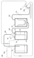
図1は、本発明の一実施形態における泥水処理システム(以下、システム)100の全体概要を示す図である。システム100は、液体処理システムの一実施形態に当たる。システム100は、浸水被害を受けた被災地に、泥水除去作業を行うために利用することができる。図1に示すように、システム100は、負圧源としての真空発生モジュール50、真空タンク40、回収タンク20、排水タンク70、および、噴射装置80を備えている。
FIG. 1 is a diagram showing an overall outline of a muddy water treatment system (hereinafter referred to as system) 100 in one embodiment of the present invention.
真空発生モジュール50は、真空タンク40内に負圧を発生させられるように構成されている。本実施形態では、真空発生モジュール50は、コンプレッサー106とディフューザー54とを備え、コンプレッサー106からの圧縮流体(例えば空気)をノズルからディフューザー54に放出することで真空タンク40内に負圧を発生させるエジェクター方式が採用される。ただし、真空発生モジュール50としては、エジェクター方式に限定されず、真空ポンプなどが用いられてもよい。
The
真空タンク40は、真空発生モジュール50に連結されて内部に負圧が発生させられる。真空タンク40には、連結管104を介して回収タンク20が接続されており、連結管104を介して回収タンク20の内部に真空タンク40内の負圧を作用させることができる。回収タンク20には、吸い込み管102が連結されており、吸い込み管102の吸い込み口を通して泥水が吸引される。回収タンク20は、吸引された泥水に含まれる泥土(固体物)を回収するように構成されている。泥土が取り除かれた泥水は、回収タンク20から連結管104を介して真空タンク40内に吸引される。連結管104は一例として回収タンク20の下方(下面または下方の側面)と真空タンク40の上方(上面または上方の側面)とに接続されることが好ましい。
The
真空タンク40の内部には、吸気吸水管60が設けられている。吸気吸水管60は真空発生モジュール50の吸い込み口に連結されている。吸気吸水管60に関しては、詳しくは後述する。真空発生モジュール50の吐き出し口は、排気排水管108を介して排水タンク70に接続されている。なお、本実施形態では、真空発生モジュール50によって負圧が発生されると、真空タンク40および回収タンク20の内部は負圧となる。一方、排水タンク70は、外部に開放されており、真空発生モジュール50の作動にかかわらず内部は約外気圧となる。なお、システム100は、排水タンク70を備えなくてもよく、排気排水管108は下水などに接続されてもよい。
An air/
噴射装置80は、排水タンク70に溜められた液体を噴射口80aから噴射できるように構成されている。噴射装置80は、システム100の使用者によって噴射/停止できるように構成されることが好ましい。これにより、使用者は、例えば泥水除去作業を行う場所に噴射口80aを向けて液体を噴射し、固まった泥土を除去したり泥水を集めたりして泥水除去の作業効率の向上を図ることができる。噴射装置80は、一例として、真空発生モジュール50による動力を用いて液体を噴射するように構成される。本実施形態では、噴射装置80は、コンプレッサー106による圧縮流体を利用して液体を噴射口80aから噴射できるように構成される。ただし、こうした例に限定されず、システム100は、噴射装置80のための動力源を更に備えてもよい。また、システム100は、噴射装置80を備えなくてもよい。
The
こうしたシステム100では、真空発生モジュール50によって発生される負圧を利用して、吸い込み管102の吸い込み口から回収タンク20に泥水が吸引される。回収タンク20では泥水に含まれる泥土が分離されて回収され、水分および細かい泥土が連結管104を通って真空タンク40内に吸引される。真空タンク40内に溜められた液体は、吸気吸水管60、真空発生モジュール50、及び、排気排水管108を通じて排水タンク70に排出される。こうしたシステム100により、泥水除去作業を省力化することができる。また、泥水除去作業を長時間にわたって連続的に行うことができる。
In such a
また、システム100は、機動性に優れる。例えば、回収タンク20、真空タンク40、及び排水タンク70は、比較的コンパクトな構成とすることができ、被災地まで比較的容易に搬送し、現場に設置することができる。また、回収タンク20、真空タンク40、及び排水タンク70は、必要に応じて、それぞれ、別々の小型車両で搬送されてもよい。これにより、比較的迅速に被災地にアクセスすることができる。
Additionally, the
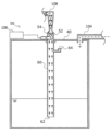
図2は、図1に示す泥水処理システムの一部の構成をより詳細に示す模式図である。図2では、主に、真空発生モジュール50、真空タンク40、及び吸気吸水管60が示されている。
FIG. 2 is a schematic diagram showing a part of the configuration of the muddy water treatment system shown in FIG. 1 in more detail. In FIG. 2, the
図2に示す例では、真空発生モジュール50は、エジェクター方式が採用されている。図示するように、真空発生モジュール50は、コンプレッサー106と、コンプレッサー106からの圧縮流体が供給されるノズル52と、ディフューザー54と、を備える。一例として、ノズル52およびディフューザー54は、真空タンク40の上部に取り付けられる。ただし、こうした例に限定されず、ノズル52およびディフューザー54は、一例として真空タンク40の側面などに取り付けられてもよい。真空発生モジュール50では、コンプレッサー106からの圧縮流体をノズル52からディフューザー54へと流入させることによって負圧を発生させることができる。
In the example shown in FIG. 2, the
吸気吸水管60は、真空発生モジュール50の吸い込み口(図2中下側)に接続され、真空タンク40内に延在する。吸気吸水管60は、一例として、金属または樹脂などの剛性の高い材料で形成される。本実施形態では、吸気吸水管60は、上端がディフューザー54と真空タンク40の上面とに連結され、下端が真空タンク40内に位置する。ただし、吸気吸水管60は、ディフューザー54と一体に形成されるなど、真空発生モジュール50と一体に構成されてもよい。または、吸気吸水管60は、真空タンク40と一体に構成されてもよい。
The
図2に示すように、吸気吸水管60は、真空タンク40内に開口する吸水口(第1開口)62および吸気口(第2開口)64を有する。吸水口62は、真空タンク40内における比較的低い第1位置に形成されており、吸気口64は、真空タンク40内における比較的高い第2位置に形成されている。つまり、吸気口64は、吸水口62よりも高い位置に形成されている。一例として、吸水口62は、真空タンク40の中央よりも低い位置に形成され、吸気口64は、真空タンク40の中央よりも低い位置に形成されることが好ましい。
As shown in FIG. 2, the air/
また、図2に示す例では、吸気口64は、吸水口62よりも小さい寸法とされる。ここで、吸気口64および吸水口62は、一例として円形の開口であるが、多角形など任意の形状であってもよい。本実施形態では、「寸法」は、開口が円形である場合には、直径または半径を意味する。また、「寸法」は、開口が多角形である場合には、一辺の長さ、または中心を通る開口幅において最小となる開口幅を意味する。あるいは、開口の寸法は、開口面積と等価な面積を有する円の直径で定義することもできる。吸水口62の寸法は、
一例として吸気口64の約1.2倍、1.5倍、2倍程度とすることができる。
Further, in the example shown in FIG. 2, the
For example, it can be about 1.2 times, 1.5 times, or twice the size of the
さらに、図2に示す例では、吸水口62は、吸気吸水管60の下端に形成され、鉛直下方を向いて開口している。また、吸気口64は、吸気吸水管60の側面にエルボ管が接続されて形成され、鉛直上方を向いて開口している。限定するものではないが、吸水口62は、水平方向、または水平方向よりも鉛直下方に開口することが好ましく、吸気口64は、水平方向、または水平方向よりも鉛直上方に開口することが好ましい。
Furthermore, in the example shown in FIG. 2, the
こうした吸気吸水管60が備えられたシステム100の動作について説明する。真空発生モジュール50が作動すると、真空タンク40内の泥水が少ないときには、吸水口62および吸気口64から真空タンク40内の空気が吸い込まれ、排気排水管108を通じて排水タンク70に空気が吐き出される。真空タンク40内の負圧は、連結管104を介して回収タンク20および吸い込み管102に作用する。これにより、使用者は、吸い込み管102を通じて回収タンク20および真空タンク40に泥水を吸い込むことができる。真空タンク40内の泥水の水位が吸気吸水管60の吸水口62に至ると、吸水口62から泥水が吸い込まれると共に吸気口64から真空タンク40内の空気が吸い込まれ、排気排水管108を通じて空気および泥水が排水タンク70に吐き出される。このように吸気吸水管60を備えることにより、真空タンク40内に吸引される泥水(液体)を、吸気吸水管60を通じて排水タンク70に排水することができる。なお、排水タンク70は外部に開放されているため、排水タンク70が満杯になった場合には容易に排水タンク70を交換することができ、真空タンク40内に吸引される泥水(液体)を連続的に排水することができる。
The operation of the
<第2実施形態>
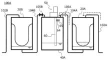
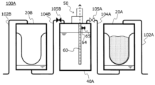
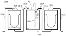
図3~図5は、第2実施形態の泥水処理システム100Aの構成概要を模式的に示す図である。第2実施形態の泥水処理システム100A(以下、「システム100A」ともいう)は、上記した泥水処理システム100と概ね同一であり、同一の構成については同一の符号を付して重複する説明を省略する。なお、図3~図5では、排水タンク70の図示を省略している。第2実施形態の泥水処理システム100Aの真空タンク40Aには、通水弁105A,105Bによって開閉可能な2つの連結管(第1の連結管、第2の連結管)104A,104Bが取り付けられており、真空タンク40Aは、2つの回収タンク(第1の回収タンク、第2の回収タンク)20A,20Bを接続可能となっている。2つの回収タンク20A,20Bのそれぞれには、吸い込み管102A,102Bが取り付けられている。また、第2実施形態の吸気吸水管60には、吸気口(第2開口)64を開閉可能な通気弁65が設けられている。通水弁105A,105B、および通気弁65は、システム100Aの使用者が操作可能なように構成される。なお、図3~図5に示す例では、通気弁65は、真空タンク40Aの内部に設けられているが、こうした例に限定されず、通気弁65は、真空タンク40Aの外部に設けられてもよい。この場合には、吸気吸水管60は、吸気吸水管60本体に接続されて真空タンク40Aの外部を通って真空タンク40A内に吸気口64を画定する分岐管(図示せず)を有し、通気弁65は、分岐管に設けられるものとしてもよい。通水弁105A,105B、および通気弁65は、公知の任意の開閉弁を採用することができ、手動の開閉弁であってもよいし、電動の開閉弁などであってもよい。
<Second embodiment>
3 to 5 are diagrams schematically showing a configuration overview of a muddy
こうした第2実施形態のシステム100Aでは、2つの回収タンク20A,20Bの切り替えを伴って、泥水除去作業を行うことができる。図3~図5を参照して、システム100Aにおける回収タンク20A,20Bの切替時処理を説明する。ここで、図3~図5では、通水弁105A,105Bおよび通気弁65によって流路が閉じられているときには弁を黒塗りで示しており、流路が開かれているときには弁を白塗りで示している。
In the
図3に示すように、システム100Aは、真空タンク40Aに接続された一方の連結管104Aを開いて他方の連結管104Bを閉じることにより、一方の連結管104Aに接続された回収タンク20Aを利用して泥水除去作業を行うことができる。これにより、回収タンク20Aに泥水に含まれる固体物(泥土など)が回収され、真空タンク40Aに泥水が吸引される。また、このときには、通気弁65を開いておくことで、上記したように真空タンク40A内の泥水と空気とが吸気吸水管60を通じて排水タンク70(図3では不図示)に送られる。なお、真空タンク40A内の泥水の水位が低いほど吸気吸水管60を通じて気体が多く排出され、真空タンク40A内の泥水の水位が高いほど吸気吸水管60を通じて液体が多く排出される。
As shown in FIG. 3, the
続いて、図4に示すように、泥水除去作業に伴って回収タンク20A内の泥土量が多くなって回収タンク20A,20Bを切り替えるときには、使用者は、吸気吸水管60の通気弁65を閉じる。これにより、吸気口64から空気が吸入されることが防がれ、真空タンク40A内の泥水を積極的に排水タンク70に排出することができる。なお、回収タンク20Aには回収タンク20Aの内部と外部とを連通する排気弁(図示せず)が設けられるものとし、真空タンク40A内の泥水を排出するときには、回収タンク20Aの排気弁を開くものとしてもよい。
Subsequently, as shown in FIG. 4, when the amount of mud in the
そして、図5に示すように、連結管104Aを閉じて連結管104Bを開くことにより、真空タンク40Aに連通する回収タンクを、回収タンク20Aから回収タンク20Bへと切り替えることができる。回収タンク20Aと真空タンク40Aとの流体接続は解除されており、使用者は、回収タンク20A内に溜められた泥土を外部に持ち出すなどして容易に処理することができる。また、真空タンク40Aには、回収タンク20Bが流体接続されており、回収タンク20Bを利用して継続して泥水除去作業を行うことができる。これにより、回収タンク20Aを用いた泥水除去作業と同様に、泥水に含まれる固体物が回収タンク20Bに回収される。また、このときには、通気弁65を開くことにより、真空タンク40A内の泥水と空気とが吸気吸水管60を通じて排水タンク70に排水される。
Then, as shown in FIG. 5, by closing the connecting
以上説明したように、第2実施形態の真空タンク40Aには、2つの連結管104A,104Bを介して2つの回収タンク20A,20Bが接続されており、2つの回収タンク20A,20Bを切り替えながら泥水除去作業を行うことができる。なお、上記したように、回収タンク20A,20Bのそれぞれには、回収タンク20A,20Bの内部と外部とを連通する排気弁が設けられてもよい。また、通水弁105A,105Bおよび通気弁65を開閉するタイミングは、上記した例に限定されず、システム100Aの使用状態に応じて使用者が適宜行うものとすればよい。
As explained above, the
<第3実施形態>
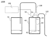
図6は、第3実施形態の液体処理システム100Bの構成概要を模式的に示す図である。第3実施形態の液体処理システム100B(以下、「システム100B」ともいう)は、上記した泥水処理システム100と概ね同一であり、同一の構成については同一の符号を付して重複する説明を省略する。システム100Bの真空タンク40Bは、連結管104を介して回収タンク20が接続されるのに代えて、吸い込み管102が接続されている。つまり、システム100Bは、上記したシステム100と異なり、回収タンク20を備えていない。
<Third embodiment>
FIG. 6 is a diagram schematically showing a configuration overview of a
システム100Bでは、吸い込み管102から吸い込まれた液体が、真空タンク40に直接に吸引される。また、真空タンク40には、上記した実施形態と同様に吸気吸水管60が設けられており、真空タンク40内に吸引された液体を、吸気吸水管60を通じて排水タンク70に排出することができる。こうした第3実施形態のシステム100Bは、一例として、雨水など、あまり固体物が含まれていない液体、またはまったく固体物が含ま
れていない液体を除去する場合に好適に利用することができる。
In
<変形例>
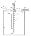
図7は、変形例の泥水処理システムの図2に対応する構成を示す図である。図7に示すように、吸気吸水管60の吸気口64(吸気口64A)は、吸気吸水管60の本体の側面に空けられた開口であってもよい。また、吸気吸水管60の吸気口64(吸気口64B)は、真空タンク40の中央より低い位置から中央より高い位置へと延びる接続配管により形成されてもよい。また、吸気吸水管60は、複数の吸水口62を有してもよいし、複数の吸気口64を有してもよい。
<Modified example>
FIG. 7 is a diagram showing a configuration corresponding to FIG. 2 of a muddy water treatment system according to a modified example. As shown in FIG. 7 , the intake port 64 (
<第4実施形態>
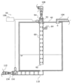
図8は、第4実施形態の泥処理システムの図2に対応する構成の一例を示す図である。第4実施形態の泥処理システムにおける真空タンク40は、吸気吸水管60に加えて、真空タンク40の底部に接続された排水管110から水を排出することができるように構成されている。排水管110には、ディフューザー154が設けられており、ディフューザー154の内部には、圧縮流体が供給されるノズル152が配置されている。ノズル152は、圧縮流体を供給するコンプレッサー106に接続されており、真空タンク40から離れる方向にディフューザー154内部に圧縮流体を流入させるように構成されている。換言すれば、ディフューザー154の吸い込み口が真空タンク40の底部に接続されている。なお、図8に示す例では、コンプレッサー106は、真空発生モジュール50におけるコンプレッサー106を利用するものとしているが、こうした例には限定されない。また、真空発生モジュール50におけるコンプレッサー106は、ノズル52とノズル152との一方のみを選択して圧縮流体を供給できるように構成されてもよいし、ノズル52及びノズル152の両方に一括して圧縮流体を供給するように構成されてもよい。そして、第4実施形態の真空タンク40では、ノズル152からディフューザー154へと圧縮流体を流入させることによって、真空タンク40に吸引される泥水(液体)を、排水管110を通じて排出することができる。このように、第4実施形態の泥処理システムでは、真空タンク40に吸引される液体を、吸気吸水管60と排水管110とのそれぞれから外部に排出することができ、より好適に液体を連続的に吸引することが可能になる。なお、排水管110は、排気排水管108と共に排水タンク70に接続されるとよい。排水管110は、排気排水管108に接続されて統合されてもよいし、排気排水管108とは別に排水タンク70に接続されてもよい。コンプレッサーからノズル152への圧縮空気管に流量調整弁(図示せず)が設けられてもよい。また、排水管110には、手動または電動の止水弁(図示せず)が設けられてもよい。さらに、図8に示す例では、排水管110は、真空タンク40に対して、吸気吸水管60の吸水口62の真下に接続されている。しかしながら、こうした例に限定されず、排水管110は、真空タンク40に対して、鉛直方向に見て吸水口62とは異なる位置に接続されてもよい。
<Fourth embodiment>
FIG. 8 is a diagram showing an example of a configuration corresponding to FIG. 2 of the mud treatment system of the fourth embodiment. The
図9は、第4実施形態の泥処理システムの図2に対応する構成の別の一例を示す図である。図8に示す例では、排水管110(ディフューザー154)は、真空タンク40の底部に取り付けられるものとした。これに代えて、図9に示す例では、排水管110(ディフューザー154)は、真空タンク40の側部(側面)に取り付けられている。こうした例においても、図8に示す例と同様の機能を奏することができる。なお、排水管110が真空タンク40の側部に取り付けられる場合には、真空タンク40の下端部、または下端部近傍に取り付けられることが好ましい。
FIG. 9 is a diagram showing another example of a configuration corresponding to FIG. 2 of the mud treatment system of the fourth embodiment. In the example shown in FIG. 8, the drain pipe 110 (diffuser 154) is attached to the bottom of the
本発明は、以下の形態としても記載することができる。
[形態1]形態1によれば、液体を吸引して収集するための液体処理システムが提案され、前記液体処理システムは、真空発生モジュールと、前記真空発生モジュールに接続され、前記真空発生モジュールによって生じる負圧により液体が吸い込まれる真空タンクと
、前記真空発生モジュールから前記真空タンク内に延び、第1位置で前記真空タンク内に開口する第1開口、および、前記第1位置よりも高い位置である第2位置で前記真空タンク内に開口する第2開口を有する吸気吸水管と、を備える。形態1によれば、液体を連続的に吸引することができるコンパクトな収集タンク装置を提供することができる。
The invention can also be described in the following form.
[Form 1] According to Form 1, a liquid processing system for suctioning and collecting liquid is proposed, and the liquid processing system includes a vacuum generation module, and is connected to the vacuum generation module, and is connected to the vacuum generation module. a vacuum tank into which liquid is sucked due to the generated negative pressure; a first opening extending from the vacuum generation module into the vacuum tank and opening into the vacuum tank at a first position; and a first opening at a position higher than the first position. an air intake/water intake pipe having a second opening opening into the vacuum tank at a certain second position. According to the first embodiment, a compact collection tank device capable of continuously sucking liquid can be provided.
[形態2]形態2によれば、形態1において、前記第1開口は、第1寸法の開口であり、前記第2開口は、前記第1寸法よりも小さい第2寸法の開口である。形態2によれば、吸気吸水管により好適に気体と液体とを吸い込むことができる。 [Form 2] According to Embodiment 2, in Embodiment 1, the first opening has a first dimension, and the second opening has a second dimension smaller than the first dimension. According to the second embodiment, the gas and liquid can be suitably sucked through the intake/water intake pipe.
[形態3]形態3によれば、形態1または2において、前記第1開口は、水平方向、または水平方向よりも鉛直下方に開口しており、前記第2開口は、水平方向、または水平方向よりも鉛直上方に開口している。形態3によれば、吸気吸水管により好適に気体と液体とを吸い込むことができる。 [Form 3] According to Form 3, in Form 1 or 2, the first opening opens in the horizontal direction or vertically below the horizontal direction, and the second opening opens in the horizontal direction or in the horizontal direction. It opens vertically upwards. According to Embodiment 3, gas and liquid can be suitably sucked into the air and water intake pipe.
[形態4]形態4によれば、形態1から3において、前記第1位置は、前記真空タンクの中央よりも下方であり、前記第2位置は、前記真空タンクの中央よりも上方である。形態4によれば、吸気吸水管により好適に気体と液体とを吸い込むことができる。 [Form 4] According to Form 4, in Forms 1 to 3, the first position is below the center of the vacuum tank, and the second position is above the center of the vacuum tank. According to the fourth embodiment, gas and liquid can be suitably sucked through the air intake pipe.
[形態5]形態5によれば、形態1から4において、前記真空発生モジュールは、圧縮された流体をノズルから送出するコンプレッサーと、前記圧縮された流体が流れるディフューザーと、を有し、前記吸気吸水管は、前記ディフューザーの吸い込み口に連結される。 [Embodiment 5] According to embodiment 5, in embodiments 1 to 4, the vacuum generation module includes a compressor that delivers compressed fluid from a nozzle, and a diffuser through which the compressed fluid flows, and A water suction pipe is connected to the suction port of the diffuser.
[形態6]形態6によれば、形態5において、前記ディフューザーの吐出し口に接続される排水タンクを備える。形態6によれば、排水タンクに液体を溜めることができる。 [Embodiment 6] According to Embodiment 6, in Embodiment 5, a drainage tank connected to the discharge port of the diffuser is provided. According to the sixth embodiment, liquid can be stored in the drainage tank.
[形態7]形態7によれば、形態6において、前記排水タンクに溜められた液体を噴射口から噴射可能な噴射装置を備える。形態7によれば、例えば液体を吸い込む場所に液体を噴射することができる。 [Embodiment 7] According to Embodiment 7, in Embodiment 6, an injection device capable of injecting the liquid stored in the drainage tank from the injection port is provided. According to the seventh embodiment, the liquid can be injected to a place where the liquid is sucked, for example.
[形態8]形態8によれば、形態7において、前記噴射装置は、前記真空発生モジュールによる動力を用いて前記液体を噴射するように構成される。 [Embodiment 8] According to Embodiment 8, in Embodiment 7, the injection device is configured to inject the liquid using the power generated by the vacuum generation module.
[形態9]形態9によれば、形態1から8において、圧縮された流体をノズルから送出するコンプレッサーと、前記圧縮された流体が流れるディフューザーと、を備え、前記ディフューザーの吸い込み口は、前記真空タンクの底部または側部に接続される。形態9によれば、真空タンクの底部または側部に接続されたディフューザーによって排水することができる。 [Embodiment 9] According to embodiment 9, in embodiments 1 to 8, it includes a compressor that delivers compressed fluid from a nozzle, and a diffuser through which the compressed fluid flows, and the suction port of the diffuser is connected to the vacuum. Connected to the bottom or side of the tank. According to Form 9, water can be drained by a diffuser connected to the bottom or side of the vacuum tank.
[形態10]形態10によれば、形態9において、前記ディフューザーの吐き出し口に接続される排水タンクを備える。形態9によれば、排水タンクに液体を溜めることができる。 [Embodiment 10] According to embodiment 10, in embodiment 9, a drainage tank connected to the outlet of the diffuser is provided. According to the ninth embodiment, liquid can be stored in the drainage tank.
[形態11]形態11によれば、形態1から10において、前記液体に含まれる固体物を回収するための回収タンクと、前記真空タンクと前記回収タンクとを接続する連結管と、前記回収タンクに接続され、液体を吸引するための吸引口を有する吸い込み管と、を備え、前記吸引口から吸引された液体が、前記回収タンクと前記連結管とを介して前記真空タンクに吸引される。形態11によれば、回収タンクに固体物を回収して、真空タンクに液体を吸引することができる。 [Form 11] According to Form 11, in Forms 1 to 10, a recovery tank for recovering solid matter contained in the liquid, a connecting pipe connecting the vacuum tank and the recovery tank, and the recovery tank a suction pipe connected to the vacuum tank and having a suction port for sucking liquid, and the liquid sucked from the suction port is sucked into the vacuum tank via the recovery tank and the connecting pipe. According to Embodiment 11, solid matter can be collected in the collection tank and liquid can be sucked into the vacuum tank.
[形態12]形態12によれば、形態11において、前記回収タンクは、第1の回収タンクと第2の回収タンクとを含み、前記連結管は、前記真空タンクと前記第1の回収タンクとを接続する第1の連結管と、前記真空タンクと前記第2の回収タンクとを接続する第2の連結管と、を含み、前記第1および第2の連結管のそれぞれには、当該第1および第2の連結管を開閉可能な通水弁が設けられ、前記吸気吸水管は、前記第2開口を開閉可能な通気弁を有する。形態12によれば、第1および第2の回収タンクを切り替えながら液体を吸引することができる。 [Embodiment 12] According to embodiment 11, in embodiment 11, the recovery tank includes a first recovery tank and a second recovery tank, and the connecting pipe connects the vacuum tank and the first recovery tank. a first connecting pipe that connects the vacuum tank and the second recovery tank, and a second connecting pipe that connects the vacuum tank and the second recovery tank; A water flow valve that can open and close the first and second connecting pipes is provided, and the air intake and water intake pipe has a vent valve that can open and close the second opening. According to the twelfth embodiment, liquid can be sucked while switching between the first and second recovery tanks.
以上、本発明の実施の形態について説明してきたが、上記した発明の実施の形態は、本発明の理解を容易にするためのものであり、本発明を限定するものではない。本発明は、その趣旨を逸脱することなく、変更、改良され得るとともに、本発明にはその均等物が含まれることはもちろんである。また、上述した課題の少なくとも一部を解決できる範囲、または、効果の少なくとも一部を奏する範囲において、実施形態および変形例の任意の組み合わせが可能であり、特許請求の範囲および明細書に記載された各構成要素の任意の組み合わせ、または、省略が可能である。一例として、第1および第3実施形態のシステム100,100Bにおいても、吸気吸水管60に通気弁が設けられてもよいし、第1実施形態のシステム100において連結管104に通水弁が設けられてもよい。また、システム100において回収タンク20に排気弁が設けられてもよい。
Although the embodiments of the present invention have been described above, the above-described embodiments of the present invention are intended to facilitate understanding of the present invention, and are not intended to limit the present invention. The present invention may be modified and improved without departing from its spirit, and it goes without saying that the present invention includes equivalents thereof. Further, any combination of the embodiments and modifications is possible as long as at least part of the above-mentioned problems can be solved or at least part of the effect can be achieved, and the combinations are possible as long as they are not described in the claims and specification. Any combination or omission of each component is possible. As an example, in the
20,20A,20B…回収タンク
40,40A…真空タンク
50…真空発生モジュール
52…ノズル
54…ディフューザー
60…吸気吸水管
62…吸水口
64,64A,64B…吸気口
65…通気弁
70…排水タンク
80…噴射装置
80a…噴射口
100,100A…泥水処理システム(液体処理システム)
100B…液体処理システム
102,102A,102B…吸い込み管
104,104A,104B…連結管
105A,105B…通水弁
106…コンプレッサー
108…排気排水管
20, 20A, 20B...
100B...
Claims (12)
真空発生モジュールと、
前記真空発生モジュールに接続され、前記真空発生モジュールによって生じる負圧により液体が吸い込まれる真空タンクと、
前記真空発生モジュールから前記真空タンク内に延び、第1位置で前記真空タンク内に開口する第1開口、および、前記第1位置よりも高い位置である第2位置で前記真空タンク内に開口する第2開口を有する吸気吸水管と、
を備える液体処理システム。 A liquid handling system for aspirating and collecting liquid, the system comprising:
A vacuum generation module,
a vacuum tank connected to the vacuum generation module, into which liquid is sucked by the negative pressure generated by the vacuum generation module;
a first opening extending into the vacuum tank from the vacuum generation module and opening into the vacuum tank at a first position; and a first opening opening into the vacuum tank at a second position higher than the first position. an intake water intake pipe having a second opening;
A liquid handling system comprising:
前記第2開口は、前記第1寸法よりも小さい第2寸法の開口である、
請求項1に記載の液体処理システム。 The first opening is an opening with a first dimension,
the second opening has a second dimension smaller than the first dimension;
A liquid treatment system according to claim 1.
前記第2開口は、水平方向、または水平方向よりも鉛直上方に開口している、
請求項1に記載の液体処理システム。 The first opening opens horizontally or vertically below the horizontal direction,
The second opening opens horizontally or vertically above the horizontal direction.
The liquid treatment system according to claim 1.
前記第2位置は、前記真空タンクの中央よりも上方である、
請求項1に記載の液体処理システム。 The first position is below the center of the vacuum tank,
the second position is above the center of the vacuum tank;
The liquid treatment system according to claim 1.
前記吸気吸水管は、前記ディフューザーの吸い込み口に連結される、
請求項1に記載の液体処理システム。 The vacuum generation module includes a compressor that delivers compressed fluid from a nozzle, and a diffuser through which the compressed fluid flows,
The intake water intake pipe is connected to the intake port of the diffuser.
The liquid treatment system according to claim 1.
前記圧縮された流体が流れるディフューザーと、
を備え、
前記ディフューザーの吸い込み口は、前記真空タンクの底部または側部に接続される、
請求項1に記載の液体処理システム。 a compressor that delivers compressed fluid from a nozzle;
a diffuser through which the compressed fluid flows;
Equipped with
The suction port of the diffuser is connected to the bottom or side of the vacuum tank.
The liquid treatment system according to claim 1.
前記真空タンクと前記回収タンクとを接続する連結管と、
前記回収タンクに接続され、液体を吸引するための吸引口を有する吸い込み管と、
を備え、
前記吸引口から吸引された液体が、前記回収タンクと前記連結管とを介して前記真空タンクに吸引される、
請求項1から9の何れか1項に記載の液体処理システム。 a recovery tank for recovering solids contained in the liquid;
a connecting pipe connecting the vacuum tank and the recovery tank;
a suction pipe connected to the recovery tank and having a suction port for suctioning liquid;
Equipped with
The liquid sucked from the suction port is sucked into the vacuum tank via the recovery tank and the connecting pipe.
A liquid treatment system according to any one of claims 1 to 9.
前記連結管は、前記真空タンクと前記第1の回収タンクとを接続する第1の連結管と、前記真空タンクと前記第2の回収タンクとを接続する第2の連結管と、を含み、
前記第1および第2の連結管のそれぞれには、当該第1および第2の連結管を開閉可能な通水弁が設けられ、
前記吸気吸水管は、前記第2開口を開閉可能な通気弁を有する、
請求項11に記載の液体処理システム。 The recovery tank includes a first recovery tank and a second recovery tank,
The connecting pipe includes a first connecting pipe that connects the vacuum tank and the first recovery tank, and a second connecting pipe that connects the vacuum tank and the second recovery tank,
Each of the first and second connecting pipes is provided with a water valve that can open and close the first and second connecting pipes,
The intake water intake pipe has a ventilation valve that can open and close the second opening.
A liquid treatment system according to claim 11.
Applications Claiming Priority (2)
| Application Number | Priority Date | Filing Date | Title |
|---|---|---|---|
| JP2022131933 | 2022-08-22 | ||
| JP2022131933 | 2022-08-22 |
Publications (1)
| Publication Number | Publication Date |
|---|---|
| JP2024029733A true JP2024029733A (en) | 2024-03-06 |
Family
ID=90104948
Family Applications (1)
| Application Number | Title | Priority Date | Filing Date |
|---|---|---|---|
| JP2022184728A Pending JP2024029733A (en) | 2022-08-22 | 2022-11-18 | liquid handling system |
Country Status (1)
| Country | Link |
|---|---|
| JP (1) | JP2024029733A (en) |
-
2022
- 2022-11-18 JP JP2022184728A patent/JP2024029733A/en active Pending
Similar Documents
| Publication | Publication Date | Title |
|---|---|---|
| KR101022423B1 (en) | Mobile sewer dredging device | |
| CN206360068U (en) | Pond is collected by filtration in a kind of rain water drainage | |
| CN208578132U (en) | A kind of dirty abandoned stream filter arrangement of Rain Garden rainwater-collecting section | |
| JP2009508028A (en) | Dam sludge treatment system | |
| CN107558600A (en) | A kind of hoisting type device for dragging dregs | |
| CN104631547A (en) | Rainwater collecting system | |
| CN204530842U (en) | Rain water collecting system | |
| CN206800613U (en) | A kind of combined suction sewage truck | |
| CN107473330B (en) | Remote control type water oil stain remover | |
| CN107165260A (en) | A kind of mud clean method of rainfall pumping station | |
| CN214884288U (en) | Rainwater regulation and storage tank cleaned by utilizing aeration sand settling and sand pump suction and discharge of silt | |
| CN109653333A (en) | Sponge city dweller's rainwater ecological system | |
| CN108636038A (en) | Air deduster | |
| CN209482442U (en) | Underground sumping, exhaust system | |
| CN108999276B (en) | Sewage lifting means convenient to separation impurity | |
| JPH0235902A (en) | Stagnant water collection equipment in the sand basin of the pump station | |
| CN210409825U (en) | Prevent to deposit drainage pump station of siltation | |
| CN206941696U (en) | The prefabricated pumping plant of novel all-in-one | |
| JP2024029586A (en) | Mud water treatment system | |
| JP2024029732A (en) | Mud water treatment system | |
| CN219846375U (en) | Negative pressure draining structure | |
| CN108149608A (en) | Construction site silt-clearing vehicle | |
| CN207295943U (en) | A kind of road drainage system | |
| CN222010419U (en) | Manual pumping device suitable for shallow ponding layer | |
| CN223398180U (en) | A rainwater collection device for community use |
Legal Events
| Date | Code | Title | Description |
|---|---|---|---|
| AA64 | Notification of invalidation of claim of internal priority (with term) |
Free format text: JAPANESE INTERMEDIATE CODE: A241764 Effective date: 20221223 |
|
| A521 | Request for written amendment filed |
Free format text: JAPANESE INTERMEDIATE CODE: A523 Effective date: 20221227 |
|
| A621 | Written request for application examination |
Free format text: JAPANESE INTERMEDIATE CODE: A621 Effective date: 20250604 |