JP2024029732A - Mud water treatment system - Google Patents

Mud water treatment system Download PDF

Info

Publication number
JP2024029732A
JP2024029732A JP2022184724A JP2022184724A JP2024029732A JP 2024029732 A JP2024029732 A JP 2024029732A JP 2022184724 A JP2022184724 A JP 2022184724A JP 2022184724 A JP2022184724 A JP 2022184724A JP 2024029732 A JP2024029732 A JP 2024029732A
Authority
JP
Japan
Prior art keywords
recovery tank
muddy water
elastic body
tank
treatment system
Prior art date
Legal status (The legal status is an assumption and is not a legal conclusion. Google has not performed a legal analysis and makes no representation as to the accuracy of the status listed.)
Pending
Application number
JP2022184724A
Other languages
Japanese (ja)
Inventor
雄二 中塩
Yuji Nakashio
修 清水
Osamu Shimizu
登子 佐々木
Takako Sasaki
Current Assignee (The listed assignees may be inaccurate. Google has not performed a legal analysis and makes no representation or warranty as to the accuracy of the list.)
Ebara Corp
Original Assignee
Ebara Corp
Priority date (The priority date is an assumption and is not a legal conclusion. Google has not performed a legal analysis and makes no representation as to the accuracy of the date listed.)
Filing date
Publication date
Application filed by Ebara Corp filed Critical Ebara Corp
Publication of JP2024029732A publication Critical patent/JP2024029732A/en
Pending legal-status Critical Current

Links

Images

Landscapes

  • Treatment Of Sludge (AREA)

Abstract

To suppress excessive suction of mud in a muddy water treatment system for sucking muddy water.SOLUTION: Proposed is a muddy water treatment system for sucking muddy water, and the muddy water treatment system comprises: a recovery tank to the inside of which a recovery container for recovering mud contained in the muddy water may be attached, and which sucks the muddy water with negative pressure by a negative pressure source; a suction tube connected to an upper part of the recovery tank; and a detection tube connected to the suction tube and extending into the recovery tank, with an opening located inside the recovery container when the recovery container is attached to the recovery tank.SELECTED DRAWING: Figure 2

Description

本願は、水害時の泥水処理などに好適に使用される泥水を吸引するための泥水処理システムに関する。 The present application relates to a muddy water treatment system for suctioning muddy water, which is suitably used for muddy water treatment during flood disasters.

近年、ゲリラ豪雨などの突発的な豪雨または大型台風による河川氾濫によって生じる浸水被害が増加している。河川氾濫では、大量の泥水が住宅地に押し寄せ、その泥水処理が社会問題となっている。河川水位が下がって水が引いた後も、浸水箇所には、大量の水分を含んだ泥水が残る。特に住宅地域の浸水箇所では、水が引いた後の泥水の除去作業を、まず地域住民とボランティアなどがスコップなどを用いて手作業で行う場合が多い。水害直後の水分を多く含んだ泥水を、スコップなどですくい取ることは難しい。従って、泥水を土のう袋などに集める作業の作業性は悪く、効率が低い。また、泥水が集められた土のう袋は重いので、その扱いには重労働を要する。 In recent years, flood damage caused by sudden heavy rains such as torrential rain or river flooding caused by large typhoons has been increasing. When rivers flood, large amounts of muddy water rush into residential areas, and the treatment of this muddy water has become a social issue. Even after the river water level drops and the water recedes, muddy water containing a large amount of water remains in the flooded areas. Particularly in flooded areas in residential areas, the removal of muddy water after the water has receded is often done manually by local residents and volunteers using shovels and other tools. It is difficult to scoop up muddy water that contains a lot of water immediately after a flood with a shovel. Therefore, the workability of collecting muddy water into sandbags or the like is poor and efficiency is low. Additionally, the sandbags that collect muddy water are heavy and require hard labor to handle.

このように、人力での泥水除去作業は、長時間にわたる重労働となるので被災者の負担が大きい。 As described above, manual muddy water removal work requires long hours of hard labor, which places a heavy burden on disaster victims.

また、泥水は、時間が経つと水分が抜けて、ある程度乾燥した状態になる。しかし、スコップ作業の際、乾燥した泥が飛散する。これは、乾燥した泥に、水道水などの水を散布することによって軽減できる。しかし、被災地では、断水および/または停電している場合が多い。一般的に停電の復旧は早いが、上下水の断水は、復旧にかなりの時間を要する。断水が復旧するまで水道水を使用することはできないので、作業者は、スコップ作業を作業性の悪い状態で長時間行わざるを得ない。 Additionally, over time, the water in the muddy water loses its moisture and becomes dry to some extent. However, when shoveling, dried mud is scattered. This can be alleviated by spraying the dry mud with water, such as tap water. However, in many cases, water and/or power outages occur in disaster-stricken areas. Generally, power outages are quickly restored, but water and sewage outages require a considerable amount of time to be restored. Since tap water cannot be used until the water outage is restored, workers are forced to shovel for long periods of time in difficult conditions.

また、住宅の床上浸水または床下浸水の復旧には、床下に溜まった泥水を除去する必要がある。現状では、床下の泥水を除去する作業は、作業者が床下に潜りこんで手作業することにより行われているので、大変な重労働となっている。床下の泥水が乾燥すると、作業はさらに困難になる。 In addition, in order to recover from flooding above or below the floor of a house, it is necessary to remove muddy water that has accumulated under the floor. Currently, the work of removing muddy water from under the floor requires workers to crawl under the floor and do the work manually, which is extremely hard work. Once the muddy water under the floor dries, the job becomes even more difficult.

一方、泥水の除去作業に、吸引装置などの機械的な手段を使用することも考えられるが、大掛かりな設備は、機動性が問題となる。例えば、大型の作業車両で泥水除去作業を行う場合、被災地へのアクセスが困難な場合がある。災害後は、幹線道路が泥やゴミでおおわれているので、大型の作業車両は、住宅地まで入ってくることができない。大型の作業車両で住宅地の泥水除去を行うためには、まず、大型車両が住宅地まで移動できるように、幹線道路や住宅周辺道路の泥水除去作業を行う必要がある。 On the other hand, it is conceivable to use mechanical means such as suction devices to remove muddy water, but large-scale equipment poses a problem of mobility. For example, when removing muddy water using a large work vehicle, it may be difficult to access the disaster area. After the disaster, the main roads are covered with mud and garbage, making it impossible for large work vehicles to reach residential areas. In order to remove muddy water from residential areas using large work vehicles, it is first necessary to remove muddy water from main roads and roads surrounding residential areas so that the large vehicles can move to residential areas.

既存の吸引装置の構成は、浸水被害に対応するのに、作業性、作業効率及び機動性などの面において不十分である。例えば、特許文献1は、圧縮空気を利用して、固体と液体を吸引する回収装置を記載している。この装置では、回収後の液体と固体は金網を通して互いに分離され、分離後の液体は、自然流下により装置から排出される。特許文献1は、切粉を含む加工用切削液の回収を企図している。分離後の固体を装置から取り出す具体的な方法は、特許文献1に記載されていない。 The configuration of existing suction devices is insufficient in terms of workability, work efficiency, mobility, etc. to deal with flood damage. For example, Patent Document 1 describes a recovery device that uses compressed air to suck up solids and liquids. In this device, the collected liquid and solid are separated from each other through a wire mesh, and the separated liquid is discharged from the device by gravity. Patent Document 1 contemplates the recovery of machining cutting fluid containing chips. A specific method for taking out the separated solid from the apparatus is not described in Patent Document 1.

特許文献2は、土木工事または建築工事で発生する汚泥などの汚泥物質を、脱水する装置を記載する。具体的には、特許文献2は、筒内の網袋と濾布上に投入された泥状物質から、真空吸引によって水を分離する装置を記載している。分離された水は、下水へ放流される。分離後の泥は、筒ごと吊り上げられるか、または網袋および濾布と共に筒から吊り
上げられる。
Patent Document 2 describes an apparatus for dewatering sludge materials such as sludge generated during civil engineering or construction work. Specifically, Patent Document 2 describes an apparatus that separates water by vacuum suction from a muddy substance placed on a mesh bag inside a cylinder and a filter cloth. The separated water is discharged to the sewer. After separation, the mud is lifted up along with the cylinder or from the cylinder together with the net bag and filter cloth.

また、特許文献3は、工事現場用の掃除機を記載している。具体的には、特許文献3は、メッシュ袋内に泥水を吸引した後、泥水を泥土と水に分離する装置を記載している。この装置は、分離後の水を排出するための専用の水中ポンプと真空ブロアを必要としている。分離後の泥土は、メッシュ袋ごと装置から取り出される。 Moreover, Patent Document 3 describes a vacuum cleaner for construction sites. Specifically, Patent Document 3 describes an apparatus that sucks muddy water into a mesh bag and then separates the muddy water into muddy soil and water. This equipment requires a dedicated submersible pump and vacuum blower to discharge the water after separation. The separated mud is taken out of the device along with the mesh bag.

特開2004-357767号公報Japanese Patent Application Publication No. 2004-357767 特開平10-15598号公報Japanese Patent Application Publication No. 10-15598 実用新案登録第3211893号公報Utility model registration No. 3211893

上記した泥水除去作業では、多量の泥水の除去が必要とされる。しかしながら、既存の吸引装置の構成は、泥水除去作業において泥水を連続的に吸引するために改良の余地がある。例えば、既存の吸引装置では、メインタンクに泥土が溜まっているか判断することができず、容器の容量を超えて泥土が吸引されるおそれがある。ポンプタンク内の水位検知器と同様にメインタンク内に泥土量検知器を設けることが考えられるが、泥土の重さは一定でないと共に、泥土は容器側面および検知手段に付着するため、フロート式またはセンサ式などの水位検知器では泥土量を適切に判定することは難しい。 The muddy water removal work described above requires the removal of a large amount of muddy water. However, the configuration of the existing suction device leaves room for improvement in order to continuously suck muddy water during muddy water removal work. For example, with existing suction devices, it is not possible to determine whether mud has accumulated in the main tank, and there is a risk that mud will be sucked in beyond the capacity of the container. It is possible to install a mud amount detector in the main tank in the same way as the water level detector in the pump tank, but since the weight of mud is not constant and mud adheres to the side of the container and the detection means, a float type or It is difficult to appropriately determine the amount of mud with sensor-type water level detectors.

以上の実情の少なくとも一部に鑑みて、本願は、泥水を吸引するための泥水処理システムにおいて、泥土の過剰な吸い込みを抑制することを1つの目的としている。 In view of at least part of the above circumstances, one object of the present application is to suppress excessive suction of mud in a mud water treatment system for sucking mud.

一実施形態によれば、泥水を吸引するための泥水処理システムが提案され、かかる泥水処理システムは、泥水に含まれる泥土を回収するための回収容器を内部に取付可能であり、負圧源による負圧を用いて泥水を吸引する回収タンクと、前記回収タンクの上部に接続された吸い込み管と、前記吸い込み管に接続されると共に前記回収タンク内に延在し、前記回収タンクに前記回収容器が取り付けられているときに当該回収容器の内部に位置する開口を有する検知管と、を備える。 According to one embodiment, a muddy water treatment system for suctioning muddy water is proposed, and the muddy water treatment system is capable of attaching therein a collection container for collecting mud contained in the muddy water, and which is operated by a negative pressure source. a collection tank that sucks muddy water using negative pressure; a suction pipe connected to the upper part of the collection tank; and a collection container connected to the suction pipe and extending into the collection tank, and connected to the collection tank. a detection tube having an opening located inside the collection container when the collection container is attached.

本発明の実施形態を適用可能な泥水処理システムの全体概要を示す図である。1 is a diagram showing an overall outline of a muddy water treatment system to which an embodiment of the present invention can be applied. 図1に示す泥水処理システムの回収タンクをより詳細に示す模式図である。FIG. 2 is a schematic diagram showing a recovery tank of the muddy water treatment system shown in FIG. 1 in more detail. 図1に示す泥水処理システムの回収タンクをより詳細に示す模式図である。FIG. 2 is a schematic diagram showing a recovery tank of the muddy water treatment system shown in FIG. 1 in more detail. 変形例の回収タンクの構成を示す図である。It is a figure which shows the structure of the recovery tank of a modification. 第2実施形態における回収タンクの一例を示す模式図であるIt is a schematic diagram showing an example of a recovery tank in a second embodiment. 第2実施形態における回収タンクの一例を示す模式図であるIt is a schematic diagram showing an example of a recovery tank in a second embodiment. 第2実施形態における回収タンクの一例を示す模式図であるIt is a schematic diagram showing an example of a recovery tank in a second embodiment. 第3実施形態における回収タンクの一例を示す模式図であるIt is a schematic diagram showing an example of a recovery tank in a third embodiment. 第3実施形態における回収タンクの一例を示す模式図であるIt is a schematic diagram showing an example of a recovery tank in a third embodiment.

以下、本発明の実施形態について図面を参照して説明する。なお、以下の説明はあくまでも一例を示すものであって、本願発明の技術的範囲を以下の実施形態に限定する趣旨ではない。また、図面では、同一または相当する構成要素には、同一の符号を付して重複し
た説明を省略する。
Embodiments of the present invention will be described below with reference to the drawings. Note that the following description is merely an example, and is not intended to limit the technical scope of the present invention to the following embodiments. Further, in the drawings, the same or corresponding components are given the same reference numerals and redundant explanations will be omitted.

<第1実施形態>
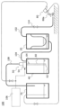
図1は、本発明の一実施形態における泥水処理システム(以下、システム)100の全体概要を示す図である。システム100は、液体処理システムの一実施形態に当たる。システム100は、浸水被害を受けた被災地に、泥水除去作業を行うために利用することができる。図1に示すように、システム100は、負圧源としての真空発生モジュール50、真空タンク40、回収タンク20、排水タンク70、および、噴射装置80を備えている。
<First embodiment>
FIG. 1 is a diagram showing an overall outline of a muddy water treatment system (hereinafter referred to as system) 100 in one embodiment of the present invention. System 100 represents one embodiment of a liquid handling system. The system 100 can be used to perform muddy water removal work in areas affected by flooding. As shown in FIG. 1, the system 100 includes a vacuum generation module 50 as a negative pressure source, a vacuum tank 40, a recovery tank 20, a drainage tank 70, and an injection device 80.

真空発生モジュール50は、真空タンク40内に負圧を発生させられるように構成されている。本実施形態では、真空発生モジュール50は、コンプレッサー106とディフューザー54とを備え、コンプレッサー106からの圧縮流体(例えば空気)をノズルからディフューザー54に放出することで真空タンク40内に負圧を発生させるエジェクター方式が採用される。ただし、真空発生モジュール50としては、エジェクター方式に限定されず、真空ポンプなどが用いられてもよい。 The vacuum generation module 50 is configured to generate negative pressure within the vacuum tank 40. In this embodiment, the vacuum generation module 50 includes a compressor 106 and a diffuser 54, and generates negative pressure in the vacuum tank 40 by discharging compressed fluid (for example, air) from the compressor 106 from a nozzle to the diffuser 54. An ejector method is adopted. However, the vacuum generation module 50 is not limited to the ejector type, and a vacuum pump or the like may be used.

真空タンク40は、真空発生モジュール50に連結されて内部に負圧が発生させられる。真空タンク40には、連結管104を介して回収タンク20が接続されており、連結管104を介して回収タンク20の内部に真空タンク40内の負圧を作用させることができる。回収タンク20には、吸い込み管102が連結されており、吸い込み管102の吸い込み口を通して泥水が吸引される。回収タンク20は、吸引された泥水に含まれる泥土(固体物)を回収するように構成されている。泥土が取り除かれた泥水は、回収タンク20から連結管104を介して真空タンク40内に吸引される。連結管104は一例として回収タンク20の下方(下面または下方の側面)と真空タンク40の上方(上面または上方の側面)とに接続されることが好ましい。 The vacuum tank 40 is connected to a vacuum generation module 50 to generate negative pressure therein. The recovery tank 20 is connected to the vacuum tank 40 via a connecting pipe 104, and the negative pressure inside the vacuum tank 40 can be applied to the inside of the recovery tank 20 via the connecting pipe 104. A suction pipe 102 is connected to the recovery tank 20, and muddy water is sucked through the suction port of the suction pipe 102. The recovery tank 20 is configured to recover mud (solid matter) contained in the sucked muddy water. The muddy water from which mud has been removed is sucked from the recovery tank 20 into the vacuum tank 40 via the connecting pipe 104. For example, the connecting pipe 104 is preferably connected to the lower side (lower surface or lower side surface) of the recovery tank 20 and the upper side (upper surface or upper side surface) of the vacuum tank 40.

真空タンク40の内部には、吸気吸水管60が設けられている。吸気吸水管60は真空発生モジュール50の吸い込み口に連結されて、真空タンク40内に延在する。本実施形態では、吸気吸水管60は、上端がディフューザー54と真空タンク40の上面とに連結され、下端が真空タンク40内に位置する。ただし、吸気吸水管60は、ディフューザー54と一体に形成されるなど、真空発生モジュール50と一体に構成されてもよい。または、吸気吸水管60は、真空タンク40と一体に構成されてもよい。吸気吸水管60は、真空タンク40内に開口する吸水口(第1開口)62および吸気口(第2開口)64を有する。吸水口62は、真空タンク40内における比較的低い第1位置(一例として真空タンク40の中央より下方)に形成されており、吸気口64は、真空タンク40内における比較的高い第2位置(一例として真空タンク40の中央より上方)に形成されている。吸気口64は、吸水口62よりも小さい寸法とされることが好ましい。ここで、吸気口64および吸水口62は、一例として円形の開口であるが、多角形など任意の形状であってもよい。本実施形態では、「寸法」は、開口が円形である場合には、直径または半径を意味する。また、「寸法」は、開口が多角形である場合には、一辺の長さ、または中心を通る開口幅において最小となる開口幅を意味する。あるいは、開口の寸法は、開口面積と等価な面積を有する円の直径で定義することもできる。また、限定するものではないが、吸水口62は、水平方向、または水平方向よりも鉛直下方に開口することが好ましく、吸気口64は、水平方向、または水平方向よりも鉛直上方に開口することが好ましい。 An air/water intake pipe 60 is provided inside the vacuum tank 40 . The suction pipe 60 is connected to the suction port of the vacuum generation module 50 and extends into the vacuum tank 40 . In this embodiment, the upper end of the air intake pipe 60 is connected to the diffuser 54 and the upper surface of the vacuum tank 40, and the lower end is located within the vacuum tank 40. However, the air intake pipe 60 may be formed integrally with the vacuum generation module 50, such as integrally formed with the diffuser 54. Alternatively, the air/water intake pipe 60 may be configured integrally with the vacuum tank 40. The air/water intake pipe 60 has a water intake port (first opening) 62 and an intake port (second opening) 64 that open into the vacuum tank 40 . The water intake port 62 is formed at a relatively low first position within the vacuum tank 40 (for example, below the center of the vacuum tank 40), and the air intake port 64 is formed at a relatively high second position within the vacuum tank 40 (as an example, below the center of the vacuum tank 40). For example, it is formed above the center of the vacuum tank 40). Preferably, the intake port 64 has a smaller size than the water intake port 62. Here, the intake port 64 and the water intake port 62 are circular openings as an example, but may have any shape such as a polygon. In this embodiment, "dimension" means diameter or radius when the aperture is circular. Furthermore, when the opening is polygonal, "dimension" means the length of one side or the minimum opening width passing through the center. Alternatively, the dimensions of the aperture may be defined by the diameter of a circle having an area equivalent to the aperture area. Further, although not limited to this, the water intake port 62 is preferably opened horizontally or vertically downward rather than horizontally, and the intake port 64 is preferably opened horizontally or vertically upwardly than horizontally. is preferred.

真空発生モジュール50の吐き出し口は、排気排水管108を介して排水タンク70に接続されている。なお、本実施形態では、真空発生モジュール50によって負圧が発生されると、真空タンク40および回収タンク20の内部は負圧となる。一方、排水タンク70は、外部に開放されており、真空発生モジュール50の作動にかかわらず内部は約外気
圧となる。なお、システム100は、排水タンク70を備えなくてもよく、排気排水管108は下水などに接続されてもよい。
The outlet of the vacuum generation module 50 is connected to the drain tank 70 via an exhaust drain pipe 108. Note that in this embodiment, when negative pressure is generated by the vacuum generation module 50, the insides of the vacuum tank 40 and the recovery tank 20 become negative pressure. On the other hand, the drain tank 70 is open to the outside, and the inside thereof is at approximately the outside pressure regardless of the operation of the vacuum generation module 50. Note that the system 100 may not include the drain tank 70, and the exhaust drain pipe 108 may be connected to a sewer or the like.

噴射装置80は、排水タンク70に溜められた液体を噴射口80aから噴射できるように構成されている。噴射装置80は、システム100の使用者によって噴射/停止できるように構成されることが好ましい。これにより、使用者は、例えば泥水除去作業を行う場所に噴射口80aを向けて液体を噴射し、固まった泥土を除去したり泥水を集めたりして泥水除去の作業効率の向上を図ることができる。噴射装置80は、一例として、真空発生モジュール50による動力を用いて液体を噴射するように構成される。本実施形態では、噴射装置80は、コンプレッサー106による圧縮流体を利用して液体を噴射口80aから噴射できるように構成される。ただし、こうした例に限定されず、システム100は、噴射装置80のための動力源を更に備えてもよい。また、システム100は、噴射装置80を備えなくてもよい。 The injection device 80 is configured to be able to inject the liquid stored in the drainage tank 70 from an injection port 80a. Preferably, the injector 80 is configured to be able to be injected/deactivated by the user of the system 100. As a result, the user can, for example, direct the injection port 80a toward the place where muddy water removal work is to be performed and spray the liquid to remove hardened muddy soil or collect muddy water, thereby improving the work efficiency of muddy water removal. can. For example, the injection device 80 is configured to use the power generated by the vacuum generation module 50 to inject the liquid. In this embodiment, the injection device 80 is configured to be able to inject liquid from the injection port 80a using compressed fluid by the compressor 106. However, the system 100 is not limited to such an example, and the system 100 may further include a power source for the injection device 80. Additionally, the system 100 may not include the injection device 80.

こうしたシステム100では、真空発生モジュール50によって発生される負圧を利用して、吸い込み管102の吸い込み口から回収タンク20に泥水が吸引される。回収タンク20では泥水に含まれる泥土が分離されて回収され、水分および細かい泥土が連結管104を通って真空タンク40内に吸引される。真空タンク40内に溜められた液体は、吸気吸水管60、真空発生モジュール50、及び、排気排水管108を通じて排水タンク70に排出される。こうしたシステム100により、泥水除去作業を省力化することができる。また、泥水除去作業を長時間にわたって連続的に行うことができる。 In such a system 100, muddy water is sucked into the recovery tank 20 from the suction port of the suction pipe 102 using negative pressure generated by the vacuum generation module 50. In the recovery tank 20, mud contained in the muddy water is separated and recovered, and water and fine mud are sucked into the vacuum tank 40 through the connecting pipe 104. The liquid stored in the vacuum tank 40 is discharged to the drain tank 70 through the air intake pipe 60, the vacuum generation module 50, and the exhaust drain pipe 108. Such a system 100 can save labor in muddy water removal work. Furthermore, muddy water removal work can be carried out continuously over a long period of time.

また、システム100は、機動性に優れる。例えば、回収タンク20、真空タンク40、及び排水タンク70は、比較的コンパクトな構成とすることができ、被災地まで比較的容易に搬送し、現場に設置することができる。また、回収タンク20、真空タンク40、及び排水タンク70は、必要に応じて、それぞれ、別々の小型車両で搬送されてもよい。これにより、比較的迅速に被災地にアクセスすることができる。 Additionally, the system 100 has excellent maneuverability. For example, the recovery tank 20, the vacuum tank 40, and the drainage tank 70 can have a relatively compact configuration, and can be relatively easily transported to the disaster area and installed at the site. Further, the recovery tank 20, the vacuum tank 40, and the drainage tank 70 may be transported by separate small vehicles, if necessary. This allows access to the disaster area relatively quickly.

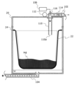
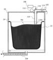
図2および図3は、図1に示す泥水処理システムの回収タンク20をより詳細に示す模式図である。ここで、図2は、回収タンク20内に泥土Mdが比較的少ない量溜められている状態を示しており、図3は、回収タンク20内に泥土Mdが満杯に溜められている状態を示している。図示するように、回収タンク20は、泥水に含まれる泥土(固体物)を回収するための回収容器22を内部に取り付けることができるように構成されている。回収容器22は、泥水から泥土を分離して回収できるように構成されており、例えば複数の孔があけられている。回収容器22は、一例として、底が網状である金属製または樹脂製などの容器であってもよいし、土のう袋など液体を通過させる袋体などであってもよい。 2 and 3 are schematic diagrams showing the recovery tank 20 of the muddy water treatment system shown in FIG. 1 in more detail. Here, FIG. 2 shows a state in which a relatively small amount of mud Md is stored in the collection tank 20, and FIG. 3 shows a state in which a relatively small amount of mud Md is stored in the collection tank 20. ing. As illustrated, the recovery tank 20 is configured such that a recovery container 22 for recovering mud (solid matter) contained in muddy water can be attached therein. The collection container 22 is configured to be able to separate and collect muddy soil from muddy water, and has, for example, a plurality of holes. The collection container 22 may be, for example, a container made of metal or resin with a net-like bottom, or a bag through which liquid passes, such as a sandbag.

図2および図3に示す例では、回収タンク20には、回収容器22の縁部を把持するように構成された支持部24が設けられている。ただし、回収タンク20における回収容器22の取り付けは、回収容器22が回収タンク20内に単に配置されることによって行われてもよく、任意の方法で行われればよい。また、図2には示していないが、回収タンク20は、回収容器22の底部を支持するための支持機構を備えてもよい。泥水に含まれる泥土は重いため、特に図3に示すように回収タンク20に満杯の泥土Mdが溜められているときには、回収容器22に大きな重量がかかる。こうした状況においても支持機構が設けられることにより、回収容器22によって連結管104が塞がれてしまうことを抑制できる。支持機構は、回収容器22を連結管104との接続口から離間させるように回収容器22を支持するものであればよく、一例として、回収容器22の底部を支持する支持台であってもよいし、回収タンク20の底面に形成されたリブなどであってもよい。 In the example shown in FIGS. 2 and 3, the recovery tank 20 is provided with a support portion 24 configured to grip the edge of the recovery container 22. In the example shown in FIGS. However, the collection container 22 may be attached to the collection tank 20 by simply placing the collection container 22 inside the collection tank 20, or may be performed by any method. Although not shown in FIG. 2, the recovery tank 20 may include a support mechanism for supporting the bottom of the recovery container 22. Since mud contained in muddy water is heavy, a large weight is applied to the collection container 22, especially when the collection tank 20 is full of mud Md as shown in FIG. Even in such a situation, by providing the support mechanism, it is possible to prevent the connecting pipe 104 from being blocked by the recovery container 22. The support mechanism may be any mechanism that supports the recovery container 22 so as to separate the recovery container 22 from the connection port with the connecting pipe 104, and may be, for example, a support stand that supports the bottom of the recovery container 22. However, it may also be a rib formed on the bottom surface of the recovery tank 20.

回収タンク20の上部には吸い込み管102が接続されており、回収タンク20の下部
には連結管104が接続されている。ここで、回収タンク20の「上部」は、回収タンク20の上面または上側の側面であり得、回収タンク20の「下部」は、回収タンク20の底面または下側の側面であり得る。また、回収タンク20の「上部」、「下部」は、回収タンク20に取り付けられる回収容器22よりも上方、下方の位置と言い換えることもできる。
A suction pipe 102 is connected to the upper part of the recovery tank 20, and a connecting pipe 104 is connected to the lower part of the recovery tank 20. Here, the “top” of the recovery tank 20 may be the top surface or upper side of the recovery tank 20, and the “lower portion” of the recovery tank 20 may be the bottom or lower side of the recovery tank 20. Furthermore, the “upper” and “lower” portions of the recovery tank 20 can also be translated as positions above and below the recovery container 22 attached to the recovery tank 20.

吸い込み管102には、回収タンク20内に延在する検知管110が接続されている。検知管110は、回収容器22の内部に位置する開口である検知口110aを有する。ここで、検知管110は、一例として、金属または樹脂などの剛性の高い材料で形成される。本実施形態では、検知管110は、上端が吸い込み管102と回収タンク20の上面とに連結され、下端である検知口110aが回収容器22の内部に位置する。ここで、回収容器22の内部は、回収容器22における泥土を溜めるための領域を意味し、図3~図5では、破線で囲まれた領域が回収容器22の内部に当たる。つまり、検知口110aは、回収タンク20内に取り付けられた回収容器22の上端よりも下方に位置する。なお、検知管110は、吸い込み管102と一体に構成されてもよいし、1つの管により吸い込み管102と検知管110とが構成されてもよい。また、検知管110は、真空タンク40と一体に構成されてもよい。検知管110は、一例として、吸い込み管102との接続口(図2および図3中、上端)と検知口110aとを除いて開口を有しない。 A detection tube 110 extending into the recovery tank 20 is connected to the suction tube 102 . The detection tube 110 has a detection port 110a that is an opening located inside the collection container 22. Here, the detection tube 110 is made of a highly rigid material such as metal or resin, for example. In this embodiment, the upper end of the detection tube 110 is connected to the suction pipe 102 and the upper surface of the recovery tank 20, and the detection port 110a, which is the lower end, is located inside the recovery container 22. Here, the inside of the collection container 22 means an area in the collection container 22 for collecting mud, and in FIGS. 3 to 5, the area surrounded by broken lines corresponds to the inside of the collection container 22. In other words, the detection port 110a is located below the upper end of the recovery container 22 installed in the recovery tank 20. Note that the detection tube 110 may be configured integrally with the suction tube 102, or the suction tube 102 and the detection tube 110 may be configured as one tube. Further, the detection tube 110 may be configured integrally with the vacuum tank 40. For example, the detection tube 110 does not have any openings except for the connection port with the suction tube 102 (the upper end in FIGS. 2 and 3) and the detection port 110a.

また、本実施形態では、吸い込み管102内の圧力を検出するための圧力センサ112が設けられている。圧力センサ112による検出情報は、システム100の使用者が認識できるようにされることが好ましく、図示しないシステム100のコントローラに送られるものとしてもよい。さらに、吸い込み管102には、吸い込み管102を開閉するための開閉弁114が設けられている。開閉弁114は、公知の任意の開閉弁を採用することができ、手動の開閉弁であってもよいし、電動の開閉弁などであってもよい。また、吸い込み管102には、圧縮流体を供給可能な供給口116が形成されている。図2および図3に示す例では、供給口116は、開閉弁114よりも下流側(回収タンク20側)に設けられている。供給口116から圧縮流体を供給することにより、吸い込み管102および検知管110内で固まった泥土などの残留物を除去する、いわゆるフラッシングを行うことができる。なお、供給口116には、真空発生モジュール50から圧縮流体を供給できるものとしてもよい。こうすれば、新たに圧縮流体源を用意しなくても、吸い込み管102および検知管110内のフラッシングを行うことができる。なお、圧力センサ112と、開閉弁114と、供給口116との少なくとも1つは、吸い込み管102に代えて、または加えて、検知管110に設けられてもよい。また、システム100は、圧力センサ112と、開閉弁114と、供給口116との少なくとも1つを備えなくてもよい。 Further, in this embodiment, a pressure sensor 112 for detecting the pressure inside the suction pipe 102 is provided. The information detected by the pressure sensor 112 is preferably made recognizable by the user of the system 100, and may be sent to a controller of the system 100 (not shown). Furthermore, the suction pipe 102 is provided with an on-off valve 114 for opening and closing the suction pipe 102. The on-off valve 114 can be any known on-off valve, and may be a manual on-off valve, an electric on-off valve, or the like. Further, the suction pipe 102 is formed with a supply port 116 through which compressed fluid can be supplied. In the example shown in FIGS. 2 and 3, the supply port 116 is provided downstream of the on-off valve 114 (on the recovery tank 20 side). By supplying compressed fluid from the supply port 116, so-called flushing can be performed to remove residues such as mud solidified within the suction pipe 102 and the detection pipe 110. Note that the supply port 116 may be capable of supplying compressed fluid from the vacuum generation module 50. In this way, the inside of the suction pipe 102 and the detection pipe 110 can be flushed without preparing a new compressed fluid source. Note that at least one of the pressure sensor 112, the on-off valve 114, and the supply port 116 may be provided in the detection tube 110 instead of or in addition to the suction tube 102. Furthermore, the system 100 may not include at least one of the pressure sensor 112, the on-off valve 114, and the supply port 116.

上記したように、本実施形態の回収タンク20には、吸い込み管102に検知管110が接続されて、検知管110の検知口110aが回収容器22の内部に位置している。これにより、図3に示すように、システム100による泥水除去作業に伴って回収容器22に溜められる泥土Mdが所定量を超えると、泥土Mdによって検知口110aが塞がれる。これにより、吸い込み管102を通じた泥水の吸い込みが阻害されるため、使用者は、回収容器22に所定量の泥土Mdが溜められたことを認識することができ、回収タンク20に過剰な泥土が吸い込まれることを抑制することができる。使用者は、吸い込み管102を通じた泥水の吸い込みが低下または停止して回収容器22に所定量の泥土Mdが溜められたことを認識すると、例えば真空発生モジュール50の作動を停止させて、回収容器22を交換することができる。そして、回収容器22を交換したら、真空発生モジュール50を再び作動させて、再び泥水除去作業を行うことができる。 As described above, in the recovery tank 20 of this embodiment, the detection tube 110 is connected to the suction pipe 102, and the detection port 110a of the detection tube 110 is located inside the recovery container 22. As a result, as shown in FIG. 3, when the mud Md accumulated in the recovery container 22 due to the mud water removal work by the system 100 exceeds a predetermined amount, the detection port 110a is blocked by the mud Md. As a result, suction of muddy water through the suction pipe 102 is inhibited, so the user can recognize that a predetermined amount of mud Md has been collected in the collection container 22, and excess mud is not stored in the collection tank 20. It can prevent being sucked in. When the user recognizes that suction of muddy water through the suction pipe 102 has decreased or stopped and a predetermined amount of mud Md has been collected in the collection container 22, the user stops the operation of the vacuum generation module 50, for example, and removes the mud from the collection container. 22 can be replaced. After replacing the collection container 22, the vacuum generating module 50 can be operated again to perform muddy water removal work again.

しかも、本実施形態の回収タンク20には、吸い込み管102および検知管110内の圧力を検知する圧力センサ112が設けられている。図2に示すように真空発生モジュー
ル50が作動して吸い込み管102を通じて泥水を吸い込んでいるときには、圧力センサ112によって負圧が検知される。一方、図3に示すように回収容器22に所定量の泥土Mdが溜められて検知管110が塞がれると、圧力センサ112によって、検知管110が塞がれていないときよりも大気圧に近い圧力が検知される。このため、使用者は、圧力センサ112による検出情報を見て、回収容器22に所定量の泥土Mdが溜められたことを認識することができる。また、システム100は、真空発生モジュール50が作動しているときに圧力センサ112による検出圧力が予め定めた圧力範囲内にあるときには、検知管110が泥土Mdによって塞がれていると判断して表示パネルへの表示またはブザーの吹鳴などによって使用者に報知するものとしてもよい。これにより、使用者は、回収容器22に所定量の泥土Mdが溜められたことを容易に認識することができ、システム100による泥水除去作業を好適に行うことができる。
Moreover, the recovery tank 20 of this embodiment is provided with a pressure sensor 112 that detects the pressure inside the suction pipe 102 and the detection pipe 110. As shown in FIG. 2, when the vacuum generating module 50 is operating and sucking muddy water through the suction pipe 102, a negative pressure is detected by the pressure sensor 112. On the other hand, as shown in FIG. 3, when a predetermined amount of mud Md is accumulated in the collection container 22 and the detection tube 110 is blocked, the pressure sensor 112 detects that the detection tube 110 is at a higher atmospheric pressure than when it is not blocked. Near pressure is detected. Therefore, the user can see the information detected by the pressure sensor 112 and recognize that a predetermined amount of mud Md has been collected in the collection container 22. Furthermore, when the pressure detected by the pressure sensor 112 is within a predetermined pressure range while the vacuum generation module 50 is operating, the system 100 determines that the detection tube 110 is blocked by mud Md. The user may be notified by displaying on the display panel or by sounding a buzzer. Thereby, the user can easily recognize that a predetermined amount of mud Md has been collected in the collection container 22, and can suitably perform the mud water removal work using the system 100.

<変形例>
図4は、変形例の回収タンクの構成を示す図である。変形例の回収タンク20Aは、回収容器22の取付方法と検知管110Aとを除いて、図2および図3に示す回収タンク20と同一の構成である。変形例の回収タンク20Aでは、回収容器22は土のう袋などの袋体であり、上端が外側に折り曲げられて袋止め26に被せられている。袋止め26は、回収容器22を挟んで固定するように構成されてもよい。こうした取付方法によっても、回収容器22に泥土Mdが溜められたときに回収容器22を容易に取り扱うことができる。また、変形例の検知管110Aは、検知口110Aaの位置を調節できるように構成されている。図4に示す例では、検知管110Aは、手動で伸縮できるように構成されており、検知管110Aの伸縮に伴って検知口110Aaの位置が変更される。ただし、検知管110の検知口110Aaの位置を調節する方法は、図4に示す例に限定されず、任意の方法を採用することができる。検知口110Aaの位置を調節することにより、回収容器22に溜められる泥土Mdの量を調節することができる。
<Modified example>
FIG. 4 is a diagram showing the configuration of a modified recovery tank. The recovery tank 20A of the modified example has the same configuration as the recovery tank 20 shown in FIGS. 2 and 3, except for the method of attaching the recovery container 22 and the detection tube 110A. In the recovery tank 20A of the modified example, the recovery container 22 is a bag body such as a sandbag, and the upper end is bent outward and placed on the bag stopper 26. The bag stopper 26 may be configured to sandwich and fix the collection container 22. This attachment method also allows the collection container 22 to be easily handled when mud Md is collected in the collection container 22. Moreover, the detection tube 110A of the modified example is configured so that the position of the detection port 110Aa can be adjusted. In the example shown in FIG. 4, the detection tube 110A is configured to be manually expandable and retractable, and the position of the detection port 110Aa is changed as the detection tube 110A expands and contracts. However, the method of adjusting the position of the detection port 110Aa of the detection tube 110 is not limited to the example shown in FIG. 4, and any method can be adopted. By adjusting the position of the detection port 110Aa, the amount of mud Md stored in the collection container 22 can be adjusted.

なお、上記した実施形態および変形例において、回収タンク20(20A)には、回収タンク20の内部と外部とを連通する排気弁(図示せず)が設けられてもよい。そして、一例として、真空タンク40または回収タンク20内の泥水または泥土Mdを排出するときには、回収タンク20の排気弁を開くものとしてもよい。 In the above-described embodiments and modifications, the recovery tank 20 (20A) may be provided with an exhaust valve (not shown) that communicates the inside and outside of the recovery tank 20. As an example, when discharging the muddy water or mud Md in the vacuum tank 40 or the recovery tank 20, the exhaust valve of the recovery tank 20 may be opened.

<第2実施形態>
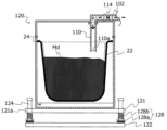
図5~図7は、第2実施形態における回収タンクの一例を示す模式図である。第2実施形態における回収タンク120は、一例として、上記した泥水処理システム100において回収タンク20に代えて使用することができる。第2実施形態の回収タンク120は、上記した回収タンク20と概ね同一であり、同一の構成については同一の符号を付して重複する説明を省略する。なお、図5~図7では、見易さを考慮して、回収タンク120に負圧を作用させるための連結管104の図示を省略している。
<Second embodiment>
5 to 7 are schematic diagrams showing an example of a recovery tank in the second embodiment. The recovery tank 120 in the second embodiment can be used in place of the recovery tank 20 in the muddy water treatment system 100 described above, as an example. The recovery tank 120 of the second embodiment is generally the same as the recovery tank 20 described above, and the same components are given the same reference numerals and redundant explanations will be omitted. Note that in FIGS. 5 to 7, illustration of the connecting pipe 104 for applying negative pressure to the recovery tank 120 is omitted for ease of viewing.

第2実施形態では、回収タンク120を支持するための支持台122が設けられている。図5~図7に示す例では、支持台122は、鉛直方向に延在する複数のガイド体124を有しており、回収タンク120は、ガイド体124を挿通させるためのガイド孔121aが形成されたフランジ部121を有している。そして、ガイド体124がガイド孔121aを挿通するように回収タンク120が配置されることで、回収タンク120は、ガイド体124に沿って支持台122に対して上下方向に移動可能に構成される。また、回収タンク120と支持台122との間には、回収タンク120の重量に応じて変形するように構成された弾性体128が設けられている。具体的な一例として、弾性体128は、回収タンク120のフランジ部121と支持台122との間に設けられたバネ部材によって構成される。図5~図7に示す例では、弾性体128は、第1の弾性率を有する第1の弾性体128aと、第1の弾性率よりも大きい第2の弾性率を有する第2の弾性体128b
とを有している。一例として、第1および第2の弾性体128a,128bは、コイルばねである。第1および第2の弾性体128a,128bは、それぞれの内部にガイド体124が挿入されてガイド体124に沿って鉛直方向に並んで配置されており、つまり互いに直列に接続されており、回収タンク120の重量に応じて変形する。なお、弾性体128は、コイルバネに限定されず、板バネ、ゴムなど、種々の弾性体を採用することができる。また、本実施形態では、回収タンク120の周りの4か所に、ガイド孔121a、ガイド体124、および弾性体128が設けられるものとしたが、こうした例には限定されない。
In the second embodiment, a support stand 122 for supporting the recovery tank 120 is provided. In the example shown in FIGS. 5 to 7, the support stand 122 has a plurality of guide bodies 124 extending in the vertical direction, and the recovery tank 120 has a guide hole 121a formed therein through which the guide bodies 124 are inserted. It has a flange portion 121 that is curved. By arranging the recovery tank 120 such that the guide body 124 is inserted through the guide hole 121a, the recovery tank 120 is configured to be movable in the vertical direction with respect to the support base 122 along the guide body 124. . Further, an elastic body 128 configured to deform according to the weight of the recovery tank 120 is provided between the recovery tank 120 and the support stand 122. As a specific example, the elastic body 128 is constituted by a spring member provided between the flange portion 121 of the recovery tank 120 and the support base 122. In the examples shown in FIGS. 5 to 7, the elastic body 128 includes a first elastic body 128a having a first elastic modulus and a second elastic body 128a having a second elastic modulus larger than the first elastic modulus. 128b
It has As an example, the first and second elastic bodies 128a, 128b are coil springs. The first and second elastic bodies 128a and 128b have a guide body 124 inserted therein and are arranged vertically along the guide body 124, that is, are connected to each other in series. It deforms depending on the weight of the tank 120. Note that the elastic body 128 is not limited to a coil spring, and various elastic bodies such as a plate spring and rubber can be employed. Further, in this embodiment, the guide hole 121a, the guide body 124, and the elastic body 128 are provided at four locations around the recovery tank 120, but the present invention is not limited to this example.

第2実施形態の回収タンク120を用いたシステム100の動作について説明する。図5に示すように、回収タンク120内に泥土Mdが溜められていない、または回収タンク120内に比較的少ない量の泥土Mdが溜められているときには、第1および第2の弾性体128a,128bは、伸びた状態となる。システム100による泥水除去作業に伴って回収タンク120の重量が第1重量以上に至ると、図6に示すように、第1の弾性体128aが完全に縮んだ状態となる。ここで、本実施形態において、「完全に縮んだ状態」とは、弾性体がそれ以上縮むことがほとんどない状態をいう。なお、弾性体128(128a,128b)には、所定量より大きい変形を制限するためのスペーサなどの変形制限部材が設けられてもよい。また、図6に示す例では、第2の弾性体128bは、第1の弾性体128aよりも大きい弾性率を有し、まだ縮むことが可能な状態となっている。そして、さらに回収タンク120内に泥土Mdが収集されて回収タンク120の重量が第1重量より大きい第2重量以上に至ると、図7に示すように、第1の弾性体128aと共に第2の弾性体128bが完全に縮んだ状態となる。 The operation of the system 100 using the recovery tank 120 of the second embodiment will be described. As shown in FIG. 5, when no mud Md is stored in the collection tank 120 or when a relatively small amount of mud Md is stored in the collection tank 120, the first and second elastic bodies 128a, 128b is in an extended state. When the weight of the recovery tank 120 reaches the first weight or more due to the muddy water removal work performed by the system 100, the first elastic body 128a becomes completely contracted, as shown in FIG. Here, in this embodiment, the "completely contracted state" refers to a state in which the elastic body hardly contracts any further. Note that the elastic body 128 (128a, 128b) may be provided with a deformation limiting member such as a spacer for restricting deformation larger than a predetermined amount. Further, in the example shown in FIG. 6, the second elastic body 128b has a higher elastic modulus than the first elastic body 128a, and is still in a state where it can be contracted. Then, when mud Md is further collected in the recovery tank 120 and the weight of the recovery tank 120 reaches a second weight or more, which is greater than the first weight, as shown in FIG. The elastic body 128b is in a completely contracted state.

このように、第2実施形態の回収タンク120では、回収タンク120の重量に応じて弾性体128が変形する。これにより、第2実施形態の回収タンク120を備えるシステム100の使用者は、弾性体128を視認することで、回収タンク120に一定重量の泥土Mdが溜められたことを知覚することができる。しかも、図5に示す例では、弾性率が異なる第1の弾性体128aと第2の弾性体128bとが設けられており、使用者は、第1の弾性体128aに基づいて回収タンク120の重量が第1重量に至ったことを知覚することができ、第2の弾性体128bに基づいて回収タンク120の重量が第2重量に至ったことを知覚することができる。よって、使用者は、検知管110が接続された吸い込み管102の吸い込み状態に合わせて弾性体128を視認することで、回収タンク120(回収容器22)に所定量または所定重量の泥土Mdが溜められたことを容易に認識することができ、システム100による泥水除去作業を好適に行うことができる。 In this way, in the recovery tank 120 of the second embodiment, the elastic body 128 deforms depending on the weight of the recovery tank 120. Thereby, the user of the system 100 including the recovery tank 120 of the second embodiment can perceive that a certain weight of mud Md has been stored in the recovery tank 120 by visually recognizing the elastic body 128. Moreover, in the example shown in FIG. 5, a first elastic body 128a and a second elastic body 128b having different elastic moduli are provided, and the user can adjust the recovery tank 120 based on the first elastic body 128a. It is possible to sense that the weight has reached the first weight, and it is possible to sense that the weight of the collection tank 120 has reached the second weight based on the second elastic body 128b. Therefore, by visually checking the elastic body 128 according to the suction state of the suction pipe 102 to which the detection tube 110 is connected, the user can determine whether a predetermined amount or weight of mud Md has accumulated in the collection tank 120 (recovery container 22). This allows the system 100 to perform muddy water removal work in a suitable manner.

なお、図5~図7に示す例では、第1および第2の弾性体128a,128bが直列に接続されるものとしたが、こうした例に限定されず、回収タンク120の重量が第1重量以上であることを示すための第1の弾性体と、回収タンク120の重量が第1重量より大きい第2重量以上であることを示すための第2の弾性体と、が備えられてもよい。一例として、回収タンク120と支持台122との間には、第1長さを有する第1の弾性体と、第1長さよりも短い第2長さを有する第2の弾性体とが並列に設けられてよい。そして、回収タンク120の重量が第1重量以下のときには第1の弾性体のみが変形し、回収タンク120の重量が第1重量以上に至ると第1の弾性体が第2長さ以下まで収縮して第1および第2の弾性体が変形するように構成されてもよい。そして、回収タンク120の重量が第1重量より大きい第2重量以上に至ると、第1および第2の弾性体が完全に縮んだ状態となるように構成されてもよい。こうした例においても、図5~図7に示す構成と同様の効果を奏することができる。また、回収タンク120には、互いに特性が異なる2つの弾性体が設けられるものに限定されず、単一の特性の弾性体が設けられもよいし、互いに特性が異なる3つ以上の弾性体が設けられてもよい。 Note that in the examples shown in FIGS. 5 to 7, the first and second elastic bodies 128a and 128b are connected in series, but the present invention is not limited to such an example, and the weight of the recovery tank 120 is equal to the first weight. A first elastic body for indicating that the weight of the recovery tank 120 is equal to or higher than the first weight, and a second elastic body for indicating that the weight of the recovery tank 120 is a second weight or more that is greater than the first weight may be provided. . As an example, between the recovery tank 120 and the support stand 122, a first elastic body having a first length and a second elastic body having a second length shorter than the first length are arranged in parallel. May be provided. When the weight of the recovery tank 120 is less than or equal to the first weight, only the first elastic body deforms, and when the weight of the recovery tank 120 reaches the first weight or more, the first elastic body contracts to a length less than or equal to the second length. The first and second elastic bodies may also be configured to deform. Then, when the weight of the recovery tank 120 reaches a second weight or more, which is greater than the first weight, the first and second elastic bodies may be configured to be in a completely contracted state. Even in such an example, the same effects as the configurations shown in FIGS. 5 to 7 can be achieved. Further, the recovery tank 120 is not limited to being provided with two elastic bodies having different characteristics from each other, but may be provided with an elastic body having a single characteristic, or may be provided with three or more elastic bodies having different characteristics from each other. may be provided.

<第3実施形態>
図8,図9は、第3実施形態における回収タンクの一例を示す模式図である。第3実施形態における回収タンク220は、一例として、上記した泥水処理システム100において回収タンク20に代えて使用することができる。第3実施形態の回収タンク220は、第2実施形態の回収タンク120と概ね同一であり、同一の構成については同一の符号を付して重複する説明を省略する。なお、図8,図9では、見易さを考慮して、回収タンク220に負圧を作用させるための連結管104の図示を省略している。
<Third embodiment>
8 and 9 are schematic diagrams showing an example of a recovery tank in the third embodiment. The recovery tank 220 in the third embodiment can be used in place of the recovery tank 20 in the muddy water treatment system 100 described above, as an example. The recovery tank 220 of the third embodiment is generally the same as the recovery tank 120 of the second embodiment, and the same components are given the same reference numerals and redundant explanations will be omitted. Note that in FIGS. 8 and 9, illustration of the connecting pipe 104 for applying negative pressure to the recovery tank 220 is omitted for ease of viewing.

第3実施形態では、弾性体128に加えて、回収タンク220と支持台122との間に磁石226および磁性体228が設けられている。磁石226は、回収タンク220と支持台122との一方に設けられ、磁性体228は、回収タンク220と支持台122との他方に設けられている。磁石226と磁性体228とは、互いに磁力で吸着されるように、一例として鉛直方向で対向するように配置される。磁石226と磁性体228との吸着力は、互いの距離に反比例する。なお、図8,9に示す例では、支持台122の上面に磁石226が取り付けられ、回収タンク220(フランジ部121)の下面に磁性体228が取り付けられるものとしている。しかしながら、こうした例に限定されず、支持台122の上面に磁性体228が取り付けられ、回収タンク220の下面に磁石226が取り付けられてもよい。また、支持台122の上面が磁石226または磁性体228で構成されてもよいし、回収タンク220の下面が磁性体228または磁石226で構成されてもよい。また、磁石226と磁性体228とは、弾性体128が完全に縮んだ状態となるときに、互いに接触するように構成されてもよい。言い換えれば、磁石226と磁性体228とは、弾性体128が完全に縮んだ状態を規定してもよい。なお、磁石226と磁性体228とは必須の構成ではなく、回収タンク220と支持台122とには、磁石226と磁性体228とが設けられなくてもよい。 In the third embodiment, in addition to the elastic body 128, a magnet 226 and a magnetic body 228 are provided between the recovery tank 220 and the support base 122. The magnet 226 is provided on one of the recovery tank 220 and the support base 122, and the magnetic body 228 is provided on the other of the recovery tank 220 and the support base 122. For example, the magnet 226 and the magnetic body 228 are arranged to face each other in the vertical direction so that they are attracted to each other by magnetic force. The attraction force between the magnet 226 and the magnetic body 228 is inversely proportional to the distance between them. In the example shown in FIGS. 8 and 9, a magnet 226 is attached to the upper surface of the support base 122, and a magnetic body 228 is attached to the lower surface of the recovery tank 220 (flange portion 121). However, the present invention is not limited to this example, and the magnetic body 228 may be attached to the upper surface of the support base 122, and the magnet 226 may be attached to the lower surface of the recovery tank 220. Furthermore, the upper surface of the support base 122 may be configured with the magnet 226 or the magnetic material 228, and the lower surface of the recovery tank 220 may be configured with the magnetic material 228 or the magnet 226. Further, the magnet 226 and the magnetic body 228 may be configured to come into contact with each other when the elastic body 128 is in a completely contracted state. In other words, the magnet 226 and the magnetic body 228 may define a state in which the elastic body 128 is completely contracted. Note that the magnet 226 and the magnetic body 228 are not essential components, and the collection tank 220 and the support base 122 may not be provided with the magnet 226 and the magnetic body 228.

また、第3実施形態では、弾性体128の変形量が所定量に至ったときに、検知管110と吸い込み管102と連結管104(図8,図9では不図示)との少なくとも1つの管(以下、「流路管」ともいう)を閉じるように構成された弁224が設けられている。弁224は、一例として、回収タンク220と支持台122との間に配置されて、回収タンク220と支持台122との距離が一定以下に至ったときに(弾性体128の変形量が所定量に至ったときに)、物理的に押されることによって作動して流路管を閉じる。また、弁224は、流路管を閉じている状態で、回収タンク220と支持台122との距離が一定以上に至ることで、再び流路管を開くように構成されているとよい。一例として、弁224は、弾性体128が完全に縮んだ状態となるときに、または、弾性体128が完全に縮んだ状態の長さから所定範囲以内の長さとなるときに、流路管を閉じるように構成される。なお、弁224は、回収タンク220と支持台122との距離が一定以下に至ったときに物理的に押されることによって作動するものに限定されず、例えば弾性体128の変形量に応じて電気的に作動するものなどでもよい。 Further, in the third embodiment, when the amount of deformation of the elastic body 128 reaches a predetermined amount, at least one of the detection tube 110, the suction tube 102, and the connecting tube 104 (not shown in FIGS. 8 and 9) (hereinafter also referred to as "flow pipe") is provided with a valve 224 configured to close the flow pipe. For example, the valve 224 is disposed between the recovery tank 220 and the support stand 122, and when the distance between the recovery tank 220 and the support stand 122 reaches a certain value or less (the amount of deformation of the elastic body 128 reaches a predetermined amount) ), it is actuated by being physically pushed to close the flow tube. Further, the valve 224 may be configured to open the flow pipe again when the distance between the recovery tank 220 and the support base 122 reaches a certain value or more while the flow pipe is closed. As an example, the valve 224 opens the channel pipe when the elastic body 128 is in a completely contracted state or when the length of the elastic body 128 is within a predetermined range from the length in the completely contracted state. Configured to close. Note that the valve 224 is not limited to being activated by being physically pushed when the distance between the recovery tank 220 and the support base 122 reaches a certain value or less; It may also be something that operates automatically.

こうした第3実施形態の回収タンク220を用いたシステム100の動作について説明する。図8に示すように、回収タンク220内に泥土Mdが溜められていない、または回収タンク220内に比較的少ない量の泥土Mdが溜められているときには、弾性体128が伸びた状態となる。また、このときには、磁石226と磁性体228との距離が長く、磁石226と磁性体228とに作用する吸着力は小さい。システム100による泥水除去作業に伴って、回収タンク220の重量が大きくなると弾性体128が縮み、磁石226と磁性体228との距離が短くなって互いに作用する吸着力が大きくなる。そして、回収タンク220の重量が所定重量G1を超えると、図9に示すように、弾性体128が完全に縮んだ状態となる。このときには磁石226と磁性体228との距離が短く、または磁石226と磁性体226とが接触する。磁石226と磁性体228との吸着力は互いの距離に反比例するため、弾性体128が完全に縮んだ状態となるときには磁石226と磁性
体228とに作用する吸着力が大きくなる。また、弾性体128の変形量が所定量に至ることで、弁224が流路管を閉じる。流路管が閉じられることにより、吸い込み管102を通じた泥水の吸い込みが停止されるので、使用者は、回収タンク220内に所定量または所定重量の泥土Mdが溜められたことを容易に認識することができ、泥土の過剰な吸い込みを抑制することができる。
The operation of the system 100 using the recovery tank 220 of the third embodiment will be described. As shown in FIG. 8, when no mud Md is stored in the collection tank 220 or when a relatively small amount of mud Md is stored in the collection tank 220, the elastic body 128 is in an expanded state. Further, at this time, the distance between the magnet 226 and the magnetic body 228 is long, and the attraction force acting on the magnet 226 and the magnetic body 228 is small. When the weight of the recovery tank 220 increases as the system 100 removes muddy water, the elastic body 128 contracts, the distance between the magnet 226 and the magnetic body 228 becomes shorter, and the attraction force acting on each other increases. Then, when the weight of the recovery tank 220 exceeds a predetermined weight G1, the elastic body 128 is completely contracted, as shown in FIG. At this time, the distance between the magnet 226 and the magnetic body 228 is short, or the magnet 226 and the magnetic body 226 are in contact with each other. Since the attraction force between the magnet 226 and the magnetic body 228 is inversely proportional to the distance between them, the attraction force acting on the magnet 226 and the magnetic body 228 increases when the elastic body 128 is in a completely contracted state. Further, when the amount of deformation of the elastic body 128 reaches a predetermined amount, the valve 224 closes the flow path pipe. By closing the flow path pipe, suction of muddy water through the suction pipe 102 is stopped, so the user can easily recognize that a predetermined amount or weight of mud Md has been stored in the collection tank 220. This makes it possible to suppress excessive suction of mud.

さらに、第3実施形態の回収タンク220では、磁石226と磁性体228とが設けられており、弾性体128が完全に縮んだ状態では、磁石226と磁性体228とに大きな吸着力が生じている。この状態では、回収タンク220の重量が多少変化しても、磁石226と磁性体228との吸着力によって弾性体128が完全に縮んだ状態が維持される。したがって、例えばシステム100の作動および移動に伴って回収タンク220から弾性体128に作用する力が変化しても弾性体128の変形状態が維持されるので、弁224が流路管を閉じたり開いたりを繰り返すハンチングを防止することができる。 Furthermore, the recovery tank 220 of the third embodiment is provided with a magnet 226 and a magnetic body 228, and when the elastic body 128 is completely contracted, a large adsorption force is generated between the magnet 226 and the magnetic body 228. There is. In this state, even if the weight of the recovery tank 220 changes somewhat, the elastic body 128 is maintained in a completely contracted state due to the attraction force between the magnet 226 and the magnetic body 228. Therefore, even if the force acting on the elastic body 128 from the collection tank 220 changes as the system 100 operates and moves, the elastic body 128 remains deformed, allowing the valve 224 to close or open the flow pipe. It is possible to prevent hunting that occurs repeatedly.

本発明は、以下の形態としても記載することができる。
[形態1]形態1によれば、泥水を吸引するための泥水処理システムが提案される。かかる泥水処理システムは、泥水に含まれる泥土を回収するための回収容器を内部に取付可能であり、負圧源による負圧を用いて泥水を吸引する回収タンクと、前記回収タンクの上部に接続された吸い込み管と、前記吸い込み管に接続されると共に前記回収タンク内に延在し、前記回収タンクに前記回収容器が取り付けられているときに当該回収容器の内部に位置する開口を有する検知管と、を備える。形態1によれば、回収容器に所定量を超えて泥土が溜められると、泥土が検知管を塞ぎ、泥土の過剰な吸い込みを抑制することができる。
The invention can also be described in the following form.
[Form 1] According to Form 1, a muddy water treatment system for sucking muddy water is proposed. Such a muddy water treatment system can be equipped with a collection container for collecting mud contained in the muddy water, and is connected to a collection tank that suctions the muddy water using negative pressure from a negative pressure source, and an upper part of the collection tank. a detection tube connected to the suction tube and extending into the recovery tank, the detection tube having an opening located inside the recovery container when the recovery container is attached to the recovery tank; and. According to the first embodiment, when mud accumulates in the collection container in excess of a predetermined amount, the mud blocks the detection tube, thereby suppressing excessive suction of mud.

[形態2]形態2によれば、形態1において、前記検知管または前記吸い込み管内の圧力を検出するための圧力センサを備える。形態2によれば、検知管が泥土によって塞がれたことを圧力センサによって検出することができる。 [Embodiment 2] According to Embodiment 2, in Embodiment 1, a pressure sensor for detecting the pressure inside the detection tube or the suction tube is provided. According to the second embodiment, the pressure sensor can detect that the detection tube is blocked by mud.

[形態3]形態3によれば、形態1または2において、前記検知管と前記吸い込み管との少なくとも一方は、圧縮流体を供給可能な供給口を有する。形態3によれば、供給口から圧縮流体を供給して、検知管または吸い込み管内の泥土を移動させることができる。 [Embodiment 3] According to Embodiment 3, in Embodiment 1 or 2, at least one of the detection tube and the suction tube has a supply port capable of supplying compressed fluid. According to the third embodiment, compressed fluid can be supplied from the supply port to move the mud in the detection tube or the suction tube.

[形態4]形態4によれば、形態3において、前記負圧源としての真空発生モジュールを備え、前記真空発生モジュールは、前記供給口に圧縮流体を供給可能である。形態4によれば、真空発生モジュールから供給口に圧縮流体を供給することができる。 [Embodiment 4] According to Embodiment 4, in Embodiment 3, a vacuum generation module is provided as the negative pressure source, and the vacuum generation module can supply compressed fluid to the supply port. According to the fourth embodiment, compressed fluid can be supplied from the vacuum generation module to the supply port.

[形態5]形態5によれば、形態1から4において、前記回収タンクを支持するための支持台と、前記回収タンク前記支持台との間に設けられ、前記回収タンクの重量に応じて変形するように構成される弾性体と、を備える。形態5によれば、弾性体の変形によって回収タンクの重量を認識することができる。 [Form 5] According to Form 5, in Forms 1 to 4, the support stand for supporting the recovery tank and the support stand for the recovery tank are provided, and are deformed according to the weight of the recovery tank. an elastic body configured to do so. According to the fifth embodiment, the weight of the recovery tank can be recognized by the deformation of the elastic body.

[形態6]形態6によれば、形態5において、前記弾性体は、前記回収タンクの重量が第1重量以上であることを示すための第1の弾性体と、前記回収タンクの重量が前記第1重量より大きい第2重量以上であることを示すための第2の弾性体と、を備える。形態6によれば、第1の弾性体によって回収タンクの重量が第1重量以上であることを認識することができ、第2の弾性体によって回収タンクの重量が第2重量以上であることを認識することができる。 [Form 6] According to Form 6, in Form 5, the elastic body includes a first elastic body for indicating that the weight of the recovery tank is the first weight or more, and a first elastic body for indicating that the weight of the recovery tank is the first weight or more. and a second elastic body for indicating that the second weight is greater than the first weight. According to the sixth embodiment, the first elastic body allows the user to recognize that the weight of the recovery tank is greater than or equal to the first weight, and the second elastic body allows the user to recognize that the weight of the recovery tank is greater than or equal to the second weight. can be recognized.

[形態7]形態7によれば、形態5または6において、前記弾性体は、第1の弾性率を有する第1の弾性体と、前記第1の弾性体と鉛直方向に並んで配置されて前記第1の弾性
率より大きい第2の弾性率を有する第2の弾性体と、を備える。形態7によれば、第1の弾性体と第2の弾性体との変形によって回収タンクの重量を認識することができる。
[Form 7] According to Form 7, in Form 5 or 6, the elastic body is arranged vertically in line with a first elastic body having a first elastic modulus and the first elastic body. a second elastic body having a second elastic modulus greater than the first elastic modulus. According to the seventh embodiment, the weight of the collection tank can be recognized by the deformation of the first elastic body and the second elastic body.

[形態8]形態8によれば、形態5から7において、前記検知管と前記吸い込み管と前記回収タンク内に負圧を供給するために接続される連結管との少なくとも1つの管に設けられ、前記弾性体の変形量が所定量に至ったときに前記少なくとも1つの管を閉じるように構成された弁を備える。形態8によれば、弾性体の変形量が所定量に至ったときに管が閉じられるので、泥土の過剰な吸い込みを抑制することができる。 [Embodiment 8] According to Embodiment 8, in Embodiments 5 to 7, at least one of the detection tube, the suction tube, and a connecting tube connected to supply negative pressure into the recovery tank is provided. , comprising a valve configured to close the at least one tube when the amount of deformation of the elastic body reaches a predetermined amount. According to the eighth embodiment, since the pipe is closed when the amount of deformation of the elastic body reaches a predetermined amount, excessive suction of mud can be suppressed.

[形態9]形態9によれば、形態8において、前記回収タンクと前記支持台との一方に設けられる磁石と、前記回収タンクと前記支持台との他方に設けられて前記磁石と吸着する磁性体と、を備える。形態9によれば、弁によって管の開閉がハンチングすることを抑制できる。 [Form 9] According to Form 9, in Form 8, a magnet provided on one of the recovery tank and the support stand, and a magnet provided on the other side of the recovery tank and the support stand that attracts the magnet. Equipped with a body. According to the ninth embodiment, it is possible to suppress hunting in opening and closing of the pipe due to the valve.

[形態10]形態10によれば、形態1から9において、前記負圧源としての真空発生モジュールを備え、前記真空発生モジュールは、圧縮された流体をノズルから供給するコンプレッサーと、前記圧縮された流体が流れるディフューザーと、を有する。 [Embodiment 10] According to embodiment 10, in embodiments 1 to 9, a vacuum generation module is provided as the negative pressure source, and the vacuum generation module includes a compressor that supplies compressed fluid from a nozzle, and a diffuser through which fluid flows.

[形態11]形態11によれば、形態1から10において、前記負圧源としての真空発生モジュールと、前記真空発生モジュールに接続された真空タンクと、前記真空タンクと前記回収タンクとを接続する連結管と、を備え、前記吸い込み管を介して前記回収タンクに泥水が吸引され、前記回収タンクと前記連結管とを介して前記真空タンクに前記泥水の少なくとも一部が吸引される。形態11に
よれば、泥土が分離された泥水を真空タンクに吸引することができる。
[Form 11] According to Form 11, in Forms 1 to 10, a vacuum generation module as the negative pressure source, a vacuum tank connected to the vacuum generation module, and the vacuum tank and the recovery tank are connected. A connecting pipe, muddy water is sucked into the recovery tank via the suction pipe, and at least a portion of the muddy water is sucked into the vacuum tank via the recovery tank and the connecting pipe. According to the eleventh embodiment, the muddy water from which the muddy soil has been separated can be sucked into the vacuum tank.

以上、本発明の実施の形態について説明してきたが、上記した発明の実施の形態は、本発明の理解を容易にするためのものであり、本発明を限定するものではない。本発明は、その趣旨を逸脱することなく、変更、改良され得るとともに、本発明にはその均等物が含まれることはもちろんである。また、上述した課題の少なくとも一部を解決できる範囲、または、効果の少なくとも一部を奏する範囲において、実施形態および変形例の任意の組み合わせが可能であり、特許請求の範囲および明細書に記載された各構成要素の任意の組み合わせ、または、省略が可能である。 Although the embodiments of the present invention have been described above, the embodiments of the invention described above are for facilitating understanding of the present invention, and are not intended to limit the present invention. The present invention may be modified and improved without departing from its spirit, and it goes without saying that the present invention includes equivalents thereof. Further, any combination of the embodiments and modifications is possible as long as at least part of the above-mentioned problems can be solved or at least part of the effect can be achieved, and the combinations are possible as long as they are not described in the claims and specification. Any combination or omission of each component is possible.

20,20A,120,220…回収タンク
22…回収容器
40…真空タンク
50…真空発生モジュール
54…ディフューザー
60…吸気吸水管
62…吸水口
64…吸気口
70…排水タンク
80…噴射装置
80a…噴射口
100…泥水処理システム
102…吸い込み管
104…連結管
106…コンプレッサー
108…排気排水管
110,110A…検知管
110a,110Aa…検知口
112…圧力センサ
114…開閉弁
116…供給口
121…フランジ部
121a…ガイド孔
122…支持台
124…ガイド体
128…弾性体
128a…第1の弾性体
128b…第2の弾性体
224…弁
226…磁石
228…磁性体
Md…泥土
20, 20A, 120, 220...Recovery tank 22...Recovery container 40...Vacuum tank 50...Vacuum generation module 54...Diffuser 60...Intake water intake pipe 62...Water intake 64...Intake port 70...Drainage tank 80...Injection device 80a...Injection Port 100...Muddy water treatment system 102...Suction pipe 104...Connecting pipe 106...Compressor 108...Exhaust drain pipe 110, 110A...Detection tube 110a, 110Aa...Detection port 112...Pressure sensor 114...Opening/closing valve 116...Supply port 121...Flange part 121a... Guide hole 122... Support stand 124... Guide body 128... Elastic body 128a... First elastic body 128b... Second elastic body 224... Valve 226... Magnet 228... Magnetic body Md... Mud

Claims (11)

泥水を吸引するための泥水処理システムであって、
泥水に含まれる泥土を回収するための回収容器を内部に取付可能であり、負圧源による負圧を用いて泥水を吸引する回収タンクと、
前記回収タンクの上部に接続された吸い込み管と、
前記吸い込み管に接続されると共に前記回収タンク内に延在し、前記回収タンクに前記回収容器が取り付けられているときに当該回収容器の内部に位置する開口を有する検知管と、
を備える泥水処理システム。
A muddy water treatment system for sucking muddy water,
A recovery tank to which a recovery container for recovering mud contained in the muddy water can be attached inside, and which sucks up the muddy water using negative pressure from a negative pressure source;
a suction pipe connected to the upper part of the recovery tank;
a detection tube connected to the suction pipe and extending into the recovery tank, the detection tube having an opening located inside the recovery container when the recovery container is attached to the recovery tank;
A muddy water treatment system equipped with
前記検知管または前記吸い込み管内の圧力を検出するための圧力センサを備える、請求項1に記載の泥水処理システム。 The muddy water treatment system according to claim 1, further comprising a pressure sensor for detecting pressure within the detection tube or the suction tube. 前記検知管と前記吸い込み管との少なくとも一方は、圧縮流体を供給可能な供給口を有する、請求項1に記載の泥水処理システム。 The muddy water treatment system according to claim 1, wherein at least one of the detection tube and the suction tube has a supply port capable of supplying compressed fluid. 前記負圧源としての真空発生モジュールを備え、
前記真空発生モジュールは、前記供給口に圧縮流体を供給可能である、
請求項3に記載の泥水処理システム。
comprising a vacuum generation module as the negative pressure source,
The vacuum generation module is capable of supplying compressed fluid to the supply port.
The muddy water treatment system according to claim 3.
前記回収タンクを支持するための支持台と、
前記回収タンク前記支持台との間に設けられ、前記回収タンクの重量に応じて変形するように構成される弾性体と、
を備える請求項1に記載の泥水処理システム。
a support stand for supporting the recovery tank;
an elastic body provided between the recovery tank and the support base and configured to deform according to the weight of the recovery tank;
The muddy water treatment system according to claim 1, comprising:
前記弾性体は、前記回収タンクの重量が第1重量以上であることを示すための第1の弾性体と、前記回収タンクの重量が前記第1重量より大きい第2重量以上であることを示すための第2の弾性体と、を備える、請求項5に記載の泥水処理システム。 The elastic body includes a first elastic body for indicating that the weight of the recovery tank is a first weight or more, and a first elastic body for indicating that the weight of the recovery tank is a second weight or more that is greater than the first weight. The muddy water treatment system according to claim 5, comprising a second elastic body for. 前記弾性体は、第1の弾性率を有する第1の弾性体と、前記第1の弾性体と鉛直方向に並んで配置されて前記第1の弾性率より大きい第2の弾性率を有する第2の弾性体と、を備える、請求項5に記載の泥水処理システム。 The elastic body includes a first elastic body having a first elastic modulus, and a second elastic body having a second elastic modulus larger than the first elastic modulus, which is arranged vertically in line with the first elastic body. The muddy water treatment system according to claim 5, comprising: a second elastic body. 前記検知管と前記吸い込み管と前記回収タンク内に負圧を供給するために接続される連結管との少なくとも1つの管に設けられ、前記弾性体の変形量が所定量に至ったときに前記少なくとも1つの管を閉じるように構成された弁を備える、請求項5に記載の泥水処理システム。 provided in at least one of the detection tube, the suction tube, and a connecting tube connected to supply negative pressure into the recovery tank, and when the amount of deformation of the elastic body reaches a predetermined amount, the 6. The mud treatment system of claim 5, comprising a valve configured to close at least one pipe. 前記回収タンクと前記支持台との一方に設けられる磁石と、
前記回収タンクと前記支持台との他方に設けられて前記磁石と吸着する磁性体と、
を備える請求項8に記載の泥水処理システム。
a magnet provided on one of the recovery tank and the support base;
a magnetic body that is provided on the other of the recovery tank and the support base and that attracts the magnet;
The muddy water treatment system according to claim 8, comprising:
前記負圧源としての真空発生モジュールを備え、
前記真空発生モジュールは、圧縮された流体をノズルから供給するコンプレッサーと、前記圧縮された流体が流れるディフューザーと、を有する、
請求項1に記載の泥水処理システム。
comprising a vacuum generation module as the negative pressure source,
The vacuum generation module includes a compressor that supplies compressed fluid from a nozzle, and a diffuser through which the compressed fluid flows.
The muddy water treatment system according to claim 1.
前記負圧源としての真空発生モジュールと、
前記真空発生モジュールに接続された真空タンクと、
前記真空タンクと前記回収タンクとを接続する連結管と、
を備え、
前記吸い込み管を介して前記回収タンクに泥水が吸引され、前記回収タンクと前記連結管とを介して前記真空タンクに前記泥水の少なくとも一部が吸引される、
請求項1から10の何れか1項に記載の泥水処理システム。
a vacuum generation module as the negative pressure source;
a vacuum tank connected to the vacuum generation module;
a connecting pipe connecting the vacuum tank and the recovery tank;
Equipped with
The muddy water is sucked into the recovery tank via the suction pipe, and at least a portion of the muddy water is sucked into the vacuum tank via the recovery tank and the connection pipe.
The muddy water treatment system according to any one of claims 1 to 10.
JP2022184724A 2022-08-22 2022-11-18 Mud water treatment system Pending JP2024029732A (en)

Applications Claiming Priority (2)

Application Number Priority Date Filing Date Title
JP2022131936 2022-08-22

Publications (1)

Publication Number Publication Date
JP2024029732A true JP2024029732A (en) 2024-03-06

Family

ID=90104959

Family Applications (1)

Application Number Title Priority Date Filing Date
JP2022184724A Pending JP2024029732A (en) 2022-08-22 2022-11-18 Mud water treatment system

Country Status (1)

Country Link
JP (1) JP2024029732A (en)

Similar Documents

Publication Publication Date Title
US5996621A (en) Circulating drainage system for sewage pipe installation work
KR101772984B1 (en) The apparatus for removing floating material in surface of water
US10046262B2 (en) Method and system to excavate and remove underground noxious vapors
KR101022423B1 (en) Mobile sewer dredging device
JP5681738B2 (en) Siphon drainage system
CN202610963U (en) Sewage suction device for sewage suction truck
CN106697679A (en) Water garbage bin
JP2024029732A (en) Mud water treatment system
CN107473330B (en) Remote control type water oil stain remover
CN211898856U (en) An underground filter device for sponge city
JP2017219008A (en) Drainage tool
CN215759520U (en) Sewage lifting device with cutting and backwashing functions
CN104782601A (en) Water collecting device for dead furrow of paddy field pesticide spraying machine
KR200213631Y1 (en) Air lifting system capturing stored waste material
KR101613351B1 (en) Maintenance management control method of seawater filtering water intake system
CN203808042U (en) Vacuum preloading treatment negative-pressure water discharging device of soft foundation
JP2024029586A (en) Mud water treatment system
CN115928868A (en) Automatic siphon drainage system for accumulated water on low-lying road and construction method
JPH08296600A (en) Suction adjusting device for suction device
JP2005013902A (en) Float suction removal device
JP2005220598A (en) Equipment for cleaning accumulated sediment on bottom of river
CN221422215U (en) Multifunctional sewer dredging vehicle
CN223135282U (en) Desilting device with anti-blocking structure
JP2006341214A (en) Vacuum type aw method
CN221741400U (en) A lake bottom dredging device

Legal Events

Date Code Title Description
AA64 Notification of invalidation of claim of internal priority (with term)

Free format text: JAPANESE INTERMEDIATE CODE: A241764

Effective date: 20221223

A521 Request for written amendment filed

Free format text: JAPANESE INTERMEDIATE CODE: A523

Effective date: 20221227

A621 Written request for application examination

Free format text: JAPANESE INTERMEDIATE CODE: A621

Effective date: 20250604