JP2024011663A - explosive loading device - Google Patents

explosive loading device Download PDF

Info

Publication number
JP2024011663A
JP2024011663A JP2022113863A JP2022113863A JP2024011663A JP 2024011663 A JP2024011663 A JP 2024011663A JP 2022113863 A JP2022113863 A JP 2022113863A JP 2022113863 A JP2022113863 A JP 2022113863A JP 2024011663 A JP2024011663 A JP 2024011663A
Authority
JP
Japan
Prior art keywords
explosive
loading
supply path
opening
die
Prior art date
Legal status (The legal status is an assumption and is not a legal conclusion. Google has not performed a legal analysis and makes no representation as to the accuracy of the status listed.)
Pending
Application number
JP2022113863A
Other languages
Japanese (ja)
Inventor
克己 宮川
Katsumi Miyagawa
孝仁 坂西
Takahito Sakanishi
徹 日暮
Toru Higure
仁 手塚
Hitoshi Tezuka
星野 義郎
Yoshiro Hoshino
Current Assignee (The listed assignees may be inaccurate. Google has not performed a legal analysis and makes no representation or warranty as to the accuracy of the list.)
KIYOMOTO TECH-1 KK
Kumagai Gumi Co Ltd
Original Assignee
KIYOMOTO TECH-1 KK
Kumagai Gumi Co Ltd
Priority date (The priority date is an assumption and is not a legal conclusion. Google has not performed a legal analysis and makes no representation as to the accuracy of the date listed.)
Filing date
Publication date
Application filed by KIYOMOTO TECH-1 KK, Kumagai Gumi Co Ltd filed Critical KIYOMOTO TECH-1 KK
Priority to JP2022113863A priority Critical patent/JP2024011663A/en
Publication of JP2024011663A publication Critical patent/JP2024011663A/en
Pending legal-status Critical Current

Links

Images

Landscapes

  • Feeding Of Articles To Conveyors (AREA)

Abstract

【課題】爆薬供給装置の爆薬出口の近傍において爆薬を整列させて装填機側にスムーズに供給できるようにした爆薬装填装置を提供する。【解決手段】切羽に形成された装薬孔に爆薬(増ダイ)を装填するための爆薬装填装置であって、爆薬供給装置2と、爆薬を装薬孔に圧送するための装填機と、爆薬を装填機側に送るための通路となる爆薬供給路4とを備え、爆薬供給装置2は、爆薬を収容可能な爆薬収容部2Aと、爆薬収容部2Aの爆薬出口(増ダイ排出口23)と爆薬供給路4との間に設けられた中継供給路40と、中継供給路40を開閉する開閉板51を有した開閉装置50とを備えたことを特徴とする。【選択図】図6An object of the present invention is to provide an explosive loading device in which explosives are arranged in the vicinity of an explosive outlet of the explosive feeding device and can be smoothly supplied to a loading machine side. [Solution] An explosive loading device for loading explosives (additional die) into a charging hole formed in a face, the device comprising: an explosive supply device 2; a loading machine for force-feeding the explosive to the charging hole; The explosive supply device 2 includes an explosive supply path 4 that serves as a passage for sending the explosive to the loading machine side, and the explosive supply device 2 includes an explosive storage section 2A that can accommodate explosives, and an explosive outlet (additional die outlet 23) of the explosive storage section 2A. ) and the explosive supply path 4, and an opening/closing device 50 having an opening/closing plate 51 for opening and closing the relay supply path 40. [Selection diagram] Figure 6

Description

本発明は、切羽に形成された装薬孔に爆薬を装填するための爆薬装填装置に関する。 The present invention relates to an explosive loading device for loading explosives into a charging hole formed in a face.

従来、切羽に形成された装薬孔に、爆薬及び込め物を装填する作業を遠隔操作で行う爆薬装填装置が知られている(特許文献1等参照)。
当該爆薬装填装置は、爆薬供給装置と、込め物供給装置と、爆薬供給装置により供給された爆薬又は込め物供給装置により供給された込め物を装薬孔に圧送する圧送装置とを備え、圧送装置は、爆薬供給装置及び込め物供給装置の排出側に設けられた装填機と、装填機の終端に接続された装填ホースと、装填ホースの終端に接続された装填パイプとを備えた構成である。
そして、装填パイプの終端側を装薬孔に挿入した状態で、装填ホース内に供給された爆薬又は込め物に装填機側から空気を送り込んで爆薬又は込め物を装薬孔内に圧送して装填するようにしている。
BACKGROUND ART Conventionally, an explosive loading device is known that remotely loads explosives and a charge into a charging hole formed in a face (see Patent Document 1, etc.).
The explosive loading device includes an explosive supply device, a charge supply device, and a pressure feeding device that pumps the explosive supplied by the explosive supply device or the charge supplied by the charge supply device to a charging hole. The device includes a loading machine provided on the discharge side of the explosive supply device and the charge supply device, a loading hose connected to the terminal end of the loading machine, and a loading pipe connected to the terminal end of the loading hose. be.
Then, with the terminal end of the loading pipe inserted into the charging hole, air is sent from the loading machine to the explosive or charge supplied into the loading hose, and the explosive or charge is forced into the charge hole. I'm trying to load it.

特許第6942624号公報Patent No. 6942624

特許文献1の爆薬装填装置では、爆薬を自由落下方式で装填機側に供給するようにしているため、爆薬が落下する落下通路内で爆薬が引掛かってしまって後続の爆薬が詰まってしまう可能性があった。
即ち、特許文献1の爆薬装填装置では、爆薬供給装置の爆薬出口の近傍において爆薬を整列させることができないという課題があった。
本発明は、爆薬供給装置の爆薬出口の近傍において爆薬を整列させて装填機側にスムーズに供給できるようにした爆薬装填装置を提供するものである。
In the explosive loading device of Patent Document 1, the explosive is supplied to the loading machine in a free-fall manner, so there is a possibility that the explosive will get caught in the falling path where the explosive falls, causing subsequent explosives to become clogged. was there.
That is, the explosive loading device of Patent Document 1 has a problem in that the explosive cannot be aligned in the vicinity of the explosive outlet of the explosive feeding device.
The present invention provides an explosive loading device that arranges explosives near the explosive outlet of the explosive feeding device so that the explosives can be smoothly supplied to the loading machine.

本発明に係る爆薬装填装置は、切羽に形成された装薬孔に爆薬を装填するための爆薬装填装置であって、爆薬供給装置と、爆薬を装薬孔に圧送するための装填機と、爆薬を装填機側に送るための通路となる爆薬供給路とを備え、爆薬供給装置は、爆薬を収容可能な爆薬収容部と、爆薬収容部の爆薬出口と爆薬供給路との間に設けられた中継供給路と、中継供給路を開閉する開閉板を有した開閉装置とを備えたことを特徴とする。
また、中継供給路は、爆薬出口から爆薬供給路まで連続して縦方向に延長する供給路であり、開閉装置の開閉板が中継供給路を閉じた場合に爆薬を受け、開閉板が中継供給路を開いた場合に爆薬が爆薬供給路に落下するように構成されたことを特徴とする。
また、開閉板の開閉を制御する制御装置を備え、制御装置は、爆薬供給装置の出口から中継供給路に排出された爆薬を開閉板で1個ずつ受けて爆薬供給路に1個ずつ供給できるように開閉板の開閉を制御することを特徴とする。
本発明に係る爆薬装填装置によれば、爆薬供給装置の爆薬出口の近傍において爆薬を整列させることができ、爆薬を爆薬供給路及び装填機側にスムーズに供給できるようになった。
また、爆薬供給装置から爆薬供給路に供給された爆薬の端面を押圧して爆薬圧送用の装填機側に送る爆薬押圧手段を備えたことを特徴とするので、爆薬供給装置から排出された爆薬を装填機側にスムーズに供給できるようになった。
また、装填機は、中心軸線が水平方向に延長するように配置され、爆薬供給路は、水平方向に延長するように設けられたことを特徴とするので、高さの低い装置を実現でき、断面が小さいトンネルにも導入が可能な爆薬装填装置を提供できるようになった。
An explosive loading device according to the present invention is an explosive loading device for loading an explosive into a charging hole formed in a face, and includes an explosive feeding device, a loading machine for force-feeding the explosive to the charging hole, The explosive supply device is provided with an explosive supply path serving as a passage for sending the explosive to the loading machine side, and the explosive supply device is provided between an explosive storage section that can accommodate the explosive, an explosive outlet of the explosive storage section, and the explosive supply path. The present invention is characterized in that it includes a relay supply path, and an opening/closing device having an opening/closing plate for opening and closing the relay supply path.
In addition, the relay supply path is a supply path that extends continuously in the vertical direction from the explosives outlet to the explosives supply path, and when the opening/closing plate of the switchgear closes the relay supply path, it receives the explosive, and the opening/closing plate receives the relay supply path. It is characterized in that the explosive is configured to fall into the explosive supply channel when the channel is opened.
The control device is also equipped with a control device that controls opening and closing of the opening/closing plate, and the control device can receive the explosives discharged from the outlet of the explosive supply device into the relay supply path one by one with the opening/closing plate and supply them one by one to the explosive supply path. It is characterized by controlling the opening and closing of the opening and closing plate as follows.
According to the explosive loading device according to the present invention, the explosives can be aligned near the explosive outlet of the explosive supply device, and the explosives can be smoothly supplied to the explosive supply path and the loading machine side.
Further, the present invention is characterized in that it includes an explosive pressing means that presses the end face of the explosive supplied from the explosive supply device to the explosive supply path and sends it to the loading machine side for pumping the explosive, so that the explosive discharged from the explosive supply device can now be smoothly supplied to the loading machine.
In addition, the loading machine is arranged so that the center axis extends horizontally, and the explosive supply path is provided so as to extend horizontally, so it is possible to realize a device with a low height. It is now possible to provide an explosive loading device that can be introduced into tunnels with small cross sections.

爆薬装填装置の使用状態を示す図。The figure which shows the use state of an explosives loading device. 爆薬装填装置の外観を示す平面図。FIG. 2 is a plan view showing the appearance of the explosive loading device. 図2のA方向から見た爆薬供給装置の外観を示す図。FIG. 3 is a diagram showing the appearance of the explosive supply device as seen from direction A in FIG. 2; 爆薬供給装置の縦断面部。Vertical section of the explosives feeding device. 爆薬装填装置の概要を示す平面図。FIG. 2 is a plan view showing an overview of an explosive loading device. 爆薬供給装置の送りローラ及び開閉装置の拡大断面図。FIG. 3 is an enlarged cross-sectional view of the feed roller and opening/closing device of the explosive supply device. 爆薬装填システムにおける爆薬強制装填方式の概要を示す正面図(図6のX方向から見た図)。FIG. 7 is a front view illustrating an overview of the forced explosive loading method in the explosive loading system (viewed from the X direction in FIG. 6). 込め物装填システムにおける込め物強制装填方式の概要を示す背面図。FIG. 3 is a rear view illustrating an overview of a forced loading method in the loading system.

実施形態1
図1に示すように、実施形態1に係る爆薬装填装置1は、トンネル掘削現場Tにおいて、切羽Kに穿孔した装薬孔Hに、爆薬及び込め物を装填するための装置であって、爆薬装填システム1Aと、込め物装填システム1Bと、制御装置1Xとを備えるとともに、爆薬装填システム1Aの装填機3Aの終端、及び、込め物装填システム1Bの装填機3Bの終端に装填ホースCが接続され、装填ホースCの終端には装填パイプDが接続されて構成されている。
Embodiment 1
As shown in FIG. 1, an explosive loading device 1 according to a first embodiment is a device for loading explosives and a charge into a charging hole H drilled in a face K at a tunnel excavation site T. It includes a loading system 1A, a charge loading system 1B, and a control device 1X, and a loading hose C is connected to the terminal end of the loading machine 3A of the explosive loading system 1A and the terminal end of the loading machine 3B of the charge loading system 1B. A loading pipe D is connected to the terminal end of the loading hose C.

爆薬装填システム1A、込め物装填システム1B、制御装置1Xは、例えば図1のようにトンネル掘削現場Tの外部から当該トンネル掘削現場Tに亘って設置されたレール1R上を走行可能な車輪等の走行手段1Yを備えた設置台1Z上に設置されて移動可能なように構成されていたり、あるいは、車両に搭載されて移動可能なように構成されている。
そして、切羽Kの手前側で作業を行う作業者Mが装填パイプDを装薬孔Hに挿入した後、作業者Mや作業補助者等が、図外の指示装置から制御装置1Xに遠隔で指示を送ったり、あるいは、制御装置1Xに直接指示を与えることによって、制御装置1Xが爆薬装填システム1Aを制御して装填ホースCに爆薬が供給されたり、制御装置1Xが込め物装填システム1Bを制御して装填ホースCに込め物が供給される。
さらに、制御装置1Xが装填機3A,3Bを制御して、装填ホースC内に供給された爆薬又は込め物に装填機3A,3Bから圧縮空気が送り込まれることで、爆薬又は込め物が装薬孔H内に圧送されて装填される。
尚、切羽Kの高所に形成された装薬孔Hに装填パイプDを挿入する際には、例えば削岩機E、作業用ケージF等を備えたドリルジャンボG等の作業用機械を用いて、作業者Mが作業用ケージFに搭乗して作業を行う。また、切羽Kの地上Lに近い低所に形成された装薬孔Hに装填パイプDを挿入する際には、作業者Mが地上Lから作業を行う。
The explosive loading system 1A, the charge loading system 1B, and the control device 1X are equipped with wheels or the like that can run on a rail 1R installed from the outside of the tunnel excavation site T to the tunnel excavation site T, as shown in FIG. It is configured to be movable by being installed on an installation stand 1Z equipped with a traveling means 1Y, or it is configured to be movable by being mounted on a vehicle.
After the worker M working on the near side of the face K inserts the loading pipe D into the charging hole H, the worker M or a work assistant remotely sends a message to the control device 1X from an instruction device (not shown). By sending instructions or directly giving instructions to the control device 1X, the control device 1X controls the explosive loading system 1A to supply explosives to the loading hose C, or the control device 1X controls the charge loading system 1B. Charge hose C is supplied with charge in a controlled manner.
Furthermore, the control device 1X controls the loading machines 3A and 3B, and compressed air is sent from the loading machines 3A and 3B to the explosive or the charge supplied into the loading hose C, so that the explosive or the charge is charged. It is forced into the hole H and loaded.
In addition, when inserting the loading pipe D into the charging hole H formed in the high part of the face K, use a working machine such as a drill jumbo G equipped with a rock drill E, a working cage F, etc. Then, the worker M gets on the work cage F and performs the work. Moreover, when inserting the loading pipe D into the charging hole H formed at a low place close to the ground L of the face K, the operator M performs the work from the ground L.

爆薬装填装置1では、爆薬としての例えばエマルションタイプの含水爆薬と当該含水爆薬に点火する雷管とを備えて構成された薬包状爆薬(親ダイナマイト)10(以下、「親ダイ10」という)が、装填パイプDの先端に取付けられる。
そして、切羽Kに形成された装薬孔Hに挿入された装填パイプDの先端に取付けられている親ダイ10が、爆薬装填システム1Aから送られてくる圧送空気によって押圧されて装薬孔Hの孔尻に装填される。
次に、親ダイ10の爆轟により爆発する雷管の付いていない含水爆薬で構成された薬包状爆薬(増分ダイナマイト)11(即ち、殉爆による起爆を期待する爆薬、以下、「増ダイ11」という)が、上述した爆薬装填システム1Aにより圧送されて装薬孔Hに供給され、装薬孔Hに装填されている親ダイ10の後側に装填される。
そして、装薬孔Hの孔口を塞ぐために粘土等で形成された込め物(以下、「アンコ」という)12が、込め物装填システム1Bにより圧送されて装薬孔Hに供給され、装薬孔Hに装填されている増ダイ11の後側に装填される。
即ち、爆薬装填装置1により、親ダイ10、増ダイ11、アンコ12が、装薬孔Hの孔尻から孔口側に向けて順番に、順次押し潰された状態に密に装填される。
In the explosive loading device 1, a cartridge-like explosive (parent dynamite) 10 (hereinafter referred to as "parent dynamite 10") is configured to include, for example, an emulsion type water-containing explosive as an explosive and a detonator for igniting the water-containing explosive. , is attached to the tip of the loading pipe D.
Then, the main die 10 attached to the tip of the loading pipe D inserted into the charging hole H formed in the face K is pressed by the compressed air sent from the explosive loading system 1A, and the charging hole H is pressed. It is loaded into the bottom of the hole.
Next, a cartridge-shaped explosive (incremental dynamite) 11 consisting of a water-containing explosive without a detonator that is detonated by the detonation of the main die 10 (in other words, an explosive that is expected to detonate by martyrdom, hereinafter referred to as "increase dynamite 11") is ") is pumped by the above-described explosive loading system 1A and supplied to the charging hole H, and is loaded onto the rear side of the parent die 10 loaded into the charging hole H.
Then, a filler (hereinafter referred to as "anko") 12 made of clay or the like to close the hole opening of the charge hole H is fed under pressure by the filler loading system 1B and is supplied to the charge hole H. It is loaded on the rear side of the additional die 11 loaded in the hole H.
That is, the explosive loading device 1 loads the main die 10, the extra die 11, and the anchor 12 in order from the bottom of the charging hole H toward the hole opening in a compressed state.

尚、装薬孔Hの孔尻に装填された親ダイ10の雷管に一端が接続された図外の脚線の他端側が装薬孔Hの外に引き出された後、増ダイ11、アンコ12が装薬孔Hに装填され、脚線の他端が図外の発破器に接続される。
即ち、装薬孔Hに親ダイ10と増ダイ11とが装薬された後、装薬孔Hの孔口がアンコ12で塞がれた状態で、発破器を操作して親ダイ10の雷管に点火することにより、切羽Kを爆破する。
In addition, after the other end of the leg line (not shown), one end of which is connected to the detonator of the main die 10 loaded in the end of the charge hole H, is pulled out of the charge hole H, the additional die 11 and the uncoated 12 is loaded into the charging hole H, and the other end of the leg wire is connected to a blaster (not shown).
That is, after the parent die 10 and the extra die 11 are charged into the charging hole H, the blaster is operated to release the parent die 10 with the opening of the charging hole H being blocked with the anchor 12. Face K is blown up by igniting the detonator.

親ダイ10、増ダイ11を構成する薬包状爆薬は、例えば、円筒状の紙筒に、水、硝酸アンモニウム、硝酸ナトリウム、ソルビタンセスキオート、マイクロクリスタリンワックス、グラスマイクロバルーン等を混ぜ合わせた粘土状の爆薬が充填されて形成された、直径約2.8cm程度、長さ16~17.7cm程度の円棒状に構成される。
アンコ12は、例えば、直径2.6cm、長さ10cm程度の円棒状に形成された粘土がビニールなどの包装材で包装されて構成される。
The cartridge-like explosive that constitutes the parent die 10 and the enlarged die 11 is, for example, a clay-like explosive in which water, ammonium nitrate, sodium nitrate, sorbitan sesquiate, microcrystalline wax, glass microballoons, etc. are mixed in a cylindrical paper tube. It is filled with explosives and has a circular rod shape with a diameter of about 2.8 cm and a length of about 16 to 17.7 cm.
The anchor 12 is constructed by, for example, a clay shaped like a circular rod with a diameter of about 2.6 cm and a length of about 10 cm wrapped in a packaging material such as vinyl.

爆薬装填装置1の爆薬装填システム1Aは、増ダイ供給装置(爆薬供給装置)2と、増ダイ11を装薬孔Hに圧送するための増ダイ圧送用(爆薬圧送用)の装填機3Aと、増ダイ11を増ダイ圧送用の装填機3A側に送るための通路となる増ダイ供給路(爆薬供給路)4と、増ダイ供給装置2から増ダイ供給路4に供給された棒状の増ダイ11の端面11eを押圧して増ダイ圧送用の装填機3A側に送る増ダイ押圧手段(爆薬押圧手段)5とを備える。
尚、実施形態1に係る爆薬装填システム1Aにおいては、装填機3Aは、管体3aの中心軸線3Cが水平方向に延長するように配置されるとともに、増ダイ供給路4は、水平方向に延長する水平な路面に形成されており、当該増ダイ供給路4の水平な路面と装填機3Aの入口とが連通するように構成されている。
そして、増ダイ供給装置2から、増ダイ供給路4の水平な路面に供給された棒状の増ダイ11の端面11eを増ダイ押圧手段5により押圧して当該増ダイ11を強制的に増ダイ圧送用の装填機3A側に送る構成とした。
The explosive loading system 1A of the explosive loading device 1 includes an additional die supply device (explosive supply device) 2, and a loading machine 3A for pressure feeding additional die (for explosives) for force feeding the additional die 11 to the charging hole H. , an additional die supply path (explosive supply path) 4 serving as a passage for sending the additional die 11 to the loading machine 3A side for pressure feeding the additional die, and a rod-shaped additional die supply path (explosive supply path) 4 that is a passage for sending the additional die 11 to the loading machine 3A side for pressure feeding the additional die; It is provided with an additional die pressing means (explosive pressing means) 5 that presses the end face 11e of the additional die 11 and sends it to the side of the loading machine 3A for pressure feeding the additional die.
In the explosive loading system 1A according to the first embodiment, the loading machine 3A is arranged so that the central axis 3C of the tube body 3a extends in the horizontal direction, and the additional die supply path 4 extends in the horizontal direction. The loading machine 3A is formed on a horizontal road surface, and is configured so that the horizontal road surface of the die increasing die supply path 4 and the entrance of the loading machine 3A communicate with each other.
Then, the end surface 11e of the rod-shaped die increaser 11 supplied from the die increaser supply device 2 to the horizontal road surface of the die increaser supply path 4 is pressed by the die increaser pressing means 5 to forcibly increase the die increaser 11. The structure is such that it is sent to the loading machine 3A side for pressure feeding.

また、爆薬装填装置1の込め物装填システム1Bは、アンコ供給装置(込め物供給装置)6と、アンコ12を装薬孔Hに圧送するためのアンコ圧送用(込め物圧送用)の装填機3Bと、アンコ12をアンコ圧送用の装填機3B側に送るための通路となるアンコ供給路(込め物供給路)7と、アンコ供給装置6からアンコ供給路7に供給された棒状のアンコ12の端面12eを押圧してアンコ圧送用の装填機3B側に送るアンコ押圧手段(込め物押圧手段)8とを備える。
尚、実施形態1に係る込め物装填システム1Bにおいては、装填機3Bは、管体3aの中心軸線3Cが水平方向に延長するように配置されるとともに、アンコ供給路7は、水平方向に延長する水平な路面に形成されており、当該アンコ供給路7の水平な路面と装填機3Bの入口とが連通するように構成されている。
そして、アンコ供給装置6から、アンコ供給路7の水平な路面に供給された棒状のアンコ12の端面12eをアンコ押圧手段8により押圧して当該アンコ12を強制的にアンコ圧送用の装填機3B側に送る構成とした。
In addition, the charge loading system 1B of the explosive loading device 1 includes an anchor supply device (charge supply device) 6 and a loading machine for pressure feeding the anchor 12 (for pressure feeding the charge) to force feed the anchor 12 to the charging hole H. 3B, an ancho supply path (filling material supply path) 7 which serves as a passage for sending the ancho 12 to the loading machine 3B side for pressure feeding the ancho, and a rod-shaped ancho 12 supplied from the ancho supply device 6 to the ancho supply path 7. It is provided with an anchor pressing means (filling object pressing means) 8 for pressing the end surface 12e of the anchor and feeding the anchor to the side of the loading machine 3B for pressure feeding.
In the material loading system 1B according to the first embodiment, the loading machine 3B is arranged so that the central axis 3C of the tube body 3a extends in the horizontal direction, and the anchor supply path 7 extends in the horizontal direction. The loading machine 3B is formed on a horizontal road surface so that the horizontal road surface of the anchor supply path 7 and the entrance of the loading machine 3B communicate with each other.
Then, the end surface 12e of the rod-shaped anchor 12 supplied from the anchor supply device 6 to the horizontal road surface of the anchor feed path 7 is pressed by the anchor pressing means 8, and the anchor 12 is forcibly transferred to the anchor feed loading machine 3B. It was configured to be sent to the side.

また、爆薬装填システム1Aの装填機3Aの終端に接続された装填ホースCと、装填ホースCの終端に接続された装填パイプDとにより、増ダイを装薬孔Hに圧送するための圧送路が構成されるとともに、込め物装填システムBの装填機3Bの終端に接続された装填ホースCと、装填ホースCの終端に接続された装填パイプDとにより、アンコを装薬孔Hに圧送するための圧送路が構成される。
尚、装填ホースCとしては、例えば図5に示すように、装填機3Aの終端、及び、装填機3Bの終端の両方に接続可能な二股接続口CWを有した装填ホースCが用いられる。
即ち、装填機3Aと装填ホースCと装填パイプDとにより、増ダイ11を装薬孔Hに圧送するための圧送装置が構成される。
また、装填機3Bと装填ホースCと装填パイプDとにより、アンコ12を装薬孔Hに圧送するための圧送装置が構成される。
In addition, a pressure feed path for pressure feeding the extra die to the charging hole H is provided by a loading hose C connected to the terminal end of the loading machine 3A of the explosive loading system 1A and a loading pipe D connected to the terminal end of the loading hose C. is constructed, and the ancho is pumped into the charging hole H by the loading hose C connected to the terminal end of the loading machine 3B of the charging system B and the loading pipe D connected to the terminal end of the loading hose C. A pumping path is constructed for this purpose.
As the loading hose C, for example, as shown in FIG. 5, a loading hose C having a bifurcated connection port CW connectable to both the terminal end of the loading machine 3A and the terminal end of the loading machine 3B is used.
That is, the loading machine 3A, the loading hose C, and the loading pipe D constitute a pressure-feeding device for force-feeding the additional die 11 to the charging hole H.
Further, the loading machine 3B, the loading hose C, and the loading pipe D constitute a pressure feeding device for force feeding the anchor 12 to the charging hole H.

まず、爆薬装填システム1Aについて説明する。
尚、本明細書においては、上、下、左、右、前、後は、図2乃至図7に示した方向と定義して説明する。
爆薬装填システム1Aの増ダイ供給装置2は、増ダイ収容部2Aと、増ダイ送出手段2Bとを備える。
First, the explosive loading system 1A will be explained.
Note that in this specification, upper, lower, left, right, front, and rear are defined as the directions shown in FIGS. 2 to 7.
The extra die supply device 2 of the explosive loading system 1A includes an extra die storage section 2A and an extra die delivery means 2B.

図2,図4,図5に示すように、増ダイ収容部2Aは、多数の増ダイ11を収容可能な収容ボックス20により構成される。
収容ボックス20は、右端壁(一端壁)21と、左端壁(他端壁)22と、右端壁21の下端から増ダイ排出口(爆薬出口)23が形成された左端壁22の下端側に向けて傾斜して下る傾斜底壁24と、前側壁(側壁)25と、後側壁(側壁)26と、上部開口27とを備え、図4に示すように、当該上部開口27が開閉蓋28により開閉可能な投入口に形成された箱体により構成される。
即ち、収容ボックス20内に、多数の増ダイ11,11…が投入されて収容される。つまり、図2に示すように、円棒状の増ダイ11の中心軸11Cが前後方向に水平に延長するように設置されて収容される。
尚、図4に示すように、収容ボックス20の傾斜底壁24の内面には、複数のフリーローラ29a,29a…が傾斜方向に並設されて形成されたグラビティコンベヤ29を備えているので、増ダイ11が、傾斜底壁24の傾斜方向に沿って移動しやすい構成となっている。
As shown in FIGS. 2, 4, and 5, the additional die accommodating section 2A is constituted by a storage box 20 that can accommodate a large number of additional dies 11.
The storage box 20 has a right end wall (one end wall) 21, a left end wall (other end wall) 22, and a lower end side of the left end wall 22 where a die increase outlet (explosive outlet) 23 is formed from the lower end of the right end wall 21. It includes an inclined bottom wall 24 that slopes downward toward the front, a front side wall (side wall) 25, a rear side wall (side wall) 26, and an upper opening 27, and as shown in FIG. It consists of a box with a slot that can be opened and closed.
That is, a large number of additional die 11, 11, . . . are placed and accommodated in the accommodation box 20. That is, as shown in FIG. 2, the circular rod-shaped die extension 11 is installed and accommodated so that the central axis 11C extends horizontally in the front-rear direction.
As shown in FIG. 4, the inner surface of the inclined bottom wall 24 of the storage box 20 is equipped with a gravity conveyor 29 in which a plurality of free rollers 29a, 29a... are arranged in parallel in the inclined direction. The additional die 11 is configured to be easily movable along the direction of inclination of the inclined bottom wall 24.

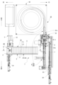
図4,図5,図6に示すように、増ダイ送出手段2Bは、増ダイ収容部2Aの増ダイ排出口23の上方に設けられて増ダイ収容部2Aから増ダイ供給路4に増ダイ11を送る送りローラ30と、増ダイ収容部2Aの増ダイ排出口23と増ダイ供給路4との間に設けられた中継供給路40と、中継供給路40を開閉する開閉板51を有した開閉装置50とを備える。 As shown in FIG. 4, FIG. 5, and FIG. 6, the additional die sending means 2B is provided above the additional die outlet 23 of the additional die accommodating section 2A and extends from the additional die accommodating section 2A to the additional die supply path 4. A feed roller 30 that feeds the die 11, a relay supply path 40 provided between the additional die outlet 23 of the additional die storage section 2A and the additional die supply path 4, and an opening/closing plate 51 that opens and closes the relay supply path 40. The opening/closing device 50 is provided.

送りローラ30は、増ダイ収容部2Aの増ダイ排出口23において、増ダイ11,11…が集中して詰まらないように、増ダイ11,11…の集中に基づく増ダイ11の詰まり状態を崩すための手段である。
当該送りローラ30は、回転中心軸31と、断面円形の外周面32aを備えたローラ32と、回転中心軸31に回転力を付与してローラ32を回転させるモータ等の回転動力付与手段33とを備えて構成される。
The feed roller 30 prevents the additional dies 11, 11, . . . from concentrating and clogging the additional dies 11, 11, . It is a means to destroy it.
The feed roller 30 includes a rotational center shaft 31, a roller 32 having an outer circumferential surface 32a having a circular cross section, and a rotational power applying means 33 such as a motor that applies rotational force to the rotational center shaft 31 to rotate the roller 32. It is composed of:

送りローラ30は、例えば、図7に示すように、回転中心軸31の一端側が連結板46に回転可能に取付けられるとともに、回転中心軸31の他端側が連結板47に回転可能に取付けられて、当該回転中心軸31の他端に、回転動力付与手段33としての例えばモータのモータ軸が連結されて構成される。
そして、制御装置1Xが当該モータを制御することによって、図6に示すように、増ダイ11を中継供給路40及び増ダイ供給路4に送る方向である正方向又は逆方向に回転するように構成されている。
For example, as shown in FIG. 7, the feed roller 30 has one end of a central rotation shaft 31 rotatably attached to a connecting plate 46, and the other end of the central rotation shaft 31 rotatably attached to a connecting plate 47. , the other end of the rotational center shaft 31 is connected to, for example, a motor shaft of a motor as the rotational power applying means 33.
Then, by controlling the motor by the control device 1X, as shown in FIG. It is configured.

図6に示すように、ローラ32の外周面32aには、複数の凸部34,34…が、周方向に沿って所定の間隔を隔てて設けられている。
凸部34は、例えば、1層目の湾曲板34aと、1層目の湾曲板34aの上に積層されて設けられた2層目の湾曲板34bとで構成される。
1層目の湾曲板34aは、ローラ32の幅方向に対応する横方向寸法がローラ32のほぼ全幅寸法に対応する寸法に形成されて、かつ、ローラ32の周方向に対応して湾曲する周方向寸法が所定の長さに形成される。
2層目の湾曲板34bは、ローラ32の幅方向に対応する横方向寸法がローラ32のほぼ全幅寸法に対応する寸法に形成されて、かつ、ローラ32の周方向に対応して湾曲する周方向寸法が1層目の湾曲板の所定の長さよりも短い寸法に形成される。
そして、凸部34は、1層目の湾曲板34aが、ローラ32の外周面32aに溶接等の取付手段で取付けられ、かつ、2層目の湾曲板34bが、1層目の湾曲板34aの上に溶接等の取付手段で取付けられて構成される。
尚、送りローラ30の材質は特に限定されないが、例えば金属材料や合成樹脂材料等で形成されたものを用いればよい。
As shown in FIG. 6, a plurality of convex portions 34, 34, . . . are provided on the outer peripheral surface 32a of the roller 32 at predetermined intervals along the circumferential direction.
The convex portion 34 includes, for example, a first-layer curved plate 34a and a second-layer curved plate 34b stacked on the first-layer curved plate 34a.
The first layer curved plate 34a has a lateral dimension corresponding to the width direction of the roller 32 that corresponds to almost the entire width dimension of the roller 32, and a circumference curved corresponding to the circumferential direction of the roller 32. The directional dimension is formed to a predetermined length.
The second layer curved plate 34b has a lateral dimension corresponding to the width direction of the roller 32 that corresponds to almost the entire width dimension of the roller 32, and a circumference curved corresponding to the circumferential direction of the roller 32. The directional dimension is formed to be shorter than the predetermined length of the first layer curved plate.
In the convex portion 34, the first layer curved plate 34a is attached to the outer peripheral surface 32a of the roller 32 by an attachment means such as welding, and the second layer curved plate 34b is attached to the first layer curved plate 34a. It is constructed by being attached to the top of the body by means of attachment means such as welding.
Note that the material of the feed roller 30 is not particularly limited, but may be made of, for example, a metal material, a synthetic resin material, or the like.

凸部34は、ローラ32を逆方向に回転させた場合に増ダイ11に衝突する側の壁面35が段差面に形成された構成である。
即ち、当該壁面35は、周方向にずれて位置された1層目の湾曲板34aの周方向一端側の端面35aと2層目の湾曲板34bの周方向一端側の端面35bとで構成された段差面に形成される。即ち、壁面35は、2段突起により構成される。
また、凸部34は、ローラ32を正方向に回転させた場合に増ダイ11に衝突する側の壁面36を備える。
即ち、当該壁面36は、周方向で一致した1層目の湾曲板34aの周方向他端側の端面36aと2層目の湾曲板34bの周方向他端側の端面36bとで構成される。つまり、当該壁面36は、湾曲板34aの板厚寸法+湾曲板34bの板厚寸法の高さを有した壁面に形成される。
The convex portion 34 has a structure in which a wall surface 35 on the side that collides with the additional die 11 when the roller 32 is rotated in the opposite direction is formed in a stepped surface.
That is, the wall surface 35 is composed of an end surface 35a on one circumferential end side of the first layer curved plate 34a and an end surface 35b on one circumferential end side of the second layer curved plate 34b, which are positioned offset in the circumferential direction. It is formed on the stepped surface. That is, the wall surface 35 is composed of two-step protrusions.
Further, the convex portion 34 includes a wall surface 36 on the side that collides with the additional die 11 when the roller 32 is rotated in the forward direction.
That is, the wall surface 36 is composed of an end surface 36a on the other end side in the circumferential direction of the first layer curved plate 34a and an end surface 36b on the other end side in the circumferential direction of the second layer curved plate 34b, which are coincident in the circumferential direction. . In other words, the wall surface 36 is formed to have a height equal to the thickness of the curved plate 34a+the thickness of the curved plate 34b.

尚、図6に示すように、上述した送りローラ30の上方に設けられた隔壁である左端壁(他端壁)22は、送りローラ30の回転中心線を含む垂直面よりも収容ボックス20の右端壁(一端壁)21側(即ち、傾斜底壁24の傾斜方向上流側)に位置する内壁面22Aを備えた構成とした。
内壁面22Aは、左端壁22の下端22eから収容ボックス20の右端壁21側及び上方に向けて延長する傾斜面22aと、当該傾斜面22aの上端から上方に垂直に延長する垂直面22bとを備える。この垂直面22bは、送りローラ40の回転中心線を含む垂直面と平行に対向する垂直面である。
当該内壁面22Aを備えたことにより、収容ボックス20内に収容された増ダイ11,11…は、傾斜面22aに沿って並ぶように位置されるようになるため、送りローラ32の上方の増ダイ11の重量が送りローラ32の直近に位置される増ダイ11や送りローラ30に加わり難くなる。従って、送りローラ32の直近に位置される増ダイ11の変形を軽減でき、また、送りローラ30の回転負荷を軽減できる。
As shown in FIG. 6, the left end wall (other end wall) 22, which is a partition wall provided above the feed roller 30, is located closer to the storage box 20 than the vertical plane including the rotation center line of the feed roller 30. The configuration includes an inner wall surface 22A located on the right end wall (one end wall) 21 side (that is, on the upstream side in the inclined direction of the inclined bottom wall 24).
The inner wall surface 22A includes an inclined surface 22a extending from the lower end 22e of the left end wall 22 toward the right end wall 21 of the storage box 20 and upward, and a vertical surface 22b extending vertically upward from the upper end of the inclined surface 22a. Be prepared. This vertical surface 22b is a vertical surface that faces parallel to a vertical surface that includes the rotation center line of the feed roller 40.
By providing the inner wall surface 22A, the additional dies 11, 11... housed in the storage box 20 are positioned so as to be lined up along the inclined surface 22a. It becomes difficult for the weight of the die 11 to be added to the additional die 11 and the feed roller 30 located in the immediate vicinity of the feed roller 32. Therefore, the deformation of the additional die 11 located in the immediate vicinity of the feed roller 32 can be reduced, and the rotational load on the feed roller 30 can be reduced.

また、左端壁22の下端22eと送りローラ30の凸部34との間に増ダイ11が挟まらないように、当該左端壁22の下端22eと送りローラ30の凸部34との間の間隔が、棒状の増ダイ11の直径寸法よりも小さい間隔となるように構成されている。 In addition, the distance between the lower end 22e of the left end wall 22 and the convex portion 34 of the feed roller 30 is set so that the additional die 11 is not caught between the lower end 22e of the left end wall 22 and the convex portion 34 of the feed roller 30. are configured to have an interval smaller than the diameter of the rod-shaped die extension 11.

制御装置1Xは、送りローラ30を、正方向又は逆方向に回転させる回転制御を行うように構成されている。このため、送りローラ30に接触している増ダイ11に異なる方向からの力が加えられるようになり、送りローラ30に接触している増ダイ11の挙動に変化を付与できるので、当該増ダイ11に接触している増ダイ11にも力が付与される。
よって、増ダイ排出口23の近傍に集中している増ダイ群を崩すことができるので、増ダイ11,11…の詰まり解消効果が得られる。
The control device 1X is configured to perform rotation control to rotate the feed roller 30 in a forward direction or a reverse direction. Therefore, forces are applied from different directions to the additional die 11 that is in contact with the feed roller 30, and the behavior of the additional die 11 that is in contact with the feed roller 30 can be changed. Force is also applied to the additional die 11 that is in contact with the die 11.
Therefore, it is possible to break up the group of additional dies concentrated in the vicinity of the additional dies 11, 11, .

特に、回転制御として、正方向に回転させる時間と逆方向に回転させる時間とを異ならせる回転制御を行う制御装置1Xとすることで、送りローラ30に接触している増ダイ11に異なる方向から不規則な力を付与できるようになり、増ダイ11,11…の詰まり解消効果を向上させることができる。
例えば、送りローラ30を、正方向に3秒間回転させた後に、逆方向に1.5秒間回転させる回転制御を行う制御装置1Xとすることで、増ダイ11,11…の詰まり解消効果が向上したことを確認できた。
In particular, by using the control device 1X that performs rotation control that makes the time for rotating in the forward direction and the time for rotating in the reverse direction different, the die expansion die 11 in contact with the feed roller 30 can be directed from different directions. It becomes possible to apply irregular force, and the effect of eliminating clogging of the additional dies 11, 11, . . . can be improved.
For example, by using a control device 1X that performs rotation control such as rotating the feed roller 30 in the forward direction for 3 seconds and then rotating it in the reverse direction for 1.5 seconds, the effect of eliminating clogging of the additional dies 11, 11, etc. is improved. I was able to confirm that I did it.

また、当該制御装置1Xによる送りローラ30の回転制御は、例えば、増ダイ供給経路4及び増ダイ排出口23の少なくとも一方に、増ダイ11が存在しない時に行うようにした。
例えば、図6に示すように、増ダイ供給経路4上に増ダイ11が存在するか否かを検出するセンサS1と、増ダイ排出口23に増ダイ11が存在するか否かを検出するセンサS2とを備える。
そして、制御装置1Xは、センサS1及びセンサS2の少なくとも一方から、増ダイ11が存在しないことを示す信号を受信した場合に、回転動力付与手段33としてのモータに駆動信号を出力することにより、送りローラ30の回転制御を行うように構成されている。従って、速やかに、増ダイ11,11…の詰まりが解消されるようになる。
また、制御装置1Xは、センサS1及びセンサS2の両方から、増ダイ11が存在することを示す信号を受信した場合には、回転動力付与手段33としてのモータに停止信号を出力することにより、送りローラ30の回転制御を中止するように構成されている。つまり、回転制御を開始してから規定動作時間(例えば上述した3秒+1.5秒)が経過していなくても回転制御を中止する。従って、増ダイ11が詰まっていない状態において増ダイ11に送りローラ30からの不要な力が加わってしまうことを防止できる。即ち、増ダイ11が詰まっていない状態で送りローラ30を回転すると、送りローラ30の凸部が増ダイ11の外径を擦って、増ダイ11のシュリンク包装が剥がれやすくなるという不具合を生じやすくなるが、このような不具合を防止できるようになる。
図6に示すように、センサS1は、例えば、収容ボックス20における増ダイ排出口23の下方に位置される傾斜底壁24の裏側に設置され、センサS2は、後述する中継供給路40の垂直路42の下端側における右内面42aの裏側に設置される。
尚、センサS1,センサS2としては、例えば、拡散反射形の光電センサが用いられ、センサS1が設置される傾斜底壁24、及び、センサS2が設置される垂直路42の下端側には、当該光電センサの光を透過させるための図外の透過孔が形成されている。
Further, the rotation control of the feed roller 30 by the control device 1X is performed, for example, when the additional die 11 is not present in at least one of the additional die supply path 4 and the additional die outlet 23.
For example, as shown in FIG. 6, a sensor S1 detects whether or not additional die 11 is present on the increase die supply path 4, and a sensor S1 detects whether or not additional die 11 is present at the increase die outlet 23. and a sensor S2.
Then, when the control device 1X receives a signal indicating that the additional die 11 is not present from at least one of the sensor S1 and the sensor S2, the control device 1X outputs a drive signal to the motor as the rotational power applying means 33. It is configured to control the rotation of the feed roller 30. Therefore, the clogging of the additional dies 11, 11, . . . can be quickly cleared.
Further, when the control device 1X receives a signal indicating that the additional die 11 is present from both the sensor S1 and the sensor S2, the control device 1X outputs a stop signal to the motor serving as the rotational power applying means 33, thereby It is configured to stop rotational control of the feed roller 30. In other words, the rotation control is stopped even if the specified operation time (for example, the above-mentioned 3 seconds + 1.5 seconds) has not elapsed since the rotation control was started. Therefore, it is possible to prevent unnecessary force from being applied to the additional die 11 from the feed roller 30 when the additional die 11 is not clogged. That is, if the feed roller 30 is rotated in a state where the extra die 11 is not clogged, the convex portion of the feed roller 30 will rub against the outer diameter of the extra die 11, causing the problem that the shrink wrapping of the extra die 11 will easily peel off. However, such problems can be prevented.
As shown in FIG. 6, the sensor S1 is installed, for example, on the back side of the inclined bottom wall 24 located below the die increase outlet 23 in the storage box 20, and the sensor S2 is installed vertically in the relay supply path 40, which will be described later. It is installed on the back side of the right inner surface 42a at the lower end side of the channel 42.
Incidentally, as the sensor S1 and the sensor S2, for example, a diffuse reflection type photoelectric sensor is used, and on the lower end side of the inclined bottom wall 24 where the sensor S1 is installed and the vertical path 42 where the sensor S2 is installed, A transmission hole (not shown) is formed to transmit light from the photoelectric sensor.

上述した増ダイ排出口23は、送りローラ30のローラ32の外周面32aにおける下端位置と収容ボックス20の傾斜底壁24の内面と間の空間により形成される。
この増ダイ排出口23と増ダイ供給路4との間には、増ダイ排出口23から増ダイ供給路4に増ダイ11を供給するための供給路となる中継供給路40を備える。
当該中継供給路40は、増ダイ排出口23から下方斜めに延長する傾斜路41と、傾斜路41の下端から下方垂直方向に延長する垂直路42とを備える。即ち、中継供給路40は、増ダイ排出口23から増ダイ供給路4まで連続して縦方向に延長する供給路である。つまり、中継供給路40は、上方の増ダイ排出口23から連続して縦方向に延長する傾斜路41及び垂直路42を介して下方の水平な増ダイ供給路4まで到達する供給路である。
傾斜路41の路面41a及び垂直路42の右内面42aは、収容ボックス20の傾斜底壁24の内面から延長するように設けられる。
また、傾斜路41の上面41b及び垂直路42の左内面42bは、カバー板43により構成される。
当該カバー板43は、傾斜路41の路面41aと平行な上面41bを形成する上側板部43Aと垂直路42の右内面42aと平行な左内面42bを形成する下側板部43Bとの間の部分を湾曲させて形成された湾曲板により構成され、当該下側板部43Bの下端側が、図6に示すように、増ダイ供給路4の左側に設けられたブラケット40Xにヒンジ機構40Yを介して取付けられている。
The above-mentioned die increase outlet 23 is formed by the space between the lower end position of the outer circumferential surface 32 a of the roller 32 of the feed roller 30 and the inner surface of the inclined bottom wall 24 of the storage box 20 .
A relay supply path 40 is provided between the additional die outlet 23 and the additional die supply path 4, which serves as a supply path for supplying the additional die 11 from the additional die outlet 23 to the additional die supply path 4.
The relay supply path 40 includes a ramp 41 extending obliquely downward from the die-expanding outlet 23 and a vertical channel 42 extending vertically downward from the lower end of the ramp 41 . That is, the relay supply path 40 is a supply path that extends continuously in the vertical direction from the die increase outlet 23 to the die increase supply path 4. In other words, the relay supply path 40 is a supply path that reaches from the upper die-increasing outlet 23 to the lower horizontal die-increasing supply path 4 via a ramp 41 and a vertical path 42 that extend continuously in the vertical direction. .
The road surface 41a of the ramp 41 and the right inner surface 42a of the vertical channel 42 are provided to extend from the inner surface of the inclined bottom wall 24 of the storage box 20.
Further, the upper surface 41b of the ramp 41 and the left inner surface 42b of the vertical path 42 are constituted by a cover plate 43.
The cover plate 43 is a portion between an upper plate portion 43A forming an upper surface 41b parallel to the road surface 41a of the ramp 41 and a lower plate portion 43B forming a left inner surface 42b parallel to the right inner surface 42a of the vertical path 42. As shown in FIG. 6, the lower end side of the lower plate portion 43B is attached to a bracket 40X provided on the left side of the die expansion supply path 4 via a hinge mechanism 40Y. It is being

つまり、当該カバー板43は、ヒンジ機構40Yを介して開閉可能に設けられている。
即ち、当該カバー板43は、図6の実線に示すように、閉じた状態に設定されることで、カバー板43の内面である傾斜路41の上面41b及び垂直路42の左内面42bと傾斜路41の路面41a及び垂直路42の右内面42aとが平行に対向した状態の中継供給路40が構成されることになる。
また、当該カバー板43は、図6の想像線に示すように左側に開くことができるように構成されている。即ち、作業終了後に、当該カバー板43を開くことによって、中継供給路40に残っている増ダイ11,11…を回収できるように構成されている。尚、ブラケット40Xには、カバー板43が所定の角度以上に開かないようにするためのストッパー40Zが設けられている。
尚、図7に示すように、閉じた状態に設定されたカバー板43の近傍には、カバー板43の開閉確認用の近接スイッチ等のセンサS3が設けられている。そして、制御装置1Xは、センサS3からカバー板43が閉じていることを示す信号を受信しているときにのみ爆薬装填装置1を動作させ、センサS3からカバー板43が開いていることを示す信号を受信しているときは、爆薬装填装置1の動作を停止する。即ち、爆薬装填装置1は、カバー板43が開いている場合には、爆薬装填装置1の動作を停止するインターロック機能を備えている。
That is, the cover plate 43 is provided so as to be openable and closable via the hinge mechanism 40Y.
That is, as shown by the solid line in FIG. 6, the cover plate 43 is set in the closed state, so that the cover plate 43 is inclined with the upper surface 41b of the ramp 41, which is the inner surface of the cover plate 43, and the left inner surface 42b of the vertical channel 42. The relay supply path 40 is configured such that the road surface 41a of the path 41 and the right inner surface 42a of the vertical path 42 face each other in parallel.
Further, the cover plate 43 is configured so that it can be opened to the left as shown by the imaginary line in FIG. That is, after the work is completed, by opening the cover plate 43, the additional die 11, 11, . . . remaining in the relay supply path 40 can be recovered. The bracket 40X is provided with a stopper 40Z for preventing the cover plate 43 from opening beyond a predetermined angle.
As shown in FIG. 7, a sensor S3 such as a proximity switch for checking whether the cover plate 43 is open or closed is provided near the cover plate 43 which is set in the closed state. Then, the control device 1X operates the explosive loading device 1 only when receiving a signal indicating that the cover plate 43 is closed from the sensor S3, and operates the explosive loading device 1 only when receiving a signal from the sensor S3 indicating that the cover plate 43 is open. When the signal is being received, the operation of the explosive loading device 1 is stopped. That is, the explosive loading device 1 has an interlock function that stops the operation of the explosive loading device 1 when the cover plate 43 is open.

当該中継供給路40の下端が増ダイ供給路4に到達し、増ダイ排出口23と増ダイ供給路4とが中継供給路40によって繋がれる。
尚、中継供給路40の前側壁44及び後側壁45が設けられている。当該前側壁44と後側壁45との間の間隔は、増ダイ11の長さ寸法よりも若干大きい間隔に設定されている。
従って、傾斜路41の路面41a及び垂直路42の右内面42aとカバー板43と前側壁44と後側壁45とで囲まれた空間により、中継供給路40が構成される。
よって、増ダイ排出口23を排出した増ダイ11が中継供給路40を経由して増ダイ供給路4上に到達する。
The lower end of the relay supply path 40 reaches the additional die supply path 4, and the additional die outlet 23 and the additional die supply path 4 are connected by the relay supply path 40.
Note that a front side wall 44 and a rear side wall 45 of the relay supply path 40 are provided. The interval between the front side wall 44 and the rear side wall 45 is set to be slightly larger than the length dimension of the additional die 11.
Therefore, a space surrounded by the road surface 41a of the ramp 41, the right inner surface 42a of the vertical path 42, the cover plate 43, the front wall 44, and the rear wall 45 constitutes the relay supply path 40.
Therefore, the additional die 11 discharged from the additional die outlet 23 reaches the additional die supply path 4 via the relay supply path 40.

また、カバー板43の下側板部43Bには、開閉装置50が設けられている。
当該開閉装置50は、中継供給路40を形成した状態において、下側板部43Bに形成されている開閉板貫通孔51を介して中継供給路40に対して進退可能に設けられた開閉板52と、開閉板52の開閉駆動装置53とを備えて構成される。
開閉装置50は、例えば、開閉駆動装置53としてのソレノイドや油圧シリンダ,エアシリンダ等の進退装置により進退するプランジャ54(図6参照)の先端側に開閉板52を備えた構成である。
Furthermore, an opening/closing device 50 is provided on the lower plate portion 43B of the cover plate 43.
The opening/closing device 50 includes an opening/closing plate 52 which is provided so as to be movable toward and away from the relay supply passage 40 through an opening/closing plate through hole 51 formed in the lower plate portion 43B when the relay supply passage 40 is formed. , and an opening/closing drive device 53 for the opening/closing plate 52.
The opening/closing device 50 has a configuration including an opening/closing plate 52 on the tip side of a plunger 54 (see FIG. 6) that is advanced and retreated by a reciprocating device such as a solenoid, a hydraulic cylinder, or an air cylinder as an opening/closing drive device 53, for example.

即ち、開閉装置50の開閉板52が中継供給路40を閉じた場合に増ダイ11を水平状態で受け、開閉板52が中継供給路40を開放した場合に増ダイ11が水平状態のまま増ダイ供給路4に落下するように構成されている。
つまり、制御装置1Xは、増ダイ排出口23から中継供給路40に排出された増ダイ11を開閉板52で1個ずつ受けて増ダイ供給路4上に1個ずつ供給できるように開閉板52の開閉を制御する。
That is, when the opening/closing plate 52 of the opening/closing device 50 closes the relay supply path 40, the additional die 11 is received in a horizontal state, and when the opening/closing plate 52 opens the relay supply path 40, the additional die 11 is received in a horizontal state. It is configured to fall into the die supply path 4.
That is, the control device 1X controls the opening/closing plate so that the additional die 11 discharged from the additional die outlet 23 to the relay supply path 40 can be received one by one by the opening/closing plate 52 and supplied one by one onto the additional die supply path 4. Controls the opening and closing of 52.

開閉板52は、例えば、前後左右方向に延長する水平な板面を有した水平板により構成される。当該開閉板52の前後方向の長さは、図7に示すように、増ダイ11の長さ寸法の例えば1/3以上の長さに形成され、中継供給路40を下降してくる増ダイ11の延長方向の中央部を支えることが可能なように構成されている。
また、図6に示すように、開閉板52の開閉方向先端側の上面は、中継供給路40内を下降する上下の増ダイ11,11の間における上の増ダイ11のカバー板43側の外周下側湾曲面に対応した湾曲面52tに形成されている。さらに、開閉板52の開閉方向の先端は、中継供給路40内を下降する上下の増ダイ11,11の間に入り込みやすいように、尖った形状に形成されている。
即ち、開閉板52は、増ダイ供給路4上に位置された下側増ダイ11と当該下側増ダイ11の直上に積み重なるように位置された上側増ダイ11との間の水平位置で左右に進退するように構成されている。
そして、中継供給路40を閉じる方向に開閉板52を移動させることによって、開閉板52の先端側の湾曲面52tが中継供給路40内を下降する増ダイ11を水平に維持した状態で受ける。つまり、開閉板52の先端側の湾曲面52tが上側増ダイ11のカバー板43側の外周下側湾曲面に接触することで、当該開閉板52が上側増ダイ11を受けて当該上側増ダイ11を水平状態に維持するように構成されている。そして、中継供給路40を開く方向に開閉板52を移動させた場合に、当該開閉板52で受け止められていた増ダイ11が水平状態のまま増ダイ供給路4上に供給されることになる。
つまり、開閉板52を開閉させることで、増ダイ11を水平に保った状態で増ダイ供給路4上に増ダイ11を1つずつスムーズに供給することができるようになる。
開閉板52を備えない構成の場合、増ダイ11が斜めの状態(図7の前後方向に傾いた状態)で増ダイ供給路4上に落下してしまう可能性がある。このように、増ダイ11が斜めの状態で増ダイ供給路4上に落下してしまった場合、増ダイ11を装填できなくなって装填作業に支障を来たしたり、増ダイ11,11…が中継供給路40内で詰まってしまう原因となる。
一方、実施形態では、開閉板52を備えているため、増ダイ供給路4の直上において上側増ダイ11を水平状態に維持することができるので、当該増ダイ11を水平状態のまま増ダイ供給路4上に落下させることができるようになる。従って、増ダイ11をスムーズかつ正確に装填できるようになり、また、中継供給路40内で増ダイ11,11…を水平状態に整列させることできて、増ダイ11が中継供給路40内で詰まってしまうようなことも解消できるようになった。
The opening/closing plate 52 is constituted by, for example, a horizontal plate having a horizontal plate surface extending in the front, rear, right and left directions. As shown in FIG. 7, the length of the opening/closing plate 52 in the front-rear direction is, for example, 1/3 or more of the length of the additional die 11, and the length of the opening/closing plate 52 is set to be 1/3 or more of the length of the additional die 11, and 11 in the extending direction.
As shown in FIG. 6, the top surface of the opening/closing plate 52 on the front end side in the opening/closing direction is located on the side of the cover plate 43 of the upper additional die 11 between the upper and lower additional dies 11, 11 descending in the relay supply path 40. It is formed into a curved surface 52t corresponding to the outer circumferential lower curved surface. Further, the tip of the opening/closing plate 52 in the opening/closing direction is formed into a sharp shape so that it can easily fit between the upper and lower die extensions 11, 11 moving down within the relay supply path 40.
That is, the opening/closing plate 52 is located horizontally between the lower die extension 11 located on the die extension supply path 4 and the upper die extension 11 positioned so as to be stacked directly above the lower die extension 11. It is configured to move forward and backward.
Then, by moving the opening/closing plate 52 in the direction to close the relay supply path 40, the curved surface 52t on the tip side of the opening/closing plate 52 receives the additional die 11 descending within the relay supply path 40 while maintaining it horizontally. In other words, the curved surface 52t on the tip side of the opening/closing plate 52 contacts the outer circumferential lower curved surface on the cover plate 43 side of the upper additional die 11, so that the opening/closing plate 52 receives the upper additional die 11 and 11 in a horizontal state. Then, when the opening/closing plate 52 is moved in the direction of opening the relay supply path 40, the additional die 11 that has been received by the opening/closing plate 52 is supplied onto the additional die supply path 4 in a horizontal state. .
That is, by opening and closing the opening/closing plate 52, the additional dies 11 can be smoothly supplied one by one onto the additional die supply path 4 while keeping the additional dies 11 horizontal.
In the case of a configuration that does not include the opening/closing plate 52, there is a possibility that the additional die 11 falls onto the additional die supply path 4 in an oblique state (a state inclined in the front-rear direction in FIG. 7). In this way, if the additional die 11 falls onto the additional die supply path 4 in an oblique state, it may become impossible to load the additional die 11, causing trouble in the loading operation, or the additional die 11, 11, etc. This may cause the supply path 40 to become clogged.
On the other hand, in the embodiment, since the opening/closing plate 52 is provided, it is possible to maintain the upper side additional die 11 in a horizontal state directly above the additional die supply path 4, so that the additional die 11 is supplied in a horizontal state. You can now drop it on Road 4. Therefore, the additional die 11 can be loaded smoothly and accurately, and the additional dies 11, 11, . I am now able to resolve things that would cause me to get stuck.

図3,図5,図7に示すように、増ダイ供給路4の前側には、増ダイ供給路4上に供給された増ダイ11を押圧する押圧体5Aが配置される。
当該押圧体5Aと、この押圧体5Aを前後方向に進退自在に駆動する押圧体駆動装置5B(図3参照)により、増ダイ供給路4に供給された棒状の増ダイ11の端面11eを押圧して増ダイ圧送用の装填機3A側に送る増ダイ押圧手段5が構成される。押圧体駆動装置5Bは、例えば、油圧シリンダ,エアシリンダ等の進退装置により構成される。
尚、増ダイ11の端面11eは、増ダイ供給路4上に供給された増ダイ11の中心軸線11Cに沿った方向の前側(一端側)の端面のことである(図5参照)。
As shown in FIGS. 3, 5, and 7, a pressing body 5A that presses the additional die 11 supplied onto the additional die supply path 4 is arranged on the front side of the additional die supply path 4.
The end face 11e of the rod-shaped die extension 11 supplied to the die extension supply path 4 is pressed by the pushing body 5A and the pushing body drive device 5B (see FIG. 3) that drives the pushing body 5A so as to be able to move back and forth in the front and rear directions. A die increasing pressing means 5 is configured to send the die to the loading machine 3A side for pressure feeding die increasing. The pressing body drive device 5B is constituted by, for example, a reciprocating device such as a hydraulic cylinder or an air cylinder.
Note that the end surface 11e of the additional die 11 is the end surface on the front side (one end side) in the direction along the central axis 11C of the additional die 11 supplied onto the additional die supply path 4 (see FIG. 5).

図7に示すように、水平な路面を有した増ダイ供給路4の終端には、例えば上述した連結板46が延長するように設けられており、当該連結板46に形成された連結孔48と装填機3Aの導入口とが連結されたことにより、増ダイ供給路4と装填機3Aの管体3a内とが連通するように構成されている。
装填機3Aは、管体3aと、管体3aの中途に設けられた装填バルブ3bと、装填バルブ開閉装置3cと、圧送空気供給機構3Xとを備える。
As shown in FIG. 7, at the end of the die increasing die supply path 4 having a horizontal road surface, for example, the above-mentioned connecting plate 46 is provided so as to extend, and a connecting hole 48 formed in the connecting plate 46 is provided. By connecting the inlet and the inlet of the loading machine 3A, the die increasing die supply path 4 and the inside of the tube body 3a of the loading machine 3A are configured to communicate with each other.
The loading machine 3A includes a tube body 3a, a loading valve 3b provided in the middle of the tube body 3a, a loading valve opening/closing device 3c, and a pressurized air supply mechanism 3X.

装填バルブ3bは、装填バルブ開閉装置3cにより管体3aの管路を開閉する例えばボールバルブのような弁体3dを有したものである。 The loading valve 3b has a valve body 3d, such as a ball valve, which opens and closes the conduit of the tubular body 3a by a loading valve opening/closing device 3c.

圧送空気供給機構3Xは、圧縮空気供給装置3eと、圧縮空気を弁体3dに供給するための圧縮空気供給管3fとを備える。 The compressed air supply mechanism 3X includes a compressed air supply device 3e and a compressed air supply pipe 3f for supplying compressed air to the valve body 3d.

装填バルブ3bの弁体3dが管体3aの管路を閉鎖した状態において、圧縮空気供給装置3eを駆動して、弁体3dよりも後側(下流側)の位置から当該弁体3dに向けて圧縮空気を吹き付けることにより、弁体3dに衝突した空気が装填ホースC側に向けた空気の流れとなり、装填ホースCに供給されている増ダイ11が当該空気の流れによる圧力によって装薬孔Hまで圧送される。 In a state where the valve body 3d of the loading valve 3b closes the conduit of the pipe body 3a, the compressed air supply device 3e is driven to direct the compressed air supply device 3e toward the valve body 3d from a position on the rear side (downstream side) of the valve body 3d. By blowing compressed air, the air that collides with the valve body 3d becomes an air flow toward the loading hose C side, and the additional die 11 supplied to the loading hose C closes the charging hole due to the pressure of the air flow. It is pumped up to H.

次に、図5に基づいて、増ダイ11が装薬孔Hに装填されるまでの流れについて説明する。尚、図5において、矢印aは増ダイ11の移動方向、矢印bは押圧体5Aの進退方向を示す。
まず、増ダイ収容部2Aに増ダイ11,11…を入れて収容した後、制御装置1Xを作動させる。
制御装置1Xは、センサS1から増ダイ供給路4上に増ダイ11が存在することを示す信号を受信した場合に、押圧体駆動装置5Bを制御して、押圧体5Aを後側(装填機3A側)に移動させることにより、押圧体5Aが、増ダイ供給路4上に供給されている増ダイ11の端面を押圧する。
押圧体5Aで押された増ダイ11は、装填機3Aの管路内、又は、装填ホースC内に移動する。
尚、開閉板52は、押圧体5Aが後側(装填機3A側)に移動するのに同期して中継供給路40を閉じ、押圧体5Aが前側に戻るのに同期して中継供給路40を開放するように制御される。
制御装置1Xは、開閉駆動装置53及び押圧体駆動装置5Bを制御して、所定数の増ダイ11を装填機3Aの管路内、又は、装填ホースC内に移動させる。
その後、制御装置1Xは、閉鎖装填バルブ開閉装置3cを制御して弁体3dで管体3aの管路を閉鎖した後、圧縮空気供給装置3eを制御して弁体3dに向けて圧縮空気を吹き付けることにより、弁体3dに衝突した空気が装填ホースC側に向けた空気の流れとなり、装填ホースCに供給されている増ダイ11が当該空気の流れによる圧力によって圧送されて、装薬孔Hに装填される。
尚、制御装置1Xは、上述したように、例えば、増ダイ供給路4及び増ダイ排出口23の少なくとも一方に増ダイ11が存在しないことを、センサS1,センサS2から受信した場合に、送りローラ30の回転制御を行う。これにより、増ダイ11,11…の詰まりが解消される。
即ち、制御装置1Xにより回転制御される送りローラ30、及び、制御装置1Xにより開閉制御される開閉体52を備えたことで、増ダイ収容部2Aの増ダイ排出口23の近傍での増ダイ11の詰まり、及び、中継供給路40内での増ダイ11の詰まりを解消でき、増ダイ11を水平に保った状態で増ダイ供給路4上に増ダイ11を1つずつスムーズに供給することができるようになった。
Next, based on FIG. 5, the flow until the additional die 11 is loaded into the charging hole H will be explained. In FIG. 5, arrow a indicates the moving direction of the additional die 11, and arrow b indicates the advancing and retreating direction of the pressing body 5A.
First, after putting and accommodating the additional dies 11, 11, . . . in the additional die storage section 2A, the control device 1X is activated.
When the control device 1X receives a signal indicating that the additional die 11 is present on the additional die supply path 4 from the sensor S1, the control device 1X controls the pressing body drive device 5B to move the pressing body 5A to the rear side (loading machine 3A side), the pressing body 5A presses the end face of the additional die 11 being supplied onto the additional die supply path 4.
The additional die 11 pressed by the pressing body 5A moves into the pipe line of the loading machine 3A or into the loading hose C.
The opening/closing plate 52 closes the relay supply path 40 in synchronization with the movement of the pressing body 5A to the rear side (toward the loading machine 3A side), and closes the relay supply path 40 in synchronization with the movement of the pressing body 5A to the front side. controlled to open.
The control device 1X controls the opening/closing drive device 53 and the pressing body drive device 5B to move a predetermined number of additional die 11 into the pipe line of the loading machine 3A or into the loading hose C.
After that, the control device 1X controls the closing/loading valve opening/closing device 3c to close the pipeline of the tube body 3a with the valve body 3d, and then controls the compressed air supply device 3e to supply compressed air toward the valve body 3d. By blowing, the air that collided with the valve body 3d becomes an air flow toward the loading hose C side, and the additional die 11 supplied to the loading hose C is forced into the charging hole by the pressure caused by the air flow. Loaded into H.
In addition, as described above, the control device 1X, for example, when receiving from the sensor S1 and the sensor S2 that the additional die 11 is not present in at least one of the additional die supply path 4 and the additional die outlet 23, sends the The rotation of the roller 30 is controlled. As a result, clogging of the additional dies 11, 11, . . . is eliminated.
That is, by providing the feed roller 30 whose rotation is controlled by the control device 1X and the opening/closing body 52 whose opening/closing is controlled by the control device 1X, the die expansion near the die expansion outlet 23 of the die expansion storage section 2A is provided. 11 and the additional die 11 in the relay supply path 40 can be eliminated, and the additional dies 11 are smoothly supplied one by one onto the additional die supply path 4 while keeping the additional dies 11 horizontal. Now I can do it.

次に、込め物装填システム1Bについて説明する。
込め物装填システム1Bは、上述したように、アンコ供給装置6と、アンコ圧送用の装填機3Bと、アンコ供給路7と、アンコ押圧手段8とを備える。
そして、アンコ供給装置6は、図5に示すように、アンコ12を後述する整列路63まで搬送する搬送装置6Aと、アンコ12を整列路63からアンコ供給路7まで移送する移送装置6Bとを備える。
Next, the object loading system 1B will be explained.
As described above, the filling system 1B includes the anchor feeding device 6, the loading machine 3B for pressure feeding the anchor, the anchor supply path 7, and the anchor pressing means 8.
As shown in FIG. 5, the anchor supply device 6 includes a transport device 6A that transports the anchors 12 to an alignment path 63, which will be described later, and a transfer device 6B that transports the anchors 12 from the alignment path 63 to the anchor supply path 7. Be prepared.

搬送装置6Aは、多数のアンコ12,12…を収容するとともに搬送するパーツフィーダ60と、パーツフィーダ60の出口に繋がれた上流側搬送路61aと、上流側搬送路61aにより搬送されてくるアンコ12の形状を矯正する矯正装置62と、矯正装置62を経由して矯正されたアンコ12を整列路63まで搬送する下流側搬送路61bとを備える。 The conveyance device 6A includes a parts feeder 60 that accommodates and conveys a large number of anchors 12, 12, . 12, and a downstream conveyance path 61b that conveys the corrected anchors 12 to an alignment path 63 via the straightening device 62.

矯正装置62は、例えば、外周面が断面湾曲凹部状に形成された4つのローラが十字状に配置されて構成され、4つのローラの湾曲凹部状の外周面で囲まれた円筒状空間をアンコ12が通過する際に、アンコ12の円棒の外周面が、4つのローラの湾曲凹部状の外周面に接触して矯正されるように構成されている。つまり、トラック輸送中、保管中、開梱時等において変形したアンコ12の形状を所定の丸棒状に矯正する装置である。 The straightening device 62 is configured, for example, by four rollers whose outer peripheral surfaces are formed in the shape of a curved concave cross section arranged in a cross shape, and which corrects a cylindrical space surrounded by the curved concave shaped outer peripheral surfaces of the four rollers. When the roller 12 passes, the outer peripheral surface of the circular bar of the anchor 12 comes into contact with the curved concave outer peripheral surfaces of the four rollers and is corrected. In other words, it is a device that corrects the shape of the anchor 12, which has been deformed during truck transportation, storage, unpacking, etc., into a predetermined round bar shape.

移送装置6Bは、搬送装置6Aにより搬送されてきたアンコ12を水平面上に複数個直列に並ぶように整列させる整列路63と、整列路63に直列に並んだ複数個のアンコ12,12をまとめてアンコ供給路7に移送する移送手段64とを備える。
当該移送手段64は、押出部材64aと、当該押出部材64aを進退させる図外の押出部材駆動装置とを備える。当該押出部材駆動装置は、例えば、油圧シリンダ,エアシリンダ等の進退装置により構成される。
尚、アンコ供給路7の路面は、例えば整列路63の路面よりアンコ12の直径寸法程度だけ下方に位置されるように構成される。
The transfer device 6B has an alignment path 63 for arranging a plurality of anchors 12 transported by the transfer device 6A so as to be lined up in series on a horizontal surface, and a plurality of anchors 12, 12 arranged in series on the alignment path 63 together. and a transfer means 64 for transferring it to the anchor supply path 7.
The transfer means 64 includes an extrusion member 64a and an extrusion member drive device (not shown) that moves the extrusion member 64a forward and backward. The extrusion member drive device is constituted by, for example, a reciprocating device such as a hydraulic cylinder or an air cylinder.
The road surface of the anchor supply path 7 is configured to be located, for example, below the road surface of the alignment path 63 by about the diameter of the anchor 12.

アンコ供給路7の前側には、アンコ供給路7上に供給された複数のアンコ12,12…(例えば3個のアンコ12)を押圧する押圧体8Aが配置される。
当該押圧体8Aと、この押圧体8Aを前後方向に進退自在に駆動する押圧体駆動装置8B(図3参照)により、アンコ供給路7に供給された棒状の複数のアンコ12,12…のうち一番前側に位置されるアンコ12の端面12eを押圧して、これら複数のアンコ12,12…をアンコ圧送用の装填機3B側に送るアンコ押圧手段8が構成される。押圧体駆動装置8Bは、例えば、油圧シリンダ,エアシリンダ等の進退装置により構成される。
尚、アンコ12の端面12eは、アンコ供給路7上に供給された複数のアンコ12,12…のうち一番前側に位置されるアンコ12の中心軸線12Cに沿った方向の前側(一端側)の端面のことである。
A pressing body 8A that presses a plurality of anchors 12, 12... (for example, three anchors 12) supplied onto the anchor supply path 7 is arranged on the front side of the anchor supply path 7.
Among the plurality of rod-shaped anchors 12, 12... supplied to the anchor supply path 7 by the pressing body 8A and the pressing body driving device 8B (see FIG. 3) that drives the pressing body 8A so as to be able to move back and forth in the front and rear directions. An anchor pressing means 8 is configured which presses the end surface 12e of the anchor 12 located at the frontmost side and sends the plurality of anchors 12, 12, . . . to the side of the loading machine 3B for pressure feeding the anchors. The pressing body drive device 8B is constituted by, for example, a reciprocating device such as a hydraulic cylinder or an air cylinder.
Note that the end surface 12e of the anchor 12 is the front side (one end side) in the direction along the central axis 12C of the anchor 12 located at the frontmost side among the plural anchors 12, 12... supplied on the anchor supply path 7. It refers to the end face of

図8に示すように、水平な路面を有したアンコ供給路7の終端には、連結板71が設けられており、当該連結板71に形成された連結孔72と装填機3Bの導入口とが連結されたことにより、アンコ供給路7と装填機3Bの管体3a内とが連通するように構成されている。
尚、装填機3Bは、上述した装填機3Aと同じ構成である。
As shown in FIG. 8, a connecting plate 71 is provided at the end of the anchor supply path 7 having a horizontal road surface, and a connecting hole 72 formed in the connecting plate 71 is connected to an inlet of the loading machine 3B. By being connected, the anchor supply path 7 and the inside of the tube body 3a of the loading machine 3B are configured to communicate with each other.
Note that the loading machine 3B has the same configuration as the loading machine 3A described above.

次に、図5に基づいて、アンコ12が装薬孔Hに装填されるまでの流れについて説明する。尚、図5において、矢印c,dはアンコ12の搬送方向、矢印eは押出部材64aの進退方向、矢印fは押圧体8Aの進退方向を示す。
まず、パーツフィーダ60にアンコ12,12…を投入した後、パーツフィーダ60を作動させることにより、所定数のアンコ12,12…を整列路63まで搬送する。
そして、所定数のアンコ12,12…が整列路63まで搬送されたことを示す搬送完了信号が図外のセンサから図外の操作盤に送信される。操作盤の操作者は、操作盤が搬送完了信号を受信したことを確認した後に、操作盤のアンコ装填信号送信スイッチを押す。そして、アンコ装填信号を受信した押出部材駆動装置が押出部材64aを図5の右側に移動させる。これにより、所定数のアンコ12,12…が押出部材64aによりまとめて押し出されて整列路63からアンコ供給路7まで移送される。
そして、制御装置1Xは、所定数のアンコ12,12…がアンコ供給路7に移送されたことを示す信号を図外の検出装置(検出センサ)から受信したならば、押圧体駆動装置8B(図3参照)を制御して、押圧体8Aを後側(装填機3B側)に移動させることにより、押圧体8Aが、アンコ供給路74上に位置されているアンコ12の端面12eを押圧する。
押圧体8Aで押された所定数のアンコ12,12…は、装填機3Bの管路内、又は、装填ホースC内に移動する。
その後、制御装置1Xは、閉鎖装填バルブ開閉装置3cを制御して弁体3dで管体3aの管路を閉鎖した後、圧縮空気供給装置3eを制御して弁体3dに向けて圧縮空気を吹き付けることにより、弁体3dに衝突した空気が装填ホースC側に向けた空気の流れとなり、装填ホースCに供給されている所定数のアンコ12,12…が当該空気の流れによる圧力によって圧送されて、装薬孔Hに装填される。
即ち、移送装置6Bを備えたので、所定数のアンコ12,12…をまとめてアンコ供給路7まで移送できて、所定数のアンコ12,12…をまとめて装薬孔Hに装填することができるようになり、アンコ装填作業をより効率的に行えるようになった。
Next, the flow until the anchor 12 is loaded into the charging hole H will be explained based on FIG. 5. In FIG. 5, arrows c and d indicate the conveying direction of the anchor 12, arrow e indicates the advancing and retreating direction of the pushing member 64a, and arrow f indicates the advancing and retreating direction of the pressing body 8A.
First, after putting the anchors 12, 12, .
Then, a conveyance completion signal indicating that a predetermined number of anchors 12, 12, . . . have been conveyed to the alignment path 63 is transmitted from a sensor (not shown) to an operation panel (not shown). After confirming that the operation panel has received the transfer completion signal, the operator of the operation panel presses the anchor loading signal transmission switch on the operation panel. Then, the push-out member driving device that has received the anchor loading signal moves the push-out member 64a to the right side in FIG. 5. As a result, a predetermined number of anchors 12, 12, .
When the control device 1X receives a signal indicating that a predetermined number of anchors 12, 12... have been transferred to the anchor supply path 7 from a detection device (detection sensor) (not shown), the control device 1X receives a signal from a detection device (detection sensor) not shown, and then the pressing body driving device 8B ( (see FIG. 3) and moves the pressing body 8A to the rear side (toward the loading machine 3B side), so that the pressing body 8A presses the end surface 12e of the anchor 12 located on the anchor supply path 74. .
A predetermined number of anchors 12, 12... pressed by the pressing body 8A move into the pipe line of the loading machine 3B or into the loading hose C.
After that, the control device 1X controls the closing/loading valve opening/closing device 3c to close the pipeline of the tube body 3a with the valve body 3d, and then controls the compressed air supply device 3e to supply compressed air toward the valve body 3d. By blowing, the air that collides with the valve body 3d becomes an air flow toward the loading hose C side, and a predetermined number of anchors 12, 12... supplied to the loading hose C are fed under pressure by the air flow. Then, the charge is loaded into the charging hole H.
That is, since the transfer device 6B is provided, a predetermined number of anchors 12, 12... can be collectively transferred to the anchor supply path 7, and a predetermined number of anchors 12, 12... can be loaded into the charging hole H at once. This allows for more efficient loading of anchors.

実施形態1に係る爆薬装填装置1によれば、増ダイ押圧手段5により増ダイ11を強制押圧して装填機3A側に供給する増ダイ強制押圧供給方式を採用した爆薬装填システム1Aを備えたことにより、増ダイ供給装置2から排出された増ダイ11を装填機3A側にスムーズに供給できるようになった。
また、実施形態1に係る爆薬装填装置1によれば、アンコ押圧手段8によりアンコ12を強制押圧して装填機3B側に供給するアンコ強制押圧供給方式を採用した込め物装填システム1Bを備えたことにより、アンコ供給装置6から排出された所定数のアンコ12,12…をまとめて装填機3B側にスムーズに供給できるようになった。
According to the explosives loading device 1 according to the first embodiment, the explosives loading system 1A is equipped with an explosives loading system 1A that employs an additional die forced press supply method in which the additional die 11 is forcibly pressed by the additional die pressing means 5 and is supplied to the loading machine 3A side. As a result, the extra die 11 discharged from the extra die supply device 2 can be smoothly supplied to the loading machine 3A side.
Moreover, according to the explosive loading device 1 according to the first embodiment, the charge loading system 1B is provided which employs an anchor forced pressure supply method in which the anchor 12 is forcibly pressed by the anchor pressing means 8 and is supplied to the loading machine 3B side. This makes it possible to smoothly supply a predetermined number of anchors 12, 12, . . . discharged from the anchor feeder 6 to the loading machine 3B side.

実施形態1に係る爆薬装填装置1によれば、増ダイ11又はアンコ12を水平方向に強制押圧する構成としたので、爆薬装填装置1の高さ寸法(機械高さ)を低減できる。
即ち、特許文献1に開示された爆薬装填装置では、増ダイ又はアンコを縦方向に自由落下させる方式であったため、落下高さを確保するために、必然的に、機械高さを高くする必要があったが、実施形態1に係る爆薬装填装置1によれば、増ダイ11又はアンコ12を水平方向に強制押圧する構成としたので、高さの低い装置を実現でき、断面が小さいトンネルにも導入が可能な爆薬装填装置1を提供できるようになった。
つまり、図7に示すように、増ダイ圧送用の装填機3Aは、中心軸線3Cが水平方向HDに延長するように配置され、増ダイ供給路4は、水平方向HDに延長するように設けられた構成とし、さらに、図8に示すように、込め物圧送用の装填機3Bは、中心軸線3Cが水平方向HDに延長するように配置され、込め物供給路7は、水平方向HDに延長するように設けられた構成としたので、高さの低い装置を実現でき、断面が小さいトンネルにも導入が可能な爆薬装填装置1を提供できるようになった。
According to the explosive loading device 1 according to the first embodiment, since the additional die 11 or the anchor 12 is forcibly pressed in the horizontal direction, the height dimension (mechanical height) of the explosive loading device 1 can be reduced.
In other words, the explosive loading device disclosed in Patent Document 1 uses a method in which the additional die or anchor is allowed to fall freely in the vertical direction, so in order to ensure the falling height, it is necessary to increase the height of the machine. However, according to the explosive loading device 1 according to the first embodiment, the additional die 11 or the anchor 12 is forcibly pressed in the horizontal direction, so a device with a low height can be realized, and it can be installed in a tunnel with a small cross section. Now we can provide an explosive loading device 1 that can also be introduced.
In other words, as shown in FIG. 7, the loading machine 3A for pressure-feeding additional die is arranged so that the central axis 3C extends in the horizontal direction HD, and the additional die supply path 4 is provided so as to extend in the horizontal direction HD. Further, as shown in FIG. 8, the loading machine 3B for pressure feeding the filling material is arranged so that the central axis 3C extends in the horizontal direction HD, and the filling material supply path 7 extends in the horizontal direction HD. Since it is configured to extend, it is possible to realize a device with a low height, and it is now possible to provide an explosive loading device 1 that can be introduced into a tunnel with a small cross section.

実施形態1に係る爆薬装填装置1によれば、爆薬供給装置2が、制御装置1Xにより回転制御されて爆薬供給路4に増ダイ11を送る送りローラ30を備えたので、増ダイ排出口23の近傍に集中している増ダイ群を崩すことができるようになり、増ダイ収容部2Aの増ダイ排出口23の近傍での増ダイ11の詰まりを抑制できるようになった。 According to the explosive loading device 1 according to the first embodiment, since the explosive supply device 2 includes the feed roller 30 that is rotationally controlled by the control device 1X and sends the extra die 11 to the explosive supply path 4, the extra die discharge port 23 It became possible to break up the group of additional dies concentrated in the vicinity of , and it became possible to suppress clogging of the additional dies 11 in the vicinity of the additional die outlet 23 of the additional die accommodating section 2A.

実施形態1に係る爆薬装填装置1によれば、爆薬供給装置2の増ダイ排出口(爆薬出口)23と爆薬供給路4との間に設けられた中継供給路40と、制御装置1Xにより開閉制御されて中継供給路40を開閉する開閉板52を有した開閉装置50とを備えたので、中継供給路40内での増ダイ11の詰まりを解消できるようになり、増ダイ11を水平に保った状態で増ダイ供給路4上に増ダイ11を1つずつスムーズに供給することができるようになった。即ち、中継供給路40及び開閉装置50を備えたことにより、爆薬供給装置2の増ダイ排出口23の近傍において増ダイ11,11…を整列させることができ、増ダイ11を1つずつ増ダイ供給路4及び装填機3A側にスムーズに供給できるようになった。 According to the explosive loading device 1 according to the first embodiment, the relay supply path 40 is provided between the die expansion outlet (explosive outlet) 23 of the explosive supply device 2 and the explosive supply path 4, and the relay supply path 40 is opened and closed by the control device 1X. Since the opening/closing device 50 is equipped with an opening/closing plate 52 that opens and closes the relay supply channel 40 in a controlled manner, it becomes possible to eliminate clogging of the additional die 11 in the relay supply channel 40, and to keep the additional die 11 horizontally. The additional dies 11 can now be smoothly supplied one by one onto the additional die supply path 4 while maintaining the condition. That is, by providing the relay supply path 40 and the opening/closing device 50, it is possible to align the additional dies 11, 11, . It is now possible to smoothly supply the die to the die supply path 4 and the loading machine 3A side.

実施形態1に係る爆薬装填装置1によれば、増ダイ圧送用の装填機3Aとアンコ圧送用の装填機3Bとを別々に備えたので、増ダイ圧送用の装填機3Aとアンコ圧送用の装填機3Bとを別々に制御することが可能となるため、後述する実施形態2のように、装填機を移動させる必要が無くなるので、作業のタイムロスを少なくできる。 According to the explosive loading device 1 according to Embodiment 1, since the loading machine 3A for pressure-feeding additional die and the loading machine 3B for pressure-feeding ancho are separately provided, the loading machine 3A for force-feeding increasing die and the loading machine 3B for force-feeding anko are separately provided. Since it becomes possible to control the loading machine 3B separately, there is no need to move the loading machine as in Embodiment 2, which will be described later, so that time loss in work can be reduced.

実施形態2
実施形態1に係る爆薬装填装置1では、増ダイ圧送用の装填機3Aとアンコ圧送用の装填機3Bとを別々に備えた構成のものを例示したが、増ダイ圧送用とアンコ圧送用とを兼用する1つの装填機を備えた構成としてもよい。
即ち、上述した増ダイ供給装置2と、込め物供給装置6と、増ダイ又はアンコを装薬孔に圧送するための1つの装填機と、増ダイ供給路4と、込め物供給路7と、装填機を、増ダイ供給路4の終端側、又は、アンコ供給路7の終端側に移動させる装填機移動手段と、増ダイ供給装置2から増ダイ供給路4に供給された増ダイ11の端面11eを押圧して装填機側に送る増ダイ押圧手段5と、アンコ供給装置6からアンコ供給路7に供給されたアンコ12の端面12eを押圧して装填機側に送るアンコ押圧手段8とを備えた構成の爆薬装填装置であってもよい。
実施形態2に係る爆薬装填装置によれば、実施形態1に係る爆薬装填装置1と同様に、増ダイ供給装置2から排出された増ダイ11、及び、アンコ供給装置6から排出されたアンコ12を装填機側にスムーズに供給できるようになる。
また、実施形態2に係る爆薬装填装置によれば、装填機を1つにできるので、装填機に係るコストを低減できるとともに、装填機の制御を簡素化できるようになる。
Embodiment 2
In the explosive loading device 1 according to the first embodiment, a configuration is illustrated in which the loading machine 3A for pressure-feeding an additional die and the loading machine 3B for pressure-feeding anko are separately provided, but the loading machine 3A for force-feeding an additional die and the loading machine 3B for force-feeding an anko are separately provided. A configuration may also be provided in which one loading machine is used for both.
That is, the above-described additional die supply device 2, the filling material supply device 6, one loading machine for feeding additional die or anko to the charging hole, the additional die supply path 4, and the filling material supply path 7. , a loading machine moving means for moving the loading machine to the terminal end of the additional die supply path 4 or the terminal end of the uncoated die supply path 7; and additional die 11 supplied from the additional die supply device 2 to the additional die supply path 4; die increasing pressing means 5 which presses the end surface 11e of the anchor 12 and sends it to the loading machine side; and anchor pressing means 8 which presses the end surface 12e of the anchor 12 supplied from the anchor supply device 6 to the anchor supply path 7 and sends it to the loading machine side. The explosive loading device may be configured to include the following.
According to the explosive loading device according to the second embodiment, similarly to the explosive loading device 1 according to the first embodiment, the extra die 11 discharged from the die extra die supply device 2 and the anchor 12 discharged from the anchor feed device 6 can be smoothly supplied to the loading machine.
Moreover, according to the explosive loading device according to the second embodiment, since the number of loading machines can be reduced to one, the cost related to the loading machine can be reduced, and the control of the loading machine can be simplified.

尚、上記実施形態で説明した「水平」の意味は、水平、又は、水平に近い状態も含むものとする。即ち、本発明の説明において使用した「水平」の意味は、厳密な水平の意味以外に、水平面に対して例えば数°程度の傾斜を有した水平に近い状態をも含むものとする。 Note that the meaning of "horizontal" explained in the above embodiment includes a horizontal state or a state close to horizontal. That is, the meaning of "horizontal" used in the description of the present invention includes not only a strictly horizontal meaning but also a near-horizontal state having an inclination of, for example, several degrees with respect to a horizontal plane.

また、上記では、増ダイ排出口(爆薬出口)23の上方に送りローラ30が設けられた構成を例示したが、当該送りローラ30を備えない構成としてもよい。
即ち、増ダイ供給装置2が、増ダイ11を収容可能な増ダイ収容部2Aと、増ダイ排出口(爆薬出口)23と増ダイ供給路4との間に設けられた中継供給路40と、中継供給路40を開閉する開閉板51を有した開閉装置50とを備えた構成であればよい。
Moreover, although the configuration in which the feed roller 30 is provided above the die increasing outlet (explosive outlet) 23 has been illustrated above, a configuration in which the feed roller 30 is not provided may be adopted.
That is, the additional die supply device 2 has an additional die storage section 2A that can accommodate the additional die 11, a relay supply path 40 provided between the additional die outlet (explosive outlet) 23, and the additional die supply path 4. , and an opening/closing device 50 having an opening/closing plate 51 for opening/closing the relay supply path 40.

また、上記では、増ダイ装填システム(爆薬装填システム)1Aとアンコ装填システム(込め物装填システム)1Bとを備えた爆薬装填装置1を例示したが、本発明の爆薬装填装置は、アンコ装填システム(込め物装填システム)1Bを備えていない構成、即ち、増ダイ装填システム(爆薬装填システム)1Aのみを備えた構成の爆薬装填装置であってもよい。 Further, in the above, the explosive loading device 1 including the die expansion loading system (explosive loading system) 1A and the ancho loading system (filling material loading system) 1B was illustrated, but the explosive loading device of the present invention includes the ancho loading system The explosive loading device may have a configuration that does not include the (filling material loading system) 1B, that is, a configuration that includes only the die increasing loading system (explosive loading system) 1A.

1 爆薬装填装置、1A 爆薬装填システム、
1X 制御装置、2 増ダイ供給装置(爆薬供給装置)、
2A 増ダイ収容部(爆薬収容部)、3A 増ダイ圧送用(爆薬圧送用)の装填機、
4 増ダイ供給路(爆薬供給路)、5 増ダイ押圧手段(爆薬押圧手段)、
11 増ダイ(爆薬)、11e 増ダイの端面、22 左端壁(隔壁)、22A 内壁面、23 増ダイ排出口(爆薬出口)、40 中継供給路、50 開閉装置、51 開閉板、H 装薬孔。

1 Explosive loading device, 1A Explosive loading system,
1X control device, 2 additional die supply device (explosives supply device),
2A additional die storage section (explosives storage section), 3A loading machine for additional die pressure feeding (explosive force feeding),
4 additional die supply path (explosive supply path), 5 additional die pressing means (explosive pressing means),
11 Additional die (explosives), 11e End face of additional die, 22 Left end wall (partition wall), 22A Inner wall surface, 23 Additional die outlet (explosives outlet), 40 Relay supply path, 50 Switching device, 51 Switching plate, H Charge Hole.

Claims (5)

切羽に形成された装薬孔に爆薬を装填するための爆薬装填装置であって、
爆薬供給装置と、
爆薬を装薬孔に圧送するための装填機と、
爆薬を装填機側に送るための通路となる爆薬供給路とを備え、
爆薬供給装置は、
爆薬を収容可能な爆薬収容部と、
爆薬収容部の爆薬出口と爆薬供給路との間に設けられた中継供給路と、
中継供給路を開閉する開閉板を有した開閉装置とを備えたことを特徴とする爆薬装填装置。
An explosive loading device for loading explosives into a charging hole formed in a face,
an explosive supply device;
a loading machine for pumping explosives into a charging hole;
Equipped with an explosive supply path that serves as a passage for sending explosives to the loading machine side,
The explosive supply device is
an explosive storage section capable of storing explosives;
a relay supply path provided between the explosives outlet of the explosives storage section and the explosives supply path;
1. An explosives loading device comprising: an opening/closing device having an opening/closing plate for opening and closing a relay supply channel.
中継供給路は、爆薬出口から爆薬供給路まで連続して縦方向に延長する供給路であり、
開閉装置の開閉板が中継供給路を閉じた場合に爆薬を受け、開閉板が中継供給路を開いた場合に爆薬が爆薬供給路に落下するように構成されたことを特徴とする請求項1に記載の爆薬装填装置。
The relay supply path is a supply path that extends continuously in the vertical direction from the explosive outlet to the explosive supply path,
Claim 1 characterized in that the opening/closing device is configured such that when the opening/closing plate closes the relay supply passage, the explosive is received, and when the opening/closing plate opens the relay supply passage, the explosive falls into the explosive supply passage. Explosive loading device as described in .
開閉板の開閉を制御する制御装置を備え、
制御装置は、爆薬供給装置の出口から中継供給路に排出された爆薬を開閉板で1個ずつ受けて爆薬供給路に1個ずつ供給できるように開閉板の開閉を制御することを特徴とする請求項1に記載の爆薬装填装置。
Equipped with a control device that controls the opening and closing of the opening and closing plate,
The control device is characterized in that it controls opening and closing of the opening/closing plate so that the opening/closing plate receives each explosive discharged from the outlet of the explosive supply device into the relay supply path and supplies the explosives one by one to the explosive supply path. Explosive loading device according to claim 1.
爆薬供給装置から爆薬供給路に供給された爆薬の端面を押圧して爆薬圧送用の装填機側に送る爆薬押圧手段を備えたことを特徴とする請求項1乃至請求項3のいずれか一項に記載の爆薬装填装置。 Any one of claims 1 to 3, further comprising explosive pressing means that presses the end face of the explosive supplied from the explosive supply device to the explosive supply path and sends it to a loading machine for pumping the explosive. Explosive loading device as described in . 装填機は、中心軸線が水平方向に延長するように配置され、
爆薬供給路は、水平方向に延長するように設けられたことを特徴とする請求項4に記載の爆薬装填装置。

The loading machine is arranged so that the central axis extends horizontally,
5. The explosive loading device according to claim 4, wherein the explosive supply path is provided to extend horizontally.

JP2022113863A 2022-07-15 2022-07-15 explosive loading device Pending JP2024011663A (en)

Priority Applications (1)

Application Number Priority Date Filing Date Title
JP2022113863A JP2024011663A (en) 2022-07-15 2022-07-15 explosive loading device

Applications Claiming Priority (1)

Application Number Priority Date Filing Date Title
JP2022113863A JP2024011663A (en) 2022-07-15 2022-07-15 explosive loading device

Publications (1)

Publication Number Publication Date
JP2024011663A true JP2024011663A (en) 2024-01-25

Family

ID=89621685

Family Applications (1)

Application Number Title Priority Date Filing Date
JP2022113863A Pending JP2024011663A (en) 2022-07-15 2022-07-15 explosive loading device

Country Status (1)

Country Link
JP (1) JP2024011663A (en)

Citations (7)

* Cited by examiner, † Cited by third party
Publication number Priority date Publication date Assignee Title
US4040355A (en) * 1975-10-09 1977-08-09 Hercules Incorporated Excavation apparatus and method
JPS58148500U (en) * 1982-03-29 1983-10-05 マツダ株式会社 explosive loading device
JPH09126700A (en) * 1995-08-31 1997-05-16 Asahi Chem Ind Co Ltd Explosive remote loading apparatus
JP2002515953A (en) * 1995-09-15 2002-05-28 フアースト・ナシヨナル・コーポレーシヨン Method, apparatus and cartridge for non-explosive rock breaking
JP2006038263A (en) * 2004-07-22 2006-02-09 Kajima Corp Explosive loading device
JP2019113199A (en) * 2017-12-20 2019-07-11 株式会社熊谷組 Explosive loading device
JP2021148367A (en) * 2020-03-19 2021-09-27 国立大学法人秋田大学 Crushed material loading device

Patent Citations (7)

* Cited by examiner, † Cited by third party
Publication number Priority date Publication date Assignee Title
US4040355A (en) * 1975-10-09 1977-08-09 Hercules Incorporated Excavation apparatus and method
JPS58148500U (en) * 1982-03-29 1983-10-05 マツダ株式会社 explosive loading device
JPH09126700A (en) * 1995-08-31 1997-05-16 Asahi Chem Ind Co Ltd Explosive remote loading apparatus
JP2002515953A (en) * 1995-09-15 2002-05-28 フアースト・ナシヨナル・コーポレーシヨン Method, apparatus and cartridge for non-explosive rock breaking
JP2006038263A (en) * 2004-07-22 2006-02-09 Kajima Corp Explosive loading device
JP2019113199A (en) * 2017-12-20 2019-07-11 株式会社熊谷組 Explosive loading device
JP2021148367A (en) * 2020-03-19 2021-09-27 国立大学法人秋田大学 Crushed material loading device

Similar Documents

Publication Publication Date Title
JP2019113199A (en) Explosive loading device
JP2019113195A (en) Explosive loading system
EP4310438A1 (en) Explosive autoloading system and explosive autoloading method
CN106091850B (en) Control method and control system of on-site mixed explosives vehicle for underground mine
JP2024011663A (en) explosive loading device
JP2024011659A (en) explosive loading device
JP2024011657A (en) explosive loading device
JP4430300B2 (en) Method and apparatus for providing an explosive with a detonator in a borehole
JP2006038263A (en) Explosive loading device
JP6963989B2 (en) Explosive loader
JP2019113197A (en) Explosive loading device
AU2003200490A1 (en) Apparatus and method for fracturing a hard material
JP6906438B2 (en) Explosive loader
EP4310440A1 (en) Explosive loading method, and detonation-use explosive mounting body
AU2001266433A1 (en) Method and apparatus for providing a primer with a detonator in a borehole
JP2005201611A (en) Explosive loader
JP7381391B2 (en) Explosive loading system and explosive loading method
AU2019296519B2 (en) A booster assembly
WO2022196571A1 (en) Initiating explosive supply device
JP3461600B2 (en) Explosive loading device
JP3679186B2 (en) Explosive loading inclusion cutout correction device
EP1876410A1 (en) Explosive loader and explosive loading method
JPS6319760Y2 (en)
CN223755901U (en) Tunnel tunneling blasting intelligent charging system based on arch frame trolley
CN119642674B (en) Tunnel tunneling blasting automatic chemical filling method

Legal Events

Date Code Title Description
A621 Written request for application examination

Free format text: JAPANESE INTERMEDIATE CODE: A621

Effective date: 20250425

A977 Report on retrieval

Free format text: JAPANESE INTERMEDIATE CODE: A971007

Effective date: 20260114

A131 Notification of reasons for refusal

Free format text: JAPANESE INTERMEDIATE CODE: A131

Effective date: 20260203