JP2023523547A - CONTAINER HANDLING VEHICLES WITH CONTAINER HANDLING POSITIONS AND RELATED SYSTEMS AND METHODS - Google Patents
CONTAINER HANDLING VEHICLES WITH CONTAINER HANDLING POSITIONS AND RELATED SYSTEMS AND METHODS Download PDFInfo
- Publication number
- JP2023523547A JP2023523547A JP2022562473A JP2022562473A JP2023523547A JP 2023523547 A JP2023523547 A JP 2023523547A JP 2022562473 A JP2022562473 A JP 2022562473A JP 2022562473 A JP2022562473 A JP 2022562473A JP 2023523547 A JP2023523547 A JP 2023523547A
- Authority
- JP
- Japan
- Prior art keywords
- container
- container handling
- handling vehicle
- vehicle
- storage
- Prior art date
- Legal status (The legal status is an assumption and is not a legal conclusion. Google has not performed a legal analysis and makes no representation as to the accuracy of the status listed.)
- Pending
Links
- 238000000034 method Methods 0.000 title claims description 24
- 238000006073 displacement reaction Methods 0.000 claims description 11
- 238000012790 confirmation Methods 0.000 claims description 4
- 230000008878 coupling Effects 0.000 claims description 3
- 238000010168 coupling process Methods 0.000 claims description 3
- 238000005859 coupling reaction Methods 0.000 claims description 3
- 238000011084 recovery Methods 0.000 claims 1
- 230000032258 transport Effects 0.000 description 59
- 210000004027 cell Anatomy 0.000 description 32
- 230000005540 biological transmission Effects 0.000 description 19
- 238000012546 transfer Methods 0.000 description 12
- 230000009977 dual effect Effects 0.000 description 8
- 230000001360 synchronised effect Effects 0.000 description 6
- 238000004891 communication Methods 0.000 description 4
- 230000007246 mechanism Effects 0.000 description 4
- 230000001133 acceleration Effects 0.000 description 3
- 230000000295 complement effect Effects 0.000 description 3
- 229910052782 aluminium Inorganic materials 0.000 description 2
- XAGFODPZIPBFFR-UHFFFAOYSA-N aluminium Chemical compound [Al] XAGFODPZIPBFFR-UHFFFAOYSA-N 0.000 description 2
- 230000008859 change Effects 0.000 description 2
- 230000002349 favourable effect Effects 0.000 description 2
- 230000005484 gravity Effects 0.000 description 2
- 230000001681 protective effect Effects 0.000 description 2
- 210000000352 storage cell Anatomy 0.000 description 2
- 230000009471 action Effects 0.000 description 1
- 238000009412 basement excavation Methods 0.000 description 1
- 230000001419 dependent effect Effects 0.000 description 1
- 238000013461 design Methods 0.000 description 1
- 230000003993 interaction Effects 0.000 description 1
- 238000004519 manufacturing process Methods 0.000 description 1
- 238000005259 measurement Methods 0.000 description 1
- 229910052751 metal Inorganic materials 0.000 description 1
- 239000002184 metal Substances 0.000 description 1
- 238000012986 modification Methods 0.000 description 1
- 230000004048 modification Effects 0.000 description 1
- 238000005192 partition Methods 0.000 description 1
Images


Classifications
-
- B—PERFORMING OPERATIONS; TRANSPORTING
- B65—CONVEYING; PACKING; STORING; HANDLING THIN OR FILAMENTARY MATERIAL
- B65G—TRANSPORT OR STORAGE DEVICES, e.g. CONVEYORS FOR LOADING OR TIPPING, SHOP CONVEYOR SYSTEMS OR PNEUMATIC TUBE CONVEYORS
- B65G1/00—Storing articles, individually or in orderly arrangement, in warehouses or magazines
- B65G1/02—Storage devices
- B65G1/04—Storage devices mechanical
- B65G1/0464—Storage devices mechanical with access from above
-
- B—PERFORMING OPERATIONS; TRANSPORTING
- B60—VEHICLES IN GENERAL
- B60B—VEHICLE WHEELS; CASTORS; AXLES FOR WHEELS OR CASTORS; INCREASING WHEEL ADHESION
- B60B19/00—Wheels not otherwise provided for or having characteristics specified in one of the subgroups of this group
- B60B19/003—Multidirectional wheels
-
- B—PERFORMING OPERATIONS; TRANSPORTING
- B65—CONVEYING; PACKING; STORING; HANDLING THIN OR FILAMENTARY MATERIAL
- B65G—TRANSPORT OR STORAGE DEVICES, e.g. CONVEYORS FOR LOADING OR TIPPING, SHOP CONVEYOR SYSTEMS OR PNEUMATIC TUBE CONVEYORS
- B65G1/00—Storing articles, individually or in orderly arrangement, in warehouses or magazines
- B65G1/02—Storage devices
- B65G1/04—Storage devices mechanical
- B65G1/0478—Storage devices mechanical for matrix-arrangements
-
- B—PERFORMING OPERATIONS; TRANSPORTING
- B65—CONVEYING; PACKING; STORING; HANDLING THIN OR FILAMENTARY MATERIAL
- B65G—TRANSPORT OR STORAGE DEVICES, e.g. CONVEYORS FOR LOADING OR TIPPING, SHOP CONVEYOR SYSTEMS OR PNEUMATIC TUBE CONVEYORS
- B65G1/00—Storing articles, individually or in orderly arrangement, in warehouses or magazines
- B65G1/02—Storage devices
- B65G1/04—Storage devices mechanical
- B65G1/06—Storage devices mechanical with means for presenting articles for removal at predetermined position or level
- B65G1/065—Storage devices mechanical with means for presenting articles for removal at predetermined position or level with self propelled cars
-
- B—PERFORMING OPERATIONS; TRANSPORTING
- B65—CONVEYING; PACKING; STORING; HANDLING THIN OR FILAMENTARY MATERIAL
- B65G—TRANSPORT OR STORAGE DEVICES, e.g. CONVEYORS FOR LOADING OR TIPPING, SHOP CONVEYOR SYSTEMS OR PNEUMATIC TUBE CONVEYORS
- B65G1/00—Storing articles, individually or in orderly arrangement, in warehouses or magazines
- B65G1/02—Storage devices
- B65G1/04—Storage devices mechanical
- B65G1/137—Storage devices mechanical with arrangements or automatic control means for selecting which articles are to be removed
- B65G1/1373—Storage devices mechanical with arrangements or automatic control means for selecting which articles are to be removed for fulfilling orders in warehouses
- B65G1/1378—Storage devices mechanical with arrangements or automatic control means for selecting which articles are to be removed for fulfilling orders in warehouses the orders being assembled on fixed commissioning areas remote from the storage areas
-
- B—PERFORMING OPERATIONS; TRANSPORTING
- B66—HOISTING; LIFTING; HAULING
- B66C—CRANES; LOAD-ENGAGING ELEMENTS OR DEVICES FOR CRANES, CAPSTANS, WINCHES, OR TACKLES
- B66C19/00—Cranes comprising trolleys or crabs running on fixed or movable bridges or gantries
-
- B—PERFORMING OPERATIONS; TRANSPORTING
- B65—CONVEYING; PACKING; STORING; HANDLING THIN OR FILAMENTARY MATERIAL
- B65G—TRANSPORT OR STORAGE DEVICES, e.g. CONVEYORS FOR LOADING OR TIPPING, SHOP CONVEYOR SYSTEMS OR PNEUMATIC TUBE CONVEYORS
- B65G2201/00—Indexing codes relating to handling devices, e.g. conveyors, characterised by the type of product or load being conveyed or handled
- B65G2201/02—Articles
- B65G2201/0235—Containers
Abstract
2次元レールシステム上での動作のためのコンテナ取り扱い車両が、説明され、2次元レールシステムは、フレーム構造の上部を横断して第1の方向にコンテナ取り扱い車両の移動を誘導するように配置された平行レールの第1の組と、第1の方向に対して直角である第2の方向にコンテナ取り扱い車両の移動を誘導するためのレールの第1の組に対して直角に配置された平行レールの第2の組とを備え、平行レールの第1および第2の組は、レールシステムを複数のグリッドセルに分割し、コンテナ取り扱い車両は、車輪の第1および第2の組を備えている車輪基部ユニットであって、車輪の第1および第2の組は、それぞれ、第1および第2の方向にレールシステムに沿ってコンテナ取り扱い車両を誘導し、車輪の第1および第2の組)は、車輪基部ユニットの外周を形成する、車輪基部ユニットと、本体ユニットと、持ち上げデバイスとを備えている。A container handling vehicle for operation on a two dimensional rail system is described, the two dimensional rail system arranged to guide movement of the container handling vehicle in a first direction across the top of a frame structure. a first set of parallel rails arranged perpendicular to the first set of rails for guiding movement of the container handling vehicle in a second direction perpendicular to the first direction; a second set of rails, the first and second sets of parallel rails dividing the rail system into a plurality of grid cells, the container handling vehicle comprising the first and second sets of wheels; a wheel base unit in which the first and second sets of wheels guide the container handling vehicle along the rail system in first and second directions, respectively; ) comprises a wheel base unit, a body unit and a lifting device, forming the circumference of the wheel base unit.
Description
本発明は、自動保管および回収システムの分野に関する。具体的に、本発明は、片持ち梁区分を伴うコンテナ取り扱い車両、および複数のコンテナ取り扱い車両を備えている自動保管および回収システムに関し、コンテナ取り扱い車両は、片持ち梁タイプの従来技術コンテナ取り扱い車両と比較して、その上に少なくとも1つの追加の保管位置を有する。保管コンテナを第1および第2のコンテナ取り扱い車両間で移送する方法、および保管コンテナをコンテナ取り扱い車両と外部コンテナ運搬位置との間で移送する方法が、さらに説明される。 The present invention relates to the field of automated storage and retrieval systems. Specifically, the present invention relates to a container handling vehicle with a cantilever section and an automated storage and retrieval system comprising a plurality of container handling vehicles, the container handling vehicle being a cantilever type prior art container handling vehicle. has at least one additional storage position thereon as compared to the A method of transferring storage containers between the first and second container handling vehicles and a method of transferring storage containers between the container handling vehicle and the external container transport location are further described.
図1Aは、骨格構造100を伴う典型的な従来技術自動保管および回収システム1を開示し、図2および3は、そのようなシステム1上で動作するために好適な2つの異なる従来技術コンテナ取り扱い車両201、301を開示する。
FIG. 1A discloses a typical prior art automated storage and
骨格構造100は、直立部材102と、水平部材103と、直立部材102および水平部材103間に列をなして配置された保管カラム105を備えている保管容積とを備えている。これらの保管カラム105では、ビンとしても公知である保管コンテナ106が、互いの上にスタックされ、スタック107を形成する。部材102、103は、典型的に、金属、例えば、押し出しアルミニウムプロファイルから成り得る。
自動保管および回収システム1の骨格構造100は、骨格構造100の上部を横断して配置されたレールシステム108を備え、そのレールシステム108上で、複数のコンテナ取り扱い車両201、301が、保管コンテナ106を保管カラム105から上昇させるために、保管コンテナ106をその中に降下させるために動作させられ、保管コンテナ106を保管カラム105の上方に輸送するためにも動作させられる。レールシステム108は、フレーム構造物100の上部を横断した第1の方向Xにおけるコンテナ取り扱い車両201、301の移動を誘導するように配置された平行レールの第1の組110と、第1の方向Xに対して直角である第2の方向Yにおけるコンテナ取り扱い車両201、301の移動を誘導するためのレールの第1の組110に対して直角に配置された平行レールの第2の組111とを備えている。カラム105内に保管されたコンテナ106が、コンテナ取り扱い車両によって、レールシステム108内のグリッドセル122内のアクセス開口部/グリッド開口部112を通してアクセスされる。コンテナ取り扱い車両201、301は、保管カラム105の上方で側方に、すなわち、水平なX-Y平面に対して平行である平面内で移動することができる。
The
骨格構造100の直立部材102は、カラム105から外へのコンテナの上昇中およびその中へのコンテナの降下中、保管コンテナを誘導するために使用され得る。コンテナ106のスタック107は、典型的に、自立型である。
The
各従来技術コンテナ取り扱い車両201、301は、車体201a、301aと、それぞれ、X方向およびY方向におけるコンテナ取り扱い車両201、301の側方移動を可能にする車輪の第1および第2の組201b、301b、201c、301cとを備えている。図2および3Aでは、各組内の2つの車輪は、完全に可視である。車輪の第1の組201b、301bは、レールの第1の組110の2つの隣接するレールと係合するように配置され、車輪の第2の組201c、301cは、レールの第2の組111の2つの隣接するレールと係合するように配置されている。組の車輪201b、301b、201c、301cのうちの少なくとも1つが、車輪の第1の組201b、301bおよび/または車輪の第2の組201c、301cが、どの時点においても、レールのそれぞれの組110、111と係合され得るように持ち上げられ、降下させられることができる。
Each prior art
各従来技術コンテナ取り扱い車両201、301は、保管コンテナ106の垂直輸送、例えば、保管コンテナ106を保管カラム105から上昇させ、それを保管カラム105の中に降下させるための持ち上げデバイス(図示せず)も備えている。持ち上げデバイスは、保管コンテナ106に係合するように適合された1つ以上の把持/係合デバイスを備え、その把持/係合デバイスは、車両201、301から降下させられることができ、それによって、車両201、301に対する把持/係合デバイスの位置が、第1の方向Xおよび第2の方向Yに直交する第3の方向Zにおいて調節されることができる。コンテナ取り扱い車両301の把持デバイスの一部が、図3Aに示され、参照番号304とともに示される。コンテナ取り扱いデバイス201の把持デバイスが、図2の車体301a内に位置する。
Each prior art
従来のように、本願の目的のためにも、Z=1は、保管コンテナの最上層、すなわち、レールシステム108の直下にある層を識別し、Z=2は、レールシステム108の下方の第2の層を識別し、Z=3は、第3の層を識別する等。図1Aに開示される例示的従来技術では、Z=8が、保管コンテナの最下底部層を識別する。同様に、X=1・・・nおよびY=1・・・nは、水平面における各保管カラム105の位置を識別する。その結果、例として、図1Aに示されるデカルト座標系X、Y、Zを使用すると、図1Aにおいて106’として識別される保管コンテナは、保管位置X=10、Y=2、Z=3を占有すると言え得る。コンテナ取り扱い車両201、301は、層Z=0内を進行すると言え得、各保管カラム105は、そのXおよびY座標によって識別されることができる。
As is conventional, and for the purposes of this application, Z=1 identifies the top layer of the storage container, i.e., the layer immediately below the
骨格構造100の保管容積は、多くの場合、グリッド104と称されており、このグリッド内の可能な保管位置は、保管セルと称される。各保管カラムは、XおよびY方向における位置によって識別され得る一方、各保管セルは、X、Y、およびZ方向におけるコンテナ番号によって識別され得る。
The storage volume of
各従来技術コンテナ取り扱い車両201、301は、レールシステム108を横断して保管コンテナ106を輸送するとき、保管コンテナ106を受け取り、収容するための保管区画または空間を備えている。保管空間は、図2に示されるように、かつ例えば、第WO2015/193278A1号(その内容は、参照することによって本明細書に組み込まれる)に説明されるように、車体201a内の中心に配置された空洞を備え得る。
Each prior art
図3Aは、片持ち梁構造物を伴うコンテナ取り扱い車両301の代替構成を示す。そのような車両は、例えば、第NO317366号(その内容も、参照することによって本明細書に組み込まれる)に詳細に説明される。
Figure 3A shows an alternative configuration of a
図2に示される中心空洞コンテナ取り扱い車両201は、例えば、第WO2015/193278A1号(その内容は、参照することによって本明細書に組み込まれる)に説明されるように、概して、保管カラム105の側方範囲に等しいXおよびY方向における寸法を伴う面積を覆う、占有領域を有し得る。本明細書で使用される用語「側方」は、「水平」を意味し得る。
The center cavity
代替として、中心空洞コンテナ取り扱い車両101は、例えば、第WO2014/090684A1号に開示されるように、保管カラム105によって画定される側方面積より大きい占有領域を有し得る。
Alternatively, the center cavity container handling vehicle 101 may have a footprint larger than the lateral area defined by the
レールシステム108は、典型的に、車両の車輪が挿入される溝を伴うレールを備えている。代替として、レールは、上向きに突出する要素を備え得、車両の車輪は、脱線を防止するためのフランジを備えている。これらの溝および上向きに突出する要素は、集合的に、軌道として公知である。各レールは、1つの軌道を備え得るか、または、各レールは、2つの平行な軌道(下記において図1B-1Dに関連して説明される、いわゆる、「二重軌道」)を備え得る。
The
第WO2018146304号(その内容は、参照することによって本明細書に組み込まれる)は、レールと、X方向およびY方向の両方における平行軌道とを備えているレールシステム108の典型的構成を図示する。
WO2018146304 (the contents of which are incorporated herein by reference) illustrates a typical configuration of a
骨格構造100では、カラム105の大部分は、保管カラム105、すなわち、保管コンテナ106がスタック107で保管されるカラム105である。しかしながら、いくつかのカラム105は、他の目的を有し得る。図1Aでは、カラム119および120は、保管コンテナ106が、保管コンテナ106が骨格構造100の外側からアクセスされるまたは骨格構造100の外またはその中に移送され得るアクセスステーション(図示せず)に輸送され得るように、それらを荷降ろしする、および/または荷積みするためのコンテナ取り扱い車両201、301によって使用されるそのような特殊目的カラムである。当技術分野内では、そのような場所は、通常、「ポート」と称され、ポートが位置するカラムは、「ポートカラム」119、120と称され得る。アクセスステーションへの輸送は、水平、斜め、および/または垂直である任意の方向におけるものであり得る。例えば、保管コンテナ106は、骨格構造100内のランダムまたは専用カラム105内に設置され、次いで、任意のコンテナ取り扱い車両によって荷積みされ、アクセスステーションへのさらなる輸送のために、ポートカラム119、120に輸送され得る。用語「斜め」が、水平と垂直との間のある一般的な輸送向きを有する保管コンテナ106の輸送を意味することに留意されたい。
In
図1Aでは、第1のポートカラム119は、例えば、コンテナ取り扱い車両201、301が、アクセスまたは移送ステーションに輸送されるべき保管コンテナ106を荷降ろしし得る専用の荷降ろしポートカラムであり得、第2のポートカラム120は、コンテナ取り扱い車両201、301が、アクセスまたは移送ステーションから輸送されている保管コンテナ106を荷積みし得る専用の荷積みポートカラムであり得る。
In FIG. 1A, the
アクセスステーションは、典型的に、製品アイテムが保管コンテナ106から除去されるか、または保管コンテナ106の中に位置付けられる、ピッキングステーションまたは備蓄ステーションであり得る。ピッキングステーションまたは備蓄ステーションでは、保管コンテナ106は、通常、自動保管および回収システム1から除去されないが、アクセスされると、再度骨格構造100の中に戻される。ポートは、保管コンテナを別の保管設備に(例えば、別の骨格構造に、または別の自動保管および回収システムに)、輸送車両(例えば、電車または大型トラック)に、または生産設備に移送するためにも、使用されることができる。
An access station may typically be a picking station or a stockpile station where product items are removed from or positioned within the
コンベヤを備えているコンベヤシステムが、通常、ポートカラム119、120とアクセスステーションとの間で保管コンテナを輸送するために採用される。
A conveyor system comprising conveyors is typically employed to transport storage containers between the
ポートカラム119、120およびアクセスステーションが、異なるレベルに位置する場合、コンベヤシステムは、保管コンテナ106をポートカラム119、120とアクセスステーションとの間で垂直に輸送するための垂直構成要素を伴う持ち上げデバイスを備え得る。
When the
コンベヤシステムは、例えば、第WO2014/075937A1号(その内容は、参照することによって本明細書に組み込まれる)に説明されるような異なる骨格構造間で保管コンテナ106を移送するために配置され得る。
The conveyor system may be arranged to transfer
図1Aに開示されるカラム105のうちの1つの中に保管される保管コンテナ106がアクセスされるべきであるとき、コンテナ取り扱い車両201、301のうちの1つが、標的保管コンテナ106をその位置から回収し、それを荷降ろしポートカラム119に輸送するように命令される。この動作は、コンテナ取り扱い車両201、301を標的保管コンテナ106が位置付けられる保管カラム105の上方の場所に移動させ、コンテナ取り扱い車両201、301の持ち上げデバイス(図示せず)を使用して、保管コンテナ106を保管カラム105から回収し、保管コンテナ106を荷降ろしポートカラム119に輸送することを伴う。標的保管コンテナ106が、スタック107内の深くに位置する場合、すなわち、1つまたは複数の他の保管コンテナ106が標的保管コンテナ106の上方に位置付けられた状態である場合、動作は、標的保管コンテナ106を保管カラム105から持ち上げることに先立って、上方に位置付けられた保管コンテナを一時的に移動させることも伴う。時として、当技術分野内では「掘出」と称されるこのステップは、続いて、標的保管コンテナを荷降ろしポートカラム119に輸送するために使用される同じコンテナ取り扱い車両を用いて、または、1つまたは複数の他の協働するコンテナ取り扱い車両を用いて、実施され得る。代替として、または加えて、自動保管および回収システム1は、保管コンテナを保管カラム105から一時的に除去するタスクに特に専用のコンテナ取り扱い車両を有し得る。標的保管コンテナ106が保管カラム105から除去されると、一時的に除去された保管コンテナは、元の保管カラム105の中に再度位置付けられることができる。しかしながら、除去された保管コンテナは、代替として、他の保管カラムに位置変更され得る。
When a
保管コンテナ106がカラム105のうちの1つの中に保管されるべきであるとき、コンテナ取り扱い車両201、301のうちの1つが、保管コンテナ106を荷積みポートカラム120から荷積みし、それをそれが保管されるべき保管カラム105の上方の場所に輸送するように命令される。保管カラムスタック107内の標的位置またはその上方に位置付けられる任意の保管コンテナが除去された後、コンテナ取り扱い車両201、301は、保管コンテナ106を所望の位置に位置付ける。除去された保管コンテナは、次いで、保管カラム105の中に戻るように降下させられるか、または、他の保管カラムに位置変更され得る。
When a
片持ち梁タイプの従来技術コンテナ取り扱い車両が1度に1つのみの保管コンテナしか輸送できないことが、それらに関する欠点である。 A drawback with these prior art container handling vehicles of the cantilever type is that they can transport only one storage container at a time.
本発明の1つの目的は、1度に2つ以上の保管コンテナを輸送可能な片持ち梁タイプのコンテナ取り扱い車両を提供することである。 One object of the present invention is to provide a cantilever type container handling vehicle capable of transporting more than one storage container at a time.
本発明は、独立請求項に記載される一方、従属請求項は、本発明の代替策を説明する。 While the invention is set forth in the independent claim, the dependent claims describe alternatives to the invention.
本発明は、フレーム構造の上部を横断して第1の方向にコンテナ取り扱い車両の移動を誘導するように配置された平行レールの第1の組と、第1の方向に対して直角である第2の方向にコンテナ取り扱い車両の移動を誘導するためのレールの第1の組に対して直角に配置された平行レールの第2の組とを備え、平行レールの第1および第2の組は、レールシステムを複数のグリッドセルに分割する2次元レールシステム上での動作のためのコンテナ取り扱い車両に関し、コンテナ取り扱い車両は、
-車輪の第1および第2の組を備えている車輪基部ユニットであって、車輪の第1および第2の組は、それぞれ、第1および第2の方向にコンテナ取り扱い車両をレールシステムに沿って誘導し、車輪の第1および第2の組は、車輪基部ユニットの外周を形成する、車輪基部ユニットと、
-車輪基部ユニット上に提供された下側区分であって、車輪基部ユニットに等しい、またはそれより小さい水平範囲を伴う占有領域を有し、上側表面を有し、上側表面は、保管コンテナを運搬するための第1のコンテナ運搬位置を提供する、下側区分と、
下側区分から垂直に延びている支持区分であって、下側区分の占有領域より小さい水平範囲を伴う占有領域を有する支持区分と、
下側区分の占有領域を越えて支持区分から水平に延びている片持ち梁区分と
を備えている本体ユニットと、
-片持ち梁区分から吊るされた持ち上げフレームを備えている持ち上げデバイスと
を備えている。
The present invention provides a first set of parallel rails arranged to guide movement of a container handling vehicle in a first direction across the top of a frame structure and a second set perpendicular to the first direction. a second set of parallel rails arranged perpendicular to the first set of rails for guiding movement of the container handling vehicle in two directions, the first and second sets of parallel rails being , a container handling vehicle for operation on a two-dimensional rail system dividing the rail system into a plurality of grid cells, the container handling vehicle comprising:
- a wheel base unit comprising first and second sets of wheels for driving the container handling vehicle along the rail system in first and second directions respectively. a wheel base unit guided by the first and second sets of wheels forming the perimeter of the wheel base unit;
- a lower section provided on the wheel base unit, having a footprint with a horizontal extent equal to or smaller than the wheel base unit and having an upper surface, the upper surface carrying a storage container; a lower section providing a first container carrying position for
a support segment extending vertically from the lower segment and having a occupied area with a horizontal extent less than the occupied area of the lower segment;
a body unit comprising a cantilevered beam section extending horizontally from the support section beyond the footprint of the lower section;
- a lifting device comprising a lifting frame suspended from the cantilever section.
ある側面では、保管コンテナが、上側表面上に位置付けられると、保管コンテナの最上部分が、第1の高さを表し、
持ち上げデバイスは、片持ち梁区分から吊るされた持ち上げフレームを備え、持ち上げフレームは、持ち上げフレームが片持ち梁区分に隣接した上側位置にドッキングされていると、第2の高さにおける最下部分を有し、
持ち上げフレームが、その上側位置内にドッキングされていると、第2の高さは、第1のコンテナ取り扱い車両のドッキングされた持ち上げフレームの最下部分が、第1および第2のコンテナ車両が隣接グリッドセル上ですれ違うとき、第2のコンテナ取り扱い車両の本体ユニットの下側区分の上側表面上に位置付けられた保管コンテナの最上部分の上を通過できるように、第1の高さを上回る。
In one aspect, when the storage container is positioned on the upper surface, a top portion of the storage container exhibits a first height;
The lifting device includes a lifting frame suspended from the cantilever section, the lifting frame lifting the lowermost portion at the second height when the lifting frame is docked in an upper position adjacent the cantilever section. have
When the lifting frame is docked in its upper position, the second height is such that the lowermost portion of the docked lifting frame of the first container handling vehicle is adjacent the first and second container vehicles. Exceeds the first height so as to pass over the uppermost portion of the storage container positioned on the upper surface of the lower section of the main body unit of the second container handling vehicle when passing on the grid cell.
他のロボットまたは人間オペレータも、第1のコンテナ運搬位置上に位置付けられた保管コンテナ内に保管されるアイテムを取り扱うこと/荷積みすることができる。すなわち、第1のコンテナ運搬位置上に位置付けられた保管コンテナは、したがって、定期的なアクセスを必要とするアイテムを保持するための有用な場所をもたらし得る。同時に、それはまた、重い保管コンテナを荷積みする必要があるときに車両にとって有用なカウンタバランスも提供する。 Other robots or human operators can also handle/load items stored in storage containers positioned on the first container transport position. That is, a storage container positioned over the first container transport location may thus provide a useful location for holding items that require regular access. At the same time, it also provides useful counterbalance for the vehicle when heavy storage containers need to be loaded.
第1のコンテナ運搬位置は、第1のコンテナ運搬位置上に位置付けられた保管コンテナのための横方向支持を提供するための窪みを作られ得る。 The first container-carrying position may be recessed to provide lateral support for a storage container positioned on the first container-carrying position.
持ち上げデバイスは、持ち上げデバイスモータと、少なくとも2つの持ち上げシャフトとを備え得、少なくとも2つの持ち上げシャフトは、片持ち梁区分内に配置され得、持ち上げデバイスモータは、下側区分内に配置され、持ち上げデバイスモータおよび少なくとも2つの持ち上げシャフトは、駆動結合部を介して互いに接続され得る。駆動結合部は、持ち上げデバイスモータおよび持ち上げシャフトからの回転移動を伝達するための任意の必要な構成要素を備え得る。 The lifting device may comprise a lifting device motor and at least two lifting shafts, the at least two lifting shafts may be arranged in the cantilever section and the lifting device motor may be arranged in the lower section to lift the The device motor and the at least two lifting shafts may be connected to each other via drive couplings. The drive coupling may comprise any necessary components for transmitting rotational movement from the lifting device motor and the lifting shaft.
持ち上げデバイスは、片持ち梁区分内に配置された持ち上げデバイスモータと、少なくとも2つの持ち上げシャフトとを備え得る。 The lifting device may comprise a lifting device motor disposed within the cantilever section and at least two lifting shafts.
本体ユニットは、下側区分、支持区分、および片持ち梁区分を一緒に連結しているS字形状筐体を備え得る。S字形状は、筐体が側面から視認されるときに捉えられる形状である。 The body unit may comprise an S-shaped housing connecting together the lower section, the support section, and the cantilever section. The S shape is a shape that can be seen when the housing is viewed from the side.
第1のコンテナ運搬位置は、第1のコンテナ運搬位置と外部支持部との間で保管コンテナを移送するためのコンベヤを備え得る。外部支持部は、外部コンベヤであり得る。保管コンテナの移送を容易にするために、外部支持部の上側表面は、好ましくは、第1のコンテナ運搬位置上のコンベヤの上側表面と同じ高さにある。 The first container-transporting location may comprise a conveyor for transferring storage containers between the first container-transporting location and the external support. The external support can be an external conveyor. To facilitate transport of the storage containers, the upper surface of the outer support is preferably level with the upper surface of the conveyor above the first container transfer position.
本体ユニットの下側区分の占有領域は、車輪基部ユニットの占有領域に対して、実質的に車輪の幅だけ、またはそれに等しく変位させられ得る。占有領域は、この事例では、下側区分がグリッドセルの真上に配置されたとき、下側区分の垂直投影(vertical projection)が隣接グリッドセル内に入り込まないものとして理解されることとする。 The footprint of the lower section of the body unit can be displaced relative to the footprint of the wheel base unit substantially by or equal to the width of the wheel. Occupied area shall be understood in this case as the vertical projection of the lower segment does not extend into adjacent grid cells when the lower segment is positioned directly above the grid cell.
持ち上げフレームは、持ち上げバンド上に吊るされ得、持ち上げフレームは、水平に延び、把持デバイスと、コーナーガイドとを備え得、コーナーガイドの最下点は、持ち上げフレームの最下部分を提供し得る。持ち上げバンドは、好ましくは、電力および命令が、持ち上げフレーム上の把持デバイスに提供され得るように、電気的および/または信号的に伝導性である。 A lifting frame may be suspended on the lifting band, the lifting frame may extend horizontally and comprise a gripping device and a corner guide, the lowest point of the corner guide providing the lowest portion of the lifting frame. The lifting band is preferably electrically and/or signally conductive so that power and commands can be provided to the gripping device on the lifting frame.
フレーム構造の上部を横断して第1の方向Xにコンテナ取り扱い車両の移動を誘導するように配置された平行レールの第1の組と、第1の方向に対して直角である第2の方向Yにコンテナ取り扱い車両の移動を誘導するためのレールの第1の組に対して直角に配置された平行レールの第2の組とを備え、平行レールの第1および第2の組は、レールシステムを複数のグリッドセルに分割する2次元レールシステムを備えている自動保管および回収システムであって、上で定義されるような複数のコンテナ取り扱い車両を備えている自動保管および回収システムが、さらに説明される。 A first set of parallel rails arranged to guide movement of the container handling vehicle in a first direction X across the top of the frame structure and a second direction perpendicular to the first direction. a second set of parallel rails arranged at right angles to the first set of rails for guiding movement of the container handling vehicle in Y, the first and second sets of parallel rails being the rails; An automated storage and retrieval system comprising a two-dimensional rail system dividing the system into a plurality of grid cells, the automated storage and retrieval system comprising a plurality of container handling vehicles as defined above further explained.
車輪の第1および第2の組を伴う車輪基部ユニットは、グリッドセルに等しくあり得る。 A wheel base unit with the first and second sets of wheels can equate to a grid cell.
同じ向きを有する2つのコンテナ取り扱い車両は、行に沿ってすれ違うとき、その1つの行に沿って、3つのみのグリッドセル空間を占有し得る。 Two container handling vehicles with the same orientation can occupy only three grid cell spaces along a row when they pass each other along the row.
レールの第1の組および/またはレールの第2の組は、単一軌道、または2つの単一軌道を備えている二重軌道のいずれを備え得、グリッドセルは、単一グリッド開口部を封入する、第1および第2の方向における単一軌道によって占有されるエリアに加えて、レールの第1および第2の組によって範囲を定められるグリッド開口部によって占有される、水平エリアとして定義され得る。 The first set of rails and/or the second set of rails may comprise either a single track or a dual track comprising two single tracks, the grid cells having single grid openings. defined as the horizontal area occupied by the grid openings delimited by the first and second sets of rails in addition to the area occupied by the single tracks in the first and second directions enclosing obtain.
車輪基部ユニットは、グリッドセルの第1および第2の方向における水平範囲に等しい占有領域を有し得る。 The wheel base unit may have a footprint equal to the horizontal extent in the first and second directions of the grid cells.
コンテナ取り扱い車両は、支持表面を備え得、支持表面は、第2のコンテナ運搬位置を提供し得る。 The container handling vehicle may comprise a support surface, and the support surface may provide a second container transport position.
第2のコンテナ運搬位置は、第1のコンテナ運搬位置の上方に配置され得る。好ましくは、第2のコンテナ運搬位置は、第1のコンテナ運搬位置と同じ垂直投影を有する。レールシステム上に配置された場合、支持区分のサイズは、好ましくは、グリッドセルに等しいか、またはそれ未満である。第2のコンテナ運搬位置に対する代替策として、2つ以上の保管コンテナが、互いの上にスタックされ得、スタックされた保管コンテナの全てが、第1のコンテナ運搬位置によって支持される。 The second container-transporting position may be arranged above the first container-transporting position. Preferably, the second container transport position has the same vertical projection as the first container transport position. When arranged on a rail system, the size of the support section is preferably equal to or less than a grid cell. As an alternative to the second container transport position, two or more storage containers may be stacked on top of each other, all of the stacked storage containers being supported by the first container transport position.
第2のコンテナ運搬位置は、
-第2のコンテナ運搬位置が第1のコンテナ運搬位置の垂直投影を越えた後退位置と、
-第2のコンテナ運搬位置が第1のコンテナ運搬位置の垂直投影の範囲内にある拡張位置と
の間で移動可能であり得る。
The second container transport position is
- a retracted position in which the second container-carrying position is beyond the vertical projection of the first container-carrying position;
- the second container-carrying position may be movable to and from an extended position within the vertical projection of the first container-carrying position;
第2のコンテナ運搬位置は、旋回接続を介して後退位置と拡張位置との間で移動可能であり得る。旋回接続は、
-後退位置において、第2の表面が実質的に垂直に延び、
-拡張位置において、第2の表面が実質的に水平に延びている
ようなものであり得る。
The second container-carrying position may be movable between a retracted position and an extended position via a pivot connection. swivel connection
- in the retracted position the second surface extends substantially vertically;
- may be such that in the extended position the second surface extends substantially horizontally;
旋回接続は、代替として、第2の表面が片持ち梁区分の屋根の上に反転するように作製され得るように、配置され得る。例えば、それは、その区分に接続し、アームの端部が、次いで、支持区分の垂直表面に対して置かれた上部における片持ち梁の裏面の角縁に沿ったヒンジ接続であり得る。 The pivot connection can alternatively be arranged such that the second surface can be made to invert onto the roof of the cantilever section. For example, it may be a hinge connection along the corner edge of the back surface of the cantilever at the top that connects to that section and the end of the arm is then placed against the vertical surface of the support section.
第2のコンテナ運搬位置は、線形移動配置を介して、後退位置と拡張位置との間で線形に移動可能であり得る。線形移動配置を使用する場合、線形移動配置は、
-後退位置において、第2のコンテナ運搬位置が、第1のコンテナ運搬位置を越え、片持ち梁区分の上方の位置まで移動させられ、
-拡張位置において、第2のコンテナ運搬位置が、第1のコンテナ運搬位置の上方にある
ように、配置されることができる。
The second container-carrying position may be linearly moveable between a retracted position and an extended position via a linear movement arrangement. When using a linear displacement arrangement, the linear displacement arrangement is
- in the retracted position, the second container-carrying position is moved beyond the first container-carrying position to a position above the cantilever section;
- In the extended position the second container-carrying position can be arranged such that it is above the first container-carrying position.
第2のコンテナ運搬位置は、コンベヤを提供され得、すなわち、それは、コンベヤと、コンベヤから降ろされる高レベルのコンテナを捕捉し得るある受け取り基礎構造との使用を通して、第1のコンテナ運搬位置における保管コンテナから独立して、第2のコンテナ運搬位置において保管コンテナを自己除去することができる。第1のコンテナ運搬位置が、コンベヤを提供される場合、第1のコンテナ運搬位置における任意の保管コンテナが、最初に第2のコンテナ運搬位置に位置付けられた保管コンテナを除去する必要なく、除去され得る。第1および第2のコンテナ運搬位置の両方がコンベヤを提供される場合、第1および/または第2のコンテナ運搬位置上に位置付けられた任意の保管コンテナが、コンベヤを使用することによって、他の保管コンテナから独立して発送されることができる。 The second container-conveying position may be provided with a conveyor, i.e. it provides storage at the first container-conveying position through the use of the conveyor and some receiving infrastructure capable of capturing high-level containers unloaded from the conveyor. The storage container can be self-removed at the second container transport position independently of the container. If the first container-carrying position is provided with a conveyor, any storage container at the first container-carrying position can be removed without first having to remove a storage container positioned at the second container-carrying position. obtain. Where both the first and second container-conveying positions are provided with conveyors, any storage container positioned on the first and/or second container-conveying positions can be transported to another container by using the conveyors. Can be shipped independently from the storage container.
上で定義されるような第1および第2のコンテナ取り扱い車両間で保管コンテナを移送する方法が、さらに説明され、第1および第2のコンテナ取り扱い車両は、フレーム構造の上部を横断して第1の方向Xにコンテナ取り扱い車両の移動を誘導するように配置された平行レールの第1の組と、第1の方向に対して直角である第2の方向Yにコンテナ取り扱い車両の移動を誘導するためのレールの第1の組に対して直角に配置された平行レールの第2の組とを備え、平行レールの第1および第2の組は、レールシステムを複数のグリッドセルに分割する2次元レールシステムを備えている自動保管および回収システム上で動作し、方法は、
-第1のコンテナ取り扱い車両の持ち上げデバイスが、第2のコンテナ取り扱い車両の下側区分の上側表面の真上に来るように、メイン制御システムを利用し、第1および第2のコンテナ取り扱い車両に、それら自体を近隣したグリッドセル内に位置付けるように命令するステップと、
-保管コンテナを第2のコンテナ取り扱い車両の下側区分の第1のコンテナ運搬位置と第1のコンテナ取り扱い車両の持ち上げデバイスとの間で移送するステップと
を含む。保管コンテナの移送は、第1のコンテナ取り扱い車両から第2のコンテナ取り扱い車両までであることができ、逆もまた同様である。
A method of transferring storage containers between first and second container handling vehicles as defined above is further described, wherein the first and second container handling vehicles traverse the top of the frame structure to the first A first set of parallel rails arranged to guide movement of the container handling vehicle in one direction X and guide movement of the container handling vehicle in a second direction Y perpendicular to the first direction. a second set of parallel rails arranged orthogonally to the first set of rails for carrying the rails, the first and second sets of parallel rails dividing the rail system into a plurality of grid cells; Operating on an automated storage and retrieval system comprising a two-dimensional rail system, the method comprises:
- using the main control system to direct the first and second container handling vehicles such that the lifting device of the first container handling vehicle is directly above the upper surface of the lower section of the second container handling vehicle; , to position themselves in neighboring grid cells;
- transferring the storage container between the first container transport position in the lower section of the second container handling vehicle and the lifting device of the first container handling vehicle; The transfer of storage containers can be from a first container handling vehicle to a second container handling vehicle and vice versa.
保管コンテナを第2のコンテナ取り扱い車両の下側区分の上側表面と第1のコンテナ取り扱い車両の持ち上げデバイスとの間で移送するステップは、
-保管コンテナを運搬または支持するコンテナ取り扱い車両をマスタ車両として設定するステップと、
-他のコンテナ取り扱い車両をスレーブ車両として設定するステップと、
-スレーブ車両にget_binコマンドを送信するステップと、
-スレーブ車両が、get_binコマンドを実施し、保管コンテナが車両上に位置付けられたことが確認されると、その内部ステータスを更新するステップと、
-保管コンテナが、好ましくは、マージンを伴って、マスタ車両の第1のコンテナ運搬位置から十分に離れるように、保管コンテナが車両上に位置付けられていることが確認されると、スレーブ車両が、制御システムに確認を送信するステップと、
-マスタ車両が、保管コンテナが去ったことを検出し、制御システムにbin_updateステータスを送信するであろうステップと、
-制御システムが、論理状態をマスタ車両およびスレーブ車両の物理状態と合致するように更新するステップと
を含み得る。
The step of transferring the storage container between the upper surface of the lower section of the second container handling vehicle and the lifting device of the first container handling vehicle comprises:
- setting a container handling vehicle that carries or supports storage containers as a master vehicle;
- setting other container handling vehicles as slave vehicles;
- sending a get_bin command to the slave vehicle;
- When the slave vehicle performs a get_bin command and confirms that a storage container has been positioned on the vehicle, updating its internal status;
- Upon confirmation that the storage container is positioned on the vehicle such that the storage container is sufficiently away from the first container transport position of the master vehicle, preferably with a margin, the slave vehicle: sending an acknowledgment to the control system;
- the master vehicle will detect that the storage container has left and send a bin_update status to the control system;
- the control system updating the logical state to match the physical state of the master and slave vehicles.
get_binコマンドは、マスタ車両の持ち上げデバイスが第1のコンテナ運搬位置上に位置付けられた保管コンテナの最上部分に等しい位置まで降下させられるように、移送されるべき保管コンテナの高さを定義するパラメータを含み得る。保管コンテナの高さは、ドッキングされた上側位置にある持ち上げデバイスと保管コンテナの上部との間の距離である。この距離は、保管コンテナの高さ、および保管コンテナが第1のコンテナ運搬位置または別の高さにおけるコンテナ運搬位置上に位置付けられているかどうかに応じて、変動し得る。 The get_bin command takes a parameter defining the height of the storage container to be transferred so that the master vehicle's lifting device is lowered to a position equal to the top of the storage container positioned over the first container transport position. can contain. The height of the storage container is the distance between the lifting device in its docked upper position and the top of the storage container. This distance may vary depending on the height of the storage container and whether the storage container is positioned over the first container transport position or a container transport position at another height.
他のコンテナ取り扱い車両をスレーブ車両として設定するステップは、スレーブ車両が、マスタ車両とともに移動し、それに追随するように、スレーブ車両にsynchronize_to_masterコマンドを送信するステップを含み得る。 Setting the other container-handling vehicles as slave vehicles may include sending a synchronize_to_master command to the slave vehicles so that the slave vehicles move with and follow the master vehicle.
スレーブ車両にsynchronize_to_masterコマンドを送信するステップの後、方法は、スレーブ車両がマスタ車両とともに移動し、それに追随するとき、スレーブ車両からメイン制御システムにメッセージを送信するステップをさらに含み得る。 After sending a synchronize_to_master command to the slave vehicle, the method may further include sending a message from the slave vehicle to the main control system as the slave vehicle moves with and follows the master vehicle.
上で定義されるようなコンテナ取り扱い車両と外部コンテナ運搬位置との間で保管コンテナを移送する方法が、さらに説明され、コンテナ取り扱い車両は2次元レールシステムを備えている自動保管および回収システム上で動作し、2次元レールシステムは、フレーム構造の上部を横断して第1の方向Xにコンテナ取り扱い車両の移動を誘導するように配置された平行レールの第1の組と、第1の方向に対して直角である第2の方向Yにコンテナ取り扱い車両の移動を誘導するためのレールの第1の組に対して直角に配置された平行レールの第2の組とを備え、平行レールの第1および第2の組は、レールシステムを複数のグリッドセルに分割し、方法は、
-下側区分の第1のコンテナ運搬位置上のコンベヤを利用して、保管コンテナをコンテナ取り扱い車両とコンテナ取り扱い車両の外側の外部位置との間で移送するステップ
を含む。
Further described is a method of transferring storage containers between a container handling vehicle as defined above and an external container transport location, the container handling vehicle on an automated storage and retrieval system comprising a two-dimensional rail system. In operation, the two-dimensional rail system comprises a first set of parallel rails arranged to guide movement of the container handling vehicle in a first direction X across the top of the frame structure and a a second set of parallel rails arranged at right angles to the first set of rails for guiding movement of the container handling vehicle in a second direction Y perpendicular to the first set of parallel rails; The first and second sets divide the rail system into a plurality of grid cells, the method comprising:
- Including transferring storage containers between the container handling vehicle and an external location outside the container handling vehicle by means of a conveyor on the first container transport position of the lower section.
相対用語「上側」、「下側」、「下方」、「上方」、「より高い」等は、それらの通常の意味において、かつデカルト座標系において見られるように理解されるものとする。 The relative terms “upper”, “lower”, “lower”, “upper”, “higher” etc. shall be understood in their ordinary meaning and as viewed in a Cartesian coordinate system.
以下において、多数の具体的な詳細が、請求されるシステムおよび車両の実施形態の徹底的な理解を提供するために、例としてのみ紹介される。しかしながら、当業者は、これらの実施形態が、具体的な詳細のうちの1つ以上のものを伴うことなく、または他の構成要素、システム等を用いて実施され得ることを認識するであろう。他の事例では、周知の構造または動作が、開示される実施形態の側面を曖昧にすることを回避するために、示されていないか、または詳細に説明されていない。 In the following, numerous specific details are introduced by way of example only, in order to provide a thorough understanding of the claimed system and vehicle embodiments. One skilled in the relevant art will recognize, however, that these embodiments can be practiced without one or more of the specific details, or with other components, systems, etc. . In other instances, well-known structures or operations are not shown or described in detail to avoid obscuring aspects of the disclosed embodiments.
以下の図面は、本発明の理解を促進するために添付される。 The following drawings are attached to facilitate understanding of the present invention.
図面では、明示的に別様に記載されるか、または、文脈から暗黙的に別様に理解されない限り、同様の参照番号が、同様の部分、要素、または特徴を示すために使用されている。 In the drawings, like reference numerals are used to denote like parts, elements or features, unless explicitly stated otherwise or understood otherwise implicitly from context. .
以下において、本発明の実施形態が、添付の図面を参照して、例としてのみ、さらに詳細に議論されるであろう。しかしながら、図面が、本発明を図面に描写される主題に限定することを意図していないことを理解されたい。 In the following, embodiments of the invention will be discussed in more detail, by way of example only, with reference to the accompanying drawings. However, it should be understood that the drawings are not intended to limit the invention to the subject matter depicted therein.
自動保管および回収システム1の骨格構造100は、図1A-1Dに関連して上で説明される従来技術骨格構造100、すなわち、いくつかの直立部材102、および直立部材102によって支持されたいくつかの水平部材103に従って構築され、さらに、骨格構造100は、X方向およびY方向における第1の上側レールシステム108を備えている。
The
骨格構造100は、部材102、103間に提供される保管カラム105の形態にある保管区画をさらに備え、保管コンテナ106は、保管カラム105内のスタック107においてスタック可能である。
骨格構造100は、任意のサイズであることができる。特に、骨格構造が、図1Aに開示されるものより大幅に広い、および/または長い、および/または深くあり得ることを理解されたい。例えば、骨格構造100は、700×700個より多いカラムの水平範囲と、12個より多いコンテナの保管深度とを有し得る。
レールシステム108は、図1Bに示されるように、単一レール(単一軌道とも示される)システムであり得る。代替として、レールシステム108は、図1Cに示されるように、二重レール(二重軌道とも示される)システムであり、したがって、コンテナ取り扱い車両201(概して、アクセス開口部/グリッドカラム112によって画定される側方面積に対応する占有領域を有する)が、別のコンテナ取り扱い車両201がその行に近隣するグリッドカラムの上方に位置付けられている場合でも、グリッドカラムの行に沿って進行することを可能にし得る。単一軌道システムおよび二重軌道システムの両方、または単一レールシステム108内に単一軌道配置と二重軌道配置とを備えている組み合わせは、水平面P内に複数の長方形かつ均一なグリッド場所またはグリッドセル122を備えているグリッドパターンを形成し、各グリッドセル122は、レールの第1の組110の軌道110a、110bの対およびレールの第2の組111の軌道111a、111bの対によって範囲を定められているグリッド開口部115を備えている。図1Cでは、グリッドセル122は、破線が付けられたボックスによって示される。例えば、アルミニウムから成っているレールベースのシステムの区分は、レールであり、レールの上側表面上に、車両の車輪が走行する、軌道の対が存在する。しかしながら、区分は、各々が軌道を伴う別個のレールであり得る。
その結果、軌道110aおよび110bは、X方向に走行するグリッドセルの平行な行を画定するレールの対を形成し、軌道111aおよび111bは、Y方向に走行するグリッドセルの平行な行を画定するレールの対を形成する。
As a result,
図1Dに示されるように、各グリッドセル122は、典型的に、30~150cmの間隔内にある幅Wcと、典型的に、50~200cmの間隔内にある長さLcとを有する。各グリッド開口部115は、典型的に、グリッドセル122の幅Wcおよび長さLcより2~10cm下回る幅Woと、長さLoとを有する。
As shown in FIG. 1D, each
X方向およびY方向において、近隣したグリッドセルが、それらの間にいかなる空間も存在しないように、互いに接触して配置されている。 In the X and Y directions, adjacent grid cells are placed in contact with each other such that there is no space between them.
図3Aは、下で保管コンテナを運搬するための片持ち梁を有する従来技術コンテナ取り扱い車両301の斜視図である。
FIG. 3A is a perspective view of a prior art
本発明による、コンテナ取り扱い車両401のための例示的車輪基部ユニットが、図3Bおよび3Cに示される。車輪基部ユニット2は、レールシステム108の上の第1の方向における移動のための車輪の第1の組32aと、第1の方向に対して直角の第2の方向における移動のための車輪の第2の組32bとを有する車輪配置32a、32bを特徴とする。車輪の各組は、車輪基部ユニット2の対向側に配置された車輪の2つの対を備えている。車輪基部ユニットがレールシステム上で進行し得る方向を変化させるために、車輪の組32bのうちの1つが、車輪変位アセンブリ7に接続される。車輪変位アセンブリは、車輪の接続された組32bを車輪の他の組32aに対して持ち上げ、降下させることが可能であり、それによって、所望の方向において進行する車輪の組のみが、レールシステムと接触する。車輪変位アセンブリ7は、電動モータ8によって駆動される。さらに、再充電可能バッテリ6によって給電される2つの電動モータ4、4’が、車輪の組32a、32bに接続され、車輪基部ユニットを所望の方向に移動させる。
An exemplary wheel base unit for a
さらに図3Bおよび3Cを参照すると、車輪基部ユニット2の水平周辺は、グリッドセルによって画定される水平エリア内に収まるように寸法を決定され、それによって、2つの車輪基部ユニット2は、レールシステム108の任意の隣接するグリッドセル上ですれ違い得る。言い換えると、車輪基部ユニット2は、例えば、第WO2015/193278A1号(その内容は、参照することによって本明細書に組み込まれる)に説明されるように、概して、グリッドセルの水平エリア、すなわち、XおよびY方向におけるグリッドセルの範囲に等しい占有領域、すなわち、XおよびY方向における範囲を有し得る。
3B and 3C, the horizontal perimeters of the
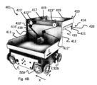
図4Aは、車輪基部ユニット2と、本体ユニット410とを備えている、本発明のある実施形態によるコンテナ取り扱い車両401の簡略側面図であり、本体ユニット410は、下側区分411と、支持区分412と、片持ち梁区分413とを備えている。下側区分411は、上側表面を有し、上側表面425は、保管コンテナ106を運搬するための第1のコンテナ運搬位置425を提供する。
FIG. 4A is a simplified side view of a
図3Bおよび4Aを参照すると、車輪基部ユニット2は、コンテナ取り扱い車両401の本体ユニット410への接続のための接続インターフェースとして構成された上部パネル/フランジ9(すなわち、上側表面)を有する。上部パネル9は、中心開口部20を有し、本体ユニット401の下側区分411内の対応する貫通孔を介したボルト接続のために好適な複数の貫通孔10(すなわち、接続要素)を特徴とする。他の実施形態では、上部パネル9の接続要素は、例えば、下側区分411の貫通孔との相互作用のためのねじ山付きピンであり得る。さらに別の実施形態では、コンテナ取り扱い車両401は、このモジュール式設計ではなく、むしろ、1つまたはいくつかの部品で作製される。中心開口部20の存在は、それが再充電可能バッテリ6および電子制御システム21等の車輪基部ユニット2の内部構成要素へのアクセスを提供するので、有利である。
Referring to FIGS. 3B and 4A, the
さらに図4Aを参照すると、本体ユニット410が、下側区分411、支持区分412、および片持ち梁区分413を一緒に連結するS字形状筐体を備えているものとして開示されている。図4Aのコンテナ取り扱い車両401は、図1A-1Dに関連して説明されるように、レールシステム108上で動作可能であり、車輪基部ユニット2と、本体ユニット410とを備えている。車輪基部ユニット2は、コンテナ取り扱い車両401をレールシステム108に沿って、第1および第2の方向X、Yに誘導するための車輪32a、32bの組を備えている。本体ユニット410は、下側区分411と、支持区分412と、片持ち梁区分413を備えている。下側区分411は、車輪基部ユニット2の上側表面上に搭載される。下側区分411は、グリッドセル122のうちの1つの水平範囲に等しいか、またはそれより小さい水平範囲を伴う占有領域を有し得る。保管コンテナ106の上部は、第1の高さh1にある。すなわち、第1の高さh1は、下側区分411が車輪基部ユニット2上に搭載されたときのレールシステム108の上部から、下側区分411の上側表面上の第1のコンテナ運搬位置上に位置付けられた保管コンテナ106の上部までの距離である。支持区分412は、下側区分411から垂直に延び、下側区分411の占有領域より小さい水平範囲を伴う占有領域を有する。支持区分412の幅(すなわち、X方向における拡張)は、(X方向における)下側区分411の幅に等しくあり得る。支持区分412のY方向における拡張は、下側区分411のY方向における拡張より小さい。
Still referring to FIG. 4A,
さらに、図4Cを参照すると、上方から平面図において見ると、支持区分412の占有領域は、下側区分411の専有面積の範囲内である。言い換えると、図4A-4Cに開示されるように、支持区分412は、下側区分411を越えて延びない。片持ち梁区分413は、支持区分412から、下側区分411の占有領域を越えて水平に延び、片持ち梁区分413から吊るされた持ち上げデバイス414を備えている。持ち上げデバイス414は、持ち上げフレーム415が片持ち梁区分413に隣接して上側位置にドッキングされていると、第2の高さh2における最下部分を有する持ち上げフレーム415を備えている(図4Aおよび4Bは、持ち上げフレーム415のドッキングされた位置を示す)。すなわち、第2の高さh2は、レールシステム108の上部から持ち上げフレーム415の最下部分までの距離である。持ち上げフレーム415は、持ち上げバンド419を介して片持ち梁区分413から吊るされている。持ち上げフレーム415は、持ち上げフレームを保管コンテナ106の相補的な持ち上げ孔に接続し、それによって、保管コンテナ106の持ち上げおよび降下を可能にするためのその下側表面から延びている把持デバイス420を備え得る。加えて、持ち上げフレーム415は、持ち上げフレーム415の下側表面のコーナーに配置され、保管コンテナ106上の相補的な持ち上げ孔に対して持ち上げフレーム415の把持デバイス420を整列させるガイド421を備え得る。多くの状況では、ガイド421または把持デバイス420は、第2の高さh2がこれらの構成要素のうちのいずれかの最下部分であるように、持ち上げフレーム415の最下部分を構成し得る。しかしながら、本発明のある実施形態によると、持ち上げフレーム415の最下部分の第2の高さh2は、持ち上げフレーム415がその上側位置内にドッキングされると、常時、第1のコンテナ運搬位置上に位置付けられた保管コンテナ106の第1の高さh1を上回る。
Further, referring to FIG. 4C, when viewed from above in plan view, the footprint of
第1および第2のコンテナ車両401が隣接グリッドセル122上ですれ違うとき、第1のコンテナ取り扱い車両401のドッキングされた持ち上げフレーム415の最下部分が第2のコンテナ取り扱い車両401の第1のコンテナ運搬位置上に支持された保管コンテナ106の上を通過できることを確実にすることによって、第1および第2のコンテナ取り扱い車両401は、従来技術の解決策において要求されるものより少ないグリッドセルを集合的に占有しながら、すれ違うことができる。
As the first and
図4Bは、本発明の実施形態によるコンテナ取り扱い車両401の斜視図であり、保護カバーは、コンテナ取り扱い車両401の本体ユニット410を構成する下側区分411、支持区分412、および片持ち梁区分413内の構成要素の設定をより明瞭に図示するために、除去されている。図4Bの実施形態では、持ち上げデバイス414は、持ち上げデバイスモータ416’と、少なくとも2つの持ち上げシャフト417’、417’’とを備えているものとして開示される。2つの持ち上げシャフト417’、417’’が、片持ち梁区分413内に並列に配置されている。持ち上げフレーム415に接続される持ち上げバンド419が、持ち上げシャフト417’、417’’上に巻き取とられ、それから送り出され、それによって、持ち上げフレーム416、および持ち上げフレーム415によって運搬される任意の保管コンテナ106を上下に移動させる。持ち上げシャフト車輪423’、423’’が、持ち上げシャフト417の各端部上に配置され、それぞれ、持ち上げシャフト417とともに動作する。図4Bに示されるように、持ち上げデバイスモータ416’が、下側区分411内に配置されている。持ち上げデバイスモータ416’および2つの持ち上げシャフト417は、持ち上げシャフト車輪423’、423’’と、例えば、滑車422を介して走行するベルト等のエンドレス可撓性力伝達要素418とを介して、互いに接続され、第1および第2の持ち上げシャフト417が同じ方向に同時に回転することを確実にする。持ち上げデバイスモータ416’に電力を供給するための任意の必要な電源(図示せず)が、重い保管コンテナ106を持ち上げる場合および/またはコンテナ取り扱い車両401の高すぎる加速度/減速度の結果としてのコンテナ取り扱い車両の傾斜の低減させられたリスクを伴って、好ましい重心を取得するために、下側区分413内に配置され得る。
FIG. 4B is a perspective view of a
持ち上げフレーム415は、持ち上げフレーム415の下側表面のコーナーに配置され、保管コンテナ106上の相補的な持ち上げ孔に対して持ち上げフレーム41の把持デバイス420を整列させるガイド421とともに示される。
Lifting
持ち上げデバイスモータ416’’に電力を供給するための任意の必要な電源(図示せず)が、重い保管コンテナ106を持ち上げる場合および/またはコンテナ取り扱い車両401の高すぎる加速度/減速度の結果としてのコンテナ取り扱い車両の傾斜の低減させられたリスクを伴って、好ましい重心を取得するために、下側区分413内に配置され得る。
Any necessary power supply (not shown) for powering the
図4Cは、下側区分411、支持区分412、および片持ち梁区分413を示す図4Bの上面図である。
4C is a top view of FIG. 4B showing
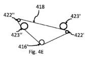
図4D-4Iは、持ち上げシャフト417’、417’’の反対回転を提供する、異なる設定の例である。図4D-4Iの例の全てにおいて開示されるように、回転可能な持ち上げデバイスモータ416’、それらの各々が回転のためにそれぞれの持ち上げシャフト417’、417’’に対して接続された第1および第2の持ち上げシャフト車輪423’、423’’、少なくとも1つの滑車422’、422’’、閉ループを形成するエンドレスベルトの形態にある力伝達要素418の存在、および滑車422’、422’’のうちの少なくとも一方が閉ループの内側に配置されていることが、力伝達設定の全てにおいて共通である。加えて、第1または第2の持ち上げシャフト車輪423’、423’’は、エンドレスベルト418の内側表面と接触し、第1または第2の持ち上げシャフト車輪423’、423’’の他方は、エンドレスベルト418の外側表面と接触する。これは、第1または第2の持ち上げシャフト車輪423’、423’’のうちの一方を力伝達要素418によって形成される閉ループの内側に、および第1または第2の持ち上げシャフト車輪423’、423’’のうちの他方を力伝達要素418によって形成される閉ループの外側に配置することによって、達成される。第1および第2の持ち上げシャフト車輪423’、423’’(例えば、エンドレスベルトの両側で動作する)、ガイド滑車422’、422’’、および力伝達要素418の相互設定は、第1および第2の持ち上げシャフト417’、417’’が、反対方向に回転(反転)する(それぞれ、第1および第2の持ち上げシャフト車輪423’、423’’を介して)ようなものである。第1および第2の持ち上げシャフト車輪423’、423’’は、好ましくは、持ち上げ中の水平安定性を確実にするために、同じ水平面内に配置されている。滑車422’、422’’は、力伝達要素418の進行方向に「変化」を提供するように、固定位置における力伝達要素418の進行に沿って配置されている。滑車422’、422’’の各々は、力伝達要素418を正確に第1および第2の持ち上げシャフト車輪423’、423’’上に導き、それによって、第1および第2の持ち上げシャフト車輪423’、423’’(したがって、持ち上げシャフト417’、417’’)が反対方向に回転することを可能にするように配置されている。
Figures 4D-4I are examples of different settings that provide opposite rotation of the lifting shafts 417', 417''. As disclosed in all of the examples of FIGS. 4D-4I, a first rotatable
図4Dの例では、1つの滑車422’が、示される。 In the example of FIG. 4D, one pulley 422' is shown.
図4E-4Iの例では、2つの滑車422’、422’’を備えている力伝達設定のいくつかの例が、示される。力伝達要素418の進行の両方向において、第1の持ち上げシャフト車輪423’の後に滑車422’、422’’が続き、第2の持ち上げシャフト車輪423’’の後に滑車422’、422’’が続くように、滑車422’、422’’は、力伝達要素418の経路に沿って交互に配置されている。
In the examples of FIGS. 4E-4I, some examples of force transmission setups comprising two pulleys 422', 422'' are shown. The first lifting shaft wheel 423' is followed by pulleys 422', 422'' and the second lifting shaft wheel 423'' is followed by pulleys 422', 422'' in both directions of travel of the
図4G、4H、4Iの例では、力伝達要素418の緊張のための緊張車輪424を含む例が、開示される。緊張車輪424は、例えば、偏心性の緊張機構であり得、偏心性の緊張機構は、固定されたブラケット内の開口部内で調節され得る軸を伴う回転可能な滑車を備えている。力伝達要素418の経路に沿った緊張車輪424の場所は、好ましくは、力伝達要素418の経路長が影響を及ぼされ得る場所にある(すなわち、力伝達要素の経路が力伝達要素内の張力をさらに緊張するために、または低減させるために短縮または延長され得る場所にある)。緊張車輪424は、力伝達要素418によって形成される閉ループの内側(図4Gおよび4I)または外側(図4H)に配置されることができる。
In the examples of FIGS. 4G, 4H, 4I, examples are disclosed that include a
図4D-4Fの例では、緊張車輪等の専用の緊張機構が、示されていないが、しかしながら、緊張機構が要求される場合、滑車422’または422’’のうちの一方が、緊張機構であり得、緊張車輪424によって置換されることができる。
In the example of FIGS. 4D-4F, a dedicated tensioning mechanism, such as a tensioning wheel, is not shown; however, if a tensioning mechanism is desired, one of the pulleys 422' or 422'' may be the tensioning mechanism. It is possible and can be replaced by a
図5は、持ち上げシャフト417、および持ち上げシャフト417’、417’’上に巻き取り可能、かつそれから送り出し可能な持ち上げバンドに加えて、持ち上げデバイスモータ416’’も、本体ユニット410の片持ち梁区分413内に配置された持ち上げデバイス414の別の設定のある例である。図5の持ち上げデバイスモータ416’’は、持ち上げシャフト417’、417’’のうちの一方を取り囲むブレラシレスDCモータである。持ち上げシャフト417’、417’’の同期的動作は、第WO2019/137870 A1号(出願人:Autostore Technology AS)(その内容は、参照することによって本明細書に組み込まれる)の図5A-5Eおよび6A-6Hに開示されるような、力伝達要素等の同期化要素によって取得されることができる。
FIG. 5 shows that in addition to the lifting
図6は、本発明のある実施形態によるコンテナ取り扱い車両401の簡略側面図であり、コンテナ取り扱い車両401は、第1のコンテナ運搬位置425上に1つの保管コンテナ106を支持し、持ち上げデバイス415によって1つの保管コンテナ106を支持し、コンテナ取り扱い車両401は、車輪基部ユニット2と、本体ユニットとを備え、本体ユニットは、下側区分411と、支持区分412と、片持ち梁区分413とを備えている。図6のコンテナ取り扱い車両の構成要素は、図4Aのコンテナ取り扱い車両に類似する。第1のコンテナ運搬位置425は、好ましくは、第1のコンテナ運搬位置425上に位置付けられた保管コンテナ425のための横方向支持を提供するための窪みを作られている。
FIG. 6 is a simplified side view of a
図7A-7Dは、2次元レールシステム108を備えている自動保管および回収システム1上で動作する第1および第2のコンテナ取り扱い車両401間で保管コンテナ106を移送する、例示的方法をステップ毎に示す。図7Aを参照すると、第1のコンテナ取り扱い車両401(すなわち、保管コンテナ106を運搬していない図の右側の車両)が、第2のコンテナ取り扱い車両401(すなわち、持ち上げデバイス内で保管コンテナ106を運搬し、第1のコンテナ運搬位置425上で保管コンテナ106を運搬する図の左側の車両)から距離を置いて位置付けられる。第1のコンテナ取り扱い車両401および第2のコンテナ取り扱い車両4011は、レールシステム108上の近隣する行内で動作する。
7A-7D show step by step an exemplary method of transferring
図7Bでは、第1および第2のコンテナ取り扱い車両401は、図7Aの状況と比較すると、互いにより近接して移動しており、第1のコンテナ取り扱い車両401の持ち上げデバイス414は、第2のコンテナ取り扱い車両401の下側区分411の上側表面/第1のコンテナ運搬位置425のほぼ上方にある。
In Figure 7B, the first and second
図7Cでは、第1および第2のコンテナ取り扱い車両401は、第1のコンテナ取り扱い車両401の持ち上げデバイス414が第2のコンテナ取り扱い車両401の下側区分411の上側表面/第1のコンテナ運搬位置425の真上に来るように、それら自体を近隣したグリッドセル122内に位置付けている。
In FIG. 7C, the first and second
図7Dでは、第1のコンテナ取り扱い車両401の持ち上げデバイス414が、第2のコンテナ取り扱い車両401上の第1のコンテナ運搬位置425上に位置付けられた保管コンテナ106を持ち上げるために降下させられ、第1のコンテナ運搬位置425から保管コンテナ106を持ち上げている。保管コンテナ106の移送は、ここで完了する。
In FIG. 7D, the
図7A-7Dを参照すると、保管コンテナを移送する方法は、
-メイン制御システムを利用して、第1および第2のコンテナ取り扱い車両401に、第1のコンテナ取り扱い車両401の持ち上げデバイス414が第2のコンテナ取り扱い車両401の下側区分411の上側表面の真上に来るように、それら自体を近隣したグリッドセル122内に位置付けるように命令するステップと、
-保管コンテナ106を第2のコンテナ取り扱い車両401の下側区分411の第1のコンテナ運搬位置425と第1のコンテナ取り扱い車両401の持ち上げデバイス414との間で移送するステップと、
を含み得る。保管コンテナ106を第2のコンテナ取り扱い車両401の下側区分411の上側表面と第1のコンテナ取り扱い車両401の持ち上げデバイス414との間で移送するステップは、
-保管コンテナ106を運搬または支持するコンテナ取り扱い車両401をマスタ車両として設定するステップと、
-他のコンテナ取り扱い車両401をスレーブ車両として設定するステップと、
-スレーブ車両にget_binコマンドを送信するステップと
を含み得、
-スレーブ車両は、get_binコマンドを実施し、保管コンテナ106が車両401上に位置付けられたことが確認されると、その内部ステータスを更新し、
-保管コンテナ106がマスタ車両の第1のコンテナ運搬位置425から十分に離れるように、車両上に位置付けられていることが確認されると、スレーブ車両が、制御システムに確認を送信し、
-マスタ車両は、保管コンテナ106が去ったことを検出し、マスタ車両は、制御システム500にbin_updateステータスを送信し、
-制御システム500が、論理状態をマスタ車両およびスレーブ車両の物理状態と合致するように更新する。
Referring to Figures 7A-7D, a method of transporting a storage container comprises:
- Utilizing the main control system to instruct the first and second
- transferring the
can include Transferring the
- setting the
- setting other
- sending a get_bin command to the slave vehicle;
- the slave vehicle performs the get_bin command and updates its internal status once it is verified that the
- Upon confirmation that the
- the master vehicle detects that the
- The
get_binコマンドは、移送されるべき保管コンテナ106の高さを定義するパラメータを含み得、それによって、マスタ車両の持ち上げデバイス414は、第1のコンテナ運搬位置上に位置付けられた保管コンテナの最上部分に等しい位置まで降下させられる。
The get_bin command may include a parameter defining the height of the
他のコンテナ取り扱い車両401をスレーブ車両として設定するステップは、スレーブ車両がマスタ車両と移動し、それに追随するように、スレーブ車両にsynchronize_to_masterコマンドを送信するステップを含み得る。これは、運転中、第2のコンテナ取り扱い車両401の下側区分411の上側表面と第1のコンテナ取り扱い車両401の持ち上げデバイス414との間での保管コンテナ106の移送を可能にする。スレーブ車両は、随意に、同期化が取得されると、メイン制御システムにメッセージを送信し得る。代替として、メイン制御システムは、スレーブ車両およびマスタ車両の位置情報に基づいて、同期化が取得されていることを決定し得る。同期化は、スレーブ車両がマスタ車両と移動し、それに追随するときに取得されている。
Setting the other
マスタ車両は、スレーブ車両に、速度、加速度、および位置データ等の移動データを送信し得る。スレーブ車両は、移動データを使用し、それ自体の移動を受信された移動データに同期させ得る。マスタ車両は、メイン制御システムを介して移動データを送信し得る。マスタ車両は、代替として、または加えて、マスタ車両とスレーブ車両との間のローカル通信を使用して、スレーブ車両に移動データを直接送信し得る。ローカル通信は、近距離無線通信(NFC)または赤外線(IR)等、ローカル無線通信の任意の手段であり得る。 A master vehicle may transmit movement data, such as speed, acceleration, and position data, to slave vehicles. Slave vehicles may use the travel data to synchronize their own travel with the received travel data. A master vehicle may transmit movement data via the main control system. The master vehicle may alternatively or additionally transmit movement data directly to the slave vehicles using local communication between the master and slave vehicles. Local communication can be any means of local wireless communication, such as near field communication (NFC) or infrared (IR).
スレーブ車両およびマスタ車両の同期させられた移動は、スレーブ車両がマスタ車両の背後に追随する電車様同期化を含み得るか、または、同期させられた移動は、スレーブ車両がマスタ車両とともに横並びに移動する並行同期化を含み得る。 Synchronized movement of the slave and master vehicles may include train-like synchronization, in which the slave vehicle follows the master vehicle behind, or synchronized movement may involve the slave vehicle moving side-by-side with the master vehicle. may include concurrent synchronization.
自動保管および回収システムは、マスタ車両およびスレーブ車両の両方の位置を決定するための飛行時間(TOF)測定システム等のマルチラテレーション技法を使用する位置決めシステムを備え得る。メイン制御システムは、位置決めシステムから、第1のコンテナ取り扱い車両の位置の位置データおよび第2のコンテナ取り扱い車両の位置の位置データを連続して受信する。メイン制御システムは、位置データを使用し、スレーブ車両に、マスタ車両から所定の間隔でマスタ車両と移動し、それに追随するように命令し得る。マスタ車両およびスレーブ車両の移動は、それによって、同期させられ、第2のコンテナ取り扱い車両401の下側区分411の上側表面と第1のコンテナ取り扱い車両401の持ち上げデバイス414との間で保管コンテナ106を移送するステップが、運転中に実施され得る。
Automated storage and retrieval systems may include positioning systems that use multilateration techniques such as time-of-flight (TOF) measurement systems to determine the position of both master and slave vehicles. The main control system continuously receives position data for the position of the first container handling vehicle and position data for the position of the second container handling vehicle from the positioning system. The main control system may use the position data to command the slave vehicle to move with and follow the master vehicle at a predetermined distance from the master vehicle. Movement of the master and slave vehicles is thereby synchronized and the
コンテナ取り扱い車両は、レールシステム上のコンテナ取り扱い車両の位置を検出し得るセンサおよび/または近くのコンテナ取り扱い車両までの距離を検出する、近接センサを伴って配置され得る。メイン制御システムは、スレーブ車両の近接センサから受信された距離データに基づいて、マスタ車両からの所定の間隔内のマスタ車両と移動し、それに追随するようにスレーブ車両に命令し得る。マスタ車両およびスレーブ車両の移動は、それによって、同期させられ、第2のコンテナ取り扱い車両401の下側区分411の上側表面と第1のコンテナ取り扱い車両401の持ち上げデバイス414との間で保管コンテナ106を移送するステップが、運転中に実施され得る。
Container handling vehicles may be deployed with sensors that may detect the position of the container handling vehicle on the rail system and/or proximity sensors that detect the distance to nearby container handling vehicles. The main control system may command the slave vehicle to move with and follow the master vehicle within a predetermined distance from the master vehicle based on the distance data received from the slave vehicle's proximity sensor. Movement of the master and slave vehicles is thereby synchronized and the
コンテナ取り扱い車両は、互いに物理的に接触して一緒に移動するように適合され得る。メイン制御システムは、最初にマスタ車両に物理的に接触するように移動し、接触の後、マスタ車両上に押し付け力を加え続け、物理的接触を維持することによって、マスタ車両と移動し、それに追随するようにスレーブ車両に命令し得る。マスタ車両およびスレーブ車両の移動は、それによって、同期させられ、第2のコンテナ取り扱い車両401の下側区分411の上側表面と第1のコンテナ取り扱い車両401の持ち上げデバイス414との間で保管コンテナ106を移送するステップが、運転中に実施され得る。
Container handling vehicles may be adapted to move together in physical contact with each other. The main control system first moves into physical contact with the master vehicle, after contact continues to exert a pushing force on the master vehicle, maintains physical contact, moves with the master vehicle, and moves with it. A slave vehicle may be commanded to follow. Movement of the master and slave vehicles is thereby synchronized and the
図8A-8Dは、第1のコンテナ運搬位置425上のコンベヤ427を伴う本発明のある実施形態によるコンテナ取り扱い車両401の例を示し、コンベヤ427は、コンテナ取り扱い車両401の短辺のうちのいずれかを通して、保管コンテナ106を別のコンテナ取り扱い車両上または外部コンベヤに後方に移送するように適合される。コンベヤ427はまた、保管コンテナ106が別のコンテナ取り扱い車両上または外部コンベヤに後方に直接移送され得るように、図8Aの実施形態に対して90度に向けられ得る(図8D参照)。図8Aは、第1のコンテナ運搬位置425上に保管コンテナを運搬していないときの状況を示し、図8Bは、第1のコンテナ運搬位置425上に保管コンテナ106を伴う状況を示し、図8Cは、第1のコンテナ運搬位置425上のコンベヤ427から外部コンベヤ428までの保管コンテナ106の可能な移送を示す。外部コンベヤ428の上側表面は、好ましくは、第1のコンテナキャリア位置425上のコンベヤ427の上側表面と実質的に同じ高さに配置されている。
8A-8D show an example of a
図7A、7B、および8Aを参照すると、下側区分411は、支持ウェブ429の対に対して窪みにされた上側表面425を有し、上側表面425は、保管コンテナ106を運搬するための第1のコンテナ運搬位置425を提供する。支持区分412は、下側区分411の支持ウェブ429の対から垂直に延び、支持区分412は、下側区分411の占有領域より小さい水平範囲を伴う占有領域を有する。
7A, 7B, and 8A, the
図9は、第1のコンテナ運搬位置425を提供する上側表面425と、第2のコンテナ運搬位置426を提供する支持表面426とを備えている本発明のある実施形態によるコンテナ取り扱い車両401のある例を示す。図9のコンテナ取り扱い車両401は、図4Aおよび6のコンテナ取り扱い車両に類似する構成要素を備え、これは、本明細書では繰り返されないであろう。しかしながら、図9のコンテナ取り扱い車両401は、加えて、第2のコンテナ運搬位置426を備えている。第2のコンテナ運搬位置426は、第1のコンテナ運搬位置425の上方に配置されるものとして開示される。好ましくは、第1および第2のコンテナ運搬位置425、426は、下にあるレールシステム108上に同じ垂直投影を形成する。
FIG. 9 illustrates a
図10Aは、旋回接続430を介して後退位置にある図9の第2のコンテナ運搬位置を示し、後退位置において、第2のコンテナキャリア位置426は、上向きに方向づけられている。矢印Aは、(図9の)水平拡張位置から図10Aの垂直後退位置までの移動の方向を示す。旋回接続430は、第2のコンテナキャリア426の回転軸を示す。
FIG. 10A shows the second container-carrying position of FIG. 9 in the retracted position via
図10Bは、第2のコンテナキャリア位置426の可能な拡張位置の別の例を示す。図10Bでは、第2のコンテナキャリア位置426は、それが保管コンテナ(図示せず)を受け取り可能な拡張された水平位置内にある。
FIG. 10B shows another example of a possible extended position for the second
図10Cは、図10Bの例を示し、第2のコンテナキャリア位置426は、後退位置にあるとき、180度旋回させられ、コンテナ取り扱い車両401の片持ち梁区分413上で上下逆に置かれる。第2のコンテナ運搬位置426は、矢印Aを用いて示されるように、後退位置から、旋回接続配置430まわりに拡張位置まで旋回させられている。
FIG. 10C shows the example of FIG. 10B where the second
図11Aおよび11Bは、第2のコンテナキャリア位置426のさらに別の例を示し、図11Aでは、第2のコンテナキャリア位置426は、第1のコンテナ運搬位置425の真上の拡張位置にあり、図11Bでは、第2のコンテナ運搬位置は、線形移動配置(図示せず)を用いて(矢印Aを用いて示されるように)線形に、後退位置まで移動させられている。
11A and 11B show yet another example of a second
したがって、図10A、10B、10C、および11Aおよび11Bを参照すると、第1のコンテナ運搬位置425上に位置付けられた保管コンテナ106へのアクセスを取得するために、第2のコンテナ運搬位置426は、好ましくは、
-第2のコンテナ運搬位置426が、第1のコンテナ運搬位置425の垂直投影を越え、第1のコンテナ運搬位置425の上側表面および/または第1のコンテナ運搬位置425上に位置付けられた保管コンテナ106へのアクセスを提供する後退位置と、
-第2のコンテナ運搬位置426が第1のコンテナ運搬位置425の垂直投影の範囲内にある拡張位置と、
の間で移動可能である。第2のコンテナ運搬位置426は、旋回接続配置430(図10A-10C)、または、それが線形移動配置を介して後退位置と拡張位置との間で線形に移動可能である線形移動配置(図11Aおよび11B)を介して、後退位置と拡張位置との間で移動可能であることができる。
Accordingly, referring to FIGS. 10A, 10B, 10C, and 11A and 11B, to gain access to the
- a storage container in which the second container-transporting
- an extended position in which the second
can be moved between The second container-carrying
旋回接続を使用する場合(図10A-10C参照)、旋回接続430は、
-後退位置において、第2のコンテナ運搬位置426が、実質的に垂直であり、
-拡張位置において、第2のコンテナキャリア位置426が実質的に水平に延びている
ように、配置されることができる。
When using a pivot connection (see FIGS. 10A-10C), the
- in the retracted position the second
- can be arranged such that in the extended position the second
線形移動配置を使用する場合(図11Aおよび11B参照)、線形移動配置は、
-後退位置において、第2のコンテナ運搬位置426が、第1のコンテナ運搬位置425を越え、片持ち梁区分413の上方の位置まで移動させられ、
-拡張位置において、第2のコンテナ運搬位置426が、第1のコンテナ運搬位置425の上方にある
ように配置されることができる。
When using a linear displacement arrangement (see FIGS. 11A and 11B), the linear displacement arrangement is
- in the retracted position, the second container-carrying
- in the extended position, the second container-carrying
前述の説明では、本発明による、自動保管および回収システムの種々の側面が、例証的実施形態を参照して説明されている。しかしながら、本説明は、限定的意味で解釈されることを意図していない。当業者に明白である、例証的実施形態の種々の修正および変形例、およびシステムの他の実施形態が、以下の請求項によって定義されるような、本発明の範囲内に存在すると見なされる。 In the foregoing description, various aspects of automated storage and retrieval systems according to the present invention are described with reference to illustrative embodiments. However, this description is not intended to be interpreted in a limiting sense. Various modifications and variations of the illustrative embodiments, and other embodiments of the system, which are apparent to those skilled in the art are deemed to lie within the scope of the invention as defined by the following claims.


Claims (23)
フレーム構造(100)の上部を横断して第1の方向(X)にコンテナ取り扱い車両(401)の移動を誘導するように配置された平行レールの第1の組(110)と、
前記第1の方向に対して直角である第2の方向(Y)に前記コンテナ取り扱い車両(401)の移動を誘導するための前記レールの第1の組(110)に対して直角に配置された平行レールの第2の組(111)と
を備え、前記平行レールの第1および第2の組(110、111)は、レールシステム(108)を複数のグリッドセル(122)に分割し、
前記コンテナ取り扱い車両(401)は、
-車輪の第1および第2の組(32a、32b)を備えている車輪基部ユニット(2)であって、前記車輪の第1および第2の組(32a、32b)は、それぞれ、前記第1および第2の方向(X、Y)に前記レールシステム(108)に沿って前記コンテナ取り扱い車両(401)を誘導し、前記車輪の第1および第2の組(32a、32b)は、前記車輪基部ユニット(2)の外周を形成する、車輪基部ユニット(2)と、
-本体ユニット(410)であって、前記本体ユニット(410)は、
前記車輪基部ユニット(2)上に提供された下側区分(411)であって、前記下側区分(411)は、前記車輪基部ユニット(2)に等しい、またはそれより小さい水平範囲を伴う占有領域を有し、前記下側区分(411)は、上側表面を有し、前記上側表面(425)は、保管コンテナ(106)を運搬するための第1のコンテナ運搬位置(425)を提供する、下側区分(411)と、
前記下側区分(411)から垂直に延びている支持区分(412)であって、前記支持区分(412)は、前記下側区分(411)の前記占有領域より小さい水平範囲を伴う占有領域を有する、支持区分(412)と、
前記下側区分(411)の前記占有領域を越えて前記支持区分(412)から水平に延びている片持ち梁区分(413)と
を備えている、本体ユニット(410)と、
-前記片持ち梁区分(413)から吊るされた持ち上げフレーム(415)を備えている持ち上げデバイス(414)と
を備えている、コンテナ取り扱い車両(401)。 A container handling vehicle (401) for operation on a two-dimensional rail system (108), said two-dimensional rail system (108) comprising:
a first set of parallel rails (110) arranged to guide movement of the container handling vehicle (401) in a first direction (X) across the top of the frame structure (100);
positioned perpendicular to said first set of rails (110) for guiding movement of said container handling vehicle (401) in a second direction (Y) perpendicular to said first direction; a second set (111) of parallel rails, said first and second sets (110, 111) of parallel rails dividing the rail system (108) into a plurality of grid cells (122);
The container handling vehicle (401)
- a wheel base unit (2) comprising a first and second set of wheels (32a, 32b), said first and second set of wheels (32a, 32b) respectively Guiding said container handling vehicle (401) along said rail system (108) in first and second directions (X, Y), said first and second sets of wheels (32a, 32b) are adapted to: a wheel base unit (2) forming the perimeter of the wheel base unit (2);
- a body unit (410), said body unit (410) comprising:
A lower section (411) provided on said wheel base unit (2), said lower section (411) occupying with a horizontal extent equal to or less than said wheel base unit (2). Having an area, said lower section (411) has an upper surface and said upper surface (425) provides a first container carrying position (425) for carrying a storage container (106). , the lower section (411), and
a support section (412) extending vertically from said lower section (411), said support section (412) having an occupation area with a horizontal extent less than said occupation area of said lower section (411); a support segment (412);
a cantilever section (413) extending horizontally from the support section (412) beyond the footprint of the lower section (411);
- A container handling vehicle (401) comprising: a lifting device (414) comprising a lifting frame (415) suspended from said cantilever section (413).
前記持ち上げデバイス(414)は、前記片持ち梁区分(413)から吊るされた持ち上げフレーム(415)を備え、前記持ち上げフレーム(415)は、前記持ち上げフレーム(415)が前記片持ち梁区分(413)に隣接した上側位置にドッキングされていると、第2の高さ(h2)における最下部分を有し、
前記持ち上げフレーム(415)がその上側位置内にドッキングされているとき、前記第2の高さ(h2)は、前記第1の高さ(h1)を上回り、第1のコンテナ取り扱い車両(401)のドッキングされた持ち上げフレーム(415)の前記最下部分は、前記第1のコンテナ車両(401)と第2のコンテナ車両(401)とが隣接したグリッドセル(122)上ですれ違うとき、第2のコンテナ取り扱い車両(401)の前記本体ユニット(410)の下側区分(411)の上側表面上に位置付けられた保管コンテナ(106)の前記最上部分の上を通過できる、請求項1に記載のコンテナ取り扱い車両(401)。 a top portion of the storage container (106) presents a first height (h1) when the storage container (106) is positioned on the upper surface;
Said lifting device (414) comprises a lifting frame (415) suspended from said cantilever section (413), said lifting frame (415) connecting said lifting frame (415) to said cantilever section (413). ) has a lowest portion at a second height (h2) when docked in an upper position adjacent to
When said lifting frame (415) is docked in its upper position, said second height (h2) exceeds said first height (h1) and the first container handling vehicle (401) The bottom portion of the docked lifting frame (415) of the second container vehicle (401) passes the second container vehicle (401) on adjacent grid cells (122). 2. A container handling vehicle (401) according to claim 1, wherein the container handling vehicle (401) of the container handling vehicle (401) of the Container handling vehicle (401).
-前記第2のコンテナ運搬位置(426)が前記第1のコンテナ運搬位置(425)の垂直投影を越えている後退位置と、
-前記第2のコンテナ運搬位置(426)が前記第1のコンテナ運搬位置(425)の垂直投影の範囲内にある拡張位置と
の間で移動可能である、請求項10または請求項11に記載のコンテナ取り扱い車両(401)。 The second container-carrying position (426) comprises:
- a retracted position in which said second container-carrying position (426) is beyond the vertical projection of said first container-carrying position (425);
- the second container-carrying position (426) is movable between an extended position within the vertical projection of the first container-carrying position (425); container handling vehicle (401).
フレーム構造(100)の上部を横断して第1の方向(X)にコンテナ取り扱い車両(401)の移動を誘導するように配置された平行レールの第1の組(110)と、
前記第1の方向に対して直角である第2の方向(Y)に前記コンテナ取り扱い車両(401)の移動を誘導するための前記レールの第1の組(110)に対して直角に配置された平行レールの第2の組(111)と
を備え、
前記平行レールの第1および第2の組(110、111)は、レールシステム(108)を複数のグリッドセル(122)に分割し、前記自動保管および回収システム(1)は、請求項1-14のいずれかに記載の複数のコンテナ取り扱い車両(401)を備えている、自動保管および回収システム(1)。 An automated storage and retrieval system (1) comprising a two-dimensional rail system (108), said two-dimensional rail system (108) comprising:
a first set of parallel rails (110) arranged to guide movement of the container handling vehicle (401) in a first direction (X) across the top of the frame structure (100);
positioned perpendicular to said first set of rails (110) for guiding movement of said container handling vehicle (401) in a second direction (Y) perpendicular to said first direction; and a second set of parallel rails (111);
Said first and second sets (110, 111) of parallel rails divide the rail system (108) into a plurality of grid cells (122), said automated storage and retrieval system (1) comprising: 15. An automated storage and collection system (1) comprising a plurality of container handling vehicles (401) according to any one of 14.
前記2次元レールシステム(108)は、
フレーム構造(100)の上部を横断して第1の方向(X)にコンテナ取り扱い車両(401)の移動を誘導するように配置された平行レールの第1の組(110)と、
前記第1の方向に対して直角である第2の方向(Y)に前記コンテナ取り扱い車両(401)の移動を誘導するための前記レールの第1の組(110)に対して直角に配置された平行レールの第2の組(111)と
を備え、
前記平行レールの第1および第2の組(110、111)は、前記レールシステム(108)を複数のグリッドセル(122)に分割し、
前記方法は、
-メイン制御システムを利用して、前記第1のコンテナ取り扱い車両(401)の前記持ち上げデバイス(414)が前記第2のコンテナ取り扱い車両(401)の前記下側区分(411)の前記上側表面の真上にあるように、それら自身を近隣したグリッドセル(122)内に位置付けるように前記第1および第2のコンテナ取り扱い車両(401)に命令するステップと、
-前記第2のコンテナ取り扱い車両(401)の前記下側区分(411)の前記第1のコンテナ運搬位置と前記第1のコンテナ取り扱い車両(401)の前記持ち上げデバイス(414)との間で保管コンテナ(106)を移送するステップと
を含む、方法。 Storage containers (106) between first and second container handling vehicles (401) according to any of claims 1-14 operating on an automated storage and retrieval system comprising a two-dimensional rail system (108). A method of transporting a
The two-dimensional rail system (108) comprises:
a first set of parallel rails (110) arranged to guide movement of the container handling vehicle (401) in a first direction (X) across the top of the frame structure (100);
positioned perpendicular to said first set of rails (110) for guiding movement of said container handling vehicle (401) in a second direction (Y) perpendicular to said first direction; and a second set of parallel rails (111);
said first and second sets (110, 111) of parallel rails divide said rail system (108) into a plurality of grid cells (122);
The method includes:
- using a main control system, said lifting device (414) of said first container handling vehicle (401) is positioned on said upper surface of said lower section (411) of said second container handling vehicle (401); directing said first and second container handling vehicles (401) to position themselves in adjacent grid cells (122) such that they are directly above;
- storage between said first container transport position of said lower section (411) of said second container handling vehicle (401) and said lifting device (414) of said first container handling vehicle (401); A method, comprising: transferring a container (106).
-前記保管コンテナ(106)を運搬または支持する前記コンテナ取り扱い車両(401)をマスタ車両として設定するステップと、
-他のコンテナ取り扱い車両をスレーブ車両として設定するステップと、
-前記スレーブ車両にget_binコマンドを送信するステップと
を含み、
-前記スレーブ車両は、前記get_binコマンドを実施し、前記保管コンテナが車両上に位置付けられたことが確認されると、その内部ステータスを更新し、
-前記スレーブ車両は、前記保管コンテナが前記マスタ車両の第1のコンテナ運搬位置から十分に離れているように、車両上に位置付けられていることが確認されると、前記制御システムに確認を送信し、
-前記マスタ車両は、前記保管コンテナが去ったことを検出し、前記マスタ車両は、前記制御システムにbin_updateステータスを送信し、
-前記制御システムは、前記マスタ車両および前記スレーブ車両の物理状態と合致するように論理状態を更新する、請求項18に記載の方法。 said storage container (106) between said upper surface of said lower section (411) of said second container handling vehicle (401) and said lifting device (414) of said first container handling vehicle (401); the step of transferring
- setting said container handling vehicle (401) carrying or supporting said storage container (106) as a master vehicle;
- setting other container handling vehicles as slave vehicles;
- sending a get_bin command to said slave vehicle,
- the slave vehicle performs the get_bin command and updates its internal status once it is verified that the storage container has been positioned on the vehicle;
- The slave vehicle sends a confirmation to the control system once it is verified that the storage container is positioned on the vehicle sufficiently away from the first container transport position of the master vehicle. death,
- the master vehicle detects that the storage container has left, the master vehicle sends a bin_update status to the control system;
19. A method according to claim 18, wherein - said control system updates logical states to match the physical states of said master and slave vehicles.
フレーム構造(100)の上部を横断して第1の方向(X)にコンテナ取り扱い車両(401)の移動を誘導するように配置された平行レールの第1の組(110)と、
前記第1の方向に対して直角である第2の方向(Y)に前記コンテナ取り扱い車両(401)の移動を誘導するための前記レールの第1の組(110)に対して直角に配置された平行レールの第2の組(111)と
を備え、前記平行レールの第1および第2の組(110、111)は、前記レールシステム(108)を複数のグリッドセル(122)に分割し
前記方法は、
-前記下側区分(411)の前記第1のコンテナ運搬位置上のコンベヤを利用し、保管コンテナ(106)を前記コンテナ取り扱い車両(401)と前記コンテナ取り扱い車両(401)の外側の外部位置との間で移送するステップ
を含む、方法。 A method of transferring storage containers between a container handling vehicle (401) according to any of claims 1-14 and an external container transport location, said container handling vehicle operating on an automated storage and recovery system. and said automated storage and retrieval system comprises a two-dimensional rail system (108), said two-dimensional rail system (108) comprising:
a first set of parallel rails (110) arranged to guide movement of the container handling vehicle (401) in a first direction (X) across the top of the frame structure (100);
positioned perpendicular to said first set of rails (110) for guiding movement of said container handling vehicle (401) in a second direction (Y) perpendicular to said first direction; and a second set (111) of parallel rails, said first and second sets (110, 111) of parallel rails dividing said rail system (108) into a plurality of grid cells (122). The method includes:
- using a conveyor on said first container transport position of said lower section (411) to transport storage containers (106) between said container handling vehicle (401) and an external position outside said container handling vehicle (401); A method comprising the step of transferring between
Applications Claiming Priority (7)
| Application Number | Priority Date | Filing Date | Title |
|---|---|---|---|
| NO20200467 | 2020-04-16 | ||
| NO20200467A NO20200467A1 (en) | 2020-04-16 | 2020-04-16 | Container handling vehicle with cantilever construction and automated storage and retrieval system comprising a plurality of the container handling vehicles |
| NO20200612 | 2020-05-25 | ||
| NO20200612A NO346266B1 (en) | 2020-05-25 | 2020-05-25 | Container handling vehicle for lifting a storage container and method of receiving a target storage container from a storage system |
| NO20200672 | 2020-06-05 | ||
| NO20200672A NO346363B1 (en) | 2020-04-16 | 2020-06-05 | Container handling vehicle comprising a container carrying position, associated system and methods |
| PCT/EP2021/059309 WO2021209337A1 (en) | 2020-04-16 | 2021-04-09 | Container handling vehicle comprising a container carrying position, associated system and methods |
Publications (2)
| Publication Number | Publication Date |
|---|---|
| JP2023523547A true JP2023523547A (en) | 2023-06-06 |
| JPWO2021209337A5 JPWO2021209337A5 (en) | 2024-04-09 |
Family
ID=75441936
Family Applications (1)
| Application Number | Title | Priority Date | Filing Date |
|---|---|---|---|
| JP2022562473A Pending JP2023523547A (en) | 2020-04-16 | 2021-04-09 | CONTAINER HANDLING VEHICLES WITH CONTAINER HANDLING POSITIONS AND RELATED SYSTEMS AND METHODS |
Country Status (7)
| Country | Link |
|---|---|
| US (1) | US20230142253A1 (en) |
| EP (1) | EP4136041A1 (en) |
| JP (1) | JP2023523547A (en) |
| KR (1) | KR20230002392A (en) |
| CN (1) | CN115427326A (en) |
| CA (1) | CA3172491A1 (en) |
| WO (1) | WO2021209337A1 (en) |
Families Citing this family (1)
| Publication number | Priority date | Publication date | Assignee | Title |
|---|---|---|---|---|
| NO20220739A1 (en) * | 2022-06-29 | 2024-01-01 | Autostore Tech As | Container handling vehicle with motor at lower elevation than first and second lifting shafts, a system comprising the container handling vehicle, and method of driving the first and second lifting shafts |
Family Cites Families (8)
| Publication number | Priority date | Publication date | Assignee | Title |
|---|---|---|---|---|
| FI126245B (en) * | 2005-03-09 | 2016-08-31 | Konecranes Finland Oy | Procedure for placing a palletless goods package on a warehouse shelf and handing it over therefrom and administering the package logistics and equipment for carrying out the procedure |
| NO334806B1 (en) | 2012-11-13 | 2014-06-02 | Jakob Hatteland Logistics As | storage System |
| NO335839B1 (en) | 2012-12-10 | 2015-03-02 | Jakob Hatteland Logistics As | Robot for transporting storage containers |
| NO337544B1 (en) | 2014-06-19 | 2016-05-02 | Jakob Hatteland Logistics As | Remote controlled vehicle assembly to pick up storage containers from a storage system |
| NO20170216A1 (en) | 2017-02-13 | 2018-08-14 | Autostore Tech As | Rail arrangement for wheeled vehicles in a storage system |
| NO347820B1 (en) | 2018-01-09 | 2024-04-08 | Autostore Tech As | Automated storage and retrieval system, a container handling vehicle which can operate on an automated storage and retrieval system and a method of operating an automated storage and retrieval system |
| WO2019238703A1 (en) * | 2018-06-12 | 2019-12-19 | Autostore Technology AS | Storage system with modular container handling vehicles |
| NO20190089A1 (en) * | 2019-01-23 | 2020-07-24 | Autostore Tech As | Service vehicle, an automated storage and retrieval system and a method for operating a service vehicle on the system. |
-
2021
- 2021-04-09 EP EP21717871.4A patent/EP4136041A1/en active Pending
- 2021-04-09 KR KR1020227035216A patent/KR20230002392A/en unknown
- 2021-04-09 CA CA3172491A patent/CA3172491A1/en active Pending
- 2021-04-09 JP JP2022562473A patent/JP2023523547A/en active Pending
- 2021-04-09 US US17/916,398 patent/US20230142253A1/en active Pending
- 2021-04-09 CN CN202180028703.3A patent/CN115427326A/en active Pending
- 2021-04-09 WO PCT/EP2021/059309 patent/WO2021209337A1/en unknown
Also Published As
| Publication number | Publication date |
|---|---|
| EP4136041A1 (en) | 2023-02-22 |
| CN115427326A (en) | 2022-12-02 |
| US20230142253A1 (en) | 2023-05-11 |
| KR20230002392A (en) | 2023-01-05 |
| CA3172491A1 (en) | 2021-10-21 |
| WO2021209337A1 (en) | 2021-10-21 |
Similar Documents
| Publication | Publication Date | Title |
|---|---|---|
| US11718477B2 (en) | Vehicle for an automated storage and retrieval system | |
| JP2021504265A (en) | Automated warehouse system | |
| WO2019017294A1 (en) | Transport vehicle and transport facility | |
| US20230183002A1 (en) | Container handling vehicle which can load and/or unload itself | |
| US20220388773A1 (en) | Rescue system and methods for retrieving a malfunctioning vehicle from a rail system | |
| NO20201315A1 (en) | Container handling vehicle which can load and/or unload itself | |
| JP2023523547A (en) | CONTAINER HANDLING VEHICLES WITH CONTAINER HANDLING POSITIONS AND RELATED SYSTEMS AND METHODS | |
| US20230183004A1 (en) | Delivery vehicle with rotatable container carrier, and methods of use thereof | |
| JP2023523552A (en) | A container handling vehicle with a cantilever structure and an automated storage and retrieval system comprising a plurality of container handling vehicles | |
| JPH06305514A (en) | Article storage device | |
| US20240002151A1 (en) | A storage container handling system and a method of transferring a storage container | |
| JP2022175430A (en) | Transfer device | |
| EP3872004A1 (en) | A mini load crane for use in an automated warehouse and a method for storing and picking goods in the automated warehouse | |
| NO20200672A1 (en) | Container handling vehicle comprising a container carrying position, associated system and methods | |
| JPH10279023A (en) | Automatic wafehouse | |
| WO2024068359A1 (en) | A buffer system for temporarily storing containers in an automated storage and retrieval system | |
| CN117957178A (en) | Container buffer assembly, storage system including the same, and related methods | |
| KR20230110611A (en) | Vehicles for transporting storage containers in automated storage and retrieval systems | |
| NO20211378A1 (en) |
Legal Events
| Date | Code | Title | Description |
|---|---|---|---|
| A521 | Request for written amendment filed |
Free format text: JAPANESE INTERMEDIATE CODE: A523 Effective date: 20240326 |
|
| A621 | Written request for application examination |
Free format text: JAPANESE INTERMEDIATE CODE: A621 Effective date: 20240326 |