KR20230002392A - Container handling vehicle including container transfer position, associated system and method - Google Patents
Container handling vehicle including container transfer position, associated system and method Download PDFInfo
- Publication number
- KR20230002392A KR20230002392A KR1020227035216A KR20227035216A KR20230002392A KR 20230002392 A KR20230002392 A KR 20230002392A KR 1020227035216 A KR1020227035216 A KR 1020227035216A KR 20227035216 A KR20227035216 A KR 20227035216A KR 20230002392 A KR20230002392 A KR 20230002392A
- Authority
- KR
- South Korea
- Prior art keywords
- container
- container handling
- vehicle
- handling vehicle
- storage
- Prior art date
Links
Images


Classifications
-
- B—PERFORMING OPERATIONS; TRANSPORTING
- B65—CONVEYING; PACKING; STORING; HANDLING THIN OR FILAMENTARY MATERIAL
- B65G—TRANSPORT OR STORAGE DEVICES, e.g. CONVEYORS FOR LOADING OR TIPPING, SHOP CONVEYOR SYSTEMS OR PNEUMATIC TUBE CONVEYORS
- B65G1/00—Storing articles, individually or in orderly arrangement, in warehouses or magazines
- B65G1/02—Storage devices
- B65G1/04—Storage devices mechanical
- B65G1/0464—Storage devices mechanical with access from above
-
- B—PERFORMING OPERATIONS; TRANSPORTING
- B60—VEHICLES IN GENERAL
- B60B—VEHICLE WHEELS; CASTORS; AXLES FOR WHEELS OR CASTORS; INCREASING WHEEL ADHESION
- B60B19/00—Wheels not otherwise provided for or having characteristics specified in one of the subgroups of this group
- B60B19/003—Multidirectional wheels
-
- B—PERFORMING OPERATIONS; TRANSPORTING
- B65—CONVEYING; PACKING; STORING; HANDLING THIN OR FILAMENTARY MATERIAL
- B65G—TRANSPORT OR STORAGE DEVICES, e.g. CONVEYORS FOR LOADING OR TIPPING, SHOP CONVEYOR SYSTEMS OR PNEUMATIC TUBE CONVEYORS
- B65G1/00—Storing articles, individually or in orderly arrangement, in warehouses or magazines
- B65G1/02—Storage devices
- B65G1/04—Storage devices mechanical
- B65G1/0478—Storage devices mechanical for matrix-arrangements
-
- B—PERFORMING OPERATIONS; TRANSPORTING
- B65—CONVEYING; PACKING; STORING; HANDLING THIN OR FILAMENTARY MATERIAL
- B65G—TRANSPORT OR STORAGE DEVICES, e.g. CONVEYORS FOR LOADING OR TIPPING, SHOP CONVEYOR SYSTEMS OR PNEUMATIC TUBE CONVEYORS
- B65G1/00—Storing articles, individually or in orderly arrangement, in warehouses or magazines
- B65G1/02—Storage devices
- B65G1/04—Storage devices mechanical
- B65G1/06—Storage devices mechanical with means for presenting articles for removal at predetermined position or level
- B65G1/065—Storage devices mechanical with means for presenting articles for removal at predetermined position or level with self propelled cars
-
- B—PERFORMING OPERATIONS; TRANSPORTING
- B65—CONVEYING; PACKING; STORING; HANDLING THIN OR FILAMENTARY MATERIAL
- B65G—TRANSPORT OR STORAGE DEVICES, e.g. CONVEYORS FOR LOADING OR TIPPING, SHOP CONVEYOR SYSTEMS OR PNEUMATIC TUBE CONVEYORS
- B65G1/00—Storing articles, individually or in orderly arrangement, in warehouses or magazines
- B65G1/02—Storage devices
- B65G1/04—Storage devices mechanical
- B65G1/137—Storage devices mechanical with arrangements or automatic control means for selecting which articles are to be removed
- B65G1/1373—Storage devices mechanical with arrangements or automatic control means for selecting which articles are to be removed for fulfilling orders in warehouses
- B65G1/1378—Storage devices mechanical with arrangements or automatic control means for selecting which articles are to be removed for fulfilling orders in warehouses the orders being assembled on fixed commissioning areas remote from the storage areas
-
- B—PERFORMING OPERATIONS; TRANSPORTING
- B66—HOISTING; LIFTING; HAULING
- B66C—CRANES; LOAD-ENGAGING ELEMENTS OR DEVICES FOR CRANES, CAPSTANS, WINCHES, OR TACKLES
- B66C19/00—Cranes comprising trolleys or crabs running on fixed or movable bridges or gantries
-
- B—PERFORMING OPERATIONS; TRANSPORTING
- B65—CONVEYING; PACKING; STORING; HANDLING THIN OR FILAMENTARY MATERIAL
- B65G—TRANSPORT OR STORAGE DEVICES, e.g. CONVEYORS FOR LOADING OR TIPPING, SHOP CONVEYOR SYSTEMS OR PNEUMATIC TUBE CONVEYORS
- B65G2201/00—Indexing codes relating to handling devices, e.g. conveyors, characterised by the type of product or load being conveyed or handled
- B65G2201/02—Articles
- B65G2201/0235—Containers
Landscapes
- Engineering & Computer Science (AREA)
- Mechanical Engineering (AREA)
- Physics & Mathematics (AREA)
- Mathematical Physics (AREA)
- Warehouses Or Storage Devices (AREA)
Abstract
2-차원적인 레일 시스템(108) 상에서의 동작을 위한 컨테이너 핸들링 운반체(401)가 설명되고, 2-차원적인 레일 시스템은 프레임 구조물(100)의 상단부를 가로질러 제1 방향(X)으로 컨테이너 핸들링 운반체(401)의 이동을 안내하도록 배열된 제1 세트의 평행 레일(110), 및 제1 방향에 수직인 제2 방향(Y)으로 컨테이너 핸들링 운반체(401)의 이동을 안내하기 위한, 제1 세트의 레일(110)에 수직으로 배열된, 제2 세트의 평행 레일(111)을 포함하고, 제1 및 제2 세트의 평행 레일(110, 111)은 레일 시스템(108)을 복수의 그리드 셀(122)로 분할하고, 컨테이너 핸들링 운반체(401)는: - 컨테이너 핸들링 운반체(401)를 제1 및 제2 방향(X, Y) 각각으로 레일 시스템(108)을 따라 안내하기 위한 제1 및 제2 세트의 휠(32a, 32b)을 포함하는 휠 기부 유닛(2)으로서, 제1 및 제2 세트의 휠(32a, 32b)은 휠 기부 유닛(2)의 외부 주변부를 형성하는, 휠 기부 유닛; - 본체 유닛(410)으로서: 휠 기부 유닛(2) 상에 제공되는 하부 섹션(411)으로서, 하부 섹션(411)은, 휠 기부 유닛(2) 이하의 수평 범위를 갖는 풋프린트를 구비하고, 하부 섹션(411)은 상부 표면을 구비하고, 상부 표면(425)은 저장 컨테이너(106)를 이송하기 위한 제1 컨테이너 이송 위치(425)를 제공하는, 하부 섹션; 하부 섹션(411)으로부터 수직으로 연장되는 지지 섹션(412)으로서, 하부 섹션(411)의 풋프린트보다 작은 수평 범위의 풋프린트를 갖는, 지지 섹션(412); 및 지지 섹션(412)으로부터 하부 섹션(411)의 풋프린트를 넘어서 수평으로 연장되는 외팔보 섹션(413)을 포함하는, 본체 유닛; 및 외팔보 섹션(413)으로부터 매달린 상승 프레임(415)을 포함하는 상승 장치(414)를 포함한다. 연관된 자동화된 저장 및 회수 시스템뿐만 아니라 저장 컨테이너(106)를 제1 및 제2 컨테이너 핸들링 운반체들(401) 사이에서, 그리고 컨테이너 핸들링 운반체(401)와 외부 컨베이어 사이에서 전달하기 위한 방법이 더 설명된다.A container handling vehicle (401) for operation on a two-dimensional rail system (108) is described, wherein the two-dimensional rail system is described for container handling in a first direction (X) across the upper end of a frame structure (100). A first set of parallel rails (110) arranged to guide the movement of the transport vehicle (401) and for guiding the movement of the container handling vehicle (401) in a second direction (Y) perpendicular to the first direction. a second set of parallel rails (111) arranged perpendicular to the set of rails (110), the first and second sets of parallel rails (110, 111) forming the rail system (108) into a plurality of grid cells; 122, the container handling vehicle 401 comprising: - first and second for guiding the container handling vehicle 401 along the rail system 108 in first and second directions (X, Y) respectively. A wheel base unit (2) comprising two sets of wheels (32a, 32b), the first and second sets of wheels (32a, 32b) forming the outer periphery of the wheel base unit (2). ; - as body unit 410: a lower section 411 provided on the wheel base unit 2, the lower section 411 having a footprint with a horizontal extent below the wheel base unit 2, The lower section (411) has an upper surface, the upper surface (425) providing a first container transfer position (425) for transferring the storage container (106); a support section 412 extending vertically from the lower section 411, having a footprint of a smaller horizontal extent than that of the lower section 411; and a cantilever section 413 extending horizontally from the support section 412 beyond the footprint of the lower section 411; and a lifting device 414 comprising a lifting frame 415 suspended from a cantilever section 413. A method for transferring a storage container 106 between first and second container handling vehicles 401 and between container handling vehicles 401 and an external conveyor, as well as an associated automated storage and retrieval system, is further described. .
Description
본 발명은 자동화된 저장 및 회수 시스템의 분야에 관한 것이다. 특히, 본 발명은 외팔보 섹션(cantilever section)을 갖는 컨테이너 핸들링 운반체 및 복수의 컨테이너 핸들링 운반체를 포함하는 자동화된 저장 및 회수 시스템에 관한 것으로서, 컨테이너 핸들링 운반체는, 외팔보 유형의 종래 기술의 컨테이너 핸들링 운반체와 비교할 때, 적어도 하나의 부가적인 저장 위치를 갖는다. 저장 컨테이너를 제1 및 제2 컨테이너 핸들링 운반체 사이에서 전달하고 저장 컨테이너를 컨테이너 핸들링 운반체와 외부 컨테이너 이송 위치 사이에서 운송하는 방법이 더 설명된다.The present invention relates to the field of automated storage and retrieval systems. In particular, the present invention relates to an automated storage and retrieval system comprising a container handling vehicle having a cantilever section and a plurality of container handling vehicles, the container handling vehicle comprising prior art container handling vehicles of the cantilever type and In comparison, it has at least one additional storage location. A method of transferring the storage container between the first and second container handling vehicles and transporting the storage container between the container handling vehicle and the outer container transfer location is further described.
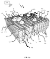
도 1a는 프레임워크 구조물(100)을 갖는 전형적인 종래 기술의 자동화된 저장 및 회수 시스템(1)을 개시하고, 도 2 및 도 3a는 그러한 시스템(1)에서의 동작에 적합한 2개의 상이한 종래 기술의 컨테이너 핸들링 운반체(201, 301)를 개시한다.1A discloses a typical prior art automated storage and
프레임워크 구조물(100)은 직립 부재(102), 수평 부재(103), 및 직립 부재(102)와 수평 부재(103) 사이에서 행(row)으로 배열되는 저장 컬럼(105)을 포함하는 저장 부피를 포함한다. 이러한 저장 컬럼(105) 내에서, 빈(bin)으로도 알려져 있는 저장 컨테이너(106)가 서로 상하로 적층되어 적층체(107)를 형성한다. 부재(102, 103)는 전형적으로 금속, 예를 들어 압축 알루미늄 프로파일로 제조될 수 있다.The framework structure (100) has a storage volume comprising upright members (102), horizontal members (103), and storage columns (105) arranged in rows between the upright members (102) and the horizontal members (103). includes Within this
자동화된 저장 및 회수 시스템(1)의 프레임워크 구조물(100)은 프레임워크 구조물(100)의 상단부에 걸쳐 배열된 레일 시스템(108)을 포함하고, 레일 시스템(108) 상에서 복수의 컨테이너 핸들링 운반체(201, 301)가 동작되어 저장 컨테이너(106)를 저장 컬럼(105)으로부터 상승시키고, 저장 컨테이너(106)를 저장 컬럼 내로 하강시키며, 또한 저장 컨테이너(106)를 저장 컬럼(105) 위에서 운송한다. 레일 시스템(108)은 프레임 구조물(100)의 상단부에 걸친 제1 방향(X)으로 컨테이너 핸들링 운반체(201, 301)의 이동을 안내하도록 배열된 제1 세트의 평행 레일(110), 및 제1 방향(X)에 수직인 제2 방향(Y)으로 컨테이너 핸들링 운반체(201, 301)의 이동을 안내하기 위한, 제1 세트의 레일(110)에 수직으로 배열된, 제2 세트의 평행 레일(111)을 포함한다. 컨테이너 핸들링 운반체는 레일 시스템(108) 내의 그리드 셀(122) 내의 접근 개구부/그리드 개구부(112)를 통해서 컬럼(105) 내에 저장된 컨테이너(106)에 접근한다. 컨테이너 핸들링 운반체(201, 301)는 저장 컬럼(105) 위에서 측방향으로, 즉 수평 X-Y 평면에 평행한 평면 내에서 이동할 수 있다.The
프레임워크 구조물(100)의 직립 부재(102)는, 컨테이너를 컬럼(105)으로부터 상승시키고 컨테이너를 컬럼 내로 하강시키는 동안 저장 컨테이너를 안내하기 위해서 사용된다. 컨테이너(106)의 적층체(107)는 전형적으로 자가-지지형이다.The
각각의 종래 기술의 컨테이너 핸들링 운반체(201, 301)는 운반체 본체(201a, 301a), 및 X 방향 및 Y 방향 각각을 따른 컨테이너 핸들링 운반체(201, 301)의 측방향 이동을 가능하게 하는 제1 및 제2 세트의 휠(201b, 301b, 201c, 301c)을 포함한다. 도 2 및 도 3a에서, 각각의 세트 내의 2개의 휠을 완전히 확인할 수 있다. 제1 세트의 휠(201b, 301b)은 제1 세트의 레일(110) 중의 2개의 인접 레일들과 결합되도록 배열되고, 제2 세트의 휠(201c, 301c)은 제2 세트의 레일(111) 중의 2개의 인접 레일들과 결합되도록 배열된다. 적어도 하나의 세트의 휠(201b, 301b, 201c, 301c)이 상승 및 하강될 수 있고, 그에 따라 제1 세트의 휠(201b, 301b) 및/또는 제2 세트의 휠(201c, 301c)이 언제든지 각각의 세트의 레일(110, 111)과 결합될 수 있다.Each prior art
각각의 종래 기술의 컨테이너 핸들링 운반체(201, 301)는 또한 저장 컨테이너(106)의 수직 운송을 위한, 예를 들어 저장 컨테이너(106)를 저장 컬럼(105)으로부터 상승시키고 저장 컨테이너(106)를 저장 컬럼 내로 하강시키기 위한 상승 장치(미도시)를 포함한다. 상승 장치는 하나 이상의 파지/결합 장치를 포함하고, 그러한 파지/결합 장치는 저장 컨테이너(106)와 결합되도록 구성되고, 그러한 파지/결합 장치는 운반체(201, 301)로부터 하강될 수 있고, 그에 따라 운반체(201, 301)에 대한 파지/결합 장치의 위치가, 제1 방향(X) 및 제2 방향(Y)에 수직인, 제3 방향(Z)으로 조정될 수 있다. 컨테이너 핸들링 운반체(301)의 파지 장치의 일부가 도 3a에 도시되어 있고 참조 번호 304로 표시되어 도시되어 있다. 컨테이너 핸들링 장치(201)의 파지 장치는 도 2에서 운반체 본체(301a) 내에 위치된다.Each prior art
통상적으로 그리고 또한 본원의 목적을 위해서, Z=1은 저장 컨테이너의 최상부 층, 즉 레일 시스템(108) 바로 아래의 층을 나타내고, Z=2는 레일 시스템(108) 아래의 2번째 층, 그리고 Z=3은 3번째 층 등을 나타낸다. 도 1a에 개시된 예시적인 종래 기술에서, Z=8은 저장 컨테이너의 최하부의 하단 층을 나타낸다. 유사하게, X=1…n 및 Y=1…n은 수평 평면 내의 각각의 저장 컬럼(105)의 위치를 나타낸다. 결과적으로, 예로서, 그리고 도 1a에 표시된 데카르트 좌표계(X, Y, Z)를 이용하면, 도 1a에서 106'으로 표시된 저장 컨테이너는 X=10, Y=2, Z=3의 저장 위치를 점유한다고 할 수 있다. 컨테이너 핸들링 운반체(201, 301)가 층(Z=0) 내에서 이동된다고 할 수 있고, 각각의 저장 컬럼(105)은 그 X 및 Y 좌표에 의해서 표시될 수 있다.Typically and also for purposes herein, Z=1 represents the topmost tier of the storage container, i.e., the tier immediately below the
프레임워크 구조물(100)의 저장 부피는 종종 그리드(104)로 지칭되고, 이러한 그리드 내의 가능한 저장 위치는 저장 셀로 지칭된다. 각각의 저장 컬럼은 X- 및 Y-방향을 따른 위치에 의해서 표시될 수 있는 한편, 각각의 저장 셀은 X-, Y- 및 Z-방향을 따른 컨테이너 번호에 의해서 표시될 수 있다.The storage volume of the
각각의 종래 기술의 컨테이너 핸들링 운반체(201, 301)는, 저장 컨테이너(106)를 레일 시스템(108)을 가로질러 운송할 때 저장 컨테이너(106)를 수용 및 수납하기 위한 저장 격실 또는 공간을 포함한다. 저장 공간은, 도 2에 도시된 바와 같은 그리고 예를 들어 기재 내용이 본원에서 참조로 포함되는 WO2015/193278A1에서 설명된 바와 같은, 운반체 본체(201a) 내의 중앙에 배열된 공동을 포함할 수 있다.Each prior art
도 3a는 외팔보 구성을 갖는 컨테이너 핸들링 운반체(301)의 대안적인 구성을 도시한다. 그러한 운반체는, 기재 내용이 또한 본원에서 참조로 포함되는 예를 들어 NO317366에 구체적으로 설명되어 있다.3A shows an alternative configuration of a
도 2에 도시된 중앙 공동 컨테이너 핸들링 운반체(201)는, 예를 들어 기재 내용이 본원에서 참조로 포함되는 WO2015/193278A1에서 설명된 바와 같이, 저장 컬럼(105)의 측방향 범위와 일반적으로 동일한 X 및 Y 방향을 따른 치수를 갖는 면적을 커버하는 풋프린트(footprint)를 가질 수 있다. 본원에서 사용된 '측방향'이라는 용어는 '수평'을 의미할 수 있다.The central common
대안적으로, 중앙 공동 컨테이너 핸들링 운반체(101)는, 예를 들어 WO2014/090684A1에 개시된 바와 같이, 저장 컬럼(105)에 의해서 형성된 측방향 면적보다 큰 풋프린트를 가질 수 있다.Alternatively, the central common container handling vehicle 101 may have a footprint larger than the lateral area formed by the
레일 시스템(108)은 전형적으로, 운반체의 휠이 내부로 삽입되는 홈을 갖는 레일을 포함한다. 대안적으로, 레일은 상향 돌출 요소를 포함할 수 있고, 운반체의 휠은 레일 이탈을 방지하기 위한 플랜지를 포함한다. 이러한 홈 및 상향 돌출 요소는 집합적으로 트랙으로서 알려져 있다. 각각의 레일은 하나의 트랙을 포함할 수 있거나, 각각의 레일은 2개의 평행한 트랙들(이하에서 도 1b 내지 도 1d와 관련하여 설명된, 소위 "이중 트랙")을 포함할 수 있다.The
기재 내용이 본원에서 참조로 포함되는 WO2018146304는, X 및 Y 방향 모두를 따라서 평행한 트랙 및 레일을 포함하는 레일 시스템(108)의 전형적인 구성을 도시한다.WO2018146304, the disclosure of which is incorporated herein by reference, shows a typical configuration of a
프레임워크 구조물(100) 내에서, 컬럼(105)의 대부분은 저장 컬럼(105)이고, 즉 저장 컨테이너(106)가 적층체(107)로 저장되는 컬럼(105)이다. 그러나, 일부 컬럼(105)이 다른 목적을 가질 수 있다. 도 1a에서, 컬럼(119 및 120)은, 프레임워크 구조물(100)의 외측으로부터 저장 컨테이너(106)에 접근할 수 있는 또는 저장 컨테이너가 프레임워크 구조물(100)의 내외로 전달될 수 있는 접근 스테이션(미도시)으로 운송될 수 있도록, 저장 컨테이너(106)를 드롭 오프(drop off) 및/또는 픽업(pick up)하기 위해서 컨테이너 핸들링 운반체(201, 301)에 의해서 이용되는 그러한 특별한-목적의 컬럼이다. 당업계에서, 그러한 위치는 일반적으로 '포트'로 지칭되고, 포트가 내부에 위치되는 컬럼은 '포트 컬럼'(119, 120)으로 지칭될 수 있다. 접근 스테이션으로의 운송은 임의의 방향일 수 있고, 즉 수평, 틸팅, 및/또는 수직일 수 있다. 예를 들어, 저장 컨테이너(106)는 프레임워크 구조물(100) 내에서 무작위적인 또는 지정된 컬럼(105) 내에 배치될 수 있고, 이어서 임의의 컨테이너 핸들링 운반체에 의해서 픽업될 수 있고, 접근 스테이션으로의 추가적인 운송을 위해서 포트 컬럼(119, 120)으로 운송될 수 있다. '틸팅된'이라는 용어는 수평과 수직 사이의 일반적인 운송 배향을 갖는 저장 컨테이너(106)의 운송을 의미한다는 것에 주목하여야 한다.Within the
도 1a에서, 제1 포트 컬럼(119)은 예를 들어, 컨테이너 핸들링 운반체(201, 301)가 접근 또는 전달 스테이션으로 운송하기 위한 저장 컨테이너(106)를 드롭 오프할 수 있는, 지정된 드롭 오프 포트 컬럼일 수 있고, 제2 포트 컬럼(120)은, 접근 또는 전달 스테이션으로부터 운송된 저장 컨테이너(106)를 컨테이너 핸들링 운반체(201, 301)가 픽업할 수 있는 지정된 픽업 포트 컬럼일 수 있다.In FIG. 1A , a
접근 스테이션은 전형적으로, 제품 아이템이 저장 컨테이너(106)로부터 제거되거나 그 내부에 배치되는 픽킹(picking) 또는 보관 스테이션일 수 있다. 픽킹 또는 보관 스테이션에서, 저장 컨테이너(106)는 일반적으로 자동화된 저장 및 회수 시스템(1)으로부터 제거되지 않고, 다시 접근되는 경우에 프레임워크 구조물(100) 내로 복귀된다. 포트가 또한 저장 컨테이너를 다른 저장 설비로(예를 들어, 다른 프레임워크 구조물로 또는 다른 자동화된 저장 및 회수 시스템으로), 운송 운반체(예를 들어, 기차 또는 대형 트럭)로, 또는 생산 설비로 전달하기 위해서 사용될 수 있다.An access station may typically be a picking or storage station where product items are removed from or placed into the
컨베이어를 포함하는 컨베이어 시스템을 일반적으로 이용하여, 저장 컨테이너를 포트 컬럼(119, 120)과 접근 스테이션 사이에서 운송한다.A conveyor system comprising a conveyor is generally used to transport storage containers between
포트 컬럼(119, 120) 및 접근 스테이션이 상이한 레벨들에 위치되는 경우에, 컨베이어 시스템은, 저장 컨테이너(106)를 포트 컬럼(119, 120)과 접근 스테이션 사이에서 수직으로 운송하기 위한 수직 구성요소를 갖춘 상승 장치를 포함할 수 있다.Where the
컨베이어 시스템은, 예를 들어 기재 내용이 본원에서 참조로 포함되는 WO2014/075937A1에 설명된 바와 같이, 저장 컨테이너(106)를 상이한 프레임워크 구조물들 사이에서 전달하도록 배열될 수 있다.The conveyor system may be arranged to convey the
도 1a에 개시된 컬럼(105) 중 하나 내에 저장된 저장 컨테이너(106)에 접근할 때, 컨테이너 핸들링 운반체(201, 301) 중 하나는 목표 저장 컨테이너(106)를 그 위치로부터 회수하도록 그리고 이를 드롭 오프 포트 컬럼(119)으로 운송하도록 명령을 받는다. 이러한 동작은, 컨테이너 핸들링 운반체(201, 301)를, 목표 저장 컨테이너(106)가 내부에 배치되는 저장 컬럼(105) 위의 위치로 이동시키는 것, 컨테이너 핸들링 운반체(201, 301) 상승 장치(미도시)를 이용하여 저장 컨테이너(106)를 저장 컬럼(105)으로부터 회수하는 것, 그리고 저장 컨테이너(106)를 드롭 오프 포트 컬럼(119)으로 운송하는 것을 포함한다. 목표 저장 컨테이너(106)가 적층체(107) 내에 깊이 위치되는 경우에, 즉 목표 저장 컨테이너(106) 위에 하나의 또는 복수의 다른 저장 컨테이너(106)가 배치된 경우에, 동작은 또한, 목표 저장 컨테이너(106)를 저장 컬럼(105)으로부터 상승시키기 전에, 위에-배치된 저장 컨테이너를 일시적으로 이동시키는 것을 포함한다. 당업계에서 종종 "디깅(digging)"으로 지칭되는 이러한 단계는, 목표 저장 컨테이너를 드롭 오프 포트 컬럼(119)으로 운송하기 위해서 추후에 이용되는 동일한 컨테이너 핸들링 운반체를 이용하여, 하나 또는 복수의 다른 협력 컨테이너 핸들링 운반체를 이용하여 수행될 수 있다. 대안적으로 또는 부가적으로, 자동화된 저장 및 회수 시스템(1)은, 저장 컨테이너를 저장 컬럼(105)으로부터 일시적으로 제거하는 과제를 위해서 특별히 지정된 컨테이너 핸들링 운반체를 가질 수 있다. 목표 저장 컨테이너(106)가 저장 컬럼(105)으로부터 제거되면, 일시적으로 제거된 저장 컨테이너가 원래의 저장 컬럼(105) 내로 재배치될 수 있다. 그러나, 대안적으로, 제거된 저장 컨테이너가 다른 저장 컬럼으로 재배치될 수 있다.Upon accessing a
저장 컨테이너(106)를 컬럼(105) 중 하나 내에 저장하고자 할 때, 컨테이너 핸들링 운반체(201, 301) 중 하나는, 저장 컨테이너(106)를 픽업 포트 컬럼(120)으로부터 픽업하도록 그리고 이를 저장하고자 하는 저장 컬럼(105) 위의 위치로 운송하도록 명령을 받는다. 저장 컬럼 적층체(107) 내의 목표 위치에 또는 그 위에 배치된 임의의 저장 컨테이너가 제거된 후에, 컨테이너 핸들링 운반체(201, 301)는 저장 컨테이너(106)를 희망 위치에 배치한다. 이어서, 제거된 저장 컨테이너는 저장 컬럼(105) 내로 다시 하강될 수 있거나, 다른 저장 컬럼으로 재배치될 수 있다.When it is desired to store the
외팔보 유형의 종래 기술의 컨테이너 핸들링 운반체의 단점은 한번에 하나의 저장 컨테이너 만을 운송할 수 있는 것이다.A disadvantage of prior art container handling vehicles of the cantilever type is that they can only transport one storage container at a time.
본 발명의 하나의 목적은 한번에 하나 초과의 저장 컨테이너를 운송할 수 있는 외팔보 유형의 컨테이너 핸들링 운반체를 제공하는 것이다.One object of the present invention is to provide a cantilever type container handling vehicle capable of transporting more than one storage container at a time.
본 발명은 독립 청구항에 기재되어 있는 한편, 종속 청구항은 본 발명의 대안예를 설명한다. The invention is described in the independent claims, while the dependent claims describe alternatives of the invention.
본 발명은 2-차원적인 레일 시스템 상에서의 동작을 위한 컨테이너 핸들링 운반체에 관한 것으로서, 2-차원적인 레일 시스템은 프레임 구조물의 상단부를 가로질러 제1 방향(X)으로 컨테이너 핸들링 운반체의 이동을 안내하도록 배열된 제1 세트의 평행 레일, 및 제1 방향에 수직인 제2 방향으로 컨테이너 핸들링 운반체의 이동을 안내하기 위한, 제1 세트의 레일에 수직으로 배열된, 제2 세트의 평행 레일을 포함하고, 제1 및 제2 세트의 평행 레일은 레일 시스템을 복수의 그리드 셀(grid cell)로 분할하고, 컨테이너 핸들링 운반체는:The present invention relates to a container handling vehicle for operation on a two-dimensional rail system, wherein the two-dimensional rail system guides movement of the container handling vehicle in a first direction (X) across the upper end of a frame structure. a first set of parallel rails arranged and a second set of parallel rails arranged perpendicular to the first set of rails for guiding movement of the container handling vehicle in a second direction perpendicular to the first direction; , first and second sets of parallel rails divide the rail system into a plurality of grid cells, and the container handling vehicle comprises:
- 컨테이너 핸들링 운반체를 제1 및 제2 방향 각각으로 레일 시스템을 따라 안내하기 위한 제1 및 제2 세트의 휠을 포함하는 휠 기부 유닛으로서, 제1 및 제2 세트의 휠은 휠 기부 유닛의 외부 주변부를 형성하는, 휠 기부 유닛;- a wheel base unit comprising first and second sets of wheels for guiding container handling vehicles along the rail system in first and second directions respectively, the first and second sets of wheels being external to the wheel base unit a wheel base unit, forming a periphery;
- 본체 유닛으로서: - As a body unit:
휠 기부 유닛 상에 제공되는 하부 섹션으로서, 하부 섹션은, 휠 기부 유닛 이하의 수평 범위를 갖는 풋프린트를 구비하고, 하부 섹션은 상부 표면을 구비하고, 상부 표면은 저장 컨테이너를 이송하기 위한 제1 컨테이너 이송 위치를 제공하는, 하부 섹션; A lower section provided on the wheel base unit, the lower section having a footprint having a horizontal extent below the wheel base unit, the lower section having an upper surface, the upper surface having a first portion for transporting a storage container. a lower section, providing a container transfer location;
하부 섹션으로부터 수직으로 연장되는 지지 섹션으로서, 하부 섹션의 풋프린트보다 작은 수평 범위의 풋프린트를 갖는, 지지 섹션; 및 a support section extending vertically from the lower section, the support section having a footprint of a smaller horizontal extent than the footprint of the lower section; and
지지 섹션으로부터 하부 섹션의 풋프린트를 넘어서 수평으로 연장되는 외팔보 섹션을 포함하는, 본체 유닛; 및 a body unit comprising a cantilever section extending horizontally from the support section beyond the footprint of the lower section; and
- 외팔보 섹션으로부터 매달린 상승 프레임을 포함하는 상승 장치를 포함한다.- includes a lifting device comprising a lifting frame suspended from a cantilever section;
일 양태에서, 저장 컨테이너가 상부 표면 상에 배치될 때, 저장 컨테이너의 최상부 부분이 제1 높이를 나타내고; 그리고In one aspect, when the storage container is placed on the top surface, a top portion of the storage container presents a first height; And
상승 장치는 외팔보 섹션으로부터 매달린 상승 프레임을 포함하고, 상승 프레임은 상승 프레임이 외팔보 섹션에 인접하여 상부 위치에 도킹될(docked) 때 제2 높이에서 최하부 부분을 구비하며; The lifting device includes a lifting frame suspended from the cantilever section, the lifting frame having a lowermost portion at a second height when the lifting frame is docked in an upper position adjacent to the cantilever section;
제2 높이는, 상승 프레임이 그 상부 위치에 도킹될 때, 제1 높이보다 높고, 그에 따라 제1 컨테이너 핸들링 운반체의 도킹된 상승 프레임의 최하부 부분은, 제1 및 제2 컨테이너 운반체가 인접 그리드 셀에서 서로를 통과할 때, 제2 컨테이너 핸들링 운반체의 본체 유닛의 하부 섹션의 상부 표면 상에 배치되는 저장 컨테이너의 최상부 부분 위를 통과할 수 있다. The second height is higher than the first height when the lift frame is docked in its upper position, so that the lowermost part of the docked lift frame of the first container handling vehicle is such that the first and second container vehicles are in adjacent grid cells. When passing each other, they can pass over the uppermost part of the storage container disposed on the upper surface of the lower section of the body unit of the second container handling vehicle.
다른 로봇 또는 인간 조작자(들)이 제1 컨테이너 이송 위치에 배치된 저장 컨테이너에 저장된 물품을 핸들링/픽킹(pick)할 수 있다. 즉, 제1 컨테이너 이송 위치에 배치된 저장 컨테이너는 그에 따라 정기적인 접근을 필요로 하는 물품을 유지하기 위한 유용한 장소가 될 수 있다. 동시에, 무거운 저장 컨테이너를 픽업할 필요가 있을 때, 이는 운반체를 위한 유용한 균형추(counterbalance)를 또한 제공한다. Another robot or human operator(s) may handle/pick items stored in the storage container disposed at the first container transfer location. That is, a storage container disposed in the first container transfer position can thus be a useful place to hold items requiring regular access. At the same time, it also provides a useful counterbalance for the conveyor when it is necessary to pick up a heavy storage container.
제1 컨테이너 이송 위치가 함몰되어, 제1 컨테이너 이송 위치에 배치된 저장 컨테이너를 위한 측부 지지부(sideways support)를 제공할 수 있다.The first container transfer position may be recessed to provide sideways support for storage containers disposed in the first container transfer position.
상승 장치는 상승 장치 모터 및 적어도 2개의 상승 샤프트를 포함할 수 있고, 적어도 2개의 상승 샤프트는 외팔보 섹션 내에 배열될 수 있고, 상승 장치 모터는 하부 섹션 내에 배열될 수 있고, 상승 장치 모터 및 적어도 2개의 상승 샤프트가 구동 커플링을 통해서 서로 연결될 수 있다. 구동 커플링은 회전 이동을 상승 장치 모터 및 상승 샤프트로부터 전달하기 위한 임의의 필요 구성요소를 포함할 수 있다. The lifting device may include a lifting device motor and at least two lifting shafts, the at least two lifting shafts may be arranged in the cantilever section, the lifting device motor may be arranged in the lower section, and the lifting device motor and at least two lifting device motors may be arranged. The two lifting shafts can be connected to each other via drive couplings. The drive coupling may include any necessary components for transferring rotational movement from the lifter motor and lift shaft.
상승 장치는 상승 장치 모터 및 외팔보 섹션 내에 배열된 적어도 2개의 상승 샤프트를 포함할 수 있다.The lifting device may include a lifting device motor and at least two lifting shafts arranged within the cantilever section.
본체 유닛은, 하부 섹션, 지지 섹션, 및 외팔보 섹션을 함께 연결하는 S-형상의 하우징을 포함할 수 있다. S-형상은, 하우징을 측면에서 볼 때 보이는 형상이다.The body unit may include an S-shaped housing connecting the lower section, the support section and the cantilever section together. The S-shape is the shape seen when viewing the housing from the side.
제1 컨테이너 이송 위치는 제1 컨테이너 이송 위치와 외부 지지부 사이에서 저장 컨테이너를 전달하기 위한 컨베이어를 포함할 수 있다. 외부 지지부는 외부 컨베이어일 수 있다. 저장 컨테이너의 용이한 전달을 위해서, 외부 지지부의 상부 표면은 바람직하게 제1 컨테이너 이송 위치에서 컨베이어의 상부 표면과 동일한 높이에 위치된다.The first container transfer location may include a conveyor for transferring storage containers between the first container transfer location and the external support. The external support may be an external conveyor. For easy delivery of the storage container, the upper surface of the outer support is preferably positioned flush with the upper surface of the conveyor in the first container transfer position.
본체 유닛의 하부 섹션의 풋프린트는 실질적으로 휠의 폭 만큼 또는 휠의 폭과 동일한 만큼 휠 기부 유닛의 풋프린트에 대해서 변위될 수 있다. 이러한 경우에, 풋프린트는, 하부 섹션이 그리드 셀 바로 위에 배열될 때, 하부 섹션의 수직 투영(vertical projection)이 인접 그리드 셀로 들어가지 않는 것으로 이해되어야 한다.The footprint of the lower section of the body unit can be displaced relative to the footprint of the wheel base unit substantially by the width of the wheel or by an amount equal to the width of the wheel. In this case, the footprint should be understood as such that when the lower section is arranged directly above the grid cell, the vertical projection of the lower section does not enter the adjacent grid cell.
상승 프레임은 상승 밴드 상에 매달릴 수 있고, 상승 프레임은 수평으로 연장될 수 있고 파지 장치 및 모서리 안내부를 포함할 수 있으며, 모서리 안내부의 최하부 지점은 상승 프레임의 최하부 부분을 제공할 수 있다. 상승 밴드는 바람직하게 전기 및/또는 신호를 전달할 수 있고, 그에 따라 전력 및 명령어가 상승 프레임 상의 파지 장치에 제공될 수 있다.The lift frame may be suspended on the lift band, the lift frame may extend horizontally and may include a gripping device and a corner guide, and a lowermost point of the corner guide may provide a lowermost portion of the lift frame. The rising band may preferably carry electricity and/or signals so that power and instructions may be provided to the gripping device on the rising frame.
자동화된 저장 및 회수 시스템이 더 설명되고, 이러한 자동화된 저장 및 회수 시스템은 2-차원적인 레일 시스템을 포함하고, 2-차원적인 레일 시스템은 프레임 구조물의 상단부를 가로질러 제1 방향(X)으로 컨테이너 핸들링 운반체의 이동을 안내하도록 배열된 제1 세트의 평행 레일, 및 제1 방향에 수직인 제2 방향(Y)으로 컨테이너 핸들링 운반체의 이동을 안내하기 위한, 제1 세트의 레일에 수직으로 배열된, 제2 세트의 평행 레일을 포함하고, 제1 및 제2 세트의 평행 레일은 레일 시스템을 복수의 그리드 셀로 분할하고, 자동화된 저장 및 회수 시스템은 전술한 바와 같은 복수의 컨테이너 핸들링 운반체를 포함한다. An automated storage and retrieval system is further described, the automated storage and retrieval system comprising a two-dimensional rail system, the two-dimensional rail system running in a first direction (X) across the upper end of the frame structure. A first set of parallel rails arranged to guide movement of the container handling vehicle, and arranged perpendicular to the first set of rails for guiding movement of the container handling vehicle in a second direction (Y) perpendicular to the first direction. and a second set of parallel rails, the first and second sets of parallel rails dividing the rail system into a plurality of grid cells, and the automated storage and retrieval system comprising a plurality of container handling vehicles as described above. do.
제1 및 제2 세트의 휠을 갖는 휠 기부 유닛이 그리드 셀과 동일할 수 있다. Wheel base units having first and second sets of wheels may be equivalent to grid cells.
동일한 배향을 갖는 2개의 컨테이너 핸들링 운반체는, 하나의 행(row)을 따라서 서로 통과할 때, 그러한 행을 따라 3개의 그리드 셀 공간만을 점유할 수 있다.Two container handling vehicles with the same orientation, when passing each other along a row, can occupy only three grid cell spaces along that row.
제1 세트의 레일 및/또는 제2 세트의 레일은 단일 트랙 또는 2개의 단일 트랙을 포함하는 이중 트랙을 포함할 수 있고, 그리드 셀은, 단일 그리드 개구부를 둘러싸는 제1 및 제2 방향으로 단일 트랙에 의해서 점유되는 지역에 더하여, 제1 및 제2 세트의 레일에 의해서 경계 지어지는 그리드 개구부에 의해서 점유되는 수평 면적으로서 정의될 수 있다.The first set of rails and/or the second set of rails may comprise a single track or a dual track comprising two single tracks, wherein the grid cells are single in a first and second direction surrounding a single grid opening. In addition to the area occupied by the tracks, it can be defined as the horizontal area occupied by the grid openings bounded by the first and second sets of rails.
휠 기부 유닛은 그리드 셀의 제1 및 제2 방향을 따른 수평 범위와 동일한 풋프린트를 가질 수 있다.The wheel base unit may have a footprint equal to the horizontal extent along the first and second directions of the grid cell.
컨테이너 핸들링 운반체는 지지 표면을 포함할 수 있고, 지지 표면은 제2 컨테이너 이송 위치를 제공할 수 있다.The container handling vehicle may include a support surface, and the support surface may provide a second container transfer location.
제2 컨테이너 이송 위치는 제1 컨테이너 이송 위치의 위에 배열될 수 있다. 바람직하게, 제2 컨테이너 이송 위치는 제1 컨테이너 이송 위치와 동일한 수직 투영을 갖는다. 레일 시스템 상에 배열되는 경우에, 지지 섹션의 크기는 바람직하게 그리드 셀 이하이다. 제2 컨테이너 이송 위치에 대한 대안으로서, 둘 이상의 저장 컨테이너가 서로 상하로 적층될 수 있고, 적층된 저장 컨테이너의 모두는 제1 컨테이너 이송 위치에 의해서 지지된다.The second container transfer position may be arranged above the first container transfer position. Preferably, the second container transfer position has the same vertical projection as the first container transfer position. When arranged on a rail system, the size of the supporting section is preferably less than or equal to a grid cell. As an alternative to the second container transfer position, two or more storage containers may be stacked on top of each other, and all of the stacked storage containers are supported by the first container transfer position.
제2 컨테이너 이송 위치는:The second container transfer position is:
- 제2 컨테이너 이송 위치가 제1 컨테이너 이송 위치의 수직 투영을 넘어서는 회수 위치와, - a withdrawal position where the second container transfer position is beyond the vertical projection of the first container transfer position;
- 제2 컨테이너 이송 위치가 제1 컨테이너 이송 위치의 수직 투영에 또는 그 내부에 있는 연장 위치 사이에서 이동될 수 있다. - The second container transfer position can be moved between extended positions in or within the vertical projection of the first container transfer position.
제2 컨테이너 이송 위치는 피벗 연결부를 통해서 회수 위치와 연장 위치 사이에서 이동될 수 있다. 피벗 연결부는:The second container transfer position can be moved between a withdrawal position and an extended position via the pivot connection. The pivot connection is:
- 회수 위치에서 제2 표면이 실질적으로 수직으로 연장되도록, 그리고- in the retracted position the second surface extends substantially vertically, and
- 연장 위치에서 제2 표면이 실질적으로 수평으로 연장되도록, 배치될 수 있다.- in the extended position the second surface may be arranged such that it extends substantially horizontally.
피벗 연결부는 대안적으로, 제2 표면이 외팔보 섹션의 지붕 상으로 접힐 수 있도록, 배열될 수 있다. 예를 들어, 이는 해당 섹션에 연결되는 상단부에서 외팔보의 후방부의 모서리 연부를 따른 힌지 연결부일 수 있고, 아암(arm)의 단부는 이어서 지지 섹션의 수직 표면에 대항하여(against) 놓인다.The pivot connection may alternatively be arranged such that the second surface can be folded onto the roof of the cantilever section. For example, this could be a hinged connection along the corner edge of the rear part of the cantilever at the upper end connected to that section, the end of the arm then resting against the vertical surface of the supporting section.
제2 컨테이너 이송 위치는 직선형 이동 배열체(linear movement arrangement)를 통해서 회수 위치와 연장 위치 사이에서 직선형으로 이동될 수 있다. 직선형 이동 배열체를 이용하는 경우에, 직선형 이동 배열체는:The second container transfer position can be moved linearly between the withdraw position and the extended position via a linear movement arrangement. In the case of using a linear movement arrangement, the linear movement arrangement is:
- 회수 위치에서, 제2 컨테이너 이송 위치가 제1 컨테이너 이송 위치를 넘어서는 그리고 외팔보 섹션 위의 위치로 이동되도록, 그리고- in the withdrawal position, the second container transfer position is moved to a position beyond the first container transfer position and above the cantilever section, and
- 연장 위치에서, 제2 컨테이너 이송 위치가 제1 컨테이너 이송 위치의 위에 있도록, 배열될 수 있다. - in the extended position, it may be arranged such that the second container transfer position is above the first container transfer position.
제2 컨테이너 이송 위치는 컨베이어를 구비할 수 있고, 즉 이는, 컨베이어 및 컨베이어로부터 오는 높은 레벨의 컨테이너를 잡을 수 있는 일부 수용 인프라스트럭처를 사용하여, 제1 컨테이너 이송 위치에 있는 저장 컨테이너와 독립적으로 제2 컨테이너 이송 위치에서 저장 컨테이너를 자가-하역할 수 있다. 제1 컨테이너 이송 위치가 컨베이어를 구비하는 경우에, 제1 컨테이너 이송 위치에 있는 임의의 저장 컨테이너는, 제2 컨테이너 이송 위치에 배치된 저장 컨테이너를 먼저 하역할 필요가 없이, 하역될 수 있다. 제1 및 제2 컨테이너 이송 위치 모두가 컨베이어를 구비하는 경우에, 제1 및/또는 제2 컨테이너 이송 위치에 배치된 임의의 저장 컨테이너가 컨베이어를 이용하여 다른 저장 컨테이너와 독립적으로 운반될 수 있다.The second container transfer location may have a conveyor, i.e. it may operate independently of the storage containers at the first container transfer location, using the conveyor and some receiving infrastructure capable of holding the higher level containers coming from the conveyor. Able to self-unload storage containers in a 2-container transfer position. When the first container transfer position has a conveyor, any storage container at the first container transfer position can be unloaded without first unloading a storage container disposed at the second container transfer position. When both the first and second container transfer positions have conveyors, any storage container disposed at the first and/or second container transfer positions can be transported independently of other storage containers using the conveyor.
저장 컨테이너를 전술한 바와 같은 제1 및 제2 컨테이너 핸들링 운반체 사이에서 전달하기 위한 방법이 더 설명되고, 제1 및 제2 컨테이너 핸들링 운반체는 자동화된 저장 및 회수 시스템 상에서 동작하고, 이러한 자동화된 저장 및 회수 시스템은 2-차원적인 레일 시스템을 포함하고, 2-차원적인 레일 시스템은 프레임 구조물의 상단부를 가로질러 제1 방향(X)으로 컨테이너 핸들링 운반체의 이동을 안내하도록 배열된 제1 세트의 평행 레일, 및 제1 방향에 수직인 제2 방향(Y)으로 컨테이너 핸들링 운반체의 이동을 안내하기 위한, 제1 세트의 레일에 수직으로 배열된, 제2 세트의 평행 레일을 포함하고, 제1 및 제2 세트의 평행 레일은 레일 시스템을 복수의 그리드 셀로 분할하고, 상기 방법은:A method for transferring a storage container between first and second container handling vehicles as described above is further described, wherein the first and second container handling vehicles operate on an automated storage and retrieval system, such an automated storage and retrieval system. The retrieval system comprises a two-dimensional rail system, the two-dimensional rail system comprising a first set of parallel rails arranged to guide movement of the container handling vehicle in a first direction (X) across the upper end of the frame structure. and a second set of parallel rails, arranged perpendicularly to the first set of rails, for guiding movement of the container handling vehicle in a second direction (Y) perpendicular to the first direction, wherein the first and second sets of parallel rails are provided. The two sets of parallel rails divide the rail system into a plurality of grid cells, the method comprising:
- 제1 컨테이너 핸들링 운반체의 상승 장치가 제2 컨테이너 핸들링 운반체의 하부 섹션의 상부 표면 바로 위에 있도록, 주 제어 시스템을 이용하여 제1 및 제2 컨테이너 핸들링 운반체에 그들 자체가 이웃 그리드 셀 내에 배치될 것을 지시하는 단계;- to place the first and second container handling vehicles themselves in neighboring grid cells using the main control system, such that the lifting device of the first container handling vehicle is directly above the upper surface of the lower section of the second container handling vehicle. instructing;
- 저장 컨테이너를 제2 컨테이너 핸들링 운반체의 하부 섹션의 제1 컨테이너 이송 위치와 제1 컨테이너 핸들링 운반체의 상승 장치 사이에서 전달하는 단계를 포함한다. 저장 컨테이너의 전달은 제1 컨테이너 핸들링 운반체로부터 제2 컨테이너 핸들링 운반체로, 그리고 그 반대로 이루어질 수 있다.- transferring the storage container between the lifting device of the first container handling vehicle and the first container transfer position of the lower section of the second container handling vehicle. The transfer of the storage container can be from a first container handling vehicle to a second container handling vehicle and vice versa.
저장 컨테이너를 제2 컨테이너 핸들링 운반체의 하부 섹션의 상부 표면과 제1 컨테이너 핸들링 운반체의 상승 장치 사이에서 전달하는 단계는:Transferring the storage container between the upper surface of the lower section of the second container handling vehicle and the lifting device of the first container handling vehicle comprises:
- 저장 컨테이너를 이송 또는 지지하는 컨테이너 핸들링 운반체를 마스터 운반체로서 설정하는 단계;- setting the container handling vehicle that transports or supports the storage container as the master vehicle;
- 다른 컨테이너 핸들링 운반체를 슬레이브 운반체(slave vehicle)로서 설정하는 단계;- setting another container handling vehicle as a slave vehicle;
- get_bin(상자_획득) 명령을 슬레이브 운반체에 송신하는 단계를 포함하고;- sending a get_bin (box_get) command to the slave vehicle;
- 슬레이브 운반체는 get_bin 명령을 수행하고 저장 컨테이너가 운반체 상에 배치된 것이 확인될 때 그 내부 상태를 업데이트하며;- the slave vehicle performs a get_bin command and updates its internal state when it is confirmed that the storage container is placed on the vehicle;
- 저장 컨테이너가 운반체 상에 배치된 것이 확인될 때, 저장 컨테이너가, 바람직하게 마진(margin)을 갖고, 마스터 운반체의 제1 컨테이너 이송 위치로부터 충분히 치워지도록(clear), 슬레이브 운반체가 제어 시스템에 확인을 송신하고;- when it is confirmed that the storage container is placed on the vehicle, the slave vehicle checks to the control system that the storage container is sufficiently clear from the transfer position of the first container of the master vehicle, preferably with a margin. send;
- 마스터 운반체는 저장 컨테이너가 옮겨진 것을 검출하고, bin_update status(상자_업데이트 상태)를 제어 시스템에 송신할 것이며;- the master vehicle will detect that the storage container has been moved and will send bin_update status to the control system;
- 제어 시스템은 로직 상태를 업데이트하여 마스터 운반체 및 슬레이브 운반체의 물리적 상태와 매칭시킨다(match).- The control system updates the logical state to match the physical state of the master vehicle and slave vehicle.
get_bin 명령은 전달되는 저장 컨테이너의 높이를 규정하는 매개변수를 포함할 수 있고, 그에 따라 마스터 운반체의 상승 장치가 제1 컨테이너 이송 위치에 배치된 저장 컨테이너의 최상부 부분과 동일한 위치로 하강된다. 저장 컨테이너의 높이는 도킹된 상부 위치의 상승 장치와 저장 컨테이너의 상단부 사이의 거리이다. 이러한 거리는 저장 컨테이너의 높이에 따라 그리고 저장 컨테이너가 제1 컨테이너 이송 위치 또는 다른 고도의 컨테이너 이송 위치에 배치되는지의 여부에 따라 달라질 수 있다.The get_bin command may include a parameter defining the height of the storage container to be transferred, such that the lifting device of the master vehicle is lowered to the same position as the uppermost part of the storage container placed at the first container transfer position. The height of the storage container is the distance between the lifting device in the docked upper position and the upper end of the storage container. This distance may vary depending on the height of the storage container and whether the storage container is placed at the first container transfer location or at a container transfer location at a different height.
다른 컨테이너 핸들링 운반체를 슬레이브 운반체로서 설정하는 단계는 슬레이브 운반체가 마스터 운반체와 함께 이동하고 마스터 운반체를 따르게 하도록 synchronize_to_master(마스터에 동기화) 명령을 슬레이브 운반체에 송신하는 단계를 포함할 수 있다.Setting the other container handling vehicle as a slave vehicle may include sending a synchronize_to_master command to the slave vehicle to cause the slave vehicle to move with and follow the master vehicle.
synchronize_to_master 명령을 슬레이브 운반체에 송신하는 단계 후에, 방법은, 슬레이브 운반체가 마스터 운반체와 함께 이동하고 마스터 운반체를 따를 때, 메시지를 슬레이브 운반체로부터 주 제어 시스템으로 송신하는 단계를 더 포함할 수 있다.After sending the synchronize_to_master command to the slave vehicle, the method may further include sending a message from the slave vehicle to the master control system when the slave vehicle moves with and follows the master vehicle.
저장 컨테이너를 전술한 바와 같은 컨테이너 핸들링 운반체와 외부 컨테이너 이송 위치 사이에서 전달하기 위한 방법이 더 설명되고, 컨테이너 핸들링 운반체는 자동화된 저장 및 회수 시스템 상에서 동작하고, 이러한 자동화된 저장 및 회수 시스템은 2-차원적인 레일 시스템을 포함하고, 2-차원적인 레일 시스템은 프레임 구조물의 상단부를 가로질러 제1 방향(X)으로 컨테이너 핸들링 운반체의 이동을 안내하도록 배열된 제1 세트의 평행 레일, 및 제1 방향에 수직인 제2 방향(Y)으로 컨테이너 핸들링 운반체의 이동을 안내하기 위한, 제1 세트의 레일에 수직으로 배열된, 제2 세트의 평행 레일을 포함하고, 제1 및 제2 세트의 평행 레일은 레일 시스템을 복수의 그리드 셀로 분할하고, 상기 방법은:A method for transferring a storage container between a container handling vehicle as described above and an external container transfer location is further described, wherein the container handling vehicle operates on an automated storage and retrieval system, the automated storage and retrieval system comprising a 2- A two-dimensional rail system comprising a first set of parallel rails arranged to guide movement of the container handling vehicle in a first direction (X) across an upper end of the frame structure, and a first set of parallel rails in the first direction. a second set of parallel rails, arranged perpendicular to the first set of rails, for guiding movement of the container handling vehicle in a second direction (Y) perpendicular to the first and second sets of parallel rails; divides the rail system into a plurality of grid cells, the method comprising:
- 저장 컨테이너를 컨테이너 핸들링 운반체와 컨테이너 핸들링 운반체 외측의 외부 위치 사이에서 전달하기 위해서, 하부 섹션의 제1 컨테이너 이송 위치 상의 컨베이어를 이용하는 단계를 포함한다.- using a conveyor on a first container transfer position in the lower section to transfer the storage container between the container handling vehicle and an external location outside the container handling vehicle.
상대적인 용어인 "상부", "하부", "아래", "위", "더 높음" 등은 그 일반적인 의미로 그리고 데카르트 좌표계에서 볼 수 있는 바와 같이 이해될 것이다.Relative terms "upper", "lower", "below", "above", "higher", etc. are to be understood in their ordinary sense and as found in a Cartesian coordinate system.
이하에서, 청구된 시스템 및 운반체의 실시형태에 대한 완전한 이해를 제공하기 위해, 다수의 특정 세부사항이 단지 예로서 도입된다. 그러나, 당업자는, 이러한 실시형태가 구체적인 세부사항 중 하나 이상이 없이, 또는 다른 구성요소, 시스템 등과 함께 실시될 수 있는 것을 이해할 것이다. 다른 경우에, 개시된 실시형태의 양태를 불명료하게 하지 않기 위해서, 잘 알려진 구조 또는 동작을 도시하지 않았거나, 구체적으로 설명하지 않았다.In the following, numerous specific details are introduced by way of example only, in order to provide a thorough understanding of embodiments of the claimed system and vehicle. However, those skilled in the art will understand that these embodiments may be practiced without one or more of the specific details, or in conjunction with other components, systems, etc. In other instances, well-known structures or operations have not been shown or described in detail in order not to obscure aspects of the disclosed embodiments.
이하의 도면은 본 발명의 이해를 돕기 위해서 첨부된 것이다.
도 1a은 종래 기술의 자동화된 저장 및 회수 시스템의 프레임워크 구조물의 사시도이다.
도 1b 내지 도 1d는 컨테이너 핸들링 운반체 레일 시스템의 상면도이며, 도 1b는 단일 트랙 레일 시스템을 도시하고, 도 1c는 이중 트랙 레일 시스템을 도시하고, 도 1d는 표시된 컨테이너 핸들링 운반체 그리드 셀의 폭 및 길이를 갖는 이중 레일 시스템을 도시한다.
도 2는 저장 컨테이너를 내부에서 이송하기 위한 중앙 배열 공동을 구비하는 종래 기술의 컨테이너 핸들링 운반체의 사시도이다.
도 3a는 저장 컨테이너를 아래에서 이송하기 위한 외팔보를 구비하는 종래 기술의 컨테이너 핸들링 운반체의 사시도이다.
도 3b 및 도 3c는 컨테이너 핸들링 운반체를 위한 예시적인 휠 기부 유닛을 도시한다.
도 4a는 휠 기부 유닛 및 본체 유닛을 포함하는 본 발명의 실시형태에 따른 컨테이너 핸들링 운반체의 단순화된 측면도이고 본체 유닛은 하부 섹션, 지지 섹션, 및 외팔보 섹션을 포함한다.
도 4b는 본 발명의 실시형태에 따른 컨테이너 핸들링 운반체의 사시도이고, 여기에서 보호 커버를 제거하여, 컨테이너 핸들링 운반체의 본체 유닛의 하부 섹션, 지지 섹션 및 외팔보 섹션 내의 구성요소의 셋업을 보다 양호하게 도시하였다.
도 4c는 도 4b의 상면도이다.
도 4d 내지 도 4i는 상승 샤프트들의 반대 회전을 제공하는 상이한 셋업들의 예시적인 측면도이다.
도 5는 본체 유닛의 외팔보 섹션의 예이고, 외팔보 섹션의 일부를 형성할 수 있는 부분들을 도시한다.
도 6는 하나의 저장 컨테이너를 제1 컨테이너 이송 위치 상에서 그리고 하나의 저장 컨테이너를 상승 장치에 의해서 지지하는 본 발명의 실시형태에 따른 컨테이너 핸들링 운반체의 단순화된 측면도이고, 컨테이너 핸들링 운반체는 휠 기부 유닛 및 본체 유닛을 포함하고, 본체 유닛은 하부 섹션, 지지 섹션, 및 외팔보 섹션을 포함한다.
도 7a 내지 도 7d는 2-차원적인 레일 시스템을 포함하는 자동화된 저장 및 회수 시스템에서 동작하는 제1 및 제2 컨테이너 핸들링 운반체 사이에서 저장 컨테이너를 전달하는 예시적인 방법을 단계별로 도시한다.
도 8a 내지 도 8d는 제1 컨테이너 이송 위치 상에서 컨베이어를 갖는 본 발명에 따른 컨테이너 핸들링 운반체의 예를 도시하며, 도 8a는 제1 컨테이너 이송 위치 상에서 저장 컨테이너를 이송하지 않을 때의 상황을 도시하고, 도 8b는 제1 컨테이너 이송 위치 상에서 저장 컨테이너를 가질 때의 상황으로 도시하고, 도 8c는 제1 컨테이너 이송 위치 상의 컨베이어로부터 외부 컨베이어로의 가능한 저장 컨테이너의 전달을 도시하고, 도 8d는 도 8a 상의 컨베이어에 대해서 90도로 배향된 컨베이어를 도시한다.
도 9는, 제1 컨테이너 이송 위치를 제공하는 상부 표면 및 제2 컨테이너 이송 위치를 제공하는 지지 표면을 포함하는 본 발명에 따른 컨테이너 핸들링 운반체의 예를 도시한다.
도 10a는, 회수 위치에서 제2 컨테이너 캐리어 위치가 위쪽으로 지향되도록 피벗 연결부를 통한 회수 위치에서의 도 9의 제2 컨테이너 이송 위치(426)를 도시한다.
도 10b는 제2 컨테이너 캐리어 위치의 가능한 연장 위치의 다른 예를 도시한다.
도 10c는 도 10b의 예를 도시하고, 여기에서 제2 컨테이너 캐리어 위치가 180도 피벗되었고 회수 위치에 있을 때 외팔보 섹션 상으로 뒤집혀 놓인다.
도 11a 및 도 11b는 제2 컨테이너 캐리어 위치의 또 다른 예를 도시하고, 도 11a에서, 제2 컨테이너 캐리어 위치는 제1 컨테이너 이송 위치 바로 위의 연장 위치에 있고, 도 11b에서, 제2 컨테이너 이송 위치는 직선형 이동 배열체에 의해서 회수 위치로 이동되었다.
도면에서, 달리 명시적으로 기술되거나 문맥으로부터 암시적으로 이해되지 않는 한, 유사한 참조 번호들을 이용하여 유사한 부품, 요소, 또는 특징부를 표시하였다.The following drawings are attached to aid understanding of the present invention.
1A is a perspective view of a framework structure of a prior art automated storage and retrieval system.
1b to 1d are top views of a container handling vehicle rail system, FIG. 1b shows a single track rail system, FIG. 1c shows a double track rail system, FIG. 1d shows the container handling vehicle grid cell width and Shows a double rail system with a length.
Figure 2 is a perspective view of a prior art container handling vehicle having a centrally arranged cavity for transporting storage containers therein;
Figure 3a is a perspective view of a prior art container handling vehicle having a cantilever for conveying a storage container underneath;
3b and 3c show an exemplary wheel base unit for a container handling vehicle.
4A is a simplified side view of a container handling vehicle according to an embodiment of the present invention comprising a wheel base unit and a body unit, the body unit comprising a lower section, a support section, and a cantilever section.
Fig. 4b is a perspective view of a container handling vehicle according to an embodiment of the invention, wherein the protective cover is removed to better illustrate the set-up of the components in the lower section, support section and cantilever section of the body unit of the container handling vehicle; did
Figure 4c is a top view of Figure 4b.
4D-4I are exemplary side views of different setups providing counter rotation of the lift shafts.
5 is an example of a cantilever section of a body unit and shows parts that may form part of the cantilever section.
6 is a simplified side view of a container handling vehicle according to an embodiment of the present invention supporting one storage container on a first container transfer position and by means of a lifting device, the container handling vehicle comprising a wheel base unit and It includes a body unit, and the body unit includes a lower section, a support section, and a cantilever section.
7A-7D show step by step an exemplary method of transferring a storage container between first and second container handling vehicles operating in an automated storage and retrieval system comprising a two-dimensional rail system.
8a to 8d show an example of a container handling vehicle according to the present invention having a conveyor on a first container transfer position, and FIG. 8a shows a situation when no storage containers are transferred on the first container transfer position; Figure 8b shows the situation when having a storage container on the first container transfer position, Figure 8c shows a possible transfer of the storage container from the conveyor on the first container transfer position to an external conveyor, Figure 8d shows the transfer of the storage container on the first container transfer position The conveyor is shown oriented at 90 degrees relative to the conveyor.
Figure 9 shows an example of a container handling vehicle according to the invention comprising an upper surface providing a first container transfer position and a support surface providing a second container transfer position.
FIG. 10A shows the second
Figure 10b shows another example of a possible extended position of the second container carrier position.
FIG. 10C shows the example of FIG. 10B , wherein the second container carrier position has been pivoted 180 degrees and flipped onto the cantilever section when in the retrieval position.
11A and 11B show another example of a second container carrier position, in FIG. 11A the second container carrier position is in an extended position directly above the first container transfer position, and in FIG. 11B the second container transfer position The position was moved to the retrieval position by means of a linear movement arrangement.
In the drawings, like reference numbers have been used to indicate like parts, elements, or features unless explicitly stated otherwise or implicitly understood from context.
이하에서, 단지 예로서 그리고 첨부 도면을 참조하여 본 발명의 실시형태를 더 구체적으로 설명할 것이다. 그러나, 도면은 본 발명을 도면에 도시된 청구-대상으로 제한하기 위한 것이 아님을 이해하여야 할 것이다.In the following, embodiments of the present invention will be described in more detail by way of example only and with reference to the accompanying drawings. However, it should be understood that the drawings are not intended to limit the invention to the claimed subject matter shown therein.
자동화된 저장 및 회수 시스템(1)의 프레임워크 구조물(100)은 도 1a 내지 도 1d와 관련하여 전술한 종래 기술의 프레임워크 구조물(100)에 따라 구성되고, 즉 많은 수의 직립 부재(102) 및 직립 부재(102)에 의해서 지지되는 많은 수의 수평 부재(103)로 구성되고, 또한 프레임워크 구조물(100)은 X 방향 및 Y 방향의 제1 상부 레일 시스템(108)을 포함한다.The
프레임워크 구조물(100)은 부재들(102, 103) 사이에 제공된 저장 컬럼(105) 형태의 저장 격실을 더 포함하고, 저장 컨테이너(106)는 저장 컬럼(105) 내에서 적층체(107)로 적층될 수 있다.The
프레임워크 구조물(100)은 임의의 크기일 수 있다. 특히, 프레임워크 구조물은 도 1a에 개시된 것보다 상당히 더 넓을 수 있고/있거나 더 길 수 있고/있거나 더 깊을 수 있다. 예를 들어, 프레임워크 구조물(100)은 700 x 700 컬럼 초과의 수평 범위 및 12개 초과의 컨테이너의 저장 깊이를 가질 수 있다.
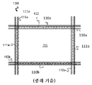
레일 시스템(108)은, 도 1b에 도시된 바와 같이, 단일 레일(단일 트랙으로도 지칭됨) 시스템일 수 있다. 대안적으로, 레일 시스템(108)은 도 1c에 도시된 바와 같은 이중 레일 시스템(이중 트랙으로도 지칭됨)일 수 있고, 그에 따라, 다른 컨테이너 핸들링 운반체(201)가 해당 행에 이웃하는 그리드 컬럼 위에 배치되는 경우에도, 접근 개구부/그리드 컬럼(112)에 의해 형성된 측방향 지역에 일반적으로 상응하는 풋프린트를 갖는 컨테이너 핸들링 운반체(201)가 그리드 컬럼의 행을 따라 이동할 수 있게 한다. 단일 및 이중 트랙 시스템 모두, 또는 단일 레일 시스템(108) 내의 단일 및 이중 트랙 배열체를 포함하는 조합은 복수의 직사각형의 그리고 균일한 그리드 위치 또는 그리드 셀(122)을 포함하는 수평 평면(P)에서 그리드 패턴을 형성하며, 여기서 각각의 그리드 셀(122)은 제1 세트의 레일(110)의 트랙(110a, 110b)의 쌍 및 제2 세트의 레일(111)의 트랙(111a, 111b)의 쌍에 의해 경계 지어지는 그리드 개구부(115)를 포함한다. 도 1c에서, 그리드 셀(122)은 쇄선 상자에 의해서 표시되어 있다. 예를 들어, 알루미늄으로 제조된 레일-기반의 시스템의 섹션은 레일이고, 레일의 상부 표면 상에는, 운반체의 휠이 내부에서 주행하는 트랙의 쌍이 위치된다. 그러나, 이러한 섹션들은 트랙을 각각 구비하는 별도의 레일들일 수 있다.
결과적으로, 트랙(110a 및 110b)은 X 방향으로 연장되는 그리드 셀의 평행 행들을 형성하는 레일의 쌍을 형성하고, 트랙(111a 및 111b)은 Y 방향으로 연장되는 그리드 셀의 평행 행들을 형성하는 레일의 쌍을 형성한다.Consequently, the
도 1d에 도시된 바와 같이, 각각의 그리드 셀(122)은, 일반적으로 30 내지 150 cm의 간격 이내의 폭(W c ), 및 일반적으로 50 내지 200 cm의 간격 이내의 길이(L c )를 갖는다. 각각의 그리드 개구부(115)는, 일반적으로 그리드 셀(122)의 폭(W c ) 및 길이(L c )보다 2 내지 10 cm 더 작은 폭(W o ) 및 길이(L o )를 갖는다.As shown in FIG. 1D, each
X 및 Y 방향으로, 이웃하는 그리드 셀들이 서로 접촉되어 배열될 수 있고, 그에 따라 그 사이에는 공간이 없다.In the X and Y directions, neighboring grid cells can be arranged in contact with each other, so that there is no space between them.
도 3a는 저장 컨테이너를 아래에서 이송하기 위한 외팔보를 구비하는 종래 기술의 컨테이너 핸들링 운반체(301)의 사시도이다.3A is a perspective view of a prior art
본 발명에 따른 컨테이너 핸들링 운반체(401)를 위한 예시적인 휠 기부 유닛이 도 3b 및 도 3c에 도시되어 있다. 휠 기부 유닛(2)은 휠 배열체(32a, 32b)를 특징으로 하고, 이러한 휠 배열체는 레일 시스템(108) 상에서 제1 방향으로 이동하기 위한 제1 세트의 휠(32a) 및 제1 방향에 수직인 제2 방향으로 이동하기 위한 제2 세트의 휠(32b)을 갖는다. 각각의 세트의 휠은 휠 기부 유닛(2)의 대향 측면들에 배열된 2개의 휠의 쌍을 포함한다. 휠 기부 유닛이 레일 시스템 상으로 이동할 수 있는 방향을 변경하기 위해서, 휠의 세트(32b) 중 하나가 휠 변위 조립체(7)에 연결된다. 휠 변위 조립체는, 희망 방향으로 이동하는 휠의 세트만이 레일 시스템과 접촉되도록, 연결된 휠의 세트(32b)를 휠의 다른 세트(32a)에 대해서 상승 및 하강시킬 수 있다. 휠 변위 조립체(7)는 전기 모터(8)에 의해서 구동된다. 또한, 재충전 가능 배터리(6)에 의해서 전력을 공급 받는 2개의 전기 모터(4, 4')가 휠의 세트(32a, 32b)에 연결되어, 휠 기부 유닛을 희망 방향으로 이동시킨다.An exemplary wheel base unit for a
도 3b 및 도 3c를 더 참조하면, 휠 기부 유닛(2)의 수평 주변부는, 2개의 휠 기부 유닛들(2)이 레일 시스템(108)의 임의의 인접 그리드 셀 상에서 서로 통과할 수 있도록, 그리드 셀에 의해서 형성된 수평 면적 내에 피팅되는(fit) 치수를 갖는다. 다시 말해서, 휠 기부 유닛(2)은, 예를 들어 기재 내용이 본원에서 참조로 포함되는 WO2015/193278A1에서 설명된 바와 같이, 그리드 셀의 수평 면적과 일반적으로 동일한, 풋프린트, 즉 X 및 Y 방향의 범위, 즉 X 및 Y 방향을 따른 그리드 셀의 범위를 가질 수 있다.3b and 3c, the horizontal periphery of the
도 4a는 휠 기부 유닛(2) 및 본체 유닛(410)을 포함하는 본 발명의 실시형태에 따른 컨테이너 핸들링 운반체(401)의 단순화된 측면도이고, 본체 유닛(410)은 하부 섹션(411), 지지 섹션(412), 및 외팔보 섹션(413)을 포함한다. 하부 섹션(411)은 상부 표면을 구비하고, 상부 표면(425)은 저장 컨테이너(106)를 이송하기 위한 제1 컨테이너 이송 위치(425)를 제공한다.4A is a simplified side view of a
도 3b 및 도 4a를 참조하면, 휠 기부 유닛(2)은, 컨테이너 핸들링 운반체(401)의 본체 유닛(410)에 연결되는 연결 인터페이스로서 구성된 상단 패널/플랜지(9)(즉, 상부 표면)를 갖는다. 상단 패널(9)은 중심 개구부(20)를 구비하고, 본체 유닛(401)의 하부 섹션(411) 내의 상응 관통-홀을 통한 볼트 연결에 적합한 다수의 관통-홀(10)(즉, 연결 요소)을 특징으로 한다. 다른 실시형태에서, 상단 패널(9)의 연결 요소는 예를 들어 하부 섹션(411)의 관통-홀과 상호 작용하기 위한 나사산형 핀일 수 있다. 또 다른 실시형태에서, 컨테이너 핸들링 운반체(401)는 이러한 모듈형 설계가 아니고, 그 대신 하나의 또는 몇 개의 단편으로 제조된다. 중심 개구부가 휠 기부 유닛(2)의 내부 구성요소, 예를 들어 재충전 가능 배터리(6) 및 전자 제어 시스템(21)에 대한 접근을 제공하기 때문에, 중심 개구부(20)의 존재가 유리하다.Referring to FIGS. 3B and 4A , the
도 4a를 더 참조하면, 본체 유닛(410)은, 하부 섹션(411), 지지 섹션(412), 및 외팔보 섹션(413)을 함께 연결하는 S-형상의 하우징을 포함하는 것으로 개시되어 있다. 도 4a의 컨테이너 핸들링 운반체(401)는 도 1a 내지 도 1d와 관련하여 설명한 된 바와 같이 레일 시스템(108) 상에서 동작될 수 있고, 휠 기부 유닛(2) 및 본체 유닛(410)을 포함한다. 휠 기부 유닛(2)은 컨테이너 핸들링 운반체(401)를 제1 및 제2 방향(X, Y)으로 레일 시스템(108)을 따라 안내하기 위한 휠의 세트(32a, 32b)를 포함한다. 본체 유닛(410)은 하부 섹션(411), 지지 섹션(412), 및 외팔보 섹션(413)을 포함한다. 하부 섹션(411)은 휠 기부 유닛(2)의 상부 표면에 장착된다. 하부 섹션(411)은, 그리드 셀(122)의 하나의 수평 범위 이하인 수평 범위를 갖는 풋프린트를 갖는다. 저장 컨테이너(106)의 상단부는 제1 높이(h1)에 위치된다. 즉, 제1 높이(h1)는, 하부 섹션(411)이 휠 기부 유닛(2) 상에 장착될 때, 레일 시스템(108)의 상단부로부터, 하부 섹션(411)의 상부 표면 상의 제1 컨테이너 이송 위치에 배치되는 저장 컨테이너(106)의 상단부까지의 거리이다. 지지 섹션(412)은 하부 섹션(411)으로부터 수직으로 연장되고, 하부 섹션(411)의 풋프린트보다 작은 수평 범위의 풋프린트를 갖는다. 지지 섹션(412)의 폭(즉, X 방향 연장 범위)은 (X 방향을 따른) 하부 섹션(411)의 폭과 같을 수 있다. Y 방향을 따른 지지 섹션(412)의 연장 범위는 Y 방향을 따른 하부 섹션(411)의 연장 범위보다 작다.Referring further to FIG. 4A , the
또한, 도 4c를 참조하면, 위로부터 평면도를 볼 때, 지지 섹션(412)의 풋프린트는 하부 섹션(411)의 풋프린트 내에 포함된다. 다시 말해서, 도 4a 내지 도 4c에 개시된 바와 같이, 지지 섹션(412)은 하부 섹션(411)을 넘어서 연장되지 않는다. 외팔보 섹션(413)은 지지 섹션(412)으로부터 하부 섹션(411)의 풋프린트를 넘어서 수평으로 연장되고, 외팔보 섹션(413)으로부터 매달린 상승 장치(414)를 포함한다. 상승 장치(414)는, 상승 프레임(415)이 외팔보 섹션(413)에 인접한 상부 위치에 도킹될 때(도 4a 및 도 4b는 상승 프레임(415)의 도킹된 위치를 도시한다), 제2 높이(h2)의 최하부 부분을 구비하는 상승 프레임(415)을 포함한다. 즉, 제2 높이(h2)는 레일 시스템(108)의 상단부로부터 상승 프레임(415)의 최하부 부분까지의 거리이다. 상승 프레임(415)은 상승 밴드(419)를 통해서 외팔보 섹션(413)으로부터 매달린다. 상승 프레임(415)은, 상승 프레임을 저장 컨테이너(106)의 상보적인 상승 홀에 연결하여 저장 컨테이너(106)의 상승 및 하강을 가능하게 하기 위한, 그 하부 표면으로부터 연장되는 파지 장치(420)를 포함할 수 있다. 또한, 상승 프레임(415)은 상승 프레임(415)의 하부 표면의 모서리에 배열된 안내부(421)를 포함할 수 있고, 그에 따라 상승 프레임(415)의 파지 장치(420)를 저장 컨테이너(106) 상의 상보적인 상승 홀에 대해서 정렬시킬 수 있다. 많은 상황에서, 안내부(421) 또는 파지 장치(420)는, 제2 높이(h2)가 이러한 구성요소 중 임의의 구성요소의 최하부 부분이 되도록, 상승 프레임(415)의 최하부 부분을 구성할 수 있다. 그러나, 본 발명의 실시형태에 따라, 상승 프레임(415)의 최하부 부분의 제2 높이(h2)는, 상승 프레임(415)이 그 상부 위치에서 도킹되었을 때, 제1 컨테이너 이송 위치에 배치된 저장 컨테이너(106)의 제1 높이(h1)보다 항상 위에 있다.Referring also to FIG. 4C , when viewed in plan view from above, the footprint of the
제1 및 제2 컨테이너 운반체(401)가 인접 그리드 셀(122) 상에서 서로 통과할 때, 제1 컨테이너 핸들링 운반체(401)의 도킹된 상승 프레임(415)의 최하부 부분이 제2 컨테이너 핸들링 운반체(401)의 제1 컨테이너 이송 위치에서 지지되는 저장 컨테이너(106) 위를 통과할 수 있도록 보장함으로써, 제1 및 제2 컨테이너 핸들링 운반체(401)는, 종래 기술의 해결책에서 필요하였던 것보다 더 적은 그리드 셀을 함께 점유하면서, 서로를 통과할 수 있다.When the first and
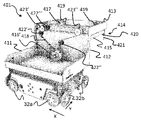
도 4b는 본 발명의 실시형태에 따른 컨테이너 핸들링 운반체(401)의 사시도이고, 여기에서 보호 커버를 제거하여, 컨테이너 핸들링 운반체(401)의 본체 유닛(410)을 구성하는 하부 섹션(411), 지지 섹션(412) 및 외팔보 섹션(413) 내의 구성요소의 셋업을 보다 양호하게 도시하였다. 도 4b의 실시형태에서, 상승 장치(414)는 상승 장치 모터(416') 및 적어도 2개의 상승 샤프트(417', 417")를 포함하는 것으로 개시되어 있다. 2개의 상승 샤프트(417', 417")는 외팔보 섹션(413) 내에서 평행하게 배열된다. 상승 프레임(415)에 연결된 상승 밴드(419)는 상승 샤프트(417', 417") 상으로 감기거나 그로부터 풀리고, 그에 의해서 상승 프레임(416) 및 상승 프레임(415)에 의해서 이송되는 임의의 저장 컨테이너(106)를 상하로 이동시킨다. 상승 샤프트 휠(423', 423")은 상승 샤프트(417)의 각각의 단부에 배열되고, 상승 샤프트(417)와 함께 각각 동작한다. 도 4b에 도시된 바와 같이, 상승 장치 모터(416')는 하부 섹션(411) 내에 배열된다. 상승 장치 모터(416') 및 2개의 상승 샤프트(417)는, 상승 샤프트 휠(423', 423") 및 도르래(422)를 통해서 연장되는 예를 들어 벨트와 같은 무한 가요성 힘 전달 요소(418)를 통해서 서로 연결되고, 그에 따라 제1 및 제2 상승 샤프트(417)가 동일 방향으로 동시에 회전되도록 보장한다. 상승 장치 모터(416')에 전력을 공급하기 위한 임의의 필수 전원(미도시)이 하부 섹션(413) 내에 배열될 수 있고, 그에 따라 무거운 저장 컨테이너(106)를 상승시키는 경우에 및/또는 컨테이너 핸들링 운반체(401)의 너무 큰 가속/감속의 결과로서 컨테이너 핸들링 운반체가 틸팅될 위험이 감소된 바람직한 중력 중심을 획득할 수 있다.4B is a perspective view of a
상승 프레임(415)은 상승 프레임(415)의 하부 표면의 모서리에 배열된 안내부(421)와 함께 도시되어 있고, 그에 따라 상승 프레임(41)의 파지 장치(420)를 저장 컨테이너(106) 상의 상보적인 상승 홀에 대해서 정렬시킬 수 있다.The
상승 장치 모터(416")에 전력을 공급하기 위한 임의의 필수 전원(미도시)이 하부 섹션(413) 내에 배열될 수 있고, 그에 따라 무거운 저장 컨테이너(106)를 상승시키는 경우에 및/또는 컨테이너 핸들링 운반체(401)의 너무 큰 가속/감속의 결과로서 컨테이너 핸들링 운반체가 틸팅될 위험이 감소된 바람직한 중력 중심을 획득할 수 있다.Any necessary power source (not shown) for powering the
도 4c는 도 4b의 상면도이고, 하부 섹션(411), 지지 섹션(412) 및 외팔보 섹션(413)을 도시한다.FIG. 4C is a top view of FIG. 4B , showing
도 4d 내지 도 4i는 상승 샤프트들(417', 417")의 반대 회전을 제공하는 상이한 셋업들의 예이다. 도 4d 내지 도 4i의 모든 예에서 개시된 바와 같이, 모든 힘 전달 셋업에서 공통되는 것은, 회전 가능 상승 장치 모터(416'), 각각의 상승 샤프트(417', 417")와 함께 회전하도록 각각 연결되는 제1 및 제2 상승 샤프트 휠(423', 423"), 적어도 하나의 도르래(422', 422"), 폐쇄 루프를 형성하고 적어도 하나의 도르래(422', 422")가 폐쇄 루프 내측에 배열되는 무한 벨트 형태의 힘 전달 요소(418)가 존재한다는 것이다. 또한, 제1 또는 제2 상승 샤프트 휠(423', 423")은 무한 벨트(418)의 내부 표면과 접촉되고, 제1 또는 제2 상승 샤프트 휠(423', 423") 중 다른 하나는 무한 벨트(418)의 외부 표면과 접촉된다. 이는, 제1 또는 제2 상승 샤프트 휠(423', 423")의 하나를 힘 전달 요소(418)에 의해서 형성된 폐쇄 루프 내측에 배열하고 제1 또는 제2 상승 샤프트 휠(423', 423")의 다른 하나를 힘 전달 요소(418)에 의해서 형성된 폐쇄 루프의 외측에 배열하는 것에 의해서 달성된다. (각각 제1 및 제2 상승 샤프트 휠(423', 423")을 통해서) 제1 및 제2 상승 샤프트(417', 417")가 반대 방향들로 회전하도록(역회전 하도록), (예를 들어, 무한 벨트의 대향 측면들에 작용하는) 제1 및 제2 상승 샤프트 휠(423', 423"), 안내 도르래(422', 422"), 및 힘 전달 요소(418)의 상호 셋업이 구성된다. 상승 중에 수평 안정성을 보장하기 위해서, 제1 및 제2 상승 샤프트 휠(423', 423")은 바람직하게 동일한 수평 평면 내에 배열된다. 도르래(들)(422', 422")는, 이들이 힘 전달 요소(418)의 이동 방향의 "변화"를 제공하도록, 고정 위치에서 힘 전달 요소(418)의 이동에 따라 배열된다. 도르래(422', 422")의 각각은 힘 전달 요소(418)를 제1 및 제2 상승 샤프트 휠(423', 423") 상으로 정확하게 유도하도록 배열되고, 그에 의해서 제1 및 제2 상승 샤프트 휠(423', 423")(그리고 그에 따라 상승 샤프트(417', 417"))가 반대 방향들로 회전될 수 있게 한다.Figures 4d-4i are examples of different setups that provide counter rotation of the
도 4d의 예에서, 하나의 도르래(422')가 도시되어 있다.In the example of FIG. 4D, one pulley 422' is shown.
도 4e 내지 도 4i의 예에서, 2개의 도르래(422', 422")를 포함하는 힘 전달 셋업의 많은 수의 예가 도시되어 있다. 힘 전달 요소(418)의 2개의 이동 방향 모두로 도르래(422', 422")가 제1 상승 샤프트 휠(423')을 따르도록 그리고 도르래(422', 422")가 제2 상승 샤프트 휠(423")을 따르도록, 도르래(422', 422")가 힘 전달 요소(418)의 경로를 따라서 교번적으로 배열된다.In the examples of FIGS. 4E-4I , a number of examples of force transmission setups are shown that include two
도 4g, 도 4h, 도 4i의 예에서, 힘 전달 요소(418)의 장력화(tensioning)를 위한 당김 휠(424)을 포함하는 예가 개시되어 있다. 당김 휠(424)은 예를 들어, 고정 브라켓 내의 개구부 내에서 조정될 수 있는 축을 갖는 회전 가능 도르래를 포함하는 편심 장력화 메커니즘일 수 있다. 힘 전달 요소(418)의 경로를 따른 당김 휠(424)의 위치는 바람직하게, 힘 전달 요소(418)의 경로 길이가 영향을 받을 수 있는(즉, 힘 전달 요소 내의 장력을 증가 또는 장력을 감소시키기 위해서 힘 전달 요소의 경로가 단축되거나 연장될 수 있는) 위치이다. 당김 휠(424)은 힘 전달 요소(418)에 의해서 형성된 폐쇄 루프의 내측(도 4g 및 도 4i) 또는 외측(도 4h)에 배열될 수 있다.In the examples of FIGS. 4G , 4H and 4I , an example is disclosed which includes a
도 4d 내지 도 4f의 예에서, 당김 휠과 같은 전용 장력화 메커니즘이 도시되어 있지 않으나; 장력화 메커니즘이 필요한 경우에, 도르래(422' 또는 422")의 하나가 장력화 메커니즘일 수 있고 당김 휠(424)에 의해서 대체될 수 있다.In the example of FIGS. 4D-4F , a dedicated tensioning mechanism such as a pull wheel is not shown; If a tensioning mechanism is required, one of the
도 5는 상승 장치(414)의 다른 셋업의 예이고, 상승 샤프트(417) 및 상승 샤프트(417', 417") 상으로 감길 수 있고 그로부터 풀릴 수 있는 상승 밴드에 더하여, 상승 장치 모터(416")가 또한 본체 유닛(410)의 외팔보 섹션(413) 내에 배열된다. 도 5의 상승 장치 모터(416")는 상승 샤프트(417', 417") 중 하나를 둘러싸는 무브러시 DC 모터이다. 상승 샤프트(417', 417")의 동기화된 동작은, 기재 내용이 본원에서 참조로 포함되는 WO 2019/137870 A1(출원인: Autostore Technology AS)의 도 5a 내지 도 5e 및 도 6a 내지 도 6h에서 개시된 바와 같은 힘 전달 요소와 같은 동기화 요소에 의해서 얻어질 수 있다. 5 is an example of another setup of a
도 6은 하나의 저장 컨테이너(106)를 제1 컨테이너 이송 위치(425) 상에서 그리고 하나의 저장 컨테이너(106)를 상승 장치(415)에 의해서 지지하는 본 발명의 실시형태에 따른 컨테이너 핸들링 운반체(401)의 단순화된 측면도이고, 컨테이너 핸들링 운반체(401)는 휠 기부 유닛(2) 및 본체 유닛을 포함하고, 본체 유닛은 하부 섹션(411), 지지 섹션(412), 및 외팔보 섹션(413)을 포함한다. 도 6의 컨테이너 핸들링 운반체의 구성요소는 도 4a의 컨테이너 핸들링 운반체와 유사하다. 제1 컨테이너 이송 위치(425)가 바람직하게 함몰되어, 제1 컨테이너 이송 위치(425)에 배치된 저장 컨테이너(425)를 위한 측부 지지부를 제공할 수 있다.6 shows a
도 7a 내지 도 7d는 2-차원적인 레일 시스템(108)을 포함하는 자동화된 저장 및 회수 시스템(1)에서 동작하는 제1 및 제2 컨테이너 핸들링 운반체(401) 사이에서 저장 컨테이너(106)를 전달하는 예시적인 방법을 단계별로 도시한다. 도 7a를 참조하면, 제1 컨테이너 핸들링 운반체(401)(즉, 저장 컨테이너(106)를 이송하지 않는 도면 우측의 운반체)가 제2 컨테이너 핸들링 운반체(401)(즉, 상승 장치 내에서 저장 컨테이너(106)를 이송하고 제1 컨테이너 이송 위치(425) 상에서 저장 컨테이너(106)를 이송하는 도면 좌측의 운반체)로부터 거리를 두고 배치된다. 제1 컨테이너 핸들링 운반체(401) 및 제2 컨테이너 핸들링 운반체(4011)는 레일 시스템(108) 상의 이웃 행들에서 동작한다.7a to 7d show the transfer of a
도 7b에서, 제1 및 제2 컨테이너 핸들링 운반체(401)는 도 7a의 상황에 비해서 서로 더 가까이 이동되었고, 제1 컨테이너 핸들링 운반체(401)의 상승 장치(414)는 제2 컨테이너 핸들링 운반체(401)의 하부 섹션(411)의 상부 표면/제1 컨테이너 이송 위치(425)의 거의 위에 있다.In FIG. 7B , the first and second
도 7c에서, 제1 컨테이너 핸들링 운반체(401)의 상승 장치(414)가 제2 컨테이너 핸들링 운반체(401)의 하부 섹션(411)의 상부 표면/제1 컨테이너 이송 위치(425)의 바로 위에 있도록, 제1 및 제2 컨테이너 핸들링 운반체(401)는 그들 자체가 이웃 그리드 셀(122) 내에 배치되었다.7c, the
도 7d에서, 제1 컨테이너 핸들링 운반체(401)의 상승 장치(414)가 제2 컨테이너 핸들링 운반체(401) 상의 제1 컨테이너 이송 위치(425) 상에 배치된 저장 컨테이너(106)를 상승시키기 위해 하강되었고, 저장 컨테이너(106)를 제1 컨테이너 이송 위치(425)로부터 상승시켰다. 이제, 저장 컨테이너(106)의 전달이 완료된다.In Fig. 7d, the
도 7a 내지 도 7d를 참조하면, 저장 컨테이너를 전달하는 방법은: Referring to Figures 7A-7D, a method of delivering a storage container is:
- 제1 컨테이너 핸들링 운반체(401)의 상승 장치(414)가 제2 컨테이너 핸들링 운반체(401)의 하부 섹션(411)의 상부 표면 바로 위에 있도록, 주 제어 시스템을 이용하여 제1 및 제2 컨테이너 핸들링 운반체(401)에 그들 자체가 이웃 그리드 셀(122) 내에 배치될 것을 지시하는 단계;- first and second container handling using the main control system such that the
- 저장 컨테이너(106)를 제2 컨테이너 핸들링 운반체(401)의 하부 섹션(411)의 제1 컨테이너 이송 위치(425)와 제1 컨테이너 핸들링 운반체(401)의 상승 장치(414) 사이에서 운송하는 단계를 포함할 수 있다. 저장 컨테이너(106)를 제2 컨테이너 핸들링 운반체(401)의 하부 섹션(411)의 상부 표면과 제1 컨테이너 핸들링 운반체(401)의 상승 장치(414) 사이에서 전달하는 단계는:- transporting the storage container (106) between the first container transfer position (425) of the lower section (411) of the second container handling vehicle (401) and the lifting device (414) of the first container handling vehicle (401). can include Transferring the
- 저장 컨테이너(106)를 이송 또는 지지하는 컨테이너 핸들링 운반체(401)를 마스터 운반체로서 설정하는 단계;- setting the
- 다른 컨테이너 핸들링 운반체(401)를 슬레이브 운반체로서 설정하는 단계;- setting another container handling vehicle (401) as a slave vehicle;
- get_bin 명령을 슬레이브 운반체에 송신하는 단계를 포함할 수 있고;- sending a get_bin command to the slave vehicle;
- 슬레이브 운반체는 get_bin 명령을 수행하고 저장 컨테이너(106)가 운반체 상승 장치(401)에 배치된 것이 확인될 때 그 내부 상태를 업데이트하며;- the slave vehicle executes the get_bin command and updates its internal state when it is confirmed that the
- 저장 컨테이너가 운반체 상에 배치된 것이 확인될 때, 저장 컨테이너(106)가 마스터 운반체의 제1 컨테이너 이송 위치(425)로부터 충분히 치워지도록, 슬레이브 운반체가 제어 시스템에 확인을 송신하고;- when it is confirmed that the storage container has been placed on the vehicle, the slave vehicle sends a confirmation to the control system so that the
- 마스터 운반체는 저장 컨테이너(106)가 옮겨진 것을 검출하고, bin_update status를 제어 시스템(500)에 송신할 것이며;- the master vehicle will detect that the
- 제어 시스템(500)은 로직 상태를 업데이트하여 마스터 운반체 및 슬레이브 운반체의 물리적 상태와 매칭시킨다.- The
get_bin 명령은 전달되는 저장 컨테이너(106)의 높이를 규정하는 매개변수를 포함할 수 있고, 그에 따라 마스터 운반체의 상승 장치(414)가 제1 컨테이너 이송 위치에 배치된 저장 컨테이너의 최상부 부분과 동일한 위치로 하강된다.The get_bin command may include a parameter defining the height of the
다른 컨테이너 핸들링 운반체(401)를 슬레이브 운반체로서 설정하는 단계는 슬레이브 운반체가 마스터 운반체와 함께 이동하고 마스터 운반체를 따르게 하도록 synchronize_to_master 명령을 슬레이브 운반체에 송신하는 단계를 포함할 수 있다. 이는, 저장 컨테이너(106)를 제2 컨테이너 핸들링 운반체(401)의 하부 섹션(411)의 상부 표면과 제1 컨테이너 핸들링 운반체(401)의 상승 장치(414) 사이에서 전달할 수 있게 한다. 동기화가 달성되었을 때, 슬레이브 운반체는 선택적으로 메시지를 주 제어 시스템에 송신할 수 있다. 대안적으로, 주 제어 시스템은, 슬레이브 운반체와 마스터 운반체의 위치 정보를 기초로 동기화가 이루어졌다는 것을 결정할 수 있다. 슬레이브 운반체가 마스터 운반체와 함께 이동하고 마스터 운반체를 따를 때, 동기화가 이루어진 것이다.Setting the other
마스터 운반체는 속력, 가속도와 같은 이동 데이터, 및 위치 데이터를 슬레이브 운반체에 송신할 수 있다. 슬레이브 운반체는 그 자체의 이동을 수신된 이동 데이터에 동기화하기 위해서 이동 데이터를 이용할 수 있다. 마스터 운반체는 주 제어 시스템을 통해서 이동 데이터를 송신할 수 있다. 대안적으로 또는 부가적으로, 마스터 운반체는 마스터 운반체와 슬레이브 운반체 사이의 근거리 통신을 이용하여 이동 데이터를 슬레이브 운반체에 직접 송신할 수 있다. 근거리 통신은, 근거리 무선통신(NFC) 또는 적외선(IR)과 같은, 임의의 적합한 근거리의 무선 통신일 수 있다.The master vehicle can transmit movement data such as speed and acceleration, and position data to the slave vehicle. The slave vehicle may use the movement data to synchronize its movement to the received movement data. The master vehicle can transmit movement data through the main control system. Alternatively or additionally, the master vehicle may transmit movement data directly to the slave vehicle using short range communication between the master vehicle and the slave vehicle. The short range communication may be any suitable short range wireless communication, such as near field communication (NFC) or infrared (IR).
슬레이브 운반체 및 마스터 운반체의 동기화된 이동은 슬레이브 운반체가 마스터 운반체의 뒤를 따르는 기차-유사 동기화를 포함할 수 있거나, 동기화된 이동은 슬레이브 운반체가 마스터 운반체와 나란히 이동하는 병렬 동기화를 포함할 수 있다.Synchronized movement of a slave vehicle and master vehicle may include a train-like synchronization in which the slave vehicle follows the master vehicle, or synchronized movement may include parallel synchronization in which the slave vehicle moves alongside the master vehicle.
자동화된 저장 및 회수 시스템은, 마스터 운반체 및 슬레이브 운반체 모두의 위치를 결정하기 위해서, 비행시간(TOF) 측정 시스템과 같은 다변측정(multilateration) 기술을 이용하는 위치 결정 시스템을 포함할 수 있다. 주 제어 시스템은 제1 컨테이너 핸들링 운반체 위치의 위치 결정 시스템으로부터의 위치 데이터 및 제2 컨테이너 핸들링 운반체 위치의 위치 데이터를 계속 수신한다. 주 제어 시스템은 위치 데이터를 이용하여, 슬레이브 운반체가 마스터 운반체로부터의 미리 결정된 간격 이내에서 마스터 운반체와 함께 이동하고 마스터 운반체를 따르도록 지시할 수 있다. 그에 의해서, 저장 컨테이너(106)를 제2 컨테이너 핸들링 운반체(401)의 하부 섹션(411)의 상부 표면과 제1 컨테이너 핸들링 운반체(401)의 상승 장치(414) 사이에서 전달하는 단계가 이동 중에 수행될 수 있도록, 마스터 운반체 및 슬레이브 운반체의 이동이 동기화된다.The automated storage and retrieval system may include a positioning system that uses multilateration techniques, such as a time-of-flight (TOF) measurement system, to determine the position of both master and slave vehicles. The main control system continues to receive position data from the positioning system of the first container handling vehicle position and position data of the second container handling vehicle position. The master control system can use the position data to instruct the slave vehicle to move with and follow the master vehicle within a predetermined distance from the master vehicle. Thereby, the step of transferring the
컨테이너 핸들링 운반체는 레일 시스템 상의 컨테이너 핸들링 운반체의 위치를 검출할 수 있는 센서, 및/또는 근처 컨테이너 핸들링 운반체까지의 거리를 검출하는 근접도 센서와 함께 배열될 수 있다. 주 제어 시스템은, 슬레이브 운반체의 근접도 센서로부터의 수신된 거리 데이터를 기초로, 마스터 운반체로부터 미리 결정된 간격 내에서 마스터 운반체와 함께 이동하고 마스터 운반체를 따르도록 슬레이브 운반체에 지시할 수 있다. 그에 의해서, 저장 컨테이너(106)를 제2 컨테이너 핸들링 운반체(401)의 하부 섹션(411)의 상부 표면과 제1 컨테이너 핸들링 운반체(401)의 상승 장치(414) 사이에서 전달하는 단계가 이동 중에 수행될 수 있도록, 마스터 운반체 및 슬레이브 운반체의 이동이 동기화된다.The container handling vehicle may be arranged with a sensor capable of detecting the position of the container handling vehicle on the rail system, and/or a proximity sensor that detects a distance to nearby container handling vehicles. The master control system may instruct the slave vehicle to move with and follow the master vehicle within a predetermined distance from the master vehicle, based on received distance data from the slave vehicle's proximity sensor. Thereby, the step of transferring the
컨테이너 핸들링 운반체들은 서로 물리적으로 접촉되어 함께 이동하도록 구성될 수 있다. 주 제어 시스템은, 마스터 운반체와 물리적으로 접촉되도록 먼저 이동시키는 것, 그리고 접촉 후에 마스터 운반체에 미는 힘을 계속 인가하여 물리적인 접촉을 유지하게 하는 것에 의해서, 슬레이브 운반체가 마스터 운반체와 함께 이동하고 마스터 운반체를 따르도록 지시할 수 있다. 그에 의해서, 저장 컨테이너(106)를 제2 컨테이너 핸들링 운반체(401)의 하부 섹션(411)의 상부 표면과 제1 컨테이너 핸들링 운반체(401)의 상승 장치(414) 사이에서 전달하는 단계가 이동 중에 수행될 수 있도록, 마스터 운반체 및 슬레이브 운반체의 이동이 동기화된다.The container handling vehicles may be configured to move together in physical contact with each other. The main control system moves the slave vehicle with the master vehicle and moves it with the master vehicle by first moving it into physical contact with the master vehicle, and then continuing to apply a pushing force to the master vehicle to maintain physical contact after contact. can be instructed to follow. Thereby, the step of transferring the
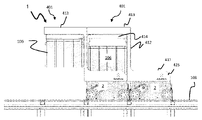
도 8a 내지 도 8d는 본 발명의 실시형태에 따른 컨테이너 핸들링 운반체(401)의 예를 도시하며, 제1 컨테이너 이송 위치(425) 상의 컨베이어(427)가 컨테이너 핸들링 운반체(401)의 임의의 짧은 측면을 통해 저장 컨테이너(106)를 역으로 다른 컨테이너 핸들링 운반체 상으로 또는 외부 컨베이어로 전달하도록 구성된다. 저장 컨테이너(106)가 역으로 다른 컨테이너 핸들링 운반체 상으로 또는 외부 컨베이어로 직접 전달될 수 있도록, 컨베이어(427)가 또한 도 8a의 실시형태에 비해서 90도로 배향될 수 있다(도 8d 참조). 도 8a는 제1 컨테이너 이송 위치(425) 상에서 저장 컨테이너를 이송하지 않을 때의 상황을 도시하고, 도 8b는 제1 컨테이너 이송 위치(425) 상에서 저장 컨테이너(106)를 가질 때의 상황으로 도시하며, 도 8c는 제1 컨테이너 이송 위치(425) 상의 컨베이어(427)로부터 외부 컨베이어(428)로의 가능한 저장 컨테이너(106)의 전달을 도시한다. 외부 컨베이어(428)의 상부 표면이 바람직하게 제1 컨테이너 캐리어 위치(425) 상의 컨베이어(427)의 상부 표면과 실질적으로 동일한 높이에 배열된다.8A-8D show an example of a
도 7a, 도 7b 및 도 8a를 참조하면, 하부 섹션(411)은, 지지 웹(429)의 쌍에 대해서 함몰된, 상부 표면(425)을 구비하며, 이러한 상부 표면(425)은 저장 컨테이너(106)를 이송하기 위한 제1 컨테이너 이송 위치(425)를 제공한다. 지지 섹션(412)은 하부 섹션(411)의 지지 웹(429)의 쌍으로부터 수직으로 연장되고, 지지 섹션(412)은 하부 섹션(411)의 풋프린트보다 작은 수평 범위의 풋프린트를 갖는다.Referring to Figures 7a, 7b and 8a, the
도 9는, 제1 컨테이너 이송 위치(425)를 제공하는 상부 표면(425) 및 제2 컨테이너 이송 위치(426)를 제공하는 지지 표면(426)을 포함하는 본 발명의 실시형태에 따른 컨테이너 핸들링 운반체(401)의 예를 도시한다. 도 9의 컨테이너 핸들링 운반체(401)는 도 4a 및 도 6의 컨테이너 핸들링 운반체와 유사한 구성요소를 포함하고, 이에 대해서는 여기에서 반복하지 않을 것이다. 그러나, 도 9의 컨테이너 핸들링 운반체(401)는 제2 컨테이너 이송 위치(426)를 또한 포함한다. 제2 컨테이너 이송 위치(426)는 제1 컨테이너 이송 위치(425)의 위에 배열되는 것으로 개시되어 있다. 바람직하게, 제1 및 제2 컨테이너 이송 위치(425, 426)는 하부 레일 시스템(108) 상에서 동일한 수직 투영을 형성한다.9 shows a container handling vehicle according to an embodiment of the present invention comprising an
도 10a는, 회수 위치에서 제2 컨테이너 캐리어 위치(426)가 위쪽으로 지향되도록 피벗 연결부(430)를 통한 회수 위치에서의 도 9의 제2 컨테이너 이송 위치를 도시한다. 화살표(A)는 도 10a에서 수평 연장 위치(도 9) 및 수직 회수 위치로부터의 이동 방향을 도시한다. 피벗 연결부(430)는 제2 컨테이너 캐리어(426)의 회전 축을 나타낸다.FIG. 10A shows the second container transfer position of FIG. 9 in the retrieval position via the
도 10b는 제2 컨테이너 캐리어 위치(426)의 가능한 연장 위치의 다른 예를 도시한다. 도 10b에서, 제2 컨테이너 캐리어 위치(426)는 저장 컨테이너(미도시)를 수용할 수 있는 연장된 수평 위치에 있다.10B shows another example of a possible extended position of the second
도 10c는 도 10b의 예를 도시하고, 여기에서 제2 컨테이너 캐리어 위치(426)가 180도 피벗되었고 회수 위치에 있을 때 컨테이너 핸들링 운반체(401)의 외팔보 섹션(413) 상으로 뒤집혀 놓인다. 제2 컨테이너 이송 위치(426)는, 화살표(A)로 도시된 바와 같이, 피벗 연결 배열체(430)를 중심으로 회수 위치로부터 연장 위치로 피벗되었다.10C shows the example of FIG. 10B , in which the second
도 11a 및 도 11b는 제2 컨테이너 캐리어 위치(426)의 또 다른 예를 도시하고, 도 11a에서, 제2 컨테이너 캐리어 위치(426)는 제1 컨테이너 이송 위치(425) 바로 위의 연장 위치에 있고, 도 11b에서, 제2 컨테이너 이송 위치는 직선형 이동 배열체(미도시)에 의해서 회수 위치로 (화살표(A)로 표시된 바와 같이) 직선적으로 이동되었다.11A and 11B show another example of a second
따라서, 도 10a, 도 10b, 도 10c 그리고 도 11a 및 도 11b를 참조하면, 제1 컨테이너 이송 위치(425)에 배치된 저장 컨테이너(106)에 접근하기 위해서, 제2 컨테이너 이송 위치(426)가 바람직하게:Therefore, referring to FIGS. 10A, 10B, 10C and 11A and 11B , in order to access the
- 제2 컨테이너 이송 위치(426)가 제1 컨테이너 이송 위치(425)의 수직 투영을 넘어서, 제1 컨테이너 이송 위치(425)의 상부 표면 및/또는 제1 컨테이너 이송 위치(425)에 배치된 저장 컨테이너(106)에 대한 접근을 제공하는 회수 위치와,- storage arranged on the upper surface of the first
- 제2 컨테이너 이송 위치(426)가 제1 컨테이너 이송 위치(425)의 수직 투영에 또는 그 내부에 있는 연장 위치 사이에서 이동될 수 있다. 제2 컨테이너 이송 위치(426)는 피벗 연결 배열체(430)(도 10a 내지 도 10c) 또는 직선형 이동 배열체(도 11a 및 도 11b)(여기에서 제2 컨테이너 이송 위치는 직선형 이동 배열체를 통해서 회수 위치와 연장 위치 사이에서 직선적으로 이동될 수 있다)를 통해서 회수 위치와 연장 위치 사이에서 이동될 수 있다.- The second
피벗 연결부(도 10a 내지 도 10c 참조)를 이용하는 경우에, 피벗 연결부(430)는:When using a pivot connection (see FIGS. 10A-10C ), the pivot connection 430:
- 회수 위치에서, 제2 컨테이너 이송 위치(426)가 실질적으로 수직이 되도록, 그리고- in the withdrawal position, the second
- 연장 위치에서 제2 컨테이너 캐리어 위치(426)가 실질적으로 수평으로 연장되도록, 배열될 수 있다.- in the extended position the second
직선형 이동 배열체(도 11a 및 도 11b 참조)를 이용하는 경우에, 직선형 이동 배열체는:When using a linear displacement arrangement (see FIGS. 11A and 11B ), the linear displacement arrangement:
- 회수 위치에서, 제2 컨테이너 이송 위치(426)가 제1 컨테이너 이송 위치(425)를 넘어서는 그리고 외팔보 섹션(413) 위의 위치로 이동되도록, 그리고- in the withdrawal position, the second
- 연장 위치에서, 제2 컨테이너 이송 위치(426)가 제1 컨테이너 이송 위치(425)의 위에 있도록, 배열될 수 있다.- It can be arranged such that, in the extended position, the second
선행 설명에서, 본 발명에 따른 자동화된 저장 및 회수 시스템의 여러 양태가 예시적인 실시형태를 참조하여 설명되었다. 그러나, 이러한 설명은 제한적인 의미로 해석되는 것으로 의도되지 않는다. 당업자에게 명확한, 예시적인 실시형태의 여러 수정 및 변경뿐만 아니라, 시스템의 다른 실시형태가 이하의 청구범위에 의해서 규정되는 바와 같은 본 발명의 범위에 포함되는 것으로 간주된다.In the foregoing description, several aspects of the automated storage and retrieval system according to the present invention have been described with reference to exemplary embodiments. However, this description is not intended to be construed in a limiting sense. Other embodiments of the system, as well as various modifications and variations of the exemplary embodiments obvious to those skilled in the art, are considered to be within the scope of the present invention as defined by the following claims.
1
자동화된 저장 및 회수 시스템
2
휠 기부 유닛
4, 4'
전기 모터
6
재충전 가능 배터리
7
휠 변위 조립체
8
휠 변위 조립체용 전기 모터
9
상단 패널/플랜지
10
관통-홀
20
중심 개구부
21
전자 제어 시스템
30
원격 동작 전달 운반체
32a, 32b
휠 배열체, 제1 및 제2 세트의 휠
100
프레임워크 구조물
102
프레임워크 구조물의 직립 부재
103
프레임워크 구조물의 수평 부재
104
저장 그리드
105
저장 컬럼
106
저장 컨테이너
106'
저장 컨테이너의 특정 위치
107
적층체
108
레일 시스템
110
제1 방향(X)의 제1 세트의 평행 레일
110a, 110b
제1 세트의 레일의 트랙
111
제2 방향(Y)의 제2 세트의 평행 레일
111a, 111b
제2 세트의 레일의 트랙
112
접근 개구부/그리드 컬럼
115
그리드 개구부
119
제1 포트 컬럼
120
제2 포트 컬럼
122
그리드 셀
201
종래 기술의 저장 컨테이너 운반체
201a
저장 컨테이너 운반체(201)의 운반체 본체
201b
구동 수단/바퀴 배열체, 제1 방향(X)
201c
구동 수단/바퀴 배열체, 제2 방향(Y)
301
종래 기술의 외팔보 저장 컨테이너 운반체
301a
저장 컨테이너 운반체(301)의 운반체 본체
301b
제1 방향(X)의 구동 수단
301c
제2 방향(Y)의 구동 수단
304
컨테이너 핸들링 운반체(301)의 파지 장치의 부분
401
컨테이너 핸들링 운반체
410
본체 유닛
411
본체 유닛의 하부 섹션
412
본체 유닛의 지지 섹션
413
본체 유닛의 외팔보 섹션
414
상승 장치
415
상승 프레임
416', 416"
상승 장치 모터
417', 417"
상승 샤프트
418
힘 전달 요소
419
상승 밴드
420
파지 장치
421
안내부
422', 422"
도르래
423', 423"
상승 샤프트 휠
424
당김 휠
425
상부 표면/제1 컨테이너 이송 위치
426
지지 표면/제2 컨테이너 이송 위치
427
컨베이어
428
외부 컨베이어
429
지지 웹
430
피벗 연결 배열체
500
제어 시스템
A
이동 방향(들)을 보여 주는 화살표
X
제1 방향
Y
제2 방향
Z
제3 방향
C
간극
h1
제1 높이
h2
제2 높이1 Automated storage and retrieval system
2 wheel base unit
4, 4' electric motor
6 rechargeable battery
7 wheel displacement assembly
Electric motor for 8 wheel displacement assembly
9 Top panel/flange
10 through-holes
20 center opening
21 electronic control system
30 Remote Action Delivery Vehicle
32a, 32b wheel arrangement, first and second sets of wheels
100 framework structures
102 Upright members of framework structures
103 Horizontal members of framework structures
104 save grid
105 storage column
106 storage container
106' Specific location of storage container
107 laminate
108 rail system
110 first set of parallel rails in first direction (X)
110a, 110b Tracks of the first set of rails
111 second set of parallel rails in second direction (Y)
111a, 111b Tracks of the second set of rails
112 access opening/grid column
115 grid openings
119 first port column
120 second port column
122 grid cells
201 prior art storage container carrier
201a Carrier body of
201b drive means/wheel arrangement, first direction (X)
201c drive means/wheel arrangement, second direction (Y)
301 Prior Art Cantilever Storage Container Carrier
301a The carrier body of the
301b driving means in the first direction (X)
301c Driving means in the second direction (Y)
304 Part of the gripping device of the container handling vehicle (301)
401 Container handling carrier
410 body unit
Lower section of the 411 body unit
Support section of 412 body unit
Cantilever section of 413 body unit
414 lift device
415 Rising Frame
416', 416" lift gear motor
417', 417" Rising Shaft
418 force transmission element
419 rising band
420 gripping device
421 information department
422', 422" pulley
423', 423" raised shaft wheel
424 pull wheel
425 top surface/first container transfer position
426 support surface/second container transfer position
427 conveyor
428 External Conveyor
429 support web
430 Pivot Connection Array
500 control system
A Arrows showing direction(s) of movement
X first direction
Y 2nd direction
Z 3rd direction
C gap
h1 first height
h2 second height
Claims (23)
- 컨테이너 핸들링 운반체(401)를 제1 및 제2 방향(X, Y) 각각으로 레일 시스템(108)을 따라 안내하기 위한 제1 및 제2 세트의 휠(32a, 32b)을 포함하는 휠 기부 유닛(2)으로서, 제1 및 제2 세트의 휠(32a, 32b)은 휠 기부 유닛(2)의 외부 주변부를 형성하는, 휠 기부 유닛(2);
- 본체 유닛(410)으로서:
휠 기부 유닛(2) 상에 제공되는 하부 섹션(411)으로서, 하부 섹션(411)은, 휠 기부 유닛(2) 이하의 수평 범위를 갖는 풋프린트를 구비하고, 하부 섹션(411)은 상부 표면을 구비하고, 상부 표면(425)은 저장 컨테이너(106)를 이송하기 위한 제1 컨테이너 이송 위치(425)를 제공하는, 하부 섹션(411);
하부 섹션(411)으로부터 수직으로 연장되는 지지 섹션(412)으로서, 하부 섹션(411)의 풋프린트보다 작은 수평 범위의 풋프린트를 갖는, 지지 섹션(412); 및
지지 섹션(412)으로부터 하부 섹션(411)의 풋프린트를 넘어서 수평으로 연장되는 외팔보 섹션(413)을 포함하는, 본체 유닛(410); 및
- 외팔보 섹션(413)으로부터 매달린 상승 프레임(415)을 포함하는 상승 장치(414)를 포함하는, 컨테이너 핸들링 운반체(401).A container handling vehicle 401 for operation on a two-dimensional rail system 108, the two-dimensional rail system traversing the upper end of the frame structure 100 in a first direction X ( 401), and a first set of parallel rails 110 for guiding the movement of the container handling vehicle 401 in a second direction Y perpendicular to the first direction. A second set of parallel rails (111) arranged perpendicularly to the rails (110), wherein the first and second sets of parallel rails (110, 111) form a rail system (108) into a plurality of grid cells (122). ), and the container handling vehicle 401 is:
- a wheel base unit comprising first and second sets of wheels 32a, 32b for guiding the container handling vehicle 401 along the rail system 108 in first and second directions (X, Y) respectively (2), the wheel base unit (2), wherein the first and second sets of wheels (32a, 32b) form an outer periphery of the wheel base unit (2);
- as body unit 410:
A lower section 411 provided on the wheel base unit 2, the lower section 411 having a footprint with a horizontal extent below the wheel base unit 2, the lower section 411 having an upper surface a lower section (411), wherein the upper surface (425) provides a first container transfer location (425) for transferring the storage container (106);
a support section 412 extending vertically from the lower section 411, having a footprint of a smaller horizontal extent than that of the lower section 411; and
a body unit 410, comprising a cantilever section 413 extending horizontally from the support section 412 beyond the footprint of the lower section 411; and
- A container handling vehicle (401) comprising a lifting device (414) comprising a lifting frame (415) suspended from a cantilever section (413).
상승 장치(414)는 외팔보 섹션(413)으로부터 매달린 상승 프레임(415)을 포함하고, 상승 프레임(415)은 상승 프레임(415)이 외팔보 섹션(413)에 인접하여 상부 위치에 도킹될 때 제2 높이(h2)에서 최하부 부분을 구비하며;
제2 높이(h2)는, 상승 프레임(415)이 그 상부 위치에 도킹될 때, 제1 높이(h1)보다 높고, 그에 따라 제1 컨테이너 핸들링 운반체(401)의 도킹된 상승 프레임(415)의 최하부 부분은, 제1 및 제2 컨테이너 운반체(401)가 인접 그리드 셀(122) 상에서 서로를 통과할 때, 제2 컨테이너 핸들링 운반체(401)의 본체 유닛(410)의 하부 섹션(411)의 상부 표면 상에 배치되는 저장 컨테이너(106)의 최상부 부분 위를 통과할 수 있는, 컨테이너 핸들링 운반체(401).The method according to claim 1, wherein when the storage container (106) is placed on the upper surface, the uppermost part of the storage container (106) exhibits a first height (h1); And
The lifting device 414 includes a lifting frame 415 suspended from a cantilever section 413, the lifting frame 415 being docked in an upper position adjacent to the cantilever section 413 when the lifting frame 415 is docked in a second position. having a lowermost part at height h2;
The second height h2 is higher than the first height h1 when the lifting frame 415 is docked in its upper position, and thus the height of the docked lifting frame 415 of the first container handling vehicle 401. The lowermost part is the upper part of the lower section 411 of the body unit 410 of the second container handling vehicle 401 when the first and second container carriers 401 pass each other on adjacent grid cells 122. A container handling vehicle (401), capable of passing over the uppermost portion of a storage container (106) disposed on a surface.
- 제2 컨테이너 이송 위치(426)가 제1 컨테이너 이송 위치(425)의 수직 투영을 넘어서는 회수 위치와,
- 제2 컨테이너 이송 위치(426)가 제1 컨테이너 이송 위치(425)의 수직 투영에 또는 그 내부에 있는 연장 위치 사이에서 이동될 수 있는, 컨테이너 핸들링 운반체(401).12. The method of claim 10 or 11, wherein the second container transfer location (426) is:
- a withdrawal position where the second container transfer position 426 is beyond the vertical projection of the first container transfer position 425;
- A container handling vehicle (401), movable between extended positions in which the second container transfer position (426) is in or within a vertical projection of the first container transfer position (425).
- 제1 컨테이너 핸들링 운반체(401)의 상승 장치(414)가 제2 컨테이너 핸들링 운반체(401)의 하부 섹션(411)의 상부 표면 바로 위에 있도록, 주 제어 시스템을 이용하여 제1 및 제2 컨테이너 핸들링 운반체(401)에게 그들 자체가 이웃 그리드 셀(122) 내에 배치될 것을 지시하는 단계;
- 저장 컨테이너(106)를 제2 컨테이너 핸들링 운반체(401)의 하부 섹션(411)의 제1 컨테이너 이송 위치와 제1 컨테이너 핸들링 운반체(401)의 상승 장치(414) 사이에서 전달하는 단계를 포함하는, 방법.A method for transferring a storage container (106) between first and second container handling vehicles (401) according to any one of claims 1 to 14 operating on an automated storage and retrieval system, comprising: The storage and retrieval system includes a two-dimensional rail system 108, which crosses the upper end of the frame structure 100 and moves the container handling vehicle 401 in a first direction X. A first set of parallel rails 110 arranged to guide the movement, and a first set of rails 110 for guiding the movement of the container handling vehicle 401 in a second direction Y perpendicular to the first direction. ), the first and second sets of parallel rails (110, 111) divide the rail system (108) into a plurality of grid cells (122). and how:
- first and second container handling using a main control system such that the lifting device 414 of the first container handling vehicle 401 is directly above the upper surface of the lower section 411 of the second container handling vehicle 401 instructing carriers 401 to place themselves within neighboring grid cells 122;
- transferring the storage container (106) between the first container transfer position of the lower section (411) of the second container handling vehicle (401) and the lifting device (414) of the first container handling vehicle (401), , method.
- 저장 컨테이너(106)를 이송 또는 지지하는 컨테이너 핸들링 운반체(401)를 마스터 운반체로서 설정하는 단계;
- 다른 컨테이너 핸들링 운반체를 슬레이브 운반체로서 설정하는 단계;
- get_bin 명령을 슬레이브 운반체에 송신하는 단계를 포함하고;
- 슬레이브 운반체는 get_bin 명령을 수행하고 저장 컨테이너가 운반체 상에 배치된 것이 확인될 때 그 내부 상태를 업데이트하며;
- 저장 컨테이너가 운반체 상에 배치된 것이 확인될 때, 저장 컨테이너가 마스터 운반체의 제1 컨테이너 이송 위치로부터 충분히 치워지도록, 슬레이브 운반체가 제어 시스템에 확인을 송신하고;
- 마스터 운반체는 저장 컨테이너가 옮겨진 것을 검출하고, bin_update status를 제어 시스템에 송신할 것이며;
- 제어 시스템은 로직 상태를 업데이트하여 마스터 운반체 및 슬레이브 운반체의 물리적 상태와 매칭시키는, 방법.19. The method of claim 18, wherein transferring the storage container (106) between the upper surface of the lower section (411) of the second container handling vehicle (401) and the lifting device (414) of the first container handling vehicle (401) comprises: :
- setting the container handling vehicle 401 that transports or supports the storage container 106 as a master vehicle;
- setting another container handling vehicle as a slave vehicle;
- sending a get_bin command to the slave vehicle;
- the slave vehicle performs a get_bin command and updates its internal state when it is confirmed that the storage container is placed on the vehicle;
- when it is confirmed that the storage container has been placed on the vehicle, the slave vehicle sends a confirmation to the control system so that the storage container is sufficiently removed from the first container transfer position of the master vehicle;
- the master vehicle will detect that the storage container has been moved and will send bin_update status to the control system;
- the control system updates the logical state to match the physical state of the master vehicle and the slave vehicle.
- 저장 컨테이너(106)를 컨테이너 핸들링 운반체(401)와 컨테이너 핸들링 운반체(401) 외측의 외부 위치 사이에서 전달하기 위해서, 하부 섹션(411)의 제1 컨테이너 이송 위치 상의 컨베이어를 이용하는 단계를 포함하는, 방법.A method for transferring a storage container between a container handling vehicle (401) according to any one of claims 1 to 14 and an external container transfer location, the container handling vehicle operating on an automated storage and retrieval system and operating on an automated storage and retrieval system. The storage and retrieval system includes a two-dimensional rail system 108, which crosses the upper end of the frame structure 100 and moves the container handling vehicle 401 in a first direction X. A first set of parallel rails 110 arranged to guide the movement, and a first set of rails 110 for guiding the movement of the container handling vehicle 401 in a second direction Y perpendicular to the first direction. ), the first and second sets of parallel rails (110, 111) divide the rail system (108) into a plurality of grid cells (122). and how:
- using a conveyor on the first container transfer position of the lower section (411) to transfer the storage container (106) between the container handling vehicle (401) and an external location outside the container handling vehicle (401), method.
Applications Claiming Priority (7)
| Application Number | Priority Date | Filing Date | Title |
|---|---|---|---|
| NO20200467 | 2020-04-16 | ||
| NO20200467A NO20200467A1 (en) | 2020-04-16 | 2020-04-16 | Container handling vehicle with cantilever construction and automated storage and retrieval system comprising a plurality of the container handling vehicles |
| NO20200612A NO346266B1 (en) | 2020-05-25 | 2020-05-25 | Container handling vehicle for lifting a storage container and method of receiving a target storage container from a storage system |
| NO20200612 | 2020-05-25 | ||
| NO20200672 | 2020-06-05 | ||
| NO20200672A NO346363B1 (en) | 2020-04-16 | 2020-06-05 | Container handling vehicle comprising a container carrying position, associated system and methods |
| PCT/EP2021/059309 WO2021209337A1 (en) | 2020-04-16 | 2021-04-09 | Container handling vehicle comprising a container carrying position, associated system and methods |
Publications (1)
| Publication Number | Publication Date |
|---|---|
| KR20230002392A true KR20230002392A (en) | 2023-01-05 |
Family
ID=75441936
Family Applications (1)
| Application Number | Title | Priority Date | Filing Date |
|---|---|---|---|
| KR1020227035216A KR20230002392A (en) | 2020-04-16 | 2021-04-09 | Container handling vehicle including container transfer position, associated system and method |
Country Status (7)
| Country | Link |
|---|---|
| US (1) | US20230142253A1 (en) |
| EP (1) | EP4136041A1 (en) |
| JP (1) | JP2023523547A (en) |
| KR (1) | KR20230002392A (en) |
| CN (1) | CN115427326A (en) |
| CA (1) | CA3172491A1 (en) |
| WO (1) | WO2021209337A1 (en) |
Families Citing this family (3)
| Publication number | Priority date | Publication date | Assignee | Title |
|---|---|---|---|---|
| US20230066910A1 (en) * | 2021-08-31 | 2023-03-02 | Intelligrated Headquarters, Llc | Robotic system for stacking and de-stacking |
| NO20220739A1 (en) * | 2022-06-29 | 2024-01-01 | Autostore Tech As | Container handling vehicle with motor at lower elevation than first and second lifting shafts, a system comprising the container handling vehicle, and method of driving the first and second lifting shafts |
| NO20221383A1 (en) * | 2022-12-21 | 2024-06-24 | Autostore Tech As | Method and system for moving automated vehicles of an automated storage system |
Family Cites Families (8)
| Publication number | Priority date | Publication date | Assignee | Title |
|---|---|---|---|---|
| FI126245B (en) * | 2005-03-09 | 2016-08-31 | Konecranes Finland Oy | Procedure for placing a palletless goods package on a warehouse shelf and handing it over therefrom and administering the package logistics and equipment for carrying out the procedure |
| NO334806B1 (en) | 2012-11-13 | 2014-06-02 | Jakob Hatteland Logistics As | storage System |
| NO335839B1 (en) | 2012-12-10 | 2015-03-02 | Jakob Hatteland Logistics As | Robot for transporting storage containers |
| NO337544B1 (en) | 2014-06-19 | 2016-05-02 | Jakob Hatteland Logistics As | Remote controlled vehicle assembly to pick up storage containers from a storage system |
| NO20170216A1 (en) | 2017-02-13 | 2018-08-14 | Autostore Tech As | Rail arrangement for wheeled vehicles in a storage system |
| NO347820B1 (en) | 2018-01-09 | 2024-04-08 | Autostore Tech As | Automated storage and retrieval system, a container handling vehicle which can operate on an automated storage and retrieval system and a method of operating an automated storage and retrieval system |
| WO2019238703A1 (en) * | 2018-06-12 | 2019-12-19 | Autostore Technology AS | Storage system with modular container handling vehicles |
| NO20190089A1 (en) * | 2019-01-23 | 2020-07-24 | Autostore Tech As | Service vehicle, an automated storage and retrieval system and a method for operating a service vehicle on the system. |
-
2021
- 2021-04-09 KR KR1020227035216A patent/KR20230002392A/en unknown
- 2021-04-09 EP EP21717871.4A patent/EP4136041A1/en active Pending
- 2021-04-09 US US17/916,398 patent/US20230142253A1/en active Pending
- 2021-04-09 JP JP2022562473A patent/JP2023523547A/en active Pending
- 2021-04-09 WO PCT/EP2021/059309 patent/WO2021209337A1/en unknown
- 2021-04-09 CA CA3172491A patent/CA3172491A1/en active Pending
- 2021-04-09 CN CN202180028703.3A patent/CN115427326A/en active Pending
Also Published As
| Publication number | Publication date |
|---|---|
| WO2021209337A1 (en) | 2021-10-21 |
| CN115427326A (en) | 2022-12-02 |
| EP4136041A1 (en) | 2023-02-22 |
| JP2023523547A (en) | 2023-06-06 |
| CA3172491A1 (en) | 2021-10-21 |
| US20230142253A1 (en) | 2023-05-11 |
Similar Documents
| Publication | Publication Date | Title |
|---|---|---|
| KR20230002392A (en) | Container handling vehicle including container transfer position, associated system and method | |
| JP2021504265A (en) | Automated warehouse system | |
| WO2019017294A1 (en) | Transport vehicle and transport facility | |
| US20230183002A1 (en) | Container handling vehicle which can load and/or unload itself | |
| US20220388773A1 (en) | Rescue system and methods for retrieving a malfunctioning vehicle from a rail system | |
| NO20201315A1 (en) | Container handling vehicle which can load and/or unload itself | |
| CN112272643A (en) | Container access station with lifting device | |
| US20240002151A1 (en) | A storage container handling system and a method of transferring a storage container | |
| JP2024026404A (en) | Unloading structure, unloading station, and method for unloading item from storage container | |
| KR20230003515A (en) | A container handling vehicle having a cantilever configuration, and an automated storage and retrieval system comprising a plurality of container handling vehicles. | |
| NO20200672A1 (en) | Container handling vehicle comprising a container carrying position, associated system and methods | |
| KR20230110611A (en) | Vehicles for transporting storage containers in automated storage and retrieval systems | |
| CN116490448A (en) | Container handling vehicle with increased stability | |
| CN115379994A (en) | Transport vehicle, system and method for moving storage containers between a first conveyor belt and an outer conveyor belt on the transport vehicle | |
| CN117957178A (en) | Container buffer assembly, storage system including the same, and related methods | |
| WO2023169805A1 (en) | A remotely operated vehicle, an automated storage and retrieval system and a method of operating a remotely operated vehicle for handling a goods holder of an automated storage and retrieval system | |
| TW202413236A (en) | Rail vehicle | |
| KR20240097888A (en) | storage system |