JP2023506830A - Drug delivery device for delivering a predetermined fixed dose - Google Patents
Drug delivery device for delivering a predetermined fixed dose Download PDFInfo
- Publication number
- JP2023506830A JP2023506830A JP2022536632A JP2022536632A JP2023506830A JP 2023506830 A JP2023506830 A JP 2023506830A JP 2022536632 A JP2022536632 A JP 2022536632A JP 2022536632 A JP2022536632 A JP 2022536632A JP 2023506830 A JP2023506830 A JP 2023506830A
- Authority
- JP
- Japan
- Prior art keywords
- drive tube
- drive
- axial
- shield
- housing
- Prior art date
- Legal status (The legal status is an assumption and is not a legal conclusion. Google has not performed a legal analysis and makes no representation as to the accuracy of the status listed.)
- Pending
Links
- 238000012377 drug delivery Methods 0.000 title claims abstract description 82
- 230000007246 mechanism Effects 0.000 claims abstract description 204
- 230000004044 response Effects 0.000 claims abstract description 107
- 230000004913 activation Effects 0.000 claims abstract description 73
- 239000003814 drug Substances 0.000 claims abstract description 36
- 229940079593 drug Drugs 0.000 claims abstract description 22
- 230000003213 activating effect Effects 0.000 claims abstract description 16
- 238000007906 compression Methods 0.000 claims description 51
- 230000006835 compression Effects 0.000 claims description 51
- 230000008859 change Effects 0.000 claims description 13
- 230000000977 initiatory effect Effects 0.000 claims description 6
- 238000010586 diagram Methods 0.000 abstract 1
- 238000002347 injection Methods 0.000 description 111
- 239000007924 injection Substances 0.000 description 111
- 230000009471 action Effects 0.000 description 21
- 238000004140 cleaning Methods 0.000 description 13
- 238000006073 displacement reaction Methods 0.000 description 10
- 230000000284 resting effect Effects 0.000 description 10
- 239000013598 vector Substances 0.000 description 10
- 230000000903 blocking effect Effects 0.000 description 9
- 239000012530 fluid Substances 0.000 description 9
- 230000002262 irrigation Effects 0.000 description 6
- 238000003973 irrigation Methods 0.000 description 6
- 230000002028 premature Effects 0.000 description 6
- 238000000034 method Methods 0.000 description 5
- 238000007689 inspection Methods 0.000 description 4
- 230000002829 reductive effect Effects 0.000 description 4
- 239000011800 void material Substances 0.000 description 4
- 238000005406 washing Methods 0.000 description 4
- 238000004891 communication Methods 0.000 description 3
- 238000010276 construction Methods 0.000 description 3
- 238000013461 design Methods 0.000 description 3
- 239000000463 material Substances 0.000 description 3
- 230000002265 prevention Effects 0.000 description 3
- 238000009517 secondary packaging Methods 0.000 description 3
- 239000007787 solid Substances 0.000 description 3
- 239000000243 solution Substances 0.000 description 3
- 238000003860 storage Methods 0.000 description 3
- 238000007920 subcutaneous administration Methods 0.000 description 3
- 239000000126 substance Substances 0.000 description 3
- 238000013519 translation Methods 0.000 description 3
- 230000008878 coupling Effects 0.000 description 2
- 238000010168 coupling process Methods 0.000 description 2
- 238000005859 coupling reaction Methods 0.000 description 2
- 238000005520 cutting process Methods 0.000 description 2
- 238000001514 detection method Methods 0.000 description 2
- 238000007373 indentation Methods 0.000 description 2
- 238000003780 insertion Methods 0.000 description 2
- 230000037431 insertion Effects 0.000 description 2
- 239000007788 liquid Substances 0.000 description 2
- 230000007774 longterm Effects 0.000 description 2
- 230000013011 mating Effects 0.000 description 2
- 230000003068 static effect Effects 0.000 description 2
- 230000001960 triggered effect Effects 0.000 description 2
- 241001631457 Cannula Species 0.000 description 1
- 102100025101 GATA-type zinc finger protein 1 Human genes 0.000 description 1
- 101710198884 GATA-type zinc finger protein 1 Proteins 0.000 description 1
- DTHNMHAUYICORS-KTKZVXAJSA-N Glucagon-like peptide 1 Chemical compound C([C@@H](C(=O)N[C@@H]([C@@H](C)CC)C(=O)N[C@@H](C)C(=O)N[C@@H](CC=1C2=CC=CC=C2NC=1)C(=O)N[C@@H](CC(C)C)C(=O)N[C@@H](C(C)C)C(=O)N[C@@H](CCCCN)C(=O)NCC(=O)N[C@@H](CCCNC(N)=N)C(N)=O)NC(=O)[C@H](CCC(O)=O)NC(=O)[C@H](CCCCN)NC(=O)[C@H](C)NC(=O)[C@H](C)NC(=O)[C@H](CCC(N)=O)NC(=O)CNC(=O)[C@H](CCC(O)=O)NC(=O)[C@H](CC(C)C)NC(=O)[C@H](CC=1C=CC(O)=CC=1)NC(=O)[C@H](CO)NC(=O)[C@H](CO)NC(=O)[C@@H](NC(=O)[C@H](CC(O)=O)NC(=O)[C@H](CO)NC(=O)[C@@H](NC(=O)[C@H](CC=1C=CC=CC=1)NC(=O)[C@@H](NC(=O)CNC(=O)[C@H](CCC(O)=O)NC(=O)[C@H](C)NC(=O)[C@@H](N)CC=1N=CNC=1)[C@@H](C)O)[C@@H](C)O)C(C)C)C1=CC=CC=C1 DTHNMHAUYICORS-KTKZVXAJSA-N 0.000 description 1
- 229910000831 Steel Inorganic materials 0.000 description 1
- 239000000853 adhesive Substances 0.000 description 1
- 238000004026 adhesive bonding Methods 0.000 description 1
- 230000001070 adhesive effect Effects 0.000 description 1
- 210000003484 anatomy Anatomy 0.000 description 1
- 230000002421 anti-septic effect Effects 0.000 description 1
- 238000013459 approach Methods 0.000 description 1
- 230000004323 axial length Effects 0.000 description 1
- 239000012459 cleaning agent Substances 0.000 description 1
- 230000001351 cycling effect Effects 0.000 description 1
- 230000000881 depressing effect Effects 0.000 description 1
- 230000000994 depressogenic effect Effects 0.000 description 1
- 239000003599 detergent Substances 0.000 description 1
- 230000000694 effects Effects 0.000 description 1
- 230000008030 elimination Effects 0.000 description 1
- 238000003379 elimination reaction Methods 0.000 description 1
- 230000014509 gene expression Effects 0.000 description 1
- 239000003292 glue Substances 0.000 description 1
- 238000001802 infusion Methods 0.000 description 1
- 230000002401 inhibitory effect Effects 0.000 description 1
- 230000003993 interaction Effects 0.000 description 1
- 230000000670 limiting effect Effects 0.000 description 1
- 239000012669 liquid formulation Substances 0.000 description 1
- 230000014759 maintenance of location Effects 0.000 description 1
- 238000004519 manufacturing process Methods 0.000 description 1
- 239000011159 matrix material Substances 0.000 description 1
- 238000005259 measurement Methods 0.000 description 1
- 238000002483 medication Methods 0.000 description 1
- 230000036961 partial effect Effects 0.000 description 1
- 239000004033 plastic Substances 0.000 description 1
- 239000003755 preservative agent Substances 0.000 description 1
- 230000000717 retained effect Effects 0.000 description 1
- 239000010959 steel Substances 0.000 description 1
- 238000011285 therapeutic regimen Methods 0.000 description 1
- 238000012546 transfer Methods 0.000 description 1
- 230000000007 visual effect Effects 0.000 description 1
- 238000003466 welding Methods 0.000 description 1
Images


Classifications
-
- A—HUMAN NECESSITIES
- A61—MEDICAL OR VETERINARY SCIENCE; HYGIENE
- A61M—DEVICES FOR INTRODUCING MEDIA INTO, OR ONTO, THE BODY; DEVICES FOR TRANSDUCING BODY MEDIA OR FOR TAKING MEDIA FROM THE BODY; DEVICES FOR PRODUCING OR ENDING SLEEP OR STUPOR
- A61M5/00—Devices for bringing media into the body in a subcutaneous, intra-vascular or intramuscular way; Accessories therefor, e.g. filling or cleaning devices, arm-rests
- A61M5/178—Syringes
- A61M5/31—Details
- A61M5/315—Pistons; Piston-rods; Guiding, blocking or restricting the movement of the rod or piston; Appliances on the rod for facilitating dosing ; Dosing mechanisms
- A61M5/31565—Administration mechanisms, i.e. constructional features, modes of administering a dose
- A61M5/3159—Dose expelling manners
- A61M5/31593—Multi-dose, i.e. individually set dose repeatedly administered from the same medicament reservoir
- A61M5/31595—Pre-defined multi-dose administration by repeated overcoming of means blocking the free advancing movement of piston rod, e.g. by tearing or de-blocking
-
- A—HUMAN NECESSITIES
- A61—MEDICAL OR VETERINARY SCIENCE; HYGIENE
- A61M—DEVICES FOR INTRODUCING MEDIA INTO, OR ONTO, THE BODY; DEVICES FOR TRANSDUCING BODY MEDIA OR FOR TAKING MEDIA FROM THE BODY; DEVICES FOR PRODUCING OR ENDING SLEEP OR STUPOR
- A61M5/00—Devices for bringing media into the body in a subcutaneous, intra-vascular or intramuscular way; Accessories therefor, e.g. filling or cleaning devices, arm-rests
- A61M5/178—Syringes
- A61M5/31—Details
- A61M5/315—Pistons; Piston-rods; Guiding, blocking or restricting the movement of the rod or piston; Appliances on the rod for facilitating dosing ; Dosing mechanisms
- A61M5/31533—Dosing mechanisms, i.e. setting a dose
- A61M5/31535—Means improving security or handling thereof, e.g. blocking means, means preventing insufficient dosing, means allowing correction of overset dose
- A61M5/31536—Blocking means to immobilize a selected dose, e.g. to administer equal doses
-
- A—HUMAN NECESSITIES
- A61—MEDICAL OR VETERINARY SCIENCE; HYGIENE
- A61M—DEVICES FOR INTRODUCING MEDIA INTO, OR ONTO, THE BODY; DEVICES FOR TRANSDUCING BODY MEDIA OR FOR TAKING MEDIA FROM THE BODY; DEVICES FOR PRODUCING OR ENDING SLEEP OR STUPOR
- A61M5/00—Devices for bringing media into the body in a subcutaneous, intra-vascular or intramuscular way; Accessories therefor, e.g. filling or cleaning devices, arm-rests
- A61M5/178—Syringes
- A61M5/31—Details
- A61M5/315—Pistons; Piston-rods; Guiding, blocking or restricting the movement of the rod or piston; Appliances on the rod for facilitating dosing ; Dosing mechanisms
- A61M5/31565—Administration mechanisms, i.e. constructional features, modes of administering a dose
- A61M5/31576—Constructional features or modes of drive mechanisms for piston rods
- A61M5/31583—Constructional features or modes of drive mechanisms for piston rods based on rotational translation, i.e. movement of piston rod is caused by relative rotation between the user activated actuator and the piston rod
-
- A—HUMAN NECESSITIES
- A61—MEDICAL OR VETERINARY SCIENCE; HYGIENE
- A61M—DEVICES FOR INTRODUCING MEDIA INTO, OR ONTO, THE BODY; DEVICES FOR TRANSDUCING BODY MEDIA OR FOR TAKING MEDIA FROM THE BODY; DEVICES FOR PRODUCING OR ENDING SLEEP OR STUPOR
- A61M5/00—Devices for bringing media into the body in a subcutaneous, intra-vascular or intramuscular way; Accessories therefor, e.g. filling or cleaning devices, arm-rests
- A61M5/178—Syringes
- A61M5/31—Details
- A61M5/32—Needles; Details of needles pertaining to their connection with syringe or hub; Accessories for bringing the needle into, or holding the needle on, the body; Devices for protection of needles
- A61M5/3202—Devices for protection of the needle before use, e.g. caps
Abstract
固定用量を送達するための薬剤送達装置(100、200)であって、薬剤送達装置が、ハウジングアセンブリ、ピストンを有する薬剤貯蔵部、および駆動機構を備える。薬剤送達装置(100、200)。駆動機構は、薬剤を排出するためにピストンを前進させるためのピストンロッド(109、209)と、駆動管(180、280)と、を備え、駆動機構は、起動に応答して、所定の固定用量を送達するように適合されている。薬剤送達装置は、駆動管を軸方向に移動させることに応答して、駆動機構を起動するための起動機構をさらに備える。ハウジングアセンブリが、起動および送達中に駆動管をガイドするためのガイド構造を備え、ガイド構造が、起動中に駆動管をガイドするための、および用量の終了を画定する回転停止部を提供するための摺動表面を提供する軸方向部分(156、256)と、投与中に駆動管(180、280)をガイドするように適合された摺動表面を提供する螺旋部分(157、257)と、を備える。駆動管(180、280)が、起動のためにハウジングアセンブリの軸方向部分と摺動可能に係合するように適合された軸方向部分(182、282)と、投与中にハウジングアセンブリの螺旋部分と摺動可能に係合するための螺旋部分(189、289)と、を備える、ガイド構造を備える。【選択図】図13AA drug delivery device (100, 200) for delivering a fixed dose, the drug delivery device comprising a housing assembly, a drug reservoir having a piston, and a drive mechanism. Drug delivery device (100, 200). The drive mechanism includes a piston rod (109, 209) for advancing the piston to discharge the drug, and a drive tube (180, 280). adapted to deliver the dose. The drug delivery device further includes an activation mechanism for activating the drive mechanism in response to axially moving the drive tube. the housing assembly includes a guide structure for guiding the drive tube during activation and delivery, the guide structure providing a rotational stop for guiding the drive tube during activation and defining an end of the dose; an axial portion (156, 256) providing a sliding surface for the drive tube (157, 257) adapted to guide the drive tube (180, 280) during administration; Equipped with. A drive tube (180, 280) has an axial portion (182, 282) adapted to slidably engage the axial portion of the housing assembly for actuation and a helical portion of the housing assembly during administration. a helical portion (189, 289) for slidably engaging the guide structure. [Selection diagram] Figure 13A
Description
本発明は、固定用量を送達するための薬剤送達装置に関する。本発明は、特に、螺旋および軸方向ガイド部分を有する駆動機構を備える、そのような薬剤送達装置に関する。 The present invention relates to drug delivery devices for delivering fixed doses. The invention particularly relates to such a drug delivery device comprising a drive mechanism having a helical and axial guide portion.
異なる液体製剤の自己投与のための薬剤送達装置は、現在、様々な形状およびサイズで存在する。輸液セットに接続するように適合されたものもあれば、注射針に接続するか、または注射針と一体化されるものもある。後者のタイプは、注射装置と呼ばれる。いくつかは、薬剤貯蔵部を有するカートリッジを備える耐久性のある装置であり、カートリッジが交換され得る。他方、カートリッジが空であるときに廃棄される使い捨て装置もある。使い捨て装置は、ユーザが各注射の前に望ましい用量サイズを設定し得る複数回投与式装置、または所与のサイズの単回投与のみを行うことができる単回投与式装置のいずれかであり得る。後者は、いわゆる「シールドアクティベーション」で存在し、カニューレは、押されたときに用量を放出する装置の正面のシールドによって覆われる。次いで、カニューレは、ユーザが装置を皮膚に押し付けて、それによって、シールドを押し下げて、用量を放出するときに、皮膚に入るようにのみ露出される。これらの注射装置は、単回注射後に廃棄される。 Drug delivery devices for self-administration of different liquid formulations currently exist in a variety of shapes and sizes. Some are adapted to connect to an infusion set, others connect to or are integral with a needle. The latter type is called an injection device. Some are durable devices that include cartridges with drug reservoirs, and the cartridges can be replaced. On the other hand, there are disposable devices that are discarded when the cartridge is empty. Disposable devices can be either multi-dose devices, which allow the user to set the desired dose size prior to each injection, or single-dose devices, which can only deliver a single dose of a given size. . The latter exists in so-called "shield activation", where the cannula is covered by a shield in front of the device that releases the dose when pushed. The cannula is then exposed only to enter the skin when the user presses the device against the skin, thereby depressing the shield and expelling the dose. These injection devices are discarded after a single injection.
固定用量装置は、毎回正しい用量を調節する装置に抵抗を感じるか、またはそれを動作させることができない場合があるため、一部のユーザに好ましい。例えば、装置が小児または高齢者によって使用されるとき、過大または過少投与につながるユーザエラーを回避するために、単純さおよび使い易さが重要である。他の事例では、治療レジメンは、例えば、GLP-1タイプの薬剤の固定用量を処方する。 Fixed dose devices are preferred by some users because they may be resistant or unable to operate a device that adjusts the correct dose each time. For example, when the device is used by children or the elderly, simplicity and ease of use are important to avoid user error leading to over- or under-dosage. In other cases, the therapeutic regimen prescribes, for example, a fixed dose of a GLP-1 type drug.
しかしながら、装置自体は、使用される材料の量、およびしたがって廃棄する必要性は言うまでもなく、ユニットの費用の相当部分を占める。それゆえに、固定容量の複数用量を送達することができる固定用量装置を作製することが望ましいであろう。 However, the device itself, not to mention the amount of material used and thus the need to dispose of it, represents a significant portion of the cost of the unit. Therefore, it would be desirable to create a fixed dose device capable of delivering multiple doses of fixed volumes.
既存の複数回投与式装置では、モータは、用量を調節するときに巻き上げられるばねから構成される。1つの解決策は、最大用量サイズが制限され、そのため、固定用量サイズまでダイヤルアップすることのみが可能である、通常の複数回投与式装置を作製することである。しかしながら、これは、ユーザが十分にダイヤルアップせず、したがって、予想されるよりも少ない用量を得るリスクをもたらすことになり、この問題は、Novo Nordiskによって出願された特許文献1で解決されており、全用量が設定され、駆動機構が解除されるまで、ラチェット管がハウジングに係止される。 In existing multi-dose devices, the motor consists of a spring that is wound up when adjusting the dose. One solution is to make a regular multi-dose device that has a limited maximum dose size and so can only dial up to a fixed dose size. However, this would lead to the risk that the user would not dial up sufficiently and thus get a lower dose than expected, a problem solved in US Pat. , the ratchet tube is locked to the housing until the full dose is set and the drive mechanism is released.
別の固定用量装置は、Sanofi-Aventisによって出願された特許文献2に開示されている。本開示は、長手方向に変位可能な用量トラッカを有する注射装置に関し、事前選択された用量サイズに従って自動用量設定を提供する。開示された注射装置は、長手方向軸(z)に沿って延在する細長いハウジング10と、医薬で充填されたカートリッジ6のピストン7と動作可能に係合するためのピストンロッド20、120と、を備える。注射装置は、ピストンロッド20、120と選択的に動作可能に係合可能である用量トラッカ60、150、250、350、450、550をさらに備え、用量トラッカが、用量の設定のために、初期位置(i)(図25参照)から少なくとも第1の起動位置(a)(図26参照)に向かってハウジング10に対して近位に変位可能であり、用量トラッカが、用量の分注のために、起動位置(a)から初期位置(i)に向かってハウジング(10)に対して遠位に変位可能である。注射装置は、用量トラッカを近位方向に付勢するためにばね80、144を備える。注射装置は、用量トラッカを初期位置(i)に係止するための相互係止84、184、284、584と、相互係止84、184、284を解除するための解除部材100、101、190、290、590と、をさらに備える。例えば、解除部材190が、用量トラッカ150を解放するか、または解除するために起動される場合、用量トラッカ150は、弛緩ばね144の作用下で、ハウジングに対して回転し始める。固定用量のサイズが選択され得る代替的な固定用量装置は、Merch Sharp&Dohme Corpによって出願された特許文献3に開示される。しかしながら、異なるサイズの固定用量の間を選択する可能性を可能にすることは、装置の複雑さを増大させ、選択機能は、常に望ましいとは限らない。異なる固定用量サイズを提供する機能は、代替的に、2つ以上の異なる固定用量装置のセットを用いて取得され得る。
Another fixed dose device is disclosed in US Pat. The present disclosure relates to an injection device having a longitudinally displaceable dose tracker and provides automatic dose setting according to a preselected dose size. The disclosed injection device comprises an elongated housing 10 extending along a longitudinal axis (z), a
代替的な固定用量装置は、Copernicusによって出願された特許文献4に開示されている。本開示は、画定された数の等用量の流体物質を送達するための注射装置に関する。開示された注射装置は、ハウジングの長手方向軸に沿って配置された、安全解除機構および用量送達機構を有するハウジング1を備える。ハウジングは、流体物質を有する貯蔵部を受容するための包囲体3に結合される。安全解除機構は、軸方向に変位不可能である設定スリーブ5を備える。安全解除機構は、画定された設定角度(a)によって、2つの反対方向にハウジングの軸を中心に回転可能である。設定スリーブ5は、装置の安全解除中に設定スリーブ5の回転によって引っ張られる、ねじりばね10と結合される。用量送達機構は、ねじリング6と、設定スリーブ5内で回転不可能かつ軸方向に変位可能であるピストンロッド4と、を備える。ピストンロッド4がねじリング6と協働するとき、装置の安全解除中、ねじリング6およびピストンロッド4は、固定される。各用量の送達中、ピストンロッド4は、ばね10の巻き戻しおよびねじリング6の回転に起因して、画定された距離だけハウジング1に沿って変位される。ピストンロッド4の変位は、流体物質を貯蔵部から放出させる。示されるように、用量の吐出を可能にするために、ねじりばねは、引っ張られなければならない。ばねの圧縮を利用する代替的な設計は、Copernicusによって出願された特許文献5にも説明される。各固定用量前のばねの圧縮を利用する別の代替的な装置もまた、Owen Mumfordによって出願された特許文献6に開示されている。しかしながら、ユーザが装置を安全解除するのに十分な力を提供する必要があるため、各用量間で装置を安全解除することは、常に望ましいわけではない。
An alternative fixed-dose device is disclosed in US Pat. No. 6,200,000 filed by Copernicus. The present disclosure relates to an injection device for delivering a defined number of equal doses of fluidic substances. The disclosed injection device comprises a housing 1 having an arming mechanism and a dose delivery mechanism arranged along the longitudinal axis of the housing. The housing is connected to an enclosure 3 for receiving a reservoir with fluid substance. The arming mechanism comprises a
代替的な固定用量装置は、Menariniによって出願された特許文献7に開示されている。本開示は、2回連続で医薬の2回の投与の自動注射のための装置に関する。本開示は、その前端3で注射部位に対して押し下げられたときに、カム手段26、27、28と相互作用して、プランジャ8のトリガを起動し、薬剤用量の送達を制御する、摺動鞘30を備える自動注射装置を説明する。プランジャガイド手段44は、トリガ順序を制御するために外側ハウジング1の内面上に提供され、用量ノブ4は、用量送達条件における装置を安全解除または設定するために使用される。装置は、各用量が送達された後の係止外れ条件の自動針再被覆およびリセットのために適合されている。装置構成要素の数が低減され、より単純な構造およびコスト低減を結果的にもたらす。同じ出願人で同様の機能を有する装置が、特許文献8および特許文献9に開示されている。示されるように、すべての代替例は、プランジャを駆動するための動力手段として、圧縮ばねを利用する。
An alternative fixed dose device is disclosed in US Pat. The present disclosure relates to a device for automatic injection of two doses of medicament in two successive doses. The present disclosure provides a sliding device which interacts with cam means 26, 27, 28 to activate the trigger of
それゆえに、単純、安全、ユーザフレンドリ、および堅牢な薬剤送達装置に対する必要性に対処する、所定の固定用量を送達するための代替的な注射装置を送達するために満たされていない必要性が存在する。 Therefore, an unmet need exists to deliver alternative injection devices for delivering predetermined fixed doses that address the need for simple, safe, user-friendly, and robust drug delivery devices. do.
上記に関して、本発明の目的は、固定用量の医薬を送達するための、ユーザフレンドリ、安全、かつ堅牢な薬剤送達装置を提供することである。さらなる目的は、螺旋および軸方向ガイド部分を有する駆動機構を備える、そのような薬剤送達装置を提供することである。 With respect to the above, it is an object of the present invention to provide a user-friendly, safe and robust drug delivery device for delivering fixed dose medications. A further object is to provide such a drug delivery device comprising a drive mechanism having a helical and axial guide portion.
本発明の開示では、上記の目的のうちの1つ以上に対処する、または例示的な実施形態の説明と同様に下記の開示から明らかな目的に対処する、実施形態および態様が説明される。 In the present disclosure, embodiments and aspects are described that address one or more of the objectives set forth above, or that address the objectives apparent from the following disclosure as well as the description of the illustrative embodiments.
本開示の第1の態様では、固定用量を送達するための薬剤送達装置が提供され、薬剤送達装置は、
-ハウジングアセンブリと、
-ピストンを有する薬剤貯蔵部と、
-駆動機構であって、ハウジングアセンブリ内に動作可能に配置され、かつ投与中に薬剤を排出するようにピストンを前進させるように適合された、ピストンロッドと、ピストンロッド(109、209)と動作可能に配置された駆動管と、を備え、駆動管(180、280)が、ハウジングアセンブリに対して軸方向に移動可能であり、静止状態で回転方向に阻止されるように適合され、かつ投与状態でハウジングに対して軸方向に移動可能および回転可能であるように適合され、駆動機構が、起動に応答して所定の固定用量を送達するように適合されている、駆動機構と、
-駆動管を軸方向に移動させることに応答して、駆動機構を起動するための起動機構と、を備え、
ハウジングアセンブリが、起動および用量の送達中に駆動管をガイドするためのガイド構造を備え、ガイド構造が、起動中に駆動管をガイドするための、および用量の終了位置を画定する回転停止部を提供するための摺動表面を提供する軸方向部分と、投与中に駆動管をガイドするように適合された摺動表面を提供する周方向部分と、を備え、
駆動管が、起動のためにハウジングアセンブリの対応する軸方向部分と摺動可能に係合するように適合された軸方向部分と、投与中の投与中にハウジングアセンブリの対応する周方向部分と摺動可能に係合するための周方向部分と、を備える、ガイド構造を備え、
それによって、駆動管(180、280)が、回転なしで軸方向部分(156、256)に沿ってガイドされ、それによって、起動中に静止状態から投与状態に変化されることができ、それによって、駆動管(180、280)が、投与状態で駆動機構によって軸方向に移動および回転されることができ、それによって、駆動管(180、280)が、用量の終了位置まで周方向部分(189、289)に沿ってガイドされ、それによって、駆動機構の起動に応答して、投与状態から静止状態に変化されることができる。
In a first aspect of the present disclosure, there is provided a drug delivery device for delivering a fixed dose, the drug delivery device comprising:
- a housing assembly;
- a drug reservoir with a piston;
- a drive mechanism, a piston rod operably disposed within the housing assembly and adapted to advance the piston to expel the medicament during administration, working with the piston rod (109, 209); a drive tube (180, 280) is adapted to be axially moveable relative to the housing assembly and rotationally blocked at rest; a drive mechanism adapted to be axially movable and rotatable relative to the housing in a state, the drive mechanism adapted to deliver a predetermined fixed dose in response to actuation;
- an activation mechanism for activating the drive mechanism in response to moving the drive tube axially;
A housing assembly includes a guide structure for guiding the drive tube during actuation and dose delivery, the guide structure having a rotation stop for guiding the drive tube during actuation and defining an end position for the dose. an axial portion providing a sliding surface for providing and a circumferential portion providing a sliding surface adapted to guide the drive tube during administration;
A drive tube has an axial portion adapted to slidably engage a corresponding axial portion of the housing assembly for actuation and slides with the corresponding circumferential portion of the housing assembly during administration. a guide structure comprising a circumferential portion for movably engaging;
The drive tube (180, 280) is thereby guided along the axial portion (156, 256) without rotation, whereby it can be changed from a rest state to a dosing state during actuation, thereby , the drive tube (180, 280) can be axially displaced and rotated by the drive mechanism in the dosing state, whereby the drive tube (180, 280) moves along the circumferential portion (189) to the dose end position. , 289) so that it can be changed from a dosing state to a rest state in response to actuation of the drive mechanism.
これによって、薬剤送達装置が提供され、駆動機構は、起動時に固定用量を提供する螺旋および軸方向ガイド部分を備える。 Hereby a drug delivery device is provided, the drive mechanism comprising a helical and axial guide portion that provides a fixed dose upon actuation.
さらなる態様では、ハウジングアセンブリのガイド構造が、駆動管の作動サイクルを提供する閉じたガイドであり、駆動管の始動位置および用量の終了位置が、同じである。 In a further aspect, the guide structure of the housing assembly is a closed guide that provides an actuation cycle of the drive tube, wherein the start position of the drive tube and the end position of the dose are the same.
これによって、駆動機構は、同じ作動サイクルを使用して複数の固定用量を提供するように適合される。 The drive mechanism is thereby adapted to provide multiple fixed doses using the same actuation cycle.
さらなる態様では、ハウジングアセンブリの構造の周方向部分(157、257)が、螺旋部分(157、257)、または少なくとも1つの段を備える階段状部分であり、駆動管(180、280)のガイド部分の対応する周方向部分(189、289)が、ハウジングアセンブリの螺旋部分(157、257)に対応する螺旋部分(189、289)、またはハウジングアセンブリの階段状部分に対応する少なくとも1つの段を備える階段状部分である。 In a further aspect, the circumferential portion (157, 257) of the structure of the housing assembly is a helical portion (157, 257) or a stepped portion with at least one step to guide portions of the drive tube (180, 280). comprises a helical portion (189, 289) corresponding to the helical portion (157, 257) of the housing assembly or at least one step corresponding to the stepped portion of the housing assembly. It is a stepped part.
さらなる態様では、ハウジングアセンブリが、内ねじをさらに備え、ピストンロッドが、ハウジングアセンブリの内ねじと係合する外ねじを備える。 In a further aspect, the housing assembly further comprises internal threads and the piston rod comprises external threads that engage the internal threads of the housing assembly.
これによって、ピストンロッドは、ねじ接続を介してハウジング内に動作可能に配置される。 The piston rod is thereby operably disposed within the housing via a threaded connection.
さらなる態様では、駆動管が、ピストンロッドに対して軸方向にスプライン結合され、それによって、相対的な軸方向移動が可能にされ、相対的回転が防止され、それによって、ピストンロッド(109、209)が、駆動管の回転に応答して前進される。 In a further aspect, the drive tube is axially splined to the piston rod, thereby allowing relative axial movement and preventing relative rotation, thereby allowing the piston rod (109, 209) ) is advanced in response to rotation of the drive tube.
これによって、ピストンロッドが、スプライン接続でピストンロッドと動作可能に配置される。スプライン接続は、キー方式におけるキー嵌合を含み得る。 This places the piston rod operatively with the piston rod in a splined connection. A splined connection may include a keyed fit in a keyed manner.
さらなる態様では、駆動機構が、駆動機構の起動に応答して、用量を送達するための駆動管の回転を付与するためのモータ機構をさらに備え、駆動管が、ピストンロッドに対して軸方向にスプライン結合され、それによって、駆動管が、ピストンロッドに対して軸方向に移動可能であり、かつ回転方向に係止され、駆動機構が、駆動管を軸方向に移動させ、それによって、起動後に駆動管を戻すための戻し機構をさらに備える。 In a further aspect, the drive mechanism further comprises a motor mechanism for imparting rotation of the drive tube for delivering the dose in response to activation of the drive mechanism, the drive tube axially relative to the piston rod. splined so that the drive tube is axially moveable and rotationally locked relative to the piston rod, and a drive mechanism moves the drive tube axially, thereby, after actuation, A return mechanism for returning the drive tube is further included.
さらなる態様では、トリガ機構が、移動可能に配置されたコネクタを備え、コネクタが、起動タブを備え、起動タブが、軸方向にコネクタを移動させることに応答して、駆動管の表面部分を係合するように適合され、それによって、コネクタが、駆動機構に動作可能に接続され、かつ駆動機構をトリガするように適合され、表面部分が、起動タブに向かう方向に配向されている。 In a further aspect, the trigger mechanism comprises a movably positioned connector, the connector comprising an activation tab, the activation tab engaging a surface portion of the drive tube in response to moving the connector axially. mating, whereby the connector is operably connected to and adapted to trigger the drive mechanism, with the surface portion oriented in a direction toward the activation tab.
これによって、起動タブは、起動中に駆動管の表面部分に当接し得る。 This allows the activation tab to abut a surface portion of the drive tube during activation.
さらなる態様では、静止状態は、駆動管がホームポジションに配置されることができること含み、駆動管が、第1の軸方向位置に配置されることができ、駆動管が、1つの軸方向に移動することを可能にされ、他の軸方向では、ハウジングによって阻止され、かつ第1の角度位置に配置され、駆動管が、一方向にハウジングによって回転方向に阻止され、駆動機構によって他の回転方向に制約され、駆動管のガイド構造が、ハウジングアセンブリの軸方向部分およびハウジングアセンブリのガイド構造の螺旋部分に当接し、投与状態は、
-駆動管が、第1の投与位置であって、駆動管が、第2の軸方向位置および第1の角度位置に配設されることができ、それによって、駆動機構が起動される、第1の投与位置と、
-第2の投与位置であって、駆動管が、第1および第2の軸方向位置の間の軸方向位置、ならびに第1の角度位置とは異なる角度位置に配置されることができ、ガイド構造の螺旋部分が、ハウジングのガイド構造の螺旋部分に沿って摺動可能に配置され、それによって用量が排出されることができる、第2の投与位置と、に配置されることができることを含む。
In a further aspect, the resting state includes that the drive tube can be located at the home position, the drive tube can be located at the first axial position, and the drive tube can move in one axial direction. blocked by the housing and disposed in a first angular position in the other axial direction, the drive tube being rotationally blocked by the housing in one direction and rotationally blocked by the drive mechanism in the other direction; and the guide structure of the drive tube abuts the axial portion of the housing assembly and the helical portion of the guide structure of the housing assembly, and the dosing state is:
- the drive tube can be arranged in a first dosing position and in a second axial position and a first angular position, whereby the drive mechanism is activated; 1 administration location;
- a second dosing position, in which the drive tube can be arranged at an axial position between the first and second axial positions and at an angular position different from the first angular position, the guide a second dispensing position in which the helical portion of the structure is slidably disposed along the helical portion of the guide structure of the housing whereby the dose can be expelled. .
さらなる態様では、コネクタが、第1の軸方向および第2の軸方向位置の間で駆動管を移動させるように適合され、それによって、駆動管(180、280)の位置が、第1の軸方向から第2の軸方向位置までコネクタを移動することに応答して、ホームポジションから第1の投与位置に変化され、駆動機構が、第1の投与位置で駆動管を設定することによって駆動機構の起動に応答して、駆動管を回転させ、それによって、駆動管の位置を第1の投与位置から、第2の投与位置に、およびホームポジションに変化されるように適合されている。 In a further aspect, the connector is adapted to move the drive tube between a first axial position and a second axial position, whereby the position of the drive tube (180, 280) is aligned with the first axial position. is changed from the home position to the first dosing position in response to moving the connector from the direction to the second axial position, the drive mechanism activating the drive mechanism by setting the drive tube in the first dosing position; to rotate the drive tube, thereby changing the position of the drive tube from the first dosing position to the second dosing position and back to the home position.
さらなる態様では、コネクタの第1および第2の位置が、駆動管の第1および第2の位置とは異なる。 In a further aspect, the first and second positions of the connector are different than the first and second positions of the drive tube.
さらなる態様では、コネクタの第1および第2の位置の間の軸方向距離が、駆動管の第1および第2の位置の間の軸方向距離以上である。 In a further aspect, the axial distance between the first and second positions of the connector is greater than or equal to the axial distance between the first and second positions of the drive tube.
さらなる態様では、モータ機構が、巻き出しによって駆動管を回転させるためのねじり駆動ばねを備え、駆動ばねが、ハウジングアセンブリと駆動管との間に固定され、駆動ばねが、回転中に駆動管を軸方向に移動させるためにさらに圧縮可能であり、駆動ばねが、起動後に駆動管を戻すための戻し機構を提供する。 In a further aspect, the motor mechanism comprises a torsional drive spring for rotating the drive tube by unrolling, the drive spring being fixed between the housing assembly and the drive tube, the drive spring for rotating the drive tube during rotation. Further compressible for axial movement, a drive spring provides a return mechanism for returning the drive tube after actuation.
さらなる態様では、駆動ばねは、圧縮可能区分を備える。 In a further aspect, the drive spring comprises a compressible section.
さらなる態様では、コネクタの起動タブが、横方向表面部分を備え、駆動管の係合可能な表面部分が、横方向であり、それによって、投与の開始が、駆動機構の起動に応答して、ねじり駆動ばねによって誘発される回転移動によって提供される。 In a further aspect, the activation tab of the connector comprises a lateral surface portion and the engagable surface portion of the drive tube is lateral whereby initiation of administration is responsive to activation of the drive mechanism to Rotational movement induced by a torsion drive spring is provided.
さらなる態様では、薬剤送達装置は、ハウジングアセンブリに対して回転可能に配置されたばね基部を備え、一方向ラチェット機構が、回転可能に配置されたばね基部とハウジングアセンブリとの間に提供され、それによって、ばねは、ばね基部を回転することによって引っ張られ得る。 In a further aspect, the drug delivery device comprises a spring base rotatably arranged with respect to the housing assembly, a one-way ratchet mechanism provided between the rotatably arranged spring base and the housing assembly, thereby: The spring can be tensioned by rotating the spring base.
さらなるまたは代替的な態様では、モータ機構が、圧縮駆動ばねを備え、起動タブが、螺旋表面部分を備え、駆動管を起動するための駆動管の係合可能な表面部分が、螺旋表面部分を備え、起動タブが、タブを係合し、かつ駆動管を圧縮ばねの付勢力に対抗して遠位および近位位置の間で移動させることに応答して、投与方向の駆動管の初期回転を付与するように適合され、ハウジングアセンブリの螺旋部分および圧縮ばねが、初期位置に応答して、駆動管のさらなる回転を提供するように適合され、それによって、完全な固定用量が、送達されることができる。 In a further or alternative aspect, the motor mechanism comprises a compression drive spring, the actuation tab comprises a helical surface portion, and the engagable surface portion of the drive tube for actuating the drive tube comprises a helical surface portion. an activation tab for initial rotation of the drive tube in the administration direction in response to engaging the tab and moving the drive tube between the distal and proximal positions against the bias of the compression spring; and the helical portion of the housing assembly and the compression spring are adapted to provide further rotation of the drive tube in response to the initial position, whereby a complete fixed dose is delivered be able to.
さらなる態様では、ピストンロッドが、軸方向に延在する軌道を備え、駆動管が、軸方向軌道と摺動可能に係合するよう適合された内向き突出部を備え、それによって、駆動管が、ピストンロッドに対して回転方向に係止される。 In a further aspect, the piston rod comprises an axially extending raceway and the drive tube comprises an inward projection adapted to slidably engage the axial raceway whereby the drive tube is , is rotationally locked to the piston rod.
さらなる実施形態では、ハウジングのガイド構造の軸方向部分および螺旋部分は、それぞれ、軸方向表面部分および螺旋表面部分であり、駆動管のガイド構造の軸方向部分および螺旋部分は、それぞれ、軸方向表面部分および螺旋表面部分である。 In a further embodiment, the axial and helical portions of the guide structure of the housing are axial and helical surface portions, respectively, and the axial and helical portions of the guide structure of the drive tube are, respectively, axial surfaces. part and spiral surface part.
さらなる態様では、第1の軸方向から第2の軸方向位置までのコネクタの移動が、純粋な軸方向移動である。 In a further aspect, movement of the connector from the first axial direction to the second axial position is pure axial movement.
さらなる態様では、第1の軸方向位置が、遠位位置であり、第2の軸方向位置が、近位位置である。 In a further aspect, the first axial position is the distal position and the second axial position is the proximal position.
さらなる態様では、薬剤送達装置が、注射装置である。 In a further aspect, the drug delivery device is an injection device.
さらなる態様では、薬剤送達装置が、コネクタを動作させるためのシールドをさらに備え、シールドが、遠位位置で針カニューレの一部分を覆うように、および近位位置で針カニューレを露出させるように適合され、近位位置にあるシールドに対して、針が、対象者内に挿入されることができ、シールドが、遠位から近位位置までシールドを移動させることに応答して、第1および第2の軸方向位置の間でコネクタを移動させるように適合され、コネクタの第1および第2の位置が、遠位および近位位置である。 In a further aspect, the drug delivery device further comprises a shield for operating the connector, the shield adapted to cover a portion of the needle cannula at the distal location and expose the needle cannula at the proximal location. , with the shield in the proximal position, the needle can be inserted into the subject and the shield moves the first and second needles in response to moving the shield from the distal to the proximal position. wherein the first and second positions of the connector are distal and proximal positions.
さらなるまたは代替的な態様では、ピストンロッドが、ハウジングアセンブリに軸方向にスプライン結合され、それによって、ピストンロッドが、軸方向に移動可能であり、かつハウジングアセンブリに対して回転方向に係止され、駆動管が、内ねじをさらに備え、それによって、ピストンロッドが、ハウジングアセンブリ内に動作可能に配置され、ピストンロッドが、駆動管の内ねじとねじ込み可能に係合するための外ねじをさらに備え、それによって、ピストンロッドが、ハウジングアセンブリおよび駆動管と動作可能に配置され、ピストンロッドが、駆動管の回転中に前進され、駆動機構が、駆動管およびピストンを軸方向に移動させるための圧縮駆動ばねを備えるモータ機構を備え、
薬剤送達装置が、圧縮駆動ばねの付勢力に対抗する起動タブと駆動管との間の係合に応答して、駆動管の傾斜表面と係合し、かつ投与方向の駆動管の初期回転を付与するように適合された、傾斜起動タブを有するコネクタをさらに備え、
静止状態は、駆動管がホームポジションに配置されることができることを含み、駆動管が、第1の軸方向位置に配置されることができ、駆動管が、1つの軸方向に移動することを可能にされ、他の軸方向、および第1の角度位置では、ハウジングによって阻止され、駆動管が、一方向にハウジングによって回転方向に阻止され、駆動機構によって他の回転方向に制約され、駆動管のガイド構造が、ハウジングアセンブリの軸方向部分およびハウジングアセンブリのガイド構造の螺旋部分に当接し、
投与状態は、
-駆動管が、第1の投与位置であって、駆動管が、第2の軸方向位置および第1の角度位置に配設されることができ、起動タブが、圧縮駆動ばねの付勢力に対抗して駆動管と係合し、それによって、駆動機構が起動される、第1の投与位置と、
-第2の投与位置であって、駆動管が、第1および第2の軸方向位置の間の軸方向位置、ならびに第1の角度位置とは異なる角度位置に配置されることができ、ガイド構造の螺旋部分(189、289)が、ハウジングのガイド構造の螺旋部分(157、257)に沿って任意の位置で摺動可能に配置され、それによって用量が排出されることができる、第2の投与位置と、に配置されることができることを含み、
駆動管およびピストンは、駆動管の位置がホームポジションから第1の投与位置に変化するときに、一緒に移動し、
駆動管は、駆動管の角度位置が第1の投与位置から第2の投与位置に変化されることに応答して、ピストンロッドに対して回転することができ、ハウジングに対する角度位置の変化が、ハウジングの螺旋ガイド表面および圧縮駆動ばねによって誘発され、
同時に駆動管は、駆動管の角度位置が第1の投与位置からホームポジションに変化されることに応答して、ピストンロッドと一緒に移動することができ、ハウジングに対する軸方向位置の変化が、ハウジングの螺旋ガイド表面および圧縮駆動ばねによって誘発され、
それによって、固定用量は、駆動機構の起動に応答して、駆動管がホームポジションに戻ったときに、送達されている。
In a further or alternative aspect, the piston rod is axially splined to the housing assembly such that the piston rod is axially movable and rotationally locked with respect to the housing assembly; The drive tube further comprises internal threads whereby a piston rod is operably disposed within the housing assembly, the piston rod further comprising external threads for threadably engaging the internal threads of the drive tube. , whereby a piston rod is operably disposed with the housing assembly and the drive tube, the piston rod is advanced during rotation of the drive tube, and a drive mechanism applies compression to axially move the drive tube and the piston. comprising a motor mechanism comprising a drive spring;
A drug delivery device engages the ramped surface of the drive tube and causes initial rotation of the drive tube in the dosing direction in response to engagement between the actuation tab and the drive tube against the biasing force of the compression drive spring. further comprising a connector having an angled activation tab adapted to provide
The resting state includes that the drive tube can be located at a home position, that the drive tube can be located at a first axial position, and that the drive tube moves in one axial direction. In other axial directions, and in a first angular position, blocked by the housing, the drive tube is rotationally blocked by the housing in one direction and constrained in the other rotational direction by the drive mechanism, and the drive tube abutting the axial portion of the housing assembly and the helical portion of the guide structure of the housing assembly;
Dosing state
- the drive tube can be arranged in a first dosing position, the drive tube being arranged in a second axial position and a first angular position, the actuation tab being subject to the biasing force of the compression drive spring; a first dosing position oppositely engaging the drive tube thereby activating the drive mechanism;
- a second dosing position, the drive tube being able to be arranged at an axial position between the first and second axial positions and at an angular position different from the first angular position, the guide The spiral portion (189, 289) of the structure is slidably disposed at any position along the spiral portion (157, 257) of the guide structure of the housing so that the dose can be expelled. administration position of and can be placed in
the drive tube and the piston move together when the position of the drive tube changes from the home position to the first dosing position;
The drive tube is rotatable relative to the piston rod in response to changing the angular position of the drive tube from the first dosing position to the second dosing position, the change in angular position relative to the housing: induced by a helical guide surface on the housing and a compression drive spring,
At the same time, the drive tube is movable with the piston rod in response to the angular position of the drive tube being changed from the first dosing position to the home position, such that a change in axial position relative to the housing causes the housing induced by a helical guide surface and a compression drive spring of
The fixed dose is thereby delivered when the drive tube returns to the home position in response to activation of the drive mechanism.
以下において、本発明の実施形態を、図面を参照しながら説明する。 Embodiments of the present invention are described below with reference to the drawings.
図では、同様の構造は、主として、同様の参照番号によって識別される。参照番号に続く文字「a」は、構造の遠位端を示すために使用され、番号に続く「b」は、近位端を示すために使用される。第1の番号に続いて「.」および第2の番号を含む参照番号は、構造の機能的または構造的詳細を示すために使用される。このようにして、第1の数字は、主(比較的大きい)構造を示し、第2の数字は、副(比較的小さい)構造または特定の機能を示す。参照番号に続く文字c、d、およびeは、回転対称性を有する特徴を示す。 In the figures, similar structures are primarily identified by similar reference numerals. The letter "a" following the reference number is used to denote the distal end of the structure and the "b" following the number is used to denote the proximal end. Reference numbers containing a first number followed by a "." and a second number are used to indicate functional or structural details of a structure. Thus, the first digit indicates the primary (relatively larger) structure and the second digit indicates the minor (relatively smaller) structure or specific function. The letters c, d, and e following the reference number denote features with rotational symmetry.
以下で「上」および「下」、「右」および「左」、「水平」および「垂直」などの用語、または同様の相対表現が使用されるとき、これらは、添付の図に言及するだけであり、必ずしも実際の使用状況ではない。示される図は、概略図であり、そのため、その相対寸法だけでなく、異なる構造の構成も、例示的な目的でのみ機能することが意図される。部材という用語が所与の構成要素に対して使用される場合、1つ以上の機能を有する単一構成要素または構成要素の一部分を定義するために使用することができる。 When terms such as "top" and "bottom", "right" and "left", "horizontal" and "vertical", or similar relative expressions are used hereinafter, these refer only to the accompanying figures. and not necessarily actual usage. The figures shown are schematic representations, and as such, the configuration of the different structures, as well as their relative dimensions, are intended to serve illustrative purposes only. When the term member is used for a given component, it can be used to define a single component or part of a component that has one or more functions.
以下の詳細な説明では、本開示の完全な理解を提供するために多数の特定の詳細が記載されている。しかしながら、本開示はこれらの特定の詳細を用いずに実践されてもよいことが、当業者には明らかであろう。他の事例では、実施形態の態様を不必要に不明瞭にすることがないように、周知の方法、手順、構成要素、回路、およびネットワークは詳細には説明されていない。 In the following detailed description numerous specific details are set forth in order to provide a thorough understanding of the present disclosure. However, it will be apparent to those skilled in the art that the present disclosure may be practiced without these specific details. In other instances, well-known methods, procedures, components, circuits, and networks have not been described in detail so as not to unnecessarily obscure aspects of the embodiments.
また当然のことながら、第1、第2などの用語が本明細書では様々な要素を記述するために使用される場合があるが、これらの要素はこれらの用語によって限定されるべきではない。これらの用語は、ある要素を別の要素と区別するためにのみ使用される。例えば、本開示の範囲から逸脱することなく、第1の対象者は、第2の対象者と称される可能性があり、同様に第2の対象者は、第1の対象者と称される可能性がある。第1の対象者および第2の対象者は、両方とも対象者であるが、同じ対象者ではない。さらに、「対象者」、「ユーザ」、および「患者」という用語は、本明細書では互換的に使用される。 It should also be appreciated that although the terms first, second, etc. may be used herein to describe various elements, these elements should not be limited by these terms. These terms are only used to distinguish one element from another. For example, a first subject could be referred to as a second subject, and similarly a second subject could be referred to as a first subject, without departing from the scope of the present disclosure. There is a possibility that The first subject and the second subject are both subjects, but not the same subject. Further, the terms "subject," "user," and "patient" are used interchangeably herein.
本明細書で使用される場合、「場合」という用語は、文脈に応じて、「ときに」または「際に」または「決定に応じて」または「検出に応じて」を意味すると解釈され得る。同様に、「決定される場合」または「〔記載の状態または事象〕が検出される場合」という語句は、文脈に応じて、「決定する際に」、または「決定に応じて」、または「〔記載の状態または事象〕を検出する際に」、または「〔記載の状態または事象〕の検出に応じて」を意味すると解釈され得る。 As used herein, the term "if" may be interpreted to mean "when" or "when" or "in response to a determination" or "in response to detection" depending on the context. . Similarly, the phrases "when determined" or "when [the stated condition or event] is detected" may, depending on the context, be "in determining" or "in response to the determination" or " It can be taken to mean "upon detecting [state or event]" or "in response to detection of [state or event]".
本明細書で使用される場合、遠位および近位端という用語は、本体への取り付け点から離れて、または最も近くに位置する端を説明するために使用される解剖学的構造からの用語と類似している。したがって、注射装置の遠位端は、ユーザが装置を注射準備完了位置に保持する文脈で画定され、それによって、注射針を有する端が、遠位端になり、反対側の端が近位端になる。さらに、装置の個々の構成要素の遠位および近位端もまた、その文脈で画定される。 As used herein, the terms distal and proximal ends are terms from the anatomy used to describe the ends located away from or closest to the point of attachment to the body. is similar to The distal end of the injection device is thus defined in the context in which the user holds the device in the injection-ready position, whereby the end with the injection needle becomes the distal end and the opposite end is the proximal end. become. Additionally, the distal and proximal ends of the individual components of the device are also defined in that context.
本明細書で使用される場合、後縁部および前縁部は、別の構造に対して移動する構造の縁部を説明するために使用される。前縁部は、移動方向の縁部であり、後縁部は、反対である。このように、前縁部および後縁部は、構造間の相対移動の方向に従って画定される。 As used herein, trailing edge and leading edge are used to describe the edge of a structure that moves relative to another structure. The leading edge is the edge in the direction of travel and the trailing edge is the opposite. Thus, the leading and trailing edges are defined according to the direction of relative movement between the structures.
本明細書で使用される場合、回転対称性は、部分的ターンによる幾らかの回転の後に、同じに見えるか、または同じ機能を保有するときの構造の特性である。構造の回転対称性の程度は、各回転に対して同じに見える、別個の配向の数である。n次の回転対称性は、nが2以上であり、特定の点(2D)または軸(3D)に対して、n重回転対称性、または第n次の離散回転対称性とも呼ばれ、これは、360°/nの角度による回転が物体を変化させないことを意味する。構造の特性は、視認可能な外観および構造的特徴の機能的能力の両方に関連し得る。 As used herein, rotational symmetry is the property of a structure when it looks the same or retains the same function after some rotation by partial turns. The degree of rotational symmetry of a structure is the number of distinct orientations that appear the same for each rotation. N-th order rotational symmetry is also called n-fold rotational symmetry, or n-th order discrete rotational symmetry, where n is 2 or more and about a particular point (2D) or axis (3D). means that rotation by an angle of 360°/n does not change the object. Structural properties can relate to both the visual appearance and the functional capabilities of structural features.
本明細書で使用される場合、時計回り方向という用語は、正面から視認されたときに時計の針が回転する方向を説明するために使用される。それゆえに、注射装置の時計回りの回転は、遠位端の正面から装置を視認するときに、観察される時計回りの回転である。反時計回り(counterclockwise)または反時計回り(anticlockwise)の回転は、反対方向として画定される。 As used herein, the term clockwise direction is used to describe the direction in which the clock hands rotate when viewed from the front. Therefore, clockwise rotation of the injection device is the clockwise rotation observed when viewing the device from the front of the distal end. Counterclockwise or anticlockwise rotation is defined as the opposite direction.
本明細書で使用される場合、近位面は、近位端から遠位方向で視認されたときの装置の面であり、遠位面は、遠位端から近位方向で視認されたときの装置の面である。 As used herein, the proximal plane is the plane of the device when viewed distally from the proximal end, and the distal plane is the plane when viewed proximally from the distal end. device aspect.
本明細書で使用される場合、正の軸方向または長手方向は、近位端から遠位端に向かって画定される。正の軸方向および遠位方向は、同じ意味で互換的に使用される。同様に、負の軸方向および近位方向の定義は、同じ意味で互換的に使用される。装置の中心軸は、同じ意味で、長手方向軸とも呼ばれる、正の軸方向における注射装置の中心を通して画定される。 As used herein, the positive axial or longitudinal direction is defined from the proximal end to the distal end. Positive axial direction and distal direction are used interchangeably. Similarly, the definitions negative axial and proximal are used interchangeably with the same meaning. The central axis of the device is defined through the center of the injection device in the positive axial direction, also referred to interchangeably as the longitudinal axis.
本明細書で使用される場合、正の半径方向は、中心軸を起点とする半径方向軸に沿って、中心軸に対して垂直な方向で画定される。 As used herein, a positive radial direction is defined along a radial axis originating at the central axis and in a direction perpendicular to the central axis.
正の周方向または正の角度方向は、中心軸から半径方向の距離に位置付けられた点に対して画定され、周方向は、反時計回りであり、軸方向および半径方向に対して垂直である。本開示で使用される方向は、正および負の両方であり得る。例えば、軸方向という用語は、近位端から遠位端に向かう正の軸方向と、反対方向にある負の軸方向と、を包含する。 A positive circumferential direction or positive angular direction is defined for a point located at a radial distance from the central axis, the circumferential direction being counterclockwise and perpendicular to the axial and radial directions. . The directions used in this disclosure can be both positive and negative. For example, the term axial includes a positive axial direction from the proximal end to the distal end and a negative axial direction in the opposite direction.
半径方向および周方向の両方は、軸方向に直交するため、本明細書では横方向と呼ばれる。横方向平面は、本明細書では、軸に沿った所与の座標に対して、かつ中心軸を法線ベクトルとして、半径方向および周方向の2つのベクトルにまたがる平面として画定される。 Both radial and circumferential directions are referred to herein as transverse directions because they are orthogonal to the axial direction. A lateral plane is defined herein as the plane that spans two vectors, radial and circumferential, for a given coordinate along an axis and with the central axis as the normal vector.
本明細書で使用される場合、構造の軸方向移動は、移動を説明するために使用され、構造の変位ベクトルは、軸方向に成分を有する。並進移動は、軸方向のみにおける均一の動きを説明するために使用される。純粋な、厳密な、または均一な軸方向移動は、並進運動と同じであり、これらの用語は、互換的に使用される。 As used herein, axial movement of a structure is used to describe movement, and a displacement vector of a structure has a component in the axial direction. Translation is used to describe uniform motion in the axial direction only. Pure, rigid, or uniform axial movement is the same as translational movement, and the terms are used interchangeably.
構造の半径方向移動は、移動を説明するために使用され、構造の変位ベクトルは、半径方向に成分を有する。純粋な、厳密な半径方向移動は、半径方向のみにおける均一の動きを説明するために使用される。したがって、純粋な、厳密な、および均一な半径方向移動は、同じであり、これらの用語は、互換的に使用される。 Radial motion of a structure is used to describe movement, and the displacement vector of a structure has a component in the radial direction. Pure, strictly radial motion is used to describe uniform motion in the radial direction only. Pure, rigid, and uniform radial movement are therefore the same, and the terms are used interchangeably.
構造の周方向、角度、または回転移動は、移動を説明するために使用され、構造の変位ベクトルは、周方向に成分を有する。純粋な、厳密な周方向移動は、周方向のみにおける均一の動きを説明するために使用される。したがって、純粋な、厳密な、および均一な周方向移動は、純粋な、厳密な、および均一な角度または回転移動と同じであり、これらの用語は、互換的に使用される。構造に対する回転移動の定義はまた、構造が回転の軸を画定する中心軸を含む、特殊な場合を包含する。この特殊な場合では、中心軸から外れた構造のすべての位置は、円周方向移動を受けるが、中心軸上の位置の変位ベクトルは、ゼロである。それゆえに、それ自体の中心軸の周りを回転し、軸方向に移動する構造は、回転移動を実施すると言われる。 Circumferential, angular, or rotational movement of a structure is used to describe movement, and the displacement vector of a structure has a component in the circumferential direction. Pure, strictly circumferential motion is used to describe uniform motion in the circumferential direction only. Pure, exact, and uniform circumferential movement are therefore the same as pure, exact, and uniform angular or rotational movement, and the terms are used interchangeably. The definition of rotational movement for a structure also encompasses the special case where the structure includes a central axis that defines the axis of rotation. In this special case, all positions of the structure off the central axis experience circumferential movement, but the displacement vector for positions on the central axis is zero. Hence, a structure that rotates about its own central axis and moves axially is said to perform rotational movement.
構造の螺旋移動は、組み合わせられた軸方向および角度または回転移動を説明するために使用され、構造の変位ベクトルは、周方向および軸方向成分を含む。構造に対する螺旋移動の定義はまた、構造が回転の軸を画定する中心軸を含む、特殊な場合を包含する。この特殊な場合では、中心軸から外れた構造のすべての位置は、螺旋移動を受けるが、中心軸上の位置の変位ベクトルは、軸方向成分のみを含む。それゆえに、それ自体の中心軸の周りを回転し、軸方向に移動する構造は、螺旋移動を実施すると言われる。 Spiral motion of a structure is used to describe combined axial and angular or rotational motion, and a displacement vector of a structure includes circumferential and axial components. The definition of helical motion for a structure also encompasses the special case where the structure includes a central axis that defines the axis of rotation. In this special case, all positions of the structure off the central axis undergo helical motion, while the displacement vector for positions on the central axis contains only an axial component. Hence, a structure that rotates about its own central axis and moves axially is said to perform a helical movement.
この文脈では、純粋な、厳密な、および均一な移動は、抽象的な数学的定義であり、これらの用語は、装置の理想的または抽象的な移動を説明するために使用される。それゆえに、実際の装置内の構造は、この理想的な挙動を呈するように期待されるべきではなく、むしろ、そのような構造は、そのような理想的な移動に近似するパターンで移動することが期待されるべきである。 In this context, pure, exact, and uniform motion are abstract mathematical definitions, and these terms are used to describe the ideal or abstract motion of a device. Therefore, structures in actual devices should not be expected to exhibit this ideal behavior, but rather such structures should move in patterns that approximate such ideal movements. should be expected.
本明細書で使用される場合、右ねじまたは螺旋部分は、ねじが時計回りに回されるとき、その螺旋が正の軸方向に移動する、ねじまたは螺旋部分である。右ねじのねじは、通常、既定のねじであり、右手によって通常実施される反時計回りの回転によって正の軸方向にねじ込まれる。同様に、左ねじを有するねじは、時計回りの回転によって正の軸方向にねじ込まれ、したがって、左手で実施され、右ねじを操作する右手の動きを鏡映し得る。 As used herein, a right-hand thread or helical portion is a thread or helical portion whose helix moves in the positive axial direction when the screw is turned clockwise. A right-hand thread is typically a default thread and is threaded in the positive axial direction with a counter-clockwise rotation typically performed by the right hand. Similarly, a screw with a left-hand thread may be threaded in the positive axial direction with a clockwise rotation, thus being performed with the left hand, mirroring the right-hand motion to operate a right-hand screw.
本開示の実施形態は、複数の固定用量を提供するように適合される注射装置に関連して詳細に説明される。しかしながら、注射装置はまた、1回分の所定の固定用量のみを提供するように適合され得、薬剤の量は、用量当たりの回転数およびピストンロッドのピッチねじを含む、駆動機構によって画定される。 Embodiments of the present disclosure will be described in detail in connection with an injection device adapted to provide multiple fixed doses. However, the injection device may also be adapted to deliver only one predetermined fixed dose, the amount of drug being defined by the drive mechanism, including the number of revolutions per dose and the pitch thread of the piston rod.
注射装置が複数の所定の固定用量を提供するように適合される本開示の実施形態は、洗浄チャンバを有する再使用可能な一体化された針カニューレを備える注射装置に関連して詳細に説明される。しかしながら、代替的な実施形態では、an injection device with integrated needlesと題され、Novo Nordiskによって出願されたEP20157959.6に説明される針マガジンが、1つの再使用可能な針に代わって一体化されてもよい。 Embodiments of the present disclosure, in which the injection device is adapted to provide multiple predetermined fixed doses, are described in detail in connection with an injection device comprising a reusable integrated needle cannula with a wash chamber. be. However, in an alternative embodiment, a needle magazine as described in EP20157959.6 filed by Novo Nordisk entitled an injection device with integrated needles is integrated instead of one reusable needle. good too.
第1の実施形態
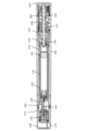
図1~図16は、本開示による、複数の固定用量を送達するための注射装置の第1の実施形態を例示する。図1Aは、注射装置の分解組立図を示す。図1B~図14は、個々の構造および機構のさらなる詳細を示す。図15Aおよび図15Bは、注射装置100の使用中の一連の状態を斜視図で示し、それによって、装置を受信し、装置を始動し、複数の固定用量を送達することからのユーザ動作を例示する。図16は、動作中の機械的構造の相互関係を詳細に例示する。本明細書で使用される場合、状態は、装置の特定の配置または構成を画定し、状態および動作は、装置の作動原理を説明するための枠組みを提供する。
First Embodiment FIGS. 1-16 illustrate a first embodiment of an injection device for delivering multiple fixed doses according to the present disclosure. FIG. 1A shows an exploded view of the injection device. Figures 1B-14 show further details of the individual structures and mechanisms. 15A and 15B show in perspective a sequence of states during use of
図1Aは、キャップ105、シールド先端119、洗浄モジュール120のシールド追従部分120.1(図2B参照)、針カニューレ124を有する針ハブ125、ハウジング挿入部分160、管状の細長い針シールド構造110、カートリッジホルダ130、カートリッジ135、管状の細長いハウジング構造140、コネクタ170、シールド戻しばね107、駆動管180、用量駆動ばね108、ピストンロッド109、およびばね基部165を示す。
1A shows
ハウジングアセンブリ
注射装置は、ハウジングアセンブリを備え、装置の他の構成要素をガイドおよび接続するためのガイドおよびコネクタを有する硬質フレームを提供する。ハウジングアセンブリは、ハウジング挿入部分160、管状の細長いハウジング構造140、カートリッジホルダ130、およびばね基部165を備える。最終組立後、これらの構造は、固定的に接続され、ハウジングアセンブリは、他の構造の相対移動および位置を説明するための基準のフレームを提供し得る。細長いハウジング構造140は、ピストンロッドの外ねじと係合するための内ねじを備える。内ねじは、ハウジング構造140に回転および軸方向の両方に固定される、一体ナット部材の形態で提供され得る。一例では、ナット部材は、ハウジング構造140の一体部品である。あるいは、ナット部材は、例えば、接着または溶接によって、注射装置の組立中にハウジングに固定される、別個の部品であってもよい。ナット部材は、ピストンロッドがハウジング構造に対して回転するときにピストンロッドを螺旋状に移動させるように、ピストンロッド109の外ねじと係合する内ねじを備える内面上にある。あるいは、内ねじは、ハウジング内に直接提供される。ハウジング挿入部分160は、キャップとのバヨネット結合のために、軌道の端にキャップスナップを備える。ハウジング挿入部分160は、シールドをガイドするための近位縁部をさらに備える。さらなる説明のために、ハウジングアセンブリは、短く、ハウジングと呼ばれ得、針シールドアセンブリは、針シールドと呼ばれ得る。
Housing Assembly The injection device includes a housing assembly that provides a rigid frame with guides and connectors for guiding and connecting other components of the device. The housing assembly comprises
注射装置100は、駆動機構と、トリガまたは起動機構と、を備える。駆動機構は、ピストンロッド109、駆動ばね108、および駆動管180を備え、用量を排出するために、構造は、ハウジング内に動作可能に配置される。トリガ機構は、細長いシールド構造110およびコネクタ170を備え、用量排出機構をトリガするために、構造は、ハウジング内に動作可能に配置される。
針シールドアセンブリ
注射装置は、シールド先端119および細長いシールド構造110を備える針シールドアセンブリをさらに備える。細長いシールド構造110は、薬剤の検査のための窓111を備え、細長いシールドは、カートリッジホルダ窓131とオーバーラップする第1の位置に、およびオーバーラップしない第2の位置に配置され得、細長いシールド構造の固体部分は、第2の位置で窓131を覆う。
Needle Shield Assembly The injection device further comprises a needle shield assembly comprising a
カートリッジホルダ
カートリッジホルダ130は、カートリッジ135を受容するように適合されている。カートリッジホルダは、カートリッジ135内の薬剤を検査するための窓131を備える。図1Bは、針ハブを軸方向にガイドするための軸方向リブ132と、カートリッジの首状部分137(図1A)に嵌まるための可撓性アームと、組立中にハウジング内に挿入されたときにカートリッジを整列および位置付けするための近位に延在するタブ130.1と、を備える、カートリッジホルダ130を外形で示す。カートリッジホルダの遠位端の内面上に、周方向に延在するフランジ134(図1A)が提供され、組立後、および初期包装解除状態に、カートリッジの遠位端表面に小さい軸方向クリアランスを提供する。
Cartridge
カートリッジ
図1Aにさらに示されるように、細長いカートリッジ135は、穿刺可能な隔壁によって密封された遠位端135aと、ピストンによって閉鎖された開口近位端135と、を備える。ピストンは、図1には示されていない。カートリッジは、医薬の複数の固定用量を収容する貯蔵部を備える。遠位端135aでは、キャップによってキャップされた隔壁が提供される。キャップおよび貯蔵部の主要部分は、首状部分137によって分離される。
Cartridge As further shown in FIG. 1A,
針アセンブリ
注射装置は、針ハブ125および再使用可能な針カニューレ124を備える針アセンブリをさらに備える。カニューレは、穿刺可能な隔壁を穿刺するための、および貯蔵部との流体連通を確立するための近位端と、装置の対象者またはユーザの皮膚への挿入のための遠位端と、を備える。
Needle Assembly The injection device further comprises a needle assembly comprising
ピストンワッシャ
図1には示されていないが、ピストンワッシャは、ピストンロッドに接続されて、ピストンに接触するための押さえを提供し得る。あるいは、ピストンロッドとピストンとの間の相対的回転を測定するための用量測定モジュールが、ピストンロッドとピストンとの間に提供され得る。そのような測定モジュールはまた、好適な押さえを提供する。そのような用量測定モジュールは、「Dose capturing cartridge module for drug delivery device」と題された、WO2014/1128155に説明されている。あるいは、ピストンロッドは、ピストンに直接接触する。
Piston Washer Although not shown in FIG. 1, a piston washer may be connected to the piston rod to provide a hold down for contacting the piston. Alternatively, a dose measuring module can be provided between the piston rod and the piston for measuring the relative rotation between the piston rod and the piston. Such measurement modules also provide a suitable hold down. Such a dose measuring module is described in WO2014/1128155 entitled "Dose capturing cartridge module for drug delivery device". Alternatively, the piston rod directly contacts the piston.
キャップ
キャップ105は、ハウジング挿入部分160への取り外し可能な装着のために適合されている。キャップは、軸方向および周方向キャップ装着軌道161によってガイドされるように適合された突出部105.2(図16F)を有する内面を備え、これは、本出願では、以下に詳細に説明されることになる。突出部は、スナップ係止部161.1と協働し、それによって、キャップ105を内側ハウジング部分160に取り外し可能に係止するようにさらに適合されている。キャップは、連続的な軸方向および回転移動によって装着および脱着されるように適合されており、それによって、注射装置と一緒にバヨネット結合を提供する。キャップ105の内面は、内面から突出し、かつ以下に図16Aを参照して説明されるように、シールドの外面上の軸方向に延在するリブ116を通してシールド構造110にトルクを伝達するようにキャップを適合させる、軸方向に延在するリブ105.1(図16A)をさらに備える。
ばね基部
ばね基部165は、近位端でハウジング構造140に固定的に装着され、圧縮可能なねじり駆動ばね108を受容および支持するように適合される。
Spring
駆動ばね
駆動ばね108は、予め引っ張られるか、または巻き付けられ、ばね基部と駆動管180との間に位置付けられる。駆動ばねは、駆動管上にトルクを誘発するようにさらに適合され、それによって、医薬が排出され得る。駆動ばねは、ねじれ区分108.3、108.4を備え、コイル間の間隔は、比較的小さく、圧縮可能区分108.4は、圧縮後および医薬の排出中に軸方向の力を駆動管に伝達するように適合されている。駆動管を軸方向に駆動する能力は、用量機構の終了を可能にし、駆動管のリセットを可能にする。
Drive Spring The
戻しばね
コネクタ戻しばね107は、ばね基部165とコネクタ170との間に位置付けられ、コネクタを遠位方向に付勢するように適合されている。
Return Spring
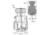
洗浄アセンブリ
注射間の針の洗浄は、同じ一体化された針が、清潔な条件で複数回使用されることを可能にする。それゆえに、本開示の代替的な実施形態では、注射装置は、図2Bに例示されるように、洗浄アセンブリ120を備える。可動シールド構造110は、シールド追従部分120.1を通して洗浄アセンブリ120に固定的に接続され、洗浄モジュールの原理は、WO2019/101670でさらに詳細に開示されている。洗浄アセンブリ120は、注射の間に針カニューレ124の遠位端を清潔に保つ洗浄剤を備える。洗浄モジュールのシールド追従部分120.1は、シールド先端119に固定的に接続され、シールド先端119は、再び、移動可能に配置された細長い針シールド構造110に固定的に接続される。シールド先端119は、細長いシールド構造110と係合する弾性アーム119.1を介して針シールド構造110にカチッと嵌まり得、それにより、洗浄チャンバアセンブリ120は、移動可能に配置されたシールド構造110の軸方向および回転移動に追従する。洗浄アセンブリ120に接続されるシールド構造110は、ハウジングに固定される針カニューレ124に対して移動可能に配置される。
Washing Assembly Needle washing between injections allows the same integrated needle to be used multiple times in clean conditions. Therefore, in an alternative embodiment of the present disclosure, the injection device comprises a
洗浄アセンブリ120は、好ましくは、一例では、カートリッジ135の液剤中に含有されるのと同じ防腐剤であり得る、液剤を有するチャンバを含有する。好ましい例では、洗浄剤は、カートリッジ135に収容されるものと同一の同じ防腐剤を含有する医薬液剤であり、これは、注射装置の始動中に洗浄モジュールのチャンバ内に充填される。代替的な実施形態では、洗浄剤は、多孔質プラグ内に埋め込まれる。さらなる代替例では、洗浄剤は、固体プラグの基質内に埋め込まれる。
The cleaning
シールドは、異なる位置に配置され得る。初期位置は、初期角度位置および対応する初期軸方向位置によって画定される。係止位置は、係止角度位置および対応する係止軸方向位置によって画定される。係止解除された遠位位置は、係止解除された角度位置および対応する遠位の係止解除された軸方向位置によって画定される。可動シールドは、初期位置から、シールドが軸方向に係止される係止位置への回転および近位移動の組み合わせによって変更され得る。両方の位置で、針先端は、シールドによって覆われ、洗浄チャンバアセンブリ内に収容される。使用中、シールドをさらに回転させ、近位方向に係止解除された遠位位置までさらに移動させ、それによって、先端が露出され得る。シールドを近位方向にさらに移動させることによって、シールドは、針のより大部分を露出させ、注射が行われ得る。注射後、シールドは、係止位置に戻され、それによって、針先端が洗浄される。 The shield can be placed in different positions. The initial position is defined by an initial angular position and a corresponding initial axial position. A locking position is defined by a locking angular position and a corresponding locking axial position. An unlocked distal position is defined by an unlocked angular position and a corresponding distal unlocked axial position. The movable shield can be changed by a combination of rotation and proximal movement from an initial position to a locked position where the shield is axially locked. In both positions the needle tip is covered by a shield and housed within the wash chamber assembly. During use, the shield may be further rotated and moved proximally further to the unlocked distal position, thereby exposing the tip. By moving the shield further proximally, it exposes a greater portion of the needle and an injection can be performed. After injection, the shield is returned to the locked position, thereby cleaning the needle tip.
何らかの理由で、針を洗浄せずに針を再使用することが望ましい場合、洗浄モジュールは、省略されてもよい。 If for some reason it is desired to reuse the needle without washing it, the washing module may be omitted.
例示された実施形態100に戻る。図1Bは、アセンブリ中にハウジングに挿入されたときに、カートリッジホルダ130をハウジング140に対して整列および位置付けするための近位に延在するタブ130.1を有するカートリッジホルダ130の斜視図を例示する。図1Cは、シールド追従部分120.1と、ピストン122、ならびに針ハブ125およびシールド追従部分120.1と協働するための半径方向に延在するアーム123.1を有するピストンロッド123を備える、可動部分120.2と、を備える洗浄モジュール120の分解組立図を例示する。半径方向に延在するアーム123.1は、洗浄チャンバ120と係合するためのチャンバハウジング係合表面123.2と、ハブ125と係合するためのハブ係合部分123.3と、を備える。針追従部分120.1は、遠位管状部分、中央管状部分、および近位管状部分を備える、洗浄チャンバハウジング121を備える。部分は、一体的に接続される。遠位管状部分の遠位端上には、キャップが提供され、遠位隔壁を洗浄チャンバハウジング上にキャップする。中央管状部分の外面上には、シールド先端119に嵌まるためのシールドタブ121.1、およびハブ押圧タブ121.2が提供される。図1Cの窓W1は、傾斜表面および空隙部分をより良好に例示するために、グレースケールで同じ構成要素を例示する。図2Bに示されるように、洗浄チャンバハウジング121の近位端には、回転に応答して、ピストンロッド123およびピストン122を近位方向にガイドするための傾斜した近位表面ガイド121.3が提供される。図の窓W3は、ピストンロッドを近位方向にガイドまたは押圧する機構の理解を裏付ける。回転ピストンロッド123は、静止摩擦を解除し、それをさらに回転させ、それを洗浄チャンバの傾斜表面121.3内に押し込むことによって、第1の良好に画定された軸方向移動を提供することになる。図2D上には、使用前に滅菌条件で、および使用中に清潔な条件で、針カニューレの遠位端を包囲するための洗浄剤貯蔵部121.4が示されている。
Returning to the illustrated
図1Dは、針カニューレ124の相対的な位置付け、ピストン122およびピストンロッド122を備える洗浄チャンバ120.2の可動部分、ならびに硬質部分126および軟質内側プラグ(図には図示せず)を備えるカートリッジ係合構造を斜視図で示す。軟質内側プラグは、ゴムで作製され得、使用前に針カニューレの近位端を滅菌初期条件で包囲するように適合され得る。硬質部分126は、軟質内側プラグの支持を提供し、針が貯蔵部内の薬剤との流体接続を確立したとき、かつハブ125を近位方向に移動させることに応答して、カートリッジを近位方向に移動させるように適合されている。軟質プラグは、針カニューレの近位鋭利端によって貫通され得る。硬質部分126は、半径方向に延在するハブ係合タブ126.1および半径方向に延在するカートリッジ係合タブ126.2を備える。硬質部分は、ハブが近位位置にあるときに、ハブのさらなる軸方向移動を阻止するための、遠位に延在する阻止部分126.3をさらに備える。図2Dに見られるように、阻止部分126.3は、小さい相対的回転の後に、ハブの小さい窪みまたは周方向スリット125.7と係合するように適合されている。硬質部分126は、組立後のカートリッジの遠位表面に当接する近位端126bに近位表面を備える。それゆえに、カートリッジ係合構造の硬質部分126の近位移動は、カートリッジの近位移動を提供する。
FIG. 1D shows the relative positioning of
図1Eは、針ハブ125の斜視図を例示する。ハブ125は、中央円形ディスク部分125.9と、ディスク部分から延在する近位に延在するスカート部分125.11と、を備える。スカート部分125.11は、カートリッジ135の遠位端と、硬質部分126を備えるカートリッジ係合構造と、を包囲するように適合されている。針ハブ125は、スカート部分125.11から近位に延在し、かつカートリッジホルダの軸方向に延在するリブ132と協働して、ハブとカートリッジホルダとの間の相対的な軸方向移動を可能にし、相対的な回転移動を防止するように適合された、軸方向に延在するフィンガ125.1をさらに備える。中央ディスク部分125.9の遠位表面から、2つの軸方向管部分(角度区分、管のように湾曲しているが、周方向に360度延在していない)、または管状部分125.13を中央部分125.9と接続するフランジ125.12が延在している。管状部分は、洗浄アセンブリ120を取り囲むように適合されている。図2Dで最もよく分かるように、針カニューレを固定するための接着剤タワー125.10が、中央ディスク部分125.9上に中央に提供される。ハブ125は、スカート部分125.11に提供され、かつカートリッジ係合構造の回転移動をガイドするように適合された、軌道をさらに備える。軌道は、カートリッジ係合構造のハブ係合タブ126.1用の初期位置を提供する近位軸方向部分125.2と、針ハブ125のガイドされた近位移動に応答して、タブ126.1を回転させ、それによって、カートリッジ係合構造の硬質部分126を回転させるための螺旋部分125.3と、を備える。軌道は、回転の終了時に、相対的な軸方向移動またはタブ126.1、それによって、カートリッジ係合構造の硬質部分126を可能にするか、またはガイドするように適合された遠位軸方向部分125.4をさらに備える。軸方向に延在するフランジ125.12の内面上には、負の半径方向、すなわち、ハブ125の中心に向かって突出するリブ128が提供される。リブ128は、フランジ125.12の縁部と同一平面の軸方向に延在する表面128.1を備える。軸方向に延在する表面128.1は、ピストンロッド123と係合するための回転停止部を提供する。リブ128の遠位端では、周方向に延在する表面128.2がさらに提供される(図1Fの窓W3および図2Dも参照)。周方向に延在する表面128.2は、チャンバハウジングの押圧タブ121.2と係合するための軸方向停止部を提供する。
FIG. 1E illustrates a perspective view of
図1Fは、図1Dに示されるモジュールのアセンブリを、初期状態、かつ針カニューレとカートリッジ135の貯蔵部との間に流体接続が確立される前である包装解除状態の図1Eに示されるハブ125とともに例示する。阻止部分126.3と中央部分125.9の近位表面との間に軸方向クリアランスが提供され、このクリアランスが、ハブ125と、カートリッジ135と当接しているカートリッジ係合構造の硬質部分126との間の相対的な軸方向移動を可能にすることに留意されたい。それゆえに、クリアランスは、相対的な軸方向移動に応答して、針カニューレがカートリッジ内に挿入されることを可能にする。窓W2は、グレースケールで白黒で示されるアセンブリ全体を例示する。窓W3は、表面128.1および128.2を有する針ハブ125およびガイド128の内面を例示する。
FIG. 1F illustrates the assembly of the module shown in FIG. 1D with the
図2Aは、包装解除状態で針ハブ125内に位置付けられた洗浄チャンバハウジング121の斜視図を例示する。管状部分125.13は、洗浄チャンバハウジングの近位部分を取り囲み、半径方向に延在するハブ押圧タブ121.2は、第1の角度位置で、ハブの遠位支持表面127上に静止する。本出願で以下に詳細に説明されるように、初期化時に針シールドは、近位螺旋移動でガイドされるように適合されている。洗浄チャンバハウジングが針シールドに固定されると、押圧タブ121.2は、初期化に応答して、回転方向に固定された針ハブに対して近位螺旋移動を実施する。針ハブは、遠位および近位位置の間で軸方向に移動可能である。針ハブがカートリッジホルダ130上に軸方向に移動可能に位置付けられると、チャンバハウジングの押圧タブ121.2は、針シールドが初期から係止位置に移動することに応答して、針ハブを遠位から近位位置に強制する。さらに、シールドの軸方向移動中、押圧タブ121.2はまた、シールドと一緒に初期から係止された角度位置に回転されている。係止された角度位置では、プッシュタブ121.2は、針ハブの管状部分125.13の切欠き125.5と角度的に整列され、軸方向停止表面128.2と整列される。軸方向クリアランスは、押圧タブ125.2と軸方向停止表面128.2との間に提供される。シールドの初期および係止された角度位置の間で、ハブは、近位距離を移動して、針カニューレ124の近位端をカートリッジ135の貯蔵部と接続する。ハブの近位移動は、カートリッジ係合構造の回転をさらに提供しており、それによって、カム表面を有するタブ126.2が回転されており、カートリッジの遠位端の遠位表面と周方向に延在するフランジ134の近位表面との間の軸方向クリアランスに強制されている(図1Aを参照)。これによって、カートリッジと周方向フランジ134との間の軸方向クリアランスは、大きくなっており、カートリッジは、カートリッジに対して近位方向に押されており、首係合アーム133は、偏向されている。ハブ125の近位位置に対応するシールドの係止位置では、カートリッジ係合構造の阻止部分126.3と中央ハブ部分125.9との間に接触が確立されている。この位置では、洗浄チャンバハウジングは、停止表面128.2に当接するまで近位に移動し得る。シールド120.1およびシールド追従部分120.1が係止位置にある場合、シールド追従部分は、遠位の係止解除位置まで、シールドと一緒にさらなる近位螺旋移動で移動するように適合される。シールドおよびシールド追従部分120.1が遠位の係止解除位置にある場合、シールドおよびシールド追従部分は、針を通して用量を送達するために、厳密な近位方向にさらに移動し得る。
FIG. 2A illustrates a perspective view of
図2Bは、洗浄チャンバハウジング121内に配置された洗浄チャンバピストンロッド123の斜視図を例示する。例示されるように、チャンバハウジング121の近位表面における傾斜表面121.3は、ピストンロッドの軸方向に延在する表面123.2と軸方向に整列される。この初期位置では、ピストンロッドの表面123.3は、ハブ125の回転停止部128.1と当接して配置され、それゆえに、ハブに対して反時計回り方向に移動することができない。周方向クリアランスは、最初に、傾斜表面121.3とチャンバハウジング係合表面123.2との間に提供され、チャンバハウジングの近位螺旋移動に応答して、傾斜表面121.3および係合表面123.2は、接触するために互いに接近および係合することになる。これによって、プランジャ122とチャンバハウジング123との間の任意の静止または付着摩擦は、相対的回転によって克服される。シールドの係止位置までのさらなる回転に応答して、傾斜表面は、ピストンロッド123上に近位に配向された力を誘発し、それによって、ピストンロッド123およびプランジャは、洗浄チャンバハウジングから引き出されることになる。
FIG. 2B illustrates a perspective view of wash
カートリッジ130内のプランジャ136がピストンロッド109と当接して位置付けられると、カートリッジホルダ(ハウジングアセンブリの一部である)に対するカートリッジの近位移動は、カートリッジ内に過圧を誘発することになる。貯蔵部が針カニューレと流体接触している場合、液体は、洗浄チャンバ内に流入することになる。プランジャ122を洗浄チャンバハウジング121から引き出すことの追加の特徴は、プランジャとチャンバハウジング121との間の付着摩擦を克服するために提供されるが、流体接続が確立されたとき、引き出すことはまた、貯蔵部とチャンバハウジング121との間に流れを加えることになる。
When
ハウジング構造
図3Aおよび図3Bは、ハウジングの軸方向切断における管状ハウジング構造140の内面に配置された特徴の斜視図を例示する。図3Bでは、軸方向切断は、窓141の中心軸線を含む平面に提供され、図3Aでは、注射は、中心軸の周囲で90度回転され、それによって、窓141cのうちの1つは、切断平面の後ろに視認可能である。図3C~図3Fに見られるように、管状ハウジング構造140は、外側管状部分143および内側管状部分154を備える。例示された例では、内側管状部分154は、外側管状部分に一体的に接続されている。外側管状部分は、外径を有する外面と、内径を有する内面と、を備える。同様に、内側管状部分は、外径を有する外面と、内径を有する内面と、を備える。
Housing Structure FIGS. 3A and 3B illustrate perspective views of features located on the inner surface of
図3Aおよび図3Bでは、内側管状部分154は、外側管状部分143と内側管状部分154との間の構造の明確な図を得るために除去されている。図は、内面から突出するハウジング142の遠位ガイド構造を例示する。遠位ガイド構造142は、シールド構造110をガイドするように適合されている。図は、ハウジング144cの中央ガイド構造およびハウジング146cの近位ガイド構造をさらに例示する。回転対称性において144cから180度に位置付けられた中央ガイド構造144dもまた、図3D上に示される。中央ガイド構造144はまた、内面から突出し、外側管状部分143と内側管状部分154との間の一体接続を提供する。中央ガイド構造は、コネクタ170およびシールド構造110をガイドするようにさらに適合されている。近位ガイド構造146cは、表面内に陥凹を形成し、コネクタ170をガイドするように適合されている。遠位、中央、および近位ガイド142c、144c、および146cは、すべて、回転対称性を有して位置付けられた対応するガイドを有するが、それらのすべてが示されるか、または指示されているわけではない。しかしながら、例えば、遠位ガイド142を参照すると、それは、回転対称性を有して位置付けられた遠位ガイドのいずれかであってもよく、例示された例142では、遠位ガイド142cおよび142dのいずれか一方または両方を指してもよい。
In FIGS. 3A and 3B, inner
遠位ガイド142は、第1の軸方向部分142.1、第1の横方向部分142.2、第2の軸方向部分142.3、第2の横方向部分142.4、および回転停止部を提供する第3の軸方向部分142.5を備える。中央ガイドは、近位横方向部分144.1、第1の軸方向部分144.2、遠位横方向部分144.3、および第2の軸方向部分144.4を備える。近位ガイドは、第1の軸方向部分146.1、第1の横方向部分146.2、第2の軸方向部分146.3、第3の軸方向部分146.4、ランプ部分146.5、同一平面部分146.6を備える。集合的に、ガイド表面は、コネクタの環状ガイドを可能にする閉じた軌道を提供する。横方向部分の表面は、半径方向および周方向に延在し、軸方向部分の表面は、軸方向および半径方向に延在し、ランプ部分146.4の表面は、陥凹の底部から、同一平面部分446.5の表面に向かって延在する。同一平面部分は、軸方向および周方向に延在し、内面と同一平面である。
The
図3Cは、図3Aに示される切断に対応し、内側管状部分154は、残されている。中央ガイド144は、外側管状部分143と内側管状部分154との間の環状空間内に位置付けられることに留意されたい。図3Dは、ハウジング構造140の斜視図を例示しており、管状切断が行われている。管状切断は、ハウジング構造の内面を含む平面で行われ、切断は、その平面の外側の構造を除去する。それによって、内面上の構造のみが視認可能である。図3Dは、ハウジング挿入部分160と接続するための内部接続構造140.3を示す。接続構造140.3は、ハウジング構造140に対して挿入部分を角度位置付けするように適合される。図3Dは、ガイド142の半径方向表面と一緒にシールド構造110の半径方向中心位置を支持する、リブ140.1をさらに示す。近位に位置付けられたリブ140.2は、戻しばね107の半径方向位置を支持する。近位端では、リブ140.2の近位に、細長いハウジング構造140の一部分が示されている。図3Eは、図3Bに示される切断に対応し、内側管状部分154は、図3Cのように、残されている。図3Fは、図3Dにおける斜視図を示すが、構造は、近位ガイド146cの詳細を明らかにする異なる角度から見られている。近位ガイド146cは、陥凹の周囲の縁部として見られるが、縁部は、内面を有する平面に位置付けられている。分かるように、ガイド142、144、146は、2重回転対称性で提供されている。近位ガイド146cについて、他の回転方向にシフトされたガイドは、斜視図の角度に起因して視認可能ではない。
FIG. 3C corresponds to the cut shown in FIG. 3A, with inner
それゆえに、図3A~図3Fは、第1の実施形態によるハウジング構造140の技術的詳細を集合的に示す。ハウジングの遠位ガイド142は、第1の軸方向部分142.1、第1の横方向部分142.2、第2の軸方向部分142.3、および第2の横方向部分142.4を備える、接続されたガイド表面に沿って、シールドを回転および軸方向にガイドするように適合されている。中央ガイドは、コネクタを回転および軸方向にガイドするように適合され、近位横方向部分144.1、第1の軸方向部分144.2、遠位横方向部分144.3、および第2の軸方向部分144.4を備える。以下に説明されるように、中央ガイド144の第1の軸方向部分144.2は、注射中にシールド110の回転停止部をさらに提供する。近位ガイドは、軸方向および回転方向の作動サイクルを通してコネクタをガイドするように適合され、回転停止部を提供して近位軸方向移動をガイドするように適合された第1の軸方向部分143.1と、回転の反時計回り移動をガイドするための第1の横方向部分146.2と、回転停止部を提供して第3の軸方向部分146.3と一緒に遠位軸方向移動をガイドするように適合された第2の軸方向部分146.2と、を備える。近位ガイドは、ランプ部分146.5と、コネクタを作動または投与サイクルの始めに戻すようにガイドするための同一平面部分と、をさらに備える。
3A-3F therefore collectively show the technical details of the
ゼロ点調節機構
図4Aおよび図4Bは、本開示の代替的な実施形態による、ゼロ点調節ナット106の斜視図を示す。示されるように、遠位面は、図3Aの遠位端106aで視認可能であり、図3Bの近位面は、近位端106bで視認可能である。調節ナット106は、ピストンロッド109の外ねじ109.1と係合するための内ねじ106.1と、ハウジングの内ねじ154.2と係合するための外ねじ部分106.2と、を備える。外ねじ106.2は、例示された実施形態では、ナット106上に近位に提供され、外面から突出する2つの外ねじ部分として示されている。外ねじ106.2は、任意の数の外ねじ部分から作製されてもよい。あるいは、ナット106とハウジングとの間のねじ接続106.2、154.2は、純粋な回転ガイドによって置換されてもよい。
Zero Adjustment Mechanism FIGS. 4A and 4B show perspective views of the zero
さらに、調節ナット106の外面上には、ラチェットアーム106.3が提供される。本開示の実施形態では、2つのラチェットアーム106.3cおよび106.3dは、調節ナット106の遠位端106aに2重回転対称性で位置付けられている。任意の好適な数のラチェットアーム106.3が提供され得る。しかしながら、調節ナット106の回転安定性を高めるために、回転対称性の少なくとも2つのラチェットアームが好ましい。2重回転対称性は、ナット106の中心軸の周囲の180度の角度による回転が、ナット106の外観を変化させないことを意味する。
Furthermore, on the outer surface of the adjusting
図5は、細長いハウジング構造140が半分に切断された斜視図を示し、それによって、構造の内面が視認可能である。細長いハウジング構造は、遠位端140aおよび近位端140bを画定する。図にも見られるように、細長いハウジング構造140の内面上には、調節ナット106を支持するように適合された内側管状部分154が提供されている。内側管状部分154はまた、切断に起因して半管として例示されている。例示された実施形態は、調節ナット106が一方向のみに回転することを可能にする、ナットのラチェットアーム106.3と係合するように適合された軸方向歯部154.3を備える。可能にされた回転方向は、時計回りであり、これは、ラチェットアーム106.3および歯部154.3の境界面が、ハウジングに対するナットの反時計回りの回転を防止することを意味する。調節ナット106の防止または阻止された方向は、ピストンロッドが投与中に遠位方向に前進する際のピストンロッドの回転の方向と同じ方向である。このようにして、調節ナットは、投与中に意図せず変位されることができない。
FIG. 5 shows a perspective view of the
いくつかの実施形態では、内側管状部分154は、調節ナット106が、可能にされる時計回り方向に回転されたときに近位方向に螺旋状にねじ込まれるように、方向を有する内ねじ154.2をさらに備える。それによって、ナットとハウジングとの間のねじ接続106.2、154.2は、調節ナット106の回転と回転方向に固定されたピストンロッド109の軸方向変位との間の追加の歯車機構を提供し、これは、例えば、調節ナット106とピストンロッド109との間の比較的大きいピッチのねじ接続を補償するために有用であり得る。
In some embodiments, the inner
注射装置の組立中、ピストンロッド109とカートリッジ135内のピストン136との間の距離または空隙が最小化されることを確保することが望ましい。空隙の最小化は、ピストンロッド109を遠位方向に移動させることに応答して、薬剤が貯蔵部から排出されることを確保する。図6に示される好ましい実施形態に開示されるように、ワッシャ104がピストンロッド109に取り付けられる場合、目的は、注射装置が貯蔵を可能にする状態で配置されているとき、かつ装置がエンドユーザに送達される準備ができている場合に、ワッシャ104およびピストン136が互いに当接するように、ワッシャ104の遠位表面とピストン136の近位表面との間の空隙を最小化することである。以下では、空隙の排除が、ピストンに当接するピストンロッドを参照して説明されることになるが、ピストンとワッシャとの間の空隙が排除されるとき、同じ考慮事項が適用される。
During assembly of the injection device, it is desirable to ensure that the distance or gap between
調節ナットが、最終組立中にハウジング構造に対して相対的に回転されるとき、ピストンロッド109は、ピストンロッド109またはワッシャ104が、カートリッジ135の内側のピストン136に当接するまで、遠位方向に螺旋状に前進される。ナットとハウジングとの間のねじ接続106.2、154.2を備える実施形態では、ハウジングに対するピストンロッドの前進は、ハウジングに対する調節ナットの近位移動によって補償または対抗される。
When the adjustment nut is rotated relative to the housing structure during final assembly, the
調節ナットの回転は、好ましくは、調節ナットと係合し、調節ナットに回転を伝えるように適合される、生産ライン内の特殊工具を使用することによって行われる。1つの好ましい例では、ピストンロッド109は、調節ナットと係合してサブアセンブリを提供するように配置され、サブアセンブリは、次いで、ハウジングの内側管状部分154内に配置される。以後、電子コンピュータ化された機器が、その特定の注射装置に使用されるカートリッジ135内のピストン136の相対位置を検出するために使用される。ピストン136の位置およびピストンロッド109の位置が得られたとき、コンピュータは、注射装置が組み立てられたときに、ピストンロッドをピストン136と当接して位置付けるように、配置された調節ナット106の必要な角度変位を決定し得る。
Rotation of the adjusting nut is preferably accomplished by using a special tool in the production line adapted to engage and impart rotation to the adjusting nut. In one preferred example, the
組立中、ピストンロッド104の近位端の位置は、したがって、調節ナットを内側管状部分154と一方向境界面内で回転させることによって調節される。ここで重要なことは、調節ナットが、ピストンロッド109をピストン136と接触させるように前進させる方向に回転し得ることである。
During assembly, the position of the proximal end of
組立後、ピストンロッド109またはワッシャ104は、ピストン136に当接し、調節ナットをさらに時計回り方向に回転させることができない。さらに、組み立てられた状態のいずれにおいても、ナット106と外部の周囲との間に外部境界面が存在しない。それゆえに、外面を外部工具と接触させ、外部トルクをナットに適用する可能性が存在しない。
After assembly, the
上記の結果は、調節ナット106が、ハウジング構造に関して自己係止しており、ナット106をハウジングに物理的に固設する必要がないことである。そのため、ナット部材11をハウジングに溶接または接着する必要はない。
A result of the above is that the
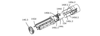
駆動機構
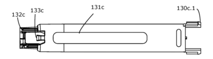
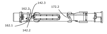
図6は、ピストン136とワッシャ104との間のゼロ点調節後の、注射装置の近位部分の断面図を示す。ピストンロッド109は、第1の用量が排出されていないことを示す近位位置に位置付けられる。図7は、ピストンロッド109の斜視図を示し、外ねじ109.1および軸方向軌道109.2を詳細に例示する。図8Aおよび図8Bは、異なる角度からの斜視図における駆動管180を例示する。図は、外面から突出し、駆動管180の起動中にコネクタ170と協働するための構造、および用量が排出された後のシールド構造110の再係止のための構造を提供する、タブ183cを示す。タブ183は、遠位に配向された表面183.1(遠位表面または遠位に配向された表面は、少なくとも法線ベクトルの成分が遠位方向に配向されることを意味する)と、コネクタ170と協働するために角度方向に配向された表面を提供する軸方向部分183.2と、を備える。図はまた、投与停止の未完の試行に応答して、外面から突出し、投与中にコネクタを軸方向に阻止するように適合されている、螺旋構造184cを示す。タブ183は、螺旋構造184に提供される横方向開口部に対して近位に位置付けられる。図は、起動中にハウジングと協働し、かつ用量の終了を画定する回転停止部を提供するように適合された、軸方向表面182cをさらに例示する。特徴182、183および184は、本出願で以下に詳細に説明されることになる。
Drive Mechanism FIG. 6 shows a cross-sectional view of the proximal portion of the injection device after zeroing between
駆動管180は、内面から突出し、ピストンロッド109の軸方向軌道109.2と係合するように適合された内向き突出部180.2を備える。ピストンロッド109は、駆動管内に摺動可能に配置されるように適合され、それによって、相対的な軸方向変位が可能にされるが、相対的回転が防止される。駆動管180は、管状ばね基部165の内側で歯部165.1と係合し、それによって、一方向ラチェット境界面を形成するためのラチェットアーム181cを備え、それにより、駆動管180は、開示される例では、用量を分注するための反時計回り方向である一方向のみに回転可能である。したがって、ラチェットアーム181cは、ピストンロッド109の時計回り方向の回転を防止する。例示された例では、駆動管は、2重回転対称性に配置された2つのラチェットアーム181c、181dを備える。ラチェットアーム181は、駆動管180およびピストンロッド135が反時計回り方向に回転することに応答して、排出中に用量クリック音を提供する。
The
ピストンロッド109と駆動管180との間の係合は、相対的回転を防止する。それゆえに、ゼロ点調節中の調節ナット106が時計回り方向に回転する際、駆動管が時計回り方向の回転に対して係止されるため、ナットは、ピストンロッド109の遠位並進を誘発する。
Engagement between
図1に示されるトルク送達駆動ばね108は、本開示による実施形態では、駆動管180の内側に配置され、各端で駆動管およびばね基部165に固定的に取り付けられる。遠位端は、駆動管180に固定的に取り付けられる遠位取り付け手段108.1と、ばね基部165に固定的に取り付けられた近位取り付け手段108.2と、を備える。駆動ばねは、アセンブリ中に巻き上げられるか、または引っ張られ、それによって、十分なトルクで駆動管を回転させるためにエネルギーを貯蔵し、それによって、さらなる引っ張りなしで複数の用量を送達する。
The torque delivering
駆動機構にねじりばねを組み込むことは、数個の利点を提供する。本発明の発明者らは、圧縮ばねで構成された一実施形態について、圧縮ばねがエネルギーを放出するにつれてカートリッジ内に前進することを認識した。注射装置が、圧縮ばねをカートリッジ内に前進させることを可能にせずに設計される場合、装置の全長は、増加することになる。それゆえに、制限された長さの構成では、ばねの直径は、カートリッジの直径によって制限される。本発明の発明者らは、ねじりばねが、装置の全長を制限するためにカートリッジ内に延在する必要がないことを見出した。それゆえに、ねじり駆動ばねは、カートリッジまたはピストンロッドの直径によって制限されず、制限された長さの構造において有利である。 Incorporating a torsion spring in the drive mechanism offers several advantages. The inventors of the present invention have recognized that for one embodiment configured with a compression spring, it advances into the cartridge as it releases energy. If the injection device is designed without allowing the compression spring to advance into the cartridge, the overall length of the device will be increased. Therefore, in the limited length configuration, the diameter of the spring is limited by the diameter of the cartridge. The inventors of the present invention have found that the torsion spring need not extend into the cartridge to limit the overall length of the device. Therefore, torsional drive springs are not limited by the diameter of the cartridge or piston rod and are advantageous in limited length constructions.
本開示の実施形態によるねじり駆動ばねは、カートリッジの近位、かつピストンロッド109の外側上に配置される。それによって、ねじり駆動ばねは、ばねがより大きい体積を包囲することを可能にし、それによって、質量、すなわち、ばね材料(例えば、鋼)の量を増加させる。言い換えれば、使用される材料または質量が増加され得るため、長期貯蔵および投与に関連する性能が改善され得る。質量が増加すると、ばねの内部応力が低減され得る、および/またはばね外径が平坦化され得、したがって、装置の最初および最後の投与の間の投与時間の変動を最小化することができる。本発明の発明者らはまた、ばねの最大内部応力が低減された場合、ばねを支持するプラスチック構成要素に誘発される応力もまた、低減されることを見出し、これは、長期貯蔵を可能にするために必要である。
A torsional drive spring according to embodiments of the present disclosure is located proximal to the cartridge and on the outside of the
本発明の発明者らは、ねじり駆動ばねが駆動管の内側に配置される一実施形態では、駆動管が、用量クリックを提供するように適合され得、直径を増加させることによって用量クリックの数の増加を可能にすることをさらに見出した。それゆえに、用量クリックの数は、装置の軸方向長さを延長せずに増加され得る。 The inventors of the present invention have found that in one embodiment where the torsional drive spring is located inside the drive tube, the drive tube can be adapted to provide dose clicks, increasing the number of dose clicks by increasing the diameter. We have further found that it allows an increase in Therefore, the number of dose clicks can be increased without extending the axial length of the device.
本開示の一実施形態によると、駆動管の外面は、用量クリックを提供するように適合された用量クリック提供構造、例えば、周囲構造上に提供される歯の上に乗るラチェットアームを備える。あるいは、ラチェットアームは、駆動管上の周囲の構造および歯の上に提供される。駆動管180の外面の円周が駆動管の直径とともに増加すると、用量クリックの数も増加する。回転駆動管の場合、用量クリックの数は、駆動管の円周と、用量クリック提供構造の間の距離、例えば、歯の間の距離との間の関係として決定される(用量クリックの数=2*pi*半径/歯の間の距離)。それゆえに、用量クリックの数は、半径を増加させることによって増加され得るが、ばねの長さ、および、それによって、装置の長さの増加を伴わない。対照的に、ピストン内に配置された圧縮ばねによって駆動されるピストンの用量クリックの数を増加させるために、圧縮ばねの長さが増加されなければならない。圧縮ばねの場合、用量クリックの数は、ばねの軸方向伸長を歯の間の距離で除算することによって決定される(用量クリックの数=軸方向伸長/歯の間の距離)。
According to one embodiment of the present disclosure, the outer surface of the drive tube comprises a dose click providing structure adapted to provide a dose click, for example a ratchet arm that rides on teeth provided on the surrounding structure. Alternatively, ratchet arms are provided on surrounding structures and teeth on the drive tube. As the circumference of the outer surface of
さらに、本発明の発明者らは、トリガ機構を解除するために必要とされるエネルギー、すなわち、起動エネルギーが、駆動ばねの内部応力の関数であることを見出した。それゆえに、ねじり駆動ばねで可能にされた用量エンジンの起動は、圧縮ばねに基づく同様の設計よりも少ない力を必要とする。 Furthermore, the inventors of the present invention have found that the energy required to release the trigger mechanism, ie the activation energy, is a function of the internal stress of the drive spring. Therefore, activation of a torsional drive spring enabled dose engine requires less force than similar designs based on compression springs.
加えて、発明者らは、ねじれ駆動ばねに基づく駆動機構を備える実施形態は、同等の圧縮駆動ばねに基づく実施形態よりも組み立てが容易であることを見出した。圧縮ばねと比較して、ねじりばねは、比較的短く、したがって、取り扱いが容易である。 In addition, the inventors have found that embodiments with drive mechanisms based on torsion drive springs are easier to assemble than equivalent compression drive spring-based embodiments. Compared to compression springs, torsion springs are relatively short and therefore easier to handle.
回転駆動管は、「Drug delivery system with multipolar magnet and sensor system」と題されたWO2019/110494に説明されているように、投与中に回転構造を登録する、電子用量捕捉装置とともに機能するように容易に適合される。 The rotary drive tube is readily adapted to work with an electronic dose capture device that registers the rotary structure during administration, as described in WO2019/110494 entitled "Drug delivery system with multipolar magnet and sensor system". is adapted to
ハウジング挿入部分
図9Aおよび図9Bは、整列構造およびスナップ構造160c.3を介して、細長いハウジング構造110の遠位端に固定的に装着される、ハウジング挿入部分160の2つの異なる斜視図を例示する。ハウジング挿入部分は、キャップ装着軌道161を備える。分かるように、キャップ装着軌道161cは、近位および遠位端を有する軸方向に延在する軌道部分161c.2と、第1の端および第2の端を有する周方向に延在する軌道部分161c.3と、を備える。周方向軌道の第1の端では、スナップ係止部161c.1が位置付けられ、第2の端は、軸方向に延在する軌道161c.2の近位端に接続され、それによって、軌道部分は、キャップ105の内側突出部と協働するためのバヨネット結合用の軌道を形成する。軌道161cの第2の端でも、回転停止部161c.4が提供される。ハウジング挿入部分160は、以下に説明されることになるように、シールドの外面上の軸方向に延在するリブ116cと協働するために内面上に、軸方向に延在するスリット163cをさらに備える(図10Aを参照)。内側ハウジング部分160は、シールド110をガイドするための近位ガイド162をさらに備える。例示された近位ガイド162dは、周方向に延在し、反時計回り方向に、ガイドは、螺旋部分162d.1、ゼロピッチを有する横方向部分162d.2、および軸方向部分162d.3を備える。あるいは、バヨネット結合に、ねじ結合が使用されてもよい。
Housing Insert Figs. 9A and 9B illustrate alignment and snap structures 160c. 3 illustrate two different perspective views of
細長いシールド構造
図10Aおよび図10Bは、管状ハウジング140の内側に配置される円筒状の細長いシールド構造110の斜視図を示す。図10Aでは、シールド構造110の遠位面を見ることができ、図10Bでは、近位面を見ることができる。図10Cは、側面斜視図におけるシールド構造の一部分を示す。細長いシールド構造110は、外径を有する外面、および内径を有する内面を備える、管状部分を備える。軸方向に延在するリブ116cは、外面から突出する遠位端アントに配置される。リブは、キャップ105の内部リブと協働するために、およびハウジング挿入部分165の内面上のスリット163と協働するように適合される。
Elongated Shield Structure FIGS. 10A and 10B show perspective views of a cylindrical
シールド構造110は、外面上に配置され、かつハウジング挿入部分の近位ガイド162およびハウジングの遠位ガイド142と協働するように適合された、階段状螺旋ガイド112をさらに備える。階段状螺旋ガイド112は、シールド構造110の管状部分の外面とハウジングの外側管状部分143の内面との間の環状空間内に提供される。階段状螺旋ガイドは、軸方向および周方向に延在する連続突出構造を備え、近位横方向突出部分、近位左螺旋突出部分、中央横方向突出部分、遠位左螺旋突出部分、遠位横方向突出部分を備える。連続突出構造は、ガイド表面を提供する複数の軸方向および周方向に配向された表面部分を備える(周方向表面または周方向に配向された表面は、少なくとも法線ベクトルの成分が周方向に配向されることを意味する)。表面部分は、図10に見ることができ、次の用語および参照番号で言及される。近位軸ガイド部分112.1、第1の近位横方向ガイド部分112.2、第2の近位横方向ガイド部分112.3、第1の近位螺旋ガイド部分112.4、第2の近位螺旋ガイド部分112.5、第1の中央横方向ガイド部分112.6、第2の中央横方向ガイド部分112.7、第1の遠位螺旋ガイド部分112.8、第2の遠位螺旋ガイド部分112.9、第1の遠位横方向ガイド部分112.10、第2の遠位横方向ガイド部分112.11、および遠位軸方向ガイド部分112.12。このようにして、ガイド部分112.2、112.4、112.6、112.8、および112.10は、階段状螺旋ガイド112の遠位面を提供し、ガイド部分112.3、112.5、112.7、112.9、および112.11は、近位面を提供する。
The
細長いシールド構造110は、シールド構造110の近位端に位置付けられた近位ガイド114をさらに備える。図10Aでは、遠位面を見ることができ、図10Bでは、近位面を見ることができる。近位ガイド114は、ハウジングのコネクタ170および中央ガイド144と協働するように適合されている。近位ガイド114は、軸方向および周方向に延在し、第1の左螺旋部分114.1、第1の右螺旋部分114.2、第2の右螺旋部分114.3、第2の左螺旋部分114.4、第1の軸方向部分114.5、第1の横方向部分114.6、第2の軸方向部分114.7、第3の軸方向部分114.8、および第2の横方向部分114.9を備える。
ガイド部分114.1~114.9は、すべて表面部分であり、ガイド部分114.1、114.2、114.3、114.4、および114.9は、近位ガイド114の近位面を提供し、表面部分114.6は、遠位面を提供し、すなわち、それぞれ、近位および遠位位置から視認可能である。近位面のガイド部分114.1、114.2、114.3、および114.4は、起動動作中にコネクタと協働するように適合されている。
Guide portions 114.1-114.9 are all surface portions, with guide portions 114.1, 114.2, 114.3, 114.4, and 114.9 covering the proximal face of
近位ガイドの遠位面のガイド部分114.6は、本出願で以下に詳細に説明されることになる、シールドに対する圧力の早過ぎる解除に応答して、投与中にコネクタと協働するように適合されている。 A guide portion 114.6 on the distal face of the proximal guide is adapted to cooperate with the connector during administration in response to premature release of pressure on the shield, which will be described in detail later in this application. is adapted to
第3の軸方向部分114.8は、ハウジングの中央ガイド144と協働するように適合され、回転停止部を提供し、ハウジングに対する、および投与中のシールドのさらなる反時計回りの回転を防止する。同様に、第2の横断部分114.9は、中央ガイド144と協働する軸方向停止部を提供し、投与中のシールドのさらなる近位移動を防止する。
The third axial portion 114.8 is adapted to cooperate with the
近位ガイド114は、ガイド部分114.4および114.5を備える係止構造115を備え、例示された実施形態では、係止構造115は、フック類似構造の一部である。以下に詳細に説明されることになるように、係止構造115は、投与中に、コネクタ170の対応するフック類似構造に取り外し可能に係止するように適合されている。
The
シールドは、クリックアーム113をさらに備え、軸方向表面部分113.1が、回転停止部を提供する。初期状態では、クリックアームは、ハウジング挿入部分160の内面によって半径方向に圧縮される。
The shield further comprises a click arm 113 and an axial surface portion 113.1 provides a rotation stop. In the initial state, the click arm is radially compressed by the inner surface of
コネクタ
図11Aおよび図11Bは、管状ハウジング140の内側、および細長いシールド構造110と駆動管との間に配置される、コネクタ170の斜視図を示す。コネクタ170は、シールドと駆動管との間の接続を確立するように、かつ駆動管180を起動するように適合されている。コネクタ170は、用量の終了時にシールドを自動的に再係止するように適合された自動再係止機構でさらに動作可能に接続されている。コネクタ170は、シールドの近位ガイド114と協働するように適合された遠位ガイド172を備える。遠位ガイド172は、周方向および軸方向に延在し、左螺旋部分172.1、右螺旋部分172.2、第1の軸方向部分172.3、横方向部分172.4、および第2の軸方向部分172.5を備える。
Connectors FIGS. 11A and 11B show perspective views of
ガイド部分172.1~114.5は、すべて表面部分であり、ガイド部分114.1および114.2は、遠位ガイド172の遠位面を提供し、表面部分172.4は、近位面を提供する。遠位面のガイド部分172.1および172.2は、起動動作中にシールドの近位ガイドと協働するように適合されている。近位面のガイド部分172.4は、本出願で以下に詳細に説明されることになる、シールドに対する圧力の早過ぎる解除に応答して、投与中にシールドの近位ガイドのガイド部分114.6と協働するように適合されている。 Guide portions 172.1-114.5 are all surface portions, with guide portions 114.1 and 114.2 providing the distal surface of distal guide 172 and surface portion 172.4 providing the proximal surface. I will provide a. The guide portions 172.1 and 172.2 of the distal face are adapted to cooperate with the proximal guide of the shield during actuation. The guide portion 172.4 of the proximal face of the shield during administration responds to premature release of pressure on the shield, which will be described in detail later in this application. 6.
戻しばね107は、コネクタを遠位方向に付勢する。それゆえに、左螺旋部分は、左螺旋部分172.1とシールドの近位ガイドの第1の左螺旋部分114.1との間の係合を確立することに応答して、または左螺旋部分172.1とシールドの近位ガイドの第2の左螺旋部分114.1との間の係合を確立することに応答して、コネクタを時計回り方向に、およびシールドを反時計回り方向に付勢する。
A
遠位ガイド172は、左螺旋部分172.1および第1の軸方向部分172.3を備える、係止構造171を備える。係止構造171は、シールドの近位ガイド114の対応するフック類似構造に取り外し可能に係止するように適合されたフック類似構造の一部である。シールドの係止構造115の第2の左螺旋部分114.4が戻しばね107からの軸方向圧縮下でコネクタの係止構造171の左螺旋部分172.1と当接されることに応答して、フック類似構造間の解除可能な係止が確立される。これによって、シールドは、反時計回り方向に付勢され、コネクタは、反時計回り方向に向かって付勢され、当接が、コネクタの第1の軸部分172.3とシールドの第1の軸部分114.5との間に確立される。係止を解除するためには、コネクタの反時計回りの回転に応答して、2つの左螺旋部分114.4と172.1との間の当接において確立された摩擦を超えなければならない。
Distal guide 172 comprises a locking
コネクタ170は、全360度の円周を有する管状部分170.1と、管内の2つの切欠きによって形成され、それによって、円周の画分のみを提供する2つの軸方向に延在する管部分170.2と、を備える。コネクタ170は、外径を有する外面と、内径を有する内面と、を有している。注射装置の近位端の断面図である図12Aおよび図12Bに例示されるように、コネクタの外面は、ハウジングの外側管状部分143の内面と極めて接近して配置される。コネクタは、ハウジングの内側管状部分154および駆動管180を取り囲む。コネクタの内径は、シールド構造110の管状部分の外径よりも大きく、それゆえ、ガイド部分172.1~172.4は、シールドの近位ガイド114とコネクタの遠位ガイド172との間の接触を可能にするために、マイナス径方向へ突出する肩部が提供される。
The
コネクタは、ハウジングの中央ガイド144と協働し、それによって、ハウジングに対するコネクタの位置を制御するように適合された中央ガイド174をさらに備える。コネクタの中央ガイドは、軸方向および周方向に延在し、回転停止部を提供する第1の軸方向部分174.1、第1の横方向部分174.2、第2の軸方向部分174.3、左螺旋部分174.4、第3の軸方向部分174.5、第4の軸方向部分174.6、および第2の横方向部分174.7を備える。
The connector further comprises a central guide 174 adapted to cooperate with the
コネクタの中央ガイド174は、コネクタの意図しない軸方向移動、および、それによって、駆動管180の意図しない起動を防止するように適合された、第2の横方向部分174.7を備える阻止構造を画定する。
The central guide 174 of the connector has a blocking structure comprising a second lateral portion 174.7 adapted to prevent unintended axial movement of the connector and thereby unintended actuation of the
中央ガイド174は、第1の横方向部分174.2および第2の軸方向部分174.3を備えるシートまたは係止構造173をさらに画定し、係止構造は、初期位置におけるコネクタの回転および遠位移動を防止するために回転方向の係止を提供するように適合されている。初期位置では、コネクタ170は、その最遠位位置にある。
The central guide 174 further defines a seat or locking structure 173 comprising a first lateral portion 174.2 and a second axial portion 174.3, the locking structure providing for rotation and distal movement of the connector in the initial position. adapted to provide rotational locking to prevent positional shift. In the initial position,
コネクタ170は、内面上に配置され、かつ負の半径方向で内面から半径方向に延在する、起動タブ178をさらに備える。起動タブ178は、駆動管180を起動するように適合された近位接触表面を提供する第1の横方向部分178.1を備える。起動タブは、駆動管180からの時計回り方向の衝撃に応答して、自動再係止機構を解除するように適合された軸方向部分178.2と、シールドに対する圧力の早過ぎる解除に応答して、分割用量を防止する保持部分を提供する第2の横方向部分178.3と、をさらに備える。
コネクタは、ハウジングの近位ガイド146と協働するように適合されたクリックアーム176の形態の近位ガイドをさらに備える。2重対称性で配置されたクリックアーム176cおよび176dをそれらの弛緩状態で周囲を囲む円は、コネクタの外径よりも大きい、かつハウジングの内径よりも大きい直径を画定する。それゆえに、クリックアーム176が内面と接触している状態でハウジングの外側管状部分143の内側にコネクタ170を配置することに応答して、クリックアームを負の半径方向に偏向させる。この位置では、クリックアーム176は、ハウジングの内面上に半径方向に半径方向の力を及ぼす。クリックアームは、ハウジングの近位ガイドの軸方向ガイド部分146.1および146.3と協働するための第1の軸方向部分176.1と、軸方向部分146.4、ランプ部分146.5、および同一平面部分146.6と協働するように適合された軸方向および周方向に延在する外面部分176.2と、を備える。
The connector further comprises a proximal guide in the form of a
注射装置の近位部分
図12Aおよび図12Bに戻る。図12Aおよび図12Bは、装置の近位端の断面を例示する。図12Aは、窓141を備える中央断面を例示する(ただし、それらは、図12では不可視である装置の遠位部分上に位置付けられる)。図12Bは、図12Aに対して90度回転された中央断面を例示する。駆動管180は、図12Bに示されるように、4つの管状部分を備える。第1の管状部分185、第2の管状部分186、第3の管状部分187、および第4の管状部分188。
Proximal Portion of Injection Device Returning to FIGS. 12A and 12B. Figures 12A and 12B illustrate cross-sections of the proximal end of the device. FIG. 12A illustrates a central section with windows 141 (although they are positioned on the distal portion of the device that is not visible in FIG. 12). FIG. 12B illustrates the central section rotated 90 degrees with respect to FIG. 12A. Drive
第1の管状部分185はまた、遠位管状部分であり、ハウジングの内側管状部分154の内側に配置される。遠位管状部分は、内側管状部分154と接触している外側管状部分185.1を備える。外側管状部分185.1は、第2の管状部分186に接続され、起動中にハウジングと協働するように、用量の終了を画定するように適合された軸方向表面部分182cをさらに備える。外側管状部分185.1は、投与中にハウジングの内側管状部分154の近位螺旋表面部分と協働するように適合された遠位螺旋表面部分189cをさらに備える(図8Aも参照)。遠位管状部分185は、近位方向に延在する中間管状部分185.2をさらに備える。中間管状部分185.2の近位部分は、第2の管状部分186によって取り囲まれ、それによって、駆動ばね108の遠位基部を提供する環状ばね収容空間を画定する。中間管状部分185.2の近位部分の外面は、環状ばね収容空間内に駆動ばねの軸方向挿入に応答して、駆動ばね108に軸方向に嵌まるためのばねスナップ180.2を画定する。遠位管状部分185は、中間管状部分から遠位に延在する内側管状部分185.3をさらに備え、ピストンロッド109の軸方向軌道109.2と係合するように適合された内向き突出部180.2を備える。
The first
第2の管状部分186は、外面上に突出する螺旋構造184cおよび184dを備える。第2の管状部分186は、軸方向表面部分182cと2重回転対称性で配置され、起動中にハウジングと協働するように、および用量の終了を画定するように適合された、軸方向表面部分182dをさらに備える。第2の管状部分186は、遠位螺旋表面部分189cと2重回転対称性で配置され、投与中にハウジングの内側管状部分154の近位螺旋表面部分157dと協働するように適合された、遠位螺旋表面部分189dをさらに備える(図8A、および図13Aも参照)。突出する螺旋構造184は、第2の管状部分186の外面から突出し、コネクタ170の内面に延在する。螺旋構造184は、コネクタに対する圧力の未完の解除に応答して、投与中にコネクタを軸方向に阻止するように適合され、それによって、螺旋構造184は、コネクタ170の内面から内向きに突出する起動タブ178の軸方向移動を阻止することになる。
The second
第2の管状部分186および第3の管状部分187は、戻しばね107によって取り囲まれる。ばね基部165の内部管状部分165.2と一緒に、第2および第3の管状部分186、187は、駆動ばね108の一部分を収容する環状空間を画定する。駆動管180の第4の管状部分188はまた、近位管状部分であり、ばね基部の外側管状部分165.3の内側で歯部165.1と係合するためのラチェットアーム181cを備える。
Second
起動機構
図13Aは、ハウジングの内側管状部分154および駆動管180の斜視図を例示しており、遠位管状部分185は、内側管状部分154内に挿入されており、それゆえに、図上で不可視であり、ここでは、駆動管180は、ホームポジションにある。第1の用量の前、ホームポジションはまた、開始位置とも呼ばれる。第1の用量の後、ホームポジションはまた、投与位置の終了とも呼ばれる。図13Bは、示される線C-Cに沿った、近位端から見た断面を例示する。図13Cは、遠位端から見た断面C-Cを例示する。
Actuation Mechanism FIG. 13A illustrates a perspective view of the inner
図13Aは、コネクタ170の内面の起動タブ178をさらに例示する(タブのみであり、残りのコネクタは、図13Aに示されていない)。起動タブ178を有するコネクタは、それが突出タブ183と接触する位置に配置され、それによって、近位移動を駆動管に伝える準備ができ、それによって、駆動管が起動され得る。駆動管180は、駆動ばねによって遠位および反時計回りに付勢される。図13Aでは、駆動管は、静止位置で例示され、軸方向表面部分182は、ハウジングの内側管状部分154の軸方向表面部分156に当接し、それによって、駆動管180の反時計回りの回転を防止する。静止位置では、遠位螺旋表面部分182はまた、ハウジングの内側管状部分154の近位螺旋表面部分157に当接し、それによって、駆動管180の遠位移動を防止する。
FIG. 13A further illustrates
図13Dは、螺旋投与起動の起点を画定する螺旋表面部分157d.1の近位端と、螺旋投与起動の終点を画定する螺旋表面部分157d.2の遠位端と、を詳細に例示する。同様に、遠位螺旋表面部分189dは、前の点または縁部189d.1、および後ろの点または縁部189d.2を画定する。コネクタを近位方向に移動させることに応答して、起動タブ178は、突出タブ183と当接して配置されたとき、駆動管180の近位移動を誘発する。これによって、前縁部189d.1は、それが軸方向表面部分の近位端を通過し、螺旋投与軌道の開始点157d.1に到達するまで、軸方向表面部分182dに沿って近位に移動される。駆動管189の反時計回りの付勢に起因して、駆動管189は、反時計回り方向に回転し、遠位の付勢に起因して、前縁部189d.1は、内側管状部分154の螺旋用量軌道と接触させられる。その後、前縁部189d.1を有する駆動管は、終点157d.2に到達するまで、遠位螺旋運動で螺旋用量軌道に沿って移動する。小さい窪みが、螺旋用量軌道の終点157d.2にあることが分かる。しかしながら、窪みは、螺旋表面部分189dの延長部よりも小さいため、前縁部189d.1の螺旋移動に影響を与えないことになる。同じ効果は、角度的にシフトされた表面部分182cおよび遠位螺旋表面部分189cによって得られる。
FIG. 13D shows the helical surface portion 157d.d. defining the starting point of the helical administration actuation. 1 and a
始動状態の注射装置の断面
図14Aおよび図14Bは、注射装置100の断面を例示する。図14Aは、図12Aに対応し、窓141を備える中央断面を例示する。図14Bは、図14Aの図に対する90度回転後の装置の中央断面を例示する。駆動管180は、図12Bに示されるように、4つの管状部分を備える。
Cross Section of Injection Device in Triggered State FIGS. 14A and 14B illustrate a cross section of
図14は、シールドが回転されて装置を始動する、始動状態の装置100を例示する。シールドは、針アセンブリ120と一緒に螺旋移動で近位に移動した。シールドの近位移動は、針ハブ125の近位移動を誘発し、それによって、針124は、カートリッジ135内の貯蔵部との流体接続を確立した。カートリッジ135およびプランジャ136はまた、近位方向に移動され、ワッシャ104との当接に起因して、プランジャは、近位移動が停止され、それによって、洗浄アセンブリ120のチャンバが充填された(ワッシャ104は、図6に示されているが、図14に示されていない)。
FIG. 14 illustrates the
装置の動作
図15は、ユーザ観点から本開示の実施形態の作動原理を説明するために使用され、作動原理のより詳細な説明は、以下に、図16を参照して説明されることになる。図15Aは、第1の用量を得るための注射装置100のユーザ動作を示し、図15Bは、後続の用量を得るための動作を示し、後続の用量は、複数の固定用量の最初および最後の用量の間の順序内の固定用量のいずれかとすることができる。注射装置は、二次包装で保管および送達され得、包装解除状態(A1)では、注射装置は、二次包装から開梱されている。
Device Operation FIG. 15 will be used to explain the working principle of an embodiment of the present disclosure from a user's point of view, and a more detailed explanation of the working principle will be described below with reference to FIG. . Figure 15A illustrates user action of
図15Aに例示されるように、ユーザが第1の固定用量を得ることを望むとき、注射装置は、開梱され、それによって、包装解除状態(A1)で提供される。その後、注射装置は、ユーザによって始動される。始動は、装置の主要部分102を右手で、キャップ105を左手で把持することによって行われ得る。以後、ユーザは、キャップを反時計回り方向に回す(例示された例について)。これによって、キャップは、ハウジングアセンブリのキャップスナップ161.1を外し、針シールドと係合し、それによって、針シールドは、キャップ105が回転停止部161.4に回されるまで、キャップ105の回転に追従する。シールドの階段状螺旋ガイド112およびハウジングアセンブリの近位ガイド162に起因して、針シールドは、ユーザがキャップを回すことに応答して、組み合わせられた近位および回転移動を受ける。さらに、キャップのこの初期回転および針シールドの組み合わせられた回転および近位移動によって、針カニューレ124は、カートリッジ135の隔壁を穿刺し、それによって、カートリッジ135内の薬剤貯蔵部との流体連通を確立する。さらに、この動作では、カートリッジ135は、近位に変位され、ピストンロッド109またはピストンワッシャ104に対して押し付けられる。カニューレが流体接続を確立しているため、およびピストンがピストンロッドと当接して配置されるため、以下に詳細に説明されることになるように、一体化された針が下準備される。キャップが回転停止部に到達すると、注射装置は、係止解除されたキャップ内、かつ始動状態(B1)に位置付けられ、キャップは、係止解除され、取り外されるように位置付けられている。始動状態はまた、図15に断面で示されている。
As illustrated in Figure 15A, when the user desires to obtain the first fixed dose, the injection device is unpacked and thereby provided in an unwrapped state (A1). The injection device is then activated by the user. Activation can be done by grasping the
以下のステップでは、ユーザは、注射装置のキャップ105を引っ張り、それによって、注射装置は、キャップが外れた状態(C1)に配置され、シールドは、軸方向並進に対して係止される。
In the following step, the user pulls on the
その後、ユーザは、シールドを反時計回り方向に手動で回し、それによって、装置は、シールド係止解除状態(D1)に配置され、シールドは、係止解除位置に配置され、ハウジング内に近位に押し込まれ得る。シールドとハウジング112、162との間のガイドに起因して、シールドは、キャップが外れた状態とシールド係止解除状態との間で動作されるとき、組み合わせられた近位および回転移動を受ける。針シールドの回転係止解除移動の間、針シールドは、ハウジング内のカートリッジ検査窓141を覆わず、それによって、カートリッジ内の薬剤が検査され得る。加えて、ピストン136もまた、検査窓141で視認可能であり、ハウジング上の固定用量目盛に対するピストン136の位置が、使用中のピストンの進行を示し、それによって、貯蔵部内の固定用量の残りの数を示す。図15Aにおいて、シールド係止解除状態(D1)では、ピストン136は、初期位置に配置され、4回の用量が貯蔵部に残っている。針シールドの近位移動の間、針先端の遠位端は、洗浄アセンブリ120の遠位端の隔壁を通して突出し、それによって、針の任意の過剰な圧力が解除される。
The user then manually rotates the shield in a counter-clockwise direction, thereby placing the device in the shield unlocked state (D1) and placing the shield in the unlocked position, proximally within the housing. can be pushed into Due to the guides between the shield and
以後、ユーザは、針シールドを注射部位に押し付け、それによって、シールドおよびコネクタ170がシールド戻しばね107の力に対して近位に変位される。これによって、針は、患者の皮膚または皮下層に挿入される。この動作によって、シールドの軸方向移動が駆動機構をトリガし、固定用量が投与状態で針カニューレを通して送達される(E1)。用量の終了時、ピストン136は、ハウジング上の固定用量残量目盛によって示される次の位置に移動しており、注射装置は、注射部位から取り外され得る。残量目盛の切欠き窓は、次の位置のピストンを示す。ピストン136が投与状態下で進行すると、それぞれの投与状態、すなわち、ピストンが、それぞれ、加圧された近位位置、および弛緩された遠位位置にある、初期投与状態(E2.1)および最終投与状態(E2.2)に対して、準安定状態を画定することが有用であり得る。
Thereafter, the user presses the needle shield against the injection site, thereby displacing the shield and
用量が完了した後、ユーザは、装置を皮膚から取り外し、それによって、圧力がシールドから解除される。結果的に、シールドは、戻しばね107の作用に起因して遠位方向に移動する。シールドとハウジングとの間のガイド112、162、およびシールドとコネクタ170との間のガイド114、142に起因して、シールドは、遠位移動を受け、その後、組み合わせられた遠位および回転運動を受け、それによって、シールドは、再係止状態(F1)に自動的に戻る。
After the dose is completed, the user removes the device from the skin, thereby releasing the pressure from the shield. Consequently, the shield moves distally due to the action of
その後、ユーザは、軸方向移動によってキャップ105をかぶせて、装置を、図15Aに示される順序に示される最後の状態である、キャップをかぶせた状態(G1)に置く。キャップ係止解除状態およびキャップをかぶせた状態は、同じ順序内で、カートリッジが、キャップをかぶせた状態でより少ない用量を含むという点で技術的に異なる。 The user then caps 105 by axial movement to place the device in the capped state (G1), the last state shown in the sequence shown in FIG. 15A. The cap-unlocked state and the capped state differ technically, within the same order, in that the cartridge contains a smaller dose in the capped state.
最後に、キャップが回され、それによって、ハウジングアセンブリにスナップ係止されて、図15Bに例示されるキャップ係止状態(A2)に入る。 Finally, the cap is turned, thereby snap-locking it to the housing assembly, into the cap-locked state (A2) illustrated in FIG. 15B.
キャップ係止状態(A2)は、装置が始動されたという点で、箱から取り出された状態(A1)とは異なる。これは、図15Aおよび図15Bにおいて、状態(A2)のシールドが、状態(A1)のシールドの位置と比較して近位かつ回転方向にシフトされるように、例示される。さらに、状態(A2)では、カートリッジは、状態(A1)よりも少ない用量を収容する。ユーザがキャップを回して後続の用量を得ると、キャップは、シールドが、始動されたが軸方向係止された位置に既に回されているため、シールドを回転させることなくキャップ係止解除位置に回される。キャップ係止解除状態(B2)は、状態(B2)において、カートリッジが状態(B1)よりも少ない用量を収容するという点で、キャップ係止解除状態(B1)とは異なり、対応する違いは、C1-C2、D1-D2…G1-G2、A2-A3、B2-B3…などの間で観察され得る。この動作のパターンは、最終用量が送達されるまで継続されることができ、駆動機構を再びトリガすることは不可能になる。 The cap locked state (A2) differs from the unboxed state (A1) in that the device has been started. This is illustrated in FIGS. 15A and 15B as the shield in state (A2) is shifted proximally and rotationally compared to the position of the shield in state (A1). Furthermore, in state (A2) the cartridge contains a smaller dose than in state (A1). When the user turns the cap to take a subsequent dose, the cap will move to the cap unlocked position without turning the shield since the shield has already been turned to the actuated but axially locked position. is turned. The cap-unlocked state (B2) differs from the cap-unlocked state (B1) in that in state (B2) the cartridge contains a smaller dose than in state (B1) and the corresponding differences are: can be observed between C1-C2, D1-D2...G1-G2, A2-A3, B2-B3...etc. This pattern of motion can continue until the final dose is delivered, making it impossible to trigger the drive mechanism again.
装置の動作の詳細な説明
図16A~図16Tは、注射装置100の一連の状態の間の異なる構造の相対的および機能的配置を集合的に例示し、それによって、装置の動作を詳細に例示する。
Detailed Description of Device Operation Figures 16A-16T collectively illustrate the relative and functional arrangement of the different structures during a sequence of states of the
本開示の一実施形態では、複数の固定用量を順次送達するための注射装置100は、細長いハウジング構造140、カートリッジホルダ130、およびハウジング挿入部分160を備えるハウジングと、内ねじと、細長いシールド構造110および針先端119を備えるシールドと、固定的に取り付けられた針カニューレ104を備える針ハブ125と、ハウジング上に取り外し可能に装着されてシールドの遠位端を覆うように適合されたキャップ105と、移動可能に配置されたカートリッジプランジャ136を有するカートリッジ135と、ねじり駆動ばね108、駆動管180、およびハウジングの内ねじと協働するための外ねじを有するピストンロッド109を備える駆動機構と、を備え、ピストンロッドが、プランジャ136と接続して配置され、ねじりばねが、ハウジングに対して駆動管180を回転させるためのトルクを提供するように適合されている。駆動管は、投与方向の回転を確保し、非投与方向の阻止を確保する、ラチェット機構を備える。駆動管は、ピストンロッドと軸方向にスプライン結合され、それによって、相対的な軸方向移動が可能にされ、相対的回転が防止される。駆動管は、駆動管を投与方向に回転させることに応答して、ピストンロッドを前進させるように適合され、ハウジングとのねじ込み接続に起因して、ピストンロッドは、固定用量を排出するためにカートリッジ135内のプランジャ136を前進させるように適合されている。駆動機構は、駆動機構が静止モードである遠位位置から、駆動機構が投与モードである近位位置まで、駆動管を変化させることによって起動されるように適合されている。遠位位置では、駆動管は、ハウジングに回転方向に係止される。近位位置では、駆動管は、ハウジングから回転方向に係止解除され、提供されるトルクは、所定の角度で駆動管を回転させて、固定用量を排出し得る。駆動機構の静止モードでは、ピストンロッドは、回転方向かつ軸方向に係止され、ピストンロッドは、駆動管180とのスプライン結合された接続を通してハウジングに回転方向に係止され、ハウジングとのねじ込み接続を通じて軸方向に係止される。
In one embodiment of the present disclosure, an
ねじりばねは、使用中に抑えることなく複数の用量を送達するように予め引っ張られている。駆動機構は、起動時にモードを変更するように適合され、以下に説明されるように、駆動機構は、最後の用量が排出されるまで反復可能に起動されるように適合されている。 The torsion spring is pretensioned to deliver multiple doses without binding during use. The drive mechanism is adapted to change modes upon activation, and as described below, the drive mechanism is adapted to be repeatedly activated until the last dose is expelled.
キャップは、軸方向係止位置および軸方向係止解除位置に配置され得る。キャップは、ハウジングに対してキャップを回すことによって、位置を変更され得る。キャップが軸方向係止解除位置にある場合、キャップは、ハウジングから取り外され得る。 The cap can be arranged in an axially locked position and an axially unlocked position. The cap can be repositioned by rotating the cap with respect to the housing. When the cap is in the axially unlocked position, the cap can be removed from the housing.
針ハブ125は、ハウジング上に移動可能に配置され、ハウジングに対する遠位位置と近位位置との間で移動され得る。針ハブ125は、カートリッジと接続して配置され、ハウジングに対して回転方向に係止される。針ハブが遠位位置にある場合、針カニューレの近位端は、カートリッジの穿刺可能な隔壁に対して遠位に配置される。近位位置にある針ハブ125について、針カニューレは、隔壁を通って延在し、カートリッジの貯蔵部と流体連通して位置付けられる。針ハブを遠位から近位位置まで移動させることに応答して、針カニューレは、カートリッジの隔壁を穿刺し、カートリッジをハウジングおよび軸方向に係止されたピストンロッドに対して近位距離移動させる。
A
シールドは、異なる位置に配置され得る。初期位置は、初期角度位置および対応する初期軸方向位置によって画定される。係止位置は、係止角度位置および対応する係止軸方向位置によって画定される。係止解除された遠位位置は、係止解除された角度位置および対応する遠位の係止解除された軸方向位置によって画定される。係止解除された近位位置は、係止解除された角度位置および対応する近位の係止解除された軸方向位置によって画定される。初期位置では、シールドは、軸方向および時計回りの移動を防止するように適合され、反時計回りの移動を可能にするように適合される。係止位置では、シールドは、時計回りおよび軸方向の移動を防止するように適合される。この位置では、シールドは、反時計回りの回転を可能にするようにさらに適合される。係止解除された遠位位置では、シールドは、シールドの反時計回りおよび遠位の移動を防止するように適合され、近位移動を可能にするようにさらに適合される。係止解除された遠位位置では、シールドは、適用されたトルクが所定の閾値を超える場合、時計回りの回転を可能にするようにさらに適合される。シールドが初期位置および係止位置にある場合、針先端は、シールドによって覆われる。係止解除位置では、シールドは、針先端がシールドによって覆われておらず、かつ貯蔵部内の圧力が解除され得る、係止解除された遠位位置から、針先端がシールドからさらに延在し、かつ対象者の皮下層内に挿入され得る、係止解除された近位位置まで近位に移動されるように適合されている。シールドは、ユーザによって異なる位置の間で手動で動作され得る。初期位置、係止位置、遠位係止解除位置、および近位係止解除位置にあるシールドに関して見えるように、4つの異なる角度および軸方向位置のセット、すなわち、3つの異なる角度位置および4つの異なる軸方向位置を画定する。 The shield can be placed in different positions. The initial position is defined by an initial angular position and a corresponding initial axial position. A locking position is defined by a locking angular position and a corresponding locking axial position. An unlocked distal position is defined by an unlocked angular position and a corresponding distal unlocked axial position. An unlocked proximal position is defined by an unlocked angular position and a corresponding proximal unlocked axial position. In the initial position, the shield is adapted to prevent axial and clockwise movement and adapted to allow counterclockwise movement. In the locked position, the shield is adapted to prevent clockwise and axial movement. In this position the shield is further adapted to allow counterclockwise rotation. In the unlocked distal position, the shield is adapted to prevent counterclockwise and distal movement of the shield and is further adapted to allow proximal movement. In the unlocked distal position, the shield is further adapted to allow clockwise rotation if the applied torque exceeds a predetermined threshold. The needle tip is covered by the shield when the shield is in the initial and locked positions. in the unlocked position the shield extends further from the shield from the unlocked distal position where the needle tip is not covered by the shield and the pressure in the reservoir can be released; and is adapted to be moved proximally to an unlocked proximal position where it can be inserted within the subcutaneous layer of a subject. The shield can be manually moved between different positions by the user. As can be seen for the shield in the initial, locked, distal unlocked, and proximal unlocked positions, there are four different sets of angular and axial positions: three different angular positions and four Defining different axial positions.
コネクタは、初期角度および初期軸方向位置によって画定された初期位置初期位置に配置され得、それは、ハウジングの中央ガイド144に回転方向に係止されて位置付けられ、中央ガイド144はまた、コネクタの遠位移動を防止する。コネクタは、戻しばね107によって遠位方向に付勢される。
The connector may be placed in an initial position initial position defined by an initial angle and an initial axial position, which is positioned rotationally locked to a
図16A~図16Tは、異なる状態および中間配置で配置された注射装置100を集合的に例示し、ハウジングの外側部分およびキャップの外側部分が切り取られており、内部構造の一部を例示している。
Figures 16A-16T collectively illustrate the
図16Aは、包装解除状態の注射装置を例示し、キャップ105、シールド構造110、ハウジング挿入部分160、カートリッジホルダ130、コネクタ170、駆動管180、および戻しばね107、ならびにばね基部165を示す。図16Aでは、ハウジング挿入部分の近位ガイド162、シールドの階段状螺旋ガイド112、およびハウジングの遠位ガイド142について、参照番号も提供される。ユーザは、薬局から装置を受け取り、二次包装から装置を開梱する。開梱することによって、ユーザは、包装解除状態で注射装置を提供した。
16A illustrates the injection device in an unwrapped state, showing
図16B~図16Eは、図16Aに例示される包装解除と、図16Fに例示されるキャップ係止解除状態との間の中間配置を集合的に例示する。図16Bでは、近位ガイド162および遠位ガイド142の詳細について、参照番号が示されている。詳細には、螺旋部分162.1、横方向部分162.2、軸方向部分162.3、第1の軸方向部分142.1、第1の横方向部分142.2、第2の軸方向部分142.3、および第2の横方向部分142.4である。階段状螺旋ガイド112の詳細についての参照番号は、図16Cおよび図16Eに示されている。詳細には、近位軸ガイド部分112.1、第1の近位横方向ガイド部分112.2、第2の近位横方向ガイド部分112.3、第1の近位螺旋ガイド部分112.4、第2の近位螺旋ガイド部分112.5、第1の中央横方向ガイド部分112.6、第2の中央横方向ガイド部分112.7、第1の遠位螺旋ガイド部分112.8、第2の遠位螺旋ガイド部分112.9、第1の遠位横方向ガイド部分112.10、第2の遠位横方向ガイド部分112.11、および遠位軸方向ガイド部分112.12である。シールドの近位ガイド114の詳細に関する参照番号が図16DCに示される。詳細には、第1の左螺旋部分114.1、第1の右螺旋部分114.2、第2の右螺旋部分114.3である。コネクタの遠位ガイド172の詳細に関する参照番号が図16Cに示される。詳細には、左螺旋部分172.1、右螺旋部分172.2、第1の軸方向部分172.3である。
Figures 16B-16E collectively illustrate intermediate arrangements between the unwrapped state illustrated in Figure 16A and the cap unlocked state illustrated in Figure 16F. In FIG. 16B, details of
包装解除状態
第1のユーザ動作は、キャップがキャップ軸方向係止解除位置に到達するまで反時計回りにキャップを回すことであり、それによって、シールドは、初期位置から係止位置まで変化し、それによって、装置は、包装解除状態から、いくつかの中間配置を通じて、シールド始動状態とも呼ばれるキャップ係止解除状態まで変化する。
Unwrapped State The first user action is to turn the cap counterclockwise until it reaches the cap axial unlocked position, whereby the shield changes from the initial position to the locked position, The device thereby changes from an unwrapped state, through several intermediate positions, to a cap-unlocked state, also called a shield activated state.
より詳細には、図16Aは、包装解除状態で提供される注射装置の配置を例示する。キャップ105は、軸方向係止位置に配置され、シールドは、初期位置に配置される。キャップの内面から突出する軸方向に延在するリブ116と、シールドの外面から突出する軸方向に延在するリブ105.1との間に、小さい周方向クリアランスが提供される。キャップ105.2の内面上の突出部は、スナップ係止161.1によってキャップ装着軌道161内に解除可能に保持される。
More particularly, Figure 16A illustrates the placement of the injection device provided in an unwrapped state. The
図16Bは、注射装置の第1の中間配置を例示する。周方向クリアランスは、回転によって排除されており、当接が、キャップの軸方向に延在するリブ116とシールドの軸方向に延在するリブ105.1との間に提供されている。さらなる回転によって、トルクがキャップからシールドに伝達されることになる。第1の中間配置では、シールドの第1の近位螺旋ガイド112.4とハウジング挿入部分の螺旋部分162.1との間に周方向クリアランスが提供され、シールドとハウジングとの間の相対的な反時計回りの回転を可能にする。さらに、シールドの第1の近位横方向ガイド部分112.2とハウジングの横方向部分162.2との間に小さい軸方向クリアランスのみが提供され、軸方向クリアランスを超えるシールドの遠位移動を防止する。同様に、シールドの第2の近位横方向ガイド部分112.3とハウジングの第1の横方向部分142.2との間に小さい軸方向クリアランスのみが提供され、軸方向クリアランスを超える近位移動を防止する。
Figure 16B illustrates a first intermediate placement of the injection device. Circumferential clearance is eliminated by rotation and abutment is provided between the
図16Cに例示された注射装置の第2の中間配置では、ハウジングの階段状螺旋ガイド112と近位ガイド162との間の周方向クリアランスが排除されて、シールドの第1の近位螺旋ガイド112.4とハウジングの螺旋部分162.1との間の当接を提供する。この位置では、シールドの第2の近位横方向ガイド部分112.3とハウジングの第1の横方向部分142.2との間に周方向クリアランスがさらに提供され、それによって、横方向部分142.2は、軸方向移動に対して阻止しない。
In a second intermediate placement of the injection device illustrated in FIG. 16C, the circumferential clearance between the stepped
図16Dに例示される注射装置の第3の中間配置では、シールドは、さらに回転されている。回転に応答して、シールドの螺旋ガイド部分とハウジングとの間の当接は、ハウジングに対する組み合わせられた回転および近位移動を提供する。それゆえに、階段状螺旋ガイド112は、螺旋ガイド部分162.1に沿って近位に移動されている。階段状螺旋ガイド部分は、シールドとハウジングとの間の相対移動の方向に従って画定された前縁部および後縁部を備える。相対移動に起因して、第1の近位螺旋ガイド部分112.4の後縁部が螺旋部分162.1の近位縁部に到達するまで、当接の面積は、漸進的に小さくなる。最小の当接のこの位置では、階段状螺旋ガイドとハウジングとの間の当接は、螺旋部分の間の当接から、横方向部分の間の当接にシフトされ、それによって、さらなる反時計回りの回転に応答して、シールドが純粋な回転でガイドされる。図16Dでは、シールドの第1の近位螺旋ガイド部分112.4とハウジングの螺旋部分162.1との間の当接は、第1の近位螺旋ガイド部分112.4の遠位部分(後縁部に近い)と後縁部との間に提供される。さらに、図16Dに例示されるように、コネクタは、初期角度および軸方向位置に配設され、ハウジングに回転方向に係止され、遠位移動を防止され、コネクタは、戻しばね107によって遠位方向に付勢される。シールドの近位螺旋移動に起因して、静止位置の当接が、シールドの近位ガイドの第1の左螺旋部分114.1とコネクタの左螺旋部分172.1との間に確立されている。シールドのこの位置では、第2の近位螺旋ガイド部分112.5と第1の横方向部分142.2との間に小さい軸方向クリアランスが提供され、それによって、クリアランスを超える近位方向の純粋な軸方向移動が防止される。
In a third intermediate configuration of the injection device illustrated in Figure 16D, the shield has been rotated further. In response to rotation, the abutment between the helical guide portion of the shield and the housing provides combined rotation and proximal movement relative to the housing. Hence, the stepped
図16Eに例示される注射装置の第4の中間配置では、シールドは、さらに回転されている。段階的螺旋ガイド112の横方向部分とハウジングとの間の当接は、純粋な回転を提供する。それゆえに、階段状螺旋ガイド112は、横方向部分162.2に沿って反時計回り方向に移動されている。横方向ガイド部分162.1は、第1および第2の縁部を画定し、第2の縁部は、第1の縁部に対して反時計回りの位置である。第1の中央横方向部分112.6は、シールドとハウジングとの間の相対移動の方向に従って画定された前および後縁部を備える。相対移動に起因して、第1の中央横方向ガイド部分112.6の後縁部が螺旋部分162.2の第2の縁部に到達するまで、当接の面積は、漸進的に小さくなる。最小の当接のこの位置では、階段状螺旋ガイドとハウジングとの間の当接は、横方向部分の間の当接から、螺旋部分の間の当接にシフトされ、それによって、さらなる反時計回りの回転に応答して、シールドが螺旋移動でガイドされる。図16Eでは、シールドの第1の中央横方向ガイド部分112.6とハウジングの横方向部分162.2との間に当接が、ガイド部分の中央と後縁部との間に提供される。例示された配置では、第2の中央横方向ガイド部分112.7とハウジングの第1の横方向部分142.2との間に小さい軸方向クリアランスが提供され、それによって、近位移動が制限される。
In a fourth intermediate configuration of the injection device illustrated in Figure 16E, the shield is further rotated. The abutment between the lateral portion of the stepped
キャップ係止解除、シールド始動および係止状態
図16Fに例示されるように、キャップ係止解除かつシールド係止状態では、キャップ105は、軸方向係止解除位置に配置され、シールドは、係止位置に配置される。キャップは、周方向軌道部分161.3の第2の端のキャップの内面上に突出部105.2を用いて位置付けされ、それによって、突出部105.1は、軸方向軌道部分161.2と角度的に整列され、遠位方向に移動され得る。シールドは、係止位置に配置され、当接は、階段状螺旋ガイド112と、横方向部分162.2および螺旋部分162.1の両方との間に確立される。シールドの近位ガイドの第1の左螺旋部分114.1とコネクタの第1の左螺旋部分172.1との間の当接に加えて、第1の右螺旋部分114.2と右螺旋部分172.2との間に追加の当接が提供されている。シールドの近位移動に起因して、コネクタは、初期軸方向位置に対して近位に、かつばね107の付勢力に対抗して移動されている。コネクタは、依然として回転方向に係止されている。包装解除状態に向かう時計回りの回転を防止するために、クリックアームの軸方向表面部分113.1は、ハウジングの軸方向部分162.3に当接する。クリック113は、ハウジング挿入部分162の後ろの圧縮状態から半径方向に偏向されている。
Cap Unlocked, Shield Activated and Locked State As illustrated in FIG. 16F, in the cap unlocked and shield locked state, the
キャップが外れた状態
第2のユーザ動作は、キャップを遠位方向に引っ張ることであり、それによって、装置は、キャップ係止解除状態からキャップが外れた状態に変化する。
Cap Unlocked State The second user action is to pull the cap distally, thereby changing the device from the cap unlocked state to the cap unlocked state.
図16Gに例示される状態のキャップでは、図16Fに示される注射装置の主要部分102から取り外されている。シールドの位置は、図16Fの配置に対して変化しておらず、依然として係止位置にある。シールドは、軸方向に係止されるが、階段状螺旋ガイド112とハウジングの螺旋部分162.1との間の当接によってガイドされる近位螺旋移動を実施することを可能にされる。
In the state illustrated in Figure 16G, the cap has been removed from the
シールド係止解除状態
第3のユーザ動作は、係止位置にあるシールドを、それが係止解除位置に到達するまで反時計回り方向に回すことであり、それによって、装置は、キャップが外れた状態から、いくつかの中間配置を通じて、シールド係止解除状態に変化している。
Shield Unlocked State A third user action is to turn the shield in the locked position in a counterclockwise direction until it reaches the unlocked position, thereby causing the device to turn the cap off. From the state, through several intermediate positions, to the shield unlocked state.
図16Hは、シールドが回転されている、第1の中間配置を例示する。回転に応答して、シールドの螺旋ガイド部分とハウジングとの間の当接は、ハウジングに対する組み合わせられた回転および近位移動を提供する。それゆえに、階段状螺旋ガイド112は、螺旋ガイド部分162.1に沿って近位に移動されている。階段状螺旋ガイド部分は、シールドとハウジングとの間の相対移動の方向に従って画定された前縁部および後縁部を備える。相対移動に起因して、第1の遠位螺旋ガイド部分112.8の後縁部が螺旋部分162.1の近位縁部に到達するまで、当接の面積は、漸進的に小さくなる。最小の当接のこの位置では、階段状螺旋ガイドとハウジングとの間の当接は、螺旋部分の間の当接から、横方向部分の間の当接にシフトされ、それによって、さらなる反時計回りの回転に応答して、シールドが純粋な回転でガイドされる。図16Hでは、シールドの第1の遠位螺旋ガイド部分112.8とハウジングの螺旋部分162.1との間の当接は、第1の遠位螺旋ガイド部分112.8の近位部分(前縁部に近い)と後縁部との間に提供される。さらに、図16Hに例示されたシールドの位置では、シールドの近位ガイドの第1の左螺旋部分114.1とコネクタの第1の左螺旋部分172.1との間に、当接が確立されている。シールドのこの位置では、第2の近位螺旋ガイド部分112.5と第1の横方向部分142.2との間に小さい軸方向クリアランスが提供され、それによって、クリアランスを超える近位方向の純粋な軸方向移動が防止される。シールドの近位螺旋移動に起因して、シールドと当接しているコネクタは、近位方向にさらに移動されている。シールドの回転移動およびハウジングの中央ガイド144によって回転係止されているコネクタに起因して、シールド110は、コネクタ170に対して回転し、それによって、右螺旋部分172.2は、第1の右螺旋部分114.2に沿って摺動し、それによって、第1の左螺旋部分172.1は、シールドの近位ガイドの第1の左螺旋部分114.1との当接から外される。
FIG. 16H illustrates a first intermediate configuration with the shield rotated. In response to rotation, the abutment between the helical guide portion of the shield and the housing provides combined rotation and proximal movement relative to the housing. Therefore, the stepped
図16Hに示される第1の中間配置から図16K1に示されるシールド係止解除位置まで、シールドは、第1の遠位螺旋部分112.8によってガイドされた近位螺旋運動で回転し、その後、第1の横方向部分112.10によってガイドされた純粋な回転運動に続く。純粋な回転運動をガイドするための配置が図16Jに例示されている。ハウジング140に対するシールド110の近位回転移動によって、シールド110は、コネクタ170に対して移動され、シールドは、ハウジングに対してコネクタを移動させる。右螺旋部分172.2は、螺旋部分172.2の後縁部が第2の右螺旋部分(図16J)の近位縁部に到達するまで、第2の右螺旋部分に沿って、第1の右螺旋部分114.2(図16H)から摺動する。後縁部が通過すると、コネクタの遠位ガイドの係止構造171がシールドの近位ガイドの係止構造115との係合に移動するため、新たな当接が、第2の左螺旋部分114.4とコネクタの左螺旋部分172.1との間に確立される(図16K1)。係止構造115、171の左螺旋部分114.4、172.1が、戻しばね107の付勢力下で当接しているため、シールドは、反時計回り方向に付勢され、それによって、遠位軸ガイド部分112.12が、ハウジングの第3の軸方向部分142.5と接触し、回転方向に停止される。付勢力および螺旋係合に起因して、解除可能な係止機構が提供される。係止を解除するために、解除閾値トルクを超えるトルクが必要とされる。上述のように、コネクタ170は、ハウジングに対して同時に移動している。コネクタ170は、ハウジングの中央ガイド144との回転方向の係止から外れて押されている(図16H)。これによって、中間ガイドの第1の軸方向部分144.2の遠位端を通過した第2の軸方向ガイド部分174.3の後縁部を有し、それによって、第1の軸方向部分144.2は、第2の軸方向ガイド部分174.3との当接から、左螺旋部分174.4との当接にシフトしている。コネクタ170は、コネクタのクリックアーム176が、図16K1に示されるように、ハウジングの近位ガイドの第1の軸方向部分146.1に当接するまで、左螺旋ガイド部分174.4に沿ってガイドされる。図16K2は、コネクタの角度部分が取り外された、駆動管180に対するコネクタの170の相対配置を例示する。残りの部分は、起動タブを含む。起動タブ178の位置は、横方向部分178.1および軸方向部分178.2によって示される。示されるように、横方向部分178.1は、駆動管の突出タブ183の横方向部分183.1と当接している。それによって、コネクタ170は、力および近位移動を駆動管に伝える位置に配置される。図16K3および図16K4は、反対側(中央軸方向軸を中心とした180度の回転)からの図16K2の配置を示す。図16K3にも示されるように、シールドをシールド係止状態に配置する際に、コネクタは、駆動管の初期位置に対して近位方向に小さい距離で駆動管を並進させており、それによって、近位螺旋表面部分157が明らかにされる(図16K3を参照)。駆動管180の初期位置は、図13Aに示される。図16K4は、表面の配向および異なる構造の伸長のより良好な印象を提供する、グレースケールにおける注射装置を例示する。
From the first intermediate position shown in FIG. 16H to the shield unlocked position shown in FIG. 16K1, the shield rotates in a proximal helical motion guided by the first distal helical portion 112.8 and then It follows a pure rotational movement guided by the first lateral portion 112.10. An arrangement for guiding pure rotational motion is illustrated in FIG. 16J. Proximal rotational movement of
投与状態
第4のユーザ動作は、係止解除された遠位位置にあるシールドを、それが係止解除された近位位置に到達するまで近位方向に回すことであり、それによって、装置は、シールド係止解除状態から、いくつかの中間配置を通じて、投与状態に変化している。
Administration State A fourth user action is to rotate the shield in its unlocked distal position proximally until it reaches its unlocked proximal position, thereby causing the device to , from the shield unlocked state, through several intermediate positions, to the dosing state.
図16K1に示されるシールド係止解除状態から、図16L1に示される注射装置の第1の配置まで、シールドは、係止解除された遠位位置から係止解除された近位位置まで軸方向に押され、それによって、起動タブ178は、外側螺旋構造184の横方向開口部を通じて押されている。シールドの近位移動によって、シールドは、相互係止されたコネクタ170を移動させている。駆動管180に当接するコネクタは、駆動管180を、駆動管がハウジングによって回転方向に係止されている遠位静止位置から、駆動管がハウジングに対して回転することになる近位回転位置まで移動させている。近位移動によって、ねじれ方向に引っ張られた駆動ばね109が圧縮されて、圧縮状態になっている。投与状態の装置の第1の配置(図16L1)から、投与状態の最後に例示された配置(図16N1)まで、駆動管は、遠位螺旋移動中に360度回って、すなわち、全回転して、ハウジングの初期位置(図13Aおよび図13N3)に戻っており、駆動管は、ハウジングに回転方向に係止され、それによって、固定用量が排出されている。駆動管の回転移動によって、遠位螺旋表面部分189の前縁部を有する駆動管は、図16L3に例示された開始投与位置から、ハウジングの内側管状部分154の近位螺旋表面部分157に沿って反時計回り方向に、図16M3および図16M4に例示された中間シールド係止解除位置まで移動しており、軸方向位置183.2は、図16M2に示されるように、タブ178の軸方向部分178.2に当たって当接する。遠位螺旋表面部分189の前縁部を有する駆動管は、それがハウジングの内側管状部分154の軸方向表面部分156に到達するまで、表面部分157に沿った遠位螺旋移動を継続する。駆動ばねは、ねじれ方向に予め引っ張られた駆動ばね108によって回転させられ、駆動管の螺旋表面部分は、圧縮された駆動ばね108が巻き出し中に展開するため、ハウジングの螺旋表面部分157と接触し続ける。これによって、駆動管は、初期位置に戻っており、これは、駆動管が停止投与位置に到達したことに対応し、さらなる反時計回りの回転は、図13Aおよび図13N3に例示されるように、防止されている。この位置では、起動タブ178は、シールド上の軸方向および近位に配向された力の解除に応答して、すなわち、装置が皮膚から持ち上げられる際にシールド先端119上の圧力が解除されることに応答して、外側螺旋構造184の横方向開口部を通して、近位に移動され得る。開始投与位置、中間シールド係止解除位置、および停止投与位置にある駆動管に関して見えるように、角度および軸方向位置の3つの異なるセット、すなわち、3つの異なる角度座標および3つの異なる軸方向座標を画定する。
From the shield unlocked state shown in FIG. 16K1 to the first configuration of the injection device shown in FIG. 16L1, the shield axially moves from the unlocked distal position to the unlocked proximal position. pushed, thereby forcing the
自動再係止機構の初期化
中間シールド係止解除位置から停止投与位置までの駆動管189の回転中、駆動管は、解除閾値トルクを超えるトルクをコネクタに提供している。これによって、コネクタの係止構造171は、シールドの係止構造115から解除されており、コネクタは、ハウジング内に提供された回転停止部との当接まで回転されている。係止構造を互いに解除することによって、自動シールド再係止機構が始動されている。
Initialization of the Automatic Relocking Mechanism During rotation of the
反時計回りの回転中、左螺旋部分172.1の後縁部は、第2の左螺旋部分114.1の近位縁部が超えられるまで、第2の左螺旋部分に沿って近位方向にわずかに移動する。それによって、コネクタは、シールドの左螺旋部分114.4との当接から、シールドの右螺旋部分114.3との当接にシフトしており、すなわち、コネクタの右螺旋部分172.2とシールドの第2の右螺旋部分114.3との間の当接が再確立されている。右螺旋当接に起因して、コネクタは、戻しばね107の遠位に配向された付勢力下で反時計回りに付勢される。しかしながら、コネクタの回転中、コネクタアーム176は、ハウジングの近位ガイドの第1の横方向部分146.2に沿って、かつコネクタアームの軸方向表面176.1とハウジングの近位ガイドの第2の軸方向部分143.3との間の当接の角度位置まで回転する。任意選択および追加の当接が、コネクタの中央ガイドの第3の軸方向部分174.5、ハウジングの中央ガイドの第1の軸方向部分144.2の間に提供される。これによって、コネクタ170のさらなる反時計回りの回転が防止される。シールド110として、この係止解除された近位位置では、シールドの階段状螺旋ガイドの遠位軸方向ガイド部分112.12とハウジングの遠位ガイドの第2の軸方向部分142.3との間の当接に起因して、時計回りの回転が防止され、また場合によって、シールドの近位ガイドの第3の軸方向部分114.8とハウジングの中央ガイドの第2の軸方向部分144.4との間の任意選択の当接に起因して、コネクタは、純粋な軸方向移動で軸方向にシールドを移動させるのみであり得る。
During the counterclockwise rotation, the trailing edge of the left spiral portion 172.1 rotates proximally along the second left spiral portion 114.1 until the proximal edge of the second left spiral portion 114.1 is passed. move slightly to The connector has thereby shifted from abutting the left helix portion 114.4 of the shield to abutting the right helix portion 114.3 of the shield, i.e. the right helix portion 172.2 of the connector and the shield. has been re-established between the second right spiral portion 114.3 of . Due to the right helical abutment, the connector is biased counterclockwise under the distally directed biasing force of
分割用量防止
駆動管180の起動中、コネクタは、起動タブ178が、図16L3の模様付き長方形で示された位置に到達するまで、純粋な近位軸方向に移動されている。上記のように、コネクタのこの移動によって、駆動管180は、結果として、駆動管がハウジングによって回転方向に係止される遠位静止位置から、駆動管が駆動ばね108によって提供されたねじりに起因してハウジングに対して回転することになる近位回転位置までの間で移動される。この軸方向移動によって、起動タブは、螺旋構造184の横方向開口部を通して移動されており、駆動管が近位回転位置に到達すると、駆動管が回転し始め、駆動管の外面から突出する外側螺旋構造184は、起動タブ178との横方向のオーバーラップに回転し、それによって、起動タブおよびコネクタは、螺旋構造184の近位の位置に保持される。図16L3に見られる開始投与位置から、図16N3に見られる停止投与位置までのコネクタの回転移動中、起動タブ178は、駆動管の螺旋構造184の近位側上に保持され、それによって、分割用量が防止されている。圧力が、時期尚早に、すなわち、停止投与位置に到達する前に解除される場合、コネクタおよびシールドは、起動タブ178の遠位に配向された保持部分178.3と螺旋構造184との間の軸方向当接まで、遠位方向に移動される。以後、シールド上の軸方向近位力が再確立されない場合、起動タブは、駆動管が停止投与位置に回転するにつれて、螺旋構造184に沿って摺動することになり、それによって、起動タブは、螺旋構造184の横方向開口部を通して純粋な遠位軸方向に移動されることになる。
Split Dose Prevention During activation of
図16M1~図16M3は、注射装置100の同じ配置を例示する。図16M2は、図16M1と同じ角度からの装置を例示するが、コネクタの角度部分が切断されている。図16M2および図16M3は、対向する部位(中央軸方向軸を中心として180度回転)から見たものである。図16M4は、図16M3をグレースケールで例示する。
16M1-16M3 illustrate the same arrangement of
図16N1~図16N3は、注射装置100の同じ配置を例示する。図16N2は、図16N1と同じ角度からの装置を例示するが、コネクタの角度部分が切断されている。図16N2および図16N3は、対向する部位(中央軸方向軸を中心として180度回転)から見たものである。
16N1-16N3 illustrate the same arrangement of
再係止状態
第5のユーザ動作は、皮膚から針先端119を持ち上げることによって、シールド上の軸方向に配向された力を解除することであり、それによって、係止解除された近位位置にあるシールドは、それが係止位置に到達するまで遠位方向に移動され、それによって、装置は、投与状態から、いくつかの中間配置を通じて、再係止状態に変化している。
Relocked State A fifth user action is to release the axially directed force on the shield by lifting the
図16N1に示される投与状態の最後の配置から、図16Pに示される中間配置まで、シールド110は、係止解除された近位位置から係止解除された遠位位置まで軸方向にコネクタ170によって移動されており、それによって、起動タブ178は、外側螺旋構造184の横方向開口部を通して移動されている。図16Pに示される中間配置から、図16Qに示される中間配置まで、コネクタは、シールドを時計回り方向に回転させている。図16Qに示される中間配置から、図16Sに示される再係止状態まで、シールドは、時計回りの回転中に遠位方向にコネクタ170によって移動されている。
16N1 to the intermediate configuration shown in FIG. 16P, shield 110 is axially displaced by
遠位移動中、コネクタの右螺旋部分172.2は、シールドの第2の右螺旋部分114.2に当接する。コネクタとシールドとの間の螺旋当接に起因して、シールドは、時計回り方向に付勢され、それによって、遠位軸方向部分112.12は、ハウジングの第2の軸方向部分142.3に向かって付勢される。それゆえに、シールドは、螺旋部分172.2の後縁部が第2の軸方向部分142.2の遠位縁部に到達するまで、ハウジングの遠位ガイドに沿って軸方向にガイドされ、それによって、シールドは、図16Pに示される中間配置に例示されるように、さらなる遠位移動に応答して、時計回り方向に回転し得る。図16P~図16Qに示される中間配置によって例示される時計回りの回転中、階段状螺旋ガイド112は、第1の横方向部分142.2と横方向部分162.2との間で摺動するが、一方、コネクタは、シールド110を付勢し、シールドの近位ガイド114に沿って摺動する。第1の遠位横方向ガイド部分112.10の後縁部が、横方向部分162.2と螺旋部分162.1との間の縁部に到達すると(図16Q)、シールドは、近位ガイドの第1の左螺旋部分114.1と当接する静止位置まで、第2の右螺旋部分114.3に沿って移動するコネクタによってガイドされた組み合わせられた遠位および回転移動で移動し得る(図16S)。
During distal movement, the right helical portion 172.2 of the connector abuts the second right helical portion 114.2 of the shield. Due to the helical abutment between the connector and the shield, the shield is biased in a clockwise direction whereby the distal axial portion 112.12 moves toward the second axial portion 142.3 of the housing. urged toward. The shield is therefore axially guided along the distal guide of the housing until the trailing edge of the helical portion 172.2 reaches the distal edge of the second axial portion 142.2, which allows the shield to rotate clockwise in response to further distal movement, as illustrated in the intermediate configuration shown in FIG. 16P. During clockwise rotation exemplified by the intermediate arrangement shown in FIGS. 16P-16Q, the stepped
シールドの遠位移動中、コネクタ170は、投与状態の最後の配置(図16N1)ならびに図16Pおよび図16Qの中間配置に例示されるように、反時計回りの回転を防止する、ハウジングの中央ガイドの第1の軸方向部分144.2によってガイドされた遠位方向に移動している。左螺旋部分174.4の前縁部が第1の軸部分144.2の近位縁部に到達すると、コネクタの時計回りの回転が始動される。遠位移動中、コネクタアームまたはクリックアーム176は、軸方向ガイド部分146.3および146.4に沿って、およびランプ部分146.4に沿って、同一平面表面部分146.5まで移動しており、それによって、図16Qに示されるように、クリックアーム176は、半径方向に圧縮されている。コネクタ170が遠位方向にさらに移動されると、左螺旋部分174.4は、ハウジングの中央ガイド144に沿って摺動し、螺旋部分174.4の後縁部が第1の軸方向部分144.2の近位縁部に到達するまで時計回りの回転を誘発する。この位置では、コネクタは、シールドの近位ガイドを用いて静止位置にほぼ到達しており、左螺旋部分172.1は、第1の左螺旋部分114.1に当接し、コネクタアームは、図16Rに例示されるように、近位ガイドの第1の軸方向部分146.1との当接に戻っている。それによって、コネクタアームは、その初期位置にリセットされており、新たな起動および投与サイクル中にコネクタをガイドする準備ができている。図16Rの中間配置から図16Sの再係止状態まで、コネクタは、第1の横方向部分144.1が第1の軸方向部分174.2に当接し、かつ軸方向部分144.1、144.2、174.1、および174.3が回転を防止する、シート内に遠位に移動される。
During distal movement of the shield, the
キャップをかぶせた状態、キャップ係止状態
第5のユーザ動作は、図16Tに例示されるようにキャップをかぶせることであり、これによって、突出部105.2は、軸方向軌道部分161.2に挿入され、それによって、キャップは、図15Bに示されたキャップ係止状態で装置を配置するために回され得る(キャップ係止状態は、動作の詳細な説明と関連して示されていない)。図16Tで見られるように、軸方向に延在するリブは、キャップが係止位置に回されるときに、突起部116から離れて移動する位置である。それゆえに、キャップが係止されているとき、キャップ105とシールド110との間に相互作用は存在しない。
Capped State, Cap Locked State A fifth user action is to cap as illustrated in FIG. 15B (the cap-locked state is not shown in connection with the detailed description of operation). . As seen in FIG. 16T, the axially extending ribs are in position to move away from
第2の実施形態
図17~図26は、本開示による、複数の固定用量を送達するための注射装置の第2の実施形態200を例示する。図17は、注射装置の分解組立図を示し、図18は、断面図を示す。図18~図23は、個々の構造および機構のさらなる詳細を示す。図25および図26は、動作中の機械的構造の相互関係を詳細に例示する。
Second Embodiment FIGS. 17-26 illustrate a
図17は、第1の実施形態1の可動部分120.2に対応する、キャップ205、シールド先端219、可動部分も備える洗浄モジュールのシールド追従部分220.1を示す。図17は、針カニューレ224を有する針ハブ225、管状の細長いハウジング構造240、およびハウジング構造240の遠位端で接続されるハウジングキャップ部分260をさらに示す。図は、管状の細長い針シールド構造210、カートリッジホルダ230、カートリッジ235、コネクタ270、シールド戻しばね207、駆動管280、用量駆動ばね208、ピストンロッド209、およびばね基部265をさらに示す。図は、それぞれ、ピストンロッド209の内面に歯付きリングおよび内ねじを係合するための、ラチェットアームおよび外ねじを備えるピストンワッシャ204をさらに示し、それによって、カートリッジ235内のピストンに対するゼロ点調節が実施され得る。図18は、注射装置が包装解除状態である、注射装置200の断面図を例示する。断面平面は、シールドの窓211を通って切断する。
FIG. 17 shows the
ハウジングアセンブリ
注射装置は、ハウジングアセンブリを備え、装置の他の構成要素をガイドおよび接続するためのガイドおよびコネクタを有する硬質フレームを提供する。ハウジングアセンブリは、ハウジングキャップ部分260、管状の細長いハウジング構造240、窓231を有するカートリッジホルダ230、およびばね基部265を備える。最終組立後、これらの構造は、固定的に接続され、ハウジングアセンブリは、他の構造の相対移動および位置を説明するための基準のフレームを提供し得る。細長いハウジング構造140は、ピストンロッドの外ねじと係合するための内ねじ254.3を備える。
Housing Assembly The injection device includes a housing assembly that provides a rigid frame with guides and connectors for guiding and connecting other components of the device. The housing assembly comprises a
注射装置200は、駆動機構と、トリガまたは起動機構と、を備える。駆動機構は、ピストンロッド209、駆動ばね208、および駆動管280を備え、用量を排出するために、構造は、ハウジング内に動作可能に配置される。トリガ機構は、細長いシールド構造210およびコネクタ280を備え、用量排出機構をトリガするために、構造は、ハウジング内に動作可能に配置される。
管状部分254は、第1の半径方向位置で長手方向軸の周囲に対称的に配置され、かつそれによって、第1の直径を画定する、外側軸方向部分244.1と、第2の半径方向位置で長手方向軸の周囲に対称的に配置され、かつそれによって、第2の直径を画定する、内側軸方向部分244.2と、を備える中央ガイド244を備える。
The
針シールドアセンブリ
注射装置は、シールド先端219および細長いシールド構造210を備える針シールドアセンブリをさらに備える。細長いシールド構造110は、薬剤の検査のための窓211を備え、細長いシールドは、カートリッジホルダ窓231とオーバーラップする第1の位置に、およびオーバーラップしない第2の位置に配置され得、細長いシールド構造の固体部分は、第2の位置で窓231を覆う。
Needle Shield Assembly The injection device further comprises a needle shield assembly comprising a
カートリッジおよびカートリッジホルダ
カートリッジホルダ230は、カートリッジ235を受容するように適合されている。カートリッジホルダは、カートリッジ235内の薬剤を検査するための窓231を備える。カートリッジ135およびカートリッジホルダ230は、それぞれ、第1の実施形態のカートリッジ135およびカートリッジホルダ130と構造的および機能的に類似している。
Cartridge and Cartridge
針アセンブリ
針ハブ225および針224を備える針アセンブリは、第1の実施形態の針アセンブリと構造的および機能的に類似している。
Needle Assembly A needle assembly comprising
キャップ
キャップ205は、ハウジングキャップ部分260への取り外し可能な装着のために適合されている。キャップは、バヨネット結合軌道と結合するよう適合された突出部を有する内面を備える。キャップ105の内面は、内面から突出し、かつシールドの外面上の軸方向に延在するリブ216を通してシールド構造110にトルクを伝達するように適合された、軸方向に延在するリブ(図示せず)をさらに備える。キャップ205は、キャップ205がシールドおよびカートリッジの主要部分も包囲していることを除いて、第1の実施形態のキャップ105と構造的および機能的に類似している。
ばね基部
ばね基部265は、近位端でハウジング構造240に固定的に装着され、圧縮可能なねじり駆動ばね108を受容および支持するように適合される。
Spring
駆動ばね
駆動ばね208は、予め引っ張られるか、または巻き付けられ、ばね基部と駆動管280との間に位置付けられる。駆動ばねは、駆動管上にトルクを誘発するようにさらに適合され、それによって、医薬が排出され得る。駆動ばねは、ねじりおよび圧縮可能な区分を備える。駆動管を軸方向に駆動する能力は、用量機構の終了を可能にし、駆動管のリセットを可能にする。
Drive Spring The
戻しばね
コネクタ戻しばね207は、ばね基部265と再係止管279との間に位置付けられ、再係止管を遠位方向に付勢するように適合されている。戻し配置では、再係止管279は、シールド210に当接し、シールドは、コネクタと係合し、それによって、シールド210およびコネクタ270は、再係止管279と一緒に戻され得る。
Return Spring
洗浄アセンブリ
洗浄アセンブリは、第1の実施形態の洗浄アセンブリと構造的および機能的に類似している。
Wash Assembly The wash assembly is structurally and functionally similar to the wash assembly of the first embodiment.
ハウジング構造
図19は、ハウジングの軸方向切断における管状ハウジング構造240の内面に配置された特徴の斜視図を例示する。図19に見られるように、管状ハウジング構造240は、外側管状部分243および内側管状部分254を備える。例示された例では、内側管状部分254は、外側管状部分に一体的に接続されている。外側管状部分は、外径を有する外面と、内径を有する内面と、を備え、外側管状部分は、駆動機構アセンブリおよび再係止管279を収容するように適合されている。
Housing Structure FIG. 19 illustrates a perspective view of features located on the inner surface of
ハウジング構造240は、摺動表面および回転停止部を提供する軸方向表面部分256と、投与中に駆動管280をガイドするように適合された摺動表面を提供する螺旋表面部分257と、を備える、ガイド構造を備える。
図20は、斜視図における内側管状部分254を詳細に例示し、外側管状部分243が切り取られている。内側管状部分は、駆動管の遠位部分を収容するための管状駆動管係合部分254.1と、ピストンロッド209をねじ込み可能に係合するためのねじ山254.3を備える管状駆動ピストンロッド係合部分254.2と、を備える。ピストンロッド係合部分は、カートリッジホルダ230とのスナップ接続を行うためのコネクタ254.4をさらに備える。
FIG. 20 illustrates in detail the inner
ゼロ点調節機構
図17に見られるように、ピストンワッシャは、ピストンの内面上のねじ山および歯付きリングと協働するための外ねじおよびラチェットアームを備え、それによって、第1の実施形態について説明された方法と類似して、ゼロ点調節が可能になる。
Zero Point Adjustment Mechanism As seen in FIG. 17, the piston washer comprises an external thread and ratchet arm for cooperating with the threads and toothed ring on the internal surface of the piston, thereby providing a A zero point adjustment is possible in analogy to the method described.
駆動機構
第2の実施形態の駆動機構の構造および機能は、第1の実施形態と類似している。特に、駆動管280は、ピストンロッドに軸方向にスプライン結合されている。図23Aおよび図23Bは、異なる角度からの斜視図における駆動管280を例示する。図23に見られるように、第1の実施形態に対するずれとして、第2の実施形態の駆動管280は、第1の横方向部分284.1、右螺旋部分284.2、左螺旋部分284.3を備える閉じたガイド軌道284を備える。横方向ガイド部分284.1は、コネクタシートを提供する近位に配向された表面を備え、コネクタは、駆動管の起動の前および後に着座する。横方向部分は、起動中にコネクタに当接するための当接表面を提供する、遠位に配向された表面部分283.1を備える、当接構造283をさらに備える。右螺旋部分284.2は、シールド圧力の未完の解除、すなわち、分割用量防止特徴に応答して、コネクタ用の当接表面を提供する遠位表面を備える。左螺旋部分284.3は、用量の終了時にコネクタを回転させるためのランプ表面を提供し、それによって、シールドのリセットが始動される。第1の実施形態100に関するように、注射装置200の駆動管は、回転方向に係止された配置でハウジングの軸方向表面部分256を摺動可能に係合するように適合された軸方向表面部分282と、投与中にハウジングの螺旋表面部分257を摺動可能に係合するための螺旋表面部分289と、を備える、ガイド構造を備える。
Drive Mechanism The structure and function of the drive mechanism of the second embodiment are similar to those of the first embodiment. In particular, the
第2の実施形態の駆動機構にねじりばねを組み込むための同じ考慮事項は、第1の実施形態で言及されたものと同じ利点を提供する。 The same considerations for incorporating torsion springs in the drive mechanism of the second embodiment provide the same advantages as mentioned in the first embodiment.
細長いシールド構造
図24は、円筒状の細長いシールド構造210の斜視図を示す。シールドの近位部分は、再びハウジング部分240、260の内側に配置されるコネクタ270の内側に配置されることになる。細長いシールド構造210は、外径を有する外面、および内径を有する内面を備える、管状部分を備える。軸方向に延在するリブ216は、外面から突出する遠位端アントに位置付けられている。リブは、キャップ205の内部リブと協働するように適合されている。
Elongated Shield Structure FIG. 24 shows a perspective view of a cylindrical
シールド構造210は、近位端に配置され、かつ半径方向に延在する、半径方向ガイド212をさらに備え、それによって、シールドは、コネクタ270と協働するように適合されている。
細長いシールド構造210は、シールド構造210の近位端に位置付けられた近位ガイド214をさらに備える。図24では、近位ガイドである近位面を見ることができる。近位ガイド214は、コネクタ270および再係止管279と協働するように適合されている。近位ガイド214は、軸方向および周方向に延在し、第1の横方向部分214.1、軸方向部分214.2、右螺旋部分214.3、および第2の横方向部分214.4を備える。近位ガイド214は、シールドをシールド始動状態で係止するための、回転方向の係止を提供する切欠き214.5をさらに備え、それは、包装解除状態に戻され得る。切欠きは、右螺旋ガイド部分214.6を提供する。ガイド部分214.1~214.4は、すべての表面部分であり、近位ガイド214の近位面を提供する。
コネクタ
図22は、管状ハウジング部分240、260の内側、かつ細長いシールド構造110と駆動管との間に配置されるコネクタ270の斜視図を示す。コネクタ270は、シールド210と駆動管280との間の接続を確立するように、かつ駆動管280を起動するように適合されている。コネクタ270は、シールドの近位ガイド114と協働するように適合された遠位ガイド272を備える。遠位ガイド272は、周方向に延在し、遠位に配向された表面である横方向表面部分272.1を備える。
Connectors FIG. 22 shows a perspective view of a
コネクタは、シールドの半径方向ガイド212と協働するための階段状螺旋軌道274をさらに備える。階段状螺旋軌道は、遠位横方向部分274.1、遠位螺旋部分274.2、中央横方向部分274.3、近位螺旋部分274.4、および近位横方向部分274.5を備える。階段状螺旋軌道の螺旋部分に起因して、シールド210の回転移動は、シールドの近位移動に変換され得、階段状螺旋軌道274の横方向部分に起因して、シールド上の遠位に配向された力は、コネクタ270に変換され得、それによって、シールドは、遠位に移動され得る。シールドが階段状螺旋軌道244の螺旋部分に遠位の力を及ぼす場合、コネクタは、遠位に、または遠位および回転方向の両方に移動し得る。
The connector further comprises a stepped helical track 274 for cooperating with the
コネクタ270は、360度全周を有する第1の管状部分270.1と、2つの切欠きを有する第2の管状部分270.2と、を備え、それによって、第2の管状部分の残りの部分は、2つの軸方向に延在する管部分276を形成する。第1の管状部分は、階段状螺旋軌道274を備え、2つの軸方向に延在する管部分276は、遠位ガイド272を形成する遠位横方向表面272.1と、第1の軸方向ガイド276.1を提供する第1の軸方向表面と、第1の表面に対して時計回りに位置付けられ、第2の軸方向ガイド276.2を提供する第2の軸方向表面と、を備える。シールドは、階段状螺旋軌道274を通って延在する半径方向ガイド212とともに第1の管状部分270.1内に配置され得る。軸方向に延在する管部分276は、第1の管状部分270.1の内面から近位方向に延在し、それゆえに、より小さい直径を有する。横方向表面部分272.1は、軸方向に延在する管部分276の遠位に配向された表面上に提供され、管部分276の直径がシールド210の直径に対応するため、近位に配向された表面を有する近位ガイド214は、横方向ガイド部分272.1と協働するように適合されている。軸方向に延在する管部分276の直径は、中央ガイドの内側軸方向部分244.2の直径にさらに対応し、それによって、軸方向に延在する管部分276は、内側軸方向部分244.2と協働し得る。コネクタ270は、外径を有する外面と、内径を有する内面と、を有している。注射装置200の断面図である図18に例示されるように、コネクタの第1の管状部分270.1の外面は、管状ハウジングキャップ部分260の内面と極めて接近して配置されている。軸方向に延在する管部分276は、ハウジングの内側管状部分254および駆動管280を取り囲む。軸方向に延在するアーム276は、ハウジングの中央ガイド244.1と協働し、それによって、ハウジングに対するコネクタの移動をガイドするようにさらに適合されている。
The
コネクタ270は、軸方向に延在する管部分270.2の近位端に配置され、かつ内面から半径方向に、すなわち、管状部分の中心に向かって延在する、起動タブ278をさらに備える。起動タブ278は、駆動管の閉じたガイド軌道284内に延在する。起動タブ278は、閉じたガイド軌道の横方向部分284.1において当接構造の遠位に配向された表面283.1と係合するように適合された近位に配向された接触表面を提供する第1の横方向部分278.1を備え、それによって、駆動管280の近位移動および起動を可能にする。起動タブ278は、閉じたガイド軌道284の遠位に配向された表面と係合するように適合された近位に配向された表面部分278.2をさらに備え、それによって、コネクタは、用量サイクル中にガイドされ得、それによって、分割用量は、シールド上の近位圧力の未完の解除に応答して、防止され得る。左螺旋ガイド部分284.3に沿って起動タブの近位部分278.2をガイドすることに応答して、シールド再係止機構が始動される。
The
再係止管
再係止管279は、第1の管状部分279.1と、2つの切欠きを有する第2の管状部分と、を備え、それによって、第2の管状部分の残りの部分は、2つの軸方向に延在する管部分279.2を形成する。再係止管は、近位端(例えば、再係止管の長さの1/10)から遠位端まで比較的小さい距離から延在する軸方向に延在するガイド軌道279.4を備える。2つの軸方向に延在する管部分279.2は、軸方向ガイド部分279.5、第1の横方向ガイド部分279.6、右螺旋部分279.7、および第2の横方向部分279.8を備える。軸方向に延在する管部分279.2は、回転停止部を提供する軸方向部分279.9と、コネクタ用の軸方向ガイドと、さらに備える。軸方向に延在する管部分279.2は、第1の管状部分279.1の内面から近位方向に延在し、それゆえに、より小さい直径を有する。螺旋および横方向ガイド部分279.6~279.8は、軸方向に延在する管部分279.2の遠位に配向された表面上に提供され、管部分279.2の直径がシールド210の直径に対応するため、近位に配向された表面を有する近位ガイド214は、螺旋および横方向ガイド部分279.8~279.8と協働するように適合されている。軸方向に延在する管部分279.2の直径は、中央ガイドの内側軸方向部分244.2の直径にさらに対応する。第1の管状部分の直径は、中央ガイドの外側軸方向部分244.1の直径に対応する。軸方向に延在するガイド軌道279.4は、中央ガイドの外側部分244.1と協働するように適合され、それによって、再係止管279は、回転方向に係止され、ガイド軌道279.4の近位端によって画定された遠位位置と近位位置との間(図18は、それらが外側部分244.1と軌道の近位端との間の軸方向の遊びであってもよいことを示す)に軸方向にガイドされる。再係止管279は、外径を有する外面と、内径を有する内面と、を有している。図18に例示されるように、再係止管の第1の管状部分279.1の外面は、ハウジングの外側管状部分243の内面と極めて接近して配置され、戻しばねは、ばね基部265と再係止管279の近位縁部との間の位置であり、それによって、再係止管は、近位移動に応答して、遠位に付勢され得る。軸方向に延在する管部分279.2は、ハウジングの内側管状部分254を取り囲み、コネクタの軸方向に延在する管部分270.2と協働し得る。
Relocking Tube The
装置の動作の詳細な説明
図25A~図26Bは、注射装置200の一連の状態の間の異なる構造の相対的および機能的配置を集合的に例示し、それによって、装置の動作を詳細に例示する。
Detailed Description of Device Operation Figures 25A-26B collectively illustrate the relative and functional arrangement of the different structures during a sequence of states of the
本開示の一実施形態では、複数の固定用量を順次送達するための注射装置200は、細長いハウジング構造240、カートリッジホルダ230、およびハウジング挿入部分260を備えるハウジングと、内ねじと、細長いシールド構造210および針先端219を備えるシールドと、固定的に取り付けられた針カニューレ204を備える針ハブ225と、ハウジング上に取り外し可能に装着されてシールドの主要部分を覆うように適合されたキャップ205と、移動可能に配置されたカートリッジプランジャまたはピストン236を有するカートリッジ235と、ねじり駆動ばね208、駆動管280、およびハウジングの内ねじと協働するための外ねじを有するピストンロッド209を備える駆動機構と、を備え、ピストンロッドが、ピストン236と接続して配置され、ねじりばねが、ハウジングに対して駆動管280を回転させるためのトルクを提供するように適合されている。駆動管は、投与方向の回転を確保し、非投与方向の阻止を確保する、ラチェット機構281、265.1を備える。駆動管は、ピストンロッドと軸方向にスプライン結合され、それによって、相対的な軸方向移動が可能にされ、相対的回転が防止される。駆動管は、駆動管を投与方向に回転させることに応答して、ピストンロッドを前進させるように適合され、ハウジングとのねじ込み接続に起因して、ピストンロッドは、固定用量を排出するためにカートリッジ235内のピストン236を前進させるように適合されている。駆動機構は、駆動機構が静止モードである遠位位置から、駆動機構が投与モードである近位位置まで、駆動管を変化させることによって起動されるように適合されている。遠位位置では、駆動管は、ハウジングに回転方向に係止される。近位位置では、駆動管は、ハウジングから回転方向に係止解除され、提供されるトルクは、所定の角度で駆動管を回転させて、固定用量を排出し得る。駆動機構の静止モードでは、ピストンロッドは、回転方向かつ軸方向に係止され、ピストンロッドは、駆動管280とのスプライン結合された接続を通してハウジングに回転方向に係止され、ハウジングとのねじ込み接続を通じて軸方向に係止される。
In one embodiment of the present disclosure, an
ねじりばね208は、使用中に抑えることなく複数の用量を送達するように予め引っ張られている。駆動機構は、起動時にモードを変更するように適合され、以下に説明されるように、駆動機構は、最後の用量が排出されるまで反復可能に起動されるように適合されている。
キャップは、軸方向係止位置および軸方向係止解除位置に配置され得る。キャップは、ハウジングに対してキャップを回すことによって、位置を変更され得る。キャップが軸方向係止解除位置にある場合、キャップは、ハウジングから取り外され得る。 The cap can be arranged in an axially locked position and an axially unlocked position. The cap can be repositioned by rotating the cap with respect to the housing. When the cap is in the axially unlocked position, the cap can be removed from the housing.
シールドは、異なる位置に配置され得る。初期位置は、初期角度位置および対応する初期軸方向位置によって画定される。係合解除位置は、係合解除された角度位置および対応する係合解除された軸方向位置によって画定される。係合解除された遠位位置は、係合解除された角度位置および対応する遠位に係合された軸方向位置によって画定される。係合解除された近位位置は、係合解除された角度位置および対応する近位に係合された軸方向位置によって画定される。初期位置では、シールドは、反時計回りの移動を可能にするように適合される。係合解除位置では、シールドは、時計回りの移動を防止し、時計回りの移動を可能にするように適合される。シールドは、シールドの近位移動がコネクタの近位移動に変換されないという意味で、コネクタと係合せず、それによって、シールドは、この位置で駆動管を起動することができない。係合解除された遠位位置では、シールドは、シールドの反時計回りおよび遠位の移動を防止するように適合され、近位移動を可能にするようにさらに適合される。係合された遠位位置では、シールドは、適用されたトルクが所定の閾値を超える場合、時計回りの回転を可能にするようにさらに適合される。シールドが初期位置および係合解除位置にある場合、針先端は、シールドによって覆われる。係合位置では、シールドは、針先端がシールドによって覆われておらず、かつ貯蔵部内の圧力が解除され得る、係合された遠位位置から、針先端がシールドからさらに延在し、かつ対象者の皮下層内に挿入され得る、係合された近位位置まで近位に移動されるように適合されている。この位置では、さらなる近位移動は、シールド先端119が針ハブ125に対して阻止されることによって防止され得る。シールドは、ユーザによって異なる位置の間で手動で動作され得る。初期位置、係合解除位置、遠位係合位置、および近位係合位置にあるシールドに関して見えるように、4つの異なる角度および軸方向位置のセット、すなわち、3つの異なる角度位置および4つの異なる軸方向位置を画定する。
The shield can be placed in different positions. The initial position is defined by an initial angular position and a corresponding initial axial position. The disengaged position is defined by an disengaged angular position and a corresponding disengaged axial position. A disengaged distal position is defined by a disengaged angular position and a corresponding distally engaged axial position. A disengaged proximal position is defined by a disengaged angular position and a corresponding proximally engaged axial position. In the initial position the shield is adapted to allow counterclockwise movement. In the disengaged position, the shield is adapted to prevent clockwise movement and allow clockwise movement. The shield does not engage the connector in the sense that proximal movement of the shield is not translated into proximal movement of the connector, thereby preventing the shield from activating the drive tube in this position. In the disengaged distal position, the shield is adapted to prevent counterclockwise and distal movement of the shield and is further adapted to allow proximal movement. In the engaged distal position, the shield is further adapted to allow clockwise rotation if the applied torque exceeds a predetermined threshold. The needle tip is covered by the shield when the shield is in the initial and disengaged positions. In the engaged position, the shield extends from the engaged distal position, where the needle tip is not covered by the shield and the pressure in the reservoir can be relieved, with the needle tip extending further from the shield and the target. adapted to be moved proximally to an engaged proximal position where it can be inserted into the subcutaneous layer of a person. In this position, further proximal movement may be prevented by blocking
コネクタは、第1の角度および対応する遠位位置によって画定された初期または第1の位置に配置され得、コネクタは、コネクタ270がハウジング上の軸方向停止部に合致するまで、またはシールド先端219がハブ225に当接するまで、回転方向に係止された再係止管279に沿ってガイドされた、近位位置に移動することを可能にされる。それゆえに、コネクタは、第1の角度位置および近位位置によって画定された第2の位置にさらに配置され得る。さらに、コネクタは、第2の角度位置および対応する遠位位置によって画定された第3の位置に配置され得、第1および第3の位置は、同じ軸方向位置によって画定されている。
The connector can be placed in an initial or first position defined by a first angle and a corresponding distal position, the connector until
図25A~図26Bは、異なる状態および中間配置で配置された注射装置200の一部分を集合的に例示し、ハウジングの外側部分およびキャップ全体が切り取られており、内部構造の一部を例示している。各例示された状態は、内部構成要素の一部がコネクタおよび再係止管によって隠されている図、例えば、図25B1で例示され、各例示された状態が、再係止管の外側部分およびコネクタの外側部分の一部分が除去されている図、例えば、図25B3で例示されている。いくつかの例示された状態はまた、グレースケールの例示、例えば、図25B1に対応する図25B2、および図25B3に対応する図25B4も提供される。
Figures 25A-26B collectively illustrate portions of the
包装解除状態
図25Aは、包装解除状態の注射装置200の一部分を例示し、シールド構造210、カートリッジホルダ230、コネクタ270、駆動管280および戻しばね207、再係止管279、ならびにばね基部265を示す。図25A1は、注射装置の一部分を白黒で例示し、図25A2は、構造の異なる構成要素をより良好に例示するために、同じものをグレースケールで例示している。
Unwrapped State FIG. 25A illustrates a portion of
キャップ係止解除状態
第1のユーザ動作は、キャップが軸方向係止解除位置に到達するまで反時計回りにキャップを回すことであり、それによって、シールドは、初期位置から係合解除位置に変化し、それによって、図25B1および図25B2に示されるように、包装解除状態からキャップ係止解除状態に変化する。キャップ係止解除状態では、キャップは、軸方向に移動され得る。キャップ係止解除状態はまた、シールドが装置を自動したとしてシールド始動状態、またはシールドがコネクタと係合されずに装置を起動するとしてシールド係合解除状態、またはシールドが駆動機構を起動することができないとして非起動状態とも呼ばれる。実施形態100とは対照的に、実施形態200のシールド210は、必ずしもこの状態でハウジングに軸方向に係止されるわけではないが、シールドがコネクタと係合しないため、軸方向移動は、シールドからコネクタに伝達されることができず、コネクタは、駆動管280を起動するように移動することができない。シールドの半径方向ガイド212が、コネクタ270の階段状螺旋軌道274と係合すると、初期から係合解除位置までのシールドの近位螺旋移動中、半径方向ガイド212は、階段状螺旋軌道の遠位螺旋ガイド部分274.2の近位表面に当接する。係合解除位置では、半径方向ガイドは、中央横方向部分273.4上で静止し、軌道274上に近位側は存在しない。シールドの近位螺旋移動中、シールドは、戻しばね208の付勢力に対抗して近位に再係止管279を移動させ、係合解除位置では、再係止管の軸方向に延在する部分279.2が切欠き214.5内に移動しており、それによって、回転方向の係止が提供される。シールドが係合解除位置にある場合、再係止管の右螺旋部分279.7は、切欠きの右螺旋ガイド部分214.6、および近位ガイドの右螺旋部分214.3に当接し、それによって、シールドを遠位方向に付勢する。遠位の力は、半径方向ガイド212と軌道274との間の当接を通じて、シールドからコネクタに伝達され、それによって、コネクタもまた、遠位方向に付勢される。それゆえに、以下の状態では、再係止管279、シールド210、およびコネクタは、遠位に付勢される。図25Bでは、シールドは、ばね基部まで延在しておらず、それゆえに圧縮されていないように見える。しかしながら、例示された実施形態が少し不正確であっても、シールドは、この状態で少なくともわずかに圧縮される。そうでなければ、構成要素は、上向きから下向きに、またはその逆のとき、装置の内側でガラガラ動くことになる。
Cap Unlocked State The first user action is to rotate the cap counterclockwise until it reaches the axial unlocked position, thereby changing the shield from the initial position to the disengaged position. 25B1 and 25B2, thereby changing from the unwrapped state to the cap-unlocked state, as shown in FIGS. In the cap unlocked state, the cap can be moved axially. The cap unlocked state can also be a shield start state, as the shield has driven the device, or a shield disengaged state, as the shield starts the device without engaging the connector, or the shield can start the drive mechanism. It is also called a non-activated state as it cannot. In contrast to
キャップが外れた状態
第2のユーザ動作は、キャップを遠位方向に引っ張ることであり、それによって、装置は、キャップ係止解除状態からキャップが外れた状態に変化する。
Cap Unlocked State The second user action is to pull the cap distally, thereby changing the device from the cap unlocked state to the cap unlocked state.
キャップが図25A~図26Bに示されていないため、図25B1および図25B2もまた、キャップが外れた状態を例示する。 Figures 25B1 and 25B2 also illustrate the cap off condition since the cap is not shown in Figures 25A-26B.
シールド係合状態または起動状態
第3のユーザ動作は、係合解除位置または非起動位置(駆動機構を起動することができないため)にあるシールドを、それが係合された遠位位置または起動位置に到達するまで、反時計回り方向に回すことであり、それによって、装置がキャップが外れた状態からシールド係止解除状態に変化している。
Shield Engaged or Activated State A third user action is to move the shield from its disengaged or unactivated position (because the drive mechanism cannot be activated) to its engaged distal or activated position. is to turn in the counter-clockwise direction until it reaches , thereby changing the device from cap off to shield unlocked.
シールドの係合解除位置から、図25C1および図25C2に示されるシールドの係合された遠位位置では、シールドは、遠位螺旋部分274.4によってガイドされた近位螺旋移動で回転し、その後、近位横方向部分274.5によってガイドされた純粋な回転移動が続く。遠位螺旋部分274.4に沿ったシールドの近位螺旋移動中、切欠きの右螺旋ガイド部分214.6およびシールドの右螺旋部分214.3は、再係止管の右螺旋部分279.7と当接して摺動し、それによって、回転方向に係止された再係止管279が近位方向に強制される。シールドの純粋な回転移動中、再係止管の螺旋部分279.7とシールドの螺旋部分214.7、214.3との間の当接は、右螺旋部分214.3、279.7のみの間の当接にシフトし、次いで、近位ガイドの第2の横方向部分214.4と再係止管の第1の横方向ガイド部分279.6との間の当接にシフトする。シールドの第2の横方向部分214.4と再係止管の第1の横方向部分279.6との間の当接表面が、戻しばねの付勢力に垂直な方向に延在するため、当接は、再係止管279およびシールド210の静止位置を提供する。付勢力、および横方向部分214.4、279.6の間の当接に起因して、シールド210と再係止管279との間に解除可能な係止機構が提供される。係止を解除するために、解除閾値トルクを超えるトルクが必要とされる。シールドの螺旋移動中、シールドの近位ガイドの第1の横方向表面部分214.1、および横方向表面部分272.1は、当接され、純粋な回転移動中、シールドは、軸方向に延在する部分276の軸方向部分276.1と軸方向ガイドの軸方向部分214.2との間の当接まで、コネクタに対して摺動する。それゆえに、係止を解除し、それによって、シールドの螺旋部分214.3、279.7と再係止管との間に当接を確立することはまた、シールドおよびコネクタの横断部分214.1、272.1を係脱することになる。コネクタの軸方向に延在する管部分276の別の軸方向部分276.2は、軸方向軌道279.4で係合された中央ガイド244で摺動可能に配置される、回転方向に係止された再係止管の軸方向部分279.9に対して反時計回り方向に回転方向に係止される。コネクタの起動タブ278は、駆動管内の閉じたガイド軌道の横方向部分284.1内に着座する。係合された遠位位置では、シールドは、駆動管を起動するためにコネクタを近位方向に移動させるように適合されている。
From the disengaged position of the shield to the engaged distal position of the shield shown in FIGS. , followed by a pure rotational movement guided by the proximal lateral portion 274.5. During proximal helical movement of the shield along the distal helical portion 274.4, the right helical guide portion 214.6 of the notch and the right helical portion 214.3 of the shield guide the right helical portion 279.7 of the relocking tube. , thereby forcing the rotationally locked
投与状態
第4のユーザ動作は、係合された遠位位置にあるシールドを、それが係合された近位位置に到達するまで近位方向に押すことであり、それによって、装置は、シールド係止解除状態から投与状態に変化している。投与状態は、図25D~図25Eに示される配置によって例示されている。
Dosing State A fourth user action is to push the shield in the engaged distal position in a proximal direction until it reaches the engaged proximal position, whereby the device causes the shield to It is changing from the unlocked state to the dosing state. Dosing conditions are exemplified by the arrangements shown in Figures 25D-25E.
シールドの係合された遠位位置から、図25D1および図25D2に示されるシールドの係合された近位位置まで、シールドは、中央ガイド144に沿って移動する再係止管によってガイドされた近位および純粋な軸方向移動で移動する。シールドの近位移動中、シールドによって、係合された再係止管179は、戻しばね208を圧縮するために近位に並進させ、なおさらに、シールドによって、係合されたコネクタが近位に並進し、それによって、起動タブ278は、閉じたガイド軌道の横方向部分284.1の近位表面と係合し、駆動管もまた、近位に並進される。それによって、駆動管は、駆動管がハウジングに回転方向に係止される遠位位置から、駆動管がハウジングから回転方向に係止解除される近位位置まで移動されている。図25D2に例示されるように、駆動ばね207によって提供されるトルクは、駆動管を回転させており、起動タブは、横方向部分284.1から外に、閉じたガイド軌道の右螺旋部分284.2の中に摺動している。図25Dはまた、ハウジングの内側管状部分254の軸方向部分257(図19を参照)に当接するための軸方向部分282と、駆動管の螺旋部分289(図23を参照)に当接させるためのハウジングの螺旋部分256と、を明らかにする。
25D1 and 25D2 from the engaged distal position of the shield to the engaged proximal position of the shield shown in FIGS. Moves in positional and pure axial motion. During proximal movement of the shield, the shield causes the engaged relocking tube 179 to translate proximally to compress the
図25Eは、駆動管180が投与中にさらに回転しており、それによって、起動タブ278が、右螺旋部分284.2の近位端に配置され、当接が、右螺旋部分284.2から左螺旋部分284.3にまさに変化する、図25Dの配置に続く、投与状態の別の配置を例示する。上記の状態と同様に、コネクタは、シールドの近位ガイドの軸方向部分114.2に当接し、再係止管の第1の横方向ガイド部分279.6は、シールドの近位ガイドの第2の横方向部分214.4に当接して、再係止管279からの軸方向の遠位の力をシールド210を通じて、コネクタ270に伝達する。
FIG. 25E shows that
自動再係止機構の初期化
駆動管が用量の終了に到達することによって回転を停止すると、起動タブ278の近位部分278.2は、右螺旋軌道で当接から外され、それによって、コネクタは、遠位方向に移動するのをこれ以上防止されない。コネクタの軸方向移動は、駆動管によって防止されないため、コネクタは、シールドから圧力を解除することに応答して、遠位方向に軸方向に移動して回転し、それによって、コネクタは、駆動管の左螺旋部分184.3と係合するように移動することになる。これによって、自動再係止機構が始動されている。
Initialization of the Auto-Relock Mechanism When the drive tube stops rotating by reaching the end of the dose, the proximal portion 278.2 of the
分割用量防止
投与サイクル中、起動タブ278は、閉じたガイド軌道284に係合されている。それゆえに、シールドを皮膚から持ち上げることに応答して、用量が完了する前に、起動タブは、ガイドトラック284の第1の横方向部分284.1または右螺旋部分284.2によって阻止されることになり、駆動管は、用量が完了されるまで回転し続けることになる。回転完了時に、コネクタは、起動タブおよびシールドとともにコネクタを遠位に押すことになるが、分割または中断用量が防止されており、それによって、次の用量が正しく得られることが確保される。シールドが遠位位置まで延在した場合、針先端は、洗浄チャンバ内に配置されることになり、それによって、洗浄チャンバ内に過圧が発生し得る。過圧は、意図せずに投与を停止し得る。
Split Dose Prevention During the dosing cycle, the
再係止状態
第5のユーザ動作は、皮膚から針先端219を持ち上げることによって、シールド上の軸方向に配向された力を解除することであり、それによって、係合された近位位置にあるシールドは、それが係合解除位置に到達するまで遠位方向に移動され、それによって、装置は、投与状態から、図25Fに示される中間配置を通じて、図25Gに示される係合解除状態または非起動状態に変化している。
Relocked State A fifth user action is to release the axially directed force on the shield by lifting the
自動再係止機構
図25Fは、投与状態と図25Gに示される係合解除状態との間の中間配置を例示し、駆動管は、軸方向部分257と当接するように回転しており、それによって、用量が完了する。駆動管の回転中、およびシールドから圧力を解除することに応答して、起動タブ278は、左螺旋部分284.3との当接にシフトされており、戻しばね207からの圧縮に起因して、起動タブ278は、左螺旋軌道に沿って移動させられ、それによって、コネクタ270を第2の角度および遠位位置に回転させられている。圧縮ばねからの力は、再係止管からシールドを通してコネクタに伝達される。コネクタの回転中、コネクタとシールドの近位ガイドの軸部分214.2との間の当接に起因して回転されている。シールドの回転に起因して、かつ再係止管が回転方向に係止されると、シールドと再係止管との間の当接は、シールドの右螺旋部分214.3と再係止管の右螺旋ガイド274.7との間の当接にシフトしている。螺旋当接表面は、再係止管279の軸方向移動がシールドの回転移動に変換されることを可能にし、かつ再係止管が遠位に付勢されると、再係止管が遠位に移動され、シールドが係合解除位置に回転され、それによって、シールドの係止構造215の第1の横方向部分214.1が、コネクタの遠位配向された横方向ガイド部分272の横方向部分272.1との当接から外される。2つの横方向部分214.1、272.1は、横方向であるため、それらは、相対的回転の適用に応答して、摺動させられ得る。
Automatic Relocking Mechanism FIG. 25F illustrates an intermediate position between the dosing state and the disengaged state shown in FIG. completes the dose. During rotation of the drive tube and in response to releasing pressure from the shield, the
キャップをかぶせた状態、キャップ係止状態
第5のユーザ動作は、注射装置200に例示されていない、キャップをかぶせることであり、これによって、キャップの内面上の突出部がハウジング上の軸方向軌道部分に挿入され、それによって、キャップ係止状態で装置を配置するために、キャップが回され得る。注射装置200のキャップ係止状態は、例示されていない。キャップ205は、係止状態に戻るように回転されたときに、シールドと係合せず、それゆえに、シールドは、初期位置に向かって押されない。
Capped State, Cap Locked State A fifth user action, not illustrated on
図26Aおよび図26Bは、コネクタがその第1の位置に戻るように回転しない場合、第2のまたはそれ以降の用量を得る際の2つの配置を例示する。再係止管がその遠位位置に移動すると、コネクタ270は、図25G2に示されるように、第2の角度位置を有する第3の位置に放置されるか、または半径方向ガイドが近位螺旋ガイド274.4に沿って遠位に摺動するため、第1の角度位置を有する第1の位置に回転するようにシールド210によって強制され得る。後者の場合、新たな用量は、図25Bに示される配置から開始することになる。第1の場合、新たな用量は、図25G2に示される配置から開始することになり、図26Aに示される配置に継続され、シールドは、シールドの軸方向部分214.2が、コネクタの軸方向に延在する部分270.2に当接するまで、再係止管を近位方向に付勢する。さらなる回転に応答して、コネクタは、図26に示されるように、第1の角度位置を有する第1の位置に押し戻される。ここから、次の用量は、図25Cから説明されるように継続する。
Figures 26A and 26B illustrate two arrangements for obtaining a second or subsequent dose if the connector is not rotated back to its first position. When the relocking tube is moved to its distal position, the
追加の実施形態
説明される追加の代替的な実施形態は、個別には例示されず、参照番号も提供されていない。しかしながら、代替的な実施形態の特徴は、例示された実施形態の特徴に対応し、それによって、代替的な実施形態の特徴は、例示された実施形態の特徴に類似するか、またはそれらに等しい、1つ以上の機能を提供する。
Additional Embodiments The additional alternative embodiments described are not individually illustrated nor provided with reference numerals. However, features of alternative embodiments correspond to features of the illustrated embodiment, whereby features of the alternative embodiment are similar to or equal to features of the illustrated embodiment. , which provides one or more functions.
代替的な実施形態では、所定の固定用量を送達するための薬剤送達装置が提供され、薬剤送達装置は、
-ハウジングアセンブリと、
-ピストンを有する薬剤貯蔵部と、
-薬剤を排出するためにピストンを前進させるためのピストンロッド、および駆動管を備える、駆動機構を備え、駆動機構が、起動に応答して、所定の固定用量を送達するように適合されており、
-駆動管を軸方向に移動させることに応答して、駆動機構を起動するための起動機構と、を備え、
ハウジングアセンブリが、起動および用量の送達中に駆動管をガイドするためのガイド構造を備え、ガイド構造が、起動中に駆動管をガイドするための、および用量の終了を画定する回転停止部を提供するための摺動表面を提供する軸方向部分と、投与中に駆動管をガイドするように適合された摺動表面を提供する螺旋部分と、を備え、
駆動管が、起動のためにハウジングアセンブリの軸方向部分と摺動可能に係合するように適合された軸方向部分と、投与中にハウジングアセンブリの螺旋部分と摺動可能に係合するための螺旋部分と、を備える。
In an alternative embodiment, a drug delivery device is provided for delivering a predetermined fixed dose, the drug delivery device comprising:
- a housing assembly;
- a drug reservoir with a piston;
- a drive mechanism comprising a piston rod for advancing the piston to expel the drug, and a drive tube, the drive mechanism being adapted to deliver a predetermined fixed dose in response to actuation; ,
- an activation mechanism for activating the drive mechanism in response to moving the drive tube axially;
A housing assembly includes a guide structure for guiding the drive tube during actuation and dose delivery, the guide structure providing a rotation stop for guiding the drive tube during actuation and defining the end of the dose. and a helical portion providing a sliding surface adapted to guide the drive tube during administration;
The drive tube has an axial portion adapted to slidably engage the axial portion of the housing assembly for actuation and a helical portion of the housing assembly for slidable engagement during administration. a spiral portion;
これによって、薬剤送達装置が提供され、駆動機構は、起動時に固定用量を提供する螺旋および軸方向ガイド部分を備える。 Hereby a drug delivery device is provided, the drive mechanism comprising a helical and axial guide portion providing a fixed dose upon actuation.
ハウジングアセンブリの螺旋部分は、第1および第2の実施形態のハウジングの螺旋部分157、257に対応し、ハウジングアセンブリの軸方向部分は、第1および第2の実施形態のハウジングの軸方向部分156、256に対応する。駆動管、ねじり駆動ばね、およびピストンロッドは、駆動管180、280、ねじり駆動ばね108、208、およびピストンロッド109、209に対応する。駆動管の軸方向部分は、第1および第2の実施形態の駆動管の軸方向部分182、282に対応し、駆動管の螺旋部分は、第1および第2の実施形態の駆動管の螺旋部分189、289に対応する。
The helical portion of the housing assembly corresponds to the
代替的な実施形態では、ハウジングアセンブリのガイド構造が、駆動管の作動サイクルを提供する閉じたガイドであり、駆動管の始動位置および用量の終了位置が、同じである。 In an alternative embodiment, the guide structure of the housing assembly is a closed guide that provides an actuation cycle of the drive tube and the drive tube start position and dose end position are the same.
代替的な実施形態では、ハウジングアセンブリが、内ねじをさらに備え、ピストンロッドが、ハウジングアセンブリの内ねじと係合する外ねじを備える。 In an alternative embodiment, the housing assembly further comprises internal threads and the piston rod comprises external threads that engage the internal threads of the housing assembly.
代替的な実施形態では、駆動管が、ピストンロッドに対して軸方向にスプライン結合される。 In an alternative embodiment, the drive tube is axially splined to the piston rod.
代替的な実施形態では、駆動機構は、駆動機構の起動に応答して、用量を送達するための駆動管の回転を付与するモータ機構をさらに備える。駆動管が、ピストンロッドに対して軸方向にスプライン結合され、それによって、駆動管が、ピストンロッドに対して回転方向に係止される。駆動機構が、駆動管を軸方向に移動させ、それによって、起動後に駆動管を戻すための戻し機構をさらに備える。これによって、駆動管は、起動後、初期位置にリセットされる。 In an alternative embodiment, the drive mechanism further comprises a motor mechanism that imparts rotation of the drive tube to deliver the dose in response to activation of the drive mechanism. A drive tube is axially splined to the piston rod, thereby rotationally locking the drive tube to the piston rod. The drive mechanism further comprises a return mechanism for axially moving the drive tube, thereby returning the drive tube after activation. This resets the drive tube to its initial position after start-up.
代替的な実施形態では、トリガ機構が、移動可能に配置されたコネクタを備え、コネクタが、起動タブを備え、起動タブが、軸方向にコネクタを移動させることに応答して、駆動管の表面部分を係合するように適合され、それによって、コネクタが、駆動機構に動作可能に接続され、かつ駆動機構をトリガするように適合され、表面部分が、起動タブに向かう方向に配向されている。 In an alternative embodiment, the trigger mechanism comprises a movably positioned connector, the connector comprising an actuation tab, the actuation tab responsive to axial movement of the connector to actuate the surface of the drive tube. adapted to engage the portion whereby the connector is operably connected to and adapted to trigger the drive mechanism, the surface portion being oriented in a direction toward the activation tab; .
コネクタおよび起動タブは、第1および第2の実施形態のコネクタ170、270および起動タブ178、278に対応する。表面部分は、第1の実施形態および第2の実施形態の遠位に配向された表面183.1、283.1に対応する。
The connectors and activation tabs correspond to the
代替的な実施形態では、薬剤送達装置は、
-静止状態であって、駆動管が、第1の軸方向位置および第1の角度位置に配置され、駆動管が、ハウジングに係止され、駆動管のガイド構造が、ハウジングアセンブリの軸方向部分およびハウジングアセンブリのガイド構造の螺旋部分に当接する、静止状態と、
-第1の投与状態であって、駆動管が、第2の軸方向位置および第1の角度位置に配置されることができ、それによって、駆動機構が起動される、第1の投与状態と、
-第2の投与状態であって、ガイド構造の螺旋部分が、ハウジングアセンブリのガイド構造の螺旋部分に沿って摺動可能に配置され、それによって、用量が排出されることができる、第2の投与状態と、を含む。
In an alternative embodiment, the drug delivery device comprises
- at rest, the drive tube being disposed in a first axial position and a first angular position, the drive tube being locked to the housing, the guide structure of the drive tube being the axial portion of the housing assembly; and resting against the helical portion of the guide structure of the housing assembly;
- a first dosing state, wherein the drive tube can be arranged in a second axial position and a first angular position, whereby the drive mechanism is activated; ,
- a second administration state, wherein the helical portion of the guide structure is slidably arranged along the helical portion of the guide structure of the housing assembly, whereby the dose can be expelled; administration state; and
代替的な実施形態では、コネクタが、第1の軸方向および第2の軸方向位置の間で駆動管を移動させるように適合され、それによって、薬剤送達装置が、コネクタを第1の軸方向位置から第2の軸方向位置に移動させることに応答して、静止状態から第1の投与状態に変化され、駆動機構が、駆動管を回転させるように適合され、それによって、第1の投与状態に注射装置を設定することに応答して、注射装置を、第1の投与状態から、第2の投与状態を通じて、静止状態まで変化させる。 In an alternative embodiment, the connector is adapted to move the drive tube between first axial and second axial positions such that the drug delivery device moves the connector to the first axial position. The stationary state is changed to the first dosing state in response to moving from the position to the second axial position, the drive mechanism being adapted to rotate the drive tube, thereby causing the first dosing. In response to setting the injection device to the state, the injection device is changed from the first dosing state, through the second dosing state, to the resting state.
コネクタの第1および第2の位置が、駆動管の第1および第2の位置とは異なり、
コネクタの第1および第2の位置の間の軸方向距離が、駆動管の第1および第2の位置の間の軸方向距離以上である。
the first and second positions of the connector being different than the first and second positions of the drive tube;
The axial distance between the first and second positions of the connector is greater than or equal to the axial distance between the first and second positions of the drive tube.
代替的な実施形態では、モータ機構が、巻き出しによって駆動管を回転させるためのねじり駆動ばねを備え、駆動ばねが、ハウジングアセンブリと駆動管との間に固定され、駆動ばねが、回転中に駆動管を軸方向に遠位に移動させるためにさらに圧縮可能であり、駆動ばねが、起動後に駆動管を戻すための戻し機構を提供する。 In an alternative embodiment, the motor mechanism comprises a torsional drive spring for rotating the drive tube by unrolling, the drive spring is fixed between the housing assembly and the drive tube, and the drive spring rotates during rotation. Further compressible to move the drive tube axially distally, the drive spring provides a return mechanism for returning the drive tube after actuation.
代替的な実施形態では、駆動ばねが、圧縮可能区分を備え、圧縮可能区分が、第1および第2の実施形態の圧縮可能区分108.4に対応する。 In an alternative embodiment, the drive spring comprises a compressible section, the compressible section corresponding to compressible section 108.4 of the first and second embodiments.
代替的な実施形態では、起動タブが、横方向表面部分を備え、駆動管の係合可能な表面部分が、横方向であり、それによって、投与の開始が、ねじり駆動ばねによって誘発される回転移動によって提供される。 In an alternative embodiment, the actuation tab comprises a lateral surface portion and the engageable surface portion of the drive tube is lateral whereby initiation of administration is rotationally induced by a torsional drive spring. provided by the move.
代替的な実施形態では、薬剤送達装置は、ハウジングアセンブリに対して回転可能に配置されたばね基部を備え、一方向ラチェット機構が、回転可能に配置されたばね基部とハウジングアセンブリとの間に提供され、それによって、ばねは、ばね基部を回転することによって引っ張られ得る。これによって、ねじりばねは、予め引っ張られる代わりに、またはそれに加えて、巻き上げられ得る。 In an alternative embodiment, the drug delivery device comprises a spring base rotatably arranged with respect to the housing assembly, a one-way ratchet mechanism is provided between the rotatably arranged spring base and the housing assembly; The spring can thereby be tensioned by rotating the spring base. This allows the torsion spring to be wound up instead of or in addition to being pre-tensioned.
代替的な実施形態では、モータ機構が、圧縮駆動ばねを備え、起動タブが、螺旋表面部分を備え、駆動管を起動するための駆動管の係合可能な表面部分が、螺旋表面部分を備え、起動タブが、タブを係合し、かつ駆動管を圧縮ばねの付勢力に対抗して遠位および近位位置の間で移動させることに応答して、投与方向の駆動管の初期回転を付与するように適合され、ハウジングアセンブリの螺旋部分および圧縮ばねが、初期位置に応答して、駆動管のさらなる回転を提供するように適合され、それによって、完全な固定用量が、送達されることができる。 In an alternative embodiment, the motor mechanism comprises a compression drive spring, the actuation tab comprises a helical surface portion, and the engagable surface portion of the drive tube for actuating the drive tube comprises a helical surface portion. , the actuation tab causes initial rotation of the drive tube in the administration direction in response to engaging the tab and moving the drive tube between the distal and proximal positions against the bias of the compression spring; the helical portion of the housing assembly and the compression spring are adapted to provide further rotation of the drive tube in response to the initial position, whereby a complete fixed dose is delivered; can be done.
タブは、第1および第2の例示された実施形態のタブ183、283に対応する。
The tabs correspond to
代替的な実施形態では、ピストンロッドが、軸方向に延在する軌道を備え、駆動管が、軸方向軌道と摺動可能に係合するよう適合された内向き突出部を備え、それによって、駆動管が、ピストンロッドに対して回転方向に係止される。 In an alternative embodiment, the piston rod comprises an axially extending raceway and the drive tube comprises an inward projection adapted to slidably engage the axial raceway, thereby A drive tube is rotationally locked to the piston rod.
代替的な実施形態では、ハウジングのガイド構造の軸方向部分および螺旋部分は、それぞれ、軸方向表面部分および螺旋表面部分であり、駆動管のガイド構造の軸方向部分および螺旋部分は、それぞれ、軸方向表面部分および螺旋表面部分である。 In an alternative embodiment, the axial and helical portions of the guide structure of the housing are axial and helical surface portions, respectively, and the axial and helical portions of the guide structure of the drive tube are, respectively, axial A directional surface portion and a helical surface portion.
代替的な実施形態では、第1の軸方向から第2の軸方向位置までのコネクタの移動が、純粋な軸方向移動である。 In an alternative embodiment, movement of the connector from the first axial position to the second axial position is purely axial movement.
代替的な実施形態では、第1の軸方向位置が、遠位位置であり、第2の軸方向位置が、近位位置である。 In an alternative embodiment, the first axial position is the distal position and the second axial position is the proximal position.
代替的な実施形態では、薬剤送達装置は、注射装置である。 In an alternative embodiment, the drug delivery device is an injection device.
代替的な実施形態では、注射装置が、コネクタを動作させるためのシールドを備え、シールドが、遠位位置で針カニューレの一部分を覆うように、および近位位置で針カニューレを露出させるように適合され、近位位置にあるシールドに対して、針が、対象者内に挿入されることができ、シールドが、遠位から近位位置までシールドを移動させることに応答して、第1および第2の軸方向位置の間でコネクタを移動させるように適合され、コネクタの第1および第2の位置が、遠位および近位位置である。 In an alternative embodiment, the injection device comprises a shield for operating the connector, the shield adapted to cover a portion of the needle cannula at the distal position and to expose the needle cannula at the proximal position. and with the shield in the proximal position, the needle can be inserted into the subject, the shield moving from the first and the first positions in response to moving the shield from the distal to the proximal position. It is adapted to move the connector between two axial positions, the first and second positions of the connector being distal and proximal positions.
シールドおよび針カニューレは、第1および第2の実施形態のシールド110、210および針カニューレ124、224に対応する。
The shield and needle cannula correspond to the
代替的な実施形態では、固定用量を送達するための薬剤送達装置100、200であって、薬剤送達装置は、
-ハウジングアセンブリと、
-ピストンを有する薬剤貯蔵部と、
-駆動機構であって、ハウジングアセンブリ内に動作可能に配置され、かつ投与中に薬剤を排出するようにピストンを前進させるように適合された、ピストンロッド109、209と、ピストンロッド109、209と動作可能に配置された駆動管180、280と、を備え、駆動管180、280が、ハウジングアセンブリに対して軸方向に移動可能であり、静止状態で回転方向に阻止されるように適合され、かつ投与状態でハウジングに対して軸方向に移動可能および回転可能であるように適合され、駆動機構が、投与状態で駆動管180、280の軸方向移動および回転に適合され、それによって、ピストンロッド109、209を前進させて、起動に応答して固定用量を送達する、駆動機構と、
-駆動管を軸方向に移動させることに応答して、駆動機構を起動するための起動機構と、を備え、
ハウジングアセンブリが、起動および用量の送達中に駆動管をガイドするためのガイド構造を備え、ガイド構造が、起動中に駆動管をガイドするための、および用量の終了位置を画定する回転停止部を提供するための摺動表面を提供する軸方向部分156、256と、投与中に駆動管180、280をガイドするように適合された摺動表面を提供する螺旋部分157、257と、を備え、
駆動管180、280が、起動のためにハウジングアセンブリの軸方向部分182、282と摺動可能に係合するように適合された軸方向部分と、投与中にハウジングアセンブリの螺旋部分と摺動可能に係合するための螺旋部分189、289と、を備え、
それによって、駆動管180、280が、回転なしで軸方向部分156、256に沿ってガイドされ、それによって、起動中に静止状態から投与状態に変化されることができ、それによって、駆動管180、280が、投与状態で駆動機構によって軸方向に移動および回転されることができ、それによって、駆動管180、280が、用量の終了位置まで螺旋部分189、289に沿ってガイドされ、それによって、駆動機構の起動に応答して、投与状態から静止状態に変化されることができる、薬剤送達装置100、200。
In an alternative embodiment, a
- a housing assembly;
- a drug reservoir with a piston;
- a
- an activation mechanism for activating the drive mechanism in response to moving the drive tube axially;
A housing assembly includes a guide structure for guiding the drive tube during actuation and dose delivery, the guide structure having a rotation stop for guiding the drive tube during actuation and defining an end position for the dose. an
A
The
代替的な実施形態では、ハウジングアセンブリが、内ねじをさらに備え、ピストンロッド109、209が、ハウジングアセンブリの内ねじと係合する外ねじを備え、それによって、ピストンロッドが、ハウジング内で動作可能に配置されている。
In an alternative embodiment, the housing assembly further comprises internal threads and the
代替的な実施形態では、駆動管180、280が、ピストンロッドに対して軸方向にスプライン結合され、それによって、相対的な軸方向移動が可能にされ、相対的回転が防止され、それによって、ピストンロッド109、209が、駆動管(180、280)の回転に応答して前進され、それによって、駆動管が、ピストンロッドと動作可能に配置される。
In an alternative embodiment, the
代替的な実施形態では、ピストンロッドが、ハウジングアセンブリに軸方向にスプライン結合され、それによって、ピストンロッドが、軸方向に移動可能であり、かつハウジングアセンブリに対して回転方向に係止され、駆動管が、内ねじをさらに備え、ピストンロッドが、駆動管の内ねじとねじ込み可能に係合するための外ねじをさらに備え、それによって、ピストンロッドが、ハウジングアセンブリおよび駆動管と動作可能に配置され、ピストンロッドが、駆動管の回転中に前進され、駆動機構が、駆動管およびピストンを軸方向に移動させるための圧縮駆動ばねを備えるモータ機構を備え、
薬剤送達装置が、圧縮駆動ばねの付勢力に対抗する起動タブと駆動管との間の係合に応答して、駆動管の傾斜表面と係合し、かつ投与方向の駆動管の初期回転を付与するように適合された、傾斜起動タブを有するコネクタをさらに備え、
静止状態は、駆動管がホームポジションに配置されることができることを含み、駆動管が、第1の軸方向位置に配置されることができ、駆動管が、1つの軸方向に移動することを可能にされ、他の軸方向、および第1の角度位置では、ハウジングによって阻止され、駆動管が、一方向にハウジングによって回転方向に阻止され、駆動機構によって他の回転方向に制約され、駆動管のガイド構造が、ハウジングアセンブリの軸方向部分およびハウジングアセンブリのガイド構造の螺旋部分に当接し、
投与状態は、
-駆動管が、第1の投与位置であって、駆動管が、第2の軸方向位置および第1の角度位置に配設されることができ、起動タブが、圧縮駆動ばねの付勢力に対抗して駆動管と係合し、それによって、駆動機構が起動される、第1の投与位置と、
-第2の投与位置であって、駆動管が、第1および第2の軸方向位置の間の軸方向位置、ならびに第1の角度位置とは異なる角度位置に配置されることができ、ガイド構造の螺旋部分(189、289)が、ハウジングのガイド構造の螺旋部分(157、257)に沿って任意の位置で摺動可能に配置され、それによって用量が排出されることができる、第2の投与位置と、に配置されることができることを含み、
駆動管およびピストンは、駆動管の位置がホームポジションから第1の投与位置に変化するときに、一緒に移動し、
駆動管は、駆動管の角度位置が第1の投与位置から第2の投与位置に変化されることに応答して、ピストンロッドに対して回転することができ、ハウジングに対する角度位置の変化が、ハウジングの螺旋ガイド表面および圧縮駆動ばねによって誘発され、
同時に駆動管は、駆動管の角度位置が第1の投与位置からホームポジションに変化されることに応答して、ピストンロッドと一緒に移動することができ、ハウジングに対する軸方向位置の変化が、ハウジングの螺旋ガイド表面および圧縮駆動ばねによって誘発され、
それによって、固定用量は、駆動機構の起動に応答して、駆動管がホームポジションに戻ったときに、送達されている。
In an alternative embodiment, the piston rod is axially splined to the housing assembly such that the piston rod is axially movable and rotationally locked to the housing assembly to provide a drive. The tube further comprises internal threads and the piston rod further comprises external threads for threadably engaging the internal threads of the drive tube whereby the piston rod is operatively arranged with the housing assembly and the drive tube. wherein the piston rod is advanced during rotation of the drive tube, the drive mechanism comprising a motor mechanism comprising a compression drive spring for axially moving the drive tube and the piston;
A drug delivery device engages the ramped surface of the drive tube and causes initial rotation of the drive tube in the dosing direction in response to engagement between the actuation tab and the drive tube against the biasing force of the compression drive spring. further comprising a connector having an angled activation tab adapted to provide
The resting state includes that the drive tube can be located at a home position, that the drive tube can be located at a first axial position, and that the drive tube moves in one axial direction. In other axial directions, and in a first angular position, blocked by the housing, the drive tube is rotationally blocked by the housing in one direction and constrained in the other rotational direction by the drive mechanism, and the drive tube abutting the axial portion of the housing assembly and the helical portion of the guide structure of the housing assembly;
Dosing state
- the drive tube can be arranged in a first dosing position, the drive tube being arranged in a second axial position and a first angular position, the actuation tab being subject to the biasing force of the compression drive spring; a first dosing position oppositely engaging the drive tube thereby activating the drive mechanism;
- a second dosing position, the drive tube being able to be arranged at an axial position between the first and second axial positions and at an angular position different from the first angular position, the guide The spiral portion (189, 289) of the structure is slidably disposed at any position along the spiral portion (157, 257) of the guide structure of the housing so that the dose can be expelled. administration position of and can be placed in
the drive tube and the piston move together when the position of the drive tube changes from the home position to the first dosing position;
The drive tube is rotatable relative to the piston rod in response to changing the angular position of the drive tube from the first dosing position to the second dosing position, the change in angular position relative to the housing: induced by a helical guide surface on the housing and a compression drive spring,
At the same time, the drive tube is movable with the piston rod in response to the angular position of the drive tube being changed from the first dosing position to the home position, such that a change in axial position relative to the housing causes the housing induced by a helical guide surface and a compression drive spring of
The fixed dose is thereby delivered when the drive tube returns to the home position in response to activation of the drive mechanism.
さらなる実施形態
さらなる実施形態では、薬剤送達装置は、針洗浄チャンバ120を有する一体化された再使用可能な針を備える。
Further Embodiments In a further embodiment, the drug delivery device comprises an integrated reusable needle with
代替的な実施形態では、薬剤送達装置は、一体化された針マガジンを備え、複数の針 In an alternative embodiment, the drug delivery device comprises an integrated needle magazine and holds multiple needles.
実施形態の第1のリスト
1.固定用量を送達するための薬剤送達装置(100、200)であって、薬剤送達装置は、
-ハウジングアセンブリと、
-ピストンを有する薬剤貯蔵部と、
-駆動機構であって、投与中に薬剤を排出するためにピストンを前進させるためのピストンロッド(109、209)、およびピストンロッド(109、209)に接続された駆動管(180、280)を備え、駆動管(180、)が、投与中に回転可能に配置され、それによって、ピストンロッド(109、209)を前進させるために適合され、駆動機構が、起動に応答して所定の固定用量を送達するように適合されている、駆動機構と、
-駆動管を軸方向に移動させることに応答して、駆動機構を起動するための起動機構と、を備え、
ハウジングアセンブリが、起動および用量の送達中に駆動管をガイドするためのガイド構造を備え、ガイド構造が、起動中に駆動管をガイドするための、および用量の終了を画定する回転停止部を提供するための摺動表面を提供する軸方向部分(156、256)と、投与中に駆動管(180、280)をガイドするように適合された摺動表面を提供する螺旋部分(157、257)と、を備え、
駆動管(180、280)が、起動のためにハウジングアセンブリの軸方向部分(182、282)と摺動可能に係合するように適合された軸方向部分と、投与中にハウジングアセンブリの螺旋部分と摺動可能に係合するための螺旋部分(189、289)と、を備える。
2.ハウジングアセンブリのガイド構造(156、157、256、257)が、駆動管の作動サイクルを提供する閉じたガイドであり、駆動管の始動位置および用量の終了位置が、同じである、実施形態1に記載の薬剤送達装置。
3.ハウジングアセンブリが、内ねじをさらに備え、ピストンロッド(109、209)が、ハウジングアセンブリの内ねじと係合する外ねじを備える、実施形態1または2に記載の薬剤送達装置。
4.駆動管が、ピストンロッドに軸方向にスプライン結合されている、実施形態1~3のいずれかに記載の薬剤送達装置。
5.駆動機構が、駆動機構の起動に応答して、用量を送達するための駆動管の回転を付与するためのモータ機構をさらに備え、
駆動管が、ピストンロッドに対して軸方向にスプライン結合され、それによって、駆動管(180、280)が、ピストンロッド(109、209)に対して回転方向に係止され、
駆動機構が、駆動管を軸方向に移動させ、それによって、起動後に駆動管を戻すための戻し機構をさらに備える、実施形態1~4のいずれかに記載の薬剤送達装置。
6.トリガ機構が、移動可能に配置されたコネクタ(170、270)を備え、コネクタが、起動タブ(178、278)を備え、起動タブが、軸方向にコネクタを移動させることに応答して、駆動管の表面部分(183.1、283.1)を係合するように適合され、それによって、コネクタが、駆動機構に動作可能に接続され、かつ駆動機構をトリガするように適合され、表面部分(183.1、283.1)が、起動タブ(178、278)に向かう方向に配向されている、実施形態1~5のいずれかに記載の薬剤送達装置。
7.薬剤送達装置が、
-静止状態であって、駆動管(180)が、第1の軸方向位置および第1の角度位置に配置され、駆動管が、ハウジングに係止され、駆動管のガイド構造(182、189、282、289)が、ハウジングアセンブリの軸方向部分(156、256)およびハウジングアセンブリのガイド構造の螺旋部分(157、257)に当接する、静止状態と、
-第1の投与状態であって、駆動管(180、280)が、第2の軸方向位置および第1の角度位置に配置されることができ、それによって、駆動機構が起動される、第1の投与状態と、
-第2の投与状態であって、ガイド構造の螺旋部分(189、289)が、ハウジングアセンブリのガイド構造の螺旋部分(157、257)に沿って摺動可能に配置され、それによって、用量が排出されることができる、第2の投与状態と、を含む、実施形態1~6のいずれかに記載の薬剤送達装置。
8.コネクタ(170、270)が、第1の軸方向および第2の軸方向位置の間で駆動管を移動させるように適合され、それによって、薬剤送達装置(100、200)が、コネクタ(170、270)を第1の軸方向位置から第2の軸方向位置に移動させることに応答して、静止状態から第1の投与状態に変化され、駆動機構が、駆動管を回転させるように適合され、それによって、第1の投与状態に注射装置を設定することに応答して、注射装置を、第1の投与状態から、第2の投与状態を通じて、静止状態まで変化させる、実施形態7に記載の薬剤送達装置。
9.モータ機構が、巻き出しによって駆動管を回転させるためのねじり駆動ばね(108、208)を備え、駆動ばね(108、208)が、ハウジングアセンブリと駆動管(180、280)との間に固定され、駆動ばねが、回転中に駆動管を軸方向に遠位に移動させるためにさらに圧縮可能であり、駆動ばねが、起動後に駆動管を戻すための戻し機構を提供する、実施形態1~8に記載の薬剤送達装置。
10.駆動ばね(108、208)が、圧縮可能区分(108.4)を備える、実施形態9に記載の薬剤送達装置。
11.起動タブ(178、278)が、横方向表面部分を備え、駆動管の係合可能な表面部分(183.1、283.1)が、横方向であり、それによって、投与の開始が、ねじり駆動ばねによって誘発される回転移動によって提供される、実施形態9または10に記載の薬剤送達装置。
12.モータ機構が、圧縮駆動ばねを備え、起動タブ(178、278)が、螺旋表面部分を備え、駆動管を起動するための駆動管の係合可能な表面部分(183.1、283.1)が、螺旋表面部分を備え、起動タブが、タブ(183、283)を係合し、かつ駆動管を圧縮ばねの付勢力に対抗して遠位および近位位置の間で移動させることに応答して、投与方向の駆動管の初期回転を付与するように適合され、ハウジングアセンブリの螺旋部分(157.257)および圧縮ばねが、初期位置に応答して、駆動管のさらなる回転を提供するように適合され、それによって、完全な固定用量が、送達されることができる、実施形態1~8のいずれかに記載の薬剤送達装置。
13.ピストンロッド(109、209)が、軸方向に延在する軌道(109.2)を備え、駆動管(180、280)が、軸方向軌道(109.2)と摺動可能に係合するように適合された内向き突出部(180.2)を備え、それによって、駆動管(180、280)が、ピストンロッド(109、210)に対して回転方向に係止される、実施形態1~12のいずれかに記載の薬剤送達装置。
14.薬剤送達装置が、コネクタ(170、270)を動作させるためのシールド(110、210)をさらに備え、シールドが、遠位位置で針カニューレ(124)の一部分を覆うように、および近位位置で針カニューレを露出させるように適合され、近位位置にあるシールドに対して、針が、対象者内に挿入されることができ、シールドが、遠位から近位位置までシールドを移動させることに応答して、第1および第2の軸方向位置の間でコネクタ(170、270)を移動させるように適合され、コネクタの第1および第2の位置が、遠位および近位位置である、実施形態1~13のいずれかに記載の薬剤送達装置。
15.ピストンロッドが、ハウジングアセンブリに軸方向にスプライン結合され、それによって、ピストンロッドが、軸方向に移動可能であり、かつハウジングアセンブリに対して回転方向に係止され、駆動管(180、280)が、内ねじをさらに備え、ピストンロッド(109、209)が、駆動管(180、280)の内ねじとねじ込み可能に係合するための外ねじをさらに備え、それによって、ピストンロッドが、ハウジングアセンブリおよび駆動管と動作可能に接続され、ピストンロッドが、回転中に前進され、モータ機構が、駆動管およびピストンを軸方向に移動させるための圧縮駆動ばねを備え、それによって、駆動機構、ならびに駆動および戻しガイドが、駆動管を第1の位置に戻すように適合されている、実施形態1または2に記載の薬剤送達装置。
First List of Embodiments 1 . A drug delivery device (100, 200) for delivering a fixed dose, the drug delivery device comprising:
- a housing assembly;
- a drug reservoir with a piston;
- a drive mechanism comprising a piston rod (109, 209) for advancing the piston to expel the drug during administration and a drive tube (180, 280) connected to the piston rod (109, 209); a drive tube (180, ) is rotatably arranged during administration, thereby adapted to advance the piston rod (109, 209), and a drive mechanism responsive to actuation to deliver a predetermined fixed dose; a drive mechanism adapted to deliver a
- an activation mechanism for activating the drive mechanism in response to moving the drive tube axially;
A housing assembly includes a guide structure for guiding the drive tube during actuation and dose delivery, the guide structure providing a rotation stop for guiding the drive tube during actuation and defining the end of the dose. and a helical portion (157, 257) providing a sliding surface adapted to guide the drive tube (180, 280) during administration. and
A drive tube (180, 280) has an axial portion adapted to slidably engage an axial portion (182, 282) of the housing assembly for actuation and a helical portion of the housing assembly during administration. and a helical portion (189, 289) for slidably engaging with.
2. According to embodiment 1, wherein the guide structure (156, 157, 256, 257) of the housing assembly is a closed guide that provides an actuation cycle of the drive tube, and the start position of the drive tube and the end position of the dose are the same. A drug delivery device as described.
3. 3. A drug delivery device according to embodiment 1 or 2, wherein the housing assembly further comprises internal threads and the piston rod (109, 209) comprises external threads that engage the internal threads of the housing assembly.
4. 4. A drug delivery device according to any preceding embodiment, wherein the drive tube is axially splined to the piston rod.
5. the drive mechanism further comprising a motor mechanism for imparting rotation of the drive tube to deliver the dose in response to activation of the drive mechanism;
the drive tube is axially splined to the piston rod such that the drive tube (180, 280) is rotationally locked to the piston rod (109, 209);
5. A medication delivery device according to any preceding embodiment, wherein the drive mechanism further comprises a return mechanism for axially moving the drive tube, thereby returning the drive tube after activation.
6. A trigger mechanism comprises a movably positioned connector (170, 270), the connector comprising an actuation tab (178, 278), the actuation tab responsive to axial movement of the connector to drive the connector. adapted to engage a surface portion (183.1, 283.1) of the tube whereby the connector is operably connected to and adapted to trigger the drive mechanism; 6. A drug delivery device according to any of embodiments 1-5, wherein (183.1, 283.1) are oriented in a direction toward activation tabs (178, 278).
7. a drug delivery device,
- at rest, the drive tube (180) being arranged in a first axial position and a first angular position, the drive tube being locked to the housing, the drive tube guide structures (182, 189, 282, 289) abut against the axial portion (156, 256) of the housing assembly and the helical portion (157, 257) of the guide structure of the housing assembly;
- in a first dosing state, the drive tube (180, 280) can be placed in a second axial position and a first angular position, thereby activating the drive mechanism; 1 dosing state;
- a second administration state, wherein the helical portion (189, 289) of the guide structure is slidably arranged along the helical portion (157, 257) of the guide structure of the housing assembly, whereby the dose is and a second dosing state that can be expelled.
8. A connector (170, 270) is adapted to move the drive tube between a first axial position and a second axial position such that the drug delivery device (100, 200) is connected to the connector (170, 270). 270) from the first axial position to the second axial position and the drive mechanism is adapted to rotate the drive tube. 8. The method of embodiment 7, thereby causing the injection device to change from the first dosing state, through the second dosing state, to the resting state in response to setting the injection device to the first dosing state. drug delivery device.
9. A motor mechanism includes a torsional drive spring (108, 208) for rotating the drive tube by unrolling, the drive spring (108, 208) being fixed between the housing assembly and the drive tube (180, 280). , wherein the drive spring is further compressible to move the drive tube axially distally during rotation, and the drive spring provides a return mechanism for returning the drive tube after activation; 4. The drug delivery device according to .
10. 10. A drug delivery device according to embodiment 9, wherein the drive spring (108, 208) comprises a compressible section (108.4).
11. The actuation tab (178, 278) comprises a lateral surface portion and the drive tube's engageable surface portion (183.1, 283.1) is lateral whereby the initiation of administration is torsional. 11. A drug delivery device according to embodiment 9 or 10, provided by rotational movement induced by a drive spring.
12. The motor mechanism comprises a compression drive spring, the actuation tab (178, 278) comprises a helical surface portion, and the drive tube engageable surface portion (183.1, 283.1) for actuation of the drive tube. includes a helical surface portion and an actuation tab is responsive to engaging tabs (183, 283) and moving the drive tube between distal and proximal positions against the bias of the compression spring. and to provide an initial rotation of the drive tube in the dosing direction, with the helical portion (157, 257) of the housing assembly and the compression spring providing further rotation of the drive tube in response to the initial position. 9. A drug delivery device according to any of embodiments 1-8, wherein a complete fixed dose can be delivered.
13. The piston rod (109, 209) comprises an axially extending track (109.2) and the drive tube (180, 280) is in slidable engagement with the axial track (109.2). 2), whereby the drive tube (180, 280) is rotationally locked to the piston rod (109, 210), adapted to the 13. A drug delivery device according to any one of 12.
14. The drug delivery device further comprises a shield (110, 210) for operating the connector (170, 270), the shield overlying a portion of the needle cannula (124) at a distal location and a needle cannula (124) at a proximal location. With the shield in the proximal position adapted to expose the needle cannula, the needle can be inserted into the subject and the shield moves the shield from the distal to the proximal position. in response, adapted to move the connector (170, 270) between first and second axial positions, wherein the first and second positions of the connector are distal and proximal positions; A drug delivery device according to any of embodiments 1-13.
15. A piston rod is axially splined to the housing assembly such that the piston rod is axially movable and rotationally locked to the housing assembly and the drive tube (180, 280) is , further comprising internal threads, and the piston rod (109, 209) further comprising external threads for threadably engaging the internal threads of the drive tube (180, 280) whereby the piston rod is threaded into the housing assembly. and a drive tube, a piston rod being advanced during rotation and a motor mechanism comprising a compression drive spring for axially moving the drive tube and piston, thereby providing a drive mechanism and a drive 3. A drug delivery device according to embodiment 1 or 2, wherein the and return guide are adapted to return the drive tube to the first position.
実施形態の第2のリスト
1.固定用量を送達するための薬剤送達装置(100、200)であって、薬剤送達装置は、
-ハウジングアセンブリと、
-ピストンを有する薬剤貯蔵部と、
-駆動機構であって、ハウジングアセンブリ内に動作可能に配置され、かつ投与中に薬剤を排出するようにピストンを前進させるように適合された、ピストンロッド(109、209)と、ピストンロッド(109、209)と動作可能に配置された駆動管(180、280)と、を備え、駆動管(180、280)が、ハウジングアセンブリに対して軸方向に移動可能であり、静止状態で回転方向に阻止されるように適合され、かつ投与状態でハウジングに対して軸方向に移動可能および回転可能であるように適合され、駆動機構が、投与状態で駆動管(180、280)の軸方向移動および回転に適合され、それによって、ピストンロッド(109、209)を前進させて、起動に応答して固定用量を送達する、駆動機構と、
-駆動管を軸方向に移動させることに応答して、駆動機構を起動するための起動機構と、を備え、
ハウジングアセンブリが、起動および用量の送達中に駆動管をガイドするためのガイド構造を備え、ガイド構造が、起動中に駆動管をガイドするための、および用量の終了位置を画定する回転停止部を提供するための摺動表面を提供する軸方向部分(156、256)と、投与中に駆動管(180、280)をガイドするように適合された摺動表面を提供する螺旋部分(157、257)と、を備え、
駆動管(180、280)が、起動のためにハウジングアセンブリの軸方向部分(182、282)と摺動可能に係合するように適合された軸方向部分と、投与中にハウジングアセンブリの螺旋部分と摺動可能に係合するための螺旋部分(189、289)と、を備え、
それによって、駆動管(180、280)が、回転なしで軸方向部分(156、256)に沿ってガイドされ、それによって、起動中に静止状態から投与状態に変化されることができ、それによって、駆動管(180、280)が、投与状態で駆動機構によって軸方向に移動および回転されることができ、それによって、駆動管(180、280)が、用量の終了位置まで螺旋部分(189、289)に沿ってガイドされ、それによって、駆動機構の起動に応答して、投与状態から静止状態に変化されることができる、薬剤送達装置(100、200)。
2.ハウジングアセンブリのガイド構造(156、157、256、257)が、駆動管の作動サイクルを提供する閉じたガイドであり、駆動管の始動位置および用量の終了位置が、同じである、実施形態1に記載の薬剤送達装置。
3.ハウジングアセンブリが、内ねじをさらに備え、ピストンロッド(109、209)が、ハウジングアセンブリの内ねじと係合する外ねじを備える、実施形態1または2に記載の薬剤送達装置。
4.駆動管が、ピストンロッドに対して軸方向にスプライン結合され、それによって、相対的な軸方向移動が可能にされ、相対的回転が防止され、それによって、ピストンロッド(109、209)が、駆動管(180、280)の回転に応答して前進される、実施形態1~3のいずれかに記載の薬剤送達装置。
5.駆動機構が、駆動機構の起動に応答して、用量を送達するための駆動管の回転を付与するためのモータ機構をさらに備え、
駆動管が、ピストンロッドに対して軸方向にスプライン結合され、それによって、駆動管(180、280)が、ピストンロッド(109、209)に対して軸方向に移動可能であり、かつ回転方向に係止され、
駆動機構が、駆動管を軸方向に移動させ、それによって、起動後に駆動管を戻すための戻し機構をさらに備える、実施形態1~4のいずれかに記載の薬剤送達装置。
6.トリガ機構が、移動可能に配置されたコネクタ(170、270)を備え、コネクタが、起動タブ(178、278)を備え、起動タブが、軸方向にコネクタを移動させることに応答して、駆動管の表面部分(183.1、283.1)を係合するように適合され、それによって、コネクタが、駆動機構に動作可能に接続され、かつ駆動機構をトリガするように適合され、表面部分(183.1、283.1)が、起動タブ(178、278)に向かう方向に配向されている、実施形態1~5のいずれかに記載の薬剤送達装置。
7.静止状態は、駆動管(180)がホームポジションに配置されることができることを含み、駆動管(180、280)が、第1の軸方向位置に配置されることができ、駆動管が、1つの軸方向に移動することを可能にされ、他の軸方向、および第1の角度位置では、ハウジングによって阻止され、駆動管が、一方向にハウジングによって回転方向に阻止され、駆動機構によって他の回転方向に制約され、駆動管のガイド構造(182、189、282、289)が、ハウジングアセンブリの軸方向部分(156、256)およびハウジングアセンブリのガイド構造の螺旋部分(157、257)に当接し、投与状態は、
-駆動管が、第1の投与位置であって、駆動管(180、280)が、第2の軸方向位置および第1の角度位置に配設されることができ、それによって、駆動機構が起動される、第1の投与位置と、
-第2の投与位置であって、駆動管が、第1および第2の軸方向位置の間の軸方向位置、ならびに第1の角度位置とは異なる角度位置に配置されることができ、ガイド構造の螺旋部分(189、289)が、ハウジングのガイド構造の螺旋部分(157、257)に沿って摺動可能に配置され、それによって用量が排出されることができる、第2の投与位置と、に配置されることができることを含む、実施形態1~6のいずれかに記載の薬剤送達装置。
8.コネクタ(170、270)が、第1の軸方向および第2の軸方向位置の間で駆動管を移動させるように適合され、それによって、駆動管(180、280)の位置が、第1の軸方向から第2の軸方向位置までコネクタ(170、270)を移動することに応答して、ホームポジションから第1の投与位置に変化され、駆動機構が、第1の投与位置で駆動管(180、280)を設定することによって駆動機構の起動に応答して、駆動管(180、280)を回転させ、それによって、駆動管(180、280)の位置を第1の投与位置から、第2の投与位置に、およびホームポジションに変化されるように適合されている、実施形態7に記載の薬剤送達装置。
9.モータ機構が、巻き出しによって駆動管を回転させるためのねじり駆動ばね(108、208)を備え、駆動ばね(108、208)が、ハウジングアセンブリと駆動管(180、280)との間に固定され、駆動ばねが、回転中に駆動管を軸方向に移動させるためにさらに圧縮可能であり、駆動ばねが、起動後に駆動管を戻すための戻し機構を提供する、実施形態1~8に記載の薬剤送達装置。
10.駆動ばね(108、208)が、圧縮可能区分(108.4)を備える、実施形態9に記載の薬剤送達装置。
11.コネクタ(170、270)の起動タブ(178、278)が、横方向表面部分を備え、駆動管の係合可能な表面部分(183.1、283.1)が、横方向であり、それによって、投与の開始が、駆動機構の起動に応答して、ねじり駆動ばねによって誘発される回転移動によって提供されることができる、実施形態9または10に記載の薬剤送達装置。
12.モータ機構が、圧縮駆動ばねを備え、起動タブ(178、278)が、螺旋表面部分を備え、駆動管を起動するための駆動管の係合可能な表面部分(183.1、283.1)が、螺旋表面部分を備え、起動タブが、タブ(183、283)を係合し、かつ駆動管を圧縮ばねの付勢力に対抗して遠位および近位位置の間で移動させることに応答して、投与方向の駆動管の初期回転を付与するように適合され、ハウジングアセンブリの螺旋部分(157.257)および圧縮ばねが、初期位置に応答して、駆動管のさらなる回転を提供するように適合され、それによって、完全な固定用量が、送達されることができる、実施形態1~8のいずれかに記載の薬剤送達装置。
13.ピストンロッド(109、209)が、軸方向に延在する軌道(109.2)を備え、駆動管(180、280)が、軸方向軌道(109.2)と摺動可能に係合するように適合された内向き突出部(180.2)を備え、それによって、駆動管(180、280)が、ピストンロッド(109、210)に対して回転方向に係止され、軸方向に移動することを可能にされる、実施形態1~12のいずれかに記載の薬剤送達装置。
14.薬剤送達装置が、コネクタ(170、270)を動作させるためのシールド(110、210)をさらに備え、シールドが、遠位位置で針カニューレ(124)の一部分を覆うように、および近位位置で針カニューレを露出させるように適合され、近位位置にあるシールドに対して、針が、対象者内に挿入されることができ、シールドが、遠位から近位位置までシールドを移動させることに応答して、第1および第2の軸方向位置の間でコネクタ(170、270)を移動させるように適合され、コネクタの第1および第2の位置が、遠位および近位位置である、実施形態1~13のいずれかに記載の薬剤送達装置。
15.ピストンロッドが、ハウジングアセンブリに軸方向にスプライン結合され、それによって、ピストンロッドが、軸方向に移動可能であり、かつハウジングアセンブリに対して回転方向に係止され、駆動管が、内ねじをさらに備え、それによって、ピストンロッドが、ハウジングアセンブリ内に動作可能に配置され、ピストンロッドが、駆動管の内ねじとねじ込み可能に係合するための外ねじをさらに備え、それによって、ピストンロッドが、ハウジングアセンブリおよび駆動管と動作可能に配置され、ピストンロッドが、駆動管の回転中に前進され、駆動機構が、駆動管およびピストンを軸方向に移動させるための圧縮駆動ばねを備えるモータ機構を備え、
薬剤送達装置が、圧縮駆動ばねの付勢力に対抗する起動タブと駆動管との間の係合に応答して、駆動管の傾斜表面と係合し、かつ投与方向の駆動管の初期回転を付与するように適合された、傾斜起動タブを有するコネクタをさらに備え、
静止状態は、駆動管がホームポジションに配置されることができることを含み、駆動管が、第1の軸方向位置に配置されることができ、駆動管が、1つの軸方向に移動することを可能にされ、他の軸方向、および第1の角度位置では、ハウジングによって阻止され、駆動管が、一方向にハウジングによって回転方向に阻止され、駆動機構によって他の回転方向に制約され、駆動管のガイド構造が、ハウジングアセンブリの軸方向部分およびハウジングアセンブリのガイド構造の螺旋部分に当接し、
投与状態は、
-駆動管が、第1の投与位置であって、駆動管が、第2の軸方向位置および第1の角度位置に配設されることができ、起動タブが、圧縮駆動ばねの付勢力に対抗して駆動管と係合し、それによって、駆動機構が起動される、第1の投与位置と、
-第2の投与位置であって、駆動管が、第1および第2の軸方向位置の間の軸方向位置、ならびに第1の角度位置とは異なる角度位置に配置されることができ、ガイド構造の螺旋部分(189、289)が、ハウジングのガイド構造の螺旋部分(157、257)に沿って任意の位置で摺動可能に配置され、それによって用量が排出されることができる、第2の投与位置と、に配置されることができることを含み、
駆動管およびピストンは、駆動管の位置がホームポジションから第1の投与位置に変化するときに、一緒に移動し、
駆動管は、駆動管の角度位置が第1の投与位置から第2の投与位置に変化されることに応答して、ピストンロッドに対して回転することができ、ハウジングに対する角度位置の変化が、ハウジングの螺旋ガイド表面および圧縮駆動ばねによって誘発され、
同時に駆動管は、駆動管の角度位置が第1の投与位置からホームポジションに変化されることに応答して、ピストンロッドと一緒に移動することができ、ハウジングに対する軸方向位置の変化が、ハウジングの螺旋ガイド表面および圧縮駆動ばねによって誘発され、
それによって、固定用量は、駆動機構の起動に応答して、駆動管がホームポジションに戻ったときに、送達されている、実施形態1または2に記載の薬剤送達装置。
Second List of Embodiments 1 . A drug delivery device (100, 200) for delivering a fixed dose, the drug delivery device comprising:
- a housing assembly;
- a drug reservoir with a piston;
- a piston rod (109, 209), a drive mechanism operably disposed within the housing assembly and adapted to advance the piston to expel the medicament during administration; , 209) and an operably positioned drive tube (180, 280), the drive tube (180, 280) being axially moveable relative to the housing assembly and rotationally rotating at rest. adapted to be blocked and adapted to be axially movable and rotatable with respect to the housing in the dosing state, the drive mechanism providing axial movement of the drive tube (180, 280) and a drive mechanism adapted to rotate, thereby advancing the piston rod (109, 209) to deliver a fixed dose in response to actuation;
- an activation mechanism for activating the drive mechanism in response to moving the drive tube axially;
A housing assembly includes a guide structure for guiding the drive tube during actuation and dose delivery, the guide structure having a rotation stop for guiding the drive tube during actuation and defining an end position for the dose. Axial portion (156, 256) providing a sliding surface for providing and a helical portion (157, 257) providing a sliding surface adapted to guide the drive tube (180, 280) during administration. ) and
A drive tube (180, 280) has an axial portion adapted to slidably engage an axial portion (182, 282) of the housing assembly for actuation and a helical portion of the housing assembly during administration. a helical portion (189, 289) for slidably engaging with
The drive tube (180, 280) is thereby guided along the axial portion (156, 256) without rotation, whereby it can be changed from a rest state to a dosing state during actuation, thereby , the drive tube (180, 280) can be axially displaced and rotated by the drive mechanism in the dosing state, whereby the drive tube (180, 280) moves the helical portion (189, 189, 280) to the dose end position. 289) so that it can be changed from a dosing state to a rest state in response to actuation of the drive mechanism.
2. According to embodiment 1, wherein the guide structure (156, 157, 256, 257) of the housing assembly is a closed guide that provides an actuation cycle of the drive tube, and the start position of the drive tube and the end position of the dose are the same. A drug delivery device as described.
3. 3. A drug delivery device according to embodiment 1 or 2, wherein the housing assembly further comprises internal threads and the piston rod (109, 209) comprises external threads that engage the internal threads of the housing assembly.
4. A drive tube is axially splined to the piston rod, thereby allowing relative axial movement and preventing relative rotation, whereby the piston rod (109, 209) is coupled to the driving A drug delivery device according to any of embodiments 1-3, wherein the drug delivery device is advanced in response to rotation of the tube (180, 280).
5. the drive mechanism further comprising a motor mechanism for imparting rotation of the drive tube to deliver the dose in response to activation of the drive mechanism;
A drive tube is axially splined to the piston rod such that the drive tube (180, 280) is axially movable and rotationally movable relative to the piston rod (109, 209). locked,
5. A medication delivery device according to any preceding embodiment, wherein the drive mechanism further comprises a return mechanism for axially moving the drive tube, thereby returning the drive tube after activation.
6. A trigger mechanism comprises a movably positioned connector (170, 270), the connector comprising an actuation tab (178, 278), the actuation tab responsive to axial movement of the connector to drive the connector. adapted to engage a surface portion (183.1, 283.1) of the tube whereby the connector is operably connected to and adapted to trigger the drive mechanism; 6. A drug delivery device according to any of embodiments 1-5, wherein (183.1, 283.1) are oriented in a direction toward activation tabs (178, 278).
7. The resting state includes that drive tube (180) can be located at a home position, drive tube (180, 280) can be located at a first axial position, and drive tube (180, 280) can be located at a first axial position. The drive tube is allowed to move in one axial direction and is blocked by the housing in the other axial direction and in a first angular position, the drive tube being rotationally blocked by the housing in one direction and by the drive mechanism in the other direction. Rotationally constrained, the drive tube guide structure (182, 189, 282, 289) abuts the housing assembly axial portion (156, 256) and the housing assembly guide structure helical portion (157, 257). , the dosing state is
- the drive tube is in a first dosing position and the drive tube (180, 280) can be arranged in a second axial position and a first angular position, whereby the drive mechanism is a first dosing position that is activated;
- a second dosing position, the drive tube being able to be arranged at an axial position between the first and second axial positions and at an angular position different from the first angular position, the guide a second dosing position in which the helical portion (189, 289) of the structure is slidably disposed along the helical portion (157, 257) of the guide structure of the housing whereby the dose can be expelled; 7. A drug delivery device according to any of embodiments 1-6, including being able to be placed in a .
8. A connector (170, 270) is adapted to move the drive tube between first and second axial positions, whereby the position of the drive tube (180, 280) changes from the first In response to moving the connector (170, 270) from the axial direction to the second axial position, the drive mechanism is changed from the home position to the first dosing position and the drive mechanism engages the drive tube (170, 270) in the first dosing position. 180, 280) to rotate the drive tube (180, 280) in response to activation of the drive mechanism by setting the position of the drive tube (180, 280) from the first dosing position to the 8. A drug delivery device according to embodiment 7, adapted to be changed into two administration positions and into a home position.
9. A motor mechanism includes a torsional drive spring (108, 208) for rotating the drive tube by unrolling, the drive spring (108, 208) being fixed between the housing assembly and the drive tube (180, 280). 9. The invention of embodiments 1-8, wherein the drive spring is further compressible to axially move the drive tube during rotation, and wherein the drive spring provides a return mechanism for returning the drive tube after activation. Drug delivery device.
10. 10. A drug delivery device according to embodiment 9, wherein the drive spring (108, 208) comprises a compressible section (108.4).
11. Actuation tabs (178, 278) of connectors (170, 270) comprise lateral surface portions and drive tube engageable surface portions (183.1, 283.1) are lateral, whereby 11. A drug delivery device according to embodiment 9 or 10, wherein initiation of administration can be provided by rotational movement induced by a torsional drive spring in response to activation of the drive mechanism.
12. The motor mechanism comprises a compression drive spring, the actuation tab (178, 278) comprises a helical surface portion, and the drive tube engageable surface portion (183.1, 283.1) for actuation of the drive tube. includes a helical surface portion and an actuation tab is responsive to engaging tabs (183, 283) and moving the drive tube between distal and proximal positions against the bias of the compression spring. and to provide an initial rotation of the drive tube in the dosing direction, with the helical portion (157, 257) of the housing assembly and the compression spring providing further rotation of the drive tube in response to the initial position. 9. A drug delivery device according to any of embodiments 1-8, wherein a complete fixed dose can be delivered.
13. The piston rod (109, 209) comprises an axially extending track (109.2) and the drive tube (180, 280) is in slidable engagement with the axial track (109.2). by which the drive tube (180, 280) is rotationally locked and axially displaced relative to the piston rod (109, 210) 13. A drug delivery device according to any of embodiments 1-12, enabled to:
14. The drug delivery device further comprises a shield (110, 210) for operating the connector (170, 270), the shield overlying a portion of the needle cannula (124) at a distal location and a needle cannula (124) at a proximal location. With the shield in the proximal position adapted to expose the needle cannula, the needle can be inserted into the subject and the shield moves the shield from the distal to the proximal position. in response, adapted to move the connector (170, 270) between first and second axial positions, wherein the first and second positions of the connector are distal and proximal positions; A drug delivery device according to any of embodiments 1-13.
15. A piston rod is axially splined to the housing assembly such that the piston rod is axially movable and rotationally locked to the housing assembly, and the drive tube further extends through the internal threads. wherein a piston rod is operably disposed within the housing assembly, the piston rod further comprising external threads for threadably engaging the internal threads of the drive tube, whereby the piston rod: A piston rod is advanced during rotation of the drive tube and the drive mechanism includes a motor mechanism including a compression drive spring for axially moving the drive tube and the piston. ,
A drug delivery device engages the ramped surface of the drive tube and causes initial rotation of the drive tube in the dosing direction in response to engagement between the actuation tab and the drive tube against the biasing force of the compression drive spring. further comprising a connector having an angled activation tab adapted to provide
The resting state includes that the drive tube can be located at a home position, that the drive tube can be located at a first axial position, and that the drive tube moves in one axial direction. In other axial directions, and in a first angular position, blocked by the housing, the drive tube is rotationally blocked by the housing in one direction and constrained in the other rotational direction by the drive mechanism, and the drive tube abutting the axial portion of the housing assembly and the helical portion of the guide structure of the housing assembly;
Dosing state
- the drive tube can be arranged in a first dosing position, the drive tube being arranged in a second axial position and a first angular position, the actuation tab being subject to the biasing force of the compression drive spring; a first dosing position oppositely engaging the drive tube thereby activating the drive mechanism;
- a second dosing position, the drive tube being able to be arranged at an axial position between the first and second axial positions and at an angular position different from the first angular position, the guide The spiral portion (189, 289) of the structure is slidably disposed at any position along the spiral portion (157, 257) of the guide structure of the housing so that the dose can be expelled. administration position of and can be placed in
the drive tube and the piston move together when the position of the drive tube changes from the home position to the first dosing position;
The drive tube is rotatable relative to the piston rod in response to changing the angular position of the drive tube from the first dosing position to the second dosing position, the change in angular position relative to the housing: induced by a helical guide surface on the housing and a compression drive spring,
At the same time, the drive tube is movable with the piston rod in response to the angular position of the drive tube being changed from the first dosing position to the home position, such that a change in axial position relative to the housing causes the housing induced by a helical guide surface and a compression drive spring of
3. A drug delivery device according to embodiment 1 or 2, whereby a fixed dose is being delivered when the drive tube returns to the home position in response to activation of the drive mechanism.
例示的実施形態の上記の説明では、異なる構成要素について説明された機能を提供する異なる構造および手段を、本発明の概念が当業者にとって明らかである程度まで、説明してきた。異なる構成要素に対する詳細な構築および仕様は、本明細書に記載されるラインに沿って当業者によって実施される通常の設計手順の対象とみなされる。
In the above description of the illustrative embodiments, different structures and means of providing the described functions for different components have been described, to the extent that the concepts of the present invention are apparent to those skilled in the art. Detailed construction and specifications for the different components are considered subject to normal design procedures performed by those skilled in the art along the lines described herein.
Claims (15)
-ハウジングアセンブリと、
-ピストンを有する薬剤貯蔵部と、
-駆動機構であって、前記ハウジングアセンブリ内に動作可能に配置され、かつ投与中に薬剤を排出するように前記ピストンを前進させるように適合された、ピストンロッド(109、209)と、前記ピストンロッド(109、209)と動作可能に配置された駆動管(180、280)と、を備え、前記駆動管(180、280)が、前記ハウジングアセンブリに対して軸方向に移動可能であり、静止状態で回転方向に阻止されるように適合され、かつ投与状態で前記ハウジングに対して軸方向に移動可能および回転可能であるように適合され、前記駆動機構が、前記投与状態で前記駆動管(180、280)の軸方向移動および回転に適合され、それによって、ピストンロッド(109、209)を前進させて、起動に応答して前記固定用量を送達する、駆動機構と、
-前記駆動管を軸方向に移動させることに応答して、前記駆動機構を起動するための起動機構と、を備え、
前記ハウジングアセンブリが、起動および用量の送達中に前記駆動管をガイドするためのガイド構造を備え、前記ガイド構造が、起動中に前記駆動管をガイドするための、および用量の終了位置を画定する回転停止部を提供するための摺動表面を提供する軸方向部分(156、256)と、投与中に前記駆動管(180、280)をガイドするように適合された摺動表面を提供する周方向部分(157、257)と、を備え、
前記駆動管(180、280)が、起動のために前記ハウジングアセンブリの前記対応する軸方向部分と摺動可能に係合するように適合された軸方向部分(182、282)と、投与中に前記ハウジングアセンブリの前記対応する周方向部分と摺動可能に係合するための周方向部分(189、289)と、を備える、ガイド構造を備え、
それによって、前記駆動管(180、280)が、回転なしで前記軸方向部分(156、256)に沿ってガイドされ、それによって、起動中に前記静止状態から前記投与状態に変化されることができ、それによって、前記駆動管(180、280)が、前記投与状態で前記駆動機構によって軸方向に移動および回転されることができ、それによって、前記駆動管(180、280)が、前記用量の終了位置まで前記周方向部分(189、289)に沿ってガイドされ、それによって、前記駆動機構の起動に応答して、前記投与状態から前記静止状態に変化されることができる、薬剤送達装置。 A drug delivery device (100, 200) for delivering a fixed dose, said drug delivery device comprising:
- a housing assembly;
- a drug reservoir with a piston;
- a drive mechanism (109, 209), a piston rod (109, 209) operably disposed within said housing assembly and adapted to advance said piston to eject medicament during administration; a rod (109, 209) and an operably positioned drive tube (180, 280), said drive tube (180, 280) being axially movable relative to said housing assembly and stationary; and adapted to be axially movable and rotatable with respect to said housing in a dosing state, said drive mechanism being adapted to engage said drive tube in said dosing state. 180, 280), thereby advancing the piston rod (109, 209) to deliver said fixed dose in response to actuation;
- an activation mechanism for activating the drive mechanism in response to axially moving the drive tube;
The housing assembly comprises a guide structure for guiding the drive tube during actuation and dose delivery, the guide structure defining a dose end position for guiding the drive tube during actuation and dose delivery. An axial portion (156, 256) providing a sliding surface for providing a rotation stop and a circumferential portion (156, 256) providing a sliding surface adapted to guide said drive tube (180, 280) during administration. a direction portion (157, 257);
Axial portions (182, 282) wherein said drive tube (180, 280) is adapted to slidably engage said corresponding axial portion of said housing assembly for actuation; a circumferential portion (189, 289) for slidably engaging the corresponding circumferential portion of the housing assembly;
Said drive tube (180, 280) is thereby guided along said axial portion (156, 256) without rotation, thereby being changed from said rest state to said dosing state during actuation. and whereby said drive tube (180, 280) is axially displaced and rotated by said drive mechanism in said dosing state, whereby said drive tube (180, 280) is capable of moving said dose guided along said circumferential portion (189, 289) to an end position of the medicament delivery device thereby capable of being changed from said dosing state to said rest state in response to activation of said drive mechanism .
前記駆動管が、前記ピストンロッドに対して軸方向にスプライン結合され、それによって、前記駆動管(180、280)が、前記ピストンロッド(109、209)に対して軸方向に移動可能であり、かつ回転方向に係止され、
駆動機構が、前記駆動管を軸方向に移動させ、それによって、起動後に前記駆動管を戻すための戻し機構をさらに備える、請求項1~4のいずれか一項に記載の薬剤送達装置。 said drive mechanism further comprising a motor mechanism for imparting rotation of said drive tube for delivering a dose in response to activation of said drive mechanism;
said drive tube is axially splined to said piston rod such that said drive tube (180, 280) is axially movable relative to said piston rod (109, 209); and locked in the rotational direction,
5. The drug delivery device of any one of claims 1-4, wherein the drive mechanism further comprises a return mechanism for axially moving the drive tube, thereby returning the drive tube after activation.
-前記駆動管が、第1の投与位置であって、前記駆動管(180、280)が、第2の軸方向位置および前記第1の角度位置に配設されることができ、それによって、前記駆動機構が起動される、第1の投与位置と、
-第2の投与位置であって、前記駆動管が、前記第1および前記第2の軸方向位置の間の軸方向位置、ならびに前記第1の角度位置とは異なる角度位置に配置されることができ、前記ガイド構造の前記螺旋部分(189、289)が、前記ハウジングの前記ガイド構造の前記螺旋部分(157、257)に沿って摺動可能に配置され、それによって用量が排出されることができる、第2の投与位置と、に配置されることができることを含む、請求項1~6のいずれか一項に記載の薬剤送達装置。 The rest state includes that the drive tube (180) can be located at a home position; the drive tube (180, 280) can be located at a first axial position; A tube is allowed to move in one axial direction and is blocked by the housing in the other axial direction and in a first angular position, and the drive tube is rotationally blocked by the housing in one direction. and constrained in the other rotational direction by the drive mechanism such that the guide structure (182, 189, 282, 289) of the drive tube engages the axial portion (156, 256) of the housing assembly and the housing assembly. abutting the helical portion (157, 257) of the guide structure, the dosing state comprising:
- said drive tube may be in a first dosing position and said drive tube (180, 280) may be arranged in a second axial position and said first angular position, whereby a first dosing position in which the drive mechanism is activated;
- a second dosing position, wherein said drive tube is arranged at an axial position between said first and said second axial position and at an angular position different from said first angular position; wherein said helical portion (189, 289) of said guide structure is slidably disposed along said helical portion (157, 257) of said guide structure of said housing, whereby a dose is expelled. A drug delivery device according to any one of claims 1 to 6, including being capable of being placed in a second administration position.
前記薬剤送達装置が、前記圧縮駆動ばねの前記付勢力に対抗する前記起動タブと前記駆動管との間の係合に応答して、前記駆動管の傾斜表面と係合し、かつ前記投与方向の前記駆動管の初期回転を付与するように適合された、傾斜起動タブを有するコネクタをさらに備え、
前記静止状態は、前記駆動管がホームポジションに配置されることができることを含み、前記駆動管が、第1の軸方向位置に配置されることができ、前記駆動管が、1つの軸方向に移動することを可能にされ、前記他の軸方向、および第1の角度位置では、前記ハウジングによって阻止され、前記駆動管が、一方向に前記ハウジングによって回転方向に阻止され、前記駆動機構によって前記他の回転方向に制約され、前記駆動管の前記ガイド構造が、前記ハウジングアセンブリの前記軸方向部分および前記ハウジングアセンブリの前記ガイド構造の前記螺旋部分に当接し、
前記投与状態は、
-前記駆動管が、第1の投与位置であって、前記駆動管が、第2の軸方向位置および前記第1の角度位置に配設されることができ、前記起動タブが、前記圧縮駆動ばねの前記付勢力に対抗して前記駆動管と係合し、それによって、前記駆動機構が起動される、第1の投与位置と、
-第2の投与位置であって、前記駆動管が、前記第1および前記第2の軸方向位置の間の軸方向位置、ならびに前記第1の角度位置とは異なる角度位置に配置されることができ、前記ガイド構造の前記螺旋部分(189、289)が、前記ハウジングアセンブリの前記ガイド構造の前記螺旋部分(157、257)に沿って任意の位置で摺動可能に配置され、それによって用量が排出されることができる、第2の投与位置と、に配置されることができることを含み、
前記駆動管および前記ピストンは、前記駆動管の前記位置が前記ホームポジションから前記第1の投与位置に変化するときに、一緒に移動し、
前記駆動管は、前記駆動管の前記角度位置が前記第1の投与位置から前記第2の投与位置に変化されることに応答して、前記ピストンロッドに対して回転することができ、前記ハウジングに対する前記角度位置の前記変化が、前記ハウジングの前記螺旋ガイド表面および前記圧縮駆動ばねによって誘発され、
同時に前記駆動管は、前記駆動管の前記軸方向位置が前記第1の投与位置から前記ホームポジションに変化されることに応答して、前記ピストンロッドと一緒に移動することができ、前記ハウジングに対する軸方向位置の前記変化が、前記ハウジングの前記螺旋ガイド表面および前記圧縮駆動ばねによって誘発され、
それによって、固定用量は、前記駆動機構の起動に応答して、前記駆動管が前記ホームポジションに戻ったときに、送達されている、請求項1または2に記載の薬剤送達装置。
The piston rod is axially splined to the housing assembly such that the piston rod is axially movable and rotationally locked to the housing assembly and the drive tube is , further comprising internal threads whereby said piston rod is operably disposed within said housing assembly and said piston rod has external threads for threadably engaging said internal threads of said drive tube. further comprising, whereby said piston rod is operably disposed with said housing assembly and said drive tube, said piston rod is advanced during rotation of said drive tube, and said drive mechanism operates between said drive tube and said drive tube; a motor mechanism with a compression drive spring for axially moving the piston;
The drug delivery device engages an angled surface of the drive tube and in the dosing direction in response to engagement between the actuation tab and the drive tube against the biasing force of the compression drive spring. further comprising a connector having an angled actuation tab adapted to impart an initial rotation of the drive tube of
The rest state may include the drive tube may be located at a home position, the drive tube may be located at a first axial position, and the drive tube may extend in one axial direction. In said other axial direction and in a first angular position, said drive tube is blocked by said housing, said drive tube being rotationally blocked by said housing in one direction, and said drive tube being rotationally blocked by said drive mechanism. constrained in another rotational direction, the guide structure of the drive tube abuts the axial portion of the housing assembly and the helical portion of the guide structure of the housing assembly;
The dosing state is
- said drive tube may be in a first dosing position, said drive tube being arranged in a second axial position and said first angular position, said actuation tab being arranged in said compression drive; a first dosing position in which the drive tube is engaged against the biasing force of the spring thereby activating the drive mechanism;
- a second dosing position, wherein said drive tube is arranged at an axial position between said first and said second axial position and at an angular position different from said first angular position; and the helical portion (189, 289) of the guide structure is slidably disposed at any position along the helical portion (157, 257) of the guide structure of the housing assembly, thereby can be placed in a second administration location, where the can be expelled;
said drive tube and said piston move together when said position of said drive tube changes from said home position to said first dosing position;
said drive tube being rotatable relative to said piston rod in response to said angular position of said drive tube being changed from said first dosing position to said second dosing position; said change in said angular position relative to is induced by said helical guide surface of said housing and said compression drive spring;
At the same time, the drive tube is moveable with the piston rod in response to the axial position of the drive tube being changed from the first dosing position to the home position relative to the housing. said change in axial position is induced by said helical guide surface of said housing and said compression drive spring;
3. A drug delivery device according to claim 1 or 2, whereby a fixed dose is being delivered when the drive tube returns to the home position in response to activation of the drive mechanism.
Applications Claiming Priority (3)
| Application Number | Priority Date | Filing Date | Title |
|---|---|---|---|
| EP19217339.1 | 2019-12-18 | ||
| EP19217339 | 2019-12-18 | ||
| PCT/EP2020/085201 WO2021122190A1 (en) | 2019-12-18 | 2020-12-09 | Drug delivery device for delivering a predefined fixed dose |
Publications (1)
| Publication Number | Publication Date |
|---|---|
| JP2023506830A true JP2023506830A (en) | 2023-02-20 |
Family
ID=68944527
Family Applications (1)
| Application Number | Title | Priority Date | Filing Date |
|---|---|---|---|
| JP2022536632A Pending JP2023506830A (en) | 2019-12-18 | 2020-12-09 | Drug delivery device for delivering a predetermined fixed dose |
Country Status (5)
| Country | Link |
|---|---|
| US (1) | US20220409821A1 (en) |
| EP (1) | EP4076594A1 (en) |
| JP (1) | JP2023506830A (en) |
| CN (1) | CN114828922A (en) |
| WO (1) | WO2021122190A1 (en) |
Families Citing this family (7)
| Publication number | Priority date | Publication date | Assignee | Title |
|---|---|---|---|---|
| EP4294482A1 (en) | 2021-02-18 | 2023-12-27 | Novo Nordisk A/S | Drug delivery device for delivering a predefined fixed dose |
| JP2024510093A (en) | 2021-02-18 | 2024-03-06 | ノボ・ノルデイスク・エー/エス | Drug delivery device for delivering a predetermined fixed dose |
| WO2022175247A1 (en) | 2021-02-18 | 2022-08-25 | Novo Nordisk A/S | Drug delivery device for delivering a predefined fixed dose |
| WO2022175242A1 (en) | 2021-02-18 | 2022-08-25 | Novo Nordisk A/S | Drug delivery device for delivering a predefined fixed dose |
| JP2024506741A (en) | 2021-02-18 | 2024-02-14 | ノボ・ノルデイスク・エー/エス | Drug delivery device for delivering a predetermined fixed dose |
| CN114681718B (en) * | 2022-03-30 | 2024-03-19 | 宁波睿爱产品设计有限公司 | Multiple quantitative injector |
| WO2023222495A1 (en) | 2022-05-16 | 2023-11-23 | Novo Nordisk A/S | Drug delivery device with adapted to prevent an unintended dose |
Family Cites Families (13)
| Publication number | Priority date | Publication date | Assignee | Title |
|---|---|---|---|---|
| GB9310163D0 (en) | 1993-05-18 | 1993-06-30 | Owen Mumford Ltd | Improvements relating to injection devices |
| IT1398501B1 (en) | 2010-03-10 | 2013-03-01 | Menarini Int Operations Lu Sa | AUTOINECTOR DEVICE FOR TWO DRUG DOSES |
| ITFI20110194A1 (en) | 2011-09-08 | 2013-03-09 | Menarini Int Operations Lu Sa | MEDICINE DOSES SELF-INJECTION DEVICE |
| ITFI20110193A1 (en) | 2011-09-08 | 2013-03-09 | Menarini Int Operations Lu Sa | DEVICE FOR AUTOMATIC INJECTION OF TWO DRUG DOSES |
| EP2958610B1 (en) | 2013-02-19 | 2016-11-30 | Novo Nordisk A/S | Dose capturing cartridge module for drug delivery device |
| PL239937B1 (en) * | 2015-12-11 | 2022-01-31 | Copernicus Spolka Z Ograniczona Odpowiedzialnoscia | Control and drive system for the device intended for injection of constant dose of a pharmaceutical and the device equipped with such a system |
| WO2017106221A1 (en) | 2015-12-18 | 2017-06-22 | Merck Sharp & Dohme Corp. | Metering injector for delivering liquid, and method of using same |
| WO2017174433A1 (en) * | 2016-04-05 | 2017-10-12 | Novo Nordisk A/S | A torsion spring driven injection device |
| EP3108914B1 (en) | 2016-07-07 | 2019-02-27 | Copernicus SP. Z O.O. | Injection device for delivering a defined number of equal doses of a liquid substance |
| SG10201705478PA (en) | 2017-07-03 | 2019-02-27 | Nec Asia Pacific Pte Ltd | Method and apparatus for adaptively managing a vehicle |
| JP2021503981A (en) | 2017-11-21 | 2021-02-15 | ノボ・ノルデイスク・エー/エス | Injection device with needle wash |
| CN111417425B (en) | 2017-12-04 | 2022-07-08 | 诺和诺德股份有限公司 | Drug delivery system with multi-pole magnet and sensor system |
| WO2020089167A1 (en) | 2018-10-30 | 2020-05-07 | Novo Nordisk A/S | A torsion spring driven injection device |
-
2020
- 2020-12-09 US US17/780,276 patent/US20220409821A1/en active Pending
- 2020-12-09 CN CN202080088040.XA patent/CN114828922A/en active Pending
- 2020-12-09 EP EP20817407.8A patent/EP4076594A1/en active Pending
- 2020-12-09 JP JP2022536632A patent/JP2023506830A/en active Pending
- 2020-12-09 WO PCT/EP2020/085201 patent/WO2021122190A1/en unknown
Also Published As
| Publication number | Publication date |
|---|---|
| CN114828922A (en) | 2022-07-29 |
| EP4076594A1 (en) | 2022-10-26 |
| US20220409821A1 (en) | 2022-12-29 |
| WO2021122190A1 (en) | 2021-06-24 |
Similar Documents
| Publication | Publication Date | Title |
|---|---|---|
| JP2023506830A (en) | Drug delivery device for delivering a predetermined fixed dose | |
| JP6629231B2 (en) | Automatic injection device with needle shield trigger | |
| JP2023506851A (en) | fixed dose injection device | |
| JP4955772B2 (en) | Injection device with several coupling mechanisms | |
| US10179212B2 (en) | Injection device having needle shield locking | |
| JP5778143B2 (en) | Automatic priming injection device | |
| JP5080976B2 (en) | Method for assembling drug delivery device | |
| US20170143902A1 (en) | Autoinjector having needle shield triggering | |
| WO2018011417A1 (en) | Medical injector having safety feature preventing accidental expelling | |
| JP6426709B2 (en) | Mixing pen needle | |
| JP2023506854A (en) | fixed dose injection device | |
| JP2023506828A (en) | fixed dose injection device | |
| US20230158249A1 (en) | Activatable drug delviery device with safety assembly | |
| JP2024510093A (en) | Drug delivery device for delivering a predetermined fixed dose | |
| US20230191037A1 (en) | Drug delivery device with click sound during delivery | |
| JP2024508771A (en) | Drug delivery device for delivering a predetermined fixed dose | |
| JP2024508770A (en) | Drug delivery device for delivering a predetermined fixed dose | |
| JP2024506742A (en) | Drug delivery device for delivering a predetermined fixed dose | |
| CN116963792A (en) | Drug delivery device for delivering a predetermined fixed dose | |
| CN116829215A (en) | Drug delivery device for delivering a predetermined fixed dose | |
| JP2024506741A (en) | Drug delivery device for delivering a predetermined fixed dose | |
| CN116867531A (en) | Drug delivery device for delivering a predetermined fixed dose |
Legal Events
| Date | Code | Title | Description |
|---|---|---|---|
| A621 | Written request for application examination |
Free format text: JAPANESE INTERMEDIATE CODE: A621 Effective date: 20231127 |