JP2023181663A - Iron-based soft magnetic powder - Google Patents
Iron-based soft magnetic powder Download PDFInfo
- Publication number
- JP2023181663A JP2023181663A JP2022094920A JP2022094920A JP2023181663A JP 2023181663 A JP2023181663 A JP 2023181663A JP 2022094920 A JP2022094920 A JP 2022094920A JP 2022094920 A JP2022094920 A JP 2022094920A JP 2023181663 A JP2023181663 A JP 2023181663A
- Authority
- JP
- Japan
- Prior art keywords
- particles
- powder
- diameter
- formula
- ratio
- Prior art date
- Legal status (The legal status is an assumption and is not a legal conclusion. Google has not performed a legal analysis and makes no representation as to the accuracy of the status listed.)
- Pending
Links
- 239000006247 magnetic powder Substances 0.000 title claims abstract description 24
- XEEYBQQBJWHFJM-UHFFFAOYSA-N Iron Chemical compound [Fe] XEEYBQQBJWHFJM-UHFFFAOYSA-N 0.000 title claims description 42
- 229910052742 iron Inorganic materials 0.000 title claims description 20
- 239000002245 particle Substances 0.000 claims abstract description 109
- 239000000843 powder Substances 0.000 claims abstract description 86
- 239000000463 material Substances 0.000 claims description 23
- 238000000034 method Methods 0.000 claims description 21
- 239000011148 porous material Substances 0.000 claims description 11
- 239000000956 alloy Substances 0.000 claims description 10
- 229910045601 alloy Inorganic materials 0.000 claims description 10
- 238000004519 manufacturing process Methods 0.000 claims description 6
- 239000007789 gas Substances 0.000 description 21
- 230000035699 permeability Effects 0.000 description 17
- XKRFYHLGVUSROY-UHFFFAOYSA-N Argon Chemical compound [Ar] XKRFYHLGVUSROY-UHFFFAOYSA-N 0.000 description 14
- 238000000889 atomisation Methods 0.000 description 13
- 238000009689 gas atomisation Methods 0.000 description 10
- 230000000052 comparative effect Effects 0.000 description 9
- 238000000137 annealing Methods 0.000 description 8
- IJGRMHOSHXDMSA-UHFFFAOYSA-N Atomic nitrogen Chemical compound N#N IJGRMHOSHXDMSA-UHFFFAOYSA-N 0.000 description 7
- 229910052786 argon Inorganic materials 0.000 description 7
- 239000000428 dust Substances 0.000 description 6
- 238000002474 experimental method Methods 0.000 description 5
- 238000010902 jet-milling Methods 0.000 description 5
- 229910052751 metal Inorganic materials 0.000 description 5
- 239000002184 metal Substances 0.000 description 5
- 238000003825 pressing Methods 0.000 description 5
- 239000002994 raw material Substances 0.000 description 5
- 239000011248 coating agent Substances 0.000 description 4
- 238000000576 coating method Methods 0.000 description 4
- 238000001816 cooling Methods 0.000 description 4
- 238000011156 evaluation Methods 0.000 description 4
- 238000010438 heat treatment Methods 0.000 description 4
- MKYBYDHXWVHEJW-UHFFFAOYSA-N N-[1-oxo-1-(2,4,6,7-tetrahydrotriazolo[4,5-c]pyridin-5-yl)propan-2-yl]-2-[[3-(trifluoromethoxy)phenyl]methylamino]pyrimidine-5-carboxamide Chemical compound O=C(C(C)NC(=O)C=1C=NC(=NC=1)NCC1=CC(=CC=C1)OC(F)(F)F)N1CC2=C(CC1)NN=N2 MKYBYDHXWVHEJW-UHFFFAOYSA-N 0.000 description 3
- QVGXLLKOCUKJST-UHFFFAOYSA-N atomic oxygen Chemical compound [O] QVGXLLKOCUKJST-UHFFFAOYSA-N 0.000 description 3
- 229910001873 dinitrogen Inorganic materials 0.000 description 3
- 238000009826 distribution Methods 0.000 description 3
- 239000001307 helium Substances 0.000 description 3
- 229910052734 helium Inorganic materials 0.000 description 3
- SWQJXJOGLNCZEY-UHFFFAOYSA-N helium atom Chemical compound [He] SWQJXJOGLNCZEY-UHFFFAOYSA-N 0.000 description 3
- 238000010191 image analysis Methods 0.000 description 3
- 239000011261 inert gas Substances 0.000 description 3
- 238000009413 insulation Methods 0.000 description 3
- 239000001301 oxygen Substances 0.000 description 3
- 229910052760 oxygen Inorganic materials 0.000 description 3
- 239000000126 substance Substances 0.000 description 3
- FARHYDJOXLCMRP-UHFFFAOYSA-N 2-[4-[2-(2,3-dihydro-1H-inden-2-ylamino)pyrimidin-5-yl]-1-[2-oxo-2-(2,4,6,7-tetrahydrotriazolo[4,5-c]pyridin-5-yl)ethyl]pyrazol-3-yl]oxyacetic acid Chemical compound C1C(CC2=CC=CC=C12)NC1=NC=C(C=N1)C=1C(=NN(C=1)CC(N1CC2=C(CC1)NN=N2)=O)OCC(=O)O FARHYDJOXLCMRP-UHFFFAOYSA-N 0.000 description 2
- 238000004364 calculation method Methods 0.000 description 2
- 238000011049 filling Methods 0.000 description 2
- 239000012535 impurity Substances 0.000 description 2
- 230000005415 magnetization Effects 0.000 description 2
- 150000002739 metals Chemical class 0.000 description 2
- 239000000203 mixture Substances 0.000 description 2
- 229910052757 nitrogen Inorganic materials 0.000 description 2
- 229910052710 silicon Inorganic materials 0.000 description 2
- -1 titanium alkoxides Chemical class 0.000 description 2
- FHKPLLOSJHHKNU-INIZCTEOSA-N [(3S)-3-[8-(1-ethyl-5-methylpyrazol-4-yl)-9-methylpurin-6-yl]oxypyrrolidin-1-yl]-(oxan-4-yl)methanone Chemical compound C(C)N1N=CC(=C1C)C=1N(C2=NC=NC(=C2N=1)O[C@@H]1CN(CC1)C(=O)C1CCOCC1)C FHKPLLOSJHHKNU-INIZCTEOSA-N 0.000 description 1
- 239000011230 binding agent Substances 0.000 description 1
- 238000009690 centrifugal atomisation Methods 0.000 description 1
- 238000010586 diagram Methods 0.000 description 1
- 230000000694 effects Effects 0.000 description 1
- 239000000314 lubricant Substances 0.000 description 1
- 239000000696 magnetic material Substances 0.000 description 1
- 238000000691 measurement method Methods 0.000 description 1
- 230000001590 oxidative effect Effects 0.000 description 1
- 229920000642 polymer Polymers 0.000 description 1
- 238000012545 processing Methods 0.000 description 1
- 238000010298 pulverizing process Methods 0.000 description 1
- 239000011347 resin Substances 0.000 description 1
- 229920005989 resin Polymers 0.000 description 1
- 239000010703 silicon Substances 0.000 description 1
- 238000007711 solidification Methods 0.000 description 1
- 230000008023 solidification Effects 0.000 description 1
- 230000001629 suppression Effects 0.000 description 1
- 239000010936 titanium Substances 0.000 description 1
- 229910052719 titanium Inorganic materials 0.000 description 1
- 239000011800 void material Substances 0.000 description 1
- 238000009692 water atomization Methods 0.000 description 1
Images


Abstract
Description
本明細書は、主たる成分が鉄である軟磁性粉末を開示する。この軟磁性粉末は、リアクトル、インダクタンス等の部品である圧粉磁心等に適している。 This specification discloses a soft magnetic powder whose main component is iron. This soft magnetic powder is suitable for powder magnetic cores, which are components such as reactors and inductances.
モーター、インバーター、コンバーター等のリアクトルは、磁心(コア)を有している。回路基板等に用いられるインダクタンスも、磁心を有している。リアクトル及びインダクタンスには、大電流化の要請がある。大電流化の観点から、電流に対して磁気飽和を起こしにくい磁性材料のニーズが高まっている。さらに、リアクトル及びインダクタンスには、小型化の要請もある。これらの観点から、リアクトル及びインダクタンスに圧粉磁心が用いられている。圧粉磁心は、金属粉末の加圧成形によって得られうる。この金属粉末は多数の粒子からなる。それぞれの粒子は、コアとこのコアを覆う絶縁性の皮膜とを有している。この圧粉磁心には、外部からの磁界変化に対して敏感に反応できる磁気的特性が求められている。 Reactors such as motors, inverters, and converters have magnetic cores. Inductances used in circuit boards and the like also have a magnetic core. There is a demand for large currents in reactors and inductances. From the viewpoint of increasing currents, there is a growing need for magnetic materials that are less susceptible to magnetic saturation with respect to currents. Furthermore, there is also a demand for miniaturization of reactors and inductances. From these viewpoints, powder magnetic cores are used for reactors and inductances. A powder magnetic core can be obtained by pressing metal powder. This metal powder consists of a large number of particles. Each particle has a core and an insulating film covering the core. This powder magnetic core is required to have magnetic properties that allow it to respond sensitively to changes in external magnetic fields.
圧粉磁心の磁気特性に関するいくつかの改良が、提案されている。特開2014-143286公報には、Cr及びSiを含有する軟磁性粉末が開示されている。特開2020-145405公報には、粒子の内部と表面とで組成が異なる軟磁性粉末が開示されている。 Several improvements regarding the magnetic properties of dust cores have been proposed. JP2014-143286A discloses a soft magnetic powder containing Cr and Si. JP 2020-145405 A discloses a soft magnetic powder whose composition differs between the inside and the surface of the particle.
圧粉磁心が交流磁場内で使用されると、エネルギー損失が発生する。このエネルギー損失は、「コアロス」と称されている。コアロスは、ヒステリシス損失と渦電流損失との和である。低周波域では、ヒステリシス損失が支配的である。高周波域では、渦電流損失が支配的である。絶縁性皮膜が厚い粉末が採用されれば、圧粉磁心のコアロスが抑制されうる。しかし、この粉末は充填性に劣る。この粉末が採用された圧粉磁心では、飽和磁化が不十分である。この圧粉磁心は、大電流化の要請に沿わない。 Energy losses occur when powder magnetic cores are used in alternating magnetic fields. This energy loss is called "core loss." Core loss is the sum of hysteresis loss and eddy current loss. In the low frequency range, hysteresis loss is dominant. In the high frequency range, eddy current loss is dominant. If a powder with a thick insulating film is used, core loss of the powder magnetic core can be suppressed. However, this powder has poor filling properties. A dust core using this powder has insufficient saturation magnetization. This powder magnetic core does not meet the demands for large currents.
本出願人の意図するところは、磁気特性に優れた磁性部材が得られうる粉末の提供にある。 The applicant's intention is to provide a powder from which a magnetic member with excellent magnetic properties can be obtained.
本明細書が開示する鉄系軟磁性粉末は、多数の粒子からなる。これらの粒子は、直径が50μm以上である粒子を含む。下記数式で算出される比率P2は、50%以下である。
P2 = (N2 / N1) * 100
この数式においてN1は、直径が50μm以上である粒子の数を表す。この数式においてN2は、直径が50μm以上であり、コアとこのコアの表面に付着しておりその高さが1.0μm以上である20以上の突起とを含んでおり、その高さが1.0μm以上である突起の平均高さが10μm以上である粒子の数を表す。
The iron-based soft magnetic powder disclosed in this specification consists of a large number of particles. These particles include particles with a diameter of 50 μm or more. The ratio P2 calculated by the following formula is 50% or less.
P2 = (N2 / N1) * 100
In this formula, N1 represents the number of particles having a diameter of 50 μm or more. In this formula, N2 has a diameter of 50 μm or more and includes a core and 20 or more protrusions attached to the surface of the core and each having a height of 1.0 μm or more. It represents the number of particles whose protrusions have an average height of 10 μm or more and are 0 μm or more.
好ましくは、下記数式で算出される比率P1は、50%以上である。
P1 = (N3 / N) * 100
この数式において、Nは粒子の総数を表し、N3は円形度が0.8以上である粒子の数を表す。好ましくは、この比率P1は、80%以下である。
Preferably, the ratio P1 calculated by the following formula is 50% or more.
P1 = (N3 / N) * 100
In this formula, N represents the total number of particles, and N3 represents the number of particles whose circularity is 0.8 or more. Preferably, this ratio P1 is 80% or less.
好ましくは、下記数式で算出される比率P3は、20%以下である。
P3 = (N4 / N1) * 100
この数式において、N1は直径が50μm以上である粒子の数を表す。この数式においてN4は、直径が50μm以上であり、1つの断面に含まれる直径が0.1μm以上である空孔の数が2以上である粒子の数を表す。
Preferably, the ratio P3 calculated using the following formula is 20% or less.
P3 = (N4 / N1) * 100
In this formula, N1 represents the number of particles having a diameter of 50 μm or more. In this formula, N4 represents the number of particles having a diameter of 50 μm or more and the number of pores included in one cross section having a diameter of 0.1 μm or more is 2 or more.
好ましくは、下記数式で算出される比率P4は、50%以上である。
P4 = (N1 / N) * 100
この数式において、Nは粒子の総数を表し、N1は直径が50μm以上である粒子の数を表す。
Preferably, the ratio P4 calculated by the following formula is 50% or more.
P4 = (N1 / N) * 100
In this formula, N represents the total number of particles, and N1 represents the number of particles having a diameter of 50 μm or more.
好ましくは、それぞれの粒子は、主部とこの主部の表面の全部又は一部を覆う絶縁性皮膜とを有する。この主部の材質は、鉄基合金である。好ましくは、この鉄基合金は、
Si:2.0質量%以上10.0質量%以下、
Cr:0.0質量%以上10.0質量%以下、
Al:0.0質量%以上10.0質量%以下、
及び
B:0.0質量%以上10.0質量%以下
を含む。残部は、Fe及び不可避不純物である。
Preferably, each particle has a main portion and an insulating coating covering all or part of the surface of the main portion. The material of this main part is an iron-based alloy. Preferably, the iron-based alloy is
Si: 2.0% by mass or more and 10.0% by mass or less,
Cr: 0.0% by mass or more and 10.0% by mass or less,
Al: 0.0% by mass or more and 10.0% by mass or less,
and B: 0.0% by mass or more and 10.0% by mass or less. The remainder is Fe and inevitable impurities.
本明細書が開示する圧粉磁心の製造方法は、
多数の粒子からなり、これらの粒子が直径が50μm以上である粒子を含んでおり、下記数式で算出される比率P2が50%以下である鉄系軟磁性粉末を、準備するステップ、
及び
上記粉末を加圧するステップ
を備える。
P2 = (N2 / N1) * 100
この数式においてN1は、直径が50μm以上である粒子の数を表す。この数式においてN2は、直径が50μm以上であり、コアとこのコアの表面に付着しておりその高さが1.0μm以上である20以上の突起とを含んでおり、その高さが1.0μm以上である突起の平均高さが10μm以上である粒子の数を表す。
The method for manufacturing a powder magnetic core disclosed in this specification includes:
A step of preparing an iron-based soft magnetic powder consisting of a large number of particles, including particles having a diameter of 50 μm or more, and having a ratio P2 calculated by the following formula of 50% or less,
and a step of pressurizing the powder.
P2 = (N2 / N1) * 100
In this formula, N1 represents the number of particles having a diameter of 50 μm or more. In this formula, N2 has a diameter of 50 μm or more and includes a core and 20 or more protrusions attached to the surface of the core and each having a height of 1.0 μm or more. It represents the number of particles whose protrusions have an average height of 10 μm or more and are 0 μm or more.
この軟磁性粉末が加圧されたとき、粒子がこれと隣接する粒子に押圧される。粉末の比率P2が50%以下であるので、この粉末では、この押圧に起因する粒子の損傷が生じにくい。この粉末から、磁気特性に優れた磁性部材が得られうる。 When this soft magnetic powder is pressurized, the particles are pressed against adjacent particles. Since the powder ratio P2 is 50% or less, this powder is less likely to be damaged by particles due to this pressing. A magnetic member with excellent magnetic properties can be obtained from this powder.
以下、適宜図面が参照されつつ、好ましい実施形態が詳細に説明される。 Hereinafter, preferred embodiments will be described in detail with appropriate reference to the drawings.
本実施形態に係る鉄系軟磁性粉末は、多数の粒子の集合である。この粉末が、後に詳説される加圧法に供されて、成形体(例えば圧粉磁心)が得られうる。図1に、1つの粒子2の投影図が示されている。図1から明らかなように、粒子2は歪である。換言すれば、粒子2の輪郭4は、凹凸を有している。粒子2に対する視野方向が無作為に選定されて、この投影図が得られる。粉末が、歪な粒子2と共に、真球に近い形状を有する粒子2を含んでもよい。
The iron-based soft magnetic powder according to this embodiment is a collection of many particles. This powder can be subjected to a pressing method that will be explained in detail later to obtain a molded body (for example, a powder magnetic core). In FIG. 1 a projection view of one
図2には、第一仮想円6が示されている。この第一仮想円6は、粒子2の輪郭4の内に画かれうる最大の円である。換言すれば、第一仮想円6は、「最大内接円中心法」にて定義される「最大内接円」である。本明細書では、粒子2のうち第一仮想円6で囲まれたゾーン、すなわち最大内接円の内側は、「コア8」と称される。粒子2のうち第一仮想円6の外のゾーン、すなわち最大内接円の外側は、「突起10」と称される。図2には、第一突起10a、第二突起10b、第三突起10c、第四突起10d、第五突起10e及び第六突起10fが示されている。これらの突起10は、コア8に付着している。図2において符号D1は、第一仮想円6の直径を表す。
In FIG. 2, a first
図2には、第二仮想円12も示されている。この第二仮想円12は、その内側に粒子2の輪郭4を含む最小の円である。図2において符号D2は、第二仮想円12の直径を表す。本明細書では、この直径D2は、「粒子2の直径」と称される。
A second
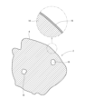
図3に、粒子2の断面が示されている。粒子2は、主部14と絶縁性皮膜16とを有している。絶縁性皮膜16は、主部14の表面を覆っている。本実施形態では、絶縁性皮膜16は、主部14の表面の全体を覆っている。従って、粒子2の輪郭4は、絶縁性皮膜16の輪郭でもある。絶縁性皮膜16が、主部14の表面の一部を覆ってもよい。粒子2が、絶縁性皮膜16を有さなくてもよい。コアロスの抑制の観点から、絶縁性皮膜16が主部14の表面の全体を覆うことが好ましい。図3において符号18は、空孔(後に詳説)を表す。
In FIG. 3 a cross section of
主部14の材質は、後に詳説される鉄基合金である。この主部14と絶縁性皮膜16とを有する多数の粒子2から得られた圧粉磁心は、磁気特性に優れる。本明細書では、主部14の材質が鉄基合金である粒子2からなる軟磁性粉末は、絶縁性皮膜16の材質にかかわらず、「鉄系軟磁性粉末」と称される。
The material of the
[比率P4]
本明細書では、下記数式によって比率P4が算出される。
P4 = (N1 / N) * 100
この数式において、Nは粒子2の総数を表し、N1は直径D2が50μm以上である粒子2の数を表す。成形体が得られるための加圧法における効率の観点から、比率P4は50%以上が好ましく、60%以上がより好ましく、70%以上が特に好ましい。比率P4が100%であってもよい。
[Ratio P4]
In this specification, the ratio P4 is calculated using the following formula.
P4 = (N1 / N) * 100
In this formula, N represents the total number of
比率P4は、レーザ回折・散乱式粒子径分布測定法によって算出される。この測定法には、例えば、マイクロトラック・ベル社の「粒子径分布測定装置 MT3000II」が使用される。粉末の粒子径分布が個数基準で測定され、径が50μm以上である粒子2の頻度が確認される。
The ratio P4 is calculated by laser diffraction/scattering particle size distribution measuring method. For this measurement method, for example, Microtrac Bell's "Particle Size Distribution Measuring Device MT3000II" is used. The particle size distribution of the powder is measured on a number basis, and the frequency of
[比率P2]
図4に、粒子2の一部が拡大されて示されている。図4には、第一突起10aの近傍が示されている。図4において符号20は、第一突起10aのトップを表す。トップ20は、第一突起10aの輪郭4aのうち、第一仮想円6から最も離れた地点である。第一突起10aの輪郭4aは、粒子2の輪郭4の一部である。図4において矢印H1は、第一突起10aの高さを表す。高さH1は、トップ20から第一仮想円6までの距離である。トップ20の近傍における輪郭4の形状は、曲線(又は直線)でもよく、コーナーでもよい。
[Ratio P2]
In FIG. 4, a part of the
図5に、第一突起10aの高さH1と共に、第二突起10bの高さH2、第三突起10cの高さH3、第四突起10dの高さH4、第五突起10eの高さH5及び第六突起10fの高さH6が示されている。第二突起10bの高さH2、第三突起10cの高さH3、第四突起10dの高さH4、第五突起10eの高さH5及び第六突起10fの高さH6の決定方法は、図4に示された、第一突起10aの高さH1の決定方法と、同じである。それぞれの高さHは、トップ20から第一仮想円6までの距離である。
FIG. 5 shows the height H1 of the
本明細書では、下記数式によって比率P2が算出される。
P2 = (N2 / N1) * 100
この数式においてN1は、直径D2が50μm以上である粒子2の数を表す。この数式においてN2は、以下の条件1-3の全てを満たす粒子2の数を表す。
条件1:直径D2が、50μm以上である。
条件2:その高さHが1.0μm以上である突起10の数Npが、20以上である。
条件3:その高さHが1.0μm以上である突起10の平均高さHpが、10μm以上である。
In this specification, the ratio P2 is calculated using the following formula.
P2 = (N2 / N1) * 100
In this formula, N1 represents the number of
Condition 1: Diameter D2 is 50 μm or more.
Condition 2: The number Np of
Condition 3: The average height Hp of the
図5に示された粒子2では、第一突起10aの高さH1、第二突起10bの高さH2、第三突起10cの高さH3、第五突起10eの高さH5及び第六突起10fの高さH6は、1.0μm以上である。従って、これらの突起10は、「突起10の数Np」及び「突起10の平均高さHp」の算出の対象である。一方、第四突起10dの高さH4は、1.0μm未満である。従って、第四突起10dは、「突起10の数Np」及び「突起10の平均高さHp」の算出の対象でない。この投影図に含まれており、その高さが測定されてはいないが1.0μm未満であることが明らかな微細な突起10も、「突起10の数Np」及び「突起10の平均高さHp」の算出の対象でない。さらに、コア8に付着しているがこの投影図に現れていない突起10も、「突起10の数Np」及び「突起10の平均高さHp」の算出の対象でない。この粒子2では、下記数式によって、突起10の平均高さHpが算出される。
Hp = (H1 + H2 + H3 + H5 + H6) / 5
In the
Hp = (H1 + H2 + H3 + H5 + H6) / 5
この条件1-3を満たす粒子2では、高さHが大きい突起10の数が多く、かつ突起10の平均高さが大きいことに起因して、その輪郭4は歪である。この粒子2が加圧法に供されると、直径D2が大きいことと相まって、隣接する粒子2の絶縁性皮膜16を傷つける。絶縁性皮膜16が損傷した粒子2から得られた圧粉磁心は、磁気特性に劣る。この圧粉磁心では、コアロスが生じやすい。磁気特性の観点から、条件1-3を満たす粒子2の数が少ないことが好ましい。磁気特性の観点から、比率P2は50%以下が好ましく、47%以下がより好ましく、45%以下が特に好ましい。理想的な比率P2は、0%である。
In the
比率P2が50%以下である粉末では、絶縁性皮膜16が薄くても、この絶縁性皮膜16の損傷が抑制されうる。絶縁性皮膜16が薄い粉末は、充填性に優れる。この粉末が採用された圧粉磁心の密度は、大きい。この圧粉磁心では、飽和磁化が大きい。この圧粉磁心は、大電流化の要請に沿いうる。
With powder having a ratio P2 of 50% or less, damage to the insulating
比率P2の算出では、目開きが50μmである篩により、粉末が分級される。篩の上に残った粒子2から無作為に50個の粒子2が選択され、実体顕微鏡で観察される。各粒子2の投影図から、この粒子2の直径D2及び突起10の平均サイズSpが測定され、数N1及び数N2がカウントされる。
In calculating the ratio P2, the powder is classified using a sieve with an opening of 50 μm. Fifty
[比率P1]
本明細書では、下記数式によって比率P1が算出される。
P1 = (N3 / N) * 100
この数式において、Nは粒子2の総数を表し、N3は円形度Roが0.8以上である粒子2の数を表す。円形度Roの大きい粒子2が加圧法に供されても、隣接する粒子2の絶縁性皮膜16を傷つけにくい。円形度Roが0.8以上である粒子2の比率P1が大きい粉末から得られた圧粉磁心は、磁気特性に優れる。この観点から、比率P1は50%以上が好ましく、55%以上がより好ましく、60%以上が特に好ましい。
[Ratio P1]
In this specification, the ratio P1 is calculated using the following formula.
P1 = (N3 / N) * 100
In this formula, N represents the total number of
円形度Roは、下記数式により算出される。
Ro = 4πS / L2
この数式において、Sは粒子2の投影面積であり、Lは粒子2の輪郭4長である。面積Sと輪郭4長Lとは、画像解析にて測定される。画像解析の測定機として、画像解析装置株式会社セイシン企業の商品名「PITA-04」が例示される。
The degree of circularity Ro is calculated using the following formula.
Ro = 4πS / L2
In this formula, S is the projected area of
比率P1の大小にかかわらず、小さな比率P2による損傷抑制効果は得られうる。換言すれば、本実施形態において、比率P1の値の設定は、必須の事項ではない。 Regardless of the size of the ratio P1, the damage suppression effect can be obtained by a small ratio P2. In other words, in this embodiment, setting the value of the ratio P1 is not an essential matter.
比率P1が小さい粉末であっても、比率P2が十分小さければ、絶縁性皮膜16の損傷が抑制されうる。比率P1が小さい粉末の製造では、材料の歩留まりが高い。従って、比率P1が小さい粉末は、低コストで得られうる。コストの観点から、比率P1は80%以下が好ましく、75%以下がより好ましく、70%以下が特に好ましい。
Even if the powder has a small ratio P1, damage to the insulating
[比率P3]
図6に、空孔18が拡大されて示されている。図6には、第三仮想円22も示されている。この第三仮想円22は、その内側に空孔18の輪郭24を含む最小の円である。換言すれば、第三仮想円22は、「最小外接円中心法」にて定義される「最小外接円」である。図6において符号D3は、第三仮想円22の直径を表す。本明細書では、この直径D3は、「空孔18の直径」と称される。
[Ratio P3]
In FIG. 6, the
本明細書では、下記数式によって比率P3が算出される。
P3 = (N4 / N1) * 100
この数式において、N1は直径D2が50μm以上である粒子2の数を表す。この数式においてN4は、直径D2が50μm以上であり、1つの断面に含まれる、直径D3が0.1μm以上である空孔18の数Nvが、2以上である粒子2の数を表す。
In this specification, the ratio P3 is calculated using the following formula.
P3 = (N4 / N1) * 100
In this formula, N1 represents the number of
比率P3は、圧粉磁心の透磁率と相関する。圧粉磁心の磁気特性の観点から、比率P3は20%以上が好ましく、18%以下がより好ましく、15%以下が特に好ましい。理想的な比率P3は、0%である。 The ratio P3 correlates with the magnetic permeability of the dust core. From the viewpoint of the magnetic properties of the dust core, the ratio P3 is preferably 20% or more, more preferably 18% or less, and particularly preferably 15% or less. The ideal ratio P3 is 0%.
比率P3の算出では、目開きが50μmである篩により、粉末が分級される。篩の上に残った多数の粒子2が樹脂に埋め込まれ、かつ研磨される。研磨面に現れた多数の粒子2の断面から、直径が50μm以上である50個の断面が、無作為に抽出される。50個の断面のそれぞれにおいて、直径D3が0.1μm以上である空孔18の数がカウントされる。1つの断面における、直径D3が0.1μm以上である空孔18の数が、当該粒子2における数Nvと定義される。この断面に現れない空孔18は、数Nvには算入されない。
In calculating the ratio P3, the powder is classified using a sieve with an opening of 50 μm. A large number of
[主部の材質]
前述の通り、主部14の材質は鉄基合金である。鉄基合金は、靱性に優れる。従ってこの粉末は、加圧法に適している。種々の軟磁性鉄基合金が、粉末に採用されうる。
[Material of main part]
As mentioned above, the material of the
好ましくは、この鉄基合金は、
Si:2.0質量%以上10.0質量%以下、
Cr:0.0質量%以上10.0質量%以下、
Al:0.0質量%以上10.0質量%以下、
及び
B:0.0質量%以上10.0質量%以下
を含む。好ましくは、残部は、Fe及び不可避不純物である。
Preferably, the iron-based alloy is
Si: 2.0% by mass or more and 10.0% by mass or less,
Cr: 0.0% by mass or more and 10.0% by mass or less,
Al: 0.0% by mass or more and 10.0% by mass or less,
and B: 0.0% by mass or more and 10.0% by mass or less. Preferably, the remainder is Fe and unavoidable impurities.
[絶縁性皮膜の材質]
皮膜16の材質は、絶縁性の物質である。皮膜16の導電率は、主部の導電率よりも小さい。主部14の表面が酸化されることで、皮膜16が形成されうる。皮膜16の材質が、有機物であってもよい。有機物の一例として、チタンアルコキシド類とケイ素アルコキシド類との混合物の重合体が挙げられる。皮膜16が、2以上の層を有してもよい。
[Material of insulating film]
The material of the
[製造方法]
この粉末の製造には、アトマイズ法、粉砕法等が採用されうる。アトマイズ法として、ガスアトマイズ法、ディスクアトマイズ法、水アトマイズ法、遠心アトマイズ法等が、採用される。粉末中の酸素含有量及び窒素含有量が抑制されうるとの観点から、ガスアトマイズ法及びディスクアトマイズ法が好ましい。
[Production method]
An atomization method, a pulverization method, etc. may be employed to produce this powder. As the atomization method, a gas atomization method, a disk atomization method, a water atomization method, a centrifugal atomization method, etc. are adopted. The gas atomization method and the disk atomization method are preferred from the viewpoint that the oxygen content and nitrogen content in the powder can be suppressed.
典型的な空孔18は、ガスアトマイズに起因するガスポアである。ガスポアは、アトマイズ用のガスが液滴内に侵入した状態で凝固することで、発生する。アトマイズ用の不活性ガスとして、ヘリウムガス、アルゴンガス及び窒素ガスが一般的である。ヘリウム及びアルゴンは金属にほとんど吸収されないので、ヘリウムガス及びアルゴンガスが用いられたガスアトマイズでは、ガスポアが生じやすい。一方、窒素は金属に吸収されうるので、窒素ガスが用いられたガスアトマイズでは、ガスポアが生じにくい。さらに、不活性ガスによる液滴形成がなされないディスクアトマイズにおいても、ガスポアが生じにくい。比率P3が小さい粉末が得られるとの観点から好ましいアトマイズは、窒素ガスによるガスアトマイズ及びディスクアトマイズである。
アトマイズにおいて、溶融金属の凝固が完了する前に、コア8に突起10が付着しうる。従って、突起10の材質は、コア8の材質と概ね同じである。この突起10は、コア8と一体である。他の原因でも、粒子2に突起10が発生しうる。
During atomization,
好ましくは、アトマイズ等で得られた原料粉末にジェットミル処理が施され、粉末が得られる。ジェットミル処理では、高速ジェット気流により粒子2同士が衝突する。この衝突により、突起10が粉砕される。従って、ジェットミル処理で得られた粉末では、小さな比率P2が達成されうる。ジェットミル処理に適した装置として、エムテック化学株式会社の商品名「MJM1」が例示される。ジェットミル処理以外の方法で、突起10が粉砕されてもよい。
Preferably, the raw material powder obtained by atomization or the like is subjected to a jet mill treatment to obtain a powder. In the jet mill process,
ジェットミル処理の後の粉末に、焼鈍が施されてもよい。ジェットミル処理によって粒子2に生じた歪みが、焼鈍によって除去されうる。焼鈍は、不活性ガス(例えばアルゴンガス)の雰囲気中で、所定温度(例えば600℃)に、所定時間(例えば5時間)、粉末が保持され、その後に炉冷される。
The powder after jet milling may be annealed. The distortion caused in the
粉末に熱処理が施されることで、粉末の表面が酸化し、絶縁性皮膜16が生成しうる。効率の観点から、前述の焼鈍がこの熱処理をかねてなされることが好ましい。この場合、焼鈍の雰囲気ガスが大気(又は一部が大気)とされる。
By subjecting the powder to heat treatment, the surface of the powder may be oxidized and an insulating
[磁性部材]
この粉末から圧粉磁心が得られる方法として、加圧法が挙げられる。加圧法では、粉末が金型に投入され、加圧される。これにより、成形体が得られる。加圧において、潤滑剤、バインダー等が用いられてもよい。この成形体が熱処理され、圧粉磁心が得られる。加圧法により、この粉末から、圧粉磁心以外の磁性部材も得られうる。
[Magnetic member]
As a method for obtaining a powder magnetic core from this powder, a pressurization method can be mentioned. In the pressurization method, powder is put into a mold and pressurized. Thereby, a molded body is obtained. In pressurizing, a lubricant, a binder, etc. may be used. This compact is heat treated to obtain a powder magnetic core. Magnetic members other than powder magnetic cores can also be obtained from this powder by the pressing method.
本明細書は、磁性部材の製造方法にも向けられる。この製造方法は、
多数の粒子2からなり、これらの粒子2が直径が50μm以上である粒子2を含んでおり、下記数式で算出される比率P2が50%以下である鉄系軟磁性粉末を、準備するステップ、
及び
上記粉末を加圧するステップ
を含む。
P2 = (N2 / N1) * 100
この数式においてN1は、直径が50μm以上である粒子2の数を表す。この数式においてN2は、直径が50μm以上であり、コア8とこのコア8の表面に付着しておりその高さが1.0μm以上である20以上の突起10とを含んでおり、その高さが1.0μm以上である突の平均高さが10μm以上である粒子2の数を表す。
The present specification is also directed to methods of manufacturing magnetic members. This manufacturing method is
A step of preparing an iron-based soft magnetic powder consisting of a large number of
and compressing the powder.
P2 = (N2 / N1) * 100
In this formula, N1 represents the number of
以下、実施例に係る軟磁性粉末の効果が明らかにされるが、この実施例の記載に基づいて本明細書で開示された範囲が限定的に解釈されるべきではない。 Hereinafter, the effects of the soft magnetic powder according to Examples will be clarified, but the scope disclosed in this specification should not be interpreted to be limited based on the description of these Examples.
[実験1]
[実施例1]
その材質が、下記表1に示された合金3である原料を、準備した。30kgの原料にアルゴンガスによるガスアトマイズを施して、原料粉末を得た。この原料粉末に、「JIS Z 8801-1」に規格された篩を用いて、粒子径が20μm以上150μm以下となるように分級を施した。この粉末に、エムテック化学株式会社のジェットミル装置(前述の「MJM1」)にて、ジェットミル処理を施した。
圧縮空気の圧力:0.7MPa
圧縮空気の風量:21m3/時(350L/min)
さらに、この粉末に、下記条件で焼鈍を施し、実施例1の軟磁性粉末を得た。焼鈍により、ジェットミル処理で生じた歪みが除去され、さらに絶縁性皮膜が生成した。この皮膜の材質は、鉄系酸化物であった。焼鈍の条件は、下記の通りであった。
雰囲気:大気の一部をアルゴンガスで置換(酸素濃度:500ppm)
昇温開始温度:常温(25℃)
昇温速度:0.16℃/s
到達温度:600℃
保持時間:5時間
冷却:常温まで炉冷
[Experiment 1]
[Example 1]
A raw material whose material was Alloy 3 shown in Table 1 below was prepared. A raw material powder was obtained by subjecting 30 kg of the raw material to gas atomization using argon gas. This raw material powder was classified using a sieve specified in "JIS Z 8801-1" so that the particle size was 20 μm or more and 150 μm or less. This powder was subjected to jet mill treatment using a jet mill device (the above-mentioned "MJM1") manufactured by Mtech Chemical Co., Ltd.
Compressed air pressure: 0.7MPa
Compressed air volume: 21m 3 /hour (350L/min)
Furthermore, this powder was annealed under the following conditions to obtain the soft magnetic powder of Example 1. Annealing removed the distortion caused by jet milling and also produced an insulating film. The material of this film was an iron-based oxide. The annealing conditions were as follows.
Atmosphere: Part of the atmosphere is replaced with argon gas (oxygen concentration: 500 ppm)
Heating start temperature: normal temperature (25℃)
Temperature increase rate: 0.16℃/s
Achieved temperature: 600℃
Holding time: 5 hours Cooling: Furnace cooling to room temperature
[実施例2-8]
材質及びアトマイズガスを下記表2に示される通りとした他は実施例1と同様にして、実施例2-8の粉末を得た。
[Example 2-8]
Powders of Examples 2-8 were obtained in the same manner as in Example 1, except that the materials and atomizing gas were changed as shown in Table 2 below.
[実施例9-11]
材質を下記表2に示される通りとし、ガスアトマイズに代えてディスクアトマイズを施し、ジェットミル処理を施さなかった他は実施例1と同様にして、実施例9-11の粉末を得た。
[Example 9-11]
Powders of Examples 9-11 were obtained in the same manner as in Example 1, except that the materials were as shown in Table 2 below, disk atomization was performed instead of gas atomization, and jet mill treatment was not performed.
[比較例1-4]
材質及びアトマイズガスを下記表2に示される通りとし、ジェットミル処理を施さなかった他は実施例1と同様にして、比較例1-4の粉末を得た。
[Comparative example 1-4]
A powder of Comparative Example 1-4 was obtained in the same manner as in Example 1 except that the materials and atomizing gas were as shown in Table 2 below, and the jet mill treatment was not performed.
[評価]
粉末を型に投入し、1520MPaの圧力を加えて、トロイダル形状の成形体を得た。この成形体のサイズは、以下の通りであった。
外径:28mm
内径:15mm
高さ:3mm
[evaluation]
The powder was put into a mold and a pressure of 1520 MPa was applied to obtain a toroidal shaped molded body. The size of this molded body was as follows.
Outer diameter: 28mm
Inner diameter: 15mm
Height: 3mm
この成形体にひずみ取り焼鈍を行い、圧粉磁心を得た。焼鈍の条件は、以下の通りであった。
雰囲気:アルゴンガス(酸素濃度:1ppm未満)
昇温開始温度:常温(25℃)
昇温速度:0.16℃/s
到達温度:800℃
保持時間:1時間
冷却:常温まで炉冷
実施例1-11及び比較例1-4のそれぞれに係る粉末から得られた圧粉磁心の電気抵抗値は、1×10⁷Ω・cm3以上であり、その絶縁性は十分であった。
This compact was subjected to strain relief annealing to obtain a powder magnetic core. The annealing conditions were as follows.
Atmosphere: Argon gas (oxygen concentration: less than 1 ppm)
Heating start temperature: normal temperature (25℃)
Temperature increase rate: 0.16℃/s
Achieved temperature: 800℃
Holding time: 1 hour Cooling: Furnace cooling to room temperature The electrical resistance value of the powder core obtained from the powders of Example 1-11 and Comparative Example 1-4 was 1×10 7 Ω・cm 3 or more. The insulation properties were sufficient.
この圧粉磁心の密度及び透磁率μ’を測定した。透磁率μ’が大きい圧粉磁心では、コアロスが生じにくい。さらに、下記の基準に従って格付けを行った。この結果が、下記の表2に示されている。
S:透磁率が30以上である。
A:透磁率が20以上30未満である。
B:透磁率が15以上20未満である。
F:透磁率が15未満である。
The density and magnetic permeability μ' of this powder magnetic core were measured. A powder magnetic core with a large magnetic permeability μ' is less likely to cause core loss. Furthermore, grading was performed according to the following criteria. The results are shown in Table 2 below.
S: Magnetic permeability is 30 or more.
A: Magnetic permeability is 20 or more and less than 30.
B: Magnetic permeability is 15 or more and less than 20.
F: Magnetic permeability is less than 15.
[実験2]
[実施例12-21]
材質及びアトマイズガスを下記表3に示される通りとした他は実施例1と同様にして、実施例12-21の粉末を得た。
[Experiment 2]
[Example 12-21]
Powders of Examples 12-21 were obtained in the same manner as in Example 1, except that the materials and atomizing gas were changed as shown in Table 3 below.
[実施例22-26]
材質を下記表3に示される通りとし、ガスアトマイズに代えてディスクアトマイズを施し、ジェットミル処理を施さなかった他は実施例1と同様にして、実施例22-26の粉末を得た。
[Example 22-26]
Powders of Examples 22-26 were obtained in the same manner as in Example 1, except that the materials were as shown in Table 3 below, disk atomization was performed instead of gas atomization, and jet mill treatment was not performed.
[比較例5-9]
材質及びアトマイズガスを下記表3に示される通りとし、ジェットミル処理を施さなかった他は実施例1と同様にして、比較例5-9の粉末を得た。
[Comparative Example 5-9]
Powders of Comparative Examples 5-9 were obtained in the same manner as in Example 1 except that the materials and atomizing gas were as shown in Table 3 below and the jet mill treatment was not performed.
[評価]
実験1と同様の方法で、圧粉磁心を得た。実施例12-26及び比較例5-9のそれぞれに係る粉末から得られた圧粉磁心の電気抵抗値は、1×10⁷Ω・cm3以上であり、その絶縁性は十分であった。
[evaluation]
A powder magnetic core was obtained in the same manner as in Experiment 1. The electric resistance value of the powder magnetic core obtained from the powder according to each of Example 12-26 and Comparative Example 5-9 was 1×10 7 Ω·cm 3 or more, and the insulation property was sufficient.
この圧粉磁心の密度及び透磁率μ’を測定した。さらに、下記の基準に従って格付けを行った。この結果が、下記の表3に示されている。
S:透磁率が25以上である。
A:透磁率が15以上25未満である。
B:透磁率が10以上15未満である。
F:透磁率が10未満である。
The density and magnetic permeability μ' of this powder magnetic core were measured. Furthermore, grading was performed according to the following criteria. The results are shown in Table 3 below.
S: Magnetic permeability is 25 or more.
A: Magnetic permeability is 15 or more and less than 25.
B: Magnetic permeability is 10 or more and less than 15.
F: Magnetic permeability is less than 10.
[実験3]
[実施例27-35]
材質及びアトマイズガスを下記表4に示される通りとした他は実施例1と同様にして、実施例27-35の粉末を得た。
[Experiment 3]
[Example 27-35]
Powders of Examples 27-35 were obtained in the same manner as in Example 1, except that the materials and atomizing gas were changed as shown in Table 4 below.
[実施例36-38]
材質を下記表4に示される通りとし、ガスアトマイズに代えてディスクアトマイズを施し、ジェットミル処理を施さなかった他は実施例1と同様にして、実施例36-38の粉末を得た。
[Example 36-38]
Powders of Examples 36-38 were obtained in the same manner as in Example 1, except that the materials were as shown in Table 4 below, disk atomization was performed instead of gas atomization, and jet mill treatment was not performed.
[比較例10-13]
材質及びアトマイズガスを下記表4に示される通りとし、ジェットミル処理を施さなかった他は実施例1と同様にして、比較例10-13の粉末を得た。
[Comparative Example 10-13]
Powders of Comparative Examples 10-13 were obtained in the same manner as in Example 1 except that the materials and atomizing gas were as shown in Table 4 below and the jet mill treatment was not performed.
[評価]
実験1と同様の方法で、圧粉磁心を得た。実施例27-35及び比較例10-13のそれぞれに係る粉末から得られた圧粉磁心の電気抵抗値は、1×10⁷Ω・cm3以上であり、その絶縁性は十分であった。
[evaluation]
A powder magnetic core was obtained in the same manner as in Experiment 1. The electric resistance value of the dust core obtained from the powder according to each of Examples 27-35 and Comparative Example 10-13 was 1×10 7 Ω·cm 3 or more, and the insulation properties were sufficient.
この圧粉磁心の密度及び透磁率μ’を測定した。さらに、下記の基準に従って格付けを行った。この結果が、下記の表4に示されている。
S:透磁率が20以上である。
A:透磁率が10以上20未満である。
B:透磁率が5以上10未満である。
F:透磁率が5未満である。
The density and magnetic permeability μ' of this powder magnetic core were measured. Furthermore, grading was performed according to the following criteria. The results are shown in Table 4 below.
S: Magnetic permeability is 20 or more.
A: Magnetic permeability is 10 or more and less than 20.
B: Magnetic permeability is 5 or more and less than 10.
F: Magnetic permeability is less than 5.


表2-4に示されるように、各実施例に係る粉末から、磁気特性に優れた成形体が得られうる。これらの評価結果から、本発明の優位性は明らかである。 As shown in Table 2-4, molded bodies with excellent magnetic properties can be obtained from the powders according to each example. From these evaluation results, the superiority of the present invention is clear.
以上説明された粉末は、種々の磁性部材に適している。 The powder described above is suitable for various magnetic members.
2・・・粒子
4・・・第一仮想円
6・・・(粒子の)輪郭
8・・・コア
10・・・突起
12・・・第二仮想円
14・・・主部
16・・・皮膜
18・・・空孔
20・・・トップ
22・・・第三仮想円
24・・・(空孔の)輪郭
2...
Claims (7)
これらの粒子が、直径が50μm以上である粒子を含んでおり、
下記数式で算出される比率P2が50%以下である、鉄系軟磁性粉末。
P2 = (N2 / N1) * 100
(この数式においてN1は、直径が50μm以上である粒子の数を表す。)
(この数式においてN2は、直径が50μm以上であり、コアとこのコアの表面に付着しておりその高さが1.0μm以上である20以上の突起とを含んでおり、その高さが1.0μm以上である突起の平均高さが10μm以上である粒子の数を表す。) Consisting of many particles,
These particles include particles having a diameter of 50 μm or more,
Iron-based soft magnetic powder whose ratio P2 calculated by the following formula is 50% or less.
P2 = (N2 / N1) * 100
(In this formula, N1 represents the number of particles with a diameter of 50 μm or more.)
(In this formula, N2 has a diameter of 50 μm or more and includes a core and 20 or more protrusions that are attached to the surface of this core and have a height of 1.0 μm or more, and whose height is 1.0 μm or more.) .Represents the number of particles whose protrusions have an average height of 10 μm or more.)
P1 = (N3 / N) * 100
(この数式において、Nは粒子の総数を表し、N3は円形度が0.8以上である粒子の数を表す。) The soft magnetic powder according to claim 1, wherein the ratio P1 calculated by the following formula is 50% or more.
P1 = (N3 / N) * 100
(In this formula, N represents the total number of particles, and N3 represents the number of particles whose circularity is 0.8 or more.)
P3 = (N4 / N1) * 100
(この数式において、N1は直径が50μm以上である粒子の数を表す。)
(この数式においてN4は、直径が50μm以上であり、1つの断面に含まれる直径が0.1μm以上である空孔の数が2以上である粒子の数を表す。) The soft magnetic powder according to claim 1 or 2, wherein the ratio P3 calculated by the following formula is 20% or less.
P3 = (N4 / N1) * 100
(In this formula, N1 represents the number of particles with a diameter of 50 μm or more.)
(In this formula, N4 represents the number of particles with a diameter of 50 μm or more and the number of pores included in one cross section with a diameter of 0.1 μm or more is 2 or more.)
P4 = (N1 / N) * 100
(この数式において、Nは粒子の総数を表し、N1は直径が50μm以上である粒子の数を表す。) The soft magnetic powder according to claim 1 or 2, wherein the ratio P4 calculated by the following formula is 50% or more.
P4 = (N1 / N) * 100
(In this formula, N represents the total number of particles, and N1 represents the number of particles with a diameter of 50 μm or more.)
上記主部の材質が鉄基合金である請求項1又は2に記載の軟磁性粉末。 Each particle has a main part and an insulating film covering all or part of the surface of the main part,
The soft magnetic powder according to claim 1 or 2, wherein the material of the main portion is an iron-based alloy.
及び
上記粉末を加圧するステップ
を備えた、磁性部材の製造方法。
P2 = (N2 / N1) * 100
(この数式においてN1は、直径が50μm以上である粒子の数を表す。)
(この数式においてN2は、直径が50μm以上であり、コアとこのコアの表面に付着しておりその高さが1.0μm以上である20以上の突起とを含んでおり、その高さが1.0μm以上である突起の平均高さが10μm以上である粒子の数を表す。) A step of preparing an iron-based soft magnetic powder consisting of a large number of particles, including particles having a diameter of 50 μm or more, and having a ratio P2 calculated by the following formula of 50% or less,
and A method for manufacturing a magnetic member, comprising the step of pressurizing the powder.
P2 = (N2 / N1) * 100
(In this formula, N1 represents the number of particles with a diameter of 50 μm or more.)
(In this formula, N2 has a diameter of 50 μm or more and includes a core and 20 or more protrusions that are attached to the surface of this core and have a height of 1.0 μm or more, and whose height is 1.0 μm or more.) .Represents the number of particles whose protrusions have an average height of 10 μm or more.)
Priority Applications (1)
| Application Number | Priority Date | Filing Date | Title |
|---|---|---|---|
| JP2022094920A JP2023181663A (en) | 2022-06-13 | 2022-06-13 | Iron-based soft magnetic powder |
Applications Claiming Priority (1)
| Application Number | Priority Date | Filing Date | Title |
|---|---|---|---|
| JP2022094920A JP2023181663A (en) | 2022-06-13 | 2022-06-13 | Iron-based soft magnetic powder |
Publications (1)
| Publication Number | Publication Date |
|---|---|
| JP2023181663A true JP2023181663A (en) | 2023-12-25 |
Family
ID=89308896
Family Applications (1)
| Application Number | Title | Priority Date | Filing Date |
|---|---|---|---|
| JP2022094920A Pending JP2023181663A (en) | 2022-06-13 | 2022-06-13 | Iron-based soft magnetic powder |
Country Status (1)
| Country | Link |
|---|---|
| JP (1) | JP2023181663A (en) |
-
2022
- 2022-06-13 JP JP2022094920A patent/JP2023181663A/en active Pending
Similar Documents
| Publication | Publication Date | Title |
|---|---|---|
| JP4613622B2 (en) | Soft magnetic material and dust core | |
| JP5305126B2 (en) | Soft magnetic powder, method of manufacturing a dust core, dust core, and magnetic component | |
| JP2007012994A (en) | Method for manufacturing insulating soft magnetic metal powder molding | |
| JP5063861B2 (en) | Composite dust core and manufacturing method thereof | |
| JP5522173B2 (en) | Composite magnetic body and method for producing the same | |
| JP2007019134A (en) | Method of manufacturing composite magnetic material | |
| JP2008028162A (en) | Soft magnetic material, manufacturing method therefor, and dust core | |
| EP3666419A1 (en) | CRYSTALLINE Fe-BASED ALLOY POWDER AND METHOD FOR PRODUCING SAME | |
| CN107924743B (en) | Soft magnetic powder | |
| JP2007214366A (en) | Powder magnetic core, powder for use thereof, and manufacturing methods of them | |
| JP2016139748A (en) | Soft magnetic metal dust core | |
| JP2013098384A (en) | Dust core | |
| JP2018018851A (en) | Soft magnetic metal powder-compact magnetic core, and reactor arranged by use thereof | |
| JP2019178402A (en) | Soft magnetic powder | |
| JP2003142310A (en) | Dust core having high electrical resistance and manufacturing method therefor | |
| JP2008172257A (en) | Method for manufacturing insulating soft magnetic metal powder molding | |
| Otsuka et al. | Magnetic properties of Fe-based amorphous powders with high-saturation induction produced by spinning water atomization process (SWAP) | |
| CA2891206C (en) | Iron powder for dust cores | |
| JP2010222670A (en) | Composite magnetic material | |
| JP5814809B2 (en) | Powder mixture for dust core | |
| WO2014034616A1 (en) | Iron powder for powder magnetic core and process for producing powder magnetic core | |
| JP2017054910A (en) | Soft magnetic metal powder compact core | |
| JP6064539B2 (en) | Powder core powder manufacturing method and dust core powder | |
| JP2009147252A (en) | Compound magnetic material and method of manufacturing thereof | |
| JP4507663B2 (en) | Method for producing soft magnetic material, soft magnetic powder and dust core |