JP2023158181A - gaming machine - Google Patents
gaming machine Download PDFInfo
- Publication number
- JP2023158181A JP2023158181A JP2023146251A JP2023146251A JP2023158181A JP 2023158181 A JP2023158181 A JP 2023158181A JP 2023146251 A JP2023146251 A JP 2023146251A JP 2023146251 A JP2023146251 A JP 2023146251A JP 2023158181 A JP2023158181 A JP 2023158181A
- Authority
- JP
- Japan
- Prior art keywords
- ball
- game
- balls
- firing
- information
- Prior art date
- Legal status (The legal status is an assumption and is not a legal conclusion. Google has not performed a legal analysis and makes no representation as to the accuracy of the status listed.)
- Withdrawn
Links
- 230000002265 prevention Effects 0.000 claims abstract description 28
- 230000002452 interceptive effect Effects 0.000 claims abstract description 10
- 238000010304 firing Methods 0.000 claims description 288
- 230000000903 blocking effect Effects 0.000 claims description 59
- 238000000034 method Methods 0.000 description 178
- 230000008569 process Effects 0.000 description 177
- 238000012545 processing Methods 0.000 description 164
- 238000001514 detection method Methods 0.000 description 102
- 238000003860 storage Methods 0.000 description 81
- 238000012790 confirmation Methods 0.000 description 41
- 230000001788 irregular Effects 0.000 description 33
- 239000011295 pitch Substances 0.000 description 26
- 238000010586 diagram Methods 0.000 description 23
- 230000005540 biological transmission Effects 0.000 description 21
- 230000006854 communication Effects 0.000 description 20
- 239000002184 metal Substances 0.000 description 19
- 230000002093 peripheral effect Effects 0.000 description 19
- 238000004891 communication Methods 0.000 description 18
- 230000006870 function Effects 0.000 description 15
- 238000012544 monitoring process Methods 0.000 description 15
- 238000007599 discharging Methods 0.000 description 11
- 238000005498 polishing Methods 0.000 description 11
- 238000005034 decoration Methods 0.000 description 8
- 230000000694 effects Effects 0.000 description 8
- 238000003780 insertion Methods 0.000 description 8
- 230000037431 insertion Effects 0.000 description 8
- 230000033001 locomotion Effects 0.000 description 7
- 230000004044 response Effects 0.000 description 7
- 238000000926 separation method Methods 0.000 description 7
- 238000012840 feeding operation Methods 0.000 description 6
- 230000007246 mechanism Effects 0.000 description 6
- 238000011144 upstream manufacturing Methods 0.000 description 6
- 230000005856 abnormality Effects 0.000 description 5
- 239000004973 liquid crystal related substance Substances 0.000 description 5
- 239000000696 magnetic material Substances 0.000 description 5
- 238000012360 testing method Methods 0.000 description 5
- 230000002457 bidirectional effect Effects 0.000 description 4
- 230000007423 decrease Effects 0.000 description 4
- 230000004308 accommodation Effects 0.000 description 3
- 230000001276 controlling effect Effects 0.000 description 3
- 238000009795 derivation Methods 0.000 description 3
- 238000005096 rolling process Methods 0.000 description 3
- 230000001360 synchronised effect Effects 0.000 description 3
- 230000002159 abnormal effect Effects 0.000 description 2
- 230000004913 activation Effects 0.000 description 2
- FFBHFFJDDLITSX-UHFFFAOYSA-N benzyl N-[2-hydroxy-4-(3-oxomorpholin-4-yl)phenyl]carbamate Chemical compound OC1=C(NC(=O)OCC2=CC=CC=C2)C=CC(=C1)N1CCOCC1=O FFBHFFJDDLITSX-UHFFFAOYSA-N 0.000 description 2
- 230000008859 change Effects 0.000 description 2
- 230000005484 gravity Effects 0.000 description 2
- 238000004519 manufacturing process Methods 0.000 description 2
- 238000011084 recovery Methods 0.000 description 2
- 230000001105 regulatory effect Effects 0.000 description 2
- 230000015607 signal release Effects 0.000 description 2
- 230000009471 action Effects 0.000 description 1
- 239000000853 adhesive Substances 0.000 description 1
- 230000001070 adhesive effect Effects 0.000 description 1
- 238000013459 approach Methods 0.000 description 1
- 238000005452 bending Methods 0.000 description 1
- 210000000078 claw Anatomy 0.000 description 1
- 238000013461 design Methods 0.000 description 1
- 230000005284 excitation Effects 0.000 description 1
- 230000005281 excited state Effects 0.000 description 1
- 239000004744 fabric Substances 0.000 description 1
- 230000010365 information processing Effects 0.000 description 1
- 238000007689 inspection Methods 0.000 description 1
- 238000009434 installation Methods 0.000 description 1
- 238000012423 maintenance Methods 0.000 description 1
- 230000007257 malfunction Effects 0.000 description 1
- 239000007769 metal material Substances 0.000 description 1
- 230000010355 oscillation Effects 0.000 description 1
- 230000000149 penetrating effect Effects 0.000 description 1
- 238000007747 plating Methods 0.000 description 1
- 230000005855 radiation Effects 0.000 description 1
- 239000011347 resin Substances 0.000 description 1
- 229920005989 resin Polymers 0.000 description 1
- 230000000717 retained effect Effects 0.000 description 1
- 230000000630 rising effect Effects 0.000 description 1
- 229910001220 stainless steel Inorganic materials 0.000 description 1
- 239000010935 stainless steel Substances 0.000 description 1
- 239000000126 substance Substances 0.000 description 1
- 239000000758 substrate Substances 0.000 description 1
- 230000003313 weakening effect Effects 0.000 description 1
Images






Landscapes
- Pinball Game Machines (AREA)
Abstract
Description
本発明は、遊技機内に所定数の遊技球を収容し、該所定数の遊技球を打球発射装置によって遊技領域に発射して遊技を行い、遊技を終えた遊技球を回収し、遊技機内を閉鎖的に循環させて打球発射装置から遊技球を遊技領域に発射することにより、前記所定数の遊技球を循環して使用するようにした封入球式遊技機に関し、特に、遊技領域に向けて遊技球を打ち出す打球発射装置が遊技機の上部に配置された封入球式遊技機に関する。 The present invention accommodates a predetermined number of game balls in a game machine, plays a game by firing the predetermined number of game balls into a game area with a ball launcher, collects the game balls after playing, and runs the inside of the game machine. The present invention relates to an enclosed ball game machine in which the predetermined number of game balls are circulated and used by firing the game balls from a ball firing device into the game area in a closed manner, and in particular, The present invention relates to an enclosed ball game machine in which a ball firing device for firing game balls is placed at the top of the game machine.
遊技盤面に区画形成された遊技領域内に遊技球を発射する打球発射装置を遊技機の上部左側(遊技領域の中央部に対して左斜め上方)に配置した遊技機が提案されている(例えば、特許文献1、2及び3)。
A game machine has been proposed in which a ball firing device that fires game balls into a game area defined on the game board surface is placed on the upper left side of the game machine (diagonally upper left with respect to the center of the game area) (for example, ,
特許文献1に記載の遊技機は、遊技機本体内に所定数封入した遊技球を、発射装置により遊技盤の遊技領域に発射して遊技を行い、遊技領域を経た遊技球を循環経路により回収して発射装置に導いて、当該遊技球を循環使用する封入球式遊技機である。
The game machine described in
パチンコ遊技に使用する遊技球が循環する循環経路を有する封入球式遊技機では、遊技機の内部に一定数の遊技球が封入された状態で遊技が行われる。そして、精算システム等を介してカード等の記憶媒体から入力された貸球数のデータに基づく遊技球の数(持球数のデータ)に対応して遊技球が発射可能となり、遊技球を発射すると、発射された遊技球の数に対応して持球数のデータが減算される。 In an enclosed ball game machine that has a circulation path through which game balls used in a pachinko game circulate, the game is played with a certain number of game balls sealed inside the game machine. Game balls can then be fired in accordance with the number of game balls (data on the number of balls held) based on the data on the number of rented balls inputted from a storage medium such as a card via a payment system, etc., and the game balls are fired. Then, data on the number of balls held is subtracted in accordance with the number of game balls fired.
また、発射された遊技球が遊技領域内の入賞口に入賞して賞球(遊技球)が発生した場合、実際の遊技球を払い出すことはなく、持球数のデータに賞球の数が加算される。また、持球数のデータが「0」になると、遊技球の発射ができない状態となる。このように封入球式遊技機による遊技は、完全にデータ上の数値として行われることになる。従って、発射された遊技球を正確に検出し、発射された遊技球の数を管理する必要がある。 In addition, if the fired game ball enters the winning hole in the gaming area and a prize ball (game ball) is generated, the actual game ball will not be paid out, and the number of prize balls will be included in the data of the number of balls held. is added. Further, when the data of the number of balls held becomes "0", the game ball becomes unable to be fired. In this way, games with the enclosed ball type gaming machine are played entirely based on numerical data. Therefore, it is necessary to accurately detect the shot game balls and to manage the number of shot game balls.
特許文献1及び特許文献2に記載の遊技機は、発射位置に遊技球を送り出す案内通路の発射位置の手前位置において発射球センサが配置されているもので、実際には発射位置に送り込む遊技球を発射球と見做しているものであり、発射装置によって発射位置から実際に発射された遊技球を検出しているものではない。このため、発射球数を正確にカウントしているとは言えず、発射球数を誤球カウントする虞がある。
The gaming machines described in
特許文献3に記載の遊技機は、遊技領域の拡大が可能となり、遊技球を高い精度で狙った位置に打ち込むことを可能にすることを目的として発射装置を遊技機の上部左側に配置したものである。また、この遊技機は、発射口から遊技領域内に打ち込まれた遊技球が戻り球として発射口(遊技球通路33内)に逆戻りすることがないように、発射口を塞ぐ位置に戻り球防止弁を取り付けたものであって、発射口の手前位置に発射球センサが配置され、発射装置で発射された遊技球の通過を検出している。特許文献3に記載の遊技機は、ファール球や戻り球が発生しないことを前提に、発射された球を検出しており、特許文献1及び特許文献2に記載の遊技機に比べて発射された遊技球を正確に検出している。
The gaming machine described in
しかしながら、特許文献3に記載の遊技機は、発射球で発射口を塞いでいる戻り球防止弁を押し開いて遊技領域に打ち出すため、発射球が必ず戻り球防止弁に衝突することになる。このため、遊技者によっては、遊技球を狙った位置に打ち込むことに対して不信感を抱いてしまい遊技に対する興趣を低下させてしまう虞がある。
However, in the gaming machine described in
そこで、本発明は、このような事情に鑑みてなされたものであり、その目的は、発射球に干渉するような戻り球防止弁を格別設けることなく、発射球の誤球カウントの原因となる戻り球を防止することが可能となる遊技機を提供することにある。 Therefore, the present invention was made in view of the above circumstances, and its purpose is to prevent the incorrect ball count of fired balls without providing a special ball return prevention valve that interferes with the fired balls. To provide a game machine that can prevent balls from returning.
上記本発明の課題を解決する手段として手段1~手段5がある。
請求項1に係る封入球式遊技機は、
遊技領域が区画形成された遊技盤と、
前記遊技盤が嵌め込まれて収容される本体枠と、
前記本体枠の上部に配置され、発射位置にある遊技球を前記遊技領域に向けて発射する打球発射装置と、
前記打球発射装置によって発射された遊技球を前記遊技盤の裏面側に封入球として回収して再び前記打球発射装置に供給するための循環経路と、
前記打球発射装置の打球動作によって前記発射位置から発射された遊技球を前記遊技領域に直接送り込むための発射口と、
を備え、
前記打球発射装置は、
前記発射位置に遊技球を停留させるための発射レールと、
電気的駆動源の駆動に基づいて前記打球動作を行い、前記発射位置に停留された遊技球を前記遊技領域に向けて発射させる発射用部材と、
を備え、
遊技球の払い出しを行うことなく、所定数量の遊技球を閉鎖的に循環させて遊技を行うようにしたものであって、上記課題を解決するために、
前記発射位置から発射された打球に干渉することなく、前記打球の通過を許容する許容位置と、前記遊技領域から前記発射口に戻って来る戻り球の進入を阻止する戻り球阻止位置との間で移動可能とされた戻り球阻止部材を備えた、
ことを特徴とする[手段1]。
The enclosed ball game machine according to
A game board in which a game area is divided into sections,
a main body frame into which the game board is fitted and housed;
a ball launcher that is disposed on the top of the main body frame and launches a game ball at a launch position toward the game area;
a circulation path for collecting the game balls fired by the batted ball firing device as enclosed balls on the back side of the game board and supplying them again to the batting ball firing device;
a launch port for directly sending a game ball fired from the launch position into the game area by a ball-hitting operation of the batted-ball launcher;
Equipped with
The batted ball launching device includes:
a launch rail for stopping the game ball at the launch position;
a firing member that performs the ball hitting operation based on the drive of an electric drive source and fires the game ball stopped at the firing position toward the game area;
Equipped with
In order to solve the above problem, the game is played by circulating a predetermined number of game balls in a closed manner without paying out the game balls.
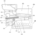
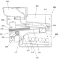
between an allowable position that allows the batted ball to pass without interfering with the batted ball fired from the firing position, and a return ball blocking position that prevents the return ball from entering the firing port from the gaming area; a return ball prevention member that is movable at
[Means 1]
[手段1]に係る封入球式遊技機によれば、戻り球阻止部材は、発射位置から発射された打球に干渉することなく、打球の通過を許容する許容位置と、遊技領域から発射口に戻って来る戻り球の進入を阻止する戻り球阻止位置との間で移動可能であるので、発射球に干渉するような戻り球防止弁を格別設けることなく、発射球の誤球カウントの原因となる戻り球を防止することができる。 According to the enclosed ball game machine according to [Means 1], the return ball prevention member has a permissible position that allows the passage of a batted ball without interfering with the batted ball fired from the firing position, and a position that allows the ball to pass from the gaming area to the firing port. Since it is movable between the return ball prevention position and the return ball prevention position that prevents the return ball from entering, there is no need to provide a return ball prevention valve that interferes with the fired balls, and it is possible to eliminate the cause of erroneous ball counting of the fired balls. It is possible to prevent the ball from returning.
[手段2]に係る封入球式遊技機は、
[手段1]に係る封入球式遊技機において、
前記戻り球阻止部材は、
電気的駆動源の駆動に基づいて、前記許容位置と前記戻り球阻止位置との間で移動可能とされ、
前記戻り球阻止部材が前記許容位置にあるときに、前記打球発射装置を作動して前記発射用部材による前記打球動作を行わせ、前記打球発射装置の作動時から予め定められた規定時間経過後に、前記戻り球阻止部材を前記戻り球阻止位置に移動することで、前記戻り球を前記戻り球阻止部材によりブロックするように制御する制御手段を備えた、
ことを特徴とするものである。
The enclosed ball game machine according to [Means 2] is:
In the enclosed ball game machine according to [Means 1],
The return ball prevention member is
movable between the allowable position and the return ball blocking position based on driving of an electric drive source;
When the return ball blocking member is in the permissible position, actuate the ball launcher to cause the ball launcher to perform the ball hitting operation, and after a predetermined time has elapsed from the time of activation of the ball launcher. , comprising control means for controlling the return ball to be blocked by the return ball blocking member by moving the return ball blocking member to the return ball blocking position;
It is characterized by this.
[手段2]に係る封入球式遊技機によれば、戻り球阻止部材が許容位置を取るときに、発射位置から発射された打球に干渉することなく打球の通過が許容されるため、発射球に干渉することがないので、遊技球を狙った位置に打ち込むことに対して不信感を抱いてしまうのを防止することができ、遊技に対する興趣が低下するのを抑止することができる。 According to the enclosed ball game machine according to [Means 2], when the return ball prevention member takes the permissible position, the ball is allowed to pass without interfering with the ball fired from the firing position, so that the ball is not allowed to pass. Since there is no interference with the player, it is possible to prevent the player from feeling distrustful of hitting the game ball into the desired position, and it is possible to prevent the player from losing interest in the game.
打球の発射後、戻り球阻止部材が戻り球阻止位置を取ることにより、遊技領域に発射された遊技球が戻り球となって発射口に入るのを戻り球阻止部材によりブロックし、戻り球を阻止できるので、戻り球によって遊技に対する興趣が低下するのを抑止することができる。 After the ball is fired, the return ball blocking member takes the return ball blocking position, so that the return ball blocking member blocks the game ball fired into the gaming area from becoming a return ball and entering the launch port, thereby preventing the return ball from entering the shooting port. Since this can be prevented, it is possible to prevent the return ball from reducing interest in the game.
[手段3]に係る封入球式遊技機は、
[手段1]又は[手段2]に係る封入球式遊技機において、
電気的駆動源の駆動に基づいて前記循環経路の一部に形成された配列通路内に配列貯留された前記遊技球を1個ずつ前記打球発射装置の前記発射位置に送り込む球送り部材を有する球送り装置を備え、
前記球送り部材の球送り動作と連動して前記戻り球阻止部材が前記許容位置と前記戻り球阻止位置との間で移動可能とされている、
ことを特徴とするものである。
The enclosed ball game machine according to [Means 3] is:
In the enclosed ball game machine according to [Means 1] or [Means 2],
A ball having a ball feeding member that feeds the game balls arranged and stored in an arrangement path formed in a part of the circulation path one by one to the shooting position of the batted ball shooting device based on the drive of an electric drive source. Equipped with a feeding device,
The return ball blocking member is movable between the allowable position and the return ball blocking position in conjunction with the ball sending operation of the ball sending member.
It is characterized by this.
[手段3]に係る封入球式遊技機によれば、戻り球阻止部材の許容位置と戻り球阻止位置との間の移動が、球送り部材の球送り動作と連動しているので、戻り球阻止部材の許容位置と戻り球阻止位置との間の移動タイミングを簡便に作り出すことができる。 According to the enclosed ball game machine according to [Means 3], the movement of the return ball blocking member between the allowable position and the return ball blocking position is linked to the ball feeding operation of the ball sending member, so that the ball does not return. The movement timing between the allowable position of the blocking member and the return ball blocking position can be easily created.
[手段4]に係る封入球式遊技機は、
[手段3]に係る封入球式遊技機において、
前記戻り球阻止部材は、前記球送り部材と一体に形成されている、
ことを特徴とするものである。
The enclosed ball game machine according to [Means 4] is:
In the enclosed ball game machine according to [Means 3],
The return ball blocking member is integrally formed with the ball sending member.
It is characterized by this.
[手段4]に係る封入球式遊技機によれば、1つの電気的駆動源の駆動に基づいて、発射位置への球送りと戻り球防止とを同時に実現できる。 According to the enclosed ball game machine according to [Means 4], it is possible to simultaneously realize sending the ball to the firing position and preventing the ball from returning based on the drive of one electric drive source.
[手段5]に係る封入球式遊技機は、
[手段4]に係る封入球式遊技機において、
前記球送り部材は、
遊技球を受け止めて保持する保持位置と、前記保持位置に保持されていた遊技球を球供給口から前記発射位置に送る供給位置との間で回動可能とされ、
球送り部材が前記供給位置にあるときに前記戻り球阻止部材が前記許容位置を取る一方、前記球送り部材を前記保持位置に移動すると、同時に前記戻り球阻止部材が前記戻り球阻止位置に移動する、
ことを特徴とするものである。
The enclosed ball game machine according to [Means 5] is:
In the enclosed ball game machine according to [Means 4],
The ball feeding member is
Rotatable between a holding position for receiving and holding a game ball and a supplying position for sending the game ball held at the holding position from the ball supply port to the firing position,
When the ball sending member is in the supply position, the return ball blocking member takes the allowable position, and when the ball sending member is moved to the holding position, the return ball blocking member simultaneously moves to the return ball blocking position. do,
It is characterized by this.
[手段5]に係る封入球式遊技機によれば、球送り部材が供給位置を取るときに、戻り球阻止部材が発射位置から発射された打球に干渉することがないので、遊技球を狙った位置に打ち込むことに対して不信感を抱いてしまうのを防止することができ、遊技に対する興趣が低下するのを抑止することができる。 According to the enclosed ball game machine according to [Means 5], when the ball sending member takes the supply position, the return ball preventing member does not interfere with the ball fired from the firing position, so that the player can aim at the game ball. It is possible to prevent the player from feeling distrustful about hitting the ball in the correct position, and it is possible to prevent the player from losing interest in the game.
また、球送り部材が保持位置に移動すると、同時に戻り球阻止部材が戻り球阻止位置に移動することで、遊技領域に発射された遊技球が戻り球となって発射口に入るのをブロックし、戻り球を阻止できるので、戻り球によって遊技に対する興趣が低下するのを抑止することができる。 In addition, when the ball sending member moves to the holding position, the return ball blocking member simultaneously moves to the return ball blocking position, thereby blocking the game balls fired into the gaming area from becoming return balls and entering the firing port. Since the ball can be prevented from returning, it is possible to prevent the player from losing interest in the game due to the ball returning.
本発明の封入球式遊技機によれば、戻り球阻止部材は、発射位置から発射された打球に干渉することなく、打球の通過を許容する許容位置と、遊技領域から発射口に戻って来る戻り球の進入を阻止する戻り球阻止位置との間で移動可能であるので、発射球に干渉するような戻り球防止弁を格別設けることなく、発射球の誤球カウントの原因となる戻り球を防止することができる。 According to the enclosed ball game machine of the present invention, the return ball blocking member has a permissible position where the ball is allowed to pass without interfering with the ball fired from the firing position, and a position where the ball returns from the gaming area to the firing port. Since it is movable between the return ball prevention position and the return ball prevention position that prevents the return ball from entering, there is no need to provide a special return ball prevention valve that would interfere with the fired ball, and the return ball that would cause the erroneous ball count of the fired ball. can be prevented.
[遊技機の概要]
以下、本発明の実施形態を、図面を参照しつつ説明する。本実施形態に係るパチンコ機1(封入球式遊技機)は、ホール(パチンコ遊技場)における現状の島設備に設置可能となっており、遊技内容は周知のパチンコ機と同様である。しかし、島設備の球供給機構や球排出機構を用いることがない遊技機となっている。即ち本実施形態に係る封入式パチンコ機1では、遊技機に非磁性体(例えば、ステンレス)により形成された所定数の遊技球を収容し、該所定数の遊技球を発射装置によって遊技領域に発射して遊技を行い、遊技を終えた遊技球を回収し、前記発射装置に導き前記遊技球を循環して使用するように、遊技機内に予め封入された遊技球を用いて遊技を行うようになっている。そして、精算システム等を介してカード等の記憶媒体から入力された貸球数のデータに基づく遊技球の数(持球数のデータ)に対応して遊技球が発射可能となり、遊技球を発射すると、発射された遊技球の数に対応して持球数のデータが減算される。
[Outline of gaming machine]
Embodiments of the present invention will be described below with reference to the drawings. The pachinko machine 1 (enclosed ball game machine) according to this embodiment can be installed in the current island equipment in a hall (pachinko game hall), and the game content is the same as that of a well-known pachinko machine. However, this game machine does not use the ball supply mechanism or ball discharge mechanism of the island equipment. That is, in the
また、発射された遊技球が遊技領域内の入賞口に入賞して賞球(遊技球)が発生した場合、実際の遊技球を払い出すことはなく、持球数のデータに賞球の数が加算される。また、持球数のデータが「0」になると、遊技球の発射ができない状態となる。この状態でカード等の記憶媒体に記憶された金額のデータや貯球のデータ等に基づいて、持球数のデータに数値(貸球数)が加算されると、再び遊技球の発射が可能となる。また、発射された遊技球は、遊技機内で回収されて再び発射位置に送られ遊技機内で循環するようになっている。即ち、本実施形態に係るパチンコ機1は、遊技領域に発射された遊技球を回収して、再び遊技に供給する封入球式遊技機である。
In addition, if the fired game ball enters the winning hole in the gaming area and a prize ball (game ball) is generated, the actual game ball will not be paid out, and the number of prize balls will be included in the data of the number of balls held. is added. Further, when the data of the number of balls held becomes "0", the game ball becomes unable to be fired. In this state, when a numerical value (number of balls rented) is added to the data on the number of balls held based on the amount data and ball storage data stored in a storage medium such as a card, the game ball can be fired again. becomes. Further, the fired game balls are collected within the game machine, sent to the firing position again, and circulated within the game machine. That is, the
[遊技機の概要]
先ず、図1乃至図4を参照して実施例1のパチンコ機1を構成する本体枠2(図3)と扉枠3(図1)について説明する。尚、図1のパチンコ機1には外部装置としての精算機4が併設されている。
[Outline of gaming machine]
First, the main body frame 2 (FIG. 3) and door frame 3 (FIG. 1) that constitute the
パチンコ機1は、矩形枠状に構成されてホール側の島設備に設置される外枠1a(図12)と、該外枠に開閉自在に軸支され且つ遊技盤5(図2)を装着し得る本体枠2と、該本体枠2に開閉自在に軸支される扉枠3と、を備えて構成されている。
本体枠2及び扉枠3よりも下側の位置において、外枠1aの前面に装飾カバー6が取付けられており、扉枠3及び装飾カバー6によって外枠1aの前面が完全に閉鎖されるようになっている。また、外枠1a、本体枠2及び扉枠3は、上端が略揃うようにそれぞれが配置されると共に、外枠1aの左辺に設けたヒンジ7(図3)で本体枠2が回転可能に軸支されており、外枠1aに対して本体枠2の右辺を前側へ移動することで本体枠2が開状態となるようになっている。扉枠3は本体枠2に対してピンで回転可能に取り付けられており、扉枠3の右辺を前側へ移動することで開状態となるようになっている。
The
A
[扉枠3]
扉枠3は、遊技盤5の遊技球が打ち込まれる遊技領域8を遊技者が視認し得る遊技窓9と、該遊技窓9の下方に配置され且つ遊技者の操作に基づいて遊技領域8に遊技球の打ち込みを行う打球ハンドル10を有する。遊技窓9には、本体枠2に対して扉枠3を閉塞した状態で、本体枠2側に装着される遊技盤5の前面(遊技領域8)を視認可能に被覆する透明板11が取り付けられている。打球ハンドル10は、遊技者の回動操作に基づいて、本体枠2の左上方に取り付けられた打球発射装置(上部発射装置12という)の発射ソレノイド13(図5参照)を駆動することで、遊技領域8への遊技球の打ち込みを行うようになっている。なお、打球ハンドル10は、回動操作するとONとなるマイクロスイッチ(図示しない)と、該マイクロスイッチがONとなっている状態で押圧操作するとマイクロスイッチがOFF状態となる発射停止スイッチと打球ハンドル10の外周表面に施された導電性のメッキを介して遊技者の打球ハンドル10への接触を検知するタッチスイッチを備えている。上部発射装置12については後述する。
[Door frame 3]
The
なお、扉枠3と本体枠2とは扉枠3の右下隅部に配置された鍵装置に鍵を差し込んで一方に回動することにより、扉枠3を本体枠2に対して開放することができるようになっている。
Note that the
[タッチパネル部14]
扉枠3には、遊技窓9の下方部分(非封入球式となる周知のパチンコ機の上皿に相当する部分)に横長に形成されたタッチパネル部14が設けられている。タッチパネル部14には、残度数、遊技機持球数、端球数が表示される。
[Touch panel section 14]
The
ここで、残度数とは、精算機4で利用するカードに記憶された金額に相当する値のことであり、遊技者持球数とは、球貸を行ったことにより遊技者に貸し出された球数と遊技を行った結果として遊技者が獲得した賞球数との合計のことである。
Here, the number of remaining balls is the value equivalent to the amount stored on the card used in the
タッチパネル部14には、遊技者により操作可能とされた球貸指令入力手段としての球貸ボタンと、遊技者により操作可能とされた精算指令入力手段としての精算ボタンとが表示される。球貸ボタンは、遊技を行うための持球の貸し出しを指示するものである。また、精算ボタンは、パチンコ遊技を終了して精算を指示するものである。
The
また、タッチパネル部14には更に遊技者により操作可能とされた端球数表示指令入力手段としての端球数表示ボタンが表示される。ここで端球数とは、遊技者持球数を景品交換の際に特殊景品1つに相当する球数で除した場合の余り球数のことである。タッチパネル部14は、端球数表示ボタンにより端球数の表示を指示した際に、例えば、「端球だけを打ち込みますか」等のメッセージ表示も行える。端球数表示ボタンと共に対話質問形式のメッセージが表示され、また、遊技者がはい・いいえのいずれかを応答するための選択入力を行うためのYESボタンとNOボタンとがそれぞれ表示される。
Further, the
[本体枠2]
本体枠2は、矩形枠状の外枠1a内に丁度収まるように、額縁状の嵌合枠15と、周壁部16とを有する箱状である(図3、図4)。嵌合枠15はその前面側に遊技盤5を嵌め込んで収容するための方形状の収容開口部17を有する。収容開口部17の奥には内側に張り出す張出壁18が一体に形成されている(図3、図12)。背面は裏カバーで閉じられる。本体枠2に対して扉枠3を閉塞すると、本体枠2に収容された遊技盤5の前面(遊技領域8)が扉枠3の遊技窓9を通して見える。
[Body frame 2]
The
収容開口部17の下方には異形球・磁性球排出ユニット収容部19が形成されており、該異形球・磁性球排出ユニット収容部19に異形球・磁性球排出ユニット20が配設されている。そして、後述して説明するように、異形球・磁性球排出ユニット20から排出された正規の遊技球に比べて径の小さい異形球や磁性球を収容する排出球受箱234は、遊技機の前方方向から着脱することができる。
また、本体枠2には図3、図5、図6に見られるように、上部発射装置12、球集合部21、球揚送装置22、球溜り部23及び配列通路24が設けられている。球集合部21は異形球・磁性球排出ユニット20を通過した遊技球を受け、球揚送装置22の基部に誘導する部分であって(図5)、球磨き装置等を備えている。
An irregularly shaped sphere/magnetic sphere ejecting
Further, as shown in FIGS. 3, 5, and 6, the
球揚送装置22は、この実施例において球揚送モータ150(図24参照)によって駆動されるスクリュー25を用いており、基部に到達した遊技球がスクリュー25によって上方に揚送される。球揚送装置22の上端には球溜り部23が配置されていて、球揚送装置22から送り出される遊技球を一時的に貯留する。球溜り部23は球揚送装置22による遊技球の送り上げが不規則になっても上部発射装置12への遊技球の供給に不足が生じないようにするためのバッファの役割をする。
In this embodiment, the
球溜り部23に続いて配列通路24が上部発射装置12との間に設けられる。配列通路24では上部発射装置12に遊技球が連続して供給されるように球溜り部23から送りこまれた遊技球を整列させる構造となっている。配列通路24には、配列通路24内に整列待機している遊技球の有無を検出する発射待機球検出スイッチ26が設けられている(図6参照)。
Following the
なお、前記球揚送装置22はスクリューに限らずベルト機構を採用しても良い。ベルト機構で球集合部21から送られた遊技球は上部発射装置12まで、球溜り部23の遊技球通じて送り込まれる。球揚送モータ150は、ベルト機構の左右方向中央下部にギアを設けた状態で配置されるものとし、球揚送モータ150の駆動によって前記ベルト機構が稼動し、一球ずつ球溜り部23に遊技球を揚送するようになっている。
Note that the
[上部発射装置]
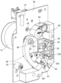
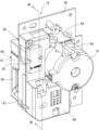
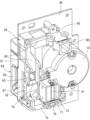
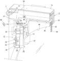
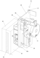
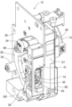
図8は、上部発射装置を示す正面図であり、図9は上部発射装置を正面左方から眺めて示す斜視図である。図10は上部発射装置を後方左方から眺めて示す斜視図であり、図11は球送りユニットカバーを取り除いて上部発射装置を後方左方から眺めて示す斜視図である。
[Top launcher]
FIG. 8 is a front view of the upper firing device, and FIG. 9 is a perspective view of the upper firing device viewed from the front left. FIG. 10 is a perspective view of the upper firing device viewed from the rear left, and FIG. 11 is a perspective view of the upper firing device viewed from the rear left with the ball feeding unit cover removed.
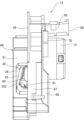
また、図12は扉枠を外して示す遊技機における上部発射装置の開状態を示す図であり、図13は、扉枠を外して示す遊技機の縦断面を示す右側図である。図14は、図2のA-Aに沿った断面見通し図の一部を概略で示す図である。図15は、上部発射装置におけるベースプレートとの接合部と、遊技盤におけるパネルホルダの迫出し部が当接している状態を示した斜視図である。 Further, FIG. 12 is a diagram showing an open state of the upper firing device in the gaming machine shown with the door frame removed, and FIG. 13 is a right side view showing a vertical cross section of the gaming machine shown with the door frame removed. FIG. 14 is a diagram schematically showing a part of a cross-sectional perspective view taken along line AA in FIG. FIG. 15 is a perspective view showing a state in which the joint portion of the upper firing device with the base plate is in contact with the protruding portion of the panel holder on the game board.
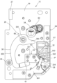
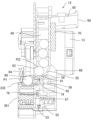
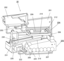
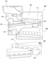
上部発射装置12は、本体枠2に対して上部発射装置12を取付固定するための金属板状のベースプレート39と、配列通路24から到達する遊技球を受け入れ、打球発射装置29の発射用ハンマー30(図8)の打球発射位置へ球送りソレノイド31(図11)と球送り部材32で遊技球を1球ずつ確実に送り出す球送り装置28と、遊技領域8に向けて遊技球を発射する打球発射装置29とを備えている(図8~図11参照)。
The
球送り装置28は、配列通路24(図6)から到達する遊技球を受け入れ、打球発射装置29の発射用ハンマー30(図8)の発射位置へ球送り部材32で遊技球を1球ずつ確実に送り出すための装置である。
The
打球発射装置29は、図9に示すように発射用ハンマー30、発射ソレノイド13、レール部材33、発射時ストッパー34、戻り時ストッパー35、発射球確認スイッチ36、上部発射装置用ヒンジ37及び発射口38を有する。これらの部材はベースプレート39(この実施例において金属板)を基板としてこれに取り付けられている。発射口38は、発射用ハンマー30の先端部に対向して形成されており、この部分にレール部材33が取り付けられている。レール部材33は球送り部材32によって発射位置(打球位置)に送り出された1個の遊技球をレール部332により保持する部材である。発射用ハンマー30により打ち出された遊技球は発射口38から遊技領域8へ発射される。
As shown in FIG. 9, the
発射球確認スイッチ36は、レール部材33のレール部332に対して配置され、発射用ハンマー30によって打ち込まれる遊技球の有無を検出すると共に、発射球確認スイッチ36による遊技球の検出が非検出に切り換わることで、遊技球1個が発射用ハンマー30によって発射されたことを検出するようになっている。
The launched
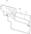
ベースプレート39は上部発射装置12を可動とする為に本体枠2に対し上下方向の上部発射装置用ヒンジ37で開閉可能に取り付けられている。ベースプレート39は上部発射装置用ヒンジ37を軸としてベースプレート39を手前に開くことができる(図9、図12)。
In order to make the
尚、上部発射装置用ヒンジ37の配置位置は、本体枠2と扉枠3とを回動可能に連結しているヒンジ7に対して、遊技盤5を本体枠2に対して着脱する際に上部発射装置12が遊技盤5を差込み装着の邪魔とならない角度まで開くことができる位置となっている(例えば120度)。
In addition, the arrangement position of the
図5に示すように遊技球の循環経路は、前記の異形球・磁性球排出ユニット20、球集合部21、球揚送装置22、球溜り部23、配列通路24、上部発射装置12、遊技領域8を経由するものである。上部発射装置12から遊技領域8の発射領域40(図7)に発射された遊技球は遊技領域を上方から下方へ流下し、入賞口41あるいはアウト口42を経て異形球・磁性球排出ユニット20に戻る。
As shown in FIG. 5, the circulation path of the game balls includes the above-mentioned irregular-shaped ball/magnetic
[遊技盤]
本体枠2の嵌合枠15には遊技盤5が装着される。この実施例において遊技盤5はパネルホルダ43に透明パネル板44を取り付け、その前面に前構成部材45を取り付けて透明パネル板44を固定した構造となっている(図12)。この遊技盤5に従来の内レールに相当するものは無く、前構成部材45の内周面上部を遊技球走行面46(図7)としている。
[Game board]
A
遊技盤5の左上隅部は前記上部発射装置12の形態に合わせて切欠き47(図12)が形成されている。切欠き47は前構成部材45から遊技領域8の透明パネル板44の一部に達している。透明パネル板44が切り欠かれた箇所には上部発射装置12の前記発射口38が臨んでおり、図7に示すように発射口38から上方の遊技球走行面46に沿った発射口38近辺の遊技領域8が発射領域40である。したがって上部発射装置12の発射用ハンマー30によって打ち出された遊技球は、発射領域40では前構成部材45の遊技球走行面46に案内される。
A notch 47 (FIG. 12) is formed in the upper left corner of the
尚、前記切欠き47においてパネルホルダ43の切欠きは前構成部材の切欠きよりも小さく、正面から見てパネルホルダ43の一部が切欠き47の内側に迫出した迫出し部48となっている(図12、図15)。そして、上部発射装置12のベースプレート39には固定具49が前後方向に貫通して装着されており、その固定具49の先端は上部発射装置12を閉じたとき本体枠2の前記張出壁18(図13、図14、図15)のネジ受け部材50に着脱可能に装着される。前記固定具49は先端部にネジを有すると共に頭部は比較的大きく形成されており、工具を利用せずに固定具49を着脱ができるものとする(コインなどの簡単な部材を利用しても良い)。ネジ受け部材50は例えば金属平板にナットを溶着した構造などであり、ビスなどで張出壁18に固定される。
In addition, in the
図13、図14、図15に示すように、上部発射装置12を貫通して固定具49をネジ受け部材50に装着すると、ベースプレート39によって本体枠2に対して遊技盤が固定される。この時ベースプレート39の当接部39a(図13)は、遊技盤5の切欠き47から迫出している迫出し部48に当接して、迫出し部48を本体枠2側に押圧して固定する。
As shown in FIGS. 13, 14, and 15, when the
このことにより、上部発射装置12の発射口38と遊技領域8の位置関係がガタなく一定に定まり、発射口38と遊技領域8との間に遊技球が走行する際の障害となる段差等が生じない。また、固定具49をネジ受け部材50から外せば、ベースプレート39を、上部発射装置用ヒンジ37を中心に手前に開くことができ、遊技盤5を本体枠2の嵌合枠15へ嵌め込む際の邪魔にならない。さらに、球送り装置28や打球発射装置29における球ガミ等のメンテナンス作業を容易に行うことができる。
As a result, the positional relationship between the
本実施形態の遊技領域8には、多数の障害釘(図示しない)と、入賞口等の各種入賞口等が設けられ、各種入賞口への入賞に応じて所定数の賞球が付与されるようになっている。なお、この実施例は封入球式遊技機なので、遊技球1個の打ち込みに応じて持球数のデータから「1」が減算される一方、各種入賞口への入賞に応じた賞球の数が持球数のデータに加算されて、これに対応する持球数がタッチパネル部14上に表示される。
The
また、封入球式パチンコ機なので賞球の払い出しは行われず、出球数、入球数、差球数、持球数等は、実際の遊技球の個数ではなく、データ上の数値となる。即ち、実際に使用される遊技球は、循環使用される限られた所定数(例えば、50個もしくは75個)しかなく、持球数は、例えば、遊技領域8に発射される遊技球を検知してカウントした発射球数、遊技領域8に発射されて回収された遊技球を検知してカウントした回収球数、入賞した場合の賞球数、ホール側から借りた貸球数等の数値から入球数、出球数、差球数、持球数が得られる。
Furthermore, since it is an enclosed ball type pachinko machine, prize balls are not paid out, and the number of balls thrown, number of balls entered, number of differential balls, number of balls held, etc. are numerical values based on data rather than the actual number of game balls. That is, the number of game balls actually used is limited to a predetermined number (for example, 50 or 75) that are used cyclically, and the number of balls held is determined by, for example, detecting the game balls fired into the
即ち、扉枠3を開放して遊技球が外に出てしまう等のトラブルがない限り、発射球数=回収球数となる。そして、入球数=回収球数=発射球数、出球数=賞球数(積算値)=入球数-貸球数(再プレイ球数)+持球数となり、持球数=貸球数(もしくは再プレイ持球数)+出球数-入球数、出球数-入球数=差球数、持球数=貸球数(もしくは再プレイ持球数)+差球数となる。このようにパチンコ機1による遊技は、完全にデータ上の数値として行われることになり、遊技球をこぼしたり、遊技球を下皿や上皿に残したりすることによる誤差が生じることがなく、整数単位で確実に管理可能となる。尚、後述する上部発射装置12の構造では基本的にファール球は生じない。
That is, unless there is a problem such as the game balls falling out when the
さらに、上記実施例では前構成部材45とパネルホルダ及び透明パネル板44は別部材で構成しているが、これらを例えば接着によって一体化するか、或いは一体成形して、一つの部材として構成することもできる。このように、透明パネル板44に前構成部材45やパネルホルダ43等を一体に形成すると、遊技盤5に切欠き47を設けたことによって、前構成部材45やパネルホルダ43が有していた枠構造(四辺がつながっている)が切断されてしまうことによるこれら部材の構造的な弱体化を抑止することができる。
Further, in the above embodiment, the
図16は上部発射装置を正面右方から眺めて示す斜視図であり、図17は上部発射装置を示す正面図であり(発射用ハンマー待機位置)、図18は上部発射装置を示す右側面図である。 FIG. 16 is a perspective view of the upper firing device viewed from the front right side, FIG. 17 is a front view of the upper firing device (launching hammer standby position), and FIG. 18 is a right side view of the upper firing device. It is.
[打球発射装置29]
打球発射装置29は、球送り装置28から供給された遊技球を、打球ハンドル10の回転操作に応じた強さで遊技盤5の遊技領域8内へ打ち込むことができるものである。打球発射装置29は、ベースプレート39の上部後面に前側へ回転駆動軸60が突出するように取付けられる発射ソレノイド13と、発射ソレノイド13の回転駆動軸60に一体回転可能に固定される発射用ハンマー30と、発射用ハンマー30の先端に固定される槌先61と、槌先61の移動軌跡上における所定位置を発射位置としてベースプレート39の前面に取付けられるレール部材33と、レール部材33により発射位置に停留された遊技球を打球可能な打球位置よりも槌先61が反時計方向に回動するのを規制する発射時ストッパ34と、発射用ハンマー30をその回動動作における待機位置(初期位置)に規制する戻り時ストッパ35と、発射位置に停留している遊技球の有無を検出するための発射球確認スイッチ36と、上部発射装置用ヒンジ37と、遊技領域8を臨んで開口された発射口38と、を備えている(図8、図9、図16、図18参照)。
[Battered ball launcher 29]
The
打球発射装置29における発射ソレノイド13は、詳細な図示は省略するが、回転駆動軸60が打球ハンドル10の回転操作角度に応じた強さ(速さ)で往復回動するようになっている。打球発射装置29の発射用ハンマー30は、発射ソレノイド13の回転駆動軸60に固定される固定部301と、固定部301から緩やかな円弧状に延出し、先端が回転駆動軸60の軸心に対して法線方向を向き、先端に槌先61が固定される棹部302と、棹部302に対して固定部301を挟んで反対側へ延出し、発射時ストッパ34と当接可能なストッパ当接部303と、を備えている。発射用ハンマー30のストッパ当接部303が発射時ストッパ34と当接することで、正面視で反時計周りの方向へ回動するのが規制されるようになっている(図8参照)。
Although detailed illustration of the firing
また、打球発射装置29のレール部材33の直上には、球送り装置28の球送りユニットベース(後述)に形成された球供給口63が配置されている。レール部材33は、後述の球送り装置28の球送り部材32の球送り動作によって球供給口63から送り出された1個の遊技球を発射位置に停留する。
Further, a
レール部材33は、金属板を屈曲成形することで形成されているもので、ベースプレート39に取付固定される取付板部331と、取付板部331から前方に向けて折曲形成されたレール部332とを備えている(図8参照)。発射位置を設定するためのレール部332は、正面視において、左方斜めに45度傾けた略L字状をなし、レール部332の左側を形成する左レール板333と、レール部332の右側を形成する右レール板334とにより構成されている(図8参照)。左レール板333には、発射用ハンマー30の打球動作時に槌先61が通過する通孔335が形成されている(図9、図21参照)。
The
図7及び図8に示すように、正面方向から眺めて、上部発射装置12の打球発射装置29の右側部の上下方向の中央から下端に亘る部分が遊技領域8に臨んで露出して配置されている。図8、図16に示すように、ベースプレート39の前面右側部には、発射口飾り部材64が配設され、該発射口飾り部材64はベースプレート39と後述の球送りユニットベース67とに取り付けられている。
As shown in FIGS. 7 and 8, when viewed from the front, a portion of the right side of the
図7、図8及び図16に示すように、発射口飾り部材64は、右側面部及び下部側面部が遊技領域8に臨んで露出して配置されており、このため発射口飾り部材64の右側面部及び下部側面部が遊技領域8に打ち出された遊技球が打球発射装置29の内部に進入するのを防止する球進入防止壁51に形成されている。発射口38は、発射口飾り部材64の右側面部の球進入防止壁51に形成されており、球進入防止壁51は、発射口38を囲むようにして、遊技領域8の後端面と略同一面から前方に向けて立ち上がるアーチ形状をなすようになっている。
As shown in FIGS. 7, 8, and 16, the firing
発射口38は、図8及び図16を参照すると理解されるように、レール部332に対して、正面視において斜め右方上方に位置している。図8及び図17から理解されるように、レール部332(発射位置)と発射口38との距離は短く(遊技球Pの直径の2倍程度)、このため、打ち出し距離が短いことにより、ファール球を発生させることがなく、発射された遊技球を確実に遊技領域8に打ち込むことが可能となっている。
As understood with reference to FIGS. 8 and 16, the
発射球確認スイッチ36は、発射位置に停留されている遊技球の有無を検出すると共に、発射位置にある遊技球が発射用ハンマー30によって打ち込まれて発射されることによって遊技球の検出が非検出に切り換わることで、遊技球1個が発射用ハンマー30によって発射されたことを検出するようになっている。
The launch
発射球確認スイッチ36は、透過形フォトセンサよりなり、発射位置を設定しているレール部332を前後に跨ぐようにして、投光部と受光部とが配置されている。発射球確認スイッチ36は、フォトブラケット361に支持されることで発射位置に対して配置されており、フォトブラケット361はベースプレート39り前面下部に取付固定されている。
The fired
打球発射装置29は、発射用ハンマー30における打球位置側への回動端を規制可能な発射時ストッパ34の前面を被覆するストッパカバー62と、発射用ハンマー30における打球位置とは離れた位置の回動端(正面視で時計回りの方向の回動端)を規制する戻り時ストッパ35とを備えている。ストッパ34,35の表面がゴムで覆われており、発射用ハンマー30が当接した時の衝撃を吸収することができると共に、当接による騒音の発生を抑制することができるようになっている。
The
また、打球発射装置29は、発射ソレノイド13が、後述の球情報制御部により打球ハンドル10の回転操作に応じた駆動強さで駆動させられるようになっていると共に、球送り装置28の球送りソレノイド31の駆動タイミングに対して、後述の駆動タイミングにより、打球動作するように駆動させられるようになっている(図41参照)。具体的には、打球発射装置29へ遊技球を供給する球送り装置28では、球送りソレノイド31が駆動(ON)すると球送り部材32が受入れた遊技球を打球発射装置29へ送り、その状態から球送りソレノイド31の駆動が解除(OFF)されると球送り部材32が遊技球を受入れるようになっている。
Further, in the batted
打球発射装置29では、打球ハンドル10が発射操作されると、その操作量に応じた電圧で発射ソレノイド13への通電・断電が繰り返される。これによる発射ソレノイド13の励磁・非励磁により、図8、図17に示すように、発射用ハンマー30が、初期位置(図17)から発射方向(反時計方向)に回動して発射位置に停留された遊技球を槌先61で打ち出した後(図8)、時計方向に回動して初期位置に戻る発射動作を繰り返す。
In the batted
[球送り装置28]
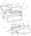
次に、球送り装置28について説明する。球送り装置28は、図10及び図11に示すように、主としてユニットとして構成され、図6に示す配列通路24の前端に連結された進入口66を有する揚送連通樋65と、揚送連通樋65に接続されると共に、揚送連通樋65から進入した遊技球を打球発射装置29に供給するための球供給口63を有し、後方が開放された球送りユニットベース67と、球送りユニットベース67の後端を塞ぐと共に前方が開放された球送りユニットカバー68と、球送りユニットベース67の下部に配設された球送りソレノイド31と、球送りソレノイド31の駆動によって球送り動作と後述の戻り球阻止動作とを同時に実現する球送り部材32と、を備えている。
[Ball feeding device 28]
Next, the
揚送連通樋65は、進入口66が形成された後端から前端に向けて緩やかに下り傾斜がかけられている。球送りユニットベース67は、ベースプレート39の後面左側部に取付られ、上部の右側部に揚送連通樋65の前端が接続されると共に、背面視において、揚送連通樋65の前端に接続される上部の右側部から上下方向中央にかけて、左右方向の左方に向けて緩やかな下り傾斜がかけられ、中途で下方に向けて屈曲形成された球送り誘導樋69と、球送り誘導樋69の下端に、前後方向に貫通した球供給口63とを有している(図11参照)。
The lifting/transporting
また、球送り誘導樋69の屈曲部分よりも下側で球供給口63よりも上側部分に対向する球送りユニットカバー68の後面には、球送り誘導樋69内に待機している遊技球の有無を検出する発射待機球検出スイッチ70が設けられている(図10参照)。発射待機球検出スイッチ70は、それぞれ高周波発振回路の検出コイルのインピーダンスの変化によって金属体としての遊技球を検出するフラット型式の近接スイッチから構成される。
In addition, on the rear surface of the ball feeding
本実施形態の球送りソレノイド31は、電磁石で構成されており、励磁により吸引機能を発揮する吸引部分を下方に向けた姿勢で、球送りユニットベース67の下部に配設されている。また、球送り部材32は、球送りソレノイド31の左方に隣接して球送りユニットベース67の下部に配置されている。本実施形態における球送り部材32は、球送りソレノイド31の励磁・非励磁により、請求項1に記載されている打球発射装置29の打球動作により発射位置から発射された打球に干渉することなく、打球の通過を許容する許容位置と、遊技領域8から発射口38に戻って来る戻り球の進入を阻止する戻り球阻止位置との間で移動可能とされた戻り球阻止部を一体に備えたものとなっている。
The
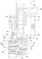
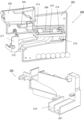
以下、球送り部材32について説明する。図18は、上部発射装置12を示す右側面図であり(球送りソレノイド31は非励磁、球送り部材32が保持位置及び戻り球阻止位置をとる)、図19は、図10の矢視B-B線で破断して示す上部発射装置12の断面図であり(球送りソレノイド31は非励磁、球送り部材32が保持位置及び戻り球阻止位置をとる)、図20は、球送り装置28における球送り部材32と球送りシャフトと球送り板金を斜め後方から示す斜視図である。
The
また、図21は、上部発射装置12を示す右側面図であり(球送りソレノイド31は励磁、球送り部材が供給位置及び許容位置をとる)、図22は、図10の矢視B-B線で破断して示す上部発射装置の断面図である(球送りソレノイド31は励磁、球送り部材32が供給位置及び許容位置をとる)。
21 is a right side view showing the upper firing device 12 (the
図20に示すように、球送り部材32の上下方向の中間には、左右方向に向けて軸孔75が形成されている。軸孔75には、球送りシャフト76が両端を突出させて挿通され、球送りシャフト76の左右方向の両端は、球送りユニットベース67に支持されている。これにより、球送り部材32が球送りシャフト76を回動中心として前後方向に回動可能に支持されている。
As shown in FIG. 20, a
また、球送り部材32の中間には、後方に向けてアーム部77が延伸形成され、アーム部77の下端には、図11に示すように、球送りソレノイド31の下方に向って延伸した作動杆部72が形成され、作動杆部72には板金収容部73が形成され、板金収容部73に磁石により吸引される金属材料よりなる球送り板金71が収納されている。
Further, an
板金収容部73の直下には、後方に向けて突出して球送り板金71の脱落を防止するための板金係止爪78が形成されており、これにより、球送り部材32の動作時、不測に球送り板金71が板金収容部73から脱落するのを防止している。
A sheet
図20に示すように、作動杆部72の端部には掛止突起79が形成され、該掛止突起79には図19に示す引張バネ52の一端が掛止されている。また、引張バネ52の他端は、図19に示すように、球送りユニットベース67の下部底面に形成されたバネ係止部53に掛止されている。
As shown in FIG. 20, a latching
また、図20に示すように、球送り部材32の軸孔75の上方には、球送り部材32と一体に球供給口63の下縁に向って屋根形状の球送り部74が形成されている。球送り部74は、上面中央が上方に高くなる山型状に形成されており、中央から前方に向って、即ち、図19において球送り誘導樋69の下端に形成された球供給口63の下縁に向って下がる傾斜がかけられた球送り誘導面80と、中央から後方に向って、即ち、図19において球送り誘導樋69の後端を塞ぐ球送りユニットカバー68に向って円弧凸状に下がる傾斜がかけられた球保持面81と、を備えている。また、球送り部74の球保持面81の後端には、下方に向って垂下した垂下片82が形成されている。
Further, as shown in FIG. 20, a roof-shaped
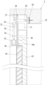
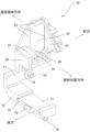
また、球送り部材32の上下方向の上部は、前方に向けて球送りユニットベース67を貫通すると共に、図18、図20及び図21に示すように、側面視においてレール部332(発射位置)からの打球経路に向って延伸形成された矩形枠状の戻り球阻止部83が形成され、戻り球阻止部83の中央には矩形状に開口された打球通過口85が形成されている。
Moreover, the upper part of the
図16乃至図17に示すように、球送り部材32と一体に形成された枠状の戻り球阻止部83は、発射口38に対して発射位置方向に隣接して配置されている。また、戻り球阻止部83の枠の前側に位置する部分の発射位置方向側には、レール部332に向けて底辺部分が水平で三角形状に張り出した球止め部84が形成されている。球止め部84は、球送り部74の前方で、かつ発射位置の上方に間隔おいて球送り部74に対向して配置されている。
As shown in FIGS. 16 and 17, a frame-shaped return
また、球送りユニットカバー68には、球供給口63の後方において、球供給口63に対面する位置に、前方に向けて縦断面が「く」字状をなした球ガイド突部54が形成され、前方に向いた球ガイド突部54の上部には、球供給口63に対面して円弧凹状をなした前方誘導面55が形成されている。球ガイド突部54の下部は、後方に向けて凸に湾曲形成され、球ガイド突部54の下部よりも下方の空間に、球送りシャフト76を回動中心とした球送り部材32の前後方向に回動動作において、球送り部74が後退可能となっている。また、球ガイド突部54の下端には、前方に向けてストッパ片56が突出して形成されている。
Further, on the ball feeding
[球送り部材32の球送り動作と戻り球阻止動作]
以上のように構成された球送り装置28の球送り部材32による球送り動作と戻り球阻止動作とについて説明する。球送りソレノイド31が非励磁状態のときには、球送り部材32の作動杆部72の端部の掛止突起79と、球送りユニットベース67の下部底面に形成されたバネ係止部53とに掛止された引張バネ52の引張力により、球送り部材32の下端部が球送りユニットベース67に向けて引き寄せられた姿勢となる。
[Ball feeding operation and return ball blocking operation of ball feeding member 32]
The ball sending operation and return ball preventing operation by the
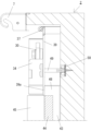
図18に示すように、球送り部材32は、常態においては(球送りソレノイド31が非励磁状態のときには)、球送りシャフト76を回動中心とした回動姿勢において、矩形枠状の戻り球阻止部83が後方に向けて傾いた姿勢をとり、遊技領域8から見た側方視において、即ち、打球発射装置29の発射位置から発射口38に至る打球経路における、発射口38の直ぐ発射位置方向側の位置において、戻り球阻止部83の枠の前に位置する部分が発射口38に対して交差した姿勢となっており、また、打球経路において発射口38に対して打球通過口85が後方にずれた位置となっており、打球経路において打球通過口85への球の通過が不可能となっている。即ち、戻り球阻止部83がこの姿勢において遊技領域8から発射口38に戻って来る戻り球の進入を阻止する戻り球阻止位置を取る。
As shown in FIG. 18, in a normal state (when the
打球の発射後、戻り球阻止部83が戻り球阻止位置を取ることにより、遊技領域8に発射された遊技球が戻り球となって発射口38に入るのを戻り球阻止部83によりブロックし、戻り球を阻止できるので、戻り球によって遊技に対する興趣が低下するのを抑止することができる。
After the ball is fired, the return
また、図19に示すように、球送り部材32は、常態においては(球送りソレノイド31が非励磁状態のときには)、球送り部74の球保持面81が球送りユニットカバー68の球ガイド突部54の下方の空間に後退し、球送り部74の下端に形成された垂下片82がストッパ片56に当接し、球送り部材32の球送りシャフト76を回動中心とした回動姿勢において、球送り動作における保持位置に規制される。
In addition, as shown in FIG. 19, in the normal state (when the
保持位置では、球送り部74の球送り誘導面80が球ガイド突部54の前方誘導面55の下端の前方に位置し、前方誘導面55の接線方向において延長線上に位置する。また、球止め部84が球供給口63に向けて接近し、球供給口63の下端部と球止め部84との間の隙間に遊技球P1が嵌り込んで、遊技球P1が留まった状態となる。
In the holding position, the ball feeding
[球送りソレノイド31の励磁]
球送りソレノイド31を通電することにより励磁すると、電磁石機能により球送り板金71が上方に吸引され、引張バネ52の引張力に抗して球送り部材32の作動杆部72が上方に移動し、球送り部材32が球送りシャフト76を回動中心として図19の反時計方向に回動し、図21及び図22に示すように、球送り部材32が球送り動作における供給位置及び打球の通過を許容する許容位置に移動する。
[Excitation of ball feed solenoid 31]
When the
これにより、球止め部84が球供給口63に接近した位置から前方に移動すると同時に、球送り部74が前方に移動し、保持位置に留まっていた遊技球P1を発射位置に送り出す(図22参照)。
As a result, the
図21に示すように、球送りソレノイド31が励磁状態のときには、球送りシャフト76を回動中心とした回動姿勢において、矩形枠状の戻り球阻止部83が正立姿勢をとり、遊技領域8から見た側方視において、即ち、打球発射装置29の発射位置から発射口38に至る打球経路における、発射口38の直ぐ発射位置方向側の位置において、打球経路において発射口38に対して打球通過口85が一致した位置となっており、打球経路において打球通過口85への球の通過を許容する位置となっている。即ち、戻り球阻止部83がこの姿勢において、発射位置から発射された打球に干渉することなく、打球の通過を許容する許容位置を取る。
As shown in FIG. 21, when the
図22に示すように、球送りソレノイド31が励磁状態のときには、球送り動作における供給位置では、球送り部74の球保持面81が球送りユニットカバー68の球ガイド突部54の前方に位置し、球供給口63の上端部と球送り部74の球保持面81との間の隙間に後続の遊技球P2が嵌り込んで、後続の遊技球P2が留まった状態となる。以上に説明した球送り動作により、球送り部材32は、球送り誘導樋69内に整列貯留された遊技球を1個ずつ打球発射装置29の発射位置に送り込む。
As shown in FIG. 22, when the
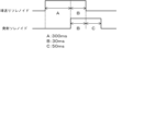
また、図41は、球送りソレノイド31と発射ソレノイド13との駆動タイミングを示すタイムチャートである。球送りソレノイド31をオンした時点から、期間Aだけ経過した時点で発射ソレノイド13をオンし、発射ソレノイド13をオンした時点から、期間Bだけ経過した時点で球送りソレノイド31をオフし、球送りソレノイド31をオフした時点から期間Cだけ経過した時点で発射ソレノイド13をオフする。
Moreover, FIG. 41 is a time chart showing the drive timing of the
本実施形態では、期間Aを300ms、期間Bを30ms、期間Cを50msとしている。球送りソレノイド31をオンすると、球送り部材32により発射位置(レール部332)に発射球が送り込まれた状態となる。即ち、発射球確認スイッチ36により発射球が検出される。本実施形態では、予め定められた規定時間に亘って(期間Dとして30msとしている)、発射球確認スイッチ36によって発射位置に停留されている遊技球が検出された場合に、発射球ありと判定する。
In this embodiment, period A is 300 ms, period B is 30 ms, and period C is 50 ms. When the
このように、発射球確認スイッチ36によって発射位置に停留されている遊技球が予め定められた規定時間に亘って検出された場合に、発射球ありと判定するようにしているので、ノイズによる発射球の誤球カウントを排除することができ、発射球の検出における確実性を上げることができる。
In this way, when a game ball parked at the firing position is detected by the firing
図41に示す球送りソレノイド31と発射ソレノイド13との駆動タイミングに従って、後述の球情報制御部118の球情報制御MPU111により、動作制御が行われる。即ち、球送り部材32の戻り球阻止部83が許容位置にあるときに、打球発射装置29を作動して発射用ハンマー30による打球動作を行わせ、打球発射装置29の作動時から予め定められた規定時間経過後(30ms経過後)に、球送りソレノイド31の励磁を解除して戻り球阻止部83を戻り球阻止位置に移動することで、戻り球を戻り球阻止部83によりブロックするように制御するのである。
According to the driving timing of the
これによれば、戻り球阻止部83が許容位置を取るときに、発射位置から発射された打球に干渉することなく打球の通過が許容されるため、発射球に干渉することがないので、遊技球を狙った位置に打ち込むことに対して不信感を抱いてしまうのを防止することができ、遊技に対する興趣が低下するのを抑止することができる。
According to this, when the return
打球の発射後、戻り球阻止部83が戻り球阻止位置を取ることにより、遊技領域8に発射された遊技球が戻り球となって発射口38に入るのを戻り球阻止部83によりブロックし、戻り球を阻止できるので、戻り球によって遊技に対する興趣が低下するのを抑止することができる。
After the ball is fired, the return
本実施形態では、戻り球阻止部83は、球送り部材32と一体に形成されているので、1つの電気的駆動源(球送りソレノイド31)の励磁・非励磁により、発射位置への球送りと戻り球防止とを同時に実現できる。即ち、球送り部材32は、供給位置を取るときに、発射位置から発射された遊技球が通過する打球経路上に打球通過口85が位置する一方、保持位置を取るときに、打球経路から外れた退避位置に打球通過口85が位置するように形成された枠状の戻り球阻止部83を備えている。
In this embodiment, since the return
球送り部材32が供給位置を取るときに、戻り球阻止部83が許容位置を取り、発射位置から発射された打球に干渉することがないので、遊技球を狙った位置に打ち込むことに対して不信感を抱いてしまうのを防止することができ、遊技に対する興趣が低下するのを抑止することができる。
When the
また、球送り部材32が保持位置に移動すると、同時に戻り球阻止部83が戻り球阻止位置に移動することで、遊技領域8に発射された遊技球が戻り球となって発射口38に入るのをブロックし、戻り球を阻止できるので、戻り球によって遊技に対する興趣が低下するのを抑止することができる。
Further, when the
また、先に挙げた特許文献3に記載の遊技機は、発射口を塞いでいる戻り球防止弁を発射球で強制的にこじ開けて遊技領域に打ち出すまたは押し出す構造としている。このため、打球動作を行わせるための電磁的駆動源をそれに見合うだけの大きさとパワーのあるものを要し、打球力を得るために大きな電流を供給する必要があり、消費電力が大きいものである。
Furthermore, the gaming machine described in
これに対し、本例の上部発射装置12は、発射用ハンマー30が打球動作を行う時には、球送り部材32の戻り球阻止部83が発射球の通過を許容する許容位置(打球通過口85と発射口38とが共に打球経路上に一致している状態)にあって、発射球に干渉することがないので、遊技領域8に打球を打ち出すだけの打球力を提供できればよいから、パワーの小さい電磁的駆動源を採用することで十分対応できる。このため、電磁的駆動源を小型化、薄型化することができ、その駆動に必要な消費電力も低く抑えることができるのである。
On the other hand, in the
また、図41に示すように、発射ソレノイド13をオンした時点から期間Cだけ発射ソレノイド13が例示されて槌先61がレール部332の通孔335を貫通して突出した状態(図9)となっているので、遊技球がレール部332に停留されないようにでき、戻り球の防止と共に発射球の誤りカウントをより確実なものとすることができる。
Further, as shown in FIG. 41, the firing
本実施形態の戻り球阻止部83は、矩形枠状をなして中央に打球通過口85を備えたものを示したが、戻り球阻止部83の形状はこれに限定されるものではなく、例えば、片状、杆状であってもよく、また、打球通過口85を備えていなくともよい。即ち、発射位置から発射口38に至る打球経路上において、発射口38の発射位置方向に隣接して設けられ、発射位置から発射された打球に干渉することなく、打球の通過を許容する許容位置と、遊技領域8から発射口38に戻って来る戻り球の進入を阻止する戻り球阻止位置との間で移動可能であればよい。
Although the return
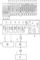
次に、パチンコ機1及びその一側に隣接して配置される外部装置としての精算機4の制御の概要について説明する。図23は、封入球式パチンコ機に配備され、RTCを備えた主制御基板の実施形態における要部を示すブロック図である。パチンコ機1の制御は、大きく分けて主基板グループと周辺基板グループとで分担されており、このうち主基板グループが遊技動作を制御しており、周辺基板グループが演出動作(液晶表示パネル、ランプ、本体枠ランプ、扉枠ランプ、音)を制御している。主基板グループは、主制御基板100と球情報制御基板110とから構成されており、周辺基板グループは、周辺制御基板130から構成されている。
Next, an outline of control of the
[主制御基板100]
主制御基板100は、パチンコ遊技の制御を行うものである。主制御基板100と後述の球情報制御基板110とは双方向のデータ通信が可能に接続されている。遊技の進行を制御する主制御基板100は、図23に示すように、各種処理プログラムや各種コマンドを記憶するROMや一時的にデータを記憶するRAM等が内蔵されるマイクロプロセッサである主制御MPU101と、入出力デバイス(I/Oデバイス)としての主制御I/Oポート102と、各種検出スイッチからの検出信号が入力される主制御入力回路103と、各種ソレノイドを駆動するための主制御ソレノイド駆動回路104と、主制御MPU101に内蔵されているRAM(以下、「主制御内蔵RAM」と記載する)に記憶された情報を完全に消去するためのRAMクリアスイッチ105と、を備えている。
[Main control board 100]
The
主制御MPU101は、その内蔵されたROM(以下、「主制御内蔵ROM」と記載する。)や主制御内蔵RAMのほかに、その動作(システム)を監視するウォッチドックタイマや不正を防止するための機能等も内蔵されている。また、主制御MPU101は不揮発性のRAMが内蔵されており、この不揮発性のRAMには、主制御MPU101を製造したメーカによって個体を識別するためのユニークな符号(世界で1つしか存在しない符号)が付された固有のIDコードが予め記憶されている。この一度付されたIDコードは、不揮発性のRAMに記憶されるため、外部装置を用いても書き換えられない。主制御MPU101は、不揮発性のRAMからIDコードを取り出して参照することができる。
In addition to its built-in ROM (hereinafter referred to as "main control built-in ROM") and main control built-in RAM, the
[RTC制御部]
また、実施形態の主制御MPU101は、時刻情報取得手段として時刻情報を取得することが可能な外付けのリアルタイムクロック(以下、「RTC」という)107を備えている。図示していないが、RTC107は、レジスタ回路、クロック入力回路、クロック出力回路、割り込み出力回路、データ入出力回路、および、制御回路を含む。
[RTC control unit]
Further, the
RTC107は、時計・カレンダー機能を備える。時計・カレンダー機能は、年,月,日,時,分,秒をカウントする計時を行う機能である。また、必要に応じて、曜日までカウントするものを用いてもよい。RTC制御部106は、RTC107およびRTC107を駆動するための電池108が設けられている。電池108を備えることによって、電源基板(図示せず)の電源遮断時においてもRTC107は計時、および、カレンダー機能を中断することがない。
The
電池108としては一次電池(例えばボタン電池)であってもよいし、充電可能な二次電池、これによって、バックアップ電源を配置する必要がなく主制御基板100の構成が複雑化するのを避けることができる。なお、電池108は、RAM109のバックアップ電源としても用いられる。
The
主制御MPU101は、RTC107を備えることによって、年・月・日・時・分・秒(カレンダー情報と時刻情報)を特定する機能を備える。主制御基板100の主制御MPU101は、遊技機の電源投入時に、RTC107から時刻情報(時・分・秒)を取得する。
By including the
遊技盤5の遊技領域8に配された上始動口(図示せず)に入賞した遊技球を検出する上始動口検出スイッチ90、下始動口(図示せず)に入賞した遊技球を検出する下始動口検出スイッチ91、及び一般入賞口(図示せず)に入賞した遊技球を検出する一般入賞口検出スイッチ93からの検出信号は、まず主制御入力回路103に入力され、主制御I/Oポート102を介して主制御MPU101に入力されている。
An upper starting
また、ゲート部(図示せず)を通過した遊技球を検出するゲートスイッチ92、一般入賞口(図示せず)に入賞した遊技球を検出する一般入賞口検出スイッチ94、大入賞口(図示せず)に入賞した遊技球を検出するカウントスイッチ98からの検出信号は、まず遊技盤5に取付けられたパネル中継端子板140を介して主制御入力回路103に入力され、主制御I/Oポート102を介して主制御MPU101に入力されている。
In addition, a
主制御MPU101は、これらの検出信号に基づいて、主制御I/Oポート102から主制御ソレノイド駆動回路104に制御信号を出力することにより、パネル中継端子板140を介して始動口ソレノイド96及び大入賞口ソレノイド97に駆動信号を出力したり、主制御I/Oポート102からパネル中継端子板140、そして機能表示基板141を介して上特別図柄表示器142、下特別図柄表示器143、上特別図柄記憶表示器144、下特別図柄記憶表示器145、普通図柄表示器146、普通図柄記憶表示器147、遊技状態表示器148、ラウンド表示器149に駆動信号を出力したりする。
The
また、主制御MPU101は、遊技に関する各種情報(遊技情報)及び入賞に応じた賞球に関する各種コマンド等を球情報制御基板110にシリアル方式で送信したり、この球情報制御基板110からのパチンコ遊技機1の状態に関する各種コマンド等をシリアル方式で受信したりする。また、主制御MPU101は、遊技演出の制御に関する各種コマンド及びパチンコ機1の状態に関する各種コマンドを周辺制御基板130に送信したりする。
In addition, the
[球情報制御基板110]
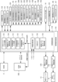
図24は、主として封入球式パチンコ機に配備された球情報制御基板110の要部を示すブロック図である。球情報制御基板110は、持球球の管理や球揚送装置22、発射ソレノイド13、球送りソレノイド31、球磨きリボン送りモータ155等に関する各種制御を行う球情報制御部118を備えている。また、主制御基板100と球情報制御基板110とは双方向のデータ通信が可能に接続されている。
[Sphere information control board 110]
FIG. 24 is a block diagram mainly showing the main parts of the ball
[球情報制御部118]
球情報制御部118は、図24に示すように、各種処理プログラムや各種コマンドを記憶するROMや一時的にデータを記憶するRAM等が内蔵されるマイクロプロセッサである球情報制御MPU111と、I/Oデバイスとしての球情報制御I/Oポート112と、球情報制御MPU111が正常に動作しているか否かを監視するための外部ウォッチドックタイマ116(以下、「外部WDT116」と記載する。)と、球揚送を行う球揚送装置22の球揚送モータ150に駆動信号を出力するための球揚送モータ駆動回路114と、各種検出スイッチからの検出信号が入力される球情報制御入力回路113と、精算機4との各種信号をやり取りするためのCRユニット入出力回路115と、球磨きリボン送りモータ155に駆動信号を出力するための球磨きリボン送りモータ駆動回路119と、を備えている。球情報制御MPU111には、その内蔵されたROM(以下、「球情報制御内蔵ROM」と記載する。)やRAM(以下、「球情報制御内蔵RAM」と記載する。)のほかに、不正を防止するため機能等も内蔵されている。
[Sphere information control unit 118]
As shown in FIG. 24, the ball
球情報制御MPU111は、主制御基板100からの遊技に関する各種情報(遊技情報)及び賞球に関する各種コマンドを球情報制御I/Oポート112を介してシリアル方式で受信したり、主制御基板100からのRAMクリアスイッチ105の操作信号(検出信号)が球情報制御I/Oポート112を介して入力されたりする。
The ball
本体枠2に対する扉枠3の開放を検出する扉枠開放スイッチ131、及び外枠に対する本体枠2の開放を検出する本体枠開放スイッチ132からの検出信号は、まず球情報制御入力回路113に入力され、球情報制御I/Oポート112を介して球情報制御MPU111に入力されている。さらに、打球ハンドル10に手のひらや指が触れているか否かを検出するタッチスイッチ87によるタッチ検出信号(オン信号)が、ハンドル中継端子板123を介して球情報制御基板110に入力され、さらにタッチ検出信号は球情報制御I/Oポート112を介して球情報制御MPU111に入力されている。
Detection signals from the door
また、球情報制御MPU111は、発射ソレノイド駆動回路120を通じて発射ソレノイド13に接続され、球送りソレノイド駆動回路122を通じて球送りソレノイド31に接続され、球情報制御MPU111からの制御出力に応じて発射ソレノイド13及び球送りソレノイド31が駆動されるようになっている。また、発射待機球検出スイッチ26、70、発射球確認スイッチ36、回収球検出スイッチ203、球経路満タン検出スイッチ206、球適正量検出スイッチ207、球揚送装置22に供給する遊技球の有無を検出するための揚送入口スイッチ156、球揚送モータ150の回転数を検知するための揚送モータセンサ(フォトセンサ)157、球磨き布リボンを収納した球磨きカートリッジが装着されていることを検知するためのカセット検出スイッチ158からの検出信号がセンサー中継基板124を介して球情報制御入力回路113に入力され、球情報制御I/Oポート112を介して球情報制御MPU111に入力されている。球情報制御MPU111は、球揚送モータ150、球磨きリボン送りモータ155、発射ソレノイド13及び球送りソレノイド31を駆動するための駆動信号を、球情報制御I/Oポート112を介して各駆動要素に出力する。
Further, the ball
また、球情報制御MPU111には、タッチパネル部14が球情報制御I/Oポート112からの制御出力により表示可能に接続されている。なお、球情報制御基板110は、主制御基板100と外部端子板133との基板間の電気的な接続を中継するほかに、扉枠開放スイッチ131及び本体枠開放スイッチ132と外部端子板133との間の電気的な接続を中継している。なお、外部端子板133は、遊技場(ホール)に設置されたホールコンピュータと電気的に接続されている。
Further, a
打球ハンドル10に手のひらや指が触れているか否かを検出するタッチスイッチ87、及び遊技者の意志によって遊技球の打ち出しを強制的に停止するか否かを検出する発射停止スイッチ86からの検出信号は、まずハンドル中継端子板123を介して球情報制御入力回路113に入力されている。また、精算機4と球情報制御基板110が電気的に接続されると、CR接続信号としてCRユニット入出力回路115に入力されるようになっている。
Detection signals from a
なお、電源基板(図示せず)から球情報制御基板110に直流電源+24V、+12V、+5.2Vが供給されている。また、球情報制御基板110を介して直流電源+24V、+12V、+5.2Vが主制御基板100に供給されている。
Note that DC power +24V, +12V, and +5.2V are supplied to the ball
停電監視回路117は、+24Vに基づく電圧V1と基準電圧、+12Vに基づく電圧V2と基準電圧とをそれぞれ比較監視しており、停電又は瞬停の兆候を検知すると、即ち、電圧V1またはV2が基準電圧よりも小さくなると、停電予告として停電予告信号を出力する。停電監視回路117から出力された停電予告信号は、球情報制御基板110の球情報制御MPU111に供給されるほかに、主制御MPU101に供給される。また、図示していないが、停電予告信号は、周辺制御基板130にも入力される。
The power outage monitoring circuit 117 compares and monitors the voltage V1 based on +24V and the reference voltage, and the voltage V2 based on +12V and the reference voltage, and when a sign of a power outage or instantaneous power outage is detected, that is, the voltage V1 or V2 becomes the reference voltage. When the voltage becomes lower than the voltage, a power outage warning signal is output as a power outage warning. The power outage warning signal output from the power outage monitoring circuit 117 is supplied to the ball
[精算機4]
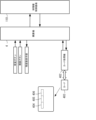
図25は、主として精算機4に接続された各要素を示すブロック図である。精算機4と球情報制御基板110とは双方向にデータ通信が可能に接続されている。精算機4の制御部は、図示していないが、CPU、ROM、RAM、入出力インタフェース、通信インタフェース等を備えている。
[Payment machine 4]
FIG. 25 is a block diagram mainly showing each element connected to the
精算機4には、封入球式遊技機1のタッチパネル部14に配設された球貸ボタン及び精算ボタンの各操作入力信号が、例えば、インタフェースを通じて入力可能に接続されている。また、封入球式パチンコ機1のタッチパネル部14に配設された残度数表示部及び操作可能報知ランプが精算機4からの制御出力により表示可能に接続されている。また、精算機4には、図1のカード挿入口の奥方にカード処理機402が設けられている。
The
[カード403]
実施形態において使用されるカード403は、例えば、磁気カード或いはICカード等で構成され、遊技者が所定の金額を支払うことにより、図示しないカード発行機により発行されて遊技者に提供される。図25において、カード403に記憶されているデータ構成を示している。
[Card 403]
The
カード403には、カード403に対して個別に付与された識別情報としてのID番号(以下、単にIDという)が記憶されたID記憶部404、カード403を購入する際に支払われた金額に相当する有価価値情報としての残度数が記憶された残度数記憶部305、遊技を行った遊技結果として遊技者が獲得した持球数(遊技機持球数)が記憶される持球数記憶部406が設定されている。なお、カード403の発行時は、ID記憶部404にIDが記憶され、残度数記憶部405にカード403を購入する際に支払われた金額に相当する残度数(例えば、支払った金額が5000円ならば残度数として「5000」)が記憶されているが、持球数記憶部406には持球数の初期値として「0」が記憶されている。
The
カード処理機402は、従来周知のものであり、カード403を検知するカードセンサ、カード403に記憶されたデータの読み取り及びカード403へのデータの書き込みを行うカードリーダ・ライタ、カード403のデータ読取書込位置への送り込み並びにカード403のカード挿入口への排出を行うカード搬送手段を備えている。カード処理機402は、カード挿入口にカード403が差し込まれると、所定のデータ読取書込位置にカード403を送り、カードリーダ・ライタにより、記憶されているデータ、即ち、ID、残度数及び持球数を読み取って精算機4に出力する。また、精算機4よりの書込指令に応じて、ID、残度数及び持球数を前述の各記憶部に書き込む(記憶する)。
The
精算機4は、カード処理機402を通じてカード403から読み取ったID、残度数及び持球数をRAMに記憶する。
The
[カード403による球貸]
精算機4は、カード403のデータの読み取りを行うと、RAMに記憶した残度数を残度数表示部に表示する。カード403の使用が可能である場合、精算機4は、球貸ボタンの操作に応じて球貸を行う。この球貸は、球貸ボタンの1回操作につき、例えば、球貸数125(球単価が4円)を球貸するものとする。なお、球貸において、持球数がある場合であって、持球数が125に満たない場合には全持球数を貸球数として球貸する。精算機4は、球情報制御基板110に貸球数を送信する。また、精算機4は、設定されている球単価に貸球数を乗じることで球貸に対する対価を求め、求めた対価(球貸に対応する対価を残度数)を現在の残度数から減じる。なお、持球数がある場合であって持球数から球貸を行った場合には、現在の持球数から貸球数を減じる。精算機4は、この結果を、残度数表示部に表示する。また、カード403の残度数記憶部405に残度数を書き込む。
[Ball lending using card 403]
When the
[遊技開始]
球情報制御基板110の球情報制御MPU111は、精算機4から送信された貸球数を受けると遊技機持球数に加算し、加算結果をタッチパネル部14に表示する。上部発射装置12を発射可能とし遊技可能状態となる。
[Start of game]
When the ball
[遊技中]
遊技者が打球ハンドル10を操作することで打球発射装置29が作動し、発射用ハンマー30によって球発射位置にある遊技球が遊技領域8に打ち出されると、これが発射球確認スイッチ36の球検出に基づいて遊技球1個ずつの遊技領域8内への打ち込みが検知される。そして、球情報制御基板110の球情報制御MPU111は、このような遊技球1個ずつの打ち込み検知に応じて、遊技機持球数記憶領域に記憶した遊技機持球数データから逐次「1」を減算していくと共にこれを持球数をタッチパネル部14に表示する。
[While playing]
When the player operates the batting ball handle 10, the batting
一方、主制御基板100の主制御MPU101は、遊技盤5面において遊技球の入球通過を可能とされたゲート(図示せず)に配されたゲートスイッチ92、普通入賞口(図示せず)に対して配された一般入賞口検出スイッチ93、94、大入賞口(図示せず)に対して配されたカウントスイッチ98、上始動口とした始動口(図示せず)に対して配された上,下始動口検出スイッチ90,91からの検出信号に基づいて、遊技に関わる処理を行い、処理結果としてのコマンドや信号を球情報制御基板110、周辺制御基板130、上、下特別図柄表示器142、143、上、下特別図柄記憶表示器144、145、普通図柄表示器146、普通図柄記憶表示器147、始動口ソレノイド96、大入賞口ソレノイド97等に出力する。
On the other hand, the
上部発射装置12によって打ち出された遊技球が遊技領域8内の各種入賞口(始動入賞口や大入賞口等)に入賞した場合、当該遊技球は、入賞口毎に設けられた各種入賞検出スイッチ(上始動口検出スイッチ90、下始動口検出スイッチ91、一般入賞口検出スイッチ93、一般入賞口検出スイッチ94、カウントスイッチ98)によって検出される。
When the game ball launched by the
主制御MPU101は、各入賞口に対して設けられた検出スイッチ(一般入賞口検出スイッチ93、94、カウントスイッチ98、上,下始動口検出スイッチ90,91が該当する)の検出信号に応じて、遊技球が入賞した入賞口に応じて設定された賞球数を指示する賞球コマンドを必要に応じて球情報制御基板110に出力する。
The
さらに、主制御MPU101は、現在の遊技状態の種別を示す遊技状態信号(ステータス)を定期的に周辺制御基板130に出力する。前記遊技状態とは、例えば、始動口と始動口への入賞に起因して当り外れの抽選を行うと共に抽選結果に基づいて特別図柄の可変表示を行って図柄を停止し、前記抽選結果が当りの場合に特別遊技状態(大当り遊技状態)に移行する第1種のパチンコ遊技機の場合では、通常遊技状態(抽選により当る確率が通常確率、かつ普通図柄の可変表示の時間が通常)、時短遊技状態(普通図柄の可変表示の時間が通常よりも短縮されている状態、時短中情報出力信号)、大当り遊技状態(15ラウンド大当り情報出力信号、または2ラウンド大当り情報出力信号)、高確率遊技状態(抽選により当る確率が通常よりも高い確率となっている状態、確率変動中情報出力信号)、特別図柄図柄変動中(特別図柄表示情報出力信号)、始動口入賞に基づく保留がある状態(始動口入賞情報出力信号)等がある。
Further, the
なお、周辺制御基板130は、主制御基板100から出力されるコマンドに基づいて、液晶表示パネル(図示せず)役物装飾基板(図示せず)、盤装飾基板(図示せず)及び枠装飾基板(図示せず)に制御信号を出力することで、各種の装飾用LEDの点灯表示を制御し、スピーカ(図示せず)から出力する音(音声、音、効果音等)を制御する共に、液晶表示パネル(図示せず)で演出表示する図柄を制御する。
Note that the
球情報制御基板110の球情報制御MPU111は、各種の入力信号に基づいて、発射ソレノイド13、球送りソレノイド31、球揚送モータ150、球磨きリボン送りモータ155、タッチパネル部14の持球数表示及び精算機4に対して信号を出力する。
The ball
球情報制御基板110の球情報制御MPU111には、主制御基板100から出力される遊技状態信号及び賞球コマンドが入力される。
The ball
球情報制御MPU111は、このような賞球コマンドを受信することに応じて、遊技機球数記憶領域に記憶した遊技機持球数データに各種入賞口毎で予め設定された賞球数の値を加算していくと共にこれをタッチパネル部14に表示する。
In response to receiving such a prize ball command, the ball
[遊技終了、精算]
その後は、遊技を終了すべく遊技者によって精算ボタンが操作されると、精算機4は、球情報制御基板110の球情報制御MPU111に対して遊技終了指令を送信する。
[End of game, payment]
Thereafter, when the player operates the payment button to end the game, the
精算ボタンの操作に応じて精算機4が遊技終了指令を球情報制御MPU111に送信することにより、球情報制御MPU111は精算機4から送られた遊技終了指令を受信することになり、球情報制御MPU111は、「終了可」を精算機4に送信する。次いで、球情報制御MPU111は、発射ソレノイド13並びに球送りソレノイド31を停止して遊技を停止する。遊技機持球数記憶領域に記憶されている現在の遊技機持球数を精算機4に送信する。
When the
そして、球情報制御MPU111から送信された遊技機持球数に対応する精算機4の処理が終了すると、精算機4が処理終了を送信するので、球情報制御MPU111は処理終了を受信することになり、RAMの遊技機持球数記憶領域を0クリアし、処理終了となる。
Then, when the processing of the
一方、精算機4は、遊技終了指令に対する終了状態についての回答として「終了可」を受信した後、球情報制御MPU111が遊技機持球数を精算機4に送信するので、精算機4は遊技機持球数を受信すると、カード挿入時にRAMに記憶した精算機持球数に受信した遊技機持球数を加算して加算結果を精算機持球数として記憶する。これにより、遊技者が遊技を行った遊技結果としての持球数の全てが精算機持球数として記憶される。そして、球情報制御MPU111に処理終了を送信し、カード403の持球数記憶部406に精算機持球数を書き込み、カード403をカード挿入口から排出し、処理を終了する。これにより、遊技結果としての遊技機持球数が加算されて書き替えられたカード403が遊技者に返却される。
On the other hand, after the
[主制御基板の各種制御処理]
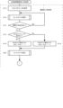
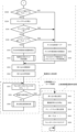
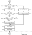
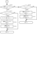
まず、パチンコ機1の遊技の進行に応じて、図23に示した主制御基板100が行う各種制御処理について、図26~図28を参照して説明する。図26は主制御基板100の主制御MPU101が実行する主制御側電源投入時処理を示すフローチャートであり、図27は図26の主制御側電源投入時処理のつづきを示すフローチャートであり、図28は主制御MPU101が実行する主制御側タイマ割り込み処理を示すフローチャートである。
[Various control processing of main control board]
First, various control processes performed by the
[主制御側電源投入時処理]
パチンコ機1に電源が投入されると、主制御基板100の主制御MPU101(以下、単に主制御MPUという)は、図26及び図27に示すように、主制御側電源投入時処理を行う。この主制御側電源投入時処理が開始されると、主制御MPUは、スタックポインタの設定を行う(ステップS10)。スタックポインタは、例えば、使用中の記憶素子(レジスタ)の内容を一時記憶するためにスタックに積んだアドレスを示したり、サブルーチンを終了して本ルーチンに復帰するときの本ルーチンの復帰アドレスを一時記憶するためにスタックに積んだアドレスを示したりするものであり、スタックが積まれるごとにスタックポインタが進む。ステップS10では、スタックポインタに初期アドレスをセットし、この初期アドレスから、レジスタの内容、復帰アドレス等をスタックに積んで行く。そして最後に積まれたスタックから最初に積まれたスタックまで、順に読み出すことによりスタックポインタが初期アドレスに戻る。
[Main control side power-on processing]
When the power is turned on to the
ステップS10に続いて、ウェイトタイマ処理1を行い(ステップS12)、停電予告信号が入力されているか否かを判定する(ステップS14)。電源投入時から所定電圧となるまでの間では電圧がすぐに上がらない。一方、停電又は瞬停(突発的に電力の供給が一時停止する現象)となるときでは電圧が下がり、停電予告電圧より小さくなると、球情報制御基板110の停電監視回路117から停電予告として停電予告信号が出力されて主制御MPUに入力される。電源投入時から所定電圧に上がるまでの間では同様に電圧が停電予告電圧より小さくなると、球情報制御基板110の停電監視回路117から停電予告信号が入力される。
Following step S10, wait
そこで、ステップS12のウェイトタイマ処理1は、電源投入後、電圧が停電予告電圧より大きくなって安定するまで待つための処理であり、本実施形態では、待ち時間(ウェイトタイマ)として200ミリ秒(ms)が設定されている。ステップS14の判定では、球情報制御基板110の停電監視回路117からの停電予告信号に基づいて行う。電源投入後、電圧が停電予告電圧より大きくなって安定すると、停電監視回路117からの停電予告信号が出力なしとなり、主制御MPUはステップS16に進む。
Therefore, the
ステップS16に進むと、主制御MPUは、RAMクリアスイッチ105(図23)が操作されているか否かを判定する(ステップS16)。この判定は、主制御基板100のRAMクリアスイッチ105が操作され、その操作信号(検出信号)が主制御MPUに入力されているか否かにより行う。検出信号が入力されているときにはRAMクリアスイッチ105が操作されていると判定する一方、検出信号が入力されていないときにはRAMクリアスイッチ105が操作されていないと判定する。
Proceeding to step S16, the main control MPU determines whether the RAM clear switch 105 (FIG. 23) is operated (step S16). This determination is made based on whether the RAM
ステップS16でRAMクリアスイッチ105が操作されていると判定したときには、RAMクリア報知フラグRCL-FLGに値1をセットし(ステップS18)、ステップS30に移行する一方、ステップS16でRAMクリアスイッチ105が操作されていないと判定したときには、RAMクリア報知フラグRCL-FLGに値0をセットし(ステップS19)、ステップS30に移行する。
When it is determined in step S16 that the RAM
このRAMクリア報知フラグRCL-FLGは、主制御MPU101に内蔵されたRAM(以下、「主制御内蔵RAM」と記載する。)に記憶されている、確率変動、未払い出し賞球等の遊技に関する遊技情報を消去するか否かを示すフラグであり、遊技情報を消去するとき値1、遊技情報を消去しないとき値0にそれぞれ設定される。なお、ステップS18及びステップS19でセットされたRAMクリア報知フラグRCL-FLGの値は、主制御MPUの汎用記憶素子(汎用レジスタ)に記憶される。 This RAM clear notification flag RCL-FLG is used for games related to probability fluctuations, unpaid prize balls, etc. stored in the RAM built in the main control MPU 101 (hereinafter referred to as "main control built-in RAM"). This is a flag indicating whether or not to erase information, and is set to a value of 1 when gaming information is to be erased, and is set to a value of 0 when gaming information is not to be erased. Note that the value of the RAM clear notification flag RCL-FLG set in steps S18 and S19 is stored in a general-purpose storage element (general-purpose register) of the main control MPU.
主制御MPUは、ステップS30に移行すると、ウェイトタイマ処理2を行う(ステップS30)。このウェイトタイマ処理2では、周辺制御基板130の液晶制御部による液晶表示装置(図示せず)の描画制御を行うシステムが起動する(ブートする)まで待っている。本実施形態では、ブートするまでの時間(ブートタイマ)として2秒(s)が設定されている。
When the main control MPU moves to step S30, it performs wait timer processing 2 (step S30). In this
ステップS30に続いて、RAMクリア報知フラグRCL-FLGが値0である否かを判定する(ステップS32)。上述したように、RAMクリア報知フラグRCL-FLGは、遊技情報を消去するとき値1、遊技情報を消去しないとき値0にそれぞれ設定される。ステップS32においてRAMクリア報知フラグRCL-FLGが値0であると判定した場合、つまり遊技情報を消去しないときには、チェックサムの算出を行う(ステップS34)。このチェックサムは、主制御内蔵RAMに記憶されている遊技情報を数値とみなしてその合計を算出するものである。
Following step S30, it is determined whether the RAM clear notification flag RCL-FLG is 0 (step S32). As described above, the RAM clear notification flag RCL-FLG is set to the
ステップS34に続いて、算出したチェックサムの値(サム値)が後述する主制御側電源断時処理(電源断時)において記憶されているチェックサムの値(サム値)と一致しているか否かを判定する(ステップS36)。一致しているときには、バックアップフラグBK-FLGが値1であるか否かを判定する(ステップS38)。このバックアップフラグBK-FLGは、遊技情報、チェックサムの値(サム値)及びバックアップフラグBK-FLGの値等のバックアップ情報を後述する主制御側電源断時処理において主制御内蔵RAMに記憶保持したか否かを示すフラグであり、主制御側電源断時処理を正常に終了したとき値1、主制御側電源断時処理を正常に終了していないとき値0にそれぞれ設定される。 Following step S34, whether or not the calculated checksum value (sum value) matches the checksum value (sum value) stored in the main control side power-off processing (power-off) described later. (Step S36). If they match, it is determined whether the backup flag BK-FLG is 1 (step S38). This backup flag BK-FLG stores and holds backup information such as game information, checksum value (sum value), and backup flag BK-FLG value in the main control built-in RAM in the main control side power-off processing described later. This flag is set to a value of 1 when the main control side power-off processing is normally completed, and is set to a value of 0 when the main control-side power-off processing is not normally completed.
ステップS38でバックアップフラグBK-FLGが値1であるとき、つまり主制御側電源断時処理を正常に終了したときには、復電時として主制御内蔵RAMの作業領域を設定する(ステップS40)。この設定は、バックアップフラグBK-FLGに値0をセットするほか、主制御MPUに内蔵されたROM(以下、「主制御内蔵ROM」と記載する。)から復電時情報を読み出し、この復電時情報を主制御内蔵RAMの作業領域にセットする。なお、「復電」とは、電源を遮断した状態から電源を投入した状態のほかに、停電又は瞬停からその後の電力の復旧した状態、高周波が照射されたことを検出してリセットし、その後に復帰した状態も含める。 When the backup flag BK-FLG has a value of 1 in step S38, that is, when the main control side power-off processing is normally completed, a work area of the main control built-in RAM is set for when the power is restored (step S40). In addition to setting the backup flag BK-FLG to a value of 0, this setting reads out power recovery information from the ROM built in the main control MPU (hereinafter referred to as "main control built-in ROM"), and Set the time information in the work area of the main control built-in RAM. In addition, "power restoration" refers to not only the state where the power is turned on from a state where the power was cut off, but also the state where power is restored after a power outage or momentary power outage, and the state where high frequency radiation is detected and reset. It also includes the state of return after that.
ステップS40に続いて、電源投入時コマンド作成処理を行う(ステップS42)。この電源投入時コマンド作成処理では、バックアップ情報から遊技情報を読み出してこの遊技情報に応じた各種コマンドを主制御内蔵RAMの所定記憶領域に記憶する。 Following step S40, a power-on command creation process is performed (step S42). In this power-on command generation process, gaming information is read from the backup information and various commands corresponding to this gaming information are stored in a predetermined storage area of the main control built-in RAM.
一方、ステップS32でRAMクリア報知フラグRCL-FLGが値0でない(値1である)と判定した場合、つまり遊技情報を消去するときには、又はステップS36でチェックサムの値(サム値)が一致していないときには、又はステップS38でバックアップフラグBK-FLGが値1でない(値0である)と判定した場合、つまり主制御側電源断時処理を正常に終了していないときには、主制御内蔵RAMの全領域をクリアする(ステップS44)。具体的には、値0を主制御内蔵RAMに書き込むことよって行う(なお、初期値として主制御内蔵ROMから所定値を読み出して、セットしてもよい)。また、大当り判定用乱数の初期値の決定に用いるための大当り判定用初期値決定用乱数は、RAMクリアスイッチ105が操作されて遊技情報を消去するとき、サム値が一致していないとき、又は主制御側電源断時処理を正常に終了していないときには、主制御MPUの不揮発性のRAMに予め記憶された固有のIDコードを取り出し、この取り出したIDコードに基づいて大当り判定用乱数を更新するカウンタの固定数値範囲から常に同一の固定値を導出する初期値導出処理を実行し、この固定値が初期値としてセットされる。
On the other hand, if it is determined in step S32 that the RAM clear notification flag RCL-FLG is not 0 (value 1), that is, when erasing gaming information, or if the checksum values (sum values) match in step S36, If the backup flag BK-FLG is not 1 (value 0) in step S38, that is, if the main control side power-off processing has not been completed normally, the main control built-in RAM is The entire area is cleared (step S44). Specifically, this is done by writing the
ステップS44に続いて、初期設定として主制御内蔵RAMの作業領域を設定する(ステップS46)。この設定は、主制御内蔵ROMから初期情報を読み出してこの初期情報を主制御内蔵RAMの作業領域にセットする。 Following step S44, the work area of the main control built-in RAM is set as an initial setting (step S46). For this setting, initial information is read from the main control built-in ROM and this initial information is set in the work area of the main control built-in RAM.
ステップS46に続いて、RAMクリア報知及びテストコマンド作成処理を行う(ステップS48)。このRAMクリア報知及びテストコマンド作成処理では、主制御内蔵RAMをクリアして初期設定を行った旨を報知するための電源投入に区分される電源投入コマンドを作成するとともに、周辺制御基板130の各種検査を行うためのテスト関連に区分されるテストコマンドを作成して、送信情報として主制御内蔵RAMの送信情報記憶領域にそれぞれ記憶する。
Following step S46, RAM clear notification and test command creation processing are performed (step S48). In this RAM clear notification and test command creation process, a power-on command classified as power-on to notify that the main control built-in RAM has been cleared and initial settings have been performed is created, and various types of
ステップS42又はステップS48に続いて、割り込み初期設定を行う(ステップS50)。この設定は、後述する主制御側タイマ割り込み処理が行われるときの割り込み周期を設定するものである。本実施形態では4msに設定されている。 Following step S42 or step S48, interrupt initialization is performed (step S50). This setting sets the interrupt cycle when main control side timer interrupt processing, which will be described later, is performed. In this embodiment, it is set to 4ms.
ステップS50に続いて、割り込み許可設定を行う。(ステップS52)。この設定によりステップS50で設定した割り込み周期、つまり4msごとに主制御側タイマ割り込み処理が繰り返し行われる。なお、このステップS10~ステップS52の処理を「主制御側電源投入時処理」という。 Following step S50, interrupt permission settings are performed. (Step S52). With this setting, the main control side timer interrupt processing is repeatedly performed at the interrupt cycle set in step S50, that is, every 4 ms. Note that the processing from step S10 to step S52 is referred to as "main control side power-on processing".
ステップS52に続いて、ウォッチドックタイマクリアレジスタWCLに値Aをセットする(ステップS54)。このウォッチドックタイマクリアレジスタWCLに、値A、値Bそして値Cを順にセットすることによりウォッチドックタイマがクリア設定される。 Following step S52, a value A is set in the watchdog timer clear register WCL (step S54). The watchdog timer is cleared by sequentially setting value A, value B, and value C in this watchdog timer clear register WCL.
ステップS54に続いて、停電予告信号が入力されているか否かを判定する(ステップS56)。上述したように、パチンコ遊技機1の電源を遮断したり、停電又は瞬停したりするときには、電圧が停電予告電圧以下となると、停電予告として停電予告信号が球情報制御基板110の停電監視回路117から入力される。ステップS56の判定は、この停電予告信号に基づいて行う。
Following step S54, it is determined whether a power outage warning signal has been input (step S56). As described above, when the power to the
ステップS56で停電予告信号の入力がないときには非当落乱数更新処理を行う(ステップS58)。この非当落乱数更新処理では、例えば、リーチ判定用乱数、変動表示パターン用乱数、大当り図柄用初期値決定用乱数、及び小当り図柄用初期値決定用乱数等を更新する。このように、非当落乱数更新処理では、当落判定(大当り判定)にかかわらない乱数を更新する。なお、普通図柄当り判定用乱数、普通図柄当り判定用初期値決定用乱数及び普通図柄変動表示パターン用乱数等もこの非当落乱数更新処理により更新される。 If no power outage warning signal is input in step S56, a non-winning random number update process is performed (step S58). In this non-winning/losing random number updating process, for example, the random numbers for reach determination, the random numbers for variable display patterns, the random numbers for determining initial values for jackpot symbols, the random numbers for determining initial values for small winning symbols, etc. are updated. In this way, in the non-winning random number updating process, random numbers that are not related to winning/losing determination (jackpot determining) are updated. In addition, the random number for normal symbol hit determination, the random number for determining the initial value for normal symbol hit determination, the random number for normal symbol fluctuation display pattern, etc. are also updated by this non-winning random number update process.
ステップS58に続いて、再びステップS54に戻り、ウォッチドックタイマクリアレジスタWCLに値Aをセットし、ステップS56で停電予告信号の入力があるか否かを判定し、この停電予告信号の入力がなければ、ステップS58で非当落乱数更新処理を行い、ステップS54~ステップS58を繰り返し行う。なお、このステップS54~ステップS58の処理を「主制御側メインループ処理」という。 Following step S58, the process returns to step S54 again to set the value A in the watchdog timer clear register WCL, and in step S56 it is determined whether or not a power outage warning signal is input. For example, a non-winning random number update process is performed in step S58, and steps S54 to S58 are repeatedly performed. Note that the processing from step S54 to step S58 is referred to as "main control side main loop processing."
一方、ステップS56で停電予告信号の入力があったときには、割り込み禁止設定を行う(ステップS60)。この設定により後述する主制御側タイマ割り込み処理が行われなくなり、主制御内蔵RAMへの書き込みを防ぎ、遊技情報の書き換えを保護している。 On the other hand, when a power outage warning signal is input in step S56, interrupt prohibition is set (step S60). This setting prevents the main control side timer interrupt processing, which will be described later, from being performed, prevents writing to the main control built-in RAM, and protects game information from being rewritten.
ステップS60に続いて、図23に示した、始動口ソレノイド96、大入賞口ソレノイド97、上特別図柄表示器142、下特別図柄表示器143、上特別図柄記憶表示器144、下特別図柄記憶表示器145、普通図柄表示器146、普通図柄記憶表示器147、遊技状態表示器148、ラウンド表示器149等に出力している駆動信号を停止する(ステップS62)。
Following step S60, the starting
ステップS62に続いて、チェックサムの算出を行ってこの算出した値を記憶する(ステップS64)。このチェックサムは、上述したチェックサムの値(サム値)及びバックアップフラグBK-FLGの値の記憶領域を除く、主制御内蔵RAMの作業領域の遊技情報を数値とみなしてその合計を算出する。 Following step S62, a checksum is calculated and the calculated value is stored (step S64). This checksum is calculated by considering the game information in the work area of the main control built-in RAM as a numerical value, excluding the storage area for the above-mentioned checksum value (sum value) and backup flag BK-FLG value.
ステップS64に続いて、バックアップフラグBK-FLGに値1をセットする(ステップS66)。これにより、バックアップ情報の記憶が完了する。 Following step S64, the backup flag BK-FLG is set to the value 1 (step S66). This completes storage of the backup information.
ステップS66に続いて、ウォッチドックタイマのクリア設定を行う(ステップS68)。このクリア設定は、上述したように、ウォッチドックタイマクリアレジスタWCLに値A、値Bそして値Cを順にセットすることにより行われる。 Following step S66, the watchdog timer is cleared (step S68). This clear setting is performed by sequentially setting value A, value B, and value C in watchdog timer clear register WCL, as described above.
ステップS68に続いて、何も実行しない状態を繰り返すというループ処理に入る。なお、ステップS60~ステップS68の処理及びループ処理を「主制御側電源断時処理」という。このループ処理では、ウォッチドックタイマクリアレジスタWCLに値A、値Bそして値Cを順にセットしないためウォッチドックタイマがクリア設定されなくなる。このため、ウォッチドックタイマがタイムアウトしてタイムアウト信号を出力し、タイムアウト信号によって主制御MPUにリセットがかかり、その後主制御MPUは、この主制御側電源投入時処理を再び最初から行う。 Following step S68, a loop process is entered in which a state in which nothing is executed is repeated. Note that the processing from step S60 to step S68 and the loop processing are referred to as "main control side power-off processing." In this loop process, the watchdog timer is not cleared and set because the value A, value B, and value C are not sequentially set in the watchdog timer clear register WCL. Therefore, the watchdog timer times out and outputs a timeout signal, and the timeout signal causes the main control MPU to be reset, and then the main control MPU performs the main control side power-on process again from the beginning.
パチンコ機1(主制御MPU101)は、停電したとき又は瞬停したときにはリセットがかかり、その後の電力の復旧により主制御側電源投入時処理を行う。 The pachinko machine 1 (main control MPU 101) is reset when there is a power outage or instantaneous power outage, and after the power is restored, the main control side power-on process is performed.
なお、ステップS36では主制御内蔵RAMに記憶されているバックアップ情報が正常なものであるか否かを検査し、続いてステップS38では主制御側電源断時処理が正常に終了された否かを検査している。このように、主制御内蔵RAMに記憶されているバックアップ情報を2重にチェックすることによりバックアップ情報が不正行為により記憶されたものであるか否かを検査している。 In addition, in step S36, it is checked whether the backup information stored in the main control built-in RAM is normal or not, and then in step S38, it is checked whether the main control side power-off processing has been completed normally. It is being inspected. In this way, by double checking the backup information stored in the main control built-in RAM, it is verified whether the backup information has been stored by fraudulent activity.
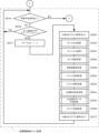
[主制御側タイマ割り込み処理]
次に、主制御側タイマ割り込み処理について説明する。この主制御側タイマ割り込み処理は、図26及び図27に示した主制御側電源投入時処理において設定された割り込み周期(本実施形態では、4ms)ごとに繰り返し行われる。
[Main control side timer interrupt processing]
Next, the main control side timer interrupt processing will be explained. This main control side timer interrupt processing is repeatedly performed at every interrupt period (4 ms in this embodiment) set in the main control side power-on processing shown in FIGS. 26 and 27.
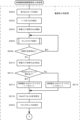
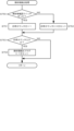
主制御側タイマ割り込み処理が開始されると、主制御基板100の主制御MPUは、図28に示すように、ウォッチドックタイマクリアレジスタWCLに値Bをセットする(ステップS70)。このとき、ウォッチドックタイマクリアレジスタWCLには、主制御側メインループ処理のステップS54においてセットされた値Aに続いて値Bがセットされる。
When the main control side timer interrupt processing is started, the main control MPU of the
ステップS70に続いて、割り込みフラグのクリアを行う(ステップS72)。この割り込みフラグがクリアされることにより割り込み周期が初期化され、次の割り込み周期がその初期値から計時される。 Following step S70, the interrupt flag is cleared (step S72). By clearing this interrupt flag, the interrupt cycle is initialized, and the next interrupt cycle is counted from the initial value.
ステップS72に続いて、スイッチ入力処理を行う(ステップS74)。このスイッチ入力処理では、主制御I/Oポート102の入力端子に入力されている各種信号を読み取り、入力情報として主制御内蔵RAMの入力情報記憶領域に記憶する。
Following step S72, switch input processing is performed (step S74). In this switch input processing, various signals input to the input terminal of the main control I/
ステップS74に続いて、タイマ減算処理を行う(ステップS76)。このタイマ減算処理では、例えば、後述する特別図柄及び特別電動役物制御処理で決定される変動表示パターンに従って上特別図柄表示器142及び下特別図柄表示器143が点灯する時間、後述する普通図柄及び普通電動役物制御処理で決定される普通図柄変動表示パターンに従って普通図柄表示器146が点灯する時間のほかに、主制御基板100(主制御MPU)が送信した各種コマンドを球情報制御基板110が正常に受信した旨を伝える球情報主ACK信号が入力されているか否かを判定する際にその判定条件として設定されているACK信号入力判定時間等の時間管理を行う。具体的には、変動表示パターン又は普通図柄変動表示パターンの変動時間が5秒間であるときには、タイマ割り込み周期が4msに設定されているので、このタイマ減算処理を行うごとに変動時間を4msずつ減算し、その減算結果が値0になることで変動表示パターン又は普通図柄変動表示パターンの変動時間を正確に計っている。
Following step S74, timer subtraction processing is performed (step S76). In this timer subtraction processing, for example, the time during which the upper
本実施形態では、ACK信号入力判定時間が100msに設定されている。このタイマ減算処理を行うごとにACK信号入力判定時間が4msずつ減算し、その減算結果が値0になることでACK信号入力判定時間を正確に計っている。なお、これらの各種時間及びACK信号入力判定時間は、時間管理情報として主制御内蔵RAMの時間管理情報記憶領域に記憶される。 In this embodiment, the ACK signal input determination time is set to 100 ms. Each time this timer subtraction process is performed, the ACK signal input determination time is subtracted by 4 ms, and the ACK signal input determination time is accurately measured when the subtraction result becomes 0. Note that these various times and ACK signal input determination time are stored as time management information in the time management information storage area of the main control built-in RAM.
ステップS76に続いて、当落乱数更新処理を行う(ステップS78)。この当落乱数更新処理では、上述した、大当り判定用乱数、大当り図柄用乱数、及び小当り図柄用乱数を更新する。またこれらの乱数に加えて、図27に示した主制御側電源投入時処理(主制御側メイン処理)におけるステップS58の非当落乱数更新処理で更新される、大当り図柄用初期値決定用乱数、及び小当り図柄用初期値決定用乱数も更新する。これらの大当り図柄用初期値決定用乱数、及び小当り図柄用初期値決定用乱数は、主制御側メイン処理及びこの主制御側タイマ割り込み処理においてそれぞれ更新されることでランダム性をより高めている。これに対して、大当り判定用乱数、大当り図柄用乱数、及び小当り図柄用乱数は、当落判定(大当り判定)にかかわる乱数であるためこの当落乱数更新処理が行われるごとにのみ、それぞれのカウンタがカウントアップする。例えば、大当り判定用乱数を更新するカウンタは、上述したように、初期値更新型のカウンタであり、最小値から最大値までに亘る予め定めた固定数値範囲(本実施形態では、最小値として値0~最大値として値32767)内において更新され、この最小値から最大値までに亘る範囲を、この主制御側タイマ割り込み処理が行われるごとに値1ずつ加算されることでカウントアップする。大当り判定用初期値決定用乱数から最大値(値32767)に向かってカウントアップし、続いて最小値(値0)から大当り判定用初期値決定用乱数に向かってカウントアップする。大当り判定用乱数の最小値から最大値までに亘る範囲を、大当り判定用乱数を更新するカウンタがカウントアップし終えると、この当落乱数更新処理により大当り判定用初期値決定用乱数は更新される。このとき、その更新される値は、主制御MPUがその内蔵する不揮発性のRAMからIDコードを取り出し、この取り出したIDコードに基づいて大当り判定用乱数を更新するカウンタの固定数値範囲から常に同一の固定値を導出する初期値導出処理を実行し、この導出した固定値が初期値としてセットされる仕組みとなっている。つまり、大当り判定用初期値決定用乱数は、初期値導出処理の実行によりIDコードに基づいて導出された同一の固定値が初期値として常に上書き更新されるようになっている。なお、上述した、普通図柄当り判定用乱数、普通図柄当り判定用初期値決定用乱数もこの当落乱数更新処理により更新される。普通図柄当り判定用乱数等は、上述した大当り判定用乱数の更新方法と同一であり、その説明を省略する。
Following step S76, a winning/losing random number update process is performed (step S78). In this win/loss random number update process, the above-mentioned random numbers for jackpot determination, random numbers for jackpot symbols, and random numbers for small win symbols are updated. In addition to these random numbers, a random number for determining the initial value for the jackpot symbol, which is updated in the non-winning random number update process of step S58 in the main control side power-on process (main control side main process) shown in FIG. And the random number for determining the initial value for small winning symbols is also updated. These random numbers for determining the initial value for the jackpot symbol and the random number for determining the initial value for the small winning symbol are updated in the main control side main processing and this main control side timer interrupt processing to further enhance randomness. . On the other hand, the random numbers for jackpot determination, the random numbers for jackpot symbols, and the random numbers for small win symbols are random numbers related to win/loss determination (jackpot determination), so each counter is updated only every time this win/loss random number update process is performed. counts up. For example, the counter that updates the random numbers for jackpot determination is, as mentioned above, an initial value update type counter, and has a predetermined fixed numerical range from the minimum value to the maximum value (in this embodiment, the minimum value is the
ステップS78に続いて、賞球制御処理を行う(ステップS80)。この賞球制御処理では、上述した入力情報記憶領域から入力情報を読み出してこの入力情報に基づいて球情報制御基板110に送信するための賞球コマンドを作成したり、主制御基板100と球情報制御基板110との基板間の接続状態を確認するためのセルフチェックコマンドを作成したりする。そして作成した賞球コマンドやセルフチェックコマンドを主球情報シリアルデータとして球情報制御基板110に送信する。例えば、大入賞口に遊技球が1球、入球すると、賞球数として15球を表す賞球コマンドを作成して球情報制御基板110に送信したり、この賞球コマンドを球情報制御基板110が正常に受信完了した旨を伝える球情報主ACK信号が所定時間内に入力されないときには主制御基板100と球情報制御基板110との基板間の接続状態を確認するセルフチェックコマンドを作成して球情報制御基板110に送信したりする。
Following step S78, prize ball control processing is performed (step S80). In this prize ball control process, input information is read from the input information storage area mentioned above, and based on this input information, a prize ball command is created to be sent to the ball
ステップS80に続いて、枠コマンド受信処理を行う(ステップS82)。球情報制御基板110は、状態表示に区分される1バイト(8ビット)の各種コマンドを送信する。ステップS82の枠コマンド受信処理では、この各種コマンドを球情報主シリアルデータとして正常に受信すると、その旨を球情報制御基板110に伝える情報を、出力情報として主制御内蔵RAMの出力情報記憶領域に記憶する。また、その正常に球情報主シリアルデータとして受信したコマンドを2バイト(16ビット)のコマンドに整形し、送信情報として上述した送信情報記憶領域に記憶する。
Following step S80, frame command reception processing is performed (step S82). The ball
ステップS82に続いて、不正行為検出処理を行う(ステップS84)。この不正行為検出処理では、賞球に関する異常状態を確認する。例えば、上述した入力情報記憶領域から入力情報を読み出し、大当り遊技状態でない場合にカウントスイッチ98からの検出信号が入力されているとき(大入賞口に遊技球が入球するとき)等には、異常状態として報知表示に区分される入賞異常表示コマンドを作成し、送信情報として上述した送信情報記憶領域に記憶する。
Following step S82, fraud detection processing is performed (step S84). In this fraud detection process, an abnormal state regarding the prize ball is checked. For example, when input information is read from the above-mentioned input information storage area and the detection signal from the
ステップS84に続いて、特別図柄及び特別電動役物制御処理を行う(ステップS86)。この特別図柄及び特別電動役物制御処理では、上述した大当り判定用乱数を更新するカウンタの値を取り出して主制御内蔵ROMに予め記憶されている大当り判定値と一致するか否かを判定(大当り遊技状態を発生させるか否かを判定(「特別抽選」という。))したり、大当り図柄用乱数を更新するカウンタの値を取り出して主制御内蔵ROMに予め記憶されている確変当り判定値と一致するか否かを判定(確率変動を発生させるか否かの判定)したりする。ここで、「確率変動」とは、大当りする確率が通常時(低確率)にくらべて高く設定された高確率(確変時)に変化することである。本実施形態では、上述した大当り判定値の範囲(大当り判定範囲)として、低確率では値32668~値32767が設定されており、通常時判定テーブルから読み出されるのに対して、高確率では値32438~値32767が設定されており、確変時判定テーブルから読み出される。このように、ステップS86の特別図柄及び特別電動役物制御処理では、大当り判定用乱数を更新するカウンタの値と、主制御内蔵ROMに予め記憶されている大当り判定値と、が一致するか否かを判定するときには、大当り判定用乱数を更新するカウンタの値が大当り判定範囲に含まれているか否かにより行う。 Following step S84, special symbol and special electric accessory control processing is performed (step S86). In this special symbol and special electric accessory control process, the value of the counter that updates the random number for jackpot determination described above is taken out, and it is determined whether it matches the jackpot determination value stored in advance in the main control built-in ROM (jackpot It determines whether or not to generate a gaming state (referred to as a "special lottery"), takes out the value of the counter that updates the random number for the jackpot symbol, and uses it as the probability variable hit determination value that is stored in advance in the main control built-in ROM. Determine whether or not they match (determine whether or not a probability fluctuation is generated). Here, "probability fluctuation" means that the probability of hitting the jackpot changes to a high probability (when the probability changes) that is set higher than when it is normal (low probability). In this embodiment, the above-mentioned jackpot judgment value range (jackpot judgment range) is set to a value of 32,668 to 32,767 for low probability, and is read from the normal judgment table, whereas for high probability, the value is 32,438. ~ value 32767 is set and read from the probability change time determination table. In this way, in the special symbol and special electric accessory control process of step S86, it is determined whether the value of the counter that updates the random number for jackpot judgment matches the jackpot judgment value stored in advance in the main control built-in ROM. The determination is made based on whether the value of the counter that updates the jackpot determination random number is included in the jackpot determination range.
これらの判定結果が上始動口検出スイッチ90によるものである場合には特図1同調演出関連の各種コマンドを作成する一方、その抽選結果が下始動口検出スイッチ91によるものである場合には特図2同調演出関連の各種コマンドを作成し、送信情報として送信情報記憶領域に記憶するとともに、その決定した特別図柄の変動表示パターンに従って上特別図柄表示器142又は下特別図柄表示器143を点灯させるよう上特別図柄表示器142又は下特別図柄表示器143への点灯信号の出力を設定し、出力情報として上述した出力情報記憶領域に記憶する。
If these determination results are based on the upper starting
また、発生させる遊技状態に応じて、例えば大当り遊技状態となるときには、大当り関連に区分される各種コマンドを作成し、送信情報として送信情報記憶領域に記憶したり、開閉部材を開閉動作させるよう大入賞口ソレノイド97への駆動信号の出力を設定し、出力情報として出力情報記憶領域に記憶したり、大入賞口が閉鎖状態から開放状態となる回数(ラウンド)が2回であるときには、ラウンド表示器149の2ラウンド表示ランプを点灯させるよう2ラウンド表示ランプへの点灯信号の出力を設定し、出力情報として出力情報記憶領域に記憶したり、ラウンドが15回であるときには、ラウンド表示器149の15ラウンド表示ランプを点灯させるよう15ラウンド表示ランプへの点灯信号の出力を設定し、出力情報として出力情報記憶領域に記憶したり、確率変動の発生の有無を所定の色で点灯させるよう遊技状態表示器148への点灯信号の出力を設定し、出力情報として出力情報記憶領域に記憶したりする。
In addition, depending on the gaming state to be generated, for example, when it becomes a jackpot gaming state, various commands classified as jackpot-related are created and stored in the transmission information storage area as transmission information, or commands such as commands to open and close the opening/closing member are created. If the output of the drive signal to the winning
ステップS86に続いて、普通図柄及び普通電動役物制御処理を行う(ステップS88)。この普通図柄及び普通電動役物制御処理では、上述した入力情報記憶領域から入力情報を読み出してこの入力情報に基づいてゲート入賞処理を行う。このゲート入賞処理では、入力情報からゲートスイッチ92からの検出信号が入力端子に入力されていたか否かを判定する。この判定結果に基づいて、検出信号が入力端子に入力されていたときには、上述した普通図柄当り判定用乱数を更新するカウンタの値等を抽出してゲート情報として主制御内蔵RAMのゲート情報記憶領域に記憶する。
Following step S86, normal symbol and normal electric accessory control processing is performed (step S88). In this normal symbol and normal electric accessory control process, input information is read from the above-mentioned input information storage area and gate winning processing is performed based on this input information. In this gate winning process, it is determined from the input information whether the detection signal from the
ステップS88に続いて、ポート出力処理を行う(ステップS90)。このポート出力処理では、主制御I/Oポート102の出力端子から、上述した出力情報記憶領域から出力情報を読み出してこの出力情報に基づいて各種信号を出力する。例えば、出力情報に基づいて主制御I/Oポート102の出力端子から、球情報制御基板110からの各種コマンドを正常に受信完了したときには主球情報ACK信号を球情報制御基板110に出力したり、大当り遊技状態であるときには大入賞口の開閉部材の開閉動作を行う大入賞口ソレノイド97に駆動信号を出力したり、可動片の開閉動作を行う始動口ソレノイド96に駆動信号を出力したりするほかに、15ラウンド大当り情報出力信号、2ラウンド大当り情報出力信号、確率変動中情報出力信号、特別図柄表示情報出力信号、普通図柄表示情報出力信号、時短中情報出力情報、始動口入賞情報出力信号等の遊技に関する各種情報(遊技情報)信号を球情報制御基板110に出力したりする。
Following step S88, port output processing is performed (step S90). In this port output processing, output information is read from the output information storage area mentioned above from the output terminal of the main control I/
ステップS90に続いて、周辺制御基板コマンド送信処理を行う(ステップS92)。この周辺制御基板コマンド送信処理では、上述した送信情報記憶領域から送信情報を読み出してこの送信情報を主周シリアルデータとして周辺制御基板130に送信する。この送信情報には、本ルーチンである主制御側タイマ割り込み処理で作成した、特図1同調演出関連に区分される各種コマンド、特図2同調演出関連に区分される各種コマンド、大当り関連に区分される各種コマンド、電源投入に区分される各種コマンド、普図同調演出関連に区分される各種コマンド、普通電役演出関連に区分される各種コマンド、報知表示に区分される各種コマンド、状態表示に区分される各種コマンド、テスト関連に区分される各種コマンド及びその他に区分される各種コマンドが記憶されている。主周シリアルデータは、1パケットが3バイトに構成されている。
Following step S90, peripheral control board command transmission processing is performed (step S92). In this peripheral control board command transmission process, transmission information is read from the above-mentioned transmission information storage area and is transmitted to the
具体的には、主周シリアルデータは、1バイト(8ビット)の記憶容量を有するコマンドの種類を示すステータスと、1バイト(8ビット)の記憶容量を有する演出のバリエーションを示すモードと、ステータス及びモードを数値とみなしてその合計を算出したサム値と、から構成されており、このサム値は、送信時に作成されている。なお、ステップS74~ステップS92の処理を「遊技制御処理」ということにする。 Specifically, the main cycle serial data includes a status that indicates the type of command that has a storage capacity of 1 byte (8 bits), a mode that indicates a variation of the effect that has a storage capacity of 1 byte (8 bits), and a status. and a sum value calculated by considering the mode as a numerical value and calculating the sum value, and this sum value is created at the time of transmission. Note that the processing from step S74 to step S92 will be referred to as "gaming control processing".
ステップS92に続いて、ウォッチドックタイマクリアレジスタWCLに値Cをセットする(ステップS94)。ステップS94でウォッチドックタイマクリアレジスタWCLに値Cがセットされることにより、ウォッチドックタイマクリアレジスタWCLには、ステップS70においてセットされた値Bに続いて値Cがセットされる。これにより、ウォッチドックタイマクリアレジスタWCLには、値A、値Bそして値Cが順にセットされ、ウォッチドックタイマがクリア設定される。 Following step S92, a value C is set in the watchdog timer clear register WCL (step S94). By setting the value C in the watchdog timer clear register WCL in step S94, the value C is set in the watchdog timer clear register WCL following the value B set in step S70. As a result, value A, value B, and value C are set in order in the watchdog timer clear register WCL, and the watchdog timer is cleared.
ステップS94に続いて、レジスタの切替(復帰)を行い(ステップS96)、このルーチンを終了する。ここで、本ルーチンである主制御側タイマ割り込み処理が開始されると、主制御MPUは、ハード的に汎用レジスタの内容をスタックに積んで退避する。これにより、主制御側メイン処理で使用していた汎用レジスタの内容の破壊を防いでいる。ステップS96では、スタックに積んで退避した内容を読み出し、もとのレジスタに書き込む。なお、主制御MPUは、ステップS96による復帰の後に割り込み許可の設定を行う。 Following step S94, register switching (return) is performed (step S96), and this routine ends. Here, when the main control side timer interrupt processing, which is this routine, is started, the main control MPU stacks and saves the contents of the general-purpose register on the stack using hardware. This prevents the contents of the general-purpose registers used in the main processing on the main control side from being destroyed. In step S96, the contents saved on the stack are read and written to the original register. Note that the main control MPU sets interrupt permission after returning in step S96.
[球情報制御基板の各種制御処理]
次に、図24に示した球情報制御基板110が行う各種制御処理について、図28~図33を参照して説明する。図29は球情報制御基板110の球情報制御MPU111が実行する球情報制御側電源投入時処理を示すフローチャートであり、図30は図29の球情報制御側電源投入時処理のつづきを示すフローチャートであり、図31は図30に続いて球情報制御側電源投入時処理のつづきを示すフローチャートであり、図32は球情報制御基板110の球情報制御MPU111が実行する球情報制御電源断時処理を示すフローチャートであり、図33は球情報制御側タイマ割り込み処理の一例を示すフローチャートである。
[Various control processing of the ball information control board]
Next, various control processes performed by the ball
[球情報制御側電源投入時処理]
パチンコ遊技機1に電源が投入されると、球情報制御基板110における球情報制御部118の球情報制御MPU111(以下、単に球情報制御MPUという)は、図29~図30に示すように、球情報制御側電源投入時処理を行う。この球情報制御側電源投入時処理が開始されると、球情報制御MPUは、割り込みモードの設定を行う(ステップS500)。この割り込みモードは、球情報制御MPUの割り込みの優先順位を設定するものである。本実施形態では、後述する球情報制御部タイマ割り込み処理が優先順位として最も高く設定されており、この球情報制御部タイマ割り込み処理の割り込みが発生すると、優先的にその処理を行う。
[Processing when power is turned on on the ball information control side]
When the power is turned on to the
ステップS500に続いて、入出力設定(I/Oの入出力設定)を行う(ステップS502)。このI/Oの入出力設定では、球情報制御MPUのI/Oポートの入出設定等を行う。 Following step S500, input/output settings (I/O input/output settings) are performed (step S502). In this I/O input/output setting, input/output settings of the I/O port of the ball information control MPU, etc. are performed.
ステップS502に続いて、図24に示した停電監視回路117に停電クリア信号の出力を開始する(ステップS504)。この停電監視回路117は、電圧比較回路と、DタイプフリップフロップICと、から構成されている。電圧比較回路は、+24Vとリファレンス電圧との電圧を比較したり、+12Vとリファレンス電圧との電圧を比較したりすることで、その比較結果を出力する。この比較結果は、停電又は瞬停が発生していない場合ではその論理がHIとなってDタイプフリップフロップのプリセット端子であるPR端子に入力される一方、停電又は瞬停が発生した場合ではその論理がLOWとなってDタイプフリップフロップのプリセット端子であるPR端子に入力されるようになっている。ステップS504では、このDタイプフリップフロップのクリア端子であるCLR端子に停電クリア信号の出力を開始する。この停電クリア信号は、球情報制御部118の球情報制御I/Oポート112を介して、その論理がLOWとなってクリア端子に入力される。これにより、球情報制御MPUは、Dタイプフリップフロップのラッチ状態を解除することができ、ラッチ状態をセットするまでの間、Dタイプフリップフロップのプリセット端子であるPR端子に入力された論理を反転して出力端子である1Q端子から出力する状態とすることができ、その1Q端子からの信号を監視することができる。
Following step S502, output of a power outage clear signal to the power outage monitoring circuit 117 shown in FIG. 24 is started (step S504). This power failure monitoring circuit 117 is composed of a voltage comparison circuit and a D-type flip-flop IC. The voltage comparison circuit compares the voltages between +24V and the reference voltage, or compares the voltages between +12V and the reference voltage, and outputs the comparison results. If a power outage or instantaneous power outage does not occur, the result of this comparison becomes HI and is input to the PR terminal, which is the preset terminal of the D-type flip-flop. The logic becomes LOW and is input to the PR terminal, which is the preset terminal of the D-type flip-flop. In step S504, output of a power failure clear signal is started to the CLR terminal, which is the clear terminal of this D-type flip-flop. This power failure clear signal is input to the clear terminal via the ball information control I/
ステップS504に続いて、ウェイトタイマ処理1を行い(ステップS506)、停電予告信号が入力されているか否かを判定する(ステップS508)。電源投入時から所定電圧となるまでの間では電圧がすぐに上がらない。一方、停電又は瞬停(突発的に電力の供給が一時停止する現象)となるときでは電圧が下がり、停電予告電圧より小さくなると、停電監視回路117から停電予告として停電予告信号が入力される。電源投入時から所定電圧に上がるまでの間では同様に電圧が停電予告電圧より小さくなると停電監視回路117から停電予告信号が入力される。そこで、ステップS506のウェイトタイマ処理1は、電源投入後、電圧が停電予告電圧より大きくなって安定するまで待つための処理であり、本実施形態では、待ち時間(ウェイトタイマ)として200ミリ秒(ms)が設定されている。ステップS508の判定でその停電予告信号が入力されているか否かの判定を行っている。この判定では、停電予告信号として、上述したDタイプフリップフロップの出力端子である1Q端子から出力されている信号に基づいて行う。
Following step S504, wait
ステップS508に続いて、Dタイプフリップフロップのクリア端子であるCLR端子に停電クリア信号の出力を停止する(ステップS510)。この停電クリア信号の出力を停止することで、球情報制御I/Oポート112を介して、その論理がHIとなってクリア端子であるCLR端子に入力される。これにより、球情報制御MPUは、Dタイプフリップフロップをラッチ状態にセットすることができる。Dタイプフリップフロップは、そのプリセット端子であるPR端子に論理がLOWとなって入力された状態をラッチすると、出力端子である1Q端子から停電予告信号を出力する。
Following step S508, the output of the power failure clear signal to the CLR terminal, which is the clear terminal of the D-type flip-flop, is stopped (step S510). By stopping the output of this power outage clear signal, its logic becomes HI and is input to the CLR terminal, which is a clear terminal, via the ball information control I/
ステップS510に続いて、RAMクリアスイッチ105が操作されているか否かを判定する(ステップS512)。この判定は、主制御基板100のRAMクリアスイッチ105が操作され、その操作信号(検出信号)が球情報制御MPUに入力されているか否かにより行う。検出信号が入力されているときにはRAMクリアスイッチ105が操作されていると判定し、一方、検出信号が入力されていないときにはRAMクリアスイッチ105が操作されていないと判定する。
Following step S510, it is determined whether the RAM
ステップS512でRAMクリアスイッチ105が操作されていると判定した場合には、球情報RAMクリアフラグに値1をセットし(ステップS514)、ステップS518に進む一方、ステップS512でRAMクリアスイッチ105が操作されていないと判定した場合には、球情報RAMクリアに値0をセットし(ステップS516)、ステップS518に進む。
If it is determined in step S512 that the RAM
この球情報RAMクリアフラグは、球情報制御MPUに内蔵されたRAM(以下、「球情報制御内蔵RAM」と記載する。)に記憶されている、例えば、各種フラグ、各種情報記憶領域に記憶されている各種球情報を消去するか否かを示すフラグであり、球情報を消去するとき値1、球情報を消去しないとき値0にそれぞれ設定される。なお、ステップS514及びステップS516でセットされた球情報RAMクリアフラグは、球情報制御MPUの汎用記憶素子(汎用レジスタ)に記憶される。 This ball information RAM clear flag is stored in, for example, various flags and various information storage areas stored in the RAM built into the ball information control MPU (hereinafter referred to as "ball information control built-in RAM"). This is a flag indicating whether or not to delete various kinds of ball information.It is set to a value of 1 when the ball information is to be deleted, and to a value of 0 when the ball information is not to be deleted. Note that the ball information RAM clear flag set in steps S514 and S516 is stored in a general-purpose storage element (general-purpose register) of the ball information control MPU.
ステップS514又はステップS516に続いて、球情報制御内蔵RAMへのアクセスを許可する設定を行う(ステップS518)。この設定により球情報制御内蔵RAMへのアクセスができ、例えば球情報の書き込み(記憶)又は読み出しを行うことができる。 Following step S514 or step S516, settings are made to permit access to the ball information control built-in RAM (step S518). With this setting, the ball information control built-in RAM can be accessed, and, for example, ball information can be written (stored) or read.
ステップS518に続いて、スタックポインタの設定を行う(ステップS520)。スタックポインタは、例えば、使用中の記憶素子(レジスタ)の内容を一時記憶するためにスタックに積んだアドレスを示したり、サブルーチンを終了して本ルーチンに復帰するときの本ルーチンの復帰アドレスを一時記憶するためにスタックに積んだアドレスを示したりするものであり、スタックが積まれるごとにスタックポインタが進む。ステップS520では、スタックポインタに初期アドレスをセットし、この初期アドレスから、レジスタの内容、復帰アドレス等をスタックに積んで行く。そして最後に積まれたスタックから最初に積まれたスタックまで、順に読み出すことによりスタックポインタが初期アドレスに戻る。 Following step S518, a stack pointer is set (step S520). For example, the stack pointer can indicate an address placed on the stack to temporarily store the contents of a storage element (register) in use, or it can temporarily indicate the return address of this routine when returning to this routine after exiting a subroutine. It indicates the address loaded onto the stack for storage, and the stack pointer advances each time the stack is loaded. In step S520, an initial address is set in the stack pointer, and the register contents, return address, etc. are stacked on the stack from this initial address. The stack pointer returns to the initial address by sequentially reading from the stack stacked last to the stack stacked first.
ステップS520に続いて、球情報制御MPUは、ステップS527に進む。ステップS527では、球情報RAMクリアフラグが値0である否かを判定する(ステップS527)。上述したように、球情報RAMクリアフラグは、球情報を消去するとき値1、球情報を消去しないとき値0にそれぞれ設定される。
Following step S520, the ball information control MPU proceeds to step S527. In step S527, it is determined whether the ball information RAM clear flag has a value of 0 (step S527). As described above, the ball information RAM clear flag is set to the
ステップS527で球情報RAMクリアフラグが値0であるとき、つまり球情報を消去しないときには、チェックサムの算出を行う(ステップS528)。このチェックサムは、球情報制御内蔵RAMに記憶されている球情報を数値とみなしてその合計を算出するものである。 When the ball information RAM clear flag is 0 in step S527, that is, when the ball information is not to be deleted, a checksum is calculated (step S528). This checksum is calculated by considering the ball information stored in the ball information control built-in RAM as a numerical value and calculating the sum thereof.
ステップS528に続いて、算出したチェックサムの値が後述する球情報制御部電源断時処理(電源断時)において記憶されているチェックサムの値と一致しているか否かを判定する(ステップS530)。一致しているときには、球情報バックアップフラグが値1であるか否かを判定する(ステップS532)。この球情報バックアップフラグは、球情報、チェックサムの値等の球情報バックアップ情報を後述する球情報制御部電源断時処理において球情報制御内蔵RAMに記憶保持したか否かを示すフラグであり、球情報制御部電源断時処理を正常に終了したとき値1、球情報制御部電源断時処理を正常に終了していないとき値0にそれぞれ設定される。 Following step S528, it is determined whether the calculated checksum value matches the checksum value stored in the ball information control unit power-off processing (power-off time) described later (step S530). ). If they match, it is determined whether the ball information backup flag has a value of 1 (step S532). This ball information backup flag is a flag indicating whether or not ball information backup information such as ball information and checksum value has been stored and retained in the ball information control built-in RAM in the ball information control section power-off processing described later. It is set to a value of 1 when the ball information control unit power-off process is completed normally, and is set to a value of 0 when the ball information control unit power-off process is not completed normally.
ステップS532で球情報バックアップフラグが値1であるとき、つまり球情報制御部電源断時処理を正常に終了したときには、復電時として球情報制御内蔵RAMの作業領域を設定する(ステップS534)。この設定は、球情報バックアップフラグに値0をセットするほかに、球情報制御MPUに内蔵されたROM(以下、「球情報制御内蔵ROM」と記載する。)から復電時情報を読み出し、この復電時情報を球情報制御内蔵RAMの作業領域にセットする。これにより、球情報制御内蔵RAMに記憶されている上述した球情報バックアップ情報である、各種フラグ、各種情報記憶領域に記憶されている各種情報等に基づいて各種処理に使用する情報が設定される。なお、「復電」とは、電源を遮断した状態から電源を投入した状態のほかに、停電又は瞬停からその後の電力の復旧した状態も含める。 When the ball information backup flag has a value of 1 in step S532, that is, when the ball information control section power-off processing has been successfully completed, a work area of the ball information control built-in RAM is set for when the power is restored (step S534). In addition to setting the ball information backup flag to a value of 0, this setting reads the power recovery information from the ROM built into the ball information control MPU (hereinafter referred to as "ball information control built-in ROM"), and Set power restoration information in the work area of the ball information control built-in RAM. As a result, information used for various processes is set based on various flags, various information stored in various information storage areas, etc., which are the above-mentioned ball information backup information stored in the ball information control built-in RAM. . Note that "power restoration" includes not only the state where the power is turned on after being cut off, but also the state where the power is restored after a power outage or instantaneous power outage.
一方、ステップS527で球情報RAMクリアフラグが値0でない(値1である)と判定した場合、又はステップS530でチェックサムの値が一致していないときには、又はステップS532で球情報バックアップフラグが値1でない(値0である)と判定したとき、つまり球情報制御部電源断時処理を正常に終了していないときには、球情報制御内蔵RAMの全領域をクリアする(ステップS536)。これにより、球情報制御内蔵RAMに記憶されている球情報バックアップ情報がクリアされる。
On the other hand, if it is determined in step S527 that the ball information RAM clear flag is not 0 (value 1), or if the checksum values do not match in step S530, or if the ball information backup flag is determined to be a
ステップS536に続いて、初期設定として球情報制御内蔵RAMの作業領域を設定する(ステップS538)。この設定は、球情報制御内蔵ROMから初期情報を読み出してこの初期情報を球情報制御内蔵RAMの作業領域にセットする。 Following step S536, the work area of the ball information control built-in RAM is set as an initial setting (step S538). For this setting, initial information is read from the ball information control built-in ROM and this initial information is set in the work area of the ball information control built-in RAM.
ステップS534又はステップS538に続いて、割り込み初期設定を行う(ステップS540)。この設定は、後述する球情報制御部タイマ割り込み処理が行われるときの割り込み周期を設定するものである。本実施形態では、2msに設定されている。 Following step S534 or step S538, interrupt initialization is performed (step S540). This setting is for setting the interrupt cycle when the ball information control unit timer interrupt process, which will be described later, is performed. In this embodiment, it is set to 2ms.
ステップS540に続いて、割り込み許可設定を行う(ステップS542)。この設定によりステップS540で設定した割り込み周期、つまり2msごとに球情報制御部タイマ割り込み処理が繰り返し行われる。 Following step S540, interrupt permission settings are performed (step S542). With this setting, the ball information control unit timer interrupt process is repeatedly performed at the interrupt cycle set in step S540, that is, every 2 ms.
ステップS542に続いて、停電予告信号が入力されているか否かを判定する(ステップS544)。上述したように、パチンコ遊技機1の電源を遮断したり、停電又は瞬停したりするときには、電圧が停電予告電圧以下となると、停電予告として停電予告信号が停電監視回路117から入力される。ステップS540の判定は、この停電予告信号に基づいて行う。
Following step S542, it is determined whether a power outage warning signal has been input (step S544). As described above, when the power to the
ステップS544で停電予告信号の入力がないときには2ms経過フラグHT-FLGが値1であるか否かを判定する(ステップS546)。この2ms経過フラグHT-FLGは、後述する、2msごとに処理される球情報制御部タイマ割り込み処理で2msを計時するフラグであり、2ms経過したとき値1、2ms経過していないとき値0にそれぞれ設定される。 If no power outage warning signal is input in step S544, it is determined whether the 2 ms elapsed flag HT-FLG is 1 (step S546). This 2ms elapsed flag HT-FLG is a flag that measures 2ms in the ball information control unit timer interrupt processing that is processed every 2ms, which will be described later.It takes a value of 1 when 2ms have elapsed, and a value of 0 when 2ms have not elapsed. Each is set.
ステップS546で2ms経過フラグHT-FLGが値0であると判定した場合には、つまり2ms経過していないときには、ステップS544に戻り、停電予告信号が入力されているか否かを判定する。 If it is determined in step S546 that the 2 ms elapse flag HT-FLG is 0, that is, if 2 ms has not elapsed, the process returns to step S544, and it is determined whether a power outage warning signal has been input.
一方、ステップS546で2ms経過フラグHT-FLGが値1であると判定した場合には、つまり2ms経過したときには、2ms経過フラグHT-FLGに値0をセットし(ステップS547)、ステップS550に進み、外部ウォッチドックタイマ(外部WDT)116に外部WDTクリア信号を出力する(ONする、ステップS550)。この外部WDT116は、球情報制御MPUの動作(システム)を監視するものであり、外部WDTクリア信号がクリア信号解除時間に停止されないときには球情報制御MPU及び球情報制御I/Oポート112にリセット信号を出力してリセットをかける(球情報制御MPUのシステムが暴走していないかを定期的に診断している)。
On the other hand, if it is determined in step S546 that the 2ms elapsed flag HT-FLG is 1, that is, when 2ms have elapsed, the 2ms elapsed flag HT-FLG is set to 0 (step S547), and the process proceeds to step S550. , outputs an external WDT clear signal to the external watchdog timer (external WDT) 116 (turns ON, step S550). This
ステップS550に続いて、ポート出力処理を行う(ステップS552)。このポート出力処理では、球情報制御内蔵RAMの出力情報記憶領域から各種情報を読み出してこの各種情報に基づいて各種信号を球情報制御I/Oポート112の出力端子から出力する。
Following step S550, port output processing is performed (step S552). In this port output processing, various types of information are read from the output information storage area of the ball information control built-in RAM, and various signals are outputted from the output terminal of the ball information control I/
出力情報記憶領域には、例えば、主制御基板100からの賞球に関する各種コマンド(賞球コマンドやセルフチェックコマンド)を正常に受信した旨を伝える球情報主ACK情報、球揚送装置22への駆動制御を行う駆動情報等の各種情報が記憶されており、この出力情報に基づいて球情報制御I/Oポート112の出力端子から、主制御基板100からの賞球コマンドを正常に受信したときには球情報主ACK信号を主制御基板100に出力したり、発射ソレノイド13に駆動信号を出力したりする。
The output information storage area includes, for example, ball information main ACK information that indicates that various commands related to prize balls (prize ball commands and self-check commands) have been successfully received from the
ステップS552に続いて、ポート入力処理を行う(ステップS554)。このポート入力処理では、球情報制御I/Oポート112の入力端子に入力されている各種信号を読み取り、入力情報として球情報制御内蔵RAMの入力情報記憶領域に記憶する。例えば、扉枠開放スイッチ131、本体枠開放スイッチ132、発射待機球検出スイッチ26、70、発射球確認スイッチ36、回収球検出スイッチ203、球経路満タン検出スイッチ206、球適正量検出スイッチ207、揚送入口スイッチ156、揚送モータセンサ(フォトセンサ)157、カセット検出スイッチ158、発射停止スイッチ86、タッチスイッチ87、精算機4からのBRQ信号、BRDY信号及びCR接続信号、後述するコマンド送信処理で送信した各種コマンドを主制御基板100が正常に受信した旨を伝える主制御基板100からの主球情報ACK信号等、をそれぞれ読み取り、入力情報として入力情報記憶領域に記憶する。
Following step S552, port input processing is performed (step S554). In this port input processing, various signals input to the input terminal of the ball information control I/
ステップS554に続いて、タイマ更新処理を行う(ステップS556)。なお、各種判定時間は、時間管理情報として球情報制御内蔵RAMの時間管理情報記憶領域に記憶される。タイマ更新処理では、各種タイマのタイマ値がセットされているか否かを判定し、タイマ値がセットされている場合にはタイマ値を1減算する。例えば、タイマに2秒(2000ms)に相当する値として「1000」がセットされた場合、タイマ割り込み周期が2msに設定されているので、2ms周期でタイマ減算処理を行うごとにタイマ値が1ずつ減算され、その減算結果が値0になることでタイムアップとなり、時間を正確に計っている。 Following step S554, timer update processing is performed (step S556). The various judgment times are stored as time management information in the time management information storage area of the ball information control built-in RAM. In the timer update process, it is determined whether or not the timer values of various timers are set, and if the timer values are set, the timer values are subtracted by 1. For example, if "1000" is set in the timer as a value equivalent to 2 seconds (2000ms), the timer interrupt cycle is set to 2ms, so each time the timer subtraction process is performed at the 2ms cycle, the timer value increases by 1. When the subtraction result becomes 0, the time is up and the time is accurately measured.
ステップS556に続いて、精算機通信処理を行う(ステップS558)。精算機通信処理では、上述した入力情報記憶領域から入力情報を読み出してこの入力情報に基づいて、精算機4からの各種信号(BRQ信号、BRDY信号及びCR接続信号)が入力されているか否かを判定する。精算機4からの各種信号に基づいて、球情報制御MPUは、精算機4と各種信号のやり取りを行う。球情報制御MPUは、例えば、精算機4から送信された貸球数を受けると遊技機持球数データに貸球数に加算する。
Following step S556, payment machine communication processing is performed (step S558). In the payment machine communication process, input information is read from the above-mentioned input information storage area, and based on this input information, it is determined whether various signals (BRQ signal, BRDY signal, and CR connection signal) from the
ステップS558に続いて、コマンド受信処理を行う(ステップS560)。このコマンド受信処理では、主制御基板100からの賞球に関する各種コマンド(賞球コマンドやセルフチェックコマンド)を受信する。この各種コマンドを正常に受信したときには、その旨を伝える球情報主ACK情報を上述した出力情報記憶領域に記憶する。一方、各種コマンドを正常に受信できなかったときには、主制御基板100と球情報制御基板110との基板間の接続に異常が生じている(各種コマンド信号に異常が生じている)旨を伝える接続異常情報を上述した状態情報記憶領域に記憶する。
Following step S558, command reception processing is performed (step S560). In this command reception process, various commands regarding prize balls (prize ball commands and self-check commands) are received from the
ステップS560に続いて、コマンド解析処理を行う(ステップS562)。このコマンド解析処理では、ステップS562で受信したコマンドの解析を行い、その解析したコマンドを受信コマンド情報として球情報制御内蔵RAMの受信コマンド情報記憶領域に記憶する。 Following step S560, command analysis processing is performed (step S562). In this command analysis process, the command received in step S562 is analyzed, and the analyzed command is stored as received command information in the received command information storage area of the ball information control built-in RAM.
ステップS562に続いて、主要動作設定処理を行う(ステップS564)。この主要動作設定処理では、球情報制御MPUは、発射ソレノイド13、球送りソレノイド31、球揚送装置22(球揚送モータ150)、球磨きリボン送りモータ155等の動作設定を行ったりする。また、球情報制御MPUは、発射球確認スイッチ36の球検出に基づく遊技球1個ずつの打ち込み検知に応じて、遊技機持球数記憶領域に記憶した遊技機持球数データから逐次「1」を減算する。さらに、受信コマンド情報記憶領域に賞球コマンドが記憶されている場合に、この賞球コマンドに対応する賞球数を遊技機持球数記憶領域に記憶した遊技機持球数データに加算する。
Following step S562, main operation setting processing is performed (step S564). In this main operation setting process, the ball information control MPU performs operation settings of the firing
ステップS564に続いて、LED表示データ作成処理を行う(ステップS566)。このLED表示データ作成処理では、例えば、上述した遊技機持球数記憶領域に記憶した遊技機持球数データを読み出し、持球数をタッチパネル部14に表示するための表示データを作成してLED表示情報として上述した出力情報記憶領域に記憶する。
Following step S564, LED display data creation processing is performed (step S566). In this LED display data creation process, for example, the data on the number of balls held by the gaming machine stored in the above-mentioned storage area for the number of balls held by the gaming machine is read out, display data for displaying the number of balls held on the
ステップS566に続いて、コマンド送信処理を行う(ステップS568)。このコマンド送信処理では、上述した状態情報記憶領域から各種情報を読み出し、この各種情報に基づいて状態表示に区分される各種コマンドを作成して主制御基板100に送信したりする。
Following step S566, command transmission processing is performed (step S568). In this command transmission process, various types of information are read from the above-mentioned status information storage area, and based on the various types of information, various commands classified into status displays are created and transmitted to the
ステップS568に続いて、外部ウォッチドックタイマ(外部WDT)116に外部WDTクリア信号の出力を停止する(OFFする、ステップS570)。これにより、外部WDT116をクリアし、球情報制御MPU及び球情報制御I/Oポート112にリセットがかからないようにする。また外部WDT116は、外部WDTクリア信号の出力が停止されると、クリア信号解除時間の計時を開始する。
Following step S568, the output of the external WDT clear signal to the external watchdog timer (external WDT) 116 is stopped (turned OFF, step S570). This clears the
ステップS570に続いて、再びステップS544に戻り、停電予告信号が入力されているか否かを判定し、この停電予告信号の入力がなければ、ステップS546で2ms経過フラグHT-FLGが値1であるか否かを判定し、この2ms経過フラグHT-FLGが値1であるとき、つまり2ms経過したときには、ステップS547で2ms経過フラグHT-FLGに値0をセットし、ステップS550で外部WDT4120cに外部WDTクリア信号を出力(ON)し、ステップS552でポート出力処理を行い、ステップS554でポート入力処理を行い、ステップS556でタイマ更新処理を行い、ステップS558で精算機通信処理を行い、ステップS560でコマンド受信処理を行い、ステップS562でコマンド解析処理を行い、ステップS564で主要動作設定処理を行い、ステップS566でLED表示データ作成処理を行い、ステップS568でコマンド送信処理を行い、ステップS570で外部WDT116に外部WDTクリア信号の出力を停止(OFF)し、ステップS544~ステップS570を繰り返し行う。なお、このステップS544~ステップS570の処理を「球情報制御メイン処理」という。
Following step S570, the process returns to step S544 again, and it is determined whether or not a power outage warning signal has been input. If this power outage warning signal has not been input, the 2 ms elapsed flag HT-FLG is set to the
一方、ステップS544で停電予告信号の入力があったときには、割り込み禁止設定を行う(ステップS572)。この設定により後述する球情報制御部タイマ割り込み処理が行われなくなり、球情報制御内蔵RAMへの書き込みを防ぎ、上述した球情報の書き換えを保護している。 On the other hand, when a power outage warning signal is input in step S544, interrupt prohibition is set (step S572). With this setting, the ball information control section timer interrupt processing described later is not performed, preventing writing to the ball information control built-in RAM, and protecting the above-mentioned ball information from being rewritten.
ステップS572に続いて、停電クリア信号を、球情報制御I/Oポート112を介して、停電監視回路117のDタイプフリップフロップのクリア端子であるCLR端子に出力する(ステップS574)。これにより、停電クリア信号が出力されることによりDタイプフリップフロップはラッチ状態を解除することができる。 Following step S572, a power failure clear signal is output to the CLR terminal, which is the clear terminal of the D-type flip-flop of the power failure monitoring circuit 117, via the sphere information control I/O port 112 (step S574). Thereby, the D type flip-flop can release the latched state by outputting the power failure clear signal.
ステップS574に続いて、発射ソレノイド13への駆動信号の出力を停止する(ステップS576)。これにより、遊技球の打ち出しを停止する。ステップS576に続いて、球送りソレノイド31への駆動信号の出力を停止する(ステップS578)。これにより、打球発射装置29側への遊技球の送り込みを停止する。
Following step S574, the output of the drive signal to the firing
ステップS578に続いて、外部WDT116に外部WDTクリア信号を出力してその出力を停止する(ON/OFFする、ステップS580)。これにより、外部WDT116をクリアする。ステップS580に続いて、チェックサムの算出を行ってこの算出した値を記憶する(ステップS582)。このチェックサムは、ステップS528で算出したチェックサムの値及び球情報バックアップフラグHBK-FLGの値の記憶領域を除く、球情報制御内蔵RAMの作業領域の球情報を数値とみなしてその合計を算出する。ステップS582に続いて、球情報バックアップフラグに値1をセットする(ステップS584)。これにより、球情報バックアップ情報の記憶が完了する。ステップS584に続いて、球情報制御内蔵RAMへのアクセスの禁止設定を行う(ステップS586)。この設定により球情報制御内蔵RAMへのアクセスが禁止され書き込み及び読み出しができなくなり、球情報制御内蔵RAMに記憶されている球情報バックアップ情報が保護される。
Following step S578, an external WDT clear signal is output to the
ステップS586に続いて、何もしない状態を繰り返すというループ処理に入る。このループ処理では、外部WDT116にクリア信号をON/OFFしない。このため、外部WDT116は、球情報制御MPU及び球情報制御I/Oポート112にリセット信号を出力してリセットをかける。その後球情報制御MPUは、この球情報制御側電源投入時処理を再び最初から行う。なお、ステップS572~ステップS586の処理及びループ処理を「球情報制御電源断時処理」という。
Following step S586, a loop process is entered in which a state of doing nothing is repeated. In this loop processing, a clear signal is not turned ON/OFF to the
パチンコ機1(球情報制御MPU)は、停電したとき又は瞬停したときにはリセットがかかり、その後の電力の復旧により球情報制御側電源投入時処理を行う。 The pachinko machine 1 (ball information control MPU) is reset when there is a power outage or instantaneous power outage, and after the power is restored, the ball information control side power-on process is performed.
なお、ステップS530では球情報制御内蔵RAMに記憶されている球情報バックアップ情報が正常なものであるか否かを検査し、続いてステップS532では球情報制御部電源断時処理が正常に終了されたか否かを検査している。このように、球情報制御内蔵RAMに記憶されている球情報バックアップ情報を2重にチェックすることにより球情報バックアップ情報が不正行為により記憶されたものであるか否かを検査している。 In addition, in step S530, it is checked whether the ball information backup information stored in the built-in RAM for ball information control is normal or not, and then in step S532, the ball information control section power-off processing is normally completed. We are checking to see if it is true or not. In this way, by double checking the ball information backup information stored in the ball information control built-in RAM, it is examined whether or not the ball information backup information has been stored by fraudulent activity.
[球情報制御側タイマ割り込み処理]
次に、球情報制御側タイマ割り込み処理について説明する。この球情報制御側タイマ割り込み処理は、図30に示した球情報制御側電源投入時処理のステップS540において設定された割り込み周期(本実施形態では、2ms)ごとに繰り返し行われる。
[Sphere information control side timer interrupt processing]
Next, the ball information control side timer interrupt processing will be explained. This ball information control side timer interrupt process is repeatedly performed at every interrupt period (2 ms in this embodiment) set in step S540 of the ball information control side power-on process shown in FIG.
球情報制御側タイマ割り込み処理が開始されると、球情報制御基板110における球情報制御部118の球情報制御MPUは、図33に示すように、タイマ割り込みを禁止に設定してレジスタの切替(退避)を行う(ステップS590)。ここでは、上述した球情報制御部メイン処理で使用していた汎用記憶素子(汎用レジスタ)から補助レジスタに切り替える。この補助レジスタを球情報制御側タイマ割り込み処理で使用することにより汎用レジスタの値が上書きされなくなる。これにより、球情報制御側メイン処理で使用していた汎用レジスタの内容の破壊を防いでいる。
When the timer interrupt processing on the ball information control side is started, the ball information control MPU of the ball
ステップS590に続いて、2ms経過フラグHT-FLGに値1をセットする(ステップS592)。この2ms経過フラグHT-FLGは、この球情報制御部タイマ割り込み処理が行われるごとに、つまり2msごとに2msを計時するフラグであり、2ms経過したとき値1、2ms経過していないとき値0にそれぞれ設定される。ステップS592に続いて、レジスタの切替(復帰)を行う(ステップS594)。この復帰は、球情報制御側タイマ割り込み処理で使用していた補助レジスタから汎用記憶素子(汎用レジスタ)に切り替える。この汎用レジスタを球情報制御側メイン処理で使用することにより補助レジスタの値が上書きされなくなる。これにより、球情報制御部タイマ割り込み処理で使用していた補助レジスタの内容の破壊を防いでいる。ステップS594に続いて、割り込み許可の設定を行い(ステップS596)、このルーチンを終了する。 Following step S590, the 2 ms elapsed flag HT-FLG is set to a value of 1 (step S592). This 2ms elapsed flag HT-FLG is a flag that measures 2ms each time this ball information control section timer interrupt processing is performed, that is, every 2ms, and the value is 1 when 2ms have passed, and the value is 0 when 2ms have not passed. are set respectively. Following step S592, register switching (return) is performed (step S594). In this return, the auxiliary register used in the ball information control side timer interrupt processing is switched to a general-purpose storage element (general-purpose register). By using this general-purpose register in the ball information control side main processing, the value of the auxiliary register will not be overwritten. This prevents the contents of the auxiliary register used in the ball information control section timer interrupt processing from being destroyed. Following step S594, interrupt permission is set (step S596), and this routine ends.
[球情報制御メイン処理において実行する各処理]
次に、球情報制御基板110の球情報制御MPUが図31の球情報制御メイン処理において2ms毎に実行する各処理について説明する。まず、貸球処理について説明し、続いて打球可不可判定処理、持球数カウント処理、球送り・発射駆動処理、発射球検出処理、持球数減算処理について説明する。なお、打球可不可判定処理、持球数カウント処理、球送り・発射駆動処理、発射球検出処理、持球数減算処理は、ステップS564の主要動作設定処理のうちの一処理として実行され、打球可不可判定処理、持球数カウント処理、球送り・発射駆動処理、発射球検出処理、持球数減算処理の順番で実行される。
[Each process executed in the ball information control main process]
Next, each process that the ball information control MPU of the ball
遊技者により、カード403がカード挿入口に差し込まれると、精算機4においてカード403の挿入が検出され、カード処理機402を通じてカード403に記憶されているデータの読み取りが行われる。即ち、図25のカード403のID記憶部404に記憶されているID、残度数記憶部405に記憶されている残度数、持球数記憶部406に記憶されている持球数を読み取ってRAMの所定の記憶エリア(ID記憶エリア、残度数記憶エリア、持球数記憶エリア)に記憶する。
When the player inserts the
次に、精算機4は、差し込まれたカード403が使用可能であるか使用不可であるかを判定する。この実施形態では、読み取った残度数が0で、かつ読み取った持球数が0である場合に、カード403は使用不可であると判定し、カード403をカード挿入口から排出する。このため、カード403が使用不可であると判定された場合、以下に説明する持球数カウント処理、球送り・発射駆動処理、持球数減算処理の各処理は実行されない。
Next, the
一方、読み取った残度数が0でない場合、または読み取った残度数が0であっても読み取った持球数が0でない場合は、精算機4は、カードは使用可能であると判定し、球情報制御基板110にカード使用可能情報を送信する。
On the other hand, if the read remaining power is not 0, or if the read remaining power is 0 but the read number of balls is not 0, the
遊技を行うために遊技者が球貸ボタンを押下操作すると、球貸ボタンの操作信号が精算機4に入力される。球貸ボタンの操作信号に応じて、精算機4は球貸処理を行い、例えば、規定の貸球数を球情報制御基板110の球情報制御MPUに送信し、この後、球情報制御MPUから送られてくる球貸終了を受信するまで待機する。
When a player presses the ball rental button to play a game, an operation signal of the ball rental button is input to the
[貸球処理]
ここで、球情報制御MPUが実行する貸球処理について説明する。図34は球情報制御MPUが行う貸球処理のサブルーチンを示すフローチャートである。なお、貸球処理は、球情報制御メイン処理において2ms毎に実行されるステップS558の精算機通信処理のうちの一処理として実行される。
[Ball rental processing]
Here, the ball rental process executed by the ball information control MPU will be described. FIG. 34 is a flowchart showing a subroutine of ball rental processing performed by the ball information control MPU. Note that the ball rental process is executed as one of the payment machine communication processes in step S558 that are executed every 2 ms in the ball information control main process.
球情報制御MPUは、貸球処理を開始すると、精算機4から送信されるカード使用可能情報が受信されるか否かを判定する(ステップS600)。ステップS600にて、精算機4から送信されるカード使用可能情報が受信された場合には、ステップS601に進み、内蔵RAMに設定された記憶領域の一部である持球数カウンタ(遊技機持球数記憶領域)を0クリアし(ステップS601)、ステップS602に進む。一方、ステップS600にて、精算機4から送信されるカード使用可能情報が受信されなければ、直接ステップS602に移行する。なお、持球数カウンタの初期値は、ステップS534のRAM作業領域の復電時設定により、「0」とされている。
When starting the ball rental process, the ball information control MPU determines whether or not the card usable information transmitted from the
球情報制御MPUは、ステップS602に進むと、精算機4から送信される貸球数が受信されるか否かを判定する(ステップS602)。ステップS602にて、精算機4から送信される貸球数が受信された場合には、ステップS603に進み、受信された貸球数を持球数カウンタの値に加算し(ステップS603)、球貸終了を精算機4に送信し(ステップS604)、貸球処理のサブルーチンを抜ける。
Proceeding to step S602, the ball information control MPU determines whether or not the number of rental balls transmitted from the
一方、ステップS602にて、精算機4から送信される貸球数が受信されなければ、ステップS603及びステップS604には移行せず、直接貸球処理のサブルーチンを抜ける。
On the other hand, if the number of rental balls transmitted from the
このように、精算機4に新規に使用可能なカード303が挿入されたときにのみ、球情報制御基板110に対してカード使用可能情報が送信されてくる。また、カード使用可能情報が受信された後に、精算機4に対して球貸ボタンの操作信号が入力された場合にのみ、球情報制御MPUに対して貸球数が送信されてくる。そして、貸球数が受信されたときに、初めて貸球数が持球数カウンタの値に加算記憶される。
In this way, card usability information is transmitted to the ball
[打球可不可判定処理]
次に、球情報制御MPUが実行する打球可不可判定処理について説明する。図35は球情報制御MPUが行う打球可不可判定処理のサブルーチンを示すフローチャートである。なお、打球可不可判定処理は、球情報制御メイン処理において2ms毎に実行されるステップS564の主要動作設定処理のうちの一処理として実行される。
[Ball hitability determination processing]
Next, a description will be given of the ball hitting/unballing determination process executed by the ball information control MPU. FIG. 35 is a flowchart illustrating a subroutine of a process for determining whether or not a ball can be hit, which is performed by the ball information control MPU. It should be noted that the ball-hittable/impossible-to-hit determination process is executed as one of the main operation setting processes in step S564, which is executed every 2 ms in the ball information control main process.
球情報制御MPUは、打球可不可判定処理を開始すると、持球数が0であるか否か、即ち、持球数カウンタの値が0であるか否かを判定する(ステップS710)。ステップS710にて、持球数カウンタの値が0ではないと判定された場合には、即ち、ステップS710をNOと判定した場合はステップS711に移行し、発射待機球検出スイッチ70(図10参照)がオンであるか否か、即ち、球送り装置28に待機球があるか否か、を判定する(ステップS711)。 When the ball information control MPU starts the process of determining whether or not a ball can be hit, it determines whether the number of balls held is 0, that is, whether the value of the number of balls held counter is 0 (step S710). If it is determined in step S710 that the value of the number of balls held counter is not 0, that is, if the determination in step S710 is NO, the process moves to step S711, and the firing waiting ball detection switch 70 (see FIG. 10) ) is on, that is, whether there is a waiting ball in the ball feeding device 28 (step S711).
ステップS711にて、発射待機球検出スイッチ70(図10参照)がオンであると判定された場合には、発射可能フラグに1(発射可)をセットし(ステップS712)、打球可不可判定処理のサブルーチンを抜ける。一方、ステップS710にて、持球数カウンタの値が0であると判定された場合と、ステップS711にて、発射待機球検出スイッチ70がオンでない(オフ)と判定された場合には、発射可能フラグに0(発射不可)をセットし(ステップS713)、打球可不可判定処理のサブルーチンを抜ける。
If it is determined in step S711 that the firing standby ball detection switch 70 (see FIG. 10) is on, the firing flag is set to 1 (launching possible) (step S712), and the ball hitting determination process is performed. Exit the subroutine. On the other hand, if it is determined in step S710 that the value of the held balls counter is 0, and if it is determined in step S711 that the launch standby
このように、持球数カウンタの値が0ではなく、球送り装置28に待機球がある場合に、発射ソレノイド13及び球送りソレノイド31が駆動可能であり、実質的に遊技球の遊技領域8への打ち込みが可能な遊技可能状態にある。また、持球数カウンタの値が0である場合、または球送り装置28に待機球がない場合には、発射ソレノイド13は駆動不可であって、実質的に遊技球の遊技領域8への打ち込みができない遊技不可能状態にある。同時に、球送りソレノイド31の駆動も不可にある。
In this way, when the value of the held ball number counter is not 0 and there is a waiting ball in the
[持球数カウント処理]
次に、遊技が実質的に可能になったものとして遊技中の球情報処理に相当する持球数カウント処理について説明する。図36は球情報制御MPUが行う持球数カウント処理のサブルーチンを示すフローチャートである。なお、持球数カウント処理は、球情報制御メイン処理において2ms毎に実行されるステップS564の主要動作設定処理のうちの一処理として実行される。
[Counting the number of balls held]
Next, a process for counting the number of balls held, which corresponds to ball information processing during a game, will be explained assuming that the game has become substantially possible. FIG. 36 is a flowchart showing a subroutine for counting the number of balls held by the ball information control MPU. Note that the held ball count process is executed as one of the main operation setting processes in step S564, which is executed every 2 ms in the ball information control main process.
球情報制御MPUは、持球数カウント処理を開始すると、ステップS562のコマンド解析処理において解析された賞球コマンドがあるか否かを判定する(ステップS720)。すなわち、受信コマンド情報記憶領域に賞球コマンドの記憶があるか否かを判定する。賞球コマンドの記憶がある場合、ステップS720をありと判定し、受信コマンド情報記憶領域に記憶されている賞球コマンドに応じた賞球数を持球数カウンタの値に加算記憶し(ステップS722)、持球数カウント処理のサブルーチンを抜ける。一方、賞球コマンドの記憶がない場合、ステップS720をなしと判定し、持球数カウント処理のサブルーチンを抜ける。 When the ball information control MPU starts the process of counting the number of balls held, it determines whether or not there is a prize ball command analyzed in the command analysis process of step S562 (step S720). That is, it is determined whether or not the prize ball command is stored in the received command information storage area. If the prize ball command is stored, step S720 is determined to be yes, and the number of prize balls corresponding to the prize ball command stored in the received command information storage area is added and stored to the value of the number of balls held counter (step S722 ), the subroutine for counting the number of balls held is exited. On the other hand, if there is no memory of the prize ball command, step S720 is determined to be none, and the process exits from the subroutine for counting the number of balls held.
例えば、賞球数「4」に設定されている入賞口に入賞が発生した場合には、持球数カウンタの値に賞球数「4」が加算記憶され、例えば、賞球数「15」に設定されている入賞口(大入賞口)に入賞が発生した場合には、持球数カウンタの値に賞球数「15」が加算記憶される。 For example, if a winning occurs in a winning slot set to the number of prize balls "4", the number of prize balls "4" is added to the value of the number of balls held counter and stored, and for example, the number of prize balls "15" is added. When a prize is won in the winning hole (big winning hole) set to , the number of prize balls "15" is added and stored to the value of the number of balls held counter.
[球送り・発射駆動処理]
次に、球送り・発射駆動処理について説明する。図37~図38は球情報制御MPUが行う球送り・発射駆動処理のサブルーチンの一例を示すフローチャートである。なお、球送り・発射駆動処理は、球情報制御メイン処理において2ms毎に実行されるステップS564の主要動作設定処理のうちの一処理として実行される。
[Ball feeding/launch drive processing]
Next, the ball feeding/shooting drive process will be explained. FIGS. 37 and 38 are flowcharts showing an example of a subroutine of ball feeding/emission drive processing performed by the ball information control MPU. Note that the ball feeding/launching drive process is executed as one of the main operation setting processes in step S564, which is executed every 2 ms in the ball information control main process.
また、図41は、球送りソレノイド31と発射ソレノイド13との駆動タイミングを示すタイムチャートである。球送りソレノイド31をオンした時点から、期間Aだけ経過した時点で発射ソレノイド13をオンし、発射ソレノイド13をオンした時点から、期間Bだけ経過した時点で球送りソレノイド31をオフし、球送りソレノイド31をオフした時点から期間Cだけ経過した時点で発射ソレノイド13をオフする。
Moreover, FIG. 41 is a time chart showing the drive timing of the
本実施形態では、期間Aを300ms、期間Bを30ms、期間Cを50msとしている。球送りソレノイド31をオンすると、球送り部材32により発射位置(レール部332)に発射球が送り込まれた状態となる。即ち、発射球確認スイッチ36により発射球が検出される。本実施形態では、予め定められた規定時間に亘って(期間Dとして30msとしている)、発射球確認スイッチ36によって発射位置に停留されている遊技球が検出された場合に、発射球ありと判定する。
In this embodiment, period A is 300 ms, period B is 30 ms, and period C is 50 ms. When the
このように、発射球確認スイッチ36によって発射位置に停留されている遊技球が予め定められた規定時間に亘って検出された場合に、発射球ありと判定するようにしているので、ノイズによる発射球の誤球カウントを排除することができ、発射球の検出における確実性を上げることができる。
In this way, when a game ball parked at the firing position is detected by the firing
そして、発射ソレノイド13がオンすると、発射用ハンマー30によって発射位置に停留されている遊技球が遊技領域8に打ち出され、発射球確認スイッチ36がオフとなる。これにより、持球数を-1する。
When the firing
球情報制御MPUは、球送り・発射駆動処理を開始すると、まず、発射可能フラグが1(発射可)であるか否かを判定する(ステップS730)。先に説明した打球可不可判定処理において発射可と判定された場合に、発射可能フラグが1(発射可)にセットされる。ステップS730にて、発射可能フラグが1(発射可)でないと判定した場合、即ち、発射可能フラグが0(発射不可)である場合、球送り・発射駆動処理のサブルーチンを抜ける。この場合、実質的な球送り・発射駆動処理は実行されない。 When the ball information control MPU starts the ball feeding/shooting drive process, it first determines whether or not the shooting enable flag is 1 (shooting possible) (step S730). When it is determined that the ball can be fired in the hittable/unavailable determination process described above, the firing flag is set to 1 (shottable). If it is determined in step S730 that the firing flag is not 1 (firing possible), that is, if the firing flag is 0 (firing not possible), the process exits from the subroutine of the ball feeding/firing drive process. In this case, the ball feeding/shooting driving process is not actually executed.
一方、ステップS730にて、発射可能フラグが1(発射可)であると判定した場合、ステップS731に移行し、処理フラグが0であるか否かを判定する(ステップS731)。 On the other hand, if it is determined in step S730 that the firing flag is 1 (fireable), the process moves to step S731, and it is determined whether the processing flag is 0 (step S731).
ここで、処理フラグは、後述の球送り・発射駆動処理において、球情報制御MPUが各処理のいずれかに分岐するのかを識別するためのフラグであり、換言すると、球送り・発射駆動における制御状態を識別するためのフラグであり、「0」で初期設定を意味するものであり、「1」で球送りソレノイド31をオンした後、発射ソレノイド13をオンする迄の期間を規定するものであり、「2」で発射ソレノイド13をオンした後、球送りソレノイド31をオフする迄の期間を規定するものであり、「3」で球送りソレノイド31をオフした後、発射ソレノイド13をオフする迄の期間を規定するものである。
Here, the processing flag is a flag for identifying whether the ball information control MPU branches to any one of the processes in the ball feeding/launching drive process described below.In other words, the control in the ball feeding/launching drive It is a flag for identifying the state, and "0" means initial setting, and "1" defines the period from turning on the
球送り・発射駆動処理を開始した時点では、処理フラグの値は0とされている。従って、ステップS731をYESと判定し、ステップS732に進んでタイマに期間A(図39参照、300ms)に相当するタイマ値をセットし(ステップS732)、球送りソレノイド31をオンし(ステップS733)、処理フラグに1をセットし(ステップS734)、球送り・発射駆動処理のサブルーチンを抜ける。なお、タイマにセットされたタイマ値は、図29のステップS556のタイマ更新処理にて、2ms周期でタイマ値が1ずつ減算される。
At the time when the ball feeding/shooting drive process is started, the value of the process flag is set to 0. Therefore, it is determined as YES in step S731, the process proceeds to step S732, a timer value corresponding to period A (see FIG. 39, 300 ms) is set in the timer (step S732), and the
球送り・発射駆動処理の次の処理周期は、2ms後となる。処理フラグに1がセットされた結果、次周期の球送り・発射駆動処理では、ステップS730YESと判定し、ステップS731をNOと判定し、ステップS735に移行する。ステップS735では、処理フラグの値が1であるか否かを判定する(ステップS735)。この場合、処理フラグに1がセットされているため、ステップS735をYESと判定し、ステップS736に進んでタイマがタイムアップしたか否かを判定する(ステップS736)。タイマがタイムアップしていなければ、ステップS736をNOと判定し、球送り・発射駆動処理のサブルーチンを抜ける。 The next processing cycle of the ball feeding/shooting drive processing will be 2 ms later. As a result of the processing flag being set to 1, in the next cycle of ball feeding/ejection drive processing, it is determined YES in step S730, NO is determined in step S731, and the process moves to step S735. In step S735, it is determined whether the value of the processing flag is 1 (step S735). In this case, since the processing flag is set to 1, it is determined YES in step S735, and the process proceeds to step S736, where it is determined whether the timer has timed up (step S736). If the timer has not timed up, the determination in step S736 is NO, and the process exits from the subroutine of the ball feeding/shooting drive process.
以下、期間Aをセットしたタイマがタイムアップする迄の間、処理フラグの値1に基づいて、ステップS730をYESと判定し、ステップS731をNOと判定し、ステップS735をYESと判定し、ステップS736をNOと判定する処理ルーチンを繰り返す。
Thereafter, until the timer that has set period A times up, based on the
そうして、タイマがタイムアップすると、ステップS736をYESと判定し、期間Aが経過したものとして、ステップS737に進んでタイマに期間B(図41参照、30ms)に相当するタイマ値をセットし(ステップS737)、発射ソレノイド13をオンし(ステップS738)、処理フラグに2をセットし(ステップS739)、球送り・発射駆動処理のサブルーチンを抜ける。
Then, when the timer times out, the determination in step S736 is YES, and the process proceeds to step S737, assuming that period A has elapsed, and sets the timer value corresponding to period B (see FIG. 41, 30 ms) in the timer. (Step S737), the firing
処理フラグに2がセットされた結果、次周期の球送り・発射駆動処理では、ステップS730をYESと判定し、ステップS731をNOと判定し、ステップS735をNOと判定し、ステップS740に移行する。ステップS740では、処理フラグの値が2であるか否かを判定する(ステップS740)。この場合、処理フラグに2がセットされているため、ステップS740をYESと判定し、ステップS741に進んでタイマがタイムアップしたか否かを判定する(ステップS741)。タイマがタイムアップしていなければ、ステップS741をNOと判定し、球送り・発射駆動処理のサブルーチンを抜ける。 As a result of the processing flag being set to 2, in the next cycle of ball feeding/shooting drive processing, step S730 is determined to be YES, step S731 is determined to be NO, step S735 is determined to be NO, and the process proceeds to step S740. . In step S740, it is determined whether the value of the processing flag is 2 (step S740). In this case, since the processing flag is set to 2, it is determined as YES in step S740, and the process proceeds to step S741, where it is determined whether the timer has timed up (step S741). If the timer has not timed up, the determination in step S741 is NO, and the process exits from the subroutine of ball feeding and firing drive processing.
以下、期間Bをセットしたタイマがタイムアップする迄の間、処理フラグの値2に基づいて、ステップS730をYESと判定し、ステップS731をNOと判定し、ステップS735をNOと判定し、ステップS740をYESと判定し、ステップS741をNOと判定する処理ルーチンを繰り返す。 Thereafter, until the timer that set period B times up, step S730 is determined to be YES, step S731 is determined to be NO, step S735 is determined to be NO, and step S730 is determined to be YES, step S731 is determined to be NO, and step The processing routine of determining YES in S740 and NO in step S741 is repeated.
そうして、タイマがタイムアップすると、ステップS741をYESと判定し、期間Bが経過したものとして、ステップS742に進んでタイマに期間C(図41参照、50ms)に相当するタイマ値をセットし(ステップS742)、球送りソレノイド31をオフし(ステップS743)、処理フラグに3をセットし(ステップS744)、球送り・発射駆動処理のサブルーチンを抜ける。
Then, when the timer times out, it is determined as YES in step S741, and it is assumed that period B has elapsed, and the process proceeds to step S742, where a timer value corresponding to period C (see FIG. 41, 50 ms) is set in the timer. (Step S742), the
処理フラグに3がセットされた結果、次周期の球送り・発射駆動処理では、ステップS730をYESと判定し、ステップS731をNOと判定し、ステップS735をNOと判定し、ステップS740をNOと判定し、ステップS745に移行する。ステップS745では、タイマがタイムアップしたか否かを判定する(ステップS745)。タイマがタイムアップしていなければ、ステップS745をNOと判定し、球送り・発射駆動処理のサブルーチンを抜ける。 As a result of the processing flag being set to 3, in the next cycle of ball feeding and firing drive processing, step S730 is determined to be YES, step S731 is determined to be NO, step S735 is determined to be NO, and step S740 is determined to be NO. It is determined, and the process moves to step S745. In step S745, it is determined whether the timer has timed up (step S745). If the timer has not timed up, the determination in step S745 is NO, and the process exits from the ball feeding/shooting drive process subroutine.
以下、期間Cをセットしたタイマがタイムアップする迄の間、処理フラグの値3に基づいて、ステップS730をYESと判定し、ステップS731をNOと判定し、ステップS735をNOと判定し、ステップS740をNOと判定し、ステップS745をNOと判定する処理ルーチンを繰り返す。
Thereafter, until the timer that set the period C times up, based on the
そうして、タイマがタイムアップすると、ステップS745をYESと判定し、期間Cが経過したものとして、ステップS746に進み、発射ソレノイド13をオフし(ステップS746)、処理フラグに0をセットして初期値に戻し(ステップS747)、球送り・発射駆動処理のサブルーチンを抜ける。
Then, when the timer times up, it is determined as YES in step S745, and it is assumed that period C has elapsed, and the process proceeds to step S746, where the firing
[発射球検出処理]
次に、発射球検出処理について説明する。図39は球情報制御MPUが行う発射球検出処理のサブルーチンを示すフローチャートである。なお、発射球検出処理は、球情報制御メイン処理において2ms毎に実行されるステップS564の主要動作設定処理のうちの一処理として実行される。
[Projected ball detection processing]
Next, the shot ball detection process will be explained. FIG. 39 is a flowchart showing a subroutine of the launched ball detection process performed by the ball information control MPU. Note that the launched ball detection process is executed as one of the main operation setting processes in step S564, which is executed every 2 ms in the ball information control main process.
球情報制御MPUは、発射球検出処理を開始すると、まず、発射球確認スイッチ36がオンであるか否かを判定する(ステップS750)。先に述べたように、球送りソレノイド31をオンすると、球送り部材32により発射位置(レール部332)に発射球が送り込まれた状態となる。即ち、発射球確認スイッチ36により発射球が検出される。
When the ball information control MPU starts the shot ball detection process, it first determines whether the shot
発射球確認スイッチ36がオンであると判定した場合、オン状態となっている時間を計時するためのカウンタである計時カウンタの値を+1し(ステップS751)、ステップS753に進む。
If it is determined that the shot
一方、発射球確認スイッチ36がオンではないと判定した場合、即ち、発射球確認スイッチ36がオフである場合、計時カウンタに0をセットし(ステップS752)、ステップS753に進む。
On the other hand, if it is determined that the shot
ステップS753に進むと、計時カウンタの値が予め定められた規定時間D(本例では、30ms)に達しているか否かを判定する(ステップS753)。計時カウンタの値が予め定められた規定時間Dに達していなければ、ステップS753をNOと判定し、発射球検出処理のサブルーチンを抜ける。 Proceeding to step S753, it is determined whether the value of the time counter has reached a predetermined specified time D (30 ms in this example) (step S753). If the value of the time counter has not reached the predetermined time D, the determination in step S753 is NO, and the process exits from the subroutine of the shot ball detection process.
発射球検出処理は2ms毎に実行されるため、発射球確認スイッチ36によって発射位置に停留されている遊技球が予め定められた規定時間Dに亘って検出され続けると、2ms毎に計時カウンタの値が1ずつアップしていき、計時カウンタの値が予め定められた規定時間D(本例では、30ms、カウント値15)に達する。この場合、ステップS753をYESと判定し、発射球が検出されたと見做し、発射球検出フラグに1(検出あり)をセットし(ステップS754)、発射球検出処理のサブルーチンを抜ける。
Since the firing ball detection process is executed every 2 ms, if the game ball that is stopped at the firing position by the firing
一方、発射球確認スイッチ36にノイズが入り込んだ場合には、発射球確認スイッチ36が瞬間的にオンするものの、その後、発射球確認スイッチ36がオフする。したがって、発射球確認スイッチ36がオフすることに応じて、計時カウンタの値が0にセットされるので、計時カウンタの値が予め定められた規定時間D(本例では、30ms、カウント値15)に達することはない。
On the other hand, when noise enters the launched
このように、発射球確認スイッチ36によって発射位置に停留されている遊技球が予め定められた規定時間に亘って検出された場合に、発射球ありと判定するようにしているので、ノイズによる発射球の誤球カウントを排除することができ、発射球の検出における確実性を上げることができる。
In this way, when a game ball parked at the firing position is detected by the firing
[持球数減算処理]
次に、持球数減算処理について説明する。図40は球情報制御MPUが行う持球数減算処理のサブルーチンを示すフローチャートである。なお、持球数減算処理は、球情報制御メイン処理において2ms毎に実行されるステップS564の主要動作設定処理のうちの一処理として実行される。
[Ball count subtraction process]
Next, the process of subtracting the number of balls held will be explained. FIG. 40 is a flowchart showing a subroutine for subtracting the number of balls held by the ball information control MPU. Note that the holding ball number subtraction process is executed as one of the main operation setting processes in step S564, which is executed every 2 ms in the ball information control main process.
球情報制御MPUは、持球数減算処理を開始すると、まず、発射球検出フラグが1(検出あり)であるか否かを判定する(ステップS760)。発射球検出フラグが1(検出あり)ではないと判定した場合は、即ち、ステップS760をNOと判定した場合は、持球数減算処理のサブルーチンを抜ける。この場合には、持球数の減算は行われない。 When the ball information control MPU starts the ball count subtraction process, it first determines whether the shot ball detection flag is 1 (detected) (step S760). If it is determined that the launched ball detection flag is not 1 (detected), that is, if the determination in step S760 is NO, the process exits from the subroutine for subtracting the number of balls held. In this case, the number of balls held is not subtracted.
ステップS760にて、発射球検出フラグが1(検出あり)であると判定した場合、即ち、ステップS760をYESと判定した場合には、ステップS761に進み、発射球確認スイッチ36がオフであるか否かを判定する(ステップS761)。ステップS761において、発射球確認スイッチ36がオフではないと判定した場合、即ち、ステップS761をNOと判定した場合は、持球数減算処理のサブルーチンを抜ける。
If it is determined in step S760 that the launched ball detection flag is 1 (detected), that is, if it is determined as YES in step S760, the process proceeds to step S761, and whether the launched
先に述べたように、発射ソレノイド13がオンすると、発射用ハンマー30によって発射位置に停留されている遊技球が遊技領域8に打ち出され、発射球確認スイッチ36がオフとなる。これにより、持球数を-1する。ステップS761において、発射球確認スイッチ36がオフであると判定した場合、即ち、ステップS761をYESと判定した場合は、持球数カウンタの値を-1し(ステップS762)、発射球検出フラグに0(検出なし)をセットし(ステップS763)、持球数減算処理のサブルーチンを抜ける。
As described above, when the firing
このように、予め定められた規定時間に亘って、発射球確認スイッチ36によって発射位置に停留されている遊技球が検出された場合に、発射球ありと判定し、発射球ありと判定したことを条件として、発射球確認スイッチ36によって遊技球が検出されない場合に、発射位置に停留されていた遊技球が発射されたと判定し、持球数を1つ減じるようにしたので、発射球確認スイッチ36にノイズが入り込んだ場合、ノイズによる発射球の誤球カウントを排除することができ、発射球の検出における確実性を上げることができる。
In this way, when a game ball that is stopped at the firing position is detected by the firing
[異形球・磁性球排出ユニット]
図42は異形球・磁性球排出ユニットを説明する図である。図43は図41において磁性球排出部カバーを分離し裏返して説明する図である。図44は異形球・磁性球排出ユニットの平面図である。図45は異形球・磁性球排出ユニットの背面図である。図46は異形球・磁性球排出ユニットのベース板を説明する図である。図47は異形球・磁性球排出ユニットを異形球排出ユニットと磁性球排出ユニットとに分離して説明する図である。図48は異形球・磁性球排出ユニットにおいて異形球と磁性球とが排出される経路を説明する図である。図49は磁性球が循環経路から分離され排出される状況を説明する図である。図50は磁性球が磁性球排出傾斜面に到達した状態を説明する図である。
[Irregular sphere/magnetic sphere ejection unit]
FIG. 42 is a diagram illustrating a deformed sphere/magnetic sphere discharge unit. FIG. 43 is a diagram illustrating the magnetic ball ejecting part cover separated from FIG. 41 and turned over. FIG. 44 is a plan view of the deformed sphere/magnetic sphere discharge unit. FIG. 45 is a rear view of the deformed sphere/magnetic sphere discharge unit. FIG. 46 is a diagram illustrating the base plate of the deformed sphere/magnetic sphere discharge unit. FIG. 47 is a diagram illustrating the irregular-shaped sphere/magnetic sphere discharging unit separated into the irregular-shaped sphere discharging unit and the magnetic sphere discharging unit. FIG. 48 is a diagram illustrating the path through which irregularly shaped spheres and magnetic spheres are discharged in the irregularly shaped sphere/magnetic sphere discharge unit. FIG. 49 is a diagram illustrating a situation in which the magnetic sphere is separated from the circulation path and discharged. FIG. 50 is a diagram illustrating a state in which the magnetic balls have reached the magnetic ball ejection slope.
図42に示されるように、異形球・磁性球排出ユニット20は、異形球排出機能と磁性球排出機能を備えている。なお、異形球は正規の遊技球より直径の小さいベアリングなどの球状物体である。異形球・磁性球排出ユニット20は透明な樹脂成形品であり、遊技機本体の下部(異形球・磁性球排出ユニット収容部19)に配設され、前側を前面板(図示せず)、後側を後面板(球受樋ベース201)で覆われる構成を有する。上部には各種の入賞口(特別変動入賞装置、一般入賞口、普通変動入賞装置)に入賞することなく流下したアウト球および各種の入賞口に入賞し、セーフ球排出経路を流下したセーフ球としての遊技球を回収する回収口202が設けられている。アウト球はアウト口42(図3,図5を参照)を介して回収口202に流入する。セーフ球は入賞口41(図5参照)を介して回収口202に流入する。
As shown in FIG. 42, the irregular-shaped sphere/magnetic
回収口202に連通する異形球・磁性球排出ユニット20内の循環経路は、異形球・磁性球排出ユニット20内を左右に蛇行して上下に折り重なって形成され、該循環経路の途中に回収球検出スイッチ203、異形球排出部204、磁性球排出部205、球経路満タン検出スイッチ206、および、球適正量検出スイッチ207を備えている。回収口202に流入した遊技球は1列になって異形球・磁性球排出ユニット20内の循環経路を移動し、異形球・磁性球排出ユニット20に接続された球集合部21に至る。ただし、異形球および磁性球は球集合部21に移動しないように、異形球・磁性球排出ユニット20内の正規の遊技球の循環経路から分離され異形球・磁性球排出ユニット20外に排出される。
A circulation path within the irregular-shaped sphere/magnetic
次に、回収口202に回収された遊技球の異形球・磁性球排出ユニット20内での移動を、順を追って説明する。回収口202に回収された遊技球の数は、回収球検出スイッチ203によって1個ずつ計数される。回収球検出スイッチ203を通過した遊技球は異形球排出部204に至る。回収球検出スイッチ203と発射球検出手段で検出される遊技球の数の差が増大した場合、遊技機に異常が発生したことを検知できる。
Next, the movement of the game balls collected into the
異形球排出部204は、球受樋ベース201に設けられた異形球排出部ベース装着部212に固定された、異形球排出部ベース208と該異形球排出部ベース208に固定された2本の異形球分離シャフト209,210から構成される。
The irregularly shaped
図45,図46に示されるように、異形球排出部ベース装着部212は球受樋ベース201に設けられた長方形状の開口部である。異形球排出部ベース装着部212には、図42に示されるように、回収口202側の辺が高くなるように球受樋ベース201傾斜して設けられている。これによって、異形球分離シャフト209,210が傾斜して配置されるので、遊技球は上流側213(図44参照)から下流側214に向かって、遊技球が移動できる。
As shown in FIGS. 45 and 46, the irregular-shaped ball ejector
図47は異形球・磁性球排出ユニットを異形球排出ユニットと磁性球排出ユニットとに分離して説明する図である。図47(a)には異形球排出部204が図示されている。図47(b)には磁性球排出部205が図示されている。
FIG. 47 is a diagram illustrating the irregular-shaped sphere/magnetic sphere discharging unit separated into the irregular-shaped sphere discharging unit and the magnetic sphere discharging unit. FIG. 47(a) shows the irregularly shaped
異形球排出部204は、正規な遊技球と不正球との径の差を利用して、正規な遊技球より小さい径の不正球を異形球・磁性球排出ユニット20内の循環経路から排除する。図44に示されるように、異形球排出部204は、循環経路の上流側から下流側に向かって並設された2本の断面円形の異形球分離シャフト209,210を備えている。異形球つまり正規の遊技球より直径が小さい不性球を正規の遊技球が循環する循環経路から排除するために、2本の異形球分離シャフト209,210間の間隙距離が、上流側213では正規の遊技球の直径より狭く、下流側214では正規の遊技球の直径より広くなるように、つまり、両異形球分離シャフト209,210間の距離が徐々に長くなるように、異形球分離シャフト209,210が異形球排出部ベース208に固定されている。
The irregularly shaped
回収口202、回収球検出スイッチ203を経由して異形球排出部204に1個ずつ流下してくる遊技球は、2本の異形球分離シャフト209,210に跨るようにして転動しながら流下する。上流側では正規の遊技球の直径より2本の異形球分離シャフト209,210の間隙距離は狭いので、正規の遊技球は異形球分離シャフト209,210の間から落下しない。
The game balls that flow down one by one into the irregular-shaped
一方、正規の遊技球より直径の小さな異形球である不正球は、2本の異形球分離シャフト209,210の間から落下する。落下した異形球は、図47(a)に示されるように異形球排出経路215を経て異形球排出口216から異形球・磁性球排出ユニット20の外部に排出される。異形球排出経路215は、球受樋ベース201の前側であって異形球排出部ベース208の下側に取り付けられた異形球排出経路形成部材217によって形成される。なお、異形球排出経路形成部材217には、正規の遊技球と同じ直径を有する球を、磁性球排出部205に導く連絡路218も一体的に設けられている。
On the other hand, the irregular ball, which is an irregularly shaped ball with a smaller diameter than the regular game ball, falls from between the two irregularly shaped
2本の異形球分離シャフト209,210を転動して流下する正規の大きさの遊技球は、下流側214で2本の異形球分離シャフト209,210の間から落下し、連絡路218を経て磁性球排出部205に形成される循環経路219に至る。
A game ball of regular size that rolls down the two irregularly shaped
磁性球排出部205は、図42に示されるように球受樋ベース201に固定される。図47は球受樋ベース201から磁性球排出部205を取り外した状態を示している。磁性球排出部205には、連絡路218に接続した傾斜面220が形成されており、傾斜面220の下流側は急峻に下降する落下面221が接続され、傾斜面220を延長した箇所には、磁性球排出傾斜面222が形成されている。傾斜面220と磁性球排出傾斜面222とが連続しないように、不連続部分223の間隙が設けられている。磁性球排出部205において、側壁224または天井壁225の少なくとも一方には、その表面、その裏面、または内部の少なくともいずれかの箇所に磁石が取り付けられている。
The magnetic
図49は天井壁225の裏面の磁石収容空間230に磁石229を装着した例を示している。磁石収容空間230は天井壁225の裏面側に沿って配置された断面が長方形状の空間として形成されている。磁石229は平板状の磁石であって、一側面がN極またはS極、他側面がS極またはN極を有する永久磁石である。磁石の磁力は、磁性体からなる遊技球(磁性球232)が吸着されて転動が阻害されるほど強力なものではなく、傾斜面220の領域を流下し、不連続部分223から落下することなく、磁性球排出傾斜面222に到達できる程度であればよい。なお、取り付けられる磁石は永久磁石であってもよいし電磁石であってもよい。
FIG. 49 shows an example in which a
連絡路218から流れてきた正規の遊技球233は傾斜面220を転動して下り、傾斜面220から落下面221を転動しつつ流下する。非磁性の正規の遊技球233は不連続部分223を落下し循環経路219を経て、異形球・磁性球排出ユニット20に接続された球集合部21に至る。
The
一方、磁性体からなる不正球(磁性球232)は、磁石収容空間230に収容された磁石229の引力によって天井壁225の内壁面に張り付いた状態で、循環経路219を傾斜面220の上流側から下流側に重力の作用により転動しながら流下する。そして、図49に示されるように、磁性球232は、不連続部分223から落下することなく、図50に示されるように磁性球排出傾斜面222(図42参照)の領域に到達する。磁性球排出傾斜面222の領域に到達した磁性体からなる不正球は、磁性球排出経路226を経て磁性球排出口227、異形球・磁性球排出ユニット20の外部に排出される(図48参照)。
On the other hand, the irregular sphere (magnetic sphere 232 ) made of a magnetic material sticks to the inner wall surface of the
磁性球排出傾斜面222の上側の天井壁225の部分は磁力調整部231として構成されている。磁力調整部231は磁性球排出経路226の下流に向かうに従って、磁石収容空間230と磁性球排出経路226の間の間隔が離れるように形成されている。図49では、磁性球排出経路226が曲線部分を有しており、この曲線部分が磁力調整部231として機能する。これによって、磁性球232と磁石229の間隔距離が磁性球排出経路226の下流に向かうに従って長くなる。そうすると、磁性球232に作用する磁石229の磁力(引力)が徐々に小さくなる。このため、天井壁225の壁面に張り付いて下流方向へ移動していた磁性球232は天井壁225の壁面から離れ、磁性球排出傾斜面222に落下する。そして、磁性球排出経路226を介して磁性球排出口227から排出される。
A portion of the
異形球と磁性体の不正球はそれぞれ異形球排出口216、磁性球排出口227から異形球・磁性球排出ユニット20の外部に排出される(図48)。異形球・磁性球排出ユニット20から排出された異形球または磁性球は、排出球受箱234に回収される(図2,図3,図5参照)。このように、異形球・磁性球排出ユニット20を使って、異形球と磁性体からなる不正球を、正規の遊技球の循環経路219から排除することができる。本実施形態では、異形球および磁性球の異形球・磁性球排出ユニット20の外部への排出に重力を利用することで構成を簡略化できる。異形球排出経路215は、磁性球排出部205の側面に沿って配置されており、異形球・磁性球排出ユニット20をコンパクトに構成できる。
The irregular spheres and the irregular magnetic spheres are discharged to the outside of the irregular sphere/magnetic
なお、遊技機を使って遊技中、あるいは、遊技機の電源をオフしたときにおいて、循環経路219内に正規の遊技球が不連続部分223にまで到達するような滞留状態が発生しないように、遊技機は構成されている。仮に、不連続部分223まで到達した場合は、循環する遊技球の数が過大であるので、不連続部分223が遊技球で埋まり、その後に流下してくる遊技球が磁性球排出経路226を流下しても、問題ない。
In addition, during a game using the game machine or when the power of the game machine is turned off, in order to prevent a stagnation state in which the regular game balls reach the
異形球・磁性球排出ユニット20は、異形球あるいは磁性体からなる不正球を、遊技を停止することなく、正規の遊技球の循環経路219から排除することができ、遊技者の興趣の低下を防止でき、一方、遊技ホールの従業員が不正球の処理のために各遊技機に呼ばれ、遊技機の不具合に対処する機会を低減することができる。なお、異形球排出部204と磁性球排出部205とをそれぞれ単独の構成としてもよい。つまり、異形球の排出を遊技機内の他の構成要素で実行する場合は、磁性球排出部205を単独で構成してもよい。
The irregularly shaped ball/magnetic
そして、本発明の封入式遊技機の一実施形態は、遊技領域が区画形成された遊技盤と、前記遊技盤が嵌め込まれて収容される本体枠と、前記本体枠の上部に配置され、前記遊技領域に向けて遊技球を発射する打球発射装置と、前記打球発射装置によって発射された遊技球を前記遊技盤の裏面側に封入球として回収し、不正球を排除し再び前記打球発射装置に供給するため、異形球・磁性球排出手段を含む循環経路と、電気的駆動源の駆動に基づいて前記循環経路の一部に形成された配列通路内に配列貯留された前記封入球を1個ずつ前記打球発射装置の発射位置に送り込む球送り装置と、パチンコ遊技に関わる遊技制御処理を行う主制御基板と、前記主制御基板と双方向のデータ通信が可能に接続され、前記遊技制御処理において前記主制御基板から送信される賞球コマンドと、前記打球発射装置によって発射された発射球の球数情報と、に基づく持球数の増減制御と、前記打球発射装置による遊技球の発射制御と、前記球送り装置による遊技球の前記発射位置への送り込み制御と、を行う球情報制御基板と、を備え、遊技球の払い出しを行うことなく、所定数量の遊技球を閉鎖的に循環させて遊技を行うようにしたものであって、前記打球発射装置は、前記発射位置に遊技球を停留させるための発射レールと、電気的駆動源の駆動に基づいて打球動作を行い、前記発射位置に停留された遊技球を発射させる発射用部材と、前記発射位置に停留されている遊技球を検出する発射球確認手段と、を備え、前記球情報制御基板は、予め定められた規定時間に亘って、前記発射球確認手段によって前記発射位置に停留されている遊技球が検出された場合に、発射球ありと判定する発射球検出判定手段と、前記発射球検出判定手段が発射球ありと判定したことを条件として、前記発射球確認手段によって遊技球が検出されない場合に、前記発射位置に停留されていた遊技球が発射されたと判定し、前記持球数を1つ減じる持球数減算手段と、を備えて構成される。
上記実施形態によれば、予め定められた規定時間に亘って、発射球確認手段によって発射位置に停留されている遊技球が検出された場合に、発射球ありと判定する発射球検出判定手段と、発射球検出判定手段が発射球ありと判定したことを条件として、発射球確認手段によって遊技球が検出されない場合に、発射位置に停留されていた遊技球が発射されたと判定し、持球数を1つ減じるようにしたので、発射球確認手段にノイズが入り込んだ場合、ノイズによる発射球の誤球カウントを排除することができ、発射球の検出における確実性を上げることができ、異形球や磁性球を正規の遊技球が循環する循環経路から排除することができる。
An embodiment of the enclosed game machine of the present invention includes a game board in which a game area is partitioned, a main body frame in which the game board is fitted and housed, and a main body frame arranged on the upper part of the main body frame, a ball launcher that fires game balls toward a gaming area; a ball launcher that collects the game balls fired by the ball launcher as enclosed balls on the back side of the game board; removes illegal balls; and then returns the game balls to the ball launcher. In order to supply one of the enclosed balls arranged and stored in a circulation path including a deformed sphere/magnetic ball discharge means and an array passage formed in a part of the circulation path based on the drive of an electric drive source. A ball feeding device that feeds each batted ball to the firing position of the ball launching device, a main control board that performs game control processing related to a pachinko game, and a main control board that is connected to the main control board so that bidirectional data communication is possible, and in the game control processing control to increase or decrease the number of balls held based on a prize ball command transmitted from the main control board and information on the number of balls fired by the batted ball launcher; and control to launch game balls by the batted ball launcher; , a ball information control board for controlling feeding of game balls to the shooting position by the ball feeding device, and circulating a predetermined number of game balls in a closed manner without paying out the game balls. The ball firing device is configured to perform a game, and the ball firing device performs a ball hitting operation based on the driving of a firing rail for stopping a game ball at the firing position and an electric drive source, and the ball firing device moves the ball to the firing position. The ball information control board includes a shooting member that shoots the parked game ball, and a shot ball confirmation device that detects the game ball parked at the shooting position, and the ball information control board is configured to fire the game ball at the shooting position for a predetermined period of time. a launched ball detection/judgment means for determining that a launched ball is present when the launched ball confirmation means detects a game ball parked at the firing position; and the launched ball detection/judgment means determines that a launched ball is present. on the condition that the game ball is not detected by the shot ball confirmation means, it is determined that the game ball parked at the shooting position has been fired, and the number of held balls is subtracted by one from the number of held balls. It is composed of and.
According to the above embodiment, the launched ball detection and determination means determines that there is a launched ball when the launched ball confirmation means detects a game ball that is stationary at the firing position for a predetermined period of time. On the condition that the shot ball detection and determination means has determined that there is a shot ball, if the shot ball confirmation means does not detect a game ball, it is determined that the game ball that was parked at the firing position has been fired, and the number of balls held is determined. is decremented by one, so if noise enters the shot ball confirmation means, it is possible to eliminate incorrect ball counts due to noise, increase the reliability of shot ball detection, and detect irregularly shaped balls. and magnetic balls can be excluded from the circulation path where regular game balls circulate.
1 パチンコ機
1a 外枠
2 本体枠
3 扉枠
4 精算機
5 遊技盤
6 装飾カバー
7 ヒンジ
8 遊技領域
9 遊技窓
10 打球ハンドル
11 透明板
12 上部発射装置
13 発射ソレノイド
14 タッチパネル部
15 嵌合枠
16 周壁部
17 収容開口部
18 張出壁
19 異形球・磁性球排出ユニット収容部
20 異形球・磁性球排出ユニット
21 球集合部
22 球揚送装置
23 球溜り部
24 配列通路
25 スクリュー
26 発射待機球検出スイッチ
28 球送り装置
29 打球発射装置
30 発射用ハンマー(発射用部材)
301 固定部
302 棹部
303 ストッパ当接部
31 球送りソレノイド
32 球送り部材
33 レール部材
331 取付板部
332 レール部
333 左レール板
334 右レール板
335 通孔
34 発射時ストッパ
35 戻り時ストッパ
36 発射球確認スイッチ
361 フォトブラケット
37 上部発射装置用ヒンジ
38 発射口
39 ベースプレート
39a 当接部
40 発射領域
41 入賞口
42 アウト口
43 パネルホルダ
44 透明パネル板
45 前構成部材
46 遊技球走行面
47 切欠き
48 迫出し部
49 固定具
50 ネジ受け部材
51 球進入防止壁
52 引張バネ
53 バネ係止部
54 球ガイド突部
55 前方誘導面
56 ストッパ片
60 回転駆動軸
61 槌先
62 ストッパカバー
63 球供給口
64 発射口飾り部材
65 揚送連通樋
66 進入口
67 球送りユニットベース
68 球送りユニットカバー
69 球送り誘導樋
70 発射待機球検出スイッチ
71 球送り板金
72 作動杆部
73 板金収容部
74 球送り部
75 軸孔
76 球送りシャフト
77 アーム部
78 板金係止爪
79 掛止突起
80 球送り誘導面
81 球保持面
82 垂下片
83 戻り球阻止部
84 球止め部
85 打球通過口
86 発射停止スイッチ
87 タッチスイッチ
90 上始動口検出スイッチ
91 下始動口検出スイッチ
92 ゲートスイッチ
93 一般入賞口検出スイッチ
94 一般入賞口検出スイッチ
96 始動口ソレノイド
97 大入賞口ソレノイド
98 カウントスイッチ
100 主制御基板
101 主制御MPU
102 主制御I/Oポート
103 主制御入力回路
104 主制御ソレノイド駆動回路
105 RAMクリアスイッチ
106 RTC制御部
107 RTC
108 電池
109 RAM
110 球情報制御基板
111 球情報制御MPU
112 球情報制御I/Oポート
113 球情報制御入力回路
114 球揚送モータ駆動回路
115 CRユニット入出力回路
116 外部WDT
117 停電監視回路
118 球情報制御部
119 球磨きリボン送りモータ駆動回路
120 発射ソレノイド駆動回路
122 球送りソレノイド駆動回路
123 ハンドル中継端子板
124 センサー中継基板
130 周辺制御基板
131 扉枠開放スイッチ
132 本体枠開放スイッチ
133 外部端子板
140 パネル中継端子板
141 機能表示基板
142 上特別図柄表示器
143 下特別図柄表示器
144 上特別図柄記憶表示器
145 下特別図柄記憶表示器
146 普通図柄表示器
147 普通図柄記憶表示器
148 遊技状態表示器
149 ラウンド表示器
150 球揚送モータ
155 球磨きリボン送りモータ
156 揚送入口スイッチ
157 揚送モータセンサ
158 カセット検出スイッチ
201 球受樋ベース
202 回収口
203 回収球検出スイッチ
204 異形球排出部
205 磁性球排出部
206 球経路満タン検出スイッチ
207 球適正量検出スイッチ
208 異形球排出部ベース
209 異形球分離シャフト
210 異形球分離シャフト
212 異形球排出部ベース装着部
213 上流側
214 下流側
215 異形球排出経路
216 異形球排出口
217 異形球排出経路形成部材
218 連絡路
219 循環経路
220 傾斜面
221 落下面
222 磁性球排出傾斜面
223 不連続部分
224 側壁
225 天井壁
226 磁性球排出経路
227 磁性球排出口
228 磁性球排出部カバー
229 磁石
230 磁石収容空間
231 磁力調整部
232 磁性球
233 正規の遊技球
234 排出球受箱
402 カード処理機
403 カード
404 ID記憶部
405 残度数記憶部
406 持球数記憶部
1
301 Fixed part 302 Rod part 303 Stopper contact part 31 Ball feeding solenoid 32 Ball feeding member 33 Rail member 331 Mounting plate part 332 Rail part 333 Left rail plate 334 Right rail plate 335 Through hole 34 Stopper when firing 35 Stopper when returning 36 Firing Ball confirmation switch 361 Photo bracket 37 Hinge for upper firing device 38 Launch port 39 Base plate 39a Contact part 40 Launch area 41 Winning port 42 Out port 43 Panel holder 44 Transparent panel board 45 Front component 46 Game ball running surface 47 Notch 48 Protrusion part 49 Fixture 50 Screw receiving member 51 Ball entry prevention wall 52 Tension spring 53 Spring locking part 54 Ball guide protrusion 55 Front guiding surface 56 Stopper piece 60 Rotation drive shaft 61 Hammer tip 62 Stopper cover 63 Ball supply port 64 Launch port decoration member 65 Lifting communication gutter 66 Entry port 67 Ball feeding unit base 68 Ball feeding unit cover 69 Ball feeding guide gutter 70 Launch standby ball detection switch 71 Ball feeding sheet metal 72 Operating rod portion 73 Sheet metal storage portion 74 Ball feeding portion 75 Shaft hole 76 Ball feed shaft 77 Arm portion 78 Sheet metal locking claw 79 Locking protrusion 80 Ball feed guide surface 81 Ball holding surface 82 Hanging piece 83 Return ball prevention portion 84 Ball stop portion 85 Ball passing port 86 Launch stop switch 87 Touch switch 90 Upper starting opening detection switch 91 Lower starting opening detection switch 92 Gate switch 93 General winning opening detection switch 94 General winning opening detection switch 96 Starting opening solenoid 97 Big winning opening solenoid 98 Count switch 100 Main control board 101 Main control MPU
102 Main control I/
108
110 Ball
112 Ball information control I/
117 Power
212 Irregular ball ejection unit
402
Claims (1)
前記遊技盤が嵌め込まれて収容される本体枠と、
前記本体枠の上部に配置され、発射位置にある遊技球を前記遊技領域に向けて発射する打球発射装置と、
前記打球発射装置によって発射された遊技球を前記遊技盤の裏面側に封入球として回収して再び前記打球発射装置に供給するための循環経路と、
前記打球発射装置の打球動作によって前記発射位置から発射された遊技球を前記遊技領域に直接送り込むための発射口と、
を備え、
前記打球発射装置は、
前記発射位置に遊技球を停留させるための発射レールと、
電気的駆動源の駆動に基づいて前記打球動作を行い、前記発射位置に停留された遊技球を前記遊技領域に向けて発射させる発射用部材と、
を備え、
遊技球の払い出しを行うことなく、所定数量の遊技球を閉鎖的に循環させて遊技を行うようにした封入球式遊技機において、
前記発射位置から発射された打球に干渉することなく、前記打球の通過を許容する許容位置と、前記遊技領域から前記発射口に戻って来る戻り球の進入を阻止する戻り球阻止位置との間で移動可能とされた戻り球阻止部材を備えた、
ことを特徴とする封入球式遊技機。 A game board in which a game area is divided into sections,
a main body frame into which the game board is fitted and housed;
a ball launcher that is disposed on the upper part of the main body frame and launches a game ball at a launch position toward the game area;
a circulation path for collecting the game balls fired by the batted ball firing device as enclosed balls on the back side of the game board and supplying them again to the batting ball firing device;
a launch port for directly sending a game ball fired from the launch position into the game area by a ball-hitting operation of the batted-ball launcher;
Equipped with
The batted ball launching device includes:
a launch rail for stopping the game ball at the launch position;
a firing member that performs the ball hitting operation based on the drive of an electric drive source and fires the game ball stopped at the firing position toward the game area;
Equipped with
In an enclosed ball game machine that plays a game by circulating a predetermined number of game balls in a closed manner without dispensing the game balls,
between an allowable position that allows the batted ball to pass without interfering with the batted ball fired from the firing position, and a return ball blocking position that prevents the return ball from entering the firing port from the gaming area; It is equipped with a return ball prevention member that is movable at
An enclosed ball game machine characterized by:
Priority Applications (1)
| Application Number | Priority Date | Filing Date | Title |
|---|---|---|---|
| JP2023146251A JP2023158181A (en) | 2020-07-01 | 2023-09-08 | gaming machine |
Applications Claiming Priority (3)
| Application Number | Priority Date | Filing Date | Title |
|---|---|---|---|
| JP2020114074A JP2020157143A (en) | 2020-07-01 | 2020-07-01 | Game machine |
| JP2022026148A JP2022060463A (en) | 2020-07-01 | 2022-02-22 | Game machine |
| JP2023146251A JP2023158181A (en) | 2020-07-01 | 2023-09-08 | gaming machine |
Related Parent Applications (1)
| Application Number | Title | Priority Date | Filing Date |
|---|---|---|---|
| JP2022026148A Division JP2022060463A (en) | 2020-07-01 | 2022-02-22 | Game machine |
Publications (1)
| Publication Number | Publication Date |
|---|---|
| JP2023158181A true JP2023158181A (en) | 2023-10-26 |
Family
ID=72640807
Family Applications (3)
| Application Number | Title | Priority Date | Filing Date |
|---|---|---|---|
| JP2020114074A Pending JP2020157143A (en) | 2020-07-01 | 2020-07-01 | Game machine |
| JP2022026148A Pending JP2022060463A (en) | 2020-07-01 | 2022-02-22 | Game machine |
| JP2023146251A Withdrawn JP2023158181A (en) | 2020-07-01 | 2023-09-08 | gaming machine |
Family Applications Before (2)
| Application Number | Title | Priority Date | Filing Date |
|---|---|---|---|
| JP2020114074A Pending JP2020157143A (en) | 2020-07-01 | 2020-07-01 | Game machine |
| JP2022026148A Pending JP2022060463A (en) | 2020-07-01 | 2022-02-22 | Game machine |
Country Status (1)
| Country | Link |
|---|---|
| JP (3) | JP2020157143A (en) |
Family Cites Families (2)
| Publication number | Priority date | Publication date | Assignee | Title |
|---|---|---|---|---|
| JP2006034564A (en) * | 2004-07-27 | 2006-02-09 | Aruze Corp | Bullet ball machine |
| JP5009645B2 (en) * | 2007-02-20 | 2012-08-22 | 株式会社平和 | Bullet ball machine |
-
2020
- 2020-07-01 JP JP2020114074A patent/JP2020157143A/en active Pending
-
2022
- 2022-02-22 JP JP2022026148A patent/JP2022060463A/en active Pending
-
2023
- 2023-09-08 JP JP2023146251A patent/JP2023158181A/en not_active Withdrawn
Also Published As
| Publication number | Publication date |
|---|---|
| JP2022060463A (en) | 2022-04-14 |
| JP2020157143A (en) | 2020-10-01 |
Similar Documents
| Publication | Publication Date | Title |
|---|---|---|
| JP7437811B2 (en) | gaming machine | |
| JP7395207B2 (en) | gaming machine | |
| JP7395208B2 (en) | gaming machine | |
| JP7444420B2 (en) | gaming machine | |
| JP5956327B2 (en) | Enclosed ball game machine | |
| JP2023158180A (en) | gaming machine | |
| JP2022118172A (en) | game machine | |
| JP7201267B2 (en) | game machine | |
| JP2014188077A (en) | Enclosed ball type game machine | |
| JP7373171B2 (en) | gaming machine | |
| JP7361352B2 (en) | gaming machine | |
| JP6931734B2 (en) | Pachinko machine | |
| JP6933433B2 (en) | Pachinko machine | |
| JP2024019499A (en) | gaming machine | |
| JP2023158182A (en) | gaming machine | |
| JP7414311B2 (en) | gaming machine | |
| JP2019081065A (en) | Game machine | |
| JP2024020642A (en) | gaming machine | |
| JP6993016B2 (en) | Pachinko machine | |
| JP2022060463A (en) | Game machine | |
| JP2023158183A (en) | gaming machine | |
| JP2022118175A (en) | game machine | |
| JP2022118173A (en) | game machine | |
| JP2023126491A (en) | game machine | |
| JP2022123105A (en) | game machine |
Legal Events
| Date | Code | Title | Description |
|---|---|---|---|
| A621 | Written request for application examination |
Free format text: JAPANESE INTERMEDIATE CODE: A621 Effective date: 20231003 |
|
| A761 | Written withdrawal of application |
Free format text: JAPANESE INTERMEDIATE CODE: A761 Effective date: 20240131 |