JP2023094271A - アンテナ装置、ビームフォーミング方法及びプログラム - Google Patents
アンテナ装置、ビームフォーミング方法及びプログラム Download PDFInfo
- Publication number
- JP2023094271A JP2023094271A JP2021209654A JP2021209654A JP2023094271A JP 2023094271 A JP2023094271 A JP 2023094271A JP 2021209654 A JP2021209654 A JP 2021209654A JP 2021209654 A JP2021209654 A JP 2021209654A JP 2023094271 A JP2023094271 A JP 2023094271A
- Authority
- JP
- Japan
- Prior art keywords
- array
- lens
- antenna elements
- antenna
- antenna device
- Prior art date
- Legal status (The legal status is an assumption and is not a legal conclusion. Google has not performed a legal analysis and makes no representation as to the accuracy of the status listed.)
- Pending
Links
Images

Classifications
-
- H—ELECTRICITY
- H01—ELECTRIC ELEMENTS
- H01Q—ANTENNAS, i.e. RADIO AERIALS
- H01Q19/00—Combinations of primary active antenna elements and units with secondary devices, e.g. with quasi-optical devices, for giving the antenna a desired directional characteristic
- H01Q19/06—Combinations of primary active antenna elements and units with secondary devices, e.g. with quasi-optical devices, for giving the antenna a desired directional characteristic using refracting or diffracting devices, e.g. lens
- H01Q19/062—Combinations of primary active antenna elements and units with secondary devices, e.g. with quasi-optical devices, for giving the antenna a desired directional characteristic using refracting or diffracting devices, e.g. lens for focusing
-
- H—ELECTRICITY
- H01—ELECTRIC ELEMENTS
- H01Q—ANTENNAS, i.e. RADIO AERIALS
- H01Q3/00—Arrangements for changing or varying the orientation or the shape of the directional pattern of the waves radiated from an antenna or antenna system
- H01Q3/26—Arrangements for changing or varying the orientation or the shape of the directional pattern of the waves radiated from an antenna or antenna system varying the relative phase or relative amplitude of energisation between two or more active radiating elements; varying the distribution of energy across a radiating aperture
- H01Q3/28—Arrangements for changing or varying the orientation or the shape of the directional pattern of the waves radiated from an antenna or antenna system varying the relative phase or relative amplitude of energisation between two or more active radiating elements; varying the distribution of energy across a radiating aperture varying the amplitude
-
- H—ELECTRICITY
- H01—ELECTRIC ELEMENTS
- H01Q—ANTENNAS, i.e. RADIO AERIALS
- H01Q19/00—Combinations of primary active antenna elements and units with secondary devices, e.g. with quasi-optical devices, for giving the antenna a desired directional characteristic
- H01Q19/06—Combinations of primary active antenna elements and units with secondary devices, e.g. with quasi-optical devices, for giving the antenna a desired directional characteristic using refracting or diffracting devices, e.g. lens
-
- H—ELECTRICITY
- H01—ELECTRIC ELEMENTS
- H01Q—ANTENNAS, i.e. RADIO AERIALS
- H01Q19/00—Combinations of primary active antenna elements and units with secondary devices, e.g. with quasi-optical devices, for giving the antenna a desired directional characteristic
- H01Q19/10—Combinations of primary active antenna elements and units with secondary devices, e.g. with quasi-optical devices, for giving the antenna a desired directional characteristic using reflecting surfaces
- H01Q19/12—Combinations of primary active antenna elements and units with secondary devices, e.g. with quasi-optical devices, for giving the antenna a desired directional characteristic using reflecting surfaces wherein the surfaces are concave
- H01Q19/17—Combinations of primary active antenna elements and units with secondary devices, e.g. with quasi-optical devices, for giving the antenna a desired directional characteristic using reflecting surfaces wherein the surfaces are concave the primary radiating source comprising two or more radiating elements
-
- H—ELECTRICITY
- H01—ELECTRIC ELEMENTS
- H01Q—ANTENNAS, i.e. RADIO AERIALS
- H01Q25/00—Antennas or antenna systems providing at least two radiating patterns
- H01Q25/007—Antennas or antenna systems providing at least two radiating patterns using two or more primary active elements in the focal region of a focusing device
-
- H—ELECTRICITY
- H01—ELECTRIC ELEMENTS
- H01Q—ANTENNAS, i.e. RADIO AERIALS
- H01Q3/00—Arrangements for changing or varying the orientation or the shape of the directional pattern of the waves radiated from an antenna or antenna system
- H01Q3/26—Arrangements for changing or varying the orientation or the shape of the directional pattern of the waves radiated from an antenna or antenna system varying the relative phase or relative amplitude of energisation between two or more active radiating elements; varying the distribution of energy across a radiating aperture
- H01Q3/2658—Phased-array fed focussing structure
-
- H—ELECTRICITY
- H01—ELECTRIC ELEMENTS
- H01Q—ANTENNAS, i.e. RADIO AERIALS
- H01Q15/00—Devices for reflection, refraction, diffraction or polarisation of waves radiated from an antenna, e.g. quasi-optical devices
- H01Q15/02—Refracting or diffracting devices, e.g. lens, prism
- H01Q15/08—Refracting or diffracting devices, e.g. lens, prism formed of solid dielectric material
-
- H—ELECTRICITY
- H01—ELECTRIC ELEMENTS
- H01Q—ANTENNAS, i.e. RADIO AERIALS
- H01Q21/00—Antenna arrays or systems
- H01Q21/06—Arrays of individually energised antenna units similarly polarised and spaced apart
- H01Q21/061—Two dimensional planar arrays
Landscapes
- Aerials With Secondary Devices (AREA)
- Variable-Direction Aerials And Aerial Arrays (AREA)
Abstract

【解決手段】アンテナ装置100は、電磁波を放射する複数のアンテナ素子が配列されたアレイ給電部111と、電磁波を屈折させるレンズ110と、を備える。アレイ給電部111は、電磁波がレンズ110によって屈折された後に所定の方向への平面波として進行させられる複素励振振幅で複数のアンテナ素子を励振する。
【選択図】図1
Description
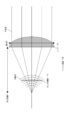
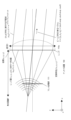
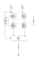
図1は、本開示の実施の形態1におけるアンテナ装置100の基本構成及び基本動作の一例を示す図である。アンテナ装置100は、レンズ110と、アレイ給電部111と、を備える。


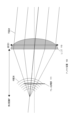
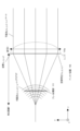
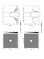
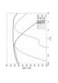
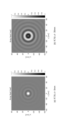
図10A及び図10Bは、2次元平面アレイにおいてアレイ給電部111の配置をレンズ110の焦点面からずらした場合の効果の一例を示す図である。この例では、レンズ110の直径Dを600mmとし、焦点距離Fを300mmとしている。
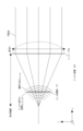
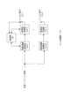
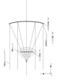
図11は、本開示の実施の形態3におけるアンテナ装置300の基本構成及び基本動作の一例を示す図である。アンテナ装置300は、実施の形態1におけるアンテナ装置100と同様の構成を有するため、同じ構成については説明を省略する。アンテナ装置300は、パラボラアンテナとして構成され、パラボラ反射鏡310と、アレイ給電部111と、を備える。
本開示の一実施例に係るアンテナ装置は、電磁波を放射する複数のアンテナ素子が配列されたアレイ給電部と、前記電磁波を屈折させるレンズと、を備え、前記アレイ給電部は、前記電磁波が前記レンズによって屈折された後に所定の方向への平面波として進行させられる複素励振振幅で前記複数のアンテナ素子を励振する。
110 レンズ
111 アレイ給電部
112 アレイ受信部
120、130 複素振幅乗算部
121、131 高周波変換部
125、135 アンテナ素子
129、139 制御部
132 加算部
310 パラボラ反射鏡
Claims (12)
- 電磁波を放射する複数のアンテナ素子が配列されたアレイ給電部と、
前記電磁波を屈折させるレンズと、
を備え、
前記アレイ給電部は、前記電磁波が前記レンズによって屈折された後に所定の方向への平面波として進行させられる複素励振振幅で前記複数のアンテナ素子を励振する、
アンテナ装置。 - 予め計算又は測定された前記レンズの変換特性又は入射面での所定の波面特性に基づいて、前記複素励振振幅を算出する制御部
をさらに備え、
前記制御部は、前記複素励振振幅で前記複数のアンテナ素子を励振するように前記アレイ給電部を制御する、
請求項1に記載のアンテナ装置。 - 前記アレイ給電部は、前記レンズの焦点面からずれた位置に配置されている、
請求項1又は2に記載のアンテナ装置。 - 複数のアンテナ素子が配列されたアレイ受信部と、
到来した電磁波を屈折させて前記アレイ受信部に照射するレンズと、
を備え、
前記アレイ受信部は、前記レンズによって屈折される前の前記電磁波が所定の方向からの平面波として前記レンズに入射させられる複素振幅で前記複数のアンテナ素子を重みづけし、前記レンズによって屈折された後の前記電磁波の波面を合成する、
アンテナ装置。 - 電磁波を放射する複数のアンテナ素子が配列されたアレイ給電部と、
前記電磁波を反射させる反射鏡と、
を備え、
前記アレイ給電部は、前記電磁波が前記反射鏡によって反射された後に所定の方向への平面波として進行させられる複素励振振幅で前記複数のアンテナ素子を励振する、
アンテナ装置。 - 複数のアンテナ素子が配列されたアレイ受信部と、
到来した電磁波を反射させて前記アレイ受信部に照射する反射鏡と、
を備え、
前記アレイ受信部は、前記反射鏡によって反射される前の前記電磁波が所定の方向からの平面波として前記反射鏡に入射させられる複素振幅で前記複数のアンテナ素子を重みづけし、前記反射鏡によって反射された後の前記電磁波の波面を合成する、
アンテナ装置。 - 複数のアンテナ素子が配列されたアレイ給電部とレンズとを備えるアンテナ装置によるビームフォーミング方法であって、
前記複数のアンテナ素子が、電磁波を放射し、
前記アレイ給電部が、前記電磁波が前記レンズによって屈折された後に所定の方向への平面波として進行させられる複素励振振幅で前記複数のアンテナ素子を励振する、
ビームフォーミング方法。 - 複数のアンテナ素子が配列されたアレイ受信部とレンズとを備えるアンテナ装置によるビームフォーミング方法であって、
前記アレイ受信部が、前記レンズによって屈折される前の到来した電磁波が所定の方向からの平面波として前記レンズに入射させられる複素振幅で前記複数のアンテナ素子を重みづけし、
前記アレイ受信部が、前記レンズによって屈折された後の前記電磁波の波面を合成する、
ビームフォーミング方法。 - 複数のアンテナ素子が配列されたアレイ給電部と反射鏡とを備えるアンテナ装置によるビームフォーミング方法であって、
前記複数のアンテナ素子が、電磁波を放射し、
前記アレイ給電部が、前記電磁波が前記反射鏡によって反射された後に所定の方向への平面波として進行させられる複素励振振幅で前記複数のアンテナ素子を励振する、
ビームフォーミング方法。 - 複数のアンテナ素子が配列されたアレイ受信部と反射鏡とを備えるアンテナ装置によるビームフォーミング方法であって、
前記アレイ受信部が、前記反射鏡によって反射される前の到来した電磁波が所定の方向からの平面波として前記反射鏡に入射させられる複素振幅で前記複数のアンテナ素子を重みづけし、
前記アレイ受信部が、前記反射鏡によって反射された後の前記電磁波の波面を合成する、
ビームフォーミング方法。 - 請求項7又は9に記載のビームフォーミング方法を実行するように前記アンテナ装置が備える制御部に前記複数のアンテナ素子及び前記アレイ給電部を制御させるためのプログラム。
- 請求項8又は10に記載のビームフォーミング方法を実行するように前記アンテナ装置が備える制御部に前記アレイ受信部を制御させるためのプログラム。
Priority Applications (2)
| Application Number | Priority Date | Filing Date | Title |
|---|---|---|---|
| JP2021209654A JP2023094271A (ja) | 2021-12-23 | 2021-12-23 | アンテナ装置、ビームフォーミング方法及びプログラム |
| US18/063,627 US20230208028A1 (en) | 2021-12-23 | 2022-12-08 | Antenna device, beamforming method, and non-transitory computer readable storage medium for performing beamforming |
Applications Claiming Priority (1)
| Application Number | Priority Date | Filing Date | Title |
|---|---|---|---|
| JP2021209654A JP2023094271A (ja) | 2021-12-23 | 2021-12-23 | アンテナ装置、ビームフォーミング方法及びプログラム |
Publications (1)
| Publication Number | Publication Date |
|---|---|
| JP2023094271A true JP2023094271A (ja) | 2023-07-05 |
Family
ID=86896193
Family Applications (1)
| Application Number | Title | Priority Date | Filing Date |
|---|---|---|---|
| JP2021209654A Pending JP2023094271A (ja) | 2021-12-23 | 2021-12-23 | アンテナ装置、ビームフォーミング方法及びプログラム |
Country Status (2)
| Country | Link |
|---|---|
| US (1) | US20230208028A1 (ja) |
| JP (1) | JP2023094271A (ja) |
-
2021
- 2021-12-23 JP JP2021209654A patent/JP2023094271A/ja active Pending
-
2022
- 2022-12-08 US US18/063,627 patent/US20230208028A1/en active Pending
Also Published As
| Publication number | Publication date |
|---|---|
| US20230208028A1 (en) | 2023-06-29 |
Similar Documents
| Publication | Publication Date | Title |
|---|---|---|
| CN110571531B (zh) | 一种基于抛物柱面反射阵的多波束相控阵天线 | |
| CN110739527B (zh) | 一种波束重构方法、天线、微波设备和网络系统 | |
| US8358249B2 (en) | Multibeam active discrete lens antenna | |
| JP3584925B2 (ja) | 宇宙太陽光発電システム | |
| CN105552556A (zh) | 轨道角动量涡旋波束产生装置及方法 | |
| CN112072309B (zh) | 一种步进补偿低成本相控阵天线架构及其设计方法 | |
| EP1764915A1 (en) | Spatially-fed high power amplifier with shaped reflectors | |
| CN106324602A (zh) | 一种mimo声呐系统 | |
| JP2007081648A (ja) | フェーズドアレイアンテナ装置 | |
| Matsumuro et al. | Basic study of both-sides retrodirective system for minimizing the leak energy in microwave power transmission | |
| JP5014193B2 (ja) | アレーアンテナの励振方法 | |
| CN115408880B (zh) | 一种交叠多波束馈源的设计方法 | |
| Rahimian | Design and Performance of a K U-Band Rotman Lens Beamforming Network for Satellite Systems | |
| JP2023094271A (ja) | アンテナ装置、ビームフォーミング方法及びプログラム | |
| Sciannella et al. | An imaging reflector system with reduced scanning aberrations | |
| CN113725627A (zh) | 一种基于反射面的超宽带多功能一体化载荷 | |
| Kim et al. | Shaped circularly symmetric dual reflector antennas by combining local conventional dual reflector systems | |
| CN112350077A (zh) | 一种超大口径平面反射阵列天线 | |
| Dubovitskiy | Practical design considerations for sparse antenna array using reflector antenna with continuously adjustable phase center displacement | |
| US10879609B1 (en) | Wave construction method for controlling, rotating, or shaping radio frequency or acoustic waves in free space or in a fluid | |
| Kehn et al. | Characterization of dense focal plane array feeds for parabolic reflectors in achieving closely overlapping or widely separated multiple beams | |
| CN115275632B (zh) | 反射面天线、波束控制方法和通信设备 | |
| RU2577827C1 (ru) | Многолучевая самофокусирующаяся антенная решетка | |
| Kumar et al. | Synthesis of a dual-band flat-top pattern using polarization dependent metasurface | |
| Sun et al. | Adaptive anti-jamming beamforming based on time-modulated programmable metasurface |
Legal Events
| Date | Code | Title | Description |
|---|---|---|---|
| A621 | Written request for application examination |
Free format text: JAPANESE INTERMEDIATE CODE: A621 Effective date: 20240927 |
|
| A977 | Report on retrieval |
Free format text: JAPANESE INTERMEDIATE CODE: A971007 Effective date: 20250530 |
|
| A131 | Notification of reasons for refusal |
Free format text: JAPANESE INTERMEDIATE CODE: A131 Effective date: 20250701 |
|
| A521 | Request for written amendment filed |
Free format text: JAPANESE INTERMEDIATE CODE: A523 Effective date: 20250801 |
|
| A131 | Notification of reasons for refusal |
Free format text: JAPANESE INTERMEDIATE CODE: A131 Effective date: 20251125 |
|
| A521 | Request for written amendment filed |
Free format text: JAPANESE INTERMEDIATE CODE: A523 Effective date: 20260105 |