JP2023094271A - Antenna device, beam forming method and program - Google Patents
Antenna device, beam forming method and program Download PDFInfo
- Publication number
- JP2023094271A JP2023094271A JP2021209654A JP2021209654A JP2023094271A JP 2023094271 A JP2023094271 A JP 2023094271A JP 2021209654 A JP2021209654 A JP 2021209654A JP 2021209654 A JP2021209654 A JP 2021209654A JP 2023094271 A JP2023094271 A JP 2023094271A
- Authority
- JP
- Japan
- Prior art keywords
- array
- lens
- antenna elements
- antenna
- antenna device
- Prior art date
- Legal status (The legal status is an assumption and is not a legal conclusion. Google has not performed a legal analysis and makes no representation as to the accuracy of the status listed.)
- Pending
Links
Images

Classifications
-
- H—ELECTRICITY
- H01—ELECTRIC ELEMENTS
- H01Q—ANTENNAS, i.e. RADIO AERIALS
- H01Q19/00—Combinations of primary active antenna elements and units with secondary devices, e.g. with quasi-optical devices, for giving the antenna a desired directional characteristic
- H01Q19/06—Combinations of primary active antenna elements and units with secondary devices, e.g. with quasi-optical devices, for giving the antenna a desired directional characteristic using refracting or diffracting devices, e.g. lens
- H01Q19/062—Combinations of primary active antenna elements and units with secondary devices, e.g. with quasi-optical devices, for giving the antenna a desired directional characteristic using refracting or diffracting devices, e.g. lens for focusing
-
- H—ELECTRICITY
- H01—ELECTRIC ELEMENTS
- H01Q—ANTENNAS, i.e. RADIO AERIALS
- H01Q3/00—Arrangements for changing or varying the orientation or the shape of the directional pattern of the waves radiated from an antenna or antenna system
- H01Q3/26—Arrangements for changing or varying the orientation or the shape of the directional pattern of the waves radiated from an antenna or antenna system varying the relative phase or relative amplitude of energisation between two or more active radiating elements; varying the distribution of energy across a radiating aperture
- H01Q3/28—Arrangements for changing or varying the orientation or the shape of the directional pattern of the waves radiated from an antenna or antenna system varying the relative phase or relative amplitude of energisation between two or more active radiating elements; varying the distribution of energy across a radiating aperture varying the amplitude
-
- H—ELECTRICITY
- H01—ELECTRIC ELEMENTS
- H01Q—ANTENNAS, i.e. RADIO AERIALS
- H01Q19/00—Combinations of primary active antenna elements and units with secondary devices, e.g. with quasi-optical devices, for giving the antenna a desired directional characteristic
- H01Q19/06—Combinations of primary active antenna elements and units with secondary devices, e.g. with quasi-optical devices, for giving the antenna a desired directional characteristic using refracting or diffracting devices, e.g. lens
-
- H—ELECTRICITY
- H01—ELECTRIC ELEMENTS
- H01Q—ANTENNAS, i.e. RADIO AERIALS
- H01Q19/00—Combinations of primary active antenna elements and units with secondary devices, e.g. with quasi-optical devices, for giving the antenna a desired directional characteristic
- H01Q19/10—Combinations of primary active antenna elements and units with secondary devices, e.g. with quasi-optical devices, for giving the antenna a desired directional characteristic using reflecting surfaces
- H01Q19/12—Combinations of primary active antenna elements and units with secondary devices, e.g. with quasi-optical devices, for giving the antenna a desired directional characteristic using reflecting surfaces wherein the surfaces are concave
- H01Q19/17—Combinations of primary active antenna elements and units with secondary devices, e.g. with quasi-optical devices, for giving the antenna a desired directional characteristic using reflecting surfaces wherein the surfaces are concave the primary radiating source comprising two or more radiating elements
-
- H—ELECTRICITY
- H01—ELECTRIC ELEMENTS
- H01Q—ANTENNAS, i.e. RADIO AERIALS
- H01Q25/00—Antennas or antenna systems providing at least two radiating patterns
- H01Q25/007—Antennas or antenna systems providing at least two radiating patterns using two or more primary active elements in the focal region of a focusing device
-
- H—ELECTRICITY
- H01—ELECTRIC ELEMENTS
- H01Q—ANTENNAS, i.e. RADIO AERIALS
- H01Q3/00—Arrangements for changing or varying the orientation or the shape of the directional pattern of the waves radiated from an antenna or antenna system
- H01Q3/26—Arrangements for changing or varying the orientation or the shape of the directional pattern of the waves radiated from an antenna or antenna system varying the relative phase or relative amplitude of energisation between two or more active radiating elements; varying the distribution of energy across a radiating aperture
- H01Q3/2658—Phased-array fed focussing structure
-
- H—ELECTRICITY
- H01—ELECTRIC ELEMENTS
- H01Q—ANTENNAS, i.e. RADIO AERIALS
- H01Q15/00—Devices for reflection, refraction, diffraction or polarisation of waves radiated from an antenna, e.g. quasi-optical devices
- H01Q15/02—Refracting or diffracting devices, e.g. lens, prism
- H01Q15/08—Refracting or diffracting devices, e.g. lens, prism formed of solid dielectric material
-
- H—ELECTRICITY
- H01—ELECTRIC ELEMENTS
- H01Q—ANTENNAS, i.e. RADIO AERIALS
- H01Q21/00—Antenna arrays or systems
- H01Q21/06—Arrays of individually energised antenna units similarly polarised and spaced apart
- H01Q21/061—Two dimensional planar arrays
Landscapes
- Aerials With Secondary Devices (AREA)
- Variable-Direction Aerials And Aerial Arrays (AREA)
Abstract
Description
本開示は、アンテナ装置、ビームフォーミング方法及びプログラムに関し、より詳細には、ビームフォーミングを実行するためのアンテナ装置、ビームフォーミング方法及びプログラムに関する。 TECHNICAL FIELD The present disclosure relates to an antenna device, beamforming method and program, and more particularly to an antenna device, beamforming method and program for performing beamforming.
高高度プラットフォーム(HAPS:High-Altitude Platform Station)の事業化に向けて国際的に環境整備及び技術開発が進み、その普及拡大が見込まれている。特にHAPSを利用した固定通信システムに対しては、上空経由にてバックホール回線の冗長経路確保実現等への期待が高まっている。WRC-19(2019年世界無線通信会議)にてHAPSに分配された38GHz帯による5G網と連携した高速大容量のHAPSシステムの実現が期待される(例えば、非特許文献1)。HAPSは、高度20km付近の成層圏で円周上を周回して飛行するため、地上局の方向にビーム(放射指向特性)が向くように、ビームフォーミングを行って追尾する必要がある。一方、地上局もHAPSの方向にビームが向くように、ビームフォーミングを行って追尾する必要がある。 International efforts are being made to improve the environment and develop technologies for the commercialization of High-Altitude Platform Stations (HAPS), and their spread is expected to expand. In particular, for fixed communication systems using HAPS, expectations are rising for realization of securing redundant routes for backhaul lines via the sky. At WRC-19 (World Radiocommunication Conference 2019), realization of a high-speed, large-capacity HAPS system that cooperates with a 5G network based on the 38 GHz band distributed to HAPS is expected (for example, Non-Patent Document 1). Since HAPS flies in a circle in the stratosphere at an altitude of about 20 km, it is necessary to perform beamforming and track so that the beam (radiation directivity) is directed toward the ground station. On the other hand, the ground station also needs to perform beamforming and track so that the beam is directed toward the HAPS.
地上局に用いるアンテナ装置には開口面アンテナやフェーズドアレイアンテナ等が考えられる。開口面アンテナは、導波路を用いたホーンアンテナ、反射を用いたパラボラアンテナ、屈折を用いたレンズアンテナ等に大別される。開口面アンテナは、大きな開口面を形成して高利得アンテナを構成することが容易であるが、HAPSを追尾するためにアンテナ装置の向きを常に機械的に駆動する必要があり、駆動のための消費電力が大きいという課題を有する。一方で、フェーズドアレイアンテナは、アンテナ素子の励振位相を制御することでビームの方向を制御してHAPSを追尾することが容易であるが、開口面を大きくして高利得アンテナを構成するためには多数のアンテナ素子が必要になるという課題を有する。 Aperture antennas, phased array antennas, and the like are conceivable for antenna devices used in ground stations. Aperture antennas are roughly classified into horn antennas using waveguides, parabolic antennas using reflection, and lens antennas using refraction. Aperture antennas are easy to construct as high-gain antennas by forming a large aperture. It has a problem of high power consumption. On the other hand, in the phased array antenna, it is easy to control the direction of the beam and track the HAPS by controlling the excitation phase of the antenna elements. has the problem of requiring a large number of antenna elements.
非特許文献2では、レンズアンテナと電子制御可能なアレイ給電部とを組み合わせ、更に全体を機械駆動ジンバルで制御する方式を採用し、他の無線との干渉を軽減するためのサイドローブの抑制と追尾制御の際の消費電力の低減とを図っている。
In
特許文献1には、OAM(Orbital Angular Momentum)の各モードに対して各々円形アレイを具備し、レンズと組み合わせることで、各モードの最大利得の放射角が同じになるようにするアンテナ装置が開示されている。
特許文献2には、アレイ状に配置された複数のレンズセットを具備し、各レンズセットが1つのレンズと複数の給電素子とを組み合わせる構成をとるアンテナシステムが開示されている。各レンズセットにおいて、給電素子毎にビームが異なり、アンテナシステムは、どの給電素子に給電するかにより粗いビーム制御を行う。また、アンテナシステムは、複数のレンズセットの給電素子に給電する信号を各々制御することにより、精密なビーム制御を行う。
特許文献3には、静止衛星に搭載されるパラボラアンテナに関して、降雨減衰時等において特定地域の放射利得を変更するための設計及び製造フローが示されている。パラボラアンテナと組み合わせるアレイ給電部の励振振幅や位相の変更で特定地域の放射利得変更が可能なように、パラボラアンテナ及びアレイ給電部を設計して製造を行う。製造後運用時に、降雨減衰時等において特定地域の放射利得を変更する際に、指示される各アレイ素子に対する励振振幅値及び/又は励振位相値に基づき、特定地域の放射利得を変更する。 Patent Literature 3 shows a design and manufacturing flow for changing the radiation gain in a specific area during rain attenuation or the like for a parabolic antenna mounted on a geostationary satellite. We design and manufacture a parabolic antenna and an array feeder so that the radiation gain of a specific area can be changed by changing the excitation amplitude and phase of the array feeder combined with the parabolic antenna. When changing the radiation gain in the specific area during rainfall attenuation or the like during post-manufacturing operation, the radiation gain in the specific area is changed based on the indicated excitation amplitude value and/or excitation phase value for each array element.
しかしながら、前述の従来技術では、これらの組み合わせにおいて、アンテナ装置(レンズアンテナ又はパラボラアンテナ及びアレイ給電部)の設計自由度を向上させる波面の生成方法について示されていないという点で、改善の余地がある。 However, in the above-described prior art, there is room for improvement in that there is no method for generating a wavefront that improves the degree of freedom in designing an antenna device (a lens antenna or a parabolic antenna and an array feeding section) in these combinations. be.
本開示の非限定的な実施例は、レンズアンテナ又はパラボラアンテナとアレイ給電部又はアレイ受信部との組み合わせにおいて、アレイ給電部が生成する波面又はアレイ受信部が合成する波面の設計自由度を向上させることができるアンテナ装置及びビームフォーミング方法の提供に資する。 Non-limiting embodiments of the present disclosure improve design flexibility of the wavefront generated by the array feed or the wavefront synthesized by the array receiver in the combination of the lens antenna or parabolic antenna and the array feed or array receiver. It contributes to the provision of an antenna device and a beam forming method that can
本開示の一実施例に係るアンテナ装置は、電磁波を放射する複数のアンテナ素子が配列されたアレイ給電部と、前記電磁波を屈折させるレンズと、を備え、前記アレイ給電部は、前記電磁波が前記レンズによって屈折された後に所定の方向への平面波として進行させられる複素励振振幅で前記複数のアンテナ素子を励振する。 An antenna device according to an embodiment of the present disclosure includes an array feeding section in which a plurality of antenna elements that radiate electromagnetic waves are arranged, and a lens that refracts the electromagnetic waves, and the array feeding section is arranged such that the electromagnetic waves Excite the plurality of antenna elements with a complex excitation amplitude that is refracted by a lens and then propagated as a plane wave in a predetermined direction.
本開示の一実施例に係るアンテナ装置は、複数のアンテナ素子が配列されたアレイ受信部と、到来した電磁波を屈折させて前記アレイ受信部に照射するレンズと、を備え、前記アレイ受信部は、前記レンズによって屈折される前の前記電磁波が所定の方向からの平面波として前記レンズに入射させられる複素振幅で前記複数のアンテナ素子を重みづけし、前記レンズによって屈折された後の前記電磁波の波面を合成する。 An antenna device according to an embodiment of the present disclosure includes an array receiver in which a plurality of antenna elements are arranged, and a lens that refracts incoming electromagnetic waves and irradiates them to the array receiver, wherein the array receiver includes weighting the plurality of antenna elements with a complex amplitude with which the electromagnetic wave before being refracted by the lens is incident on the lens as a plane wave from a predetermined direction, and wavefront of the electromagnetic wave after being refracted by the lens; to synthesize.
本開示の一実施例に係るアンテナ装置は、電磁波を放射する複数のアンテナ素子が配列されたアレイ給電部と、前記電磁波を反射させる反射鏡と、を備え、前記アレイ給電部は、前記電磁波が前記反射鏡によって反射された後に所定の方向への平面波として進行させられる複素励振振幅で前記複数のアンテナ素子を励振する。 An antenna device according to an embodiment of the present disclosure includes an array feeding section in which a plurality of antenna elements that radiate electromagnetic waves are arranged, and a reflector that reflects the electromagnetic waves, and the array feeding section includes: The plurality of antenna elements are excited with a complex excitation amplitude which is propagated as a plane wave in a predetermined direction after being reflected by the reflecting mirror.
本開示の一実施例に係るアンテナ装置は、複数のアンテナ素子が配列されたアレイ受信部と、到来した電磁波を反射させて前記アレイ受信部に照射する反射鏡と、を備え、前記アレイ受信部は、前記反射鏡によって反射される前の前記電磁波が所定の方向からの平面波として前記反射鏡に入射させられる複素振幅で前記複数のアンテナ素子を重みづけし、前記反射鏡によって反射された後の前記電磁波の波面を合成する。 An antenna device according to an embodiment of the present disclosure includes an array reception unit in which a plurality of antenna elements are arranged, and a reflector that reflects incoming electromagnetic waves to irradiate the array reception unit, and the array reception unit weights the plurality of antenna elements with a complex amplitude at which the electromagnetic wave before being reflected by the reflecting mirror is made incident on the reflecting mirror as a plane wave from a predetermined direction, and after being reflected by the reflecting mirror The wavefronts of the electromagnetic waves are synthesized.
本開示の一実施例に係るビームフォーミング方法は、複数のアンテナ素子が配列されたアレイ給電部とレンズとを備えるアンテナ装置によるビームフォーミング方法であって、前記複数のアンテナ素子が、電磁波を放射し、前記アレイ給電部が、前記電磁波が前記レンズによって屈折された後に所定の方向への平面波として進行させられる複素励振振幅で前記複数のアンテナ素子を励振する。 A beamforming method according to an embodiment of the present disclosure is a beamforming method using an antenna device including an array feeding unit in which a plurality of antenna elements are arranged, and a lens, wherein the plurality of antenna elements radiate electromagnetic waves. , the array feeding section excites the plurality of antenna elements with a complex excitation amplitude that causes the electromagnetic wave to travel as a plane wave in a predetermined direction after being refracted by the lens.
本開示の一実施例に係るビームフォーミング方法は、複数のアンテナ素子が配列されたアレイ受信部とレンズとを備えるアンテナ装置によるビームフォーミング方法であって、前記アレイ受信部が、前記レンズによって屈折される前の到来した電磁波が所定の方向からの平面波として前記レンズに入射させられる複素振幅で前記複数のアンテナ素子を重みづけし、前記アレイ受信部が、前記レンズによって屈折された後の前記電磁波の波面を合成する。 A beamforming method according to an embodiment of the present disclosure is a beamforming method using an antenna device that includes an array receiver in which a plurality of antenna elements are arranged and a lens, wherein the array receiver is refracted by the lens. weighting the plurality of antenna elements with a complex amplitude of an electromagnetic wave that arrived before being incident on the lens as a plane wave from a predetermined direction; Synthesize the wavefront.
本開示の一実施例に係るビームフォーミング方法は、複数のアンテナ素子が配列されたアレイ給電部と反射鏡とを備えるアンテナ装置によるビームフォーミング方法であって、前記複数のアンテナ素子が、電磁波を放射し、前記アレイ給電部が、前記電磁波が前記反射鏡によって反射された後に所定の方向への平面波として進行させられる複素励振振幅で前記複数のアンテナ素子を励振する。 A beamforming method according to an embodiment of the present disclosure is a beamforming method using an antenna device including an array feeding unit in which a plurality of antenna elements are arranged and a reflector, wherein the plurality of antenna elements radiate electromagnetic waves. The array feeding section excites the plurality of antenna elements with a complex excitation amplitude that causes the electromagnetic wave to travel as a plane wave in a predetermined direction after being reflected by the reflecting mirror.
本開示の一実施例に係るビームフォーミング方法は、複数のアンテナ素子が配列されたアレイ受信部と反射鏡とを備えるアンテナ装置によるビームフォーミング方法であって、前記アレイ受信部が、前記反射鏡によって反射される前の到来した電磁波が所定の方向からの平面波として前記反射鏡に入射させられる複素振幅で前記複数のアンテナ素子を重みづけし、前記アレイ受信部が、前記反射鏡によって反射された後の前記電磁波の波面を合成する。 A beamforming method according to an embodiment of the present disclosure is a beamforming method using an antenna device that includes an array receiver in which a plurality of antenna elements are arranged, and a reflector, wherein the array receiver is configured by the reflector. The plurality of antenna elements are weighted by a complex amplitude with which an electromagnetic wave that arrives before being reflected is made incident on the reflecting mirror as a plane wave from a predetermined direction, and the array receiving section receives the signal after being reflected by the reflecting mirror. to synthesize the wavefronts of the electromagnetic waves of
なお、これらの包括的または具体的な態様は、システム、装置、方法、集積回路、コンピュータープログラム、または、記録媒体で実現されてもよく、システム、装置、方法、集積回路、コンピュータープログラムおよび記録媒体の任意な組み合わせで実現されてもよい。 In addition, these general or specific aspects may be realized by systems, devices, methods, integrated circuits, computer programs, or recording media. may be realized by any combination of
本開示の一実施例によれば、アレイ給電部は、電磁波がレンズによって屈折された後に所定の方向への平面波として進行させられる複素励振振幅で複数のアンテナ素子を励振する。これにより、放射される電力がレンズ内に収まるようにビーム整形(ビーム形成と称されてもよい)を行い、開口効率の向上及びレンズ外への放射の抑圧が可能となり、レンズとアレイ給電部との組み合わせにおいて、アレイ給電部が生成する波面の設計自由度を向上させることができる。 According to one embodiment of the present disclosure, an array feed excites a plurality of antenna elements with a complex excitation amplitude such that an electromagnetic wave travels as a plane wave in a predetermined direction after being refracted by a lens. As a result, beam shaping (also referred to as beam forming) is performed so that the radiated power is contained within the lens, and it is possible to improve aperture efficiency and suppress radiation outside the lens. , the degree of freedom in designing the wavefront generated by the array feed can be improved.
本開示の一実施例における更なる利点および効果は、明細書および図面から明らかにされる。かかる利点および/または効果は、いくつかの実施形態並びに明細書および図面に記載された特徴によってそれぞれ提供されるが、1つまたはそれ以上の同一の特徴を得るために必ずしも全てが提供される必要はない。 Further advantages and advantages of an embodiment of the disclosure are apparent from the specification and drawings. Such advantages and/or advantages are provided by the several embodiments and features described in the specification and drawings, respectively, not necessarily all provided to obtain one or more of the same features. no.
以下、図面を適宜参照して、本開示の実施の形態について、詳細に説明する。但し、必要以上に詳細な説明は省略する場合がある。例えば、既によく知られた事項の詳細説明や実質的に同一の構成に対する重複説明を省略する場合がある。これは、以下の説明が不必要に冗長になるのを避け、当業者の理解を容易にするためである。 Hereinafter, embodiments of the present disclosure will be described in detail with reference to the drawings as appropriate. However, more detailed description than necessary may be omitted. For example, detailed descriptions of well-known matters and redundant descriptions of substantially the same configurations may be omitted. This is to avoid unnecessary verbosity in the following description and to facilitate understanding by those skilled in the art.
なお、添付図面および以下の説明は、当業者が本開示を十分に理解するために、提供されるのであって、これらにより特許請求の範囲に記載の主題を限定することは意図されていない。 It should be noted that the accompanying drawings and the following description are provided for a thorough understanding of the present disclosure by those skilled in the art and are not intended to limit the claimed subject matter.
(実施の形態1)
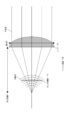
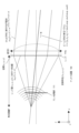
図1は、本開示の実施の形態1におけるアンテナ装置100の基本構成及び基本動作の一例を示す図である。アンテナ装置100は、レンズ110と、アレイ給電部111と、を備える。
(Embodiment 1)
FIG. 1 is a diagram showing an example of the basic configuration and basic operation of an antenna device 100 according to
レンズ110は、アレイ給電部111によって放射された電磁波を屈折させる。
アレイ給電部111は、電磁波を放射する2次元に配列されたアンテナ素子を含み、送信ビームを生成して(レンズ110に向けて)放射する。 Array feeding section 111 includes two-dimensionally arranged antenna elements that radiate electromagnetic waves, and generates and radiates transmission beams (toward lens 110).
図1に示すように、アレイ給電部111の基本動作は、例えば、レンズ110の仮想的な放射位置から放射される波面を生成し、放射される電力がレンズ110内に収まるようにビーム整形を行うことである。
As shown in FIG. 1, the basic operation of the array feed section 111 is to generate a wavefront radiated from, for example, a virtual radiation position of the
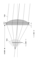
図2は、実施の形態1におけるアンテナ装置100におけるアレイ給電部111のビームシフト方法を示す図である。 FIG. 2 is a diagram showing a beam shifting method of array feeding section 111 in antenna device 100 according to the first embodiment.
アレイ給電部111は、アレイ給電部111が備える制御部(例えば、後述する制御部129)が、アンテナ素子の励振位相を制御することによって、図2に示すように放射位置を仮想的にシフトした波面を生成し、放射される電力がレンズ110内に収まるようにビーム整形を行い、これにより、ビームシフトを実現する。
The array feeding section 111 virtually shifts the radiation position as shown in FIG. A wavefront is generated and beam shaping is performed so that the radiated power is contained within the
以降、アンテナ装置100の動作原理を説明するために、まず理想的なレンズの集光特性を仮定して、アレイ給電部111の励振振幅について説明する。次いで、一般的なレンズ特性について説明する。ここで、理想的な集光特性とは、焦点から放射された球面波がレンズを通過することで平面波に変換される位相変換特性を指す。また、レンズは、厚みがない円形の平面とし、レンズの通過損失はないものとする。 Hereinafter, in order to explain the principle of operation of the antenna device 100, first, the excitation amplitude of the array feeding section 111 will be explained assuming ideal light condensing characteristics of the lens. Next, general lens characteristics will be described. Here, the ideal condensing characteristic refers to a phase conversion characteristic in which a spherical wave emitted from a focal point passes through a lens and is converted into a plane wave. Also, the lens is assumed to be a circular flat surface with no thickness, and the lens has no transmission loss.
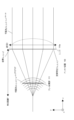
図3は、アンテナ装置100において理想的なレンズの集光特性を仮定した場合のアンテナ装置100の基本動作の詳細の一例を示す図である。 FIG. 3 is a diagram showing an example of the details of the basic operation of the antenna device 100 assuming ideal condensing characteristics of the lens in the antenna device 100. As shown in FIG.
図3において、理想的な集光特性を有するレンズは、レンズ110aとして示されている。図3に示すように、直交座標系においてレンズ110aの焦点を原点とし、レンズ110aの主軸をz軸とし、レンズ面をx-y平面に対して平行に配置する。レンズの直径をDとし、焦点距離をFとすると、レンズ面の座標(xl,yl,zl)は、式(1)のように表される。

レンズ110aは、焦点から放射された球面波s(x,y,z)を屈折させてz軸方向に進行する平面波p(x,y,z)に変換する。球面波s(x,y,z)及び平面波p(x,y,z)は各々、式(2)及び式(3)のように表される。


レンズ面(xl,yl,zl)におけるレンズの変換特性f(xl,yl,zl)は、式(4)のように表される。


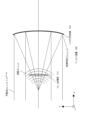
図4は、アンテナ装置100におけるアレイ給電部111の励振振幅を説明するための図である。 FIG. 4 is a diagram for explaining the excitation amplitude of array feeding section 111 in antenna apparatus 100. As shown in FIG.
アレイ給電部111として、例えば、上述したように、アンテナ素子を2次元に等間隔に配置した平面アレイアンテナが用いられてよい。1つのアンテナ素子から放射される電磁波の電界E(r,θ,φ)は、球面座標を用いて式(6)のように表される。


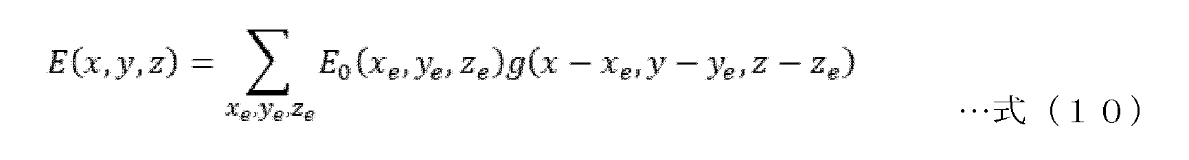
位置(xe,ye,ze)におけるアンテナ素子の複素励振振幅をE0(xe,ye,ze)とする。アレイ給電部111から放射される電磁波の位置(x,y,z)における電界E(x,y,z)は、全アンテナ素子から放射された電磁波の電界の和として、式(10)のように表される。

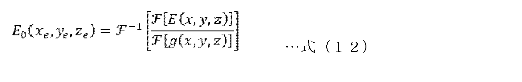
アレイ給電によって所望の電界分布E(x,y,z)を得たい場合、アレイ給電部111は、式(12)に従って各アンテナ素子のE0(xe,ye,ze)を求めて(別言すれば、決定して又は算出して)、求められたE0(xe,ye,ze)で各アンテナ素子を励振すればよい。

なお、上記で説明した演算は、アレイ給電部111が備える制御部(例えば、後述する制御部129)によって行われてもよいし、別の機能部によって行われてもよい。 Note that the calculation described above may be performed by a control unit provided in the array power supply unit 111 (for example, a control unit 129 to be described later), or may be performed by another function unit.
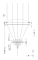
図5は、アンテナ装置100においてアレイ給電部111がビームシフトを行うための波面整形を説明するための図である。 FIG. 5 is a diagram for explaining wavefront shaping for beam shifting by the array feeding section 111 in the antenna device 100 .
図5に示すように、レンズ110aから放射される平面波(ビーム)を(θ,φ)方向にビームフォーミングする場合を考える。ビーム方向の単位ベクトルを式(14)のように表すと、式(15)で示される座標ベクトルを用いて、(θ,φ)方向に進行する平面波は、式(16)又は式(17)のように表すことができる。
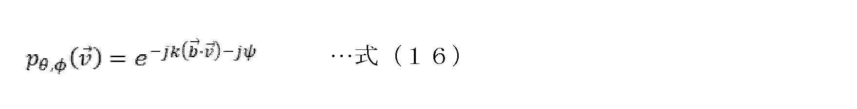
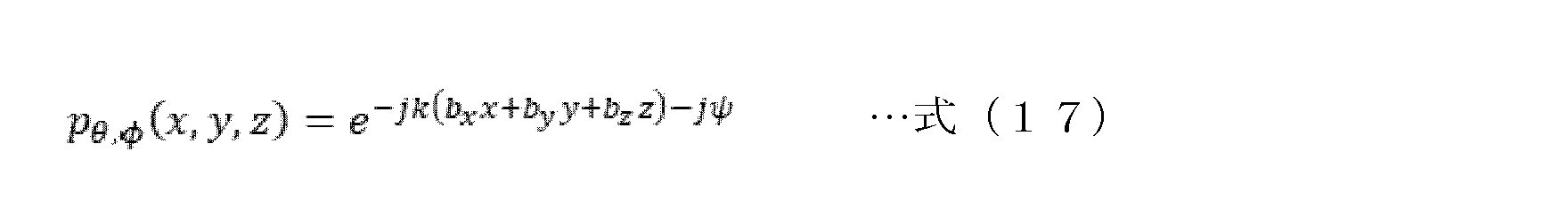
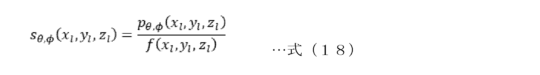
レンズ面(xl,yl,zl)において、(θ,φ)方向に進行する平面波pθ,φ(xl,yl,zl)を放射するためには、レンズに対して式(18)のように表される波面sθ,φ(xl,yl,zl)を入射すればよい。
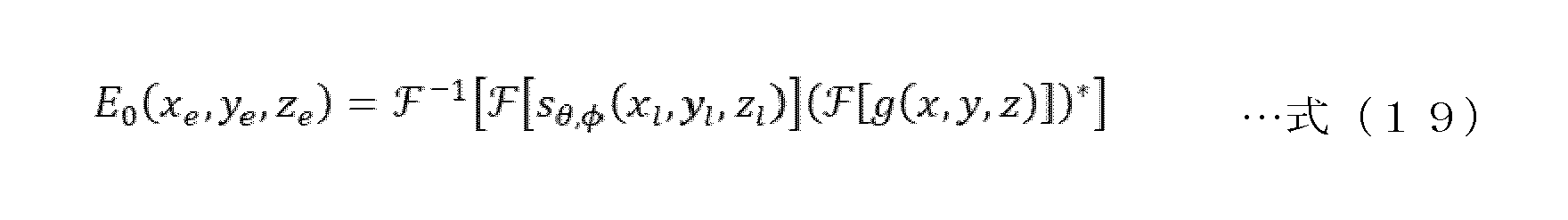
入射波面sθ,φ(xl,yl,zl)を得るためには、アレイ給電部111は、式(19)で得られる複素励振振幅E0(xe,ye,ze)で各アンテナ素子を励振すればよい。但し、式(19)で得られる励振振幅E0(xe,ye,ze)は、アンテナ素子間の相対的な値であるため、全アンテナ素子の送信電力の総和が所定の送信電力になるように各アンテナ素子の送信電力を正規化することが望ましい。
上記は、理想的なレンズ110aの集光特性を仮定した場合のアンテナ装置100の基本動作の詳細の一例である。収差や厚みがある一般的なレンズ110の場合は、レンズの変換特性f(xl,yl,zl)を予め計算又は測定しておくか、レンズ110の入射面付近の入射平面(xl,yl,zl)での所望の波面特性sθ,φ(xl,yl,zl)を予め計算又は測定しておく等の手順によって、対応する複素励振振幅E0(xe,ye,ze)を求めることができる。
The above is an example of the details of the basic operation of the antenna device 100 assuming the ideal condensing characteristics of the lens 110a. In the case of a
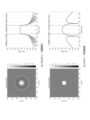
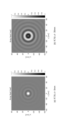
図6は、2次元平面アレイ(アレイ給電部111)における波面整形の開口効率に対する効果の一例を示す図である。この例では、レンズの直径Dを600mmとし、焦点距離Fを750mmとしている。 FIG. 6 is a diagram showing an example of the effect of wavefront shaping on aperture efficiency in a two-dimensional planar array (array feeding section 111). In this example, the lens diameter D is 600 mm and the focal length F is 750 mm.
図6(a)は、32x32素子の2次元平面アレイに対して上記の波面整形を行った場合を示しており、図6(b)は、4x4素子の平面アレイに対して上記の波面整形を行わず等位相かつ等振幅で励振した場合を示している。 FIG. 6(a) shows a case where the above wavefront shaping is performed on a two-dimensional planar array of 32×32 elements, and FIG. 6(b) shows a case where the above wavefront shaping is performed on a planar array of 4×4 elements. It shows the case where excitation is performed with equal phase and equal amplitude without excitation.
図6の左側は各々、複素励振振幅の実数部の振幅値を表している。図6の右側は各々、放射特性を表しており、±20°付近の破線は、レンズ径の両端の位置を表している。上記の波面整形を行うことにより、レンズ径内の利得が高く、平坦であるため開口効率が向上し、アンテナ利得が向上することが分かる。また、上記の波面整形を行うことにより、レンズ外への不要な放射が抑圧されるが分かる。 The left side of FIG. 6 each represents the amplitude value of the real part of the complex excitation amplitude. The right side of FIG. 6 shows the radiation characteristics, and the dashed lines near ±20° show the positions of both ends of the lens diameter. It can be seen that by performing the above-described wavefront shaping, the gain within the lens diameter is high, the aperture efficiency is improved due to the flatness, and the antenna gain is improved. Moreover, it can be seen that unnecessary radiation to the outside of the lens is suppressed by performing the above-described wavefront shaping.
以上により、レンズ110とアレイ給電部111との組み合わせにおいて、アレイ給電部111の複数のアンテナ素子を励振する複素励振振幅を適切に制御することで、レンズの変換特性に応じて所望のビーム形状を得ることができ、ビームフォーミングによる追尾が可能となる。さらに、アンテナ利得を向上させ、不要な放射を抑圧することができる。
As described above, in the combination of the
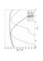
図7は、2次元平面アレイ(アレイ給電部111)における波面整形のF/D比(焦点距離/直径)の自由度向上に対する効果の一例を示す図である。 FIG. 7 is a diagram showing an example of the effect of improving the degree of freedom of F/D ratio (focal length/diameter) of wavefront shaping in a two-dimensional planar array (array feeding section 111).
図示するように、波面整形を行わず等位相かつ等振幅で励振した場合には、大きな利得が得られるF/D比の範囲が狭く、その範囲は、アンテナ素子数により異なる。一方、波面整形を行った場合には、大きな利得が得られる範囲が広く、F/D比が小さい領域(すなわちアンテナ装置100の小型化が可能)で高い利得を維持することが可能であり、特にアンテナ素子数が多い場合(32x32素子の場合)は、F/D比が大きい領域においても高い利得を維持することが可能である。以上より、波面整形によりF/D比の自由度向上が可能であることが分かる。 As shown in the figure, when excitation is performed with equal phase and equal amplitude without wavefront shaping, the F/D ratio range in which a large gain can be obtained is narrow, and the range varies depending on the number of antenna elements. On the other hand, when wavefront shaping is performed, the range in which a large gain is obtained is wide, and a high gain can be maintained in a region where the F/D ratio is small (that is, the size of the antenna device 100 can be reduced), Especially when the number of antenna elements is large (32×32 elements), it is possible to maintain a high gain even in a region where the F/D ratio is large. From the above, it can be seen that the degree of freedom of the F/D ratio can be improved by wavefront shaping.
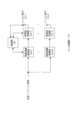
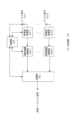
図8は、アレイ給電部111の構成の一例を示す図である。アレイ給電部111は、N個の複素振幅乗算部120-1~120-Nと、N個の高周波変換部121-1~121-Nと、N個のアンテナ素子125-1~125-Nと、制御部129と、を備える。複素振幅乗算部120-1~120-Nは各々、複素振幅励振部120-1~120-Nと称されてもよい。 FIG. 8 is a diagram showing an example of the configuration of the array feeding section 111. As shown in FIG. Array feeding section 111 includes N complex amplitude multiplication sections 120-1 to 120-N, N high frequency conversion sections 121-1 to 121-N, and N antenna elements 125-1 to 125-N. , and a control unit 129 . Complex amplitude multipliers 120-1 through 120-N may be referred to as complex amplitude excitation units 120-1 through 120-N, respectively.
N個の複素振幅乗算部120-1~120-Nは各々、レンズ面(xl,yl,zl)において、(θ,φ)方向に進行する平面波pθ,φ(xl,yl,zl)を放射するように、送信ベースバンド信号に複素励振振幅E0(xe,ye,ze)を乗算して(すなわち、複素励振振幅E0(xe,ye,ze)で送信ベースバンド信号を励振して)N個の高周波変換部121-1~121-Nに出力する。 N complex amplitude multipliers 120-1 to 120-N generate plane waves p θ, φ ( x l , y l , z l ) by multiplying the transmitted baseband signal by the complex excitation amplitude E 0 (x e , y e , ze ) (i.e., the complex excitation amplitude E 0 (x e , y e , The transmission baseband signal is excited by z e ) and output to N high-frequency converters 121-1 to 121-N.
N個の高周波変換部121-1~121-Nは各々、N個の複素振幅乗算部120-1~120-Nから入力された励振された送信ベースバンド信号を、送信する高周波信号に変換してN個のアンテナ素子125-1~125-Nに出力する。 The N high-frequency converters 121-1 to 121-N respectively convert the excited transmission baseband signals input from the N complex amplitude multipliers 120-1 to 120-N into high-frequency signals to be transmitted. are output to N antenna elements 125-1 to 125-N.
制御部129は、アレイ給電部111の処理全般を制御する。例えば、制御部129は、上述した処理を実行するように、N個の複素振幅乗算部120-1~120-N、N個の高周波変換部121-1~121-N及びN個のアンテナ素子125-1~125-Nを制御する。例えば、制御部129は、記憶部(例えばメモリ;図示せず)に記憶されたプログラムを実行することによって、上述した処理を実行するように、N個の複素振幅乗算部120-1~120-N、N個の高周波変換部121-1~121-N及びN個のアンテナ素子125-1~125-Nを制御してもよい。別言すれば、このようなプログラムは、本開示に係るビームフォーミング方法を実行するように、制御部129に、N個のアンテナ素子135-1~135-Nを備えるアレイ給電部111を制御させてもよい。また、制御部129は、上述したように、各アンテナ素子の複素励振振幅E0(xe,ye,ze)を算出してもよい。 The control unit 129 controls overall processing of the array power supply unit 111 . For example, the control unit 129 may include N complex amplitude multiplication units 120-1 to 120-N, N high frequency conversion units 121-1 to 121-N, and N antenna elements so as to execute the above-described processing. 125-1 to 125-N. For example, the control unit 129 executes a program stored in a storage unit (for example, memory; not shown) so as to perform the above-described processing so that the N complex amplitude multipliers 120-1 to 120- N, N high frequency converters 121-1 to 121-N and N antenna elements 125-1 to 125-N may be controlled. In other words, such a program causes the control unit 129 to control the array feed unit 111 comprising N antenna elements 135-1 to 135-N so as to perform the beamforming method according to the present disclosure. may Also, the control unit 129 may calculate the complex excitation amplitude E 0 (x e , y e , ze ) of each antenna element as described above.
このようにして、アレイ給電部111は、レンズ110で屈折された後の電磁波の放射特性が所望のビーム形状になるようにレンズ110へ入射する電磁波の波面を制御する。具体的には、アレイ給電部111は、電磁波がレンズ110によって屈折された後に平面波pθ,φ(xl,yl,zl)として所定の方向への平面波として進行させられる複素励振振幅E0(xe,ye,ze)でN個のアンテナ素子125-1~125-Nを励振する。
In this manner, the array feeding section 111 controls the wavefront of the electromagnetic wave incident on the
以上の構成により、レンズ110とアレイ給電部111との組み合わせにおいて、アレイ給電部111が生成する波面の設計自由度を向上させることを可能にするアンテナ装置100を提供することができる。
With the configuration described above, it is possible to provide the antenna device 100 that can improve the degree of freedom in designing the wavefront generated by the array feeding section 111 in the combination of the
上記は、アンテナ装置100の送信機能に関する説明であるが、同じ原理でアンテナ装置100の受信機能も実現できる。そのために、アンテナ装置100は、アレイ受信部112をさらに備えてよい。 Although the above is a description of the transmission function of the antenna device 100, the reception function of the antenna device 100 can also be realized on the same principle. Therefore, the antenna device 100 may further include an array receiver 112 .
レンズ110は、到来した電磁波を屈折させてアレイ受信部112に照射する。
The
アレイ受信部112は、アレイ給電部111と対応するように、レンズ110によって屈折された到来した電磁波を受ける2次元に配列されたアンテナ素子を含む。
The array receiver 112 includes two-dimensionally arranged antenna elements that receive incoming electromagnetic waves refracted by the
図9は、アレイ受信部112の構成の一例を示す図である。アレイ受信部112は、アレイ給電部111と対応するように、N個のアンテナ素子135-1~135-Nと、N個の高周波変換部131-1~131-Nと、N個の複素振幅乗算部130-1~130-Nと、加算部132と、制御部139と、を備える。
FIG. 9 is a diagram showing an example of the configuration of array reception section 112. As shown in FIG. Array reception section 112 has N antenna elements 135-1 to 135-N, N high frequency conversion sections 131-1 to 131-N, and N complex amplitude Multiplication units 130 - 1 to 130 -N,
N個のアンテナ素子135-1~135-Nは各々、電磁波(高周波信号)を受信してN個の高周波変換部131-1~131-Nに出力する。 Each of the N antenna elements 135-1 to 135-N receives electromagnetic waves (high frequency signals) and outputs them to the N high frequency converters 131-1 to 131-N.
N個の高周波変換部131-1~131-Nは各々、N個のアンテナ素子135-1~135-Nから入力された高周波信号をベースバンド信号に変換してN個の複素振幅乗算部130-1~Nに出力する。
The N high-frequency converters 131-1 to 131-N respectively convert the high-frequency signals input from the N antenna elements 135-1 to 135-N into baseband signals, which are converted to N
N個の複素振幅乗算部130-1~Nは各々、レンズ面(xl,yl,zl)において、(θ,φ)方向から到来した平面波pθ,φ(xl,yl,zl)が入射するように、ベースバンド信号に対して複素振幅E0(xe,ye,ze)を乗算して(すなわち、送信機能における複素励振振幅E0(xe,ye,ze)をベースバンド信号に乗算して)加算部132に出力する。
The N complex amplitude multipliers 130-1 to N each receive plane waves p θ , φ (x l , y l , x l , y l , z l ) is incident on the baseband signal ( i.e. , the complex excitation amplitude E 0 (x e , ye , z e ) are multiplied by the baseband signal) and output to the
加算部132は、N個の複素振幅乗算部130-1~Nから入力された乗算されたN個のベースバンド信号を加算し(すなわち、レンズ110によって屈折された後の電磁波の波面を合成し)、これにより、アンテナ素子135-1~135-Nでの所望の波面特性sθ,φ(xl,yl,zl)を実現する。
The
制御部139は、アレイ受信部112の処理全般を制御する。例えば、制御部139は、上述した処理を実行するように、N個のアンテナ素子135-1~135-N、N個の高周波変換部131-1~131-N、N個の複素振幅乗算部130-1~130-N及び加算部132を制御する。例えば、制御部139は、アンテナ装置100の記憶部(例えばメモリ;図示せず)に記憶されているプログラムを実行することによって、上述した処理を実行するように、N個のアンテナ素子135-1~135-N、N個の高周波変換部131-1~131-N、N個の複素振幅乗算部130-1~130-N及び加算部132を制御してもよい。別言すれば、このようなプログラムは、本開示に係るビームフォーミング方法を実行するように、制御部139に、N個のアンテナ素子135-1~135-Nを備えるアレイ受信部112を制御させてもよい。また、制御部139は、上述したように、各アンテナ素子の複素(励振)振幅E0(xe,ye,ze)を算出してもよい。
The control unit 139 controls overall processing of the array reception unit 112 . For example, the control unit 139 may include N antenna elements 135-1 to 135-N, N high frequency conversion units 131-1 to 131-N, N complex amplitude multipliers, and 130-1 to 130-N and the
このようにして、アレイ受信部112は、レンズ110で屈折される前の電磁波の受信特性が所望のビーム形状になるようにレンズ110から照射された電磁波の波面を合成する。具体的には、アレイ受信部112は、レンズ110によって屈折される前の電磁波が所定の方向からの平面波pθ,φ(xl,yl,zl)としてレンズ110に入射させられるように、複素振幅E0(xe,ye,ze)でN個のアンテナ素子135-1~135-Nを介して受信したベースバンド信号を重みづけし(別言すれば、レンズ110によって屈折される前の電磁波が所定の方向からの平面波pθ,φ(xl,yl,zl)としてレンズ110に入射させられる複素振幅E0(xe,ye,ze)でN個のアンテナ素子135-1~135-Nを重みづけし)、レンズ110によって屈折された後の電磁波の波面を合成する。
In this manner, the array receiver 112 synthesizes the wavefront of the electromagnetic wave irradiated from the
以上の構成により、レンズ110とアレイ受信部112との組み合わせにおいて、アレイ受信部112が合成する波面の設計自由度を向上させることを可能にするアンテナ装置100を提供することができる。
With the above configuration, the combination of the
(実施の形態2)
図10A及び図10Bは、2次元平面アレイにおいてアレイ給電部111の配置をレンズ110の焦点面からずらした場合の効果の一例を示す図である。この例では、レンズ110の直径Dを600mmとし、焦点距離Fを300mmとしている。
(Embodiment 2)
10A and 10B are diagrams showing an example of the effect of displacing the array feeding section 111 from the focal plane of the
図10A(a)は、送信電力の総和に対する素子当たりの最大電力を示しており、図10A(b)は、利得を示している。本実施の形態では波面整形を行った場合のみが図示されている。図10A(a)及び図10A(b)の横軸は、アレイ給電部111が配置される位置を示している。横軸の0は、アレイ給電部111の配置がレンズ110の焦点面である場合を示しており、右方向(正の方向)は、レンズ110の焦点面からレンズ110に対して近付く場合を示しており、左方向(負の方向)は、レンズ110の焦点面からレンズ110に対して遠ざかる場合を示している。
FIG. 10A(a) shows the maximum power per element with respect to the total transmission power, and FIG. 10A(b) shows the gain. In this embodiment, only the case where wavefront shaping is performed is illustrated. The horizontal axis of FIGS. 10A(a) and 10A(b) indicates the position where the array feeding section 111 is arranged. 0 on the horizontal axis indicates the case where the array feeding section 111 is arranged on the focal plane of the
図10A(a)に示す通り、アンテナ素子数が4x4から32x32の全てで、アレイ給電部111の配置をレンズ110の焦点面からずらすにしたがって、素子当たりの最大電力を減少させることが可能であることが分かる。
As shown in FIG. 10A(a), for all antenna elements from 4×4 to 32×32, the maximum power per element can be reduced as the array feeding section 111 is displaced from the focal plane of the
図10B(a)及び図10B(b)は各々、図10A(a)の横軸(オフセット値)が0mmにおけるアレイ給電の振幅及び図10A(a)の横軸(オフセット値)が30mmにおけるアレイ給電の振幅を示している。図10Bに示す通り、アレイ給電部111の配置をレンズ110の焦点面からずらすことにより一部の素子に電力が集中することを回避する様子が分かる。
10B(a) and 10B(b) respectively show the amplitude of the array feed at 0 mm in the horizontal axis (offset value) of FIG. 10A(a) and the array feed at 30 mm in the horizontal axis (offset value) of FIG. It shows the amplitude of the feed. As shown in FIG. 10B, it can be seen that power concentration on some elements is avoided by displacing the array feeding section 111 from the focal plane of the
一方、図10A(b)に示す通り、利得を維持可能なオフセットの範囲は、アンテナ素子数によって異なるが、アンテナ素子数が多くなるにしたがってその範囲が拡大することが分かる。 On the other hand, as shown in FIG. 10A(b), although the range of offset in which the gain can be maintained differs depending on the number of antenna elements, it can be seen that the range expands as the number of antenna elements increases.
以上より、アレイ給電部111の配置をレンズ110の焦点面からずらした場合、実施の形態1と同様の処理を用いて、レンズ110とアレイ給電部111との組み合わせにおいて、利得を維持しながら一部の素子に電力が集中することを回避することを可能にするアンテナ装置100を提供することができる。
As described above, when the array feeding section 111 is displaced from the focal plane of the
また、アレイ受信部112の配置をレンズ110の焦点面からずらした場合も、実施の形態1と同様の処理を用いて、レンズ110とアレイ受信部112との組み合わせにおいて、利得を維持しながら一部の素子に電力が集中することを回避することを可能にするアンテナ装置100を提供することができる。
Further, even when the array receiver 112 is displaced from the focal plane of the
(実施の形態3)
図11は、本開示の実施の形態3におけるアンテナ装置300の基本構成及び基本動作の一例を示す図である。アンテナ装置300は、実施の形態1におけるアンテナ装置100と同様の構成を有するため、同じ構成については説明を省略する。アンテナ装置300は、パラボラアンテナとして構成され、パラボラ反射鏡310と、アレイ給電部111と、を備える。
(Embodiment 3)
FIG. 11 is a diagram showing an example of the basic configuration and basic operation of the antenna device 300 according to Embodiment 3 of the present disclosure. Since antenna device 300 has the same configuration as antenna device 100 in
パラボラ反射鏡310は、アレイ給電部111によって放射された電磁波を反射させる。 Parabolic reflector 310 reflects the electromagnetic waves radiated by array feeding section 111 .
本実施の形態におけるアレイ給電部111は、実施の形態1におけるアレイ給電部111と同じである。但し、アレイ給電部111は、電磁波を放射する2次元に配列されたアンテナ素子を含み、送信ビームを生成して(レンズ110の代わりにパラボラ反射鏡310に向けて)放射する。 Array feeding section 111 in the present embodiment is the same as array feeding section 111 in the first embodiment. However, array feeding section 111 includes two-dimensionally arranged antenna elements that radiate electromagnetic waves, and generates and radiates transmission beams (toward parabolic reflector 310 instead of lens 110).
パラボラ反射鏡310は、反射による変換特性f(xl,yl,zl)を有し、アレイ給電部111が生成する波面s(x,y,z)を、z軸方向に進行する平面波p(x,y,z)に変換する。 Parabolic reflector 310 has conversion characteristics f(x l , y l , z l ) due to reflection, and transforms wavefront s (x, y, z) generated by array feeding section 111 into a plane wave traveling in the z-axis direction. Convert to p(x, y, z).
実施の形態1と同様にして、本実施の形態でも、アレイ給電部111は、パラボラ反射鏡310で反射された後の電磁波の放射特性が所望のビーム形状になるようにパラボラ反射鏡310へ入射する電磁波の波面を制御する。具体的には、アレイ給電部111は、電磁波がパラボラ反射鏡310によって反射された後に所定の方向(例えば、z軸に平行な方向等)への平面波pθ,φ(xl,yl,zl)として進行させられる複素励振振幅E0(xe,ye,ze)でN個のアンテナ素子125-1~125-Nを励振する。 As in the first embodiment, in the present embodiment as well, the array feeding section 111 is arranged so that the electromagnetic waves reflected by the parabolic reflector 310 are incident on the parabolic reflector 310 so that the radiation characteristics of the electromagnetic waves have a desired beam shape. control the wave front of the electromagnetic wave. Specifically, after the electromagnetic waves are reflected by the parabolic reflector 310, the array feeding section 111 generates plane waves p θ, φ (x l , y l , z l ) to excite the N antenna elements 125-1 through 125-N with a complex excitation amplitude E 0 (x e , y e , z e ).
また、アンテナ装置300は、アレイ受信部112をさらに備えてよい。 Also, the antenna device 300 may further include an array receiver 112 .
パラボラ反射鏡310は、到来した電磁波を反射させてアレイ受信部112に照射する。 The parabolic reflector 310 reflects the incoming electromagnetic waves and irradiates them to the array receiver 112 .
本実施の形態におけるアレイ受信部112は、実施の形態1におけるアレイ受信部112と同じである。但し、アレイ受信部112は、レンズ110の代わりに、パラボラ反射鏡310によって反射された到来した電磁波を受ける2次元に配列されたアンテナ素子を含む。
Array reception section 112 in the present embodiment is the same as array reception section 112 in the first embodiment. However, array receiver 112 includes two-dimensionally arranged antenna elements for receiving incoming electromagnetic waves reflected by parabolic reflector 310 instead of
実施の形態1と同様にして、本実施の形態でも、アレイ受信部112は、パラボラ反射鏡310で反射される前の電磁波の受信特性が所望のビーム形状になるようにパラボラ反射鏡310から照射された電磁波の波面を合成する。具体的には、アレイ受信部112は、パラボラ反射鏡310によって反射される前の電磁波が所定の方向からの平面波pθ,φ(xl,yl,zl)としてパラボラ反射鏡310に入射させられる複素振幅E0(xe,ye,ze)でN個のアンテナ素子135-1~135-Nを重みづけし、パラボラ反射鏡310によって反射された後の電磁波の波面を合成する。
As in
よって、図11に示すアンテナ装置300の構成により、実施の形態1と同様にして、パラボラ反射鏡310とアレイ給電部111との組み合わせにおいて、アレイ給電部111が生成する波面の設計自由度を向上させることを可能にするアンテナ装置300を提供することができる。また、実施の形態1と同様にして、パラボラ反射鏡310とアレイ受信部112との組み合わせにおいて、アレイ受信部112が合成する波面の設計自由度を向上させることを可能にするアンテナ装置300を提供することができる。また、実施の形態2と同様にして、パラボラ反射鏡310とアレイ給電部111との組み合わせにおいて、利得を維持しながら一部の素子に電力が集中することを回避することを可能にするアンテナ装置300を提供することができる。また、実施の形態2と同様にして、パラボラ反射鏡310とアレイ受信部112との組み合わせにおいて、利得を維持しながら一部の素子に電力が集中することを回避することを可能にするアンテナ装置300を提供することができる。
Therefore, with the configuration of the antenna device 300 shown in FIG. 11, in the combination of the parabolic reflecting mirror 310 and the array feeding section 111, the degree of freedom in designing the wavefront generated by the array feeding section 111 is improved in the same manner as in the first embodiment. An antenna device 300 can be provided that allows for Further, in the same manner as in
(1)実施の形態1~3において、図8に示す通り、フルデジタルビームフォーミングの構成としたが、本開示はこれに限られず、ハイブリッドビームフォーミングやフルデジタルビームフォーミングの構成でもよい。これらの場合でも、上記の効果と同様の効果を得ることができる。
(1) In
(2)実施の形態1~3において、アレイ給電部111が制御部129を備え、アレイ受信部112が制御部139を備える例について説明したが、本開示はこの例に限られない。例えば、アレイ給電部111が制御部129を備え、アレイ受信部112が制御部139を備える代わりに、アンテナ装置100及び300は、アレイ給電部111及びアレイ受信部112の外部に制御部129及び制御部139を備えてもよい。この場合、制御部129及び制御部139は、統合された制御部であってもよい。これらの制御部は、一例として、プロセッサであってもよい。
(2) In
(3)実施の形態1~3において、各構成要素に用いる「・・・部」という表記は、「・・・回路(circuitry)」、「・・・アッセンブリ」、「・・・デバイス」、「・・・ユニット」、又は、「・・・モジュール」といった他の表記に置換されてもよい。
(3) In
(4)本開示は、ハードウェアとソフトウェアを使った実装に関するものであってもよい。上記の実施の形態はコンピューティングデバイス(プロセッサ)を使って実装又は実行されてもよい。コンピューティングデバイスまたはプロセッサは、例えば、メインプロセッサ/汎用プロセッサ(general purpose processor)、デジタル信号プロセッサ(DSP)、ASIC(application specific integrated circuit)、FPGA(field programmable gate array)、他のプロラマブル論理デバイスなどであってよい。上記の実施の形態は、これらのデバイスの結合によって実行され、あるいは、実現されてもよい。 (4) The present disclosure may relate to implementation using hardware and software. The above embodiments may be implemented or executed using a computing device (processor). A computing device or processor may be, for example, a main processor/general purpose processor, a digital signal processor (DSP), an application specific integrated circuit (ASIC), a field programmable gate array (FPGA), other programmable logic devices, etc. It's okay. The above embodiments may be practiced or implemented by a combination of these devices.
(5)実施の形態1~3は、プロセッサによって、または、直接ハードウェアによって実行される、ソフトウェアモジュールの仕組みによって実現されてもよい。また、ソフトウェアモジュールとハードウェア実装の組み合わせも可能である。ソフトウェアモジュールは、様々な種類のコンピュータ読み取り可能なストレージメディア、例えば、RAM、EPROM、EEPROM、フラッシュメモリ、レジスタ、ハードディスク、CD-ROM、DVDなど、に保存されてもよい。
(5)
(実施の形態のまとめ)
本開示の一実施例に係るアンテナ装置は、電磁波を放射する複数のアンテナ素子が配列されたアレイ給電部と、前記電磁波を屈折させるレンズと、を備え、前記アレイ給電部は、前記電磁波が前記レンズによって屈折された後に所定の方向への平面波として進行させられる複素励振振幅で前記複数のアンテナ素子を励振する。
(Summary of embodiment)
An antenna device according to an embodiment of the present disclosure includes an array feeding section in which a plurality of antenna elements that radiate electromagnetic waves are arranged, and a lens that refracts the electromagnetic waves, and the array feeding section is arranged such that the electromagnetic waves Excite the plurality of antenna elements with a complex excitation amplitude that is refracted by a lens and then propagated as a plane wave in a predetermined direction.
本開示の一実施例に係るビームフォーミング方法は、複数のアンテナ素子が配列されたアレイ給電部とレンズとを備えるアンテナ装置によるビームフォーミング方法であって、前記複数のアンテナ素子が、電磁波を放射し、前記アレイ給電部が、前記電磁波が前記レンズによって屈折された後に所定の方向への平面波として進行させられる複素励振振幅で前記複数のアンテナ素子を励振する。 A beamforming method according to an embodiment of the present disclosure is a beamforming method using an antenna device including an array feeding unit in which a plurality of antenna elements are arranged, and a lens, wherein the plurality of antenna elements radiate electromagnetic waves. , the array feeding section excites the plurality of antenna elements with a complex excitation amplitude that causes the electromagnetic wave to travel as a plane wave in a predetermined direction after being refracted by the lens.
上記の構成により、アレイ給電部は、電磁波がレンズによって屈折された後に所定の方向への平面波として進行させられる複素励振振幅で複数のアンテナ素子を励振する。これにより、放射される電力がレンズ内に収まるようにビーム整形を行い、開口効率の向上及びレンズ外への放射の抑圧が可能となり、レンズとアレイ給電部との組み合わせにおいて、アレイ給電部が生成する波面の設計自由度を向上させることができる。 With the above configuration, the array feeding section excites the plurality of antenna elements with a complex excitation amplitude that causes the electromagnetic wave to travel as a plane wave in a predetermined direction after being refracted by the lens. As a result, the beam is shaped so that the radiated power is contained within the lens, and it is possible to improve the aperture efficiency and suppress the radiation outside the lens. It is possible to improve the degree of freedom in designing the wavefront.
本開示の一実施例に係るアンテナ装置は、電磁波を放射する複数のアンテナ素子が配列されたアレイ給電部と、前記電磁波を反射させる反射鏡と、を備え、前記アレイ給電部は、前記電磁波が前記反射鏡によって反射された後に所定の方向への平面波として進行させられる複素励振振幅で前記複数のアンテナ素子を励振する。 An antenna device according to an embodiment of the present disclosure includes an array feeding section in which a plurality of antenna elements that radiate electromagnetic waves are arranged, and a reflector that reflects the electromagnetic waves, and the array feeding section includes: The plurality of antenna elements are excited with a complex excitation amplitude which is propagated as a plane wave in a predetermined direction after being reflected by the reflecting mirror.
本開示の一実施例に係るビームフォーミング方法は、複数のアンテナ素子が配列されたアレイ給電部と反射鏡とを備えるアンテナ装置によるビームフォーミング方法であって、前記複数のアンテナ素子が、電磁波を放射し、前記アレイ給電部が、前記電磁波が前記反射鏡によって反射された後に所定の方向への平面波として進行させられる複素励振振幅で前記複数のアンテナ素子を励振する。 A beamforming method according to an embodiment of the present disclosure is a beamforming method using an antenna device including an array feeding unit in which a plurality of antenna elements are arranged and a reflector, wherein the plurality of antenna elements radiate electromagnetic waves. The array feeding section excites the plurality of antenna elements with a complex excitation amplitude that causes the electromagnetic wave to travel as a plane wave in a predetermined direction after being reflected by the reflecting mirror.
上記の構成により、アレイ給電部は、電磁波が反射鏡によって反射された後に所定の方向への平面波として進行させられる複素励振振幅で複数のアンテナ素子を励振する。これにより、放射される電力が反射鏡内に収まるようにビーム整形を行い、開口効率の向上及び反射鏡外への放射の抑圧が可能となり、反射鏡とアレイ給電部との組み合わせにおいて、アレイ給電部が生成する波面の設計自由度を向上させることができる。 With the above configuration, the array feeding section excites the plurality of antenna elements with a complex excitation amplitude that causes the electromagnetic wave to travel as a plane wave in a predetermined direction after being reflected by the reflecting mirror. As a result, beam shaping is performed so that the radiated power is contained within the reflector, and it is possible to improve aperture efficiency and suppress radiation outside the reflector. The degree of freedom in designing the wavefront generated by the section can be improved.
本開示の一実施例に係るアンテナ装置は、複数のアンテナ素子が配列されたアレイ受信部と、到来した電磁波を屈折させて前記アレイ受信部に照射するレンズと、を備え、前記アレイ受信部は、前記レンズによって屈折される前の前記電磁波が所定の方向からの平面波として前記レンズに入射させられる複素振幅で前記複数のアンテナ素子を重みづけし、前記レンズによって屈折された後の前記電磁波の波面を合成する。 An antenna device according to an embodiment of the present disclosure includes an array receiver in which a plurality of antenna elements are arranged, and a lens that refracts incoming electromagnetic waves and irradiates them to the array receiver, wherein the array receiver includes weighting the plurality of antenna elements with a complex amplitude with which the electromagnetic wave before being refracted by the lens is incident on the lens as a plane wave from a predetermined direction, and wavefront of the electromagnetic wave after being refracted by the lens; to synthesize.
本開示の一実施例に係るビームフォーミング方法は、複数のアンテナ素子が配列されたアレイ受信部とレンズとを備えるアンテナ装置によるビームフォーミング方法であって、前記アレイ受信部が、前記レンズによって屈折される前の到来した電磁波が所定の方向からの平面波として前記レンズに入射させられる複素振幅で前記複数のアンテナ素子を重みづけし、前記アレイ受信部が、前記レンズによって屈折された後の前記電磁波の波面を合成する。 A beamforming method according to an embodiment of the present disclosure is a beamforming method using an antenna device that includes an array receiver in which a plurality of antenna elements are arranged and a lens, wherein the array receiver is refracted by the lens. weighting the plurality of antenna elements with a complex amplitude of an electromagnetic wave that arrived before being incident on the lens as a plane wave from a predetermined direction; Synthesize the wavefront.
上記の構成により、アレイ受信部は、電磁波がレンズによって屈折される前の到来した電磁波が所定の方向からの平面波としてレンズに入射させられる複素振幅で複数のアンテナ素子を重みづけし、レンズによって屈折された後の電磁波の波面を合成する。これにより、入射される電力がレンズ内に収まるようにビーム整形を行い、開口効率の向上及びレンズ外からの入射の抑圧が可能となり、レンズとアレイ受信部との組み合わせにおいて、アレイ受信部が合成する波面の設計自由度を向上させることができる。 With the above configuration, the array receiving unit weights the plurality of antenna elements with the complex amplitude at which the electromagnetic wave that arrives before being refracted by the lens is made incident on the lens as a plane wave from a predetermined direction, and is refracted by the lens. Synthesize the wavefront of the electromagnetic wave after being As a result, the beam is shaped so that the incident power is contained within the lens, and it is possible to improve the aperture efficiency and suppress the incidence from outside the lens. It is possible to improve the degree of freedom in designing the wavefront.
本開示の一実施例に係るアンテナ装置は、複数のアンテナ素子が配列されたアレイ受信部と、到来した電磁波を反射させて前記アレイ受信部に照射する反射鏡と、を備え、前記アレイ受信部は、前記反射鏡によって反射される前の前記電磁波が所定の方向からの平面波として前記反射鏡に入射させられる複素振幅で前記複数のアンテナ素子を重みづけし、前記反射鏡によって反射された後の前記電磁波の波面を合成する。 An antenna device according to an embodiment of the present disclosure includes an array reception unit in which a plurality of antenna elements are arranged, and a reflector that reflects incoming electromagnetic waves to irradiate the array reception unit, and the array reception unit weights the plurality of antenna elements with a complex amplitude at which the electromagnetic wave before being reflected by the reflecting mirror is made incident on the reflecting mirror as a plane wave from a predetermined direction, and after being reflected by the reflecting mirror The wavefronts of the electromagnetic waves are synthesized.
本開示の一実施例に係るビームフォーミング方法は、複数のアンテナ素子が配列されたアレイ受信部と反射鏡とを備えるアンテナ装置によるビームフォーミング方法であって、前記アレイ受信部が、前記反射鏡によって反射される前の到来した電磁波が所定の方向からの平面波として前記反射鏡に入射させられる複素振幅で前記複数のアンテナ素子を重みづけし、前記アレイ受信部が、前記反射鏡によって反射された後の前記電磁波の波面を合成する。 A beamforming method according to an embodiment of the present disclosure is a beamforming method using an antenna device that includes an array receiver in which a plurality of antenna elements are arranged, and a reflector, wherein the array receiver is configured by the reflector. The plurality of antenna elements are weighted by a complex amplitude with which an electromagnetic wave that arrives before being reflected is made incident on the reflecting mirror as a plane wave from a predetermined direction, and the array receiving section receives the signal after being reflected by the reflecting mirror. to synthesize the wavefronts of the electromagnetic waves of
上記の構成により、アレイ受信部は、電磁波が反射鏡によって反射される前の到来した電磁波が所定の方向からの平面波として反射鏡に入射させられる複素振幅で複数のアンテナ素子を重みづけし、反射鏡によって反射された後の電磁波の波面を合成する。これにより、入射される電力が反射鏡内に収まるようにビーム整形を行い、開口効率の向上及び反射鏡外からの入射の抑圧が可能となり、反射鏡とアレイ受信部との組み合わせにおいて、アレイ受信部が合成する波面の設計自由度を向上させることができる。 With the above configuration, the array receiving unit weights the plurality of antenna elements with a complex amplitude at which an electromagnetic wave that arrives before the electromagnetic wave is reflected by the reflecting mirror is made incident on the reflecting mirror as a plane wave from a predetermined direction, and is reflected. Synthesize the wavefront of the electromagnetic wave after it has been reflected by the mirror. As a result, beam shaping is performed so that the incident power is contained within the reflector, and it is possible to improve the aperture efficiency and suppress the incidence from outside the reflector. It is possible to improve the degree of freedom in designing the wavefronts synthesized by the parts.
本開示は、HAPSに限らず、無線伝送におけるビームフォーミング技術に適用することができる。 The present disclosure can be applied not only to HAPS but also to beamforming technology in wireless transmission.
100、300 アンテナ装置
110 レンズ
111 アレイ給電部
112 アレイ受信部
120、130 複素振幅乗算部
121、131 高周波変換部
125、135 アンテナ素子
129、139 制御部
132 加算部
310 パラボラ反射鏡
Reference Signs List 100, 300
Claims (12)
前記電磁波を屈折させるレンズと、
を備え、
前記アレイ給電部は、前記電磁波が前記レンズによって屈折された後に所定の方向への平面波として進行させられる複素励振振幅で前記複数のアンテナ素子を励振する、
アンテナ装置。 an array feeding unit in which a plurality of antenna elements that radiate electromagnetic waves are arranged;
a lens that refracts the electromagnetic wave;
with
The array feeding section excites the plurality of antenna elements with a complex excitation amplitude that causes the electromagnetic wave to travel as a plane wave in a predetermined direction after being refracted by the lens.
antenna device.
をさらに備え、
前記制御部は、前記複素励振振幅で前記複数のアンテナ素子を励振するように前記アレイ給電部を制御する、
請求項1に記載のアンテナ装置。 a control unit that calculates the complex excitation amplitude based on the pre-calculated or measured transformation characteristics of the lens or predetermined wavefront characteristics at the plane of incidence;
The control unit controls the array feeding unit to excite the plurality of antenna elements with the complex excitation amplitude.
The antenna device according to claim 1.
請求項1又は2に記載のアンテナ装置。 The array feeding unit is arranged at a position shifted from the focal plane of the lens,
The antenna device according to claim 1 or 2.
到来した電磁波を屈折させて前記アレイ受信部に照射するレンズと、
を備え、
前記アレイ受信部は、前記レンズによって屈折される前の前記電磁波が所定の方向からの平面波として前記レンズに入射させられる複素振幅で前記複数のアンテナ素子を重みづけし、前記レンズによって屈折された後の前記電磁波の波面を合成する、
アンテナ装置。 an array receiver in which a plurality of antenna elements are arranged;
a lens that refracts incoming electromagnetic waves and irradiates them to the array receiving unit;
with
The array receiver weights the plurality of antenna elements with a complex amplitude at which the electromagnetic wave before being refracted by the lens is incident on the lens as a plane wave from a predetermined direction, and weights the antenna elements after being refracted by the lens. synthesizing the wavefront of said electromagnetic wave of
antenna device.
前記電磁波を反射させる反射鏡と、
を備え、
前記アレイ給電部は、前記電磁波が前記反射鏡によって反射された後に所定の方向への平面波として進行させられる複素励振振幅で前記複数のアンテナ素子を励振する、
アンテナ装置。 an array feeding unit in which a plurality of antenna elements that radiate electromagnetic waves are arranged;
a reflecting mirror that reflects the electromagnetic wave;
with
The array feeding section excites the plurality of antenna elements with a complex excitation amplitude that causes the electromagnetic wave to travel as a plane wave in a predetermined direction after being reflected by the reflecting mirror.
antenna device.
到来した電磁波を反射させて前記アレイ受信部に照射する反射鏡と、
を備え、
前記アレイ受信部は、前記反射鏡によって反射される前の前記電磁波が所定の方向からの平面波として前記反射鏡に入射させられる複素振幅で前記複数のアンテナ素子を重みづけし、前記反射鏡によって反射された後の前記電磁波の波面を合成する、
アンテナ装置。 an array receiver in which a plurality of antenna elements are arranged;
a reflecting mirror that reflects incoming electromagnetic waves and irradiates them to the array receiving unit;
with
The array receiver weights the plurality of antenna elements with a complex amplitude at which the electromagnetic wave before being reflected by the reflecting mirror is incident on the reflecting mirror as a plane wave from a predetermined direction, and is reflected by the reflecting mirror. synthesizing the wavefront of the electromagnetic wave after being
antenna device.
前記複数のアンテナ素子が、電磁波を放射し、
前記アレイ給電部が、前記電磁波が前記レンズによって屈折された後に所定の方向への平面波として進行させられる複素励振振幅で前記複数のアンテナ素子を励振する、
ビームフォーミング方法。 A beamforming method using an antenna device comprising an array feeding section in which a plurality of antenna elements are arranged and a lens,
the plurality of antenna elements radiating electromagnetic waves,
The array feeding section excites the plurality of antenna elements with a complex excitation amplitude that causes the electromagnetic wave to travel as a plane wave in a predetermined direction after being refracted by the lens.
beamforming method.
前記アレイ受信部が、前記レンズによって屈折される前の到来した電磁波が所定の方向からの平面波として前記レンズに入射させられる複素振幅で前記複数のアンテナ素子を重みづけし、
前記アレイ受信部が、前記レンズによって屈折された後の前記電磁波の波面を合成する、
ビームフォーミング方法。 A beam forming method using an antenna device comprising an array receiving unit in which a plurality of antenna elements are arranged and a lens,
The array receiving unit weights the plurality of antenna elements with a complex amplitude at which an electromagnetic wave that arrives before being refracted by the lens is made incident on the lens as a plane wave from a predetermined direction,
The array receiver combines wavefronts of the electromagnetic waves after being refracted by the lens.
beamforming method.
前記複数のアンテナ素子が、電磁波を放射し、
前記アレイ給電部が、前記電磁波が前記反射鏡によって反射された後に所定の方向への平面波として進行させられる複素励振振幅で前記複数のアンテナ素子を励振する、
ビームフォーミング方法。 A beam forming method using an antenna device including an array feeding section in which a plurality of antenna elements are arranged and a reflector,
the plurality of antenna elements radiating electromagnetic waves,
The array feeding section excites the plurality of antenna elements with a complex excitation amplitude that causes the electromagnetic wave to travel as a plane wave in a predetermined direction after being reflected by the reflector.
beamforming method.
前記アレイ受信部が、前記反射鏡によって反射される前の到来した電磁波が所定の方向からの平面波として前記反射鏡に入射させられる複素振幅で前記複数のアンテナ素子を重みづけし、
前記アレイ受信部が、前記反射鏡によって反射された後の前記電磁波の波面を合成する、
ビームフォーミング方法。 A beam forming method using an antenna device comprising an array receiving unit in which a plurality of antenna elements are arranged and a reflector,
The array receiving unit weights the plurality of antenna elements with a complex amplitude at which an electromagnetic wave arriving before being reflected by the reflecting mirror is made incident on the reflecting mirror as a plane wave from a predetermined direction,
wherein the array receiver synthesizes the wavefront of the electromagnetic wave after being reflected by the reflector;
beamforming method.
Priority Applications (2)
| Application Number | Priority Date | Filing Date | Title |
|---|---|---|---|
| JP2021209654A JP2023094271A (en) | 2021-12-23 | 2021-12-23 | Antenna device, beam forming method and program |
| US18/063,627 US20230208028A1 (en) | 2021-12-23 | 2022-12-08 | Antenna device, beamforming method, and non-transitory computer readable storage medium for performing beamforming |
Applications Claiming Priority (1)
| Application Number | Priority Date | Filing Date | Title |
|---|---|---|---|
| JP2021209654A JP2023094271A (en) | 2021-12-23 | 2021-12-23 | Antenna device, beam forming method and program |
Publications (1)
| Publication Number | Publication Date |
|---|---|
| JP2023094271A true JP2023094271A (en) | 2023-07-05 |
Family
ID=86896193
Family Applications (1)
| Application Number | Title | Priority Date | Filing Date |
|---|---|---|---|
| JP2021209654A Pending JP2023094271A (en) | 2021-12-23 | 2021-12-23 | Antenna device, beam forming method and program |
Country Status (2)
| Country | Link |
|---|---|
| US (1) | US20230208028A1 (en) |
| JP (1) | JP2023094271A (en) |
-
2021
- 2021-12-23 JP JP2021209654A patent/JP2023094271A/en active Pending
-
2022
- 2022-12-08 US US18/063,627 patent/US20230208028A1/en active Pending
Also Published As
| Publication number | Publication date |
|---|---|
| US20230208028A1 (en) | 2023-06-29 |
Similar Documents
| Publication | Publication Date | Title |
|---|---|---|
| CN110571531B (en) | A multi-beam phased array antenna based on parabolic reflector | |
| CN110739527B (en) | Beam reconstruction method, antenna, microwave equipment and network system | |
| US8358249B2 (en) | Multibeam active discrete lens antenna | |
| JP3584925B2 (en) | Space solar power system | |
| CN105552556A (en) | Orbital angular momentum vortex wave beam generation apparatus and method | |
| CN112072309B (en) | A Low-cost Phased Array Antenna Architecture with Step Compensation and Its Design Method | |
| EP1764915A1 (en) | Spatially-fed high power amplifier with shaped reflectors | |
| CN106324602A (en) | MIMO sonar system | |
| JP2007081648A (en) | Phased-array antenna device | |
| Matsumuro et al. | Basic study of both-sides retrodirective system for minimizing the leak energy in microwave power transmission | |
| JP5014193B2 (en) | Array antenna excitation method | |
| CN115408880B (en) | A design method for overlapping multi-beam feed | |
| Rahimian | Design and Performance of a K U-Band Rotman Lens Beamforming Network for Satellite Systems | |
| JP2023094271A (en) | Antenna device, beam forming method and program | |
| Sciannella et al. | An imaging reflector system with reduced scanning aberrations | |
| CN113725627A (en) | Ultra-wideband multifunctional integrated load based on reflecting surface | |
| Kim et al. | Shaped circularly symmetric dual reflector antennas by combining local conventional dual reflector systems | |
| CN112350077A (en) | Ultra-large-diameter planar reflection array antenna | |
| Dubovitskiy | Practical design considerations for sparse antenna array using reflector antenna with continuously adjustable phase center displacement | |
| US10879609B1 (en) | Wave construction method for controlling, rotating, or shaping radio frequency or acoustic waves in free space or in a fluid | |
| Kehn et al. | Characterization of dense focal plane array feeds for parabolic reflectors in achieving closely overlapping or widely separated multiple beams | |
| CN115275632B (en) | Reflector antenna, beam control method, and communication device | |
| RU2577827C1 (en) | Self-focusing multibeam antenna array | |
| Kumar et al. | Synthesis of a dual-band flat-top pattern using polarization dependent metasurface | |
| Sun et al. | Adaptive anti-jamming beamforming based on time-modulated programmable metasurface |
Legal Events
| Date | Code | Title | Description |
|---|---|---|---|
| A621 | Written request for application examination |
Free format text: JAPANESE INTERMEDIATE CODE: A621 Effective date: 20240927 |
|
| A977 | Report on retrieval |
Free format text: JAPANESE INTERMEDIATE CODE: A971007 Effective date: 20250530 |
|
| A131 | Notification of reasons for refusal |
Free format text: JAPANESE INTERMEDIATE CODE: A131 Effective date: 20250701 |
|
| A521 | Request for written amendment filed |
Free format text: JAPANESE INTERMEDIATE CODE: A523 Effective date: 20250801 |
|
| A131 | Notification of reasons for refusal |
Free format text: JAPANESE INTERMEDIATE CODE: A131 Effective date: 20251125 |
|
| A521 | Request for written amendment filed |
Free format text: JAPANESE INTERMEDIATE CODE: A523 Effective date: 20260105 |