JP2023075577A - Information processing apparatus, information processing method, and program - Google Patents

Information processing apparatus, information processing method, and program Download PDF

Info

Publication number
JP2023075577A
JP2023075577A JP2021188564A JP2021188564A JP2023075577A JP 2023075577 A JP2023075577 A JP 2023075577A JP 2021188564 A JP2021188564 A JP 2021188564A JP 2021188564 A JP2021188564 A JP 2021188564A JP 2023075577 A JP2023075577 A JP 2023075577A
Authority
JP
Japan
Prior art keywords
screen
displayed
event
information
information processing
Prior art date
Legal status (The legal status is an assumption and is not a legal conclusion. Google has not performed a legal analysis and makes no representation as to the accuracy of the status listed.)
Pending
Application number
JP2021188564A
Other languages
Japanese (ja)
Inventor
尚己 岩永
Naomi Iwanaga
文洋 柴本
Fumihiro Shibamoto
剛 高塚
Takeshi Takatsuka
健太 辻
Kenta Tsuji
Current Assignee (The listed assignees may be inaccurate. Google has not performed a legal analysis and makes no representation or warranty as to the accuracy of the list.)
Canon Marketing Japan Inc
Canon IT Solutions Inc
Original Assignee
Canon Marketing Japan Inc
Canon IT Solutions Inc
Priority date (The priority date is an assumption and is not a legal conclusion. Google has not performed a legal analysis and makes no representation as to the accuracy of the date listed.)
Filing date
Publication date
Application filed by Canon Marketing Japan Inc, Canon IT Solutions Inc filed Critical Canon Marketing Japan Inc
Priority to JP2021188564A priority Critical patent/JP2023075577A/en
Publication of JP2023075577A publication Critical patent/JP2023075577A/en
Pending legal-status Critical Current

Links

Images

Abstract

To provide an information processing apparatus, an information processing method, and a program for easily creating a content that allows a customer to virtually see the execution of a plurality of events in application software for a real environment.SOLUTION: A method has: first selection means that selects any one of a plurality of screens displayed by application software; second selection means that selects any one of operations stored in association with the screen selected by the first selection means; and control means that performs control to generate instruction information instructing to sequentially execute a plurality of events including a first event for displaying the screen selected by the first selection means and a second event corresponding to the operation selected by the second selection means.SELECTED DRAWING: Figure 8

Description

本発明は、開発中のアプリケーションソフトウェアの動作を仮想的に実行する情報処理装置、情報処理方法およびプログラムに関する。 The present invention relates to an information processing apparatus, information processing method, and program for virtually executing the operation of application software under development.

顧客の為のアプリケーションソフトウェアを作成する場合、顧客の要望を汲み取るために、顧客とのミーティングを重ねてアプリケーションソフトウェアを作成することになる。 When creating application software for a customer, in order to understand the customer's needs, the application software is created through repeated meetings with the customer.

特に、アプリケーションソフトウェアの画面や操作手順は、顧客と開発者とで適宜情報共有され、完成されるアプリケーションソフトウェアのイメージを一致させるべく、プレビューを繰り返すことがある。なお、以下、アプリケーションソフトウェアを省略してアプリケーションと称することもあるものとする。 In particular, screens and operation procedures of application software are appropriately shared between customers and developers, and previews are repeated in order to match the image of the completed application software. Note that the application software may be abbreviated as an application hereinafter.

アプリケーションソフトウェアのプレビューの際に有効な手段が、プロトタイプ開発されたアプリケーション(プロトタイプアプリケーション)である。 An effective means for previewing application software is a prototype developed application (prototype application).

プロトタイプアプリケーションとは、開発段階の本番用アプリケーションソフトウェアを顧客に開示するためのアプリケーションであり、あたかも本番用アプリケーションソフトウェアが動作しているかのように画面遷移させることが可能なアプリケーションである。プロトタイプアプリケーションは、顧客が操作する部品操作(テキスト入力やGUIボタン押下などの画面部品に対する操作)を受け付け、本番用アプリケーションソフトウェアと同じように画面遷移を行う。但し、部品操作に対応するデータの検索や結果の出力などは行わず、予め設定された出力結果などを表示する。画面部品に対する操作に対応するデータの検索や結果の出力などは行わないため、開発者はサーバサイドや本番用アプリケーションソフトウェア内でのビジネスロジックを生成する前に、顧客の望むアプリケーションソフトウェアのイメージを確認することができる。顧客と開発者が本番用アプリケーションソフトウェアの完成イメージを共有できるため、両者での完成イメージの齟齬を少なくさせ、開発の手戻りを減らすことができる。また、MVP(Minimum Viable Product:実用最小限の製品)による開発時には、プロトタイプアプリケーションは、顧客からのフィードバックを早いタイミングで得られるため、不必要な機能の開発に工数を使わず、開発工数の削減に寄与できる。 A prototype application is an application for presenting production application software in the development stage to a customer, and is an application that allows screen transitions as if the production application software were running. The prototype application accepts customer-operated component operations (operations on screen components such as text input and GUI button depression), and performs screen transitions in the same manner as production application software. However, it does not search for data corresponding to component operations or output results, but displays preset output results. Since it does not search for data corresponding to operations on screen parts or output the results, the developer should check the image of the application software desired by the customer before generating business logic on the server side or in the production application software. can do. Since the customer and the developer can share the completed image of the production application software, it is possible to reduce discrepancies in the completed image between the two parties and reduce rework in development. In addition, when developing with MVP (Minimum Viable Product), the prototype application can obtain feedback from customers at an early timing, so it is possible to reduce development man-hours without spending man-hours on developing unnecessary functions. can contribute to

本番用アプリケーションの提供元の人材(開発者や営業担当など)と顧客とが直接会って行う対面でプロトタイプアプリケーションを用いた説明を行う状況のほかに、非対面で、提供元の人材からの直接の説明無しに顧客にプロトタイプアプリケーションを披露する状況もある。非対面で説明なしとすることで効率的に顧客にプロトタイプアプリケーションを披露できる一方、プロトタイプアプリケーションを顧客に頒布するだけでは、提供元の人材からの説明がない分、顧客はプロトタイプアプリケーションの操作方法がわからないといったことや、十分な理解ができないことも考えられる。そこでプロトタイプアプリケーションを顧客に頒布する際に説明書類を添えたり、わかりやすい動画サイトや動画アプリケーションを提供することが考えられる。 In addition to face-to-face explanations using the prototype application, where the human resources (developers, sales representatives, etc.) of the provider of the production application and the customer meet face-to-face, there are non-face-to-face situations where the human resources of the provider directly There are situations in which a prototype application is shown to a customer without any explanation. While the prototype application can be efficiently presented to the customer by not face-to-face and without explanation, the customer does not know how to operate the prototype application because there is no explanation from the provider's personnel if the prototype application is only distributed to the customer. It is also possible that they do not understand or that they do not fully understand. Therefore, when distributing the prototype application to the customer, it is conceivable to attach an explanatory document, or to provide an easy-to-understand video site or video application.

特許文献1は、アプリケーションのリプレイ動画像を作成するための機能を汎用化し、ユーザの所望の部分のリプレイ動画像を作成でき、他のユーザが閲覧できるようにすることが記載されている。 Japanese Patent Laid-Open No. 2004-100003 describes generalizing the function of an application for creating a replay moving image so that a replay moving image of a portion desired by the user can be created and viewed by other users.

特開2014-106648号公報JP 2014-106648 A

特許文献1のように動画として本番用アプリケーションの動作を見れるようにすれば、顧客(本番用アプリケーションを提供される側のユーザ)は、本願用のアプリケーションにおける複数のイベントの実行がどのように行われるのかを分かりやすく理解することができる。例えば、画面の初期表示という第1のイベントの後に、GUIボタンの操作という第2のイベントが発生して画面遷移する様子などを、動画を見ることで確認することができる。しかしながら、特許文献1の場合、アプリケーションの任意の部分のリプレイ動画像を作成するにあたって、本番用アプリケーションソフトウェアが動作可能な状態まで完成しなければリプレイ動画像を作成できない。すなわち、本番用アプリケーションソフトウェア開発中は、サーバサイドのプログラムや本番用アプリケーションソフトウェア内でのビジネスロジックが完成されていないことがあり、リプレイ動画像は確実に作成できるとは限らない。すなわち、本番用のアプリケーションソフトウェアにおける複数のイベントの実行を仮想的に見ることのできるコンテンツを容易に生成することができないという課題があった。 If it is possible to see the operation of the production application as a video as in Patent Document 1, the customer (the user who is provided with the production application) can understand how multiple events are executed in the application for this application. It is possible to understand in an easy-to-understand manner For example, after a first event of initial display of a screen, a second event of operation of a GUI button occurs, and screen transitions can be confirmed by watching a moving image. However, in the case of Patent Document 1, when creating a replay moving image of an arbitrary portion of an application, the replay moving image cannot be created unless the production application software is completed to an operable state. That is, during the development of the production application software, the server-side program and business logic in the production application software may not be completed, and it is not always possible to create a replay moving image. In other words, there is the problem that it is not possible to easily generate content that allows one to virtually see the execution of multiple events in production application software.

そこで本発明は、本番用のアプリケーションソフトウェアにおける複数のイベントの実行を仮想的に見ることのできるコンテンツを容易に生成できるようにすることを目的とする。 SUMMARY OF THE INVENTION Accordingly, it is an object of the present invention to facilitate the generation of content that allows users to virtually see the execution of multiple events in production application software.

本発明の情報処理装置は、
アプリケーションソフトウェアで表示される複数の画面のうちいずれかを選択する第1の選択手段と、
前記選択手段で選択された画面に対応づけて記憶された動作のうちいずれかを選択する第2の選択手段と、
前記第1の選択手段で選択された画面を表示する第1のイベントと、
前記第2の選択手段で選択された動作が示す特定の処理に対応するイベントであって、前記特定の処理を実行することなく行われる第2のイベントと
を含む複数のイベントを順次実行することを指示する指示情報を生成するように制御する制御手段と
を有することを特徴とする。
The information processing device of the present invention includes:
first selection means for selecting one of a plurality of screens displayed by application software;
a second selection means for selecting one of the actions stored in association with the screen selected by the selection means;
a first event for displaying the screen selected by the first selection means;
Sequentially executing a plurality of events including: a second event corresponding to a specific process indicated by the action selected by the second selection means, the second event being performed without executing the specific process; and control means for controlling to generate instruction information for instructing.

本発明によれば、本番用のアプリケーションソフトウェアにおける複数のイベントの実行を仮想的に見ることのできるコンテンツを容易に生成することができる。 According to the present invention, it is possible to easily generate content that enables virtual viewing of the execution of a plurality of events in production application software.

本実施形態に係るシステム構成図である。1 is a system configuration diagram according to an embodiment; FIG. 本実施形態に係るプログラム開発装置、実行サーバ、データベースサーバ、クライアント装置として適用可能なハードウェア構成の一例を示すブロック図である。1 is a block diagram showing an example of a hardware configuration applicable as a program development device, an execution server, a database server, and a client device according to this embodiment; FIG. プロトタイプアプリケーション生成処理のフローチャートである。10 is a flowchart of prototype application generation processing; プロトタイプアプリケーション実行処理のフローチャートである。4 is a flowchart of prototype application execution processing; 再生モジュール生成処理のフローチャートである。9 is a flowchart of playback module generation processing; 再生情報定義受付処理のフローチャートである。9 is a flowchart of reproduction information definition reception processing; 再生モジュール実行処理のフローチャートである。4 is a flowchart of playback module execution processing; プロトタイプアプリケーション生成処理に係る表示例である。It is an example of a display concerning prototype application generation processing. プロトタイプアプリケーション生成処理に係る表示例である。It is an example of a display concerning prototype application generation processing. プロトタイプアプリケーション生成処理に係る表示例である。It is an example of a display concerning prototype application generation processing. プロトタイプアプリケーション実行処理に係る表示例である。It is an example of a display concerning a prototype application execution process. プロトタイプアプリケーションの一部分の例である。4 is an example of a portion of a prototype application; プロトタイプアプリケーションの一部分の例である。4 is an example of a portion of a prototype application; 再生情報定義受付処理に係る表示例である。It is an example of a display concerning reproduction information definition acceptance processing. 再生情報定義受付処理で生成される再生情報定義の例である。It is an example of the reproduction information definition generated by the reproduction information definition reception process. 再生モジュール実行処理に係る表示例である。It is an example of a display concerning reproduction|regeneration module execution processing. 再生モジュール実行処理に係る表示例である。It is an example of a display concerning reproduction|regeneration module execution processing.

以下、図面を参照して本発明の実施形態を詳細に説明する。
<第一実施形態>
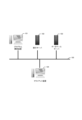
図1は、本実施形態のシステム構成図である。本システムには、プログラム開発装置101(開発者がWebアプリケーション生成のために操作する情報処理装置)、実行サーバ102、データベースサーバ103、クライアント装置104を含む。
Hereinafter, embodiments of the present invention will be described in detail with reference to the drawings.
<First embodiment>
FIG. 1 is a system configuration diagram of this embodiment. This system includes a program development device 101 (an information processing device operated by a developer to generate a web application), an execution server 102 , a database server 103 and a client device 104 .

プログラム開発装置101は、開発者の操作に従って画面レイアウト及びデータベース検索指示などを定義する。プログラム開発装置101は、プログラム生成、アプリケーション生成を行う。 The program development device 101 defines screen layouts, database search instructions, and the like according to the developer's operation. The program development device 101 generates programs and applications.

なお、本実施形態においては、プログラム開発装置101で生成するアプリケーションソフトウェアはWebアプリケーションとしたが、これに限定するものではなく、携帯電話・スマートフォン・タブレットなどの情報処理装置で動作するアプリケーションソフトウェアや組込みソフトウェアなど、Web技術による通信を利用したアプリケーションソフトウェアでなくてもよい。 In the present embodiment, the application software generated by the program development device 101 is a web application, but is not limited to this, and application software that operates on information processing devices such as mobile phones, smart phones, tablets, etc. It does not have to be application software, such as software, that utilizes communication by Web technology.

実行サーバ102は、プログラム開発装置101で開発されたアプリケーションソフトウェアを実行する。また、データベースサーバ103と接続して動作することが可能である。 The execution server 102 executes application software developed by the program development device 101 . Also, it is possible to operate by connecting to the database server 103 .

データベースサーバ103は、開発されたアプリケーションソフトウェアが使用するデータベースであり、また本実施形愛におけるアプリケーションソフトウェアの開発時にも動作確認などのために利用してもよい。例えば、開発者が利用するためにデータベースサーバ103は、プログラム開発装置101や、実行サーバ102と同一の装置で構成されていてもよいし、LANなどのネットワーク105内に配置されてもよい。 The database server 103 is a database used by the developed application software, and may also be used for operation confirmation during development of the application software in this embodiment. For example, for use by developers, the database server 103 may consist of the same device as the program development device 101 and the execution server 102, or may be arranged in a network 105 such as a LAN.

クライアント装置104(情報処理装置)は、実行サーバ102と協調してプログラム開発装置101で開発したアプリケーションプログラムを動作させる、エンドユーザの入力端末である。この、クライアント装置104は、携帯端末などの情報処理装置であってもよいこととする。 The client device 104 (information processing device) is an end-user input terminal that operates an application program developed by the program development device 101 in cooperation with the execution server 102 . The client device 104 may be an information processing device such as a mobile terminal.

なお、プログラム開発装置101、実行サーバ102、データベースサーバ103、および、クライアント装置104の何れかを、クラウドなどのインターネット上に配置してもよいし、いくつかの情報処理装置を一つの筐体としてもよい。 Any one of the program development device 101, the execution server 102, the database server 103, and the client device 104 may be arranged on the Internet such as a cloud, or several information processing devices may be arranged as one housing. good too.

図2は、本発明に係わるプログラム開発装置101、実行サーバ102、データベースサーバ103、クライアント装置104として適用可能な各ハードウェア構成の一例を示すブロック図である。 FIG. 2 is a block diagram showing an example of each hardware configuration applicable as the program development device 101, the execution server 102, the database server 103, and the client device 104 according to the present invention.

図2において、CPU201は、システムバス204に接続される各デバイスを統括的に制御する。 In FIG. 2, a CPU 201 centrally controls each device connected to a system bus 204 .

また、ROM203あるいは外部メモリ211には、CPU201の制御プログラムであるオペレーティングシステム(OS)や、各サーバ、クライアント、装置など情報処理装置の後述する各種機能を実現するためのプログラムが記憶されている。 The ROM 203 or the external memory 211 also stores an operating system (OS), which is a control program for the CPU 201, and programs for realizing various functions of information processing apparatuses such as servers, clients, and apparatuses, which will be described later.

RAM202は、CPU201の主メモリ、ワークエリア、一時待避領域等として機能する。 A RAM 202 functions as a main memory, a work area, a temporary save area, and the like for the CPU 201 .

入力コントローラ205は、入力部209からの入力を制御する。この入力部209としては、情報処理装置では、キーボード、マウス等のポインティングデバイス、タッチパネルが挙げられる。 The input controller 205 controls input from the input unit 209 . Examples of the input unit 209 include a keyboard, a pointing device such as a mouse, and a touch panel in the information processing apparatus.

なお、入力部209がタッチパネルの場合、ユーザがタッチパネルに表示されたアイコンやカーソルやボタンに合わせて押下(指等でタッチ)することにより、各種の指示を行うことができることとする。 If the input unit 209 is a touch panel, the user can give various instructions by pressing (touching with a finger or the like) an icon, cursor, or button displayed on the touch panel.

また、タッチパネルは、マルチタッチスクリーン等の、複数の指でタッチされた位置を検出することが可能なタッチパネルであってもよい。 Also, the touch panel may be a touch panel, such as a multi-touch screen, capable of detecting positions touched by a plurality of fingers.

出力コントローラ206は、出力部210の表示を制御する。この出力部210としては、例えば、CRTや液晶ディスプレイ等が挙げられる。尚、本体と一体になったノート型パソコンのディスプレイも含まれるものとする。また、プロジェクタであってもよいこととする。 The output controller 206 controls the display of the output section 210 . Examples of the output unit 210 include a CRT, a liquid crystal display, and the like. It should be noted that the display of the notebook computer integrated with the main body is also included. Also, it may be a projector.

外部メモリコントローラ207は、ブートプログラム、各種のアプリケーションソフトウェア、フォントデータ、ユーザーファイル、編集ファイル、プリンタドライバ等を記憶する外部メモリ211へのアクセスを制御する。外部メモリ211には、各サーバ、クライアント、装置等の各種機能を実現するための各種テーブル、パラメータが記憶されている。この外部メモリ211としては、ハードディスク(HD)やフレキシブルディスク(FD)、PCMCIAカードスロットにアダプタを介して接続されるコンパクトフラッシュ(登録商標)、スマートメディア等が挙げられる。 An external memory controller 207 controls access to an external memory 211 that stores boot programs, various application software, font data, user files, edit files, printer drivers, and the like. The external memory 211 stores various tables and parameters for realizing various functions of each server, client, device, and the like. Examples of the external memory 211 include a hard disk (HD), flexible disk (FD), compact flash (registered trademark) connected to a PCMCIA card slot via an adapter, smart media, and the like.

なお、CPU201は、例えばRAM202内の表示情報用領域へアウトラインフォント展開(ラスタライズ)処理を実行することにより、出力部210上での表示を可能としている。また、CPU201は、出力部210上の不図示のマウスカーソル等でのユーザ指示を可能とする。 It should be noted that the CPU 201 enables display on the output unit 210 by executing outline font expansion (rasterization) processing to a display information area in the RAM 202, for example. Also, the CPU 201 enables a user's instruction with a mouse cursor or the like (not shown) on the output unit 210 .

通信I/Fコントローラ208は、ネットワークを介して外部機器との通信制御処理を実行する。例えば、TCP/IPを用いた通信等が可能である。 A communication I/F controller 208 executes communication control processing with external devices via a network. For example, communication using TCP/IP is possible.

本発明を実現するためのプログラム212は外部メモリ211に記録されており、必要に応じてRAM202にロードされることによりCPU201によって実行されるものである。 A program 212 for realizing the present invention is recorded in the external memory 211 and is executed by the CPU 201 by being loaded into the RAM 202 as necessary.

次の図3から図4を参照して、Webアプリケーションソフトウェア(本番用アプリケーション)のプロトタイプアプリケーションを生成する手順を説明する。図3~図4の処理は、プログラム開発装置101のCPU201が、ROM203に記録され、RAM202に展開されたプログラムを実行することにより各処理を実行する。 A procedure for generating a prototype application of Web application software (production application) will be described with reference to FIGS. 3 and 4 below. 3 and 4 are executed by the CPU 201 of the program development apparatus 101 executing a program recorded in the ROM 203 and developed in the RAM 202. FIG.

図3は、Webアプリケーションソフトウェア(以下、Webアプリケーションと略す)の生成処理のうち、プロトタイプアプリケーション生成処理に関する部分のフローチャートの一例を示す図である。 FIG. 3 is a diagram showing an example of a flowchart of a part related to prototype application generation processing in generation processing of web application software (hereinafter abbreviated as web application).

S301では、プログラム開発装置101のCPU201は、開発者によりWebアプリケーションの画面定義の入力を受け付ける。この処理は、生成されるWebアプリケーションの画面のどの位置にどのような画面部品を配置(レイアウト)するか、各画面部品にどのような機能を持たせるかの指示をユーザから受け付ける処理である。図8を参照して、S301の処理を説明する。 In S301, the CPU 201 of the program development apparatus 101 receives an input of the screen definition of the web application by the developer. This process is a process of receiving instructions from the user as to what kind of screen parts should be arranged (layouted) at what positions on the screen of the generated Web application and what kind of functions each screen part should have. The processing of S301 will be described with reference to FIG.

図8(a)の画面800の左側にある部品パレット部801は画面に配置する部品(GUI部品)の一覧であり、ユーザはこの中からWEBアプリケーションの画面に配置するGUI部品を選択する。右側の画面定義エディタ部802はWebアプリケーションの画面に表示される表示画面を編集する領域である。図8は、ユーザIDと名前をデータベースなどに登録させる処理を実行するWebアプリケーションを生成している例である。 A component palette section 801 on the left side of the screen 800 in FIG. 8A is a list of components (GUI components) to be arranged on the screen, from which the user selects a GUI component to be arranged on the WEB application screen. A screen definition editor section 802 on the right side is an area for editing the display screen displayed on the screen of the Web application. FIG. 8 shows an example of generating a Web application that executes processing for registering a user ID and name in a database or the like.

たとえば、開発者がWebアプリケーションの表示画面にボタンアイコン805を配置する場合、部品パレット部801内のボタン部品を矢印803のようにドラッグ&ドロップして配置する。同様にテキスト入力が可能なテキストボックス806を図示の位置に配置することにより、画面部品配置例804が生成される。なお、画面部品の配置方法は、部品パレット部801から画面定義エディタ部802へのドラッグ&ドロップに限らず、既に配置した部品を移動する方法や、既に配置した部品をコピー&ペーストにより複製する方法であってもよい。また、一度配置した部品を削除できてもよい。 For example, when the developer arranges the button icon 805 on the display screen of the Web application, the button component in the component palette section 801 is dragged and dropped as indicated by an arrow 803 and arranged. Similarly, a screen component layout example 804 is generated by arranging a text box 806 into which text can be input at the illustrated position. Note that the method of arranging screen components is not limited to the method of dragging and dropping from the component palette section 801 to the screen definition editor section 802, but also the method of moving already placed components, and the method of copying and pasting already placed components. may be Also, it may be possible to delete a part that has been placed once.

画面定義エディタ部802に配置された部品の中でアクションイベントを含む部品(たとえば、ボタンアイコン805など)がある場合は、ボタンに対するアクションを登録する。具体的には、ボタンアイコン805において、マウスの右クリックもしくはマウスオーバで所定時間経過すると、アイコン811を表示する。表示されたアイコン811をユーザがクリックすると登録画面812(登録ダイアログ)を表示する。図8(b)は、表示された登録画面812に、ユーザが[名前]項目として「登録」と入力し、[タイプ]項目としてドロップダウンメニューから「ボタン」、[次画面]項目として、ドロップダウンメニューから「ユーザ一覧画面」を選択している例である。すなわち、図8の登録画面812は、「登録」と言う名前のボタンアイコン805が押下されると、「ユーザ一覧画面」に遷移するという内容を登録した例である。この画面で生成される画面のJSONデータの例を図12を参照して説明する。 If there is a component including an action event (for example, the button icon 805) among the components arranged in the screen definition editor unit 802, the action for the button is registered. Specifically, when the button icon 805 is right-clicked or moused over for a predetermined period of time, an icon 811 is displayed. When the user clicks the displayed icon 811, a registration screen 812 (registration dialog) is displayed. In FIG. 8B, on the displayed registration screen 812, the user enters "Register" as the [Name] item, selects "Button" as the [Type] item from the drop-down menu, and selects "Next Screen" as the item. In this example, "user list screen" is selected from the down menu. In other words, the registration screen 812 of FIG. 8 is an example of registering the content that, when the button icon 805 with the name "registration" is pressed, the screen transitions to the "user list screen". An example of JSON data of the screen generated on this screen will be described with reference to FIG.

図12は、図8の画面のJSONデータの抜粋した例である。図12のJSONコードの内、枠1204で囲まれた“instance003”が、ボタンアイコン805を示すデータである。枠1201内には、“code”というキーに対して、登録を意味する“regist”と言う値を持ち、“name”というキーには、図8(b)の登録画面812で入力した“登録”と言う文字、“nextUI”というキーには、次のユーザ一覧画面を指す“sampleUi002”(登録画面812では、ユーザ一覧画面)が設定されている。枠1202内の“actions”というキーに対応する値には、本番用Webアプリケーションでボタンアイコン805を押下すると実行される処理が記述される。枠1203内の“examples”というキーに対応する値には、プロトタイプアプリケーションでボタンアイコン805を押下すると実行される処理が記述される。どちらの場合も、図示の例ではWebアプリケーションの作成途中であるため、ボタンアイコン805の押下時は画面遷移しか設定されていない。そのため、枠1205内に示すように“instance003”がキーの“onClick”時の処理は何もしない“null”と設定されている。図3のフローチャートの説明に戻る。 FIG. 12 is an example of the JSON data extracted from the screen of FIG. In the JSON code of FIG. 12, “instance003” surrounded by a frame 1204 is data representing the button icon 805 . In a frame 1201, a key "code" has a value "register" which means registration, and a key "name" has a value of "registration" entered on the registration screen 812 of FIG. 8B. "" and the key "nextUI" are set with "sampleUi002" (user list screen in the registration screen 812) indicating the next user list screen. A value corresponding to the key “actions” in the frame 1202 describes the processing to be executed when the button icon 805 is pressed in the production Web application. A value corresponding to the key "examples" in the frame 1203 describes the processing to be executed when the button icon 805 is pressed in the prototype application. In both cases, since the Web application is being created in the illustrated example, only the screen transition is set when the button icon 805 is pressed. Therefore, as shown in a frame 1205, "instance003" is set to "null" which does nothing when the key is "onClick". Returning to the description of the flowchart in FIG.

図3のS302において、プログラム開発装置101のCPU201は、プロトタイプアプリケーション実行時に画面に表示するプロトタイプデータの入力要求があったか否かを判定する。プロトタイプデータとは、プロトタイプアプリケーションを実行する際にWebアプリケーション画面に表示されるデータであり、開発者により、例として予め設定されている値や図である。つまり、プロトタイプデータとは、本番環境のようにデータベースからデータを検索したり、算出したデータ結果から作図をしたりするものではない。プロトタイプデータは、アプリケーション開発ツールを介して、開発者によって予め入力設定または配置される。S302において、プロトタイプデータを入力する要求があった場合にはS303へと遷移し、プロトタイプデータを入力する要求がない場合は、S304へと処理を遷移する。図8(c)を参照して、ユーザからプロトタイプデータの入力要求がある場合の画面表示例を説明する。 In S302 of FIG. 3, the CPU 201 of the program development apparatus 101 determines whether or not there is an input request for prototype data to be displayed on the screen when the prototype application is executed. The prototype data is data displayed on the web application screen when the prototype application is executed, and is values and diagrams preset by the developer as an example. In other words, prototype data is not data that is retrieved from a database or plotted from calculated data results as in a production environment. Prototype data is pre-populated or placed by a developer via an application development tool. In S302, if there is a request to input prototype data, the process proceeds to S303, and if there is no request to input prototype data, the process proceeds to S304. A screen display example when the user requests the input of prototype data will be described with reference to FIG. 8(c).

図8(c)は、プロトタイプデータ入力要求時の画面表示例である。画面820のボタンアイコン805にマウスオーバした状態で、マウスの右クリックもしくはマウスオーバで所定時間経過すると、アイコン821aを表示する。表示されたアイコン821aをユーザがクリックすると選択肢821bを表示する。選択肢821bは「クリックされた時」と表記された選択肢である。選択肢821bを選択して押下(マウスクリック)することによりプロトタイプデータの入力要求がなされる。プロトタイプデータが入力されると、本番用アプリケーションの提供側人材(開発者や営業担当など)がデモなどでプロトタイプアプリケーションを実行した際に、ボタンアイコン805を押下すると、同じ画面にプロトタイプデータを表示したり、遷移先画面にプロトタイプデータを表示した画面を表示することができる。本実施形態では、遷移先画面(図9)にプロトタイプデータが表示される例を説明する。なお、アイコン821aと同じ機能はアイコン822を押下しても可能である。アイコン822を押下した場合は、図9(a)の領域906に選択肢821bと同じ選択肢を表示する。図3のフローチャートの説明に戻る。 FIG. 8(c) is an example of a screen display when requesting input of prototype data. With the mouse over the button icon 805 on the screen 820, an icon 821a is displayed when the mouse is right-clicked or the mouse is over for a predetermined period of time. When the user clicks the displayed icon 821a, an option 821b is displayed. Option 821b is an option labeled "when clicked". By selecting and pressing (mouse clicking) the option 821b, an input request for prototype data is made. When the prototype data is input, when the human resources (developers, sales staff, etc.) on the side of providing the production application run the prototype application in a demonstration or the like, pressing the button icon 805 causes the prototype data to be displayed on the same screen. Alternatively, a screen displaying prototype data can be displayed on the transition destination screen. In this embodiment, an example in which prototype data is displayed on the transition destination screen (FIG. 9) will be described. Note that the same function as the icon 821a can also be performed by pressing the icon 822. FIG. When the icon 822 is pressed, the same option as the option 821b is displayed in the area 906 of FIG. 9A. Returning to the description of the flowchart in FIG.

図3のS303において、プログラム開発装置101のCPU201は、S302で指定されたアクション(選択された選択肢821b、すなわち、「クリックされた時」が示すアクションであるボタンアイコンの押下)により表示されるプロトタイプデータの入力を受け付ける。プロトタイプデータの入力を受け付ける処理を、図9、図10を参照して説明する。 In S303 of FIG. 3, the CPU 201 of the program development apparatus 101 generates a prototype displayed by the action specified in S302 (pressing the button icon, which is the action indicated by the selected option 821b, that is, "when clicked"). Accept data input. The process of accepting input of prototype data will be described with reference to FIGS. 9 and 10. FIG.

図9、図10は、プロトタイプデータを入力する処理を説明する画面例である。ボタンアイコン805の次の遷移画面が、図8(a)の画面定義エディタ部802に示したようなユーザ登録画面ではなく、ユーザ一覧画面であるため、選択肢821bが押下されると、次の遷移画面である登録者リスト902(ユーザー一覧画面のこと)を含む図9(a)の画面900に切り替わる。画面900は、プロトタイプデータを入力する画面であるため、画面のタイトルは部品パレット部801に示した「部品パレット」から図9(a)のプロトタイプ設定部901に示すように「プロトタイプ設定」に変わっている。登録者リスト902が、ボタンアイコン805が押下された際に遷移する遷移先画面(ユーザ一覧画面)であり、ユーザにより予め生成されている画面である。登録者リスト902は、図8(a)の画面部品配置例804に含まれる各テキストボックスに入力されたIDや名前がリスト形式で表示されるものである。登録者リスト902には、ID表示領域903、名前表示領域904、登録日時表示領域905が含まれる。複数のユーザが登録されている場合にはこれらがリスト形式で表示される。登録者リスト902は、前述した図12のJSONコードでは、枠1201内の“nextUi”というキーに対応する“sampleUi002”に該当する。 9 and 10 are screen examples for explaining the process of inputting prototype data. Since the next transition screen of the button icon 805 is not the user registration screen shown in the screen definition editor section 802 of FIG. The screen is switched to the screen 900 of FIG. 9A including a registrant list 902 (user list screen). Since the screen 900 is a screen for inputting prototype data, the title of the screen is changed from "parts palette" shown in the parts palette section 801 to "prototype settings" as shown in the prototype setting section 901 of FIG. 9(a). ing. The registrant list 902 is a transition destination screen (user list screen) that transitions when the button icon 805 is pressed, and is a screen generated in advance by the user. The registrant list 902 displays the IDs and names entered in the respective text boxes included in the screen component layout example 804 in FIG. 8A in a list format. The registrant list 902 includes an ID display area 903 , a name display area 904 and a registration date/time display area 905 . If multiple users are registered, they are displayed in a list format. The registrant list 902 corresponds to "sampleUi002" corresponding to the key "nextUi" in the frame 1201 in the JSON code of FIG.

図9(b)において、ユーザがプロトタイプデータを入力したい場合、入力する項目(画面の場合は名前表示領域904)において、マウスの右クリックもしくはマウスオーバで所定時間経過させる。それに応じて、アイコン911とアイコン912を表示する。表示されたアイコン911をユーザがクリックすると図9(c)の画面920に表示が切り替わり、プロトタイプデータ入力ダイアログ921が表示される。例えば図示のように、プロトタイプデータ入力ダイアログ921に「谷川 則之」という文字列(値)を入力してOKボタンを押下することで、プロトタイプデータとして登録される。登録されたプロトタイプデータは、プロトタイプアプリケーションの実行時に、登録対象のアクション(ボタンアイコン805の押下)に応答して表示される遷移先画面において表示される。この結果、例えば、ボタンアイコン805の押下に応じて図10(a)の登録者リスト902の名前表示領域904に「谷川 則之」という文字列のように表示される。別の例として、プロトタイプデータを複数まとめて入力させたい場合の方法を説明する。図9(b)のアイコン912をユーザがクリックすると、図10(b)の表示に切り替わる。枠1021で示すプロトタイプデータのリスト入力ダイアログに含まれるインポート欄1022に、例えばCSV形式でデータを入力してOKボタン1024を押下すると、それぞれ対応する値をプロトタイプデータとして登録できる。同様にファイルによる指定も可能であり、アイコン1023を押下後、適切なファイルを選択して、データを入力できる。これらのプロトタイプデータを設定したJSONコードの例を図13を参照して説明する。 In FIG. 9B, when the user wants to input prototype data, the item to be input (name display area 904 in the case of screen) is right-clicked or moused over for a predetermined time. Icons 911 and 912 are displayed accordingly. When the user clicks the displayed icon 911, the display is switched to the screen 920 shown in FIG. 9C, and a prototype data input dialog 921 is displayed. For example, as shown in the figure, by inputting a character string (value) "Noriyuki Tanigawa" in the prototype data input dialog 921 and pressing the OK button, it is registered as prototype data. The registered prototype data is displayed on the transition destination screen that is displayed in response to the action to be registered (pressing the button icon 805) when the prototype application is executed. As a result, for example, when the button icon 805 is pressed, a character string such as "Noriyuki Tanigawa" is displayed in the name display area 904 of the registrant list 902 of FIG. 10(a). As another example, a method for collectively inputting a plurality of prototype data will be described. When the user clicks the icon 912 in FIG. 9(b), the display is switched to that in FIG. 10(b). By inputting data in, for example, CSV format into an import field 1022 included in the prototype data list input dialog box 1021 and pressing an OK button 1024, the corresponding values can be registered as prototype data. Similarly, specification by file is also possible, and after pressing the icon 1023, an appropriate file can be selected and data can be input. An example of JSON code in which these prototype data are set will be described with reference to FIG.

図13は、図10(b)に図示した入力例の入力が行われた後のJSONデータの抜粋した例である。図13のJSONコードの内、枠1302内の“actions”というキーに対応する値には、本番用Webアプリケーションで動作、表示する処理が記述されている。枠1301内の“examples”というキーに対応する値には、プロトタイプアプリケーション実施時に表示されるデータが登録されており、インポート欄1022に登録されているデータが枠1301内に登録されている。 FIG. 13 is an example of extracted JSON data after the input example shown in FIG. 10(b) has been entered. In the JSON code of FIG. 13, the value corresponding to the key "actions" in the frame 1302 describes the processing to operate and display in the production Web application. Data to be displayed when the prototype application is executed is registered in the value corresponding to the key “examples” in the frame 1301 , and data registered in the import column 1022 is registered in the frame 1301 .

図11(a)、(b)に、生成されたプロトタイプアプリケーションを実行した場合の表示例を示す。図11(a)の画面1100、前述した画面定義エディタ部802に部品を配置する操作によって作成した画面である。図11(b)の画面1110は、図11(a)の登録ボタン1101(前述したボタンアイコン805に対応するボタン)が押下されたことに応じて表示さえる遷移先画面であり、前述した登録者リスト902に対応するものである。プロトタイプアプリケーション動作時は、遷移前の画面1100においてID入力欄1102や名前入力欄1103にデータを入力してもしなくても、登録ボタン1101を押下すると、図9(b)の画面1110において、予め登録されているプロトタイプデータ1111が表示される。プロトタイプデータ1111は、前述した図10(b)のインポート欄1022で登録された値を反映した表示である。図3のフローチャートの説明に戻る。 FIGS. 11A and 11B show display examples when the generated prototype application is executed. The screen 1100 in FIG. 11A is a screen created by the operation of arranging components in the screen definition editor section 802 described above. A screen 1110 in FIG. 11B is a transition destination screen displayed in response to pressing of the registration button 1101 (the button corresponding to the button icon 805 described above) in FIG. It corresponds to list 902 . When the prototype application is running, regardless of whether or not data is entered in the ID input field 1102 and the name input field 1103 on the screen 1100 before transition, when the registration button 1101 is pressed, the screen 1110 in FIG. Registered prototype data 1111 is displayed. Prototype data 1111 is a display that reflects the values registered in the import column 1022 in FIG. 10B described above. Returning to the description of the flowchart in FIG.

図3のS304において、プログラム開発装置101のCPU201は、画面定義(部品の配置など)やプロトタイプデータを保存する要求(図示しない保存ボタンの押下)があったかどうかを判断する。保存要求があった場合はS305へと処理を遷移し、保存要求がない場合はS306へと処理を進める。 In S304 of FIG. 3, the CPU 201 of the program development apparatus 101 determines whether or not there is a request (pressing of a save button (not shown)) to save the screen definition (arrangement of components, etc.) and prototype data. If there is a save request, the process proceeds to S305, and if there is no save request, the process proceeds to S306.

S305において、プログラム開発装置101のCPU201は、画面定義情報やプロトタイプデータを保存する。 In S305, the CPU 201 of the program development apparatus 101 saves screen definition information and prototype data.

S306において、プログラム開発装置101のCPU201は、プロトタイプアプリケーション生成要求があったかを判定する。プロトタイプアプリケーション生成要求があったと判定した場合には、S307に遷移する。一方、プロトタイプアプリケーション生成要求がなかった場合には、S301に遷移する。 In S306, the CPU 201 of the program development device 101 determines whether a prototype application generation request has been received. If it is determined that a prototype application generation request has been made, the process proceeds to S307. On the other hand, if there is no prototype application generation request, the process transitions to S301.

S307において、プログラム開発装置101のCPU201は、プロトタイプアプリケーションのソースコードを生成する。ソースコード生成の際に、S305で保存した画面定義や画面遷移定義、プロトタイプデータなどを読み込んでソースコードを生成する。 In S307, the CPU 201 of the program development device 101 generates the source code of the prototype application. When generating the source code, the screen definition, screen transition definition, prototype data, etc. saved in S305 are read to generate the source code.

S308において、プログラム開発装置101のCPU201は、S507において生成したソースコードのコンパイルを行う。 In S308, the CPU 201 of the program development device 101 compiles the source code generated in S507.

S309において、プログラム開発装置101のCPU201は、S508においてコンパイルしたプロトタイプアプリケーションを実行サーバ102にデプロイする。こうして、プロトタイプアプリケーションが生成される。なお、生成されたプログラム(プロトタイプアプリケーション)は、クライアントで動作するSPA(Single Page Application)としてデプロイしても良い。図4以降ではSPAとしてデプロイされた例として説明する。以上で図3のフローチャートの説明を終了する。 In S<b>309 , the CPU 201 of the program development device 101 deploys the prototype application compiled in S<b>508 to the execution server 102 . A prototype application is thus generated. Note that the generated program (prototype application) may be deployed as an SPA (Single Page Application) that runs on the client. From FIG. 4 onwards, an example of deployment as an SPA will be described. This completes the description of the flowchart in FIG.

次に、図4を参照して、クライアント装置104がプロトタイプアプリケーション実行する際の処理の流れを説明する。 Next, the flow of processing when the client device 104 executes the prototype application will be described with reference to FIG.

図4のフローチャートは、前述した図3の処理によって生成されて実行サーバにデプロイされたプロトタイプアプリケーションに、クライアント装置104のWebブラウザからユーザのアクセスがあった際に開始される処理の流れである。なお、以下でSPAと記載するものは、図3で生成されたプロトタイプアプリケーションであるものとする。 The flowchart in FIG. 4 shows the flow of processing that is started when a user accesses the prototype application generated by the processing in FIG. It should be noted that what is described as SPA below is the prototype application generated in FIG.

S401において、クライアント装置104のCPU201は、実行サーバにデプロイされたSPAを取得し、SPAの実行画面をクライアント装置104の出力部210(ディスプレイ)に表示する。これによって前述した図11(a)のような表示が行われる。 In S<b>401 , the CPU 201 of the client device 104 acquires the SPA deployed to the execution server and displays the SPA execution screen on the output unit 210 (display) of the client device 104 . As a result, the display as shown in FIG. 11A is performed.

S402において、クライアント装置104のCPU201は、ユーザによるアクション実行要求を受付ける。具体的には、図11(a)の登録ボタン1101の押下などを受け付ける。このとき、ユーザは本番用のWebアプリケーションを使用した際のイメージを再現するための動作イメージを確認することが目的であるため、先にも述べたようにID入力欄1102や名前入力欄1103にはユーザによる入力は必ずしも必要ではない。 In S402, the CPU 201 of the client device 104 accepts an action execution request from the user. Specifically, pressing of the registration button 1101 in FIG. 11A is accepted. At this time, the purpose of the user is to confirm the operation image for reproducing the image when using the production Web application. does not necessarily require user input.

S403において、クライアント装置104のCPU201は、ユーザによるアクション実行要求があったかを判定する。具体的には、図11(a)の登録ボタン1101が押下されたかなどを判定する。アクション実行要求があった(登録ボタン1101が押下された)と判定した場合は、S404に遷移し、ユーザによるアクション実行要求がなかった場合は、S402へと処理を戻す。 In S403, the CPU 201 of the client device 104 determines whether or not the user has issued an action execution request. Specifically, it is determined whether the registration button 1101 in FIG. 11A has been pressed. If it is determined that there has been an action execution request (the registration button 1101 has been pressed), the process proceeds to S404, and if there is no action execution request from the user, the process returns to S402.

S404において、クライアント装置104のCPU201は、S402で受け付けたアクション実行要求が画面遷移を伴うかを判定する。アクション実行要求が画面遷移を伴うと判定した場合は、S406に遷移し、アクションが画面遷移を伴わない場合は、S407に遷移する。 In S404, the CPU 201 of the client apparatus 104 determines whether the action execution request accepted in S402 involves screen transition. If it is determined that the action execution request accompanies screen transition, the process proceeds to S406, and if the action does not accompany screen transition, the process proceeds to S407.

S405において、クライアント装置104のCPU201は、アクション実行要求に伴う遷移先の画面を表示する。 In S405, the CPU 201 of the client device 104 displays a transition destination screen associated with the action execution request.

S406において、クライアント装置104のCPU201は、取得したSPAに登録されているプロトタイプデータを表示する。具体的なプロトタイプデータの表示例が、図11(b)で前述した遷移先画面である画面1110である。以上で、図4のフローチャートの説明を終了する。 In S406, the CPU 201 of the client device 104 displays prototype data registered in the acquired SPA. A specific display example of the prototype data is the screen 1110, which is the transition destination screen described above with reference to FIG. 11(b). This is the end of the description of the flowchart in FIG.

次に、図5を参照して、プログラム開発装置101が本実施形態のプロトタイプアプリケーションを順序立てて表示させる(再生させる)ためのモジュール(以下、再生モジュールと称する)を生成する処理の流れについて説明する。生成される再生モジュールは、複数のイベントを仮想的に順次自動的に実行するモジュールである。すなわち、再生モジュールを実行すると複数のイベントの仮想的な実行により、動画のような自動的な画面遷移が行われる。仮想的なイベント実行は、本番環境とは異なり、本番同様のイベントを実行することなく、イベントに対応するプロトタイプデータの出力を実行する。この処理は、図3でプロトタイプアプリケーションが生成された後で実行されるフローチャートである。 Next, referring to FIG. 5, the flow of processing for generating a module (hereinafter referred to as a reproduction module) for displaying (reproducing) the prototype applications of the present embodiment in order by the program development apparatus 101 will be described. do. The generated playback module is a module that automatically and virtually sequentially executes a plurality of events. That is, when the reproduction module is executed, virtual execution of a plurality of events causes automatic screen transition like animation. Unlike the production environment, the virtual event execution outputs prototype data corresponding to the event without executing an event similar to the production environment. This process is a flowchart executed after the prototype application is generated in FIG.

S501において、プログラム開発装置101のCPU201は、再生モジュールを生成するための再生情報定義受付処理(再生情報定義の設定・編集受け付ける処理)を実行する。詳細は図6において後述する。再生情報定義とは、再生情報定義受付処理でユーザから指示された複数のイベントを順次実行することを指示する指示情報である。 In S501, the CPU 201 of the program development apparatus 101 executes reproduction information definition acceptance processing (processing for accepting reproduction information definition setting/editing) for generating a reproduction module. Details will be described later with reference to FIG. A reproduction information definition is instruction information for instructing the sequential execution of a plurality of events instructed by the user in the reproduction information definition acceptance process.

S502において、プログラム開発装置101のCPU201は、S501で設定または編集された再生情報定義を保存する要求があったか否かを判定する。保存要求があれば、S503へと処理を遷移し、保存要求がなければ、S504へと処理を遷移する。 In S502, the CPU 201 of the program development apparatus 101 determines whether or not there is a request to save the reproduction information definition set or edited in S501. If there is a save request, the process transitions to S503, and if there is no save request, the process transitions to S504.

S503において、プログラム開発装置101のCPU201は、再生情報定義を実行サーバ102に保存する。 In S<b>503 , the CPU 201 of the program development device 101 saves the reproduction information definition in the execution server 102 .

S504において、プログラム開発装置101のCPU201は、保存した再生情報定義に基づく再生モジュールを生成する要求があったか否かを判定する。再生モジュールの生成要求があれば、S505へと処理を遷移し、再生モジュール生成要求がない場合は、S501へと処理を戻す。 In S504, the CPU 201 of the program development apparatus 101 determines whether or not there is a request to generate a reproduction module based on the saved reproduction information definition. If there is a reproduction module generation request, the process proceeds to S505, and if there is no reproduction module generation request, the process returns to S501.

S505において、プログラム開発装置101のCPU201は、保存された再生情報定義に対応する再生モジュールのソースコードを生成し、S506でコンパイルし、S507で実行サーバ102にSPAとしてデプロイする。生成された再生モジュールは、実行サーバ102に記録された再生情報定義を参照して動作するように生成される。 In S505, the CPU 201 of the program development apparatus 101 generates the source code of the reproduction module corresponding to the saved reproduction information definition, compiles it in S506, and deploys it as SPA on the execution server 102 in S507. The generated reproduction module is generated so as to operate by referring to the reproduction information definition recorded in the execution server 102 .

次に、図6を参照して、前述した図5のS501の再生情報定義受付の処理の詳細を説明する。なお、後述する処理において、「イベント」は生成される再生モジュールの実行によって画面に変化を及ぼすものの総称であり、画面サクセス、アクション、吹き出しの表示、プロトタイプデータの表示を含むものとする。 Next, with reference to FIG. 6, the details of the reproduction information definition acceptance processing in S501 of FIG. 5 will be described. In the processing to be described later, "event" is a general term for things that change the screen due to execution of a generated playback module, and includes screen success, action, balloon display, and prototype data display.

S601において、プログラム開発装置101のCPU201は、図3のS307で生成されたプロトタイプアプリケーションのソースコード(画面定義情報や部品情報、画面遷移情報、プロトタイプデータを含む)を読み込み、出力部210(ディスプレイ)に再生情報の編集画面を表示する。 In S601, the CPU 201 of the program development apparatus 101 reads the prototype application source code (including screen definition information, component information, screen transition information, and prototype data) generated in S307 of FIG. to display the playback information editing screen.

図14(a)に再生情報の編集画面(プロトタイプ動作記録の編集画面)の表示例を示す。 FIG. 14(a) shows a display example of a playback information edit screen (prototype operation record edit screen).

UI定義選択エリア1410はプロトタイプアプリケーションまたは対応する本願用アプリケーションに定義されているUI定義(画面)を選択肢として表示する領域である。プロトタイプアプリケーションのソースコードから取得された少なくとも1つのUI定義が、UI定義選択エリアに一覧で表示される。図示の例では、UI定義選択エリア1410に、選択項目1411~1414が表示されている。選択項目1411は“MENU”であり、本番用アプリケーションにおける複数のメニュー項目が定義されたメニュー画面のUI定義を選択する項目である。選択項目1412は“ML_QUERY”であり、メーリングリストアドレスをデータベースなどから検索する画面のUI定義を選択する項目である。選択項目1413は“MEMBER_LIST”であり、参加しているメーリングリストのメンバを一覧で表示する画面のUI定義を選択する項目である。選択項目1414は“MEMBER_EDIT”であり、参加しているメーリングリストのメンバを編集する画面のUI定義の選択項目である。UI定義選択エリア1410に表示される選択肢は、本番用アプリケーションソフトウェアを作成する際に定義された複数の画面にそれぞれ対応する複数の選択肢である。 A UI definition selection area 1410 is an area that displays UI definitions (screens) defined in the prototype application or the corresponding application of the present application as options. At least one UI definition obtained from the source code of the prototype application is listed in the UI definition selection area. In the illustrated example, selection items 1411 to 1414 are displayed in the UI definition selection area 1410 . A selection item 1411 is “MENU”, which is an item for selecting a UI definition of a menu screen in which a plurality of menu items are defined in the production application. A selection item 1412 is "ML_QUERY", which is an item for selecting a UI definition of a screen for searching a mailing list address from a database or the like. A selection item 1413 is "MEMBER_LIST", which is an item for selecting a UI definition of a screen that displays a list of members of the participating mailing list. A selection item 1414 is "MEMBER_EDIT", which is a selection item of the UI definition of the screen for editing the members of the participating mailing list. The options displayed in the UI definition selection area 1410 are multiple options corresponding to multiple screens defined when the production application software is created.

アクション選択エリア1420は、UI定義選択エリア1410で選択されたUI定義に含まれるアクション(動作)を選択肢(選択項目)として表示する領域である。このように、プロトタイプアプリケーションのUI定義を取得することで、プロトタイプアプリケーションで実行するアクションを一覧で表示でき、後述するアクション選択が容易に可能となる。各アクションはそれぞれ、本番用アプリケーションで行われる特定の処理を示すものである。
プレビューエリア1430は、選択されたUI定義に定義されたGUI部品(表示要素)を用いて、選択されたUI定義に定義された画面が表示される領域である。また、再生順序指定エリア1440に吹き出しと値セットが登録されている場合には、これらもUI定義に定義された画面上に表示し、どのように吹き出しや値が表示されるかを確認できるようになっている。
The action selection area 1420 is an area that displays actions (operations) included in the UI definition selected in the UI definition selection area 1410 as options (selection items). By acquiring the UI definition of the prototype application in this way, it is possible to display a list of actions to be executed by the prototype application, and easily select an action to be described later. Each action represents a specific process to be performed in the production application.
The preview area 1430 is an area where a screen defined in the selected UI definition is displayed using GUI parts (display elements) defined in the selected UI definition. In addition, when speech balloons and value sets are registered in the playback order designation area 1440, these are also displayed on the screen defined in the UI definition so that it is possible to check how speech balloons and values are displayed. It has become.

再生順序指定エリア1440は。再生モジュールを実行した場合に順次行われるイベントを上から下の順番で並べて表示した領域である。ユーザは、再生モジュールで実行させたいイベントを実行させたい順に再生順序指定エリア1440に上から下に並べて登録していくことで、所望の順序でイベントを自動実行させる再生モジュールを生成することができる。再生順序指定エリア1440に登録された各イベントは、プログラム開発装置101のRAM202に保持され、保存指示に応じて実行サーバ102に保存される。図15の再生情報定義1500と再生順序指定エリア1440に表示された各イベントはそれぞれ対応しており、画面アクセス1441は再生情報定義1500の枠1501内に、イベント1442~1445は、再生情報定義1500の枠1502~1505内にそれぞれ対応している。再生情報定義1500は、画面アクセス1441、イベント1442~1445を順次実行することを指示指示する指示情報である。 The playback order designation area 1440 is: This is an area in which the events that are performed sequentially when the playback module is executed are arranged in order from top to bottom. The user can create a playback module that automatically executes the events in a desired order by arranging and registering the events to be executed by the playback module in the desired order in the playback order specification area 1440 from top to bottom. . Each event registered in the reproduction order designation area 1440 is held in the RAM 202 of the program development apparatus 101 and saved in the execution server 102 in response to a save instruction. The playback information definition 1500 in FIG. 15 and each event displayed in the playback order designation area 1440 correspond to each other. , respectively correspond to the frames 1502 to 1505 of . The playback information definition 1500 is instruction information for instructing the sequential execution of the screen access 1441 and the events 1442 to 1445 .

図6のS602において、プログラム開発装置101のCPU201は、UI定義選択エリアに表示されたいずれかの選択肢が選択されたか否かを判定する。UI定義の選択肢がユーザにより選択された場合はS603へと処理を遷移し、そうでない場合はS602へと処理を戻し、UI定義が選択されるのを待つ。 In S602 of FIG. 6, the CPU 201 of the program development apparatus 101 determines whether any option displayed in the UI definition selection area has been selected. If the UI definition option is selected by the user, the process proceeds to S603; otherwise, the process returns to S602 and waits for the UI definition to be selected.

S603において、プログラム開発装置101のCPU201は、S602で選択されたUI定義に含まれるアクションを実行サーバ102から取得し、アクション選択エリア1420に表示する。より詳しくは、本番用アプリケーションの各UI定義のうち、S602で選択されたUI定義に含まれるアクションを取得する。図14(a)の例では、UI定義として選択されている“ML_QUERY”に、検索ボタンが含まれており、検索ボタンのクリックに応じた検索というアクション(動作)が定義づけられている。そのため、アクション選択エリア1420には、“ML_QUERY”の画面を初期表示するアクションの選択項目1421と、検索のアクションの選択項目1422とが表示される。 In S<b>603 , the CPU 201 of the program development apparatus 101 acquires the action included in the UI definition selected in S<b>602 from the execution server 102 and displays it in the action selection area 1420 . More specifically, among the UI definitions of the production application, the actions included in the UI definition selected in S602 are acquired. In the example of FIG. 14A, "ML_QUERY" selected as the UI definition includes a search button, and an action (operation) of searching in response to clicking of the search button is defined. Therefore, in the action selection area 1420, an action selection item 1421 for initial display of the "ML_QUERY" screen and a search action selection item 1422 are displayed.

S604において、プログラム開発装置101のCPU201は、S602のUI定義選択で選択されたUI定義(図14(a)の場合、選択項目1412の“ML_QUERY”)を画面アクセスとして設定してRAMに保持する。再生順序指定エリア1440に表示された画面アクセス1441に対応するイベントが、選択されたUI定義の画面を表示するイベントとなる。 In S604, the CPU 201 of the program development apparatus 101 sets the UI definition selected in the UI definition selection in S602 (in the case of FIG. 14A, "ML_QUERY" in the selection item 1412) as screen access and stores it in the RAM. . The event corresponding to the screen access 1441 displayed in the reproduction order designation area 1440 is the event for displaying the selected UI-defined screen.

S605において、プログラム開発装置101のCPU201は、実行サーバ102から、選択されたUI定義に関連付けて記録された再生情報定義(選択されたUI定義が画面アクセスとして登録された再生情報定義)を取得し、取得した再生情報定義に従って、再生順序指定エリア1440の画面アクセス1441に続いて実行されるイベントとして表示する。選択されたUI定義に関連付けて、以前に再生順序の定義を行っていた場合は。これによって以前保存した再生順序が読み込まれ、それに対して編集を加えることができる。実行サーバ102に、選択されたUI定義に関連付く再生情報定義が記録されていない場合は、新規作成となり、このタイミングでは再生順序指定エリア1440には、画面アクセス1441だけが表示される。また、プレビューエリア1430には、選択されたUI定義に定義されたGUI部品と、再生順序指定エリア1440に表示された吹き出しと値セットがプレビュー表示される。 In S605, the CPU 201 of the program development apparatus 101 acquires from the execution server 102 the reproduction information definition recorded in association with the selected UI definition (the reproduction information definition in which the selected UI definition is registered as screen access). , is displayed as an event executed following the screen access 1441 in the reproduction order designation area 1440 according to the acquired reproduction information definition. If you have previously defined a play order associated with the selected UI definition. This will load a previously saved play order and allow you to make edits to it. If the reproduction information definition associated with the selected UI definition is not recorded in the execution server 102, it is newly created, and only the screen access 1441 is displayed in the reproduction order designation area 1440 at this timing. A preview area 1430 displays a preview of the GUI parts defined in the selected UI definition and the speech balloon and value set displayed in the reproduction order designation area 1440 .

S606において、プログラム開発装置101のCPU201は、画面アクセスエディタ1450を表示し、S602で選択されたUI定義を表示する。 In S606, the CPU 201 of the program development apparatus 101 displays the screen access editor 1450 to display the UI definition selected in S602.

S607において、プログラム開発装置101のCPU201は、UI定義が変更されたか否かを判定する。UI定義が変更された場合には、S603へ進み、変更後のUI定義に基づく処理を行う。UI定義選択エリア1410で別の選択項目を選択される、あるいは画面アクセスエディタ1450で別のUI定義が選択されると、UI定義が変更されたと判定する。これによって、別のUI定義に関する再生情報を定義(設定)することができる。S607でUI定義が変更されたと判定されなかった場合はS608へと処理を遷移する。 In S607, the CPU 201 of the program development apparatus 101 determines whether the UI definition has been changed. If the UI definition has been changed, the process advances to step S603 to perform processing based on the changed UI definition. When another selection item is selected in the UI definition selection area 1410 or another UI definition is selected in the screen access editor 1450, it is determined that the UI definition has been changed. This makes it possible to define (set) playback information for another UI definition. If it is determined in S607 that the UI definition has not been changed, the process proceeds to S608.

S608において、プログラム開発装置101のCPU201は、再生順序指定エリア1440にイベントを追加する操作が行われたか否かを判定する。イベントを追加する操作は、アクション選択エリア1420でいずれかの選択項目を選択することによりアクションを追加する操作(クリックあるいは再生順序指定エリア1440へのドラッグ&ドロップ)か、追加ボタン1446の押下であるものとする。イベントを追加する操作があった場合にはS609に進み、そうでない場合はS629に進む。 In S<b>608 , the CPU 201 of the program development apparatus 101 determines whether or not an operation to add an event to the reproduction order designation area 1440 has been performed. The operation of adding an event is an operation of adding an action by selecting one of the selection items in the action selection area 1420 (clicking or dragging and dropping to the reproduction order designation area 1440), or pressing the add button 1446. shall be If there is an operation to add an event, the process proceeds to S609; otherwise, the process proceeds to S629.

S609において、プログラム開発装置101のCPU201は、S608で判定されたイベントの追加操作がアクションを追加する操作だったかを判定する。アクションを追加する操作であった場合はS610へと処理を遷移し、そうでない場合はS611へと処理を遷移する。 In S<b>609 , the CPU 201 of the program development apparatus 101 determines whether the event addition operation determined in S<b>608 was an action addition operation. If the operation is to add an action, the process proceeds to S610; otherwise, the process proceeds to S611.

S610において、プログラム開発装置101のCPU201は、再生順序指定エリア1440に表示済み(登録済み)のイベントの最後尾に、選択されたアクションを追加する。例えば、アクション選択エリア1420の選択項目1422を再生順序指定エリア1440にドラッグ&ドロップすることにより、再生順序指定エリア1440に、選択項目1422が示す「検索」というアクションをイベント1445として追加して表示する。 In S<b>610 , CPU 201 of program development device 101 adds the selected action to the tail end of the displayed (registered) event in reproduction order designation area 1440 . For example, by dragging and dropping the selection item 1422 of the action selection area 1420 to the reproduction order designation area 1440, the action "search" indicated by the selection item 1422 is added and displayed in the reproduction order designation area 1440 as an event 1445. .

アクションではないイベントの追加操作、すなわち追加ボタン1446の押下であった場合には、S611において、プログラム開発装置101のCPU201は、追加対象の選択肢を表示する。選択肢には、「値セット」と「吹き出し」を含むものとする。 If the addition operation of an event that is not an action, that is, pressing the add button 1446, the CPU 201 of the program development device 101 displays options to be added in S611. The options shall include "value set" and "balloon".

S612において、プログラム開発装置101のCPU201は、S611で表示した選択肢のうち、「値セット」と「吹き出し」のいずれが操作されたかを判定する。「値セット」が選択された場合にはS613にしすすみ、そうでない場合、すなわち「吹き出し」が選択された場合はS621に進む。 In S<b>612 , the CPU 201 of the program development apparatus 101 determines which of the options displayed in S<b>611 has been operated, “value set” or “balloon”. If "value set" is selected, proceed to S613; otherwise, that is, if "balloon" is selected, proceed to S621.

S613において、プログラム開発装置101のCPU201は、再生順序指定エリア1440に表示済み(登録済み)のイベントの最後尾に「値セット」のイベント追加し、追加した「値セット」のイベントを選択状態にして表示する。再生順序に「値セット」のイベントは複数登録することができるため。図示のイベント1442のように、それぞれの値セットを識別するために、通し番号を付して表示される。 In S613, the CPU 201 of the program development apparatus 101 adds the "value set" event to the end of the displayed (registered) events in the reproduction order designation area 1440, and selects the added "value set" event. displayed. Because you can register multiple "value set" events in the playback order. Like the event 1442 shown, each value set is displayed with a serial number to identify it.

S614において、プログラム開発装置101のCPU201は、編集画面の右下部分(図14(a)において画面アクセスエディタ1450が表示されている領域)に値セットエディタ1460を表示する。図14(b)に値セットエディタ1460を表示した場合の値セットエディタ1460と再生順序指定エリア1440の表示例を示す。図14(b)は、編集画面の右側の一部分の表示例である。再生順序指定エリア1440では値セットのイベント1442が選択されており、値セットエディタ1460には、選択されているイベント1442の値をセットする対象のGUI部品を選択する対象部品設定欄1461、値を入力する値入力欄1462、再生順序指定エリア1440から選択中の値セットのイベントを削除する指示を受け付ける削除ボタン1463が表示される。 In S614, the CPU 201 of the program development device 101 displays the value set editor 1460 in the lower right portion of the edit screen (the area where the screen access editor 1450 is displayed in FIG. 14(a)). FIG. 14B shows a display example of the value set editor 1460 and the reproduction order designation area 1440 when the value set editor 1460 is displayed. FIG. 14B is a display example of a portion of the right side of the editing screen. A value set event 1442 is selected in the playback order designation area 1440, and a value set editor 1460 includes a target component setting field 1461 for selecting a target GUI component for which the value of the selected event 1442 is to be set. A value input field 1462 to be input and a delete button 1463 for accepting an instruction to delete the event of the value set being selected from the reproduction order designation area 1440 are displayed.

S615において、プログラム開発装置101のCPU201は、値をセットする対象部品を選択する操作があったか否かを判断する。対象部品を選択する操作があった場合S616へと処理を遷移し、そうでない場合はS617へ進む。対象部品を選択する操作は、例えば、対象部品設定欄1461を操作することで表示されるプルダウンメニューに表示された選択肢のいずれかを選択することで行う。なお、ユーザが対象部品を選択する操作を行う前は、デフォルト(初期設定)で、選択されているUI定義画面に含まれるGUI部品のいずれかが選択されるものとする。 In S<b>615 , the CPU 201 of the program development apparatus 101 determines whether or not there is an operation to select a target component for setting a value. If there is an operation to select the target component, the process proceeds to S616; otherwise, the process proceeds to S617. The operation of selecting the target component is performed by selecting one of the options displayed in the pull-down menu displayed by operating the target component setting column 1461, for example. Before the user performs an operation to select a target component, any one of the GUI components included in the selected UI definition screen is selected by default (initial setting).

S616において、プログラム開発装置101のCPU201は、S615で判定された対象部品を選択する操作に応じて、値をセットする対象部品を変更する処理を行う。具体的には、値セットエディタ1460の対象部品設定欄1461に変更後の対象部品名を表示し、値入力欄1462に、変更後の部品に既に入力されていた値を表示する。この値は、図15に例示した再生情報定義に記録された値を取得して表示する。再生定義情報に値として表示するデータが記録されていない新規のGUI部品である場合は、値入力欄1462の初期値は空欄となる。 In S<b>616 , the CPU 201 of the program development apparatus 101 performs processing for changing the target part for setting the value in accordance with the operation of selecting the target part determined in S<b>615 . Specifically, the changed target part name is displayed in the target part setting field 1461 of the value set editor 1460, and the value that has already been input to the changed part is displayed in the value input field 1462. FIG. As for this value, the value recorded in the reproduction information definition illustrated in FIG. 15 is acquired and displayed. If the GUI component is a new GUI component for which data to be displayed as a value is not recorded in the reproduction definition information, the initial value of the value input column 1462 is blank.

S617において、プログラム開発装置101のCPU201は、値入力欄1462に値を入力する操作(対象部品に対する値を入力する操作)があったか否かを判定する。値を入力する操作があった場合にはS618へ進み、そうでない場合にはS619へと処理を遷移する。値の入力は例えば、値入力欄1462を選択してキーボードなどで文字列を入力することにより行う。 In S617, the CPU 201 of the program development apparatus 101 determines whether or not there has been an operation of inputting a value in the value input field 1462 (an operation of inputting a value for the target component). If there is an operation to input a value, the process proceeds to S618; otherwise, the process proceeds to S619. A value is entered by, for example, selecting the value entry field 1462 and entering a character string using a keyboard or the like.

S618において、プログラム開発装置101のCPU201は、値入力欄1462に入力された値を再生情報定義に記録(登録)する。また、入力された値をプレビューエリア1430に表示された対象部品に表示する。図14(b)の例では、対象部品として「ML_ADDRESS」が選択され、値入力欄1462に「dev」と入力されているので、図15の再生情報定義1500の枠1502内のように情報が登録される。また、プレビューエリア1430では、対象部品であるGUI部品1431(「MLアドレス」)に値入力欄1462に入力された文字列「dev」が表示されている。 In S618, the CPU 201 of the program development apparatus 101 records (registers) the value input in the value input field 1462 in the reproduction information definition. Also, the input value is displayed on the target part displayed in the preview area 1430 . In the example of FIG. 14(b), "ML_ADDRESS" is selected as the target part, and "dev" is entered in the value input field 1462, so the information is displayed as in the frame 1502 of the reproduction information definition 1500 in FIG. be registered. Also, in the preview area 1430, the character string "dev" input in the value input field 1462 is displayed for the target GUI component 1431 ("ML address").

S619において、プログラム開発装置101のCPU201は、削除ボタン1463が押下されたか否かを判定する。削除ボタン1463が押下された場合にはS620へ進み、そうでない場合はS608へ進む。 In S619, the CPU 201 of the program development device 101 determines whether or not the delete button 1463 has been pressed. If the delete button 1463 has been pressed, the process proceeds to S620; otherwise, the process proceeds to S608.

S620では、プログラム開発装置101のCPU201は、再生順序指定エリア1440から選択されている値セットを削除する。同時に、図15の再生情報定義1500からも対応する情報を削除する。これによって、再生モジュールを実行した場合に、削除されたイベントに対応する画面遷移は行われなくなる。 In S<b>620 , CPU 201 of program development device 101 deletes the selected value set from reproduction order designation area 1440 . At the same time, corresponding information is deleted from the reproduction information definition 1500 in FIG. As a result, screen transition corresponding to the deleted event is not performed when the playback module is executed.

S621において、プログラム開発装置101のCPU201は、再生順序指定エリア1440に表示済み(登録済み)のイベントの最後尾に「吹き出し」のイベント追加し、追加した「吹き出し」のイベントを選択状態にして表示する。再生順序に「吹き出し」のイベントは複数登録することができるため。図示のイベント1443やイベント1444のように、それぞれの吹き出しを識別するために、通し番号を付して表示される。 In S621, the CPU 201 of the program development device 101 adds a "balloon" event to the end of the displayed (registered) events in the reproduction order designation area 1440, and displays the added "balloon" event in a selected state. do. This is because multiple "balloon" events can be registered in the playback order. Like event 1443 and event 1444 in the drawing, each speech balloon is displayed with a serial number to identify it.

S622において、プログラム開発装置101のCPU201は、編集画面の右下部分(図14(a)において画面アクセスエディタ1450が表示されている領域)に値セット吹き出しエディタ1470を表示する。図14(c)に吹き出しエディタ1470を表示した場合の吹き出しエディタ1470と再生順序指定エリア1440の表示例を示す。図14(c)は、編集画面の右側の一部分の表示例である。再生順序指定エリア1440では吹き出しのイベント1443が選択されており、吹き出しエディタ1470には、選択されているイベント1443が示す吹き出しを表示する対象のGUI部品を選択する対象部品設定欄1471が表示される。また、値を入力する値入力欄1472、再生順序指定エリア1440から選択中の吹き出しのイベントを削除する指示を受け付ける削除ボタン1473が表示される。なお、本実施形態では、GUI部品に対して吹き出しという形態で付加情報(値入力欄1472に入力された文字列)を表示するイベントを追加できる例を説明したが、付加情報の表示形式は吹き出しに限るものではない。引出線を付けた先に付加情報を表示したり、注釈番号を付して注釈を記載するなどでもよい。 In S622, the CPU 201 of the program development device 101 displays the value set balloon editor 1470 in the lower right portion of the edit screen (the area where the screen access editor 1450 is displayed in FIG. 14(a)). FIG. 14C shows a display example of the balloon editor 1470 and the reproduction order designation area 1440 when the balloon editor 1470 is displayed. FIG. 14C is a display example of a portion of the right side of the editing screen. A balloon event 1443 is selected in the playback order designation area 1440, and a target part setting field 1471 for selecting a target GUI part for displaying a balloon indicated by the selected event 1443 is displayed in the balloon editor 1470. . Also, a value input field 1472 for inputting a value and a delete button 1473 for receiving an instruction to delete the balloon event being selected from the reproduction order designation area 1440 are displayed. In this embodiment, an example has been described in which an event for displaying additional information (a character string entered in the value input field 1472) in the form of a speech bubble can be added to a GUI component. is not limited to Additional information may be displayed at the end of the leader line, or an annotation number may be added to write an annotation.

S623において、プログラム開発装置101のCPU201は、吹き出しを表示する対象部品を選択する操作があったか否かを判断する。対象部品を選択する操作があった場合S624へと処理を遷移し、そうでない場合はS625へ進む。対象部品を選択する操作は、例えば、対象部品設定欄1471を操作することで表示されるプルダウンメニューに表示された選択肢のいずれかを選択することで行う。なお、ユーザが対象部品を選択する操作を行う前は、デフォルト(初期設定)で、選択されているUI定義画面に含まれるGUI部品のいずれかが選択されるものとする。 In S<b>623 , the CPU 201 of the program development device 101 determines whether or not there has been an operation to select a target component for displaying a balloon. If there is an operation to select the target component, the process proceeds to S624; otherwise, the process proceeds to S625. The operation of selecting the target component is performed by selecting one of the options displayed in the pull-down menu displayed by operating the target component setting column 1471, for example. Before the user performs an operation to select a target component, any one of the GUI components included in the selected UI definition screen is selected by default (initial setting).

S624において、プログラム開発装置101のCPU201は、S623で判定された対象部品を選択する操作に応じて、吹き出しを表示する対象部品を変更する処理を行う。具体的には、吹き出しエディタ1470の対象部品設定欄1471に変更後の対象部品名を表示し、値入力欄1472に、変更後の部品に既に入力されていた吹き出しの値を図15の再生情報定義から読みだして表示する。新規に吹き出しが追加された部品であれば、値入力欄1472の初期値は空欄となる。 In S<b>624 , the CPU 201 of the program development device 101 performs processing for changing the target part for displaying the balloon according to the operation of selecting the target part determined in S<b>623 . Specifically, the target part name after change is displayed in the target part setting field 1471 of the balloon editor 1470, and the value of the balloon that has already been input for the part after change is displayed in the value input field 1472 as the reproduction information of FIG. Read from definition and display. If the part has a newly added speech balloon, the initial value of the value input field 1472 is blank.

S625において、プログラム開発装置101のCPU201は、値入力欄1472に値を入力する操作があったか否かを判定する。値を入力する操作があった場合にはS626へ進み、そうでない場合にはS627へと処理を遷移する。値の入力は例えば、値入力欄1472を選択してキーボードなどで文字列を入力することにより行う。 In S<b>625 , the CPU 201 of the program development device 101 determines whether or not there has been an operation to input a value in the value input field 1472 . If there is an operation to input a value, the process proceeds to S626; otherwise, the process proceeds to S627. A value is entered by, for example, selecting the value entry field 1472 and entering a character string using a keyboard or the like.

S626において、プログラム開発装置101のCPU201は、値入力欄1472に入力された値を再生モジュールの生成に用いる再生情報定義に記録もしくは上書き保存する。また、入力された値をプレビューエリア1430に表示された吹き出し(選択された対象部品からの吹き出し)に表示する。図14(c)の例では、対象部品として「ML_ADDRESS」が選択され、値入力欄1472に「MLアドレスを前方一致で入力します」と入力されているので、図15の再生情報定義1500の枠1503内のように情報が登録される。また、プレビューエリア1430では、対象部品であるGUI部品1431(「MLアドレス」)に対して表示された吹き出し1418に、値入力欄1472に入力された文字列が表示されている。 In S626, the CPU 201 of the program development apparatus 101 records or overwrites the value input in the value input field 1472 in the reproduction information definition used for generating the reproduction module. Also, the input value is displayed in a balloon displayed in the preview area 1430 (a balloon from the selected target part). In the example of FIG. 14(c), "ML_ADDRESS" is selected as the target part, and "Enter the ML address with prefix match" is entered in the value input field 1472. Therefore, the reproduction information definition 1500 of FIG. Information is registered as in a frame 1503 . Also, in the preview area 1430, the character string input in the value input field 1472 is displayed in the balloon 1418 displayed for the target GUI component 1431 (“ML address”).

S627において、プログラム開発装置101のCPU201は、削除ボタン1473が押下されたか否かを判定する。削除ボタン1473が押下された場合にはS628へ進み、そうでない場合はS608へ進む。 In S627, the CPU 201 of the program development device 101 determines whether or not the delete button 1473 has been pressed. If the delete button 1473 has been pressed, the process proceeds to S628; otherwise, the process proceeds to S608.

S628では、プログラム開発装置101のCPU201は、再生順序指定エリア1440から選択されている吹き出しを削除する。また、プレビューエリア1430からも該当する吹き出しを削除する。同時に、図15の再生情報定義1500からも対応する情報を削除する。これによって、再生モジュールを実行した場合に、削除されたイベントに対応する吹き出しの表示は行われなくなる。 In S<b>628 , CPU 201 of program development device 101 deletes the balloon selected from reproduction order designation area 1440 . Also, the corresponding balloon is deleted from preview area 1430 . At the same time, corresponding information is deleted from the reproduction information definition 1500 in FIG. As a result, balloons corresponding to deleted events are not displayed when the playback module is executed.

S629へと処理を遷移すると、プログラム開発装置101のCPU201は、再生順序指定エリア1440の画面アクセス1441を選択する操作があったか否かを判定する。画面アクセス1441が選択された場合は、S630へと処理を遷移し、そうでない場合はS631へと処理を遷移する。 After shifting the process to S<b>629 , the CPU 201 of the program development apparatus 101 determines whether or not there is an operation to select the screen access 1441 of the reproduction order designation area 1440 . If the screen access 1441 is selected, the process proceeds to S630; otherwise, the process proceeds to S631.

S630において、プログラム開発装置101のCPU201は、再生順序指定エリア1440の画面アクセス1441を選択状態で表示して、S606に遷移する。そして、S606で画面アクセスエディタ1450を表示する。すなわち、値セットエディタ1460または吹き出しエディタ1470が表示されている場合に画面アクセス1441が選択されると、値セットエディタ1460または吹き出しエディタ1470に代わって画面アクセスエディタ1450が表示される。 In S630, the CPU 201 of the program development apparatus 101 displays the screen access 1441 of the reproduction order designation area 1440 in a selected state, and transitions to S606. Then, in S606, the screen access editor 1450 is displayed. That is, if screen access 1441 is selected while value set editor 1460 or balloon editor 1470 is displayed, screen access editor 1450 is displayed instead of value set editor 1460 or balloon editor 1470 .

S631において、プログラム開発装置101のCPU201は、再生順序指定エリア1440に表示されたイベントのうち、値セットのイベントを選択する操作と、プレビューエリア1430に表示された値セットが表示されたGUI部品を選択する操作のいずれかがあったか否かを判定する。いずれかの操作があった場合には、S632において、再生順序指定エリア1440における、S631での選択に対応する値セットのイベントを選択状態で表示して、S614に遷移する。そして、S614で値セットエディタ1460を表示する。すなわち、画面アクセスエディタ1450または吹き出しエディタ1470が表示されている場合に値セットに対応するイベントが選択されると、画面アクセスエディタ1450または吹き出しエディタ1470に代わって値セットエディタ1460が表示される。 In S<b>631 , the CPU 201 of the program development device 101 performs an operation of selecting the event of the value set from the events displayed in the reproduction order designation area 1440 and the GUI component displaying the value set displayed in the preview area 1430 . It is determined whether or not there has been any selection operation. If any operation has been performed, in S632, the event of the value set corresponding to the selection in S631 is displayed in a selected state in the reproduction order designation area 1440, and the process proceeds to S614. Then, at S614, the value set editor 1460 is displayed. That is, when the screen access editor 1450 or balloon editor 1470 is displayed and an event corresponding to a value set is selected, the value set editor 1460 is displayed instead of the screen access editor 1450 or balloon editor 1470 .

S633において、プログラム開発装置101のCPU201は、再生順序指定エリア1440に表示されたイベントのうち、吹き出しのイベントを選択する操作と、プレビューエリア1430に表示された吹き出しを選択する操作のいずれかがあったか否かを判定する。いずれかの操作があった場合には、S634において、再生順序指定エリア1440における、S633での選択に対応する吹き出しのイベントを選択状態で表示して、S623に遷移する。そして、S623で吹き出しエディタ1470を表示する。すなわち、画面アクセスエディタ1450または値セットエディタ1460が表示されている場合に吹き出しに対応するイベントが選択されると、画面アクセスエディタ1450または値セットエディタ1460に代わって吹き出しエディタ1470が表示される。 In S<b>633 , CPU 201 of program development device 101 determines whether an operation to select a balloon event or an operation to select a balloon displayed in preview area 1430 among the events displayed in reproduction order designation area 1440 has been performed. determine whether or not If any operation has been performed, in S634, the balloon event corresponding to the selection in S633 is displayed in a selected state in the reproduction order designation area 1440, and the process proceeds to S623. Then, in S623, the balloon editor 1470 is displayed. That is, when an event corresponding to a balloon is selected while screen access editor 1450 or value set editor 1460 is displayed, balloon editor 1470 is displayed instead of screen access editor 1450 or value set editor 1460 .

S635において、プログラム開発装置101のCPU201は、再生順序指定エリア1440に表示されたイベントのうち、アクションを削除する操作があったか否かを判定する。アクションを削除する操作があった場合は、S636へと処理を遷移し、そうでない場合はS637へと処理を遷移する。アクションを削除する操作は、例えば、ユーザがマウスで再生順序指定エリア1440のアクションのイベントを選択し、キーボードの[DEL](デリートキー)などの押下する操作である。 In S<b>635 , CPU 201 of program development apparatus 101 determines whether or not an action has been deleted from the events displayed in reproduction order designation area 1440 . If there is an operation to delete the action, the process transitions to S636; otherwise, the process transitions to S637. An operation to delete an action is, for example, an operation in which the user selects an action event in the playback order designation area 1440 with a mouse and presses [DEL] (delete key) or the like on the keyboard.

S636において、プログラム開発装置101のCPU201は、再生順序指定エリア1440ら対象のアクションのイベントを削除する。同時に、図15の再生情報定義1500からも対応するイベントの情報を削除する。例えば再生順序指定エリア1440において検索のアクションであるイベント1445が削除されると、再生情報定義1500のうち枠1505内の情報を削除する。その後、S608へ進む。 In S<b>636 , CPU 201 of program development apparatus 101 deletes the event of the target action from reproduction order designation area 1440 . At the same time, the corresponding event information is deleted from the reproduction information definition 1500 in FIG. For example, when the event 1445, which is the search action, is deleted in the reproduction order designation area 1440, the information within the frame 1505 of the reproduction information definition 1500 is deleted. After that, the process proceeds to S608.

S637において、プログラム開発装置101のCPU201は、プレビューエリア1430に表示されている吹き出しのサイズや位置を変更する操作を受け付けたかを判断する。吹き出しのサイズか位置を変更する操作を受け付けると、S638へと処理を遷移し、そうでない場合は、S639へと処理を遷移する。具体的には、たとえば、ユーザがマウスでプレビューエリア1430に表示された吹き出しを選択し、吹き出しをマウスでドラッグ・アンド・ドロップすることで吹き出しの表示位置を変更することができる。吹き出しの吹き出し元である対象のGUI部品はこの操作では変更されない。また、プレビューエリア1430に表示された吹き出しの四隅に表示されるマークをマウスでドラッグ・アンド・ドロップする操作によって、吹き出しを拡大または縮小してサイズを変更することができる。 In S<b>637 , CPU 201 of program development device 101 determines whether an operation to change the size and position of the balloon displayed in preview area 1430 has been received. If an operation to change the size or position of the balloon is accepted, the process proceeds to S638; otherwise, the process proceeds to S639. Specifically, for example, the user can select a balloon displayed in the preview area 1430 with the mouse and drag and drop the balloon with the mouse to change the display position of the balloon. This operation does not change the target GUI component from which the balloon is created. Also, by dragging and dropping the marks displayed at the four corners of the balloon displayed in the preview area 1430 with a mouse, the size of the balloon can be changed by enlarging or reducing it.

S638において、プログラム開発装置101のCPU201は、S637で受け付けた操作に応じて、選択された吹き出しのサイズや位置を変更する。変更されたサイズ・位置を再生情報定義1500に記録する。その後、S608へ進む。 In S638, the CPU 201 of the program development device 101 changes the size and position of the selected balloon according to the operation accepted in S637. The changed size and position are recorded in the reproduction information definition 1500 . After that, the process proceeds to S608.

S639において、プログラム開発装置101のCPU201は、再生順序の並び替え操作(順序の指定操作)を受け付けたか否かを判定する。並び替え操作があった場合にはS640へと処理を遷移し、そうでない場合には、S640へと処理を遷移する。並び替え操作は、たとえば、ユーザがマウスで再生順序指定エリア1440内のいずれかのイベントを再生順序指定エリア1440内でドラッグ・アンド・ドロップで移動し、他のイベントとの順序を入れ替える操作である。 In S<b>639 , the CPU 201 of the program development device 101 determines whether or not an operation for rearranging the reproduction order (an operation for specifying the order) has been received. If there is a rearrangement operation, the process transitions to S640; otherwise, the process transitions to S640. The rearrangement operation is, for example, an operation in which the user drags and drops any of the events in the reproduction order designation area 1440 with the mouse to change the order of the events with other events. .

S640において、プログラム開発装置101のCPU201は、S639で受け付けた操作に応じて、再生順序指定エリア1440に表示されるイベントの表示位置を並べ替える。変更された順序を再生情報定義1500に記録する(「再生順」の情報を、変更後の再生順序通りの情報に更新する)。その後、S608へ進む。なお、最初に行うイベント(再生順序が1番目のイベント)は、画面アクセス1441から変更できないものとする。 In S640, CPU 201 of program development device 101 rearranges the display positions of the events displayed in reproduction order designation area 1440 according to the operation received in S639. The changed order is recorded in the playback information definition 1500 (the "playback order" information is updated to the information in accordance with the changed playback order). After that, the process proceeds to S608. It is assumed that the first event (the first event in the playback order) cannot be changed from the screen access 1441 .

S641において、プログラム開発装置101のCPU201は、図4(a)に示した編集画面を閉じて再生情報定義受付処理を終了させる指示があったか否かを判定する。たとえば、図14(a)の終了ボタン1401などが押下されると終了させる指示があったと判定する。終了させる指示があった場合は図6のフローチャートの処理を終える。そうでない場合にはS642へ進む。 In S641, the CPU 201 of the program development apparatus 101 determines whether or not there is an instruction to close the editing screen shown in FIG. 4A and end the reproduction information definition acceptance process. For example, when the end button 1401 in FIG. 14A or the like is pressed, it is determined that there has been an instruction to end. If there is an instruction to end, the process of the flowchart of FIG. 6 is finished. Otherwise, the process proceeds to S642.

S642では、プログラム開発装置101のCPU201は、値セットエディタ1460が表示されているか否かを判定する。値セットエディタ1460が表示されている場合にはS615に進み、そうでない場合にはS643へ進む。 In S642, the CPU 201 of the program development device 101 determines whether or not the value set editor 1460 is displayed. If the value set editor 1460 is displayed, proceed to S615; otherwise, proceed to S643.

S642では、プログラム開発装置101のCPU201は、吹き出しエディタ1470が表示されているか否かを判定する。吹き出しエディタ1470が表示されている場合にはS623に進み、そうでない場合にはS607へ進む。 In S642, the CPU 201 of the program development device 101 determines whether or not the balloon editor 1470 is displayed. If the balloon editor 1470 is displayed, the process proceeds to S623; otherwise, the process proceeds to S607.

図6、図14を用いて説明した処理により、再生モジュールの再生情報定義を容易に設定、編集することができる。 The processing described with reference to FIGS. 6 and 14 makes it possible to easily set and edit the reproduction information definition of the reproduction module.

次に、図7を参照して、クライアント装置104が図5で生成された再生モジュールを実行することによる再生処理のフローチャートを示す。 Next, referring to FIG. 7, there is shown a flowchart of playback processing by the client device 104 executing the playback module generated in FIG.

S701において、クライアント装置104のCPU201は、S309で実行サーバ102にデプロイされた再生モジュールを含むプロトタイプアプリケーションのSPAを取得する。 In S701, the CPU 201 of the client device 104 acquires the SPA of the prototype application including the playback module deployed on the execution server 102 in S309.

S702において。取得したSPAに含まれる再生モジュールの再生要求を受け付ける画面を表示する。この時の表示例を図16(a)に示す。 At S702. A screen for accepting a reproduction request for the reproduction module included in the acquired SPA is displayed. A display example at this time is shown in FIG.

S703において、クライアント装置104のCPU201は、プロトタイプアプリケーション再生要求を受け付けたか否かを判定する。図16(a)のボタン1601に対する操作があった場合には再生要求があったと判定してS704に進み、そうでない場合にはS702に戻る。なお、再生要求を受け付けない場合、図16(a)の例にある「検索」ボタンの押下に応じて、対応するプロトタイプデータを表示するといったように、通常のプロトタイプアプリケーションと同様に機能させることもできる。 In S703, the CPU 201 of the client device 104 determines whether or not a prototype application reproduction request has been received. If the button 1601 in FIG. 16A has been operated, it is determined that a reproduction request has been made, and the process proceeds to S704. If not, the process returns to S702. It should be noted that, if the playback request is not accepted, the corresponding prototype data can be displayed in response to pressing of the "search" button in the example of FIG. 16(a). can.

S704において、クライアント装置104のCPU201は、再生モジュールに対応する再生情報定義を実行サーバ102から取得する。 In S<b>704 , the CPU 201 of the client device 104 acquires the reproduction information definition corresponding to the reproduction module from the execution server 102 .

S705において、取得した再生情報定義に定義されたイベントを順番に1つずつ取得する。最初にS705に遷移した場合は1番目のイベント、すなわち再生アクセスを取得する。再生アクセスは対象となる画面定義UIの画面を表示する処理である。 In S705, events defined in the acquired reproduction information definition are acquired one by one in order. When the process first transits to S705, the first event, that is, the playback access is acquired. Playback access is a process of displaying a target screen definition UI screen.

S706では、クライアント装置104のCPU201は、S705で取得したイベントが画面遷移を伴うイベントであるか否かを判定する。画面定義を伴うイベントであればS707に進み、そうでない場合はS708に進む。 In S706, the CPU 201 of the client apparatus 104 determines whether the event acquired in S705 is an event involving screen transition. If the event is associated with screen definition, the process proceeds to S707; otherwise, the process proceeds to S708.

S707では、クライアント装置104のCPU201は、S705で取得したイベントを実行する。取得したイベントが画面アクセスであれば、対象となるUI定義画面に従って画面を表示する。取得したイベントが吹き出しであれば、再生情報定義に記録された定義に従って、対象となるGUI部品に吹き出しを表示する。取得したイベントが値入力(値セット)であれば、対象となるGUI部品にプロトタイプデータまたは再生情報定義に従った値を表示する。取得したイベントがアクション(本番環境ではユーザの操作をトリガーに行われるイベント)であればそのアクションに対応するプロトタイプデータの表示を行う。アクションが画面遷移を伴うものであれば、S707で遷移先の画面に切り替えたうえで、アクションに定義されたプロトタイプデータを表示する処理を行う。 In S707, the CPU 201 of the client device 104 executes the event acquired in S705. If the acquired event is a screen access, the screen is displayed according to the target UI definition screen. If the acquired event is a balloon, the balloon is displayed on the target GUI component according to the definition recorded in the reproduction information definition. If the acquired event is a value input (value set), a value according to the prototype data or playback information definition is displayed on the target GUI part. If the acquired event is an action (in a production environment, an event triggered by a user's operation), the prototype data corresponding to that action is displayed. If the action involves a screen transition, then in S707 the screen is switched to the transition destination screen, and then the prototype data defined for the action is displayed.

S709では、クライアント装置104のCPU201は。S705で取得したイベントが、再生情報定義における順番が最後のイベントであったか否かを判定する。最後でないと判定した場合にはS706に進んで、次のイベントを取得して実行する。なお、S709からS705への遷移は、予め設定された所定時間(例えば2秒)が経過してから遷移するものとする。これによって、再生情報定義に定義された複数のイベントが所定時間おき(例えば2秒ごと)に順次実行される。なお、遷移待機時間であるこの所定時間は固定である例を説明したが。これに限るものではなく、前出した図14の編集画面などでユーザがイベント毎に可変に設定できるようにしてもよい。S709で最後の処理であると判定した場合は図7の処理を終了する。 In S709, the CPU 201 of the client device 104 It is determined whether or not the event acquired in S705 is the last event in the reproduction information definition. If it is determined not to be the last event, the process advances to S706 to acquire and execute the next event. It should be noted that the transition from S709 to S705 is made after a predetermined time (for example, two seconds) has passed. As a result, a plurality of events defined in the reproduction information definition are sequentially executed at predetermined time intervals (for example, every two seconds). It should be noted that an example has been described in which this predetermined time, which is the transition waiting time, is fixed. The setting is not limited to this, and the user may be allowed to variably set for each event on the editing screen shown in FIG. 14 described above. If it is determined in S709 that it is the last process, then the process of FIG. 7 ends.

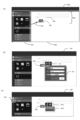
図16(b)~図16(d)、図17(a)、図17(b)に、前述した図15の再生情報定義1500に従った再生モジュールの実行が行われた場合の画面遷移例を示す。再生モジュールの実行(再生)が行われると、再生情報定義1500に従って、図16(b)が表示され、所定時間後に図16(c)に表示が遷移し、さらにその後に図16(d)、図17(a)、図17(b)という順で表示が自動的に遷移する。 16(b) to 16(d), 17(a), and 17(b) show screen transition examples when the playback module is executed according to the playback information definition 1500 in FIG. 15 described above. indicates When the reproduction module is executed (reproduced), FIG. 16(b) is displayed according to the reproduction information definition 1500. After a predetermined time, the display transitions to FIG. The display automatically transitions in the order of FIG. 17(a) and FIG. 17(b).

図16(b)は、再生情報定義1500の再生順が1番目である、枠1501内に記録された情報に基づく表示であり、UI_QUERYのUI画面定義に従った画面表示である。この表示は、SPAに記録された画面定義情報を参照して、UI_QUERYに定義された情報に基づいて行われる。 FIG. 16(b) is a display based on the information recorded in the frame 1501 in which the reproduction order of the reproduction information definition 1500 is the first, and is a screen display according to the UI screen definition of UI_QUERY. This display is performed based on the information defined in UI_QUERY by referring to the screen definition information recorded in SPA.

図16(b)は、再生情報定義1500の再生順が2番目である、枠1502内に記録された情報に基づく表示である。より詳しくは、入力ターゲットであるML_ADDRESSで示されるGUI部品に対して、再生情報定義1500に記録された入力値である「Dev」という文字列を、枠1621内に示すように表示したものである。ML_ADDRESSで示されるGUI部品は、本番用アプリケーションではユーザからのデータ入力を受け付ける入力領域である。しかし、再生モジュールを実行した場合には、再生モジュールの再生を見ているユーザ(顧客)がデータ入力をしなくても自動的に「Dev」という文字列が表示される。 FIG. 16(b) is a display based on the information recorded in the frame 1502, which is the second reproduction order of the reproduction information definition 1500. FIG. More specifically, the character string "Dev", which is the input value recorded in the reproduction information definition 1500, is displayed in a frame 1621 for the GUI component indicated by ML_ADDRESS, which is the input target. . A GUI component indicated by ML_ADDRESS is an input area for accepting data input from the user in the production application. However, when the reproduction module is executed, the character string "Dev" is automatically displayed without data input by the user (customer) watching the reproduction of the reproduction module.

図16(d)は、再生情報定義1500の再生順が3番目である枠1503に記録された情報に基づく表示を行い、さらにその後、再生順が4番目である枠1504に記録された情報に基づく表示を行った例である。より詳しくは、枠1503が示す情報に従って、吹き出しターゲットであるML_ADDRESSで示されるGUI部品に対して、再生情報定義1500に記録された吹き出し文字列が、吹き出し1631に示すように表示されている。また、枠1504が示す情報に従って、吹き出しターゲットであるSEARCN_BUTTONで示されるGUI部品(検索ボタン1616)に対して、再生情報定義1500に記録された吹き出し文字列が、吹き出し1632に示すように表示されている。 FIG. 16D shows a display based on the information recorded in the frame 1503, which is the third reproduction order of the reproduction information definition 1500, and then displays the information recorded in the frame 1504, which is the fourth reproduction order. This is an example of display based on More specifically, according to the information indicated by the frame 1503, the balloon character string recorded in the reproduction information definition 1500 is displayed as indicated by a balloon 1631 for the GUI component indicated by the balloon target ML_ADDRESS. In addition, according to the information indicated by the frame 1504, the balloon character string recorded in the reproduction information definition 1500 is displayed as indicated by a balloon 1632 for the GUI component (search button 1616) indicated by SEARCN_BUTTON which is a balloon target. there is

図17(a)は、再生情報定義1500の再生順が5番目である枠1505に記録された情報に基づく表示を行い、さらにその後、再生順が6番目として記録された情報(不図示)に基づく表示を行った例である。より詳しくは、枠1505が示す情報に従って、実行ターゲットであるSEARCN_BUTTONが示すGUI部品(検索ボタン1616)に対して、実行処理に示す操作であるクリックが行われた場合のアクションに対応づいて記録されたプロトタイプデータの表示を行う。なお、検索ボタン1616のクリックというアクションには、画面遷移が定義されていないため、S706ではNoと判定され、画面遷移をすることなく、検索ボタン1616のクリックというアクションに対応付けて記録されたプロトタイプデータ1701が表示される。なお、本番環境のアプリケーションであれば検索ボタンのクリックに応じて、データベースにアクセスして、ML_ADDRESSで示されるGUI部品に対して入力された文字列を検索キーとして検索する処理を行う。これに対し、この再生モジュールの実行においては、データベースにアクセスして、ML_ADDRESSで示されるGUI部品に対して入力された文字列を検索キーとして検索する処理は行わず、対応するプロトタイプアプリケーションを表示するという処理が行われる。その後、再生順が6番目であるイベントに従って吹き出しが表示される。
図17(b)は、再生情報定義1500の再生順が6番目以降である情報に基づく表示を行った例である。より詳しくは、図17(a)でリンク先を示すプロトタイプデータのクックというイベントを実行し、その後、吹き出しを表示するイベントを2つ実行した後の表示例である。リンク先のクリックというアクションは画面遷移を伴うものとして定義されているため、図7のS706はYesと判定され、S707で遷移先の画面である画面1710を表示する。その後、画面1710に、リンク先のクリックに対応づけて記録されているプロトタイプデータ1711を表示する。なお、本番環境のアプリケーションであればリンク先のクリックに応じて、クリックしたリンク先にアクセスする処理を行う。これに対し、この再生モジュールの実行においてはリンク先にアクセスする処理は行わず、対応するプロトタイプアプリケーションを表示するという処理が行われる。その後、吹き出しを表示するイベントを2つ実行すると図17(b)の表示となる。

以上の処理により、本番用のアプリケーションソフトウェアにおける複数のイベントの実行を仮想的に見ることのできるコンテンツ(再生モジュール)を容易に生成することができる。このコンテンツを顧客(本番用アプリケーションを提供される側のユーザ)が見ることで、顧客は、本願用のアプリケーションにおける複数のイベントの実行がどのように行われるのかを分かりやすく理解することができる。従って本番用アプリケーションの提供元の人材(開発者や営業担当など)が顧客に対して直接説明する手間を省き、効率的に顧客に本番用アプリケーションの動きを理解してもらうことが可能となる。さらに、開発途中で画面の仕様が変わる場合などでも、再生モジュールは変更があったUI定義を読み込んで実行するため、修正にかかる工数を減らすことができる効果を有する。さらに、再生モジュールに更なる編集(吹き出し、値の削除や追加、アクションの追加など)を行いたい場合にも、既存の再生情報定義を読み込んで編集をすればよいので、一から作り直す必要がなく、編集に係る手間を削減することができる。
FIG. 17A shows a display based on the information recorded in the frame 1505 whose reproduction order is the fifth in the reproduction information definition 1500, and then the information (not shown) recorded as the sixth reproduction order. This is an example of display based on More specifically, in accordance with the information indicated by the frame 1505, the action is recorded in correspondence with the action when the click, which is the operation indicated by the execution process, is performed on the GUI component (search button 1616) indicated by SEARCN_BUTTON, which is the execution target. display prototype data. Note that screen transition is not defined for the action of clicking the search button 1616, so a determination of No is made in S706, and the prototype recorded in association with the action of clicking the search button 1616 does not perform screen transition. Data 1701 is displayed. In the case of a production environment application, when the search button is clicked, the database is accessed and a search is performed using the character string input to the GUI component indicated by ML_ADDRESS as a search key. On the other hand, in the execution of this reproduction module, the corresponding prototype application is displayed without accessing the database and searching the GUI component indicated by ML_ADDRESS using the character string entered as the search key. process is performed. After that, a balloon is displayed according to the event that is the sixth in the playback order.
FIG. 17(b) is an example of display based on the information that the playback order of the playback information definition 1500 is the sixth or later. More specifically, in FIG. 17A, this is a display example after executing an event of cooking prototype data indicating a link destination, and then executing two events of displaying balloons. Since the action of clicking the link destination is defined as an action involving screen transition, S706 in FIG. 7 is determined as Yes, and screen 1710, which is the screen of the transition destination, is displayed in S707. After that, the screen 1710 displays the prototype data 1711 recorded in association with the click of the link destination. In the case of an application in a production environment, processing for accessing the clicked link destination is performed according to the click of the link destination. On the other hand, in executing the reproduction module, the process of accessing the link destination is not performed, but the process of displaying the corresponding prototype application is performed. After that, when two balloon display events are executed, the display of FIG. 17(b) is obtained.

With the above processing, it is possible to easily generate content (playback module) that allows one to virtually see the execution of multiple events in the production application software. By viewing this content, the customer (the user who is provided with the production application) can easily understand how multiple events are executed in the application for this application. Therefore, it is possible to save the time and effort of personnel (developers, sales representatives, etc.) who provide the production application to explain directly to the customer, and to make it possible for the customer to efficiently understand the operation of the production application. Furthermore, even if screen specifications change during development, the reproduction module reads and executes the changed UI definition, which has the effect of reducing man-hours required for correction. Furthermore, if you want to edit the playback module further (deleting or adding balloons, values, adding actions, etc.), you can read the existing playback information definition and edit it, so you don't have to recreate it from scratch. , the labor involved in editing can be reduced.

以上のように、前述した実施形態の機能を実現するプログラムを記録した記録媒体を、システムあるいは装置に供給し、そのシステムあるいは装置のコンピュータ(またはCPUやMPU)が記録媒体に格納されたプログラムを読み出し、実行することによっても本発明の目的が達成されることは言うまでもない。 As described above, a recording medium recording a program for realizing the functions of the above-described embodiments is supplied to a system or device, and the computer (or CPU or MPU) of the system or device reads the program stored in the recording medium. Needless to say, the object of the present invention can also be achieved by reading and executing.

この場合、記録媒体から読み出されたプログラム自体が本発明の新規な機能を実現することになり、そのプログラムを記録した記録媒体は本発明を構成することになる。 In this case, the program itself read from the recording medium implements the novel functions of the present invention, and the recording medium recording the program constitutes the present invention.

プログラムを供給するための記録媒体としては、例えば、フレキシブルディスク、ハードディスク、光ディスク、光磁気ディスク、CD-ROM、CD-R、DVD-ROM、磁気テープ、不揮発性のメモリカード、ROM、EEPROM、シリコンディスク等を用いることが出来る。 Examples of recording media for supplying programs include flexible disks, hard disks, optical disks, magneto-optical disks, CD-ROMs, CD-Rs, DVD-ROMs, magnetic tapes, non-volatile memory cards, ROMs, EEPROMs, silicon A disk or the like can be used.

また、コンピュータが読み出したプログラムを実行することにより、前述した実施形態の機能が実現されるだけでなく、そのプログラムの指示に基づき、コンピュータ上で稼働しているOS(オペレーティングシステム)等が実際の処理の一部または全部を行い、その処理によって前述した実施形態の機能が実現される場合も含まれることは言うまでもない。 Further, by executing the program read by the computer, not only the functions of the above-described embodiments are realized, but also based on the instructions of the program, the OS (operating system) and the like running on the computer are actually executed. Needless to say, a case where part or all of the processing is performed and the functions of the above-described embodiments are realized by the processing are included.

さらに、記録媒体から読み出されたプログラムが、コンピュータに挿入された機能拡張ボードやコンピュータに接続された機能拡張ユニットに備わるメモリに書き込まれた後、そのプログラムコードの指示に基づき、その機能拡張ボードや機能拡張ユニットに備わるCPU等が実際の処理の一部または全部を行い、その処理によって前述した実施形態の機能が実現される場合も含まれることは言うまでもない。 Furthermore, after the program read from the recording medium is written in the memory provided in the function expansion board inserted into the computer or the function expansion unit connected to the computer, the function expansion board is read according to the instruction of the program code. It goes without saying that a case where a CPU or the like provided in a function expansion unit performs part or all of the actual processing and the functions of the above-described embodiments are realized by the processing.

また、本発明は、複数の機器から構成されるシステムに適用しても、ひとつの機器から成る装置に適用しても良い。また、本発明は、システムあるいは装置にプログラムを供給することによって達成される場合にも適応できることは言うまでもない。この場合、本発明を達成するためのプログラムを格納した記録媒体を該システムあるいは装置に読み出すことによって、そのシステムあるいは装置が、本発明の効果を享受することが可能となる。 Moreover, the present invention may be applied to a system composed of a plurality of devices or to an apparatus composed of a single device. Further, it goes without saying that the present invention can be applied to the case where it is achieved by supplying a program to a system or device. In this case, by loading a recording medium storing a program for achieving the present invention into the system or device, the system or device can enjoy the effects of the present invention.

上記プログラムの形態は、オブジェクトコード、インタプリタにより実行されるプログラムコード、OS(オペレーティングシステム)に供給されるスクリプトデータ等の形態から成ってもよい。 The program may be in the form of object code, program code executed by an interpreter, script data supplied to an OS (Operating System), or the like.

さらに、本発明を達成するためのプログラムをネットワーク上のサーバ、データベース等から通信プログラムによりダウンロードして読み出すことによって、そのシステムあるいは装置が、本発明の効果を享受することが可能となる。なお、上述した各実施形態およびその変形例を組み合わせた構成も全て本発明に含まれるものである。 Furthermore, by downloading and reading out the program for achieving the present invention from a server, database, etc. on the network using a communication program, the system or device can enjoy the effects of the present invention. It should be noted that all configurations obtained by combining each of the above-described embodiments and modifications thereof are also included in the present invention.

101 プログラム開発装置
102 実行サーバ
103 データベースサーバ
104 クライアント装置
105 ネットワーク

101 Program development device 102 Execution server 103 Database server 104 Client device 105 Network

Claims (14)

アプリケーションソフトウェアで表示される複数の画面のうちいずれかを選択する第1の選択手段と、
前記第1の選択手段で選択された画面に対応づけて記憶された動作のうちいずれかを選択する第2の選択手段と、
前記第1の選択手段で選択された画面を表示する第1のイベントと、前記第2の選択手段で選択された動作に対応する第2のイベントとを含む複数のイベントを順次実行することを指示する指示情報を生成するように制御する制御手段と
を有することを特徴とする情報処理装置。
first selection means for selecting one of a plurality of screens displayed by application software;
a second selection means for selecting one of the actions stored in association with the screen selected by the first selection means;
sequentially executing a plurality of events including a first event for displaying the screen selected by the first selection means and a second event corresponding to the action selected by the second selection means; and control means for controlling to generate instruction information for instructing.
前記第1の選択手段は、前記アプリケーションソフトウェアを作成する際に定義された複数の画面にそれぞれ対応する複数の選択肢のうちいずれかを選択する操作に応じて選択することを特徴とする請求項1に記載の情報処理装置。 2. The first selection means selects one of a plurality of options corresponding to a plurality of screens defined when the application software is created, in accordance with an operation of selecting one of the options. The information processing device according to . 前記制御手段は、前記第1の選択手段によって前記複数の画面のうちいずれかが選択されると、選択された画面に対応づけて記憶された少なくとも1つの動作がある場合に、前記少なくとも1つの動作を前記第2の選択手段での選択肢として表示するように制御することを特徴とする請求項1または2に記載の情報処理装置。 When one of the plurality of screens is selected by the first selection means, the control means selects the at least one action when there is at least one action stored in association with the selected screen. 3. The information processing apparatus according to claim 1, wherein the operation is controlled to be displayed as an option by said second selection means. 生成される前記指示情報において前記複数のイベントを実行する順序を指定する操作を受け付ける第1の受付手段を更に有することを特徴とする請求項1乃至3のいずれか1項に記載の情報処理装置。 4. The information processing apparatus according to any one of claims 1 to 3, further comprising first receiving means for receiving an operation specifying an order of executing the plurality of events in the generated instruction information. . 前記第2の選択手段で選択された動作が、特定の処理を実行した結果に応じた表示を行うことを含む動作である場合にも、前記指示情報に基づいて実行される前記第2のイベントは、前記特定の処理を実行することなく予め定められた表示を行うイベントであることを特徴とする請求項1乃至4のいずれか1項に記載の情報処理装置。 The second event executed based on the instruction information even when the action selected by the second selection means is an action including displaying a result of executing a specific process. 5. The information processing apparatus according to any one of claims 1 to 4, wherein is an event in which a predetermined display is performed without executing the specific process. 前記第1の選択手段で選択された画面に含まれる表示要素に対応づけた付加情報の入力を受け付ける第2の受付手段を更に有し、
前記複数のイベントは、前記第2の受付手段で入力を受け付けた付加情報を表示する第3のイベントをさらに含むことを特徴とする請求項1乃至3のいずれか1項に記載の情報処理装置。
further comprising second reception means for receiving input of additional information associated with the display element included in the screen selected by the first selection means;
4. The information processing apparatus according to any one of claims 1 to 3, wherein said plurality of events further include a third event for displaying additional information whose input is received by said second receiving means. .
前記制御手段は、前記第1の選択手段によって前記複数の画面のうちいずれかが選択されると、選択された画面に対応づけて生成された前記指示情報がある場合に、当該指示情報に基づいて、前記選択された画面と、前記第3のイベントで表示される付加情報とを表示するように制御することを特徴とする請求項6に記載の情報処理装置。 When one of the plurality of screens is selected by the first selection means, the control means, if there is the instruction information generated in association with the selected screen, 7. The information processing apparatus according to claim 6, wherein the selected screen and the additional information displayed in the third event are displayed. 前記付加情報は文字列であることを特徴とする請求項6または7に記載の情報処理装置。 8. An information processing apparatus according to claim 6, wherein said additional information is a character string. 前記付加情報は、対応する表示要素に対する吹き出しに表示する情報であることを特徴とする請求項6乃至8のいずれか1項に記載の情報処理装置。 9. The information processing apparatus according to any one of claims 6 to 8, wherein the additional information is information displayed in a balloon for a corresponding display element. 前記第1の選択手段で選択された画面に含まれる入力領域であって、前記指示情報に対応する本番用の画面においてはユーザからのデータ入力を受け付ける入力領域に対して自動的に表示するデータの入力を受け付ける第3の受付手段を更に有し、
前記複数のイベントは、前記第3の受付手段で入力を受け付けたデータを表示する第4のイベントを更に含むことを特徴とする請求項1乃至9のいずれか1項に記載の情報処理装置。
Data to be automatically displayed in the input area included in the screen selected by the first selection means and for accepting data input from the user on the actual screen corresponding to the instruction information. It further has a third receiving means for receiving the input of
10. The information processing apparatus according to any one of claims 1 to 9, wherein said plurality of events further includes a fourth event for displaying data received by said third receiving means.
前記指示情報は、前記指示情報に含まれる最初のイベントの実行の後は、前記複数のイベントをユーザからの操作が無くとも自動的に順次実行することを指示する情報であることを特徴とする請求項1乃至12のいずれか1項に記載の情報処理装置。 The instruction information is information for instructing that the plurality of events are automatically sequentially executed without a user's operation after execution of the first event included in the instruction information. The information processing apparatus according to any one of claims 1 to 12. 前記指示情報を反映するプログラムのソースコードを生成する生成手段を更に有することを特徴とする請求項1乃至11のいずれか1項に記載の情報処理装置。 12. The information processing apparatus according to any one of claims 1 to 11, further comprising generating means for generating source code of a program reflecting said instruction information. アプリケーションソフトウェアで表示される複数の画面のうちいずれかを選択する第1の選択ステップと、
前記第1の選択ステップで選択された画面に対応づけて記憶された動作のうちいずれかを選択する第2の選択ステップと、
前記第1の選択ステップで選択された画面を表示する第1のイベントと、前記第2の選択ステップで選択された動作に対応する第2のイベントとを含む複数のイベントを順次実行することを指示する指示情報を生成するように制御する制御ステップと
を有することを特徴とする情報処理装置の制御方法。
a first selection step of selecting one of a plurality of screens displayed by the application software;
a second selection step of selecting one of the actions stored in association with the screen selected in the first selection step;
sequentially executing a plurality of events including a first event for displaying the screen selected in the first selection step and a second event corresponding to the action selected in the second selection step; A control method for an information processing device, comprising: a control step of controlling to generate instruction information for instructing.
コンピュータを、請求項1乃至12のいずれか1項に記載された情報処理装置の各手段として機能させるためのプログラム。 A program for causing a computer to function as each means of the information processing apparatus according to any one of claims 1 to 12.
JP2021188564A 2021-11-19 2021-11-19 Information processing apparatus, information processing method, and program Pending JP2023075577A (en)

Priority Applications (1)

Application Number Priority Date Filing Date Title
JP2021188564A JP2023075577A (en) 2021-11-19 2021-11-19 Information processing apparatus, information processing method, and program

Applications Claiming Priority (1)

Application Number Priority Date Filing Date Title
JP2021188564A JP2023075577A (en) 2021-11-19 2021-11-19 Information processing apparatus, information processing method, and program

Publications (1)

Publication Number Publication Date
JP2023075577A true JP2023075577A (en) 2023-05-31

Family

ID=86542443

Family Applications (1)

Application Number Title Priority Date Filing Date
JP2021188564A Pending JP2023075577A (en) 2021-11-19 2021-11-19 Information processing apparatus, information processing method, and program

Country Status (1)

Country Link
JP (1) JP2023075577A (en)

Similar Documents

Publication Publication Date Title
JP2006221582A (en) Information processor, method of controlling the same, and program
KR102543722B1 (en) Method, system, and non-transitory computer readable record medium for business cooperation using desing kit
JP2022022451A (en) Server, information processing apparatus, processing method, and program
Delessio et al. Sams teach yourself Android application development in 24 hours
JP2023075577A (en) Information processing apparatus, information processing method, and program
JP6423933B2 (en) Information processing apparatus, form management system, form management server, information processing method, and program thereof
JP4386243B2 (en) PROGRAM GENERATION DEVICE, PROGRAM GENERATION METHOD, PROGRAM AND RECORDING MEDIUM
JP6594359B2 (en) Information processing apparatus, information processing method, and program
JP2018181073A (en) Information processing apparatus, processing method thereof, and program
JP6836077B2 (en) Information processing device and its processing method and program
JP2016126764A (en) Information processing device, method for controlling information processing device and program
JP7381900B2 (en) Information processing system, its control method and program
JP5447621B2 (en) PROGRAM GENERATION DEVICE, PROGRAM GENERATION METHOD, AND PROGRAM
JP2023157179A (en) Information processing apparatus, information processing method, and program
JP7421137B2 (en) Information processing device, information processing method and program
JP6862521B2 (en) Information processing equipment, information processing methods, and programs
JP7231864B2 (en) Information processing device, information processing method and program
JP7290095B2 (en) Display control program, display control method and display control device
JP7048912B2 (en) Information processing equipment and its processing method and program
JP2022101746A (en) Information processing apparatus, information processing method, and program
JP7280475B2 (en) Information processing device, its control method, and program
KR102228241B1 (en) Method and system for virtual input on the web
JP6572984B2 (en) Electronic form system, form retrieval apparatus, control method, and program
JP2000227914A (en) Document edition device
JP2022110184A (en) Information processing apparatus, control method, and program