JP2023027770A - Exhaust gas apparatus for internal combustion engine - Google Patents
Exhaust gas apparatus for internal combustion engine Download PDFInfo
- Publication number
- JP2023027770A JP2023027770A JP2022129544A JP2022129544A JP2023027770A JP 2023027770 A JP2023027770 A JP 2023027770A JP 2022129544 A JP2022129544 A JP 2022129544A JP 2022129544 A JP2022129544 A JP 2022129544A JP 2023027770 A JP2023027770 A JP 2023027770A
- Authority
- JP
- Japan
- Prior art keywords
- exhaust gas
- casing
- region
- shielding
- wall
- Prior art date
- Legal status (The legal status is an assumption and is not a legal conclusion. Google has not performed a legal analysis and makes no representation as to the accuracy of the status listed.)
- Granted
Links
Images

Classifications
-
- F—MECHANICAL ENGINEERING; LIGHTING; HEATING; WEAPONS; BLASTING
- F01—MACHINES OR ENGINES IN GENERAL; ENGINE PLANTS IN GENERAL; STEAM ENGINES
- F01N—GAS-FLOW SILENCERS OR EXHAUST APPARATUS FOR MACHINES OR ENGINES IN GENERAL; GAS-FLOW SILENCERS OR EXHAUST APPARATUS FOR INTERNAL-COMBUSTION ENGINES
- F01N3/00—Exhaust or silencing apparatus having means for purifying, rendering innocuous, or otherwise treating exhaust
- F01N3/08—Exhaust or silencing apparatus having means for purifying, rendering innocuous, or otherwise treating exhaust for rendering innocuous
- F01N3/10—Exhaust or silencing apparatus having means for purifying, rendering innocuous, or otherwise treating exhaust for rendering innocuous by thermal or catalytic conversion of noxious components of exhaust
- F01N3/24—Exhaust or silencing apparatus having means for purifying, rendering innocuous, or otherwise treating exhaust for rendering innocuous by thermal or catalytic conversion of noxious components of exhaust characterised by constructional aspects of converting apparatus
- F01N3/28—Construction of catalytic reactors
- F01N3/2892—Exhaust flow directors or the like, e.g. upstream of catalytic device
-
- F—MECHANICAL ENGINEERING; LIGHTING; HEATING; WEAPONS; BLASTING
- F01—MACHINES OR ENGINES IN GENERAL; ENGINE PLANTS IN GENERAL; STEAM ENGINES
- F01N—GAS-FLOW SILENCERS OR EXHAUST APPARATUS FOR MACHINES OR ENGINES IN GENERAL; GAS-FLOW SILENCERS OR EXHAUST APPARATUS FOR INTERNAL-COMBUSTION ENGINES
- F01N13/00—Exhaust or silencing apparatus characterised by constructional features
- F01N13/08—Other arrangements or adaptations of exhaust conduits
-
- F—MECHANICAL ENGINEERING; LIGHTING; HEATING; WEAPONS; BLASTING
- F01—MACHINES OR ENGINES IN GENERAL; ENGINE PLANTS IN GENERAL; STEAM ENGINES
- F01N—GAS-FLOW SILENCERS OR EXHAUST APPARATUS FOR MACHINES OR ENGINES IN GENERAL; GAS-FLOW SILENCERS OR EXHAUST APPARATUS FOR INTERNAL-COMBUSTION ENGINES
- F01N13/00—Exhaust or silencing apparatus characterised by constructional features
- F01N13/14—Exhaust or silencing apparatus characterised by constructional features having thermal insulation
- F01N13/141—Double-walled exhaust pipes or housings
- F01N13/143—Double-walled exhaust pipes or housings with air filling the space between both walls
-
- F—MECHANICAL ENGINEERING; LIGHTING; HEATING; WEAPONS; BLASTING
- F01—MACHINES OR ENGINES IN GENERAL; ENGINE PLANTS IN GENERAL; STEAM ENGINES
- F01N—GAS-FLOW SILENCERS OR EXHAUST APPARATUS FOR MACHINES OR ENGINES IN GENERAL; GAS-FLOW SILENCERS OR EXHAUST APPARATUS FOR INTERNAL-COMBUSTION ENGINES
- F01N13/00—Exhaust or silencing apparatus characterised by constructional features
- F01N13/009—Exhaust or silencing apparatus characterised by constructional features having two or more separate purifying devices arranged in series
- F01N13/0097—Exhaust or silencing apparatus characterised by constructional features having two or more separate purifying devices arranged in series the purifying devices are arranged in a single housing
-
- F—MECHANICAL ENGINEERING; LIGHTING; HEATING; WEAPONS; BLASTING
- F01—MACHINES OR ENGINES IN GENERAL; ENGINE PLANTS IN GENERAL; STEAM ENGINES
- F01N—GAS-FLOW SILENCERS OR EXHAUST APPARATUS FOR MACHINES OR ENGINES IN GENERAL; GAS-FLOW SILENCERS OR EXHAUST APPARATUS FOR INTERNAL-COMBUSTION ENGINES
- F01N13/00—Exhaust or silencing apparatus characterised by constructional features
- F01N13/18—Construction facilitating manufacture, assembly, or disassembly
- F01N13/1872—Construction facilitating manufacture, assembly, or disassembly the assembly using stamp-formed parts or otherwise deformed sheet-metal
-
- F—MECHANICAL ENGINEERING; LIGHTING; HEATING; WEAPONS; BLASTING
- F01—MACHINES OR ENGINES IN GENERAL; ENGINE PLANTS IN GENERAL; STEAM ENGINES
- F01N—GAS-FLOW SILENCERS OR EXHAUST APPARATUS FOR MACHINES OR ENGINES IN GENERAL; GAS-FLOW SILENCERS OR EXHAUST APPARATUS FOR INTERNAL-COMBUSTION ENGINES
- F01N2240/00—Combination or association of two or more different exhaust treating devices, or of at least one such device with an auxiliary device, not covered by indexing codes F01N2230/00 or F01N2250/00, one of the devices being
- F01N2240/20—Combination or association of two or more different exhaust treating devices, or of at least one such device with an auxiliary device, not covered by indexing codes F01N2230/00 or F01N2250/00, one of the devices being a flow director or deflector
-
- F—MECHANICAL ENGINEERING; LIGHTING; HEATING; WEAPONS; BLASTING
- F01—MACHINES OR ENGINES IN GENERAL; ENGINE PLANTS IN GENERAL; STEAM ENGINES
- F01N—GAS-FLOW SILENCERS OR EXHAUST APPARATUS FOR MACHINES OR ENGINES IN GENERAL; GAS-FLOW SILENCERS OR EXHAUST APPARATUS FOR INTERNAL-COMBUSTION ENGINES
- F01N2250/00—Combinations of different methods of purification
- F01N2250/02—Combinations of different methods of purification filtering and catalytic conversion
-
- F—MECHANICAL ENGINEERING; LIGHTING; HEATING; WEAPONS; BLASTING
- F01—MACHINES OR ENGINES IN GENERAL; ENGINE PLANTS IN GENERAL; STEAM ENGINES
- F01N—GAS-FLOW SILENCERS OR EXHAUST APPARATUS FOR MACHINES OR ENGINES IN GENERAL; GAS-FLOW SILENCERS OR EXHAUST APPARATUS FOR INTERNAL-COMBUSTION ENGINES
- F01N2260/00—Exhaust treating devices having provisions not otherwise provided for
- F01N2260/20—Exhaust treating devices having provisions not otherwise provided for for heat or sound protection, e.g. using a shield or specially shaped outer surface of exhaust device
-
- F—MECHANICAL ENGINEERING; LIGHTING; HEATING; WEAPONS; BLASTING
- F01—MACHINES OR ENGINES IN GENERAL; ENGINE PLANTS IN GENERAL; STEAM ENGINES
- F01N—GAS-FLOW SILENCERS OR EXHAUST APPARATUS FOR MACHINES OR ENGINES IN GENERAL; GAS-FLOW SILENCERS OR EXHAUST APPARATUS FOR INTERNAL-COMBUSTION ENGINES
- F01N2450/00—Methods or apparatus for fitting, inserting or repairing different elements
- F01N2450/22—Methods or apparatus for fitting, inserting or repairing different elements by welding or brazing
-
- F—MECHANICAL ENGINEERING; LIGHTING; HEATING; WEAPONS; BLASTING
- F01—MACHINES OR ENGINES IN GENERAL; ENGINE PLANTS IN GENERAL; STEAM ENGINES
- F01N—GAS-FLOW SILENCERS OR EXHAUST APPARATUS FOR MACHINES OR ENGINES IN GENERAL; GAS-FLOW SILENCERS OR EXHAUST APPARATUS FOR INTERNAL-COMBUSTION ENGINES
- F01N2530/00—Selection of materials for tubes, chambers or housings
- F01N2530/26—Multi-layered walls
-
- F—MECHANICAL ENGINEERING; LIGHTING; HEATING; WEAPONS; BLASTING
- F01—MACHINES OR ENGINES IN GENERAL; ENGINE PLANTS IN GENERAL; STEAM ENGINES
- F01N—GAS-FLOW SILENCERS OR EXHAUST APPARATUS FOR MACHINES OR ENGINES IN GENERAL; GAS-FLOW SILENCERS OR EXHAUST APPARATUS FOR INTERNAL-COMBUSTION ENGINES
- F01N2610/00—Adding substances to exhaust gases
- F01N2610/02—Adding substances to exhaust gases the substance being ammonia or urea
-
- F—MECHANICAL ENGINEERING; LIGHTING; HEATING; WEAPONS; BLASTING
- F01—MACHINES OR ENGINES IN GENERAL; ENGINE PLANTS IN GENERAL; STEAM ENGINES
- F01N—GAS-FLOW SILENCERS OR EXHAUST APPARATUS FOR MACHINES OR ENGINES IN GENERAL; GAS-FLOW SILENCERS OR EXHAUST APPARATUS FOR INTERNAL-COMBUSTION ENGINES
- F01N2610/00—Adding substances to exhaust gases
- F01N2610/10—Adding substances to exhaust gases the substance being heated, e.g. by heating tank or supply line of the added substance
- F01N2610/102—Adding substances to exhaust gases the substance being heated, e.g. by heating tank or supply line of the added substance after addition to exhaust gases, e.g. by a passively or actively heated surface in the exhaust conduit
-
- F—MECHANICAL ENGINEERING; LIGHTING; HEATING; WEAPONS; BLASTING
- F01—MACHINES OR ENGINES IN GENERAL; ENGINE PLANTS IN GENERAL; STEAM ENGINES
- F01N—GAS-FLOW SILENCERS OR EXHAUST APPARATUS FOR MACHINES OR ENGINES IN GENERAL; GAS-FLOW SILENCERS OR EXHAUST APPARATUS FOR INTERNAL-COMBUSTION ENGINES
- F01N2610/00—Adding substances to exhaust gases
- F01N2610/14—Arrangements for the supply of substances, e.g. conduits
- F01N2610/1453—Sprayers or atomisers; Arrangement thereof in the exhaust apparatus
-
- F—MECHANICAL ENGINEERING; LIGHTING; HEATING; WEAPONS; BLASTING
- F01—MACHINES OR ENGINES IN GENERAL; ENGINE PLANTS IN GENERAL; STEAM ENGINES
- F01N—GAS-FLOW SILENCERS OR EXHAUST APPARATUS FOR MACHINES OR ENGINES IN GENERAL; GAS-FLOW SILENCERS OR EXHAUST APPARATUS FOR INTERNAL-COMBUSTION ENGINES
- F01N3/00—Exhaust or silencing apparatus having means for purifying, rendering innocuous, or otherwise treating exhaust
- F01N3/02—Exhaust or silencing apparatus having means for purifying, rendering innocuous, or otherwise treating exhaust for cooling, or for removing solid constituents of, exhaust
- F01N3/021—Exhaust or silencing apparatus having means for purifying, rendering innocuous, or otherwise treating exhaust for cooling, or for removing solid constituents of, exhaust by means of filters
-
- F—MECHANICAL ENGINEERING; LIGHTING; HEATING; WEAPONS; BLASTING
- F01—MACHINES OR ENGINES IN GENERAL; ENGINE PLANTS IN GENERAL; STEAM ENGINES
- F01N—GAS-FLOW SILENCERS OR EXHAUST APPARATUS FOR MACHINES OR ENGINES IN GENERAL; GAS-FLOW SILENCERS OR EXHAUST APPARATUS FOR INTERNAL-COMBUSTION ENGINES
- F01N3/00—Exhaust or silencing apparatus having means for purifying, rendering innocuous, or otherwise treating exhaust
- F01N3/08—Exhaust or silencing apparatus having means for purifying, rendering innocuous, or otherwise treating exhaust for rendering innocuous
- F01N3/10—Exhaust or silencing apparatus having means for purifying, rendering innocuous, or otherwise treating exhaust for rendering innocuous by thermal or catalytic conversion of noxious components of exhaust
- F01N3/103—Oxidation catalysts for HC and CO only
-
- F—MECHANICAL ENGINEERING; LIGHTING; HEATING; WEAPONS; BLASTING
- F01—MACHINES OR ENGINES IN GENERAL; ENGINE PLANTS IN GENERAL; STEAM ENGINES
- F01N—GAS-FLOW SILENCERS OR EXHAUST APPARATUS FOR MACHINES OR ENGINES IN GENERAL; GAS-FLOW SILENCERS OR EXHAUST APPARATUS FOR INTERNAL-COMBUSTION ENGINES
- F01N3/00—Exhaust or silencing apparatus having means for purifying, rendering innocuous, or otherwise treating exhaust
- F01N3/08—Exhaust or silencing apparatus having means for purifying, rendering innocuous, or otherwise treating exhaust for rendering innocuous
- F01N3/10—Exhaust or silencing apparatus having means for purifying, rendering innocuous, or otherwise treating exhaust for rendering innocuous by thermal or catalytic conversion of noxious components of exhaust
- F01N3/105—General auxiliary catalysts, e.g. upstream or downstream of the main catalyst
- F01N3/106—Auxiliary oxidation catalysts
-
- F—MECHANICAL ENGINEERING; LIGHTING; HEATING; WEAPONS; BLASTING
- F01—MACHINES OR ENGINES IN GENERAL; ENGINE PLANTS IN GENERAL; STEAM ENGINES
- F01N—GAS-FLOW SILENCERS OR EXHAUST APPARATUS FOR MACHINES OR ENGINES IN GENERAL; GAS-FLOW SILENCERS OR EXHAUST APPARATUS FOR INTERNAL-COMBUSTION ENGINES
- F01N3/00—Exhaust or silencing apparatus having means for purifying, rendering innocuous, or otherwise treating exhaust
- F01N3/08—Exhaust or silencing apparatus having means for purifying, rendering innocuous, or otherwise treating exhaust for rendering innocuous
- F01N3/10—Exhaust or silencing apparatus having means for purifying, rendering innocuous, or otherwise treating exhaust for rendering innocuous by thermal or catalytic conversion of noxious components of exhaust
- F01N3/105—General auxiliary catalysts, e.g. upstream or downstream of the main catalyst
- F01N3/108—Auxiliary reduction catalysts
-
- F—MECHANICAL ENGINEERING; LIGHTING; HEATING; WEAPONS; BLASTING
- F01—MACHINES OR ENGINES IN GENERAL; ENGINE PLANTS IN GENERAL; STEAM ENGINES
- F01N—GAS-FLOW SILENCERS OR EXHAUST APPARATUS FOR MACHINES OR ENGINES IN GENERAL; GAS-FLOW SILENCERS OR EXHAUST APPARATUS FOR INTERNAL-COMBUSTION ENGINES
- F01N3/00—Exhaust or silencing apparatus having means for purifying, rendering innocuous, or otherwise treating exhaust
- F01N3/08—Exhaust or silencing apparatus having means for purifying, rendering innocuous, or otherwise treating exhaust for rendering innocuous
- F01N3/10—Exhaust or silencing apparatus having means for purifying, rendering innocuous, or otherwise treating exhaust for rendering innocuous by thermal or catalytic conversion of noxious components of exhaust
- F01N3/18—Exhaust or silencing apparatus having means for purifying, rendering innocuous, or otherwise treating exhaust for rendering innocuous by thermal or catalytic conversion of noxious components of exhaust characterised by methods of operation; Control
- F01N3/20—Exhaust or silencing apparatus having means for purifying, rendering innocuous, or otherwise treating exhaust for rendering innocuous by thermal or catalytic conversion of noxious components of exhaust characterised by methods of operation; Control specially adapted for catalytic conversion
- F01N3/206—Adding periodically or continuously substances to exhaust gases for promoting purification, e.g. catalytic material in liquid form, NOx reducing agents
- F01N3/2066—Selective catalytic reduction [SCR]
-
- F—MECHANICAL ENGINEERING; LIGHTING; HEATING; WEAPONS; BLASTING
- F01—MACHINES OR ENGINES IN GENERAL; ENGINE PLANTS IN GENERAL; STEAM ENGINES
- F01N—GAS-FLOW SILENCERS OR EXHAUST APPARATUS FOR MACHINES OR ENGINES IN GENERAL; GAS-FLOW SILENCERS OR EXHAUST APPARATUS FOR INTERNAL-COMBUSTION ENGINES
- F01N3/00—Exhaust or silencing apparatus having means for purifying, rendering innocuous, or otherwise treating exhaust
- F01N3/08—Exhaust or silencing apparatus having means for purifying, rendering innocuous, or otherwise treating exhaust for rendering innocuous
- F01N3/10—Exhaust or silencing apparatus having means for purifying, rendering innocuous, or otherwise treating exhaust for rendering innocuous by thermal or catalytic conversion of noxious components of exhaust
- F01N3/24—Exhaust or silencing apparatus having means for purifying, rendering innocuous, or otherwise treating exhaust for rendering innocuous by thermal or catalytic conversion of noxious components of exhaust characterised by constructional aspects of converting apparatus
- F01N3/28—Construction of catalytic reactors
- F01N3/2882—Catalytic reactors combined or associated with other devices, e.g. exhaust silencers or other exhaust purification devices
-
- Y—GENERAL TAGGING OF NEW TECHNOLOGICAL DEVELOPMENTS; GENERAL TAGGING OF CROSS-SECTIONAL TECHNOLOGIES SPANNING OVER SEVERAL SECTIONS OF THE IPC; TECHNICAL SUBJECTS COVERED BY FORMER USPC CROSS-REFERENCE ART COLLECTIONS [XRACs] AND DIGESTS
- Y02—TECHNOLOGIES OR APPLICATIONS FOR MITIGATION OR ADAPTATION AGAINST CLIMATE CHANGE
- Y02A—TECHNOLOGIES FOR ADAPTATION TO CLIMATE CHANGE
- Y02A50/00—TECHNOLOGIES FOR ADAPTATION TO CLIMATE CHANGE in human health protection, e.g. against extreme weather
- Y02A50/20—Air quality improvement or preservation, e.g. vehicle emission control or emission reduction by using catalytic converters
-
- Y—GENERAL TAGGING OF NEW TECHNOLOGICAL DEVELOPMENTS; GENERAL TAGGING OF CROSS-SECTIONAL TECHNOLOGIES SPANNING OVER SEVERAL SECTIONS OF THE IPC; TECHNICAL SUBJECTS COVERED BY FORMER USPC CROSS-REFERENCE ART COLLECTIONS [XRACs] AND DIGESTS
- Y02—TECHNOLOGIES OR APPLICATIONS FOR MITIGATION OR ADAPTATION AGAINST CLIMATE CHANGE
- Y02T—CLIMATE CHANGE MITIGATION TECHNOLOGIES RELATED TO TRANSPORTATION
- Y02T10/00—Road transport of goods or passengers
- Y02T10/10—Internal combustion engine [ICE] based vehicles
- Y02T10/12—Improving ICE efficiencies
Landscapes
- Engineering & Computer Science (AREA)
- Chemical & Material Sciences (AREA)
- Chemical Kinetics & Catalysis (AREA)
- Combustion & Propulsion (AREA)
- Mechanical Engineering (AREA)
- General Engineering & Computer Science (AREA)
- Health & Medical Sciences (AREA)
- Toxicology (AREA)
- Exhaust Gas After Treatment (AREA)
- Materials Engineering (AREA)
- Processes For Solid Components From Exhaust (AREA)
- Exhaust Gas Treatment By Means Of Catalyst (AREA)
Abstract
【課題】構造的に簡単な対策で外部への熱放出を低減する熱遮蔽を達成することができる内燃機関のための排ガス装置を提供すること。【解決手段】内燃機関用の排ガス装置であって、外壁により排ガス流容積を画定し、かつ外壁の、排ガス流容積に面した内面において少なくとも1つの遮蔽要素(64,66)を支持する少なくとも1つの構成要素を含んでおり、外壁と遮蔽要素(64,66)との間に中間室(65、67)が形成されており、少なくとも1つの遮蔽要素(64,66)に、外壁に向けられ、この外壁に固定的に結合された少なくとも1つの結合成形部が設けられている、排ガス装置。【選択図】図1An object of the present invention is to provide an exhaust gas device for an internal combustion engine that can achieve heat shielding that reduces heat release to the outside with structurally simple measures. The exhaust gas device for an internal combustion engine includes at least one shielding element (64, 66) which defines an exhaust gas flow volume by an outer wall and supports at least one shielding element (64, 66) on the inner surface of the outer wall facing the exhaust gas flow volume. an intermediate chamber (65, 67) is formed between the outer wall and the shielding element (64, 66), and at least one shielding element (64, 66) is directed towards the outer wall. , the exhaust gas device is provided with at least one connection molding fixedly connected to the outer wall. [Selection diagram] Figure 1
Description
本発明は、内燃機関の排ガス装置に関する。 The present invention relates to an exhaust gas system for an internal combustion engine.
車両に設けられた内燃機関もしくは内燃機関に対応して配置された排ガス装置では、有害物質排出に関して重要な段階はコールドスタートであり、このコールドスタートでは、内燃機関もしくは排ガス装置の様々な構成要素も比較的低い温度を有していて、したがって、たとえばこのような排ガス装置に含まれる、排ガス浄化のための排ガス処理ユニット、たとえば酸化触媒コンバータ、粒子フィルタまたはSCR触媒が実質的にアクティブではありえない。比較的高い汚染物質排出を伴うこの段階をできるだけ短く維持するために、排ガス装置の様々なシステム領域を、内燃機関から排出される排ガス中の汚染物質割合の十分な低減を保証することができるような高温にできるだけ迅速に到達させることが必要となる。 For an internal combustion engine in a vehicle or for an exhaust gas system arranged correspondingly to the internal combustion engine, a critical phase with respect to pollutant emissions is the cold start, during which the various components of the internal combustion engine or the exhaust gas system are also turned on. Exhaust gas treatment units for purifying exhaust gases, such as oxidation catalytic converters, particle filters or SCR catalysts, which have relatively low temperatures and which are included, for example, in such exhaust gas systems, cannot be substantially active. In order to keep this phase with relatively high pollutant emissions as short as possible, the various system areas of the exhaust system are designed to ensure a sufficiently low pollutant fraction in the exhaust gases emitted by the internal combustion engine. It is necessary to reach a high temperature as quickly as possible.
本発明の課題は、構造的に簡単な対策で外部への熱放出を低減する熱遮蔽を達成することができる内燃機関のための排ガス装置を提供することである。 SUMMARY OF THE INVENTION It is an object of the present invention to provide an exhaust gas system for an internal combustion engine with which a heat shield can be achieved with structurally simple measures to reduce heat emission to the outside.
本発明によれば、この課題は、内燃機関用の排ガス装置であって、外壁により排ガス流容積を画定し、かつ外壁の、排ガス流容積に面した内面において少なくとも1つの遮蔽要素を支持する少なくとも1つの構成要素を含んでおり、外壁と遮蔽要素との間に中間室が形成されており、少なくとも1つの遮蔽要素に、外壁に向けられ、この外壁に固定的に結合された少なくとも1つの第1の結合成形部が設けられており、かつ/または外壁に、少なくとも1つの遮蔽要素に向けられ、少なくとも1つの遮蔽要素に固定的に結合された少なくとも1つの第2の結合成形部が設けられている、排ガス装置によって解決される。 According to the invention, the object is an exhaust gas system for an internal combustion engine, the outer wall defining an exhaust gas flow volume and supporting at least one shielding element on the inner surface of the outer wall facing the exhaust gas flow volume. An intermediate chamber is formed between the outer wall and the shielding element, and the at least one shielding element is provided with at least one second shield directed toward the outer wall and fixedly connected to the outer wall. One bonding profile is provided and/or the outer wall is provided with at least one second bonding profile directed towards the at least one shielding element and fixedly connected to the at least one shielding element. is solved by the exhaust gas system.
排ガス装置の1つ以上の構成要素に1つ以上の遮蔽要素を設けることによって、その内側において覆われていて、外側において概して周囲と熱伝達接触している外壁は、少なくとも部分的に排ガスが直接に当たるように流れることに対して遮蔽される。このような遮蔽要素は外壁に対して間隔を有しており、専ら結合成形部の領域においてこの外壁に接触しているので、排ガス内で搬送された熱は、ごく限られた程度でのみ外壁に伝達され、この外壁を介して外部へ放出される。これにより、熱損失が著しく制限され、このことは一方ではコールドスタート段階での排ガス装置の迅速な加熱をもたらし、他方では、このような排ガス装置の周辺に設けられた車両のシステム領域への熱負荷を減じるので、このようなシステム領域を排ガス装置の近傍に配置することも可能性も生じる。 By providing one or more components of the exhaust gas system with one or more shielding elements, the outer wall covered on the inside thereof and generally in heat transfer contact with the surroundings on the outside is at least partially directly exposed to the exhaust gas. shielded against flowing against the Since such shielding elements are spaced from the outer wall and are in contact with this wall exclusively in the region of the bond formation, the heat transported in the exhaust gas is transferred only to a very limited extent to the outer wall. and emitted to the outside through this outer wall. As a result, heat losses are significantly limited, which on the one hand leads to rapid heating of the exhaust system during the cold start phase and, on the other hand, heat transfer to system areas of the vehicle arranged around such an exhaust system. There is also the possibility of arranging such system areas in the vicinity of the exhaust system, since this reduces the load.
十分な安定性で良好な遮蔽特性を提供できるようにするために、少なくとも1つの遮蔽要素が、金属薄板変形加工部材である、または/かつ少なくとも1つの遮蔽要素が、0.6mm~1.0mmの範囲、好適には約0.8mmの厚さを有していることが規定されている。 In order to be able to provide good shielding properties with sufficient stability, at least one shielding element is a sheet metal deformed member or/and at least one shielding element is between 0.6 mm and 1.0 mm. , preferably about 0.8 mm.
外壁も、少なくとも1つの金属薄板変形加工部材を含んでいてよい。さらに、良好な遮蔽効果を達成するために、中間室が、0.5mm~6mmの範囲の寸法を有していてよい。 The outer wall may also include at least one sheet metal deformation member. Furthermore, the intermediate chamber may have dimensions in the range from 0.5 mm to 6 mm in order to achieve a good shielding effect.
一方では熱的接触を回避し、他方では相互の当付けによるガタつき騒音を回避するために、少なくとも1つの、好適には各遮蔽要素が、外壁に対して間隔を空けて位置決めされた外縁部領域を含んでいることが提案される。つまり、このような遮蔽要素は、実質的に単に結合成形部の領域においてのみ、この遮蔽要素に結合された構成要素もしくはその外壁との物理的な接触を有している。 At least one, preferably each shielding element is positioned at a distance from the outer wall in order to avoid thermal contact on the one hand and rattling noise due to mutual contact on the other hand. It is suggested to include a region. Such a shielding element thus has physical contact with the component connected to it or its outer wall substantially only in the region of the bonding molding.
ケーシングの外壁が複雑な幾何学形状である場合にも、排ガスが直接に当たって流れることに対して外壁をほぼ完全に遮蔽することができるように、複数の遮蔽要素がこのような構成要素もしくは構成要素の外壁に設けられていてよい。この場合に、このような遮蔽要素が互いに接続する場所において、構成要素の外壁に直接に当たって流れることを回避するために、少なくとも2つの遮蔽要素が、隣接領域において互いに部分的にオーバラップするように配置されていてよい。 A plurality of shielding elements are provided in such a component or components so that the outer wall of the casing can be almost completely shielded against the direct impingement and flow of the exhaust gases, even if the outer wall of the casing has a complex geometry. may be provided on the outer wall of the In this case, at least two shielding elements partially overlap each other in adjacent regions to avoid flowing directly against the outer wall of the component at the locations where such shielding elements connect to each other. may be placed.
このようなオーバラップ領域において相互の当接およびこれに伴うガタつき騒音を回避するために、隣接領域において互いにオーバラップして配置された遮蔽部材間に、中間室が形成されていることが提案される。 In order to avoid mutual abutment and the associated rattling noise in such overlap regions, it is proposed that an intermediate chamber is formed between the shielding members which are arranged overlapping each other in adjacent regions. be done.
熱負荷可能かつ化学的に耐性を有する結合のために、少なくとも1つの遮蔽要素が、少なくとも1つの、好適には各結合成形部において材料結合部、好適には溶接、たとえば抵抗溶接、レーザ溶接またはスロット溶接により外壁に結合されていてよい。 For a thermally loadable and chemically resistant connection, at least one shielding element is provided in at least one, preferably in each bond formation, with a material connection, preferably welding, for example resistance welding, laser welding or It may be connected to the outer wall by slot welding.
コンパクトな構成のために、排ガス装置は、上流側の流入領域および下流側の流出領域を備えた少なくとも1つの第1の排ガス処理ユニットと、上流側の流入領域および下流側の流出領域を備えた少なくとも1つの第2の排ガス処理ユニットと、少なくとも1つの第1の排ガス処理ユニットの下流側の流出領域および少なくとも1つの第2の排ガス処理ユニットの上流側の流入領域に結合された結合ケーシングとを含んでいてよい。結合ケーシングは、1つの構成要素を提供することができる。 For a compact design, the exhaust gas system has at least one first exhaust gas treatment unit with an upstream inlet region and a downstream outlet region, and an upstream inlet region and a downstream outlet region. at least one second exhaust gas treatment unit and a combined casing coupled to the downstream outflow region of the at least one first exhaust gas treatment unit and to the upstream inflow region of the at least one second exhaust gas treatment unit may contain. A combined casing can provide one component.
構造的に単純に実現すべき構成では、結合ケーシングは、流入開口および流出開口を備えた第1のケーシング要素を含んでよく、流入開口の領域において、少なくとも1つの第1の排ガス処理ユニットの下流側の流出領域が、結合ケーシングに結合されており、流出開口の領域において、少なくとも1つの第2の排ガス処理ユニットの上流側の流入領域が、結合ケーシングに結合されている。さらに、結合ケーシングは、第1のケーシング要素と一緒に、排ガスにより通流可能な結合容積を画定する第2のケーシング要素を含んでいてよい。結合ケーシングが、その内面において少なくとも1つの遮蔽要素によって遮蔽された構成要素を提供する場合、この構成要素の外壁が、第1のケーシング要素または/および第2のケーシング要素を含んでいてよい。 In a configuration that is to be structurally simple, the combined casing can comprise a first casing element with an inlet opening and an outlet opening, downstream of the at least one first exhaust gas treatment unit in the region of the inlet opening. The side outflow area is connected to the connection housing, and in the area of the outflow opening the upstream inflow area of the at least one second exhaust gas treatment unit is connected to the connection housing. Furthermore, the combined housing can comprise a second housing element which, together with the first housing element, defines a combined volume through which the exhaust gas can flow. If the combined casing provides a component shielded by at least one shielding element on its inner surface, the outer wall of this component may comprise the first casing element or/and the second casing element.
結合ケーシングの領域において排ガス流の流れ変向が行われてよく、かつ特に第2のケーシング要素の、流入開口もしくは流出開口もしくは流入開口と流出開口との間の移行領域と反対に位置する領域が、排ガス流と相互作用することができるので、良好な遮蔽効果を達成するために、第2のケーシング要素の、結合容積に面した内面に、流入開口に対峙する領域において、または/かつ流出開口に対峙する領域において、または/かつ流入開口と流出開口との間に形成された移行領域に対峙する領域において、少なくとも1つの遮蔽要素が設けられていることが提案される。 The flow deflection of the exhaust gas stream can take place in the region of the connecting housing and in particular the region of the second housing element located opposite the inlet or outlet opening or the transition region between the inlet and outlet openings. , can interact with the exhaust gas stream and, in order to achieve a good shielding effect, the inner surface of the second casing element facing the coupling volume, in the region opposite the inlet opening and/or the outlet opening. It is proposed that at least one shielding element is provided in the area facing the , and/or in the area facing the transition area formed between the inflow opening and the outflow opening.
結合ケーシングの複雑な幾何学形状に適合させるために、第2のケーシング要素に、第1のケーシング要素の移行領域に対峙する領域において互いにオーバラップする少なくとも2つの遮蔽要素が設けられていてよい。 In order to adapt to the complex geometry of the combined casing, the second casing element can be provided with at least two shielding elements which overlap each other in the areas facing the transition area of the first casing element.
第2のケーシング要素に少なくとも1つの遮蔽要素を設けることに対して代替的または付加的に、第1のケーシング要素に、移行領域の領域において、少なくとも1つの遮蔽要素が設けられていてよい。 Alternatively or additionally to the provision of the second casing element with at least one shielding element, the first casing element can be provided with at least one shielding element in the region of the transition region.
排ガス装置のたとえば管状の別の要素に結合するために、第1の排ガス処理ユニットの上流側の流入領域が、流入ケーシングに結合されていてよい。この流入ケーシングは、1つの構成要素を提供することができる。 The upstream inlet region of the first exhaust gas treatment unit can be connected to the inlet housing for connection to another, for example tubular, element of the exhaust gas system. This inlet casing can provide one component.
第1の排ガス処理ユニットは、酸化触媒または/および粒子フィルタまたは/およびSCR触媒を含んでいてよい。第2の排ガス処理ユニットは、SCR触媒を含んでいてよい。 The first exhaust gas treatment unit may contain an oxidation catalyst or/and a particle filter or/and an SCR catalyst. The second exhaust gas treatment unit may contain an SCR catalyst.
特に、第2の排ガス処理ユニットがSCR触媒を含んでいる場合、結合ケーシングにおいてSCR触媒の上流で排ガスと反応物質とを混合するために、結合ケーシング内を通流する排ガスに反応物質を放出する反応物質放出装置が設けられていてよい。 In particular, when the second exhaust gas treatment unit contains an SCR catalyst, the reactants are released into the exhaust gas flowing through the combined casing for mixing the reactants with the exhaust gas upstream of the SCR catalyst in the combined casing. A reactant release device may be provided.
本発明を以下に添付した図面を参照しながら詳細に説明する。 The present invention will be described in detail below with reference to the attached drawings.
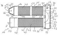
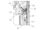
図1には、車両の内燃機関用の排ガス装置もしくは排ガス装置の一部が概して符号10で示されている。この排ガス装置10は、その上流側の領域において、排ガス装置10内に導入され、もしくはこの排ガス装置10内を流れる排ガスAの流れ方向で拡張する流入ケーシング12を含んでいる。この流入ケーシング12には、概して符号16で示される第1の排ガス処理ユニットの上流側の流入領域14が結合されている。第1の排ガス処理ユニット16は、管状のケーシング18内に、酸化触媒20または/および粒子フィルタ22を含んでいてよく、酸化触媒20および粒子フィルタ22は、流れ方向で連続して管状のケーシング18内に配置されており、このケーシング18内でたとえば繊維マット24,26等によって支持されていてよい。さらに第1の排ガス処理ユニット16は、たとえばSCR触媒を含んでいてよく、このSCR触媒は、たとえばディーゼル酸化触媒と組み合わせて、またはディーゼル粒子フィルタと組み合わせてケーシング18内に配置されていてよい。
In FIG. 1 an exhaust gas system or part of an exhaust gas system for an internal combustion engine of a vehicle is indicated generally at 10 . In its upstream region, the
第1の排ガス処理ユニット16の下流側の流出領域28は、概して符号30で示される結合ケーシングに結合されている。結合ケーシング30は、たとえば金属薄板変形加工部材として一体的に形成された、流入開口34を備えた第1のケーシング要素32を含んでおり、流入開口34の領域において、第1の排ガス処理ユニット16の管状のケーシング18が結合ケーシング30に気密に結合されている。さらに第1のケーシング要素32は、流出開口36を含んでおり、流出開口36の領域において、第2の排ガス処理ユニット40の上流側の流入領域38が結合ケーシング30に気密に結合されている。
The
第2の排ガス処理ユニット40は、たとえば管状のケーシング42を含んでおり、ケーシング42内に、たとえば繊維マット44を介してSCR触媒46が支持されている。第2の排ガス処理ユニット40の下流側の流出領域48は、たとえば、流出ケーシング50に結合されているか、または排ガス装置10の、たとえば消音器に通じるたとえば管状の要素に結合されている。
The second exhaust
結合ケーシング30は、たとえば金属薄板変形加工部材として一体的に提供された第2のケーシング要素52をさらに含んでいる。第1のケーシング要素32が、たとえば実質的にプレート状に形成されていてよく、流入開口34または流出開口36の領域に排ガス処理ユニット16、40との結合のために設けられた縁部状の成形を有していてよい一方で、第2のケーシング要素52は、第1のケーシング要素32と一緒に、排ガスAが通流可能である結合容積54を画定するために鍋状に形成されていてよい。この場合、第2のケーシング要素52の周壁56は、第1のケーシング要素32の外周領域に形成された縁部領域に被さっていてよく、かつこの縁部領域にたとえば溶接によって固定的かつ気密に結合されていてよい。第2のケーシング要素52の底壁58は、第1のケーシング要素32、特に第1のケーシング要素32の流入開口34、流出開口36、および流入開口34と流出開口36との間に形成された移行領域60に対峙している。
The
結合ケーシング30もしくは結合ケーシング30の第2のケーシング要素52に、概してインジェクタと呼ばれる反応物質放出装置62が支持されている。反応物質放出装置62は、たとえば尿素および水の混合物である反応物質Rを結合容積54内に放出するので、結合容積54内を流れる排ガスAと反応物質Rとが混合され、排ガスAと反応物質Rもしくは反応物質蒸気との混合物が上流側の流入領域38において第2の排ガス処理ユニット40に流入することができる。
A
図1を参照して上述した排ガス装置の構造を、多種多様な形式で変化させることができることに留意されたい。たとえば、2つの排ガス処理ユニットもしくは排ガス処理ユニットの管状のケーシング18、42を、その長手方向で実質的に平行ではなく、かつ互いに隣接もしくは互いにオーバラップして配置し、これにより結合ケーシング30が、2つの排ガス処理ユニット16、40間の移行部で排ガス流が約180°変向される変向ケーシングを本質的に提供するが、2つの排ガス処理ユニットを結合ケーシングにおいて実質的にその長手方向で互いに隣接して設けることが可能である。さらに、たとえば、2つの第1の排ガス処理ユニット16または/および2つの第2の排ガス処理ユニット40が互いに実質的に平行に配置され、かつ結合ケーシング30に結合されていてよい。2つの排ガス処理ユニット16,40において、図1に関連して上述した構成要素とは別の排ガス処理のために働く構成要素が位置決めされていてよい。
It should be noted that the structure of the exhaust system described above with reference to FIG. 1 can be varied in many different ways. For example, the two exhaust gas treatment units or the
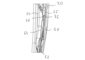
図1に図示した排ガス装置10では、結合ケーシング30と流入ケーシング12とに、金属薄板変形加工部材として提供された遮蔽部材64,66が設けられている。結合ケーシング30に設けられた遮蔽要素64は、その形状において、第2のケーシング要素52の輪郭に実質的に適合させられており、これによりたとえば底壁58の実質的な領域を覆っている。周壁56の少なくとも一部も、遮蔽要素64によって覆われていてよい。たとえば0.8mmの厚さを有する金属薄板材料で構成された遮蔽要素64は、第2のケーシング要素52に対して間隔を有しており、この間隔は、0.5mm~6mmの範囲であってよく、遮蔽要素64にわたって変化してもよく、これにより遮蔽要素64と第2のケーシング要素52との間に中間室65が形成されている。
In the
複数の位置において、遮蔽要素64には、金属薄板ブランクを変形加工することによって形成された結合成形部68が設けられており、この結合成形部68の領域において、遮蔽要素64が第2のケーシング要素52の底壁58の内面に接触し、底壁58に材料結合部、特にたとえば抵抗溶接、レーザ溶接または穴溶接のような溶接によって固定的に結合されている。結合成形部68間の領域もしくは結合成形部68の外側の領域において、特にその外縁部領域70全体においても、遮蔽要素64は第2のケーシング要素52に対して間隔を空けて配置されているので、運転中に発生する振動は遮蔽要素64と第2のケーシング要素52との相互の衝突をもたらすことがない。
At a number of locations, the shielding
図1において、遮蔽要素64が、第2のケーシング要素52において、流入開口34、流出開口36、さらに移行領域60に対峙する領域に設けられていることが分かる。したがって、結合ケーシング30の第2のケーシング要素52が、結合容積54内を流れる排ガスAが直接に当たるように流れることに対して効率的に遮蔽される。したがって、排ガスAと結合ケーシング30との間の直接的な熱伝達接触は、遮蔽要素64によって遮蔽された結合ケーシング30の領域において実質的に排除される。遮蔽要素64と結合ケーシング30との間の直接的な熱伝達は、遮蔽要素64がその結合成形部68の領域で第2のケーシング要素52に接触している僅かな領域に限定されている。したがって、外方に向かって露出する比較的大きな面を提供する結合ケーシング30からの排ガス装置10からの放熱は著しく減じられ、これにより、排ガス装置10を通流する排ガスAを比較的高い温度レベルに保つことができ、したがって排ガスA中で輸送される熱の大部分を排ガス処理ユニット16,40に伝達することができるようにすることが保証されている。
In FIG. 1 it can be seen that shielding
流入ケーシング12に設けられた遮蔽要素66も、複数の結合成形部72を有しており、これらの結合成形部72の領域において、遮蔽要素66は流入ケーシング12の内面に接触し、この流入ケーシング12にたとえば溶接のような材料結合によって結合されている。遮蔽要素66は、その形状において、流入ケーシング12の形状に適合されていてよく、たとえば排ガスの流れ方向で拡張する輪郭を有していてもよい。遮蔽要素66と流入ケーシング12もしくは流入ケーシング12の、遮蔽要素66を支持する壁との間にも、中間室67が形成されており、この中間室は、0.5mm~6mmの範囲の寸法を有していてよい。同様に、遮蔽要素66は、実質的に結合成形部72の領域のみで流入ケーシング12に接触している。遮蔽要素66は、その外縁部領域74の領域において、流入ケーシング12と結合もしくは接触していない。代替的には、遮蔽要素66が流入ケーシング12の流入開口に隣接して位置決めされている外縁部領域74において、遮蔽要素66は、溶接によって遮蔽ケーシング12に固定的に結合されていてよい。
The shielding
図1に関連して上述した排ガス装置10の構造では、結合ケーシング30および流入ケーシング12がそれぞれ排ガス装置10の構成要素を提供する。この構成要素は、排ガス流に面したその内面に1つもしくは少なくとも1つの遮蔽要素を支持しており、遮蔽要素によって、この遮蔽要素により覆われている外壁の領域において排ガスが直接に当たるように流れることに対して遮蔽されている。排ガス装置の別の領域においても、基本的に図1に関連して上述で説明した構成を有していてよい遮蔽要素によりこのような遮蔽硬化を達成することができることに留意すべきである。
In the structure of the
以下で説明するように、このような遮蔽要素は、異なって構成されているか、もしくは別の形式でこの遮蔽要素を支持し、この遮蔽要素により遮蔽される構成要素に結合されていてよい。 As will be explained below, such shielding elements may be configured differently or otherwise support the shielding elements and be coupled to the components shielded by the shielding elements.
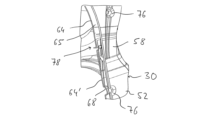
図2は、代替的な構成で、遮蔽ケーシング30の第2のケーシング要素52の底壁58の領域を示している。この底壁58の領域において、図2に示す実施例の第2のケーシング要素52は、底壁58と遮蔽要素64との間に既に述べた中間室65が形成されているように、遮蔽要素64によって覆われている。遮蔽要素64には、複数の結合成形部68が設けられている。第2のケーシング要素52の、遮蔽要素64がその結合成形部68で第2のケーシング要素52に固定されるべき領域において、第2のケーシング要素52はやはり結合成形部76を有している。したがって、遮蔽要素64の結合成形部68が第1の結合成形部を提供する一方で、結合ケーシング30の第2のケーシング要素52の結合成形部76は、第2の結合成形部を提供する。好適には、遮蔽要素64の各第1の結合成形部68が、第2のケーシング要素52の第2の結合成形部76に対応配置されているので、遮蔽要素64と第2のケーシング要素52とはそれぞれ、互いに対応配置された対において第1の結合成形部68および第2の結合成形部76で互いに接触し、材料結合部によって互いに結合されている。したがって、比較的小さく寸法設計された結合成形部68、76によって、それぞれの対の結合成形部78,76の間もしくは周辺に位置する領域において、遮蔽要素64と第2のケーシング要素52との間に比較的大きな間隔を提供する可能が生じる。
FIG. 2 shows the area of the
図3および図4は、結合ケーシング30の第2のケーシング部材52に2つの遮蔽要素64,64’が支持されている構成を示している。遮蔽要素64,64’の各々は、複数の第1の結合成形部68を有しており、これらの第1の結合成形部68の領域において、それぞれの遮蔽要素64,64’が、たとえば、第2のケーシング要素52のそれぞれの第2の結合成形部76において材料結合部により固定されている。
3 and 4 show an arrangement in which two shielding
2つの遮蔽要素64,64’は、隣接領域78において互いに隣接し、隣接領域78において互いにオーバラップしている。この場合、遮蔽要素64,64’の互いにオーバラップしている区分においても、これらの区分間に間隔が空いているようにされる。したがって、隣接領域78においても、遮蔽要素64,64’が互いにぶつかり合うことがなく、ひいてはガタつき騒音が発生しないことが保証されている。
The two
図3および図4に図示した構成では、たとえば、遮蔽要素64が、第2のケーシング要素52の、流入開口34に対峙する領域において実質的に結合ケーシング30に支持されている一方で、接続要素64’が、第2のケーシング要素52の、流出開口36に対峙する領域において実質的に結合ケーシング30に支持されていることが規定されていてよい。2つの遮蔽要素64,64’の隣接領域78は、実質的に、第2のケーシング要素52の、第1のケーシング要素32の移行領域60に対峙して位置決めされている領域に位置決めされていてよい。
3 and 4, for example, the shielding
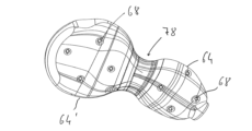
図5は、結合ケーシング30の第2のケーシング要素52に1つ以上の結合要素64,64’を設けることに対して代替的または付加的に、第1のケーシング要素32、特に流入開口34と流出開口36と間の移行領域60にも、この移行領域60を遮蔽する遮蔽要素80が設けられており、1つ以上の結合成形部82の領域において、材料結合部、たとえば溶接により結合成形部に固定されている構成を示している。したがって、この構成では、結合ケーシング30の、排ガスが当たるように流れ得る内側表面全体を、排ガスが直接に当たるように流れることに対して遮蔽することができる。
5 shows that, alternatively or additionally to providing one or more
図6は、図1に図示した流入ケーシング12に対応配置された遮蔽要素66もしくは流入ケーシング12の構成の変化形を示している。この変形形では、遮蔽要素66における結合成形部72に対応して、流入ケーシング12にも結合成形部84が設けられている。好適には、遮蔽要素66の各第1の結合成形部72に対応して、流入ケーシング12の第2の結合成形部84が設けられているので、遮蔽要素66と流入ケーシング12との間の固定的な結合部を、遮蔽要素66に設けられた第1の結合成形部72と流入ケーシング12に設けられた第2の結合成形部84から成る各対の領域において達成することができる。これにより、比較的小さく寸法設計された結合成形部72、84で、遮蔽要素66と、流入ケーシング12の、遮蔽要素66に対峙する壁との間に比較的大きく寸法設計された中間室67を達成することができる。
FIG. 6 shows a variant of the configuration of the shielding
本発明は、構造的に簡単な措置で、排ガス装置の構成要素の1つ以上の外壁の効果的な遮蔽を達成することができる排ガス装置の構造を規定している。排ガスが直接に当たるように流れることを、特にこれに関して重要な領域において十分に排除することができるので、外部への熱損失が減じられ、したがって排ガスを浄化するための排ガス装置の効率が高められる。さらに、熱が車両の別のシステム領域に伝達されるリスクが減じられ、これにより、このようなシステム領域を排ガス装置の近傍に位置決めすることが可能にされる。 The invention provides for the construction of an exhaust gas system with which, with structurally simple measures, an effective shielding of one or more outer walls of the components of the exhaust gas system can be achieved. Since the direct impingement flow of the exhaust gas can be largely excluded, especially in the areas of importance in this regard, the heat loss to the outside is reduced and thus the efficiency of the exhaust gas system for cleaning the exhaust gas is increased. Furthermore, the risk of heat being transferred to other system areas of the vehicle is reduced, which makes it possible to position such system areas in the vicinity of the exhaust system.
本発明により使用すべき遮蔽要素は、単に離散的な領域においてこの遮蔽要素を支持する構成要素もしくは構成要素の外壁に結合されているので、熱膨張を考慮しながら生じる過剰な負荷は、遮蔽要素の領域、遮蔽要素を支持する構成要素の領域、かつそれぞれ材料結合式の結合部の領域において回避される。排ガスによる化学的負荷にも耐性のある、熱機械的に耐久性のある構成が達成される。特に、互いに隣接し、互いにオーバラップする複数の遮蔽要素を設けることは、このような遮蔽要素を支持する構成要素の幾何学形状が複雑な場合であっても効率的な遮蔽を可能にし、互いに分離し、好適には互いに接触しない複数の遮蔽要素を設けることにより、それぞれの遮蔽要素が、この遮蔽要素を支持する構成要素に結合されている領域の、熱膨張により発生する負荷も減じることができる。 Since the shielding element to be used according to the invention is only bonded in discrete areas to the component or the outer wall of the component that supports this shielding element, the excessive loads that occur taking into account thermal expansion are , the area of the component supporting the shielding element, and the area of the material-bonded joint, respectively. A thermomechanically durable construction is achieved which is also resistant to chemical stress by the exhaust gases. In particular, providing a plurality of shielding elements adjacent to each other and overlapping each other allows for efficient shielding even when the geometry of the components supporting such shielding elements is complex and By providing a plurality of shielding elements which are separate and preferably do not contact each other, the load caused by thermal expansion in the area where each shielding element is bonded to the component supporting it can also be reduced. can.
最後に、本発明の意図において、外壁、特に排ガスが直接に当たるように流れることに対して遮蔽要素によって遮蔽された外壁は、排ガスが流れる容積を画定し、したがって排ガスに直接接触することができる壁であることが指摘される。このような外壁は、排ガスが通流する容積に面する外側面において周囲に露出することができるが、たとえば排ガス装置の別の構成要素により覆われており、かつこれらの構成要素に直接接触していてよい。 Finally, for the purposes of the present invention, the outer wall, in particular the outer wall shielded by the shielding element against the direct impingement flow of the exhaust gas, defines the volume through which the exhaust gas flows and can therefore be in direct contact with the exhaust gas. It is pointed out that Such an outer wall can be exposed to the environment on the outer side facing the volume through which the exhaust gas flows, but is covered, for example, by other components of the exhaust gas system and is in direct contact with these components. It's okay.
Claims (15)
Applications Claiming Priority (2)
| Application Number | Priority Date | Filing Date | Title |
|---|---|---|---|
| DE102021121289.8 | 2021-08-17 | ||
| DE102021121289.8A DE102021121289A1 (en) | 2021-08-17 | 2021-08-17 | Exhaust system for an internal combustion engine |
Publications (2)
| Publication Number | Publication Date |
|---|---|
| JP2023027770A true JP2023027770A (en) | 2023-03-02 |
| JP7425840B2 JP7425840B2 (en) | 2024-01-31 |
Family
ID=82702896
Family Applications (1)
| Application Number | Title | Priority Date | Filing Date |
|---|---|---|---|
| JP2022129544A Active JP7425840B2 (en) | 2021-08-17 | 2022-08-16 | Exhaust gas equipment for internal combustion engines |
Country Status (5)
| Country | Link |
|---|---|
| US (1) | US12025045B2 (en) |
| EP (1) | EP4137683B1 (en) |
| JP (1) | JP7425840B2 (en) |
| CN (1) | CN115875119A (en) |
| DE (1) | DE102021121289A1 (en) |
Citations (2)
| Publication number | Priority date | Publication date | Assignee | Title |
|---|---|---|---|---|
| JP2003193835A (en) * | 2001-12-27 | 2003-07-09 | Toyota Motor Corp | Exhaust pipe structure |
| JP2007247549A (en) * | 2006-03-16 | 2007-09-27 | Mitsubishi Fuso Truck & Bus Corp | Exhaust emission control device for internal combustion engine |
Family Cites Families (32)
| Publication number | Priority date | Publication date | Assignee | Title |
|---|---|---|---|---|
| US4685534A (en) * | 1983-08-16 | 1987-08-11 | Burstein A Lincoln | Method and apparatus for control of fluids |
| DE4445557A1 (en) * | 1994-12-20 | 1996-06-27 | Emitec Emissionstechnologie | Double-walled housing, especially for exhaust gas catalysts of motor vehicles |
| EP0992659B1 (en) * | 1998-10-05 | 2007-05-02 | Scambia Industrial Developments Aktiengesellschaft | Exhaust pipe element and method for producing an exhaust pipe element |
| JP2005155404A (en) * | 2003-11-25 | 2005-06-16 | Komatsu Ltd | Exhaust gas purification device for internal combustion engine |
| DE102006058402A1 (en) * | 2006-12-12 | 2008-06-19 | Bayerische Motoren Werke Ag | Device for admixing a reducing agent in an exhaust gas stream of an internal combustion engine |
| US8939638B2 (en) * | 2008-04-21 | 2015-01-27 | Tenneco Automotive Operating Company Inc. | Method for mixing an exhaust gas flow |
| DE102009027713A1 (en) * | 2009-07-15 | 2011-01-20 | Robert Bosch Gmbh | Exhaust gas after-treatment device for internal-combustion engine, has seal provided between dosing module and exhaust pipe, where seal is made of small heat conductivity material |
| JP6053096B2 (en) * | 2012-01-12 | 2016-12-27 | 日野自動車株式会社 | Exhaust purification device |
| US9581067B2 (en) * | 2012-09-28 | 2017-02-28 | Faurecia Emissions Control Technologies, Usa, Llc | Exhaust system mixer with impactor |
| CN105229273B (en) * | 2013-04-11 | 2018-12-07 | 珀金斯发动机有限公司 | Heat Shield and Emissions Cleaning Module |
| GB2512934C (en) * | 2013-04-12 | 2020-03-11 | Eminox Ltd | Reductant injection in an exhaust system |
| US9238991B2 (en) * | 2013-04-29 | 2016-01-19 | GM Global Technology Operations LLC | Internal combustion engine and exhaust aftertreatment system |
| CN203547852U (en) * | 2013-11-07 | 2014-04-16 | 哈尔滨艾瑞汽车排气系统有限公司 | Air inlet end cone for catalyst packaging |
| DE102013223296A1 (en) | 2013-11-15 | 2015-05-21 | Robert Bosch Gmbh | Injection module and exhaust system with injection module |
| DE102014214093A1 (en) | 2013-11-15 | 2015-05-21 | Robert Bosch Gmbh | Device for mixing a liquid medium with a gas stream |
| WO2015187162A1 (en) * | 2014-06-05 | 2015-12-10 | Faurecia Emissions Control Technologies, Usa, Llc | Insulated cover for mixer assembly |
| DE102014112651A1 (en) * | 2014-09-03 | 2016-03-03 | Friedrich Boysen Gmbh & Co. Kg | Exhaust system of an internal combustion engine |
| KR101917966B1 (en) * | 2014-10-06 | 2018-11-12 | 얀마 가부시키가이샤 | Engine device |
| WO2016119865A1 (en) * | 2015-01-29 | 2016-08-04 | Faurecia Emissions Control Technologies, Germany Gmbh | Method for producing a cylindrical housing of an exhaust system and a method for producing an exhaust treatment unit |
| WO2017022301A1 (en) * | 2015-07-31 | 2017-02-09 | 日産自動車株式会社 | Metal plate and metal cover employing same |
| JP2017155693A (en) * | 2016-03-03 | 2017-09-07 | いすゞ自動車株式会社 | Exhaust gas purification device for internal combustion engine |
| EP3346103B1 (en) * | 2017-01-05 | 2019-05-22 | Eberspächer Exhaust Technology GmbH & Co. KG | Exhaust gas system |
| DE102017100132A1 (en) * | 2017-01-05 | 2018-07-05 | Eberspächer Exhaust Technology GmbH & Co. KG | exhaust system |
| EP3372797B1 (en) * | 2017-03-06 | 2019-12-11 | Volvo Car Corporation | Exhaust gas aftertreatment system |
| EP3437717A1 (en) * | 2017-08-01 | 2019-02-06 | Alfa Laval Corporate AB | A scrubber for cleaning of a gas |
| WO2019138427A1 (en) * | 2018-01-12 | 2019-07-18 | Hero MotoCorp Limited | Exhaust system of an internal combustion engine |
| DE102018103368A1 (en) * | 2018-02-15 | 2019-08-22 | Man Truck & Bus Ag | Device for mixing exhaust gas and an additive |
| DE202018105198U1 (en) * | 2018-09-11 | 2019-12-16 | Reinz-Dichtungs-Gmbh | Heat shield and component with such a heat shield |
| WO2020074072A1 (en) * | 2018-10-09 | 2020-04-16 | Volvo Truck Corporation | An exhaust aftertreatment arrangement for an exhaust system of an internal combustion engine |
| CN110420560A (en) * | 2019-08-14 | 2019-11-08 | 江苏科技大学 | A flow guiding device for a marine SCR system reactor |
| US11421577B2 (en) * | 2020-02-25 | 2022-08-23 | Divergent Technologies, Inc. | Exhaust headers with integrated heat shielding and thermal syphoning |
| CN111764987B (en) * | 2020-06-29 | 2023-10-13 | 东风商用车有限公司 | Post-treatment packaging SCR mixer system and treatment method thereof |
-
2021
- 2021-08-17 DE DE102021121289.8A patent/DE102021121289A1/en active Pending
-
2022
- 2022-07-24 EP EP22186597.5A patent/EP4137683B1/en active Active
- 2022-08-16 JP JP2022129544A patent/JP7425840B2/en active Active
- 2022-08-16 CN CN202210978285.0A patent/CN115875119A/en active Pending
- 2022-08-17 US US17/889,552 patent/US12025045B2/en active Active
Patent Citations (2)
| Publication number | Priority date | Publication date | Assignee | Title |
|---|---|---|---|---|
| JP2003193835A (en) * | 2001-12-27 | 2003-07-09 | Toyota Motor Corp | Exhaust pipe structure |
| JP2007247549A (en) * | 2006-03-16 | 2007-09-27 | Mitsubishi Fuso Truck & Bus Corp | Exhaust emission control device for internal combustion engine |
Also Published As
| Publication number | Publication date |
|---|---|
| EP4137683A1 (en) | 2023-02-22 |
| BR102022016157A2 (en) | 2023-03-07 |
| EP4137683B1 (en) | 2024-02-28 |
| DE102021121289A1 (en) | 2023-02-23 |
| US12025045B2 (en) | 2024-07-02 |
| CN115875119A (en) | 2023-03-31 |
| JP7425840B2 (en) | 2024-01-31 |
| US20230057647A1 (en) | 2023-02-23 |
Similar Documents
| Publication | Publication Date | Title |
|---|---|---|
| US9494067B2 (en) | Emissions cleaning module and associated electronics support unit | |
| JP4554294B2 (en) | Muffler with internal heat shield | |
| US5220789A (en) | Integral unitary manifold-muffler-catalyst device | |
| CN114526143B (en) | Crown inlet baffles for high efficiency mixers | |
| US7611561B2 (en) | Diesel exhaust filter construction | |
| US10907522B2 (en) | Internal box flow deflector for a vehicle exhaust system mixer assembly | |
| KR101756240B1 (en) | Exhaust gas purification device | |
| CN100376768C (en) | Exhaust muffler with exhaust purification function for engines | |
| CN114522537A (en) | Flow diverter for high efficiency mixer | |
| CN103174498B (en) | A kind of vent systems for internal-combustion engine | |
| JPH05288048A (en) | Engine exhaust purification device | |
| CN103174499B (en) | Vent systems | |
| RU2653715C2 (en) | Exhaust gas system component for internal combustion engine and method of manufacturing exhaust gas system component | |
| JP2952997B2 (en) | Exhaust gas purification device | |
| EP3146174A1 (en) | System for treating the exhaust gases for a vehicle equipped with internal combustion engine | |
| JP2023027770A (en) | Exhaust gas apparatus for internal combustion engine | |
| JP6806614B2 (en) | Exhaust purification device | |
| US7517501B2 (en) | Exhaust system for internal combustion engines | |
| CN101473113A (en) | A muffler for an exhaust system | |
| US20110214411A1 (en) | Device for the purification of exhaust gases and motor vehicle having the device | |
| US10724415B1 (en) | Exhaust aftertreatment component with heat exchanger | |
| JP2583377Y2 (en) | Flat metal carrier |
Legal Events
| Date | Code | Title | Description |
|---|---|---|---|
| A521 | Request for written amendment filed |
Free format text: JAPANESE INTERMEDIATE CODE: A523 Effective date: 20220816 |
|
| A621 | Written request for application examination |
Free format text: JAPANESE INTERMEDIATE CODE: A621 Effective date: 20220816 |
|
| A977 | Report on retrieval |
Free format text: JAPANESE INTERMEDIATE CODE: A971007 Effective date: 20230831 |
|
| A131 | Notification of reasons for refusal |
Free format text: JAPANESE INTERMEDIATE CODE: A131 Effective date: 20230905 |
|
| A521 | Request for written amendment filed |
Free format text: JAPANESE INTERMEDIATE CODE: A523 Effective date: 20231204 |
|
| TRDD | Decision of grant or rejection written | ||
| A01 | Written decision to grant a patent or to grant a registration (utility model) |
Free format text: JAPANESE INTERMEDIATE CODE: A01 Effective date: 20231220 |
|
| A61 | First payment of annual fees (during grant procedure) |
Free format text: JAPANESE INTERMEDIATE CODE: A61 Effective date: 20240119 |
|
| R150 | Certificate of patent or registration of utility model |
Ref document number: 7425840 Country of ref document: JP Free format text: JAPANESE INTERMEDIATE CODE: R150 |