JP2022546292A - Cathode material for free-standing film type lithium secondary battery, manufacturing method thereof, and lithium secondary battery including the same - Google Patents
Cathode material for free-standing film type lithium secondary battery, manufacturing method thereof, and lithium secondary battery including the same Download PDFInfo
- Publication number
- JP2022546292A JP2022546292A JP2022511087A JP2022511087A JP2022546292A JP 2022546292 A JP2022546292 A JP 2022546292A JP 2022511087 A JP2022511087 A JP 2022511087A JP 2022511087 A JP2022511087 A JP 2022511087A JP 2022546292 A JP2022546292 A JP 2022546292A
- Authority
- JP
- Japan
- Prior art keywords
- positive electrode
- sulfur
- carbon
- secondary battery
- lithium secondary
- Prior art date
- Legal status (The legal status is an assumption and is not a legal conclusion. Google has not performed a legal analysis and makes no representation as to the accuracy of the status listed.)
- Granted
Links
Images


Classifications
-
- H—ELECTRICITY
- H01—ELECTRIC ELEMENTS
- H01M—PROCESSES OR MEANS, e.g. BATTERIES, FOR THE DIRECT CONVERSION OF CHEMICAL ENERGY INTO ELECTRICAL ENERGY
- H01M4/00—Electrodes
- H01M4/02—Electrodes composed of, or comprising, active material
- H01M4/36—Selection of substances as active materials, active masses, active liquids
- H01M4/362—Composites
- H01M4/364—Composites as mixtures
-
- H—ELECTRICITY
- H01—ELECTRIC ELEMENTS
- H01M—PROCESSES OR MEANS, e.g. BATTERIES, FOR THE DIRECT CONVERSION OF CHEMICAL ENERGY INTO ELECTRICAL ENERGY
- H01M4/00—Electrodes
- H01M4/02—Electrodes composed of, or comprising, active material
- H01M4/13—Electrodes for accumulators with non-aqueous electrolyte, e.g. for lithium-accumulators; Processes of manufacture thereof
- H01M4/133—Electrodes based on carbonaceous material, e.g. graphite-intercalation compounds or CFx
-
- C—CHEMISTRY; METALLURGY
- C01—INORGANIC CHEMISTRY
- C01B—NON-METALLIC ELEMENTS; COMPOUNDS THEREOF; METALLOIDS OR COMPOUNDS THEREOF NOT COVERED BY SUBCLASS C01C
- C01B17/00—Sulfur; Compounds thereof
-
- H—ELECTRICITY
- H01—ELECTRIC ELEMENTS
- H01M—PROCESSES OR MEANS, e.g. BATTERIES, FOR THE DIRECT CONVERSION OF CHEMICAL ENERGY INTO ELECTRICAL ENERGY
- H01M10/00—Secondary cells; Manufacture thereof
- H01M10/05—Accumulators with non-aqueous electrolyte
- H01M10/052—Li-accumulators
-
- H—ELECTRICITY
- H01—ELECTRIC ELEMENTS
- H01M—PROCESSES OR MEANS, e.g. BATTERIES, FOR THE DIRECT CONVERSION OF CHEMICAL ENERGY INTO ELECTRICAL ENERGY
- H01M10/00—Secondary cells; Manufacture thereof
- H01M10/05—Accumulators with non-aqueous electrolyte
- H01M10/052—Li-accumulators
- H01M10/0525—Rocking-chair batteries, i.e. batteries with lithium insertion or intercalation in both electrodes; Lithium-ion batteries
-
- H—ELECTRICITY
- H01—ELECTRIC ELEMENTS
- H01M—PROCESSES OR MEANS, e.g. BATTERIES, FOR THE DIRECT CONVERSION OF CHEMICAL ENERGY INTO ELECTRICAL ENERGY
- H01M4/00—Electrodes
- H01M4/02—Electrodes composed of, or comprising, active material
- H01M4/04—Processes of manufacture in general
- H01M4/0471—Processes of manufacture in general involving thermal treatment, e.g. firing, sintering, backing particulate active material, thermal decomposition, pyrolysis
-
- H—ELECTRICITY
- H01—ELECTRIC ELEMENTS
- H01M—PROCESSES OR MEANS, e.g. BATTERIES, FOR THE DIRECT CONVERSION OF CHEMICAL ENERGY INTO ELECTRICAL ENERGY
- H01M4/00—Electrodes
- H01M4/02—Electrodes composed of, or comprising, active material
- H01M4/13—Electrodes for accumulators with non-aqueous electrolyte, e.g. for lithium-accumulators; Processes of manufacture thereof
- H01M4/139—Processes of manufacture
- H01M4/1393—Processes of manufacture of electrodes based on carbonaceous material, e.g. graphite-intercalation compounds or CFx
-
- H—ELECTRICITY
- H01—ELECTRIC ELEMENTS
- H01M—PROCESSES OR MEANS, e.g. BATTERIES, FOR THE DIRECT CONVERSION OF CHEMICAL ENERGY INTO ELECTRICAL ENERGY
- H01M4/00—Electrodes
- H01M4/02—Electrodes composed of, or comprising, active material
- H01M4/36—Selection of substances as active materials, active masses, active liquids
- H01M4/38—Selection of substances as active materials, active masses, active liquids of elements or alloys
-
- H—ELECTRICITY
- H01—ELECTRIC ELEMENTS
- H01M—PROCESSES OR MEANS, e.g. BATTERIES, FOR THE DIRECT CONVERSION OF CHEMICAL ENERGY INTO ELECTRICAL ENERGY
- H01M4/00—Electrodes
- H01M4/02—Electrodes composed of, or comprising, active material
- H01M4/36—Selection of substances as active materials, active masses, active liquids
- H01M4/58—Selection of substances as active materials, active masses, active liquids of inorganic compounds other than oxides or hydroxides, e.g. sulfides, selenides, tellurides, halogenides or LiCoFy; of polyanionic structures, e.g. phosphates, silicates or borates
- H01M4/583—Carbonaceous material, e.g. graphite-intercalation compounds or CFx
- H01M4/587—Carbonaceous material, e.g. graphite-intercalation compounds or CFx for inserting or intercalating light metals
-
- H—ELECTRICITY
- H01—ELECTRIC ELEMENTS
- H01M—PROCESSES OR MEANS, e.g. BATTERIES, FOR THE DIRECT CONVERSION OF CHEMICAL ENERGY INTO ELECTRICAL ENERGY
- H01M4/00—Electrodes
- H01M4/02—Electrodes composed of, or comprising, active material
- H01M4/62—Selection of inactive substances as ingredients for active masses, e.g. binders, fillers
- H01M4/624—Electric conductive fillers
- H01M4/625—Carbon or graphite
-
- H—ELECTRICITY
- H01—ELECTRIC ELEMENTS
- H01M—PROCESSES OR MEANS, e.g. BATTERIES, FOR THE DIRECT CONVERSION OF CHEMICAL ENERGY INTO ELECTRICAL ENERGY
- H01M4/00—Electrodes
- H01M4/02—Electrodes composed of, or comprising, active material
- H01M2004/021—Physical characteristics, e.g. porosity, surface area
-
- H—ELECTRICITY
- H01—ELECTRIC ELEMENTS
- H01M—PROCESSES OR MEANS, e.g. BATTERIES, FOR THE DIRECT CONVERSION OF CHEMICAL ENERGY INTO ELECTRICAL ENERGY
- H01M4/00—Electrodes
- H01M4/02—Electrodes composed of, or comprising, active material
- H01M2004/026—Electrodes composed of, or comprising, active material characterised by the polarity
- H01M2004/028—Positive electrodes
-
- H—ELECTRICITY
- H01—ELECTRIC ELEMENTS
- H01M—PROCESSES OR MEANS, e.g. BATTERIES, FOR THE DIRECT CONVERSION OF CHEMICAL ENERGY INTO ELECTRICAL ENERGY
- H01M4/00—Electrodes
- H01M4/02—Electrodes composed of, or comprising, active material
- H01M4/36—Selection of substances as active materials, active masses, active liquids
- H01M4/38—Selection of substances as active materials, active masses, active liquids of elements or alloys
- H01M4/381—Alkaline or alkaline earth metals elements
- H01M4/382—Lithium
-
- Y—GENERAL TAGGING OF NEW TECHNOLOGICAL DEVELOPMENTS; GENERAL TAGGING OF CROSS-SECTIONAL TECHNOLOGIES SPANNING OVER SEVERAL SECTIONS OF THE IPC; TECHNICAL SUBJECTS COVERED BY FORMER USPC CROSS-REFERENCE ART COLLECTIONS [XRACs] AND DIGESTS
- Y02—TECHNOLOGIES OR APPLICATIONS FOR MITIGATION OR ADAPTATION AGAINST CLIMATE CHANGE
- Y02E—REDUCTION OF GREENHOUSE GAS [GHG] EMISSIONS, RELATED TO ENERGY GENERATION, TRANSMISSION OR DISTRIBUTION
- Y02E60/00—Enabling technologies; Technologies with a potential or indirect contribution to GHG emissions mitigation
- Y02E60/10—Energy storage using batteries
Landscapes
- Chemical & Material Sciences (AREA)
- Chemical Kinetics & Catalysis (AREA)
- Electrochemistry (AREA)
- General Chemical & Material Sciences (AREA)
- Engineering & Computer Science (AREA)
- Manufacturing & Machinery (AREA)
- Inorganic Chemistry (AREA)
- Composite Materials (AREA)
- Materials Engineering (AREA)
- Organic Chemistry (AREA)
- Battery Electrode And Active Subsutance (AREA)
- Secondary Cells (AREA)
Abstract
本発明は、フリースタンディングフィルム型リチウム二次電池用正極材、この製造方法及びこれを含むリチウム二次電池に関する。より詳しくは、上記正極材は加圧条件で硫黄が強い自己凝集力を表し、多孔性炭素材は柔軟性を示す特性を利用して、乾式工程を通じて炭素を含む硫黄溶融物を含むフリースタンディングフィルム形態で製造されることができるし、上記正極材自体で高ローディング量の正極に適用されることができ、簡素化された工程で製造されるので、費用と時間の側面で工程効率を改善することができる。The present invention relates to a positive electrode material for a free-standing film type lithium secondary battery, a method for producing the same, and a lithium secondary battery including the same. More specifically, the positive electrode material exhibits a strong self-cohesive force of sulfur under pressurized conditions, and the porous carbon material exhibits flexibility, and a free-standing film containing sulfur melt containing carbon is formed through a dry process. The positive electrode material itself can be manufactured in various forms, and the positive electrode material itself can be applied to a high-loading positive electrode, and is manufactured by a simplified process, thereby improving process efficiency in terms of cost and time. be able to.
Description
本出願は、2020年05月27日付韓国特許出願第2020‐0063882号及び2021年05月18日付韓国特許出願第2021‐0064083号に基づく優先権の利益を主張し、該当韓国特許出願の文献に開示されている全ての内容は本明細書の一部として組み込む。 This application claims the benefit of priority based on Korean Patent Application No. 2020-0063882 dated May 27, 2020 and Korean Patent Application No. 2021-0064083 dated May 18, 2021, All disclosures are incorporated as part of this specification.
本発明は、フリースタンディングフィルム型リチウム二次電池用正極材、この製造方法及びこれを含むリチウム二次電池に関する。 The present invention relates to a positive electrode material for a free-standing film type lithium secondary battery, a method for producing the same, and a lithium secondary battery including the same.
最近電子機器分野と電気自動車分野の急速な発展によって二次電池の需要が増加している。特に、携帯用電子機器の小型化及び軽量化によって、それに応えられる高エネルギー密度を持つ二次電池に対する要求が高まっている。 Recently, the demand for secondary batteries is increasing due to the rapid development of the fields of electronic devices and electric vehicles. In particular, as portable electronic devices become smaller and lighter, there is an increasing demand for secondary batteries with high energy densities to meet such needs.
二次電池の中でリチウム‐硫黄二次電池は、硫黄‐硫黄結合を持つ硫黄系化合物を正極活物質で使用し、リチウムのようなアルカリ金属またはリチウムイオンのような金属イオンの挿入及び脱挿入が起きる炭素系物質またはリチウムと合金を形成するシリコーンやスズなどを負極活物質で使う二次電池である。具体的に、還元反応である放電の際に硫黄‐硫黄結合が切れて硫黄の酸化数が減少し、酸化反応である充電の際に硫黄の酸化数が増加して硫黄‐硫黄結合が再び形成される酸化‐還元反応を利用して電気的エネルギーを貯蔵して生成する。 Among secondary batteries, a lithium-sulfur secondary battery uses a sulfur-based compound having a sulfur-sulfur bond as a positive electrode active material, and inserts and deinserts alkali metals such as lithium or metal ions such as lithium ions. It is a secondary battery that uses a carbon-based material that causes , silicon or tin that forms an alloy with lithium as a negative electrode active material. Specifically, during discharge, which is a reduction reaction, the sulfur-sulfur bond is broken and the oxidation number of sulfur decreases, and during charging, which is an oxidation reaction, the oxidation number of sulfur increases and the sulfur-sulfur bond is formed again. It stores and generates electrical energy using oxidation-reduction reactions.
特に、リチウム‐硫黄二次電池に正極活物質で使われる硫黄は、理論エネルギー密度が1,675mAh/gで、既存のリチウム二次電池に使われる正極活物質に比べて5倍程度高い理論エネルギー密度を持っていて、高出力、高エネルギー密度の発現が可能な電池である。これに加え、硫黄は安価で埋蔵量が豊かであり、需給が容易で、環境にやさしいという利点のため、携帯用電子機器だけでなく電気自動車のような中大型装置のエネルギー源として注目されている。 In particular, sulfur, which is used as a positive electrode active material in lithium-sulfur secondary batteries, has a theoretical energy density of 1,675 mAh/g, which is five times higher than the positive active material used in existing lithium secondary batteries. It is a battery that has a high density and is capable of exhibiting high output and high energy density. In addition, sulfur is inexpensive, has abundant reserves, is easy to supply and demand, and is environmentally friendly. Therefore, sulfur is attracting attention as an energy source for not only portable electronic devices but also medium- and large-sized devices such as electric vehicles. there is
硫黄は電気伝導度が5×10‐30S/cmで電気伝導性がない不導体なので、電気化学反応で生成された電子の移動が難しい問題がある。ここで、電気化学的反応サイトを提供することができる炭素のような電気伝導性物質とともに複合化されて硫黄‐炭素複合体で使われている。 Since sulfur has an electrical conductivity of 5×10 −30 S/cm and is a non-conductive material, it is difficult to transfer electrons generated in the electrochemical reaction. Here, it is combined with an electrically conductive material such as carbon that can provide an electrochemical reaction site and is used in a sulfur-carbon composite.
上記硫黄‐炭素複合体を正極材で使うために、導電材及びバインダーとともにスラリーを製造した後、上記スラリーを集電体に塗布するスラリー工程を通じて正極を製造する方式が一般的に使われている。 In order to use the sulfur-carbon composite as a positive electrode material, it is common to manufacture a positive electrode through a slurry process in which a slurry is prepared with a conductive material and a binder, and then the slurry is applied to a current collector. .
しかし、上記スラリー工程によって製造される正極は、スラリーを製造する時使われる導電材及びバインダーによって正極のローディング量が低下してエネルギー密度も減少する問題がある。また、上記スラリー工程は、混合、コーティング、乾燥及び圧延を含む一連の細部工程に要される時間と費用が増加する問題がある。 However, the positive electrode manufactured by the slurry process has a problem in that the loading amount of the positive electrode and the energy density are reduced due to the conductive material and binder used in manufacturing the slurry. In addition, the slurry process increases the time and cost required for a series of detailed processes including mixing, coating, drying and rolling.
ここで、簡素な工程で高ローディング量のリチウム二次電池用正極を製造することができる技術開発が必要である。 Here, it is necessary to develop a technology that can manufacture a positive electrode for a lithium secondary battery with a high loading capacity through a simple process.
本発明者らは上記問題点を解決するために多角的に研究した結果、加圧条件で硫黄‐炭素複合体の表面に形成された硫黄が溶融されて周りの硫黄と結集する性質と炭素材の柔軟性を利用し、硫黄‐炭素複合体に加圧条件を与える乾式工程を通じて炭素を含む硫黄溶融物からなるフリースタンディングフィルム型正極材を製造することができるし、上記フリースタンディングフィルム型正極材自体をリチウム二次電池の正極で適用できることを確認した。 As a result of multifaceted research by the present inventors to solve the above problems, the sulfur formed on the surface of the sulfur-carbon composite is melted under pressure conditions and aggregates with the surrounding sulfur, and the carbon material Using the flexibility of the sulfur-carbon composite, a free-standing film-type positive electrode material made of a molten sulfur containing carbon can be produced through a dry process that applies pressure to the sulfur-carbon composite, and the free-standing film-type positive electrode material It was confirmed that it can be applied to the positive electrode of a lithium secondary battery.
したがって、本発明の目的は炭素を含む硫黄溶融物を含むフリースタンディングフィルム型リチウム二次電池用正極材及びこの製造方法を提供することである。 SUMMARY OF THE INVENTION Accordingly, it is an object of the present invention to provide a positive electrode material for a free-standing film type lithium secondary battery containing carbon-containing sulfur melt and a method for producing the same.
本発明の他の目的は上記フリースタンディングフィルム型リチウム二次電池用正極材を含むリチウム二次電池を提供することである。 Another object of the present invention is to provide a lithium secondary battery comprising the positive electrode material for a free-standing film type lithium secondary battery.
上記目的を達成するために、本発明は、フリースタンディングフィルム形態のリチウム二次電池用正極材であって、上記正極材は炭素を含む硫黄溶融物を含むことである、リチウム二次電池用正極材を提供する。 To achieve the above objects, the present invention provides a positive electrode material for a lithium secondary battery in the form of a free-standing film, wherein the positive electrode material comprises a molten sulfur containing carbon. provide materials.
本発明は、また、(S1)硫黄と多孔性炭素材を混合する段階;
(S2)上記(S1)段階で形成された混合物を熱処理する段階;及び
(S3)上記(S2)段階で形成された硫黄‐炭素複合体を容器に充填した後、加圧して炭素を含む硫黄溶融物を形成する段階;を含むリチウム二次電池用正極材の製造方法を提供する。
The present invention also provides (S1) a step of mixing sulfur and a porous carbon material;
(S2) heat-treating the mixture formed in step (S1); and (S3) filling the sulfur-carbon composite formed in step (S2) in a container and pressurizing the sulfur containing carbon. A method for producing a cathode material for a lithium secondary battery, comprising: forming a melt.
本発明は、また、上記正極材を含む正極;リチウム金属またはリチウム合金を含む負極;上記正極と負極の間に位置する分離膜;及び上記正極、負極及び分離膜が含浸された電解液;を含むリチウム二次電池を提供する。 The present invention also provides a positive electrode comprising the positive electrode material; a negative electrode comprising lithium metal or a lithium alloy; a separator positioned between the positive electrode and the negative electrode; and an electrolytic solution impregnated with the positive electrode, the negative electrode and the separator. A lithium secondary battery comprising:
本発明による正極材は、硫黄と多孔性炭素材のみからなる炭素を含む硫黄溶融物を含んで高ローディング量の正極を具現することができる。 The positive electrode material according to the present invention can implement a high-loading positive electrode by including a molten sulfur containing carbon consisting only of sulfur and a porous carbon material.
また、上記正極材は、スラリーを利用して集電体にコーティングする方式ではなく、フリースタンディングフィルム型としてそれ自体で正極として活用可能である。 In addition, the positive electrode material itself can be used as a positive electrode in the form of a free-standing film rather than coating a current collector using a slurry.
また、上記正極材は、混合、コーティング、乾燥及び圧延を含む一連の細部工程を含むスラリー工程ではなく、硫黄と多孔性炭素材を混合した後、熱処理後加圧する簡素な乾式工程によって製造されることができて、費用及び時間の側面で工程効率を向上させることができる。 In addition, the cathode material is manufactured by a simple dry process of mixing sulfur and a porous carbon material, heat-treating them, and then pressurizing them, instead of a slurry process including a series of detailed processes including mixing, coating, drying and rolling. It is possible to improve process efficiency in terms of cost and time.
以下、本発明に対して理解しやすくするために、本発明をより詳しく説明する。 Hereinafter, the present invention will be described in more detail in order to facilitate understanding of the present invention.
本明細書及び請求範囲で使われた用語や単語は通常的や辞書的な意味で限定して解釈されてはならないし、発明者は自分の発明を最善の方法で説明するために用語の概念を適切に定義することができるという原則に即して本発明の技術的思想に符合する意味と概念で解釈しなければならない。 The terms and words used in the specification and claims are not to be construed in a limiting, ordinary or dictionary sense, and the inventors have chosen notions of terms in order to best describe their invention. should be construed with a meaning and concept consistent with the technical idea of the present invention in line with the principle that can be properly defined.
本明細書で使われた用語「フリースタンディングフィルム(free‐standing film)」とは、常温・常圧で別途支持体なしにそれ自体でフィルム形態を維持することができるフィルムを意味する。 As used herein, the term "free-standing film" means a film that can maintain a film shape by itself without a separate support at room temperature and pressure.
本明細書で使われた用語「炭素を含む硫黄溶融物」は硫黄と炭素を原料にして、熱処理及び加圧する工程を経た後で製造されたもので、多孔性炭素材が硫黄溶融物の内部に分散された状態の物質を意味する。 The term ``sulfur melt containing carbon'' used in the present specification is produced by using sulfur and carbon as raw materials and undergoing heat treatment and pressure processes, and the porous carbon material is formed inside the sulfur melt. means a substance in a dispersed state.
リチウム二次電池用正極材
本発明はフリースタンディングフィルム形態のリチウム二次電池用正極材であって、上記正極材は炭素を含む硫黄溶融物を含むものであってもよい。上記正極材は硫黄溶融物に多孔性炭素材が分散された形態であってもよい。また、上記正極材は後述するように、硫黄と多孔性炭素材のみを原料にして乾式工程で製造されたもので、もっぱら硫黄と多孔性炭素材のみで構成されたものであってもよい。
Cathode Material for Lithium Secondary Battery The present invention is a cathode material for a lithium secondary battery in the form of a free-standing film, wherein the cathode material may contain sulfur melt containing carbon. The positive electrode material may be in the form of a porous carbon material dispersed in a sulfur melt. In addition, as will be described later, the positive electrode material may be produced by a dry process using only sulfur and a porous carbon material as raw materials, and may consist entirely of sulfur and a porous carbon material.
一般に、リチウム二次電池の正極材で使われる上記硫黄‐炭素複合体は、硫黄が多孔性炭素材に担持されている複合体を意味する。例えば、上記多孔性炭素材の表面に硫黄が均一に付着またはコーティングされている形態であってもよい。また、上記硫黄は上記多孔性炭素材の内部気孔に付着、充填またはコーティングされていてもよい。 Generally, the sulfur-carbon composite, which is used as a positive electrode material for lithium secondary batteries, means a composite in which sulfur is supported on a porous carbon material. For example, sulfur may be uniformly attached or coated on the surface of the porous carbon material. Also, the sulfur may adhere to, fill, or coat the internal pores of the porous carbon material.
しかし、本発明で上記正極材は硫黄溶融物の内部に多孔性炭素材が分散された形態の炭素を含む硫黄溶融物を含むものであって、硫黄が加圧条件で溶融されて結集する性質によって成形が容易であり、多孔性炭素材の柔軟性によってフリースタンディングフィルム形態で製造されることができる。 However, in the present invention, the positive electrode material includes molten sulfur containing carbon in which porous carbon materials are dispersed inside the molten sulfur, and sulfur is melted and aggregated under pressurized conditions. Due to the flexibility of the porous carbon material, it can be manufactured in the form of a free-standing film.
上記フリースタンディングフィルム形態の正極材は、集電体にコーティングせずに上記フリースタンディングフィルム形態の正極材自体を正極で活用することもできる。 The free-standing film-type positive electrode material itself may be used as a positive electrode without being coated on a current collector.
上記正極材は硫黄と多孔性炭素材を原料にして乾式工程によって製造されるので、正極材内に硫黄と多孔性炭素材のみが含まれていて、正極で使用する時ローディング量が高い長所がある。また、上記乾式工程は従来のスラリー工程時に要求される混合、あわ消し、コーティング、乾燥及び圧延のような一連の工程を省略することができて、工程費用の節減が可能である。また、上記乾式工程はスラリーを使わないため、上記乾式工程によって製造された炭素を含む硫黄溶融物にはバインダーが全然含まれていないので、バインダー抵抗による電池性能低下を根本的に取り除くことができる。また、上記乾式工程によって製造された炭素を含む硫黄溶融物には導電材が全然含まれていないので、凝集力が足りない導電材によって成形性が低下する問題が最小化されることがある。 Since the positive electrode material is manufactured by a dry process using sulfur and a porous carbon material as raw materials, the positive electrode material contains only sulfur and a porous carbon material, and has the advantage of a high loading amount when used in the positive electrode. be. In addition, the dry process can omit a series of processes such as mixing, defoaming, coating, drying and rolling required in the conventional slurry process, thereby reducing process costs. In addition, since the dry process does not use a slurry, the carbon-containing sulfur melt produced by the dry process does not contain any binder, so that deterioration of battery performance due to binder resistance can be fundamentally eliminated. . In addition, since the carbon-containing sulfur melt produced by the dry process does not contain any conductive material, the problem of poor moldability due to insufficient cohesion of the conductive material may be minimized.
また、上記正極材は多孔性炭素材が正極材の骨格をなした状態で上記多孔性炭素材の表面に形成されたり、上記多孔性炭素材を取り囲んだ硫黄溶融物によって繋がってフリースタンディングフィルム形態を示す。 In addition, the positive electrode material is formed on the surface of the porous carbon material in a state that the porous carbon material forms the skeleton of the positive electrode material, or is connected by the molten sulfur surrounding the porous carbon material to form a free standing film. indicates
また、上記正極材は電極加圧成形後に正極材内の接着力が10gf/cm以上の正極材であってもよい。上記接着力は加圧工程時に硫黄が溶融されて周りの硫黄と結集する性質に基づくことであり、上記正極材の接着力が10gf/cm未満であれば正極の間の接着力不足によって電極成形が難しくなる。具体的に、上記接着力は10gf/cm以上、15gf/cm以上、20gf/cm以上、25gf/cm以上、30gf/cm以上または35gf/cm以上であってもよい。また、上記接着力の上限は50gf/cm以下、60gf/cm以下、70gf/cm以下、80gf/cm以下、90gf/cm以下または100gf/cm以下であってもよいが、これに制限されるものではなく、正極材内の接着力は高いほど成形性、耐久性及び電池性能の側面でよいことがある。 Further, the positive electrode material may be a positive electrode material having an adhesive strength of 10 gf/cm or more in the positive electrode material after pressure molding of the electrode. The adhesive strength is based on the property that sulfur is melted during the pressurization process and aggregates with the surrounding sulfur. becomes difficult. Specifically, the adhesive strength may be 10 gf/cm or more, 15 gf/cm or more, 20 gf/cm or more, 25 gf/cm or more, 30 gf/cm or more, or 35 gf/cm or more. The upper limit of the adhesive strength may be 50 gf/cm or less, 60 gf/cm or less, 70 gf/cm or less, 80 gf/cm or less, 90 gf/cm or less, or 100 gf/cm or less, but is limited thereto. Rather, the higher the adhesive strength in the positive electrode material, the better the moldability, durability, and battery performance.
また、上記正極材の気孔率は68%以下、65%以下、60%以下、55%以下であってもよく、45%以上または50%以上であってもよい。上記正極材の気孔率が68%超過であれば正極の耐久性が低下することがあるし、45%未満であれば気孔内で電気化学反応が起きる空間が細くなるので、正常的なセルの駆動が難しくなることがある。 The porosity of the positive electrode material may be 68% or less, 65% or less, 60% or less, 55% or less, or 45% or more or 50% or more. If the porosity of the positive electrode material exceeds 68%, the durability of the positive electrode may be deteriorated. Driving can be difficult.
本発明において、上記硫黄は無機硫黄(S8)、Li2Sn(n≧1、nは整数)、有機硫黄化合物及び炭素‐硫黄ポリマー[(C2Sx)n、2.5≦x≦50、n≧2、x及びnは整数である]からなる群から選択される1種以上であってもよい。 In the present invention, the sulfur includes inorganic sulfur (S 8 ), Li 2 Sn ( n ≧1, n is an integer), organic sulfur compounds and carbon-sulfur polymers [(C 2 S x ) n , 2.5≦x ≦50, n≧2, x and n are integers].
また、上記硫黄は上記炭素を含む硫黄溶融物全体質量を基準にして50質量%以上、55質量%以上または60質量%以上可能で、70質量%以下、75質量%以下、80質量%以下可能である。上記硫黄が50質量%未満であれば電気化学的活物質である硫黄の割合が減って多孔性炭素材の表面に形成される硫黄溶融物の厚さが薄くなって、炭素を含む硫黄溶融物がちゃんと成形されにくいか、または硫黄の量が減少して電池容量が低下することがある。また、上記硫黄が80質量%超過であれば、非伝導性の硫黄が多孔性炭素材の導電構造を遮断して電気化学的活性が遮断されるので、電池駆動が制限的である。 In addition, the sulfur may be 50% by mass or more, 55% by mass or more, or 60% by mass or more, and may be 70% by mass or less, 75% by mass or less, or 80% by mass or less based on the total mass of the molten sulfur containing the carbon. is. If the sulfur content is less than 50% by mass, the ratio of sulfur, which is an electrochemically active material, is reduced, and the thickness of the sulfur melt formed on the surface of the porous carbon material is reduced, resulting in a sulfur melt containing carbon. may be difficult to form properly, or the amount of sulfur may decrease, resulting in lower battery capacity. In addition, if the sulfur content exceeds 80% by mass, the non-conductive sulfur blocks the conductive structure of the porous carbon material and blocks the electrochemical activity, thus restricting battery operation.
上記炭素を含む硫黄溶融物で硫黄が50質量%ないし80質量%含まれる時、正極材が強い自己凝集力を示すことができるし、上記多孔性炭素材が硫黄溶融物内でよく分散されることができるので、フリースタンディング形態の正極がよく形成されることができる。 When the carbon-containing sulfur melt contains 50% by mass to 80% by mass of sulfur, the positive electrode material can exhibit a strong self-cohesive force, and the porous carbon material is well dispersed in the sulfur melt. Therefore, a free-standing positive electrode can be formed well.
本発明において、上記多孔性炭素材は内部に気孔または中孔が形成されている構造であるか、または比表面積が高い多孔性炭素材であってもよく、当業界で通常使われるものであれば、いずれもかまわない。 In the present invention, the porous carbon material may have a structure in which pores or hollow pores are formed therein, or may be a porous carbon material having a high specific surface area, whichever is commonly used in the industry. Either is fine.
上記多孔性炭素材は、グラファイト(graphite);グラフェン(graphene);デンカブラック、アセチレンブラック、ケッチェンブラック、チャンネルブラック、ファーネスブラック、ランプブラック及びサーマルブラックの中で選択されるカーボンブラック;単一壁炭素ナノチューブ(SWCNT)及び多重壁炭素ナノチューブ(MWCNT)から選択される炭素ナノチューブ(CNT);グラファイトナノファイバー(GNF)、カーボンナノファイバー(CNF)及び活性化炭素ファイバー(ACF)の中で選択される炭素繊維;及び活性炭素からなる群から選択される1種以上であってもよいが、これに制限されない。好ましくは、上記多孔性炭素材は炭素ナノチューブであってもよい。 The porous carbon material is graphite; graphene; carbon black selected from Denka black, acetylene black, Ketjen black, channel black, furnace black, lamp black and thermal black; carbon nanotubes (CNT) selected from carbon nanotubes (SWCNT) and multi-walled carbon nanotubes (MWCNT); selected among graphite nanofibers (GNF), carbon nanofibers (CNF) and activated carbon fibers (ACF) Carbon fiber; and one or more selected from the group consisting of activated carbon, but not limited thereto. Preferably, the porous carbon material may be carbon nanotubes.
上記炭素ナノチューブは構造的特徴によって連結点が多く、フリースタンディングフィルムの成形時にもっと有利である。具体的に上記炭素ナノチューブは縦横比が1を超える形態を持つので、互いに繋がってフリースタンディングフィルムを形成するに有利である。 Due to their structural characteristics, the carbon nanotubes have many connection points, which is more advantageous when forming a free-standing film. Specifically, since the carbon nanotubes have an aspect ratio of more than 1, they are advantageous in connecting to each other to form a free-standing film.
また、上記グラフェンは炭素原子が2次元相に蜂の巣模様の配列を持つ単一層の形態を意味し、薄くて広い断面積と優れる伝導特性を持ち、撓む特性、光に対する高感度など、優れる物性を示す物質である。本発明において、グラフェンは酸化グラフェンを還元して形成した、還元されたグラフェン及び物理的に剥離されたグラフェンの中で選択される1種以上を全て含む。上記グラフェン薄膜は炭素ナノチューブの外面を包む形態で含まれてもよく、電気伝導経路を補強すると同時に、電池の駆動時に硫黄が電解液に湧出されることを抑制することができる。 In addition, the graphene is a single layer in which carbon atoms are arranged in a honeycomb pattern in a two-dimensional phase. It is a substance that shows In the present invention, graphene includes at least one selected from reduced graphene formed by reducing graphene oxide and physically exfoliated graphene. The graphene thin film may be included in the form of wrapping the outer surface of the carbon nanotube, and may reinforce the electrical conduction path and prevent sulfur from leaching into the electrolyte when the battery is operated.
また、上記多孔性炭素材の含量は上記炭素を含む硫黄溶融物全体質量を基準にして20質量%以上、25質量%以上、30質量%以上または35質量%以上であってもよく、40質量%以下、45質量%以下または50質量%以下であってもよい。上記多孔性炭素材が20質量%未満であれば溶融された硫黄が充填、付着またはコーティングされることができる表面積と空間の提供が十分ではなく、硫黄の電気化学活用性(反応性)が低下することがある。上記炭素材が50質量%を超えれば硫黄の含量が相対的に低下してリチウム二次電池に適用する時、電池のエネルギー密度が低下しすぎることがある。 In addition, the content of the porous carbon material may be 20% by weight or more, 25% by weight or more, 30% by weight or more, or 35% by weight or more, or 40% by weight, based on the total weight of the molten sulfur containing carbon. % or less, 45 mass % or less, or 50 mass % or less. If the content of the porous carbon material is less than 20% by mass, the surface area and space where molten sulfur can be filled, adhered or coated is not sufficiently provided, and the electrochemical utilization (reactivity) of sulfur is lowered. I have something to do. If the carbon material exceeds 50% by mass, the sulfur content is relatively low, and when applied to a lithium secondary battery, the energy density of the battery may be too low.
リチウム二次電池用正極材の製造方法
図1は、リチウム二次電池用正極材で使用されることができる硫黄、炭素及び硫黄‐炭素複合体を加圧する場合の物性変化及び成形性を示す模式図である。
Method for manufacturing positive electrode material for lithium secondary battery FIG. 1 is a schematic diagram showing changes in physical properties and moldability when sulfur, carbon, and a sulfur-carbon composite that can be used as a positive electrode material for a lithium secondary battery are pressurized. It is a diagram.
上記硫黄は加圧条件で表面が溶融され、周りの硫黄と結集する性質を示して成形は可能だが、柔軟性がないため硫黄単独ではフリースタンディングフィルム形態の正極材(正極)を製造することができない。 The surface of the sulfur is melted under pressure conditions, and it exhibits the property of gathering together with the surrounding sulfur, so it can be molded. Can not.
上記炭素は柔軟性はあるが凝集力が足りないため、加圧時に成形自体がされず、フリースタンディングフィルム形態の正極材(正極)を製造することができない。 Although the carbon is flexible, it has insufficient cohesive force, so that it cannot be formed into a free-standing film type cathode material (cathode) when pressurized.
上記硫黄‐炭素複合体は硫黄と多孔性炭素材が複合されたもので、上記多孔性炭素材の外部表面にも硫黄が存在するので、加圧時に多孔性炭素材の外部表面に存在する硫黄が溶融されるので、多孔性炭素材が硫黄溶融物に分散された形態になって成形が可能であり、上記多孔性炭素材が柔軟性があるので、打ち抜きによるフリースタンディングフィルム形態の正極材(正極)成形も可能である。 The sulfur-carbon composite is a composite of sulfur and a porous carbon material, and sulfur is also present on the outer surface of the porous carbon material. is melted, the porous carbon material is dispersed in the molten sulfur and can be molded. Since the porous carbon material is flexible, the positive electrode material ( positive electrode) molding is also possible.
したがって、本発明は加圧時に上記のような硫黄‐炭素複合体の特徴を利用して硫黄‐炭素複合体を乾式工程に適用し、炭素を含む硫黄溶融物を形成することで、リチウム二次電池用正極材を製造する方法を提供する。 Therefore, the present invention utilizes the characteristics of the sulfur-carbon composite as described above to apply the sulfur-carbon composite to a dry process to form a carbon-containing sulfur melt, thereby producing lithium secondary A method of manufacturing a battery cathode material is provided.
上記リチウム二次電池用正極材の製造方法は、下記(S1)ないし(S3)段階を含む:
(S1)硫黄と多孔性炭素材を混合する段階;
(S2)上記(S1)段階で形成された混合物を熱処理する段階;及び
(S3)上記(S2)段階で形成された硫黄‐炭素複合体を容器に充填した後、加圧して炭素を含む硫黄溶融物を形成する段階。
The method for manufacturing the positive electrode material for lithium secondary batteries includes the following steps (S1) to (S3):
(S1) mixing sulfur and a porous carbon material;
(S2) heat-treating the mixture formed in step (S1); and (S3) filling the sulfur-carbon composite formed in step (S2) in a container and then pressurizing the sulfur containing carbon. forming a melt;
以下、各段階別に本発明のリチウム二次電池用正極材の製造方法について、より詳しく説明する。 Hereinafter, the manufacturing method of the positive electrode material for a lithium secondary battery according to the present invention will be described in detail for each step.
上記(S1)段階では、炭素を含む硫黄溶融物からなる正極材を製造するための原料物質である硫黄と多孔性炭素材を混合した混合物を形成することができる。この時、上記硫黄と多孔性炭素材の種類及び適正質量の範囲は上述したとおりである。 In step (S1), a mixture of sulfur, which is a raw material for manufacturing a cathode material made of carbon-containing molten sulfur, and a porous carbon material may be formed. At this time, the types and appropriate mass ranges of the sulfur and porous carbon materials are as described above.
上記(S2)段階では、上記(S1)段階で形成された混合物を熱処理することができる。 In step (S2), the mixture formed in step (S1) may be heat-treated.
上記硫黄と多孔性炭素材の混合物を加熱すると、硫黄は液体状態に変わるようになって、液体状態の硫黄が多孔性炭素材の内部に入ったり表面にコーティングまたは附着されて、上記多孔性炭素材が液体状態の硫黄に分散された形態になることがある。例えば、上記多孔性炭素材が炭素ナノチューブの場合、液体状態の硫黄が毛細管現象を通じて炭素ナノチューブ内部に吸い込まれて硫黄が炭素ナノチューブに担持され、上記炭素ナノチューブは液体状態の硫黄に分散されるようになる。 When the mixture of the sulfur and the porous carbon material is heated, the sulfur changes to a liquid state, and the liquid sulfur enters the inside of the porous carbon material or coats or attaches to the surface of the porous carbon material. The material may be dispersed in liquid sulfur. For example, when the porous carbon material is a carbon nanotube, sulfur in a liquid state is sucked into the carbon nanotube through capillary action, the sulfur is supported on the carbon nanotube, and the carbon nanotube is dispersed in the liquid sulfur. Become.
上記熱処理は硫黄の融点以上で行われることがある。例えば、上記熱処理温度は130℃以上、140℃以上または150℃以上であってもよく、160℃以下、165℃以下または170℃以下であってもよい。上記熱処理温度が130℃未満であれば、硫黄が溶けなくて炭素材に担持されたりコーティングされた形態を形成しにくく、炭素材が硫黄に分散された形態も形成しにくいし、170℃を超えれば硫黄が揮発して硫黄の損失と製造装備の劣化を誘発することができる。 The heat treatment may be performed above the melting point of sulfur. For example, the heat treatment temperature may be 130° C. or higher, 140° C. or higher, or 150° C. or higher, and may be 160° C. or lower, 165° C. or lower, or 170° C. or lower. If the heat treatment temperature is less than 130°C, it is difficult to form a form in which sulfur is not dissolved and is supported or coated on the carbon material, and it is difficult to form a form in which the carbon material is dispersed in sulfur. Sulfur can volatilize and induce sulfur loss and deterioration of production equipment.
また、上記熱処理時間は硫黄が熱処理によって溶けて多孔性炭素材に担持されたり、上記多孔性炭素材が硫黄の内部に分散されることができる程度の適正時間であれば可能であり、25分以上または30分以上可能で、40分以下、45分以下または50分以下可能である。 In addition, the heat treatment time may be 25 minutes, as long as sulfur is melted by the heat treatment and supported on the porous carbon material, or the porous carbon material can be dispersed inside the sulfur. or 30 minutes or more, and 40 minutes or less, 45 minutes or less, or 50 minutes or less.
上記(S3)段階では、上記(S2)段階で形成された炭素を含む硫黄溶融物を容器に充填した後、加圧してフリースタンディングフィルム形態の正極材を製造することができる。 In the step (S3), the molten sulfur containing carbon formed in the step (S2) may be filled in a container and pressurized to manufacture a cathode material in the form of a free-standing film.
硫黄と炭素の複合体は、加圧状態で強い自己凝集力を表す特性がある。具体的に、加圧状態で上記硫黄‐炭素複合体表面の硫黄が部分的に溶融され、連結性を与えて強い自己凝集力を表すことができる。よって、硫黄‐炭素複合体に対して圧力をかければ、炭素が分散された硫黄溶融物が形成されて炭素粒子の間に凝集力が発生し、また、炭素材は骨格の機能をして、それ自体で柔軟性を持つので、フリースタンディングフィルムが形成されるようになる。 Composites of sulfur and carbon have the property of exhibiting strong self-cohesion under pressure. Specifically, sulfur on the surface of the sulfur-carbon composite is partially melted under pressure to provide connectivity and exhibit strong self-cohesion. Therefore, when pressure is applied to the sulfur-carbon composite, a sulfur melt in which carbon is dispersed is formed to generate cohesive force between carbon particles, and the carbon material functions as a skeleton. Since it has flexibility in itself, a free-standing film will be formed.
上記加圧時の圧力は硫黄‐炭素複合体の間に凝集力が充分発生してフリースタンディングフィルムを形成する程度の圧力であってもよい。例えば、上記加圧時の圧力は0.8Mpa以上、0.9Mpa以上または1Mpa以上であってもよく、5Mpa以下、8Mpa以下、10Mpa以下、13Mpa以下または15Mpa以下が可能である。上記加圧時の圧力が0.8Mpa未満であれば硫黄‐炭素複合体の間の凝集力が弱くてフリースタンディングフィルムが形成されないこともあって、15Mpaを超えれば正極材の気孔率が低すぎて電極の構造が崩れることがある。 The pressure at the time of pressurization may be a pressure that sufficiently generates a cohesive force between the sulfur-carbon composites to form a free-standing film. For example, the pressure during pressurization may be 0.8 Mpa or more, 0.9 Mpa or more, or 1 Mpa or more, and can be 5 Mpa or less, 8 Mpa or less, 10 Mpa or less, 13 Mpa or less, or 15 Mpa or less. If the pressure during pressurization is less than 0.8 Mpa, the cohesive force between the sulfur-carbon composites is weak and a free standing film may not be formed. the structure of the electrode may collapse.
リチウム二次電池
本発明はまた、上記のような炭素を含む硫黄溶融物を含むフリースタンディングフィルム型正極材を正極で含むリチウム二次電池に関する。
Lithium secondary battery The present invention also relates to a lithium secondary battery comprising, at the positive electrode, the free-standing film type positive electrode material containing the carbon-containing sulfur melt as described above.
上記フリースタンディングフィルム型正極材を正極で使う場合、正極で正極活物質のローディング量は3.0mAh/cm2ないし5.0mAh/cm2であってもよく、これは上記正極材がバインダーや導電材が必要ない乾式工程で製造されたことに基づく。 When the free-standing film-type positive electrode material is used as a positive electrode, the positive electrode active material may have a loading amount of 3.0 mAh/cm 2 to 5.0 mAh/cm 2 , because the positive electrode material is a binder or a conductive material. It is based on being manufactured in a dry process that does not require wood.
本発明によるリチウム二次電池は、正極、負極及びこれらの間に介在された電解質を含み、この時、上記正極として前述したようなフリースタンディングフィルム形態の正極材自体を正極で使うことができる。 A lithium secondary battery according to the present invention includes a positive electrode, a negative electrode, and an electrolyte interposed therebetween. At this time, the positive electrode material itself in the form of a free-standing film can be used as the positive electrode.
また、本発明によるリチウム二次電池において、負極は負極集電体上に負極活物質を持つ負極活物質層が形成されたり、負極活物質層(一例として、リチウムホイル)を単独で使うことができる。 In addition, in the lithium secondary battery according to the present invention, the negative electrode may be formed by forming a negative electrode active material layer having a negative electrode active material on a negative electrode current collector, or using a negative electrode active material layer (for example, lithium foil) alone. can.
この時、負極集電体や負極活物質層の種類は本発明で特に限定せず、公知の材質が使用可能である。 At this time, the types of the negative electrode current collector and the negative electrode active material layer are not particularly limited in the present invention, and known materials can be used.
また、負極集電体は当該電池に化学的変化を引き起こさずに導電性を持つものであれば特に制限されず、例えば、銅、ステンレススチール、アルミニウム、ニッケル、チタン、焼成炭素、銅やステンレススチールの表面にカーボン、ニッケル、チタン、銀などで表面処理したもの、アルミニウム‐カドミウム合金などが使われることができる。また、上記負極集電体は、正極集電体と同様、表面に微細な凹凸が形成されたフィルム、シート、ホイル、ネット、多孔質体、発泡体、不織布体など多様な形態が使われることができる。 In addition, the negative electrode current collector is not particularly limited as long as it has conductivity without causing chemical changes in the battery. Examples include copper, stainless steel, aluminum, nickel, titanium, baked carbon, copper and stainless steel. surface treated with carbon, nickel, titanium, silver, etc., aluminum-cadmium alloy, etc. can be used. In addition, the negative electrode current collector, like the positive electrode current collector, may be used in various forms such as a film, a sheet, a foil, a net, a porous body, a foam, a non-woven fabric, etc., having fine irregularities formed on the surface. can be done.
また、負極活物質は結晶質人造黒鉛、結晶質天然黒鉛、非晶質ハードカーボン、低結晶質ソフトカーボン、カーボンブラック、アセチレンブラック、ケッチェンブラック、スーパー‐P、グラフェン(graphene)、繊維状炭素からなる群から選択される一つ以上の炭素系物質、Si系物質、LixFe2O3(0≦x≦1)、LixWO2(0≦x≦1)、SnxMe1‐xMe’yOz(Me:Mn、Fe、Pb、Ge;Me’:Al、B、P、Si、周期表の1族、2族、3族元素、ハロゲン;0<x≦1;1≦y≦3;1≦z≦8)などの金属複合酸化物;リチウム金属;リチウム合金;ケイ素系合金;スズ系合金;SnO、SnO2、PbO、PbO2、Pb2O3、Pb3O4、Sb2O3、Sb2O4、Sb2O5、GeO、GeO2、Bi2O3、Bi2O4、Bi2O5などの金属酸化物;ポリアセチレンなどの導電性高分子;Li‐Co‐Ni系材料;チタン酸化物;リチウムチタン酸化物などを含むことができるが、これらのみに限定されない。
In addition, the negative electrode active material includes crystalline artificial graphite, crystalline natural graphite, amorphous hard carbon, low crystalline soft carbon, carbon black, acetylene black, ketjen black, super-P, graphene, and fibrous carbon. one or more carbon-based materials selected from the group consisting of Si-based materials, LixFe2O3 ( 0≤x≤1 ), LixWO2 ( 0≤x≤1 ), SnxMe1 - xMe ' y O z (Me: Mn, Fe, Pb, Ge; Me': Al, B, P, Si,
これに加え、負極活物質はSnxMe1‐xMe’yOz(Me:Mn、Fe、Pb、Ge;Me’:Al、B、P、Si、周期表の1族、2族、3族元素、ハロゲン;0<x≦1;1≦y≦3;1≦z≦8)などの金属複合酸化物;SnO、SnO2、PbO、PbO2、Pb2O3、Pb3O4、Sb2O3、Sb2O4、Sb2O5、GeO、GeO22、Bi2O3、Bi2O4及びBi2O5などの酸化物などを使うことができるし、結晶質炭素、非晶質炭素または炭素複合体のような炭素系負極活物質が単独で、または2種以上が混用されて使われることができる。
In addition, the negative electrode active material is SnxMe1 - xMe'yOz (Me: Mn, Fe, Pb, Ge; Me': Al, B, P, Si,
また、本発明によるリチウム二次電池において、電解液はリチウム二次電池の製造に通常使われたものなどがいずれも使われることができる。 In addition, in the lithium secondary battery according to the present invention, any electrolyte commonly used in the manufacture of lithium secondary batteries can be used.
例えば、上記電解液において、電解質として含まれてもよいリチウム塩は、リチウム二次電池用電解液に通常使われるものなどが制限されずに使われてもよく、例えば、上記リチウム塩の陰イオンでは、F‐、Cl‐、Br‐、I‐、NO3 ‐、N(CN)2 ‐、BF4 ‐、ClO4 ‐、PF6 ‐、(CF3)2PF4 ‐、(CF3)3PF3 ‐、(CF3)4PF2 ‐、(CF3)5PF‐、(CF3)6P‐、CF3SO3 ‐、CF3CF2SO3 ‐、(CF3SO2)2N‐、(FSO2)2N‐ 、CF3CF2(CF3)2CO‐、(CF3SO2)2CH‐、(SF5)3C‐、(CF3SO2)3C‐、CF3(CF2)7SO3 ‐、CF3CO2 ‐、CH3CO2 ‐、SCN‐及び(CF3CF2SO2)2N‐からなる群から選択されたいずれか一つであってもよい。具体的に、上記リチウム塩では、LiPF6、LiClO4、LiAsF6、LiBF4、LiSbF6、LiAl04、LiAlCl4、LiCF3SO3、LiC4F9SO3、LiN(C2F5SO3)2、LiN(C2F5SO2)2(Lithium bis(perfluoroethylsulfonyl)imide、BETI)、LiN(CF3SO2)2(Lithium bis(Trifluoromethanesulfonyl)imide、LiTFSI)、LiN(CaF2a+1SO2)(CbF2b+1SO2)(ただし、a及びbは自然数、好ましくは1≦a≦20で、1≦b≦20である)、リチウムポリ[4,4’‐(ヘキサフルオロイソプロピリデン)ジフェノキシ]スルホニルイミド(lithium poly[4,4’‐(hexafluoroisopropylidene)diphenoxy]sulfonylimide、LiPHFIPSI)、LiCl、LiI、LiB(C2O4)2、LiNO3などが使われることができるし、この中でもLiTFSI、BETIまたはLiPHFIPSIなどのようなスルホニル基‐含有イミドリチウム化合物がより好ましい。 For example, in the electrolyte, the lithium salt that may be contained as an electrolyte may be used without limitation, such as those commonly used in electrolytes for lithium secondary batteries. In F − , Cl − , Br − , I − , NO 3 − , N(CN) 2 − , BF 4 − , ClO 4 − , PF 6 − , (CF 3 ) 2 PF 4 − , (CF 3 ) 3PF3- , ( CF3 ) 4PF2- , ( CF3 ) 5PF- , ( CF3 ) 6P- , CF3SO3- , CF3CF2SO3- , ( CF3SO2 ) 2N- , ( FSO2 ) 2N- , CF3CF2 ( CF3 ) 2CO- , ( CF3SO2 ) 2CH- , ( SF5 ) 3C- , ( CF3SO2 ) 3C - , CF 3 (CF 2 ) 7 SO 3 - , CF 3 CO 2 - , CH 3 CO 2 - , SCN - and (CF 3 CF 2 SO 2 ) 2 N - may be Specifically, the lithium salts include LiPF 6 , LiClO 4 , LiAsF 6 , LiBF 4 , LiSbF 6 , LiAlO 4 , LiAlCl 4 , LiCF 3 SO 3 , LiC 4 F 9 SO 3 , LiN(C 2 F 5 SO 3 ) 2 , LiN(C 2 F 5 SO 2 ) 2 (Lithium bis(perfluoroethylsulfonyl) imide, BETI), LiN(CF 3 SO 2 ) 2 (Lithium bis(Trifluoromethanesulfonyl) imide, LiTFSI), LiN(Ca 2 F a 1 SO 2 ) (C b F 2b+1 SO 2 ) (where a and b are natural numbers, preferably 1 ≤ a ≤ 20 and 1 ≤ b ≤ 20), lithium poly[4,4'-(hexafluoroisopropylidene ) diphenoxy]sulfonylimide (lithium poly[4,4′-(hexafluoroisopropylidene)diphenoxy]sulfonylimide, LiPHFIPSI), LiCl, LiI, LiB(C 2 O 4 ) 2 , LiNO 3 and the like can be used, among which More preferred are sulfonyl group-containing imidolithium compounds such as LiTFSI, BETI or LiPHFIPSI.
本発明で使われる電解液において、電解液に含まれる有機溶媒では、リチウム二次電池用電解液に通常使われるものなどが制限されずに使われることができるし、代表的に、プロピレンカーボネート(propylene carbonate、PC)、エチレンカーボネート(ethylene carbonate、EC)、ジエチルカーボネート(diethyl carbonate、DEC)、ジメチルカーボネート(dimethyl carbonate、DMC)、エチルメチルカーボネート(EMC)、メチルプロピルカーボネート、ジプロピルカーボネート、テトラエチレングリコールジメチルエーテル(TEGDME)、ジオキソラン(DOL)、ジメチルスルファオキサイド、アセトニトリル、ジメトキシエタン、ジエトキシエタン、ビニレンカーボネート、スルホラン、ガンマ‐ブチロラクトン、プロピレンスルフィド及びテトラヒドロフランからなる群から選択されるいずれか一つまたはこれらの中で2種以上の混合物などが代表的に使われることができる。特に、上記カーボネート系有機溶媒の中で環形カーボネートであるエチレンカーボネート及びプロピレンカーボネートは高粘度有機溶媒として誘電率が高く、電解質内のリチウム塩をよく解離させるので好ましく使われることができるし、このような環形カーボネートにジメチルカーボネート及びジエチルカーボネートのような低粘度、低誘電率線形カーボネートを適当な割合で混合して使用すれば、高い電気伝導率を持つ電解液を作ることができて、より好ましく使われることができる。 In the electrolyte used in the present invention, the organic solvent contained in the electrolyte can be used without limitation, such as those commonly used in electrolytes for lithium secondary batteries, and typically propylene carbonate ( propylene carbonate (PC), ethylene carbonate (EC), diethyl carbonate (DEC), dimethyl carbonate (DMC), ethyl methyl carbonate (EMC), methyl propyl carbonate, dipropyl carbonate, tetraethylene any one or A mixture of two or more of these can be typically used. In particular, among the carbonate-based organic solvents, ethylene carbonate and propylene carbonate, which are cyclic carbonates, are highly viscous organic solvents having a high dielectric constant and dissociating the lithium salt in the electrolyte. It is more preferable to use low-viscosity, low-permittivity linear carbonates such as dimethyl carbonate and diethyl carbonate in a suitable ratio to prepare an electrolyte having high electrical conductivity. can be
また、本発明によるリチウム二次電池において、分離膜は従来に分離膜で使われた通常の多孔性高分子フィルムを使うことができる。例えば、上記分離膜はエチレン単独重合体、プロピレン単独重合体、エチレン/ブテン共重合体、エチレン/ヘキセン共重合体及びエチレン/メタクリレート共重合体などのようなポリオレフィン系高分子で製造した多孔性高分子フィルムを単独で、またはこれらを積層して使うことができるし、または通常の多孔性不織布、例えば高融点のガラス繊維、ポリエチレンテレフタレート繊維などからなる不織布を使うことができるが、これに限定されるものではない。 Also, in the lithium secondary battery according to the present invention, the separator may be a conventional porous polymer film that has been used as a separator. For example, the separator is a highly porous membrane made of polyolefin polymers such as ethylene homopolymer, propylene homopolymer, ethylene/butene copolymer, ethylene/hexene copolymer, and ethylene/methacrylate copolymer. Molecular films can be used alone or laminated together, or ordinary porous nonwoven fabrics such as high-melting glass fiber, polyethylene terephthalate fiber, etc. can be used, but are not limited thereto. not something.
前述したリチウム二次電池の形態は特に制限されないし、例えば、ゼリー‐ロール形、スタック形、スタック‐フォールディング型(スタック‐Z‐フォールディング型を含む)、またはラミネーション‐スタック型であってもよく、好ましくはスタック‐フォールディング型であってもよい。 The form of the lithium secondary battery described above is not particularly limited, and may be, for example, a jelly-roll type, a stack type, a stack-folding type (including a stack-Z-folding type), or a lamination-stack type, It may preferably be of the stack-folding type.
このような上記負極、分離膜及び正極を順次積層して電解液を注入した電極組立体を製造した後、これを電池ケースに入れた後、キャッププレート及びガスケットで密封して組み立て、リチウム二次電池を製造することができる。 After manufacturing an electrode assembly by sequentially stacking the negative electrode, the separation membrane and the positive electrode and injecting an electrolytic solution, the electrode assembly is placed in a battery case, sealed with a cap plate and a gasket, and assembled. Batteries can be manufactured.
この時、リチウム二次電池は、使用する正極/負極材質によってリチウム‐硫黄二次電池、リチウム‐空気電池、リチウム‐酸化物電池、リチウム全固体電池など様々な電池で分類可能で、形態によって円筒状、角形、コイン型、ポーチ型などに分類されることができるし、サイズによってバルク形と薄膜タイプに分けることができる。これらの電池の構造と製造方法はこの分野に広く知られているので詳細な説明は省略する。 At this time, lithium secondary batteries can be classified into various batteries such as lithium-sulfur secondary batteries, lithium-air batteries, lithium-oxide batteries, and lithium all-solid-state batteries, depending on the positive/negative materials used. It can be classified into shape, square, coin, pouch, etc., and can be divided into bulk type and thin film type according to size. Since the structures and manufacturing methods of these batteries are well known in the art, detailed descriptions thereof will be omitted.
本発明において、リチウム二次電池は正極として炭素を含む硫黄溶融物を含むフリースタンディングフィルム形態の正極材を使用するので、リチウム‐硫黄二次電池であってもよい。上記リチウム‐硫黄二次電池は、負極活物質でリチウム金属を使うことができる。リチウム‐硫黄二次電池の放電時、負極ではリチウムの酸化反応が起きて、正極では硫黄の還元反応が発生する。この時、還元された硫黄は負極から移動されてきたリチウムイオンと結合してリチウムポリスルフィドに変換され、最終的にリチウムスルフィドを形成する反応を伴う。 In the present invention, the lithium secondary battery may be a lithium-sulfur secondary battery since the positive electrode uses a free-standing film type cathode material containing carbon-containing sulfur melt. The lithium-sulfur secondary battery may use lithium metal as a negative active material. When the lithium-sulfur secondary battery is discharged, an oxidation reaction of lithium occurs at the negative electrode, and a reduction reaction of sulfur occurs at the positive electrode. At this time, the reduced sulfur is combined with the lithium ions transferred from the negative electrode and converted into lithium polysulfide, which is accompanied by a reaction to finally form lithium sulfide.
本発明は、また、上記リチウム二次電池を含む電池モジュールに係り、高容量及び高いレート特性などが要求されるデバイスの電源として使われることができる。上記デバイスの具体的な例では、電池的モーターによって動力を受けて動くパワーツール(power tool);電気自動車(Electric Vehicle、EV)、ハイブリッド電気自動車(Hybrid Electric Vehicle、HEV)、プラグ‐インハイブリッド電気自動車(Plug‐in Hybrid Electric Vehicle、PHEV)などを含む電気車;電気自転車(E‐bike)、電気スクーター(Escooter)を含む電気二輪車;電気ゴルフカート(electric golf cart);電力貯蔵用システムなどを挙げることができるが、これに限定されるものではない。 The present invention also relates to a battery module including the lithium secondary battery, which can be used as a power source for devices requiring high capacity and high rate characteristics. Specific examples of such devices include power tools powered by battery-like motors; Electric Vehicles (EV); Hybrid Electric Vehicles (HEV); Electric vehicles including automobiles (Plug-in Hybrid Electric Vehicle, PHEV); electric bicycles (E-bikes), electric scooters (Escooter) including electric motorcycles; electric golf carts; Examples include, but are not limited to.
以下、本発明を理解しやすくするために好ましい実施例を提示するが、下記実施例は本発明を例示するものに過ぎず、本発明の範疇及び技術思想の範囲内で様々な変更及び修正が可能であることは当業者にとって明白なことであり、このような変更及び修正が添付の特許請求範囲に属することも当然である。 Hereinafter, preferred embodiments will be presented to facilitate understanding of the present invention, but the following embodiments are merely illustrative of the present invention, and various changes and modifications can be made within the scope and technical spirit of the present invention. It is obvious to those skilled in the art that it is possible and such changes and modifications should be covered by the appended claims.
製造例1:硫黄‐炭素複合体の製造
硫黄(S)と炭素ナノチューブ(CNT)を固体状態で65:35の質量比で均一に混合した後、100rpmの条件で1時間ボールミーリングして混合物を製造した。
Preparation Example 1: Preparation of Sulfur-Carbon Composite Sulfur (S) and carbon nanotubes (CNT) were uniformly mixed in a solid state at a mass ratio of 65:35, and ball milled for 1 hour at 100 rpm to obtain a mixture. manufactured.
上記混合物を155℃で35分間熱処理して硫黄をCNTの気孔内に担持、及び表面にコーティングされるようにして硫黄‐炭素複合体(S‐CNT)を製造した。この時、上記CNTは比表面積350m2/gのものを使用した。 The mixture was heat-treated at 155° C. for 35 minutes to support sulfur in the pores of the CNT and to coat the surface of the CNT, thereby preparing a sulfur-carbon composite (S-CNT). At this time, the CNT having a specific surface area of 350 m 2 /g was used.
実施例1
(1)フリースタンディングフィルム型正極材の製造
上記製造例1の硫黄‐炭素複合体(S‐CNT)をモールドに充填させた後、油圧プレスを利用して1MPaの圧力で加圧することで炭素を含む硫黄溶融物を形成して、図2に示すようにフリースタンディングフィルム型正極材を製造した。
Example 1
(1) Production of free-standing film type positive electrode material After filling the sulfur-carbon composite (S-CNT) of Production Example 1 above in a mold, pressurize it with a pressure of 1 MPa using a hydraulic press to remove carbon. A sulfur melt was formed to produce a free-standing film cathode material as shown in FIG.
(2)リチウム‐硫黄二次電池の製造
上記製造されたフリースタンディングフィルム型正極材を正極で用意し、厚さ150μmのリチウム金属を負極で用意した。
(2) Manufacture of Lithium-Sulfur Secondary Battery The free-standing film type positive electrode material prepared above was prepared as a positive electrode, and lithium metal having a thickness of 150 μm was prepared as a negative electrode.
電解液はテトラエチレングリコールジメチルエテル(TEGDME)/ジオキソラン(DOL)/ジメトキシエタン(DME)を1:1:1の体積比で混合した有機溶媒に1M濃度のリチウムビス(トリフルオロメタンスルホニル)イミド(LiTFSI)と0.1M濃度の窒化リチウム(LiNO3)を溶解させて製造した。 The electrolyte was 1 M concentration lithium bis(trifluoromethanesulfonyl)imide (LiTFSI ) and 0.1M lithium nitride (LiNO 3 ).
上記正極と負極の間に厚さ20μm及び気孔率45%の多孔性ポリエチレン分離膜を介在して電極組立体を製造し、上記電極組立体をケース内部に位置させた後、ケース内部に上記電解質を注入してリチウム‐硫黄二次電池を製造した。 An electrode assembly is manufactured by interposing a porous polyethylene separator having a thickness of 20 μm and a porosity of 45% between the positive electrode and the negative electrode. was injected to fabricate a lithium-sulphur secondary battery.
実施例2
上記硫黄‐炭素複合体の加圧時の圧力を1.5Mpaにしたことを除いて実施例1と同様の方法で実施した。
Example 2
It was carried out in the same manner as in Example 1, except that the pressure during pressurization of the sulfur-carbon composite was set to 1.5 MPa.
実施例3
上記硫黄‐炭素複合体の加圧時の圧力を3Mpaにしたことを除いて実施例1と同様の方法で実施した。
Example 3
It was carried out in the same manner as in Example 1, except that the pressure during pressurization of the sulfur-carbon composite was set to 3 MPa.
比較例1
上記製造例1の硫黄‐炭素複合体(S‐CNT)、導電材及びバインダーを90:5:5の質量比で混合してスラリーを製造した後、アルミニウムホイルの上にコーティングした後、乾燥及び圧延して正極を製造したことを除いて実施例1と同様の方法でリチウム‐硫黄二次電池を製造した。この時、上記導電材はVGCF(Vapor grown carbon fiber)を使用し、上記バインダーはSBR(Styrene Butadiene Rubber)を使用した。
Comparative example 1
Slurry was prepared by mixing the sulfur-carbon composite (S-CNT) of Production Example 1, a conductive material and a binder at a mass ratio of 90:5:5, coated on an aluminum foil, dried and A lithium-sulfur secondary battery was manufactured in the same manner as in Example 1, except that the positive electrode was manufactured by rolling. At this time, VGCF (Vapor-grown carbon fiber) was used as the conductive material, and SBR (Styrene Butadiene Rubber) was used as the binder.
また、上記圧延によって正極の気孔率が68%になるようにした。 The porosity of the positive electrode was adjusted to 68% by the above rolling.
比較例2
圧延された厚さを比較例1に比べて相対的に減少させ、正極の気孔率が65%になるようにしたことを除いて比較例1と同様の方法でリチウム‐硫黄二次電池を製造した。
Comparative example 2
A lithium-sulfur secondary battery was manufactured in the same manner as in Comparative Example 1, except that the rolled thickness was relatively reduced compared to Comparative Example 1 and the porosity of the positive electrode was 65%. did.
比較例3
圧延された厚さを比較例2に比べて相対的に減少させ、正極の気孔率が58%になるようにしたことを除いて比較例1と同様の方法でリチウム‐硫黄二次電池を製造した。
Comparative example 3
A lithium-sulfur secondary battery was manufactured in the same manner as in Comparative Example 1, except that the rolled thickness was relatively reduced compared to Comparative Example 2 so that the porosity of the positive electrode was 58%. did.
比較例4
加圧時の圧力を0.5Mpaにしたことを除いて実施例1と同様の方法で実施した。
Comparative example 4
It was carried out in the same manner as in Example 1, except that the pressure during pressurization was 0.5 Mpa.
比較例5
加圧時の圧力を20Mpaにしたことを除いて実施例1と同様の方法でリチウム‐硫黄二次電池を製造した。
Comparative example 5
A lithium-sulfur secondary battery was manufactured in the same manner as in Example 1, except that the pressure during pressurization was 20 MPa.
比較例6
硫黄‐炭素複合体と一緒に導電材であるCNTを10質量%のモールドに充填して加圧したことを除いて、実施例1と同様の方法でリチウム‐硫黄二次電池を製造した。この時、導電材の含量は硫黄‐炭素複合体と導電材の全体質量を基準にしたものである。
Comparative example 6
A lithium-sulfur secondary battery was manufactured in the same manner as in Example 1, except that 10% by mass of CNT as a conductive material was filled in a mold together with the sulfur-carbon composite and pressed. At this time, the content of the conductive material is based on the total weight of the sulfur-carbon composite and the conductive material.
実験例1:工程時間比較
実施例及び比較例で正極材を製造するために工程に要される時間を測定して比べた。工程に必要な時間は下記表1に記載したとおりである。
Experimental Example 1: Comparison of process time The time required for the process to manufacture cathode materials was measured and compared between the examples and the comparative examples. The time required for the process is as shown in Table 1 below.
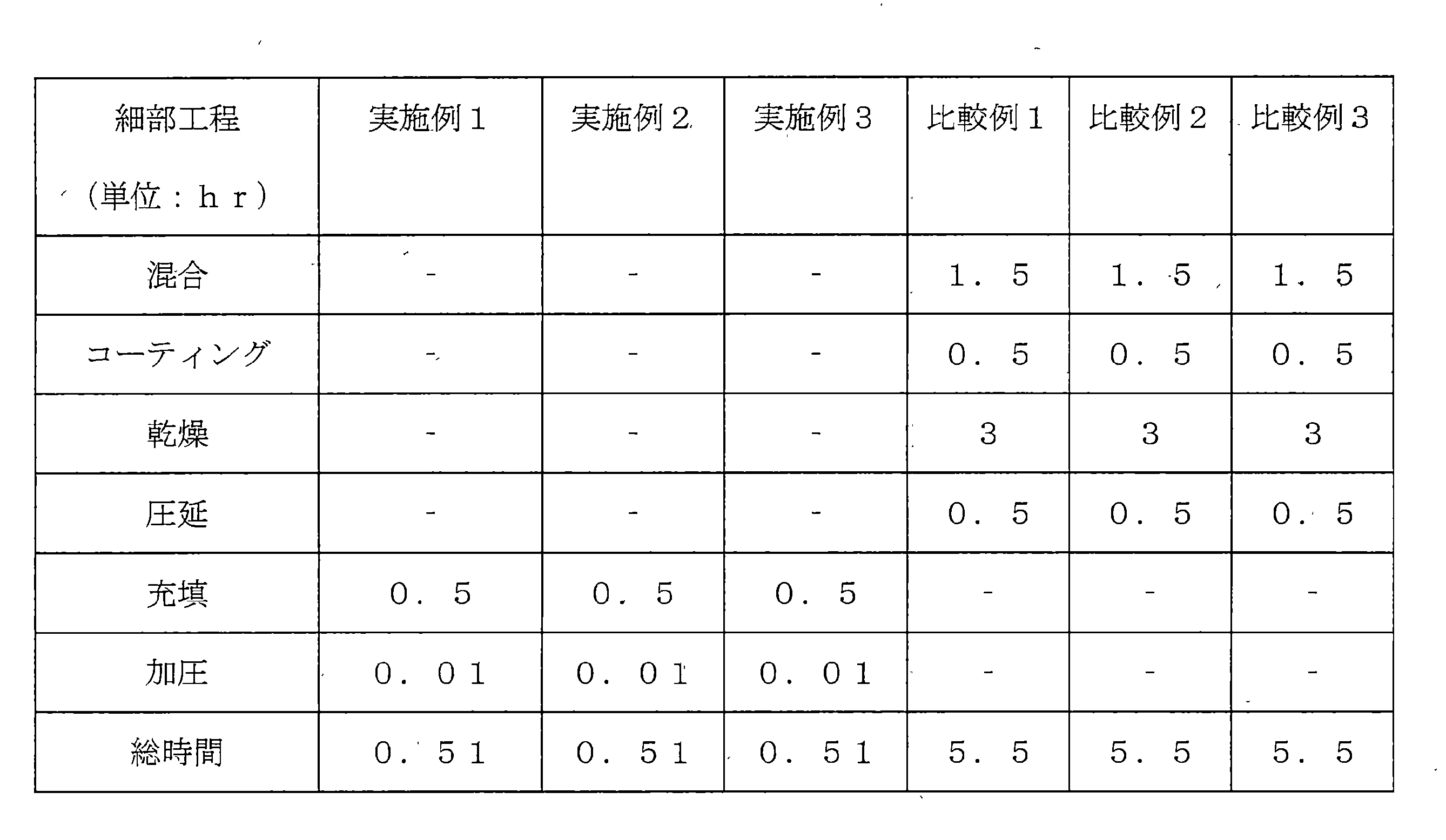
上記表1に示すように、実施例1、2及び3は細部工程として充填及び加圧工程のみを含む乾式工程を利用して正極材を製造するので、全体工程時間が1時間未満であることが分かる。 As shown in Table 1 above, Examples 1, 2 and 3 use a dry process including only filling and pressing processes as detailed processes to manufacture the cathode material, so the total process time is less than 1 hour. I understand.
一方、比較例1、2及び3は、細部工程として混合、コーティング、乾燥及び圧延工程を含むスラリー工程を利用して正極材を製造するので、全体工程時間がいずれも5時間を超えることが分かる。 On the other hand, in Comparative Examples 1, 2, and 3, the slurry process including mixing, coating, drying, and rolling was used as a detailed process to manufacture the cathode material, and the total process time exceeded 5 hours. .
このような結果から、乾式工程を利用して正極材を製造する場合、工程効率を向上させることができるということを確認することができた。 From these results, it was confirmed that the process efficiency can be improved when manufacturing the cathode material using the dry process.
実験例2:正極材の気孔率及び正極材内の接着力測定
実施例及び比較例でそれぞれ製造された正極の気孔率を測定して比べ、その結果は表2に記載したとおりである。
Experimental Example 2 Measurement of Porosity of Positive Electrode Material and Adhesive Strength in Positive Electrode Material The porosity of the positive electrodes manufactured in Examples and Comparative Examples was measured and compared, and the results are shown in Table 2.
上記気孔率は正極の質量と厚さに基づいて正極の密度を計算した後、硫黄と炭素の真密度で逆計算して気孔率を計算した(硫黄の真密度:2.07mg/cc、炭素の真密度:2.00mg/cc)。 The porosity was calculated by calculating the density of the positive electrode based on the mass and thickness of the positive electrode and then calculating back with the true density of sulfur and carbon (true density of sulfur: 2.07 mg / cc, carbon true density: 2.00 mg/cc).
上記接着力は、接着力測定機器(AMETEK社、LS1)を利用して測定した。 The adhesive force was measured using an adhesive force measuring instrument (LS1, AMETEK).

上記表2に示すように、乾式工程によって正極材を製造した実施例1、2及び3の場合、加圧時の圧力が増加するほど気孔率は減少し、正極材内の接着力は増加することを確認した。 As shown in Table 2, in the case of Examples 1, 2, and 3, in which the positive electrode material was manufactured by the dry process, the porosity decreased and the adhesive strength in the positive electrode material increased as the pressure during pressurization increased. It was confirmed.
また、湿式工程によって正極材を製造した比較例1、2及び3の場合も圧延回数を増加させるほど気孔率が減少し、正極材内の接着力は増加することが分かった。 Also, in Comparative Examples 1, 2 and 3, in which the positive electrode material was manufactured by a wet process, it was found that the porosity decreased and the adhesive strength in the positive electrode material increased as the number of rolling times increased.
正極材の気孔率が高すぎると耐久性が低下し、低すぎると電気伝導度やイオン伝導度が低くなるので、適正気孔率を示すためには、やはり加圧時の圧力を適切に調節することが必要である。 If the porosity of the positive electrode material is too high, the durability will decrease, and if it is too low, the electrical conductivity and ionic conductivity will be low. It is necessary.
図3は比較例4で得た正極材の写真で、比較例4は加圧時の圧力が低くて硫黄‐炭素複合体の間の結集力不足によって炭素を含む硫黄溶融物が形成されず、正極材が製造されないことが分かる。 FIG. 3 is a photograph of the positive electrode material obtained in Comparative Example 4. In Comparative Example 4, a sulfur melt containing carbon was not formed due to insufficient cohesion between sulfur-carbon composites due to low pressure during pressurization. It can be seen that no cathode material is produced.
比較例5は加圧時の圧力が高くて気孔率が顕著に減少し、比較例6は硫黄‐炭素複合体に別途導電材を添加した場合であって、接着力が顕著に減少したことが分かった。 In Comparative Example 5, the porosity was remarkably reduced due to high pressure, and in Comparative Example 6, a conductive material was added to the sulfur-carbon composite, and the adhesive strength was remarkably reduced. Do you get it.
実験例3:容量及び充電効率測定
実施例及び比較例で製作された電池に対して25℃で0.1C放電、0.1C充電して容量(Capacity、mAh)を測定し、充放電を繰り返して測定することで容量及び充電効率を測定し、その結果を下記表3及び図4aないし図4eに示す。上記表2に示すように、比較例4は加圧圧力が低くて硫黄‐炭素複合体の間の結集力が不足して電極が製造されなかったので、実施例1ないし3と比較例1ないし3及び5と6に対して実験を行った。
Experimental Example 3: Measurement of Capacity and Charging Efficiency The batteries manufactured in Examples and Comparative Examples were discharged at 0.1 C and charged at 0.1 C at 25° C., and the capacity (mAh) was measured, and charging and discharging were repeated. The capacity and charging efficiency were measured by measuring with , and the results are shown in Table 3 below and Figures 4a to 4e. As shown in Table 2 above, in Comparative Example 4, the applied pressure was low and the cohesive force between the sulfur-carbon composites was insufficient, so the electrode was not manufactured. 3 and 5 and 6 were tested.
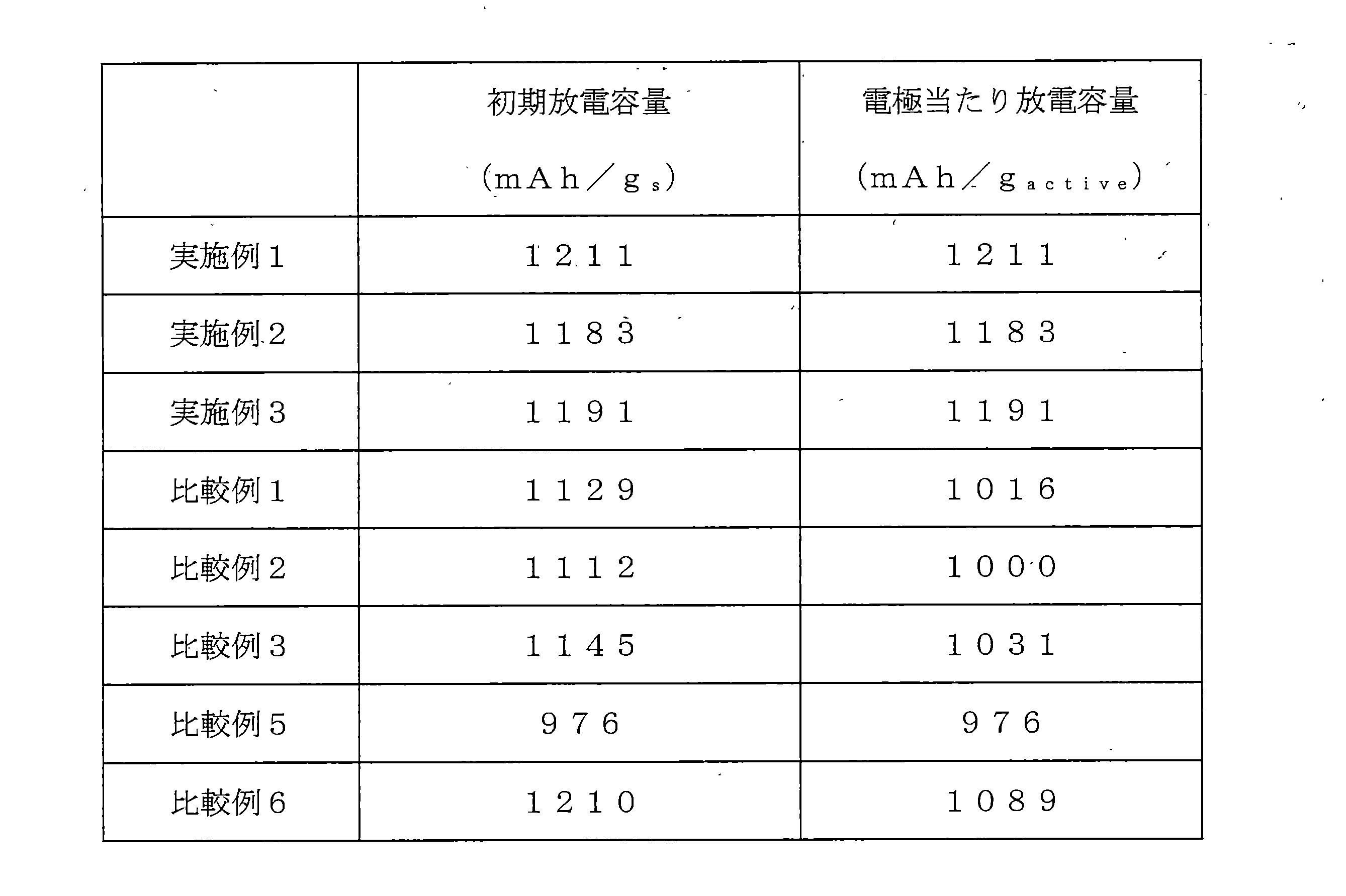
上記表3、図4a、図4b及び図4cを参照すれば、乾式工程によって製造された電極である実施例1、2、3は、湿式工程で製造された比較例1、2、3に比べて初期放電カーブで過電圧が改善されたし、より高い初期放電容量を示すことを確認することができた。 Referring to Table 3, FIGS. 4a, 4b, and 4c, Examples 1, 2, and 3, which are electrodes manufactured by a dry process, are superior to Comparative Examples 1, 2, and 3, which are manufactured by a wet process. It was confirmed that the overvoltage was improved in the initial discharge curve and that the initial discharge capacity was higher.
一般に、リチウム‐硫黄二次電池では、気孔率が重要な要素である。気孔率が低いほど電池がさらにコンパクト(compact)になることを意味する。しかし、気孔率が低くなるほど反応空間が細くなるので、低い気孔率で正常なセル駆動が難しい状況が発生することがある。 Generally, porosity is an important factor in lithium-sulfur secondary batteries. A lower porosity means a more compact battery. However, the lower the porosity, the narrower the reaction space.
しかし、乾式工程によって製造された実施例1、2、3は、湿式工程で製造された比較例1、2、3に比べて同一な気孔率を持つ場合、過電圧が改善され、より高い初期放電容量を示すことを確認した。 However, when the porosities of Examples 1, 2, and 3, which are manufactured by a dry process, are the same as those of Comparative Examples 1, 2, and 3, which are manufactured by a wet process, the overvoltage is improved and the initial discharge is higher. Confirmed to show capacity.
また、表3及び図4dを参照すれば、比較例5は正極材の製造時に加えられた圧力が20Mpaと高くて、気孔率が過度に低くなるので、セルが正常に駆動されないことが分かった。 In addition, referring to Table 3 and FIG. 4d, in Comparative Example 5, the pressure applied during the manufacture of the positive electrode material was as high as 20 MPa, and the porosity was excessively low, so the cell was not normally operated. .
また、表3及び図4eを参照すれば、比較例6は硫黄‐炭素複合体以外に導電材としてCNTをさらに添加して乾式工程で正極材を製造する場合、炭素自体の凝集力の不足によって、加圧時に正極材の成形自体が難しく、正極材の容量が導電材を未添加した実施例1に比べて劣位にあることを確認した。 In addition, referring to Table 3 and FIG. 4e, in Comparative Example 6, when the cathode material is manufactured by a dry process by adding CNT as a conductive material in addition to the sulfur-carbon composite, the cohesive force of the carbon itself is insufficient. It was confirmed that molding of the positive electrode material itself was difficult during pressurization, and that the capacity of the positive electrode material was inferior to that of Example 1 in which no conductive material was added.
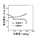
また、図5は実施例2及び比較例2で製造された正極材を適用したコインセルに対する寿命特性測定結果を示すグラフで、乾式工程によって製造された実施例2の電極を含む電池の寿命特性が改善されたことが分かる。 In addition, FIG. 5 is a graph showing the measurement results of life characteristics of coin cells to which the positive electrode materials manufactured in Example 2 and Comparative Example 2 are applied. It can be seen that the improvement has been made.
実験例4:正極材の内部形態確認
製造例1で原料として使われた炭素ナノチューブ(CNT)と硫黄‐炭素複合体(S‐CNT)を加圧工程に適用した後、内部形態を確認した。加圧工程は実施例1の(1)に示すように適用した。
Experimental Example 4 Confirmation of Internal Morphology of Cathode Materials The carbon nanotubes (CNT) and the sulfur-carbon composite (S-CNT) used as raw materials in Preparation Example 1 were subjected to a pressurization process, and then the internal morphology was confirmed. The pressing step was applied as shown in Example 1 (1).
上記炭素ナノチューブ(CNT)と硫黄‐炭素複合体(S‐CNT)をモールドに充填させた後、油圧プレスを利用して1Mpaの圧力で加圧した後、走査電子顕微鏡(SEM、Scanning Electron Microscope)で内部形態を確認した。 After the carbon nanotube (CNT) and the sulfur-carbon composite (S-CNT) were filled in the mold, they were pressed with a pressure of 1 MPa using a hydraulic press, and then examined with a scanning electron microscope (SEM). confirmed the internal morphology.
図6は、製造例1の炭素ナノチューブ(CNT)と硫黄‐炭素複合体(S‐CNT)に対するSEM写真である。 FIG. 6 is a SEM photograph of the carbon nanotube (CNT) and the sulfur-carbon composite (S-CNT) of Preparation Example 1. FIG.
図6に示すように、CNTはCNTの間の連結性がなくて、互いに繋がることなく、加圧工程後にも互いに繋がらないことで示された。 As shown in FIG. 6, the CNTs were not connected to each other due to lack of connectivity between the CNTs, and were not connected to each other even after the pressing process.
また、上記硫黄‐炭素複合体(S‐CNT)は硫黄が溶融して形成された硫黄溶融物にCNTが分散されて全体的に繋がったことで示された。これは高い加圧工程中に硫黄の融点が上がって、瞬間的に硫黄‐炭素複合体の表面で硫黄の溶融が起きれば、これによって形成された硫黄溶融物によってCNTが全体的に繋がったのである。すなわち、硫黄溶融物にCNTが分散された形態を示すことが分かる。 In addition, the sulfur-carbon composite (S-CNT) was shown to be a sulfur melt formed by melting sulfur, in which CNTs were dispersed and connected as a whole. This is because the melting point of sulfur rises during the high pressure process, and if sulfur melts instantaneously on the surface of the sulfur-carbon composite, the CNTs are connected as a whole by the sulfur melt formed by this. be. That is, it can be seen that the CNTs are dispersed in the molten sulfur.
以上、本発明はたとえ限定された実施例と図面によって説明されたが、本発明はこれによって限定されないし、本発明が属する技術分野で通常の知識を持つ者によって本発明の技術思想と下記特許請求範囲の均等範囲内で多様な修正及び変形が可能であることは勿論である。 Although the present invention has been described by way of limited examples and drawings, the present invention is not limited thereto. Of course, various modifications and variations are possible within the equivalent scope of the claims.
Claims (12)
上記正極材は炭素を含む硫黄溶融物を含むものである、リチウム二次電池用正極材。 A positive electrode material for a lithium secondary battery in the form of a free-standing film, comprising:
A positive electrode material for a lithium secondary battery, wherein the positive electrode material contains a carbon-containing sulfur melt.
(S2)上記(S1)段階で形成された混合物を熱処理する段階;及び
(S3)上記(S2)段階で形成された硫黄‐炭素複合体を容器に充填した後、加圧して炭素を含む硫黄溶融物を形成する段階;を含むリチウム二次電池用正極材の製造方法。 (S1) mixing sulfur and a porous carbon material;
(S2) heat-treating the mixture formed in step (S1); and (S3) filling the sulfur-carbon composite formed in step (S2) in a container and pressurizing the sulfur containing carbon. A method for producing a positive electrode material for a lithium secondary battery, comprising the step of forming a melt.
リチウム金属またはリチウム合金を含む負極;
上記正極と負極の間に位置する分離膜;及び
上記正極、負極及び分離膜が含浸された電解液;
を含むリチウム二次電池。 A positive electrode comprising the positive electrode material according to any one of claims 1 to 6;
a negative electrode comprising lithium metal or a lithium alloy;
a separator positioned between the positive electrode and the negative electrode; and an electrolyte impregnated with the positive electrode, the negative electrode, and the separator;
Lithium secondary battery including.
Applications Claiming Priority (5)
| Application Number | Priority Date | Filing Date | Title |
|---|---|---|---|
| KR10-2020-0063882 | 2020-05-27 | ||
| KR20200063882 | 2020-05-27 | ||
| KR1020210064083A KR102917426B1 (en) | 2020-05-27 | 2021-05-18 | Freestanding film type positive electrode material for lithium secondary battery, method for preparing the same and lithium secondary battery comprising the same |
| KR10-2021-0064083 | 2021-05-18 | ||
| PCT/KR2021/006415 WO2021241959A1 (en) | 2020-05-27 | 2021-05-24 | Free-standing film-type positive electrode material for lithium secondary battery, method for manufacturing same, and lithium secondary battery comprising same |
Publications (2)
| Publication Number | Publication Date |
|---|---|
| JP2022546292A true JP2022546292A (en) | 2022-11-04 |
| JP7431947B2 JP7431947B2 (en) | 2024-02-15 |
Family
ID=78744694
Family Applications (1)
| Application Number | Title | Priority Date | Filing Date |
|---|---|---|---|
| JP2022511087A Active JP7431947B2 (en) | 2020-05-27 | 2021-05-24 | Free-standing film type lithium secondary battery positive electrode material, manufacturing method thereof, and lithium secondary battery containing the same |
Country Status (5)
| Country | Link |
|---|---|
| US (1) | US20220359861A1 (en) |
| EP (1) | EP4002516A4 (en) |
| JP (1) | JP7431947B2 (en) |
| CN (1) | CN114207875B (en) |
| WO (1) | WO2021241959A1 (en) |
Families Citing this family (3)
| Publication number | Priority date | Publication date | Assignee | Title |
|---|---|---|---|---|
| CN114792813B (en) * | 2022-04-27 | 2023-07-14 | 电子科技大学 | Preparation and battery of carbon-free self-supporting cathode film material for lithium-carbon dioxide battery |
| US20250286141A1 (en) * | 2024-03-06 | 2025-09-11 | Lyten, Inc. | Electrolyte systems including performance-enhancing additives, and electrochemical cells including the same |
| CN118299671A (en) * | 2024-06-05 | 2024-07-05 | 中能瑞新(深圳)能源科技有限公司 | A lithium ion battery cell and a method for preparing the same, and a lithium ion battery |
Citations (2)
| Publication number | Priority date | Publication date | Assignee | Title |
|---|---|---|---|---|
| KR20160051610A (en) * | 2014-10-31 | 2016-05-11 | 주식회사 엘지화학 | Freestanding type-cathode active material for lithium-sulfur battery and lithium-sulfur battery having the same |
| US20180212252A1 (en) * | 2017-01-26 | 2018-07-26 | Caitlin Nicole Dillard | Rapid sulfur melt diffusion into carbon host for making electrodes |
Family Cites Families (16)
| Publication number | Priority date | Publication date | Assignee | Title |
|---|---|---|---|---|
| KR20050052258A (en) * | 2003-11-29 | 2005-06-02 | 삼성에스디아이 주식회사 | Lithium sulfur battery and method for manufacturing thereof |
| KR101384198B1 (en) * | 2011-05-31 | 2014-04-25 | 한양대학교 산학협력단 | Manufacturing method of carbon sulfur complex, carbon sulfur complex made by the same, lithium sulfur battery including the same |
| US20180100037A1 (en) * | 2015-07-13 | 2018-04-12 | Arizona Board Of Regents On Behalf Of The University Of Arizona | Copolymerization of elemental sulfur and epoxy functional styrenics |
| US9306207B2 (en) * | 2012-12-28 | 2016-04-05 | Hyundai Motor Company | Method of fabricating sulfur-infiltrated mesoporous conductive nanocomposites for cathode of lithium-sulfur secondary battery |
| KR101669316B1 (en) * | 2013-07-30 | 2016-10-25 | 주식회사 엘지화학 | Sulfur-carbon composite and method for manufacturing the same |
| US20170047581A1 (en) * | 2014-02-11 | 2017-02-16 | Batelle Memorial Institute | Additives to enhance electrode wetting and performance and methods of making electrodes comprising the same |
| KR101683963B1 (en) * | 2014-05-26 | 2016-12-07 | 현대자동차주식회사 | A method for preparing sulfur-carbon complex by dual dry complexation |
| WO2017053962A1 (en) * | 2015-09-24 | 2017-03-30 | Massachusetts Institute Of Technology | Systems and methods of preparing lithium sulfur electrode using sacrificial template |
| CN109873120A (en) | 2017-12-05 | 2019-06-11 | 中国科学院大连化学物理研究所 | Preparation method of metal-free current collector and self-supporting graphene-based lithium-sulfur battery cathode |
| KR102268184B1 (en) * | 2018-08-08 | 2021-06-22 | 주식회사 엘지화학 | Sulfur-carbon composite, method for preparing the same, positive electrode and lithium secondary battery comprising the same |
| US20200052279A1 (en) * | 2018-08-13 | 2020-02-13 | Tuqiang Chen | Method of preparing energy storage electrodes |
| CN111224079B (en) * | 2018-11-27 | 2021-11-05 | 清华大学 | Lithium-sulfur battery electrode, preparation method of lithium-sulfur battery electrode, and lithium-sulfur battery |
| KR102150848B1 (en) | 2018-11-28 | 2020-09-02 | 주식회사 보아스에스이 | Method of Detecting Malfunction of Power Generation System for New Renewable Energy |
| BR112021018814A2 (en) * | 2019-03-22 | 2021-11-30 | Aspen Aerogels Inc | Carbon Airgel Based Cathodes for Lithium Sulfur Batteries |
| KR102081775B1 (en) | 2019-08-22 | 2020-02-26 | 주식회사 엘지화학 | Cathode for lithium-sulfur battery comprising secondary particle of carbon, manufacturing method thereof and lithium-sulfur battery comprising the same |
| US11454837B2 (en) | 2019-11-22 | 2022-09-27 | Eagle Technology, Llc | AOM system with interface board and signal vias and related methods |
-
2021
- 2021-05-24 CN CN202180004710.XA patent/CN114207875B/en active Active
- 2021-05-24 EP EP21812418.8A patent/EP4002516A4/en active Pending
- 2021-05-24 WO PCT/KR2021/006415 patent/WO2021241959A1/en not_active Ceased
- 2021-05-24 US US17/634,114 patent/US20220359861A1/en active Pending
- 2021-05-24 JP JP2022511087A patent/JP7431947B2/en active Active
Patent Citations (2)
| Publication number | Priority date | Publication date | Assignee | Title |
|---|---|---|---|---|
| KR20160051610A (en) * | 2014-10-31 | 2016-05-11 | 주식회사 엘지화학 | Freestanding type-cathode active material for lithium-sulfur battery and lithium-sulfur battery having the same |
| US20180212252A1 (en) * | 2017-01-26 | 2018-07-26 | Caitlin Nicole Dillard | Rapid sulfur melt diffusion into carbon host for making electrodes |
Also Published As
| Publication number | Publication date |
|---|---|
| JP7431947B2 (en) | 2024-02-15 |
| EP4002516A1 (en) | 2022-05-25 |
| EP4002516A4 (en) | 2022-11-09 |
| CN114207875A (en) | 2022-03-18 |
| CN114207875B (en) | 2024-11-08 |
| WO2021241959A1 (en) | 2021-12-02 |
| US20220359861A1 (en) | 2022-11-10 |
Similar Documents
| Publication | Publication Date | Title |
|---|---|---|
| KR102006727B1 (en) | Sulfur-carbon composite and lithium-sulfur battery including the same | |
| KR101774683B1 (en) | Electorde active material slurry, preparation method thereof, and all solid secondary battery comprising the same | |
| WO2020041767A1 (en) | Hybrid and solid-state battery architectures with high loading and methods of manufacture thereof | |
| KR102726743B1 (en) | Graphite-free composite anode for all-solid state battery and process for preparing thereof | |
| KR102917426B1 (en) | Freestanding film type positive electrode material for lithium secondary battery, method for preparing the same and lithium secondary battery comprising the same | |
| US11394054B2 (en) | Polymer microspheres as binders for composite electrolytes | |
| JP5515257B2 (en) | Bipolar secondary battery | |
| KR102771681B1 (en) | Negative electrode and secondary battery comprising the negative electrode | |
| JP7431947B2 (en) | Free-standing film type lithium secondary battery positive electrode material, manufacturing method thereof, and lithium secondary battery containing the same | |
| CN115803904B (en) | Positive electrode for lithium secondary batteries, manufacturing method thereof, and lithium secondary batteries comprising thereof | |
| CN106848379A (en) | Electrode for lithium secondary battery containing hygroscopic substance and lithium secondary battery containing same | |
| JP5711825B2 (en) | Integrated electrode assembly and secondary battery using the integrated electrode assembly | |
| KR101586536B1 (en) | Manufacturing method of carbon fiber sheet current collector for all solid state rechargeable thin film lithium secondary battery, and all solid state rechargeable thin film lithium secondary battery comprising carbon fiber sheet current collector | |
| JP6212305B2 (en) | Composite current collector, and electrode and secondary battery using the same | |
| JP2022550821A (en) | LITHIUM SECONDARY BATTERY ELECTRODE INCLUDING PERFORATED CURRENT COLLECTOR, METHOD FOR MANUFACTURING THE SAME, AND LITHIUM SECONDARY BATTERY INCLUDING THE SAME ELECTRODE | |
| CN116250099A (en) | Sulfur-carbon composite material, method for its preparation, and lithium-sulfur battery comprising it | |
| CN119895624A (en) | Positive electrode for all-solid-state battery and all-solid-state battery comprising same | |
| CN118575323A (en) | Solid electrolyte membrane and all-solid battery comprising same | |
| JP7039846B2 (en) | Manufacturing method of non-aqueous electrolyte secondary battery | |
| CN118843959A (en) | Positive electrode for lithium-sulfur battery comprising different types of conductive materials and lithium-ion secondary battery comprising same | |
| CN116235308A (en) | Apparatus for manufacturing film-type positive electrode, manufacturing method thereof, and lithium secondary battery, battery module, and battery pack including same | |
| JP2011029136A (en) | Electrode for secondary battery, secondary battery, and manufacturing method of electrode for secondary battery | |
| US12126004B2 (en) | Fabrication of Si-MWCNT nanocomposites (SMC) as anodes for lithium-ion batteries | |
| JP7497527B2 (en) | Positive electrode for lithium secondary battery, method for producing same and lithium secondary battery including same | |
| JP2024174503A (en) | Non-aqueous electrolyte secondary battery |
Legal Events
| Date | Code | Title | Description |
|---|---|---|---|
| A621 | Written request for application examination |
Free format text: JAPANESE INTERMEDIATE CODE: A621 Effective date: 20220218 |
|
| A977 | Report on retrieval |
Free format text: JAPANESE INTERMEDIATE CODE: A971007 Effective date: 20230216 |
|
| A131 | Notification of reasons for refusal |
Free format text: JAPANESE INTERMEDIATE CODE: A131 Effective date: 20230403 |
|
| A521 | Request for written amendment filed |
Free format text: JAPANESE INTERMEDIATE CODE: A523 Effective date: 20230628 |
|
| A131 | Notification of reasons for refusal |
Free format text: JAPANESE INTERMEDIATE CODE: A131 Effective date: 20230807 |
|
| A521 | Request for written amendment filed |
Free format text: JAPANESE INTERMEDIATE CODE: A523 Effective date: 20231101 |
|
| TRDD | Decision of grant or rejection written | ||
| A01 | Written decision to grant a patent or to grant a registration (utility model) |
Free format text: JAPANESE INTERMEDIATE CODE: A01 Effective date: 20240122 |
|
| A61 | First payment of annual fees (during grant procedure) |
Free format text: JAPANESE INTERMEDIATE CODE: A61 Effective date: 20240202 |
|
| R150 | Certificate of patent or registration of utility model |
Ref document number: 7431947 Country of ref document: JP Free format text: JAPANESE INTERMEDIATE CODE: R150 |