JP2022519210A - Manufacturing method and equipment of consumable unit for inhalation device, and consumable unit for inhalation device - Google Patents
Manufacturing method and equipment of consumable unit for inhalation device, and consumable unit for inhalation device Download PDFInfo
- Publication number
- JP2022519210A JP2022519210A JP2021544160A JP2021544160A JP2022519210A JP 2022519210 A JP2022519210 A JP 2022519210A JP 2021544160 A JP2021544160 A JP 2021544160A JP 2021544160 A JP2021544160 A JP 2021544160A JP 2022519210 A JP2022519210 A JP 2022519210A
- Authority
- JP
- Japan
- Prior art keywords
- container
- closing plate
- consumable unit
- station
- weighing
- Prior art date
- Legal status (The legal status is an assumption and is not a legal conclusion. Google has not performed a legal analysis and makes no representation as to the accuracy of the status listed.)
- Granted
Links
Images


Classifications
-
- B—PERFORMING OPERATIONS; TRANSPORTING
- B65—CONVEYING; PACKING; STORING; HANDLING THIN OR FILAMENTARY MATERIAL
- B65B—MACHINES, APPARATUS OR DEVICES FOR, OR METHODS OF, PACKAGING ARTICLES OR MATERIALS; UNPACKING
- B65B7/00—Closing containers or receptacles after filling
- B65B7/16—Closing semi-rigid or rigid containers or receptacles not deformed by, or not taking-up shape of, contents, e.g. boxes or cartons
- B65B7/28—Closing semi-rigid or rigid containers or receptacles not deformed by, or not taking-up shape of, contents, e.g. boxes or cartons by applying separate preformed closures, e.g. lids, covers
- B65B7/2842—Securing closures on containers
- B65B7/2892—Securing closures on containers by deformation of the container rim
-
- A—HUMAN NECESSITIES
- A24—TOBACCO; CIGARS; CIGARETTES; SIMULATED SMOKING DEVICES; SMOKERS' REQUISITES
- A24F—SMOKERS' REQUISITES; MATCH BOXES; SIMULATED SMOKING DEVICES
- A24F40/00—Electrically operated smoking devices; Component parts thereof; Manufacture thereof; Maintenance or testing thereof; Charging means specially adapted therefor
- A24F40/20—Devices using solid inhalable precursors
-
- A—HUMAN NECESSITIES
- A24—TOBACCO; CIGARS; CIGARETTES; SIMULATED SMOKING DEVICES; SMOKERS' REQUISITES
- A24F—SMOKERS' REQUISITES; MATCH BOXES; SIMULATED SMOKING DEVICES
- A24F40/00—Electrically operated smoking devices; Component parts thereof; Manufacture thereof; Maintenance or testing thereof; Charging means specially adapted therefor
- A24F40/30—Devices using two or more structurally separated inhalable precursors, e.g. using two liquid precursors in two cartridges
-
- A—HUMAN NECESSITIES
- A24—TOBACCO; CIGARS; CIGARETTES; SIMULATED SMOKING DEVICES; SMOKERS' REQUISITES
- A24F—SMOKERS' REQUISITES; MATCH BOXES; SIMULATED SMOKING DEVICES
- A24F40/00—Electrically operated smoking devices; Component parts thereof; Manufacture thereof; Maintenance or testing thereof; Charging means specially adapted therefor
- A24F40/40—Constructional details, e.g. connection of cartridges and battery parts
- A24F40/42—Cartridges or containers for inhalable precursors
-
- B—PERFORMING OPERATIONS; TRANSPORTING
- B65—CONVEYING; PACKING; STORING; HANDLING THIN OR FILAMENTARY MATERIAL
- B65B—MACHINES, APPARATUS OR DEVICES FOR, OR METHODS OF, PACKAGING ARTICLES OR MATERIALS; UNPACKING
- B65B1/00—Packaging fluent solid material, e.g. powders, granular or loose fibrous material, loose masses of small articles, in individual containers or receptacles, e.g. bags, sacks, boxes, cartons, cans, or jars
- B65B1/30—Devices or methods for controlling or determining the quantity or quality or the material fed or filled
- B65B1/36—Devices or methods for controlling or determining the quantity or quality or the material fed or filled by volumetric devices or methods
-
- A—HUMAN NECESSITIES
- A24—TOBACCO; CIGARS; CIGARETTES; SIMULATED SMOKING DEVICES; SMOKERS' REQUISITES
- A24F—SMOKERS' REQUISITES; MATCH BOXES; SIMULATED SMOKING DEVICES
- A24F40/00—Electrically operated smoking devices; Component parts thereof; Manufacture thereof; Maintenance or testing thereof; Charging means specially adapted therefor
- A24F40/10—Devices using liquid inhalable precursors
-
- A—HUMAN NECESSITIES
- A24—TOBACCO; CIGARS; CIGARETTES; SIMULATED SMOKING DEVICES; SMOKERS' REQUISITES
- A24F—SMOKERS' REQUISITES; MATCH BOXES; SIMULATED SMOKING DEVICES
- A24F40/00—Electrically operated smoking devices; Component parts thereof; Manufacture thereof; Maintenance or testing thereof; Charging means specially adapted therefor
- A24F40/70—Manufacture
Abstract
吸入デバイスと共に使用される消耗品ユニットの製造方法が開示されている。この方法は 消耗品ユニットの容器に所与の用量のエアロゾル化可能な材料を供給することと、容器の端部に閉鎖板を位置決めすることと、容器に閉鎖板を固定することとを含む。吸入デバイスと共に使用される消耗品ユニットの製造装置も開示されている。Disclosed are methods of manufacturing consumable units used with inhalation devices. This method involves supplying a given dose of aerosolable material to the container of the consumable unit, positioning the closure plate at the end of the container, and fixing the closure plate to the container. Equipment for manufacturing consumable units used with inhalation devices is also disclosed.
Description
本発明は、吸入デバイス用の消耗品ユニットの製造装置および方法、特に、吸入デバイスに使用される粒状タバコ材を含むタバコポッドの製造装置および方法に関するが、これらに限定されない。また本発明は、吸入デバイス用の消耗品ユニット、例えば、吸入デバイスと共に使用される粒状タバコ材を含む消耗品ユニットに関する。 The present invention relates to, but is not limited to, manufacturing equipment and methods for consumable units for inhalation devices, in particular, manufacturing equipment and methods for tobacco pods containing granular tobacco material used in inhalation devices. The present invention also relates to a consumable unit for an inhalation device, eg, a consumable unit containing a granular tobacco material used with the inhalation device.
下記特許文献1は、小さな容器にタバコ材料を充填する装置を開示しており、この小さな容器は、吸入デバイスの消耗品ユニットである。この充填装置は、タバコ材料を漏斗に投入するためのオーガースクリューとタバコ材料を漏斗から容器の開口端部に導くパイプを含む。容器の他端部には吸引パイプが設けられており、容器から空気を吸い込み、タバコ材料が確実に容器に入るようにする。 The following Patent Document 1 discloses a device for filling a small container with a tobacco material, and the small container is a consumable unit of an inhalation device. The filling device includes an auger screw for charging the tobacco material into the funnel and a pipe leading the tobacco material from the funnel to the open end of the container. A suction pipe is provided at the other end of the container to suck air from the container and ensure that the tobacco material enters the container.
吸入デバイス用の消耗品ユニットの効率的な製造を提供するためにポッドを粒状タバコ材で確実かつ迅速に充填する必要性がある。 There is a need to reliably and quickly fill the pods with granular tobacco material to provide efficient manufacture of consumable units for inhalation devices.
本発明の実施態様では吸入デバイスと共に使用される消耗品ユニットの製造方法が提供され、この方法は、
消耗品ユニットの容器に所与の用量のエアロゾル化可能な材料を供することと、
容器の端部に閉鎖板を位置決めすることと、
容器に閉鎖板を固定することとを含む。
In embodiments of the present invention, a method of manufacturing a consumable unit used with an inhalation device is provided, the method of which is:
The container of the consumable unit is provided with a given dose of aerosolizable material, and
Positioning the closure plate at the end of the container and
Includes fixing the closing plate to the container.
好ましい例では本発明の方法は、複数の容器に対して同時に実行される。 In a preferred example, the method of the invention is performed on multiple containers simultaneously.
本発明の方法は、複数の空の容器を、容器を支持する機械トレイ内に位置決めすることを含んでもよい。 The method of the present invention may include positioning a plurality of empty containers within a mechanical tray that supports the containers.
本発明の方法は、容器に所与の用量のエアロゾル化可能な材料を供給する計量投入ステーションに機械トレイを挿入することをさらに含んでもよい。 The method of the invention may further comprise inserting a mechanical tray into a metering loading station that supplies a container with a given dose of aerosolizable material.
本発明の方法は、機械トレイを計量投入ステーションから各容器の端部に閉鎖板を位置決めする閉鎖板位置決めステーションに移動させることを含んでもよい。 The method of the present invention may include moving the mechanical tray from the weighing loading station to a closing plate positioning station that positions the closing plate at the end of each container.
本発明の方法は、機械トレイを閉鎖板位置決めステーションから閉鎖板を容器に固定する閉鎖板固定ステーションに移動させることを含んでもよい。 The method of the present invention may include moving the mechanical tray from the closing plate positioning station to the closing plate fixing station that secures the closing plate to the container.
機械トレイの移動は、機械トレイをコンベアで運ぶことを含んでもよい。 Moving the machine tray may include carrying the machine tray on a conveyor.
これとは別に本発明の方法は定置機械トレイ支持体内に機械トレイを位置決めすることを含んでもよく、かつこの方法は機械トレイ支持体の機械トレイ内の容器に対して実行される。この例では計量投入ステーションおよび/または閉鎖板位置決めステーションおよび/または閉鎖板固定ステーションは、定置機械トレイ支持体内の容器に関する操作を実行するように配置されてもよい。 Alternatively, the method of the invention may include positioning the machine tray within a stationary machine tray support, and the method is performed on a container in the machine tray of the machine tray support. In this example, the weighing loading station and / or the closing plate positioning station and / or the closing plate fixing station may be arranged to perform operations on the container in the stationary machine tray support.
いくつかの例において所与の用量のエアロゾル化可能材料を容器に提供することは、所定体積のエアロゾル化可能材料を容器に計量投入することを含む。エアロゾル化可能な材料は、タバコを含んでもよい。これとは別にあるいはそれに加えて、エアロゾル化可能な材料は、粒状材、例えば、粒状タバコ材を含む。 Providing a given dose of an aerosolizable material to a container in some examples comprises weighing a predetermined volume of the aerosolizable material into the container. Aerosolizable materials may include tobacco. Apart from or in addition to this, aerosolizable materials include granular materials such as granular tobacco materials.
閉鎖板はメッシュを含んでもよい。 The closing plate may include a mesh.
容器は、複数の柵を含んでもよく、容器に閉鎖板を固定することは、複数の柵を変形させて閉鎖板を容器に固定することを含んでもよい。柵は、変形しやすくするために加熱され、および/または柵は容器に閉鎖板を固定するために曲げられてもよい。 The container may include a plurality of fences, and fixing the closing plate to the container may include deforming the plurality of fences to fix the closing plate to the container. The fence may be heated to facilitate deformation and / or the fence may be bent to secure the closure plate to the container.
いくつかの例では閉鎖板の反対側の容器の端部はスクリーンを含み、消耗品ユニットは、マウスピースを含んでもよく、このマウスピースは蒸気がスクリーンを介して容器からマウスピースに流れることができるように配置される。 In some examples, the end of the container opposite the closure plate may include a screen and the consumable unit may include a mouthpiece, which allows steam to flow from the container to the mouthpiece through the screen. Arranged so that it can be done.
本発明のさらなる態様では吸入デバイスと共に使用される消耗品ユニットの製造装置も提供され、この装置は、
消耗品ユニットの容器に所与の用量のエアロゾル化可能な材料を供給するように構成された計量投入ステーションと、
容器の端部に閉鎖板を位置決めするように構成された閉鎖板位置決めステーションと、
閉鎖板を容器に固定するように構成された閉鎖板固定ステーションとを含む。
In a further aspect of the invention, a device for manufacturing a consumable unit used with an inhalation device is also provided, which device.
With a weighing input station configured to supply a given dose of aerosolizable material to the container of the consumable unit,
A closure plate positioning station configured to position the closure plate at the end of the container,
Includes a closing plate fixing station configured to secure the closing plate to the container.
計量投入ステーションおよび/または閉鎖板位置決めステーションおよび/または閉鎖板固定ステーションは、それぞれ複数の容器で同時に動作するように構成されてもよい。 The weighing loading station and / or the closing plate positioning station and / or the closing plate fixing station may each be configured to operate simultaneously in multiple containers.
計量投入ステーションおよび/または閉鎖板位置決めステーションおよび/または閉鎖板固定ステーションは、それぞれ機械トレイを支持する機械トレイ支持体を含んでもよい。機械トレイは、複数の容器を受け入れて支持するように適合させてもよい。 The weighing loading station and / or the closing plate positioning station and / or the closing plate fixing station may each include a machine tray support that supports the machine tray. The machine tray may be adapted to accept and support multiple containers.
本発明の装置は、計量投入ステーション、閉鎖板位置決めステーション、および閉鎖板固定ステーションのうちの少なくとも2台の装置間で機械トレイを搬送するように配置されたコンベアをさらに含んでもよい。 The device of the present invention may further include a conveyor arranged to transport the machine tray between at least two devices of the weighing loading station, the closing plate positioning station, and the closing plate fixing station.
計量投入ステーション、閉鎖板位置決めステーション、および閉鎖板固定ステーションのうちの少なくとも1つは、工具群が配置された棚を含んでもよい。棚または機械トレイの一方を、棚または機械トレイの他方に対して移動するようにアクチュエーターが設けられてもよい。工具群および/または棚は、容器と係合するように適合させてもよい。 At least one of the weighing loading station, the closing plate positioning station, and the closing plate fixing station may include a shelf on which the tool group is arranged. Actuators may be provided to move one of the shelves or machine trays relative to the other of the shelves or machine trays. The tools and / or shelves may be adapted to engage the container.
いくつかの例では棚は、少なくとも1本のレールに取り付けられており、棚は、少なくとも1本のレールに沿って移動して機械トレイに対して工具群を移動させてもよい。 In some examples, the shelves are attached to at least one rail, and the shelves may be moved along at least one rail to move the tools to the machine tray.
計量投入ステーションは、棚と工具群を含んでもよい。この例では工具群は、容器に所与の用量のエアロゾル化可能な材料を供給するように動作可能な計量投入機構を含んでもよい。 The weighing loading station may include shelves and tools. In this example, the tool group may include a weighing loading mechanism that can operate to supply a given dose of aerosolizable material to the container.
計量投入機構は、エアロゾル化可能な材料を受け入れるホッパーと、計量投入キャビティを含む可動式計量投入機とを含んでもよい。この計量投入機は、エアロゾル化可能な材料がホッパーから計量投入キャビティに移動可能な第1の位置と、エアロゾル化可能な材料が計量投入キャビティから容器に移動可能な第2の位置との間を移動するように構成されてもよい。 The weighing loading mechanism may include a hopper that accepts aerosolizable material and a movable weighing loading machine that includes a weighing loading cavity. The metering machine is located between a first position where the aerosolizable material can be moved from the hopper to the weighing loading cavity and a second position where the aerosolizable material can be moved from the weighing loading cavity to the container. It may be configured to move.
いくつかの例では閉鎖板位置決めステーションは、棚と、工具群とを含む。この例では工具群は、閉鎖板を閉鎖板支持ウェブから分離し、閉鎖板を容器に向かって移動させるように構成されたパンチを含んでもよい。 In some examples, the closing plate positioning station includes shelves and a set of tools. In this example, the tool group may include a punch configured to separate the closure plate from the closure plate support web and move the closure plate towards the container.
いくつかの例では閉鎖板固定ステーションは、棚と、工具群とを含む。この例では工具群はプレスを含んでもよく、容器は、容器から突出する複数の柵を含んでもよく、プレスは、複数の柵を変形させて閉鎖板を容器に固定するように構成されている。 In some examples, the closed plate fixing station includes shelves and a set of tools. In this example, the tool group may include a press, the container may include a plurality of fences protruding from the container, and the press is configured to deform the plurality of fences to secure the closing plate to the container. ..
いくつかの例ではエアロゾル化可能な材料はタバコを含んでもよい。これとは別にあるいはこれに加えてエアロゾル化可能な材料は、粒状材、例えば、粒状タバコ材を含んでもよい。 In some examples, the aerosolizable material may include tobacco. Separately or in addition to this, the material that can be aerosolized may include a granular material, for example, a granular tobacco material.
閉鎖板はメッシュを含んでもよい。 The closing plate may include a mesh.
いくつかの例では閉鎖板の反対側の容器の端部はスクリーンを含み、消耗品ユニットは、マウスピースを含んでもよく、このマウスピースは蒸気が容器およびマウスピースを通って流れることができるように配置されている。 In some examples, the end of the container opposite the closure plate may include a screen and the consumable unit may include a mouthpiece, which allows steam to flow through the container and mouthpiece. Is located in.
本発明の装置は、
容器内のエアロゾル化可能な材料の投入量、
容器の端への閉鎖板の位置決め、および/または
閉鎖板の容器への固定、
のうちの1項目以上を検査するように構成された検査装置をさらに含んでもよい。
The apparatus of the present invention
Input amount of aerosolizable material in the container,
Positioning the closure plate to the edge of the container and / or fixing the closure plate to the container,
Further may include an inspection device configured to inspect one or more of the items.
本発明のさらなる態様では上記の方法に従って製造された消耗品ユニットおよび上記の装置を用いて製造された消耗品ユニットも提供される。 In a further aspect of the present invention, a consumable unit manufactured according to the above method and a consumable unit manufactured by using the above device are also provided.
本発明のさらなる態様では吸入デバイスと共に使用される消耗品ユニットも提供される。この消耗品ユニットは、所与の用量のエアロゾル化可能な材料を保持する容器と、容器の端部を覆う閉鎖板とを含む。この容器は、閉鎖板を容器に固定するために変形する複数の柵を含む。 In a further aspect of the invention, a consumable unit used with an inhalation device is also provided. This consumable unit includes a container that holds a given dose of aerosolizable material and a closing plate that covers the end of the container. This container contains multiple fences that are deformed to secure the closure plate to the container.
複数の柵は、閉鎖板に対して曲げることができる。例えば、消耗品ユニットは縁部を含んでもよく、閉鎖板は縁部と複数の柵との間に固定されてもよい。 Multiple fences can be bent against the closing plate. For example, the consumable unit may include an edge, and the closing plate may be fixed between the edge and the plurality of fences.
閉鎖板はメッシュを含んでもよい。消耗品ユニットは、マウスピースをさらに含んでもよい。 The closing plate may include a mesh. The consumable unit may further include a mouthpiece.
閉鎖板の反対側の容器の端部は、蒸気が消耗品ユニットを通り、閉鎖板から、容器およびスクリーンを通り、マウスピースに流れることができるように、スクリーンを含んでもよい。 The end of the container opposite the closure plate may include a screen so that steam can flow through the consumable unit, from the closure plate, through the container and screen, and to the mouthpiece.
スクリーンはメッシュを含んでもよい。 The screen may include a mesh.
いくつかの例では、エアロゾル化可能な材料はタバコを含んでもよい。これとは別にあるいはそれに加えて、エアロゾル化可能な材料は、粒状材、例えば、粒状タバコ材を含んでもよい。 In some examples, the aerosolizable material may include tobacco. Separately or in addition, the aerosolizable material may include a granular material, for example, a granular tobacco material.
本発明の実施態様は、添付の図面を参照して例示目的でのみ説明される。
この特許明細書は、吸入デバイス用の消耗品ユニットを製造装置および方法を開示する。特に、この特許明細書は、吸入デバイスで燃焼せずに生成された蒸気を送達する消耗品ユニットの製造装置および製造方法を開示する。 This patent specification discloses an apparatus and method for manufacturing a consumable unit for an inhalation device. In particular, this patent specification discloses a manufacturing apparatus and manufacturing method for a consumable unit that delivers the vapor generated without burning in an inhalation device.
本明細書に開示される実施態様では、吸入デバイスは、成人消費者が保持するのに適した大きさおよび形状の作動ユニットと、作動ユニットに着脱可能で、その中に保持された消耗液を噴霧する噴霧器を有するアトマイザーカートリッジと、このカートリッジに着脱可能であり、容器とマウスピースを有し、所定用量のエアロゾル化可能な材料、例えば粒状タバコ材を含むタバコポッドと、粒状タバコ材を容器内に保持する閉鎖板とを含む。 In the embodiments disclosed herein, the inhalation device comprises an actuating unit of a size and shape suitable for an adult consumer to hold and a consumable fluid that is removable and retained in the actuating unit. An atomizer cartridge with a sprayer to spray, a tobacco pod that is removable to this cartridge, has a container and a mouthpiece, and contains a predetermined dose of aerosolizable material, such as granular tobacco material, and granular tobacco material in the container. Includes a closing plate to hold in.
ユーザーは、交換が必要な場合、つまり消耗液を使い切ったとき、またはタバコポッド内のタバコを使い切ったときに、アトマイザーカートリッジとタバコポッドを別々に交換できる。 The user can replace the atomizer cartridge and the cigarette pod separately when they need to be replaced, that is, when the consumables are used up or when the cigarette in the cigarette pod is used up.
使用中に、消費者が吸入デバイスから空気を引き込むと、作動ユニットは、消費者の制御の下でアトマイザーカートリッジにエネルギーを供給する。アトマイザーカートリッジ内の液体は噴霧化されてエアロゾルを形成し、タバコポッド内の粒状タバコ材は揮発して揮発性香味材を放出する。従って、デバイスから吸入される空気は、アトマイザーカートリッジから噴霧化された液体のエアロゾルをタバコポッド内の粒状タバコ材を加熱することによって発生した蒸気と共に消費者へ供給する。気化可能なタバコ材料および消耗液の組成は、消費者にアピールする広範囲の組み合わせの風味を供給するように選択してもよい。 During use, when the consumer draws air from the inhalation device, the actuating unit energizes the atomizer cartridge under consumer control. The liquid in the atomizer cartridge is atomized to form an aerosol, and the granular tobacco material in the tobacco pod volatilizes and releases the volatile flavor material. Thus, the air sucked from the device supplies the consumer with the liquid aerosol atomized from the atomizer cartridge along with the vapor generated by heating the granular tobacco material in the tobacco pod. The composition of the vaporizable tobacco material and consumables may be selected to provide a wide range of combinations of flavors that appeal to the consumer.
本明細書は、上記のように吸入デバイス用のタバコポッドの製造装置および製造方法に関する。しかしながら、当然のことながら別の吸入デバイスでは、粒状タバコ材を代りの粒子状の気化可能な材料で置き換えることができる。例えば、粒子状の気化可能な材料は、粒子状の植物性材料であってもよい。以下に説明する装置および方法は、タバコポッド内の粒状物質によって制限されないので、このタバコポッドは、粒状物質を含む消耗品ユニットと呼ばれる。 The present specification relates to an apparatus and a method for manufacturing a tobacco pod for an inhalation device as described above. However, of course, in another inhalation device, the granular tobacco material can be replaced with an alternative particulate vaporizable material. For example, the particulate vaporizable material may be particulate vegetable material. The devices and methods described below are not limited by the particulate matter within the tobacco pod, so the tobacco pod is referred to as a consumable unit containing the particulate matter.
図1を参照すると吸入デバイス1は、成形プラスチック材料製の3つの中空セクション、即ち、デバイスの操作系と機構を含む本体2、揮発性液体風味剤を含むアトマイザーカートリッジ3、および加熱するとエアロゾルを発生する所与の用量の粒状物質を含む消耗品ユニット4を有する。3つの中空セクションは、互いに取り外し可能に接続されているので、アトマイザーカートリッジ3および消耗品ユニット4は、それぞれ互いに本体2から取り外すことができ、交換用消耗品ユニット4とアトマイザーカートリッジ3を本体2に取り付けることができるようになっている。
Referring to FIG. 1, the inhalation device 1 has three hollow sections made of molded plastic material, namely a body 2 containing the operation system and mechanism of the device, an
本体2は、成人消費者が手で持ちやすいように、軸方向に長尺で、平らにされたほぼ円筒形のものである。本体2は、2つの軸方向に整列した中空の成形セクション、即ち上方セクション2aおよび下方セクション2bから形成されている。本体2の上方セクション2aは、アトマイザーカートリッジ3を受け入れる凹部を画定する開口した上端部および閉じた下方端部壁5を有する。本体の下方セクション2bは、防火壁を供するために上方セクション1aの下方端部壁5によって上方セクションから隔絶されている。本体2の下方セクション2bは、バッテリー、電気回路板、パフセンサおよびここに示されていない他の操作構成要素を含み、これらは、本体2の片面にある操作ボタン6で作動される。本体2の開口部に収容された電光はデバイスの作動状態を示す。
The main body 2 is an axially long, flattened and substantially cylindrical body so that an adult consumer can easily hold it by hand. The body 2 is formed from two axially aligned hollow molded sections, namely the
アトマイザーカートリッジ3は、上方セクション1aの凹部内に押し込み式接続によって本体2に取り外し自在に接続され、本体2から離れて上部出口3aの方へ軸方向にテーパーしている。アトマイザーカートリッジ3は、揮発性液風味剤が充填された貯蔵部と、作動ボタン6によって本体2のバッテリーから電気の供給が制御される該液体を揮発させるための加熱エレメントとを含む。
The
消耗品ユニット4は、アトマイザーカートリッジ3の上部出口3a内に押し込み式接続によって取り外し自在に接続される。消耗品ユニット4の外面は、蒸気出口5の方へと軸方向にテーパーしたアトマイザーカートリッジ3の形状に続くスカートを形成しており、消費者の口で快適に保持される形状になっている。
The
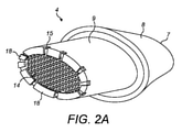
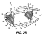
図2Aおよび2Bに示すように消耗品ユニット4は、マウスピース8と、軸方向に延びる開口端部容器9とを含む。この例では、容器9は、楕円形の半径方向断面を有する。容器9の一端は、マウスピース8のスカート10内にあり、栓11で終端し、これは、蒸気出口7の上流のマウスピース8の内面に形成された相補形状のソケット12内に受け入れられる。
As shown in FIGS. 2A and 2B, the
マウスピース8は、超音波溶接、誘導溶接、または他の任意の適切な方法によって容器9に接続することができる。これとは別にマウスピース8および容器9は、例えば射出成形によって一体的に形成される。
The
この実施態様では容器9と一体に成型されている内部穿孔されたスクリーン13が容器9断面の半径方向に延び、蒸気出口7の上流の近い距離に容器9を横切る蒸気透過性の仕切りを画定している。図2Bに示すように内部穿孔されたスクリーン13は、容器9の内方端部を横切って延びている。容器9の他端部15はマウスピース8のスカート部10から突出し、閉鎖板14が設けられている。この例では、閉鎖板14は穿孔スクリーンの形態である。閉鎖板14は、例えばメッシュまたは箔、あるいはプラスチック材料の成形品から構成される。
In this embodiment, an internally perforated
これとは別の例では内部穿孔スクリーン13は、マウスピース8と一体的に成形され、マウスピース8と容器9が組み合わされるときに、容器9の端部を横切って位置決めされる。
In another example, the
内部穿孔スクリーン13と閉鎖板14は、所与の用量の粒状物質が保持される容器9内のチェンバー16の端部壁を画定する。内側の有孔スクリーン13および閉鎖板14の穿孔により、蒸気はチェンバー16を通ってマウスピース8および蒸気出口7に向かって下流の軸方向に通過する。穿孔は、粒状材の粒子寸法との関連で選択される大きさのものであり、粒子が容器9から落下することまたは吸入された蒸気と共にマウスピース8に引き込まれることを防ぐ。
The internal
使用時、消費者は作動ボタン6を使用してデバイス1のスイッチを入れ、マウスピース8から吸い込み、デバイス1から引き込まれる蒸気を吸入する。始動させると、本体2内の電子システムがデバイス内の空気およびアトマイザーカートリッジ3内の液体を霧化を引き起こすのに十分に加熱する。加熱された空気は容器9内の粒状材から風味剤を揮発させ、アトマイザーカートリッジ2からの霧化させた液体風味剤を同伴する。風味剤の混合物はこれにより吸入用のエアロゾルとして消費者に送られる。
During use, the consumer uses the actuation button 6 to switch on device 1, inhale through the
消耗品ユニット4の製造方法は、図3Aに示す空の消耗品ユニットを受け取ることを含む。ここでチェンバー16は空であり、閉鎖板14は存在しないので、チェンバー16の端部15は開口している。図3Bに概略的に示すこの方法は、チェンバー16にチェンバー9の開口端部15を通して所与の用量の粒状物質17を提供すること、チェンバー16の開口端部15の上に閉鎖板14を位置決めするとと、次いで、閉鎖板14を容器9に固定することを含む。図3Aに示すように容器9は、容器9の開口端部15から最初に軸方向に突出する複数の柵18を含む。閉鎖板14はこれらの柵18の間で受容され、図2Aおよび2Bに示すように柵18を、閉鎖板14上に曲げて、閉鎖板14を容器9に固定する。
The method of manufacturing the
具体的には図3Aに示すようにチェンバー16を画定する容器9は、端部15を含み、柵18は、端部15の半径方向の縁部19から軸方向に突出し、その結果、リップ20は、容器9の端部に画定される。図2Bに示すように閉鎖板14は、リップ20に対して位置決めされ、柵18は、閉鎖板14の外側上で曲げられ、それによって、閉鎖板14を容器9に固定する。
Specifically, as shown in FIG. 3A, the
図示のように、柵18は、容器9の半径方向の縁部19の周りに間隔を置いて配置され、柵18間の間隙によって、それらが衝突することなく折りたたまれる。柵18の大きさ(幅)は異なっていてもよい。より狭い柵18は、好ましくは、より小さな半径を有する容器9の半径方向縁部19の部分に配置され、その結果、柵18が曲がっている点での応力および歪みがより低くなるので、柵18はより簡単に曲げられる。
As shown, the
図4は、図2Aから3Bを参照して説明した消耗品ユニット4、特にマウスピース8および粒状物質17を保持する容器9を含む消耗品ユニット4の製造装置21の概略図を示す。図示の装置21は、
粒状物質17を消耗品ユニット4のチェンバー16に投入する工程、
消耗品ユニット4の容器9上に閉鎖板14を位置決めする工程、
閉鎖板14を容器9に固定する工程、
を実行するための装置を含む。
FIG. 4 shows a schematic diagram of the
Step of charging the
Step of positioning the
The process of fixing the
Includes equipment for performing.
図4に示すように第1の工程は、空の消耗品ユニット4の提供22である。提供22での消耗品ユニット4は、図3Aに示す形体である。特に、提供22時の空の消耗品ユニット4は、マウスピース8と、開口端部15を有する容器9とを含む。容器9は、図3Aに示すように粒状物質17がチェンバー16に位置決めされた後に閉鎖板14を固定するための突出する柵18を含む。
As shown in FIG. 4, the first step is to provide an empty
空の消耗品ユニット4の提供22の後、計量投入ステーション23は、所与の用量の粒状物質17を消耗品ユニット4のチェンバー16に供する。次に閉鎖板位置決めステーション24は、容器9の端部15に閉鎖板14を位置決めする。次に閉鎖板固定ステーション25は、閉鎖板14を容器9に固定する。特に閉鎖板固定ステーション25は、図2Aおよび図2Bに示すように柵18を閉鎖板14に対して折り曲げて、閉鎖板14を容器9に固定する。粒状物質17を含む図2Aおよび2Bに示すような完全な消耗品ユニット4は、次いで装置21から出力26される。
After providing the
ここで説明した装置21において、計量投入ステーション23、閉鎖板位置決めステーション24、および閉鎖板固定ステーション25は、それぞれ別個であり、互いに隣接して配置され、消耗品ユニット4は、これらの装置23、24、25の間で順次移動することができる。消耗品ユニット4は手動で移動させても、コンベアに乗せて移動させてもよい。コンベアを使用して、自動製造ができるようにしてもよい。コンベアは、例えば、コンベアの軌道に沿って個々の車両を独立して制御することを可能にする、いわゆる「スマートコンベア」であってもよい。このようなコンベアの例は、ベッコフのXTSシリーズのコンベアである。コンベアを採用する例では、消耗品ユニット4が計量投入ステーション23、閉鎖板位置決めステーション24、および閉鎖板固定ステーション25を通って直線的に移動するように、計量投入ステーション23、閉鎖板位置決めステーション24、および閉鎖板固定ステーション25を配置することができる。
In the device 21 described here, the weighing
他の例では計量投入ステーション23、閉鎖板位置決めステーション24、および閉鎖板固定ステーション25は、消耗品ユニット4が置かれる単一の場所の周りに配置することができ、各装置23、24、25は、消耗品ユニット4に対して順にその機能を実行することができる。さらに別の例では単一の装置が、図4を参照して説明した過程のうちの1つ以上を実行するための工具群を有するために、これらの装置23、24、25のうちの2つ以上を組み合わせてもよい。例えば、計量投入ステーション23、閉鎖板位置決めステーション24、および閉鎖板固定ステーション25のうちの1つ以上のための工具群は回転タレットおよび(工具群の各部分を整列させるべく回転する)タレットの下に置かれた消耗品ユニット4上に配置されてもよい。
In another example, the weighing
次に計量投入ステーション23、閉鎖板位置決めステーション24、および閉鎖板固定ステーション25のそれぞれについてさらに詳細に説明する。
Next, each of the weighing
図5Aおよび図5Bは、複数の消耗品ユニット4を保持する機械トレイ27を示す。機械トレイ27は、装置21によるい提供22の際に複数の空の消耗品ユニット4が供され、次に、機械トレイ27は図4を参照して説明される装置21を通って移動し、その結果、消耗品ユニット4が所与の用量の粒状物質17が供され、消耗品ユニット4が機械トレイ27に保持されている間に閉鎖板14が位置決めされ固定される。
5A and 5B show a
機械トレイ27は、消耗品ユニット4を立て向きに保持し、さらに粒状物質17を収容し、閉鎖板14を位置決めし固定することができるように、容器9の開口端部15を縦方向上側に向ける。図5Aに示すように機械トレイ27は、それぞれが消耗品ユニット4を受け入れて支持する形の一連の支持凹部28を含む。特に図5Bに示すように各支持凹部28は、容器9の開口端部15が上向きになるように消耗品ユニット4のマウスピース8を受け入れて支持する形になっている。
The
必要に応じて機械トレイ27は、機械トレイ27を手動で持ち上げて移動するための1つ以上のハンドルを含んでもよい。これとは別に装置21が前述のようにコンベアを含む場合、機械トレイ27は、装置21内を通過するためにコンベアに取り付けられてもよい。機械トレイ27は、そのようなコンベアに取り外し可能に取り付けられてもよい。
If desired, the
図6Aおよび6Bは、消耗品ユニット4の容器9のそれぞれに粒状物質17を計量投入する計量投入ステーション23を示す。
6A and 6B show a weighing and charging
計量投入ステーション23は、図5Aに示す機械トレイ27を支持するためのレール30を含む機械トレイ支持部29を含む。機械トレイ27の反対側を支持するレール30上で機械トレイ27を複数の消耗品ユニット4と共に摺動させて、機械トレイ27を計量投入ステーション23に挿入することができる。機械トレイ支持部29は、機械トレイ27が機械トレイ支持部29に挿入されたときに接触する止め具も含む。機械トレイ支持部29により、機械トレイ27および消耗品ユニット4が計量投入ステーション23内に正確かつ確実に位置決めされ支持される。
The weighing
計量投入ステーション23は、機械トレイ27が機械トレイ支持部29上に適切に位置決めされたことを確認する近接スイッチを含んでもよい。正しい位置決めを確実にするために、位置合わせピンが追加でまたは代わりに設けられてもよい。
The weighing
計量投入ステーション23は可動棚31も含む。可動棚31は、摺動ベアリング34を介して支柱33に摺動可能に取り付けられ、その結果、可動棚31は、機械トレイ支持部29に対して、ならびに機械トレイ27および消耗品ユニット4に対して上下に移動することができる。可動棚31を、アクチュエーター(図示せず)を設けて移動させてもよく、または例えばハンドル32により手動で移動させてもよい。可動棚31は機械トレイ支持部29の上に位置決めされる。棚31は、以下にさらに説明するように、機械トレイ27上の消耗ユニット4の容器9に粒状物質を計量投入するための計量投入機構35を含む。可動棚31は、非係合位置と係合位置との間を移動することができる。係合位置では可動棚31は、粒状物質17を容器9に投入する位置で、機械トレイ27および消耗品ユニット4に近接している。非係合位置では可動棚31は、機械トレイ27および消耗品ユニット4から離れており、その結果、機械トレイ27は、機械トレイ支持部29に挿入または機械トレイ支持部29から取り外しができる。
The weighing
計量投入ステーション23、特に計量投入機構35は、機械トレイ27上の複数の容器9に粒状物質17を同時に投入し、好ましくは計量投入ステーション23は、機械トレイ27上のすべての容器9に粒状材17を同時に投入する。
The weighing
図7A~図7Cに示す計量投入機構35は可動棚31に埋め込まれており、図6Aおよび6Bにも見られる。図示のように計量投入機構35は、粒状物質17を受け入れるホッパー37を含むホッパー部材36を含む。ホッパー37は、平坦な下方壁38を有し、これは下方壁38を通って延びる一連の開口部39を含む。ホッパー37の一連の開口部39は、図5Aに示すように機械トレイ27に保持されている一連の消耗品ユニット4に対応する。ホッパー37は、粒状物質17が開口部39に向かって進むように、各開口部39の間に傾斜面40を含む。図6Bに示すように振動器41は、ホッパー部材36または可動棚31に取り付けられて、ホッパー部材36を振動させ、粒状物質17の詰まりやブリッジングを防ぎ、粒状物質17の開口部39内へ移動しやすくする。
The weighing
ホッパー37の下方壁38は平面であり、下方壁38の下には計量投入器、この例では計量投入プレート42がある。計量投入プレート42は摺動可能に取り付けられ、図7Aに示す位置と図7Cに示す位置の間を図7Bに示す位置を経て直線的に摺動することができる。計量投入プレート42は、ホッパー37の開口部39に対応する一連の計量投入キャビティ43と、機械トレイ27の一連の消耗品ユニット4とを含む。計量投入プレート42を移動させるためのアクチュエーター44が図6Bに示されている。アクチュエーター44は、計量投入機構35および可動棚31の平面内で計量投入プレート42を、可動棚31の下の機械トレイ支持部29に保持された機械トレイ27に平行に動かすようになっている。
The
位置合わせ部材45は、計量投入プレート42の下に配置されている。位置合わせ部材45はまた、ホッパー37の開口部39、計量投入プレート42の計量投入キャビティ43、および機械トレイ27内の一連の消耗品ユニット4に対応する一連の開口部46を有する。位置合わせ部材45の開口部46は、図7Aから7Cに示すように機械トレイ27内の消耗品ユニット4の容器9と位置合わせされている。位置合わせ部材45は、可動棚31の固定位置にあり、計量投入プレート42と共に移動しない。図示のように位置合わせ部材45の開口部46は、ホッパー37の開口部39からずれている。
The
好ましい実施態様では位置合わせ部材45は、図3Aに示すように消耗品ユニット4の容器9、特に、柵18が位置する場所にある容器9の端部15と係合する。機械トレイ27が機械トレイ支持部29に挿入された後、可動棚31は、位置合わせ部材45が容器9に係合するように、下向きに係合位置に移動することができる。位置合わせ部材45の各開口部46の下側は、容器9と係合するための凹部を含んでもよい。粒状材17の流れが容器9に向けられ、容器9の端部に引っ掛からないために、開口部46は容器9よりも小さい(例えば、より小さな直径)のが好ましい。これとは別に容器9が位置合わせ部材45の開口部46に挿入されるように、開口部46は容器9よりも大きくてもよい。これとは別に位置合わせ部材45は、棚31に係合位置で容器9に近接して位置決めされる。
In a preferred embodiment, the
図7A~7Cは、計量投入機構35を概略的に示す。当然のことながらプレート(ホッパープレート36、計量投入プレート42、位置合わせ部材45)は、使用中に互いに隣接するか、またはプレート36、42、45が互いに隣接するので、図7A~図7Cに示すような隙間は存在しない。
7A-7C schematically show the weighing
次に計量投入機構35の動作について説明する。図7Aは、機械トレイ27および消耗品ユニット4が最初に計量投入ステーション23に挿入されたときの計量投入プレート42の初期位置を示す。上述したように粒状材17はホッパー37内に置かれ、重力によりそして必要に応じて振動器41からの振動による補助によって開口部39内に落下する。図7Aの初期位置では、計量投入プレート42の計量投入キャビティ43がホッパー37の開口部39と整列していないため、粒状物質17がホッパー37の開口部39から離れることを計量投入プレート42が阻止する。
Next, the operation of the weighing
次に図7Bに示すように計量投入プレート42は、アクチュエーター(44、図6Bを参照)によって動かされるので、計量投入プレート42の計量投入キャビティ43は、ホッパー37の開口部39と整列される。この位置で粒状材17は計量投入プレート42の計量投入キャビティ43の中を落下する。当然のことながら計量投入プレート42の計量投入キャビティ43は、ホッパー37からの粒状物質17で完全に満たされる。振動器からの振動(41、図6Bを参照)で、粒状物質17は計量投入プレート42の投入計量キャビティ43内に容易に移動することができる。
Next, as shown in FIG. 7B, the weighing
計量投入プレート42の計量投入キャビティ43が粒状物質17で満たされると、計量投入プレート42は、図7Cに示す位置に移動する。この位置で、計量投入プレート42の計量投入キャビティ43は、位置合わせ部材45の開口部46に整列され、粒状物質17が位置合わせ部材45の開口部46を通って容器9に落下できるようになる。このようにして粒状材17が容器9に計量投入される。
When the weighing
計量投入プレート42が図7Cに示す位置から図7Aに示す位置に戻る際に、図7Bに示す位置を通過し、一部の粒状物質17が計量投入プレート42の計量投入キャビティ43に移動してもよい。次の計量投入作業の開始時に、計量投入プレート42は、上述のように図7Bの位置に移動する。この構成は、計量投入キャビティ43がホッパー37に2回露されて粒状物質17が充填されるので、計量投入プレート42の計量投入キャビティ43に全用量の粒状物質17が確実に提供されるので有利である。
When the weighing
別の構成では所与の用量の粒状物質17が計量投入キャビティ43内に収納される図7Bに示す位置と粒状物質17が位置合わせ部材45の開口部46から消耗品ユニット4に移送される図7Cに示す位置の間で計量投入プレート42を移動させる。即ち、計量投入プレート42は、必ずしも図7Aに示す位置に移動する必要はない。
In another configuration, the position shown in FIG. 7B where a given dose of
いくつかの例では計量投入プレート42は、図7Cに示す位置からわずかな距離だけ移動させ、次に図7Cに示す位置に戻す。この移動は、粒状物質17を、計量投入プレート42内の計量投入キャビティ43から確実に揺するか叩いて落とすことができる。計量投入プレート42を急に止めるタップ効果で、粒状材17を叩いて落としてもよい。粒状物質17がタバコを含む場合、粒状タバコ材は様々な粒子径をもち、粘着性で、凝集しやすい可能性があるため、このようなタップ操作は有益である。
In some examples, the weighing
計量投入プレート42内の各計量投入キャビティ43の体積は、消耗品ユニット4の各容器9に計量投入される粒状物質17の体積と一致してもよい。このようにして計量投入プレート42の1つの移動サイクルは各消耗品ユニット4に望ましい用量の粒状物質17を提供する。これとは別に計量投入プレート42内の各計量投入キャビティ43の体積は、消耗品ユニット4の各容器9に計量投入される粒状物質17の体積の半分であってもよい。この計量投入工程は、計量投入ステーション23に挿入された消耗品ユニット4の各トレイに対して2回繰り返される。他の例では体積は、3分の1または4分の1でもよく、それぞれ3回または4回の計量投入を必要とする。計量投入プレート42の厚さは、異なる量の投入量を提供するように変更することができる。
The volume of each weighing
いくつかの例では計量投入キャビティ43の大きさ(例えば、直径)は、ホッパー37の開口部39の大きさ(例えば、直径)よりも大きい。これにより計量投入プレート42の縁部が粒状物質17の計量投入キャビティ43への流入を妨げるのを防ぐことができる。同様に位置合わせ部材45の開口部46は、投入計量キャビティから位置合わせ部材45の開口部46を通る粒状物質17の流れは妨げられないように計量投入キャビティ43よりも大きく(例えば、より大きな直径を有する)することができる。
In some examples, the size (eg, diameter) of the weighing
いくつかの例では開口部39、計量投入キャビティ43、および開口部46の数は2倍にされ、それらは、図7Bに示す位置と図7Cに示す位置の間で計量投入プレート42の動きの半分のピッチで配置される。このようにして互いに半ピッチ間隔が開けられている2組の開口部39、計量投入キャビティ43および開口部46が存在する。従って、1組の開口部39、計量投入キャビティ43および開口部46が図7Bに示す位置にあるとき、他の組の開口部39、計量投入キャビティ43および開口部46は、図7Cに示す位置にある。このようにして、より少ない操作で、より多くの容器9に粒状物質17を計量投入することができる。
In some examples, the number of
機械トレイ27内の消耗品ユニット4を検査するために、検査装置を計量投入ステーション23に設けてもよい。一例では粒状物質17の計量投入後に機械トレイ27が計量投入ステーション23から取り外されるときに、光学走査システムが機械トレイ27全体の高さ測定を行い、かつ検査システムが各容器9内の粒状物質17の充填高さを決定して、十分な粒状物質17が各容器9に計量投入されたことを確認することができる。
An inspection device may be provided at the weighing
図8Aおよび8Bは、閉鎖板位置決めステーション24を示す。閉鎖板位置決めステーション24は、図3Aに示すように各消耗品ユニット4上、リップ20上、および各柵18の間に閉鎖板14を位置決めする。
8A and 8B show the closing
閉鎖板位置決めステーション24は、上記の計量投入ステーション23の機械トレイ支持部29と類似の機械トレイ支持部29を含む。特に機械トレイ支持部29は、複数の消耗品ユニット4と共に図5Aに示す機械トレイ27を支持するレール30を含む。機械トレイ27は、機械トレイ27の反対側を支持するレール30上で機械トレイ27を摺動させることで、閉鎖板位置決めステーション24に挿入することができる。機械トレイ支持部29は、機械トレイ27が機械トレイ支持部29に挿入されたときに接触する止め具も含む。機械トレイ支持部29により機械トレイ27および消耗品ユニット4が正確かつ確実に位置決めされ、閉鎖板位置決めステーション24内で確実に支持される。
The closing
閉鎖板位置決めステーション24は、機械トレイ27が機械トレイ支持部29上に適切に位置決めされたことを確認する近接スイッチを含んでもよい。正しい位置決めを確実にするために位置合わせピンが近接スイッチに加えて、あるいはその代わりに設けられてもよい。
The closing
閉鎖板位置決めステーション24はまた、計量投入ステーション23の可動棚31と類似の可動棚31を備える。特に、可動棚31は、可動棚31が機械トレイ支持部29に対して、かつ機械トレイ27および消耗品ユニット4に対して上下に移動できるように摺動ベアリング34を介して支柱33に摺動可能に取り付けられる。可動棚31は、アクチュエーター47を設けて動かしてもよく、あるいは例えばハンドルによって手動で動かすことができる。可動棚31は、機械トレイ支持部29の上に位置決めされている。
The closing
閉鎖板位置決めステーション24の可動棚31は、以下にさらに説明するように、機械トレイ27上の各容器9に閉鎖板14を位置決めする閉鎖板位置決め機構48を含む。可動棚31は、非係合位置と係合位置との間で移動することができる。係合位置では、可動棚31は、機械トレイ27および消耗品ユニット4に近接しており、各容器9に閉鎖板14を位置決めする位置にある。非係合位置では、可動棚31は、機械トレイ27および消耗品ユニット4から離れており、機械トレイ27を機械トレイ支持部29に挿入または機械トレイ支持部29から取り外すことができる。
The
閉鎖板14は、図9に示す閉鎖板支持ウェブ50内の閉鎖板位置決めステーション24に供される。閉鎖板支持ウェブ50は、支持構造51と、規則的に配列された複数の閉鎖板14とを含む。閉鎖板14は、例えば接続タブを介して、支持構造51に取り外し可能に取り付けられている。図示のように個々の閉鎖板14は、閉鎖板14を閉鎖板支持ウェブ50の平面から押し出すことで、閉鎖板支持ウェブ50から取り外すことができる。
The
好ましくは閉鎖板14を支持構造51に取り付ける接続タブは、支持構造51ではなく、閉鎖板14で破損するように構成される。従って、閉鎖板が閉鎖板支持ウェブ50から取り外されても、接続タブは支持構造に残っている。一例では接続タブは、支持構造51よりも閉鎖板部で狭くなっている。
Preferably, the connection tab that attaches the closing
図10に示すように閉鎖板位置決めステーション24の可動棚31は、閉鎖板支持ウェブ50を一緒に保持する支持面52およびクランプ49を含む。可動棚31の支持面52およびクランプ49は、閉鎖板支持ウェブ50内の閉鎖板14が機械トレイ27内の各消耗品ユニット4と整列するように、機械トレイ27内の各消耗品ユニット4の上の位置に閉鎖板支持ウェブ50を保持する。好ましい例では可動棚31は、可動棚31が消耗品ユニット4に向かって移動するときに、閉鎖板支持ウェブ50の穴と係合する位置合わせピンを含む。これにより閉鎖板14および消耗品ユニット4の容器9の間の位置合わせを確実にすることができる。
As shown in FIG. 10, the
閉鎖板位置決めステーション24は、図10に示すように閉鎖板支持ウェブ50から消耗品ユニット4に閉鎖板14を押し込むように位置決めされたパンチ53も含む。パンチ53は、パンチヘッド54を動かすアクチュエーターを含む。パンチヘッド54は、閉鎖板支持ウェブ50内の一連の閉鎖板14と一致し、また、機械トレイ27内の消耗品ユニット4と一致する配列に配置された複数の突起55を含む。突起55は、閉鎖板14を閉鎖板支持ウェブ50から消耗品ユニット4に押し出す。このようにして、パンチヘッド54の1回の動きは、閉鎖板14を消耗品ユニット4のそれぞれの中に同時に位置決めすることができる。
The closing
好ましい例では閉鎖板支持ウェブ50は2組の閉鎖板14を含み、1組の閉鎖板14を消耗品ユニット4に移動した後、閉鎖板支持ウェブ50を動かして、もう1組の閉鎖板14を消耗品ユニット4の次の機械トレイ27に位置合わせする。これには、閉鎖板支持ウェブ50を交換する回数を減らすという利点がある。
In a preferred example, the closing
図10に示すようにアクチュエーターがパンチヘッド54を消耗品ユニット4に向けて下に動かすと、パンチヘッド54上の各突起55は、閉鎖板支持ウェブ50内の閉鎖板14に接触する。パンチヘッド54の動きは、閉鎖板14を閉鎖板支持ウェブ50から分離し、閉鎖板14を消耗品ユニット4に押し込む。図3Aを参照して説明したように各消耗品ユニット4の容器9は、リップ20を画定する端面15およびこの端部15から突出する柵18を含む。閉鎖板14は、図3Aに示すようにリップ20に配置された各柵18の間に位置決めされる。
As shown in FIG. 10, when the actuator moves the
図10に示すように可動棚31の支持面52は、パンチヘッド54の反対側で、閉鎖板支持ウェブ50の下に支持を提供する。支持面52は、パンチ53がそれらを閉鎖支持ウェブ50から消耗品ユニット4に押し込むときに、個々の閉鎖板14が通過するための一連の開口部56を含む。好ましくはパンチヘッド54の各突起55は、閉鎖板14および支持面52の開口部56の大きさと形状に厳密に一致する大きさと形状を有しており、動作中の閉鎖板支持ウェブ50と閉鎖板14の屈曲と移動の防止を助ける。
As shown in FIG. 10, the support surface 52 of the
図10に示すように支持面52の各開口部56は、可動棚31が係合位置にあるときに、容器9、特に柵18と係合する凹部57を含んでもよい。これは閉鎖板14の閉鎖板支持ウェブ50から消耗品ユニット4へのスムーズな移動を確実にする。
As shown in FIG. 10, each opening 56 of the support surface 52 may include a
前述のように計量投入ステーション23と同様に閉鎖板位置決めステーション24は、消耗品ユニット4を機械トレイ支持部29から取り外す際に、機械トレイ27内の消耗品ユニット4を検査するための検査装置を含んでもよい。図8Aおよび8Bに示すようにスキャナ58のレーザー/光学システムが機械トレイ27全体の高さ測定を行うことができ、検査システムが各容器9の閉鎖板14の存在およびそれが正しく配置されているかをチェックすることができるようにスキャナ58を機械トレイ支持部29の上に位置決めすることができる。
As described above, the closing
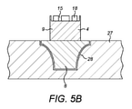
図11は、閉鎖板固定ステーション25を示す。閉鎖板固定ステーション25は、図2Aおよび図2Bに示すように柵18を曲げることで閉鎖板14を消耗品ユニット4に固定する。
FIG. 11 shows a closing
閉鎖板固定ステーション25は、計量投入ステーション23の機械トレイ支持部29と、閉鎖板位置決めステーション24と同様の機械トレイ支持部29とを含む。特に機械トレイ支持部29は、複数の消耗品ユニット4と共に図5Aに示す機械トレイ27を支持するためのレール30を含む。機械トレイ27の反対側を支持するレール30上で機械トレイ27を摺動させることで、機械トレイ27を閉鎖板固定ステーション25に挿入することができる。機械トレイ支持部29は、機械トレイ27が機械トレイ支持部29に挿入されたときに接触する止め具も含む。機械トレイ支持部29は、機械トレイ27および消耗品ユニット4が、確実に閉鎖板固定ステーション25内に正確かつ確実に位置決めされ、支持されるようにする。
The closing
閉鎖板固定ステーション25は、機械トレイ27が機械トレイ支持部29上に適切に位置決めされたことを確認する近接スイッチを含んでもよい。正しい位置決めを確実にするために位置合わせピンがそれに加えて、あるいはその代わりに提供されてもよい。
The closing
図11に示すように閉鎖板固定ステーション25は、プレス59を含む。プレス59は、図2Aおよび図2Bに示すように容器9の柵18を閉鎖板14に対して曲げて、閉鎖板14を容器9に固定する。
As shown in FIG. 11, the closing
図11に示すように閉鎖板固定ステーション25は、計量投入ステーション23および閉鎖板位置決めステーション24の可動棚31と類似の可動棚31を含む。この例では可動棚31は、以下でさらに説明するプレス59のプレスヘッド60を含む。可動棚31の支柱33と摺動ベアリング34は、可動棚31とプレスヘッド60を案内し、プレスヘッド60の信頼できる正確な動作を保証する。他の例では、閉鎖板固定ステーション25は、可動棚31を含まず、プレスヘッド60は独立した部材である。
As shown in FIG. 11, the closing
プレス59は、図11に示すようにプレスヘッド60を垂直に動かすように作用するアクチュエーター61を含む。プレスヘッド60は、機械トレイ27内の一連の消耗品ユニット4に一致する配列に位置決めされた複数の個別のプレスを有する。このようにして複数またはすべての消耗品ユニット4を同時に処理して曲げ、柵18および閉鎖板14を消耗品ユニット4に固定することができる。
The press 59 includes an
一例ではプレスヘッド60は、第1の曲げ作業を実行するための第1の組のプレス62と、第2の曲げ作業を実行するための第2の組のプレス63とを含む。第1および第2の組のプレス62、63は、それぞれプレスヘッド60の半分を占めるように位置決めすることができる。これとは別の構成では第1の組のプレス62は、第2の組のプレス63とは別の装置に設けられる。 In one example, the press head 60 includes a first set of presses 62 for performing a first bending operation and a second set of presses 63 for performing a second bending operation. The first and second sets of presses 62, 63 can be positioned to occupy half of the press head 60, respectively. In another configuration, the first set of presses 62 is provided in a device separate from the second set of presses 63.
図12は、第1の組のプレス62および第2の組のプレス63が、柵18を閉鎖板14に対して曲げて左から右に移動する順序を示す。図12は、柵18が上方に延び、閉鎖板14が柵18の間に受け取られた状態で、閉鎖板固定ステーション25に受け入れられたときの消耗品ユニット4を示す。
FIG. 12 shows the order in which the first set of presses 62 and the second set of presses 63 bend the
図示のように第1の組のプレス62の内の一台の第1のプレス64は、柵18を部分的に曲げる角度の付いたプレス面66を含む。特にこの例では角度の付いたプレス面66は、第1の曲げ作業で柵18を45度曲げるように45度の角度が付けられている。
As shown, one of the first set of presses 62, the first press 64, includes an
続いて第2の組のプレス63の内の一台の第2のプレス65は、柵18をその残りの部分に曲げて閉鎖板14に対して横にし、容器9に固定する平坦なプレス面67を含む。
Subsequently, the second press 65, which is one of the second set of press 63, has a flat press surface in which the
柵18を2段階で曲げる第1および第2の組のプレス64、65のこの配置で柵18を壊さずに確実に曲げることができる。
Bending the
いくつかの例では柵18の曲げを容易にするために第1および/または第2のプレス64、65を加熱するか、プレスヘッド60全体を加熱する。閉鎖板14が金属であるか金属を含むいくつかの例では、誘導加熱システムを配置し、閉鎖板14を加熱し、それにより柵18を含む容器9の周囲部分を加熱することができる。当然のことながらこの方法は容器9と柵18の材料に依存する。例えば、柵18が熱可塑性物質製の場合、加熱されたプレスで曲げ作業を容易にすることができる。
In some examples, the first and / or second presses 64, 65 are heated to facilitate bending of the
図13は、第1のプレス68および第2のプレス69が同心円状に位置決めされているもう一つのプレスを示す。図示のようにこの例では第1のプレス68は、角度の付いたプレス面70および中央ボア71を有する。中央ボア71内にはボア71内を移動できる第2のプレス69がある。このようにして第1のプレス68が、最初に移動し、角度の付いたプレス面70で柵18の曲げを開始する。続いて第2のプレス69が移動して、柵18を閉鎖板14に対して曲げ、容器9に閉鎖板を固定することができる。
FIG. 13 shows another press in which the
図13の構成ではプレスヘッド60は、第1のプレス68を形成する突起および第1のプレス68のボア71を形成する開口部を含む第1のプレートを含んでもよく、かつ第2のプレートは、第1のプレートの開口部内を延びる第2のプレス69を形成する突起を含んでもよい。第1および第2のプレートは、互いに隣接して配置することができ、それぞれのアクチュエーターは、第1および第2のプレートを動かして、図13に示す作業を実行することができる。この例では、すべての消耗品ユニット4は、一台の閉鎖板固定ステーション25で同時に処理することができる。
In the configuration of FIG. 13, the press head 60 may include a first plate containing a protrusion forming the
いくつかの例では柵18の曲げを容易にするために、第1および第2のプレス68、69を加熱するか、プレスヘッド60全体を加熱する。当然のことながらこの加熱は、容器9、特に柵18の材料に依存する。例えば、柵18が熱可塑性プラスチック製の場合、加熱されたプレスで曲げ作業を容易にすることができる。
In some examples, the first and
これとは別の構成では閉鎖板固定ステーション25は、閉鎖板14を消耗品ユニット4に固定する代替手段を含んでもよい。例えば、閉鎖板固定ステーション25は、閉鎖板14を消耗品ユニット4の容器9に溶接する超音波溶接装置などの溶接装置を含んでもよい。他の例では閉鎖板固定ステーション25は、圧入で閉鎖板14を消耗品ユニット4のチェンバー16に押し込み閉鎖板14を消耗品ユニット4の容器9に固定するプレスを備えてもよい。
In another configuration, the closing
計量投入ステーション23および閉鎖板位置決めステーション24と類似して前述のように、閉鎖板固定ステーション25は、消耗品ユニット4を機械トレイ支持部29から取り外すときに、機械トレイ27内の消耗品ユニット4を検査するための検査装置を備えてもよい。特にスキャナのレーザー/光学システムが機械トレイ27全体の高さ測定を行い、検査システムが各容器9内の閉鎖板14の存在とそれが正しく配置されているかを、そして柵18の存在およびそれが正しく位置決めされているかをチェックして、閉鎖板14が適切に固定されていることを確認できるようにスキャナを機械トレイ支持部29の上に配置してもよい。
Similar to the weighing
閉鎖板固定ステーション25から取り外すと、消耗品ユニット4の製造が完了する。次に消耗品ユニット4を機械トレイ27から取り外して、包装および流通作業に移すことができる。機械トレイ27は、作業の最初に戻して再利用することができる。
When removed from the closing
当然のことながら計量投入ステーション23、閉鎖板位置決めステーション24、および閉鎖板固定ステーション25は、多くの共通の特徴を有する。例えば、各ステーション23、24、25は、機械トレイ支持部29と、垂直移動のために支柱33に取り付けられた可動棚31とを含む。これによりこれらの装置23、24、25をより大きな装置、例えば、消耗品ユニット4をパッケージ化する装置、および/または図3Aに示す空の消耗品ユニット4を組み立てまたは形成する装置内にモジュール式に配置することができる。
Not surprisingly, the weighing
本明細書で使用される場合、「エアロゾル化可能な材料」という用語は、エアロゾル化可能な材料が加熱されるとエアロゾルを生成することを意味する。例えば、エアロゾル化可能な材料は、風味基材であっても、風味基材を含んでもよい。風味基材は、タバコ風味料または他の風味料などの風味料を含んでもよく、および/またはグリセリンまたはグリセリンの代わりあるいはそれに加えて他の添加物または増強剤を含んでもよい。グリセリンまたは他の添加物の有無にかかわらず、風味基材を加熱してエアロゾルを生成してもよい。 As used herein, the term "aerosolable material" means that when an aerosolizable material is heated, it produces an aerosol. For example, the material that can be aerosolized may be a flavor base material or may contain a flavor base material. The flavor substrate may contain flavors such as tobacco flavors or other flavors and / or may contain glycerin or glycerin substitutes or in addition to other additives or enhancers. The flavor substrate may be heated to produce an aerosol with or without glycerin or other additives.
なお一般にエアロゾルは、空気または別の気体中の微細な固体粒子または液滴のコロイドであり、コロイドは、微視的に分散した不溶性粒子が別の物質全体に懸濁している物質である。一方、蒸気は臨界温度よりも低い温度で気相にある物質であり、これは、例えば、温度を下げずに圧力を上げることで蒸気を液体に凝縮できることを意味する。なお本明細書で使用される場合、エアロゾルという用語は、エアロゾルおよび/または蒸気を含むものとする。 In general, an aerosol is a colloid of fine solid particles or droplets in air or another gas, and a colloid is a substance in which microscopically dispersed insoluble particles are suspended in the whole of another substance. On the other hand, vapor is a substance in the gas phase at a temperature lower than the critical temperature, which means that the vapor can be condensed into a liquid, for example, by increasing the pressure without lowering the temperature. As used herein, the term aerosol shall include aerosol and / or vapor.
上述したようにエアロゾル化可能な材料はタバコを含んでもよい。例えば、エアロゾル化可能な材料は、粒状タバコ材であってもよい。 As mentioned above, the aerosolizable material may include tobacco. For example, the material that can be aerosolized may be granular tobacco material.
本明細書で使用される場合、「タバコ」または「粒状タバコ材」という用語は、タバコ、タバコ誘導体、膨張タバコ、再構成タバコ、またはタバコ代替物を含む材料を意味する。粒状物質はまた、非タバコ物質を含んでもよい。いくつかの例では、「粒子材料」は粉末状であり、別の例では、「粒子材料」は、材料をより小さな粒子に細断して形成される。いくつかの例では、「粒状タバコ材」は、タバコを小さな粒子に細断または切断して形成される、いわゆる「カットラグ(切りくず)」を含んでもよい。粒状タバコ材は、タバコスラリーを押し出し、押し出された材料を粒子に切断して製造することができる。 As used herein, the term "tobacco" or "granular tobacco material" means a material that includes tobacco, tobacco derivatives, swollen tobacco, reconstituted tobacco, or tobacco substitutes. Particulate matter may also include non-tobacco material. In some examples, the "particle material" is in powder form, in another example, the "particle material" is formed by chopping the material into smaller particles. In some examples, the "granular tobacco material" may include so-called "cut lugs" formed by chopping or cutting tobacco into small particles. Granular tobacco material can be produced by extruding a tobacco slurry and cutting the extruded material into particles.
当然のことながら消耗品ユニットの上記の例は、図1を参照して説明した吸入デバイス以外の装置で使用できる。例えば、吸入デバイスは、タバコ加熱製品など、燃焼することなく粒状物質から化合物を放出する装置であってもよい。一実施態様では、吸入デバイスは、基材、例えば粒状物質を加熱するが燃焼はしないことで化合物を放出する加熱装置である。粒状物質は、例えば、ニコチンを含む場合も含まない場合もある、タバコまたは他の非タバコ製品であってもよい。一実施態様では、吸入デバイスはタバコ加熱装置である。 As a matter of course, the above example of the consumable unit can be used in devices other than the inhalation device described with reference to FIG. For example, the inhalation device may be a device that releases the compound from the particulate matter without burning, such as a tobacco heated product. In one embodiment, the inhalation device is a heating device that heats a substrate, eg, a particulate matter, but does not burn to release the compound. The particulate matter may be, for example, tobacco or other non-tobacco products, which may or may not contain nicotine. In one embodiment, the inhalation device is a cigarette heating device.
別の実施態様では、タバコ工業製品は、基材、例えばアトマイザーカートリッジの内容物と消費可能ユニット内の粒状材との組み合わせを加熱するが燃焼はしないことでエアロゾルを生成するハイブリッドシステムである。アトマイザーカートリッジ内の基材および消耗品ユニット内の粒状材は、例えば、ニコチンを含む場合も含まない場合もある固体、液体、またはゲルを含んでもよい。一実施態様では、ハイブリッドシステムは、液体またはゲル基材および固体基質を含む。固体基材は、例えば、ニコチンを含む場合も含まない場合もある、タバコまたは他の非タバコ製品であってもよい。一実施態様では、ハイブリッドシステムは、液体またはゲル基材およびタバコを含む。 In another embodiment, the tobacco industrial product is a hybrid system that heats a combination of a substrate, eg, the contents of an atomizer cartridge, and a granular material in a consumable unit, but does not burn to produce an aerosol. The substrate in the atomizer cartridge and the granules in the consumable unit may include, for example, a solid, liquid, or gel that may or may not contain nicotine. In one embodiment, the hybrid system comprises a liquid or gel substrate and a solid substrate. The solid substrate may be, for example, tobacco or other non-tobacco products, which may or may not contain nicotine. In one embodiment, the hybrid system comprises a liquid or gel substrate and a cigarette.
様々な問題に対処し、技術を進歩させるために、本開示の全体は、例示として、特許請求される発明が実施され得る様々な実施態様を示し、吸入デバイスで使用される消耗品ユニットを製造する優れた方法および装置を提供する。本開示の利点および特徴は、実施態様の代表的な実例に過ぎず、メッシュ羅的でも排他的でもない。それらは、クレームされている機能の理解と教示を支援する目的にのみ提示されている。当然のことながら本開示の利点、実施態様、実施例、機能、特徴、構造、および/または他の側面は、特許請求の範囲によって規定された開示の限定または特許請求の範囲の均等物の限定と見なされるべきではない。従って、他の実施態様を利用することができ、本開示の範囲および/または精神から逸脱することなく修正を行うことができる。様々な実施態様は、開示された要素、構成要素、特徴、部品、工程、手段などの様々な組み合わせを適切に含む、からなる、または本質的にからなる。さらに、本開示は、現在請求されていないが将来請求され得る他の発明を含む。 In order to address various problems and advance technology, the entire disclosure illustrates, by way of example, various embodiments in which the claimed invention can be carried out and manufactures consumable units used in inhalation devices. Provides excellent methods and equipment to do. The advantages and features of the present disclosure are merely representative examples of embodiments and are neither mesh-like nor exclusive. They are presented solely for the purpose of assisting in understanding and teaching the claimed function. Not surprisingly, the advantages, embodiments, examples, functions, features, structures, and / or other aspects of the present disclosure are the limitations of the disclosure or the equivalent of the claims as defined by the claims. Should not be considered. Accordingly, other embodiments may be utilized and modifications may be made without departing from the scope and / or spirit of the present disclosure. Various embodiments consist of, or essentially consist of, appropriately comprising various combinations of disclosed elements, components, features, parts, processes, means, and the like. Further, the present disclosure includes other inventions that are not currently claimed but may be claimed in the future.
Claims (41)
消耗品ユニットの容器に所与の用量のエアロゾル化可能な材料を供給することと、
容器の端部に閉鎖板を位置決めすることと、
容器に閉鎖板を固定することと、
を含む方法。 A method of manufacturing a consumable unit used with an inhalation device.
Supplying a given dose of aerosolable material to the container of the consumable unit,
Positioning the closure plate at the end of the container and
Fixing the closing plate to the container and
How to include.
消耗品ユニットの容器に所与の用量のエアロゾル化可能な材料を提供するように構成された計量投入ステーションと、
容器の端部に閉鎖板を位置決めするように構成された閉鎖板位置決めステーションと、 閉鎖板を容器に固定するように構成された閉鎖板固定ステーションとを含む製造装置。 A consumable unit manufacturing device used with an inhalation device.
With a weighing input station configured to provide a given dose of aerosolizable material to the container of the consumable unit,
A manufacturing apparatus including a closing plate positioning station configured to position a closing plate at the end of a container and a closing plate fixing station configured to secure the closing plate to the container.
容器の端部への閉鎖板の位置決め、および/または
閉鎖板の容器への固定
のうちの1つ以上を検査するように構成された検査装置をさらに含むことを特徴とする請求項15乃至29いずれか1項記載の装置。 Input amount of aerosolizable material in the container,
Claims 15-29 further include an inspection device configured to inspect one or more of the positioning of the closure plate to the end of the container and / or the fixation of the closure plate to the container. The device according to any one.
Applications Claiming Priority (3)
| Application Number | Priority Date | Filing Date | Title |
|---|---|---|---|
| GBGB1901198.0A GB201901198D0 (en) | 2019-01-29 | 2019-01-29 | Method and apparatus for manufacturing a consumable unit for an inhalation device, and a consumable unit for an inhalation device |
| GB1901198.0 | 2019-01-29 | ||
| PCT/GB2020/050124 WO2020157461A2 (en) | 2019-01-29 | 2020-01-21 | Method and apparatus for manufacturing a consumable unit for an inhalation device, and a consumable unit for an inhalation device |
Publications (2)
| Publication Number | Publication Date |
|---|---|
| JP2022519210A true JP2022519210A (en) | 2022-03-22 |
| JP7299326B2 JP7299326B2 (en) | 2023-06-27 |
Family
ID=65998003
Family Applications (1)
| Application Number | Title | Priority Date | Filing Date |
|---|---|---|---|
| JP2021544160A Active JP7299326B2 (en) | 2019-01-29 | 2020-01-21 | Method and apparatus for manufacturing consumable unit for inhalation device, and consumable unit for inhalation device |
Country Status (8)
| Country | Link |
|---|---|
| US (1) | US20220079247A1 (en) |
| EP (1) | EP3917842A2 (en) |
| JP (1) | JP7299326B2 (en) |
| CN (1) | CN113329942B (en) |
| CA (1) | CA3125433A1 (en) |
| GB (1) | GB201901198D0 (en) |
| MX (1) | MX2021009039A (en) |
| WO (1) | WO2020157461A2 (en) |
Families Citing this family (3)
| Publication number | Priority date | Publication date | Assignee | Title |
|---|---|---|---|---|
| GB201909882D0 (en) * | 2019-07-10 | 2019-08-21 | Nicoventures Trading Ltd | Vapour delivery systems |
| IT201900021381A1 (en) | 2019-11-18 | 2021-05-18 | Gd Spa | Packaging machine and packaging method for the production of disposable cartridges |
| GB202011797D0 (en) * | 2020-07-29 | 2020-09-09 | British American Tobacco Investments Ltd | Method and apparatus for manufacturing a consumable unit for an inhalation device |
Citations (7)
| Publication number | Priority date | Publication date | Assignee | Title |
|---|---|---|---|---|
| JPS6344493A (en) * | 1986-08-07 | 1988-02-25 | ロ−ベルト・ボツシユ・ゲゼルシヤフト・ミツト・ベシユレンクテル・ハフツング | Machine for selecting, filling and closing sleeve-shaped case |
| JP2001087016A (en) * | 1999-07-16 | 2001-04-03 | Ra Bueruju Kk | Decoration member and method of manufacturing the same |
| JP2008029414A (en) * | 2006-07-26 | 2008-02-14 | Gem Network:Kk | Mount for gem and method for mounting gem on this mount |
| WO2016075747A1 (en) * | 2014-11-10 | 2016-05-19 | 日本たばこ産業株式会社 | Non-combusting flavor inhaler and package |
| WO2018009135A1 (en) * | 2016-07-07 | 2018-01-11 | Å&R Carton Lund Aktiebolag | Transfer plate and attachment unit for container element |
| WO2018069328A1 (en) * | 2016-10-10 | 2018-04-19 | Gima Tt S.P.A. | Machine and method for making encapsulated articles |
| JP2018535149A (en) * | 2015-09-22 | 2018-11-29 | ジー.デー ソチエタ ペル アツィオニG.D Societa Per Azioni | Machine to manufacture cartridges for electronic cigarette |
Family Cites Families (7)
| Publication number | Priority date | Publication date | Assignee | Title |
|---|---|---|---|---|
| CN203575642U (en) * | 2013-12-06 | 2014-05-07 | 永康市龙山森飞五金工艺制造厂 | Shisha base |
| JPWO2016208756A1 (en) * | 2015-06-26 | 2017-12-07 | 日本たばこ産業株式会社 | Atomization unit |
| CN205947122U (en) * | 2016-07-01 | 2017-02-15 | 林光榕 | Adopt electron smog spinning disk atomiser of ultrasonic atomization unit |
| SI3487323T1 (en) * | 2016-07-25 | 2021-01-29 | Philip Morris Products S.A. | Manufacturing a fluid permeable heater assembly with cap |
| GB201707769D0 (en) * | 2017-05-15 | 2017-06-28 | British American Tobacco Investments Ltd | Liquid tobacco extract |
| CN207505919U (en) * | 2017-09-22 | 2018-06-19 | 深圳市新宜康电子技术有限公司 | Atomizer with filter screen |
| EP3817607B1 (en) * | 2018-07-05 | 2022-09-07 | Philip Morris Products S.A. | Inductively heated aerosol-generating system with ambient temperature sensor |
-
2019
- 2019-01-29 GB GBGB1901198.0A patent/GB201901198D0/en not_active Ceased
-
2020
- 2020-01-21 CA CA3125433A patent/CA3125433A1/en active Pending
- 2020-01-21 MX MX2021009039A patent/MX2021009039A/en unknown
- 2020-01-21 US US17/419,897 patent/US20220079247A1/en active Pending
- 2020-01-21 JP JP2021544160A patent/JP7299326B2/en active Active
- 2020-01-21 EP EP20701874.8A patent/EP3917842A2/en active Pending
- 2020-01-21 WO PCT/GB2020/050124 patent/WO2020157461A2/en unknown
- 2020-01-21 CN CN202080011537.1A patent/CN113329942B/en active Active
Patent Citations (7)
| Publication number | Priority date | Publication date | Assignee | Title |
|---|---|---|---|---|
| JPS6344493A (en) * | 1986-08-07 | 1988-02-25 | ロ−ベルト・ボツシユ・ゲゼルシヤフト・ミツト・ベシユレンクテル・ハフツング | Machine for selecting, filling and closing sleeve-shaped case |
| JP2001087016A (en) * | 1999-07-16 | 2001-04-03 | Ra Bueruju Kk | Decoration member and method of manufacturing the same |
| JP2008029414A (en) * | 2006-07-26 | 2008-02-14 | Gem Network:Kk | Mount for gem and method for mounting gem on this mount |
| WO2016075747A1 (en) * | 2014-11-10 | 2016-05-19 | 日本たばこ産業株式会社 | Non-combusting flavor inhaler and package |
| JP2018535149A (en) * | 2015-09-22 | 2018-11-29 | ジー.デー ソチエタ ペル アツィオニG.D Societa Per Azioni | Machine to manufacture cartridges for electronic cigarette |
| WO2018009135A1 (en) * | 2016-07-07 | 2018-01-11 | Å&R Carton Lund Aktiebolag | Transfer plate and attachment unit for container element |
| WO2018069328A1 (en) * | 2016-10-10 | 2018-04-19 | Gima Tt S.P.A. | Machine and method for making encapsulated articles |
Also Published As
| Publication number | Publication date |
|---|---|
| EP3917842A2 (en) | 2021-12-08 |
| CN113329942B (en) | 2023-07-04 |
| US20220079247A1 (en) | 2022-03-17 |
| GB201901198D0 (en) | 2019-03-20 |
| WO2020157461A2 (en) | 2020-08-06 |
| JP7299326B2 (en) | 2023-06-27 |
| MX2021009039A (en) | 2021-08-27 |
| CA3125433A1 (en) | 2020-08-06 |
| CN113329942A (en) | 2021-08-31 |
| WO2020157461A3 (en) | 2020-09-10 |
Similar Documents
| Publication | Publication Date | Title |
|---|---|---|
| JP7450009B2 (en) | Method and apparatus for manufacturing a consumable unit for an inhalation device, and a consumable unit for an inhalation device | |
| JP2022519210A (en) | Manufacturing method and equipment of consumable unit for inhalation device, and consumable unit for inhalation device | |
| JP7308271B2 (en) | Method and apparatus for manufacturing consumable unit for inhalation device, and consumable unit for inhalation device | |
| CN109475185B (en) | Methods for assembling cartridges for aerosol delivery devices and associated systems and apparatuses | |
| KR20180069897A (en) | A machine for manufacturing a substantially cylindrical article | |
| WO2009132828A1 (en) | Apparatus and method for manufacturing smoking articles | |
| CN108135281A (en) | For producing the machine of substantially cylinder-shaped product | |
| JP2019501629A (en) | Machine for producing substantially cylindrical articles | |
| US20230276861A1 (en) | Method and apparatus for manufacturing a consumable unit for an inhalation device | |
| US20230270180A1 (en) | Modular apparatus for manufacturing a consumable unit for an inhalation device and method for reconfiguring said apparatus | |
| KR20200085487A (en) | Micro particle generator having a plurality of heaters | |
| TW202015969A (en) | Manufacturing method and manufacturing apparatus for cartridge including flavor source for non-combustion flavor inhaler | |
| KR20230011320A (en) | Aerosol substance collection device | |
| JP2022519209A (en) | Automatic assembly device and automatic assembly method for suction devices and their parts | |
| IT201600072773A1 (en) | Machine for manufacturing industry articles |
Legal Events
| Date | Code | Title | Description |
|---|---|---|---|
| A621 | Written request for application examination |
Free format text: JAPANESE INTERMEDIATE CODE: A621 Effective date: 20210831 |
|
| A131 | Notification of reasons for refusal |
Free format text: JAPANESE INTERMEDIATE CODE: A131 Effective date: 20220927 |
|
| A521 | Request for written amendment filed |
Free format text: JAPANESE INTERMEDIATE CODE: A523 Effective date: 20221226 |
|
| A131 | Notification of reasons for refusal |
Free format text: JAPANESE INTERMEDIATE CODE: A131 Effective date: 20230214 |
|
| A521 | Request for written amendment filed |
Free format text: JAPANESE INTERMEDIATE CODE: A523 Effective date: 20230420 |
|
| TRDD | Decision of grant or rejection written | ||
| A01 | Written decision to grant a patent or to grant a registration (utility model) |
Free format text: JAPANESE INTERMEDIATE CODE: A01 Effective date: 20230516 |
|
| A61 | First payment of annual fees (during grant procedure) |
Free format text: JAPANESE INTERMEDIATE CODE: A61 Effective date: 20230615 |
|
| R150 | Certificate of patent or registration of utility model |
Ref document number: 7299326 Country of ref document: JP Free format text: JAPANESE INTERMEDIATE CODE: R150 |