JP2022518140A - Anti-knock type reaction force arm mechanism - Google Patents
Anti-knock type reaction force arm mechanism Download PDFInfo
- Publication number
- JP2022518140A JP2022518140A JP2021539089A JP2021539089A JP2022518140A JP 2022518140 A JP2022518140 A JP 2022518140A JP 2021539089 A JP2021539089 A JP 2021539089A JP 2021539089 A JP2021539089 A JP 2021539089A JP 2022518140 A JP2022518140 A JP 2022518140A
- Authority
- JP
- Japan
- Prior art keywords
- reaction force
- moment arm
- arm lever
- cross member
- tool
- Prior art date
- Legal status (The legal status is an assumption and is not a legal conclusion. Google has not performed a legal analysis and makes no representation as to the accuracy of the status listed.)
- Granted
Links
Images

Classifications
-
- B—PERFORMING OPERATIONS; TRANSPORTING
- B25—HAND TOOLS; PORTABLE POWER-DRIVEN TOOLS; MANIPULATORS
- B25B—TOOLS OR BENCH DEVICES NOT OTHERWISE PROVIDED FOR, FOR FASTENING, CONNECTING, DISENGAGING OR HOLDING
- B25B21/00—Portable power-driven screw or nut setting or loosening tools; Attachments for drilling apparatus serving the same purpose
-
- B—PERFORMING OPERATIONS; TRANSPORTING
- B25—HAND TOOLS; PORTABLE POWER-DRIVEN TOOLS; MANIPULATORS
- B25B—TOOLS OR BENCH DEVICES NOT OTHERWISE PROVIDED FOR, FOR FASTENING, CONNECTING, DISENGAGING OR HOLDING
- B25B23/00—Details of, or accessories for, spanners, wrenches, screwdrivers
- B25B23/0078—Reaction arms
Landscapes
- Engineering & Computer Science (AREA)
- Mechanical Engineering (AREA)
- Gripping Jigs, Holding Jigs, And Positioning Jigs (AREA)
- Clamps And Clips (AREA)
- Details Of Spanners, Wrenches, And Screw Drivers And Accessories (AREA)
Abstract
本発明は、締結装置の技術分野に関し、具体的には、対ノック式反力アーム機構を開示する。対ノック式反力アーム機構は、クロスメンバと、前記クロスメンバに取り付けられて前記クロスメンバの長手方向に沿って平行移動可能なモーメントアームレバーと、前記クロスメンバの一端に固定的に接続されて電動工具を固定するための工具挟持装置とを含み、前記モーメントアームレバーと前記クロスメンバとの間には引っ張られた弾性部材が接続され、前記モーメントアームレバーの底端には、ナット又はボルトを嵌着するための固定スリーブが接続され、かつ電動工具が工具挟持装置に挟持された時、前記固定スリーブは電動工具の動力出力端に正対する。該対ノック式反力アーム機構は、作業者の締結作業を行う時、反力を直接相殺することでき、対応するトルク工程を削減し、作業効率の向上に寄与するとともに、労働強度を低減させることができる。【選択図】図1The present invention relates to the technical field of a fastening device, and specifically discloses a knock-type reaction force arm mechanism. The anti-knock type reaction force arm mechanism is fixedly connected to a cross member, a moment arm lever attached to the cross member and capable of translating along the longitudinal direction of the cross member, and one end of the cross member. A tool holding device for fixing a power tool is included, a pulled elastic member is connected between the moment arm lever and the cross member, and a nut or a bolt is attached to the bottom end of the moment arm lever. When the fixing sleeve for fitting is connected and the power tool is sandwiched by the tool holding device, the fixing sleeve faces the power output end of the power tool. The knock-type reaction force arm mechanism can directly cancel the reaction force when the worker fastens, reduces the corresponding torque process, contributes to the improvement of work efficiency, and reduces the labor strength. be able to. [Selection diagram] Fig. 1
Description
本発明は、締結装置の技術分野に関し、特に、対ノック式(opposite-knocking type)反力アーム機構に関する。 The present invention relates to the technical field of a fastening device, and more particularly to an opposite-knocking type reaction force arm mechanism.
ボルトは、ナットと組み合わせて部品間の締結接続に用いられる。作業者が組立・締結作業を行う時、まず、空気圧レンチを使用して仮締結を行い、その後、締結時にボルトとナットとの間が反力の存在により共回りすることを防止するように、レンチを組み合わせて用いることにより手動で締結する必要がある。この過程において、作業者は、レンチを使用して手動で締め作業を行うため、共回りせずに完全にロックすることを確保できず、よって、ワークを所定の位置までロックすることを確保するために、締結作業後に、トルク試験を行う必要がある。しかし、トルク試験中でも、同様に、共回りを防止する必要があり、かつ2人で協力して操作する必要があるため、時間が掛かり、作業効率が低く、コストが高くなる。そして、作業者は、空気圧レンチを使用するため、左右の手に加えられる振動力が大きいと共に、トルク作業を担当する作業者は、ワークのトルクを確保するために、ねじる回数が多くなり、トルクが大きい場合には、その作業負荷が大きくなる。 Bolts are used in combination with nuts to fasten connections between parts. When an operator performs assembly and fastening work, first temporarily fasten with a pneumatic wrench, and then prevent the bolts and nuts from rotating together due to the presence of reaction force during fastening. It is necessary to manually fasten by using a combination of wrenches. In this process, the operator manually tightens with a wrench, so it cannot be ensured that it is completely locked without rotating together, thus ensuring that the workpiece is locked in place. Therefore, it is necessary to perform a torque test after the fastening work. However, even during the torque test, it is also necessary to prevent co-rotation and it is necessary for two people to cooperate with each other, so that it takes time, work efficiency is low, and cost is high. Since the worker uses a pneumatic wrench, the vibration force applied to the left and right hands is large, and the worker in charge of torque work increases the number of twists to secure the torque of the work, resulting in torque. When is large, the workload becomes large.
上記の背景技術における問題を解決するために、本発明は、締結作業を行う時に反力を直接相殺させることでき、対応するトルク工程を削減し、作業効率の向上に寄与するとともに、作業負荷を低減させることができる対ノック式反力アーム機構を提供する。 In order to solve the above-mentioned problems in the background technology, the present invention can directly cancel the reaction force when performing the fastening work, reduce the corresponding torque process, contribute to the improvement of work efficiency, and reduce the workload. Provided is an anti-knock type reaction force arm mechanism that can be reduced.
これに基づき、本発明は、クロスメンバと、前記クロスメンバに取り付けられて前記クロスメンバの長手方向に沿って平行移動可能なモーメントアームレバーと、前記クロスメンバの一端に固定的に接続されて電動工具を固定するための工具挟持装置と、を含み、
前記モーメントアームレバーと前記クロスメンバとの間には引っ張られた弾性部材が接続され、前記モーメントアームレバーの底端には、ナット又はボルトを嵌着するための固定スリーブが接続され、電動工具が工具挟持装置に挟持された時、前記固定スリーブは電動工具の動力出力端に正対する、対ノック式反力アーム機構を提供する。
Based on this, the present invention is electrically connected to a cross member, a moment arm lever attached to the cross member and capable of translating along the longitudinal direction of the cross member, and fixedly connected to one end of the cross member. Including a tool holding device for fixing the tool,
A pulled elastic member is connected between the moment arm lever and the cross member, and a fixing sleeve for fitting a nut or a bolt is connected to the bottom end of the moment arm lever, and a power tool is attached. When sandwiched by a tool pinching device, the fixing sleeve provides a knock-type reaction force arm mechanism that faces the power output end of the power tool.
好ましい態様としては、前記工具挟持装置に取り付けられた電動工具が前記モーメントアームレバーと交差して設置されるように、前記工具挟持装置は、前記モーメントアームレバーに対して所定の角度をなす。 In a preferred embodiment, the tool holding device forms a predetermined angle with respect to the moment arm lever so that the power tool attached to the tool holding device is installed so as to intersect the moment arm lever.
好ましい態様としては、前記工具挟持装置は、軸取付板及び挟持部材を含み、前記軸取付板の第1端は前記クロスメンバの一端に固定的に接続され、前記軸取付板の第2端は前記挟持部材に固定的に接続され、前記挟持部材は、電動工具の外周壁を挟持するためのスリーブ式である。 In a preferred embodiment, the tool pinching device includes a shaft mounting plate and a pinching member, the first end of the shaft mounting plate is fixedly connected to one end of the cross member, and the second end of the shaft mounting plate is fixed. It is fixedly connected to the holding member, and the holding member is a sleeve type for holding the outer peripheral wall of the power tool.
好ましい態様としては、前記軸取付板は、アングル状に形成され、連結板部と、前記連結板部の一端に接続され、前記連結板部に対して所定の角度をなす取付板部とを含み、前記挟持部材が前記取付板部の外端に垂直に取り付けられることにより、前記挟持部材に取り付けられた電動工具は、前記モーメントアームレバーと同じ角度をなす。 In a preferred embodiment, the shaft mounting plate includes a connecting plate portion formed in an angle shape, and a mounting plate portion connected to one end of the connecting plate portion and forming a predetermined angle with respect to the connecting plate portion. By mounting the holding member perpendicularly to the outer end of the mounting plate portion, the power tool attached to the holding member forms the same angle as the moment arm lever.
好ましい態様としては、前記クロスメンバの底端にはその長手方向に沿ってリニアガイドが取り付けられ、前記リニアガイドにはスライダがスライド可能に接続され、前記モーメントアームレバーの先端は前記スライダに固定的に接続される。 In a preferred embodiment, a linear guide is attached to the bottom end of the cross member along its longitudinal direction, a slider is slidably connected to the linear guide, and the tip of the moment arm lever is fixed to the slider. Connected to.
好ましい態様としては、前記モーメントアームレバーの先端は、スライドベースを介して前記スライダに接続され、前記弾性部材の一端は前記スライドベースに接続され、他端は前記クロスメンバにおける前記工具挟持装置に近い一端に接続される。 In a preferred embodiment, the tip of the moment arm lever is connected to the slider via a slide base, one end of the elastic member is connected to the slide base, and the other end is close to the tool holding device in the cross member. Connected to one end.
好ましい態様としては、前記モーメントアームレバーの先端には、前記モーメントアームレバーを前記工具挟持装置から離間させるための移動ハンドルが接続される。 In a preferred embodiment, a moving handle for separating the moment arm lever from the tool holding device is connected to the tip of the moment arm lever.
好ましい態様としては、前記移動ハンドルと前記モーメントアームレバーとの間には、折り畳み構造が設けられる。 In a preferred embodiment, a folding structure is provided between the moving handle and the moment arm lever.
好ましい態様としては、前記挟持部材と前記モーメントアームレバーとのなす角度の範囲は10°~60°である。 In a preferred embodiment, the range of the angle formed by the holding member and the moment arm lever is 10 ° to 60 °.
好ましい態様としては、前記クロスメンバにはリフティングアイが設けられ、前記弾性部材はバネである。 In a preferred embodiment, the cross member is provided with a lifting eye and the elastic member is a spring.
従来技術と比べ、本発明の有益な効果は以下のとおりである。 Compared with the prior art, the beneficial effects of the present invention are as follows.
本発明の対ノック式反力アーム機構は、クロスメンバと、モーメントアームレバーと、工具挟持装置とを含み、モーメントアームレバーは、クロスメンバの長手方向に平行移動可能であり、モーメントアームレバーとクロスメンバとの間には引っ張られた状態にある弾性部材が接続されて設けられ、モーメントアームレバーの底端には固定スリーブが設けられることにより、ロックする必要があるナット又はボルトを嵌着し、かつ、工具挟持装置により電動工具を固定することで、固定スリーブが電動工具の動力出力端に正対するようになり、使用時、電動工具の動力出力端がボルト又はナットを嵌着するための締付スリーブに嵌着され、すなわち、締付スリーブが該固定スリーブに対向して設けられ、ボルト及びナットの締結工程に入る時、作業者は、弾性部材の弾性力に抵抗して、クロスメンバに沿って工具挟持装置から離れる方向にモーメントアームレバーを引くことにより、固定スリーブと締付スリーブとの間に螺着されるボルトとナットを収容可能な十分な空間を有することを確保するように、モーメントアームレバーを電動工具から一定の距離で離間させ、この後、電動工具の動力出力端及び固定スリーブを両端からそれぞれ対応するボルト/ナット(又はナット/ボルト)に嵌着し、嵌着が完了した後、モーメントアームレバーを放して、弾性部材の復帰力の作用で、電動工具の動力出力端及び固定スリーブは、ボルト/ナットに緩みなく圧着する。このような左右開きの締め付け方式は、便利で効率的であり、かつ弾性部材により確実に圧着し、締結時に緩みがないようにする。電動工具とモーメントアームレバーとの位置が相対的に固定されているため、モーメントアームレバーの一端は固定モーメントアームとして用いられ、工具挟持装置の一端は、電動工具に固定されて締結モーメントアームとして用いられ、そのため、作業者が後で電動工具を起動させ仮締結を開始する時又は締結作業が完了した後、ボルトとナットとの間に共回り傾向により発生する反力は、電動工具とモーメントアームレバーとからなる反力アーム機構によって直接相殺され、それにより、ボルトとナットとが共回りしないことを確保することができ、締結トルクが設定値の要求を満たすことができ、そして、対応するトルク工程を削減し、作業効率の向上に寄与するとともに、労働強度を低減させることができる。 The anti-knock type reaction force arm mechanism of the present invention includes a cross member, a moment arm lever, and a tool holding device, and the moment arm lever can move in parallel in the longitudinal direction of the cross member, and the moment arm lever and the cross. A pulled elastic member is connected to and provided from the member, and a fixing sleeve is provided at the bottom end of the moment arm lever to fit a nut or bolt that needs to be locked. In addition, by fixing the electric tool with the tool holding device, the fixing sleeve comes to face the power output end of the electric tool, and the power output end of the electric tool is tightened for fitting bolts or nuts during use. When fitted to the attached sleeve, i.e., the tightening sleeve is provided facing the fixing sleeve and enters the bolt and nut fastening process, the operator resists the elastic force of the elastic member and attaches to the cross member. By pulling the moment arm lever away from the tool pinch device along, to ensure that there is enough space to accommodate the bolts and nuts screwed between the fixing sleeve and the tightening sleeve. Separate the moment arm lever from the power tool at a certain distance, and then fit the power output end and fixing sleeve of the power tool to the corresponding bolts / nuts (or nuts / bolts) from both ends to complete the fitting. After that, the moment arm lever is released, and the power output end and the fixing sleeve of the electric tool are firmly crimped to the bolt / nut by the action of the returning force of the elastic member. Such a tightening method that opens to the left and right is convenient and efficient, and is securely crimped by an elastic member so that there is no looseness at the time of fastening. Since the positions of the electric tool and the moment arm lever are relatively fixed, one end of the moment arm lever is used as a fixed moment arm, and one end of the tool holding device is fixed to the electric tool and used as a fastening moment arm. Therefore, when the operator later activates the electric tool to start temporary fastening or after the fastening work is completed, the reaction force generated due to the co-rotation tendency between the bolt and the nut is generated between the electric tool and the moment arm. It is directly offset by a reaction arm mechanism consisting of a lever, which ensures that the bolt and nut do not rotate together, the fastening torque can meet the set value requirements, and the corresponding torque. It is possible to reduce the number of processes, contribute to the improvement of work efficiency, and reduce the labor intensity.
以下、図面及び実施例を参照しながら、本発明の具体的な実施形態についてさらに詳細に説明する。明らかなように、説明する実施例は、本発明の一部の実施例にすぎず、全ての実施例ではない。本発明における実施例に基づき、当業者が創造的な労働をしないという前提で得られた全ての他の実施例は、いずれも本発明の保護範囲に属する。 Hereinafter, specific embodiments of the present invention will be described in more detail with reference to the drawings and examples. As is clear, the examples described are only partial examples of the present invention, not all examples. Based on the embodiments of the present invention, all other embodiments obtained on the premise that those skilled in the art do not perform creative labor belong to the scope of protection of the present invention.
なお、本発明の説明において、「中心」、「縦方向」、「横方向」、「上」、「下」、「左」、「右」、「前」、「後」、「垂直」、「水平」、「頂」、「底」「内」、「外」等の用語により指示された方位又は位置関係は、図面に示された方位又は位置関係に基づき、本発明の説明上の便宜及び説明の簡略化のためのものに過ぎず、言及された装置又は素子が特定の方位を有し、特定の方位で構成して操作されることを明示又は暗示するものではないので、本発明を限定するものと理解されるべきではない。「第1」、「第2」などの用語は、説明のために用いられ、同じタイプの技術的特徴を区別するためのものであり、相対的な重要性を明示又は暗示するものとして理解されるべきではない。 In the description of the present invention, "center", "vertical direction", "horizontal direction", "top", "bottom", "left", "right", "front", "rear", "vertical", The orientation or positional relationship indicated by terms such as "horizontal", "top", "bottom", "inside", and "outside" is based on the orientation or positional relationship shown in the drawings, and is convenient for the explanation of the present invention. And, for the sake of brevity of description only, the present invention does not explicitly or imply that the mentioned device or element has a specific orientation and is configured and operated in a specific orientation. Should not be understood as limiting. Terms such as "first" and "second" are used for illustration purposes to distinguish between technical features of the same type and are understood to indicate or imply relative importance. Should not be.
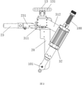
図1は、本発明の対ノック式反力アーム機構を模式的に示している。この対ノック式反力アーム機構は、クロスメンバ10と、モーメントアームレバー20と、工具挟持装置30とを含み、モーメントアームレバー20は、前記クロスメンバ10に取り付けられてクロスメンバ10の長手方向に沿って並進可能であり、工具挟持装置30は、前記クロスメンバ10の一端に固定的に接続され、電動工具100を固定するためのものである。さらに、モーメントアームレバー20とクロスメンバ10との間には、伸長状態にある弾性部材40が接続され、モーメントアームレバー20の底端には、ナット又はボルトを嵌着するための固定スリーブ21が接続される。使用時、電動工具100を工具挟持装置30に取り付け、かつ、電動工具100の動力出力端101は、締付スリーブ102に嵌着され、締付スリーブ102の外端は、ボルト又はナットを嵌着するために用いられ、この時、より重要なことは、固定スリーブ21が、電動工具の動力出力端101が嵌着された締付スリーブ102に正対することである。
FIG. 1 schematically shows the anti-knock type reaction force arm mechanism of the present invention. This anti-knock type reaction force arm mechanism includes a
上記技術的特徴に基づく対ノック式反力アーム機構は、モーメントアームレバー20の底端に締め付けが必要なナット又はボルトを嵌着するための固定スリーブ21が設けられ、かつ工具挟持装置30で電動工具100を固定することにより、固定スリーブ21が電動工具100の動力出力端101に正対するようになり、すなわち、電動工具の動力出力端101が嵌着された締付スリーブ102は、該固定スリーブ21と対向して設けられ、締付スリーブ102の外端は、ボルト又はナットを嵌着するために用いられる。ボルト及びナットの締結工程に入る時、作業者は、弾性部材40の弾性力に抵抗して、クロスメンバ10に沿って工具挟持装置30から離れる方向にモーメントアームレバー20を引くことにより、固定スリーブ21と締付スリーブ102との間に、螺着されるボルトとナットを収容可能な空間が形成されることを確保するように、モーメントアームレバー20を電動工具100から一定の距離で離間させ、この後、電動工具の動力出力端101における締付スリーブ102と固定スリーブ21とを両端からそれぞれ対応するボルト/ナット(又はナット/ボルト)に嵌着し、嵌着が完了した後、モーメントアームレバー20を放して、弾性部材40の弾性力の作用で、締付スリーブ102及び固定スリーブ21は、ボルト/ナットに緩みなく圧着する。このような左右開きの締め付け方式は、便利で効率的であり、かつ弾性部材40で確実に圧着し、締結時に緩みがないようにする。電動工具100とモーメントアームレバー20との位置は、相対的に固定されるため、モーメントアームレバー20の一端は固定モーメントアームとして用いられ、工具挟持装置30の一端は、電動工具100に固定されて締結モーメントアームとして用いられる。そのため、作業者が電動工具100を起動させ仮締結を開始する時、又は締結作業が完了した後、ボルトとナットとの間に共回り傾向により発生する反力は、電動工具100とモーメントアームレバー20とからなる反力アーム機構によって直接相殺され、それにより、ボルトとナットとが共回りしないことを確保することができ、締結トルクが設定値の要求を満たすようにし、対応するトルク工程を削減し、作業効率の向上に寄与するとともに、作業負荷を低減させることができる。好ましくは、スリーブのトルク締結効果を向上させるために、固定スリーブ21及び締付スリーブ102の内部はいずれも十二角に設定される。
The knock-type reaction force arm mechanism based on the above technical features is provided with a
対ノック式反力アーム機構の操作の利便性及び反力相殺の効果を向上させるために、上記工具挟持装置30は、上記モーメントアームレバー20に対して所定の角度をなすように設けられ、それにより、工具挟持装置30に取り付けられた電動工具100は、モーメントアームレバー20と交差して設置される。このように電動工具100がモーメントアームレバー20と交差して設置されることにより、操作の視野角を大きくするとともに、人間工学的に好適で、作業者がボルト又はナットに対して嵌入式の予備位置合せを行うことを容易にし、生産効率を向上させることができる。また、交差設置の形態は、レンチで締め付けて共回りを防止する形態を模して、反力相殺をより容易にすることができる。
In order to improve the convenience of operation of the anti-knock type reaction force arm mechanism and the effect of the reaction force canceling, the
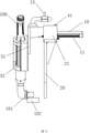
具体的には、図1及び図2に示すように、工具挟持装置30は、軸取付板31及び挟持部材32を含み、上記軸取付板31の第1端は、上記クロスメンバ10の一端に固定的に接続され、上記軸取付板31の第2端は、上記挟持部材32に固定的に接続される。本実施例では、上記挟持部材32はスリーブ式であり、使用時、電動工具100の外周壁を固定するように、電動工具100はスリーブ式の挟持部材32内に挿入される。
Specifically, as shown in FIGS. 1 and 2, the
上記構成に加えて、図2に示すように、上記軸取付板31は、アングル状に形成され、具体的には、連結板部311と、連結板部311の一端に接続され、連結板部311に対して所定の角度をなす取付板部312を含み、上記挟持部材32は、上記取付板部312の外端に垂直に取り付けられ、これにより、上記挟持部材32に取り付けられた電動工具100は、上記モーメントアームレバー20と同じ角度をなす。さらに、連結板部311と取付板部312とのなす角度、及び挟持部材32とモーメントアームレバー20とのなす角度の範囲は、10°~60°であり、好ましくは10°、20°、30°、40°、50°又は60°である。所定の角度を該範囲内に設定することにより、使用者による該反力アーム機構の操作がより便利になる。
In addition to the above configuration, as shown in FIG. 2, the
より具体的には、図1及び図3に示すように、上記クロスメンバ10の底端にはその長手方向に沿ってリニアガイド11が取り付けられ、上記リニアガイド11にはスライダ12がスライド可能に接続され、上記モーメントアームレバー20の先端は、上記スライダ12に固定的に接続され、リニアガイド11及びスライダ12の設置により、モーメントアームレバー20がクロスメンバ10の長手方向に沿って平行移動可能にすることが容易になり、使用時、作業者がモーメントアームレバー20を引くと、モーメントアームレバー20を電動工具100から離れた方向へ移動させることができ、ボルト/ナットに対する予備位置合わせを容易にする。
More specifically, as shown in FIGS. 1 and 3, a
より好ましくは、上記モーメントアームレバー20の先端には、上記モーメントアームレバー20を上記工具挟持装置30から離間させるための移動ハンドル23が接続され、使用時、作業者が移動ハンドル23を引くだけで、モーメントアームレバー20を電動工具100から離れた方向に移動させることができ、ボルト/ナット対する予備位置合わせが容易になり、作業者の使用をより容易にする。さらに、上記移動ハンドル23とモーメントアームレバー20との間には折り畳み構造が設けられ、図1及び図2に示すように、折り畳み構造は、具体的に移動ハンドル23とモーメントアームレバー20の先端との間に接続されるフランジ231であり、フランジ231の一端は、移動ハンドル23に固定的に接続され、他端は、モーメントアームレバー20の先端にヒンジ連結され、ボルトとナットとの位置合わせが完了した後に、締結工程に入る時、フランジ231により移動ハンドル23をクロスメンバ10の長手方向に合わせて折り畳み、それにより、操作のスベースを大きくする。
More preferably, a moving
好ましい実施形態として、図1及び図3に示すように、上記モーメントアームレバー20の先端は、スライドベース22を介して上記スライダ12に接続され、スライドベース22の設置により、弾性部材40の装着接続を容易にし、このように、弾性部材40の一端はスライドベース22に接続され、弾性部材40の他端は、クロスメンバ10における上記工具挟持装置30に近い一端に接続される。本実施例では、弾性部材40はバネであることが好ましく、無論、他の実施例では、弾性部材40は他の弾性材料で製造された部品であってもよく、ここでは説明を省略する。より具体的には、スライドベース22は、U字状の折曲板であり、折曲板はクロスメンバ10の上下両側に亘って接続され、折曲板の下端は、スライダ12とモーメントアームレバー20の先端との間に接続され、これにより、モーメントアームレバー20が折曲板を介して折曲板とともにスライダ12に固定的に接続され、折曲板の上端にはバネピン41が挿設され、バネの一端は、バネピン41に引っ掛けられて、バネピン41がバネの引張力によって回転することを防止するように、セルフロックナット221によりバネピン41を固定する。
As a preferred embodiment, as shown in FIGS. 1 and 3, the tip of the
反力アーム機構の取り付けを容易にし、補助者が手で持つことを回避するために、一例として、クロスメンバ10にはリフティングアイ13が接続され、リフティングアイ13は、固定板14を介してクロスメンバ10の一端に取り付けられ、リフティングアイ13には、複数の吊り点孔131が形成され、吊り点孔131を利用して反力アーム機構を吊り上げることができ、使用時、作業者が該機構を手前に引くだけで操作でき、使用後に直接放せばよく、操作の利便性を大幅に向上させる。
As an example, the lifting
なお、本発明の説明において、明確に規定及び限定される場合を除き、「取付」、「繋ぐ」、「接続」は広義に解釈されるべきであり、例えば、固定的に接続されていてもよいし、着脱可能に接続されていてもよいし、又は一体的に接続されていてもよい。機械的に接続されていてもよいし、電気的に接続されていてもよい。直接接続されていてもよいし、中間媒体を介して間接的に接続されていてもよいし、2つの部品の内部の連通であってもよい。当業者であれば、具体的な状況に応じて上記用語の本発明における具体的な意味を理解することができる。 In the description of the present invention, "mounting", "connecting", and "connecting" should be interpreted in a broad sense, except when explicitly defined and limited, and even if they are fixedly connected, for example. It may be detachably connected, or it may be integrally connected. It may be mechanically connected or electrically connected. It may be directly connected, may be indirectly connected via an intermediate medium, or may be an internal communication between the two components. A person skilled in the art can understand the specific meanings of the above terms in the present invention according to the specific circumstances.
以上のように、本発明の対ノック式反力アーム機構は、ボルトとナットとの間に発生する反力を直接相殺することができ、共回りの発生を効果的に防止するとともに、締結トルクが設定値の要求を満たすようにすることで、後続の対応するトルク工程の部署を設ける必要なく、作業効率を向上させるとともに、労働強度を軽減することができ、高い利用及び普及価値を有する。 As described above, the anti-knock type reaction force arm mechanism of the present invention can directly cancel the reaction force generated between the bolt and the nut, effectively prevent the occurrence of co-rotation, and the fastening torque. By satisfying the requirements of the set value, it is possible to improve the work efficiency and reduce the labor intensity without the need to establish a department for the subsequent corresponding torque process, and it has high utilization and widespread value.
本発明では、詳細に説明しない方法及び装置はいずれも従来技術であるため、説明を省略する。 In the present invention, since the methods and devices not described in detail are all prior art, the description thereof will be omitted.
以上の説明は、本発明の好ましい実施形態であり、なお、本発明の技術分野における当業者であれば、本発明の技術的原理から逸脱しない限り、いくつかの改良及び置換を行うことは可能であり、これらの改良及び置換も、本発明の保護範囲内にあるとみなされるべきである。 The above description is a preferred embodiment of the present invention, and a person skilled in the art of the present invention can make some improvements and substitutions without departing from the technical principle of the present invention. And these improvements and substitutions should also be considered within the scope of protection of the present invention.
10 クロスメンバ、11 リニアガイド、12 スライダ、13 リフティングアイ、131 吊り点孔、14 固定板、20 モーメントアームレバー、21 固定スリーブ、22 スライドベース、221 セルフロックナット、23 移動ハンドル、231 フランジ、30 工具挟持装置、31 軸取付板、311 連結板部、312 取付板部、32 挟持部材、40 弾性部材、41 バネピン、100 電動工具、101 動力出力端、102 締付スリーブ。 10 Cross member, 11 Linear guide, 12 Slider, 13 Lifting eye, 131 Hanging point hole, 14 Fixed plate, 20 Moment arm lever, 21 Fixed sleeve, 22 Slide base, 221 Self-lock nut, 23 Moving handle, 231 flange, 30 Tool pinching device, 31 axis mounting plate, 311 connecting plate, 312 mounting plate, 32 pinching member, 40 elastic member, 41 spring pin, 100 power tool, 101 power output end, 102 tightening sleeve.
Claims (10)
クロスメンバと、
前記クロスメンバに取り付けられて前記クロスメンバの長手方向に沿って平行移動可能なモーメントアームレバーと、
前記クロスメンバの一端に固定的に接続されて電動工具を固定するための工具挟持装置と、を含み、
前記モーメントアームレバーと前記クロスメンバとの間には引っ張られた弾性部材が接続され、前記モーメントアームレバーの底端には、ナット又はボルトを嵌着するための固定スリーブが接続され、電動工具が工具挟持装置に挟持された時、前記固定スリーブは電動工具の動力出力端に正対する、ことを特徴とする対ノック式反力アーム機構。 Anti-knock type reaction force arm mechanism,
With cross members,
A moment arm lever attached to the cross member and capable of translating along the longitudinal direction of the cross member,
Includes a tool holding device, which is fixedly connected to one end of the cross member to secure a power tool.
A pulled elastic member is connected between the moment arm lever and the cross member, and a fixing sleeve for fitting a nut or a bolt is connected to the bottom end of the moment arm lever, and a power tool is attached. A knock-type reaction force arm mechanism characterized in that the fixed sleeve faces the power output end of a power tool when sandwiched by a tool pinching device.
Applications Claiming Priority (3)
| Application Number | Priority Date | Filing Date | Title |
|---|---|---|---|
| CN201910298303.9A CN109955177A (en) | 2019-04-12 | 2019-04-12 | Bucketing formula reaction force arm mechanism |
| CN201910298303.9 | 2019-04-12 | ||
| PCT/CN2020/076070 WO2020207122A1 (en) | 2019-04-12 | 2020-02-20 | Opposite-knocking type counter-acting force arm mechanism |
Publications (2)
| Publication Number | Publication Date |
|---|---|
| JP2022518140A true JP2022518140A (en) | 2022-03-14 |
| JP7194490B2 JP7194490B2 (en) | 2022-12-22 |
Family
ID=67026091
Family Applications (1)
| Application Number | Title | Priority Date | Filing Date |
|---|---|---|---|
| JP2021539089A Active JP7194490B2 (en) | 2019-04-12 | 2020-02-20 | Anti-knock type reaction force arm mechanism |
Country Status (3)
| Country | Link |
|---|---|
| JP (1) | JP7194490B2 (en) |
| CN (1) | CN109955177A (en) |
| WO (1) | WO2020207122A1 (en) |
Families Citing this family (1)
| Publication number | Priority date | Publication date | Assignee | Title |
|---|---|---|---|---|
| CN109955177A (en) * | 2019-04-12 | 2019-07-02 | 广汽本田汽车有限公司 | Bucketing formula reaction force arm mechanism |
Citations (5)
| Publication number | Priority date | Publication date | Assignee | Title |
|---|---|---|---|---|
| JPH0839415A (en) * | 1994-07-29 | 1996-02-13 | Nippei Toyama Corp | Wire saw device |
| JPH10244471A (en) * | 1997-02-27 | 1998-09-14 | Onodani Kiko Kk | Impact wrench having silencing function |
| JPH11226826A (en) * | 1998-02-12 | 1999-08-24 | Mitsubishi Heavy Ind Ltd | Bolt nut tightening/loosening device |
| JP2005030552A (en) * | 2003-07-10 | 2005-02-03 | Honda Motor Co Ltd | Engine driven working machine |
| CN203993693U (en) * | 2014-04-11 | 2014-12-10 | 东风汽车公司 | The anti-transfer of servo tightening machine mechanism |
Family Cites Families (10)
| Publication number | Priority date | Publication date | Assignee | Title |
|---|---|---|---|---|
| US3175433A (en) * | 1961-06-29 | 1965-03-30 | Jr Richard J Akers | Double-acting reversible wrench |
| WO2012006234A2 (en) * | 2010-07-07 | 2012-01-12 | Actuant Corporation | Fastener wrenching apparatus and method |
| CN203185235U (en) * | 2013-03-22 | 2013-09-11 | 中船重工环境工程有限公司 | Recoil force arm device for air wrench |
| CN203993688U (en) * | 2014-07-31 | 2014-12-10 | 采埃孚富奥底盘技术(长春)有限公司 | A kind of electric wrench with countertorque |
| CN205184236U (en) * | 2015-12-17 | 2016-04-27 | 湖北楚粤自动化科技有限公司 | Rotatable device of screwing up |
| CN105773504A (en) * | 2016-03-30 | 2016-07-20 | 戴畅 | Current guiding plate bolt tightener |
| CN107443289B (en) * | 2017-09-28 | 2019-05-10 | 北京福田戴姆勒汽车有限公司 | Threaded fastener assembles auxiliary tool |
| CN207309822U (en) * | 2017-10-20 | 2018-05-04 | 上海凤凰自行车江苏有限公司 | A kind of bicycle shaft assembles device |
| CN109955177A (en) * | 2019-04-12 | 2019-07-02 | 广汽本田汽车有限公司 | Bucketing formula reaction force arm mechanism |
| CN209903068U (en) * | 2019-04-12 | 2020-01-07 | 广汽本田汽车有限公司 | Knocking type reaction force arm mechanism |
-
2019
- 2019-04-12 CN CN201910298303.9A patent/CN109955177A/en active Pending
-
2020
- 2020-02-20 WO PCT/CN2020/076070 patent/WO2020207122A1/en active Application Filing
- 2020-02-20 JP JP2021539089A patent/JP7194490B2/en active Active
Patent Citations (5)
| Publication number | Priority date | Publication date | Assignee | Title |
|---|---|---|---|---|
| JPH0839415A (en) * | 1994-07-29 | 1996-02-13 | Nippei Toyama Corp | Wire saw device |
| JPH10244471A (en) * | 1997-02-27 | 1998-09-14 | Onodani Kiko Kk | Impact wrench having silencing function |
| JPH11226826A (en) * | 1998-02-12 | 1999-08-24 | Mitsubishi Heavy Ind Ltd | Bolt nut tightening/loosening device |
| JP2005030552A (en) * | 2003-07-10 | 2005-02-03 | Honda Motor Co Ltd | Engine driven working machine |
| CN203993693U (en) * | 2014-04-11 | 2014-12-10 | 东风汽车公司 | The anti-transfer of servo tightening machine mechanism |
Also Published As
| Publication number | Publication date |
|---|---|
| CN109955177A (en) | 2019-07-02 |
| JP7194490B2 (en) | 2022-12-22 |
| WO2020207122A1 (en) | 2020-10-15 |
Similar Documents
| Publication | Publication Date | Title |
|---|---|---|
| CA2524044C (en) | Attachment device for fixing various elements to a support | |
| JP2015528865A (en) | Removal tool and removal method for photovoltaic fasteners | |
| US3024018A (en) | Bench mount for locking jaw pliers | |
| JP2022518140A (en) | Anti-knock type reaction force arm mechanism | |
| CN209207374U (en) | A kind of percussion copper rod clamping device | |
| WO2020015280A1 (en) | Lock mounting device between gearbox and shift cable | |
| US20130228050A1 (en) | Electric fastening head for fastening lock nut of single through shaft | |
| CN209903068U (en) | Knocking type reaction force arm mechanism | |
| CN103647231A (en) | Anti-shedding earthing wire clamp for power transmission line | |
| CN105619298A (en) | Multifunctional self-locking wrench | |
| KR100872325B1 (en) | Sound proofing wall pipe clamp | |
| CN204171934U (en) | A kind of torque sensor | |
| KR200477506Y1 (en) | Back-surface facing machine of main engine joining part | |
| CN201357308Y (en) | Independent suspension triangular arm preassembling device | |
| CN213946325U (en) | Module box-entering tool | |
| CN216781709U (en) | Double-torsion spring disassembling tool | |
| CN2399163Y (en) | Auto-locking tongs | |
| CN212947252U (en) | Fixing clamp for polishing motor shell | |
| CN216382121U (en) | Heavy type plane hasp with self-locking and limiting functions | |
| CN209050374U (en) | Self-positioning twin shaft device for screwing up in high precision | |
| CN210060921U (en) | A kind of spanner | |
| CN215433518U (en) | Multipurpose nail puller | |
| CN212626853U (en) | Electric power overhauls with preventing mixing anchor clamps structure | |
| CN210550775U (en) | Sleeve connecting rod | |
| JPH10129977A (en) | Hanging tool used for steel beam and wooden beam in common |
Legal Events
| Date | Code | Title | Description |
|---|---|---|---|
| A621 | Written request for application examination |
Free format text: JAPANESE INTERMEDIATE CODE: A621 Effective date: 20210702 |
|
| A977 | Report on retrieval |
Free format text: JAPANESE INTERMEDIATE CODE: A971007 Effective date: 20220720 |
|
| A131 | Notification of reasons for refusal |
Free format text: JAPANESE INTERMEDIATE CODE: A131 Effective date: 20220726 |
|
| A521 | Request for written amendment filed |
Free format text: JAPANESE INTERMEDIATE CODE: A523 Effective date: 20221024 |
|
| TRDD | Decision of grant or rejection written | ||
| A01 | Written decision to grant a patent or to grant a registration (utility model) |
Free format text: JAPANESE INTERMEDIATE CODE: A01 Effective date: 20221122 |
|
| A61 | First payment of annual fees (during grant procedure) |
Free format text: JAPANESE INTERMEDIATE CODE: A61 Effective date: 20221210 |
|
| R150 | Certificate of patent or registration of utility model |
Ref document number: 7194490 Country of ref document: JP Free format text: JAPANESE INTERMEDIATE CODE: R150 |