JP2022512120A - Patient interface device with magnetic coupling mechanism - Google Patents
Patient interface device with magnetic coupling mechanism Download PDFInfo
- Publication number
- JP2022512120A JP2022512120A JP2021531801A JP2021531801A JP2022512120A JP 2022512120 A JP2022512120 A JP 2022512120A JP 2021531801 A JP2021531801 A JP 2021531801A JP 2021531801 A JP2021531801 A JP 2021531801A JP 2022512120 A JP2022512120 A JP 2022512120A
- Authority
- JP
- Japan
- Prior art keywords
- patient
- frame
- opening
- facing
- interface device
- Prior art date
- Legal status (The legal status is an assumption and is not a legal conclusion. Google has not performed a legal analysis and makes no representation as to the accuracy of the status listed.)
- Pending
Links
- 230000008878 coupling Effects 0.000 title abstract description 12
- 238000010168 coupling process Methods 0.000 title abstract description 12
- 238000005859 coupling reaction Methods 0.000 title abstract description 12
- 230000000241 respiratory effect Effects 0.000 claims description 15
- 238000007789 sealing Methods 0.000 claims description 6
- 239000000463 material Substances 0.000 description 7
- 229910000831 Steel Inorganic materials 0.000 description 5
- 239000010959 steel Substances 0.000 description 5
- 239000012530 fluid Substances 0.000 description 4
- 229920001296 polysiloxane Polymers 0.000 description 4
- 125000006850 spacer group Chemical group 0.000 description 4
- 238000009423 ventilation Methods 0.000 description 4
- 208000001797 obstructive sleep apnea Diseases 0.000 description 2
- 229920003023 plastic Polymers 0.000 description 2
- 239000004033 plastic Substances 0.000 description 2
- 230000029058 respiratory gaseous exchange Effects 0.000 description 2
- 238000002644 respiratory therapy Methods 0.000 description 2
- 238000002560 therapeutic procedure Methods 0.000 description 2
- 241000473391 Archosargus rhomboidalis Species 0.000 description 1
- 206010021079 Hypopnoea Diseases 0.000 description 1
- 206010041235 Snoring Diseases 0.000 description 1
- 239000000853 adhesive Substances 0.000 description 1
- 230000001070 adhesive effect Effects 0.000 description 1
- 208000008784 apnea Diseases 0.000 description 1
- 230000005540 biological transmission Effects 0.000 description 1
- 230000001419 dependent effect Effects 0.000 description 1
- 208000037265 diseases, disorders, signs and symptoms Diseases 0.000 description 1
- 208000035475 disorder Diseases 0.000 description 1
- 210000003238 esophagus Anatomy 0.000 description 1
- 238000003780 insertion Methods 0.000 description 1
- 230000037431 insertion Effects 0.000 description 1
- 239000000696 magnetic material Substances 0.000 description 1
- 238000004519 manufacturing process Methods 0.000 description 1
- 238000000034 method Methods 0.000 description 1
- 230000003319 supportive effect Effects 0.000 description 1
- 238000004448 titration Methods 0.000 description 1
- 238000002627 tracheal intubation Methods 0.000 description 1
- 230000007704 transition Effects 0.000 description 1
- 238000003466 welding Methods 0.000 description 1
Images


Classifications
-
- A—HUMAN NECESSITIES
- A61—MEDICAL OR VETERINARY SCIENCE; HYGIENE
- A61M—DEVICES FOR INTRODUCING MEDIA INTO, OR ONTO, THE BODY; DEVICES FOR TRANSDUCING BODY MEDIA OR FOR TAKING MEDIA FROM THE BODY; DEVICES FOR PRODUCING OR ENDING SLEEP OR STUPOR
- A61M16/00—Devices for influencing the respiratory system of patients by gas treatment, e.g. mouth-to-mouth respiration; Tracheal tubes
- A61M16/06—Respiratory or anaesthetic masks
- A61M16/0605—Means for improving the adaptation of the mask to the patient
- A61M16/0616—Means for improving the adaptation of the mask to the patient with face sealing means comprising a flap or membrane projecting inwards, such that sealing increases with increasing inhalation gas pressure
-
- A—HUMAN NECESSITIES
- A61—MEDICAL OR VETERINARY SCIENCE; HYGIENE
- A61M—DEVICES FOR INTRODUCING MEDIA INTO, OR ONTO, THE BODY; DEVICES FOR TRANSDUCING BODY MEDIA OR FOR TAKING MEDIA FROM THE BODY; DEVICES FOR PRODUCING OR ENDING SLEEP OR STUPOR
- A61M16/00—Devices for influencing the respiratory system of patients by gas treatment, e.g. mouth-to-mouth respiration; Tracheal tubes
- A61M16/06—Respiratory or anaesthetic masks
- A61M16/0666—Nasal cannulas or tubing
-
- A—HUMAN NECESSITIES
- A61—MEDICAL OR VETERINARY SCIENCE; HYGIENE
- A61M—DEVICES FOR INTRODUCING MEDIA INTO, OR ONTO, THE BODY; DEVICES FOR TRANSDUCING BODY MEDIA OR FOR TAKING MEDIA FROM THE BODY; DEVICES FOR PRODUCING OR ENDING SLEEP OR STUPOR
- A61M16/00—Devices for influencing the respiratory system of patients by gas treatment, e.g. mouth-to-mouth respiration; Tracheal tubes
- A61M16/06—Respiratory or anaesthetic masks
- A61M16/0683—Holding devices therefor
-
- A—HUMAN NECESSITIES
- A61—MEDICAL OR VETERINARY SCIENCE; HYGIENE
- A61M—DEVICES FOR INTRODUCING MEDIA INTO, OR ONTO, THE BODY; DEVICES FOR TRANSDUCING BODY MEDIA OR FOR TAKING MEDIA FROM THE BODY; DEVICES FOR PRODUCING OR ENDING SLEEP OR STUPOR
- A61M16/00—Devices for influencing the respiratory system of patients by gas treatment, e.g. mouth-to-mouth respiration; Tracheal tubes
- A61M16/08—Bellows; Connecting tubes ; Water traps; Patient circuits
- A61M16/0816—Joints or connectors
-
- A—HUMAN NECESSITIES
- A61—MEDICAL OR VETERINARY SCIENCE; HYGIENE
- A61M—DEVICES FOR INTRODUCING MEDIA INTO, OR ONTO, THE BODY; DEVICES FOR TRANSDUCING BODY MEDIA OR FOR TAKING MEDIA FROM THE BODY; DEVICES FOR PRODUCING OR ENDING SLEEP OR STUPOR
- A61M16/00—Devices for influencing the respiratory system of patients by gas treatment, e.g. mouth-to-mouth respiration; Tracheal tubes
- A61M16/08—Bellows; Connecting tubes ; Water traps; Patient circuits
- A61M16/0875—Connecting tubes
-
- A—HUMAN NECESSITIES
- A61—MEDICAL OR VETERINARY SCIENCE; HYGIENE
- A61M—DEVICES FOR INTRODUCING MEDIA INTO, OR ONTO, THE BODY; DEVICES FOR TRANSDUCING BODY MEDIA OR FOR TAKING MEDIA FROM THE BODY; DEVICES FOR PRODUCING OR ENDING SLEEP OR STUPOR
- A61M2202/00—Special media to be introduced, removed or treated
- A61M2202/02—Gases
- A61M2202/0225—Carbon oxides, e.g. Carbon dioxide
-
- A—HUMAN NECESSITIES
- A61—MEDICAL OR VETERINARY SCIENCE; HYGIENE
- A61M—DEVICES FOR INTRODUCING MEDIA INTO, OR ONTO, THE BODY; DEVICES FOR TRANSDUCING BODY MEDIA OR FOR TAKING MEDIA FROM THE BODY; DEVICES FOR PRODUCING OR ENDING SLEEP OR STUPOR
- A61M2205/00—General characteristics of the apparatus
- A61M2205/02—General characteristics of the apparatus characterised by a particular materials
- A61M2205/0272—Electro-active or magneto-active materials
-
- A—HUMAN NECESSITIES
- A61—MEDICAL OR VETERINARY SCIENCE; HYGIENE
- A61M—DEVICES FOR INTRODUCING MEDIA INTO, OR ONTO, THE BODY; DEVICES FOR TRANSDUCING BODY MEDIA OR FOR TAKING MEDIA FROM THE BODY; DEVICES FOR PRODUCING OR ENDING SLEEP OR STUPOR
- A61M2205/00—General characteristics of the apparatus
- A61M2205/60—General characteristics of the apparatus with identification means
- A61M2205/6045—General characteristics of the apparatus with identification means having complementary physical shapes for indexing or registration purposes
Landscapes
- Health & Medical Sciences (AREA)
- Pulmonology (AREA)
- Life Sciences & Earth Sciences (AREA)
- Animal Behavior & Ethology (AREA)
- Anesthesiology (AREA)
- Biomedical Technology (AREA)
- Heart & Thoracic Surgery (AREA)
- Hematology (AREA)
- Emergency Medicine (AREA)
- Engineering & Computer Science (AREA)
- General Health & Medical Sciences (AREA)
- Public Health (AREA)
- Veterinary Medicine (AREA)
- Otolaryngology (AREA)
- Orthopedics, Nursing, And Contraception (AREA)
- Magnetic Treatment Devices (AREA)
Abstract
患者インターフェース装置は、患者に面する側、反対側の外側に面する側、患者に面する側の上又はその中に固定される第1の複数の磁気要素、及びそれを通り画定される第1の開口を有する中央部分を持つフレームを含む。第1の開口は、送達導管に連結されるように構成され、外側に面する側から患者に面する側に向かって延在する第1の部分、及び患者に面する側から外側に延在し、ハブを形成する壁により画定される患者側部分を有する。この装置は、患者の1つ以上のオリフィスの周りに密封係合するように構成される患者接触側、ハブの周りに係合するようにサイズ決定及び構成される、その中に画定される第2の開口を含む反対側のフレーム接触側、並びにクッションをフレームに磁気的に結合するための第2の複数の磁気要素を持つクッションをさらに含む。The patient interface device is defined through a first plurality of magnetic elements fixed on or within the patient-facing side, the opposite outward facing side, the patient-facing side, and the first. Includes a frame with a central portion with an opening of 1. The first opening is configured to be connected to the delivery conduit and extends outward from the side facing the patient and the first portion extending from the side facing the outside toward the side facing the patient. And has a patient-side portion defined by a wall forming the hub. The device is defined in a patient contact side configured to engage hermetically around one or more orifices of the patient, sized and configured to engage around a hub. It further includes a frame contact side on the opposite side including the two openings, as well as a cushion with a second plurality of magnetic elements for magnetically coupling the cushion to the frame.
Description
本特許出願は、米国特許法第119条の下、2018年12月24日に出願された米国仮特許出願第62/784,572号の優先権を主張し、その内容は、参照することにより本明細書に組み込まれる。 This patent application claims the priority of U.S. Provisional Patent Application No. 62 / 784,572 filed on December 24, 2018 under Article 119 of the U.S. Patent Act, the contents of which are by reference. Incorporated herein.
本発明は、患者に呼吸ガス流を送達するために患者インターフェース装置が使用される非侵襲的換気及び圧力支持システムに関し、より詳細には、クッションとフレームとを結合するのに使用するための磁気結合特徴を有する患者インターフェース装置に関する。 The present invention relates to a non-invasive ventilation and pressure support system in which a patient interface device is used to deliver a respiratory gas stream to a patient, more particularly magnetically for use in coupling a cushion to a frame. It relates to a patient interface device having a binding feature.
患者の気道に呼吸ガス流を非侵襲的に、すなわち患者に挿管することなく又は患者の食道に気管チューブを外科的に挿入することなく、送達することが必要である又は望ましい状況が多く存在する。例えば、非侵襲的換気として知られる技術を用いて患者を換気することが知られている。ある内科的疾患を治療するために、陽圧呼吸(PAP)療法を行うことも知られており、その疾患の中で最も有名なのは、閉塞性睡眠時無呼吸(OSA)である。既知のPAP療法は、患者の気道をスプリント解放(splint open)するために、患者の気道に一定の陽圧が供給される持続的気道陽圧(CPAP)と、患者の気道に供給される圧力が患者の呼吸サイクルと共に変化する可変気道圧力とを含む。そのような治療は通例、患者が眠っている夜間に患者に施される。 There are many situations in which it is necessary or desirable to deliver a respiratory gas stream non-invasively into the patient's airway, i.e., without intubation of the patient or surgical insertion of a tracheal tube into the patient's esophagus. .. For example, it is known to ventilate a patient using a technique known as non-invasive ventilation. Positive pressure breathing (PAP) therapy is also known to treat certain medical disorders, the most famous of which is obstructive sleep apnea (OSA). Known PAP therapies include continuous positive airway pressure (CPAP), which provides a constant positive pressure in the patient's airway to splint open the patient's airway, and pressure applied to the patient's airway. Includes variable airway pressure that changes with the patient's respiratory cycle. Such treatment is usually given to the patient at night when the patient is asleep.
上述したような非侵襲的な換気及び圧力支持療法は、呼吸ガス流を生成するためのガス流発生器、及びマスク構成要素を含む患者インターフェース装置を患者の顔の上に配置することを含む。ガス流発生器は、周囲環境から空気を取り込み、ファンを回転させることにより正の空気圧を生成し、このガス流発生器からの空気を、送達導管を介して患者に送達される患者インターフェース装置内に押し出す。 Non-invasive ventilation and pressure supportive care as described above involves placing a gas flow generator to generate a respiratory gas flow and a patient interface device including mask components on the patient's face. The gas flow generator takes in air from the ambient environment and rotates a fan to generate positive air pressure, and the air from this gas flow generator is delivered to the patient via the delivery conduit in the patient interface device. Extrude to.
患者インターフェース装置の従来のクッション部材は、患者の顔との密封を提供するために、患者の顔と係合するよう構成される密封部分、並びにクッションを所望の位置に保持するため、並びにフレーム及びクッションを患者の頭部に固定するのに使用されるヘッドギア部材の取り付け点を提供するために一般的に使用されるより硬質の材料から通例に形成されるフレームを含む。通例、クッション及びフレームは、これら部材の1つを清掃及び/又は交換することを可能にするために容易に分離されるような方法で結合される。従って、そのような結合は一般に、不意に外れないように十分な強さである必要がある一方、依然として素早い及び一般に簡単な方法で分解及び再組み立てされることもできない。 The conventional cushioning member of the patient interface device is a sealing portion configured to engage the patient's face to provide a seal with the patient's face, as well as to hold the cushion in the desired position, as well as the frame and Includes a frame typically formed from a harder material commonly used to provide attachment points for headgear members used to secure the cushion to the patient's head. Typically, the cushions and frames are coupled in such a way that they are easily separated to allow one of these members to be cleaned and / or replaced. Thus, while such bonds generally need to be strong enough to prevent accidental dislodgement, they still cannot be disassembled and reassembled in a quick and generally simple manner.
本発明の実施形態は、従来の設計を改善する結合機構を提供する。本発明の一態様として、患者の気道に呼吸ガス流を送達するのに使用するための患者インターフェース装置は、一般に薄い部材として形成される中央部分を持つフレーム及びクッションを有し、前記中央部分は、患者に面する側、反対側の外側に面する側、中央部分を通り画定される第1の開口及び第1の複数の磁気要素を有し、前記第1の開口は、前記外側に面する側から、呼吸ガス流を供給する送達導管に結合されるように構成される前記患者に面する側に向かって延在している第1の部分、及び前記患者に面する側から外側に延在する壁により画定され、ハブを形成する患者側部分を持ち、前記第1の複数の磁気要素の各々の磁気要素は、前記患者に面する側の上又はその中に固定され、前記クッションは、患者の1つ以上のオリフィスの周りに密封係合するように構成される患者接触側、前記患者接触側の反対側に置かれるフレーム接触側及び第2の複数の磁気要素を有し、前記フレーム接触側は、前記フレームの前記中央部分の前記ハブの周りに係合するようにサイズ決定及び構成され、並びに前記フレームの前記中央部分の前記第1の開口を通過する呼吸ガス流の流れが、一般に前記患者接触側と前記フレーム接触側との間にある、前記クッションに画定される空洞に入るように構成される前記クッション内に画定される第2の開口を含み、前記第2の複数の磁気要素の各々の磁気要素は、前記クッションが前記フレームに磁気的に結合されるように、前記フレームの前記第1の複数の磁気要素の各々の磁気要素に対応する位置において、前記クッションの前記フレーム接触側の上又はその中に固定される。 Embodiments of the present invention provide a coupling mechanism that improves conventional design. As an aspect of the invention, a patient interface device for use in delivering a respiratory gas stream to a patient's airway has a frame and cushion with a central portion, generally formed as a thin member, said central portion. It has a first opening and a plurality of magnetic elements defined through a central portion, a side facing the patient, an opposite side facing the outside, the first opening facing the outside. A first portion extending from the patient-facing side towards the patient-facing side configured to be coupled to a delivery conduit that supplies the respiratory gas flow, and outward from the patient-facing side. Having a patient-side portion defined by an extending wall and forming a hub, each magnetic element of the first plurality of magnetic elements is secured on or within the patient-facing side and the cushion. Has a patient contact side configured to be hermetically engaged around one or more orifices of the patient, a frame contact side placed opposite the patient contact side and a second plurality of magnetic elements. The frame contact side is sized and configured to engage around the hub in the central portion of the frame, and the flow of respiratory gas flow through the first opening in the central portion of the frame. Includes a second opening defined within the cushion, generally between the patient contact side and the frame contact side, configured to enter the cavity defined by the cushion. Each magnetic element of the plurality of magnetic elements is located at a position corresponding to each magnetic element of the first plurality of magnetic elements of the frame so that the cushion is magnetically coupled to the frame. It is fixed on or in the frame contact side of the frame.
構成物の関連する要素の動作方法及び機能、並びに製造部品と製造の経済性との組み合わせと同じく、本開示のこれら及び他の目的、特徴並びに特性は、付随する図面を参照して、以下の説明及び添付の請求項を考慮するとより明白となり、これらの全てが本明細書を形成している。様々な図面において、同様の参照番号は対応する部品を示している。しかしながら、これら図面は単に例証及び説明を目的とするものであり、本発明の境界を規定するものとは意図されないことは明白に理解されるべきである。 These and other objectives, features, and characteristics of the present disclosure, as well as the manner and function of operation and function of the relevant elements of the component, as well as the combination of manufactured parts and manufacturing economics, are described below with reference to the accompanying drawings. It becomes clearer in consideration of the description and the accompanying claims, all of which form the present specification. In various drawings, similar reference numbers indicate corresponding parts. However, it should be clearly understood that these drawings are for illustration and illustration purposes only and are not intended to define the boundaries of the invention.
明細書において、特に文脈上はっきりと述べていない限り、複数あると述べていなくても、それらが複数あることを含む。明細書において、2つ以上の部品又は構成要素が"結合される"と述べることは、連動している限り、これらの部品が直接的に又は間接的、すなわち1つ以上の中間部品若しくは構成要素を介しての何れかにより接合される又は共に動作することを意味する。明細書において、"直接結合される"は、2つの要素が互いに直に接して結合される(すなわち接触している)ことを意味している。明細書において、"固定して結合される"又は"固定される"は、2つの構成要素が互いに対し一定の方向を維持している間、1つとして移動するように結合されることを意味している。 Unless otherwise explicitly stated in the context, the specification includes having more than one of them, even if they are not stated to be more than one. In the specification, the statement that two or more parts or components are "combined" means that these parts are directly or indirectly, that is, one or more intermediate parts or components, as long as they are interlocked. Means being joined or working together by any of the following. As used herein, "directly coupled" means that the two elements are directly in contact with each other (ie, in contact with each other). In the specification, "fixed and joined" or "fixed" means that the two components are joined so as to move as one while maintaining a certain direction with respect to each other. is doing.
明細書において、2つ以上の部品又は構成要素が互いに"係合する"と述べることは、これらの部品が互いに向けて直接的に又は1つ以上の中間部品若しくは構成要素を介して間接的にの何れかにより力を及ぼしていることを意味する。明細書において、"数字"は、1若しくは1以上の整数(すなわち複数)を意味する。 In the specification, the statement that two or more parts or components "engage" with each other means that these parts are directed toward each other or indirectly through one or more intermediate parts or components. It means that the force is exerted by any of. In the specification, "number" means one or more integers (ie, plural).
明細書において、例であり限定ではない方向の表現は、左、右、上方、下方、前、後、その上に及びそれらの派生語は、図面に示される要素の方位に関連し、特に明瞭に言わない限り、請求項を制限しない。明細書において、「及び/又は」という用語は、そのような言葉で隔てられた要素の一方又は両方を意味する。例えば、「A及び/又はB」は、i)A、ii)B、又はiii)AとBの何れかを意味する。 In the specification, the representation of directions, examples and not limiting, is left, right, upward, downward, anterior, posterior, and above, and their derivatives are particularly clear as they relate to the orientation of the elements shown in the drawings. Does not limit claims unless you tell us. As used herein, the term "and / or" means one or both of the elements separated by such terms. For example, "A and / or B" means either i) A, ii) B, or iii) A and B.
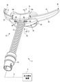
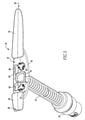
本発明のある例示的な実施形態に従う、患者に呼吸療法レジメンを提供するように適応するシステム2が図1に一般的に示される。システム2は、(概略的に示される)圧力発生装置4、(概略的に示される)送達導管6、導管セグメント12を介して結合される流体結合導管10を持つ患者インターフェース装置8及び(ストラップ14のみが示される)ヘッドギアを含む。圧力発生装置4は、呼吸ガス流を生成するように構成され、限定ではないが、人工呼吸器、定圧力支持装置(例えば、持続陽圧呼吸療法装置又はCPAP装置)、可変圧力装置(例えば、ペンシルベニア州マリスビルのフィリップス・レスピロニクス社により製造及び流通されるBiPAP(登録商標)、Bi-Flex(登録商標)又はC-Flex(登録商標)装置)及び自動滴定圧力支持装置を含む。送出導管6は、圧力発生装置4からの呼吸ガス流を、流体結合導管10及び導管セグメント12を介して患者インターフェース装置8に伝達するように構成される。図1に示される例示的な実施形態において、流体結合導管10は真っすぐなコネクタであるが、この流体結合導管10は、本発明の範囲から逸脱することなく、他の適切な結合部が用いられてよいことを分かるべきである。導管セグメント12は取り除かれてもよく、故に、送達導管6は、本発明の範囲から逸脱することなく、患者インターフェース装置8に直接接続されるか、又は上述した結合部を介して接続されることも分かるべきである。送達導管6及び患者インターフェース装置8はしばしば、患者回路と総称される。
A system 2 adapted to provide a respiratory therapy regimen to a patient according to one exemplary embodiment of the invention is generally shown in FIG. The system 2 includes a pressure generator 4 (schematically shown), a delivery conduit 6 (schematically shown), a
BiPAP(登録商標)装置は、患者に供給される圧力が患者の呼吸サイクルと共に変化するので、呼気中よりも吸気中に高い圧力が供給されるバイレベル装置である。自動滴定圧力支持システムは、患者の状態、例えば患者がいびきをしているかどうか、又は無呼吸或いは低呼吸を経験しているかどうかにより圧力が変化するシステムである。現在の目的では、フロー/圧力発生装置4は、圧力勾配が生成されるとき、流れが生じるので、ガス流発生装置とも呼ばれる。本発明は、フロー/圧力発生装置4が、患者の気道にガス流を送達するため、又は患者の気道におけるガスの圧力を上昇させるための、上記に要約された圧力支持システム及び非侵襲的換気システムを含む如何なる従来のシステムでもあることを考慮している。 A BiPAP® device is a bilevel device that provides higher pressure during inspiration than during exhalation because the pressure delivered to the patient changes with the patient's respiratory cycle. An automatic titration pressure support system is a system in which the pressure changes depending on the patient's condition, for example, whether the patient is snoring or experiencing apnea or hypopnea. For current purposes, the flow / pressure generator 4 is also referred to as a gas flow generator because the flow is generated when a pressure gradient is generated. The present invention is the pressure support system and non-invasive ventilation summarized above for the flow / pressure generator 4 to deliver a gas stream to the patient's airway or to increase the pressure of the gas in the patient's airway. It considers that it is any conventional system, including the system.
図1を引き続き参照すると共に、図2を参照すると、患者インターフェース装置8は、以下に詳細に説明される磁気機構を介してフレーム18に結合されるクッション16を含む。クッション16は、如何なる柔軟な材料(例えば、限定ではないがシリコーン)から形成される。フレーム18は、実質的に堅い材料(例えば、限定ではないが1つ以上のプラスチック)から形成される。
With reference to FIG. 1 and FIG. 2, the
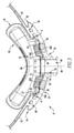
図1及び図2を引き続き参照すると共に、図3-5を参照すると、フレーム18は、患者に面する側22及び反対の外側に面する側24を持つ一般に薄い部材として形成される中央部分20を含む。恐らくは図3の断面図が最もよく分かるように、示される例示的な実施形態において、中央部分20は、患者に面する側22が概ね凹形であるのに対し、外側に面する側24は概ね凸形であるように湾曲している。フレーム18は、中央部分20の第1の端部28から第1の遠位端30に、わずかに先細りながら延在する第1のウィング部分26、及び中央部分20の第2の端部34から第2の遠位端36に、わずかに先細りながら延在する第2のウィング部分32をさらに含む。図3に示されるように、示される実施形態において、第1及び第2のウィング部分26及び32の各々は、(36及び38に概ね示される)夫々のスペーサ部分により、中央部分20の患者に面する側面22から距離dだけ各々オフセットされ、これらスペーサ部分は、各々が、中央部分20、並びにこの中央部分の近接するウィング部分26及び32からなる部分よりも狭い寸法である。
With reference to FIGS. 1 and 2 and FIG. 3-5, the
図4及び図1の分解図及び組立図を参照すると、各ウィング部分26及び32は、各ストラップ14をフレーム18に固定するやり方で、ヘッドギアストラップ14の夫々のストラップと協働して係合するように構成される。より詳細には、各ストラップ14は、閉じた先端14Aを持つ一般に平坦な管状部材として、伸縮性のある織物材料から形成される。各々の平坦な管状部材の内側部分へのアクセスを提供する開口14Bは、各ストラップ14において、そのストラップの閉じた先端14Aから距離d1だけ離れて画定される。ストラップ14をフレーム18に固定するために、ウィング部分26の遠位部30が、ストラップ14の開口14Bに挿入される。次いで、開口14Bの周界の外を向く部分がスペーサ部分36に接するまで、この開口14Bは、ウィング部分26に沿ってスライドされる。このとき、ウィング部分26の大部分は、ストラップ14である平坦な管状部材の内部に位置決められる。次に、ウィング部分26の残りの部分が、一般に開口14Bとシールされる端部14Aとの間にある前記平坦な管状部材の部分に位置決められ、開口14Bがスペーサ部36を取り囲んで配されるように、開口14Bは、前記ウィング部分26の残りの部分の周りに伸ばされ、故に、ストラップ14をフレーム18に固定する。他方のストラップ14も同様に、第2のウィング部分32を用いて同じステップを繰り返すことによりフレーム18に固定される。ストラップ14は、本発明の範囲から逸脱することなく、如何なる適切なヘッドギアと共に使用され得ることも分かるべきである。
With reference to the exploded views and assembly views of FIGS. 4 and 1, each
ここで図3、図5、図8及び図9を参照すると、中央部分20は、導管6から受け取った呼吸ガス流を、中央部分20を介して外側に面する側24から患者に面する側22に伝達するための、中央部分を通り画定される開口40を含む。例示される実施例において、開口40は、(導管セグメント12の内径により概ね画定される)直径Dを持つ一般的にねじ部分42(図3)を含む。ねじ部分42は、外側に面する側24から患者に面する側に向かって延在し、導管セグメント12の端部と協働して係合するようにサイズ決定及び構成され、導管セグメントは、(例えば、接着剤又は他の如何なる適切な機構を介して)容易にネジ山部分42に確実に結合される。しかしながら、開口40は代わりに、本発明の範囲から逸脱することなく、直接結合される、又は適切な結合導管(例えば、エルボ又は直線コネクタ)を介して結合されるように構成されてもよいことも分かるべきである。
Here, referring to FIGS. 3, 5, 8 and 9, the
患者に面する側22において、開口40は、壁44により画定され、この壁は、患者に面する側22から外向き延び、ハブを形成する。好ましくは、開口40は、導管セグメント12から出る空気流をできるだけ拡散させるために、できるだけ大きく作られる。示される例示的な実施形態において、壁44は、開口40の中心線46に沿って見るとき、わずかに台形形状のハブを形成する。このような台形形状は、中央部分20に含まれる他の要素の中で、使用可能な領域内で開口の面積を最大にするので、このような実施形態において一般に利用される。従って、このような機構において、開口40は、外側に面する側24の円形断面から、患者に面する側22の略台形断面に移行することが分かるべきである。所定の利用のために、開口の面積を最大にすることに加えて、前記台形形状は、患者が自分の鼻先で穴を塞ぐことも非常に困難にさせる。
On the patient-facing
フレーム18をクッション16に固定するために、フレーム18は、開口40の対向する側において、中央部分20の患者に面する側22の上又はその中に(例えばオーバーモールドにより)固定される複数の(示される実施形態では2つ含む)磁気要素50をさらに含む。各々の磁気要素50は、各々の磁気要素50の外側に面する(すなわち、クッション16に面する)面が一般に、中央部分20において、(示されるように)患者に面する側22から外向きに突出するか、又は中央部分20の患者に面する側22内に引っ込む(図示せず)ように位置決められる。各々の磁気要素50の位置決め及び機能のより詳細な説明が以下に述べられる。例示される実施形態において、磁気要素50の各々は、軸方向に磁化されたディスク状の磁石50を有するが、本発明の範囲から逸脱することなく、他の適切な磁石及び/又は磁気材料が用いられてよいことを分かるべきである。
To secure the
フレーム18は、開口40の周りに置かれる複数の(示される実施形態では2つ示される)より小さな開口60をさらに含んでもよい。各々の開口60のさらなる詳細及び機能は、以下にさらに述べられる。
The
ここで図2、図4及び図6を一般に参照すると、クッション16は、患者の1つ以上のオリフィスの周りに密封係合するように構成され、好ましくは柔軟な材料(例えば、限定ではないが、シリコーン)から形成される患者接触側62、及びこの患者接触側62の反対側に置かれ、好ましくはより堅い材料(例えば、限定ではないが、より堅いシリコーン、プラスチック)から形成されるフレーム接触側64を含む。示される例において、クッション16は、鼻クレードルであり、従って、患者接触側62は、患者の鼻孔の両方を収容するようにサイズ決定及び構成される単一の開口66(図2)を含む。クッション16は、その代わりとして、本発明の範囲から逸脱することなく、鼻枕の機構でもよいし、又は他の如何なる適切な患者インターフェース機構でよいことも分かるべきである。フレーム接触側64は、その側に画定される開口68を含む。開口68は、壁44により形成されるフレーム18の中央部分20のハブの周りと係合するようにサイズ決定及び構成され、並びにフレーム18の中央部分20の開口40を通過する呼吸ガス流の流れが、一般に患者接触側62とフレーム接触側64との間にあり、クッション16に画定される空洞70に入る(このとき、開口66を通り患者の鼻孔に至る)ことを提供するように構成される。
Here in general reference to FIGS. 2, 4 and 6, the
開口40及び68を通過する呼吸ガス流が漏れるのを防ぐために、開口68は、フレーム18の中央部分20の開口40の周りにおいて、この中央部分20から延在する壁44と密封係合するように対応して形成される、好ましくは可撓性材料(例えば、シリコーン)から形成されるシーリングリップ72により囲まれる。図3に示されるように、示される例において、シーリングリップ72は、壁44と容易に位置合され、一貫して係合するように、空洞70に向かって角度が付けられている。壁44及び故にシーリングリップ72の台形形状は、フレーム18とクッション16との間において、円形の機構よりも大きな密封領域を提供する。
In order to prevent the breathing gas flow passing through the
クッション16をフレーム18に固定するために、クッション16は、上述したフレーム18の磁石50と対応するように、開口68の対向する側において、クッション16のフレームに面する側64の上又はその中に(例えば、オーバーモールド、圧入、スナップ嵌め、超音波溶接により)固定される複数の(示される実施形態では2つ含む)磁気要素50をさらに含む。各々の磁気素子50は、クッション16が、フレーム18に磁気的に結合されるだけでなく、クッション16とフレーム18との間における如何なる可能な回転も一般に防ぐような方法で、フレーム18の対応する磁気素子50と協調的に係合するように、各々の磁気素子50の外側に面する(すなわち、フレーム18に面する)面が一般に、(示されるように)フレームに面する側64に引っ込むか又はフレームに面する側64から突出する(図示せず)ように位置決められる。図3の例に示されるように、そのような突出部50A及び引っ込み部50Bの位置合わせを促進するために、好ましくは、そのような素子の各々は、協調的に先細りする。クッション16にある引っ込み部と協調的に係合する突出する磁石部分を備えるフレーム18が示されたとしても、そのような協調する機能の一方又は両方が、本発明の範囲から逸脱することなく、反対にされてよいことが分かるべきである。
In order to secure the
追加の回転防止機能として、クッション16は、開口68の周りに、フレームに面する側64から延在する複数の(示される実施形態では2つ示される)突出要素80をさらに含む。各々の突出要素80は、フレーム18の中央部分20に画定されるより小さな開口60の対応する開口に協調的に収容されるように位置決められる。上述した突出部と引っ込み部との機構と同様に、各々の突出要素80は、対応するより小さな開口60との位置合わせを促進し、一旦完全に係合すると、その中に密着嵌合(tight fit)を提供するように、好ましくは先細りしている。示される例において、各々の突出要素80は、それを介して、空洞70からのガスの流れがその中を通過することを可能にするように構成される呼気ポート82を画定する。
As an additional anti-rotation feature, the
磁気要素50の配置は、円滑で信頼性のある磁気的なクッション取り付け機構を提供するために極めて重要である。図8及び図9は、最適な磁石配置のためのガイドラインを示す。より詳細には、図8は、軸方向の磁石50の中心Cが一般に置かれるべき最適の配置区域Zを示す。この区域Zは、開口40の中心線46を中心とし、開口40の直径Dの0.75倍の高さ、及び開口40の直径Dの2.5倍の幅を持つ。図9も同様に、3つ以上の磁石が用いられる場合の最適な配置区域Zを示す。このような例において、区域Zは、開口40の中心線46を中心とし、開口40の直径Dの3倍の直径(すなわち、3×D)を持つ円により画定される。これらの区域外の配置は、時折起こる位置合わせ不良(misalignment)、キックスタンディング及びユーザによるより正確な配置の必要につながる。例えば、離し過ぎて置かれる磁石は、第2の対の磁石が互いの範囲内に入る前に、位置がずれ、貼り付いてしまう可能性がある。対の磁石間の一方の磁場が引き寄せているとき、他方の磁場は範囲外となる可能性がある。位置がずれたクッションは、ハブ(即ち、壁44)上でキックスタンドとなる。
The placement of the
前記ハブに近接して置かれる磁石は、位置ずれ又はキックスタンドにはならない。一方の磁場が引き寄せ、位置合わせする時間まで、他方の磁場は、範囲内にあり、位置合わせ/引き寄せを開始する。図10に示されるように、理想的には、磁石50は、磁石50の隣接面がハブ(すなわち、壁44)と同じ平面P内にあるように置かれるべきであるが、このような配置は、所定の用途に対して常に実用的であるとは限らない。そのような配置が実用的でないそのような用途において、磁石50の隣接面が作る平面Pからの最大角Θは25°である。内側に傾き過ぎる(すなわち、25°を超える)磁石は、互いにけんかする傾向があり、クッション16は、磁石がクッション16をフレーム18に引き寄せる前に、フレーム18により近づける必要がある。
Magnets placed in close proximity to the hub will not be misaligned or kickstand. Until the time when one magnetic field is attracted and aligned, the other magnetic field is within range and initiates alignment / attraction. Ideally, the
図10を引き続き参照すると、クッション16がフレーム18に逆さま(すなわち、適切な位置合わせから中心線46の周りを180°逆さま)に磁気的に結合される、又は部分的に磁気的に結合されることを防ぐために、磁石50は、フレーム18の一方の磁石50が、その極を第1の向きに(例えば、N極側の端部が中央部分20の外側に面する側24の方に向けて)配向され、フレーム18の他方の磁石50が、その極を第1の向きと反対の第2の向きに(例えば、N極側の端部が中央部分20の外側に面する側24から離れる方に向けて)配向されるように配されてもよい。クッション16の対応する磁石50も同様に配される場合、対ではない磁石50は単に互いに反発し合うだけなので、180°の位置ずれは不可能であり、従って、望まない結合を防ぎ、企てられる位置ずれの目安となる。そのような180°の位置ずれを防ぐためのもう1つの解決策の一例が図11に示される。そのような例において、一方の磁気的な対の磁石50は、中心線46から一般に第1の距離S1だけ離間しているのに対し、他方の磁気的に対の磁石50は、第1の距離とは異なる第2の距離S2だけ離間している。
With reference to FIG. 10, the
さらにもう1つの例として、4つの磁石50からなる2つの対を使用する代わりに、各々が1つの磁石50及び1つの鋼部材からなる2つの対が使用されてもよい。そのような例において、フレーム18は、1つの磁石50及び1つの鋼部材を含むのに対し、クッション16も同様に、正しく位置合わされるとき、フレーム18の磁石50がクッション16の鋼部材に磁気的に結合され、同様に、クッション16の磁石50がフレーム18の鋼部材に磁気的に結合されるように配される夫々の1つを含む。そのような機構が位置合わせから180°回転される場合、磁石は互いに反発し合い、鋼部材は如何なる引力も持たない。
As yet another example, instead of using two pairs of four
従って、上述した例から、本発明の実施形態は、患者インターフェース装置のクッションとフレームとの間に一貫した信頼できる接続を提供する磁気結合機能を利用する、患者インターフェース装置を提供することが分かるべきである。 Accordingly, from the examples described above, it should be seen that embodiments of the invention provide a patient interface device that utilizes a magnetic coupling feature that provides a consistent and reliable connection between the cushion and frame of the patient interface device. Is.
請求項において、括弧の間に置かれる如何なる参照記号もその請求項を限定するとは解釈されない。「有する」又は「含む」という言葉は、請求項に挙げられる以外の素子又はステップの存在を排除するものではない。幾つかの手段を列挙している装置の請求項において、これらの手段の幾つかは、ハードウェアの同一のアイテムにより具現化されてもよい。要素が複数あると述べていなくても、その要素が複数あることを排除しない。幾つかの手段を列挙している如何なる装置の請求項において、これらの手段の幾つかは、ハードウェアの1つの同じアイテムによって具現化されてもよい。幾つかの要素が互いに異なる従属請求項に挙げられているという単なる事実は、これらの要素が組み合わせて使用されることができないことを示していない。 In a claim, any reference symbol placed between parentheses is not construed to limit the claim. The words "have" or "include" do not preclude the presence of elements or steps other than those listed in the claims. In the device claim listing some means, some of these means may be embodied by the same item of hardware. Even if we do not state that there are multiple elements, we do not rule out that there are multiple elements. In the claims of any device enumerating some means, some of these means may be embodied by one and the same item of hardware. The mere fact that some elements are listed in different dependent claims does not indicate that these elements cannot be used in combination.
本発明は、最も実用的で好ましい実施例であると現在考えられているものに基づいて、例示の目的に詳細に説明されていたとしても、そのような詳細は、単に例示が目的であること、並びに本発明は、開示される実施例に限定されるのではなく、それどころか添付の特許請求の範囲の主旨及び範囲内にある修正案及び同等の構成を含むことが意図されることを理解されたい。例えば、本発明は、可能な限り、何れかの実施例の1つ以上の特徴が他の何れかの実施例の1つ以上の特徴と組み合わされ得ることを検討していることが理解されるべきである。 Although the present invention has been described in detail for purposes of illustration based on what is currently considered to be the most practical and preferred embodiment, such details are merely for purposes of illustration. , And it is understood that the invention is not limited to the disclosed examples, but rather is intended to include the gist of the appended claims and amendments and equivalent configurations within the scope. sea bream. For example, it is understood that the present invention considers, wherever possible, one or more features of any of the embodiments may be combined with one or more features of any other embodiment. Should be.
Claims (15)
一般に薄い部材として形成される中央部分を持つフレーム、及び
クッション
を有し、前記中央部分は、
患者に面する側、
反対側の外側に面する側、
前記中央部分を通り画定される第1の開口であり、前記呼吸ガス流を供給する送達導管に結合されるように構成され、前記外側に面する側から前記患者に面する側に向かって延在する第1の部分、及び前記患者に面する側から外向きに延在する壁により画定され、ハブを形成する患者側部分を持つ、第1の開口、並びに
各々が前記患者に面する側の上又はその中に固定される、第1の複数の磁気要素
を有し、前記クッションは、
患者の1つ以上のオリフィスの周りに密封係合するように構成される患者接触側、
前記患者接触側の反対側に置かれるフレーム接触側であり、前記フレームの前記中央部分の前記ハブの周りに係合するようにサイズ決定及び構成され、並びに前記フレームの前記中央部分の前記第1の開口を通過する呼吸ガス流の流れが、一般に前記患者接触側と前記フレーム接触側との間にあり、前記クッション内に画定される空洞に入るように構成される、前記クッション内に画定される第2の開口を含む、フレーム接触側、並びに
前記クッションが前記フレームに磁気的に結合されるように、各々が、前記フレームの前記第1の複数の磁石要素の各々の磁気要素に対応する位置において、前記クッションのフレーム接触側の上又はその中に固定される、第2の複数の磁気要素
を有する、患者インターフェース装置。 In a patient interface device for use in delivering a respiratory gas stream to the patient's airways, said patient interface device.
It has a frame with a central portion, generally formed as a thin member, and a cushion, said central portion.
The side facing the patient,
The side facing the outside on the opposite side,
A first opening defined through the central portion, configured to be coupled to a delivery conduit that supplies the respiratory gas stream, extending from the outward facing side to the patient facing side. A first opening having a first portion present and a patient-side portion defined by a wall extending outward from the patient-facing side and forming a hub, and a side each facing the patient. The cushion has a first plurality of magnetic elements fixed on or in it.
Patient contact side, configured to be hermetically engaged around one or more orifices of the patient,
A frame contact side placed opposite the patient contact side, sized and configured to engage around the hub of the central portion of the frame, and said first of the central portion of the frame. The flow of respiratory gas flow through the opening is defined within the cushion, which is generally between the patient contact side and the frame contact side and is configured to enter a cavity defined within the cushion. Each corresponds to the magnetic element of each of the first plurality of magnetic elements of the frame so that the frame contact side, including the second opening, and the cushion are magnetically coupled to the frame. A patient interface device having a second plurality of magnetic elements secured in or within the frame contact side of the cushion in position.
前記第2の複数の磁気要素の各々の磁気要素は、前記フレームの前記第1の複数の磁気素子の対応する磁気要素と協調して係合するように、各々の磁気素子のフレームに面する面が一般に、前記クッションの前記フレームに面する側に引っ込むか、又は前記クッションの前記フレームに面する側から外向き突出するように位置決められる、
請求項1に記載の患者インターフェース装置。 For each of the first plurality of magnetic elements, whether the surface of each magnetic element facing the cushion generally projects outward from the side of the central portion facing the patient in the central portion. , Or positioned to retract towards the patient-facing side of the central portion.
Each magnetic element of the second plurality of magnetic elements faces the frame of each magnetic element so as to coordinately engage with the corresponding magnetic element of the first plurality of magnetic elements of the frame. The surface is generally positioned to retract toward the frame-facing side of the cushion or to project outward from the frame-facing side of the cushion.
The patient interface device according to claim 1.
Applications Claiming Priority (3)
| Application Number | Priority Date | Filing Date | Title |
|---|---|---|---|
| US201862784572P | 2018-12-24 | 2018-12-24 | |
| US62/784,572 | 2018-12-24 | ||
| PCT/EP2019/086197 WO2020136070A1 (en) | 2018-12-24 | 2019-12-19 | Patient interface device having magnetic coupling features |
Publications (2)
| Publication Number | Publication Date |
|---|---|
| JP2022512120A true JP2022512120A (en) | 2022-02-02 |
| JPWO2020136070A5 JPWO2020136070A5 (en) | 2022-10-21 |
Family
ID=69063772
Family Applications (1)
| Application Number | Title | Priority Date | Filing Date |
|---|---|---|---|
| JP2021531801A Pending JP2022512120A (en) | 2018-12-24 | 2019-12-19 | Patient interface device with magnetic coupling mechanism |
Country Status (5)
| Country | Link |
|---|---|
| US (1) | US11554236B2 (en) |
| EP (1) | EP3902588B1 (en) |
| JP (1) | JP2022512120A (en) |
| CN (1) | CN113226422A (en) |
| WO (1) | WO2020136070A1 (en) |
Families Citing this family (11)
| Publication number | Priority date | Publication date | Assignee | Title |
|---|---|---|---|---|
| USD691257S1 (en) * | 2010-08-23 | 2013-10-08 | Fisher & Paykel Healthcare Limited | Seal for a patient interface |
| USD692554S1 (en) | 2011-09-08 | 2013-10-29 | Fisher & Paykel Healthcare Limited | Patient interface assembly |
| USD855793S1 (en) * | 2017-09-20 | 2019-08-06 | Fisher & Paykel Healthcare Limited | Frame for a nasal mask |
| USD875242S1 (en) | 2017-09-20 | 2020-02-11 | Fisher & Paykel Healthcare Limited | Nasal mask and breathing tube set |
| USD901003S1 (en) | 2018-04-09 | 2020-11-03 | Fisher & Paykel Healthcare Limited | Direct nasal mask assembly |
| US11554236B2 (en) * | 2018-12-24 | 2023-01-17 | Koninklijke Philips N.V. | Patient interface device having magnetic coupling features |
| USD1003428S1 (en) * | 2020-05-01 | 2023-10-31 | ResMed Asia Pte. Ltd. | Respiratory mask with air delivery adapter |
| US11529485B1 (en) * | 2021-06-15 | 2022-12-20 | Sleepnet Corporation | Positive airway pressure (PAP) mask |
| KR102426354B1 (en) * | 2021-07-19 | 2022-07-29 | 엘지전자 주식회사 | Mask apparatus |
| US11471634B1 (en) | 2021-12-14 | 2022-10-18 | ResMed Pty Ltd | Oro-pillow cushion assembly |
| EP4279108A1 (en) * | 2022-05-18 | 2023-11-22 | Air Liquide Medical Systems | Minimum contact respiratory nasal mask |
Citations (3)
| Publication number | Priority date | Publication date | Assignee | Title |
|---|---|---|---|---|
| JP2013230397A (en) * | 2006-12-15 | 2013-11-14 | Resmed Ltd | Delivery of respiratory therapy |
| JP2015530159A (en) * | 2012-09-21 | 2015-10-15 | コーニンクレッカ フィリップス エヌ ヴェ | Respirator with magnetically supported cushion |
| US20170021123A1 (en) * | 2015-07-24 | 2017-01-26 | Hsiner Co., Ltd. | Respiratory Mask |
Family Cites Families (22)
| Publication number | Priority date | Publication date | Assignee | Title |
|---|---|---|---|---|
| AUPS192602A0 (en) * | 2002-04-23 | 2002-05-30 | Resmed Limited | Nasal mask |
| US8042542B2 (en) * | 2002-04-23 | 2011-10-25 | Resmed Limited | Respiratory mask assembly with magnetic coupling to headgear assembly |
| US7743767B2 (en) * | 2002-04-23 | 2010-06-29 | Resmed Limited | Ergonomic and adjustable respiratory mask assembly with frame |
| NZ562500A (en) | 2005-05-02 | 2011-06-30 | Saime Sarl | Gas regulating valve that blocks a main passage but leaves communication with a leak orifice in the absence of a signal |
| US8770190B2 (en) * | 2007-04-25 | 2014-07-08 | Resmed Limited | Connectors for connecting components of a breathing apparatus |
| EP2022528B1 (en) * | 2007-07-30 | 2016-03-09 | Resmed Limited | Patient interface |
| US9149593B2 (en) * | 2009-05-29 | 2015-10-06 | Resmed Limited | Nasal mask system |
| NZ747496A (en) * | 2010-09-30 | 2020-05-29 | ResMed Pty Ltd | Mask system |
| CN204364581U (en) * | 2012-01-24 | 2015-06-03 | 蒸汽热能公司 | Be used to provide the system of respiratory therapy |
| US10206571B2 (en) * | 2012-03-21 | 2019-02-19 | Fresca Medical, Inc. | Apparatus, systems, and methods for treating obstructive sleep apnea |
| ES2584304T3 (en) | 2012-06-29 | 2016-09-27 | Air Liquide Medical Systems | Coupling system to secure a nasal cushion to a respiratory mask |
| SG10201700946YA (en) * | 2012-08-08 | 2017-03-30 | Fisher & Paykel Healthcare Ltd | Headgear for patient interface |
| AU2014268127A1 (en) | 2013-05-14 | 2015-10-29 | Resmed Limited | Oro-nasal patient interface |
| EP3808397B1 (en) * | 2014-03-18 | 2024-04-24 | Fisher & Paykel Healthcare Limited | Gel resuscitation mask |
| US10232137B2 (en) | 2014-05-22 | 2019-03-19 | Resmed Limited | Patient interface |
| CN106413450B (en) * | 2014-05-29 | 2020-01-21 | 马克斯 艾伦.C | Magnetic snap fastener |
| JP6739429B2 (en) * | 2014-10-30 | 2020-08-12 | コーニンクレッカ フィリップス エヌ ヴェKoninklijke Philips N.V. | Interconnect assembly and support assembly including same |
| WO2016203376A1 (en) * | 2015-06-18 | 2016-12-22 | Koninklijke Philips N.V. | Patient interface device and retention assembly therefor |
| CN113633865A (en) | 2015-09-23 | 2021-11-12 | 瑞思迈私人有限公司 | Patient interface |
| JP6946355B2 (en) * | 2016-06-16 | 2021-10-06 | コーニンクレッカ フィリップス エヌ ヴェKoninklijke Philips N.V. | Magnetically assisted seal placement for patient interface devices |
| SG11201811318XA (en) * | 2016-07-06 | 2019-01-30 | Fisher & Paykel Healthcare Ltd | Respiratory interface |
| US11554236B2 (en) * | 2018-12-24 | 2023-01-17 | Koninklijke Philips N.V. | Patient interface device having magnetic coupling features |
-
2019
- 2019-12-12 US US16/712,249 patent/US11554236B2/en active Active
- 2019-12-19 JP JP2021531801A patent/JP2022512120A/en active Pending
- 2019-12-19 WO PCT/EP2019/086197 patent/WO2020136070A1/en unknown
- 2019-12-19 EP EP19829544.6A patent/EP3902588B1/en active Active
- 2019-12-19 CN CN201980085382.3A patent/CN113226422A/en active Pending
Patent Citations (3)
| Publication number | Priority date | Publication date | Assignee | Title |
|---|---|---|---|---|
| JP2013230397A (en) * | 2006-12-15 | 2013-11-14 | Resmed Ltd | Delivery of respiratory therapy |
| JP2015530159A (en) * | 2012-09-21 | 2015-10-15 | コーニンクレッカ フィリップス エヌ ヴェ | Respirator with magnetically supported cushion |
| US20170021123A1 (en) * | 2015-07-24 | 2017-01-26 | Hsiner Co., Ltd. | Respiratory Mask |
Also Published As
| Publication number | Publication date |
|---|---|
| US20200197649A1 (en) | 2020-06-25 |
| EP3902588B1 (en) | 2022-04-13 |
| CN113226422A (en) | 2021-08-06 |
| US11554236B2 (en) | 2023-01-17 |
| WO2020136070A1 (en) | 2020-07-02 |
| EP3902588A1 (en) | 2021-11-03 |
Similar Documents
| Publication | Publication Date | Title |
|---|---|---|
| JP2022512120A (en) | Patient interface device with magnetic coupling mechanism | |
| US11730908B2 (en) | Magnetically assisted sealing arrangement for a patient interface device | |
| US8517024B2 (en) | Elbow assembly | |
| US9821133B2 (en) | Patient interface device having cam wheel adjustment mechanism | |
| JP2018504158A (en) | Adjustable tension device for CPAP mask | |
| EP2858703B1 (en) | Pediatric total facemask | |
| US20130220328A1 (en) | Gas delivery conduit management system | |
| US11660414B2 (en) | Patient interface device and retention assembly therefor | |
| JP6946422B2 (en) | Magnetic anti-crash function for conduits | |
| US20140000618A1 (en) | Helical forehead support adjustment mechanism | |
| US20140069434A1 (en) | Lever arm cushion attachment mechanism | |
| US20230001124A1 (en) | Arrangements for headgear strap management | |
| JP2023554259A (en) | Mask with quick-release frame and headgear |
Legal Events
| Date | Code | Title | Description |
|---|---|---|---|
| A521 | Request for written amendment filed |
Free format text: JAPANESE INTERMEDIATE CODE: A523 Effective date: 20221013 |
|
| A621 | Written request for application examination |
Free format text: JAPANESE INTERMEDIATE CODE: A621 Effective date: 20221013 |
|
| A977 | Report on retrieval |
Free format text: JAPANESE INTERMEDIATE CODE: A971007 Effective date: 20230623 |
|
| A131 | Notification of reasons for refusal |
Free format text: JAPANESE INTERMEDIATE CODE: A131 Effective date: 20230627 |
|
| A601 | Written request for extension of time |
Free format text: JAPANESE INTERMEDIATE CODE: A601 Effective date: 20230926 |
|
| A131 | Notification of reasons for refusal |
Free format text: JAPANESE INTERMEDIATE CODE: A131 Effective date: 20231226 |
|
| A601 | Written request for extension of time |
Free format text: JAPANESE INTERMEDIATE CODE: A601 Effective date: 20240321 |