JP2018504158A - Adjustable tension device for CPAP mask - Google Patents
Adjustable tension device for CPAP mask Download PDFInfo
- Publication number
- JP2018504158A JP2018504158A JP2017529009A JP2017529009A JP2018504158A JP 2018504158 A JP2018504158 A JP 2018504158A JP 2017529009 A JP2017529009 A JP 2017529009A JP 2017529009 A JP2017529009 A JP 2017529009A JP 2018504158 A JP2018504158 A JP 2018504158A
- Authority
- JP
- Japan
- Prior art keywords
- cushion body
- cushion
- tension member
- tension
- adjustment assembly
- Prior art date
- Legal status (The legal status is an assumption and is not a legal conclusion. Google has not performed a legal analysis and makes no representation as to the accuracy of the status listed.)
- Pending
Links
Images


Classifications
-
- A—HUMAN NECESSITIES
- A61—MEDICAL OR VETERINARY SCIENCE; HYGIENE
- A61M—DEVICES FOR INTRODUCING MEDIA INTO, OR ONTO, THE BODY; DEVICES FOR TRANSDUCING BODY MEDIA OR FOR TAKING MEDIA FROM THE BODY; DEVICES FOR PRODUCING OR ENDING SLEEP OR STUPOR
- A61M16/00—Devices for influencing the respiratory system of patients by gas treatment, e.g. mouth-to-mouth respiration; Tracheal tubes
- A61M16/06—Respiratory or anaesthetic masks
- A61M16/0605—Means for improving the adaptation of the mask to the patient
- A61M16/0616—Means for improving the adaptation of the mask to the patient with face sealing means comprising a flap or membrane projecting inwards, such that sealing increases with increasing inhalation gas pressure
- A61M16/0622—Means for improving the adaptation of the mask to the patient with face sealing means comprising a flap or membrane projecting inwards, such that sealing increases with increasing inhalation gas pressure having an underlying cushion
-
- A—HUMAN NECESSITIES
- A61—MEDICAL OR VETERINARY SCIENCE; HYGIENE
- A61M—DEVICES FOR INTRODUCING MEDIA INTO, OR ONTO, THE BODY; DEVICES FOR TRANSDUCING BODY MEDIA OR FOR TAKING MEDIA FROM THE BODY; DEVICES FOR PRODUCING OR ENDING SLEEP OR STUPOR
- A61M16/00—Devices for influencing the respiratory system of patients by gas treatment, e.g. mouth-to-mouth respiration; Tracheal tubes
- A61M16/06—Respiratory or anaesthetic masks
- A61M16/0683—Holding devices therefor
-
- A—HUMAN NECESSITIES
- A61—MEDICAL OR VETERINARY SCIENCE; HYGIENE
- A61M—DEVICES FOR INTRODUCING MEDIA INTO, OR ONTO, THE BODY; DEVICES FOR TRANSDUCING BODY MEDIA OR FOR TAKING MEDIA FROM THE BODY; DEVICES FOR PRODUCING OR ENDING SLEEP OR STUPOR
- A61M16/00—Devices for influencing the respiratory system of patients by gas treatment, e.g. mouth-to-mouth respiration; Tracheal tubes
- A61M16/06—Respiratory or anaesthetic masks
- A61M2016/0661—Respiratory or anaesthetic masks with customised shape
Abstract
呼吸インタフェース装置のためのクッションの張力組立体が提供される。クッションの張力組立体は、調節組立体及び多数の張力部材を含む。各張力部材は、前記調節組立体に動作可能に結合される及び前記クッション本体に動作可能に結合される。この形状において、調節組立体は、クッション本体を、このクッション本体が概ね連続する封止を提供する第1の形状と、このクッション本体がより完全な封止を提供する第2の形状との間を移動させるように構成される。A cushion tension assembly for a respiratory interface device is provided. The cushion tension assembly includes an adjustment assembly and a number of tension members. Each tension member is operably coupled to the adjustment assembly and operably coupled to the cushion body. In this configuration, the adjustment assembly includes a cushion body between a first shape in which the cushion body provides a generally continuous seal and a second shape in which the cushion body provides a more complete seal. Configured to move.
Description
本特許出願は、米国特許法第119条(e)の下、2014年12月9日に出願された米国仮特許出願第62/089,357号の優先権を主張し、その内容は、参照することにより本明細書に組み込まれる。 This patent application claims priority from US Provisional Patent Application No. 62 / 089,357, filed on December 9, 2014, under 35 USC 119 (e), the contents of which are hereby incorporated by reference Is incorporated herein by reference.
本発明は、例えば呼吸療法中に患者に呼吸ガス流を送出するための患者インタフェース装置に関し、特にクッションの張力組立体を含む患者インタフェース装置に関する。 The present invention relates to a patient interface device for delivering a flow of respiratory gas to a patient, for example during respiratory therapy, and more particularly to a patient interface device including a cushion tension assembly.
患者の気道に呼吸ガス流を非侵襲的に、すなわち患者に挿管することなく又は患者の食道内に気管チューブを外科的に差し込むことなく送出することを必要とする又はそれが望ましい状況が多数ある。例えば、非侵襲的な換気として知られる技術を用いて患者を換気することも知られている。例えば睡眠時無呼吸症候群又は特に閉塞性睡眠時無呼吸(OSA)のような医療疾患を治療するために、持続性気道陽圧(CPAP)又は患者の呼吸サイクルと共に変化する可変気道圧力を送出することも知られている。 There are many situations in which it is necessary or desirable to deliver respiratory gas flow into a patient's airway non-invasively, i.e. without intubating the patient or without surgically inserting a tracheal tube into the patient's esophagus . For example, it is also known to ventilate a patient using a technique known as non-invasive ventilation. Delivers continuous positive airway pressure (CPAP) or variable airway pressure that varies with the patient's respiratory cycle to treat medical conditions such as sleep apnea syndrome or in particular obstructive sleep apnea (OSA) It is also known.
非侵襲的な換気及び圧支持療法は、マスク構成要素を含む患者インタフェース装置の患者の顔の上への配置を含む。このマスク構成要素は、限定ではなく、患者の鼻を覆う鼻マスク、患者の鼻孔内に収容される鼻カニューレを持つ鼻クッション、鼻及び口を覆う鼻/口マスク又は患者の顔を覆うフルフェースマスクでもよい。患者インタフェース装置は、呼吸ガス流が圧力/ガス流発生装置から患者の気道に送出され得るように、換気又は圧支持装置と患者の気道とを連結する。患者の頭の上/周りで嵌合するように構成される1つ以上のストラップを持つヘッドギアにより着用者の顔の上に上記装置を保持することが知られている。そのような患者インタフェース装置は一般に長期間にわたり着用されるので、ヘッドギアは、前記装置のマスク構成要素を患者の顔に対し不快にすることなく十分な密封で保持されることが重要である。 Non-invasive ventilation and pressure support therapy involves placement of a patient interface device including a mask component on the patient's face. This mask component includes, but is not limited to, a nasal mask covering the patient's nose, a nasal cushion with a nasal cannula housed in the patient's nostril, a nose / mouth mask covering the nose and mouth, or a full face covering the patient's face It may be a mask. The patient interface device couples the ventilation or pressure support device and the patient's airway so that respiratory gas flow can be delivered from the pressure / gas flow generator to the patient's airway. It is known to hold the device on the wearer's face by headgear with one or more straps configured to fit over / around the patient's head. Since such patient interface devices are typically worn for extended periods of time, it is important that the headgear be kept in a sufficient seal without making the device's mask components uncomfortable with the patient's face.
一般的なクッションは、より厚い支持構造物により支援される薄いシール膜を含み、これらは共に硬質なフェースプレートに取り付けられている。明細書で使用されるとき、上記クッションにより提供される封止の種類は、"概ね連続する封止"である。しかしながら、そのようなクッションは、患者の顔の輪郭にあまり上手く一致しない。"より完全な封止"は、クッション形状の僅かな変更を用いて確立される。すなわち、一般的なクッションは、使用中にクッションを再構成することを含む、クッションを再構成することにより特定のユーザにより完全な封止を提供するように構成されることができる。 A typical cushion includes a thin sealing membrane supported by a thicker support structure, both of which are attached to a rigid faceplate. As used herein, the type of seal provided by the cushion is “generally continuous seal”. However, such a cushion does not match the patient's facial contour very well. A “more complete seal” is established with slight changes in the cushion shape. That is, a typical cushion can be configured to provide a more complete seal to a particular user by reconfiguring the cushion, including reconfiguring the cushion during use.
現在開示される概念の1つの実施例は、呼吸インタフェース装置にクッションの張力組立体を提供する。クッションの張力組立体は、調節組立体及び多数の張力部材を含む。各張力部材は、前記調節組立体及び前記クッション本体に動作可能に結合される。この形状において、調節組立体は、クッション本体を、このクッション本体が概ね連続する封止を提供する第1の形状と、クッション本体がより完全な封止を提供する第2の形状との間を移動させるように構成される。 One embodiment of the presently disclosed concept provides a cushion tension assembly for a respiratory interface device. The cushion tension assembly includes an adjustment assembly and a number of tension members. Each tension member is operably coupled to the adjustment assembly and the cushion body. In this configuration, the adjustment assembly moves the cushion body between a first shape in which the cushion body provides a generally continuous seal and a second shape in which the cushion body provides a more complete seal. Configured to move.
構成物の関連する要素の動作方法及び機能、並びに製造部品と製造の経済性との組み合わせと同じく、本開示のこれら及び他の目的、特徴並びに特性は、付随する図面を参照して、以下の説明及び添付の請求項を考慮するとより明白となり、これらの全てが本明細書を形成している。様々な図面において、同様の参照番号は対応する部品を示している。しかしながら、これら図面は単に例証及び説明を目的とするものであり、本発明の境界を規定するものとは意図されないことは明白に理解されるべきである。明細書及び請求項に用いられるように、文脈上明白に他の意味で述べている場合を除き、複数あることを述べなくとも、それらが複数あることも含んでいる。 These and other objects, features and characteristics of the present disclosure, as well as the manner and function of operation of the relevant elements of the component, as well as the combination of manufactured parts and manufacturing economy, are described below with reference to the accompanying drawings. This will become more apparent in light of the description and the appended claims, all of which form the specification. In the various drawings, like reference numerals designate corresponding parts. However, it should be clearly understood that these drawings are for purposes of illustration and description only and are not intended to define the boundaries of the present invention. As used in the specification and claims, the absence of a plurality includes the presence of a plurality, unless the context clearly dictates otherwise.
本発明のさらなる目的は、調節組立体を含む呼吸インタフェース装置を使用する方法を提供することであり、この方法は、ユーザの顔の上に呼吸インタフェース装置を位置決めるステップ、クッション本体の係合部が概ね連続する封止を提供するように、ユーザの顔に対し前記クッション本体の係合部を取り付けるステップ、及び前記クッション本体が第1の形態と第2の形態との間を移動するようにクッション張力組立体を作動させるステップを含む。 It is a further object of the present invention to provide a method of using a respiratory interface device including an adjustment assembly, the method comprising positioning the respiratory interface device on a user's face, an engagement portion of a cushion body Attaching the engagement portion of the cushion body to the user's face so that the cushion body moves between the first configuration and the second configuration, so as to provide a generally continuous seal. Actuating the cushion tension assembly.
明細書で使用されるとき、2つ以上の部品又は構成要素が"結合される"と述べることは、連動している限り、これらの部品が直接又は間接的、すなわち1つ以上の中間部品若しくは構成要素を介しての何れかにより接合される又は共に動作することを意味している。明細書で使用されるとき、"直接結合される"は、2つの要素が互いに直に接していることを意味している。明細書で使用されるとき、"固定して結合される"又は"固定される"は、2つの構成要素が互いに対し一定の方向を保ちながら1つとして移動するように結合されることを意味している。 As used herein, stating that two or more parts or components are “coupled” means that these parts are directly or indirectly, ie one or more intermediate parts or It is meant to be joined or operate together either via the component. As used herein, “directly coupled” means that two elements are in direct contact with each other. As used herein, “fixedly coupled” or “fixed” means that two components are coupled so that they move as one while maintaining a fixed orientation relative to each other. doing.
明細書で使用されるとき、2つ以上の部品又は構成要素が互いに"係合する"と述べることは、これらの部品が互いに直接力を及ぼしている又は1つ以上の中間部品若しくは構成要素を介して力を及ぼしていることを意味している。明細書で使用されるとき、"単一(unitary)"という言葉は、構成要素が単体又は単ユニットとして作られることを意味している。すなわち、別々に作られ、その後ユニットとして結合される部品を含んでいる構成要素は、"単一"である構成要素又は本体ではない。明細書で使用されるとき、"数字"は、1若しくは1以上の整数(すなわち複数)を意味する。 As used herein, stating that two or more parts or components "engage" each other means that these parts directly exert forces on each other or one or more intermediate parts or components. It means that exerting power through. As used herein, the term “unitary” means that the component is made as a single unit or as a single unit. That is, a component that includes parts that are made separately and then combined as a unit is not a “single” component or body. As used herein, “number” means one or an integer greater than or equal to one (ie, a plurality).
明細書で使用されるとき、"結合組立体"は、2つ以上の結合器(coupling)若しくは結合構成要素を含む。結合器又は結合組立体の構成要素は一般に、同じ要素又は他の構成要素の部品ではない。そのようなものとして、"結合組立体"の構成要素は、以下の説明において同時に説明されない。 As used herein, a “coupling assembly” includes two or more couplings or coupling components. The components of a coupler or coupling assembly are generally not the same element or parts of other components. As such, the components of the “joint assembly” will not be described simultaneously in the following description.
明細書で使用されるとき、"結合器"又は"結合構成要素"は、結合組立体の1つ以上の構成要素である。すなわち、結合組立体は、共に結合されるように構成される少なくとも2つの構成要素を含む。結合組立体の構成要素は互いに互換性があると理解される。例えば、結合組立体において、一方の結合構成要素がスナップソケット(snap socket)である場合、他方の結合構成要素は、スナッププラグ(snap plug)であり、又は一方の結合構成要素がボルトである場合、このとき他方の結合構成要素はナットである。もう1つの例として、互いに接着される2つの要素の部分は、"結合器"又は"結合構成要素"である。さらに、"結合器"又は"結合構成要素"は、もう1つの結合器が通過する開口又は通路を含んでもよい。 As used herein, a “coupler” or “coupling component” is one or more components of a coupling assembly. That is, the coupling assembly includes at least two components configured to be coupled together. It is understood that the components of the coupling assembly are compatible with each other. For example, in a coupling assembly, if one coupling component is a snap socket, the other coupling component is a snap plug, or one coupling component is a bolt At this time, the other coupling component is a nut. As another example, the part of two elements that are bonded together is a “coupler” or “coupled component”. Further, a “coupler” or “coupling component” may include an opening or passage through which another coupler passes.
明細書で使用されるとき、"動作可能に結合される"は、各々が第1の位置と第2の位置との間、若しくは第1の形態と第2の形態との間を移動可能である多数の要素又は組立体が、第1の要素が一方の位置/形態から他方に移動し、第2の要素も同様にこれら位置/形態間を移動するように結合されることを意味している。第1の要素は、逆が当てはまらなくても、もう一方に"動作可能に結合され"てもよいことを述べておく。 As used herein, “operably coupled” is each movable between a first position and a second position, or between a first form and a second form. A number of elements or assemblies means that the first element is moved from one position / configuration to the other, and the second element is coupled to move between these positions / configuration as well Yes. It should be noted that the first element may be “operably coupled” to the other, even if the reverse is not true.
明細書で使用されるとき、"対応する"は、2つの構造的構成要素が互いに類似するようなサイズ及び形状であること及び最小量の摩擦で結合されることを示している。従って、ある部材に対応する開口は、この部材が最小量の摩擦で開口を通過するように、この部材よりも僅かに大きなサイズである。この定義は、2つの構成要素が共に"ぴったり"嵌ると考えられる場合、変更される。この状況において、構成要素のサイズ間の差はさらに小さく、それによって摩擦の量は増大する。開口を規定する要素及び/又は開口に挿入される構成要素が変形可能又は圧縮可能な材料から作られる場合、開口はさらに、この開口に挿入される構成要素よりもさらに僅かに小さくしてもよい。面、形状及び線に関し、2つ又はそれ以上の"対応する"面、形状及び線は、一般に同じサイズ、形状及び輪郭を持つ。 As used herein, “corresponding” indicates that the two structural components are similar in size and shape to each other and are coupled with a minimum amount of friction. Thus, the opening corresponding to a member is slightly larger in size than this member so that the member passes through the opening with the least amount of friction. This definition is changed when two components are considered to "fit" together. In this situation, the difference between the component sizes is even smaller, thereby increasing the amount of friction. If the element defining the opening and / or the component inserted into the opening is made of a deformable or compressible material, the opening may further be slightly smaller than the component inserted into the opening . With respect to faces, shapes and lines, two or more “corresponding” faces, shapes and lines generally have the same size, shape and contour.
明細書で使用されるとき、"概ね連続する封止"は、ユーザが動くときに間隙を持つ又は間隙を作る。明細書で使用されるとき、"より完全な封止"は、"概ね連続する封止"の間隙よりも短い長さの間隙を持つ、又はユーザが動くときに間隙を作るのに抵抗する。明細書で使用されるとき、"長軸"は、概ね直線である必要はない。すなわち、明細書で使用されるとき、"長軸"は一般に曲線を含み得る身体の中心線である。 As used herein, a “substantially continuous seal” has or creates a gap as the user moves. As used herein, a “more complete seal” has a shorter length of gap than a “substantially continuous seal” gap or resists creating a gap as the user moves. As used herein, the “major axis” need not be generally straight. That is, as used herein, the “major axis” is a body centerline that may generally include a curve.
明細書で使用されるとき、"張力部材"という言葉は、張力を受けている間、負荷を支持することが可能な部材を意味するが、一般に圧縮力の影響下で柔軟な部材である。明細書で使用されるとき、"ハンドル"は、人間の手及び/又は指により握られるように構成される要素である。故に、"ハンドル"は、人間の手及び/又は指により握られるようなサイズであり、形状であり及び位置にある。単に人間の手により握られることが可能であるが、人間の手により握られるサイズではなく、形状ではなく及び位置にはない要素は、"ハンドル"ではない。 As used herein, the term “tensile member” means a member that can support a load while under tension, but is generally a flexible member under the influence of a compressive force. As used herein, a “handle” is an element configured to be grasped by a human hand and / or finger. Thus, the “handle” is sized, shaped and in position to be grasped by a human hand and / or finger. An element that can only be grasped by a human hand, but is not sized and shaped and not in position by a human hand, is not a “handle”.
明細書に用いられる方向の表現、例えば限定ではないは、頂部、底部、左側、右側、上部、下部、前方、後方及びそれらの派生語は、図面に示される要素の向きに関連し、特にはっきりと言わない限り、請求項を制限しない。 Directional representations used in the specification, such as, but not limited to, top, bottom, left side, right side, top, bottom, front, back and their derivatives are related to the orientation of the elements shown in the drawings and are particularly clear. Does not limit the claims.
図1、6及び12は、本発明の実施例により呼吸インタフェース組立体8を示す。呼吸インタフェース組立体8は、呼吸インタフェース装置10及び例えばそれに限定されないがストラップのような支持組立体(図示せず)を含む。呼吸インタフェース装置10は、当技術分野で従来周知のように患者回路を介して圧力発生システム(図示せず)に結合される。本発明の目的のために、この圧力発生システムは、呼吸ガス流を発生させる又はガスを上昇した圧力で供給することが可能な如何なる装置である。そのような圧力発生システムの例は、送風機、CPAP装置又は可変圧力装置、例えば自動滴定装置、比例補助換気(PAV)装置、比例気道陽圧(PPAP)装置、C−Flex装置、Bi−Flex装置、若しくは患者に供給される圧力は、呼気中よりも吸気中により高い圧力が送出されるように、患者の呼吸周期と共に変化する、ペンシルバニア州のマリーズヴィルにあるフィリップス レスピロニクスにより製造及び流通されるBiPAP装置、又は他の圧支持装置を含む。
1, 6 and 12 show a respiratory interface assembly 8 according to an embodiment of the present invention. The respiratory interface assembly 8 includes a
例示的な実施例において、呼吸インタフェース装置10は、ユーザの口及び鼻の上に置かれるように構成される鼻及び口の呼吸インタフェース装置10である。示されていなもう1つの例示的な実施例において、呼吸インタフェース装置は、ユーザの鼻の上に置かれるように構成される鼻の呼吸インタフェース装置である。しかしながら、呼吸インタフェース装置10は、限定ではないが、鼻マスク、鼻枕又は適切なガス流を伝達する機能を提供する他の如何なる装置を含むことができると理解される。従って、明細書で使用されるとき、"呼吸インタフェース装置"という言葉は、上記装置の何れかを指している。
In the exemplary embodiment,
図1−6に示されるように、鼻及び口の呼吸インタフェース装置10は、フェースプレート12、クッション30、クッション張力組立体80を備える本体11を含む。分かっているように、呼吸インタフェース装置10は、例えばそれに限定しないが多数のストラップのような支持組立体(図示せず)に結合されるように構成される。さらに、及び分かっているように、呼吸インタフェース装置10は、例えばそれに限定しないが多数のホースのような患者回路を介して圧力発生システム(図示せず)及びこのシステムに結合する及び流体連通するように構成される。例示的な実施例において、呼吸インタフェース装置本体のフェースプレート12(以後、"フェースプレート"12)は、実質的に硬質な本体である。図1に示される例示的な実施例において、フェースプレート12は、ユーザの鼻及び口を覆うように構成される単一部品である。すなわち、呼吸インタフェース装置10は、ユーザの鼻及び口の上を延在するように構成される周囲輪郭を持つ。この実施例において、呼吸インタフェース装置本体11は、フェースプレート12と同一の広がりを持つ。フェースプレート12は下方の開口14を規定する。
As shown in FIGS. 1-6, the nose and mouth
下方の開口14は、ガス注入口として機能することができる。ガス注入口(下方の開口14)は、呼吸インタフェース装置10と例えば送風機のような外部のガス供給源(図示せず)との間でガス、例えば空気を搬送するための、例えばスイベル導管のような結合装置16又は他の如何なる適切な装置に結合されることができる。この外部のガス供給源は、限定ではなく、ユーザが消費するガスを供給することが可能である如何なるガス送出又はガス発生システムを含むことができると考えられる。様々なガス送出療法の限定ではない例は、上述したような持続性気道陽圧(CPAP)療法、自動滴定気道陽圧療法及びバイレベル気道陽圧(BiPAP)療法を含むがこれらに限定されない。前記結合装置は、ガスを呼吸インタフェース装置10に又は装置10から搬送するために、下方の開口14に永久的に若しくは選択的にの何れかで取り付けられる色々な異なる結合装置の何れかでよい。従って、(例えば一端若しくは両端にスイベルを持つ又は持たない、及び呼気システムが結合装置に一体化して形成される又は形成されない)色々な結合装置が使用されてもよい。
The
例示的な実施例において、フェースプレート12は一般に、凸状であるか又はボウル形状である。この形状は、呼吸インタフェース装置10が使用中であるとき、ユーザの鼻及び他のパーツを収容する内部空間を規定する。フェースプレート12は、このフェースプレート12の周りに延在する周囲端18を含む。この例示的な実施例において、フェースプレートの周囲端18は、呼吸インタフェース装置10が使用中であるとき、概ねユーザの顔に向けて延在している。フェースプレート12は、(前記内部空間に対して)外面20、内面22を含む。すなわち、明細書で使用されるとき及びフェースプレート12を参照して、"外"又は"外側"は、ボウル形状のフェースプレート12により規定される内部空間から離れることを意味し、"内"又は"内側"は、ボウル形状のフェースプレート12により規定される内部空間に向かうことを意味する。周知のように、フェースプレート12は、ユーザの顔の輪郭に概ね対応するようにオーダーメードとすることができる。例示的な実施例において、フェースプレート12は、例えばこれに限定されないが、クッション本体32上にある舌状部31が挿入される溝(図示せず)を規定するフェースプレート12の部分であるような、結合構成要素24を含む。フェースプレートの結合要素24は、以下に説明されるクッション本体32をフェースプレート12に結合するように構成される。
In the exemplary embodiment,
呼吸インタフェース装置のクッション30(以下"クッション"30)は、本体32を含む。クッション本体32は、従来技術として知られる多種多様な弾性材料から構築されることができ、これらに限定されないが例えば、プラスチック、ゴム、シリコーン、ビニール、発泡樹脂又はこれらの如何なる組み合わせのようなエラストマーを含む、これらに限定されないが、熱可塑性又は熱弾性材料を含むことができる。クッション本体32は、結合構成要素34、係合部36、中心38、中心線40を含む。クッション本体の結合構成要素34は、クッション本体32をフェースプレート12に結合するように構成される。明細書で使用されるとき、クッション本体の"中心線"40は、概ね垂直に延在する線である。すなわち、呼吸インタフェース装置10が使用中であるとき、クッション本体の中心線40は一般に患者の顔の中心線、すなわち患者の鼻の上を概ね垂直に延在している中心線に対応している。明細書で使用されるとき、クッション本体の"中心"38は、クッション本体32の頂部とクッション本体32の底部との間の中間点辺りに置かれる、前記クッション本体の中心線40に沿った地点である。さらに、クッション本体の"中心"38は、クッション本体の結合構成要素34を通る線に沿って配される。すなわち、クッション本体32がフェースプレート12に結合されるとき、クッション本体の"中心"38は、フェースプレートの結合構成要素24とクッション本体の結合構成要素34との間にある接合部分(interface)を通る(図3、4、9、10及び14、15に示される)概ね水平な線に沿って配される。
The respiratory interface device cushion 30 (hereinafter “cushion” 30) includes a
クッション本体の係合部36は、概ね連続する封止でユーザの顔に係合するように構成される。クッション本体32の弾力性は、クッション本体の係合部36がより完全な封止を提供するように再構成されることを可能にする。
The
クッション本体32はさらに、第1の鼻部分50及び第2の鼻部分52を含む。呼吸インタフェース装置10が使用中であるとき、クッション本体の第1の鼻部分50及びクッション本体の第2の鼻部分52は、ユーザの鼻の両側に置かれる。すなわち、クッション本体の第1の鼻部分50及びクッション本体の第2の鼻部分52は、クッション本体の中心線40の左右にオフセットされる。
The
クッション本体32はさらに、多数の張力部材の結合構成要素60を含む。クッション本体の張力部材の結合構成要素60の各々は、以下に説明される張力部材のクッション本体の結合構成要素99に結合されるように構成される。クッション本体の張力部材の結合構成要素60の各々は、クッション本体32の関連する選択部分62、或いは"クッション本体の選択部分62"を持つ。明細書で使用されるとき、"クッション本体32の選択部分62"は、クッション本体の張力部材の結合構成要素60の辺り、すなわち周りに延在しているクッション本体32の部分である。
The
クッション張力組立体80は、クッション本体32の形状を変えるように構成される。明細書で使用されるとき、"クッション本体の形状を変えるように構成される"とは、以下に説明される調節組立体82が、機械的作用又は機械的な動きが意図的に作動しなければならないように構成されることを意味する。すなわち、クッション本体32又はクッション本体32に動作可能に結合される(以下に説明される)張力部材84の動きが呼吸インタフェース装置10の利用を開始する行動、すなわち呼吸インタフェース装置10をユーザの顔の上にある動作位置に入れる行動により引き起こされる組立体又は装置は、明細書で使用されるとき"クッション本体の形状を変えるように構成される" 組立体又は装置ではない。例示的な実施例において、クッション張力組立体80は、クッション本体32の形状を、クッション本体32が概ね連続する封止を提供する第1の形状からクッション本体32がより完全な封止を提供する第2の形状に変化するように構成される。
The
例示的な実施例において、クッション張力組立体80は、調節組立体82及び多数の張力部材84を含む。すなわち、例示的な実施例において、調節組立体82の作動は、クッション本体32をクッション本体32の選択部分62がクッション本体の中心38又はクッション本体の中心線40の一方から第1の距離にある第1の形状と、クッション本体32の選択部分62がクッション本体の中心38又はクッション本体32の中心線40の一方から第2の距離にある第2の形状との間を移動させるように構成される。明細書で使用されるとき、"クッション本体を動かすように構成される調節組立体の作動"は、調節組立体82が意図的に機械的作用又は機械的な動きに移されることを意味する。すなわち、呼吸インタフェース装置10の利用を開始する行動、すなわち呼吸インタフェース装置10を患者の顔の上にある動作位置に入れる行動により引き起こされる、クッション本体32又はクッション本体32に動作可能に結合される張力部材84の動きは、明細書で使用される"クッション本体を動かすように構成される調節組立体の作動"ではない。
In the exemplary embodiment, cushion
以下に述べられるように、クッション張力組立体80の少なくとも3つの実施例がある。各実施例は、以下に述べられる多数の要素を共有し、各実施例は以下にさらに詳述される。調節組立体82は、少なくとも1つの張力部材84の有効長を変更するように構成される。明細書で使用されるとき、"有効長"は、張力部材のクッション本体の結合構成要素99と調節組立体82との間における張力部材84の長さである。各実施例において、調節組立体82は、多数の作動装置90と、多数の張力部材の結合部92とを含む。各張力部材の結合部92は、少なくとも1つの作動装置90に動作可能に結合される。さらに、各作動装置90は、フェースプレートの外面20に隣接して置かれる。明細書で使用されるとき、"フェースプレートの外面に隣接して置かれる"要素は、フェースプレート12がこの要素とフェースプレートの外面20との間に置かれていないことを意味する。すなわち、フェースプレート12の内側に置かれる要素がフェースプレートの外面20の近くにあったとしても、そのような要素は、明細書で使用される"フェースプレートの外面に隣接して置かれる"ではない。同様に、各張力部材の結合部92は、フェースプレートの内面22に隣接して置かれる。明細書で使用されるとき、"フェースプレートの内面22に隣接して置かれる"要素は、フェースプレート12が前記要素とフェースプレートの内面22との間に置かれていないことを意味する。すなわち、フェースプレート12の外面に置かれる要素がフェースプレートの内面22に近くあったとしても、明細書で使用されるとき、そのような要素は、"フェースプレートの内面22に隣接して置かれる"ではない。
As described below, there are at least three embodiments of the
各張力部材84は細長い本体94を含む。各張力部材の本体94は、第1の端部96及び第2の端部98を含む。各張力部材の本体の第1の端部96は、調節組立体の結合構成要素97を含む。各張力部材の本体の調節組立体の結合構成要素97は、調節組立体82に結合される、直接結合される又は動作可能に結合されるように構成される。各張力部材の本体の第2の端部98は、張力部材のクッション本体の結合構成要素99を含む。各張力部材のクッション本体の結合構成要素99は、クッション本体32に結合される、直接結合される又は動作可能に結合されるように構成される。
Each
上述したように、クッション張力組立体80の少なくとも3つの実施例がある。一般的に、これら実施例は、調節組立体82の実施例と共に変わる。例示的な実施例において、調節組立体82は、ねじ棒の調節組立体182(図1−図5)、刻み目のある(notched)ストラップの調節組立体282(図6−図11)及びリールベースの閉鎖の調節組立体382(図12−図16)を含む、すなわちそれらに限定される集合から選択される。以後、ねじ棒の調節組立体182と関連付けられる要素は、100番台の参照番号を持ち、刻み目のあるストラップの調節組立体282と関連付けられる要素は、200番台の参照番号を持ち、リールベースの閉鎖の調節組立体382と関連付けられる要素は、300番台の参照番号を持つ。
As described above, there are at least three embodiments of the
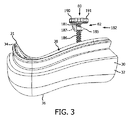
図1−図5に示される第1の例示的な実施例において、クッション張力組立体180は、ねじ棒の調節組立体182及び多数の(2つ示される)張力部材184を含む。この実施例において、ねじ棒の調節組立体182は、取付け部材185、ねじ棒186及び作動装置190を含む。取付け部材185は、ねじ棒186に対応するねじ山を持つねじ穴187を含む。ねじ棒186は、第1の端部181及び第2の端部183を含む。例示的な実施例においてノブ191である作動装置190は、ねじ棒の第1の端部181に結合される、直接結合される又は固定される。ねじ棒の第2の端部183は、張力部材の結合部192を含む。例示的な実施例において、張力部材の結合部192は、フランジ付き環状部品(flanged collar)193である。明細書で使用されるとき、"フランジ付き環状部品"は、外側の放射方向面に溝を持つ環状部品である。
In the first exemplary embodiment shown in FIGS. 1-5, the
この例示的な実施例において、張力部材184は、各々が第1の端部196及び第2の端部196を備える2つの細長い本体194を含む。例示的な実施例において、細長い本体194は単一である、すなわち細長い本体194は、夫々の第1の端部196において接合されている。別に述べると、細長い本体194は、第1の端部196を共有している。さらに、例示的な実施例において、張力部材184は、クッション本体32とも単一である。追加の張力部材184が含まれ得ることも述べておく。例えば、4つの張力部材(図示せず)がX形状で置かれることができる。
In the exemplary embodiment,
張力部材の調節組立体の結合構成要素197は、共有される張力部材本体の第1の端部196に置かれる。この例示的な実施例において、調節組立体の結合構成要素197は、前記フランジ付き環状部品193に対応する大きさの通路197'である。張力部材のクッション本体の結合構成要素199は、各張力部材本体の第2の端部198に置かれる。張力部材184がクッション本体32と単一である実施例において、クッション本体の張力部材の結合構成要素60及び張力部材のクッション本体の結合構成要素199は、張力部材184とクッション本体32との間の接合部分におけるクッション本体32及び張力部材184の部分である。代わりに、クッション本体の張力部材の結合構成要素60は、クッション本体32を通る通路(図示せず)であり、張力部材のクッション本体の結合構成要素199は、くぎの頭に似た広がった頭部(図示せず)である。この実施例において、張力部材のクッション本体の結合構成要素199は、前記頭部がクッション本体の張力部材の結合構成要素の通路を通過することを可能にするように、クッション本体32を伸ばすことにより、クッション本体の張力部材の結合構成要素の通路を通る。
The
取付け部材185は、フェースプレート12に結合される、直接結合される又は固定される。ねじ棒186は、ねじ穴187内に置かれることにより取付け部材185に動作可能に結合される。ねじ棒の第1の端部181及びノブ191は、フェースプレートの外面20に隣接して置かれる。ねじ棒の第2の端部183及び張力部材の結合部192は、フェースプレートの内面22に隣接して置かれる。張力部材の調節組立体の結合構成要素197、すなわち通路197'は、フランジ付き環状部品193に結合される。張力部材のクッション本体の結合構成要素199は、クッション本体の張力部材の結合構成要素60においてクッション本体32に結合、直接結合又は固定され、これによりクッション本体32に動作可能に結合される。例示的な実施例において、張力部材のクッション本体の結合構成要素199及びクッション本体の張力部材の結合構成要素60は、クッション本体の第1の鼻部分50及びクッション本体の第2の鼻部分52に置かれる。
The mounting
この形状において、調節組立体182の作動、すなわちノブ191を回すことは、ねじ棒186をクッション本体32の内部空間内/空間外に移動させる。さらに、ねじ棒186をクッション本体32の内部空間内/空間外に移動させるにつれて、ねじ棒の第2の端部183は夫々、フェースプレート12から離れる又はフェースプレート12に向けて移動する。ねじ棒の第2の端部183が移動するので、張力部材184も夫々フェースプレート12から離れる又はフェースプレート12に向けて移動する。張力部材のクッション本体の結合構成要素199がクッション本体32に結合される(又は直接結合される、固定される若しくはクッション本体32と単一である)ので、クッション本体32も、このクッション本体32が概ね連続する封止を提供する第1の形状と、クッション本体32がより完全な封止を提供する第2の形状との間を移動する。
In this configuration, actuation of the
別に述べると、調節組立体82の作動、すなわちノブ191を回すことは、クッション本体32を、このクッション本体32の選択部分62がクッション本体の中心38又はクッション本体の中心線40の一方から第1の距離にある第1の形状と、クッション本体32の選択部分62がクッション本体の中心38又はクッション本体の中心線40の一方から第2の距離にある第2の形状との間を移動させる。別に述べると、調節組立体182の作動、すなわちノブ191を回すことは、クッション本体32を、第1の鼻部分50及び第2の鼻部分52がクッション本体の中心38又はクッション本体の中心線40の一方から第1の距離にある第1の形状と、第1の鼻部分50及び第2の鼻部分52がクッション本体の中心38又はクッション本体の中心線40の一方から第2の距離にある第2の形状との間を移動させる。この実施例において、調節組立体182は、如何なる張力部材184とも単一ではない。
In other words, actuation of the
図6−図11に示される第2の実施例において、クッションの張力組立体280は、刻み目のあるストラップの調節組立体282を含む。この実施例において、調節組立体282は、(4つ示される)張力部材284と部分的に単一である。すなわち、この実施例において、調節組立体の作動装置290は、張力部材284と単一である(すなわち、1つのハンドル291は2つの張力部材284と単一となる)多数の(2つ示される)ハンドル291である。すなわち、ハンドルの張力部材の結合部292は、ハンドル291と張力部材284との間の接合部分である。調節組立体282はさらに、フェースプレート12に多数のラッチ通路283を含む。明細書で使用されるとき、"ラッチ通路"は、張力部材の一部がその中を通るより小さな断面領域を持つ通路である。さらに、"ラッチ通路"は、弾性材料から作られる又は弾性材料から作られる張力部材と関連する。
In the second embodiment shown in FIGS. 6-11, the
この実施例において、各々が第1の端部296及び第2の端部298を備える弾力性のある本体294を含む2つの張力部材284が存在する。さらに、各張力部材本体294の中央部分285は多数の突起部287を含む。明細書で使用されるとき、"突起部"は、張力部材の他の部分よりも大きな断面領域を持つ細長い張力部材の部分である。張力部材の調節組立体の結合構成要素297は、各張力部材の本体の第1の端部296に置かれる。張力部材のクッション本体の結合構成要素299は、各張力部材の本体の第2の端部298に置かれる。この実施例において、各張力部材の本体294は、調節組立体の作動装置290、すなわちハンドル291と単一である。すなわち、例示的な実施例において、各張力部材の調節組立体の結合構成要素297は、ハンドルの張力部材の結合部292と、張力部材の本体の第1の端部296との間の接合部分297'である。さらに、例示的な実施例において、張力部材の本体294は、クッション本体32と単一である。従って、張力部材284がクッション本体32と単一であるこの実施例において、クッション本体の張力部材の結合構成要素60及び張力部材のクッション本体の結合構成要素299は、張力部材284とクッション本体32との間の接合部分におけるクッション本体32及び張力部材284の部分である。
In this embodiment, there are two
代わりに、クッション本体の張力部材の結合構成要素60は、クッション本体32を通る通路(図示せず)であり、張力部材のクッション本体の結合構成要素299は、くぎの頭に似た広がった頭部(図示せず)である。この実施例において、張力部材のクッション本体の結合構成要素299は、前記頭部がクッション本体の張力部材の結合構成要素の通路を通ることを可能にするように、クッション本体32を伸ばすことにより、このクッション本体の張力部材の結合構成要素の通路を通る。例示的な実施例において、張力部材のクッション本体の結合構成要素299及びクッション本体の張力部材の結合構成要素60は、クッション本体の第1の鼻部分50及びクッション本体の第2の鼻部分52に置かれる。
Instead, the cushion body tension
この実施例において、各張力部材の本体の中央部分285は、ラッチ通路283を通る。例示的な実施例において、各張力部材284に対し2つのラッチ通路が存在している。各ラッチ通路283は、クッション本体の中心線40からオフセットされる、すなわち離間されている。さらに、各張力部材のクッション本体の結合構成要素299は、上述したようにクッション本体32に結合される。さらに、各張力部材の調節組立体の結合構成要素297は、調節組立体の作動装置290、すなわちハンドル291と単一である。
In this embodiment, the
それに応じて、調節組立体の作動装置290、すなわちハンドル291は、フェースプレートの外面20に隣接して置かれる。各ハンドルの張力部材の結合部292は、フェースプレートの内面22に隣接して置かれる。張力部材のクッション本体の結合構成要素299は、クッション本体の張力部材の結合構成要素60においてクッション本体32に結合される、直接結合される又は固定される及びそれにより動作可能に結合される。
Accordingly, the
この形状において、ユーザは、調節組立体の作動装置290、すなわちハンドル291を引く又は押すことにより調節組立体282を作動させる。調節組立体282を作動させることは、張力部材284をラッチ通路283に進めさせる。すなわち、弾性突起部287が変形し、ラッチ通路283を通る。調節組立体282が作動していないとき、弾性突起部287を変形させるのに十分なバイアスはない。従って、調節組立体282が作動していないとき、弾性突起部287は、ラッチ通路283においてフェースプレート12と係合し、張力部材284が動かないようにする。本明細書で使用されるとき、単一のハンドル291及びハンドル291と特定される張力部材284の部分は、ユーザが調節組立体282を作動させるので変化することをさらに述べておく。すなわち、明細書で使用されるとき、"ハンドル"291は、単一のハンドル291及びユーザが握る張力部材284の部分、すなわち単一のハンドル291及びフェースプレートの外面20に隣接する張力部材284の部分である。従って、例えば、ユーザがハンドル291を引くので、単一のハンドル291及びフェースプレートの外面20に隣接して置かれる張力部材284の部分は長くなる、故に、ハンドル291は長くなり、各張力部材284は短くなる。従って、明細書で使用されるとき、各張力部材の隣接組立体の結合構成要素197及びハンドルの張力部材の結合部292の場所は、単一のハンドル291及び張力部材284の形状に基づいて、フェースプレート12に対し変化すると理解される。すなわち、明細書で使用されるとき、ハンドルの張力部材の結合部292と張力部材の本体の第1の端部296及び張力部材の調節組立体の結合構成要素197との間の接合部分197"は常にフェースプレート12に置かれる。
In this configuration, the user activates the
それに応じて、張力部材のクッション本体の結合構成要素299は、クッション本体32に結合される(又は直接結合される、固定される若しくはそれと単一となる)ので、クッション本体32もこのクッション本体32が概ね連続する封止を提供する第1の形状と、クッション本体32がより完全な封止を提供する第2の形状との間を移動する。別に述べると、調節組立体282の作動、すなわちハンドル291を引く/押すことは、クッション本体32をこのクッション本体32の選択部分62がクッション本体の中心38又はクッション本体の中心線40の一方から第1の距離にある第1の形状と、クッション本体32の選択部分62がクッション本体の中心38又はクッション本体の中心線40の一方から第2の距離にある第2の形状との間を移動させる。別に言うと、調節組立体282の作動、すなわちハンドル291を引く/押すことは、クッション本体32を第1の鼻部分50及び第2の鼻部分52がクッション本体の中心38又はクッション本体の中心線40の一方から第1の距離にある第1の形状と、第1の鼻部分50及び第2の鼻部分52がクッション本体の中心38又はクッション本体の中心線40の一方から第2の距離にある第2の形状との間を移動させる。
Accordingly, the tension member cushion
図12−図16に示される第3の例示的な実施例において、リールベースの閉鎖の調節組立体382は、リールベースの閉鎖装置383を含む。リールベースの閉鎖装置383は、米国特許番号第8,516,662号、第8,424,168号、第8,091,182号及び第7,954,204号に開示されるような装置である。そのような装置の詳細及び装置の動作は、本開示とは関連していない。リールベースの閉鎖装置383は、例示的な実施例ではノブ391である作動装置390を含むことを述べておく。さらに、リールベースの閉鎖装置383は、その周りに多数の張力部材384が巻かれるリール(図示せず)を含む。この開示のために、クッション張力組立体380は、リールベースの閉鎖の調節組立体382及び多数の(4つ示される)張力部材384を含むことを述べておく。この実施例において、リールベースの閉鎖の調節組立体382は、ハウジング組立体385、リール(図示せず)及び作動装置390を含む。例示的な実施例においてノブ391である作動装置390は、ハウジング組立体385に回転可能に結合される、直接結合される又は固定される。作動装置390、すなわちノブ391は、リールに固定される。故に、作動装置390、すなわちノブ391の回転は、リールをハウジング組立体385内で回転させる。リールは概略的に示される張力部材の結合部392を含む。
In the third exemplary embodiment shown in FIGS. 12-16, the reel-based
この例示的な実施例において、張力部材384は、各々が第1の端部396及び第2の端部398を備える4つの細長い本体394を含む。張力部材の調節組立体の結合構成要素397は、各張力部材の本体の第1の端部396に置かれる。張力部材のクッション本体の結合構成要素399は、各張力部材の本体の第2の端部398に置かれる。例示的な実施例において、張力部材384はクッション本体32に接着される。張力部材384がクッション本体32に接着される実施例において、クッション本体の張力部材の結合構成要素60及び張力部材のクッション本体の結合構成要素399は、張力部材384とクッション本体32との間の接合部分にあるクッション本体32及び張力部材384の部分である。代わりに、クッション本体の張力部材の結合構成要素60は、クッション本体32を通る通路(図示せず)であり、張力部材のクッション本体の結合構成要素399は、くぎの頭に似た広がった頭部(図示せず)である。この実施例において、張力部材のクッション本体の結合構成要素399は、前記頭部がクッション本体の張力部材の結合構成要素の通路を通ることを可能にするように、クッション本体32を伸ばすことにより、クッション本体の張力部材の結合構成要素の通路を通る。
In the exemplary embodiment, tension member 384 includes four
ハウジング組立体385は、フェースプレート12に結合される、直接結合される又は固定される。ノブ391は、フェースプレートの外面20に隣接して置かれる。リールの張力部材の結合部392は、フェースプレートの内面22に隣接して置かれる。張力部材のクッション本体の結合構成要素399は、クッション本体の張力部材の結合構成要素60においてクッション本体32に結合される、直接結合される又は固定される及びそれにより動作可能に結合される。例示的な実施例において、張力部材のクッション本体の結合構成要素399及びクッション本体の張力部材の結合構成要素60は、クッション本体の第1の鼻部分50及びクッション本体の第2の鼻部分52に置かれる。
The
この形状において、調節組立体382の作動、すなわちノブ391を回すことは、リールをハウジング組立体385内で回転させる。この動作は、張力部材384をリールに巻く又はリールから解く。張力部材のクッション本体の結合構成要素399はクッション本体32に結合される(又は直接結合される、固定される若しくはそれと単一となる)ので、クッション本体32も、このクッション本体32が概ね連続する封止を提供する第1の形状と、クッション本体32がより完全な封止を提供する第2の形状との間を移動する。別に述べると、調節組立体82の作動、すなわちノブ391を回すことは、クッション本体を、クッション本体32の選択部分62がクッション本体の中心38又はクッション本体の中心線40の一方から第1の距離にある第1の形状と、クッション本体32の選択部分62がクッション本体の中心38又はクッション本体の中心線40の一方から第2の距離にある第2の形状との間を移動させる。別に述べると、調節組立体382の作動、すなわちノブ391を回すことは、クッション本体32を、第1の鼻部分50及び第2の鼻部分52がクッション本体の中心38又はクッション本体の中心線40の一方から第1の距離にある第1の形状と、第1の鼻部分50及び第2の鼻部分52がクッション本体の中心38又はクッション本体の中心線40の一方から第2の距離にある第2の形状との間を移動させる。この実施例において、調節組立体382は、如何なる張力部材384と単一ではない。
In this configuration, actuation of the
図17に示されるように、クッションの張力組立体80又は上述したようなクッションの張力組立体180、280、380の特定される実施例の何れかを含む呼吸インタフェース装置10を使用する方法は以下のことを含んでいる。ユーザの顔の上に呼吸インタフェース装置10を位置決める(1000)、クッション本体の係合部36が概ね連続する封止を提供するようにユーザの顔にクッション本体の係合部36を取り付ける(1002)及びクッション本体32が第1の形状と第2の形状との間を移動するように、クッションの張力組立体80、180、280、380を作動させる(1004)。さらに、クッション本体32が第1の形状と第2の形状との間を移動するようにクッションの張力組立体80、180、280、380を作動させる(1004)ことは、少なくとも1つの張力部材84、184、284、384の有効長を変更する(1006)ことを含む。さらに、クッション本体32が第1の形状と第2の形状との間を移動するようにクッションの張力組立体80、180,280、380を作動させる(1004)ことは、第1の鼻部分50及び第2の鼻部分52をクッション本体の中心38又はクッション本体の中心線40の一方からの第1の距離と、クッション本体の中心38又はクッション本体の中心線40の一方からの第2の距離との間を移動させる(1008)ことを含む。
As shown in FIG. 17, a method of using the
請求項において、括弧の間に置かれる如何なる参照符号もその請求項を限定していると考えない。"有する"又は"含む"という言葉は、その請求項に挙げられている以外の要素又はステップの存在を排除するものではない。幾つかの手段を列挙している装置の請求項において、これら手段の幾つかがハードウェアの同一のアイテムにより具現化されてもよい。複数あることを述べていなくても、その要素が複数あることを排除するものではない。幾つかの手段を列挙している如何なる装置の請求項においても、これら手段の幾つかがハードウェアの同一のアイテムにより具現化されてもよい。ある要素が互いに異なる従属請求項に挙げられているという単なる事実は、これらの要素が組み合わせて用いられることができないことを示しているのではない。 In the claims, any reference signs placed between parentheses shall not be construed as limiting the claim. The word “comprising” or “including” does not exclude the presence of elements or steps other than those listed in a claim. In the device claim enumerating several means, several of these means may be embodied by one and the same item of hardware. The absence of a plurality does not exclude the presence of a plurality of elements. In any device claim enumerating several means, several of these means may be embodied by one and the same item of hardware. The mere fact that certain elements are recited in mutually different dependent claims does not indicate that these elements cannot be used in combination.
本発明は、最も実用的であり、好ましい実施例であると現在考えられるものに基づいて、説明を目的に詳細に説明されていたとしても、そのような詳細は単に説明を目的とし、本発明は開示される実施例に限定されるのではなく、それどころか付随する請求項の真意及び範囲内である修正案及び等価な配置にも及んでいると意図されると理解される。例えば、本発明は、可能な限り、如何なる実施例の1つ以上の特徴が他の如何なる実施例の1つ以上の特徴と組み合わされ得ると考えられると理解される。 While the present invention has been described in detail for purposes of illustration based on what is presently considered to be the most practical and preferred embodiment, such details are for purposes of illustration only and It is understood that this is not intended to be limited to the disclosed embodiments, but rather extends to modifications and equivalent arrangements that are within the spirit and scope of the appended claims. For example, it is understood that the present invention contemplates that, where possible, one or more features of any embodiment can be combined with one or more features of any other embodiment.
Claims (18)
調節組立体、及び
多数の張力部材
を有し、各張力部材は、前記調節組立体に動作可能に結合され、各張力部材は、前記クッション本体に動作可能に結合され、及び前記調節組立体は、前記クッション本体を、前記クッション本体が概ね連続する封止を提供する第1の形状と、前記クッションがより完全な封止を提供する第2の形状との間を移動させるように構成される、クッションの張力組立体。 A cushion tension assembly for a breathing interface device, wherein the breathing interface device includes a faceplate and a cushion, the faceplate includes an inner surface and an outer surface, and the cushion includes a resilient body; A cushion body of the breathing interface device includes a center, a centerline and an engagement portion configured to engage a user's face, the cushion body being coupled to the face plate, Is
An adjustment assembly, and a plurality of tension members, each tension member operably coupled to the adjustment assembly, each tension member operably coupled to the cushion body, and the adjustment assembly comprising: The cushion body is configured to move between a first shape in which the cushion body provides a generally continuous seal and a second shape in which the cushion provides a more complete seal. , Cushion tension assembly.
中心、中心線及びユーザの顔に係合するように構成される係合部を含む弾力性のある本体を含むクッションであり、前記クッション本体は前記フェースプレートに結合される、クッション、並びに
調節組立体及び多数の張力部材を含むクッションの張力組立体であり、各張力部材は、前記調節組立体に結合され、各張力部材は前記クッション本体に動作可能に結合され、前記調節組立体は、前記クッション本体を、前記クッション本体が概ね連続する封止を提供する第1の形状と、前記クッション本体がより完全な封止を提供する第2の形状との間を移動させるように構成される、クッションの張力組立体
を有する呼吸インタフェース装置。 A faceplate including an inner surface and an outer surface;
A cushion including a resilient body including a center, a centerline and an engagement portion configured to engage a user's face, wherein the cushion body is coupled to the face plate, and an adjustment set A tension assembly of a cushion including a three-dimensional and a plurality of tension members, wherein each tension member is coupled to the adjustment assembly, each tension member is operably coupled to the cushion body, and the adjustment assembly includes: The cushion body is configured to move between a first shape in which the cushion body provides a generally continuous seal and a second shape in which the cushion body provides a more complete seal; A respiratory interface device having a cushion tension assembly.
前記ユーザの顔の上に前記呼吸インタフェース装置を位置決めるステップ、
前記クッション本体の係合部が概ね連続する封止を提供するように、前記ユーザの上に前記クッション本体の係合部を置くステップ、及び
前記クッション本体が第1の形状と第2の形状との間を移動するように、前記クッションの張力組立体を作動させるステップ、
を有する方法。 A method of using a breathing interface device, wherein the breathing interface device includes a faceplate, a cushion and a cushion tension assembly, the faceplate includes an inner surface and an outer surface, and the cushion includes a resilient body. The cushion body includes a center, a centerline and an engagement portion configured to engage a user's face, the cushion body is coupled to the face plate, and the cushion tension assembly includes: An adjustment assembly and a plurality of tension members, each tension member being operably coupled to the adjustment assembly, each tension member being operably coupled to the cushion body, wherein the adjustment assembly includes the cushion A body having a first shape that provides a generally continuous seal with the cushion body and a more complete seal with the cushion body; It is configured to move between a second shape that provides, the method comprising:
Positioning the respiratory interface device on the user's face;
Placing the engagement portion of the cushion body over the user such that the engagement portion of the cushion body provides a generally continuous seal, and the cushion body has a first shape and a second shape; Activating the cushion tension assembly to move between
Having a method.
Applications Claiming Priority (3)
| Application Number | Priority Date | Filing Date | Title |
|---|---|---|---|
| US201462089357P | 2014-12-09 | 2014-12-09 | |
| US62/089,357 | 2014-12-09 | ||
| PCT/IB2015/059422 WO2016092462A1 (en) | 2014-12-09 | 2015-12-07 | Adjustable tension device for cpap mask |
Publications (2)
| Publication Number | Publication Date |
|---|---|
| JP2018504158A true JP2018504158A (en) | 2018-02-15 |
| JP2018504158A5 JP2018504158A5 (en) | 2018-11-15 |
Family
ID=55071087
Family Applications (1)
| Application Number | Title | Priority Date | Filing Date |
|---|---|---|---|
| JP2017529009A Pending JP2018504158A (en) | 2014-12-09 | 2015-12-07 | Adjustable tension device for CPAP mask |
Country Status (3)
| Country | Link |
|---|---|
| US (1) | US10765828B2 (en) |
| JP (1) | JP2018504158A (en) |
| WO (1) | WO2016092462A1 (en) |
Families Citing this family (23)
| Publication number | Priority date | Publication date | Assignee | Title |
|---|---|---|---|---|
| US8783257B2 (en) | 2004-02-23 | 2014-07-22 | Fisher & Paykel Healthcare Limited | Breathing assistance apparatus |
| ES2703450T3 (en) | 2004-04-02 | 2019-03-08 | Fisher & Paykel Healthcare Ltd | Breathing assistance device |
| ES2954589T3 (en) | 2006-07-14 | 2023-11-23 | Fisher & Paykel Healthcare Ltd | Respiratory assistance device |
| US10792451B2 (en) | 2008-05-12 | 2020-10-06 | Fisher & Paykel Healthcare Limited | Patient interface and aspects thereof |
| US11660413B2 (en) | 2008-07-18 | 2023-05-30 | Fisher & Paykel Healthcare Limited | Breathing assistance apparatus |
| DK3323462T3 (en) | 2008-10-10 | 2022-01-17 | Fisher & Paykel Healthcare Ltd | NOSE PILLOWS FOR A PATIENT INTERFACE. |
| WO2012047121A1 (en) | 2010-10-08 | 2012-04-12 | Fisher & Paykel Healthcare Limited | Breathing assistance apparatus |
| US10603456B2 (en) | 2011-04-15 | 2020-03-31 | Fisher & Paykel Healthcare Limited | Interface comprising a nasal sealing portion |
| CA2833106C (en) | 2011-04-15 | 2019-08-27 | Fisher & Paykel Healthcare Limited | Interface comprising a rolling nasal bridge portion |
| EP2726132B1 (en) | 2011-07-01 | 2018-10-10 | Fisher & Paykel Healthcare Limited | Nasal mask interface assembly |
| USD693459S1 (en) | 2011-09-16 | 2013-11-12 | Fisher & Paykel Healthcare Limited | Patient interface assembly |
| CA2880749C (en) | 2012-08-08 | 2022-03-08 | Fisher & Paykel Healthcare Limited | Headgear for patient interface |
| US9950130B2 (en) | 2012-09-04 | 2018-04-24 | Fisher & Paykel Healthcare Limited | Valsalva mask |
| USD884152S1 (en) | 2016-10-24 | 2020-05-12 | ResMed Pty Ltd | Patient interface |
| WO2016032343A1 (en) | 2014-08-25 | 2016-03-03 | Fisher & Paykel Healthcare Limited | Respiratory mask and related portions, components or sub-assemblies |
| US10953181B2 (en) * | 2015-06-11 | 2021-03-23 | Ventific Holdings Pty Ltd. | Respiratory mask |
| USD784515S1 (en) | 2015-09-25 | 2017-04-18 | Fisher & Paykel Healthcare Limited | Headgear |
| USD828917S1 (en) * | 2015-09-25 | 2018-09-18 | Fisher & Paykel Healthcare Limited | Vent diffuser |
| USD800895S1 (en) | 2015-09-25 | 2017-10-24 | Fisher & Paykel Healthcare Limited | Face mask cushion |
| USD784516S1 (en) | 2015-09-25 | 2017-04-18 | Fisher & Paykel Healthcare Limited | Face mask frame |
| USD895105S1 (en) | 2016-10-24 | 2020-09-01 | ResMed Pty Ltd | Combined cushion and frame module for patient interface |
| USD892304S1 (en) * | 2019-01-04 | 2020-08-04 | Sleepnet Corporation | Facemask pressure adjustment device |
| US20230338687A1 (en) * | 2020-09-28 | 2023-10-26 | Roheet Patel | Patient interface and respiratory support apparatus |
Citations (5)
| Publication number | Priority date | Publication date | Assignee | Title |
|---|---|---|---|---|
| JP2006505373A (en) * | 2002-11-06 | 2006-02-16 | レスメド リミテッド | Mask and its components |
| JP2009504320A (en) * | 2005-08-15 | 2009-02-05 | アールアイシー・インベストメンツ・エルエルシー | Patient interface with adjustable buffer |
| JP2012530561A (en) * | 2009-06-24 | 2012-12-06 | レスメド・リミテッド | Mask system |
| WO2013128309A1 (en) * | 2012-03-01 | 2013-09-06 | Koninklijke Philips N.V. | Lever adjustment assembly for mask |
| US20140338671A1 (en) * | 2011-12-14 | 2014-11-20 | Koninklijke Philips N.V. | Patient interface device with customizable cushion |
Family Cites Families (8)
| Publication number | Priority date | Publication date | Assignee | Title |
|---|---|---|---|---|
| BE868894A (en) | 1977-07-15 | 1979-01-11 | Henkin Melvyn Lane | BREATH MASK |
| US20060156517A1 (en) | 1997-08-22 | 2006-07-20 | Hammerslag Gary R | Reel based closure system |
| US8146595B2 (en) | 2006-08-31 | 2012-04-03 | Nellcor Puritan Bennett Llc | Adjustable patient interface for a breathing assistance system |
| US8424168B2 (en) | 2008-01-18 | 2013-04-23 | Boa Technology, Inc. | Closure system |
| CN101496646B (en) | 2009-03-13 | 2010-06-30 | 李琪 | Health-care mouth and nose mask |
| DE112011101525B4 (en) | 2010-04-30 | 2020-07-09 | Boa Technology, Inc. | Retractor-based lacing system |
| CN103974738B (en) | 2011-12-06 | 2017-03-15 | 皇家飞利浦有限公司 | There is the liner of adjustable stabilizing member |
| US20160015922A1 (en) * | 2012-02-27 | 2016-01-21 | Koninklijke Philips N.V. | Lower mount flexing oral-nasal mask |
-
2015
- 2015-12-07 JP JP2017529009A patent/JP2018504158A/en active Pending
- 2015-12-07 WO PCT/IB2015/059422 patent/WO2016092462A1/en active Application Filing
- 2015-12-07 US US15/533,507 patent/US10765828B2/en active Active
Patent Citations (5)
| Publication number | Priority date | Publication date | Assignee | Title |
|---|---|---|---|---|
| JP2006505373A (en) * | 2002-11-06 | 2006-02-16 | レスメド リミテッド | Mask and its components |
| JP2009504320A (en) * | 2005-08-15 | 2009-02-05 | アールアイシー・インベストメンツ・エルエルシー | Patient interface with adjustable buffer |
| JP2012530561A (en) * | 2009-06-24 | 2012-12-06 | レスメド・リミテッド | Mask system |
| US20140338671A1 (en) * | 2011-12-14 | 2014-11-20 | Koninklijke Philips N.V. | Patient interface device with customizable cushion |
| WO2013128309A1 (en) * | 2012-03-01 | 2013-09-06 | Koninklijke Philips N.V. | Lever adjustment assembly for mask |
Also Published As
| Publication number | Publication date |
|---|---|
| US20170368288A1 (en) | 2017-12-28 |
| US10765828B2 (en) | 2020-09-08 |
| WO2016092462A1 (en) | 2016-06-16 |
Similar Documents
| Publication | Publication Date | Title |
|---|---|---|
| JP2018504158A (en) | Adjustable tension device for CPAP mask | |
| JP6720186B2 (en) | Patient interface device | |
| US11730908B2 (en) | Magnetically assisted sealing arrangement for a patient interface device | |
| JP6422880B2 (en) | Motion stabilizer system for respiratory interface devices | |
| AU2008101257A4 (en) | Breathing assistance apparatus | |
| US9744325B2 (en) | Portable patient interface system | |
| US20150246199A1 (en) | Articulating full face mask | |
| US20070277828A1 (en) | Flexible connector | |
| EP2858703B1 (en) | Pediatric total facemask | |
| JP2024042085A (en) | Adjustable frame for interface devices | |
| JP2016508814A (en) | Respiratory interface device manifold assembly | |
| JP6431192B2 (en) | Frame / headgear adjustment assembly | |
| US20140000618A1 (en) | Helical forehead support adjustment mechanism | |
| US10507299B2 (en) | Releasable elbow connector | |
| US9821132B2 (en) | Patient interface device including an adjustable forehead support having a vertical wheel drive mechanism | |
| US10556083B2 (en) | Patient interface device and maintaining apparatus and maintaining member therefor | |
| US20170361049A1 (en) | Rigid contoured ribbon and variable spring sealing | |
| JP2019520892A (en) | Strap with adhesive silicone adjustment | |
| JP2017537741A (en) | Adjustable airflow diffuser |
Legal Events
| Date | Code | Title | Description |
|---|---|---|---|
| A521 | Request for written amendment filed |
Free format text: JAPANESE INTERMEDIATE CODE: A523 Effective date: 20181005 |
|
| A621 | Written request for application examination |
Free format text: JAPANESE INTERMEDIATE CODE: A621 Effective date: 20181005 |
|
| A977 | Report on retrieval |
Free format text: JAPANESE INTERMEDIATE CODE: A971007 Effective date: 20190805 |
|
| A131 | Notification of reasons for refusal |
Free format text: JAPANESE INTERMEDIATE CODE: A131 Effective date: 20190813 |
|
| A601 | Written request for extension of time |
Free format text: JAPANESE INTERMEDIATE CODE: A601 Effective date: 20191108 |
|
| A521 | Request for written amendment filed |
Free format text: JAPANESE INTERMEDIATE CODE: A523 Effective date: 20200213 |
|
| A131 | Notification of reasons for refusal |
Free format text: JAPANESE INTERMEDIATE CODE: A131 Effective date: 20200714 |
|
| A02 | Decision of refusal |
Free format text: JAPANESE INTERMEDIATE CODE: A02 Effective date: 20210302 |