JP2022190238A - Image reading device and image forming apparatus - Google Patents
Image reading device and image forming apparatus Download PDFInfo
- Publication number
- JP2022190238A JP2022190238A JP2021098475A JP2021098475A JP2022190238A JP 2022190238 A JP2022190238 A JP 2022190238A JP 2021098475 A JP2021098475 A JP 2021098475A JP 2021098475 A JP2021098475 A JP 2021098475A JP 2022190238 A JP2022190238 A JP 2022190238A
- Authority
- JP
- Japan
- Prior art keywords
- image
- document
- reading
- unit
- image data
- Prior art date
- Legal status (The legal status is an assumption and is not a legal conclusion. Google has not performed a legal analysis and makes no representation as to the accuracy of the status listed.)
- Pending
Links
- 238000001514 detection method Methods 0.000 claims abstract description 23
- 230000002159 abnormal effect Effects 0.000 claims description 6
- 239000000428 dust Substances 0.000 abstract description 45
- 239000011521 glass Substances 0.000 abstract description 13
- 238000010586 diagram Methods 0.000 description 14
- 238000003708 edge detection Methods 0.000 description 12
- 238000000034 method Methods 0.000 description 12
- 230000006870 function Effects 0.000 description 5
- 230000003287 optical effect Effects 0.000 description 5
- 230000002093 peripheral effect Effects 0.000 description 5
- 238000003705 background correction Methods 0.000 description 3
- 238000000926 separation method Methods 0.000 description 3
- 230000015572 biosynthetic process Effects 0.000 description 2
- 230000000694 effects Effects 0.000 description 2
- 238000011144 upstream manufacturing Methods 0.000 description 2
- 238000006243 chemical reaction Methods 0.000 description 1
- 239000004744 fabric Substances 0.000 description 1
- 230000001678 irradiating effect Effects 0.000 description 1
- 239000011347 resin Substances 0.000 description 1
- 229920005989 resin Polymers 0.000 description 1
- 239000004065 semiconductor Substances 0.000 description 1
- 230000035945 sensitivity Effects 0.000 description 1
Images


Abstract
Description
本発明は、画像読取装置によって読み取られた画像を表す画像データの補正技術に関する。 The present invention relates to a technique for correcting image data representing an image read by an image reading apparatus.
画像読取装置は、原稿に光を照射し、その反射光を読取部で読み取りガラスを介して検出することによって当該原稿の画像を読み取る。画像読取装置として、原稿給送装置(ADF)により搬送される原稿を読取部で読み取るものがある。 An image reading apparatus reads an image of a document by irradiating the document with light and detecting the reflected light through a reading glass in a reading unit. 2. Description of the Related Art As an image reading device, there is an image reading device that reads a document conveyed by a document feeder (ADF) with a reading section.
この様な画像読取装置においては、原稿を搬送するローラのニップ圧や回転速度のばらつきにより、原稿の斜行や、搬送方向とは垂直な方向(以下、主走査方向)における原稿の位置のバラつきが生じ得る。特許文献1には、読み取り結果を表す画像データから搬送方向における原稿の先端の影を検出し、検出された原稿の先端の影の主走査方向に対する傾き角度に基づいて画像データを回転補正する構成が記載されている。 In such an image reading device, due to variations in the nip pressure and rotation speed of the rollers that transport the document, skew of the document and variation in the position of the document in the direction perpendicular to the transport direction (hereinafter referred to as the main scanning direction). can occur. Japanese Patent Application Laid-Open No. 2002-200002 discloses a configuration in which a shadow of the leading edge of a document in the transport direction is detected from image data representing a reading result, and the image data is rotationally corrected based on the tilt angle of the detected shadow of the leading edge of the document with respect to the main scanning direction. is described.
読み取りガラス上にゴミが付着した状態で原稿が読み取られると、当該ゴミに起因して、読取画像にゴミスジが生じる。検出された原稿の先端の影に基づいて傾き角度を算出する構成においてゴミスジが生じると、当該ゴミスジに起因して傾き角度に誤差が生じてしまう。即ち、算出された傾き角度と実際の原稿の傾き角度とが異なる可能性がある。この場合、検出角度に基づいて回転補正が行われると、補正後の画像に傾きが生じてしまう。 When a document is read with dust adhering to the reading glass, dust streaks appear on the read image due to the dust. If a dust streak occurs in a configuration in which the tilt angle is calculated based on the detected shadow of the leading edge of the document, an error in the tilt angle will occur due to the dust streak. That is, the calculated skew angle may differ from the actual document skew angle. In this case, if rotation correction is performed based on the detected angle, the corrected image will be tilted.
上記課題に鑑み、本発明は、補正後の画像に生じる傾きを抑制することを目的とする。 SUMMARY OF THE INVENTION In view of the above problems, an object of the present invention is to suppress the inclination of an image after correction.
上記課題を解決するために、本発明にかかる画像読取装置は、
原稿が積載される積載部と、
前記積載部に積載された原稿を給送する給送部と、
前記給送部によって給送された原稿を読取位置へと搬送する搬送部と、
光を出射する光源と、
前記読取位置を通過する原稿からの反射光を受光することによって前記原稿の画像を読み取る読取部と、
前記読取部によって読み取られた原稿の画像を表す画像データに基づいて、異常画素を検出する第1検出部と、
前記読取部によって読み取られた原稿の画像を表す画像データに基づいて、前記原稿が搬送される搬送方向における前記原稿の先端側の辺を検出する第2検出部と、
前記検出部によって検出された前記原稿の先端側の辺を表す画像データと、前記第1検出部によって検出された異常画素の、前記搬送方向に直交する所定方向における位置と、に基づいて、に基づいて、前記所定方向に対する前記原稿の先端側の辺の傾き角度に対応する傾き量を決定する決定手段と、
前記決定手段によって決定された傾き量に基づいて前記画像データに対して回転補正を行う補正手段と、
を有することを特徴とする。
In order to solve the above problems, an image reading device according to the present invention includes:
a stacking unit on which documents are stacked;
a feeding unit that feeds the originals stacked on the stacking unit;
a conveying unit that conveys the document fed by the feeding unit to a reading position;
a light source that emits light;
a reading unit for reading an image of the document by receiving reflected light from the document passing through the reading position;
a first detection unit that detects an abnormal pixel based on image data representing an image of a document read by the reading unit;
a second detection unit that detects a leading edge side of the document in a transport direction in which the document is transported, based on image data representing an image of the document read by the reading unit;
based on the image data representing the edge of the leading edge of the document detected by the detection unit and the position of the abnormal pixel detected by the first detection unit in a predetermined direction orthogonal to the conveying direction; determination means for determining a tilt amount corresponding to the tilt angle of the edge of the leading edge of the document with respect to the predetermined direction based on the
correction means for performing rotation correction on the image data based on the tilt amount determined by the determination means;
characterized by having
本発明によれば、補正後の画像に生じる傾きを抑制することができる。 According to the present invention, it is possible to suppress the tilt occurring in the corrected image.
以下に図面を参照して、本発明の好適な実施の形態を説明する。ただし、この実施の形態に記載されている構成部品の形状及びそれらの相対配置などは、この発明が適用される装置の構成や各種条件により適宜変更されるべきものであり、この発明の範囲が以下の実施の形態に限定される趣旨のものではない。 Preferred embodiments of the present invention will be described below with reference to the drawings. However, the shapes and relative positions of the components described in this embodiment should be changed as appropriate according to the configuration of the device to which this invention is applied and various conditions, and the scope of this invention is It is not intended to be limited to the following embodiments.
〔第1実施形態〕
[画像形成装置]
図1は、本実施形態で用いられるモノクロの電子写真方式の複写機(以下、画像形成装置と称する)100の構成を示す断面図である。なお、画像形成装置は複写機に限定されず、例えば、ファクシミリ装置、印刷機、プリンタ等であっても良い。また、記録方式は、電子写真方式に限らず、例えば、インクジェット等であっても良い。更に、画像形成装置の形式はモノクロ及びカラーのいずれの形式であっても良い。
[First embodiment]
[Image forming apparatus]
FIG. 1 is a sectional view showing the configuration of a monochrome electrophotographic copier (hereinafter referred to as an image forming apparatus) 100 used in this embodiment. Note that the image forming apparatus is not limited to a copying machine, and may be, for example, a facsimile machine, a printing machine, a printer, or the like. Moreover, the recording method is not limited to the electrophotographic method, and may be, for example, an inkjet method. Furthermore, the format of the image forming apparatus may be either monochrome or color.
以下に、図1を用いて、画像形成装置100の構成および機能について説明する。図1に示すように、画像形成装置100は、原稿給送装置201及び読取装置202を含む画像読取装置200及び画像印刷装置301を有する。原稿給送装置201は、読取装置202に対して回動可能である。
The configuration and functions of the
<画像読取装置>
給送部としてのピックアップローラ103は、積載部としてのトレイ102に積載されている原稿101を原稿給送装置201の内部に給送する。分離ローラ104及び105は、ピックアップローラ103により複数の原稿101が同時に給送されることを防ぐために設けられる。搬送路に給送された原稿101は、搬送ローラ106及びリードローラ107によって読取位置Aに向けて搬送される。なお、分離ローラ104、105、搬送ローラ106及びリードローラ107は搬送部に含まれる。
<Image reader>
A
読取位置Aには透明なガラス108が配置されており、ガラス108に対して搬送路と逆側には読取部109Aが設けられる。読取部109Aは、LED110、イメージセンサ111及び光学部品群112を有する。イメージセンサ111は、主走査方向に渡り、R(赤)、G(緑)、B(青)の光を受光する複数の画素を有している。
A
読取部109Aは、以下のようにして原稿101の表面(第1面)の画像を読み取る。具体的には、光源としてのLED110は、ガラス108を介して原稿101の表面に光を照射(出射)する。光学部品群112は、ガラス108を介して受信する原稿101からの反射光をイメージセンサ111に導く。イメージセンサ111は、受光する反射光に基づきアナログ画像データを出力する。なお、イメージセンサ111は、主走査方向に渡る1ライン分の画像を同時に読み取る。したがって、原稿101を搬送しながら、複数回、イメージセンサ111により1ライン分の画像を読み取ることで、イメージセンサ111は、原稿101全体を含む画像データを出力することができる。読取部109Aの図示しないA/D変換部は、アナログ画像データをデジタル画像データに変換してコントローラ200(図2)に出力する。
The
原稿101の搬送方向において、読取位置Aの上流側には、原稿101を検知する検知センサ113が設けられる。コントローラ200は、検知センサ113が原稿101を検知したタイミングに基づき原稿101の読取部109Aが読み取りを開始するタイミングを判定する。
A
押さえローラ114及び115は原稿101をガラス108に向けて押さえる。なお、押さえローラ114及び115の間の読取部109Aと正対する位置、即ち、原稿が搬送される搬送路に関して読取部109Aとは反対側には、対向部材としての白色のガイド板116が配置される。
読取位置Aを通過した原稿101は、搬送ローラ117により読取位置Bに向けて搬送される。読取位置Bには透明なガラス118が配置されており、ガラス118に対して搬送路とは逆側には読取部109Bが設けられている。読取部109Bは、読取部109Aと同様の構成であり、原稿101の裏面(第2面)の画像を読み取る。読取部109Bが読み取りを開始するタイミングも、検知センサ113が原稿を検知したタイミングに基づき判定される。読取部109Bに正対する位置には白色のガイド板119が配置される。
The
読取位置Bを通過した原稿101は、排紙ローラ120により排紙トレイ121に排出される。
After passing through the reading position B, the
ガラス108の右側にはシェーディングデータを取得する際の基準読取部材である白色基準板122が設けられる。
A
<画像印刷装置>
画像印刷装置301の内部には、シート収納トレイ302、304が設けられている。シート収納トレイ302、304には、それぞれ異なる種類の記録媒体を収納することができる。例えば、シート収納トレイ302にはA4サイズの普通紙が収納され、シート収納トレイ304にはA4サイズの厚紙が収納される。なお、記録媒体とは、画像形成装置によって画像が形成されるものであって、例えば、用紙、樹脂シート、布、OHPシート、ラベル等は記録媒体に含まれる。
<Image printing device>
シート収納トレイ302に収納された記録媒体は、ピックアップローラ303によって給送されて、搬送ローラ306によってレジストレーションローラ308へ送り出される。また、シート収納トレイ304に収納された記録媒体は、ピックアップローラ305によって給送されて、搬送ローラ307及び306によってレジストレーションローラ308へ送り出される。
A recording medium stored in a
画像読取装置200から出力された画像データは、半導体レーザ及びポリゴンミラーを含む光走査装置311に入力される。また、感光ドラム309は、帯電器310によって外周面が帯電される。感光ドラム309の外周面が帯電された後、原稿読取装置200から光走査装置311に入力された画像信号に応じたレーザ光が、光走査装置311からポリゴンミラー及びミラー312、313を経由し、感光ドラム309の外周面に照射される。この結果、感光ドラム309の外周面に静電潜像が形成される。
Image data output from the
続いて、静電潜像が画像形成部としての現像器314内のトナーによって現像され、感光ドラム309の外周面にトナー像が形成される。感光ドラム309に形成されたトナー像は、感光ドラム309と対向する位置(転写位置)に設けられた転写帯電器315によって記録媒体に転写される。レジストレーションローラ308は、転写帯電器315によって記録媒体に画像が転写される転写タイミングに合わせて記録媒体を転写位置へ送り込む。
Subsequently, the electrostatic latent image is developed with toner in a developing
前述の如くして、トナー像が転写された記録媒体は、搬送ベルト317によって定着器318へ送り込まれ、定着器318によって加熱加圧されて、トナー像が記録媒体に定着される。このようにして、画像形成装置100によって記録媒体に画像が形成される。
As described above, the recording medium to which the toner image has been transferred is sent to the
片面印刷モードで画像形成が行われる場合は、定着器318を通過した記録媒体は、排紙ローラ319、324によって、不図示の排紙トレイへ排紙される。また、両面印刷モードで画像形成が行われる場合は、定着器318によって記録媒体の第1面に定着処理が行われた後に、記録媒体は、排紙ローラ319、搬送ローラ320、及び反転ローラ321によって、反転パス325へと搬送される。その後、記録媒体は、搬送ローラ322、323によって再度レジストレーションローラ308へと搬送され、前述した方法で記録媒体の第2面に画像が形成される。その後、記録媒体は、排紙ローラ319、324によって不図示の排紙トレイへ排紙される。
When image formation is performed in the single-sided printing mode, the recording medium that has passed through the fixing
また、第1面に画像形成された記録媒体がフェースダウンで画像形成装置100の外部へ排紙される場合は、定着器318を通過した記録媒体は、排紙ローラ319を通って搬送ローラ320へ向かう方向へ搬送される。その後、記録媒体の後端が搬送ローラ320のニップ部を通過する直前に搬送ローラ320の回転が反転することによって、記録媒体の第1面が下向きになった状態で、記録媒体が排紙ローラ324を経由して、画像形成装置100の外部へ排出される。
When the recording medium on which the image is formed on the first surface is ejected facedown to the outside of the
以上が画像形成装置100の構成および機能についての説明である。
The configuration and functions of the
<制御構成>
図2は、画像形成装置100の制御構成の例を示すブロック図である。まず、画像印刷装置301の制御構成について説明する。
<Control configuration>
FIG. 2 is a block diagram showing an example of the control configuration of the
システムコントローラ151は、図2に示すように、CPU151a、ROM151b、RAM151cを備えている。また、システムコントローラ151は、アナログ・デジタル(A/D)変換器153、高圧制御部155、モータ制御装置600、センサ類159、ACドライバ160と接続されている。システムコントローラ151は、接続された各ユニットとの間でデータやコマンドの送受信をすることが可能である。
The
CPU151aは、ROM151bに格納された各種プログラムを読み出して実行することによって、予め定められた画像形成シーケンスに関連する各種シーケンスを実行する。
The
RAM151cは記憶デバイスである。RAM151cには、例えば、高圧制御部155に対する設定値、モータ制御装置600に対する指令値等の各種データが格納される。
システムコントローラ151は、センサ類159からの信号を受信して、受信した信号に基づいて高圧制御部155の設定値を設定する。
The
高圧制御部155は、システムコントローラ151によって設定された設定値に応じて、高圧ユニット156(帯電器310、現像器314、転写帯電器315等)に必要な電圧を供給する。
The high-
モータ制御装置600は、CPU151aから出力された指令に応じて、画像印刷装置301に設けられた負荷を駆動するモータ509を制御する。
The
A/D変換器153は、定着ヒータ161の温度を検出するためのサーミスタ154が検出した検出信号を受信し、検出信号をアナログ信号からデジタル信号に変換してシステムコントローラ151に送信する。システムコントローラ151は、A/D変換器153から受信したデジタル信号に基づいてACドライバ160の制御を行う。ACドライバ160は、定着ヒータ161の温度が定着処理を行うために必要な温度となるように定着ヒータ161を制御する。なお、定着ヒータ161は、定着処理に用いられるヒータであり、定着器318に含まれる。
A/
前述の如くして、システムコントローラ151は、画像形成装置100の動作シーケンスを制御する。
The
次に、画像読取装置200の制御構成について説明する。CPU203は、不揮発性メモリ209に格納されているプログラムを実行することで画像読取装置100を制御する。
Next, the control configuration of the
搬送モータ201は、原稿給送装置201に設けられた各ローラの駆動源であり、コントローラ200の制御により回転駆動される。
A conveying
操作部202は、ユーザインタフェースを提供する。CPU203は、使用する記録媒体の種類(以下、紙種と称する)等の設定をユーザが行うための操作画面を、操作部202に設けられた表示部に表示するように、操作部202を制御する。CPU203は、ユーザが設定した情報を操作部202から受信し、ユーザが設定した情報をシステムコントローラ151に出力する。
An
システムコントローラ151は、画像形成装置の状態を示す情報を操作部202に送信する。なお、画像形成装置の状態を示す情報とは、例えば、画像形成枚数、画像形成動作の進行状況、画像印刷装置301及び原稿給送装置201におけるシートのジャムや重送等に関する情報である。操作部202は、システムコントローラ151から受信した情報を表示部に表示する。
The
読取部109A及び109Bは、デジタル画像データをコントローラ200に出力する。この画像データは、反射光の強度が大きいほど高い数値となる。この数値レベルを、以下では、輝度レベルと表現する。また、以下では、読取部109Aが出力する画像データを表面画像データと表記し、読取部109Bが出力する画像データを裏面画像データと表記する。
The reading
読取部109Aが出力する表面画像データはシェーディング回路204Aに入力され、読取部109Bが出力する裏面画像データはシェーディング回路204Bに入力される。シェーディング回路204A及び204Bは、画像データに対して加減算や乗除算を行うことで、LED110の光量の不均一性や、イメージセンサ111の画素毎の感度ムラの影響を補正(シェーディング補正)し、主走査方向に均一な画像データを生成する。
The front side image data output by the
シェーディング回路204Aによるシェーディング補正後の表面画像データは、ゴミ検知部210及び画像メモリ205に格納される。一方、シェーディング回路204Bによるシェーディング補正後の裏面画像データは、画像反転回路210に入力される。
The surface image data after shading correction by the
画像反転回路210は、裏面画像データの主走査方向を反転させる。これは、本実施形態において、読取部109A及び読取部109Bは同様の構成であり、読取部109Bが読み取る画像は、読取部109Aが読み取る画像に対して主走査方向が反転しているからである。画像反転回路210による処理後の裏面画像データは、ゴミ検知部210及び画像メモリ205に格納される。即ち、画像メモリ205は、第1格納部として機能する。
The
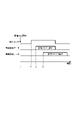
図3は、画像メモリ205に格納される表面画像データ及び裏面画像データの取得タイミングの説明図である。時刻t0で原稿101の搬送を開始した後、時刻t1で検知センサ113が原稿101の先端を検知する。CPU203は、時刻t1に基づき原稿101が読取位置Aに到達する前の時刻t2を、例えば、原稿101が搬送される搬送速度に基づいて判定する。そして、CPU203は、時刻t2から所定期間、読取部109Aが出力する表面画像データを画像メモリ205に格納する。なお、当該所定期間は、少なくとも原稿101の後端が読取位置Aを抜けるまでの期間とする。この所定期間は、原稿101の搬送速度に基づき求められる。同様に、CPU203は、時刻t1に基づき原稿101が読取位置Bに到達する前の時刻t3を判定する。そして、CPU203は、時刻t3から所定期間、読取部109Bが出力する裏面画像データを画像メモリ205に格納する。なお、CPU203は、時刻t2において読取部109Aによる読み取りを開始して表面画像データを画像メモリ205に格納してもよいし、時刻t2よりも前から読取を行っている読取部109Aの表面画像データを画像メモリ205に格納してもよい。また、CPU203は、時刻t3において読取部109Bによる読み取りを開始して裏面画像データを画像メモリ205に格納してもよいし、時刻t3よりも前から読取を行っている読取部109Bの裏面画像データを画像メモリ205に格納してもよい。なお、以下の説明において、表面画像データが示す画像を表面画像とも呼び、裏面画像データが示す画像を裏面画像とも呼ぶものとする。
FIG. 3 is an explanatory diagram of acquisition timing of the front side image data and the back side image data stored in the
図2に示すように、シェーディング回路204Aから出力される表面画像データはエッジ検出部206にも入力される。また、画像反転回路210から出力される裏面画像データもエッジ検出部206に入力される。以下では、表面画像データの補正について説明するが、裏面画像データも同様にして補正される。
As shown in FIG. 2, the surface image data output from the
図4は、エッジ検出部206による処理の説明図である。図4は、時刻t2から所定の時間毎に読取部109Aによって得られた主走査方向における画素の列を主走査方向に直交する副走査方向に結合させた画像を示している。上述した様に、エッジ検出部206に入力される表面画像データは、搬送方向における原稿101の先端が読取位置Aに到達する前の時刻t2からのものである。つまり、読取部109Aによる画像の読み取りが開始されると、まずガイド板116が読み取られる。その後、原稿101が搬送されるにつれて原稿101の画像が読み取られる。つまり、エッジ検出部206に入力される表面画像データは、ガイド板116を示す画像データ及び原稿101の先端側の辺を示す画像データを含む。
FIG. 4 is an explanatory diagram of the processing by the
エッジ検出部206は、主走査方向に3画素、かつ、副走査方向に3画素の計9画素分の領域を1つのブロックとして表面画像データの2値化処理を実行する。以下では、読取部109A及び109Bの主走査方向の画素数を7488個とし、読取部109A及び109Bは、前記所定期間の間に12000回、読み取りを行うものとする。そして、主走査方向の画素位置をn(0≦n≦7487)と表記し、副走査方向の画素位置をm(0≦m≦11999)と表記する。また、1つのブロックの9つの画素の輝度値をpx(x=0~8)とし、その最大値及び最小値をpmax及びpminと表記する。
The
図4(A)のA点のように9画素全てがガイド板116(白色)の箇所では9画素全てが白画素となるためpmaxとpminの差は小さい値となる。一方、図4(A)のB点のようにガイド板116(白色)と原稿101の先端側の辺の影(グレー)との境目では、9画素の中に白画素とグレー画素が混在するため、pmaxとpminの差が大きくなる。従って、pmaxとpminの差が所定の閾値pthよりも大きい場合、ブロック内に原稿101の先端側の辺によって生じた影の候補となる画素(以下、候補画素と称する)があると判定することができる。本実施形態では、ブロック内のpmaxとpminの差が所定の閾値pthよりも大きいと、当該ブロックの中央画素(座標(n、m)の画素)を候補画素と判定する。エッジ検出部206は、この判定処理を、n=0、n=7487、m=0、m=11999を除く各n、mに対して行う。なお、本実施形態におけるx軸及びy軸における1目盛りは、隣接する2つの画素のそれぞれの中央の位置の間の距離に対応する。
At the point A in FIG. 4A where all nine pixels are the guide plate 116 (white), all the nine pixels are white pixels, so the difference between pmax and pmin is small. On the other hand, at the boundary between the guide plate 116 (white) and the shadow (gray) of the edge of the leading edge of the
図4(A)は、8ビット(輝度レベル:0~255)の画像データが示す画像であり、図4(B)は、図4(A)の画像の画像データを閾値pth=14で2値化した画像データが示す画像である。図4(B)の白色は、上記処理により原稿101の先端側の辺によって生じた影の候補と判定された画素を示している。図4(B)に示す複数の候補画素の内、副走査方向において最も先端側にある主走査方向の候補画素の列(副走査方向において最初に候補画素と判定された主走査方向の画素列)が、原稿101の先端側の辺によって生じた影であると判定される。
FIG. 4A shows an image represented by 8-bit (luminance level: 0 to 255) image data, and FIG. 4B shows the image data of the image in FIG. This is an image represented by valued image data. White in FIG. 4B indicates pixels determined as shadow candidates caused by the edge of the leading edge of the
図2に示すように、エッジ検出部206が出力する2値化データは、原稿情報判定部207に入力される。
As shown in FIG. 2 , the binarized data output from the
原稿情報判定部207は、2値化データに基づき表面の原稿情報(以下、表面原稿情報)を判定する。また、原稿情報判定部207は、原稿101の先端側の2つの角部の主走査方向における距離(幅)Wを判定する。そして、原稿情報判定部207は、表面原稿情報と、幅WをCPU203に出力する。ここで、表面原稿情報は、表面画像における原稿の位置及び角度を含む情報である。なお、原稿101の位置とは、原稿101の第1位置の表面画像内における位置(x1,y1)である。本実施形態では、この第1位置を、原稿101によって生じる影の先端側の2つの角部の内の一方(図5の左側)の角部とする。また、原稿101の角度とは、表面画像内における原稿101の所定の辺の表面画像の基準方向に対する角度である。本実施形態では、当該所定の辺を原稿101の先端側の辺によって生じる影とし、基準方向を主走査方向(所定方向)とする。つまり、原稿101の角度は、図8のθ1である。なお、搬送方向において原稿101の先端側の辺によって生じる影が位置(x1,y1)よりも上流側に傾く場合、角度θ1は負の値をとり、原稿101の先端側の辺によって生じる影が位置(x1,y1)よりも下流側に傾く場合、角度θ1は正の値をとるものとする。
A document
図5は、ガラス108に紙粉などのゴミが付着した状態で読み取られた原稿の画像の2値化後の画像を示す図である。図6は、2値化した画像の主走査画素の副走査方向における座標を示す図である。なお、図6において、原稿の先端側の辺の位置(原稿先端座標)は-300であり、図6においては、原稿の傾き角度は0度である。
FIG. 5 is a diagram showing an image after binarization of an image of an original read with dust such as paper dust adhering to the
図6に示したゴミ付着条件で最小二乗法により、回帰直線を求めると式(1)となる。
y=0.0091x―298 (1)
式(1)から以下の式(2)、(3)を用いて原稿の傾き角度θ1を求めると、0.52°となる。
arctan(0.0091)=0.009 (2)
θ1=0.009×(180/Π)=0.52° (3)
A regression line obtained by the method of least squares under the dust adhesion conditions shown in FIG.
y=0.0091x−298 (1)
If the inclination angle θ1 of the document is obtained from the equation (1) using the following equations (2) and (3), it is 0.52°.
arctan (0.0091) = 0.009 (2)
θ1=0.009×(180/Π)=0.52° (3)
このように、ゴミスジが生じた画像に基づいて傾き角度を算出すると、誤差が出てしまう。そこで、本実施形態では、以下の構成が用いられる。 In this way, if the tilt angle is calculated based on an image with dust streaks, an error occurs. Therefore, the following configuration is used in this embodiment.
ゴミ検知部210は、公知の技術により、入力された画像データに基づいて、主走査方向においてゴミがある位置を検知し、ゴミの位置を示す情報を原稿情報判定部207に出力する。公知の技術とは、例えば、輝度値が所定値より小さい状態が副走査方向に所定長さ連続する位置を主操作方向におけるゴミの位置とする方法である。
原稿情報判定部207は、ゴミの位置に対応する画素の画像データを、隣接するゴミのない画素の画像データに置き換える。図7(a)は、ゴミの位置に対応する領域を拡大した図である。図7(b)は、ゴミの位置に対応する領域における各画素の原稿先端側の副走査位置を示した図である。例えば、主走査方向における位置496の画素の副走査位置は300を示す。
The document
図7(b)においては、主走査位置が500から507までの画素が、ゴミがある位置に対応する画素(異常画素)と検知されるので、原稿情報判定部207は、異常画素に隣接するゴミの無い画素(正常画素)の副走査位置に置き換えを行う。図7(c)は、図7(a)のゴミがある主走査位置500から507までの画素の原稿先端側の副走査位置をゴミの無い画素の副走査位置に置き換えた図を示す。
In FIG. 7B, the pixels whose main scanning positions are from 500 to 507 are detected as pixels (abnormal pixels) corresponding to positions where dust exists. Sub-scanning positions of pixels without dust (normal pixels) are replaced. FIG. 7(c) shows a diagram in which the sub-scanning positions on the front end side of the original for pixels from
図7(c)のようにゴミ影響を除去した状態で最小二乗法により、回帰直線を求めると式(4)となる。
y=―300 (4)
式(4)から角度θ1を求めると、0°となる。
Equation (4) is obtained by obtaining a regression line by the method of least squares with the effect of dust removed as shown in FIG. 7(c).
y=-300 (4)
When the angle θ1 is obtained from the equation (4), it becomes 0°.
CPU203は、表面原稿情報、つまり、位置(x1,y1)及び角度θ1を補正部208に出力する。
The
補正部208は、位置(x1,y1)及び角度θ1に基づき、画像メモリに格納されている表面画像データを読み出してシステムコントローラ151に出力する。具体的には、補正部208は、読出開始位置(x1,y1)を始点にして、位置原稿101の先端側の辺によって生じる影に平行な方向に沿って画像データを読み出す。
Based on the position (x1, y1) and the angle θ1, the
補正部208は、上述のようにして、画像メモリに格納されている表面画像データを原稿の後端側の辺まで読み取る。即ち、補正部208は、読出部として機能する。
As described above, the
図8は、補正部208によって読み出された画像を表す図である。図8に示すように、影に平行な方向に沿って幅Wに対応する量だけ画像データが読み出されることによって、原稿の先端側の辺が主走査方向と平行となる。なお、裏面画像データにも同様の処理が行われる。
FIG. 8 is a diagram showing an image read by the
システムコントローラ151は、補正部208から出力された画像データから印刷すべき画像領域を切り取る。具体的には、例えば、システムコントローラ151は、ユーザが操作部202を用いて設定した記録媒体のサイズに応じて、補正部208から出力された図8に示す画像データの位置(0,0)を基準にして画像データを切り抜く。より具体的には、例えば、図9に示す原稿がA4サイズであって且つユーザが操作部202を用いて設定した記録媒体のサイズがA4サイズである場合、システムコントローラ151は、原稿の右端の影及び後端の影を除く原稿の画像を切り取ることができる。システムコントローラ151は、切り抜かれた画像データに基づいて印刷を行うように画像印刷装置301を制御する。即ち、システムコントローラ151は、外部機器として機能する。なお、外部機器には、画像形成装置100に設けられたシステムコントローラ151だけでなく、スマートフォン、タブレット、PCなども含まれる。
The
図10は、本実施形態による画像読取処理のフローチャートである。図10に示すフローチャートの処理は、コントローラ200によって実行される。
FIG. 10 is a flowchart of image reading processing according to this embodiment. The processing of the flowchart shown in FIG. 10 is executed by the
原稿の読み取りを開始する指示が入力されると、コントローラ200は、S10において、トレイ102上の原稿101の給送及び搬送を開始する。
When an instruction to start reading the document is input, the
コントローラ200は、S11において、検知センサ113が原稿を検知するまで待機する。検知センサ113が原稿を検知すると、コントローラ200は、図3で説明した時刻t2及びt3を判定する。
In S11, the
そして、コントローラ200は、時刻t2であるS12から、表面画像データの画像メモリ205への格納を開始する。なお、S12において、表面画像データのエッジ検出部206への出力も開始される。エッジ検出部206は、原稿の先端側の辺によって生じる影を検出する検出処理を行う。
Then, the
次に、S13において、ゴミ検知部210は、ゴミの影響を受けた異常画素の主走査方向における位置を検知し、検知結果を原稿情報判定部207に出力する。
Next, in S<b>13 , the
そして、S14において、原稿情報判定部207は、S13において入力された情報に基づいて表面原稿情報を判定する。
Then, in S14, the document
S15において、補正部208は、検出された傾き量に基づいて画像メモリ205に格納された表面画像データの読み出しを開始する。
In S15, the
コントローラ200は、S16において、補正部208が画像メモリ205に格納されている表面画像データを出力するまで待機する。
The
補正部208が、補正後の画像データを出力すると、コントローラ200は、S17において、画像を読み取る次の原稿がトレイ102にあるかを判定する。次の原稿がある場合、コントローラ200は、S10から処理を繰り返す。一方、次の原稿が無い場合、コントローラ200は、図8の処理を終了する。
When the
以上のように、本実施形態では、ゴミ検知部210は、公知の技術により、入力された画像データに基づいて、主走査方向においてゴミがある位置を検知し、ゴミの位置を示す情報を原稿情報判定部207に出力する。原稿情報判定部207は、ゴミの位置に対応する画素の画像データを、隣接するゴミのない画素の画像データに置き換え、置き換え後のデータに基づいて、表面原稿情報を決定する。この結果、補正後の画像に生じる傾きを抑制することを抑制できる。
As described above, in the present embodiment, the
102 トレイ
103 ピックアップローラ
104、105 分離ローラ
106 搬送ローラ
107 リードローラ
110 LED
111 イメージセンサ
200 コントローラ
203 CPU
206 エッジ検出部
207 原稿情報判定部
208 補正部
210 ゴミ検知部
102
111
206
Claims (2)
前記積載部に積載された原稿を給送する給送部と、
前記給送部によって給送された原稿を読取位置へと搬送する搬送部と、
光を出射する光源と、
前記読取位置を通過する原稿からの反射光を受光することによって前記原稿の画像を読み取る読取部と、
前記読取部によって読み取られた原稿の画像を表す画像データに基づいて、異常画素を検出する第1検出部と、
前記読取部によって読み取られた原稿の画像を表す画像データに基づいて、前記原稿が搬送される搬送方向における前記原稿の先端側の辺を検出する第2検出部と、
前記検出部によって検出された前記原稿の先端側の辺を表す画像データと、前記第1検出部によって検出された異常画素の、前記搬送方向に直交する所定方向における位置と、に基づいて、に基づいて、前記所定方向に対する前記原稿の先端側の辺の傾き角度に対応する傾き量を決定する決定手段と、
前記決定手段によって決定された傾き量に基づいて前記画像データに対して回転補正を行う補正手段と、
を有することを特徴とする画像読取装置。 a stacking unit on which documents are stacked;
a feeding unit that feeds the originals stacked on the stacking unit;
a conveying unit that conveys the document fed by the feeding unit to a reading position;
a light source that emits light;
a reading unit for reading an image of the document by receiving reflected light from the document passing through the reading position;
a first detection unit that detects an abnormal pixel based on image data representing an image of a document read by the reading unit;
a second detection unit that detects a leading edge side of the document in a transport direction in which the document is transported, based on image data representing an image of the document read by the reading unit;
based on the image data representing the edge of the leading edge of the document detected by the detection unit and the position of the abnormal pixel detected by the first detection unit in a predetermined direction orthogonal to the conveying direction; determination means for determining a tilt amount corresponding to the tilt angle of the leading edge side of the document with respect to the predetermined direction based on the
correction means for performing rotation correction on the image data based on the tilt amount determined by the determination means;
An image reading device comprising:
前記画像読取装置によって読み取られた画像に基づいて、記録媒体に画像を形成する画像形成部と、
を有することを特徴とする画像形成装置。 an image reading device according to claim 1;
an image forming unit that forms an image on a recording medium based on the image read by the image reading device;
An image forming apparatus comprising:
Priority Applications (1)
| Application Number | Priority Date | Filing Date | Title |
|---|---|---|---|
| JP2021098475A JP2022190238A (en) | 2021-06-14 | 2021-06-14 | Image reading device and image forming apparatus |
Applications Claiming Priority (1)
| Application Number | Priority Date | Filing Date | Title |
|---|---|---|---|
| JP2021098475A JP2022190238A (en) | 2021-06-14 | 2021-06-14 | Image reading device and image forming apparatus |
Publications (1)
| Publication Number | Publication Date |
|---|---|
| JP2022190238A true JP2022190238A (en) | 2022-12-26 |
Family
ID=84601919
Family Applications (1)
| Application Number | Title | Priority Date | Filing Date |
|---|---|---|---|
| JP2021098475A Pending JP2022190238A (en) | 2021-06-14 | 2021-06-14 | Image reading device and image forming apparatus |
Country Status (1)
| Country | Link |
|---|---|
| JP (1) | JP2022190238A (en) |
-
2021
- 2021-06-14 JP JP2021098475A patent/JP2022190238A/en active Pending
Similar Documents
| Publication | Publication Date | Title |
|---|---|---|
| CN110086950B (en) | Image reading apparatus, image forming apparatus, and density correction method | |
| US10999470B2 (en) | Image reading apparatus with a reference roller having flat planar surfaces and an arcuate surface | |
| JP2021044697A (en) | Image forming apparatus | |
| JP2013070163A (en) | Image reading device, image forming device, and image reading program | |
| JP2021190900A (en) | Image reading device | |
| JP7056312B2 (en) | Image formation system, quality determination method, and computer program | |
| US11330127B2 (en) | Image reading apparatus and image forming apparatus | |
| US11258920B2 (en) | Image diagnostic device, failure diagnostic apparatus, and diagnostic method | |
| JP2022190238A (en) | Image reading device and image forming apparatus | |
| JP7433865B2 (en) | Image reading device and image forming device | |
| JP4580718B2 (en) | Image reading apparatus and shading correction method | |
| JP2022186167A (en) | Image reading device and image forming apparatus | |
| JP2022125767A (en) | Image reading device and image forming apparatus | |
| JP7215213B2 (en) | inspection equipment | |
| JP2022115729A (en) | Image reading device and image forming apparatus | |
| JP2022021120A (en) | Image reading device and image forming apparatus | |
| JP7081296B2 (en) | Inspection device, image reader, image forming device, calculation method and program | |
| US20210084188A1 (en) | Image forming apparatus and control method by the same | |
| JP2024049726A (en) | Image forming device | |
| JP2007019854A (en) | Image processing apparatus and image processing method | |
| JP2023162478A (en) | Image reading apparatus and image forming apparatus | |
| JP2021087178A (en) | Image reading device | |
| US20240114095A1 (en) | Image forming apparatus | |
| JP2008148067A (en) | Image processor, control method therefor, image forming apparatus, and program | |
| US11422496B2 (en) | Image forming apparatus |
Legal Events
| Date | Code | Title | Description |
|---|---|---|---|
| RD01 | Notification of change of attorney |
Free format text: JAPANESE INTERMEDIATE CODE: A7421 Effective date: 20231213 |