JP2022166313A - Personalized coronary stent - Google Patents
Personalized coronary stent Download PDFInfo
- Publication number
- JP2022166313A JP2022166313A JP2022134599A JP2022134599A JP2022166313A JP 2022166313 A JP2022166313 A JP 2022166313A JP 2022134599 A JP2022134599 A JP 2022134599A JP 2022134599 A JP2022134599 A JP 2022134599A JP 2022166313 A JP2022166313 A JP 2022166313A
- Authority
- JP
- Japan
- Prior art keywords
- stent
- mandrel
- shape
- sleeve
- establishing
- Prior art date
- Legal status (The legal status is an assumption and is not a legal conclusion. Google has not performed a legal analysis and makes no representation as to the accuracy of the status listed.)
- Granted
Links
Images

Classifications
-
- A—HUMAN NECESSITIES
- A61—MEDICAL OR VETERINARY SCIENCE; HYGIENE
- A61F—FILTERS IMPLANTABLE INTO BLOOD VESSELS; PROSTHESES; DEVICES PROVIDING PATENCY TO, OR PREVENTING COLLAPSING OF, TUBULAR STRUCTURES OF THE BODY, e.g. STENTS; ORTHOPAEDIC, NURSING OR CONTRACEPTIVE DEVICES; FOMENTATION; TREATMENT OR PROTECTION OF EYES OR EARS; BANDAGES, DRESSINGS OR ABSORBENT PADS; FIRST-AID KITS
- A61F2/00—Filters implantable into blood vessels; Prostheses, i.e. artificial substitutes or replacements for parts of the body; Appliances for connecting them with the body; Devices providing patency to, or preventing collapsing of, tubular structures of the body, e.g. stents
- A61F2/82—Devices providing patency to, or preventing collapsing of, tubular structures of the body, e.g. stents
- A61F2/86—Stents in a form characterised by the wire-like elements; Stents in the form characterised by a net-like or mesh-like structure
- A61F2/90—Stents in a form characterised by the wire-like elements; Stents in the form characterised by a net-like or mesh-like structure characterised by a net-like or mesh-like structure
- A61F2/91—Stents in a form characterised by the wire-like elements; Stents in the form characterised by a net-like or mesh-like structure characterised by a net-like or mesh-like structure made from perforated sheets or tubes, e.g. perforated by laser cuts or etched holes
- A61F2/915—Stents in a form characterised by the wire-like elements; Stents in the form characterised by a net-like or mesh-like structure characterised by a net-like or mesh-like structure made from perforated sheets or tubes, e.g. perforated by laser cuts or etched holes with bands having a meander structure, adjacent bands being connected to each other
-
- A—HUMAN NECESSITIES
- A61—MEDICAL OR VETERINARY SCIENCE; HYGIENE
- A61B—DIAGNOSIS; SURGERY; IDENTIFICATION
- A61B34/00—Computer-aided surgery; Manipulators or robots specially adapted for use in surgery
- A61B34/10—Computer-aided planning, simulation or modelling of surgical operations
-
- A—HUMAN NECESSITIES
- A61—MEDICAL OR VETERINARY SCIENCE; HYGIENE
- A61F—FILTERS IMPLANTABLE INTO BLOOD VESSELS; PROSTHESES; DEVICES PROVIDING PATENCY TO, OR PREVENTING COLLAPSING OF, TUBULAR STRUCTURES OF THE BODY, e.g. STENTS; ORTHOPAEDIC, NURSING OR CONTRACEPTIVE DEVICES; FOMENTATION; TREATMENT OR PROTECTION OF EYES OR EARS; BANDAGES, DRESSINGS OR ABSORBENT PADS; FIRST-AID KITS
- A61F2/00—Filters implantable into blood vessels; Prostheses, i.e. artificial substitutes or replacements for parts of the body; Appliances for connecting them with the body; Devices providing patency to, or preventing collapsing of, tubular structures of the body, e.g. stents
- A61F2/82—Devices providing patency to, or preventing collapsing of, tubular structures of the body, e.g. stents
- A61F2/844—Devices providing patency to, or preventing collapsing of, tubular structures of the body, e.g. stents folded prior to deployment
-
- A—HUMAN NECESSITIES
- A61—MEDICAL OR VETERINARY SCIENCE; HYGIENE
- A61B—DIAGNOSIS; SURGERY; IDENTIFICATION
- A61B34/00—Computer-aided surgery; Manipulators or robots specially adapted for use in surgery
- A61B34/10—Computer-aided planning, simulation or modelling of surgical operations
- A61B2034/101—Computer-aided simulation of surgical operations
- A61B2034/102—Modelling of surgical devices, implants or prosthesis
- A61B2034/104—Modelling the effect of the tool, e.g. the effect of an implanted prosthesis or for predicting the effect of ablation or burring
-
- A—HUMAN NECESSITIES
- A61—MEDICAL OR VETERINARY SCIENCE; HYGIENE
- A61B—DIAGNOSIS; SURGERY; IDENTIFICATION
- A61B34/00—Computer-aided surgery; Manipulators or robots specially adapted for use in surgery
- A61B34/10—Computer-aided planning, simulation or modelling of surgical operations
- A61B2034/101—Computer-aided simulation of surgical operations
- A61B2034/105—Modelling of the patient, e.g. for ligaments or bones
-
- A—HUMAN NECESSITIES
- A61—MEDICAL OR VETERINARY SCIENCE; HYGIENE
- A61B—DIAGNOSIS; SURGERY; IDENTIFICATION
- A61B34/00—Computer-aided surgery; Manipulators or robots specially adapted for use in surgery
- A61B34/10—Computer-aided planning, simulation or modelling of surgical operations
- A61B2034/108—Computer aided selection or customisation of medical implants or cutting guides
-
- A—HUMAN NECESSITIES
- A61—MEDICAL OR VETERINARY SCIENCE; HYGIENE
- A61B—DIAGNOSIS; SURGERY; IDENTIFICATION
- A61B34/00—Computer-aided surgery; Manipulators or robots specially adapted for use in surgery
- A61B34/20—Surgical navigation systems; Devices for tracking or guiding surgical instruments, e.g. for frameless stereotaxis
- A61B2034/2046—Tracking techniques
- A61B2034/2048—Tracking techniques using an accelerometer or inertia sensor
-
- A—HUMAN NECESSITIES
- A61—MEDICAL OR VETERINARY SCIENCE; HYGIENE
- A61B—DIAGNOSIS; SURGERY; IDENTIFICATION
- A61B90/00—Instruments, implements or accessories specially adapted for surgery or diagnosis and not covered by any of the groups A61B1/00 - A61B50/00, e.g. for luxation treatment or for protecting wound edges
- A61B90/36—Image-producing devices or illumination devices not otherwise provided for
- A61B90/37—Surgical systems with images on a monitor during operation
- A61B2090/373—Surgical systems with images on a monitor during operation using light, e.g. by using optical scanners
- A61B2090/3735—Optical coherence tomography [OCT]
-
- A—HUMAN NECESSITIES
- A61—MEDICAL OR VETERINARY SCIENCE; HYGIENE
- A61B—DIAGNOSIS; SURGERY; IDENTIFICATION
- A61B90/00—Instruments, implements or accessories specially adapted for surgery or diagnosis and not covered by any of the groups A61B1/00 - A61B50/00, e.g. for luxation treatment or for protecting wound edges
- A61B90/39—Markers, e.g. radio-opaque or breast lesions markers
- A61B2090/3966—Radiopaque markers visible in an X-ray image
-
- A—HUMAN NECESSITIES
- A61—MEDICAL OR VETERINARY SCIENCE; HYGIENE
- A61F—FILTERS IMPLANTABLE INTO BLOOD VESSELS; PROSTHESES; DEVICES PROVIDING PATENCY TO, OR PREVENTING COLLAPSING OF, TUBULAR STRUCTURES OF THE BODY, e.g. STENTS; ORTHOPAEDIC, NURSING OR CONTRACEPTIVE DEVICES; FOMENTATION; TREATMENT OR PROTECTION OF EYES OR EARS; BANDAGES, DRESSINGS OR ABSORBENT PADS; FIRST-AID KITS
- A61F2/00—Filters implantable into blood vessels; Prostheses, i.e. artificial substitutes or replacements for parts of the body; Appliances for connecting them with the body; Devices providing patency to, or preventing collapsing of, tubular structures of the body, e.g. stents
- A61F2/82—Devices providing patency to, or preventing collapsing of, tubular structures of the body, e.g. stents
- A61F2/86—Stents in a form characterised by the wire-like elements; Stents in the form characterised by a net-like or mesh-like structure
- A61F2/90—Stents in a form characterised by the wire-like elements; Stents in the form characterised by a net-like or mesh-like structure characterised by a net-like or mesh-like structure
- A61F2/91—Stents in a form characterised by the wire-like elements; Stents in the form characterised by a net-like or mesh-like structure characterised by a net-like or mesh-like structure made from perforated sheets or tubes, e.g. perforated by laser cuts or etched holes
- A61F2/915—Stents in a form characterised by the wire-like elements; Stents in the form characterised by a net-like or mesh-like structure characterised by a net-like or mesh-like structure made from perforated sheets or tubes, e.g. perforated by laser cuts or etched holes with bands having a meander structure, adjacent bands being connected to each other
- A61F2002/9155—Adjacent bands being connected to each other
- A61F2002/91575—Adjacent bands being connected to each other connected peak to trough
-
- A—HUMAN NECESSITIES
- A61—MEDICAL OR VETERINARY SCIENCE; HYGIENE
- A61F—FILTERS IMPLANTABLE INTO BLOOD VESSELS; PROSTHESES; DEVICES PROVIDING PATENCY TO, OR PREVENTING COLLAPSING OF, TUBULAR STRUCTURES OF THE BODY, e.g. STENTS; ORTHOPAEDIC, NURSING OR CONTRACEPTIVE DEVICES; FOMENTATION; TREATMENT OR PROTECTION OF EYES OR EARS; BANDAGES, DRESSINGS OR ABSORBENT PADS; FIRST-AID KITS
- A61F2/00—Filters implantable into blood vessels; Prostheses, i.e. artificial substitutes or replacements for parts of the body; Appliances for connecting them with the body; Devices providing patency to, or preventing collapsing of, tubular structures of the body, e.g. stents
- A61F2/95—Instruments specially adapted for placement or removal of stents or stent-grafts
- A61F2/958—Inflatable balloons for placing stents or stent-grafts
- A61F2002/9583—Means for holding the stent on the balloon, e.g. using protrusions, adhesives or an outer sleeve
-
- A—HUMAN NECESSITIES
- A61—MEDICAL OR VETERINARY SCIENCE; HYGIENE
- A61F—FILTERS IMPLANTABLE INTO BLOOD VESSELS; PROSTHESES; DEVICES PROVIDING PATENCY TO, OR PREVENTING COLLAPSING OF, TUBULAR STRUCTURES OF THE BODY, e.g. STENTS; ORTHOPAEDIC, NURSING OR CONTRACEPTIVE DEVICES; FOMENTATION; TREATMENT OR PROTECTION OF EYES OR EARS; BANDAGES, DRESSINGS OR ABSORBENT PADS; FIRST-AID KITS
- A61F2240/00—Manufacturing or designing of prostheses classified in groups A61F2/00 - A61F2/26 or A61F2/82 or A61F9/00 or A61F11/00 or subgroups thereof
- A61F2240/001—Designing or manufacturing processes
- A61F2240/002—Designing or making customized prostheses
Landscapes
- Health & Medical Sciences (AREA)
- Engineering & Computer Science (AREA)
- Biomedical Technology (AREA)
- Life Sciences & Earth Sciences (AREA)
- Animal Behavior & Ethology (AREA)
- General Health & Medical Sciences (AREA)
- Heart & Thoracic Surgery (AREA)
- Veterinary Medicine (AREA)
- Public Health (AREA)
- Surgery (AREA)
- Oral & Maxillofacial Surgery (AREA)
- Cardiology (AREA)
- Transplantation (AREA)
- Vascular Medicine (AREA)
- Nuclear Medicine, Radiotherapy & Molecular Imaging (AREA)
- Molecular Biology (AREA)
- Medical Informatics (AREA)
- Physics & Mathematics (AREA)
- Optics & Photonics (AREA)
- Robotics (AREA)
- Media Introduction/Drainage Providing Device (AREA)
- Prostheses (AREA)
Abstract
Description
本発明は、医療技術に関し、より詳細には介入心臓学に関する。 The present invention relates to medical technology, and more particularly to interventional cardiology.
心血管疾患は、先進国における最大の健康問題の1つである。より深刻な状態の1つが冠状動脈疾患(CAD)であり、これは通常、冠状動脈の内側の滑らかな弾性のある内膜(lining)の一部が、カルシウム沈着、脂肪沈着、および異常な炎症細胞により硬くなり、硬化し、腫大して、プラークおよびアテローム性動脈硬化と呼ばれるものの形成につながる。このプラークは、酸素を含んだ血液の心筋への正常な供給に対する障害(狭窄として知られている)を生成し、それにより胸痛(狭心症)を引き起こすことがあり、最終的には心停止につながる恐れがある。 Cardiovascular disease is one of the greatest health problems in developed countries. One of the more serious conditions is coronary artery disease (CAD), in which a portion of the smooth, elastic lining inside the coronary arteries is usually damaged by calcium deposits, fatty deposits, and abnormal inflammation. The cells harden, harden, and swell, leading to the formation of plaque and what is called atherosclerosis. This plaque creates an obstruction to the normal supply of oxygenated blood to the heart muscle (known as a stenosis), which can cause chest pain (angina pectoris) and ultimately cardiac arrest. may lead to
介入心臓学の分野は、CADなどの構造的心疾患のカテーテルによる治療を専門的に扱う心臓学の一部門である。1つの介入心臓学手順は、経皮冠動脈インターベンション(PCI)として知られている。PCIの1つのモードでは、足の付け根か腕のいずれかの主要な全身動脈にカテーテルが挿入され、大動脈の起始部にある冠状動脈枝の入口部に向かって操作される。このカテーテルは、(ジャドキンス・カテーテルとして知られている)細いチューブの形をとり、それを通して血流に放射線不透過性染料を送達することができ、蛍光透視法と呼ばれる特殊なタイプのX線を使用して冠状動脈の可視化を可能にする(血管造影図として知られている)。冠状動脈を撮像するための他の技術(たとえば、血管内超音波法)を用いることもできる。狭まり(狭窄)が十分に深刻だと判断された場合、一般的な治療法は、ステントを挿入して動脈をその元の(非狭窄)直径に回復させることである。ステントを配置するために、最初のカテーテルに別のカテーテルを通し、次いでさらに奥へ冠状動脈が狭まっている場所まで進める。先端が定位置にくると、周りにステントがクリンプされているバルーンを膨らませる。バルーンの先端がプラークを圧迫し、ステントを拡張する。プラークが圧迫され、ステントが定位置にくると、バルーンをしぼめて引き抜く。ステントは、動脈を開いた状態に保持しながらその中に残る。 The field of interventional cardiology is the branch of cardiology that specializes in catheter-based treatment of structural heart disease, such as CAD. One interventional cardiology procedure is known as percutaneous coronary intervention (PCI). In one mode of PCI, a catheter is inserted into a major systemic artery, either in the groin or arm, and steered toward the ostium of the coronary branch at the origin of the aorta. This catheter takes the form of a thin tube (known as a Judkins catheter) through which a radiopaque dye can be delivered into the bloodstream, allowing a special type of X-ray called fluoroscopy. to allow visualization of the coronary arteries (known as an angiogram). Other techniques for imaging the coronary arteries (eg, intravascular ultrasound) can also be used. If the narrowing (stenosis) is deemed severe enough, a common treatment is to insert a stent to restore the artery to its original (non-stenotic) diameter. To deploy the stent, another catheter is threaded through the first catheter and then advanced further to where the coronary artery is narrowed. Once the tip is in place, the balloon around which the stent is crimped is inflated. The tip of the balloon compresses the plaque and expands the stent. Once the plaque is compressed and the stent is in place, the balloon is deflated and withdrawn. The stent remains in the artery, holding it open.
PCIは、概ね有益な患者の転帰をもたらすが、ステント内再狭窄(ISR)またはステント血栓症(ST)などの長期的な合併症が存在し得る。ISRは、組織とプラークがステント壁を通って成長するときに生じる。STは、凝血塊がステントに付着すると生じる。いずれの合併症も、ステントが回復させるはずだった正常な血流を再び妨げることになる。 Although PCI generally provides beneficial patient outcomes, long-term complications such as in-stent restenosis (ISR) or stent thrombosis (ST) can exist. ISR occurs when tissue and plaque grow through the stent wall. ST occurs when a clot attaches to the stent. Either complication re-interrupts the normal blood flow that the stent was supposed to restore.
ステントの材料選択が進歩してきており、それにより、現世代のステントは、薬物溶出性ステント(薬物でコーティングされており、その薬物がゆっくり放出されて細胞増殖を防止し、ISRおよびSTを低減させる)、ならびに生体再吸収性ステント(長期にわたって血流に溶け出すように設計されており、その期間に、非狭窄状態で治癒する機会が動脈に与えられる)を含む。材料選択は、患者の転帰に大きく影響するが、非常に重要な別の特徴は、患者の動脈にステントがどれだけうまく嵌まるかということである。理想的にはステントは、拡張されたときに、内皮(動脈壁の内膜を形成する細胞の層)を傷つけるところまでは壁に押し込まれない「並置された」状態で、動脈壁に接触して残るべきである。この場合内皮は、動脈が治癒するにつれてステントを覆うように成長する薄い層を形成すべきであるが、ISRまたはSTが生じるところまで成長すべきではない。 Material selection for stents has advanced so that current generation stents are drug-eluting stents (coated with a drug that is slowly released to prevent cell proliferation and reduce ISR and ST). ), as well as bioresorbable stents, which are designed to dissolve into the bloodstream over an extended period of time, during which time the artery is given a chance to heal in a non-stenotic state. While material selection greatly affects patient outcome, another very important characteristic is how well the stent fits in the patient's artery. Ideally, the stent, when expanded, contacts the arterial wall in an "apposed" state that does not push against the wall to the point of damaging the endothelium (the layer of cells that forms the inner lining of the arterial wall). should remain. In this case, the endothelium should form a thin layer that grows over the stent as the artery heals, but not to the point where ISR or ST occurs.
現在、ステントは様々な長さおよび直径で製造され、撮像技術、たとえば血管造影図を使用して、狭窄した動脈を検査することにより、適切なサイズが選択される。この手法の1つの問題点は、動脈が先細りになっていたり、何らかの複雑な形状を呈していたりする場合があり、その動脈に対して単なる円筒形の構造は、並置された状態で動脈壁への接触を維持するには適さない場合があることである。したがって、既製のステントの形状と患者特有の形状との違いがかなり大きくなることがあり、その結果、不完全密着および不適切なサイズに起因して合併症を発する。これらの違いは、数十ミクロンから数百ミクロンであるが、現在採用されている技術では、公差のこれより精密な制御を実現することができない。ステントと動脈壁とが接触しないこと(不完全密着)によって、低い壁せん断応力(血流によって動脈壁に生じる摩擦)の複雑なパターンが生じることがあり、その結果、ISRおよびSTにつながり得る細胞増殖がもたらされる。 Stents are currently manufactured in a variety of lengths and diameters, and the appropriate size is selected by examining the stenosed artery using imaging techniques such as an angiogram. One problem with this approach is that the artery may be tapered or have some complex shape, and for that artery a simple cylindrical structure would not fit into the artery wall in apposition. may not be suitable for maintaining contact between Therefore, the difference between the off-the-shelf stent shape and the patient-specific shape can be substantial, resulting in complications due to malapposition and inappropriate size. These differences are tens of microns to hundreds of microns, but the technology currently employed does not allow for more precise control of the tolerances. The lack of contact between the stent and the arterial wall (maladhesion) can result in complex patterns of low wall shear stress (friction caused by blood flow to the arterial wall), which can lead to ISR and ST. Proliferation is brought about.
したがって、上述した問題に対処する技術が必要とされている。 Accordingly, there is a need for techniques that address the problems discussed above.
本発明の原理は、個別化冠状動脈ステントを生成する技術を提供する。 The principles of the present invention provide techniques for producing individualized coronary stents.
第1の態様から見ると、本発明は、ステントを提供する方法であって、血管の実際の形状の三次元(3D)モデルに応答して、血管の非狭窄形状の3Dモデルを生成することと、しぼんだ(collapsed)構成から、非狭窄形状に並置される最終構成に拡張することができるステントのパラメータ記述(parametric description)を確立することであって、パラメータ記述が、ステントの支柱を特徴付けるパラメータを含む、確立することと、しぼんだ構成と最終構成の間での塑性変形中にステント支柱が破損するリスクを含んだ発見的設計(design heuristic)に応答して、パラメータ記述のパラメータを変えることによってステント用の設計を作り出すことと、ステント用の設計に従ってステントを具体化することとを含む方法を提供する。 Viewed from a first aspect, the present invention is a method of providing a stent, comprising generating a non-stenotic 3D model of the vessel in response to a three dimensional (3D) model of the vessel's actual geometry. and establishing a parametric description of a stent that can be expanded from a collapsed configuration to a final configuration apposed to a non-stenotic configuration, the parametric description characterizing the struts of the stent. Varying the parameters of the parametric description in response to a design heuristic that includes establishing and risking stent strut failure during plastic deformation between the collapsed configuration and the final configuration. A method is provided that includes creating a design for a stent by cutting, and shaping a stent according to the design for the stent.
さらなる態様から見ると、本発明は、装置であって、バルーンを受けるための概ね円筒形の中空の膜を有し、膜の外側表面から突出する複数の柱を有するマンドレルであって、柱のうちの少なくとも1つが、柱のうちの少なくとも1つの他の柱とは異なる半径まで突出している、マンドレルと、マンドレルの柱がステントのブリッジに当接することによって、マンドレルに支持されるステントとを備える装置を提供する。 Viewed from a further aspect, the present invention is an apparatus comprising a mandrel having a generally cylindrical hollow membrane for receiving a balloon and having a plurality of posts projecting from the outer surface of the membrane, the mandrel comprising: At least one of the mandrels protrudes to a different radius than at least one of the other posts, and a stent supported on the mandrels by the posts of the mandrel abutting the bridges of the stent. Provide equipment.
さらなる態様から見ると、本発明は、ステントを提供する方法であって、非対称的なしぼんだ構成を有するステントを血管に挿入することと、血管を通って血管の所与のロケーションにある狭窄部に至るようにステントを操作することと、しぼんだ構成から、血管内の所与のロケーションの非対称的な非狭窄形状に対応した非対称的な最終構成に、ステントを拡張することとを含む方法を提供する。 Viewed from a further aspect, the present invention is a method of providing a stent comprising: inserting a stent having an asymmetric collapsed configuration into a blood vessel; and expanding the stent from a collapsed configuration to an asymmetric final configuration corresponding to the asymmetric non-stenotic shape of a given location within the vessel. offer.
さらなる態様から見ると、本発明は、ステントを提供するためのコンピュータ・プログラム製品であって、処理回路によって読取り可能なコンピュータ読取り可能記憶媒体であって、本発明のステップを実施する方法を実施するために処理回路によって実行される命令を記憶するコンピュータ読取り可能記憶媒体を含むコンピュータ・プログラム製品を提供する。 Viewed from a further aspect, the invention is a computer program product for providing a stent and a computer readable storage medium readable by a processing circuit to implement a method for performing the steps of the invention. A computer program product is provided that includes a computer readable storage medium storing instructions to be executed by a processing circuit to perform the processing.
さらなる態様から見ると、本発明は、コンピュータ読取り可能媒体に記憶され、デジタル・コンピュータの内部メモリにロード可能なコンピュータ・プログラムであって、前記プログラムがコンピュータ上で走らされたときに本発明のステップを実施するためのソフトウェア・コード部分を含むコンピュータ・プログラムを提供する。 Viewed from a further aspect, the invention is a computer program stored on a computer readable medium and loadable into the internal memory of a digital computer, said program performing the steps of the invention when run on the computer. provides a computer program comprising software code portions for performing
一態様では、例示的な方法は、血管の実際の形状の3Dモデルに応答して、血管の非狭窄形状の3Dモデルを生成することとを含む。この方法は、しぼんだ構成から、非狭窄形状に並置される最終構成に拡張されるステントのパラメータ記述を確立することであって、パラメータ記述が、ステントの支柱を特徴付けるパラメータを含む、確立することをさらに含む。この方法は、しぼんだ構成と最終構成の間での塑性変形中にステント支柱が破損するリスクを含んだ発見的設計に応答して、パラメータ記述のパラメータを変えることによって、ステント用の設計を作り出すことをさらに含む。さらに、この方法は、ステント用の設計に従ってステントを具体化することを含む。 In one aspect, an exemplary method includes generating a 3D model of a non-stenotic shape of the vessel in response to a 3D model of the actual shape of the vessel. The method comprises establishing a parametric description of a stent expanded from a collapsed configuration to a final configuration apposed to a non-constricted shape, the parametric description including parameters characterizing struts of the stent. further includes The method produces a design for the stent by varying the parameters of the parametric description in response to a heuristic design that included the risk of stent strut failure during plastic deformation between a collapsed configuration and a final configuration. further including Additionally, the method includes configuring the stent according to the design for the stent.
本発明の別の態様によれば、例示的な装置は、バルーンを受けるための概ね円筒形の中空の膜を有し、その膜の外側表面から突出する複数の柱を有するマンドレルであって、柱のうちの少なくとも1つが、柱のうちの少なくとも1つの他の柱とは異なる半径まで突出しているマンドレルと、マンドレルの柱がステントのブリッジに当接することによって、マンドレルに支持されるステントとを含む。 In accordance with another aspect of the invention, an exemplary apparatus is a mandrel having a generally cylindrical hollow membrane for receiving a balloon and having a plurality of posts projecting from an outer surface of the membrane, comprising: a mandrel in which at least one of the posts protrudes to a different radius than at least one other of the posts; and a stent supported on the mandrel by the posts of the mandrel abutting the bridges of the stent. include.
本発明に別の態様によれば、例示的な方法は、非対称的なしぼんだ構成を有するステントを血管に挿入することと、血管を通って血管の所与のロケーションにある狭窄部に至るようにステントを操作することと、しぼんだ構成から、血管内の所与のロケーションの非対称的な非狭窄形状に対応した非対称的な最終構成に、ステントを拡張することとを含む。 According to another aspect of the invention, an exemplary method includes inserting a stent having an asymmetric collapsed configuration into a blood vessel and moving through the blood vessel to reach a stenosis at a given location in the blood vessel. and expanding the stent from a collapsed configuration to an asymmetric final configuration corresponding to the asymmetric, non-stenotic shape of the given location within the vessel.
本発明の別の態様によれば、非一過性のコンピュータ読取り可能媒体は、コンピュータによって実行されたときに、上で議論した例示的な方法のいずれかを容易にすることをコンピュータに行わせるコンピュータ実行可能命令を具体化する。1つまたは複数の実施形態では、コンピュータ実行可能命令は、ステントを具体化するように3Dプリンタを制御する命令を含む。本発明の別の態様によれば、装置は、コンピュータ実行可能命令を具体化するメモリと、メモリに結合され、上で議論した例示的な方法のいずれかを容易にするようにコンピュータ実行可能命令によって動作する少なくとも1つのプロセッサとを含む。 In accordance with another aspect of the invention, a non-transitory computer-readable medium causes a computer, when executed by a computer, to facilitate any of the exemplary methods discussed above. embody computer-executable instructions; In one or more embodiments, the computer-executable instructions include instructions for controlling a 3D printer to materialize the stent. In accordance with another aspect of the invention, an apparatus includes a memory embodying computer-executable instructions and, coupled to the memory, computer-executable instructions to facilitate any of the exemplary methods discussed above. and at least one processor operating by
本明細書で使用する、行為を「容易にする」ことは、その行為を実施すること、その行為を簡単にすること、その行為の実施を補助すること、またはその行為を実施させることを含む。したがって、限定ではなく例として、1つのプロセッサ上で実行している命令は、その行為を実施させるため、もしくはそれが実施されるのを補助するための適切なデータまたはコマンドを送信することにより、リモート・プロセッサ上で実行している命令によって実施される行為を容易にすることができる。誤解を避けるために、行為の主体(actor)が行為を、その行為を実行すること以外によって容易にする場合、その行為はなお、何らかのエンティティまたはエンティティの組合せによって実施される。 As used herein, "facilitate" an action includes performing the action, facilitating the action, assisting the action to be performed, or causing the action to be performed. . Thus, by way of example and not limitation, an instruction executing on one processor may, by sending appropriate data or commands to cause it to perform its action, or to assist its performance, to It can facilitate actions performed by instructions executing on a remote processor. For the avoidance of doubt, if an action is facilitated by an actor other than by performing that action, that action is still performed by some entity or combination of entities.
本発明もしくはその要素の1つまたは複数の実施形態は、示される方法ステップを実施するためのコンピュータ使用可能なプログラム・コードとともにコンピュータ読取り可能記憶媒体を含むコンピュータ・プログラム製品の形で実装することができる。さらに、本発明もしくはその要素の1つまたは複数の実施形態は、メモリと、メモリに結合され、例示的な方法ステップを実行するように動作する少なくとも1つのプロセッサとを含むシステム(または装置)の形で実装することができる。さらに別の態様では、本発明もしくはその要素の1つまたは複数の実施形態は、本明細書に記載の方法ステップのうちの1つまたは複数を実施するための手段の形で実装することができ、手段は、(i)ハードウェア・モジュール、(ii)コンピュータ読取り可能記憶媒体(もしくは複数のそのような媒体)に記憶され、ハードウェア・プロセッサ上で実装されるソフトウェア・モジュール、または(iii)(i)と(ii)の組合せを含むことができ、(i)~(iii)のうちのいずれかは、本明細書に述べる特定の技術を実装する。 One or more embodiments of the invention or elements thereof may be implemented in the form of a computer program product comprising a computer readable storage medium together with computer usable program code for performing the method steps indicated. can. Further, one or more embodiments of the invention or elements thereof are directed to a system (or apparatus) including a memory and at least one processor coupled to the memory and operable to perform the exemplary method steps. can be implemented in the form In yet another aspect, one or more embodiments of the invention or elements thereof may be embodied in a means for performing one or more of the method steps described herein. , the means are (i) a hardware module, (ii) a software module stored on a computer readable storage medium (or multiple such media) and implemented on a hardware processor, or (iii) A combination of (i) and (ii) may be included, any of (i)-(iii) implementing the particular technique described herein.
本発明の上記その他の特徴および利点は、添付図面に関連して読まれることになるその例示的な実施形態の以下の詳細な説明から明らかになろう。 These and other features and advantages of the present invention will become apparent from the following detailed description of exemplary embodiments thereof, which shall be read in conjunction with the accompanying drawings.
本発明の実施形態を、添付図面を参照しながら単なる例としてここで説明する。 Embodiments of the invention will now be described, by way of example only, with reference to the accompanying drawings.
血管造影図および他の撮像技術に基づき、狭窄状態の血管の詳細な三次元(3D)モデルを構築することが可能である。たとえば、標準的な血管内撮像カテーテルは、放射状にレーザを照射することにより解像度の高い画像が得られる光干渉断層法を使用する。撮像カテーテルに慣性計測装置(「IMU」)を設けることにより、位置情報を得ることが可能になる。この位置情報を使用して、血管内部(すなわち、狭窄血管の内部)の3Dモデルを、画像から作り出すことができる。 Based on angiograms and other imaging techniques, it is possible to build detailed three-dimensional (3D) models of stenosed vessels. For example, standard intravascular imaging catheters use optical coherence tomography, which provides high resolution images by radially illuminating the laser. Equipping the imaging catheter with an inertial measurement unit (“IMU”) allows position information to be obtained. Using this position information, a 3D model of the vessel interior (ie, the interior of a stenosed vessel) can be created from the images.
1つまたは複数の例示的な実施形態によれば、放射線不透過性の位置マーカも担持するカメラ付きのカテーテルを使用して、時間的に変化する3Dモデルが生成される。たとえば、放射線不透過性の位置マーカは、カメラに対して静止したまま維持されるようにカテーテルに取り付けられた一対の楕円フープを含んでもよい。フープは互いに直交して配設され、それぞれのフープ全体が放射線不透過性であることから、血管造影図では完全な楕円をすべての角度から見ることができるが、例外的に楕円のうちの1つの楕円の平面に平行な角度からは見ることができず、その場合には血管造影図で1本の線が見える。カメラ付きのカテーテルは、患者の血管系にガイドワイヤで導入され、カテーテルが血管系を通って対象ロケーションへ導かれる間に、カテーテルからカメラ画像が捕捉され、この対象ロケーションについて3Dモデルが生成される。カテーテルからのカメラ画像に加えて、カテーテルおよびガイドワイヤの血管造影画像も捕捉されて、時間的に変化する参照曲線が定義され、カテーテルの加速度計およびジャイロスコープのデータが記録される。加速度計データとジャイロスコープデータを、カメラ画像および血管造影画像と組み合わせて時間で積分することによって、カテーテルおよび対象ロケーションの時間的に変化する3Dモデル(4Dモデル)が作り出される。本開示は、2017年4月26日出願の米国特許出願第15/498,159号、名称「Intravascular Catheter for Modeling Blood Vessels」、および2017年4月26日出願の米国特許出願第15/498,185号、名称「Intravascular Catheter Including Markers」の開示全体を参照により組み込む。 According to one or more exemplary embodiments, a time-varying 3D model is generated using a camera-equipped catheter that also carries radiopaque position markers. For example, radiopaque position markers may include a pair of elliptical hoops attached to the catheter so that they remain stationary relative to the camera. The hoops are arranged orthogonally to each other, and since the entirety of each hoop is radiopaque, the full ellipse can be seen from all angles on the angiogram, with the exception of one of the ellipses. It cannot be viewed from an angle parallel to the plane of the single ellipse, in which case a single line is visible on the angiogram. A catheter with a camera is introduced over a guidewire into the patient's vasculature, and while the catheter is guided through the vasculature to a location of interest, a camera image is captured from the catheter to generate a 3D model of the location of interest. . In addition to camera images from the catheter, angiographic images of the catheter and guidewire are also captured to define a time-varying reference curve, and catheter accelerometer and gyroscope data are recorded. By integrating the accelerometer and gyroscope data in combination with camera and angiographic images over time, a time-varying 3D model (4D model) of the catheter and target location is created. This disclosure is directed to U.S. patent application Ser. 185, entitled "Intravascular Catheter Including Markers," the entire disclosure of which is incorporated by reference.
特に、先に出願されたこれらの特許出願は、四次元モデルを生成する方法であって、カテーテルが血管を通って対象ロケーションへ導かれるときに、カテーテルおよび血管の画像を捕捉することであって、カテーテルがガイドワイヤに配設されている、捕捉することと、ガイドワイヤの軌道を記述する、時間的に変化する三次元の参照曲線を構築することと、この参照曲線を使用して、動脈の時間的に変化する三次元モデルを構築することとを含む方法を開示している。好ましくは、先に出願されたこれらの特許出願は、ガイドワイヤの軌道を記述する、時間的に変化する三次元の参照曲線を構築することがさらに、完全な一心周期にわたって見ることができるガイドワイヤ、ならびに近位マーカ、遠位先端マーカ、およびレンズ・マーカに対して異なる視野角からの少なくとも2回の血管造影ランを取得することと、少なくとも2回の血管造影ランのそれぞれのフレームを、心周期内の位置にマッピングすることと、少なくともその心周期を含む、少なくとも2回の血管造影ランのうちのフレームのサブセットを選択することと、近位マーカ、遠位先端マーカ、レンズ・マーカ、およびガイドワイヤを、フレームのそのサブセットからセグメント化するステップと、近位マーカ、遠位先端マーカ、レンズ・マーカ、およびガイドワイヤのそれぞれについて、少なくとも2回の血管造影ラン同士間の交点を、ワールド座標系において経時的に計算して、参照曲線を、ワールド座標系におけるレンズ・マーカの時間の関数としての軌道と判定することとを含む方法をさらに開示する。 In particular, these previously filed patent applications are a method of generating a four-dimensional model by capturing images of a catheter and vessel as the catheter is guided through the vessel to a target location. , the catheter is disposed on a guidewire; constructing a time-varying three-dimensional reference curve that describes the trajectory of the guidewire; and constructing a time-varying three-dimensional model of . Advantageously, these earlier-filed patent applications further demonstrate that constructing a time-varying three-dimensional reference curve describing the trajectory of the guidewire also allows the guidewire to be viewed over a complete cardiac cycle. , and at least two angiographic runs from different viewing angles for the proximal marker, the distal tip marker, and the lens marker; mapping to positions within a cycle; selecting a subset of frames of at least two angiography runs that include at least the cardiac cycle; proximal marker, distal tip marker, lens marker, and segmenting the guidewire from that subset of frames; calculating over time in the system to determine the reference curve as the trajectory of the lens marker in the world coordinate system as a function of time.
好ましくは、先に出願されたこれらの特許出願は、方法であって、参照曲線を使用して動脈の時間的に変化する三次元モデルを構築することがさらに、カテーテルの線形加速度および回転加速度を記録している間に、知られている速度で血管内撮像の引き戻しを実施することと、ガイドワイヤの軌道を判定する際に使用された視野角からの少なくとも1回の血管造影ランを、血管内撮像の引き戻し中に取得することと、少なくとも1回の血管造影ランのそれぞれのフレームを、心周期内の位置にマッピングすることと、フレームのそれぞれにおいてカテーテルのレンズ・マーカをセグメント化することと、血管内撮像の引き戻しの複数のステップにおいて、ガイドワイヤの軌道に沿ったレンズ・マーカの、開始位置に対する距離を、血管内撮像の引き戻しの知られている速度を使用して計算することと、フレームのそれぞれにおけるカテーテルのレンズ・マーカの配向を、ワールド座標系に変換することと、レンズ・マーカのワールド座標位置を使用して、カテーテルの線形加速度および回転加速度を、ガイドワイヤの軌道とともに前方に時間で積分することと、それぞれのフレームの複数の断面曲線を得ることと、それぞれの断面曲線を、ガイドワイヤの軌道に沿った対応する点にマッピングすることと、断面曲線をつなげることによって、時間的に変化する3D表面モデルを得ることとを含む、方法をさらに開示する。 Preferably, these earlier-filed patent applications describe a method wherein constructing a time-varying three-dimensional model of an artery using a reference curve further comprises measuring linear and rotational accelerations of the catheter. While recording, perform intravascular imaging pullback at a known speed and at least one angiographic run from the viewing angle used in determining the guidewire trajectory. acquiring during intraimaging pullback; mapping each frame of at least one angiographic run to a position within the cardiac cycle; and segmenting the lens markers of the catheter in each of the frames. , calculating the distance of the lens marker along the trajectory of the guidewire to the starting position in multiple steps of the intravascular imaging pullback using the known speed of the intravascular imaging pullback; Transforming the orientation of the catheter lens markers in each of the frames to the world coordinate system, and using the world coordinate positions of the lens markers to translate the linear and rotational accelerations of the catheter forward along with the trajectory of the guidewire. By integrating over time, obtaining multiple cross-sectional curves for each frame, mapping each cross-sectional curve to a corresponding point along the trajectory of the guidewire, and connecting the cross-sectional curves, the time obtaining a dynamically varying 3D surface model.
さらに、先に出願されたこれらの特許出願は、経皮冠動脈インターベンション(PCI)手順中に四次元(4D)モデルを生成する方法であって、カテーテルが血管を通って対象ロケーションへ導かれるときに、カテーテルおよび血管の画像を捕捉することであって、カテーテルがガイドワイヤに配設され、複数のマーカ、および監視本体を備え、画像が少なくとも2つの異なる視点から捕捉される、捕捉することと、ガイドワイヤおよび少なくとも1つのマーカを画像からセグメント化し、セグメント化したガイドワイヤおよび少なくとも1つのセグメント化したマーカを、三次元(3D)空間に逆投影して、監視本体の動きを定義する時間的に変化する参照曲線を定義することと、カテーテルが対象ロケーションから引き離されるときに、センサの組合せを使用してカテーテルの加速度計およびジャイロスコープのデータを記録することと、加速度計およびジャイロスコープのデータを時間で積分することと、画像における監視本体の線形位置および回転位置を予測することと、予測した監視本体の線形位置および回転位置を使用して、監視本体および血管の4Dモデルを構築することであって、4Dモデルが、血管を表す時間的に変化する表面を含む、構築することとを含む方法を開示している。 Additionally, these previously filed patent applications are methods for generating a four-dimensional (4D) model during a percutaneous coronary intervention (PCI) procedure, wherein the catheter is guided through a vessel to a target location. and capturing images of a catheter and blood vessel, wherein the catheter is disposed on a guidewire and comprises a plurality of markers and a monitoring body, wherein the images are captured from at least two different viewpoints. , segmenting the guidewire and at least one marker from the image, and backprojecting the segmented guidewire and at least one segmented marker into three-dimensional (3D) space to define the movement of the monitoring body temporally recording accelerometer and gyroscope data of the catheter using a combination of sensors as the catheter is pulled away from the location of interest; accelerometer and gyroscope data , predicting the linear and rotational positions of the surveillance body in the image, and using the predicted linear and rotational positions of the surveillance body to construct a 4D model of the surveillance body and the vessel. and constructing a 4D model that includes a time-varying surface representing a blood vessel.
好ましくは、先に出願されたこれらの特許出願は、方法であって、画像を捕捉することが、複数の血管造影図を捕捉することを含む方法をさらに開示している。好ましくは、先に出願されたこれらの特許出願は、方法であって、画像を捕捉することが、単一の心周期にわたって異なる視点を同時に捕捉することを含む方法をさらに開示している。好ましくは、先に出願されたこれらの特許出願は、方法であって、画像を捕捉することが、連続した心周期にわたって、異なる視点を一度に1つ捕捉することを含む方法をさらに開示している。好ましくは、先に出願されたこれらの特許出願は、方法であって、時間的に変化する参照曲線が、監視本体の動きを時空間における一連の座標として定義する方法をさらに開示している。好ましくは、先に出願されたこれらの特許出願は、方法であって、加速度計およびジャイロスコープのデータが、三次元における慣性加速度および回転位置の測定値を含む方法をさらに開示している。好ましくは、先に出願されたこれらの特許出願は、方法であって、加速度計データに蓄積したドリフト誤差を、磁力計データを使用して補正することをさらに含む方法をさらに開示している。 Preferably, these previously filed patent applications further disclose a method wherein capturing the images comprises capturing a plurality of angiograms. Preferably, these previously filed patent applications further disclose a method wherein capturing the images includes simultaneously capturing different viewpoints over a single cardiac cycle. Preferably, these previously filed patent applications further disclose a method wherein capturing the images comprises capturing different viewpoints one at a time over successive cardiac cycles. there is Preferably, these earlier filed patent applications further disclose a method wherein the time-varying reference curve defines the movement of the monitoring body as a series of coordinates in space-time. Preferably, these earlier-filed patent applications further disclose methods wherein the accelerometer and gyroscope data include measurements of inertial acceleration and rotational position in three dimensions. Preferably, these earlier filed patent applications further disclose a method further comprising correcting drift error accumulated in accelerometer data using magnetometer data.
しかし、時間的に変化する3Dモデルを得る正確なモードは異なってもよく、たとえば、時間的に変化する3Dモデルは、MRIまたは超音波によって得られてもよい。したがって、時間的に変化する3Dモデルは任意の方法で得られ、そのモデルを使用して狭窄部が特定され、そのモデルが狭窄領域にわたって平滑化されて、非狭窄形状が作り出されることが推定される。 However, the exact mode of obtaining the time-varying 3D model may differ, for example the time-varying 3D model may be obtained by MRI or ultrasound. Therefore, it is presumed that a time-varying 3D model is obtained by any method, the model is used to identify the stenosis, and the model is smoothed over the stenotic region to create a non-stenotic shape. be.
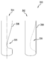
図1に示すように、本発明の例示的な実施形態によれば、コンピュータは、上述した方法のうちの1つによって得られる血管の狭窄形状304の時間的に変化する3Dモデルに応答して、血管の非狭窄形状302の3Dモデルを生成する方法300を実装する。1つまたは複数の実施形態では、コンピュータは、狭窄形状304の時間的に変化する3Dモデルを平均して狭窄部306を特定し、血管壁308を狭窄部306にわたって平滑化することによって非狭窄形状302を生成する。
As shown in FIG. 1, according to an exemplary embodiment of the invention, a computer responds to a time-varying 3D model of a
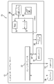
図2は、汎用ステント・テンプレート403および非狭窄形状302の3Dモデルを基にして、個別化冠状動脈ステント402の最終構成を作り出す方法400をブロック図に示す。本発明の実施形態による個別化冠状動脈ステント402は、非狭窄形状302に適切に並置され、それにより既製のステントの使用に関する問題を軽減する。
FIG. 2 illustrates in block diagram form a
個別化冠状動脈ステント402の最終構成を生成する自動的な方法を提供するには、ステントのパラメータ記述が必要である。パラメータ記述は、連続体力学的ソルバ(continuum mechanics solver)を伴う最適化ルーチンに同調させることができるいくつかの主要な形状パラメータを定義する。
To provide an automated method of generating the final configuration of the individualized
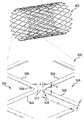
図3は、汎用ステント・テンプレート403の細部500を表しており、この細部には、汎用ステント・テンプレート403の2つの隣り合うアーチ502、504が示される。各アーチ502、504は、1対の支柱506を備え、それらは支柱交点(アーチの頂点508)において互いに接合される。2つのアーチの頂点508は、ブリッジ510によって連結される。この特定の設計のパラメータには、ブリッジ510の長さ(aで示す)および厚さ(bで示す)、ならびにそれぞれの支柱506の厚さ(cで示す)および長さ(dで示す)が含まれる。患者向けの最終構成を決定することの一部分として、ソフトウェアは、ステント402の最終構成が非狭窄形状302に並置され、拡張事象中に故障する可能性が確実に低くなるように、テンプレートのパラメータを修正する。
FIG. 3 depicts a
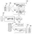
図2を再度参照すると、非狭窄形状302が生成されたら、コンピュータは、発見的設計を使用して汎用ステント・テンプレート403の主要な形状パラメータを調節することによって、個別化冠状動脈ステント402の最終構成を決定する方法400を実装する。404において、コンピュータは、非狭窄形状302の3Dモデルに並置されるように汎用ステント・テンプレート403の頂点508を弛緩することによって、候補構成406を生成する。コンピュータは、汎用ステント・テンプレート403に径方向の慣性力412をかけることによって弛緩を実装し、それにより頂点508が、非狭窄血管形状302に均一に分散される。次に、コンピュータは、留置手順に対する候補構成406の妥当性を検査する方法600(図4に示す)を実装する。
Referring again to FIG. 2, once the
図4は、留置手順に対する候補構成406の妥当性を検査する方法600をフローチャートに示す。1つまたは複数の実施形態では、コンピュータは、候補構成の妥当性を発見的設計により検査する。1つまたは複数の実施形態では、候補構成406の妥当性を検査することは、602において、候補構成406からしぼんだ構成416へのステントの塑性変形(血管に挿入できるようにステントをクリンプすること)の機械的応力/ひずみ解析を、上述した連続体力学的ソルバを使用して容易にすることを含む。1つまたは複数の実施形態では、候補構成の妥当性を検査することは、604において、しぼんだ構成416から候補構成406へ戻るステントの塑性変形(血管内に留置できるようにステントを拡張すること)の機械的応力/ひずみ解析を容易にすることをさらに含む。605においてコンピュータは、機械的応力/ひずみ解析602、604の結果に、発見的設計を適用する。発見的設計は、たとえば、塑性変形の後にステントの破損がないことである。発見的設計が満たされない場合、すなわちコンピュータが、塑性変形中に何らかの破損を特定した場合には、606において、コンピュータは、汎用ステント・テンプレート403の支柱506およびブリッジ510のうちの1つまたは複数について、パラメータa、b、c、dのうちの1つまたは複数を修正することによって、異なるステント支柱厚さ(可変の剛性)を有する修正されたステント・テンプレート418を生成する。608において、コンピュータは、修正されたステント・テンプレート418および非狭窄形状302に基づき、新しい候補構成420を生成する。
FIG. 4 flowcharts a
1つまたは複数の実施形態では、しぼんだ構成416は、修正されたステント・テンプレート418に一致する。他の実施形態では、しぼんだ構成416は、修正されたステント・テンプレート418と同じ半径内に嵌まるように塑性変形(クリンプ)されている候補構成406のバージョンであり、これについては図9を参照しながら以下でさらに説明する。
In one or more embodiments, collapsed
コンピュータは、ブロック602、604、606、608を繰り返して、最終的には候補構成406が発見的設計(たとえば、破損がないこと)を満たし、それに応答して、コンピュータは、610において、妥当な候補構成406をステント402の最終構成として保存するのを容易にする。
The computer repeats
したがって方法400は、汎用ステント「テンプレート」設計403のパラメータ記述のパラメータを変えることによって、3D個別化冠状動脈ステント402用の設計を作り出し、ここでパラメータ記述は、ステント・テンプレートの支柱を特徴付けるパラメータを含む。より具体的には、方法400は、先細り、隆起、および他の非軸対称な特徴などの特徴を含む複雑な動脈形状302の輪郭に、変形されたテンプレートの形状を一致させることができるように、支柱506およびブリッジ510の長さおよび厚さを変形することを含む。ステント・テンプレート403を修正するために、形状は、頂点508の質量中心が3D空間の座標セットを定義し、2つの座標により定義される線形セグメントが、単純化された支柱またはブリッジを定義する単純化された構造とみなされる。次いで、頂点508に対応する点が、支柱506とブリッジ510のトポロジ的な連結性を維持しながら、繰り返し周囲に動かされて、動脈形状302の複雑さに形状を一致させる。変形工程の実施方法は、ステント支柱506の頂点508を定義するその点が(開始点が目標の形状表面302の内側にあるか外側にあるかに応じて)径方向内向きまたは外向きに繰り返し動かされ、表面からのユーザ指定距離(並置公差)内にすべての頂点508が入るまで続けられるというものである。点を動かす方向は、ステント・テンプレート403の中心線か、目標の形状302の中心線かのいずれかから計算することができ、または計算幾何学において一般的な他の技術を使用して計算することができる。図4を参照しながら上述したように、ステント402のしぼんだ構成と最終構成の間での塑性変形中にステント支柱が破損するリスクを表すまたはそれを含む発見的設計に応答して、ステント・テンプレートのパラメータを変更することが繰り返される。
The
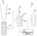
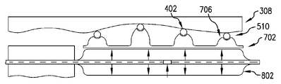
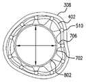
図5は、しぼんだ構成のステント402を支持するようにマンドレル702の形状を確立する方法700をフローチャートに示す。マンドレル702は、マンドレル・テンプレート704、および個別化冠状動脈ステント402の最終構成から作り出される。マンドレル・テンプレート704は、概ね円筒形の本体を有し、その本体はその長さの大部分が、相対的に薄い膜705として形成される。マンドレル・テンプレート704は、その膜705から突出している相対的に剛性の高い複数の柱706、およびその膜705の端部に連結された相対的に剛性の高い案内区分707も含む。1つまたは複数の実施形態では、柱706および案内区分707は、膜705よりも断面が分厚いことによって、剛性を相対的に高くすることができる。案内区分707は、放射線不透過性のマーカ708、たとえばカメラ付きカテーテルに関して上述したものと同様の楕円マーカを含む。このマーカ708は、血管造影図内のマンドレルの位置および配向の一義的な指標を提供するように配置される。
FIG. 5 shows a flowchart of a
マンドレル702は、弛緩形状および伸長形状を有する。弛緩形状では、中空の膜705が弛緩しており、膨らんでいない状態の標準的なバルーン・カテーテルの上に嵌まる。伸長形状では、中空の膜705は、膨らんだ状態の標準的なバルーン・カテーテルの上で伸長する。膜705は相対的に可撓性の高い膜であり、一方柱706は、その基部で膜705に取り付けられた相対的に剛性の高い部材である。マンドレル702は、以下のように決定される半径まで延在する複数の柱706それぞれを有する。まず、710において、マンドレル702および個別化冠状動脈ステント402の同心、同軸の構成のモデル711を確立する。次いで、712において、マンドレル702の伸長形状から、個別化冠状動脈ステント402の最終構成の各ブリッジ510までの径方向距離713を計算する。径方向距離713によって、柱706の高さが得られる。こうして、標準的なバルーン・カテーテルを膨らませることによって実現されるマンドレル膜705の均一な径方向変位を前提として、個別化冠状動脈ステント402をそのしぼんだ構成416から最終構成に拡張するように、柱706の位置および大きさが選択される。
図6は、本発明の例示的な実施形態による、血管壁308内でマンドレル702の柱706上でそのブリッジ510によって支持されている個別化冠状動脈ステント402の最終構成を側方断面図に示す。バルーン・カテーテル802は、マンドレル702内で膨らまされて、マンドレルをその伸長形状で保持した状態で示される。バルーン・カテーテル802がしぼむことが可能になると、マンドレルはその弛緩形状に弾性的に戻り、その一方で個別化冠状動脈ステント402は、その最終構成に塑性変形されて、血管壁308に並置された状態で残る。
FIG. 6 illustrates in side cross-sectional view the final construction of individualized
図7は、個別化冠状動脈ステント402、マンドレル702、バルーン・カテーテル802、および血管壁308を端部断面図に示す。
FIG. 7 shows individualized
1つまたは複数の実施形態では、個別化冠状動脈ステント402は、バルーン・カテーテル802およびマンドレル702にスライドして被せることができるように、その拡張状態(最終構成)で3D印刷され、次いでそれらに塑性的にクリンプされてから配置される。あるいは、個別化冠状動脈ステント402は、マンドレル702の柱706の周りに3D印刷され、次いで柱706にクリンプされる。主にこのために、ステント設計工程には、最終構成からしぼんだ構成への変形、およびしぼんだ構成から最終構成に戻る変形の応力/ひずみ解析が含まれる。
In one or more embodiments, individualized
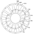
冠状動脈ステント用の標準的なクリンプ・デバイスは、均一な径方向内向きの変位を加えるが、これは個別化冠状動脈ステント402の非対称的な形状には適さないものであろう。したがって、図8を参照すると、個別化冠状動脈ステント402とともに、スリーブ1002が設計され、具体化(たとえば3D印刷)される。このスリーブ1002により、ステントをクリンプするために標準的なクリンプ・デバイスを使用できるようになる。スリーブ1002は、汎用ステント・テンプレートと本質的に同じ、したがって対称な本体1004を有するが、個別化冠状動脈ステントの最終構成における最大直径よりもわずかに大きい直径を有する。スリーブ1002は、内向きに突出した指部1006を含み、これらの指部は、スリーブ1002の残りの部分およびステントと同じ3D印刷可能な材料(たとえばポリ乳酸)の塊である。指部1006は、スリーブ1002のブリッジ1010に印刷され、ステントのブリッジ510と位置合わせされる(in registry with)ように整合されるが、これは、クリンプ工程または拡張工程の間に、ブリッジがいかなる周方向の変位も受けないからである。指部1006の長さは、支持スリーブ1002と、ステントの対応する接触点(ブリッジ510)との間の距離を計算することによって定義される。したがって図8は、スリーブ1002によってマンドレル702の柱706にクリンプされた個別化冠状動脈ステントのしぼんだ構成416を、端部断面図で示している。
A standard crimping device for a coronary stent would apply a uniform radial inward displacement, which would not be suitable for the asymmetric shape of the individualized
図9は、個別化冠状動脈ステント402、マンドレル702、およびスリーブ1002を構築および留置する方法1100を示す。方法1100の1つまたは複数の実装形態によれば、コンピューティング・システム10は、個別化冠状動脈ステント402をその最終構成で具体化するのを容易にする。1つまたは複数の実施形態では、コンピューティング・システム10は、3Dプリンタ1103を制御することによって、個別化冠状動脈ステント402を具体化するのを容易にする。したがって1つまたは複数の実施形態では、1102において、コンピュータは、マンドレル膜705、柱706および、および案内区分707を3D印刷するように3Dプリンタ1103を制御する。マンドレル702の3D印刷には、可撓性が非常に高いが、弾性のある材料(たとえば、伸長可能なUV硬化性エラストマ)が使用される。次いで1104において、コンピュータは、個別化冠状動脈ステント402を3D印刷するように3Dプリンタ1103を制御する。1つまたは複数の実施形態では、個別化冠状動脈ステント402は、ステント402のブリッジ510が柱に位置合わせされるように、マンドレルの柱706の周りに印刷される。配置中に使用されることになるX線システムの参照ビューに応じて、楕円マーカ708は、特定のビューを有するように選択され、これは、個別化冠状動脈ステント402および柱706が、マーカに対してマンドレル膜705上に印刷される角度位置に影響を及ぼす。あるいは、1つまたは複数の実施形態では、個別化冠状動脈ステント402は、マンドレル702とは別々に印刷され、次いでマンドレルに組み付けられる。ステント402を3D印刷するために、塑性変形可能な材料(たとえば、ポリ乳酸)が使用される。
FIG. 9 shows a
1106において、コンピュータは、スリーブ1002およびその指部1006を印刷するように3Dプリンタ1103を制御する。1つまたは複数の実施形態では、スリーブ1002は、指部1006がステント402のブリッジに位置合わせされるように、個別化冠状動脈ステント402の周りに印刷される。あるいは、1つまたは複数の実施形態では、スリーブ1002は、ステント402とは別々に印刷され、次いでステントに組み付けられる。スリーブ1002を3D印刷するために、塑性変形可能な材料(たとえば、ポリ乳酸)が使用される。
At 1106 the computer controls the 3D printer 1103 to print the
1108において、個別化冠状動脈ステント402、マンドレル702、およびスリーブ1002が、バルーン・カテーテル802の周りに装着される。1110において、アセンブリがバルーン・カテーテル802にクリンプされる。1111において、スリーブ1002が、たとえばそれを切断することによって除去される。次いで1112において、バルーン・カテーテル802、マンドレル702、および個別化冠状動脈ステント402のクリンプ済みアセンブリが、血管に挿入される。1114において、血管内のアセンブリの位置および配向を確認するために、連続的または周期的な血管造影図を使用して、アセンブリがその留置部位へ案内される。1116において、バルーン・カテーテル802が膨らまされて、個別化冠状動脈ステント402を塑性変形させて血管壁308に並置させる。1118において、バルーン・カテーテル802をしぼませて、カテーテルおよび弾性マンドレル702を血管を通して後退させ、挿入部位から出す。
At 1108 , individualized
時間的に変化する血管のモデルを使用して、ステントの配置を補助することができる。ステントが動脈内に配置されるとき、心臓の動き、したがって冠状動脈の動きに起因して、ステントが動き回ることを想像することができる。したがって、マンドレル上の楕円も動き回ることになり、ステントの配置中に取得される血管造影図においてそれらの見え方が変化する。1つまたは複数の実施形態では、時間的に変化するモデルのスナップショットを使用して非狭窄形状が生成されるが、ステントが正常に配置されたときに、心周期の対応する点に合致する血管造影フレームに放射線不透過性の楕円が特定の形で現れることが、(X線システムについての)参照視野角、またスナップショットが選択されたその心周期の点からわかるように、マンドレルの柱およびステントをマンドレル・テンプレートに印刷することが可能である。さらに、心周期中にバルーン、マンドレル、ステントのアセンブリ全体が動き回るとき、楕円の見え方がどのように変わるかがわかり、これにより、アセンブリの現在どのように位置しているかについてより多くの情報が与えられる。 A time-varying model of the vessel can be used to aid in stent placement. When a stent is placed in an artery, one can imagine it moving around due to the motion of the heart and thus the coronary arteries. Therefore, the ellipses on the mandrel will also move around and change their appearance in the angiograms acquired during stent placement. In one or more embodiments, snapshots of the time-varying model are used to generate a non-stenotic shape that, when the stent is successfully deployed, matches the corresponding point in the cardiac cycle. The mandrel column, as can be seen from the reference viewing angle (for the X-ray system) and the point of the cardiac cycle from which the snapshot was chosen, that the radiopaque ellipse appears in a particular shape in the angiographic frame. and stents can be printed on the mandrel template. Additionally, we can see how the ellipse changes appearance as the entire balloon, mandrel, and stent assembly is moved around during the cardiac cycle, which provides more information about how the assembly is currently positioned. Given.
本発明の技術は、かなり有益な技術的効果を提供することができる。たとえば、1つまたは複数の実施形態は、ステントを内腔壁により良好に並置すること、カスタムのステント設計を研究室内で開発および作製することのうちの1つまたは複数を実現する。 The techniques of the present invention can provide significant beneficial technical effects. For example, one or more embodiments provide one or more of better apposing the stent to the lumen wall, developing and fabricating custom stent designs in the laboratory.
これまでの議論を考えると、大まかに言えば、本発明の一態様による例示的な方法は、血管の実際の形状の3Dモデルに応答して、血管の非狭窄形状の3Dモデルを生成することを含むことが理解される。この方法は、しぼんだ構成から、非狭窄形状に並置される最終構成に拡張されるステントのパラメータ記述を確立することであって、パラメータ記述が、ステントの支柱を特徴付けるパラメータを含む、確立することをさらに含む。この方法は、しぼんだ構成と最終構成の間での塑性変形中にステント支柱が破損するリスクを含んだ発見的設計に応答して、パラメータ記述のパラメータを変えることによって、ステント用の設計を作り出すことをさらに含む。さらに、この方法は、ステント用の設計に従ってステントを具体化することを含む。 Given the discussion above, broadly speaking, an exemplary method according to one aspect of the present invention is to generate a 3D model of a non-stenotic shape of a blood vessel in response to a 3D model of the actual shape of the blood vessel. is understood to include The method comprises establishing a parametric description of a stent expanded from a collapsed configuration to a final configuration apposed to a non-constricted shape, the parametric description including parameters characterizing struts of the stent. further includes The method produces a design for the stent by varying the parameters of the parametric description in response to a heuristic design that included the risk of stent strut failure during plastic deformation between a collapsed configuration and a final configuration. further including Additionally, the method includes configuring the stent according to the design for the stent.
1つまたは複数の実施形態では、方法は、しぼんだ構成のステントを支持するようにマンドレルの形状を確立することと、そのマンドレルの形状に従ってマンドレルを具体化することとをさらに含む。1つまたは複数の実施形態では、マンドレルの形状を確立することは、マンドレルの膜から突出する複数の柱を確立することであって、柱のうちの少なくとも1つが、柱のうちの少なくとも1つの他の柱とは異なる半径まで延在する、確立することを含む。さらに、1つまたは複数の実施形態では、マンドレルの形状を確立することは、しぼんだ構成のステントのブリッジを支持するようにマンドレルの柱を構成することを含む。また、1つまたは複数の実施形態では、マンドレルの形状を確立することは、マンドレルがその伸長形状に拡張されたときに最終構成のステントのブリッジも支持するように、マンドレルの柱を構成することを含む。1つまたは複数の実施形態では、マンドレルを具体化することは、マンドレルを3D印刷することを含み、ステントを具体化することは、ステントのブリッジがマンドレルの柱に位置合わせされるようにマンドレルの周りにステントを3D印刷することを含む。 In one or more embodiments, the method further includes establishing a shape of the mandrel to support the stent in a collapsed configuration, and shaping the mandrel according to the shape of the mandrel. In one or more embodiments, establishing the shape of the mandrel is establishing a plurality of pillars projecting from the membrane of the mandrel, wherein at least one of the pillars is at least one of the pillars. Includes establishing, extending to a different radius than other posts. Further, in one or more embodiments, establishing the shape of the mandrel includes configuring posts of the mandrel to support bridges of the stent in a collapsed configuration. Also, in one or more embodiments, establishing the shape of the mandrel comprises configuring the posts of the mandrel to also support the bridges of the stent in its final configuration when the mandrel is expanded to its elongated shape. including. In one or more embodiments, materializing the mandrel includes 3D printing the mandrel, and materializing the stent includes printing the mandrel such that the bridges of the stent are aligned with the posts of the mandrel. It involves 3D printing a stent around it.
1つまたは複数の実施形態では、ステントを具体化することは、最終構成のステントを3D印刷することを含み、例示的な方法は、最終構成からしぼんだ構成にステントをクリンプするのを容易にするようにスリーブの形状を確立することと、そのスリーブの形状に従って、スリーブを具体化することとをさらに含む。1つまたは複数の実施形態では、スリーブの形状は、概ね円筒形の本体、およびその本体から内向きに突出する柱を含む。特定の実施形態によれば、スリーブの形状を確立することは、ステントのブリッジをその最終構成からそのしぼんだ構成に均一に径方向に圧縮するようにスリーブの柱を構成することを含む。1つまたは複数の実施形態では、スリーブを具体化することは、ステントの周りにスリーブを3D印刷することを含む。 In one or more embodiments, shaping the stent includes 3D printing the stent in a final configuration, and an exemplary method facilitates crimping the stent from the final configuration to a collapsed configuration. establishing a shape of the sleeve so as to do so; and embodying the sleeve according to the shape of the sleeve. In one or more embodiments, the shape of the sleeve includes a generally cylindrical body and a post projecting inwardly from the body. According to certain embodiments, establishing the shape of the sleeve includes configuring the posts of the sleeve to uniformly radially compress the bridges of the stent from its final configuration to its collapsed configuration. In one or more embodiments, embodying the sleeve includes 3D printing the sleeve around the stent.
1つまたは複数の実施形態では、例示的な方法はまた、しぼんだ構成のステントを支持するようにマンドレルの形状を確立することと、そのマンドレルの形状に従ってマンドレルを具体化することと、最終構成のステントをマンドレルの周りに配置することと、最終構成からしぼんだ構成にステントをクリンプするのを容易にするようにスリーブの形状を確立することと、そのスリーブの形状に従ってスリーブを具体化することと、ステントの周りにスリーブを配置することと、スリーブを使用して均一な径方向の力をステントの非対称的なブリッジに分散させて、マンドレルにステントをクリンプすることとを含む。 In one or more embodiments, an exemplary method also includes establishing a shape of a mandrel to support a stent in a collapsed configuration; shaping the mandrel according to the shape of the mandrel; around a mandrel; establishing a shape of the sleeve to facilitate crimping the stent from its final configuration to a collapsed configuration; and shaping the sleeve according to that sleeve shape. placing a sleeve around the stent; and crimping the stent onto the mandrel using the sleeve to distribute a uniform radial force to the asymmetric bridges of the stent.
本発明の別の態様によれば、例示的な装置は、バルーンを受けるための概ね円筒形の中空の膜を有し、その膜の外側表面から突出する複数の柱を有するマンドレルであって、柱のうちの少なくとも1つが、柱のうちの少なくとも1つの他の柱とは異なる半径まで突出している、マンドレルと、マンドレルの柱がステントのブリッジに当接することによって、マンドレルに支持されるステントとを含む。 In accordance with another aspect of the invention, an exemplary apparatus is a mandrel having a generally cylindrical hollow membrane for receiving a balloon and having a plurality of posts projecting from an outer surface of the membrane, comprising: a mandrel wherein at least one of the posts protrudes to a different radius than at least one other of the posts; and a stent supported on the mandrel by the posts of the mandrel abutting the bridges of the stent. including.
1つまたは複数の実施形態では、装置はまた、マンドレル内に挿入されるバルーン・カテーテルを含む。1つまたは複数の実施形態では、装置はまた、ステントを囲むスリーブを含み、スリーブは、マンドレルの指部に対向してステントのブリッジに接触する内向きに突出する指部を有し、その内向きに突出する指部のうちの少なくとも1つは、その内向きに突出する指部のうちの少なくとも1つの他の指部とは異なる半径まで突出している。 In one or more embodiments, the device also includes a balloon catheter inserted within the mandrel. In one or more embodiments, the device also includes a sleeve surrounding the stent, the sleeve having inwardly projecting fingers opposite the fingers of the mandrel and contacting the bridges of the stent; At least one of the inwardly projecting fingers projects to a different radius than at least one other of the inwardly projecting fingers.
1つまたは複数の実施形態では、バルーン・カテーテルはマンドレルに挿入される。 In one or more embodiments, the balloon catheter is inserted into the mandrel.
1つまたは複数の実施形態では、マンドレルは、楕円形の放射線不透過性マーカを含む。 In one or more embodiments, the mandrel includes elliptical radiopaque markers.
本発明の別の態様によれば、例示的な方法は、非対称的なしぼんだ構成を有するステントを血管に挿入することと、血管を通って血管の所与のロケーションにある狭窄部に至るようにステントを操作することと、しぼんだ構成から、血管内の所与のロケーションの非対称的な非狭窄形状に対応した非対称的な最終構成に、ステントを拡張することとを含む。1つまたは複数の実施形態では、方法はまた、ステントの挿入および操作中に、ステントのしぼんだ構成をステントのブリッジにおいて支持するように非対称的な柱を有するマンドレルで、ステントを支持することを含み、ステントを拡張することが、マンドレル内でバルーンを膨らませることを含む。 According to another aspect of the invention, an exemplary method includes inserting a stent having an asymmetric collapsed configuration into a blood vessel and moving the stent through the blood vessel to reach a stenosis at a given location in the blood vessel. and expanding the stent from a collapsed configuration to an asymmetric final configuration corresponding to the asymmetric, non-stenotic shape of the given location within the vessel. In one or more embodiments, the method also includes supporting the stent with a mandrel having asymmetrical posts to support the collapsed configuration of the stent at the bridges of the stent during insertion and manipulation of the stent. and expanding the stent includes inflating a balloon within the mandrel.
本発明の別の態様によれば、コンピュータによって実行されたときに、上で議論した例示的な方法のいずれかを容易にすることをコンピュータに行わせるコンピュータ実行可能命令を、非一過性のコンピュータ読取り可能媒体が具体化する。1つまたは複数の実施形態では、コンピュータ実行可能命令は、ステントを具体化するように3Dプリンタを制御する命令を含む。 In accordance with another aspect of the invention, computer-executable instructions that, when executed by a computer, cause the computer to facilitate any of the exemplary methods discussed above are defined as non-transitory A computer readable medium embodies. In one or more embodiments, the computer-executable instructions include instructions for controlling a 3D printer to materialize the stent.
本発明の別の態様によれば、装置は、コンピュータ実行可能命令を具体化するメモリと、メモリに結合され、上で議論した例示的な方法のいずれかを容易にするようにコンピュータ実行可能命令によって動作する少なくとも1つのプロセッサとを含む。 In accordance with another aspect of the invention, an apparatus includes a memory embodying computer-executable instructions and, coupled to the memory, computer-executable instructions to facilitate any of the exemplary methods discussed above. and at least one processor operating by
本発明もしくはその要素の1つまたは複数の実施形態は、メモリと、メモリに結合され、例示的な方法ステップを実施するように動作する少なくとも1つのプロセッサとを含む装置の形で実装することができる。図10は、本発明の1つもしくは複数の態様、または要素、あるいはその組合せを実装するのに役立つことがあるコンピューティング・システム10であって、本発明の実施形態によるコンピュータ・システムを示すものでもあるコンピューティング・システム10の例示的な実施形態を示す。ここで図10を参照すると、コンピューティング・システム10は、好適なコンピュータ・システムの一例に過ぎず、本明細書に記載の本発明の実施形態の使用または機能の範囲に関していかなる限定をも示唆するものではない。いずれにせよ、コンピューティング・システム10は、上に述べた機能のいずれかを実装し、または実施し、あるいはその両方を行うことができる。
One or more embodiments of the invention or elements thereof may be implemented in the form of an apparatus including a memory and at least one processor coupled to the memory and operable to perform the exemplary method steps. can. FIG. 10 illustrates a
コンピューティング・システム10には、多数の他の汎用または専用のコンピューティング・システム環境または構成とともに動作するコンピュータ・システム/サーバ12が存在する。コンピュータ・システム/サーバ12とともに使用するのに好適であり得るよく知られたコンピューティング・システム、環境、または構成、あるいはそれらの組合せの例は、パーソナル・コンピュータ・システム、サーバ・コンピュータ・システム、シン・クライアント、シック・クライアント、ハンドヘルド型またはラップトップ型のデバイス、マルチプロセッサ・システム、マイクロプロセッサ・ベースのシステム、セット・トップ・ボックス、プログラム可能な消費者向けエレクトロニクス製品、ネットワークPC、ミニコンピュータ・システム、メインフレーム・コンピュータ・システム、および、これらのシステムもしくはデバイスのいずれかを含む分散型クラウド・コンピューティング環境などを含むが、これらに限定されない。
In
コンピュータ・システム/サーバ12は、コンピュータ・システムによって実行されているプログラム・モジュールなど、コンピュータ・システム実行可能命令の一般的な文脈において説明することができる。一般的にプログラム・モジュールは、特定のタスクを実施する、または特定の抽象データ型を実装するルーチン、プログラム、オブジェクト、構成要素、論理、データ構造などを含んでもよい。コンピュータ・システム/サーバ12は、通信ネットワークを介してリンクされたリモート処理デバイスによってタスクが実行される分散型クラウド・コンピューティング環境において実践されてもよい。分散型クラウド・コンピューティング環境では、プログラム・モジュールは、メモリ記憶デバイスを含む、ローカルとリモートの両方のコンピュータ・システム記憶媒体に位置付けられてもよい。
Computer system/
図10に示すように、コンピューティング・システム10のコンピュータ・システム/サーバ12は、汎用コンピューティング・デバイスの形である。コンピュータ・システム/サーバ12の構成要素は、1つもしくは複数のプロセッサまたは処理ユニット16と、システム・メモリ28と、システム・メモリ28を含む様々なシステム構成要素をプロセッサ16に結合するバス18とを含んでもよいが、これらに限定されない。
As shown in FIG. 10, computer system/
バス18は、多様なバス・アーキテクチャのうちのいずれかを使用するメモリバスもしくはメモリコントローラ、ペリフェラル・バス、アクセラレーテッド・グラフィックス・ポート、およびプロセッサもしくはローカル・バスを含め、いくつかのタイプのバス構造のうちのいずれかの1つまたは複数の構造を表す。限定ではなく例として、こうしたアーキテクチャは、業界標準アーキテクチャ(ISA)バス、マイクロ・チャネル・アーキテクチャ(MCA)バス、拡張ISA(EISA)バス、ビデオ・エレクトロニクス・スタンダーズ・アソシエーション(VESA)ローカル・バス、およびペリフェラル・コンポーネント・インターコネクト(PCI)バスを含む。
コンピュータ・システム/サーバ12は、通常、様々なコンピュータ・システム読取り可能媒体を含む。こうした媒体は、コンピュータ・システム/サーバ12によってアクセス可能な任意の利用可能な媒体であってもよく、揮発性媒体と不揮発性媒体の両方、取外し可能な媒体と取外し不可能な媒体の両方を含む。
Computer system/
システム・メモリ28は、ランダム・アクセス・メモリ(RAM)30、またはキャッシュ・メモリ32、あるいはその両方など、揮発性メモリの形のコンピュータ・システム読取り可能媒体を含むことができる。コンピュータ・システム/サーバ12はさらに、他の取外し可能/取外し不可能な、揮発性/不揮発性のコンピュータ・システム記憶媒体を含んでもよい。単なる例として、記憶システム34は、取外し不可能な不揮発性の磁気媒体(図示していないが、通常は「ハード・ドライブ」と呼ぶ)からの読取りおよびそれへの書込みを行うために提供することができる。図示していないが、取外し可能な不揮発性の磁気ディスク(たとえば「フロッピー(R)・ディスク」)からの読取りおよびそれへの書込みを行うための磁気ディスク・ドライブ、およびCD-ROM、DVD-ROM、または他の光学媒体などの取外し可能な不揮発性の光ディスクからの読取りまたはそれへの書込みを行うための光ディスク・ドライブを提供することができる。こうした事例では、それぞれが、1つまたは複数のデータ媒体インターフェースによってバス18に接続されてもよい。以下でさらに示し説明するように、メモリ28は、本発明の実施形態の機能を実施するように構成されたプログラム・モジュールのセット(たとえばその少なくとも1つ)を有する少なくとも1つのプログラム製品を含んでもよい。
The
限定ではなく例として、オペレーティング・システム、1つまたは複数のアプリケーション・プログラム、他のプログラム・モジュール、およびプログラム・データのみならず、プログラム・モジュール42のセット(少なくとも1つ)を有するプログラム/ユーティリティ40も、メモリ28に記憶されてもよい。それぞれのオペレーティング・システム、1つもしくは複数のアプリケーション・プログラム、他のプログラム・モジュール、およびプログラム・データ、またはそれらの何らかの組合せは、ネットワーク化環境の実装形態を含んでもよい。プログラム・モジュール42は、本明細書に記載の本発明の実施形態の機能、または方法、あるいはその両方を概ね実施する。
By way of example and not limitation, program/
コンピュータ・システム/サーバ12は、キーボード、ポインティング・デバイス、ディスプレイ24などの1つもしくは複数の外部デバイス14、ユーザがコンピュータ・システム/サーバ12と対話できるようにする1つもしくは複数のデバイス、または、コンピュータ・システム/サーバ12が1つもしくは複数の他のコンピューティング・デバイスと通信できるようにする任意のデバイス(たとえば、ネットワーク・カード、モデムなど)、あるいはそれらの組合せとも通信してもよい。こうした通信は、入力/出力(I/O)インターフェース22を介して行うことができる。さらに、コンピュータ・システム/サーバ12は、ネットワーク・アダプタ20を介して、ローカル・エリア・ネットワーク(LAN)、汎用広域ネットワーク(WAN)、またはパブリック・ネットワーク(たとえば、インターネット)、あるいはそれらの組合せなどの1つまたは複数のネットワークと通信することができる。示されるように、ネットワーク・アダプタ20は、バス18を介して、コンピュータ・システム/サーバ12の他の構成要素と通信する。図示していないが、他のハードウェア構成要素、またはソフトウェア構成要素、あるいはその両方が、コンピュータ・システム/サーバ12と併用されてもよいことを理解すべきである。例は、マイクロ・コード、デバイス・ドライブ、冗長処理ユニット、外部ディスク・ドライブ・アレイ、RAIDシステム、テープ・ドライブ、およびデータ・アーカイブ記憶システムなどを含むが、これらに限定されない。
Computer system/
したがって、1つまたは複数の実施形態は、汎用コンピュータまたはワークステーションで走るソフトウェアを利用することができる。図10を参照すると、こうした実装形態は、たとえばプロセッサ16、メモリ28、ならびにディスプレイ24、およびキーボードまたはポインティング・デバイスなどの外部デバイス14への入力/出力インターフェース22を使用してもよい。本明細書で使用される「プロセッサ」という用語は、たとえばCPU(中央処理装置)、または他の形態の処理回路、あるいはその両方を含むものなどの任意の処理デバイスを含むことが意図される。さらに、「プロセッサ」という用語は、2つ以上の個々のプロセッサを指してもよい。「メモリ」という用語は、たとえばRAM(ランダム・アクセス・メモリ)30、ROM(リード・オンリ・メモリ)、固定メモリ・デバイス(たとえばハード・ドライブ34)、取外し可能なメモリ・デバイス(たとえばディスケット)、およびフラッシュ・メモリなど、プロセッサまたはCPUに関連付けられたメモリを含むことが意図される。さらに、本明細書で使用される「入力/出力インターフェース」という句は、たとえば、処理ユニットにデータを入力するための1つまたは複数の機構(たとえばマウス)、および処理ユニットに関連付けられた結果を提供するための1つまたは複数の機構(たとえばプリンタ)に対するインターフェースを想定することが意図される。プロセッサ16、メモリ28、および入力/出力インターフェース22は、たとえばデータ処理ユニット12の一部分としてのバス18を介して相互接続することができる。たとえばバス18を介した好適な相互接続は、コンピュータ・ネットワークとインターフェースをとるために提供することができるネットワーク・カードなどのネットワーク・インターフェース20、および好適な媒体とインターフェースをとるために提供することができるディスケットまたはCD-ROMドライブなどの媒体インターフェースにも提供することができる。
Accordingly, one or more embodiments may utilize software running on a general purpose computer or workstation. Referring to FIG. 10, such implementations may use, for example,
したがって、本明細書に記載の本発明の方法を実施するための命令またはコードを含むコンピュータ・ソフトウェアは、関連付けられたメモリ・デバイス(たとえばROM、固定のもしくは取外し可能なメモリ)のうちの1つまたは複数に記憶され、利用される準備が整ったときに、部分的にまたは全体的に(たとえばRAMに)ロードされ、CPUによって実装されてもよい。こうしたソフトウェアは、ファームウェア、常駐ソフトウェア、およびマイクロ・コードなどを含んでもよいが、これらに限定されない。 Accordingly, computer software containing instructions or code for implementing the inventive methods described herein can be stored in one of the associated memory devices (eg, ROM, fixed or removable memory). or may be stored in multiples, loaded partially or wholly (eg, into RAM), and implemented by the CPU when ready for use. Such software may include, but is not limited to, firmware, resident software, microcode, and the like.
プログラム・コードを記憶する、または実行する、あるいはその両方を行うのに適したデータ処理システムは、メモリ要素28に直接結合された、またはシステム・バス18を通して間接的にそれに結合された少なくとも1つのプロセッサ16を含む。メモリ要素は、プログラム・コードの実際の実装中に用いられるローカル・メモリ、大容量記憶装置、および実装中に大容量記憶装置からコードを読み出さなくてはならない回数を減らすために、少なくとも一部のプログラム・コードの一時的な記憶を実現するキャッシュ・メモリ32を含むことができる。
A data processing system suitable for storing and/or executing program code includes at least one memory element coupled directly to
入力/出力すなわちI/Oデバイス(キーボード、ディスプレイ、およびポインティング・デバイスなどを含むが、これらに限定されない)は、システムに直接結合することができ、または介在するI/Oコントローラを介してそれに結合することができる。 Input/output or I/O devices (including but not limited to keyboards, displays, pointing devices, etc.) can be coupled to the system either directly or coupled thereto through intervening I/O controllers. can do.
データ処理システムが、介在するプライベート・ネットワークまたはパブリック・ネットワークを介して、他のデータ処理システム、またはリモート・プリンタ、または記憶デバイスに結合されるのを可能にするために、ネットワーク・アダプタ20はシステムにも結合されてよい。モデム、ケーブル・モデム、およびイーサネット(R)・カードは、現在利用可能なタイプのネットワーク・アダプタのうちのごく一部に過ぎない。
特許請求の範囲を含め本明細書で使用するとき、「サーバ」は、サーバ・プログラムを走らせる物理的なデータ処理システム(たとえば、図10に示されるシステム12)を含む。こうした物理的なサーバは、ディスプレイおよびキーボードを含んでも含まなくてもよいことが理解されよう。
As used herein, including in the claims, "server" includes a physical data processing system (eg,
本明細書に記載の方法のいずれかは、コンピュータ読取り可能記憶媒体上に具体化される別個のソフトウェア・モジュールを備えるシステムを提供するさらなるステップを含むことができ、そのモジュールは、たとえば、ブロック図に示す、または本明細書に記載の、あるいはその両方の適切な要素のうちのいずれかまたはすべてを含むことができ、限定ではなく例として、説明したモジュール/ブロック、またはサブモジュール/サブブロックあるいはその両方のうちのいずれか1つ、一部、または全部であることが留意されよう。次いでこの方法ステップは、16などの1つまたは複数のハードウェア・プロセッサを実行している上述したシステムの別個のソフトウェア・モジュール、またはサブモジュール、あるいはその両方を使用して、実施することができる。さらに、別個のソフトウェア・モジュールを有するシステムを提供することを含めて、コンピュータ・プログラム製品は、本明細書に記載の1つまたは複数の方法ステップを実行するように実装されるように適合されたコードを有するコンピュータ読取り可能記憶媒体を含むことができる。 Any of the methods described herein can include the further step of providing the system with separate software modules embodied on a computer-readable storage medium, which modules are represented by, for example, block diagrams and/or described herein, and by way of example and not by way of limitation, the modules/blocks or sub-modules/sub-blocks described or Note that either one, some, or all of both. This method step can then be implemented using separate software modules and/or sub-modules of the system described above running on one or more hardware processors such as 16 . Further, computer program products, including providing systems with separate software modules, adapted to be implemented to perform one or more of the method steps described herein It can include a computer readable storage medium having code.
例示的なシステムおよび製造物の詳細
本発明は、システム、方法、またはコンピュータ・プログラム製品、あるいはそれらの組合せであってもよい。コンピュータ・プログラム製品は、本発明の態様をプロセッサに実施させるためのコンピュータ読取り可能プログラム命令を有するコンピュータ読取り可能な1つ(または複数)の記憶媒体を含んでもよい。
Exemplary System and Articles of Manufacture Details The present invention may be a system, method, or computer program product, or a combination thereof. A computer program product may include one or more computer-readable storage media having computer-readable program instructions for causing a processor to implement aspects of the present invention.
コンピュータ読取り可能記憶媒体は、命令実行デバイスにより使用される命令を保持および記憶することができる有形のデバイスとすることができる。コンピュータ読取り可能記憶媒体は、たとえば、電子記憶デバイス、磁性記憶デバイス、光学記憶デバイス、電磁記憶デバイス、半導体記憶デバイス、またはこれらの任意の適切な組合せであってもよいが、これらに限定されない。コンピュータ読取り可能記憶媒体のさらに具体的な例の、すべてを網羅しているわけではない一覧には、ポータブル・コンピュータ・ディスケット、ハードディスク、ランダム・アクセス・メモリ(RAM)、リード・オンリ・メモリ(ROM)、消去可能でプログラム可能なリード・オンリ・メモリ(EPROMまたはフラッシュ・メモリ)、静的ランダム・アクセス・メモリ(SRAM)、ポータブル・コンパクト・ディスク・リード・オンリ・メモリ(CD-ROM)、デジタル多用途ディスク(DVD)、メモリ・スティック、フロッピー(R)・ディスク、命令が記録されたパンチカードまたは溝の隆起構造などの機械的に符号化されたデバイス、およびこれらの任意の適切な組合せが含まれる。本明細書で使用するコンピュータ読取り可能記憶媒体は、ラジオ波または自由に伝播する他の電磁波、導波路もしくは他の伝送媒体を介して伝播する電磁波(たとえば、光ファイバ・ケーブルを通る光パルス)、またはワイヤを介して伝送される電気信号など、一過性の信号そのものであると解釈されるべきではない。 A computer-readable storage medium may be a tangible device capable of holding and storing instructions for use by an instruction-executing device. A computer-readable storage medium may be, for example, without limitation, an electronic storage device, a magnetic storage device, an optical storage device, an electromagnetic storage device, a semiconductor storage device, or any suitable combination thereof. A non-exhaustive list of more specific examples of computer readable storage media include portable computer diskettes, hard disks, random access memory (RAM), read only memory (ROM), ), Erasable Programmable Read Only Memory (EPROM or Flash Memory), Static Random Access Memory (SRAM), Portable Compact Disc Read Only Memory (CD-ROM), Digital Mechanically encoded devices such as versatile discs (DVDs), memory sticks, floppy discs, punched cards or ridges of grooves on which instructions are recorded, and any suitable combination thereof. included. Computer-readable storage media, as used herein, include radio waves or other freely propagating electromagnetic waves, electromagnetic waves propagating through waveguides or other transmission media (e.g., light pulses through fiber optic cables); Also, it should not be construed as a transient signal per se, such as an electrical signal transmitted over a wire.
本明細書に記載のコンピュータ読取り可能プログラム命令は、コンピュータ読取り可能記憶媒体からそれぞれのコンピューティング/処理デバイスに、あるいはネットワーク、たとえばインターネット、ローカル・エリア・ネットワーク、広域ネットワーク、もしくはワイヤレス・ネットワーク、またはそれらの組合せを介して、外部コンピュータもしくは外部記憶デバイスにダウンロードすることができる。ネットワークは、銅伝送ケーブル、光伝送ファイバ、ワイヤレス伝送、ルータ、ファイヤウォール、スイッチ、ゲートウェイ・コンピュータ、またはエッジ・サーバ、あるいはそれらの組合せを含んでもよい。各コンピューティング/処理デバイスのネットワーク・アダプタ・カードまたはネットワーク・インターフェースは、コンピュータ読取り可能プログラム命令をネットワークから受け取り、それぞれのコンピューティング/処理デバイス内のコンピュータ読取り可能記憶媒体に記憶できるようにそのコンピュータ読取り可能プログラム命令を転送する。 Computer readable program instructions described herein can be transferred from a computer readable storage medium to a respective computing/processing device or over a network, such as the Internet, a local area network, a wide area network, or a wireless network, or both. can be downloaded to an external computer or external storage device via a combination of A network may include copper transmission cables, optical transmission fibers, wireless transmissions, routers, firewalls, switches, gateway computers, or edge servers, or combinations thereof. A network adapter card or network interface in each computing/processing device receives computer-readable program instructions from the network for storage on a computer-readable storage medium within the respective computing/processing device. Transfer possible program instructions.
本発明の動作を実施するためのコンピュータ読取り可能プログラム命令は、アセンブラ命令、命令セット・アーキテクチャ(ISA)命令、機械命令、機械依存命令、マイクロ・コード、ファームウェア命令、状態設定データ、集積回路用の構成データ、あるいはSmalltalk、C++などのオブジェクト指向のプログラミング言語、および「C」プログラミング言語もしくは同様のプログラミング言語などの手続き型プログラミング言語を含む1つもしくは複数のプログラミング言語の任意の組合せで書かれたソース・コードまたはオブジェクト・コードであってもよい。コンピュータ読取り可能プログラム命令は、全部がユーザのコンピュータ上で、一部がユーザのコンピュータ上で、スタンドアローン型ソフトウェア・パッケージとして、一部がユーザのコンピュータ上でかつ一部がリモート・コンピュータ上で、または全部がリモート・コンピュータもしくはサーバ上で実行されてもよい。後者の場合には、リモート・コンピュータは、ローカル・エリア・ネットワーク(LAN)もしくは広域ネットワーク(WAN)を含む任意のタイプのネットワークを介してユーザのコンピュータに接続されてもよく、または(たとえば、インターネット・サービス・プロバイダを使用してインターネットを介して)外部のコンピュータに接続されてもよい。いくつかの実施形態では、たとえばプログラム可能な論理回路、フィールド・プログラマブル・ゲート・アレイ(FPGA)、またはプログラム可能な論理アレイ(PLA)を含む電子回路は、本発明の態様を実施するために、この電子回路を個別化するためのコンピュータ読取り可能プログラム命令の状態情報を利用することによって、コンピュータ読取り可能プログラム命令を実行してもよい。 Computer readable program instructions for implementing the operations of the present invention include assembler instructions, Instruction Set Architecture (ISA) instructions, machine instructions, machine dependent instructions, micro code, firmware instructions, state setting data, configuration data or source written in any combination of one or more programming languages, including object-oriented programming languages such as Smalltalk, C++, and procedural programming languages such as the "C" programming language or similar programming languages; • May be code or object code. The computer readable program instructions may be distributed entirely on the user's computer, partly on the user's computer, as a stand-alone software package, partly on the user's computer and partly on a remote computer, Or it may all run on a remote computer or server. In the latter case, the remote computer may be connected to the user's computer via any type of network, including a local area network (LAN) or wide area network (WAN), or (e.g., the Internet • May be connected to external computers (via the Internet using a service provider). In some embodiments, an electronic circuit including, for example, a programmable logic circuit, field programmable gate array (FPGA), or programmable logic array (PLA) is used to implement aspects of the present invention. The computer readable program instructions may be executed by utilizing the state information of the computer readable program instructions to personalize the electronic circuitry.
本発明の態様は、本発明の実施形態による方法、装置(システム)、およびコンピュータ・プログラム製品のフローチャート図、またはブロック図、あるいはそれらの組合せを参照しながら本明細書で説明される。フローチャート図、またはブロック図、あるいはそれらの組合せの各ブロック、ならびにフローチャート図、またはブロック図、あるいはそれらの組合せにおけるブロックの組合せは、コンピュータ読取り可能プログラム命令によって実装できることが理解されよう。 Aspects of the present invention are described herein with reference to flowchart illustrations and/or block diagrams of methods, apparatus (systems) and computer program products according to embodiments of the invention. It will be understood that each block of the flowchart illustrations, or block diagrams, or combinations thereof, and combinations of blocks in the flowchart illustrations, or block diagrams, or combinations thereof, can be implemented by computer readable program instructions.
これらのコンピュータ読取り可能プログラム命令は、コンピュータまたは他のプログラム可能なデータ処理装置のプロセッサを介して実行される命令が、フローチャート、またはブロック図、あるいはそれらの組合せの1つもしくは複数のブロックに示された機能/行為を実装するための手段を生成するために、汎用コンピュータ、専用コンピュータ、または他のプログラム可能なデータ処理装置のプロセッサに提供されてマシンを作り出すものであってよい。これらのコンピュータ読取り可能プログラム命令はまた、命令が記憶されているコンピュータ読取り可能媒体が、フローチャート、またはブロック図、あるいはそれらの組合せの1つもしくは複数のブロックに示された機能/行為の態様を実装する命令を含む製造物を含むように、コンピュータ読取り可能記憶媒体に記憶され、コンピュータ、プログラム可能なデータ処理装置、または他のデバイス、あるいはこれらの組合せに特定のやり方で機能するよう指示することができるものであってもよい。 These computer readable program instructions are represented in one or more blocks of flowcharts, block diagrams, or combinations thereof as the instructions to be executed via a processor of a computer or other programmable data processing apparatus. It may be provided to a processor of a general purpose computer, special purpose computer, or other programmable data processing apparatus to produce a machine to produce means for implementing the functions/acts described therein. These computer readable program instructions may also be used to indicate that the computer readable medium on which the instructions are stored implements aspects of the functions/acts illustrated in one or more blocks of flowchart illustrations, or block diagrams, or a combination thereof. stored on a computer readable storage medium to include articles of manufacture containing instructions to direct a computer, programmable data processor, or other device, or combination thereof, to function in a particular manner; It may be possible.
コンピュータ読取り可能プログラム命令はまた、コンピュータ、他のプログラム可能な装置、または他のデバイスで実行される命令が、フローチャート、またはブロック図、あるいはそれらの組合せの1つもしくは複数のブロックに示された機能/行為を実装するように、コンピュータ実装プロセスを生成すべく、他のプログラム可能なデータ処理装置、または他のデバイスにロードされて、コンピュータ、他のプログラム可能な装置、または他のデバイス上で一連の動作ステップを実行させるものであってもよい。 Computer readable program instructions may also refer to the functions illustrated in one or more blocks of flowcharts or block diagrams, or combinations thereof, that are executed by a computer, other programmable apparatus, or other device. A sequence of steps on a computer, other programmable apparatus, or other device, loaded into another programmable data processing apparatus, or other device, to produce a computer-implemented process to implement an act. may be executed.
図面のフローチャートおよびブロック図は、本発明の様々な実施形態によるシステム、方法、およびコンピュータ・プログラム製品の考えられる実装形態のアーキテクチャ、機能、および動作を例示する。これに関し、フローチャートまたはブロック図の各ブロックは、モジュール、セグメント、または命令の一部を表してもよく、それらは、特定の論理関数を実装するための1つまたは複数の実行可能な命令を含む。いくつかの代替的な実装形態では、ブロックに示した機能は、図に示した順序とは異なる順序で行われてもよい。たとえば、連続して示された2つのブロックは、実際には、実質的に同時に実行されてもよく、またはこれらのブロックは、関係する機能に応じて場合により逆の順序で実行されてもよい。また、ブロック図、またはフローチャート図、あるいはその両方の各ブロック、およびブロック図、またはフローチャート図、あるいはその両方のブロックの組合せは、特定の機能もしくは行為を実施する、または専用のハードウェアとコンピュータ命令との組合せを実施する専用のハードウェア・ベースのシステムによって実装できることも、留意されよう。 The flowcharts and block diagrams in the drawings illustrate the architecture, functionality, and operation of possible implementations of systems, methods and computer program products according to various embodiments of the present invention. In this regard, each block of a flowchart or block diagram may represent a module, segment, or portion of instructions, which contain one or more executable instructions for implementing a particular logic function. . In some alternative implementations, the functions noted in the blocks may occur out of the order noted in the figures. For example, two blocks shown in succession may, in fact, be executed substantially concurrently or the blocks may possibly be executed in the reverse order depending on the functionality involved. . In addition, each block of the block diagrams and/or flowchart illustrations, and combinations of blocks in the block diagrams and/or flowchart illustrations, perform the specified functions or acts, or represent dedicated hardware and computer instructions. Note that it can also be implemented by a dedicated hardware-based system that implements a combination of
本発明の様々な実施形態の説明は、例示を目的として提示されてきたものであり、網羅的であること、または開示する実施形態に限定されることは意図していない。説明した実施形態の範囲から逸脱することなく、多くの変更形態および変形形態が当業者には明らかであろう。本明細書で使用される用語は、実施形態の原理、実用的な応用例、もしくは市場で見いだされる技術よりも向上した技術を最もうまく説明するため、または本明細書に開示する実施形態を当業者が理解できるようにするために選択された。 The description of various embodiments of the invention has been presented for purposes of illustration and is not intended to be exhaustive or limited to the disclosed embodiments. Many modifications and variations will be apparent to those skilled in the art without departing from the scope of the described embodiments. The terms used herein are used to best describe principles of the embodiments, practical applications, or improvements over technology found on the market, or to describe the embodiments disclosed herein. Chosen to make it understandable for traders.
300,400,600,700 方法
302 非狭窄形状
304 狭窄形状
306 狭窄部
308 血管壁
402 個別化冠状動脈ステント
403 汎用ステント・テンプレート
406 候補構成
416 しぼんだ構成
412 慣性力
418 修正されたステント・テンプレート
420 新しい候補構成
500 細部
502,504 アーチ
506 支柱
508 アーチの頂点
510 ブリッジ
702 マンドレル
704 マンドレル・テンプレート
705 膜
706 柱
707 案内区分
708 マーカ
802 バルーン・カテーテル
1002 スリーブ
1006 指部
1010 ブリッジ
300, 400, 600, 700
Claims (12)
血管の実際の形状の三次元(3D)モデルに応答して、前記血管の非狭窄形状の3Dモデルを生成することと、
ステントのパラメータ記述を確立することであって、前記ステントは、複数の支柱を含み、前記ステントは、血管に挿入できる所定の構成から、前記複数の支柱の間の間隙が広がることにより前記非狭窄形状に並置される最終構成に拡張することができるものであり、前記パラメータ記述が、前記ステントの支柱の寸法を特徴付けるパラメータを含む、前記確立することと、
機械的応力/ひずみ解析により、前記所定の構成と前記最終構成の間での前記ステントの塑性変形中に前記支柱が破損するリスクを有するか否かの判断をすることと、前記リスクを有すると判断されたことに従って前記パラメータ記述のパラメータを変えて前記判断を反復することとを含む発見的設計によって、前記ステント用の設計を作り出すことと、
前記ステント用の前記設計に従って前記ステントを具体化することと
を含む方法。 A method of providing a stent, comprising:
generating a 3D model of the non-stenotic shape of the vessel in response to a three-dimensional (3D) model of the vessel's actual shape;
Establishing a parametric description of a stent, the stent comprising a plurality of struts, the stent being configured to be insertable into a vessel from a predetermined configuration to the non-stenotic structure by widening the gaps between the struts. said establishing, expandable to a final configuration juxtaposed in shape, said parametric description including parameters characterizing dimensions of struts of said stent;
determining whether the struts are at risk of failure during plastic deformation of the stent between the given configuration and the final configuration by mechanical stress/strain analysis; creating a design for the stent by heuristic design comprising varying the parameters of the parametric description according to what has been determined and repeating the determination;
and shaping the stent according to the design for the stent.
前記マンドレルの前記形状に従って前記マンドレルを具体化することと
をさらに含む、請求項1に記載の方法。 establishing a shape of a mandrel that supports the stent of the predetermined configuration;
2. The method of claim 1, further comprising: shaping the mandrel according to the shape of the mandrel.
前記最終構成から前記所定の構成に前記ステントをクリンプするのを容易にするようにスリーブの形状を確立することと、
前記スリーブの前記形状に従って前記スリーブを具体化することと
をさらに含む、請求項1ないし6のいずれかに記載の方法。 Consolidating the stent includes 3D printing the stent in the final configuration, the method comprising:
establishing a sleeve shape to facilitate crimping of the stent from the final configuration to the predetermined configuration;
7. A method according to any preceding claim, further comprising embodying the sleeve according to the shape of the sleeve.
前記マンドレルの前記形状に従って前記マンドレルを具体化することと、
前記ステントをその最終構成で前記マンドレルの周りに配置することと、
前記最終構成から前記所定の構成に前記ステントをクリンプするのを容易にするようにスリーブの形状を確立することと、
前記スリーブの前記形状に従って前記スリーブを具体化することと、
前記ステントの周りに前記スリーブを配置することと、
前記スリーブを使用して前記ステントの非対称的な複数のブリッジに前記スリーブの中心軸を向く均一な大きさの力を分散させることによって、前記マンドレルに前記ステントをクリンプすることと
をさらに含む、請求項1ないし10のいずれかに記載の方法。 establishing a shape of a mandrel that supports the stent of the predetermined configuration;
embodying the mandrel according to the shape of the mandrel;
placing the stent in its final configuration around the mandrel;
establishing a sleeve shape to facilitate crimping of the stent from the final configuration to the predetermined configuration;
embodying the sleeve according to the shape of the sleeve;
placing the sleeve around the stent;
crimping the stent to the mandrel by using the sleeve to distribute a uniform amount of force directed toward the central axis of the sleeve to asymmetrical bridges of the stent. Item 11. The method according to any one of Items 1 to 10.
Applications Claiming Priority (6)
| Application Number | Priority Date | Filing Date | Title |
|---|---|---|---|
| US15/651,197 US10568696B2 (en) | 2017-07-17 | 2017-07-17 | Apparatus for supporting personalized coronary stents |
| US15/651,197 | 2017-07-17 | ||
| US15/859,558 US10568697B2 (en) | 2017-07-17 | 2017-12-31 | Personalized coronary stent methods |
| US15/859,558 | 2017-12-31 | ||
| PCT/IB2018/055253 WO2019016676A1 (en) | 2017-07-17 | 2018-07-16 | Personalized coronary stents |
| JP2020501177A JP7164928B2 (en) | 2017-07-17 | 2018-07-16 | Personalized coronary stent |
Related Parent Applications (1)
| Application Number | Title | Priority Date | Filing Date |
|---|---|---|---|
| JP2020501177A Division JP7164928B2 (en) | 2017-07-17 | 2018-07-16 | Personalized coronary stent |
Publications (2)
| Publication Number | Publication Date |
|---|---|
| JP2022166313A true JP2022166313A (en) | 2022-11-01 |
| JP7854898B2 JP7854898B2 (en) | 2026-05-07 |
Family
ID=
Citations (1)
| Publication number | Priority date | Publication date | Assignee | Title |
|---|---|---|---|---|
| JP2004528858A (en) * | 2000-10-04 | 2004-09-24 | トライバスキュラー・インコーポレイテッド | Virtual Prototyping and Testing for Medical Device Development |
Patent Citations (1)
| Publication number | Priority date | Publication date | Assignee | Title |
|---|---|---|---|---|
| JP2004528858A (en) * | 2000-10-04 | 2004-09-24 | トライバスキュラー・インコーポレイテッド | Virtual Prototyping and Testing for Medical Device Development |
Also Published As
| Publication number | Publication date |
|---|---|
| US10568697B2 (en) | 2020-02-25 |
| US20190015158A1 (en) | 2019-01-17 |
| JP2020528301A (en) | 2020-09-24 |
| WO2019016676A1 (en) | 2019-01-24 |
| GB202001224D0 (en) | 2020-03-11 |
| CN110891529B (en) | 2021-12-03 |
| US11660141B2 (en) | 2023-05-30 |
| US20200163720A1 (en) | 2020-05-28 |
| US10568696B2 (en) | 2020-02-25 |
| DE112018003648B4 (en) | 2024-09-12 |
| GB2579290B (en) | 2022-08-10 |
| JP7164928B2 (en) | 2022-11-02 |
| GB2579290A (en) | 2020-06-17 |
| DE112018003648T5 (en) | 2020-04-23 |
| US20190015159A1 (en) | 2019-01-17 |
| CN110891529A (en) | 2020-03-17 |
Similar Documents
| Publication | Publication Date | Title |
|---|---|---|
| JP7164928B2 (en) | Personalized coronary stent | |
| US11026749B1 (en) | Computational simulation platform for planning of interventional procedures | |
| US12096986B2 (en) | Computational simulation platform for planning of interventional procedures | |
| Larrabide et al. | Fast virtual deployment of self-expandable stents: method and in vitro evaluation for intracranial aneurysmal stenting | |
| US11712301B2 (en) | Intravascular catheter for modeling blood vessels | |
| Cai et al. | VR simulated training for less invasive vascular intervention | |
| JP7854898B2 (en) | Personalized coronary artery stents | |
| KR102806459B1 (en) | Method and device to decide shape of guidewire tip | |
| Zhang | Modeling of soft tissues interacting with fluid (blood or air) using the immersed finite element method | |
| Wu et al. | A Preliminary Real‐Time and Realistic Simulation Environment for Percutaneous Coronary Intervention | |
| Li et al. | A Novel FEM‐Based Numerical Solver for Interactive Catheter Simulation in Virtual Catheterization | |
| JP2025508611A (en) | Methods for simulating device deployment | |
| Valencia et al. | 3D models for vascular lumen segmentation in MRA images and for artery-stenting simulation | |
| EP4623833A1 (en) | Providing feedback during balloon angioplasty | |
| CN121647716A (en) | Determining the position of an implant in a hollow organ | |
| Rahman et al. | Simulation based patient-specific optimal catheter selection for right coronary angiography | |
| HK40077780A (en) | Computational simulation platform for planning of interventional procedures | |
| Cai et al. | Using VR technology for training in minimally invasive vascular surgery | |
| Selvarasu | Investigation of the Hemodynamics of Coronary Arteries-Effect of Stenting | |
| Vayalappil | An Automated Instrumentation System for Expansion and Deployment Characterization of Tubular Stent Devices |
Legal Events
| Date | Code | Title | Description |
|---|---|---|---|
| A621 | Written request for application examination |
Free format text: JAPANESE INTERMEDIATE CODE: A621 Effective date: 20220830 |
|
| A977 | Report on retrieval |
Free format text: JAPANESE INTERMEDIATE CODE: A971007 Effective date: 20230825 |
|
| A131 | Notification of reasons for refusal |
Free format text: JAPANESE INTERMEDIATE CODE: A131 Effective date: 20230919 |
|
| A02 | Decision of refusal |
Free format text: JAPANESE INTERMEDIATE CODE: A02 Effective date: 20240319 |
|
| A521 | Request for written amendment filed |
Free format text: JAPANESE INTERMEDIATE CODE: A523 Effective date: 20240702 |
|
| A911 | Transfer to examiner for re-examination before appeal (zenchi) |
Free format text: JAPANESE INTERMEDIATE CODE: A911 Effective date: 20240724 |
|
| A912 | Re-examination (zenchi) completed and case transferred to appeal board |
Free format text: JAPANESE INTERMEDIATE CODE: A912 Effective date: 20240913 |
|
| A521 | Request for written amendment filed |
Free format text: JAPANESE INTERMEDIATE CODE: A523 Effective date: 20260212 |
|
| RD14 | Notification of resignation of power of sub attorney |
Free format text: JAPANESE INTERMEDIATE CODE: A7434 Effective date: 20260407 |
|
| A61 | First payment of annual fees (during grant procedure) |
Free format text: JAPANESE INTERMEDIATE CODE: A61 Effective date: 20260421 |