JP2022154690A - Connection structure - Google Patents
Connection structure Download PDFInfo
- Publication number
- JP2022154690A JP2022154690A JP2021057843A JP2021057843A JP2022154690A JP 2022154690 A JP2022154690 A JP 2022154690A JP 2021057843 A JP2021057843 A JP 2021057843A JP 2021057843 A JP2021057843 A JP 2021057843A JP 2022154690 A JP2022154690 A JP 2022154690A
- Authority
- JP
- Japan
- Prior art keywords
- wooden
- joint
- concrete
- steel
- steel frame
- Prior art date
- Legal status (The legal status is an assumption and is not a legal conclusion. Google has not performed a legal analysis and makes no representation as to the accuracy of the status listed.)
- Pending
Links
- 229910000831 Steel Inorganic materials 0.000 claims abstract description 150
- 239000010959 steel Substances 0.000 claims abstract description 150
- 239000004567 concrete Substances 0.000 claims abstract description 82
- 239000011162 core material Substances 0.000 claims abstract description 19
- 238000005304 joining Methods 0.000 claims description 15
- 239000000463 material Substances 0.000 claims description 14
- 238000010276 construction Methods 0.000 description 17
- 239000000945 filler Substances 0.000 description 9
- 238000000034 method Methods 0.000 description 9
- 238000005452 bending Methods 0.000 description 8
- 230000003014 reinforcing effect Effects 0.000 description 6
- 238000009415 formwork Methods 0.000 description 5
- 238000010586 diagram Methods 0.000 description 4
- 230000000694 effects Effects 0.000 description 3
- 239000002131 composite material Substances 0.000 description 2
- 239000000203 mixture Substances 0.000 description 2
- 238000012986 modification Methods 0.000 description 2
- 230000004048 modification Effects 0.000 description 2
- 239000007787 solid Substances 0.000 description 2
- 238000003466 welding Methods 0.000 description 2
- 239000002023 wood Substances 0.000 description 2
- 239000000853 adhesive Substances 0.000 description 1
- 230000001070 adhesive effect Effects 0.000 description 1
- 239000011440 grout Substances 0.000 description 1
- 238000003780 insertion Methods 0.000 description 1
- 230000037431 insertion Effects 0.000 description 1
- 230000010354 integration Effects 0.000 description 1
- 238000004519 manufacturing process Methods 0.000 description 1
- 230000002093 peripheral effect Effects 0.000 description 1
- 239000011150 reinforced concrete Substances 0.000 description 1
Images


Abstract
Description
本発明は、木質柱と鉄骨梁との接合構造に関する。 TECHNICAL FIELD The present invention relates to a joint structure between a wooden column and a steel beam.
木質柱と木質梁との接合構造として、ドリフトピンやGIR(Glued In Rod)を用いたものが知られている。しかし、木質柱と木質梁を剛接合とすることは難しく、また接合構造に用いる鋼製金物がめり込むなどして木の局所的な破壊が生じ、保有耐力が小さく変形性能にも乏しいという課題があった。 A structure using a drift pin or a Glued In Rod (GIR) is known as a joint structure between a wooden column and a wooden beam. However, it is difficult to rigidly connect the wooden columns and beams, and the steel hardware used in the joint structure may become embedded in the wood, causing local damage to the wood. there were.
そのため、木質柱と塑性変形能力のある鉄骨梁をコンクリートによる接合部で接合し、合成構造化する工法が提案されている。例えば特許文献1には、木質柱と鉄骨梁との接合部にネジ部と異形鉄筋部とからなる鋼棒を用い、鋼棒のネジ部を上側柱部材および下側柱部材に付着固定して鋼棒の異形鉄筋部をコンクリートによる仕口部材内で鉄筋継手に接合した接合構造が記載されている。
Therefore, a construction method has been proposed in which wooden columns and steel beams with plastic deformation ability are joined at joints with concrete to form a composite structure. For example, in
しかしながら、特許文献1において、木質柱の仕口部材側の端部の仕様は従来と同様となっており、鉄骨梁の耐力に見合った柱端の曲げ耐力の確保が難しい。特に中高層の建物などを対象とする場合、接合部を剛接合とし地震に対する抵抗力を確保するためには、柱端の曲げに対する耐力や剛性の不足が生じる。
However, in
また高層建物の柱部材は高い軸力を支持する必要があるが、特許文献1の方法は軸耐力の確保や木質柱のクリープ変形などの点についても課題を残す。
In addition, the column members of high-rise buildings need to support a high axial force, but the method of
本発明は、前述した問題点に鑑みてなされたものであり、その目的は、柱端の耐力を向上できる木質柱と鉄骨梁の接合構造等を提供することである。 SUMMARY OF THE INVENTION The present invention has been made in view of the problems described above, and an object thereof is to provide a joint structure between a wooden column and a steel frame beam capable of improving the bearing strength of the column end.
前述した目的を達成するための本発明は、木質材料を用いた柱と鉄骨梁の接合構造であって、上下の柱の間にコンクリート製の仕口部が配置され、前記仕口部に鉄骨梁の一部が埋設され、前記柱の少なくとも前記仕口部側の端部において、前記柱の内部に芯材が設けられたことを特徴とする接合構造である。 The present invention for achieving the above-mentioned object is a joint structure of a column and a steel beam using a wooden material, a joint made of concrete is arranged between the upper and lower columns, and a steel frame is attached to the joint. The joint structure is characterized in that a part of the beam is embedded, and a core material is provided inside the pillar at least at the end of the pillar on the side of the joint portion.
本発明では、木質柱と鉄骨梁をコンクリート製の仕口部により接合し、且つ木質柱の内部に芯材を配置することで、木質柱と鉄骨梁とをコンクリート製の仕口部を介して接合する合成構造において、柱端の曲げに対する耐力を向上できる。 In the present invention, a wooden column and a steel beam are joined by a concrete joint, and a core material is arranged inside the wooden column, so that the wooden column and the steel beam are connected through the concrete joint. In the composite structure to be joined, the resistance to bending of the column end can be improved.
例えば前記芯材は鉄骨であり、前記鉄骨が上下の前記柱と前記仕口部に跨るように配置される。
これにより、木質柱と鉄骨梁の接合部の剛性、耐力を向上させることができ、柱端の曲げに対する耐力や剛性、変形性能も高めることができる。
For example, the core material is a steel frame, and the steel frame is arranged so as to straddle the upper and lower columns and the joint portion.
As a result, it is possible to improve the rigidity and yield strength of the joint between the wooden column and the steel beam, and to increase the bending resistance, rigidity, and deformation performance of the column end.
あるいは、前記芯材がコンクリートであり、筒状の前記柱の内部に前記コンクリートが充填されてもよい。
これにより、軸力や曲げに対する柱の耐力を向上させることができる。
Alternatively, the core material may be concrete, and the inside of the tubular column may be filled with the concrete.
As a result, the strength of the column against axial force and bending can be improved.
さらに、前記芯材が鉄骨とコンクリートであり、筒状の前記柱の内部に前記コンクリートが充填され、前記鉄骨が上下の前記柱と前記仕口部に跨るように配置され、前記鉄骨の両端部が上下の前記柱の内部に挿入されてもよい。
芯材として鉄骨とコンクリートをミックスして用いることで、木質柱、鉄骨梁、仕口部を統合一体化したさらに高性能な架構が実現できる。
Further, the core material is a steel frame and concrete, the inside of the cylindrical column is filled with the concrete, the steel frame is arranged so as to straddle the upper and lower columns and the joint portion, and both ends of the steel frame may be inserted inside the upper and lower posts.
By using a mixture of steel frames and concrete as the core material, it is possible to realize a higher-performance frame that integrates wooden columns, steel beams, and joints.
本発明によれば、柱端の耐力を向上できる木質柱と鉄骨梁の接合構造等を提供できる。 Advantageous Effects of Invention According to the present invention, it is possible to provide a joint structure between a wooden column and a steel frame beam that can improve the strength of the column end.
以下、図面に基づいて本発明の好適な実施形態について詳細に説明する。 Preferred embodiments of the present invention will be described in detail below with reference to the drawings.
[第1の実施形態]
(1.接合構造1)
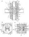
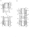
図1は、本発明の第1の実施形態の接合構造1を示す図である。図1(a)は接合構造1の鉛直断面を示す図、図1(b)は木質柱2の水平断面を示す図、図1(c)は仕口部4の水平断面を示す図である。図1(a)は図1(b)、(c)の線A3-A3による断面であり、図1(b)、(c)はそれぞれ図1(a)の線A1-A1、A2-A2による断面である。
[First Embodiment]
(1. Joining structure 1)
FIG. 1 is a diagram showing a
図1に示すように、接合構造1では、上下階の木質柱2と鉄骨梁3との接合部にコンクリート製の仕口部4が配置され、木質柱2と鉄骨梁3が仕口部4を介して接合される。木質柱2は集成材等の木質材料を用いた柱である。鉄骨梁3はH形鋼等の鋼材を用いた梁である。仕口部4は上下階の木質柱2の間に配置される。
As shown in FIG. 1, in the
接合構造1は、仕口部4の他、木質柱2の芯材である鉄骨5と、上下階の木質柱2を一体化させるための棒材6を有する。
The
鉄骨5は、上階の木質柱2、仕口部4、下階の木質柱2に跨るように配置される。鉄骨5は、木質柱2や仕口部4の水平断面の中心部に配置される。鉄骨5にはH形鋼が用いられ、平面における向きは木質柱2、鉄骨梁3、仕口部4に生じる応力等に応じて決定される。なお、H形鋼に代えてその他の形鋼を鉄骨5として用いてもよく、また角形鋼管や円形鋼管などの鋼管を鉄骨5として用いてもよい。
The
上下階の木質柱2の仕口部4側の端面(上階の木質柱2の下端面と下階の木質柱2の上端面)には孔21が設けられる。孔21の平面形状は、鉄骨5の軸方向と直交する断面の形状に対応し、H形となっている。
鉄骨5の軸方向の両端部は、上下階の木質柱2の孔21にそれぞれ挿入され、孔21に充填された充填材23により各木質柱2と一体化される。充填材23には既知のグラウト材や接着材等を用いることができる。鉄骨5の挿入長は、木質柱2の幅の0.5倍以上1倍以下程度とするが、これに限らない。
Both ends of the
棒材6も、上階の木質柱2、仕口部4、下階の木質柱2に跨るように配置される。棒材6は、木質柱2や仕口部4の水平断面の外周部に配置される。棒材6には例えば異形鉄筋を用いることができるが、これに限らない。また、柱端の曲げに対する耐力や剛性を鉄骨5のみで確保できる場合には、棒材6を省略することもできる。
The
上下階の木質柱2の仕口部4側の端面には孔22が設けられる。棒材6の軸方向の両端部は、上下階の木質柱2の孔22にそれぞれ挿入され、孔22に充填された充填材23により各木質柱2と一体化される。
A
鉄骨梁3の軸方向の端部には端板31が設けられ、端板31と鉄骨5のフランジがボルト7等を用いて接合される。ボルト7には高力ボルトを用いることができる。鉄骨梁3の上記端部は仕口部4のコンクリートConに埋設される。
An
(2.接合構造1の構築方法)
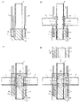
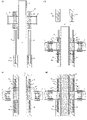
次に、図2等を参照して接合構造1の構築方法について説明する。図2の(a)~(d)はそれぞれ図1(a)と同様の断面を見たものである。
(2. Construction method of joint structure 1)
Next, a method for constructing the
接合構造1を構築するには、まず図2(a)に示すように、下階の木質柱2に鉄骨5、棒材6を工場で一体化したプレキャスト部材を現場に搬入し設置する。
To construct the
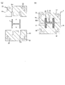
プレキャスト部材は、木質柱2の孔21、22に鉄骨5と棒材6を挿入してこれらの孔21、22に充填材23を充填することで製作できるが、プレキャスト部材の製作方法は特に限定されない。例えば木質柱2と鉄骨5の一体化に関しては、図3(a)に水平断面を示すように、木質柱2を半割した半割部材20、20に孔21の平面の半部に対応する溝201、201を形成しておき、これらの溝201で鉄骨5を挟み込むように半割部材20を組み合わせて半割部材20同士を接着することで、図3(b)に示すように木質柱2を形成することもできる。両半割部材20の溝201により木質柱2の孔21が形成されるので、この孔21に充填材23を充填して木質柱2と鉄骨5を一体化できる。
The precast member can be manufactured by inserting the
図2の説明に戻る。本実施形態では、図2(a)の工程の後、図2(b)に示すように、鉄骨梁3と鉄骨5を前記したように接合する。
Returning to the description of FIG. In this embodiment, after the step of FIG. 2(a), as shown in FIG. 2(b), the
そして、図示しない型枠をセットし、図2(c)に示すように下階の木質柱2の上にコンクリートConを打設して仕口部4を形成する。この時、鉄骨5と棒材6の上端部は仕口部4から上方に突出する。
Then, a formwork (not shown) is set, and concrete Con is placed on the
なお、型枠を下階の木質柱2の外側面に沿って設置することで仕口部4と木質柱2の平面寸法が同一となるが、型枠を下階の木質柱2の上端面の外周部の上に設置した場合には、仕口部4の平面寸法が木質柱2の平面寸法より小さくなる。型枠は工場において下階の木質柱2に予め取り付けておいてもよい。
By placing the formwork along the outer surface of the
仕口部4を形成したら、図2(d)に示すように、上階の木質柱2を仕口部4の上方から建て込む。鉄骨5と棒材6の仕口部4からの突出部分を上階の木質柱2の下端面の孔21、22にそれぞれ挿入し、孔21、孔22に充填材23を充填することで、図1に示す接合構造1が完成する。
After the
以上説明した第1の実施形態の接合構造1では、木質柱2と鉄骨梁3をコンクリート製の仕口部4により接合し、且つ芯材として木質柱2の内部に鉄骨5を配置することで、木質柱2の柱端の曲げに対する耐力や剛性、変形性能が向上し、また木質柱2と鉄骨梁3の接合部の剛性、耐力も向上させることができる。
In the
しかしながら、本発明は上記の実施形態に限定されない。例えば棒材6としてボルトを用い、木質柱2の仕口部4側の端面に予め埋設したラグスクリューボルト(雌ネジ)に当該ボルトを螺合させてもよい。ただし、本実施形態では鉄骨5を用いることにより棒材6の応力も軽減され、施工が簡単なGIRの手法を採用できる。
However, the invention is not limited to the above embodiments. For example, a bolt may be used as the
また、接合構造1の構築方法も図2の例に限らない。例えば、図2(a)の工程の後、図4に示すように、鉄骨梁3と鉄骨5の接合と、上階の木質柱2の建て込みを行ってもよい。鉄骨5と棒材6の上端部は上階の木質柱2の孔21、22に挿入され、この後、孔21、22への充填材23の充填と仕口部4のコンクリートConの打設を行うことで図1に示す接合構造1が完成する。この場合、コンクリートConの打設工程をクリティカルパスから外すことができる。
Also, the construction method of the
また、図5(a)に示すように、上下階の木質柱2として、鉄骨50と棒材60を前記と同様に木質柱2に一体化したプレキャスト部材を用い、下階の木質柱2の上に上階の木質柱2を建て込んだ後、図5(b)に示すように両木質柱2の鉄骨50の端部同士をボルト7と添接板9等を用いて接合してもよい。この後、接合された鉄骨50に対して鉄骨梁3を接合し、仕口部4のコンクリートを打設する。
Further, as shown in FIG. 5(a), as the
各鉄骨50の長さは前記した鉄骨5の半分程度であり、この例では、接合された鉄骨50が上階の木質柱2、仕口部4、下階の木質柱2に跨るように配置される。棒材60の長さは前記した棒材6の半分よりやや長く、上下階の木質柱2の棒材60の端部同士が重ね継手を形成する。
The length of each
その他、図6(a)に示すように、仕口部4、鉄骨5、棒材6を工場または現場で一体に製作したプレキャスト部材を、下階の木質柱2の上方から建て込んでもよい。鉄骨5と棒材6の上端部と下端部は仕口部4から上下に突出しており、図6(b)に示すように鉄骨5と棒材6の下端部を下階の木質柱2の孔21、22に挿入して充填材23の孔21、22への充填を行う。
Alternatively, as shown in FIG. 6(a), a precast member in which the
図6(a)に示すように、鉄骨5の両フランジには、接合部鉄骨梁8(鉄骨梁)の軸方向の端部が溶接等で接合されている。接合部鉄骨梁8には鉄骨梁3と同様の断面を有するH形鋼が用いられる。接合部鉄骨梁8は鉄骨5から外側に延び、外側の端部が仕口部4の外側に突出する。なお、接合部鉄骨梁8の鉄骨5への接合方法は溶接に限らず、ボルト等を用いてもよい。
As shown in FIG. 6A, axial ends of joint portion steel beams 8 (steel beams) are joined to both flanges of the
接合部鉄骨梁8の外側の端部には、図6(b)に示すように鉄骨梁3がボルト7と添接板9等を用いて接合される。この後、上階の木質柱2の建て込みを第1の実施形態と同様に行うことで、仕口部4による木質柱2と鉄骨梁(接合部鉄骨梁8と鉄骨梁3)の接合構造が完成する。この例では仕口部4等をプレキャスト化することで施工が簡単になる。ただし鉄骨梁の接合箇所が増えるので、この点では接合箇所の少ない図1の例の方が好ましい。
As shown in FIG. 6B, the
なお本実施形態では、仕口部4において鉄骨梁が鉄骨5により分断されるが、鉄骨梁を仕口部4において連続させて通し梁としてもよい。図6(c)は図6(a)の接合部鉄骨梁8を通し梁とした接合部鉄骨梁8aの例であり、上下階の木質柱2に挿入される鉄骨5’の仕口部4側の端部に設けた端板51が、ボルト7等で接合部鉄骨梁8aのフランジに接合される。図1の例においても同様のディテールが採用でき、鉄骨梁3を仕口部4内で連続させて通し梁とすることができる。
In this embodiment, the steel frame beam is divided by the
以下、本発明の別の例について、第2、第3の実施形態として説明する。各実施形態はそれまでに説明した実施形態と異なる点について説明し、同様の構成については図等で同じ符号を付すなどして説明を省略する。また、第1の実施形態も含め、各実施形態で説明する構成は必要に応じて組み合わせることができる。 Other examples of the present invention will be described below as second and third embodiments. In each embodiment, points different from the embodiments described so far will be described, and descriptions of similar configurations will be omitted by attaching the same reference numerals in the drawings and the like. In addition, the configurations described in each embodiment, including the first embodiment, can be combined as necessary.
[第2の実施形態]
(1.接合構造1a)
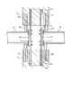
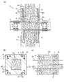
図7は、本発明の第2の実施形態の接合構造1aを示す図である。図7(a)は接合構造1aの鉛直断面を示す図、図7(b)は木質柱2aの水平断面を示す図、図7(c)は仕口部4aの水平断面を示す図である。図7(a)は図7(b)、(c)の線B3-B3による断面であり、図7(b)、(c)はそれぞれ図7(a)の線B1-B1、B2-B2による断面である。
[Second embodiment]
(1. Joining
FIG. 7 is a diagram showing a
接合構造1aでは、上下階の木質柱2aと鉄骨梁(接合部鉄骨梁8aと鉄骨梁3)がコンクリート製の仕口部4aを介して接合される。接合構造1aは、木質柱2aの芯材として鉄骨5の代わりにコンクリートConが用いられる点で第1の実施形態の接合構造1と主に異なる。
In the
木質柱2aは水平断面の中心部を空洞とした筒状の部材であり、内部にコンクリートConが充填される。コンクリートConは木質柱2aの全長に亘って充填され、また上下階の木質柱2aの間においては仕口部4aを形成する。
The
接合構造1aでは、第1の実施形態と同様の棒材6も設けられる。また仕口部4aの内部には、接合部鉄骨梁8aが通し梁として埋設される。接合部鉄骨梁8aは仕口部4aを水平方向に貫通し、その両端部が仕口部4aの外側に突出する。接合部鉄骨梁8aの両端部には、鉄骨梁3がボルト7と添接板9等を用いて接合される。
In the
(2.接合構造1aの構築方法)
次に、図8を参照して接合構造1aの構築方法について説明する。図8の(a)~(d)はそれぞれ図7(a)と同様の断面を見たものである。
(2. Construction method of
Next, a method for constructing the
接合構造1aを構築するには、まず図8(a)に示すように、下階の木質柱2aに棒材6を工場で一体化したプレキャスト部材を現場に搬入し設置する。その後、図8(b)に示すように、下階の木質柱2aの内部にコンクリートConを打設し、接合部鉄骨梁8aを配置する。コンクリートConは下階の木質柱2aの上端面の高さまで打設する。接合部鉄骨梁8aは、下階の木質柱2aに仕込まれた図示しないレベル調整用の治具によって下階の木質柱2aの上端面から浮いた位置に支持される。
To construct the
次に、図示しない型枠をセットし、図8(c)に示すように仕口部4aのコンクリートConを打ち継いで、接合部鉄骨梁8aに鉄骨梁3を接合する。棒材6の上端部は仕口部4aから上方に突出する。
Next, a formwork (not shown) is set, and as shown in FIG. 8(c), the concrete Con of the
続いて、上階の木質柱2aを仕口部4aの上方から建て込み、図8(d)に示すように棒材6の突出部分を孔22に挿入して充填材23を孔22に充填する。この後、上階の木質柱2の内部にコンクリートConを打ち継ぐことで、図7に示す接合構造1aが完成する。
Subsequently, the
なお、コンクリートConと木質柱2aとは、付着のみで一体化してもよいし、木質柱2aの内面にボルト等の突出部を設けてコンクリートConと木質柱2aを機械的に一体化してもよい。またコンクリートConは無筋コンクリートとしているが、コンクリートConに主筋やせん断補強筋を埋設し鉄筋コンクリートとすることもでき、後者の場合、棒材6を省略することも可能である。
The concrete Con and the
以上説明した第2の実施形態でも、木質柱2aと鉄骨梁3をコンクリート製の仕口部4aにより接合し、且つ木質柱2aの芯材としてコンクリートConを充填することで、第1の実施形態と同様の効果が得られる。また本実施形態では、コンクリートConが木質柱2aに充填されることで、木質柱2aの軸力や曲げに対する耐力も向上する。またコンクリートConを芯材に用いることで柱のクリープ変形に対しても有利となり、木質柱2aの断面寸法を合理的に小さくできる。
In the second embodiment described above as well, the
なお、接合構造1aの構築方法は図8の例に限らない。例えば図9(a)に示すように、鉛直方向の貫通孔41を壁部に有する筒状のコンクリート部材4a’を工場等で予め製作し、前記した図8(a)の工程の後、下階の木質柱2aの上方から建て込んでもよい。図9(b)に示すように、下階の木質柱2aの棒材6を貫通孔41に通してコンクリート部材4a’を下階の木質柱2a上に設置し、貫通孔41内に図示しない充填材を充填する。
Note that the construction method of the
図9(a)に示すように、コンクリート部材4a’には接合部鉄骨梁8aが設けられ、その両端部がコンクリート部材4a’を水平方向に貫通してコンクリート部材4a’の外側に突出する。図9(b)に示すように、接合部鉄骨梁8aの両端部には鉄骨梁3が接合され、上階の木質柱2aがコンクリート部材4a’の上方から建て込まれる。
As shown in FIG. 9(a), the
棒材6の上端部はコンクリート部材4a’から上方に突出し、上階の木質柱2aは、下端面の孔22に当該突出部分を挿入して図9(c)に示すようにコンクリート部材4a’上に設置する。孔22には充填材23が充填される。
The upper end of the
以下、図9(a)~(c)の工程を建物の複数階に亘って繰り返した後、図9(d)に示すように複数階分の木質柱2aおよびコンクリート部材4a’の内部にコンクリートConを充填する。コンクリートConの充填にはCFT(Concrete Filled Steel Tube)柱と同様の圧入充填手法を用いることができる。 After repeating the steps of FIGS. 9(a) to (c) over multiple floors of the building, as shown in FIG. Fill with Con. Concrete Con can be filled using the same press-fit filling method as for CFT (Concrete Filled Steel Tube) columns.
この例では、コンクリート部材4a’とその内部のコンクリートConが上下階の木質柱2aの間の仕口部を形成する。なお、複数階分の木質柱2aとコンクリート部材4a’を工場で一体に製作して現場に搬入、設置し、コンクリートConを充填してもよい。
In this example, the
また、コンクリート部材4a’を中空としない(中実の部材とする)場合もあり、この場合は、図8(a)の工程の後、下階の木質柱2aの内部にコンクリートConを打設した上で、中実のコンクリート部材4a’を下階の木質柱2aの上に設置すればよい。以下、図8(c)~(d)と同様の手順で接合構造1aを構築できる。
In some cases, the
[第3の実施形態]
(1.接合構造1b)
図10は、本発明の第3の実施形態に係る接合構造1bを示す図である。図10(a)は接合構造1bの鉛直断面を示す図、図10(b)は木質柱2aの水平断面を示す図、図10(c)は仕口部4bの水平断面を示す図である。図10(a)は図10(b)、(c)の線C3-C3による断面であり、図10(b)、(c)はそれぞれ図10(a)の線C1-C1、C2-C2による断面である。
[Third Embodiment]
(1. Joining
FIG. 10 is a diagram showing a
接合構造1bでも、上下階の木質柱2aと鉄骨梁3とがコンクリート製の仕口部4bを介して接合される。接合構造1bは、木質柱2aの芯材としてコンクリートConと鉄骨5が用いられる点で第1、第2の実施形態の接合構造1、1aと主に異なる。
In the
鉄骨5は、上階の木質柱2a、仕口部4b、下階の木質柱2aに跨るように配置され、その両端部が筒状の木質柱2aの内部に挿入される。コンクリートConは木質柱2aの内部に木質柱2aの全長に亘って充填され、上下階の木質柱2aの間においては仕口部4bを形成する。鉄骨5はコンクリートCon内に埋設される。
The
鉄骨5のフランジには、第1の実施形態と同様、鉄骨梁3の軸方向の端部の端板31がボルト7等で接合される。鉄骨梁3の当該端部は仕口部4bのコンクリートConに埋設される。
An
(2.接合構造1bの構築方法)
次に、図11を参照して接合構造1bの構築方法について説明する。図11の(a)~(d)はそれぞれ図10(a)と同様の断面を見たものである。
(2. Construction method of
Next, a construction method of the
接合構造1bを構築するには、まず図11(a)に示すように、下階の木質柱2aに棒材6を工場で一体化したプレキャスト部材を現場に搬入し設置する。そして、下階の木質柱2aの内部に鉄骨5の下端部を挿入する。本実施形態では、木質柱2aの内面にボルト等の突出部241を予め設けておき、鉄骨5の下端部を突出部241によって下から支持させる。
To construct the
その後、図11(b)に示すように、下階の木質柱2aの内部にコンクリートConを打設し、鉄骨梁3と鉄骨5を接合する。コンクリートConは下階の木質柱2aの上端面の高さまで打設する。
After that, as shown in FIG. 11(b), concrete Con is placed inside the
そして、図示しない型枠をセットし、図11(c)に示すように仕口部4bのコンクリートConを打ち継ぐ。鉄骨5と棒材6の上端部は仕口部4bから上方に突出する。
Then, a formwork (not shown) is set, and the concrete Con of the
続いて、上階の木質柱2aを仕口部4bの上方から建て込み、図11(d)に示すように、鉄骨5の突出部分を木質柱2aの内部に、棒材6の突出部分を孔22にそれぞれ挿入して上階の木質柱2aを仕口部4bの上に設置し、孔22に充填材23を充填する。この後、上階の木質柱2aの内部にコンクリートConを打ち継ぐことで、図10に示す接合構造1bが完成する。
Subsequently, the
以上説明した第3の実施形態でも、木質柱2aと鉄骨梁3をコンクリート製の仕口部4bにより接合し、且つ木質柱2aの芯材として鉄骨5とコンクリートConを設けることで、第1、第2の実施形態と同様の効果が得られる。また芯材として鉄骨5とコンクリートConをミックスして用いることで、木質柱2a、鉄骨梁3、仕口部4bを統合一体化したさらに高性能な架構が実現できる。
In the third embodiment described above as well, the
なお、接合構造1bの構築方法は図11の例に限らない。例えば図12(a)に示すように、鉛直方向の貫通孔41を壁部に有する筒状のコンクリート部材4b’を工場等で予め製作し、このコンクリート部材4b’を下階の木質柱2aの上方から建て込んでもよい。図12(b)に示すように、下階の木質柱2aの棒材6を貫通孔41に通してコンクリート部材4b’を下階の木質柱2a上に設置し、貫通孔41内に図示しない充填材を充填する。
Note that the construction method of the
図12(a)に示すように、コンクリート部材4b’の内部には鉄骨5が設けられており、鉄骨5はコンクリート部材4b’の上下に突出する。さらに、鉄骨5の両フランジには接合部鉄骨梁8が図6(a)の例と同様に接合されており、当該接合部鉄骨梁8の外側の端部がコンクリート部材4b’を貫通してコンクリート部材4b’の外側に突出する。
As shown in FIG. 12(a), a
図12(b)に示すように、接合部鉄骨梁8の外側の端部には鉄骨梁3が接合され、上階の木質柱2aがコンクリート部材4b’の上方から建て込まれる。
As shown in FIG. 12(b), the
棒材6の上端部はコンクリート部材4b’から上方に突出し、上階の木質柱2aは、下端面の孔22に棒材6の突出部分を挿入して図12(c)に示すようにコンクリート部材4b’の上に設置する。孔22には充填材23が充填される。
The upper end of the
以下、図12(a)~(c)の工程を建物の複数階に亘って繰り返した後、図12(d)に示すように複数階分の木質柱2aおよびコンクリート部材4b’の内部にコンクリートConを充填する。コンクリートConの充填には前記の圧入充填手法を用いることができる。コンクリート部材4b’とその内部のコンクリートConは上下階の木質柱2aの間の仕口部を形成する。なお、前記と同様、複数階分の木質柱2aとコンクリート部材4b’を工場で一体に製作して現場に搬入、設置し、コンクリートConを打設してもよい。
12(a) to 12(c) are repeated over a plurality of floors of the building, and then, as shown in FIG. Fill with Con. The aforementioned press-fit filling method can be used for filling the concrete Con. The
以上、添付図面を参照しながら、本発明に係る好適な実施形態について説明したが、本発明はかかる例に限定されない。当業者であれば、本願で開示した技術的思想の範疇内において、各種の変更例又は修正例に想到し得ることは明らかであり、それらについても当然に本発明の技術的範囲に属するものと了解される。 Although the preferred embodiments of the present invention have been described above with reference to the accompanying drawings, the present invention is not limited to such examples. It is obvious that a person skilled in the art can conceive of various modifications or modifications within the scope of the technical ideas disclosed in the present application, and these naturally belong to the technical scope of the present invention. Understood.
1、1a、1b:接合構造
2、2a:木質柱
3:鉄骨梁
4、4a、4b:仕口部
5、5’、50:鉄骨
6、60:棒材
8、8a:接合部鉄骨梁
21、22:孔
1, 1a, 1b:
Claims (4)
上下の柱の間にコンクリート製の仕口部が配置され、
前記仕口部に鉄骨梁の一部が埋設され、
前記柱の少なくとも前記仕口部側の端部において、前記柱の内部に芯材が設けられたことを特徴とする接合構造。 A joint structure of a column and a steel beam using a wooden material,
Concrete joints are placed between the upper and lower pillars,
A part of the steel beam is embedded in the joint,
A joint structure, wherein a core material is provided inside the pillar at least at the end of the pillar on the side of the joint portion.
前記鉄骨が上下の前記柱と前記仕口部に跨るように配置されたことを特徴とする請求項1記載の接合構造。 The core material is a steel frame,
2. The joining structure according to claim 1, wherein the steel frame is arranged so as to straddle the upper and lower columns and the joint portion.
筒状の前記柱の内部に前記コンクリートが充填されたことを特徴とする請求項1記載の接合構造。 The core material is concrete,
2. The joining structure according to claim 1, wherein said concrete is filled inside said tubular column.
筒状の前記柱の内部に前記コンクリートが充填され、
前記鉄骨が上下の前記柱と前記仕口部に跨るように配置され、
前記鉄骨の両端部が上下の前記柱の内部に挿入されたことを特徴とする請求項1記載の接合構造。 The core material is a steel frame and concrete,
The inside of the cylindrical pillar is filled with the concrete,
The steel frame is arranged so as to straddle the upper and lower columns and the joint,
2. The joining structure according to claim 1, wherein both ends of said steel frame are inserted inside said upper and lower columns.
Priority Applications (1)
| Application Number | Priority Date | Filing Date | Title |
|---|---|---|---|
| JP2021057843A JP2022154690A (en) | 2021-03-30 | 2021-03-30 | Connection structure |
Applications Claiming Priority (1)
| Application Number | Priority Date | Filing Date | Title |
|---|---|---|---|
| JP2021057843A JP2022154690A (en) | 2021-03-30 | 2021-03-30 | Connection structure |
Publications (1)
| Publication Number | Publication Date |
|---|---|
| JP2022154690A true JP2022154690A (en) | 2022-10-13 |
Family
ID=83557885
Family Applications (1)
| Application Number | Title | Priority Date | Filing Date |
|---|---|---|---|
| JP2021057843A Pending JP2022154690A (en) | 2021-03-30 | 2021-03-30 | Connection structure |
Country Status (1)
| Country | Link |
|---|---|
| JP (1) | JP2022154690A (en) |
Cited By (1)
| Publication number | Priority date | Publication date | Assignee | Title |
|---|---|---|---|---|
| JP2022154206A (en) * | 2021-03-30 | 2022-10-13 | 株式会社大林組 | Composite structure and construction method |
-
2021
- 2021-03-30 JP JP2021057843A patent/JP2022154690A/en active Pending
Cited By (1)
| Publication number | Priority date | Publication date | Assignee | Title |
|---|---|---|---|---|
| JP2022154206A (en) * | 2021-03-30 | 2022-10-13 | 株式会社大林組 | Composite structure and construction method |
Similar Documents
| Publication | Publication Date | Title |
|---|---|---|
| KR102187993B1 (en) | Prefabricated Bridge Structure and Construction Method | |
| KR101663132B1 (en) | Self-supporting type column structure | |
| KR20180109766A (en) | E-z connecting structure for beam and column wherein the end-moment and bending resistibility are reinforced | |
| JP2022154690A (en) | Connection structure | |
| JP2020037775A (en) | Non-brace steel frame building construction method and column base unit | |
| JP5757175B2 (en) | Support pillar for high-rise building and its construction method | |
| JP2011149265A (en) | Beam member and building structure | |
| JP5658966B2 (en) | Composite beam, composite beam joint structure, and composite beam joint method | |
| KR101778040B1 (en) | Earthquake Exterior Composite Reinforcing Method | |
| KR20180134163A (en) | Seismic reinforcing structures with frame shear wall | |
| JP3052100B2 (en) | A building drive system combining a column and a joint structure and its construction method | |
| JPH11343667A (en) | Structure for fixing column base with underground beam made of reinforced concrete | |
| JP4439938B2 (en) | Wall type reinforced concrete structure and its construction method | |
| KR102554408B1 (en) | Connection Structure Between Steel-Concrete Hybrid Columns Using Vetical Member | |
| JP4045502B2 (en) | Structure | |
| JPH01154944A (en) | Post for structure and frame structure | |
| KR20130051183A (en) | Seismic resistant reinforcement structures and the reinforcing method using it | |
| KR20120037222A (en) | Precast concrete member with junction for reinforcing earthquake resistance of building and method of constructing using it | |
| KR102109468B1 (en) | Hybrid Beam System for Underground Parking Using Post Tension | |
| JP2018059319A (en) | Brace fitting structure and brace fitting method | |
| JPH0598653A (en) | Steel pipe concrete pillar in underground inverter construction method | |
| JP2005002585A (en) | Capital member and rcft pole construction method using the same | |
| JP2017155442A (en) | Column-beam joint structure | |
| JPH06105003B2 (en) | Centrifugal molded steel rod reinforced concrete member | |
| JP2003074120A (en) | Method for executing concrete-filled steel-pipe column |
Legal Events
| Date | Code | Title | Description |
|---|---|---|---|
| A621 | Written request for application examination |
Free format text: JAPANESE INTERMEDIATE CODE: A621 Effective date: 20230921 |
|
| A977 | Report on retrieval |
Free format text: JAPANESE INTERMEDIATE CODE: A971007 Effective date: 20240411 |