JP2022123775A - Manufacturing method of rotor for rotary electric machine - Google Patents
Manufacturing method of rotor for rotary electric machine Download PDFInfo
- Publication number
- JP2022123775A JP2022123775A JP2021021301A JP2021021301A JP2022123775A JP 2022123775 A JP2022123775 A JP 2022123775A JP 2021021301 A JP2021021301 A JP 2021021301A JP 2021021301 A JP2021021301 A JP 2021021301A JP 2022123775 A JP2022123775 A JP 2022123775A
- Authority
- JP
- Japan
- Prior art keywords
- porous
- magnet
- magnet mounting
- composite material
- gas
- Prior art date
- Legal status (The legal status is an assumption and is not a legal conclusion. Google has not performed a legal analysis and makes no representation as to the accuracy of the status listed.)
- Pending
Links
Images


Classifications
-
- Y—GENERAL TAGGING OF NEW TECHNOLOGICAL DEVELOPMENTS; GENERAL TAGGING OF CROSS-SECTIONAL TECHNOLOGIES SPANNING OVER SEVERAL SECTIONS OF THE IPC; TECHNICAL SUBJECTS COVERED BY FORMER USPC CROSS-REFERENCE ART COLLECTIONS [XRACs] AND DIGESTS
- Y02—TECHNOLOGIES OR APPLICATIONS FOR MITIGATION OR ADAPTATION AGAINST CLIMATE CHANGE
- Y02T—CLIMATE CHANGE MITIGATION TECHNOLOGIES RELATED TO TRANSPORTATION
- Y02T10/00—Road transport of goods or passengers
- Y02T10/60—Other road transportation technologies with climate change mitigation effect
- Y02T10/64—Electric machine technologies in electromobility
Abstract
Description
本発明は回転電機用ロータの製造方法に係り、特に、ロータコアに対して磁石を固定する技術に関するものである。 The present invention relates to a method of manufacturing a rotor for a rotating electrical machine, and more particularly to a technique for fixing magnets to a rotor core.
(a) ロータコアと、前記ロータコアを軸方向に貫通するように設けられた磁石取付孔内に挿入された磁石と、外部に連通する多数の空隙を有して前記磁石取付孔と前記磁石との間に配設され、前記磁石を前記磁石取付孔に固定している多孔質モールド材と、を有する一方、(b) 前記多孔質モールド材は、多孔質素材と結合材とが混合され加圧により一体化された複合材を前記磁石取付孔と前記磁石との間の環状空間に介在させた状態で、前記複合材が加熱されて前記結合材が軟化させられることにより前記多孔質素材が膨張したものである、回転電機用ロータが知られている。特許文献1に記載の回転電機用ロータはその一例で、多孔質モールド材内の空隙を冷却流体が流通させられることにより磁石を効果的に冷却することができる。 (a) A rotor core, magnets inserted into magnet mounting holes axially penetrating through the rotor core, and a plurality of gaps communicating with the outside between the magnet mounting holes and the magnets. (b) the porous mold material is a mixture of a porous material and a binder and pressurized. The composite material integrated by is interposed in the annular space between the magnet mounting hole and the magnet, and the composite material is heated to soften the binding material, thereby expanding the porous material. Rotors for rotary electric machines are known. A rotor for a rotary electric machine described in Patent Literature 1 is an example of such a rotor, and a magnet can be effectively cooled by allowing a cooling fluid to flow through the gaps in the porous molding material.
ところで、磁石取付孔と磁石との間に配設された複合材を加熱する方法としては、例えば熱容量が大きいロータコアを含めて加熱炉により外部から雰囲気加熱することが考えられるが、加熱のために多くの時間やエネルギーが必要であるとともに、長時間の加熱により磁石やロータコアの磁気特性が劣化する恐れがある。 By the way, as a method of heating the composite material arranged between the magnet mounting hole and the magnet, for example, the atmosphere including the rotor core having a large heat capacity may be heated from the outside using a heating furnace. A lot of time and energy are required, and the magnetic properties of the magnets and rotor core may deteriorate due to long-term heating.
本発明は以上の事情を背景として為されたもので、その目的とするところは、磁石取付孔と磁石との間に配設された複合材を比較的短時間で加熱して、磁石を速やかに磁石取付孔に固定できるようにすることにある。 The present invention has been made against the background of the above circumstances, and its object is to heat the composite material disposed between the magnet mounting hole and the magnet in a relatively short period of time to quickly remove the magnet. To enable fixing to a magnet mounting hole.
かかる目的を達成するために、第1発明は、(a) ロータコアと、前記ロータコアを軸方向に貫通するように設けられた磁石取付孔内に挿入された磁石と、外部に連通する多数の空隙を有して前記磁石取付孔と前記磁石との間に配設され、前記磁石を前記磁石取付孔に固定している多孔質モールド材と、を有する一方、(b) 前記多孔質モールド材は、多孔質素材と結合材とが混合され加圧により一体化された複合材を前記磁石取付孔と前記磁石との間の環状空間に介在させた状態で、前記複合材が加熱されて前記結合材が軟化させられることにより前記多孔質素材が膨張したものである、回転電機用ロータの製造方法において、(c) 前記環状空間に前記複合材を介在させた状態で前記磁石取付孔を気密に閉塞し、その磁石取付孔を含む密閉空間を形成する密閉工程と、(d) 前記密閉空間に連通する通気路に設けられた温度調節装置により、前記密閉空間内のガス温度を上昇させて前記複合材を加熱し、前記多孔質素材を膨張させて前記多孔質モールド材に変化させる加熱工程と、を有することを特徴とする。
上記密閉空間内のガスは、空気のままでも良いし、窒素ガスやアルゴンガスなどでも良く、特定の種類に限定されない。
In order to achieve this object, the first invention provides (a) a rotor core, magnets inserted in magnet mounting holes axially penetrating the rotor core, and a large number of gaps communicating with the outside. a porous molding material disposed between the magnet mounting hole and the magnet, and fixing the magnet to the magnet mounting hole; (b) the porous molding material having The composite material is interposed in the annular space between the magnet mounting hole and the magnet, and the composite material is heated to form the bond. In a method for manufacturing a rotor for a rotary electric machine, wherein the porous material is expanded by softening the material, (c) the magnet mounting holes are hermetically sealed while the composite material is interposed in the annular space. (d) a temperature control device provided in an air passage communicating with the sealed space to increase the temperature of the gas in the sealed space, thereby increasing the temperature of the gas in the sealed space; and a heating step of heating the composite material to expand the porous material and change it into the porous molding material.
The gas in the sealed space may be air, nitrogen gas, argon gas, or the like, and is not limited to a specific type.
第2発明は、第1発明の回転電機用ロータの製造方法において、前記加熱工程で前記複合材が加熱され、前記多孔質素材が膨張して前記多孔質モールド材に変化した後に、前記温度調節装置により前記ガス温度を低下させて前記多孔質モールド材を冷却させる冷却工程を有することを特徴とする。 In a second aspect of the invention, in the method of manufacturing a rotor for a rotary electric machine according to the first aspect, the composite material is heated in the heating step, and after the porous material expands and changes into the porous molding material, the temperature is adjusted. The method is characterized by comprising a cooling step of cooling the porous molding material by lowering the gas temperature using a device.
第3発明は、第1発明または第2発明の回転電機用ロータの製造方法において、前記密閉工程では、前記磁石取付孔の内壁面を断熱シール材で密閉するとともに、前記磁石取付孔が前記ロータコアの軸方向の両端面に開口する開口部を一対の断熱部材で覆蓋するとともにOリングで密閉することにより前記密閉空間を形成し、前記一対の断熱部材の少なくとも一方に気密に設けられた連結具を介して前記密閉空間が前記通気路に接続されることを特徴とする。 A third invention is the method for manufacturing a rotor for a rotary electric machine according to the first invention or the second invention, wherein in the sealing step, the inner wall surface of the magnet mounting hole is sealed with a heat insulating sealing material, A coupler provided in an airtight manner on at least one of the pair of heat insulating members to form the sealed space by covering the openings on both axial end faces of the heat insulating member with a pair of heat insulating members and sealing with an O-ring. The airtight space is connected to the air passage through.
このような回転電機用ロータの製造方法においては、磁石取付孔と磁石との間の環状空間に複合材が配設された状態で磁石取付孔を含む密閉空間が形成され、その密閉空間内のガス温度が温度調節装置によって上昇させられることにより、磁石取付孔内の複合材が加熱され、多孔質素材が膨張して多孔質モールド材に変化するとともに、その多孔質モールド材の膨張圧力によって磁石が磁石取付孔に固定される。その場合に、磁石取付孔を含む密閉空間内のガスは複合材の表面に接しているとともに、加熱により多孔質素材が膨張し始めて空隙が大きくなると、その空隙にもガスが侵入するため、高温ガスにより複合材が効率よく加熱される。これにより、ロータコアを含めて加熱炉等により外部から雰囲気加熱する場合に比較して、加熱に必要な時間やエネルギーが低減されるとともに、磁石やロータコアの磁気特性の劣化が抑制される。 In such a method for manufacturing a rotor for a rotary electric machine, a sealed space including the magnet mounting holes is formed in a state in which the composite material is arranged in the annular space between the magnet mounting holes and the magnets, and a As the gas temperature is raised by the temperature control device, the composite material in the magnet mounting hole is heated, the porous material expands and changes into a porous mold material, and the expansion pressure of the porous mold material causes the magnet to expand. is fixed to the magnet mounting hole. In that case, the gas in the sealed space including the magnet mounting holes is in contact with the surface of the composite material, and when the porous material begins to expand due to heating and the gaps become larger, the gas also penetrates into the gaps, resulting in a high temperature. The gas efficiently heats the composite. This reduces the time and energy required for heating and suppresses the deterioration of the magnetic properties of the magnets and the rotor core, compared to the case where the rotor core and the rotor core are heated from the outside using a heating furnace or the like.
ここで、ガスの代わりに潤滑油等の液体を用いて、例えば高温の液体を密閉空間を含めて循環させることにより複合材を加熱することも考えられる。しかし、複合材は通液性が悪いとともに液体は圧力損失が大きいため、複合材の内部まで加熱して多孔質素材を膨張させるのに時間が掛かり、時間やエネルギーを低減する効果が十分に得られない。 Here, it is conceivable to heat the composite material by using liquid such as lubricating oil instead of gas, for example, by circulating a high-temperature liquid including a closed space. However, since composite materials have poor liquid permeability and the pressure loss of liquids is large, it takes time to heat the inside of the composite material and expand the porous material. can't
第2発明は、加熱工程で多孔質素材が膨張して多孔質モールド材に変化させられた後に、ガス温度を低下させて多孔質モールド材を冷却させる場合で、磁石の固定に要する所要時間が更に短縮されるとともに、磁石やロータコアが速やかに冷却されて磁気特性の劣化が更に抑制される。多孔質モールド材は、外部に連通する空隙を備えているため、その空隙内にもガスが侵入し或いは流通させられることにより、ガス温度の低下に伴って多孔質モールド材が効率良く冷却される。 In the second invention, after the porous material expands in the heating process and is changed into the porous molding material, the gas temperature is lowered to cool the porous molding material. In addition to further shortening, the magnets and rotor core are quickly cooled, further suppressing the deterioration of the magnetic properties. Since the porous mold material has voids communicating with the outside, the gas enters or flows through the voids, so that the porous mold material is efficiently cooled as the gas temperature decreases. .
第3発明は、磁石取付孔の内壁面を断熱シール材で密閉するとともに、磁石取付孔の開口部を一対の断熱部材で覆蓋するとともにOリングで密閉することにより密閉空間を形成し、一対の断熱部材の少なくとも一方に気密に設けられた連結具を介して密閉空間が通気路に接続される場合で、密閉空間の気密性および断熱性が高いとともに内部容積が必要最小限とされ、複合材を効率良く加熱することができる。 In the third invention, the inner wall surface of the magnet mounting hole is sealed with a heat insulating sealing material, and the opening of the magnet mounting hole is covered with a pair of heat insulating members and sealed with an O-ring to form a sealed space. In the case where the closed space is connected to the air passage through a connector provided airtightly on at least one of the heat insulating members, the closed space has high airtightness and heat insulation, and the internal volume is minimized, and the composite material can be efficiently heated.
回転電機は回転電気機械のことで、回転機と言われることもあり、電動モータや発電機、或いはその両方で用いられるモータジェネレータで、例えば永久磁石型同期モータなどである。ロータは、内周側に配設されるインナロータ型でも良いし、外周側に配設されるアウタロータ型でも良い。磁石は、希土類磁石が好適に用いられるが、他の永久磁石が用いられても良い。磁石には、必要に応じて合成樹脂や酸化膜等の絶縁被膜が設けられる。また、極性や磁束、保持力、断面形状等が異なる複数種類の磁石が用いられても良い。 A rotating electrical machine is a rotating electrical machine, and is sometimes called a rotating machine, and is a motor generator used as an electric motor, a generator, or both, such as a permanent magnet type synchronous motor. The rotor may be an inner rotor type arranged on the inner peripheral side, or an outer rotor type arranged on the outer peripheral side. A rare earth magnet is preferably used as the magnet, but other permanent magnets may be used. The magnet is provided with an insulating film such as a synthetic resin or an oxide film, if necessary. Moreover, a plurality of types of magnets having different polarities, magnetic fluxes, coercive forces, cross-sectional shapes, etc. may be used.
磁石をロータコアに固定する多孔質モールド材は、多孔質素材と結合材とが混合され加圧により一体化された複合材が加熱されることにより、結合材が軟化して多孔質素材が膨張したものである。すなわち、加圧成形により結合材の作用で多孔質素材を薄板状等に成形した複合材を磁石と共に磁石取付孔内に配置し、加熱により結合材を軟化させると、多孔質素材が残留応力等により膨張して多孔質になるとともに、膨張による押圧力で磁石がロータコアに固定される。多孔質素材は、例えば多孔質ガラスや多孔質セラミック、多孔質金属などで、多孔質ガラスとしてはガラス繊維が好適に用いられ、多孔質金属としては金属繊維が好適に用いられる。結合材は、接着剤として機能するとともに加熱により軟化するもので、例えばポリエチレン、ポリプロピレン、ポリ塩化ビニル、ポリアミド等の熱可塑性合成樹脂が好適に用いられる。この結合材は、加熱により溶けて除去されても良いが、多孔質素材が膨張した多孔質モールド材に残留していても良い。多孔質モールド材は、外部に連通する多数の空隙を有するため、回転電機の使用時に潤滑油等の冷却流体を流通させて磁石を効果的に冷却することができる。 In the porous molding material that fixes the magnets to the rotor core, the porous material and the binder are mixed and the composite material is heated to soften the binder and expand the porous material. It is. That is, when a composite material, which is formed into a thin plate or the like from a porous material by the action of a binding material by pressure molding, is placed in the magnet mounting hole together with a magnet, and the binding material is softened by heating, the porous material is affected by residual stress, etc. The magnets are fixed to the rotor core by the pressing force caused by the expansion. Examples of the porous material include porous glass, porous ceramic, and porous metal. Glass fiber is preferably used as the porous glass, and metal fiber is preferably used as the porous metal. The binder functions as an adhesive and is softened by heating, and thermoplastic synthetic resins such as polyethylene, polypropylene, polyvinyl chloride and polyamide are preferably used. This binding material may be melted and removed by heating, but may remain in the porous mold material in which the porous material has expanded. Since the porous molding material has a large number of voids communicating with the outside, it is possible to effectively cool the magnets by circulating cooling fluid such as lubricating oil when the rotating electrical machine is in use.
磁石取付孔がロータコアの回転中心線まわりに複数設けられており、その複数の磁石取付孔にそれぞれ磁石を取り付ける場合、例えば総ての磁石取付孔の内周側および外周側の両側をOリング等で密閉することにより、総ての磁石取付孔を含んで密閉空間を形成し、その密閉空間の内部のガス温度を調節することにより、総ての磁石取付孔に対して磁石を同時に固定することができる。また、多数の磁石取付孔の一部である1または複数の磁石取付孔の開口部をOリング等により密閉し、ガス温度を調節することにより、その1または複数の磁石取付孔毎に磁石を固定しても良い。ロータコア全体を所定の密閉容器内に収容し、その密閉容器内のガス温度を調節することにより、総ての磁石取付孔に対して磁石を同時に固定することも可能であり、温度調節されるガスが複合材の表面に接していることから本発明の効果が得られる。 When a plurality of magnet mounting holes are provided around the rotational center line of the rotor core and magnets are mounted in each of the plurality of magnet mounting holes, for example, O-rings or the like are attached to both the inner and outer peripheral sides of all the magnet mounting holes. to form a sealed space including all the magnet mounting holes by sealing with, and by adjusting the gas temperature inside the sealed space, fixing the magnets to all the magnet mounting holes at the same time. can be done. Also, by sealing the openings of one or more magnet mounting holes, which are part of the many magnet mounting holes, with an O-ring or the like, and adjusting the gas temperature, the magnet can be attached to each of the one or more magnet mounting holes. You can fix it. By housing the entire rotor core in a predetermined hermetic container and adjusting the gas temperature in the hermetic container, it is also possible to fix the magnets to all the magnet mounting holes at the same time. is in contact with the surface of the composite material, the effect of the present invention can be obtained.
前記温度調節装置は、例えば前記通気路および前記密閉空間内のガス圧をコンプレッサーにより高くして前記密閉空間内のガス温度を上昇させるように構成される。また、(a) 前記通気路は、例えば前記密閉空間を含めてガスが流通する循環回路を形成するように設けられ、(b) 前記温度調節装置は、例えば前記循環回路を流通させられる前記ガスを加熱装置により加熱して前記密閉空間内のガス温度を上昇させるように構成される。 The temperature control device is configured, for example, to raise the gas pressure in the air passage and the sealed space by a compressor to raise the gas temperature in the sealed space. In addition, (a) the ventilation path is provided so as to form, for example, a circulation circuit through which gas flows, including the closed space, and (b) the temperature control device is provided, for example, with the gas flowing through the circulation circuit. is heated by a heating device to raise the gas temperature in the closed space.
以下、本発明の実施例を、図面を参照して詳細に説明する。なお、以下の実施例において、図は説明のために適宜簡略化或いは変形されており、各部の寸法比や形状、角度等は必ずしも正確に描かれていない。 Hereinafter, embodiments of the present invention will be described in detail with reference to the drawings. In the following examples, the drawings are appropriately simplified or modified for explanation, and the dimensional ratios, shapes, angles, etc. of each part are not necessarily drawn accurately.
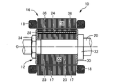
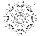
図1は、本発明方法に従って製造された回転電機用ロータ12(以下、単にロータ12という)を備えている回転電機10を説明する概略図で、図2のI-I矢視部分における断面図であり、図2はロータ12の回転中心線Oと直角な断面図で、図1に比較して拡大して示した図である。回転電機10は永久磁石埋込型同期モータで、電動モータおよび発電機として択一的に用いることができるモータジェネレータであり、例えばハイブリッド車両を含む電気自動車の駆動力源として好適に用いられる。回転電機10は、回転中心線Oと同心に設けられたロータ12およびステータ14を備えている。本実施例の説明では回転電機10の回転中心線Oを、ロータ12の回転中心線としても使用する。ステータ14は、ロータ12の外周側に配設された円筒形状のステータコア16と、そのステータコア16に巻回された複数のステータコイル18とを備えている。ステータコア16は、多数の円環形状の鋼板17を回転中心線Oに対して垂直な姿勢で軸方向、すなわち回転中心線Oと平行な方向に積層したもので、圧入或いは取付ボルト等を介して図示しないケースに固定されている。
FIG. 1 is a schematic diagram for explaining a rotating
ロータ12は、ロータシャフト20の外周面に取り付けられた円筒形状のロータコア22と、そのロータコア22に埋設された多数の磁石24とを備えている。ロータコア22は、多数の円環形状の鋼板23を回転中心線Oに対して垂直な姿勢で軸方向、すなわち回転中心線Oと平行な方向に積層したもので、その両端部に一対のエンドプレート28、30が設けられてロータシャフト20に固定されている。ロータシャフト20には鍔部32が設けられているとともにナット34が螺合されるようになっており、多数の鋼板23から成るロータコア22は、その鍔部32とナット34との間で挟圧されてロータシャフト20に固定される。
The
ロータコア22の外周部には、多数のフラックスバリア36が軸方向に貫通して設けられており、そのフラックスバリア36にそれぞれ磁石24が挿入されて固定されている。フラックスバリア36は磁束の通過を規制する貫通孔で、その一部が磁石取付孔として用いられる。多数のフラックスバリア36は、図2において外周側に向かって浅いV字形状を成すように互いに近接して設けられた一対のフラックスバリア36を1組として、回転中心線Oまわりに等角度間隔で複数組(実施例では8組)設けられている。V字形状の一対のフラックスバリア36には、N極およびS極の極性が反対向きになる姿勢で磁石24が挿入されて固定される。磁石24およびフラックスバリア36の数や形状、配置パターンなどは適宜変更することが可能で、磁石24の着磁はロータコア22に磁石24を固定した後で行なうこともできる。フラックスバリア36は磁石取付孔に相当するが、磁石24よりも大きく、磁石24の両端部に所定の空洞が残るようになっており、磁石24を冷却する冷却流体の通路として利用できる。ロータコア22の内周部には、軸方向に貫通するように複数の空洞部46が設けられており、例えば磁束の流れを規制する磁束迂回孔として機能する。
A large number of
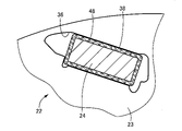
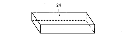
図3は、磁石24の取付構造を説明する図で、図2の上端部に設けられた一つの磁石24の近傍部分を図2よりも更に拡大して示した断面図である。磁石24は、ロータコア22の軸方向長さと略等しい長さ寸法を有するとともに、その長手方向である軸方向と直角な断面形状、すなわち回転中心線Oと直角な断面形状は長方形であり、全体として四角柱形状を成している。図4は磁石24の斜視図で、軸方向に長い長方形の平板形状を成している。磁石24は希土類磁石で、必要に応じて絶縁被膜によって被覆される。磁石24とフラックスバリア36との間には隙間があり、その隙間が多孔質モールド材38によって埋められることにより、磁石24がフラックスバリア36の内部に固定されている。多孔質モールド材38は、外部に連通する多数の空隙を有するもので、回転電機10の使用時に潤滑油等の冷却流体が空隙内を流通させられることにより、磁石24を効果的に冷却することができる。
FIG. 3 is a diagram for explaining the mounting structure of the
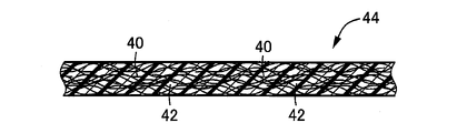
多孔質モールド材38は、図5に示す複合材44をフラックスバリア36と磁石24との間の環状空間に介在させた状態で、その複合材44を加熱することにより、複合材44に含まれる多孔質素材40が膨張成形されたものである。多孔質素材40は、例えばガラス繊維や金属繊維など不織布のように絡み合った多孔質状の部材で、複合材44は、その多孔質素材40と結合材42とが混合されるとともに、加圧により多孔質素材40の空隙が潰された状態で結合材42により一体化された薄板状の部材である。接着剤として機能する結合材42としては、例えばポリエチレンやポリプロピレン、ポリ塩化ビニルなど、多孔質素材40よりも融点が低い熱可塑性合成樹脂が用いられる。したがって、フラックスバリア36と磁石24との間の環状空間に配置された複合材44を加熱すると、結合材42が軟化するとともに多孔質素材40が自身の残留応力等により膨張し、空隙が大きくなって多孔質モールド材38に変化するとともに、その多孔質モールド材38の膨張による押圧力で磁石24がロータコア22のフラックスバリア36に固定される。結合材42は、加熱により溶けて無くなっても良いが、多孔質モールド材38に残留し、冷却硬化することにより接着剤として磁石24の固定に寄与するようにしても良い。
図6は、多孔質モールド材38によりロータコア22のフラックスバリア36に磁石24を固定する際の製造工程を説明するフローチャートで、ステップS1~S5(以下、ステップを省略して単にS1~S5という。他のフローチャートも同じ。)に従って作業を実行する。図7は、図6のS3の加熱工程およびS4の冷却工程を更に具体的に説明するフローチャートで、Q1~Q4がS3の加熱工程で、Q5~Q7がS4の冷却工程である。各ステップの作業は、作業者が手作業で行なっても良いが、ロボット等を用いて自動的に行なわれるようにしても良い。
FIG. 6 is a flow chart for explaining the manufacturing process for fixing the
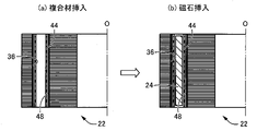
図6のS1は磁石配置工程で、磁石24および複合材44をロータコア22のフラックスバリア36内に挿入する。具体的には、例えば図8の(a) に示すように、磁石24の周囲に薄板状の複合材44を巻き付けたり、薄板筒状の複合材44の内部に磁石24を嵌合したりして、磁石24の外周面に複合材44を貼り付けて、磁石24の総ての外周面を複合材44で被覆する。複合材44の貼り付け方法は、例えば接着剤が適当であるが、圧着、水圧転写など種々の態様が可能である。溶融状態乃至は可塑状態の複合材44を、射出成形やプレス成形等により磁石24の周囲に加圧成形すると同時に固着しても良い。そして、図8の(b) に示すように、複合材44で被覆された磁石24を、ロータコア22のフラックスバリア36内に挿入する。本実施例では、ロータコア22に設けられた総てのフラックスバリア36に対し、複合材44で被覆された磁石24を挿入する。フラックスバリア36の内壁面には、密閉空間64(図10参照)を形成するために、耐熱性を有する断熱シール材48が予めコーティング等によって固着されている。断熱シール材48としては、例えばポリエチレン等が用いられる。断熱シール材48として断熱シートを用いて、接着剤などでフラックスバリア36の内壁面に貼り付けるようにしても良い。
S 1 in FIG. 6 is a magnet placement step, in which the
なお、図9に示すように、筒形状の複合材44を予めフラックスバリア36内に挿入し、その複合材44の内側に磁石24を挿入するようにしても良い。すなわち、フラックスバリア36と磁石24との間の環状空間に複合材44を介在させれば良いため、図8においても、フラックスバリア36の内壁面に対面する磁石24の側面、すなわち磁石24の長手方向(図8における上下方向)と平行な側面のみを、複合材44によって被覆するだけでも良い。
Alternatively, as shown in FIG. 9, a cylindrical
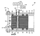
図6のS2は密閉工程で、図10に示すロータ製造装置60の磁石取付治具62にロータコア22を装着することにより、磁石24および複合材44が配置されたフラックスバリア36を含む密閉空間64を形成する。磁石取付治具62は、互いに平行な平板形状の一対の挟圧板70、72と、その挟圧板70、72の互いに対面する内側面に固定された断熱板74、76とを備えており、一対の断熱板74、76の間でロータコア22が軸方向の両側から挟まれた状態で保持される。断熱板74、76は断熱部材に相当し、例えばポリエチレン等が用いられる。一対の挟圧板70、72のロータコア22よりも外周側には複数の締付ボルト78が設けられており、ナット80が螺合されることにより、断熱板74と76との間でロータコア22が挟圧される。油圧シリンダ等の流体圧シリンダ、或いは電動モータおよび送りねじ機構などの押圧装置を用いて、一対の挟圧板70、72の間でロータコア22が一定の挟圧力で挟圧されるようにしても良い。
S2 in FIG. 6 is a sealing step, in which the
下側の断熱板74の上面には、ロータコア22の回転中心線Oと同心に3本のOリング82、84、86が配設されており、ロータコア22の下端面に気密に密着させられるとともに、上側の断熱板76の下面には、ロータコア22の回転中心線Oと同心に3本のOリング88、90、92が配設されており、ロータコア22の上端面に気密に密着させられるようになっている。Oリング82、88は、フラックスバリア36よりも外周側に密着させられるとともに、Oリング84、86、90、92はフラックスバリア36よりも内周側に密着させられるようになっており、これによりロータコア22に設けられた総てのフラックスバリア36を含む気密な密閉空間64が形成される。これ等のOリング82、84、86、88、90、92は耐熱性を有するもので、例えばフッ化ゴム等が好適に用いられる。最も内周側のOリング86、92は、内周側の気密性能を高めるために設けられているが、省略することも可能である。この磁石取付治具62は縦型で、ロータコア22は回転中心線Oが略垂直になる姿勢で保持されるが、回転中心線Oが略水平になる姿勢でロータコア22を保持する横型に構成することもできる。
Three O-
磁石取付治具62の上側の挟圧板72および断熱板76には、それ等を貫通するようにカプラ等の連結具100が気密に固定されている。挟圧板72から外部に突き出す連結具100の連結端部には、通気路として配管102が連結され、その配管102にはコンプレッサー104および圧力計106が接続されている。ロータ製造装置60は、磁石取付治具62の他に連結具100、配管102、コンプレッサー104、および圧力計106を備えて構成されており、S2の密閉工程で磁石取付治具62にロータコア22を装着した場合には、コンプレッサー104を作動させて密閉空間64内のガス圧を上昇させ、その時のガス圧を圧力計106で検出することにより、ガス圧の上昇率等から密閉状態か否かを確認することができる。密閉空間64内のガスは大気(空気)のままでも良いが、コンプレッサー104を逆作動させて密閉空間64内の大気を排気し、アルゴンガス等の所定のガスに入れ替えることもできる。
A
図6のS3の加熱工程では、図7のQ1~Q4に従って密閉空間64内の複合材44を加熱する。Q1でコンプレッサー104を始動(ON)し、配管102を介してガスを密閉空間64内に送り込むことにより、その密閉空間64内のガス圧を高くする。これにより、密閉空間64内のガスの断熱圧縮によりガス温度が高くなり、そのガスに接している複合材44が加熱される(Q2)。すなわち、ガス圧を高くするために外部から加えられた仕事のエネルギーを熱源として、熱力学第一法則により内部エネルギーが増大してガス温度が上昇させられる。Q3では、予め定められた一定時間だけ密閉空間64内のガス圧或いはガス温度が所定の目標値に保持されるように、フィードバック制御等によりコンプレッサー104の作動を制御する。この間の複合材44の加熱により結合材42が軟化すると、多孔質素材40が自身の残留応力等により膨張して多孔質モールド材38に変化し、その多孔質モールド材38の膨張圧力によって磁石24がフラックスバリア36に固定される(Q4)。フラックスバリア36を含む密閉空間64内のガスは複合材44の表面に接しているとともに、加熱により多孔質素材40が膨張し始めて空隙が大きくなると、その空隙にもガスが侵入するため、高温ガスにより複合材44が効率よく加熱される。これにより、図6のS3の加熱工程が終了する。図11は、多孔質素材40が膨張して多孔質モールド材38となり、その多孔質モールド材38による押圧力で磁石24がフラックスバリア36に固定された状態である。本実施例ではコンプレッサー104が温度調節装置として機能する。
In the heating step S3 in FIG. 6, the
図6のS4の冷却工程では、図7のQ5~Q7に従って密閉空間64を冷却する。Q5では、コンプレッサー104を逆作動させることにより密閉空間64内のガスを排気する。これにより、密閉空間64内のガス圧が低くなり、密閉空間64の断熱膨張によりガス温度が低くなり、そのガスに接している多孔質モールド材38が冷却される(Q6)。多孔質モールド材38の空隙にもガスが侵入するため、断熱膨張によるガス温度の低下に伴って多孔質モールド材38が効率よく冷却される。複合材44に含まれていた結合材42は、加熱により溶け出して除去されても良いが、一部が多孔質モールド材38に残存していても良く、その結合材42の冷却硬化により磁石24が一層強固にフラックスバリア36に固定される。その後、Q7でコンプレッサー104を停止(OFF)することで、図6のS4の冷却工程が終了する。
In the cooling step of S4 in FIG. 6, the closed
図6のS5は取出工程で、ロータ製造装置60の磁石取付治具62から、複数のフラックスバリア36にそれぞれ磁石24が固定されたロータコア22を取り出す。すなわち、複数の締付ボルト78のナット80を緩めて、一対の挟圧板70、72を互いに離間させることにより、それ等の間からロータコア22を取り出すことができる。これにより、ロータコア22の複数のフラックスバリア36に磁石24を固定する一連の磁石取付作業が終了する。
S5 in FIG. 6 is a removal step, in which the
このように本実施例の回転電機10のロータ12の製造方法においては、図8または図9のようにロータコア22のフラックスバリア36と磁石24との間の環状空間に複合材44が配設された状態で、そのロータコア22が図10に示す磁石取付治具62に装着されることにより、磁石取付孔であるフラックスバリア36を含んで密閉空間64が形成される。そして、その密閉空間64内のガス圧をコンプレッサー104により高くすると、断熱圧縮により密閉空間64内のガス温度が高くなってフラックスバリア36内の複合材44が加熱され、多孔質素材40が膨張して多孔質モールド材38に変化するとともに、その多孔質モールド材38の膨張圧力によって磁石24がフラックスバリア36に固定される。その場合に、密閉空間64内のガスは複合材44の表面に接しているとともに、加熱により多孔質素材40が膨張し始めて空隙が大きくなると、その空隙にもガスが侵入するため、高温ガスにより複合材44が効率よく加熱される。これにより、ロータコア22を含めて加熱炉等により外部から雰囲気加熱する場合に比較して、加熱に必要な時間やエネルギーが低減されるとともに、磁石24やロータコア22の磁気特性の劣化が抑制される。
As described above, in the method of manufacturing the
また、多孔質素材40が膨張して多孔質モールド材38に変化させられた後に、コンプレッサー104の逆作動により密閉空間64内のガスが排気されてガス圧が低くされ、断熱膨張によりガス温度が低くなって多孔質モールド材38が冷却されるため、磁石24の固定に要する所要時間が更に短縮されるとともに、磁石24やロータコア22が速やかに冷却されて磁気特性の劣化が更に抑制される。多孔質モールド材38は、外部に連通する空隙を備えているため、その空隙内にも密閉空間64内のガスが侵入することにより、ガス温度の低下に伴って多孔質モールド材38が効率良く冷却される。
After the
また、磁石取付孔であるフラックスバリア36の内壁面に断熱シール材48を設けて密閉、すなわち気密にシールする一方、フラックスバリア36の開口部を一対の断熱板74、76で覆蓋するとともにOリング82、84、86、88、90、92で密閉、すなわち気密にシールすることにより、密閉空間64が形成される。そして、上側の挟圧板72および断熱板76に気密に固定された連結具100を介して、コンプレッサー104等が接続された配管102が連結されるため、密閉空間64の気密性および断熱性が高いとともに内部容積が必要最小限とされ、複合材44を効率良く加熱することができるとともに、複合材44が変化した多孔質モールド材38を効率良く冷却することができる。
A heat-insulating
また、S3の加熱工程では、コンプレッサー104により配管102および密閉空間64内のガス圧を高くすることにより、熱力学第一法則に従って断熱圧縮により密閉空間64内のガス温度が高くなってフラックスバリア36内の複合材44が加熱される。すなわち、コンプレッサー104を作動させて密閉空間64内のガス圧を高くするだけで複合材44を加熱できるため、加熱工程を簡便に実施することができる。
In the heating step of S3, the
次に、本発明の他の実施例を説明する。なお、以下の実施例において前記実施例と実質的に共通する部分には同一の符号を付して詳しい説明を省略する。 Another embodiment of the present invention will now be described. In the following embodiments, the same reference numerals are given to the parts that are substantially the same as those in the previous embodiment, and detailed description thereof will be omitted.
図12は、図6のS3の加熱工程およびS4の冷却工程の別の例を説明する図で、図7の代わりに実行されるフローチャートであり、この実施例では図13、図14に示すロータ製造装置120が用いられる。図12のQQ1~QQ5はS3の加熱工程で、QQ6~QQ8はS4の冷却工程である。各ステップの作業は、作業者が手作業で行なっても良いが、ロボット等を用いて自動的に行なわれるようにしても良い。また、ロータ製造装置120は、磁石取付治具122を備えて構成されており、図13は前記図10に対応する図で、予め磁石24および複合材44がフラックスバリア36内に配置されたロータコア22が磁石取付治具122に装着された状態を示した図である。図14は前記図11に対応する図で、複合材44が加熱されることにより多孔質素材40が膨張して多孔質モールド材38に変化した磁石固定状態を示した図である。
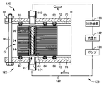
FIG. 12 is a diagram for explaining another example of the heating process of S3 and the cooling process of S4 in FIG. 6, and is a flowchart executed instead of FIG. A
磁石取付治具122は、基本的には前記磁石取付治具62と同じであるが、下側の挟圧板70および断熱板74にも、それ等を貫通するようにカプラ等の連結具124が気密に固定されている点が相違する。そして、その連結具124が挟圧板70から外側に突き出す連結端部には、上側の連結具100に連結されて循環回路126を形成するように、通気路として配管128が連結されている。配管128には、配管128内のガスを加熱するための加熱装置130、配管128内を流通するガスの流量を検出する流量計132、および電動式のポンプ134が接続されており、配管128および密閉空間64を含む循環回路126内のガスが、加熱装置130により温度調節されつつ例えば矢印Aで示すように循環させられる。加熱装置130は、例えば電熱線ヒーターやボイラー等を熱源として備えている熱交換器などである。このような磁石取付治具122においては、S2の密閉工程で磁石取付治具122にロータコア22を装着した後に、ポンプ134を作動させて密閉空間64を含む循環回路126内のガスを循環させ、その時のガスの流量を流量計132で検出することにより、密閉状態か否かを確認できる。
The
図12のQQ1では、加熱装置130を始動(ON)し、配管128内のガスを加熱してガス温度を上昇させる。QQ2では、ポンプ134を始動(ON)し、密閉空間64を含む循環回路126内のガスを循環させる。これにより、加熱装置130によって温度調節された高温のガスが密閉空間64内を流通させられるようになり、そのガスに接している複合材44が加熱される(QQ3)。QQ4では、予め定められた一定時間だけ密閉空間64内のガス温度が所定の目標値に保持されるように、フィードバック制御等により加熱装置130による加熱温度やポンプ134による循環流量を制御する。この間の複合材44の加熱により結合材42が軟化すると、多孔質素材40が自身の残留応力等により膨張して多孔質モールド材38に変化し、その多孔質モールド材38の膨張圧力によって磁石24がフラックスバリア36に固定される(QQ5)。フラックスバリア36を含む密閉空間64内のガスは複合材44の表面に接しているとともに、加熱により多孔質素材40が膨張し始めて空隙が大きくなると、その空隙内もガスが流通するため、高温ガスにより複合材44が効率よく加熱される。これにより、図6のS3の加熱工程が終了する。図14は、多孔質素材40が膨張して多孔質モールド材38となり、その多孔質モールド材38による押圧力で磁石24がフラックスバリア36に固定された状態である。本実施例では、加熱装置130およびポンプ134が、密閉空間64内のガス温度を調節する温度調節装置として機能する。
In QQ1 of FIG. 12, the
次のQQ6では、加熱装置130による加熱を停止(OFF)し、密閉空間64を含む循環回路126内を循環するガスの温度を低下させる。これにより、そのガスに接している多孔質モールド材38が冷却される(QQ7)。多孔質モールド材38の空隙内もガスが流通するため、ガス温度の低下に伴って多孔質モールド材38が効率よく冷却される。その後、QQ8でポンプ134を停止(OFF)することで、図6のS4の冷却工程が終了する。
In the next QQ6, the heating by the
本実施例においても、密閉空間64内のガス温度を上昇させてフラックスバリア36内の複合材44を加熱することにより、多孔質素材40が膨張して多孔質モールド材38に変化させられるとともに、その多孔質モールド材38の膨張圧力によって磁石24がフラックスバリア36に固定されるなど、前記実施例と同様の作用効果が得られる。また、密閉空間64を含めてガスが流通する循環回路126を形成するように配管128が設けられ、その循環回路126を流通させられるガスを加熱装置130により加熱して密閉空間64内のガス温度を上昇させるため、加熱装置130でガスを加熱するとともに加熱されたガスをポンプ134で循環させるだけで良く、加熱工程を簡便に実施することができる。
Also in this embodiment, by raising the gas temperature in the closed
以上、本発明の実施例を図面に基づいて詳細に説明したが、これ等はあくまでも一実施形態であり、本発明は当業者の知識に基づいて種々の変更、改良を加えた態様で実施することができる。 Although the embodiments of the present invention have been described in detail above with reference to the drawings, these are only one embodiment, and the present invention can be implemented with various modifications and improvements based on the knowledge of those skilled in the art. be able to.
10:回転電機 12:回転電機用ロータ 22:ロータコア 24:磁石 36:フラックスバリア(磁石取付孔) 38:多孔質モールド材 40:多孔質素材 42:結合材 44:複合材 48:断熱シール材 64:密閉空間 74、76:断熱板(断熱部材) 82、84、86、88、90、92:Oリング 100、124:連結具 102、128:配管(通気路) 104:コンプレッサー(温度調節装置) 130:加熱装置(温度調節装置) 134:ポンプ(温度調節装置) S2:密閉工程 S3、Q1~Q4、QQ1~QQ5:加熱工程 S4、Q5~Q7、QQ6~QQ8:冷却工程
10: Rotating electric machine 12: Rotor for rotating electric machine 22: Rotor core 24: Magnet 36: Flux barrier (magnet mounting hole) 38: Porous molding material 40: Porous material 42: Binder 44: Composite material 48: Thermal insulation sealing material 64 : Sealed
Claims (3)
前記多孔質モールド材は、多孔質素材と結合材とが混合され加圧により一体化された複合材を前記磁石取付孔と前記磁石との間の環状空間に介在させた状態で、前記複合材が加熱されて前記結合材が軟化させられることにより前記多孔質素材が膨張したものである、回転電機用ロータの製造方法において、
前記環状空間に前記複合材を介在させた状態で前記磁石取付孔を気密に閉塞し、該磁石取付孔を含む密閉空間を形成する密閉工程と、
前記密閉空間に連通する通気路に設けられた温度調節装置により、前記密閉空間内のガス温度を上昇させて前記複合材を加熱し、前記多孔質素材を膨張させて前記多孔質モールド材に変化させる加熱工程と、
を有することを特徴とする回転電機用ロータの製造方法。 A rotor core, magnets inserted in magnet mounting holes axially penetrating through the rotor core, and a large number of gaps communicating with the outside are arranged between the magnet mounting holes and the magnets. a porous molding material provided therein and securing the magnet to the magnet mounting hole;
The porous molding material is formed by interposing a composite material, which is a mixture of a porous material and a binding material and integrated by pressure, in an annular space between the magnet mounting hole and the magnet. is heated to soften the binding material, thereby expanding the porous material,
a sealing step of airtightly closing the magnet mounting hole with the composite material interposed in the annular space to form a sealed space including the magnet mounting hole;
A temperature control device provided in an air passage communicating with the sealed space increases the temperature of the gas in the sealed space to heat the composite material, thereby expanding the porous material and changing it into the porous molding material. a heating step to cause
A method for manufacturing a rotor for a rotary electric machine, comprising:
ことを特徴とする請求項1に記載の回転電機用ロータの製造方法。 After the composite material is heated in the heating step and the porous material expands and changes into the porous mold material, the temperature control device lowers the gas temperature to cool the porous mold material. The method for manufacturing a rotor for a rotary electric machine according to claim 1, comprising the steps of:
ことを特徴とする請求項1または2に記載の回転電機用ロータの製造方法。 In the sealing step, an inner wall surface of the magnet mounting hole is sealed with a heat insulating sealing material, and an opening of the magnet mounting hole that opens to both axial end surfaces of the rotor core is covered with a pair of heat insulating members and an O-ring is provided. The sealed space is formed by sealing with, and the sealed space is connected to the air passage via a connector airtightly provided to at least one of the pair of heat insulating members. 3. The method for manufacturing a rotor for a rotary electric machine according to 2.
Priority Applications (1)
| Application Number | Priority Date | Filing Date | Title |
|---|---|---|---|
| JP2021021301A JP2022123775A (en) | 2021-02-12 | 2021-02-12 | Manufacturing method of rotor for rotary electric machine |
Applications Claiming Priority (1)
| Application Number | Priority Date | Filing Date | Title |
|---|---|---|---|
| JP2021021301A JP2022123775A (en) | 2021-02-12 | 2021-02-12 | Manufacturing method of rotor for rotary electric machine |
Publications (1)
| Publication Number | Publication Date |
|---|---|
| JP2022123775A true JP2022123775A (en) | 2022-08-24 |
Family
ID=82940474
Family Applications (1)
| Application Number | Title | Priority Date | Filing Date |
|---|---|---|---|
| JP2021021301A Pending JP2022123775A (en) | 2021-02-12 | 2021-02-12 | Manufacturing method of rotor for rotary electric machine |
Country Status (1)
| Country | Link |
|---|---|
| JP (1) | JP2022123775A (en) |
-
2021
- 2021-02-12 JP JP2021021301A patent/JP2022123775A/en active Pending
Similar Documents
| Publication | Publication Date | Title |
|---|---|---|
| CN108390510B (en) | Method for producing an electric drive machine and electric drive machine | |
| CN107438939B (en) | Method for manufacturing axial flux motor | |
| US10069388B2 (en) | Stator-plate overmoulding | |
| CN111066233B (en) | Method for manufacturing cooling device and motor housing cooling device using the same | |
| TW200937810A (en) | Cylindrical linear motor, and its stator manufacturing method | |
| US20220094247A1 (en) | Method and apparatus for manufacturing rotor for rotating electric machine | |
| JP2022123775A (en) | Manufacturing method of rotor for rotary electric machine | |
| JP2020141552A (en) | Method of manufacturing rotary electric machine rotor | |
| JP7187287B2 (en) | Laminated core product manufacturing method | |
| CN110417195A (en) | Driving motor automated assembly line | |
| US6109903A (en) | Apparatus for manufacturing a rubber-metal plate composite | |
| US3763551A (en) | Method of manufacturing a tubular printed circuit armature | |
| CN101309034B (en) | Machining method of shielding motor rotor | |
| WO2003047075A1 (en) | Linear motor armature and linear motor | |
| KR101532015B1 (en) | Thermal bonding apparatus for motor core | |
| JP7316528B2 (en) | Manufacturing method of rotor core | |
| JP2017093188A (en) | Method for manufacturing rotor for rotary electric machine | |
| JP3961081B2 (en) | Heating method for laminate of unvulcanized rubber and metal plate | |
| JP2021114823A (en) | Manufacturing method of rotor core | |
| WO2023176748A1 (en) | Motor core manufacturing method, and motor core | |
| JP2022023605A (en) | Manufacturing method of motor | |
| JP7444021B2 (en) | Rotor manufacturing equipment and rotor manufacturing method | |
| JP2013251943A (en) | Linear motor armature and linear motor | |
| JP2024024956A (en) | Rotor manufacturing equipment for rotating electric machines and rotor manufacturing equipment for rotating electric machines | |
| JP2022059995A (en) | Method for manufacturing rotor of electric motor |