JP2022096889A - X-ray tube apparatus and x-ray radiography apparatus - Google Patents

X-ray tube apparatus and x-ray radiography apparatus Download PDF

Info

Publication number
JP2022096889A
JP2022096889A JP2020210137A JP2020210137A JP2022096889A JP 2022096889 A JP2022096889 A JP 2022096889A JP 2020210137 A JP2020210137 A JP 2020210137A JP 2020210137 A JP2020210137 A JP 2020210137A JP 2022096889 A JP2022096889 A JP 2022096889A
Authority
JP
Japan
Prior art keywords
oscillator
ray
ray tube
rotation
vibration
Prior art date
Legal status (The legal status is an assumption and is not a legal conclusion. Google has not performed a legal analysis and makes no representation as to the accuracy of the status listed.)
Pending
Application number
JP2020210137A
Other languages
Japanese (ja)
Inventor
英稔 工藤
Hidetoshi Kudo
Current Assignee (The listed assignees may be inaccurate. Google has not performed a legal analysis and makes no representation or warranty as to the accuracy of the list.)
Canon Medical Systems Corp
Original Assignee
Canon Medical Systems Corp
Priority date (The priority date is an assumption and is not a legal conclusion. Google has not performed a legal analysis and makes no representation as to the accuracy of the date listed.)
Filing date
Publication date
Application filed by Canon Medical Systems Corp filed Critical Canon Medical Systems Corp
Priority to JP2020210137A priority Critical patent/JP2022096889A/en
Publication of JP2022096889A publication Critical patent/JP2022096889A/en
Pending legal-status Critical Current

Links

Images

Landscapes

  • Apparatus For Radiation Diagnosis (AREA)

Abstract

To suppress vibration caused by the rotation of a rotary anode.SOLUTION: An X-ray tube apparatus 1 has a rotary anode 13, a housing 11, and a shaker 20. The rotary anode 13 receives thermo electrons emitted from a cathode 15 and emits X-rays L. The housing 11 holds at least the rotary anode 13. The shaker 20 is mounted on the housing 11 and rotates to provide the housing with vibration. A first rotary shaft 23 of the shaker 20 is provided parallel to a second rotary shaft 17 of the rotary anode 13.SELECTED DRAWING: Figure 1

Description

本明細書及び図面に開示の実施形態は、X線管装置及びX線撮影装置に関する。 The embodiments disclosed in the present specification and drawings relate to an X-ray tube device and an X-ray imaging device.

従来、陽極が回転する回転陽極X線管装置が知られている。回転陽極X線管装置では、回転体である回転陽極のバランス調整がなされており、安定した回転を維持するようにしている。この回転陽極X線管装置にかかる熱負荷や衝撃によって回転陽極X線管に不可逆的な変形が生じると、回転陽極のバランスが崩れる。その結果、回転陽極の回転に伴う振動が大きくなり、この振動が回転陽極X線管より撮影装置の各部位に伝達し、画質の低下や騒音の問題が生じることがある。 Conventionally, a rotating anode X-ray tube device in which an anode rotates is known. In the rotating anode X-ray tube device, the balance of the rotating anode, which is a rotating body, is adjusted so as to maintain stable rotation. When the rotating anode X-ray tube is irreversibly deformed by the heat load or impact applied to the rotating anode X-ray tube device, the balance of the rotating anode is lost. As a result, the vibration accompanying the rotation of the rotating anode becomes large, and this vibration is transmitted from the rotating anode X-ray tube to each part of the photographing apparatus, which may cause deterioration of image quality and noise problems.

バランスが崩れた回転陽極では、例えば、バランスの調整が求められる。しかし、回転陽極X線管では、回転陽極が真空容器内に組み込まれている。このため、回転陽極X線管を組み立てた後に、回転陽極の位置調整を図るなどして回転陽極を直接バランス調整することは難しかった。 For a rotating anode that is out of balance, for example, adjustment of the balance is required. However, in the rotating anode X-ray tube, the rotating anode is incorporated in the vacuum vessel. Therefore, after assembling the rotating anode X-ray tube, it is difficult to directly balance the rotating anode by adjusting the position of the rotating anode.

特開2005-27914号公報Japanese Unexamined Patent Publication No. 2005-27914 特開2010-73365号公報Japanese Unexamined Patent Publication No. 2010-73365 特開平4-359851号公報Japanese Unexamined Patent Publication No. 4-359851

本明細書及び図面に開示の実施形態が解決しようとする課題は、回転陽極の回転に伴って生じる振動を抑制することである。ただし、本明細書及び図面に開示の実施形態により解決しようとする課題は上記課題に限られない。後述する実施形態に示す各構成による各効果に対応する課題を他の課題として位置づけることもできる。 The problem to be solved by the embodiments disclosed in the present specification and the drawings is to suppress the vibration generated by the rotation of the rotating anode. However, the problems to be solved by the embodiments disclosed in the present specification and the drawings are not limited to the above problems. The problem corresponding to each effect by each configuration shown in the embodiment described later can be positioned as another problem.

実施形態のX線管装置は、回転陽極と、ハウジングと、加振器と、を持つ。回転陽極は、陰極から放出される熱電子を受けてX線を放出する。ハウジングは、前記回転陽極を少なくとも保持する。加振器は、前記ハウジングに取り付けられ、回転することで振動を与える。前記加振器の第1回転軸は前記回転陽極の第2回転軸と平行に設けられる。 The X-ray tube device of the embodiment has a rotating anode, a housing, and a vibration exciter. The rotating anode receives thermions emitted from the cathode and emits X-rays. The housing holds at least the rotating anode. The exciter is attached to the housing and rotates to give vibration. The first rotation axis of the exciter is provided in parallel with the second rotation axis of the rotation anode.

第1の実施形態のX線管装置1の断面図。Sectional drawing of the X-ray tube apparatus 1 of 1st Embodiment. 振動子24の側面図。A side view of the oscillator 24. 制御装置40における処理の一例を示すフローチャート。The flowchart which shows an example of the processing in a control device 40. 第2の実施形態のX線管装置2の断面図。FIG. 3 is a cross-sectional view of the X-ray tube device 2 of the second embodiment. 第2の実施形態の加振器20の側面図。The side view of the exciter 20 of the 2nd Embodiment. 第2の実施形態の加振器20の正面図。The front view of the exciter 20 of the 2nd Embodiment. 第3の実施形態のX線CT装置100の構成図。The block diagram of the X-ray CT apparatus 100 of 3rd Embodiment.

以下、図面を参照しながら、実施形態のX線管装置及びX線撮影装置について説明する。 Hereinafter, the X-ray tube device and the X-ray imaging device of the embodiment will be described with reference to the drawings.

(第1の実施形態)
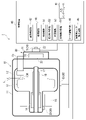
図1は、第1の実施形態のX線管装置1の断面図である。X線管装置1は、例えば、X線管10と、加振器20と、センサ類30と、制御装置40と、を備える。X線管10は、箱型のハウジング11を備えている。ハウジング11の内部には、真空容器12が設けられている。真空容器の12の内部には、ターゲット13及びロータ14が設けられている。X線管10は、ハウジング11及び真空容器12を貫通するカソード(陰極)15を備えている。
(First Embodiment)
FIG. 1 is a cross-sectional view of the X-ray tube device 1 of the first embodiment. The X-ray tube device 1 includes, for example, an X-ray tube 10, a vibration exciter 20, sensors 30, and a control device 40. The X-ray tube 10 includes a box-shaped housing 11. A vacuum container 12 is provided inside the housing 11. A target 13 and a rotor 14 are provided inside the vacuum container 12. The X-ray tube 10 includes a cathode 15 that penetrates the housing 11 and the vacuum vessel 12.

真空容器12内は、真空状態とされている。ハウジング11の内側であり真空容器12の内側に配置されるロータ14の外周には、ステータ16が設けられている。ステータ16に電気が流れることにより、ステータ16とロータ14の間に発生する磁力によってロータ14が回転する。ロータ14には、第2回転軸17が接続されている。第2回転軸17には、ターゲット13が接続されている。ロータ14が回転することにより、第2回転軸17を介してターゲット13が回転する。ターゲット13の内側には、ベアリング、例えば流体軸受18が設けられている。 The inside of the vacuum container 12 is in a vacuum state. A stator 16 is provided on the outer periphery of the rotor 14 which is inside the housing 11 and is arranged inside the vacuum vessel 12. When electricity flows through the stator 16, the rotor 14 rotates due to the magnetic force generated between the stator 16 and the rotor 14. A second rotating shaft 17 is connected to the rotor 14. The target 13 is connected to the second rotation shaft 17. As the rotor 14 rotates, the target 13 rotates via the second rotation shaft 17. A bearing, for example, a fluid bearing 18, is provided inside the target 13.

ターゲット13は、例えば円盤状をなし、半径方向に沿った断面の外側に傾斜部13Rが設けられている。ターゲット13はアノード(陽極)である。ターゲット13が回転し、X線高電圧装置114から高電圧が印加されると、カソード(陰極)15にはフィラメントが実装されており、フィラメントから電子が放出される。カソード(陰極)15から放出された電子は、ターゲット13の傾斜部13Rに衝突し、ターゲット13に電子が衝突することでX線Lが発生する。発生したX線Lは、真空容器12及びハウジング11を介してX線管10の外部に照射される。ターゲット13は、回転陽極の一例である。 The target 13 has, for example, a disk shape, and the inclined portion 13R is provided on the outside of the cross section along the radial direction. The target 13 is an anode (anode). When the target 13 rotates and a high voltage is applied from the X-ray high voltage device 114, a filament is mounted on the cathode (cathode) 15, and electrons are emitted from the filament. The electrons emitted from the cathode (cathode) 15 collide with the inclined portion 13R of the target 13, and the electrons collide with the target 13, so that X-ray L is generated. The generated X-ray L is irradiated to the outside of the X-ray tube 10 via the vacuum container 12 and the housing 11. The target 13 is an example of a rotating anode.

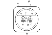
加振器20は、例えば、ケース21と、モータ22と、第1回転軸23と、振動子24と、を備える。ケース21は、ハウジング11に取り付けられている。モータ22は、ケース21の外側に設けられている、第1回転軸23及び振動子24は、ケース21の内側に収容されている。モータ22には、第1回転軸23が接続されている。 The exciter 20 includes, for example, a case 21, a motor 22, a first rotating shaft 23, and an oscillator 24. The case 21 is attached to the housing 11. The motor 22 is provided on the outside of the case 21, and the first rotating shaft 23 and the oscillator 24 are housed inside the case 21. The first rotary shaft 23 is connected to the motor 22.

モータ22は、第1回転軸23を回転させる。第1回転軸23には、振動子24が取り付けられている。振動子24は、第1回転軸23が回転することにより、第1回転軸23周りに回転する。第1回転軸23は、第2回転軸17に対して、平行かつ同軸に設けられている。第1回転軸23は、第2回転軸17に対して、同軸でない状態で設けられていてもよい。 The motor 22 rotates the first rotation shaft 23. An oscillator 24 is attached to the first rotating shaft 23. The oscillator 24 rotates around the first rotation shaft 23 due to the rotation of the first rotation shaft 23. The first rotating shaft 23 is provided parallel and coaxially with the second rotating shaft 17. The first rotating shaft 23 may be provided in a state of not being coaxial with the second rotating shaft 17.

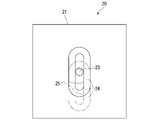
図2は、振動子24の側面図である。振動子24は、底面が長円形をなす柱体である。振動子24には、第1回転軸23に交差、例えば直交する方向である長円の長手方向に沿って伸びる長孔25が設けられている。長孔25に第1回転軸23が貫通する。長孔25は、振動子24における長手方向の中央位置に配置されている。長孔25は、振動子24における長手方向のどの位置に設けられていてもよい。例えば、長孔25は、その一端が振動子24における長手方向の中央位置に位置するように配置されていてもよい。 FIG. 2 is a side view of the oscillator 24. The oscillator 24 is a prism whose bottom surface is oval. The oscillator 24 is provided with an elongated hole 25 that intersects the first rotation axis 23 and extends along the longitudinal direction of an ellipse that is orthogonal to the first rotation axis 23, for example. The first rotating shaft 23 penetrates the elongated hole 25. The elongated hole 25 is arranged at the center position in the longitudinal direction of the vibrator 24. The elongated hole 25 may be provided at any position in the longitudinal direction of the vibrator 24. For example, the elongated hole 25 may be arranged so that one end thereof is located at the center position in the longitudinal direction of the vibrator 24.

第1回転軸23は、長孔25の長手方向の任意の位置に例えば操作者による手作業で取付可能である。長孔25における第1回転軸23が取り付けられる位置に応じて、振動子24は、第1回転軸23に対して偏心する。例えば、第1回転軸23が長孔25の長手方向中央部に取り付けられている場合には、振動子24は第1回転軸23に対して偏心していない。第1回転軸23が取り付けられる位置が、長孔25の長手方向中央部よりずれるほど、第1回転軸23に対する振動子24の偏心が大きくなる。例えば、図2に仮想線で示すように、振動子24の端部に第1回転軸23が位置するときに、振動子24の偏心量が最大となる。長孔25は、振動子24を第1回転軸23に対して偏心させる。長孔25は、偏心部の一例である。 The first rotating shaft 23 can be manually attached to, for example, an operator at an arbitrary position in the longitudinal direction of the elongated hole 25. The vibrator 24 is eccentric with respect to the first rotating shaft 23 according to the position in the elongated hole 25 where the first rotating shaft 23 is attached. For example, when the first rotating shaft 23 is attached to the central portion in the longitudinal direction of the elongated hole 25, the oscillator 24 is not eccentric with respect to the first rotating shaft 23. The more the position where the first rotating shaft 23 is attached deviates from the central portion in the longitudinal direction of the elongated hole 25, the greater the eccentricity of the vibrator 24 with respect to the first rotating shaft 23. For example, as shown by a virtual line in FIG. 2, when the first rotation shaft 23 is located at the end of the oscillator 24, the amount of eccentricity of the oscillator 24 becomes maximum. The elongated hole 25 eccentricizes the oscillator 24 with respect to the first rotation shaft 23. The elongated hole 25 is an example of an eccentric portion.

振動子24は、ターゲット13の回転に同期して回転することにより、振動子24の回転によってハウジング11に与える振動により、ハウジング11の振動を相殺して打ち消す。振動子24の偏心量が大きくなるほど、振動子24の回転によってハウジング11に与える振動が大きくなる。このため、例えば、ターゲット13の回転によるハウジング11の振動が大きくなるほど、振動子24の偏心量を大きくするとよい。 The oscillator 24 rotates in synchronization with the rotation of the target 13, and the vibration applied to the housing 11 by the rotation of the oscillator 24 cancels out and cancels the vibration of the housing 11. As the amount of eccentricity of the oscillator 24 increases, the vibration applied to the housing 11 due to the rotation of the oscillator 24 increases. Therefore, for example, the larger the vibration of the housing 11 due to the rotation of the target 13, the larger the eccentricity of the vibrator 24 may be.

ターゲット13を回転させた場合にハウジング11に生じる振動は、長期間を経ていない段階ではある程度安定している。このため、ハウジング11に振動が生じる場合には、例えば、ターゲット13を回転させるX線検査を実行する前の段階で、作業員の手によって第1回転軸23に対して振動子24を偏心させる。 The vibration generated in the housing 11 when the target 13 is rotated is stable to some extent before a long period of time. Therefore, when the housing 11 vibrates, for example, the oscillator 24 is eccentric to the first rotating shaft 23 by the operator's hand before performing the X-ray inspection for rotating the target 13. ..

図1に示すように、センサ類30は、第1速度位置センサ31と、第2速度位置センサ32と、加速度センサ33と、を備える。第1速度位置センサ31は、加振器20における第1回転軸23の回転速度及び位相(回転角度)を検出し、検出結果に応じた第1情報を生成する。第1速度位置センサ31は、生成した第1情報を制御装置40に送信する。 As shown in FIG. 1, the sensors 30 include a first speed position sensor 31, a second speed position sensor 32, and an acceleration sensor 33. The first speed position sensor 31 detects the rotation speed and phase (rotation angle) of the first rotation shaft 23 in the exciter 20, and generates the first information according to the detection result. The first speed position sensor 31 transmits the generated first information to the control device 40.

第2速度位置センサ32は、X線管10における第2回転軸17の回転速度及び位相を検出し、検出結果に応じた第2情報を生成する。第2速度位置センサ32は、生成した第2情報を制御装置40に送信する。加速度センサ33は、X線管10のハウジング11に取り付けられ、ハウジング11の振動(加速度)を検出し、検出結果に応じた第3情報を生成する。加速度センサ33は生成した第3情報を制御装置40に送信する。第1情報、第2情報、及び第3情報は、検出情報の一例である。ハウジング11の振動は、回転陽極の回転に応じた振動の一例である。 The second speed position sensor 32 detects the rotation speed and the phase of the second rotation shaft 17 in the X-ray tube 10, and generates the second information according to the detection result. The second speed position sensor 32 transmits the generated second information to the control device 40. The acceleration sensor 33 is attached to the housing 11 of the X-ray tube 10, detects the vibration (acceleration) of the housing 11, and generates the third information according to the detection result. The acceleration sensor 33 transmits the generated third information to the control device 40. The first information, the second information, and the third information are examples of the detection information. The vibration of the housing 11 is an example of vibration corresponding to the rotation of the rotating anode.

制御装置40は、例えば、入力インターフェース41と、送受信回路42と、処理回路43と、ロータ駆動回路44と、加振器モータ駆動回路45と、を備える。制御装置40は、センサ類30により送信される検出情報に基づいて、加振器20を制御する。制御装置40は、制御部の一例である。入力インターフェース41は、例えば、操作者が操作可能であり、操作者の操作に応じてX線管装置1をON-OFFするON-OFF情報を送受信回路42に送信する。 The control device 40 includes, for example, an input interface 41, a transmission / reception circuit 42, a processing circuit 43, a rotor drive circuit 44, and a vibration exciter motor drive circuit 45. The control device 40 controls the exciter 20 based on the detection information transmitted by the sensors 30. The control device 40 is an example of a control unit. The input interface 41 can be operated by the operator, for example, and transmits ON-OFF information for turning the X-ray tube device 1 ON-OFF according to the operation of the operator to the transmission / reception circuit 42.

なお、本明細書において入力インターフェース41はマウス、キーボードなどの物理的な操作部品を備えるものだけに限られない。例えば、装置とは別体に設けられた外部の入力機器から入力操作に対応する電気信号を受け取り、この電気信号を制御回路へ出力する電気信号の処理回路も入力インターフェース41の例に含まれる。 In the present specification, the input interface 41 is not limited to the one provided with physical operation parts such as a mouse and a keyboard. For example, an example of the input interface 41 includes an electric signal processing circuit that receives an electric signal corresponding to an input operation from an external input device provided separately from the device and outputs the electric signal to a control circuit.

送受信回路42は、入力インターフェース41により送信されるON-OFF情報及びセンサ類30により送信される情報を受信する。送受信回路42は、受信した情報を処理回路43に出力する。 The transmission / reception circuit 42 receives the ON-OFF information transmitted by the input interface 41 and the information transmitted by the sensors 30. The transmission / reception circuit 42 outputs the received information to the processing circuit 43.

処理回路43は、例えば、検出機能51と、振動解析機能52と、判定機能53と、回転制御機能54と、を備える。処理回路43は、例えば、ハードウェアプロセッサが記憶装置(記憶回路)に記憶されたプログラムを実行することにより、これらの機能を実現するものである。ハードウェアプロセッサとは、例えば、CPU(Central Processing Unit)、GPU(Graphics Processing Unit)、特定用途向け集積回路(Application Specific Integrated Circuit; ASIC)、プログラマブル論理デバイス(例えば、単純プログラマブル論理デバイス(Simple Programmable Logic Device; SPLD)または複合プログラマブル論理デバイス(Complex Programmable Logic Device; CPLD)、フィールドプログラマブルゲートアレイ(Field Programmable Gate Array; FPGA))などの回路(circuitry)を意味する。記憶装置にプログラムを記憶させる代わりに、ハードウェアプロセッサの回路内にプログラムを直接組み込むように構成しても構わない。この場合、ハードウェアプロセッサは回路内に組み込まれたプログラムを読み出し実行することで機能を実現する。ハードウェアプロセッサは、単一の回路として構成されるものに限らず、複数の独立した回路を組み合わせて1つのハードウェアプロセッサとして構成され、各機能を実現するようにしてもよい。記憶装置は、非一時的(ハードウェアの)記憶媒体でもよい。また、複数の構成要素を1つのハードウェアプロセッサに統合して各機能を実現するようにしてもよい。 The processing circuit 43 includes, for example, a detection function 51, a vibration analysis function 52, a determination function 53, and a rotation control function 54. The processing circuit 43 realizes these functions by, for example, a hardware processor executing a program stored in a storage device (storage circuit). The hardware processor is, for example, a CPU (Central Processing Unit), a GPU (Graphics Processing Unit), an application specific integrated circuit (ASIC), and a programmable logic device (for example, a simple programmable logic device (Simple Programmable Logic)). It means a circuit such as a Device (SPLD) or a Complex Programmable Logic Device (CPLD) or a Field Programmable Gate Array (FPGA). Instead of storing the program in the storage device, the program may be configured to be directly embedded in the circuit of the hardware processor. In this case, the hardware processor realizes the function by reading and executing the program embedded in the circuit. The hardware processor is not limited to the one configured as a single circuit, but may be configured as one hardware processor by combining a plurality of independent circuits to realize each function. The storage device may be a non-temporary (hardware) storage medium. Further, a plurality of components may be integrated into one hardware processor to realize each function.

検出機能51は、第2速度位置センサ32により送信され、送受信回路42により出力された第2情報を取得する。検出機能51は、取得した第2情報に基づいて、ターゲット13の回転速度及び位相を検出する。検出機能51は、検出したターゲット13の回転速度及び位相を振動解析機能52及び回転制御機能54に出力する。 The detection function 51 acquires the second information transmitted by the second speed position sensor 32 and output by the transmission / reception circuit 42. The detection function 51 detects the rotation speed and the phase of the target 13 based on the acquired second information. The detection function 51 outputs the detected rotation speed and phase of the target 13 to the vibration analysis function 52 and the rotation control function 54.

振動解析機能52は、加速度センサ33により送信され、送受信回路42により出力された第3情報を取得する。振動解析機能52は、検出機能51により出力されたターゲット13の回転速度及び位相を取得する。振動解析機能52は、取得した第3情報に基づいて、ハウジング11の加速度を検出する。振動解析機能52は、検出したハウジング11の加速度と、取得したターゲット13の回転速度及び位相を用いて振動解析を実行し、ハウジング11の振動量を算出する。振動解析機能52は、算出したハウジング11の振動量を判定機能53に出力する。 The vibration analysis function 52 acquires the third information transmitted by the acceleration sensor 33 and output by the transmission / reception circuit 42. The vibration analysis function 52 acquires the rotation speed and phase of the target 13 output by the detection function 51. The vibration analysis function 52 detects the acceleration of the housing 11 based on the acquired third information. The vibration analysis function 52 executes vibration analysis using the detected acceleration of the housing 11 and the acquired rotation speed and phase of the target 13, and calculates the vibration amount of the housing 11. The vibration analysis function 52 outputs the calculated vibration amount of the housing 11 to the determination function 53.

判定機能53は、振動解析機能52により出力されたハウジング11の振動量に基づいて加振器20を作動させるか否かを判定する。判定機能53は、X線管10のターゲット13が回転しているときに、加振器20を作動させるか否かについての判定を実行する。制御装置40は、例えば、加振器20を作動させるか否かを判定するためのハウジング11の振動量のしきい値を記憶している。 The determination function 53 determines whether or not to operate the vibrating device 20 based on the vibration amount of the housing 11 output by the vibration analysis function 52. The determination function 53 executes a determination as to whether or not to operate the exciter 20 when the target 13 of the X-ray tube 10 is rotating. The control device 40 stores, for example, a threshold value of the vibration amount of the housing 11 for determining whether or not to operate the exciter 20.

判定機能53は、振動解析機能52により出力されたハウジング11の振動量と、制御装置40が記憶するしきい値とを比較して加振器20を作動させるか否かを判定する。判定機能53は、加振器20を作動させるか否かについての判定結果を回転制御機能54に出力する。判定機能53は、加振器20を作動させるか否かについての判定をターゲット13が回転しているときに実行してもよいし、振動解析機能52により出力されたハウジング11の振動量を記憶しておき、ターゲット13が回転していないときに実行してもよい。 The determination function 53 compares the vibration amount of the housing 11 output by the vibration analysis function 52 with the threshold value stored in the control device 40, and determines whether or not to operate the exciter 20. The determination function 53 outputs a determination result as to whether or not to operate the exciter 20 to the rotation control function 54. The determination function 53 may execute a determination as to whether or not to operate the exciter 20 when the target 13 is rotating, or may store the vibration amount of the housing 11 output by the vibration analysis function 52. However, it may be executed when the target 13 is not rotating.

回転制御機能54は、入力インターフェース41により送信されたON情報を送受信回路42が受信した場合に、停止中のターゲット13を回転させるようにロータ駆動回路44を制御する。回転制御機能54は、入力インターフェース41により送信されたOFF情報を送受信回路42が受信した場合に、回転中のターゲット13を停止させるようにロータ駆動回路44を制御する。 The rotation control function 54 controls the rotor drive circuit 44 so as to rotate the stopped target 13 when the transmission / reception circuit 42 receives the ON information transmitted by the input interface 41. The rotation control function 54 controls the rotor drive circuit 44 so as to stop the rotating target 13 when the transmission / reception circuit 42 receives the OFF information transmitted by the input interface 41.

回転制御機能54は、判定機能53により出力された判定結果を取得する。回転制御機能54は、取得した判定結果に応じて、加振器20を作動させる。回転制御機能54は、加振器20を作動させるとの判定結果を取得した場合に、モータ22を作動させて第1回転軸23及び振動子24を回転させるように加振器モータ駆動回路45を制御する。 The rotation control function 54 acquires the determination result output by the determination function 53. The rotation control function 54 operates the exciter 20 according to the acquired determination result. The rotation control function 54 operates the exciter motor drive circuit 45 so as to operate the motor 22 to rotate the first rotary shaft 23 and the vibrator 24 when the determination result of operating the exciter 20 is acquired. To control.

回転制御機能54は、加振器20を作動させている間、第1速度位置センサ31により送信され、送受信回路42により出力された第1情報を取得する。回転制御機能54は、取得した第1情報に基づいて、ロータ14の回転速度及び位相を取得する。回転制御機能54は、検出機能51により出力されたターゲット13の回転速度及び位相を取得する。 The rotation control function 54 acquires the first information transmitted by the first speed position sensor 31 and output by the transmission / reception circuit 42 while the exciter 20 is being operated. The rotation control function 54 acquires the rotation speed and the phase of the rotor 14 based on the acquired first information. The rotation control function 54 acquires the rotation speed and phase of the target 13 output by the detection function 51.

回転制御機能54は、取得したターゲット13と振動子24の回転速度及び位相をそれぞれ比較して、ターゲット13と振動子24が同期して回転するためのモータ22の回転速度及び位相を算出する。振動解析機能52は、振動子24がターゲット13と同期して回転するように加振器モータ駆動回路45にモータ22を作動させる。ターゲット13と振動子24が同期して回転することにより、ターゲット13の回転によって生じるハウジング11の振動を、振動子24を回転させて生じる振動によって相殺して打ち消す。その結果、ハウジング11の振動を抑制することができる。 The rotation control function 54 compares the acquired rotation speed and phase of the target 13 and the vibrator 24, respectively, and calculates the rotation speed and phase of the motor 22 for the target 13 and the vibrator 24 to rotate in synchronization with each other. The vibration analysis function 52 causes the exciter motor drive circuit 45 to operate the motor 22 so that the oscillator 24 rotates in synchronization with the target 13. When the target 13 and the oscillator 24 rotate in synchronization, the vibration of the housing 11 caused by the rotation of the target 13 is canceled and canceled by the vibration generated by rotating the oscillator 24. As a result, the vibration of the housing 11 can be suppressed.

ロータ駆動回路44は、回転制御機能54の制御に基づいて駆動し、例えばターゲット13を回転させたり停止させたりする。加振器モータ駆動回路45は、回転制御機能54の制御に基づいて駆動し、例えば振動子24がターゲット13と同期して回転するようにモータ22を作動させる。 The rotor drive circuit 44 is driven based on the control of the rotation control function 54, and for example, the target 13 is rotated or stopped. The exciter motor drive circuit 45 is driven based on the control of the rotation control function 54, and for example, the motor 22 is operated so that the oscillator 24 rotates in synchronization with the target 13.

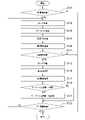
次に、制御装置40における処理について説明する。図3は、制御装置40における処理の一例を示すフローチャートである。制御装置40は、まず、入力インターフェース41により送信されるON情報を送受信回路42が受信したか否かを判定する(ステップS101)。送受信回路42がON情報を受信していないと判定した場合、制御装置40は、図3に示す処理を終了する。 Next, the processing in the control device 40 will be described. FIG. 3 is a flowchart showing an example of processing in the control device 40. First, the control device 40 determines whether or not the transmission / reception circuit 42 has received the ON information transmitted by the input interface 41 (step S101). When it is determined that the transmission / reception circuit 42 has not received the ON information, the control device 40 ends the process shown in FIG.

送受信回路42がON情報を受信したと判定した場合、回転制御機能54は、ロータ駆動回路44を制御してロータ14を回転させる(ステップS103)。ロータ14は、ステータ16からのトルクを受けて作動する。ロータ14が作動することにより、第2回転軸17を介してターゲット13が回転する(ステップS105)。 When it is determined that the transmission / reception circuit 42 has received the ON information, the rotation control function 54 controls the rotor drive circuit 44 to rotate the rotor 14 (step S103). The rotor 14 operates by receiving torque from the stator 16. By operating the rotor 14, the target 13 rotates via the second rotation shaft 17 (step S105).

ターゲット13が回転すると、第2速度位置センサ32は、例えば一定時間ごとにターゲット13の回転速度及び位相を検出し、第2情報を生成して制御装置40に送信する(ステップS107)。さらに、加速度センサ33は、例えば一定時間ごとにハウジング11の振動を検出し、第3情報を生成して制御装置40に送信する(ステップS109)。 When the target 13 rotates, the second speed position sensor 32 detects, for example, the rotation speed and the phase of the target 13 at regular time intervals, generates second information, and transmits the second information to the control device 40 (step S107). Further, the acceleration sensor 33 detects the vibration of the housing 11 at regular intervals, for example, generates the third information, and transmits the third information to the control device 40 (step S109).

続いて、振動解析機能52は、加速度センサ33により送信された第3情報に基づいて、ハウジング11の振動量を算出し、判定機能53に出力する。判定機能53は、振動解析機能52により出力されたハウジング11の振動量と、制御装置40が記憶するしきい値を比較して加振器20を作動させるか否かを判定する(ステップS111)。 Subsequently, the vibration analysis function 52 calculates the vibration amount of the housing 11 based on the third information transmitted by the acceleration sensor 33, and outputs the vibration amount to the determination function 53. The determination function 53 compares the vibration amount of the housing 11 output by the vibration analysis function 52 with the threshold value stored in the control device 40, and determines whether or not to operate the vibration exciter 20 (step S111). ..

判定機能53は、振動解析機能52により出力されたハウジング11の振動量が、制御装置40が記憶するしきい値を超えない場合に、加振器20を作動させないと判定する。判定機能53は、振動解析機能52により出力されたハウジング11の振動量が、制御装置40が記憶するしきい値を超えた場合に、加振器20を作動させると判定する。 The determination function 53 determines that the vibration exciter 20 is not operated when the vibration amount of the housing 11 output by the vibration analysis function 52 does not exceed the threshold value stored in the control device 40. The determination function 53 determines that the vibration exciter 20 is operated when the vibration amount of the housing 11 output by the vibration analysis function 52 exceeds the threshold value stored in the control device 40.

振動解析機能52により出力されたハウジング11の振動量がしきい値を超えず、加振器20を作動させないと判定機能53が判定した場合、制御装置40は、図3に示す処理を終了する。振動解析機能52により出力されたハウジング11の振動量がしきい値を超えて加振器20を作動させると判定した場合、回転制御機能54は、加振器モータ駆動回路45を制御してモータ22を作動させる(ステップS113)。モータ22が作動することにより、第1回転軸23を介して振動子24が回転する(ステップS115)。 When the determination function 53 determines that the vibration amount of the housing 11 output by the vibration analysis function 52 does not exceed the threshold value and the vibration exciter 20 is not operated, the control device 40 ends the process shown in FIG. .. When it is determined that the vibration amount of the housing 11 output by the vibration analysis function 52 exceeds the threshold value to operate the exciter 20, the rotation control function 54 controls the exciter motor drive circuit 45 to drive the motor. 22 is operated (step S113). By operating the motor 22, the oscillator 24 rotates via the first rotating shaft 23 (step S115).

振動子24が回転すると、第1速度位置センサ31は、例えば一定時間ごとに振動子24の回転速度及び位相を検出し、第1情報を生成して制御装置40に送信する(ステップS117)。続いて、回転制御機能54は、取得したターゲット13と振動子24の回転速度及び位相をそれぞれ比較し、ともに回転するターゲット13と振動子24が同期しているか否かを判定する(ステップS119)。 When the vibrator 24 rotates, the first speed position sensor 31 detects, for example, the rotation speed and the phase of the vibrator 24 at regular time intervals, generates the first information, and transmits it to the control device 40 (step S117). Subsequently, the rotation control function 54 compares the acquired rotation speed and phase of the target 13 and the vibrator 24, respectively, and determines whether or not the target 13 and the vibrator 24 rotating together are synchronized (step S119). ..

ターゲット13と振動子24が同期していないと判定した場合、回転制御機能54は、ターゲット13と振動子24が同期して回転するためのモータ22の回転速度及び位相を算出する。回転制御機能54は、算出した回転速度及び位相に応じて加振器モータ駆動回路45を制御し、モータ22によって振動子24をターゲット13と同期して回転させる(ステップS121)。ターゲット13と振動子24が同期していると判定した場合、回転制御機能54は、そのままステップS123に処理を進める。 When it is determined that the target 13 and the oscillator 24 are not synchronized, the rotation control function 54 calculates the rotation speed and the phase of the motor 22 for the target 13 and the oscillator 24 to rotate in synchronization. The rotation control function 54 controls the exciter motor drive circuit 45 according to the calculated rotation speed and phase, and the motor 22 rotates the vibrator 24 in synchronization with the target 13 (step S121). When it is determined that the target 13 and the oscillator 24 are synchronized, the rotation control function 54 proceeds to step S123 as it is.

続いて、入力インターフェース41により送信されるOFF情報を送受信回路42が受信して処理回路43に出力したか否かを判定する(ステップS123)。送受信回路42が受信したOFF情報を処理回路43に出力していないと判定した場合、制御装置40は、処理をステップS103に戻す。送受信回路42が受信したOFF情報を処理回路43に出力したと判定した場合、制御装置40は、図3に示す処理を終了する。 Subsequently, it is determined whether or not the transmission / reception circuit 42 receives the OFF information transmitted by the input interface 41 and outputs it to the processing circuit 43 (step S123). When it is determined that the OFF information received by the transmission / reception circuit 42 is not output to the processing circuit 43, the control device 40 returns the processing to step S103. When it is determined that the OFF information received by the transmission / reception circuit 42 is output to the processing circuit 43, the control device 40 ends the processing shown in FIG.

以上説明した第1の実施形態のX線管装置1では、ハウジング11に取り付けられた加振器20における振動子24。振動子24は、ターゲット13と同期して回転するので、ターゲット13の回転に起因するハウジング11の振動を、振動子24の回転によって抑制することができる。さらには、X線管装置1に生じる振動の許容範囲を広くすることができるので、生産歩留まりの向上に寄与することができる。 In the X-ray tube device 1 of the first embodiment described above, the oscillator 24 in the exciter 20 attached to the housing 11. Since the oscillator 24 rotates in synchronization with the target 13, the vibration of the housing 11 caused by the rotation of the target 13 can be suppressed by the rotation of the oscillator 24. Furthermore, since the allowable range of vibration generated in the X-ray tube device 1 can be widened, it is possible to contribute to the improvement of the production yield.

ここで、振動子24を回転させる第1回転軸23は、ターゲット13の回転軸となる第2回転軸17と平行に配置されている。このため、ハウジング11の振動をさらに好適に抑制することができる。さらに、第1回転軸23は、第2回転軸17と同軸に配置されている。このため、ハウジング11の振動をさらに好適に抑制することができる。 Here, the first rotation shaft 23 for rotating the vibrator 24 is arranged in parallel with the second rotation shaft 17 which is the rotation axis of the target 13. Therefore, the vibration of the housing 11 can be suppressed more preferably. Further, the first rotating shaft 23 is arranged coaxially with the second rotating shaft 17. Therefore, the vibration of the housing 11 can be suppressed more preferably.

(第2の実施形態)
次に、第2の実施形態について説明する。第2の実施形態のX線管装置2は、第1の実施形態のX線管装置1と比較して、加振器の構造及び加振器の構造の相違に伴う制御装置における制御が主に異なる。第1の実施形態では、第1回転軸23に対して振動子24を操作者が取り付けることによって振動子24を第1回転軸23に対して偏心させる。第2の実施形態のX線管装置2では、第1回転軸23に対する可動式振動子60の偏心量を制御装置40によって調整する。以下、第1の実施形態との相違点を中心として、第2の実施形態のX線管装置2について説明する。以下の説明において、第1の実施形態と共通の要素については同一の符号を付して、その説明を省略または簡略化することがある。
(Second embodiment)
Next, the second embodiment will be described. The X-ray tube device 2 of the second embodiment is mainly controlled by the control device due to the difference in the structure of the exciter and the structure of the exciter as compared with the X-ray tube device 1 of the first embodiment. Different to. In the first embodiment, the operator attaches the oscillator 24 to the first rotating shaft 23 to eccentric the oscillator 24 with respect to the first rotating shaft 23. In the X-ray tube device 2 of the second embodiment, the amount of eccentricity of the movable oscillator 60 with respect to the first rotating shaft 23 is adjusted by the control device 40. Hereinafter, the X-ray tube device 2 of the second embodiment will be described with a focus on the differences from the first embodiment. In the following description, the elements common to the first embodiment may be designated by the same reference numerals, and the description thereof may be omitted or simplified.

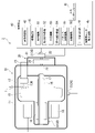
図4は、第2の実施形態のX線管装置2の断面図である。第2の実施形態のX線管装置2は、例えば、X線管10と、加振器20と、センサ類30と、制御装置40と、を備える。第2の実施形態の加振器20は、第1の実施形態の加振器20の振動子24に代えて、可動式振動子60を備える。 FIG. 4 is a cross-sectional view of the X-ray tube device 2 of the second embodiment. The X-ray tube device 2 of the second embodiment includes, for example, an X-ray tube 10, a shaker 20, sensors 30, and a control device 40. The exciter 20 of the second embodiment includes a movable oscillator 60 in place of the oscillator 24 of the exciter 20 of the first embodiment.

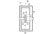
図5Aは、第2の実施形態の加振器20の側面図である。図5Bは、第2の実施形態の加振器20の正面図である。第2の実施形態の加振器20は、第1の実施形態の加振器20と同様のケース21と、図1に示すモータ22と、第1回転軸23とを備えるとともに、可動式振動子60を備える。 FIG. 5A is a side view of the exciter 20 of the second embodiment. FIG. 5B is a front view of the exciter 20 of the second embodiment. The exciter 20 of the second embodiment includes the same case 21 as the exciter 20 of the first embodiment, the motor 22 shown in FIG. 1, and the first rotating shaft 23, and is movable vibration. It has a child 60.

可動式振動子60は、例えば、スリップリング61と、内部モータ62と、ギア63と、第1中継ギア64と、第2中継ギア65と、第1スクリューシャフト66と、第2スクリューシャフト67と、第1振動子68と、第2振動子69と、を備える。スリップリング61は、例えばケース21の内側に設けられている。スリップリング61は、ケース21の外部から供給される電力を内部モータ62に供給する。 The movable oscillator 60 includes, for example, a slip ring 61, an internal motor 62, a gear 63, a first relay gear 64, a second relay gear 65, a first screw shaft 66, and a second screw shaft 67. , A first oscillator 68 and a second oscillator 69. The slip ring 61 is provided inside, for example, the case 21. The slip ring 61 supplies electric power supplied from the outside of the case 21 to the internal motor 62.

ギア63、第1中継ギア64、第2中継ギア65、第1スクリューシャフト66、及び第2スクリューシャフト67は、内部モータ62の駆動力を第1振動子68及び第2振動子69に伝達する伝達機構である。伝達機構は他の構造でもよい。例えば、伝達機構は、ラックアンドピニオン形式の伝達機構でもよい。伝達機構は、例えば、傘歯車を介在させた伝達機構でもよい。 The gear 63, the first relay gear 64, the second relay gear 65, the first screw shaft 66, and the second screw shaft 67 transmit the driving force of the internal motor 62 to the first oscillator 68 and the second oscillator 69. It is a transmission mechanism. The transmission mechanism may be another structure. For example, the transmission mechanism may be a rack and pinion type transmission mechanism. The transmission mechanism may be, for example, a transmission mechanism with a bevel gear interposed therebetween.

第1回転軸23には、内部モータ62及びギア63が設けられている。内部モータ62は、ギア63に接続されている。内部モータ62は、例えばサーボモータである。ギア63は、第1回転軸23周りに回転する。内部モータ62は、回転駆動することにより、ギア63の位相を調整する。ギア63には、第1中継ギア64及び第2中継ギア65が噛み合わされている。 The first rotary shaft 23 is provided with an internal motor 62 and a gear 63. The internal motor 62 is connected to the gear 63. The internal motor 62 is, for example, a servo motor. The gear 63 rotates around the first rotation shaft 23. The internal motor 62 is driven to rotate to adjust the phase of the gear 63. A first relay gear 64 and a second relay gear 65 are meshed with the gear 63.

第1中継ギア64及び第2中継ギア65は、第1回転軸23を挟んで互いに対称となる位置に配置されている。第1中継ギア64及び第2中継ギア65は、いずれも鉛直軸周りに回転する。第1中継ギア64及び第2中継ギア65には、第1スクリューシャフト66及び第2スクリューシャフト67がそれぞれねじ込まれている。 The first relay gear 64 and the second relay gear 65 are arranged at positions symmetrical with each other with the first rotating shaft 23 interposed therebetween. Both the first relay gear 64 and the second relay gear 65 rotate around a vertical axis. A first screw shaft 66 and a second screw shaft 67 are screwed into the first relay gear 64 and the second relay gear 65, respectively.

第1スクリューシャフト66及び第2スクリューシャフト67は、いずれも鉛直方向に延在する。第1中継ギア64が第1方向に回転することにより、第1スクリューシャフト66が上昇する。第1中継ギア64が第1方向に反する第2方向に回転することにより、第1スクリューシャフト66が下降する。第2中継ギア65が第1方向に回転することにより、第2スクリューシャフト67が上昇する。第2中継ギア65が第2方向に回転することにより、第2スクリューシャフト67が下降する。 Both the first screw shaft 66 and the second screw shaft 67 extend in the vertical direction. As the first relay gear 64 rotates in the first direction, the first screw shaft 66 rises. The first screw shaft 66 is lowered by rotating the first relay gear 64 in the second direction opposite to the first direction. As the second relay gear 65 rotates in the first direction, the second screw shaft 67 rises. As the second relay gear 65 rotates in the second direction, the second screw shaft 67 is lowered.

第1中継ギア64及び第2中継ギア65は、ギア63の回転に伴って、互いに共通の方向に回転する。このため、ギア63とかみ合う第1中継ギア64及び第2中継ギア65の回転方向は共通である。さらに、第1スクリューシャフト66及び第2スクリューシャフト67は、互いに共通の方向に移動する。図5A、図5Bに示す状態では、第1スクリューシャフト66及び第2スクリューシャフト67は、互いに上昇または下降する。 The first relay gear 64 and the second relay gear 65 rotate in a common direction with the rotation of the gear 63. Therefore, the rotation directions of the first relay gear 64 and the second relay gear 65 that mesh with the gear 63 are common. Further, the first screw shaft 66 and the second screw shaft 67 move in a common direction with each other. In the state shown in FIGS. 5A and 5B, the first screw shaft 66 and the second screw shaft 67 rise or fall with each other.

第1スクリューシャフト66及び第2スクリューシャフト67の一端(上端)部には、第1振動子68が固定されている。第1スクリューシャフト66及び第2スクリューシャフト67の他端(下端)部には、第2振動子69が固定されている。内部モータ62がギア63を回転させると、第1中継ギア64、第2中継ギア65、第1スクリューシャフト66、及び第2スクリューシャフト67を介して、第1振動子68及び第2振動子69が互いに共通の方向に移動する。図5A、図5Bに示す状態では、第1振動子68及び第2振動子69は、互いに上昇または下降する。 The first oscillator 68 is fixed to one end (upper end) of the first screw shaft 66 and the second screw shaft 67. A second oscillator 69 is fixed to the other end (lower end) of the first screw shaft 66 and the second screw shaft 67. When the internal motor 62 rotates the gear 63, the first oscillator 68 and the second oscillator 69 pass through the first relay gear 64, the second relay gear 65, the first screw shaft 66, and the second screw shaft 67. Move in a common direction to each other. In the state shown in FIGS. 5A and 5B, the first oscillator 68 and the second oscillator 69 rise or fall with each other.

第1振動子68及び第2振動子69は、移動することによって第1回転軸23に対して偏心する。内部モータ62と、ギア63と、第1中継ギア64と、第2中継ギア65と、第1スクリューシャフト66と、第2スクリューシャフト67は、偏心部の一例である。第1スクリューシャフト66及び第2スクリューシャフト67は、第1中継ギア64及び第2中継ギア65とともに、第1振動子68及び第2振動子69の移動を案内する。内部モータ62は、第1振動子68及び第2振動子69を移動させる。内部モータ62は、動力源の一例である。動力源は、電動モータ以外のものでもよく、例えば弾性を有する部材や流体圧系シリンダなどでもよい。第1スクリューシャフト66及び第2スクリューシャフト67は、案内部の一例である。 The first oscillator 68 and the second oscillator 69 are eccentric with respect to the first rotation shaft 23 by moving. The internal motor 62, the gear 63, the first relay gear 64, the second relay gear 65, the first screw shaft 66, and the second screw shaft 67 are examples of the eccentric portion. The first screw shaft 66 and the second screw shaft 67 guide the movement of the first oscillator 68 and the second oscillator 69 together with the first relay gear 64 and the second relay gear 65. The internal motor 62 moves the first oscillator 68 and the second oscillator 69. The internal motor 62 is an example of a power source. The power source may be something other than an electric motor, and may be, for example, an elastic member or a fluid pressure system cylinder. The first screw shaft 66 and the second screw shaft 67 are examples of guide portions.

図4に示すように、可動式振動子60には、制御装置40が接続されている。制御装置40は、内部モータ62を制御して、第1振動子68及び第2振動子69の位置を調整するための調整情報を可動式振動子60に送信する。制御装置40における処理回路43は、第1の実施形態に示す各機能のほか、バランス解析機能55及び調整機能56を備える。 As shown in FIG. 4, a control device 40 is connected to the movable oscillator 60. The control device 40 controls the internal motor 62 to transmit adjustment information for adjusting the positions of the first oscillator 68 and the second oscillator 69 to the movable oscillator 60. The processing circuit 43 in the control device 40 includes a balance analysis function 55 and an adjustment function 56 in addition to the functions shown in the first embodiment.

バランス解析機能55は、振動解析機能52により算出されたハウジング11の振動量を用いてX線管装置2のバランス解析を実行する。バランス解析機能55は、バランス解析の結果に基づいて、加振器20によってハウジング11の振動を打ち消すために要求される加振器20の可動式振動子60における第1振動子68及び第2振動子69の第1回転軸23に対する偏心量を算出する。 The balance analysis function 55 executes the balance analysis of the X-ray tube device 2 using the vibration amount of the housing 11 calculated by the vibration analysis function 52. Based on the result of the balance analysis, the balance analysis function 55 has the first oscillator 68 and the second vibration in the movable oscillator 60 of the exciter 20 required for canceling the vibration of the housing 11 by the exciter 20. The amount of eccentricity of the child 69 with respect to the first rotation axis 23 is calculated.

バランス解析機能55は、例えば、ハウジング11の振動量が大きく、加振器20によってハウジング11の振動を打ち消す度合が大きい場合に、第1振動子68及び第2振動子69の偏心量を大きくする。バランス解析機能55は、例えば、ハウジング11の振動量が小さく、加振器20によってハウジング11の振動を打ち消す度合が小さい場合に、第1振動子68及び第2振動子69の偏心量を小さくしたり、なくしたりする。バランス解析機能55は、算出した第1振動子68及び第2振動子69の偏心量を調整機能56に出力する。 The balance analysis function 55 increases the eccentricity of the first oscillator 68 and the second oscillator 69, for example, when the vibration amount of the housing 11 is large and the degree of canceling the vibration of the housing 11 by the exciter 20 is large. .. The balance analysis function 55 reduces the eccentricity of the first oscillator 68 and the second oscillator 69, for example, when the vibration amount of the housing 11 is small and the degree of canceling the vibration of the housing 11 by the exciter 20 is small. Or lose it. The balance analysis function 55 outputs the calculated eccentricity of the first oscillator 68 and the second oscillator 69 to the adjustment function 56.

調整機能56は、バランス解析機能55により出力された第1振動子68及び第2振動子69の偏心量に応じた駆動情報を生成する。調整機能56は、生成した駆動情報を内部モータ62に送信する。調整機能56は、駆動情報を内部モータ62に送信することにより、第1振動子68及び第2振動子69を第1回転軸23に対して偏心させる。 The adjustment function 56 generates drive information according to the amount of eccentricity of the first oscillator 68 and the second oscillator 69 output by the balance analysis function 55. The adjustment function 56 transmits the generated drive information to the internal motor 62. The adjustment function 56 eccentricizes the first oscillator 68 and the second oscillator 69 with respect to the first rotation shaft 23 by transmitting drive information to the internal motor 62.

以上説明した第2の実施形態のX線管装置2では、第1の実施形態のX線管装置1と同様、ターゲット13が回転し、ハウジング11の振動が大きくなると、加振器20を作動させて可動式振動子60を回転させる。可動式振動子60が回転すると、第1振動子68及び第2振動子69の回転によってハウジング11に与える振動により、ハウジング11の振動を相殺して打ち消すことになる。 In the X-ray tube device 2 of the second embodiment described above, as in the X-ray tube device 1 of the first embodiment, when the target 13 rotates and the vibration of the housing 11 becomes large, the exciter 20 is operated. The movable oscillator 60 is rotated. When the movable oscillator 60 rotates, the vibration applied to the housing 11 by the rotation of the first oscillator 68 and the second oscillator 69 cancels out and cancels the vibration of the housing 11.

第2の実施形態のX線管装置2では、例えば期間の経過によって劣化が進行し、ターゲット13の振動が大きくなることがある。この場合、加振器20を作動させたとしても、ハウジング11の振動を十分に相殺して打ち消すことができないことがある。 In the X-ray tube device 2 of the second embodiment, for example, deterioration progresses with the lapse of a period, and the vibration of the target 13 may become large. In this case, even if the exciter 20 is operated, the vibration of the housing 11 may not be sufficiently offset and canceled.

そこで、第2の実施形態にX線管装置2では、加速度センサ33により送信される加速度情報に基づいてX線管装置2のバランス解析を実行する。X線管装置2は、バランス解析の結果、ハウジング11の振動量が変化した場合に、加振器20における第1振動子68及び第2振動子69の偏心量を調整する。このため、ターゲット13を回転させているときのハウジング11の振動量に変化が生じても、加振器20によってハウジング11の振動を好適に相殺して打ち消すことができる。 Therefore, in the second embodiment, the X-ray tube device 2 executes the balance analysis of the X-ray tube device 2 based on the acceleration information transmitted by the acceleration sensor 33. The X-ray tube device 2 adjusts the eccentricity of the first oscillator 68 and the second oscillator 69 in the vibration exciter 20 when the vibration amount of the housing 11 changes as a result of the balance analysis. Therefore, even if the vibration amount of the housing 11 changes when the target 13 is rotated, the vibration of the housing 11 can be suitably canceled and canceled by the vibration exciter 20.

X線管装置2では、制御装置40が内部モータ62に駆動情報を送信することで、第1振動子68及び第2振動子69の偏心量を調整する。このため、操作者の手を煩わせることなく第1振動子68及び第2振動子69の偏心量を調整することができる。X線管装置2では、ターゲット13及び可動式振動子60を回転させている間も制御装置40が内部モータ62に駆動情報を送信することができる。このため、X線の放射を実行している間に、リアルタイムで第1振動子68及び第2振動子69の偏心量調整することができる。したがって、例えば、X線の放射を実行している間に、ハウジング11の振動が激しくなった場合でも、即座に第1振動子68及び第2振動子69の偏心量を調整して、ハウジング11の振動を抑制することができる。その結果、ダウンタイムを減らすことができる。 In the X-ray tube device 2, the control device 40 adjusts the eccentricity of the first oscillator 68 and the second oscillator 69 by transmitting drive information to the internal motor 62. Therefore, the amount of eccentricity of the first oscillator 68 and the second oscillator 69 can be adjusted without bothering the operator. In the X-ray tube device 2, the control device 40 can transmit drive information to the internal motor 62 while the target 13 and the movable oscillator 60 are being rotated. Therefore, the amount of eccentricity of the first oscillator 68 and the second oscillator 69 can be adjusted in real time while the X-rays are emitted. Therefore, for example, even if the vibration of the housing 11 becomes violent while emitting X-rays, the eccentricity of the first oscillator 68 and the second oscillator 69 is immediately adjusted to adjust the housing 11. Vibration can be suppressed. As a result, downtime can be reduced.

(第3の実施形態)
図6は、第3の実施形態に係るX線CT装置100の構成図である。X線CT装置100は、例えば、架台装置110と、寝台装置130と、コンソール装置140とを有する。図6では、説明の都合上、架台装置110をZ軸方向から見た図とX軸方向から見た図の双方を掲載しているが、実際には、架台装置110は一つである。実施形態では、寝台装置130の天板133の長手方向をZ軸方向(前後方向)、Z軸方向に直交し、床面に対して水平である軸をX軸方向(周方向)、Z軸方向に直交し、床面に対して垂直である方向をY軸方向(上下方向)とそれぞれ定義する。
(Third embodiment)
FIG. 6 is a block diagram of the X-ray CT apparatus 100 according to the third embodiment. The X-ray CT device 100 includes, for example, a gantry device 110, a sleeper device 130, and a console device 140. In FIG. 6, for convenience of explanation, both a view of the gantry device 110 as viewed from the Z-axis direction and a view as viewed from the X-axis direction are shown, but in reality, the gantry device 110 is one. In the embodiment, the longitudinal direction of the top plate 133 of the sleeper device 130 is orthogonal to the Z-axis direction (front-back direction) and the Z-axis direction, and the axis horizontal to the floor surface is the X-axis direction (circumferential direction) and the Z-axis. The directions orthogonal to the direction and perpendicular to the floor surface are defined as the Y-axis direction (vertical direction).

架台装置110は、例えば、X線管10と、ウェッジ112と、コリメータ113と、X線高電圧装置114と、X線検出器115と、データ収集システム(以下、DAS:Data Acquisition System)116と、回転フレーム117と、制御装置40と、を備える。X線管10、ウェッジ112、コリメータ113、X線高電圧装置114、X線検出器115、DAS116、及び回転フレーム117は、架台装置110における架台筐体に収容される。 The gantry device 110 includes, for example, an X-ray tube 10, a wedge 112, a collimator 113, an X-ray high voltage device 114, an X-ray detector 115, and a data acquisition system (hereinafter, DAS: Data Acquisition System) 116. , A rotating frame 117 and a control device 40. The X-ray tube 10, wedge 112, collimator 113, X-ray high voltage device 114, X-ray detector 115, DAS116, and rotating frame 117 are housed in a gantry housing in the gantry 110.

X線管10は、第1の実施形態で用いたものと共通である、ウェッジ112は、X線管10から被検体Pに照射されるX線量を調節するためのフィルタである。ウェッジ112は、X線管10から被検体Pに照射されるX線量の分布が予め定められた分布になるように、自身を透過するX線を減衰させる。ウェッジ112は、ウェッジフィルタ(wedge filter)、ボウタイフィルタ(bow-tie filter)とも呼ばれる。ウェッジ112は、例えば、所定のターゲット角度や所定の厚みとなるようにアルミニウムを加工したものである。 The X-ray tube 10 is the same as that used in the first embodiment, and the wedge 112 is a filter for adjusting the X-ray dose irradiated from the X-ray tube 10 to the subject P. The wedge 112 attenuates the X-rays passing through itself so that the distribution of the X-ray dose radiated from the X-ray tube 10 to the subject P becomes a predetermined distribution. The wedge 112 is also referred to as a wedge filter or a bow-tie filter. The wedge 112 is made by processing aluminum so as to have a predetermined target angle and a predetermined thickness, for example.

コリメータ113は、ウェッジ112を透過したX線の照射範囲を絞り込むための機構である。コリメータ113は、例えば、複数の鉛板の組み合わせによってスリットを形成することで、X線の照射範囲を絞り込む。コリメータ113は、X線絞りと呼ばれる場合もある。コリメータ113の絞り込み範囲は、機械的に駆動可能であってよい。 The collimator 113 is a mechanism for narrowing the irradiation range of X-rays transmitted through the wedge 112. The collimator 113 narrows down the X-ray irradiation range by forming a slit, for example, by combining a plurality of lead plates. The collimator 113 is sometimes called an X-ray diaphragm. The narrowing range of the collimator 113 may be mechanically driveable.

X線高電圧装置114は、例えば、高電圧発生装置と、X線制御装置とを有する。高電圧発生装置は、変圧器(トランス)及び整流器などを含む電気回路を有し、X線管10に印加する高電圧を発生させる。X線制御装置は、X線管10に発生させるべきX線量に応じて高電圧発生装置の出力電圧を制御する。高電圧発生装置は、上述した変圧器によって昇圧を行うものであってもよいし、インバータによって昇圧を行うものであってもよい。X線高電圧装置114は、回転フレーム117に設けられてもよいし、架台装置110の固定フレーム(不図示)の側に設けられてもよい。 The X-ray high voltage device 114 includes, for example, a high voltage generator and an X-ray control device. The high voltage generator has an electric circuit including a transformer, a rectifier, and the like, and generates a high voltage applied to the X-ray tube 10. The X-ray control device controls the output voltage of the high voltage generator according to the X-ray dose to be generated in the X-ray tube 10. The high voltage generator may be one that boosts the voltage by the transformer described above, or may be one that boosts the voltage by an inverter. The X-ray high voltage device 114 may be provided on the rotating frame 117, or may be provided on the side of the fixed frame (not shown) of the gantry device 110.

X線検出器115は、X線管10が発生させ、被検体Pを通過して入射したX線の強度を検出する。X線検出器115は、検出したX線の強度に応じた電気信号(光信号などでもよい)をDAS116に出力する。X線検出器115は、例えば、複数のX線検出素子列を有する。複数のX線検出素子列のそれぞれは、X線管10の焦点を中心とした円弧に沿ってチャネル方向に複数のX線検出素子が配列されたものである。複数のX線検出素子列は、スライス方向(列方向、row方向)に配列される。X線検出器115は、X線管10のターゲット13が放出するX線を検出する。X線検出器115は、検出部の一例である。 The X-ray detector 115 detects the intensity of X-rays generated by the X-ray tube 10 and passed through the subject P to be incident. The X-ray detector 115 outputs an electric signal (which may be an optical signal or the like) according to the intensity of the detected X-ray to the DAS 116. The X-ray detector 115 has, for example, a plurality of X-ray detection element trains. Each of the plurality of X-ray detection element trains is an arrangement of a plurality of X-ray detection elements in the channel direction along an arc centered on the focal point of the X-ray tube 10. The plurality of X-ray detection element sequences are arranged in the slice direction (column direction, row direction). The X-ray detector 115 detects the X-rays emitted by the target 13 of the X-ray tube 10. The X-ray detector 115 is an example of a detection unit.

X線検出器115は、例えば、グリッドと、シンチレータアレイと、光センサアレイとを有する間接型の検出器である。シンチレータアレイは、複数のシンチレータを有する。それぞれのシンチレータは、シンチレータ結晶を有する。シンチレータ結晶は、入射するX線の強度に応じた光量の光を発する。グリッドは、シンチレータアレイのX線が入射する面に配置され、散乱X線を吸収する機能を有するX線遮蔽板を有する。なお、グリッドは、コリメータ(一次元コリメータまたは二次元コリメータ)と呼ばれる場合もある。光センサアレイは、例えば、光電子増倍管(フォトマルチプライヤー:PMT)等の光センサを有する。光センサアレイは、シンチレータにより発せられる光の光量に応じた電気信号を出力する。X線検出器115は、入射したX線を電気信号に変換する半導体素子を有する直接変換型の検出器であってもよい。 The X-ray detector 115 is, for example, an indirect detector having a grid, a scintillator array, and an optical sensor array. The scintillator array has a plurality of scintillators. Each scintillator has a scintillator crystal. The scintillator crystal emits light in an amount corresponding to the intensity of incident X-rays. The grid is arranged on the plane on which the X-rays of the scintillator array are incident and has an X-ray shielding plate having a function of absorbing scattered X-rays. The grid may also be called a collimator (one-dimensional collimator or two-dimensional collimator). The optical sensor array has, for example, an optical sensor such as a photomultiplier tube (PMT). The optical sensor array outputs an electric signal according to the amount of light emitted by the scintillator. The X-ray detector 115 may be a direct conversion type detector having a semiconductor element that converts incident X-rays into an electric signal.

DAS116は、例えば、増幅器と、積分器と、A/D変換器とを有する。増幅器は、X線検出器115の各X線検出素子により出力される電気信号に対して増幅処理を行う。積分器は、増幅処理が行われた電気信号をビュー期間(後述)に亘って積分する。A/D変換器は、積分結果を示す電気信号をデジタル信号に変換する。DAS116は、デジタル信号に基づく検出データをコンソール装置140に出力する。検出データは、生成元のX線検出素子のチャンネル番号、列番号、及び収集されたビューを示すビュー番号により識別されたX線強度のデジタル値である。ビュー番号は、回転フレーム117の回転に応じて変化する番号であり、例えば、回転フレーム117の回転に応じてインクリメントされる番号である。従って、ビュー番号は、X線管10の回転角度を示す情報である。ビュー期間とは、あるビュー番号に対応する回転角度から、次のビュー番号に対応する回転角度に到達するまでの間に収まる期間である。DAS116は、ビューの切り替わりを、制御装置40から入力されるタイミング信号によって検知してもよいし、内部のタイマーによって検知してもよいし、図示しないセンサから取得される信号によって検知してもよい。フルスキャンを行う場合においてX線管10によりX線が連続曝射されている場合、DAS116は、全周囲分(360度分)の検出データ群を収集する。ハーフスキャンを行う場合においてX線管10によりX線が連続曝射されている場合、DAS116は、半周囲分(180度分)の検出データを収集する。 The DAS116 has, for example, an amplifier, an integrator, and an A / D converter. The amplifier performs amplification processing on the electric signal output by each X-ray detection element of the X-ray detector 115. The integrator integrates the amplified electrical signal over the view period (discussed below). The A / D converter converts an electrical signal indicating the integration result into a digital signal. The DAS 116 outputs the detection data based on the digital signal to the console device 140. The detection data is a digital value of the X-ray intensity identified by the channel number, the column number, and the view number indicating the collected view of the X-ray detection element of the generation source. The view number is a number that changes according to the rotation of the rotation frame 117, and is, for example, a number that is incremented according to the rotation of the rotation frame 117. Therefore, the view number is information indicating the rotation angle of the X-ray tube 10. The view period is a period within the period from the rotation angle corresponding to a certain view number to the arrival of the rotation angle corresponding to the next view number. The DAS 116 may detect the view switching by a timing signal input from the control device 40, by an internal timer, or by a signal acquired from a sensor (not shown). .. When X-rays are continuously exposed by the X-ray tube 10 in the case of performing a full scan, the DAS116 collects the detection data group for the entire circumference (360 degrees). When X-rays are continuously exposed by the X-ray tube 10 in the case of performing a half scan, the DAS116 collects detection data for a half circumference (180 degrees).

X線CT装置100は、例えば、X線管10とX線検出器115の双方が回転フレーム117によって支持されて被検体Pの周囲を回転するRotate/Rotate-TypeのX線CT装置(第3世代CT)であるが、これに限らず、円環状に配列された複数のX線検出素子が固定フレームに固定され、X線管10が被検体Pの周囲を回転するStationary/Rotate-TypeのX線CT装置(第4世代CT)であってもよい。X線CT装置100は、X線撮影装置の一例である。 The X-ray CT device 100 is, for example, a Rotate / Rotate-Type X-ray CT device (third) in which both the X-ray tube 10 and the X-ray detector 115 are supported by the rotating frame 117 and rotate around the subject P. Generation CT), but not limited to this, in Stationary / Rotate-Type in which a plurality of X-ray detection elements arranged in an annular shape are fixed to a fixed frame and the X-ray tube 10 rotates around the subject P. It may be an X-ray CT device (4th generation CT). The X-ray CT device 100 is an example of an X-ray imaging device.

寝台装置130は、スキャン対象の被検体Pを載置して移動させ、架台装置110の回転フレーム117の内部に導入する装置である。寝台装置130は、例えば、基台131と、寝台駆動装置132と、天板133と、支持フレーム134とを備える。架台装置110は、中央に開口を備える。寝台装置130の天板133は、架台装置110の開口に挿入される。 The bed device 130 is a device on which the subject P to be scanned is placed, moved, and introduced into the rotating frame 117 of the pedestal device 110. The sleeper device 130 includes, for example, a base 131, a sleeper drive device 132, a top plate 133, and a support frame 134. The gantry 110 has an opening in the center. The top plate 133 of the sleeper device 130 is inserted into the opening of the gantry device 110.

基台131は、支持フレーム134を鉛直方向(Y軸方向)に移動可能に支持する筐体を含む。寝台駆動装置132は、モータやアクチュエータを含む。寝台駆動装置132は、被検体Pが載置された天板133を、支持フレーム134に沿って、天板133の長手方向(Z軸方向)に移動させる。天板133は、被検体Pが載置される板状の部材である。寝台駆動装置132は、天板133を後退させて架台装置110の開口に挿入させる。寝台駆動装置132は、天板133を前進させて架台装置110から引き抜く。 The base 131 includes a housing that movably supports the support frame 134 in the vertical direction (Y-axis direction). The sleeper drive device 132 includes a motor and an actuator. The bed driving device 132 moves the top plate 133 on which the subject P is placed along the support frame 134 in the longitudinal direction (Z-axis direction) of the top plate 133. The top plate 133 is a plate-shaped member on which the subject P is placed. The sleeper drive device 132 retracts the top plate 133 and inserts it into the opening of the gantry device 110. The sleeper drive device 132 advances the top plate 133 and pulls it out from the gantry device 110.

寝台駆動装置132は、天板133だけでなく、支持フレーム134を天板133の長手方向に移動させてもよい。また、上記とは逆に、架台装置110がZ軸方向に移動可能であり、架台装置110の移動によって回転フレーム117が被検体Pの周囲に来るように制御されてもよい。また、架台装置110と天板133の双方が移動可能な構成でもよい。 The sleeper drive device 132 may move not only the top plate 133 but also the support frame 134 in the longitudinal direction of the top plate 133. Further, contrary to the above, the gantry device 110 may be movable in the Z-axis direction, and the rotation frame 117 may be controlled to come around the subject P by the movement of the gantry device 110. Further, both the gantry device 110 and the top plate 133 may be movable.

コンソール装置140は、例えば、メモリ141と、ディスプレイ142と、入力インターフェース143と、処理回路150とを有する。実施形態では、コンソール装置140は架台装置110とは別体として説明するが、架台装置110にコンソール装置140の各構成要素の一部または全部が含まれてもよい。 The console device 140 has, for example, a memory 141, a display 142, an input interface 143, and a processing circuit 150. In the embodiment, the console device 140 will be described as a separate body from the gantry device 110, but the gantry device 110 may include a part or all of each component of the console device 140.

メモリ141は、例えば、RAM(Random Access Memory)、フラッシュメモリ等の半導体メモリ素子、ハードディスク、光ディスク等により実現される。メモリ141は、例えば、検出データや投影データ、再構成画像データ、CT画像データ等を記憶する。これらのデータは、メモリ141ではなく(或いはメモリ141に加えて)、X線CT装置100が通信可能な外部メモリに記憶されてもよい。外部メモリは、例えば、外部メモリを管理するクラウドサーバが読み書きの要求を受け付けることで、クラウドサーバによって制御されるものである。 The memory 141 is realized by, for example, a RAM (Random Access Memory), a semiconductor memory element such as a flash memory, a hard disk, an optical disk, or the like. The memory 141 stores, for example, detection data, projection data, reconstructed image data, CT image data, and the like. These data may be stored in an external memory with which the X-ray CT apparatus 100 can communicate, instead of the memory 141 (or in addition to the memory 141). The external memory is controlled by the cloud server, for example, when the cloud server that manages the external memory receives a read / write request.

ディスプレイ142は、各種の情報を表示する。例えば、ディスプレイ142は、処理回路によって生成された医用画像(CT画像)や、医師や技師などの操作者による各種操作を受け付けるGUI(Graphical User Interface)画像等を表示する。ディスプレイ142は、例えば、液晶ディスプレイやCRT(Cathode Ray Tube)、有機EL(Electroluminescence)ディスプレイ等である。ディスプレイ142は、架台装置110に設けられてもよい。ディスプレイ142は、デスクトップ型でもよいし、コンソール装置140の本体部と無線通信可能な表示装置(例えばタブレット端末)でもよい。 The display 142 displays various information. For example, the display 142 displays a medical image (CT image) generated by a processing circuit, a GUI (Graphical User Interface) image that accepts various operations by an operator such as a doctor or a technician, and the like. The display 142 is, for example, a liquid crystal display, a CRT (Cathode Ray Tube), an organic EL (Electroluminescence) display, or the like. The display 142 may be provided on the gantry device 110. The display 142 may be a desktop type or a display device (for example, a tablet terminal) capable of wirelessly communicating with the main body of the console device 140.

入力インターフェース143は、操作者による各種の入力操作を受け付け、受け付けた入力操作の内容を示す電気信号を処理回路150に出力する。入力インターフェース143は、例えば、マウスやキーボード、タッチパネル、ドラッグボール、スイッチ、ボタン、ジョイスティック、カメラ、赤外線センサ、マイク等により実現される。入力インターフェース143は、コンソール装置140の本体部と無線通信可能な表示装置(例えばタブレット端末)により実現されてもよい。 The input interface 143 receives various input operations by the operator and outputs an electric signal indicating the contents of the received input operations to the processing circuit 150. The input interface 143 is realized by, for example, a mouse, a keyboard, a touch panel, a drag ball, a switch, a button, a joystick, a camera, an infrared sensor, a microphone, and the like. The input interface 143 may be realized by a display device (for example, a tablet terminal) capable of wireless communication with the main body of the console device 140.

処理回路150は、X線CT装置100の全体の動作を制御する。処理回路150は、例えば、制御機能151と、前処理機能152と、再構成処理機能153と、画像処理機能154とを備える。処理回路150は、例えば、ハードウェアプロセッサが記憶装置(記憶回路)に記憶されたプログラムを実行することにより、これらの機能を実現するものである。 The processing circuit 150 controls the overall operation of the X-ray CT device 100. The processing circuit 150 includes, for example, a control function 151, a preprocessing function 152, a reconstruction processing function 153, and an image processing function 154. The processing circuit 150 realizes these functions by, for example, a hardware processor executing a program stored in a storage device (storage circuit).

コンソール装置140または処理回路150が有する各構成要素は、分散化されて複数のハードウェアにより実現されてもよい。処理回路150は、コンソール装置140が有する構成ではなく、コンソール装置140と通信可能な処理装置によって実現されてもよい。処理装置は、例えば、一つのX線CT装置と接続されたワークステーション、或いは、複数のX線CT装置に接続され、以下に説明する処理回路150と同等の処理を一括して実行する装置(例えばクラウドサーバ)である。 Each component of the console device 140 or the processing circuit 150 may be distributed and realized by a plurality of hardware. The processing circuit 150 may be realized by a processing device capable of communicating with the console device 140, instead of the configuration of the console device 140. The processing device is, for example, a workstation connected to one X-ray CT device, or a device connected to a plurality of X-ray CT devices and collectively executing the same processing as the processing circuit 150 described below (the processing device). For example, a cloud server).

制御機能151は、入力インターフェース143が受け付けた入力操作に基づいて、処理回路150の各種機能を制御する。例えば、制御機能151は、X線高電圧装置114、DAS116、制御装置40、及び寝台駆動装置132を制御することで、架台装置110における検出データの収集処理等を実行する。 The control function 151 controls various functions of the processing circuit 150 based on the input operation received by the input interface 143. For example, the control function 151 controls the X-ray high voltage device 114, the DAS 116, the control device 40, and the sleeper drive device 132 to execute the collection process of the detection data in the gantry device 110 and the like.

前処理機能152は、DAS116により出力された検出データに対して対数変換処理やオフセット補正処理、チャネル間の感度補正処理、ビームハードニング補正等の前処理を行い、投影データを生成し、生成した投影データをメモリ141に記憶させる。 The preprocessing function 152 performs preprocessing such as logarithmic conversion processing, offset correction processing, sensitivity correction processing between channels, and beam hardening correction on the detection data output by DAS116, and generates and generates projection data. The projection data is stored in the memory 141.

再構成処理機能153は、前処理機能152によって生成された投影データに対して、フィルタ補正逆投影法や逐次近似再構成法等による再構成処理を行って、CT画像データを生成し、生成したCT画像データをメモリ141に記憶させる。 The reconstruction processing function 153 generated and generated CT image data by performing reconstruction processing on the projection data generated by the preprocessing function 152 by a filter correction back projection method, a sequential approximation reconstruction method, or the like. The CT image data is stored in the memory 141.

画像処理機能154は、入力インターフェース143が受け付けた入力操作に基づいて、CT画像データを公知の方法により、三次元画像データや任意断面の断面像データに変換する。三次元画像データへの変換は、前処理機能152によって行われてもよい。画像処理機能154は、X線検出器115が検出したX線に基づく画像を生成する。画像処理機能154は、生成部の一例である。 The image processing function 154 converts CT image data into three-dimensional image data or cross-sectional image data of an arbitrary cross section by a known method based on the input operation received by the input interface 143. The conversion to the three-dimensional image data may be performed by the preprocessing function 152. The image processing function 154 generates an image based on the X-ray detected by the X-ray detector 115. The image processing function 154 is an example of a generation unit.

X線管10には、第1の実施形態と同様の加振器20が取り付けられている。X線検出器115には、加速度センサ33が取り付けられている。加速度センサ33は、X線検出器115の振動を検出する。X線検出器115には、ターゲット13が回転すると、ターゲット13の回転に伴って発生する振動が架台筐体を介して伝達される。このため、X線検出器115は、ターゲット13が回転することによって振動する。X線検出器115の振動は、回転陽極の回転に応じた振動の一例である。 The X-ray tube 10 is provided with the same exciter 20 as in the first embodiment. An acceleration sensor 33 is attached to the X-ray detector 115. The accelerometer 33 detects the vibration of the X-ray detector 115. When the target 13 rotates, the vibration generated by the rotation of the target 13 is transmitted to the X-ray detector 115 via the gantry housing. Therefore, the X-ray detector 115 vibrates as the target 13 rotates. The vibration of the X-ray detector 115 is an example of vibration corresponding to the rotation of the rotating anode.

以上説明した第3の実施形態のX線CT装置100では、X線管10のターゲット13が回転し、X線CT装置100の振動が大きくなると、加振器20を回転させることによって、X線CT装置100の振動を打ち消す。振動子24は、ターゲット13と同期して回転するので、ターゲット13の回転に起因するX線CT装置100振動を、振動子24の回転によって抑制することができる。 In the X-ray CT apparatus 100 of the third embodiment described above, when the target 13 of the X-ray tube 10 rotates and the vibration of the X-ray CT apparatus 100 becomes large, the X-ray is rotated by rotating the exciter 20. Cancels the vibration of the CT device 100. Since the oscillator 24 rotates in synchronization with the target 13, the vibration of the X-ray CT device 100 caused by the rotation of the target 13 can be suppressed by the rotation of the oscillator 24.

第3の実施形態において、加速度センサ33は、X線検出器115に取り付けられている。このため、制御装置40は、X線CT装置100におけるX線検出器115の振動を抑制するように、振動子24を回転させる。したがって、X線検出器115によって得られる検出結果の精度を高めることができる。 In the third embodiment, the accelerometer 33 is attached to the X-ray detector 115. Therefore, the control device 40 rotates the oscillator 24 so as to suppress the vibration of the X-ray detector 115 in the X-ray CT device 100. Therefore, the accuracy of the detection result obtained by the X-ray detector 115 can be improved.

第3の実施形態において、X線撮影装置は、X線CT装置100としているが、X線撮影装置は、他の装置としてもよい。例えば、X線撮影装置は、側面視してC字形状をなすアームの先端にX線管装置が設けられ、アームの他端にX線検出器が設けられたCアーム型X線診断装置としてもよい。 In the third embodiment, the X-ray imaging apparatus is the X-ray CT apparatus 100, but the X-ray imaging apparatus may be another apparatus. For example, the X-ray imaging device is a C-arm type X-ray diagnostic device in which an X-ray tube device is provided at the tip of an arm having a C-shape when viewed from the side and an X-ray detector is provided at the other end of the arm. May be good.

以上説明した少なくとも1つの実施形態によれば、陰極から放出される熱電子を受けてX線を放出する回転陽極と、前記回転陽極を少なくとも保持するハウジングと、前記ハウジングに取り付けられ、回転することで振動を与える加振器と、を持ち、前記加振器の第1回転軸は前記回転陽極の第2回転軸と平行に設けられることにより、回転陽極の回転に伴って生じる振動を抑制することができる。 According to at least one embodiment described above, a rotating anode that receives thermions emitted from the cathode and emits X-rays, a housing that holds at least the rotating anode, and a housing that is attached to and rotates. The first rotating shaft of the exciter is provided in parallel with the second rotating shaft of the rotating anode, thereby suppressing the vibration generated by the rotation of the rotating anode. be able to.

いくつかの実施形態を説明したが、これらの実施形態は、例として提示したものであり、発明の範囲を限定することは意図していない。これら実施形態は、その他の様々な形態で実施されることが可能であり、発明の要旨を逸脱しない範囲で、種々の省略、置き換え、変更を行うことができる。これら実施形態やその変形は、発明の範囲や要旨に含まれると同様に、特許請求の範囲に記載された発明とその均等の範囲に含まれるものである。 Although some embodiments have been described, these embodiments are presented as examples and are not intended to limit the scope of the invention. These embodiments can be implemented in various other embodiments, and various omissions, replacements, and changes can be made without departing from the gist of the invention. These embodiments and variations thereof are included in the scope of the invention described in the claims and the equivalent scope thereof, as are included in the scope and gist of the invention.

以上の実施形態に関し、発明の一側面及び選択的な特徴として以下の付記を開示する。
(付記1)
陰極から放出される熱電子を受けてX線を放出する回転陽極と、
前記回転陽極を少なくとも保持するハウジングと、
前記ハウジングに取り付けられ、回転することで振動を与える加振器と、を備え、
前記加振器の第1回転軸は前記回転陽極の第2回転軸と平行に設けられる、
X線管装置。
(付記2)
前記第1回転軸は、前記第2回転軸と同軸に配置されてよい。
(付記3)
前記回転陽極の回転速度及び位相のうち少なくともいずれか一方を検出するセンサと、
前記センサにより検出された検出情報に基づいて、前記加振器を制御する制御部と、を更に備えてよい。
(付記4)
前記加振器は、前記第1回転軸周りに回転する振動子と、
前記振動子を前記第1回転軸に対して偏心させる偏心部と、を備えてよい。
(付記5)
前記偏心部は、前記振動子の移動を案内する案内部と、
前記振動子を移動させる動力源と、を備えてよい。
(付記6)
前記回転陽極の回転に応じた振動を検出する加速度センサを更に備えてよい。
(付記7)
前記加速度センサは、前記ハウジングに設けられてよい。
(付記8)
前記回転陽極の回転に応じた振動を検出する加速度センサを更に備え、
前記加振器は、前記第1回転軸周りに回転する振動子と、
前記振動子を前記第1回転軸に対して偏心させる偏心部と、を備え、
前記偏心部は、前記振動子の移動を案内する案内部と、
前記振動子を移動させる動力源と、を備え、
前記制御部は、前記加速度センサにより検出された加速度情報に基づいて、前記動力源を作動させて前記振動子を移動させてよい。
(付記9)
上記のうちいずれかのX線管装置と、
前記回転陽極が放出するX線を検出する検出部と、
前記検出部が検出したX線に基づく画像を生成する生成部と、を備える、
X線撮影装置。
(付記10)
上記のX線管装置と、
前記回転陽極が放出するX線を検出する検出部と、
前記検出部が検出したX線に基づく画像を生成する生成部と、を備え、
前記加速度センサは、前記検出部に設けられる、
X線撮影装置。
(付記11)
前記第2回転軸をモータによって回転させてよい。
(付記12)
前記モータは、前記第2回転軸の回転に同期させて前記第1回転軸を回転させてよい。
(付記13)
前記振動子は、前記第1回転軸に交差する方向に沿って伸びる長孔を備え、前記長孔に前記第2軸に貫通してよい。
(付記14)
前記振動子を移動させる内部モータを備え、
前記内部モータの駆動力が伝達機構を介して前記振動子に伝達されてもよい。
(付記15)
前記X線管装置のバランス解析の結果に基づいて、前記加振器が与える振動の大きさを調整してよい。
(付記16)
前記回転陽極と前記第1回転軸の間に、流体軸受が設けられてよい。
Regarding the above embodiments, the following appendices are disclosed as one aspect and selective features of the invention.
(Appendix 1)
A rotating anode that receives thermions emitted from the cathode and emits X-rays,
A housing that holds at least the rotating anode,
A vibration exciter, which is attached to the housing and gives vibration by rotating, is provided.
The first rotation axis of the exciter is provided parallel to the second rotation axis of the rotation anode.
X-ray tube device.
(Appendix 2)
The first rotation axis may be arranged coaxially with the second rotation axis.
(Appendix 3)
A sensor that detects at least one of the rotational speed and phase of the rotating anode,
A control unit that controls the vibration exciter based on the detection information detected by the sensor may be further provided.
(Appendix 4)
The exciter includes an oscillator that rotates around the first axis of rotation and a vibrator.
An eccentric portion for eccentricizing the oscillator with respect to the first rotation axis may be provided.
(Appendix 5)
The eccentric portion includes a guide portion that guides the movement of the oscillator and a guide portion.
A power source for moving the oscillator may be provided.
(Appendix 6)
An acceleration sensor that detects vibration corresponding to the rotation of the rotating anode may be further provided.
(Appendix 7)
The accelerometer may be provided in the housing.
(Appendix 8)
Further equipped with an acceleration sensor that detects vibration according to the rotation of the rotating anode,
The exciter includes an oscillator that rotates around the first axis of rotation and a vibrator.
An eccentric portion for eccentricizing the oscillator with respect to the first rotation axis is provided.
The eccentric portion includes a guide portion that guides the movement of the oscillator and a guide portion.
It is equipped with a power source for moving the oscillator.
The control unit may operate the power source to move the oscillator based on the acceleration information detected by the acceleration sensor.
(Appendix 9)
With any of the above X-ray tube devices,
A detector that detects X-rays emitted by the rotating anode,
A generation unit that generates an image based on the X-ray detected by the detection unit is provided.
X-ray equipment.
(Appendix 10)
With the above X-ray tube device,
A detector that detects X-rays emitted by the rotating anode,
A generation unit that generates an image based on the X-ray detected by the detection unit is provided.
The acceleration sensor is provided in the detection unit.
X-ray equipment.
(Appendix 11)
The second rotation shaft may be rotated by a motor.
(Appendix 12)
The motor may rotate the first rotating shaft in synchronization with the rotation of the second rotating shaft.
(Appendix 13)
The oscillator may include an elongated hole extending along a direction intersecting the first rotation axis, and may penetrate the elongated hole through the second axis.
(Appendix 14)
Equipped with an internal motor to move the oscillator
The driving force of the internal motor may be transmitted to the oscillator via the transmission mechanism.
(Appendix 15)
The magnitude of the vibration given by the exciter may be adjusted based on the result of the balance analysis of the X-ray tube device.
(Appendix 16)
A fluid bearing may be provided between the rotary anode and the first rotary shaft.

1,2…X線管装置
10…X線管
11…ハウジング
12…真空容器
13…ターゲット
14…ロータ
15…カソード(陰極)
16…ステータ
17…第2回転軸
18…流体軸受
20…加振器
21…ケース
22…モータ
23…第1回転軸
24…振動子
25…長孔
30…センサ類
31…第1速度位置センサ
32…第2速度位置センサ
33…加速度センサ
40…制御装置
41,143…入力インターフェース
42…送受信回路
43,150…処理回路
51…検出機能
52…振動解析機能
53…判定機能
54…回転制御機能
55…バランス解析機能
56…調整機能
60…可動式振動子
62…内部モータ
68…第1振動子
69…第2振動子
100…X線CT装置
110…架台装置
112…ウェッジ
113…コリメータ
114…X線高電圧装置
115…X線検出器
116…DAS
117…回転フレーム
130…寝台装置
131…基台
132…寝台駆動装置
133…天板
134…支持フレーム
140…コンソール装置
141…メモリ
142…ディスプレイ
151…制御機能
152…前処理機能
153…再構成処理機能
154…画像処理機能
L…X線
P…被検体
1, 2, ... X-ray tube device 10 ... X-ray tube 11 ... Housing 12 ... Vacuum container 13 ... Target 14 ... Rotor 15 ... Cathode (cathode)
16 ... Stator 17 ... Second rotating shaft 18 ... Fluid bearing 20 ... Exciter 21 ... Case 22 ... Motor 23 ... First rotating shaft 24 ... Oscillator 25 ... Long hole 30 ... Sensors 31 ... First speed position sensor 32 Second speed position sensor 33 ... Accelerometer 40 ... Control device 41, 143 ... Input interface 42 ... Transmission / reception circuit 43, 150 ... Processing circuit 51 ... Detection function 52 ... Vibration analysis function 53 ... Judgment function 54 ... Rotation control function 55 ... Balance analysis function 56 ... Adjustment function 60 ... Movable oscillator 62 ... Internal motor 68 ... First oscillator 69 ... Second oscillator 100 ... X-ray CT device 110 ... Mount device 112 ... Wedge 113 ... Collimeter 114 ... X-ray height Voltage device 115 ... X-ray detector 116 ... DAS
117 ... Rotating frame 130 ... Bed device 131 ... Base 132 ... Bed drive device 133 ... Top plate 134 ... Support frame 140 ... Console device 141 ... Memory 142 ... Display 151 ... Control function 152 ... Preprocessing function 153 ... Reconstruction processing function 154 ... Image processing function L ... X-ray P ... Subject

Claims (10)

陰極から放出される熱電子を受けてX線を放出する回転陽極と、
前記回転陽極を少なくとも保持するハウジングと、
前記ハウジングに取り付けられ、回転することで振動を与える加振器と、を備え、
前記加振器の第1回転軸は前記回転陽極の第2回転軸と平行に設けられる、
X線管装置。
A rotating anode that receives thermions emitted from the cathode and emits X-rays,
A housing that holds at least the rotating anode,
A vibration exciter, which is attached to the housing and gives vibration by rotating, is provided.
The first rotation axis of the exciter is provided parallel to the second rotation axis of the rotation anode.
X-ray tube device.
前記第1回転軸は、前記第2回転軸と同軸に配置される、
請求項1に記載のX線管装置。
The first rotation axis is arranged coaxially with the second rotation axis.
The X-ray tube apparatus according to claim 1.
前記回転陽極の回転速度及び位相のうち少なくともいずれか一方を検出するセンサと、
前記センサにより検出された検出情報に基づいて、前記加振器を制御する制御部と、を更に備える、
請求項1または2に記載のX線管装置。
A sensor that detects at least one of the rotational speed and phase of the rotating anode,
A control unit that controls the vibration exciter based on the detection information detected by the sensor is further provided.
The X-ray tube apparatus according to claim 1 or 2.
前記加振器は、前記第1回転軸周りに回転する振動子と、
前記振動子を前記第1回転軸に対して偏心させる偏心部と、を備える、
請求項1または2に記載のX線管装置。
The exciter includes an oscillator that rotates around the first axis of rotation and a vibrator.
An eccentric portion for eccentricizing the oscillator with respect to the first rotation axis.
The X-ray tube apparatus according to claim 1 or 2.
前記偏心部は、前記振動子の移動を案内する案内部と、
前記振動子を移動させる動力源と、を備える、
請求項4に記載のX線管装置。
The eccentric portion includes a guide portion that guides the movement of the oscillator and a guide portion.
A power source for moving the oscillator, and the like.
The X-ray tube apparatus according to claim 4.
前記回転陽極の回転に応じた振動を検出する加速度センサを更に備える、
請求項4または5に記載にX線管装置。
Further, an acceleration sensor for detecting vibration corresponding to the rotation of the rotating anode is provided.
The X-ray tube apparatus according to claim 4 or 5.
前記加速度センサは、前記ハウジングに設けられる、
請求項6に記載のX線管装置。
The accelerometer is provided in the housing.
The X-ray tube apparatus according to claim 6.
前記回転陽極の回転に応じた振動を検出する加速度センサを更に備え、
前記加振器は、前記第1回転軸周りに回転する振動子と、
前記振動子を前記第1回転軸に対して偏心させる偏心部と、を備え、
前記偏心部は、前記振動子の移動を案内する案内部と、
前記振動子を移動させる動力源と、を備え、
前記制御部は、前記加速度センサにより検出された加速度情報に基づいて、前記動力源を作動させて前記振動子を移動させる、
請求項3に記載のX線管装置。
Further equipped with an acceleration sensor that detects vibration according to the rotation of the rotating anode,
The exciter includes an oscillator that rotates around the first axis of rotation and a vibrator.
An eccentric portion for eccentricizing the oscillator with respect to the first rotation axis is provided.
The eccentric portion includes a guide portion that guides the movement of the oscillator and a guide portion.
It is equipped with a power source for moving the oscillator.
The control unit operates the power source to move the oscillator based on the acceleration information detected by the acceleration sensor.
The X-ray tube apparatus according to claim 3.
請求項1から7のうちいずれか1項に記載のX線管装置と、
前記回転陽極が放出するX線を検出する検出部と、
前記検出部が検出したX線に基づく画像を生成する生成部と、を備える、
X線撮影装置。
The X-ray tube apparatus according to any one of claims 1 to 7.
A detector that detects X-rays emitted by the rotating anode,
A generation unit that generates an image based on the X-ray detected by the detection unit is provided.
X-ray equipment.
請求項8に記載のX線管装置と、
前記回転陽極が放出するX線を検出する検出部と、
前記検出部が検出したX線に基づく画像を生成する生成部と、を備え、
前記加速度センサは、前記検出部に設けられる、
X線撮影装置。
The X-ray tube apparatus according to claim 8 and
A detector that detects X-rays emitted by the rotating anode,
A generation unit that generates an image based on the X-ray detected by the detection unit is provided.
The acceleration sensor is provided in the detection unit.
X-ray equipment.
JP2020210137A 2020-12-18 2020-12-18 X-ray tube apparatus and x-ray radiography apparatus Pending JP2022096889A (en)

Priority Applications (1)

Application Number Priority Date Filing Date Title
JP2020210137A JP2022096889A (en) 2020-12-18 2020-12-18 X-ray tube apparatus and x-ray radiography apparatus

Applications Claiming Priority (1)

Application Number Priority Date Filing Date Title
JP2020210137A JP2022096889A (en) 2020-12-18 2020-12-18 X-ray tube apparatus and x-ray radiography apparatus

Publications (1)

Publication Number Publication Date
JP2022096889A true JP2022096889A (en) 2022-06-30

Family

ID=82164956

Family Applications (1)

Application Number Title Priority Date Filing Date
JP2020210137A Pending JP2022096889A (en) 2020-12-18 2020-12-18 X-ray tube apparatus and x-ray radiography apparatus

Country Status (1)

Country Link
JP (1) JP2022096889A (en)

Similar Documents

Publication Publication Date Title
JP7361568B2 (en) X-ray imaging device and monochromatic X-ray generation method
JP2020115975A (en) X-ray CT device and imaging planning device
JP7224829B2 (en) Medical image processing apparatus and method
JP7199920B2 (en) X-ray computed tomography device
JP7106392B2 (en) Sensitivity correction method and photon counting detector
JP2022096889A (en) X-ray tube apparatus and x-ray radiography apparatus
JP2017113083A (en) Medical diagnostic imaging equipment
JP2023154102A (en) Medical image diagnostic equipment
JP2020018766A (en) Radiation detector and radiation detector module
JP7399780B2 (en) Medical image diagnostic equipment
JP2024057817A (en) X-ray computed tomography apparatus, medical image correction method, and medical image correction program
JP7224208B2 (en) Medical processing equipment and medical diagnostic systems
JP2022103615A (en) X-ray computer tomographic imaging apparatus, positive electrode deterioration estimation method, and positive electrode deterioration estimation program
JP2021112380A (en) X-ray CT device
JP2020174783A (en) X-ray CT equipment, X-ray CT system and control program
US20240423564A1 (en) X-ray image diagnostic system, x-ray image diagnostic method, and storage medium
JP2020074826A (en) X-ray CT device and detector unit
JP7725189B2 (en) X-ray CT device
JP7224880B2 (en) X-ray equipment
JP7258473B2 (en) X-ray CT device and imaging condition management device
JP2024048076A (en) Photon counting X-ray CT device, imaging method, and program
JP7062514B2 (en) X-ray CT device and X-ray tube control device
JP2024030428A (en) Spectral imaging X-ray CT device, image-guided display method, and image-guided display program
JP7043303B2 (en) X-ray computer tomography equipment
JP2024017301A (en) Medical image diagnostic device and method of operating the medical image diagnostic device