JP2022073451A - Magnet structure and method for manufacturing the same - Google Patents
Magnet structure and method for manufacturing the same Download PDFInfo
- Publication number
- JP2022073451A JP2022073451A JP2020183442A JP2020183442A JP2022073451A JP 2022073451 A JP2022073451 A JP 2022073451A JP 2020183442 A JP2020183442 A JP 2020183442A JP 2020183442 A JP2020183442 A JP 2020183442A JP 2022073451 A JP2022073451 A JP 2022073451A
- Authority
- JP
- Japan
- Prior art keywords
- magnet
- polyurea resin
- strength
- resin
- magnet structure
- Prior art date
- Legal status (The legal status is an assumption and is not a legal conclusion. Google has not performed a legal analysis and makes no representation as to the accuracy of the status listed.)
- Pending
Links
Images


Abstract
Description
本発明は、マグネット構造及びその製法に関し、特に、所定の形状をなすマグネットの全面又は一面を除く全ての面に、ポリウレア樹脂を設けて、マグネットの強度を向上させるようにするための新規な改良に関する。 The present invention relates to a magnet structure and a manufacturing method thereof, and in particular, a novel improvement for providing a polyurea resin on all surfaces or all surfaces of a magnet having a predetermined shape to improve the strength of the magnet. Regarding.
従来、用いられていたこの種のマグネットとしては、例えば、特許文献1‐3の構成を挙げることができる。
すなわち、特許文献1のコイルの実装法においては、コイルの表面にウレタン樹脂を塗布し、そのウレタン樹脂の長面に2次皮膜としてセルロースアセテートを被膜したマグネットワイヤを用いる構成が開示されている。
Examples of this type of magnet that have been conventionally used include the configuration of Patent Document 1-3.
That is, in the coil mounting method of Patent Document 1, a configuration is disclosed in which a urethane resin is coated on the surface of the coil, and a magnet wire coated with cellulose acetate as a secondary film on the long surface of the urethane resin is used.
また、特許文献2のDCモータにおいては、円筒状のマグネットの構造が開示されている。
また、特許文献3のリニアDCブラシレスモータにおいては、マグネットに電着メッキやエポキシ樹脂を施す構成が開示されている。
Further, in the DC motor of Patent Document 2, the structure of a cylindrical magnet is disclosed.
Further, in the linear DC brushless motor of Patent Document 3, a configuration in which electrodeposition plating or epoxy resin is applied to a magnet is disclosed.
従来のモータ等に用いられるマグネットは、以上のように構成されていたため、次のような課題が存在していた。
すなわち、前述の特許文献1においては、コイルにポリウレタン樹脂を塗布したのみであるため、コイルの被覆性能は向上するが、本願のように、マグネットへの適用は好適ではなかった。
また、特許文献2においては、円筒状のマグネットを対象としているが、本願のように、ポリウレア樹脂を用いたマグネットの構成は何ら開示されていない。
また、特許文献3においては、DCブラシレスモータ用のマグネットに、電着メッキやエポキシ樹脂を施しているが、マグネットに対して、電着メッキやエポキシ樹脂を施した構成では十分な強度を得ることは困難であった。
Since the magnets used in conventional motors and the like are configured as described above, the following problems exist.
That is, in the above-mentioned Patent Document 1, since the polyurethane resin is only applied to the coil, the coating performance of the coil is improved, but the application to the magnet is not suitable as in the present application.
Further, Patent Document 2 targets a cylindrical magnet, but does not disclose any configuration of a magnet using a polyurea resin as in the present application.
Further, in Patent Document 3, the magnet for the DC brushless motor is electrodeposition-plated or epoxy resin is applied, but a configuration in which the magnet is electrodeposition-plated or epoxy resin is obtained with sufficient strength. Was difficult.
本発明は、以上のような課題を解決するためになされたもので、特に、所定の形状をなすマグネットの全面又は一面を除く全ての面に、ポリウレア樹脂を設け、マグネットの強度を向上させるようにしたマグネット構造を得ることである。 The present invention has been made to solve the above problems, and in particular, a polyurea resin is provided on all surfaces or all surfaces of a magnet having a predetermined shape except for the entire surface or one surface to improve the strength of the magnet. It is to obtain the magnet structure.
本発明によるマグネット構造は、所定の形状をなすマグネットの全面又は一面を除く全ての面に、ポリウレア樹脂を設け、前記マグネットの強度を、前記ポリウレア樹脂を設けていない時の前記マグネットの強度よりも向上させるようにした構成であり、また、前記マグネットは、円柱形、板状形、断面弧状をなす長板形、三角形の何れか1つである構成であり、また、前記ポリウレア樹脂は、前記マグネットを相手方に取付ける時の取付部分には、形成されていないようにした構成であり、また、前記ポリウレア樹脂は、塗布、噴霧、貼り付け、及び浸漬の何れかによって前記マグネットに設けられている構成であり、また、本発明によるマグネット構造の製法は、所定の形状をなすマグネットの全面又は一面を除く全ての面に、ポリウレア樹脂を設け、前記マグネットの強度を、前記ポリウレア樹脂を設けていない時の前記マグネットの強度よりも向上させる方法であり、また、前記マグネットは、円柱形、板状形、断面弧状をなす長板形、三角形の何れか1つである方法であり、また、前記ポリウレア樹脂は、前記マグネットを相手方に取付ける時の取付部分には、形成されていない方法であり、また、前記ポリウレア樹脂は、塗布、噴霧、貼り付け、及び浸漬の何れかによって前記マグネットに設けている方法である。 In the magnet structure according to the present invention, the polyurea resin is provided on all surfaces or all surfaces of the magnet having a predetermined shape, and the strength of the magnet is higher than the strength of the magnet when the polyurea resin is not provided. The magnet has an improved structure, and the magnet has a structure of any one of a columnar shape, a plate shape, a long plate shape having an arc-shaped cross section, and a triangle shape, and the polyurea resin has the above-mentioned structure. The structure is such that the magnet is not formed on the mounting portion when the magnet is mounted on the other party, and the polyurea resin is provided on the magnet by any of coating, spraying, pasting, and dipping. Further, in the method for producing a magnet structure according to the present invention, a polyurea resin is provided on all surfaces or all surfaces of a magnet having a predetermined shape except for the entire surface or one surface, and the strength of the magnet is not provided with the polyurea resin. It is a method of improving the strength of the magnet at the time, and the magnet is one of a columnar shape, a plate shape, a long plate shape having an arcuate cross section, and a triangle shape, and the magnet is also described above. The polyurea resin is a method that is not formed on the attachment portion when the magnet is attached to the other party, and the polyurea resin is provided on the magnet by any of coating, spraying, pasting, and immersion. Is the way to go.
本発明によるマグネット構造及びその製法は、以上のように構成されているため、次のような効果を得ることができる。すなわち、所定の形状をなすマグネットの全面又は一面を除く全ての面に、ポリウレア樹脂を設け、前記マグネットの強度を、前記ポリウレア樹脂を設けていない時の前記マグネットの強度よりも向上させる構造と方法により、どのような形状のマグネットであっても、その機械的な強度を大幅に向上させ、あらゆる機械の空気中、水中、油中での使用強度を大とし、モータ等の信頼性を従来より大幅に向上できる。
また、前記マグネットは、円柱形、板状形、断面弧状をなす長板形、三角形の何れか1つであることにより、あらゆる用途のマグネットの強度を向上でき、あらゆる製品の信頼性を向上できる。
また、前記ポリウレア樹脂は、前記マグネットを相手方に取付ける時の取付部分には、形成されていないことにより、実際に使用するポリウレア樹脂の量を少なくすることができ、かつ、強度も十分に保つことができる。
また、前記ポリウレア樹脂は、塗布、噴霧、貼り付け、及び浸漬の何れかによって前記マグネットに設けていることにより、マグネットに対してポリウレア樹脂を簡単に設けることができ、マグネット自体の強度を簡単に向上させることができる。
Since the magnet structure and the manufacturing method thereof according to the present invention are configured as described above, the following effects can be obtained. That is, a structure and a method in which a polyurea resin is provided on all surfaces or all surfaces of a magnet having a predetermined shape, and the strength of the magnet is improved more than the strength of the magnet when the polyurea resin is not provided. As a result, the mechanical strength of magnets of any shape has been greatly improved, the strength of use in air, water, and oil of all machines has been increased, and the reliability of motors, etc. has been improved. It can be greatly improved.
Further, since the magnet is any one of a cylinder, a plate, a long plate having an arc-shaped cross section, and a triangle, the strength of the magnet for all purposes can be improved, and the reliability of all products can be improved. ..
Further, since the polyurea resin is not formed on the mounting portion when the magnet is mounted on the other party, the amount of the polyurea resin actually used can be reduced and the strength can be sufficiently maintained. Can be done.
Further, by providing the polyurea resin on the magnet by any of coating, spraying, pasting, and dipping, the polyurea resin can be easily provided to the magnet, and the strength of the magnet itself can be easily increased. Can be improved.
本発明は、所定の形状をなすマグネットの全面又は一面を除く全ての面に、ポリウレア樹脂を設けて、マグネットの強度を向上させることである。 The present invention is to improve the strength of a magnet by providing a polyurea resin on the entire surface or all surfaces of a magnet having a predetermined shape except for the entire surface or one surface.
以下、図面と共に、本発明によるマグネット構造及びその製法の好適な実施の形態について説明する。
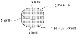
図1において符号1で示されるものは、円盤型又はタブレット型をなすマグネットであり、このマグネット1の表面である第1面2、第2面3及び第3面4、すなわち、表面の全面にわたり、周知のポリウレア樹脂10が塗布等で設けられている。
尚、前記ポリウレア樹脂10をマグネット1に設ける手段としては、塗布、噴霧、貼り付け、浸漬の何れかである。
Hereinafter, a preferred embodiment of the magnet structure according to the present invention and a method for producing the same will be described with reference to the drawings.
In FIG. 1, what is indicated by reference numeral 1 is a disk-shaped or tablet-shaped magnet, which covers the first surface 2, the second surface 3, and the third surface 4, that is, the entire surface of the magnet 1. , A well-known polyurea resin 10 is provided by coating or the like.
The means for providing the polyurea resin 10 on the magnet 1 is any of coating, spraying, pasting, and dipping.
前記ポリウレア樹脂10は、周知のように、その特徴は、強度と柔軟性であり、コンクリート並の強度を持ちながら、そのグレードによっては、400%以上の伸長率を誇るものもあり、その柔軟性がもたらす強度は、軍事施設の防爆対策として用いられるほどのものである。
また、その施工法は極めて簡単で、スプレーによる塗布によって100平方メートル/1日の施工が可能で、マグネットに施した場合には、マグネットの割れや欠け等に絶大な保護、絶大な外部衝撃に対する防止力を発揮するものである。
また、このポリウレア樹脂10は、対薬品性にもすぐれ、水中、油中、ガス中においても、マグネット1の保護が完全に行われ、また、過酷な屋外環境下でもマグネット1の保護は完全に行われる。
従って、耐薬品腐食性、耐爆性及び耐摩耗性にすぐれた特性を発揮することができる。
As is well known, the polyurea resin 10 is characterized by strength and flexibility, and while having strength comparable to that of concrete, some grades boast an elongation rate of 400% or more, and the flexibility thereof. The strength it brings is enough to be used as an explosion-proof measure for military facilities.
In addition, the construction method is extremely simple, and it is possible to construct 100 square meters / day by applying with a spray. It exerts its power.
In addition, this polyurea resin 10 has excellent chemical resistance, and the magnet 1 is completely protected even in water, oil, and gas, and the magnet 1 is completely protected even in a harsh outdoor environment. Will be done.
Therefore, it is possible to exhibit excellent properties of chemical corrosion resistance, explosion resistance and wear resistance.
また、図1のマグネット1は、その全面にポリウレア樹脂10を、スプレー等によって塗布して設けることにより、マグネット1全面をポリウレア樹脂10で覆っている状態を示しているが、前記マグネット1の一部を図示しない相手方へ取付けるための取付面として用いる場合は、この取付面には、ポリウレア樹脂10を設けなくてもよく、一面を除く全ての面に設けた場合でも、すなわち、一面を除く全ての面とは、図1では、第3面4を除き、第1、第2面2、3が全ての面である。また、図2では、第5面6を除き、第1、第2、第3、第4、第6面2、3、4、5、7が全ての面であり、一面は通常、モータ等への取付面として用いられることが多い。尚、前述の全面形成の時と同様の強度をもつことができる。 Further, the magnet 1 in FIG. 1 shows a state in which the entire surface of the magnet 1 is covered with the polyurea resin 10 by applying the polyurea resin 10 to the entire surface thereof by spraying or the like. When the portion is used as a mounting surface for mounting to a partner (not shown), the polyurea resin 10 does not have to be provided on this mounting surface, and even if the portion is provided on all surfaces except one surface, that is, all except one surface. In FIG. 1, the first surface, the second surface 2, and 3 are all surfaces except the third surface 4. Further, in FIG. 2, except for the fifth surface 6, the first, second, third, fourth, and sixth surfaces 2, 3, 4, 5, and 7 are all surfaces, and one surface is usually a motor or the like. Often used as a mounting surface for. It should be noted that the strength can be the same as that of the above-mentioned full surface formation.
また、前述のマグネット1の強度が向上するのは、ポリウレア樹脂10を設けていない時の前記マグネット1の強度よりも向上していることを示しており、前記ポリウレア樹脂は、インシアネートとアミンが反応して生成されるウレア結合を主体とする化合物で、固化する前は溶融物である。
また、耐酸性、耐アルカリ性、耐候性、弾性や引張り強度等にすぐれ、物性が非常に安定している。
また、硬化までの時間も短く安定した施工性もあるため、ポリウレアの被膜はコンクリートや金属のライニングとして利用される場合が多く、モータ等のマグネットに用いられることは、前述したように最適であると云える。
Further, the improvement in the strength of the above-mentioned magnet 1 indicates that the strength is higher than that of the magnet 1 when the polyurea resin 10 is not provided, and the polyurea resin contains incyanate and amine. It is a compound mainly composed of urea bonds produced by reaction, and is a melt before solidification.
In addition, it has excellent acid resistance, alkali resistance, weather resistance, elasticity, tensile strength, etc., and its physical properties are very stable.
In addition, since the time to cure is short and stable workability is achieved, the polyurea coating is often used as a lining for concrete or metal, and it is optimal to use it for magnets such as motors as described above. It can be said.
また、本発明による前述のマグネット1は、円盤型又はタブレット型の形状で構成されているが、図2は図1の他の形態として四角板状のマグネット1を示し、マグネット1の面としては、第1~第6面2~7が形成され、前記各面2~7にポリウレア樹脂10が塗布等で設けられ、マグネット1全体がポリウレア樹脂10で覆われている。
また、前記第5面6が、仮に、図示しない相手方に接着剤等で取付ける取付面である場合には、この取付面のみは、前述の一面として、前記ポリウレア樹脂10を設けないようにすることもできる。
さらに、図3は、図1の他の形態を示すもので、弧状板型のマグネット1を示している。
図3に示されるマグネット1は、例えば、図示しないモータのロータの外周に多数貼り付けて輪状に形成されるためのもので、モータのロータのマグネットの強度を大幅に向上させることができる。
従って、マグネット1の形状は、一例として、円柱形、円盤形、板状形、断面弧状をなす長板形、三角形の何れか1つとすることができる。
Further, the above-mentioned magnet 1 according to the present invention is configured in a disk-shaped or tablet-shaped shape, but FIG. 2 shows a square plate-shaped magnet 1 as another form of FIG. 1, and the surface of the magnet 1 is , 1st to 6th surfaces 2 to 7 are formed, polyurea resin 10 is provided on each of the surfaces 2 to 7 by coating or the like, and the entire magnet 1 is covered with the polyurea resin 10.
Further, if the fifth surface 6 is a mounting surface to be attached to a counterparty (not shown) with an adhesive or the like, only this mounting surface should not be provided with the polyurea resin 10 as the above-mentioned one surface. You can also.
Further, FIG. 3 shows another form of FIG. 1, and shows an arcuate plate type magnet 1.
A large number of magnets 1 shown in FIG. 3 are attached to the outer periphery of a rotor of a motor (not shown) to be formed in a ring shape, and the strength of the magnet of the rotor of the motor can be significantly improved.
Therefore, the shape of the magnet 1 can be, for example, any one of a cylinder, a disk, a plate, a long plate having an arc-shaped cross section, and a triangle.
本発明によるマグネット構造及びその製法は、所定の形状をなすマグネットの全面又は一面を除く全ての面に、ポリウレア樹脂を設けて、マグネットの強度を向上させることがきるため、このマグネットを用いるモータ等の品質及び信頼性を著しく向上させることができる。 In the magnet structure and its manufacturing method according to the present invention, polyurea resin can be provided on all surfaces or all surfaces of a magnet having a predetermined shape to improve the strength of the magnet. Therefore, a motor or the like using this magnet or the like. The quality and reliability of the magnet can be significantly improved.
1 マグネット
2 第1面
3 第2面
4 第3面
5 第4面
6 第5面
7 第6面
10 ポリウレア樹脂
1 Magnet 2 1st surface 3 2nd surface 4 3rd surface 5 4th surface 6 5th surface 7 6th surface 10 Polyurea resin
Claims (8)
Priority Applications (1)
| Application Number | Priority Date | Filing Date | Title |
|---|---|---|---|
| JP2020183442A JP2022073451A (en) | 2020-11-02 | 2020-11-02 | Magnet structure and method for manufacturing the same |
Applications Claiming Priority (1)
| Application Number | Priority Date | Filing Date | Title |
|---|---|---|---|
| JP2020183442A JP2022073451A (en) | 2020-11-02 | 2020-11-02 | Magnet structure and method for manufacturing the same |
Publications (2)
| Publication Number | Publication Date |
|---|---|
| JP2022073451A true JP2022073451A (en) | 2022-05-17 |
| JP2022073451A5 JP2022073451A5 (en) | 2023-11-01 |
Family
ID=81605283
Family Applications (1)
| Application Number | Title | Priority Date | Filing Date |
|---|---|---|---|
| JP2020183442A Pending JP2022073451A (en) | 2020-11-02 | 2020-11-02 | Magnet structure and method for manufacturing the same |
Country Status (1)
| Country | Link |
|---|---|
| JP (1) | JP2022073451A (en) |
-
2020
- 2020-11-02 JP JP2020183442A patent/JP2022073451A/en active Pending
Similar Documents
| Publication | Publication Date | Title |
|---|---|---|
| JP6940007B2 (en) | Manufacturing method of laminated core, core block, rotary electric machine and core block | |
| US20070245543A1 (en) | Rotary electric machine | |
| JP4674679B2 (en) | Stator structure of variable reluctance resolver | |
| JP6709813B2 (en) | Casing unit for electric machine | |
| CN103312062A (en) | Magnet installation type rotor | |
| US9604676B2 (en) | Method of providing a corrosion barrier between dissimilar metals with an epoxy insulator | |
| JP2022073451A (en) | Magnet structure and method for manufacturing the same | |
| CN201695265U (en) | Composite antiseptic type steel strand | |
| WO2017022590A1 (en) | Resolver | |
| JP2007018732A (en) | Wire, coil, stator coil, rotor coil, transformer and manufacturing method of wire | |
| KR20220100941A (en) | Permanent magnet rotor structure of submersible motors, submersible motors and submersible installations | |
| JP2005318765A (en) | Rotor core and rotor | |
| JP2022073452A (en) | Surface protection structure of magnet for motor and method of the same | |
| US9203270B2 (en) | Stator core with varied lamination shapes and sizes to reduce wire insulation stress | |
| US4726443A (en) | Diaphragm | |
| JP2010193568A (en) | Integral assembly composed of motor case and magnet in electric motor, and method of manufacturing the same | |
| CN100368648C (en) | Integral-filled type plastic-coated steel twisted line | |
| CN211922537U (en) | A safety gate for hydraulic engineering | |
| CN202651910U (en) | DD motor having aluminum varnished wire | |
| JPS5933830B2 (en) | Heat exchanger manufacturing method | |
| CN211043751U (en) | Optical cable steel wire | |
| JP2008010726A (en) | Rare earth bond magnet | |
| CN205862830U (en) | High adhesion force enamel-covered wire | |
| CN112615518B (en) | Magnetic gear and composite motor with same | |
| JP3134304B2 (en) | motor |
Legal Events
| Date | Code | Title | Description |
|---|---|---|---|
| A521 | Request for written amendment filed |
Free format text: JAPANESE INTERMEDIATE CODE: A523 Effective date: 20231024 |
|
| A621 | Written request for application examination |
Free format text: JAPANESE INTERMEDIATE CODE: A621 Effective date: 20231024 |