JP2022050737A - Laminated sheet, continuous sheet and tag for baggage - Google Patents

Laminated sheet, continuous sheet and tag for baggage Download PDF

Info

Publication number
JP2022050737A
JP2022050737A JP2020156835A JP2020156835A JP2022050737A JP 2022050737 A JP2022050737 A JP 2022050737A JP 2020156835 A JP2020156835 A JP 2020156835A JP 2020156835 A JP2020156835 A JP 2020156835A JP 2022050737 A JP2022050737 A JP 2022050737A
Authority
JP
Japan
Prior art keywords
adhesive
base material
laminated sheet
self
layer
Prior art date
Legal status (The legal status is an assumption and is not a legal conclusion. Google has not performed a legal analysis and makes no representation as to the accuracy of the status listed.)
Granted
Application number
JP2020156835A
Other languages
Japanese (ja)
Other versions
JP7552187B2 (en
Inventor
俊輔 宮内
Shunsuke Miyauchi
Current Assignee (The listed assignees may be inaccurate. Google has not performed a legal analysis and makes no representation or warranty as to the accuracy of the list.)
Dai Nippon Printing Co Ltd
Original Assignee
Dai Nippon Printing Co Ltd
Priority date (The priority date is an assumption and is not a legal conclusion. Google has not performed a legal analysis and makes no representation as to the accuracy of the date listed.)
Filing date
Publication date
Application filed by Dai Nippon Printing Co Ltd filed Critical Dai Nippon Printing Co Ltd
Priority to JP2020156835A priority Critical patent/JP7552187B2/en
Publication of JP2022050737A publication Critical patent/JP2022050737A/en
Application granted granted Critical
Publication of JP7552187B2 publication Critical patent/JP7552187B2/en
Active legal-status Critical Current
Anticipated expiration legal-status Critical

Links

Images

Landscapes

  • Adhesive Tapes (AREA)
  • Wrappers (AREA)

Abstract

To provide a laminated sheet, a continuous sheet, and a tag for baggage that can save exposed adhesion and can be easily fixed on an attachment target object.SOLUTION: In a peelable laminated sheet 1, a surface base material 2 with a delivery slip 2a is bonded to a support base material 6 via adhesive layers 4, 8, a peeling layer 3 is provided between the delivery slip 2a and the support base material 6, and the slip 2a can be peeled off the support base material 6. A self adhesion layer 7 containing pressure-sensitive adhesive is formed on the face of the support base material 6 that is the opposite side to the surface base material 2. In the self adhesion layer 7, an adhesive applied part 7a to which the pressure-sensitive adhesive is applied and a non-adhesive applied part 7b to which the pressure-sensitive adhesive is not applied are formed alternately so as to extend in the oblique direction to one side of the laminated sheet.SELECTED DRAWING: Figure 1

Description

本発明は、長手方向を有する取付対象に巻き付けるための積層シート、連続シートおよび手荷物用タグに関する。 The present invention relates to a laminated sheet, a continuous sheet and a baggage tag for wrapping around a mounting object having a longitudinal direction.

従来、手荷物(キャリーバッグ、リュック、ボストンバッグなど)を配送する場合、手荷物を樹脂製の透明カバーで覆い、透明カバーにあるポケットに配送先を表示した配送伝票を入れて運ぶ運用であったり、大きめのタグを手荷物に巻きつけ、タグに配送伝票を貼ったり、袋型のタグを手荷物に巻きつけ、タグ(袋)の中に配送伝票を入れるなど、配送伝票を用いた運用が多く行われている。このとき用いられる配送伝票としては、複数の基材を積層した積層シートの形態であって、粘着層、剥離層を用いたものが用いられる(特許文献1参照)。 Conventionally, when delivering baggage (carry bag, backpack, Boston bag, etc.), the baggage is covered with a transparent resin cover, and a delivery slip indicating the delivery address is put in the pocket on the transparent cover. Many operations are performed using delivery slips, such as wrapping a large tag around baggage and attaching a delivery slip to the tag, wrapping a bag-shaped tag around baggage, and putting the delivery slip in the tag (bag). ing. As the delivery slip used at this time, a laminated sheet in which a plurality of base materials are laminated and using an adhesive layer and a release layer is used (see Patent Document 1).

特開2013-94974号公報Japanese Unexamined Patent Publication No. 2013-94974

しかしながら、上記従来の配送伝票では、剥離紙を剥がすと粘着力が比較的強い粘着剤層が表出するため、巻き付けた配送伝票が、手荷物の取っ手に付着して手荷物を汚す惧れがある。この対策として一部の粘着剤を表出させて接着させる方法が考えられるが、巻き付ける手荷物の取っ手部と断面を輪状にする配送伝票の間に空間ができてしまい、配送伝票を固定するのが難しい。また、荷物に巻き付けるために表出させている接着剤等を節約したいという要望もある。 However, in the above-mentioned conventional delivery slip, when the release paper is peeled off, an adhesive layer having a relatively strong adhesive force is exposed, so that the wrapped delivery slip may adhere to the handle of the baggage and stain the baggage. As a countermeasure, a method of exposing and adhering a part of the adhesive can be considered, but a space is created between the handle of the baggage to be wrapped and the delivery slip having a ring-shaped cross section, and the delivery slip is fixed. difficult. There is also a desire to save on the adhesive and the like that are exposed for wrapping around luggage.

そこで、本発明は、表出した接着剤を節約することが可能であるとともに、取付対象に容易に固定することが可能な積層シート、連続シートおよび手荷物用タグを提供することを課題とする。 Therefore, it is an object of the present invention to provide a laminated sheet, a continuous sheet, and a baggage tag, which can save the exposed adhesive and can be easily fixed to an attachment target.

上記課題を解決するため、本発明では、
剥離片を有する表面基材と支持基材とが接着剤層を介して接着されており、前記剥離片と支持基材の間には、剥離層が設けられて、前記支持基材から前記剥離片が剥離可能な積層シートであって、
前記支持基材の前記表面基材と反対側の面には、感圧接着剤を含んだ自着層が形成されており、前記自着層は、前記感圧接着剤が塗布された接着剤塗布部と、前記感圧接着剤が塗布されていない接着剤非塗布部が、積層シートの一辺に対して斜め方向に延びるように交互に形成されている、積層シートを提供する。
In order to solve the above problems, the present invention
A surface base material having a peeling piece and a supporting base material are adhered to each other via an adhesive layer, and a peeling layer is provided between the peeling piece and the supporting base material, and the peeling piece is separated from the supporting base material. A laminated sheet whose pieces can be peeled off,
A self-adhesive layer containing a pressure-sensitive adhesive is formed on the surface of the support base material opposite to the surface base material, and the self-adhesive layer is an adhesive to which the pressure-sensitive adhesive is applied. Provided is a laminated sheet in which a coated portion and an adhesive non-applied portion to which the pressure-sensitive adhesive is not applied are alternately formed so as to extend diagonally with respect to one side of the laminated sheet.

また、本発明に係る積層シートは、
前記接着剤塗布部の幅は、前記接着剤非塗布部の幅より狭くてもよい。
Further, the laminated sheet according to the present invention is
The width of the adhesive-applied portion may be narrower than the width of the adhesive-non-applied portion.

また、本発明に係る積層シートは、
前記接着剤塗布部が、前記積層シートの一辺となす角度は、30度以上60度以下であってもよい。
Further, the laminated sheet according to the present invention is
The angle formed by the adhesive-applied portion with one side of the laminated sheet may be 30 degrees or more and 60 degrees or less.

また、本発明に係る積層シートは、
前記剥離片の表面、および前記表面基材における前記剥離片以外の部分の表面には、配送情報欄が形成されており、配送伝票として機能するようにしてもよい。
Further, the laminated sheet according to the present invention is
A delivery information column may be formed on the surface of the peeled piece and the surface of the portion of the surface substrate other than the peeled piece so as to function as a delivery slip.

また、本発明に係る積層シートは、
前記剥離片の表面、および前記表面基材における前記剥離片以外の部分の表面には、配送情報欄が形成されており、前記表面基材における前記剥離片以外に形成された配送情報欄以外の部分に重ねられた自着層が、取付対象に巻き付けるための取付部として機能するようにしてもよい。
Further, the laminated sheet according to the present invention is
A delivery information column is formed on the surface of the peeled piece and the surface of the portion of the surface base material other than the peeled piece, except for the delivery information column formed on the surface base material other than the peeled piece. The self-adhesive layer superimposed on the portion may function as a mounting portion for winding around the mounting target.

また、本発明では、
前記積層シートが切り離し予定線を介して複数連接されてなる連続シートであって、
隣接する各前記積層シートの接着剤塗布部が延びる方向が、前記切り離し予定線に対して互いに対称な方向であり、
前記切り離し予定線における接着剤塗布部の端部の中心が互いにずれている、連続シートを提供する。
Further, in the present invention,
It is a continuous sheet in which a plurality of laminated sheets are connected via a planned separation line.
The direction in which the adhesive-applied portion of each of the adjacent laminated sheets extends is a direction symmetrical to the planned separation line.
Provided is a continuous sheet in which the centers of the ends of the adhesive-applied portion on the planned cutting line are offset from each other.

また、本発明では、
剥離片を有する表面基材と支持基材とが接着剤層を介して接着されているとともに、前記剥離片と支持基材の間には、剥離層が設けられて、前記支持基材から前記剥離片が剥離可能な手荷物用タグであって、
前記支持基材の前記表面基材と反対側の面には、感圧接着剤を含んだ自着層が形成されており、前記自着層は、前記感圧接着剤が塗布された接着剤塗布部と、前記感圧接着剤が塗布されていない接着剤非塗布部が、積層シートの一辺に対して斜め方向に延びるように交互に形成されている手荷物用タグを提供する。
Further, in the present invention,
A surface base material having a peeling piece and a supporting base material are adhered to each other via an adhesive layer, and a peeling layer is provided between the peeling piece and the supporting base material, and the support base material is separated from the support base material. A baggage tag that can be peeled off,
A self-adhesive layer containing a pressure-sensitive adhesive is formed on the surface of the support base material opposite to the surface base material, and the self-adhesive layer is an adhesive to which the pressure-sensitive adhesive is applied. Provided is a baggage tag in which a coated portion and a non-adhesive-coated portion to which the pressure-sensitive adhesive is not applied are alternately formed so as to extend diagonally with respect to one side of the laminated sheet.

本発明によれば、表出した接着剤を節約することが可能であるとともに、取付対象を汚す惧れを低減しつつ、取付対象に容易に固定することが可能となる。 According to the present invention, it is possible to save the exposed adhesive and to easily fix the mounting target to the mounting target while reducing the risk of soiling the mounting target.

本発明の一実施形態に係る積層シートを示す図である。It is a figure which shows the laminated sheet which concerns on one Embodiment of this invention. 本発明の一実施形態に係る連続シートを示す図である。It is a figure which shows the continuous sheet which concerns on one Embodiment of this invention. 図2(b)におけるB部分の拡大図である。It is an enlarged view of the B part in FIG. 2 (b). 本発明の一実施形態に係る積層シートの使用例を示す図である。It is a figure which shows the use example of the laminated sheet which concerns on one Embodiment of this invention. 自着層7どうしが重ねられた状態を示す図である。It is a figure which shows the state which the self-adhesive layers 7 are overlapped with each other.

以下、本発明の好適な実施形態について、図面を参照して詳細に説明する。
<1.積層シートの構成>
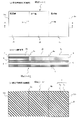
図1は、本発明の一実施形態に係る積層シートを示す図である。図1においては、一例として手荷物タグの形態をした積層シートを示している。図1のうち、図1(a)は表側平面図、図1(b)は図1(a)におけるA-Aに対応する断面図、図1(c)は裏側平面図である。積層シート1において、実際には、どちらを表(おもて)側、どちらを裏側としてもよいが、便宜上、図1(a)に示す側を表側、図1(c)に示す側を裏側として、以下説明していく。また、図1(b)の層構成において、どちらが上層であってどちらが下層であってもよいが、便宜上、図1(b)の上側(表面基材2の側)を上層、図1(b)の下側(自着層7の側)を下層として、以下説明していく。図1において表現された各層の厚みの比率、各層の厚みと平面図の面積との比率については、図示の都合上、必ずしも実際のものと同じではない。
Hereinafter, preferred embodiments of the present invention will be described in detail with reference to the drawings.
<1. Laminated sheet configuration>
FIG. 1 is a diagram showing a laminated sheet according to an embodiment of the present invention. FIG. 1 shows a laminated sheet in the form of a baggage tag as an example. 1A is a front side plan view, FIG. 1B is a cross-sectional view corresponding to AA in FIG. 1A, and FIG. 1C is a back side plan view. In the laminated sheet 1, either side may actually be the front side and either side may be the back side, but for convenience, the side shown in FIG. 1 (a) is the front side and the side shown in FIG. 1 (c) is the back side. Will be explained below. Further, in the layer structure of FIG. 1 (b), which may be the upper layer and which may be the lower layer, but for convenience, the upper side (the side of the surface base material 2) of FIG. 1 (b) is the upper layer, and FIG. 1 (b). ) (The side of the self-adhesive layer 7) will be referred to as a lower layer, and the following description will be made. The ratio of the thickness of each layer and the ratio of the thickness of each layer to the area of the plan view expressed in FIG. 1 are not necessarily the same as the actual ones for the convenience of illustration.

図1に示すように、本実施形態に係る積層シートは、手荷物タグとしての機能も備えている。手荷物タグは、空港等において、手荷物を管理するために、手荷物に添付するためのものであり、荷物を配送するための配送伝票などと実質的に同じ機能を有している。そのため、表面に配送情報欄(図示省略)が印刷された配達票2aと、表面に配送情報欄(図示省略)が印字された貼付票2bと、荷物に取り付けるための取付部2cが図中左右方向(横方向)に配置された表面基材2が最上層に設けられている。すなわち、剥離片である配達票2aの表面、および表面基材2における剥離片以外の部分である貼付票2bの表面には、配送情報欄が形成されている。 As shown in FIG. 1, the laminated sheet according to the present embodiment also has a function as a baggage tag. The baggage tag is attached to the baggage in order to manage the baggage at an airport or the like, and has substantially the same function as a delivery slip for delivering the baggage. Therefore, the delivery slip 2a on which the delivery information column (not shown) is printed on the surface, the affixed slip 2b on which the delivery information column (not shown) is printed on the surface, and the mounting portion 2c for attaching to the luggage are left and right in the figure. The surface base material 2 arranged in the direction (horizontal direction) is provided on the uppermost layer. That is, a delivery information column is formed on the surface of the delivery slip 2a which is a peeling piece and the surface of the sticking slip 2b which is a portion other than the peeling piece in the surface base material 2.

そして、表面基材2における剥離片以外の部分である貼付票2bに形成された配送情報欄以外の部分である取付部2cに重ねられた自着層7が、取付部2cとともに取付対象に巻き付けるために機能する。配送情報欄は、一般的な配送伝票に形成されるものであり、図示を省略しているが、記入/印字枠を備え、その記入/印字枠内に、届け先・送り主双方の住所・氏名等が記入及び/または印字が可能となっている。 Then, the self-adhesive layer 7 overlapped with the attachment portion 2c, which is a portion other than the delivery information column formed on the attachment slip 2b, which is a portion other than the peeled piece of the surface base material 2, is wound around the attachment target together with the attachment portion 2c. Works for. The delivery information column is formed in a general delivery slip, and although not shown, it is provided with an entry / print frame, and the address, name, etc. of both the delivery address and the sender are provided in the entry / print frame. Can be filled in and / or printed.

表面基材2は、図1(a)に示すように、図面上下方向(縦方向)に形成された分離予定線9aにより配達票2aと貼付票2bに分離可能に形成されている。分離予定線9aとしては、剥離片である配達票2aを分離可能なものであれば、ミシン目その他、どのような形態のものであっても良いが、本実施形態では、表面基材2を貫通し、支持基材6まで達していない切込みとしている。すなわち、本実施形態では、積層シート1全体としてみれば、分離予定線9aはハーフカット構造の切込みとなっている。 As shown in FIG. 1A, the surface base material 2 is separably formed into a delivery slip 2a and a sticking slip 2b by a planned separation line 9a formed in the vertical direction (vertical direction) of the drawing. The planned separation line 9a may be of any form such as a perforation or the like as long as the delivery slip 2a which is a peeling piece can be separated. However, in the present embodiment, the surface base material 2 is used. It is a notch that penetrates and does not reach the support base material 6. That is, in the present embodiment, the planned separation line 9a is a notch having a half-cut structure when viewed from the laminated sheet 1 as a whole.

また、図1(a)に示すように、表面基材2には、取付部2cが設けられており、図面上下方向(縦方向)に形成された区分線9bにより貼付票2bと区分されている。本実施形態では、区分線9bとして、ミシン目が形成されている。 Further, as shown in FIG. 1A, the surface base material 2 is provided with a mounting portion 2c, and is separated from the sticking slip 2b by a dividing line 9b formed in the vertical direction (vertical direction) of the drawing. There is. In the present embodiment, perforations are formed as the dividing line 9b.

図1(b)のA-A断面図に示すように、配達票2a(表面基材2)の下層には、剥離層3、接着剤層4を介して、表面に目止め層5、裏面に自着層7が設けられた支持基材6が重ね合わされている。すなわち、配達票2a、剥離層3、接着剤層4、目止め層5、支持基材6、自着層7の順に積層されている。自着層7は、最下層として表出した状態となっている。また、剥離層3と接着剤層4の2つの層により擬似的に接着可能な擬似接着構造を実現している。剥離層3の存在により、支持基材6から剥離片である配達票2aが剥離可能となっている。そして、貼付票2b(表面基材2)の下層では、目止め層5、支持基材6、自着層7の構成は、配達票2aの下層と同じであるが、剥離層を有さず、接着剤層8のみが設けられている点が異なっている。強接着の接着剤層8により、貼付票2bは、支持基材6から剥離することが困難なようになっている。 As shown in the cross-sectional view taken along the line AA of FIG. 1 (b), the lower layer of the delivery slip 2a (surface base material 2) has a sealing layer 5 on the front surface and a back surface via the release layer 3 and the adhesive layer 4. A support base material 6 provided with a self-adhesive layer 7 is superposed on the surface. That is, the delivery slip 2a, the peeling layer 3, the adhesive layer 4, the sealing layer 5, the supporting base material 6, and the self-adhesive layer 7 are laminated in this order. The self-adhesive layer 7 is in a state of being exposed as the lowest layer. Further, the two layers of the peeling layer 3 and the adhesive layer 4 realize a pseudo-adhesive structure capable of pseudo-adhesion. Due to the presence of the peeling layer 3, the delivery slip 2a, which is a peeling piece, can be peeled from the supporting base material 6. In the lower layer of the sticking slip 2b (surface base material 2), the composition of the sealing layer 5, the supporting base material 6, and the self-adhesive layer 7 is the same as that of the lower layer of the delivery slip 2a, but without a peeling layer. The difference is that only the adhesive layer 8 is provided. The strong adhesive layer 8 makes it difficult for the sticking slip 2b to be peeled off from the supporting base material 6.

本実施形態では、接着剤層4と接着剤層8に用いられる接着剤として、同一のものを採用しているが、互いに異なるものを採用しても良い。積層シート1は、取付部2cを屈曲させて、配送物等の取付対象の一部に巻き付け、自着層7どうしを貼り合わせて使用する。 In the present embodiment, the same adhesive is used for the adhesive layer 4 and the adhesive layer 8, but different adhesives may be used. The laminated sheet 1 is used by bending the mounting portion 2c, winding it around a part of the mounting target such as a delivered product, and laminating the self-adhesive layers 7 to each other.

なお、図1(b)のA-A断面図においては、図面の簡略化のため、各層の厚みを略同一にして示してあるが、現実には、後述するように各層の厚みは異なっている。また、図1(b)のA-A断面図においては、図面左右方向の長さと図面上下方向の厚さの比率は現実のものとは異なっている。現実には、図面左右方向の長さは、数cm~数十cm程度であるのに対して、図面上下方向の厚さは、数百μm程度である。もちろん、この長さ、厚さに限定されるものではない。また、配達票2a(表面基材2)の下層においては、剥離層3、接着剤層4、支持基材6は配達票2aの全面に渡って設けられている。 In the cross-sectional view taken along the line AA of FIG. 1B, the thickness of each layer is shown to be substantially the same for the sake of simplification of the drawing, but in reality, the thickness of each layer is different as described later. There is. Further, in the cross-sectional view taken along the line AA of FIG. 1B, the ratio of the length in the left-right direction of the drawing to the thickness in the up-down direction of the drawing is different from the actual one. In reality, the length in the left-right direction of the drawing is about several cm to several tens of cm, while the thickness in the vertical direction of the drawing is about several hundred μm. Of course, it is not limited to this length and thickness. Further, in the lower layer of the delivery slip 2a (surface base material 2), the release layer 3, the adhesive layer 4, and the support base material 6 are provided over the entire surface of the delivery slip 2a.

<2.各層の組成>
表面基材2としては、充分な強度とプリンターによる印字適性及び搬送適性を有するものであれば使用でき、例えば、上質紙、クラフト紙、複写用紙、グラシン紙、パーチメント紙、レーヨン紙、コート紙、合成紙、樹脂フィルムによりラミネートされた紙等の紙が好適に用いられるが、セロファン、延伸ポリプロピレン、ポリエチレンテレフタレート、延伸ポリスチレン、ポリ塩化ビニル等の樹脂フィルムであっても良い。表面基材2の厚さは20~200μm程度が好ましい。さらに、控票などを積層シート1等の上に重ねた場合に、複写特性をもたせるために、ロイコ系染料などからなる感熱発色層を設けても良い。支持基材6としても、表面基材2と同様のものを用いることができる。
<2. Composition of each layer>
The surface base material 2 can be used as long as it has sufficient strength, printability by a printer, and transportability. For example, high-quality paper, kraft paper, copy paper, glassin paper, parchment paper, rayon paper, coated paper, etc. Paper such as synthetic paper and paper laminated with a resin film is preferably used, but resin films such as cellophane, stretched polypropylene, polyethylene terephthalate, stretched polystyrene, and polyvinyl chloride may also be used. The thickness of the surface base material 2 is preferably about 20 to 200 μm. Further, when a voucher or the like is stacked on the laminated sheet 1 or the like, a heat-sensitive color-developing layer made of a leuco-based dye or the like may be provided in order to have copying characteristics. As the support base material 6, the same material as that of the surface base material 2 can be used.

上記剥離層3、接着剤層4、目止め層5、自着層7は、本実施形態に係る積層シートに適したものであれば、その組成については特に限定されるものではないが、好ましい例を以下に列挙する。 The composition of the release layer 3, the adhesive layer 4, the sealing layer 5, and the self-adhesive layer 7 is not particularly limited as long as it is suitable for the laminated sheet according to the present embodiment, but is preferable. Examples are listed below.

剥離層3としては、配達票2aが支持基材6から容易に剥離できるような接着性の低い樹脂を使用することが好ましく、ポリエチレン、ポリプロピレン、ポリブチレン等のオレフィン系(共)重合体を用いることが最も好ましいが、他にも、ポリスチレン、ポリビニルブチラール、酢酸ビニル重合体、エチレン-酢酸ビニル共重合体、塩化ビニル-酢酸ビニル共重合体、アクリル樹脂、セルロース樹脂等の熱可塑性樹脂及びこれらの混合物からなるフィルムでも良い。また、ポリウレタン等の熱硬化性樹脂等から形成されたフィルムを用いても良い。さらに、所望に応じて、酸化防止剤、熱安定剤、紫外線吸収剤、スリップ剤、帯電防止剤、防曇剤、着色剤、フィラー等が添加されていても良い。剥離層3を形成するための樹脂の塗布量と塗布厚は特に限定されないが、好ましくは、塗布量は0.1~10g/m2であり、塗布厚は0.1~10μmである。 As the release layer 3, it is preferable to use a resin having low adhesiveness so that the delivery slip 2a can be easily peeled from the support base material 6, and an olefin-based (co) polymer such as polyethylene, polypropylene, or polybutylene is used. Is most preferable, but in addition, thermoplastic resins such as polystyrene, polyvinyl butyral, vinyl acetate polymer, ethylene-vinyl acetate copolymer, vinyl chloride-vinyl acetate copolymer, acrylic resin, cellulose resin and the like, and mixtures thereof. It may be a film made of. Further, a film formed of a thermosetting resin such as polyurethane may be used. Further, if desired, an antioxidant, a heat stabilizer, an ultraviolet absorber, a slip agent, an antistatic agent, an anti-fog agent, a colorant, a filler and the like may be added. The coating amount and coating thickness of the resin for forming the release layer 3 are not particularly limited, but the coating amount is preferably 0.1 to 10 g / m 2 , and the coating thickness is 0.1 to 10 μm.

接着剤層4は、例えば、ウレタン系、アクリル系などの熱可塑性樹脂を使用することができ、フレキソ法、グラビア法などの公知の印刷法又はコーティング法によって、厚み0.1~50μm程度に塗布し、貼り合わせ後に、必要に応じて乾燥させる。表面基材2と支持基材6は、接着剤(又は樹脂)が乾燥していない状態で貼り合わせるウェット又はセミウェットラミネート方式、熱圧着方式や感圧方式によって貼り合わせる。 For the adhesive layer 4, for example, a thermoplastic resin such as urethane-based or acrylic-based can be used, and the adhesive layer 4 is coated to a thickness of about 0.1 to 50 μm by a known printing method such as a flexographic method or a gravure method or a coating method. After bonding, it is dried if necessary. The surface base material 2 and the support base material 6 are bonded by a wet or semi-wet laminating method, a thermocompression bonding method, or a pressure-sensitive method in which the adhesive (or resin) is bonded in a non-dried state.

目止め層5は、接着剤層4、8の接着剤が支持基材6に浸透しないように支持基材6の目止めをするための層であり、ポリエチレン、ポリビニルアルコール、クレー等を用いることができる。目止め層5を形成するための目止め剤の塗布量と塗布厚は特に限定されないが、好ましくは、塗布量は0.1~20g/m2であり、塗布厚は0.1~20μmである。 The sealing layer 5 is a layer for sealing the supporting base material 6 so that the adhesives of the adhesive layers 4 and 8 do not penetrate into the supporting base material 6, and polyethylene, polyvinyl alcohol, clay, or the like is used. Can be done. The coating amount and coating thickness of the sealing agent for forming the sealing layer 5 are not particularly limited, but preferably the coating amount is 0.1 to 20 g / m 2 and the coating thickness is 0.1 to 20 μm. be.

自着層7は、自着層どうしを比較的弱い圧力で接着することが可能な層であり、感圧接着剤を含んでいる。自着層7に用いる感圧接着剤としては、天然ゴム系感圧接着剤が最も好ましいが、アクリル系感圧接着剤、合成ゴム系感圧接着剤、シリコーンゴム系感圧接着剤等でも良い。自着層7を形成するための感圧接着剤の塗布量と塗布厚は特に限定されないが、好ましくは、塗布量は0.1~50g/m2であり、塗布厚は0.1~50μmである。特に、天然ゴム系の感圧接着剤は、粘着力が比較的弱く、また、粘着力の調整も比較的容易であるため、自着層7の形成に適している。自着層7は、同じ組成のものどうしが重ね合さらないと接着しない。そのため、自着層7を下側にして台に置いて、表面基材2の配達票2aや貼付票2bに記入を行ったとしても、自着層7が台に接着する惧れは少ない。 The self-adhesive layer 7 is a layer capable of adhering the self-adhesive layers to each other with a relatively weak pressure, and contains a pressure-sensitive adhesive. As the pressure-sensitive adhesive used for the self-adhesive layer 7, a natural rubber-based pressure-sensitive adhesive is most preferable, but an acrylic-based pressure-sensitive adhesive, a synthetic rubber-based pressure-sensitive adhesive, a silicone rubber-based pressure-sensitive adhesive, or the like may also be used. .. The coating amount and coating thickness of the pressure-sensitive adhesive for forming the self-adhesive layer 7 are not particularly limited, but the coating amount is preferably 0.1 to 50 g / m 2 , and the coating thickness is 0.1 to 50 μm. Is. In particular, the natural rubber-based pressure-sensitive adhesive is suitable for forming the self-adhesive layer 7 because the adhesive strength is relatively weak and the adhesive strength can be adjusted relatively easily. The self-adhesive layer 7 does not adhere unless the materials having the same composition are overlapped with each other. Therefore, even if the self-adhesive layer 7 is placed on the table with the self-adhesive layer 7 facing down and the delivery slip 2a and the sticking slip 2b of the surface base material 2 are filled in, there is little possibility that the self-adhesive layer 7 adheres to the table.

図1(c)に示すように、自着層7には、感圧接着剤がストライプ状に塗布されている。具体的には、感圧接着剤が塗布された接着剤塗布部7aと、感圧接着剤が塗布されていない接着剤非塗布部7bが、交互に配置されている。本実施形態では、積層シート1は、平面視において矩形状であり、互いに対向する短辺である辺Sa、辺Sbを有している。接着剤塗布部7a、接着剤非塗布部7bは、配達票2a側の辺Saまたは取付部2c側の辺Sbに対して斜め方向に延びるように形成されている。斜め方向とは、なす角度が0度または90度でなく、0度より大きく90度より小さいことを意味する。本実施形態のように、積層シート1の平面形状が矩形である場合、短辺である辺Sa、辺Sbに対して斜め方向であるということは、積層シート1の長辺に対しても斜め方向であることを意味している。接着剤塗布部7a、接着剤非塗布部7bの延伸方向は、1つの積層シート内においては変わることなく、全て同一方向となっている。 As shown in FIG. 1 (c), the pressure-sensitive adhesive is applied to the self-adhesive layer 7 in a striped manner. Specifically, the adhesive-applied portion 7a to which the pressure-sensitive adhesive is applied and the adhesive-non-applied portion 7b to which the pressure-sensitive adhesive is not applied are alternately arranged. In the present embodiment, the laminated sheet 1 has a rectangular shape in a plan view and has sides Sa and sides Sb which are short sides facing each other. The adhesive coated portion 7a and the adhesive non-coated portion 7b are formed so as to extend diagonally with respect to the side Sa on the delivery slip 2a side or the side Sb on the mounting portion 2c side. The diagonal direction means that the angle formed is not 0 degrees or 90 degrees, but is greater than 0 degrees and smaller than 90 degrees. When the planar shape of the laminated sheet 1 is rectangular as in the present embodiment, the diagonal direction with respect to the short sides Sa and Sb means that the laminated sheet 1 is also diagonal with respect to the long side. It means that it is a direction. The stretching directions of the adhesive coated portion 7a and the adhesive non-coated portion 7b do not change in one laminated sheet and are all in the same direction.

自着層7において、接着剤塗布部7a、接着剤非塗布部7bが交互に配置されていることにより、感圧接着剤の塗布量を少なく抑えながら、全体に広く感圧接着剤を塗布することが可能となる。後述するように、取付対象物に積層シート(手荷物タグ)を取り付ける際には、取付部2cを巻き付けるようにして曲げ、取付部2cの下層の自着層7どうしを重ね合わせ、圧力を加えることにより接着させる。この際、辺Saまたは辺Sbに対して平行(0度)または垂直(90度)であると、接着剤塗布部7aが対向する接着剤非塗布部7bに全て収まってしまい、接着剤塗布部7aどうしが重ならないことがある。こうなると、比較的接着力の弱い接着剤塗布部7aでは、対向する取付部2cどうしを接着することができない。このため、取付対象物に手荷物タグを取り付けることができなくなってしまう。 By alternately arranging the adhesive-applied portion 7a and the adhesive-non-applied portion 7b in the self-adhesive layer 7, the pressure-sensitive adhesive is widely applied to the entire surface while suppressing the application amount of the pressure-sensitive adhesive to a small amount. It becomes possible. As will be described later, when attaching a laminated sheet (baggage tag) to an object to be attached, bend the attachment portion 2c so as to wind it around, overlap the self-adhesive layers 7 under the attachment portion 2c, and apply pressure. To bond. At this time, if it is parallel (0 degrees) or perpendicular (90 degrees) to the side Sa or the side Sb, the adhesive coating portion 7a is completely contained in the facing non-adhesive coating portion 7b, and the adhesive coating portion 7a is accommodated. 7a may not overlap. In this case, the adhesive coating portion 7a having a relatively weak adhesive force cannot bond the facing mounting portions 2c to each other. Therefore, it becomes impossible to attach the baggage tag to the object to be attached.

接着剤塗布部7a、接着剤非塗布部7bが延びる方向が辺Sa、辺Sbとなす角度Rは、0度より大きく90度より小さい必要がある(0<R<90)。角度Rは、30度以上60度以下であることが好ましく(30≦R≦60)、40度以上50度以下であることがより好ましい(40≦R≦50)。角度Rが小さ過ぎても大き過ぎても取付部2cを重ね合わせたときの接着剤塗布部7aどうしの接触面積が安定せず、取り付けに必要な接着力を維持することが困難となるためである。本実施形態では、R=45度としている。Rは45度に近付くほど好ましい。なお、角度Rは、最小値0度、最大値90度となるように換算されて求められる。例えば、接着剤塗布部7a、接着剤非塗布部7bが辺Sa、辺Sbとなす角度が90度超180度であるとも言える場合は、その角度を180から減算して、0以上90以下の範囲に換算した値を角度Rとする。 The angle R formed by the adhesive-applied portion 7a and the adhesive-non-applied portion 7b extending in the direction of the side Sa and the side Sb needs to be larger than 0 degrees and smaller than 90 degrees (0 <R <90). The angle R is preferably 30 degrees or more and 60 degrees or less (30 ≦ R ≦ 60), and more preferably 40 degrees or more and 50 degrees or less (40 ≦ R ≦ 50). Even if the angle R is too small or too large, the contact area between the adhesive application parts 7a when the mounting parts 2c are overlapped is not stable, and it becomes difficult to maintain the adhesive force required for mounting. be. In this embodiment, R = 45 degrees. The closer R is to 45 degrees, the more preferable. The angle R is obtained by converting so that the minimum value is 0 degrees and the maximum value is 90 degrees. For example, if it can be said that the angle formed by the adhesive coated portion 7a and the non-adhesive coated portion 7b with the side Sa and the side Sb is more than 90 degrees and 180 degrees, the angle is subtracted from 180 and is 0 or more and 90 or less. The value converted into the range is defined as the angle R.

<3.連続シート>
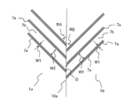
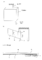
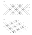
次に、個別の積層シート1が複数連接された連続シートについて説明する。図2は、本発明の一実施形態に係る連続シートを示す図である。本実施形態に係る連続シート10は、ある積層シート1の配達票2a側の短辺である辺Saと、隣接する積層シート1の取付部2c側の短辺である辺Sbを1つの切り離し予定線10aとして、複数の積層シート1を連続させたものである。切り離し予定線10aは、連続シート10の搬送時に折ることができ、最終的に個別の各積層シート1に分離するため、切り離し可能であれば、どのような態様で形成されていてもよい。本実施形態では、切れ目と繋ぎ目(カット部とタイ部)が交互に配置されたミシン目となっている。
<3. Continuous sheet>
Next, a continuous sheet in which a plurality of individual laminated sheets 1 are connected will be described. FIG. 2 is a diagram showing a continuous sheet according to an embodiment of the present invention. In the continuous sheet 10 according to the present embodiment, one side Sa, which is the short side of the delivery slip 2a side of a certain laminated sheet 1, and one side Sb, which is the short side of the adjacent laminated sheet 1 on the mounting portion 2c side, are scheduled to be separated. A plurality of laminated sheets 1 are connected as the line 10a. Since the planned separation line 10a can be folded during the transportation of the continuous sheet 10 and finally separated into each individual laminated sheet 1, it may be formed in any manner as long as it can be separated. In the present embodiment, the cuts and joints (cut portion and tie portion) are alternately arranged as perforations.

また、連続シート10においては、奇数番目の積層シート1と偶数番目の積層シート1で、接着剤塗布部7a、接着剤非塗布部7bの延伸方向が異なる。以下、奇数番目の積層シート1を積層シート1aとし、偶数番目の積層シート1を積層シート1bとして説明する。なお、奇数番目の積層シート1を積層シート1bとし、偶数番目の積層シート1を積層シート1aとしても同じである。積層シート1a、積層シート1bの両方に共通する特徴を説明する場合には、総称して積層シート1と呼ぶ場合もある。 Further, in the continuous sheet 10, the odd-numbered laminated sheet 1 and the even-numbered laminated sheet 1 have different stretching directions of the adhesive coated portion 7a and the adhesive non-coated portion 7b. Hereinafter, the odd-numbered laminated sheet 1 will be referred to as a laminated sheet 1a, and the even-numbered laminated sheet 1 will be referred to as a laminated sheet 1b. The same applies to the case where the odd-numbered laminated sheet 1 is the laminated sheet 1b and the even-numbered laminated sheet 1 is the laminated sheet 1a. When explaining the features common to both the laminated sheet 1a and the laminated sheet 1b, they may be collectively referred to as the laminated sheet 1.

図3は、図2(b)におけるB部分の拡大図である。図3に示すように、本実施形態では、積層シート1aにおいても積層シート1bにおいても、接着剤塗布部7aの幅はW1であり、接着剤非塗布部7bの幅はW2である。また、切り離し予定線10aにおける積層シート1aの接着剤塗布部7aと積層シート1bの接着剤塗布部7aの形成位置は互いにずれている。具体的には、図3に示すように、切り離し予定線10aにおける積層シート1aの接着剤塗布部7aの幅方向の中心どうしの間隔が2Dである場合、切り離し予定線10aにおける積層シート1bの接着剤非塗布部7bの中心どうしの間隔も2Dであり、切り離し予定線10aにおいては、積層シート1aの接着剤塗布部7aの幅方向の中心と、接着剤非塗布部7bの中心が互いにDだけずれている。 FIG. 3 is an enlarged view of a portion B in FIG. 2 (b). As shown in FIG. 3, in the present embodiment, the width of the adhesive coated portion 7a is W1 and the width of the adhesive non-coated portion 7b is W2 in both the laminated sheet 1a and the laminated sheet 1b. Further, the formation positions of the adhesive coating portion 7a of the laminated sheet 1a and the adhesive coating portion 7a of the laminated sheet 1b on the planned cutting line 10a are deviated from each other. Specifically, as shown in FIG. 3, when the distance between the centers in the width direction of the adhesive coating portion 7a of the laminated sheet 1a on the planned cutting line 10a is 2D, the bonding of the laminated sheet 1b on the planned cutting line 10a is performed. The distance between the centers of the non-applied adhesive portion 7b is also 2D, and on the planned separation line 10a, the center in the width direction of the adhesive coated portion 7a of the laminated sheet 1a and the center of the non-applied adhesive portion 7b are only D from each other. It is out of alignment.

切り離し予定線10aを谷折して自着層7どうしが互いに対向するように積層シート1aと積層シート1bを折り畳んだ際、接着剤塗布部7aどうしが接触しないように形成できる限り、接着剤塗布部7aの幅W1、接着剤非塗布部7bの幅W2、切り離し予定線10aにおける、積層シート1aの接着剤塗布部7aの幅方向の中心と、接着剤非塗布部7bの幅方向の中心の距離Dは、適宜設定することができる。製造時における誤差等も考慮して、接着剤非塗布部7bの幅W2は、接着剤塗布部7aの幅W1より1mm以上大きいことが好ましい。例えば、幅W1=1(mm)、幅W2=3(mm)、距離D=2.8(mm)とすることができる。 When the laminated sheet 1a and the laminated sheet 1b are folded so that the self-adhesive layers 7 face each other by folding the planned separation line 10a in a valley, the adhesive is applied as long as it can be formed so that the adhesive application portions 7a do not come into contact with each other. The width W1 of the portion 7a, the width W2 of the adhesive non-applied portion 7b, the center in the width direction of the adhesive coated portion 7a of the laminated sheet 1a and the center in the width direction of the adhesive non-applied portion 7b on the planned separation line 10a. The distance D can be set as appropriate. The width W2 of the adhesive non-applied portion 7b is preferably 1 mm or more larger than the width W1 of the adhesive coated portion 7a in consideration of an error in manufacturing and the like. For example, the width W1 = 1 (mm), the width W2 = 3 (mm), and the distance D = 2.8 (mm) can be set.

本実施形態に係る連続シート10は、個別の各積層シート1に分離する前は、長手方向に進むように搬送される。例えば、積層シート1が航空用の手荷物に用いられる手荷物タグである場合、旅行会社や運送会社等により空港内に設置された手荷物タグ発行機内で、連続シート10は搬送される。この場合、手荷物タグ発行機の取り出し口において、個別の積層シート1がカットされて取り出され、利用者の手元に渡る。手荷物タグ発行機内においては、連続シートを中心軸の周りに巻き回していわゆるロール状にした状態で供給する方法や、連続シートを積層シート1単位でいわゆるジグザグに折り畳んだ状態で供給する方法がある。ジグザグに折り畳んだ状態とは、各切り離し予定線10aを交互に逆方向に折り畳んだ状態である。本実施形態に係る連続シート10は、ジグザグに折り畳んだ状態で供給する方法に特に適している。発行機内で個別の積層シートに分離する前の状態において、自着層7どうしが対向して保管されていても、自着層7どうしが接着してしまう可能性が低くなる。 The continuous sheet 10 according to the present embodiment is conveyed so as to advance in the longitudinal direction before being separated into the individual laminated sheets 1. For example, when the laminated sheet 1 is a baggage tag used for baggage for aviation, the continuous sheet 10 is transported in a baggage tag issuing machine installed in an airport by a travel agency, a transportation company, or the like. In this case, the individual laminated sheet 1 is cut and taken out at the take-out port of the baggage tag issuing machine, and is handed over to the user. In the baggage tag issuing machine, there is a method of winding a continuous sheet around a central axis and supplying it in a so-called roll shape, or a method of supplying a continuous sheet in a so-called zigzag state in one laminated sheet unit. .. The zigzag folded state is a state in which each planned separation line 10a is alternately folded in the opposite direction. The continuous sheet 10 according to the present embodiment is particularly suitable for a method of supplying in a zigzag folded state. Even if the self-adhesive layers 7 are stored facing each other in the state before being separated into individual laminated sheets in the issuing machine, the possibility that the self-adhesive layers 7 are adhered to each other is reduced.

本実施形態に係る連続シート10では、隣接する2つの積層シート1における接着剤塗布部7aが、切り離し予定線10aに対して互いに対称な角度で延びるように形成されている。具体的には、図3に示したように、切り離し予定線10aにより積層シート1aと積層シート1bが連接されている場合、積層シート1aにおける接着剤塗布部7aが、切り離し予定線10aから反時計回りになす角度RAと、積層シート1bにおける接着剤塗布部7aが、切り離し予定線10aから時計回りになす角度RBが等しい。 In the continuous sheet 10 according to the present embodiment, the adhesive application portion 7a of the two adjacent laminated sheets 1 is formed so as to extend at an angle symmetrical to each other with respect to the planned cutting line 10a. Specifically, as shown in FIG. 3, when the laminated sheet 1a and the laminated sheet 1b are connected by the planned cutting line 10a, the adhesive application portion 7a on the laminated sheet 1a is counterclockwise from the planned cutting line 10a. The angle RA formed in a clockwise direction and the angle RB formed in a clockwise direction by the adhesive coating portion 7a on the laminated sheet 1b from the planned cutting line 10a are equal.

そして、切り離し予定線10aにおいて、積層シート1aにおける接着剤塗布部7aの端部と積層シート1bにおける接着剤塗布部7aの端部が互いにずれた位置に形成されている。1つの積層シート1においては、全ての接着剤塗布部7a、接着剤非塗布部7bが平行となるように形成されている。また、接着剤塗布部7aの幅は、接着剤非塗布部7bの幅より狭い。このため、切り離し予定線10aを谷折して自着層7どうしが互いに対向するように積層シート1aと積層シート1bを折り畳んだ際に、接着剤塗布部7aどうしが接触することがない。したがって、図2(a)に示したように、ジグザグ折りで連続シート10を搬送する際に、向かい合った積層シート1どうしが接着してしまうことがなく、良好に搬送できる。 Then, on the planned separation line 10a, the end portion of the adhesive coating portion 7a on the laminated sheet 1a and the end portion of the adhesive coating portion 7a on the laminated sheet 1b are formed at positions shifted from each other. In one laminated sheet 1, all the adhesive-applied portions 7a and the adhesive-non-applied portions 7b are formed so as to be parallel to each other. Further, the width of the adhesive-applied portion 7a is narrower than the width of the adhesive-non-applied portion 7b. Therefore, when the laminated sheet 1a and the laminated sheet 1b are folded so that the self-adhesive layers 7 face each other by valley folding of the planned separation line 10a, the adhesive coating portions 7a do not come into contact with each other. Therefore, as shown in FIG. 2A, when the continuous sheets 10 are conveyed by zigzag folding, the laminated sheets 1 facing each other do not adhere to each other and can be conveyed satisfactorily.

<4.連続シートおよび積層シートの製造>
上記実施形態に係る積層シート1は、表面基材2、剥離層3、接着剤層4、接着剤層8により構成される1枚目シートと、目止め層5、支持基材6、自着層7により構成される2枚目シートを貼り合わせた構成となっている。個別の積層シート1に分離する前の連続シート10も、当然のことながら、表面基材2、剥離層3、接着剤層4、接着剤層8により構成される1枚目シートと、目止め層5、支持基材6、自着層7により構成される2枚目シートを貼り合わせた構成となっている。自着層7には、上述のように、1つの積層シートに対応した全ての接着剤塗布部7a、接着剤非塗布部7bが平行であり、隣接する積層シートとの間では、切り離し予定線10aに対して互いに対称な角度RA、RBで延びるようにし、一方の積層シートにおける接着剤塗布部7aの端部と隣接する積層シート1bにおける接着剤塗布部7aの端部が切り離し予定線10aに互いに距離Dだけずれた位置となるように、接着剤塗布部7a、接着剤非塗布部7bを形成する。1枚目シート、2枚目シートともに、複数の積層シート1について連続させたものとなっており、さらに、通常は搬送のための送り孔等を有する搬送方向における側片を備えている。
<4. Manufacture of continuous sheets and laminated sheets>
The laminated sheet 1 according to the above embodiment includes a first sheet composed of a surface base material 2, a peeling layer 3, an adhesive layer 4, and an adhesive layer 8, a sealing layer 5, a supporting base material 6, and self-adhesive. The second sheet composed of the layer 7 is bonded together. As a matter of course, the continuous sheet 10 before being separated into the individual laminated sheets 1 is also sealed with the first sheet composed of the surface base material 2, the release layer 3, the adhesive layer 4, and the adhesive layer 8. The second sheet composed of the layer 5, the supporting base material 6, and the self-adhesive layer 7 is bonded together. As described above, all the adhesive-applied portions 7a and the non-adhesive-applied portions 7b corresponding to one laminated sheet are parallel to the self-adhesive layer 7, and are scheduled to be separated from the adjacent laminated sheets. Extend at angles RA and RB symmetrical to each other with respect to 10a, and the end of the adhesive coating portion 7a on one laminated sheet and the end of the adhesive coating portion 7a on the adjacent laminated sheet 1b are separated to the planned line 10a. The adhesive coated portion 7a and the adhesive non-coated portion 7b are formed so as to be displaced from each other by a distance D. Both the first sheet and the second sheet are continuous with respect to a plurality of laminated sheets 1, and usually have side pieces in the transport direction having feed holes and the like for transport.

まず、1枚目シートに対しては、ミシン目加工を行うことにより、表面基材2を貫通するミシン目である区分線9bを形成する。そして、各積層シートの4つの角の位置を合わせるようにして、1枚目シートと2枚目シートを重ねて貼り合わせる。続いて、1枚目シートの表面基材2側からハーフカット加工を行い、表面基材2を貫通し、支持基材6に達しない切込みである分離予定線9aを形成する。さらに、ミシン目加工を行うことにより、1枚目シートおよび2枚目シートを貫通するミシン目である切り離し予定線10aを、各積層シート間に形成する。これにより図2に示したような連続シート10が得られる。 First, the first sheet is perforated to form a dividing line 9b which is a perforation penetrating the surface base material 2. Then, the first sheet and the second sheet are overlapped and bonded so as to align the positions of the four corners of each laminated sheet. Subsequently, a half-cut process is performed from the surface base material 2 side of the first sheet to penetrate the surface base material 2 and form a planned separation line 9a which is a notch that does not reach the support base material 6. Further, by performing perforation processing, a planned separation line 10a, which is a perforation penetrating the first sheet and the second sheet, is formed between the laminated sheets. As a result, the continuous sheet 10 as shown in FIG. 2 is obtained.

連続シート10は、切り離し予定線10aを折り線として、隣接する積層シート1の自着層7どうしが互位に対向するように折り畳まれた状態で、供給、搬送される。そして、所定のタイミング、または指示に基づいて、切り離し予定線10aで切り離すことにより、個別の各積層シート1が得られる。例えば、図2(a)に示したように、連続シート10が、いわゆるジグザグ折りされた状態で、空港内に設置された手荷物タグ発行機内にセットされる。そして、手荷物タグ発行機の取り出し口において、個別の積層シート1がカットされて、排出される。このようにして、利用者は、個別の積層シート1を取得することができる。 The continuous sheet 10 is supplied and conveyed in a state of being folded so that the self-adhesive layers 7 of the adjacent laminated sheets 1 face each other with the planned separation line 10a as a folding line. Then, each individual laminated sheet 1 is obtained by separating at a planned separation line 10a based on a predetermined timing or instruction. For example, as shown in FIG. 2A, the continuous sheet 10 is set in a baggage tag issuing machine installed in an airport in a so-called zigzag folded state. Then, the individual laminated sheet 1 is cut and discharged at the take-out port of the baggage tag issuing machine. In this way, the user can acquire the individual laminated sheet 1.

<5.積層シートの使用例>
次に、本実施形態に係る積層シートの使用例について説明する。ここでは、積層シート1を手荷物タグとして空港において使用する場合について説明する。まず、上述のようにして、運送会社や旅行会社により空港内に設置された手荷物タグ発行機により、連続シート10から切り離された積層シート1を取得する。積層シート1の配送情報欄には、手荷物タグ発行機内のプリンタにより届け先・送り主双方の住所・氏名等の配送情報が印字されて出力される。これにより、図1に示したような積層シート1が得られる。配送情報が印字されておらず記入する必要がある場合、または、配送情報以外の情報を記入する必要がある場合には、利用者は配達票2a、貼付票2b等に随時情報を記入することができる。このような積層シート1は、表面基材2と反対側の最下層が自着層7である。この自着層7は、同じ組成のもの同士が重ね合さらないと接着しないため、そのままでは、他の物体に接着し難い。そのため、配達票2a、貼付票2bへの記入時には、一般の用紙と同様、最下層が接着してしまう心配をすることなく、記入を行うことができる。
<5. Example of using laminated sheet>
Next, an example of using the laminated sheet according to the present embodiment will be described. Here, a case where the laminated sheet 1 is used as a baggage tag at an airport will be described. First, as described above, the laminated sheet 1 separated from the continuous sheet 10 is acquired by the baggage tag issuing machine installed in the airport by the transportation company or the travel agency. In the delivery information column of the laminated sheet 1, delivery information such as the address and name of both the delivery destination and the sender is printed and output by the printer in the baggage tag issuing machine. As a result, the laminated sheet 1 as shown in FIG. 1 is obtained. If the delivery information is not printed and needs to be filled in, or if it is necessary to fill in information other than the delivery information, the user should fill in the information on the delivery slip 2a, affixed slip 2b, etc. at any time. Can be done. In such a laminated sheet 1, the bottom layer on the opposite side of the surface base material 2 is the self-adhesive layer 7. Since the self-adhesive layer 7 does not adhere unless those having the same composition are overlapped with each other, it is difficult to adhere to other objects as it is. Therefore, when filling out the delivery slip 2a and the sticking slip 2b, it is possible to fill out the form without worrying that the bottom layer will be adhered, as in the case of general paper.

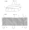
図4は、本発明の一実施形態に係る積層シートの使用例を示す図である。ここでは、配送物等の手荷物に取り付ける手荷物用タグとして、本実施形態の積層シートを使用する場合について説明する。図4(a)は、旅行カバン等の配送物Hを示す図であり、図4(b)は、図4(a)における取っ手Tの拡大図であり、図4(c)は、図4(b)において取っ手Tに巻き付けられた積層シートのC-Cに対応する断面図である。なお、図4(c)においては、巻き付けの状態を簡略化して示すため、剥離層3、接着剤層4、目止め層5を省略し、表面基材2の貼付票2b、取付部2c、支持基材6、自着層7のみを示している。 FIG. 4 is a diagram showing an example of using a laminated sheet according to an embodiment of the present invention. Here, a case where the laminated sheet of the present embodiment is used as a baggage tag to be attached to baggage such as a delivered item will be described. 4 (a) is a diagram showing a delivery product H such as a travel bag, FIG. 4 (b) is an enlarged view of a handle T in FIG. 4 (a), and FIG. 4 (c) is a diagram of FIG. It is sectional drawing corresponding to CC of the laminated sheet wound around the handle T in (b). In addition, in FIG. 4C, in order to simplify the winding state, the release layer 3, the adhesive layer 4, and the sealing layer 5 are omitted, and the sticking slip 2b and the mounting portion 2c of the surface base material 2 are omitted. Only the support base material 6 and the self-adhesive layer 7 are shown.

配達票2a、貼付票2bへの記入を終えたら、利用者は、取付部2cを、取付対象に巻き付ける。取付対象は、取付部2cを半分に折った際に、その幅に収まる程度の大きさのものである必要がある。例えば、図4に示すような配送物Hの取っ手Tなどが取付対象となる。利用者は、長手方向を有する棒状などの比較的細い取っ手Tに、取付部2cを巻き付けるようにして曲げ、取付部2cの下層の自着層7同士を重ね合わせ、圧力を加える。この圧力は、人間が軽く握る程度でよい。この圧力により、自着層7どうしが接着する。この際、自着層7は、取っ手T自体にはほとんど接着しない。このため、図4(b)(c)に示すように、取付部2cが取っ手Tに巻き付けられたような状態となる。 After completing the entries on the delivery slip 2a and the sticking slip 2b, the user winds the mounting portion 2c around the mounting target. The mounting target needs to be large enough to fit in the width when the mounting portion 2c is folded in half. For example, the handle T of the delivery item H as shown in FIG. 4 is the attachment target. The user bends the attachment portion 2c so as to wind it around a relatively thin handle T such as a rod having a longitudinal direction, superimposes the self-adhesive layers 7 on the lower layer of the attachment portion 2c, and applies pressure. This pressure need only be lightly grasped by a human. Due to this pressure, the self-adhesive layers 7 adhere to each other. At this time, the self-adhesive layer 7 hardly adheres to the handle T itself. Therefore, as shown in FIGS. 4 (b) and 4 (c), the mounting portion 2c is wound around the handle T.

図5は、自着層7どうしが重ねられた状態を示す図である。図5(a)は、区分線9bに平行な線に沿って折り畳まれた場合の状態を示しており、図5(b)は、区分線9bから傾いた角度で折り畳まれた場合の状態を示している。辺Sa、辺Sbとなす角度R=45度である場合、区分線9bに平行な線に沿って折り畳まれると、図5(a)に示すように、2つの積層シート1の接着剤塗布部7aどうしが重なった部分(図中ハッチングされた部分)は、正方形に近い形状となり、接着力が強まる。このため、積層シート1を手荷物等に安定的に固定することができる。 FIG. 5 is a diagram showing a state in which the self-adhesive layers 7 are overlapped with each other. FIG. 5A shows a state when folded along a line parallel to the dividing line 9b, and FIG. 5B shows a state when folded at an angle inclined from the dividing line 9b. Shows. When the angle R = 45 degrees formed by the side Sa and the side Sb is folded along the line parallel to the dividing line 9b, as shown in FIG. 5A, the adhesive coating portion of the two laminated sheets 1 is applied. The portion where the 7a overlaps (the portion hatched in the figure) has a shape close to a square, and the adhesive strength is strengthened. Therefore, the laminated sheet 1 can be stably fixed to baggage or the like.

しかしながら、積層シート1を手荷物タグとして用いる場合、利用者は、必ずしも丁寧に区分線9bに平行な線に沿って折り畳むとは限らず、無造作に自着層7どうしを重ね合わせることもある。この場合、区分線9bから傾いた角度で折り畳まれると、図5(b)に示すように、2つの積層シート1の接着剤塗布部7aどうしが重なった部分は、ひし形になり、接着力が弱まる。それでも、接着剤塗布部7aは、積層シート1の短辺Sa、Sbに対して斜め方向に延びるように形成されているため、無造作に折り曲げた場合でも、必ず重なり部分7cが形成され、自着層7どうしが接着されることになる。このように、自着層7は、感圧接着剤が塗布された接着剤塗布部7aと、感圧接着剤が塗布されていない接着剤非塗布部7bが、積層シート1の一辺に対して斜め方向に延びるように交互に形成されているため、無造作に折り曲げた場合でも、配送物H等の対象物に対して固定することが可能となる。 However, when the laminated sheet 1 is used as a baggage tag, the user does not always fold it carefully along a line parallel to the dividing line 9b, and may randomly overlap the self-adhesive layers 7 with each other. In this case, when folded at an angle inclined from the dividing line 9b, as shown in FIG. 5B, the portion where the adhesive coating portions 7a of the two laminated sheets 1 overlap each other becomes a rhombus, and the adhesive strength becomes strong. It weakens. Even so, since the adhesive coating portion 7a is formed so as to extend diagonally with respect to the short sides Sa and Sb of the laminated sheet 1, the overlapping portion 7c is always formed and self-adhesive even when bent casually. The layers 7 will be bonded to each other. As described above, in the self-adhesive layer 7, the adhesive coating portion 7a to which the pressure-sensitive adhesive is applied and the adhesive non-coating portion 7b to which the pressure-sensitive adhesive is not applied are applied to one side of the laminated sheet 1. Since it is formed alternately so as to extend in an oblique direction, it can be fixed to an object such as a delivery product H even if it is bent casually.

このようにして、配送先が記入された積層シート1が、配送物Hに取り付けられ、この配送先に配送されることになる。配送物Hの配送後、配達票2aは、積層シート1から剥離される。以上のように、手荷物タグとして積層シート1を用いた場合、最下層の自着層7が通常時は粘性が低く、他の物体に接着し難いため、記入に支障が少ない。このため、記入後そのまま圧着により自着することで取っ手等の比較的細い部分に巻き付けて取り付けることが可能となる。このため、従来の手荷物タグや配送伝票のように、記入後、粘着層を覆っている剥離紙等を剥がす手間がなくなる。また、剥離紙自体も不要となり、省資源化が図れる。 In this way, the laminated sheet 1 on which the delivery destination is entered is attached to the delivery item H and delivered to this delivery destination. After delivery of the delivery item H, the delivery slip 2a is peeled off from the laminated sheet 1. As described above, when the laminated sheet 1 is used as the baggage tag, the self-adhesive layer 7 at the bottom layer has a low viscosity at normal times and is difficult to adhere to other objects, so that there is little trouble in filling in. For this reason, it is possible to wrap it around a relatively thin part such as a handle and attach it by self-adhesion by crimping as it is after filling in. For this reason, unlike conventional baggage tags and delivery slips, there is no need to remove the release paper or the like covering the adhesive layer after filling in the form. In addition, the release paper itself becomes unnecessary, and resource saving can be achieved.

以上、本発明の好適な実施形態について説明したが、本発明は上記実施形態に限定されず、種々の変形が可能である。例えば、上記実施形態では、区分線9bとしてミシン目を形成したが、表面基材2を貫通して、支持基材6に達しない切り込みを、積層シート1に対するハーフカットとして形成するようにしても良い。また、ミシン目や切り込みのように表面基材2自体に加工を行うものでなく、目視可能な線を印刷することにより、区分線9bを形成してもよい。また、区分線9b自体を形成しないようにすることも可能である。区分線9bを形成しない場合は、貼付票2bの表面に印刷された配送情報欄の、配達票2aと反対側の端部から先が取付部2cとして機能する。 Although the preferred embodiment of the present invention has been described above, the present invention is not limited to the above embodiment and can be modified in various ways. For example, in the above embodiment, the perforations are formed as the dividing lines 9b, but the cuts that penetrate the surface base material 2 and do not reach the support base material 6 may be formed as half cuts for the laminated sheet 1. good. Further, the dividing line 9b may be formed by printing a visible line instead of processing the surface base material 2 itself like a perforation or a notch. It is also possible not to form the dividing line 9b itself. When the dividing line 9b is not formed, the end portion of the delivery information column printed on the surface of the attachment slip 2b on the opposite side of the delivery slip 2a functions as the attachment portion 2c.

1、1a、1b・・・積層シート
2・・・表面基材
2a・・・配達票
2b・・・貼付票
2c・・・取付部
3・・・剥離層
4・・・接着剤層
5・・・目止め層
6・・・支持基材
7・・・自着層
7a・・・接着剤塗布部
7b・・・接着剤非塗布部
8・・・接着剤層
9a・・・分離予定線
9b・・・区分線
10・・・連続シート
10a・・・切り離し予定線
W1・・・接着剤塗布部の幅
W2・・・接着剤非塗布部の幅
1, 1a, 1b ... Laminated sheet 2 ... Surface base material 2a ... Delivery slip 2b ... Attachment slip 2c ... Mounting part 3 ... Peeling layer 4 ... Adhesive layer 5.・ ・ Sealing layer 6 ・ ・ ・ Supporting base material 7 ・ ・ ・ Self-adhesive layer 7a ・ ・ ・ Adhesive coated part 7b ・ ・ ・ Adhesive non-coated part 8 ・ ・ ・ Adhesive layer 9a ・ ・ ・ Scheduled separation line 9b ・ ・ ・ Division line 10 ・ ・ ・ Continuous sheet 10a ・ ・ ・ Scheduled line to be separated W1 ・ ・ ・ Width of adhesive coated part W2 ・ ・ ・ Width of adhesive non-coated part

Claims (7)

剥離片を有する表面基材と支持基材とが接着剤層を介して接着されており、前記剥離片と支持基材の間には、剥離層が設けられて、前記支持基材から前記剥離片が剥離可能な積層シートであって、
前記支持基材の前記表面基材と反対側の面には、感圧接着剤を含んだ自着層が形成されており、前記自着層は、前記感圧接着剤が塗布された接着剤塗布部と、前記感圧接着剤が塗布されていない接着剤非塗布部が、積層シートの一辺に対して斜め方向に延びるように交互に形成されている、積層シート。
A surface base material having a peeling piece and a supporting base material are adhered to each other via an adhesive layer, and a peeling layer is provided between the peeling piece and the supporting base material, and the peeling piece is separated from the supporting base material. A laminated sheet whose pieces can be peeled off,
A self-adhesive layer containing a pressure-sensitive adhesive is formed on the surface of the support base material opposite to the surface base material, and the self-adhesive layer is an adhesive to which the pressure-sensitive adhesive is applied. A laminated sheet in which the coated portion and the non-adhesive-coated portion to which the pressure-sensitive adhesive is not applied are alternately formed so as to extend diagonally with respect to one side of the laminated sheet.
前記接着剤塗布部の幅は、前記接着剤非塗布部の幅より狭い、請求項1に記載の積層シート。 The laminated sheet according to claim 1, wherein the width of the adhesive-applied portion is narrower than the width of the adhesive-non-applied portion. 前記接着剤塗布部が、前記積層シートの一辺となす角度は、30度以上60度以下である、請求項1または請求項2に記載の積層シート。 The laminated sheet according to claim 1 or 2, wherein the angle formed by the adhesive coating portion with one side of the laminated sheet is 30 degrees or more and 60 degrees or less. 前記剥離片の表面、および前記表面基材における前記剥離片以外の部分の表面には、配送情報欄が形成されており、配送伝票として機能する、請求項1から請求項3のいずれか一項に記載の積層シート。 One of claims 1 to 3, wherein a delivery information column is formed on the surface of the peeled piece and the surface of a portion of the surface substrate other than the peeled piece, which functions as a delivery slip. The laminated sheet described in. 前記剥離片の表面、および前記表面基材における前記剥離片以外の部分の表面には、配送情報欄が形成されており、前記表面基材における前記剥離片以外に形成された配送情報欄以外の部分に重ねられた自着層が、取付対象に巻き付けるための取付部として機能することを特徴とする請求項1から請求項4のいずれか一項に記載の積層シート。 A delivery information column is formed on the surface of the peeled piece and the surface of the portion of the surface base material other than the peeled piece, except for the delivery information column formed on the surface base material other than the peeled piece. The laminated sheet according to any one of claims 1 to 4, wherein the self-adhesive layer laminated on the portion functions as a mounting portion for winding around the mounting target. 請求項1から請求項5のいずれか一項に記載の積層シートが切り離し予定線を介して複数連接されてなる連続シートであって、
隣接する各前記積層シートの接着剤塗布部が延びる方向が、前記切り離し予定線に対して互いに対称な方向であり、
前記切り離し予定線における接着剤塗布部の端部の中心が互いにずれている、連続シート。
A continuous sheet in which a plurality of laminated sheets according to any one of claims 1 to 5 are connected via a planned separation line.
The direction in which the adhesive-applied portion of each of the adjacent laminated sheets extends is a direction symmetrical to the planned separation line.
A continuous sheet in which the centers of the ends of the adhesive-applied portion on the planned cutting line are offset from each other.
剥離片を有する表面基材と支持基材とが接着剤層を介して接着されているとともに、前記剥離片と支持基材の間には、剥離層が設けられて、前記支持基材から前記剥離片が剥離可能な手荷物用タグであって、
前記支持基材の前記表面基材と反対側の面には、感圧接着剤を含んだ自着層が形成されており、前記自着層は、前記感圧接着剤が塗布された接着剤塗布部と、前記感圧接着剤が塗布されていない接着剤非塗布部が、積層シートの一辺に対して斜め方向に延びるように交互に形成されている手荷物用タグ。

A surface base material having a peeling piece and a supporting base material are adhered to each other via an adhesive layer, and a peeling layer is provided between the peeling piece and the supporting base material, and the support base material is separated from the support base material. A baggage tag that can be peeled off,
A self-adhesive layer containing a pressure-sensitive adhesive is formed on the surface of the support base material opposite to the surface base material, and the self-adhesive layer is an adhesive to which the pressure-sensitive adhesive is applied. A baggage tag in which the coated portion and the non-adhesive-coated portion to which the pressure-sensitive adhesive is not applied are alternately formed so as to extend diagonally with respect to one side of the laminated sheet.

JP2020156835A 2020-09-18 2020-09-18 Laminated sheets, continuous sheets and baggage tags Active JP7552187B2 (en)

Priority Applications (1)

Application Number Priority Date Filing Date Title
JP2020156835A JP7552187B2 (en) 2020-09-18 2020-09-18 Laminated sheets, continuous sheets and baggage tags

Applications Claiming Priority (1)

Application Number Priority Date Filing Date Title
JP2020156835A JP7552187B2 (en) 2020-09-18 2020-09-18 Laminated sheets, continuous sheets and baggage tags

Publications (2)

Publication Number Publication Date
JP2022050737A true JP2022050737A (en) 2022-03-31
JP7552187B2 JP7552187B2 (en) 2024-09-18

Family

ID=80854613

Family Applications (1)

Application Number Title Priority Date Filing Date
JP2020156835A Active JP7552187B2 (en) 2020-09-18 2020-09-18 Laminated sheets, continuous sheets and baggage tags

Country Status (1)

Country Link
JP (1) JP7552187B2 (en)

Family Cites Families (3)

* Cited by examiner, † Cited by third party
Publication number Priority date Publication date Assignee Title
JP2015165330A (en) 2015-05-27 2015-09-17 株式会社イシダ printer
JP6933049B2 (en) 2017-08-22 2021-09-08 大日本印刷株式会社 Laminated sheets and baggage tags
JP7062508B2 (en) 2018-05-10 2022-05-06 トッパン・フォームズ株式会社 Labels and label sheets that are connected to each other

Also Published As

Publication number Publication date
JP7552187B2 (en) 2024-09-18

Similar Documents

Publication Publication Date Title
JP2001353987A (en) Delivery slip form
JP6933049B2 (en) Laminated sheets and baggage tags
JP6040520B2 (en) Delivery slip
JP7062508B2 (en) Labels and label sheets that are connected to each other
JP4464456B1 (en) Slip sheet
JP7552187B2 (en) Laminated sheets, continuous sheets and baggage tags
JP6331734B2 (en) Delivery slip
JP7131202B2 (en) laminated sheet
JP5957849B2 (en) Delivery slip
JP2017219752A (en) label
JP5974459B2 (en) Delivery slip
JP6303319B2 (en) Delivery slip
JP4362205B2 (en) Delivery slip
JP2004291292A (en) Delivery slip form
JP2002046767A (en) Labels for integrated packaging and integrated packaging
JP5648337B2 (en) Delivery slip
JP5609359B2 (en) Delivery slip
JP4249518B2 (en) Integrated foam and method for manufacturing the same
JP6287460B2 (en) Delivery slip with label
JPH09254571A (en) Manufacture of cut forms with plural sheets as one set
JP2017226168A (en) Delivery slip and continuous slip sheet
JP2012006274A (en) Delivery slip
JP2020006590A (en) Laminated sheet
JP6291891B2 (en) Delivery slip
JP5231904B2 (en) Delivery slip

Legal Events

Date Code Title Description
A621 Written request for application examination

Free format text: JAPANESE INTERMEDIATE CODE: A621

Effective date: 20230727

A977 Report on retrieval

Free format text: JAPANESE INTERMEDIATE CODE: A971007

Effective date: 20240314

A131 Notification of reasons for refusal

Free format text: JAPANESE INTERMEDIATE CODE: A131

Effective date: 20240402

A521 Request for written amendment filed

Free format text: JAPANESE INTERMEDIATE CODE: A523

Effective date: 20240530

TRDD Decision of grant or rejection written
A01 Written decision to grant a patent or to grant a registration (utility model)

Free format text: JAPANESE INTERMEDIATE CODE: A01

Effective date: 20240806

A61 First payment of annual fees (during grant procedure)

Free format text: JAPANESE INTERMEDIATE CODE: A61

Effective date: 20240819

R150 Certificate of patent or registration of utility model

Ref document number: 7552187

Country of ref document: JP

Free format text: JAPANESE INTERMEDIATE CODE: R150