JP2022014792A - Packaging bag - Google Patents

Packaging bag Download PDF

Info

Publication number
JP2022014792A
JP2022014792A JP2020117345A JP2020117345A JP2022014792A JP 2022014792 A JP2022014792 A JP 2022014792A JP 2020117345 A JP2020117345 A JP 2020117345A JP 2020117345 A JP2020117345 A JP 2020117345A JP 2022014792 A JP2022014792 A JP 2022014792A
Authority
JP
Japan
Prior art keywords
straight line
opening
weak
line portion
opening direction
Prior art date
Legal status (The legal status is an assumption and is not a legal conclusion. Google has not performed a legal analysis and makes no representation as to the accuracy of the status listed.)
Granted
Application number
JP2020117345A
Other languages
Japanese (ja)
Other versions
JP7498045B2 (en
Inventor
達哉 厚東
Tatsuya Koto
聡 ▲高▼松
Satoshi Takamatsu
Current Assignee (The listed assignees may be inaccurate. Google has not performed a legal analysis and makes no representation or warranty as to the accuracy of the list.)
Howa Sangyo KK
Original Assignee
Howa Sangyo KK
Priority date (The priority date is an assumption and is not a legal conclusion. Google has not performed a legal analysis and makes no representation as to the accuracy of the date listed.)
Filing date
Publication date
Application filed by Howa Sangyo KK filed Critical Howa Sangyo KK
Priority to JP2020117345A priority Critical patent/JP7498045B2/en
Publication of JP2022014792A publication Critical patent/JP2022014792A/en
Application granted granted Critical
Publication of JP7498045B2 publication Critical patent/JP7498045B2/en
Active legal-status Critical Current
Anticipated expiration legal-status Critical

Links

Images

Landscapes

  • Bag Frames (AREA)

Abstract

To provide a packaging bag of which nick is guided by a weakened line reliably across a whole length of an expected opening line during opening and which can form the weakened line easily.SOLUTION: A packaging bag comprises a plurality of packaging materials 2, a seal part 4 to which a peripheral edge part 3 of the packaging material 2 is bonded, a storage part 5, and an opening guiding strip 6 provided at the packaging material 2 along an expected opening line 7 extending in an opening direction. The opening guiding strip 6 extends across a substantially whole length of the expected opening line 7, and has a weakened line part 10 in a plurality of rows by a groove of a half-cut-off formed by removing a part of a thickness direction of the packaging material 2 from a surface. The weakened line part 10 comprises a plurality of first straight line parts inclined in the opening direction, and a plurality of second straight line parts inclined in an opposite direction to the first straight line parts in the opening direction, and is provided in a zigzag pattern having a crest part and a trough part by arranging the first and second straight line parts along the opening direction.SELECTED DRAWING: Figure 1

Description

本発明は、包装袋に関する。 The present invention relates to a packaging bag.

従来、例えば、液状、粒状、粉状あるいは固形状等の食品や薬品等の収容物を密封して収容する包装袋として、可撓性を有するシート状の樹脂で形成された2枚の包材を引き裂いて開封する形式の包装袋が使用されている。この種の包装袋としては、引き裂きを容易とする弱線が、開封予定ラインに沿って形成されたものがある。 Conventionally, for example, as a packaging bag for sealing and accommodating liquid, granular, powdery or solid foods and chemicals, two packaging materials made of a flexible sheet-like resin. A packaging bag of the type that tears and opens is used. Some packaging bags of this type have weak lines that facilitate tearing along the line to be opened.

例えば、特許文献1には、開封予定ラインの両側(開口側と底部側)に、切れ目を誘導する直線状の主誘導線を表裏の包材に分けて設けるとともに、開封予定ラインの途中の部分における2つの主誘導線の間に、開封予定ラインに交差する方向に傾斜して主誘導線に合流する補助誘導線を表裏の包材において傾斜方向が互いに逆向きになるように設け、切れ目が補助誘導線から主誘導線に導かれる包装袋が開示されている。また、特許文献2には、開封予定ラインに沿った弱線として、表裏の包材のうちの一方側にW字形状の弱線を設け、他方側の包材にW字とは逆さまの形状となるM字形状の弱線を設けた包装袋が開示されている。 For example, in Patent Document 1, linear main guide lines for guiding cuts are provided separately on the front and back packaging materials on both sides (opening side and bottom side) of the scheduled opening line, and a portion in the middle of the scheduled opening line. Between the two main guide lines in the above, an auxiliary guide line that inclines in the direction intersecting the planned opening line and joins the main guide line is provided in the front and back packaging materials so that the inclination directions are opposite to each other, and a cut is provided. A packaging bag guided from an auxiliary lead wire to a main lead wire is disclosed. Further, in Patent Document 2, a W-shaped weak line is provided on one side of the front and back packaging materials as a weak line along the scheduled opening line, and the packaging material on the other side has a shape upside down from the W shape. A packaging bag provided with an M-shaped weak line is disclosed.

特開2019-123538号公報JP-A-2019-123538 特開2007-331804号公報Japanese Unexamined Patent Publication No. 2007-331804

上記特許文献1に開示される包装袋は、主誘導線に導く補助誘導線は、開封予定ラインの途中に部分的に設けられているため、包材を引き裂いた切り口端縁が補助誘導線を横断して補助誘導線から外れてしまい、開封しにくい事態となる可能性がある。この点、特許文献2に開示される包装袋の弱線は開封予定ライン上の全長にわたって形成されているため、常に弱線が引き裂かれて切り口端縁が弱線と一致する。しかし、弱線の形状が円弧と直線との組み合わせであるため複雑であり、弱線の形成に手間がかかる点で改善の余地がある。 In the packaging bag disclosed in Patent Document 1, since the auxiliary guide wire leading to the main guide wire is partially provided in the middle of the line to be opened, the cut end edge that tears the packaging material serves as the auxiliary guide wire. There is a possibility that it will be difficult to open the package because it will cross and come off the auxiliary guide line. In this respect, since the weak line of the packaging bag disclosed in Patent Document 2 is formed over the entire length on the line to be opened, the weak line is always torn and the cut end edge coincides with the weak line. However, since the shape of the weak line is a combination of an arc and a straight line, it is complicated, and there is room for improvement in that it takes time and effort to form the weak line.

そこで本発明は、包材を引き裂いて開封する際に開封予定ラインの全長にわたり確実に切れ目が弱線に誘導されて開封がしやすく、かつ弱線を容易に形成することができる包装袋を提供することを目的とする。 Therefore, the present invention provides a packaging bag in which when the packaging material is torn and opened, the cut is surely guided to the weak line over the entire length of the line to be opened, the package is easily opened, and the weak line can be easily formed. The purpose is to do.

(1)本発明の包装袋は、互いに重ねられる複数のシート状の包材と、前記複数の包材の周縁部が互いに接着される封止部と、前記複数の包材の間に形成され、前記封止部に囲まれて封止される収容部と、前記封止部の任意の2個所の間に設定される開封方向に延びる開封予定ラインに沿って前記包材に設けられる開封誘導帯と、を備え、前記開封誘導帯は、前記開封予定ラインの略全長にわたって延在し、前記包材の厚み方向の一部を表面から削除して形成されるハーフカットの溝による複数列の弱線部を有し、前記弱線部は、前記開封方向に対して傾斜する複数の第1直線部と、前記開封方向に対して前記第1直線部と逆向きに傾斜する複数の第2直線部と、を含み、前記第1直線部と前記第2直線部とが前記開封方向に沿って配列されることにより、山状部分と谷状部分とを有するジグザグ状のパターンに設けられる。 (1) The packaging bag of the present invention is formed between a plurality of sheet-shaped packaging materials that are overlapped with each other, a sealing portion in which peripheral edges of the plurality of packaging materials are adhered to each other, and the plurality of packaging materials. , The opening guide provided in the packaging material along the opening scheduled line extending in the opening direction set between the accommodating portion surrounded by the sealing portion and sealed, and any two positions of the sealing portion. The opening guide band comprises a band, and the opening guide band extends over substantially the entire length of the planned opening line, and has a plurality of rows of half-cut grooves formed by removing a part of the packaging material in the thickness direction from the surface. The weak line portion has a plurality of first straight line portions inclined with respect to the opening direction, and a plurality of second straight portions inclined with respect to the opening direction in the direction opposite to the first straight line portion. By arranging the first straight line portion and the second straight line portion along the opening direction, including the straight line portion, the first straight line portion and the second straight line portion are provided in a zigzag pattern having a mountain-shaped portion and a valley-shaped portion.

(2)(1)において、前記第1直線部と前記第2直線部とは、長さが略同一であり、前記開封方向に沿って間欠的に、かつ交互に配列されており、前記開封誘導帯においては、隣り合う前記弱線部の前記第1直線部及び前記第2直線部のそれぞれの位置が前記開封方向において略同じである。
なお、本明細書での「略」は厳密にその状態を特定するものではなく、それらの機能や効果を達成可能な範囲で近似する状態を含むという意味である。
(2) In (1), the first straight line portion and the second straight line portion have substantially the same length and are intermittently and alternately arranged along the opening direction, and the opening is performed. In the induction zone, the positions of the first straight line portion and the second straight line portion of the adjacent weak line portions are substantially the same in the opening direction.
It should be noted that the "abbreviation" in the present specification does not strictly specify the state, but means that the state includes a state that approximates those functions and effects within an achievable range.

(3)(1)において、前記弱線部は、前記第1直線部の長さが前記第2直線部の長さよりも短く、前記開封方向に沿って2つの前記第1直線部の間に1つの前記第2直線部が配置された略Z字状の第1弱線パターンを有し、複数の前記第1弱線パターンが、前記開封方向に位相をずらして交互に配列されることにより前記山状部分と前記谷状部分とが前記開封方向に略直交する方向において菱形状に重畳しており、前記複数の第1弱線パターンは離間している。 (3) In (1), in the weak line portion, the length of the first straight line portion is shorter than the length of the second straight line portion, and the weak line portion is between the two first straight line portions along the opening direction. It has a substantially Z-shaped first weak line pattern in which one second straight line portion is arranged, and a plurality of the first weak line patterns are alternately arranged in a phase shift in the opening direction. The mountain-shaped portion and the valley-shaped portion are superimposed in a diamond shape in a direction substantially orthogonal to the opening direction, and the plurality of first weak line patterns are separated from each other.

(4)(3)において、前記第1弱線パターンは、前記第1直線部と前記第2直線部とが連続している。 (4) In (3), in the first weak line pattern, the first straight line portion and the second straight line portion are continuous.

(5)(3)において、前記第1弱線パターンは、前記第1直線部と前記第2直線部とが離間している。 (5) In (3), in the first weak line pattern, the first straight line portion and the second straight line portion are separated from each other.

(6)(1)において、前記弱線部は、1つの前記山状部分と1つの前記谷状部分とが前記開封方向に略直交する方向において離間した状態で菱形状に重畳する第2弱線パターンを有し、複数の前記第2弱線パターンが前記開封方向に沿って間欠的に配列され、前記開封誘導帯においては、隣り合う前記弱線部の前記第2弱線パターンの位置が前記開封方向において略同じである。 (6) In (1), the weak line portion is a second weak line in which one mountain-shaped portion and one valley-shaped portion are superposed on a diamond shape in a state of being separated in a direction substantially orthogonal to the opening direction. It has a line pattern, and a plurality of the second weak line patterns are intermittently arranged along the opening direction, and in the opening guide zone, the positions of the second weak line patterns of the adjacent weak line portions are located. It is substantially the same in the opening direction.

(7)(1)~(6)のいずれかにおいて、前記山状部分及び前記谷状部分のそれぞれは、前記開封方向に沿う線を底辺とする二等辺三角形の形状を形成し、前記山状部分の頂点を形成する角部及び前記谷状部分の底部を形成する角部のそれぞれの角度は同一であって60°~150°である。 (7) In any of (1) to (6), each of the mountain-shaped portion and the valley-shaped portion forms the shape of an isosceles triangle whose base is a line along the opening direction, and the mountain-shaped portion is formed. The angles of the corners forming the apex of the portion and the corners forming the bottom of the valley portion are the same and are 60 ° to 150 °.

本発明によれば、包材を引き裂いて開封する際に開封予定ラインの全長にわたり確実に切れ目が弱線に誘導されて開封がしやすく、かつ弱線を容易に形成することができる包装袋を提供することができる。 According to the present invention, when the packaging material is torn and opened, the cut is surely guided to the weak line over the entire length of the line to be opened, and the packaging bag can be easily opened and the weak line can be easily formed. Can be provided.

本発明の第1実施形態に係る包装袋を示す平面図である。It is a top view which shows the packaging bag which concerns on 1st Embodiment of this invention. 第1実施形態に係る開封誘導帯の一部を示す図である。It is a figure which shows a part of the opening guide zone which concerns on 1st Embodiment. 第1実施形態に係る開封誘導帯が破断されて形成された切り口端縁を示す図である。It is a figure which shows the cut end edge formed by breaking the opening guide band which concerns on 1st Embodiment. 弱線が全周にわたり形成された開封誘導帯の参考例を示す図であるIt is a figure which shows the reference example of the opening guide zone which the weak line was formed over the whole circumference. 本発明の第2実施形態に係る包装袋の開封端部側を示す平面図である。It is a top view which shows the opened end side of the packaging bag which concerns on 2nd Embodiment of this invention. 第2実施形態に係る開封誘導帯の一部を示す図である。It is a figure which shows a part of the opening guide zone which concerns on 2nd Embodiment. 本発明の第3実施形態に係る包装袋の開封端部側を示す平面図である。It is a top view which shows the opened end side of the packaging bag which concerns on 3rd Embodiment of this invention. 第3実施形態に係る開封誘導帯の一部を示す図である。It is a figure which shows a part of the opening guide zone which concerns on 3rd Embodiment. 本発明の第4実施形態に係る包装袋の開封端部側を示す平面図である。It is a top view which shows the opened end side of the packaging bag which concerns on 4th Embodiment of this invention. 第4実施形態に係る開封誘導帯の一部を示す図である。It is a figure which shows a part of the opening guide zone which concerns on 4th Embodiment.

以下、本発明に係る実施形態について図面を参照しつつ説明する。 Hereinafter, embodiments according to the present invention will be described with reference to the drawings.

(第1実施形態)
図1は、第1実施形態に係る包装袋1の平面図である。包装袋1は、重ねられる2枚の包材2を備える。図1では、表側の包材2が示されている。包材2は、シート状の樹脂を矩形状に形成したものである。本実施形態の包装袋1は平面視が縦長の長方形状であって、図1の上側の端部が開封される。本発明に係る包装袋1の外形形状は長方形状に制限されず、正方形状、多角形状、あるいは外形線に曲線が含まれる形状であってもよい。
(First Embodiment)
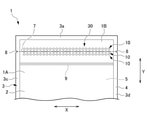
FIG. 1 is a plan view of the packaging bag 1 according to the first embodiment. The packaging bag 1 includes two packaging materials 2 to be stacked. In FIG. 1, the packaging material 2 on the front side is shown. The packaging material 2 is a sheet-shaped resin formed into a rectangular shape. The packaging bag 1 of the present embodiment has a vertically long rectangular shape in a plan view, and the upper end portion of FIG. 1 is opened. The outer shape of the packaging bag 1 according to the present invention is not limited to a rectangular shape, and may be a square shape, a polygonal shape, or a shape including a curved line in the outer line.

包装袋1は、図1において図面表裏方向である厚み方向に重ねられた2枚の包材2の周縁部3が互いに接着された封止部4を有する。周縁部3は、図1において、上側の端部であり開封側の端部となる周縁部3aと、周縁部3aと平行な下端の周縁部3bと、互いに平行な左右の端縁の周縁部3c、3dと、を含む。周縁部3の接着は、例えば、熱溶着(ヒートシール)や超音波溶着等の手段で行われる。2枚の包材2の間には、封止部4で囲まれて封止される空間からなる収容部5が形成される。すなわち包装袋1は、シート状の樹脂からなる2枚の包材2と、2枚の包材2の周縁部3が互いに接着される封止部4と、2枚の包材2の間に形成され、封止部4に囲まれて封止される収容部5と、を備える。包装袋1は、さらに後述する開封誘導帯6を備える。 The packaging bag 1 has a sealing portion 4 in which peripheral edges 3 of two packaging materials 2 stacked in the thickness direction, which is the front and back directions of the drawing in FIG. 1, are adhered to each other. In FIG. 1, the peripheral edge portion 3 is the peripheral edge portion 3a which is the upper end portion and is the end portion on the opening side, the peripheral edge portion 3b at the lower end parallel to the peripheral edge portion 3a, and the peripheral edge portions of the left and right edges parallel to each other. 3c, 3d and so on. Adhesion of the peripheral edge portion 3 is performed by means such as heat welding (heat sealing) or ultrasonic welding. Between the two packaging materials 2, an accommodating portion 5 is formed, which is a space surrounded by and sealed by the sealing portion 4. That is, the packaging bag 1 is formed between two packaging materials 2 made of sheet-shaped resin, a sealing portion 4 to which peripheral portions 3 of the two packaging materials 2 are adhered to each other, and two packaging materials 2. It includes an accommodating portion 5 that is formed and surrounded by and sealed by the sealing portion 4. The packaging bag 1 further includes an opening guide band 6, which will be described later.

包材2は、例えば、塩化ビニール、ポリエチレン、ポリプロピレン、ポリエチレンテレフタレート、ナイロン(ポリアミド)等の樹脂により成形された可撓性を有するシートである。包材2は、例えば上記樹脂のうちの1種からなるフィルムの単層構造のものや、1種または複数種のフィルムが貼り合わされた複層構造のものなどが用いられる。単層構造の場合、包材2の厚さは20~100μm程度とされ、複層構造の場合、包材2の厚さは30~200μm程度とされる。収容部5には、例えば、所定量の、液状、粒状、粉状あるいは固形状等の食品や薬品等の収容物が収容される。収容物は、例えば開封側の端部の周縁部3a以外を封止し、封止されていない開口から収容部5に収容される。この後、開口していた周縁部3aを接着して封止して、収容物は包装袋1内に密封される。 The packaging material 2 is a flexible sheet molded from a resin such as vinyl chloride, polyethylene, polypropylene, polyethylene terephthalate, nylon (polyamide) and the like. As the packaging material 2, for example, a single-layer structure of a film made of one of the above resins, a multi-layer structure in which one or a plurality of types of films are bonded, or the like is used. In the case of the single-layer structure, the thickness of the packaging material 2 is about 20 to 100 μm, and in the case of the multi-layer structure, the thickness of the packaging material 2 is about 30 to 200 μm. In the storage unit 5, for example, a predetermined amount of liquid, granular, powdery or solid food or chemicals is stored. The container is housed in the container 5 through an unsealed opening, for example, by sealing a portion other than the peripheral edge 3a of the end on the opening side. After that, the peripheral portion 3a that has been opened is adhered and sealed, and the contained material is sealed in the packaging bag 1.

図1に示すように、本実施形態の包装袋1は、矢印Yで示す長手方向の一端部(図1で上端部)の周縁部3aに近接する内側部分に、矢印Xで示す幅方向に延在する開封誘導帯6を備える。本実施形態の包装袋1は、開封誘導帯6を上側に配置するとともに横方向に延在するように保持して、開封誘導帯6を引き裂いて開封することが行われる。以下の説明では、この開封時の姿勢に基づき、図1において、矢印Y方向を上下方向といい、矢印X方向を左右方向あるいは開封方向という。 As shown in FIG. 1, the packaging bag 1 of the present embodiment has an inner portion close to a peripheral edge portion 3a of one end portion (upper end portion in FIG. 1) in the longitudinal direction indicated by arrow Y, in the width direction indicated by arrow X. It is provided with an extended opening guide band 6. In the packaging bag 1 of the present embodiment, the opening guide band 6 is arranged on the upper side and held so as to extend laterally, and the opening guide band 6 is torn and opened. In the following description, based on this opening posture, in FIG. 1, the arrow Y direction is referred to as a vertical direction, and the arrow X direction is referred to as a left-right direction or an opening direction.

開封誘導帯6は、ある程度の幅(上下方向の長さ寸法)をもって包材2における左右の周縁部3c、3dの間に設けられる。開封誘導帯6の上下方向の中央に、開封方向に延びる開封予定ライン7が設定される。本実施形態の包装袋1は、開封予定ライン7に沿って2枚の包材2に引き裂く力を与えると、開封誘導帯6にその力が伝わって開封誘導帯6が引き裂かれ、開封される。開封誘導帯6が破断されることにより、包装袋1は、開封誘導帯6より下側の袋部1Aと、開封誘導帯6より上側の切り離し部1Bとに切り離され、収容部5が外部に開放される。袋部1Aは、収容部5のほとんどの部分を備える。 The opening guide band 6 is provided between the left and right peripheral edges 3c and 3d of the packaging material 2 with a certain width (length dimension in the vertical direction). A scheduled opening line 7 extending in the opening direction is set at the center of the opening guide band 6 in the vertical direction. In the packaging bag 1 of the present embodiment, when a tearing force is applied to the two packaging materials 2 along the scheduled opening line 7, the force is transmitted to the opening guide band 6 to tear the opening guide band 6 and open the package. .. When the opening guide band 6 is broken, the packaging bag 1 is separated into a bag portion 1A below the opening guide band 6 and a separating portion 1B above the opening guide band 6, and the accommodating portion 5 is brought to the outside. Be released. The bag portion 1A includes most of the accommodating portion 5.

左右の周縁部3c、3dには、それぞれノッチ8が形成されている。ノッチ8は、引き裂きの始点として開封予定ライン7の延長線上に形成されている。本実施形態では、ノッチ8はV字形状の切り欠きである。ノッチとしては、U字形状の切り欠きや、周縁部3c、3dを表裏方向に貫通する貫通孔でもよく、単なる切れ目でもよい。 Notches 8 are formed on the left and right peripheral edges 3c and 3d, respectively. The notch 8 is formed on an extension of the line 7 to be opened as a starting point of tearing. In this embodiment, the notch 8 is a V-shaped notch. The notch may be a U-shaped notch, a through hole penetrating the peripheral edges 3c and 3d in the front-back direction, or a simple cut.

包装袋1における開封誘導帯6の下側には、左右の周縁部3c、3dの間において幅方向に延びるインナーファスナー9が設けられる。包装袋1は、開封誘導帯6が破断されて開封した後は、インナーファスナー9を繰り返し開閉して、収容部5を繰り返し密封したり開いたりすることができる。なお、インナーファスナー9は、本発明の実施に際しては必須ではなく、必要に応じて設けられる。 On the lower side of the opening guide band 6 in the packaging bag 1, an inner fastener 9 extending in the width direction is provided between the left and right peripheral edges 3c and 3d. After the opening guide band 6 is broken and opened, the packaging bag 1 can repeatedly open and close the inner fastener 9 to repeatedly seal and open the accommodating portion 5. The inner fastener 9 is not essential in carrying out the present invention, and is provided as needed.

開封誘導帯6は、開封方向に沿って延在している。開封誘導帯6は、開封方向に延在する3列の弱線部10を有する。すなわち弱線部10は、上下方向に3列形成されている。3列の弱線部10のそれぞれは、開封予定ライン7の略全長にわたって延在している。 The opening guide zone 6 extends along the opening direction. The opening guide band 6 has three rows of weak lines 10 extending in the opening direction. That is, the weak line portions 10 are formed in three rows in the vertical direction. Each of the weak line portions 10 in the three rows extends over substantially the entire length of the line 7 to be opened.

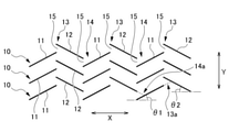
図2に示すように、弱線部10のそれぞれは、複数の第1直線部11と、複数の第2直線部12と、を含む。複数の第1直線部11及び第2直線部12は、開封方向に間欠的に、かつ交互に配列されている。第1直線部11及び第2直線部12は、いずれも、包材2の厚み方向の一部を表面から所定深さ削除したハーフカットの溝である。第1直線部11及び第2直線部12の形成方法としては、高い精度で微細な溝を形成し得るため、レーザビームを走査させるレーザ加工が好適に採用される。本実施形態では、開封誘導帯6は、一方の包材2の外面に形成される。なお、開封誘導帯6は包材2の内面に形成されてもよく、双方の包材2に形成されてもよい。 As shown in FIG. 2, each of the weak line portions 10 includes a plurality of first straight line portions 11 and a plurality of second straight line portions 12. The plurality of first straight line portions 11 and second straight line portions 12 are arranged intermittently and alternately in the opening direction. Both the first straight line portion 11 and the second straight line portion 12 are half-cut grooves in which a part of the packaging material 2 in the thickness direction is removed from the surface by a predetermined depth. As a method for forming the first straight line portion 11 and the second straight line portion 12, laser processing for scanning a laser beam is preferably adopted because fine grooves can be formed with high accuracy. In the present embodiment, the opening guide band 6 is formed on the outer surface of one of the packaging materials 2. The opening guide band 6 may be formed on the inner surface of the packaging material 2 or may be formed on both packaging materials 2.

図2に示すように、第1直線部11は、矢印Xで示す開封方向に対して傾斜する方向に直線状に延在する。第2直線部12は、開封方向に対して第1直線部11と逆向きに傾斜する方向に直線状に延在する。第1直線部11と第2直線部12とは、長さが略同一である。第1直線部11及び第2直線部12の長さは、包材2を引き裂きやすくなる適度な長さでよく、長すぎると引き裂きの誘導性が低下する観点から、例えば0.5mm~20mm程度とされ、より好ましくは2mm~10mmとされる。 As shown in FIG. 2, the first straight line portion 11 extends linearly in a direction inclined with respect to the opening direction indicated by the arrow X. The second straight line portion 12 extends linearly in a direction inclined in the direction opposite to the first straight line portion 11 with respect to the opening direction. The lengths of the first straight line portion 11 and the second straight line portion 12 are substantially the same. The length of the first straight line portion 11 and the second straight line portion 12 may be an appropriate length that makes it easy to tear the packaging material 2, and if it is too long, the inducibility of tearing decreases, for example, about 0.5 mm to 20 mm. It is more preferably 2 mm to 10 mm.

3列の弱線部10のそれぞれは、第1直線部11と第2直線部12とが、開封方向に沿って互いに交わることなく配列され、山状部分13と谷状部分14とを有するジグザグ状のパターンに設けられる。各弱線部10は、開封方向に隣り合う第1直線部11と第2直線部12との間に、ハーフカットされない包材2の厚みのままの非弱線部15を有する。 In each of the three rows of weak line portions 10, the first straight line portion 11 and the second straight line portion 12 are arranged along the opening direction without intersecting each other, and have a chevron portion 13 and a valley-shaped portion 14 in a zigzag manner. It is provided in a patterned pattern. Each weak line portion 10 has a non-weak line portion 15 having the thickness of the packaging material 2 which is not half-cut, between the first straight line portion 11 and the second straight line portion 12 adjacent to each other in the opening direction.

3列の弱線部10の上下方向の間隔は、等間隔である。各弱線部10のそれぞれの第1直線部11の開封方向の位置、及び、それぞれの第2直線部12の開封方向の位置は、ともに同じ位置であって揃っており、上下方向に重畳している。1つの弱線部10において、開封方向に隣り合う第1直線部11と第2直線部12とは上下方向にややずれている。また、開封方向に隣り合う第1直線部11の端部と第2直線部12の端部の開封方向の位置はともに同じであって揃っている。山状部分13及び谷状部分14の1つ1つの幅寸法や配列数は、包装袋1の幅に応じて適宜選択される。 The vertical spacing of the three rows of weak line portions 10 is evenly spaced. The positions of the first straight line portions 11 of the weak line portions 10 in the opening direction and the positions of the second straight line portions 12 in the opening direction are both the same positions and are aligned, and are superimposed in the vertical direction. ing. In one weak line portion 10, the first straight line portion 11 and the second straight line portion 12 adjacent to each other in the opening direction are slightly displaced in the vertical direction. Further, the positions of the end portions of the first straight line portion 11 and the end portions of the second straight line portion 12 adjacent to each other in the opening direction are the same and are aligned in the opening direction. The width dimension and the number of arrangements of each of the mountain-shaped portion 13 and the valley-shaped portion 14 are appropriately selected according to the width of the packaging bag 1.

図2に示すように、開封方向に対する第1直線部11の傾斜角度θ1と、開封方向に対する第2直線部12の傾斜角度θ2とは同じ角度であって、例えば10°~60°程度である。したがって、第1直線部11と第2直線部12とにより形成される山状部分13及び谷状部分14のそれぞれは、開封方向に沿う線を底辺とする二等辺三角形の形状を形成する。これとともに、山状部分13の頂点を形成する角部13a及び谷状部分14の底部を形成する角部14aのそれぞれの角度は同一であって、60°~150°であり、より好ましくは90°~120°である。 As shown in FIG. 2, the inclination angle θ1 of the first straight line portion 11 with respect to the opening direction and the inclination angle θ2 of the second straight line portion 12 with respect to the opening direction are the same angles, for example, about 10 ° to 60 °. .. Therefore, each of the mountain-shaped portion 13 and the valley-shaped portion 14 formed by the first straight line portion 11 and the second straight line portion 12 forms the shape of an isosceles triangle whose base is a line along the opening direction. At the same time, the angles of the corners 13a forming the apex of the chevron portion 13 and the corners 14a forming the bottom of the valley portion 14 are the same, and are 60 ° to 150 °, more preferably 90. ° to 120 °.

本実施形態の包装袋1においては、一方のノッチ8から開封誘導帯6に向かって包材2を引き裂いていくことにより、引き裂きによって生じる切れ目が弱線部10の各直線部11、12に順次伝わって、各直線部11、12及びこれら直線部11、12の間の非弱線部15が誘導的に引き裂かれる。引き裂きによる包材2の破断が開封方向に進行し、包装袋1は開封誘導帯6が破断されて開封される。 In the packaging bag 1 of the present embodiment, by tearing the packaging material 2 from one notch 8 toward the opening guide band 6, the cuts caused by the tearing are sequentially formed in the straight lines 11 and 12 of the weak line portion 10. Along the way, the straight lines 11 and 12 and the non-weak line 15 between these straight lines 11 and 12 are inductively torn. The breakage of the packaging material 2 due to tearing proceeds in the opening direction, and the opening guide band 6 is broken and the packaging bag 1 is opened.

図3において、矢印X1方向に引き裂く力が与えられた場合、その力はいずれか1つの弱線部10の第1直線部11(11a)を引き裂き、続いて、その第1直線部11(11a)の延びる方向(矢印F1で示す)に引き裂き力が導かれて非弱線部15が引き裂かれ、切れ目が隣りの第2直線部12(12a)に到達し、次いで、この第2直線部12(12a)が引き裂かれる。さらに第2直線部12(12a)が引き裂かれると、その第2直線部12(12a)の延びる方向(矢印F2で示す)に引き裂き力が導かれて次の非弱線部15が引き裂かれ、切れ目が次の第1直線部11(11b)に到達する。 In FIG. 3, when a tearing force is applied in the direction of the arrow X1, the force tears the first straight line portion 11 (11a) of any one of the weak line portions 10, and then the first straight line portion 11 (11a). ) Is guided in the extending direction (indicated by the arrow F1), the non-weak line portion 15 is torn, the cut reaches the adjacent second straight line portion 12 (12a), and then the second straight line portion 12 (12a) is torn. Further, when the second straight line portion 12 (12a) is torn, the tearing force is guided in the extending direction of the second straight line portion 12 (12a) (indicated by the arrow F2), and the next non-weak line portion 15 is torn. The cut reaches the next first straight line portion 11 (11b).

このようにして、各直線部11、12の間の非弱線部15が破断されながら、各直線部11、12に切れ目が必ず引き継がれてこれら各直線部11、12が交互に、かつ次々に引き裂かれることにより、開封誘導帯6の破断がジグザグ状に進行し、包装袋1は開封される。第1直線部11、非弱線部15、第2直線部12の順で切れ目が形成されていく過程では、引き裂きにより生じる音が一定のリズムで聞こえるとともに、切り裂きによって断続的に生じる抵抗感が手指に感触として伝わることにより、心地よい感覚を得ることができる。 In this way, while the non-weak line portion 15 between the straight portions 11 and 12 is broken, the cuts are always taken over by the straight portions 11 and 12, and the straight portions 11 and 12 are alternately and one after another. By being torn apart, the opening guide band 6 is broken in a zigzag manner, and the packaging bag 1 is opened. In the process of forming a break in the order of the first straight line portion 11, the non-weak line portion 15, and the second straight line portion 12, the sound generated by the tearing is heard with a constant rhythm, and the resistance generated intermittently by the tearing is heard. A comfortable sensation can be obtained by transmitting it to the fingers as a touch.

上述した開封操作において、引き裂き力が強いと、切れ目が非弱線部15から例えば第2直線部12を横断して隣りの弱線部10に至る場合が生じる。しかしその場合には、その隣の弱線部10の第2直線部12あるいは第1直線部11が引き裂かれて切れ目となる。すなわち、破断される弱線部10が隣りの弱線部10に移行し、引き続きその弱線部10で開封方向に沿った破断が進行する。このように引き裂き力が開封予定ライン7に対して交差する方向に強く掛かった場合でも、引き裂き力は各直線部11、12によって開封予定ライン7に沿うように導かれ、破断が進行する。 In the above-mentioned opening operation, if the tearing force is strong, the cut may reach the adjacent weak line portion 10 from the non-weak line portion 15 across, for example, the second straight line portion 12. However, in that case, the second straight line portion 12 or the first straight line portion 11 of the weak line portion 10 adjacent to the weak line portion 10 is torn and becomes a break. That is, the weak line portion 10 to be broken shifts to the adjacent weak line portion 10, and the weak line portion 10 continues to break along the opening direction. Even when the tearing force is strongly applied in the direction intersecting the planned opening line 7 in this way, the tearing force is guided along the planned opening line 7 by the straight lines 11 and 12, and the fracture proceeds.

以上説明した本実施形態に係る包装袋1は、互いに重ねられる複数のシート状の包材2と、複数の包材2の周縁部3が互いに接着される封止部4と、複数の包材2の間に形成され、封止部4に囲まれて封止される収容部5と、封止部4の任意の2個所の間に設定される開封方向に延びる開封予定ライン7に沿って包材2に設けられる開封誘導帯6と、を備え、開封誘導帯6は、開封予定ライン7の略全長にわたって延在し、包材2の厚み方向の一部を表面から削除して形成されるハーフカットの溝による複数列(3列)の弱線部10を有し、弱線部10は、開封方向に対して傾斜する複数の第1直線部11と、開封方向に対して第1直線部11と逆向きに傾斜する複数の第2直線部12と、を含み、第1直線部11と第2直線部12とが開封方向に沿って配列されることにより、山状部分13と谷状部分14とを有するジグザグ状のパターンに設けられる。 The packaging bag 1 according to the present embodiment described above includes a plurality of sheet-shaped packaging materials 2 that are overlapped with each other, a sealing portion 4 in which peripheral edges 3 of the plurality of packaging materials 2 are adhered to each other, and a plurality of packaging materials. Along the opening scheduled line 7 extending in the opening direction set between the accommodating portion 5 formed between the two and surrounded by the sealing portion 4 and sealed at any two positions of the sealing portion 4. The opening guide band 6 provided in the packaging material 2 is provided, and the opening guide band 6 extends over substantially the entire length of the scheduled opening line 7 and is formed by removing a part of the packaging material 2 in the thickness direction from the surface. The weak line portion 10 has a plurality of rows (three rows) of weak line portions 10 due to the half-cut grooves, and the weak line portion 10 has a plurality of first straight line portions 11 inclined with respect to the opening direction and a first with respect to the opening direction. A plurality of second straight line portions 12 that are inclined in the opposite direction to the straight line portion 11 are included, and the first straight line portion 11 and the second straight line portion 12 are arranged along the opening direction to form a chevron portion 13. It is provided in a zigzag pattern having a valley-shaped portion 14.

これにより、包材2を開封する際に開封予定ライン7の全長にわたり確実に切れ目が第1直線部11及び第2直線部12に誘導されるため、円滑に開封することができる。また、開封を誘導する弱線としては、直線状の第1直線部11及び第2直線部12であり、曲線を有さないため、弱線をレーザ加工等により容易に形成することができる。 As a result, when the packaging material 2 is opened, the cut is surely guided to the first straight line portion 11 and the second straight line portion 12 over the entire length of the line 7 scheduled to be opened, so that the package can be opened smoothly. Further, the weak lines for inducing the opening are the linear first straight line portion 11 and the second straight line portion 12, and since they do not have a curved line, the weak lines can be easily formed by laser processing or the like.

本実施形態に係る包装袋1は、第1直線部11と第2直線部12とは、長さが略同一であり、開封方向に沿って間欠的に、かつ交互に配列されており、開封誘導帯6においては、隣り合う弱線部10の第1直線部11及び第2直線部12のそれぞれの位置が開封方向において略同じである。 The packaging bag 1 according to the present embodiment has substantially the same length as the first straight line portion 11 and the second straight line portion 12, and is intermittently and alternately arranged along the opening direction, and is opened. In the induction zone 6, the positions of the first straight line portion 11 and the second straight line portion 12 of the adjacent weak line portions 10 are substantially the same in the opening direction.

これにより、第1直線部11及び第2直線部12による開封誘導帯6のジグザグ状のパターンが規則的、かつシンプルな形状となるため、開封誘導帯6をレーザ加工等により容易に形成することができる。また、弱線部10の第1直線部11及び第2直線部12のそれぞれの位置が開封方向において略同じで揃っていることから、引き裂き力が強い場合において切れ目が隣りの弱線部10の各直線部11、12に確実に導かれ、開封操作を開封予定ライン7に沿って円滑に進行させることができる。 As a result, the zigzag pattern of the opening guide band 6 formed by the first straight line portion 11 and the second straight line portion 12 becomes a regular and simple shape, so that the opening guide band 6 can be easily formed by laser processing or the like. Can be done. Further, since the positions of the first straight line portion 11 and the second straight line portion 12 of the weak line portion 10 are substantially the same in the opening direction, the cut is formed in the adjacent weak line portion 10 when the tearing force is strong. It is surely guided to each of the straight lines 11 and 12, and the opening operation can proceed smoothly along the scheduled opening line 7.

本実施形態に係る包装袋1は、山状部分13及び谷状部分14のそれぞれは、開封方向に沿う線を底辺とする二等辺三角形の形状を形成し、山状部分13の頂点を形成する角部及び谷状部分14の頂点を形成する角部のそれぞれの角度は同一であって60°~150°である。 In the packaging bag 1 according to the present embodiment, each of the chevron portion 13 and the trough portion 14 forms an isosceles triangle shape with a line along the opening direction as the base, and forms the apex of the chevron portion 13. The angles of the corners forming the vertices of the corners and the valleys 14 are the same and are 60 ° to 150 °.

これにより、山状部分13及び谷状部分14を形成する第1直線部11及び第2直線部12は開封方向に対してなだらかに傾斜するため、引き裂き力は第1直線部11及び第2直線部12に沿うように確実に伝わり、これら直線部11、12を確実に引き裂くことができる。また、開封誘導帯6のジグザグ状のパターンが規則的、かつシンプルな形状となるため、開封誘導帯6をレーザ加工等により容易に形成することができる。 As a result, the first straight line portion 11 and the second straight line portion 12 forming the chevron portion 13 and the valley-shaped portion 14 are gently inclined with respect to the opening direction, so that the tearing force is the first straight line portion 11 and the second straight line portion 11. It is surely transmitted along the portion 12, and these straight portions 11 and 12 can be surely torn. Further, since the zigzag pattern of the opening guide band 6 has a regular and simple shape, the opening guidance band 6 can be easily formed by laser processing or the like.

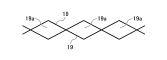
本実施形態に係る包装袋1は、第1直線部11と第2直線部12とが互いに交わることなく開封方向に沿って配列されることにより、各直線部11、12によって全周が囲まれる領域は形成されない。例えば、図4に示すように、ハーフカットによる2本のジグザグ状の弱線19が開封方向に位相をずらして形成された場合、弱線19で全周が囲まれる複数の菱形状の領域19aが形成される。この場合、例えばその領域19aを囲む弱線19が全周にわたり破断されると、領域19aは脱落し、収容物に異物として混入するおそれがある。しかし、本実施形態では第1直線部11と第2直線部12とが互いに交わっていないため、包材2に部分的な破片が生じ、その破片が脱落する事態は起こらない。 In the packaging bag 1 according to the present embodiment, the first straight line portion 11 and the second straight line portion 12 are arranged along the opening direction without intersecting each other, so that the entire circumference is surrounded by the straight line portions 11 and 12. No region is formed. For example, as shown in FIG. 4, when two zigzag-shaped weak lines 19 by half-cut are formed by shifting their phases in the opening direction, a plurality of diamond-shaped regions 19a whose entire circumference is surrounded by the weak lines 19 are formed. Is formed. In this case, for example, if the weak line 19 surrounding the region 19a is broken over the entire circumference, the region 19a may fall off and be mixed into the contained matter as a foreign substance. However, in the present embodiment, since the first straight line portion 11 and the second straight line portion 12 do not intersect each other, partial debris is generated in the packaging material 2, and the debris does not fall off.

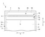
本実施形態に係る包装袋1において、開封誘導帯6は、2枚の包材2のうちの一方の包材2の外面に形成される。このため、図3に示すように、開封誘導帯6が形成されていない側の包材2Bにおいては、図3に示すように切り口端縁2bが、開封誘導帯6が形成されている側の包材2Aの切り口端縁2aと揃わない部分が生じる。これにより、双方の切り口端縁2a、2bを離間させて開口を開く作業が行いやすくなる。 In the packaging bag 1 according to the present embodiment, the opening guide band 6 is formed on the outer surface of one of the two packaging materials 2. Therefore, as shown in FIG. 3, in the packaging material 2B on the side where the opening guide band 6 is not formed, the cut end edge 2b is on the side where the opening guide band 6 is formed as shown in FIG. There is a portion that is not aligned with the cut edge 2a of the packaging material 2A. This facilitates the work of opening the opening by separating the both cut end edges 2a and 2b.

次いで、以下に本発明に係る第2~第4実施形態を説明する。なお、これら実施形態において上記第1実施形態と同一の構成要素には同一の符号を付し、それらの説明を省略して第1実施形態と相違する点を主に説明する。 Next, the second to fourth embodiments according to the present invention will be described below. In these embodiments, the same components as those in the first embodiment are designated by the same reference numerals, and the description thereof will be omitted, and the differences from the first embodiment will be mainly described.

(第2実施形態)
図5は、第2実施形態に係る包装袋1を示している。第2実施形態に係る包装袋1は、上記第1実施形態の開封誘導帯6に代えて、開封誘導帯20を備える。開封誘導帯20は、上記第1実施形態と同様に3列の弱線部10を有する。それぞれの弱線部10は、開封方向に沿って複数の第1弱線パターン21を有する。
(Second Embodiment)
FIG. 5 shows the packaging bag 1 according to the second embodiment. The packaging bag 1 according to the second embodiment includes an opening guide band 20 instead of the opening guide band 6 of the first embodiment. The opening guide band 20 has three rows of weak lines 10 as in the first embodiment. Each weak line portion 10 has a plurality of first weak line patterns 21 along the opening direction.

図6に示すように、第1弱線パターン21は、開封方向に対して傾斜する第1直線部11と、開封方向に対して第1直線部11と逆向きに傾斜する第2直線部12と、を含む。第1直線部11の長さは第2直線部12の長さよりも短い。第1弱線パターン21は、開封方向に沿って2つの第1直線部11の間に1つの第2直線部12が配置された略Z字状のパターンを有する。第1直線部11の長さは、例えば0.5mm~10mm程度とされ、第2直線部12の長さは、例えば1mm~30mm程度とされる。この範囲では、第1直線部11の長さは1mm~5mmがより好ましく、第2直線部12の長さは2mm~10mmがより好ましい。 As shown in FIG. 6, the first weak line pattern 21 has a first straight line portion 11 that is inclined with respect to the opening direction and a second straight line portion 12 that is inclined in the direction opposite to the first straight line portion 11 with respect to the opening direction. And, including. The length of the first straight line portion 11 is shorter than the length of the second straight line portion 12. The first weak line pattern 21 has a substantially Z-shaped pattern in which one second straight line portion 12 is arranged between two first straight line portions 11 along the opening direction. The length of the first straight line portion 11 is, for example, about 0.5 mm to 10 mm, and the length of the second straight line portion 12 is, for example, about 1 mm to 30 mm. In this range, the length of the first straight line portion 11 is more preferably 1 mm to 5 mm, and the length of the second straight line portion 12 is more preferably 2 mm to 10 mm.

第1弱線パターン21は、第2直線部12に対して第1直線部11が左右両側に連続しており、図6において左側の端部には山状部分13が形成され、右側の端部には谷状部分14が形成されている。3列の弱線部10のそれぞれは、複数の第1弱線パターン21が、開封方向に位相をずらして交互に配列されることにより、山状部分13と谷状部分14とが開封方向に略直交する上下方向において菱形状に重畳し、かつ互いに離間している。第1弱線パターン21が上下方向に離間することにより、弱線部10は、第1直線部11の端部と第2直線部12の中間部分との間に、ハーフカットされない包材2の厚みのままの非弱線部15を有する。 In the first weak line pattern 21, the first straight line portion 11 is continuous on both the left and right sides with respect to the second straight line portion 12, a mountain-shaped portion 13 is formed at the left end portion in FIG. 6, and the right end portion is formed. A valley-shaped portion 14 is formed in the portion. In each of the three rows of weak line portions 10, a plurality of first weak line patterns 21 are arranged alternately with their phases shifted in the opening direction, so that the chevron portion 13 and the valley-shaped portion 14 are arranged in the opening direction. It overlaps in a diamond shape in the vertically orthogonal direction and is separated from each other. Since the first weak line pattern 21 is separated in the vertical direction, the weak line portion 10 is a packaging material 2 that is not half-cut between the end portion of the first straight line portion 11 and the intermediate portion of the second straight line portion 12. It has a non-weak line portion 15 having the same thickness.

各直線部11、12の開封方向に対する傾斜角度は互いに同じであって、山状部分13及び谷状部分14のそれぞれは、開封方向に沿う線を底辺とする二等辺三角形の形状を形成する。山状部分13の頂点を形成する角部13a及び谷状部分14の底部を形成する角部14aのそれぞれの角度は同一であって、上記第1実施形態と同様に60°~150°である。 The inclination angles of the straight lines 11 and 12 with respect to the opening direction are the same, and each of the chevron portion 13 and the valley-shaped portion 14 forms an isosceles triangle with a line along the opening direction as the base. The angles of the corners 13a forming the apex of the mountain-shaped portion 13 and the corners 14a forming the bottom of the valley-shaped portion 14 are the same, and are 60 ° to 150 ° as in the first embodiment. ..

第2実施形態に係る開封誘導帯20によれば、例えば、図5および図6において左側から開封誘導帯20を引き裂く場合、開封誘導帯20は次のようにして引き裂かれる。1つの弱線部10において、最初の第1弱線パターン21の第1直線部11が引き裂かれ、引き続きその第1直線部11に連なる第2直線部12が引き裂かれて山状部分13が引き裂かれ、続いて第2直線部12に連なる第1直線部11が引き裂かれて谷状部分14が引き裂かれる。すなわち、まず1つの第1弱線パターン21が引き裂かれる。次に、第1直線部11を引き裂いた力は、その第1直線部11に誘導されて非弱線部15を引き裂き、切れ目が上側の第1弱線パターン21の第2直線部12に移る。そしてその第2直線部12がほぼ中央部から右側に引き裂かれて谷状部分14が引き裂かれ、次いで、第1直線部11に誘導されて次の非弱線部15が引き裂かれ、次の上側の第1弱線パターン21の第2直線部12の中央部付近に切れ目が移る。なお、このような切れ目の遷移のパターンは一例であり、これに限られない。 According to the opening guide band 20 according to the second embodiment, for example, when the opening guide band 20 is torn from the left side in FIGS. 5 and 6, the opening guide band 20 is torn as follows. In one weak line portion 10, the first straight line portion 11 of the first weak line pattern 21 is torn, and then the second straight line portion 12 connected to the first straight line portion 11 is torn and the mountain-shaped portion 13 is torn. Subsequently, the first straight line portion 11 connected to the second straight line portion 12 is torn, and the valley-shaped portion 14 is torn. That is, first, one first weak line pattern 21 is torn. Next, the force that tears the first straight line portion 11 is guided by the first straight line portion 11 to tear the non-weak line portion 15, and the cut is transferred to the second straight line portion 12 of the first weak line pattern 21 on the upper side. .. Then, the second straight line portion 12 is torn to the right from the central portion, the valley-shaped portion 14 is torn, and then the next non-weak line portion 15 is torn by being guided to the first straight line portion 11, and the next upper side is torn. The cut shifts to the vicinity of the central portion of the second straight line portion 12 of the first weak line pattern 21 of the above. It should be noted that the pattern of such a break transition is an example, and is not limited to this.

このように第1弱線パターン21の下側部分から上側の第1弱線パターン21に切れ目が順次移るようにして、各直線部11、12の間の非弱線部15が破断されながら、各直線部11、12に切れ目が必ず引き継がれてこれら各直線部11、12が交互に、かつ次々に引き裂かれることにより、開封誘導帯20の破断がジグザグ状に進行し、包装袋1は開封される。なお、図5および図6において右側から開封誘導帯20を引き裂く場合には、上記と逆の順序で各直線部11、12は引き裂かれ、その場合は第1弱線パターン21の上側部分から下側の第1弱線パターン21に切れ目が順次移るようにして切り裂きが右側から左側に進行する。開封の方向は、例えば利き手に応じて利用者に選択される。 In this way, the cuts are sequentially moved from the lower portion of the first weak line pattern 21 to the upper first weak line pattern 21, and the non-weak line portion 15 between the straight line portions 11 and 12 is broken while being broken. The cuts are always taken over by the straight portions 11 and 12, and the straight portions 11 and 12 are torn alternately and one after another, so that the opening guide band 20 is broken in a zigzag manner and the packaging bag 1 is opened. Will be done. When the opening guide band 20 is torn from the right side in FIGS. 5 and 6, the straight lines 11 and 12 are torn in the reverse order of the above, and in that case, from the upper part to the lower part of the first weak line pattern 21. The tear progresses from the right side to the left side so that the cuts sequentially shift to the first weak line pattern 21 on the side. The opening direction is selected by the user according to, for example, the dominant hand.

第2実施形態によれば、包材2を開封する際に開封予定ライン7の全長にわたり確実に切れ目が第1直線部11及び第2直線部12に誘導されるため、円滑に開封することができる。また、開封を誘導する弱線としては、直線状の第1直線部11及び第2直線部12であり、曲線を有さないため、弱線をレーザ加工等により容易に形成することができる。 According to the second embodiment, when the packaging material 2 is opened, the cut is surely guided to the first straight line portion 11 and the second straight line portion 12 over the entire length of the line 7 to be opened, so that the package can be opened smoothly. can. Further, the weak lines for inducing the opening are the linear first straight line portion 11 and the second straight line portion 12, and since they do not have a curved line, the weak lines can be easily formed by laser processing or the like.

また、第2実施形態によれば、弱線部10において、第1弱線パターン21の山状部分13と谷状部分14とが上下方向において菱形状に重畳し、かつ互いに離間しており、非弱線部15を有する。これにより、第1直線部11及び第2直線部12で全周が囲まれる領域が包材2に形成されない。このため、開封時において図4に示したような破片は生じず、その破片が脱落して収容物に混入する事態は起こらない。 Further, according to the second embodiment, in the weak line portion 10, the mountain-shaped portion 13 and the valley-shaped portion 14 of the first weak line pattern 21 are superimposed in a rhombic shape in the vertical direction and are separated from each other. It has a non-weak line portion 15. As a result, the region surrounded by the entire circumference of the first straight line portion 11 and the second straight line portion 12 is not formed on the packaging material 2. Therefore, the debris as shown in FIG. 4 does not occur at the time of opening, and the debris does not fall off and mix with the contained material.

(第3実施形態)
図7は、第3実施形態に係る包装袋1を示している。第3実施形態に係る包装袋1は、図8に示すように、上記第2実施形態の開封誘導帯20において、第1弱線パターン21の第1直線部11と第2直線部12とが離間しており、その離間する部分に、非弱線部16を有する点のみが上記第2実施形態と相違している。
(Third Embodiment)
FIG. 7 shows the packaging bag 1 according to the third embodiment. As shown in FIG. 8, in the packaging bag 1 according to the third embodiment, in the opening guide band 20 of the second embodiment, the first straight line portion 11 and the second straight line portion 12 of the first weak line pattern 21 are formed. It is different from the second embodiment only in that it is separated and the non-weak line portion 16 is provided in the separated portion.

第3実施形態によれば、上記第2実施形態と同様に、開封誘導帯20により円滑に開封することができるとともに、開封誘導帯20を容易に形成することができるといった効果を奏する。また、第2実施形態に対して非弱線部16が付加された構成により、第2実施形態よりも開封誘導帯20の強度がやや強くなるので、包材2の厚みが比較的薄い場合に適用することにより、開封誘導帯20が過度に弱くなりにくいという利点を備える。 According to the third embodiment, as in the second embodiment, the opening guide band 20 can be smoothly opened and the opening guide band 20 can be easily formed. Further, since the strength of the opening guide band 20 is slightly stronger than that of the second embodiment due to the configuration in which the non-weak line portion 16 is added to the second embodiment, when the thickness of the packaging material 2 is relatively thin. By applying it, the opening guide band 20 has an advantage that it is unlikely to be excessively weakened.

(第4実施形態)
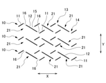
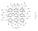
図9は、第4実施形態に係る包装袋1を示している。第4実施形態に係る包装袋1は、上記第1実施形態の開封誘導帯6に代えて、開封誘導帯30を備える。開封誘導帯30は、上記第1実施形態と同様に3列の弱線部10を有する。それぞれの弱線部10は、開封方向に沿って間欠的に配列された複数の第2弱線パターン31を有する。
(Fourth Embodiment)
FIG. 9 shows the packaging bag 1 according to the fourth embodiment. The packaging bag 1 according to the fourth embodiment includes an opening guide band 30 instead of the opening guide band 6 of the first embodiment. The opening guide band 30 has three rows of weak lines 10 as in the first embodiment. Each weak line portion 10 has a plurality of second weak line patterns 31 intermittently arranged along the opening direction.

第2弱線パターン31は、山状部分13と谷状部分14とが開封方向に略直交する上下方向において離間した状態で菱形状に重畳したパターンである。山状部分13及び谷状部分14のそれぞれは、同じ長さを有し、かつ互いに連続する第1直線部11と第2直線部12とを有する。第1直線部11及び第2直線部12は、開封方向に対して互いに逆向きに傾斜しており、その傾斜角度は互いに同じであって、山状部分13及び谷状部分14のそれぞれは、開封方向に沿う線を底辺とする二等辺三角形の形状を形成する。山状部分13の頂点を形成する角部13a及び谷状部分14の底部を形成する角部14aのそれぞれの角度は同一であって、上記第1実施形態と同様に60°~150°である。 The second weak line pattern 31 is a pattern in which the mountain-shaped portion 13 and the valley-shaped portion 14 are superimposed on a diamond shape in a state of being separated in the vertical direction substantially orthogonal to the opening direction. Each of the mountain-shaped portion 13 and the valley-shaped portion 14 has the same length and has a first straight line portion 11 and a second straight line portion 12 that are continuous with each other. The first straight line portion 11 and the second straight line portion 12 are inclined in opposite directions with respect to the opening direction, and the inclination angles thereof are the same as each other. Form an isosceles triangle with the line along the opening direction as the base. The angles of the corners 13a forming the apex of the mountain-shaped portion 13 and the corners 14a forming the bottom of the valley-shaped portion 14 are the same, and are 60 ° to 150 ° as in the first embodiment. ..

第2弱線パターン31の上下方向に離間する山状部分13と谷状部分14とは、それぞれの左右方向両端部において、第1直線部11と第2直線部12の端部どうしが近接して離間している。第2弱線パターン31は、その離間部分に、ハーフカットされない包材2の厚みのままの非弱線部17を有する。さらに弱線部10は、開封方向に隣接する第2弱線パターン31の間に、ハーフカットされない包材2の厚みのままの非弱線部18を有する。第4実施形態に係る開封誘導帯30においては、上下方向に隣り合う弱線部10の第2弱線パターン31の位置が開封方向において略同じであって揃っている。 The mountain-shaped portion 13 and the valley-shaped portion 14, which are separated from each other in the vertical direction of the second weak line pattern 31, are close to each other at both ends in the left-right direction of the first straight line portion 11 and the second straight line portion 12. Are separated. The second weak line pattern 31 has a non-weak line portion 17 having the thickness of the packaging material 2 which is not half-cut at the separated portion thereof. Further, the weak line portion 10 has a non-weak line portion 18 having the same thickness as the packaging material 2 that is not half-cut between the second weak line patterns 31 adjacent to each other in the opening direction. In the opening guide band 30 according to the fourth embodiment, the positions of the second weak line patterns 31 of the weak line portions 10 adjacent to each other in the vertical direction are substantially the same in the opening direction and are aligned.

第4実施形態に係る開封誘導帯30によれば、開封誘導帯30に開封方向に沿って引き裂く力が与えられると、1つの弱線部10において、最初の第2弱線パターン31の山状部分13または谷状部分14のうちのいずれか一方が引き裂かれる。例えば、最初に山状部分13が引き裂かれる場合には、その山状部分13の第1直線部11、第2直線部12の順に切れ目が生じ、次いで非弱線部17が引き裂かれて隣りの山状部分13に移り、第1直線部11、第2直線部12が順に切り裂かれ、次いで非弱線部17が引き裂かれて隣りの山状部分13に移る。このようにして非弱線部17を引き裂きながら山状部分13が順次引き裂かれて、開封誘導帯30はジグザグ状に破断して開封される。また、最初に谷状部分14が引き裂かれた場合には、谷状部分14が順次引き裂かれて、開封誘導帯30はジグザグ状に破断して開封される。なお、必ずしも山状部分13のみ、あるいは谷状部分14のみが引き裂かれるとは限らず、山状部分13と谷状部分14に交互に切れ目が伝達して引き裂かれたり、順不同で引き裂かれたりする場合もある。 According to the opening guide band 30 according to the fourth embodiment, when a tearing force is applied to the opening guide band 30 along the opening direction, the mountain shape of the first second weak line pattern 31 in one weak line portion 10 Either the portion 13 or the valley portion 14 is torn. For example, when the mountain-shaped portion 13 is torn first, a cut occurs in the order of the first straight line portion 11 and the second straight line portion 12 of the mountain-shaped portion 13, and then the non-weak line portion 17 is torn and adjacent to each other. It moves to the mountain-shaped portion 13, the first straight line portion 11 and the second straight line portion 12 are torn in order, and then the non-weak line portion 17 is torn to move to the adjacent mountain-shaped portion 13. In this way, the chevron portion 13 is sequentially torn while tearing the non-weak line portion 17, and the opening guide band 30 is broken in a zigzag shape and opened. Further, when the valley-shaped portion 14 is torn first, the valley-shaped portion 14 is sequentially torn, and the opening guide band 30 is broken in a zigzag shape and opened. It should be noted that the mountain-shaped portion 13 or the valley-shaped portion 14 is not always torn, and the cuts are alternately transmitted to the mountain-shaped portion 13 and the valley-shaped portion 14 to be torn or torn in no particular order. In some cases.

第4実施形態によれば、包材2を切り裂いて開封する際に開封予定ライン7の全長にわたり確実に切れ目が第2弱線パターン31に誘導されるため、円滑に開封することができる。また、開封を誘導する弱線としては、直線状の第1直線部11及び第2直線部12であり、曲線を有さないため、弱線をレーザ加工等により容易に形成することができる。 According to the fourth embodiment, when the packaging material 2 is torn and opened, the cut is surely guided to the second weak line pattern 31 over the entire length of the line 7 to be opened, so that the package can be opened smoothly. Further, the weak lines for inducing the opening are the linear first straight line portion 11 and the second straight line portion 12, and since they do not have a curved line, the weak lines can be easily formed by laser processing or the like.

また、第4実施形態によれば、弱線部10において、第2弱線パターン31の山状部分13と谷状部分14とが上下方向において菱形状に重畳し、かつ互いに離間しており、非弱線部17を有する。これにより、山状部分13と谷状部分14とで全周が囲まれる領域が包材2に形成されない。このため、開封時において破片は生じず、その破片が脱落して収容物に混入する事態は起こらない。 Further, according to the fourth embodiment, in the weak line portion 10, the mountain-shaped portion 13 and the valley-shaped portion 14 of the second weak line pattern 31 are superimposed in a rhombic shape in the vertical direction and are separated from each other. It has a non-weak line portion 17. As a result, the area surrounded by the entire circumference of the mountain-shaped portion 13 and the valley-shaped portion 14 is not formed in the packaging material 2. Therefore, no debris is generated at the time of opening, and the debris does not fall off and mix with the contents.

本発明は上記各実施形態の態様に制限されるものではなく、適宜変更が可能である。例えば、包材2は、樹脂以外のシート状の材料であってよく、例えば、適宜厚さのシート状の紙で構成されてもよい。また、第1直線部11及び第2直線部12の開封方向に対する傾斜角度は、上記各実施形態では同一であるが異なっていてもよい。また、例えば複数の第1直線部11の傾斜角度が2種類あって、開封方向に交互に異なるように配列されてもよい。 The present invention is not limited to the embodiments of the above embodiments, and can be appropriately modified. For example, the packaging material 2 may be a sheet-like material other than the resin, and may be made of, for example, a sheet-like paper having an appropriate thickness. Further, the inclination angles of the first straight line portion 11 and the second straight line portion 12 with respect to the opening direction are the same in each of the above embodiments, but may be different. Further, for example, there may be two types of inclination angles of the plurality of first straight line portions 11, and they may be arranged so as to be alternately different in the opening direction.

上記各実施形態では、開封方向に延在する弱線部10は3列となっているが、本発明では2列以上の複数列であればその数に制限はなく、例えば弱線部10の幅(上下方向の長さ寸法)などに応じて列の数が選択される。山状部分13と谷状部分14の開封方向の配列数及びその間隔(ピッチ)は任意であり、例えば包材2の材質に応じた引き裂きやすさなどに応じて適宜決定される。 In each of the above embodiments, the number of weak line portions 10 extending in the opening direction is three rows, but in the present invention, the number of weak line portions 10 is not limited as long as there are two or more rows, for example, the weak line portion 10. The number of columns is selected according to the width (length dimension in the vertical direction) and the like. The number of arrangements of the mountain-shaped portion 13 and the valley-shaped portion 14 in the opening direction and their intervals (pitch) are arbitrary, and are appropriately determined depending on, for example, the ease of tearing according to the material of the packaging material 2.

1 包装袋
2 包材
3 周縁部
4 封止部
5 収容部
6、20、30 開封誘導帯
7 開封予定ライン
10 弱線部
11 第1直線部
12 第2直線部
13 山状部分
13a 山状部分の頂点を形成する角部
14 谷状部分
14a 谷状部分の頂点を形成する角部
21 第1弱線パターン
31 第2弱線パターン
1 Packaging bag 2 Packaging material 3 Peripheral part 4 Sealing part 5 Storage part 6, 20, 30 Opening guide band 7 Scheduled opening line 10 Weak line part 11 1st straight part 12 2nd straight part 13 Mountain-shaped part 13a Mountain-shaped part 14 valleys that form the vertices of the corner 14a corners that form the vertices of the valley 21 1st weak line pattern 31 2nd weak line pattern

Claims (7)

互いに重ねられる複数のシート状の包材と、
前記複数の包材の周縁部が互いに接着される封止部と、
前記複数の包材の間に形成され、前記封止部に囲まれて封止される収容部と、
前記封止部の任意の2個所の間に設定される開封方向に延びる開封予定ラインに沿って前記包材に設けられる開封誘導帯と、を備え、
前記開封誘導帯は、前記開封予定ラインの略全長にわたって延在し、前記包材の厚み方向の一部を表面から削除して形成されるハーフカットの溝による複数列の弱線部を有し、
前記弱線部は、前記開封方向に対して傾斜する複数の第1直線部と、前記開封方向に対して前記第1直線部と逆向きに傾斜する複数の第2直線部と、を含み、前記第1直線部と前記第2直線部とが前記開封方向に沿って配列されることにより、山状部分と谷状部分とを有するジグザグ状のパターンに設けられる、包装袋。
Multiple sheet-shaped packaging materials that can be stacked on top of each other,
A sealing portion in which the peripheral edges of the plurality of packaging materials are adhered to each other, and a sealing portion.
An accommodating portion formed between the plurality of packaging materials and surrounded by the sealing portion and sealed.
The packaging material is provided with an opening guide band provided along an opening scheduled line extending in the opening direction set between any two positions of the sealing portion.
The opening guide band extends over substantially the entire length of the opening line, and has a plurality of rows of weak lines formed by half-cut grooves formed by removing a part of the packaging material in the thickness direction from the surface. ,
The weak line portion includes a plurality of first straight line portions inclined with respect to the opening direction and a plurality of second straight line portions inclined in the direction opposite to the first straight line portion with respect to the opening direction. A packaging bag provided with a zigzag pattern having a mountain-shaped portion and a valley-shaped portion by arranging the first straight line portion and the second straight line portion along the opening direction.
前記第1直線部と前記第2直線部とは、長さが略同一であり、前記開封方向に沿って間欠的に、かつ交互に配列されており、
前記開封誘導帯においては、隣り合う前記弱線部の前記第1直線部及び前記第2直線部のそれぞれの位置が前記開封方向において略同じである、請求項1に記載の包装袋。
The first straight line portion and the second straight line portion have substantially the same length, and are intermittently and alternately arranged along the opening direction.
The packaging bag according to claim 1, wherein in the opening guide band, the positions of the first straight line portion and the second straight line portion of the adjacent weak line portions are substantially the same in the opening direction.
前記弱線部は、前記第1直線部の長さが前記第2直線部の長さよりも短く、前記開封方向に沿って2つの前記第1直線部の間に1つの前記第2直線部が配置された略Z字状の第1弱線パターンを有し、複数の前記第1弱線パターンが、前記開封方向に位相をずらして交互に配列されることにより前記山状部分と前記谷状部分とが前記開封方向に略直交する方向において菱形状に重畳しており、前記複数の第1弱線パターンは離間している、請求項1に記載の包装袋。 In the weak line portion, the length of the first straight line portion is shorter than the length of the second straight line portion, and one second straight line portion is formed between the two first straight line portions along the opening direction. It has a substantially Z-shaped first weak line pattern arranged, and a plurality of the first weak line patterns are alternately arranged in a phase shift in the opening direction, whereby the mountain-shaped portion and the valley-shaped portion are arranged. The packaging bag according to claim 1, wherein the portions are superimposed in a diamond shape in a direction substantially orthogonal to the opening direction, and the plurality of first weak line patterns are separated from each other. 前記第1弱線パターンは、前記第1直線部と前記第2直線部とが連続している、請求項3に記載の包装袋。 The packaging bag according to claim 3, wherein the first weak line pattern is a continuous portion of the first straight line portion and the second straight line portion. 前記第1弱線パターンは、前記第1直線部と前記第2直線部とが離間している、請求項3に記載の包装袋。 The packaging bag according to claim 3, wherein the first weak line pattern is such that the first straight line portion and the second straight line portion are separated from each other. 前記弱線部は、1つの前記山状部分と1つの前記谷状部分とが前記開封方向に略直交する方向において離間した状態で菱形状に重畳する第2弱線パターンを有し、複数の前記第2弱線パターンが前記開封方向に沿って間欠的に配列され、
前記開封誘導帯においては、隣り合う前記弱線部の前記第2弱線パターンの位置が前記開封方向において略同じである、請求項1に記載の包装袋。
The weak line portion has a plurality of second weak line patterns in which one mountain-shaped portion and one valley-shaped portion are superimposed on a diamond shape in a state of being separated in a direction substantially orthogonal to the opening direction. The second weak line pattern is intermittently arranged along the opening direction.
The packaging bag according to claim 1, wherein in the opening guide band, the positions of the second weak line patterns of the adjacent weak line portions are substantially the same in the opening direction.
前記山状部分及び前記谷状部分のそれぞれは、前記開封方向に沿う線を底辺とする二等辺三角形の形状を形成し、
前記山状部分の頂点を形成する角部及び前記谷状部分の底部を形成する角部のそれぞれの角度は同一であって60°~150°である、請求項1~6のいずれかに記載の包装袋。
Each of the mountain-shaped portion and the valley-shaped portion forms the shape of an isosceles triangle whose base is a line along the opening direction.
6. Packaging bag.
JP2020117345A 2020-07-07 2020-07-07 Packaging Bag Active JP7498045B2 (en)

Priority Applications (1)

Application Number Priority Date Filing Date Title
JP2020117345A JP7498045B2 (en) 2020-07-07 2020-07-07 Packaging Bag

Applications Claiming Priority (1)

Application Number Priority Date Filing Date Title
JP2020117345A JP7498045B2 (en) 2020-07-07 2020-07-07 Packaging Bag

Publications (2)

Publication Number Publication Date
JP2022014792A true JP2022014792A (en) 2022-01-20
JP7498045B2 JP7498045B2 (en) 2024-06-11

Family

ID=80120396

Family Applications (1)

Application Number Title Priority Date Filing Date
JP2020117345A Active JP7498045B2 (en) 2020-07-07 2020-07-07 Packaging Bag

Country Status (1)

Country Link
JP (1) JP7498045B2 (en)

Citations (5)

* Cited by examiner, † Cited by third party
Publication number Priority date Publication date Assignee Title
JPH0489760U (en) * 1990-11-30 1992-08-05
JPH0585563A (en) * 1991-09-26 1993-04-06 Toppan Printing Co Ltd Tearable packaging material and package
JPH08268467A (en) * 1995-03-31 1996-10-15 Toppan Printing Co Ltd Easy-to-open packaging material and package
JP2001287767A (en) * 2000-04-10 2001-10-16 Dainippon Printing Co Ltd Packaging material with a score line
JP2018002155A (en) * 2016-06-27 2018-01-11 大成ラミック株式会社 Packaging bag

Patent Citations (5)

* Cited by examiner, † Cited by third party
Publication number Priority date Publication date Assignee Title
JPH0489760U (en) * 1990-11-30 1992-08-05
JPH0585563A (en) * 1991-09-26 1993-04-06 Toppan Printing Co Ltd Tearable packaging material and package
JPH08268467A (en) * 1995-03-31 1996-10-15 Toppan Printing Co Ltd Easy-to-open packaging material and package
JP2001287767A (en) * 2000-04-10 2001-10-16 Dainippon Printing Co Ltd Packaging material with a score line
JP2018002155A (en) * 2016-06-27 2018-01-11 大成ラミック株式会社 Packaging bag

Also Published As

Publication number Publication date
JP7498045B2 (en) 2024-06-11

Similar Documents

Publication Publication Date Title
US20090074333A1 (en) Packaging Bag with Tearing Aid
US11220387B2 (en) Sealed single-dose break-open package and relative production method
JP7286265B2 (en) bag
EP3536627A1 (en) Spouted pouch
JPH08324597A (en) Opening notch and packaging bag
US10793334B2 (en) Packaging bag
JP4917362B2 (en) Packaging bag
JP2022014792A (en) Packaging bag
JP6681563B2 (en) Packaging bag
JP7171346B2 (en) food packaging
JP6191065B2 (en) Packaging bag
JP2001058655A (en) Packaging bag
JP6842863B2 (en) Packaging bag
JP5059426B2 (en) Liquid packaging bag
JP6662012B2 (en) Packaging bag
JP7105161B2 (en) food packaging
JP7211412B2 (en) Packaging film, film package using the same, and film packaging method
JP4824075B2 (en) Packaging bag
JP7125316B2 (en) food packaging
JP2017105531A (en) Notched bag
JP2016107999A (en) Packaging bag
JP6898068B2 (en) Packaging bag
JPH1179197A (en) Packaging bag
JP2008222275A (en) Liquid packaging bag
JP7782227B2 (en) packaging bag

Legal Events

Date Code Title Description
RD03 Notification of appointment of power of attorney

Free format text: JAPANESE INTERMEDIATE CODE: A7423

Effective date: 20221110

RD04 Notification of resignation of power of attorney

Free format text: JAPANESE INTERMEDIATE CODE: A7424

Effective date: 20221110

A621 Written request for application examination

Free format text: JAPANESE INTERMEDIATE CODE: A621

Effective date: 20230626

A977 Report on retrieval

Free format text: JAPANESE INTERMEDIATE CODE: A971007

Effective date: 20240117

A131 Notification of reasons for refusal

Free format text: JAPANESE INTERMEDIATE CODE: A131

Effective date: 20240206

A521 Request for written amendment filed

Free format text: JAPANESE INTERMEDIATE CODE: A523

Effective date: 20240402

TRDD Decision of grant or rejection written
A01 Written decision to grant a patent or to grant a registration (utility model)

Free format text: JAPANESE INTERMEDIATE CODE: A01

Effective date: 20240521

A61 First payment of annual fees (during grant procedure)

Free format text: JAPANESE INTERMEDIATE CODE: A61

Effective date: 20240530

R150 Certificate of patent or registration of utility model

Ref document number: 7498045

Country of ref document: JP

Free format text: JAPANESE INTERMEDIATE CODE: R150