JP6662012B2 - Packaging bag - Google Patents
Packaging bag Download PDFInfo
- Publication number
- JP6662012B2 JP6662012B2 JP2015241780A JP2015241780A JP6662012B2 JP 6662012 B2 JP6662012 B2 JP 6662012B2 JP 2015241780 A JP2015241780 A JP 2015241780A JP 2015241780 A JP2015241780 A JP 2015241780A JP 6662012 B2 JP6662012 B2 JP 6662012B2
- Authority
- JP
- Japan
- Prior art keywords
- side seal
- guide line
- opening guide
- seal portion
- opening
- Prior art date
- Legal status (The legal status is an assumption and is not a legal conclusion. Google has not performed a legal analysis and makes no representation as to the accuracy of the status listed.)
- Active
Links
Images


Description
本発明は、包装袋に係り、より詳細には、手指で一方のサイドシール部から他方のサイドシール部まで開封される包装袋に関する。 The present invention relates to a packaging bag, and more particularly, to a packaging bag that can be opened from one side seal portion to the other side seal portion with fingers.
近年、レトルトパウチのように内容物を収容した包装袋が広く利用されている。かかる包装袋の多くは、上部シール部に近い部分を一方のサイドシール部から他方のサイドシール部まで手指で引き裂くことによって開封される。そのため、多くの包装袋のサイドシール部には、ノッチや切り込みのような易開封部が形成されている。また、下記の特許文献1には、開封を容易にするため、周辺熱溶着部に切断開始傷加工を施すとともに、切断開始傷加工に連続して非熱融着部分に切断継続傷加工を施した軟質包装袋が開示されている。
In recent years, packaging bags containing contents, such as retort pouches, have been widely used. Many of such packaging bags are opened by tearing a portion close to the upper seal portion from one side seal portion to the other side seal portion with a finger. Therefore, an easy-opening portion such as a notch or a cut is formed in a side seal portion of many packaging bags. Further, in
ところで、レトルトカレーのような粘稠性の内容物が収容された包装袋を開封する際には、包装袋を端から端まで引き裂くだけでなく、引き裂いた破断片が切り離されることが望まれる。破断片が切り離されずに残ると、内容物を取り出す際に、破断片に付着している内容物が手に付着してしまうことがある。また、切れ残った破断片を無理に引き千切ろうとすると、その弾みで破断片に付着していた内容物が周囲に飛び散ってしまうことがある。 By the way, when opening a packaging bag containing viscous contents such as retort curry, it is desired not only to tear the packaging bag from one end to the other, but also to tear apart the torn fragments. If the broken fragments remain without being separated, the contents adhering to the broken fragments may adhere to hands when the contents are taken out. Also, if the forearm fragments are forcibly shredded, the contents attached to the torn fragments may be scattered around by the momentum.
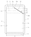
ここで、図22及び図23に、従来の包装袋を開封する様子を示す。従来例の包装袋は、表フィルム101aと裏フィルム101bとを重ね合わせ、左右のサイドシール部102、104、トップシール部106、及びボトムシール部108により四方をヒートシールした平パウチである。図22及び図23に示す例では、左側のサイドシール部102のノッチ110から右側のサイドシール部104まで包装袋を開封する。破断片100が右側へ移動するにつれて、表フィルム101a及び裏フィルム101bを引き裂いた破断線110a及び110bが右側のサイドシール部104へ向かって形成されていく。
Here, FIGS. 22 and 23 show how a conventional packaging bag is opened. The packaging bag of the conventional example is a flat pouch in which a
左右のサイドシール部102及び104の間の収納部では、図23に示すように、表フィルム101aの破断線110aと裏フィルム101bの破断線110bとが上下にずれる。その結果、破断線110aと破断線110bは、右側のサイドシール部104の内縁104a上で互いに異なる位置にしばしば到達する。
In the storage portion between the left and right
図24に、図23中の破線Cで囲まれた部分の拡大図を示す。サイドシール部104の内縁104a上において、表フィルム101aの破断線110aの到達点Paと、裏フィルム101bの破断線110bの到達点Pbとは、間隔Wだけ離れている。到達点Pa及びPbから更にサイドシール部104を引き裂くためには、この間隔Wの幅でサイドシール部104の融着部分を引き剥がす必要がある。しかし、サイドシール部104を引き剥がしつつ破断させるには大きな力を必要とするため、破断片100を切り離すことが困難となる場合が少なくない。
FIG. 24 is an enlarged view of a portion surrounded by a broken line C in FIG. On the
本発明は、上記の事情に鑑みてなされたものであり、包装袋を一方のサイドシール部から他方のサイドシール部まで破断して開封するときに、付着していた内容物が周囲に飛び散ることなく、破断片を容易に切り離すことができる包装袋を提供することを目的としている。 The present invention has been made in view of the above circumstances, and when the packaging bag is broken from one side seal portion to the other side seal portion and opened, the attached contents are scattered around. It is another object of the present invention to provide a packaging bag from which broken pieces can be easily separated.
本発明に係る発明者は、種々の実験及び検討の結果、包装袋を開封する際に、表フィルムの切断線と裏フィルムの切断線とが、一方のサイドシール部から他方のサイドシール部の内縁上の同一地点に最終的に到達すれば、他方のサイドシール部において表フィルムと裏フィルムを大きな力で剥離させる必要がなく、小さな剪断力で他方のサイドシール部を引き裂いて、包装袋の破断片を容易に切り離すことができることに着目した。 As a result of various experiments and studies, the inventor of the present invention has found that when the packaging bag is opened, the cutting line of the front film and the cutting line of the back film are moved from one side seal portion to the other side seal portion. When the same point on the inner edge is finally reached, there is no need to peel the front film and the back film with a large force at the other side seal portion, and the other side seal portion is torn with a small shearing force, and We focused on the fact that broken fragments can be easily separated.
そこで、本発明の包装袋は、重ね合わせた表フィルムと裏フィルムの両側縁を密封する一対のサイドシール部と、前記表フィルムと前記裏フィルムの上縁を密封するトップシール部とを有し、前記一対のサイドシール部の一方のサイドシール部に易開封部を形成した包装袋であって、前記表フィルム及び裏フィルムの前記一対のサイドシール部間の領域に、前記表フィルムに設けられた表開封ガイド線と、前記裏フィルムに設けられた裏開封ガイド線とを有し、前記表開封ガイド線及び前記裏開封ガイド線は、前記易開封部から他方のサイドシール部に向けて前記包装袋の縦方向に延びる対称軸線と直交する方向に延びる開封仮想直線に対して傾斜して延在し、前記表開封ガイド線の前記他方のサイドシール部寄りの端部と、前記裏開封ガイド線の前記他方のサイドシール寄りの端部とが、前記他方のサイドシール部の内縁上又は前記内縁の近傍、又は、前記トップシール部の下縁上又は前記下縁の近傍で互いに重なっており、前記表開封ガイド線及び裏開封ガイド線の各々の前記一方のサイドシール部寄りの端部は、前記開封仮想直線よりも下側に位置し、前記表開封ガイド線及び裏開封ガイド線の各々の前記他方のサイドシール部寄りの端部は、前記開封仮想直線よりも上側に位置し、又は、前記表開封ガイド線及び裏開封ガイド線の各々の前記他方のサイドシール部寄りの端部は、前記他方のサイドシール部の内縁上又は前記内縁の近傍で互いに重なり、前記表開封ガイド線及び裏開封ガイド線の各々の前記一方のサイドシール部寄りの端部は、前記開封仮想直線よりも上側に位置し、前記表開封ガイド線及び裏開封ガイド線の各々の前記他方のサイドシール部寄りの端部は、前記開封仮想直線よりも下側に位置していることを特徴としている。
また、本発明の包装袋は、重ね合わせた表フィルムと裏フィルムの両側縁を密封する一対のサイドシール部と、前記表フィルムと前記裏フィルムの上縁を密封するトップシール部とを有し、前記一対のサイドシール部の一方のサイドシール部に易開封部を形成した包装袋であって、前記表フィルム及び裏フィルムの前記一対のサイドシール部間の領域に、前記表フィルムに設けられた表開封ガイド線と、前記裏フィルムに設けられた裏開封ガイド線とを有し、前記表開封ガイド線及び前記裏開封ガイド線は、前記易開封部から他方のサイドシール部に向けて前記包装袋の縦方向に延びる対称軸線と直交する方向に延びる開封仮想直線に対して傾斜して延在し、前記表開封ガイド線の前記他方のサイドシール部寄りの端部と、前記裏開封ガイド線の前記他方のサイドシール寄りの端部とが、前記他方のサイドシール部の内縁上又は前記内縁の近傍、又は、前記トップシール部の下縁上又は前記下縁の近傍で互いに重なっており、前記表開封ガイド線及び裏開封ガイド線の各々の前記一方のサイドシール部寄りの端部は、前記トップシール部の下縁上に位置していることを特徴としている。
また、本発明の包装袋は、重ね合わせた表フィルムと裏フィルムの両側縁を密封する一対のサイドシール部と、前記表フィルムと前記裏フィルムの上縁を密封するトップシール部とを有し、前記一対のサイドシール部の一方のサイドシール部に易開封部を形成した包装袋であって、前記表フィルム及び裏フィルムの前記一対のサイドシール部間の領域に、前記表フィルムに設けられた表開封ガイド線と、前記裏フィルムに設けられた裏開封ガイド線とを有し、前記表開封ガイド線及び前記裏開封ガイド線は、前記易開封部から他方のサイドシール部に向けて前記包装袋の縦方向に延びる対称軸線と直交する方向に延びる開封仮想直線に対して傾斜して延在し、前記表開封ガイド線の前記他方のサイドシール部寄りの端部と、前記裏開封ガイド線の前記他方のサイドシール寄りの端部とが、前記他方のサイドシール部の内縁上又は前記内縁の近傍、又は、前記トップシール部の下縁上又は前記下縁の近傍で互いに重なっており、前記表開封ガイド線及び裏開封ガイド線の各々の前記他方のサイドシール部寄りの端部は、前記一対のサイドシール部の内縁間の前記開封仮想直線に沿った長さの28%以上の距離だけ前記開封仮想直線から離れて位置していることを特徴としている。
また、本発明の包装袋は、重ね合わせた表フィルムと裏フィルムの両側縁を密封する一対のサイドシール部と、前記表フィルムと前記裏フィルムの上縁を密封するトップシール部とを有し、前記一対のサイドシール部の一方のサイドシール部に易開封部を形成した包装袋であって、前記表フィルム及び裏フィルムの前記一対のサイドシール部間の領域に、前記表フィルムに設けられた表開封ガイド線と、前記裏フィルムに設けられた裏開封ガイド線とを有し、前記表開封ガイド線及び前記裏開封ガイド線は、前記易開封部から他方のサイドシール部に向けて前記包装袋の縦方向に延びる対称軸線と直交する方向に延びる開封仮想直線に対して傾斜して延在し、前記表開封ガイド線の前記他方のサイドシール部寄りの端部と、前記裏開封ガイド線の前記他方のサイドシール寄りの端部とが、前記他方のサイドシール部の内縁上又は前記内縁の近傍、又は、前記トップシール部の下縁上又は前記下縁の近傍で互いに重なっており、前記表開封ガイド線及び裏開封ガイド線の各々の前記一方のサイドシール部寄りの端部は、前記一方のサイドシール部の内縁上に位置している前記表開封ガイド線及び裏開封ガイド線の各々の前記他方のサイドシール部寄りの端部は、前記一対のサイドシール部の内縁間の前記開封仮想直線に沿った長さの38%以上の距離だけ前記開封仮想直線から離れて位置していることを特徴としている。
また、本発明の包装袋は、重ね合わせた表フィルムと裏フィルムの両側縁を密封する一対のサイドシール部と、前記表フィルムと前記裏フィルムの上縁を密封するトップシール部とを有し、前記一対のサイドシール部の一方のサイドシール部に易開封部を形成した包装袋であって、前記表フィルム及び裏フィルムの前記一対のサイドシール部間の領域に、前記表フィルムに設けられた表開封ガイド線と、前記裏フィルムに設けられた裏開封ガイド線とを有し、前記表開封ガイド線及び前記裏開封ガイド線は、前記易開封部から他方のサイドシール部に向けて前記包装袋の縦方向に延びる対称軸線と直交する方向に延びる開封仮想直線に対して傾斜して延在し、前記表開封ガイド線の前記他方のサイドシール部寄りの端部と、前記裏開封ガイド線の前記他方のサイドシール寄りの端部とが、前記他方のサイドシール部の内縁上又は前記内縁の近傍、又は、前記トップシール部の下縁上又は前記下縁の近傍で互いに重なっており、前記表開封ガイド線及び裏開封ガイド線の各々の前記他方のサイドシール部寄りの端部は、前記開封仮想直線の下側であって、前記開封仮想直線から、前記一対のサイドシール部の内縁間の前記開封仮想直線に沿った長さの23%以内の距離に位置していることを特徴としている。
また、本発明の包装袋は、重ね合わせた表フィルムと裏フィルムの両側縁を密封する一対のサイドシール部と、前記表フィルムと前記裏フィルムの上縁を密封するトップシール部とを有し、前記一対のサイドシール部の一方のサイドシール部に易開封部を形成した包装袋であって、前記表フィルム及び裏フィルムの前記一対のサイドシール部間の領域に、前記表フィルムに設けられた表開封ガイド線と、前記裏フィルムに設けられた裏開封ガイド線とを有し、前記表開封ガイド線及び前記裏開封ガイド線は、前記易開封部から他方のサイドシール部に向けて前記包装袋の縦方向に延びる対称軸線と直交する方向に延びる開封仮想直線に対して傾斜して延在し、前記表開封ガイド線の前記他方のサイドシール部寄りの端部と、前記裏開封ガイド線の前記他方のサイドシール寄りの端部とが、前記他方のサイドシール部の内縁上又は前記内縁の近傍、又は、前記トップシール部の下縁上又は前記下縁の近傍で互いに重なっており、前記表開封ガイド線及び裏開封ガイド線の各々の前記一方のサイドシール部寄りの端部は、前記一方のサイドシール部の内縁上に位置していることを特徴としている。
Therefore, the packaging bag of the present invention has a pair of side seal portions for sealing both side edges of the superposed front film and the back film, and a top seal portion for sealing the top edges of the front film and the back film. A packaging bag in which an easy-open portion is formed in one side seal portion of the pair of side seal portions, provided in the front film in a region between the pair of side seal portions of the front film and the back film. Having a front opening guide line and a back opening guide line provided on the back film, wherein the front opening guide line and the back opening guide line are arranged from the easy opening portion toward the other side seal portion. An end portion of the front opening guide line closer to the other side seal portion, the end portion being inclined with respect to an opening virtual straight line extending in a direction orthogonal to a symmetry axis extending in a longitudinal direction of the packaging bag, and the back opening guide. The end of the line near the other side seal is overlapped on the inner edge of the other side seal portion or near the inner edge, or on the lower edge of the top seal portion or near the lower edge. The end of each of the front opening guide line and the back opening guide line near the one side seal portion is located below the opening virtual straight line, and each of the front opening guide line and the back opening guide line. The end near the other side seal portion is located above the opening imaginary straight line, or the end near the other side seal portion of each of the front opening guide line and the back opening guide line is , On the inner edge of the other side seal portion or near the inner edge, the end of the front opening guide line and the back opening guide line closer to the one side seal portion is more than the opening virtual straight line. Upper side Position, and the table opening guide wire and the other of the side seal portion side of the end portion of each of the back opening guide wire is characterized in that located on the lower side than the opening imaginary straight line.
Further, the packaging bag of the present invention has a pair of side seal portions for sealing both side edges of the superposed front film and the back film, and a top seal portion for sealing the top edges of the front film and the back film. A packaging bag in which an easy-open portion is formed in one side seal portion of the pair of side seal portions, provided in the front film in a region between the pair of side seal portions of the front film and the back film. Having a front opening guide line and a back opening guide line provided on the back film, wherein the front opening guide line and the back opening guide line are arranged from the easy opening portion toward the other side seal portion. An end portion of the front opening guide line near the other side seal portion extends obliquely with respect to an opening virtual straight line extending in a direction orthogonal to the symmetry axis extending in the longitudinal direction of the packaging bag, and the back opening guide. The other end of the side seal closer to the end, on the inner edge of the other side seal portion or near the inner edge, or on the lower edge of the top seal portion or near the lower edge, overlap each other, An end of each of the front opening guide line and the back opening guide line near the one side seal portion is located on a lower edge of the top seal portion.
Further, the packaging bag of the present invention has a pair of side seal portions for sealing both side edges of the superposed front film and the back film, and a top seal portion for sealing the top edges of the front film and the back film. A packaging bag in which an easy-open portion is formed in one side seal portion of the pair of side seal portions, provided in the front film in a region between the pair of side seal portions of the front film and the back film. Having a front opening guide line and a back opening guide line provided on the back film, wherein the front opening guide line and the back opening guide line are arranged from the easy opening portion toward the other side seal portion. An end portion of the front opening guide line near the other side seal portion extends obliquely with respect to an opening virtual straight line extending in a direction orthogonal to the symmetry axis extending in the longitudinal direction of the packaging bag, and the back opening guide. The other end of the side seal closer to the end, on the inner edge of the other side seal portion or near the inner edge, or on the lower edge of the top seal portion or near the lower edge, overlap each other, An end of each of the front opening guide line and the back opening guide line near the other side seal portion is a distance of 28% or more of a length along the opening virtual straight line between inner edges of the pair of side seal portions. Only the opening virtual straight line.
Further, the packaging bag of the present invention has a pair of side seal portions for sealing both side edges of the superposed front film and the back film, and a top seal portion for sealing the top edges of the front film and the back film. A packaging bag in which an easy-open portion is formed in one side seal portion of the pair of side seal portions, provided in the front film in a region between the pair of side seal portions of the front film and the back film. Having a front opening guide line and a back opening guide line provided on the back film, wherein the front opening guide line and the back opening guide line are arranged from the easy opening portion toward the other side seal portion. An end portion of the front opening guide line near the other side seal portion extends obliquely with respect to an opening virtual straight line extending in a direction orthogonal to the symmetry axis extending in the longitudinal direction of the packaging bag, and the back opening guide. The other end of the side seal closer to the end, on the inner edge of the other side seal portion or near the inner edge, or on the lower edge of the top seal portion or near the lower edge, overlap each other, The end of each of the front opening guide line and the back opening guide line near the one side seal portion is the end of the front opening guide line and the back opening guide line located on the inner edge of the one side seal portion. Each of the other end portions near the other side seal portion is located apart from the virtual opening straight line by a distance of 38% or more of the length along the virtual opening straight line between the inner edges of the pair of side seal portions. It is characterized by having.
Further, the packaging bag of the present invention has a pair of side seal portions for sealing both side edges of the superposed front film and the back film, and a top seal portion for sealing the top edges of the front film and the back film. A packaging bag in which an easy-open portion is formed in one side seal portion of the pair of side seal portions, provided in the front film in a region between the pair of side seal portions of the front film and the back film. Having a front opening guide line and a back opening guide line provided on the back film, wherein the front opening guide line and the back opening guide line are arranged from the easy opening portion toward the other side seal portion. An end portion of the front opening guide line near the other side seal portion extends obliquely with respect to an opening virtual straight line extending in a direction orthogonal to the symmetry axis extending in the longitudinal direction of the packaging bag, and the back opening guide. The other end of the side seal closer to the end, on the inner edge of the other side seal portion or near the inner edge, or on the lower edge of the top seal portion or near the lower edge, overlap each other, An end of each of the front opening guide line and the back opening guide line near the other side seal portion is below the opening virtual straight line, and an inner edge of the pair of side seal portions is located from the opening virtual straight line. And a distance within 23% of the length along the opening virtual straight line.
Further, the packaging bag of the present invention has a pair of side seal portions for sealing both side edges of the superposed front film and the back film, and a top seal portion for sealing the top edges of the front film and the back film. A packaging bag in which an easy-open portion is formed in one side seal portion of the pair of side seal portions, provided in the front film in a region between the pair of side seal portions of the front film and the back film. Having a front opening guide line and a back opening guide line provided on the back film, wherein the front opening guide line and the back opening guide line are arranged from the easy opening portion toward the other side seal portion. An end portion of the front opening guide line near the other side seal portion extends obliquely with respect to an opening virtual straight line extending in a direction orthogonal to the symmetry axis extending in the longitudinal direction of the packaging bag, and the back opening guide. The other end of the side seal closer to the end, on the inner edge of the other side seal portion or near the inner edge, or on the lower edge of the top seal portion or near the lower edge, overlap each other, An end of each of the front opening guide line and the back opening guide line near the one side seal portion is located on an inner edge of the one side seal portion.
このように、本発明の包装袋は、表開封ガイド線の他方のサイドシール部寄りの端部と、裏開封ガイド線の他方のサイドシール寄りの端部とが、他方のサイドシール部の内縁上又は内縁の近傍、又は、トップシール部の下縁上又は下縁の近傍で互いに重なるように開封ガイド線を設けている。このため、包装袋を一方のサイドシール部から他方のサイドシール部まで破断して開封するときに、表開封ガイド線及び裏開封ガイド線にそれぞれ到達した表フィルムの破断線及び裏フィルムの破断線が、他方のサイドシール部の内縁上で又は当該内縁に到達するまでに合流して重なるように、表開封ガイド線及び裏開封ガイド線によって誘導される。その結果、表開封ガイド線に誘導された表フィルムの破断線と裏開封ガイド線に誘導された裏フィルムの破断線とが合流し、他方のサイドシール部の内縁上の同一地点に最終的に到達する。その結果、他方のサイドシール部を小さな剪断力で引き裂くことができ、これにより、包装袋の破断片を容易に切り離すことができる。 Thus, in the packaging bag of the present invention, the end of the front opening guide line near the other side seal portion and the end of the back opening guide line near the other side seal portion have the inner edge of the other side seal portion. Unsealing guide lines are provided so as to overlap each other near the upper or inner edge, or above or near the lower edge of the top seal portion. Therefore, when the packaging bag is broken and opened from one side seal portion to the other side seal portion, the break line of the front film and the break line of the back film that have reached the front opening guide line and the back opening guide line, respectively. Are guided by the front opening guide line and the back opening guide line so as to merge and overlap on the inner edge of the other side seal portion or until reaching the inner edge. As a result, the break line of the front film guided to the front opening guide line and the break line of the back film guided to the back opening guide line merge, and finally to the same point on the inner edge of the other side seal portion. To reach. As a result, the other side seal portion can be torn with a small shearing force, so that the broken pieces of the packaging bag can be easily separated.
本発明の包装袋によれば、包装袋を一方のサイドシール部から他方のサイドシール部まで破断して開封するときに、破断片を容易に切り離すことができる。 ADVANTAGE OF THE INVENTION According to the packaging bag of this invention, when a packaging bag is fractured | ruptured from one side seal part to the other side seal part, and it opens, a broken piece can be easily cut off.
以下、図面を参照して本発明の包装袋の実施形態を説明する。
(第1実施形態)
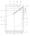
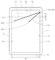
図1に、第1実施形態の包装袋の平面図を示す。本実施形態の包装袋は、重ね合わせた表フィルム1aと裏フィルム1b(図4〜図7参照)の四方を、一対のサイドシール部2,4、トップシール部6、及びボトムシール部8によりヒートシールした平パウチであり、これらシール部2,4,6,8に囲まれた領域の表フィルム1aと裏フィルム1bとの間に、内容物が密封包装されている。
Hereinafter, an embodiment of a packaging bag of the present invention will be described with reference to the drawings.
(1st Embodiment)
FIG. 1 shows a plan view of the packaging bag of the first embodiment. In the packaging bag of the present embodiment, the four sides of the
表フィルム1a及び裏フィルム1bは、例えば、それぞれポリオレフィン層上にナイロン層を積層した積層フィルムにより構成されている。
なお、表フィルム1a及び裏フィルム1bには、熱溶着可能な種々の材料及び構成を採用することができる。例えば、表フィルム1a及び裏フィルム1bは、熱溶着可能な熱可塑性樹脂からなる単層フィルムにより構成してもよいし、溶着面をヒートシール性樹脂とする積層フィルムにより構成してもよい。積層フィルムは、中間層にバリア層を設けた積層構造としてもよいし、表層にバリア層を設けた積層構造としてもよい。また、積層フィルムは、樹脂層を基材としてもよいし、紙を基材としてもよい。
The
The
表フィルム1a及び裏フィルム1bの一対のサイドシール部2,4間のシールされていない領域には、表フィルム1aに設けられた表開封ガイド線14と、裏フィルム1bに設けられた裏開封ガイド線14が設けられている。なお、図1では、表開封ガイド線及び裏開封ガイド線14を重ねて1本の線で示している。
表開封ガイド線及び裏開封ガイド線14は、開封仮想直線12と斜めに交差し、左下から右上に向かう方向に沿って延在している。開封仮想直線12は、一方のサイドシール部(以下、「左サイドシール部」ともいう)2に形成されたノッチの易開封部10から他方のサイドシール部4(以下、「右サイドシール部」ともいう)に向けて包装袋の縦方向に延びる対称軸線11と直交する方向に延びる仮想線であり、開封時に、易開封部10よりも上側の部分1c(以下、「破断片」ともいう)が手指で引っ張られる方向に沿った仮想線である。
In an unsealed region between the pair of
The front opening guide line and the back
本実施形態のように、包装袋が互いに平行な直線状の一対のサイドシール部2,4とこれらと直交する方に延びるトップシール部6とを有する長方形を有している場合には、図1に示すように、対称軸線11は、一対のサイドシール部2,4間の中央で、一対のサイドシール部2,4と平行に延び、直線状のトップシール部6とも直交し、開封仮想直線12はトップシール部6の直線状の下縁6aと平行に延在する。
When the packaging bag has a rectangular shape having a pair of linear
表開封ガイド線及び裏開封ガイド線14の各々が開封仮想直線12となす角度θは、好ましくは、10〜50°であり、より好ましくは、20〜45°である。角度θが50°よりも大きくなると、開封時に、開封仮想直線12に沿って引っ張る力のうち開封ガイド線14に沿った方向の分力が小さくなり、開封ガイド線14に沿って引き裂きにくくなる。一方、角度θが10°よりも小さくなると、開封時に、破断線が開封ガイド線14に到達しない可能性が高くなる。
The angle θ formed by each of the front opening guide line and the back
表開封ガイド線及び裏開封ガイド線14の各々の右サイドシール部4寄りの端部(以下、「終端」ともいう)14bは、右サイドシール部4の内縁4a上で互いに重なっている。これにより、開封時に、表フィルム1aの破断線10aと裏フィルム1bの破断線10bは、表開封ガイド線及び裏開封ガイド線14によって、右サイドシール部4の内縁4a上の一点に直接誘導される。
Ends (hereinafter, also referred to as “ends”) 14 b of the front opening guide line and the back
なお、終端14bは、表フィルム1aの破断線10a及び裏フィルム1bの破断線10bを右サイドシール部4の内縁4a上の一点に実質的に誘導できれば、右サイドシール部4の内縁4a上に位置していなくてもよく、内縁4aの近傍に位置してもよい。ここで、内縁4aの近傍の終端14bは、内縁4aから10mm以内に位置することが好ましい。後述する他の実施形態においても同様である。
In addition, if the
また、表開封ガイド線及び裏開封ガイド線14の各々の左サイドシール部2寄りの端部(以下、「始端」ともいう)14aは、開封仮想直線12よりも下側に所定距離L以上離れて位置している。一方、開封ガイド線14の右サイドシール部4寄りの端部(終端)14bは、開封仮想直線12よりも上側に所定距離L以上離れて位置している。
In addition, the respective ends (hereinafter, also referred to as “start ends”) 14 a of the front opening guide line and the back
ここで、所定距離Lは、好ましくは、一対のサイドシール部2,4の内縁2a,4a間の開封仮想直線12に沿った長さDの28%以上の距離、更に好ましくは、38%以上の距離として設定される(後述する他の実施形態においても同様である)。この長さDに対する距離の比率は、包装袋を開封する際に破断線が形成される範囲を含むように実験的に求めたものである。表開封ガイド線及び裏開封ガイド線14の各々の始端14a及び終端14bを開封仮想直線12から所定の距離L以上離れた位置に配置することにより、開封時に破断線が開封ガイド線14に到達する確率を高くすることができる。
Here, the predetermined distance L is preferably a distance of 28% or more of the length D along the opening virtual
図2に、本実施形態の表開封ガイド線及び裏開封ガイド線14の一例を示す。図2に示す表開封ガイド線及び裏開封ガイド線14は、表フィルム1a及び裏フィルム1bよりも破断しにくい強化部15の縁15aによって構成されている。強化部15は、表フィルム1aと裏フィルム1bとを部分的に融着又は接着して形成してもよいし、表フィルム1a及び裏フィルム1bそれぞれの外面側、内面側又は層間に、部材やテープを設けて形成してもよい。表フィルム1aと裏フィルム1bとを部分的に融着又は接着した場合には、表フィルム1aと裏フィルム1bの融着又は接着した部分の縁が、それぞれ表開封ガイド線及び裏開封ガイド線14となる。開封時に強化部15の縁15aに到達した破断線は、強化部15が破断しにくいため、強化部15の縁15aに沿って進む。このため、強化部15の縁15aが、前述した表開封ガイド線及び裏開封ガイド線14として機能する。
FIG. 2 shows an example of the front opening guide line and the back
また、表開封ガイド線及び裏開封ガイド線14は、表フィルム1a及び裏フィルム1bよりも破断しやすい弱化部によって構成してもよい。開封時に弱化部に到達した破断線は、周囲よりも破断しやすい弱化部に沿って進むため、弱化部が表開封ガイド線及び裏開封ガイド線14として機能する。弱化部は、表フィルム1a及び裏フィルム1bそれぞれに、非貫通のハーフカット加工部として形成することができる。ハーフカット加工部は、レーザ加工、表面に微細な刃を取り付けたロールや抜き型を用いるナイフ加工、及び高硬度の砥粒を取付けたロールで押圧する研磨加工などの種々の方法によって形成することができ、これらの方法から適宜の方法を選択して直線状またはミシン目状の非貫通のハーフカット加工部を形成すればよい。
Further, the front opening guide line and the back
なお、本実施形態では、表フィルム1aの破断線10aを誘導する表開封ガイド線14と、裏フィルム1bの破断線10bを誘導する裏開封ガイド線14とが、融着部のように共通の構成として形成されているものとして、或いは、表フィルム1aに形成されている表開封ガイド線14と裏フィルム1bに形成されている裏開封ガイド線14とが互いに重なる位置に形成されているものとして説明する。以下の各実施形態においても同様である。
In the present embodiment, the front
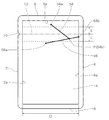
次に、図3〜図7を参照して、本実施形態の包装袋の開封を説明する。図3に、開封時の表フィルム1aの破断線10a(以下、「表破断線」ともいう)及び裏フィルム1bの破断線10b(以下、「裏破断線」ともいう)の位置を、未開封状態の包装袋に重ねて示す。
Next, opening of the packaging bag of the present embodiment will be described with reference to FIGS. In FIG. 3, the positions of the
左サイドシール部2の易開封部10から右サイドシール部4まで包装袋を開封する際には、易開封部10よりも上側の部分を手指で右サイドシール部4に向かって引っ張ることにより、易開封部10から左サイドシール部2が破断する。そして、易開封部10よりも上側の部分が破断片1cとなる。
When opening the packaging bag from the easy-opening
更に破断片1cを右側へ引っ張ると、一対のサイドシール部2,4の間の収納部で表フィルム1a及び裏フィルム1bが開裂し、表破断線10aと裏破断線10bが右サイドシール部4へ向かって延びていく。このとき、図3に示すように、表破断線10aと裏破断線10bとが上下にずれる表裏ずれが発生する。
When the
本実施形態では、図4に示すように、先ず表フィルム1aの表破断線10aが表開封ガイド線14上の点P1に到達する。点P1に到達した表破断線10aは、表開封ガイド線14に沿って、図3中に矢印A1で示す方向へ進む。
In the present embodiment, as shown in FIG. 4, first, the
次いで、図5に示すように、裏破断線10bが裏開封ガイド線14上の点P2に到達し、表開封ガイド線14に沿って進んできた表破断線10aと合流する。点P2で合流した表破断線10a及び裏破断線10bは、表開封ガイド線及び裏開封ガイド線14に沿って、図3中に矢印A2で示す方向へ進む。
Next, as shown in FIG. 5, the
そして、図6に示すように、表破断線10a及び裏破断線10bは共に、表開封ガイド線及び裏開封ガイド線14の各々の終端14bに到達する。これらの終端14bは、右サイドシール部4の内縁4a上の点P3に互いに重なって配置されている。このため、表破断線10a及び裏破断線10bは、表開封ガイド線及び裏開封ガイド線14によって、右サイドシール部4の内縁4a上の同一地点である点P3まで直接誘導される。
Then, as shown in FIG. 6, both the
破断片1cを図面右側へ更に引っ張ると、図7に示すように、表破断線10aと裏破断線10bとが合流した1本の破断線10cが、点P3から右サイドシール部4に伸長し、右サイドシール部4が破断する。この際、右サイドシール部4の破断線10cは1本だけであるため、右サイドシール部4において表フィルム1aと裏フィルム1bを大きな力で剥離させる必要がなく、小さな剪断力で右サイドシール部4を引き裂くことができる。その結果、破断片1cを容易に切り離すことができる。
When the fractured
また、図1に示したように表開封ガイド線及び裏開封ガイド線14が左下から右上に向かう方向に沿って延在しているため、左側から開封ガイド線14に到達した表破断線10a及び裏破断線10bは、表開封ガイド線及び裏開封ガイド線14に沿って到達地点よりも上側へ誘導される。その結果、表破断線10a及び裏破断線10bは表開封ガイド線及び裏開封ガイド線14よりも下側へは進まず、開封時に内容物の上面より下側まで破断して内容物がこぼれてしまうことを防止することができる。
Further, as shown in FIG. 1, the front opening guide line and the back
(変形例)
上述した第1実施形態では、表破断線10aを誘導する表開封ガイド線14と、裏破断線10bを誘導する裏開封ガイド線14とが、共通の構成又は重なって配置された例を示したが、これら表開封ガイド線及び裏開封ガイド線14は別々に配置してもよい。
(Modification)
In the above-described first embodiment, an example is shown in which the front
図8に、第1実施形態の変形例を示す。本変形例では、表開封ガイド線及び裏開封ガイド線は、表フィルム1aの破断線(表破断線)10aを誘導する表開封ガイド線16と、裏フィルム1bの破断線(裏破断線)10bを誘導する裏開封ガイド線17が、表フィルム1a及び裏フィルム1bに、弱化部又は強化部の縁としてそれぞれ形成されている。
FIG. 8 shows a modification of the first embodiment. In this modification, the front opening guide line and the back opening guide line are a front
表開封ガイド線16の左サイドシール部2寄りの端部(始端)16aと裏開封ガイド線17の左サイドシール部2寄りの端部(始端)17aは、互いに異なる位置に配置されている。一方、表開封ガイド線16の右サイドシール部4寄りの端部(終端)16bと裏開封ガイド線17の右サイドシール部4寄りの端部(終端)17bとは、右サイドシール部4の内縁4a上の点P3で重なっている。
An end (starting end) 16a of the front
次に、図9を参照して、本変形例の包装袋の開封を説明する。図9に、開封時の表破断線10a及び裏破断線10bの位置を、未開封状態の包装袋に重ねて示す。
開封時に、表破断線10a及び裏破断線10bは、左サイドシール部2から右サイドシール部4へ向かって延びていく。その結果、表破断線10aは、表開封ガイド線16上の点P1に到達し、表開封ガイド線16に沿って、図9中の矢印A1の方向へ進む。一方、裏破断線10bは、裏開封ガイド線17上の点P2に到達し、裏開封ガイド線17に沿って、図9中の矢印A2の方向へ進む。
Next, opening of the packaging bag of the present modified example will be described with reference to FIG. FIG. 9 shows the positions of the
At the time of opening, the
表開封ガイド線16の終端16bと裏開封ガイド線17の終端17bとは、右サイドシール部4の内縁4a上の同一地点である点P3に配置されている。このため、表破断線10aと裏破断線10bとは、点P3で合流する。その結果、右サイドシール部4を小さな剪断力で引き裂くことができ、点P3から1本の破断線10cが右サイドシール部4を進み、破断片を容易に切り離すことができる。
The
(第2実施形態)
次に、図10を参照して、第2実施形態の包装袋を説明する。
なお、以下の各実施形態の包装袋は、開封ガイド線を除き第1実施形態のものと実質的に同じであるため、同一構成要素については、同一符号を付してその詳細な説明を省略する。また、以下の各実施形態においても、第1実施形態及びその変形例と同様に、開封ガイド線は、弱化部として形成してもよいし、強化部の縁として形成してもよく、また、表フィルムと裏フィルムで別々の位置に配置してもよい。また、以下の各実施形態において、開封ガイド線が開封仮想直線12と成す角度の好適範囲も、第1実施形態と同様である。また、以下の各実施形態においても、開封ガイド線の左サイドシール部2寄りの端部を始端と称し、右サイドシール部4寄りの端部を終端と称する。
(2nd Embodiment)
Next, a packaging bag according to a second embodiment will be described with reference to FIG.
Note that the packaging bags of the following embodiments are substantially the same as those of the first embodiment except for an opening guide line, and therefore, the same components are denoted by the same reference numerals and detailed description thereof will be omitted. I do. Also, in each of the following embodiments, similarly to the first embodiment and its modifications, the opening guide line may be formed as a weakened portion, or may be formed as an edge of a reinforced portion, The front film and the back film may be arranged at different positions. In each of the following embodiments, the preferred range of the angle formed by the opening guide line and the opening virtual
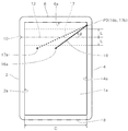
図10に示すように、本実施形態の包装袋における表開封ガイド線及び裏開封ガイド線18は、開封仮想直線12と斜めに交差し、左下から右上に向かう方向に沿って延在している。表開封ガイド線及び裏開封ガイド線18の各々の終端18bは、第1実施形態と同様に、右サイドシール部4の内縁4a上の、開封仮想直線12よりも上側に所定距離L以上離れた位置で互いに重なっている。これにより、開封時に破断線が表開封ガイド線及び裏開封ガイド線14に到達する確率を高くすることができる。
As shown in FIG. 10, the front opening guide line and the back
一方、表開封ガイド線及び裏開封ガイド線18の各々の始端18aは、左サイドシール部2の内縁2a上に配置されている。これにより、開封時に、開封仮想直線12よりも下側に進む破断線は、開封ガイド線18に確実に到達する。
On the other hand, the starting
開封時に、表破断線と裏破断線は、表開封ガイド線及び裏開封ガイド線18にそれぞれ到達して合流し、右サイドシール部4の内縁4a上の終端18bに到達する。これにより、本実施形態においても、右サイドシール部4を小さな剪断力で引く裂ことができ、終端18bから1本の破断線が右サイドシール部4を進み、破断片を容易に切り離すことができる。
At the time of opening, the front break line and the back break line respectively reach the front opening guide line and the back
(第3実施形態)
次に、図11を参照して、第3実施形態の包装袋を説明する。
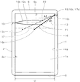
なお、本実施形態の包装袋の易開封部10は、第1実施形態のものよりもトップシール部6に近い位置に設けられている。
(Third embodiment)
Next, a packaging bag according to a third embodiment will be described with reference to FIG.
Note that the easy-opening
図11に示すように、本実施形態の包装袋における表開封ガイド線及び裏開封ガイド線20は、開封仮想直線12と斜めに交差し、左下から右上に向かう方向に沿って延在している。表開封ガイド線及び裏開封ガイド線20の各々の始端20aは、第1実施形態と同様に、開封仮想直線12よりも下側に所定距離L以上離れて位置している。これにより、開封時に破断線が開封ガイド線20に到達する確率を高くすることができる。
As shown in FIG. 11, the front opening guide line and the back
一方、表開封ガイド線及び裏開封ガイド線20の各々の終端20bは、トップシール部6の下縁6a上に互いに重なって位置している。これにより、開封時に、開封仮想直線12よりも上側に進む破断線は、開封ガイド線20に確実に到達する。
On the other hand, the
次に、図12を参照して、本実施形態の包装袋の開封を説明する。図12に、開封時の表破断線10a及び裏破断線10bの位置を、未開封状態の包装袋に重ねて示す。
開封時に、表破断線10a及び裏破断線10bは、左サイドシール部2から右サイドシール部4へ向かって延びていく。その結果、本実施形態では、先ず表破断線10aが、表開封ガイド線20上の点P1に到達し、表開封ガイド線20に沿って、矢印A1の方向へ進む。
Next, opening of the packaging bag of the present embodiment will be described with reference to FIG. FIG. 12 shows the positions of the
At the time of opening, the
次いで、裏破断線10bが、裏開封ガイド線20上の点P2に到達し、表開封ガイド線20に沿って進んできた表破断線10aと合流する。点P2で合流した表破断線10aと裏破断線10bは、表開封ガイド線及び裏開封ガイド線20に沿って、矢印A2の方向へ進む。その結果、表破断線10a及び裏破断線10bは共に、表開封ガイド線及び裏開封ガイド線20によって、表開封ガイド線及び裏開封ガイド線20の終端20b、即ち、トップシール部6の下縁6a上の点P3に誘導される。
Next, the
点P3に到達した表破断線10a及び裏破断線10bは、揃ってトップシール部6の下縁6aに沿って、矢印A3の方向へ進み、トップシール部6の下縁6aと右サイドシール部4の内縁4aとが合わさるコーナーの点P4に到達する。したがって、本実施形態においても、表開封ガイド線及び裏開封ガイド線20によって、表破断線10a及び裏破断線10bは、右サイドシール部4の内縁4a上の同一地点に誘導されることになる。これにより、本実施形態においても、右サイドシール部4を小さな剪断力で引く裂ことができ、点P4から1本の破断線10cが右サイドシール部4を進み、破断片を容易に切り離すことができる。
The
なお、終端20bは、表破断線10a及び裏破断線10bが揃ってトップシール部6の下縁6aに沿って進み、右サイドシール部4の内縁4a上の同一地点に実質的に誘導できれば、トップシール部6の下縁6a上に位置していなくともよく、トップシール部6の下縁6aの近傍に位置してもよい。ここで、下縁6aの近傍に終端20bは、下縁6aから10mm以内に位置することが好ましい。他の実施形態においても同様である。
Note that if the
(第4実施形態)
次に、図13を参照して、第4実施形態の包装袋を説明する。
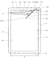
なお、本実施形態の包装袋の易開封部10は、第1実施形態のものよりもトップシール部6に近い位置に設けられている。
(Fourth embodiment)
Next, a packaging bag according to a fourth embodiment will be described with reference to FIG.
Note that the easy-opening
図13に示すように、本実施形態の包装袋における表開封ガイド線及び裏開封ガイド線22は、開封仮想直線12と斜めに交差し、左下から右上に向かう方向に沿って延在している。表開封ガイド線及び裏開封ガイド線22の各々の終端22bは、第3実施形態と同様に、トップシール部6の下縁6a上に位置している。これにより、開封時に、開封仮想直線12よりも上側に進む破断線は、表開封ガイド線及び裏開封ガイド線22に確実に到達する。
As shown in FIG. 13, the front opening guide line and the back
一方、表開封ガイド線及び裏開封ガイド線22の各々の始端22aは、左サイドシール部2の内縁2a上に位置している。これにより、開封時に、開封仮想直線12よりも下側に進む破断線も、表開封ガイド線及び裏開封ガイド線22に確実に到達する。したがって、本実施形態では、開封時に、表破断線及び裏破断線はそれぞれ表開封ガイド線及び裏開封ガイド線22に確実に達することになる。
On the other hand, the
開封時に、表破断線と裏破断線は、表開封ガイド線及び裏開封ガイド線22にそれぞれ到達して合流し、トップシール部6の下縁6a上で互いに重なっている終端22bに到達する。終端22bに到達した表破断線及び裏破断線は、揃ってトップシール部6の下縁6aに沿って進み、トップシール部6の下縁6aと右サイドシール部4の内縁4aとが合わさるコーナーに到達する。その結果、本実施形態においても、右サイドシール部4を小さな剪断力で引く裂ことができ、コーナーから1本の破断線が右サイドシール部4を進み、破断片を容易に切り離すことができる。
At the time of opening, the front break line and the back break line reach the front opening guide line and the back
(第5実施形態)
次に、図14を参照して、第5実施形態の包装袋を説明する。図14に示すように、本実施形態の包装袋における表開封ガイド線及び裏開封ガイド線30は、開封仮想直線12と斜めに交差し、左上から右下に向かう方向に沿って延在している。表開封ガイド線及び裏開封ガイド線30の各々の終端30bは、右サイドシール部4の内縁4a上の、開封仮想直線12よりも下側に所定距離L以上離れた位置で互いに重なっている。これにより、開封時に、開封仮想直線よりも下側に進む破断線が開封ガイド線30に到達する確率を高くすることができる。
(Fifth embodiment)
Next, a packaging bag according to a fifth embodiment will be described with reference to FIG. As shown in FIG. 14, the front opening guide line and the back
なお、開封時に包装袋の内容物が溢れないように、表開封ガイド線及び裏開封ガイド線30の終端30bは、内容物の上面よりも高い位置に配置されるとよい。一般に、レトルトパウチの包装袋においては、レトルトパウチのトップシール部6を上にした状態で、内容物の上面が、開封仮想直線12の下側であって、開封仮想直線12から、一対のサイドシール部2、4の内縁2a、4a間の開封仮想直線12に沿った長さDの23%以内の距離だけ開封仮想直線12の下方に位置することが多い。このため、本実施形態においても、内容物の上面が、開封仮想直線12よりも下側に所定距離Lだけ離れた位置よりも高い位置となる場合には、表開封ガイド線及び裏開封ガイド線30の各々の右サイドシール部4寄りの端部30bを、開封仮想直線12の下側であって、開封仮想直線12から、長さDの23%以内の距離に位置させることが好ましい。
Note that the
一方、開封ガイド線30の始端30aは、開封仮想直線12よりも上側に所定距離L以上離れて位置している。これにより、開封時に、開封仮想直線12よりも上側に進む破断線が開封ガイド線30に到達する確率を高くすることができる。
On the other hand, the starting
開封時に、表破断線と裏破断線は、表開封ガイド線及び裏開封ガイド線30にそれぞれ到達して合流し、右サイドシール部4の内縁4a上で互いに重なっている終端30bに到達する。その結果、本実施形態においても、右サイドシール部4を小さな剪断力で引く裂ことができ、表開封ガイド線及び裏開封ガイド線30の終端30bから1本の破断線が右サイドシール部4を進み、破断片を容易に切り離すことができる。
At the time of opening, the front break line and the back break line reach the front opening guide line and the back
(第6実施形態)
次に、図15を参照して、第6実施形態の包装袋を説明する。
なお、本実施形態の包装袋の易開封部10は、第1実施形態のものよりもトップシール部6に近い位置に設けられている。
(Sixth embodiment)
Next, a packaging bag according to a sixth embodiment will be described with reference to FIG.
Note that the easy-opening
図15に示すように、本実施形態の包装袋における表開封ガイド線及び裏開封ガイド線32は、開封仮想直線12と斜めに交差し、左上から右下に向かう方向に沿って延在している。表開封ガイド線及び裏開封ガイド線32の各々の終端32bは、第5実施形態と同様に、右サイドシール部4の内縁4a上の、開封仮想直線12よりも上側に所定距離L以上離れた位置で互いに重なっている。これにより、開封時に、開封仮想直線12よりも下側に進む破断線が表開封ガイド線及び裏開封ガイド線32に到達する確率を高くすることができる。
As shown in FIG. 15, the front opening guide line and the back
一方、表開封ガイド線及び裏開封ガイド線32の各々の始端32aは、トップシール部6の下縁6a上に位置している。これにより、開封時に、開封仮想直線12よりも上側に進む破断線は、表開封ガイド線及び裏開封ガイド線32に確実に到達することができる。
On the other hand, the
開封時に、表破断線と裏破断線は、表開封ガイド線及び裏開封ガイド線32にそれぞれ到達して合流し、右サイドシール部4の内縁4a上の終端32bに到達する。その結果、本実施形態においても、右サイドシール部4を小さな剪断力で引き裂くことができ、表開封ガイド線及び裏開封ガイド線32の互いに重なっている終端32bから1本の破断線が右サイドシール部4を進み、破断片を容易に切り離すことができる。
At the time of opening, the front break line and the back break line respectively reach the front opening guide line and the back
(第7実施形態)
次に、図16を参照して、第7実施形態の包装袋を説明する。
図16に示すように、本実施形態の包装袋における表開封ガイド線及び裏開封ガイド線34は、開封仮想直線12と斜めに交差し、左上から右下に向かう方向に沿って延在している。表開封ガイド線及び裏開封ガイド線34の各々の終端34bは、第5実施形態と同様に、右サイドシール部4の内縁4a上の、開封仮想直線12よりも上側に所定距離L以上離れた位置で互いに重なっている。これにより、開封時に、開封仮想直線12よりも下側に進む破断線が開封ガイド線32に到達する確率を高くすることができる。
(Seventh embodiment)
Next, a packaging bag according to a seventh embodiment will be described with reference to FIG.
As shown in FIG. 16, the front opening guide line and the back
一方、表開封ガイド線及び裏開封ガイド線34の各々の始端34aは、左サイドシール部2の内縁2a上に位置している。これにより、開封時に、開封仮想直線12よりも上側に進む破断線は、開封ガイド線34に確実に到達することができる。
On the other hand, the
開封時に、表破断線と裏破断線は、表開封ガイド線及び裏開封ガイド線34にそれぞれ到達して合流し、右サイドシール部4の内縁4a上で互いに重なっている終端34bに到達する。その結果、本実施形態においても、右サイドシール部4を小さな剪断力で引き裂くことができ、表開封ガイド線及び裏開封ガイド線34の終端34bから1本の破断線が右サイドシール部4を進み、破断片を容易に切り離すことができる。
At the time of opening, the front break line and the back break line respectively reach the front opening guide line and the back
(第8実施形態)
次に、図17を参照して、第8実施形態の包装袋を説明する。
図17に示すように、本実施形態の開封ガイド線は、表フィルム1a及び裏フィルム1bにそれぞれ設けられた、第1開封ガイド線38と、第1開封ガイド線38よりも他方のサイドシール部4寄りに配置された第2開封ガイド線40とから構成されている。第1開封ガイド線38及び第2開封ガイド線40は、共に開封仮想直線12と斜めに交差し、左下から右上に向かう方向に沿って延在している。
(Eighth embodiment)
Next, a packaging bag according to an eighth embodiment will be described with reference to FIG.
As shown in FIG. 17, the opening guide line of the present embodiment includes a first
第1開封ガイド線38の始端38aは、開封仮想直線12よりも下側に所定距離L以上離れて位置し、一方、第1開封ガイド線38の終端38bは、右サイドシール部4の内縁4a上で、開封仮想直線12よりも上側に所定距離L以上離れて位置している。
The
第2開封ガイド線40は、第1開封ガイド線38上の点Pから分岐し、左サイドシール部2に近づくにつれて第1開封ガイド線38から遠ざかるように配置されている。第2開封ガイド線40の終端40bは、第1開封ガイド線38上の点Pに配置され、第2開封ガイド線40の始端40aは、開封仮想直線12よりも下側に所定距離L以上離れて位置している。
The second
このように、第1開封ガイド線38に加えて第2開封ガイド線40を設けているので、開封時に、第1開封ガイド線38に到達した表破断線及び裏破断線の一方又は双方が、第1開封ガイド線38を横切って進んだ場合であっても、第2開封ガイド線40に到達した破断線を第1開封ガイド線38上の点Pに誘導し、続いて、第1開封ガイド線38によって破断線を右サイドシール部4の内縁4a上の終端38bへ誘導することができる。
As described above, since the second
(第9実施形態)
次に、図18を参照して、第9実施形態の包装袋を説明する。
図18に示すように、本実施形態の開封ガイド線は、表フィルム1a及び裏フィルム1bのそれぞれに設けられた、第1開封ガイド線42と、第1開封ガイド線42よりも他方のサイドシール部4寄りに配置された第2開封ガイド線44とから構成されている。第1開封ガイド線42及び第2開封ガイド線44は、共に開封仮想直線12と斜めに交差し、左下から右上に向かう方向に沿って延在し、かつ、左サイドシール部2に近づくにつれて互いに遠ざかるように配置されている。
(Ninth embodiment)
Next, a packaging bag according to a ninth embodiment will be described with reference to FIG.
As shown in FIG. 18, the opening guide line of the present embodiment includes a first
第1開封ガイド線42の終端42bと、第2開封ガイド線44の終端44bとは、右サイドシール部4の内縁4a上の、開封仮想直線12から上側に所定距離L以上離れた位置に互いに重なって配置されている。また、第1開封ガイド線42の始端42a及び第2開封ガイド線44の始端44aは、開封仮想直線12よりも下側に所定距離L以上離れた位置に配置されている。
The
このように、第1開封ガイド線42に加えて第2開封ガイド線44を設けたので、開封時に、第1開封ガイド線42に到達した表破断線及び裏破断線の一方又は双方が、第1開封ガイド線42を横切って進んだ場合であっても、第2開封ガイド線44に到達した破断線を右サイドシール部4の内縁4a上の終端44bへ誘導することができる。
As described above, since the second
(第10実施形態)
次に、図19を参照して、第10実施形態の包装袋を説明する。
本実施形態の開封ガイド線は、表フィルム1a及び裏フィルム1bのそれぞれに設けられた、第1開封ガイド線46と第2開封ガイド線48とから構成されている。第1及び第2開封ガイド線46及び48は、開封仮想直線12に対して互いに反対に傾斜し、かつ、左サイドシール部2に近づくにつれて互いに遠ざかるように配置されている。
(Tenth embodiment)
Next, a packaging bag according to a tenth embodiment will be described with reference to FIG.
The opening guide line of the present embodiment includes a first
第1開封ガイド線46の終端46bと、第2開封ガイド線48の終端48bとは、右サイドシール部4の内縁4a上で、開封仮想直線12上に、互いに重なって配置されている。
なお、終端46b及び終端48bは、右サイドシール部4の内縁4a上で、開封仮想直線12から離れた位置に、互いに重なって配置されてもよい。
The
Note that the
また、第1開封ガイド線46の始端46aは、開封仮想直線12よりも上側に所定距離L以上離れた位置に配置され、一方、第2開封ガイド線48の始端48aは、開封仮想直線12よりも下側に所定距離L以上離れた位置に配置されている。これにより、破断線が、第1及び第2開封ガイド線46及び48の少なくとも一方に到達する可能性を高くすることができる。
The
次に、図20を参照して、本実施形態の包装袋の開封を説明する。図20に、開封時の表破断線10a及び裏破断線10bの位置を、未開封状態の包装袋に重ねて示す。
開封時に、表破断線10a及び裏破断線10bは、左サイドシール部2から右サイドシール部4へ向かって延びていく。その結果、表破断線10aは、第2開封ガイド線48に到達し、第2開封ガイド線48に沿って矢印A1の方向へ進み、第2開封ガイド線48の終端48bに到達する。一方、裏破断線10bは、第1開封ガイド線46に到達し、第1開封ガイド線46に沿って矢印A2の方向へ進み、第1開封ガイド線46の終端46bに到達する。
Next, opening of the packaging bag of the present embodiment will be described with reference to FIG. FIG. 20 shows the positions of the
At the time of opening, the
終端46b及び終端48bは共に、右サイドシール部4の内縁4a上の点Pに重なって配置されているため、表破断線10aと裏破断線10bとは、点Pで合流する。その結果、右サイドシール部4を小さな剪断力で引き裂くことができ、点Pから1本の破断線10cが右サイドシール部4を進み、破断片を容易に切り離すことができる。
Since both the
(第11実施形態)
次に、図21を参照して、第11実施形態の包装袋を説明する。
本実施形態の開封ガイド線は、表フィルム1a及び裏フィルム1bのそれぞれに設けられた、第1開封ガイド線56と、第1開封ガイド線56から分岐した第2開封ガイド線54とから構成されている。第1開封ガイド線56及び第2開封ガイド線54は、開封仮想直線12に対して互いに反対に傾斜し、かつ、左サイドシール部2に近づくにつれて互いに遠ざかるように配置されている。
(Eleventh embodiment)
Next, a packaging bag according to an eleventh embodiment will be described with reference to FIG.
The opening guide line of the present embodiment includes a first
第1開封ガイド線56の始端56aは、開封仮想直線12よりも下側に所定距離L以上離れた位置に配置され、一方、第2開封ガイド線54の始端54aは、開封仮想直線12よりも上側に所定距離L以上離れた位置に配置されている。これにより、破断線が、第1開封ガイド線56及び第2開封ガイド線54の少なくとも一方に到達する可能性を高くすることができる。
The
また、第1開封ガイド線56の終端56bは、右サイドシール部4の内縁4a上に配置され、一方、第2開封ガイド線54の終端54bは、第1開封ガイド線56上の点Pに配置されている。このため、開封時に、第1開封ガイド線56に到達した破断線は、右サイドシール部4の内縁4a上の終端56bに誘導される。一方、第2開封ガイド線54に到達した破断線は、終端54b(即ち、第1開封ガイド線56上の点P)に誘導され、続いて、第1開封ガイド線56によって右サイドシール部4の内縁4a上の終端56bへ誘導される。このように、本実施形態においても、表及び裏破断線が共に右サイドシール部4の内縁4a上の一点に誘導される。その結果、右サイドシール部4を小さな剪断力で引く裂ことができ、コーナーから1本の破断線が右サイドシール部4を進み、破断片を容易に切り離すことができる。
The
以上、本発明の実施形態を説明したが、本発明は、上述した実施形態に限定されるものではなく、本発明の範囲で種々の変更実施が可能である。上述した実施形態では、直線状に延在した開封ガイド線の例を説明したが、本発明では,開封ガイド線は直線に限定されず、曲線状又は屈曲線としてもよい。 The embodiments of the present invention have been described above, but the present invention is not limited to the above-described embodiments, and various modifications can be made within the scope of the present invention. In the above-described embodiment, the example of the opening guide line extending linearly has been described. However, in the present invention, the opening guide line is not limited to a straight line, and may be a curved line or a bent line.
また、上述した実施形態では、ほぼ長方形の平面形状を有し、四方がヒートシールされた平パウチの包装袋の例を説明したが、本発明では、包装袋の形状はこれに限定されず、例えば、スタンディングパウチ、ガゼット付きパウチ、及び、折り返したフィルムの三方をシールした包装袋にも適用するができる。 Further, in the above-described embodiment, an example of a flat pouch packaging bag having a substantially rectangular planar shape and heat-sealed on all sides has been described, but in the present invention, the shape of the packaging bag is not limited to this. For example, the present invention can be applied to a standing pouch, a pouch with a gusset, and a packaging bag in which three sides of a folded film are sealed.
また、一対のサイドシール部それぞれの長さ及び幅は互いに同一であってもよいし、異なっていてもよい。また、一対のサイドシール部は、包装袋の中心線に対して対称に配置されてもよいし、非対称に配置されてもよい。また、一対のサイドシール部は、互いに平行に配置されてもよいし、非平行に配置されてもよい。例えば、一対のサイドシール部が互いに非平行であって、包装袋の平面形状が台形である場合には、その台形の中心軸線が縦方向に延びる対称軸線となる。 In addition, the length and width of each of the pair of side seal portions may be the same or different. Further, the pair of side seal portions may be arranged symmetrically with respect to the center line of the packaging bag, or may be arranged asymmetrically. Further, the pair of side seal portions may be arranged parallel to each other or may be arranged non-parallel. For example, when the pair of side seals are not parallel to each other and the packaging bag has a trapezoidal planar shape, the central axis of the trapezoid is a symmetric axis extending in the vertical direction.
本発明に係る包装袋は、レトルトパウチのように食品を収容する包装袋の他、飲料や医薬品等に用いる各種包装袋にも適用することができる。 The packaging bag according to the present invention can be applied to various packaging bags used for beverages, medicines and the like, in addition to packaging bags for storing foods such as retort pouches.
1a 表フィルム
1b 裏フィルム
1c 破断片
2 一方のサイドシール部(左サイドシール部)
2a 左サイドシール部の内縁
4 他方のサイドシール部(右サイドシール部)
4a 右サイドシール部の内縁
6 トップシール部
6a トップシール部の下縁
8 ボトムシール部
10 易開封部
10a 表フィルムの破断線(表破断線)
10b 裏フィルムの破断線(裏破断線)
10c 右サイドシール部の破断線
11 対称軸線
12 開封仮想直線
14,16,17,18,20,22,30,32,34,38,40,42,44,46,48,54,56 開封ガイド線
14a,16a,17a,18a,20a,22a,30a,32a,34a,38a,40a,42a,44a,46a,48a,54a,56a 一方のサイドシール部寄りの端部(始端)
14b,16b,17b,18b,20b,22b,30b,32b,34b,38b,40b,42b,44b,46b,48b,54b,56b 他方のサイドシール部寄りの端部(終端)
15 強化部
15a 強化部の縁
2a Inner edge of left
4a Inner edge of right
10b Break line of back film (back break line)
10c Breaking line of right
14b, 16b, 17b, 18b, 20b, 22b, 30b, 32b, 34b, 38b, 40b, 42b, 44b, 46b, 48b, 54b, 56b An end (end) near the other side seal portion.
15 Reinforcement 15a Edge of reinforcement
Claims (16)
前記表フィルム及び裏フィルムの前記一対のサイドシール部間の領域に、前記表フィルムに設けられた表開封ガイド線と、前記裏フィルムに設けられた裏開封ガイド線とを有し、
前記表開封ガイド線及び前記裏開封ガイド線は、前記易開封部から他方のサイドシール部に向けて前記包装袋の縦方向に延びる対称軸線と直交する方向に延びる開封仮想直線に対して傾斜して延在し、
前記表開封ガイド線の前記他方のサイドシール部寄りの端部と、前記裏開封ガイド線の前記他方のサイドシール寄りの端部とが、前記他方のサイドシール部の内縁上又は前記内縁の近傍、又は、前記トップシール部の下縁上又は前記下縁の近傍で互いに重なっており、
前記表開封ガイド線及び裏開封ガイド線の各々の前記一方のサイドシール部寄りの端部は、前記開封仮想直線よりも下側に位置し、前記表開封ガイド線及び裏開封ガイド線の各々の前記他方のサイドシール部寄りの端部は、前記開封仮想直線よりも上側に位置し、
又は、
前記表開封ガイド線及び裏開封ガイド線の各々の前記他方のサイドシール部寄りの端部は、前記他方のサイドシール部の内縁上又は前記内縁の近傍で互いに重なり、前記表開封ガイド線及び裏開封ガイド線の各々の前記一方のサイドシール部寄りの端部は、前記開封仮想直線よりも上側に位置し、前記表開封ガイド線及び裏開封ガイド線の各々の前記他方のサイドシール部寄りの端部は、前記開封仮想直線よりも下側に位置している
ことを特徴とする、包装袋。 One of the pair of side seal portions includes a pair of side seal portions for sealing both side edges of the superposed front film and the back film, and a top seal portion for sealing the upper edges of the front film and the back film. A packaging bag having an easy-open portion formed in a side seal portion of
In a region between the pair of side seal portions of the front film and the back film, a front opening guide line provided on the front film, and a back opening guide line provided on the back film,
The front opening guide line and the back opening guide line are inclined with respect to a virtual opening straight line extending in a direction orthogonal to a symmetry axis extending in a longitudinal direction of the packaging bag from the easy opening portion to the other side seal portion. Extend
An end of the front opening guide line near the other side seal portion and an end of the back opening guide line near the other side seal portion are on or near the inner edge of the other side seal portion. Or, overlap each other on the lower edge of the top seal portion or near the lower edge ,
The end of each of the front opening guide line and the back opening guide line near the one side seal portion is located below the opening virtual line, and each of the front opening guide line and the back opening guide line. The end near the other side seal portion is located above the opening virtual straight line,
Or
Ends of the front opening guide line and the back opening guide line near the other side seal portion overlap with each other on or near the inner edge of the other side seal portion, and the front opening guide line and the back surface. The end of each of the opening guide lines closer to the one side seal portion is located above the virtual opening straight line, and each of the front opening guide line and the back opening guide line is closer to the other side seal portion. The packaging bag , wherein the end is located below the opening virtual straight line .
ことを特徴とする、請求項1記載の包装袋。 End of the table opening guide wire and back opening guide line each of the one side seal portion side of the is characterized by being located on the lower edge of the top seal portion, the packaging of claim 1, wherein bag.
ことを特徴とする、請求項1又は2記載の包装袋。 An end of each of the front opening guide line and the back opening guide line near the other side seal portion is a distance of 28% or more of a length along the opening virtual straight line between inner edges of the pair of side seal portions. characterized in that only situated away from the opening imaginary straight line, according to claim 1 or 2 packaging bag according.
ことを特徴とする、請求項1又は2記載の包装袋。 An end of each of the front opening guide line and the back opening guide line near the other side seal portion is a distance of 38% or more of a length along the opening virtual line between the inner edges of the pair of side seal portions. characterized in that only situated away from the opening imaginary straight line, according to claim 1 or 2 packaging bag according.
ことを特徴とする、請求項1又は2記載の包装袋。 An end of each of the front opening guide line and the back opening guide line near the other side seal portion is below the opening virtual straight line, and an inner edge of the pair of side seal portions is located from the opening virtual straight line. The packaging bag according to claim 1 , wherein the packaging bag is located at a distance within 23% of a length along the opening virtual straight line therebetween.
ことを特徴とする、請求項1〜5の何れか一項に記載の包装袋。 End of the table opening guide wire and back opening guide line each of the one side seal portion side of the is characterized by being located on the inner edge of the one side seal portion, claim 1-5 The packaging bag according to any one of the above.
ことを特徴とする、請求項1〜6の何れか一項に記載の包装袋。 An end of each of the front opening guide line and the back opening guide line near the one side seal portion is a distance of 28% or more of a length along the imaginary opening straight line between inner edges of the pair of side seal portions. The packaging bag according to any one of claims 1 to 6 , wherein the packaging bag is positioned apart from the opening virtual straight line only.
ことを特徴とする、請求項1〜6の何れか一項に記載の包装袋。 An end of each of the front opening guide line and the back opening guide line near the one side seal portion is a distance of 38% or more of a length along the imaginary opening straight line between inner edges of the pair of side seal portions. The packaging bag according to any one of claims 1 to 6 , wherein the packaging bag is positioned apart from the opening virtual straight line only.
ことを特徴とする、請求項1〜8の何れか一項に記載の包装袋。 The packaging bag according to any one of claims 1 to 8 , wherein an inclination angle of an extension direction of the opening guide line with respect to the opening virtual straight line is 10 ° to 50 °.
ことを特徴とする、請求項1〜9の何れか一項に記載の包装袋。 Table opening guide wire and back opening guide wire is characterized by being composed by an edge of the reinforcing portion is not easily broken than the table film and backing film, according to any one of claims 1-9 Packaging bag.
ことを特徴とする、請求項1〜10の何れか一項に記載の包装袋。 The package according to any one of claims 1 to 10 , wherein the front opening guide line and the back opening guide line are configured by a weakened portion that is more easily broken than the front film and the back film. bag.
前記表フィルム及び裏フィルムの前記一対のサイドシール部間の領域に、前記表フィルムに設けられた表開封ガイド線と、前記裏フィルムに設けられた裏開封ガイド線とを有し、In a region between the pair of side seal portions of the front film and the back film, a front opening guide line provided on the front film, and a back opening guide line provided on the back film,
前記表開封ガイド線及び前記裏開封ガイド線は、前記易開封部から他方のサイドシール部に向けて前記包装袋の縦方向に延びる対称軸線と直交する方向に延びる開封仮想直線に対して傾斜して延在し、The front opening guide line and the back opening guide line are inclined with respect to a virtual opening straight line extending in a direction orthogonal to a symmetry axis extending in a longitudinal direction of the packaging bag from the easy opening portion to the other side seal portion. Extend
前記表開封ガイド線の前記他方のサイドシール部寄りの端部と、前記裏開封ガイド線の前記他方のサイドシール寄りの端部とが、前記他方のサイドシール部の内縁上又は前記内縁の近傍、又は、前記トップシール部の下縁上又は前記下縁の近傍で互いに重なっており、An end of the front opening guide line near the other side seal portion and an end of the back opening guide line near the other side seal portion are on or near the inner edge of the other side seal portion. Or, overlap each other on the lower edge of the top seal portion or near the lower edge,
前記表開封ガイド線及び裏開封ガイド線の各々の前記一方のサイドシール部寄りの端部は、前記トップシール部の下縁上に位置しているAn end of each of the front opening guide line and the back opening guide line near the one side seal portion is located on a lower edge of the top seal portion.
ことを特徴とする、包装袋。A packaging bag, characterized in that:
前記表フィルム及び裏フィルムの前記一対のサイドシール部間の領域に、前記表フィルムに設けられた表開封ガイド線と、前記裏フィルムに設けられた裏開封ガイド線とを有し、In a region between the pair of side seal portions of the front film and the back film, a front opening guide line provided on the front film, and a back opening guide line provided on the back film,
前記表開封ガイド線及び前記裏開封ガイド線は、前記易開封部から他方のサイドシール部に向けて前記包装袋の縦方向に延びる対称軸線と直交する方向に延びる開封仮想直線に対して傾斜して延在し、The front opening guide line and the back opening guide line are inclined with respect to a virtual opening straight line extending in a direction orthogonal to a symmetry axis extending in a longitudinal direction of the packaging bag from the easy opening portion to the other side seal portion. Extend
前記表開封ガイド線の前記他方のサイドシール部寄りの端部と、前記裏開封ガイド線の前記他方のサイドシール寄りの端部とが、前記他方のサイドシール部の内縁上又は前記内縁の近傍、又は、前記トップシール部の下縁上又は前記下縁の近傍で互いに重なっており、An end of the front opening guide line near the other side seal portion and an end of the back opening guide line near the other side seal portion are on or near the inner edge of the other side seal portion. Or, overlap each other on the lower edge of the top seal portion or near the lower edge,
前記表開封ガイド線及び裏開封ガイド線の各々の前記他方のサイドシール部寄りの端部は、前記一対のサイドシール部の内縁間の前記開封仮想直線に沿った長さの28%以上の距離だけ前記開封仮想直線から離れて位置しているAn end of each of the front opening guide line and the back opening guide line near the other side seal portion is a distance of 28% or more of a length along the opening virtual straight line between inner edges of the pair of side seal portions. Only located away from the opening virtual straight line
ことを特徴とする、包装袋。A packaging bag, characterized in that:
前記表フィルム及び裏フィルムの前記一対のサイドシール部間の領域に、前記表フィルムに設けられた表開封ガイド線と、前記裏フィルムに設けられた裏開封ガイド線とを有し、In a region between the pair of side seal portions of the front film and the back film, a front opening guide line provided on the front film, and a back opening guide line provided on the back film,
前記表開封ガイド線及び前記裏開封ガイド線は、前記易開封部から他方のサイドシール部に向けて前記包装袋の縦方向に延びる対称軸線と直交する方向に延びる開封仮想直線に対して傾斜して延在し、The front opening guide line and the back opening guide line are inclined with respect to a virtual opening straight line extending in a direction orthogonal to a symmetry axis extending in a longitudinal direction of the packaging bag from the easy opening portion to the other side seal portion. Extend
前記表開封ガイド線の前記他方のサイドシール部寄りの端部と、前記裏開封ガイド線の前記他方のサイドシール寄りの端部とが、前記他方のサイドシール部の内縁上又は前記内縁の近傍、又は、前記トップシール部の下縁上又は前記下縁の近傍で互いに重なっており、An end of the front opening guide line near the other side seal portion and an end of the back opening guide line near the other side seal portion are on or near the inner edge of the other side seal portion. Or, overlap each other on the lower edge of the top seal portion or near the lower edge,
前記表開封ガイド線及び裏開封ガイド線の各々の前記一方のサイドシール部寄りの端部は、前記一方のサイドシール部の内縁上に位置しているAn end of each of the front opening guide line and the back opening guide line near the one side seal portion is located on an inner edge of the one side seal portion.
前記表開封ガイド線及び裏開封ガイド線の各々の前記他方のサイドシール部寄りの端部は、前記一対のサイドシール部の内縁間の前記開封仮想直線に沿った長さの38%以上の距離だけ前記開封仮想直線から離れて位置しているAn end of each of the front opening guide line and the back opening guide line near the other side seal portion is a distance of 38% or more of a length along the opening virtual line between the inner edges of the pair of side seal portions. Only located away from the opening virtual straight line
ことを特徴とする、包装袋。A packaging bag, characterized in that:
前記表フィルム及び裏フィルムの前記一対のサイドシール部間の領域に、前記表フィルムに設けられた表開封ガイド線と、前記裏フィルムに設けられた裏開封ガイド線とを有し、In a region between the pair of side seal portions of the front film and the back film, a front opening guide line provided on the front film, and a back opening guide line provided on the back film,
前記表開封ガイド線及び前記裏開封ガイド線は、前記易開封部から他方のサイドシール部に向けて前記包装袋の縦方向に延びる対称軸線と直交する方向に延びる開封仮想直線に対して傾斜して延在し、The front opening guide line and the back opening guide line are inclined with respect to a virtual opening straight line extending in a direction orthogonal to a symmetry axis extending in a longitudinal direction of the packaging bag from the easy opening portion to the other side seal portion. Extend
前記表開封ガイド線の前記他方のサイドシール部寄りの端部と、前記裏開封ガイド線の前記他方のサイドシール寄りの端部とが、前記他方のサイドシール部の内縁上又は前記内縁の近傍、又は、前記トップシール部の下縁上又は前記下縁の近傍で互いに重なっており、An end of the front opening guide line near the other side seal portion and an end of the back opening guide line near the other side seal portion are on or near the inner edge of the other side seal portion. Or, overlap each other on the lower edge of the top seal portion or near the lower edge,
前記表開封ガイド線及び裏開封ガイド線の各々の前記他方のサイドシール部寄りの端部は、前記開封仮想直線の下側であって、前記開封仮想直線から、前記一対のサイドシール部の内縁間の前記開封仮想直線に沿った長さの23%以内の距離に位置しているAn end of each of the front opening guide line and the back opening guide line near the other side seal portion is below the opening virtual straight line, and an inner edge of the pair of side seal portions is located from the opening virtual straight line. Between 23% and 23% of the length along the opening virtual straight line
ことを特徴とする、包装袋。A packaging bag, characterized in that:
前記表フィルム及び裏フィルムの前記一対のサイドシール部間の領域に、前記表フィルムに設けられた表開封ガイド線と、前記裏フィルムに設けられた裏開封ガイド線とを有し、In a region between the pair of side seal portions of the front film and the back film, a front opening guide line provided on the front film, and a back opening guide line provided on the back film,
前記表開封ガイド線及び前記裏開封ガイド線は、前記易開封部から他方のサイドシール部に向けて前記包装袋の縦方向に延びる対称軸線と直交する方向に延びる開封仮想直線に対して傾斜して延在し、The front opening guide line and the back opening guide line are inclined with respect to a virtual opening straight line extending in a direction orthogonal to a symmetry axis extending in a longitudinal direction of the packaging bag from the easy opening portion to the other side seal portion. Extend
前記表開封ガイド線の前記他方のサイドシール部寄りの端部と、前記裏開封ガイド線の前記他方のサイドシール寄りの端部とが、前記他方のサイドシール部の内縁上又は前記内縁の近傍、又は、前記トップシール部の下縁上又は前記下縁の近傍で互いに重なっており、An end of the front opening guide line near the other side seal portion and an end of the back opening guide line near the other side seal portion are on or near the inner edge of the other side seal portion. Or, overlap each other on the lower edge of the top seal portion or near the lower edge,
前記表開封ガイド線及び裏開封ガイド線の各々の前記一方のサイドシール部寄りの端部は、前記一方のサイドシール部の内縁上に位置しているAn end of each of the front opening guide line and the back opening guide line near the one side seal portion is located on an inner edge of the one side seal portion.
ことを特徴とする、包装袋。A packaging bag, characterized in that:
Priority Applications (7)
| Application Number | Priority Date | Filing Date | Title |
|---|---|---|---|
| JP2015241780A JP6662012B2 (en) | 2015-12-11 | 2015-12-11 | Packaging bag |
| KR1020177029776A KR101998145B1 (en) | 2015-04-16 | 2016-04-12 | Packing bag |
| PCT/JP2016/001986 WO2016166968A1 (en) | 2015-04-16 | 2016-04-12 | Packaging bag |
| EP16779764.6A EP3284691B1 (en) | 2015-04-16 | 2016-04-12 | Packaging bag |
| MYPI2017703705A MY186436A (en) | 2015-04-16 | 2016-04-12 | Packaging bag |
| US15/566,241 US10793334B2 (en) | 2015-04-16 | 2016-04-12 | Packaging bag |
| CN201680021831.4A CN107531365B (en) | 2015-04-16 | 2016-04-12 | Packaging bag |
Applications Claiming Priority (1)
| Application Number | Priority Date | Filing Date | Title |
|---|---|---|---|
| JP2015241780A JP6662012B2 (en) | 2015-12-11 | 2015-12-11 | Packaging bag |
Publications (2)
| Publication Number | Publication Date |
|---|---|
| JP2017105514A JP2017105514A (en) | 2017-06-15 |
| JP6662012B2 true JP6662012B2 (en) | 2020-03-11 |
Family
ID=59059022
Family Applications (1)
| Application Number | Title | Priority Date | Filing Date |
|---|---|---|---|
| JP2015241780A Active JP6662012B2 (en) | 2015-04-16 | 2015-12-11 | Packaging bag |
Country Status (1)
| Country | Link |
|---|---|
| JP (1) | JP6662012B2 (en) |
Families Citing this family (1)
| Publication number | Priority date | Publication date | Assignee | Title |
|---|---|---|---|---|
| JP2021127145A (en) * | 2020-02-14 | 2021-09-02 | 智啓 古川 | Bag with zipper |
Family Cites Families (4)
| Publication number | Priority date | Publication date | Assignee | Title |
|---|---|---|---|---|
| JP4234458B2 (en) * | 2003-02-07 | 2009-03-04 | 共同印刷株式会社 | Packaging bag |
| JP2007039122A (en) * | 2005-08-02 | 2007-02-15 | Akira Kitagishi | Outlet for fastener packaged container |
| JP4819555B2 (en) * | 2006-04-06 | 2011-11-24 | 京阪セロフアン株式会社 | Packaging bag |
| WO2008033919A2 (en) * | 2006-09-12 | 2008-03-20 | General Mills, Inc. | Pouch opening feature |
-
2015
- 2015-12-11 JP JP2015241780A patent/JP6662012B2/en active Active
Also Published As
| Publication number | Publication date |
|---|---|
| JP2017105514A (en) | 2017-06-15 |
Similar Documents
| Publication | Publication Date | Title |
|---|---|---|
| KR101998145B1 (en) | Packing bag | |
| JP4917362B2 (en) | Packaging bag | |
| JP6188312B2 (en) | Packaging bag | |
| JP2008105719A (en) | Packaging bag | |
| JP2016008066A (en) | Packaging bag | |
| JP2014088185A (en) | Easily opened packaging bag | |
| JP6662012B2 (en) | Packaging bag | |
| JP6681563B2 (en) | Packaging bag | |
| JPH05509060A (en) | Opening tools for flexible packaging materials | |
| JP2007290771A (en) | Packaging body | |
| JP6447478B2 (en) | Film packaging bags | |
| JP6740568B2 (en) | Packaging bag | |
| JP2009132444A (en) | Packaging container | |
| JP2009096495A (en) | Packaging bag | |
| JP7238264B2 (en) | packaging bag | |
| JP6191065B2 (en) | Packaging bag | |
| JP7419800B2 (en) | packaging container | |
| JP7346805B2 (en) | Packaging bag, packaging bag manufacturing method, and pressing member | |
| JP6337654B2 (en) | Packaging bag | |
| JP2018039559A (en) | Packaging bag | |
| JP6330954B2 (en) | Standing type packaging bag | |
| JP2022039750A (en) | Packaging bag | |
| JP2023117815A (en) | packaging bag | |
| JP2021113087A (en) | Package | |
| JP5569929B2 (en) | Pouch container with spout |
Legal Events
| Date | Code | Title | Description |
|---|---|---|---|
| RD01 | Notification of change of attorney |
Free format text: JAPANESE INTERMEDIATE CODE: A7421 Effective date: 20170630 |
|
| A621 | Written request for application examination |
Free format text: JAPANESE INTERMEDIATE CODE: A621 Effective date: 20181113 |
|
| A131 | Notification of reasons for refusal |
Free format text: JAPANESE INTERMEDIATE CODE: A131 Effective date: 20190910 |
|
| A521 | Written amendment |
Free format text: JAPANESE INTERMEDIATE CODE: A523 Effective date: 20191111 |
|
| TRDD | Decision of grant or rejection written | ||
| A01 | Written decision to grant a patent or to grant a registration (utility model) |
Free format text: JAPANESE INTERMEDIATE CODE: A01 Effective date: 20200114 |
|
| A61 | First payment of annual fees (during grant procedure) |
Free format text: JAPANESE INTERMEDIATE CODE: A61 Effective date: 20200127 |
|
| R150 | Certificate of patent or registration of utility model |
Ref document number: 6662012 Country of ref document: JP Free format text: JAPANESE INTERMEDIATE CODE: R150 |