JP2022012584A - Traveling dolly - Google Patents
Traveling dolly Download PDFInfo
- Publication number
- JP2022012584A JP2022012584A JP2020114512A JP2020114512A JP2022012584A JP 2022012584 A JP2022012584 A JP 2022012584A JP 2020114512 A JP2020114512 A JP 2020114512A JP 2020114512 A JP2020114512 A JP 2020114512A JP 2022012584 A JP2022012584 A JP 2022012584A
- Authority
- JP
- Japan
- Prior art keywords
- traveling
- steering
- drive
- bogie
- horizontal axle
- Prior art date
- Legal status (The legal status is an assumption and is not a legal conclusion. Google has not performed a legal analysis and makes no representation as to the accuracy of the status listed.)
- Granted
Links
Images


Landscapes
- Handcart (AREA)
Abstract

【課題】荷重制限がかかりにくく、また安定して運搬でき、さらに移動方向に制限がかかりにくく、比較的小回りが利く走行台車を提供する。
【解決手段】
台車Pの下部に等間隔に設けられた、偶数本の垂直方向の垂直操舵軸11と、各垂直操舵軸11の軸下部から屈曲して設けられた、平面視外方への伸長方向へ伸長する水平車軸12と、各水平車軸12の先に取り付けられた、水平車軸周りに駆動可能な走行輪2と、前記走行輪2の水平車軸12の伸長方向を規制する規制機構4とを具備する。駆動した走行輪2Aが地面との反力によって駆動車軸の伸長方向たる操舵方向を可変させるものであり、隣り合う水平車軸2Aは互いに相反する方向へ、互いに相反する等しい回転位相だけ伸長方向たる操舵方向を可変させるよう制御することで、台車全体でモーメントが常に釣り合った状態で操舵方向を可変させる。
【選択図】図4
PROBLEM TO BE SOLVED: To provide a traveling trolley which is hard to be restricted in load, can be stably transported, is not easily restricted in a moving direction, and has a relatively small turn.
SOLUTION:
An even number of vertical vertical steering shafts 11 provided at equal intervals in the lower part of the trolley P, and extending in the outward extension direction in a plan view provided by bending from the lower part of each vertical steering shaft 11. The horizontal axle 12 is provided, a traveling wheel 2 attached to the tip of each horizontal axle 12 that can be driven around the horizontal axle, and a regulating mechanism 4 that regulates the extension direction of the horizontal axle 12 of the traveling wheel 2. .. The driven traveling wheel 2A changes the steering direction in the extension direction of the drive axle by the reaction force with the ground, and the adjacent horizontal axles 2A are steered in the directions opposite to each other and in the extension direction by the same rotation phase opposite to each other. By controlling to change the direction, the steering direction is changed in a state where the moments are always balanced in the entire trolley.
[Selection diagram] FIG. 4
Description
本発明は、各種装置や資材を自動制御によって牽引運搬しながら自走する走行台車に関する。 The present invention relates to a traveling bogie that self-propells while towing and transporting various devices and materials by automatic control.
従来、誘導線によりガイドされて走行したり又は自立走行させる全方向無人車として、車体フレームに設けられた車輪のうち二つの駆動輪の操舵方向を垂直の操舵軸で操舵方向を切り替える無人車が開示される(特許文献1)。 Conventionally, as an omnidirectional unmanned vehicle that is guided by a guide line or runs independently, an unmanned vehicle that switches the steering direction of two drive wheels among the wheels provided on the vehicle body frame by a vertical steering axis has been used. It is disclosed (Patent Document 1).
ほかに従来、無人車の走行制御装置として、操舵軸を介して車輪2を操舵する操舵モータと、走行軸を介して車輪を駆動しAGV20を走行させる走行モータと、を含む走行操舵モジュールと、操舵モータ及び走行モータを実際の走行に使用するか否かを示す使用状況を保持するパラメータ設定テーブルと、操舵モータ及び走行モータを制御することでAGVの走行制御を行うAGVコントローラ24と、を有した制御装置が開示される(特許文献2)。
In addition, conventionally, as a traveling control device for an unmanned vehicle, a traveling steering module including a steering motor for steering the
しかしながら、前記従来のものはパルスインバーターと電磁ブレーキで操舵制御を行うものであり、操舵制御のために走行駆動とは別の駆動源を必要としていた。つまり、走行用の駆動機構と操舵方向変更用の駆動機構とが別々の回路構成で組まれており、操舵制御駆動ののちに駆動系をリレーして走行駆動を行うものであった。このため、2つの機構の搭載によって構造及び制御が複雑になり、機構重量が増すと共に製造コストがかさむという問題があった。 However, the conventional one performs steering control by a pulse inverter and an electromagnetic brake, and requires a drive source different from the traveling drive for steering control. That is, the drive mechanism for traveling and the drive mechanism for changing the steering direction are assembled in separate circuit configurations, and after the steering control drive, the drive system is relayed to drive the vehicle. For this reason, there is a problem that the structure and control become complicated due to the mounting of the two mechanisms, the weight of the mechanism increases, and the manufacturing cost increases.
そこで本発明では、操舵制御と走行制御とを単一の駆動機構で行うことで、構造及び制御の複雑さを回避し、機構重量の軽減と製造コストの低減を可能とする走行台車を提供することを課題とする。 Therefore, the present invention provides a traveling carriage that avoids the complexity of structure and control, reduces the weight of the mechanism, and reduces the manufacturing cost by performing steering control and traveling control with a single drive mechanism. That is the issue.
上記課題を解決するため、以下の手段を講じている。なお、下記の各構成名称に続けて記載する数字又は数字とアルファベットの組合せは、図面を参照して各構成名称の形態例を理解するための参照符号であって、各構成の概念や実施形態を特定又は限定するものではない。
(1)本発明に係る走行台車は、
台車Pの下部であって台車中心C周りに等間隔に設けられた、偶数本の垂直方向の操舵軸11と、
前記各垂直操舵軸11の軸下部から屈曲して設けられた、平面視外方への伸長方向へ伸長する車軸12と、
車軸12の先に取り付けられた走行輪2と、
前記走行輪2を車軸12周りに駆動させる駆動機構3と、
前記走行輪2の水平車軸12の伸長方向を規制する規制機構4と、を具備してなり、
走行輪2Aの駆動操舵軸11Aは台車中心C周りに平面視等間隔に設けられるとともに、
駆動機構3によって駆動した走行輪2Aが地面との反力によって駆動車軸の伸長方向(操舵方向)を可変させるものであり、
駆動機構3及び規制機構4によって、
隣り合う水平車軸2Aは互いに相反する方向へ、互いに相反する等しい回転位相だけ伸長方向(操舵方向)を可変させるよう制御することで、台車全体でモーメントが常に釣り合った状態で操舵方向を可変させることを特徴とする。
The following measures are taken to solve the above problems. It should be noted that the numbers or combinations of numbers and alphabets described after each configuration name below are reference codes for understanding the form examples of each configuration name with reference to the drawings, and are the concepts and embodiments of each configuration. Is not specified or limited.
(1) The traveling carriage according to the present invention is
An even number of
An
The traveling
A
It is provided with a regulation mechanism 4 that regulates the extension direction of the
The drive steering shafts 11A of the traveling wheels 2A are provided around the center C of the bogie at equal intervals in a plan view, and are also provided at equal intervals in a plan view.
The traveling wheel 2A driven by the
By the
By controlling the adjacent horizontal axles 2A to change the extension direction (steering direction) in the directions opposite to each other by the same rotation phase opposite to each other, the steering direction can be changed while the moments are always balanced in the entire bogie. It is characterized by.
(2)前記駆動機構及び規制機構は、
複数の水平車軸の伸長方向たる操舵方向を、ほぼ同じタイミングで、かつ同じ可変速度で可変させるよう、各走行輪の転動及び停止を同期制御することで、台車全体が地面に対して移動乃至回転することなく、各水平車軸の操舵方向を可変させることを特徴とする。
またさらに好ましくは、台車Pは矩形の辺縁PEを有した枠体又は板体からなり、走行輪2Aの駆動車軸の伸長方向に拘わらず、走行輪2Aの平面視外縁の1/3範囲が辺縁PEと一致することを特徴とする。
(2) The drive mechanism and the regulation mechanism are
By synchronously controlling the rolling and stopping of each traveling wheel so that the steering direction, which is the extension direction of multiple horizontal axles, can be changed at almost the same timing and at the same variable speed, the entire trolley moves or moves with respect to the ground. It is characterized in that the steering direction of each horizontal axle is changed without rotating.
Even more preferably, the bogie P is made of a frame or a plate having a rectangular edge PE, and has a range of 1/3 of the outer edge of the traveling wheel 2A in a plan view regardless of the extension direction of the drive axle of the traveling wheel 2A. It is characterized by matching with the marginal PE.
(3)規制機構4は、
駆動操舵軸2Aに固定され、駆動操舵軸2Aの駆動方向変更と共に回転する回転係止器41と、
台車下部であって駆動操舵軸2Aの近傍に設けられ、各回転角度の回転係止器41に対向係止する対向係止器42と、から構成され、
回転形式41及び対向係止器42は、
突出制御される係止ピン42Pと、係止ピンに係止する係止溝を有した係止プレート41Pの一方及び他方からなり、隣り合う駆動操舵軸すべての係止ないし係止解除を同期制御することを特徴とする。
(3) Regulatory mechanism 4
A
It is composed of an
The
It consists of one and the other of the locking pin 42P that is controlled to protrude and the locking plate 41P that has a locking groove that locks to the locking pin, and synchronously controls the locking or unlocking of all adjacent drive steering shafts. It is characterized by doing.
(4)前記台車は一又は複数の台板によって、前後辺と両側辺とが垂直に交わる略矩形形状をなし、
前記走行輪は、少なくとも、台車の前記略矩形形状の四隅の角部に配置され、
前記規制機構は、前記四隅の角部に配置された走行輪を、
各走行輪の外辺縁が前記略矩形形状の前後辺及び両側辺に対して並行な状態と、
各走行輪の外辺縁が前記略矩形形状の前後辺及び両側辺に対して斜めに交わる状態と、を維持するよう制御することを特徴とする。
またさらに好ましくは、前記台車Pの平面視四隅の台板P1には、水平に自由回転するローラー51を備えたガイドローラー51を、台板P11,12の角部から部分突出した状態で設けていることを特徴とする。
(4) The bogie has a substantially rectangular shape in which the front and rear sides and both sides vertically intersect with one or more base plates.
The traveling wheels are arranged at least at the four corners of the substantially rectangular shape of the bogie.
The regulatory mechanism uses the traveling wheels arranged at the corners of the four corners.
The outer edge of each traveling wheel is parallel to the front-rear side and both sides of the substantially rectangular shape.
It is characterized in that the outer edge of each traveling wheel is controlled to maintain a state in which the front and rear sides and both side surfaces of the substantially rectangular shape intersect diagonally.
Further, more preferably, a
(5)前記台車はねじり方向に可変するサスペンション機構を有して連結された第一台板と第二台板とから構成され、サスペンション機構によって、走行輪が常に一定の接地力で接地するように規制することを特徴とする。 (5) The bogie is composed of a first base plate and a second base plate connected by having a suspension mechanism variable in the twisting direction, and the suspension mechanism ensures that the traveling wheels are always grounded with a constant ground contact force. It is characterized by being regulated to.
上記手段を講じることで本発明では、操舵制御と走行制御とを単一の駆動機構で行うことで、構造及び制御の複雑さを回避し、機構重量の軽減と製造コストの低減を可能とする走行台車を提供することが可能となった。 By taking the above means, in the present invention, by performing steering control and traveling control with a single drive mechanism, it is possible to avoid the complexity of structure and control, reduce the weight of the mechanism, and reduce the manufacturing cost. It has become possible to provide a traveling trolley.
以下、本発明を実施するための最良の形態を、実施例1~3として示す各図とともに説明する。
いずれの実施例においても、本発明に係る走行台車は、
台車Pの下部であって台車中心C周りに等間隔に設けられた、偶数本の垂直方向の操舵軸11と、
前記各垂直操舵軸11の軸下部から屈曲して設けられた、平面視外方への伸長方向へ伸長する車軸12と、
車軸12の先に取り付けられた走行輪2と、
(前記走行輪2のうち、全部又は一つ置きに隣り合って特定される複数の走行輪2を走行輪2Aとしたとき、)
前記走行輪2を車軸12周りに駆動させる駆動機構3と、
前記走行輪2の水平車軸12の伸長方向を規制する規制機構4と、を具備してなる。
Hereinafter, the best mode for carrying out the present invention will be described together with the drawings shown as Examples 1 to 3.
In any of the embodiments, the traveling carriage according to the present invention is
An even number of
An
The traveling
(When a plurality of traveling
A
It is provided with a regulation mechanism 4 that regulates the extension direction of the
そして、走行輪2Aの駆動操舵軸11Aは台車中心C周りに平面視等間隔に設けられるとともに、
駆動機構3によって駆動した走行輪2Aが地面との反力によって駆動車軸の伸長方向(操舵方向)を可変させるものであり、
駆動機構3及び規制機構4によって、
隣り合う水平車軸2Aは互いに相反する方向へ、互いに相反する等しい回転位相だけ伸長方向(操舵方向)を可変させるよう制御することで、台車全体でモーメントが常に釣り合った状態で操舵方向を可変させることを特徴とする。
The drive steering shafts 11A of the traveling wheels 2A are provided around the center C of the bogie at equal intervals in a plan view.
The traveling wheel 2A driven by the
By the
By controlling the adjacent horizontal axles 2A to change the extension direction (steering direction) in the directions opposite to each other by the same rotation phase opposite to each other, the steering direction can be changed while the moments are always balanced in the entire bogie. It is characterized by.
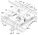
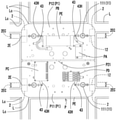
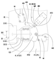
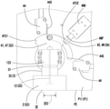
図1~図7は、本発明の実施例1の走行台車の上方斜視図、下方斜視図、平面図、底面図、及び、各動作状態(第一状態S1、第二状態S2、第三状態S3)における底面図のA-A部分拡大図である。 1 to 7 are an upward perspective view, a downward perspective view, a plan view, a bottom view, and each operating state (first state S1, second state S2, third state) of the traveling carriage of the first embodiment of the present invention. It is a partial enlarged view of AA of the bottom view in S3).
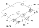
台板P1は第一台板P11と第二台板P12とから同一面内に構成され、サスペンション軸P21によって第一台板P11と第二台板P12とが連結される。サスペンション軸P21は、台板P1の裏側にて軸ホルダーP22に保持される。また第一台板P11と第二台板P12の境界部の裏側には、緩衝バネP31とこれを覆う鉤板P32とからなる緩衝機構が2セット設けられ、サスペンション軸周りの回転を緩衝規制してなる。 The base plate P1 is configured in the same plane from the first base plate P11 and the second base plate P12, and the first base plate P11 and the second base plate P12 are connected by the suspension shaft P21. The suspension shaft P21 is held by the shaft holder P22 on the back side of the base plate P1. Further, on the back side of the boundary between the first base plate P11 and the second base plate P12, two sets of cushioning mechanisms including the cushioning spring P31 and the hook plate P32 covering the cushioning spring P31 are provided to regulate the rotation around the suspension shaft. It becomes.
垂直操舵軸11は、台板P1の四隅の近傍に嵌め込み固定された、回転可能な円盤状の軸頭部111の下方であって、台板P1の裏側に、略鉛直方向に伸長する。
The
水平車軸12は、垂直操舵軸11の下端から屈曲して外方に水平延伸してなり、駆動機構3が走行輪2を転動走行させることで、垂直操舵軸11の回転と共に水平車軸12の平面視方向を位相変化させる。この際、走行輪の駆動機構の走行駆動力のみをもって、台車に対して垂直操舵軸11の回転駆動をさせと水平車軸12の位相変化を行っている。つまり、水平車軸12の位相変化のための駆動機構別の駆動機構は具備しない。実施例の駆動機構3は、水平車軸12の同軸上に駆動機構3たるモーター32及びシャフト31が連結され、モーター32のシャフト31の駆動力を、シャフト31の先側に同軸連結された走行輪2に直接伝達させる、いわゆるダイレクトドライブ方式で各走行輪2が駆動する。
走行輪2は、各水平車軸12の先部である車軸先端12E周りに連結された、計4輪の走行車輪からなる。各走行輪2同士は同じ接地面を有する。走行輪2の、水平車軸12の先部への連結位置、すなわち垂直操舵軸11の中心からの距離は、車軸先端12Eによって調整される。この調整によって、図5、図7に示す第一、第三状態では車輪の外縁2Eのうち、少なくとも中央1/3部分の中央部2CEが台車の辺縁PEと平面視にて一致する位置となる。この中央部2CEは外縁2Eのうち接地面から反力を受ける中心部である。車軸先端12Eは平面視にて走行輪2の幅方向内部に位置しており、車軸先端12Eに連なる水平車軸12が駆動機構によって回転駆動することで走行輪2が転動する。このとき、接地面からうける反力モーメントは、隣接する走行輪2同士で打ち消されることで、いわゆる据え切り現象は発生しない。
一方、水平車軸12の変更時には、複数の走行輪2が同時に、かつ両側に隣接する走行輪2と異なる方向に同じタイミングで転動することで、隣接する走行輪2同士で、位相方向が対称に変位する。また走行時には、複数の走行輪2が同時に、かつ片側に隣接する自身と平行な走行輪2と同じ方向に転動することで、転動方向に台車走行させる。
The
The traveling
On the other hand, when the
(規制機構4)
規制機構4は少なくとも、水平車軸12と共に回転移動する回転係止器41と、台車Pの台板P1に固定された対向係止器42とからなる。対向係止器42は、回転移動する回転係止器41の各回転移動位置のうち、設定された複数の係止位置の近傍にそれぞれ係止可能に設置される。
(Regulatory mechanism 4)
The regulating mechanism 4 includes at least a
実施例の規制機構4はさらに、台板P1に円弧軌跡状に形成されたガイド孔43Hと、ガイド孔43H内を挿通した状態で回転係止器41に固定されたガイドピン43とを備える。ガイドピン43は鉛直方向に伸長したピンからなり、回転係止器41たる係止プレートにその一端が貫通固定される。係止プレート4Tの回転と共に、ガイドピン43は円弧軌跡状のガイド孔43H内の一端から他端までを移動する。
The regulation mechanism 4 of the embodiment further includes a
また実施例の規制機構4はさらに、リミットスイッチセンサーSを備えたリミットスイッチ44を、回転係止器41の回転上限及び回転下限の各位置であってガイド孔43Hの端部に重畳するよう、設置してある。
Further, the regulation mechanism 4 of the embodiment further superimposes the
(対向係止器42)
一つの回転係止器41に対応する対向係止器42は一個または複数個のいずれでもよいが、例えば実施例1では、一つの回転係止器41に対応する対向係止器42が一個ずつ設けられる(図4、図5)。図4、図5では、鉛直操舵軸11の底面視中央寄り斜め方向(図示略45度方向)に一個の対向係止器42たる係止ピン4Nが、底面視斜め方向に突出入可能に設けられる。係止ピン4Nは、ボックス状のソレノイド4NH内に収容されると共に、コントロールボード及びターミナルリレーからの動作信号によってソレノイド4NHから往復一軸方向への突出入状態を維持するよう規制されている。
(Opposite locking device 42)
The number of facing locking
この係止ピン4Nは、係止プレート4Tが、回転位相上限の回転移動位置、回転位相下限の回転移動位置、回転位相中間(上限と下限を等分割した中間)の回転移動位置、のそれぞれの位置になったときに突出して、係止プレート4Tの切り欠き4TC又はガイドピン43に係止する(図5、図6、図7)。
In the
(対向係止器42が複数個設けられる場合)
なお、本実施例のほかに、例えば対向係止器42が複数個設けられる場合は、回転位相上限の回転移動位置、回転位相下限の回転移動位置、回転位相中間(上限と下限を等分割した中間)の回転移動位置、のそれぞれの位置に1個ずつ設けられる。それぞれの位置に1個ずつ設けられた各対向係止器42は、
前記各回転移動位置それぞれの回転係止器41と対向係止可能となっており、水平車軸12の各回転位相のうち、所定の係止位相に回転移動した回転係止器41と対向して係止する。
(When a plurality of facing locking
In addition to this embodiment, for example, when a plurality of facing locking
It is possible to lock against the
実施例では回転係止器41が、垂直操舵軸11の回転と共に回転移動する円弧状の係止プレート4Tからなり、対向係止器42が、台板P1の裏面であって各回転移動位置の係止プレート4Tに対向して突出入可能に固定された、複数の係止ピン4Nからなる。
In the embodiment, the
ガイドピン43または回転軸係止ピン4Nが各位相位置の切欠き4TC又は係止プレート4Tの一部分に突出係止した係止状態となることで、第一状態、第二状態、第三状態といった各移動状態を維持する。より具体的には、円弧状の係止プレート4Tの円弧部の両端位置ないし円弧途中位置には複数の切欠き4TCが形成されており、係止ピン4Nは、各位相位置の係止プレート4Tの切欠き4TCに対向して突出することで係止状態となる。
The
(第一状態S1)
図4、図5に示す第一状態S1は、走行輪が台板P1の図示縦方向側辺と平行になると共に水平車軸12が平面視横方向を向いた、平面視縦方向すなわち図示上下方向への走行が可能な動作状態である。水平車軸12が平面視横方向を向いた第一状態(図4、図5)では回転位相上限の係止プレート4Tの一端(図示上端)の切欠き4TCに係止する。
(First state S1)
In the first state S1 shown in FIGS. 4 and 5, the traveling wheel is parallel to the shown vertical side side of the base plate P1 and the
(第二状態S2)
図6に示す第二状態S2は、台板P1の側辺に対して水平車軸12が45度の斜め角度になると共に、水平車軸12が平面視斜め方向を向いた、第一状態から第三状態までの中間位置の動作状態である。この第二状態は、係止ピン4Nの先端が係止プレート4Tの円弧辺に沿って摺接した状態であって、平面視斜め方向への走行が可能な動作状態でもある。なお図6に示す第二状態では係止ピン4Nはガイドピン43と接していない。
(Second state S2)
In the second state S2 shown in FIG. 6, the
(第三状態S3)
図7に示す第三状態S3は、走行輪が台板P1の図示横方向側辺と平行になると共に、水平車軸12が平面視縦方向を向いた、平面視横方向すなわち図示左右方向への走行が可能な動作状態である。水平車軸12が平面視縦方向を向いた第三状態(図7)では回転位相下限の係止プレート4Tの他端(図示下端)の切欠き4TCに係止する。
(Third state S3)
In the third state S3 shown in FIG. 7, the traveling wheel is parallel to the shown horizontal side of the base plate P1, and the
(外縁と辺縁の関係)
上記いずれの動作状態においても、実施例1では、平面視にて走行輪2の外縁2Eが、台板P1の辺縁PEと一致している。走行輪2の外縁2Eの中央三分の一部分が外縁中央部2ECであり、この外縁中央部2ECは台板P1の辺縁PE及びコーナー部と略一致したまま各動作状態となる。
(Relationship between outer edge and edge)
In any of the above operating states, in the first embodiment, the
(軸回転駆動)
上記各動作状態において、全走行輪2に一対一対応して各水平車軸12状に同軸配置された駆動機構3たるモーター32が軸回転駆動することで、水平操舵軸12及び係止プレート4Tが回転移動(操舵位相変化)して回転係止器と対向係止器とが係止状態となり、この係止状態のままさらに軸回転駆動することで走行輪2が走行する。
(Axis rotation drive)
In each of the above operating states, the
(操舵位相変化時の制御)
水平操舵軸12及び係止プレート4Tが前記回転移動(操舵位相変化)するとき、隣り合う走行輪2の駆動機構3が互いに反対の方向へ同じタイミングで回転駆動するよう、コントロールボードPCによって制御される。また、走行輪2は台車の中心からみて等位相間隔毎に、等距離を開けて同一半径の仮想円上に複数輪が設けられている。これによって、軸回転駆動により接地面から受ける反力に基づくモーメントが、隣り合う走行輪によって互いに打ち消されることとなる。
(Control when steering phase changes)
When the
(走行時の制御)
係止プレート4Tが係止状態となって前記回転移動を終了し、走行状態に移行する際には、ターミナルリレー及びコントロールボードによって各走行輪2の駆動機構3が回転駆動方向及び駆動トルクを可変するよう制御される。
(Control during driving)
When the
具体的には、隣り合う走行輪2の駆動機構3のうち、水平車軸12が互いに相反方向を向いた同軸上の相反位置関係にある一対同士の組では、互いに反対の方向へ同じタイミングで回転駆動すると共に、
水平車軸12が平行方向を向いた異軸上の平行位置関係にある一対同士の組では、互いに同じ方向へ同じタイミングで回転駆動するように制御される。
Specifically, among the
In a pair of pairs in which the
(一括制御)
走行輪の走行と操舵軸の位相回転とを、走行輪2に一対一で同軸組み込みされた駆動機構3によって一括制御して行うことで、操舵軸の変更機構と走行機構とを別々に備える必要がなく、装置の軽量化、制御の簡便化、動作の機敏化を図ることができる。
(Batch control)
It is necessary to separately provide a steering shaft change mechanism and a traveling mechanism by collectively controlling the traveling of the traveling wheels and the phase rotation of the steering shaft by a
図8~11は、本発明の実施例2の走行台車の上方斜視図、平面図、底面図、及び底面図のB-B部分拡大図である。実施例2では実施例1の構成に加え、台車Pの平面視四隅に、ローラー51とローラー軸52とからなるガイドローラー51を、台板P11,12の角部から部分突出した状態で設けている。
実施例2のガイドローラー51のローラーはローラー軸52周りに自由回転可能となっている。実施例2の走行台車を、実施例1の図1や図3に示すガイドレールL内で走行させる際、ガイドレールLに対して台板が平面視にて回転方向に傾いたときに、ガイドローラー5がレールコーナーLCに接することで、台車の姿勢を、常にガイドレールLのレール方向と略平行なものに制御するものとしている。
8 to 11 are an upward perspective view, a plan view, a bottom view, and a BB partial enlarged view of the traveling carriage of the second embodiment of the present invention. In the second embodiment, in addition to the configuration of the first embodiment, guide
The roller of the
実施例2では、ガイドローラー51が台車Pよりも平面視外方へ突出してなる代わりに、走行輪2の外縁2Eが、台車Pの辺縁PEよりも平面視内側に配置されている。その他の形態及び各動作状態は実施例1と同様である。(なお、12Eは水平車軸12の車軸端部であって、走行輪2の外縁2Eよりも内側に位置する。)
In the second embodiment, the
図12、13は、本発明の実施例3の走行台車の上方斜視図、及び下方斜視図である。実施例3では第一台板P11と第二台板P12の面積比率が、約4:1となっており、第二台P12の奥行き方向の長さが第一台板P11の奥行き方向の長さの四分の一に設定されている。 12 and 13 are an upper perspective view and a lower perspective view of the traveling carriage of the third embodiment of the present invention. In the third embodiment, the area ratio of the first base plate P11 and the second base plate P12 is about 4: 1, and the length in the depth direction of the second base plate P12 is the length in the depth direction of the first base plate P11. It is set to a quarter of that.
その他の形態及び各動作状態は実施例1と同様である。 Other embodiments and each operating state are the same as those in the first embodiment.
上記したように、従来の走行制御装置や走行台車は走行用に走行用電動モーターを、操方向変更用に操方向用電動モーターを、それぞれ別に備えており、走行時と操方向変更時とで各電動モーターの一方を停止させると共に他方を動作させるよう切替え動作を行う必要がある。このため、電動モーターの駆動制御に時間がかかり、それぞれの電動モータの搭載によって制御が複雑であると共に重量ないし容積がかさむものとなっていた。また複数のモーターの相互制御が複雑となり、動作の機敏性に欠ける場合があった。 As described above, the conventional drive control device and the trolley are equipped with a separate drive motor for driving and an electric motor for steering for changing the steering direction, respectively, when traveling and when changing the steering direction. It is necessary to perform a switching operation so that one of the electric motors is stopped and the other is operated. For this reason, it takes time to control the drive of the electric motor, and the mounting of each electric motor complicates the control and increases the weight or volume. In addition, mutual control of a plurality of motors becomes complicated, and there is a case where the agility of operation is lacking.
一方、一つの電動モーターで走行と操舵方向変更とを担う構成を採用する場合は、操舵方向の制御や切替えのスイッチング制御が複雑となり、走行時や旋回時、操舵方向変更時において姿勢を制御することが困難であった。 On the other hand, when a configuration in which one electric motor is responsible for traveling and steering direction change is adopted, steering direction control and switching control for switching become complicated, and the attitude is controlled during traveling, turning, and steering direction change. It was difficult.
これに対し、上述した実施例に係る本発明の走行台車は、電動モーターの駆動制御を簡便化して制御時間を短縮させ、重量ないし容積が比較的嵩むことなく構成し、動作の機敏性、及び姿勢制御の容易性に優れた走行台車を提供することとなった。 On the other hand, the traveling carriage of the present invention according to the above-described embodiment simplifies the drive control of the electric motor, shortens the control time, is configured without relatively increasing the weight or volume, and has the agility of operation and the agility of operation. It was decided to provide a traveling trolley with excellent ease of attitude control.
また従来の走行制御装置や走行台車は、操方向用電動モータによって、垂直車軸を走行駆動機構とは別の駆動機構で回転駆動させ、これによって水平車軸の位相を変化させるため、台車が静止した状態のまま別の駆動機構で回転駆動させて水平車軸を変更する、いわゆる据え切り現象が発生していた。この据え切り現象は走行輪を偏摩耗させ、走行輪の耐久性を低下させる原因となる。これに対し、本発明の走行台車は、走行輪の走行駆動によって走行輪の転動と共に第一状態ないし第三状態を相互に切り替えるため、前記据え切り現象が発生しない。 Further, in the conventional traveling control device and traveling trolley, the vertical axle is rotationally driven by a drive mechanism different from the traveling drive mechanism by the electric motor for steering, which changes the phase of the horizontal axle, so that the trolley is stationary. A so-called stationary steering phenomenon occurred in which the horizontal axle was changed by rotationally driving it with another drive mechanism in the state. This stationary cutting phenomenon causes uneven wear of the traveling wheels and reduces the durability of the traveling wheels. On the other hand, in the traveling carriage of the present invention, since the traveling wheel is driven to switch between the first state and the third state together with the rolling of the traveling wheel, the stationary phenomenon does not occur.
本発明の走行台車は、台車Pの下部であって台車中心C周りに等間隔に設けられた、偶数本の垂直方向の垂直操舵軸11と、
前記各垂直操舵軸11の軸下部から屈曲して設けられた、平面視外方への伸長方向へ伸長する水平車軸12と、
各水平車軸12の先に取り付けられた、水平車軸周りに駆動可能な走行輪2と、
前記走行輪2を水平車軸12周りに駆動させる駆動機構3と、
前記走行輪2の水平車軸12の伸長方向を規制する規制機構4と、を具備してなり、
走行輪2Aの駆動操舵軸11Aは台車中心C周りに平面視等間隔にかつ平面視同一径の仮想円上に設けられるとともに、
駆動機構3によって駆動した走行輪2Aが地面との反力によって駆動車軸の伸長方向たる操舵方向を可変させるものであり、
駆動機構3及び規制機構4によって、
隣り合う水平車軸2Aは互いに相反する方向へ、互いに相反する等しい回転位相だけ伸長方向たる操舵方向を可変させるよう制御することで、台車全体でモーメントが常に釣り合った状態で操舵方向を可変させることを特徴とする。
The traveling carriage of the present invention includes an even number of vertical
A
A traveling
A
It is provided with a regulation mechanism 4 that regulates the extension direction of the
The drive steering shaft 11A of the traveling wheel 2A is provided around the center C of the bogie at equal intervals in a plan view and on a virtual circle having the same diameter in a plan view.
The traveling wheel 2A driven by the
By the
By controlling the adjacent horizontal axles 2A to change the steering direction, which is the extension direction by the same rotation phase opposite to each other, in the directions opposite to each other, the steering direction can be changed while the moments are always balanced in the entire bogie. It is a feature.
前記台車Pは矩形の辺縁PEを有した枠体又は板体からなり、走行輪2Aの駆動車軸の伸長方向に拘わらず、走行輪2Aの平面視外縁の1/3範囲が辺縁PEと一致することが好ましい。 The bogie P is made of a frame or a plate having a rectangular edge PE, and a 1/3 range of the outer edge of the traveling wheel 2A in a plan view is the edge PE regardless of the extension direction of the drive axle of the traveling wheel 2A. It is preferable that they match.
前記規制機構4は、駆動操舵軸2Aに固定され、駆動操舵軸2Aの駆動方向変更と共に回転する回転係止器41と、
台車下部であって駆動操舵軸2Aの近傍に設けられ、各回転角度の回転係止器41に対向係止する対向係止器42と、から構成され、
回転係止器41及び対向係止器42は、
突出制御される係止ピン42Pと、係止ピンに係止する係止溝を有した係止プレート41Pの一方及び他方からなり、隣り合う駆動操舵軸すべての係止ないし係止解除を同期制御することが好ましい。
The regulation mechanism 4 includes a
It is composed of an
The
It consists of one and the other of the locking pin 42P that is controlled to protrude and the locking plate 41P that has a locking groove that locks to the locking pin, and synchronously controls the locking or unlocking of all adjacent drive steering shafts. It is preferable to do so.
前記駆動機構及び規制機構は、
複数の水平車軸の伸長方向たる操舵方向を、ほぼ同じタイミングで、かつ同じ可変速度で可変させるよう制御することで、台車全体が地面に対して移動乃至回転することなく、各水平車軸の操舵方向を可変させることを特徴とする。
The drive mechanism and the regulation mechanism are
By controlling the steering direction, which is the extension direction of multiple horizontal axles, to be changed at almost the same timing and at the same variable speed, the steering direction of each horizontal axle does not move or rotate with respect to the ground as a whole. Is characterized by being variable.
前記台車は一又は複数の台板によって、前後辺と両側辺とが垂直に交わる略矩形形状をなし、
前記走行輪は、少なくとも、台車の前記略矩形形状の四隅の角部に配置され、
前記規制機構は、前記四隅の角部に配置された走行輪を、
各走行輪の外辺縁が前記略矩形形状の前後辺及び両側辺に対して並行な状態と、
各走行輪の外辺縁が前記略矩形形状の前後辺及び両側辺に対して斜めに交わる状態と、を維持するよう制御することを特徴とする、請求項1,2,又は3のいずれかに記載の走行台車。
The dolly has a substantially rectangular shape in which the front and rear sides and both sides vertically intersect with one or more pedestals.
The traveling wheels are arranged at least at the four corners of the substantially rectangular shape of the bogie.
The regulatory mechanism uses the traveling wheels arranged at the corners of the four corners.
The outer edge of each traveling wheel is parallel to the front-rear side and both sides of the substantially rectangular shape.
Any of
前記台車Pの平面視四隅の台板P1には、水平に自由回転するローラー51を備えたガイドローラー51を、台板P11,12の角部から部分突出した状態で設けていることが好ましい。
It is preferable that the base plate P1 at the four corners of the carriage P is provided with a
前記台車はねじり方向に可変するサスペンション機構を有して連結された第一台板と第二台板とから構成され、サスペンション機構によって、走行輪が常に一定の接地力で接地するように規制することが好ましい。 The bogie is composed of a first base plate and a second base plate connected by having a suspension mechanism variable in the twisting direction, and the suspension mechanism regulates the traveling wheels to always touch the ground with a constant ground contact force. Is preferable.
上記実施例の走行輪2は水平車軸2Aの先側に片持ち状態で支持されているが、他の構成として、両持ち支持枠によって、両持ち状態で支持されていてもよい。また上記実施例の走行輪2の水平車軸2Aによる先端支持部は走行輪2の輪幅中心に位置しており、輪幅中心で支持するものとなっているが、他の構成として、輪幅の外縁辺付近を先端支持部としてもよい。
The traveling
上記の他、本発明の走行台車は上述した実施例の構成に限定されることなく、本発明の趣旨ないし特徴を逸脱しない範囲で種々の構成の変更が可能である。具体的には、上述した実施例の各構成同士の置換、上述した実施例における一部構成の抽出、又は公知の構成への置き換え、又は部分的な構成の削除ないし構成部分の数や配置の変更、第一台板P11、P12、辺縁PE、鉤板P32といった、各構成部品の形状の変更、取り付け位置の変更、或いは、各実施例間における、一部の構成同士の組合せや置換が可能である。 In addition to the above, the traveling carriage of the present invention is not limited to the configuration of the above-described embodiment, and various configurations can be changed without departing from the spirit or feature of the present invention. Specifically, replacement of each configuration in the above-described embodiment, extraction of a partial configuration in the above-mentioned embodiment, replacement with a known configuration, deletion of a partial configuration, or the number and arrangement of constituent parts. Change, change of shape of each component such as first base plate P11, P12, edge PE, hook plate P32, change of mounting position, or combination or replacement of some configurations between each embodiment. It is possible.
台車P
台板P1
第一台板P11、P12
辺縁PE
サスペンション軸P21
軸ホルダーP22
緩衝バネP31
鉤板P32
垂直操舵軸11
軸頭部111
軸カバー123
水平車軸12
走行輪2
外縁2E
外縁中央部2EC
駆動機構3
モーター軸31
モーター32
規制機構4
回転係止器41
対向係止器42
ガイドピン43
ガイド孔43H
リミットスイッチ44
スイッチセンサー44S
係止ピン4N
ソレノイド4NH
係止プレート4T
プレート切り欠き4TC
5 ガイドローラー
51 ローラー
52 ローラー軸
端子台PA
バッテリーPB
コントロールボードPC
ターミナルリレーPD
Bogie P
Base plate P1
First base plate P11, P12
Edge PE
Suspension shaft P21
Shaft holder P22
Buffer spring P31
Hook plate P32
Running
Outer edge central part 2EC
Regulatory mechanism 4
Opposing
Locking
Solenoid 4NH
Locking
Plate notch 4TC
5
Terminal block PA
Battery PB
Control board PC
Terminal relay PD
Claims (5)
前記各垂直操舵軸の軸下部から屈曲して設けられた、平面視外方への伸長方向へ伸長する水平車軸と、
各水平車軸の先に取り付けられた、水平車軸周りに駆動可能な走行輪と、
前記走行輪を水平車軸周りに駆動させる駆動機構と、
前記走行輪の水平車軸の伸長方向を規制する規制機構と、を具備してなり、
走行輪の駆動操舵軸は台車中心周りであって平面視同一径の仮想円上に設けられるとともに、
駆動機構によって駆動した走行輪が地面との反力によって駆動車軸の伸長方向たる操舵方向を可変させるものであり、
駆動機構及び規制機構によって、
隣り合う水平車軸は互いに相反する方向へ、互いに相反する等しい回転位相だけ伸長方向たる操舵方向を可変させるよう制御することで、台車全体でモーメントが常に釣り合った状態で操舵方向を可変させることを特徴とする走行台車。 An even number of vertical vertical steering axes, which are located at the bottom of the bogie and are evenly spaced around the center of the bogie.
A horizontal axle that is bent from the lower part of each vertical steering shaft and extends in the outward extension direction in a plan view, and a horizontal axle.
A traveling wheel that is attached to the tip of each horizontal axle and can be driven around the horizontal axle,
A drive mechanism that drives the traveling wheels around the horizontal axle,
It is equipped with a regulation mechanism that regulates the extension direction of the horizontal axle of the traveling wheel.
The drive steering shaft of the traveling wheel is provided around the center of the bogie on a virtual circle having the same diameter in a plan view, and is also provided.
The traveling wheel driven by the drive mechanism changes the steering direction, which is the extension direction of the drive axle, by the reaction force with the ground.
By drive mechanism and regulatory mechanism
Adjacent horizontal axles are controlled to change the steering direction, which is the extension direction by the same rotation phase, which is opposite to each other, so that the steering direction can be changed while the moments are always balanced in the entire bogie. Traveling trolley.
複数の水平車軸の伸長方向たる操舵方向を、ほぼ同じタイミングで、かつ同じ可変速度で可変させるよう制御することで、台車全体が地面に対して移動乃至回転することなく、各水平車軸の操舵方向を可変させることを特徴とする、請求項1に記載の走行台車。 The drive mechanism and the regulation mechanism are
By controlling the steering direction, which is the extension direction of multiple horizontal axles, to be changed at almost the same timing and at the same variable speed, the steering direction of each horizontal axle does not move or rotate with respect to the ground as a whole. The traveling carriage according to claim 1, wherein the traveling vehicle is variable.
台車下部であって駆動操舵軸の近傍に設けられ、各回転角度の回転係止器に対向係止する対向係止器と、から構成され、
回転係止器及び対向係止器は、
突出制御される係止ピンと、係止ピンに係止する係止溝を有した係止プレートの一方及び他方からなり、隣り合う駆動操舵軸すべての係止ないし係止解除を同期制御することを特徴とする、請求項1又は2に記載の走行台車。 The regulation mechanism includes a rotary locking device that is fixed to the drive steering shaft and rotates with a change in the drive direction of the drive steering shaft.
It is composed of an opposite locking device, which is provided in the vicinity of the drive steering shaft at the bottom of the bogie and is opposed to the rotation locking device at each rotation angle.
The rotary locker and the opposite locker are
It consists of a locking pin that is projected to be projected and one and the other of the locking plates that have a locking groove that locks to the locking pin, and synchronously controls the locking or unlocking of all adjacent drive steering shafts. The traveling trolley according to claim 1 or 2, which is characteristic.
前記走行輪は、少なくとも、台車の前記略矩形形状の四隅の角部に配置され、
前記規制機構は、前記四隅の角部に配置された走行輪を、
各走行輪の外辺縁が前記略矩形形状の前後辺及び両側辺に対して並行な状態と、
各走行輪の外辺縁が前記略矩形形状の前後辺及び両側辺に対して斜めに交わる状態と、を維持するよう制御することを特徴とする、請求項1,2,又は3のいずれかに記載の走行台車。 The dolly has a substantially rectangular shape in which the front and rear sides and both sides vertically intersect with one or more pedestals.
The traveling wheels are arranged at least at the four corners of the substantially rectangular shape of the bogie.
The regulatory mechanism uses the traveling wheels arranged at the corners of the four corners.
The outer edge of each traveling wheel is parallel to the front-rear side and both sides of the substantially rectangular shape.
Any of claims 1, 2, or 3, characterized in that the outer edge of each traveling wheel is controlled to maintain a state in which the front and rear sides and both side surfaces of the substantially rectangular shape intersect diagonally. The traveling trolley described in.
Priority Applications (1)
| Application Number | Priority Date | Filing Date | Title |
|---|---|---|---|
| JP2020114512A JP7511228B2 (en) | 2020-07-01 | 2020-07-01 | Traveling cart |
Applications Claiming Priority (1)
| Application Number | Priority Date | Filing Date | Title |
|---|---|---|---|
| JP2020114512A JP7511228B2 (en) | 2020-07-01 | 2020-07-01 | Traveling cart |
Publications (2)
| Publication Number | Publication Date |
|---|---|
| JP2022012584A true JP2022012584A (en) | 2022-01-17 |
| JP7511228B2 JP7511228B2 (en) | 2024-07-05 |
Family
ID=80148786
Family Applications (1)
| Application Number | Title | Priority Date | Filing Date |
|---|---|---|---|
| JP2020114512A Active JP7511228B2 (en) | 2020-07-01 | 2020-07-01 | Traveling cart |
Country Status (1)
| Country | Link |
|---|---|
| JP (1) | JP7511228B2 (en) |
Citations (5)
| Publication number | Priority date | Publication date | Assignee | Title |
|---|---|---|---|---|
| JP2003182584A (en) * | 2001-12-25 | 2003-07-03 | Hitachi Plant Eng & Constr Co Ltd | Steering / drive wheel mechanism and electric transport cart |
| JP2005306178A (en) * | 2004-04-21 | 2005-11-04 | Symtec Hozumi:Kk | Automated guided vehicle |
| JP2005306173A (en) * | 2004-04-20 | 2005-11-04 | Nishikawa Rubber Co Ltd | Sound insulating sheet and fixing method thereof |
| JP2008137631A (en) * | 2006-11-06 | 2008-06-19 | Mitsuba Corp | Carrier with electric caster |
| WO2019137468A1 (en) * | 2018-01-12 | 2019-07-18 | 锥能机器人(上海)有限公司 | Omni-directional moving trolley |
-
2020
- 2020-07-01 JP JP2020114512A patent/JP7511228B2/en active Active
Patent Citations (5)
| Publication number | Priority date | Publication date | Assignee | Title |
|---|---|---|---|---|
| JP2003182584A (en) * | 2001-12-25 | 2003-07-03 | Hitachi Plant Eng & Constr Co Ltd | Steering / drive wheel mechanism and electric transport cart |
| JP2005306173A (en) * | 2004-04-20 | 2005-11-04 | Nishikawa Rubber Co Ltd | Sound insulating sheet and fixing method thereof |
| JP2005306178A (en) * | 2004-04-21 | 2005-11-04 | Symtec Hozumi:Kk | Automated guided vehicle |
| JP2008137631A (en) * | 2006-11-06 | 2008-06-19 | Mitsuba Corp | Carrier with electric caster |
| WO2019137468A1 (en) * | 2018-01-12 | 2019-07-18 | 锥能机器人(上海)有限公司 | Omni-directional moving trolley |
Also Published As
| Publication number | Publication date |
|---|---|
| JP7511228B2 (en) | 2024-07-05 |
Similar Documents
| Publication | Publication Date | Title |
|---|---|---|
| KR102264036B1 (en) | Agv with improved grip force driving wheel | |
| US20230146720A1 (en) | Vehicle drive unit and vehicle with a vehicle drive unit | |
| JP7349110B1 (en) | automated guided vehicle | |
| JP2018020665A (en) | Automobile body | |
| JP2022012584A (en) | Traveling dolly | |
| WO2020059189A1 (en) | Drive wheel, carriage, and device | |
| WO2012008005A1 (en) | Inverted pendulum type moving body and moving robot | |
| CN218876964U (en) | Battery replacing equipment and battery replacing station | |
| JP6361124B2 (en) | Automated guided vehicle | |
| JP2013147313A (en) | Tray feeding type parking device | |
| JP2008075351A (en) | Vehicle moving device | |
| JP7415185B2 (en) | vehicle seat | |
| CN110802570A (en) | Mobile device and construction robot | |
| CN112793657B (en) | Steering mechanism and mobile device | |
| JP4788412B2 (en) | Inverted pendulum type moving body | |
| JP6922776B2 (en) | Bed transfer device | |
| JP7188697B2 (en) | truck | |
| JP2022028343A (en) | Running device | |
| JP6906120B1 (en) | Traveling device and automatic guided vehicle equipped with the traveling device | |
| JP6042616B2 (en) | Tray-fed parking device | |
| JP7779238B2 (en) | Conveying Equipment | |
| KR19980058764U (en) | Unmanned carriage | |
| JP6914225B2 (en) | Mechanical parking device | |
| KR101320957B1 (en) | A manual guided vehicle with perpendicular change of driving direction | |
| JP6920726B2 (en) | Wheelchair attachment |
Legal Events
| Date | Code | Title | Description |
|---|---|---|---|
| A621 | Written request for application examination |
Free format text: JAPANESE INTERMEDIATE CODE: A621 Effective date: 20230623 |
|
| A977 | Report on retrieval |
Free format text: JAPANESE INTERMEDIATE CODE: A971007 Effective date: 20231106 |
|
| A131 | Notification of reasons for refusal |
Free format text: JAPANESE INTERMEDIATE CODE: A131 Effective date: 20231114 |
|
| A601 | Written request for extension of time |
Free format text: JAPANESE INTERMEDIATE CODE: A601 Effective date: 20240115 |
|
| A521 | Request for written amendment filed |
Free format text: JAPANESE INTERMEDIATE CODE: A523 Effective date: 20240313 |
|
| TRDD | Decision of grant or rejection written | ||
| A01 | Written decision to grant a patent or to grant a registration (utility model) |
Free format text: JAPANESE INTERMEDIATE CODE: A01 Effective date: 20240606 |
|
| A61 | First payment of annual fees (during grant procedure) |
Free format text: JAPANESE INTERMEDIATE CODE: A61 Effective date: 20240618 |