JP2022011908A - Route selection apparatus and route selection method - Google Patents
Route selection apparatus and route selection method Download PDFInfo
- Publication number
- JP2022011908A JP2022011908A JP2020113332A JP2020113332A JP2022011908A JP 2022011908 A JP2022011908 A JP 2022011908A JP 2020113332 A JP2020113332 A JP 2020113332A JP 2020113332 A JP2020113332 A JP 2020113332A JP 2022011908 A JP2022011908 A JP 2022011908A
- Authority
- JP
- Japan
- Prior art keywords
- lane change
- route
- point
- change point
- lane
- Prior art date
- Legal status (The legal status is an assumption and is not a legal conclusion. Google has not performed a legal analysis and makes no representation as to the accuracy of the status listed.)
- Granted
Links
Images


Classifications
-
- G—PHYSICS
- G01—MEASURING; TESTING
- G01C—MEASURING DISTANCES, LEVELS OR BEARINGS; SURVEYING; NAVIGATION; GYROSCOPIC INSTRUMENTS; PHOTOGRAMMETRY OR VIDEOGRAMMETRY
- G01C21/00—Navigation; Navigational instruments not provided for in groups G01C1/00 - G01C19/00
- G01C21/26—Navigation; Navigational instruments not provided for in groups G01C1/00 - G01C19/00 specially adapted for navigation in a road network
- G01C21/34—Route searching; Route guidance
- G01C21/3453—Special cost functions, i.e. other than distance or default speed limit of road segments
- G01C21/3461—Preferred or disfavoured areas, e.g. dangerous zones, toll or emission zones, intersections, manoeuvre types or segments such as motorways, toll roads or ferries
-
- B—PERFORMING OPERATIONS; TRANSPORTING
- B60—VEHICLES IN GENERAL
- B60W—CONJOINT CONTROL OF VEHICLE SUB-UNITS OF DIFFERENT TYPE OR DIFFERENT FUNCTION; CONTROL SYSTEMS SPECIALLY ADAPTED FOR HYBRID VEHICLES; ROAD VEHICLE DRIVE CONTROL SYSTEMS FOR PURPOSES NOT RELATED TO THE CONTROL OF A PARTICULAR SUB-UNIT
- B60W30/00—Purposes of road vehicle drive control systems not related to the control of a particular sub-unit, e.g. of systems using conjoint control of vehicle sub-units
- B60W30/18—Propelling the vehicle
- B60W30/18009—Propelling the vehicle related to particular drive situations
- B60W30/18163—Lane change; Overtaking manoeuvres
-
- B—PERFORMING OPERATIONS; TRANSPORTING
- B60—VEHICLES IN GENERAL
- B60W—CONJOINT CONTROL OF VEHICLE SUB-UNITS OF DIFFERENT TYPE OR DIFFERENT FUNCTION; CONTROL SYSTEMS SPECIALLY ADAPTED FOR HYBRID VEHICLES; ROAD VEHICLE DRIVE CONTROL SYSTEMS FOR PURPOSES NOT RELATED TO THE CONTROL OF A PARTICULAR SUB-UNIT
- B60W60/00—Drive control systems specially adapted for autonomous road vehicles
- B60W60/001—Planning or execution of driving tasks
- B60W60/0011—Planning or execution of driving tasks involving control alternatives for a single driving scenario, e.g. planning several paths to avoid obstacles
-
- G—PHYSICS
- G01—MEASURING; TESTING
- G01C—MEASURING DISTANCES, LEVELS OR BEARINGS; SURVEYING; NAVIGATION; GYROSCOPIC INSTRUMENTS; PHOTOGRAMMETRY OR VIDEOGRAMMETRY
- G01C21/00—Navigation; Navigational instruments not provided for in groups G01C1/00 - G01C19/00
- G01C21/26—Navigation; Navigational instruments not provided for in groups G01C1/00 - G01C19/00 specially adapted for navigation in a road network
- G01C21/34—Route searching; Route guidance
- G01C21/3407—Route searching; Route guidance specially adapted for specific applications
-
- G—PHYSICS
- G01—MEASURING; TESTING
- G01C—MEASURING DISTANCES, LEVELS OR BEARINGS; SURVEYING; NAVIGATION; GYROSCOPIC INSTRUMENTS; PHOTOGRAMMETRY OR VIDEOGRAMMETRY
- G01C21/00—Navigation; Navigational instruments not provided for in groups G01C1/00 - G01C19/00
- G01C21/26—Navigation; Navigational instruments not provided for in groups G01C1/00 - G01C19/00 specially adapted for navigation in a road network
- G01C21/34—Route searching; Route guidance
- G01C21/3453—Special cost functions, i.e. other than distance or default speed limit of road segments
-
- G—PHYSICS
- G06—COMPUTING OR CALCULATING; COUNTING
- G06T—IMAGE DATA PROCESSING OR GENERATION, IN GENERAL
- G06T7/00—Image analysis
- G06T7/70—Determining position or orientation of objects or cameras
- G06T7/73—Determining position or orientation of objects or cameras using feature-based methods
-
- G—PHYSICS
- G06—COMPUTING OR CALCULATING; COUNTING
- G06V—IMAGE OR VIDEO RECOGNITION OR UNDERSTANDING
- G06V20/00—Scenes; Scene-specific elements
- G06V20/50—Context or environment of the image
- G06V20/56—Context or environment of the image exterior to a vehicle by using sensors mounted on the vehicle
- G06V20/588—Recognition of the road, e.g. of lane markings; Recognition of the vehicle driving pattern in relation to the road
-
- B—PERFORMING OPERATIONS; TRANSPORTING
- B60—VEHICLES IN GENERAL
- B60W—CONJOINT CONTROL OF VEHICLE SUB-UNITS OF DIFFERENT TYPE OR DIFFERENT FUNCTION; CONTROL SYSTEMS SPECIALLY ADAPTED FOR HYBRID VEHICLES; ROAD VEHICLE DRIVE CONTROL SYSTEMS FOR PURPOSES NOT RELATED TO THE CONTROL OF A PARTICULAR SUB-UNIT
- B60W50/00—Details of control systems for road vehicle drive control not related to the control of a particular sub-unit, e.g. process diagnostic or vehicle driver interfaces
- B60W2050/0001—Details of the control system
- B60W2050/0019—Control system elements or transfer functions
- B60W2050/0022—Gains, weighting coefficients or weighting functions
- B60W2050/0025—Transfer function weighting factor
-
- B—PERFORMING OPERATIONS; TRANSPORTING
- B60—VEHICLES IN GENERAL
- B60W—CONJOINT CONTROL OF VEHICLE SUB-UNITS OF DIFFERENT TYPE OR DIFFERENT FUNCTION; CONTROL SYSTEMS SPECIALLY ADAPTED FOR HYBRID VEHICLES; ROAD VEHICLE DRIVE CONTROL SYSTEMS FOR PURPOSES NOT RELATED TO THE CONTROL OF A PARTICULAR SUB-UNIT
- B60W2552/00—Input parameters relating to infrastructure
- B60W2552/10—Number of lanes
-
- B—PERFORMING OPERATIONS; TRANSPORTING
- B60—VEHICLES IN GENERAL
- B60W—CONJOINT CONTROL OF VEHICLE SUB-UNITS OF DIFFERENT TYPE OR DIFFERENT FUNCTION; CONTROL SYSTEMS SPECIALLY ADAPTED FOR HYBRID VEHICLES; ROAD VEHICLE DRIVE CONTROL SYSTEMS FOR PURPOSES NOT RELATED TO THE CONTROL OF A PARTICULAR SUB-UNIT
- B60W2552/00—Input parameters relating to infrastructure
- B60W2552/53—Road markings, e.g. lane marker or crosswalk
-
- B—PERFORMING OPERATIONS; TRANSPORTING
- B60—VEHICLES IN GENERAL
- B60W—CONJOINT CONTROL OF VEHICLE SUB-UNITS OF DIFFERENT TYPE OR DIFFERENT FUNCTION; CONTROL SYSTEMS SPECIALLY ADAPTED FOR HYBRID VEHICLES; ROAD VEHICLE DRIVE CONTROL SYSTEMS FOR PURPOSES NOT RELATED TO THE CONTROL OF A PARTICULAR SUB-UNIT
- B60W2554/00—Input parameters relating to objects
- B60W2554/80—Spatial relation or speed relative to objects
- B60W2554/802—Longitudinal distance
-
- G—PHYSICS
- G06—COMPUTING OR CALCULATING; COUNTING
- G06F—ELECTRIC DIGITAL DATA PROCESSING
- G06F18/00—Pattern recognition
- G06F18/20—Analysing
- G06F18/24—Classification techniques
-
- G—PHYSICS
- G06—COMPUTING OR CALCULATING; COUNTING
- G06T—IMAGE DATA PROCESSING OR GENERATION, IN GENERAL
- G06T2207/00—Indexing scheme for image analysis or image enhancement
- G06T2207/30—Subject of image; Context of image processing
- G06T2207/30248—Vehicle exterior or interior
- G06T2207/30252—Vehicle exterior; Vicinity of vehicle
- G06T2207/30256—Lane; Road marking
Landscapes
- Engineering & Computer Science (AREA)
- Radar, Positioning & Navigation (AREA)
- Remote Sensing (AREA)
- Automation & Control Theory (AREA)
- Physics & Mathematics (AREA)
- General Physics & Mathematics (AREA)
- Mechanical Engineering (AREA)
- Transportation (AREA)
- Theoretical Computer Science (AREA)
- Human Computer Interaction (AREA)
- Multimedia (AREA)
- Computer Vision & Pattern Recognition (AREA)
- Navigation (AREA)
- Traffic Control Systems (AREA)
Abstract
【課題】運転者が想定していない地点での車線変更の少ない経路を選択可能な経路選択装置を提供する。【解決手段】経路選択装置は、車両が現在走行中の車線の位置を特定する車線特定部と、車両の現在位置から、出発地から目的地に至る経路における現在位置と目的地との間のいずれかの通過点に至る複数の部分経路の候補を探索する探索部と、探索された複数の部分経路の候補のそれぞれにおいて、車線変更が行われる車線変更地点を特定する車線変更地点特定部と、探索された複数の部分経路の候補のうち、特定された車線変更地点の位置、または、車線変更地点での車線変更が走行制御装置により制御可能か否かに応じて重みづけされた車線変更地点の点数の合計が最も小さい部分経路の候補を、部分経路として選択する選択部と、を備える【選択図】図1PROBLEM TO BE SOLVED: To provide a route selection device capable of selecting a route with less lane change at a point not expected by a driver. SOLUTION: A route selection device is located between a lane specifying unit that identifies a position of a lane in which a vehicle is currently traveling, and a current position and a destination on a route from the current position of the vehicle to a destination. A search unit that searches for candidates for multiple partial routes to any of the passing points, and a lane change point identification unit that identifies lane change points where lane changes are performed in each of the searched multiple partial route candidates. , The location of the specified lane change point among the multiple partial route candidates searched, or the lane change weighted according to whether the lane change at the lane change point can be controlled by the driving control device. [Selection diagram] FIG. 1 is provided with a selection unit for selecting a candidate for a partial route having the smallest total number of points as a partial route.
Description
本発明は、車両の走行経路を選択する経路選択装置および経路選択方法に関する。 The present invention relates to a route selection device and a route selection method for selecting a traveling route of a vehicle.
車両の現在位置および目的地の位置に基づいて、現在位置から目的地に至る複数の経路を作成し、複数の経路から、走行距離が最短となる経路、所要時間が最短となる経路といった、最適な経路を選択する技術が知られている。 Based on the current position of the vehicle and the position of the destination, multiple routes from the current position to the destination are created, and from multiple routes, the route with the shortest mileage and the route with the shortest travel time are optimal. Techniques for selecting various routes are known.
特許文献1には、自動運転制御による適格性を考慮した経路探索を行う経路探索システムが記載されている。特許文献1に記載の経路探索システムは、自動運転制御による走行に適した経路ほど低いコスト値が算出されるように設定されたテーブルを用いて経路のコスト値を算出し、算出されたコスト値に基づいて経路を探索する。
カーナビゲーションシステムにより車線を考慮せずに作成された経路では、運転者が想定していない地点で車線変更が発生する場合がある。 A route created by the car navigation system without considering the lane may cause a lane change at a point not expected by the driver.
本発明は、運転者が想定していない地点での車線変更の少ない経路を選択可能な経路選択装置を提供することを目的とする。 An object of the present invention is to provide a route selection device capable of selecting a route with few lane changes at a point not assumed by the driver.
本発明にかかる経路選択装置は、車両が現在走行中の車線の位置を特定する車線特定部と、車両の現在位置から、出発地から目的地に至る経路における現在位置と目的地との間のいずれかの通過点に至る複数の部分経路の候補を探索する探索部と、探索された複数の部分経路のそれぞれの候補において、車線変更が行われる車線変更地点を特定する車線変更地点特定部と、探索された複数の部分経路の候補のうち、特定された車線変更地点の位置、または、車線変更地点を自動走行可能か否かに応じて重みづけされた車線変更地点の点数の合計が最も小さい部分経路の候補を、部分経路として選択する選択部と、を備える。 The route selection device according to the present invention is between a lane specifying unit that identifies the position of the lane in which the vehicle is currently traveling and the current position and the destination on the route from the current position of the vehicle to the destination. A search unit that searches for candidates for multiple partial routes to any of the passing points, and a lane change point identification unit that identifies lane change points where lane changes are performed in each candidate of the searched multiple partial routes. , Of the multiple partial route candidates searched, the total number of points of the specified lane change point or the total number of lane change points weighted according to whether or not the lane change point can be automatically driven is the highest. A selection unit for selecting a candidate for a small partial route as a partial route is provided.
本発明にかかる経路選択装置において、車線変更地点の点数は、通過点から近い車線変更地点の点数が通過点から遠い車線変更地点の点数よりも小さくなるように重みづけされることが好ましい。 In the route selection device according to the present invention, it is preferable that the points of the lane change points are weighted so that the points of the lane change points near the passing point are smaller than the points of the lane change points far from the passing point.
本発明にかかる経路選択装置において、車線変更地点の点数は、自動走行可能な車線変更地点の点数が自動走行可能でない車線変更地点の点数よりも小さくなるように重みづけされることが好ましい。 In the route selection device according to the present invention, it is preferable that the points of the lane change points that can be automatically driven are weighted so that the points of the lane change points that can be automatically driven are smaller than the points of the lane change points that cannot be automatically driven.
本発明にかかる経路選択装置において、車線変更地点の点数は、当該車線変更地点の前の車線変更地点との間の距離が短いほど大きくなるように重みづけされることが好ましい。 In the route selection device according to the present invention, it is preferable that the score of the lane change point is weighted so that the shorter the distance from the lane change point in front of the lane change point, the larger the score.
本発明にかかる経路選択装置において、選択部は、車線変更地点の点数の合計が同じである複数の部分経路の候補のうち、含まれる車線変更地点の少ない部分経路の候補を部分経路として選択することが好ましい。 In the route selection device according to the present invention, the selection unit selects as a partial route a candidate for a partial route having a small number of included lane change points from among a plurality of partial route candidates having the same total number of lane change points. Is preferable.
本発明にかかる経路選択装置において、選択部は、探索された複数の部分経路の候補のうち、現在位置と通過点との間の走行距離と自動走行の制御に用いられている経路における現在位置と通過点との間の走行距離との差が距離差分閾値を超える部分経路の候補を除外して部分経路の選択を行うことが好ましい。 In the route selection device according to the present invention, the selection unit is the current position in the route used for controlling the mileage between the current position and the passing point and the automatic traveling among the plurality of searched partial route candidates. It is preferable to select the partial route by excluding the candidate of the partial route in which the difference between the travel distance between the vehicle and the passing point exceeds the distance difference threshold value.
本発明にかかる経路選択方法は、車両が現在走行中の車線の位置を特定し、車両の現在位置から、出発地から目的地に至る経路における現在位置と目的地との間のいずれかの通過点に至る複数の部分経路の候補を探索し、探索された複数の部分経路の候補のそれぞれにおいて、車線変更が行われる車線変更地点を特定し、探索された複数の部分経路の候補のうち、特定された車線変更地点の位置、または、車線変更地点を自動走行可能か否かに応じて重みづけされた車線変更地点の点数の合計が最も小さい部分経路の候補を、部分経路として選択する、ことを含む。 The route selection method according to the present invention identifies the position of the lane in which the vehicle is currently traveling, and passes between the current position and the destination on the route from the current position of the vehicle to the destination. Search for multiple partial route candidates to reach the point, identify the lane change point where the lane change is performed in each of the searched multiple partial route candidates, and among the searched multiple partial route candidates, The candidate for the partial route having the smallest total number of points of the specified lane change point or the total number of points of the lane change point weighted according to whether or not the lane change point can be automatically driven is selected as the partial route. Including that.
本発明にかかる経路選択装置によれば、運転者が想定していない地点での車線変更の少ない経路を選択することができる。 According to the route selection device according to the present invention, it is possible to select a route with few lane changes at a point not expected by the driver.
以下、図面を参照して、運転者が想定していない地点での車線変更の少ない経路を選択することができる経路選択装置について詳細に説明する。経路選択装置は、車両が現在走行中の車線の位置を特定する。また、経路選択装置は、現在位置から、出発地から目的地に至る経路における現在位置と目的地との間のいずれかの通過点に至る複数の部分経路の候補を探索する。また、経路選択装置は、探索された複数の部分経路の候補のそれぞれにおいて、車線変更が行われる車線変更地点を特定する。そして、経路選択装置は、探索された複数の部分経路の候補のうち、特定された車線変更地点の位置、または、車線変更地点を自動走行可能か否かに応じて重みづけされた車線変更地点の点数の合計が最も小さい部分経路を、部分経路の候補として選択する。 Hereinafter, a route selection device capable of selecting a route with few lane changes at a point not expected by the driver will be described in detail with reference to the drawings. The route selection device identifies the position of the lane in which the vehicle is currently traveling. Further, the route selection device searches for a plurality of partial route candidates from the current position to any passing point between the current position and the destination in the route from the departure point to the destination. Further, the route selection device identifies a lane change point where the lane change is performed in each of the searched plurality of partial route candidates. Then, the route selection device is weighted according to the position of the specified lane change point or whether or not the lane change point can be automatically driven among the candidates of the plurality of searched partial routes. The partial route with the smallest total score is selected as a candidate for the partial route.
図1は、経路選択装置が実装される車両の概略構成図である。 FIG. 1 is a schematic configuration diagram of a vehicle on which a route selection device is mounted.
車両1は、カメラ2と、GNSS受信機3と、ストレージ装置4と、走行制御装置5と、経路選択装置6とを有する。カメラ2、GNSS受信機3およびストレージ装置4と、走行制御装置5および経路選択装置6とは、コントローラエリアネットワークといった規格に準拠した車内ネットワークを介して通信可能に接続される。
The
カメラ2は、車両近傍の状況を検出するためのセンサの一例である。カメラ2は、CCDあるいはC-MOSなど、赤外光に感度を有する光電変換素子のアレイで構成された2次元検出器と、その2次元検出器上の撮影対象となる領域の像を結像する結像光学系とを有する。カメラ2は、例えば車室内の前方上部に、前方を向けて配置され、所定の撮影周期(例えば1/30秒~1/10秒)ごとにフロントガラスを介して車両1の周辺の状況を撮影し、周辺の状況に対応した画像を出力する。
The
GNSS受信機3は、所定の周期ごとにGNSS(Global Navigation Satellite System)衛星からのGNSS信号を受信し、受信したGNSS信号に基づいて車両1の自己位置を測位する。GNSS受信機3は、所定の周期ごとに、GNSS信号に基づく車両1の自己位置の測位結果を表す測位信号を、車内ネットワークを介して経路選択装置6へ出力する。
The GNSS
ストレージ装置4は、記憶部の一例であり、例えば、ハードディスク装置、または不揮発性の半導体メモリを有する。ストレージ装置4は、高精度地図を記憶する。高精度地図には、例えば、その高精度地図に表される所定の領域に含まれる各道路についての車線区画線または停止線といった道路標示を表す情報及び道路標識を表す情報が含まれる。
The
走行制御装置5は、入出力インタフェースと、メモリと、プロセッサとを有するECU(Electronic Control Unit)である。走行制御装置5は、入出力インタフェースを介してカメラ2から受信する画像を、画像に表された地物を検出するように予め学習された識別器に入力することにより、車両1の周辺の地物を検出する。地物とは、道路の周辺に存在する物体または表示であり、例えば道路上で車線を区分するために表示される車線区画線および車両1以外の走行車両が含まれる。
The
識別器は、例えば、入力側から出力側に向けて直列に接続された複数の層を有する畳み込みニューラルネットワーク(CNN)とすることができる。予め検出対象の地物を含む画像を教師データとして用いてCNNに入力し、学習を行うことにより、CNNは検出対象の地物を含む画像を検出する識別器として動作する。 The classifier can be, for example, a convolutional neural network (CNN) having a plurality of layers connected in series from the input side to the output side. By inputting an image including the feature to be detected into the CNN in advance as teacher data and performing learning, the CNN operates as a discriminator for detecting the image including the feature to be detected.
走行制御装置5は、受信した画像から検出された地物に基づいて、車両1が目的地に向かう経路において車線を適切に走行するよう、入出力インタフェースを介して車両1の走行機構(不図示)に制御信号を出力する。走行機構には、例えば車両1に動力を供給するエンジン、車両1の走行速度を減少させるブレーキ、および車両1を操舵するステアリング機構が含まれる。例えば、走行制御装置5は、車線区画線との距離を一定に保つように、走行機構に制御信号を出力する。また、走行制御装置5は、前を走行する他の車両との距離を一定に保つように、走行機構に制御信号を出力する。
The
経路選択装置6は、車両が現在走行している車線を特定し、現在位置からの部分経路の候補を探索し、部分経路の候補における車線変更地点を特定し、部分経路の候補から一の候補を部分経路として選択する。
The
図2は、経路選択装置6のハードウェア模式図である。経路選択装置6は、通信インタフェース61と、メモリ62と、プロセッサ63とを備える。
FIG. 2 is a schematic hardware diagram of the
通信インタフェース61は、通信部の一例であり、経路選択装置6を車内ネットワークへ接続するための通信インタフェース回路を有する。通信インタフェース61は、受信したデータをプロセッサ63に供給する。また、通信インタフェース61は、プロセッサ63から供給されたデータを外部に出力する。
The
メモリ62は、記憶部の一例であり、揮発性の半導体メモリおよび不揮発性の半導体メモリを有する。メモリ62は、プロセッサ63による処理に用いられる各種データ、例えば車線変更地点ごとに点数を求めるための条件を定める点数テーブル、通過点までの走行距離に基づいて部分経路の候補を除外するか否かを決定するための距離差分閾値等を保存する。また、メモリ62は、各種アプリケーションプログラム、例えば経路選択処理を実行する経路選択プログラム等を保存する。
The
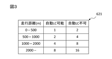
図3は、点数テーブルの例を示す図である。 FIG. 3 is a diagram showing an example of a score table.
点数テーブル621には、部分経路における車線変更地点の、部分経路の終点までの走行距離、および、車線変更地点を走行制御装置5による自動走行の可否に応じて、点数が関連づけられている。部分経路とは、車両1の現在位置から、現在位置と目的地との間のいずれかの通過点に至る経路であり、部分経路の終点は当該通過点に該当する。
In the score table 621, the mileage of the lane change point in the partial route to the end point of the partial route and the score are associated with the lane change point according to the possibility of automatic traveling by the
点数テーブル621では、例えば自動運転による車線変更(自動LC)可能な車線変更地点について、部分経路の終点までの走行距離が500mまでの場合に1点、2000m以上の場合に8点が関連づけられている。このように、点数テーブル621では、部分経路の終点から近い車線変更地点の点数が部分経路の終点から遠い前記車線変更地点の点数よりも小さくなるように重みづけされている。 In the score table 621, for example, for lane change points that can be changed by automatic driving (automatic LC), 1 point is associated when the mileage to the end point of the partial route is up to 500 m, and 8 points are associated when the mileage is 2000 m or more. There is. As described above, in the score table 621, the score of the lane change point near the end point of the partial route is weighted so as to be smaller than the score of the lane change point far from the end point of the partial route.
また、点数テーブル621では、例えば部分経路の終点までの走行距離が500m-1000mの車線変更地点について、自動LC可能な場合に2点、自動LC不可の場合に4点が関連づけられている。このように、点数テーブル621では、自動LC可能な車線変更地点の点数は、自動LC不可の車線変更地点の点数よりも小さくなるように重みづけされている。 Further, in the score table 621, for example, for a lane change point where the mileage to the end point of the partial route is 500 m-1000 m, 2 points are associated when automatic LC is possible, and 4 points are associated when automatic LC is not possible. As described above, in the score table 621, the score of the lane change point where automatic LC is possible is weighted so as to be smaller than the score of the lane change point where automatic LC is not possible.
プロセッサ63は、制御部の一例であり、1以上のプロセッサおよびその周辺回路を有する。プロセッサ63は、論理演算ユニット、数値演算ユニット、またはグラフィック処理ユニットといった他の演算回路をさらに有していてもよい。
The
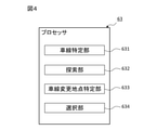
図4は、経路選択装置6が有するプロセッサ63の機能ブロック図である。
FIG. 4 is a functional block diagram of the
経路選択装置6のプロセッサ63は、機能ブロックとして、車線特定部631と、探索部632と、車線変更地点特定部633と、選択部634とを有する。プロセッサ63が有するこれらの各部は、プロセッサ63上で実行されるプログラムによって実装される機能モジュールである。あるいは、プロセッサ63が有するこれらの各部は、独立した集積回路、マイクロプロセッサ、またはファームウェアとして経路選択装置6に実装されてもよい。
The
車線特定部631は、入出力インタフェースを介してカメラ2から受信する画像を、画像に表された地物を検出するように予め学習された識別器に入力することにより、車両1の周辺の地物を検出する。そして、車線特定部631は、検出された地物に基づいて、車両1が現在走行中の車線の位置を特定する。
The
探索部632は、GNSS受信機3の出力する測位信号に示される車両1の現在位置から、経路における現在位置と目的地との間のいずれかの通過点に至る部分経路の候補を探索する。探索部632は、まず、現在位置と目的地との間の経路上にあるいずれかのノードを通過点として選択する。ノードとは、道路網表現上の結節点であり、交差点、複数車線を有する道路において車線変更が可能な地点等を含む。次に、探索部632は、ストレージ装置4に保存された高精度地図を参照し、ダイクストラ法といった所定の経路探索手法に従って、現在位置から選択されたノードまで連続するように区間を選択することにより、部分経路の候補を作成する。部分経路の候補には、走行制御装置5による走行の制御に用いられている経路が含まれていてもよい。
The
探索部632は、現在位置と目的地との間の経路上にあるノードのうち、現在位置から2つ目以降のノードを選択する。探索部632は、ストレージ装置4に保存された高精度地図に示される範囲に含まれるノードを選択する。探索部632が選択するノードの数には、上限が設けられていてもよい。このとき、探索部632は、現在位置から近いノードから順に選択してよい。
The
車線変更地点特定部633は、ストレージ装置4に保存された高精度地図を参照し、探索された部分経路の候補において車線変更が行われる車線変更地点を特定する。車線変更地点として特定されるノードは、複数車線を有する道路において車線変更が可能な地点である。車線変更地点特定部633は、車線特定部631により特定された車両1が現在走行中の車線のまま部分経路の終点まで走行することができない場合、部分経路上のいずれかのノードを車線変更地点として特定する。また、車線変更地点特定部633は、車線特定部631により特定された車両1が現在走行中の車線のまま部分経路の終点まで走行することができる場合であっても、部分経路上のいずれかのノードを車線変更地点として特定してよい。
The lane change
選択部634は、探索された部分経路の候補のそれぞれについて、点数テーブル621を参照して車線変更地点ごとに定められる点数の合計を求め、合計が最も小さい部分経路の候補を選択する。点数は、特定された車線変更地点の位置、または、車線変更地点を自動走行可能か否かに応じて重みづけされる。
The
選択部634は、探索された部分経路の候補のそれぞれについて、現在位置から部分経路の候補の終点までの走行距離と走行制御装置5が自動走行に用いている経路における現在位置と当該終点までの走行距離との差が距離差分閾値を超える経路の候補を除外して部分経路の選択を行ってもよい。このように動作することで、経路選択装置6は、過剰に迂回しない範囲で運転者が想定していない地点での車線変更の少ない経路を選択することができる。
For each of the searched partial route candidates, the
なお、経路選択装置6は、出発地から目的地に至る経路を作成するナビゲーション装置として実装されてもよい。また、経路選択装置6は、走行制御装置5と同一のECUに実装されてもよい。
The
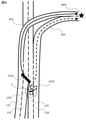
図5は、経路選択の第1の例を示す図である。 FIG. 5 is a diagram showing a first example of route selection.
車両1は、車線L11上の現在位置CP1から車線L12上の通過点WP1に向けて経路R11を走行している。車線L11は、所定の条件を満たす車両の走行が許可された許可レーンL11aを有している。所定の条件とは、例えば所定人数以上が乗車した車両であることである。経路R11では、許可レーンL11aの手前の車線変更地点LC11で車線変更が行われる。車線変更地点LC11から通過点WP1までの距離はd11である。
The
現在位置CP1において、部分経路の候補として経路R12が探索される。経路R12では、許可レーンL11a内の車線変更地点LC12で車線変更が行われる。車線変更地点LC12から通過点WP1までの距離はd12であり、d12はd11よりも短い。そのため、経路R12の点数は経路R11の点数よりも小さく、経路R12が部分経路として選択される。 At the current position CP1, the route R12 is searched as a candidate for a partial route. On the route R12, the lane change is performed at the lane change point LC12 in the permitted lane L11a. The distance from the lane change point LC12 to the passing point WP1 is d12, and d12 is shorter than d11. Therefore, the score of the route R12 is smaller than the score of the route R11, and the route R12 is selected as the partial route.
この例では、車両1が所定の条件を満たしていることを前提としている。車両1が所定の条件を満たしていない場合、車両1の運転者は経路R12の選択をキャンセルする。このとき、経路選択装置6は、経路R12が選択されたことおよび経路R12を走行する条件を、不図示のメーターディスプレイ等に表示することが好ましい。
In this example, it is assumed that the
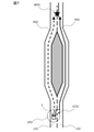
図6は、経路選択の第2の例を示す図である。 FIG. 6 is a diagram showing a second example of route selection.
車両1は、車線L23およびL24を有する道路における車線L23上の現在位置CP2を走行している。車線L23およびL24を有する道路は、車線L21およびL22を有する道路と合流して4車線となる。このうち、車線L21およびL24は、分岐して通過点WP2に至る。
The
現在位置CP2から通過点WP2までの走行距離は、車線L21を通る経路R21の方が車線L24を通る経路R22よりも短い。そのため、走行制御装置5は、経路R21に従って走行を制御している。このとき、車線変更地点LC21では、連続して2回の車線変更を行う必要があり、走行制御装置5の制御により走行することができない。そのため、経路R21を走行する場合、走行制御装置5は、車線変更地点LC21で運転者に対し、手動運転への交代を要求することになる。
The mileage from the current position CP2 to the passing point WP2 is shorter on the route R21 passing through the lane L21 than on the route R22 passing through the lane L24. Therefore, the
現在位置CP2において、部分経路の候補として経路R22が探索される。経路R22では、車線L23から車線L24へと1回車線変更を行う必要があり、走行制御装置5の制御による走行が可能である。そのため、経路R22の点数は経路R21の点数よりも小さく、経路R22が部分経路として選択される。
At the current position CP2, the route R22 is searched as a candidate for a partial route. On the route R22, it is necessary to change lanes once from the lane L23 to the lane L24, and the vehicle can travel under the control of the
図7は、経路選択の第3の例を示す図である。 FIG. 7 is a diagram showing a third example of route selection.
車両1は、車線L31およびL32を有する道路における車線L31上の現在位置CP3を走行している。車線L31およびL32はこの先で分岐し、その後通過点WP3の手前で合流する。
The
走行制御装置5が走行の制御に用いている経路R31では、車線L32が選択されている。そのため、経路R31では車線変更地点LC31で車線変更が行われる。
Lane L32 is selected on the route R31 used by the
現在位置CP3において、部分経路の候補として経路R32が探索される。経路R32では、車線L31が選択され、車線変更を行わない走行が可能である。そのため、経路R32の点数は経路R31の点数よりも小さく、経路R32が部分経路として選択される。 At the current position CP3, the route R32 is searched as a candidate for the partial route. On the route R32, the lane L31 is selected, and it is possible to travel without changing lanes. Therefore, the score of the route R32 is smaller than the score of the route R31, and the route R32 is selected as the partial route.
図8は、経路選択処理のフローチャートである。経路選択装置6は、車両1が走行制御装置の制御に基づいて経路を走行する間、経路選択処理を所定の時間間隔(例えば30秒間隔)で繰り返し実行する。
FIG. 8 is a flowchart of the route selection process. The
まず、車線特定部631は、車両1が現在走行中の車線の位置を特定する(ステップS1)。次に、探索部632は、現在位置からの部分経路の候補を探索する(ステップS2)。次に、車線変更地点特定部633は、部分経路の候補における車線変更地点を特定する(ステップS3)。そして、選択部634は、部分経路の候補のうち、車線変更地点の点数の合計が最も小さい部分経路の候補を、部分経路として選択する(ステップS4)。
First, the
このように経路選択処理を実行することにより、経路選択装置6は、運転者が想定していない地点での車線変更の少ない経路を選択することができる。
By executing the route selection process in this way, the
変形例によれば、車線変更地点の点数は、隣接する車線変更地点との間隔が小さいほど大きくなるように重みづけされていてもよい。このように点数を重みづけすることにより、経路選択装置6は、余裕をもって車線変更可能な部分経路を選択することができる。
According to the modification, the score of the lane change point may be weighted so that the smaller the distance from the adjacent lane change point, the larger the score. By weighting the points in this way, the
異なる変形例によれば、選択部634は、車線変更地点の点数の合計が同じである複数の部分経路の候補のうち、含まれる車線変更地点の少ない部分経路の候補を部分経路として選択してよい。選択部634がこのように動作することにより、経路選択装置6は、より車線変更の少ない部分経路を選択することができる。
According to a different modification, the
当業者は、本発明の精神および範囲から外れることなく、種々の変更、置換および修正をこれに加えることが可能であることを理解されたい。 It will be appreciated by those skilled in the art that various changes, substitutions and modifications can be made to this without departing from the spirit and scope of the invention.
1 車両
6 経路選択装置
631 車線特定部
632 探索部
633 車線変更地点特定部
634 選択部
1
Claims (7)
前記車両の現在位置から、出発地から目的地に至る経路における前記現在位置と前記目的地との間のいずれかの通過点に至る複数の部分経路の候補を探索する探索部と、
探索された前記複数の部分経路の候補のそれぞれにおいて、車線変更が行われる車線変更地点を特定する車線変更地点特定部と、
探索された前記複数の部分経路の候補のうち、特定された前記車線変更地点の位置、または、前記車線変更地点を自動走行可能か否かに応じて重みづけされた前記車線変更地点の点数の合計が最も小さい部分経路の候補を、部分経路として選択する選択部と、
を備える経路選択装置。 A lane identification part that identifies the position of the lane in which the vehicle is currently traveling,
A search unit that searches for candidates for a plurality of partial routes from the current position of the vehicle to any passing point between the current position and the destination in the route from the departure point to the destination.
In each of the plurality of partial route candidates searched, the lane change point specifying part that specifies the lane change point where the lane change is performed, and the lane change point specifying part.
Of the plurality of searched partial route candidates, the position of the specified lane change point or the score of the lane change point weighted according to whether or not the lane change point can be automatically driven. A selection unit that selects the candidate for the partial route with the smallest total as the partial route,
A route selection device comprising.
前記車両の現在位置から、出発地から目的地に至る経路における前記現在位置と前記目的地との間のいずれかの通過点に至る複数の部分経路の候補を探索し、
探索された前記複数の部分経路の候補のそれぞれにおいて、車線変更が行われる車線変更地点を特定し、
探索された前記複数の部分経路の候補のうち、特定された前記車線変更地点の位置、または、前記車線変更地点を自動走行可能か否かに応じて重みづけされた前記車線変更地点の点数の合計が最も小さい部分経路の候補を、部分経路として選択する、
ことを含む経路選択方法。 Identify the position of the lane in which the vehicle is currently driving,
Searching for a plurality of partial route candidates from the current position of the vehicle to any passing point between the current position and the destination in the route from the departure point to the destination.
In each of the searched multiple partial route candidates, the lane change point where the lane change is performed is specified, and the lane change point is specified.
Of the plurality of searched partial route candidates, the position of the specified lane change point or the score of the lane change point weighted according to whether or not the lane change point can be automatically driven. Select the candidate for the subroute with the smallest total as the subroute,
Route selection method including that.
Priority Applications (3)
| Application Number | Priority Date | Filing Date | Title |
|---|---|---|---|
| JP2020113332A JP7294254B2 (en) | 2020-06-30 | 2020-06-30 | Route selection device and route selection method |
| US17/349,553 US11946758B2 (en) | 2020-06-30 | 2021-06-16 | Route selection device and method |
| CN202110708817.4A CN113859239B (en) | 2020-06-30 | 2021-06-25 | Path selection device and path selection method |
Applications Claiming Priority (1)
| Application Number | Priority Date | Filing Date | Title |
|---|---|---|---|
| JP2020113332A JP7294254B2 (en) | 2020-06-30 | 2020-06-30 | Route selection device and route selection method |
Publications (2)
| Publication Number | Publication Date |
|---|---|
| JP2022011908A true JP2022011908A (en) | 2022-01-17 |
| JP7294254B2 JP7294254B2 (en) | 2023-06-20 |
Family
ID=78989927
Family Applications (1)
| Application Number | Title | Priority Date | Filing Date |
|---|---|---|---|
| JP2020113332A Active JP7294254B2 (en) | 2020-06-30 | 2020-06-30 | Route selection device and route selection method |
Country Status (3)
| Country | Link |
|---|---|
| US (1) | US11946758B2 (en) |
| JP (1) | JP7294254B2 (en) |
| CN (1) | CN113859239B (en) |
Cited By (2)
| Publication number | Priority date | Publication date | Assignee | Title |
|---|---|---|---|---|
| WO2023145272A1 (en) * | 2022-01-31 | 2023-08-03 | 株式会社デンソー | Presentation control device, presentation control program, automatic driving control device, and automatic driving control program |
| JP2023111830A (en) * | 2022-01-31 | 2023-08-10 | 株式会社デンソー | Presentation control device, presentation control program, automatic operation control device, and automatic operation control program |
Citations (5)
| Publication number | Priority date | Publication date | Assignee | Title |
|---|---|---|---|---|
| JP2015158467A (en) * | 2014-02-25 | 2015-09-03 | アイシン・エィ・ダブリュ株式会社 | Route search system, route search method, computer program and data structure of cost table |
| JP2017030436A (en) * | 2015-07-30 | 2017-02-09 | クラリオン株式会社 | Lighting control device for direction indicator |
| WO2018073887A1 (en) * | 2016-10-18 | 2018-04-26 | 本田技研工業株式会社 | Vehicle control device |
| JP2018095149A (en) * | 2016-12-15 | 2018-06-21 | 本田技研工業株式会社 | Locus evaluation device, locus evaluation method and locus evaluation program |
| US20190171206A1 (en) * | 2017-12-05 | 2019-06-06 | Waymo Llc | Real-time lane change selection for autonomous vehicles |
Family Cites Families (12)
| Publication number | Priority date | Publication date | Assignee | Title |
|---|---|---|---|---|
| JP5039455B2 (en) | 2007-06-29 | 2012-10-03 | パナソニック株式会社 | Navigation device |
| JP2011038794A (en) | 2009-08-06 | 2011-02-24 | Sumitomo Electric System Solutions Co Ltd | Route search device, route search method, computer program, and map database |
| JP5692628B2 (en) * | 2010-02-26 | 2015-04-01 | アイシン・エィ・ダブリュ株式会社 | Navigation device and navigation program |
| JP5585406B2 (en) * | 2010-11-15 | 2014-09-10 | 株式会社デンソー | Route search device, route search method, route guidance device, and route guidance method |
| US9404761B2 (en) | 2014-05-30 | 2016-08-02 | Nissan North America, Inc. | Autonomous vehicle lane routing and navigation |
| JP7046359B2 (en) * | 2018-04-24 | 2022-04-04 | シャロン株式会社 | Operation control device and automatic driving device |
| US10691130B2 (en) * | 2018-06-06 | 2020-06-23 | Uatc, Llc | Gridlock solver for motion planning system of an autonomous vehicle |
| JP6664441B2 (en) * | 2018-07-23 | 2020-03-13 | 株式会社ゼンリン | Vehicle control system and data structure of map data |
| JP7048444B2 (en) | 2018-07-27 | 2022-04-05 | 株式会社アイシン | Pathfinding system and pathfinding program |
| US10809733B2 (en) * | 2018-10-16 | 2020-10-20 | GM Global Technology Operations LLC | Intelligent motor vehicles, systems, and control logic for driver behavior coaching and on-demand mobile charging |
| GB2579020B (en) * | 2018-11-14 | 2021-05-12 | Jaguar Land Rover Ltd | Vehicle control system and method |
| US20210364305A1 (en) * | 2020-05-19 | 2021-11-25 | Gm Cruise Holdings Llc | Routing autonomous vehicles based on lane-level performance |
-
2020
- 2020-06-30 JP JP2020113332A patent/JP7294254B2/en active Active
-
2021
- 2021-06-16 US US17/349,553 patent/US11946758B2/en active Active
- 2021-06-25 CN CN202110708817.4A patent/CN113859239B/en active Active
Patent Citations (5)
| Publication number | Priority date | Publication date | Assignee | Title |
|---|---|---|---|---|
| JP2015158467A (en) * | 2014-02-25 | 2015-09-03 | アイシン・エィ・ダブリュ株式会社 | Route search system, route search method, computer program and data structure of cost table |
| JP2017030436A (en) * | 2015-07-30 | 2017-02-09 | クラリオン株式会社 | Lighting control device for direction indicator |
| WO2018073887A1 (en) * | 2016-10-18 | 2018-04-26 | 本田技研工業株式会社 | Vehicle control device |
| JP2018095149A (en) * | 2016-12-15 | 2018-06-21 | 本田技研工業株式会社 | Locus evaluation device, locus evaluation method and locus evaluation program |
| US20190171206A1 (en) * | 2017-12-05 | 2019-06-06 | Waymo Llc | Real-time lane change selection for autonomous vehicles |
Cited By (3)
| Publication number | Priority date | Publication date | Assignee | Title |
|---|---|---|---|---|
| WO2023145272A1 (en) * | 2022-01-31 | 2023-08-03 | 株式会社デンソー | Presentation control device, presentation control program, automatic driving control device, and automatic driving control program |
| JP2023111830A (en) * | 2022-01-31 | 2023-08-10 | 株式会社デンソー | Presentation control device, presentation control program, automatic operation control device, and automatic operation control program |
| JP7597097B2 (en) | 2022-01-31 | 2024-12-10 | 株式会社デンソー | Presentation control device, presentation control program, automatic driving control device, and automatic driving control program |
Also Published As
| Publication number | Publication date |
|---|---|
| CN113859239B (en) | 2024-04-05 |
| CN113859239A (en) | 2021-12-31 |
| JP7294254B2 (en) | 2023-06-20 |
| US11946758B2 (en) | 2024-04-02 |
| US20210403028A1 (en) | 2021-12-30 |
Similar Documents
| Publication | Publication Date | Title |
|---|---|---|
| JP6036371B2 (en) | Vehicle driving support system and driving support method | |
| KR101076538B1 (en) | Route guidance system and program | |
| US20100017117A1 (en) | Navigation system and lane information display method | |
| RU2661963C1 (en) | Device for calculating route of motion | |
| JP5674567B2 (en) | Navigation device | |
| JP2005189008A (en) | Navigation device and navigation system | |
| WO2019049323A1 (en) | Driving assistance method and driving assistance device | |
| JP7662087B2 (en) | Vehicle control device, location notification method, and location notification computer program | |
| JP2015145849A (en) | Navigator, navigation method and program | |
| US11959767B2 (en) | Map information assessment device, storage medium storing computer program for map information assessment, and map information assessment method | |
| JP2020008681A (en) | data structure | |
| KR102085464B1 (en) | Route navigation device and how to navigate | |
| US7970536B2 (en) | Navigation system | |
| US20200209007A1 (en) | Lane guidance system and lane guidance program | |
| JP2018151822A (en) | Electronic device, driving lane detection program and driving lane detection method | |
| CN113859239B (en) | Path selection device and path selection method | |
| JP2006189326A (en) | Next road prediction device of traveling vehicle | |
| US11898861B2 (en) | Road zone assessment device, medium storing computer program for road zone assessment, and road zone assessment method | |
| JP2023169631A (en) | Vehicle control device, vehicle control method and computer program for vehicle control | |
| JP2020008401A (en) | Information processor | |
| JP3964230B2 (en) | Car navigation system | |
| JP2010071810A (en) | Lane determining device and lane determination program, and navigation apparatus using the lane determining device | |
| JP2020101422A (en) | Driving support device and method | |
| JP2022158005A (en) | Travel control apparatus | |
| JP2007132828A (en) | Navigation system and route searching method |
Legal Events
| Date | Code | Title | Description |
|---|---|---|---|
| A621 | Written request for application examination |
Free format text: JAPANESE INTERMEDIATE CODE: A621 Effective date: 20211015 |
|
| A977 | Report on retrieval |
Free format text: JAPANESE INTERMEDIATE CODE: A971007 Effective date: 20220922 |
|
| A131 | Notification of reasons for refusal |
Free format text: JAPANESE INTERMEDIATE CODE: A131 Effective date: 20221004 |
|
| A521 | Request for written amendment filed |
Free format text: JAPANESE INTERMEDIATE CODE: A523 Effective date: 20221101 |
|
| A131 | Notification of reasons for refusal |
Free format text: JAPANESE INTERMEDIATE CODE: A131 Effective date: 20230117 |
|
| A521 | Request for written amendment filed |
Free format text: JAPANESE INTERMEDIATE CODE: A523 Effective date: 20230307 |
|
| TRDD | Decision of grant or rejection written | ||
| A01 | Written decision to grant a patent or to grant a registration (utility model) |
Free format text: JAPANESE INTERMEDIATE CODE: A01 Effective date: 20230509 |
|
| A61 | First payment of annual fees (during grant procedure) |
Free format text: JAPANESE INTERMEDIATE CODE: A61 Effective date: 20230522 |
|
| R151 | Written notification of patent or utility model registration |
Ref document number: 7294254 Country of ref document: JP Free format text: JAPANESE INTERMEDIATE CODE: R151 |