JP2022010555A - Vehicular table device - Google Patents
Vehicular table device Download PDFInfo
- Publication number
- JP2022010555A JP2022010555A JP2020111201A JP2020111201A JP2022010555A JP 2022010555 A JP2022010555 A JP 2022010555A JP 2020111201 A JP2020111201 A JP 2020111201A JP 2020111201 A JP2020111201 A JP 2020111201A JP 2022010555 A JP2022010555 A JP 2022010555A
- Authority
- JP
- Japan
- Prior art keywords
- table body
- rod
- deployed position
- article support
- article
- Prior art date
- Legal status (The legal status is an assumption and is not a legal conclusion. Google has not performed a legal analysis and makes no representation as to the accuracy of the status listed.)
- Granted
Links
Images


Landscapes
- Passenger Equipment (AREA)
- Vehicle Step Arrangements And Article Storage (AREA)
Abstract
Description
車両のシートバックの背面に備えられるテーブル状のカップホルダ装置に開口部を設けると共に、この開口部の下方に飲料容器の底部及び携帯端末の底部を保持する保持部材を設けさせたものとして、特許文献1に示されるものがある。この特許文献1のものでは、前記開口部に上方から入れ込まれて上側をテーブル面より上方に位置させ下側をテーブル面よりも下方に位置させる携帯端末を前記保持部材で起立状態に支持する態様となっている(特許文献1の図2参照)。 A patent is provided for providing an opening in a table-shaped cup holder device provided on the back surface of a vehicle seat back and providing a holding member for holding the bottom of a beverage container and the bottom of a mobile terminal below the opening. There is one shown in Document 1. In Patent Document 1, a mobile terminal that is inserted into the opening from above and has an upper side positioned above the table surface and a lower side positioned below the table surface is supported in an upright state by the holding member. It is an embodiment (see FIG. 2 of Patent Document 1).
前記特許文献1のものに支持される携帯端末は、前記のようにその上側をテーブル面より上方に位置させ下側をテーブル面よりも下方に位置させることから、その表示面かつ操作面の全体を自動車の後部座席側から見ることはできす、また、視認可能な部分も前記表示面かつ操作面が鉛直方向に沿って位置づけられることからこれより上方に位置される後部座席の利用者の視点から眺め難い。また、かかる支持状態においては携帯端末の操作もなし得ないところであった。 Since the mobile terminal supported by the one in Patent Document 1 has its upper side positioned above the table surface and its lower side positioned below the table surface as described above, the entire display surface and operation surface thereof. Can be seen from the rear seat side of the automobile, and since the display surface and the operation surface of the visible part are positioned along the vertical direction, the viewpoint of the user of the rear seat located above this. It's hard to see from. Moreover, in such a support state, it was impossible to operate the mobile terminal.
この発明が解決しようとする主たる問題点は、この種の車両用テーブル装置においてその載置面上に各種の物品を斜めにした状態で安定的に載せ置けるようにする、特に、携帯端末をその表示面かつ操作面の全体を眺めやすく且つ操作しやすい態様で載せ置けるようにする点にある。 The main problem to be solved by the present invention is to enable stable mounting of various articles on the mounting surface of this type of vehicle table device in an inclined state, particularly to a mobile terminal. The point is that the entire display surface and operation surface can be placed in an easy-to-see and easy-to-operate manner.
前記課題を達成するために、この発明にあっては、車両用テーブル装置を、車両の内装構成部材に備えられるテーブル装置であって、
テーブル基部側を前記内装構成部材に軸支させて、少なくとも非展開位置と載置面部を実質的に水平に位置させる展開位置との間に亘る回動可能に前記内装構成部材に備えられるテーブル本体と、
前記テーブル本体を、前記非展開位置と前記展開位置と両位置間の少なくとも一つの中間展開位置とにおいてそれぞれ支持状態の解除可能に支持する支持体とを備えており、
前記テーブル本体の前記載置面部に、物品支持部分を備えさせてなる、ものとした。
In order to achieve the above object, in the present invention, the vehicle table device is a table device provided in the interior component of the vehicle.
A table body provided in the interior component so that the table base side is pivotally supported by the interior component so that it can rotate at least between a non-deployed position and a deployed position where the mounting surface portion is positioned substantially horizontally. When,
The table body is provided with a support that supports the table body in a non-deployed position and at least one intermediate expanded position between the expanded position and both positions so that the supported state can be released.
An article support portion is provided on the previously described surface portion of the table body.
テーブル本体を利用しないときは前記支持体によってテーブル本体は邪魔にならない非展開位置に位置づけられ、テーブル本体の載置面部を利用するときは前記支持体によってにテーブル本体は載置面部を実質的に水平に位置させる展開位置に位置づけられる。支持体によってテーブル本体はテーブル基部側を上にしてこれと対向する自由端側を下にして載置面部を斜めにした中間位置にも位置づけることができる。これにより、この中間位置において、載置面部に各種の物品を斜めにした状態で載せ置くことができる。例えば、スマートフォンやタブレットなどの一面を表示面かつ操作面とした板状の携帯端末を、その表示面かつ操作面を眺めやすく、かつ、操作可能な状態で、テーブル本体に載せ置くことができる。載置面部には、物品支持部分が備えられていることから、テーブル本体を中間位置に位置づけた状態で物品支持部分によって斜めになった載置面部上に載せ置かれた携帯端末などの物品の滑り落ちを防いで板状の携帯端末などの物品を斜めにした状態で安定的にテーブル本体に載せ置くことができる。 When the table body is not used, the table body is positioned in a non-deployed position where the support does not interfere with the table body, and when the table body mounting surface portion is used, the table body substantially covers the mounting surface portion by the support. It is positioned in the unfolded position to be positioned horizontally. With the support, the table body can be positioned at an intermediate position where the mounting surface portion is slanted with the table base side facing up and the free end side facing the table bottom facing down. As a result, various articles can be placed on the mounting surface in an inclined state at this intermediate position. For example, a plate-shaped mobile terminal having one surface such as a smartphone or tablet as a display surface and an operation surface can be placed on a table body in a state where the display surface and the operation surface can be easily viewed and operated. Since the mounting surface portion is provided with an article supporting portion, an article such as a mobile terminal placed on the mounting surface portion slanted by the article supporting portion with the table body positioned at an intermediate position is provided. It is possible to prevent slipping off and stably place an article such as a plate-shaped mobile terminal on the table body in a slanted state.
前記物品支持部分を、前記テーブル本体の前記テーブル基部との間に間隔を開けて、前記テーブル本体に起伏動可能に支持されてなるものとすることが、この発明の態様の一つとされる。 It is one of the aspects of the present invention that the article supporting portion is supported by the table body so as to be undulating and undulating at a distance from the table base of the table body.
また、前記物品支持部分と前記テーブル本体の前記テーブル基部との間において、前記テーブル本体の前記載置面部に、起立状態において起立状態にある前記物品支持部分と共働して物品の少なくとも一部を挟み込み状に支持可能な追加物品支持部分を起伏動可能に付設させておくことが、この発明の態様の一つとされる。 Further, between the article support portion and the table base portion of the table body, at least a part of the article cooperates with the article support portion which is in the upright state on the front-described surface portion of the table body. It is one of the aspects of the present invention that an additional article support portion that can be supported in a sandwiched manner is attached so as to be undulating.
また、前記支持体を、前記内装構成部材に軸支される基部と、前記テーブル本体側にスライド移動可能に組み合わされた先端部とを備え、前記テーブル本体の回動に追随して回動される弾性変形可能なロッドから構成すると共に、
前記内装構成部材側に、前記回動の過程において前記ロッドの側部に摺接されるカム部を備えさせ、
前記カム部に前記テーブル本体が前記非展開位置と前記展開位置と前記中間展開位置とにあるときにそれぞれ、前記ロッドの弾性復元力により前記ロッドに係合する複数箇所の係合部を備えさせておくことが、この発明の態様の一つとされる。
Further, the support is provided with a base portion pivotally supported by the interior constituent member and a tip portion combined so as to be slidable toward the table body side, and is rotated following the rotation of the table body. It is composed of elastically deformable rods and
The interior component side is provided with a cam portion that is slidably contacted with the side portion of the rod in the process of rotation.
The cam portion is provided with a plurality of engaging portions that engage with the rod by the elastic restoring force of the rod when the table body is in the non-deployed position, the deployed position, and the intermediate deployed position, respectively. It is one of the aspects of the present invention.
この発明によれば、この種の車両用テーブル装置においてその載置面上に各種の物品を斜めにした状態で安定的に載せ置くことができ、特に、携帯端末をその表示面かつ操作面の全体を眺めやすく且つ操作しやすい態様で載せ置くことができる。 According to the present invention, in this type of vehicle table device, various articles can be stably placed on the mounting surface in an inclined state, and in particular, a mobile terminal can be placed on the display surface and the operation surface thereof. It can be placed in a manner that makes it easy to see and operate the whole.
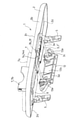
以下、図1~図9に基づいて、この発明の典型的な実施の形態について、説明する。この実施の形態にかかるテーブル装置1は、自動車などの車両の内装構成部材Iに備えられて用いられるものである。 Hereinafter, a typical embodiment of the present invention will be described with reference to FIGS. 1 to 9. The table device 1 according to this embodiment is provided in the interior component I of a vehicle such as an automobile and is used.
図1は、かかるテーブル装置1を、シートのシートバックSに備え付けるようにした例を示している。 FIG. 1 shows an example in which the table device 1 is provided on the seat back S of the seat.
かかるテーブル装置1は、テーブル本体2と、支持体3とを備えてなる。
The table device 1 includes a
テーブル本体2は、テーブル基部2a側を前記内装構成部材Iに軸支させて、少なくとも非展開位置と載置面部を実質的に水平に位置させる展開位置との間に亘る回動可能に前記内装構成部材Iに備えられる。
The interior of the
図示の例では、テーブル本体2は、平面視の状態において、実質的に四角形の盤状を呈している。テーブル本体2は、長さと幅を持ち、長さ方向に沿った一辺部を前記テーブル基部2aとし、長さ方向に沿った他辺部を自由端2bとした構成となっている。図示の例では、テーブル本体2は、その長さ方向を左右方向x(図1、図4参照)に沿わせるようにしてシートバックSの背面Saに備えられるようになっている。
In the illustrated example, the
テーブル基部2aには、テーブル本体2の載置面部2cと反対の裏面2dであって、テーブル本体2の左右にそれぞれ、テーブル側軸受け部4が形成されている。シートバックSには、左右一対のテーブル支持用ブラケット5が固定される。左右のテーブル側軸受け部4を構成する左右一対の側壁4a間にそれぞれ、対応するテーブル支持用ブラケット5の上部5aが納められ、この一対の側壁4aとテーブル支持用ブラケット5の上部5aとを左右方向xに中心線を沿わせた軸6(図6参照)を介して回動可能に組み合わせることでシートバックSに前記のような回動可能にテーブル本体2が備え付けられている。
The
左側のテーブル側軸受け部4と左側のテーブル支持用ブラケット5とを組み合わせる軸6と、右側のテーブル側軸受け部4と右側のテーブル支持用ブラケット5とを組み合わせる軸6とは、仮想の一つの直線L1(図2参照)にその中心線を沿わせており、テーブル本体2は、シートバックSの面にテーブル本体2の裏面2dを実質的に平行にするように向き合わせた非展開位置(図7)から載置面部2cを実質的に水平に位置させる展開位置(図5)との間に亘る回動可能にシートバックSに備え付けられている。
The shaft 6 that combines the left table side bearing 4 and the left
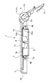
この実施の形態にあっては、前記テーブル本体2の前記載置面部2cに、物品支持部分7が起伏動可能に付設されている。
In this embodiment, the
図示の例では、前記仮想の直線L1に直交してテーブル本体2を左右に二分する仮想の直線L2(図1、図2参照)を挟んだ一方側、図示の例では、左側に、物品支持部分7が付設されている。
In the illustrated example, the article support is on one side of the virtual straight line L2 (see FIGS. 1 and 2) that divides the
図示の例では、仮想の直線L2の左側において、載置面部2cに凹所8が形成されている。テーブル本体2の裏面2dには載置面部2c側にこの凹所8を形成させるための凸所9が形成されている。凹所8は、前記仮想の直線L2に沿った、つまり、前後方向yに沿った側壁8aと、前記仮想の直線L1に沿った、つまり、左右方向xに沿った側壁8bとを備えた平面視実質的に四角形の輪郭を持った形態となっている。
In the illustrated example, the
物品支持部分7は、前記凹所8の前後方向yに沿った左右の側壁8a間に亘る左右方向xの寸法と、前記凹所8の左右方向xに沿った前後の側壁8b間の距離の実質的に半分の前後方向yの寸法とを備えた板状を呈している。
The
図示の例では、物品支持部分7は、前記凹所8の前側において、前後方向yに沿った左右の側壁8a間に起伏動可能に納められている。図示の例では、物品支持部分7の前側が左右方向xに中心線を沿わせた軸7a(図6参照)を介して凹所8側に回動可能に組み合わされており、これにより、物品支持部分7は、その表面7bを載置面部2cと実質的に面一に位置させる伏倒位置(図6参照)と、その表面7bを載置面部2cに実質的に直交させる起立位置(図1、図3、図8)との間に亘る起伏動可能にテーブル本体2に備え付けられている。図示の例では、物品支持部分7が起立位置にある状態は凹所8の前側にある左右方向xに沿った側壁8bが物品支持部分7の前側の表面7bに突き当たることで維持されるようになっている。
In the illustrated example, the
すなわち、前記物品支持部分7は、前記テーブル本体2の前記テーブル基部2aとの間に間隔を開けて、前記テーブル本体2に起伏動可能に支持されている。そして、後述のように、テーブル基部2aと起立位置に位置づけた物品支持部分7との間に携帯端末Tを保持できるようになっている。
That is, the
また、この実施の形態にあっては、前記物品支持部分7と前記テーブル本体2の前記テーブル基部2aとの間において、前記テーブル本体2の前記載置面部2cに、起立状態において起立状態にある前記物品支持部分7と共働して物品の少なくとも一部を挟み込み状に支持可能な追加物品支持部分10を起伏動可能に付設させている。
Further, in this embodiment, the
追加物品支持部分10は、前記凹所8の前後方向yに沿った左右の側壁8a間に亘る左右方向xの寸法と、前記凹所8の左右方向xに沿った前後の側壁8b間の距離の実質的に半分の前後方向の寸法とを備えた板状を呈している。
The additional
図示の例では、追加物品支持部分10は、前記凹所8の後側において、前後方向xに沿った左右の側壁8a間に起伏動可能に納められている。図示の例では、追加物品支持部分10の後側が左右方向xに中心線を沿わせた軸10a(図6参照)を介して凹所8側に回動可能に組み合わされており、これにより、追加物品支持部分10は、その表面10bを載置面部2cと実質的に面一に位置させる伏倒位置と、その表面10bを載置面部2cに実質的に直交させる起立位置との間に亘る起伏動可能にテーブル本体2に備え付けられている。図示の例では、追加物品支持部分10が起立位置にある状態は凹所8の後側にある左右方向xに沿った側壁8bが追加物品支持部分10の後側の表面10bに突き当たることで維持されるようになっている。
In the illustrated example, the additional
図示の例では、テーブル本体2を展開位置に位置づけた状態において、物品支持部分7と追加物品支持部分10をとを共に起立位置に位置づけることで(図1参照)、両者の間で物品の少なくとも一部、例えば飲料容器の底部側を挟むようにして凹所8内に飲料容器の底部側を入れ込むことができ、これにより、かかる飲料容器などの物品を展開位置にあるテーブル本体2上に安定的に支持することができる。
In the illustrated example, in the state where the
なお、図示の例では、テーブル本体2の前記仮想の直線L2を挟んだ右側にテーブル本体2を貫通する丸穴状部11が形成されており、この丸穴状部11を利用してテーブル本体2の右側においても飲料容器などを保持できるようになっている。
In the illustrated example, a round hole-shaped
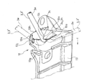
一方、支持体3は、前記テーブル本体2を、前記非展開位置と前記展開位置と両位置間の少なくとも一つの中間展開位置(図3、図8参照)とにおいてそれぞれ支持状態の解除可能に支持する。
On the other hand, the support 3 supports the
この実施の形態にあっては、前記支持体3は、前記内装構成部材Iに軸支される基部3aと、前記テーブル本体2側にスライド移動可能に組み合わされた先端部3bとを備え、前記テーブル本体2の回動に追随して回動される弾性変形可能なロッド3’から構成されている。
In this embodiment, the support 3 includes a
それと共に、前記内装構成部材I側に、前記回動の過程において前記弾性変形可能なロッド3’の側部3cに摺接されるカム部12を備えさせている。そして、前記カム部12に前記テーブル本体2が前記非展開位置と前記展開位置と前記中間展開位置とにあるときにそれぞれ、前記ロッド3’の弾性復元力により前記ロッド3’に係合する複数箇所の係合部12aを備えさせている。
At the same time, the interior component I side is provided with a
この実施の形態にあっては、シートバックSにおける左右のテーブル支持用ブラケット5の間に、ロッド支持用ブラケット13が固定され、このロッド支持用ブラケット13によってロッド3’の基部3aがシートバックSに軸支されるようになっている。
In this embodiment, the
また、この実施の形態にあっては、テーブル本体2の裏面2dであって、前記凹所8と丸穴状部11との間となる箇所に、ロッド3’の先端部3bの案内部14が形成されている。
Further, in this embodiment, the
図示の例では、ロッド3’は、前後方向y(図1、図5参照)に沿った左側桿部3d及び右側桿部3eと、左側桿部3dの一端と右側桿部3eの一端との間に亘る左右方向xに沿った連接桿部3fと、左側桿部3dの他端から左方に突き出す左側軸部3gと、右側桿部3eの他端から右方に突き出す右側軸部3hとを備えてなる。左側桿部3d及び右側桿部3eがロッド3’の側部3cを構成し、連接桿部3fがロッド3’の先端部3bを構成し、左側軸部3gと右側軸部3hがロッド3’の基部3aを構成する。
In the illustrated example, the rod 3'has a left
ロッド支持用ブラケット13は、シートバックSに対する取付面13aと、この取付面13aと反対の前面13bとを有し、左右の耳部13cに形成された通し穴13dを通じてシートバックS側に止着されるネジなどによってシートバックSに固定されるようになっている。
The
ロッド支持用ブラケット13の前面13b側には、左右にそれぞれ、ロッド3’の軸受け部13eが形成されている。軸受け部13eは前方に突き出す壁状をなし左側の軸受け部13eにロッド3’の左側軸部3gの軸穴13fが形成され、右側の軸受け部13eにロッド3’の右側軸部3hの軸穴13fが形成されている(図4参照)。
また、左側の軸受け部13eはその突き出し端から右側に張り出す庇部13gを有し、右側の軸受け部13eはその突き出し端から左側に張り出す庇部13gを有している。そして、ロッド3’は、左側軸部3g及び右側軸部3hを対応する前記軸穴13fに納めた状態で、テーブル本体2の回動に追随する前記回動の過程において、左側桿部3dと右側桿部3eとの距離を狭める向きf(図9参照)の弾性変形を生じながら庇部13gに左側桿部3d及び右側桿部3eを摺接させるようになっている。
Further, the bearing
ロッド3’の先端部3bの案内部14は、この先端部3bの太さと略等しい間隔を持ったガイド隙間14aを、図2中符号14bで示される部材によってテーブル本体2の裏面2dに前後方向yに沿うように形成させてなる。
The
具体的には、テーブル本体2が非展開位置にあるときは、ロッド3’の先端部3bは案内部14におけるテーブル本体2の自由端2b側に位置される箇所14cに位置し(図7)、ロッド3’の左側軸部3g及び右側軸部3hは先端部3bよりも上方に位置し、両者の間においてロッド3’の左側桿部3d及び右側桿部3eは前記庇部13g下に入り込む(図7、図9においてはこのときのロッド3’を二点鎖線で示す)。これにより、テーブル本体2が非展開位置にある状態は維持される。
Specifically, when the
非展開位置にあるテーブル本体2を展開位置に向けて回動操作すると、ロッド3’の先端部3bは案内部14におけるテーブル本体2のテーブル基部2a側に位置される箇所14d側に移動し、ロッド3’の右側軸部3hは図9中符号fで示される向きに弾性変形しながら前記庇部13gの突き出し端に摺接する(図示は省略するが、このとき、ロッド3’の左側軸部3gは右側軸部3hと反対の向きに弾性変形しながら前記庇部13gの突き出し端に摺接する。)。
When the
図示の例では、前記庇部13gには、この庇部13gの根本13hに向けて凹む凹部13i、13jが上下に間隔を開けて二箇所形成されている。
In the illustrated example, the
下側の凹部13iにロッド3’の左側軸部3g及び右側軸部3hが入り込む位置までロッド3’が回動されると、ロッド3’の弾性復帰により下側の凹部13iにロッド3’の左側軸部3g及び右側軸部3hにおける庇部13gに対する摺接側の一部が入り込み、これにより、テーブル本体2が中間位置にある状態は維持される(図8、図9)。
When the rod 3'is rotated to a position where the
テーブル本体2が中間位置にある状態から展開位置に向けてテーブル本体2が回動操作されると、ロッド3’は再び弾性変形して前記下側の凹部13iからロッド3’の左側軸部3g及び右側軸部3hの一部を抜け出させる。この後、上側の凹部13jにロッド3’の左側軸部3g及び右側軸部3hが入り込む位置までロッド3’が回動されると、ロッド3’の弾性復帰により上側の凹部13jにロッド3’の左側軸部3g及び右側軸部3hにおける庇部13gに対する摺接側の一部が入り込み、これにより、テーブル本体2が展開位置にある状態は維持される(図5、図9においてはこのときのロッド3’を一点鎖線で示す)。
When the
すなわち、この実施の形態にあっては、前記庇部13gとこれに設けられた二箇所の凹部13i、13jによって、前記ロッド3’の弾性復元力により前記ロッド3’に係合する複数箇所の係合部12aが形成されている。
That is, in this embodiment, the
テーブル本体2を利用しないときは前記支持体3によってテーブル本体2は邪魔にならない非展開位置に位置づけられ、テーブル本体2の載置面部2cを利用するときは前記支持体3によってにテーブル本体2は載置面部2cを実質的に水平に位置させる展開位置に位置づけられる。支持体3によってテーブル本体2はテーブル基部2a側を上にしてこれと対向する自由端2b側を下にして載置面部2cを斜めにした中間位置にも位置づけることができる。これにより、この中間位置において、載置面部2cに各種の物品を斜めにした状態で載せ置くことができる。例えば、図3及び図8に示されるように、スマートフォンやタブレットなどの一面を表示面かつ操作面Taとした板状の携帯端末Tを、その表示面かつ操作面Taを眺めやすく、かつ、操作可能な状態で、テーブル本体2に載せ置くことができる。載置面部2cには、物品支持部分7が起伏動可能に付設されていることから、テーブル本体2を中間位置に位置づけた状態で物品支持部分7を起立させることで、斜めになった載置面部2c上に載せ置かれた携帯端末Tなどの物品の滑り落ちをかかる物品支持部分7で防いで板状の携帯端末などの物品を斜めにした状態で安定的にテーブル本体2に載せ置くことができる。典型的には、以上に説明したテーブル装置1をシートバックSの背面Saに備えさせたときは、前記のような携帯端末Tを、自動車の後部座席側からアクセスし易い状態で、テーブル本体2に安定的に載せ置くことができる。
When the
なお、当然のことながら、本発明は以上に説明した実施態様に限定されるものではなく、本発明の目的を達成し得るすべての実施態様を含むものである。 As a matter of course, the present invention is not limited to the embodiments described above, but includes all embodiments that can achieve the object of the present invention.
I 内装構成部材
1 テーブル装置
2 テーブル本体
2a テーブル基部
2c 載置面部
3 支持体
7 物品支持部分
I Interior components 1
Claims (4)
テーブル基部側を前記内装構成部材に軸支させて、少なくとも非展開位置と載置面部を実質的に水平に位置させる展開位置との間に亘る回動可能に前記内装構成部材に備えられるテーブル本体と、
前記テーブル本体を、前記非展開位置と前記展開位置と両位置間の少なくとも一つの中間展開位置とにおいてそれぞれ支持状態の解除可能に支持する支持体とを備えており、
前記テーブル本体の前記載置面部に、物品支持部分を備えさせてなる、車両用テーブル装置。 A table device provided in the interior components of a vehicle.
A table body provided in the interior component so that the table base side is pivotally supported by the interior component so that it can rotate at least between a non-deployed position and a deployed position in which the mounting surface portion is substantially horizontally positioned. When,
The table body is provided with a support that supports the table body in a non-deployed position and at least one intermediate expanded position between the expanded position and both positions so that the supported state can be released.
A vehicle table device provided with an article support portion on the previously described surface portion of the table body.
前記内装構成部材側に、前記回動の過程において前記ロッドの側部に摺接されるカム部を備えさせており、
前記カム部に前記テーブル本体が前記非展開位置と前記展開位置と前記中間展開位置とにあるときにそれぞれ、前記ロッドの弾性復元力により前記ロッドに係合する複数箇所の係合部を備えさせてなる、請求項1~請求項3に記載の車両用テーブル装置。 The support includes a base portion pivotally supported by the interior constituent member and a tip portion that is slidably combined with the table body side, and is elastically rotated following the rotation of the table body. It consists of a deformable rod and
The interior component side is provided with a cam portion that is slidably contacted with the side portion of the rod in the process of rotation.
The cam portion is provided with a plurality of engaging portions that engage with the rod by the elastic restoring force of the rod when the table body is in the non-deployed position, the deployed position, and the intermediate deployed position, respectively. The vehicle table device according to claim 1 to 3.
Priority Applications (1)
| Application Number | Priority Date | Filing Date | Title |
|---|---|---|---|
| JP2020111201A JP7286589B2 (en) | 2020-06-29 | 2020-06-29 | Vehicle table device |
Applications Claiming Priority (1)
| Application Number | Priority Date | Filing Date | Title |
|---|---|---|---|
| JP2020111201A JP7286589B2 (en) | 2020-06-29 | 2020-06-29 | Vehicle table device |
Publications (2)
| Publication Number | Publication Date |
|---|---|
| JP2022010555A true JP2022010555A (en) | 2022-01-17 |
| JP7286589B2 JP7286589B2 (en) | 2023-06-05 |
Family
ID=80147647
Family Applications (1)
| Application Number | Title | Priority Date | Filing Date |
|---|---|---|---|
| JP2020111201A Active JP7286589B2 (en) | 2020-06-29 | 2020-06-29 | Vehicle table device |
Country Status (1)
| Country | Link |
|---|---|
| JP (1) | JP7286589B2 (en) |
Citations (4)
| Publication number | Priority date | Publication date | Assignee | Title |
|---|---|---|---|---|
| US5857740A (en) * | 1996-07-22 | 1999-01-12 | Bertrand Faure Equipements S.A. | Seat with a retractable table |
| JP2002114069A (en) * | 2000-10-10 | 2002-04-16 | Kasai Kogyo Co Ltd | Seat device for automobile |
| DE102014220200A1 (en) * | 2014-10-06 | 2016-04-07 | Sitech Sitztechnik Gmbh | Lockable folding table with comfort features |
| CN107487273A (en) * | 2016-07-11 | 2017-12-19 | 宝沃汽车(中国)有限公司 | A kind of vehicle-mounted wireless charging device and vehicle |
-
2020
- 2020-06-29 JP JP2020111201A patent/JP7286589B2/en active Active
Patent Citations (4)
| Publication number | Priority date | Publication date | Assignee | Title |
|---|---|---|---|---|
| US5857740A (en) * | 1996-07-22 | 1999-01-12 | Bertrand Faure Equipements S.A. | Seat with a retractable table |
| JP2002114069A (en) * | 2000-10-10 | 2002-04-16 | Kasai Kogyo Co Ltd | Seat device for automobile |
| DE102014220200A1 (en) * | 2014-10-06 | 2016-04-07 | Sitech Sitztechnik Gmbh | Lockable folding table with comfort features |
| CN107487273A (en) * | 2016-07-11 | 2017-12-19 | 宝沃汽车(中国)有限公司 | A kind of vehicle-mounted wireless charging device and vehicle |
Also Published As
| Publication number | Publication date |
|---|---|
| JP7286589B2 (en) | 2023-06-05 |
Similar Documents
| Publication | Publication Date | Title |
|---|---|---|
| JPWO2016103580A1 (en) | Electronics | |
| KR200444702Y1 (en) | Car Seat Table | |
| JP2022010555A (en) | Vehicular table device | |
| CN107000626B (en) | Lockable folding table with comfort equipment | |
| US20190329715A1 (en) | Display holder | |
| CN106985757A (en) | Accommodating apparatus for vehicle | |
| US12415451B2 (en) | Multifunctional portable article holder and vehicles having same | |
| KR20170102939A (en) | Beverage container holding device | |
| JP2011235843A (en) | Cup holder device for vehicle seat | |
| JP2013095272A (en) | Vehicle seat with flip-up seat locking mechanism | |
| JP5792042B2 (en) | Vehicle cup holder device | |
| CN210454567U (en) | A copilot tray device and vehicle for vehicle | |
| FR2976875A1 (en) | Retractable support shelf arrangement for use in dashboard of car for placing e.g. cellphone, has housing moved from retracted position to holding position such that cover is suspended in front of housing so as to retain shelf | |
| JP6167980B2 (en) | Vehicle seat table | |
| CN216734004U (en) | Automobile-used table, seat and vehicle of receiving and releasing | |
| JP3339179B2 (en) | Cup holder and accessory case | |
| JP2002166772A (en) | Table structure of seat | |
| JP2017144928A (en) | Table for vehicle seat | |
| JP2020066343A (en) | Seat table for vehicles | |
| JP6507720B2 (en) | Jack fixing bracket structure | |
| JP3946085B2 (en) | Drawing device | |
| JP2006163041A (en) | Display product information display | |
| CN211280751U (en) | Seat table assembly, seat and vehicle | |
| JP2004203065A (en) | Holder for vehicle | |
| JPH0672225A (en) | Vehicle cup holder device |
Legal Events
| Date | Code | Title | Description |
|---|---|---|---|
| A621 | Written request for application examination |
Free format text: JAPANESE INTERMEDIATE CODE: A621 Effective date: 20220822 |
|
| A977 | Report on retrieval |
Free format text: JAPANESE INTERMEDIATE CODE: A971007 Effective date: 20230328 |
|
| A131 | Notification of reasons for refusal |
Free format text: JAPANESE INTERMEDIATE CODE: A131 Effective date: 20230404 |
|
| A521 | Request for written amendment filed |
Free format text: JAPANESE INTERMEDIATE CODE: A523 Effective date: 20230419 |
|
| TRDD | Decision of grant or rejection written | ||
| A01 | Written decision to grant a patent or to grant a registration (utility model) |
Free format text: JAPANESE INTERMEDIATE CODE: A01 Effective date: 20230511 |
|
| A61 | First payment of annual fees (during grant procedure) |
Free format text: JAPANESE INTERMEDIATE CODE: A61 Effective date: 20230524 |
|
| R150 | Certificate of patent or registration of utility model |
Ref document number: 7286589 Country of ref document: JP Free format text: JAPANESE INTERMEDIATE CODE: R150 |