JP2022003753A - Imaging apparatus - Google Patents

Imaging apparatus Download PDF

Info

Publication number
JP2022003753A
JP2022003753A JP2020108235A JP2020108235A JP2022003753A JP 2022003753 A JP2022003753 A JP 2022003753A JP 2020108235 A JP2020108235 A JP 2020108235A JP 2020108235 A JP2020108235 A JP 2020108235A JP 2022003753 A JP2022003753 A JP 2022003753A
Authority
JP
Japan
Prior art keywords
sound
sound collection
subject
unit
digital camera
Prior art date
Legal status (The legal status is an assumption and is not a legal conclusion. Google has not performed a legal analysis and makes no representation as to the accuracy of the status listed.)
Pending
Application number
JP2020108235A
Other languages
Japanese (ja)
Other versions
JP2022003753A5 (en
Inventor
宏樹 春日井
Hiroki Kasugai
真一 山本
Shinichi Yamamoto
Current Assignee (The listed assignees may be inaccurate. Google has not performed a legal analysis and makes no representation or warranty as to the accuracy of the list.)
Panasonic Intellectual Property Management Co Ltd
Original Assignee
Panasonic Intellectual Property Management Co Ltd
Priority date (The priority date is an assumption and is not a legal conclusion. Google has not performed a legal analysis and makes no representation as to the accuracy of the date listed.)
Filing date
Publication date
Application filed by Panasonic Intellectual Property Management Co Ltd filed Critical Panasonic Intellectual Property Management Co Ltd
Priority to JP2020108235A priority Critical patent/JP2022003753A/en
Priority to US17/352,313 priority patent/US11490001B2/en
Publication of JP2022003753A publication Critical patent/JP2022003753A/en
Publication of JP2022003753A5 publication Critical patent/JP2022003753A5/ja
Pending legal-status Critical Current

Links

Images

Classifications

    • GPHYSICS
    • G06COMPUTING; CALCULATING OR COUNTING
    • G06FELECTRIC DIGITAL DATA PROCESSING
    • G06F3/00Input arrangements for transferring data to be processed into a form capable of being handled by the computer; Output arrangements for transferring data from processing unit to output unit, e.g. interface arrangements
    • G06F3/16Sound input; Sound output
    • G06F3/167Audio in a user interface, e.g. using voice commands for navigating, audio feedback
    • HELECTRICITY
    • H04ELECTRIC COMMUNICATION TECHNIQUE
    • H04NPICTORIAL COMMUNICATION, e.g. TELEVISION
    • H04N23/00Cameras or camera modules comprising electronic image sensors; Control thereof
    • H04N23/60Control of cameras or camera modules
    • H04N23/67Focus control based on electronic image sensor signals
    • H04N23/675Focus control based on electronic image sensor signals comprising setting of focusing regions
    • GPHYSICS
    • G06COMPUTING; CALCULATING OR COUNTING
    • G06FELECTRIC DIGITAL DATA PROCESSING
    • G06F3/00Input arrangements for transferring data to be processed into a form capable of being handled by the computer; Output arrangements for transferring data from processing unit to output unit, e.g. interface arrangements
    • G06F3/16Sound input; Sound output
    • G06F3/165Management of the audio stream, e.g. setting of volume, audio stream path
    • HELECTRICITY
    • H04ELECTRIC COMMUNICATION TECHNIQUE
    • H04NPICTORIAL COMMUNICATION, e.g. TELEVISION
    • H04N23/00Cameras or camera modules comprising electronic image sensors; Control thereof
    • H04N23/60Control of cameras or camera modules
    • H04N23/61Control of cameras or camera modules based on recognised objects
    • H04N23/611Control of cameras or camera modules based on recognised objects where the recognised objects include parts of the human body
    • HELECTRICITY
    • H04ELECTRIC COMMUNICATION TECHNIQUE
    • H04NPICTORIAL COMMUNICATION, e.g. TELEVISION
    • H04N23/00Cameras or camera modules comprising electronic image sensors; Control thereof
    • H04N23/60Control of cameras or camera modules
    • H04N23/63Control of cameras or camera modules by using electronic viewfinders
    • H04N23/631Graphical user interfaces [GUI] specially adapted for controlling image capture or setting capture parameters
    • HELECTRICITY
    • H04ELECTRIC COMMUNICATION TECHNIQUE
    • H04NPICTORIAL COMMUNICATION, e.g. TELEVISION
    • H04N23/00Cameras or camera modules comprising electronic image sensors; Control thereof
    • H04N23/60Control of cameras or camera modules
    • H04N23/667Camera operation mode switching, e.g. between still and video, sport and normal or high- and low-resolution modes

Abstract

To provide an imaging apparatus that takes an image while acquiring voice, the apparatus making it easier to collect voice of an object according to an intention of a user.SOLUTION: The imaging apparatus includes: an imaging unit for imaging an object and generating image data; a voice acquisition unit for acquiring a voice signal showing voice collected during imaging of the imaging unit; a setting unit for setting an own device in an auto-mode as an operation mode for automatically changing the directivity of the voice acquisition unit in response to an instruction of a user; and a control unit for controlling a voice collecting area for collecting voice from an object in the voice signal. The control unit controls the voice collecting area so that the area will include the object, by changing the directivity of the voice acquisition unit in association with the imaging state of the own device when the setting unit sets the own device in the auto-mode.SELECTED DRAWING: Figure 1

Description

本開示は、音声を取得しながら撮像を行う撮像装置に関する。 The present disclosure relates to an image pickup apparatus that performs image pickup while acquiring sound.

特許文献1は、顔検出機能を有するビデオカメラを開示している。特許文献1のビデオカメラは、ズーム比率及び撮影した画面内の人物の顔の大きさに応じて、マイクの指向角を変化させる。これにより、当該ビデオカメラは、ビデオカメラと被写体映像の距離に、マイクの指向角を関連付けて制御することで、映像と音声の整合をとりつつ、被写体の声をより確実に捉えるようにマイクの指向角を変化させる制御の実現を図っている。この際、当該ビデオカメラは、人物(被写体)の顔の位置及び大きさを検出し、検出した顔部分に枠(顔検出枠)を付けて表示するとともに、顔検出枠の大きさ(顔の大きさ)の情報を利用する。 Patent Document 1 discloses a video camera having a face detection function. The video camera of Patent Document 1 changes the directivity angle of the microphone according to the zoom ratio and the size of the face of a person in the imaged screen. As a result, the video camera controls the distance between the video camera and the subject image by associating the pointing angle of the microphone with the microphone so that the image and audio can be matched and the subject's voice can be captured more reliably. We are trying to realize control that changes the direction angle. At this time, the video camera detects the position and size of the face of the person (subject), attaches a frame (face detection frame) to the detected face portion and displays it, and also displays the size of the face detection frame (face). Use the information of size).

特開2010−283706号公報Japanese Unexamined Patent Publication No. 2010-283706

本開示は、音声を取得しながら撮像を行う撮像装置において、ユーザの意図に沿って被写体の音声を収音し易くすることができる撮像装置を提供する。 The present disclosure provides an imaging device capable of easily collecting the sound of a subject according to a user's intention in an imaging device that performs imaging while acquiring sound.

本開示において、撮像装置は、被写体を撮像して画像データを生成する撮像部と、撮像部による撮像中に収音される音声を示す音声信号を取得する音声取得部と、ユーザの指示を受けて、音声取得部の指向性を自動で変える動作モードであるオートモードに自装置を設定する設定部と、音声信号において被写体からの音声を収音する収音エリアを制御する制御部とを備え、制御部は、設定部がオートモードに設定している場合、音声取得部の指向性を自装置の撮影状態に連動して変えることで、被写体を含めるように収音エリアを制御する。 In the present disclosure, the image pickup apparatus receives instructions from a user, an image pickup unit that captures a subject and generates image data, a sound acquisition unit that acquires a sound signal indicating sound picked up during image pickup by the image pickup unit, and a user. It also has a setting unit that sets its own device to the auto mode, which is an operation mode that automatically changes the directivity of the voice acquisition unit, and a control unit that controls the sound collection area that collects the sound from the subject in the voice signal. When the setting unit is set to the auto mode, the control unit controls the sound collection area so as to include the subject by changing the directivity of the voice acquisition unit in conjunction with the shooting state of the own device.

本開示に係る撮像装置によると、音声を取得しながら撮像を行う撮像装置において、ユーザの意図に沿って被写体の音声を収音し易くすることができる。 According to the image pickup apparatus according to the present disclosure, it is possible to easily collect the sound of the subject according to the intention of the user in the image pickup device that takes an image while acquiring the sound.

本開示の実施の形態1に係るデジタルカメラ100の構成を示す図The figure which shows the structure of the digital camera 100 which concerns on Embodiment 1 of this disclosure. デジタルカメラ100の背面を例示する図The figure which illustrates the back of the digital camera 100 自分撮り時のデジタルカメラ100の状態を例示する図The figure which illustrates the state of the digital camera 100 at the time of taking a selfie 縦撮り時のデジタルカメラ100の状態を例示する図The figure which illustrates the state of the digital camera 100 at the time of vertical shooting. デジタルカメラ100におけるビーム形成部172の構成を例示する図The figure which illustrates the structure of the beam forming part 172 in a digital camera 100. デジタルカメラ100において収音エリアを例示する図The figure which illustrates the sound collection area in a digital camera 100 デジタルカメラ100における設定メニューの表示例を示す図The figure which shows the display example of the setting menu in a digital camera 100 デジタルカメラ100において更なる収音エリアを例示する図The figure which illustrates the further sound collection area in a digital camera 100 デジタルカメラ100のオートモードの動作の概要を説明するための図The figure for demonstrating the outline of the operation of the auto mode of a digital camera 100. 実施の形態1に係るデジタルカメラ100のフォーカスモードの動作を例示するフローチャートA flowchart illustrating the operation of the focus mode of the digital camera 100 according to the first embodiment. デジタルカメラ100のフォーカスモードの動作の概要を説明するための図The figure for demonstrating the outline of the operation of the focus mode of a digital camera 100. 実施の形態1に係るデジタルカメラ100の収音対象の選別処理(図10のS3)を例示するフローチャートA flowchart illustrating a sound collection target selection process (S3 in FIG. 10) of the digital camera 100 according to the first embodiment. デジタルカメラ100における収音対象の選別処理を説明するための図The figure for demonstrating the selection process of the sound pickup target in a digital camera 100. デジタルカメラ100における収音エリアの決定処理(図10のS4)を例示するフローチャートA flowchart illustrating a sound collection area determination process (S4 in FIG. 10) in the digital camera 100. デジタルカメラ100における収音エリアの決定処理を説明するための図The figure for demonstrating the determination process of the sound collection area in a digital camera 100. デジタルカメラ100における顔認識を用いた収音制御(図10のS5)を例示するフローチャートA flowchart illustrating sound collection control (S5 in FIG. 10) using face recognition in the digital camera 100. 収音エリアの決定処理によって得られる管理情報を説明するための図Diagram for explaining the management information obtained by the sound collection area determination process デジタルカメラ100における水平画角および合焦距離からゲインを求める関係を例示する図The figure which exemplifies the relationship which obtains a gain from a horizontal angle of view and a focusing distance in a digital camera 100. デジタルカメラ100における顔認識を用いない収音制御(図10のS6)を例示するフローチャートA flowchart illustrating sound collection control (S6 in FIG. 10) without using face recognition in the digital camera 100. 実施の形態1に係るデジタルカメラ100のオートモードの動作を例示するフローチャートA flowchart illustrating the operation of the auto mode of the digital camera 100 according to the first embodiment. 実施の形態1のオートモードにおける横撮り時と縦撮り時の収音制御を説明するための図The figure for demonstrating the sound pickup control at the time of horizontal shooting and the time of vertical shooting in the auto mode of Embodiment 1. 実施の形態2に係るデジタルカメラ100の表示例を示す図The figure which shows the display example of the digital camera 100 which concerns on Embodiment 2. 実施の形態2のデジタルカメラ100におけるマニュアル操作を説明するための図The figure for demonstrating the manual operation in the digital camera 100 of Embodiment 2. 実施の形態2のデジタルカメラ100におけるマニュアル操作時の動作を例示するフローチャートA flowchart illustrating an operation during manual operation in the digital camera 100 of the second embodiment. 変形例のデジタルカメラ100Aにおけるマイク161Aの配置を例示する図The figure which illustrates the arrangement of the microphone 161A in the digital camera 100A of a modification. 変形例のオートモードにおける縦撮り時の収音制御を説明するための図The figure for demonstrating the sound pickup control at the time of vertical shooting in the auto mode of a modification. デジタルカメラ100における顔認識に連動した収音制御の動作例を説明するための図The figure for demonstrating the operation example of the sound collection control interlocked with face recognition in a digital camera 100.

以下、適宜図面を参照しながら、実施の形態を詳細に説明する。但し、必要以上に詳細な説明は省略する場合がある。例えば、既によく知られた事項の詳細説明や実質的に同一の構成に対する重複説明を省略する場合がある。これは、以下の説明が不必要に冗長になるのを避け、当業者の理解を容易にするためである。なお、発明者(ら)は、当業者が本開示を十分に理解するために添付図面および以下の説明を提供するのであって、これらによって特許請求の範囲に記載の主題を限定することを意図するものではない。 Hereinafter, embodiments will be described in detail with reference to the drawings as appropriate. However, more detailed explanation than necessary may be omitted. For example, detailed explanations of already well-known matters and duplicate explanations for substantially the same configuration may be omitted. This is to avoid unnecessary redundancy of the following description and to facilitate the understanding of those skilled in the art. It should be noted that the inventor (or others) intends to limit the subject matter described in the claims by those skilled in the art by providing the accompanying drawings and the following description in order to fully understand the present disclosure. It is not something to do.

(実施の形態1)
実施の形態1では、本開示に係る撮像装置の一例として、画像認識技術に基づいて被写体を検出し、検出した被写体の大きさに応じた収音エリアの制御、及び収音する音声を強調する収音ゲインの制御を行うデジタルカメラについて説明する。
(Embodiment 1)
In the first embodiment, as an example of the image pickup apparatus according to the present disclosure, a subject is detected based on the image recognition technology, the sound collection area is controlled according to the size of the detected subject, and the sound to be collected is emphasized. A digital camera that controls the sound pickup gain will be described.

〔1−1.構成〕 [1-1. composition〕

図1は、本実施形態に係るデジタルカメラ100の構成を示す図である。本実施形態のデジタルカメラ100は、イメージセンサ115と、画像処理エンジン120と、表示モニタ130と、コントローラ135とを備える。さらに、デジタルカメラ100は、バッファメモリ125と、カードスロット140と、フラッシュメモリ145と、操作部150と、通信モジュール160とを備える。また、デジタルカメラ100は、マイク161と、マイク用のアナログ/デジタル(A/D)コンバータ165と、音声処理エンジン170とを備える。また、デジタルカメラ100は、例えば光学系110及びレンズ駆動部112を備える。さらに、デジタルカメラ100は、例えば磁気センサ132と、加速度センサ137とを備える。 FIG. 1 is a diagram showing a configuration of a digital camera 100 according to the present embodiment. The digital camera 100 of the present embodiment includes an image sensor 115, an image processing engine 120, a display monitor 130, and a controller 135. Further, the digital camera 100 includes a buffer memory 125, a card slot 140, a flash memory 145, an operation unit 150, and a communication module 160. Further, the digital camera 100 includes a microphone 161, an analog / digital (A / D) converter 165 for the microphone, and a voice processing engine 170. Further, the digital camera 100 includes, for example, an optical system 110 and a lens driving unit 112. Further, the digital camera 100 includes, for example, a magnetic sensor 132 and an acceleration sensor 137.

図2は、デジタルカメラ100の背面を例示する。図2では、デジタルカメラ100の3軸方向X,Y,Zと共に、重力方向Gを例示している。X,YおよびZ軸は、それぞれデジタルカメラ100の水平画角方向、垂直画角方向および光学系110におけるレンズの光軸方向に対応する。図2の例では、デジタルカメラ100のY軸方向が重力方向Gに沿った向き即ち横向きとなっている。 FIG. 2 illustrates the back surface of the digital camera 100. FIG. 2 illustrates the gravity direction G together with the three-axis directions X, Y, and Z of the digital camera 100. The X, Y, and Z axes correspond to the horizontal angle of view, the vertical angle of view, and the optical axis of the lens in the optical system 110, respectively, of the digital camera 100. In the example of FIG. 2, the Y-axis direction of the digital camera 100 is the direction along the gravity direction G, that is, the sideways direction.

本実施形態のデジタルカメラ100は、ユーザが自身を撮影する自分撮りをしたり、デジタルカメラ100を縦向きに用いる縦撮りをしたりして利用可能である。図3は、自分撮り時のデジタルカメラ100の状態を例示する。図4は、縦撮り時のデジタルカメラ100の状態を例示する。 The digital camera 100 of the present embodiment can be used by a user taking a self-portrait to take a picture of himself / herself or taking a vertical shot using the digital camera 100 in a vertical direction. FIG. 3 illustrates a state of the digital camera 100 at the time of taking a selfie. FIG. 4 illustrates a state of the digital camera 100 at the time of vertical shooting.

図1に戻り、光学系110は、フォーカスレンズ、ズームレンズ、光学式手ぶれ補正レンズ(OIS)、絞り、シャッタ等を含む。フォーカスレンズは、イメージセンサ115上に形成される被写体像のフォーカス状態を変化させるためのレンズである。ズームレンズは、光学系で形成される被写体像の倍率を変化させるためのレンズである。フォーカスレンズ等は、それぞれ1枚又は複数枚のレンズで構成される。 Returning to FIG. 1, the optical system 110 includes a focus lens, a zoom lens, an optical image stabilization lens (OIS), an aperture, a shutter, and the like. The focus lens is a lens for changing the focus state of the subject image formed on the image sensor 115. The zoom lens is a lens for changing the magnification of the subject image formed by the optical system. The focus lens and the like are each composed of one or a plurality of lenses.

レンズ駆動部112は、光学系110におけるフォーカスレンズ等を駆動する。レンズ駆動部112はモータを含み、コントローラ135の制御に基づいてフォーカスレンズを光学系110の光軸に沿って移動させる。レンズ駆動部112においてフォーカスレンズを駆動する構成は、DCモータ、ステッピングモータ、サーボモータ、または超音波モータなどで実現できる。 The lens driving unit 112 drives the focus lens and the like in the optical system 110. The lens drive unit 112 includes a motor and moves the focus lens along the optical axis of the optical system 110 under the control of the controller 135. The configuration for driving the focus lens in the lens driving unit 112 can be realized by a DC motor, a stepping motor, a servo motor, an ultrasonic motor, or the like.

イメージセンサ115は、光学系110を介して形成された被写体像を撮像して、撮像データを生成する。撮像データは、イメージセンサ115による撮像画像を示す画像データを構成する。イメージセンサ115は、所定のフレームレート(例えば、30フレーム/秒)で新しいフレームの画像データを生成する。イメージセンサ115における、撮像データの生成タイミングおよび電子シャッタ動作は、コントローラ135によって制御される。イメージセンサ115は、CMOSイメージセンサ、CCDイメージセンサ、またはNMOSイメージセンサなど、種々のイメージセンサを用いることができる。 The image sensor 115 captures a subject image formed via the optical system 110 and generates imaging data. The captured data constitutes image data showing an image captured by the image sensor 115. The image sensor 115 generates image data of a new frame at a predetermined frame rate (for example, 30 frames / sec). The generation timing of the image pickup data and the electronic shutter operation in the image sensor 115 are controlled by the controller 135. As the image sensor 115, various image sensors such as a CMOS image sensor, a CCD image sensor, or an MIMO image sensor can be used.

イメージセンサ115は、動画像、静止画像の撮像動作、スルー画像の撮像動作等を実行する。スルー画像は主に動画像であり、ユーザが例えば静止画像の撮像のための構図を決めるために表示モニタ130に表示される。
スルー画像、動画像及び静止画像は、それぞれ本実施形態における撮像画像の一例である。イメージセンサ115は、本実施形態における撮像部の一例である。
The image sensor 115 executes an operation of capturing a moving image and a still image, an operation of capturing a through image, and the like. The through image is mainly a moving image, and is displayed on the display monitor 130 for the user to determine a composition for capturing a still image, for example.
The through image, the moving image, and the still image are examples of the captured image in the present embodiment, respectively. The image sensor 115 is an example of an image pickup unit in this embodiment.

画像処理エンジン120は、イメージセンサ115から出力された撮像データに対して各種の処理を施して画像データを生成したり、画像データに各種の処理を施して、表示モニタ130に表示するための画像を生成したりする。各種処理としては、ホワイトバランス補正、ガンマ補正、YC変換処理、電子ズーム処理、圧縮処理、伸張処理等が挙げられるが、これらに限定されない。画像処理エンジン120は、ハードワイヤードな電子回路で構成してもよいし、プログラムを用いたマイクロコンピュータ、プロセッサなどで構成してもよい。 The image processing engine 120 performs various processes on the image pickup data output from the image sensor 115 to generate image data, or performs various processes on the image data to display an image on the display monitor 130. Or generate. Examples of various processes include, but are not limited to, white balance correction, gamma correction, YC conversion processing, electronic zoom processing, compression processing, decompression processing, and the like. The image processing engine 120 may be configured by a hard-wired electronic circuit, or may be configured by a microcomputer, a processor, or the like using a program.

本実施形態において、画像処理エンジン120は、撮像画像の画像認識によって人の顔といった被写体の検出機能を実現する顔認識部122を含む。顔認識部122は、例えば、ルールベースの画像認識処理によって顔検出を行い、検出情報を出力する。顔検出は、種々の画像認識アルゴリズムによって行われてもよい。検出情報は、被写体の検出結果に対応する位置情報を含む。位置情報は、例えば処理対象の画像Im上の水平位置及び垂直位置で規定され、例えば検出された被写体として人の顔を矩形状に囲む領域を示す(図11参照)。 In the present embodiment, the image processing engine 120 includes a face recognition unit 122 that realizes a detection function of a subject such as a human face by image recognition of a captured image. The face recognition unit 122 performs face detection by, for example, rule-based image recognition processing, and outputs the detection information. Face detection may be performed by various image recognition algorithms. The detection information includes position information corresponding to the detection result of the subject. The position information is defined by, for example, a horizontal position and a vertical position on the image Im to be processed, and indicates, for example, a region surrounding a human face in a rectangular shape as a detected subject (see FIG. 11).

表示モニタ130は、種々の情報を表示する表示部の一例である。例えば、表示モニタ130は、イメージセンサ115で撮像され、画像処理エンジン120で画像処理された画像データが示す画像(スルー画像)を表示する。また、表示モニタ130は、ユーザがデジタルカメラ100に対して種々の設定を行うためのメニュー画面等を表示する。表示モニタ130は、例えば、液晶ディスプレイデバイスまたは有機ELデバイスで構成できる。 The display monitor 130 is an example of a display unit that displays various information. For example, the display monitor 130 displays an image (through image) imaged by the image sensor 115 and indicated by image data image-processed by the image processing engine 120. Further, the display monitor 130 displays a menu screen or the like for the user to make various settings for the digital camera 100. The display monitor 130 can be composed of, for example, a liquid crystal display device or an organic EL device.

本実施形態のデジタルカメラ100は、例えば図2,3に示すように、表示モニタ130の位置を変更可能な可動式で構成される。図2の例では、表示モニタ130が、デジタルカメラ100の背面側(−Z側)に表示面を向けた位置にある。こうした表示モニタ130の位置を以下「通常位置」という。図3の例では、表示モニタ130が、デジタルカメラ100の前面側(+Z側)即ち被写体側に表示面を向けた位置にある。こうした表示モニタ130の位置を以下「自分撮り位置」という。 As shown in FIGS. 2 and 3, for example, the digital camera 100 of the present embodiment is configured to be movable so that the position of the display monitor 130 can be changed. In the example of FIG. 2, the display monitor 130 is in a position where the display surface faces the back side (−Z side) of the digital camera 100. The position of such a display monitor 130 is hereinafter referred to as a "normal position". In the example of FIG. 3, the display monitor 130 is located at a position where the display surface faces the front side (+ Z side) of the digital camera 100, that is, the subject side. The position of such a display monitor 130 is hereinafter referred to as a "self-portrait position".

磁気センサ132は、表示モニタ130が通常位置にあるか又は自分撮り位置にあるかを検知する検知部の一例である。磁気センサ132は、例えば表示モニタ130の位置の検出結果を示す検出信号をコントローラ135に出力する。 The magnetic sensor 132 is an example of a detection unit that detects whether the display monitor 130 is in the normal position or the self-portrait position. The magnetic sensor 132 outputs, for example, a detection signal indicating a detection result of the position of the display monitor 130 to the controller 135.

可動式の表示モニタ130としては、例えばバリアングル式またはチルト式を採用できる。例えば、表示モニタ130を回動可能にデジタルカメラ100の本体に連結するヒンジ131が設けられる。磁気センサ132は、例えばヒンジ131内部に設けられ、図2,3に対応する2状態を有するスイッチ等で構成される。 As the movable display monitor 130, for example, a vari-angle type or a tilt type can be adopted. For example, a hinge 131 that rotatably connects the display monitor 130 to the main body of the digital camera 100 is provided. The magnetic sensor 132 is provided inside the hinge 131, for example, and is composed of a switch having two states corresponding to FIGS. 2 and 3.

加速度センサ137は、例えば3軸方向X,Y,Zの内の1つ又は複数の角速度を検出して、検出信号をコントローラ135に出力する。加速度センサ137は、重力加速度の検出状態に基づき、デジタルカメラ100の姿勢が、図2に例示したような横向きか、又は図4に例示したような縦向きかを検出する姿勢検出部の一例である。 The accelerometer 137 detects, for example, one or a plurality of angular velocities in the three axial directions X, Y, Z, and outputs a detection signal to the controller 135. The acceleration sensor 137 is an example of a posture detection unit that detects whether the posture of the digital camera 100 is horizontal as illustrated in FIG. 2 or vertical as illustrated in FIG. 4 based on the detection state of gravitational acceleration. be.

操作部150は、デジタルカメラ100の外装に設けられた操作釦や操作レバー等のハードキーの総称であり、使用者による操作を受け付ける。操作部150は、例えば、レリーズ釦、モードダイヤル、タッチパネル、カーソルボタン、ジョイスティックを含む。操作部150はユーザによる操作を受け付けると、ユーザ操作に対応した操作信号をコントローラ135に送信する。操作部150は、例えば図2に示すように、レリーズボタン151、選択ボタン152、決定ボタン153、機能ボタン154およびタッチパネル155等を含む。 The operation unit 150 is a general term for hard keys such as operation buttons and operation levers provided on the exterior of the digital camera 100, and accepts operations by the user. The operation unit 150 includes, for example, a release button, a mode dial, a touch panel, a cursor button, and a joystick. When the operation unit 150 receives an operation by the user, the operation unit 150 transmits an operation signal corresponding to the user operation to the controller 135. As shown in FIG. 2, for example, the operation unit 150 includes a release button 151, a selection button 152, a decision button 153, a function button 154, a touch panel 155, and the like.

コントローラ135は、デジタルカメラ100全体の動作を統括制御する。コントローラ135はCPU等を含み、CPUがプログラム(ソフトウェア)を実行することで所定の機能を実現する。コントローラ135は、CPUに代えて、所定の機能を実現するように設計された専用の電子回路で構成されるプロセッサを含んでもよい。すなわち、コントローラ135は、CPU、MPU、GPU、DSU、FPGA、ASIC等の種々のプロセッサで実現できる。コントローラ135は1つまたは複数のプロセッサで構成してもよい。また、コントローラ135は、画像処理エンジン120などと共に1つの半導体チップで構成してもよい。 The controller 135 controls the operation of the entire digital camera 100 in an integrated manner. The controller 135 includes a CPU and the like, and the CPU realizes a predetermined function by executing a program (software). The controller 135 may include, instead of the CPU, a processor composed of dedicated electronic circuits designed to perform a predetermined function. That is, the controller 135 can be realized by various processors such as CPU, MPU, GPU, DSU, FPGA, and ASIC. The controller 135 may be composed of one or more processors. Further, the controller 135 may be configured by one semiconductor chip together with the image processing engine 120 and the like.

バッファメモリ125は、画像処理エンジン120やコントローラ135のワークメモリとして機能する記録媒体である。バッファメモリ125は、DRAM(Dynamic Random Access Memory)などにより実現される。フラッシュメモリ145は不揮発性の記録媒体である。また、図示していないが、コントローラ135は各種の内部メモリを有してもよく、例えばROMを内蔵してもよい。ROMには、コントローラ135が実行する様々なプログラムが記憶されている。また、コントローラ135は、CPUの作業領域として機能するRAMを内蔵してもよい。 The buffer memory 125 is a recording medium that functions as a work memory for the image processing engine 120 and the controller 135. The buffer memory 125 is realized by a DRAM (Dynamic Random Access Memory) or the like. The flash memory 145 is a non-volatile recording medium. Further, although not shown, the controller 135 may have various internal memories, for example, a ROM may be built in. Various programs executed by the controller 135 are stored in the ROM. Further, the controller 135 may include a RAM that functions as a work area of the CPU.

カードスロット140は、着脱可能なメモリカード142が挿入される手段である。カードスロット140は、メモリカード142を電気的及び機械的に接続可能である。メモリカード142は、内部にフラッシュメモリ等の記録素子を備えた外部メモリである。メモリカード142は、画像処理エンジン120で生成される画像データなどのデータを格納できる。 The card slot 140 is a means for inserting a removable memory card 142. The card slot 140 can electrically and mechanically connect the memory card 142. The memory card 142 is an external memory provided with a recording element such as a flash memory inside. The memory card 142 can store data such as image data generated by the image processing engine 120.

通信モジュール160は、通信規格IEEE802.11またはWi−Fi規格等に準拠した通信を行う通信モジュール(回路)である。デジタルカメラ100は、通信モジュール160を介して、他の機器と通信することができる。デジタルカメラ100は、通信モジュール160を介して、他の機器と直接通信を行ってもよいし、アクセスポイント経由で通信を行ってもよい。通信モジュール160は、インターネット等の通信ネットワークに接続可能であってもよい。 The communication module 160 is a communication module (circuit) that performs communication in accordance with the communication standard 802.11 or the Wi-Fi standard. The digital camera 100 can communicate with other devices via the communication module 160. The digital camera 100 may directly communicate with other devices via the communication module 160, or may communicate with each other via an access point. The communication module 160 may be connectable to a communication network such as the Internet.

マイク161は、音を収音する収音部の一例である。マイク161は、収音した音声を電気信号であるアナログ信号に変換して出力する。本実施形態のマイク161は、3つのマイクロフォン素子161L,161C及び161Rを含む。マイク161は、2つ又は4つ以上のマイクロフォン素子から構成されてもよい。 The microphone 161 is an example of a sound collecting unit that collects sound. The microphone 161 converts the collected voice into an analog signal which is an electric signal and outputs the sound. The microphone 161 of the present embodiment includes three microphone elements 161L, 161C and 161R. The microphone 161 may be composed of two or four or more microphone elements.

マイク用のA/Dコンバータ165は、マイク161からのアナログ信号をデジタル信号の音声データに変換する。マイク用のA/Dコンバータ165は、本実施形態における音声取得部の一例である。なお、マイク161は、デジタルカメラ100の外部にあるマイクロフォン素子を含んでもよい。この場合、デジタルカメラ100は音声取得部として、外部のマイク161に対するインタフェース回路を備える。 The A / D converter 165 for the microphone converts the analog signal from the microphone 161 into the audio data of the digital signal. The A / D converter 165 for a microphone is an example of a voice acquisition unit in this embodiment. The microphone 161 may include a microphone element outside the digital camera 100. In this case, the digital camera 100 includes an interface circuit for an external microphone 161 as a sound acquisition unit.

音声処理エンジン170は、マイク用のA/Dコンバータ165等の音声取得部から出力された音声データを受信して、受信した音声データに対して種々の音声処理を施す。音声処理エンジン170は、本実施形態における音声処理部の一例である。 The voice processing engine 170 receives voice data output from a voice acquisition unit such as an A / D converter 165 for a microphone, and performs various voice processing on the received voice data. The voice processing engine 170 is an example of a voice processing unit in the present embodiment.

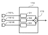
本実施形態の音声処理エンジン170は、例えば図1に示すように、ビーム形成部172と、ゲイン調整部174とを備える。ビーム形成部172は、音声の指向性を制御する機能を実現する。ビーム形成部172の詳細については後述する。ゲイン調整部174は、入力される音声データに、例えばコントローラ135によって設定される収音ゲインを乗じる乗算処理を行って、音声を増幅する。ゲイン調整部174は、入力の音声データに負のゲインを乗じて音声を抑圧する処理を行ってもよい。収音ゲイン調整部14はさらに、入力される音声データの周波数特性及びステレオ特性を変化させる機能を有してもよい。収音ゲインの設定についての詳細は後述する。 The voice processing engine 170 of the present embodiment includes, for example, a beam forming unit 172 and a gain adjusting unit 174, as shown in FIG. The beam forming unit 172 realizes a function of controlling the directivity of the voice. The details of the beam forming unit 172 will be described later. The gain adjusting unit 174 amplifies the voice by performing a multiplication process for multiplying the input voice data by, for example, the sound pick-up gain set by the controller 135. The gain adjusting unit 174 may perform a process of suppressing the voice by multiplying the input voice data by a negative gain. The sound pickup gain adjusting unit 14 may further have a function of changing the frequency characteristic and the stereo characteristic of the input audio data. Details of the sound pickup gain setting will be described later.

〔1−1−1.ビーム形成部について〕
本実施形態におけるビーム形成部172の詳細を、以下説明する。
[1-1-1. About the beam forming part]
The details of the beam forming unit 172 in the present embodiment will be described below.

ビーム形成部172は、マイク161が収音する音声の指向性を制御するビームフォーミングを行う。本実施形態におけるビーム形成部172の構成例を図5に示す。 The beam forming unit 172 performs beamforming that controls the directivity of the sound picked up by the microphone 161. FIG. 5 shows a configuration example of the beam forming unit 172 in the present embodiment.

図5に示すように、ビーム形成部172は、例えばフィルタD1〜D3と加算器173を備え、各マイクロフォン素子161L,161C及び161Rで収音された音声の遅延期間を調整して、その重み付き和を出力する。ビーム形成部172によると、マイク161の収音指向性の方向および範囲を制御して、マイク161が収音する物理的な範囲を設定できる。 As shown in FIG. 5, the beam forming unit 172 includes, for example, filters D1 to D3 and an adder 173, and the delay period of the sound picked up by the microphone elements 161L, 161C and 161R is adjusted and weighted. Output the sum. According to the beam forming unit 172, the direction and range of the sound collection directivity of the microphone 161 can be controlled to set the physical range in which the microphone 161 collects sound.

ビーム形成部172は、図示では1つの加算器173により1チャネルの出力を行うが、2つ以上の加算器を備え、例えばステレオ出力のような各チャネルで異なる出力を行う構成であってもよい。また、加算器173の他に減算器を用いて、特に感度が低い方向である死角を特定方向に有する指向性を形成してもよいし、環境に適応して処理を変える適応ビームフォーミングを行ってもよい。また、音声信号の周波数帯域によって異なる処理を適用してもよい。 Although the beam forming unit 172 outputs one channel by one adder 173 in the figure, it may be configured to include two or more adders and output different outputs in each channel such as a stereo output. .. Further, in addition to the adder 173, a subtractor may be used to form a directivity having a blind spot in a specific direction, which is a direction in which the sensitivity is particularly low, or adaptive beamforming that changes the processing according to the environment is performed. May be. Further, different processing may be applied depending on the frequency band of the audio signal.

図5では、マイクロフォン素子161L,161C及び161Rを直線的に配置した例を示しているが、各マイクロフォン素子の配置は、これに限らない。例えば、三角形状に配置する場合であっても、フィルタD1〜D3の遅延期間及び重みを適宜調整して、マイク161の収音指向性を制御できる。また、ビーム形成部172は、収音指向性の制御に公知の手法を適用してもよい。例えば、OZO Audioといった音声処理技術を用いて、指向性を形成する処理を行い、併せて音声の雑音を抑制する処理等を実行してもよい。 FIG. 5 shows an example in which the microphone elements 161L, 161C and 161R are arranged linearly, but the arrangement of the microphone elements is not limited to this. For example, even when the filters D1 to D3 are arranged in a triangular shape, the delay period and the weight of the filters D1 to D3 can be appropriately adjusted to control the sound collection directivity of the microphone 161. Further, the beam forming unit 172 may apply a known method for controlling the sound collection directivity. For example, a voice processing technique such as OZO Audio may be used to perform a process of forming directivity, and at the same time, perform a process of suppressing voice noise.

上記のようなビーム形成部172により設定可能なデジタルカメラ100の収音エリアについて説明する。 The sound collecting area of the digital camera 100 that can be set by the beam forming unit 172 as described above will be described.

〔1−1−2.収音エリアについて〕
図6は、デジタルカメラ100において定義される収音エリアの例を示す。図6は、収音エリアを、デジタルカメラ100を中心とする円の扇形領域によって例示している。本実施形態のデジタルカメラ100では、水平画角方向は、マイクロフォン素子161R,161Cおよび161Rが並ぶ方向と一致する。
[1-1-2. About the sound collection area]
FIG. 6 shows an example of a sound collecting area defined in the digital camera 100. FIG. 6 illustrates the sound collecting area by a circular fan-shaped region centered on the digital camera 100. In the digital camera 100 of the present embodiment, the horizontal angle of view direction coincides with the direction in which the microphone elements 161R, 161C and 161R are arranged.

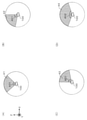
図6(A)は、角度範囲401(例えば70°)において、デジタルカメラ100の前方(すなわち撮影方向)に収音エリアを向ける「前方中心収音エリア」41を示す。図6(B)は、角度範囲401において、デジタルカメラ100の左方に収音エリアを向ける「左半分収音エリア」42を示す。図6(C)は、角度範囲401において、デジタルカメラ100の右方に収音エリアを向ける「右半分収音エリア」43を示す。図6(D)は、角度範囲401より大きい角度範囲402(例えば160°)において、デジタルカメラ100の前方に収音エリアを向ける「前方収音エリア」44を示す。これらの収音エリアは、本実施形態における複数の所定エリアの一例であり、角度範囲401及び402は、第1の角度範囲及び第2の角度範囲の一例である。 FIG. 6A shows a “front center sound collection area” 41 that directs the sound collection area to the front (that is, the shooting direction) of the digital camera 100 in the angle range 401 (for example, 70 °). FIG. 6B shows a “left half sound collecting area” 42 in which the sound collecting area is directed to the left side of the digital camera 100 in the angle range 401. FIG. 6C shows a “right half sound collecting area” 43 in which the sound collecting area is directed to the right side of the digital camera 100 in the angle range 401. FIG. 6D shows a “front sound pickup area” 44 that directs the sound pickup area to the front of the digital camera 100 in an angle range 402 (for example, 160 °) larger than the angle range 401. These sound collecting areas are examples of a plurality of predetermined areas in the present embodiment, and the angle ranges 401 and 402 are examples of a first angle range and a second angle range.

本実施形態のデジタルカメラ100は、被写体が撮像画像の中心部分に位置するとき、図6(A)の前方中心収音エリア41を用いる。また、被写体が撮像画像の左半分に位置するとき、図6(B)の左半分収音エリア42を用い、被写体が撮像画像の右半分に位置するとき、図6(C)の右半分収音エリア43を用いる。さらに、被写体が撮像画像の全体に位置するとき、主に図6(D)の前方収音エリア44を用いる。 The digital camera 100 of the present embodiment uses the front center sound pickup area 41 of FIG. 6A when the subject is located in the central portion of the captured image. Further, when the subject is located in the left half of the captured image, the left half sound collecting area 42 of FIG. 6 (B) is used, and when the subject is located in the right half of the captured image, the right half of FIG. 6 (C) is collected. The sound area 43 is used. Further, when the subject is located on the entire captured image, the front sound collecting area 44 of FIG. 6D is mainly used.

図11(B)の例では、収音対象の被写体R1及びR3が撮像画像の中心部分に位置するため、前方中心収音エリア41が用いられる。図11(C)の例では、収音対象の被写体R1及びR2が撮像画像の左半分に位置するため、左半分収音エリア42が用いられる。 In the example of FIG. 11B, since the subjects R1 and R3 to be sound-collected are located in the central portion of the captured image, the front center sound-collecting area 41 is used. In the example of FIG. 11C, since the subjects R1 and R2 to be sound-collected are located in the left half of the captured image, the left half sound-collecting area 42 is used.

デジタルカメラ100のマイク161といった撮像装置の収音部において、マイクロフォン素子の数および配置は、素子の搭載スペース等の事情により制約を受ける。例えば、ユーザが複数の被写体について音声を記録したい撮影場面において、マイクロフォン素子数の制約により収音指向性を十分に狭められない場合がある。こうした場合でも、本実施形態のデジタルカメラ100は、ユーザの撮影場面を想定して収音エリアを定義しておき、顔認識を用いて収音エリアを決定することで、ユーザの意図に沿った収音エリアを提供することができる。 In the sound collecting unit of an image pickup device such as the microphone 161 of the digital camera 100, the number and arrangement of microphone elements are restricted by the circumstances such as the mounting space of the elements. For example, in a shooting scene where a user wants to record sound for a plurality of subjects, the sound collection directivity may not be sufficiently narrowed due to the limitation of the number of microphone elements. Even in such a case, the digital camera 100 of the present embodiment defines the sound collection area assuming the shooting scene of the user, and determines the sound collection area by using face recognition, in line with the user's intention. A sound collecting area can be provided.

〔1−1−3.マイク設定について〕
デジタルカメラ100におけるマイク161の収音エリアに関する設定について、図7〜図8を用いて説明する。
[1-1-3. About microphone settings]
The setting regarding the sound collecting area of the microphone 161 in the digital camera 100 will be described with reference to FIGS. 7 to 8.

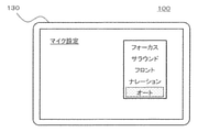
図7は、デジタルカメラ100における設定メニューの表示例を示す。本実施形態のデジタルカメラ100は、マイク161の収音エリアを制御する動作モード(即ち収音モード)として、例えば図7に示すように、「オート」、「サラウンド」、「フロント」、「フォーカス」及び「ナレーション」というモードを有する。 FIG. 7 shows a display example of the setting menu in the digital camera 100. The digital camera 100 of the present embodiment has, as an operation mode for controlling the sound collection area of the microphone 161 (that is, a sound collection mode), for example, as shown in FIG. 7, "auto", "surround", "front", and "focus". It has a mode called "" and "narration".

フォーカスモードは、デジタルカメラ100による顔認識及び画角に連動して、自動的にマイク161の指向性を変え、収音エリアを調整する動作モードである。例えば、フォーカスモードは上述した各種収音エリア41〜44を切り替えて用いることにより実現できる。フォーカスモードを4つの収音エリア41〜44で敢えて大まかに実現することにより、被写体の僅かな動きによって頻繁に収音指向性が変化するような事態を回避し、ユーザの聴感上の煩わしさを低減することができる。デジタルカメラ100において更なる収音エリアを図8に例示する。 The focus mode is an operation mode in which the directivity of the microphone 161 is automatically changed and the sound collection area is adjusted in conjunction with the face recognition and the angle of view by the digital camera 100. For example, the focus mode can be realized by switching and using the various sound collecting areas 41 to 44 described above. By daringly realizing the focus mode in the four sound collection areas 41 to 44, it is possible to avoid a situation in which the sound collection directivity frequently changes due to a slight movement of the subject, and the user's hearing is annoying. Can be reduced. FIG. 8 illustrates a further sound collecting area in the digital camera 100.

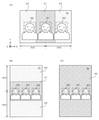
図8(A)は、サラウンドモードの収音エリア45を例示する。サラウンドモードは、デジタルカメラ100の左右前後に渡る広い範囲の音を収音するための動作モードである。サラウンドモードの収音エリア45は、例えばXZ平面の全周360°といった角度範囲を有する。 FIG. 8A exemplifies the sound collection area 45 in the surround mode. The surround mode is an operation mode for collecting a wide range of sounds across the left, right, front, and back of the digital camera 100. The sound collecting area 45 in the surround mode has an angle range such as 360 ° around the entire circumference of the XZ plane.

図8(B)は、フロントモードの収音エリア46を例示する。フロントモードは、デジタルカメラ100の前方の音を収音するための動作モードである。フロントモードの収音エリア46は、デジタルカメラ100から+Z側に向いており、例えば上述した前方収音エリア44以上の角度範囲を有する。 FIG. 8B exemplifies the sound collecting area 46 in the front mode. The front mode is an operation mode for collecting the sound in front of the digital camera 100. The sound collecting area 46 in the front mode faces the + Z side from the digital camera 100, and has an angle range of, for example, the above-mentioned front sound collecting area 44 or more.

図8(C)は、ナレーションモードの収音エリア47を例示する。ナレーションモードは、デジタルカメラ100の後方の音を収音するための動作モードである。ナレーションモードの収音エリア47は、デジタルカメラ100から−Z側に向けて形成される。ナレーションモードが設定された状態で、表示モニタ130が自分撮り位置にあることが検出された場合、デジタルカメラ100は、フォーカスモードの動作を実行してもよい。 FIG. 8C exemplifies the sound collection area 47 in the narration mode. The narration mode is an operation mode for collecting the sound behind the digital camera 100. The sound collecting area 47 in the narration mode is formed from the digital camera 100 toward the −Z side. When it is detected that the display monitor 130 is in the self-shooting position while the narration mode is set, the digital camera 100 may execute the operation of the focus mode.

オートモードは、デジタルカメラ100の撮影状態に連動して、自動的にマイク161の指向性を変え、収音エリアを調整する動作モードである。デジタルカメラ100の撮影状態は、例えばフォーカスモードで考慮される顔認識等に加えて、自分撮りか否か、及び縦撮りか横撮りかなども含む。 The auto mode is an operation mode in which the directivity of the microphone 161 is automatically changed and the sound collection area is adjusted in conjunction with the shooting state of the digital camera 100. The shooting state of the digital camera 100 includes, for example, face recognition considered in the focus mode, self-shooting, vertical shooting, horizontal shooting, and the like.

以上のような各種の収音モードを設定するマイク設定は、例えばデジタルカメラ100の設定メニューにおける動画メニューの1つとして設けられる。ユーザは、タッチパネル155のタッチ操作あるいは各種ボタン152,153の押下操作により、設定メニューから所望の収音モードを選択可能である。又、マイク設定は、予め機能ボタン154等に割り当てられてもよい。オートモード等の特定の収音モードの設定が、機能ボタン154等に割り当てられてもよい。 The microphone setting for setting various sound collection modes as described above is provided as one of the moving image menus in the setting menu of the digital camera 100, for example. The user can select a desired sound collection mode from the setting menu by touch operation of the touch panel 155 or pressing various buttons 152 and 153. Further, the microphone setting may be assigned to the function button 154 or the like in advance. The setting of a specific sound collection mode such as the auto mode may be assigned to the function button 154 or the like.

〔1−2.動作〕
以上のように構成されるデジタルカメラ100の動作について説明する。以下では、デジタルカメラ100による動画撮影時の動作を説明する。
[1-2. motion〕
The operation of the digital camera 100 configured as described above will be described. Hereinafter, the operation at the time of moving image shooting by the digital camera 100 will be described.

デジタルカメラ100は順次、光学系110を介して形成された被写体像をイメージセンサ115で撮像して撮像データを生成する。画像処理エンジン120は、イメージセンサ115により生成された撮像データに対して各種処理を施して画像データを生成し、バッファメモリ125に記録する。また、画像処理エンジン120の顔認識部122は、撮像データが示す画像に基づき、被写体の領域を検出して、例えば検出情報をコントローラ135に出力する。 The digital camera 100 sequentially captures a subject image formed via the optical system 110 with the image sensor 115 to generate imaging data. The image processing engine 120 performs various processing on the image pickup data generated by the image sensor 115 to generate image data, and records the image data in the buffer memory 125. Further, the face recognition unit 122 of the image processing engine 120 detects a region of the subject based on the image indicated by the captured data, and outputs, for example, the detection information to the controller 135.

本実施形態のデジタルカメラ100は、顔認識部122に入力された撮像画像において、画像認識処理により顔検出を行い、検出情報に基づいてオートフォーカス(AF)制御の対象とする被写体を特定する動作モードである顔認識モードを備える。 The digital camera 100 of the present embodiment performs face detection by image recognition processing in the captured image input to the face recognition unit 122, and identifies a subject to be subject to autofocus (AF) control based on the detection information. It has a face recognition mode, which is a mode.

以上の撮像動作と同時並行で、デジタルカメラ100は、マイク161において収音を行う。マイク用のA/Dコンバータ165から収音結果の音声データを音声処理エンジン170にて処理する。音声処理エンジン170は、処理後の音声データAoutをバッファメモリ125に記録する。 At the same time as the above image pickup operation, the digital camera 100 collects sound in the microphone 161. The voice processing engine 170 processes the voice data of the sound collection result from the A / D converter 165 for the microphone. The voice processing engine 170 records the processed voice data Aout in the buffer memory 125.

コントローラ135は、バッファメモリ125を介して、画像処理エンジン120から受け付ける画像データと音声処理エンジン170から受け付ける音声データとの間で、同期を取って動画をメモリカード142に記録する。また、コントローラ135は逐次、表示モニタ130にスルー画像を表示させる。ユーザは、表示モニタ130のスルー画像により随時、撮影の構図等を確認することができる。動画撮影の動作は、操作部150におけるユーザの操作に応じて開始/終了される。 The controller 135 records the moving image in the memory card 142 in synchronization with the image data received from the image processing engine 120 and the voice data received from the voice processing engine 170 via the buffer memory 125. Further, the controller 135 sequentially causes the display monitor 130 to display the through image. The user can check the composition of shooting and the like at any time from the through image of the display monitor 130. The operation of moving image shooting is started / ended according to the operation of the user in the operation unit 150.

以上のようなデジタルカメラ100の動画撮影においては、様々な撮影状態においてユーザが収音したい種々の状況が考えられる。例えば撮影者とその同伴者など、仲間内で会話をする被写体のグループに注目して行われる場合がある。この場合、音声についても、当該被写体のグループの発声を明瞭に収音したいとのニーズが考えられる。 In the above-mentioned moving image shooting of the digital camera 100, various situations in which the user wants to collect sound in various shooting states can be considered. For example, the photographer and his / her companion may be focused on a group of subjects who have a conversation with each other. In this case, as for the voice, there is a need to clearly collect the utterance of the group of the subject.

本実施形態のデジタルカメラ100は、例えば上述したフォーカスモードの動作として、画像処理エンジン120における顔認識部122の検出情報によって被写体を検出し、AF対象の被写体が決定されたときに、音声処理エンジン170において、当該被写体および撮影する空間で当該被写体の周囲にいる被写体について収音する音声を強調する処理を実行する。このように、画像処理エンジン120の顔認識と音声処理エンジン170の音声強調等とを連動させて、上記のような会話をする被写体のグループによる音声を強調した収音を精度良く実現する。 The digital camera 100 of the present embodiment detects a subject by the detection information of the face recognition unit 122 in the image processing engine 120, for example, as the operation of the focus mode described above, and when the subject to be AF is determined, the voice processing engine At 170, a process of emphasizing the sound picked up for the subject and the subject around the subject in the space to be photographed is executed. In this way, the face recognition of the image processing engine 120 and the speech enhancement of the speech processing engine 170 are interlocked to accurately realize the speech pickup by the group of subjects having the conversation as described above.

さらに、本実施形態のデジタルカメラ100は、オートモードの動作として、上記のようなフォーカスモードの動作に加えて、さらに様々な撮影状態に応じて適切な収音制御を実現する。図9を用いて、オートモードの動作の概要を説明する。 Further, the digital camera 100 of the present embodiment realizes appropriate sound collection control according to various shooting states in addition to the operation of the focus mode as described above as the operation of the auto mode. The outline of the operation of the auto mode will be described with reference to FIG.

図9は、デジタルカメラ100のオートモードと各種収音モードとの対応関係を例示する。オートモードのデジタルカメラ100は、例えば横撮りの状態で顔認識が為されたときは、フォーカスモードと同様の動作を行う。 FIG. 9 illustrates the correspondence between the auto mode of the digital camera 100 and various sound collection modes. For example, when face recognition is performed in the state of horizontal shooting, the digital camera 100 in the auto mode performs the same operation as in the focus mode.

一方、顔認識が為されていないときは、例えば自撮りでない状態(図2参照)であれば、デジタルカメラ100は、サラウンドモードと同様の動作を行う、すなわちサラウンドモードの収音エリア45を採用する。また、顔認識が為されず、自分撮りが行われる状態(図3参照)では、デジタルカメラ100は、フロントモードと同様の動作を行う。 On the other hand, when face recognition is not performed, for example, in a state where self-shooting is not performed (see FIG. 2), the digital camera 100 performs the same operation as the surround mode, that is, adopts the sound collection area 45 in the surround mode. do. Further, in a state where face recognition is not performed and self-shooting is performed (see FIG. 3), the digital camera 100 operates in the same manner as in the front mode.

また、縦撮りの場合、顔認識が為されていないときの動作は、上述した横撮りの場合と同様である。一方、縦撮りにおいて顔認識が為された場合、本実施形態のデジタルカメラ100は、フォーカスモードの代わりに、フロントモードと同様の動作を行う。 Further, in the case of vertical shooting, the operation when face recognition is not performed is the same as in the case of horizontal shooting described above. On the other hand, when face recognition is performed in vertical shooting, the digital camera 100 of the present embodiment performs the same operation as in the front mode instead of the focus mode.

以上のようなオートモードの動作によると、図9に示すように、種々の撮影状態に応じて各種の収音モードの動作を組み合わせることにより、それぞれの撮影状態において適切な収音制御を実現し易くすることができる。 According to the operation of the auto mode as described above, as shown in FIG. 9, by combining the operations of various sound collection modes according to various shooting states, appropriate sound collection control is realized in each shooting state. It can be made easier.

〔1−2−1.フォーカスモードの動作〕
図10及び図11を用いて、本実施形態に係るデジタルカメラ100のフォーカスモードの動作の概要を説明する。
[1-2-1. Focus mode operation]
An outline of the operation of the focus mode of the digital camera 100 according to the present embodiment will be described with reference to FIGS. 10 and 11.

図10は、本実施形態に係るデジタルカメラ100のフォーカスモードの動作を例示するフローチャートである。図10のフローチャートに示す各処理は、例えばデジタルカメラ100がフォーカスモードに設定された状態において所定の周期で繰り返し実行される。所定の周期は、例えば動画のフレーム周期である。図11は、本実施形態に係るデジタルカメラ100のフォーカスモードの動作の概要を説明するための図である。 FIG. 10 is a flowchart illustrating the operation of the focus mode of the digital camera 100 according to the present embodiment. Each process shown in the flowchart of FIG. 10 is repeatedly executed at a predetermined cycle, for example, in a state where the digital camera 100 is set to the focus mode. The predetermined cycle is, for example, a moving frame cycle. FIG. 11 is a diagram for explaining an outline of the operation of the focus mode of the digital camera 100 according to the present embodiment.

コントローラ135は、顔認識部122による検出情報に基づいてAF対象を特定し、AF制御を実行する(S1)。AF対象は、AF制御の対象とする被写体の画像上の領域を示す。図11(A)は、顔認識部122の検出情報において被写体が検出された領域を示す顔領域R1,R2及びR3を含む撮像画像Imを例示する。顔領域R1,R2及びR3は、本実施形態における被写体領域の一例である。例えば顔領域R1がAF対象の顔領域60として特定される。 The controller 135 identifies the AF target based on the detection information by the face recognition unit 122, and executes AF control (S1). The AF target indicates a region on the image of the subject to be AF controlled. FIG. 11A exemplifies a captured image Im including face regions R1, R2, and R3 indicating regions in which a subject is detected in the detection information of the face recognition unit 122. Face areas R1, R2 and R3 are examples of subject areas in this embodiment. For example, the face area R1 is specified as the face area 60 to be AF.

次にコントローラ135は、AF対象として特定された顔領域が存在するか否かを判断する(S2)。具体的には、コントローラ135は、顔領域が検出されていて、かつAF対象が顔領域であるか否かを判断する。 Next, the controller 135 determines whether or not the face region specified as the AF target exists (S2). Specifically, the controller 135 determines whether or not the face region is detected and the AF target is the face region.

AF対象の顔領域60がある場合(S2でYES)、コントローラ135は、検出情報における被写体からマイク161の収音対象を選別する処理を実行する(S3)。収音対象は、マイク161により音声を強調して収音する対象とする被写体である。AF対象として特定された顔領域R1(60)は、収音対象になる。図11(B)は、図11(A)に示す検出情報に基づき、顔領域R1及びR3を収音対象に決定し、一方で顔領域R2を収音対象としない例を示す。 When there is a face area 60 to be AF (YES in S2), the controller 135 executes a process of selecting the sound collection target of the microphone 161 from the subject in the detection information (S3). The sound collection target is a subject whose sound is emphasized by the microphone 161 and is to be collected. The face region R1 (60) specified as the AF target is the sound collection target. FIG. 11B shows an example in which the face regions R1 and R3 are determined to be the sound collection targets, while the face region R2 is not the sound collection target, based on the detection information shown in FIG. 11 (A).

本実施形態のデジタルカメラ100は、収音対象の選別処理(S3)において、AF対象の顔領域R1(60)に加え、撮像画像Imにおいて顔領域R1と同程度の顔の大きさを示す顔R3を、更なる収音対象として決定する。一方で、顔領域R1と異なる大きさの顔領域R2は収音対象から外される。これにより、人物21と人物23がデジタルカメラ100から同程度の距離にいて(すなわち、Z軸方向の距離の差が小さい)、人物22は異なる距離にいることを反映して、例えば仲間内で会話する被写体のグループを収音対象とすることができる。収音対象の選別処理(S3)についての詳細は後述する。 In the digital camera 100 of the present embodiment, in the sound collection target selection process (S3), in addition to the AF target face region R1 (60), the face showing the same face size as the face region R1 in the captured image Im. R3 is determined as a further sound collection target. On the other hand, the face region R2 having a size different from that of the face region R1 is excluded from the sound collection target. As a result, the person 21 and the person 23 are at the same distance from the digital camera 100 (that is, the difference in the distance in the Z-axis direction is small), and the person 22 is at different distances, for example, within a group. A group of subjects to be talked to can be picked up. Details of the sound collection target selection process (S3) will be described later.

次に、コントローラ135は、決定した収音対象に基づいて、収音エリアを決定する処理を行う(S4)。収音エリアの決定処理(S4)は、決定した全ての収音対象を含む収音エリアを決定する。図11(B)の例において、収音エリアを収音対象の顔領域R1及びR3を含むように前方中心収音エリア41(図6(A))に決定されている。収音エリアの決定処理(S4)についての詳細は後述する。 Next, the controller 135 performs a process of determining the sound collection area based on the determined sound collection target (S4). The sound collection area determination process (S4) determines the sound collection area including all the determined sound collection targets. In the example of FIG. 11B, the sound collection area is determined to be the front center sound collection area 41 (FIG. 6A) so as to include the face areas R1 and R3 to be sound collection. Details of the sound collection area determination process (S4) will be described later.

次に、コントローラ135は、決定した収音対象及び収音エリアに基づいて、顔認識を用いて収音の制御を行う(S5)。顔認識を用いた収音制御(S5)は、コントローラ135が決定した収音対象、収音エリア及び収音ゲインを含む収音パラメータを、音声処理エンジン170に設定することによって行われる。音声処理エンジン170は、収音パラメータに応じた収音指向性及び収音ゲインを実現する。 Next, the controller 135 controls the sound collection using face recognition based on the determined sound collection target and sound collection area (S5). The sound collection control (S5) using face recognition is performed by setting the sound collection parameters including the sound collection target, the sound collection area, and the sound collection gain determined by the controller 135 in the voice processing engine 170. The voice processing engine 170 realizes sound pick-up directivity and sound pick-up gain according to the sound pick-up parameter.

一方、例えば顔認識モードの動作中に顔領域が検出されない等、AF対象の顔領域60がない場合(S2でNO)、コントローラ135は、顔認識を用いない収音制御(S6)を行う。顔認識を用いた、または用いない収音制御(S5,S6)についての詳細は後述する。 On the other hand, when there is no face area 60 to be AF (NO in S2), for example, the face area is not detected during the operation of the face recognition mode, the controller 135 performs sound collection control (S6) without using face recognition. Details of sound collection control (S5, S6) with or without face recognition will be described later.

コントローラ135は、ステップS5またはS6の収音制御を実行後、ステップS1以降の処理を繰り返す。 After executing the sound collection control in step S5 or S6, the controller 135 repeats the processes after step S1.

以上の処理によると、本実施形態のデジタルカメラ100は、顔認識により検出した被写体から収音対象を選別し、収音対象を全て含む収音エリアを決定して、顔認識を用いた収音制御を行う。これにより、例えば仲間内で会話をする被写体のグループについて、音声を強調して収音することができる。 According to the above processing, the digital camera 100 of the present embodiment selects a sound collection target from the subject detected by face recognition, determines a sound collection area including all the sound collection targets, and uses face recognition to collect sound. Take control. As a result, for example, it is possible to emphasize and collect the sound of a group of subjects having a conversation with each other.

なお、顔認識によるAF制御(S1)において、検出情報に基づくAF対象の特定は、例えば表示モニタ130に表示させたスルー画像上に顔領域を示す枠表示等を行い、操作部150によりユーザが枠表示を選択する操作を受けて実行することができる。 In the AF control (S1) by face recognition, the AF target is specified based on the detection information, for example, a frame indicating the face area is displayed on the through image displayed on the display monitor 130, and the user can use the operation unit 150 to specify the AF target. It can be executed by receiving the operation of selecting the frame display.

図11(C)は、図11(A),(B)とは異なる位置に人物21〜23がいる場合の撮像画像Imの例を示す。デジタルカメラ100は、図11(B)の例と同様に、まず、例えば顔領域R1をAF対象の顔領域60として特定し(S1)、収音対象に決定する。図11(C)の例において、収音対象の選別処理(S3)は、撮像画像Im上で顔領域R1と同程度の顔の大きさである顔領域R2を収音対象に決定し、顔領域R3を収音対象から外す。収音エリアの決定処理(S4)は、収音対象として決定された顔領域R1及びR2を含む左半分収音エリア42(図6(B))を収音エリアに決定する。顔認識を用いた収音制御(S5)は、左半分収音エリア42に指向性を制御して人物21及び22の音声を明瞭に収音するように、収音パラメータを設定することによって行われる。 11 (C) shows an example of the captured image Im when the persons 21 to 23 are at positions different from those in FIGS. 11 (A) and 11 (B). Similar to the example of FIG. 11B, the digital camera 100 first identifies, for example, the face region R1 as the face region 60 to be AF (S1), and determines the sound collection target. In the example of FIG. 11C, in the sound collection target selection process (S3), the face region R2, which has the same face size as the face region R1 on the captured image Im, is determined as the sound collection target, and the face is selected. The area R3 is excluded from the sound collection target. The sound collection area determination process (S4) determines the left half sound collection area 42 (FIG. 6B) including the face areas R1 and R2 determined as sound collection targets as the sound collection area. The sound collection control (S5) using face recognition is performed by setting the sound collection parameters so that the directivity is controlled in the left half sound collection area 42 and the voices of the persons 21 and 22 are clearly collected. Will be.

〔1−2−2.収音対象の選別処理〕
図10のステップS3における収音対象の選別処理の詳細を、図12〜図13を用いて説明する。
[1-2-2. Selection process for sound collection]
The details of the sound collection target selection process in step S3 of FIG. 10 will be described with reference to FIGS. 12 to 13.

図12は、デジタルカメラ100の収音対象の選別処理(S3)を例示するフローチャートである。図12に示すフローチャートによる各処理は、図10のステップS11でYESに進んだとき、例えばデジタルカメラ100のコントローラ135によって実行される。 FIG. 12 is a flowchart illustrating a sound collection target selection process (S3) of the digital camera 100. Each process according to the flowchart shown in FIG. 12 is executed by, for example, the controller 135 of the digital camera 100 when the process proceeds to YES in step S11 of FIG.

図13は、デジタルカメラ100における収音対象の選別処理(S3)を説明するための図である。以下では、図11(A),(B)の例で収音対象を決定する動作について説明する。 FIG. 13 is a diagram for explaining a sound collection target selection process (S3) in the digital camera 100. Hereinafter, the operation of determining the sound collection target will be described using the examples of FIGS. 11A and 11B.

図12のフローチャートにおいて、コントローラ135は、図10のステップS1において特定したAF対象の顔領域に対応する被写体を収音対象に決定する(S10)。このとき、コントローラ135は、顔認識部122から取得した検出情報に基づいて、AF対象の顔領域の大きさ(即ち顔幅W)を、他の被写体から収音対象を選別する基準に設定する。 In the flowchart of FIG. 12, the controller 135 determines the subject corresponding to the face region of the AF target specified in step S1 of FIG. 10 as the sound collection target (S10). At this time, the controller 135 sets the size of the face region of the AF target (that is, the face width W) as a criterion for selecting the sound collection target from other subjects based on the detection information acquired from the face recognition unit 122. ..

図13(A)は、図11(A),(B)の例において収音対象が選別される場合を例示する。顔幅W1,W2,W3は、撮像画像Imにおける顔領域R1,R2,R3の大きさをX軸方向の幅で示す。図13(A)の例において、コントローラ135は、AF対象の顔領域R1の顔幅W1を、基準の顔幅Wに設定する(S10)。設定した顔幅Wは、例えばコントローラ135のRAM等に保持される。 FIG. 13A illustrates a case where the sound collection target is selected in the examples of FIGS. 11A and 11B. The face widths W1, W2, and W3 indicate the sizes of the face regions R1, R2, and R3 in the captured image Im by the width in the X-axis direction. In the example of FIG. 13A, the controller 135 sets the face width W1 of the face region R1 to be AF to the reference face width W (S10). The set face width W is held in, for example, the RAM of the controller 135.

次に、コントローラ135は、AF対象の他に検出された被写体があるか否かを判断する(S11)。具体的には、コントローラ135は、顔認識部122の検出情報がAF対象の顔領域の他に顔領域を含むか否かを判断する。 Next, the controller 135 determines whether or not there is a detected subject other than the AF target (S11). Specifically, the controller 135 determines whether or not the detection information of the face recognition unit 122 includes the face area in addition to the face area to be AF.

AF対象の他に検出された被写体がある場合(S11でYES)、コントローラ135は、収音対象の候補である収音候補として、一つの被写体iを選択する(S12)。図13(A)の例では、検出情報はAF対象の顔領域R1の他の顔領域R2及びR3が、ステップS12ごとに順次、収音候補の被写体iに対応付けて選択される。 When there is a detected subject other than the AF target (YES in S11), the controller 135 selects one subject i as a sound collection candidate which is a sound collection target candidate (S12). In the example of FIG. 13A, the detection information is selected by sequentially associating the other face regions R2 and R3 of the face region R1 to be AF with the subject i of the sound collection candidate in each step S12.

コントローラ135は、選択した被写体iの顔幅Wiと、基準の顔幅Wとを比較する演算を行う(S13)。具体的には、コントローラ135は、基準の顔幅Wに対する被写体iの顔幅Wiの割合Wi/Wを算出する。図13(A)の例において、顔領域R2を収音候補とする選択時(S12)には、その顔幅W2についての割合W2/Wが算出される(S13)。 The controller 135 performs an operation of comparing the face width Wi of the selected subject i with the reference face width W (S13). Specifically, the controller 135 calculates the ratio Wi / W of the face width Wi of the subject i to the reference face width W. In the example of FIG. 13A, when the face region R2 is selected as a sound collection candidate (S12), the ratio W2 / W with respect to the face width W2 is calculated (S13).

コントローラ135は、収音候補の顔幅Wiと基準の顔幅W間の割合Wi/Wが、所定範囲内であるか否かを判断する(S14)。所定範囲は、例えば収音候補の顔幅Wiが相対的に基準の顔幅Wiと同程度であるとみなす範囲を規定する観点から、「1」よりも大きい上限値と、「1」よりも小さい下限値で規定される。なお、所定範囲を設定するためのユーザインタフェースが提供されてもよく、例えばユーザが操作部150により設定した所定範囲がバッファメモリ125等に保持されてもよい。 The controller 135 determines whether or not the ratio Wi / W between the face width Wi of the sound collection candidate and the reference face width W is within a predetermined range (S14). The predetermined range is, for example, an upper limit value larger than "1" and an upper limit value larger than "1" from the viewpoint of defining a range in which the face width Wi of the sound collection candidate is considered to be relatively similar to the reference face width Wi. It is specified by a small lower limit. A user interface for setting a predetermined range may be provided, and for example, a predetermined range set by the user by the operation unit 150 may be held in the buffer memory 125 or the like.

コントローラ135は、顔幅の割合Wi/Wが所定範囲内であると判断すると(S14でYES)、被写体iを収音対象とすることを決定する(S15)。 When the controller 135 determines that the face width ratio Wi / W is within the predetermined range (YES in S14), the controller 135 determines that the subject i is the sound collection target (S15).

一方、コントローラ135は、顔幅の割合Wi/Wが所定範囲内でないと判断すると(S14でNO)、コントローラ135は、被写体iを収音対象としないことを決定する(S16)。図13(A)の例において、割合W2/Wは所定範囲の下限値を下回り、顔領域R2を収音対象としないことが決定される。 On the other hand, when the controller 135 determines that the face width ratio Wi / W is not within the predetermined range (NO in S14), the controller 135 determines that the subject i is not the sound collection target (S16). In the example of FIG. 13A, the ratio W2 / W is below the lower limit of the predetermined range, and it is determined that the face region R2 is not subject to sound collection.

コントローラ135は、被写体iを収音対象とするか否かを決定すると(S15またはS16)、例えば被写体iについて決定した結果をバッファメモリ125に記録する(S17)。次に、コントローラ135は、収音候補として選択済みの被写体とは他の被写体について、ステップS11以降の処理を再び行う。 When the controller 135 determines whether or not the subject i is to be picked up (S15 or S16), the controller 135 records, for example, the result of the determination regarding the subject i in the buffer memory 125 (S17). Next, the controller 135 performs the processing after step S11 again for the subject other than the subject selected as the sound collection candidate.

図13(A)の例では、顔領域R2の他に顔領域R3が検出情報に含まれる(S11でYES)。コントローラ135は、顔領域R3に対応する被写体を選択する(S12)と、顔領域R2の場合と同様に、基準の顔幅Wに対する顔幅W3の割合W3/Wを算出する(S13)。図13(A)の例では、割合W3/Wは「1」近傍に算出される。コントローラ135は、算出した顔幅の割合W3/Wが収音対象の所定範囲内であると判断して(S14でYES)、顔領域R3に対応する被写体を収音対象として決定する(S15)。 In the example of FIG. 13A, the face region R3 is included in the detection information in addition to the face region R2 (YES in S11). When the controller 135 selects the subject corresponding to the face area R3 (S12), the controller 135 calculates the ratio W3 / W of the face width W3 to the reference face width W as in the case of the face area R2 (S13). In the example of FIG. 13A, the ratio W3 / W is calculated in the vicinity of “1”. The controller 135 determines that the calculated face width ratio W3 / W is within the predetermined range of the sound collection target (YES in S14), and determines the subject corresponding to the face area R3 as the sound collection target (S15). ..

コントローラ135は、収音候補として選択されていない被写体がなくなるまで(ステップS11でNO)、ステップS11〜S17の処理を繰り返す。その後、コントローラ135は、収音対象の選別処理(S3)を終了して、図10のステップS4に進む。 The controller 135 repeats the processes of steps S11 to S17 until there are no subjects not selected as sound collection candidates (NO in step S11). After that, the controller 135 ends the sound collection target selection process (S3), and proceeds to step S4 in FIG.

以上の処理によると、顔認識により検出した被写体について、AF対象として特定した顔領域R1を基準とする相対的な顔領域R2,R3の大きさ比較が行われる。これにより、相対的な顔領域R3の大きさがAF対象の顔領域R1と同程度である被写体を選別して収音対象に決定することができる。 According to the above processing, the relative sizes of the face regions R2 and R3 are compared with respect to the subject detected by the face recognition with respect to the face region R1 specified as the AF target. As a result, it is possible to select a subject whose relative size of the face region R3 is about the same as that of the face region R1 to be AF and determine the sound collection target.

図13(B)は、図11(C)の例において収音対象が選別される場合を例示する。図13(B)の例において、顔領域R1は、図13(A)の例と同様にAF対象として特定されている。このことから、コントローラ135は、顔領域R1を収音対象に決定し、顔幅W1を基準の顔幅Wに設定する(S10)。 FIG. 13B illustrates a case where the sound collection target is selected in the example of FIG. 11C. In the example of FIG. 13 (B), the face region R1 is specified as an AF target as in the example of FIG. 13 (A). From this, the controller 135 determines the face region R1 as the sound collection target, and sets the face width W1 to the reference face width W (S10).

図13(B)の例では、顔領域R2の顔幅W2は、基準の顔幅W(=W1)と同程度の大きさである。一方、顔領域R3の顔幅W3は、他の顔幅W1及びW2と比較して大きい。本例において、コントローラ135は、割合W2/Wが所定範囲内であると判断して(S14でYES)、顔領域R2の被写体を収音対象として決定する(S15)。一方、割合W3/Wが所定範囲の上限値を上回るため(S14でNO)、顔領域R3の被写体は収音対象としないことが決定される(S16)。よって、本例の収音対象は、顔領域R1及びR2に対応する2つの被写体に決定される(図11(C)参照)。 In the example of FIG. 13B, the face width W2 of the face region R2 is about the same size as the reference face width W (= W1). On the other hand, the face width W3 of the face region R3 is larger than the other face widths W1 and W2. In this example, the controller 135 determines that the ratio W2 / W is within the predetermined range (YES in S14), and determines the subject in the face region R2 as the sound collection target (S15). On the other hand, since the ratio W3 / W exceeds the upper limit of the predetermined range (NO in S14), it is determined that the subject in the face region R3 is not subject to sound collection (S16). Therefore, the sound collection target of this example is determined to be two subjects corresponding to the face regions R1 and R2 (see FIG. 11C).

図13(C)は、図11(C)と同様の撮影画像Imにおいて顔領域R3がAF対象の顔領域60として特定された(図10のS1)場合を例示する。コントローラ135は、顔領域R3を収音対象に決定し、顔幅W3を基準の顔幅Wに設定する(S10)。図13(C)の例において、割合W2/W及びW1/Wが所定範囲の下限値を下回るため(S14でNO)、顔領域R1及びR2に対応する被写体を収音対象としないことが決定される(S16)。よって、本例の収音対象は、顔領域R3に対応する1つの被写体に決定される。 FIG. 13 (C) illustrates a case where the face region R3 is specified as the face region 60 to be AF in the same photographed image Im as in FIG. 11 (C) (S1 in FIG. 10). The controller 135 determines the face region R3 as the sound collection target, and sets the face width W3 to the reference face width W (S10). In the example of FIG. 13C, since the ratios W2 / W and W1 / W are below the lower limit of the predetermined range (NO in S14), it is determined that the subjects corresponding to the face regions R1 and R2 are not targeted for sound collection. Is done (S16). Therefore, the sound collection target of this example is determined to be one subject corresponding to the face region R3.

以上のように、本実施形態のデジタルカメラ100は、画像認識により検出した複数の被写体から、AF対象と同程度の大きさである被写体を収音対象として決定することで、後述するユーザの意図に沿った収音エリアの決定に利用することができる。 As described above, the digital camera 100 of the present embodiment determines a subject having the same size as the AF target as a sound collection target from a plurality of subjects detected by image recognition, and is intended by the user to be described later. It can be used to determine the sound collection area along the line.

〔1−2−3.収音エリアの決定処理〕
図10のステップS4における収音エリアの決定処理の詳細を、図14〜図15を用いて説明する。
[1-2-3. Sound collection area determination process]
The details of the sound collection area determination process in step S4 of FIG. 10 will be described with reference to FIGS. 14 to 15.

図14は、本実施形態のデジタルカメラ100における収音エリアの決定処理(S4)を例示するフローチャートである。図14に示すフローチャートによる各処理は、図10のステップS3を実行した後、例えばデジタルカメラ100のコントローラ135によって実行される。 FIG. 14 is a flowchart illustrating a sound collection area determination process (S4) in the digital camera 100 of the present embodiment. Each process according to the flowchart shown in FIG. 14 is executed by, for example, the controller 135 of the digital camera 100 after executing step S3 of FIG.

図15は、デジタルカメラ100における収音エリアの決定処理(S4)を説明するための図である。図15(A),(B)は、それぞれ図13(A),(B)の例に続いて、収音エリアを決定する場合を例示する。図15(C)は、図15(A),(B)とは更に別の場合を例示する。図15(A)〜(C)において、中心位置x0は、X軸方向における撮像画像Imの中心の位置を示し、画像幅Whは、X軸方向における撮像画像Imの幅を示す。画像範囲は、撮像画像Im上で中心位置x0を基準に、X座標−xhからxhの範囲x0±xhと規定される。X座標xhは、xh=Wh/2(>0)で定義される。 FIG. 15 is a diagram for explaining a sound collection area determination process (S4) in the digital camera 100. 15 (A) and 15 (B) exemplify the case where the sound collection area is determined following the examples of FIGS. 13 (A) and 13 (B), respectively. FIG. 15 (C) exemplifies a case still different from FIGS. 15 (A) and 15 (B). In FIGS. 15A to 15C, the center position x0 indicates the position of the center of the captured image Im in the X-axis direction, and the image width Wh indicates the width of the captured image Im in the X-axis direction. The image range is defined as a range x0 ± xh from the X coordinate −xh to xh with respect to the center position x0 on the captured image Im. The X coordinate xh is defined by xh = Wh / 2 (> 0).

図14のフローチャートにおいて、コントローラ135は、全ての収音対象について、顔領域の中心等の位置が撮像画像Imの中心範囲にあるか否かを判断する(S20)。中心範囲は、撮像画像Imにおいて前方中心収音エリア41に対応付けられる範囲である。 In the flowchart of FIG. 14, the controller 135 determines whether or not the position such as the center of the face region is within the center range of the captured image Im for all the sound collection targets (S20). The center range is a range associated with the front center sound collection area 41 in the captured image Im.

中心範囲は、例えば図15(A)に示すように、撮像画像Im上で中心位置x0を基準に、X座標−xeからxeの範囲x0±xeとして規定される。X座標xeは、所定の画角θeと、画像幅Whに対応する水平画角θhとに基づき、例えばxe=xh×θe/θh(>0)で定義される。所定の画角θeは、例えば1人の人物を含める観点から予め設定され、例えば30°等である。コントローラ135は、例えば光学系110のズームレンズのズーム倍率等から現在の水平画角θhを取得して、中心範囲x0±xeを算出する。 As shown in FIG. 15A, for example, the center range is defined as a range x0 ± x from the X coordinate −xe to the center position x0 on the captured image Im. The X coordinate xe is defined by, for example, xe = xh × θe / θh (> 0) based on a predetermined angle of view θe and a horizontal angle of view θh corresponding to the image width Wh. The predetermined angle of view θe is set in advance from the viewpoint of including, for example, one person, and is, for example, 30 °. The controller 135 acquires the current horizontal angle of view θh from, for example, the zoom magnification of the zoom lens of the optical system 110, and calculates the center range x0 ± xe.

水平画角θhが大きい広角撮影においては、X座標xeが小さくなり中心範囲x0±xeは狭い。一方、水平画角θhが小さい望遠撮影においては、X座標xeが大きくなり中心範囲x0±xeは広い。これにより、撮像する物理的な範囲と距離に対応した収音エリアの決定を実現しやすくすることができる。 In wide-angle shooting with a large horizontal angle of view θh, the X coordinate xe becomes small and the center range x0 ± xe is narrow. On the other hand, in telephoto shooting where the horizontal angle of view θh is small, the X coordinate xe is large and the center range x0 ± xe is wide. This makes it easier to determine the sound collection area corresponding to the physical range and distance to be imaged.

全収音対象の顔領域の位置が中心範囲内にある場合(S20でYES)、コントローラ135は、収音エリアを前方中心収音エリア41に決定する(S21)。図15(A)の例では、収音対象は顔領域R1及びR3に対応する。それぞれの顔領域R1及びR3の中心の位置x1及びx3は、いずれもx0±xeの範囲内にある(S20でYES)。よって、収音エリアが前方中心収音エリア41に決定される(S21,図11(B)参照)。 When the position of the face region for all sound collection targets is within the center range (YES in S20), the controller 135 determines the sound collection area to be the front center sound collection area 41 (S21). In the example of FIG. 15A, the sound collection target corresponds to the face regions R1 and R3. The positions x1 and x3 at the center of the face regions R1 and R3 are both within the range of x0 ± xe (YES in S20). Therefore, the sound collection area is determined to be the front center sound collection area 41 (see S21, FIG. 11B).

一方、少なくとも一つ以上の収音対象の顔領域の位置が中心範囲内にない場合(S20でNO)、前方中心収音エリア41以外の収音エリアが用いられる。この場合、コントローラ135は、全ての収音対象について、例えば顔領域の位置が撮像画像Imにおける左右いずれか半分の範囲のみにあるか否かを判断する(S22)。左半分の範囲はX軸方向の中心位置x0よりもX座標が小さい範囲であり、右半分の範囲は中心位置x0よりもX座標が大きい範囲である。 On the other hand, when at least one position of the face region to be picked up is not within the center range (NO in S20), a sound picking area other than the front center sound picking area 41 is used. In this case, the controller 135 determines whether or not the position of the face region is, for example, only in the left or right half range of the captured image Im for all the sound collection targets (S22). The range on the left half is a range in which the X coordinate is smaller than the center position x0 in the X-axis direction, and the range on the right half is a range in which the X coordinate is larger than the center position x0.

全ての収音対象について、顔領域の位置が撮像画像Imにおける左半分または右半分の範囲のみにある場合(S22でYES)、コントローラ135は、さらに全収音対象の顔領域の位置が撮像画像Imにおける左半分の範囲内であるか否かを判断する(S23)。 When the position of the face region is only in the range of the left half or the right half of the captured image Im for all sound collection targets (YES in S22), the controller 135 further positions the face region of all sound collection targets in the captured image. It is determined whether or not it is within the range of the left half in Im (S23).

全収音対象の顔領域の位置が撮像画像Imにおける左半分の範囲内である場合(S23でYES)、コントローラ135は、収音エリアを左半分収音エリア42に決定する(S24)。図15(B)の例では、収音対象は顔領域R1及びR2に対応する。顔領域R1の位置x1及び顔領域R2の位置x2が、X軸方向の中心位置x0より左(すなわち、X座標が小さい)側にあるため(S23でYES)、収音エリアは左半分収音エリア42に決定される(S24,図11(C)参照)。 When the position of the face region of the entire sound collection target is within the range of the left half of the captured image Im (YES in S23), the controller 135 determines the sound collection area to be the left half sound collection area 42 (S24). In the example of FIG. 15B, the sound collection target corresponds to the face regions R1 and R2. Since the position x1 of the face area R1 and the position x2 of the face area R2 are on the left side (that is, the X coordinate is small) from the center position x0 in the X-axis direction (YES in S23), the sound collection area is the left half sound collection. It is determined to be the area 42 (see S24, FIG. 11 (C)).

一方、全収音対象の顔領域の位置が撮像画像Imにおける右半分の範囲内であって、左半分の範囲内でない(S23でNO)、コントローラ135は、収音エリアを右半分収音エリア43に決定する(S25)。 On the other hand, the position of the face area of the entire sound collection target is within the range of the right half of the captured image Im and not within the range of the left half (NO in S23), and the controller 135 sets the sound collection area to the right half sound collection area. It is determined to be 43 (S25).

また、全ての収音対象の顔領域の位置が、撮像画像Imにおける左右いずれか半分の範囲のみにはない場合(S22でNO)、コントローラ135は、収音エリアを前方収音エリア44に決定する(S26)。図6(D),(A)に示すように、前方収音エリア44は、前方中心収音エリア41の角度範囲401より広い角度範囲402を有する。すなわち、前方収音エリア44は、撮像画像ImにおいてX軸方向に広い範囲に位置する収音対象の被写体を含む。 Further, when the positions of all the face regions to be picked up are not in the range of either the left or right half of the captured image Im (NO in S22), the controller 135 determines the sound picking area to be the front sound picking area 44. (S26). As shown in FIGS. 6D and 6A, the front sound collecting area 44 has an angle range 402 wider than the angle range 401 of the front center sound collecting area 41. That is, the front sound collecting area 44 includes a subject to be sound picked up located in a wide range in the X-axis direction in the captured image Im.

図15(C)の例では、収音対象は、顔領域R1,R2及びR3に対応する。顔領域R1〜R3の中心の位置x1,x2及びx3は、中心範囲x0±xe外の位置x1及びx2を含み(S20でNO)、且つ、左半分の範囲内の位置x1と右半分の範囲内の位置x2及びx3とを含む(S22,S23でNO)。したがって、本例において収音エリアは、前方収音エリア44に決定される(S26)。 In the example of FIG. 15C, the sound collection target corresponds to the face regions R1, R2 and R3. The center positions x1, x2 and x3 of the face regions R1 to R3 include the positions x1 and x2 outside the center range x0 ± xe (NO in S20), and the positions x1 and the right half within the left half range. Includes positions x2 and x3 within (NO in S22, S23). Therefore, in this example, the sound collecting area is determined to be the front sound collecting area 44 (S26).

コントローラ135は、収音エリアを決定すると(S21,S24〜S26)、決定した収音エリアをバッファメモリ125等に管理情報として記録する(S27)。これにより、収音エリアの決定処理(S4)は終了し、図10のステップS5に進む。 When the controller 135 determines the sound collection area (S21, S24 to S26), the controller 135 records the determined sound collection area in the buffer memory 125 or the like as management information (S27). As a result, the sound collection area determination process (S4) is completed, and the process proceeds to step S5 in FIG.

以上の処理によると、収音対象として決定した被写体の撮像画像上での位置に応じて、予め定義した複数の収音エリアから、全ての収音対象を含むように収音エリアが決定される。これにより、動画撮影において、ユーザの意図に沿った収音対象の被写体を含むように、収音エリアを決定することができる。 According to the above processing, the sound collection area is determined so as to include all the sound collection targets from the plurality of preset sound collection areas according to the position of the subject determined as the sound collection target on the captured image. .. Thereby, in the moving image shooting, the sound collection area can be determined so as to include the subject to be sound collection target according to the user's intention.

図17は、収音エリアの決定処理(S4)によって得られる管理情報を説明するための図である。図17(A)は、図13(A)及び図15(A)の例において、収音対象の選別処理(S3)及び収音エリアの決定処理(S4)を実行した段階で得られる管理情報を例示する。図17(B)は、図13(B)及び図15(B)の例における管理情報を例示する。 FIG. 17 is a diagram for explaining the management information obtained by the sound collection area determination process (S4). FIG. 17A shows management information obtained at the stage of executing the sound collection target selection process (S3) and the sound collection area determination process (S4) in the examples of FIGS. 13 (A) and 15 (A). Is illustrated. FIG. 17B illustrates the management information in the examples of FIGS. 13B and 15B.

管理情報は、例えば収音対象の選別処理(S3)によって決定される「収音対象」、収音エリアの決定処理(S4)によって決定される「収音エリア」、「水平画角」及び「合焦距離」を関連付けて管理する。なお、合焦距離は、例えば顔認識によるAF制御(S1)を実行する際に取得される。例えば、コントローラ135は、合焦時における光学系110の各種レンズの位置或いは焦点距離に基づいて、対応する合焦距離を取得してもよい。また、デジタルカメラ100は、DFD(Depth from Defocus)技術または測距センサによる測定により、合焦距離を検出してもよい。 The management information includes, for example, a "sound collection target" determined by the sound collection target selection process (S3), a "sound collection area" determined by the sound collection area determination process (S4), a "horizontal angle of view", and a "horizontal angle of view". "Focus distance" is associated and managed. The focusing distance is acquired when, for example, AF control (S1) by face recognition is executed. For example, the controller 135 may acquire the corresponding focusing distance based on the position or focal length of various lenses of the optical system 110 at the time of focusing. Further, the digital camera 100 may detect the focusing distance by the DFD (Deep from Defocus) technology or the measurement by the distance measuring sensor.

なお、本実施形態のデジタルカメラ100は、前方中心収音エリアの判断(S20)で用いる中心範囲の画角θeを設定可能であり、例えばコントローラ135のROM等に記録される。また、画角θeを設定するためのユーザインタフェースが提供され、例えばユーザが操作部150により設定した値がバッファメモリ125等に保持されてもよい。 The digital camera 100 of the present embodiment can set the angle of view θe of the center range used in the determination of the front center sound collection area (S20), and is recorded in, for example, the ROM of the controller 135. Further, a user interface for setting the angle of view θe is provided, and for example, a value set by the user by the operation unit 150 may be held in the buffer memory 125 or the like.

〔1−2−4.収音制御〕
(1)図10のステップS5について
図10のステップS5における顔認識を用いた収音制御の詳細を、図16〜図18を用いて説明する。
[1-2-4. Sound collection control]
(1) Regarding step S5 of FIG. 10, the details of sound collection control using face recognition in step S5 of FIG. 10 will be described with reference to FIGS. 16 to 18.

収音パラメータ設定による収音制御において、本実施形態のデジタルカメラ100は、例えばAF対象の顔領域に対応する被写体について動画音声を強調するように、収音ゲインの設定を行う。収音ゲインは、例えば周波数フィルタ特性およびステレオセパレーション特性を有する。デジタルカメラ100は、例えばデジタルカメラ100が動画の撮影中に、AF対象の顔領域に合焦したときの水平画角及び合焦距離に基づき、収音ゲインを算出する。収音ゲインは、例えば算出される値が大きいほど人の声以外の周波数帯を抑制したりステレオ効果を制御したりして収音ズーム効果を生じさせるように規定される。 In the sound collection control by setting the sound collection parameters, the digital camera 100 of the present embodiment sets the sound collection gain so as to emphasize the moving image sound for the subject corresponding to the face region to be AF, for example. The sound pickup gain has, for example, a frequency filter characteristic and a stereo separation characteristic. For example, the digital camera 100 calculates the sound pickup gain based on the horizontal angle of view and the focusing distance when the digital camera 100 focuses on the face region to be AF while shooting a moving image. The sound pickup gain is defined so that, for example, the larger the calculated value, the more the sound pickup zoom effect is produced by suppressing the frequency band other than the human voice or controlling the stereo effect.

図16は、顔認識を用いた収音制御(S5)を例示するフローチャートである。図16のフローチャートに示す各処理は、図10のステップS4を実行した後、例えばデジタルカメラ100のコントローラ135によって実行される。 FIG. 16 is a flowchart illustrating sound collection control (S5) using face recognition. Each process shown in the flowchart of FIG. 16 is executed by, for example, the controller 135 of the digital camera 100 after executing step S4 of FIG.

デジタルカメラ100は、図17に示す管理情報が保持された状態で、ステップS5の処理を開始する。 The digital camera 100 starts the process of step S5 while the management information shown in FIG. 17 is retained.

コントローラ135は、例えばバッファメモリ125から水平画角を取得して、水平画角に基づくゲインGhを算出する(S30)。図18(A)は、水平画角からゲインGhを求める関係を例示する。図18(A)の例で、ゲインGhは、予め定めたゲインの最大値Gmaxと最小値Gminの間で、水平画角が小さくなるほど増加する。これにより、ズーム等で水平画角が小さいほど収音時にゲインを大きくして、望遠側で撮影される被写体の音声を強調することができる。 The controller 135 acquires a horizontal angle of view from, for example, the buffer memory 125, and calculates a gain Gh based on the horizontal angle of view (S30). FIG. 18A exemplifies the relationship for obtaining the gain Gh from the horizontal angle of view. In the example of FIG. 18A, the gain Gh increases as the horizontal angle of view becomes smaller between the maximum value Gmax and the minimum value Gmin of the predetermined gain. As a result, the smaller the horizontal angle of view in zooming or the like, the larger the gain at the time of sound collection, and the sound of the subject shot on the telephoto side can be emphasized.

コントローラ135は、ステップS30と同様に合焦距離を取得して、合焦距離に基づくゲインGdを算出する(S31)。図18(B)は、合焦距離からゲインGdを求める関係を例示する。図18(B)の例で、ゲインGdは、予め定めたゲインの最大値Gmaxと最小値Gminの間で、合焦距離が大きくなるほど増加する。これにより、デジタルカメラ100から遠い被写体に合焦するときほど収音時にゲインを大きくして、遠い被写体ほど音声を強調することができる。 The controller 135 acquires the focusing distance in the same manner as in step S30, and calculates the gain Gd based on the focusing distance (S31). FIG. 18B exemplifies the relationship for obtaining the gain Gd from the focusing distance. In the example of FIG. 18B, the gain Gd increases as the focusing distance increases between the maximum value Gmax and the minimum value Gmin of the predetermined gain. As a result, the gain can be increased when the sound is picked up when the subject is focused farther from the digital camera 100, and the sound can be emphasized as the subject is farther away.

コントローラ135は、算出した水平画角による収音ゲインGhと、合焦距離による収音ゲインGdと比較し、いずれか大きいゲインを収音ゲインGとする(S32)。これにより、例えば望遠の水平画角または遠い合焦距離で撮影を行うユーザの意図に沿って被写体の音声を強調するように、収音ゲインGを算出することができる。 The controller 135 compares the sound collection gain Gh based on the calculated horizontal angle of view and the sound collection gain Gd based on the focusing distance, and sets the larger gain as the sound collection gain G (S32). Thereby, for example, the sound pickup gain G can be calculated so as to emphasize the sound of the subject according to the intention of the user who shoots at a telephoto horizontal angle of view or a long focusing distance.

コントローラ135は、過去の所定回数(例えば5回)にわたり算出された収音ゲインG及び決定された収音エリアが、互いに同じであるか否かを判断する(S33)。例えば収音ゲインGは、図10のステップS1〜S5の実行周期における所定回数の範囲内で、算出される毎に上記の管理情報と共に記憶される。コントローラ135は、過去の所定回数の収音ゲインGおよび収音エリアが同じであると判断した場合と(S33でYES)、ステップS34に進む。 The controller 135 determines whether or not the sound collection gain G calculated over the past predetermined number of times (for example, 5 times) and the determined sound collection area are the same as each other (S33). For example, the sound collection gain G is stored together with the above management information every time it is calculated within a predetermined number of times in the execution cycle of steps S1 to S5 in FIG. When the controller 135 determines that the sound collection gain G and the sound collection area of the predetermined number of times in the past are the same (YES in S33), the controller 135 proceeds to step S34.

コントローラ135は、ステップS3の収音対象の選別処理により決定した収音対象と、ステップS4の収音エリアの決定処理により決定した収音エリアと、ステップS32で算出した収音ゲインGを、音声処理エンジン170に収音パラメータとして設定する(S34)。音声処理エンジン170は、ビーム形成部172及びゲイン調整部174により、設定された収音パラメータに応じた収音エリア及び収音ゲインを実現する。 The controller 135 uses the sound collection target determined by the sound collection target selection process in step S3, the sound collection area determined by the sound collection area determination process in step S4, and the sound collection gain G calculated in step S32 as voice. It is set as a sound collection parameter in the processing engine 170 (S34). The voice processing engine 170 realizes a sound collection area and a sound collection gain according to the set sound collection parameters by the beam forming unit 172 and the gain adjustment unit 174.

収音パラメータの設定(S34)後、コントローラ135は、顔認識を用いた収音制御の処理(S5)を終了する。また、コントローラ135は、過去の所定回数の収音ゲインGおよび収音エリアが同じでないと判断した場合(S33でNO)、ステップS34の処理を行わずに図10のステップS5の処理を終了する。その後、図10のステップS1以降の処理が繰り返される。 After setting the sound collection parameter (S34), the controller 135 ends the sound collection control process (S5) using face recognition. Further, when the controller 135 determines that the sound collection gain G and the sound collection area of the past predetermined number of times are not the same (NO in S33), the controller 135 ends the process of step S5 of FIG. 10 without performing the process of step S34. .. After that, the processes after step S1 in FIG. 10 are repeated.

以上の処理によると、算出した収音ゲインと、顔認識に基づいて決定された収音対象及び収音エリアを、収音パラメータに設定して、AF対象を含む収音対象の被写体の音声を明瞭に収音しやすくする収音エリア及び収音ゲインを実現することができる。 According to the above processing, the calculated sound collection gain and the sound collection target and sound collection area determined based on face recognition are set as the sound collection parameters, and the sound of the sound collection target subject including the AF target is set. It is possible to realize a sound collection area and a sound collection gain that make it easy to clearly collect sound.

なお、ステップS30とS31の実行順序は、本フローチャートの順に限らず、例えばステップS31でゲインGdを算出してから、ステップS30でゲインGhを算出してもよく、またはステップS30とS31を並列に実行してもよい。 The execution order of steps S30 and S31 is not limited to the order of this flowchart. For example, the gain Gd may be calculated in step S31 and then the gain Gh may be calculated in step S30, or steps S30 and S31 may be arranged in parallel. You may do it.

また、以上のステップS33によると、収音エリア及び収音ゲインGが所定回数(例えば5回)変化しない場合のみ、収音パラメータが設定する処理(S34)が実行される。これにより、被写体の動きなどにより過度に頻繁に収音エリア及び収音ゲインGが変更されることを防ぎ、顔認識を用いた収音制御(S5)をユーザの意図に沿って精度よく実現することができる。 Further, according to the above step S33, the process (S34) for setting the sound collection parameter is executed only when the sound collection area and the sound collection gain G do not change a predetermined number of times (for example, 5 times). This prevents the sound collection area and the sound collection gain G from being changed excessively frequently due to the movement of the subject, etc., and realizes sound collection control (S5) using face recognition with high accuracy according to the user's intention. be able to.

(2)図10のステップS6について
図10のステップS6における顔認識を用いない収音制御(S6)の詳細を、図19を用いて説明する。
(2) About step S6 of FIG. 10 The details of the sound collection control (S6) without face recognition in step S6 of FIG. 10 will be described with reference to FIG.

図19は、顔認識を用いない収音制御(S6)を例示するフローチャートである。図19のフローチャートに示す各処理は、顔領域が検出されない等、図10のステップS2においてAF対象の顔領域がない(S2でNO)場合に、例えばデジタルカメラ100のコントローラ135によって実行される。 FIG. 19 is a flowchart illustrating a sound collection control (S6) that does not use face recognition. Each process shown in the flowchart of FIG. 19 is executed by, for example, the controller 135 of the digital camera 100 when there is no face region to be AF in step S2 of FIG. 10 (NO in S2) such that the face region is not detected.

まず、コントローラ135は、収音エリアを、例えば前方収音エリア44に決定する(S40)。 First, the controller 135 determines the sound collecting area to be, for example, the front sound collecting area 44 (S40).

次に、コントローラ135は、水平画角に基づくゲインGhをステップS30と同様に算出して、収音ゲインGとする(S41)。さらに、コントローラ135は、ステップS33と同様に、過去の所定回数にわたり算出された収音ゲインG及び決定された収音エリアが、互いに同じであるか否かを判断する(S42)。 Next, the controller 135 calculates the gain Gh based on the horizontal angle of view in the same manner as in step S30, and sets it as the sound pickup gain G (S41). Further, the controller 135 determines whether or not the sound collection gain G calculated over the past predetermined number of times and the determined sound collection area are the same as each other, as in step S33 (S42).

コントローラ135は、過去の所定回数の収音ゲインGおよび収音エリアが同じであると判断した場合(S42でYES)、収音エリアと収音ゲインGを収音パラメータに設定し(S43)、顔認識を用いない収音制御(S6)を終了する。また、コントローラ135は、過去の所定回数の収音ゲインGおよび収音エリアが同じでないと判断した場合(S42でNO)、ステップS43の処理を行わずに図10のステップS6を終了する。ステップS6の終了後、ステップS1以降の処理が繰り返される。 When the controller 135 determines that the sound collection gain G and the sound collection area are the same a predetermined number of times in the past (YES in S42), the sound collection area and the sound collection gain G are set as the sound collection parameters (S43). The sound collection control (S6) without using face recognition is terminated. Further, when the controller 135 determines that the sound collection gain G and the sound collection area of the predetermined number of times in the past are not the same (NO in S42), the controller 135 ends step S6 in FIG. 10 without performing the process of step S43. After the end of step S6, the processes after step S1 are repeated.

以上の処理によると、AF対象の顔領域がない場合でも、デジタルカメラ100の前方における広い範囲の音声を収音するように、また、ズーム等で水平画角が小さいほど収音ゲインを大きくするようにして、撮像される範囲の音声を明瞭に収音しやすくすることができる。 According to the above processing, even if there is no face area to be AF, the sound collection gain is increased so as to collect sound in a wide range in front of the digital camera 100, and as the horizontal angle of view is smaller by zooming or the like. In this way, it is possible to make it easier to clearly pick up the sound in the range to be captured.

なお、デジタルカメラ100の動作モードに応じて、デジタルカメラ100の周囲360°の角度範囲を有する全体収音エリアが定義され、ステップS40において全体収音エリアに決定されてもよい。このとき、例えば全体収音エリアのみが収音パラメータに設定されてもよい。 An overall sound pickup area having an angle range of 360 ° around the digital camera 100 may be defined according to the operation mode of the digital camera 100, and may be determined as the overall sound pickup area in step S40. At this time, for example, only the entire sound collection area may be set as the sound collection parameter.

〔1−2−5.オートモードの動作〕
本実施形態に係るデジタルカメラ100のオートモードの動作の詳細を、図20〜図21を用いて説明する。
[1-2-5. Operation of auto mode]
The details of the operation of the auto mode of the digital camera 100 according to the present embodiment will be described with reference to FIGS. 20 to 21.

図20は、実施の形態1に係るデジタルカメラ100のオートモードの動作を例示するフローチャートである。図20のフローチャートに示す各処理は、例えば図10と同様にコントローラ135により、デジタルカメラ100がオートモードに設定された状態において実行される。 FIG. 20 is a flowchart illustrating the operation of the auto mode of the digital camera 100 according to the first embodiment. Each process shown in the flowchart of FIG. 20 is executed by the controller 135 in a state where the digital camera 100 is set to the auto mode, as in FIG. 10, for example.

図20に示すように、オートモードのデジタルカメラ100において、コントローラ135は、例えば磁気センサ132の検出信号に基づいて、表示モニタ130が自分撮り位置であるか否かを判断する(S51)。コントローラ135は、表示モニタ130が自分撮り位置でないと判断すると(S51でNO)、非顔認識時の収音エリアをサラウンドモードの収音エリア45に設定する(S52)。一方、表示モニタ130が自分撮り位置であると判断すると(S51でYES)、コントローラ135は、非顔認識時の収音エリアをフロントモードの収音エリア46に設定する(S53)。 As shown in FIG. 20, in the digital camera 100 in the auto mode, the controller 135 determines whether or not the display monitor 130 is in the self-shooting position based on, for example, the detection signal of the magnetic sensor 132 (S51). When the controller 135 determines that the display monitor 130 is not in the self-shooting position (NO in S51), the controller 135 sets the sound collection area at the time of non-face recognition to the sound collection area 45 in the surround mode (S52). On the other hand, when the display monitor 130 determines that it is the self-shooting position (YES in S51), the controller 135 sets the sound collection area at the time of non-face recognition to the sound collection area 46 in the front mode (S53).

コントローラ135は、上述したフォーカスモードと同様に、顔認識の処理を行う(S1,S2)。例えば、AF対象の顔領域が検出された場合(S2でYES)、コントローラ135は、加速度センサ137の検出信号に基づいて、デジタルカメラ100が縦撮りの姿勢か否かを判断する(S54)。コントローラ135は、縦撮りでないと判断すると(S54でNO)、フォーカスモードと同様のステップS3〜S5の処理を行い、収音制御を実行する。一方、コントローラ135は、縦撮りと判断すると(S54でYES)、フロントモードの収音エリア46を採用して、収音制御を実行する(S55)。 The controller 135 performs face recognition processing in the same manner as the focus mode described above (S1, S2). For example, when the face region to be AF is detected (YES in S2), the controller 135 determines whether or not the digital camera 100 is in the vertical shooting posture based on the detection signal of the acceleration sensor 137 (S54). When the controller 135 determines that the shooting is not vertical (NO in S54), the controller 135 performs the same processes as in the focus mode in steps S3 to S5, and executes sound collection control. On the other hand, when the controller 135 determines that the vertical shooting is performed (YES in S54), the controller 135 adopts the sound collecting area 46 in the front mode and executes the sound collecting control (S55).

また、AF対象の顔領域が検出されなかった場合(S2でNO)、コントローラ135は、ステップS52,S53の設定結果に基づいて、顔認識を用いない収音制御を行う(S6A)。ステップS6Aの収音制御は、非顔認識時の収音エリアとして設定された収音エリアを用いて、上述したステップS6と同様に行われる。 When the face area to be AF is not detected (NO in S2), the controller 135 performs sound collection control without using face recognition based on the setting results of steps S52 and S53 (S6A). The sound collection control in step S6A is performed in the same manner as in step S6 described above, using the sound collection area set as the sound collection area at the time of non-face recognition.

以上の処理によると、各種の撮影状態に連動してマイク161の指向性を調整するオートモードの動作を実現できる。オートモードにおける横撮り時と縦撮り時の収音制御について、図21を用いて更に説明する。 According to the above processing, it is possible to realize the operation of the auto mode in which the directivity of the microphone 161 is adjusted in conjunction with various shooting states. The sound collection control during horizontal shooting and vertical shooting in the auto mode will be further described with reference to FIG. 21.

図21(A)は、横撮り時の撮像画像Imと収音エリア41〜43との関係を例示する。図21(B)は、縦撮り時にステップS55を行わなかった場合を例示する。図21(C)は、縦撮り時にステップS55を行った場合を例示する。 FIG. 21A exemplifies the relationship between the captured image Im during horizontal shooting and the sound collecting areas 41 to 43. FIG. 21B illustrates a case where step S55 is not performed during vertical shooting. FIG. 21C exemplifies the case where step S55 is performed during vertical shooting.

図21(A)に例示するように、横取り時においては、収音エリアと顔領域R1〜R3と収音エリア41〜43とは同軸上の関係にあり、収音エリア41〜43の切り替えによって所望の顔領域R1〜R3の位置に合わせるような意図通りの収音制御が可能である。しかしながら、縦撮り時においては、図21(B)に示すように、収音エリア41〜43と顔領域R1〜R3との関係が合わなくなる。このことから、所望の顔領域R1〜R3の位置に対して意図通りの収音制御ができず、寧ろ意図に反した収音制御が生じてしまう事態が考えられる。 As illustrated in FIG. 21A, the sound collecting area, the face areas R1 to R3, and the sound collecting areas 41 to 43 are in a coaxial relationship at the time of interception, and the sound collecting areas 41 to 43 are switched. It is possible to control the sound collection as intended so as to match the positions of the desired face regions R1 to R3. However, at the time of vertical shooting, as shown in FIG. 21B, the relationship between the sound collecting areas 41 to 43 and the face areas R1 to R3 does not match. From this, it is conceivable that the sound collection control as intended cannot be performed for the positions of the desired face regions R1 to R3, and rather the sound collection control contrary to the intention occurs.

そこで、本実施形態では、縦撮り時には図21(C)に示すように、収音エリアをフロントモードの収音エリア46に固定する。これにより、撮像中の範囲にわたり収音可能な範囲を確保して、意図に反した収音制御が生じるような事態を回避できる。 Therefore, in the present embodiment, the sound collecting area is fixed to the sound collecting area 46 in the front mode as shown in FIG. 21 (C) at the time of vertical shooting. As a result, it is possible to secure a range in which sound can be picked up over a range during imaging, and to avoid a situation in which unintended sound pick-up control occurs.

〔1−3.効果等〕
本実施形態において、デジタルカメラ100は、撮像部の一例のイメージセンサ115と、音声取得部の一例のマイク161と、設定部の一例の操作部150と、制御部の一例のコントローラ135とを備える。イメージセンサ115は、被写体を撮像して画像データを生成する。マイク161は、撮像部による撮像中に収音される音声を示す音声信号を取得する。操作部150は、ユーザの指示を受けて、音声取得部の指向性を自動で変える動作モードであるオートモードに自装置を設定する。コントローラ135は、音声信号において被写体からの音声を収音する収音エリアを制御する。コントローラ135は、オートモードに設定されている場合、マイク161の指向性を自装置の撮影状態に連動して変えることで、被写体を含めるように収音エリアを制御する。これにより、様々な撮影状態に応じて適切な収音制御が実現でき、音声を取得しながら撮像を行う際に、ユーザの意図に沿って被写体の音声を収音し易くすることができる。
[1-3. Effect, etc.]
In the present embodiment, the digital camera 100 includes an image sensor 115 as an example of an imaging unit, a microphone 161 as an example of a voice acquisition unit, an operation unit 150 as an example of a setting unit, and a controller 135 as an example of a control unit. .. The image sensor 115 captures a subject and generates image data. The microphone 161 acquires an audio signal indicating a sound picked up during imaging by the imaging unit. The operation unit 150 sets its own device in the auto mode, which is an operation mode that automatically changes the directivity of the voice acquisition unit in response to a user's instruction. The controller 135 controls a sound collecting area for picking up the sound from the subject in the sound signal. When the controller 135 is set to the auto mode, the controller 135 controls the sound collection area so as to include the subject by changing the directivity of the microphone 161 in conjunction with the shooting state of the own device. As a result, appropriate sound collection control can be realized according to various shooting conditions, and it is possible to easily collect the sound of the subject according to the user's intention when performing imaging while acquiring the sound.

本実施形態のデジタルカメラ100は、画像データにおいて被写体の顔領域を検出する顔検出部の一例の顔認識部122を備える。コントローラ135は、オートモードに設定されている場合、顔認識部122によって検出された顔領域に基づいて音声信号における収音対象とする被写体を決定し、収音対象に決定した被写体を含めるように、収音エリアを制御する。これにより、被写体の各種顔認識のような撮影状態に応じて収音制御を行い、ユーザの意図に沿った収音を行い易くできる。 The digital camera 100 of the present embodiment includes a face recognition unit 122, which is an example of a face detection unit that detects a face region of a subject in image data. When the controller 135 is set to the auto mode, the controller 135 determines the subject to be picked up in the audio signal based on the face area detected by the face recognition unit 122, and includes the subject determined to be the sound picking up target. , Control the sound collection area. This makes it possible to control the sound collection according to the shooting state such as recognition of various faces of the subject, and to facilitate the sound collection according to the user's intention.

本実施形態において、コントローラ135は、オートモードに設定されている場合、自装置が縦向きか又は横向きかで撮影する撮影状態に連動して、音声取得部の指向性を変えるように、収音エリアを制御する。これにより、縦撮りか横撮りかといった撮影状態に応じて収音制御を行い、ユーザの意図に沿った収音を行い易くできる。 In the present embodiment, when the controller 135 is set to the auto mode, the controller 135 collects sound so as to change the directivity of the sound acquisition unit in conjunction with the shooting state in which the own device shoots in portrait or landscape orientation. Control the area. As a result, sound collection control can be performed according to the shooting state such as vertical shooting or horizontal shooting, and it is possible to easily perform sound collection according to the user's intention.

本実施形態において、コントローラ135は、オートモードに設定されている場合、撮影者が自身を撮影するか否かの撮影状態に連動して、音声取得部の指向性を変えるように、収音エリアを制御する。これにより、自分撮りか否かといった撮影状態に応じて収音制御を行い、ユーザの意図に沿った収音を行い易くできる。 In the present embodiment, when the controller 135 is set to the auto mode, the sound collecting area is changed so that the directivity of the sound acquisition unit is changed in conjunction with the shooting state of whether or not the photographer shoots itself. To control. As a result, sound collection control can be performed according to the shooting state such as whether or not to take a selfie, and it is possible to easily perform sound collection according to the user's intention.

本実施形態のデジタルカメラ100は、表示部の一例の表示モニタ130と、検知部の一例の磁気センサ132とをさらに備える。表示モニタ130は、被写体の画像等を表示する表示面を有し、当該表示面を被写体側に変位可能に構成される。磁気センサ132は、表示モニタ130が被写体側に表示面を変位したか否かを検知する。本実施形態の設定部は、磁気センサ132が、表示モニタ130が被写体側に表示面を変位したことを検知すると、オートモードに設定するものであってもよい。例えば、コントローラ135が磁気センサ132からの検出信号に応じて、表示モニタ130が自分撮り位置にあるときに自動的にデジタルカメラ100オートモードに設定してもよい。 The digital camera 100 of the present embodiment further includes a display monitor 130 as an example of a display unit and a magnetic sensor 132 as an example of a detection unit. The display monitor 130 has a display surface for displaying an image or the like of the subject, and the display surface is configured to be displaceable toward the subject. The magnetic sensor 132 detects whether or not the display monitor 130 has displaced the display surface toward the subject. The setting unit of the present embodiment may be set to the auto mode when the magnetic sensor 132 detects that the display monitor 130 has displaced the display surface toward the subject. For example, the controller 135 may automatically set the digital camera 100 auto mode when the display monitor 130 is in the self-shooting position according to the detection signal from the magnetic sensor 132.

本実施形態のデジタルカメラ100において、設定部は、ユーザの指示に応じて、オートモードのほかに音声取得部の指向性が互いに異なる複数の動作モードうちの少なくとも1つに設定可能である。例えば、サラウンドモード、フロントモード、或いはナビゲーションモードに設定可能であり、更にフォーカスモードに設定可能であってもよい。 In the digital camera 100 of the present embodiment, the setting unit can be set to at least one of a plurality of operation modes in which the directivity of the voice acquisition unit is different from each other in addition to the auto mode according to the instruction of the user. For example, the surround mode, the front mode, or the navigation mode can be set, and the focus mode may be set.

本実施形態のデジタルカメラ100において、コントローラ135は、設定部がオートモードに設定している場合にイメージセンサ115によって撮像が開始されると、表示モニタ130に被写体と共にオートモードに設定されていることを示す情報を表示させてもよい。例えば、コントローラ135は、表示モニタ130にオートモード専用のアイコン等を表示させてもよい。 In the digital camera 100 of the present embodiment, when the image sensor 115 starts imaging when the setting unit is set to the auto mode, the controller 135 is set to the auto mode together with the subject on the display monitor 130. Information indicating that may be displayed. For example, the controller 135 may display an icon or the like dedicated to the auto mode on the display monitor 130.

(実施の形態2)
以下、図面を用いて実施の形態2を説明する。実施の形態1では、動画撮影時等に収音対象を選別して決定するデジタルカメラ100について説明した。実施の形態2では、実施の形態1のような動作時に、決定された収音対象に関する情報をユーザに可視化するデジタルカメラ100について説明する。
(Embodiment 2)
Hereinafter, the second embodiment will be described with reference to the drawings. In the first embodiment, the digital camera 100 that selects and determines the sound collection target at the time of moving image shooting or the like has been described. In the second embodiment, the digital camera 100 that visualizes the information regarding the determined sound collection target to the user at the time of the operation as in the first embodiment will be described.

以下、実施の形態1に係るデジタルカメラ100と同様の構成、動作の説明は適宜省略して、本実施形態に係るデジタルカメラ100を説明する。 Hereinafter, the digital camera 100 according to the present embodiment will be described by omitting appropriate description of the same configuration and operation as the digital camera 100 according to the first embodiment.

〔2−1.概要〕
図22を用いて、本実施形態に係るデジタルカメラ100が各種情報を表示する動作の概要を説明する。
[2-1. Overview〕
An outline of the operation of displaying various information by the digital camera 100 according to the present embodiment will be described with reference to FIG. 22.

図22は、本実施形態に係るデジタルカメラ100の表示例を示す。図22の表示例は、デジタルカメラ100が図11(B)に例示するように収音対象を決定した場合に、表示部130においてリアルタイムに表示される一例を示す。本表示例において、デジタルカメラ100は表示モニタ130に、AF対象の被写体を示すAF枠11及びAF対象以外の検出された被写体を示す検出枠13に加えて、収音対象の被写体を示す収音アイコン12を、撮像画像Im上に重畳して表示している。 FIG. 22 shows a display example of the digital camera 100 according to the present embodiment. The display example of FIG. 22 shows an example of being displayed in real time on the display unit 130 when the digital camera 100 determines the sound collection target as illustrated in FIG. 11 (B). In this display example, the digital camera 100 uses the display monitor 130 to collect sound indicating the subject to be sound-collected, in addition to the AF frame 11 indicating the subject to be AF and the detection frame 13 indicating the detected subject other than the AF target. The icon 12 is superimposed and displayed on the captured image Im.

本実施形態のデジタルカメラ100は、収音アイコン12を、AF枠11及び検出枠13に組み合わせて用いることで、AF対象のような主要被写体とそれ以外に検出した被写体が、AF対象及び/または収音対象に決定されているか否かをユーザに可視化する。 In the digital camera 100 of the present embodiment, by using the sound collecting icon 12 in combination with the AF frame 11 and the detection frame 13, the main subject such as the AF target and the other detected subjects are the AF target and / or the subject. Visualize to the user whether or not it is determined to be the sound collection target.

例えば図22の表示例において、デジタルカメラ100は、図11(B)の例で顔領域R1(60)に対応する被写体をAF対象かつ収音対象として決定したことから、人物21にAF枠11と収音アイコン12を表示する。また、デジタルカメラ100は、図11(B)の例で顔領域R3に対応する被写体をAF対象以外の収音対象として決定したことから、人物23に検出枠13と収音アイコン12を表示する。さらに、デジタルカメラ100は、収音アイコン12を伴わない検出枠13の表示により、図11(B)の例で顔領域R2に対応するAF対象以外の被写体を収音対象としない決定をしたことをユーザに可視化する。 For example, in the display example of FIG. 22, since the digital camera 100 determines the subject corresponding to the face region R1 (60) as the AF target and the sound collection target in the example of FIG. 11 (B), the AF frame 11 is attached to the person 21. And the sound collection icon 12 is displayed. Further, since the digital camera 100 determines the subject corresponding to the face region R3 as the sound collection target other than the AF target in the example of FIG. 11B, the detection frame 13 and the sound collection icon 12 are displayed on the person 23. .. Further, the digital camera 100 has determined that the subject other than the AF target corresponding to the face region R2 is not the sound collection target in the example of FIG. 11B by displaying the detection frame 13 without the sound collection icon 12. Is visualized to the user.

本実施形態のデジタルカメラ100において、ユーザは、AF枠11または検出枠13のいずれか一方の表示により、検出した被写体がAF対象か否かを確認できる。ユーザはまた、収音アイコン12の有無により、収音対象か否かを確認できる。AF枠11と収音アイコン12との組み合わせは、本実施形態における第1の識別情報の一例である。検出枠13と収音アイコン12との組み合わせは、本実施形態における第2の識別情報の一例である。検出枠13は、第3の識別情報の一例である。 In the digital camera 100 of the present embodiment, the user can confirm whether or not the detected subject is an AF target by displaying either the AF frame 11 or the detection frame 13. The user can also confirm whether or not the sound is to be collected by the presence or absence of the sound collection icon 12. The combination of the AF frame 11 and the sound collecting icon 12 is an example of the first identification information in the present embodiment. The combination of the detection frame 13 and the sound collection icon 12 is an example of the second identification information in the present embodiment. The detection frame 13 is an example of the third identification information.

以上のように、本実施形態に係るデジタルカメラ100は、検出情報が含む被写体から決定した収音対象及びAF対象の被写体を区別する表示を行う。これによりユーザは、デジタルカメラ100が検出した被写体のうち収音対象の被写体を把握して、例えば意図に沿った被写体が収音対象として決定されているか否かを確認することができる。 As described above, the digital camera 100 according to the present embodiment displays to distinguish between the sound collection target and the AF target subject determined from the subject included in the detection information. As a result, the user can grasp the subject to be sound-collected among the subjects detected by the digital camera 100, and confirm, for example, whether or not the subject according to the intention is determined as the sound-collecting target.

図23(A),(B)は、本実施形態のデジタルカメラ100におけるマニュアル操作を説明するための図である。図23(A)は、特定の人物22が、顔認識部122により検出されていない状態を例示する。例えば、撮影者が人物22の音声を収音したくても、人物22の顔がデジタルカメラ100に対して横向き又は後ろ向きであることにより、顔認識が為されない場合が想定される。また、撮影者が収音したい音源が、人物でないような場合も想定される。こうした場合を考慮して、本実施形態のデジタルカメラ100は、収音エリアを手動で設定可能にするマニュアル操作を入力可能に動作する。 23 (A) and 23 (B) are diagrams for explaining manual operation in the digital camera 100 of the present embodiment. FIG. 23A illustrates a state in which the specific person 22 is not detected by the face recognition unit 122. For example, even if the photographer wants to pick up the sound of the person 22, it is assumed that the face of the person 22 is not recognized because the face of the person 22 is sideways or backward with respect to the digital camera 100. It is also assumed that the sound source that the photographer wants to collect is not a person. In consideration of such a case, the digital camera 100 of the present embodiment operates so that a manual operation that enables the sound collection area to be manually set can be input.

図23(B)は、デジタルカメラ100における収音エリアのマニュアル操作を例示する。例えば、収音エリアのマニュアル操作は、タッチ操作として実装される。図24は、デジタルカメラ100におけるマニュアル操作時の動作を例示するフローチャートである。本フローチャートに示す処理は、例えば上述したオートモード又はフォーカスモードの処理とは独立に実行されてもよいし、オートモード又はフォーカスモードの処理時に割り込んで実行されてもよい。 FIG. 23B illustrates the manual operation of the sound collecting area in the digital camera 100. For example, the manual operation of the sound collecting area is implemented as a touch operation. FIG. 24 is a flowchart illustrating the operation of the digital camera 100 during manual operation. The process shown in this flowchart may be executed independently of the above-described auto mode or focus mode process, or may be interrupted and executed during the auto mode or focus mode process.

まず、デジタルカメラ100のコントローラ135は、撮影者などのユーザによるマニュアル操作を受け付ける(S61)。コントローラ135は、例えば図23(B)に示すように、マニュアル操作時において、表示モニタ130に収音エリアの指定範囲48を表示する。この例はマニュアル操作がオートモード又はフォーカスモードの処理時に割り込んで実施される場合である。 First, the controller 135 of the digital camera 100 accepts a manual operation by a user such as a photographer (S61). As shown in FIG. 23B, for example, the controller 135 displays the designated range 48 of the sound collection area on the display monitor 130 during manual operation. This example is a case where the manual operation is performed by interrupting the processing of the auto mode or the focus mode.

図23(B)の例では、撮影者がタッチ操作により、収音エリアの指定範囲48が、顔認識されなかった人物22を含むように調整するマニュアル操作を入力している。コントローラ135は、入力されたマニュアル操作に基づき、収音エリアの指定範囲48を決定する(S62)。マニュアル操作として収音範囲とする始点と終点をタッチ操作で入力すれば、始点と終点を含む所定サイズの収音範囲48が表示される。この状態で表示モニタ130に表示される確定ボタンをタッチ操作すれば、収音範囲48が確定される。 In the example of FIG. 23B, the photographer inputs a manual operation for adjusting the designated range 48 of the sound collection area to include the person 22 whose face is not recognized by a touch operation. The controller 135 determines the designated range 48 of the sound collection area based on the input manual operation (S62). If the start point and the end point to be the sound collection range are manually input by touch operation, the sound collection range 48 of a predetermined size including the start point and the end point is displayed. If the confirmation button displayed on the display monitor 130 is touch-operated in this state, the sound collection range 48 is confirmed.

コントローラ135は、決定した収音エリアの指定範囲48をマイク161の収音制御に反映する(S63)。これにより、指定範囲48に対応する収音エリアからの音声を強調するように、収音制御が実行される。 The controller 135 reflects the determined range 48 of the sound collection area in the sound collection control of the microphone 161 (S63). As a result, the sound collection control is executed so as to emphasize the sound from the sound collection area corresponding to the designated range 48.

〔2−3.効果等〕
以上のように、本実施形態のデジタルカメラ100は、被写体を撮像して画像データを生成するイメージセンサ115と、イメージセンサ115による撮像中に収音される音声を示す音声信号を取得するマイク161と、被写体の画像を表示する表示モニタ130とを備える。本実施形態のデジタルカメラ100は、表示モニタ130に表示された被写体を、被写体からの音声を収音する収音エリアに設定するユーザ操作を入力する操作部150等の入力部と、音声信号において収音エリアを制御するコントローラ135とを備える。コントローラ135は、収音エリアを設定するユーザ操作が入力されると、ユーザ操作に基づいて、マイク161の指向性を変えることで被写体を含めるように、収音エリアを制御する。こうしたマニュアル操作により、収音エリアを制御でき、ユーザの意図に沿った収音を行い易くすることができる。
[2-3. Effect, etc.]
As described above, the digital camera 100 of the present embodiment has an image sensor 115 that captures an image of a subject and generates image data, and a microphone 161 that acquires an audio signal indicating sound picked up during imaging by the image sensor 115. And a display monitor 130 for displaying an image of a subject. The digital camera 100 of the present embodiment has an input unit such as an operation unit 150 for inputting a user operation for setting a subject displayed on the display monitor 130 in a sound collection area for collecting sound from the subject, and an audio signal. It is equipped with a controller 135 that controls the sound collection area. When a user operation for setting the sound collection area is input, the controller 135 controls the sound collection area so as to include the subject by changing the directivity of the microphone 161 based on the user operation. By such manual operation, the sound collection area can be controlled, and it is possible to facilitate sound collection according to the user's intention.

本実施形態のデジタルカメラ100において、表示モニタ130は、実施形態1と同様に、被写体側に表示面を変位可能に構成されてもよい。表示モニタ130が、被写体側に表示面が変位された状態において、ユーザ操作がなされてもよい。即ち、デジタルカメラ100において自分撮りを行う際に、上述したマニュアル操作が入力されてもよい。 In the digital camera 100 of the present embodiment, the display monitor 130 may be configured so that the display surface can be displaced toward the subject side, as in the first embodiment. The display monitor 130 may be operated by the user in a state where the display surface is displaced toward the subject. That is, the above-mentioned manual operation may be input when taking a selfie with the digital camera 100.

(他の実施の形態)
以上のように、本出願において開示する技術の例示として、上記の各実施の形態を説明した。しかしながら、本開示における技術は、これに限定されず、適宜、変更、置き換え、付加、省略などを行った実施の形態にも適用可能である。また、上記の各実施の形態で説明した各構成要素を組み合わせて、新たな実施の形態とすることも可能である。
(Other embodiments)
As described above, each of the above embodiments has been described as an example of the technique disclosed in the present application. However, the technique in the present disclosure is not limited to this, and can be applied to embodiments in which changes, replacements, additions, omissions, etc. are made as appropriate. It is also possible to combine the components described in each of the above embodiments into a new embodiment.

実施の形態1では、マイク161に3つのマイクロフォン素子161L,161C及び161Rを用いる例を説明した。4つのマイクロフォン素子を用いる変形例を、図25〜図26を用いて説明する。 In the first embodiment, an example in which three microphone elements 161L, 161C and 161R are used for the microphone 161 has been described. A modification using four microphone elements will be described with reference to FIGS. 25 to 26.

図25は、本変形例のデジタルカメラ100Aにおけるマイク161Aの配置を例示する。本変形例において、デジタルカメラ100Aのマイク161Aは、互いにXZ平面上にある3つのマイクロフォン素子161L,161C及び161Rに加えて、4つ目のマイクロフォン素子161Bを含む。4つ目のマイクロフォン素子161Bは、Y方向における位置が他のマイクロフォン素子161L〜161Rとは異なるように配置される。 FIG. 25 illustrates the arrangement of the microphone 161A in the digital camera 100A of this modification. In this modification, the microphone 161A of the digital camera 100A includes a fourth microphone element 161B in addition to the three microphone elements 161L, 161C and 161R which are mutually on the XZ plane. The fourth microphone element 161B is arranged so that the position in the Y direction is different from that of the other microphone elements 161L to 161R.

図26は、本変形例において縦撮り時の撮像画像Imと収音エリア41A〜43Aとの関係を例示する。上記のマイク161Aの構成によると、デジタルカメラ100のY軸方向においても収音エリアを変えることができる。このため、縦撮り時の収音制御時には、4つ目のマイクロフォン素子161Bを用いた収音エリアを利用することにより、例えば図26に示すように、縦撮り時にも顔認識に追従するような収音制御を実現できる。例えば、本変形例のデジタルカメラ100Aのコンロトーラ135は、図20と同様の処理において、ステップS55の代わりに、上記のような4つ目のマイクロフォン素子161Bを用いた収音制御を行う。これにより、縦撮り時においても、収音エリア41A〜43Aを用いて所望の顔領域R1〜R3の位置に合わせるような意図通りの収音制御が可能となる。 FIG. 26 illustrates the relationship between the captured image Im and the sound collecting areas 41A to 43A at the time of vertical shooting in this modified example. According to the configuration of the microphone 161A described above, the sound collection area can be changed even in the Y-axis direction of the digital camera 100. Therefore, by using the sound collection area using the fourth microphone element 161B during sound collection control during vertical shooting, for example, as shown in FIG. 26, face recognition is followed even during vertical shooting. Sound collection control can be realized. For example, in the same process as in FIG. 20, the controller 135 of the digital camera 100A of the present modification performs sound collection control using the fourth microphone element 161B as described above instead of step S55. As a result, even during vertical shooting, it is possible to control the sound collection as intended by using the sound collection areas 41A to 43A to match the positions of the desired face areas R1 to R3.

また、上記各実施形態において説明した収音制御においては、顔認識と連動して収音エリアを遷移させる期間に緩急を設けることにより、聴感上の違和感をより抑制することができる。この動作例について、図27を用いて説明する。 Further, in the sound collection control described in each of the above embodiments, the sense of discomfort in hearing can be further suppressed by providing a slow / fast period in which the sound collection area is transitioned in conjunction with face recognition. An example of this operation will be described with reference to FIG. 27.

図27では、デジタルカメラ100において顔認識の有無に連動して収音指向性の幅(即ち収音エリアの角度範囲)を変化させる動作例を示す。本動作例では、時刻t1においてデジタルカメラ100の顔認識部122により被写体の顔が検出されている。すると、誤検出防止制御(即ちチャタリング)が行われる(図16のS33参照)。 FIG. 27 shows an operation example in which the width of the sound collection directivity (that is, the angle range of the sound collection area) is changed in conjunction with the presence or absence of face recognition in the digital camera 100. In this operation example, the face of the subject is detected by the face recognition unit 122 of the digital camera 100 at time t1. Then, false detection prevention control (that is, chattering) is performed (see S33 in FIG. 16).

例えば顔認識が一瞬だけ為されたり、顔認識した被写体が横を向いてしまったりしたときに収音指向性を変化させると、収音結果を聴くユーザが聴感上の違和感を覚える事態が考えられる。これに対して、上述した誤検出防止制御によると、被写体の顔認識の位置を常に監視し、一定時間収音エリアにいるときに収音指向性を変化させる。これにより、上記のような聴感上の違和感を回避可能になる。 For example, if the sound collection directivity is changed when face recognition is performed only for a moment or when the face-recognized subject turns sideways, the user who listens to the sound collection result may feel a sense of discomfort. .. On the other hand, according to the above-mentioned false detection prevention control, the position of the face recognition of the subject is constantly monitored, and the sound collection directivity is changed when the person is in the sound collection area for a certain period of time. This makes it possible to avoid the above-mentioned sense of discomfort in hearing.

また、デジタルカメラ100のコントローラ135は、時刻t1からチャタリング後に、収音指向性を狭めるように収音エリアを遷移させる。収音指向性を狭める際の遷移期間は、例えば比較的短く設定される。これにより、画像認識において被写体の顔が検出された際に、検出された顔に向けて収音指向性がフォーカスされるように速やかな変化を与え、収音結果を聴くユーザに聴感上、良好な印象を与えることができる。また、例えば、前方中心収音エリア41と左半分収音エリア42など同じ角度範囲の収音エリアの遷移についても、上記と同様に比較的速やかに行われる。 Further, the controller 135 of the digital camera 100 shifts the sound collection area so as to narrow the sound collection directivity after chattering from the time t1. The transition period for narrowing the sound collection directivity is set relatively short, for example. As a result, when the face of the subject is detected in image recognition, a rapid change is given so that the sound collection directivity is focused on the detected face, which is good for the user listening to the sound collection result. Can give a good impression. Further, for example, the transition of the sound collecting area in the same angle range such as the front center sound collecting area 41 and the left half sound collecting area 42 is performed relatively quickly in the same manner as described above.

図27の例においては、例えば被写体が移動したり顔を横向きにしたりする等により、時刻t2において、顔認識部122により被写体の顔が検出されなくなっている。この際も、チャタリング制御の後に、デジタルカメラ100は収音指向性を遷移させる。ここで、収音指向性の範囲を広げるときの遷移期間は、上述した狭めるときの遷移期間よりも長く設定される。これにより、広い範囲からの音が聴こえ出す状況が突然に起こることで生じ得るような聴感上の違和感をユーザに与えることを回避することができる。寧ろ、収音指向性の範囲を広げるときの遷移を遅く実行することにより、ユーザの聴感上の違和感を抑制することができる。 In the example of FIG. 27, the face of the subject is not detected by the face recognition unit 122 at time t2, for example, because the subject moves or the face is turned sideways. Also in this case, after the chattering control, the digital camera 100 shifts the sound collection directivity. Here, the transition period when expanding the range of sound collection directivity is set longer than the transition period when narrowing the range. As a result, it is possible to avoid giving the user an audible discomfort that may occur when a situation in which sound is heard from a wide range suddenly occurs. Rather, by executing the transition later when expanding the range of sound collection directivity, it is possible to suppress a sense of discomfort in the user's sense of hearing.

さらに、本例では時刻t3において、収音指向性を広げる遷移期間中に、顔認識が再び為されている。この場合、デジタルカメラ100は、割り込み制御として収音指向性を広げきる前に、再び狭める制御に切り替わる。これにより、被写体の顔認識が断続的で有る場合に、顔認識が為された被写体に対して収音指向性を向ける制御が速やかに行われ、ユーザの聴感上の違和感をさらに抑制することができる。 Further, in this example, at time t3, face recognition is performed again during the transition period for expanding the sound collection directivity. In this case, the digital camera 100 switches to the control of narrowing the sound collection directivity again before expanding the sound collection directivity as the interrupt control. As a result, when the face recognition of the subject is intermittent, the control to direct the sound collection directivity to the subject for which the face recognition is performed is promptly performed, and the user's sense of discomfort can be further suppressed. can.

上記の各実施形態においては、収音対象の検出に顔認識部122を用いた。本実施形態において、収音対象の検出は顔認識部122に限らず、例えばこれに代えて、又は加えて、人間の全体又は少なくとも一部を画像認識する人体認識を用いてもよい。また、収音対象は、必ずしも人物でなくてもよく、例えば各種の動物であってもよい。この場合、動物の一部又は全体の画像認識により、収音対象の検出が行われてもよい。 In each of the above embodiments, the face recognition unit 122 was used to detect the sound pick-up target. In the present embodiment, the detection of the sound pick-up target is not limited to the face recognition unit 122, and for example, instead of or in addition to this, human body recognition that recognizes the whole or at least a part of human beings may be used. Further, the sound collection target does not necessarily have to be a person, and may be, for example, various animals. In this case, the sound collection target may be detected by image recognition of a part or the whole of the animal.

また、実施の形態2に係る第1の識別情報、第2の識別情報、及び第3の識別情報は、AF枠11の有無において主要被写体か否かを識別し、収音アイコン12の有無において収音対象か否かを識別した。本実施形態において、第1〜第3の識別情報は、特にこれに限らず、例えば3種類の枠表示であってもよい。図22は、本実施形態における3種類の枠表示を例示する。図22の例では、AF対象かつ収音対象の被写体を示す枠表示11A、AF対象以外で収音対象の被写体を示す枠表示13A及び収音対象でない被写体を示す枠表示13Bにより、AF対象及びそれ以外の被写体の表示と収音対象の表示とが一体的に為されている。 Further, the first identification information, the second identification information, and the third identification information according to the second embodiment identify whether or not the subject is the main subject depending on the presence or absence of the AF frame 11, and the presence or absence of the sound collection icon 12. It was identified whether or not it was a sound collection target. In the present embodiment, the first to third identification information is not particularly limited to this, and may be, for example, three types of frame display. FIG. 22 illustrates three types of frame display in this embodiment. In the example of FIG. 22, the AF target and the frame display 13B indicating the subject to be AF target and the sound collection target, the frame display 13A indicating the subject to be sound collection target other than the AF target, and the frame display 13B indicating the subject not to be the sound collection target are used. The display of other subjects and the display of the sound collection target are integrated.

上記の実施形態1,2では、オートモードの動作とマニュアル操作とをそれぞれ説明したが、これらは組み合わせてもよい。すなわち、本実施形態のデジタルカメラ100は、被写体の画像を表示する表示部としての表示モニタ135と、表示モニタ135に表示された被写体を、被写体からの音声を収音する収音エリアに設定するユーザ操作を入力する入力部としての操作部150とを備えてもよい。コントローラ135は、収音エリアを設定するユーザ操作が入力されると、ユーザ操作に基づいて、マイク161の指向性を変えることで被写体を含めるように、収音エリアを制御してもよい。こうした場合、表示モニタ135は特に可動式でなくてもよく、例えば上述した通常位置などに固定される固定式であってもよい。 In the above-mentioned first and second embodiments, the operation of the auto mode and the manual operation have been described, respectively, but these may be combined. That is, in the digital camera 100 of the present embodiment, the display monitor 135 as a display unit for displaying the image of the subject and the subject displayed on the display monitor 135 are set in the sound collecting area for collecting the sound from the subject. An operation unit 150 as an input unit for inputting a user operation may be provided. When a user operation for setting the sound collection area is input, the controller 135 may control the sound collection area so as to include the subject by changing the directivity of the microphone 161 based on the user operation. In such a case, the display monitor 135 does not have to be particularly movable, and may be, for example, a fixed type fixed at the above-mentioned normal position or the like.

実施の形態1〜2では、図10のフローチャートにおいて、デジタルカメラ100が内蔵するマイク161について、顔認識を用いた又は用いない収音制御(S5又はS6)を行う動作例を説明した。本実施形態のデジタルカメラ100は、内蔵のマイク161に代えて、外付けのマイク(以下「マイク161aという」)を備えてもよい。マイク161aは、デジタルカメラ100の外部にあるマイクロフォン素子を含み、3つ以上のマイクロフォン素子を備える。本実施形態においてコントローラ135は、マイク161aについて、予めマイクロフォン素子の配置に関する情報をバッファメモリ125等に保持しておくことにより、実施の形態1と同様にステップS5又はS6を実行することができる。この場合においても、実施の形態1と同様に決定した収音対象及び/または収音エリアに応じて、被写体の音声を明瞭に得やすくすることができる。 In the first and second embodiments, in the flowchart of FIG. 10, an operation example of performing sound collection control (S5 or S6) with or without face recognition for the microphone 161 built in the digital camera 100 has been described. The digital camera 100 of the present embodiment may include an external microphone (hereinafter referred to as “microphone 161a”) instead of the built-in microphone 161. The microphone 161a includes a microphone element located outside the digital camera 100, and includes three or more microphone elements. In the present embodiment, the controller 135 can execute steps S5 or S6 in the same manner as in the first embodiment by holding information regarding the arrangement of the microphone elements in the buffer memory 125 or the like in advance for the microphone 161a. Also in this case, it is possible to make it easy to clearly obtain the sound of the subject according to the sound collection target and / or the sound collection area determined in the same manner as in the first embodiment.

また、実施の形態1〜2では、図16のフローチャートにおいて、デジタルカメラ100の撮像範囲に対応する水平画角に基づき、ゲインGhを算出(S30)する動作例を説明した。この場合の水平画角は、図14のフローチャートにおける前方中心収音エリアの判定(S20)に用いる水平画角θhと同一である。本実施形態において、ゲインGhの算出に、ステップS20における水平画角θhと異なる用いる水平画角を用いてもよい。例えば、撮像画像上で全ての収音対象の被写体を含むX軸方向の幅に対応する角度範囲を、ステップS30における水平画角とする。これにより、収音対象が映る画角に応じて、遠くの被写体の声をより明瞭に収音するように、ゲインGhを算出することができる。 Further, in the first and second embodiments, in the flowchart of FIG. 16, an operation example of calculating the gain Gh (S30) based on the horizontal angle of view corresponding to the imaging range of the digital camera 100 has been described. The horizontal angle of view in this case is the same as the horizontal angle of view θh used for determining the front center sound pickup area (S20) in the flowchart of FIG. In the present embodiment, a horizontal angle of view different from the horizontal angle of view θh in step S20 may be used for calculating the gain Gh. For example, the angle range corresponding to the width in the X-axis direction including all the subjects to be picked up on the captured image is defined as the horizontal angle of view in step S30. As a result, the gain Gh can be calculated so that the voice of a distant subject can be picked up more clearly according to the angle of view of the sound picking target.

また、実施の形態1〜2では、顔認識部122が人の顔を検出した。本実施形態において、顔認識部122は、例えば動物の顔を検出してもよい。動物の顔は、動物の種別によって大きさが多様であることが考えられる。この場合でも、例えば収音対象を選別するための所定範囲(S14参照)を拡大することにより、実施の形態1と同様に収音対象を選別することができる。さらに、顔認識部122が動物の種別ごとに顔を検出し、種別に応じてステップS14における所定範囲を設定してもよい。 Further, in the first and second embodiments, the face recognition unit 122 detects a human face. In the present embodiment, the face recognition unit 122 may detect, for example, the face of an animal. Animal faces are considered to vary in size depending on the type of animal. Even in this case, for example, by expanding the predetermined range (see S14) for selecting the sound collection target, the sound collection target can be selected in the same manner as in the first embodiment. Further, the face recognition unit 122 may detect a face for each type of animal and set a predetermined range in step S14 according to the type.

また、実施の形態1〜2では、顔認識部122を備えるデジタルカメラ100を説明した。本実施形態において、顔認識部122は、外部サーバに設けられてもよい。この場合、デジタルカメラ100は、通信モジュール160を介して、外部サーバに撮像画像の画像データを送信し、外部サーバから顔認識部122による処理結果の検出情報を受信してもよい。このようなデジタルカメラ100においては、通信モジュール160が検出部として機能する。 Further, in the first and second embodiments, the digital camera 100 including the face recognition unit 122 has been described. In the present embodiment, the face recognition unit 122 may be provided on an external server. In this case, the digital camera 100 may transmit the image data of the captured image to the external server via the communication module 160 and receive the detection information of the processing result by the face recognition unit 122 from the external server. In such a digital camera 100, the communication module 160 functions as a detection unit.

また、実施の形態1〜2では、光学系110及びレンズ駆動部112を備えるデジタルカメラ100を例示した。本実施形態の撮像装置は、光学系110及びレンズ駆動部112を備えなくてもよく、例えば交換レンズ式のカメラであってもよい。 Further, in the first and second embodiments, the digital camera 100 including the optical system 110 and the lens driving unit 112 is exemplified. The image pickup apparatus of this embodiment does not have to include the optical system 110 and the lens driving unit 112, and may be, for example, an interchangeable lens type camera.

また、実施の形態1〜2では、撮像装置の例としてデジタルカメラを説明したが、これに限定されない。本開示の撮像装置は、画像撮影機能を有する電子機器(例えば、ビデオカメラ、スマートフォン、タブレット端末等)であればよい。 Further, in the first and second embodiments, the digital camera has been described as an example of the image pickup apparatus, but the present invention is not limited thereto. The image pickup apparatus of the present disclosure may be an electronic device having an image capturing function (for example, a video camera, a smartphone, a tablet terminal, etc.).

以上のように、本開示における技術の例示として、実施の形態を説明した。そのために、添付図面および詳細な説明を提供した。 As described above, an embodiment has been described as an example of the technique in the present disclosure. To that end, the accompanying drawings and detailed description are provided.

したがって、添付図面および詳細な説明に記載された構成要素の中には、課題解決のために必須な構成要素だけでなく、上記技術を例示するために、課題解決のためには必須でない構成要素も含まれ得る。そのため、それらの必須ではない構成要素が添付図面や詳細な説明に記載されていることをもって、直ちに、それらの必須ではない構成要素が必須であるとの認定をするべきではない。 Therefore, among the components described in the attached drawings and the detailed description, not only the components essential for problem solving but also the components not essential for problem solving in order to illustrate the above-mentioned technology. Can also be included. Therefore, the fact that those non-essential components are described in the accompanying drawings or detailed description should not immediately determine that those non-essential components are essential.

また、上述の実施の形態は、本開示における技術を例示するためのものであるから、特許請求の範囲またはその均等の範囲において種々の変更、置き換え、付加、省略などを行うことができる。 Further, since the above-described embodiment is for exemplifying the technique in the present disclosure, various changes, replacements, additions, omissions, etc. can be made within the scope of claims or the equivalent thereof.

本開示は、音声を取得しながら撮像を行う撮像装置に適用可能である。 The present disclosure is applicable to an image pickup apparatus that performs image pickup while acquiring sound.

100 デジタルカメラ
115 イメージセンサ
120 画像処理エンジン
122 顔認識部
125 バッファメモリ
130 表示モニタ
132 磁気センサ
135 コントローラ
137 加速度センサ
145 フラッシュメモリ
150 操作部
11 AF枠
12 収音アイコン
13 検出枠
100 Digital camera 115 Image sensor 120 Image processing engine 122 Face recognition unit 125 Buffer memory 130 Display monitor 132 Magnetic sensor 135 Controller 137 Acceleration sensor 145 Flash memory 150 Operation unit 11 AF frame 12 Sound collection icon 13 Detection frame

Claims (9)

被写体を撮像して画像データを生成する撮像部と、
前記撮像部による撮像中に収音される音声を示す音声信号を取得する音声取得部と、
ユーザの指示を受けて、前記音声取得部の指向性を自動で変える動作モードであるオートモードに自装置を設定する設定部と、
前記音声信号において前記被写体からの音声を収音する収音エリアを制御する制御部と
を備え、
前記制御部は、前記設定部が前記オートモードに設定している場合、前記音声取得部の指向性を自装置の撮影状態に連動して変えることで、前記被写体を含めるように前記収音エリアを制御する、撮像装置。
An image pickup unit that captures an image of a subject and generates image data,
A sound acquisition unit that acquires a sound signal indicating sound picked up during imaging by the image pickup unit, and a sound acquisition unit.
A setting unit that sets its own device to the auto mode, which is an operation mode that automatically changes the directivity of the voice acquisition unit in response to a user's instruction.
A control unit for controlling a sound collecting area for collecting sound from the subject in the sound signal is provided.
When the setting unit is set to the auto mode, the control unit changes the directivity of the voice acquisition unit in conjunction with the shooting state of the own device, so that the sound collection area includes the subject. An image pickup device that controls.
前記画像データにおいて前記被写体の顔領域を検出する顔検出部を備え、
前記制御部は、前記設定部が前記オートモードに設定している場合、前記顔検出部によって検出された前記顔領域に基づいて前記音声信号における収音対象とする被写体を決定し、前記収音対象に決定した被写体を含めるように、前記収音エリアを制御する、請求項1記載の撮像装置。
A face detection unit for detecting the face area of the subject in the image data is provided.
When the setting unit is set to the auto mode, the control unit determines a subject to be picked up in the audio signal based on the face region detected by the face detection unit, and the sound picking unit determines the subject to be picked up. The imaging device according to claim 1, wherein the sound collecting area is controlled so as to include a determined subject.
前記制御部は、前記設定部が前記オートモードに設定している場合、自装置が縦向きか又は横向きかで撮影する撮影状態に連動して、前記音声取得部の指向性を変えるように、前記収音エリアを制御する、請求項1記載の撮像装置。 When the setting unit is set to the auto mode, the control unit changes the directivity of the sound acquisition unit in conjunction with the shooting state in which the own device shoots vertically or horizontally. The imaging device according to claim 1, which controls the sound collection area. 前記制御部は、前記設定部が前記オートモードに設定している場合、撮影者が自身を撮影するか否かの撮影状態に連動して、前記音声取得部の指向性を変えるように、前記収音エリアを制御する、請求項1記載の撮像装置。 When the setting unit is set to the auto mode, the control unit changes the directivity of the sound acquisition unit in conjunction with the shooting state of whether or not the photographer shoots itself. The imaging device according to claim 1, which controls a sound collecting area. 前記被写体の画像を表示する表示面を有し、当該表示面を前記被写体側に変位可能な表示部と、
前記表示部が前記被写体側に前記表示面を変位したか否かを検知する検知部と
をさらに備え、
前記設定部は、前記検知部が、前記表示部が前記被写体側に前記表示面を変位したことを検知すると、前記オートモードに設定する、請求項1記載の撮像装置。
A display unit having a display surface for displaying an image of the subject and being able to displace the display surface toward the subject.
Further, a detection unit for detecting whether or not the display surface is displaced toward the subject side is provided.
The image pickup apparatus according to claim 1, wherein the setting unit sets the auto mode when the detection unit detects that the display unit has displaced the display surface toward the subject.
前記設定部は、前記ユーザの指示に応じて、前記オートモードのほかに前記音声取得部の指向性が互いに異なる複数の動作モードうちの少なくとも1つに設定可能である、請求項1記載の撮像装置。 The imaging unit according to claim 1, wherein the setting unit can be set to at least one of a plurality of operation modes in which the directivity of the voice acquisition unit is different from each other in addition to the auto mode according to the instruction of the user. Device. 前記被写体の画像を表示する表示部と、
前記表示部に表示された被写体を、前記被写体からの音声を収音する収音エリアに設定するユーザ操作を入力する入力部と
をさらに備え、
前記制御部は、前記収音エリアを設定するユーザ操作が入力されると、前記ユーザ操作に基づいて、前記音声取得部の指向性を変えることで前記被写体を含めるように、前記収音エリアを制御する、請求項1記載の撮像装置。
A display unit that displays the image of the subject and
Further, an input unit for inputting a user operation for setting a subject displayed on the display unit in a sound collection area for collecting sound from the subject is provided.
When a user operation for setting the sound collection area is input, the control unit sets the sound collection area so as to include the subject by changing the directivity of the voice acquisition unit based on the user operation. The imaging device according to claim 1, which is controlled.
被写体を撮像して画像データを生成する撮像部と、
前記撮像部による撮像中に収音される音声を示す音声信号を取得する音声取得部と、
前記被写体の画像を表示する表示部と、
前記表示部に表示された被写体を、前記被写体からの音声を収音する収音エリアに設定するユーザ操作を入力する入力部と、
前記音声信号において前記収音エリアを制御する制御部とを備え、
前記制御部は、前記収音エリアを設定するユーザ操作が入力されると、前記ユーザ操作に基づいて、前記音声取得部の指向性を変えることで前記被写体を含めるように、前記収音エリアを制御する、撮像装置。
An image pickup unit that captures an image of a subject and generates image data,
A sound acquisition unit that acquires a sound signal indicating sound picked up during imaging by the image pickup unit, and a sound acquisition unit.
A display unit that displays the image of the subject and
An input unit for inputting a user operation for setting a subject displayed on the display unit in a sound collection area for collecting sound from the subject, and an input unit.
A control unit that controls the sound collection area in the audio signal is provided.
When a user operation for setting the sound collection area is input, the control unit sets the sound collection area so as to include the subject by changing the directivity of the voice acquisition unit based on the user operation. An image pickup device to control.
前記表示部は、前記被写体側に表示面を変位可能に構成され、
前記表示部が、前記被写体側に前記表示面が変位された状態において、前記ユーザ操作がなされる、請求項8記載の撮像装置。
The display unit is configured so that the display surface can be displaced toward the subject side.
The imaging device according to claim 8, wherein the display unit is operated by the user in a state where the display surface is displaced toward the subject.
JP2020108235A 2020-06-23 2020-06-23 Imaging apparatus Pending JP2022003753A (en)

Priority Applications (2)

Application Number Priority Date Filing Date Title
JP2020108235A JP2022003753A (en) 2020-06-23 2020-06-23 Imaging apparatus
US17/352,313 US11490001B2 (en) 2020-06-23 2021-06-20 Imaging apparatus

Applications Claiming Priority (1)

Application Number Priority Date Filing Date Title
JP2020108235A JP2022003753A (en) 2020-06-23 2020-06-23 Imaging apparatus

Publications (2)

Publication Number Publication Date
JP2022003753A true JP2022003753A (en) 2022-01-11
JP2022003753A5 JP2022003753A5 (en) 2023-02-06

Family

ID=79022386

Family Applications (1)

Application Number Title Priority Date Filing Date
JP2020108235A Pending JP2022003753A (en) 2020-06-23 2020-06-23 Imaging apparatus

Country Status (2)

Country Link
US (1) US11490001B2 (en)
JP (1) JP2022003753A (en)

Cited By (1)

* Cited by examiner, † Cited by third party
Publication number Priority date Publication date Assignee Title
WO2023228713A1 (en) * 2022-05-25 2023-11-30 ソニーグループ株式会社 Sound processing device and method, information processing device, and program

Family Cites Families (5)

* Cited by examiner, † Cited by third party
Publication number Priority date Publication date Assignee Title
JP2010283706A (en) 2009-06-08 2010-12-16 Hitachi Ltd Video camera
US9495012B2 (en) * 2011-09-27 2016-11-15 Z124 Secondary single screen mode activation through user interface activation
EP2680616A1 (en) * 2012-06-25 2014-01-01 LG Electronics Inc. Mobile terminal and audio zooming method thereof
JP2016189584A (en) 2015-03-27 2016-11-04 パナソニックIpマネジメント株式会社 Imaging device
JP6758927B2 (en) 2016-06-01 2020-09-23 キヤノン株式会社 Imaging device, control method of imaging device, and program

Cited By (1)

* Cited by examiner, † Cited by third party
Publication number Priority date Publication date Assignee Title
WO2023228713A1 (en) * 2022-05-25 2023-11-30 ソニーグループ株式会社 Sound processing device and method, information processing device, and program

Also Published As

Publication number Publication date
US11490001B2 (en) 2022-11-01
US20210400204A1 (en) 2021-12-23

Similar Documents

Publication Publication Date Title
JP6739064B1 (en) Imaging device
JP4934968B2 (en) Camera device, camera control program, and recorded voice control method
US8767116B2 (en) Imaging apparatus, imaging method and imaging program for displaying an enlarged area of subject image
JP2005241805A (en) Automatic focusing system and its program
JP2012002951A (en) Imaging device, method for detecting in-focus position and in-focus position detection program
JP2013070164A (en) Imaging device and imaging method
JP2017129828A (en) Imaging device and imaging method
JP2011175281A (en) Imaging apparatus and program therefor
JP7209358B2 (en) Imaging device
US10412321B2 (en) Imaging apparatus and image synthesis method
JP5299034B2 (en) Imaging device
JP2009171428A (en) Control method and program for digital camera apparatus and electronic zoom
US11490001B2 (en) Imaging apparatus
KR20140116014A (en) Image acquisition apparatus,image acquisition method and recording medium
JP2018074439A (en) Imaging apparatus and control method of the same
EP2658281A1 (en) Audio control device and image capture device
US9064487B2 (en) Imaging device superimposing wideband noise on output sound signal
JP6793369B1 (en) Imaging device
JP2010283706A (en) Video camera
JP2011017754A (en) Imaging device, control method of the same, and computer program
JP2014122978A (en) Imaging device, voice recognition method, and program
JP2018113527A (en) Imaging apparatus
JP2011053550A (en) Optical instrument
JP7009604B2 (en) Image pickup device and its control method
JP2011114769A (en) Imaging device

Legal Events

Date Code Title Description
A521 Request for written amendment filed

Free format text: JAPANESE INTERMEDIATE CODE: A523

Effective date: 20230127

A621 Written request for application examination

Free format text: JAPANESE INTERMEDIATE CODE: A621

Effective date: 20230127

A977 Report on retrieval

Free format text: JAPANESE INTERMEDIATE CODE: A971007

Effective date: 20240110

A131 Notification of reasons for refusal

Free format text: JAPANESE INTERMEDIATE CODE: A131

Effective date: 20240305