JP2011114769A - Imaging device - Google Patents
Imaging device Download PDFInfo
- Publication number
- JP2011114769A JP2011114769A JP2009271468A JP2009271468A JP2011114769A JP 2011114769 A JP2011114769 A JP 2011114769A JP 2009271468 A JP2009271468 A JP 2009271468A JP 2009271468 A JP2009271468 A JP 2009271468A JP 2011114769 A JP2011114769 A JP 2011114769A
- Authority
- JP
- Japan
- Prior art keywords
- sensitivity
- target
- sound
- cpu
- objects
- Prior art date
- Legal status (The legal status is an assumption and is not a legal conclusion. Google has not performed a legal analysis and makes no representation as to the accuracy of the status listed.)
- Pending
Links
Images


Abstract
Description
本発明は、撮像装置に関する。 The present invention relates to an imaging apparatus.
特許文献1には、操作部により集音の方向の調整を可能とし、撮像被写体とは異なる集音対象に集音部の指向性を設定可能とした撮像装置が知られている。 Japanese Patent Application Laid-Open No. 2004-133867 discloses an imaging apparatus that enables adjustment of the direction of sound collection using an operation unit, and allows the directivity of the sound collection unit to be set for a sound collection target that is different from the imaging subject.
しかしながら、撮像装置との距離や方向が異なる複数の対象が存在する場合は、各対象が発する音を適正に集音することができない。 However, when there are a plurality of targets having different distances and directions from the imaging device, it is not possible to properly collect sounds emitted from the targets.
本発明は、上記課題に鑑みなされたものであり、複数の対象が発する音を適正に集音することが可能な撮像装置を提供することを目的とする。 The present invention has been made in view of the above problems, and an object of the present invention is to provide an imaging apparatus capable of appropriately collecting sounds emitted from a plurality of objects.
本撮像装置は、画像を撮像する撮像手段(10、16、18)と、前記画像内における対象の数を検出する検出手段(22、28)と、前記対象が発する音を集音する複数の集音手段(44、46、48)と、前記対象の数が複数の場合に、前記複数の集音手段の感度を調整する感度調整手段(50、52、54、60)と、を有する。 The imaging apparatus includes an imaging unit (10, 16, 18) that captures an image, a detection unit (22, 28) that detects the number of objects in the image, and a plurality of sounds that collect sound generated by the object. Sound collecting means (44, 46, 48) and sensitivity adjusting means (50, 52, 54, 60) for adjusting the sensitivity of the plurality of sound collecting means when the number of the objects is plural.
上記撮像装置において、前記検出手段は、前記画像内における前記対象の範囲を検出し、前記対象の範囲に基づいて、前記複数の集音手段の少なくとも一つの指向性を調整する指向性調整手段(56、60)を有してもよい。 In the imaging apparatus, the detection unit detects a range of the target in the image, and adjusts at least one directivity of the plurality of sound collection units based on the range of the target. 56, 60).
上記撮像装置において、前記感度調整手段は、前記対象の数が複数の場合に、前記複数の集音手段が出力する各音信号のレベルが所定の範囲内となるように前記対象に対応する前記複数の集音手段の少なくとも一つの感度を調整してもよい。 In the imaging apparatus, when the number of the objects is plural, the sensitivity adjustment unit corresponds to the object so that the level of each sound signal output from the plurality of sound collecting units is within a predetermined range. At least one sensitivity of the plurality of sound collecting means may be adjusted.
上記撮像装置において、前記検出手段は、前記画像内における前記対象の範囲を検出し、前記感度調整手段は、前記対象の範囲に基づいて、前記対象に対応する前記複数の集音手段の少なくとも一つの感度を調整してもよい。 In the imaging apparatus, the detection unit detects a range of the target in the image, and the sensitivity adjustment unit is based on the range of the target and is at least one of the plurality of sound collecting units corresponding to the target. One sensitivity may be adjusted.
上記撮像装置において、前記検出手段は、前記対象との距離を検出し、前記感度調整手段は、前記対象との距離に基づいて、前記対象に対応する前記複数の集音手段の少なくとも一つの感度を調整してもよい。 In the imaging apparatus, the detecting unit detects a distance to the target, and the sensitivity adjusting unit is based on the distance to the target and at least one sensitivity of the plurality of sound collecting units corresponding to the target. May be adjusted.
上記撮像装置において、前記検出手段は、前記画像内における顔を検出し、前記顔の数に基づいて、前記対象の数を検出してもよい。 In the imaging apparatus, the detection unit may detect a face in the image and detect the number of the objects based on the number of the faces.
上記撮像装置において、前記検出手段は、光学系の像面内に設定された焦点検出位置に対する前記光学系の焦点状態を検出し、前記焦点状態が合焦状態である前記焦点検出位置の数に基づいて、前記対象の数を検出してもよい。 In the imaging apparatus, the detection unit detects a focus state of the optical system with respect to a focus detection position set in an image plane of the optical system, and determines the number of the focus detection positions where the focus state is an in-focus state. Based on this, the number of the objects may be detected.
上記撮像装置において、前記複数の集音手段の感度を調整するパターンを記憶する記憶手段(34)を有し、前記感度調整手段は、前記記憶手段が記憶するパターンに基づいて前記複数の集音手段の感度を調整してもよい。 The imaging apparatus includes a storage unit (34) for storing a pattern for adjusting sensitivity of the plurality of sound collecting units, and the sensitivity adjustment unit is configured to store the plurality of sound collecting units based on the pattern stored in the storage unit. The sensitivity of the means may be adjusted.
本発明によれば、複数の対象が発する音を適正に集音することができる。 ADVANTAGE OF THE INVENTION According to this invention, the sound which a some object emits can be collected appropriately.
以下、図面を参照して本発明の実施例を説明する。 Embodiments of the present invention will be described below with reference to the drawings.
図1(a)及び図1(b)を参照して、実施例1に係る撮像装置の一例を説明する。図1(a)及び図1(b)は、カメラ100の外観の一例を示す図であって、図1(a)はカメラ100の正面の斜視図、図1(b)はカメラ100の背面の斜視図である。カメラ100は、対象の撮像及び対象が発する音の集音を行う装置である。図1(a)のように、カメラ100は、シャッタスイッチ64、光学系10並びにマイク44、46及び48を有する。図1(b)のように、カメラ100は、背面に表示パネル40、RECボタン66及び操作部68を有する。カメラ100の各部の詳細は後述する。
An example of an imaging apparatus according to the first embodiment will be described with reference to FIGS. 1A and 1B are diagrams illustrating an example of the appearance of the
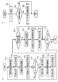
図2を参照して、カメラ100の構成を説明する。図2は、カメラ100のブロック図である。図2において、図1と同一の構成については、同一の符号を付して説明を省略する。図2のように、カメラ100は、光学系10、通信接点14、シャッタ幕16、撮像素子18、AF(Auto Focus)ユニット22、シャッタユニット24、画像処理部26、顔検出部28、メモリ34、表示パネル40、マイク44、46及び48、VCA(Voltage Controlled Amplifier)50、52及び54、指向性制御モータ56、MTX(Multiplexer)58、音制御部60、音記録部62、シャッタスイッチ64、RECボタン66、操作部68、CPU(Central Processing Unit)70、電源部80並びに筐体90を備える。
The configuration of the
光学系10は、レンズ11、通信接点12、AFモータ(不図示)及び絞り(不図示)を有する。光学系10の通信接点12と筐体90の通信接点14との接続により、光学系10は電源部80からの電源の供給を受け、CPU70と通信を行う。光学系10はCPU70へレンズ情報を送信する。CPU70はレンズ情報に基づいて光学系10のAFモータ及び絞りの制御を行う。
The
シャッタユニット24は、シャッタ幕16を制御して露光を制御する。シャッタユニット24は、測光センサ(不図示)を有し、CPU70にて演算されたシャッタ秒時に合わせてシャッタ幕16の開閉時間を制御する。撮像素子18への露光時間は、シャッタ幕16の開閉時間により決定される。
The
AFユニット22は、複数の焦点検出位置を有し、光学系10のフォーカシングを制御する。AFユニット22は、測距を行う測距センサ(不図示)を有し、光学系10のAFモータを駆動させる。AFユニット22は、対象の動きに応じて光学系10を駆動して対象を追尾する追尾機能も備える。
The
撮像素子18は、シャッタ幕16を通過した光学像を電気信号に変換する。撮像素子18は、例えばCCD(Charge Coupled Device)、CMOS(Complementary Metal Oxide Semiconductor)等である。
The
顔検出部28は、撮像素子18が撮像した画像(以下、撮像画像と記す)の特徴を調べて、撮像画像内における対象110の顔、顔の位置及び顔の範囲を検出する。顔検出部28は、撮像画像における複数の対象の顔を検出する。
The
画像処理部26は、撮像素子18が出力する撮像画像をアナログ信号からデジタル信号へ変換する。画像処理部26は、画像信号に対して所定の画素補間処理や色変換処理を行う。画像処理部26は、画像信号の色情報(赤、緑及び青成分の信号)を輝度情報及び色差情報に変換して、JPEG(Joint Photographic Experts Group)等の所定のフォーマット形式に圧縮する。画像処理部26は、圧縮された所定のフォーマット形式の画像信号を伸張する。
The
マイク44、46及び48は、単一の指向性を有するマイク(ガンマイク)であって、対象が発する音を集音する。マイク44、46及び48は、それぞれカメラ100の右、正面及び左方向の音を集音する。VCA50、52及び54は、印加される電圧に応じて増幅率を変化させてマイク44、46及び48の感度を調節し、マイク44、46及び48が出力する音信号のレベルを調節する。音制御部60は、VCA50、52及び54が出力する音信号のレベルを検出して、VCA50、52及び54に印加される電圧を調整する。音制御部60は、指向性制御モータ56を制御する。指向性制御モータ56は、音制御部60の制御に基づいて、マイク44、46及び48の指向性を調整する。
The
MTX58は、VCA50、52及び54によりレベルが調整された各音信号に所定の重み付けをして足し合わせて、左右成分を有する音信号を生成する。音記録部62は、MTX58が出力する音信号をアナログ信号からデジタル信号へ変換して、MP3(Motion Picture Experts Group Audio Layer 3)等の所定のフォーマット形式の音信号に変換する。CPU70は、音信号と画像信号とを同期させた信号をメモリ34に記録する。
The
メモリ34は、画像処理部26が出力する画像信号及び音記録部62が出力する音信号を記憶する。メモリ34は、マイク44、46及び48の感度や指向性等を調整するパターンファイルを記憶する。パターンファイルの詳細は後述する。表示パネル40は、画像処理部26により伸張された画像信号や操作用のカーソル等を表示する。
The
シャッタスイッチ64は、ユーザが静止画の撮像を行うときにオンするスイッチである。RECボタン66は、ユーザが動画の撮像及び集音を開始するときにオン、終了するときにオフするボタンである。操作部68は、ユーザがカメラ100の操作を行うためのキーやボタン等である。
The
光学系10、シャッタ幕16及び撮像素子18は、画像を撮像する。顔検出部28及びAFユニット22は、撮像画像内における対象の位置、対象の範囲、対象との距離及び対象の顔を検出する。
The
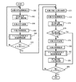
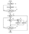
図3(a)を参照して、実施例1に係るマイクの感度を調整して複数の対象が発する音を集音する処理を説明する。図3(a)は、マイクの感度を調整して対象が発する音を集音する処理のフローチャートである。 With reference to Fig.3 (a), the process which adjusts the sensitivity of the microphone which concerns on Example 1 and collects the sound which a several object emits is demonstrated. FIG. 3A is a flowchart of a process of collecting sounds emitted from the target by adjusting the sensitivity of the microphone.
まず、CPU70はシャッタユニット24及びAFユニット22に指示して、撮像画像内における対象の位置情報を検出する(ステップS10)。CPU70は、光学系10の像面内に設定された焦点検出位置の焦点状態が合焦状態となる位置(以下、合焦位置と記す)又は顔検出部28が検出する対象の顔の位置に基づいて、撮像画像内における対象の位置を検出する。ここでは、コントラスト検出AF方式により、CPU70が撮像画像内における合焦位置を検出して、撮像画像内における対象の位置を検出する例を説明する。まず、シャッタユニット24が有する測光センサが、対象の色情報又は輝度情報を検知する。AFユニット22が、光学系10を駆動しながら対象の色情報又は輝度情報を随時取得し、光学系10の焦点状態の情報と対象の色情報又は輝度情報との関係を取得する。CPU70は、取得した関係から、対象の位置(距離)を検出する。なお、AFユニット22は、光学系10を駆動しながら顔検出部28から対象の顔の情報を随時取得し、光学系10の焦点状態の情報と対象の顔との関係を取得するようにして、CPU70は、取得した関係から、対象の顔の位置を検出するようにしてもよい。また、検出した合焦位置を動画の撮像処理に用いてもよい。
First, the
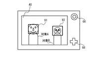
図4は、撮像及び集音の対象を対象A及びBとして、対象A及びBを撮像するときのカメラ100の背面図であって、表示パネル40における対象A及びBの表示の一例である。表示パネル40の表示は、撮像画像と一致する。図4中の枠91及び93は、それぞれCPU70がステップS10により検出した対象A及びBの位置を示しており、それぞれ対象A及びBの顔の位置に対応している。
FIG. 4 is a rear view of the
図3(a)の説明に戻る。CPU70は、ステップS10により検出した撮像画像内における対象の位置情報を、REC前位置情報としてメモリ34に記憶する(ステップS12)。CPU70は、検出した撮像画像内における対象の位置情報に基づいて、カメラ100に対する対象の方向を認識する(ステップS14)。
Returning to the description of FIG. The
ここで、図5を参照して、ステップS14について説明する。図5は、カメラ100と対象A及びBとの平面上の位置関係を示す図であり、カメラ100並びに対象A及びBをX−Y平面上に配置した例である。例えば、図4のように対象A及びBが表示パネル40に表示され、CPU70が対象A及びBの位置を検出する場合、CPU70は図5のようにカメラ100に対する対象A及びBの方向を認識する。図5において、カメラ100はX−Y平面の原点に位置し、カメラ100の左から右に向かう方向がX軸の正の方向及びカメラ100の背面から前面に向かう方向がY軸の正の方向にそれぞれ対応する。破線で示す領域160、162及び164はそれぞれマイク44、46及び48により集音可能な領域を示す。図5のように、CPU70は、対象A及びBの方向はカメラ100に対してそれぞれ左斜め前方及び右斜め前方と認識する。対象A及びBは、それぞれ領域164及び160内に位置している。
Here, step S14 will be described with reference to FIG. FIG. 5 is a diagram illustrating a positional relationship between the
図3(a)の説明に戻る。CPU70は、対象が発する音を集音するマイクを選択して、選択したマイクの感度を調整するサブ処理を行う(ステップS16)。ステップS16に対応するサブ処理の詳細は後述する。
Returning to the description of FIG. The
CPU70は、RECボタンがオンされているか否かを判定する(ステップS18)。CPU70は、RECボタンがオンされている場合にYesと判定する。ステップS18がNoの場合、CPU70はステップS10に戻る。ステップS18がYesの場合、CPU70は動画の撮像を開始して、対象が発する音を集音する(ステップS19)。CPU70は、ステップS10と同様に、撮像画像内における対象の位置情報を検出する(ステップS20)。CPU70は、検出した対象の位置情報を、REC後位置情報としてそれぞれメモリ34に記憶する(ステップS22)。
The
CPU70は、REC前位置情報とREC後位置情報とが一致するか否かを判定する(ステップS24)。すなわち、CPU70は、動画の撮像及び集音の開始後に、対象がそれぞれ移動したか否かを判定する。対象がいずれも移動しない場合、REC前位置情報とREC後位置情報とが一致し、対象の少なくとも一つが移動した場合、REC前位置情報とREC後位置情報とが異なる。CPU70は、REC前位置情報とREC後位置情報とが一致する場合にYesと判定する。CPU70は、ステップS24がYesの場合、ステップS32に進む。ステップS24がNoの場合、対象がREC前位置情報に対応する位置から移動しているため、CPU70は、REC後位置情報に基づいてカメラ100に対する対象の方向を認識し直す(ステップS26)。CPU70は、対象が発する音を集音するためのマイクを選択して、選択したマイクの感度を調整するサブ処理を行う(ステップS28)。ステップS28に対応するサブ処理は、ステップS16と同様であるため、詳細は後述する。
The
CPU70は、REC前位置情報をREC後位置情報に更新する(ステップS30)。CPU70は、RECボタンがオフされているか否かを判定する(ステップS32)。CPU70は、RECボタンがオフされている場合にYesと判定する。ステップS32がYesの場合、CPU70は処理を終了する。ステップS32がNoの場合、CPU70はステップS19に戻って処理を繰り返す。以上が図3(a)の説明である。
The
図3(b)を参照して、図3(a)のステップS16及びステップS28に対応するマイクの選択及び感度調整を行うサブ処理を説明する。図3(b)は、マイクの選択及び感度の調整を行うサブ処理のフローチャートである。 With reference to FIG. 3B, sub-processing for performing microphone selection and sensitivity adjustment corresponding to steps S16 and S28 of FIG. 3A will be described. FIG. 3B is a flowchart of sub-processing for selecting a microphone and adjusting sensitivity.
CPU70は、図3(a)のステップS14又はステップS26で認識したカメラ100に対する対象の方向に基づいて、マイク44、46及び48のいずれかを選択する(ステップS34)。例えば図5のように、対象A及びBが領域164及び160内に位置する場合、CPU70は集音可能な領域が領域164であるマイク48及び集音可能な領域が領域160であるマイク44を選択する。
The
CPU70は、対象の数が複数であるか否かを判定する(ステップS36)。例えば、CPU70は、コントラスト検出AF方式により検出した合焦位置や顔検出部28が検出した顔の数から対象の数を推定して、対象の数が複数であるか否かを判定する。CPU70は、対象の数が複数の場合にYesと判定する。
The
CPU70は、ステップS36がYesの場合、選択したマイクの感度を調整するサブ処理を行って(ステップS38)、処理を終了する。CPU70は、ステップS36がNoの場合、処理を終了する。
If step S36 is Yes, the
図6を参照して、図3(b)のステップS38に対応するマイクの感度の調整を行うサブ処理を説明する。図6は、マイクの感度の調整を行うサブ処理のフローチャートである。以下、検出した音信号のレベルを平均化する周期(単位はフレームとする)を格納するための変数をXとする。変数Xは、ユーザが任意の値を設定できるようにしてもよいし、出荷時にあらかじめ設定されてもよい。 With reference to FIG. 6, the sub-process for adjusting the sensitivity of the microphone corresponding to step S38 in FIG. 3B will be described. FIG. 6 is a flowchart of sub processing for adjusting the sensitivity of the microphone. Hereinafter, let X be a variable for storing a period (unit: frame) for averaging the levels of the detected sound signal. The variable X may be set to an arbitrary value by the user, or may be set in advance at the time of shipment.
CPU70は、メモリ34に記憶された変数Xを確認し、値が設定されているか否かを判定する(ステップS40)。CPU70は、変数Xに値が設定されている場合にYesと判定する。
The
CPU70は、ステップS40がYesの場合、選択した各マイクで対象が発する音を集音して、Xフレームの区間に1フレーム周期で検出した音信号のレベルの平均値を算出する(ステップS42)。マイクごとに算出した音信号のレベルの平均値を、メモリ34にそれぞれ記憶する。例えば、変数Xが900の場合、Xフレームの区間とは30秒間である。30秒間のフレームごとに音信号を検出して総和を求め、その総和をXで除算することにより、30秒あたりの音信号のレベルの平均値を算出する。なお、音信号のレベルの平均値を算出する方法は、他の方法でもよい。例えば、音信号のレベルをXフレームの区間に任意のフレーム周期で検出するようにして、音信号のレベルの平均値を算出してもよい。以下、各マイクについて記憶した音信号のレベルの平均値の一つを値Yとする。
When step S40 is Yes, the
CPU70は、ステップS40がNoの場合、選択した各マイクで対象が発する音を集音して、先頭フレームにおける音信号のレベルを検出する。マイクごとに検出した音信号のレベルを、メモリ34にそれぞれ記憶する。例えば、1秒が30フレームである場合、2〜30フレームに対応する音信号のレベルは検出せず、先頭フレームに対応する音信号のレベルのみを検出する。なお、先頭フレーム以外のフレームの音信号のレベルを検出してもよい。以下、各マイクについて記憶した音信号のレベルの一つを、ステップS42の場合と同様に値Yとする。
When Step S40 is No, the
CPU70は、メモリ34に記憶された値Yが所定のレベルと等しいか否かを判定し(ステップS46)、値Yが所定のレベルと等しい場合にYesと判定する。ここでは、一例として、所定のレベルをマイクに予め設定されている最大入力レベル(130dBとする)の60%に相当する78dBとしている。CPU70は、ステップS46がYesの場合、ステップS54に進む。CPU70は、ステップS46がNoの場合に、値Yが78dBより大きいか否かを判定し(ステップS48)、値Yが78dBより大きい場合にYesと判定する。CPU70は、ステップS48がYesの場合に、対応するVCAの制御により、マイクの感度を下げる(ステップS50)。CPU70は、ステップS48がNoの場合に、マイクの感度を上げる(ステップS52)。CPU70は、選択したマイクの調整が全て終了したか否かを判定して(ステップS54)、全て終了した場合Yesと判定する。ステップS54がNoの場合、ステップS46に戻って、感度の調整が終了していない各マイクに対応する値Yについて、選択した各マイクの感度の調整を行う。ステップS54がYesの場合、処理を終了する。以上により、選択した各マイクの感度を調整して、各マイクが出力する音信号のレベルを互いに同一とすることができる。
The
実施例1によれば、図3(b)のステップS36のYesのように、対象の数が複数の場合に、図6のステップS50又はS52のように、音制御部60並びにVCA50、52及び54がマイク44、46及び48の感度を調整する。これにより、対象が複数の場合に、複数の対象が発する音を適正に集音して、明瞭な音を取得することができる。図6のステップS46、48、50及び52では、マイクが出力する音信号のレベルが所定のレベルと同一となるように、複数のマイクの少なくとも一つの感度を調整する例を説明した。他に例えば、複数のマイクが出力する音信号のレベルが所定の範囲内となるように、複数のマイクの少なくとも一つの感度を調整してもよい。また、選択した複数のマイクの音信号のいずれかのレベルを所定のレベルとして、ステップS46、48、50及び52の処理と同様の処理をしてもよい。
According to the first embodiment, when there are a plurality of objects as in step S36 of FIG. 3B, the
実施例1によれば、図3(b)のステップS36の説明のように、顔検出部28が、撮像画像内における顔の数を検出して、顔の数から対象の数を推定して、対象の数を検出する。これにより、対象が複数の人である場合に、複数の人を認識して、複数の人が発する声を適正に集音することができる。例えば、複数の人が撮像装置の手前と奥とに配置されて会話を行う場合に、マイクの感度を調整して、会話の音信号のレベルを同一又は所定の範囲内とすることができる。よって、会話を聞き取りやすく的確に集音することができる。また、実施例1によれば、図3(b)のステップS36の説明のように、焦点状態が合焦状態である焦点検出位置の数に基づいて、対象の数を検出する。これにより、任意の対象について、複数の対象を認識して、複数の対象が発する音を適正に集音することができる。合焦位置を検出する例としてコントラスト検出AF方式を挙げたが、他に例えば位相差検出AF方式を用いてもよい。顔の検出と合焦位置の検出とを組み合わせて対象の数を検出するようにしてもよい。
According to the first embodiment, as described in step S36 in FIG. 3B, the
実施例1によれば、図3(a)、図3(b)及び図6に示す処理により、複数の対象が動く場合においても、マイクが出力する音信号のレベルが所定のレベルと同一となるように、複数のマイクの少なくとも一つの感度を調整して、複数の対象が発する音を適正に集音することができる。 According to the first embodiment, the level of the sound signal output from the microphone is the same as the predetermined level even when a plurality of objects move by the processes shown in FIGS. 3A, 3B, and 6. As described above, it is possible to appropriately collect sounds generated by a plurality of objects by adjusting at least one sensitivity of the plurality of microphones.
実施例1において、図2を参照して、カメラ100の構成を説明した。図2に示す画像処理部26、顔検出部28、音制御部60、音記録部62の機能をCPU70で実行されるソフトウェアにより構成してもよい。
In the first embodiment, the configuration of the
図7を参照して、実施例2に係るマイクの指向性及び感度を調整して複数の対象が発する音を集音する処理を説明する。図7は、マイクの指向性及び感度を調整して複数の対象が発する音を集音する処理のフローチャートである。 With reference to FIG. 7, a process of collecting sounds emitted by a plurality of objects by adjusting the directivity and sensitivity of the microphone according to the second embodiment will be described. FIG. 7 is a flowchart of a process of collecting sounds emitted from a plurality of objects by adjusting the directivity and sensitivity of the microphone.
ステップS60、S62及びS64は、それぞれ図3(a)のステップS10、S12及びS14と同様の処理であるため、説明を省略する。CPU70は、撮像画像内における対象の範囲を認識する(ステップS66)。
Steps S60, S62, and S64 are the same processes as steps S10, S12, and S14 of FIG. The
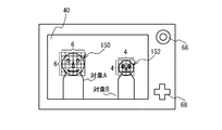
ここで、図8を参照して、ステップS66について説明する。対象の範囲を認識する一例として、対象の顔の範囲を認識する場合を説明する。図8は、撮像画像における対象の顔の範囲の一例を示す図であって、図4に示す対象A及びBの表示に顔検出部28が検出したそれぞれの顔150及び152の範囲を示す矩形を付加した図である。CPU70は、図8のように対象Aの顔150が縦横の画素数が6である矩形内に含まれる場合に、顔150の範囲を6と認識する。同様に、CPU70は、対象Bの顔152の範囲を4と認識する。このように、図8では一辺の画素数が同じ矩形の範囲に顔の範囲が含まれる場合に、一辺の画素数を顔の範囲と定義している。なお、顔の範囲の定義は他の方法でもよい。例えば、縦横の画素数が異なる矩形の範囲に顔の範囲が含まれる場合に、矩形内の総画素数を顔の範囲と定義してもよい。また、矩形の代わりに例えば円形として、円形の半径若しくは直径又は円形内の画素数を顔の範囲と定義してもよい。
Here, step S66 will be described with reference to FIG. As an example of recognizing the target range, a case of recognizing the target face range will be described. FIG. 8 is a diagram illustrating an example of the range of the target face in the captured image, and a rectangle indicating the range of each of the
図7の説明に戻る。CPU70は、対象が発する音を集音するマイクを選択して、選択したマイクの指向性及び感度を調整するサブ処理を行う(ステップS68)。ステップS68に対応するサブ処理の詳細は後述する。
Returning to the description of FIG. The
CPU70は、RECボタンがオンされているか否かを判定する(ステップS70)。CPU70は、RECボタンがオンされている場合にYesと判定する。ステップS70がNoの場合、CPU70はステップS60に戻る。ステップS70がYesの場合、CPU70はステップS71、S72、S74、S76及びS78の処理を行う。ステップS71、S72、S74、S76及びS78は、それぞれ図3(a)のステップS19、S20、S22、S24及びS26と同様の処理であるため、説明を省略する。
The
CPU70は、ステップS78に続いて、対象がREC前位置情報に対応する位置から移動しているため、CPU70は、ステップS66と同様に、対象の範囲を認識し直す(ステップS80)。CPU70は、認識し直した対象の方向及び範囲に基づいて、対象が発する音を集音するマイクを選択して、選択したマイクの指向性及び感度を調整するサブ処理を行う(ステップS82)。ステップS82に対応するサブ処理の詳細はステップS68と同様のため後述する。
Since the target has moved from the position corresponding to the pre-REC position information subsequent to step S78, the
CPU70は、REC前位置情報をREC後位置情報に更新する(ステップS84)。CPU70は、RECボタンがオフされているか否かを判定する(ステップS86)。CPU70は、RECボタンがオフされている場合にYesと判定する。ステップS86がYesの場合、CPU70は処理を終了する。ステップS86がNoの場合、CPU70はステップS71に戻って処理を繰り返す。以上が図7の説明である。
The
図9を参照して、ステップS68及びS82に対応するマイクの指向性及び感度を調整するサブ処理を説明する。図9は、マイクの指向性及び感度を調整するサブ処理のフローチャートである。 With reference to FIG. 9, the sub-process for adjusting the directivity and sensitivity of the microphone corresponding to steps S68 and S82 will be described. FIG. 9 is a flowchart of sub-processing for adjusting the directivity and sensitivity of the microphone.
CPU70は、図7のステップS64又はステップS78で認識したカメラ100に対する対象の方向に基づいて、マイクを選択する(ステップS88)。CPU70は、図7のステップS66又はステップS80で認識した対象の範囲に基づいて、選択したマイクの指向性を調整する(ステップS90)。
CPU70 selects a microphone based on the direction of the object with respect to the
ステップS90について、図10を参照して説明する。図10は、対象の範囲とマイクの指向性との関係を示す図である。図10は、図5と同様に、カメラ100並びに対象A及びBをX−Y平面上に配置した例を示しており、破線で示す領域160、162及び164はそれぞれマイク44、46及び48により集音可能な領域を示す。角度θ1及びθ2で表される範囲は、マイク48の指向性を模式的に示しており、指向性制御モータにより調整することができる。同様に、角度θ3及びθ4で表される範囲は、マイク44の指向性を模式的に示している。角度θ2で表される範囲は対象Aの範囲に比べて広いため、マイク48は対象Aが発する音以外に、角度θ2で表される範囲内の対象Aの周辺の音も集音してしまう。したがって、マイク48は対象Aが発する音を的確に集音することができない。一方、角度θ1で表される範囲は対象Aの範囲とほぼ一致している。よって、マイク46の指向性の範囲を角度θ1で表される範囲に調整することにより、対象Aが発する音を的確に集音することができる。同様に、角度θ3で表される範囲は対象Bの範囲とほぼ一致しているため、マイク44の指向性の範囲を角度θ3で表される範囲に調整することにより、対象Bが発する音を的確に集音することができる。
Step S90 will be described with reference to FIG. FIG. 10 is a diagram illustrating the relationship between the target range and the microphone directivity. FIG. 10 shows an example in which the
図9の説明に戻る。CPU70は、図3(a)のステップS36と同様に、対象の数が複数であるか否かを判定する(ステップS94)。CPU70は、対象の数が複数の場合にYesと判定する。CPU70は、ステップS71がNoの場合に処理を終了する。CPU70は、ステップS94がYesの場合に、検出した対象の範囲が所定の基準値と等しいか否かを判定する(ステップS96)。所定の基準値はユーザが設定してもよいし、あらかじめ設定されてもよい。CPU70は、検出した対象の範囲と所定の基準値とが等しい場合Yesと判定する。CPU70は、ステップS96がNoの場合、検出した対象の範囲が所定の基準値より大きいか否かを判定する(ステップS98)。CPU70は、検出した対象の範囲が所定の基準値より大きい場合Yesと判定する。CPU70は、ステップS98がYesの場合、対応するVCAの制御により、ステップS88で選択したマイクの感度を下げる(ステップS100)。CPU70は、ステップS74がNoの場合、対応するVCAの制御により、ステップS68で選択したマイクの感度を上げる(ステップS102)。
Returning to the description of FIG. The
ここで、図8を参照して、ステップS96、S98、S100及びS102について説明する。例えばユーザが、対象の範囲が5である対象が発する音を適正なレベルで記録したいと考え、所定の基準値を5と設定したとする。対象Aの範囲は所定の基準値より大きい6であるため、カメラ100は対象Aとの距離が近いと推定する。この場合、マイク48の感度を下げることにより、対象Aが発する音をより小さいレベルで集音することができる。一方、対象Bの範囲は所定の基準値より小さい4であるため、カメラ100は対象Bとの距離が大きいと推定する。この場合、マイク48の感度を上げることにより、対象Bが発する音をより大きいレベルで集音することができる。このように、集音される音信号のレベルと対象の範囲が所定の基準値である対象が発する音信号のレベルとを互いに同一とすることができる。
Here, steps S96, S98, S100, and S102 will be described with reference to FIG. For example, it is assumed that the user wants to record a sound emitted by a target whose target range is 5 at an appropriate level and sets a predetermined reference value as 5. Since the range of the target A is 6, which is larger than the predetermined reference value, the
図9の説明に戻る。CPU70は、ステップS88で選択した全てのマイクの感度の調整が終了したか否かを判定する(ステップS104)。CPU70は、ステップS88で選択した全てのマイクの感度の調整が終了した場合Yesと判定する。CPU70は、ステップS104がNoの場合、ステップS96に戻る。CPU70は、ステップS104がYesの場合、処理を終了する。
Returning to the description of FIG. The
実施例2によれば、図9のステップS90及び図10のように、対象の顔の範囲とマイクの指向性の範囲とが一致するように、音制御部60及び指向性制御モータ56がマイク44、46及び48の少なくとも一つの指向性を調整する。これにより、対象の周辺の音が集音されることを抑制することができるため、対象が発する音を的確に集音することができる。
According to the second embodiment, as shown in step S90 of FIG. 9 and FIG. 10, the
実施例2において、図9のステップS94のYesのように対象の数が複数の場合に、図9のステップS96、S98、S100及びS102のように、対象の顔の範囲に基づいて、マイクの少なくとも一つの感度を調整する例を説明した。すなわち、対象の顔の範囲が所定の範囲より大きい場合にマイクの少なくとも一つの感度を下げて、対象の顔の範囲が所定の範囲より小さい場合にマイクの少なくとも一つの感度を上げる。これにより、撮像装置が認識する複数の対象の顔の範囲が互いに異なる場合であっても、対応するマイクの感度を調整して、集音される音信号のレベルを同一とすることができる。他に例えば、対応するマイクの感度を調整して、集音される音信号のレベルが所定の範囲内となるようにしてもよい。図9のフローチャートでは、対象の範囲の値と所定の基準値とを比較して、感度を調整する例を説明した。他に例えば、対象の範囲が最も大きい対象以外の対象の音を集音可能なマイクの感度を上げて、マイクが出力する各音信号のレベルが同一又は所定の範囲内となるように調整してもよい。逆に、対象の範囲が最も小さい対象以外の対象の音を集音可能なマイクの感度を上げて、マイクが出力する各音信号のレベルが同一又は所定の範囲内となるように調整してもよい。 In the second embodiment, when there are a plurality of objects as shown in Yes in step S94 in FIG. 9, the microphones are selected based on the range of the target face as in steps S96, S98, S100, and S102 in FIG. An example of adjusting at least one sensitivity has been described. That is, when the target face range is larger than the predetermined range, at least one sensitivity of the microphone is decreased, and when the target face range is smaller than the predetermined range, at least one sensitivity of the microphone is increased. As a result, even when the ranges of the plurality of target faces recognized by the imaging device are different from each other, the levels of the sound signals to be collected can be made the same by adjusting the sensitivity of the corresponding microphones. In addition, for example, the sensitivity of the corresponding microphone may be adjusted so that the level of the collected sound signal falls within a predetermined range. In the flowchart of FIG. 9, the example in which the sensitivity is adjusted by comparing the value of the target range with a predetermined reference value has been described. In addition, for example, increase the sensitivity of the microphone that can collect the sound of the target other than the target with the largest target range, and adjust the level of each sound signal output by the microphone to be the same or within a predetermined range. May be. Conversely, increase the sensitivity of the microphone that can collect the sound of the target other than the target with the smallest target range, and adjust the level of each sound signal output by the microphone to be the same or within the predetermined range. Also good.
撮像装置が認識する対象の顔の範囲の大小は、撮像装置と対象との距離に反比例する。すなわち、撮像装置が認識する対象の顔の範囲が大きければ、撮像装置と対象との距離は近く、撮像装置が認識する対象の顔の範囲が小さければ、撮像装置と対象との距離は遠い。したがって、対象の顔の範囲の代わりに、対象との距離に基づいて、マイクの少なくとも一つの感度を調整するようにしてもよい。例えば、対象との距離が所定の距離より大きい場合にマイクの少なくとも一つの感度を下げて、対象との距離が所定の距離より小さい場合にマイクの少なくとも一つの感度を上げる。対象との距離は、AFユニットにより検出された合焦位置から推定してもよい。 The size of the target face range recognized by the imaging device is inversely proportional to the distance between the imaging device and the target. That is, the distance between the imaging device and the target is close if the target face range recognized by the imaging device is large, and the distance between the imaging device and the target is long if the target face range recognized by the imaging device is small. Therefore, at least one sensitivity of the microphone may be adjusted based on the distance to the target instead of the target face range. For example, at least one sensitivity of the microphone is decreased when the distance to the target is larger than a predetermined distance, and at least one sensitivity of the microphone is increased when the distance to the target is smaller than the predetermined distance. The distance to the target may be estimated from the focus position detected by the AF unit.
図11(a)を参照して、実施例3に係るパターンファイルを生成する処理を説明する。図10はパターンファイルを生成する処理のフローチャートである。パターンファイルとは、記憶した対象の位置情報に基づいて、マイクの感度を調整するための制御情報のパターンを記したデータである。パターンファイルのデータの形式は、特にファイルでなくともよい。マイクの感度を調整するための制御情報とは、CPU70が音制御部60へ送信するコマンド、VCAに印加する電圧値等である。
With reference to FIG. 11A, a process for generating a pattern file according to the third embodiment will be described. FIG. 10 is a flowchart of processing for generating a pattern file. The pattern file is data describing a pattern of control information for adjusting the sensitivity of the microphone based on the stored position information of the object. The format of the pattern file data need not be a file. The control information for adjusting the sensitivity of the microphone is a command transmitted from the
CPU70は、RECボタンがオンであるか否かを確認する(ステップS110)。CPU70は、RECボタンがオンの場合にYesと判定する。ステップS110がNoの場合、処理を終了する。ステップS110がYesの場合、CPU70は、図3(a)のステップS10及びS20並びに図7のステップS60及びS72と同様に、対象の位置情報を検出する(ステップS112)。CPU70は、メモリ34に対象の位置情報を記憶する(ステップS114)。CPU70は、RECボタンがオフであるか否かを確認する(ステップS116)。CPU70は、RECボタンがオフの場合、Yesと判定する。ステップS116がNoの場合、CPU70は、ステップS112に戻り、RECボタンがオフになるまで、対象の位置情報の検出及び記憶を繰り返し行う。CPU70は、ステップS116がYesの場合、記憶した対象の位置情報に基づいて、パターンファイルを生成して(ステップS110)、処理を終了する。
The
図11(b)を参照して、実施例3に係るパターンに基づいて対象が発する音を集音する処理を説明する。図11(b)は、パターンに基づいて対象が発する音を集音する処理のフローチャートである。 With reference to FIG.11 (b), the process which collects the sound which an object emits based on the pattern which concerns on Example 3 is demonstrated. FIG. 11B is a flowchart of the process of collecting the sound emitted by the target based on the pattern.
CPU70は、パターンファイルを再生するか否かを判定する(ステップS120)。CPU70は、ユーザによるパターンファイルの再生の開始の指示がある場合にYesと判定する。ユーザによるパターンファイルの再生の開始の指示は、例えば表示パネル40に表示される操作画面を操作部68の操作により行う。ステップS120がYesの場合、CPU70は表示パネル40にパターンを表示する(ステップS122)。ここで、表示されるパターンは、例えば図4のように、対象の位置に重ねられた枠91及び93である。CPU70は、パターンに基づいてマイクの感度を調節しながら対象が発する音の集音を行う(ステップS124)。CPU70は、パターンファイルの再生を終了するか否かを判定する(ステップS126)。CPU70は、ユーザによるパターンファイルの再生の終了の指示がある場合にYesと判定する。CPU70は、ステップS126がNoの場合に、ステップS122に戻り、パターンの表示及びパターンによる集音を継続する。CPU70は、ステップS126がYesの場合に処理を終了する。
The
実施例3によれば、図11(a)のステップS114のように、メモリ34がマイク44、46及び48の感度を調整するパターンを記憶し、図11(b)のステップS124のように、音制御部60及びVCA50、52及び54がパターンに基づいてマイク44、46及び48の感度を調整する。これにより、対象が所定の動作を行いながら音を発するシーンや複数の対象の位置関係が同じ場合のシーンの集音を繰り返し行う場合に、対象の位置検出を繰り返し行うことなく、効率よく行うことができる。
According to the third embodiment, the
実施例1から3において、撮像装置の一例として、カメラを例に説明した。撮像装置は、他にビデオカメラやカメラ付き携帯電話等でもよい。
In
以上、本発明の実施例について詳述したが、本発明は係る特定の実施例に限定されるものではなく、特許請求の範囲に記載された本発明の要旨の範囲内において、種々の変形・変更が可能である。 Although the embodiments of the present invention have been described in detail above, the present invention is not limited to such specific embodiments, and various modifications and changes can be made within the scope of the gist of the present invention described in the claims. It can be changed.
10 光学系
18 撮像素子
22 AFユニット
24 シャッタユニット
26 画像処理部
28 顔検出部
34 メモリ
40 表示パネル
44、46、48 マイク
50、52、54 VCA
56 指向性制御モータ
60 音制御部
62 音記録部
66 RECボタン
70 CPU
100 撮像装置
DESCRIPTION OF
56
100 Imaging device
Claims (8)
前記画像内における対象の数を検出する検出手段と、
前記対象が発する音を集音する複数の集音手段と、
前記対象の数が複数の場合に、前記複数の集音手段の感度を調整する感度調整手段と、
を有することを特徴とする撮像装置。 An imaging means for capturing an image;
Detecting means for detecting the number of objects in the image;
A plurality of sound collecting means for collecting sounds emitted by the object;
A sensitivity adjusting means for adjusting the sensitivity of the plurality of sound collecting means when the number of objects is plural;
An imaging device comprising:
前記対象の範囲に基づいて、前記複数の集音手段の少なくとも一つの指向性を調整する指向性調整手段を有することを特徴とする請求項1記載の撮像装置。 The detecting means detects a range of the object in the image;
The imaging apparatus according to claim 1, further comprising directivity adjusting means for adjusting at least one directivity of the plurality of sound collecting means based on the target range.
前記感度調整手段は、前記対象の範囲に基づいて、前記対象に対応する前記複数の集音手段の少なくとも一つの感度を調整することを特徴とする請求項1から3のいずれか一項記載の撮像装置。 The detecting means detects a range of the object in the image;
The said sensitivity adjustment means adjusts at least one sensitivity of the said several sound collection means corresponding to the said object based on the range of the said object, The Claim 1 characterized by the above-mentioned. Imaging device.
前記感度調整手段は、前記対象との距離に基づいて、前記対象に対応する前記複数の集音手段の少なくとも一つの感度を調整することを特徴とする請求項1から3のいずれか一項記載の撮像装置。 The detecting means detects a distance to the object;
The said sensitivity adjustment means adjusts at least 1 sensitivity of the said several sound collection means corresponding to the said object based on the distance with the said object, The any one of Claim 1 to 3 characterized by the above-mentioned. Imaging device.
前記感度調整手段は、前記記憶手段が記憶するパターンに基づいて前記複数の集音手段の感度を調整することを特徴とする請求項1から7のいずれか一項記載の撮像装置。
Storing means for storing a pattern for adjusting sensitivity of the plurality of sound collecting means;
The imaging apparatus according to claim 1, wherein the sensitivity adjusting unit adjusts the sensitivity of the plurality of sound collecting units based on a pattern stored in the storage unit.
Priority Applications (1)
| Application Number | Priority Date | Filing Date | Title |
|---|---|---|---|
| JP2009271468A JP2011114769A (en) | 2009-11-30 | 2009-11-30 | Imaging device |
Applications Claiming Priority (1)
| Application Number | Priority Date | Filing Date | Title |
|---|---|---|---|
| JP2009271468A JP2011114769A (en) | 2009-11-30 | 2009-11-30 | Imaging device |
Publications (2)
| Publication Number | Publication Date |
|---|---|
| JP2011114769A true JP2011114769A (en) | 2011-06-09 |
| JP2011114769A5 JP2011114769A5 (en) | 2013-05-23 |
Family
ID=44236749
Family Applications (1)
| Application Number | Title | Priority Date | Filing Date |
|---|---|---|---|
| JP2009271468A Pending JP2011114769A (en) | 2009-11-30 | 2009-11-30 | Imaging device |
Country Status (1)
| Country | Link |
|---|---|
| JP (1) | JP2011114769A (en) |
Cited By (2)
| Publication number | Priority date | Publication date | Assignee | Title |
|---|---|---|---|---|
| EP2527277A1 (en) | 2011-05-23 | 2012-11-28 | Kyocera Document Solutions Inc. | Sheet size setting device, sheet feeder and image forming apparatus |
| JP2015198413A (en) * | 2014-04-03 | 2015-11-09 | 日本電信電話株式会社 | Sound collection system and sound emitting system |
Citations (13)
| Publication number | Priority date | Publication date | Assignee | Title |
|---|---|---|---|---|
| JPH05111090A (en) * | 1991-10-14 | 1993-04-30 | Nippon Telegr & Teleph Corp <Ntt> | Sound receiving device |
| JPH1051889A (en) * | 1996-08-05 | 1998-02-20 | Toshiba Corp | Device and method for gathering sound |
| JPH10162118A (en) * | 1996-11-29 | 1998-06-19 | Canon Inc | Device and method for image processing |
| JP2000165983A (en) * | 1998-11-25 | 2000-06-16 | Robert Bosch Gmbh | Method for controlling sensitivity of microphone |
| JP2000209689A (en) * | 1999-01-12 | 2000-07-28 | Canon Inc | Sound processor, its control method and recording medium |
| JP2003259479A (en) * | 2002-03-04 | 2003-09-12 | Matsushita Electric Ind Co Ltd | Microphone device |
| JP2005236644A (en) * | 2004-02-19 | 2005-09-02 | Canon Inc | Recording/reproducing device and method |
| JP2006039254A (en) * | 2004-07-28 | 2006-02-09 | Sanyo Electric Co Ltd | Camera |
| JP2006340151A (en) * | 2005-06-03 | 2006-12-14 | Matsushita Electric Ind Co Ltd | Acoustic echo canceling device, telephone using it, and acoustic echo canceling method |
| JP2008288785A (en) * | 2007-05-16 | 2008-11-27 | Yamaha Corp | Video conference apparatus |
| JP2009027246A (en) * | 2007-07-17 | 2009-02-05 | Yamaha Corp | Television conference apparatus |
| JP2009156888A (en) * | 2007-12-25 | 2009-07-16 | Sanyo Electric Co Ltd | Speech corrector and imaging apparatus equipped with the same, and sound correcting method |
| JP2009157242A (en) * | 2007-12-27 | 2009-07-16 | Fujifilm Corp | Imaging apparatus |
-
2009
- 2009-11-30 JP JP2009271468A patent/JP2011114769A/en active Pending
Patent Citations (13)
| Publication number | Priority date | Publication date | Assignee | Title |
|---|---|---|---|---|
| JPH05111090A (en) * | 1991-10-14 | 1993-04-30 | Nippon Telegr & Teleph Corp <Ntt> | Sound receiving device |
| JPH1051889A (en) * | 1996-08-05 | 1998-02-20 | Toshiba Corp | Device and method for gathering sound |
| JPH10162118A (en) * | 1996-11-29 | 1998-06-19 | Canon Inc | Device and method for image processing |
| JP2000165983A (en) * | 1998-11-25 | 2000-06-16 | Robert Bosch Gmbh | Method for controlling sensitivity of microphone |
| JP2000209689A (en) * | 1999-01-12 | 2000-07-28 | Canon Inc | Sound processor, its control method and recording medium |
| JP2003259479A (en) * | 2002-03-04 | 2003-09-12 | Matsushita Electric Ind Co Ltd | Microphone device |
| JP2005236644A (en) * | 2004-02-19 | 2005-09-02 | Canon Inc | Recording/reproducing device and method |
| JP2006039254A (en) * | 2004-07-28 | 2006-02-09 | Sanyo Electric Co Ltd | Camera |
| JP2006340151A (en) * | 2005-06-03 | 2006-12-14 | Matsushita Electric Ind Co Ltd | Acoustic echo canceling device, telephone using it, and acoustic echo canceling method |
| JP2008288785A (en) * | 2007-05-16 | 2008-11-27 | Yamaha Corp | Video conference apparatus |
| JP2009027246A (en) * | 2007-07-17 | 2009-02-05 | Yamaha Corp | Television conference apparatus |
| JP2009156888A (en) * | 2007-12-25 | 2009-07-16 | Sanyo Electric Co Ltd | Speech corrector and imaging apparatus equipped with the same, and sound correcting method |
| JP2009157242A (en) * | 2007-12-27 | 2009-07-16 | Fujifilm Corp | Imaging apparatus |
Cited By (2)
| Publication number | Priority date | Publication date | Assignee | Title |
|---|---|---|---|---|
| EP2527277A1 (en) | 2011-05-23 | 2012-11-28 | Kyocera Document Solutions Inc. | Sheet size setting device, sheet feeder and image forming apparatus |
| JP2015198413A (en) * | 2014-04-03 | 2015-11-09 | 日本電信電話株式会社 | Sound collection system and sound emitting system |
Similar Documents
| Publication | Publication Date | Title |
|---|---|---|
| JP4042710B2 (en) | Autofocus device and program thereof | |
| US8724981B2 (en) | Imaging apparatus, focus position detecting method, and computer program product | |
| TWI514847B (en) | Image processing device, image processing method, and recording medium | |
| US8228419B2 (en) | Method of controlling digital photographing apparatus for out-focusing operation and digital photographing apparatus adopting the method | |
| KR20040045638A (en) | Method to control operation of digital camera for user to easily take an identification photograph | |
| JP4637045B2 (en) | Imaging device | |
| JP2007232793A (en) | Imaging apparatus | |
| JP2009065577A (en) | Imaging apparatus and method | |
| JP2014531829A (en) | Remotely controllable digital video camera system | |
| KR20120115127A (en) | Image processing device capable of generating wide-range image | |
| US8654204B2 (en) | Digtal photographing apparatus and method of controlling the same | |
| JP4957825B2 (en) | Imaging apparatus and program | |
| JP2011175281A (en) | Imaging apparatus and program therefor | |
| US20130293768A1 (en) | Imaging apparatus, imaging method, imaging program and computer readable information recording medium | |
| US8712231B2 (en) | Camera body, and camera system | |
| JP5100410B2 (en) | Imaging apparatus and control method thereof | |
| JP2006319903A (en) | Mobile apparatus provided with information display screen | |
| JP4591120B2 (en) | Imaging apparatus, autofocus control method, and autofocus control program | |
| JP2010068071A (en) | Imaging device and method, image processor and method, and image processing program | |
| JP2011114769A (en) | Imaging device | |
| US10104291B2 (en) | Imaging device | |
| US9064487B2 (en) | Imaging device superimposing wideband noise on output sound signal | |
| JPWO2019181024A1 (en) | Imaging device, imaging method, and program | |
| US20110032390A1 (en) | Digital photographing apparatus and moving picture capturing method performed by the same | |
| JP2011188055A (en) | Imaging device |
Legal Events
| Date | Code | Title | Description |
|---|---|---|---|
| A621 | Written request for application examination |
Free format text: JAPANESE INTERMEDIATE CODE: A621 Effective date: 20121102 |
|
| A521 | Request for written amendment filed |
Free format text: JAPANESE INTERMEDIATE CODE: A523 Effective date: 20130412 |
|
| A977 | Report on retrieval |
Free format text: JAPANESE INTERMEDIATE CODE: A971007 Effective date: 20131024 |
|
| A131 | Notification of reasons for refusal |
Free format text: JAPANESE INTERMEDIATE CODE: A131 Effective date: 20131105 |
|
| A521 | Request for written amendment filed |
Free format text: JAPANESE INTERMEDIATE CODE: A523 Effective date: 20131227 |
|
| A131 | Notification of reasons for refusal |
Free format text: JAPANESE INTERMEDIATE CODE: A131 Effective date: 20140902 |
|
| A02 | Decision of refusal |
Free format text: JAPANESE INTERMEDIATE CODE: A02 Effective date: 20150106 |