JP2021525676A - How to control the vehicle's braking system and related systems - Google Patents
How to control the vehicle's braking system and related systems Download PDFInfo
- Publication number
- JP2021525676A JP2021525676A JP2020567017A JP2020567017A JP2021525676A JP 2021525676 A JP2021525676 A JP 2021525676A JP 2020567017 A JP2020567017 A JP 2020567017A JP 2020567017 A JP2020567017 A JP 2020567017A JP 2021525676 A JP2021525676 A JP 2021525676A
- Authority
- JP
- Japan
- Prior art keywords
- vehicle
- information
- processing block
- data processing
- brake
- Prior art date
- Legal status (The legal status is an assumption and is not a legal conclusion. Google has not performed a legal analysis and makes no representation as to the accuracy of the status listed.)
- Pending
Links
- 238000012545 processing Methods 0.000 claims abstract description 144
- 238000001514 detection method Methods 0.000 claims abstract description 57
- 238000000034 method Methods 0.000 claims abstract description 54
- 238000004891 communication Methods 0.000 claims description 14
- 230000004913 activation Effects 0.000 claims description 8
- 230000008569 process Effects 0.000 claims description 3
- 230000007613 environmental effect Effects 0.000 claims 1
- 238000010586 diagram Methods 0.000 abstract 1
- 230000006870 function Effects 0.000 description 8
- 230000009471 action Effects 0.000 description 6
- 230000001629 suppression Effects 0.000 description 4
- XLYOFNOQVPJJNP-UHFFFAOYSA-N water Substances O XLYOFNOQVPJJNP-UHFFFAOYSA-N 0.000 description 3
- 230000003044 adaptive effect Effects 0.000 description 2
- 230000008859 change Effects 0.000 description 2
- JEIPFZHSYJVQDO-UHFFFAOYSA-N iron(III) oxide Inorganic materials O=[Fe]O[Fe]=O JEIPFZHSYJVQDO-UHFFFAOYSA-N 0.000 description 2
- 230000009467 reduction Effects 0.000 description 2
- 230000004044 response Effects 0.000 description 2
- 201000006681 severe congenital neutropenia Diseases 0.000 description 2
- WNEODWDFDXWOLU-QHCPKHFHSA-N 3-[3-(hydroxymethyl)-4-[1-methyl-5-[[5-[(2s)-2-methyl-4-(oxetan-3-yl)piperazin-1-yl]pyridin-2-yl]amino]-6-oxopyridin-3-yl]pyridin-2-yl]-7,7-dimethyl-1,2,6,8-tetrahydrocyclopenta[3,4]pyrrolo[3,5-b]pyrazin-4-one Chemical compound C([C@@H](N(CC1)C=2C=NC(NC=3C(N(C)C=C(C=3)C=3C(=C(N4C(C5=CC=6CC(C)(C)CC=6N5CC4)=O)N=CC=3)CO)=O)=CC=2)C)N1C1COC1 WNEODWDFDXWOLU-QHCPKHFHSA-N 0.000 description 1
- 238000012935 Averaging Methods 0.000 description 1
- 230000006978 adaptation Effects 0.000 description 1
- 230000008901 benefit Effects 0.000 description 1
- 238000004140 cleaning Methods 0.000 description 1
- 230000001419 dependent effect Effects 0.000 description 1
- 230000008034 disappearance Effects 0.000 description 1
- 230000000694 effects Effects 0.000 description 1
- 239000012717 electrostatic precipitator Substances 0.000 description 1
- 239000012530 fluid Substances 0.000 description 1
- 230000006872 improvement Effects 0.000 description 1
- 230000007246 mechanism Effects 0.000 description 1
- 230000004048 modification Effects 0.000 description 1
- 238000012986 modification Methods 0.000 description 1
- 230000005855 radiation Effects 0.000 description 1
- 239000000725 suspension Substances 0.000 description 1
- 125000000858 thiocyanato group Chemical group *SC#N 0.000 description 1
Images


Classifications
-
- B—PERFORMING OPERATIONS; TRANSPORTING
- B60—VEHICLES IN GENERAL
- B60T—VEHICLE BRAKE CONTROL SYSTEMS OR PARTS THEREOF; BRAKE CONTROL SYSTEMS OR PARTS THEREOF, IN GENERAL; ARRANGEMENT OF BRAKING ELEMENTS ON VEHICLES IN GENERAL; PORTABLE DEVICES FOR PREVENTING UNWANTED MOVEMENT OF VEHICLES; VEHICLE MODIFICATIONS TO FACILITATE COOLING OF BRAKES
- B60T8/00—Arrangements for adjusting wheel-braking force to meet varying vehicular or ground-surface conditions, e.g. limiting or varying distribution of braking force
- B60T8/17—Using electrical or electronic regulation means to control braking
- B60T8/171—Detecting parameters used in the regulation; Measuring values used in the regulation
-
- B—PERFORMING OPERATIONS; TRANSPORTING
- B60—VEHICLES IN GENERAL
- B60T—VEHICLE BRAKE CONTROL SYSTEMS OR PARTS THEREOF; BRAKE CONTROL SYSTEMS OR PARTS THEREOF, IN GENERAL; ARRANGEMENT OF BRAKING ELEMENTS ON VEHICLES IN GENERAL; PORTABLE DEVICES FOR PREVENTING UNWANTED MOVEMENT OF VEHICLES; VEHICLE MODIFICATIONS TO FACILITATE COOLING OF BRAKES
- B60T13/00—Transmitting braking action from initiating means to ultimate brake actuator with power assistance or drive; Brake systems incorporating such transmitting means, e.g. air-pressure brake systems
- B60T13/74—Transmitting braking action from initiating means to ultimate brake actuator with power assistance or drive; Brake systems incorporating such transmitting means, e.g. air-pressure brake systems with electrical assistance or drive
-
- B—PERFORMING OPERATIONS; TRANSPORTING
- B60—VEHICLES IN GENERAL
- B60T—VEHICLE BRAKE CONTROL SYSTEMS OR PARTS THEREOF; BRAKE CONTROL SYSTEMS OR PARTS THEREOF, IN GENERAL; ARRANGEMENT OF BRAKING ELEMENTS ON VEHICLES IN GENERAL; PORTABLE DEVICES FOR PREVENTING UNWANTED MOVEMENT OF VEHICLES; VEHICLE MODIFICATIONS TO FACILITATE COOLING OF BRAKES
- B60T7/00—Brake-action initiating means
- B60T7/12—Brake-action initiating means for automatic initiation; for initiation not subject to will of driver or passenger
-
- B—PERFORMING OPERATIONS; TRANSPORTING
- B60—VEHICLES IN GENERAL
- B60T—VEHICLE BRAKE CONTROL SYSTEMS OR PARTS THEREOF; BRAKE CONTROL SYSTEMS OR PARTS THEREOF, IN GENERAL; ARRANGEMENT OF BRAKING ELEMENTS ON VEHICLES IN GENERAL; PORTABLE DEVICES FOR PREVENTING UNWANTED MOVEMENT OF VEHICLES; VEHICLE MODIFICATIONS TO FACILITATE COOLING OF BRAKES
- B60T8/00—Arrangements for adjusting wheel-braking force to meet varying vehicular or ground-surface conditions, e.g. limiting or varying distribution of braking force
- B60T8/17—Using electrical or electronic regulation means to control braking
- B60T8/172—Determining control parameters used in the regulation, e.g. by calculations involving measured or detected parameters
-
- B—PERFORMING OPERATIONS; TRANSPORTING
- B60—VEHICLES IN GENERAL
- B60T—VEHICLE BRAKE CONTROL SYSTEMS OR PARTS THEREOF; BRAKE CONTROL SYSTEMS OR PARTS THEREOF, IN GENERAL; ARRANGEMENT OF BRAKING ELEMENTS ON VEHICLES IN GENERAL; PORTABLE DEVICES FOR PREVENTING UNWANTED MOVEMENT OF VEHICLES; VEHICLE MODIFICATIONS TO FACILITATE COOLING OF BRAKES
- B60T8/00—Arrangements for adjusting wheel-braking force to meet varying vehicular or ground-surface conditions, e.g. limiting or varying distribution of braking force
- B60T8/32—Arrangements for adjusting wheel-braking force to meet varying vehicular or ground-surface conditions, e.g. limiting or varying distribution of braking force responsive to a speed condition, e.g. acceleration or deceleration
- B60T8/88—Arrangements for adjusting wheel-braking force to meet varying vehicular or ground-surface conditions, e.g. limiting or varying distribution of braking force responsive to a speed condition, e.g. acceleration or deceleration with failure responsive means, i.e. means for detecting and indicating faulty operation of the speed responsive control means
- B60T8/885—Arrangements for adjusting wheel-braking force to meet varying vehicular or ground-surface conditions, e.g. limiting or varying distribution of braking force responsive to a speed condition, e.g. acceleration or deceleration with failure responsive means, i.e. means for detecting and indicating faulty operation of the speed responsive control means using electrical circuitry
-
- B—PERFORMING OPERATIONS; TRANSPORTING
- B60—VEHICLES IN GENERAL
- B60T—VEHICLE BRAKE CONTROL SYSTEMS OR PARTS THEREOF; BRAKE CONTROL SYSTEMS OR PARTS THEREOF, IN GENERAL; ARRANGEMENT OF BRAKING ELEMENTS ON VEHICLES IN GENERAL; PORTABLE DEVICES FOR PREVENTING UNWANTED MOVEMENT OF VEHICLES; VEHICLE MODIFICATIONS TO FACILITATE COOLING OF BRAKES
- B60T8/00—Arrangements for adjusting wheel-braking force to meet varying vehicular or ground-surface conditions, e.g. limiting or varying distribution of braking force
- B60T8/32—Arrangements for adjusting wheel-braking force to meet varying vehicular or ground-surface conditions, e.g. limiting or varying distribution of braking force responsive to a speed condition, e.g. acceleration or deceleration
- B60T8/88—Arrangements for adjusting wheel-braking force to meet varying vehicular or ground-surface conditions, e.g. limiting or varying distribution of braking force responsive to a speed condition, e.g. acceleration or deceleration with failure responsive means, i.e. means for detecting and indicating faulty operation of the speed responsive control means
- B60T8/92—Arrangements for adjusting wheel-braking force to meet varying vehicular or ground-surface conditions, e.g. limiting or varying distribution of braking force responsive to a speed condition, e.g. acceleration or deceleration with failure responsive means, i.e. means for detecting and indicating faulty operation of the speed responsive control means automatically taking corrective action
- B60T8/96—Arrangements for adjusting wheel-braking force to meet varying vehicular or ground-surface conditions, e.g. limiting or varying distribution of braking force responsive to a speed condition, e.g. acceleration or deceleration with failure responsive means, i.e. means for detecting and indicating faulty operation of the speed responsive control means automatically taking corrective action on speed responsive control means
-
- B—PERFORMING OPERATIONS; TRANSPORTING
- B60—VEHICLES IN GENERAL
- B60T—VEHICLE BRAKE CONTROL SYSTEMS OR PARTS THEREOF; BRAKE CONTROL SYSTEMS OR PARTS THEREOF, IN GENERAL; ARRANGEMENT OF BRAKING ELEMENTS ON VEHICLES IN GENERAL; PORTABLE DEVICES FOR PREVENTING UNWANTED MOVEMENT OF VEHICLES; VEHICLE MODIFICATIONS TO FACILITATE COOLING OF BRAKES
- B60T2201/00—Particular use of vehicle brake systems; Special systems using also the brakes; Special software modules within the brake system controller
- B60T2201/03—Brake assistants
-
- B—PERFORMING OPERATIONS; TRANSPORTING
- B60—VEHICLES IN GENERAL
- B60T—VEHICLE BRAKE CONTROL SYSTEMS OR PARTS THEREOF; BRAKE CONTROL SYSTEMS OR PARTS THEREOF, IN GENERAL; ARRANGEMENT OF BRAKING ELEMENTS ON VEHICLES IN GENERAL; PORTABLE DEVICES FOR PREVENTING UNWANTED MOVEMENT OF VEHICLES; VEHICLE MODIFICATIONS TO FACILITATE COOLING OF BRAKES
- B60T2201/00—Particular use of vehicle brake systems; Special systems using also the brakes; Special software modules within the brake system controller
- B60T2201/10—Automatic or semi-automatic parking aid systems
-
- B—PERFORMING OPERATIONS; TRANSPORTING
- B60—VEHICLES IN GENERAL
- B60T—VEHICLE BRAKE CONTROL SYSTEMS OR PARTS THEREOF; BRAKE CONTROL SYSTEMS OR PARTS THEREOF, IN GENERAL; ARRANGEMENT OF BRAKING ELEMENTS ON VEHICLES IN GENERAL; PORTABLE DEVICES FOR PREVENTING UNWANTED MOVEMENT OF VEHICLES; VEHICLE MODIFICATIONS TO FACILITATE COOLING OF BRAKES
- B60T2210/00—Detection or estimation of road or environment conditions; Detection or estimation of road shapes
- B60T2210/10—Detection or estimation of road conditions
-
- B—PERFORMING OPERATIONS; TRANSPORTING
- B60—VEHICLES IN GENERAL
- B60T—VEHICLE BRAKE CONTROL SYSTEMS OR PARTS THEREOF; BRAKE CONTROL SYSTEMS OR PARTS THEREOF, IN GENERAL; ARRANGEMENT OF BRAKING ELEMENTS ON VEHICLES IN GENERAL; PORTABLE DEVICES FOR PREVENTING UNWANTED MOVEMENT OF VEHICLES; VEHICLE MODIFICATIONS TO FACILITATE COOLING OF BRAKES
- B60T2210/00—Detection or estimation of road or environment conditions; Detection or estimation of road shapes
- B60T2210/30—Environment conditions or position therewithin
- B60T2210/36—Global Positioning System [GPS]
-
- B—PERFORMING OPERATIONS; TRANSPORTING
- B60—VEHICLES IN GENERAL
- B60T—VEHICLE BRAKE CONTROL SYSTEMS OR PARTS THEREOF; BRAKE CONTROL SYSTEMS OR PARTS THEREOF, IN GENERAL; ARRANGEMENT OF BRAKING ELEMENTS ON VEHICLES IN GENERAL; PORTABLE DEVICES FOR PREVENTING UNWANTED MOVEMENT OF VEHICLES; VEHICLE MODIFICATIONS TO FACILITATE COOLING OF BRAKES
- B60T2220/00—Monitoring, detecting driver behaviour; Signalling thereof; Counteracting thereof
- B60T2220/04—Pedal travel sensor, stroke sensor; Sensing brake request
-
- B—PERFORMING OPERATIONS; TRANSPORTING
- B60—VEHICLES IN GENERAL
- B60T—VEHICLE BRAKE CONTROL SYSTEMS OR PARTS THEREOF; BRAKE CONTROL SYSTEMS OR PARTS THEREOF, IN GENERAL; ARRANGEMENT OF BRAKING ELEMENTS ON VEHICLES IN GENERAL; PORTABLE DEVICES FOR PREVENTING UNWANTED MOVEMENT OF VEHICLES; VEHICLE MODIFICATIONS TO FACILITATE COOLING OF BRAKES
- B60T2220/00—Monitoring, detecting driver behaviour; Signalling thereof; Counteracting thereof
- B60T2220/06—Adjustment of accelerator pedal reaction forces
-
- B—PERFORMING OPERATIONS; TRANSPORTING
- B60—VEHICLES IN GENERAL
- B60T—VEHICLE BRAKE CONTROL SYSTEMS OR PARTS THEREOF; BRAKE CONTROL SYSTEMS OR PARTS THEREOF, IN GENERAL; ARRANGEMENT OF BRAKING ELEMENTS ON VEHICLES IN GENERAL; PORTABLE DEVICES FOR PREVENTING UNWANTED MOVEMENT OF VEHICLES; VEHICLE MODIFICATIONS TO FACILITATE COOLING OF BRAKES
- B60T2240/00—Monitoring, detecting wheel/tire behaviour; counteracting thereof
-
- B—PERFORMING OPERATIONS; TRANSPORTING
- B60—VEHICLES IN GENERAL
- B60T—VEHICLE BRAKE CONTROL SYSTEMS OR PARTS THEREOF; BRAKE CONTROL SYSTEMS OR PARTS THEREOF, IN GENERAL; ARRANGEMENT OF BRAKING ELEMENTS ON VEHICLES IN GENERAL; PORTABLE DEVICES FOR PREVENTING UNWANTED MOVEMENT OF VEHICLES; VEHICLE MODIFICATIONS TO FACILITATE COOLING OF BRAKES
- B60T2250/00—Monitoring, detecting, estimating vehicle conditions
-
- B—PERFORMING OPERATIONS; TRANSPORTING
- B60—VEHICLES IN GENERAL
- B60T—VEHICLE BRAKE CONTROL SYSTEMS OR PARTS THEREOF; BRAKE CONTROL SYSTEMS OR PARTS THEREOF, IN GENERAL; ARRANGEMENT OF BRAKING ELEMENTS ON VEHICLES IN GENERAL; PORTABLE DEVICES FOR PREVENTING UNWANTED MOVEMENT OF VEHICLES; VEHICLE MODIFICATIONS TO FACILITATE COOLING OF BRAKES
- B60T2270/00—Further aspects of brake control systems not otherwise provided for
- B60T2270/88—Pressure measurement in brake systems
Landscapes
- Engineering & Computer Science (AREA)
- Transportation (AREA)
- Mechanical Engineering (AREA)
- Regulating Braking Force (AREA)
- Braking Arrangements (AREA)
Abstract
【課題】【解決手段】 車両のブレーキシステムに分散された第1の複数の検出装置によって、前記車両の動作状態を示す第1の情報を検出する工程(501)と、前記車両に関連付けられた第1の運転支援サブシステムに属する複数の第2の検出装置によって、前記車両の動作状態を示す第2の情報を検出する工程(502)と、第1のデータ処理ブロックによって、前記第1の情報及び前記第2の情報に基づいて、前記車両のブレーキモジュールの第1の制御信号を決定する工程(503)と、前記第1のデータ処理ブロックによって、前記決定された第1の制御信号に基づいて前記車両の前記ブレーキモジュールを制御する工程(504)と、を含む車両のブレーキシステムシステムを制御する方法(500)。【選択図】図5A step (501) of detecting first information indicating an operating state of the vehicle by a first plurality of detection devices distributed in a vehicle braking system is associated with the vehicle. The first step (502) of detecting the second information indicating the operating state of the vehicle by the plurality of second detection devices belonging to the first driving support subsystem, and the first data processing block. Based on the information and the second information, the step (503) of determining the first control signal of the brake module of the vehicle and the first data processing block make the determined first control signal. Based on the step of controlling the brake module of the vehicle (504), and a method of controlling the vehicle brake system system including (500). [Selection diagram] Fig. 5
Description
本発明は、車両のブレーキシステム、特に車両のブレーキシステム及び関連システムを制御する方法に関する。 The present invention relates to a vehicle braking system, in particular a method of controlling a vehicle braking system and related systems.
通常旅客を輸送するための自動車及び2以上の車輪を有する路上車両は、車両の車輪をロックし(動かなくし)、それ故車両が駐車されたときその動きを止める機能を有するハンドブレーキを装備している。 Automobiles for transporting passengers and road vehicles with two or more wheels are usually equipped with a handbrake that has the ability to lock (stuck) the wheels of the vehicle and therefore stop its movement when the vehicle is parked. ing.
最新のブレーキシステム、例えば電動ブレーキ・バイ・ワイヤ(BBW)ブレーキシステムにおいて、ハンドブレーキは電動パーキングブレーキ(EPB)に置換される。 In modern braking systems, such as electric brake-by-wire (BBW) braking systems, handbrake is replaced by electric parking brake (EPB).
EPB電動パーキングブレーキは、あらゆる効果に至るまで、サービスブレーキに使用される電動ブレーキ・バイ・ワイヤBBWのサブシステムである。 The EPB electric parking brake is a subsystem of the electric brake-by-wire BBW used for service brakes to all effects.
さらなる詳細において、EPBサブシステムを使用することで、ドライバーは、一度押されると、ブレーキパッドを電気的に作動させ、ブレーキディスクをロックして車両の動きをロックする、車両の電子制御ユニットに、ブレーキパーキング起動要求を送るボタンによって、車輪ロック機構を作動させることができる。 In further detail, by using the EPB subsystem, the driver, once pressed, electrically activates the brake pads, locks the brake discs and locks the movement of the vehicle, to the electronic control unit of the vehicle. The wheel lock mechanism can be activated by a button that sends a brake parking activation request.
さらに、慣例上、ハンドブレーキによって動かされるパーキングブレーキ機能を置換するために、EPBサブシステムは、いわゆる「オートホールド」機能のような自動サポート機能、つまり、例えば、登り道で車両が止まっている時に自動的にかつドライバーの要求なしで車輪をロックし、ドライバーが車両のアクセルペダルを踏むと直ぐに車輪を解除するための機能をドライバーに提供するように構成される。 In addition, by convention, to replace the parking brake function driven by the handbrake, the EPB subsystem has an automatic support function, such as the so-called "auto hold" function, i.e., for example, when the vehicle is stopped on an uphill road. It is configured to lock the wheels automatically and without the driver's request and provide the driver with the ability to release the wheels as soon as the driver depresses the accelerator pedal of the vehicle.
それゆえ、EPBサブシステムは、車両が移動中に静止または停止しているとき、車両を使用するドライバーに、パーキングブレーキの機能だけでなく、より安全で、容易で、補助的な機能を提供し得る。 Therefore, the EPB subsystem provides the driver using the vehicle with safer, easier and ancillary functions as well as the function of the parking brake when the vehicle is stationary or stationary while moving. obtain.
それゆえ、この点において、正確に作動し、特に車両が移動中、作動しない又はドライバーによって作動させられないことがEPBサブシステムには不可欠である。 Therefore, in this respect it is essential for the EPB subsystem to operate correctly, especially when the vehicle is in motion, not actuated or not actuated by the driver.
一般的に、車両が静止状態か運動状態かを決定するため、すなわち車両が動いていると作動しないEPBサブシステムを制御するため、車両制御ユニットは、各車輪と関連付けられるエンコーダタイプの各速度センサによって提供される車両の全車輪の回転速度を表す情報を処理する。 In general, a vehicle control unit is an encoder-type speed sensor associated with each wheel to determine whether the vehicle is stationary or in motion, i.e. to control an EPB subsystem that does not operate when the vehicle is in motion. Processes information that represents the rotational speed of all wheels of the vehicle provided by.
しかしながら、そのような速度センサは、BBWサブシステムに必然的に統合されることに加えて、特に故障しやすい傾向がある。 However, such speed sensors are particularly prone to failure, in addition to being necessarily integrated into the BBW subsystem.
それ故、速度センサの作動が止まると、車両の動作状態に関する、タイムリーかつ信頼性のある情報を得ることができず、それ故、EPBサブシステムの信頼性があり、かつタイムリーな制御を得ることができない。 Therefore, when the speed sensor stops operating, it is not possible to obtain timely and reliable information about the operating state of the vehicle, and therefore, reliable and timely control of the EPB subsystem. I can't get it.
本発明の課題は、先行技術に関する上述された欠点を少なくとも部分的に回避することができ、かつ可能な限り正確で、タイムリーで、安全な制御を特に保証する、車両のブレーキシステムを制御する方法を発明し、提供することである。 The object of the present invention is to control a vehicle braking system, which can at least partially avoid the above-mentioned drawbacks of the prior art and specifically guarantees as accurate, timely and safe control as possible. To invent and provide a method.
このような目的は、請求項1に係る方法によって達成される。 Such an object is achieved by the method according to claim 1.
本発明はまた、車両のブレーキシステムの電子制御システムに関する。 The present invention also relates to an electronic control system for a vehicle braking system.
いくつかの有利な実施形態は従属項の主題である。 Some advantageous embodiments are the subject of dependent terms.
本発明に係る方法及びシステムのさらなる特徴及び利点は、添付図面を参照して、例示的で非限定的な例として与えられた、以下の好ましい形態の詳細な説明から明らかになる。
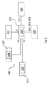
まず、図1〜4を参照すると、符号100は、以下、電子システム又は単にシステムともいう、本発明に係る車両のブレーキシステムの電子制御システム全体を示す。
First, referring to FIGS. 1 to 4,
図面における同一または類似の構成要素は、同一の符号数字又は符号英数字によって示されることに留意されたい。 Note that the same or similar components in the drawings are indicated by the same sign number or sign alphanumeric.
本詳細な説明の目的のために、車両は、商用であり、2、3、4若しくはそれ以上の車輪を有する、任意の車両またはオートバイである。 For the purposes of this detailed description, the vehicle is commercial and is any vehicle or motorcycle with 2, 3, 4 or more wheels.
さらに、ブレーキシステムは、図面に示されていないが、サービスブレーキまたはパーキングブレーキのいずれであっても、車両のブレーキの発生に寄与する、一組のすべての構成要素(機械的および/または電気的または電子的要素やブレーキ液)を意味します。 In addition, the braking system, which is not shown in the drawing, is a set of all components (mechanical and / or electrical) that contribute to the generation of vehicle braking, whether it is a service brake or a parking brake. Or electronic element or brake fluid).
通常、図1〜4を参照すると、一実施形態におけるシステム100は、車両の動作状態を表す第1の情報I1を検出するように構成された車両のブレーキシステム上に分散された第1の複数の検出装置101を備える。
Generally, referring to FIGS. 1 to 4, the
第1の複数の検出装置101は、車両車輪の1以上の回転速度センサ(例えば、各車両車輪に接続されたエンコーダ)、ブレーキペダルに直接接続された、車両のブレーキペダルの位置センサ、若しくは車両のアクセルペダルに直接接続された、車両のアクセルペダルの位置を検出するセンサと、ブレーキペダル及び/又はアクセルペダルに接続された、又はブレーキキャリパ又は、ブレーキシステム若しくは他の構成要素のブレーキキャリパの各アクチュエータに接続された力センサまたは圧力センサと、を備えている。
The first plurality of
言い換えると、一実施形態において、前記第1の複数の検出装置101の各デバイスは、車両車輪の回転速度センサ、車両のブレーキペダルの位置センサ、車両のアクセルペダルの位置センサ、ブレーキペダル及び/又はアクセルペダルに接続された、若しくはブレーキキャリパ又はブレーキシステム若しくはブレーキシステムの他の構成要素のブレーキキャリパの各アクチュエータに接続された力又は圧力センサを含むグループに属する。
In other words, in one embodiment, each device of the first plurality of
この点において、車両の動作状態を表す第1の情報I1は、車両のブレーキシステムにおいて分散される第1の複数の検出装置101の各検出装置によって検出される情報又は該情報の組み合わせを意味する。
In this respect, the first information I1 representing the operating state of the vehicle means the information detected by each of the detection devices of the first plurality of
各情報I1は、検出装置のタイプに依拠することを繰り返すことに価値がある。 It is worth repeating that each piece of information I1 relies on the type of detector.
例によると、検出装置が車両車輪の速度センサである場合、第1の情報I1は、車両車輪の回転速度(車輪回転)から推定された車両速度である。このような推定は、例えば車両の1つの車輪の、他の車輪に対する速度を平均すること、又は車両の全ての車輪の回転速度の中央値を取ること、または他の組み合わせで得ることができる。 According to an example, when the detection device is a vehicle wheel speed sensor, the first information I1 is a vehicle speed estimated from the vehicle wheel rotation speed (wheel rotation). Such an estimate can be obtained, for example, by averaging the speeds of one wheel of the vehicle relative to the other wheels, or by taking the median of the rotational speeds of all the wheels of the vehicle, or in other combinations.
検出装置が車両のブレーキペダル又はアクセルペダルの位置センサの場合、第1の情報I1は車両のブレーキ要求または車両のアクセル要求であり得る。 If the detection device is a vehicle brake or accelerator pedal position sensor, the first information I1 may be a vehicle brake request or a vehicle accelerator request.
より詳細には、車両ブレーキ要求または車両アクセル要求はそれぞれ、車両のブレーキペダルの位置に基づいて又は車両のアクセルペダルの位置と、各特性曲線(例えば、車両のブレーキペダルの位置/ブレーキ要求または車両のアクセルペダルの位置/アクセル要求)とに基づいて決定される。 More specifically, the vehicle brake request or vehicle accelerator request is based on the position of the vehicle brake pedal or the position of the vehicle accelerator pedal and each characteristic curve (eg, vehicle brake pedal position / brake request or vehicle). It is determined based on the position of the accelerator pedal / accelerator request).
上記の例より、動作状態は、車両が移動している(例えば、車両速度がゼロでない、ブレーキ要求がない、アクセル要求がゼロでない)か否(例えば、車両速度がゼロである、ブレーキ要求がゼロでない、アクセル要求)かに関係することは明らかである。例示は一般的な場合を明らかにし、車両の動作状態を示す情報の確実性を向上させるものであって必ずしも常に正しいとは限らないことに留意すべきである。 From the above example, the operating state is whether the vehicle is moving (for example, the vehicle speed is not zero, there is no brake request, the accelerator request is not zero) (for example, the vehicle speed is zero, the brake request is It is clear that it is related to non-zero, accelerator request). It should be noted that the examples clarify the general case and improve the certainty of the information indicating the operating state of the vehicle and are not always correct.
通常、図1〜4を参照すると、一実施形態において、システム100は、車両に関連付けられた第1の運転支援サブシステム102を備えており、第1の運転支援サブシステム102は、以下、単に第1のサブシステム102ともする。
Generally, referring to FIGS. 1 to 4, in one embodiment, the
第1のサブシステム102は、運転中にドライバーに高度なサービスを提供することに寄与する機械的構成要素、電気的構成要素、電子的構成要素の内のいずれか1つ以上のセットである。このような第1サブシステム102の1つのタイプは、頭文字ADASで示される先進運転支援システムによっても知られている。
The
より詳細には、第1のサブシステム102は、車両の動作状態を示す第2の情報I2を検出する第2の複数の検出装置103を備える。
More specifically, the
特に、一実施形態によると、第2の複数の検出装置103は、車両に搭載され、車両の位置に関する情報を提供するように構成された第1のサブシステム102、つまり、ADASタイプのサブシステムに属する任意の装置を備えており、それによって、車両の動作状態、つまり、車両が動いているか否かを推定することができる。
In particular, according to one embodiment, the second plurality of
前述のタイプのこのような検出装置は、受動的または能動的であってもよい。 Such detectors of the type described above may be passive or active.
受動的な検出装置は、情報を受動的に受け取るためのものである。 The passive detector is for passively receiving information.
ADASタイプの第1のサブシステム102内にある受動的なタイプの検出装置の例は、デジタルカメラ、赤外線デジタルカメラ、例えば、GPS(全地球測位システム)タイプまたはそれに同等の衛星ナビゲーションシステムである。
Examples of passive type detectors within the
能動的検出装置は、放射線を放出し、物によって反射する、照射された信号の応答を測定するように構成される。このタイプの検出装置は、車両を取り巻く環境における照明条件、つまり季節や日中の時間に関わらず有利に測定できる。 The active detector is configured to emit radiation and measure the response of the irradiated signal, which is reflected by an object. This type of detector can advantageously measure lighting conditions in the environment surrounding the vehicle, that is, regardless of the season or daytime.
ADASタイプの第1のサブシステム102内にある能動的なタイプの検出装置の例は、長距離型レーダモジュール、短/中距離型レーダモジュール、LIDAR型リモートセンシングモジュールまたは超音波検出モジュールである。
Examples of active type detectors within the
言い換えると、一実施形態において、前記第2の複数の検出装置103はそれぞれ、デジタルカメラ、赤外線デジタルカメラ、GPS等の衛星ナビゲーションシステム、長距離型レーダモジュール、短/中距離型レーダモジュール、LIDAR型リモートセンシングモジュール、超音波検出モジュールを含むグループに属する。
In other words, in one embodiment, the second plurality of
この点において、車両の動作状態を示す第2の情報I2は、車両と関連付けられた第1の運転支援サブシステム102に属する前記第2の複数の検出装置103の各検出装置によって検出される情報または該情報の組み合わせを意味する。
In this respect, the second information I2 indicating the operating state of the vehicle is information detected by each detection device of the second plurality of
各情報I2は検出装置のタイプに依拠するということを繰り返すことは価値がある。 It is worth repeating that each piece of information I2 depends on the type of detector.
例によると、検出装置がデジタルカメラまたは赤外線デジタルカメラである場合、第2の情報I2は、車両の速度及び/又は「停止」位置を推定できるデジタル画像であってもよい。例えば、これは、各設定された時間間隔で変化がない同一のデジタル画像を検出することによって推定されてもよい。 By way of example, if the detector is a digital camera or an infrared digital camera, the second information I2 may be a digital image capable of estimating the speed and / or "stop" position of the vehicle. For example, this may be estimated by detecting the same digital image that does not change at each set time interval.
検出装置が衛星ナビゲーションシステムである場合、第2の情報I2は、車両速度の推定及び/又は車両の「停止」位置の推定であってもよい。例えば、これは、各設定された時間間隔で変化がない同一位置又は速度がゼロのままであることを検出することによって推定されてもよい。 If the detector is a satellite navigation system, the second information I2 may be an estimate of vehicle speed and / or an estimate of the "stop" position of the vehicle. For example, this may be estimated by detecting that the same position or velocity remains zero at each set time interval.
検出装置がV2Vコミュニケーションモジュールである場合、第2の情報I2は、別の車両の速度に係る車両速度の推定であってもよい。 When the detection device is a V2V communication module, the second information I2 may be an estimation of the vehicle speed with respect to the speed of another vehicle.
検出モジュールが長距離型レーダモジュール、短/中距離型レーダモジュール、LIDAR型リモートセンシングモジュール、若しくは超音波検出モジュールである場合、第2の情報I2は、空間内の複数の地点の補間から始まる車両速度の推定であってもよい。例えば、これは予め決められた各時間間隔で同一の情報を測定することによって推定されてもよい。 If the detection module is a long-range radar module, a short / medium range radar module, a lidar remote sensing module, or an ultrasonic detection module, the second information I2 is a vehicle that begins with interpolation of multiple points in space. It may be an estimation of speed. For example, this may be estimated by measuring the same information at each predetermined time interval.
上記で示された例より、動作状態は、車両が移動している(車両速度がゼロでない)か否(車両速度がゼロ)かに関連していることが明らかである。 From the examples shown above, it is clear that the operating state is related to whether the vehicle is moving (vehicle speed is not zero) or not (vehicle speed is zero).
一実施形態に係る図1〜4を参照すると、システム100は、さらに車両ブレーキモジュール104を備える。
Referring to FIGS. 1 to 4 according to one embodiment, the
ブレーキモジュール104は、車両のブレーキシステムの一部である。
The
ブレーキモジュール104は、車両ブレーキシステムに動作可能に接続された、車両の1以上の動作構成要素(例えば、図示されていないが車両車輪)に、ブレーキ動作を適用するように構成される。
The
より詳細には、ブレーキモジュール104は、以下に記載する第1の制御信号SC1を受信するように構成される。
More specifically, the
以下に記載するように、一実施形態における第1の制御信号SC1は、車両のブレーキモジュール104の作動を抑制する信号を含む。
As described below, the first control signal SC1 in one embodiment includes a signal that suppresses the operation of the
さらなる実施形態において、先の実施形態と組み合わせて、第1の制御信号SC1は、車両のブレーキモジュール104の作動信号を含む。
In a further embodiment, in combination with the previous embodiment, the first control signal SC1 includes an actuation signal of the
図1〜4に戻ると、一実施形態において、ブレーキモジュール104が、例えばEPBタイプの電動パーキングブレーキを備えることは注目に値する。
Returning to FIGS. 1 to 4, it is noteworthy that, in one embodiment, the
先の実施形態の代替又は組み合わせであるさらなる実施形態において、車両ブレーキモジュール104は、例えばBBWタイプの電動サービスブレーキを含む。
In a further embodiment that is an alternative or combination of the previous embodiments, the
再び図1〜4を参照すると、一実施形態において、システム100はさらに、前記第1の複数の検出装置101、前記運転支援サブシステム102及び前記車両ブレーキモジュール104と作動可能なように接続された第1のデータ処理ブロック105、例えば、マイクロプロセッサまたはマイクロコントローラを含む。
Referring again to FIGS. 1-4, in one embodiment, the
「データ処理ブロック」は、電子制御ユニットに搭載された単一のブロックまたは互いに作動可能なように接続され、車両に設けられた2以上の電子制御ユニットに分散された複数のブロックを意味する。 “Data processing block” means a single block mounted on an electronic control unit or a plurality of blocks operably connected to each other and distributed among two or more electronic control units provided in a vehicle.
さらに、システム100はさらに、第1のデータ処理ブロック105に作動可能なように接続され、第1のデータ処理ブロック105によって実行され得る1以上のプログラムコードを蓄積し、前記1以上のプログラムコードを実行するとき第1のデータ処理ブロック105によって処理されるデータを蓄積するように構成された各第1のメモリブロック105’を備える。
Further, the
第1のメモリブロック105’は、図1と図2に示されるように、第1のデータ処理ブロック105内にあってもよいし、又は(図示されていない)代替実施形態において、第1のデータ処理ブロック105外にあってもよい。
The first memory block 105'may be within the first
第1のデータ処理ブロック105によって各プログラムコードを実行することが、システム100に、以下により詳細を記載する本発明の目的である、車両ブレーキシステムを制御する方法を実行可能にすることは注目に値する。
It is noteworthy that executing each program code by the first
この点に関して、一実施形態に係る第1のデータ処理ブロック105は、前記第1の情報I1と前記第2の情報I2に基づいて第1の制御信号SC1を決定するように構成されることは注目に値する。
In this regard, the first
一実施形態において、第1のデータ処理ブロック105は、いわゆるブレーキ制御に相当することは注目に値する。
It is worth noting that in one embodiment, the first
図1と図2とを参照し、一実施形態によると、第1の運転支援サブシステム102、従って第2の複数の検出装置103は、第1のデータ処理ブロック105に直接接続される。
With reference to FIGS. 1 and 2, according to one embodiment, the first
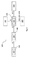
先の実施形態の代替であり、図3と図4とに示されるさらなる実施形態において、システム100はさらに、第2のデータ処理ブロック106、例えば、マイクロプロセッサまたはマイクロコントローラを含む。
In a further embodiment shown in FIGS. 3 and 4, which is an alternative to the previous embodiment, the
第1のサブシステム102は、第1の運転支援サブシステム102、従って、第2の複数の検出装置103に直接接続された第2のデータ処理ブロック106によって、第1のデータ処理ブロック105に接続される。
The
さらに、システム100は、第2のデータ処理ブロック106に作動可能なように接続され、第2のデータ処理ブロック106によって実行され得る1以上のプログラムコードを蓄積し、前記1以上のプログラムコードを実行するとき第2のデータ処理ブロック106によって処理されるデータを蓄積するように構成された各第2のメモリブロック106’を備える。
Further, the
第2のメモリブロック106’は、図3と図4に示されるように、第2のデータ処理ブロック106内にあってもよいし、又は(図示されていない)代替実施形態において、第2のデータ処理ブロック106外にあってもよい。
The second memory block 106'may be within the second
第2のデータ処理ブロック106によって各プログラムコードを実行することが、システム100により、以下により詳細を記載する本発明の目的である、車両ブレーキシステムを制御する方法を実行することに寄与することは注目に値する。
Executing each program code by the second
この実施形態において、本発明の主題である方法の一実施形態に関して以下に記載するように、第2のデータ処理ブロック106は、前記第2の情報I2に基づいて、追加の第2の情報I2’を決定するように構成される。
In this embodiment, as described below with respect to one embodiment of the method that is the subject of the present invention, the second
この実施形態において、第1データ処理ブロック105は、前記第1の情報I1と前記さらなる第2の情報I2’に基づいて、第1の制御信号SC1を決定するように構成される。
In this embodiment, the first
一実施形態において、第2のデータ処理ブロック106は、いわゆる車両制御システム、つまり、いわゆる車両の電子制御ユニット(ECU)に相当することは注目に値する。
It is worth noting that in one embodiment, the second
さらなる実施形態において、図2に示すように、システム100はさらに、第2の車両データ接続サブシステム107を備える。
In a further embodiment, as shown in FIG. 2,
第2の車両データ接続サブシステム107は、車両の動作状態を示す第3の情報I3を検出するように構成された第3の検出装置108を備える。
The second vehicle
より詳細には、一実施形態において、第3の複数の検出装置108は、第2のデータ接続サブシステム107に属し、1以上のデータコミュニケーションネットワークに接続されるように構成され、車両の状態、他の車両の状態、又は車両の近くに位置するインフラストラクチャー(例えば、建物、橋、高速道路、郊外の道路、都市街路若しくは道路インフラストラクチャーの種類などに応じたその他の構造物)の状態に関する情報の送信及び/又は受信する任意の装置を備える。
More specifically, in one embodiment, the third plurality of
前述のタイプのこのような検出装置は、車両のジオロケーション、車両のルートを示す静止または運動情報、車両の瞬間速度を示す情報等のような情報を取得するように構成される衛星ナビゲーションシステム、例えばGPS(全地球測位システム)タイプまたは同等のものであり得、車両の基本状態及び別の車両の近接を示す情報、車両のルートに沿った交通状態を示す情報等の情報を示すV2V(車両間)タイプのコミュニケーションモジュール、天候(例えば、湿度、風、温度)を示す情報、車両のルートの道路に沿った交通制御状態を示す情報等の情報を示すV2I(車両とインフラストラクチャー間)タイプのコミュニケーションモジュールであってもよい。 Such detectors of the type described above are satellite navigation systems configured to acquire information such as vehicle geolocation, stationary or motion information indicating the route of the vehicle, information indicating the instantaneous speed of the vehicle, and the like. For example, it can be a GPS (Global Positioning System) type or equivalent, and V2V (Vehicle) showing information such as the basic state of a vehicle and information indicating the proximity of another vehicle, information indicating the traffic condition along the route of the vehicle, and the like. V2I (between vehicle and infrastructure) type information such as communication module of type (between) type, information indicating weather (for example, humidity, wind, temperature), information indicating traffic control status along the road of the vehicle route, etc. It may be a communication module.
言い換えると、一実施形態において、前記第3の複数の検出装置108はそれぞれ、衛星ナビゲーションシステムGPSまたは同等のもの、V2Vタイプのコミュニケーションモジュール、V2Iタイプのコミュニケーションモジュールを含むグループに属する。
In other words, in one embodiment, the third plurality of
この点において、車両の動作状態を示す第3の情報I3は、第2の車両データ接続サブシステム107に属する、前記第3の複数の検出装置108の各検出装置によって検出される情報または該情報の組み合わせを意味する。
In this respect, the third information I3 indicating the operating state of the vehicle is the information detected by each of the detection devices of the third plurality of
情報I3はそれぞれ、検出装置のタイプに依拠することは繰り返す価値がある。 It is worth repeating that each piece of information I3 relies on the type of detector.
例によって、検出装置が衛星ナビゲーターである場合、第3の情報I3は、車両速度の推定及び/又は車両の「停止」位置の推定であってもよい。 As usual, if the detector is a satellite navigator, the third piece of information I3 may be an estimate of vehicle speed and / or an estimate of the "stop" position of the vehicle.
言い換えると、第2のデータ接続サブシステム107は、車両の速度または車両の位置等のデータを送信してもよい。
In other words, the second
検出装置がV2Vコミュニケーションモジュールである場合、第3の情報I3は、別の車両の速度に係る車両速度の推定であってもよい。 When the detection device is a V2V communication module, the third information I3 may be an estimation of the vehicle speed with respect to the speed of another vehicle.
検出装置がV2Iコミュニケーションモジュールである場合、第3の情報I3は、車両速度を推定できる3G又は4Gタイプのコミュニケーションにおけるアンテナまたは中継器の位置等の追加情報を伴う車両の速度の推定及び/又は車両の「停止」位置の推定であってもよい。 If the detector is a V2I communication module, the third information I3 is the vehicle speed estimation and / or vehicle with additional information such as the position of the antenna or repeater in 3G or 4G type communication that can estimate the vehicle speed. It may be an estimation of the "stop" position of.
言い換えると、V2Iコミュニケーションモジュールは、車両の位置または車両の相対速度を決定することができる情報源(アンテナ又は中継器)の位置を伝達し得る。 In other words, the V2I communication module may transmit the position of a vehicle (antenna or repeater) capable of determining the position of the vehicle or the relative speed of the vehicle.
図2の実施形態に戻ると、第2のデータ接続サブシステム107は、第1のデータ処理ブロック105に直接接続される。
Returning to the second embodiment, the second
本発明の主題である方法の一実施形態を参照して、以下により詳細に記載するように、図2の実施形態に係る第1のデータ処理ブロック105は、前記第1の情報I1、前記第2情報I2及び前記第3情報I3に基づいて制御信号SC1を決定するために構成される。
As described in more detail below with reference to one embodiment of the method that is the subject of the present invention, the first
第2のデータ処理ブロック106が配置される組み合わせ(例えば図3の組み合わせ)において、図4に示す一実施形態を参照すると、システム100は、車両の第2のデータ接続サブシステム107を備える。
In the combination in which the second
第2の車両データ接続サブシステム107は、車両の動作状態を示す第3の情報I3を検出するように構成された第3の複数の検出装置108を備える。
The second vehicle
第2のサブシステム107及び第3の複数の検出装置108は、図2の実施形態を参照して既に先に記載されたそれらと同一であることは注目に値する。
It is worth noting that the
図4の実施形態において、第1のデータ処理ブロック105は、第2のデータ処理ブロック106によって第2のデータ接続サブシステム107に接続される。
In the embodiment of FIG. 4, the first
この実施形態において、本発明の方法の一実施形態を参照して以下に記載されるように、第2のデータ処理ブロック106は、前記第2の情報I2及び前記第3の情報I3に基づいて、車両の動作状態を示す第4の情報I4を決定するように構成される。
In this embodiment, the second
この実施形態において、第1のデータ処理ブロック105は、前記第1の情報I1及び前記第4の情報I4に基づいて第1の制御信号SC1を決定するように構成される。
In this embodiment, the first
図1〜4において破線で示された、前述の実施形態の任意の一実施形態との組み合わせにおけるさらなる実施形態において、第1データ処理ブロック105はさらに、前記第1の情報I1と前記第2の情報I2に基づいて、車両の安全又は危険状態を識別するように構成されている。
In a further embodiment in combination with any one embodiment of the aforementioned embodiment, shown by the dashed lines in FIGS. 1 to 4, the first
本詳細な説明の目的のため、車両の「安全」状態は、車両が障害物となり得るものに対して安全であるという事実、又は緊急時(従って、障害物がない場合、例えばクリーンロードの場合)に迅速かつタイムリーな方法でブレーキペダルを踏む必要がないという事実を示す車両状態の組み合わせを意味する。 For the purposes of this detailed description, the "safe" state of the vehicle is the fact that the vehicle is safe against potential obstacles, or in an emergency (and thus in the absence of obstacles, eg clean roads). ) Means a combination of vehicle conditions that indicates the fact that it is not necessary to step on the brake pedal in a quick and timely manner.
言い換えると、安全状態は、(障害物、歩行者、車両とインフラストラクチャー間の距離による)起こり得るブレーキ又は緊急ブレーキとはかけ離れている。 In other words, safety conditions are far from possible or emergency braking (depending on obstacles, pedestrians, the distance between the vehicle and the infrastructure).
例によると、車両状態の可能な組み合わせは、例えばインフラストラクチャータイプ(高速、郊外の道路、都市の道路)の機能が以下であり得るとき、車両の安全状態を識別するように構成されている。
−車両速度<インフラストラクチャータイプが例えば高速の場合、例えば130km/hの「高速」と定義され得る、設定された最高速度値
−ブレーキペダル位置:解除
−道路上の先行車両からの距離>設定された最小距離の値、例えば50m
By way of example, a possible combination of vehicle conditions is configured to identify the vehicle's safety condition, for example when the function of the infrastructure type (high speed, suburban road, urban road) can be:
-Vehicle speed <Set maximum speed value, which can be defined as "high speed", for example 130 km / h, if the infrastructure type is, for example, high speed.
− Brake pedal position: Release
-Distance from the preceding vehicle on the road> Set minimum distance value, for example 50m
車両の安全状態が第1のデータ処理ブロック105によって識別されない場合、車両の「危険」状態が識別される。
If the vehicle's safety state is not identified by the first
図1における実施形態によると、第1のデータ処理ブロック105は、前記第1の情報I1及び前記第2の情報I2に基づいて、車両の安全または危険状態を識別するように構成されている。
According to the embodiment in FIG. 1, the first
図2における実施形態によると、第1のデータ処理ブロック105は、前記第1の情報I1、前記第2の情報I2及び前記第3の情報I3に基づいて、車両の安全または危険状態を識別するように構成されている。
According to the embodiment in FIG. 2, the first
図3における実施形態によると、第1のデータ処理ブロック105は、前記第1の情報I1及び(順に、前記第2の情報I2に係る第2のデータ処理ブロック106によって決定される)前記さらなる第2の情報I2’に基づいて、車両の安全または危険状態を識別するように構成されている。
According to the embodiment in FIG. 3, the first
図4における実施形態によると、第1のデータ処理ブロック105は、前記第1の情報I1及び(順に、前記第2の情報I2及び前記第3の情報I3に基づいて第2のデータ処理ブロック106によって決定される)前記第4の情報I4に基づいて、車両の安全または危険状態を識別するように構成されている。
According to the embodiment in FIG. 4, the first
前述の特許請求の範囲のいずれかに関して、システム100は、第1のデータ処理ブロック105に作動可能なように接続されたサービスブレーキモジュール109を備えることは注目する価値がある。
For any of the claims mentioned above, it is worth noting that the
サービスブレーキモジュール109は、車両ブレーキシステムの一部である。
The
より詳細には、サービスブレーキモジュール109は、車両ブレーキシステムの複数のアクチュエータ(図示されていない)を備える。
More specifically, the
各アクチュエータ(電気機械式または電気油圧式)は、車両の各動作構成要素(車輪)に搭載された各ブレーキディスクにサービスブレーキ作動を適用するように構成されている。 Each actuator (electromechanical or electrohydraulic) is configured to apply a service brake actuation to each brake disc mounted on each operating component (wheel) of the vehicle.
第1のデータ処理ブロック105は、車両の安全状態が識別されると、第2の制御信号SC2をサービスブレーキモジュール109に与えるように構成されている。
The first
第2の制御信号SC2は、ブレーキシステムによって、車両の各動作構成要素(車輪)に搭載された各ディスクブレーキに生じる残留トルクを減少及び/又は消失させるためのものである。 The second control signal SC2 is for reducing and / or eliminating the residual torque generated in each disc brake mounted on each operating component (wheel) of the vehicle by the braking system.
このような減少または消失は、例えば、ブレーキパッドをブレーキディスクから遠ざけること(溝又は距離を広げること)、(たとえば、ブレーキディスクからパッドを機械的に離すため、および/またはブレーキシステムの油圧を下げるために)単一の電動ブレーキのアクチュエータ(電気機械式または電気油圧式)に適切に作用することによってなされてもよい。 Such reduction or disappearance is, for example, moving the brake pads away from the brake disc (growing or increasing the distance), (eg, mechanically separating the pads from the brake disc, and / or lowering the oil pressure of the brake system. It may be done by acting appropriately on a single electric brake actuator (electromechanical or electrohydraulic).
さらに、第1のデータ処理ブロック105は、パッドと車両の各動作構成要素(車輪)に搭載された各ディスクブレーキディスクとの間の距離を減らすために、車両の危険状態が識別され、それ故車両の安全状態が識別されないとき、第3の制御信号SC3をサービスブレーキモジュール109に提供するように構成されている。
In addition, the first
より詳細には、第3の制御信号SC3は、例えば、(たとえば、ブレーキディスクからパッドを機械的に接近させるために)単一の電動ブレーキのアクチュエータ(電気機械式または電気油圧式)に適切な方法で作用することによって、車両の危険状態においてパッドとディスクブレーキとの間のギャップ(それゆえ距離)を減少させるためのものである。 More specifically, the third control signal SC3 is suitable, for example, for a single electric brake actuator (electromechanical or electrohydraulic) (for mechanically approaching the pad from the brake disc). By acting in a manner, it is intended to reduce the gap (hence the distance) between the pad and the disc brake in the dangerous state of the vehicle.
それによって、車両の危険状態の場合のプロンプトブレーキシステムを得ることができ、それゆえブレーキ時間を減らし、車両を止める。 Thereby, a prompt braking system can be obtained in case of danger of the vehicle, thus reducing the braking time and stopping the vehicle.
先に記載した実施形態の任意の組み合わせのさらなる実施形態において、第1のデータ処理ブロック105は、車両の静止状態が識別される又はされないとき、又は、安全状態が識別される又はされないとき、又は、さらなる車両の状態、環境、道路表面、インフラストラクチャーのうちの1以上が識別されたとき、ブレーキシステムにまたは一般的には車両で追加の操作を実行するために、1以上の制御信号SCNをサービスブレーキモジュール109に提供するように構成されており、例えば、ブレーキディスクを清掃して錆や水を取り除き、作動構成要素(車輪)の負荷分散を改善します。
In a further embodiment of any combination of embodiments described above, the first
より詳細には、一実施形態において、状態は、車両に取付けられ得る各降雨センサ又は1以上のデジタルカメラによって検出可能な環境における水及び/又は湿度の検出であり得る。 More specifically, in one embodiment, the condition can be the detection of water and / or humidity in an environment that can be detected by each rainfall sensor or one or more digital cameras that can be mounted on the vehicle.
この状態の存在の識別に続いて、ブレーキシステムで実行できるさらなる操作は、車両を始動または再始動する前に各ブレーキディスクをクリーンにすることであり得る。 Following the identification of the presence of this condition, a further operation that can be performed on the braking system may be to clean each brake disc before starting or restarting the vehicle.
さらなる実施形態において、状態は、始動前に車両の追加の負荷または複数のサスペンションを検出することであり得、これは、車両に取り付けることができる各移動センサまたは圧力センサによって検出することができる。 In a further embodiment, the condition can be to detect an additional load or suspension of the vehicle prior to starting, which can be detected by each movement sensor or pressure sensor that can be attached to the vehicle.
この状態の存在の識別に続いて、ブレーキシステムで実行することができるさらなる操作は、次のブレーキのための特別なバランスをともなうブレーキシステムの較正であり得る。 Following the identification of the presence of this condition, a further operation that can be performed on the braking system may be the calibration of the braking system with a special balance for the next brake.
さらなる実施形態によると、状態は、
−例えば、インフラストラクチャーによって車両に提供される情報から検出できる不均一な路面またはオフロード路面の表示であり得る道路の状態を検出すること;
−例えば、参照画像またはテクスチャと比較されるデジタル画像を検出するように構成された車両に装備されているデジタルカメラによって検出され得る道路表面の状態を検出すること;
−例えば、車両が取り付けられ得る各車輪状態センサによって検出され得る車両の状態である、車両構成要素の状態を検出すること
であり得る。
According to a further embodiment, the state is
-For example, detecting road conditions that can be a non-uniform or off-road road marking that can be detected from the information provided to the vehicle by the infrastructure;
-For example, to detect road surface conditions that can be detected by a digital camera mounted on a vehicle that is configured to detect a digital image that is compared to a reference image or texture;
-For example, it may be to detect the state of a vehicle component, which is the state of the vehicle that can be detected by each wheel state sensor to which the vehicle can be mounted.
これらの状態のいずれかの存在の識別に続いて、ブレーキシステムで実行され得るさらなる操作は、初期ABS介入閾値の調整(上昇/下降)、減速の要求などであり得る。 Following the identification of the presence of any of these conditions, additional operations that may be performed on the braking system may be adjustment (up / down) of the initial ABS intervention threshold, request for deceleration, and the like.
図1〜4に戻ると、例えばそのような図に示される、ブレーキモジュール104がパーキングブレーキを含む一実施形態では、サービスブレーキモジュール109が異なり、ブレーキモジュール104に加えてられていることは注目に値する。
Returning to FIGS. 1-4, it should be noted that in one embodiment where the
ブレーキモジュール104がサービスブレーキを含む、図には示されていない別の実施形態によれば、サービスブレーキモジュール104は、ブレーキモジュール104を含む。
According to another embodiment not shown in which the
さらなる実施形態によれば、例えば図3〜4に前述および示されているもののいずれか1つと組み合わせて、第2のデータ処理ブロック106が存在する場合、第1のデータ処理ブロック105および第2のデータ処理ブロック106は互いに異なる。
According to a further embodiment, if a second
さらなる実施形態によれば、前述の実施形態の代替として、いくつかの図には示されていないが、第1のデータ処理ブロック105および第2のデータ処理ブロック106は一致する。
According to a further embodiment, as an alternative to the aforementioned embodiment, although not shown in some figures, the first
次に、本発明による車両のブレーキシステムを制御するための方法500を、前述の図および図5のブロックチャートを参照して説明する。
Next, the
方法500は、象徴的な開始工程STを含む。
方法500は、車両のブレーキシステム上に分散された第1の複数の検出装置101によって、車両の動作状態を表す第1の情報I1を検出する工程501を含む。
The
第1の複数の検出装置101及び車両の動作状態を表す第1の情報I1は、すでに定義され、説明されている。
The first plurality of
図5の実施形態によれば、方法500は、車両に関連する第1の運転支援サブシステム102に属する第2の複数の検出装置103によって、車両の動作状態を表す第2の情報I2を検出する工程502をさらに含む。
According to the embodiment of FIG. 5, the
第2の複数の検出装置103および車両の動作状態を表す第2の情報I2は、すでに定義され、説明されている
The second plurality of
図5の実施形態を参照すると、方法500は、第1のデータ処理ブロック105によって、前記第1の情報I1および前記第2の情報I2に基づいて、車両のブレーキモジュール104の第1の制御信号SC1を決定する工程503を含む。
Referring to the embodiment of FIG. 5, the
第1のデータ処理ブロック105およびブレーキモジュール104は、先に定義および説明されている
The first
再び図5を参照すると、方法500は、第1のデータ処理ブロック105によって、決定された第1の制御信号SC1に基づいて、車両のブレーキモジュール104を制御する工程504をさらに含む。
Referring again to FIG. 5, the
図5に示されるように、方法500は、象徴的な終了工程EDを含む。
As shown in FIG. 5,
図5の破線で示される一実施形態では、方法500は、第1の複数の検出装置101によって、前記第2の情報I2を第1のデータ処理ブロック105に直接提供する工程505をさらに含む。
In one embodiment, shown by the dashed line in FIG. 5, the
この実施形態では、決定する工程503は、第1の情報I1および第2の情報I2に直接基づいて、第1のデータ処理ブロック105によって実行される。
In this embodiment, the determining
より詳細には、図5に破線で示される一実施形態では、決定する工程503は、第1のデータ処理ブロック105によって、前記第1の情報I1が第1の停止車両状態を表す場合をチェックする各第1の工程506を含む。
More specifically, in one embodiment shown by the dashed line in FIG. 5, the
一実施形態では、第1の情報I1は、第1の停止車両状態が設定された第1の時間間隔の間維持されるとき、第1の停止車両状態を表すものとしてチェックされる。 In one embodiment, the first information I1 is checked to represent the first stopped vehicle state when the first stopped vehicle state is maintained for the set first time interval.
例によると、前記第1の複数の検出装置101(例えば、車両車輪の回転速度センサ)のうちの1つが、車両車輪の回転速度が実質的にゼロまたはゼロに非常に近いことを示す場合、第1のデータ処理ブロック105は、実質的にゼロまたは0に非常に近い値に等しい車両速度を推定し、(さらなる実施形態では、1秒以上の第1の設定された時間間隔についても)車両速度がこの実質的にゼロの値をとるとした場合、第1のデータ処理ブロック105は、第1の停止車両状態の存在をチェックすることになる。
According to an example, when one of the first plurality of detection devices 101 (for example, a vehicle wheel rotation speed sensor) indicates that the vehicle wheel rotation speed is substantially zero or very close to zero. The first
前述の推定値は、例えば、車両の速度をそれぞれの閾値(例えば、信号の数/時間)と比較することからなり、車両速度がそれぞれの閾値よりも低い場合、車両速度0に等しいと推定されることに留意されたい。 The above estimate consists, for example, comparing the speed of the vehicle with each threshold (eg, number of signals / hour) and is estimated to be equal to zero vehicle speed if the vehicle speed is lower than each threshold. Please note that.
さらに、図5に破線で再び示されるこの実施形態では、決定する工程503は、第1のデータ処理ブロック105によって、前記第2の情報I2が第2の停止車両状態を表す場合をチェックする各第2のチェック工程507を含む。
Further, in this embodiment again shown by the dashed line in FIG. 5, the determining
一実施形態では、第2の情報I2は、第2の停止車両状態が設定された第2の時間間隔の間維持されるとき、第2の停止車両状態を表すものとしてチェックされる。 In one embodiment, the second information I2 is checked as representing a second stopped vehicle state when the second stopped vehicle state is maintained for a set second time interval.
例によると、前記第2の複数の検出装置103(例えば、デジタルカメラ)のうちの1つが、車両が停止したことを示す(例えば、デジタル画像が、それぞれの設定された、例えば、1秒以上の時間間隔の変化なしで検出される)場合、第1のデータ処理ブロック105は、実質的にゼロまたは0に非常に近い値に等しい車両速度を推定し、(さらなる実施形態では、1秒以上の第2の設定時間間隔についても)車両速度がこの実質的にゼロの値をとるとする場合、第2のデータ処理ブロック105は、第2の停止車両状態の存在をチェックすることになる。
According to an example, one of the second plurality of detectors 103 (eg, a digital camera) indicates that the vehicle has stopped (eg, a digital image is set for each, eg, 1 second or longer). If detected without a change in the time interval of), the first
前述の推定は、例えば、車両の速度をそれぞれの閾値(例えば、信号の数/時間)と比較することからなり、車両速度がそれぞれの閾値よりも低い場合、車両速度は0と等しいと推定されることに留意されたい。 The above estimation consists, for example, comparing the speed of the vehicle with each threshold (eg, number of signals / hour), and if the vehicle speed is lower than each threshold, the vehicle speed is estimated to be equal to zero. Please note that.
この場合、第1のデータ処理ブロック105による第1の停止車両状態および第2の停止車両状態の両方のチェックは、第1のデータ処理ブロック105による車両ブレーキモジュール104の第1の制御信号SC1の最終的な決定を意味する。
In this case, the check of both the first stopped vehicle state and the second stopped vehicle state by the first
この場合、第1の処理ブロック105による、車両のブレーキモジュール104をチェックすることに基づく第1の制御信号SC1は、車両にブレーキ動作(車両ブレーキモジュール104の類型によると、電動パーキングブレーキまたはサービスブレーキ)を適用することはできない、車両のブレーキモジュール104の起動に関する抑制信号を含む。
In this case, the first control signal SC1 based on checking the
第1のチェック工程506および第2のチェック工程507が、結果として、少なくとも第1の停止車両状態または第2の停止車両状態のいずれかがチェックされない(車速がゼロでない、またはさらなる実施形態では、車両速度がゼロではなく、そのようなゼロでない値が設定された時間間隔よりも短い時間間隔で検出される)と、第1の制御信号SC1は、ブレーキ動作(車両ブレーキモジュール104のタイプに応じて電動パーキングブレーキまたはサービスブレーキ)を車両に適用することができる車両ブレーキモジュール104の起動信号を含む。
As a result, the
さらなる実施形態によれば、図5に破線で示される先の実施形態の代替として、方法500は、第2の複数の検出装置103によって、前記第2の情報I2を第2のデータ処理ブロック106に直接提供する工程508をさらに含む。
According to a further embodiment, as an alternative to the previous embodiment shown by the dashed line in FIG. 5, the
第2のデータ処理ブロック106は、先に定義され、説明された。
The second
この実施形態では、方法500は、第2のデータ処理ブロック106によって、前記第2の情報I2に基づいて車両の動作状態を示すさらなる第2の情報I2’を決定する工程509をさらに含む。
In this embodiment, the
例えば、第2のデータ処理ブロック106は、第2の情報I2を復号および集約して、それらをより信頼できるもの(例えば、複数のセンサから受信した同じ情報)にすることによって、さらに第2の情報I2’を決定し、次にブレーキコントローラは、独自の情報に加えて、VCSによって提供される情報に従って何をすべきかを決定する。
For example, the second
この実施形態では、方法500は、第2のデータ処理ブロック106によって、前記第2の情報I2’を第1のデータ処理ブロック106に提供する工程510を含む。
In this embodiment,
この実施形態では、車両のブレーキモジュール104の第1の制御信号SC1を決定する工程503は、前記第1の情報I1および前記第2の情報I2’に基づいて、第1のデータ処理ブロック105によって実行される。
In this embodiment, the
より詳細には、図5に破線で示される一実施形態では、決定する工程503は、第1のデータ処理ブロック105によって、前記第1の情報I1が第1の停止車両状態を表す場合をチェックする各第1のチェックする工程511を含む。
More specifically, in one embodiment shown by the dashed line in FIG. 5, the
一実施形態では、第1の情報I1は、第1の停止車両状態が設定された第1の時間間隔の間維持されるとき、第1の停止車両状態を表すものとしてチェックされる。 In one embodiment, the first information I1 is checked to represent the first stopped vehicle state when the first stopped vehicle state is maintained for the set first time interval.
この第1のチェックする工程511の実装例は、前述の第1のチェックする工程506の実装例と完全に類似している。
The mounting example of the
さらに、この実施形態では、図5に破線で再び示され、決定する工程503は、前記さらなる第2の情報I2’が第2の停止車両状態を表すかどうかを、第1のデータ処理ブロック105によってチェックする各第2のチェック工程512を含む。
Further, in this embodiment, the
一実施形態では、第2の停止車両状態が設定された第2の時間間隔の間維持されるとき、第2の停止車両状態を表すものとして、さらなる第2の情報I2’がチェックされる。 In one embodiment, when the second stopped vehicle state is maintained for the set second time interval, additional second information I2'is checked to represent the second stopped vehicle state.
例として、前記第2の複数の検出装置103(例えば、デジタルカメラ)のうちの1つが、車両が停止した(例えば、デジタル画像が、それぞれの設定された時間間隔の間、変化なしで検出された)ことを示すと、第1のデータ処理ブロック105は、第2のデータ処理ブロック106によって提供されるさらなる第2の情報I2’に基づいて、実質的にゼロまたはゼロに非常に近い値に等しい車両速度を推定し、(さらなる実施形態では、1秒以上の第2の設定時間間隔についても)車両速度がこの実質的に0の値をとる場合、第2のデータ処理ブロック106は、第2の停止車両状態の存在をチェックすることになる。
As an example, one of the second plurality of detectors 103 (eg, a digital camera) has the vehicle stopped (eg, a digital image is detected unchanged during each set time interval). Indicating that, the first
前述の推定は、例えば、車両の速度をそれぞれの閾値(例えば、信号の数/時間)と比較することからなり、車両速度がそれぞれの閾値よりも低い場合、車両速度は0に等しいと推定されることは注目に値する。 The above estimation consists, for example, comparing the speed of the vehicle with each threshold (eg, number of signals / hour), and if the vehicle speed is lower than each threshold, the vehicle speed is estimated to be equal to zero. It is worth noting.
この場合、第1の停止車両状態および第2の停止車両状態の両方における第1のデータ処理ブロック105によるチェックは、第1のデータ処理ブロック105による、車両ブレーキモジュール104の第1の制御信号SC1、すなわち、車両にブレーキ作用(車両ブレーキモジュール104のタイプに応じて、電動パーキングブレーキまたはサービスブレーキ)を適用することができない車両ブレーキモジュール104の作動の抑制信号の最終的な決定を意味する。
In this case, the check by the first
第1のチェックする工程511および第2のチェックする工程512は、結果として、少なくとも第1の停止車両状態または第2の停止車両状態のいずれかがチェックされない(車両速度がゼロでない、またはさらなる実施形態では、車両速度がゼロではない場合、そのような値がゼロではないことが、設定された時間間隔よりも短い時間間隔で検出される)場合、第1の制御信号SC1は、ブレーキ動作(車両ブレーキモジュール104のタイプに応じた電動パーキングブレーキまたはサービスブレーキ)を車両に適用することができる車両ブレーキモジュール104の起動信号を含む。
The
破線で図5に示される前述の実施形態のいずれかに代わるさらなる実施形態によれば、方法500は、第2の車両データ接続サブシステム107に属する第3の複数の検出装置108によって、車両の動作状態を表す第3の情報I3を検出する工程513をさらに含む。
According to a further embodiment that replaces any of the aforementioned embodiments shown in FIG. The
第3の複数の検出装置108、第2の車両データ接続サブシステム107、および第3の情報I3は、先に定義され、説明された。
A third plurality of
この実施形態では、車両のブレーキモジュール104の第1の制御信号SC1を決定する工程503は、前記第1の情報I1、前記さらなる第2の情報I2’および前記第3の情報I3に基づいて、第1のデータ処理ブロック105によって実行される。
In this embodiment, the
より詳細には、図5に破線で示される一実施形態では、決定する工程503は、第1のデータ処理ブロック105によって、前記第1の情報I1が第1の停止車両状態を表すことをチェックする各第1のチェック工程514を含む。
More specifically, in one embodiment shown by the dashed line in FIG. 5, the determining
一実施形態では、第1の情報I1は、第1の停止車両状態が設定された第1の時間間隔の間維持されるとき、第1の停止車両状態を表すものとしてチェックされる。 In one embodiment, the first information I1 is checked to represent the first stopped vehicle state when the first stopped vehicle state is maintained for the set first time interval.
この第1のチェックする工程514の実装例は、前述の第1のチェックする工程506の実装例と完全に類似している。
The mounting example of the
さらに、この実施形態では、図5に破線で再び示され、決定する工程503は、第1のデータ処理ブロック105によって、前記第2の情報I2が第2の停止車両状態を表すことをチェックする各第2のチェック工程515を含む。
Further, in this embodiment, the
一実施形態では、第2の情報I2は、第2の停止車両状態が設定された第2の時間間隔の間維持されるとき、第2の停止車両状態を表すものとしてチェックされる。 In one embodiment, the second information I2 is checked as representing a second stopped vehicle state when the second stopped vehicle state is maintained for a set second time interval.
この第2のチェックする工程515の実装例は、前述の第2のチェックする工程507の実装例と完全に類似している。
The mounting example of the
再び図5に破線で示されるこの実施形態では、決定する工程503は、第1のデータ処理ブロック105によって前記第2の情報I2が第3の停止車両状態を表すかどうかをチェックする各第3のチェック工程516をさらに含む。
In this embodiment again shown by the dashed line in FIG. 5, each
一実施形態では、第3の情報I3は、第3の停止車両状態が設定された第3の時間間隔の間維持されるとき、第3の停止車両状態を表すものとしてチェックされる。 In one embodiment, the third information I3 is checked as representing a third stopped vehicle state when the third stopped vehicle state is maintained for a set third time interval.
例として、前記第3の複数の検出装置108(例えば、V2Vタイプの通信モジュール)のうちの1つが、車両が停止した(例えば、先行車両から一定の距離が検出された)ことを示す場合、第3の情報I3に基づいて、第1のデータ処理ブロック105は、実質的にゼロまたはゼロに非常に近い車両速度を推定し、(さらなる実施形態では、例えば1秒以上に等しい第2の設定された時間間隔についても)車両速度がこの実質的にゼロの値をとる場合、第1のデータ処理ブロック105は第3の停止した車両の状態の存在をチェックすることになる。
As an example, when one of the third plurality of detection devices 108 (for example, a V2V type communication module) indicates that the vehicle has stopped (for example, a certain distance from the preceding vehicle has been detected). Based on the third information I3, the first
前述の推定は、例えば、車両の速度を前方の車両の速度と比較することから成り、車両の速度および前方の車両の速度が0に等しい場合、及び前方の車両の速度がゼロに等しい場合、車両の速度は0に等しいと推定されることは注目に値する。 The above estimation consists, for example, of comparing the speed of the vehicle with the speed of the vehicle in front, where the speed of the vehicle and the speed of the vehicle in front are equal to 0, and when the speed of the vehicle in front is equal to zero. It is worth noting that the speed of the vehicle is estimated to be equal to zero.
この場合、第1のデータ処理ブロック105による第1の停止車両状態、第2の停止車両状態、および第3の停止車両状態のチェックは、第1のデータ処理ブロック105による車両のモジュール104の制御信号SC1、すなわち、車両にいかなるブレーキ動作(車両ブレーキモジュール104の類型による、電気パークまたはサービスブレーキ)を適用することができない車両ブレーキモジュール104の作動の抑制信号の決定的な決定を意味する。
In this case, the check of the first stopped vehicle state, the second stopped vehicle state, and the third stopped vehicle state by the first
第1のチェックする工程514、第2のチェックする工程515、および第3のチェックする工程516が、結果として、少なくとも第1の停止車両状態または第2の停止車両状態または第3の停止車両状態のいずれかがチェックされない(車両速度がゼロでない場合、またはさらなる実施形態では、車両速度がゼロでない場合、そのような値がゼロでない場合、設定された時間間隔よりも短い時間間隔で検出される)と、第1の制御信号SC1は、車両にブレーキ作用(車両ブレーキモジュール104のタイプに応じて、電動パーキングブレーキまたはサービスブレーキ)を適用することができる、車両ブレーキモジュール104の起動信号を含む。
The
さらなる実施形態によれば、図5に破線で再び示される先の実施形態の代替として、方法500は、第2の車両データ接続サブシステム107に属する第3の複数の検出装置108によって、車両の動作状態を表す第3の情報I3を検出する工程517を含む。
According to a further embodiment, as an alternative to the previous embodiment again shown by the dashed line in FIG. 5, the
第3の複数の検出装置108、第2の車両データ接続サブシステム107、および第3の情報I3は、他の実施形態を参照して以前に定義および説明された。
A third plurality of
この実施形態では、方法500は、第3の複数の検出装置108によって、前記第3の情報I3を第2のデータ処理ブロック106に直接提供する工程518をさらに含む。
In this embodiment, the
第2のデータ処理ブロック106は、他の実施形態を参照して先に説明された。
The second
本実施形態によれば、方法500は、第2のデータ処理ブロック106により、前記第2の情報I2および前記第3の情報I3に基づいて、車両の動作状態を表す第4の情報I4を決定する工程519をさらに含む。
According to the present embodiment, the
そのような処理は、例えば、第2の情報I2がそれぞれの閾値内にあり、第3の情報I3がそれぞれの閾値内にあることをチェックすることによって得られる。 Such processing is obtained, for example, by checking that the second information I2 is within each threshold and the third information I3 is within each threshold.
さらに、方法500は、第2のデータ処理ブロック106によって、第1のデータ処理ブロック105に前記第4の情報I4を提供する工程520を含む。
Further, the
この実施形態では、車両のブレーキモジュール104の第1の制御信号SC1を決定する工程503は、前記第1の情報I1および(前記第2の情報I2に依存する)前記第4の情報I4に基づいて、第1のデータ処理ブロック105によって実行される。
In this embodiment, the
より詳細には、図5に破線で示される一実施形態では、決定する工程503は、第1のデータ処理ブロック105によって、前記第1の情報I1が第1の停止車両状態を表す場合をチェックする各第1のチェックする工程521を含む。
More specifically, in one embodiment shown by the dashed line in FIG. 5, the
一実施形態では、第1の情報I1は、第1の停止車両状態が設定された第1の時間間隔の間維持されるとき、第1の停止車両状態を表すものとしてチェックされる。 In one embodiment, the first information I1 is checked to represent the first stopped vehicle state when the first stopped vehicle state is maintained for the set first time interval.
この第1のチェックする工程521の実装例は、前述の第1のチェックする工程506の実装例と完全に類似している。
The mounting example of the
さらに、この実施形態では、図5に破線で再び示されているように、決定する工程503は、第1のデータ処理ブロック105によって、前記第4の情報I4が第2の停止車両状態を表すか否かをチェックするそれぞれの第2のチェックする工程522を含む。
Further, in this embodiment, as shown again by the broken line in FIG. 5, in the
一実施形態では、第4の情報I4は、第2の停止車両状態が設定された第2の時間間隔の間維持されるとき、第2の停止車両状態を表すものとしてチェックされる。 In one embodiment, the fourth information I4 is checked as representing a second stopped vehicle state when the second stopped vehicle state is maintained for a set second time interval.
この第2のチェックする工程515の実装例は、前述の第2のチェックする工程507の実装例と完全に類似している。
The mounting example of the
例によると、前記第2の複数の検出装置103(例えば、デジタルカメラ)のうちの1つが、車両が(例えば、上記の方法で)停止したこと示す場合、および前記第3の複数の検出装置108、例えば、V2Vタイプのコミュニケーションモジュールが、車両が(例えば、上記の方法で)停止したことを順番に示す場合、第1のデータ処理ブロック105は、第2のデータ処理ブロック106によって提供されるさらなる第4の情報I4に基づいて、(例えば、上記の方法で)実質的にゼロまたは0に非常に近い値に等しい車両速度を推定し、(さらなる実施形態では、1秒以上に等しい第2の設定時間間隔についても)車両速度がこの実質的にゼロの値をとる場合、第2のデータ処理ブロック106は、第2の停止車両状態の存在をチェックすることになる。
According to an example, when one of the second plurality of detectors 103 (eg, a digital camera) indicates that the vehicle has stopped (eg, as described above), and the third plurality of detectors. A first
この場合、第1の停止車両状態および第2の停止車両状態の第1のデータ処理ブロック105によるチェックは、第1のデータ処理ブロック105による、車両ブレーキモジュール104の第1の制御信号SC1、または車両にブレーキ作用(車両ブレーキモジュール104のタイプに応じて、電動パーキングブレーキまたはサービスブレーキ)を適用することができない車両ブレーキモジュール104の作動の抑制信号の最終的な決定を意味する。
In this case, the check by the first
第1のチェック工程521および第2のチェック工程522が、結果として、少なくとも第1の停止車両状態または第2の停止車両状態のいずれかがチェックされない(車両速度がゼロでない、またはさらなる実施形態では、車両速度がゼロではなく、そのような値がゼロではないことが、設定された時間間隔よりも短い時間間隔で検出される)と、第1の制御信号SC1は、車両にブレーキ動作(車両ブレーキモジュール104のタイプに応じた電動パーキングブレーキまたはサービスブレーキ)を適用することができる車両ブレーキモジュール104の起動信号を含む。
The
さらなる実施形態によれば、図5に破線で示される前述のもののいずれか1つと組み合わせて、方法500は、以下の工程をさらに含む。
−前記第1の情報I1および前記第2の情報I2に基づいて、第1のデータ処理ブロック105によって、車両の安全または危険な状態を識別する工程523;
−車両の安全な状態が識別された場合、車両の各可動部材に搭載されている各ブレーキディスク上のブレーキシステムによって発生させられる残留トルクを低減および/または消失するために、第1のデータ処理ブロック105によって、第2の制御信号SC2をサービスブレーキモジュール109に提供する工程524;
−車両の危険な状態が識別された場合、車両の各可動部材に搭載されたブレーキパッドと各ブレーキディスクとの間の距離を縮めるために、第1のデータ処理ブロック105によって、第3の制御信号SC3をサービスブレーキモジュール109に提供する工程524’。
According to a further embodiment, the
-Step 523 to identify the safe or dangerous state of the vehicle by the first
-First data processing to reduce and / or eliminate residual torque generated by the braking system on each brake disc mounted on each moving member of the vehicle when the safe state of the vehicle is identified. Step 524 to provide the second control signal SC2 to the
-When a dangerous condition of the vehicle is identified, a third control by the first
車両の安全状態および第2の制御信号SC2、車両の危険状態および第3の制御信号SC3は、先に定義され、説明された。 The vehicle safety state and the second control signal SC2, the vehicle danger state and the third control signal SC3 have been previously defined and described.
一実施形態によれば、車両の安全または危険な状態は、第2のデータ処理ブロック106(前述)によって提供される前記第1の情報I1およびさらなる第2の情報I2’に基づいて、第1のデータ処理ブロック105によって識別される。
According to one embodiment, the safe or dangerous condition of the vehicle is based on the first information I1 and further second information I2'provided by the second data processing block 106 (described above). Is identified by the
さらなる実施形態によれば、先の実施形態と組み合わせて、車両の安全または危険な状態は、前記第1の情報I1、前記第2の情報I2、及び車両の第2のデータ接続サブシステム107(前述)に属する第3の複数の検出装置108によって検出される車両の動作状態を表す第3の情報I3に基づいて、第1のデータ処理ブロック105よって識別される。
According to a further embodiment, in combination with the previous embodiment, the vehicle's safe or dangerous condition is the first information I1, the second information I2, and the vehicle's second data connection subsystem 107 ( It is identified by the first
さらなる実施形態によれば、車両の安全または危険な状態は、前記第1の情報I1、及び前記第2の情報I2と前記第3の情報I3とに基づいて第2のデータ処理ブロック106によって決定された車両(前述)の動作状態を表す第4の情報I4に基づいて、第1のデータ処理ブロック105によって識別される。
According to a further embodiment, the safety or danger condition of the vehicle is determined by the second
これに関して、本発明の実施形態による、車両の安全な状態の決定の実施例を以下に示す。 In this regard, an example of determining the safe state of the vehicle according to the embodiment of the present invention is shown below.
前記第1の情報I1に基づいて、第1のデータ処理ブロック105は、ブレーキ要求表す情報RF、RF=f(I1)を決定する。
Based on the first information I1, the first
前記第1の情報I1および前記第2の情報I2に基づいて、第1のデータ処理ブロック105は、車両の動作状態VM、VM=f(I1、I2)を決定する。
Based on the first information I1 and the second information I2, the first
車両の動作状態は、前記第1の情報I1および前記さらなる第2の情報I2’(第2のデータ処理ブロック106が存在する場合)に基づいて、または前記第1の情報I1及び前記第4の情報I4(第2のデータ処理ブロック106が存在する場合)に基づいて決定され得ることに留意されたい。
The operating state of the vehicle is based on the first information I1 and the further second information I2'(if the second
前記第2の情報I2および前記第3の情報I3に基づいて、第1のデータ処理ブロック105は、ブレーキをかけることの必要性を表す情報IF:IF=f(I1、I2、I3)を決定する。
Based on the second information I2 and the third information I3, the first
第1のデータ処理ブロック105は、ブレーキ要求RF、車両の動作状態VM、およびブレーキ必要性を表す情報IFに基づいて、車両の安全状態の値CS=f(RF、VM、IF)を与えられる。
The first
車両の安全状態値が真であると識別された場合、第1のデータ処理ブロック105は、第2の制御信号SC2をサービスブレーキモジュール190に提供する。
If the vehicle safety state value is determined to be true, the first
さらなる実施形態によれば、前述のいずれか1つの実施形態と組み合わせて、停止又は非停止(動いている)車両状態が識別されたとき、または安全若しくは危険な状態が識別されたとき、または車両および/または環境および/または路面および/またはインフラストラクチャーのさらなる状態が識別されると、方法500は、ブレーキシステムまたは一般的な車両でさらに操作、たとえば、ブレーキディスクの錆や水からの清掃、作動構成要素(車輪)の負荷分散の改善などを実行するために、第1の情報ブロック105によって、サービスブレーキモジュール109に1つ以上のさらなる制御信号SCNを提供する工程525をさらに含む。
According to a further embodiment, when a stopped or non-stop (moving) vehicle condition is identified, or when a safe or dangerous condition is identified, or the vehicle in combination with any one of the aforementioned embodiments. Once further conditions of the environment and / or road surface and / or infrastructure have been identified,
車両および/または環境および/または路面および/または検出可能なインフラストラクチャーのさらなる状態、ならびにブレーキシステムまたは一般に車両上で実行できるそれぞれの操作のさらなる状態の例は、前述の以下のとおりである。 Examples of additional conditions of the vehicle and / or environment and / or road surface and / or detectable infrastructure, as well as additional conditions of the braking system or each operation that can generally be performed on the vehicle, are as follows:
本発明の目的が完全に達成されていることは注目に値する。 It is noteworthy that the object of the present invention has been fully achieved.
実際、本発明による方法および関連システムは、有利には、ブレーキシステムに分散された検出装置によって検出された第1の情報I1を、車両またはADAS(先進運転支援システム)サブシステムに関連付けられた第1の運転支援サブシステム102において車両に存在する検出装置によって検出された第2の情報I2で複製することを可能にする。
In fact, the methods and related systems according to the invention advantageously associate the first information I1 detected by the detectors distributed in the braking system with the vehicle or ADAS (advanced driver assistance system) subsystem. It is possible to duplicate with the second information I2 detected by the detection device present in the vehicle in the
さらに、前述の情報は、第2の車両データ接続サブシステム107に属する検出装置によって検出され得る第3の情報I3によってさらに複製され得、したがって、システム、したがって車両の安全レベルを有利に高める。
In addition, the aforementioned information can be further replicated by a third piece of information I3 that can be detected by a detector belonging to the second vehicle
さらに、第1のサブシステム102(ADAS)に属する検出装置の使用および/または第2の車両データ接続サブシステム107から利用可能な情報の使用を通じて、有利には、EPBタイプのパーキングブレーキモジュールの構造および構成を単純化することができ、従来使用されていたセンサの故障時の安全性が向上します。
Further, through the use of detectors belonging to the first subsystem 102 (ADAS) and / or the use of information available from the second vehicle
たとえば、ADASタイプのサブシステムを搭載した車両は、ブレーキモジュールの入力情報(例えば、EPAタイプ、すなわち車両のブレーキシステムにおいて分散された検出装置、例えば車両の四輪の速度センサからの情報を複製すること)などのサブシステムの検出装置検出装置によって実行される測定値を利用できる。 For example, a vehicle equipped with an ADAS type subsystem replicates information from brake module inputs (eg, EPA type, ie information from distributed detectors in the vehicle's braking system, such as the vehicle's four-wheel speed sensors. The measured values performed by the detector detector of the subsystem such as) are available.
この場合、ブレーキモジュール(例えば、EPB)によって使用され得る検出装置は、信号源をさらに区別し、有利に1以上の検出装置が故障した場合の安全性を高めるために、車両のブレーキシステムの外部に複数ある。 In this case, the detectors that can be used by the brake module (eg EPB) are external to the vehicle's brake system to further distinguish the signal source and advantageously increase safety in the event of one or more detectors failing. There are multiple in.
同様に、データ接続サブシステムを備えた車両は、車両の状態に関連する情報を、ブレーキモジュール(例えば、EPB)のさらなる入力情報として利用して、ブレーキシステムに分散された検出装置の情報、およびADASサブシステムに属するものを複製することができる。 Similarly, a vehicle with a data connection subsystem uses information related to the vehicle's condition as additional input information for the brake module (eg, EPB) to provide information on the detectors distributed in the brake system, and Those belonging to the ADAS subsystem can be duplicated.
さらに、本発明による方法および関連システムはまた、ブレーキシステムに分散された検出装置によって検出された第1の情報を、第1のサブシステム102(ADAS)に属する検出装置によって検出された第2の情報と組み合わせることができ、車両の第2のデータ接続サブシステム107に属する検出装置によって検出された第3の情報I3は、車両の全残留トルクを有利に能動的に制御し、適切な状態(例えば、安全な状態で)でそれを低減し、したがって、ブレーキの残留トルクによる機械的損失を減らし、車両の全体的な効率を高める。
In addition, the methods and related systems according to the invention also have a second information detected by a detector distributed in the braking system, the first information detected by a detector belonging to the first subsystem 102 (ADAS). The third information I3, which can be combined with the information and detected by the detector belonging to the vehicle's second
実際、従来のブレーキシステムでは、車両レベルの非効率性、ひいては消費量とPM排出量の増加を引き起こす主な要因のひとつは、非実装のブレーキ状態におけるブレーキパッドとディスクとの間の残留摩擦によって生成されるドラッグトルクの現象です。しかし、電動ブレーキ・バイ・ワイヤ(BBW)タイプの最新のブレーキシステムの場合、ブレーキパッドとディスクの間のギャップを制御して、残留トルクを低減および/または排除することは可能だが、その一方でギャップが広がるということは、ブレーキをかけたときの応答時間が長くなることを意味する。 In fact, in traditional braking systems, one of the main factors causing vehicle-level inefficiency and thus increased consumption and PM emissions is the residual friction between the brake pads and the disc in the unmounted braking state. This is the phenomenon of drag torque generated. However, with modern electric brake-by-wire (BBW) type braking systems, it is possible to control the gap between the brake pads and the disc to reduce and / or eliminate residual torque, while on the other hand. Widening the gap means a longer response time when braking.
本発明による方法およびシステムは、実際に、車両の安全な状態、すなわち、車両が起こり得る/あり得るブレーキ事象から遠く離れている状態において、残留トルクのそのような能動的制御(低減)を可能にし、車両ブレーキシステムに分散された検出装置によって検出される第1の情報I1、第1のサブシステム102(ADAS)に属する検出装置によって検出される第2の情報I2、第2の車両データ接続サブシステム107(例えば、GPS位置と地図、プログラムされたルート、別の車両からの情報−V2V−または他のインフラストラクチャーV2X)に属する検出装置によって検出される第3の情報I3の組み合わせによって識別される。 The methods and systems according to the invention actually allow such active control (reduction) of residual torque in the safe state of the vehicle, i.e., far away from possible / possible braking events. First information I1 detected by detection devices distributed in the vehicle braking system, second information I2 detected by detection devices belonging to the first subsystem 102 (ADAS), second vehicle data connection. Identified by a combination of third information I3 detected by a detector belonging to subsystem 107 (eg GPS location and map, programmed route, information from another vehicle-V2V- or other infrastructure V2X). NS.
最後に、本発明の方法および関連システムは、従来のブレーキシステムまたは適応機能または論理を備えたESPを備えた電気油圧式ブレーキシステムでも、すなわちブレーキパッドとブレーキディスクとの間のギャップを制御する可能性がある場合でも、残留トルクを低減するために使用できることは注目に値する。 Finally, the methods and related systems of the present invention can also control conventional braking systems or electro-hydraulic braking systems with ESPs with adaptive functions or logic, i.e., the gap between brake pads and brake discs. It is worth noting that it can be used to reduce residual torque, even if it is.
このようなシステムの場合、例えば、ブレーキパッドとディスクとの間のギャップを制御して、ABS/ESP電子制御ユニットによって、論理機能または適応機能のみの実装を制御することによって、及び前述のように、第1の情報I1、第2の情報I2、および第3の情報I3を処理することによって、排他的に「安全」と識別された状態から、すなわち、起こり得る/ありそうなブレーキ事象から離れて、作用する残留トルクを低減することが可能である。 For such systems, for example, by controlling the gap between the brake pads and the disc, and by controlling the implementation of only logical or adaptive functions by the ABS / ESP electronic control unit, and as described above. By processing the first information I1, the second information I2, and the third information I3, away from the state exclusively identified as "safe", i.e., from possible / probable braking events. Therefore, it is possible to reduce the residual torque that acts.
当業者は、上記の方法および関連するシステムに変更および適合を行うことができるか、または添付の特許請求の範囲から逸脱することなく偶発的なニーズを満たすために機能的に同等である他の要素に置き換えることができる。1つの可能な実施形態に属するものとして上記に記載されたすべての特徴は、記載された他の実施形態に関係なく実施され得る。 One of ordinary skill in the art can make modifications and adaptations to the above methods and related systems, or any other functionally equivalent to meet contingent needs without departing from the appended claims. Can be replaced with an element. All the features described above as belonging to one possible embodiment can be implemented regardless of the other embodiments described.
Claims (22)
前記車両に関連付けられた第1の運転支援サブシステム(102)に属する第2の複数の検出装置(103)によって、前記車両の動作状態を示す第2の情報(I2)を検出する工程(502)と、
第1のデータ処理ブロック(105)によって、前記第1の情報(I1)及び前記第2の情報(I2)に基づいて、前記車両のブレーキモジュール(104)の第1の制御信号(SC1)を決定する工程(503)と、
前記第1のデータ処理ブロック(105)によって、前記決定された第1の制御信号(SC1)に基づいて前記車両の前記ブレーキモジュール(104)を制御する工程(504)と、
を含む、車両のブレーキシステムシステムを制御する方法(500)。 A step (501) of detecting the first information (I1) indicating the operating state of the vehicle by the first plurality of detection devices (101) distributed in the brake system of the vehicle.
A step (502) of detecting a second information (I2) indicating an operating state of the vehicle by a second plurality of detection devices (103) belonging to the first driving support subsystem (102) associated with the vehicle. )When,
The first data processing block (105) sends the first control signal (SC1) of the brake module (104) of the vehicle based on the first information (I1) and the second information (I2). The process of determining (503) and
A step (504) of controlling the brake module (104) of the vehicle based on the determined first control signal (SC1) by the first data processing block (105).
A method of controlling a vehicle braking system, including (500).
前記第1のデータ処理ブロック(105)によって、前記第1の情報(I1)が第1の停止車両状態を示すか否かをチェックする各第1のチェック工程(506)と、
前記第1のデータ処理ブロック(105)によって、前記第2の情報(I2)が第2の停止車両状態を示すか否かをチェックする第2のチェック工程(507)と、
を含む、請求項2に係る方法(500)。 The determination step (503) is performed.
Each first check step (506) of checking whether or not the first information (I1) indicates a first stopped vehicle state by the first data processing block (105), and
A second check step (507) for checking whether or not the second information (I2) indicates a second stopped vehicle state by the first data processing block (105).
2. The method according to claim 2 (500).
前記第2のデータ処理ブロック(106)によって、前記第2の情報(I2)に基づいて、前記車両の動作状態を示すさらなる第2の情報(I2’)を決定する工程(509)と、
前記第1の情報(I1)及び前記さらなる第2の情報(I2’)に基づいて、前記第1のデータ処理ブロック(105)によって実行される前記車両の前記ブレーキモジュール(104)の前記第1の制御信号(SC1)を決定する工程(503)と、
を含む、請求項1に係る方法(500)。 A step (508) of providing the second information (I2) directly to the second data processing block (106) by the second plurality of detection devices (103).
A step (509) of determining further second information (I2') indicating the operating state of the vehicle based on the second information (I2) by the second data processing block (106).
The first of the brake modules (104) of the vehicle executed by the first data processing block (105) based on the first information (I1) and the further second information (I2'). Step (503) of determining the control signal (SC1) of
The method according to claim 1 (500).
前記第1のデータ処理ブロック(105)によって、前記第1の情報(I1)が第1の停止車両状態か否かをチェックする各第1のチェック工程(511)と、
前記第1のデータ処理ブロック(105)によって、前記さらなる第2の情報(I2’)が第2の停止車両状態を示すか否かをチェックする各第2のチェック工程(512)と、
を含む、請求項4に係る方法(500)。 The determination step (503) further includes
Each first check step (511) for checking whether or not the first information (I1) is in the first stopped vehicle state by the first data processing block (105), and
Each second check step (512) of checking whether or not the further second information (I2') indicates a second stopped vehicle state by the first data processing block (105).
The method according to claim 4 (500).
前記第1の情報(I1)、前記さらなる第2の情報(I2’)、及び前記第3の情報(I3)に基づいて、前記第1のデータ処理ブロック105によって実行される前記車両の前記ブレーキモジュール(104)の前記第1の制御信号(SC1)を決定する工程(503)と、
をさらに含む、請求項1に係る方法(500)。 A step (513) of detecting a third information (I3) indicating an operating state of the vehicle by a third plurality of detection devices (108) belonging to the second data connection subsystem (107) of the vehicle.
The brake of the vehicle executed by the first data processing block 105 based on the first information (I1), the further second information (I2'), and the third information (I3). The step (503) of determining the first control signal (SC1) of the module (104), and
The method (500) according to claim 1, further comprising.
前記第1のデータ処理ブロック(105)によって、前記第1の情報(I1)が第1の停止車両状態を示すか否かをチェックする各第1のチェック工程(514)と、
前記第1のデータ処理ブロック(105)によって、前記第2の情報(I2)が第2の停止車両状態を示すか否かをチェックする各第2のチェック工程(515)と、
前記第1のデータ処理ブロック(105)によって、前記第3の情報(I3)が第3の停止車両状態を示すか否かをチェックする各第3のチェック工程(516)と、
を含む、請求項6に係る方法(500)。 The determination step (503) further
Each first check step (514) of checking whether or not the first information (I1) indicates a first stopped vehicle state by the first data processing block (105), and
Each second check step (515) of checking whether or not the second information (I2) indicates a second stopped vehicle state by the first data processing block (105), and
Each third check step (516) of checking whether or not the third information (I3) indicates a third stopped vehicle state by the first data processing block (105), and
The method according to claim 6 (500).
前記第3の複数の検出装置(108)によって、前記第3の情報(I3)を第2のデータ処理ブロック(106)に提供する工程(518)と、
前記第2のデータ処理ブロック(106)によって、前記第2の情報(I2)及び前記第3の情報(I3)に基づいて、前記車両の動作状態を示す第4の情報(I4)を決定する工程(519)と、
前記第2のデータ処理ブロック(106)によって、前記第1のデータ処理ブロック(105)に前記第4の情報(I4)を提供する工程(520)と、
前記第1の情報(I1)及び前記第4の情報(I4)に基づいて、前記第1のデータ処理ブロック(105)によって実行される、前記車両の前記ブレーキモジュール(104)の前記第1の制御信号(SC1)を決定する工程(503)と、
をさらに含む、請求項1に係る方法(500)。 A step (517) of detecting a third information (I3) indicating an operating state of the vehicle by a third plurality of detection devices (108) belonging to the second data connection subsystem (107) of the vehicle.
A step (518) of providing the third information (I3) to the second data processing block (106) by the third plurality of detection devices (108).
The second data processing block (106) determines the fourth information (I4) indicating the operating state of the vehicle based on the second information (I2) and the third information (I3). Process (519) and
A step (520) of providing the fourth information (I4) to the first data processing block (105) by the second data processing block (106).
The first of the brake modules (104) of the vehicle, executed by the first data processing block (105), based on the first information (I1) and the fourth information (I4). The step (503) of determining the control signal (SC1) and
The method (500) according to claim 1, further comprising.
前記第1のデータ処理ブロック(105)によって、前記第1の情報(I1)が第1の停止車両状態を示すか否かをチェックする各チェック工程(521)と、
前記第1のデータ処理ブロック(105)によって、前記第4の情報(I4)が第2の停止車両状態を示すか否かをチェックする各第2のチェック工程(522)と、
を含む、請求項8に係る方法(500)。 The determination step (503) further
Each check step (521) of checking whether or not the first information (I1) indicates a first stopped vehicle state by the first data processing block (105), and
Each second check step (522) of checking whether or not the fourth information (I4) indicates a second stopped vehicle state by the first data processing block (105), and
The method according to claim 8 (500).
前記車両の安全状態が識別された場合、前記車両の各可動部材に搭載された各ブレーキディスク上に前記ブレーキシステムによって発生させられた残留トルクを減らす及び/又は消失するために、前記第1のデータ処理ブロック(105)によって、第2の制御信号(SC2)をサービスブレーキモジュール(109)に提供する工程(524)と、
前記車両の危険状態が識別された場合、前記車両の各可動部材に搭載されたブレーキパッド及び前記各ブレーキディスクの間の距離を縮めるために、前記第1のデータ処理ブロック(105)によって、第3の制御信号(SC3)を前記サービスブレーキモジュール(109)に提供する工程(524’)と、
を含む、請求項1〜9のいずれか1項に係る方法(500)。 The step (523) of identifying the safety state or the dangerous state of the vehicle by the first data processing block (105) based on the first information (I1) and the second information (I2).
When the safety state of the vehicle is identified, the first is to reduce and / or eliminate the residual torque generated by the brake system on each brake disc mounted on each movable member of the vehicle. A step (524) of providing a second control signal (SC2) to the service brake module (109) by the data processing block (105), and
When the dangerous state of the vehicle is identified, the first data processing block (105) is used to reduce the distance between the brake pads mounted on the movable members of the vehicle and the brake discs. The step (524') of providing the control signal (SC3) of 3 to the service brake module (109), and
The method according to any one of claims 1 to 9 (500).
前記車両の動作状態を示す第2の情報(I2)を検出するように構成された第2の複数の検出装置(103)を備える、前記車両と関連付けられた第1の運転支援サブシステム(102)と、
前記車両のブレーキモジュール(104)と、
前記第1の複数の検出装置(101)と、前記第1の運転支援サブシステム(102)と、前記車両の前記ブレーキモジュール(104)と、に作動可能なように関連付けられた第1のデータ処理ブロック(105)と、
請求項1〜16のいずれか1項に係る方法を実行するように構成された前記システム(100)と、
を備える、車両のブレーキシステムの電子制御システム(100)。 A plurality of detection devices (101) distributed in the braking system of the vehicle configured to detect the first information (I1) indicating the operating state of the vehicle, and a plurality of detection devices (101).
A first driving assistance subsystem (102) associated with the vehicle, comprising a second plurality of detection devices (103) configured to detect a second information (I2) indicating the operating state of the vehicle. )When,
The vehicle brake module (104) and
First data associated with the first plurality of detection devices (101), the first driving support subsystem (102), and the brake module (104) of the vehicle so as to be operable. Processing block (105) and
The system (100) configured to perform the method according to any one of claims 1 to 16.
An electronic control system (100) for a vehicle braking system.
Applications Claiming Priority (3)
| Application Number | Priority Date | Filing Date | Title |
|---|---|---|---|
| IT102018000005950 | 2018-06-01 | ||
| IT102018000005950A IT201800005950A1 (en) | 2018-06-01 | 2018-06-01 | Method of controlling a vehicle brake system and its system |
| PCT/IB2019/054396 WO2019229641A1 (en) | 2018-06-01 | 2019-05-28 | Method for controlling a braking system of a vehicle and related system |
Publications (2)
| Publication Number | Publication Date |
|---|---|
| JP2021525676A true JP2021525676A (en) | 2021-09-27 |
| JPWO2019229641A5 JPWO2019229641A5 (en) | 2022-05-20 |
Family
ID=63579593
Family Applications (1)
| Application Number | Title | Priority Date | Filing Date |
|---|---|---|---|
| JP2020567017A Pending JP2021525676A (en) | 2018-06-01 | 2019-05-28 | How to control the vehicle's braking system and related systems |
Country Status (6)
| Country | Link |
|---|---|
| US (1) | US20210221341A1 (en) |
| EP (1) | EP3802245A1 (en) |
| JP (1) | JP2021525676A (en) |
| CN (1) | CN112533803A (en) |
| IT (1) | IT201800005950A1 (en) |
| WO (1) | WO2019229641A1 (en) |
Families Citing this family (3)
| Publication number | Priority date | Publication date | Assignee | Title |
|---|---|---|---|---|
| US11479249B2 (en) * | 2018-10-10 | 2022-10-25 | Waterblasting, Llc | Speed control system for road equipment |
| US11718287B2 (en) * | 2020-12-09 | 2023-08-08 | Bendix Commercial Vehicle Systems Llc | Automated system and method for parking a commercial vehicle |
| US20220266806A1 (en) * | 2021-02-24 | 2022-08-25 | Textron Inc. | Emergency vehicle braking using closed-loop pulsing |
Citations (3)
| Publication number | Priority date | Publication date | Assignee | Title |
|---|---|---|---|---|
| JP2009051403A (en) * | 2007-08-28 | 2009-03-12 | Denso Corp | Controller for vehicle and control system |
| JP2009190597A (en) * | 2008-02-15 | 2009-08-27 | Kanto Auto Works Ltd | Vehicle control apparatus |
| WO2016024907A1 (en) * | 2014-08-13 | 2016-02-18 | Scania Cv Ab | System and method for preventing undesired movements of a motor vehicle combination |
Family Cites Families (9)
| Publication number | Priority date | Publication date | Assignee | Title |
|---|---|---|---|---|
| US6904350B2 (en) * | 2000-09-25 | 2005-06-07 | Ford Global Technologies, Llc | System for dynamically determining the wheel grounding and wheel lifting conditions and their applications in roll stability control |
| CN102753411B (en) * | 2010-02-08 | 2015-09-02 | 福特全球技术公司 | Outside controlled storing cycle feature |
| DE102011080431A1 (en) * | 2011-08-04 | 2013-02-07 | Robert Bosch Gmbh | Control device for a brake system of a vehicle, brake system for a vehicle and method for operating a brake system of a vehicle |
| US10737665B2 (en) * | 2012-08-28 | 2020-08-11 | Ford Global Technologies, Llc | Vehicle braking based on external object communications |
| JP5856941B2 (en) * | 2012-10-24 | 2016-02-10 | オムロンオートモーティブエレクトロニクス株式会社 | Vehicle speed detection system and vehicle control device |
| DE102013200793A1 (en) * | 2013-01-18 | 2014-07-24 | Robert Bosch Gmbh | Driver assistance system |
| CN103863293A (en) * | 2013-08-12 | 2014-06-18 | 中国科学院合肥物质科学研究院 | Vehicle parking braking system and control method for same |
| JP6332180B2 (en) * | 2015-07-15 | 2018-05-30 | トヨタ自動車株式会社 | Vehicle control device |
| EP3315369B1 (en) * | 2016-10-25 | 2021-03-03 | KNORR-BREMSE Systeme für Nutzfahrzeuge GmbH | Apparatus and method for controlling a traction of a vehicle |
-
2018
- 2018-06-01 IT IT102018000005950A patent/IT201800005950A1/en unknown
-
2019
- 2019-05-28 US US15/733,938 patent/US20210221341A1/en active Pending
- 2019-05-28 WO PCT/IB2019/054396 patent/WO2019229641A1/en unknown
- 2019-05-28 EP EP19731349.7A patent/EP3802245A1/en active Pending
- 2019-05-28 CN CN201980051337.6A patent/CN112533803A/en active Pending
- 2019-05-28 JP JP2020567017A patent/JP2021525676A/en active Pending
Patent Citations (3)
| Publication number | Priority date | Publication date | Assignee | Title |
|---|---|---|---|---|
| JP2009051403A (en) * | 2007-08-28 | 2009-03-12 | Denso Corp | Controller for vehicle and control system |
| JP2009190597A (en) * | 2008-02-15 | 2009-08-27 | Kanto Auto Works Ltd | Vehicle control apparatus |
| WO2016024907A1 (en) * | 2014-08-13 | 2016-02-18 | Scania Cv Ab | System and method for preventing undesired movements of a motor vehicle combination |
Also Published As
| Publication number | Publication date |
|---|---|
| WO2019229641A1 (en) | 2019-12-05 |
| EP3802245A1 (en) | 2021-04-14 |
| IT201800005950A1 (en) | 2019-12-01 |
| CN112533803A (en) | 2021-03-19 |
| US20210221341A1 (en) | 2021-07-22 |
Similar Documents
| Publication | Publication Date | Title |
|---|---|---|
| US9145114B2 (en) | Method for ensuring a braking effect | |
| CN107415945B (en) | Automatic driving system for evaluating lane change and using method thereof | |
| JP2021525676A (en) | How to control the vehicle's braking system and related systems | |
| US9469307B2 (en) | Vehicle, vehicle system and method for increasing safety and/or comfort during autonomous driving | |
| CN103072574B (en) | Collision avoidance system and method for operation thereof | |
| JP2012532060A (en) | How to accurately perform spontaneous emergency braking in road vehicles | |
| JP2013519592A (en) | How to automatically prevent hydroplaning | |
| CN110949375B (en) | Information processing system and server | |
| CN105922981B (en) | Enhanced brake disc wiping functionality for vehicles with brake-by-wire systems | |
| EP2938525B1 (en) | Vehicle standstill recognition | |
| US11649867B2 (en) | Brake pad state estimation device and brake pad state estimation method | |
| CN112061125B (en) | Method for dynamically adapting the longitudinal distance between vehicles | |
| US11273823B2 (en) | Method for determining a maximum speed of a vehicle during a parking maneuver | |
| US9539992B2 (en) | Method for operating an electromechanical vehicle brake system | |
| US11091154B2 (en) | Method and apparatus for rapid stopping of a motor vehicle particularly on snow or ice | |
| KR20150142225A (en) | Vehicle active safety system | |
| CN109421687B (en) | Braking system delay self-learning method and computer readable storage medium | |
| CN102849058A (en) | Hydraulic brake assist vacuum maintenance system and method | |
| CN105667519A (en) | Method and device for detecting friction value of road surface | |
| JPH0542862A (en) | Inter-vehicle distance control device | |
| CN112739592B (en) | Brake performance optimizing device | |
| US20200201341A1 (en) | Method for Operating an Automated Vehicle | |
| CN113942485B (en) | Brake pad state estimating device and brake pad state estimating method | |
| CN117162976B (en) | Vehicle braking control method and device, electronic equipment and storage medium | |
| US20230415718A1 (en) | Method for Operating a Brake System of a Motor Vehicle |
Legal Events
| Date | Code | Title | Description |
|---|---|---|---|
| A521 | Request for written amendment filed |
Free format text: JAPANESE INTERMEDIATE CODE: A523 Effective date: 20220512 |
|
| A621 | Written request for application examination |
Free format text: JAPANESE INTERMEDIATE CODE: A621 Effective date: 20220512 |
|
| A977 | Report on retrieval |
Free format text: JAPANESE INTERMEDIATE CODE: A971007 Effective date: 20230515 |
|
| A131 | Notification of reasons for refusal |
Free format text: JAPANESE INTERMEDIATE CODE: A131 Effective date: 20230523 |
|
| A521 | Request for written amendment filed |
Free format text: JAPANESE INTERMEDIATE CODE: A523 Effective date: 20230821 |
|
| A131 | Notification of reasons for refusal |
Free format text: JAPANESE INTERMEDIATE CODE: A131 Effective date: 20231205 |
|
| A601 | Written request for extension of time |
Free format text: JAPANESE INTERMEDIATE CODE: A601 Effective date: 20240227 |
|
| A601 | Written request for extension of time |
Free format text: JAPANESE INTERMEDIATE CODE: A601 Effective date: 20240501 |