JP2021519411A - High temperature surface igniter for stove - Google Patents
High temperature surface igniter for stove Download PDFInfo
- Publication number
- JP2021519411A JP2021519411A JP2021502715A JP2021502715A JP2021519411A JP 2021519411 A JP2021519411 A JP 2021519411A JP 2021502715 A JP2021502715 A JP 2021502715A JP 2021502715 A JP2021502715 A JP 2021502715A JP 2021519411 A JP2021519411 A JP 2021519411A
- Authority
- JP
- Japan
- Prior art keywords
- igniter
- high temperature
- surface igniter
- temperature surface
- burner
- Prior art date
- Legal status (The legal status is an assumption and is not a legal conclusion. Google has not performed a legal analysis and makes no representation as to the accuracy of the status listed.)
- Pending
Links
Images


Classifications
-
- F—MECHANICAL ENGINEERING; LIGHTING; HEATING; WEAPONS; BLASTING
- F24—HEATING; RANGES; VENTILATING
- F24C—DOMESTIC STOVES OR RANGES ; DETAILS OF DOMESTIC STOVES OR RANGES, OF GENERAL APPLICATION
- F24C3/00—Stoves or ranges for gaseous fuels
- F24C3/10—Arrangement or mounting of ignition devices
- F24C3/103—Arrangement or mounting of ignition devices of electric ignition devices
-
- F—MECHANICAL ENGINEERING; LIGHTING; HEATING; WEAPONS; BLASTING
- F23—COMBUSTION APPARATUS; COMBUSTION PROCESSES
- F23D—BURNERS
- F23D14/00—Burners for combustion of a gas, e.g. of a gas stored under pressure as a liquid
- F23D14/02—Premix gas burners, i.e. in which gaseous fuel is mixed with combustion air upstream of the combustion zone
- F23D14/04—Premix gas burners, i.e. in which gaseous fuel is mixed with combustion air upstream of the combustion zone induction type, e.g. Bunsen burner
- F23D14/06—Premix gas burners, i.e. in which gaseous fuel is mixed with combustion air upstream of the combustion zone induction type, e.g. Bunsen burner with radial outlets at the burner head
-
- F—MECHANICAL ENGINEERING; LIGHTING; HEATING; WEAPONS; BLASTING
- F23—COMBUSTION APPARATUS; COMBUSTION PROCESSES
- F23N—REGULATING OR CONTROLLING COMBUSTION
- F23N5/00—Systems for controlling combustion
- F23N5/24—Preventing development of abnormal or undesired conditions, i.e. safety arrangements
-
- F—MECHANICAL ENGINEERING; LIGHTING; HEATING; WEAPONS; BLASTING
- F23—COMBUSTION APPARATUS; COMBUSTION PROCESSES
- F23Q—IGNITION; EXTINGUISHING-DEVICES
- F23Q7/00—Incandescent ignition; Igniters using electrically-produced heat, e.g. lighters for cigarettes; Electrically-heated glowing plugs
- F23Q7/06—Incandescent ignition; Igniters using electrically-produced heat, e.g. lighters for cigarettes; Electrically-heated glowing plugs structurally associated with fluid-fuel burners
- F23Q7/10—Incandescent ignition; Igniters using electrically-produced heat, e.g. lighters for cigarettes; Electrically-heated glowing plugs structurally associated with fluid-fuel burners for gaseous fuel, e.g. in welding appliances
- F23Q7/12—Incandescent ignition; Igniters using electrically-produced heat, e.g. lighters for cigarettes; Electrically-heated glowing plugs structurally associated with fluid-fuel burners for gaseous fuel, e.g. in welding appliances actuated by gas-controlling device
-
- F—MECHANICAL ENGINEERING; LIGHTING; HEATING; WEAPONS; BLASTING
- F23—COMBUSTION APPARATUS; COMBUSTION PROCESSES
- F23Q—IGNITION; EXTINGUISHING-DEVICES
- F23Q7/00—Incandescent ignition; Igniters using electrically-produced heat, e.g. lighters for cigarettes; Electrically-heated glowing plugs
- F23Q7/22—Details
-
- F—MECHANICAL ENGINEERING; LIGHTING; HEATING; WEAPONS; BLASTING
- F24—HEATING; RANGES; VENTILATING
- F24C—DOMESTIC STOVES OR RANGES ; DETAILS OF DOMESTIC STOVES OR RANGES, OF GENERAL APPLICATION
- F24C15/00—Details
- F24C15/10—Tops, e.g. hot plates; Rings
- F24C15/108—Mounting of hot plate on worktop
-
- F—MECHANICAL ENGINEERING; LIGHTING; HEATING; WEAPONS; BLASTING
- F24—HEATING; RANGES; VENTILATING
- F24C—DOMESTIC STOVES OR RANGES ; DETAILS OF DOMESTIC STOVES OR RANGES, OF GENERAL APPLICATION
- F24C3/00—Stoves or ranges for gaseous fuels
- F24C3/08—Arrangement or mounting of burners
- F24C3/085—Arrangement or mounting of burners on ranges
-
- F—MECHANICAL ENGINEERING; LIGHTING; HEATING; WEAPONS; BLASTING
- F24—HEATING; RANGES; VENTILATING
- F24C—DOMESTIC STOVES OR RANGES ; DETAILS OF DOMESTIC STOVES OR RANGES, OF GENERAL APPLICATION
- F24C3/00—Stoves or ranges for gaseous fuels
- F24C3/12—Arrangement or mounting of control or safety devices
- F24C3/126—Arrangement or mounting of control or safety devices on ranges
-
- H—ELECTRICITY
- H05—ELECTRIC TECHNIQUES NOT OTHERWISE PROVIDED FOR
- H05B—ELECTRIC HEATING; ELECTRIC LIGHT SOURCES NOT OTHERWISE PROVIDED FOR; CIRCUIT ARRANGEMENTS FOR ELECTRIC LIGHT SOURCES, IN GENERAL
- H05B3/00—Ohmic-resistance heating
- H05B3/40—Heating elements having the shape of rods or tubes
- H05B3/42—Heating elements having the shape of rods or tubes non-flexible
-
- F—MECHANICAL ENGINEERING; LIGHTING; HEATING; WEAPONS; BLASTING
- F23—COMBUSTION APPARATUS; COMBUSTION PROCESSES
- F23D—BURNERS
- F23D2207/00—Ignition devices associated with burner
-
- F—MECHANICAL ENGINEERING; LIGHTING; HEATING; WEAPONS; BLASTING
- F23—COMBUSTION APPARATUS; COMBUSTION PROCESSES
- F23N—REGULATING OR CONTROLLING COMBUSTION
- F23N2227/00—Ignition or checking
- F23N2227/42—Ceramic glow ignition
-
- H—ELECTRICITY
- H05—ELECTRIC TECHNIQUES NOT OTHERWISE PROVIDED FOR
- H05B—ELECTRIC HEATING; ELECTRIC LIGHT SOURCES NOT OTHERWISE PROVIDED FOR; CIRCUIT ARRANGEMENTS FOR ELECTRIC LIGHT SOURCES, IN GENERAL
- H05B2203/00—Aspects relating to Ohmic resistive heating covered by group H05B3/00
- H05B2203/013—Heaters using resistive films or coatings
-
- H—ELECTRICITY
- H05—ELECTRIC TECHNIQUES NOT OTHERWISE PROVIDED FOR
- H05B—ELECTRIC HEATING; ELECTRIC LIGHT SOURCES NOT OTHERWISE PROVIDED FOR; CIRCUIT ARRANGEMENTS FOR ELECTRIC LIGHT SOURCES, IN GENERAL
- H05B2203/00—Aspects relating to Ohmic resistive heating covered by group H05B3/00
- H05B2203/027—Heaters specially adapted for glow plug igniters
Abstract
コンロで使用される高温表面イグナイタアセンブリが示され、説明される。高温表面イグナイタには、抵抗性発熱回路が埋め込まれた窒化ケイ素セラミック体が含まれる。イグナイタの厚さは0.04インチ(約0.1016cm)未満で、通電すると4秒以内に表面温度が2000°F(1093℃)を超え、プロパン、ブタン、天然ガスなどの調理用ガスに点火する。コンロ用バーナシステムの実施例も提供されており、点火後も、点火時よりも低いが、燃焼停止が起こった場合に調理用ガスを点火するのに充分高い電力レベルでイグナイタをオンのままにすることができる。コンロ業界で一般的な高流量設定とは対照的に、低流量設定(例えば、とろ火)で点火するバーナの実施例も提供される。The hot surface igniter assembly used in the stove is shown and described. The high temperature surface igniter includes a silicon nitride ceramic body in which a resistant heating circuit is embedded. The thickness of the igniter is less than 0.04 inch (about 0.1016 cm), and when energized, the surface temperature exceeds 2000 ° F (1093 ° C) within 4 seconds and ignites cooking gas such as propane, butane, and natural gas. do. An example of a burner system for a stove is also provided, which keeps the igniter on after ignition at a power level that is lower than at ignition but high enough to ignite the cooking gas in the event of a combustion outage. can do. An example of a burner igniting at a low flow setting (eg, a smoldering fire) is also provided, as opposed to the high flow setting common in the stove industry.
Description
関連出願の相互参照
本願は、2018年3月27日に出願された米国仮特許出願第62/648,574号明細書及び2018年12月18日に出願された米国仮特許出願第62/781,588号明細書の利益を主張し、それぞれの全体が参照により本明細書に援用される。
Cross-references to related applications This application is written in US Provisional Patent Application No. 62 / 648,574 filed on March 27, 2018 and US Provisional Patent Application No. 62/781 filed on December 18, 2018. , 588 claiming the interests of this specification, the entire of which is incorporated herein by reference.
本開示は高温表面イグナイタアセンブリを含む、バーナを備えるガスコンロに関する。 The present disclosure relates to a gas stove with a burner, including a hot surface igniter assembly.
ガスコンロは一組のバーナを含み、バーナのそれぞれは調理用ガスを受け入れて調理用ガスに点火する。バーナは、典型的には、ガスがバーナへ入る際に通るオリフィスを保持するオリフィスホルダと、クラウン(crown)と、クラウンキャップとを含む。クラウンは、典型的にはその外周に配列される複数のフルート(オリフィス)を含み、このフルートを通って燃焼ガスが半径方向外側方向へ向けられる。ガスはオリフィスを介して軸方向にクラウンへ入る。クラウンキャップはオリフィスの頂点に位置し、上向きに流れるガスの方向を、フルートを通って半径方向外側方向へと変える。 The gas stove contains a set of burners, each of which accepts cooking gas and ignites the cooking gas. The burner typically includes an orifice holder that holds an orifice through which gas enters the burner, a crown, and a crown cap. The crown typically contains a plurality of flutes (orifices) arranged around it, through which the combustion gas is directed radially outward. The gas enters the crown axially through the orifice. The crown cap is located at the apex of the orifice and diverts the upwardly flowing gas through the flute to the radial outward direction.
また、典型的なバーナは、調理用ガスへ点火するためにスパークイグナイタも含む。あるスパークイグナイタは小さなバネ仕掛けのハンマで構成され、このハンマは作動すると圧電性結晶を叩く。ハンマと結晶の接触により、変形と大きな電位差が生じる。電位差により放電が起こり、ガスに点火する火花が作られる。もっと最近では、点火回路に小型の変圧器が提供され、120V入力電圧を最大で10桁以上の大きさまで増大させて、放電を発生する大きな電位差を作り出す。 A typical burner also includes a spark igniter to ignite the cooking gas. One spark igniter consists of a small spring-loaded hammer that, when activated, strikes a piezoelectric crystal. The contact between the hammer and the crystal causes deformation and a large potential difference. The potential difference causes an electric discharge, which creates a spark that ignites the gas. More recently, small transformers have been provided in ignition circuits to increase the 120V input voltage up to 10 orders of magnitude or more, creating a large potential difference that produces a discharge.
スパークイグナイタは、典型的にはそれぞれが10000〜12000ボルトの電位差で火花を発する。コンロの各バーナ用のイグナイタはすべて、ガスがどのバーナへ向けられているかに関わらず、同時に点火する。その結果、それぞれの火花点火事象には、合計で、バーナの数にイグナイタ当たり10〜12kVの電位をかけたものに等しい電位差のパルスが伴う。この大きな電位差のパルスにより、電子部品に損傷を与えて制御盤の故障を引き起こしうる起電力が発生する。さらに、顧客はしばしば、スパークイグナイタのカチッと聞こえる音が耳障りと不平を言う。 Spark igniters typically spark with a potential difference of 1000 to 12000 volts each. All igniters for each burner on the stove ignite at the same time, regardless of which burner the gas is directed to. As a result, each spark ignition event is accompanied by a total potential difference pulse equal to the number of burners multiplied by a potential of 10-12 kV per igniter. The pulse of this large potential difference generates an electromotive force that can damage electronic components and cause control panel failure. In addition, customers often complain that the spark igniter's clicking sound is jarring.
高温表面イグナイタは、スパークイグナイタに対する代替手段になりうる。高温表面イグナイタは、かまどや衣類用乾燥機を含む、様々な電化製品で燃焼ガスに点火するのに使用される。炭化ケイ素イグナイタなどの一部の高温表面イグナイタは、電位差が印加される端子端部を有する半導体セラミック体を含む。セラミック体を流れる電流によりセラミック体が熱くなり、温度が上昇して、燃焼ガスに対する点火源が提供される。 High temperature surface igniters can be an alternative to spark igniters. High temperature surface igniters are used to ignite combustion gases in a variety of appliances, including kamadoya and clothes dryers. Some high temperature surface igniters, such as silicon carbide igniters, include a semiconductor ceramic body having terminal ends to which a potential difference is applied. The current flowing through the ceramic body heats the ceramic body and raises the temperature to provide an ignition source for the combustion gas.
窒化シリコンイグナイタなどの他の種類の高温表面イグナイタは、電位差が印加される埋設された回路を有するセラミック体を含む。埋設された回路を流れる電流によりセラミック体が熱くなり、温度が上昇して、燃焼ガスに対する点火源が提供される。しかしながら、高温表面イグナイタをコンロに適用するには一定の課題が提示される。コンロ用バーナを点火するのに要する点火時間は、かまどやボイラーなどへの適用で要する点火時間よりも典型的に短い。加えて、イグナイタは外被中で機能しなければならず、イグナイタの長さ、幅、厚さに制約が課される。これら要件のため、多くの既存の高温表面イグナイタは、コンロへの適用の多くに必要な構造的強度及び短い点火時間の組み合わせを欠く。 Other types of high temperature surface igniters, such as silicon nitride igniters, include ceramic bodies with embedded circuits to which potential differences are applied. The current flowing through the embedded circuit heats the ceramic body, raising the temperature and providing an ignition source for the combustion gas. However, applying a high temperature surface igniter to a stove presents certain challenges. The ignition time required to ignite a stove burner is typically shorter than the ignition time required for application to a furnace, a boiler, or the like. In addition, the igniter must function in the jacket, which imposes restrictions on the length, width and thickness of the igniter. Due to these requirements, many existing hot surface igniters lack the combination of structural strength and short ignition time required for many of the stove applications.
また、コンロへの適用では、炎が消えた場合に調理用ガスを再点火する方法があるのが好ましく、自動的に炎の消失を検出するのが好ましい場合もある。既存の制御手法やシステムは、調理用ガスを再点火するように、又は、許容可能な時間内に調理用ガスを再点火するように構成されていない。調理用ガスの供給と高温表面イグナイタの通電を調整し、点火、調理、再点火の際にこのような調整ができるユーザ用制御装置を提供することがより望ましい。 Further, in application to a stove, it is preferable that there is a method of reigniting the cooking gas when the flame is extinguished, and it may be preferable to automatically detect the extinction of the flame. Existing control methods and systems are not configured to reignite the cooking gas or to reignite the cooking gas within an acceptable time. It is more desirable to provide a user control device that regulates the supply of cooking gas and the energization of the hot surface igniter and allows such adjustment during ignition, cooking and reignition.
現代的なコンロは、典型的に、ガスが最高流量設定付近の場合にのみ点火するよう構成されている。イグナイタは、典型的に、クラウン内のイグナイタオリフィスを介してガス源と流体連結されている。バーナへのガス流量が低いと、ガスの圧力が充分でなく、イグナイタ付近でガスと空気の可燃混合気が形成されないことがある。ガスが高流量のときにのみ点火することで、イグナイタで爆発性混合気が形成されることを確実にし、より確実な点火が提供される。しかしながら、これはガスの無駄遣いになり、予期せずガスの点火プルームを作り出す可能性があり、又は、部屋を未燃焼ガスで充満させて、好ましくない屋内環境を作り出すことがある。したがって、高温表面イグナイタを備え、バーナへのガス流量がより低くても点火又は再点火するバーナシステムを提供することも望まれるであろう。 Modern stoves are typically configured to ignite only when the gas is near the maximum flow setting. The igniter is typically fluid connected to the gas source via an igniter orifice in the crown. If the gas flow rate to the burner is low, the gas pressure may not be sufficient and a combustible mixture of gas and air may not be formed near the igniter. Ignition only at high flow rates of the gas ensures that the igniter forms an explosive mixture, providing more reliable ignition. However, this is a waste of gas and can unexpectedly create an ignition plume of gas, or it can fill the room with unburned gas, creating an unfavorable indoor environment. Therefore, it would also be desirable to provide a burner system with a hot surface igniter that ignites or reignites even at lower gas flow rates to the burner.
一定の国や地理的区域には業界標準があり、イグナイタが準拠しなければならない点火時間及び再点火時間が規定されている。米国とカナダでは、ANSI(米国国家規格協会;American National Standards Institute)Z21.1−2016及びCSA(カナダ規格協会;Canadian Standards Association)1.1−2016標準が、家庭用ガス調理機器を規定する。チリでは、Standard Nch1397で、ガス燃料を使用した家庭用調理機器が規定され、メキシコでは、Official Mexican Standard NOM−1010−SESH−2012で、LPガス又は天然ガスを使用した食品調理用の家庭電化製品が規定される。これら標準が最小点火時間、(炎の消失後の)最小再点火時間、イグナイタの再通電の最小時間を設定する場合もある。例えば、ANSI Z211.1−2016は、ガスが最初にバーナ用ポートに達してから4秒以内に(未燃料の調理用ガスがコンロ周囲に充満するのを防ぐため)点火と炎の消失後の再点火が起こることを要求し、イグナイタへの電気が点火後に切断される場合には、燃焼停止後0.8秒以内に再通電しなければならないことを要求している。Official Mexican Standard NOM−1010−SESH−2012にも同様の要件があるが、チリのNch1397 Standardでは5秒の点火時間を許している。ANSI標準は、また、調理用ガス供給圧が高い場面と低い場面とを特定し、各場面において様々な最小点火時間を充足しなければならない。低ガス流量での点火又は再点火は、バーナシステムがこのような標準を充足する能力に影響を与え得る。したがって、1以上の上記標準を充足しながら、より低いガス流量で点火可能な高温表面イグナイタを備えるバーナシステムを提供するのが望ましい。 Industry standards for certain countries and geographic areas stipulate ignition and reignition times that igniters must comply with. In the United States and Canada, ANSI (American National Standards Institute) Z21.1-2016 and CSA (Canadian Standards Institute) 1.1-2016 standards define household gas cooking equipment. In Chile, Standard Nch 1397 defines gas-fueled household cooking equipment, and in Mexico, Official Mexican Stand NOM-1010-SESH-2012, household appliances for food cooking using LP gas or natural gas. Is stipulated. These standards may set the minimum ignition time, the minimum reignition time (after the flame is extinguished), and the minimum re-energization time of the igniter. For example, ANSI Z211.1-2016 is used within 4 seconds of the gas first reaching the burner port (to prevent unfueled cooking gas from filling the area around the stove) after ignition and extinguishing the flame. It requires that reignition occur, and that if the electricity to the igniter is cut off after ignition, it must be re-energized within 0.8 seconds after the combustion has stopped. Official Mexican Standard NOM-1010-SESH-2012 has similar requirements, but Chile's Nch1397 Standard allows an ignition time of 5 seconds. The ANSI standard must also identify when the cooking gas supply pressure is high and low, and meet various minimum ignition times in each scene. Ignition or reignition at low gas flow rates can affect the ability of the burner system to meet such standards. Therefore, it is desirable to provide a burner system with a high temperature surface igniter capable of igniting at a lower gas flow rate while satisfying one or more of the above criteria.
調理用ガスを点火する高温表面イグナイタを備えるコンロ用バーナシステムの実施例を以下に記載する。高温表面イグナイタは埋設された導電性インク回路を有するセラミック体を含む。導電性インク回路は、その一部として、電源に接続されると発熱する抵抗熱生成部を含む。 Examples of a stove burner system including a high temperature surface igniter that ignites cooking gas are described below. The hot surface igniter comprises a ceramic body having an embedded conductive ink circuit. The conductive ink circuit includes, as a part thereof, a resistance heat generating unit that generates heat when connected to a power source.
一定の実施例では、本開示のバーナシステムは、セラミック体を有する高温表面イグナイタを備え、セラミック体の長さが長さ方向軸を定義し、幅が幅方向軸を定義し、厚さが厚さ方向軸を定義する。イグナイタは、各々が外面を有する第1のセラミックタイルと第2のセラミックタイルとを備える。第1のセラミックタイルと第2のセラミックタイルとの間に導電性インクパターンが配置される。イグナイタは、厚さ方向軸に沿った0.04インチ(約0.1016cm)未満の厚さを有し、120V交流電圧(rms)の電位差が印加されると、イグナイタは4秒以内に少なくとも1400°F(約760℃)の温度に達する。本明細書に別段が特定されない限り、全てのAC電圧はrms電圧とする。 In certain embodiments, the burner system of the present disclosure comprises a high temperature surface igniter having a ceramic body, the length of the ceramic body defining the length axis, the width defining the width axis, and the thickness being thick. Define the directional axis. The igniter comprises a first ceramic tile and a second ceramic tile, each having an outer surface. A conductive ink pattern is arranged between the first ceramic tile and the second ceramic tile. The igniter has a thickness of less than 0.04 inches (about 0.1016 cm) along the thickness direction axis, and when a potential difference of 120 V AC voltage (rms) is applied, the igniter will have at least 1400 within 4 seconds. It reaches a temperature of ° F (about 760 ° C). Unless otherwise specified herein, all AC voltages are rms voltages.
本明細書に記載の高温表面イグナイタは、略直方体形状であり、2つの主要面、2つの副面、上面及び下面を含む。主要面は、セラミックイグナイタ主部の最長寸法(長さ)及び2番目に長い寸法(幅)によって画定される。副面は、イグナイタ主部の最長寸法(長さ)と3番目に長い寸法(厚さ)によって画定される。イグナイタ主部は、2番目に長い寸法(幅)と3番目に長い寸法(厚さ)で画定される上面と下面も含む。 The high temperature surface igniter described herein has a substantially rectangular parallelepiped shape and includes two main surfaces, two sub-planes, an upper surface and a lower surface. The main surface is defined by the longest dimension (length) and the second longest dimension (width) of the ceramic igniter main part. The secondary surface is defined by the longest dimension (length) and the third longest dimension (thickness) of the igniter main part. The igniter main part also includes an upper surface and a lower surface defined by the second longest dimension (width) and the third longest dimension (thickness).
イグナイタタイルはセラミックであり、好ましくは窒化ケイ素を含む。導電性インク回路はタイルの間に配置され、通電すると熱を発生する。セラミックタイルは電気的に絶縁されているが、天然ガス、プロパン、ブタン、ブタン1400(発熱量1400Btu/ft3(約52163kJ/m3)のブタンと空気の混合気)などの調理用ガスを所望の時間内に点火するのに必要な外面温度に達するのに充分な熱伝導性がある。 The igniter tile is ceramic and preferably contains silicon nitride. Conductive ink circuits are placed between tiles and generate heat when energized. Although the ceramic tile is electrically insulated, cooking gas such as natural gas, propane, butane, butane 1400 (a mixture of butane and air with a calorific value of 1400 Btu / ft 3 (about 52163 kJ / m 3)) is desired. There is sufficient thermal conductivity to reach the outer surface temperature required to ignite within the time.
一定の実施例では、セラミックタイルは、窒化ケイ素、酸化イッテルビウム、及び二珪化モリブデンを含む。同じ又は他の実施例では、導電性インク回路は炭化タングステンを含み、ある一定の実装では、導電性インクは、酸化イッテルビウム、窒化ケイ素、及び炭化ケイ素を付加的に含む。しかしながら、好ましい実装では、導電性インクは、導電性インクの0.00重量パーセント以下の酸化イッテルビウムを含み、より好ましい実装では、導電性インクは、0.00重量パーセント以下の希土類酸化物を含む。酸化イッテルビウム濃度をこのレベル未満に実質的に又は完全に排除することで、高温表面イグナイタのサイクル寿命を著しく延長することが確認されている。一定の実施例では、本明細書に記載の高温表面イグナイタは、窒化ケイ素と炭化タングステンを含む(ただし、酸化イッテルビウムは0.00重量パーセント未満)導電性インクを含み、120V交流電圧で少なくとも約90,000サイクル、好ましくは少なくとも約100,000サイクル、より好ましくは少なくとも約120,000サイクルのサイクル寿命を達成する。本明細書中で、「サイクル寿命」という用語は、高温表面イグナイタが故障するまで連続して30秒間の通電、30秒間の通電停止を行う試験を意味する。つまり、各サイクルには60秒かかる。イグナイタの「オン時間」は、サイクル寿命の間に、点火のためにイグナイタが通電された時間の合計である。コンロへの適用の多くで、イグナイタのオン時間は20,000秒である。しかしながら、一定の実施例では、本明細書に記載の窒化ケイ素と炭化タングステンを含む(ただし、酸化イッテルビウムは0.00重量パーセント未満)導電性インクを含む高温表面イグナイタは、少なくとも2,700,000秒、好ましくは3,000,000秒、より好ましくは3,600,000秒のイグナイタのオン時間を達成する。したがって、酸化イッテルビウムを実質的又は完全に除去することで、イグナイタのオン時間に2桁の改善をもたらすと考えられる。同じ又は他の実施例では、導電性インク中の窒化ケイ素の量は、インクの約25重量パーセントから約40重量パーセント、好ましくは約28重量パーセントから約37重量パーセント、より好ましくは約30重量パーセントから約33重量パーセントである。同じ又は他の実施例では、導電性インクの重量において、導電性インク中に存在する炭化タングステンの量は、好ましくは約60重量パーセントから約80重量パーセント、より好ましくは約65重量パーセントから約75重量パーセント、更により好ましくは約67重量パーセントから約70重量パーセントである。 In certain embodiments, the ceramic tile comprises silicon nitride, ytterbium oxide, and molybdenum disilicate. In the same or other embodiments, the conductive ink circuit comprises tungsten carbide, and in certain implementations, the conductive ink additionally comprises ittelbium oxide, silicon nitride, and silicon carbide. However, in a preferred implementation, the conductive ink contains less than 0.00% by weight of ytterbium oxide of the conductive ink, and in a more preferred implementation, the conductive ink contains less than 0.00% by weight of a rare earth oxide. It has been confirmed that substantially or completely eliminating the ytterbium oxide concentration below this level significantly prolongs the cycle life of the hot surface igniter. In certain embodiments, the high temperature surface igniters described herein include a conductive ink containing silicon nitride and tungsten carbide (where ytterbium oxide is less than 0.00 weight percent) and at least about 90 at 120 V AC voltage. A cycle life of 000 cycles, preferably at least about 100,000 cycles, more preferably at least about 120,000 cycles is achieved. In the present specification, the term "cycle life" means a test in which energization is continuously performed for 30 seconds and energization is stopped for 30 seconds until the high temperature surface igniter fails. That is, each cycle takes 60 seconds. The "on time" of the igniter is the total amount of time the igniter has been energized for ignition during the cycle life. For most stove applications, the igniter has an on-time of 20,000 seconds. However, in certain embodiments, a high temperature surface igniter containing the silicon nitride and tungsten carbide described herein (where itterbium oxide is less than 0.00% by weight) and a conductive ink comprises at least 2.700,000. Achieve an igniter on-time of seconds, preferably 3,000,000 seconds, more preferably 3,600,000 seconds. Therefore, substantial or complete removal of ytterbium oxide is believed to result in a double digit improvement in igniter on-time. In the same or other examples, the amount of silicon nitride in the conductive ink is from about 25 weight percent to about 40 weight percent, preferably from about 28 weight percent to about 37 weight percent, more preferably about 30 weight percent of the ink. From about 33 weight percent. In the same or other embodiment, in terms of the weight of the conductive ink, the amount of tungsten carbide present in the conductive ink is preferably from about 60 weight percent to about 80 weight percent, more preferably from about 65 weight percent to about 75 weight percent. By weight percent, even more preferably from about 67 weight percent to about 70 weight percent.
コンロへの適用の一定の実施例では、本明細書に記載の高温表面イグナイタは、120V交流電圧の電位差が印加されると、電位差が印加されてから4秒以内に、少なくとも1400°F(約760℃)、好ましくは1800°F(約982℃)以上、より好ましくは2100°F(約1149℃)以上、更により好ましくは2130°F(約1166℃)以上の表面温度に達する。これらの温度に達するのは、好ましくは3秒以内、より好ましくは2秒以内、更により好ましくは1秒以内である。 In certain embodiments of the application to the stove, the high temperature surface igniter described herein, when a potential difference of 120 V AC voltage is applied, at least 1400 ° F (about) within 4 seconds of the potential difference being applied. 760 ° C.), preferably 1800 ° F. (about 982 ° C.) or higher, more preferably 2100 ° F. (about 1149 ° C.) or higher, and even more preferably 2130 ° F. (about 1166 ° C.) or higher. These temperatures are preferably reached within 3 seconds, more preferably within 2 seconds, and even more preferably within 1 second.
同じ又は追加的実施例において、本明細書に記載の高温表面イグナイタの表面温度は、全波整流で120V交流電圧の電圧差が印加された後に、定常状態の温度に達した後を含め常に2600°F(約1427℃)を超えない、好ましくは2550°F(約1399℃)を超えない、より好ましくは2500°F(約1371℃)を超えない、更により好ましくは2450°F(約1343℃)を超えない。 In the same or additional embodiment, the surface temperature of the high temperature surface igniter described herein is always 2600, including after a steady state temperature has been reached after a voltage difference of 120 V AC voltage has been applied in full-wave rectification. Does not exceed ° F (about 1427 ° C), preferably does not exceed 2550 ° F (about 1399 ° C), more preferably does not exceed 2500 ° F (about 1371 ° C), even more preferably 2450 ° F (about 1343 ° C). ℃) does not exceed.
本開示に係わる高温表面イグナイタの同じ又は追加的実施例において、本明細書に記載の高温表面イグナイタは、102V交流電圧の電位差が印加されると、102V交流電圧の電位差が初めに印加されてから5秒以内に、少なくとも1400°F(約760℃)、好ましくは少なくとも1800°F(約982℃)、より好ましくは少なくとも2100°F(約1149℃)の表面温度に達する。これらの温度に達するのは、好ましくは4秒以内、より好ましくは3秒以内である。 In the same or additional embodiment of the high temperature surface igniter according to the present disclosure, the high temperature surface igniter described herein will assume that when a potential difference of 102V AC voltage is applied, the potential difference of 102V AC voltage will be applied first. Within 5 seconds, a surface temperature of at least 1400 ° F (about 760 ° C), preferably at least 1800 ° F (about 982 ° C), more preferably at least 2100 ° F (about 1149 ° C) is reached. These temperatures are preferably reached within 4 seconds, more preferably within 3 seconds.
同じ又は追加的実施例において、イグナイタ主部の厚さは、約0.040インチ(約0.1016cm)以下、好ましくは約0.035インチ(約0.0889cm)以下、より好ましくは約0.030インチ(約0.0762cm)以下である。同じ又は追加的実施例において、イグナイタ主部の厚さは、少なくとも約0.02インチ(約0.0508cm)、好ましくは少なくとも約0.024インチ(約0.06096cm)、より好ましくは少なくとも約0.026インチ(約0.06604cm)である。 In the same or additional embodiment, the thickness of the igniter main portion is about 0.040 inches (about 0.1016 cm) or less, preferably about 0.035 inches (about 0.0889 cm) or less, more preferably about 0. It is 030 inches (about 0.0762 cm) or less. In the same or additional embodiment, the thickness of the igniter main portion is at least about 0.02 inches (about 0.0508 cm), preferably at least about 0.024 inches (about 0.06096 cm), more preferably at least about 0. It is .026 inches (about 0.06604 cm).
同じ又は追加的実施例において、高温表面イグナイタの導電性インク回路の(厚さ方向軸に沿った)厚さは約0.002インチ(約0.00508cm)以下、好ましくは約0.0015インチ(約0.00381cm)以下、より好ましくは約0.0009インチ(約0.002286cm)以下である。同じ又は追加的実施例において、導電性インク回路の(厚さ方向軸に沿った)厚さは、約0.00035インチ(約0.000889cm)以上、好ましくは約0.0003インチ(約0.000762cm)以上、より好ましくは約0.0004インチ(約0.001016cm)以上である。 In the same or additional embodiment, the conductive ink circuit of the hot surface igniter has a thickness (along the thickness direction axis) of about 0.002 inches (about 0.00508 cm) or less, preferably about 0.0015 inches (about 0.0015 inches). It is about 0.00381 cm) or less, more preferably about 0.009 inch (about 0.002286 cm) or less. In the same or additional embodiment, the thickness of the conductive ink circuit (along the thickness direction axis) is about 0.00035 inches (about 0.000889 cm) or more, preferably about 0.0003 inches (about 0.003 inches). 000762 cm or more, more preferably about 0.0004 inch (about 0.001016 cm) or more.
同じ又は他の実施例において、導電性インクは、窒化ケイ素と炭化タングステンとを含む。好ましい実施例では、導電性インクは導電性インクの重量で0.00パーセント以下の酸化イッテルビウム(Yb2O3)を含む。同じ又は他の好ましい実施例において、導電性インクは0.00パーセント以下の希土類酸化物を含む。 In the same or other examples, the conductive ink comprises silicon nitride and tungsten carbide. In a preferred embodiment, the conductive ink contains ytterbium oxide (Yb 2 O 3 ) of 0.00% or less by weight of the conductive ink. In the same or other preferred embodiment, the conductive ink contains less than 0.00 percent rare earth oxides.
また、本開示の高温表面イグナイタは、好ましくは理論密度の少なくとも50パーセント、より好ましくは少なくとも55パーセント、更により好ましくは、理論密度の少なくとも60パーセントのグリーンボディ密度を有する。 Also, the high temperature surface igniters of the present disclosure preferably have a green body density of at least 50 percent of the theoretical density, more preferably at least 55 percent, and even more preferably at least 60 percent of the theoretical density.
図1を参照すると、複数のバーナ110を含むコンロシステム100が図示される。制御部104は、ユーザ用制御装置、例えば、押下可能で回転可能な各バーナ110に対応するつまみに動作可能に接続されている。制御部104はアクチュエータ108に動作可能に接続されており、アクチュエータ108は、3つのバーナ110それぞれのガスバルブ102を開閉するよう各々が独立して選択的に動作することができる。調理用ガス供給源106は、ユーザのつまみ(図示せず)の位置に基づく元圧(丸印のPで示される)及び総質量流量において、各バーナ110に対して調理用ガスを供給する。バーナ110に高圧保護を提供するため、図1に示される圧力インジケータの下流に整圧器が提供されるのが好ましい。供給圧力が過剰な場合、整圧器はバーナ110への異常高圧を回避するため補足的に圧力降下を行う。整圧器は、使用する調理用ガスの種類に基づいて設定されることが好ましく、以下の表3に示すように、特定の整圧器の圧力に基づいたバーナ設計標準が存在する場合がある。
With reference to FIG. 1, a
各バーナ110は、それぞれ高温表面イグナイタ112を含む。図1には図示されないが、以下に記載される好ましい実施例では、ユーザによるイグナイタの損傷を防ぎ、点火用の可燃性混合気を作り出す燃焼ガスを溜め易くするため、各高温表面イグナイタはバーナクラウンの凹み内に配置される。
Each
各高温表面イグナイタ112は、それぞれの外面を調理用ガスの自己点火温度より高い温度に加熱し、イグナイタ112付近の酸素及び調理用ガスの割合が爆発下限界(LEL)と爆発上限界(UEL)との間にあるときに点火を引き起こすように選択的に通電できる。制御部104は、各イグナイタ112及びそのバーナ110に対応するつまみの位置に基づいて、イグナイタ112を選択的に通電するように動作できる。つまみは、各々のイグナイタ112の通電状態及び各々のバーナ110への調理用ガスの流量の両方を調節するために、少なくとも2局面で操作可能であることが好ましい。一実施例では、各つまみは、中心方向軸に沿って押下し、中心方向軸を中心に回転することが可能で、つまみのそれぞれのイグナイタ112の3つの通電状態及び対応するバーナ110への様々なガス流量を定める。一実施例では、点火又は調理中、つまみの回転によって、それぞれの調理用ガスバルブ102が開閉する。制御部104は、以下で更に説明するように、イグナイタ112の通電状態を指示するスイッチの位置を調節するため、図5A〜5C(以下に記載)に示されるようなイグナイタ通電回路を含むか、又は、動作可能に接続され得る。一定の実施例では、電流センサ又は炎検出器が1つ以上のイグナイタ112が点火に失敗したことを示した場合、調理用ガス供給源106の下流で圧力インジケータの手前にある制御バルブを使用して、3つのバーナ110全てへのガスの流れを遮断することができる。スパークイグナイタと比較して高温表面イグナイタを使用する利点の1つは、火花点火中に発生する「カチッ」と聞こえる音がしないことである。しかしながら、カチッという音に慣れているユーザもいる可能性がある。そこで、一定の実施例では、制御部104は音発生器に動作可能に接続され、発生器に、イグナイタ112が通電されたことを示す可聴表示を発生させてもよい。
Each high
図2A〜2Cを参照すると、図1のバーナ110のうち1つの拡大図が示される。図2Aは、高温表面イグナイタ112が配置されるバーナ側面からのバーナ110の図である。バーナバルブ102下流のガスライン124も示される。
With reference to FIGS. 2A-2C, an enlarged view of one of the
より具体的に図2Gに示されるように、バーナ110は、バーナの中心方向軸に沿って延びるフランジ114を有するディスク形状の剛性構造であるクラウン113を含む。フランジ114は、外面115aと内面115b(図では不可視)とを備える。複数のフルート117がフランジ114の外周に配置される。フルートは、フランジの内面115bから外面115aまで半径方向に延びるオリフィスである。中央開口131は、調理用ガス源から調理用ガスを受け取り、バーナ蓋122によってガスがフルート117を通過するよう方向付けられる。軸方向下向きに延びるフランジ122が設けられ、フランジ122は、中央開口131と流体連結する開口(図示せず)を含む。図2Bに示されるように、供給ライン124からのガスは、ガス入口ポート135に入り、ガスオリフィス116を出る。接続管(図示せず)がオリフィス116をオリフィスホルダの中央開口138に接続するため、調理用ガスは中央開口131を通ってバーナクラウン113に流入する。
More specifically, as shown in FIG. 2G, the
オリフィスホルダ120は、バーナクラウン113を調理用ガス源に接続し、クラウンをコンロに固定する。オリフィスホルダ120は、イグナイタホルダ132と、ガス入口ポート135と、及び、中央開口138を画定し軸方向上向きに延びるフランジ137とを含む。バーナクラウン113の軸方向下向きに延びるフランジ122は、バーナクラウン113の軸方向上向きに延びるフランジ122と連係的に係合するため、バーナクラウンの中央開口131は、オリフィスホルダの中央開口138と同軸上にあり、流体連結する。調理用ガス供給ライン124(図2B)は、オリフィスホルダのガス入口ポート135に接続する。
The
図2C及び2Dを参照すると、イグナイタ112の遠位部が絶縁体118の長さ方向軸に沿って絶縁体118から突出するように、セラミック絶縁体118は高温表面イグナイタ112の長手方向の一部を収容する。絶縁体118は略円筒形であり、上部が開口し、上部開口133に外接するカラー119を有する。図2C及び2Eの実施例では、イグナイタ112の遠位部は、これ以上の構造又は囲いなく、絶縁体の長さ方向軸に沿ってカラー119から外に突出する。オリフィスホルダ120は、絶縁体孔149を有するイグナイタホルダ132を含み、絶縁体孔149にセラミック絶縁体118が挿入される。高温表面イグナイタの抵抗熱回路及び加熱域(以下に記載)の全体が、好ましくは、絶縁体118から離れて突出する。図2C及び2Eでは、クラウン凹み126内に絶縁体118及びイグナイタ112を配置することによって、ユーザが洗浄又はその他の活動を行う際に、イグナイタ112を損傷から保護する。また、絶縁体118は、イグナイタホルダ132内の保持クリップと係合する平面部121(絶縁体118反対側の対応する平面部は図示されない)を含み得る。
Referring to FIGS. 2C and 2D, the
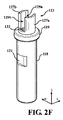
場合により、絶縁体118から軸方向に離れて突出するイグナイタ112の遠位部分を更に囲み、保護することが望ましいことがある。図2Fに示されるように、保護囲い123が設けられ、カラー119で絶縁体118の遠位側の端部に取り付けられる。保護囲い123は、絶縁体118と一体的に形成されるか、又は、分離して形成され、絶縁体118に取り付けられてもよい。保護囲い123は、好ましくは、イグナイタ112の最遠位側の端部を超えて延び、イグナイタ112の遠位側の端部の周りに、調理用ガスがイグナイタ112の表面まで通過することを可能にする開口領域129a及び129bを含む。図2Fの保護囲いは、互いに向かい合う2つの部分円筒形の支柱127a及び127bを備え、支柱127a及び127bは、同じく互いに向かい合う開口129a及び129bを画定する。絶縁体118がオリフィスホルダ132に取り付けられる際、開口129a、129bのうちの1つは、好ましくは、イグナイタ用ポート130がイグナイタ112の表面に対して直接見通し線を有するように配置される。一定の実施例では、イグナイタ112の一面(好ましくは主要面)がイグナイタ用ポート130に面し、それによって、このイグナイタ112の面に垂直な線が、絶縁体118又は保護囲い123の一部によって遮られることなくイグナイタ用ポート130と交差する。また、保護囲い123は、好ましくはセラミックなどの絶縁材料である。バーナ110と共に使用するのに適した様々な絶縁体及び保護囲い構造が、参照により本明細書に援用される米国仮特許出願第62/648,574号明細書の図1A〜7Eに示される。イグナイタ112を損傷から保護することに加え、クラウン凹み126及び保護囲い123の両方は、燃焼ガスを「溜める」効果を有し、この「溜める」領域をイグナイタ112の遠位部分の表面付近とすることを可能にし、これによって、イグナイタ112の表面付近で空気とガスの可燃性混合気(すなわち、爆発下限界と爆発上限界との間にある組成を有する混合気)がより迅速に生成されるのを促進する。したがって、カラー119及び保護囲い123の両方が、燃焼を容易にする、又は、促進する、又はその両方を実施するという予想外の利益を達成する。
In some cases, it may be desirable to further enclose and protect the distal portion of the
図2Aに示す調理用ガス供給ライン124の一部分は、図1の調理用ガスバルブ102の下流にある。調理用ガスは、供給ライン124を通ってガスオリフィスホルダ120に流れ込み、ガスオリフィス116から出る。図2A〜2Gのバーナ110は、クラウン113の下部から周囲の空気を引き込むという点で「下呼吸」である。前述したように、接続管(図示せず)は、軸方向下向きに延びるフランジ119(図2G)を介してガスオリフィス116をクラウン113の内部に接続する。接続管は中央が細く、両端が広くなっている。接続管の狭窄部の下流には空気穴があり、狭窄部を通るガスの流れによって圧力が低下すると、内部の圧力降下が外気を吸い込み、燃焼に必要な空気/ガス混合気が提供される。下呼吸バーナ110に加えて、上呼吸バーナを使用してもよい。上呼吸バーナでは、周囲の空気が調理用ガスと共にクラウンの下部に進入しない。その代わりに、可燃性空気ガス混合気は、フルート117のすぐ外側で形成される。上呼吸バーナ及び下呼吸バーナの両方とも、フルート117のすぐ外側で燃焼が起こる。
A portion of the cooking
高温表面イグナイタ112は、クラウン113内でイグナイタ凹み126に突出する。リード(図示せず)は、イグナイタ112を、制御部104に動作可能に接続されたイグナイタ回路に導通する。イグナイタ用ガスポート130(図2G)は、イグナイタ112をクラウン113の内部と流体連結させ、これによって、供給ライン124からの調理用ガスがイグナイタ112に供給され得る。イグナイタ112が点火電圧まで通電されると、イグナイタ112の外面は調理用ガスの自己点火温度よりも高い温度に達する。イグナイタ表面が自己発火温度以上である間に空気と調理用ガスの可燃性混合気が高温表面イグナイタ112に到達すると、調理用ガスが発火し、これによってイグナイタのフルート117外側の調理用ガスが発火し、発火し続ける。各種調理用ガスの自己発火温度は次の通りである。

点火が起こるためには、高温表面イグナイタ112付近の空気と調理用ガスの混合気が、調理用ガスの爆発下限界/可燃下限界(LEL/LFL)と爆発上限界/可燃上限界(UEL/UFL)との間でなければならない。表2に、空気の体積パーセントとしてLEL値とUEL値とを示す。
前述のように、一定の場合において、点火又は再点火中のバーナのガス流量は、よくあるように最高ガス流量に調節されるのではなく、むしろ「とろ火」などのより低いガス流量に調節されるバーナシステムを提供することが望ましいことがある。既知のコンロは、点火中に空気と調理用ガスの可燃性混合気がスパークイグナイタに存在することを確保するため、比較的高いガス流量で点火する。しかしながら、これはガスを浪費し、予期しないガス点火プルームを作り出したり、部屋を未燃焼ガスで充満させたりする可能性があり、したがって、望ましくない屋内環境を作り出す可能性がある。低ガス流量で調理する場合、バーナ110で流量が減少すると、ガスバルブ102(図1)は絞られ、クラウンのガス供給ライン124内の総ガス流量を減少させる。クラウン113に流入するガスがクラウン113から流出するには、クラウンフルート117から出る又はイグナイタ凹みオリフィス130から出る(図2G)2つの競合する流路がある。イグナイタの凹みオリフィス130の面積に対して、フルート117は数が多く、面積が大きいため、フルート117は総量でイグナイタオリフィス130よりも多くの調理用ガス流を受け取る。ガスバルブ102の上流で供給圧力Pが下降すると(図1)、調理用ガスのイグナイタ112への流量は最終的に不足し、LEL/LFLに達しなくなる。さらに、ANSI Z211.1−2016では、3つの調理用ガス供給圧力(低圧、通常、高圧)で前述の4秒の点火要件を満たす必要がある。しかしながら、バーナの流量を低レベルに維持する場合(とろ火モードなど)、ガスバルブ102を絞らなければならず、これにより、ガスバルブ102それぞれの圧力降下が大きくなり、最終的に充分な圧力が供給されずに、イグナイタ付近の領域をLEL/LFLより上に保つのに必要な量の調理用ガスがイグナイタ112に供給されなくなる可能性がある。表3に、各種調理用ガスに対して4秒の点火要件を満たすことを要求するANSI Z211.1−2016の調理用ガス供給圧力Pを示す。
一定の実施形態によれば、各バーナ110のバーナフルート117の数及び開口面積、並びに、イグナイタオリフィス130の面積は、供給圧力P(図1)が8.0水柱インチ(1.99kPa)であり、メタン又はブタン1400が調理用ガスとして使用される場合に、各供給ライン124を通る各バーナ110への総ガス流量が1.8L/分以下、好ましくは1.0L/分以下、更により好ましくは0.2L以下となるような大きさとされる。同時に、高温表面イグナイタ112による点火を確実に確保するため、対応するイグナイタ112への(イグナイタオリフィス130を通る)ガス流量は、少なくとも9.9×10−3L/分、好ましくは少なくとも0.05L/分、より好ましくは少なくとも0.09L/分である。同じ又は他の実施形態では、各バーナ110のバーナフルート117の数及び開口面積、並びに、イグナイタオリフィス130の面積は、供給圧力P(図1)が8.0水柱インチであり、n−ブタン又はプロパンHD−5が調理用ガスとして使用される場合に、各供給ライン124を通る各バーナ110への総ガス流量が2.7L/分以下、好ましくは1.5L/分以下、更により好ましくは0.32L/分以下となるような大きさとされる。同時に、高温表面イグナイタ112による点火を確実に確保するため、対応するイグナイタ112への(イグナイタオリフィス130を通る)ガス流量は、少なくとも0.016L/分、好ましくは少なくとも0.08L/分、より好ましくは少なくとも0.14L/分である。本明細書に記載のバーナシステムの好ましい実施例では、前述の条件で、可燃性混合気(すなわち、爆発上限界と爆発下限界との間の可燃性混合気)がイグナイタ112に提供され、イグナイタ112は、空気と調理用ガスの混合気を4秒以内に点火することができる。
According to certain embodiments, the number and opening area of the burner flutes 117 of each
一定の実施例では、クラウン113内の調理用ガスが点火されたことを検出する炎センサが設けられ、炎センサは炎の有無を示す信号を制御部104に提供する。一実施例では、炎が感知されると、制御部104は、イグナイタのイグナイタ回路に信号を送信し、高温表面イグナイタ112への通電が停止される。別の実施例では、炎が感知されることなくイグナイタが所望の期間を経過しても通電されたままである場合、制御部104は、ガスバルブ102を閉じるためにアクチュエータ108に信号を送り、バーナ110へのガスの流れが遮断される。更なる実施例では、炎が感知されると、イグナイタ112に供給される電力が減少して、イグナイタの表面温度を点火中の表面温度に対して下げるが、調理用ガスの自己発火温度より高く維持する。点火後、点火電力レベルよりも低い電力レベルであるが、イグナイタ表面を特定の調理用ガスの自動点火温度より高温に維持するのに充分な電力レベルでイグナイタ112を通電し続けるイグナイタ回路に関して、図5A〜5Cを参照して以下で説明する。
In certain embodiments, a flame sensor is provided to detect that the cooking gas in the
別の実施例では炎センサは用いられない。代わりに、ユーザ用制御装置(つまみなど)を操作して点火の意図を示すことができ(例えば、つまみの中心方向軸に沿って内側に押す)、操作が中断されると(例えば、つまみを離す)、高温表面イグナイタの通電が停止される、又は、初期点火電力レベルよりも低い電力レベルで通電される。「初期」点火は、調理用ガスバルブ102が閉じられた後に点火が開始されるときに発生し、一定の実施形態では、燃焼が停止し、調理用ガスバルブ102が開いているにもかかわらず、イグナイタへの調理用ガスの供給が妨げられるときに発生する「再点火」よりも高い電力レベルで初期点火が発生する。
No flame sensor is used in another embodiment. Instead, a user controller (such as a knob) can be manipulated to indicate the intent of ignition (eg, push inward along the central axis of the knob) and the operation is interrupted (eg, the knob is pressed). Release), the high temperature surface igniter is de-energized or energized at a power level lower than the initial ignition power level. The "initial" ignition occurs when the ignition is started after the
図3A〜3Hを参照すると、高温表面イグナイタ112の実施例が図示される。図3A及び3Cに示されるように、高温表面イグナイタ112はイグナイタの長さ方向軸lに沿って離間された近位側の端部144及び遠位側の端部146を有するセラミック体139を備える。セラミック体139はまた、幅方向軸w及び厚さ方向軸tを有する。長さl方向軸はセラミック体139の最長寸法に対応する。幅w方向軸はセラミック体139の2番目に長い寸法に対応し、厚さt方向軸はセラミック体139の3番目に長い(又は最短)寸法に対応する。イグナイタ112の長さは、少なくとも1.7インチ(約4.318cm)、好ましくは少なくとも1.8インチ(約4.572cm)、より好ましくは少なくとも1.9インチ(約4.826cm)である。同時に、イグナイタ112の長さは、2.2インチ(約5.588cm)以下、好ましくは2.1インチ(約5.334cm)以下、更により好ましくは2.0インチ(約5.08cm)以下である。イグナイタ112の幅方向軸に沿った幅は、0.160から0.210インチ(約0.4064〜約0.5334cm)、好ましくは0.170から0.200インチ(約0.4318〜約0.508cm)、より好ましくは0.180から0.190インチ(約0.4572〜約0.4826cm)である。
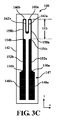
With reference to FIGS. 3A-3H, an embodiment of the high
セラミック体139は、前述した種類の埋設された導電性インク回路147を2つ備えるセラミックタイル140及び142を備える。セラミックタイル140、142は、好ましくは窒化ケイ素を含み、より好ましくは窒化ケイ素、酸化イッテルビウム、及び二珪化モリブデンを含む。イグナイタ112は、イグナイタの長さ方向軸lに沿って遠位側の端部146から離れて近位方向に突出するコネクタ148a及び148bを含む。外部リード134及び136(図示せず)はセラミック体139に取り付けられ、それぞれコネクタ148a及び148bに接続されている。
The
コンロ用バーナシステムの一定の実施例では、イグナイタの温度までの時間要件を満たすために、イグナイタ主部139は、厚さ方向軸tに沿って従来のイグナイタの多くよりも薄くなければならない。イグナイタ112は、厚さ方向軸tに沿って、0.04インチ(約0.1016cm)未満、好ましくは0.035インチ(約0.0889cm)未満、より好ましくは0.030インチ(約0.0762cm)未満の厚さを有する。同じ又は他の実施例では、イグナイタ主部の厚さ方向軸tに沿った厚さは、少なくとも約0.02インチ(約0.0508cm)、好ましくは少なくとも約0.024インチ(約0.06096cm)、より好ましくは少なくとも約0.026インチ(約0.06604cm)である。
In certain embodiments of the stove burner system, the igniter
同じ又は追加的実施例では、厚さ方向軸tに沿った高温表面イグナイタ112の導電性インク回路147の厚さは、約0.002インチ(約0.00508cm)以下、好ましくは約0.0015インチ(約0.00381cm)以下、より好ましくは約0.0009インチ(約0.002286cm)以下である。同じ又は追加的実施例では、厚さ方向軸tに沿った導電性インク回路147の厚さは、約0.0006インチ(約0.001524cm)以上、好ましくは約0.0005インチ(約0.00127cm)以上、より好ましくは約0.0004インチ(約0.001016cm)以上である。
In the same or additional embodiment, the thickness of the
高温表面イグナイタ112は、前述の厚さを有しながら、バーナ環境に耐えるために必要な構造的完全性を有する。構造的完全性に有効な試験は曲げ強度である。曲げ強度は、曲げ試験中に発せられる破壊応力である。曲げ強度又は破断係数とも呼ばれる。これは、ある要素を変形又は破壊する際にかかり得る最大引張応力を表す。セラミック材料は概して張力が弱いため、引張応力は機械的強度の主要な指標の1つである。曲げ強度が高いほど、材料を曲げたり壊したりするのがより「困難」になる。高温表面イグナイタ112は、ASTM C−1161に準拠して試験された場合、少なくとも400MPa、好ましくは少なくとも425MPa、より好ましくは少なくとも450MPaの曲げ強度を有する。同時に、イグナイタ112は、ASTM C−1161に準拠して試験された場合、600MPa以下、好ましくは575MPa以下、更により好ましくは550MPa以下の曲げ強度を有する。いかなる理論にも拘束されることを望むものではないが、理論密度の少なくとも約45パーセント、好ましくは理論密度の少なくとも約55パーセント、より好ましくは理論密度の少なくとも約60パーセントのグリーンボディ密度を有するグリーンイグナイタタイルを形成することで、イグナイタ112が曲げ強度及び薄さの前述の組み合わせを有することを可能にし、イグナイタ112が薄いことによって、温度に達するまでの時間値の大幅な改善が見込まれると考えられる。
The high
焼結後、タイル140及び142(導電性インク回路147を含まない)は、1012Ω・cm以上、好ましくは1013Ω・cm以上、より好ましくは1014Ω・cm以上の室温抵抗率を有する。同じ又は他の実施例では、タイル140及び142は、900°F(約482℃)以上、好ましくは950°F(510℃)以上、より好ましくは1000°F(約538℃)以上のASTM C−1525に準拠した熱衝撃値を有する。
After sintering, the
導電性インク回路147を形成する導電性インクは、約3.0×10⁻⁴Ω・cmから1.2×10⁻³Ω・cm、好ましくは約3.5×10⁻³Ω・cmから約1.0×10⁻³Ω・cm、より好ましくは約4.3×10⁻⁴Ω・cmから約8.7×10⁻⁴Ω・cmの(焼結後)室温抵抗率を有する。長さに沿って一定の断面積を持つ材料の場合、以下の周知の式のように、特定の温度Tでの抵抗率ρは、同じ温度Tでの抵抗Rに関係づけられる。
(1)R(T)=ρ(T)(l/A)
ρ=温度Tでの導電性回路材料の抵抗率(Ω・cm)
R=温度Tでの抵抗(オーム(Ω))
T=温度(°F又は℃)
A=電流の方向に垂直な導電性インク回路の断面積(cm2)、及び、
l=電流の方向に沿った導電性インク回路の全長(cm)
The conductive ink forming the
(1) R (T) = ρ (T) (l / A)
ρ = resistivity of conductive circuit material at temperature T (Ω · cm)
R = resistance at temperature T (ohm (Ω))
T = temperature (° F or ° C)
A = Cross-sectional area (cm 2 ) of the conductive ink circuit perpendicular to the direction of the current, and
l = Overall length (cm) of the conductive ink circuit along the direction of current
導電性回路の長さに沿って変化する断面積の場合、抵抗は次のように表すことができる。
導電性インク回路147は、好ましくは、セラミックタイル140、142いずれかの面に印刷されて、約50Ωから約150Ω、好ましくは約60Ωから約120Ω、より好ましくは約70Ωから約110Ωの(焼結後の)室温抵抗(RTR)を示す。導電性インク回路147を形成する導電性インクは、好ましくは窒化ケイ素を含み、より好ましくは窒化ケイ素及び炭化タングステンを含む。同じ又は他の例において、導電性インクは、好ましくは、0.00重量パーセント以下の酸化イッテルビウム(Yb2O3)を含み、より好ましくは、約0.00重量パーセント以下の希土類酸化物を含む。同じ又は他の実施例では、導電性インク中の窒化ケイ素の量は、約25パーセントから約40パーセント、好ましくは約28パーセントから約37パーセント、より好ましくは約30から約33パーセントである。同じ又は他の実施例において、導電性インクの重量で導電性インク中に存在する炭化タングステンの量は、好ましくは約60重量パーセントから約80重量パーセント、より好ましくは約65重量パーセントから約75重量パーセントであり、更により好ましくは、約67重量パーセントから約70重量パーセントである。図3A、3C、及び3Dのイグナイタ112は、120V交流電圧で少なくとも約90,000サイクル、好ましくは少なくとも約100,000サイクル、より好ましくは少なくとも約120,000サイクルのサイクルを有する。また、図3A、3C、及び3Dのイグナイタ112は少なくとも270万秒、好ましくは300万秒、より好ましくは360万秒のオン時間を有する。前述のように、いかなる理論にも拘束されることを望むものではないが、酸化イッテルビウム及び他の希土類酸化物の除去は、サイクル寿命及びイグナイタのオン時間に大幅な改善をもたらすと考えられる。
The
120V交流電圧の電位差が印加されると、高温表面イグナイタ112の外面141は、電位差が印加されてから4秒以内に少なくとも1400°F(約760℃)、好ましくは1800°F(約982℃)以上、より好ましくは2100°F(約1149℃)以上、更により好ましくは2130°F(約1166℃)以上の表面温度に達するのが望ましい。これらの温度のそれぞれは、電位差が初めに印加されてから、好ましくは3秒以内に到達し、より好ましくは2秒以内に到達し、更により好ましくは1秒以内に到達する。
When a potential difference of 120 V AC voltage is applied, the
同じ又は追加の実施例において、120V交流電圧の電位差が印加された場合、高温表面イグナイタ112の外面141の温度は、120V交流電圧の電位差の印加後、定常状態の温度に達した後を含め、常に2600°F(約1427℃)を超えない、好ましくは2550°F(約1399℃)を超えない、より好ましくは2500°F(約1372℃)を超えない、更により好ましくは2450°F(約1343℃)を超えない。
In the same or additional embodiment, when a potential difference of 120V AC voltage is applied, the temperature of the
本開示に係わる高温表面イグナイタの同じ又は他の例では、102V交流電圧の電位差が印加されると、本明細書に記載の高温表面イグナイタは、102V交流電圧の電位差が印加されてから5秒以内に、少なくとも1400°F(約760℃)、好ましくは少なくとも1800°F(約982℃)、更により好ましくは少なくとも2100°F(約1149℃)で、2050°F(約1121℃)以上、好ましくは2080°F(約1138℃)以上、より好ましくは2130°F(約1166℃)以上の表面141温度に達する。これらの温度のそれぞれは、好ましくは4秒以内に到達し、より好ましくは3秒以内に到達する。
In the same or other example of the high temperature surface igniter according to the present disclosure, when a potential difference of 102V AC voltage is applied, the high temperature surface igniter described herein is within 5 seconds of the application of the potential difference of 102V AC voltage. In addition, at least 1400 ° F (about 760 ° C), preferably at least 1800 ° F (about 982 ° C), even more preferably at least 2100 ° F (about 1149 ° C), 2050 ° F (about 1121 ° C) or higher, preferably. Reaches a
便宜上、図3A及び3C〜3Dの高温表面イグナイタ112は、「長尺薄型窒化物」又は「TNL」イグナイタと呼ばれる。
For convenience, the high
図3A及び3Bを参照すると、2つの異なる焼結高温表面イグナイタの形状が提供される。図3Aの対称な例では、2つのセラミックタイル140及び142は同じ厚さであり、導電性インク回路はタイル140及び142の対面する2つの面のうちの1つにスクリーン印刷されている。
With reference to FIGS. 3A and 3B, two different sintered hot surface igniter shapes are provided. In the symmetrical example of FIG. 3A, the two
図3Bの非対称な実施例では、セラミックタイル143及び145は、異なる厚さを持つ。より厚いタイル145は、イグナイタ112により大きな構造的完全性を提供する。より薄いタイル143は、セラミック体139の露出した主要面の熱伝導により短い経路を提供し、イグナイタがバーナに取り付けられた際に、好ましくはガスポート130に面するであろう「高温」表面を提供する。両方の場合で(図3A及び3B)、セラミック体は、好ましくは、窒化ケイ素と希土類酸化物焼結助剤とを含み、希土類元素は、イッテルビウム、イットリウム、スカンジウム、及びランタンのうちの1つ以上である。焼結助剤は、前述の希土類酸化物及び1つ以上のシリカ、アルミナ、及びマグネシアから選択される共ドーパントとして提供され得る。焼結助剤保護剤も含まれることが好ましく、これも高密度化を促進する。好ましい焼結助剤保護剤は、二珪化モリブデンである。希土類酸化物焼結助剤(共ドーパントあり又はなし)は、好ましくはセラミック体の約2から約15重量パーセント、より好ましくは約8から約14重量パーセント、更により好ましくは、約12から約14重量パーセントの範囲の量で存在する。二珪化モリブデンは、好ましくは、セラミック体の約3から約7重量パーセント、より好ましくは約4から約7重量パーセント、更により好ましくは約5.5から約6.5重量パーセントの範囲の量で存在する。残りは窒化ケイ素である。
In the asymmetrical embodiment of FIG. 3B, the
図3Bの非対称な実施例の場合、より薄いタイル143は、好ましくは、約0.01インチ(約0.0254cm)以下、より好ましくは約0.012インチ(約0.03048cm)以下、更により好ましくは約0.015インチ(約0.0381cm)以下の厚さを有する。同じ又は追加の実施例では、より厚いタイル146の厚さは、好ましくは約0.04インチ(約0.1016cm)以下、より好ましくは約0.02インチ(約0.0508cm)以下、更により好ましくは約0.018インチ(約0.04572cm)以下である。
In the case of the asymmetrical embodiment of FIG. 3B, the
図3Cを参照すると、本明細書に記載の高温表面イグナイタで使用する印刷インク回路147の例が示される。インクは、焼結前に、セラミックタイル140、142のうちの1つの主要面にスクリーン印刷によって塗布されるのが好ましい。導電性インク回路は、外部リードに接続されたコネクタ148a及び148bを備える。リード152a及び152bは、それぞれコネクタ148a及び148bに接続される。次に、リード152a及び152bは、電位差がコネクタ148a及び148bの間に印加されたときに抵抗性加熱をもたらすように構成された導電性インクパターンを含む抵抗加熱回路153に接続される。抵抗加熱回路は、凹状移行部150a及び150bのイグナイタの長さ方向軸に沿った遠位に当たり、脚部158a及び158bの最も近位の端部が幅方向軸に沿って実質的に一定の幅に達するところから始まると定義される。
With reference to FIG. 3C, an example of a
抵抗加熱回路153は、図3Dに更なる詳細が示される。図3Dに示すように、抵抗加熱回路は、各々がイグナイタの長さ方向軸lに沿った長さ及びイグナイタの幅方向軸wに沿った幅を有する脚部158a、158b、162a及び162bを備える。脚部158a、158b、162a及び162bは、イグナイタの幅方向軸wに沿って離間している。抵抗加熱回路153全体は、イグナイタの厚さ方向軸tに沿って実質的に一定の厚さを有するのが好ましい。
The
脚部は、接続(又は「コネクタ」)160a、160b、及び156によって接続される。接続160a、160b、及び156で、インクパターンは、イグナイタの長さ方向軸lに平行な方向から、イグナイタの幅方向軸wに平行な方向に変わる。一定のコンロへの適用において、導電性インクパターンの脚部158a、158b、162a、及び162bの(幅方向軸wに沿った)幅よりも接続160a、160b、及び156を(長さ方向軸lに沿って)広い導電性インク幅とすることで、接続160a、160b、及び156の抵抗を有利に低減し、脚部162a及び162bの温度を低下させ、これにより、抵抗加熱回路153の熱劣化の傾向が低減される。好ましい実施例として、接続160a、160b、及び156のイグナイタの長さ方向軸lに沿ったインク幅は、脚部158a、1548b、162a、及び162bのイグナイタの幅方向軸wに沿った幅の2倍である。
The legs are connected by connections (or "connectors") 160a, 160b, and 156. At the
従来の導電性インクパターンの多くと比較して、リード152a及び152bは、より急激に抵抗加熱回路153に移行する。図3Cを参照すると、移行領域154a及び154bは、リード152a及び152bから脚部158a及び158bに移行するときに、イグナイタの幅方向w軸に沿ってインク幅が減少する領域である。図3Cの実施例では、イグナイタの長さ方向幅wに沿ったイグナイタのリード152a及び152bの幅は、凹領域である温度移行部150a及び150bの端部から始まり、長さ方向軸lに沿ったリード152a及び152bの長さの10%以下に沿って変化する。
Compared to many conventional conductive ink patterns, the
接続160a、160b、及び156のインク幅が大きくなるのに加えて、接続は、好ましくは略直角である角部161a及び161bを含む。多くの従来のインクパターンでは、インクパターンは、脚部158a及び158bからそれぞれの接続160a及び160bへ移行する際に丸められている。しかし、特定の好ましい実施例では、図3Dに示されるように、移行部は尖っており、インクパターンの外側輪郭における角部161a及び161bでの直角により画定される。
In addition to increasing the ink widths of the
図3Dを参照すると、導電性インク回路147の「加熱域」は、導電性インク回路147の両端に電位差が印加されたときに最も熱が発生する領域である。加熱域は、lhzとして表されるイグナイタの長さ方向軸lに沿った長さを有する。加熱ゾーンの長さlhzは、第3又は中間コネクタ156の近位側の端部159から第1のコネクタ160a及び第2のコネクタ160bの遠位側の端部165a及び165bまでの距離として定義される。図3C及び3Dの実施例では、コネクタ160a及び160bの遠位側の端部165a及び165bは、実質的に真っすぐであり、好ましくは真っすぐである。第1及び第2のコネクタ160a及び160bの近位側の端部167a及び167bは、好ましくは湾曲しており、より好ましくは、それらの対応する遠位側の端部165a及び165bに対して凹状である。図3Dにおいて、第3のコネクタ156の遠位側の端部157は、好ましくは真っ直ぐであり、第3のコネクタ156の近位側の端部159は好ましくは湾曲しており、より好ましくは、遠位側の端部157並びに脚部162a及び162bに対して凸状である。導電性インク回路147全体の長さに対するパーセンテージとして、加熱域の長さlhzは、10から40パーセント、好ましくは15から35パーセント、より好ましくは19から31パーセントである。
With reference to FIG. 3D, the “heating region” of the
先に述べたように、図3A、3C、及び3Dは、「TNL」の実施形態、特に「TNLフラットトップ」の実施形態として参照され、「フラットトップ」は、イグナイタの導電性インク回路147の幅を横切る真っ直ぐな遠位側の端部エッジ165a及び165bを指す。TNLの実施形態では、長さ方向軸に沿ったイグナイタの長さは、概して、約1.7インチから約2.3インチ(約4.318cm〜約5.842cm)、好ましくは約1.8インチから約2.2インチ(約4.572cm〜約5.588cm)、より好ましくは約1.90インチから約2.0インチ(約4.826cm〜約5.08cm)である。長さ方向軸lに沿った導電性インク回路147の全長は、好ましくは約1.6インチから約1.11インチ(約4.064cm〜約2.8194cm)、好ましくは約1.7インチから約1.10インチ(約4.318cm〜約2.794cm)、より好ましくは約1.8インチから約1.9インチ(約4.318cm〜約4.826cm)である。長さ方向軸lに沿った抵抗加熱回路153の長さは、好ましくは約0.40インチから約0.44インチ(約1.016cm〜約1.1176cm)、好ましくは約0.41インチから約0.43インチ(約1.0414cm〜約1.0922cm)、より好ましくは約0.415インチから約0.425インチ(約1.0541cm〜約1.0795cm)である。
As mentioned earlier, FIGS. 3A, 3C, and 3D are referred to as embodiments of the "TNL", particularly the "TNL flat top", where the "flat top" is the igniter's
加熱域の長さlhzは、好ましくは約0.15インチから約0.5インチ(約0.381cm〜約1.27cm)であり、好ましくは約0.17インチから約0.45インチ(約0.4318cm〜約1.143cm)、より好ましくは約0.19インチから約0.4インチ(約0.4826cm〜約1.016cm)である。幅方向軸wに沿った脚部158a、158b、162a、及び162bの幅は、約0.008インチから約0.012インチ(約0.02032cm〜約0.03048cm)、好ましくは約0.009インチから約0.011インチ(約0.02286cm〜約0.02794cm)、より好ましくは約0.0095インチから約.00105インチ(約0.02413cm〜約0.002667cm)である。脚部158aと162aとの間、更に、脚部158bと162bとの間、脚部162aと162bとの間の脚部間間隔は、約0.023インチから約0.027インチ(約0.05842cm〜約0.06858cm)、好ましくは約0.024インチから約0.026インチ(約0.06096cm〜約0.06604cm)、より好ましくは約0.0245インチから約0.0255インチ(約0.06223cm〜約0.06477cm)である。
The length lhz of the heating region is preferably from about 0.15 inch to about 0.5 inch (about 0.381 cm to about 1.27 cm), preferably from about 0.17 inch to about 0.45 inch (about). 0.4318 cm to about 1.143 cm), more preferably from about 0.19 inch to about 0.4 inch (about 0.4826 cm to about 1.016 cm). The widths of the
図3E及び3Fは、本明細書に記載のイグナイタ112で用いられる導電性インク回路の「TNLラウンドトップ」の実施形態を図示する。好ましい一実施例では、TNLラウンドトップ導電性インク回路は、TNLフラットトップイグナイタに関して上述したものと同じセラミックタイルの間に挟まれている。長さ方向軸に沿ったイグナイタ112の長さ及び長さ方向軸に沿った導電性回路147の長さは、図3C及び3DのTNLフラットトップの実施形態と同じである。「ラウンドトップ」は、導電性インク回路347の最遠位側の端部365a及び365bがイグナイタ幅方向軸wに沿って湾曲しているという事実を指す。特に、最遠位側の端部365a及び365bは、脚部358a、358b、362a、及び362bに対して凸状である。最遠位側の端部365a及び365bは、好ましくは、一定の曲率半径を有する。図3E及び3Fの部位は、百の位の数字が「1」ではなく「3」であることを除いて、図3A及び3Cの部位に対応する。例えば、脚部358aは、図3Cの脚部158aに対応する。
3E and 3F illustrate an embodiment of a "TNL round top" of a conductive ink circuit used in the
近位側の端部コネクタ348a及び348bは、導電性インク回路347に電力を供給するために使用される外部リードに接続可能である。凹状移行部350a及び350bは、それぞれのコネクタ348a及び348bを、リード352a及び352bのそれぞれ1つに接続する。傾斜移行部354a及び354bは、それぞれのリード352a及び352bを、イグナイタ幅w軸方向に沿って互いに離間された抵抗加熱回路脚部358a及び358bのそれぞれ1つに接続する。加熱域の長さlhzは、図3Cの導電性インクパターン147と同じである。同様に、脚部358a、358b、362a、362bの幅、並びに、脚部358a、358b、362a、及び362bの隣接する脚部対の間の脚部間幅方向軸間隔は、0.016インチから0.020インチ(約0.04064cm〜約0.0508cm)、好ましくは0.017インチから0.019インチ(約0.04318cm〜約0.04826cm)、より好ましくは、0.0175インチから0.0185インチ(約0.04445cm〜約0.04699cm)である。
図3C及び3Dとは異なり、コネクタ360a及び360bの最遠位側の端部365a及び365bは、イグナイタ幅方向軸wに沿って湾曲している。好ましくは、最遠位側の端部は、脚部358a及び358bの最も外側の(幅方向軸に沿った)エッジ間の間隔によって画定される実質的に一定の曲率半径を有する。一定の実施例では、最遠位側の端部365a及び365bの曲率半径は、約0.017インチから約0.021インチ(約0.04318cm〜約0.05334cm)、好ましくは約0.018インチから約0.020インチ(約0.04572cm〜約0.0508cm)、より好ましくは約0.0185インチから約0.0195インチ(約0.04699cm〜約0.04953cm)である。近位側の端部367a及び367bもまた幅方向軸に沿って湾曲しており、好ましくは、脚部間間隔によって画定される実質的に一定の曲率半径を有する。近位側の端部367a及び367bの曲率半径は、約0.007インチから約0.011インチ(約0.01778cm〜約0.02794cm)、好ましくは約0.008インチから約0.010インチ(約0.02032cm〜約0.0254cm)、より好ましくは約0.0085インチから約0.0095インチ(約0.02159cm〜約0.02413cm)である。同様に、第3のコネクタ356の遠位側の端部359の曲率半径は、近位側の端部367a及び367bの曲率半径と同じであり、コネクタ356の近位側の端部357の曲率半径は、コネクタ360a及び360bの遠位側の端部365a及び365bの曲率半径と同じである。
Unlike FIGS. 3C and 3D, the most
図3E〜3FのTNLラウンドトップ導電性インク回路を使用する好ましいイグナイタは、図3A、及び3C〜3Dのイグナイタと同じ熱特性を達成する。したがって、120V交流電圧の電位差が印加されると、外面は、電位差が印加されてから4秒以内に少なくとも1400°F(約760℃)、好ましくは1800°F(約982℃)以上、より好ましくは2100°F(約1149℃)以上、更により好ましくは2130°F(約1166℃)以上の表面温度に達する。これらの温度は、それぞれ電位差が初めに印加されてから好ましくは3秒以内に到達し、より好ましくは2秒以内に到達し、更により好ましくは、1秒以内に到達する。 Preferred igniters using the TNL round top conductive ink circuit of FIGS. 3E-3F achieve the same thermal properties as the igniters of FIGS. 3A and 3C-3D. Therefore, when a potential difference of 120 V AC voltage is applied, the outer surface is more preferably at least 1400 ° F (about 760 ° C), preferably 1800 ° F (about 982 ° C) or more within 4 seconds after the potential difference is applied. Reaches a surface temperature of 2100 ° F. (about 1149 ° C.) or higher, and even more preferably 2130 ° F. (about 1166 ° C.) or higher. Each of these temperatures reaches within 3 seconds, more preferably within 2 seconds, and even more preferably within 1 second after the potential difference is first applied.
同じ又は追加の実施例では、120V交流電圧の電位差が印加されると、図3E〜図3FのTNLラウンドトップ導電性インク回路347を用いるイグナイタは、120V交流電圧の電位差が印加された後は、定常状態の温度に達した後を含め、常に2600°F(約1427℃)を超えない、好ましくは2550°F(約1399℃)を超えない、より好ましくは2500°F(約1371℃)を超えない、更により好ましくは2450°F(約1343℃)を超えない外面温度に到達する。
In the same or additional embodiment, when a potential difference of 120V AC voltage is applied, the igniter using the TNL roundtop
本開示に係わる高温表面イグナイタの同じ又は他の実施例では、102V交流電圧の電位差が印加されると、図3E〜図3FのTNLラウンドトップ導電性インク回路を用いる高温表面イグナイタは、102V交流電圧の電位差が適用されてから5秒以内に少なくとも1400°F(約760℃)、好ましくは少なくとも1800°F(約982℃)、更により好ましくは少なくとも2100°F(約1149℃)で、2050°F(約1121℃)以上、好ましくは2080°F(約1138℃)以上、より好ましくは2130°F(約1166℃)以上の表面温度に達する。これらの温度のそれぞれは、好ましくは4秒以内に到達し、より好ましくは3秒以内に到達する。 In the same or other embodiment of the high temperature surface igniter according to the present disclosure, when a potential difference of 102V AC voltage is applied, the high temperature surface igniter using the TNL round top conductive ink circuit of FIGS. 3E-3F has a 102V AC voltage. Within 5 seconds of applying the potential difference of, at least 1400 ° F (about 760 ° C), preferably at least 1800 ° F (about 982 ° C), even more preferably at least 2100 ° F (about 1149 ° C), 2050 ° C. It reaches a surface temperature of F (about 1121 ° C.) or higher, preferably 2080 ° F. (about 1138 ° C.) or higher, more preferably 2130 ° F. (about 1166 ° C.) or higher. Each of these temperatures preferably reaches within 4 seconds, more preferably within 3 seconds.
一定の実施例によると、「短尺薄型窒化物」又は「TNS」イグナイタも提供される。セラミックタイルと導電性インクの組成は、TNLイグナイタについて記載したものと同じである。ただし、長さ方向軸に沿ったイグナイタの長さは、約1.0から約1.5インチ(約2.54cm〜約3.81cm)、好ましくは約1.1インチから約1.4インチ(約2.794cm〜約3.556cm)、より好ましくは約1.15から約1.35インチ(約2.921cm〜約3.429cm)である。幅方向軸に沿ったイグナイト幅は、0.16インチから0.21インチ(0.4064cm〜0.5334cm)、好ましくは0.17インチから0.20インチ(0.4318cm〜0.508cm)、より好ましくは0.18インチから0.19インチ(0.4572cm〜0.4826cm)である。TNSイグナイタに関する例示的な導電性インク回路447が図3Gに示される。導電性インク回路447の構成要素は、百の位の桁が「4」であることを除いて、前述の導電性インク回路147及び347の構成要素に対応する。したがって、コネクタ448a及び448bは外部リードに接続可能であり、それぞれ凹状移行部450a及び450bによって伝導体リード452a及び452bに接続されている。各リード452a及び452bは、それぞれの傾斜移行部454a及び454bに接続され、傾斜移行部454a及び454bは、次に、抵抗加熱域の脚部458a及び458bのそれぞれ1つに接続される。抵抗加熱域453は、長さ方向軸に沿った長さを有し、イグナイタ幅方向軸に沿って互いに離間された4つの脚部458a、460a、458b、及び460bを含む。コネクタ460aは、脚部458aを脚部462aに接続し、コネクタ460bは、脚部458bを脚部462bに接続する。図3G及び3Hの導電性インク回路は、図3E及び3Fのような「ラウンドトップ」回路である。したがって、コネクタ460a及び460bは、イグナイタ幅方向軸に沿って湾曲した遠位側の端部465a及び465bと、イグナイタ幅方向軸に沿って湾曲したそれぞれの近位側の端部467a及び467bとを有する。同様に、脚部462a及び462bを接続するコネクタ456は、湾曲した遠位側の端部457及び湾曲した近位側の端部459を有する。抵抗加熱回路453の寸法、加熱域の長さlhz、脚部458a、458b、460a、460bの幅、遠位コネクタエッジ465a、465b、457の曲率半径、及び近位コネクタエッジ467a、467b、及び459の曲率半径は、好ましくは、図3E及び3Fの導電性インク回路347の対応する部位及び寸法と同じである。したがって、図3E〜3FのTNLラウンドトップの実施形態、並びに、図3G〜3HのTNSラウンドトップの実施形態は実質的に同じ加熱特性を持つ。しかしながら、TNSラウンドトップイグナイタの実施形態はより短いため、TNLラウンドトップよりも小さい覆いに収まるであろう。
According to certain embodiments, a "short thin nitride" or "TNS" igniter is also provided. The composition of the ceramic tile and the conductive ink is the same as described for the TNL igniter. However, the length of the igniter along the length axis is about 1.0 to about 1.5 inches (about 2.54 cm to about 3.81 cm), preferably about 1.1 inches to about 1.4 inches. (About 2.794 cm to about 3.556 cm), more preferably from about 1.15 to about 1.35 inches (about 2.921 cm to about 3.429 cm). The ignite width along the width axis is 0.16 inches to 0.21 inches (0.4064 cm to 0.5334 cm), preferably 0.17 inches to 0.20 inches (0.4318 cm to 0.508 cm). More preferably, it is 0.18 inches to 0.19 inches (0.4572 cm to 0.4826 cm). An exemplary
導電性インク回路347及び447のイグナイタの厚さ方向軸tに沿った導電性インクの組成及び厚さは、好ましくは導電性インク回路147と同じである。導電性インク回路347及び447は、好ましくは、図3A、及び3C〜3Dのものと同じ組成のセラミックタイルの間に挟まれており、その結果作成されたイグナイタは、好ましくは同じ曲げ強度を有する。
The composition and thickness of the conductive ink along the thickness direction axis t of the igniters of the
図4を参照し、高温表面イグナイタ112を製造する例示的な方法1002について説明する。第1の粉末加工ステップ1004において、セラミックタイル140、142を形成するために用いられる化合物を含む粉末、及び、蒸留水又は脱イオン水が、それらの所望の重量パーセントに従って秤量され、アルミナ粉砕媒体を備えたボールミルに加えられる。ボールミルは密封され、粉末は均一な混合物を作るために回転攪拌される。次に、混合物を細かいメッシュスクリーンでふるいにかけ、大きく固い凝集物を取り除く。結合剤乳状液を更に添加して、最終的なスラリー又はスリップを形成する。次に、スリップはテープ成形によってグリーンイグナイタテープに成形される。テープ成形では、スリップがドクターブレードとMylar(登録商標)シートとの間を通過して、連続的に厚くされたテープを形成する。テープのグリーン密度を更に高めるためにローラー圧縮を用いることがある。
An
あるいは、ステップ1008で高せん断圧縮を行うことができ、この場合はスラリーを形成する必要がない。高せん断圧縮は、マサチューセッツ州ウィンチェンドンのRagan Technologies,Inc独自の加工工程である。高せん断圧縮では、セラミック粉末と結合剤が高せん断力を用いて混合及び分散される。この材料は非常に高い粘度に維持され、非常に高いせん断力を受ける。粒子は沈降できず、z方向軸(厚さ方向軸)に沿って粒子サイズ分布が不均一となることが防がれる。その結果得られたテープは等方性であり、この加工により、厚さの精密な制御が可能になる。次に、スクリーン印刷とダイシングの位置合わせを容易にするため、タイルを小さな正方形に切断し、レーザで印を付ける。
Alternatively, high shear compression can be performed in
ステップ1006で、インク成分が結合剤と混合され、ステップ1010で、インクがタイル上にスクリーン印刷され、乾燥される。次に、スクリーン印刷されたタイルは、結合剤の焼失に備えて、ブランクのカバータイル(すなわち、回路がスクリーン印刷されていない図3Aのセラミックタイル140又は142)と積層される。(ステップ1012)。タイル140及び142は、この時点では「グリーン」(未焼結)タイルと呼ばれる。
In
ステップ1014において、グリーンタイルは、粉末調製工程で用いられた有機粉末に基づく所定の温度で空気中で燃焼される。結合剤の約60〜85%が除去される。残りの結合剤は、取扱い強度を提供するために必要となる。
In
次に、ステップ1016でホットプレスが実行される。このステップで、タイルは、ホットプレスダイに載せられ、制御雰囲気炉内に入れられる。酸素のない不活性環境を提供するため、炉内の空気を排気して窒素に置き換える。炉は通常、3回に渡って真空引きされ、窒素で充填される。炉は真空のまま、炉に電力が供給される。残った有機物の除去を補助するため、温度が1100℃に達するまで炉は継続して真空にされる。このとき、炉は窒素で充填され、油圧ラムを介してパーツに圧力が加えられる。所望の圧力に達するまで、圧力は時間の経過とともにゆっくりと増加される。圧力は、1780℃で80分間実施される焼結浸漬が完了するまで保持される。所定の温度に達するまで温度は制御され、所定の温度に達するとラムの圧力が解放され、炉への電力が遮断される。パーツが冷却されると、炉から取り出され、ダイシング操作に備えてクリーンアップされる。ステップ1018。ダイシング中には、ダイヤモンドダイシングソーを使用して個々の要素がタイルからダイシングされる。ダイシングソーカットを行う必要があるかどうかが決められるため、積層工程においてレーザで付けた印が用いられる。
Next, hot press is performed in
各種要素に、Ti−Cu−Agろう付けペーストを用いて電気端子がろう付けされ、外部リードを形成する(図示せず)。ろう付けされたイグナイタ要素は、アルミナ、ステアタイト、又はコーディエライトなどの適切なセラミックから形成されたセラミック絶縁体118内に組み立てられる。要素は、セラミックポッティングセメントを使用して絶縁体に接続される。
Electrical terminals are brazed to various elements using Ti-Cu-Ag brazing paste to form external leads (not shown). The brazed igniter element is assembled in a
本開示の別の態様によれば、本明細書に記載のバーナアセンブリは、イグナイタ112の長時間の通電を回避する点火制御方式を用いて使用され得る。この態様によると、前述の種類のバーナ110が提供される。必要に応じてイグナイタ112を加熱するために、イグナイタ112は電源に選択的に接続される。ユーザ用制御装置(例えば、コンロのつまみ)が設けられ、ユーザがユーザ用制御装置で点火作動操作を実行しているとき、高温表面イグナイタ112は通電され、ユーザが点火作動操作の制御を実行していないとき、高温表面イグナイタ112の通電が停止される。一定の実施例では、ユーザ用制御装置は、点火作動操作中に高温表面イグナイタ112を選択的に電源と導通させるスイッチに操作可能に接続されている。点火作動操作は、コンロのつまみを「点火」設定に回すか、つまみを押し込んで保持することを含み得る。一定の実施例では、ユーザ用制御装置は、イグナイタ112に点火することと、バーナ110に調理用ガスを供給することの両方に関して操作可能である。
According to another aspect of the present disclosure, the burner assembly described herein can be used with an ignition control scheme that avoids prolonged energization of the
本開示の別の態様によれば、本明細書に記載されるバーナアセンブリはとろ火制御方式を用いて使用されうる。そのような例では、バーナ110へ供給される調理用ガスはパルス幅変調制御される。例えば、調理用ガスを第1期間にわたってバーナへ供給し、別の期間にわたって停止する、ということを交互の順番で行ってもよい。そのような例では、イグナイタ112は、好ましくは第1期間の間のみ通電される。
According to another aspect of the present disclosure, the burner assembly described herein can be used with a smoldering control scheme. In such an example, the cooking gas supplied to the
高温表面イグナイタのもう1つの利点は、導電性インク回路の抵抗率が温度に依存することである。この温度依存性は、炎が存在するかどうかを判断するために使用できる。炎がない場合、イグナイタの温度は、導電性インク回路の抵抗による発熱程度まで低下する。例えば、抵抗加熱部分を含む別の導電性インク回路がイグナイタ112上に提供され、回路の抵抗、抵抗の変化、又はその両方を測定することによって炎が存在するかどうかを決定するために使用され得る。あるいは、別のイグナイタ主部が同じ絶縁体又は隣接する絶縁体に提供され、炎の存在を感知するために使用され得る。一定の実施例では、炎が検出されないときに調理用ガスの流れを遮断する制御システムが提供され得る。
Another advantage of the hot surface igniter is that the resistivity of the conductive ink circuit depends on the temperature. This temperature dependence can be used to determine if a flame is present. In the absence of flame, the temperature of the igniter drops to the extent of heat generation due to the resistance of the conductive ink circuit. For example, another conductive ink circuit containing a resistance heating portion is provided on the
他の実施例によると、イグナイタ112は、初期点火中は全出力電力モードで動作し、調理中は低電力モード(第2モード)で動作する。低電力又は「調理」(第2)モードの高温表面イグナイタが受け取る平均(サイクルあたり)120V(rms)交流電圧の電力は、好ましくは、初期点火モード中にイグナイタ112が受け取る電力の90パーセント以下、より好ましくは、初期点火モード中にイグナイタ112が受け取る電力の80パーセント以下、更により好ましくは、初期点火モード中にイグナイト112が受け取る電力の70パーセント以下である。
According to another embodiment, the
一定の実施例では、初期点火操作中、イグナイタ112は、第1(点火)操作モードで交流電源から全波交流電流を受け取り、第2(調理)操作モードで交流電源から半波整流交流電流を受け取る。イグナイタ112は、第2の操作モードの間、表面温度を調理用ガスの自己発火温度よりも高く維持するのが好ましい。
In certain embodiments, during the initial ignition operation, the
図5A〜5Cを参照すると、様々なイグナイタ回路が図示されている。イグナイタ回路は、点火回路及び調理回路(又は、燃料停止時に調理用ガスを点火するのに充分な電力をイグナイタに供給し続ける「再点火回路」)を含む。イグナイタ回路200、210、及び230は全て交流電源201を備え、これは、米国では、60Hzサイクルで120V(rms)の交流電圧が好ましい。電源は世界の地域に合わせて調整されるであろう。例えば、ヨーロッパでは、交流電源は50Hzで240V(rms)となる。
With reference to FIGS. 5A-5C, various igniter circuits are illustrated. The igniter circuit includes an ignition circuit and a cooking circuit (or a "reignition circuit" that continues to supply the igniter with sufficient power to ignite the cooking gas when the fuel is stopped). The
図5Aのイグナイタ回路200は、交流電源201と、高温表面イグナイタ112と、ダイオード202と、スイッチ204と、及び電流センサ207とを備える。イグナイタ112は、交流電源201と直列である。スイッチ極206及び208もまたイグナイタ回路200の一部である。スイッチ204が開いているとき(極206又は208に接触していないとき)、例えば、対応するバーナ110がオフになっているときなどに、イグナイタ112の通電が停止される。
The
(再点火ではなく)初期点火操作中、スイッチ204は極206に接触し、極208を開いたままにする。したがって、前半サイクル中に、交流電流は点火回路を、端子203からスイッチ極206、ノード209に流れ、そして高温表面イグナイタ112を通って端子205に流れ、次に、後半サイクル中に反対方向に流れる。結果として高温表面イグナイタ112で検出される電圧信号は、図6Aに示される全波信号である。
During the initial ignition operation (rather than reignition), switch 204
初期点火に続き、調理操作中に、スイッチ204は極208に接触し、極206を開いたままにする。つまり、極206からノード209までの分岐回路を電流が流れない。前半サイクル中に、電流は、電源201、極208、ダイオード202、及び高温表面イグナイタ112を通って調理回路(又は、イグナイタ112は燃焼停止時にガスを再点火する準備ができているので「再点火回路」)を流れる。ダイオードは一方向にのみ導通するため、交流電流の後半サイクル中、ダイオード202は導通せず、高温表面イグナイタ112に電流が流れない。結果として高温表面イグナイタで検出される電圧信号は、図6Bに示される形式の半波整流信号である。その結果、イグナイタには、スイッチ204が極206に接続された点火モードの全電圧サイクル中に得られる平均電力の半分が供給される。好ましい実施例では、スイッチ204が極206に接続された調理モードでは、高温表面イグナイタ112は、(定常状態の場合に)調理用ガスの自己発火温度よりも高い定常状態の表面温度に達する。同じ又は他の実施例では、120V交流電圧(rms)の調理モードにおいて、高温表面イグナイタ112の表面は、少なくとも1700°F(約927℃)、好ましくは少なくとも1800°F(約982℃)、より好ましくは少なくとも1900°F(約1038℃)の定常状態表面温度に達する。好ましい実施例では、ガスバルブ102が閉じられると、スイッチ204は、イグナイタ112の通電を停止するため図5Aに示される開位置に戻る。
Following the initial ignition, during the cooking operation, switch 204
電流センサ207(図示せず)は、イグナイタ112とノード209との間に提供され得る。電流センサ207は、高温表面イグナイタ112に電流が流れているかどうかを検出し、スイッチ204が極206又は208に接続されているときのイグナイタの故障を検出するために使用され得る。故障が発生した場合、電流センサ207は故障を示す信号を生成する。信号は、制御部104によって対応するガスバルブ102を閉じるために使用されることがあり、これによって、コンロが置かれた部屋が未燃焼ガスで充満されるのを防ぐ。
The current sensor 207 (not shown) may be provided between the
図5Bを参照すると、イグナイタ回路210の別の実施例が示される。回路210は、正端子203及び負端子205を有する電源201を含む。また、回路210は、イグナイタ112と、トライアック216と、トライアックゲート213と、及びトライアックゲート抵抗器214とを含む。イグナイタ112は、交流電源201と直列である。
With reference to FIG. 5B, another embodiment of the
初期点火モードでは、スイッチ211は極220に接触する。したがって、交流電流の全波サイクルが、電源201からスイッチ極220、ノード215、及びイグナイタ112に流れ、トライアック216及びゲート抵抗器214をバイパスすることで、点火回路を流れる。しかしながら、スイッチ211が極218に接触するとき、ゲート抵抗器214は、トライアックゲート213に、電源201の電圧よりも低い電圧を検出させる。トライアックゲート213の電圧がトライアックの閾値ゲート電圧Vgを超えるまで、トライアック216は導通しない。トライアックゲート213の電圧がトライアックの閾値ゲート電圧を超えると、トライアック216は導通し、電流は、トライアック216、ノード215、及びイグナイタ112を通って、調理回路を電源201からスイッチ極218まで流れる。ダイオードとは異なり、トライアック216は、ゲートがトリガされている限り双方向に導通する。イグナイタ112での電圧信号は、図6Cに示される通りである。電源電圧がトライアックゲートでトライアックの閾値ゲート電圧Vgを超えるのに充分高くなるまで、トライアック216には電流が流れず、イグナイタ112は事実上ゼロ又は非常に低い電圧を検出する。電源電圧によって、トライアックゲートがVgを超える電圧を検出すると、トライアック216は導通する。その結果、調理モード中にイグナイタ112が受け取る平均電力は、点火モード中の平均電力よりも低い。ゲート抵抗器214の抵抗値は、サイクル当たりの所望の平均電力をイグナイタ112に提供し、それによって、調理モード中のイグナイタ112の定常状態の表面温度を決定するように選択され得る。好ましい実施例では、調理用ガスバルブ102が閉じられると、スイッチ211は、図5Bに示される開位置に戻る。
In the initial ignition mode, the
図5Cを参照すると、点火回路230の第3の実施例が示される。この実施例によると、交流電源201が提供され、正端子203及び負端子205を含む。イグナイタ112は、交流電源201と直列である。イグナイタ回路230は、電源201と、極231及び240を有するスイッチ242と、トライアック232と、ダイアック234と、ダイアック抵抗器238と、及びコンデンサ236とを含む。初期点火モード中、スイッチ242は極240と接触しており、交流電流は、電源201からスイッチ極240、ノード237及び233、及び、イグナイタ112を通って点火回路を流れる。したがって、イグナイタ112は、図5A〜5Bの回路と同様に、全波電源電圧を検出する。
With reference to FIG. 5C, a third embodiment of the
調理モードの間、スイッチ242は極244と接触している。電源電圧がゼロから増加すると、コンデンサ236は飽和に達するまで充電する。電源電圧がコンデンサ236の飽和電圧を下回ると、ダイアック234の電圧は(コンデンサ236の蓄積エネルギーのため)最終的にダイアックブレークオーバ電圧に到達し、電流がゲート235に流れてゲートをトリガする。次に、トライアック232が導通し、電流が電源201からスイッチ極244、トライアック232を通って、ノード237、ノード233、そしてイグナイタ112を通って調理回路を流れるようになる。多くのトライアック232は対称的に導通しないが、ダイアック234はトライアック232の導通点を両方向により均一にする。抵抗器238の抵抗値は、ダイアック234が所与の交流電流サイクルでブレークオーバ電圧に達する際に影響を与える。したがって、抵抗器238の抵抗値は、調理モード中に高温表面イグナイタ112が所望の定常状態表面温度を達成するように選択され得る。好ましい実施例では、調理用ガスバルブ102が閉じられると、スイッチ242は、図5Cに示される開位置に戻る。
During the cooking mode, the
一定の実施例では、図5A〜5Cのイグナイタ回路は制御部104(図1)に動作可能に接続され、制御部104は、バーナ110が点火しているかどうかを示す炎感知信号を受信する。このような実施例によれば、バーナ110が点火している場合、制御部104は対応するスイッチ204、211、242の位置を調節して回路を調理モードにし、前述のように、対応するイグナイタ112は全出力の交流電力未満の電力を受け取り、これによって、高温表面イグナイタ112は調理用アスの自己発火温度を超える定常状態の表面温度で通電され続ける。さらに、高温表面イグナイタ112に電流が流れているかどうかを判断するために、図5A〜5Cのいずれかの回路と共に(イグナイタ112と直列で)電流センサを使用してもよい。電流が流れていない場合、電流センサは制御部104によって受信される信号を生成してもよく、制御部104は対応するガスバルブ102を閉じて、未燃焼ガスで台所が充満されるのを防ぐ。表4は、バーナ110の例示的な操作モードを示す。ユーザ用制御装置及び制御部104は、所望の操作モードを提供するように構成され得る。
「スイッチ位置」列は、図5A〜5Cのスイッチ204、211、及び242を意味する。
The "switch position" column means
表4によると、第1のスイッチ位置(位置0)においてガスバルブ102は閉じられ、イグナイタ112に交流電流(AC)は供給されない。図5A〜5Cのイグナイタ回路で、スイッチ204、211、及び242は開いているはずである。
According to Table 4, the
スイッチ204、211、及び242がそれぞれ点火位置(位置1)にあるとき、イグナイタ回路の点火回路が作動し、好ましくは、ガスバルブ102が開いてイグナイタ112に所望のガス流量を供給する。一定の実施例では、イグナイタ回路の点火回路の作動中に、ガス流量を点火ガス流量から変更するようにガスバルブ102を操作することはできない。
When the
スイッチ204、211、及び242がそれぞれ調理位置(位置2)にあるとき、イグナイタ回路の調理回路が作動し、ガスバルブ102は全範囲に渡るガス流量を操作可能になる。調理回路が作動するとき、イグナイタ112のLEL/LFLとUEL/UFLとの間にある空気/ガス混合気をイグナイタ112に提供するのに充分な調理用ガスの流量がある場合、再点火が起こり得る。したがって、バーナクラウン113は、バーナへの調理用ガス流量が最低でも、点火を引き起こすのに充分な調理用ガス流量がイグナイタ112に提供されることを確実にするように設計されるのが好ましい。
When the
コンロシステム100は、バルブ102からそれぞれのバーナ110への調理用ガスの流れを調節し、イグナイタ112を通電するために、複数のユーザ用制御装置を含むのが好ましい。ユーザ用制御装置は、点火回路又は調理回路を選択的に通電させ(又はイグナイタ112への通電を停止し)、対応するガスバルブ102を開閉するために、イグナイタ回路スイッチ(例えば、スイッチ204、211、242)の位置を調節するよう操作可能である。
The
一定の実施例では、ユーザ用制御装置は、各バーナ110を点火モード、調理モード、及びオフモードにするように操作可能である。点火モードでは、イグナイタ112は、(例えば、図5A〜5Cを参照して説明したように)いずれかの点火回路に動作可能に接続され、点火回路が使用する電源201から全電力を受け取るのが好ましい。調理モードでは、イグナイタ112は、(例えば、図5A〜5Cを参照して説明したように)調理回路に動作可能に接続され、電源201から、調理用ガスの自己発火温度を超える定常状態のイグナイタ表面温度を維持するのに充分な電力であるが、低減された平均電力を受け取る。好ましくは、バーナ110は、バーナ110への調理用ガスの流量が最小で(バーナが「とろ火」に設定されているときなど)、イグナイタ112がその定常状態温度にあるとき、イグナイタ112へのガス及び空気の流量が、バーナ110へのガス流の再開から6秒以内、好ましくは5秒以内、更により好ましくは4秒以内で点火を引き起こすのに充分となるように設計される。同じ又は他の実施例では、定常状態で、イグナイタの表面温度は、好ましくは少なくとも1700°F(約927℃)、より好ましくは少なくとも1800°F(約982℃)、更により好ましくは少なくとも1900°F(約1038℃)である。同じ又は他の実施例では、メタン又はブタン1400の点火中、バーナ110への(供給ライン124を介した)総ガス流量は、1.8L/分以下、好ましくは1.0L/分以下であり、より好ましくは0.2L/分以下であり、n−ブタン又はプロパンHD−5の点火中、バーナ110への(供給ライン124を介した総ガス流量は、2.7L/分以下、好ましくは1.5L/分以下、より好ましくは0.32L/分以下である。同時に、とろ火モード(又は別の低バーナガス流量モード)における、フルート117への体積ガス流量に対する、イグナイタオリフィス130を通るイグナイタ112への体積ガス流量の割合は、少なくとも0.0055、好ましくは少なくとも0.05、より好ましくは少なくとも0.45である。
In certain embodiments, the user controller can be operated to put each
同じ又は他の実施例では、ユーザ用制御装置は、電源を高温表面イグナイタ112と導通させ、調理用ガスの供給源106を高温表面イグナイタ112と選択的に流体連結させるように操作可能である。同じ又は他の実施例では、ユーザ用制御装置は、第1の局面として、高温表面イグナイタ112に電力を供給するため、又は、点火回路及び調理回路のいずれかを選択するために操作可能で、さらに、第2の局面として、バルブ102を開くことによって調理用ガスを供給し、調理用ガスの高温表面イグナイタへの流量を調節するために操作可能である。好ましい実施例では、ユーザ用制御装置がイグナイタ112への通電を停止する位置にあるとき、ユーザ用制御装置はガスバルブ102を開く操作ができず、これによって、ユーザが未燃焼の調理用ガスで部屋を充満させることが防がれる。
In the same or other embodiment, the user controller can be operated to conduct the power source with the
一実施形態では、ユーザ用制御装置は、回転軸方向を中心とした回転及び回転軸方向に沿った位置変化など2つの局面で操作可能なつまみである。一実施例では、炎センサが設けられず、つまみは押し込むまで回転できない。つまみが押し込まれると、イグナイタ回路の点火回路が通電し、つまみは(例えば、戻り止めが押し込まれることで)点火ガス位置に回転可能になる。次に、つまみを押し込んだまま、ガスバルブを開くためつまみを点火位置まで回転させる。戻り止め又は同様の機構により、つまみが押し込まれている間はそれ以上の回転が防がれる。一旦つまみを放すと、ガスの流量を変えるためにつまみを回転することが可能になる。つまみを放すことで、イグナイタ回路が点火回路から調理回路に切り替わる。つまみが「オフ」位置に回転されると、イグナイタ回路は「オフ」モードに切り替えられ、ガスバルブ102が閉じられる。一定の好ましい実施例では、点火操作中のガス流量は、最高ガス流量よりも低く、「中」又は「弱」火設定のガス流量である。点火中の各バーナ110の供給ライン124への例示的な総ガス流量は、2.7L/分以下、好ましくは1.0L/分以下、より好ましくは0.2L/分以下である。
In one embodiment, the user control device is a knob that can be operated in two aspects such as rotation about the rotation axis direction and position change along the rotation axis direction. In one embodiment, the flame sensor is not provided and the knob cannot rotate until it is pushed in. When the knob is pushed in, the ignition circuit of the igniter circuit is energized and the knob can rotate to the ignition gas position (for example, by pushing the detent). Next, with the knob pushed in, rotate the knob to the ignition position to open the gas valve. A detent or similar mechanism prevents further rotation while the knob is being pushed in. Once the knob is released, it becomes possible to rotate the knob to change the flow rate of the gas. By releasing the knob, the igniter circuit switches from the ignition circuit to the cooking circuit. When the knob is rotated to the "off" position, the igniter circuit is switched to "off" mode and the
炎センサが設けられている場合、一実施例では、ユーザは、点火操作中にユーザ用制御装置を押し続ける必要はない。その代わりに、ユーザ用制御装置を一度押すとイグナイタ回路の点火回路が作動し、炎センサが炎を検出するか、ユーザ用制御装置が「オフ」の位置に戻るまで、点火回路は動作し続ける。点火回路の動作中、炎センサが炎を検出すると、制御部104は、イグナイタ回路の調理回路を作動させ、バーナ110を調理モードにし得る。バーナ110は、「オフ」位置に回されるまで調理モードを維持する。低電力再点火/調理モードを使用することで、点火完了後にイグナイタ112を全出力で通電し続けるのと比較して、イグナイタ112のサイクル寿命を大幅に延ばしながら、燃焼停止の場合の再点火システムの安全性が提供される。
If a flame sensor is provided, in one embodiment the user does not have to hold down the user controller during the ignition operation. Instead, pressing the user controller once activates the ignition circuit in the igniter circuit, and the ignition circuit continues to operate until the flame sensor detects a flame or the user controller returns to the "off" position. .. When the flame sensor detects a flame during the operation of the ignition circuit, the
(実施例1)
4つの高温表面イグナイタは、図4の方法によってグリーンボディ窒化ケイ素イグナイタをホットプレス及び焼結することによって形成される。焼結後のイグナイタは、それぞれ0.02インチ(約0.0508cm)、0.025インチ(約0.0635cm)、0.037インチ(約0.09398cm)、及び0.054インチ(約0.13716cm)の厚さを持つ。各イグナイタは、同じ室温抵抗(50±2Ω)、同じセラミック体長、幅、及び組成、並びに同じインク組成を持つ。図7Aに示すように、より薄いイグナイタは消費電力が幾分小さく、エネルギー消費の観点から望ましい。ただし、両電圧において、温度に達するまでの時間は、イグナイタ主部の厚さが有する強力な機能である。0.02インチ(約0.0508cm)のイグナイタは各電圧において約2.5秒で目標温度に到達し、0.054インチ(約0.13716cm)のイグナイタは各電圧において約11秒で目標温度に到達する。このデータは、加熱の観点から、高温表面イグナイタを薄くし、温度に達するまでの時間をより短くすることが望ましいことを示している。
(Example 1)
The four high temperature surface igniters are formed by hot pressing and sintering a green body silicon nitride igniter by the method of FIG. The igniters after sintering are 0.02 inch (about 0.0508 cm), 0.025 inch (about 0.0635 cm), 0.037 inch (about 0.09398 cm), and 0.054 inch (about 0. It has a thickness of 13716 cm). Each igniter has the same room temperature resistance (50 ± 2Ω), the same ceramic length, width, and composition, as well as the same ink composition. As shown in FIG. 7A, thinner igniters consume somewhat less power and are desirable from an energy consumption standpoint. However, at both voltages, the time to reach temperature is a powerful function of the thickness of the igniter main part. The 0.02 inch (about 0.0508 cm) igniter reaches the target temperature in about 2.5 seconds at each voltage, and the 0.054 inch (about 0.13716 cm) igniter reaches the target temperature in about 11 seconds at each voltage. To reach. This data indicates that from a heating point of view, it is desirable to thin the hot surface igniter and shorten the time to reach temperature.
(実施例2)
この実施例は、厚さ方向軸に沿って異なる厚さを有する高温表面イグナイタの熱管理に係わる。高温表面イグナイタの一定の構成要素は加熱されない。例えば、図2E及び2Fの絶縁体118は加熱されない。高温表面イグナイタ112の長時間の操作中に、絶縁体118、絶縁体118のイグナイタ電気端子ろう接部、及び絶縁体118の充填材料は非常に高温になることがあり、イグナイタの故障につながる可能性がある。イグナイタが長さ方向軸と幅方向軸に沿った一定の長さと幅を持ちながら、厚さ方向軸に沿って薄くなると、絶縁体の118絶縁効果は大きくなり、その結果、絶縁体118の表面温度が低くなる。前述の種類の導電性インク回路が埋設された窒化ケイ素セラミック体から形成された2つの高温表面イグナイタが用意される。インク組成は同一であり、導電性インクパターンは同じであり、同じ寸法を有する。ただし、第1のイグナイタは厚さ方向軸に沿って0.054インチ(約0.13716cm)の厚さを持ち、第2のイグナイタは厚さ方向軸に沿って0.020インチ(約0.0508cm)の厚さを持つ。イグナイタは、同じ量と種類の充填材料を含む同じ絶縁体内に配置される。イグナイタには120V交流電圧が印加され、絶縁体118の外面の温度が約70分間測定される。結果を図7Bに示す。0.054インチ(約0.13716cm)のイグナイタの外面温度は、70分間に渡って約118℃である。一方、0.020インチ(約0.0508cm)のイグナイタの外面温度は、全期間を通して約72℃から75℃である。したがって、より薄いイグナイタは、イグナイタの電気端子ろう接部、絶縁体、絶縁体の充填材料のいずれか、又はその全てを劣化させにくく、イグナイタの寿命を有益に延ばす。
(Example 2)
This embodiment relates to thermal management of high temperature surface igniters having different thicknesses along the thickness direction axis. Certain components of the hot surface igniter are not heated. For example, the
(実施例3)
4種類のイグナイタが用意され、各イグナイタは、その間に導電性インク組成物を有する2枚のセラミックタイルを含む。セラミックタイルは、82パーセントの窒化ケイ素、13パーセントの酸化イッテルビウム、及び5パーセントの二珪化モリブデン(それぞれ、イグナイタの重量パーセント)の本体で構成される。2つのイグナイタ(TNSラウンドトップ)に関して、全体的な(焼結後の)イグナイタの厚さは0.025インチ(約0.0635cm)、導電性インクの厚さは0.0005インチ(約0.00127cm)、イグナイタの長さは1.19インチ(約3.0226cm)、及び、導電性回路の長さは1.106インチ(約2.80924cm)である。他の2つのイグナイタ(TNLラウンドトップ)に関して、全体的なイグナイタの厚さは0.055インチ(約0.1397cm)、導電性インクの厚さは0.0005インチ(約0.00127cm)、導電性回路の長さは1.816インチ(約4.61264cm)、及び、イグナイタの長さは1.9インチ(約4.826cm)である。
(Example 3)
Four types of igniters are provided, each igniter containing two ceramic tiles with a conductive ink composition in between. Ceramic tiles are composed of 82% silicon nitride, 13% ytterbium oxide, and 5% molybdenum disilicate (each by weight percent of the igniter). For the two igniters (TNS round tops), the overall (post-saturated) igniter thickness is 0.025 inches and the conductive ink thickness is 0.0005 inches. The length of the igniter is 1.19 inches (about 3.0226 cm), and the length of the conductive circuit is 1.106 inches (about 2.80924 cm). For the other two igniters (TNL round tops), the overall igniter thickness is 0.055 inches (about 0.1397 cm), the conductive ink thickness is 0.0005 inches (about 0.00127 cm), and conductive. The length of the sex circuit is 1.816 inches (about 4.61264 cm), and the length of the igniter is 1.9 inches (about 4.826 cm).
各種類(TNL及びTNS)の2つのイグナイタには、酸化イッテルビウム含有回路と酸化イッテルビウム非含有回路の2つの導電性インク回路のいずれかが備わる。酸化イッテルビウム含有回路は、75パーセントの炭化タングステン、20パーセントの窒化ケイ素、3パーセントの酸化イッテルビウム、及び2パーセントの炭化ケイ素(それぞれ導電性インクの重量パーセント)を含む。イッテルビウム非含有導電性インクは、75重量パーセントの炭化タングステン、23重量パーセントの窒化ケイ素、及び2重量パーセントの炭化ケイ素を含む。TNLラウンドトップイグナイタのインクパターンは、図3E及び3Fに示される通りである。TNSイグナイタのインクパターンは、図3G及び3Hに示される通りである。2つのTNLイグナイタは、一方がイッテルビウムを含まない導電性インク組成物を有し、他方が酸化イッテルビウムを含む導電性インク組成物を有することを除いて、すべての点で同一である。2つのTNSイグナイタは、同じ組成の違いを有することを除いて、すべての点で同一である。 The two igniters of each type (TNL and TNS) are provided with one of two conductive ink circuits, an ytterbium oxide-containing circuit and an ytterbium oxide-free circuit. The itterbium oxide-containing circuit contains 75% tungsten carbide, 20% silicon nitride, 3% itterbium oxide, and 2% silicon carbide (each weight percent of conductive ink). The ytterbium-free conductive ink contains 75 weight percent tungsten carbide, 23 weight percent silicon nitride, and 2 weight percent silicon carbide. The ink pattern of the TNL round top igniter is as shown in FIGS. 3E and 3F. The ink pattern of the TNS igniter is as shown in FIGS. 3G and 3H. The two TNL igniters are identical in all respects, except that one has a conductive ink composition that does not contain ytterbium and the other has a conductive ink composition that contains ytterbium oxide. The two TNS igniters are identical in all respects, except that they have the same compositional differences.
4種類のイグナイタをそれぞれ18パーツ用意し、ライフサイクル試験を実施する。ライフサイクルテストでは、各パーツに132Vの電圧を断続的に30秒のサイクルで印加する(つまり、各サイクルで電圧を30秒間オン、30秒間オフにする)。各イグナイタの種類の最初の故障(すなわち、イグナイタが点火に失敗する、又は、所望の温度に到達しない。これは導電性インク回路、イグナイタ主部の材料、又はその両方の破損が原因となり得る)が発生するサイクル数は、18パーツのサンプルサイズで故障が発生する平均サイクル数と同様に決定される。結果を図8に示す。図8は、酸化イッテルビウム非含有導電性インク回路を有するイグナイタが、酸化イッテルビウム含有回路を有する同じイグナイタ主部の少なくとも6倍長い平均サイクル寿命を有するという予想外の結果を示している。最初に故障したパーツの寿命は、4種類のイグナイタのそれぞれで同様の結果を示している。いかなる理論にも拘束されることを望むものではないが、導電性インクから酸化イッテルビウム及び他の希土類酸化物焼結助剤を排除することが、イグナイタの寿命の大幅な増加に関係すると考えられる。さらに、希土類酸化物焼結助剤を排除すると、インクからガラス相を排除することが促進されると考えられる。ガラス相が存在する場合、イグナイタの使用中に、共晶反応から再軟化を開始したり、他のガラス転移を起こしたりする可能性がある。ガラス相の塑性流動は短絡につながる可能性があり、最終的にはイグナイタが故障する原因となる。 Eighteen parts of each of the four types of igniters will be prepared and a life cycle test will be conducted. In the life cycle test, a voltage of 132 V is intermittently applied to each part in a cycle of 30 seconds (that is, the voltage is turned on for 30 seconds and off for 30 seconds in each cycle). The first failure of each igniter type (ie, the igniter fails to ignite or does not reach the desired temperature, which can be due to damage to the conductive ink circuit, the material of the igniter main part, or both). The number of cycles in which a failure occurs is determined in the same manner as the average number of cycles in which a failure occurs in a sample size of 18 parts. The results are shown in FIG. FIG. 8 shows the unexpected result that an igniter with an itterbium oxide-free conductive ink circuit has an average cycle life of at least 6 times longer than the same igniter main part having an itterbium oxide-containing circuit. The lifespan of the first failed part shows similar results for each of the four igniters. Without wishing to be bound by any theory, it is believed that the elimination of ytterbium oxide and other rare earth oxide sintering aids from conductive inks is associated with a significant increase in igniter life. Furthermore, elimination of the rare earth oxide sintering aid is believed to facilitate the elimination of the glass phase from the ink. The presence of a glass phase can initiate resoftening from the eutectic reaction or cause other glass transitions during use of the igniter. The plastic flow of the glass phase can lead to shunts and ultimately cause the igniter to fail.
(実施例4)
この実施例は、加熱域の軸方向の脚部(例えば、コネクタ160a、160b、360a、360b、460a、460b)間の移行部におけるインクパターンの影響を実証する。一方は図3C〜3Dそして他方は図3E〜3Fの導電性インクパターンを有する2種類のTNLイグナイタが用意される。各イグナイタで使用されるインク組成は、実施例3に記載された酸化イッテルビウムを含まない組成である。セラミックタイルは実施例3に記載された組成を有し、各種類のイグナイタの総厚は0.055インチ(約0.1397cm)である。導電性インクパターンは、第1のイグナイタが図3C〜3DのTNLフラットトップパターンを使用し、第2のイグナイタが図3E〜3FのTNLラウンドトップパターンを使用することを除いて、各イグナイタで同一である。インクパターンの各区域の寸法は、図3C〜3D及び図3E〜3Fのパターンについて前述した通りである。脚部158a、158b、162a、162b及び358a、358b、362a、362bは、それぞれ0.010インチ(約0.0254cm)の幅方向軸に沿った幅を有する。脚部158bと162bとの間及び162aと162bとの間の幅方向軸に沿った間隔と同様に、脚部158aと162aとの幅方向軸に沿った脚部間の間隔は0.025インチ(約0.0635cm)である。図3Dを参照すると、第1のイグナイタのコネクタ160及び160bの遠位側の端部165a及び165bは真っ直ぐであり、0.045インチ(約0.1143cm)のイグナイタ幅方向軸に沿った幅を有する。TNLフラットトップイグナイタの加熱域長さlhzは0.350インチ(約0.889cm)であり、TNLラウンドトップイグナイタの加熱域長さlhzは0.344インチ(約0.87376cm)である。近位側の端部167a及び167bは湾曲しており、曲率半径は0.025インチ(約0.0635cm)である。第3のコネクタ156の遠位側の端部156は、約0.025インチ(約0.0635cm)の幅方向軸に沿った幅を有する。コネクタ156の近位側の端部159の曲率半径は約0.045インチ(約0.1143cm)である。TNLラウンドトップイグナイタに関して、抵抗加熱部の脚部358a、358b、362a、362bの幅は0.010インチ(約0.0254cm)であり、脚部間の間隔は0.018インチ(約0.04572cm)である。遠位側の端部365a及び365bの曲率半径は0.019インチ(約0.04826cm)であり、近位側の端部367a及び367bの曲率半径は0.009インチ(約0.02286cm)である。第3のコネクタ356の遠位側の端部359は、0.009インチ(約0.02286cm)の曲率半径を有し、近位側の端部357は、0.019インチ(約0.04826cm)の曲率半径を有する。
(Example 4)
This example demonstrates the effect of ink patterns on transitions between axial legs in the heating area (eg,
10個のTNLフラットトップイグナイタと10個のTNLラウンドトップイグナイタが用意される。各イグナイタには132Vの交流電圧が印加され、イグナイタの故障が検出されるまで30秒間オン、30秒間オフのサイクルを実施する。各種類のイグナイタについて、各種類のイグナイタの全ての検査済みパーツの平均ライフサイクル数と併せて、最も早い故障時の電圧サイクル数が記録される。 Ten TNL flat top igniters and 10 TNL round top igniters will be prepared. An AC voltage of 132 V is applied to each igniter, and a cycle of turning on for 30 seconds and turning off for 30 seconds is performed until a failure of the igniter is detected. For each type of igniter, the number of voltage cycles at the earliest failure is recorded, along with the average life cycle of all inspected parts of each type of igniter.
表5にその結果を示す。
ラウンドトップイグナイタは、フラットトップイグナイタと比較して、全ての検査済みパーツの最初の故障までのサイクル数と平均サイクル寿命との両方で予期しない改善を示した。いかなる理論にも拘束されることを望むものではないが、サイクル寿命の違いは、脚部158a及び158bからコネクタ160a及び160bへの急激な移行のために、フラットトップイグナイタに大きな熱応力が発生するという事実に起因すると考えられる。フラットトップ設計では、セラミック体と導電性インク回路との間の加熱及び冷却中の熱の不一致がより顕著であると考えられている。したがって、本明細書に記載の高温表面イグナイタを使用してコンロを点火する一定の実施例では、フラットトップ設計と比較して、ラウンドトップ設計が好ましい。
The round top igniter showed unexpected improvements in both the number of cycles to the first failure of all inspected parts and the average cycle life compared to the flat top igniter. Although not bound by any theory, the difference in cycle life causes a large thermal stress on the flat top igniter due to the rapid transition from the
したがって、本明細書に記載された本発明の実施形態は、本発明の原理の適用を例示するに過ぎないことを理解されたい。本明細書において示される実施形態の詳細の言及は、特許請求の範囲を制限することは意図しておらず、請求項自体が本発明に必須であるとみなされる特徴を記載している。 Therefore, it should be understood that the embodiments of the present invention described herein merely exemplify the application of the principles of the present invention. References to the details of the embodiments presented herein are not intended to limit the scope of the claims and describe the features that the claims themselves are deemed essential to the invention.
Claims (70)
各々が外面を有する第1のセラミックタイル及び第2のセラミックタイルと、
前記第1のセラミックタイルと前記第2のセラミックタイルとの間に配置された導電性インクパターンとを備え、
前記イグナイタは0.04インチ(約0.1016cm)未満の前記厚さ方向軸に沿った厚さを有し、120V交流電圧(rms)の電位差が印加されると、前記各々のイグナイタ外面の少なくとも1つが、4秒以内に少なくとも1400°F(約760℃)の温度に達する、高温表面イグナイタ。 A high temperature surface igniter having a ceramic body in which the length defines the length axis, the width defines the width axis, and the thickness defines the thickness axis.
A first ceramic tile and a second ceramic tile, each having an outer surface,
It comprises a conductive ink pattern disposed between the first ceramic tile and the second ceramic tile.
The igniter has a thickness of less than 0.04 inch (about 0.1016 cm) along the thickness direction axis, and when a potential difference of 120 V AC voltage (rms) is applied, at least the outer surface of each of the igniters is applied. One is a hot surface igniter that reaches a temperature of at least 1400 ° F (about 760 ° C) within 4 seconds.
及び
前記未焼結のイグナイタをホットプレス焼結すること、とを含み、
前記第1のセラミックタイル及び前記第2のセラミックタイルは窒化ケイ素を含み、前記未焼結のイグナイタは、理論密度の少なくとも60パーセントのグリーンボディ密度と、0.04インチ(約0.1016cm)未満の厚さ方向軸に沿った厚さとを有し、前記導電性インクパターンを形成する前記導電性インクは窒化ケイ素と炭化タングステンとを含む、高温表面イグナイタを製造する方法。 To prepare an unsintered igniter having the first ceramic tile and the second ceramic tile having a conductive ink pattern between the first ceramic tile and the second ceramic tile.
And hot press sintering of the unsintered igniter.
The first ceramic tile and the second ceramic tile contain silicon nitride, and the unsintered igniter has a green body density of at least 60% of the theoretical density and less than 0.04 inch (about 0.1016 cm). A method for producing a high-temperature surface igniter, wherein the conductive ink having a thickness along the thickness direction axis and forming the conductive ink pattern contains silicon nitride and tungsten carbide.
窒化ケイ素、炭化タングステン、及び結合剤からなるスリップを形成することと、及び、
ローラー圧縮とテープ成型から選択される成形プロセスを用いて、前記スリップを前記グリーンイグナイタテープに成形することとを含む、請求項32又は請求項34に記載の高温表面イグナイタを製造する方法。 The step of preparing a green igniter tape having a green body density of at least 60 percent of the theoretical density
Forming a slip consisting of silicon nitride, tungsten carbide, and a binder, and
The method of making a high temperature surface igniter according to claim 32 or 34, comprising molding the slip into the green igniter tape using a molding process selected from roller compression and tape molding.
前記第1及び第2のタイルの一方の面に前記導電性インクパターンを印刷することと、及び、
前記第1及び第2のタイルの他方を、前記第1及び第2のタイルの前記一方の前記面に積層することとを更に含む、請求項32〜35のいずれか1項に記載の方法。 Separating the first and second ceramic tiles from the green igniter tape and
Printing the conductive ink pattern on one side of the first and second tiles, and
The method according to any one of claims 32 to 35, further comprising laminating the other of the first and second tiles on the surface of the one of the first and second tiles.
交流電源と前記高温表面イグナイタとを含む点火回路とを備え、
前記高温表面イグナイタシステムは、3つの操作モード間で選択的に切り替え可能であり、第1の操作モードでは、前記高温表面イグナイタは、前記交流電源から第1の波形によって定義される第1の交流電流を受け取り、第2の操作モードでは、前記高温表面イグナイタは、前記交流電源から第2の波形によって定義される第2の交流電流を受け取り、第3の操作モードでは、前記高温表面イグナイタは通電されない、高温表面イグナイタシステム。 A high temperature surface igniter with a ceramic body in which a conductive ink circuit is embedded,
It is equipped with an ignition circuit including an AC power supply and the high temperature surface igniter.
The hot surface igniter system can be selectively switched between three operating modes, in which in the first operating mode the hot surface igniter is a first alternating current defined by a first waveform from the alternating current power source. Upon receiving the current, in the second operating mode, the hot surface igniter receives a second alternating current defined by the second waveform from the alternating current power source, and in the third operating mode, the hot surface igniter is energized. Not a hot surface igniter system.
外周を有し、前記外周に配置された複数のバーナ用ポートと、イグナイタ用ポートとを備えるバーナクラウンと
前記複数のバーナ用ポート及び前記イグナイタ用ポートに選択的に流体接続された調理用ガスの供給源と、
前記高温表面イグナイタシステムを前記高温表面イグナイタシステムの前記3つの操作モードの各々に切り替えるように操作可能なユーザ用制御装置とを備え、
前記ユーザ用制御装置が第1の位置にあり、第1の方法で第2の位置に操作されると、前記高温表面イグナイタシステムは、前記第3の操作モードから前記第2の操作モードに切り替えられ、調理用ガスの第1の体積流量が前記複数のバーナ用ポートに供給され、点火ガスの第1の体積流量が前記イグナイタ用ポートに供給される、バーナシステム。 The high temperature surface igniter system according to claim 38,
A burner crown having an outer circumference and having a plurality of burner ports arranged on the outer circumference and an igniter port, and a cooking gas selectively fluidly connected to the plurality of burner ports and the igniter port. Source and
A user control device capable of operating the high temperature surface igniter system to switch to each of the three operation modes of the high temperature surface igniter system is provided.
When the user control device is in the first position and is operated to the second position by the first method, the high temperature surface igniter system switches from the third operation mode to the second operation mode. A burner system in which a first volumetric flow rate of cooking gas is supplied to the plurality of burner ports and a first volumetric flow rate of ignition gas is supplied to the igniter port.
前記バーナ用ポート及び前記高温表面イグナイタと選択的に流体連結する調理用ガスの供給源と、
前記高温表面イグナイタを選択的に通電し、調理用ガスを前記高温表面イグナイタに選択的に供給するように操作可能なユーザ用制御装置と、を備え、
ユーザが前記ユーザ用制御装置で点火作動操作を実行しているとき、調理用ガスが前記高温表面イグナイタに供給され、前記高温表面イグナイタは第1の平均電力レベルで通電され、前記ユーザが前記ユーザ用制御装置で調理操作を実行しているとき、調理用ガスが前記高温表面イグナイタに供給され、前記高温表面イグナイタは第2の平均電力レベルで通電され、前記第2の電力レベルは前記第1の平均電力レベルの90パーセント以下であり、前記第1の電力レベルで、前記高温表面イグナイタは、通電されてから4秒以内に前記調理用ガスの自己発火温度を超える表面温度に達し、及び、前記第2の平均電力レベルで、前記高温表面イグナイタは、前記調理用ガスの自己発火温度を超える定常状態の表面温度に達する、コンロ用バーナシステム。 A burner with a crown with multiple burner ports and a high temperature surface igniter that conducts with the power supply and can be selectively energized.
A cooking gas source that selectively fluidly connects to the burner port and the high temperature surface igniter.
A user control device capable of selectively energizing the high temperature surface igniter and selectively supplying cooking gas to the high temperature surface igniter.
When the user is performing an ignition actuation operation on the user control device, cooking gas is supplied to the hot surface igniter, the hot surface igniter is energized at a first average power level, and the user is the user. When performing a cooking operation on the control device, cooking gas is supplied to the high temperature surface igniter, the high temperature surface igniter is energized at a second average power level, and the second power level is the first. At the first power level, the hot surface igniter reaches a surface temperature above the self-ignition temperature of the cooking gas within 4 seconds of being energized, and is less than 90% of the average power level of A burner system for a stove where at the second average power level, the hot surface igniter reaches a steady surface temperature above the self-ignition temperature of the cooking gas.
電源と、前記電源を前記高温表面イグナイタと導通させるように動作可能な点火スイッチとを有する点火回路とを更に備え、
前記ユーザ用制御装置は、前記ガスバルブ及び前記点火スイッチに操作可能に接続される、請求項51〜60のいずれか1項に記載のコンロ用バーナシステム。 A cooking gas valve that can be opened and closed to selectively fluidly connect the cooking gas supply source to the high temperature surface igniter, and
Further comprising a power supply and an ignition circuit having an ignition switch that can operate to conduct the power supply with the high temperature surface igniter.
The burner system for a stove according to any one of claims 51 to 60, wherein the user control device is operably connected to the gas valve and the ignition switch.
第1の平均電力で高温表面イグナイタを通電することと、
調理用ガスが発火するように、前記調理用ガスを前記高温表面イグナイタに供給することと、
調理用ガスを前記高温表面イグナイタに供給しながら、前記高温表面イグナイタを第2の平均電力で通電することと、を含み、
前記第2の平均電力は前記第1の平均電力の90パーセント以下であり、前記第1の平均電力又は前記第2の平均電力のいずれかで動作する場合、前記高温表面イグナイタの表面温度が前記調理用ガスの自己発火温度を超える方法。 A method of operating a stove burner with a crown with multiple flutes.
Energizing the high temperature surface igniter with the first average power,
To supply the cooking gas to the high temperature surface igniter so that the cooking gas ignites.
The present invention includes energizing the high temperature surface igniter with a second average electric power while supplying cooking gas to the high temperature surface igniter.
The second average power is 90% or less of the first average power, and when operating with either the first average power or the second average power, the surface temperature of the high temperature surface igniter is said. A method of exceeding the self-ignition temperature of cooking gas.
Applications Claiming Priority (5)
| Application Number | Priority Date | Filing Date | Title |
|---|---|---|---|
| US201862648574P | 2018-03-27 | 2018-03-27 | |
| US62/648,574 | 2018-03-27 | ||
| US201862781588P | 2018-12-18 | 2018-12-18 | |
| US62/781,588 | 2018-12-18 | ||
| PCT/US2019/024344 WO2019191272A1 (en) | 2018-03-27 | 2019-03-27 | Hot surface igniters for cooktops |
Publications (2)
| Publication Number | Publication Date |
|---|---|
| JP2021519411A true JP2021519411A (en) | 2021-08-10 |
| JPWO2019191272A5 JPWO2019191272A5 (en) | 2022-04-04 |
Family
ID=68054862
Family Applications (2)
| Application Number | Title | Priority Date | Filing Date |
|---|---|---|---|
| JP2021502714A Pending JP2021519410A (en) | 2018-03-27 | 2019-03-27 | High temperature surface igniter for stove |
| JP2021502715A Pending JP2021519411A (en) | 2018-03-27 | 2019-03-27 | High temperature surface igniter for stove |
Family Applications Before (1)
| Application Number | Title | Priority Date | Filing Date |
|---|---|---|---|
| JP2021502714A Pending JP2021519410A (en) | 2018-03-27 | 2019-03-27 | High temperature surface igniter for stove |
Country Status (8)
| Country | Link |
|---|---|
| US (4) | US11493208B2 (en) |
| EP (2) | EP3775693A4 (en) |
| JP (2) | JP2021519410A (en) |
| KR (2) | KR20200143691A (en) |
| CN (2) | CN112236622A (en) |
| CA (2) | CA3094963A1 (en) |
| SA (1) | SA520420213B1 (en) |
| WO (2) | WO2019191244A1 (en) |
Families Citing this family (7)
| Publication number | Priority date | Publication date | Assignee | Title |
|---|---|---|---|---|
| US10222069B2 (en) * | 2016-07-19 | 2019-03-05 | Whirlpool Corporation | Sliding orifice holder for a gas powered cooktop |
| EP3876668A4 (en) * | 2018-10-31 | 2022-08-03 | Kyocera Corporation | Heater |
| US11125440B2 (en) * | 2019-06-28 | 2021-09-21 | Midea Group Co., Ltd. | Igniter assembly for a gas cooking appliance |
| CA3177140A1 (en) * | 2020-07-01 | 2022-01-06 | Brian C. Dougherty | Cooktop gas safety valve hold open circuit with ceramic heater |
| WO2023059719A1 (en) * | 2021-10-06 | 2023-04-13 | Scp R&D, Llc | Methods and systems for using flame rectification to detect the presence of a burner flame |
| CN114393264A (en) * | 2022-01-25 | 2022-04-26 | 扬州市飞鹰电子科技有限公司 | Ignition needle welding process |
| CN116959827A (en) | 2022-04-13 | 2023-10-27 | 国巨电子(中国)有限公司 | Method for manufacturing ignition resistor |
Citations (5)
| Publication number | Priority date | Publication date | Assignee | Title |
|---|---|---|---|---|
| JPH11506194A (en) * | 1996-01-26 | 1999-06-02 | サン―ゴバン インダストリアル セラミックス,インコーポレイティド | Novel ceramic igniter and its use |
| JP2008519234A (en) * | 2004-10-28 | 2008-06-05 | サン−ゴバン セラミックス アンド プラスティクス,インコーポレイティド | Ceramic igniter |
| JP2012509827A (en) * | 2008-11-24 | 2012-04-26 | エクソンモービル・ケミカル・パテンツ・インク | Molded thermally stable ceramic, apparatus and method using the same |
| WO2013081110A1 (en) * | 2011-11-30 | 2013-06-06 | 京セラ株式会社 | Ceramic structure, ceramic heater, and glow plug provided with same |
| JP2014532030A (en) * | 2011-10-13 | 2014-12-04 | サン−ゴバン セラミック マテリアルズ アクスイェ セルスカプ | Manufacturing method of dense ceramic products based on SiC |
Family Cites Families (192)
| Publication number | Priority date | Publication date | Assignee | Title |
|---|---|---|---|---|
| DE1526326C3 (en) | 1964-02-10 | 1974-06-06 | Hermann 7742 St. Georgen Papst | Injection and ignition device for internal combustion engines |
| US3426953A (en) | 1966-01-19 | 1969-02-11 | Carrier Corp | Method and apparatus for brazing |
| US3597139A (en) | 1969-07-09 | 1971-08-03 | Whirlpool Co | Dual coil gas burner control circuit |
| US3823345A (en) | 1971-01-19 | 1974-07-09 | J Willson | Electric igniter construction |
| US3840768A (en) | 1972-08-10 | 1974-10-08 | Gen Electric | High intensity lamp with cermet igniter |
| US3806308A (en) | 1972-10-20 | 1974-04-23 | Gen Electric | Gas dryer timer control circuit |
| US3906341A (en) | 1974-04-25 | 1975-09-16 | Whirlpool Co | Fault detector for igniter testing using high frequency noise |
| US3906342A (en) | 1974-04-25 | 1975-09-16 | Whirlpool Co | Fault detector for igniter testing using high frequency noise |
| US4029936A (en) | 1975-01-13 | 1977-06-14 | The Tappan Company | Igniter assembly |
| US4205363A (en) | 1976-03-12 | 1980-05-27 | The Carborundum Company | Fuel ignitor comprising a novel silicon carbide composition |
| US4265612A (en) | 1979-03-08 | 1981-05-05 | Ram Products, Inc. | Intermittent pulsing gas ignition system |
| JPS57204364A (en) | 1981-06-05 | 1982-12-15 | Honda Motor Co Ltd | Fluid torque converter for vehicle |
| US4405299A (en) | 1981-07-24 | 1983-09-20 | Honeywell Inc. | Burner ignition and flame monitoring system |
| US4486651A (en) | 1982-01-27 | 1984-12-04 | Nippon Soken, Inc. | Ceramic heater |
| DE3335144A1 (en) | 1982-09-30 | 1984-04-05 | Isuzu Motors Ltd., Tokyo | INLET BURNER |
| US4545339A (en) * | 1982-09-30 | 1985-10-08 | Allied Corporation | Glow plug having a conductive film heater |
| JPS60216484A (en) | 1984-04-09 | 1985-10-29 | 株式会社日本自動車部品総合研究所 | Ceramic heater |
| US4560343A (en) | 1984-06-11 | 1985-12-24 | Honeywell Inc. | Functional check for a hot surface ignitor element |
| US4641043A (en) | 1985-09-12 | 1987-02-03 | Honeywell Inc. | Printed wiring board means with isolated voltage source means |
| US4804823A (en) | 1986-07-31 | 1989-02-14 | Kyocera Corporation | Ceramic heater |
| US5003161A (en) | 1987-06-23 | 1991-03-26 | Robertshaw Controls Company | Combination of an igniter for a gas furnace and a control unit therefor |
| US4815524A (en) | 1987-06-29 | 1989-03-28 | Carrier Corporation | Control system for a furnace operating in the continuous blower mode |
| US4891004A (en) | 1987-06-29 | 1990-01-02 | Carrier Corporation | Control of energy use in a furnace |
| JPH01121628A (en) * | 1987-11-04 | 1989-05-15 | Matsushita Electric Ind Co Ltd | Ignition heater |
| US4789330A (en) | 1988-02-16 | 1988-12-06 | Carrier Corporation | Gas furnace control system |
| US4850852A (en) | 1988-02-16 | 1989-07-25 | Carrier Corporation | Gas valve shut off method and apparatus |
| JP2535372B2 (en) | 1988-03-09 | 1996-09-18 | 日本碍子株式会社 | Ceramic heater, electrochemical device and oxygen analyzer |
| JPH01272078A (en) * | 1988-04-21 | 1989-10-31 | Rinnai Corp | Ceramic heater |
| JPH01313362A (en) | 1988-06-09 | 1989-12-18 | Ngk Spark Plug Co Ltd | Ceramic heating element and production thereof |
| JP2752649B2 (en) | 1988-09-09 | 1998-05-18 | 日本特殊陶業株式会社 | Ceramic heater |
| US4925386A (en) | 1989-02-27 | 1990-05-15 | Emerson Electric Co. | Fuel burner control system with hot surface ignition |
| JPH02251014A (en) * | 1989-03-23 | 1990-10-08 | Ngk Spark Plug Co Ltd | Igniter using ceramic heater |
| JPH02251015A (en) | 1989-03-23 | 1990-10-08 | Ngk Spark Plug Co Ltd | Ceramic heater for ignition |
| US4978293A (en) | 1989-07-19 | 1990-12-18 | A. O. Smith Corporation | Nozzle mix, open power burner |
| US5002038A (en) | 1989-12-12 | 1991-03-26 | Robert Shaw Controls Company | Burner construction and method of making the same |
| US5076494A (en) | 1989-12-18 | 1991-12-31 | Carrier Corporation | Integrated hot water supply and space heating system |
| US4951870A (en) | 1990-02-21 | 1990-08-28 | Carrier Corporation | Overtemperature control |
| US5112217A (en) | 1990-08-20 | 1992-05-12 | Carrier Corporation | Method and apparatus for controlling fuel-to-air ratio of the combustible gas supply of a radiant burner |
| US5035607A (en) | 1990-10-22 | 1991-07-30 | Honeywell Inc. | Fuel burner having an intermittent pilot with pre-ignition testing |
| JP2648890B2 (en) * | 1990-12-28 | 1997-09-03 | 一郎 兼坂 | Gas heater |
| US5264681A (en) | 1991-02-14 | 1993-11-23 | Ngk Spark Plug Co., Ltd. | Ceramic heater |
| US5133656A (en) | 1991-02-19 | 1992-07-28 | Honeywell Inc. | Fuel burner valve operator circuit with intermittent ignition |
| JP2804393B2 (en) | 1991-07-31 | 1998-09-24 | 京セラ株式会社 | Ceramic heater |
| US5249096A (en) | 1992-01-28 | 1993-09-28 | Robertshaw Controls Company | Heating element operating unit, control device therefor and methods of making the same |
| US5813394A (en) | 1992-03-23 | 1998-09-29 | Convenience Technologies, Inc. | Cooking grill with moisture-insensitive flame detector |
| US5435717A (en) | 1993-04-30 | 1995-07-25 | Honeywell Inc. | Burner control system with continuous check of hot surface ignitor during run cycle |
| US5324194A (en) | 1993-07-15 | 1994-06-28 | Carrier Corporation | Snap-in hot surface ignitor bracket |
| US5379853A (en) | 1993-09-20 | 1995-01-10 | Smith International, Inc. | Diamond drag bit cutting elements |
| US5750958A (en) * | 1993-09-20 | 1998-05-12 | Kyocera Corporation | Ceramic glow plug |
| DE4338539A1 (en) | 1993-11-11 | 1995-05-18 | Hoechst Ceram Tec Ag | Method of making ceramic heating elements |
| JP3467070B2 (en) | 1994-03-08 | 2003-11-17 | ボルカノ株式会社 | Burner ignition device |
| US5544645A (en) | 1994-08-25 | 1996-08-13 | Lennox Industries Inc. | Combination water heating and space heating apparatus |
| JP3624225B2 (en) | 1994-10-04 | 2005-03-02 | 独立行政法人産業技術総合研究所 | Silicon nitride or sialon ceramics and molding method thereof |
| US5514630A (en) | 1994-10-06 | 1996-05-07 | Saint Gobain/Norton Industrial Ceramics Corp. | Composition for small ceramic igniters |
| US5522541A (en) | 1994-10-12 | 1996-06-04 | Carrier Corporation | Method for proving furnace high-heat pressure switch |
| US5458011A (en) | 1994-10-14 | 1995-10-17 | Carrier Corporation | Component test method for variable speed motors |
| JPH08273814A (en) | 1995-03-29 | 1996-10-18 | Ngk Spark Plug Co Ltd | Ceramic heater |
| US5492469A (en) | 1995-05-04 | 1996-02-20 | Eaton Corporation | Gaseous fuel burner and dual probe spark electrode therefor |
| US5804092A (en) | 1995-05-31 | 1998-09-08 | Saint-Gobain/Norton Industrial Ceramics Corporation | Modular ceramic igniter with metallized coatings on the end portions thereof and associated terminal socket |
| US5785911A (en) | 1995-06-07 | 1998-07-28 | Saint-Gobain/Norton Industrial Ceramics Corp. | Method of forming ceramic igniters |
| CA2218968A1 (en) | 1995-08-18 | 1999-04-17 | James Rollins Maughan | Gas oven fuel control with proof of ignition |
| US6030205A (en) | 1995-08-18 | 2000-02-29 | General Electric Company | Gas oven control |
| JP3205230B2 (en) | 1995-08-31 | 2001-09-04 | 株式会社島津製作所 | Infrared light source |
| US5820789A (en) | 1995-10-05 | 1998-10-13 | Saint Gobain/Norton Industrail Ceramics Corp. | High voltage ceramic igniter |
| JP3192073B2 (en) | 1995-11-08 | 2001-07-23 | 株式会社ユニシアジェックス | Ceramic heater |
| US5624252A (en) | 1995-12-26 | 1997-04-29 | Carrier Corporation | Low no burner |
| US5865612A (en) | 1996-02-16 | 1999-02-02 | Honeywell Inc. | Hot surface ignitor |
| JP3711182B2 (en) | 1997-01-20 | 2005-10-26 | 株式会社ハーマンプロ | Gas burner for stove |
| US6002107A (en) | 1997-01-27 | 1999-12-14 | Saint-Gobain Industrial Ceramics, Inc. | Method of heating a stovetop range using a continuously energized ceramic igniter having relight capability |
| US5786565A (en) * | 1997-01-27 | 1998-07-28 | Saint-Gobain/Norton Industrial Ceramics Corporation | Match head ceramic igniter and method of using same |
| US5725368A (en) | 1997-02-20 | 1998-03-10 | Emerson Electric Co. | System for providing rapid warm-up of electrical resistance igniter |
| JP3691649B2 (en) | 1997-10-28 | 2005-09-07 | 日本特殊陶業株式会社 | Ceramic heater |
| US6144015A (en) * | 1998-09-25 | 2000-11-07 | General Motors Corporation | Glow sensor--ceramic flat plate |
| US6028292A (en) | 1998-12-21 | 2000-02-22 | Saint-Gobain Industrial Ceramics, Inc. | Ceramic igniter having improved oxidation resistance, and method of using same |
| US6168418B1 (en) | 1999-04-29 | 2001-01-02 | General Electric Company | Ignition system with delay switch for a gas appliance |
| US6217312B1 (en) | 1999-04-29 | 2001-04-17 | General Electric Company | Ignition system for a gas appliance |
| US6297183B1 (en) | 1999-07-28 | 2001-10-02 | Saint-Gobain Ceramics And Plastics, Inc. | Aging resistant porous silicon carbide ceramic igniter |
| WO2001029483A1 (en) | 1999-10-18 | 2001-04-26 | Pierre Repper | Electronic gas cooktop control with simmer system and method thereof |
| JP3889536B2 (en) | 1999-10-29 | 2007-03-07 | 日本特殊陶業株式会社 | Ceramic heater, method for manufacturing the same, and glow plug including the ceramic heater |
| US6582629B1 (en) | 1999-12-20 | 2003-06-24 | Saint-Gobain Ceramics And Plastics, Inc. | Compositions for ceramic igniters |
| JP2001196152A (en) | 2000-01-13 | 2001-07-19 | Sumitomo Electric Ind Ltd | Ceramics heater |
| US6278087B1 (en) | 2000-01-25 | 2001-08-21 | Saint-Gobain Industrial Ceramics, Inc. | Ceramic igniters and methods for using and producing same |
| US6479949B1 (en) | 2000-02-01 | 2002-11-12 | General Electric Company | Power regulation circuit for high frequency electronic ballast for ceramic metal halide lamp |
| US6777650B1 (en) * | 2000-02-04 | 2004-08-17 | Saint-Gobtain Industrial Ceramics, Inc. | Igniter shields |
| US6861165B2 (en) | 2000-02-24 | 2005-03-01 | Ibiden Co., Ltd. | Aluminum nitride sintered compact, ceramic substrate, ceramic heater and electrostatic chuck |
| US6728600B1 (en) | 2000-06-08 | 2004-04-27 | Honeywell International Inc. | Distributed appliance control system having fault isolation |
| US6967312B2 (en) | 2000-07-19 | 2005-11-22 | Ibiden Co., Ltd. | Semiconductor manufacturing/testing ceramic heater, production method for the ceramic heater and production system for the ceramic heater |
| JP2002179464A (en) | 2000-12-08 | 2002-06-26 | Ngk Spark Plug Co Ltd | Silicon nitride/tungsten carbide composite sintered compact |
| US20020073985A1 (en) | 2000-12-18 | 2002-06-20 | Bsh Home Appliances Corporation | Pulsed sequence burner control with valve |
| JP4808852B2 (en) | 2001-01-17 | 2011-11-02 | 日本特殊陶業株式会社 | Silicon nitride / tungsten carbide composite sintered body |
| US6474492B2 (en) * | 2001-02-22 | 2002-11-05 | Saint-Gobain Ceramics And Plastics, Inc. | Multiple hot zone igniters |
| PT1366324E (en) | 2001-03-05 | 2016-01-12 | Coorstek Inc | Ceramic igniters |
| JP4685257B2 (en) | 2001-03-09 | 2011-05-18 | 日本特殊陶業株式会社 | Silicon nitride sintered body and manufacturing method thereof |
| US20050198917A1 (en) * | 2001-04-19 | 2005-09-15 | Minebea Co., Ltd. | Roofing tile and snow-melting, tiled roof using the same |
| US6572363B1 (en) | 2001-06-01 | 2003-06-03 | Carrier Corporation | System and method for detecting flame rollout in a furnace |
| DE60220523T2 (en) | 2001-07-19 | 2008-02-07 | Lg Electronics Inc. | GAS BURNER FOR DRYERS |
| US6933471B2 (en) | 2001-08-18 | 2005-08-23 | Saint-Gobain Ceramics & Plastics, Inc. | Ceramic igniters with sealed electrical contact portion |
| JP3804516B2 (en) * | 2001-11-06 | 2006-08-02 | 株式会社デンソー | Combustor |
| US7148454B2 (en) | 2002-03-04 | 2006-12-12 | Saint-Gobain Ceramics & Plastics, Inc. | Systems for regulating voltage to an electrical resistance igniter |
| US7559293B2 (en) | 2002-06-04 | 2009-07-14 | Bradford White Corporation | High efficiency water heater |
| US6777653B2 (en) | 2002-09-26 | 2004-08-17 | Emerson Electric Co. | Igniter controller |
| US20040209209A1 (en) | 2002-11-04 | 2004-10-21 | Chodacki Thomas A. | System, apparatus and method for controlling ignition including re-ignition of gas and gas fired appliances using same |
| AU2003901309A0 (en) | 2003-03-21 | 2003-04-03 | Technical Components Pty Ltd | Hot surface re-igniter control |
| US6935328B2 (en) | 2003-06-13 | 2005-08-30 | General Electric Company | Method and apparatuses for gas ranges |
| CA2531146A1 (en) | 2003-07-07 | 2005-03-03 | The Scripps Research Institute | Compositions of orthogonal lysyl-trna and aminoacyl-trna synthetase pairs and uses thereof |
| US20050053884A1 (en) | 2003-09-05 | 2005-03-10 | Channel Products, Inc. | Hot wire igniter |
| EP1696704B1 (en) | 2003-11-25 | 2009-07-29 | Kyocera Corporation | Ceramic heater and method for manufacture thereof |
| EP1711034B1 (en) | 2003-12-24 | 2011-06-29 | Kyocera Corporation | Ceramic heater and method for manufacturing same |
| WO2005117492A1 (en) | 2004-05-27 | 2005-12-08 | Kyocera Corporation | Ceramic heater, and glow plug using the same |
| US7291009B2 (en) | 2004-09-08 | 2007-11-06 | General Electric Company | Dual stacked gas burner and a venturi for improving burner operation |
| WO2006050201A2 (en) | 2004-10-28 | 2006-05-11 | Saint-Gobain Corporation | Ceramic igniters |
| WO2006086225A2 (en) * | 2005-02-05 | 2006-08-17 | Saint-Gobain Ceramics & Plastics, Inc. | Igniter shields |
| JP2008530489A (en) | 2005-02-05 | 2008-08-07 | サン−ゴバン セラミックス アンド プラスティクス,インコーポレイティド | Ceramic igniter |
| EP1916480B1 (en) | 2005-07-26 | 2013-04-03 | Kyocera Corporation | Brazed structure, ceramic heater, and glow plug |
| US7469840B2 (en) | 2005-08-04 | 2008-12-30 | Emerson Electric Co. | Controller for a fuel fired water heating application |
| US7647762B2 (en) | 2005-08-25 | 2010-01-19 | Lennox Industries Inc. | Combined apparatus for fluid heating and electrical power generation |
| US7785482B2 (en) | 2005-12-07 | 2010-08-31 | General Electric Company | Method of making an ignition device |
| US8302593B2 (en) | 2005-12-30 | 2012-11-06 | General Electric Company | Gas burner assembly including inner and outer burners and methods for implementing same |
| US7358466B1 (en) | 2006-01-12 | 2008-04-15 | General Electric Company | Localized heat treating apparatus for blisk airfoils |
| EP1998596B1 (en) | 2006-03-21 | 2017-05-10 | NGK Spark Plug Co., Ltd. | Ceramic heater and glow plug |
| KR20090009294A (en) | 2006-05-04 | 2009-01-22 | 생-고뱅 세라믹스 앤드 플라스틱스, 인코포레이티드 | Ceramic heating elements |
| EP2033490A2 (en) | 2006-05-09 | 2009-03-11 | Saint-Gobain Ceramics and Plastics, Inc. | Ceramic heating elements |
| US7538297B2 (en) | 2006-07-17 | 2009-05-26 | Honeywell International Inc. | Appliance control with ground reference compensation |
| US7772780B2 (en) | 2006-12-27 | 2010-08-10 | General Electric Company | Lamp igniter module and transformer carrier |
| JP2010540881A (en) | 2007-09-23 | 2010-12-24 | サン−ゴバン セラミックス アンド プラスティクス,インコーポレイティド | Heating element system |
| US8413648B2 (en) | 2007-12-24 | 2013-04-09 | Coprecitec, S.L. | Fuel-fired barbecue |
| EP2232145A1 (en) | 2007-12-29 | 2010-09-29 | Saint-Gobain Ceramics & Plastics, Inc. | Coaxial ceramic igniter and methods of fabrication |
| MX2010007138A (en) | 2007-12-29 | 2010-08-11 | Saint Gobain Ceramics | Ceramic heating elements having open-face structure and methods of fabrication thereof. |
| EP2232144A1 (en) | 2007-12-29 | 2010-09-29 | Saint-Gobain Ceramics & Plastics, Inc. | Ceramic heating elements |
| DE102009014745A1 (en) | 2008-03-26 | 2009-11-05 | Fisher & Paykel Appliances Ltd., East Tamaki | Gas cooker device |
| US8992211B2 (en) | 2008-06-24 | 2015-03-31 | Robertshaw Us Holding Corp. | Hot surface igniter adaptive control method |
| US7834295B2 (en) * | 2008-09-16 | 2010-11-16 | Alexza Pharmaceuticals, Inc. | Printable igniters |
| US20100116182A1 (en) | 2008-09-18 | 2010-05-13 | Saint-Gobain Ceramics & Plastics, Inc. | Resistance heater based air heating device |
| US8851884B2 (en) | 2008-10-02 | 2014-10-07 | Coprecitec, S.L. | Control system for the ignition of a gas burner |
| US8882492B2 (en) | 2008-10-02 | 2014-11-11 | Coprecitec, S.L. | Control systems for the ignition of a gas burner |
| ES2335853B1 (en) | 2008-10-02 | 2011-02-07 | Coprecitec, S.L. | CONTROL SYSTEM FOR THE IGNITION OF GAS BURNERS. |
| WO2010047776A2 (en) | 2008-10-20 | 2010-04-29 | Saint-Gobain Ceramics & Plastics, Inc. | Dual voltage regulating system for electrical resistance hot surface igniters and methods related thereto |
| EP2370689A2 (en) | 2008-11-30 | 2011-10-05 | Saint-Gobain Ceramics & Plastics, Inc. | Igniter voltage compensation circuit |
| CA2706061A1 (en) | 2009-06-03 | 2010-12-03 | Nordyne Inc. | Premix furnace and methods of mixing air and fuel and improving combustion stability |
| EP2454527A4 (en) | 2009-07-15 | 2017-12-20 | Saint-Gobain Ceramics&Plastics, Inc. | Fuel gas ignition system for gas burners including devices and methods related thereto |
| US8591222B2 (en) | 2009-10-30 | 2013-11-26 | Trane International, Inc. | Gas-fired furnace with cavity burners |
| US9068752B2 (en) | 2010-02-22 | 2015-06-30 | General Electric Company | Rapid gas ignition system |
| WO2011133930A2 (en) | 2010-04-23 | 2011-10-27 | Coorstek, Inc. | Ignition system having control circut with learning capabilities and devices and methods related thereto |
| US20110269080A1 (en) * | 2010-04-28 | 2011-11-03 | Rogue Engineering, Inc. | Automatic electronic igniter |
| JP5503410B2 (en) | 2010-05-21 | 2014-05-28 | アズビル株式会社 | Setting value management method and apparatus |
| CN101900324B (en) * | 2010-07-23 | 2011-08-10 | 重庆大学 | Atmospheric gas radiation heating device |
| US20120085832A1 (en) | 2010-10-05 | 2012-04-12 | Carrier Corporation | Method And System For Controlling A Blower Motor |
| CA2753549A1 (en) | 2010-10-05 | 2012-04-05 | Carrier Corporation | Method and system for controlling an inducer in a modulating furnace |
| US20120088199A1 (en) | 2010-10-06 | 2012-04-12 | General Electric Company | Apparatus and method for improved ignition of a gaseous fuel burner in an appliance |
| US8634179B2 (en) | 2010-10-16 | 2014-01-21 | Peter Rubinshtein | Hot surface re-ignition controller |
| US8878104B2 (en) | 2010-11-22 | 2014-11-04 | General Electric Company | Voltage switching microswitch for hot surface igniter system |
| US9200847B2 (en) | 2011-02-07 | 2015-12-01 | Carrier Corporation | Method and system for variable speed blower control |
| US8616194B2 (en) | 2011-03-31 | 2013-12-31 | Trane International Inc. | Gas-fired furnace and intake manifold for low NOx applications |
| CN103493586B (en) | 2011-04-27 | 2015-11-25 | 京瓷株式会社 | Heater and there is the glow plug of this heater |
| CN103648977B (en) | 2011-05-03 | 2016-06-22 | 阿克逊动力国际公司 | Manufacturing process for the carbon thin slice of electrode |
| US20120282560A1 (en) | 2011-05-05 | 2012-11-08 | General Electric Company | Offset igniter assembly |
| US20130061844A1 (en) | 2011-09-13 | 2013-03-14 | General Electric Company | Surface mount igniter assembly |
| US8899223B2 (en) * | 2011-09-30 | 2014-12-02 | General Electric Company | Hot surface igniter shield for a gaseous fuel appliance |
| DE102011055283B4 (en) * | 2011-11-11 | 2016-06-23 | Borgwarner Ludwigsburg Gmbh | Glow plug and method of making a glow plug |
| US9157638B2 (en) | 2012-01-31 | 2015-10-13 | General Electric Company | Adaptor assembly for removable components |
| US9741023B2 (en) | 2012-02-28 | 2017-08-22 | Emerson Electric Co. | HVAC system remote monitoring and diagnosis |
| US20130224671A1 (en) | 2012-02-29 | 2013-08-29 | Carrier Corporation | Unitary igniter and flame sensor |
| US8757137B2 (en) | 2012-03-05 | 2014-06-24 | General Electric Company | Multi-ringed burner with spill containment |
| US20130252185A1 (en) | 2012-03-21 | 2013-09-26 | Carrier Corporation | Igniter air shield |
| US9004058B1 (en) * | 2012-06-01 | 2015-04-14 | Curtis D. Brown | Patio accessory and barbeque grill system |
| US9439712B2 (en) | 2012-07-12 | 2016-09-13 | Covidien Lp | Heat-distribution indicators, thermal zone indicators, electrosurgical systems including same and methods of directing energy to tissue using same |
| US9316411B2 (en) | 2012-07-20 | 2016-04-19 | Trane International Inc. | HVAC furnace |
| US9261292B2 (en) | 2012-08-03 | 2016-02-16 | Trane International Inc. | Furnace header |
| US9188343B2 (en) | 2013-01-15 | 2015-11-17 | General Electric Company | Oven appliance and a gas burner assembly for the same |
| US8985999B2 (en) | 2013-01-18 | 2015-03-24 | Trane International Inc. | Fuel/air furnace mixer |
| JP2014163636A (en) * | 2013-02-27 | 2014-09-08 | Rinnai Corp | Burner for cooking stove |
| US20140261386A1 (en) | 2013-03-18 | 2014-09-18 | Bsh Home Appliances Corporation | Broil burner of a household cooking appliance |
| US9746182B2 (en) | 2013-06-21 | 2017-08-29 | Bsh Home Appliances Corporation | Home cooking appliance with an electrode chamber |
| US20150010872A1 (en) | 2013-07-03 | 2015-01-08 | Edmund S. Schindler | Hot Surface Igniter With Fuel Assist |
| US9951959B2 (en) | 2013-12-20 | 2018-04-24 | Bsh Home Appliances Corporation | Home appliance with improved burner |
| ES2545928B1 (en) | 2014-03-14 | 2016-06-29 | Coprecitec, S.L. | Method of implementing a gas cooking appliance and gas cooking appliance implementing said method |
| US9574774B2 (en) | 2014-03-27 | 2017-02-21 | Kyocera Corporation | Heater and ignition apparatus equipped with the heater |
| US10352783B2 (en) | 2014-05-07 | 2019-07-16 | Emerson Climate Technologies, Inc. | Building envelope and interior grading systems and methods |
| EP3140599B1 (en) | 2014-05-07 | 2020-04-22 | Emerson Climate Technologies, Inc. | Heat pump and air conditioning grading systems and methods |
| US10670488B2 (en) | 2014-05-15 | 2020-06-02 | Emerson Climate Technologies, Inc. | Current based air filter diagnostics and monitoring |
| US10119701B2 (en) | 2014-05-21 | 2018-11-06 | Johnson Controls Technology Company | Furnace combustion system and method |
| US10156378B2 (en) | 2014-05-29 | 2018-12-18 | Emerson Climate Technologies, Inc. | HVAC system remote monitoring and diagnosis of refrigerant line obstruction |
| US20150354834A1 (en) | 2014-06-09 | 2015-12-10 | Nordyne Llc | Thaw cycle in condensing style gas furnaces |
| US10697713B2 (en) | 2014-07-02 | 2020-06-30 | Trane International Inc. | Gas-fired tube swaged joint |
| US9951952B2 (en) * | 2014-10-15 | 2018-04-24 | Specialized Component Parts Limited, Inc. | Hot surface igniters and methods of making same |
| US20160313049A1 (en) | 2015-04-24 | 2016-10-27 | Trane International Inc. | Condensate Collector and Trap |
| US10036555B2 (en) | 2015-05-27 | 2018-07-31 | Haier Us Appliance Solutions, Inc. | Method for controlling a gas cooking appliance |
| US9841194B2 (en) | 2015-06-18 | 2017-12-12 | Haier Us Appliance Solutions, Inc. | Oven appliances having improved oven burner air supplies |
| US11031271B2 (en) | 2016-04-28 | 2021-06-08 | Kyocera Corporation | Heater system, ceramic heater, plasma treatment system, and adsorption system |
| US11022340B2 (en) | 2016-08-01 | 2021-06-01 | Johnson Controls Technology Company | Enhanced heat transfer surfaces for heat exchangers |
| US20180045418A1 (en) | 2016-08-11 | 2018-02-15 | Bsh Home Appliances Corporation | Gas cooktop with defined simmer settings |
| US10345038B2 (en) | 2017-04-25 | 2019-07-09 | Emerson Climate Technologies Retail Solutions, Inc. | Dynamic coefficient of performance calculation for refrigeration systems |
-
2019
- 2019-03-27 KR KR1020207030973A patent/KR20200143691A/en not_active Application Discontinuation
- 2019-03-27 CN CN201980032723.0A patent/CN112236622A/en active Pending
- 2019-03-27 CA CA3094963A patent/CA3094963A1/en active Pending
- 2019-03-27 KR KR1020207030972A patent/KR20200142519A/en not_active Application Discontinuation
- 2019-03-27 CN CN201980035726.XA patent/CN112314052A/en active Pending
- 2019-03-27 JP JP2021502714A patent/JP2021519410A/en active Pending
- 2019-03-27 WO PCT/US2019/024301 patent/WO2019191244A1/en unknown
- 2019-03-27 JP JP2021502715A patent/JP2021519411A/en active Pending
- 2019-03-27 US US16/366,479 patent/US11493208B2/en active Active
- 2019-03-27 WO PCT/US2019/024344 patent/WO2019191272A1/en unknown
- 2019-03-27 EP EP19775226.4A patent/EP3775693A4/en not_active Withdrawn
- 2019-03-27 CA CA3095044A patent/CA3095044A1/en active Pending
- 2019-03-27 EP EP19778238.6A patent/EP3777474A4/en active Pending
- 2019-03-27 US US16/366,147 patent/US11125439B2/en active Active
-
2020
- 2020-09-27 SA SA520420213A patent/SA520420213B1/en unknown
-
2021
- 2021-08-23 US US17/408,605 patent/US20210381694A1/en not_active Abandoned
-
2022
- 2022-10-04 US US17/959,898 patent/US11788728B2/en active Active
Patent Citations (5)
| Publication number | Priority date | Publication date | Assignee | Title |
|---|---|---|---|---|
| JPH11506194A (en) * | 1996-01-26 | 1999-06-02 | サン―ゴバン インダストリアル セラミックス,インコーポレイティド | Novel ceramic igniter and its use |
| JP2008519234A (en) * | 2004-10-28 | 2008-06-05 | サン−ゴバン セラミックス アンド プラスティクス,インコーポレイティド | Ceramic igniter |
| JP2012509827A (en) * | 2008-11-24 | 2012-04-26 | エクソンモービル・ケミカル・パテンツ・インク | Molded thermally stable ceramic, apparatus and method using the same |
| JP2014532030A (en) * | 2011-10-13 | 2014-12-04 | サン−ゴバン セラミック マテリアルズ アクスイェ セルスカプ | Manufacturing method of dense ceramic products based on SiC |
| WO2013081110A1 (en) * | 2011-11-30 | 2013-06-06 | 京セラ株式会社 | Ceramic structure, ceramic heater, and glow plug provided with same |
Also Published As
| Publication number | Publication date |
|---|---|
| EP3775693A1 (en) | 2021-02-17 |
| US11125439B2 (en) | 2021-09-21 |
| WO2019191272A1 (en) | 2019-10-03 |
| CA3094963A1 (en) | 2019-10-03 |
| JP2021519410A (en) | 2021-08-10 |
| CN112314052A (en) | 2021-02-02 |
| EP3777474A1 (en) | 2021-02-17 |
| US11788728B2 (en) | 2023-10-17 |
| CA3095044A1 (en) | 2019-10-03 |
| EP3777474A4 (en) | 2022-08-10 |
| EP3775693A4 (en) | 2021-12-22 |
| KR20200143691A (en) | 2020-12-24 |
| US20230038340A1 (en) | 2023-02-09 |
| US11493208B2 (en) | 2022-11-08 |
| US20210381694A1 (en) | 2021-12-09 |
| SA520420213B1 (en) | 2022-11-17 |
| WO2019191244A1 (en) | 2019-10-03 |
| US20190301742A1 (en) | 2019-10-03 |
| US20190301741A1 (en) | 2019-10-03 |
| KR20200142519A (en) | 2020-12-22 |
| CN112236622A (en) | 2021-01-15 |
Similar Documents
| Publication | Publication Date | Title |
|---|---|---|
| JP2021519411A (en) | High temperature surface igniter for stove | |
| EP0956478B1 (en) | Match head ceramic igniter and method of using same | |
| US20110207065A1 (en) | Rapid gas ignition system | |
| JP2008116192A (en) | Baked ceramic igniter | |
| JP3137264B2 (en) | New ceramic igniter and its use | |
| CA2585072A1 (en) | Ceramic igniters | |
| US6002107A (en) | Method of heating a stovetop range using a continuously energized ceramic igniter having relight capability | |
| EP0950854A2 (en) | Combustion device | |
| CA3177140A1 (en) | Cooktop gas safety valve hold open circuit with ceramic heater | |
| AU2004237862B2 (en) | Compositions for ceramic igniters | |
| KR20220044943A (en) | Thermal Actuated Gas Valve With Ceramic Heater | |
| JPH0449003B2 (en) |
Legal Events
| Date | Code | Title | Description |
|---|---|---|---|
| A521 | Request for written amendment filed |
Free format text: JAPANESE INTERMEDIATE CODE: A523 Effective date: 20220325 |
|
| A621 | Written request for application examination |
Free format text: JAPANESE INTERMEDIATE CODE: A621 Effective date: 20220325 |
|
| A977 | Report on retrieval |
Free format text: JAPANESE INTERMEDIATE CODE: A971007 Effective date: 20220921 |
|
| A131 | Notification of reasons for refusal |
Free format text: JAPANESE INTERMEDIATE CODE: A131 Effective date: 20220927 |
|
| A601 | Written request for extension of time |
Free format text: JAPANESE INTERMEDIATE CODE: A601 Effective date: 20221226 |
|
| A02 | Decision of refusal |
Free format text: JAPANESE INTERMEDIATE CODE: A02 Effective date: 20230523 |