JP2021506472A - Ultrasound device for in-situ ultrasonic imaging - Google Patents
Ultrasound device for in-situ ultrasonic imaging Download PDFInfo
- Publication number
- JP2021506472A JP2021506472A JP2020534305A JP2020534305A JP2021506472A JP 2021506472 A JP2021506472 A JP 2021506472A JP 2020534305 A JP2020534305 A JP 2020534305A JP 2020534305 A JP2020534305 A JP 2020534305A JP 2021506472 A JP2021506472 A JP 2021506472A
- Authority
- JP
- Japan
- Prior art keywords
- ultrasonic
- tissue
- support element
- ultrasonic transducer
- ultrasound
- Prior art date
- Legal status (The legal status is an assumption and is not a legal conclusion. Google has not performed a legal analysis and makes no representation as to the accuracy of the status listed.)
- Withdrawn
Links
- OEUDHFWMZOYHKW-UHFFFAOYSA-N CCC(CCC1)C1C1CCCC1 Chemical compound CCC(CCC1)C1C1CCCC1 OEUDHFWMZOYHKW-UHFFFAOYSA-N 0.000 description 1
Images


Classifications
-
- A—HUMAN NECESSITIES
- A61—MEDICAL OR VETERINARY SCIENCE; HYGIENE
- A61B—DIAGNOSIS; SURGERY; IDENTIFICATION
- A61B8/00—Diagnosis using ultrasonic, sonic or infrasonic waves
- A61B8/44—Constructional features of the ultrasonic, sonic or infrasonic diagnostic device
- A61B8/4444—Constructional features of the ultrasonic, sonic or infrasonic diagnostic device related to the probe
- A61B8/445—Details of catheter construction
-
- A—HUMAN NECESSITIES
- A61—MEDICAL OR VETERINARY SCIENCE; HYGIENE
- A61B—DIAGNOSIS; SURGERY; IDENTIFICATION
- A61B8/00—Diagnosis using ultrasonic, sonic or infrasonic waves
- A61B8/12—Diagnosis using ultrasonic, sonic or infrasonic waves in body cavities or body tracts, e.g. by using catheters
-
- A—HUMAN NECESSITIES
- A61—MEDICAL OR VETERINARY SCIENCE; HYGIENE
- A61B—DIAGNOSIS; SURGERY; IDENTIFICATION
- A61B8/00—Diagnosis using ultrasonic, sonic or infrasonic waves
- A61B8/42—Details of probe positioning or probe attachment to the patient
-
- A—HUMAN NECESSITIES
- A61—MEDICAL OR VETERINARY SCIENCE; HYGIENE
- A61B—DIAGNOSIS; SURGERY; IDENTIFICATION
- A61B8/00—Diagnosis using ultrasonic, sonic or infrasonic waves
- A61B8/42—Details of probe positioning or probe attachment to the patient
- A61B8/4209—Details of probe positioning or probe attachment to the patient by using holders, e.g. positioning frames
-
- A—HUMAN NECESSITIES
- A61—MEDICAL OR VETERINARY SCIENCE; HYGIENE
- A61B—DIAGNOSIS; SURGERY; IDENTIFICATION
- A61B8/00—Diagnosis using ultrasonic, sonic or infrasonic waves
- A61B8/46—Ultrasonic, sonic or infrasonic diagnostic devices with special arrangements for interfacing with the operator or the patient
- A61B8/461—Displaying means of special interest
Abstract
本発明は、その場超音波撮像のために患者の体(2)に挿入可能な超音波装置(1)に関する。 装置(1)は、撮像される組織に接触し、支持要素(21)に取り付けられる撮像表面(5)を有する超音波トランスデューサ装置(4)を備える。 支持要素(21)は、組織に少なくとも一時的に取り付けられるように構成される把持表面を有する把持部材(21、23)を含み、把持部材(21)は、超音波トランスデューサの撮像表面(5)を少なくとも部分的に囲む。 装置(4)及び把持表面(23)は変形可能な材料から作られている。 把持部材(21、23)により、装置(1)を自動的に撮像位置に保持することができる。 さらに、装置(1)は、超音波モジュールを操作するために細長いシャフトを必要とせず、これは他の手術用装置と干渉する可能性がある。The present invention relates to an ultrasound apparatus (1) that can be inserted into a patient's body (2) for in-situ ultrasound imaging. The device (1) comprises an ultrasonic transducer device (4) having an imaging surface (5) that contacts the tissue to be imaged and is attached to the support element (21). The support element (21) includes a grip member (21, 23) having a grip surface configured to be attached to the tissue at least temporarily, the grip member (21) being the imaging surface (5) of the ultrasonic transducer. At least partially enclose. The device (4) and gripping surface (23) are made of deformable material. The gripping members (21, 23) can automatically hold the device (1) at the imaging position. In addition, device (1) does not require an elongated shaft to operate the ultrasound module, which can interfere with other surgical devices.
Description
本発明は、概して、最小侵襲性プロシージャにおけるその場(インシツ)超音波撮像に関する。より具体的には、本発明は、その場超音波撮像のために患者の体に挿入可能な超音波装置に関する。 The present invention generally relates to in-situ ultrasound imaging in minimally invasive procedures. More specifically, the present invention relates to an ultrasound apparatus that can be inserted into the patient's body for in-situ ultrasound imaging.
低侵襲手術では、患者の体の小さな切開から手術が行われる。患者の体内では、患者の体内に挿入されるイメージングプローブを使用するその場イメージングにより、低侵襲のプロシージャがガイドされる。この点で、低侵襲プロシージャに適用される適切な撮像技術の1つは超音波撮像である。 Minimally invasive surgery involves making a small incision in the patient's body. In the patient's body, in-situ imaging using an imaging probe inserted into the patient's body guides a minimally invasive procedure. In this regard, one of the suitable imaging techniques applied to minimally invasive procedures is ultrasound imaging.
その場超音波撮像では、ポートを介して患者の体に挿入され、患者の体外で使用される大きな超音波プローブと同様に関心のある組織部位を撮像するように操作される小型超音波プローブが従来使用されている。超音波プローブは通常、プローブをステアリングすることを可能にし、患者の体外の超音波コンソールへの接続ワイヤを含む、比較的剛性のシャフトを有する細長い装置として構成される。 In-situ ultrasound imaging involves a small ultrasound probe that is inserted into the patient's body through a port and manipulated to image the tissue area of interest, similar to the large ultrasound probe used outside the patient's body. Conventionally used. The ultrasonic probe is usually configured as an elongated device with a relatively rigid shaft that allows the probe to be steered and includes a connecting wire to the ultrasonic console outside the patient's body.
そのような従来のプローブの欠点は、プローブ及び特にそれらのシャフトが、最小侵襲性プロシージャ中に使用される他の装置と干渉する可能性があることである。したがって、通常、超音波プローブを頻繁に再配置する必要がある。これは他の手術のルーチンを妨害し、しばしば超音波プローブを扱うために追加の人の存在を必要とする。さらに、これは超音波プローブの次善の位置決めをもたらす。 The disadvantage of such conventional probes is that the probes and especially their shafts can interfere with other devices used during minimally invasive procedures. Therefore, it is usually necessary to reposition the ultrasonic probe frequently. This interferes with other surgical routines and often requires the presence of an additional person to handle the ultrasonic probe. In addition, this results in suboptimal positioning of the ultrasonic probe.
US 2009/0163910は、トランスデューサがプロシージャのためにトラックに沿って動かされている間、標的領域に隣接するイメージング又はアブレーショントランスデューサをガイドするためのトラックを開示している。トラックは、その基部を組織に取り付け又は固定するための手段を含む。一実施形態では、基部は、1つ又は複数の吸引ポートを含み、取り付けは、基部と組織との間に加えられる吸引によって達成される。さらに、トラックの基部は、可鍛性又は可撓性であり得る。トランスデューサはトラック上に置かれ、トラックと磁気的に係合するために1つ以上の磁石を含み得る。トラックに沿ったトランスデューサの移動は、回転するか、押されるか、又は引かれる駆動ワイヤ、コード又はチェーンを含み得る駆動システムを使用して行われる。 US 2009/0163910 discloses a track for guiding an imaging or ablation transducer adjacent to a target area while the transducer is being moved along the track for a procedure. The track includes means for attaching or fixing its base to the tissue. In one embodiment, the base comprises one or more suction ports and attachment is achieved by suction applied between the base and the tissue. In addition, the base of the track can be malleable or flexible. The transducer is placed on the track and may include one or more magnets to magnetically engage the track. The movement of the transducer along the track is done using a drive system that may include drive wires, cords or chains that are rotated, pushed or pulled.
米国特許第5,247,938号は、腸壁の生理学的機能を研究するためのプローブに関する。プローブは超音波トランスデューサを含み、腸壁に取り付けることができる。これは、粘膜に付着するクリップ、一時的な接着剤、又は吸引チャンバを用いて達成され得る。 U.S. Pat. No. 5,247,938 relates to probes for studying the physiological function of the intestinal wall. The probe includes an ultrasonic transducer and can be attached to the intestinal wall. This can be achieved using clips that adhere to the mucosa, temporary glue, or suction chambers.
本発明の目的は、最小侵襲性プロシージャ中に使用される他の装置との干渉が少なく、より容易に取り扱うことができるその場超音波装置を提供することである。 An object of the present invention is to provide an in-situ ultrasonic device that has less interference with other devices used during a minimally invasive procedure and can be handled more easily.
一態様では、本発明は、その場超音波撮像のために患者の体に挿入可能な超音波装置を提案する。超音波装置は、撮像される組織に接触するための撮像表面を有し、支持要素に取り付けられている超音波トランスデューサ装置を備える。支持要素は、組織に少なくとも一時的に固定されるように構成される把持表面を有する把持部材を有する。把持部材は、超音波トランスデューサ装置の撮像表面を、撮像表面に実質的に平行な平面で少なくとも部分的に囲み、把持表面は、変形可能な材料から作られる。 In one aspect, the present invention proposes an ultrasound apparatus that can be inserted into the patient's body for in-situ ultrasound imaging. The ultrasonic device has an imaging surface for contact with the tissue to be imaged and includes an ultrasonic transducer device attached to a support element. The support element has a grip member having a grip surface that is configured to be at least temporarily secured to the tissue. The gripping member surrounds the imaging surface of the ultrasonic transducer device at least partially in a plane substantially parallel to the imaging surface, the gripping surface being made of a deformable material.
超音波装置は、支持要素の把持部材によって撮像される組織に取り付けられることができるので、装置は自動的に撮像位置に保持されることができる。さらに、超音波装置は、超音波モジュールを操作するための細長いシャフトを必要としない。これにより、他の手術装置との干渉が最小限に抑えられ、超音波装置の取り扱いが容易になる。 Since the ultrasonic device can be attached to the tissue imaged by the gripping member of the support element, the device can be automatically held in the imaging position. Moreover, the ultrasonic device does not require an elongated shaft to operate the ultrasonic module. This minimizes interference with other surgical devices and facilitates handling of the ultrasonic device.
本発明の一実施形態では、把持部材は、撮像表面に実質的に平行な平面で超音波トランスデューサ装置を囲む実質的に円形、楕円形、長方形の形状を有し、把持部材の少なくとも一部を組織に一時的に固定することができるように構成される。把持部材が実質的に円形又は楕円形の形状を有する場合、イメージングのための装置を適切に配置するために、組織上で超音波装置を動かすことがより容易である。特に超音波モジュールを把持部材に対して移動させることができる場合、把持部材の長方形の形状が好ましい場合がある。この構成では、把持部材の長方形の形状により、装置のコンパクトな設計が可能になる。 In one embodiment of the invention, the gripping member has a substantially circular, elliptical, or rectangular shape that surrounds the ultrasonic transducer device in a plane substantially parallel to the imaging surface and comprises at least a portion of the gripping member. It is configured so that it can be temporarily fixed to the tissue. When the grip member has a substantially circular or elliptical shape, it is easier to move the ultrasound device over the tissue in order to properly position the device for imaging. In particular, when the ultrasonic module can be moved with respect to the gripping member, the rectangular shape of the gripping member may be preferable. In this configuration, the rectangular shape of the gripping member allows for a compact design of the device.
本発明の1つの対応する実施形態において、超音波トランスデューサ装置は把持部材にスライド可能に取り付けられるので、超音波トランスデューサ装置が、超音波トランスデューサ装置の撮像表面に実質的に平行な平面において一方向に把持部材に対して移動され得る。関連する実施形態では、把持部材が組織の表面に取り付けられたときに、支持要素はさらに、組織の表面に対する傾斜に対して超音波トランスデューサ装置を固定するように構成される保持部材を含む。さらなる関連する実施形態では、把持部材は、実質的に長方形の形状を有し、脚の2つの対向する対を有し、超音波トランスデューサ装置は脚の第1の対とスライド可能に接触し、脚の第2の対は超音波トランスデューサ装置のスライド移動を制限する。本発明のさらなる関連する実施形態では、2対の脚は、超音波トランスデューサ装置を収容する体積の側面を規定し、前記把持部材が前記組織及び前記底面に対向する上面を少なくとも部分的に閉じる前記保持部材に取り付けられるとき、前記組織の前記表面が前記体積の底面を規定する。 In one corresponding embodiment of the invention, the ultrasonic transducer device is slidably attached to the gripping member so that the ultrasonic transducer device is unidirectional in a plane substantially parallel to the imaging surface of the ultrasonic transducer device. Can be moved relative to the gripping member. In a related embodiment, when the gripping member is attached to the surface of the tissue, the support element further includes a holding member configured to secure the ultrasonic transducer device against an inclination with respect to the surface of the tissue. In a further related embodiment, the gripping member has a substantially rectangular shape, has two opposing pairs of legs, and the ultrasonic transducer device is in sliding contact with the first pair of legs. The second pair of legs limits the sliding movement of the ultrasonic transducer device. In a further related embodiment of the invention, the pair of legs define the sides of the volume that accommodates the ultrasonic transducer device, with the gripping member at least partially closing the top surface facing the tissue and the bottom surface. When attached to a retaining member, the surface of the tissue defines the bottom surface of the volume.
これらの実施形態では、超音波モジュールを組織上で移動させることができ、移動中、撮像表面を組織表面と実質的に平行に保つことができる。そのような撮像技術は、他の撮像技術よりも優れている。特に、他の撮像技術では通常、より多くの量の表面組織を撮像することができないのに対し、表層組織と深部組織を等量で撮像することが可能である。これは特に、組織のスキャン中に表層病変が見落とされるのを防ぐ。従来、この撮像技術は、その撮像表面が組織に対して平行に保たれるように超音波モジュールを動かすことが通常困難であるため、適用するのが難しい。超音波モジュールのこの移動は、支持要素による超音波モジュールの誘導により容易化される。 In these embodiments, the ultrasound module can be moved over the tissue and the imaging surface can be kept substantially parallel to the tissue surface during the movement. Such imaging techniques are superior to other imaging techniques. In particular, while other imaging techniques cannot usually image a larger amount of surface tissue, it is possible to image surface tissue and deep tissue in equal amounts. This in particular prevents superficial lesions from being overlooked during tissue scanning. Conventionally, this imaging technique is difficult to apply because it is usually difficult to move the ultrasound module so that its imaging surface is kept parallel to the tissue. This movement of the ultrasonic module is facilitated by guiding the ultrasonic module with supporting elements.
本発明の1つの実施形態において、把持部材は、組織への吸引の適用を通じて組織と係合するための少なくとも1つの吸引部材を備える。関連する実施形態では、吸引部材は、前記患者の体の外部に配置される吸引源に接続可能である。これらの実施形態では、超音波装置は組織に確実に取り付けることができ、超音波装置を組織に取り付けるために加えられた負圧を解放することにより、組織から容易に取り外すことができる。これらの実施形態の一実施態様では、吸引源は、吸引部材に負圧を継続的に加えることができる。これにより、時間の経過とともに装置が組織から外れることが防止される。又は、吸引部材は、吸引源によって吸引部材を真空にするときに閉じることができる弁を含んでもよい。この実施態様では、弁が閉じているときに、吸引部材を吸引源から切り離すことができる。これは、吸引部材と吸引源とを接続するための管を取り外すことができるので、そのような管が体腔に挿入される他の装置を妨害しないという利点を有する。 In one embodiment of the invention, the gripping member comprises at least one suction member for engaging with the tissue through application of suction to the tissue. In a related embodiment, the suction member is connectable to a suction source located outside the patient's body. In these embodiments, the ultrasonic device can be reliably attached to the tissue and can be easily removed from the tissue by releasing the negative pressure applied to attach the ultrasonic device to the tissue. In one embodiment of these embodiments, the suction source can continuously apply negative pressure to the suction member. This prevents the device from detaching from the tissue over time. Alternatively, the suction member may include a valve that can be closed when the suction member is evacuated by the suction source. In this embodiment, the suction member can be disconnected from the suction source when the valve is closed. This has the advantage that the tube for connecting the suction member and the suction source can be removed so that such a tube does not interfere with other devices inserted into the body cavity.
本発明のさらなる実施形態では、把持部材は、把持部材を組織に接着するために、接着剤、特に生体接着剤を備えている。この実施形態では、超音波装置は、撮像される組織に容易に取り付けることができる。さらに、超音波装置と患者の体外の装置との間に管又はワイヤを設けて超音波装置を組織に固定する必要がないため、超音波装置と他の装置との間の干渉がさらに低減される。 In a further embodiment of the invention, the gripping member comprises an adhesive, especially a bioadhesive, to bond the gripping member to the tissue. In this embodiment, the ultrasound device can be easily attached to the tissue to be imaged. In addition, interference between the ultrasound device and other devices is further reduced because there is no need to provide a tube or wire between the ultrasound device and the device outside the patient's body to secure the ultrasound device to the tissue. To.
本発明のさらなる実施形態では、把持部材は、前記組織と接触させることができる少なくとも1つの容器を有し、粒状材料を有し、前記容器は、前記粒状物質を詰まらせるように真空にされるために吸引源に接続可能である。この実施形態では、把持部材は、有利には、超音波装置を組織に固定するための妨害グリッパとして構成される。 In a further embodiment of the invention, the gripping member has at least one container that can be brought into contact with the tissue, has a granular material, and the container is evacuated to clog the granular material. It can be connected to a suction source. In this embodiment, the gripping member is advantageously configured as a jamming gripper for fixing the ultrasonic device to the tissue.
本発明の一実施形態では、支持要素は、流体を支持要素に導入することによって構造を膨張させるための圧力源に接続するためのポートを備える膨張可能構造として構成される。この実施形態は、装置よりも小さい寸法を有するポートを通して超音波装置を患者の体内に導入することを可能にする。したがって、超音波装置を患者の体に挿入するためにより小さいポートを使用することができ、及び/又は超音波装置を拡大することができる。 In one embodiment of the invention, the support element is configured as an inflatable structure with a port for connecting to a pressure source for expanding the structure by introducing a fluid into the support element. This embodiment allows the ultrasonic device to be introduced into the patient's body through a port that has a smaller size than the device. Therefore, smaller ports can be used to insert the ultrasound device into the patient's body and / or the ultrasound device can be magnified.
関連する実施形態では、支持要素は、支持要素を膨張させたときにポートを密閉するための弁を備える。これにより、支持要素を膨張させたときに、支持要素を圧力源から切り離すことができる。そこで、低侵襲プロシージャ中にこれらの管と患者の体に挿入される他の装置との間の干渉を回避するために、吸引部材を圧力源と接続するための管を取り外すことができる。 In a related embodiment, the support element comprises a valve for sealing the port when the support element is inflated. This allows the support element to be disconnected from the pressure source when it is inflated. There, the tube for connecting the suction member to the pressure source can be removed to avoid interference between these tubes and other devices inserted into the patient's body during the minimally invasive procedure.
本発明のさらなる実施形態では、超音波トランスデューサ装置及び/又は前記支持要素に接続される少なくとも1つのワイヤ又は管を有し、前記患者の体への入口を確立するためのアクセス装置をさらに有し、前記アクセス装置は、手術器具を前記アクセス装置に通すための第1のチャネルと、前記少なくとも1つのワイヤ又は管を含む第2のチャネルとを有する。特に、アクセス装置は、患者の体に入るためのトロカール又は同様のポートとして構成され得る。超音波装置に接続される少なくとも1つのワイヤ又は管が別個の第2のチャネルを通過するとき、それは、アクセス装置の第1のチャネルを通過する他の手術器具と干渉しない。 In a further embodiment of the invention, it has an ultrasonic transducer device and / or at least one wire or tube connected to the support element and further has an access device for establishing an entrance to the patient's body. The access device has a first channel for passing the surgical instrument through the access device and a second channel including the at least one wire or tube. In particular, the access device can be configured as a trocar or similar port to enter the patient's body. When at least one wire or tube connected to the ultrasound device passes through a separate second channel, it does not interfere with other surgical instruments passing through the first channel of the access device.
前述の実施形態では、超音波装置は、アクセス装置と共に患者の体内に挿入されてもよい。この目的のために、超音波トランスデューサ及び支持要素はアクセス装置の別個の第2のチャネルを通過する少なくとも1つのワイヤ又は管を用いてアクセス装置の内部に特に配置され得、アクセス装置は、超音波トランスデューサ及び支持要素が、アクセス装置から解放され得るように構成される。これは、アクセス装置が患者の体に挿入されると行われることができる。 In the aforementioned embodiment, the ultrasonic device may be inserted into the patient's body together with the access device. For this purpose, ultrasonic transducers and supporting elements may be specifically placed inside the access device using at least one wire or tube that passes through a separate second channel of the access device, where the access device is ultrasonic. The transducer and support elements are configured to be free from the access device. This can be done when the access device is inserted into the patient's body.
本発明のさらなる実施形態では、超音波装置は、その先端が超音波トランスデューサ装置の視野内に配置されるように手術器具を保持するように構成されるホルダをさらに備える。さらに、手術器具は、その先端が超音波トランスデューサの視野内に維持されるように、超音波トランスデューサに対して移動可能であってもよい。これらの実施形態では、超音波装置は、手術器具のステアリングを容易にすることができ、同時に、手術器具によって実行されるプロシージャを超音波トランスデューサによって監視できることを確実にする。 In a further embodiment of the invention, the ultrasonic device further comprises a holder configured to hold the surgical instrument so that its tip is located within the field of view of the ultrasonic transducer device. In addition, the surgical instrument may be movable relative to the ultrasonic transducer so that its tip is kept within the field of view of the ultrasonic transducer. In these embodiments, the ultrasonic device can facilitate the steering of the surgical instrument and at the same time ensure that the procedure performed by the surgical instrument can be monitored by the ultrasonic transducer.
さらなる態様によれば、本発明は、上記及び関連する請求項で論じられるような超音波装置を含み、超音波装置に接続される超音波コンソールをさらに含む超音波撮像システムを提案する。超音波コンソールは、超音波装置によって提供される超音波画像信号から超音波画像を生成するように構成される。特に、これらの信号は、超音波装置に含まれる超音波トランスデューサ装置によって提供され得る。 According to a further aspect, the present invention proposes an ultrasound imaging system that includes an ultrasound apparatus as discussed above and related claims, and further includes an ultrasound console connected to the ultrasound apparatus. The ultrasound console is configured to generate an ultrasound image from the ultrasound image signal provided by the ultrasound apparatus. In particular, these signals may be provided by an ultrasonic transducer device included in the ultrasonic device.
本発明のこれら及び他の態様は、以下に説明される実施形態を参照して明らかになり、解明されるであろう。 These and other aspects of the invention will be apparent and elucidated with reference to the embodiments described below.
図1は、腹腔鏡プロシージャ又は他の低侵襲性プロシージャで使用するための一実施形態によるその場超音波撮像のためのシステムを概略的かつ例示的に示す。この実施形態では、システムは、患者の体内の組織の超音波画像を取得するために患者の体2に挿入される超音波モジュール1を備える。超音波モジュール1は、トロカール又は同様の装置として構成され得るポート3を介して患者の体2に挿入され得る小型装置として構成されている。ポート3は、低侵襲プロシージャ中に超音波モジュール1及び他の装置を挿入するためのポータルとして機能するために、腹部又は患者の体の別の部分に配置されてもよい。
FIG. 1 schematically and exemplary shows a system for in-situ ultrasound imaging according to one embodiment for use in laparoscopic procedures or other minimally invasive procedures. In this embodiment, the system comprises an
超音波モジュール1は、当業者に知られているように、超音波トランスデューサによって受信される超音波エコーに基づいて超音波信号を放出し、超音波画像信号を取得するように構成される超音波トランスデューサ4を備える。一実施例では、超音波トランスデューサ4は、3D超音波画像を生成するための3次元(3D)超音波画像信号を取得するように構成される。しかしながら、超音波トランスデューサ4は、同様に、2次元(2D)超音波画像を生成するための超音波信号を取得するように構成されてもよい。
As is known to those skilled in the art, the
超音波トランスデューサ4は撮像表面5を有し、撮像表面5は超音波画像信号を取得するために組織と接触させられ、撮像表面5を介して超音波信号が発信及び受信される。撮像表面5において、超音波トランスデューサアレイ6は、撮像表面を介して、超音波信号を送信し、超音波エコーを受信する超音波トランスデューサ4の筐体内に配置されてもよい。撮像表面5は、特に、超音波トランスデューサアレイ6を保護する音響整合層を含み、超音波トランスデューサアレイ6と外部材料との間の音響トランスとして機能し得る。
The
超音波トランスデューサアレイ6は、2次元アレイとして構成されてもよく、圧電素子を含んでもよい。超音波トランスデューサ4によって生成される超音波信号の中心周波数は、超音波画像の高い侵入深度(より低い周波数)と高い空間分解能(より高い周波数)との間で変化するために、好ましくは変化され得る。この目的のために、トランスデューサアレイ6は、特に容量性マイクロマシン超音波トランスデューサ(CMUT)アレイとして構成され得る。超音波トランスデューサアレイ6に加えて、超音波トランスデューサ4は、超音波信号を送信するように超音波トランスデューサアレイ6を制御し、超音波トランスデューサアレイ6によって検出される信号を処理する回路を備える。対応する特定の例として、超音波トランスデューサ6は、市販のPhilips X7-2 xMatrixアレイトランスデューサとして構成できる。
The
超音波トランスデューサ4は、超音波コンソール7に接続され、超音波画像信号を超音波コンソール7に送信し、超音波コンソール7から制御信号を受信する。接続は、電線8を使用して確立される有線接続であってもよく、ポート3を通してガイドされ、ポート3は、ワイヤ8がそれを通過するときに他の手術器具のアクセスポートとして使用できるように十分に薄い厚さを有する。さらなる実施形態では、超音波トランスデューサ4と超音波コンソール7との間の接続は、無線で確立されてもよい。この実施形態では、超音波トランスデューサ4は、超音波コンソール7の対応する回路と通信する、情報信号を無線で送受信するための回路を備える。超音波コンソール7では、超音波画像信号は、超音波画像を生成するために当業者に知られている方法で処理される。これらの超音波画像は、超音波コンソール7に接続される表示装置9に表示されてもよい。
The
特に、超音波トランスデューサ4と超音波コンソール7との間に有線接続がある場合、超音波トランスデューサ4を制御し、超音波画像信号を処理するタスクは、超音波コンソール7によってではなく、超音波トランスデューサ4に含まれる対応する回路によって実行されることが好ましい。これにより、超音波トランスデューサ4と超音波コンソール7との間で交換される情報の量を減らすことができる。これにより、超音波トランスデューサ4と超音波コンソール7とを接続する接続ワイヤ8の数を減らすことができるので、有線接続の寸法(すなわち、厚さ)を減らすことができる。例えば、超音波トランスデューサ4は、内部制御される送信及び受信スイッチ、画像前処理のための調整可能なゲインを低ノイズ増幅器に提供する電子機器、及び/又は例えばデュアルステージビームフォーミングを適用するための内部ビームフォーマロジックを含み得る。対応する回路は、超音波トランスデューサ4に含まれる特定用途向け集積回路(ASIC)に含まれてもよい。
Especially when there is a wired connection between the
超音波コンソール7は、超音波画像信号から超音波画像を生成し、例えば放出される超音波信号の中心周波数及び/又は撮像モードに関して、超音波トランスデューサの動作を制御するための制御信号を生成するためのソフトウェアを実行するためのプロセッサを備えるコンピュータ装置として構成されてもよい。制御信号は、自動的に、及び/又は超音波コンソール7の適切な入力手段を使用して行うことができる対応するユーザ入力に応答して生成することができる。
The
超音波システムにおいて、超音波モジュール1は、撮像される組織に超音波モジュール1を取り付けることを可能にする支持要素21をさらに備える。組織に取り付けられている間、超音波モジュール1は、低侵襲手術中、連続撮像に使用することができる。固定により、超音波モジュール1は、最小侵襲性の手術プロシージャで使用される他の器具に最小限にしか干渉しない。本明細書で以下に説明する異なる実施形態では、超音波モジュール1は、超音波トランスデューサ4が固定位置として保持されるように、又は超音波トランスデューサ4が所定の自由度で移動可能であるように組織に固定され、特に、超音波トランスデューサの撮像表面5を組織表面に平行に動かしながら組織を撮像する。
In an ultrasonic system, the
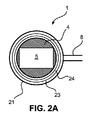
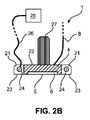
図2A及び2Bは、超音波モジュール1の一実施形態を、下から見た図(図2A)及び断面図(図2B)で概略的かつ例示的に示す。図示の実施形態では、超音波モジュール1が組織に取り付けられるとき、超音波トランスデューサ4は固定位置に保持される。
2A and 2B show an embodiment of the
この目的のために、超音波モジュール1は、超音波トランスデューサアレイ6を備える超音波トランスデューサ4の筐体22に取り付けられる支持要素21を備える。支持要素21は、超音波トランスデューサ4、特にその撮像表面5を囲み、撮像される組織に取り付けられ、超音波トランスデューサ4の撮像表面5と同じ方向に対向する把持表面23を有する。組織に把持表面23を取り付けることにより、超音波トランスデューサ4の撮像表面5は、組織を撮像するために、超音波トランスデューサ4を組織に密着させることができる。一実施態様では、超音波トランスデューサ4の支持要素21及び筐体22は、互いに固定的に接続されて、一体化装置を形成することができる。超音波トランスデューサ4の筐体22上に支持要素21を取り付けるために、支持要素21は、適切な方法で、例えば接着することによって、筐体22に固定されてもよい。又は支持要素21は、筐体22の一体化(外側)部分であってもよい。いくつかの実施例形態では、支持要素21は、超音波トランスデューサの筐体22に取り外し可能に接続され、支持要素21は、上述する超音波モジュール1の使い捨て部品として構成されてもよい。これは、本明細書で以下にさらに説明されるように、低侵襲プロシージャの後に、把持表面を含む支持要素21の一部が患者の体内に残っている場合に特に有用である。
For this purpose, the
支持要素21は、例えば、ポリマー、プラスチック又はセラミック材料などの適切な材料から製造されてもよい。支持要素21の少なくとも把持表面23は、好ましくは、例えばシリコーンゴム材料などの変形可能な材料から作られる。把持表面23が変形可能な材料から作製される場合、それは、撮像される組織の表面に適合することができる。これにより、把持表面23と組織との間の接触を強化することができる。把持表面23を含む支持要素21の一部が最小侵襲性プロシージャの後に患者の体内に残る場合、関連部分は吸収性及び/又は水溶性材料から作られるので、支持要素21の関連部分はしばらくすると患者の体内で消える。
The
一例として図2Aに示される一実施態様では、支持要素21及びその把持表面23は、実質的に円形又は楕円形を有する。これにより、超音波モジュール1を撮像される組織の上を容易に移動させることができる。しかしながら、支持要素21は、同様に、例えば、長方形のような他の形状で構成されてもよい。この場合、長方形の支持要素の場合には、組織上での超音波モジュール1の移動を容易にするために、支持要素21の角が丸められていることが好ましい。
As an example, in one embodiment shown in FIG. 2A, the
超音波トランスデューサ4の筐体22の外側輪郭は、支持要素21の形状に対応する形状を有し得るので、支持要素は、上記で説明したように超音波トランスデューサ4に取り付けられることによって方向付けられ得る。しかしながら、同様に、超音波トランスデューサ4の筐体の外側輪郭の形状が支持要素21の形状に対応しないこともあり得る。この場合、筐体22と支持要素22との間に空間が形成され、適当な充填材で満たすことができる。さらに、超音波トランスデューサ4は、支持要素21に固定して取り付けられてもよい。代替として、超音波トランスデューサ4は、支持要素21に対して移動可能であってもよい。特に、超音波トランスデューサ4は、超音波トランスデューサ4が超音波トランスデューサ4の撮像表面5に実質的に垂直な軸の周りで支持要素21に対して回転され得る態様で、支持要素21に接続されてもよい。この実施において、超音波トランスデューサの支持要素21及び筐体22の外側輪郭は、特に実質的に円形の形状を有し得る。
Since the outer contour of the
支持要素21は、オプションとして、膨張可能な構造として構成されてもよい。この実施形態では、超音波モジュール1は、支持要素21が減少する体積を有する収縮状態にある間に患者に挿入することができる。したがって、より大きな体積を有し、膨張される支持要素21を有するポート3を通じて適合しない超音波モジュール1を提供することが可能である。例えば超音波トランスデューサ4により多くの画像機能を実装するため、又は特に支持要素21のサイズを大きくするため、特に、以下に説明するように超音波トランスデューサが支持要素に対して変位できるように支持要素21を構成するため、より大きな体積を使用して、超音波トランスデューサ4の体積を増加させることができる。
The
膨張可能な支持要素21は、変形可能な材料から作製されてもよい。さらに、対応する流体管26(ここで使用される流体という用語は気体及び液体流体を指す)によって圧力源25に接続することができる1つ又は複数の膨張可能な流体チャンバ24を含むことができる。圧力源25によって、流体チャンバ24は、空気又は別の流体で満たすことができる。圧力源25は、好ましくは患者の体2の外側に配置される。収縮する支持要素21で超音波モジュール1を患者の体2に挿入すると、圧力源25が作動して流体チャンバ24に圧力を加え、支持要素21を膨張させる。支持要素21が膨張すると、支持要素21の十分な剛性を確保するために、流体チャンバ24にさらに圧力を加えることができる。代わりの実施例において、支持要素21は、流体チャンバ24を密封するために1つ又は複数の弁(図示せず)を有する。支持要素21が膨張すると、圧力源によって圧力を絶えず加える必要なしに、流体チャンバ24内の圧力を維持するために、弁を閉じることができる。したがって、流体管26を取り外して、患者の体2から引き抜かれることができる。この実施には、低侵襲プロシージャ中にポート3に他の手術器具を通すためにポート3がより広い幅を提供するように支持要素21を膨張させたときに流体管26がポート3にないという利点がある。
The
超音波モジュール1が組織を撮像するのにもはや必要でないとき、支持要素21は再び収縮され、それからポート3を通して患者の体2から取り除かれる。この目的のために、弁が再び開かれる。代わりに、弁は1回だけ使用されることができるように構成されるので、弁を再び開けないようにすることもできる。これにより、弁の構造が簡素化される。この代替例において、超音波モジュール1を患者の体2から取り外すために、流体チャンバ24は、例えば、 メスまたははさみを使用して穿刺されることができる。これにより、支持要素21は収縮するので、ポート3を通じて患者の体2から取り外すことができる。
When the
前述の代替案では、支持要素21は、超音波モジュール1の使い捨て構成要素として構成され得、超音波トランスデューサ4の筐体22に取り外し可能に取り付けられ得る。これを達成するために、支持要素21は、例えば、プラグ接続によって筐体22に取り付けられ得る。この実施において、超音波モジュール1は、それぞれの新しい最小侵襲性プロシージャのために新しい支持要素21を備え得る。
In the alternative described above, the
さらに、超音波モジュール1は、好ましくは、超音波トランスデューサ4及び/又は支持要素21に取り付けられ得、手術器具によって超音波モジュール1を操作することを可能にするハンドル27を備える。特に、ハンドル27は、手術用把持器によって容易に把持できるように構成されてもよい。この目的のために、ハンドル27は、ロッドとして構成され得る。しかしながら、他の適切な構成も同様に可能である。ハンドル27によって、超音波モジュール1は、撮像される組織上に超音波モジュール1を適切に配置するために、患者の体の体腔内で動かされてもよい。超音波モジュール1を配置すると、それは組織に固定され得る。この目的のために、超音波モジュール1の異なる実施例は、異なる固定機構を使用することができ、そのいくつかを以下に本明細書で説明する。
Further, the
さらに、組織と撮像表面5との間の音響結合を改善するために、超音波伝達ゲルが適用され得る。このゲルは、撮像表面5の領域の対応する出口に接続されるさらなる管を介して患者の体2の外部から提供されてもよい。
In addition, ultrasonic transfer gels may be applied to improve the acoustic coupling between the tissue and the
図3A及び3B(流体チャンバなしのバージョン)に概略的かつ例示的に示される1つの実施において、支持要素21は、把持表面23を通って延びる開口部32を有する中空の吸引チャネル31を備える。吸引チャネル31は、実質的にその全周にわたって把持表面23に沿って延びることができる。開口部32は、小さい規則的な距離で配置されてもよい。さらに、吸引チャネル31は、流体連通している吸引源33に接続され、負圧を吸引チャネル31に加えて、組織を開口部32に対して(及び中に)引くことができる。これにより、超音波モジュール1は、撮像される組織に固定可能である。吸引源33は、好ましくは患者の体外に配置され、吸引チャネル31は、管34を介して吸引源33に接続される。超音波モジュール1がイメージングのために患者の体内に挿入されると、管34がポート3を介して通される。
In one embodiment, schematically and exemplified in FIGS. 3A and 3B (version without fluid chamber), the
吸引源33は、超音波モジュール1が撮像される組織に取り付けられている間、吸引チャネル31から流体(空気)を継続的に吸引することができる。これにより、超音波モジュール1が確実に組織に固定される。さらに、超音波モジュール1は、吸引源33を停止することにより、組織から容易に取り外すことができる。その後、流体、特に空気が管34を通って吸引チャネル31に流入するので、吸引チャネルは組織から外れる。
The
代替として、吸引チャネル31は、吸引源33の動作により吸引チャネル31内に負圧が存在し、超音波モジュール1が組織に取り付けられていると、閉鎖され得る弁(図示せず)を備えることができる。弁は、関連する制御機構によって患者の体外から操作可能であってもよく、又は手術用把持器などの手術器具によって支持要素21で操作可能であってもよい。弁を閉じた後、最小侵襲性プロシージャ中の管34とさらなる器具との間の干渉を回避するために、管34を取り外してポート3から引き出すことができる。
Alternatively, the
超音波モジュール1を組織から外すために、弁を開いて流体を吸引チャネル31に流入させて、その中に生成される低圧を解放することができる。この目的のために、弁の開放機構は超音波モジュール1のハンドル27に接続されるので、超音波モジュール1を組織から持ち上げるためにハンドル27を引っ張るとき、弁が開くことができる。さらなるオプションとして、ポート3から患者の体2の領域に通じる吸引チャネル31に細い管を接続することができる。超音波モジュール1が組織に取り付けられている間、管を閉じることができる。超音波モジュール1を解放するために、流体が管を通して吸引チャネルに流れるようにするために、患者の体2の外側に配置される開放機構によって管を開放することができる。
To remove the
さらなる実施において、支持要素21の把持表面23には、撮像される組織に把持表面23を一時的に接着するための接着剤が提供されてもよい。特に、接着剤は、生体接着剤、すなわち撮像されるべき組織のタイプの生物組織に接着する(合成)材料として構成されてもよい。この実施態様では、超音波モジュール1が患者の体に挿入される前に、生体接着剤を把持表面に塗布することができる。生体接着剤が把持表面23に塗布される状態で超音波モジュール1を患者の体に挿入すると、超音波モジュール1は、把持表面23が組織に接触する態様で、上述のように撮像される組織上に適切に配置され得る。それから、超音波モジュール1を生体接着剤で固定するために、超音波モジュール1は、例えば手術用把持器によって組織に押し付けられることができる。
In a further embodiment, the gripping
超音波モジュール1が使用されなくなったとき、支持要素21は、組織に付着する把持表面23の近くで切断されて、把持表面23を超音波モジュール1の残りの部分から分離することができる。それから、超音波モジュール(より具体的には、前述の残りの部分)は、ポート3を介して患者の体2から取り外されてもよい。把持表面23を含む超音波モジュール1のカットオフ部分は、患者の中に残ってもよい。上述のように、それは吸収性又は水溶性の材料から作られ、しばらくすると患者の体内に消える。
When the
図4A及び図4Bに例示的及び概略的に示されている別の実施形態では、支持要素21は、妨害グリッパ技術を使用して撮像される組織に取り付けられる。妨害グリッパは、粒状材料で満たされる弾性エンクロージャを備えている。エンクロージャが把持されるべき物体と接触すると、エンクロージャは真空にされる。これにより、材料が詰まる(つまり硬化する)ので、粒状材料が物体の周囲の所定の位置にロックされ、例えば物体をピックアップするように物体はエンクロージャによって保持される。このようなグリッパの例は、US 2013/0106127 A1に記載されている。
In another embodiment, exemplary and schematically shown in FIGS. 4A and 4B, the
この実施形態では、支持要素21は、粒状材料で満たされる円周チャネル又はいくつかのエンクロージャ41を含み、チャネル又はエンクロージャは、(それぞれ)把持表面23又はその一部を形成する膜によって形成される。チャネル又はエンクロージャ41は、チャネル又はエンクロージャ41が吸引源42と流体連通するように、1つ又は複数の管43によって吸引源に接続されている。吸引源42は、ここでも患者の体2の外側に配置され得る。超音波モジュール1が撮像される組織上に配置されるとき、支持要素21は組織と接触し、吸引源42は作動してチャネル又はエンクロージャ41から流体(特に空気)を排出する。これにより、チャネル又はエンクロージャ41内の粒状材料が詰まる。これにより、支持要素21、したがって超音波モジュール1を組織に一時的に取り付けることができる。
In this embodiment, the
場合によっては、支持要素21はしばらくすると組織から外れる。そうである場合、流体は、チャネル又はエンクロージャ41に再び流れ込むことが可能になるので、粒状材料は変形可能な状態に戻る。それから、支持要素21を組織に再び固定するために、流体をチャネル又はエンクロージャ41から再び排出することができる。さらに、超音波モジュール1を組織から除去するために、流体は同様にチャネル内を流れることができるので、超音波モジュール1を組織から分離することができる。
In some cases, the
図5A(上面図)及び5B(断面図)において概略的かつ例示的に示されるさらなる実施例において、超音波モジュール1は、支持要素21(及び撮像される組織)に対する超音波トランスデューサ4の変位を可能にするという点で、上で説明した実施例における超音波モジュール1とは異なる。より具体的には、超音波トランスデューサ4は、撮像表面5及び組織に実質的に平行な平面内で一方向に支持要素21に対して移動することができる。したがって、撮像表面5をそれに平行に保ちながら、超音波トランスデューサ4を組織の上で移動させることが可能である。これにより、表層組織と深部組織を同じ量でイメージングできる。
In a further embodiment shown schematicly and exemplary in FIGS. 5A (top view) and 5B (cross section), the
さらなる撮像技術によれば、組織は、超音波トランスデューサを回転させることにより、及び経路に沿った異なる位置でこの操作をシーケンシャルに実行することにより、しばしばスキャンされる。しかしながら、これにより、大量の深部組織がスキャンされるが、表面でスキャンされる組織はごくわずかである。したがって、表層病変は見逃される可能性がある。これは、上で説明したように撮像面を前記表面に平行に保ちながら、超音波トランスデューサ4を組織上で動かすことで防ぐことができる。この撮像技術は、図5Aと5Bに示す超音波モジュール1の実装によって容易になる。
According to further imaging techniques, tissue is often scanned by rotating the ultrasound transducer and by performing this operation sequentially at different locations along the path. However, this scans a large amount of deep tissue, but only a small amount of tissue is scanned on the surface. Therefore, superficial lesions can be overlooked. This can be prevented by moving the
この実施態様では、支持要素31は、脚の2つの対向する対51a乃至51dを含む実質的に長方形の形状を有する。超音波トランスデューサ4の筐体22は、超音波トランスデューサ4がこれらの脚51a、51bに平行な方向にこれらの脚32a、51bに対して移動できるように脚の第1の対の脚51a、51bとスライド可能に接触してもよい。脚の他の対の脚51b、51cは、特に支持要素1を安定させるために、脚の第1の対の脚を接続する。すべての脚51a乃至51dは、内部体積及びこの体積の平行な方向の寸法を囲み、脚の第1の対に平行な方向におけるこの体積の寸法は、超音波トランスデューサ4の筐体22のサイズよりも大きい。したがって、超音波トランスデューサ4は、この領域内でこの方向に移動することができる。脚の第2の対は、超音波トランスデューサ4のこの動きを制限する。
In this embodiment, the
超音波トランスデューサ4が傾くことを防止するために、支持要素21は、好ましくは、保持部材52をさらに備える。保持部材33は、超音波トランスデューサの撮像表面5が撮像される組織に平行に移動することを確実にする。一実施形態では、保持部材52は、脚の第1の対の一方の脚51aに、及び随意に脚の第2の対のセクションに取り付けられ、4つの脚によって規定される体積の上面を閉じることができる。保持部材52と脚の第1の対の他方の脚51bとの間には開口部があり、超音波トランスデューサ4の筐体はこの開口部を通って延在し得るので、それは、撮像される組織上を移動するために特に把持され得る。
In order to prevent the
本実施形態では、超音波トランスデューサ4を支持要素21に対して移動させることができるが、超音波トランスデューサ4を支持要素21に取り付けて、超音波トランスデューサ4を支持要素21から分離できないようにすることができる。これにより、ポート3を介して超音波モジュール1を患者の体2に挿入することが簡単になる。代替として、超音波トランスデューサ4及び支持要素21は、互いに独立して患者の体2に導入され得る超音波モジュール1の別個の構成要素であり得る。それから、患者の体2において、超音波トランスデューサ4が、例えば手術用グラスパーの助けを借りて支持要素21に挿入されてもよい。この実施には、完全な超音波モジュール1(超音波トランスデューサ4及び支持要素21を含む)がポート3の寸法よりも大きい寸法を有することができるという利点がある。他の点では、支持要素21は、上記の実施例のように構成されてもよい。特に、支持要素21は、上述の方法で撮像される組織に取り付け可能であり得る。したがって、支持要素21は、吸引力を用いて、(生物)接着剤を用いて、又は上で説明したような妨害グリッパ技術を使用して、組織に固定されてもよい。
In the present embodiment, the
さらに、支持要素21は、これも上述したように、膨張可能な構造として構成されてもよい。これは、支持要素のサイズが大きくなるため、この実施例で特に役立つ。上述の膨張可能な構造の特徴に加えて、支持要素は、例えば金属などの剛性材料で作られた複数のワイヤセクションをさらに含むことができる。ワイヤセクションは、支持要素31の前述の脚51a乃至51dに一体化されてもよく、これらの脚51a乃至51dの長手方向に延在してもよい。ワイヤにより、支持要素21の安定性を改善することができる。さらに、複数のワイヤセクションが設けられているため、特に超音波モジュール1を患者の体に挿入し、超音波モジュール1を患者の体から取り外すために、支持要素を収縮させてそのサイズを縮小することができる。
Further, the
上述の実施形態では、超音波モジュール1は、ポート3を通過させることによって体腔内に挿入することができる。超音波モジュール1の構成要素を超音波コンソール7に接続するための接続ワイヤ及び管、吸引源33、42(存在する場合)、及び圧力源25(存在する場合)がポート3を通過する。
In the above-described embodiment, the
さらなる実施形態では、超音波モジュール1と超音波コンソール7との間の接続ワイヤのための別個のチャネルを含むトロカール又は他のポートが提供される。さらに、別個のチャネルは、超音波モジュール1を吸引源33、42(存在する場合)及び圧力源25(存在する場合)に接続するための管も収容し得る。これにより、接続ワイヤ及び管は、最小侵襲性プロシージャでポート3を通過する可能性がある他の手術用装置を妨害しない。
In a further embodiment, a trocar or other port is provided that includes a separate channel for the connecting wire between the
この実施形態では、超音波モジュール1は、ポート3と一緒に患者の体2に挿入され得る。この目的のために、超音波モジュール1は、特に、上記で説明した個別のチャネルを通過する超音波モジュールに接続される管及びワイヤを用いてポート3の内側に配置され得る。ここで、別個のチャネルは、例えば、その先端の領域でポート3の内部に開口することができる。ポート3が患者の体2に挿入されると、超音波モジュール3は、適切な解放機構によって、ポート3によって開かれた体腔内に解放されてもよい。
In this embodiment, the
上記のように、ポート3は、特にトロカールとして構成され得る。通常、トロカールは、患者の体2に突き刺さって腹部などの体腔への入口を形成する鋭い内部を備えた中空シャフトを含む。その後すぐに、鋭い内部が取り除かれ、内部が取り除かれると、トロカールを体腔へのポータルとして使用することができる。前述の実施形態では、トロカール3は、超音波モジュール1に接続されるワイヤ及びタブを含む別個のチャネルを含むことができ、超音波モジュール1は、患者の体2に導入されるときにトロカールの内部に配置され得る。
As mentioned above, port 3 can be configured specifically as a trocar. Trocars typically include a hollow shaft with a sharp interior that pierces the patient's
図6に概略的かつ例示的に示されるさらなる実施形態では、超音波モジュール1は、手術器具62のステアリングを容易にするため、及び手術器具62を用いて実行されるプロシージャを監視するために、手術器具62を超音波モジュール1に取り付けるためのホルダ61を有する。ホルダ61は、超音波トランスデューサ4の筐体22上に、又は図6に示すように、支持要素21上に取り付けられてもよい。手術器具62は、例えば、針であってもよい。しかしながら、他の手術器具62も同様に、ホルダ61によって超音波モジュール1に取り付けられ得る。ホルダ62は、手術器具がホルダに適切に挿入されたとき、少なくとも手術器具62の先端が超音波トランスデューサの視野内に配置されるように構成される。さらに、超音波モジュール1が組織に取り付けられているとき、その先端が超音波トランスデューサの視野内に保持されるように、手術器具は超音波モジュール1に対して可動であってもよい。
In a further embodiment, schematically and exemplified in FIG. 6, the
手術器具62が針である場合、対応する動きは、針の長手方向における前後の動きを特に含み得る。さらに、さらなる自由度に従って手術器具62を移動させることが可能であり得る。この目的のために、ホルダ62は、対応する動きが実行されるように移動可能であり得る。手術器具62の実施が可能である。同様に、手術器具62は、ホルダ62に挿入される近位セクションと、手術器具の先端を超音波モジュールの視野内でステアリングできるように近位セクションに対して移動できる遠位セクションとを備えることができる。
When the
開示される実施形態に対する変形は、図面、開示、及び添付の特許請求の範囲の研究から、請求される発明を実施する際に当業者によって理解及び達成され得る。 Modifications to the disclosed embodiments can be understood and achieved by one of ordinary skill in the art in carrying out the claimed invention from the drawings, disclosures, and studies of the appended claims.
特許請求の範囲において、「含む」という語は他の要素又はステップを除外せず、不定冠詞「a」又は「an」は複数を除外しない。 In the claims, the word "contains" does not exclude other elements or steps, and the indefinite article "a" or "an" does not exclude more than one.
単一のコンポーネント又は装置は、特許請求の範囲に記載されているいくつかのアイテムの機能を満たすことができる。特定の手段が相互に異なる従属請求項に記載されているという単なる事実は、これらの手段の組み合わせが有利に使用できないことを示すものではない。 A single component or device can satisfy the functions of several items described in the claims. The mere fact that certain means are described in different dependent claims does not indicate that the combination of these means cannot be used in an advantageous manner.
請求項の参照符号は、範囲を限定するものとして解釈されるべきではない。 The reference code of the claims should not be construed as limiting the scope.
Claims (15)
Applications Claiming Priority (5)
| Application Number | Priority Date | Filing Date | Title |
|---|---|---|---|
| US201762608093P | 2017-12-20 | 2017-12-20 | |
| US62/608,093 | 2017-12-20 | ||
| EP18151168.4A EP3510932A1 (en) | 2018-01-11 | 2018-01-11 | Ultrasound device for in-situ ultrasound imaging |
| EP18151168.4 | 2018-01-11 | ||
| PCT/EP2018/085371 WO2019121601A1 (en) | 2017-12-20 | 2018-12-18 | Ultrasound device for in-situ ultrasound imaging |
Publications (2)
| Publication Number | Publication Date |
|---|---|
| JP2021506472A true JP2021506472A (en) | 2021-02-22 |
| JP2021506472A5 JP2021506472A5 (en) | 2022-01-06 |
Family
ID=60954941
Family Applications (1)
| Application Number | Title | Priority Date | Filing Date |
|---|---|---|---|
| JP2020534305A Withdrawn JP2021506472A (en) | 2017-12-20 | 2018-12-18 | Ultrasound device for in-situ ultrasonic imaging |
Country Status (5)
| Country | Link |
|---|---|
| US (1) | US20210015455A1 (en) |
| EP (2) | EP3510932A1 (en) |
| JP (1) | JP2021506472A (en) |
| CN (1) | CN111655155A (en) |
| WO (1) | WO2019121601A1 (en) |
Family Cites Families (19)
| Publication number | Priority date | Publication date | Assignee | Title |
|---|---|---|---|---|
| US4877033A (en) * | 1988-05-04 | 1989-10-31 | Seitz Jr H Michael | Disposable needle guide and examination sheath for transvaginal ultrasound procedures |
| US5247938A (en) * | 1990-01-11 | 1993-09-28 | University Of Washington | Method and apparatus for determining the motility of a region in the human body |
| US5331947A (en) * | 1992-05-01 | 1994-07-26 | Shturman Cardiology Systems, Inc. | Inflatable sheath for introduction of ultrasonic catheter through the lumen of a fiber optic endoscope |
| US5820552A (en) * | 1996-07-12 | 1998-10-13 | United States Surgical Corporation | Sonography and biopsy apparatus |
| AU766783B2 (en) * | 1997-08-19 | 2003-10-23 | Philipp Lang | Ultrasonic transmission films and devices, particularly for hygienic transducer surfaces |
| US6728565B2 (en) * | 2000-02-25 | 2004-04-27 | Scimed Life Systems, Inc. | Diagnostic catheter using a vacuum for tissue positioning |
| US7477763B2 (en) * | 2002-06-18 | 2009-01-13 | Boston Scientific Scimed, Inc. | Computer generated representation of the imaging pattern of an imaging device |
| JP5073415B2 (en) * | 2006-08-28 | 2012-11-14 | オリンパスメディカルシステムズ株式会社 | Ultrasound endoscope |
| WO2008057566A2 (en) * | 2006-11-07 | 2008-05-15 | Amir Belson | Attachable ultrasound imaging device |
| US8540707B2 (en) * | 2007-12-21 | 2013-09-24 | St. Jude Medical, Atrial Fibrillation Division, Inc. | Template system and methods |
| DK200900527A (en) * | 2009-04-24 | 2010-10-25 | Region Nordjylland Aalborg Syg | Device for holding an imaging probe and use of such device |
| US8882165B2 (en) | 2010-04-15 | 2014-11-11 | Cornell University | Gripping and releasing apparatus and method |
| US11612377B2 (en) * | 2010-12-16 | 2023-03-28 | Best Medical International, Inc. | Image guided surgical methodology and system employing patient movement detection and correction |
| WO2014115056A1 (en) * | 2013-01-22 | 2014-07-31 | Koninklijke Philips N.V. | Ultrasound probe and ultrasound imaging system |
| JP2015037528A (en) * | 2013-07-19 | 2015-02-26 | 株式会社東芝 | Ultrasonic medical device and ultrasonic diagnostic device |
| US9730675B2 (en) * | 2014-01-27 | 2017-08-15 | Koninklijke Philips N.V. | Ultrasound imaging system and an ultrasound imaging method |
| WO2015153931A1 (en) * | 2014-04-02 | 2015-10-08 | The Board Of Trustees Of The Leland Stanford Jr. University | Biopsy devices, systems, and methods for use |
| US10639503B2 (en) * | 2014-08-27 | 2020-05-05 | Fusmobile Inc. | Handheld devices for projecting focused ultrasound and related methods |
| JP6668817B2 (en) * | 2016-02-26 | 2020-03-18 | コニカミノルタ株式会社 | Ultrasound diagnostic apparatus and control program |
-
2018
- 2018-01-11 EP EP18151168.4A patent/EP3510932A1/en not_active Withdrawn
- 2018-12-18 EP EP18826287.7A patent/EP3727157A1/en not_active Withdrawn
- 2018-12-18 CN CN201880087134.8A patent/CN111655155A/en active Pending
- 2018-12-18 JP JP2020534305A patent/JP2021506472A/en not_active Withdrawn
- 2018-12-18 WO PCT/EP2018/085371 patent/WO2019121601A1/en unknown
- 2018-12-18 US US16/955,894 patent/US20210015455A1/en not_active Abandoned
Also Published As
| Publication number | Publication date |
|---|---|
| EP3727157A1 (en) | 2020-10-28 |
| US20210015455A1 (en) | 2021-01-21 |
| CN111655155A (en) | 2020-09-11 |
| WO2019121601A1 (en) | 2019-06-27 |
| EP3510932A1 (en) | 2019-07-17 |
Similar Documents
| Publication | Publication Date | Title |
|---|---|---|
| US8167805B2 (en) | Systems and methods for ultrasound applicator station keeping | |
| KR102443416B1 (en) | Mounting datum of surgical instrument | |
| EP2116188B1 (en) | Ultrasound probe device | |
| US20090318797A1 (en) | System and method for deflecting endoscopic tools | |
| EP1971280A2 (en) | Instrument port for minimally invasive cardiac surgery | |
| JP2013503690A (en) | Improved anorectal probe and method | |
| JP4487050B2 (en) | In-vivo medical device | |
| JP2023530477A (en) | Tissue-tripping acoustic/patient coupling system and method | |
| WO2003099101A2 (en) | Breast stabilizers having an open lattice structure and imaging methods using same | |
| JP5981081B1 (en) | Ultrasonic endoscope, ultrasonic endoscope suction device, and ultrasonic endoscope system | |
| JP6767575B2 (en) | Ultrasonic Transducer / Tile Alignment | |
| JP2021506472A (en) | Ultrasound device for in-situ ultrasonic imaging | |
| KR20140133672A (en) | Ultrasound Probe | |
| JP4526298B2 (en) | Ultrasound endoscope device | |
| JP4307957B2 (en) | Ultrasound endoscope device | |
| Gumprecht et al. | A new ultrasound imaging concept for laparoscopy in urology | |
| JP6987029B2 (en) | How to operate the ultrasonic diagnostic device and the ultrasonic diagnostic device | |
| Stilli et al. | Track-guided ultrasound scanning for tumour margins outlining in robot-assisted partial nephrectomy | |
| JP7301114B2 (en) | ULTRASOUND DIAGNOSTIC SYSTEM AND METHOD OF OPERATION OF ULTRASOUND DIAGNOSTIC SYSTEM | |
| US20210339052A1 (en) | Removable High Intensity Focused Ultrasound Transducer Assembly and Coupling Mechanism | |
| WO2023018914A2 (en) | Ultrasound sensing system | |
| WO2012057274A1 (en) | Ultrasonic irradiation device | |
| JP2021506472A5 (en) | ||
| JPH02189137A (en) | Audio coupler with holder and manufacture thereof | |
| Gumprecht et al. | A flat-panel ultrasound robot to align an abdominal ultrasound probe during laparoscopic partial nephrectomy |
Legal Events
| Date | Code | Title | Description |
|---|---|---|---|
| A521 | Request for written amendment filed |
Free format text: JAPANESE INTERMEDIATE CODE: A523 Effective date: 20211122 |
|
| A621 | Written request for application examination |
Free format text: JAPANESE INTERMEDIATE CODE: A621 Effective date: 20211122 |
|
| A761 | Written withdrawal of application |
Free format text: JAPANESE INTERMEDIATE CODE: A761 Effective date: 20220602 |