JP2021192004A - Method for inspecting airtightness of container, and inspection apparatus therefor - Google Patents
Method for inspecting airtightness of container, and inspection apparatus therefor Download PDFInfo
- Publication number
- JP2021192004A JP2021192004A JP2020098397A JP2020098397A JP2021192004A JP 2021192004 A JP2021192004 A JP 2021192004A JP 2020098397 A JP2020098397 A JP 2020098397A JP 2020098397 A JP2020098397 A JP 2020098397A JP 2021192004 A JP2021192004 A JP 2021192004A
- Authority
- JP
- Japan
- Prior art keywords
- container
- cover
- liquid
- trace gas
- space
- Prior art date
- Legal status (The legal status is an assumption and is not a legal conclusion. Google has not performed a legal analysis and makes no representation as to the accuracy of the status listed.)
- Pending
Links
- 238000007689 inspection Methods 0.000 title claims abstract description 42
- 238000000034 method Methods 0.000 title claims abstract description 21
- 239000007788 liquid Substances 0.000 claims abstract description 80
- 230000002950 deficient Effects 0.000 claims abstract description 28
- 238000001514 detection method Methods 0.000 claims description 28
- 238000003756 stirring Methods 0.000 claims description 13
- 238000011010 flushing procedure Methods 0.000 claims 1
- 238000004519 manufacturing process Methods 0.000 abstract description 17
- 239000007789 gas Substances 0.000 description 65
- 238000007789 sealing Methods 0.000 description 21
- 239000000523 sample Substances 0.000 description 9
- 229910052734 helium Inorganic materials 0.000 description 5
- 239000001307 helium Substances 0.000 description 5
- SWQJXJOGLNCZEY-UHFFFAOYSA-N helium atom Chemical compound [He] SWQJXJOGLNCZEY-UHFFFAOYSA-N 0.000 description 5
- XLYOFNOQVPJJNP-UHFFFAOYSA-N water Substances O XLYOFNOQVPJJNP-UHFFFAOYSA-N 0.000 description 5
- 230000000694 effects Effects 0.000 description 4
- 230000007547 defect Effects 0.000 description 3
- 239000000446 fuel Substances 0.000 description 3
- CURLTUGMZLYLDI-UHFFFAOYSA-N Carbon dioxide Chemical compound O=C=O CURLTUGMZLYLDI-UHFFFAOYSA-N 0.000 description 2
- 238000012790 confirmation Methods 0.000 description 2
- 238000010586 diagram Methods 0.000 description 2
- 230000000630 rising effect Effects 0.000 description 2
- 230000000007 visual effect Effects 0.000 description 2
- 229910002092 carbon dioxide Inorganic materials 0.000 description 1
- 239000001569 carbon dioxide Substances 0.000 description 1
- 238000005516 engineering process Methods 0.000 description 1
- 238000007667 floating Methods 0.000 description 1
- 229910052736 halogen Inorganic materials 0.000 description 1
- 150000002367 halogens Chemical class 0.000 description 1
- 239000001257 hydrogen Substances 0.000 description 1
- 229910052739 hydrogen Inorganic materials 0.000 description 1
- 150000002431 hydrogen Chemical class 0.000 description 1
- JEIPFZHSYJVQDO-UHFFFAOYSA-N iron(III) oxide Inorganic materials O=[Fe]O[Fe]=O JEIPFZHSYJVQDO-UHFFFAOYSA-N 0.000 description 1
- 238000012986 modification Methods 0.000 description 1
- 230000004048 modification Effects 0.000 description 1
- 150000002894 organic compounds Chemical class 0.000 description 1
- RVZRBWKZFJCCIB-UHFFFAOYSA-N perfluorotributylamine Chemical compound FC(F)(F)C(F)(F)C(F)(F)C(F)(F)N(C(F)(F)C(F)(F)C(F)(F)C(F)(F)F)C(F)(F)C(F)(F)C(F)(F)C(F)(F)F RVZRBWKZFJCCIB-UHFFFAOYSA-N 0.000 description 1
- 230000003449 preventive effect Effects 0.000 description 1
- 238000010998 test method Methods 0.000 description 1
Images

Landscapes
- Examining Or Testing Airtightness (AREA)
Abstract
Description
本発明は、容器の気密性を検査する方法、及びその検査装置に関する。 The present invention relates to a method for inspecting the airtightness of a container and an inspection device thereof.
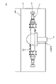
例えばアクスルケースや燃料ケース等のように気密性を要する容器においては、これらを製造した後、容器に欠陥部が生じていないか検査が行われている。このような気密性の検査は、効率性の観点から製造ラインに組み込まれていることが一般的である。また従来、容器の気密性を検査する場合には、図2、図3に示す検査装置や、以下の特許文献及び非特許文献に示された方法が用いられている。 For example, in containers that require airtightness such as axle cases and fuel cases, after manufacturing these, inspection is performed to see if there are any defects in the container. Such an airtightness inspection is generally incorporated in the production line from the viewpoint of efficiency. Further, conventionally, when inspecting the airtightness of a container, the inspection apparatus shown in FIGS. 2 and 3 and the methods shown in the following patent documents and non-patent documents have been used.
図2は、気密性の検査を行うための従来の検査装置を模式的に示した図である。図2に示した検査装置101は、アクスルケースAの気密性を検査するものであって、所定の液体(例えば水)を収容可能な液槽102にアクスルケースAを液没させて検査を行うものである。具体的には、アクスルケースAにおける左右の開口部を第1密閉機構103で閉鎖するとともに中央の開口部を第2密閉機構104で閉鎖する。なお、第2密閉機構104は、中央の開口部からアクスルケースA内に空気を送り込む機能を備えている。そして、第1密閉機構103と第2密閉機構104によって開口部を密閉した状態でアクスルケースAを液槽102の液体に液没させ、第2密閉機構104から送り込む空気によって、アクスルケースA内を加圧する。この状態においてアクスルケースAに欠陥部があると、欠陥部から気泡が漏れ出てくるため、検査員による目視での気泡確認によって、欠陥部の有無を判断している。
FIG. 2 is a diagram schematically showing a conventional inspection device for inspecting airtightness. The
しかし、このような検査装置101による検査では、欠陥部が小さいと漏れ出す気泡の大きさも小さくなるため、目視での確認では気泡を見逃すおそれがある。また、アクスルケースAの外側に取り付けられている部品の隙間に空気が残っていて、この空気が気泡となって表れることもあるため、実際には欠陥部はないものの、不良と判断してしまうおそれもある。更に、製造ラインのサイクルタイム内に検査を終える必要があるため、検査員の負担も大きくなっている。
However, in the inspection by such an
一方、検査員の目視確認によらずに自動で欠陥部の有無を判断する検査装置も使用されている。図3に示した検査装置201は、密閉したアクスルケースA内にトレースガス(例えばヘリウム)を送り込み、欠陥部から漏れ出すトレースガスを検知するものである。具体的には、アクスルケースAにおける左右の開口部を第1密閉機構203で閉鎖し、中央の開口部は、アクスルケースA内にトレースガスを送り込む機能を有する第2密閉機構204で閉鎖する。そして、トレースガスの有無を検知する検知装置(検知装置本体205と、検知装置本体205に接続されるプローブ206を含んで構成される)とロボット207(例えば6軸マニピュレータ)によって、アクスルケースA内をトレースガスで加圧した状態で、欠陥部が存在しそうな部位(例えばアクスルケースAの継ぎ目等)を中心にプローブ206をロボット207で走査する。
On the other hand, an inspection device that automatically determines the presence or absence of a defective portion without visual confirmation by an inspector is also used. The
しかしこのような検査装置201の検査では、トレースガスを検知することによって欠陥部の有無は把握できるものの、欠陥部の正確な位置を掴むことが難しい。このため、欠陥部があると判断した場合は、一旦製造ラインから外して、図2に示した如き装置でアクスルケースAを液没させて気泡によって欠陥部の位置を特定し、欠陥部の補修を行った後に再び製造ラインに投入して再検査を行う必要がある。また、検査対象となる容器の種類に応じてロボット207のティーチングが必要となるため、製造ラインの立ち上げに時間を要することになる。更に、図示した如きアクスルケースAにおいては、通常、これを製造ラインで製造する際の時間に対し、1台のロボット207でプローブ206を走査する時間の方が長くなる。従ってサイクルタイムを短縮するためには、ロボット207等を複数台(例えば1つの製造ラインにつきロボット207は2台)準備しなければならず、設備に要する費用も嵩むことになる。
However, in such an inspection of the
そして特許文献1に示された検査装置は、検査対象となる容器の形状に合わせた覆い24を使用しているため、容器の形状が異なれば覆い24も取り換えなければならず、多品種の容器を製造するための製造ラインに適用することは難しく、汎用性に乏しい。また特許文献2に示された検査装置は、検査対象となる容器を検査室3の内側に配置し、容器にヘリウムを供給するとともに検査室3のヘリウム濃度を測定して、濃度変化が生じた場合に容器に欠陥部があると判断している。しかし、検査室3の容積は、容器全体を取り囲む必要があるために大きくなり、その結果、検査室3のヘリウム濃度はすぐには変化せず、検査結果が得られるまで時間を要することになる。また特許文献1、2に示された検査装置では、トレースガスの濃度変化等によって欠陥部の有無は把握できるものの、その位置を特定することはできない。
Since the inspection device shown in
また非特許文献1、2にも、容器の気密性を検査する方法や検査装置が開示されている。しかし非特許文献1、2に示された複数の検査方法は、上述した図2や図3と同種の方法、又は製造ラインに組み込むには難しい方法であるため、図2、図3の検査装置で生じる問題の解決には至っていなかった。
In addition, Non-Patent
本発明は、このような従来の問題を解決することを課題とするものであって、容器の気密性を検査する方法及びその装置に関して、検査員の技量に依存せずに自動で精度よく検査を行うことができ、また多品種の容器を製造するための製造ラインに適用することも可能な技術の提供を目的とする。 An object of the present invention is to solve such a conventional problem, and the method and device for inspecting the airtightness of a container are automatically and accurately inspected without depending on the skill of an inspector. The purpose is to provide a technology that can be applied to a production line for producing a wide variety of containers.
本発明は、容器の気密性を検査する方法であって、開口部を密閉した容器の内部にトレースガスを充満させるとともに所定の液体内に当該容器を液没させる工程と、下部に開口を有し上部を閉鎖可能であって当該上部に前記トレースガスを検知可能な検知装置を備えるカバーによって、当該カバーの内部に気体が溜まる空間が形成される状態で液没させた前記容器の上方を覆う工程と、前記液体の液面下において前記容器又は前記カバーの内側に向かう液流を発生させて、当該容器の欠陥部から漏れ出て当該容器の表面又は当該カバーの内側に付着した前記トレースガスを前記空間に押し流す工程と、前記検知装置によって前記空間に存在する前記トレースガスを検知する工程と、を含むことを特徴とする。 The present invention is a method for inspecting the airtightness of a container, in which a container having a closed opening is filled with trace gas and the container is submerged in a predetermined liquid, and an opening is provided at the bottom. A cover provided with a detection device capable of closing the upper part and detecting the trace gas covers the upper part of the submerged container in a state where a space for collecting gas is formed inside the cover. The step and the trace gas leaking from the defective portion of the container and adhering to the surface of the container or the inside of the cover by generating a liquid flow toward the inside of the container or the cover under the liquid surface of the liquid. It is characterized by including a step of pushing the trace gas into the space and a step of detecting the trace gas existing in the space by the detection device.
そして、前記トレースガスを前記空間に押し流す工程は、前記液体の液面下において前記容器及び前記カバーの内側に向かう液流を発生させて行われることが好ましい。 The step of pushing the trace gas into the space is preferably performed by generating a liquid flow toward the inside of the container and the cover under the liquid surface of the liquid.
また前記カバーは、下部に対して上部が狭い上窄まり形状であることが好ましい。 Further, it is preferable that the cover has an upper constriction shape in which the upper portion is narrower than the lower portion.
また前記カバーは、前記空間の気体を撹拌する気体撹拌手段を備えることが好ましい。 Further, it is preferable that the cover is provided with a gas stirring means for stirring the gas in the space.
そして前記検知装置によって検知された前記トレースガスの濃度が所定値以上である場合、又は当該検知装置によって検知された当該トレースガスの濃度が経時的に上昇している場合に、前記容器に前記欠陥部があると判定する工程を含むことが好ましい。 Then, when the concentration of the trace gas detected by the detection device is equal to or higher than a predetermined value, or when the concentration of the trace gas detected by the detection device increases with time, the defect is found in the container. It is preferable to include a step of determining that there is a portion.
また本発明は、容器の気密性を検査するための検査装置であって、所定の液体を収容して前記容器を液没可能な液槽と、前記容器の内部にトレースガスを送り込むトレースガス送給手段と、下部に開口を有し上部を閉鎖可能であって、内部に気体が溜まる空間が形成される状態で前記液槽に液没させた前記容器の上方を覆うカバーと、前記液槽の液面下において、液没させた前記容器又は当該容器の上方を覆う前記カバーの内側に向かう液流を発生させる液流発生手段と、前記カバーの上部に設けられ、前記空間に存在する前記トレースガスを検知する検知装置と、を備えることを特徴とする検査装置でもある。 Further, the present invention is an inspection device for inspecting the airtightness of a container, which is a liquid tank capable of containing a predetermined liquid and submerging the container, and a trace gas feeding device for feeding the trace gas into the inside of the container. A supply means, a cover that covers the upper part of the container submerged in the liquid tank in a state where the upper part can be closed with an opening at the lower part and a space for gas to collect inside, and the liquid tank. A liquid flow generating means for generating a liquid flow toward the inside of the container that is submerged or the cover that covers the upper part of the container, and a liquid flow generating means that is provided on the upper part of the cover and exists in the space. It is also an inspection device characterized by being provided with a detection device that detects trace gas.
本発明によれば、検査員の技量に依存することなく、製造ラインに組み込んで自動で検査を行うことができる。また、容器の種類が異なる場合でも設備を大幅に変更する必要はない。更に、容器における欠陥部の位置を特定することも容易であるため、容器を製造ラインから外さずに、その場で欠陥部の補修と再検査を行うことも可能である。 According to the present invention, the inspection can be automatically performed by incorporating it into the production line without depending on the skill of the inspector. Moreover, even if the type of container is different, it is not necessary to change the equipment drastically. Further, since it is easy to identify the position of the defective portion in the container, it is possible to repair and re-inspect the defective portion on the spot without removing the container from the production line.
以下、添付の図面を参照しながら、本発明に係る容器の気密性を検査する方法、及びその検査装置の一実施形態について説明する。 Hereinafter, a method for inspecting the airtightness of the container according to the present invention and an embodiment of the inspection device will be described with reference to the accompanying drawings.
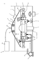
図1は、本発明に係る検査装置の一実施形態を模式的に示した図である。本実施形態の検査装置1は、アクスルケースAの気密性が検査できるように構成されている。なお後述するように検査装置1は、形状が多少異なる他のアクスルケースについても、設備を変更することなく(又は多少変更する程度で)気密性の検査を行うことができる。また検査装置1で検査可能な容器はアクスルケースに限定されず、例えば後述する第1密閉機構等を適宜変更することによって他の容器(例えば燃料ケース、エアタンク、SCRタンク)の気密性を検査することも可能である。
FIG. 1 is a diagram schematically showing an embodiment of an inspection device according to the present invention. The
本実施形態の検査装置1は、液槽2、第1密閉機構3、第2密閉機構4、ポンプ5、攪拌装置6、超音波振動装置7、カバー8、検知装置9、ファン10を備えている。
The
液槽2は、所定の液体Lを収容するものであって、アクスルケースAが液没できる大きさで形成されている。液槽2に収容される液体Lは特に限定されず、例えば水、油(例えば防錆油)、液体有機化合物(例えばフロリナート(登録商標))が使用される。 The liquid tank 2 accommodates a predetermined liquid L, and is formed in a size that allows the axle case A to be submerged. The liquid L contained in the liquid tank 2 is not particularly limited, and for example, water, oil (for example, rust preventive oil), and liquid organic compound (for example, Fluorinert (registered trademark)) are used.
第1密閉機構3は、アクスルケースAにおける左右の開口部を閉鎖するよう構成されている。第1密閉機構3は、アクスルケースAの左右の開口部に対して進退移動可能であって、後退位置から前進位置に移動させることによってこれらの開口部を自動で閉鎖するものでもよいし、例えば作業員によって左右の開口部に嵌め込まれるキャップの如きものでもよい。
The
第2密閉機構4は、アクスルケースAの中央の開口部を閉鎖するように構成されている。また第2密閉機構4は、本明細書等において「トレースガス送給手段」と称するものでもあって、アクスルケースA内にトレースガスを送り込む機能も有している。なお、アクスルケースA内にトレースガスを送り込む機能は、第1密閉機構3に持たせてもよい。ここでトレースガスとして使用される気体としては、例えばヘリウム、水素、二酸化炭素、ハロゲン等が挙げられるが、これらに限定されるものではない。
The second sealing mechanism 4 is configured to close the central opening of the axle case A. Further, the second sealing mechanism 4 is also referred to as a "trace gas feeding means" in the present specification and the like, and has a function of feeding the trace gas into the axle case A. The
ポンプ5、攪拌装置6、超音波振動装置7は、本明細書等において「液流発生手段」と称するものであって、液槽2に収容した液体Lを流動させて液流を発生させるものである。本実施形態のポンプ5は、液没させたアクスルケースAの下部に向けて指向する第1パイプ5aや、後述するようにアクスルケースAの上方を覆うように移動したカバー8の内側に向けて指向する第2パイプ5bに接続されていて、吸引パイプ5cを通して液槽2の液体を吸引し、第1パイプ5aや第2パイプ5bから液体を排出することによって、アクスルケースAやカバー8の内側に向かう液流を発生させることができる。また攪拌装置6は、本実施形態では液槽2の底部において上方に向けて取り付けられていて、複数のブレード(羽根)を有するプロペラ状の回転体を回転させることによって、アクスルケースAに向かう液流を発生させることができる。そして超音波振動装置7は、超音波によって液体を振動させて液流を発生させるものであって、本実施形態では液槽2の底部と、カバー8における中間部(カバー8をアクスルケースAの上方を覆う位置へ移動させた際に、カバー8の内側が液面よりも下方に位置する部位)に設けられていて、アクスルケースAに向かう液流を発生させることができる。なお、ポンプ5、攪拌装置6、超音波振動装置7は、液流発生手段の一例であって、他の手段によって液体Lを流動させてもよい。またポンプ5、攪拌装置6、超音波振動装置7は全て設ける必要はなく、また第1パイプ5a等も含めてその取り付け位置や向きは図示例に限定されるものではない。
The
カバー8は、下部8aに開口8bを有していて、上部8cには、開閉可能な不図示の蓋部が設けられている。本実施形態のカバー8は、下部8aに対して上部8cが狭い上窄まり形状である。なお開口8bは、平面視におけるアクスルケースAの全体を覆うことができる広さとなっている。またカバー8は、液槽2に対して上下方向に移動可能に構成されていて、液体Lの液面よりも上方に位置する高さから液没させたアクスルケースAの上方を覆う高さまで移動することができる。なおカバー8は、アクスルケースAの上方を覆う高さへ移動させた際、上部8cは液面よりも上方に位置していて、上部8cの内部には気体が溜まる空間Kが形成される。本実施形態においては、空間Kの容積が20L程度になるようにしている。
The
検知装置9は、検知装置本体9aと、検知装置本体9aに接続されるプローブ9bを備えていて、プローブ9bを取り付けた場所にトレースガスが存在する場合、これを検知することができる。本実施形態のプローブ9bは、カバー8の上部8cに取り付けられ、空間Kにおけるトレースガスを検知することができる。本実施形態の検知装置9は、空間Kにおけるトレースガスを検知するにあたり、トレースガスの濃度が所定値以上である場合に空間Kにトレースガスが存在すると判定する機能や、トレースガスの濃度が経時的に上昇している場合に空間Kにトレースガスが存在すると判定する機能を有する。
The
そしてファン10は、本明細書等において「気体撹拌手段」と称するものであって、例えばプロペラ状の回転体を回転させることによって気体を撹拌させるものである。本実施形態のファン10は、カバー8における上部8cの内側に取り付けられていて、空間Kに溜まった気体を空間K内で撹拌させることができる。なおファン10は、気体撹拌手段一例であって、他の手段によって空間K内の気体を撹拌させてもよい。
The
本実施形態の検査装置1は、以下に説明する方法によってアクスルケースAの気密性を検査することができる。
The
まず、アクスルケースAにおける左右の開口部と中央の開口部を、第1密閉機構3と第2密閉機構4で閉鎖する。そして、第2密閉機構4からアクスルケースA内にトレースガスを送り込み、アクスルケースA内をトレースガスで充満させる。トレースガスの圧力は、例えば大気圧よりも0.07MPa程度高くなるように設定し、アクスルケースA内がトレースガスで加圧されるようにしておく。そしてトレースガスで加圧した状態のまま、アクスルケースAを液槽2の液体Lに液没させる。
First, the left and right openings and the central opening in the axle case A are closed by the
次いで、液体Lの液面よりも上方に位置していたカバー8を、液没させたアクスルケースAの上方を覆う位置へ下降させる。ここでカバー8を下降させる際は、上部8cに設けた不図示の蓋部を開いて、カバー8の外側と内側において液体Lの液面高さが揃うようにし、所定の位置まで下降した後に蓋部を閉じることとする。これにより、上部8cの内部に、空気が溜まった所定量の容積となる空間Kが形成される。
Next, the
その後、ポンプ5、攪拌装置6、超音波振動装置7を駆動させることによって液体Lを流動させ、アクスルケースAやカバー8の内側に向かう液流を発生させる。ここで、アクスルケースAに欠陥部がある場合は、この欠陥部からアクスルケースA内のトレースガスが漏れ出して液体L内で気泡となる。この気泡は、空間Kが面する水面に向けてそのまま浮上するものがある一方、アクスルケースAの表面やカバー8の下部8aにおける内側に付着してそこに留まるものもある。しかし本実施形態では、アクスルケースAやカバー8の内側に向かう液流を発生させているため、アクスルケースAやカバー8に付着した気泡を押し流して空間Kが面する水面に浮上させることができる。
After that, the
このようにアクスルケースAに欠陥部がある場合は、空間Kが面する水面に浮上したトレースガスの気泡が破裂して、空間Kでトレースガスが拡散する。ここでカバー8の上部8cには、検知装置本体9aに接続されるプローブ9bが取り付けられていて、検知装置本体9aとプローブ9bを備える検知装置9によって空間Kのトレースガスを検知することができる。従って、検知装置9でトレースガスを検知した場合にアクスルケースAに欠陥部があることが分かる。なお、本実施形態において空間Kにトレースガスが溜まって検知装置9によって検知できる時間は、検知装置9の性能にもよるが、液没させたアクスルケースAの上方を覆う位置へカバー8を移動させてから1分程度である。また、検知装置9によって空間Kのトレースガスを検知するにあたっては、トレースガスの濃度が所定値以上である場合に空間Kにトレースガスが存在すると判定させてもよいし、トレースガスの濃度が経時的に上昇している場合に空間Kにトレースガスが存在すると判定させてもよい。
When the axle case A has a defect portion as described above, the bubbles of the trace gas floating on the water surface facing the space K burst, and the trace gas diffuses in the space K. Here, a
本実施形態のカバー8は、図示したように、下部8aに対して上部8cが狭い上窄まり形状である。すなわち、立方体形状や直方体形状のカバーに比して、上部8cの内部が狭いため、空間Kの容積を小さくすることができる。従って欠陥部から漏れ出たトレースガスが少量であっても、立方体形状等のカバーに比して空間Kにおけるトレースガスの濃度を高めることができるため、トレースガスの検知に要する時間を短縮することができる。また、カバー8に設けたファン10によって空間Kに溜まった気体を撹拌することができるため、トレースガスが滞留しやすい性質を有するものであっても、検知に要する時間を短縮することができる。
As shown in the figure, the
なお、空間Kのトレースガスを検知した場合には、アクスルケースAに対してカバー8を移動させる。これにより、アクスルケースAから気泡が漏れ出ている箇所を目視によって特定することができるため、アクスルケースAを液体Lから引き上げて、その場で欠陥部の補修を行うことができ、更に補修後の再検査を行うことができる。
When the trace gas in the space K is detected, the
また本実施形態の検査装置1は、容器(アクスルケースA)の形状によらず、カバー8で容器の上方を覆っていればトレースガスを空間Kに集めてこれを検知することができるため、形状が異なる他のアクスルケースやその他の容器(例えば燃料ケース、エアタンク、SCRタンク)についても、設備を変更することなく(又は多少変更する程度で)気密性の検査を行うことができる。
Further, the
以上、本発明の一実施形態について説明したが、本発明は係る特定の実施形態に限定されるものではなく、上記の説明で特に限定しない限り、特許請求の範囲に記載された本発明の趣旨の範囲内において、種々の変形・変更が可能である。また、上記の実施形態における効果は、本発明から生じる効果を例示したに過ぎず、本発明による効果が上記の効果に限定されることを意味するものではない。 Although one embodiment of the present invention has been described above, the present invention is not limited to the specific embodiment, and unless otherwise specified in the above description, the gist of the present invention described in the claims. Various modifications and changes are possible within the range of. Moreover, the effect in the above-described embodiment is merely an example of the effect resulting from the present invention, and does not mean that the effect according to the present invention is limited to the above-mentioned effect.
1:検査装置
2:液槽
3:第1密閉機構
4:第2密閉機構(トレースガス送給手段)
5:ポンプ(液流発生手段)
5a:第1パイプ
5b:第2パイプ
5c:吸引パイプ
6:攪拌装置(液流発生手段)
7:超音波振動装置(液流発生手段)
8:カバー
8a:カバーの下部
8b:開口
8c:カバーの上部
9:検知装置
9a:検知装置本体
9b:プローブ
10:ファン(気体撹拌手段)
A:アクスルケース(容器)
K:空間
L:液体
1: Inspection device 2: Liquid tank 3: First sealing mechanism 4: Second sealing mechanism (trace gas feeding means)
5: Pump (means for generating liquid flow)
5a:
7: Ultrasonic vibration device (liquid flow generating means)
8:
A: Axle case (container)
K: Space L: Liquid
Claims (7)
開口部を密閉した容器の内部にトレースガスを充満させるとともに所定の液体内に当該容器を液没させる工程と、
下部に開口を有し上部を閉鎖可能であって当該上部に前記トレースガスを検知可能な検知装置を備えるカバーによって、当該カバーの内部に気体が溜まる空間が形成される状態で液没させた前記容器の上方を覆う工程と、
前記液体の液面下において前記容器又は前記カバーの内側に向かう液流を発生させて、当該容器の欠陥部から漏れ出て当該容器の表面又は当該カバーの内側に付着した前記トレースガスを前記空間に押し流す工程と、
前記検知装置によって前記空間に存在する前記トレースガスを検知する工程と、を含むことを特徴とする方法。 It is a method to inspect the airtightness of the container.
The process of filling the inside of a container with a closed opening with trace gas and submerging the container in a predetermined liquid.
The cover is provided with a detection device having an opening in the lower part and capable of closing the upper part and detecting the trace gas in the upper part, and the cover is submerged in a state where a space for collecting gas is formed inside the cover. The process of covering the top of the container and
The trace gas leaking from the defective portion of the container and adhering to the surface of the container or the inside of the cover is generated in the space by generating a liquid flow toward the inside of the container or the cover under the liquid surface of the liquid. And the process of flushing
A method comprising a step of detecting the trace gas existing in the space by the detection device.
所定の液体を収容して前記容器を液没可能な液槽と、
前記容器の内部にトレースガスを送り込むトレースガス送給手段と、
下部に開口を有し上部を閉鎖可能であって、内部に気体が溜まる空間が形成される状態で前記液槽に液没させた前記容器の上方を覆うカバーと、
前記液槽の液面下において、液没させた前記容器又は当該容器の上方を覆う前記カバーの内側に向かう液流を発生させる液流発生手段と、
前記カバーの上部に設けられ、前記空間に存在する前記トレースガスを検知する検知装置と、を備えることを特徴とする検査装置。
An inspection device for inspecting the airtightness of containers.
A liquid tank that can contain a predetermined liquid and submerge the container,
A trace gas feeding means for feeding trace gas into the inside of the container,
A cover that has an opening at the bottom and can be closed at the top, and covers the upper part of the container submerged in the liquid tank in a state where a space for collecting gas is formed inside.
A liquid flow generating means for generating a liquid flow toward the inside of the container or the cover that covers the upper part of the container under the liquid surface of the liquid tank.
An inspection device provided on an upper portion of the cover and provided with a detection device for detecting the trace gas existing in the space.
Priority Applications (1)
| Application Number | Priority Date | Filing Date | Title |
|---|---|---|---|
| JP2020098397A JP2021192004A (en) | 2020-06-05 | 2020-06-05 | Method for inspecting airtightness of container, and inspection apparatus therefor |
Applications Claiming Priority (1)
| Application Number | Priority Date | Filing Date | Title |
|---|---|---|---|
| JP2020098397A JP2021192004A (en) | 2020-06-05 | 2020-06-05 | Method for inspecting airtightness of container, and inspection apparatus therefor |
Publications (1)
| Publication Number | Publication Date |
|---|---|
| JP2021192004A true JP2021192004A (en) | 2021-12-16 |
Family
ID=78890611
Family Applications (1)
| Application Number | Title | Priority Date | Filing Date |
|---|---|---|---|
| JP2020098397A Pending JP2021192004A (en) | 2020-06-05 | 2020-06-05 | Method for inspecting airtightness of container, and inspection apparatus therefor |
Country Status (1)
| Country | Link |
|---|---|
| JP (1) | JP2021192004A (en) |
-
2020
- 2020-06-05 JP JP2020098397A patent/JP2021192004A/en active Pending
Similar Documents
| Publication | Publication Date | Title |
|---|---|---|
| JP4232183B2 (en) | Airtight inspection method and apparatus | |
| JP6031074B2 (en) | Ultrasonic flaw detection apparatus and ultrasonic flaw detection method | |
| US9177677B2 (en) | Underwater remote inspection device and method for underwater remote inspection | |
| KR200438808Y1 (en) | Inspecting apparatus of penetration tube under reactor vessel | |
| KR102294189B1 (en) | Inspection device to detect welding status of missing or folding tab of battery electrode | |
| CN208588516U (en) | A kind of sealing propertytest robot device | |
| KR101377448B1 (en) | Welding bead part immersion ultrasonic scanning device of small and narrow place | |
| JP2021192004A (en) | Method for inspecting airtightness of container, and inspection apparatus therefor | |
| CN114216618A (en) | Method and device for detecting air tightness of module box of water meter | |
| US8573032B2 (en) | Underwater method and apparatus for detecting leaks in a metallic tank or pit liner plate | |
| TW201937143A (en) | Method for inspecting pressure resistance of pressure instrument such as valve, device for inspecting pressure resistance thereof, and pressure instrument | |
| CN205580692U (en) | T type welding seam vacuum test ware | |
| JP2019056612A (en) | Airtightness inspection method and device | |
| RU2368881C1 (en) | Test bench for testing of welded products for tightness | |
| RU2392596C1 (en) | Method to check up welded products for tightness and test bench to this end | |
| JP2012073174A (en) | Tube wall thickness measuring apparatus | |
| JP2008180536A (en) | Apparatus and method for inspecting leakage of housing and the like | |
| JP4352255B2 (en) | Underwater inspection device and underwater inspection method | |
| JP3447720B2 (en) | Airtight inspection device | |
| CN213301585U (en) | Airtight detection equipment | |
| KR100921501B1 (en) | Water tank for ultrasonic reflectoscope | |
| JP6628655B2 (en) | Water leakage inspection device | |
| JP2000002798A (en) | Underwater defect inspection device for lining tank | |
| CN220437677U (en) | Tank automatic detection leak detection device | |
| CN216247043U (en) | Water detection airtight equipment of liquid storage tank |
Legal Events
| Date | Code | Title | Description |
|---|---|---|---|
| A621 | Written request for application examination |
Free format text: JAPANESE INTERMEDIATE CODE: A621 Effective date: 20230328 |
|
| A131 | Notification of reasons for refusal |
Free format text: JAPANESE INTERMEDIATE CODE: A131 Effective date: 20231212 |
|
| A977 | Report on retrieval |
Free format text: JAPANESE INTERMEDIATE CODE: A971007 Effective date: 20231213 |
|
| A601 | Written request for extension of time |
Free format text: JAPANESE INTERMEDIATE CODE: A601 Effective date: 20240208 |
|
| A521 | Request for written amendment filed |
Free format text: JAPANESE INTERMEDIATE CODE: A523 Effective date: 20240410 |