JP2021136879A - Puddling work machine - Google Patents

Puddling work machine Download PDF

Info

Publication number
JP2021136879A
JP2021136879A JP2020035233A JP2020035233A JP2021136879A JP 2021136879 A JP2021136879 A JP 2021136879A JP 2020035233 A JP2020035233 A JP 2020035233A JP 2020035233 A JP2020035233 A JP 2020035233A JP 2021136879 A JP2021136879 A JP 2021136879A
Authority
JP
Japan
Prior art keywords
rod
ground leveling
elastic body
rotation
end side
Prior art date
Legal status (The legal status is an assumption and is not a legal conclusion. Google has not performed a legal analysis and makes no representation as to the accuracy of the status listed.)
Granted
Application number
JP2020035233A
Other languages
Japanese (ja)
Other versions
JP7205918B2 (en
Inventor
裕紀 戸舘
Hironori Todate
裕紀 戸舘
拓未 野村
Takumi Nomura
拓未 野村
Current Assignee (The listed assignees may be inaccurate. Google has not performed a legal analysis and makes no representation or warranty as to the accuracy of the list.)
Sasaki Corp
Original Assignee
Sasaki Corp
Priority date (The priority date is an assumption and is not a legal conclusion. Google has not performed a legal analysis and makes no representation as to the accuracy of the date listed.)
Filing date
Publication date
Application filed by Sasaki Corp filed Critical Sasaki Corp
Priority to JP2020035233A priority Critical patent/JP7205918B2/en
Publication of JP2021136879A publication Critical patent/JP2021136879A/en
Priority to JP2022205021A priority patent/JP7438576B2/en
Application granted granted Critical
Publication of JP7205918B2 publication Critical patent/JP7205918B2/en
Active legal-status Critical Current
Anticipated expiration legal-status Critical

Links

Images

Landscapes

  • Soil Working Implements (AREA)

Abstract

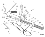
【課題】整地部の回動方向の規制位置を安定させながら、整地部の回動方向に対する両側への付勢力を付加可能な代掻き作業機を提供する。【解決手段】調圧部6は、フレーム2の近傍で整地部5と同方向に回動自在に一端側を支持し、他端側を整地部5に設けた保持部材53によって軸方向に摺動自在に保持されるロッド61と、整地部5を整地面に近づくように付勢する第1弾性体62と、整地部5を整地面から遠ざけるように付勢する第2弾性体63と、フレーム2の近傍で整地部5と同方向に回動自在に一端側を支持されるとともに、保持部材53を摺動させる長孔部641を他端側に設け、ロッド61を覆う回動規制部材64と、ロッド61の軸方向を摺動可能に設け、第1弾性体62の一端側を当接させることで伸縮を規制する規制体65とを備える。【選択図】図4[PROBLEMS] To provide a puddling work machine capable of applying biasing force to both sides in the rotation direction of a ground leveling unit while stabilizing the regulation position in the rotation direction of the ground leveling unit. A pressure regulating part (6) has one end side rotatably supported in the vicinity of a frame (2) in the same direction as the ground leveling part (5), and the other end side is axially slidable by a holding member (53) provided on the ground leveling part (5). A rod 61 held movably, a first elastic body 62 that biases the ground leveling unit 5 toward the leveled surface, a second elastic body 63 that biases the leveling unit 5 away from the leveled surface, A rotation restricting member which is supported at one end side near the frame 2 so as to be rotatable in the same direction as the leveling portion 5, and which has an elongated hole portion 641 for sliding the holding member 53 at the other end side and covers the rod 61. 64, and a restricting body 65 that is provided slidably in the axial direction of the rod 61 and that restricts expansion and contraction by bringing one end side of the first elastic body 62 into contact. [Selection drawing] Fig. 4

Description

この発明は、代掻き作業機に係る。更に詳細には、代掻き作業機における折り畳み機構、あるいは整地部の連結機構にかかる。 The present invention relates to a puddling work machine. More specifically, it relates to a folding mechanism in a puddling work machine or a connecting mechanism of a ground leveling portion.

代掻き作業機を用いて、代掻き作業機が有する整地部による整地作業においては、整地部に適正な圧力をかけて土壌に接地させることで、整地性能が向上する。作業圃場である泥水は軟弱圃場であるため、整地部が接地したときは、円滑に上方側に回動させる必要がある。円滑な上方回動により圃場面を抉ることなく整地部を接地させている。 In the ground leveling work by the ground leveling part of the substitute scraping work machine, the ground leveling performance is improved by applying an appropriate pressure to the ground leveling part to bring it into contact with the soil. Since the muddy water in the work field is a soft field, it is necessary to smoothly rotate it upward when the ground leveling portion touches the ground. The smooth upward rotation keeps the ground leveling part in contact with the ground without scooping out the field scene.

また、作業効率向上のため、作業幅は可能な限り広い方が良いが、使用する作業者の使用環境に合わせ、作業幅にバリエーションを持たせている。
作業幅を拡大させるとともに、作業以外の移動時の取扱性を向上させるものとしては、特許文献1「折畳み代掻き装置」記載の折畳み代掻き装置によって開示されている。この折畳み代掻き装置において、延長耕耘作業体を展開させて作業幅を拡大するときは、中央作業機の整地部と、延長耕耘作業体の整地部を連結させる機構を採用している。
延長作業体を側方に展開させて作業幅を拡大させた場合、中央作業体と延長作業体にそれぞれに設けた整地部が連結されて、一体となって上下回動することで、整地性能を発揮する。
Further, in order to improve work efficiency, it is better that the work width is as wide as possible, but the work width is varied according to the usage environment of the worker who uses it.
A folding allowance scraping device described in Patent Document 1 “Folding allowance scraping device” is disclosed as a device for expanding the work width and improving the handleability during movement other than work. In this folding allowance scraping device, when the extended tillage work body is expanded to expand the work width, a mechanism for connecting the ground leveling portion of the central work machine and the ground leveling portion of the extended tillage work body is adopted.
When the extension work body is expanded to the side to expand the work width, the ground leveling parts provided for each of the central work body and the extension work body are connected and rotate up and down as a unit to achieve the ground leveling performance. Demonstrate.

また、特許文献2「耕耘装置」記載の耕耘装置は、整地部である後部カバーの上方の弾下ロッドの後端に当たりが配置されている。この当たりによって、後部カバーの下方側への回動を規制するとされる。
また、同様に、整地体に連結するとともに、この整地体の上方に位置する加圧ロッドを備えたロータリ作業機が、特許文献3「ロータリ作業機のリヤカバーロック装置」によって開示されている。この装置は、ロッド端部の座金によってリヤカバーの回動を固定するものである。
加圧機構と減圧機構を共に具備した農作業機が、特許文献4「農作業機」で開示されている。この農作業機は、整地板を上方に付勢する第1ガススプリング、整地板を下方に付勢する第2ガススプリングを有していて、整地部を圃場面に対する加圧あるいは減圧が可能になっている。
Further, in the tilling device described in Patent Document 2 “Tilling device”, a hit is arranged at the rear end of the repellent rod above the rear cover which is a ground leveling portion. It is said that this hit restricts the downward rotation of the rear cover.
Similarly, Patent Document 3 “Rear cover lock device for rotary work machine” discloses a rotary work machine provided with a pressure rod located above the ground leveling body while being connected to the ground leveling body. This device fixes the rotation of the rear cover with a washer at the end of the rod.
A farming machine provided with both a pressurizing mechanism and a depressurizing mechanism is disclosed in Patent Document 4 “Agricultural Working Machine”. This agricultural work machine has a first gas spring that urges the ground leveling plate upward and a second gas spring that urges the ground leveling plate downward, so that the ground leveling portion can be pressurized or depressurized with respect to the field scene. ing.

特開2007−061033号公報JP-A-2007-061033 特開2009―219440号公報Japanese Unexamined Patent Publication No. 2009-219440 特開平9−135601号公報Japanese Unexamined Patent Publication No. 9-135601 特開2013―230129号公報Japanese Unexamined Patent Publication No. 2013-230129

特許文献2「耕耘装置」において、整地部である後部カバーの下方側への揺動を規制する当たりが、後部カバーの上方の弾下ロッドの後端に配置されている。代掻き作業に関し、整地部が圃場面である泥水上に設置したときにスムーズに上方に回動しないと、垂れ下がった整地部で圃場面を掘ってしまう問題があるため、この整地部を上方に付勢する減圧機構が必要である。この付勢部材を当たりと支持孔の間に配置するのが、容易な方法である。 In Patent Document 2 “Tilling device”, a hit for restricting the downward swing of the rear cover, which is a ground leveling portion, is arranged at the rear end of the repellent rod above the rear cover. Regarding the puddling work, if the ground leveling part is not smoothly rotated upward when it is installed on the muddy water that is the field scene, there is a problem that the field scene is dug in the hanging ground leveling part, so this ground leveling part is attached upward. A vigorous decompression mechanism is needed. It is an easy method to place this urging member between the hit and the support hole.

しかし、特許文献2「耕耘装置」の方法を特許文献1「折畳み代掻き装置」に採用する場合、整地部の連結は、整地部が下方側に回動した状態で行う。この時、減圧機構による揺動によって、整地部が上下揺動して整地部の連結に不都合が生じる。また、作業幅のバリエーションによって整地部の幅を変更した場合、減圧機構にも調整機構を付加する必要が出てくる。
特許文献2「耕耘装置」の当たりに調整機構をつけると、作業者が容易に取扱える取扱性と、整地部の揺動を規制する強度を両立する必要が出てくるため、この部分が過剰に複雑化かつ大型化することが懸念されている。特許文献3「ロータリ作業機のリヤカバーロック装置」においても同様のことが言える。
However, when the method of Patent Document 2 "Tilling device" is adopted in Patent Document 1 "Folding allowance scraping device", the ground leveling portion is connected in a state where the ground leveling portion is rotated downward. At this time, the rocking by the decompression mechanism causes the ground leveling portion to swing up and down, causing inconvenience in connecting the ground leveling portion. Further, when the width of the ground leveling portion is changed according to the variation of the working width, it becomes necessary to add an adjusting mechanism to the decompression mechanism.
If an adjustment mechanism is attached to the area of Patent Document 2 "Tilling device", it is necessary to achieve both handleability that can be easily handled by the operator and strength that regulates the swing of the leveling part, so this part is excessive. There is concern that it will become complicated and large. The same can be said for Patent Document 3 “Rear cover lock device for rotary work machine”.

特許文献4「農作業機」において、整地板を下方に加圧する第2ガススプリングは、整地部である整地板の回動支点より前方に大きく突出して配置することになる。すると、整地部の調圧に係る部材の占有面積が大きくなり、調圧部がコンパクトに配置できない問題がある。また、調圧部がコンパクト化、且つ、単純化できれば、空いたスペースに他の部品を配置が可能にできたり、部品の組み立て及びメンテナンスの容易化が可能となったりする。 In Patent Document 4 “Agricultural Work Machine”, the second gas spring that pressurizes the ground leveling plate downward is arranged so as to project significantly forward from the rotation fulcrum of the ground leveling plate, which is the ground leveling portion. Then, the occupied area of the member related to the pressure adjusting portion of the ground leveling portion becomes large, and there is a problem that the pressure adjusting portion cannot be arranged compactly. Further, if the pressure regulating portion can be made compact and simplified, other parts can be arranged in the vacant space, and the assembly and maintenance of the parts can be facilitated.

従来から、代掻き作業機において、ロッドとばねは備わっていた。更に、従来は、代掻き作業機の下部にあるカバー体で、整地体の回動規制をしていた。例えば、従来は、整地体の回動規制をする回動規制部材は、整地体の内側に設けていた。しかし、それでは、整地体の内側は圃場に面しており、圃場から跳ね上げた土壌等ごみが付きやすい。整地体の内側にごみ等が付着すると、整地体の上下動の位置がずれ、延長作業体が中央作業体の側方に位置する展開状態となるとき、互いの整地体の位置が揃わずスムーズな連結がしにくい課題を有した。
また、整地体が接地を開始する時において、整地体は圃場を整地しなければならないのに、寧ろ圃場の泥水に突き刺さってしまう現象も避けねばならない。
Conventionally, a rod and a spring have been provided in a puddling work machine. Further, conventionally, the cover body at the lower part of the puddling work machine regulates the rotation of the ground leveling body. For example, conventionally, a rotation restricting member for restricting the rotation of a ground leveling body has been provided inside the leveling body. However, in that case, the inside of the ground leveling body faces the field, and it is easy for dust such as soil that has jumped up from the field to adhere to it. If dust or the like adheres to the inside of the leveling body, the vertical movement position of the leveling body shifts, and when the extension work body is in the deployed state located on the side of the central work body, the positions of the ground leveling bodies are not aligned with each other and are smooth. There was a problem that it was difficult to connect them properly.
In addition, when the ground leveling body starts to touch down, the ground leveling body must level the field, but rather the phenomenon of being stuck in the muddy water of the field must be avoided.

本発明は上記課題に着眼してなされたものであり、調圧部を簡易構成としながらも、接地部の回動方向に対する両側への付勢力を付加可能な代掻き作業機を提供することを目的とする。
本発明では、整地体よりも上部に設置したロッドと、弾性体とを用いて、ロッドの回動規制をして、整地体の上下動を規制することを目的とする。
The present invention has been made with an eye on the above problems, and an object of the present invention is to provide a substitute scraping work machine capable of applying urging force to both sides with respect to the rotation direction of the ground contact portion while having a simple structure of the pressure adjusting portion. And.
An object of the present invention is to regulate the vertical movement of the ground leveling body by restricting the rotation of the rod by using the rod installed above the leveling body and the elastic body.

この発明は、
走行機体に装着可能な装着部を有したフレームと、該フレームに回転可能に支持されて土壌を砕土する砕土部と、該砕土部の後方で進行方向と直交する方向を軸にして回動可能に設け土壌を整地する整地部と、該整地部を回動方向に付勢する調圧部と、を備え、
該調圧部は、前記フレームの近傍で前記整地部と同方向に回動自在に一端側を支持されるとともに、他端側を前記整地部に設けた保持部材によって軸方向に摺動自在に保持されるロッドと、
前記整地部を整地面に近づくように付勢し、前記ロッドと同軸に設けた第1弾性体と、
前記整地部を整地面から遠ざけるように付勢し、前記ロッドと同軸に設けた第2弾性体と、
前記フレームの近傍で前記整地部と同方向に回動自在に一端側を支持されるとともに、前記保持部材を摺動させる長孔部を他端側に設け、前記ロッドを覆う回動規制部材と、
前記ロッドの軸方向を摺動可能に設け、前記第1弾性体の一端側を当接させることで伸縮を規制する規制体と、
を備えたことを特徴とする代掻き作業機、
に係る。
This invention
A frame having a mounting portion that can be mounted on a traveling machine, a soil crushing portion that is rotatably supported by the frame and crushes soil, and a soil crushing portion that can rotate around the direction orthogonal to the traveling direction behind the soil crushing portion. It is provided with a ground leveling portion provided in the soil to level the soil and a pressure adjusting portion for urging the ground leveling portion in the rotational direction.
One end side of the pressure adjusting portion is rotatably supported in the same direction as the ground leveling portion in the vicinity of the frame, and the other end side is slidable in the axial direction by a holding member provided on the ground leveling portion. The rod to be held and
A first elastic body that urges the ground leveling portion so as to approach the ground leveling and is provided coaxially with the rod.
A second elastic body that is urged to keep the ground leveling portion away from the ground leveling and is provided coaxially with the rod.
One end side is rotatably supported in the vicinity of the frame in the same direction as the ground leveling portion, and an elongated hole portion for sliding the holding member is provided on the other end side to cover the rod. ,
A regulatory body that regulates expansion and contraction by providing the rod in the axial direction so as to be slidable and bringing one end side of the first elastic body into contact with the first elastic body.
Scratching work machine, which is characterized by being equipped with
Related to.

この発明は、更に、
規制体が固定状態と固定解除状態を選択することが可能なことを特徴とする代掻き作業機、
に係る。
The present invention further
A puddling work machine, characterized in that the regulator can select between a fixed state and a defixed state.
Related to.

この発明は、更に、
前記規制体を前記ロッドの軸方向に移動させるために前記回動規制部材に回動自在に設けた切換アームと、
をさらに備えたことを特徴とする代掻き作業機に係る。
The present invention further
A switching arm rotatably provided on the rotation restricting member for moving the restricting body in the axial direction of the rod, and a switching arm.
It relates to a puddling work machine characterized by being further equipped with.

この発明は、更に、
前記切換アームは、回動を固定する固定手段と、
前記フレームと前記切換アームに掛け渡すように設け、前記第1弾性体の付勢力を強める方向に前記規制体を移動させるように前記切換アームを付勢する第3弾性体と、
をさらに備えたことを特徴とする代掻き作業機、に係る。
The present invention further
The switching arm includes a fixing means for fixing the rotation and
A third elastic body provided so as to hang over the frame and the switching arm and urging the switching arm so as to move the restricting body in a direction of strengthening the urging force of the first elastic body.
It relates to a puddling work machine, which is characterized by being further equipped with.

この発明は、更に、
ロッドは、整地部よりも上部に設置した、
ことを特徴とする代掻き作業機、に係る。
The present invention further
The rod was installed above the leveling area,
It relates to a puddling work machine, which is characterized in that.

本発明は上記課題に着眼してなされたものであり、整地部の回動方向の規制位置を安定させながら、整地部の回動方向に対する両側への付勢力を付加可能な代掻き作業機を提供する。
本発明では、整地体よりも上部に設置したロッドと、弾性体とを用いて、ロッドの回動規制をして、整地体の上下動を規制する。
The present invention has been made with an eye on the above problems, and provides a puddling work machine capable of applying urging force to both sides with respect to the rotation direction of the ground leveling portion while stabilizing the regulated position in the rotation direction of the ground leveling portion. do.
In the present invention, the rotation of the rod is regulated by using the rod installed above the leveling body and the elastic body, and the vertical movement of the leveling body is regulated.

この発明の実施例に係る機体の進行方向左側から見た全体の側面図である。It is the whole side view seen from the left side of the traveling direction of the airframe which concerns on embodiment of this invention. この発明の実施例に係る機体の平面図である。It is a top view of the airframe which concerns on embodiment of this invention. この発明の実施例に係る機体の全体の進行方向後方側からみた正面図である。It is a front view seen from the rear side in the traveling direction of the whole body which concerns on embodiment of this invention. この発明の実施例に係る機体の調圧部を拡大した側面図であって、第1弾性体の付勢力を強める「強位置」で切換アームが固定状態であり、整地体が最下方への回動が、第1長孔部によって規制された状態をあらわす。It is an enlarged side view of the pressure adjusting part of the airframe which concerns on embodiment of this invention, in which the switching arm is fixed at the "strong position" which strengthens the urging force of the 1st elastic body, and the leveling body moves to the lowermost part. The rotation is regulated by the first elongated hole portion. この発明の実施例に係る機体のロッド軸方向からみた切換アームの図4aa線概念断面図である。FIG. 4 is a conceptual cross-sectional view taken along line FIG. 4aa of a switching arm viewed from the rod axial direction of the airframe according to the embodiment of the present invention. この発明の実施例に係る機体のロッド軸方向から見た保持部材の断面図である。It is sectional drawing of the holding member seen from the rod axial direction of the machine body which concerns on embodiment of this invention. この発明の実施例に係る機体のロッドの軸方向で切断した断面図であって、第1弾性体の付勢力を強める「強位置」で切換アームが固定状態であり、整地体が最下方への回動が、第1長孔部によって規制された状態をあらわす。It is a cross-sectional view cut in the axial direction of the rod of the airframe according to the embodiment of the present invention, in which the switching arm is fixed at the "strong position" where the urging force of the first elastic body is strengthened, and the ground leveling body moves downward. Represents a state in which the rotation of is regulated by the first elongated hole portion. この発明の実施例に係る機体のロッドの軸方向で切断した断面図であって、第1弾性体の付勢力を強める「強位置」で切換アームが固定状態であり、更に、整地体が上方に回動した状態をあらわす。It is a cross-sectional view cut in the axial direction of the rod of the machine body which concerns on embodiment of this invention, in which the switching arm is fixed at the "strong position" which strengthens the urging force of the 1st elastic body, and further, the leveling body is upward. Represents the state of rotation. この発明の実施例に係る機体のロッドの軸方向で切断した断面図であって、切換アームが固定解除状態であり、整地体の最下方への回動が、第1長孔部によって規制された状態をあらわす。It is sectional drawing which cut in the axial direction of the rod of the machine body which concerns on embodiment of this invention, the switching arm is in a fixed release state, and the downward rotation of a ground leveling body is regulated by a 1st elongated hole part. Represents the state of being. この発明の実施例に係る機体のロッドの軸方向で切断した断面図であって、切換アームが固定解除状態であり、整地体が上方へ回動した状態をあらわす。It is sectional drawing which cut in the axial direction of the rod of the machine body which concerns on embodiment of this invention, and shows the state which the switching arm is in the fixed release state, and the leveling body is rotated upward.

1は、この発明の実施例に係る代掻き作業機である。
11は、代掻き作業機1の中央作業体、11Lは、同左側の延長作業体、11Rは、同右側の延長作業体である。中央作業体11は、作業機1の中央部を構成する。延長作業体11Lは、作業機1の左側を構成し、中央作業体11の左側に設ける。延長作業体11Rは、作業機1の右側を構成し、中央作業体11の右側に設ける。
Reference numeral 1 denotes a substitute scraping work machine according to an embodiment of the present invention.
Reference numeral 11 denotes a central working body of the puddling work machine 1, 11L is an extension working body on the left side of the same, and 11R is an extension working body on the right side of the same. The central working body 11 constitutes the central portion of the working machine 1. The extension work body 11L constitutes the left side of the work machine 1 and is provided on the left side of the central work body 11. The extension work body 11R constitutes the right side of the work machine 1 and is provided on the right side of the central work body 11.

2は、フレームである。フレーム2は、走行機体(図示せず)に装着可能な装着部20を有する。
212は、トップマストである。213は、ロワプレートである。ロワプレート213は、2個からなる。201は、トップリンクピンである。トップリンクピン201は、装着部20のトップマスト212先端に設ける。202は、ロアリンクピンである。ロアリンクピン202は、装着部20のロワプレート213先端に設ける。
トップマスト212に設けたトップリンクピン201と、2個のロワプレート213にそれぞれ設けたロアリンクピン202とで、代掻き作業機1を走行機体(図示せず)に装着する。
2 is a frame. The frame 2 has a mounting portion 20 that can be mounted on a traveling machine body (not shown).
212 is the top mast. Reference numeral 213 is a lower plate. The lower plate 213 is composed of two pieces. 201 is a top link pin. The top link pin 201 is provided at the tip of the top mast 212 of the mounting portion 20. 202 is a lower link pin. The lower link pin 202 is provided at the tip of the lower plate 213 of the mounting portion 20.
With the top link pin 201 provided on the top mast 212 and the lower link pin 202 provided on each of the two lower plates 213, the substitute scraping work machine 1 is attached to the traveling machine body (not shown).

21は、入力ケースである。211は、入力軸である。走行機体(図示せず)のPTO軸から、入力軸211を介して、入力ケース21に駆動力を導入する。
22は、パイプフレームである。パイプフレーム22は、入力ケース21の左右にそれぞれ取付ける。入力ケース21からの駆動力は、ベベルギヤを介して分配し、パイプフレーム22先端側にそれぞれ伝動する。
Reference numeral 21 is an input case. Reference numeral 211 is an input shaft. A driving force is introduced into the input case 21 from the PTO shaft of the traveling machine body (not shown) via the input shaft 211.
Reference numeral 22 is a pipe frame. The pipe frame 22 is attached to the left and right sides of the input case 21, respectively. The driving force from the input case 21 is distributed via the bevel gear and transmitted to the tip side of the pipe frame 22 respectively.

23は、伝動ケースである。伝動ケース23は、パイプフレーム22先端側にそれぞれ取り付ける。
24は、サポートフレームである。サポートフレーム24は、伝動ケース23に連結する。
25は、支点部である。支点部25は、代掻き作業機1の中央作業体11と、左右の延長作業体11L、延長作業体11Rを、それぞれ回動自在に取り付ける。
Reference numeral 23 is a transmission case. The transmission case 23 is attached to the tip end side of the pipe frame 22 respectively.
Reference numeral 24 denotes a support frame. The support frame 24 is connected to the transmission case 23.
Reference numeral 25 denotes a fulcrum portion. The fulcrum portion 25 is rotatably attached to the central working body 11 of the puddling work machine 1, the left and right extension working bodies 11L, and the extension working body 11R, respectively.

3は、砕土部である。砕土部3は、フレーム2に回転可能に支持されて土壌を砕土する。
3L(図示せず)は、左側の延長砕土部である。延長砕土部3Lは、砕土部3の左側部分に設け、延長作業体11L下部に設置する。
3R(図示せず)は、右側の延長砕土部である。延長砕土部3Rは、砕土部3の右側部分に設け、延長作業体11R下部に設置する。
Reference numeral 3 is a soil crushed portion. The soil crushing portion 3 is rotatably supported by the frame 2 to crush the soil.
3L (not shown) is the extended soil crushed portion on the left side. The extended soil crushing portion 3L is provided on the left side portion of the soil crushing portion 3, and is installed below the extension work body 11L.
The 3Rs (not shown) are the extended soil crushed portion on the right side. The extended soil crushing portion 3R is provided on the right side portion of the soil crushing portion 3, and is installed below the extension work body 11R.

31は、ロータ軸である。ロータ軸31は、中央作業体11、延長作業体11L、延長作業体11Rに設け、入力ケース21からの駆動力により駆動する。
32は、耕耘爪である。耕耘爪32は、ロータ軸31周囲に突設させて設け、ロータ軸31の回動に伴い回動して、圃場を耕耘する。
Reference numeral 31 is a rotor shaft. The rotor shaft 31 is provided on the central working body 11, the extension working body 11L, and the extension working body 11R, and is driven by the driving force from the input case 21.
32 is a tillage claw. The tilling claw 32 is provided so as to project around the rotor shaft 31 and rotates with the rotation of the rotor shaft 31 to cultivate the field.

4は、カバー体である。カバー体4は、中央作業体11の砕土部3の上部を被覆するように設置する。
4Lは、カバー体である。カバー体4Lは、左側の延長作業体11Lの延長砕土部3Lの上部を被覆するように設置する。
4Rは、カバー体である。カバー体4Rは、右側の延長作業体11Rの延長砕土部3Rの上部を被覆するように設置する。
Reference numeral 4 denotes a cover body. The cover body 4 is installed so as to cover the upper portion of the soil crushed portion 3 of the central working body 11.
4L is a cover body. The cover body 4L is installed so as to cover the upper part of the extended soil crushing portion 3L of the extension work body 11L on the left side.
4R is a cover body. The cover body 4R is installed so as to cover the upper part of the extended soil crushing portion 3R of the extension work body 11R on the right side.

41Lは、左支点フレームである。左支点フレーム41Lは、パイプフレーム22の延長砕土部3L側の支点部25に取り付ける。
41Rは、右支点フレームである。右支点フレーム41Rは、パイプフレーム22の延長砕土部3R側の支点部25に取り付ける。
41L is a left fulcrum frame. The left fulcrum frame 41L is attached to the fulcrum portion 25 on the extended soil crushing portion 3L side of the pipe frame 22.
41R is a right fulcrum frame. The right fulcrum frame 41R is attached to the fulcrum portion 25 on the extended soil crushing portion 3R side of the pipe frame 22.

42は、第1土寄せ体である。第1土寄せ体42は、中央作業体11の左右のロアリンクピン202下部に設け、耕耘爪32で耕耘する前の土を機体幅の中央側に掻き集める。
42bは、第1土寄せ体支持部である。第1土寄せ体支持部42bは、第1土寄せ体42を中央作業体11の前部に取り付ける。
Reference numeral 42 denotes a first soil gathering body. The first soil gathering body 42 is provided at the lower part of the lower link pins 202 on the left and right sides of the central working body 11, and the soil before being cultivated by the tilling claw 32 is scraped up to the center side of the machine body width.
Reference numeral 42b is a first soil gathering body support portion. The first soil gathering body support portion 42b attaches the first soil gathering body 42 to the front portion of the central working body 11.

43は、第2土寄せ体である。第2土寄せ体43は、第1土寄せ体42の外側の中央作業体11に取り付け、耕耘爪32で耕耘する前の土を、第1土寄せ体42の外側で機体幅の中央側に掻き集める。
43bは、第2土寄せ体支持部である。第2土寄せ体支持部43bは、第2土寄せ体43を中央作業体11の前部に取り付ける。
Reference numeral 43 denotes a second soil gathering body. The second soil gathering body 43 is attached to the central working body 11 on the outside of the first soil gathering body 42, and the soil before being cultivated by the tilling claw 32 is scraped to the center side of the machine body width on the outside of the first soil gathering body 42.
Reference numeral 43b is a second soil gathering body support portion. The second soil gathering body support portion 43b attaches the second soil gathering body 43 to the front portion of the central working body 11.

44は、第3土寄せ体である。第3土寄せ体44は、第2土寄せ体43の外側の中央作業体11に取り付け、耕耘爪32で耕耘する前の土を、第2土寄せ体43の外側で機体幅の中央側に掻き集める。
45は、前部カバーである。前部カバー45は、カバー体4及びカバー体左4L及びカバー体右4Rの前端より前側に位置させている。さらに、前部カバー45の下端部はカバー体4及びカバー体左4L及びカバー体右4Rの前端より下方に位置させている。実施例において、前部カバー45はカバー体4の前方に配置している。前部カバー45はカバー体4と圃場面の間から前方に飛散する泥土等の飛散を防止する。
Reference numeral 44 denotes a third soil gathering body. The third soil gathering body 44 is attached to the central working body 11 on the outside of the second soil gathering body 43, and the soil before being cultivated by the tilling claw 32 is scraped to the center side of the machine body width on the outside of the second soil gathering body 43.
Reference numeral 45 is a front cover. The front cover 45 is located on the front side of the cover body 4, the cover body left 4L, and the cover body right 4R from the front end. Further, the lower end portion of the front cover 45 is positioned below the front ends of the cover body 4, the cover body left 4L, and the cover body right 4R. In the embodiment, the front cover 45 is arranged in front of the cover body 4. The front cover 45 prevents the scattering of mud and the like scattered forward from between the cover body 4 and the field scene.

46は、スタンドブラケットである。
スタンドブラケット46は、保管時に代掻き機を単独で接地させるためのスタンド(図示せず)を取り付けるための保持部材である。実施例の場合、伝動ケース23及びサポートフレーム24の前方部のカバー体4端部に設置することで、安定性を確保している。
46 is a stand bracket.
The stand bracket 46 is a holding member for attaching a stand (not shown) for grounding the scraper independently during storage. In the case of the embodiment, stability is ensured by installing the transmission case 23 and the support frame 24 at the four ends of the front cover body.

47は、後部土寄せ体である。後部土寄せ体47は、板状部材であり、ロータ軸31及び延長側ロータ軸左31L及び延長側ロータ軸右31Rのより進行方向の後方側に位置させるとともに、カバー体左4L又はカバー体4Rに取り付けられている。
後部土寄せ体47は代掻き作業機1の進行方向後部で、代掻き作業機1の進行に伴い、土寄せ作業を行う。
Reference numeral 47 is a rear soil gathering body. The rear soil gathering body 47 is a plate-shaped member, and is located on the rear side of the rotor shaft 31, the extension side rotor shaft left 31L, and the extension side rotor shaft right 31R in the traveling direction, and is placed on the cover body left 4L or the cover body 4R. It is attached.
The rear soil gathering body 47 is at the rear in the traveling direction of the scavenging work machine 1, and performs the soil gathering work as the scavenging work machine 1 advances.

5は、整地部(整地体)である。整地部(整地体)5は、砕土部3の後方且つカバー体4の後部で進行方向と直交する方向を軸にして回動可能に設け、砕土部3側の面を土壌に接触させることで、砕土部3が圃場を砕土した土壌を整地する。
51は、第1整地体である。第1整地体51は、中央作業体11に取り付ける。
5Lは、左整地体である。51Lは、左第1整地体である。左整地体5L、左第1整地体51Lは、延長作業体11Lに取り付ける。
5Rは、右整地体である。51Rは、右第1整地体である。右整地体5R、右第1整地体51Rは、延長作業体11Rに取り付ける。
Reference numeral 5 denotes a ground leveling portion (ground leveling body). The ground leveling portion (ground leveling body) 5 is rotatably provided behind the soil crushing portion 3 and behind the cover body 4 about a direction orthogonal to the traveling direction, and the surface on the soil crushing portion 3 side is brought into contact with the soil. , The soil crushing section 3 prepares the soil obtained by crushing the field.
51 is the first leveling body. The first leveling body 51 is attached to the central working body 11.
5L is a left leveling body. 51L is the left first leveling body. The left leveling body 5L and the left first leveling body 51L are attached to the extension work body 11L.
5R is a right leveling body. 51R is the first right leveling body. The right leveling body 5R and the right first leveling body 51R are attached to the extension work body 11R.

図1に図示する512は、支点軸である。支点軸512は、整地部(整地体)5を、砕土部3の後方で進行方向と直交する方向を軸にして回動可能に代掻き作業機1に取り付ける。
52は、ヒンジである。ヒンジ52によって、支点軸512に整地部(整地体)5を取り付け、上下方向へ回動自在に支持する。
53は、保持部材である。保持部材53は、整地部(整地体)5から起立させた2つの板によって、支点軸512と平行な回転軸で回動自在に保持されている。保持部材53は自身の回転軸と直交方向に孔532を有していて、この孔532に後述するロッド61を挿入する。
512 shown in FIG. 1 is a fulcrum axis. The fulcrum shaft 512 attaches the ground leveling portion (ground leveling body) 5 to the puddling work machine 1 so as to be rotatable behind the soil crushing portion 3 in a direction orthogonal to the traveling direction.
52 is a hinge. A ground leveling portion (ground leveling body) 5 is attached to the fulcrum shaft 512 by a hinge 52 and is rotatably supported in the vertical direction.
Reference numeral 53 denotes a holding member. The holding member 53 is rotatably held by a rotating shaft parallel to the fulcrum shaft 512 by two plates erected from the ground leveling portion (ground leveling body) 5. The holding member 53 has a hole 532 in a direction orthogonal to its own rotation axis, and a rod 61, which will be described later, is inserted into the hole 532.

図4、図6に図示する531は、突出部である。突出部531は、保持部材53から支点軸512と平行な横方向に突設し、後述する回動規制部材64に設けられた第1長孔部641に係止する。
56は、第2整地体である。56Lは、左第2整地体である。左第2整地体56Lは、延長作業体11Lに取り付ける。
56Rは、右第2整地体である。右第2整地体56Rは、延長作業体11Lに取り付ける。
562は、回動支点である。回動支点562は、第2整地体56及び左第2整地体56L及び右第2整地体56Rの機体幅方向と平行な回動軸であって、第2整地体56及び左第2整地体56L及び右第2整地体56Rを、この回動支点562を軸にして上下に回動可能にする。
Reference numeral 531 shown in FIGS. 4 and 6 is a protruding portion. The protruding portion 531 projects from the holding member 53 in the lateral direction parallel to the fulcrum shaft 512, and is locked to the first elongated hole portion 641 provided in the rotation restricting member 64, which will be described later.
56 is the second leveling body. 56L is the left second leveling body. The left second leveling body 56L is attached to the extension work body 11L.
56R is the second right leveling body. The right second leveling body 56R is attached to the extension work body 11L.
Reference numeral 562 is a rotation fulcrum. The rotation fulcrum 562 is a rotation axis parallel to the body width direction of the second leveling body 56, the left second leveling body 56L, and the right second leveling body 56R, and is the second leveling body 56 and the left second leveling body. The 56L and the right second leveling body 56R can be rotated up and down about the rotation fulcrum 562.

6は、調圧部である。調圧部6は、整地部(整地体5)を回動方向に付勢する。調圧部6は、ロッド61、第1弾性体62、第2弾性体63、回動規制部材64、規制体65、切換アーム66、固定手段67、第3弾性体68を有する。
611は、ロッド回動支点軸である。ロッド回動支点軸611は、回動規制部材64のフレーム2の近傍である一端側で整地部(整地体)5と同方向に、ロッド61を回動自在に支持する。
ロッド61は、他端側を前記整地部(整地体)5に設けた保持部材53によってロッド61の軸方向に摺動自在に保持される。保持部材53は、第1整地体51及び左第1整地体51L及び右第1整地体51Rの上下回動に伴って、ロッド61の軸方向に摺動する。実施例において、ロッド61は丸棒状の部材で示したが、筒状部材を用いてもよく、また、断面形状は丸形に限らない。
Reference numeral 6 is a pressure adjusting unit. The pressure adjusting portion 6 urges the ground leveling portion (ground leveling body 5) in the rotation direction. The pressure adjusting portion 6 includes a rod 61, a first elastic body 62, a second elastic body 63, a rotation restricting member 64, a restricting body 65, a switching arm 66, a fixing means 67, and a third elastic body 68.
Reference numeral 611 is a rod rotation fulcrum shaft. The rod rotation fulcrum shaft 611 rotatably supports the rod 61 on one end side near the frame 2 of the rotation restricting member 64 in the same direction as the ground leveling portion (ground leveling body) 5.
The other end of the rod 61 is slidably held in the axial direction of the rod 61 by a holding member 53 provided on the ground leveling portion (ground leveling body) 5. The holding member 53 slides in the axial direction of the rod 61 as the first leveling body 51, the left first leveling body 51L, and the right first leveling body 51R rotate vertically. In the embodiment, the rod 61 is shown by a round bar-shaped member, but a cylindrical member may be used, and the cross-sectional shape is not limited to the round shape.

62は、第1弾性体である。第1弾性体62は、ロッド61と同軸にロッド61の周囲に巻き付けるように設け、ロッド回動支点軸611と保持部材53の間に位置させる。第1弾性体62は第1整地体51あるいは左第1整地体51Lあるいは右第1整地体51Rを砕土体3側に付勢することが可能である。砕土体3側に回動するように第1整地体51を付勢することで、第1整地体51を整地面に対する押圧力を増加させて、整地性能を向上させることができる。左第1整地体51L及び右第1整地体51Rも同様である。
65は、規制体である。規制体65は、ロッド61の軸方向を摺動可能に設け、かつ、ロッド回動支点軸611と第1弾性体62の間に設ける。規制体65を第1弾性体62のロッド回動支点軸611側の一端側を当接させることで、第1弾性体62の伸縮を規制する。規制体65をロッド61に対して相対的に動かすことで、第1弾性体62の伸縮を規制する位置を変えることができる。
第1弾性体62は、規制体65と保持部材53との間に挟んで設置する。規制体65の作動は切換アーム66によって行われる。切換アーム66が固定状態を取ると、第1弾性体62は、保持部材53を、ロッド61の他端側の先端方向に付勢する。
第1弾性体62は、保持部材53をロッド61先端方向に移動させることで、整地部(整地体)5を整地面に近づくように付勢する。規制体65は、ロッド61直交する方向に突出部651を設け、この突出部651を切換アーム66に連結することで、規制体65の規制位置を変更できる。規制体65の規制位置および切換アーム66の詳細構造は後述する。
Reference numeral 62 denotes a first elastic body. The first elastic body 62 is provided so as to be wound around the rod 61 coaxially with the rod 61, and is positioned between the rod rotation fulcrum shaft 611 and the holding member 53. The first elastic body 62 can urge the first ground leveling body 51, the left first leveling body 51L, or the right first leveling body 51R to the soil crushing body 3 side. By urging the first ground leveling body 51 so as to rotate toward the soil crushing body 3, the pressing force on the ground leveling body 51 can be increased and the ground leveling performance can be improved. The same applies to the left first leveling body 51L and the right first leveling body 51R.
65 is a regulator. The restricting body 65 is provided so as to be slidable in the axial direction of the rod 61, and is provided between the rod rotation fulcrum shaft 611 and the first elastic body 62. The expansion and contraction of the first elastic body 62 is regulated by bringing the restricting body 65 into contact with one end side of the first elastic body 62 on the rod rotation fulcrum shaft 611 side. By moving the restricting body 65 relative to the rod 61, the position for restricting the expansion and contraction of the first elastic body 62 can be changed.
The first elastic body 62 is installed so as to be sandwiched between the regulating body 65 and the holding member 53. The operation of the regulator 65 is performed by the switching arm 66. When the switching arm 66 takes a fixed state, the first elastic body 62 urges the holding member 53 toward the tip end side of the other end side of the rod 61.
The first elastic body 62 urges the ground leveling portion (ground leveling body) 5 so as to approach the ground leveling by moving the holding member 53 toward the tip of the rod 61. The restricting body 65 is provided with a protruding portion 651 in a direction orthogonal to the rod 61, and the restricting position of the restricting body 65 can be changed by connecting the protruding portion 651 to the switching arm 66. The regulation position of the regulation body 65 and the detailed structure of the switching arm 66 will be described later.

63は、第2弾性体である。第2弾性体63は、ロッド61と同軸に、保持部材53よりロッド61の他端側に、ロッド61の周囲に巻き付けるように設ける。
631は、係止部材である。係止部材631は、ロッド61のロッド回動支点軸611とは反対端であるロッド61の他端部に突設して設ける。
係止部材631は、図示するように、ロッド61先端側で、第2弾性体63のそれ以上のロッド61先端側への移動を阻止する。そのため、第2弾性体63は、ロッド回動支点軸611端側に、保持部材53を付勢する。
第2弾性体63は、保持部材53をロッド回動支点軸611方向に移動させるように付勢することで、整地部(整地体)5を整地面から遠ざけるように付勢する。
Reference numeral 63 denotes a second elastic body. The second elastic body 63 is provided coaxially with the rod 61, on the other end side of the rod 61 from the holding member 53, so as to be wound around the rod 61.
631 is a locking member. The locking member 631 is provided so as to project from the other end of the rod 61, which is the end opposite to the rod rotation fulcrum shaft 611 of the rod 61.
As shown in the drawing, the locking member 631 prevents the second elastic body 63 from moving further toward the tip end side of the rod 61 on the tip end side of the rod 61. Therefore, the second elastic body 63 urges the holding member 53 toward the end side of the rod rotation fulcrum shaft 611.
The second elastic body 63 urges the holding member 53 to move in the direction of the rod rotation fulcrum shaft 611, thereby urging the ground leveling portion (ground leveling body) 5 away from the ground leveling.

第2弾性体63は、整地体5が回動方向の最下端位置から上方に回動する場合において、整地体5を上方に付勢する。これにより、整地体5が泥水状態の圃場面に接地した時において、整地体5が圃場面に突き刺さることなく、速やかに上方に回動させる効果がある。
この実施例では、第1弾性体62および、第2弾性体63をそれぞれ、ロッド61と同軸に設ける。そのため、保持部材53をロッド61の他端方向に移動させることで整地部(整地体)5を整地面に近づくように付勢する第1弾性体62と、保持部材53をロッド回動支点軸611方向に移動させることで整地部(整地体)5を整地面から遠ざけるように付勢する第2弾性体63とを併せて、限られたスペースの中で、設置することができる。
The second elastic body 63 urges the ground leveling body 5 upward when the ground leveling body 5 rotates upward from the lowermost position in the rotation direction. As a result, when the ground leveling body 5 touches the field scene in a muddy water state, the ground leveling body 5 has the effect of quickly rotating upward without sticking to the field scene.
In this embodiment, the first elastic body 62 and the second elastic body 63 are provided coaxially with the rod 61, respectively. Therefore, the first elastic body 62 that urges the ground leveling portion (ground leveling body) 5 to approach the ground leveling by moving the holding member 53 toward the other end of the rod 61, and the holding member 53 are rod rotation fulcrum shafts. It can be installed in a limited space together with the second elastic body 63 that biases the ground leveling portion (ground leveling body) 5 away from the ground leveling by moving it in the 611 direction.

64は、回動規制部材である。回動規制部材64は、ロッド61を覆うように設け、作業体の外側に位置して設けている。そのため、ロッド61に土壌や夾雑物等の異物の付着を防ぎ、整地体5の回動規制位置のずれを解消できる。
回動規制部材64は、フレーム2の近傍で整地部(整地体)5と同方向に回動自在に一端側をロッド回動支点軸611で、支持する。
Reference numeral 64 denotes a rotation restricting member. The rotation restricting member 64 is provided so as to cover the rod 61, and is provided so as to be located outside the working body. Therefore, it is possible to prevent foreign matter such as soil and impurities from adhering to the rod 61, and to eliminate the deviation of the rotation restriction position of the ground leveling body 5.
The rotation restricting member 64 is rotatably supported in the vicinity of the frame 2 in the same direction as the ground leveling portion (ground leveling body) 5 by a rod rotation fulcrum shaft 611 on one end side.

641は、第1長孔部である。642は、第2長孔部である。回動規制部材64の側部の前後2か所に長孔状に長孔部である第1長孔部641、第2長孔部642を設ける。第2長孔部642は、回動規制部材64のフレーム2の近傍で回動自在に支持されるロッド回動支点軸611寄りの一端寄りに設け、第2長孔部642の回動規制部材64他端である先端寄りに第1長孔部641を設ける。
規制体65は、突出部651を第2長孔部642の長孔に沿わせてロッド61を摺動する。突出部651と第2長孔部642により、規制体65がロッド61の軸周りに回動することなく、ロッド61を摺動できる。
641 is the first elongated hole portion. 642 is the second elongated hole portion. The first elongated hole portion 641 and the second elongated hole portion 642, which are elongated holes, are provided at two locations in the front and rear of the side portion of the rotation restricting member 64. The second elongated hole portion 642 is provided near one end of the rod rotation fulcrum shaft 611, which is rotatably supported in the vicinity of the frame 2 of the rotation restricting member 64, and the rotation restricting member of the second elongated hole portion 642. 64 A first elongated hole portion 641 is provided near the tip, which is the other end.
The regulator 65 slides the rod 61 along the elongated hole of the second elongated hole portion 642 with the protruding portion 651. The protrusion 651 and the second elongated hole 642 allow the rod 61 to slide without the regulator 65 rotating around the axis of the rod 61.

第1長孔部641、第2長孔部642はロッド61の軸方向に長く、且つ、ロッド61と平行に設ける。
突出部651、突出部531の径に応じて、第1長孔部641の方が、第2長孔部642よりも径が大きい。整地部(整地体)5の回動規制は、第1長孔部641の端部に突出部531が当接することによって行われる。特に下方側への回動規制は、整地部(整地体)5の自重が第1長孔部641の端部にかかる。この時、接触時の面圧を低下させるために、第1長孔部641と突出部531の接触面積を増加させる必要がある。このため、第1長孔部641の径を大きくしている。
643は、回動固定用孔である。回動固定用孔643は、回動規制部材64に複数設けられ、切換アーム66の回動を固定する。
The first elongated hole portion 641 and the second elongated hole portion 642 are provided so as to be long in the axial direction of the rod 61 and parallel to the rod 61.
The diameter of the first elongated hole portion 641 is larger than that of the second elongated hole portion 642 according to the diameters of the protruding portions 651 and 531. The rotation regulation of the ground leveling portion (ground leveling body) 5 is performed by the protrusion 531 coming into contact with the end portion of the first elongated hole portion 641. In particular, in the downward rotation regulation, the weight of the ground leveling portion (ground leveling body) 5 is applied to the end portion of the first elongated hole portion 641. At this time, in order to reduce the surface pressure at the time of contact, it is necessary to increase the contact area between the first elongated hole portion 641 and the protruding portion 531. Therefore, the diameter of the first elongated hole portion 641 is increased.
Reference numeral 643 is a hole for fixing rotation. A plurality of rotation fixing holes 643 are provided in the rotation restricting member 64 to fix the rotation of the switching arm 66.

保持部材53は、突出部531が第1長孔部641の長孔に沿ってロッド61を摺動する。
後方側(自由端側)の第1長孔部641は、保持部材53の左右両端からピン状に突出した突出部531を案内する。整地体5(第1整地体)が上下に回動に伴うロッド61の摺動と共に、突出部531は第1長孔部641の内周側を移動する。突出部531と第1長孔部641により、第1整地体51あるいは左第1整地体51Lあるいは右第1整地体51Rは、第1長孔部641の範囲内で回動することができる。
651は、突出部である。突出部651は、規制体65の左右両端からピン状に突出する。
In the holding member 53, the protruding portion 531 slides the rod 61 along the elongated hole of the first elongated hole portion 641.
The first elongated hole portion 641 on the rear side (free end side) guides the protruding portion 531 protruding from the left and right ends of the holding member 53 in a pin shape. The projecting portion 531 moves on the inner peripheral side of the first elongated hole portion 641 as the rod 61 slides as the ground leveling body 5 (first leveling body) rotates up and down. The protrusion 531 and the first elongated hole portion 641 allow the first ground leveling body 51, the left first ground leveling body 51L, or the right first ground leveling body 51R to rotate within the range of the first elongated hole portion 641.
Reference numeral 651 is a protruding portion. The projecting portion 651 projects in a pin shape from the left and right ends of the regulating body 65.

前方側の第2長孔部642は、規制体65の左右両端からピン状に突出した突出部651を案内する。ロッド61に対して軸方向に摺動可能な規制体65は、第2長孔部642の範囲内において自由に移動可能である。また、突出部65と第2長孔部642によって、規制体65がロッド軸周りに回動することを防ぐ。
規制体65を長孔に沿って摺動させる第2長孔部642と、保持部材53を長孔に沿って摺動させる第1長孔部641を、別個に回動規制部材64の長手方向に設け、且つ、回動支点軸611側であるロッド61の一端側に第2長孔部642、ロッド61の他端側に第1長孔部641を設けることで、切替アーム66の作動と保持部材53の作動を円滑に行うことができる。
The second elongated hole portion 642 on the front side guides the protruding portion 651 protruding from the left and right ends of the regulator 65 in a pin shape. The restricting body 65 slidable in the axial direction with respect to the rod 61 can freely move within the range of the second elongated hole portion 642. Further, the protruding portion 65 and the second elongated hole portion 642 prevent the restricting body 65 from rotating around the rod axis.
The second elongated hole portion 642 that slides the restricting body 65 along the elongated hole and the first elongated hole portion 641 that slides the holding member 53 along the elongated hole are separately separated in the longitudinal direction of the rotation restricting member 64. By providing the second elongated hole portion 642 on one end side of the rod 61 on the rotation fulcrum shaft 611 side and the first elongated hole portion 641 on the other end side of the rod 61, the switching arm 66 can be operated. The holding member 53 can be operated smoothly.

図4、図7乃至図10に図示するように、ロッド61の一端側をフレーム22側の近傍で回動自在とすることで、ロッド61は、寝せる(水平状態とする)ことが可能である。
整地体5の回動によってロッド61が、ロッド61の自由端である先端が、上下方向に出たり入ったり出没することがないので、延長作業体11L,11Rが折畳状態でもロッド61が干渉する等の不都合がない。
As shown in FIGS. 4, 7 to 10, the rod 61 can be laid down (horizontally) by making one end side of the rod 61 rotatable in the vicinity of the frame 22 side. ..
Since the tip of the rod 61, which is the free end of the rod 61, does not move in and out in the vertical direction due to the rotation of the leveling body 5, the rod 61 interferes even when the extension work bodies 11L and 11R are in the folded state. There is no inconvenience such as doing.

ロッド61は、更に、ロッド61の回動支点軸611をカバー体4ではなくフレーム22側に設けることで、作業によるカバー体4の変形によって支点位置が変動することがなく、整地体5の下方側の回動規制位置が安定する。
図4、図7乃至図10に図示するように、実施形態のロッド61の一端側は、フレーム22の後部から後方に突出させた部材に回動自在に設けているが、整地体5の回動に連動してロッド61が回動できれば取付位置に限定はない。例えば、カバー体4の剛性及び強度を向上させて、砕土部3を覆うカバー体4上でロッド61の一端側を回動自在に設けてもよい。
Further, the rod 61 is provided with the rotation fulcrum shaft 611 of the rod 61 on the frame 22 side instead of the cover body 4, so that the fulcrum position does not change due to the deformation of the cover body 4 due to the work, and the rod 61 is below the ground leveling body 5. The rotation regulation position on the side is stable.
As shown in FIGS. 4 and 7 to 10, one end side of the rod 61 of the embodiment is rotatably provided on a member projecting rearward from the rear portion of the frame 22, but the ground leveling body 5 is rotated. If the rod 61 can rotate in conjunction with the movement, the mounting position is not limited. For example, one end side of the rod 61 may be rotatably provided on the cover body 4 covering the soil crushed portion 3 by improving the rigidity and strength of the cover body 4.

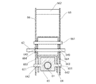
ロッド61は、図6に図示するように保持部材53に設けた孔532内をロッド61の軸方向に摺動する。すなわち、整地体5(第1整地体)が上下に回動に伴い、ロッド61の軸方向に保持部材53が摺動する。 As shown in FIG. 6, the rod 61 slides in the hole 532 provided in the holding member 53 in the axial direction of the rod 61. That is, as the ground leveling body 5 (first leveling body) rotates up and down, the holding member 53 slides in the axial direction of the rod 61.

従来から、代掻き作業機1において、ロッドとばねは備わっていた。更に、従来は、代掻き作業機1の下部にあるカバー体4で、整地体5の回動規制をしていた。
例えば、従来は、整地体5の回動規制をする回動規制部材64は、図4に図示する第1整地体51の内側に設けていた。しかし、それでは、第1整地体51の内側は圃場に面しており、圃場から跳ね上げた土壌等ごみが付きやすい。第1整地体51の内側にごみ等が付着すると、整地体5の上下動の位置がずれ、延長作業体11L,11Rが中央作業体11の左右側方に位置する展開状態となるとき、互いの整地体5の位置が揃わずスムーズな連結がしにくい課題を有した。また、整地体5が接地を開始する時において、整地体は圃場を整地しなければならないのに、寧ろ圃場の泥水に突き刺さってしまう現象も避けねばならない。
Conventionally, the puddling work machine 1 has been provided with a rod and a spring. Further, conventionally, the cover body 4 at the lower part of the puddling work machine 1 regulates the rotation of the ground leveling body 5.
For example, conventionally, the rotation restricting member 64 that regulates the rotation of the ground leveling body 5 is provided inside the first leveling body 51 shown in FIG. However, in that case, the inside of the first leveling body 51 faces the field, and it is easy for dust such as soil that has jumped up from the field to adhere to it. When dust or the like adheres to the inside of the first leveling body 51, the vertical movement position of the leveling body 5 shifts, and when the extension work bodies 11L and 11R are in the deployed state located on the left and right sides of the central work body 11, they are mutually aligned. There was a problem that the positions of the ground leveling bodies 5 were not aligned and it was difficult to connect them smoothly. Further, when the ground leveling body 5 starts grounding, the ground leveling body must level the field, but rather the phenomenon of being stuck in the muddy water of the field must be avoided.

この発明の実施例では、整地体5よりも上部に設置したロッド61と、第1弾性体62と、第2弾性体63とを用いて、ロッド61の回動規制をして、整地体5の上下動を規制する。
第1弾性体62は、整地部(整地体)5を整地面に近づくように付勢するとともに、第2弾性体63は、整地部(整地体)5を整地面から遠ざけるように付勢している。このため、回動方向における一端側から他端側に回動する場合、付勢方向の切り替えが、スムーズに移行できる。このため、整地体5の回動による整地面への押圧力は回動角度に比例するように変化させることができる。整地体5の砕土体3とは異なる側である、整地板5の上方に回動規制部材64を設けることで、整地面上のごみが詰まることはなく、安定した整地体5の回動規制が実現できる。また、回動規制部材64によって整地体5の上下回動を規制するので、ロッド61および第1弾性体62および第2弾性体63に依存することなく、この回動規制部材64だけで安定した回動規制が実現できる。
In the embodiment of the present invention, the rod 61 installed above the ground leveling body 5, the first elastic body 62, and the second elastic body 63 are used to restrict the rotation of the rod 61, and the ground leveling body 5 is used. Regulate the vertical movement of.
The first elastic body 62 urges the ground leveling portion (ground leveling body) 5 to approach the ground leveling, and the second elastic body 63 urges the ground leveling portion (ground leveling body) 5 to move away from the ground leveling. ing. Therefore, when rotating from one end side to the other end side in the rotation direction, the switching of the urging direction can be smoothly shifted. Therefore, the pressing force on the ground leveling due to the rotation of the ground leveling body 5 can be changed so as to be proportional to the rotation angle. By providing the rotation restricting member 64 above the ground leveling plate 5, which is a side different from the soil crushing body 3 of the ground leveling body 5, dust on the ground leveling body is not clogged and stable rotation regulation of the ground leveling body 5 is performed. Can be realized. Further, since the vertical rotation of the ground leveling body 5 is regulated by the rotation restricting member 64, the rotation restricting member 64 alone is stable without depending on the rod 61, the first elastic body 62, and the second elastic body 63. Rotation regulation can be realized.

ロッド61上で摺動可能な規制体65は、整地体5を加圧する第1弾性体62のみを任意の位置に固定することで調整ができる。
66は、切換アームである。切換アーム66は、回動規制部材64を跨ぐように、回動規制部材64の両側に、規制体65を前記ロッド61の軸方向に移動させるために回動自在に設ける。
The restricting body 65 slidable on the rod 61 can be adjusted by fixing only the first elastic body 62 that pressurizes the leveling body 5 at an arbitrary position.
Reference numeral 66 denotes a switching arm. The switching arm 66 is rotatably provided on both sides of the rotation restricting member 64 so as to straddle the rotation restricting member 64 in order to move the restricting body 65 in the axial direction of the rod 61.

661は、回動支点軸である。回動支点軸661は、切換アーム66が回動する支点軸であり、切換アーム66を前後方向に回動自在にさせる。
662は、把持部である。把持部662は、切換アーム66の上端側に、両側の切換アーム66を連結するとともに、作業者が把持して操作する部材である。
661 is a rotation fulcrum axis. The rotation fulcrum shaft 661 is a fulcrum shaft on which the switching arm 66 rotates, and causes the switching arm 66 to rotate in the front-rear direction.
662 is a grip portion. The grip portion 662 is a member that connects the switching arms 66 on both sides to the upper end side of the switching arm 66 and is gripped and operated by the operator.

663は、長孔部である。長孔部663は、切換アーム66の一端部の把持部662と回動支点軸661を挟んだ反対端側に切換アーム66の長手方向に長孔状に設ける。長孔部663内周側には、規制体65の突出部651が位置する。切換アーム66の回動規制部材64に対する相対的な回動によって、長孔部663は突出部651を案内し、ロッド61に位置する規制体65を移動させることができる。
67は、固定手段である。固定手段67は、切換アーム66に設け、切換アーム66の回動を固定する。
664は、孔である。孔664は、切換アーム66に設ける、切換アーム66の回動を固定するための孔である。回動規制部材64に複数設けた回動固定用孔643のうちいずれか1か所の孔を選択し、孔664に合わせて、固定手段67を通すことで、切換アーム66の回動、規制体65の移動を固定状態にできる。実施例を示す図4、図7、図8において、回動固定用孔643は2か所であり、整地板を整地面側に不勢する強の位置と弱の位置であり、強の位置で回動を固定した状態である。また、回動固定用孔643は2か所に限られるものではない。
663 is a long hole portion. The elongated hole portion 663 is provided in a elongated hole shape in the longitudinal direction of the switching arm 66 on the opposite end side of the grip portion 662 at one end of the switching arm 66 and the rotation fulcrum shaft 661. A protruding portion 651 of the regulating body 65 is located on the inner peripheral side of the elongated hole portion 663. By the relative rotation of the switching arm 66 with respect to the rotation restricting member 64, the elongated hole portion 663 can guide the protruding portion 651 and move the restricting body 65 located on the rod 61.
67 is a fixing means. The fixing means 67 is provided on the switching arm 66 to fix the rotation of the switching arm 66.
664 is a hole. The hole 664 is a hole provided in the switching arm 66 for fixing the rotation of the switching arm 66. By selecting one of the plurality of rotation fixing holes 643 provided in the rotation restricting member 64 and passing the fixing means 67 in accordance with the hole 664, the switching arm 66 can be rotated and regulated. The movement of the body 65 can be fixed. In FIGS. 4, 7, and 8 showing an embodiment, there are two rotation fixing holes 643, which are a strong position and a weak position where the ground leveling plate is displaced toward the ground leveling side, and the strong position. It is in a state where the rotation is fixed with. Further, the rotation fixing hole 643 is not limited to two places.

孔664、回動固定用孔643の孔の選択を、固定手段67を排除して解除することで、切換アーム66、規制体65の固定状態を解除する。孔664、回動固定用孔643の孔の選択の解除をすることで、規制体65は、ロッド61を自由に移動できる状態になる。
68は、第3弾性体である。第3弾性体68は、第1弾性体に接触可能な規制体65をロッド61の他端側に付勢する。
By removing the fixing means 67 and releasing the selection of the holes 664 and the rotation fixing hole 643, the fixed state of the switching arm 66 and the restricting body 65 is released. By deselecting the holes of the holes 664 and the rotation fixing holes 643, the regulator 65 is in a state where the rod 61 can be freely moved.
68 is a third elastic body. The third elastic body 68 urges a restricting body 65 that can come into contact with the first elastic body on the other end side of the rod 61.

第3弾性体68は、フレーム2と切換アーム66に掛け渡すように設け、第1弾性体62の付勢力を強める方向である、前記規制体65を第1弾性体62とともにロッド61の他端側に移動させる方向に切換アーム66を付勢する。 The third elastic body 68 is provided so as to hang over the frame 2 and the switching arm 66, and the restricting body 65, which is a direction for strengthening the urging force of the first elastic body 62, is provided together with the first elastic body 62 at the other end of the rod 61. The switching arm 66 is urged in the direction of moving it to the side.

切換アーム66を設けることで、作業者がリンク機構で作動する規制体65を、より容易に移動させることができる。
切換アーム66を固定する回動固定用孔643は、1個以上設けられることによって、回動の固定と解除が可能である。
また回動固定用孔643を複数向けた場合は、ロッド61に対する規制体65の位置を段階的な切り替えが可能となる。
By providing the switching arm 66, the operator can more easily move the regulator 65 operated by the link mechanism.
The rotation can be fixed and released by providing one or more rotation fixing holes 643 for fixing the switching arm 66.
Further, when a plurality of rotation fixing holes 643 are directed, the position of the regulating body 65 with respect to the rod 61 can be switched stepwise.

第3弾性体68は、切換アーム66の回動によって第1弾性体62を圧縮する方向(弾性力を蓄える方向)に付勢する。第3弾性体68は、規制体65および第1弾性体62を保持部材53に押圧する方向に付勢して規制体65および第1弾性体62の振動を防止する。これにより、ロッド61に位置する規制体65および第1弾性体62が振動し異音や異常摩耗の発生を抑制する。第3弾性体68は、第1弾性体62より弱く設定しているため、第1弾性体62が整地体5を付勢する作用に影響はしない。 The third elastic body 68 is urged in the direction of compressing the first elastic body 62 (direction of accumulating elastic force) by the rotation of the switching arm 66. The third elastic body 68 urges the restricting body 65 and the first elastic body 62 in a direction of pressing against the holding member 53 to prevent the regulating body 65 and the first elastic body 62 from vibrating. As a result, the regulating body 65 and the first elastic body 62 located on the rod 61 vibrate to suppress the occurrence of abnormal noise and abnormal wear. Since the third elastic body 68 is set to be weaker than the first elastic body 62, it does not affect the action of the first elastic body 62 to urge the ground leveling body 5.

第3弾性体68は、第1弾性体62より弱く設定しているため、第1弾性体62および規制体65の異音や摩耗を抑制しながら、第1弾性体62の整地板への付勢作用を阻害しない。 Since the third elastic body 68 is set to be weaker than the first elastic body 62, the first elastic body 62 is attached to the ground preparation plate while suppressing abnormal noise and wear of the first elastic body 62 and the restricting body 65. Does not interfere with force action.

この発明の実施形態では、調圧部6は、折畳可能な作業体11L、11Rを有した代掻き作業機の中央作業体11の整地体5に設けているが、左右それぞれの延長整地体5L、5Rに設けてもよい。また、折畳機構を有しない代掻き作業機1に設置することも可能である。さらに、例示の調圧部6は、2か所に設けた場合を示したが、個数に限定はない。 In the embodiment of the present invention, the pressure adjusting unit 6 is provided on the ground leveling body 5 of the central working body 11 of the substitute scraping work machine having the foldable working bodies 11L and 11R, but the left and right extended ground leveling bodies 5L are provided. It may be provided in 5R. It is also possible to install it in the shaving work machine 1 which does not have a folding mechanism. Further, although the illustrated pressure adjusting unit 6 is provided at two places, the number is not limited.

切換アーム66が回動規制部材64で回動自在状態である非固定時において、規制体65は、整地体5(第1整地体)が上下に回動に伴う第1弾性体62に押されてロッド61の軸方向に摺動する。第2長孔部642によって、移動が止まると、ロッド61に対する規制体65の動きは止まるので、規制体65と保持部材53に挟まれた第1弾性体62の弾性体は弾性力を蓄える。第1弾性体62は整地体5を下方に付勢可能な状態となる。 When the switching arm 66 is not fixed by the rotation restricting member 64 in a rotatable state, the regulating body 65 is pushed by the first elastic body 62 as the ground leveling body 5 (first leveling body) rotates up and down. Slides in the axial direction of the rod 61. When the movement is stopped by the second elongated hole portion 642, the movement of the regulating body 65 with respect to the rod 61 is stopped, so that the elastic body of the first elastic body 62 sandwiched between the regulating body 65 and the holding member 53 stores elastic force. The first elastic body 62 is in a state where the ground leveling body 5 can be urged downward.

切換アーム66は回動規制部材64上で回動可能な回動支点軸661によって回動可能である。切換アーム66は、一端側に作業者が把持して操作する把持部662と、他端側に規制体65を移動可能又は移動を固定する長孔部663を設ける。長孔部663は、切換アーム66の回動によって、規制体65の左右の突出部651を第2長孔部642でガイドさせながら、ロッド61の軸方向に移動させることができる。 The switching arm 66 is rotatable by a rotating fulcrum shaft 661 that is rotatable on the rotation restricting member 64. The switching arm 66 is provided with a grip portion 662 that is gripped and operated by an operator on one end side, and an elongated hole portion 663 on the other end side that allows or fixes the movement of the regulator 65. The elongated hole portion 663 can be moved in the axial direction of the rod 61 while guiding the left and right protruding portions 651 of the restricting body 65 by the second elongated hole portion 642 by the rotation of the switching arm 66.

また、切換アーム66は回動を固定するための孔664を設け、回動規制部材64に複数設けた回動固定用孔643のうちいずれか1か所の孔を選択し固定手段67を通すことで、回動を固定状態にできる。切換アーム66の回動が固定状態のとき、規制体65はロッド61に対する移動も固定状態となるので、規制体65がロッド61に対して相対的に固定された位置と、ロッド61に対して相対的に移動可能な保持部材53と、の間に位置する第1弾性体62は、反発力を蓄えることができる。 Further, the switching arm 66 is provided with holes 664 for fixing the rotation, and one of a plurality of rotation fixing holes 643 provided in the rotation restricting member 64 is selected and the fixing means 67 is passed therethrough. As a result, the rotation can be fixed. When the rotation of the switching arm 66 is in the fixed state, the restricting body 65 is also in the fixed state in moving with respect to the rod 61. The first elastic body 62 located between the relatively movable holding member 53 can store the repulsive force.

この発明の実施形態において、回動固定用孔643は2か所で設けてあるが、これより少なくても、多くてもよい。多い場合は、より細かな調整が可能になるし、少ない場合は、選択肢が減る分、よりシンプルになり、操作する作業者にとってわかりやすいものとなる。 In the embodiment of the present invention, the rotation fixing holes 643 are provided at two places, but may be less or more than this. If there are many, finer adjustments will be possible, and if there are few, the choices will be reduced, making it simpler and easier for the operator to understand.

この発明の実施例の作動について説明する。
図4に図示する調圧部6の拡大側面図、ロッド61の軸方向で切断した断面図である図7に図示する図では、第1弾性体62による整地体5の整地面側への付勢力を強める「強位置」で、切換アーム66が固定状態であり、整地体5は最下方への回動が、第1長孔部641によって規制された状態をとっている。
固定手段67は、回動規制部材64に複数設けた回動固定用孔643のうちいずれか1か所の回動固定用孔643と孔664に嵌っているため、切換アーム66が固定状態であり、規制体65は、回動規制部材64中央部付近に位置する。
The operation of the embodiment of the present invention will be described.
In the enlarged side view of the pressure adjusting portion 6 shown in FIG. 4 and the cross-sectional view shown in FIG. 7 which is a cross-sectional view of the rod 61 cut in the axial direction, the first elastic body 62 attaches the ground leveling body 5 to the ground leveling side. In the "strong position" where the force is strengthened, the switching arm 66 is in a fixed state, and the ground leveling body 5 is in a state in which the downward rotation is restricted by the first elongated hole portion 641.
Since the fixing means 67 fits into the rotation fixing hole 643 and the hole 664 at any one of the rotation fixing holes 643 provided in the rotation restricting member 64, the switching arm 66 is in the fixed state. Yes, the restricting body 65 is located near the central portion of the rotation restricting member 64.

図4および図7に示す切換アーム66は、回動支点軸661を回動支点として回動していないため、規制体65の突出部651は、第2長孔部642の先端側に位置し、第3弾性体68は縮状態を取る。
保持部材の53の突出部531は、第1長孔部641の先端側すなわちロッド61の他端側に位置して、整地体5の最下方への回動を、第1長孔部641によって規制している。
第1弾性体62は、保持部材53と規制体65の間で最大長を取る。第2弾性体63は、係止部材631と保持部材53に位置して、整地体5を上方側に付勢する付勢力を最大にしている。
Since the switching arm 66 shown in FIGS. 4 and 7 does not rotate with the rotation fulcrum shaft 661 as the rotation fulcrum, the protrusion 651 of the regulator 65 is located on the tip end side of the second elongated hole portion 642. , The third elastic body 68 takes a contracted state.
The protruding portion 531 of the holding member 53 is located on the tip end side of the first elongated hole portion 641, that is, on the other end side of the rod 61, and the ground leveling body 5 is rotated downward by the first elongated hole portion 641. It is regulated.
The first elastic body 62 has a maximum length between the holding member 53 and the restricting body 65. The second elastic body 63 is located at the locking member 631 and the holding member 53, and maximizes the urging force for urging the ground leveling body 5 upward.

突出部531は、第1長孔部641の先端側に位置する。
第1弾性体62の両端は、保持部材53と規制体65とに接することが可能である。第2弾性体63は、保持部材53に接触している。切換アーム66が固定状態であるため、第3弾性体68は、縮状態を取る。
回動固定用孔643で切換アーム66を固定しているため、図4、図7に図示する状態のように、ロッド回動支点軸611と規制体65の相対位置を維持する。
The protruding portion 531 is located on the tip end side of the first elongated hole portion 641.
Both ends of the first elastic body 62 can be in contact with the holding member 53 and the restricting body 65. The second elastic body 63 is in contact with the holding member 53. Since the switching arm 66 is in the fixed state, the third elastic body 68 takes a contracted state.
Since the switching arm 66 is fixed by the rotation fixing hole 643, the relative position between the rod rotation fulcrum shaft 611 and the regulator 65 is maintained as shown in FIGS. 4 and 7.

図8では、第1弾性体63の付勢力を強める「強位置」で、固定手段67によって切換アーム66が固定状態であり、更に、整地体5が上方に回動した途中の状態をとる。
切換アーム66が、回動支点軸661を回動支点として回動していないため、規制体65およびこの突出部651は、第2長孔部642の先端側すなわちロッド61の他端側に位置した状態を維持している。
In FIG. 8, in the “strong position” where the urging force of the first elastic body 63 is strengthened, the switching arm 66 is fixed by the fixing means 67, and the ground leveling body 5 is in the middle of rotating upward.
Since the switching arm 66 does not rotate with the rotation fulcrum shaft 661 as the rotation fulcrum, the restrictor 65 and the protruding portion 651 are located on the tip end side of the second elongated hole portion 642, that is, on the other end side of the rod 61. It is maintained in the same state.

整地体5が上方に回動した状態をとるため、保持部材53の突出部531は、第1長孔部641の中間部に位置する。切換アーム66は固定状態であるのでロッド61と規制体65の相対位置は変化していない。そのため、保持部材53と規制体65の相対距離が縮まり、第1弾性体62のばねは、保持部材53に押されて、規制体65と挟まれ縮状態を取る。
第2弾性体63は、保持部材53から離れていて伸状態をとる。切換アーム66が、回動支点軸661を回動支点として回動していないため、第3弾性体68は、縮状態を維持している。
回動固定用孔643で切換アーム66を固定して、図8に図示する状態を維持する。
なお、保持部材53の突出部531が、第1長孔部641のロッド61の一端側の端部に接触するまで、整地板5は上方に回動可能である。
Since the ground leveling body 5 is in a state of being rotated upward, the protruding portion 531 of the holding member 53 is located at the intermediate portion of the first elongated hole portion 641. Since the switching arm 66 is in a fixed state, the relative positions of the rod 61 and the regulator 65 have not changed. Therefore, the relative distance between the holding member 53 and the restricting body 65 is shortened, and the spring of the first elastic body 62 is pushed by the holding member 53 and is sandwiched between the holding member 53 and the restricting body 65 to take a contracted state.
The second elastic body 63 is separated from the holding member 53 and takes an extended state. Since the switching arm 66 does not rotate with the rotation fulcrum shaft 661 as the rotation fulcrum, the third elastic body 68 maintains the contracted state.
The switching arm 66 is fixed by the rotation fixing hole 643 to maintain the state shown in FIG.
The ground leveling plate 5 can rotate upward until the protruding portion 531 of the holding member 53 comes into contact with the end portion of the first elongated hole portion 641 on the one end side of the rod 61.

図9では、切換アーム66を図示するように、固定手段67を排除して切換アーム66を固定解除状態とし、整地体5は最下方への回動が、第1長孔部641によって規制された状態となる。第1弾性体62は、規制体65が自由に移動可能な状態であるため、ばねは伸状態すなわち自由長状態をとる。第2弾性体63は、保持部材53と係止部材631に接触し縮状態をとる。第3弾性体68は、切換アーム66が固定解除状態を取り、かつ、第1弾性体62に押された規制体65によって、図中やや右回転し、やや伸状態となる。 In FIG. 9, as shown in the drawing of the switching arm 66, the fixing means 67 is eliminated to put the switching arm 66 in the unfixed state, and the downward rotation of the leveling body 5 is regulated by the first elongated hole portion 641. It will be in a state of being. Since the regulating body 65 is in a state in which the first elastic body 62 can move freely, the spring is in an extended state, that is, a free length state. The second elastic body 63 comes into contact with the holding member 53 and the locking member 631 and takes a contracted state. The third elastic body 68 is in a slightly extended state by rotating the switching arm 66 slightly clockwise in the figure by the restricting body 65 pushed by the first elastic body 62 while the switching arm 66 is in a fixed release state.

切換アーム66が、回動支点軸661を回動支点として回動する。このため、切換アーム66先端の長孔部663に位置する突出部651は、整地板5の上方への回動に伴ってロッド61を移動する保持部材53と、これに押される第1弾性体62を介して規制体65を移動させ、切換アーム66を回動させる。
規制体65は、切換アーム66が固定解除状態をとるため、回動規制部材64中央部からロッド回動支点軸611よりに、第2長孔部642の中間部に位置する。
突出部531は、第1長孔部641の先端側であるロッド61の一端側に位置するまで、移動可能である。すなわち、整地板5は、第1長孔部641内で保持部材53が移動できる範囲内で回動が可能である。
The switching arm 66 rotates with the rotation fulcrum shaft 661 as a rotation fulcrum. Therefore, the protruding portion 651 located in the elongated hole portion 663 at the tip of the switching arm 66 is a holding member 53 that moves the rod 61 as the ground preparation plate 5 rotates upward, and a first elastic body pushed by the holding member 53. The regulator 65 is moved via the 62, and the switching arm 66 is rotated.
Since the switching arm 66 is in the unlocked state, the restricting body 65 is located in the middle portion of the second elongated hole portion 642 from the central portion of the rotation restricting member 64 to the rod rotation fulcrum shaft 611.
The protruding portion 531 can move until it is located on one end side of the rod 61 which is the tip end side of the first elongated hole portion 641. That is, the ground preparation plate 5 can rotate within the range in which the holding member 53 can move in the first elongated hole portion 641.

図10では、固定手段67の排除により切換アーム66が固定解除状態であり、整地体5が上方へ回動した途中の状態である。
切換アーム66が固定解除状態であるため、第3弾性体68は、規制体の65移動に伴って伸縮する。
切換アーム66が、回動支点軸661を回動支点として回動するため、切換アーム66先端に位置する突出部651は、第2長孔部642のロッド回動支点軸611寄りに位置する。
In FIG. 10, the switching arm 66 is in the unlocked state due to the elimination of the fixing means 67, and the leveling body 5 is in the process of rotating upward.
Since the switching arm 66 is in the unlocked state, the third elastic body 68 expands and contracts as the restricting body moves 65.
Since the switching arm 66 rotates with the rotation fulcrum shaft 661 as the rotation fulcrum, the protrusion 651 located at the tip of the switching arm 66 is located closer to the rod rotation fulcrum shaft 611 of the second elongated hole portion 642.

規制体65は、整地板5の回動に伴って回動規制部材64のロッド回動支点軸611に近づくように移動する。
整地板5は、突出部531が案内される第1長孔部641の範囲内で回動が可能である。また、第1弾性体62のばねは保持部材53に押されて接触しているが、固定解除状態の切換アーム66によって、規制体65はロッド61を移動自在であるので、第1弾性体62は伸状態を取る。整地板5の上方側への回動をさらに続け、第1弾性体62が規制体65を押し上げて、第2長孔部642内の移動範囲限界に達すると、規制体65の移動が止まる。その後、さらに整地板5を回動させると、第1弾性体62は縮状態への変形を開始し、整地板5の下方への付勢をする。
第2弾性体63は、保持部材53から離れていて伸状態をとり、整地板5への付勢はしない。
第3弾性体は、回動自在状態の切換アーム66を介して規制体65および第1弾性体62を保持部材53側に押し付けて、これらの不要な振動や異音等の発生を抑止している。
The restricting body 65 moves so as to approach the rod rotation fulcrum shaft 611 of the rotation restricting member 64 as the ground leveling plate 5 rotates.
The ground leveling plate 5 can rotate within the range of the first elongated hole portion 641 to which the protruding portion 531 is guided. Further, the spring of the first elastic body 62 is pushed into contact with the holding member 53, but the restricting body 65 can move the rod 61 by the switching arm 66 in the fixed release state, so that the first elastic body 62 Takes a stretched state. The movement of the regulating body 65 is stopped when the first elastic body 62 pushes up the regulating body 65 and reaches the movement range limit in the second elongated hole portion 642 while further rotating the ground leveling plate 5 upward. After that, when the ground preparation plate 5 is further rotated, the first elastic body 62 starts to be deformed into a contracted state and is urged downward of the ground preparation plate 5.
The second elastic body 63 is separated from the holding member 53 and takes an extended state, and does not urge the ground preparation plate 5.
The third elastic body presses the regulating body 65 and the first elastic body 62 against the holding member 53 side via the rotatable switching arm 66 to suppress the generation of these unnecessary vibrations and abnormal noises. There is.

この発明の実施例では、係止部材631は1か所に設けているが、ロッドへの固定孔を複数設けることで、第2弾性体の付勢力を調整可能である。
整地部の回動方向の規制位置を安定させながら、整地部の回動方向に対する両側への付勢力を付加可能な代掻き作業機を提供する。
本発明の実施例では、整地体5よりも上部に設置したロッド61と、回動規制部材64を用いて、整地体5の上下動を規制するとともに、第1弾性体62、第2弾性体63、規制体65を用いて、整地板の回動方向への付勢力を調整できる。
In the embodiment of the present invention, the locking member 631 is provided at one place, but the urging force of the second elastic body can be adjusted by providing a plurality of fixing holes for the rod.
Provided is a substitute scraping work machine capable of applying urging force to both sides with respect to the rotation direction of the ground leveling portion while stabilizing the regulated position in the rotation direction of the ground leveling portion.
In the embodiment of the present invention, the rod 61 installed above the leveling body 5 and the rotation restricting member 64 are used to regulate the vertical movement of the leveling body 5, and the first elastic body 62 and the second elastic body 62 are used. 63, the restricting body 65 can be used to adjust the urging force of the ground leveling plate in the rotation direction.

1 代掻き作業機
2 フレーム
20 装着部
3 砕土部
4 カバー体
5 整地部(整地体)
6 調圧部
53 保持部材
61 ロッド
62 第1弾性体
63 第2弾性体
64 回動規制部材
641 長孔部(第1長孔部)
642 長孔部(第2長孔部)
65 規制体
66 切換アーム
67 固定手段
68 第3弾性体

1 Substitute scraping work machine 2 Frame 20 Mounting part 3 Soil crushing part 4 Cover body 5 Ground leveling part (ground leveling body)
6 Pressure regulating part 53 Holding member 61 Rod 62 First elastic body 63 Second elastic body 64 Rotation restricting member 641 Long hole part (first long hole part)
642 long hole part (second long hole part)
65 Regulator 66 Switching arm 67 Fixing means 68 Third elastic body

Claims (5)

走行機体に装着可能な装着部を有したフレームと、該フレームに回転可能に支持されて土壌を砕土する砕土部と、該砕土部の後方で進行方向と直交する方向を軸にして回動可能に設け土壌を整地する整地部と、該整地部を回動方向に付勢する調圧部と、を備え、
該調圧部は、前記フレームの近傍で前記整地部と同方向に回動自在に一端側を支持されるとともに、他端側を前記整地部に設けた保持部材によって軸方向に摺動自在に保持されるロッドと、
前記整地部を整地面に近づくように付勢し、前記ロッドと同軸に設けた第1弾性体と、
前記整地部を整地面から遠ざけるようにし、前記ロッドと同軸に設けた第2弾性体と、
前記フレームの近傍で前記整地部と同方向に回動自在に一端側を支持されるとともに、前記保持部材を摺動させる長孔部を他端側に設け、前記ロッドを覆う回動規制部材と、
前記ロッドの軸方向を摺動可能に設け、前記第1弾性体の一端側を当接させることで伸縮を規制する規制体と、
を備えたことを特徴とする代掻き作業機。
A frame having a mounting portion that can be mounted on a traveling machine, a soil crushing portion that is rotatably supported by the frame and crushes soil, and a soil crushing portion that can rotate around the direction orthogonal to the traveling direction behind the soil crushing portion. It is provided with a ground leveling portion provided in the soil to level the soil and a pressure adjusting portion for urging the ground leveling portion in the rotational direction.
One end side of the pressure adjusting portion is rotatably supported in the same direction as the ground leveling portion in the vicinity of the frame, and the other end side is slidable in the axial direction by a holding member provided on the ground leveling portion. The rod to be held and
A first elastic body that urges the ground leveling portion so as to approach the ground leveling and is provided coaxially with the rod.
A second elastic body provided coaxially with the rod so that the ground leveling portion is kept away from the ground leveling.
One end side is rotatably supported in the vicinity of the frame in the same direction as the ground leveling portion, and an elongated hole portion for sliding the holding member is provided on the other end side to cover the rod. ,
A regulatory body that regulates expansion and contraction by providing the rod in the axial direction so as to be slidable and bringing one end side of the first elastic body into contact with the first elastic body.
A shaving work machine characterized by being equipped with.
規制体が固定状態と固定解除状態を選択することが可能なことを特徴とする請求項1に記載の代掻き作業機。 The substitute scraping work machine according to claim 1, wherein the regulator can select a fixed state and a fixed release state. 前記規制体を前記ロッドの軸方向に移動させるために前記回動規制部材に回動自在に設けた切換アームと、
をさらに備えたことを特徴とする請求項1または請求項2のいずれかに記載の代掻き作業機。
A switching arm rotatably provided on the rotation restricting member for moving the restricting body in the axial direction of the rod, and a switching arm.
The substitute scraping work machine according to claim 1 or 2, further comprising.
前記切換アームは、回動を固定する固定手段と、
前記フレームと前記切換アームに掛け渡すように設け、前記第1弾性体の付勢力を強める方向に前記規制体を移動させるように前記切換アームを付勢する第3弾性体と、
をさらに備えたことを特徴とする請求項1または請求項2または請求項3のいずれかに記載の代掻き作業機。
The switching arm includes a fixing means for fixing the rotation and
A third elastic body provided so as to hang over the frame and the switching arm and urging the switching arm so as to move the restricting body in a direction of strengthening the urging force of the first elastic body.
The substitute scraping work machine according to any one of claims 1 or 2 or 3, further comprising.
ロッドは、整地部よりも上部に設置した、
ことを特徴とする請求項1または請求項2または請求項3または請求項4のいずれかにに記載の代掻き作業機。


The rod was installed above the leveling area,
The substitute scraping work machine according to any one of claims 1 or 2 or 3 or 4.


JP2020035233A 2020-03-02 2020-03-02 Puddling machine Active JP7205918B2 (en)

Priority Applications (2)

Application Number Priority Date Filing Date Title
JP2020035233A JP7205918B2 (en) 2020-03-02 2020-03-02 Puddling machine
JP2022205021A JP7438576B2 (en) 2020-03-02 2022-12-22 plowing work machine

Applications Claiming Priority (1)

Application Number Priority Date Filing Date Title
JP2020035233A JP7205918B2 (en) 2020-03-02 2020-03-02 Puddling machine

Related Child Applications (1)

Application Number Title Priority Date Filing Date
JP2022205021A Division JP7438576B2 (en) 2020-03-02 2022-12-22 plowing work machine

Publications (2)

Publication Number Publication Date
JP2021136879A true JP2021136879A (en) 2021-09-16
JP7205918B2 JP7205918B2 (en) 2023-01-17

Family

ID=77666701

Family Applications (2)

Application Number Title Priority Date Filing Date
JP2020035233A Active JP7205918B2 (en) 2020-03-02 2020-03-02 Puddling machine
JP2022205021A Active JP7438576B2 (en) 2020-03-02 2022-12-22 plowing work machine

Family Applications After (1)

Application Number Title Priority Date Filing Date
JP2022205021A Active JP7438576B2 (en) 2020-03-02 2022-12-22 plowing work machine

Country Status (1)

Country Link
JP (2) JP7205918B2 (en)

Cited By (1)

* Cited by examiner, † Cited by third party
Publication number Priority date Publication date Assignee Title
JP2024003381A (en) * 2022-06-27 2024-01-15 株式会社ササキコーポレーション agricultural machinery

Citations (5)

* Cited by examiner, † Cited by third party
Publication number Priority date Publication date Assignee Title
JPS52112407U (en) * 1976-02-23 1977-08-26
JP2007151503A (en) * 2005-12-08 2007-06-21 Matsuyama Plow Mfg Co Ltd Agricultural implement
JP2009219440A (en) * 2008-03-17 2009-10-01 Kubota Corp Tilling apparatus
JP2013099351A (en) * 2013-01-25 2013-05-23 Kobashi Kogyo Co Ltd Shield cover for rotary working machine
JP2019170239A (en) * 2018-03-28 2019-10-10 小橋工業株式会社 Working machine

Patent Citations (5)

* Cited by examiner, † Cited by third party
Publication number Priority date Publication date Assignee Title
JPS52112407U (en) * 1976-02-23 1977-08-26
JP2007151503A (en) * 2005-12-08 2007-06-21 Matsuyama Plow Mfg Co Ltd Agricultural implement
JP2009219440A (en) * 2008-03-17 2009-10-01 Kubota Corp Tilling apparatus
JP2013099351A (en) * 2013-01-25 2013-05-23 Kobashi Kogyo Co Ltd Shield cover for rotary working machine
JP2019170239A (en) * 2018-03-28 2019-10-10 小橋工業株式会社 Working machine

Cited By (2)

* Cited by examiner, † Cited by third party
Publication number Priority date Publication date Assignee Title
JP2024003381A (en) * 2022-06-27 2024-01-15 株式会社ササキコーポレーション agricultural machinery
JP7842453B2 (en) 2022-06-27 2026-04-08 株式会社ササキコーポレーション agricultural machinery

Also Published As

Publication number Publication date
JP7438576B2 (en) 2024-02-27
JP7205918B2 (en) 2023-01-17
JP2023027351A (en) 2023-03-01

Similar Documents

Publication Publication Date Title
KR101581841B1 (en) Weeding device for excavators
JP7438576B2 (en) plowing work machine
KR101329683B1 (en) Walking type management machine
DE102016106647A1 (en) Work machine, support mechanism for operating device and shock absorbing mechanism for operating device
US8485272B2 (en) Soil aerating device and method for pushing penetration tools into soil
EP1688541B1 (en) Grass treatment apparatus
JP7064241B2 (en) Working machine
WO2008028652A1 (en) Oscillation exciter
KR102555574B1 (en) Soil moving apparatus for rotavator
JP5591058B2 (en) 畦 coating machine
JP6796939B2 (en) Work machine
JP5000311B2 (en) Pricking machine
JP7025011B2 (en) Working machine
JP6694352B2 (en) Farm work machine
JP4597758B2 (en) 畦 coating machine
KR102432991B1 (en) Farm working machinery of center driving type
JP4749695B2 (en) Tractor draft control device
JP7064240B2 (en) Mowing machine
JP2007053971A (en) Rotary tilling apparatus
JP5078137B2 (en) 畦 coating machine
JP3607556B2 (en) Flat plate pressure regulator for machining equipment
JP2002165509A (en) Handle length regulator for walking-type mower
JP6151057B2 (en) Agricultural machine
JP6674324B2 (en) Farm work machine
JP7093994B2 (en) Connection position adjustment mechanism and agricultural work machine

Legal Events

Date Code Title Description
RD04 Notification of resignation of power of attorney

Free format text: JAPANESE INTERMEDIATE CODE: A7424

Effective date: 20210401

A621 Written request for application examination

Free format text: JAPANESE INTERMEDIATE CODE: A621

Effective date: 20220616

A977 Report on retrieval

Free format text: JAPANESE INTERMEDIATE CODE: A971007

Effective date: 20221110

TRDD Decision of grant or rejection written
A01 Written decision to grant a patent or to grant a registration (utility model)

Free format text: JAPANESE INTERMEDIATE CODE: A01

Effective date: 20221206

A61 First payment of annual fees (during grant procedure)

Free format text: JAPANESE INTERMEDIATE CODE: A61

Effective date: 20221222

R150 Certificate of patent or registration of utility model

Ref document number: 7205918

Country of ref document: JP

Free format text: JAPANESE INTERMEDIATE CODE: R150

R250 Receipt of annual fees

Free format text: JAPANESE INTERMEDIATE CODE: R250