JP2021136877A - Strut spacing adjustment device - Google Patents
Strut spacing adjustment device Download PDFInfo
- Publication number
- JP2021136877A JP2021136877A JP2020035057A JP2020035057A JP2021136877A JP 2021136877 A JP2021136877 A JP 2021136877A JP 2020035057 A JP2020035057 A JP 2020035057A JP 2020035057 A JP2020035057 A JP 2020035057A JP 2021136877 A JP2021136877 A JP 2021136877A
- Authority
- JP
- Japan
- Prior art keywords
- horizontal axis
- housing
- parts
- hole
- component
- Prior art date
- Legal status (The legal status is an assumption and is not a legal conclusion. Google has not performed a legal analysis and makes no representation as to the accuracy of the status listed.)
- Granted
Links
Images

Landscapes
- Cultivation Of Plants (AREA)
- Supports For Plants (AREA)
Abstract
Description
本発明は、複数本仕立ての洋ランの鉢植えにおいて、花茎の間隔を調整するための器具に関する。 The present invention relates to an instrument for adjusting the spacing between flower stalks in a potted plant of a plurality of tailored orchids.
従来より、洋ランの鉢植えにおいて、花びらを鑑賞用に最適な角度に仕立てるために花茎を支持する支柱が用いられ(特許文献1)、複数本仕立ての鉢植えにあっては、広がりを見せる方向に向かって湾曲する様に複数本の支柱を鉢に設置し、各支柱に沿わせる様に花茎を仕立てることで見栄えの良い鉢植えを提供する提案もなされている(特許文献2)。 Conventionally, in potted plants of Western orchids, struts that support flower stalks have been used to tailor the petals to the optimum angle for appreciation (Patent Document 1), and in potted plants of multiple tailoring, the direction of spreading is widened. It has also been proposed to provide a good-looking potted plant by installing a plurality of stanchions in a pot so as to be curved toward each other and tailoring flower stalks along each stanchion (Patent Document 2).
ところが、複数本仕立ての洋ランの鉢植えにおいて、広がりを見せる方向に花茎を仕立てる場合、豪華な仕立てにすればするほど梱包状態の荷姿が大きくなるという問題が生じる。 However, in the case of potted orchids with multiple tailoring, when the flower stalks are tailored in a direction that spreads, there arises a problem that the more luxurious the tailoring, the larger the packaged state.
そこで、本発明は、洋ランの鉢植えの梱包状態の荷姿を小さくしつつ鑑賞の際の見栄えを良くすることを目的とする。 Therefore, it is an object of the present invention to improve the appearance at the time of appreciation while reducing the packing state of the potted orchid plant.
かかる目的を達成するためになされた本発明の支柱間隔調整器具は、複数本仕立ての洋ランの鉢植えに設置された複数本の支柱同士を所定の間隔を保って保持するための器具であって、以下の構成を備えさせたことを特徴とする。
(1A)前記所定の間隔を保って保持すべき一方の支柱に固定する縦軸部と該縦軸部から一方に向かって伸びる横軸部とを備える第1の間隔調整部品と、前記所定の間隔を保って保持すべき他方の支柱に固定する縦軸部と該縦軸部から一方に向かって伸びる横軸部とを備える第2の間隔調整部品と、前記第1,第2の間隔調整部品の横軸部をそれぞれ反対方向から挿通可能であって、横軸挿通方向に開口する第1,第2の横軸挿入孔を有する筐体を備えた器具本体と、を備えていること。
(1B)前記筐体内には、前記第1,第2の横軸挿入孔と重なり合うことによって前記横軸挿通方向に貫通する横軸挿通孔を形成する貫通孔を備えた動作部品が、前記横軸挿通方向に直交する方向に移動可能に収納されていること。
(1C)前記筐体には、前記動作部品を前記横軸挿通方向に直交する方向に押し上げるバネ部材が収納されると共に、前記動作部品を前記バネ部材によって押し上げられたときに当接して停止させる段付き凹部が備えられ、前記貫通孔と前記第1,第2の横軸挿入孔とは、前記動作部品が前記段付き凹部に当接した状態にあっては前記横軸挿通孔を形成しない関係となる様に形成されていること。
(1D)前記動作部品には、前記段付き凹部に当接した状態において前記筐体の外に突出する操作ボタンが備えられ、前記貫通孔と前記第1,第2の横軸挿入孔とは、前記操作ボタンを押し込むことにより、前記バネ部材による押し上げに抗して前記動作部品を押し下げ、前記横軸挿通孔を形成しうる関係となる様に形成されていること。
The support column spacing adjusting device of the present invention made to achieve such an object is a device for holding a plurality of columns installed in a potted plant of a plurality of tailored orchids at a predetermined distance. , It is characterized by having the following configurations.
(1A) A first interval adjusting component including a vertical axis portion fixed to one of the columns to be held at the predetermined interval and a horizontal axis portion extending from the vertical axis portion toward one side, and the predetermined interval adjusting component. A second spacing adjusting component including a vertical axis portion fixed to the other support column to be held at a spacing and a horizontal axis portion extending from the vertical axis portion toward one side, and the first and second spacing adjusting parts. The instrument body is provided with a housing having first and second horizontal axis insertion holes that allow the horizontal axis portions of the parts to be inserted from opposite directions and that open in the horizontal axis insertion direction.
(1B) In the housing, an operating component provided with a through hole that forms a horizontal axis insertion hole that penetrates in the horizontal axis insertion direction by overlapping with the first and second horizontal axis insertion holes is described laterally. It must be retractable so that it can be moved in the direction orthogonal to the shaft insertion direction.
(1C) The housing contains a spring member that pushes up the moving component in a direction orthogonal to the horizontal axis insertion direction, and when the moving component is pushed up by the spring member, it abuts and stops. A stepped recess is provided, and the through hole and the first and second horizontal shaft insertion holes do not form the horizontal shaft insertion hole when the operating component is in contact with the stepped recess. It must be formed so that it becomes a relationship.
(1D) The operating component is provided with an operation button that projects to the outside of the housing in a state of being in contact with the stepped recess, and the through hole and the first and second horizontal axis insertion holes are By pushing the operation button, the operating component is pushed down against the push-up by the spring member, and the horizontal shaft insertion hole is formed.
本発明の支柱間隔調整器具によれば、器具本体の操作ボタンを押し込むことにより、バネ部材による押し上げに抗して動作部品を押し下げ、筐体の第1,第2の横軸挿入孔と動作部品の貫通孔とを重なり合わせて横軸挿通方向に貫通する横軸挿通孔を形成することができる。こうして形成された横軸挿通孔に対して、第1,第2の間隔調整部品の横軸部をそれぞれ反対方向から挿通させる。その後、操作ボタンの押し込みを止めると、バネ部材が動作部品を押し上げ、第1,第2の間隔調整部品の横軸部を、第1,第2の横軸挿入孔の下縁と貫通孔の上縁との間に挟み付けた状態に保持する。このとき、横軸部の挿入量に応じて、第1の間隔調整部品の縦軸部と第2の間隔調整部品の縦軸部を所定間隔に保った状態とすることができる。 According to the support column spacing adjusting device of the present invention, by pushing the operation button of the device body, the operating component is pushed down against the push-up by the spring member, and the first and second horizontal axis insertion holes and the operating component of the housing are pushed down. It is possible to form a horizontal axis insertion hole that penetrates in the horizontal axis insertion direction by overlapping with the through hole of. The horizontal shaft portions of the first and second spacing adjusting parts are inserted into the horizontal shaft insertion holes formed in this manner from opposite directions. After that, when the pressing of the operation button is stopped, the spring member pushes up the operating component, and the horizontal axis portion of the first and second interval adjusting parts is moved to the lower edge of the first and second horizontal axis insertion holes and the through hole. Hold it sandwiched between it and the upper edge. At this time, the vertical axis portion of the first interval adjusting component and the vertical axis portion of the second interval adjusting component can be kept at a predetermined interval according to the insertion amount of the horizontal axis portion.
本発明の支柱間隔調整器具の各縦軸部を、複数本仕立ての洋ランの鉢植えの外側の支柱同士の間隔を保つ様に各支柱と各縦軸部とを固定すれば外側の支柱同士を所定間隔を保った状態に保持することができる。この間隔を狭いものとすれば鉢植えの全体の幅を小さくすることができ、梱包時の荷姿を小さくすることができる。この様に梱包されて搬入された洋ランの鉢植えを開梱した後、本発明の支柱間隔調整器具の操作ボタンを押し込んで横軸部を横軸挿通方向に移動可能な状態として抜き差し方向に移動させて縦軸部の間隔を拡げた後に操作ボタンの押し込みを止めることにより、これら縦軸部が固定された外側の支柱同士の間隔を拡げることができ、鑑賞の際の見栄えを良くした状態で展示することができる。 If each vertical axis portion of the support column spacing adjusting device of the present invention is fixed between each vertical column portion and each vertical axis portion so as to maintain a distance between the outer support columns of a plurality of tailored orchid potted plants, the outer support columns can be connected to each other. It can be held in a state where a predetermined interval is maintained. If this interval is made narrow, the overall width of the potted plant can be reduced, and the packaging shape at the time of packing can be reduced. After unpacking the potted orchid plant that was packed and carried in this way, the operation button of the support column spacing adjusting device of the present invention is pushed in to move the horizontal axis portion in the horizontal axis insertion direction so that it can be moved in the insertion / removal direction. By stopping the pressing of the operation button after widening the space between the vertical axis parts, the space between the outer columns to which these vertical axis parts are fixed can be widened, and the appearance at the time of viewing is improved. It can be exhibited.
本発明の支柱間隔調整器具は、さらに、以下の構成をも備えたものとするとよい。
(2A)前記動作部品は、前記第1の横軸挿入孔に対して前記横軸挿通方向に貫通する横軸挿通孔を形成する貫通孔を備えた第1の動作部品と、前記第2の横軸挿入孔に対して前記横軸挿通方向に貫通する横軸挿通孔を形成する貫通孔を備えた第2の動作部品とから構成され、前記第1,第2の動作部品は、前記横軸挿通方向に直交する方向に別個に移動可能となる様に別体の部品として構成されていること。
(2B)前記第1,第2の動作部品には、それぞれ前記操作ボタンが備えられると共に、該操作ボタンと反対側に突起が設けられ、前記バネ部材として、第1,第2のコイルバネが前記突起を挿入されて前記筐体と各動作部品との間に挟み込まれる様に設置されていること。
The strut spacing adjusting device of the present invention may further include the following configurations.
(2A) The operating component includes a first operating component having a through hole forming a horizontal axis insertion hole that penetrates the first horizontal axis insertion hole in the horizontal axis insertion direction, and the second operating component. It is composed of a second operating component having a through hole forming a horizontal axis insertion hole that penetrates the horizontal axis insertion hole in the horizontal axis insertion direction, and the first and second operating components are the lateral axis. It shall be configured as a separate part so that it can be moved separately in the direction orthogonal to the shaft insertion direction.
(2B) The first and second operating parts are each provided with the operation button, and a protrusion is provided on the side opposite to the operation button. As the spring member, the first and second coil springs are used. It is installed so that a protrusion is inserted and sandwiched between the housing and each operating component.
かかる構成をも備えた支柱間隔調整器具によれば、上述の様な縦軸部同士の間隔の調整に当たって、第1の間隔調整部品だけ、あるいは第2の間隔調整部品だけ、横軸部を移動させることができるから、縦軸部同士の間隔の調整作業を容易に実施することが可能となる。 According to the support column spacing adjusting device having such a configuration, when adjusting the spacing between the vertical axis portions as described above, only the first spacing adjusting component or only the second spacing adjusting component moves the horizontal axis portion. Therefore, it is possible to easily carry out the work of adjusting the distance between the vertical axis portions.
これら本発明の支柱間隔調整器具は、さらに、以下の構成をも備えたものとすることができる。
(3)前記筐体は二分割された第1,第2の筐体部品を嵌合させて形成され、前記器具本体をさらに他の支柱等に固定するためのブラケットを備えていること。
These strut spacing adjusting devices of the present invention may further include the following configurations.
(3) The housing is formed by fitting the first and second housing parts divided into two, and is provided with a bracket for fixing the instrument main body to another support column or the like.
かかる構成をも備えた支柱間隔調整器具によれば、第1,第2の動作部品及び第1,第2のコイルバネを片方の筐体部品に嵌め込んだ後に他方の筐体部品を嵌合させる方法により容易に組み立てることができる。また、ブラケットを介して器具本体を他の支柱等に固定することができるから、支柱間隔調整器具の取付状態を安定化させたり、複数本仕立ての洋ランの花茎を左右対称なだけでなく左右どちらかへ寄った様な躍動感のある仕立てにしたいなどの要望に的確に対応することができる。 According to the support column spacing adjusting device having such a configuration, the first and second operating parts and the first and second coil springs are fitted into one housing part, and then the other housing part is fitted. It can be easily assembled by the method. In addition, since the instrument body can be fixed to other columns via the bracket, the mounting state of the column spacing adjustment instrument can be stabilized, and the flower stalks of multiple tailored western orchids are not only symmetrical but also left and right. It is possible to accurately respond to requests such as wanting to make a dynamic tailoring that seems to be closer to either side.
これら本発明の支柱間隔調整器具は、さらに、以下の構成をも備えたものとすることができる。
(4)前記筐体、前記動作部品及び前記第1,第2の間隔調整部品はABS樹脂製の成形体で構成されていること。
These strut spacing adjusting devices of the present invention may further include the following configurations.
(4) The housing, the operating parts, and the first and second spacing adjusting parts are made of a molded body made of ABS resin.
かかる構成をも備えた支柱間隔調整器具によれば、器具自体の軽量化が可能となり、動作部品や筐体を射出成形品とするなどによるコストダウンにも寄与する。 According to the support column spacing adjusting device having such a configuration, the weight of the device itself can be reduced, and the cost can be reduced by using the moving parts and the housing as injection-molded products.
これら本発明の支柱間隔調整器具は、さらに、以下の構成をも備えたものとすることができる。
(5)前記第1,第2の間隔調整部品は前記縦軸部と横軸部とが一体となった丸棒状成形体で構成され、前記横軸部には等間隔にて複数の細径部が備えられていること。
These strut spacing adjusting devices of the present invention may further include the following configurations.
(5) The first and second spacing adjusting parts are composed of a round bar-shaped molded body in which the vertical axis portion and the horizontal axis portion are integrated, and the horizontal axis portion has a plurality of small diameters at equal intervals. The part is provided.
かかる構成をも備えた支柱間隔調整器具によれば、細径部にて横軸部を折ることができ、様々なサイズの鉢植えに対して適用可能な汎用性を高めることができる。また、細径部は、等間隔に設けられているから、横軸部を移動させる際の移動量の目安となる目盛りとしても機能する。この結果、所望の見栄えとなる様に縦軸部同士の間隔を調整する際の作業性を向上する役割も果たすことができる。 According to the support column spacing adjusting device having such a configuration, the horizontal shaft portion can be folded at the small diameter portion, and the versatility applicable to potted plants of various sizes can be enhanced. Further, since the small diameter portions are provided at equal intervals, they also function as a scale that serves as a guide for the amount of movement when the horizontal axis portion is moved. As a result, it is possible to play a role of improving workability when adjusting the distance between the vertical axis portions so as to obtain a desired appearance.
本発明によれば、洋ランの鉢植えの梱包状態の荷姿を小さくしつつ鑑賞の際の見栄えを良くすることができる。 According to the present invention, it is possible to improve the appearance at the time of appreciation while reducing the packing state of the potted orchid plant.
以下に、本発明を実施するための形態を実施例に基づいて説明する。 Hereinafter, embodiments for carrying out the present invention will be described based on examples.
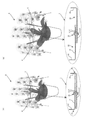
実施例1の支柱間隔調整器具1は、図1に示す様に、2つの操作ボタン21,21を備える器具本体10に対して横軸部31,31を左右から挿通させた2本の間隔調整部品30,30の各縦軸部32,32を、3本仕立ての胡蝶蘭の鉢植えAの外側2本の花茎を支持する支柱B,Cに固定して用いるものであって、図1(A)に示す様に、縦軸部32,32の間隔を狭くした状態で使用して梱包時の荷姿を小さくしたり、図1(B)に示す様に、縦軸部32,32の間隔を拡げた状態で使用して鑑賞に際しての見栄えを良くしたりするために用いるものである。
As shown in FIG. 1, the support column spacing adjusting device 1 of the first embodiment has two spacing adjustments in which the
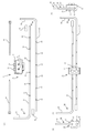
支柱間隔調整器具1は、図2(A)に示す様に、一つの器具本体10と、二つの間隔調整部品30,30とから構成され、好ましくは、花茎支持用の支柱に縦軸部32,32を固定するための結束バンド41,41や横軸部31,31の末端に被せるキャップ42,42を併せて用いる。器具本体10には二つの横軸挿入孔11,11が形成され、操作ボタン21,21を押し込んで横軸挿入孔11,11を横軸挿通方向に開通した横軸挿通孔を形成し、この状態にて間隔調整部品30,30の横軸部31,31を挿通させた後に操作ボタン21,21の押し込みを止めることにより、図2(B)〜(D)に示す様な状態とすることができる。なお、キャップ42,42は、横軸部31,31を器具本体10に挿通させた後に端部に被せる。キャップ42,42は植物が傷つくのを防止する。
As shown in FIG. 2A, the support column spacing adjusting device 1 is composed of one device
間隔調整部品30はABS樹脂製の直径3mmの湾曲した丸棒状成形体からなり、横軸部31には30mm間隔で長さ1mm,直径2mmの細径部33,33,…が設けられている。間隔調整部品30の横軸31は、細径部33の両側を手で持って力を加えることによって折り取ることが可能となっている。また、細径部33は、縦軸部32,32の間隔を調整する際に調整量の目安となる目盛りとしても機能する。
The
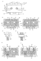
器具本体10は、図3(A)〜(F)に示す様に、二つ割りの筐体部品12A,12Bから構成される筐体12と、操作ボタン21,21の押下に従って出没方向に動作する動作部品20,20とを備える。
As shown in FIGS. 3 (A) to 3 (F), the instrument
筐体部品12A,12Bには、図3(B)に示す様に、それぞれ二つの動作部品収納空間13A,13A,13B,13Bが備えられると共に、互いに嵌合させて筐体12を構成するため、一方の筐体部品12Aにはピン14A,14A,…が、他方の筐体部品12Bにはピン孔14B,14B,…が備えられている。また、動作部品収納空間13A,13A,13B,13Bには、各一個の円孔11A,11A,11B,11Bが貫通されている。これら筐体部品12Aに貫通された円孔11A,11Aと筐体部品12Bに貫通された円孔11B,11Bは、筐体部品12A,12Bを嵌合状態に組み立てたときに横軸挿通方向に重なり合って横軸挿通孔を形成し得る位置に設けられている。
As shown in FIG. 3B, the
筐体部品12A,12Bには、動作部品収納空間13A,13Bに連続する様に、下側凹部15A,15Bと、上側の段付き凹部16A,16Bとが設けられている。また、筐体部品12A,12Bの底部には嵌合時に内側に向く爪と細長角孔とを備えたブラケット部材17A,17Bが設けられている。ブラケット部材17A,17Bは、他の支柱などに器具本体10を固定したいときなどに用いることができる。
The
動作部品20は、図3(C),(D)に示す様に、操作ボタン21を上端に備え、横軸挿通方向に貫通孔22を備える動作本体部23と、コイルバネ25とを備える。動作本体部23の下面にはコイルバネ25を支持する突起24も形成されている。動作部品20は、図3(E),(F)に示す様に、コイルバネ25を突起24に嵌め込んだ状態とした上で、筐体部品12A(又は12B)の動作部品収納部13A(又は13B)に、動作本体部23の貫通孔22を横軸挿通方向に向かせる様に組み付ける。このとき、下側凹部15A,15Bはコイルバネ25を収納し、段付き凹部16A,16Bは動作本体部23を収納すると共に操作ボタン21,21を筐体外に突出させた状態に維持する。
As shown in FIGS. 3C and 3D, the operating
こうして筐体部品12A(又は12B)に動作部品20を組み付け終えた状態にあっては、図3(F)に示す様に、コイルバネ25が伸びようとして動作本体部23を段付き凹部16A,16Bの広い方の凹部の上面に押し当てた状態となるため、円孔11A(及び11B)と貫通孔22とは重なり合っていない状態となる。
In the state where the operating
間隔調整部品30を組み付けるに当たっては、図4(A)に示す様に、操作ボタン21を一杯に押し込んで横軸挿入孔11と貫通孔22とが重なり合った状態とした上で、横軸部31を挿通させる。この後、操作ボタン21の押下を止めると、図4(B)に示す様に、コイルバネ25が伸びて動作本体部23を押し上げる結果、横軸部21は横軸挿入孔11の上縁と貫通孔22の下縁との間に挟まれて保持された状態となる。縦軸部32,32の間隔を調整する際には、図4(C),(D)に示す様に、一方の操作ボタン21を押し込んで横軸挿入孔11と貫通孔22とが重なり合った状態とした上で、横軸部31を軸方向に移動させる。
When assembling the
なお、二つの操作ボタン21,21を同時に押し込んでもよいが、片方ずつ押し込んで調整を行う方が作業性がよい。本実施例の支柱間隔調整器具1は、2つの操作ボタン21,21を独立して操作可能に構成した結果、良好な作業性を確保することもできている。
The two
なお、筐体部品12A,12B、動作部品20は、ABS樹脂製の射出成形品で構成している。
The
以上、本発明の実施例を説明したが、本発明はこれに限定されるものではなく、その要旨を逸脱しない範囲内で種々に実施することができる。 Although the examples of the present invention have been described above, the present invention is not limited to this, and can be variously implemented within a range that does not deviate from the gist thereof.
本発明は、複数本仕立ての洋ラン鉢植えの生産、流通、販売、鑑賞の各シーンにて利用することができる。 The present invention can be used in each scene of production, distribution, sale, and appreciation of a plurality of tailored orchid potted plants.
1・・・支柱間隔調整器具、10・・・器具本体、11・・・横軸挿入孔、11A,11B・・・円孔、12・・・筐体、12A,12B・・・筐体部品、13A,13B・・・動作部品収納空間、14A・・・ピン、14B・・・ピン孔、15A,15B・・・下側凹部、16A,16B・・・段付き凹部、17A,17B・・・ブラケット部材、20・・・動作部品、21・・・操作ボタン、22・・・貫通孔、23・・・動作本体部、24・・・突起、25・・・コイルバネ、30・・・間隔調整部品、31・・・横軸部、32・・・縦軸部、33・・・細径部、41・・・結束バンド、42・・・キャップ、A・・・胡蝶蘭の鉢植え、B,C・・・支柱。 1 ... Support spacing adjustment device, 10 ... Equipment body, 11 ... Horizontal axis insertion hole, 11A, 11B ... Circular hole, 12 ... Housing, 12A, 12B ... Housing parts , 13A, 13B ... Operating parts storage space, 14A ... Pin, 14B ... Pin hole, 15A, 15B ... Lower recess, 16A, 16B ... Stepped recess, 17A, 17B ... -Bracket member, 20 ... operating parts, 21 ... operation buttons, 22 ... through holes, 23 ... operating body, 24 ... protrusions, 25 ... coil springs, 30 ... intervals Adjustment parts, 31 ... horizontal axis, 32 ... vertical axis, 33 ... small diameter, 41 ... binding band, 42 ... cap, A ... potted Phalaenopsis orchid, B , C ... prop.
Claims (5)
(1A)前記所定の間隔を保って保持すべき一方の支柱に固定する縦軸部と該縦軸部から一方に向かって伸びる横軸部とを備える第1の間隔調整部品と、前記所定の間隔を保って保持すべき他方の支柱に固定する縦軸部と該縦軸部から一方に向かって伸びる横軸部とを備える第2の間隔調整部品と、前記第1,第2の間隔調整部品の横軸部をそれぞれ反対方向から挿通可能であって、横軸挿通方向に開口する第1,第2の横軸挿入孔を有する筐体を備えた器具本体と、を備えていること。
(1B)前記筐体内には、前記第1,第2の横軸挿入孔と重なり合うことによって前記横軸挿通方向に貫通する横軸挿通孔を形成する貫通孔を備えた動作部品が、前記横軸挿通方向に直交する方向に移動可能に収納されていること。
(1C)前記筐体には、前記動作部品を前記横軸挿通方向に直交する方向に押し上げるバネ部材が収納されると共に、前記動作部品を前記バネ部材によって押し上げられたときに当接して停止させる段付き凹部が備えられ、前記貫通孔と前記第1,第2の横軸挿入孔とは、前記動作部品が前記段付き凹部に当接した状態にあっては前記横軸挿通孔を形成しない関係となる様に形成されていること。
(1D)前記動作部品には、前記段付き凹部に当接した状態において前記筐体の外に突出する操作ボタンが備えられ、前記貫通孔と前記第1,第2の横軸挿入孔とは、前記操作ボタンを押し込むことにより、前記バネ部材による押し上げに抗して前記動作部品を押し下げ、前記横軸挿通孔を形成しうる関係となる様に形成されていること。 A device for holding a plurality of columns installed in a potted plant of a plurality of tailored orchids at a predetermined distance, and characterized by having the following configuration.
(1A) A first interval adjusting component including a vertical axis portion fixed to one of the columns to be held at the predetermined interval and a horizontal axis portion extending from the vertical axis portion toward one side, and the predetermined interval adjusting component. A second spacing adjusting component including a vertical axis portion fixed to the other support column to be held at a spacing and a horizontal axis portion extending from the vertical axis portion toward one side, and the first and second spacing adjusting parts. The instrument body is provided with a housing having first and second horizontal axis insertion holes that allow the horizontal axis portions of the parts to be inserted from opposite directions and that open in the horizontal axis insertion direction.
(1B) In the housing, an operating component provided with a through hole that forms a horizontal axis insertion hole that penetrates in the horizontal axis insertion direction by overlapping with the first and second horizontal axis insertion holes is described laterally. It must be retractable so that it can be moved in the direction orthogonal to the shaft insertion direction.
(1C) The housing contains a spring member that pushes up the moving component in a direction orthogonal to the horizontal axis insertion direction, and when the moving component is pushed up by the spring member, it abuts and stops. A stepped recess is provided, and the through hole and the first and second horizontal shaft insertion holes do not form the horizontal shaft insertion hole when the operating component is in contact with the stepped recess. It must be formed so that it becomes a relationship.
(1D) The operating component is provided with an operation button that projects to the outside of the housing in a state of being in contact with the stepped recess, and the through hole and the first and second horizontal axis insertion holes are By pushing the operation button, the operating component is pushed down against the push-up by the spring member, and the horizontal shaft insertion hole is formed.
(2A)前記動作部品は、前記第1の横軸挿入孔に対して前記横軸挿通方向に貫通する横軸挿通孔を形成する貫通孔を備えた第1の動作部品と、前記第2の横軸挿入孔に対して前記横軸挿通方向に貫通する横軸挿通孔を形成する貫通孔を備えた第2の動作部品とから構成され、前記第1,第2の動作部品は、前記横軸挿通方向に直交する方向に別個に移動可能となる様に別体の部品として構成されていること。
(2B)前記第1,第2の動作部品には、それぞれ前記操作ボタンが備えられると共に、該操作ボタンと反対側に突起が設けられ、前記バネ部材として、第1,第2のコイルバネが前記突起を挿入されて前記筐体と各動作部品との間に挟み込まれる様に設置されていること。 The strut spacing adjusting device according to claim 1, further comprising the following configuration.
(2A) The operating component includes a first operating component having a through hole for forming a horizontal axis insertion hole that penetrates the first horizontal axis insertion hole in the horizontal axis insertion direction, and the second operating component. It is composed of a second operating component having a through hole forming a horizontal axis insertion hole that penetrates the horizontal axis insertion hole in the horizontal axis insertion direction, and the first and second operating components are the lateral axis. It shall be configured as a separate part so that it can be moved separately in the direction orthogonal to the shaft insertion direction.
(2B) The first and second operating parts are each provided with the operation button, and a protrusion is provided on the side opposite to the operation button. As the spring member, the first and second coil springs are used. It is installed so that a protrusion is inserted and sandwiched between the housing and each operating component.
(3)前記筐体は二分割された第1,第2の筐体部品を嵌合させて形成され、前記器具本体をさらに他の支柱等に固定するためのブラケットを備えていること。 The strut spacing adjusting device according to claim 1 or 2, further comprising the following configuration.
(3) The housing is formed by fitting the first and second housing parts divided into two, and is provided with a bracket for fixing the instrument main body to another support column or the like.
(4)前記筐体、前記動作部品及び前記第1,第2の間隔調整部品はABS樹脂製の成形体で構成されていること。 The strut spacing adjusting device according to any one of claims 1 to 3, further comprising the following configuration.
(4) The housing, the operating parts, and the first and second spacing adjusting parts are made of a molded body made of ABS resin.
(5)前記第1,第2の間隔調整部品は前記縦軸部と横軸部とが一体となった丸棒状成形体で構成され、前記横軸部には等間隔にて複数の細径部が備えられていること。 The strut spacing adjusting device according to any one of claims 1 to 4, further comprising the following configuration.
(5) The first and second spacing adjusting parts are composed of a round bar-shaped molded body in which the vertical axis portion and the horizontal axis portion are integrated, and the horizontal axis portion has a plurality of small diameters at equal intervals. The part is provided.
Priority Applications (1)
| Application Number | Priority Date | Filing Date | Title |
|---|---|---|---|
| JP2020035057A JP7102011B2 (en) | 2020-03-02 | 2020-03-02 | Strut spacing adjustment device |
Applications Claiming Priority (1)
| Application Number | Priority Date | Filing Date | Title |
|---|---|---|---|
| JP2020035057A JP7102011B2 (en) | 2020-03-02 | 2020-03-02 | Strut spacing adjustment device |
Publications (2)
| Publication Number | Publication Date |
|---|---|
| JP2021136877A true JP2021136877A (en) | 2021-09-16 |
| JP7102011B2 JP7102011B2 (en) | 2022-07-19 |
Family
ID=77666700
Family Applications (1)
| Application Number | Title | Priority Date | Filing Date |
|---|---|---|---|
| JP2020035057A Active JP7102011B2 (en) | 2020-03-02 | 2020-03-02 | Strut spacing adjustment device |
Country Status (1)
| Country | Link |
|---|---|
| JP (1) | JP7102011B2 (en) |
Citations (10)
| Publication number | Priority date | Publication date | Assignee | Title |
|---|---|---|---|---|
| JPS61162120A (en) * | 1985-01-11 | 1986-07-22 | 三菱マテリアル株式会社 | Support for plant |
| JPH0619435U (en) * | 1992-03-19 | 1994-03-15 | 第一ビニール株式会社 | Strut device for plant cultivation |
| JP2004141157A (en) * | 2002-10-02 | 2004-05-20 | Ube Nitto Kasei Co Ltd | Cultivation props and cultivation tools |
| JP3112002U (en) * | 2004-12-28 | 2005-07-28 | 進 松浦 | Phalaenopsis potted plant |
| JP3166051U (en) * | 2010-12-03 | 2011-02-17 | 雅之 島田 | Prop fixture |
| JP3203565U (en) * | 2016-01-25 | 2016-04-07 | 株式会社花職人 | Phalaenopsis potted plant |
| JP2016158546A (en) * | 2015-02-27 | 2016-09-05 | 加藤 悟 | Potted cymbidium and method of setting up cymbidium |
| JP3210039U (en) * | 2017-02-09 | 2017-04-20 | キャル株式会社 | A collection of Phalaenopsis orchids |
| JP2020074727A (en) * | 2018-11-09 | 2020-05-21 | 有限会社ヒカル・オーキッド | Shape retention frame |
| JP2020137472A (en) * | 2019-02-28 | 2020-09-03 | 有限会社ヒカル・オーキッド | Pot assembly system for ornamental plant |
-
2020
- 2020-03-02 JP JP2020035057A patent/JP7102011B2/en active Active
Patent Citations (10)
| Publication number | Priority date | Publication date | Assignee | Title |
|---|---|---|---|---|
| JPS61162120A (en) * | 1985-01-11 | 1986-07-22 | 三菱マテリアル株式会社 | Support for plant |
| JPH0619435U (en) * | 1992-03-19 | 1994-03-15 | 第一ビニール株式会社 | Strut device for plant cultivation |
| JP2004141157A (en) * | 2002-10-02 | 2004-05-20 | Ube Nitto Kasei Co Ltd | Cultivation props and cultivation tools |
| JP3112002U (en) * | 2004-12-28 | 2005-07-28 | 進 松浦 | Phalaenopsis potted plant |
| JP3166051U (en) * | 2010-12-03 | 2011-02-17 | 雅之 島田 | Prop fixture |
| JP2016158546A (en) * | 2015-02-27 | 2016-09-05 | 加藤 悟 | Potted cymbidium and method of setting up cymbidium |
| JP3203565U (en) * | 2016-01-25 | 2016-04-07 | 株式会社花職人 | Phalaenopsis potted plant |
| JP3210039U (en) * | 2017-02-09 | 2017-04-20 | キャル株式会社 | A collection of Phalaenopsis orchids |
| JP2020074727A (en) * | 2018-11-09 | 2020-05-21 | 有限会社ヒカル・オーキッド | Shape retention frame |
| JP2020137472A (en) * | 2019-02-28 | 2020-09-03 | 有限会社ヒカル・オーキッド | Pot assembly system for ornamental plant |
Also Published As
| Publication number | Publication date |
|---|---|
| JP7102011B2 (en) | 2022-07-19 |
Similar Documents
| Publication | Publication Date | Title |
|---|---|---|
| JP7102011B2 (en) | Strut spacing adjustment device | |
| JP2011103797A (en) | Pet-play apparatus | |
| US20160262551A1 (en) | Bed Base Capable of Fixing Mattress | |
| KR20130027131A (en) | The cake box consist of be fixed body of pedestal | |
| JP3230096U (en) | Flower wrapping | |
| KR200479732Y1 (en) | Apparatus for bouquet | |
| JP2018167847A (en) | Packaging container for preserved flower | |
| US1355038A (en) | Hair-trimming gage | |
| KR101780940B1 (en) | Wrapper for seedling and packing method using the same | |
| US1665618A (en) | Ornamental object | |
| US20130270398A1 (en) | Flower Support Collar for Vases | |
| JP6594387B2 (en) | Flower arrangement system | |
| KR102173660B1 (en) | Altar flower decorating apparatus | |
| JP7004293B2 (en) | Plant holder | |
| KR101769497B1 (en) | Portable Flower Packaging Case | |
| KR102144224B1 (en) | flower arrangement support system | |
| JP3162438U (en) | Seedling support tool and seedling support kit | |
| KR20020090585A (en) | an apparatus for forming bouquet | |
| JP2009285271A (en) | Altar for funeral | |
| JP3214722U (en) | Decorative artificial flowers | |
| KR20220074448A (en) | Insulated bouquet box | |
| JP3209325U (en) | Packaging boxes and stands | |
| EP4212070A1 (en) | Fixing structure for flower combination | |
| JP3206219U (en) | Group planting pot seedling fixing tool | |
| US2710687A (en) | Display and shipping device for annular object or the like |
Legal Events
| Date | Code | Title | Description |
|---|---|---|---|
| A621 | Written request for application examination |
Free format text: JAPANESE INTERMEDIATE CODE: A621 Effective date: 20210928 |
|
| A977 | Report on retrieval |
Free format text: JAPANESE INTERMEDIATE CODE: A971007 Effective date: 20220608 |
|
| TRDD | Decision of grant or rejection written | ||
| A01 | Written decision to grant a patent or to grant a registration (utility model) |
Free format text: JAPANESE INTERMEDIATE CODE: A01 Effective date: 20220628 |
|
| A61 | First payment of annual fees (during grant procedure) |
Free format text: JAPANESE INTERMEDIATE CODE: A61 Effective date: 20220629 |
|
| R150 | Certificate of patent or registration of utility model |
Ref document number: 7102011 Country of ref document: JP Free format text: JAPANESE INTERMEDIATE CODE: R150 |
|
| R250 | Receipt of annual fees |
Free format text: JAPANESE INTERMEDIATE CODE: R250 |