JP2021136857A - Portable general-purpose power supply output device and system - Google Patents
Portable general-purpose power supply output device and system Download PDFInfo
- Publication number
- JP2021136857A JP2021136857A JP2020118760A JP2020118760A JP2021136857A JP 2021136857 A JP2021136857 A JP 2021136857A JP 2020118760 A JP2020118760 A JP 2020118760A JP 2020118760 A JP2020118760 A JP 2020118760A JP 2021136857 A JP2021136857 A JP 2021136857A
- Authority
- JP
- Japan
- Prior art keywords
- unit
- connector
- output
- transformer
- portable
- Prior art date
- Legal status (The legal status is an assumption and is not a legal conclusion. Google has not performed a legal analysis and makes no representation as to the accuracy of the status listed.)
- Granted
Links
Images


Landscapes
- Stand-By Power Supply Arrangements (AREA)
Abstract
【課題】避難所等で安全かつ収容人数に見合う可変な出力容量を持ち、コンパクトで可搬性があり、汎用性の高い可搬型汎用電源出力装置およびシステムを提供すること。【解決手段】本発明に係る可搬型汎用電源出力装置は、移動電源車などの低圧発電機と接続可能な入力コネクタと、この入力コネクタから供給される電源により作動する変圧器を内蔵する可搬型の変圧ユニットと、前記変圧器により動作され外部出力コネクタを備えた可搬型の出力ユニットとを有し、前記両ユニットを積層可能とし、前記両ユニットの積層部には各ユニット内に設けられた電源供給ラインに繋がる嵌合型の接続コネクタ部を形成しワンタッチ接続を可能としてなる。【選択図】図1PROBLEM TO BE SOLVED: To provide a portable general-purpose power output device and system which are safe in an evacuation center or the like, have a variable output capacity suitable for a capacity, are compact and portable, and have high versatility. A portable general-purpose power output device according to the present invention is a portable type having a built-in input connector that can be connected to a low-voltage generator such as a mobile power supply vehicle and a transformer that is operated by a power source supplied from the input connector. The transformer unit and the portable output unit operated by the transformer and provided with an external output connector are provided, both units can be laminated, and the laminated portion of both units is provided in each unit. A mating type connector that connects to the power supply line is formed to enable one-touch connection. [Selection diagram] Fig. 1
Description
本発明は可搬型汎用電源出力装置およびシステムに係り、特に、電源出力部の増減が簡単にできるようにした可搬型汎用電源出力装置およびシステムに関する。 The present invention relates to a portable general-purpose power output device and a system, and more particularly to a portable general-purpose power output device and a system in which the power output unit can be easily increased or decreased.
従来、非常用電源出力装置は、特許文献1に記載されているように、一般的には、一つのフレーム内に蓄電池とインバータおよびバッテリーチャージャーを搭載し、増設フレームにもインバータ以外の同設備を搭載し、両フレーム同士の支柱間を連結する連結部材により機械的連結を図った構成とされたものが知られている。蓄電池を搭載したフレームを増すことにより、使用電力の増大化に対応することができるようにしている。
Conventionally, as described in
しかしながら、上述のような構成では、通常時商用電源にて蓄電池に充電し、停電時に蓄電池から直流電力をインバータ部で交流電力に変換する構成であり、蓄電池の充電量が無くなればそれで終了してしまう。充電量を増すためには蓄電池の数を増やさなければならないという欠点がある。また、上記構成では、商用電源出力口数が増えるたび、蓄電池を備えたフレームの増大を図らなければならず、特に電源が必要な避難所での使用に応えられない。 However, in the configuration as described above, the storage battery is normally charged by a commercial power source, and DC power is converted from the storage battery to AC power by the inverter unit in the event of a power failure. It ends up. There is a drawback that the number of storage batteries must be increased in order to increase the amount of charge. Further, in the above configuration, each time the number of commercial power output ports increases, the number of frames equipped with a storage battery must be increased, and it cannot be used in an evacuation center where a power supply is particularly required.
また、住民が避難している場合、避難所には多くの被災者が集まり、避難所には電源救済に対応した設備がないのが実情である。発電機を準備しても電源を必要とする被災者のニーズと一致しておらず、スピーディな対応が必要であるにも拘わらず、どこで電源を必要となるか分からない問題がある。特に昨今では大多数の人々は携帯電話やスマートフォンが生活のマストアイテムとなっており、必要不可欠と言っても過言ではない。その様な中で、避難所の数少ないコンセントは延長タップを取り付け充電器が鈴なりとなっている状況である。更に、医療機器に電源が必要な入院中の患者が避難される場合、近隣の病院に受け入れられる人数は限られており、対応できる避難所も限られることが予想され、電源確保は大変重要だと考えられる。また、非常用発電機が準備されても容量が小さく、大容量であっても人々が必要としているAC100Vコンセントや充電用USBコンセントは不足する状況である。 In addition, when residents are evacuated, many victims gather at the evacuation center, and the evacuation center does not have facilities for power supply relief. Even if a generator is prepared, it does not meet the needs of the victims who need a power source, and despite the need for speedy response, there is a problem of not knowing where the power source is needed. Especially nowadays, it is no exaggeration to say that mobile phones and smartphones have become a must-have item for most people in their daily lives. Under such circumstances, the few outlets in evacuation shelters are equipped with extension taps and the chargers are bell-shaped. Furthermore, when inpatients who need power for medical equipment are evacuated, the number of people accepted by nearby hospitals is limited, and it is expected that the number of evacuation centers that can handle them will be limited, so securing power is very important. it is conceivable that. In addition, even if an emergency generator is prepared, the capacity is small, and even if the capacity is large, the AC100V outlet and the USB outlet for charging that people need are in short supply.
従来の仮設分電盤を配置することも考えられるが、これは建設現場等において建設途上に必要な電源を供給することを主たる目的としているものである。この場合、専門知識・技術を有する技術者が取り扱うため、外部配線の接続や分電盤内部の配線接続箇所および構成品といった部品も露出しており、一般の方にとっては生命の危険が生じるものである。従って、この様な仮設分電盤を設置するためには立入禁止措置や取扱者を限定する必要があった。また、筐体は金属製のため重量も重く運搬においても労力と時間が掛かるものであった。緊急避難場所における仮設電源は、小容量の携帯発電機から延長コード等でわずかな電源しか供給することができず、多くの電源を供給する場合は、そのような発電機を複数準備しなければならず、ユーザーのニーズに合致していないものであった。 It is conceivable to arrange a conventional temporary distribution board, but this is mainly for the purpose of supplying the power required during construction at a construction site or the like. In this case, since it is handled by a technician with specialized knowledge and technology, parts such as external wiring connections and wiring connection points and components inside the distribution board are also exposed, which poses a risk of life to the general public. Is. Therefore, in order to install such a temporary distribution board, it was necessary to take off-limits measures and limit the number of operators. In addition, since the housing is made of metal, it is heavy and requires labor and time for transportation. Temporary power sources in emergency evacuation areas can supply only a small amount of power from a small-capacity portable generator with an extension cord, etc., and if a large amount of power is to be supplied, multiple such generators must be prepared. It did not meet the needs of the users.
本発明は、上記従来の問題点に着目し、避難所等で安全かつ収容人数に見合う可変な出力容量を持ち、コンパクトで可搬性があり、汎用性の高い可搬型汎用電源出力装置およびシステムを提供することを目的とする。また、広い避難所の複数個所に設置することができる可搬型汎用電源出力装置およびシステムを提供することを目的とする。 Focusing on the above-mentioned conventional problems, the present invention provides a portable general-purpose power output device and system that are safe in evacuation centers and have a variable output capacity suitable for the number of people that can be accommodated, are compact and portable, and are highly versatile. The purpose is to provide. Another object of the present invention is to provide a portable general-purpose power output device and system that can be installed in a plurality of large evacuation shelters.
上記目的を達成するため、本発明に係る可搬型汎用電源出力装置は、移動電源車などの低圧発電機と接続可能な入力コネクタと、この入力コネクタから供給される電源により作動する変圧器を内蔵する可搬型の変圧ユニットと、前記変圧器により動作され外部出力コネクタを備えた可搬型の出力ユニットとを有し、前記両ユニットを積層可能とし、前記両ユニットの積層部には各ユニット内に設けられた電源供給ラインに繋がる嵌合型の接続コネクタ部を形成しワンタッチ接続を可能としてなる構成とした。 In order to achieve the above object, the portable general-purpose power output device according to the present invention has a built-in input connector that can be connected to a low-voltage generator such as a mobile power supply vehicle and a transformer that is operated by the power supply supplied from this input connector. It has a portable transformer unit that is operated by the transformer and a portable output unit that is operated by the transformer and has an external output connector, and both units can be laminated. A mating-type connector that connects to the provided power supply line is formed to enable one-touch connection.
前記出力ユニットは複数の出力ユニットを更に積層して増設可能とすることができる。同じく前記変圧ユニットも複数の変圧ユニットを更に積層して増設可能としている。前記入力コネクタには複数のタップを設けて複数の変圧ユニットに分配供給可能としてよい。前記出力ユニットに接続されるインバータを設け、このインバータには電気自動車の充電器に接続される第2の入力コネクタを設ける構成としても良い。
前記変圧ユニットおよび出力ユニットには積層状態で固定されるロック手段を備えればよい。更に、前記変圧ユニットと出力ユニットの積層体の最上部にはルーフパネルを積層可能としていることが望ましい。前記変圧ユニットと出力ユニットの入力コネクタ、および外部出力コネクタは各ユニットケースの凹部箇所に設けている方がよい。
The output unit can be expanded by further stacking a plurality of output units. Similarly, the transformer unit can be expanded by further stacking a plurality of transformer units. A plurality of taps may be provided on the input connector so that the input connector can be distributed and supplied to a plurality of transformer units. An inverter connected to the output unit may be provided, and the inverter may be provided with a second input connector connected to a charger of an electric vehicle.
The transformer unit and the output unit may be provided with locking means that are fixed in a laminated state. Further, it is desirable that a roof panel can be laminated on the uppermost portion of the laminated body of the transformer unit and the output unit. It is preferable that the input connector of the transformer unit and the output unit, and the external output connector are provided in the recessed portion of each unit case.
また、本発明に係る可搬型汎用電源出力システムは、移動電源車などの低圧発電機と、この低圧発電機からの出力ケーブルと、当該出力ケーブルに接続可能な入力コネクタから供給される電源により動作する変圧器を内蔵する可搬型の変圧ユニットと、外部出力コネクタを備えた可搬型の出力ユニットと、を有し、変圧ユニットと出力ユニットとを積層可能とし、前記両ユニットの積層部には各ユニット内に設けられた電源供給ラインに繋がる嵌合形の接続コネクタ部を形成しワンタッチ接続を可能としてなるものである。 Further, the portable general-purpose power output system according to the present invention operates by a low-voltage generator such as a mobile power supply vehicle, an output cable from the low-voltage generator, and a power supply supplied from an input connector connectable to the output cable. It has a portable transformer unit with a built-in transformer and a portable output unit equipped with an external output connector, and the transformer unit and the output unit can be stacked. A mating type connection connector portion connected to a power supply line provided in the unit is formed to enable one-touch connection.
前記出力ケーブルは、接続する状況によりコネクタ式移動電源車用電源ケーブルで直接、または、インターフェース変換電源ケーブルとコネクタ式移動電源車用電源ケーブルを接続して使用することができ、この場合接続部は嵌合形の接続コネクタ式とし通電部は外部露出することはないようにする。
更に、前記出力ユニットと変圧ユニットとは、複数積層させ増設を可能とし、また電気自動車の充電器により駆動され前記出力ユニットに接続可能なインバータを搭載可能とすることができる。
The output cable can be used directly with a connector type mobile power supply vehicle power cable or by connecting an interface conversion power supply cable and a connector type mobile power supply vehicle power cable depending on the connection situation. In this case, the connection portion is A mating type connector type should be used so that the energized part is not exposed to the outside.
Further, a plurality of the output unit and the transformer unit can be stacked and expanded, and an inverter driven by a charger of an electric vehicle and connectable to the output unit can be mounted.
上記本発明の構成によれば、発電機に合わせて外部出力コネクタを増設可能となり、避難所などでは収容人数に見合う可変容量にすることができる。また、各ユニットは可搬性があり、例えばFRPにより製作しコンパクトで持ち運びが容易であるため避難所には最適となる。更にユニット間の接続方法はコネクタ方式となり、外部配線が不要で誰でも簡易に安全に接続できるものとなる。また、入力コネクタは複数のタップを設けて複数の変圧ユニットに分配供給可能とすることにより、前記可搬型汎用電源出力装置を広い範囲で複数個所に配置することができ、分散配置して利便性を上げることができる。また、前記出力ユニットに接続されるインバータを設け、このインバータには電気自動車の充電器に接続される第2の入力コネクタを設けることにより、電気自動車を利用することが出来て電源供給源を増やすこともできる。 According to the above-described configuration of the present invention, an external output connector can be added according to the generator, and the variable capacity can be adjusted to match the number of people accommodated in an evacuation center or the like. In addition, each unit is portable, and is ideal for evacuation shelters because it is made of FRP, for example, and is compact and easy to carry. Furthermore, the connection method between the units is a connector method, which does not require external wiring and allows anyone to easily and safely connect. Further, by providing a plurality of taps for the input connector so that it can be distributed and supplied to a plurality of transformer units, the portable general-purpose power output device can be arranged in a plurality of places in a wide range, and it is convenient to arrange them in a distributed manner. Can be raised. Further, by providing an inverter connected to the output unit and providing a second input connector connected to the charger of the electric vehicle in this inverter, the electric vehicle can be used and the power supply source is increased. You can also do it.
以下、本発明の可搬型汎用電源出力装置およびシステムに係る実施の形態について、図面を参照して詳細に説明する。なお、以下に示す実施の形態は、本発明を実施するための好適な形態の一部であり、その対象や選択項目に変化を加えたとしても、本発明の効果を奏する限りにおいて、本発明の一部とみなすことができる。 Hereinafter, embodiments of the portable general-purpose power output device and system of the present invention will be described in detail with reference to the drawings. It should be noted that the embodiments shown below are a part of the preferred embodiments for carrying out the present invention, and even if the objects and selection items thereof are changed, the present invention is as long as the effects of the present invention are exhibited. Can be considered part of.
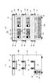
図1は、本発明の実施形態に係る可搬型汎用電源出力装置の外観図を示すもので同図(1)は左側面図、同図(2)は正面図である。図2は、本発明の実施形態に係る同装置の分解正面図である。図3は、本発明の実施形態に係る同装置に用いられる変圧ユニットの左側面図(同図(1))、正面図(同図(2))、平面図(同図(3))である。図4は、本発明の実施形態に係る同装置に用いられる出力ユニットの左側面図(同図(1))、正面図(同図(2))、平面図(同図(3))である。図5は、本発明の実施形態に係る同装置の電気回路図である。 FIG. 1 shows an external view of a portable general-purpose power output device according to an embodiment of the present invention, in which FIG. 1 is a left side view and FIG. 1 is a front view. FIG. 2 is an exploded front view of the device according to the embodiment of the present invention. FIG. 3 is a left side view (the same figure (1)), a front view (the same figure (2)), and a plan view (the same figure (3)) of the transformer unit used in the apparatus according to the embodiment of the present invention. be. FIG. 4 is a left side view (the same figure (1)), a front view (the same figure (2)), and a plan view (the same figure (3)) of the output unit used in the apparatus according to the embodiment of the present invention. be. FIG. 5 is an electric circuit diagram of the device according to the embodiment of the present invention.
図1は、可搬型汎用電源出力装置の実施形態を示しており、装置ユニット組立時の外観図である。この図に示すように、可搬型汎用電源出力装置10は、一つの変圧ユニット12と、これに積層される出力ユニット14A、更にこの上に増設される出力ユニット14B、および最上段に配置される増設出力ユニット14Bの上面をカバーするルーフパネル16から構成されている。
FIG. 1 shows an embodiment of a portable general-purpose power output device, which is an external view when the device unit is assembled. As shown in this figure, the portable general-purpose
各ユニット12、14(14A、14B)は略同一の形状を有する直方体からなり、筐体はFRP(繊維強化プラスチック)から形成され、電気的安全性を向上させている。変圧ユニット12の上面と出力ユニット14の上下面には、積み重ねると内部の電源供給ライン(後述する)と自動で接続状態となる嵌合型の接続コネクタ18が設けられ、ユニット間の外部配線を無くすようにしている。
Each
まず変圧ユニット12は、図3に示しているように、内部に第1変圧器20aと第2変圧器20bを上下二段に配置しており、両者の入力部には主遮断器22を介して外部からの出力電源200Vを入力する雌型の入力コネクタ24が備えられている。主遮断器22と入力コネクタ24とは、変圧ユニット12のフレーム外側面部に形成された凹み部分、すなわち第1深堀部26から外部に臨んで配置されている。一方、内部の第1、第2の変圧器20(20a、20b)はそれぞれ入力電源200Vを100Vに変圧するように構成され、その出力電源100Vを電源供給ライン28a、28bから、外部すなわち上部の出力ユニット14Aに向けられた接続コネクタ18を構成している雌型接続コネクタ18a、18bに出力可能にしている。雌型接続コネクタ18a、18bは、図3(3)の平面図で明らかなように、変圧器20の後部側に一定間隔に配置され、変圧ユニット12の上面に2系統の電源供給ライン28a、28bを形成している。この雌型接続コネクタ18a、18bは、変圧ユニット12の上面に形成した第2深堀部(表面から凹んでいる部分)30に配置されている。また、変圧ユニット12の前面部にも、上下2段重ねで配置される第1変圧器20a、第2変圧器20bの前面が臨まれる第3深堀部32が形成されている。
First, as shown in FIG. 3, the
一方、出力ユニット14A、14Bは同様に構成されており、これには変圧ユニット12の2系統の電源供給ライン28a、28bの端末となる雌型接続コネクタ18a、18bから電源の供給を受けるものとなっている。先ず、出力ユニット14の外観は、直方体形状とされ、投影平面は下部変圧ユニット12と同一とされ、下面部に第2深堀部30に嵌入可能な下部矩形フレーム34を突出させている。上面部にはその表面から凹んでいる部分とされ、前記矩形フレーム34が丁度嵌入する大きさの第4深堀部36が形成されている。また、出力ユニット14の前面部にも第5深堀部38が形成されている。したがって、出力ユニット14は変圧ユニット12の天井面で、水平面に沿った移動が防止されて積層可能となっている。さらに出力ユニット14同士の積層も可能で、下部矩形フレーム34を上段の出力ユニット14Bの第4深堀部36に嵌入することで多段に積み重ねることができる。
On the other hand, the
このような出力ユニット14Aの下面部には、変圧ユニット12に積層した際、前記雌型接続コネクタ18a、18bから電源供給を受けるため、雄型接続コネクタ40a、40bが設けられている。雄型接続コネクタ40a、40bは、変圧ユニット12の上面に2系統の電源供給ライン28a、28bと同列、同間隔に形成されている。これにより下位の変圧ユニット12に積層した際、接続コネクタ18の雌型接続コネクタ18a、18bと雄型接続コネクタ40a、40bが嵌合して変圧ユニット12から電源供給を受けることができる。
出力ユニット14Aの上面部には、第4深堀部36内に位置して、雄型接続コネクタ40a、40bと同様に配列された雌型接続コネクタ42a、42bが設けられている。雄型接続コネクタ40aと雌型接続コネクタ42aとは電源供給ライン44aで、また、雄型接続コネクタ40bと雌型接続コネクタ42bとは電源供給ライン44bでそれぞれ接続され、第1変圧器20aと第2変圧器20bの2系統で電源が供給される。
On the upper surface of the
出力ユニット14Aの内部では、電源供給ライン44a、44bから分岐された分岐路46a、46bに接続されている配線基板48a、48bが設けられ、この配線基板48a、48bから引き出された外部出力コネクタ50a、50bが設けられている。この外部出力コネクタ50a、50bとしては100Vコンセント52a、52bやUSBコンセント54a、54bなどである。そして、このような外部出力コネクタ50a、50bは、前述した第5深堀部38に配置され、外部に臨んでいる。また、前述した分岐路46a、46bには遮断器56a、56bが介在し、この遮断器50a、50bも第5深堀部38に設けられている。
Inside the
このような構成は増設される出力ユニット14Bでも全く同様であるので、同一番号を付して説明を省略する。
最下部に変圧ユニット12を配置し、その上部に出力ユニット14Aを積層し、さらにその上部に出力ユニット14Bを積層するが、そのままでは最上段の天井面から雌型接続コネクタ42a、40bが外部に晒されてしまう。そのため実施例に係る装置にはルーフパネル16を積層する構造とされている。ルーフパネル16は、施蓋可能なパネル本体58と、出力ユニット14の下部矩形フレーム34と同様な下部矩形フレーム60を有し、最上段の出力ユニット14Bの第4深堀部36に嵌合させている。
Since such a configuration is exactly the same for the
The
また、変圧ユニット12、出力ユニット14A、および増設出力ユニット14Bの両側面部には取手62が設けられ、手持ち移動が容易になっている。また、各ユニット間およびルーフパネル16との間には、接続ロック機構64が設けられ、これはバックル機構によりロックさせるもので、ユニット間あるいはルーフパネル16を堅固に縛りつけるものとなっている。
In addition, handles 62 are provided on both side surfaces of the
このような可搬型汎用電源出力装置10は、図6に示されるように、AC200V(低圧発電機)を出力する移動電源車66と、コネクタ式移動電源車用電源ケーブル68を用いて接続している。あるいはレンタルエンジンと言われるAC200Vを出力する低圧発電機70とRST端子と接続可能なインターフェース変換電源ケーブル72とコネクタ式移動電源車用電源ケーブル68を利用して電源を供給するものである。したがって、低圧発電機としてその出力端子部分に合わせた端子を利用することができ、利用性が増す。
As shown in FIG. 6, such a portable general-purpose
このように構成された可搬型汎用電源出力装置10およびシステムでは、移動電源車66や低圧発電機70から電源が投入されると、変圧ユニット12で100Vに変換され、これが接続コネクタ18を介して2系統に分離し、それぞれ出力ユニット14Aに設けた外部出力コネクタ50a、50bを通じて100V仕様の電気器具の使用が可能となり、またUSBを接続することにより例えばスマートフォンやパソコンの利用が可能となる。タップが足りなくなれば、変圧器20の容量の範囲で出力ユニット14を積層して増設することが可能なり、出力ユニット14の容量を増大すればさらに出力ユニット14の数を増やすことができる。
In the portable general-purpose
また、ユニットタイプとして積層構造としているので、積み重ねが容易でしかもFRP構造としているので軽量安全に作業することができる。また、ユニットタイプとして取手62を持って移動が簡易であり、避難所などへの搬入や搬出が簡単にでき、しかもユニットを積み重ねると自動で接続状態になるコネクタを採用しているので、ユニット間の外部配線が無くなり、誰でも安全に使用することができる。
In addition, since the unit type has a laminated structure, it is easy to stack, and since it has an FRP structure, it is possible to work lightweight and safely. In addition, as a unit type, it is easy to move with the
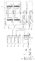
次に、図7には、他の実施形態の可搬型汎用電源出力装置のシステム図を示している。この例では、移動電源車66若しくはレンタルエンジンの低圧発電機70と可搬型汎用電源出力装置10との間に、入力分配ユニット80を設け、入力分配ユニット80の複数のタップ82(CN1〜CNn)を介して、複数の可搬型汎用電源出力装置10nに電源を供給するようにしている。これにより避難所が広い場所であっても、あるいは上下階層に分かれていても複数の箇所に可搬型汎用電源出力装置10nを配置できる。
Next, FIG. 7 shows a system diagram of a portable general-purpose power output device of another embodiment. In this example, an
このようにした電気回路例を図8に示す。移動電源車66若しくは低圧発電機70から入力分配ユニット80の入力端子CN0に入力し、これが分配されて各タップ82(CN1〜CNn)から電源が供給される。電源が供給される可搬型汎用電源出力装置10は、図5に示した回路例でもよいが、図8に示されるような回路構成でもよい。これは一台の変圧ユニット20を内蔵する変圧ユニット12を最下部に配置し、この上部に出力ユニット14Aを積層し、さらにその上部に出力ユニット14Bを積層する。そしてルーフパネル16を積層して終了する。このような装置101〜10nを、各入力タップ82に接続して、広い避難所に分散配置することで使用勝手が格段によくなる。
An example of an electric circuit in this way is shown in FIG. The mobile
次に、図7の中央に配置された例を説明する。これは第1実施形態では変圧ユニット12は第1、第2の変圧器20a、20bを単に収納した形態であったのに対し、この実施形態では個別に変圧ユニット12に内蔵させた形態とした。電気回路例を図9に示している。変圧ユニット12A、12Bを接続するために、ワンタッチ接続が可能な雌雄接続型のコネクタを設けている。これは第一実施形態の出力ユニット14同士と同様な構造のものを使用する。
Next, an example arranged in the center of FIG. 7 will be described. In the first embodiment, the
このように変圧ユニット12A、12Bを積層することによって、前記雌型接続コネクタ18a、18bから電源供給を受けるため、出力ユニット14側には雄型接続コネクタ40a、40bが設けられている。雄型接続コネクタ40a、40bは、変圧ユニット12の上面に2系統の電源供給ライン28a、28bと同列、同間隔に形成されている。これにより下位の変圧ユニット12に積層した際、接続コネクタ18の雌型接続コネクタ18a、18bと雄型接続コネクタ40a、40bが嵌合して変圧ユニット12から電源供給を受けることができる。
斯かる実施形態では、変圧ユニット12をそれぞれ積層接続するタイプとしたため、出力ユニット14の増設も簡単にできるというメリットが得られる。
By stacking the
In such an embodiment, since the
更に図7の右側に記載した例を説明する。この例は電気自動車90の充電器によって動作可能なインバータ92を有し、このインバータ92を内蔵するインバータユニット94を設け、このインバータユニット94を出力ユニット14の外観構成と同様な構成としたものである。このような構成を付加することにより、インバータを用いて電気自動車からも電源供給を受け、益々可搬型汎用電源出力装置10の用途が高くなる。
Further, an example described on the right side of FIG. 7 will be described. In this example, an
なお、これらの実施例には上下結合用の接続ロック機構64は取手62を設け、回路的には上部出力ユニット14の下面に設けた雄型接続コネクタ40に接続されるコネクタ18を設けて構成されることは共通している。
In these embodiments, the
本発明は、避難所や病院などに用いることが出来、通信業者、マスコミ、イベント企画会社、商店などの企業利用が可能である。 The present invention can be used in evacuation shelters, hospitals, etc., and can be used by companies such as telecommunications carriers, the media, event planning companies, and shops.
10……可搬型汎用電源出力装置、12……変圧ユニット、14A……出力ユニット、14B……出力ユニット(増設)、16……ルーフパネル、18……接続コネクタ、18a、18b……雌型接続コネクタ、20a……第1変圧器、20b……第2変圧器、22……主遮断器、24……入力コネクタ、26……第1深堀部、28a、28b……電源供給ライン、30……第2深堀部、32……第3深堀部、34……下部矩形フレーム、36……第4深堀部、38……第5深堀部、40a、40b……雄型接続コネクタ、42a、42b……雌型接続コネクタ、44a、44b……電源供給ライン、46a、44b……分岐路、48a、48b……配線基板、50a、50b……外部出力コネクタ、52a、52b……100Vコンセント、54a、54b……USBコンセント、56a、56b……遮断器、58……パネル本体、60……下部矩形フレーム、62……取手、64……接続ロック機構、66……移動電源車、68……コネクタ式移動電源車用電源ケーブル、70……低圧発電機、72……インターフェース変換電源ケーブル、80……入力分配ユニット、82……タップ、90……電気自動車、92……インバータ、94……インバータユニット。 10 ... Portable general-purpose power output device, 12 ... Transformer unit, 14A ... Output unit, 14B ... Output unit (expansion), 16 ... Roof panel, 18 ... Connection connector, 18a, 18b ... Female type Connector, 20a ... 1st transformer, 20b ... 2nd transformer, 22 ... Main breaker, 24 ... Input connector, 26 ... 1st deep moat, 28a, 28b ... Power supply line, 30 ...... 2nd deep moat part, 32 ... 3rd deep moat part, 34 ... lower rectangular frame, 36 ... 4th deep moat part, 38 ... 5th deep moat part, 40a, 40b ... male connector, 42a, 42b ... Female connector, 44a, 44b ... Power supply line, 46a, 44b ... Branch path, 48a, 48b ... Wiring board, 50a, 50b ... External output connector, 52a, 52b ... 100V outlet, 54a, 54b ... USB outlet, 56a, 56b ... Breaker, 58 ... Panel body, 60 ... Lower rectangular frame, 62 ... Handle, 64 ... Connection lock mechanism, 66 ... Mobile power supply vehicle, 68 ... ... Power cable for connector type mobile power supply vehicle, 70 ... Low pressure generator, 72 ... Interface conversion power cable, 80 ... Input distribution unit, 82 ... Tap, 90 ... Electric vehicle, 92 ... Inverter, 94 ... … Inverter unit.
Claims (14)
この低圧発電機からの出力ケーブルと、
当該出力ケーブルに接続可能な入力コネクタから供給される電源により動作する変圧器を内蔵する可搬型の変圧ユニットと、
外部出力コネクタを備えた可搬型の出力ユニットと、を有し、
変圧ユニットと出力ユニットとを積層可能とし、
前記両ユニットの積層部には各ユニット内に設けられた電源供給ラインに繋がる嵌合形の接続コネクタ部を形成しワンタッチ接続を可能としてなることを特徴とする可搬型汎用電源出力システム。 With low-voltage generators such as mobile power supply cars
With the output cable from this low voltage generator,
A portable transformer unit with a built-in transformer that operates with the power supplied from the input connector that can be connected to the output cable.
Has a portable output unit with an external output connector,
The transformer unit and output unit can be stacked,
A portable general-purpose power output system characterized in that a mating type connection connector portion connected to a power supply line provided in each unit is formed in a laminated portion of both units to enable one-touch connection.
Applications Claiming Priority (2)
| Application Number | Priority Date | Filing Date | Title |
|---|---|---|---|
| JP2020031452 | 2020-02-27 | ||
| JP2020031452 | 2020-02-27 |
Publications (2)
| Publication Number | Publication Date |
|---|---|
| JP2021136857A true JP2021136857A (en) | 2021-09-13 |
| JP7048677B2 JP7048677B2 (en) | 2022-04-05 |
Family
ID=77661923
Family Applications (1)
| Application Number | Title | Priority Date | Filing Date |
|---|---|---|---|
| JP2020118760A Active JP7048677B2 (en) | 2020-02-27 | 2020-07-09 | Portable general-purpose power output device and system |
Country Status (1)
| Country | Link |
|---|---|
| JP (1) | JP7048677B2 (en) |
Cited By (1)
| Publication number | Priority date | Publication date | Assignee | Title |
|---|---|---|---|---|
| CN120414823A (en) * | 2025-07-02 | 2025-08-01 | 深圳市中电核心科技有限公司 | A method and system for intelligently controlling the internal current of a shared power bank |
Citations (9)
| Publication number | Priority date | Publication date | Assignee | Title |
|---|---|---|---|---|
| JP2003515913A (en) * | 1999-11-30 | 2003-05-07 | ウェーハマスターズ・インコーポレイテッド | Modular voltage adapter and method of using same |
| JP2003274604A (en) * | 2002-03-15 | 2003-09-26 | Asahi Denki Kk | Mobile power supply vehicle |
| US20030230934A1 (en) * | 2002-06-17 | 2003-12-18 | Cordelli Gary Gerard | Modular power supply with multiple and interchangeable output units for AC- and DC-powered equipment |
| JP2006025577A (en) * | 2004-07-09 | 2006-01-26 | Toyota Motor Corp | Hybrid vehicle and hybrid drive system |
| JP2008271734A (en) * | 2007-04-24 | 2008-11-06 | Densei Lambda Kk | Relay device |
| JP2017210178A (en) * | 2016-05-27 | 2017-11-30 | 三菱自動車工業株式会社 | Power supply device outside vehicle |
| JP2017212868A (en) * | 2016-05-20 | 2017-11-30 | 株式会社東芝 | Power supply device |
| JP2018038118A (en) * | 2016-08-29 | 2018-03-08 | パナソニックIpマネジメント株式会社 | Charge/discharge unit and power source unit including the same, charge/discharge system, power source system |
| US20200052481A1 (en) * | 2018-08-08 | 2020-02-13 | Brand Shared Services, Llc | Power distribution and protection cabinet |
-
2020
- 2020-07-09 JP JP2020118760A patent/JP7048677B2/en active Active
Patent Citations (9)
| Publication number | Priority date | Publication date | Assignee | Title |
|---|---|---|---|---|
| JP2003515913A (en) * | 1999-11-30 | 2003-05-07 | ウェーハマスターズ・インコーポレイテッド | Modular voltage adapter and method of using same |
| JP2003274604A (en) * | 2002-03-15 | 2003-09-26 | Asahi Denki Kk | Mobile power supply vehicle |
| US20030230934A1 (en) * | 2002-06-17 | 2003-12-18 | Cordelli Gary Gerard | Modular power supply with multiple and interchangeable output units for AC- and DC-powered equipment |
| JP2006025577A (en) * | 2004-07-09 | 2006-01-26 | Toyota Motor Corp | Hybrid vehicle and hybrid drive system |
| JP2008271734A (en) * | 2007-04-24 | 2008-11-06 | Densei Lambda Kk | Relay device |
| JP2017212868A (en) * | 2016-05-20 | 2017-11-30 | 株式会社東芝 | Power supply device |
| JP2017210178A (en) * | 2016-05-27 | 2017-11-30 | 三菱自動車工業株式会社 | Power supply device outside vehicle |
| JP2018038118A (en) * | 2016-08-29 | 2018-03-08 | パナソニックIpマネジメント株式会社 | Charge/discharge unit and power source unit including the same, charge/discharge system, power source system |
| US20200052481A1 (en) * | 2018-08-08 | 2020-02-13 | Brand Shared Services, Llc | Power distribution and protection cabinet |
Cited By (1)
| Publication number | Priority date | Publication date | Assignee | Title |
|---|---|---|---|---|
| CN120414823A (en) * | 2025-07-02 | 2025-08-01 | 深圳市中电核心科技有限公司 | A method and system for intelligently controlling the internal current of a shared power bank |
Also Published As
| Publication number | Publication date |
|---|---|
| JP7048677B2 (en) | 2022-04-05 |
Similar Documents
| Publication | Publication Date | Title |
|---|---|---|
| CN108778823B (en) | Electric vehicle charging station with medium voltage input | |
| US20230123166A1 (en) | Power station systems including modular power storage systems | |
| US10523018B2 (en) | Modular energy storage systems and related methods | |
| US11437948B2 (en) | Modular sustainable power generation unit | |
| CN117677750A (en) | Modular interconnectable housing structures and building structures formed therefrom | |
| US20220069598A1 (en) | Modular power supply system including a battery power supply module | |
| KR102768514B1 (en) | Multi-port power converter device | |
| CN101394099A (en) | Convenient power supply system of mobile equipment | |
| CN112186905B (en) | Container electric power energy storage system | |
| AU2023301764A1 (en) | Hybrid electric and hydrogen dispensing systems and methods | |
| JP7048677B2 (en) | Portable general-purpose power output device and system | |
| CN219247496U (en) | Hybrid solar inverter energy storage power supply | |
| US9711997B2 (en) | System and method for storing and distributing DC power | |
| US10938237B2 (en) | Direct connect Homegrid system for DC power distribution | |
| JP2018107879A (en) | Power switching device | |
| JP7661723B2 (en) | Power supply system and bidirectional power conversion device | |
| JP2020150737A (en) | Power supply system, power transmission device and portable power supply device | |
| CA3134264A1 (en) | Portable power source | |
| US12080979B2 (en) | Direct connect UEI cartridges for DC power systems | |
| CN213461254U (en) | Container electric energy storage system | |
| US20240170980A1 (en) | Modular & upgradable ev charging ecosystem | |
| JP6357611B1 (en) | A device that collects power and supplies power to a load group. | |
| US20210376785A1 (en) | Magnetically linkable modular solar panel system | |
| CN213716947U (en) | Energy storage cabinet | |
| CN215580483U (en) | Temporary supply device for operating locking power supply of 10kV cabinet |
Legal Events
| Date | Code | Title | Description |
|---|---|---|---|
| AA64 | Notification of invalidation of claim of internal priority (with term) |
Free format text: JAPANESE INTERMEDIATE CODE: A241764 Effective date: 20200916 |
|
| A521 | Request for written amendment filed |
Free format text: JAPANESE INTERMEDIATE CODE: A523 Effective date: 20200918 |
|
| A621 | Written request for application examination |
Free format text: JAPANESE INTERMEDIATE CODE: A621 Effective date: 20210427 |
|
| A871 | Explanation of circumstances concerning accelerated examination |
Free format text: JAPANESE INTERMEDIATE CODE: A871 Effective date: 20210427 |
|
| A131 | Notification of reasons for refusal |
Free format text: JAPANESE INTERMEDIATE CODE: A131 Effective date: 20210713 |
|
| A521 | Request for written amendment filed |
Free format text: JAPANESE INTERMEDIATE CODE: A523 Effective date: 20210823 |
|
| A02 | Decision of refusal |
Free format text: JAPANESE INTERMEDIATE CODE: A02 Effective date: 20211102 |
|
| A521 | Request for written amendment filed |
Free format text: JAPANESE INTERMEDIATE CODE: A523 Effective date: 20220127 |
|
| C60 | Trial request (containing other claim documents, opposition documents) |
Free format text: JAPANESE INTERMEDIATE CODE: C60 Effective date: 20220127 |
|
| A911 | Transfer to examiner for re-examination before appeal (zenchi) |
Free format text: JAPANESE INTERMEDIATE CODE: A911 Effective date: 20220204 |
|
| C21 | Notice of transfer of a case for reconsideration by examiners before appeal proceedings |
Free format text: JAPANESE INTERMEDIATE CODE: C21 Effective date: 20220209 |
|
| TRDD | Decision of grant or rejection written | ||
| A01 | Written decision to grant a patent or to grant a registration (utility model) |
Free format text: JAPANESE INTERMEDIATE CODE: A01 Effective date: 20220323 |
|
| A61 | First payment of annual fees (during grant procedure) |
Free format text: JAPANESE INTERMEDIATE CODE: A61 Effective date: 20220324 |
|
| R150 | Certificate of patent or registration of utility model |
Ref document number: 7048677 Country of ref document: JP Free format text: JAPANESE INTERMEDIATE CODE: R150 |
|
| R250 | Receipt of annual fees |
Free format text: JAPANESE INTERMEDIATE CODE: R250 |
|
| R250 | Receipt of annual fees |
Free format text: JAPANESE INTERMEDIATE CODE: R250 |