JP2021136834A - Driver - Google Patents
Driver Download PDFInfo
- Publication number
- JP2021136834A JP2021136834A JP2020033532A JP2020033532A JP2021136834A JP 2021136834 A JP2021136834 A JP 2021136834A JP 2020033532 A JP2020033532 A JP 2020033532A JP 2020033532 A JP2020033532 A JP 2020033532A JP 2021136834 A JP2021136834 A JP 2021136834A
- Authority
- JP
- Japan
- Prior art keywords
- housing
- hole
- recess
- oil
- predetermined direction
- Prior art date
- Legal status (The legal status is an assumption and is not a legal conclusion. Google has not performed a legal analysis and makes no representation as to the accuracy of the status listed.)
- Granted
Links
- 238000005192 partition Methods 0.000 claims abstract description 42
- 239000012530 fluid Substances 0.000 claims abstract description 17
- 230000005540 biological transmission Effects 0.000 claims description 19
- 239000003921 oil Substances 0.000 description 150
- 239000003638 chemical reducing agent Substances 0.000 description 9
- 230000002093 peripheral effect Effects 0.000 description 6
- 239000000498 cooling water Substances 0.000 description 4
- 239000007788 liquid Substances 0.000 description 4
- 238000013459 approach Methods 0.000 description 3
- 238000004891 communication Methods 0.000 description 3
- 238000001816 cooling Methods 0.000 description 3
- 230000005484 gravity Effects 0.000 description 3
- 238000001514 detection method Methods 0.000 description 2
- 238000004512 die casting Methods 0.000 description 2
- 238000000465 moulding Methods 0.000 description 2
- 239000003507 refrigerant Substances 0.000 description 2
- XLYOFNOQVPJJNP-UHFFFAOYSA-N water Substances O XLYOFNOQVPJJNP-UHFFFAOYSA-N 0.000 description 2
- 230000007423 decrease Effects 0.000 description 1
- 238000010586 diagram Methods 0.000 description 1
- 230000005611 electricity Effects 0.000 description 1
- 239000012212 insulator Substances 0.000 description 1
- 230000001050 lubricating effect Effects 0.000 description 1
- 239000010687 lubricating oil Substances 0.000 description 1
- 230000004048 modification Effects 0.000 description 1
- 238000012986 modification Methods 0.000 description 1
- 230000035515 penetration Effects 0.000 description 1
- 238000005086 pumping Methods 0.000 description 1
Images
Classifications
-
- H—ELECTRICITY
- H02—GENERATION; CONVERSION OR DISTRIBUTION OF ELECTRIC POWER
- H02K—DYNAMO-ELECTRIC MACHINES
- H02K5/00—Casings; Enclosures; Supports
- H02K5/04—Casings or enclosures characterised by the shape, form or construction thereof
-
- H—ELECTRICITY
- H02—GENERATION; CONVERSION OR DISTRIBUTION OF ELECTRIC POWER
- H02K—DYNAMO-ELECTRIC MACHINES
- H02K9/00—Arrangements for cooling or ventilating
- H02K9/19—Arrangements for cooling or ventilating for machines with closed casing and closed-circuit cooling using a liquid cooling medium, e.g. oil
-
- Y—GENERAL TAGGING OF NEW TECHNOLOGICAL DEVELOPMENTS; GENERAL TAGGING OF CROSS-SECTIONAL TECHNOLOGIES SPANNING OVER SEVERAL SECTIONS OF THE IPC; TECHNICAL SUBJECTS COVERED BY FORMER USPC CROSS-REFERENCE ART COLLECTIONS [XRACs] AND DIGESTS
- Y02—TECHNOLOGIES OR APPLICATIONS FOR MITIGATION OR ADAPTATION AGAINST CLIMATE CHANGE
- Y02T—CLIMATE CHANGE MITIGATION TECHNOLOGIES RELATED TO TRANSPORTATION
- Y02T10/00—Road transport of goods or passengers
- Y02T10/60—Other road transportation technologies with climate change mitigation effect
- Y02T10/64—Electric machine technologies in electromobility
Landscapes
- Engineering & Computer Science (AREA)
- Power Engineering (AREA)
- Motor Or Generator Cooling System (AREA)
- Arrangement Or Mounting Of Propulsion Units For Vehicles (AREA)
- General Details Of Gearings (AREA)
- Motor Or Generator Frames (AREA)
Abstract
Description
本発明は、駆動装置に関する。 The present invention relates to a drive device.
2つのハウジングと、2つのハウジングの内部同士を隔てる隔壁と、を備え、隔壁に2つのハウジングの内部同士を繋ぐ貫通孔が設けられた駆動装置が知られている。例えば、特許文献1には、そのような駆動装置として、車両用の動力伝達装置が記載されている。 A drive device is known that includes two housings and a partition wall that separates the insides of the two housings, and the partition wall is provided with a through hole that connects the insides of the two housings. For example, Patent Document 1 describes a power transmission device for a vehicle as such a drive device.
上記のような駆動装置は、一方のハウジングの内部に溜まったオイル等の流体を、隔壁に設けられた貫通孔を介して、他方のハウジングの内部に流す場合がある。しかし、単に貫通孔を設けるのみでは、オイル等の流体を他方のハウジングに流しにくい場合があった。 In a drive device as described above, a fluid such as oil accumulated inside one housing may flow into the inside of the other housing through a through hole provided in the partition wall. However, it may be difficult for a fluid such as oil to flow into the other housing simply by providing a through hole.
本発明は、上記事情に鑑みて、一方のハウジングの内部から他方のハウジングの内部にオイル等の流体を流しやすくできる構造を有する駆動装置を提供することを目的の一つとする。 In view of the above circumstances, one object of the present invention is to provide a drive device having a structure capable of easily flowing a fluid such as oil from the inside of one housing to the inside of the other housing.
本発明の駆動装置の一つの態様は、モータと、前記モータを内部に収容するハウジングと、を備える。前記ハウジングは、第1ハウジングと、前記第1ハウジングに繋がる第2ハウジングと、前記第1ハウジングの内部と前記第2ハウジングの内部とを隔てる隔壁と、を有する。前記第1ハウジングは、所定方向の一方側に位置する第1底部を有する。前記第2ハウジングは、前記所定方向の一方側に位置する第2底部を有する。前記第2底部のうち前記所定方向の他方側の面は、少なくとも一部が前記第1底部のうち前記所定方向の他方側の面よりも前記所定方向の一方側に位置する。前記第1底部は、前記隔壁と隣接する位置に前記所定方向の一方側に窪む凹部を有する。前記隔壁は、前記第1ハウジングの内部と前記第2ハウジングの内部とを繋ぐ貫通孔を有する。前記凹部の内部は、前記貫通孔の内部と繋がる。 One aspect of the drive device of the present invention includes a motor and a housing that houses the motor. The housing has a first housing, a second housing connected to the first housing, and a partition wall separating the inside of the first housing and the inside of the second housing. The first housing has a first bottom located on one side in a predetermined direction. The second housing has a second bottom located on one side in the predetermined direction. At least a part of the surface of the second bottom portion on the other side in the predetermined direction is located on one side of the first bottom portion in the predetermined direction with respect to the surface on the other side in the predetermined direction. The first bottom portion has a recess recessed on one side in the predetermined direction at a position adjacent to the partition wall. The partition wall has a through hole connecting the inside of the first housing and the inside of the second housing. The inside of the recess is connected to the inside of the through hole.
本発明の一つの態様によれば、駆動装置において、一方のハウジングの内部から他方のハウジングの内部にオイル等の流体を流しやすくできる。 According to one aspect of the present invention, in the drive device, a fluid such as oil can be easily flowed from the inside of one housing to the inside of the other housing.
以下の説明では、各図に示す各実施形態の駆動装置が水平な路面上に位置する車両に搭載された場合の位置関係を基に、鉛直方向を規定して説明する。また、図面においては、適宜3次元直交座標系としてXYZ座標系を示す。XYZ座標系において、Z軸方向は、鉛直方向である。+Z側は、鉛直方向上側であり、−Z側は、鉛直方向下側である。以下の説明では、鉛直方向上側を単に「上側」と呼び、鉛直方向下側を単に「下側」と呼ぶ。X軸方向は、Z軸方向と直交する方向であって駆動装置が搭載される車両の前後方向である。以下の各実施形態において、+X側は、車両の前側であり、−X側は、車両の後側である。Y軸方向は、X軸方向とZ軸方向との両方と直交する方向であって、車両の左右方向、すなわち車幅方向である。以下の各実施形態において、+Y側は、車両の左側であり、−Y側は、車両の右側である。前後方向および左右方向は、鉛直方向と直交する水平方向である。各実施形態において鉛直方向は、「所定方向」に相当する。下側は、「所定方向の一方側」に相当し、上側は、「所定方向の他方側」に相当する。 In the following description, the vertical direction will be defined and described based on the positional relationship when the drive device of each embodiment shown in each figure is mounted on a vehicle located on a horizontal road surface. Further, in the drawings, the XYZ coordinate system is shown as a three-dimensional Cartesian coordinate system as appropriate. In the XYZ coordinate system, the Z-axis direction is the vertical direction. The + Z side is the upper side in the vertical direction, and the −Z side is the lower side in the vertical direction. In the following description, the upper side in the vertical direction is simply referred to as "upper side", and the lower side in the vertical direction is simply referred to as "lower side". The X-axis direction is a direction orthogonal to the Z-axis direction and is a front-rear direction of the vehicle on which the drive device is mounted. In each of the following embodiments, the + X side is the front side of the vehicle and the −X side is the rear side of the vehicle. The Y-axis direction is a direction orthogonal to both the X-axis direction and the Z-axis direction, and is the left-right direction of the vehicle, that is, the vehicle width direction. In each of the following embodiments, the + Y side is the left side of the vehicle and the −Y side is the right side of the vehicle. The front-back direction and the left-right direction are horizontal directions orthogonal to the vertical direction. In each embodiment, the vertical direction corresponds to the "predetermined direction". The lower side corresponds to "one side in a predetermined direction", and the upper side corresponds to "the other side in a predetermined direction".
なお、前後方向の位置関係は、以下の各実施形態の位置関係に限られず、+X側が車両の後側であり、−X側が車両の前側であってもよい。この場合には、+Y側は、車両の右側であり、−Y側は、車両の左側である。 The positional relationship in the front-rear direction is not limited to the positional relationship of each of the following embodiments, and the + X side may be the rear side of the vehicle and the −X side may be the front side of the vehicle. In this case, the + Y side is the right side of the vehicle and the −Y side is the left side of the vehicle.
各図に適宜示すモータ軸J1は、鉛直方向と交差する方向に延びる。より詳細には、モータ軸J1は、Y軸方向、すなわち車両の左右方向に延びる。以下の説明においては、特に断りのない限り、モータ軸J1に平行な方向を単に「軸方向」と呼び、モータ軸J1を中心とする径方向を単に「径方向」と呼び、モータ軸J1を中心とする周方向、すなわち、モータ軸J1の軸回りを単に「周方向」と呼ぶ。なお、本明細書において、「平行な方向」は略平行な方向も含み、「直交する方向」は略直交する方向も含む。 The motor shaft J1 appropriately shown in each figure extends in a direction intersecting the vertical direction. More specifically, the motor shaft J1 extends in the Y-axis direction, that is, in the left-right direction of the vehicle. In the following description, unless otherwise specified, the direction parallel to the motor shaft J1 is simply referred to as the "axial direction", the radial direction centered on the motor shaft J1 is simply referred to as the "radial direction", and the motor shaft J1 is referred to as the motor shaft J1. The circumferential direction around the center, that is, the circumference of the motor shaft J1 is simply referred to as the "circumferential direction". In the present specification, the "parallel direction" includes a substantially parallel direction, and the "orthogonal direction" also includes a substantially orthogonal direction.
<第1実施形態>
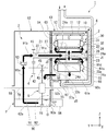
図1に示す本実施形態の駆動装置1は、ハイブリッド自動車(HEV)、プラグインハイブリッド自動車(PHV)、電気自動車(EV)等、モータを動力源とする車両に搭載され、その動力源として使用される。図1に示すように、駆動装置1は、モータ2と、減速装置4および差動装置5を含む伝達装置3と、ハウジング6と、オイルポンプ96と、クーラー97と、パイプ10と、を備える。なお、本実施形態において、駆動装置1はインバータユニットを含まない。言い換えると、駆動装置1はインバータユニットと別体構造となっている。
<First Embodiment>
The drive device 1 of the present embodiment shown in FIG. 1 is mounted on a vehicle powered by a motor, such as a hybrid electric vehicle (HEV), a plug-in hybrid electric vehicle (PHV), and an electric vehicle (EV), and is used as the power source thereof. Will be done. As shown in FIG. 1, the drive device 1 includes a
ハウジング6は、内部にモータ2および伝達装置3を収容する。ハウジング6は、第1ハウジング61と、第2ハウジング62と、隔壁63と、を有する。第1ハウジング61は、内部にモータ2を収容する。第2ハウジング62は、内部に伝達装置3を収容する。第2ハウジング62は、第1ハウジング61に繋がる。本実施形態において第2ハウジング62は、第1ハウジング61の左側に位置する。隔壁63は、第1ハウジング61の内部と第2ハウジング62の内部とを隔てる。隔壁63は、第1ハウジング61の内部と第2ハウジング62の内部とを繋ぐ貫通孔68を有する。
The
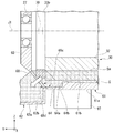
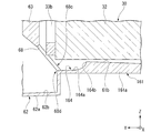
第1ハウジング61は、モータ2を径方向外側から囲む。図2に示すように、第1ハウジング61の内周面は、右側に向かうに従って内径が大きくなるテーパ面である。第1ハウジング61は、下側に位置する第1底部61aを有する。第1底部61aの底面61bは、第1ハウジング61の内周面の一部である。第1ハウジング61の内周面がテーパ面であるため、底面61bは、右側に向かうに従って下側に位置する傾斜面となっている。底面61bは、第1底部61aの上側の面である。
The
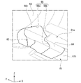
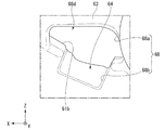
図2から図4に示すように、第1底部61aは、隔壁63と隣接する位置に下側に窪む凹部64を有する。図4に示すように、凹部64は、例えば、底面61bから下側斜め前方に窪む。軸方向に見て、凹部64の内部は、略矩形状である。図3に示すように、本実施形態において凹部64は、軸方向に延びる溝である。凹部64のうち右側の端部は、閉じられている。凹部64のうち左側の端部は、貫通孔68に繋がる。これにより、凹部64の内部は、貫通孔68の内部と繋がる。このように、本実施形態において凹部64は、貫通孔68まで延びる溝である。凹部64のうち左側の端部は、貫通孔68を介して、第2ハウジング62の内部に開口する。
As shown in FIGS. 2 to 4, the
図2に示すように、凹部64の内側面のうち下側に位置する面は、貫通孔68に向かうに従って下側に位置する傾斜面64aである、本実施形態において傾斜面64aは、左側に向かうに従って僅かに下側に位置する。凹部64の内側面のうち右側に位置する面は、第1底部61aの底面61bから下側に延び、底面61bと傾斜面64aとを繋ぐ接続面64bである。接続面64bは、例えば、軸方向と直交する平坦面である。接続面64bは、底面61bと傾斜面64aとの間に設けられた段差の段差面である。
As shown in FIG. 2, the lower surface of the inner surface of the
なお、本明細書において「凹部が所定方向の一方側に窪む」とは、凹部の窪む向きが、所定方向の一方側向きの成分を含んでいればよい。例えば、本実施形態において「凹部64が下側に窪む」とは、凹部64の窪む向きが、下側向きの成分を含んでいればよい。すなわち、本実施形態において「凹部64が下側に窪む」とは、凹部64が鉛直方向真下に窪んでもよいし、鉛直方向真下に対して90°未満の範囲内で鉛直方向と直交する方向に斜めに傾いた向きに窪んでもよい。上述したように図示の例では、凹部64は、下側斜め前方に窪む。
In addition, in this specification, "the recess is recessed on one side in a predetermined direction" means that the recessing direction of the recess may include a component facing one side in a predetermined direction. For example, in the present embodiment, "the
第2ハウジング62は、下側に位置する第2底部62aを有する。第2底部62aの底面62bは、少なくとも一部が第1底部61aの底面61bよりも下側に位置する。本実施形態において第2底部62aの底面62bは、全体が第1底部61aの底面61bよりも下側に位置する。底面62bは、第2底部62aの上側の面である。底面62bは、例えば、貫通孔68よりも下側に離れて位置する。底面62bと凹部64の傾斜面64aとの間には段差が設けられる。本実施形態では、第2底部62aの全体が、第1底部61aよりも下側に位置する。
The
図1に示すように、本実施形態において隔壁63は、第1ハウジング61の内部と第2ハウジング62の内部とを軸方向に区画する。隔壁63は、ステータ30の左側に位置する。隔壁63は、後述するベアリング27を保持する。図2に示すように、隔壁63のうちベアリング27が保持された部分は、例えば、左側に突出する。隔壁63のうちベアリング27が保持された部分は、例えば、隔壁63の鉛直方向の中央部分である。
As shown in FIG. 1, in the present embodiment, the
本実施形態において貫通孔68は、隔壁63の下側の端部に設けられる。貫通孔68は、例えば、隔壁63の下側の端部を、第1ハウジング61側の面から第2ハウジング62側の面に向かって軸方向斜め下側向きに貫通する。これにより、貫通孔68のうち第1ハウジング61の内部に開口する開口部68cは、鉛直方向上側に斜めに傾いた向きに開口する。貫通孔68のうち第2ハウジング62の内部に開口する開口部68dは、鉛直方向下側に斜めに傾いた向きに開口する。
In the present embodiment, the through
貫通孔68の下側の端部は、底面61bよりも下側に位置する。本実施形態において貫通孔68の下側の端部は、凹部64の下側の端部と鉛直方向において同じ位置に位置する。これにより、凹部64のうち下側の端部は、貫通孔68を介して、第2ハウジング62の内部に開口する。本実施形態において貫通孔68の上側の端部は、第1底部61aよりも上側に位置する。
The lower end of the through
本実施形態において凹部64のうち左側(+Y側)の端部の全体は、貫通孔68に繋がり、貫通孔68を介して第2ハウジング62の内部に開口する。図4に示すように、第1ハウジング61と第2ハウジング62とが並ぶ軸方向に見て、凹部64の全体は、貫通孔68と重なる。
In the present embodiment, the entire left side (+ Y side) end of the
貫通孔68は、上側部分68aと、下側部分68bと、を有する。上側部分68aは、貫通孔68のうち底面61bよりも上側に位置する部分である。上側部分68aは、凹部64を介さずに、第1ハウジング61の内部と第2ハウジング62の内部とを繋ぐ。下側部分68bは、上側部分68aの下側に繋がる。下側部分68bは、凹部64のうち第2ハウジング62側の開口によって構成される。下側部分68bは、凹部64を介して、第1ハウジング61の内部と第2ハウジング62の内部とを繋ぐ。下側部分68bの前後方向の寸法は、上側部分68aの前後方向の寸法よりも小さい。
The through
本実施形態において、隔壁63と、第1ハウジング61のうちモータ2を周方向に囲む部分と、第2ハウジング62のうち伝達装置3を周方向に囲む部分とは、一体成形された成形体である。当該成形体は、例えば、ダイカストによって作られている。貫通孔68および凹部64を成形する金型は、例えば、当該成形体の成形後、左側に移動させられて成形体から取り外される。ここで、上述したように凹部64の傾斜面64aは、左側に向かうに従って僅かに下側に位置する傾斜面である。このように、凹部64の傾斜面64aには抜き勾配が設けられており、金型のうち凹部64を成形する部分を左側に抜きやすくできる。
In the present embodiment, the
図1に示すように、ハウジング6は、内部に冷媒としてのオイルOを収容する。本実施形態では、第1ハウジング61の内部および第2ハウジング62の内部に、オイルOが収容される。第2ハウジング62の内部における下部領域には、オイルOが溜るオイル溜りPが設けられる。オイル溜りPのオイルOは、後述する油路90によって第1ハウジング61の内部に送られる。第1ハウジング61の内部に送られたオイルOは、第1ハウジング61の内部における下部領域に溜まる。第1ハウジング61の内部に溜まったオイルOの少なくとも一部は、貫通孔68を介して第2ハウジング62に移動し、オイル溜りPに戻る。
As shown in FIG. 1, the
なお、本明細書において「ある部分の内部にオイルが収容される」とは、モータが駆動している最中の少なくとも一部において、ある部分の内部にオイルが位置していればよく、モータが停止している際には、ある部分の内部にオイルが位置していなくてもよい。例えば、本実施形態において第1ハウジング61の内部にオイルOが収容されるとは、モータ2が駆動している最中の少なくとも一部において、第1ハウジング61の内部にオイルOが位置していればよく、モータ2が停止している際においては、第1ハウジング61の内部のオイルOがすべて貫通孔68を通って第2ハウジング62に移動してしまっていてもよい。なお、後述する油路90によって第1ハウジング61の内部へと送られたオイルOの一部は、モータ2が停止した状態において、第1ハウジング61の内部に残っていてもよい。
In the present specification, "oil is stored inside a certain part" means that the oil is located inside a certain part at least in a part while the motor is being driven, and the motor may be used. When is stopped, the oil does not have to be located inside a part. For example, in the present embodiment, the fact that the oil O is housed inside the
オイルOは、後述する油路90内を循環する。オイルOは、減速装置4および差動装置5の潤滑用として使用される。また、オイルOは、モータ2の冷却用として使用される。オイルOとしては、潤滑油および冷却油の機能を奏するために、比較的粘度の低いオートマチックトランスミッション用潤滑油(ATF:Automatic Transmission Fluid)と同等のオイルを用いることが好ましい。
The oil O circulates in the
本実施形態においてモータ2は、インナーロータ型のモータである。モータ2は、ロータ20と、ステータ30と、ベアリング26,27と、を備える。ロータ20は、水平方向に延びるモータ軸J1を中心として回転可能である。ロータ20は、シャフト21と、ロータ本体24と、を有する。図示は省略するが、ロータ本体24は、ロータコアと、ロータコアに固定されるロータマグネットと、を有する。ロータ20のトルクは、伝達装置3に伝達される。
In the present embodiment, the
シャフト21は、モータ軸J1を中心として軸方向に沿って延びる。シャフト21は、モータ軸J1を中心として回転する。シャフト21は、内部に中空部22が設けられた中空シャフトである。シャフト21には、連通孔23が設けられる。連通孔23は、径方向に延びて中空部22とシャフト21の外部とを繋ぐ。
The
シャフト21は、ハウジング6の第1ハウジング61と第2ハウジング62とに跨って延びる。シャフト21の左側の端部は、第2ハウジング62の内部に突出する。シャフト21の左側の端部には、伝達装置3の後述する第1のギヤ41が固定される。シャフト21は、ベアリング26,27により回転可能に支持される。
The
ステータ30は、ロータ20と径方向に隙間を介して対向する。より詳細には、ステータ30は、ロータ20の径方向外側に位置する。ステータ30は、ステータコア32と、コイルアセンブリ33と、を有する。ステータコア32は、ロータ20を囲む。ステータコア32は、第1ハウジング61の内周面に固定される。図示は省略するが、ステータコア32は、軸方向に延びる円筒状のコアバックと、コアバックから径方向内側に延びる複数のティースと、を有する。複数のティースは、周方向に沿って一周に亘って等間隔に配置される。
The
図2に示すように、ステータコア32と第1底部61aとの鉛直方向の間には、隙間Gが設けられる。本実施形態では、第1底部61aの底面61bが左側に向かうに従って上側に位置するため、隙間Gの鉛直方向の寸法は、左側に向かうに従って小さくなる。
As shown in FIG. 2, a gap G is provided between the
図1に示すように、コイルアセンブリ33は、周方向に沿ってステータコア32に取り付けられる複数のコイル31を有する。複数のコイル31は、図示しないインシュレータを介してステータコア32の各ティースにそれぞれ装着される。複数のコイル31は、周方向に沿って配置される。より詳細には、複数のコイル31は、周方向に沿って一周に亘って等間隔に配置される。図示は省略するが、コイルアセンブリ33は、各コイル31を結束する結束部材等を有してもよいし、各コイル31同士を繋ぐ渡り線を有してもよい。
As shown in FIG. 1, the
コイルアセンブリ33は、ステータコア32から軸方向に突出するコイルエンド33a,33bを有する。コイルエンド33aは、ステータコア32から右側に突出する部分である。コイルエンド33bは、ステータコア32から左側に突出する部分である。コイルエンド33aは、コイルアセンブリ33に含まれる各コイル31のうちステータコア32よりも右側に突出する部分を含む。コイルエンド33bは、コイルアセンブリ33に含まれる各コイル31のうちステータコア32よりも左側に突出する部分を含む。図2に示すように、本実施形態においてコイルエンド33a,33bは、モータ軸J1を中心とする円環状である。図示は省略するが、コイルエンド33a,33bは、各コイル31を結束する結束部材等を含んでもよいし、各コイル31同士を繋ぐ渡り線を含んでもよい。
The
図1に示すように、ベアリング26,27は、ロータ20を回転可能に支持する。ベアリング26,27は、例えば、ボールベアリングである。ベアリング26は、ロータ20のうちステータコア32よりも右側に位置する部分を回転可能に支持するベアリングである。本実施形態においてベアリング26は、シャフト21のうちロータ本体24が固定される部分よりも右側に位置する部分を支持する。ベアリング26は、第1ハウジング61のうちロータ20およびステータ30の右側を覆う壁部61cに保持される。
As shown in FIG. 1,
ベアリング27は、ロータ20のうちステータコア32よりも左側に位置する部分を回転可能に支持するベアリングである。本実施形態においてベアリング27は、シャフト21のうちロータ本体24が固定される部分よりも左側に位置する部分を支持する。ベアリング27は、隔壁63に保持される。
The
伝達装置3は、ハウジング6の第2ハウジング62に収容される。伝達装置3は、モータ2に接続される。より詳細には、伝達装置3は、シャフト21の左側の端部に接続される。伝達装置3は、減速装置4と、差動装置5と、を有する。モータ2から出力されるトルクは、減速装置4を介して差動装置5に伝達される。
The
減速装置4は、モータ2に接続される。減速装置4は、モータ2の回転速度を減じて、モータ2から出力されるトルクを減速比に応じて増大させる。減速装置4は、モータ2から出力されるトルクを差動装置5へ伝達する。減速装置4は、第1のギヤ41と、第2のギヤ42と、第3のギヤ43と、中間シャフト45と、を有する。
The speed reducer 4 is connected to the
第1のギヤ41は、シャフト21の左側の端部における外周面に固定される。第1のギヤ41は、シャフト21とともに、モータ軸J1を中心に回転する。中間シャフト45は、モータ軸J1と平行な中間軸J2に沿って延びる。中間シャフト45は、中間軸J2を中心として回転する。第2のギヤ42および第3のギヤ43は、中間シャフト45の外周面に固定される。第2のギヤ42と第3のギヤ43は、中間シャフト45を介して接続される。第2のギヤ42および第3のギヤ43は、中間軸J2を中心として回転する。第2のギヤ42は、第1のギヤ41に噛み合う。第3のギヤ43は、差動装置5の後述するリングギヤ51と噛み合う。
The
モータ2から出力されるトルクは、シャフト21、第1のギヤ41、第2のギヤ42、中間シャフト45および第3のギヤ43をこの順に介して差動装置5のリングギヤ51へ伝達される。各ギヤのギヤ比およびギヤの個数等は、必要とされる減速比に応じて種々変更可能である。本実施形態において減速装置4は、各ギヤの軸芯が平行に配置される平行軸歯車タイプの減速機である。
The torque output from the
差動装置5は、減速装置4を介しモータ2に接続される。差動装置5は、モータ2から出力されるトルクを車両の車輪に伝達するための装置である。差動装置5は、車両の旋回時に、左右の車輪の速度差を吸収しつつ、左右両輪の車軸55に同トルクを伝える。このように、本実施形態において伝達装置3は、減速装置4および差動装置5を介して、車両の車軸55にモータ2のトルクを伝達する。差動装置5は、リングギヤ51と、図示しないギヤハウジングと、図示しない一対のピニオンギヤと、図示しないピニオンシャフトと、図示しない一対のサイドギヤと、を有する。リングギヤ51は、モータ軸J1と平行な差動軸J3を中心として回転する。リングギヤ51には、モータ2から出力されるトルクが減速装置4を介して伝えられる。
The
モータ2には、ハウジング6の内部においてオイルOが循環する油路90が設けられる。油路90は、オイル溜りPからオイルOをモータ2に供給し、再びオイル溜りPに導くオイルOの経路である。油路90は、第1ハウジング61の内部と第2ハウジング62の内部とに跨って設けられる。
The
なお、本明細書において「油路」とは、オイルの経路を意味する。したがって、「油路」とは、定常的に一方向に向かうオイルの流動を作る「流路」のみならず、オイルを一時的に滞留させる経路およびオイルが滴り落ちる経路をも含む概念である。オイルを一時的に滞留させる経路とは、例えば、オイルを貯留するリザーバ等を含む。 In addition, in this specification, "oil passage" means the route of oil. Therefore, the "oil passage" is a concept that includes not only a "flow path" that constantly creates a flow of oil in one direction, but also a path for temporarily retaining oil and a path for oil to drip. The route for temporarily retaining the oil includes, for example, a reservoir for storing the oil.
油路90は、第1の油路91と、第2の油路92と、を有する。第1の油路91および第2の油路92は、それぞれハウジング6の内部でオイルOを循環させる。第1の油路91は、かき上げ経路91aと、シャフト供給経路91bと、シャフト内経路91cと、ロータ内経路91dと、を有する。また、第1の油路91の経路中には、第1のリザーバ93が設けられる。第1のリザーバ93は、第2ハウジング62内に設けられる。
The
かき上げ経路91aは、差動装置5のリングギヤ51の回転によってオイル溜りPからオイルOをかき上げて、第1のリザーバ93でオイルOを受ける経路である。第1のリザーバ93は、上側に開口する。第1のリザーバ93は、リングギヤ51がかき上げたオイルOを受ける。また、モータ2の駆動直後などオイル溜りPの液面Sgが高い場合等には、第1のリザーバ93は、リングギヤ51に加えて第2のギヤ42および第3のギヤ43によってかき上げられたオイルOも受ける。
The scooping
シャフト供給経路91bは、第1のリザーバ93からシャフト21の中空部22にオイルOを誘導する。シャフト内経路91cは、シャフト21の中空部22内をオイルOが通過する経路である。ロータ内経路91dは、シャフト21の連通孔23からロータ本体24の内部を通過して、ステータ30に飛散する経路である。
The
ロータ内経路91dは、ロータ本体24に設けられた供給口24aを有する。供給口24aは、第1ハウジング61の内部に開口する。ロータ内経路91dを通るオイルOは、供給口24aからステータ30に向けて噴射される。このようにして供給口24aは、第1ハウジング61の内部に流体としてのオイルOを供給する。供給口24aは、例えば、複数設けられる。本実施形態においてロータ本体24は、供給口24aを有する供給部に相当する。
The rotor
シャフト内経路91cにおいて、ロータ20の内部のオイルOには、ロータ20の回転に伴い遠心力が付与される。これにより、オイルOは、ロータ20から径方向外側に連続的に飛散する。また、オイルOの飛散に伴い、ロータ20内部の経路が負圧となり、第1のリザーバ93に溜るオイルOが、ロータ20の内部に吸引され、ロータ20内部の経路にオイルOが満たされる。
In the in-
ステータ30に到達したオイルOは、ステータ30から熱を奪う。ステータ30を冷却したオイルOは、下側に滴下され、第1ハウジング61内の下部領域に溜る。第1ハウジング61内の下部領域に溜ったオイルOは、隔壁63に設けられた貫通孔68を介して第2ハウジング62に移動する。以上のようにして、第1の油路91は、オイルOをロータ20およびステータ30に供給する。
The oil O that has reached the
第2の油路92においてオイルOは、オイル溜りPから引き上げられてステータ30に供給される。第2の油路92には、オイルポンプ96と、クーラー97と、パイプ10と、が設けられる。第2の油路92は、第1の流路92aと、第2の流路92bと、第3の流路92cと、第4の流路94と、を有する。
In the
第1の流路92a、第2の流路92b、第3の流路92c、および第4の流路94は、ハウジング6の壁部に設けられる。第1の流路92aは、オイル溜りPとオイルポンプ96とを繋ぐ。第2の流路92bは、オイルポンプ96とクーラー97とを繋ぐ。第3の流路92cは、クーラー97と第4の流路94とを繋ぐ。第3の流路92cは、例えば、第1ハウジング61の壁部のうち前側(+X側)の壁部に設けられる。第4の流路94は、隔壁63に設けられる。第4の流路94は、第3の流路92cとパイプ10とを繋ぐ。
The
本実施形態においてパイプ10は、軸方向に延びる。パイプ10の左側の端部は、隔壁63に固定される。本実施形態においてパイプ10は、軸方向に直線状に延びる円筒状である。パイプ10は、ハウジング6の内部に収容される。パイプ10は、ステータ30の径方向外側に位置する。パイプ10は、例えば、ステータ30の上側に位置する。なお、パイプ10は、複数設けられてもよい。
In this embodiment, the
パイプ10は、第1ハウジング61の内部に流体としてのオイルOを供給する供給口11,12を有する。供給口11,12は、第1ハウジング61の内部に開口する。第4の流路94からパイプ10内に流入したオイルOは、供給口11,12からステータ30に向けて噴射される。供給口11から噴射されたオイルOは、ステータコア32に供給される。供給口12から噴射されたオイルOは、コイルエンド33a,33bに供給される。供給口11と供給口12とは、例えば、それぞれ複数ずつ設けられる。本実施形態においてパイプ10は、供給口11,12を有する供給部に相当する。
The
このように本実施形態において駆動装置1は、供給部として、ロータ本体24およびパイプ10を備える。本実施形態において貫通孔68の開口部68cの開口面積および開口部68dの開口面積は、それぞれ供給口11,12,24aの総開口面積よりも大きい。本実施形態において供給口11,12,24aの総開口面積とは、全ての供給口11,12,24aの開口面積を足し合わせた総和である。なお、例えば、供給口が1つのみ設けられる場合には、供給口の総開口面積とは、1つの供給口の開口面積である。
As described above, in the present embodiment, the drive device 1 includes a rotor
オイルポンプ96は、冷媒としてのオイルOを送るポンプである。本実施形態においてオイルポンプ96は、電気により駆動する電動ポンプである。オイルポンプ96は、第1の流路92aを介してオイル溜りPからオイルOを吸い上げて、第2の流路92b、クーラー97、第3の流路92c、第4の流路94、およびパイプ10を介して、オイルOをモータ2に供給する。
The
パイプ10からステータ30に供給されたオイルOは、下側に滴下され、第1ハウジング61内の下部領域に溜る。第1ハウジング61内の下部領域に溜ったオイルOは、隔壁63に設けられた貫通孔68を介して第2ハウジング62のオイル溜りPに移動する。以上のようにして、第2の油路92は、オイルOをステータ30に供給する。
The oil O supplied from the
クーラー97は、第2の油路92を通過するオイルOを冷却する。クーラー97には、第2の流路92bおよび第3の流路92cが接続される。クーラー97は、第2の流路92bと第3の流路92cとを繋ぐ流路97aを有する。流路97aは、クーラー97の内部に設けられた流路である。流路97aは、第2の流路92bおよび第1の流路92aを介して、第2ハウジング62の内部と繋がる。クーラー97には、図示しないラジエータで冷却された冷却水を通過させる冷却水用配管98が接続される。クーラー97の内部に設けられた流路97aを通過するオイルOは、冷却水用配管98を通過する冷却水との間で熱交換されて冷却される。
The cooler 97 cools the oil O passing through the
図2に示すように、クーラー97は、第1ハウジング61の外側面に固定される。より詳細には、クーラー97は、第1底部61aのうち凹部64が設けられた部分の外側面に固定される。クーラー97の少なくとも一部は、凹部64が窪む方向に見て、凹部64と重なる。本実施形態では、クーラー97の左側の端部が、凹部64が窪む方向に見て、凹部64と重なる。本実施形態においてクーラー97は、補機に相当する。
As shown in FIG. 2, the cooler 97 is fixed to the outer surface of the
駆動装置1は、モータ2の温度を検出可能な温度センサ70をさらに備える。温度センサ70の種類は、モータ2の温度を検出可能であれば、特に限定されない。モータ2の温度とは、ステータ30の温度を含む。本実施形態において温度センサ70は、ステータ30の温度を検出可能である。温度センサ70は、第1ハウジング61の内部に位置する。本実施形態において温度センサ70は、コイルエンド33bに配置される。より詳細には、温度センサ70の少なくとも一部は、コイルエンド33bに埋め込まれる。本実施形態では、温度センサ70は、コイルエンド33bに挿し込まれて、ほぼ全体がコイルエンド33bに埋め込まれる。
The drive device 1 further includes a
本実施形態において温度センサ70は、コイルエンド33bのうち鉛直方向の中央部分に配置される。温度センサ70は、例えば、前後方向に見て、シャフト21と重なる。温度センサ70は、貫通孔68よりも上側に位置する。ここで、本実施形態において第1ハウジング61内に溜まるオイルOは、貫通孔68を介して第2ハウジング62に流れるため、第1ハウジング61内のオイルOの液面Smは、貫通孔68よりも上側になりにくい。これにより、温度センサ70を貫通孔68よりも上側に配置することで、温度センサ70が第1ハウジング61内においてオイルOに浸かりにくくできる。
In the present embodiment, the
温度センサ70がオイルOに浸かると、ステータ30の実際の温度によらず温度センサ70によって検出される温度が低下する。そのため、ステータ30の温度を正確に検出しにくくなる場合がある。これに対して、本実施形態によれば、上述したように温度センサ70がオイルOに浸かりにくいため、温度センサ70によってステータ30の温度を正確に検出しにくくなることを抑制できる。
When the
本実施形態において駆動装置1は、温度センサ70の検出結果に基づいて、オイルポンプ96の駆動を制御する。例えば、駆動装置1は、温度センサ70の検出結果からステータ30の温度が所定の閾値以上になっていると判断した場合、オイルポンプ96の出力を上昇させる。これにより、第1の油路91および第2の油路92を介してステータ30に供給されるオイルOの量を増加させることができ、ステータ30の温度を低下させることができる。
In the present embodiment, the drive device 1 controls the drive of the
本実施形態によれば、第1底部61aは、隔壁63と隣接する位置に下側に窪む凹部64を有する。隔壁63は、第1ハウジング61の内部と第2ハウジング62の内部とを繋ぐ貫通孔68を有する。凹部64の内部は、貫通孔68の内部と繋がる。そのため、凹部64が窪む向きに貫通孔68を大きくできる。これにより、貫通孔68を上側に広げることなく、貫通孔68全体の大きさを大きくできる。したがって、例えば、隔壁63に保持されるベアリング27等との干渉を避けつつ、貫通孔68を大きくできる。そのため、貫通孔68を介して、第1ハウジング61の内部から第2ハウジング62の内部にオイルOを流しやすくできる。
According to the present embodiment, the
また、凹部64が設けられることで、第1ハウジング61の内部に収容された部材と第1底部61aとの隙間を広げることができる。本実施形態では、凹部64によって、モータ2と第1底部61aとの隙間を広げることができる。そのため、凹部64を介して、第1ハウジング61内のオイルOを貫通孔68に導きやすくできる。これにより、貫通孔68を介して、第1ハウジング61の内部から第2ハウジング62の内部にオイルOを流しやすくできる。
Further, by providing the
特に、本実施形態のように第1底部61aの底面61bが隔壁63に向かうに従ってモータ2に近づく傾斜面となっている場合、上述したように底面61bとステータ30との隙間Gは、軸方向において隔壁63に向かうに従って狭くなる。そのため、第1ハウジング61内のオイルOが貫通孔68へと流れにくくなる虞がある。これに対して、凹部64を設けることで、第1底部61aのうち隔壁63に隣接した部分、すなわちステータ30との隙間Gが最も狭くなる部分において、ステータ30と第1底部61aとの間を広げることができる。これにより、底面61bが隔壁63に向かうに従ってモータ2に近づく傾斜面となっている場合であっても、第1ハウジング61の内部のオイルOを、貫通孔68を介して第2ハウジング62の内部に流しやすくできる。
In particular, when the
以上のように第1ハウジング61の内部から第2ハウジング62の内部にオイルOを流しやすくできることで、第1ハウジング61内にオイルOが溜まり過ぎることを抑制できる。そのため、例えば、第1ハウジング61内のオイルOの液面Smが、ロータ20の下端部よりも上側に位置することを抑制できる。これにより、ロータ20が回転する際に、第1ハウジング61の内部に収容されたオイルOが抵抗となることを抑制できる。また、温度センサ70がオイルOに浸かることをより抑制できる。
As described above, since the oil O can be easily flowed from the inside of the
また、本実施形態によれば、所定方向は、鉛直方向であり、凹部64が窪む所定方向の一方側は、鉛直方向下側である。そのため、第1ハウジング61内のオイルOを重力によって凹部64から貫通孔68へと流しやすい。これにより、第1ハウジング61の内部から第2ハウジング62の内部に、よりオイルOを流しやすくできる。
Further, according to the present embodiment, the predetermined direction is the vertical direction, and one side of the predetermined direction in which the
また、本実施形態によれば、第2底部62aの上側の面、すなわち底面62bは、全体が第1底部61aの上側の面、すなわち底面61bよりも下側に位置する。そのため、図2に示すように、第1ハウジング61内において第1底部61a上に溜まったオイルOを、重力を利用して貫通孔68から、第2ハウジング62内の第2底部62a上に流しやすくできる。これにより、第1ハウジング61の内部から第2ハウジング62の内部に、よりオイルOを流しやすくできる。
Further, according to the present embodiment, the upper surface of the
また、本実施形態によれば、貫通孔68のうち第2ハウジング62の内部に開口する開口部68dは、鉛直方向下側に斜めに傾いた向きに開口する。そのため、貫通孔68から第2ハウジング62内に流れるオイルOを、重力を利用して流しやすい。これにより、第1ハウジング61の内部から第2ハウジング62の内部に、よりオイルOを流しやすくできる。
Further, according to the present embodiment, the
また、本実施形態によれば、貫通孔68のうち上側の端部は、第1底部61aよりも上側に位置する。そのため、貫通孔68をより大きくできる。これにより、第1ハウジング61の内部から第2ハウジング62の内部に、よりオイルOを流しやすくできる。
Further, according to the present embodiment, the upper end portion of the through
また、本実施形態によれば、凹部64のうち下側の端部は、貫通孔68を介して、第2ハウジング62の内部に開口する。そのため、凹部64の下端部が隔壁63で塞がれる場合に比べて、貫通孔68を大きくできる。これにより、窪んだ凹部64を最大限利用して貫通孔68を大きくしやすい。したがって、第1ハウジング61の内部から第2ハウジング62の内部に、よりオイルOを流しやすくできる。
Further, according to the present embodiment, the lower end portion of the
また、本実施形態によれば、凹部64は、貫通孔68まで延びる溝である。そのため、第1ハウジング61内において凹部64に流入したオイルOを、貫通孔68までより導きやすくできる。これにより、第1ハウジング61の内部から第2ハウジング62の内部に、よりオイルOを流しやすくできる。
Further, according to the present embodiment, the
また、本実施形態によれば、凹部64の内側面のうち下側に位置する面は、貫通孔68に向かうに従って下側に位置する傾斜面64aである。そのため、凹部64内に流入したオイルOを傾斜面64aに沿って貫通孔68へと導きやすくできる。ここで、上述したように傾斜面64aの傾きは、凹部64を成形する金型の部分を抜く際における抜き勾配としても機能する。したがって、ダイカストによって凹部64を成形しやすくでき、かつ、第1ハウジング61の内部から第2ハウジング62の内部に、よりオイルOを流しやすくできる。
Further, according to the present embodiment, the surface of the inner surface of the
また、本実施形態によれば、第1ハウジング61と第2ハウジング62とが並ぶ方向に見て、凹部64の全体は、貫通孔68と重なる。そのため、貫通孔68を下側に広げるために必要な部分のみに凹部64を設けることができる。これにより、凹部64によって貫通孔68を大きくしつつも、凹部64の大きさを比較的小さくできる。したがって、例えば凹部64が貫通孔68よりも前後方向に延びている場合等に比べて、第1底部61aにおいて凹部64が設けられる領域を小さくできる。そのため、凹部64によって第1底部61aの厚さが薄くなる部分を少なくできる。これにより、第1底部61aの厚さを大きくしなくても、第1底部61aの強度を確保しやすい。
Further, according to the present embodiment, when viewed in the direction in which the
また、本実施形態によれば、貫通孔68のうち第1ハウジング61の内部に開口する開口部68cの開口面積は、供給口11,12,24aの総開口面積よりも大きい。そのため、供給口11,12,24aから第1ハウジング61内に流入するオイルOの量よりも、貫通孔68から第2ハウジング62内に流出するオイルOの量を多くしやすい。これにより、第1ハウジング61の内部から第2ハウジング62の内部に、よりオイルOを流しやすくでき、第1ハウジング61の内部にオイルOが溜まり過ぎることを抑制できる。
Further, according to the present embodiment, the opening area of the
また、本実施形態によれば、駆動装置1は、第1ハウジング61の外側面に固定された補機として、クーラー97を備える。そのため、第1底部61aに凹部64が設けられた第1ハウジング61を、外側面に取り付けられたクーラー97によって補強できる。これにより、第1底部61aに凹部64を設けても、第1ハウジング61の強度を確保しやすい。
Further, according to the present embodiment, the drive device 1 includes a cooler 97 as an auxiliary machine fixed to the outer surface of the
また、本実施形態によれば、補機としてのクーラー97は、第2ハウジング62の内部と繋がる流路97aを有し、かつ、第1底部61aのうち凹部64が設けられた部分の外側面に固定される。そのため、凹部64が繋がる貫通孔68の近くに、クーラー97を配置しやすい。これにより、貫通孔68を介して第2ハウジング62の内部に流入したオイルOが、流路97aに流れるまでの経路を短くしやすい。したがって、第2ハウジング62の内部からクーラー97の流路97aに流れるまでのオイルOの損失を小さくしやすい。また、第1底部61aのうち凹部64が設けられた部分の外側面にクーラー97を固定することで、凹部64によって低下した第1底部61aの強度をより好適に補強できる。
Further, according to the present embodiment, the cooler 97 as an auxiliary machine has a
また、本実施形態によれば、第1ハウジング61は、内部にモータ2を収容し、第2ハウジング62は、内部に伝達装置3を収容する。そのため、モータ2を冷却するために第1ハウジング61の内部に送られたオイルOを、貫通孔68を介して、好適に第2ハウジング62の内部に戻すことができる。
Further, according to the present embodiment, the
(第1実施形態の変形例)
図5に示すように、本変形例の第1ハウジング161の第1底部161aにおいて凹部164の内側面は、曲面を含む。そのため、凹部164内に流入したオイルOを、曲面に沿って貫通孔68に流しやすくできる。これにより、第1ハウジング161の内部から第2ハウジング62の内部に、よりオイルOを流しやすくできる。
(Modified example of the first embodiment)
As shown in FIG. 5, the inner surface of the
凹部164の内側面のうち下側の面164aと凹部164の内側面のうち右側の面164bとは、滑らかに繋がり、前後方向に見て下側に凹となる湾曲面を構成している。凹部164の内側面は、例えば、全体が滑らかに繋がる曲面である。第1ハウジング161のその他の構成は、上述した第1ハウジング61のその他の構成と同様にできる。
The
<第2実施形態>
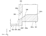
図6に示すように、本実施形態において隔壁263の貫通孔268は、隔壁263の下端部を、軸方向に対して鉛直方向に斜めに傾く方向に貫通する。貫通孔268の内側面のうち鉛直方向両側に位置する面は、第1ハウジング261から第2ハウジング62に向かうに従って下側に位置する傾斜面268e,268fである。傾斜面268eは、貫通孔268の内側面のうち上側に位置する面である。傾斜面268fは、貫通孔268の内側面のうち下側に位置する面である。傾斜面268eと傾斜面268fとは、例えば、互いに平行である。
<Second Embodiment>
As shown in FIG. 6, in the present embodiment, the through
第1ハウジング261の第1底部261aにおける底面261bは、例えば、鉛直方向と直交する平坦面である。本実施形態において凹部264の内側面は、隔壁263に向かうに従って下側に位置する傾斜面264aを有する。傾斜面264aは、底面261bと傾斜面268fとを繋いでいる。前後方向に見て、傾斜面264aの軸方向に対する傾斜角度は、例えば、貫通孔268の傾斜面268e,268fの軸方向に対する傾斜角度と同じである。傾斜面264aと傾斜面268fとは、滑らかに繋がり、一定の傾斜角度で傾く傾斜面を構成している。凹部264は、例えば、第1底部261aの前後方向の全体に亘って設けられている。本実施形態のその他の構成は、第1実施形態のその他の構成と同様にできる。
The
本実施形態によれば、貫通孔268が第1ハウジング261から第2ハウジング62に向かうに従って下側に位置する傾斜面268fを有し、凹部264が貫通孔268の傾斜面268fに繋がる傾斜面264aを有する。そのため、第1ハウジング261内のオイルOを、傾斜面264aおよび傾斜面268fに沿って第2ハウジング62内へと導きやすくできる。これにより、第1ハウジング261の内部から第2ハウジング62の内部に、よりオイルOを流しやすくできる。
According to the present embodiment, the through
本発明は上述の実施形態に限られず、本発明の技術的思想の範囲内において、他の構成を採用することもできる。上述した実施形態では、第1ハウジングの内部から貫通孔を介して第2ハウジングの内部に流れる流体がオイルOである場合について説明したが、これに限られない。流体は、特に限定されない。流体は、例えば、絶縁液であってもよいし、水であってもよい。流体が水である場合、ステータの表面に絶縁処理を施してもよい。 The present invention is not limited to the above-described embodiment, and other configurations may be adopted within the scope of the technical idea of the present invention. In the above-described embodiment, the case where the fluid flowing from the inside of the first housing to the inside of the second housing through the through hole is oil O has been described, but the present invention is not limited to this. The fluid is not particularly limited. The fluid may be, for example, an insulating liquid or water. When the fluid is water, the surface of the stator may be insulated.
凹部の形状は、特に限定されない。第1ハウジングと第2ハウジングとが並ぶ方向に見て、凹部の内部は、例えば、半円状であってもよいし、円弧状であってもよいし、多角形状であってもよい。貫通孔の形状は、特に限定されない。貫通孔は、円形状の孔であってもよいし、矩形状の孔であってもよいし、円弧状の孔であってもよい。 The shape of the recess is not particularly limited. When viewed in the direction in which the first housing and the second housing are arranged side by side, the inside of the recess may be, for example, a semicircular shape, an arc shape, or a polygonal shape. The shape of the through hole is not particularly limited. The through hole may be a circular hole, a rectangular hole, or an arc-shaped hole.
凹部の内部が貫通孔の内部と繋がるならば、貫通孔のうち所定方向の一方側の端部は、凹部のうち所定方向の一方側の端部よりも所定方向の他方側に位置してもよい。例えば、上述した第1実施形態の貫通孔68の下端部は、凹部64の下端部より上側に位置してもよい。
If the inside of the recess is connected to the inside of the through hole, one end of the through hole in the predetermined direction may be located on the other side of the recess in the predetermined direction rather than one end in the predetermined direction. good. For example, the lower end of the through
第2底部のうち所定方向の他方側の面は、一部において第1底部のうち所定方向の他方側の面と所定方向において同じ位置にあってもよいし、一部において第1底部のうち所定方向の他方側の面よりも所定方向の他方側に位置してもよい。例えば、上述した第1実施形態では、第2底部62aの底面62bの一部が、第1底部61aの底面61bと鉛直方向において同じ位置にあってもよいし、底面61bより上側に位置してもよい。また、第2底部のうち所定方向の他方側の面は、貫通孔のうち第2ハウジングの内部に開口する開口部の縁と繋がっていてもよい。例えば、上述した第1実施形態では、底面62bが貫通孔68の下端部と鉛直方向において同じ位置に位置し、底面62bの右側の端部が貫通孔68の開口部68dにおける下側の縁と繋がっていてもよい。
The other side surface of the second bottom portion in the predetermined direction may be partially located at the same position as the other side surface of the first bottom portion in the predetermined direction in the predetermined direction, or partly of the first bottom portion. It may be located on the other side in the predetermined direction from the surface on the other side in the predetermined direction. For example, in the first embodiment described above, a part of the
第1ハウジングが内部に収容する部材、および第2ハウジングが内部に収容する部材は、特に限定されない。第1ハウジングは、内部に伝達装置を収容してもよい。第2ハウジングは、内部にモータを収容してもよい。第1ハウジングの外側面に固定された補機は、特に限定されない。第1ハウジングの外側面に固定された補機は、オイルポンプであってもよいし、電動アクチュエータであってもよい。 The member housed inside by the first housing and the member housed inside by the second housing are not particularly limited. The first housing may house the transmission device inside. The second housing may house the motor inside. The auxiliary machine fixed to the outer surface of the first housing is not particularly limited. The auxiliary machine fixed to the outer surface of the first housing may be an oil pump or an electric actuator.
所定方向は、特に限定されない。所定方向は、鉛直方向と直交する水平方向であってもよい。この場合、例えば、第2ハウジング内の流体がポンプによって吸引されて、第1ハウジング内から第2ハウジング内に向かう流体の流れが生じてもよい。この場合においても、第1底部に凹部が設けられることにより貫通孔を大きくすることができ、第1ハウジングの内部から第2ハウジングの内部に流体を流しやすくできる。なお、この場合、第1底部は、第1ハウジングのうち水平方向の一方側に位置する部分であり、第2底部は、第2ハウジングのうち水平方向の一方側に位置する部分である。 The predetermined direction is not particularly limited. The predetermined direction may be a horizontal direction orthogonal to the vertical direction. In this case, for example, the fluid in the second housing may be sucked by the pump to generate a flow of the fluid from the inside of the first housing to the inside of the second housing. Also in this case, the through hole can be enlarged by providing the recess in the first bottom portion, and the fluid can easily flow from the inside of the first housing to the inside of the second housing. In this case, the first bottom portion is a portion of the first housing located on one side in the horizontal direction, and the second bottom portion is a portion of the second housing located on one side in the horizontal direction.
駆動装置は、モータを動力源として対象となる物体を動かすことができる装置であれば、特に限定されない。駆動装置は、伝達機構を備えなくてもよい。モータのトルクがモータのシャフトから直接対象に出力されてもよい。この場合、駆動装置は、モータそのものに相当する。モータ軸が延びる方向は、特に限定されない。モータ軸は、鉛直方向に延びてもよい。なお、本明細書において「モータ軸が鉛直方向と直交する水平方向に延びる」とは、モータ軸が厳密に水平方向に延びる場合に加えて、モータ軸が略水平方向に延びる場合も含む。すなわち、本明細書において「モータ軸が鉛直方向と直交する水平方向に延びる」とは、モータ軸が水平方向に対して僅かに傾いていてもよい。また、上述した実施形態では、駆動装置がインバータユニットを含まない場合について説明したが、これに限られない。駆動装置は、インバータユニットを含んでいてもよい。言い換えると、駆動装置がインバータユニットと一体構造となっていてもよい。 The drive device is not particularly limited as long as it is a device capable of moving a target object using a motor as a power source. The drive device does not have to include a transmission mechanism. The torque of the motor may be output directly from the shaft of the motor to the target. In this case, the drive device corresponds to the motor itself. The direction in which the motor shaft extends is not particularly limited. The motor shaft may extend in the vertical direction. In the present specification, "the motor shaft extends in the horizontal direction orthogonal to the vertical direction" includes not only the case where the motor shaft extends strictly in the horizontal direction but also the case where the motor shaft extends in the substantially horizontal direction. That is, in the present specification, "the motor shaft extends in the horizontal direction orthogonal to the vertical direction" may mean that the motor shaft is slightly tilted with respect to the horizontal direction. Further, in the above-described embodiment, the case where the drive device does not include the inverter unit has been described, but the present invention is not limited to this. The drive device may include an inverter unit. In other words, the drive device may be integrated with the inverter unit.
駆動装置の用途は、特に限定されない。駆動装置は、車両に搭載されなくてもよい。以上、本明細書において説明した構成は、相互に矛盾しない範囲内において、適宜組み合わせることができる。 The use of the drive device is not particularly limited. The drive device does not have to be mounted on the vehicle. As described above, the configurations described in the present specification can be appropriately combined within a range that does not contradict each other.
1…駆動装置、2…モータ、3…伝達装置、6…ハウジング、10…パイプ(供給部)、11,12,24a…供給口、24…ロータ本体(供給部)、61,161,261…第1ハウジング、61a,161a,261a…第1底部、62…第2ハウジング、62a…第2底部、63,263…隔壁、64,164,264…凹部、64a…傾斜面、68,268…貫通孔、68c,68d,268c…開口部、70…温度センサ、97…クーラー(補機)、97a…流路、O…オイル(流体) 1 ... Drive device, 2 ... Motor, 3 ... Transmission device, 6 ... Housing, 10 ... Pipe (supply section), 11,12,24a ... Supply port, 24 ... Rotor body (supply section), 61,161,261 ... 1st housing, 61a, 161a, 261a ... 1st bottom, 62 ... 2nd housing, 62a ... 2nd bottom, 63,263 ... partition wall, 64,164,264 ... recess, 64a ... inclined surface, 68,268 ... Penetration Hole, 68c, 68d, 268c ... Opening, 70 ... Temperature sensor, 97 ... Cooler (auxiliary machine), 97a ... Flow path, O ... Oil (fluid)
Claims (15)
前記モータを内部に収容するハウジングと、
を備え、
前記ハウジングは、
第1ハウジングと、
前記第1ハウジングに繋がる第2ハウジングと、
前記第1ハウジングの内部と前記第2ハウジングの内部とを隔てる隔壁と、
を有し、
前記第1ハウジングは、所定方向の一方側に位置する第1底部を有し、
前記第2ハウジングは、前記所定方向の一方側に位置する第2底部を有し、
前記第2底部のうち前記所定方向の他方側の面は、少なくとも一部が前記第1底部のうち前記所定方向の他方側の面よりも前記所定方向の一方側に位置し、
前記第1底部は、前記隔壁と隣接する位置に前記所定方向の一方側に窪む凹部を有し、
前記隔壁は、前記第1ハウジングの内部と前記第2ハウジングの内部とを繋ぐ貫通孔を有し、
前記凹部の内部は、前記貫通孔の内部と繋がる、駆動装置。 With the motor
A housing that houses the motor inside
With
The housing is
1st housing and
The second housing connected to the first housing and
A partition wall that separates the inside of the first housing from the inside of the second housing,
Have,
The first housing has a first bottom located on one side in a predetermined direction.
The second housing has a second bottom located on one side in the predetermined direction.
At least a part of the surface of the second bottom portion on the other side in the predetermined direction is located on one side of the first bottom portion in the predetermined direction with respect to the surface on the other side in the predetermined direction.
The first bottom portion has a recess recessed on one side in the predetermined direction at a position adjacent to the partition wall.
The partition wall has a through hole connecting the inside of the first housing and the inside of the second housing.
The inside of the recess is a driving device connected to the inside of the through hole.
前記所定方向の一方側は、鉛直方向下側である、請求項1に記載の駆動装置。 The predetermined direction is the vertical direction.
The drive device according to claim 1, wherein one side in the predetermined direction is the lower side in the vertical direction.
前記貫通孔のうち前記第1ハウジングの内部に開口する開口部の開口面積は、前記供給口の総開口面積よりも大きい、請求項1から9のいずれか一項に記載の駆動装置。 A supply unit having a supply port for supplying a fluid is further provided inside the first housing.
The driving device according to any one of claims 1 to 9, wherein the opening area of the opening of the through hole that opens inside the first housing is larger than the total opening area of the supply port.
前記温度センサは、前記貫通孔よりも鉛直方向上側に位置する、請求項1から11のいずれか一項に記載の駆動装置。 Further equipped with a temperature sensor capable of detecting the temperature of the motor,
The driving device according to any one of claims 1 to 11, wherein the temperature sensor is located above the through hole in the vertical direction.
前記第1ハウジングは、内部に前記モータを収容し、
前記第2ハウジングは、内部に前記伝達装置を収容する、請求項1から14のいずれか一項に記載の駆動装置。 Further equipped with a transmission device connected to the motor,
The first housing houses the motor inside, and the first housing accommodates the motor.
The drive device according to any one of claims 1 to 14, wherein the second housing houses the transmission device inside.
Priority Applications (2)
| Application Number | Priority Date | Filing Date | Title |
|---|---|---|---|
| JP2020033532A JP7424106B2 (en) | 2020-02-28 | 2020-02-28 | drive device |
| CN202110221202.9A CN113328553A (en) | 2020-02-28 | 2021-02-26 | Drive device |
Applications Claiming Priority (1)
| Application Number | Priority Date | Filing Date | Title |
|---|---|---|---|
| JP2020033532A JP7424106B2 (en) | 2020-02-28 | 2020-02-28 | drive device |
Publications (2)
| Publication Number | Publication Date |
|---|---|
| JP2021136834A true JP2021136834A (en) | 2021-09-13 |
| JP7424106B2 JP7424106B2 (en) | 2024-01-30 |
Family
ID=77414545
Family Applications (1)
| Application Number | Title | Priority Date | Filing Date |
|---|---|---|---|
| JP2020033532A Active JP7424106B2 (en) | 2020-02-28 | 2020-02-28 | drive device |
Country Status (2)
| Country | Link |
|---|---|
| JP (1) | JP7424106B2 (en) |
| CN (1) | CN113328553A (en) |
Cited By (5)
| Publication number | Priority date | Publication date | Assignee | Title |
|---|---|---|---|---|
| JP7192941B1 (en) | 2021-09-22 | 2022-12-20 | 株式会社明電舎 | Rotating electric machine |
| JP2023092672A (en) * | 2021-12-22 | 2023-07-04 | マツダ株式会社 | Vehicle drive system |
| WO2023243316A1 (en) * | 2022-06-15 | 2023-12-21 | ニデック株式会社 | Rotary electric machine |
| WO2024004434A1 (en) * | 2022-06-30 | 2024-01-04 | ニデック株式会社 | Drive device, and method for manufacturing drive device |
| WO2024004435A1 (en) * | 2022-06-30 | 2024-01-04 | ニデック株式会社 | Drive device |
Families Citing this family (1)
| Publication number | Priority date | Publication date | Assignee | Title |
|---|---|---|---|---|
| JP7785223B1 (en) * | 2025-04-14 | 2025-12-12 | MCF Electric Drive株式会社 | Motor Control System |
Citations (5)
| Publication number | Priority date | Publication date | Assignee | Title |
|---|---|---|---|---|
| WO2018030342A1 (en) * | 2016-08-09 | 2018-02-15 | 日本電産株式会社 | Motor unit |
| WO2018030343A1 (en) * | 2016-08-09 | 2018-02-15 | 日本電産株式会社 | Motor unit |
| WO2018030371A1 (en) * | 2016-08-09 | 2018-02-15 | 日本電産株式会社 | Motor unit |
| JP2018103977A (en) * | 2016-12-26 | 2018-07-05 | Ntn株式会社 | In-wheel motor drive device |
| WO2019131424A1 (en) * | 2017-12-28 | 2019-07-04 | 日本電産株式会社 | Motor unit |
Family Cites Families (5)
| Publication number | Priority date | Publication date | Assignee | Title |
|---|---|---|---|---|
| FR2673854B1 (en) * | 1991-03-12 | 1993-07-16 | Cambier Benjamin | PARTITION FOR A BALLOON CYLINDRICAL CRUSHER WITH MULTIPLE LEVELS OF MATERIAL LIFTING. |
| JP6023976B2 (en) * | 2012-07-19 | 2016-11-09 | パナソニックIpマネジメント株式会社 | Clothes dryer |
| CN111566909B (en) * | 2017-12-28 | 2022-12-06 | 日本电产株式会社 | motor unit |
| CN110729856A (en) * | 2019-09-03 | 2020-01-24 | 精进电动科技股份有限公司 | Oil-water double-cooling electric drive assembly and new energy automobile |
| CN110808659A (en) * | 2019-11-11 | 2020-02-18 | 宜宾凯翼汽车有限公司 | Electric drive assembly |
-
2020
- 2020-02-28 JP JP2020033532A patent/JP7424106B2/en active Active
-
2021
- 2021-02-26 CN CN202110221202.9A patent/CN113328553A/en active Pending
Patent Citations (5)
| Publication number | Priority date | Publication date | Assignee | Title |
|---|---|---|---|---|
| WO2018030342A1 (en) * | 2016-08-09 | 2018-02-15 | 日本電産株式会社 | Motor unit |
| WO2018030343A1 (en) * | 2016-08-09 | 2018-02-15 | 日本電産株式会社 | Motor unit |
| WO2018030371A1 (en) * | 2016-08-09 | 2018-02-15 | 日本電産株式会社 | Motor unit |
| JP2018103977A (en) * | 2016-12-26 | 2018-07-05 | Ntn株式会社 | In-wheel motor drive device |
| WO2019131424A1 (en) * | 2017-12-28 | 2019-07-04 | 日本電産株式会社 | Motor unit |
Cited By (10)
| Publication number | Priority date | Publication date | Assignee | Title |
|---|---|---|---|---|
| JP7192941B1 (en) | 2021-09-22 | 2022-12-20 | 株式会社明電舎 | Rotating electric machine |
| WO2023047875A1 (en) * | 2021-09-22 | 2023-03-30 | 株式会社明電舎 | Rotating electrical machine |
| JP2023045544A (en) * | 2021-09-22 | 2023-04-03 | 株式会社明電舎 | Rotary electric machine |
| CN118020237A (en) * | 2021-09-22 | 2024-05-10 | 株式会社明电舍 | Rotating electric machines |
| US12451755B2 (en) | 2021-09-22 | 2025-10-21 | Meidensha Corporation | Rotary electric machine with stator and oil injection port |
| JP2023092672A (en) * | 2021-12-22 | 2023-07-04 | マツダ株式会社 | Vehicle drive system |
| JP7800116B2 (en) | 2021-12-22 | 2026-01-16 | マツダ株式会社 | Vehicle drive unit |
| WO2023243316A1 (en) * | 2022-06-15 | 2023-12-21 | ニデック株式会社 | Rotary electric machine |
| WO2024004434A1 (en) * | 2022-06-30 | 2024-01-04 | ニデック株式会社 | Drive device, and method for manufacturing drive device |
| WO2024004435A1 (en) * | 2022-06-30 | 2024-01-04 | ニデック株式会社 | Drive device |
Also Published As
| Publication number | Publication date |
|---|---|
| JP7424106B2 (en) | 2024-01-30 |
| CN113328553A (en) | 2021-08-31 |
Similar Documents
| Publication | Publication Date | Title |
|---|---|---|
| JP2021136834A (en) | Driver | |
| CN111585394B (en) | Motor unit | |
| JP2022032456A (en) | Driving device | |
| JP7331501B2 (en) | drive | |
| US20230069613A1 (en) | Drive apparatus | |
| CN111512526B (en) | motor unit | |
| JP2020137405A (en) | Motor unit | |
| US20220158522A1 (en) | Motor and drive device | |
| CN112564385B (en) | Driving device | |
| WO2019208421A1 (en) | Motor unit | |
| CN113472137B (en) | Driving device | |
| WO2021200537A1 (en) | Motor unit and electric vehicle | |
| CN113285564B (en) | Driving device | |
| WO2019208063A1 (en) | Motor unit | |
| JP7424041B2 (en) | drive device | |
| JP7415616B2 (en) | drive device | |
| JP2024145695A (en) | Drive unit | |
| CN211456844U (en) | Motors and Drives | |
| US20240333100A1 (en) | Drive device | |
| JP2021164298A (en) | Driving device | |
| JP2020174480A (en) | Driving device and pipeline connection structure | |
| CN115706465A (en) | Drive device | |
| CN116073590A (en) | Driving device | |
| JP2023048539A (en) | Drive device | |
| WO2019208065A1 (en) | Motor unit |
Legal Events
| Date | Code | Title | Description |
|---|---|---|---|
| A621 | Written request for application examination |
Free format text: JAPANESE INTERMEDIATE CODE: A621 Effective date: 20221223 |
|
| A977 | Report on retrieval |
Free format text: JAPANESE INTERMEDIATE CODE: A971007 Effective date: 20230823 |
|
| A131 | Notification of reasons for refusal |
Free format text: JAPANESE INTERMEDIATE CODE: A131 Effective date: 20230829 |
|
| A521 | Request for written amendment filed |
Free format text: JAPANESE INTERMEDIATE CODE: A523 Effective date: 20231025 |
|
| TRDD | Decision of grant or rejection written | ||
| A01 | Written decision to grant a patent or to grant a registration (utility model) |
Free format text: JAPANESE INTERMEDIATE CODE: A01 Effective date: 20231219 |
|
| A61 | First payment of annual fees (during grant procedure) |
Free format text: JAPANESE INTERMEDIATE CODE: A61 Effective date: 20240101 |
|
| R151 | Written notification of patent or utility model registration |
Ref document number: 7424106 Country of ref document: JP Free format text: JAPANESE INTERMEDIATE CODE: R151 |