JP2021136819A - Cooling system - Google Patents
Cooling system Download PDFInfo
- Publication number
- JP2021136819A JP2021136819A JP2020033172A JP2020033172A JP2021136819A JP 2021136819 A JP2021136819 A JP 2021136819A JP 2020033172 A JP2020033172 A JP 2020033172A JP 2020033172 A JP2020033172 A JP 2020033172A JP 2021136819 A JP2021136819 A JP 2021136819A
- Authority
- JP
- Japan
- Prior art keywords
- motor
- cooling
- current
- axis
- inverter
- Prior art date
- Legal status (The legal status is an assumption and is not a legal conclusion. Google has not performed a legal analysis and makes no representation as to the accuracy of the status listed.)
- Granted
Links
Images


Classifications
-
- H—ELECTRICITY
- H05—ELECTRIC TECHNIQUES NOT OTHERWISE PROVIDED FOR
- H05K—PRINTED CIRCUITS; CASINGS OR CONSTRUCTIONAL DETAILS OF ELECTRIC APPARATUS; MANUFACTURE OF ASSEMBLAGES OF ELECTRICAL COMPONENTS
- H05K7/00—Constructional details common to different types of electric apparatus
- H05K7/20—Modifications to facilitate cooling, ventilating, or heating
- H05K7/2089—Modifications to facilitate cooling, ventilating, or heating for power electronics, e.g. for inverters for controlling motor
- H05K7/20927—Liquid coolant without phase change
-
- H—ELECTRICITY
- H02—GENERATION; CONVERSION OR DISTRIBUTION OF ELECTRIC POWER
- H02K—DYNAMO-ELECTRIC MACHINES
- H02K9/00—Arrangements for cooling or ventilating
-
- H—ELECTRICITY
- H02—GENERATION; CONVERSION OR DISTRIBUTION OF ELECTRIC POWER
- H02K—DYNAMO-ELECTRIC MACHINES
- H02K9/00—Arrangements for cooling or ventilating
- H02K9/19—Arrangements for cooling or ventilating for machines with closed casing and closed-circuit cooling using a liquid cooling medium, e.g. oil
-
- H—ELECTRICITY
- H02—GENERATION; CONVERSION OR DISTRIBUTION OF ELECTRIC POWER
- H02M—APPARATUS FOR CONVERSION BETWEEN AC AND AC, BETWEEN AC AND DC, OR BETWEEN DC AND DC, AND FOR USE WITH MAINS OR SIMILAR POWER SUPPLY SYSTEMS; CONVERSION OF DC OR AC INPUT POWER INTO SURGE OUTPUT POWER; CONTROL OR REGULATION THEREOF
- H02M7/00—Conversion of AC power input into DC power output; Conversion of DC power input into AC power output
- H02M7/42—Conversion of DC power input into AC power output without possibility of reversal
- H02M7/44—Conversion of DC power input into AC power output without possibility of reversal by static converters
- H02M7/48—Conversion of DC power input into AC power output without possibility of reversal by static converters using discharge tubes with control electrode or semiconductor devices with control electrode
-
- H—ELECTRICITY
- H05—ELECTRIC TECHNIQUES NOT OTHERWISE PROVIDED FOR
- H05K—PRINTED CIRCUITS; CASINGS OR CONSTRUCTIONAL DETAILS OF ELECTRIC APPARATUS; MANUFACTURE OF ASSEMBLAGES OF ELECTRICAL COMPONENTS
- H05K7/00—Constructional details common to different types of electric apparatus
- H05K7/20—Modifications to facilitate cooling, ventilating, or heating
- H05K7/2089—Modifications to facilitate cooling, ventilating, or heating for power electronics, e.g. for inverters for controlling motor
- H05K7/20945—Thermal management, e.g. inverter temperature control
-
- H—ELECTRICITY
- H02—GENERATION; CONVERSION OR DISTRIBUTION OF ELECTRIC POWER
- H02K—DYNAMO-ELECTRIC MACHINES
- H02K11/00—Structural association of dynamo-electric machines with electric components or with devices for shielding, monitoring or protection
- H02K11/30—Structural association with control circuits or drive circuits
- H02K11/33—Drive circuits, e.g. power electronics
-
- Y—GENERAL TAGGING OF NEW TECHNOLOGICAL DEVELOPMENTS; GENERAL TAGGING OF CROSS-SECTIONAL TECHNOLOGIES SPANNING OVER SEVERAL SECTIONS OF THE IPC; TECHNICAL SUBJECTS COVERED BY FORMER USPC CROSS-REFERENCE ART COLLECTIONS [XRACs] AND DIGESTS
- Y02—TECHNOLOGIES OR APPLICATIONS FOR MITIGATION OR ADAPTATION AGAINST CLIMATE CHANGE
- Y02T—CLIMATE CHANGE MITIGATION TECHNOLOGIES RELATED TO TRANSPORTATION
- Y02T50/00—Aeronautics or air transport
- Y02T50/60—Efficient propulsion technologies, e.g. for aircraft
Landscapes
- Engineering & Computer Science (AREA)
- Microelectronics & Electronic Packaging (AREA)
- Power Engineering (AREA)
- Physics & Mathematics (AREA)
- Thermal Sciences (AREA)
- Inverter Devices (AREA)
- Electric Propulsion And Braking For Vehicles (AREA)
- Control Of Ac Motors In General (AREA)
Abstract
【課題】モータ及びインバータを冷却する冷却システムの重量増加を抑制する。
【解決手段】モータ2とモータを駆動させるインバータ1とを有する電駆動システム6を冷却する冷却システム50は、自身の内部を流通する冷却媒体を利用した熱交換により、モータを冷却する第1冷却部3と、自身の内部を流通する冷却媒体を利用した熱交換により、インバータ1を冷却する第2冷却部7と、第1冷却部と第2冷却部とを通り、冷却媒体が循環する循環流路10と、循環流路に配置され、冷却媒体を圧送するポンプ12と、を備える。
【選択図】図1PROBLEM TO BE SOLVED: To suppress an increase in weight of a cooling system for cooling a motor and an inverter.
SOLUTION: A cooling system 50 for cooling an electric drive system 6 having a motor 2 and an inverter 1 for driving the motor is a first cooling system for cooling the motor by heat exchange using a cooling medium circulating inside the motor. Circulation in which the cooling medium circulates through the second cooling section 7 that cools the inverter 1 by heat exchange using the section 3 and the cooling medium that circulates inside itself, and the first cooling section and the second cooling section. A flow path 10 and a pump 12 arranged in the circulation flow path and pumping a cooling medium are provided.
[Selection diagram] Fig. 1
Description
本開示は、冷却システムに関する。 The present disclosure relates to a cooling system.
従来から、モータを冷却する冷却システムが種々提案されている。例えば、特許文献1には、モータを通る油路と、油路を流れる冷却油を圧送するオイルポンプを有し、油路を流れる冷却油によりモータを冷却する冷却システムが開示されている。かかる冷却システムでは、インバータ回路を備えるモータコントローラは、冷却油の温度が所定温度以下の場合に、銅損が増大するようにモータへの供給電力を制御することにより冷却油を加熱して冷却油の粘性を低下させる。これにより、低温時においても冷却油の流量を確保する。
Conventionally, various cooling systems for cooling a motor have been proposed. For example,
移動体等の電動化に伴い、モータとインバータ回路とを有する電駆動システム(EDS:Electric Drive System)が、様々な用途で用いられている。電動航空機の回転翼や、船舶のスクリューや、自動車の車輪を回転駆動させるために、電駆動システムが用いられている。電動航空機としては、例えば、電動垂直離着陸機(eVTOL:electric Vertical Take-Off and Landing aircraft)と呼ばれる有人または無人の航空機が挙げられるが、通常の離着陸機等であってもよい。電駆動システムでは、モータに加えてインバータの冷却も望まれる。しかし、特許文献1の冷却システムでは、インバータの冷却は考慮されていない。このため、かかる冷却システムを利用してモータとインバータとを冷却しようとする場合、インバータ冷却用のシステムとして、モータ冷却用のシステムと同様なシステムを、モータ冷却用のシステムとは別に用意する構成が想定される。しかし、このような構成では、冷却システム全体の重量の増大を招くという問題がある。電駆動システムを移動体に搭載する場合、冷却システムの重量の増大は、移動性能及び燃費の悪化につながり、大きなデメリットとなる。このため、モータ及びインバータを冷却する冷却システムの重量増加を抑制可能な技術が望まれる。
With the electrification of mobile objects and the like, an electric drive system (EDS) having a motor and an inverter circuit has been used for various purposes. Electric drive systems are used to rotationally drive rotary wings of electric aircraft, screws of ships, and wheels of automobiles. Examples of the electric aircraft include a manned or unmanned aircraft called an electric vertical take-off and landing aircraft (eVTOL), but an ordinary takeoff and landing aircraft may also be used. In an electric drive system, it is desired to cool the inverter in addition to the motor. However, in the cooling system of
本開示は、以下の形態として実現することが可能である。 The present disclosure can be realized in the following forms.
本開示の一形態によれば、モータ(2)と前記モータを駆動させるインバータ(1)とを有する電駆動システム(6)を冷却する冷却システム(50)が提供される。この冷却システムは、自身の内部を流通する冷却媒体を利用した熱交換により、前記モータを冷却する第1冷却部(3)と、自身の内部を流通する前記冷却媒体を利用した熱交換により、前記インバータを冷却する第2冷却部(7)と、前記第1冷却部と前記第2冷却部とを通り、前記冷却媒体が循環する循環流路(10)と、前記循環流路に配置され、前記冷却媒体を圧送するポンプ(12)と、を備える。 According to one embodiment of the present disclosure, a cooling system (50) for cooling an electric drive system (6) having a motor (2) and an inverter (1) for driving the motor is provided. This cooling system uses a first cooling unit (3) that cools the motor by heat exchange using a cooling medium that circulates inside itself, and heat exchange that uses the cooling medium that circulates inside itself. A second cooling unit (7) for cooling the inverter, a circulation flow path (10) through which the first cooling unit and the second cooling unit circulate, and the circulation flow path are arranged. , A pump (12) for pumping the cooling medium.
この形態の冷却システムによれば、モータを冷却する第1冷却部とインバータを冷却する第2冷却部とを通り、冷却媒体が循環する循環流路を備えるので、モータとインバータとを共通の冷却媒体で冷却することができる。このため、モータとインバータを冷却する流路が別々に形成されているシステムに比べて、流路及び冷却媒体の重量を軽減でき、冷却システムの重量増加を抑制できる。 According to this type of cooling system, a circulation flow path through which a cooling medium circulates through a first cooling unit that cools the motor and a second cooling unit that cools the inverter is provided, so that the motor and the inverter are cooled in common. It can be cooled with a medium. Therefore, the weight of the flow path and the cooling medium can be reduced and the weight increase of the cooling system can be suppressed as compared with the system in which the flow paths for cooling the motor and the inverter are separately formed.
本開示は、種々の形態で実現することも可能である。例えば、自動車や電動航空機等の移動体に搭載される電駆動システムの冷却方法等の形態で実現することができる。 The present disclosure can also be realized in various forms. For example, it can be realized in the form of a cooling method of an electric drive system mounted on a moving body such as an automobile or an electric aircraft.
A.第1実施形態:
A−1.システム構成:
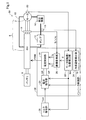
図1に示す冷却システム50は、電駆動システム6を冷却する。本実施形態において、電駆動システム6は、モータ2と、インバータ1とを有し、eVTOLの回転翼を回転駆動させるために用いられる。
A. First Embodiment:
A-1. System configuration:
The
モータ2は、本実施形態において、三相交流ブラシレスモータにより構成され、後述するインバータ1から供給される電圧および電流に応じた回転数およびトルクで回転する。なお、モータ2は、ブラシレスモータに限らず、誘導モータやリラクタンスモータ等の任意の種類のモータにより構成されていてもよい。なお、本実施形態においてモータ2とは電動機としてのモータであるが、モータ2は、電動発電機としてのいわゆるモータジェネレータも含む。
In the present embodiment, the
図2に示すインバータ1は、モータ2を駆動させる。インバータ1は、バッテリ8から供給される直流電圧を、三相交流電圧に変換してモータ2に供給する。インバータ回路4は、U相、V相、W相の各相に設けられた合計三つのレグ13を有する。各レグ13は上アームおよび下アームにスイッチング素子5を有する。なお、バッテリ8からインバータ回路4に供給される直流電圧は、コンデンサ15によって平滑化されている。
The
本実施形態において、スイッチング素子5は、IGBT(Insulated Gate Bipolar Transistor)などのスイッチング素子により構成されている。
In the present embodiment, the
図1に示すように、eVTOLには、上述の電駆動システム6および後述の冷却システム50に加えて、バッテリ8と、電流センサ19と、回転数センサ20と、トルク指令部28とを備える。
As shown in FIG. 1, the eVTOL includes a
バッテリ8は、リチウムイオン電池により構成され、電駆動システム6における電力供給源の1つとして機能する。バッテリ8は、主に、電駆動システム6が有するインバータ1の駆動部へと電力を供給してモータ2を駆動させる。なお、リチウムイオン電池に代えて、ニッケル水素電池等の任意の二次電池により構成されていてもよく、バッテリ8に代えて、またはバッテリ8に加えて、燃料電池や発電機等の任意の電力供給源が搭載されていてもよい。
The
電流センサ19は、図1に示すように、インバータ1に設けられる。電流センサ19は、インバータ1から出力される相電流値Iu、Iv、Iwを検出する三相交流電流センサである。
As shown in FIG. 1, the
回転数センサ20は、モータ2に設けられている。回転数センサ20は、モータ2の回転数Nmと回転角度θを測定する。本実施形態においては、回転数センサ20はレゾルバを用いている。なお、回転数センサ20は、ロータリーエンコーダなどの他の任意の方式の回転数センサであってもよい。
The rotation speed sensor 20 is provided in the
トルク指令部28は、eVTOLが有する図示しないフライトコントローラから入力される目標トルクと、モータ回転数・位置検出部22から取得したモータ回転数Nmとに基づいて、トルク指令値Tm*を算出する。トルク指令部28は、算出したトルク指令値Tm*を電流指令部29へ入力する。
The
図3に示すように、冷却システム50は、第1冷却部3と、第2冷却部7と、循環流路10と、ポンプ12と、熱交換器14と、温度センサ18と、インバータ制御部30とを備える。
As shown in FIG. 3, the
第1冷却部3は、自身の内部を流通する冷却媒体を利用した熱交換によりモータ2の発熱体を冷却する。本実施形態において、冷却媒体はロング・ライフ・クーラント(Long Life Coolant : LLC)である。なお、冷却媒体はロング・ライフ・クーラントに限らず、冷却油や純水などの他の任意の種類の液体や、空気や窒素ガスなどの気体であってもよい。
The
第2冷却部7は、自身の内部を流通する冷却媒体を利用した熱交換によりインバータ1の発熱体を冷却する。インバータ1の発熱体とは、例えば、インバータ回路4やコンデンサ15等である。
The
図3に示すように、循環流路10は、流路R1と、流路R2と、流路R3と、流路R4とを有する環状に形成された流路である。冷却媒体は、ポンプ12によって圧送される。圧送された冷却媒体は、流路R1から第2冷却部7へと流れ、インバータ1の発熱体を冷却する。第2冷却部7から流出した冷却媒体は、流路R2を通って、第1冷却部3へと至り、モータ2を冷却する。モータ2から流出した冷却媒体は、流路R3を通って熱交換器14へと至る。熱交換器14から流出した冷却媒体は、流路R4を通ってポンプ12へと戻る。
As shown in FIG. 3, the
ポンプ12は、図1および図3に示すように、循環流路10に配置される。ポンプ12は、本実施形態では電動式ポンプにより構成され、図示しない補機バッテリからの電力を利用して循環流路10内に冷却媒体を圧送する。
The
熱交換器14は、循環流路10に配置される。熱交換器14は、冷却媒体と循環流路10の外部の空気との間で熱交換を行う。第2冷却部7において、インバータ1の発熱体と熱交換し、第1冷却部3において、モータ2と熱交換して昇温した冷却媒体は、熱交換器14を通ることにより冷却される。
The
図1および図3に示すように、温度センサ18は、循環流路10に接して配置される。温度センサ18は、循環流路10を流通する冷却媒体の温度(以下、「冷却媒体温度」と呼ぶ)を測定する。
As shown in FIGS. 1 and 3, the
図1に示すように、インバータ制御部30は、電流制御部16と、モータ回転数・位置検出部22と、冷媒温度検出部24と、座標変換部26と、電流指令部29とを有する。インバータ制御部30は、マイコンやFPGA等を有するECU(Electronic Control Unit)により構成されている。
As shown in FIG. 1, the
電流制御部16は、インバータ回路4を制御する。具体的には、電流制御部16は、トルク指令部28にて記載のないスロットルなどの入力情報より飛行および走行に必要な駆動力を算出し、モータ回転数Nmに基づき出力されたトルク指令値Tm*に応じて、また、電流センサ19により検出される相電流値Iu、Iv、Iwに応じて、スイッチング素子5に対して制御信号を出力することによって、インバータ回路4の出力電力をPWM(Pulse Width Modulation)制御する。
The
モータ回転数・位置検出部22は、回転数センサ20において測定されたモータ回転数Nmと、回転角度θとを検出する。モータ回転数・位置検出部22は、検出したモータ回転数Nmをトルク指令部28および電流指令部29へ入力する。また、モータ回転数・位置検出部22は、検出した回転角度θを座標変換部26へ設定する。
The motor rotation speed /
冷媒温度検出部24は、温度センサ18において測定された冷却媒体温度Trを検出する。冷媒温度検出部24は、検出した冷却媒体温度Trを電流指令部29へ入力する。
The refrigerant
座標変換部26は、電流センサ19において測定された相電流値Iu、Iv、Iwを取得する。座標変換部26は、取得された相電流値Iu、Iv、Iwを回転角度θに基づいてモータ2の実電流値Id、Iqに変換する。電流値Idは、d軸電流値を意味し、電流値Iqは、q軸電流値を意味する。座標変換部26は、変換後の電流値Id、Iqを電流制御部16へ入力する。
The coordinate
電流指令部29は、マップを参照して、トルク指令値Tm*およびモータ回転数Nmに対応する電流指令値Id*、Iq*を生成する。電流指令部29は、生成した電流指令値Id*、Iq*を電流制御部16に入力する。電流制御部16は、座標変換部26から入力する実電流値Id、Iqが電流指令部29から入力する電流指令値Id*、Iq*に追従するように、制御信号を生成する。
The
A−2.モータ制御処理:
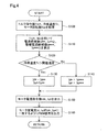
図4に示すモータ制御処理は、モータ2の動作を制御する処理である。インバータ制御部30では、バッテリ8から電駆動システム6へ電力が供給されるとモータ制御処理が実行される。電流指令部29は、上述したように、トルク指令値Tm*、冷却媒体温度Tr、モータ回転数Nmを取得する(ステップS100)。
A-2. Motor control processing:
The motor control process shown in FIG. 4 is a process for controlling the operation of the
電流指令部29は、トルク指令値Tm*、モータ回転数Nmを用いて、予め作成されたトルク−電流マップに基づき、d軸電流指令値Id*の候補値の1つであるd軸電流候補値Id**と、q軸電流指令値Iq*の候補値の1つであるq軸電流候補値Iq**を算出する。また、電流指令部29は、予め作成されたトルク−暖機電流マップに基づき、d軸電流指令値Id*の候補値の1つであるd軸暖機電流候補値Id***と、q軸電流指令値Iq*の候補値の1つであるq軸暖機電流候補値Iq***とを算出する。(ステップS110)。後述するように、d軸暖機電流候補値Id***と、q軸暖機電流候補値Iq***とは、冷却システム50を暖機するために用いられる。より正確には、冷却システムを流れる冷却媒体を加熱するために用いられる。なお、トルク−電流マップと、トルク−暖機電流マップとは、予め解析および実機検証を基に作成されている。ただし、使用するモータの仕様が異なる場合は、各マップを変更する必要がある。
The
電流指令部29は、冷却媒体温度Trが予め定められた所定の閾値温度より高いかどうかを判定する(ステップS120)。電流指令部29は、冷却媒体温度Trが予め定められた所定の閾値温度より高いと判定した場合(ステップS120:Yes)、d軸電流指令値Id*にd軸電流候補値Id**を代入し、q軸電流指令値Iq*にq軸電流候補値Iq**を代入する(ステップS130)。
The
電流指令部29は、冷却媒体温度Trが予め定められた所定の閾値温度以下と判定した場合(ステップS120:No)、d軸電流指令値Id*にd軸暖機電流候補値Id***を代入し、q軸電流指令値Iq*にq軸暖機電流候補値Iq***を代入する(ステップS140)。
When the
電流指令部29は、モータ2のd軸電流指令値Id*、q軸電流指令値Iq*を電流制御部16に出力する(ステップS150)。電流制御部16は、モータ2の実電流値Id、Iqがd軸電流指令値Id*、q軸電流指令値Iq*に近づいて一致するようにPWM信号を出力する(ステップS160)。例えば、電流制御部16は、PI制御やPID制御などのフィードバック制御を行う。
The
ここで、d軸暖機電流候補値Id***は、d軸電流候補値Id**よりも大きく設定されている。また、q軸暖機電流候補値Iq***は、q軸電流候補値Iq**と略同一に設定されている。このため、d軸電流指令値Id*としてd軸暖機電流候補値Id***が代入され、q軸電流指令値Iq*としてq軸暖機電流候補値Iq***が代入され、実電流値Id、Iqが電流指令値Id*、Iq*に一致するようにPWM信号が出力されると、インバータ1およびモータ2の相電流は増加し、インバータ1とモータ2における発熱量は増大する。このため、冷却システム50を流通する冷却媒体をインバータ1(第2冷却部7)およびモータ2(第1冷却部3)において温めることができる。加えて、トルクに影響を与えるq軸暖機電流候補値Iq***とq軸電流候補値Iq**とは、略同一であるので、フィードバック制御の結果、モータ2の出力トルクがトルク指令値Tm*とは大きく異なることを抑制できる。
Here, d Jikudan motor current candidate value Id *** is set larger than the d-axis current candidate value Id **. Further, the q-axis warm-up current candidate value Iq *** is set to be substantially the same as the q-axis current candidate value Iq **. Therefore, the d-axis warm-up current candidate value Id *** is substituted as the d-axis current command value Id * , and the q-axis warm-up current candidate value Iq *** is substituted as the q-axis current command value Iq *. When the PWM signal is output so that the current values Id and Iq match the current command values Id * and Iq * , the phase currents of the
本実施形態におけるd軸電流指令値Id*は、特許請求の範囲におけるd軸電流目標値に相当し、q軸電流指令値Iq*は、特許請求の範囲におけるq軸電流目標値に相当する。また、モータ2の実電流値Id、Iqは、特許請求の範囲におけるd軸電流、q軸電流にそれぞれ相当する。
The d-axis current command value Id * in the present embodiment corresponds to the d-axis current target value in the claims, and the q-axis current command value Iq * corresponds to the q-axis current target value in the claims. Further, the actual current values Id and Iq of the
以上説明した第1実施形態の冷却システム50によれば、モータ2を冷却する第1冷却部3とインバータ1を冷却する第2冷却部7とを通り、冷却媒体が循環する循環流路10を備えるので、モータ2とインバータ1とを共通の冷却媒体で冷却することができる。このため、モータ2とインバータ1を冷却する流路が別々に形成されているシステムに比べて、流路及び冷却媒体の重量を軽減でき、冷却システム50の重量増加を抑制できる。
According to the
また、温度センサ18により検出される冷却媒体温度が閾値温度以下であるか否かを判定し、温度センサ18により検出される冷却媒体温度が閾値温度以下と判定された場合には、d軸電流候補値Id**よりも大きなd軸暖機電流候補値Id***をd軸電流指令値Id*に設定し、q軸電流候補値Iq**と略同一のq軸暖機電流候補値Iq***をq軸電流指令値Iq*に設定する。さらに、電流センサ19により検出されるモータ電流を構成するモータ2の実電流値Idがd軸電流指令値Id*に近づき、モータ電流を構成するモータ2の実電流値Iqがq軸電流指令値Iq*に近づくように、制御信号を設定する。このため、冷却媒体温度が所定温度以下のとき、モータ2の出力トルクを目標トルクに近い状態のまま、モータ2による損失(発熱)とインバータ1による損失(発熱)とが増大するように制御できる。したがって、低温時においても冷却媒体の粘性を低下させ流量を確保でき、冷却媒体用のポンプの大型化を抑制できると共に、モータ2の出力トルクが目標トルクと大きく異なり、ユーザに違和感を与えることを抑制できる。
Further, it is determined whether or not the cooling medium temperature detected by the
B.他の実施形態:
(B1)本実施形態の冷却システム50は、インバータ1のスイッチング素子5がワイドバンドギャップ素子で構成されている点において、第1実施形態の冷却システム50と異なる。本実施形態における他の構成は、第1実施形態の冷却システム50と同じであるので、同一の構成要素には同一の符号を付し、その詳細な説明を省略する。
B. Other embodiments:
(B1) The
本実施形態における冷却システム50のインバータ1のスイッチング素子5は、ワイドバンドギャップ素子で構成されている。具体的には、SiC(炭化珪素)やGaN(窒化ガリウム)といったワイドバンドギャップ素子である。このようなワイドバンドギャップ素子は、従来のSiを用いたスイッチング素子と比べて、損失も低く、耐熱温度が大きく向上する。例えば、耐熱温度が従来の150℃〜175℃から最大250℃まで向上する。
The switching
以上説明した他の実施形態(B1)の冷却システムによれば、インバータ1のスイッチング素子5は、ワイドバンドギャップ素子で構成されている。このため、モータ2とインバータ1との冷媒流路を共通にした冷却システムにおいても、耐熱性能を向上させ、電駆動システム6の出力維持または向上を可能にできる。
According to the cooling system of the other embodiment (B1) described above, the switching
(B2)第1実施形態の冷却システム50は、熱交換器14を備えていたが、本実施形態の冷却システムはこれに限られない。本実施形態における冷却システムは、熱交換器14を備えていなくてもよい。これにより、冷却システムを簡易にできる。
(B2) The
(B3)第1実施形態の冷却システム50においては、温度センサ18を備えていたが、本実施形態の冷却システムはこれに限られない。本実施形態における冷却システムは、温度センサを冷却システムの一部として備えていなくてもよい。例えば、冷却システムとは別の所にある温度センサから冷却媒体温度を測定してもよい。
(B3) The
(B4)第1実施形態の冷却システム50において、インバータ制御部30は、温度センサ18により検出される冷却媒体温度が予め定められた閾値温度以下の場合に、モータ2のトルクを一定にした状態で、モータ2による損失とインバータ1による損失とが増大するように制御信号を出力してインバータ1を制御していたが、本実施形態はこれに限られない。本実施形態においては、当該制御を実行しなくてもよい。例えば、インバータ制御部30は、温度センサ18により検出される冷却媒体温度にかかわらず、モータ2のトルクを一定にした状態で、モータ2による損失とインバータ1による損失とが増大するように制御信号を出力してインバータ1を制御してもよい。
(B4) In the
(B5)第1実施形態の冷却システム50において、q軸暖機電流候補値Iq***は、q軸電流候補値Iq**と略同一に設定されていたが、略同一に設定されていなくてもよい。例えば、モータ2の出力トルクの変動が、乗員が違和感を覚えないような設定範囲である、予め定められた変動範囲に収まるように設定されてもよい。具体的には、d軸暖機電流候補値Id***とd軸電流候補値Id**との差分は、q軸暖機電流候補値Iq***とq軸電流候補値Iq**との差分よりも大きく設定されてもよい。なお、q軸暖機電流候補値Iq***とq軸電流候補値Iq**との差分は、絶対値であっても絶対値でなくもよい。すなわち、q軸暖機電流候補値Iq***とq軸電流候補値Iq**との差分の絶対値は、d軸暖機電流候補値Id***とd軸電流候補値Id**との差分より小さい。加えて、q軸暖機電流候補値Iq***とq軸電流候補値Iq**との差分は、d軸暖機電流候補値Id***とd軸電流候補値Id**との差分より小さい。
(B5) In the
本開示は、上述の実施形態に限られるものではなく、その趣旨を逸脱しない範囲において種々の構成で実現することができる。例えば、発明の概要の欄に記載した形態中の技術的特徴に対応する各実施形態中の技術的特徴は、上述の課題の一部又は全部を解決するために、あるいは、上述の効果の一部又は全部を達成するために、適宜、差し替えや、組み合わせを行うことが可能である。また、その技術的特徴が本明細書中に必須なものとして説明されていなければ、適宜、削除することが可能である。 The present disclosure is not limited to the above-described embodiment, and can be realized by various configurations within a range not deviating from the gist thereof. For example, the technical features in each embodiment corresponding to the technical features in the embodiments described in the column of the outline of the invention may be used to solve some or all of the above-mentioned problems, or one of the above-mentioned effects. It is possible to replace or combine as appropriate to achieve part or all. Further, if the technical feature is not described as essential in the present specification, it can be deleted as appropriate.
1…インバータ、2…モータ、3…第1冷却部、6…電駆動システム、7…第2冷却部、10…循環流路、12…ポンプ、50…冷却システム 1 ... Inverter, 2 ... Motor, 3 ... 1st cooling unit, 6 ... Electric drive system, 7 ... 2nd cooling unit, 10 ... Circulation flow path, 12 ... Pump, 50 ... Cooling system
Claims (4)
自身の内部を流通する冷却媒体を利用した熱交換により、前記モータを冷却する第1冷却部(3)と、
自身の内部を流通する前記冷却媒体を利用した熱交換により、前記インバータを冷却する第2冷却部(7)と、
前記第1冷却部と前記第2冷却部とを通り、前記冷却媒体が循環する循環流路(10)と、
前記循環流路に配置され、前記冷却媒体を圧送するポンプ(12)と、
を備える、冷却システム。 A cooling system (50) for cooling an electric drive system (6) having a motor (2) and an inverter (1) for driving the motor.
A first cooling unit (3) that cools the motor by heat exchange using a cooling medium that circulates inside the motor.
A second cooling unit (7) that cools the inverter by heat exchange using the cooling medium that circulates inside the inverter.
A circulation flow path (10) through which the cooling medium circulates through the first cooling unit and the second cooling unit.
A pump (12) arranged in the circulation flow path and pumping the cooling medium, and
A cooling system.
前記インバータは、スイッチング素子(5)を有し、
前記モータの目標トルクに応じて前記スイッチング素子に対して制御信号を出力することにより、前記インバータの出力電力をPWM制御するインバータ制御部(30)と、
前記循環流路を流通する前記冷却媒体の温度である冷却媒体温度を検出する温度センサ(18)と、
をさらに備え、
前記インバータ制御部は、前記温度センサにより検出される前記冷却媒体温度が予め定められた閾値温度以下の場合に、前記目標トルクに対する前記モータの出力トルクの変動が予め定められた変動範囲に収まる状態で、前記モータによる損失と前記インバータによる損失とが増大するように前記制御信号を出力して前記スイッチング素子を制御する、冷却システム。 In the cooling system according to claim 1,
The inverter has a switching element (5).
An inverter control unit (30) that PWM-controls the output power of the inverter by outputting a control signal to the switching element according to the target torque of the motor.
A temperature sensor (18) that detects the temperature of the cooling medium, which is the temperature of the cooling medium flowing through the circulation flow path, and
With more
The inverter control unit is in a state where the fluctuation of the output torque of the motor with respect to the target torque falls within the predetermined fluctuation range when the cooling medium temperature detected by the temperature sensor is equal to or lower than a predetermined threshold temperature. A cooling system that controls the switching element by outputting the control signal so that the loss due to the motor and the loss due to the inverter increase.
前記インバータ制御部は、
前記モータを流れる電流であるモータ電流を検出する電流センサ(19)から前記モータ電流を取得し、
前記モータの回転数を検出する回転数センサ(20)から前記回転数を取得し、
前記目標トルクと取得された前記回転数とに基づき、d軸電流目標値の候補値であるd軸電流候補値と、d軸暖機電流候補値と、q軸電流目標値の候補値であるq軸電流候補値と、q軸暖機電流候補値とを求め、
前記温度センサにより検出される前記冷却媒体温度が前記閾値温度以下であるか否かを判定し
前記冷却媒体温度が前記閾値温度よりも高いと判定された場合には前記d軸電流候補値を前記d軸電流目標値に設定し、前記q軸電流候補値を前記q軸電流目標値に設定し、
前記冷却媒体温度が前記閾値温度以下と判定された場合には前記d軸暖機電流候補値を前記d軸電流目標値に設定し、前記q軸暖機電流候補値を前記q軸電流目標値に設定し、
前記電流センサにより検出される前記モータ電流を構成するd軸電流が前記d軸電流目標値に近づき、前記モータ電流を構成するq軸電流が前記q軸電流目標値に近づくように、前記制御信号を設定し、
前記d軸暖機電流候補値は、前記d軸電流候補値よりも大きく、
前記d軸暖機電流候補値と前記d軸電流候補値との差分は、前記q軸暖機電流候補値と前記q軸電流候補値との差分よりも大きい、
冷却システム。 In the cooling system according to claim 2.
The inverter control unit
The motor current is acquired from the current sensor (19) that detects the motor current, which is the current flowing through the motor.
The rotation speed is acquired from the rotation speed sensor (20) that detects the rotation speed of the motor, and the rotation speed is acquired.
Based on the target torque and the acquired rotation speed, the d-axis current candidate value, which is a candidate value for the d-axis current target value, the d-axis warm-up current candidate value, and the q-axis current target value candidate value. Obtain the q-axis current candidate value and the q-axis warm-up current candidate value,
It is determined whether or not the cooling medium temperature detected by the temperature sensor is equal to or lower than the threshold temperature, and if it is determined that the cooling medium temperature is higher than the threshold temperature, the d-axis current candidate value is used. The d-axis current target value is set, and the q-axis current candidate value is set to the q-axis current target value.
When the cooling medium temperature is determined to be equal to or lower than the threshold temperature, the d-axis warm-up current candidate value is set to the d-axis current target value, and the q-axis warm-up current candidate value is set to the q-axis current target value. Set to
The control signal so that the d-axis current constituting the motor current detected by the current sensor approaches the d-axis current target value and the q-axis current constituting the motor current approaches the q-axis current target value. Set and
The d-axis warm-up current candidate value is larger than the d-axis current candidate value.
The difference between the d-axis warm-up current candidate value and the d-axis current candidate value is larger than the difference between the q-axis warm-up current candidate value and the q-axis current candidate value.
Cooling system.
前記インバータは、スイッチング素子を有し、
前記インバータの前記スイッチング素子は、ワイドバンドギャップ素子で構成されている、
冷却システム。 In the cooling system according to any one of claims 1 to 3.
The inverter has a switching element and
The switching element of the inverter is composed of a wide bandgap element.
Cooling system.
Priority Applications (3)
| Application Number | Priority Date | Filing Date | Title |
|---|---|---|---|
| JP2020033172A JP7247924B2 (en) | 2020-02-28 | 2020-02-28 | cooling system |
| PCT/JP2021/005724 WO2021172102A1 (en) | 2020-02-28 | 2021-02-16 | Cooling system |
| US17/898,024 US12167580B2 (en) | 2020-02-28 | 2022-08-29 | Cooling system |
Applications Claiming Priority (1)
| Application Number | Priority Date | Filing Date | Title |
|---|---|---|---|
| JP2020033172A JP7247924B2 (en) | 2020-02-28 | 2020-02-28 | cooling system |
Publications (3)
| Publication Number | Publication Date |
|---|---|
| JP2021136819A true JP2021136819A (en) | 2021-09-13 |
| JP2021136819A5 JP2021136819A5 (en) | 2022-02-03 |
| JP7247924B2 JP7247924B2 (en) | 2023-03-29 |
Family
ID=77491534
Family Applications (1)
| Application Number | Title | Priority Date | Filing Date |
|---|---|---|---|
| JP2020033172A Active JP7247924B2 (en) | 2020-02-28 | 2020-02-28 | cooling system |
Country Status (3)
| Country | Link |
|---|---|
| US (1) | US12167580B2 (en) |
| JP (1) | JP7247924B2 (en) |
| WO (1) | WO2021172102A1 (en) |
Cited By (1)
| Publication number | Priority date | Publication date | Assignee | Title |
|---|---|---|---|---|
| WO2024048341A1 (en) * | 2022-09-01 | 2024-03-07 | 株式会社デンソー | Drive device |
Families Citing this family (3)
| Publication number | Priority date | Publication date | Assignee | Title |
|---|---|---|---|---|
| JP7784935B2 (en) | 2022-03-25 | 2025-12-12 | 三菱重工業株式会社 | Electric fan and electric aircraft |
| JP2024093978A (en) * | 2022-12-27 | 2024-07-09 | 株式会社日立製作所 | Power Conversion Equipment |
| KR102853353B1 (en) * | 2023-11-10 | 2025-09-02 | 현대트랜시스 주식회사 | Apparatus and method for preventing condensation using invertor |
Citations (2)
| Publication number | Priority date | Publication date | Assignee | Title |
|---|---|---|---|---|
| JP2013158181A (en) * | 2012-01-31 | 2013-08-15 | Toyota Motor Corp | Inverter device equipped with dew condensation prevention function |
| JP2016208686A (en) * | 2015-04-23 | 2016-12-08 | トヨタ自動車株式会社 | Electric vehicle |
Family Cites Families (2)
| Publication number | Priority date | Publication date | Assignee | Title |
|---|---|---|---|---|
| JP2005348535A (en) | 2004-06-03 | 2005-12-15 | Nissan Motor Co Ltd | Motor control device and control method thereof |
| JP6239020B2 (en) * | 2016-03-08 | 2017-11-29 | 三菱電機株式会社 | Control device and control method for electric vehicle |
-
2020
- 2020-02-28 JP JP2020033172A patent/JP7247924B2/en active Active
-
2021
- 2021-02-16 WO PCT/JP2021/005724 patent/WO2021172102A1/en not_active Ceased
-
2022
- 2022-08-29 US US17/898,024 patent/US12167580B2/en active Active
Patent Citations (2)
| Publication number | Priority date | Publication date | Assignee | Title |
|---|---|---|---|---|
| JP2013158181A (en) * | 2012-01-31 | 2013-08-15 | Toyota Motor Corp | Inverter device equipped with dew condensation prevention function |
| JP2016208686A (en) * | 2015-04-23 | 2016-12-08 | トヨタ自動車株式会社 | Electric vehicle |
Cited By (1)
| Publication number | Priority date | Publication date | Assignee | Title |
|---|---|---|---|---|
| WO2024048341A1 (en) * | 2022-09-01 | 2024-03-07 | 株式会社デンソー | Drive device |
Also Published As
| Publication number | Publication date |
|---|---|
| US12167580B2 (en) | 2024-12-10 |
| WO2021172102A1 (en) | 2021-09-02 |
| JP7247924B2 (en) | 2023-03-29 |
| US20220418171A1 (en) | 2022-12-29 |
Similar Documents
| Publication | Publication Date | Title |
|---|---|---|
| WO2021172102A1 (en) | Cooling system | |
| KR100973763B1 (en) | Motor drive device and vehicle with same | |
| AU2010233518B2 (en) | Cooling device for a motor vehicle | |
| JP7047964B2 (en) | Inverter controller | |
| JP7230848B2 (en) | Controller for electric drive system | |
| CN111347833A (en) | Temperature regulation control system of electric vehicle | |
| JP2009185915A (en) | Motor controller for electric oil pump | |
| CN117400688A (en) | thermal management device | |
| CN111376795A (en) | Control method and system for heating battery of electric automobile and electric automobile | |
| US20130094972A1 (en) | Climate Thermal Load Based Minimum Flow Rate Water Pump Control | |
| CN111865184A (en) | A kind of motor active heating control method and system for vehicle and vehicle | |
| CN120345175A (en) | Drive device for electric vehicle, electric vehicle and method for operating a drive device in an electric vehicle | |
| JP6400529B2 (en) | Electric motor control device | |
| JP2009106106A (en) | Electric motor control device | |
| JP2005086919A (en) | LOAD DRIVE DEVICE AND COMPUTER-READABLE RECORDING MEDIUM RECORDING PROGRAM FOR CAUSING COMPUTER TO EXECUTE THE SAME | |
| JP7860549B1 (en) | Motor control device and air conditioner | |
| JP2020043681A (en) | Electric power conversion device | |
| US20250239959A1 (en) | Electric power conversion device | |
| JP2009261184A (en) | Controller of electric motor | |
| JP2010183658A (en) | Drive controller for rotating electrical machine | |
| JP7033973B2 (en) | Motor control device and motor control method | |
| WO2025197067A1 (en) | Warm-up control method and warm-up control device | |
| JP2025123808A (en) | Motor control device and motor control method | |
| JP2025071619A (en) | Motor control method and motor control device | |
| JP2026036559A (en) | Drive unit |
Legal Events
| Date | Code | Title | Description |
|---|---|---|---|
| A521 | Request for written amendment filed |
Free format text: JAPANESE INTERMEDIATE CODE: A523 Effective date: 20220126 |
|
| A621 | Written request for application examination |
Free format text: JAPANESE INTERMEDIATE CODE: A621 Effective date: 20220126 |
|
| TRDD | Decision of grant or rejection written | ||
| A01 | Written decision to grant a patent or to grant a registration (utility model) |
Free format text: JAPANESE INTERMEDIATE CODE: A01 Effective date: 20230214 |
|
| A61 | First payment of annual fees (during grant procedure) |
Free format text: JAPANESE INTERMEDIATE CODE: A61 Effective date: 20230227 |
|
| R151 | Written notification of patent or utility model registration |
Ref document number: 7247924 Country of ref document: JP Free format text: JAPANESE INTERMEDIATE CODE: R151 |
|
| R250 | Receipt of annual fees |
Free format text: JAPANESE INTERMEDIATE CODE: R250 |