JP2021097005A - Electromagnetic relay - Google Patents
Electromagnetic relay Download PDFInfo
- Publication number
- JP2021097005A JP2021097005A JP2019229125A JP2019229125A JP2021097005A JP 2021097005 A JP2021097005 A JP 2021097005A JP 2019229125 A JP2019229125 A JP 2019229125A JP 2019229125 A JP2019229125 A JP 2019229125A JP 2021097005 A JP2021097005 A JP 2021097005A
- Authority
- JP
- Japan
- Prior art keywords
- movable
- terminal
- electromagnet
- winding frame
- fixed
- Prior art date
- Legal status (The legal status is an assumption and is not a legal conclusion. Google has not performed a legal analysis and makes no representation as to the accuracy of the status listed.)
- Granted
Links
Images


Classifications
-
- H—ELECTRICITY
- H01—ELECTRIC ELEMENTS
- H01H—ELECTRIC SWITCHES; RELAYS; SELECTORS; EMERGENCY PROTECTIVE DEVICES
- H01H50/00—Details of electromagnetic relays
- H01H50/44—Magnetic coils or windings
-
- H—ELECTRICITY
- H01—ELECTRIC ELEMENTS
- H01H—ELECTRIC SWITCHES; RELAYS; SELECTORS; EMERGENCY PROTECTIVE DEVICES
- H01H50/00—Details of electromagnetic relays
- H01H50/16—Magnetic circuit arrangements
-
- H—ELECTRICITY
- H01—ELECTRIC ELEMENTS
- H01H—ELECTRIC SWITCHES; RELAYS; SELECTORS; EMERGENCY PROTECTIVE DEVICES
- H01H50/00—Details of electromagnetic relays
- H01H50/02—Bases; Casings; Covers
- H01H50/04—Mounting complete relay or separate parts of relay on a base or inside a case
- H01H50/041—Details concerning assembly of relays
-
- H—ELECTRICITY
- H01—ELECTRIC ELEMENTS
- H01H—ELECTRIC SWITCHES; RELAYS; SELECTORS; EMERGENCY PROTECTIVE DEVICES
- H01H50/00—Details of electromagnetic relays
- H01H50/16—Magnetic circuit arrangements
- H01H50/18—Movable parts of magnetic circuits, e.g. armature
- H01H50/24—Parts rotatable or rockable outside coil
- H01H50/28—Parts movable due to bending of a blade spring or reed
-
- H—ELECTRICITY
- H01—ELECTRIC ELEMENTS
- H01H—ELECTRIC SWITCHES; RELAYS; SELECTORS; EMERGENCY PROTECTIVE DEVICES
- H01H50/00—Details of electromagnetic relays
- H01H50/54—Contact arrangements
-
- H—ELECTRICITY
- H01—ELECTRIC ELEMENTS
- H01H—ELECTRIC SWITCHES; RELAYS; SELECTORS; EMERGENCY PROTECTIVE DEVICES
- H01H50/00—Details of electromagnetic relays
- H01H50/54—Contact arrangements
- H01H50/56—Contact spring sets
-
- H—ELECTRICITY
- H01—ELECTRIC ELEMENTS
- H01H—ELECTRIC SWITCHES; RELAYS; SELECTORS; EMERGENCY PROTECTIVE DEVICES
- H01H50/00—Details of electromagnetic relays
- H01H50/54—Contact arrangements
- H01H50/56—Contact spring sets
- H01H50/58—Driving arrangements structurally associated therewith; Mounting of driving arrangements on armature
-
- H—ELECTRICITY
- H01—ELECTRIC ELEMENTS
- H01H—ELECTRIC SWITCHES; RELAYS; SELECTORS; EMERGENCY PROTECTIVE DEVICES
- H01H50/00—Details of electromagnetic relays
- H01H50/44—Magnetic coils or windings
- H01H2050/446—Details of the insulating support of the coil, e.g. spool, bobbin, former
-
- H—ELECTRICITY
- H01—ELECTRIC ELEMENTS
- H01H—ELECTRIC SWITCHES; RELAYS; SELECTORS; EMERGENCY PROTECTIVE DEVICES
- H01H50/00—Details of electromagnetic relays
- H01H50/02—Bases; Casings; Covers
- H01H50/04—Mounting complete relay or separate parts of relay on a base or inside a case
- H01H50/041—Details concerning assembly of relays
- H01H50/042—Different parts are assembled by insertion without extra mounting facilities like screws, in an isolated mounting part, e.g. stack mounting on a coil-support
-
- H—ELECTRICITY
- H01—ELECTRIC ELEMENTS
- H01H—ELECTRIC SWITCHES; RELAYS; SELECTORS; EMERGENCY PROTECTIVE DEVICES
- H01H50/00—Details of electromagnetic relays
- H01H50/14—Terminal arrangements
-
- H—ELECTRICITY
- H01—ELECTRIC ELEMENTS
- H01H—ELECTRIC SWITCHES; RELAYS; SELECTORS; EMERGENCY PROTECTIVE DEVICES
- H01H50/00—Details of electromagnetic relays
- H01H50/16—Magnetic circuit arrangements
- H01H50/18—Movable parts of magnetic circuits, e.g. armature
- H01H50/24—Parts rotatable or rockable outside coil
-
- H—ELECTRICITY
- H01—ELECTRIC ELEMENTS
- H01H—ELECTRIC SWITCHES; RELAYS; SELECTORS; EMERGENCY PROTECTIVE DEVICES
- H01H50/00—Details of electromagnetic relays
- H01H50/16—Magnetic circuit arrangements
- H01H50/36—Stationary parts of magnetic circuit, e.g. yoke
-
- H—ELECTRICITY
- H01—ELECTRIC ELEMENTS
- H01H—ELECTRIC SWITCHES; RELAYS; SELECTORS; EMERGENCY PROTECTIVE DEVICES
- H01H50/00—Details of electromagnetic relays
- H01H50/54—Contact arrangements
- H01H50/60—Contact arrangements moving contact being rigidly combined with movable part of magnetic circuit
Abstract
Description
本発明は、電磁継電器に関する。 The present invention relates to an electromagnetic relay.
電磁継電器(リレー)は、コイルに電圧を印加して接点を開閉するように構成されている(例えば特許文献1−5参照)。また電磁継電器には、コイルへの電圧の印加によって可動する可動端子と、2つの固定端子とを有し、可動端子は電圧印加時には一方の固定端子に接触し、電圧が印加されていないときは他方の固定端子に接触するように構成されたものがある(例えば特許文献6−7参照)。 The electromagnetic relay is configured to apply a voltage to the coil to open and close the contacts (see, for example, Patent Document 1-5). Further, the electromagnetic relay has a movable terminal that can be moved by applying a voltage to the coil and two fixed terminals. The movable terminal contacts one fixed terminal when the voltage is applied, and when the voltage is not applied, the movable terminal contacts one of the fixed terminals. Some are configured to contact the other fixed terminal (see, eg, Patent Document 6-7).
従来の電磁継電器では、継鉄にプレス成形等によってかしめ用の突起を形成し、該突起を可動ばねに挿入してかしめることによって可動端子を継鉄に固定する。かしめる際のパンチのプレス力等により、比較的薄い金属板からなる可動ばねが変形することがある。 In a conventional electromagnetic relay, a protrusion for caulking is formed on a joint iron by press molding or the like, and the movable terminal is fixed to the joint iron by inserting the protrusion into a movable spring and crimping. The movable spring made of a relatively thin metal plate may be deformed due to the pressing force of the punch when crimping.
そこで本発明は、可動ばねをかしめる際の該可動ばねの変形を防止する構造を備えた電磁継電器を提供することを目的とする。 Therefore, an object of the present invention is to provide an electromagnetic relay having a structure for preventing deformation of the movable spring when the movable spring is crimped.
本開示の一態様は、巻枠に巻回されたコイル及び前記巻枠内に配置された鉄心を有する電磁石と、前記電磁石の作動に伴って動作する接極子、前記接極子に取り付けられた可動ばね、及び前記可動ばねに取り付けられた可動接点を備える可動端子と、前記可動接点に対向して配置された固定接点と、前記可動ばねがかしめられる継鉄と、を備え、前記継鉄は、前記可動ばねに挿入されるかしめ用の突起と、前記突起に隣接しかつ前記突起より高さが低い段差状の隆起部とを有する、電磁継電器である。 One aspect of the present disclosure is an electromagnet having a coil wound around a winding frame and an iron core arranged in the winding frame, a relay that operates with the operation of the electromagnet, and a movable pole attached to the pole. The joint includes a spring, a movable terminal having a movable contact attached to the movable spring, a fixed contact arranged to face the movable contact, and a relay to which the movable spring is crimped. An electromagnetic relay having a caulking protrusion inserted into the movable spring and a stepped ridge adjacent to the protrusion and having a height lower than that of the protrusion.
本開示によれば、継鉄の突起の根元に隣接しかつ突起より高さが低い段差状の隆起部を設けることで、可動ばねをかしめたときのかしめ方向の寸法変化を低減できる。 According to the present disclosure, it is possible to reduce the dimensional change in the crimping direction when the movable spring is crimped by providing the stepped ridge portion adjacent to the root of the protrusion of the joint iron and having a height lower than that of the protrusion.
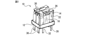
図1は、実施形態に係る電磁継電器の構成を示し、図2は図1の分解斜視図である。電磁継電器10は例えば車載電装用リレーであり、図示しないプリント基板等に実装可能なベース12と、ベース12に設けられ、巻枠14に巻回されたコイル巻線16及び巻枠14内に配置された鉄心18を有する電磁石20と、鉄心18の一端に結合された略L字形状の継鉄22と、電磁石20の作動に伴って鉄心18の他端に対して接離する方向に動作する2つの可動接点24を備えた可動端子26と、巻枠14に取り付けられるとともにコイル巻線16の両端に接続された2つのコイル端子28とを有する。
FIG. 1 shows a configuration of an electromagnetic relay according to an embodiment, and FIG. 2 is an exploded perspective view of FIG. The
電磁継電器10は、可動接点24に対向して配置された固定接点を備え、かつ巻枠14に取り付けられた固定端子を有する。本実施形態では、2つの固定常閉接点30を有する第1固定端子(ブレーク端子)32と、2つの固定常開接点34を有する第2固定端子(メーク端子)36とを有する。可動接点24は、電磁石20がOFFのときは固定常閉接点30に接触し、ONのときは固定常開接点34に接触する。可動端子26、ブレーク端子32及びメーク端子36の各々が2つの接点を有することにより、高い通電性能の電磁継電器10が得られる。
The
また電磁継電器10は、ベース12に嵌合するように構成され、ベース12と協働して上述の構成要素を収容するカバー38を有する。図1ではカバー38は省略している。
Further, the
なお本実施形態では便宜上、鉄心18の軸方向に平行な方向をz方向(高さ方向)、z方向に垂直でかつ、2つの可動接点24又は2つの固定接点30若しくは34の配列方向をy方向(幅方向)、y方向及びz方向の双方に垂直な方向をx方向(前後方向)とそれぞれ称する。
In the present embodiment, for convenience, the direction parallel to the axial direction of the
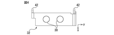
図3は、巻枠14に対する各端子の取り付け方向を示す。従来の電磁継電器では、固定端子は巻枠に対して上方からz方向に挿入して固定する場合が多いが、本実施形態では、固定端子32及び36の少なくとも一方を巻枠14に対してz方向に交差する方向(ここではx方向)に移動させて固定する。より具体的には、巻枠14は、y方向両側に形成されかつx方向、好ましくはx方向にのみ開口した第1挿入穴40を有する。第1固定端子32は図4に示すように、第1挿入穴40に対してx方向に挿入可能な凸状の第1挿入部42を有する。
FIG. 3 shows the mounting direction of each terminal with respect to the winding
同様に、巻枠14は、y方向両側に形成されかつx方向、好ましくはx方向にのみ開口した第2挿入穴44を有し、第2固定端子36は第2挿入穴44に対してx方向に挿入可能な凸状の第2挿入部46を有する。なお、巻枠14は、y方向両側に形成されかつx方向、好ましくはx方向にのみ開口した第3挿入穴48を有し、コイル端子28は第3挿入穴48に対してx方向に挿入可能な凸状の第3挿入部50を有してもよい。
Similarly, the
z方向から固定端子を挿入する方法では、端子の挿入方向と可動接点の変位方向がほぼ同一となるので、固定端子の固定が確実でないと可動接点が動作したときに固定端子が可動接点の動作方向に変位してしまい、電磁継電器の性能・特性が不都合に変化する場合がある。この現象は特に、電磁継電器の製造工程においてカバーと端子を接着する前の段階で、中間検査を実施したときなどに発生し得る。 In the method of inserting the fixed terminal from the z direction, the insertion direction of the terminal and the displacement direction of the movable contact are almost the same. Therefore, if the fixed terminal is not fixed securely, the fixed terminal operates the movable contact when the movable contact operates. It may be displaced in the direction, and the performance and characteristics of the electromagnetic relay may change inconveniently. This phenomenon can occur especially when an intermediate inspection is performed before the cover and the terminal are bonded in the manufacturing process of the electromagnetic relay.
これに対し本実施形態では、端子をx方向に挿入することで、可動接点が動作しても固定端子が動いてしまうことがなく、電磁継電器の性能・特性のばらつきを抑えられる。また、メーク端子36、ブレーク端子32及びコイル端子28を巻枠14に対して全てx方向に挿入するようにしてもよく、その場合は、巻枠14の樹脂成形に使用する金型の割り方を単純化できる。なお各挿入部は、圧入によって各挿入穴内に固定されることが好ましい。
On the other hand, in the present embodiment, by inserting the terminals in the x direction, the fixed terminals do not move even if the movable contacts operate, and variations in the performance and characteristics of the electromagnetic relay can be suppressed. Further, the make
また図4に示すように、第1挿入部42をy方向の両側に1つずつ形成し、巻枠14に2つの第1挿入部42がそれぞれ挿入される2つの第1挿入穴40を設けることもできる。これにより、第1固定端子32はより確実に巻枠14に対して固定される。
Further, as shown in FIG. 4, one
例えば第1固定端子32をx方向に移動させて巻枠14に取り付ける場合、第1固定端子32の第1挿入部42に対応する第1挿入穴40の位置によっては、巻枠14が大型化することがある。そこで図3に示すように、第1固定端子32の第1挿入部42を第1固定接点30よりもz方向の下方に設けることにより、第1挿入穴40を巻枠14の上端に形成する必要がなくなる。よって巻枠14の高さを小さくすることができ、結果として高さが低いコンパクトな電磁継電器10が提供される。このことは、第2固定端子36についても同様である。
For example, when the first
第1固定端子32に対する第1固定接点30の固定方法には種々の方法がある。例えばかしめを用いた場合、図5に示すように第1固定端子32上側のかしめた側にかしめによる突出部52が形成され得る。突出部52によって、第1固定端子32とカバー38とのクリアランスが大きくなり、結果として電磁継電器10が高さ方向に大型化する場合がある。
There are various methods for fixing the first fixed
そこで第1固定接点30を、溶接又はロウ付け等による接合によって第1固定端子32に固定してもよい。この場合、突出部52は形成されないので、第1固定端子32とカバー38とのクリアランスを小さくでき、電磁継電器10の小型化が図れる。
Therefore, the first fixed
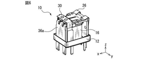
図6は、第2固定端子の他の構造例を示す。図1〜図3に示す第2固定端子36は、2つの端子部材の各々に1つの固定接点34を設けているが、図6の例では、実質1枚の金属板に2つの固定接点を設けたものを第2固定端子36aとして使用している。第2固定端子36aを1枚の板から形成することによって、2つ以上の部材で固定端子を構成する場合よりも通電容量を大きくすることができる。また、第2固定端子36aによりコイル16が存在する空間と接点が存在する空間とを分断できるので、コイル16から水蒸気が発生しても、水蒸気が接点又はその近傍に付着・進入し、結露又は氷結して接点の開閉動作に悪影響を与える可能性を低減できる。
FIG. 6 shows another structural example of the second fixed terminal. The second fixed
図7は、鉄心18の配置例を示す図であり、明確化のために可動端子及びブレーク端子は省略している。従来の電磁継電器には、鉄心が巻枠の中心に配置されず、例えば継鉄側に偏心して配置され、鉄心と固定接点との間の距離が比較的大きいものがある。このような電磁継電器では、巻線空間を有効に活用できない。そこで図7のように、鉄心18を巻枠14の中心に配置することで、電磁継電器10内部の巻線空間を最大限活用することができる。
FIG. 7 is a diagram showing an arrangement example of the
また図7の配置では、鉄心18の頭部54の形状が単純な円板状であると、頭部54が接点34等と干渉し、これを回避するために電磁継電器が大型化する虞がある。そこで図7及び図8に示すように、頭部54を、鉄心18の軸部55の径方向断面より大きい面積を有する一方で、鉄心18の中心から頭部54の周縁までの距離が少なくとも接点側において他の部分より短い、小判形、トラック形や楕円形などの形状とすることができる。これにより、図7に示すように鉄心18と接点34とをより近接させることができ、電磁継電器のx方向の寸法をより小さくすることができる。なお頭部54は、接点側の周縁までの距離のみが他より短い、例えば円形の一部を直線状に切除した形状でもよいが、組立時に鉄心18の角度位置を考慮する必要があること等から、図示例のように例えば180°の点対称形状であることが好ましい。
Further, in the arrangement of FIG. 7, if the shape of the
図9に示すように、可動端子26は、接極子56と、接極子56にかしめられた可動ばね58と、可動ばね58にかしめられた2つの可動接点24とを有する。可動端子26の製造工程として、個々の可動ばね58が切断される前の金属板を接極子56にかしめた後に金属板を自動切断機に順送して所定の切断位置60で切断し、可動端子26を形成するものがある。ここで、図9に示す例のように可動ばね58の切断位置60が接極子56に接している場合、可動ばね58を切断する治具が接極子56に干渉し、切断が困難となり得る。
As shown in FIG. 9, the
そこで図10に示すように、接極子56をその幅方向(y方向)両端が中心より凹んだ形状とし、必要に応じて切断部位60をx方向に延長することにより、可動ばね58の切断部位60に接極子56が存在しないようにすることができ、好適な切断が可能となる。
Therefore, as shown in FIG. 10, the
また、可動ばね58を接極子56にかしめる際のプレス力によって、可動ばね58に歪みが生じる場合がある。このとき、可動ばね58のかしめ位置と可動接点24のかしめ位置がx方向に整列していると、可動ばね58の歪みの影響が可動接点24のかしめ位置に及び、可動接点24の位置決め精度が悪化する場合がある。
Further, the
そこで図10に示すように、可動ばね58のかしめ部位62と可動接点24のかしめ位置とがx方向に整列しないように、例えばy方向に所定距離y1だけ互いにずらすことにより、かしめによる可動ばね58の歪みによって可動接点24が悪影響を受けないようにすることができる。
Therefore, as shown in FIG. 10, the
図11は、継鉄22の側面を、その部分拡大図とともに示す。継鉄22はプレス成形等によって形成されたかしめ用突起64を有し、突起64を可動ばね58の穴66(図9参照)に挿入してかしめることにより、可動端子26が継鉄22に固定される。ここで、かしめる際のパンチのプレス力等により、比較的薄い金属板からなる可動ばね58が変形してしまうことがある。
FIG. 11 shows the side surface of the
そこで図11のA部詳細図に示すように、突起64の根元に隣接しかつ突起64より低い段差状の隆起部68を継鉄22に設けることで、可動ばねをかしめたときのかしめ方向(x方向)の寸法変化を低減することができる。一例であるが、隆起部68は、高さが20〜50μmであり、x方向にみたときに、突起64の直径に等しい内径と、直径より大きい外径とを有するリング形状を有する。さらに、隆起部68の外形はx方向にみたときのパンチの外形より大きいことが好ましい。
Therefore, as shown in the detailed view of part A in FIG. 11, by providing the
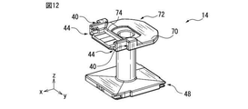
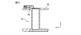
図12及び図13はそれぞれ、巻枠14の斜視図及び側断面図である。電磁継電器の小型化を図る手段として巻枠14の薄肉化が挙げられるが、薄肉の巻枠14にコイル巻線を巻いたときの圧力によって巻枠14の端部に形成されたフランジ70が反り、接極子56等に干渉する虞がある。そこで、フランジ70と接極子56との干渉を防止するため、図13に示すようにフランジ70を先細のテーパ形状とする。
12 and 13 are a perspective view and a side sectional view of the winding
さらに、フランジ70の反りの影響はその外周部に近付くほど大きくなるので、例えば図12に示すように、フランジ70の外周部の少なくとも一部を面取り形状又は丸みを持った形状72とすることにより、フランジ70が反っても他部材と干渉する可能性を大きく低減することができる。
Further, since the influence of the warp of the
電磁継電器では、可動接点と固定接点との接離を繰り返すと、接点が摩耗し金属粉や金属くずが発生する。ここで電磁継電器の搭載方向や、振動などの外的要因により、電磁継電器内部を金属粉等が移動して、接極子と鉄心又は継鉄との間に進入し、動作不良を起こすことがある。 In an electromagnetic relay, when a movable contact and a fixed contact are repeatedly connected and separated, the contacts are worn and metal powder and metal scraps are generated. Here, due to external factors such as the mounting direction of the electromagnetic relay and vibration, metal powder or the like may move inside the electromagnetic relay and enter between the polaron and the iron core or the relay, causing malfunction. ..
そこで図12又は図13に示すように、固定接点又は可動接点から発生した金属くずが鉄心方向へ移動しないように、固定接点及び可動接点が配置される領域と鉄心が配置される領域との間に、両領域を分断する壁74を設けることができる。図示例では、壁74は所定高さを有し、y方向に所定の幅を有する直線状の壁として巻枠14の上端面に形成され、例えば巻枠14を樹脂成形する際のモールド壁として形成することができる。壁74により、金属くずの進入を効率的に防止でき、電磁継電器の動作不良の確率を大きく低減することができる。
Therefore, as shown in FIG. 12 or 13, between the region where the fixed contact and the movable contact are arranged and the region where the iron core is arranged so that the metal scraps generated from the fixed contact or the movable contact do not move toward the iron core. A
図14及び図15は、ベース12の構造例を示す。ベース12と各端子、さらにベース12とカバー38は、例えば熱硬化性樹脂によって互いに接着される。これらの部材間の接着強度を満足するためには、接着層76が所定の深さを有することが望まれる。また、電磁継電器が実装される基板(図示せず)からの遮熱のため、ベース12の下面は基板に接触しないことが望まれる。さらに、電磁継電器内部の構造物間の不要な干渉を回避することが望まれる。これらの要求を満足した上で、ベース12自体が一定以上の強度を有することが望ましい。
14 and 15 show a structural example of the
そこで図14に示すように、ベース12の内側下面領域を、端子が挿入・接着される端子挿入穴78を含む端子用の領域80と、巻枠14及び継鉄22等が配置される構造物用の領域82と、領域80と領域82との間の中間領域84とに区分し、それぞれの領域間に段差部86、88を設けて、各領域の深さが異なるようにすることができる。領域80を中間領域84よりも浅くすることによって、領域80の下方の接着層76の厚さを大きくして接着力を高めることができる。また接着剤を使用しない領域82を中間領域84よりも深くすることによって、巻枠等の構造物の配置空間をより大きく確保することができる。ベース自体の強度に関し、ベース各部で薄い箇所ができないようテーパを設けたり、リブを設けたりすることによって剛性を高めている。
Therefore, as shown in FIG. 14, the inner lower surface region of the
10 電磁継電器、12 ベース、14 巻枠、16 コイル、
18 鉄心、20 電磁石、22 継鉄、24 可動接点、
26 可動端子、28 コイル端子、30 第1固定接点、32 第1固定端子、
34 第2固定接点、36,36a 第2固定端子、38 カバー、
40 第1挿入穴、42 第1挿入部、44 第2挿入穴、46、第2挿入部、
48 第3挿入穴、50 第3挿入部、52 突出部、54 頭部、
56 接極子、58 可動ばね、60 切断部位、62 かしめ部位、
64 かしめ用突起、66 穴、68 隆起部、70 フランジ、
72 丸み部、74 壁、76 接着層、78 端子挿入穴、80 端子用領域、
82 構造物用領域、84 中間領域、86,88 段差部
10 electromagnetic relay, 12 base, 14 winding frame, 16 coil,
18 iron core, 20 electromagnet, 22 joint iron, 24 movable contact,
26 movable terminal, 28 coil terminal, 30 first fixed contact, 32 first fixed terminal,
34 2nd fixed contact, 36, 36a 2nd fixed terminal, 38 cover,
40 1st insertion hole, 42 1st insertion part, 44 2nd insertion hole, 46, 2nd insertion part,
48 3rd insertion hole, 50 3rd insertion part, 52 protrusion, 54 head,
56 polaron, 58 movable spring, 60 cutting site, 62 caulking site,
64 caulking protrusions, 66 holes, 68 ridges, 70 flanges,
72 Rounded part, 74 wall, 76 adhesive layer, 78 terminal insertion hole, 80 terminal area,
82 Structural area, 84 Intermediate area, 86,88 Steps
Claims (7)
前記電磁石の作動に伴って動作する接極子、前記接極子に取り付けられた可動ばね、及び前記可動ばねに取り付けられた可動接点を備える可動端子と、
前記可動接点に対向して配置された固定接点と、
前記可動ばねがかしめられる継鉄と、を備え、
前記継鉄は、前記可動ばねに挿入されるかしめ用の突起と、前記突起に隣接しかつ前記突起より高さが低い段差状の隆起部とを有する、電磁継電器。 A coil wound around a winding frame, an electromagnet having an iron core arranged in the winding frame, and an electromagnet.
A polaron that operates with the operation of the electromagnet, a movable spring attached to the polaron, and a movable terminal having a movable contact attached to the movable spring.
Fixed contacts arranged facing the movable contacts and
With a joint iron to which the movable spring is crimped,
The relay iron is an electromagnetic relay having a protrusion for caulking inserted into the movable spring and a stepped ridge portion adjacent to the protrusion and having a height lower than the protrusion.
前記電磁石の作動に伴って動作する可動接点と、
前記可動接点に対向して配置された固定接点と、を備え、
前記巻枠の軸方向端部に形成されたフランジが先細のテーパ形状を有するとともに、前記フランジの外周部の少なくとも一部が面取り形状又は丸み形状を有する、電磁継電器。 A coil wound around a winding frame, an electromagnet having an iron core arranged in the winding frame, and an electromagnet.
Movable contacts that operate with the operation of the electromagnet,
A fixed contact arranged to face the movable contact is provided.
An electromagnetic relay in which a flange formed at the axial end of the winding frame has a tapered tapered shape, and at least a part of the outer peripheral portion of the flange has a chamfered shape or a rounded shape.
前記電磁石の作動に伴って動作する可動接点と、
前記可動接点に対向して配置された固定接点と、を備え、
前記巻枠は、前記固定接点及び前記可動接点が配置される領域と前記鉄心が配置される領域との間に、両領域を分断する壁を有する、電磁継電器。 A coil wound around a winding frame, an electromagnet having an iron core arranged in the winding frame, and an electromagnet.
Movable contacts that operate with the operation of the electromagnet,
A fixed contact arranged to face the movable contact is provided.
The winding frame is an electromagnetic relay having a wall that separates both regions between a region in which the fixed contact and the movable contact are arranged and a region in which the iron core is arranged.
前記電磁石の作動に伴って動作する可動接点を有する可動端子と、
前記可動接点に対向して配置された固定接点を有する固定端子と、
前記巻枠、前記可動端子及び前記固定端子を内部に有するベースと、を備え、
前記ベースは、前記可動端子及び前記固定端子が挿入される端子挿入穴を含む端子用領域と、前記巻枠が配置される構造物用領域と、前記端子用領域と前記構造物用領域との間の中間領域とを有し、前記鉄心の軸方向の深さが、前記端子用領域は前記中間領域より浅く、前記構造物用領域は前記中間領域より深い、電磁継電器。 A coil wound around a winding frame, an electromagnet having an iron core arranged in the winding frame, and an electromagnet.
A movable terminal having a movable contact that operates with the operation of the electromagnet,
A fixed terminal having a fixed contact arranged so as to face the movable contact,
The winding frame, the movable terminal, and the base having the fixed terminal inside are provided.
The base includes a terminal area including the movable terminal and a terminal insertion hole into which the fixed terminal is inserted, a structure area in which the winding frame is arranged, a terminal area, and a structure area. An electromagnetic relay having an intermediate region between the iron cores, the terminal region being shallower than the intermediate region, and the structure region deeper than the intermediate region.
前記電磁石の作動に伴って動作する接極子、前記接極子に取り付けられる可動ばね、及び前記可動ばねに取り付けられる可動接点を備える可動端子と、
前記可動接点に対向して配置された固定接点と、を備え、
前記接極子は、前記鉄心の軸方向に垂直な幅方向についての両端が中心より凹んだ形状を有し、前記可動ばねを形成する際の切断部位における厚さ方向には前記接極子が存在しない、電磁継電器。 A coil wound around a winding frame, an electromagnet having an iron core arranged in the winding frame, and an electromagnet.
A polaron that operates with the operation of the electromagnet, a movable spring attached to the polaron, and a movable terminal having a movable contact attached to the movable spring.
A fixed contact arranged to face the movable contact is provided.
The quadrupole has a shape in which both ends are recessed from the center in the width direction perpendicular to the axial direction of the iron core, and the quadrupole does not exist in the thickness direction at the cutting portion when forming the movable spring. , Electromagnetic relay.
前記電磁石の作動に伴って、前記鉄心に対して接離する方向に動作する接極子と、
前記接極子に取り付けられ、可動ばねを有する可動端子と、
前記可動端子に取り付けられる可動接点と、
前記可動接点に対向して配置された固定接点と、を備え、
前記接極子に対する前記可動ばねのかしめ位置は、前記可動ばねに対する前記可動接点のかしめ位置に対して、前記鉄心の軸方向に垂直な幅方向について外側にずれている、電磁継電器。 A coil wound around a winding frame, an electromagnet having an iron core arranged in the winding frame, and an electromagnet.
With the operation of the electromagnet, the polaron that moves in the direction of contact and separation with respect to the iron core,
A movable terminal attached to the polaron and having a movable spring,
Movable contacts attached to the movable terminals
A fixed contact arranged to face the movable contact is provided.
An electromagnetic relay in which the caulking position of the movable spring with respect to the polaron is displaced outward in the width direction perpendicular to the axial direction of the iron core with respect to the caulking position of the movable contact with respect to the movable spring.
前記電磁石の作動に伴って動作する可動接点と、
前記可動接点に対向して配置された固定接点を有し、前記巻枠に取り付けられた固定端子と、を備え、
前記巻枠は、前記鉄心の軸方向に交差する方向に開口した挿入穴を複数有し、前記固定端子は、固定常閉接点を有する第1固定端子と、固定常開接点を有する第2固定端子と、前記コイルに電気的に接続されたコイル端子とを有し、前記第1固定端子、前記第2固定端子及び前記コイル端子の各々は、前記複数の挿入穴の各々に挿入される挿入部を有する、電磁継電器。 A coil wound around a winding frame, an electromagnet having an iron core arranged in the winding frame, and an electromagnet.
Movable contacts that operate with the operation of the electromagnet,
It has a fixed contact arranged so as to face the movable contact, and includes a fixed terminal attached to the winding frame.
The winding frame has a plurality of insertion holes opened in a direction intersecting the axial direction of the iron core, and the fixed terminal has a first fixed terminal having a fixed normally closed contact and a second fixed terminal having a fixed normally open contact. It has a terminal and a coil terminal electrically connected to the coil, and each of the first fixed terminal, the second fixed terminal, and the coil terminal is inserted into each of the plurality of insertion holes. An electromagnetic relay having a part.
Priority Applications (8)
| Application Number | Priority Date | Filing Date | Title |
|---|---|---|---|
| JP2019229125A JP7361593B2 (en) | 2019-12-19 | 2019-12-19 | electromagnetic relay |
| US17/125,604 US20210193420A1 (en) | 2019-12-19 | 2020-12-17 | Relay |
| US17/125,575 US20210193419A1 (en) | 2019-12-19 | 2020-12-17 | Relay |
| US17/125,623 US11521816B2 (en) | 2019-12-19 | 2020-12-17 | Relay with a yoke having protrusion for caulking and bulge portion adjacent to protrusion |
| CN202011505282.2A CN113012987A (en) | 2019-12-19 | 2020-12-18 | Electromagnetic relay |
| US18/049,939 US20230068018A1 (en) | 2019-12-19 | 2022-10-26 | Relay having base with multiple regions in which a winding frame, movable terminal, and fixed terminal are arranged |
| JP2023134221A JP2023144142A (en) | 2019-12-19 | 2023-08-21 | electromagnetic relay |
| US18/466,240 US20230420205A1 (en) | 2019-12-19 | 2023-09-13 | Relay |
Applications Claiming Priority (1)
| Application Number | Priority Date | Filing Date | Title |
|---|---|---|---|
| JP2019229125A JP7361593B2 (en) | 2019-12-19 | 2019-12-19 | electromagnetic relay |
Related Child Applications (1)
| Application Number | Title | Priority Date | Filing Date |
|---|---|---|---|
| JP2023134221A Division JP2023144142A (en) | 2019-12-19 | 2023-08-21 | electromagnetic relay |
Publications (2)
| Publication Number | Publication Date |
|---|---|
| JP2021097005A true JP2021097005A (en) | 2021-06-24 |
| JP7361593B2 JP7361593B2 (en) | 2023-10-16 |
Family
ID=76383658
Family Applications (2)
| Application Number | Title | Priority Date | Filing Date |
|---|---|---|---|
| JP2019229125A Active JP7361593B2 (en) | 2019-12-19 | 2019-12-19 | electromagnetic relay |
| JP2023134221A Pending JP2023144142A (en) | 2019-12-19 | 2023-08-21 | electromagnetic relay |
Family Applications After (1)
| Application Number | Title | Priority Date | Filing Date |
|---|---|---|---|
| JP2023134221A Pending JP2023144142A (en) | 2019-12-19 | 2023-08-21 | electromagnetic relay |
Country Status (3)
| Country | Link |
|---|---|
| US (5) | US11521816B2 (en) |
| JP (2) | JP7361593B2 (en) |
| CN (1) | CN113012987A (en) |
Families Citing this family (1)
| Publication number | Priority date | Publication date | Assignee | Title |
|---|---|---|---|---|
| JP7361593B2 (en) | 2019-12-19 | 2023-10-16 | 富士通コンポーネント株式会社 | electromagnetic relay |
Family Cites Families (27)
| Publication number | Priority date | Publication date | Assignee | Title |
|---|---|---|---|---|
| DE8506345U1 (en) | 1985-03-05 | 1986-07-03 | Siemens AG, 1000 Berlin und 8000 München | Contact arrangement in a relay for high switching capacity |
| JPS63135744U (en) * | 1987-02-27 | 1988-09-06 | ||
| US5274348A (en) * | 1992-02-19 | 1993-12-28 | Potter & Brumfield, Inc. | Electromagnetic relay |
| JPH09213189A (en) | 1996-01-29 | 1997-08-15 | Niles Parts Co Ltd | Structure for electromagnetic relay |
| JP3590738B2 (en) * | 1999-04-27 | 2004-11-17 | Necトーキン株式会社 | Electromagnetic relay, adjustment method and assembly method thereof |
| JP2000315448A (en) | 1999-05-06 | 2000-11-14 | Omron Corp | Electromagnetic relay |
| JP2002100274A (en) | 2000-09-26 | 2002-04-05 | Omron Corp | Electromagnetic relay |
| US6794966B2 (en) | 2002-07-01 | 2004-09-21 | Tyco Electronics Corporation | Low noise relay |
| JP2004172036A (en) * | 2002-11-22 | 2004-06-17 | Omron Corp | Electromagnetic relay |
| KR20050078988A (en) | 2004-02-03 | 2005-08-08 | 타이코 일렉트로닉스 에이엠피 게엠베하 | Electromagnetic relay having at least one relay auctuator and a receptacle for relay actuators |
| JP4476072B2 (en) | 2004-08-20 | 2010-06-09 | 富士通コンポーネント株式会社 | Electromagnetic relay |
| JP5004244B2 (en) | 2008-05-30 | 2012-08-22 | Necトーキン株式会社 | Electromagnetic relay |
| JP5506319B2 (en) | 2009-10-05 | 2014-05-28 | 富士通コンポーネント株式会社 | Electromagnetic relay |
| JP2012142208A (en) | 2011-01-04 | 2012-07-26 | Fujitsu Component Ltd | Electromagnetic relay device |
| JP2012142210A (en) | 2011-01-04 | 2012-07-26 | Fujitsu Component Ltd | Electromagnetic relay |
| JP2013196763A (en) | 2012-03-15 | 2013-09-30 | Omron Corp | Electromagnetic relay |
| JP6037730B2 (en) | 2012-08-31 | 2016-12-07 | 富士通コンポーネント株式会社 | Electromagnetic relay |
| JP6115195B2 (en) | 2013-03-08 | 2017-04-19 | オムロン株式会社 | Electromagnetic relay |
| JP2017187047A (en) | 2013-11-22 | 2017-10-12 | ポップリベット・ファスナー株式会社 | Caulking collar and caulking nut |
| JP6299214B2 (en) | 2013-12-27 | 2018-03-28 | オムロン株式会社 | Electromagnetic relay |
| JP6403476B2 (en) * | 2014-07-28 | 2018-10-10 | 富士通コンポーネント株式会社 | Electromagnetic relay |
| JP6428425B2 (en) | 2015-03-20 | 2018-11-28 | オムロン株式会社 | Contact mechanism and electromagnetic relay having the same |
| JP6981732B2 (en) | 2015-09-28 | 2021-12-17 | 富士通コンポーネント株式会社 | Electromagnetic relay |
| US10403460B2 (en) | 2016-12-14 | 2019-09-03 | Panasonic Intellectual Property Management Co., Ltd. | Electromagnetic relay |
| JP2019096460A (en) | 2017-11-22 | 2019-06-20 | 富士通コンポーネント株式会社 | Electromagnetic relay |
| JP2019121490A (en) | 2017-12-28 | 2019-07-22 | パナソニックIpマネジメント株式会社 | Magnetic relay |
| JP7361593B2 (en) | 2019-12-19 | 2023-10-16 | 富士通コンポーネント株式会社 | electromagnetic relay |
-
2019
- 2019-12-19 JP JP2019229125A patent/JP7361593B2/en active Active
-
2020
- 2020-12-17 US US17/125,623 patent/US11521816B2/en active Active
- 2020-12-17 US US17/125,575 patent/US20210193419A1/en not_active Abandoned
- 2020-12-17 US US17/125,604 patent/US20210193420A1/en not_active Abandoned
- 2020-12-18 CN CN202011505282.2A patent/CN113012987A/en active Pending
-
2022
- 2022-10-26 US US18/049,939 patent/US20230068018A1/en active Pending
-
2023
- 2023-08-21 JP JP2023134221A patent/JP2023144142A/en active Pending
- 2023-09-13 US US18/466,240 patent/US20230420205A1/en active Pending
Also Published As
| Publication number | Publication date |
|---|---|
| US20230420205A1 (en) | 2023-12-28 |
| CN113012987A (en) | 2021-06-22 |
| US20210193418A1 (en) | 2021-06-24 |
| US20230068018A1 (en) | 2023-03-02 |
| US20210193420A1 (en) | 2021-06-24 |
| US11521816B2 (en) | 2022-12-06 |
| JP7361593B2 (en) | 2023-10-16 |
| US20210193419A1 (en) | 2021-06-24 |
| JP2023144142A (en) | 2023-10-06 |
Similar Documents
| Publication | Publication Date | Title |
|---|---|---|
| CN101620950B (en) | Contact device | |
| US7750769B2 (en) | Electromagnetic relay | |
| EP3118880B1 (en) | Sealed contact device and manufacturing method therefor | |
| WO2015136909A1 (en) | Coil component and method for producing same | |
| JP5004243B2 (en) | Electromagnetic relay | |
| JP2023144142A (en) | electromagnetic relay | |
| JP5880233B2 (en) | Electromagnetic relay | |
| JP4840386B2 (en) | Contact device | |
| JP5948559B2 (en) | Surface mount electronic components | |
| WO2016166925A1 (en) | Electronic component and electronic equipment using same | |
| JPH05219668A (en) | Permanent magnet type rotor | |
| JP6748886B2 (en) | Electromagnetic relay | |
| JP6115198B2 (en) | Electromagnetic relay and manufacturing method thereof | |
| JP2016127189A (en) | Coil component and manufacturing method for the same | |
| JP2005102424A (en) | Split laminated core and manufacturing method for divided laminated core | |
| JP6047908B2 (en) | Electromagnet device | |
| JP6019683B2 (en) | Seal structure of electronic equipment | |
| JP6631947B2 (en) | Electromagnetic relay | |
| JP5140885B2 (en) | Manufacturing method of laminated iron core | |
| JP2015201537A (en) | Coil component and manufacturing method for the same | |
| JP2001121227A (en) | Laminated binding part | |
| JP7380028B2 (en) | relay | |
| JP2014175256A (en) | Contact terminal and contact switchgear using the same | |
| JP2016207793A (en) | Electronic component | |
| WO2013154111A1 (en) | Electronic apparatus seal structure |
Legal Events
| Date | Code | Title | Description |
|---|---|---|---|
| A621 | Written request for application examination |
Free format text: JAPANESE INTERMEDIATE CODE: A621 Effective date: 20221102 |
|
| A977 | Report on retrieval |
Free format text: JAPANESE INTERMEDIATE CODE: A971007 Effective date: 20230615 |
|
| A131 | Notification of reasons for refusal |
Free format text: JAPANESE INTERMEDIATE CODE: A131 Effective date: 20230620 |
|
| A521 | Request for written amendment filed |
Free format text: JAPANESE INTERMEDIATE CODE: A523 Effective date: 20230821 |
|
| TRDD | Decision of grant or rejection written | ||
| A01 | Written decision to grant a patent or to grant a registration (utility model) |
Free format text: JAPANESE INTERMEDIATE CODE: A01 Effective date: 20230905 |
|
| A61 | First payment of annual fees (during grant procedure) |
Free format text: JAPANESE INTERMEDIATE CODE: A61 Effective date: 20231003 |
|
| R150 | Certificate of patent or registration of utility model |
Ref document number: 7361593 Country of ref document: JP Free format text: JAPANESE INTERMEDIATE CODE: R150 |