JP2021069863A - Absorbent article - Google Patents
Absorbent article Download PDFInfo
- Publication number
- JP2021069863A JP2021069863A JP2019200003A JP2019200003A JP2021069863A JP 2021069863 A JP2021069863 A JP 2021069863A JP 2019200003 A JP2019200003 A JP 2019200003A JP 2019200003 A JP2019200003 A JP 2019200003A JP 2021069863 A JP2021069863 A JP 2021069863A
- Authority
- JP
- Japan
- Prior art keywords
- absorbent article
- leak
- straight line
- standing
- virtual straight
- Prior art date
- Legal status (The legal status is an assumption and is not a legal conclusion. Google has not performed a legal analysis and makes no representation as to the accuracy of the status listed.)
- Pending
Links
Images


Abstract
Description
本発明は、着用者の肌側に向かって起立する防漏カフを備えた吸収性物品に関する。 The present invention relates to an absorbent article with a leak-proof cuff that stands up toward the wearer's skin.
使い捨ておむつなどの吸収性物品において、防漏カフ、立体ギャザー、立体ガードなどとも呼ばれる横漏れ防止部材を具備するものが知られている。この横漏れ防止部材は、典型的には、吸収性物品の本体の縦方向(着用者の前後方向に対応する方向)に沿う両側部に一対配され、横漏れ防止部材形成用シートと、該シートに伸縮可能な状態で固定された弾性部材とを具備し、該吸収性物品の着用時に着用者の肌側に起立し、便などの排泄物を堰き止めて横漏れを防止する。 Absorbent articles such as disposable diapers are known to be provided with a lateral leakage prevention member, which is also called a leakage prevention cuff, a three-dimensional gather, or a three-dimensional guard. The lateral leakage prevention member is typically arranged on both sides along the vertical direction (direction corresponding to the front-rear direction of the wearer) of the main body of the absorbent article, and the lateral leakage prevention member forming sheet and the sheet. It is provided with an elastic member fixed to the seat in a stretchable state, stands up on the wearer's skin side when the absorbent article is worn, and blocks excrement such as stool to prevent lateral leakage.
特許文献1及び2には、横漏れ防止部材として、横漏れ防止部材形成用シートが他の部材に固定された基端部と、該基端部を起点として該シートが着用者側に起立する起立部とを有し、該起立部が、縦方向に延びる折り曲げ部にて折り曲げられ、該基端部から該折り曲げ部に向かって横方向(縦方向と直交する方向)内側へ延びる内側延出部と、該折り曲げ部から横方向外側へ延び、該内側延出部よりも着用者の肌に近い側に位置する外側延出部とを有するものが記載されている。
In
特許文献3には、吸収性物品に配置して使用する吸収性補助パッドにおいて、該パッドの横方向の一方の側端部にのみ、撥水性又は液不透過性を有する二重のシートから構成される立体ギャザーを設け、該立体ギャザーの表面シートからの高さを、該パッドの横方向の寸法に対して、20%以上とすることが記載されている。特許文献3記載の吸収性補助パッドによれば、軟便等の漏れを適切に防止することができ、且つ低コスト化を図ることができるとされている。
防漏カフを備えた従来の吸収性物品は、防漏カフの漏れ防止性能の点で改善の余地があった。したがって本発明の課題は、防漏カフの漏れ防止性能に優れ、横漏れを効果的に防止し得る吸収性物品を提供することに関する。 Conventional absorbent articles equipped with a leak-proof cuff have room for improvement in terms of the leak-proof performance of the leak-proof cuff. Therefore, an object of the present invention is to provide an absorbent article which is excellent in the leakage prevention performance of the leakage prevention cuff and can effectively prevent lateral leakage.
本発明は、着用者の前後方向に対応する縦方向と該縦方向に直交する横方向とを有し、吸収体を具備する吸収性本体と、該吸収性本体の肌対向面に該縦方向に延び、該横方向に離間部を設けて配置された一対の防漏カフとを具備する吸収性物品であって、一対の前記防漏カフは、それぞれ、防漏カフ形成用シートを含んで構成され、且つ該防漏カフ形成用シートが他の部材に固定された基端部と、該基端部を起点として該防漏カフ形成用シートが着用者側に起立する起立部とを有し、前記起立部の前記防漏カフ形成用シートは、前記縦方向に延びる折り曲げ部にて折り曲げられており、該起立部は、前記基端部から該折り曲げ部にわたる第1起立部と、該折り曲げ部から該起立部の自由端にわたり、該第1起立部よりも着用者の肌に近い側に位置する第2起立部とを含んで構成され、前記吸収性物品の展開且つ伸長状態において、該吸収性物品を前記横方向に横断する1本の仮想直線を引いた場合に、該仮想直線における前記第2起立部と重複する部分の長さの合計が、該仮想直線における前記離間部と重複する部分の長さの20%以上50%以下である特定部分を有する、吸収性物品である。 The present invention has an absorbent body having a vertical direction corresponding to the front-back direction of the wearer and a horizontal direction orthogonal to the vertical direction, and the absorbent body having an absorber, and the vertical direction on the skin-facing surface of the absorbent body. An absorbent article comprising a pair of leak-proof cuffs extending in the lateral direction and arranged with a separation portion in the lateral direction, each of the pair of leak-proof cuffs including a leak-proof cuff forming sheet. It has a base end portion that is configured and the leak-proof cuff forming sheet is fixed to another member, and an upright portion in which the leak-proof cuff forming sheet stands up on the wearer side with the base end portion as a starting point. The leak-proof cuff forming sheet of the upright portion is bent at the bent portion extending in the vertical direction, and the upright portion includes a first upright portion extending from the base end portion to the bent portion and the bent portion. It is configured to extend from the bent portion to the free end of the upright portion and include a second upright portion located closer to the wearer's skin than the first upright portion, and in the unfolded and stretched state of the absorbent article. When one virtual straight line crossing the absorbent article in the lateral direction is drawn, the total length of the portions overlapping the second standing portion in the virtual straight line is the distance from the separated portion in the virtual straight line. An absorbent article having a specific portion that is 20% or more and 50% or less of the length of the overlapping portion.
本発明によれば、防漏カフの漏れ防止性能に優れ、横漏れを効果的に防止し得る吸収性物品が提供される。 According to the present invention, there is provided an absorbent article which is excellent in the leakage prevention performance of the leakage prevention cuff and can effectively prevent lateral leakage.
以下本発明を、その好ましい実施形態に基づき図面を参照しながら説明する。なお、以下の図面の記載において、同一又は類似の部分には、同一又は類似の符号を付している。図面は基本的に模式的なものであり、各寸法の比率などは現実のものとは異なる場合がある。 Hereinafter, the present invention will be described based on the preferred embodiment with reference to the drawings. In the description of the drawings below, the same or similar parts are designated by the same or similar reference numerals. The drawings are basically schematic, and the ratio of each dimension may differ from the actual one.
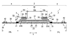
図1及び図2には、本発明の吸収性物品の一実施形態である使い捨ておむつ1が示されている。おむつ1は、着用者の前後方向、すなわち腹側から股間部を介して背側に延びる方向に対応する縦方向Xと、これに直交する横方向Yとを有し、吸収体23を具備する吸収性本体2と、縦方向Xに延び、該吸収性本体2の肌対向面に離間部39を設けて配置された一対の防漏カフ3,3とを具備する。
1 and 2 show a
本明細書において、「肌対向面」は、吸収性物品又はその構成部材(例えば吸収性本体)における、吸収性物品の着用時に着用者の肌側に向けられる面、すなわち相対的に着用者の肌から近い側であり、「非肌対向面」は、吸収性物品又はその構成部材における、吸収性物品の着用時に肌側とは反対側に向けられる面、すなわち相対的に着用者の肌から遠い側である。なお、ここでいう「着用時」は、通常の適正な着用位置、すなわち当該吸収性物品の正しい着用位置が維持された状態を意味する。 In the present specification, the "skin facing surface" is a surface of the absorbent article or its constituent members (for example, an absorbent body) that is directed toward the skin side of the wearer when the absorbent article is worn, that is, relatively of the wearer. The side closer to the skin, the "non-skin facing surface" is the surface of the absorbent article or its constituents that faces the opposite side of the skin when the absorbent article is worn, that is, relatively from the wearer's skin. The distant side. The term "when worn" as used herein means a state in which the normal proper wearing position, that is, the correct wearing position of the absorbent article is maintained.
本実施形態のおむつ1(吸収性本体2)は、図1に示すように、着用時に着用者の股間部に配される股下部Mと、該股下部Mより縦方向Xの前方すなわち着用者の腹側に配される腹側部Fと、該股下部Mより縦方向Xの後方すなわち着用者の背側に配される背側部Rとを有する。股下部Mは、着用時に着用者の陰茎等の排泄部に対向配置される排泄部対向部(不図示)を含む。 As shown in FIG. 1, the diaper 1 (absorbent body 2) of the present embodiment has a crotch portion M arranged in the crotch portion of the wearer at the time of wearing and a front portion of the crotch portion M in the vertical direction X, that is, the wearer. It has a ventral portion F arranged on the ventral side of the diaper and a dorsal portion R arranged on the back side of the inseam M in the longitudinal direction X, that is, on the dorsal side of the wearer. The inseam M includes an excretion portion facing portion (not shown) that is arranged to face the excretion portion such as the wearer's penis when worn.
吸収性本体2は、吸収体23と、該吸収体23の肌対向面側に配された表面シート21と、該吸収体23の非肌対向面側に配された裏面シート22とを具備し、これらが接着剤等の公知の接合手段により一体化されて構成されている。吸収体23は、表面シート21と裏面シート22との間に介在配置されており、吸水性材料を含む液保持性の吸収性コア24と、該吸収性コア24の外面(肌対向面及び非肌対向面)を被覆するコアラップシート25とを含んで構成されている。本実施形態の吸収性本体2は平面視長方形形状を有し、腹側部Fから背側部Rにわたって縦方向Xに延在し、その長手方向が縦方向Xに一致している。
The
表面シート21、裏面シート22及び吸収体23としては、それぞれ、この種の吸収性物品に従来用いられている各種のものを特に制限なく用いることができる。表面シート21としては、例えば、液透過性を有する単層若しくは多層構造の不織布又は開孔フィルムを用いることができる。裏面シート22としては、防漏性を有するシート、すなわち、液不透過性(液を全く通さない性質)又は液難透過性(液不透過性とまでは言えないものの、液を通し難い性質)を有するシートを用いることができ、例えば、透湿性の樹脂フィルム、樹脂フィルムと不織布との積層体を用いることができる。吸収体23を構成する吸収性コア24としては、例えば、木材パルプや吸水性ポリマー等の吸水性材料を積繊してなる積繊体、該吸水性材料を含有するシート状の吸収構造体を用いることができる。吸収体23を構成するコアラップシート25としては、液透過性を有するシートを用いることができ、例えば、紙、不織布を用いることができる。
As the
本実施形態のおむつ1は、吸収体23の縦方向Xに沿う両側縁23S,23Sから横方向Yの外方に延出する部材を含んで構成される一対のサイドフラップ部4,4を具備する。本実施形態では図2に示すように、表面シート21は吸収体23の肌対向面の全域を被覆し、裏面シート22は吸収体23の非肌対向面の全域を被覆し、両シート21,22は更に、吸収体23の両側縁23S,23Sから横方向Yの外方に延出し、後述する防漏カフ形成用シート30とともにサイドフラップ部4を構成している。このように、本実施形態のサイドフラップ部4は、吸収体23の非配置部に位置し、表面シート21、裏面シート22及び防漏カフ形成用シート30を含んで構成されている。サイドフラップ部4を構成するこれら複数の部材は、接着剤、ヒートシール、超音波シール等の公知の接合手段によって互いに接合されている。
The
一対のサイドフラップ部4,4の着用者の脚周りに対応する部位のそれぞれにはレッグカフ41が形成されている。レッグカフ41は、サイドフラップ部4の一部であり、少なくとも防漏カフ形成用シート30と、該シート30に伸縮可能な状態で固定されたレッグカフ形成用弾性部材42とを含んで構成され、本実施形態では更に図2に示すように、裏面シート22を含んで構成されている。本実施形態では一対のレッグカフ41,41(サイドフラップ部4,4)それぞれに、縦方向Xに延びる複数(具体的には2本)の糸状のレッグカフ形成用弾性部材42が、横方向Yに並べて配置され、各該弾性部材42は、少なくとも股下部Mの縦方向Xの全長にわたって縦方向Xに伸縮可能な状態で延在している。斯かる構成によりおむつ1の着用時には、レッグカフ形成用弾性部材42の収縮力によってレッグカフ41(サイドフラップ部4)が収縮し、着用者の脚周りにフィットし得る。
A
腹側部F及び背側部Rそれぞれの縦方向Xの端部すなわちウエスト端部には、横方向Yに伸縮可能な状態で配された胴周りギャザー形成用弾性部材11が、横方向Yの一方側のサイドフラップ部4から他方側のサイドフラップ部4にわたって横方向Yに延在している。斯かる構成によりおむつ1の着用時には、胴周りギャザー形成用弾性部材11の収縮力によって前記ウエスト端部が収縮し、着用者の腰周りにフィットし得る。
At the ends of the ventral side F and the dorsal side R in the longitudinal direction X, that is, the waist ends,
おむつ1は、いわゆる展開型使い捨ておむつであり、着用時に使用される止着構造5を具備する。止着構造5は、図1に示すように、おむつ1の背側部Rの縦方向Xに沿う両側縁部に配置された一対のファスニングテープ51,51と、おむつ1の腹側部Fの非肌対向面(裏面シート22の非肌対向面)に配置されたターゲット領域53とを含んで構成されている。ファスニングテープ51には止着部52が設けられており、おむつ1を着用する際には、止着部52をターゲット領域53に止着する。ターゲット領域53は、止着部52が着脱自在に止着可能になされている。典型的には、止着部52は機械的面ファスナーのオス部材からなり、ターゲット領域53は機械的面ファスナーのメス部材からなる。
The
おむつ1の主たる特徴部分である防漏カフ3について詳細に説明する。図1及び図2に示すように、一対の防漏カフ3,3は、それぞれ、防漏カフ形成用シート30を含んで構成され、且つ該シート30が他の部材に固定された基端部31と、該基端部31を起点として該シート30が着用者側に起立する起立部32とを横方向Yに有する。
The leak-
防漏カフ形成用シート30は、図1及び図2に示すように、吸収性本体2の肌対向面における縦方向Xに沿う両側部に一対配置されており、その一対の防漏カフ形成用シート30,30どうしの間には離間部39が設けられている。離間部39は、吸収性本体2(おむつ1)の横方向Yの中央部に位置する。各防漏カフ形成用シート30は、吸収体23の側縁23Sを横方向Yに跨ぐように配され、平面視において吸収体23と重複する部分と、吸収体23よりも横方向Yの外方に位置する部分とを横方向Yに有する。
As shown in FIGS. 1 and 2, a pair of leak-proof
防漏カフ形成用シート30としては、尿等の体液の外部への漏れ出しを防止するという役割を確実に果たす観点から、疎水性のシート材料が用いられる。疎水性のシート材料としては、例えば、疎水性の不織布として、エアスルー不織布、スパンボンド不織布、SMS不織布、SMMS不織布、SSMS不織布等を用いることができ、その他にも、疎水性の樹脂フィルム、該樹脂フィルムと該不織布との積層体等を用いることができる。ここでいう「S」はスパンボンド不織布、「M」はメルトブローン不織布を意味する。
As the leak-proof
基端部31は、おむつ1の着用時に起立部32が着用者の肌側に向かって起立する際の起立起点となる部分である。より具体的には、基端部31は、防漏カフ形成用シート30の「他の部材」との固定部における、起立部32と横方向Yにおいて隣接する部分であり、換言すれば、該固定部における横方向Yの最内方に位置する部分である。また、前記「他の部材」は、おむつ1の構成部材のうちで防漏カフ形成用シート30以外のものであり、典型的には、該シート30の非肌対向面側に該シート30と接触可能に配された部材であり、本実施形態においては図2に示すように、表面シート21である。
The
基端部31は、前述したとおり、防漏カフ形成用シート30と他の部材との固定部であり、典型的には、ホットメルト等の接着剤、熱融着等の公知の接合手段によって形成されている。本実施形態の基端部31は、図1に示すように、平面視において直線状をなし、防漏カフ形成用シート30の縦方向Xの略全長にわたって縦方向Xに延在し、また、図2に示すように、吸収体23の側縁23Sよりも横方向Yの外方で且つ該側縁23Sの近傍に位置している。基端部31の平面視形状は特に限定されず、直線の他、例えば、波線、湾曲線、ジグザグ線などでもよく、また、基端部31は一方向(縦方向X)に連続していなくてもよく、防漏カフ形成用シート30と他の部材との固定部と非固定部とが縦方向Xに交互に配置された構成の破断線でもよい。
As described above, the
起立部32は、防漏カフ形成用シート30における他の部材との非固定部である。起立部32の防漏カフ形成用シート30は、図1及び図2に示すように、縦方向Xに延びる折り曲げ部33にて折り曲げられており、起立部32は、基端部31から折り曲げ部33にわたる第1起立部34と、折り曲げ部33から起立部32の自由端32aにわたり、第1起立部34よりも着用者の肌に近い側に位置する第2起立部35とを含んで構成されている。第2起立部35の表面は、おむつ1の着用時に着用者の肌と接触し得る。
The
本実施形態では図2に示すように、第1起立部34は、基端部31から折り曲げ部33に向かって横方向Yの内側に延び、第2起立部35は、折り曲げ部33から横方向Yの外側に延びている。折り曲げ部33は、起立部32においておむつ1の横方向Yの中央に最も近い部位であり、図1に示す如きおむつ1の展開且つ伸長状態において、縦方向Xに延びる直線状をなしている。一対の防漏カフ3,3どうしの離間部39は、一方の防漏カフ3の折り曲げ部33と他方の防漏カフ3の折り曲げ部33とに挟まれた領域である。
In the present embodiment, as shown in FIG. 2, the first standing
本発明において、おむつ1(吸収性物品)の「展開且つ伸長状態」とは、おむつ1を図1に示す如き展開状態とし、その展開状態のおむつ1を各部の弾性部材を伸長させて設計寸法(弾性部材の影響を一切排除した状態で平面状に広げたときの寸法と同じ)となるまで拡げた状態をいう。
In the present invention, the "expanded and stretched state" of the diaper 1 (absorbent article) means that the
本実施形態においては、図1及び図2に示すように、第2起立部35に防漏カフ形成用弾性部材36が縦方向Xに伸縮可能な状態で配されている。第2起立部35における、防漏カフ形成用弾性部材36が縦方向Xに伸縮可能な状態で配されている部分は、縦方向Xに伸縮性を有している。より具体的には、第2起立部35は図2に示すように、防漏カフ形成用シート30が横方向Yに二つに折られて二層構造となった部分を含んで構成され、該二層構造を構成する2枚の該シート30,30間に、糸状の複数(4本)の防漏カフ形成用弾性部材36が伸長状態で横方向Yに並べて固定されており、これにより各弾性部材36が縦方向Xに伸縮可能な状態で配されている。起立部32の自由端32aは、この防漏カフ形成用シート30における二つ折りの折り目に位置している。防漏カフ形成用弾性部材36は糸状が好ましいが、これに変えて帯状であってもよい。また、本実施形態においては、各第2起立部35に防漏カフ形成用弾性部材36が4本配されているが、該弾性部材36の数は特に制限されず、1本でもよい。
In the present embodiment, as shown in FIGS. 1 and 2, an
防漏カフ3は、典型的には、防漏カフ形成用シート30に対して防漏カフ形成用弾性部材36を伸長状態で固定した後にその伸長状態を解放することによって作製されているところ、斯かる作製方法に起因して、おむつ1の着用者の肌と接触し得る第2起立部35の表面に多数の皺が存在する。この第2起立部35の表面の皴は、縦方向Xに略規則的に間欠配置されている。
The leak-
起立部32は、少なくとも股下部Mに存在することが好ましい。おむつ1において排泄物が集中し横漏れが特に問題となる部位は股下部Mであるためである。本実施形態の起立部32は、図1に示すように、股下部Mの縦方向Xの全長にわたり、更に腹側部F及び背側部Rの双方に延出している。
The
図1に示すように、一対の防漏カフ3,3それぞれの起立部32の縦方向Xの両外方には起立阻害部37が形成されている。起立部32は、縦方向Xの一端側(腹側部F側)の起立阻害部37と他端側(背側部R側)の起立阻害部37とに挟まれている。起立阻害部37では、防漏カフ形成用シート30における起立部32(すなわち他の部材との非固定部)と横方向Yにおいて同位置に存在する部分が、平面視で吸収体23と重なる位置にて他の部材(本実施形態においては表面シート21)に固定されており、これにより、起立部32が起立しても、起立阻害部38は起立しないようになされている。
As shown in FIG. 1, standing
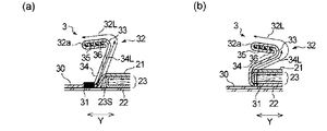
おむつ1の着用時には、一対の防漏カフ3,3それぞれの起立部32(第1起立部34及び第2起立部35)が、第2起立部35に配された防漏カフ形成用弾性部材36の収縮力により、基端部31を起立基端として起立し(図3参照)、これにより、少なくとも股下部Mにおける吸収性本体2の肌対向面の縦方向Xに沿う両側部に、起立部32からなる防漏壁が一対形成される。この一対の防漏壁は、おむつ1の肌対向面に排泄された尿や便等の排泄物を堰き止め、排泄物がおむつ1の横方向Yの外方に漏れ出す、いわゆる横漏れを防止する。
When the
また、おむつ1の着用時には、防漏カフ形成用弾性部材36の収縮力により、該弾性部材36の配置部であるおむつ1の縦方向Xの中央部(股下部Mを含む部分)が、非肌対向面側(裏面シート22側)に凸となるように、換言すれば肌対向面側(表面シート21側)に凹となるように、おむつ1が湾曲する。こうしておむつ1は全体として舟形形状に変形する。このような舟形形状のおむつ1は着用者の股間部の形状に沿いやすいため、該おむつ1における起立状態の起立部32の第2起立部35は、着用者の肌にフィット性良く密着し、これにより防漏カフ3による横漏れ防止機能が効果的に発現し得る。
Further, when the
おむつ1の主たる特徴の1つとして、図1に示す如きおむつ1の展開且つ伸長状態において、おむつ1を横方向Yに横断する1本の仮想直線VLを引いた場合に、該仮想直線VLにおける一対の防漏カフ3,3それぞれの第2起立部35と重複する部分の長さ35L(図2参照)の合計が、該仮想直線VLにおける離間部39と重複する部分の長さ39L(図2参照)の20%以上50%以下である「特定部分」を有する点が挙げられる。なお、長さ35L、39Lは前記のとおり、横方向Yに延びる仮想直線VLにおける所定部分(第2起立部35又は離間部39と重複する部分)の長さであり、すなわち、第2起立部35又は離間部39の平面視での横方向Yの長さ、換言すれば、第2起立部35又は離間部39をおむつ1(吸収体23)の厚み方向に投影した場合の投影像の横方向Yの長さである。
As one of the main features of the
このように、おむつ1の展開且つ伸長状態において、一対の第2起立部35,35それぞれの平面視での横方向Yの長さ35Lの合計(35L+35L)と該一対の第2起立部35,35に挟まれた離間部39の平面視での横方向Yの長さ39Lとの比率(以下、「第2起立部/離間部比率」ともいう。)が、20%以上50%以下の範囲にあることにより、防漏カフ3が漏れ防止性能に優れたものとなり、横漏れが効果的に防止され得る。第2起立部/離間部比率が20%未満では、起立状態の起立部32の上部(着用者の肌に最も近い部分)を構成する第2起立部35の防漏機能すなわち尿や便などの排泄物のブロック機能が低下し、排泄物が起立状態の防漏カフ3(起立部32)を乗り越えて横方向Yの外方に漏れ出すおそれがある。また、第2起立部/離間部比率が50%を超えると、第2起立部35が、その横方向Yの外方に位置するおむつ1(サイドフラップ部4)の縦方向Xに沿う側縁に近づきすぎたり、該側縁を超えておむつ1の外方にはみ出たりする場合があり、その結果、防漏カフ3による防漏作用が十分に発揮されない、防漏カフ3の外観が悪化するなどの不都合が生じるおそれがある。また、本実施形態では前述したとおり、サイドフラップ部4にレッグカフ41が設けられているところ、第2起立部/離間部比率が50%を超えると、第2起立部35がレッグカフ41(レッグカフ形成用弾性部材42)と重なりやすくなり、その結果、レッグカフ41のフィット性が低下する、着用者の肌トラブルを招くなどの不都合が生じるおそれがある。後者の肌トラブルは、縦方向Xに伸縮性を有する第2起立部35と同方向に伸縮性を有するレッグカフ41とが重なることによって、それらの重なり部が着用者の脚周りをきつく締める結果として起こり得るものである。第2起立部/離間部比率は、好ましくは25%以上47.5%以下、より好ましくは30%以上45%以下である。
As described above, in the unfolded and extended state of the
第2起立部/離間部比率が前記特定範囲にあることによる作用効果をより一層確実に奏させるようにする観点から、おむつ1の各部の寸法等は以下のように設定することが好ましい。
おむつ1の展開且つ伸長状態における仮想直線VLの第2起立部35と重複する部分の長さ35L(図2参照)、すなわち第2起立部35の平面視での横方向Yの長さ35Lは、好ましくは7.5mm以上、より好ましくは10mm以上、そして、好ましくは17.5mm以下、より好ましくは15mm以下である。なお、一対の防漏カフ3,3うちの一方の第2起立部35についての長さ35Lと他方のそれとは、典型的には同じであるが、異なっていてもよい。
おむつ1の展開且つ伸長状態における仮想直線VLの離間部39と重複する部分の長さ39L(図2参照)、すなわち離間部39の平面視での横方向Yの長さ39Lは、好ましくは60mm以上、より好ましくは70mm以上、そして、好ましくは90mm以下、より好ましくは80mm以下である。なお、本実施形態のおむつ1では、長さ39Lは、離間部39の縦方向Xの全長にわたって一定であるが、本発明では縦方向Xにおいて一定でなくてもよく、その場合、長さ39Lは前記の好ましい範囲内で縦方向Xにおいて変化することが好ましい。
It is preferable to set the dimensions and the like of each part of the
The
The
前記特定部分、すなわち第2起立部/離間部比率が20%以上50%以下の範囲にある部分は、少なくとも股下部Mに存在することが好ましい。股下部Mが最も横漏れが懸念される部位であるためである。最も好ましい形態は、一対の防漏カフ3,3(一対の起立部32,32)を横方向Yに横断する任意の1本の仮想直線VLを引いた場合に、第2起立部/離間部比率が20%以上50%以下の範囲にある形態である。すなわち、一対の防漏カフ3,3(一対の起立部32,32)及びそれらに挟まれた離間部39の全体が前記特定部分であることが最も好ましい。
The specific portion, that is, a portion in which the ratio of the second standing portion / separated portion is in the range of 20% or more and 50% or less is preferably present in at least the inseam M. This is because the inseam M is the site where lateral leakage is most a concern. The most preferable form is a second standing portion / separating portion when an arbitrary one virtual straight line VL that crosses the pair of leakage-
前記特定部分では、おむつ1の展開且つ伸長状態において、おむつ1を横方向Yに横断する1本の仮想直線VL(図1参照)を引いた場合に、「該仮想直線VLにおける第1起立部34と重複する部分の長さ34L(図4参照)の合計」、換言すれば、「一対の防漏カフ3,3それぞれの該仮想直線VLと重複する第1起立部34の横方向Yの長さ34Lの合計」が、「該仮想直線VLにおける離間部39と重複する部分の長さ39L(図2参照)」の55%以上100%以下であることが好ましい。
In the specific portion, when one virtual straight line VL (see FIG. 1) crossing the
なお、長さ34Lは、図4(a)に示すように、第1起立部34の実際の横方向Yの長さ、すなわち、基端部31から折り曲げ部33にわたる部分を設計寸法まで伸ばした状態での横方向Yの長さであり、長さ39Lのような、対象(第1起立部34)の平面視での長さではなく、第1起立部34の平面視での横方向Yの長さとは必ずしも一致しない。本発明には、図4(b)に示す如き、基端部31が吸収体23と平面視で重なる位置に存在する形態が包含され、斯かる形態では、防漏カフ形成用シート30における平面視で吸収体23と重なる部分の全体が基端部31であるところ、斯かる形態における第1起立部34の横方向Yの長さ34Lの意味するところも前記と同様である。また図4には、後述する起立部32全体(基端部31から折り曲げ部33を介して自由端32aにわたる部分)の横方向Yの長さ32Lが示されているところ、この長さ32Lの意味するところも前記と同様に、起立部32の実際の横方向Yの長さである。
As shown in FIG. 4A, the
このように、おむつ1の展開且つ伸長状態において、一対の第1起立部34,34それぞれの横方向Yの長さ34Lの合計(34L+34L)と該一対の第1起立部34,34に挟まれた離間部39の平面視での横方向Yの長さ39Lとの比率(以下、「第1起立部/離間部比率」ともいう。)が、55%以上100%以下の範囲にあることにより、起立状態の防漏カフ3(起立部32)の起立高さが十分なものとなるため、第2起立部/離間部比率が前記特定範囲にあることと相俟って、横漏れがより一層効果的に防止され得る。第1起立部/離間部比率は、好ましくは60%以上95%以下、より好ましくは65%以上90%以下である。
In this way, in the unfolded and extended state of the
第1起立部/離間部比率が前記特定範囲にあることによる作用効果をより一層確実に奏させるようにする観点から、おむつ1の展開且つ伸長状態における第1起立部34の横方向Yの長さ34L(図4参照)は、好ましくは20mm以上、より好ましくは25mm以上、そして、好ましくは40mm以下、より好ましくは35mm以下である。なお、一対の防漏カフ3,3うちの一方の第1起立部34についての長さ34Lと他方のそれとは、典型的には同じであるが、異なっていてもよい。離間部39の平面視での横方向Yの長さ39Lの好ましい範囲については前述したとおりである。
The length of the first standing
前記特定部分では、おむつ1の展開且つ伸長状態において、おむつ1を横方向Yに横断する1本の仮想直線VL(図1参照)を引いた場合に、「該仮想直線VLと重複する第1起立部34の横方向Yの長さ34L(図4参照)」が、「該仮想直線VLにおける、第1起立部34に隣接する基端部31から横方向Yの外方に位置するおむつ1の縦方向Xに沿う側縁1S(図1参照)にわたる部分と重複する部分の長さ31L(図2参照)」よりも短いことが好ましい。なお、長さ31Lは前記のとおり、横方向Yに延びる仮想直線VLにおける所定部分(第1起立部34に隣接する基端部31からその横方向Yの外方に位置するおむつ1の側縁1Sにわたる部分)の長さであり、すなわち、該所定部分の平面視での横方向Yの長さ、換言すれば、該所定部分をおむつ1(吸収体23)の厚み方向に投影した場合の投影像の横方向Yの長さである。また、前記の「基端部31からその横方向Yの外方に位置するおむつ1の側縁1Sにわたる部分」は、要は、第1起立部34よりも横方向Yの外方に位置する部分であり、本実施形態ではサイドフラップ部4である。
In the specific portion, when one virtual straight line VL (see FIG. 1) crossing the
このように、おむつ1の展開且つ伸長状態において、「第1起立部34の横方向Yの長さ34L<第1起立部34よりも横方向Yの外方に位置する部分の平面視での横方向Yの長さ31L」という大小関係が成立することにより、防漏カフ3、特に第2起立部35がおむつ1の側縁からはみ出す不都合が防止される。防漏カフ3(第2起立部35)がおむつ1の側縁からはみ出すと、防漏カフ3による防漏作用が十分に発揮されない、防漏カフ3の外観が悪化するなどの不都合が生じるおそれがある。また、本実施形態のように、サイドフラップ部4にレッグカフ41が設けられている場合には、第2起立部35がレッグカフ41と重なる機会が増加することになるため、レッグカフ41の性能低下などを招くおそれがある。
In this way, in the unfolded and extended state of the
なお、前記の「第1起立部34の横方向Yの長さ34L<第1起立部34よりも横方向Yの外方に位置する部分の平面視での横方向Yの長さ31L」という大小関係が成立する前記特定部分は、該特定部分を有する吸収性物品が、図1に示すおむつ1のように、展開且つ伸長状態において横方向Yの長さ(製品幅)が縦方向Xで異なるものである場合は、製品幅が最小となる部分に存在することが好ましい。例えば図1に示すおむつ1は、股下部M(おむつ1の縦方向Xの中央部)に、製品幅が最小となる部分である括れ部を有しているので、該括れ部に、前記特定部分であって且つ前記の「第1起立部34の横方向Yの長さ34L<第1起立部34よりも横方向Yの外方に位置する部分の平面視での横方向Yの長さ31L」という大小関係が成立する部分が存在することが好ましい。
It should be noted that the above-mentioned "
前記大小関係の成立による作用効果をより一層確実に奏させるようにする観点から、長さ34Lと長さ31Lとの比率は、前者<後者と前提として、前者/後者として、好ましくは0.99以下、より好ましくは0.9以下である。斯かる比率の下限は特に制限されないが、防漏カフ3の起立高さを実用上十分なものとして防漏性能を確保する観点から、好ましくは0.4以上、より好ましくは0.5以上である。
おむつ1の展開且つ伸長状態における仮想直線VLの、「基端部31からその横方向Yの外方に位置するおむつ1の側縁1Sにわたる部分と重複する部分」の長さ31L(図2参照)、すなわち該部分の平面視での横方向Yの長さ31Lは、好ましくは30mm以上、より好ましくは35mm以上、そして、好ましくは55mm以下、より好ましくは50mm以下である。第1起立部34の横方向Yの長さ34Lの好ましい範囲については前述したとおりである。
From the viewpoint of ensuring that the action and effect of the establishment of the magnitude relationship are more reliably performed, the ratio of the
The
前記特定部分では、おむつ1の展開且つ伸長状態において、おむつ1を横方向Yに横断する1本の仮想直線VL(図1参照)を引いた場合に、「起立部32全体における該仮想直線VLと重複する部分の長さ32L(図4参照)」、すなわち、「基端部31から折り曲げ部33を介して自由端32aにわたる部分の長さ32L」が、「該仮想直線VLにおける、第1起立部34に隣接する基端部31からその横方向Yの外方に位置するおむつ1の縦方向Xに沿う側縁1S(図1参照)にわたる部分と重複する部分の長さ31L(図2参照)」よりも短いことがより好ましい。すなわち、「第1起立部34よりも横方向Yの外方に位置する部分の平面視での横方向Yの長さ31L」に対しては、第1起立部34のみならず、これに連接する第2起立部35含めた、起立部32全体の方が、横方向Yの長さが短いことがより好ましい。
In the specific portion, when one virtual straight line VL (see FIG. 1) crossing the
前記大小関係の成立による作用効果をより一層確実に奏させるようにする観点から、長さ32Lと長さ31Lとの比率は、前者<後者と前提として、前者/後者として、好ましくは0.99以下、より好ましくは0.95以下である。斯かる比率の下限は特に制限されないが、防漏カフ3の起立高さを実用上十分なものとして防漏性能を確保する観点から、好ましくは0.5以上、より好ましくは0.6以上である。
おむつ1の展開且つ伸長状態における起立部32全体(第1起立部34及び第2起立部35)の横方向Yの長さ32L(図4参照)は、好ましくは30mm以上、より好ましくは35mm以上、そして、好ましくは55mm以下、より好ましくは50mm以下である。なお、一対の防漏カフ3,3うちの一方の起立部32についての長さ32Lと他方のそれとは、典型的には同じであるが、異なっていてもよい。
From the viewpoint of ensuring that the action and effect of the establishment of the magnitude relationship are more reliably performed, the ratio of the
The
本実施形態においては前述したとおり、図1及び図2に示すように、第2起立部35に防漏カフ形成用弾性部材36が縦方向Xに伸縮可能な状態で配されているところ、図1に示す如きおむつ1の展開且つ伸長状態において、該弾性部材36は吸収体23と平面視で重なることが好ましい。斯かる構成により、おむつ1の着用時におむつ1の全体が舟形形状に変形しやすくなり、これに伴って、起立状態の防漏カフ3の第2起立部35が着用者の肌に一層接しやすくなる。本実施形態のように、第2起立部35に複数(本実施形態では4本)の防漏カフ形成用弾性部材36が並列に配置されている場合は、その複数の該弾性部材36の全部が吸収体23と平面視で重なることがより好ましい。また、おむつ1の展開且つ伸長状態において防漏カフ形成用弾性部材36が吸収体23と平面視で重なる部分は、少なくとも股下部Mに存在することが好ましく、起立部32が存在する部分(防漏カフ3における縦方向Xに伸縮性を有する部分)の全体に存在することがより好ましく、本実施形態では後者が採用されている。
In the present embodiment, as described above, as shown in FIGS. 1 and 2, an
本実施形態のおむつ1は、未使用状態(例えば製品として店頭で販売されている状態)では折り畳まれて比較的コンパクトな個装体(不図示)とされるところ、この個装体にするときに利用される折曲線の一部がサイドフラップ部4に存在する。すなわち、サイドフラップ部4は、おむつ1の未使用状態において、縦方向Xに延びる一対のサイドフラップ部折曲線FL,FL(図1参照)にて折り曲げられる。サイドフラップ部折曲線FLは、図1に示すように、一対のサイドフラップ部4,4それぞれにおけるレッグカフ形成用弾性部材42よりも横方向Yの内側に位置し、サイドフラップ部4の縦方向Xの全長にわたって縦方向Xに延在している。図1に示す如きおむつ1の展開且つ伸長状態において、一対の防漏カフ3,3それぞれの第2起立部35(より具体的には、起立部32の自由端32a)は、一対のサイドフラップ部折曲線FL,FLに挟まれた領域に存在することが好ましく、本実施形態ではそのように構成されている。斯かる構成により、おむつ1を個装体にする場合において、サイドフラップ部折曲線FLにてサイドフラップ部4を折り曲げた場合に、第2起立部35がサイドフラップ部4とともに折り曲げられる不都合が防止される。第2起立部35は、おむつ1の着用状態において着用者の肌に対して面で接触し得る部分であるところ、第2起立部35が折り曲げられてしまうと、斯かる面接触が阻害されるおそれがある。
The
以上、本発明について説明したが、本発明は前記実施形態に制限されず、本発明の趣旨を逸脱しない範囲で適宜変更可能である。
本発明の吸収性物品は、人体から排出される体液(尿、経血、軟便、汗等)の吸収に用いられる物品を広く包含し、前記実施形態の如き展開型使い捨ておむつの他、例えば、パンツ型使い捨ておむつ、尿取りパッド、生理用ナプキン、生理用ショーツなどを包含しうる。本発明の実施形態に関し、更に以下の付記を開示する。
Although the present invention has been described above, the present invention is not limited to the above-described embodiment, and can be appropriately modified without departing from the spirit of the present invention.
The absorbable article of the present invention broadly includes articles used for absorbing body fluids (urine, menstrual blood, loose stool, sweat, etc.) discharged from the human body, and other than the deployable disposable diaper as in the above embodiment, for example, It may include pants-type disposable diapers, urine absorbing pads, sanitary napkins, sanitary shorts, and the like. The following additional notes are further disclosed with respect to the embodiments of the present invention.
<1>
着用者の前後方向に対応する縦方向と該縦方向に直交する横方向とを有し、吸収体を具備する吸収性本体と、該吸収性本体の肌対向面に該縦方向に延び、該横方向に離間部を設けて配置された一対の防漏カフとを具備する吸収性物品であって、
一対の前記防漏カフは、それぞれ、防漏カフ形成用シートを含んで構成され、且つ該防漏カフ形成用シートが他の部材に固定された基端部と、該基端部を起点として該防漏カフ形成用シートが着用者側に起立する起立部とを有し、
前記起立部の前記防漏カフ形成用シートは、前記縦方向に延びる折り曲げ部にて折り曲げられており、該起立部は、前記基端部から該折り曲げ部にわたる第1起立部と、該折り曲げ部から該起立部の自由端にわたり、該第1起立部よりも着用者の肌に近い側に位置する第2起立部とを含んで構成され、
前記吸収性物品の展開且つ伸長状態において、該吸収性物品を前記横方向に横断する1本の仮想直線を引いた場合に、該仮想直線における前記第2起立部と重複する部分の長さ(35L)の合計が、該仮想直線における前記離間部と重複する部分の長さ(39L)の20%以上50%以下である特定部分を有する、吸収性物品。
<2>
前記特定部分では、前記吸収性物品の展開且つ伸長状態において、該吸収性物品を前記横方向に横断する1本の仮想直線を引いた場合に、該仮想直線における前記第2起立部と重複する部分の長さ(35L)の合計が、該仮想直線における前記離間部と重複する部分の長さ(39L)の25%以上47.5%以下、好ましくは30%以上45%以下である、前記<1>に記載の吸収性物品。
<3>
前記特定部分では、前記吸収性物品の展開且つ伸長状態において、該吸収性物品を前記横方向に横断する1本の仮想直線を引いた場合に、該仮想直線における前記第2起立部と重複する部分の長さ(35L)が、7.5mm以上17.5mm以下、好ましくは10mm以上15mm以下である、前記<1>又は<2>に記載の吸収性物品。
<4>
前記特定部分では、前記吸収性物品の展開且つ伸長状態において、該吸収性物品を前記横方向に横断する1本の仮想直線を引いた場合に、該仮想直線における前記離間部と重複する部分の長さ(39L)が、60mm以上90mm以下、好ましくは70mm以上80mm以下である、前記<1>〜<3>の何れか1に記載の吸収性物品。
<5>
前記特定部分では、前記吸収性物品の展開且つ伸長状態において、該吸収性物品を前記横方向に横断する1本の仮想直線を引いた場合に、該仮想直線における該第1起立部と重複する部分の長さ(34L)の合計が、該仮想直線における前記離間部と重複する部分の長さ(39L)の55%以上100%以下である、前記<1>〜<4>の何れか1に記載の吸収性物品。
<6>
前記特定部分では、前記吸収性物品の展開且つ伸長状態において、該吸収性物品を前記横方向に横断する1本の仮想直線を引いた場合に、該仮想直線における該第1起立部と重複する部分の長さ(34L)の合計が、該仮想直線における前記離間部と重複する部分の長さ(39L)の60%以上95%以下、好ましくは65%以上90%以下である、前記<5>に記載の吸収性物品。
<7>
前記特定部分では、前記吸収性物品の展開且つ伸長状態において、該吸収性物品を前記横方向に横断する1本の仮想直線を引いた場合に、該仮想直線における前記第1起立部と重複する部分の長さ(34L)が、20mm以上40mm以下、好ましくは25mm以上35mm以下である、前記<5>又は<6>に記載の吸収性物品。
<8>
前記特定部分では、前記吸収性物品の展開且つ伸長状態において、該吸収性物品を前記横方向に横断する1本の仮想直線を引いた場合に、該仮想直線における前記第1起立部と重複する部分の長さ(34L)の合計が、該仮想直線における、該第1起立部に隣接する前記基端部から該横方向外方に位置する前記吸収性物品の前記縦方向に沿う側縁にわたる部分と重複する部分の長さ(31L)よりも短い、前記<1>〜<7>の何れか1に記載の吸収性物品。
<9>
前記特定部分では、前記吸収性物品の展開且つ伸長状態において、該吸収性物品を前記横方向に横断する1本の仮想直線を引いた場合に、前記基端部から該横方向外方に位置する前記吸収性物品の前記縦方向に沿う側縁にわたる部分と重複する部分の長さ(31L)に対する、該仮想直線における前記第1起立部と重複する部分の長さ(34L)の比率が、0.4以上0.99以下、好ましくは0.5以上0.9以下である、前記<8>に記載の吸収性物品。
<10>
前記特定部分では、前記吸収性物品の展開且つ伸長状態において、該吸収性物品を前記横方向に横断する1本の仮想直線を引いた場合に、前記基端部から該横方向外方に位置する前記吸収性物品の前記縦方向に沿う側縁にわたる部分と重複する部分の長さ(31L)が、30mm以上55mm以下、好ましくは35mm以上50mm以下である、前記<9>又は<10>に記載の吸収性物品。
<11>
前記特定部分では、前記吸収性物品の展開且つ伸長状態において、該吸収性物品を前記横方向に横断する1本の仮想直線を引いた場合に、前記起立部全体における該仮想直線と重複する部分の長さ(32L)が、該仮想直線における、該起立部に隣接する前記基端部から該横方向外方に位置する前記吸収性物品の前記縦方向に沿う側縁にわたる部分と重複する部分の長さ(31L)よりも短い、前記<1>〜<10>の何れか1に記載の吸収性物品。
<12>
前記特定部分では、前記吸収性物品の展開且つ伸長状態において、該吸収性物品を前記横方向に横断する1本の仮想直線を引いた場合に、該起立部に隣接する前記基端部から該横方向外方に位置する前記吸収性物品の前記縦方向に沿う側縁にわたる部分と重複する部分の長さ(31L)に対する、該起立部全体における該仮想直線と重複する部分の長さ(32L)の比率が、0.5以上0.99以下、好ましくは0.6以上0.95以下である、前記<11>に記載の吸収性物品。
<13>
前記第2起立部に防漏カフ形成用弾性部材が前記縦方向に伸縮可能に配されており、前記吸収性物品の展開且つ伸長状態において、該防漏カフ形成用弾性部材が前記吸収体と平面視で重なる、前記<1>〜<12>の何れか1に記載の吸収性物品。
<14>
前記吸収体の縦方向に沿う両側縁から横方向外方に延出する部材を含んで構成される一対のサイドフラップ部を具備し、該一対のサイドフラップ部の着用者の脚周りに対応する部位のそれぞれにレッグカフが形成されており、
前記レッグカフは、前記防漏カフ形成用シートと、該防漏カフ形成用シートに伸縮可能に固定されたレッグカフ形成用弾性部材とを含んで構成されている、前記<1>〜<13>の何れか1に記載の吸収性物品。
<15>
前記サイドフラップ部は、前記吸収性物品の未使用状態において、前記縦方向に延びるサイドフラップ部折曲線にて折り曲げられ、
前記吸収性物品の展開且つ伸長状態において、前記一対の防漏カフそれぞれの前記第2起立部は、前記一対のサイドフラップ部折曲線に挟まれた領域に存在する、前記<14>に記載の吸収性物品。
<1>
An absorbent main body having a vertical direction corresponding to the front-back direction of the wearer and a horizontal direction orthogonal to the vertical direction and having an absorber, and an absorbent main body extending in the vertical direction on a skin-facing surface of the absorbent main body. An absorbent article comprising a pair of leak-proof cuffs arranged with a laterally spaced portion.
Each of the pair of the leak-proof cuffs includes a leak-proof cuff forming sheet, and the leakage-proof cuff forming sheet is fixed to another member at a base end portion and the base end portion as a starting point. The leak-proof cuff forming sheet has an upright portion that stands up on the wearer side.
The leak-proof cuff forming sheet of the upright portion is bent at the bent portion extending in the vertical direction, and the upright portion includes a first upright portion extending from the base end portion to the bent portion and the bent portion. From to the free end of the upright portion, including a second upright portion located closer to the wearer's skin than the first upright portion.
In the unfolded and stretched state of the absorbent article, when one virtual straight line crossing the absorbent article in the lateral direction is drawn, the length of the portion of the virtual straight line overlapping with the second standing portion ( An absorbent article having a specific portion in which the total of 35L) is 20% or more and 50% or less of the length (39L) of the portion overlapping the separation portion in the virtual straight line.
<2>
In the specific portion, when one virtual straight line crossing the absorbent article in the lateral direction is drawn in the unfolded and stretched state of the absorbent article, it overlaps with the second standing portion in the virtual straight line. The total length of the portions (35L) is 25% or more and 47.5% or less, preferably 30% or more and 45% or less of the length (39L) of the portion overlapping the separated portion in the virtual straight line. The absorbent article according to <1>.
<3>
In the specific portion, when one virtual straight line crossing the absorbent article in the lateral direction is drawn in the unfolded and stretched state of the absorbent article, it overlaps with the second standing portion in the virtual straight line. The absorbent article according to <1> or <2>, wherein the length (35 L) of the portion is 7.5 mm or more and 17.5 mm or less, preferably 10 mm or more and 15 mm or less.
<4>
In the specific portion, when one virtual straight line crossing the absorbent article in the lateral direction is drawn in the unfolded and stretched state of the absorbent article, the portion overlapping the separated portion in the virtual straight line. The absorbent article according to any one of <1> to <3>, wherein the length (39L) is 60 mm or more and 90 mm or less, preferably 70 mm or more and 80 mm or less.
<5>
In the specific portion, when one virtual straight line crossing the absorbent article in the lateral direction is drawn in the unfolded and stretched state of the absorbent article, it overlaps with the first standing portion in the virtual straight line. Any one of <1> to <4>, wherein the total length of the portions (34L) is 55% or more and 100% or less of the length (39L) of the portion overlapping the separated portion in the virtual straight line. Absorbent article described in.
<6>
In the specific portion, when one virtual straight line crossing the absorbent article in the lateral direction is drawn in the unfolded and stretched state of the absorbent article, it overlaps with the first standing portion in the virtual straight line. The total length of the portions (34L) is 60% or more and 95% or less, preferably 65% or more and 90% or less of the length (39L) of the portion overlapping the separated portion in the virtual straight line. > The absorbent article described in.
<7>
In the specific portion, when one virtual straight line crossing the absorbent article in the lateral direction is drawn in the unfolded and stretched state of the absorbent article, it overlaps with the first standing portion in the virtual straight line. The absorbent article according to <5> or <6>, wherein the length (34L) of the portion is 20 mm or more and 40 mm or less, preferably 25 mm or more and 35 mm or less.
<8>
In the specific portion, when one virtual straight line crossing the absorbent article in the lateral direction is drawn in the unfolded and stretched state of the absorbent article, it overlaps with the first standing portion in the virtual straight line. The sum of the lengths (34L) of the portions extends along the longitudinal direction of the absorbent article located laterally outward from the proximal end adjacent to the first upright portion of the virtual straight line. The absorbent article according to any one of <1> to <7>, which is shorter than the length (31L) of the portion overlapping the portion.
<9>
In the specific portion, when one virtual straight line crossing the absorbent article in the lateral direction is drawn in the unfolded and stretched state of the absorbent article, the position is located outward from the proximal end portion in the lateral direction. The ratio of the length (34L) of the portion overlapping the first standing portion in the virtual straight line to the length (31L) of the portion overlapping the side edge along the vertical direction of the absorbent article. The absorbent article according to <8> above, which is 0.4 or more and 0.99 or less, preferably 0.5 or more and 0.9 or less.
<10>
In the specific portion, when one virtual straight line crossing the absorbent article in the lateral direction is drawn in the unfolded and extended state of the absorbent article, the position is located outward from the proximal end portion in the lateral direction. The length (31L) of the portion overlapping the portion extending along the side edge in the vertical direction of the absorbent article is 30 mm or more and 55 mm or less, preferably 35 mm or more and 50 mm or less. The absorbent article described.
<11>
In the specific portion, when one virtual straight line crossing the absorbent article in the lateral direction is drawn in the deployed and extended state of the absorbent article, the portion overlapping the virtual straight line in the entire standing portion. The length (32L) of the imaginary straight line overlaps with the portion of the virtual straight line extending from the base end portion adjacent to the standing portion to the lateral edge of the absorbent article located laterally outward. The absorbent article according to any one of <1> to <10>, which is shorter than the length (31 L) of.
<12>
In the specific portion, when one virtual straight line crossing the absorbent article in the lateral direction is drawn in the unfolded and stretched state of the absorbent article, the base end portion adjacent to the upright portion is said to be the same. The length of the portion overlapping the virtual straight line (32L) in the entire standing portion with respect to the length (31L) of the portion overlapping the lateral edge of the absorbent article located laterally outward. The absorbent article according to <11>, wherein the ratio of) is 0.5 or more and 0.99 or less, preferably 0.6 or more and 0.95 or less.
<13>
An elastic member for forming a leak-proof cuff is arranged in the second standing portion so as to be expandable and contractible in the vertical direction, and the elastic member for forming a leak-proof cuff is attached to the absorber in the deployed and extended state of the absorbent article. The absorbent article according to any one of <1> to <12>, which overlaps in a plan view.
<14>
It is provided with a pair of side flap portions including members extending laterally outward from both side edges along the vertical direction of the absorber, and corresponds to the wearer's leg circumference of the pair of side flap portions. Leg cuffs are formed on each part,
The leg cuff is composed of the leak-proof cuff forming sheet and the leg cuff-forming elastic member stretchably fixed to the leak-proof cuff forming sheet. The absorbent article according to any one.
<15>
The side flap portion is bent by the side flap portion folding curve extending in the vertical direction in the unused state of the absorbent article.
The second upright portion of each of the pair of leak-proof cuffs exists in a region sandwiched between the pair of side flap portion folding curves in the unfolded and extended state of the absorbent article, according to the above <14>. Absorbent article.
以下、本発明を実施例により更に具体的に説明するが、本発明は斯かる実施例に限定されるものではない。 Hereinafter, the present invention will be described in more detail with reference to Examples, but the present invention is not limited to such Examples.
〔実施例1〜5、比較例1〜2、参考例1〜3〕
図1に示すおむつ1と基本構成が同様の展開型使い捨ておむつを作製した。具体的には、展開型使い捨ておむつとして、花王株式会社製のメリーズテープタイプSサイズ(2017年製、登録商標)を用意し、その用意したおむつの防漏カフの各部の寸法等を適宜調整して、実施例、比較例及び参考例の展開型使い捨ておむつを作製した。
[Examples 1 to 5, Comparative Examples 1 to 2, Reference Examples 1 to 3]
A deployable disposable diaper having the same basic configuration as the
実施例、比較例及び参考例の使い捨ておむつについて、下記方法により、防漏カフの横漏れ防止性及びはみ出しやすさをそれぞれ評価した。その結果を下記表1に示す。 The disposable diapers of Examples, Comparative Examples, and Reference Examples were evaluated for lateral leakage prevention and easiness of protrusion of the leakage-proof cuff by the following methods. The results are shown in Table 1 below.
<防漏カフの横漏れ防止性の評価方法>
排泄ポイントを設けたモデル人形に評価対象のおむつをはかせ、下記方法により、該おむつの防漏カフの横漏れ防止性を評価した。まず、おむつを前記モデル人形に装着し、横向きとなるようにモデル人形を90°傾けた。この状態でおむつにおける前記排泄ポイントに対応する部位に疑似軟便10gを注入した。擬似軟便の組成は、ベントナイト22.5質量%、界面活性剤(ポイズ530、固形分40質量%、花王株式会社製)0.5質量%、エマルゲン130K0.03質量%水溶液(花王株式会社製)1.5質量%、イオン交換水75.5質量%であり、粘度は40mPa・s(23℃、振動式粘度計:株式会社エー・アンド・デイ製、SV−10)、表面張力は55mN/mであった。擬似軟便の注入後、速やかに、モデル人形を直立状態にし、モデル人形の股下に位置するおむつをモデル人形側に3kPaの圧力で圧迫した時に、疑似軟便がおむつの防漏カフより横方向外側に漏れるか否かを観察した。以上の操作を1個の評価対象につき10回行い、横漏れを防止できた確率(全10回に占める、擬似軟便の漏れが観察されなかった回数の割合)を横漏れ防止性とした。この数値が大きいほど、防漏カフの横漏れ防止性に優れ、高評価となる。この数値が70%以上の場合を合格とした。
<Evaluation method for lateral leakage prevention of leak-proof cuffs>
The model doll provided with the excretion point was put on the diaper to be evaluated, and the lateral leakage prevention property of the leakage-proof cuff of the diaper was evaluated by the following method. First, the diaper was attached to the model doll, and the model doll was tilted 90 ° so as to be turned sideways. In this state, 10 g of pseudo loose stool was injected into the site corresponding to the excretion point in the diaper. The composition of the pseudo loose stool is 22.5% by mass of bentonite, 0.5% by mass of a surfactant (poise 530, solid content 40% by mass, manufactured by Kao Co., Ltd.), and an aqueous solution of Emargen 130K 0.03% by mass (manufactured by Kao Co., Ltd.). 1.5% by mass, ion-exchanged water 75.5% by mass, viscosity 40 mPa · s (23 ° C, vibration viscometer: A & D Co., Ltd., SV-10), surface tension 55 mN / It was m. Immediately after injecting the pseudo loose stool, the model doll is placed upright, and when the diaper located in the inseam of the model doll is pressed against the model doll with a pressure of 3 kPa, the pseudo loose stool laterally outwards from the leak-proof cuff of the diaper. It was observed whether or not it leaked. The above operation was performed 10 times for each evaluation target, and the probability that lateral leakage could be prevented (the ratio of the number of times that pseudo loose stool leakage was not observed to the total of 10 times) was defined as the lateral leakage prevention property. The larger this value is, the better the lateral leakage prevention property of the leakage prevention cuff is, and the higher the evaluation is. A case where this value was 70% or more was regarded as a pass.
<防漏カフのはみ出しやすさの評価方法>
モデル人形に評価対象のおむつをはかせ、該おむつの防漏カフが該おむつの縦方向に沿う側縁から横方向外方にはみ出しているか否かを観察した。以上の操作を1個の評価対象につき10回行い、防漏カフがはみ出した確率(全10回に占める、防漏カフのはみ出しが確認できた回数の割合)を防漏カフのはみ出しやすさとした。この数値が小さいほど、防漏カフがおむつの側縁から横方向外方にはみ出しにくく、高評価となる。この数値が0%以下の場合を合格とした。
<Evaluation method for ease of protrusion of leak-proof cuff>
The model doll was put on the diaper to be evaluated, and it was observed whether or not the leak-proof cuff of the diaper protruded laterally outward from the side edge along the vertical direction of the diaper. The above operation was performed 10 times for each evaluation target, and the probability that the leak-proof cuff squeezed out (the ratio of the number of times the leak-proof cuff squeezed out to the total of 10 times) was determined to be the easiness of the leak-proof cuff sticking out. .. The smaller this value is, the more difficult it is for the leak-proof cuff to protrude laterally outward from the side edge of the diaper, and the higher the evaluation. A case where this value was 0% or less was regarded as a pass.

表1に示すとおり、各実施例は、第2起立部/離間部比率が20%以上50%以下の範囲にあるため、これを満たさない各比較例に比べて、防漏カフの横漏れ防止性に優れ、且つ防漏カフがおむつの側縁を超えて外方にはみ出しにくいものであった。
参考例1〜2は、第2起立部/離間部比率が20%以上50%以下の範囲にあるものの、第1起立部/離間部比率が55%以上100%以下の範囲から外れているため、各実施例に比べて評価に劣る結果となった。
参考例3は、「34L/31L」及び「32L/31L」の双方が1以上であるため、防漏カフがおむつの側縁を超えて外方にはみ出しやすい結果となった。
As shown in Table 1, since the second standing portion / separation portion ratio is in the range of 20% or more and 50% or less in each example, lateral leakage prevention of the leak-proof cuff is compared with each comparative example which does not satisfy this. It had excellent properties, and the leak-proof cuff did not easily protrude outward beyond the side edges of the diaper.
In Reference Examples 1 and 2, the second standing portion / separation portion ratio is in the range of 20% or more and 50% or less, but the first standing portion / separation portion ratio is out of the range of 55% or more and 100% or less. , The result was inferior to each example.
In Reference Example 3, since both “34L / 31L” and “32L / 31L” were 1 or more, the result was that the leak-proof cuff easily protruded beyond the side edge of the diaper.
1 使い捨ておむつ(吸収性物品)
F 腹側部
M 股下部
R 背側部
2 吸収性本体
21 表面シート
22 裏面シート
23 吸収体
3 防漏カフ
30 防漏カフ形成用シート
31 基端部
32 起立部
32a 起立部の自由端
33 折り曲げ部
34 第1起立部
35 第2起立部
36 防漏カフ形成用弾性部材
37 起立阻害部
39 離間部
4 サイドフラップ部
41 レッグカフ
42 レッグカフ形成用弾性部材
5 止着構造
X 縦方向
Y 横方向
1 Disposable diapers (absorbent articles)
F Ventral part M Inseam
Claims (7)
一対の前記防漏カフは、それぞれ、防漏カフ形成用シートを含んで構成され、且つ該防漏カフ形成用シートが他の部材に固定された基端部と、該基端部を起点として該防漏カフ形成用シートが着用者側に起立する起立部とを有し、
前記起立部の前記防漏カフ形成用シートは、前記縦方向に延びる折り曲げ部にて折り曲げられており、該起立部は、前記基端部から該折り曲げ部にわたる第1起立部と、該折り曲げ部から該起立部の自由端にわたり、該第1起立部よりも着用者の肌に近い側に位置する第2起立部とを含んで構成され、
前記吸収性物品の展開且つ伸長状態において、該吸収性物品を前記横方向に横断する1本の仮想直線を引いた場合に、該仮想直線における前記第2起立部と重複する部分の長さの合計が、該仮想直線における前記離間部と重複する部分の長さの20%以上50%以下である特定部分を有する、吸収性物品。 An absorbent main body having a vertical direction corresponding to the front-back direction of the wearer and a horizontal direction orthogonal to the vertical direction and having an absorber, and an absorbent main body extending in the vertical direction on a skin-facing surface of the absorbent main body. An absorbent article comprising a pair of leak-proof cuffs arranged with a laterally spaced portion.
Each of the pair of the leak-proof cuffs includes a leak-proof cuff forming sheet, and the leakage-proof cuff forming sheet is fixed to another member at a base end portion and the base end portion as a starting point. The leak-proof cuff forming sheet has an upright portion that stands up on the wearer side.
The leak-proof cuff forming sheet of the upright portion is bent at the bent portion extending in the vertical direction, and the upright portion includes a first upright portion extending from the base end portion to the bent portion and the bent portion. From to the free end of the upright portion, including a second upright portion located closer to the wearer's skin than the first upright portion.
In the unfolded and stretched state of the absorbent article, when one virtual straight line crossing the absorbent article in the lateral direction is drawn, the length of the portion of the virtual straight line overlapping with the second standing portion is An absorbent article having a specific portion having a total of 20% or more and 50% or less of the length of the portion overlapping the separation portion in the virtual straight line.
前記レッグカフは、前記防漏カフ形成用シートと、該防漏カフ形成用シートに伸縮可能に固定されたレッグカフ形成用弾性部材とを含んで構成されている、請求項1〜5の何れか1項に記載の吸収性物品。 A pair of side flap portions including members extending outward in the lateral direction from both side edges of the absorber along the vertical direction are provided, and the pair of side flap portions are provided around the wearer's legs. Leg cuffs are formed on each of the corresponding parts,
Any one of claims 1 to 5, wherein the leg cuff includes the leak-proof cuff forming sheet and a leg cuff-forming elastic member stretchably fixed to the leak-proof cuff forming sheet. The absorbent article described in the section.
前記吸収性物品の展開且つ伸長状態において、前記一対の防漏カフそれぞれの前記第2起立部は、前記一対のサイドフラップ部折曲線に挟まれた領域に存在する、請求項6に記載の吸収性物品。 The side flap portion is bent by the side flap portion folding curve extending in the vertical direction in the unused state of the absorbent article.
The absorption according to claim 6, wherein the second standing portion of each of the pair of leak-proof cuffs exists in a region sandwiched between the pair of side flap portion folding curves in the unfolded and extended state of the absorbent article. Sex goods.
Priority Applications (2)
| Application Number | Priority Date | Filing Date | Title |
|---|---|---|---|
| JP2019200003A JP2021069863A (en) | 2019-11-01 | 2019-11-01 | Absorbent article |
| CN202022398243.9U CN214073877U (en) | 2019-11-01 | 2020-10-26 | Absorbent article |
Applications Claiming Priority (1)
| Application Number | Priority Date | Filing Date | Title |
|---|---|---|---|
| JP2019200003A JP2021069863A (en) | 2019-11-01 | 2019-11-01 | Absorbent article |
Related Child Applications (1)
| Application Number | Title | Priority Date | Filing Date |
|---|---|---|---|
| JP2023002314U Continuation JP3243460U (en) | 2023-06-30 | 2023-06-30 | absorbent article |
Publications (1)
| Publication Number | Publication Date |
|---|---|
| JP2021069863A true JP2021069863A (en) | 2021-05-06 |
Family
ID=75713923
Family Applications (1)
| Application Number | Title | Priority Date | Filing Date |
|---|---|---|---|
| JP2019200003A Pending JP2021069863A (en) | 2019-11-01 | 2019-11-01 | Absorbent article |
Country Status (2)
| Country | Link |
|---|---|
| JP (1) | JP2021069863A (en) |
| CN (1) | CN214073877U (en) |
-
2019
- 2019-11-01 JP JP2019200003A patent/JP2021069863A/en active Pending
-
2020
- 2020-10-26 CN CN202022398243.9U patent/CN214073877U/en active Active
Also Published As
| Publication number | Publication date |
|---|---|
| CN214073877U (en) | 2021-08-31 |
Similar Documents
| Publication | Publication Date | Title |
|---|---|---|
| JP6108152B2 (en) | Disposable diapers | |
| JP5577085B2 (en) | Pants-type disposable diapers | |
| JP2008093289A (en) | Absorbent article | |
| JP6386883B2 (en) | Absorbent articles | |
| JP2001252303A (en) | Absorptive article | |
| JP5964146B2 (en) | Absorbent articles | |
| JP5654318B2 (en) | Absorbent articles | |
| JP2019022727A (en) | Underpants type absorbent article | |
| CN107847371B (en) | Absorbent article | |
| JP6269201B2 (en) | Absorbent articles | |
| WO2020262210A1 (en) | Absorbent article | |
| WO2020256104A1 (en) | Absorbent article | |
| JP2021069863A (en) | Absorbent article | |
| JP3243460U (en) | absorbent article | |
| JP2021006246A (en) | Absorber and absorbent article | |
| WO2021085361A1 (en) | Absorbent article | |
| JP2019198592A (en) | Underpants type absorbent article | |
| JP2019198591A (en) | Underpants type absorbent article | |
| JP7470606B2 (en) | Absorbent articles | |
| JP6901613B2 (en) | Pants type absorbent article | |
| WO2022270419A1 (en) | Absorbent article | |
| JP3241886U (en) | Absorbent bodies and absorbent articles | |
| CN112118817B (en) | Pants-type absorbent article | |
| JP3635013B2 (en) | Disposable absorbent article | |
| JP2005198802A (en) | Disposable diaper |
Legal Events
| Date | Code | Title | Description |
|---|---|---|---|
| A621 | Written request for application examination |
Free format text: JAPANESE INTERMEDIATE CODE: A621 Effective date: 20220905 |
|
| A977 | Report on retrieval |
Free format text: JAPANESE INTERMEDIATE CODE: A971007 Effective date: 20230526 |
|
| A131 | Notification of reasons for refusal |
Free format text: JAPANESE INTERMEDIATE CODE: A131 Effective date: 20230606 |