JP2021031299A - Heat roller conveyor for printing business - Google Patents
Heat roller conveyor for printing business Download PDFInfo
- Publication number
- JP2021031299A JP2021031299A JP2019217451A JP2019217451A JP2021031299A JP 2021031299 A JP2021031299 A JP 2021031299A JP 2019217451 A JP2019217451 A JP 2019217451A JP 2019217451 A JP2019217451 A JP 2019217451A JP 2021031299 A JP2021031299 A JP 2021031299A
- Authority
- JP
- Japan
- Prior art keywords
- rod
- fixedly connected
- space
- slide
- end surface
- Prior art date
- Legal status (The legal status is an assumption and is not a legal conclusion. Google has not performed a legal analysis and makes no representation as to the accuracy of the status listed.)
- Pending
Links
Images


Classifications
-
- B—PERFORMING OPERATIONS; TRANSPORTING
- B66—HOISTING; LIFTING; HAULING
- B66F—HOISTING, LIFTING, HAULING OR PUSHING, NOT OTHERWISE PROVIDED FOR, e.g. DEVICES WHICH APPLY A LIFTING OR PUSHING FORCE DIRECTLY TO THE SURFACE OF A LOAD
- B66F9/00—Devices for lifting or lowering bulky or heavy goods for loading or unloading purposes
- B66F9/06—Devices for lifting or lowering bulky or heavy goods for loading or unloading purposes movable, with their loads, on wheels or the like, e.g. fork-lift trucks
- B66F9/075—Constructional features or details
- B66F9/07504—Accessories, e.g. for towing, charging, locking
-
- B—PERFORMING OPERATIONS; TRANSPORTING
- B66—HOISTING; LIFTING; HAULING
- B66F—HOISTING, LIFTING, HAULING OR PUSHING, NOT OTHERWISE PROVIDED FOR, e.g. DEVICES WHICH APPLY A LIFTING OR PUSHING FORCE DIRECTLY TO THE SURFACE OF A LOAD
- B66F9/00—Devices for lifting or lowering bulky or heavy goods for loading or unloading purposes
- B66F9/06—Devices for lifting or lowering bulky or heavy goods for loading or unloading purposes movable, with their loads, on wheels or the like, e.g. fork-lift trucks
- B66F9/075—Constructional features or details
- B66F9/12—Platforms; Forks; Other load supporting or gripping members
- B66F9/14—Platforms; Forks; Other load supporting or gripping members laterally movable, e.g. swingable, for slewing or transverse movements
-
- B—PERFORMING OPERATIONS; TRANSPORTING
- B66—HOISTING; LIFTING; HAULING
- B66F—HOISTING, LIFTING, HAULING OR PUSHING, NOT OTHERWISE PROVIDED FOR, e.g. DEVICES WHICH APPLY A LIFTING OR PUSHING FORCE DIRECTLY TO THE SURFACE OF A LOAD
- B66F9/00—Devices for lifting or lowering bulky or heavy goods for loading or unloading purposes
- B66F9/06—Devices for lifting or lowering bulky or heavy goods for loading or unloading purposes movable, with their loads, on wheels or the like, e.g. fork-lift trucks
- B66F9/075—Constructional features or details
- B66F9/12—Platforms; Forks; Other load supporting or gripping members
- B66F9/18—Load gripping or retaining means
- B66F9/184—Roll clamps
-
- B—PERFORMING OPERATIONS; TRANSPORTING
- B66—HOISTING; LIFTING; HAULING
- B66F—HOISTING, LIFTING, HAULING OR PUSHING, NOT OTHERWISE PROVIDED FOR, e.g. DEVICES WHICH APPLY A LIFTING OR PUSHING FORCE DIRECTLY TO THE SURFACE OF A LOAD
- B66F9/00—Devices for lifting or lowering bulky or heavy goods for loading or unloading purposes
- B66F9/06—Devices for lifting or lowering bulky or heavy goods for loading or unloading purposes movable, with their loads, on wheels or the like, e.g. fork-lift trucks
- B66F9/075—Constructional features or details
- B66F9/20—Means for actuating or controlling masts, platforms, or forks
- B66F9/22—Hydraulic devices or systems
-
- B—PERFORMING OPERATIONS; TRANSPORTING
- B66—HOISTING; LIFTING; HAULING
- B66F—HOISTING, LIFTING, HAULING OR PUSHING, NOT OTHERWISE PROVIDED FOR, e.g. DEVICES WHICH APPLY A LIFTING OR PUSHING FORCE DIRECTLY TO THE SURFACE OF A LOAD
- B66F9/00—Devices for lifting or lowering bulky or heavy goods for loading or unloading purposes
- B66F9/06—Devices for lifting or lowering bulky or heavy goods for loading or unloading purposes movable, with their loads, on wheels or the like, e.g. fork-lift trucks
- B66F9/075—Constructional features or details
- B66F9/20—Means for actuating or controlling masts, platforms, or forks
- B66F9/24—Electrical devices or systems
Landscapes
- Engineering & Computer Science (AREA)
- Transportation (AREA)
- Structural Engineering (AREA)
- Life Sciences & Earth Sciences (AREA)
- Civil Engineering (AREA)
- Geology (AREA)
- Mechanical Engineering (AREA)
- Combustion & Propulsion (AREA)
- Chemical & Material Sciences (AREA)
- Automatic Assembly (AREA)
- Handcart (AREA)
- Forklifts And Lifting Vehicles (AREA)
- Load-Engaging Elements For Cranes (AREA)
Abstract
Description
本願発明はヒートローラーを搬送する技術分野に関し、具体的には印刷業向けのヒートローラー搬送設備である。 The present invention relates to a technical field for transporting a heat roller, and specifically, is a heat roller transport facility for the printing industry.
ヒートローラーは、定着ローラーとも呼ばれる。その機能はレーザープリンターから出力された用紙上のトナーを溶解させ、用紙に吸収されることでトナーを用紙に定着させ、さらに用紙上の元のテキスト、写真などを定着させるのである。ロール用紙、トナーなどがヒートローラーを通過する時、ヒートローラー自体が粘着性を有しないので、汚れ(余分のトナー、紙粉など)がヒートローラーに付着することは避けられないため、ヒートローラーを分解して清掃する必要がある。ヒートローラーはアルミニウム合金で作られ、質量が大きく、温度が高く、従来のヒートローラー搬送作業は作業員によって簡易な用具を利用するのであり、作業強度が大きく、火傷の恐れがある。また、現在のヒートローラー搬送設備は自動的に異なる直径のあるヒートローラーに対応できなく、ヒートローラーを挟んで固定することもできないため、適応範囲が小さく、安全上のリスクがある。本願発明は上記の問題を解決できる設備を明らかにする。 The heat roller is also called a fixing roller. Its function is to dissolve the toner on the paper output from the laser printer, fix the toner on the paper by being absorbed by the paper, and further fix the original text, photographs, etc. on the paper. When roll paper, toner, etc. pass through the heat roller, the heat roller itself does not have adhesiveness, so dirt (excess toner, paper dust, etc.) inevitably adheres to the heat roller. Must be disassembled and cleaned. The heat roller is made of an aluminum alloy, has a large mass, and has a high temperature. In the conventional heat roller transport work, a simple tool is used by the worker, the work strength is high, and there is a risk of burns. In addition, the current heat roller transfer equipment cannot automatically handle heat rollers having different diameters, and cannot be fixed by sandwiching the heat rollers, so that the applicable range is small and there is a safety risk. The invention of the present application clarifies the equipment capable of solving the above problems.
技術問題:現在のヒートローラー搬送設備は自動的に異なる直径のあるヒートローラーに対応できなく、ヒートローラーを挟んで固定することもできないため、適応範囲が小さく、安全上のリスクがある。 Technical problem: Current heat roller transfer equipment cannot automatically handle heat rollers with different diameters and cannot be fixed by sandwiching the heat rollers, so the applicable range is small and there is a safety risk.
上記の問題を解決するため、本願発明は印刷業向けのヒートローラー搬送設備を設計する。本願発明に記載される印刷業向けのヒートローラー搬送設備は、手押し車を含み、前記手押し車の上側端面には本願発明を昇降させることができる昇降装置が設置され、前記昇降装置は前記昇降装置をロックできるロック装置が設置され、前記昇降装置には前記ロック装置の下側に位置する連動装置が設置され、前記連動装置は前記ロック装置の動作を触発させることで、前記ロック装置が前記昇降装置をロックまたは解除し、前記昇降装置の中には本願発明を左右に移動させる横移動装置が設置され、前記横移動装置の左側には挟持装置が設置され、前記挟持装置は固定ロッド、シリンダー、エア空間、スライド栓、プッシュロッド、プッシュ板、上挟持ロッド、挟持ロッド、回転軸、回転ロッド、前記回転ロッドの上向きの回転、前記上挟持ロッドの下向きの移動、前記プッシュ板の左向きの移動により、ヒートローラーを挟んで固定し、前記固定ロッドが前記横移動装置の左側に設置され、前記シリンダーが前記固定ロッドの右側端面と左側端面に固定的に連結され、前記エア空間が前記シリンダーの中に設置され、前記スライド栓が前記エア空間の中にはがスライド可能に連結され、前記プッシュロッドがそれぞれ右側の前記スライド栓の左側端面と左側の前記スライド栓の下側端面に固定的に連結され、右側の前記プッシュロッドが左方へ右側の前記固定ロッドの左側端面の左側まで延在し、左側の前記プッシュロッドが下方へ左側の前記エア空間の端面の外側まで延在し、前記プッシュ板が右側の前記プッシュロッドに固定的に連結されかつ前記固定ロッドの左側端面の左側に位置し、前記上挟持ロッドが左側の前記プッシュロッドに固定的に連結されかつ前記固定ロッドの左側端面にスライド可能に連結され、また前記上挟持ロッドが前記プッシュ板の上側に位置し、前記挟持ロッドが前記固定ロッドの左側端面に固定的に連結されかつ前記プッシュ板の下側に位置し、前記回転軸が前記挟持ロッドの後側端面に回転可能に設置されかつ前方へ前記挟持ロッドの前側端面の外側まで延在し、前記回転ロッドが前記回転軸に固定的に連結されている。 In order to solve the above problems, the present invention designs a heat roller transfer facility for the printing industry. The heat roller transport facility for the printing industry described in the present invention includes a push rod, and an elevating device capable of raising and lowering the present invention is installed on the upper end surface of the push rod, and the elevating device is the elevating device. A lock device capable of locking the rod is installed, an interlocking device located below the lock device is installed in the elevating device, and the interlocking device is inspired by the operation of the lock device so that the lock device elevates the rod. A lateral moving device for locking or unlocking the device and moving the present invention to the left or right is installed in the lifting device, a holding device is installed on the left side of the lateral moving device, and the holding device is a fixed rod and a cylinder. , Air space, slide plug, push rod, push plate, upper holding rod, holding rod, rotating shaft, rotating rod, upward rotation of the rotating rod, downward movement of the upper holding rod, leftward movement of the push plate The heat roller is sandwiched and fixed, the fixing rod is installed on the left side of the lateral movement device, the cylinder is fixedly connected to the right end surface and the left end surface of the fixing rod, and the air space is connected to the cylinder. Installed inside, the slide plug is slidably connected into the air space, and the push rods are fixed to the left end face of the slide plug on the right side and the lower end face of the slide plug on the left side, respectively. Connected, the push rod on the right extends to the left to the left of the left end face of the fixed rod on the right, and the push rod on the left extends downward to the outside of the end face of the air space on the left. The push plate is fixedly connected to the right push rod and is located on the left side of the left end surface of the fixed rod, and the upper holding rod is fixedly connected to the left push rod and the left end surface of the fixed rod. The upper holding rod is located above the push plate, the holding rod is fixedly connected to the left end surface of the fixed rod, and is located below the push plate. The rotating shaft is rotatably installed on the rear end surface of the holding rod and extends forward to the outside of the front end surface of the holding rod, and the rotating rod is fixedly connected to the rotating shaft.
有益なように、前記手押し車には手押しハンドルが付いている。 For the benefit, the wheelbarrow has a wheelbarrow.
前記昇降装置はモーター軸を含み、前記モーター軸が前記手押し車の上側端面に回転可能に設置されかつ上方に延在し、前記モーター軸には前記手押し車の上側端面に固定的に連結されたモーターが伝動可能に連結され、前記モーター軸には止めリングが固定的に連結され、前記モーター軸には前記止めリングの上側に位置するスライド歯車がフェザーキーにより連結され、前記手押し車の後側端面にはL字型固定台が固定的に連結され、前記L字型固定台の上側内壁には下方に延在するネジロッドが固定的に連結され、前記ネジロッドと前記モーター軸とが等しい直径を有し、また前記ネジロッドと前記モーター軸との軸線が同一の直線であり、前記スライド歯車が前記ネジロッドとフェザーキーにより連結され、前記ネジロッドには前記スライド歯車の上側に位置する電磁石が固定的に連結され、前記ネジロッドには前記電磁石の上側に位置する固定リングが固定的に連結され、前記ネジロッドには昇降箱がネジ山により連結され、前記ネジロッドが前記昇降箱を貫通する。 The elevating device includes a motor shaft, the motor shaft is rotatably installed on the upper end face of the push wheel and extends upward, and is fixedly connected to the motor shaft on the upper end face of the push wheel. The motor is movably connected, a stop ring is fixedly connected to the motor shaft, and a slide gear located above the stop ring is connected to the motor shaft by a feather key, and the rear side of the push wheel. An L-shaped fixing base is fixedly connected to the end face, and a screw rod extending downward is fixedly connected to the upper inner wall of the L-shaped fixing base so that the screw rod and the motor shaft have the same diameter. The screw rod and the motor shaft have the same straight axis, the slide gear is connected to the screw rod by a feather key, and an electric magnet located above the slide gear is fixedly connected to the screw rod. A fixing ring located above the electromagnet is fixedly connected to the screw rod, an elevating box is connected to the screw rod by a screw thread, and the screw rod penetrates the elevating box.
前記ロック装置は前記昇降箱の下側端面に固定的に連結された挟持箱を含み、前記挟持箱の中には挟持空間が設置され、前記ネジロッドが前記挟持空間を貫通し、前記挟持空間の左側内壁と右側内壁にはそれぞれコンロッドが回転可能に連結され、二つの前記コンロッドが左右対称位置に設置され、前記コンロッドにおいて対称中心に近接した一端には前後に延在するスライドピンが回転可能に連結され、前記スライドピンには前記コンロッドの後側に位置する揺れロッドが固定的に連結され、前記挟持空間の後側内壁には左右対称位置に二つの挟持ブロックがスライド可能に連結され、前記挟持ブロックが前記ネジロッドと当接しかつ前記揺れロッドとヒンジで連結されている。 The locking device includes a holding box fixedly connected to the lower end surface of the lifting box, a holding space is installed in the holding box, and the screw rod penetrates the holding space to form the holding space. A connecting rod is rotatably connected to the left inner wall and the right inner wall, respectively, and the two connecting rods are installed at symmetrical positions, and a slide pin extending in the front-rear direction can be rotated at one end of the connecting rod close to the center of symmetry. A swing rod located on the rear side of the connecting rod is fixedly connected to the slide pin, and two holding blocks are slidably connected to the rear inner wall of the holding space at symmetrical positions. The holding block is in contact with the screw rod and is connected to the swing rod by a hinge.
前記連動装置は副シリンダーを含み、前記副シリンダーが前記挟持箱の下側端面に固定的に連結され、かつ前記ネジロッドの左側に位置し、前記副シリンダーには副エア空間が設置され、前記副エア空間の中には副スライド栓がスライド可能に連結され、前記副スライド栓の上側端面には昇降ロッドが固定的に連結され、前記昇降ロッドが上方へ前記挟持空間の中まで延在し、前記昇降ロッドの上側端面には前記副エア空間の端面の外側に位置する横ロッドが固定的に連結され、前記横ロッドの上側端面には左右対称位置に二つの副プッシュロッドが固定的に連結され、前記副プッシュロッドの上側端面には昇降ブロックが固定的に連結され、前記昇降ブロックの中には前後方向に貫通するスライド溝が形成され、前記スライド溝が前記スライドピンとスライド可能に連結され、前記固定リングの左側端面にはピストンシリンダーが固定的に連結され、前記ピストンシリンダーの中にはピストン空間が設置され、前記ピストン空間の中にはピストンがスライド可能に連結され、前記ピストンの下側端面には下方へ前記ピストン空間の端面の外側まで延在するピストンロッドが固定的に連結され、前記ピストンロッドには前記ピストン空間の端面の外側に位置する固定ブロックが固定的に連結され、前記ピストン空間と前記副エア空間とが空気管により連通するように連結されている。 The interlocking device includes a sub-cylinder, the sub-cylinder is fixedly connected to the lower end surface of the holding box, and is located on the left side of the screw rod, and the sub-cylinder is provided with a sub air space. A sub-slide plug is slidably connected to the air space, an elevating rod is fixedly connected to the upper end surface of the sub-slide plug, and the elevating rod extends upward into the holding space. A horizontal rod located outside the end face of the sub air space is fixedly connected to the upper end surface of the elevating rod, and two sub push rods are fixedly connected to the upper end face of the horizontal rod at symmetrical positions. An elevating block is fixedly connected to the upper end surface of the auxiliary push rod, a slide groove penetrating in the front-rear direction is formed in the elevating block, and the slide groove is slidably connected to the slide pin. , A piston cylinder is fixedly connected to the left end surface of the fixing ring, a piston space is installed in the piston cylinder, and a piston is slidably connected in the piston space, and below the piston. A piston rod extending downward to the outside of the end face of the piston space is fixedly connected to the side end face, and a fixed block located outside the end face of the piston space is fixedly connected to the piston rod. The piston space and the sub air space are connected so as to communicate with each other by an air pipe.
有益なように、前記副スライド栓と前記副エア空間の上側内壁とが引っ張りばねにより連結されている。 Beneficially, the secondary slide plug and the upper inner wall of the secondary air space are connected by a tension spring.
前記横移動装置は回転軸を含み、前記回転軸が前記手押し車の上側端面に回転可能に連結され、かつ上方に延在し、前記回転軸が前記ネジロッドの右側に位置し、前記回転軸には前記スライド歯車と噛み合うように連結される歯車が固定的に連結され、前記歯車が前記昇降箱の下側に位置し、前記昇降箱の中には横移動空間が設置され、前記回転軸が前記横移動空間を貫通し、前記横移動空間の下側内壁には前記回転軸とフェザーキーにより連結されたスライド筒が回転可能に連結され、前記スライド筒の上側端面には前記回転軸とスライド可能に連結された副傘歯車が固定的に連結され、前記横移動空間の後側内壁には前方に延在する歯車軸が回転可能に連結され、前記歯車軸には前記副傘歯車と噛み合うように連結された傘歯車が固定的に連結され、前記歯車軸には前記傘歯車の後側に位置する副歯車が固定的に連結され、前記横移動空間の下側内壁には左右方向に前記横移動空間の両側端面の外側まで延在するラックがスライド可能に連結され、前記ラックが前記副歯車と噛み合うように連結されている。 The lateral moving device includes a rotating shaft, the rotating shaft is rotatably connected to the upper end face of the pusher and extends upward, the rotating shaft is located on the right side of the screw rod, and is attached to the rotating shaft. Is a gear that is fixedly connected so as to mesh with the slide gear, the gear is located under the elevating box, a lateral movement space is installed in the elevating box, and the rotating shaft is A slide cylinder that penetrates the lateral movement space and is rotatably connected to the rotation shaft and a feather key is connected to the lower inner wall of the lateral movement space, and the rotation shaft and the slide are connected to the upper end surface of the slide cylinder. The possibly connected sub-capsule gears are fixedly connected, and the gear shaft extending forward is rotatably connected to the rear inner wall of the lateral movement space, and the gear shaft meshes with the sub-capsule gear. The bevel gears connected in this manner are fixedly connected, the auxiliary gear located on the rear side of the bead gear is fixedly connected to the gear shaft, and the lower inner wall of the lateral movement space is fixedly connected in the left-right direction. Racks extending to the outside of both end faces of the lateral movement space are slidably connected, and the racks are connected so as to mesh with the auxiliary gears.
有益なように、前記傘歯車と前記副傘歯車との速度伝達比は一対一である。 To be beneficial, the speed transmission ratio between the bevel gear and the sub-bevel gear is one-to-one.
前記挟持装置は前記ラックの左側端面に固定的に連結された前記固定ロッドを含み、前記挟持ロッドの上側端面にはタッチスイッチが設置され、前記プッシュ板の左側端面には滑車が回転可能に連結され、前記回転ロッドの上側端面には回転車が回転可能に連結され、前記挟持ロッドの前側端面には蒸気タービンが固定的に連結され、前記回転軸が前方へ前記蒸気タービンの前側端面の外側まで延在し、前記蒸気タービンが前記回転軸を駆動して回転させることができ、前記回転軸には前記回転軸の前側に位置するカムが固定的に連結され、前記蒸気タービンの左側端面には前記カムと当接できる副位置制限ブロックが固定的に連結され、前記蒸気タービンの前側端面には前記カムと当接できる位置制限ブロックが固定的に連結され、前記挟持ロッドの下側端面には前記蒸気タービンの右側に位置するエアポンプが固定的に連結され、前記エアポンプと前記蒸気タービンとが副空気管により連通するように連結され、前記挟持ロッドの下側端面には前記エアポンプの右側に位置するバルブボディーが固定的に連結され、前記バルブボディーの中にはスライド空間が設置され、前記スライド空間の中にはスライダがスライド可能に連結され、前記スライダの中には右方かつ下方に開口する連通空間が設置され、前記連通空間の下側開口部には密封板が回転可能に連結され、前記密封板が前記連通空間の下側端面と当接できることを通して前記密封板が前記連通空間へ回転することを制限し、前記密封板において回転連結部にはトーションばねが設置され、前記スライド空間と前記エアポンプとが気送管により連通するように連結され、前記連通空間の下側開口部が前記気送管と前記スライド空間との連通部に位置でき、前記スライド空間と左側の前記エア空間とが連結管により連通するように連結され、右側の前記エア空間と前記連結管とが連通管により連通するように連結され、前記連結管が前記連通空間の右側開口と連通し、前記挟持ロッドの前側端面には前記エアポンプの上側に位置する連結ロッドがスライド可能に連結され、前記連結ロッドの左側端面には前記カムと当接するプッシュブロックが固定的に連結され、前記連結ロッドと前記エアポンプとがばねにより連結され、前記連結ロッドの右側端面にはスライドロッドが固定的に連結され、前記スライドロッドが右方へ前記スライド空間の中まで延在し、かつ前記スライダの左側端面と固定的に連結されている。 The pinching device includes the fixed rod fixedly connected to the left end surface of the rack, a touch switch is installed on the upper end surface of the pinching rod, and a pulley is rotatably connected to the left end surface of the push plate. A rotary wheel is rotatably connected to the upper end surface of the rotating rod, a steam turbine is fixedly connected to the front end surface of the holding rod, and the rotating shaft is moved forward to the outside of the front end surface of the steam turbine. The steam turbine can drive and rotate the rotating shaft, and a cam located on the front side of the rotating shaft is fixedly connected to the rotating shaft to the left end surface of the steam turbine. Is fixedly connected to the sub-position limiting block that can come into contact with the cam, and the position limiting block that can come into contact with the cam is fixedly connected to the front end face of the steam turbine, and is fixedly connected to the lower end face of the holding rod. Is fixedly connected to an air pump located on the right side of the steam turbine, the air pump and the steam turbine are connected so as to communicate with each other by an auxiliary air pipe, and the lower end surface of the holding rod is on the right side of the air pump. The position valve body is fixedly connected, a slide space is installed in the valve body, a slider is slidably connected in the slide space, and the slider is connected to the right and downward in the slider. A communication space to be opened is installed, a sealing plate is rotatably connected to the lower opening of the communication space, and the sealing plate can be brought into contact with the lower end surface of the communication space so that the sealing plate can be brought into contact with the communication space. A torsion spring is installed in the rotary connecting portion in the sealing plate, and the slide space and the air pump are connected so as to communicate with each other by an air supply pipe, and the lower opening of the communication space is connected. Can be located at the communication portion between the air supply pipe and the slide space, the slide space and the air space on the left side are connected so as to communicate with each other by a connecting pipe, and the air space on the right side and the connecting pipe communicate with each other. The connecting pipe is connected so as to communicate with the pipe, the connecting pipe communicates with the right opening of the communication space, and a connecting rod located on the upper side of the air pump is slidably connected to the front end surface of the holding rod, and the connecting rod is connected. A push block that comes into contact with the cam is fixedly connected to the left end surface of the above, the connecting rod and the air pump are connected by a spring, and a slide rod is fixedly connected to the right end surface of the connecting rod. The slide rod extends to the right into the slide space and is in front of it. It is fixedly connected to the left end face of the slider.
本願発明の有益な効果は:本願発明の昇降装置がネジロッド及びナット構成を利用し、安定的に昇降でき、昇降装置の下側には安全装置が設置され、昇降装置が回転を止めた後にこの安全装置が回転してネジロッドを固定することができ、ネジロッド及びナットは外力の衝撃で自動的なロック機能が効かないために本願発明が下方に移動することを避け、同時に挟持固定装置がエアポンプによりエアシリンダーの伸縮を駆動することにより異なる直径のあるヒートローラーに対応でき、また、挟持固定装置は上下二つの挟持板及び左右二つの挟持ブロックにより、四つの方向からヒートローラーと当接して固定することができ、ヒートローラーをきつく挟持固定でき、従って、本願発明は自動的に異なる直径のあるヒートローラーに対応してヒートローラーをきつく挟持固定でき、広い適応範囲及び高い安全性を有する。 The beneficial effect of the present invention is: The lifting device of the present invention can be lifted and lowered stably by using the screw rod and nut configuration, and a safety device is installed under the lifting device, and this is performed after the lifting device stops rotating. The safety device can rotate to fix the screw rod, and the screw rod and nut do not have the automatic locking function due to the impact of external force, so the present invention avoids moving downward, and at the same time, the pinching fixing device is operated by the air pump. By driving the expansion and contraction of the air cylinder, it is possible to handle heat rollers with different diameters, and the holding and fixing device is fixed by contacting the heat rollers from four directions with two upper and lower holding plates and two left and right holding blocks. The heat roller can be tightly pinched and fixed, and therefore the present invention can automatically pinch and fix the heat roller corresponding to heat rollers having different diameters, and has a wide range of application and high safety.
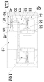
下記に図1〜8をあわせて本願発明について詳しく説明し、便利に説明するために、下記の方向を以下のように規定する:図1は本願発明装置の正面図であり、以下に述べる上下左右前後の方向と図1の自身投影関係の上下左右前後の方向とが一致である。 In order to explain the invention of the present application in detail with reference to FIGS. 1 to 8 below and to explain the present invention in a convenient manner, the following directions are defined as follows: FIG. The left-right front-back direction and the up-down, left-right front-back direction of the self-projection relationship in FIG. 1 coincide with each other.
本願発明は印刷業向けのヒートローラー搬送設備に関し、主にヒートローラー搬送作業に使用され、以下、本願発明図面を参照してさらなる説明をする。 The present invention relates to a heat roller transport facility for the printing industry, and is mainly used for heat roller transport work, and will be further described below with reference to the drawings of the present invention.
本願発明に記載される印刷業向けのヒートローラー搬送設備は、手押し車11を含み、前記手押し車11の上側端面には本願発明を昇降させることができる昇降装置101が設置され、前記昇降装置101は前記昇降装置101をロックできるロック装置102が設置され、前記昇降装置101には前記ロック装置102の下側に位置する連動装置103が設置され、前記連動装置103は前記ロック装置102の動作を触発させることで、前記ロック装置102が前記昇降装置101をロックまたは解除し、前記昇降装置101の中には本願発明を左右に移動させる横移動装置104が設置され、前記横移動装置104の左側には挟持装置105が設置され、前記挟持装置105は固定ロッド24、シリンダー22、エア空間23、スライド栓31、プッシュロッド28、プッシュ板27、上挟持ロッド34、挟持ロッド25、回転軸74、回転ロッド77、前記回転ロッド77の上向きの回転、前記上挟持ロッド34の下向きの移動、前記プッシュ板27の左向きの移動により、ヒートローラーを挟んで固定し、前記固定ロッド24が前記横移動装置104の左側に設置され、前記シリンダー22が前記固定ロッド24の右側端面と左側端面に固定的に連結され、前記エア空間23が前記シリンダー22の中に設置され、前記スライド栓31が前記エア空間23の中にはがスライド可能に連結され、前記プッシュロッド28がそれぞれ右側の前記スライド栓31の左側端面と左側の前記スライド栓31の下側端面に固定的に連結され、右側の前記プッシュロッド28が左方へ右側の前記固定ロッド24の左側端面の左側まで延在し、左側の前記プッシュロッド28が下方へ左側の前記エア空間23の端面の外側まで延在し、前記プッシュ板27が右側の前記プッシュロッド28に固定的に連結されかつ前記固定ロッド24の左側端面の左側に位置し、前記上挟持ロッド34が左側の前記プッシュロッド28に固定的に連結されかつ前記固定ロッド24の左側端面にスライド可能に連結され、また前記上挟持ロッド34が前記プッシュ板27の上側に位置し、前記挟持ロッド25が前記固定ロッド24の左側端面に固定的に連結されかつ前記プッシュ板27の下側に位置し、前記回転軸74が前記挟持ロッド25の後側端面に回転可能に設置されかつ前方へ前記挟持ロッド25の前側端面の外側まで延在し、前記回転ロッド77が前記回転軸74に固定的に連結されている。
The heat roller transport facility for the printing industry described in the present invention includes a
有益なように、前記手押し車11には手押しハンドルが付いている。
For convenience, the
前記昇降装置101はモーター軸41を含み、前記モーター軸41が前記手押し車11の上側端面に回転可能に設置されかつ上方に延在し、前記モーター軸41には前記手押し車11の上側端面に固定的に連結されたモーター15が伝動可能に連結され、前記モーター軸41には止めリング16が固定的に連結され、前記モーター軸41には前記止めリング16の上側に位置するスライド歯車17がフェザーキーにより連結され、前記手押し車11の後側端面にはL字型固定台44が固定的に連結され、前記L字型固定台44の上側内壁には下方に延在するネジロッド19が固定的に連結され、前記ネジロッド19と前記モーター軸41とが等しい直径を有し、また前記ネジロッド19と前記モーター軸41との軸線が同一の直線であり、前記スライド歯車17が前記ネジロッド19とフェザーキーにより連結され、前記ネジロッド19には前記スライド歯車17の上側に位置する電磁石14が固定的に連結され、前記ネジロッド19には前記電磁石14の上側に位置する固定リング18が固定的に連結され、前記ネジロッド19には昇降箱36がネジ山により連結され、前記ネジロッド19が前記昇降箱36を貫通し、
前記モーター15により前記ネジロッド19を駆動して回転させ、前記ネジロッド19がネジ山での連結により前記昇降箱36を駆動して上下に移動させる。
The elevating
The
前記ロック装置102は前記昇降箱36の下側端面に固定的に連結された挟持箱51を含み、前記挟持箱51の中には挟持空間52が設置され、前記ネジロッド19が前記挟持空間52を貫通し、前記挟持空間52の左側内壁と右側内壁にはそれぞれコンロッド54が回転可能に連結され、二つの前記コンロッド54が左右対称位置に設置され、前記コンロッド54において対称中心に近接した一端には前後に延在するスライドピン59が回転可能に連結され、前記スライドピン59には前記コンロッド54の後側に位置する揺れロッド55が固定的に連結され、前記挟持空間52の後側内壁には左右対称位置に二つの挟持ブロック56がスライド可能に連結され、前記挟持ブロック56が前記ネジロッド19と当接しかつ前記揺れロッド55とヒンジで連結され、
前記コンロッド54と前記揺れロッド55との回転により、前記挟持ブロック56が駆動されて対称中心から離れた片側へ移動し、前記挟持ブロック56が前記ネジロッド19との当接から離脱し、前記ロック装置102が前記ネジロッド19をロックすることにより、前記ネジロッド19と前記昇降箱36との間のロックが解除された後に前記昇降箱36が下方に移動することを避ける。
The
The rotation of the connecting
前記連動装置103は副シリンダー45を含み、前記副シリンダー45が前記挟持箱51の下側端面に固定的に連結され、かつ前記ネジロッド19の左側に位置し、前記副シリンダー45には副エア空間46が設置され、前記副エア空間46の中には副スライド栓47がスライド可能に連結され、前記副スライド栓47の上側端面には昇降ロッド48が固定的に連結され、前記昇降ロッド48が上方へ前記挟持空間52の中まで延在し、前記昇降ロッド48の上側端面には前記副エア空間46の端面の外側に位置する横ロッド50が固定的に連結され、前記横ロッド50の上側端面には左右対称位置に二つの副プッシュロッド53が固定的に連結され、前記副プッシュロッド53の上側端面には昇降ブロック57が固定的に連結され、前記昇降ブロック57の中には前後方向に貫通するスライド溝58が形成され、前記スライド溝58が前記スライドピン59とスライド可能に連結され、前記固定リング18の左側端面にはピストンシリンダー63が固定的に連結され、前記ピストンシリンダー63の中にはピストン空間64が設置され、前記ピストン空間64の中にはピストン65がスライド可能に連結され、前記ピストン65の下側端面には下方へ前記ピストン空間64の端面の外側まで延在するピストンロッド62が固定的に連結され、前記ピストンロッド62には前記ピストン空間64の端面の外側に位置する固定ブロック61が固定的に連結され、前記ピストン空間64と前記副エア空間46とが空気管20により連通するように連結され、
前記電磁石14が通電して前記固定ブロック61に吸い付くことにより、前記ピストン65が下方に移動して負圧を生み出し、かつ前記空気管20により前記副スライド栓47が下方に移動することで、前記昇降ブロック57が駆動されて前記コンロッド54を下方に回転させ、さらに前記ネジロッド19へのロックを解除して前記ネジロッド19を固定しなくなる。
The interlocking
When the
有益なように、前記副スライド栓47と前記副エア空間46の上側内壁とが引っ張りばね49により連結されている。
Beneficially, the sub-slide plug 47 and the upper inner wall of the
前記横移動装置104は回転軸12を含み、前記回転軸12が前記手押し車11の上側端面に回転可能に連結され、かつ上方に延在し、前記回転軸12が前記ネジロッド19の右側に位置し、前記回転軸12には前記スライド歯車17と噛み合うように連結される歯車13が固定的に連結され、前記歯車13が前記昇降箱36の下側に位置し、前記昇降箱36の中には横移動空間37が設置され、前記回転軸12が前記横移動空間37を貫通し、前記横移動空間37の下側内壁には前記回転軸12とフェザーキーにより連結されたスライド筒40が回転可能に連結され、前記スライド筒40の上側端面には前記回転軸12とスライド可能に連結された副傘歯車39が固定的に連結され、前記横移動空間37の後側内壁には前方に延在する歯車軸42が回転可能に連結され、前記歯車軸42には前記副傘歯車39と噛み合うように連結された傘歯車38が固定的に連結され、前記歯車軸42には前記傘歯車38の後側に位置する副歯車43が固定的に連結され、前記横移動空間37の下側内壁には左右方向に前記横移動空間37の両側端面の外側まで延在するラック35がスライド可能に連結され、前記ラック35が前記副歯車43と噛み合うように連結され、
前記歯車13がフェザーキーでの連結により前記スライド筒40を駆動して回転させ、前記副歯車43を駆動して回転させ、前記ラック35を駆動して左右に移動させる。
The
The
有益なように、前記傘歯車38と前記副傘歯車39との速度伝達比は一対一である。
To be beneficial, the speed transmission ratio between the
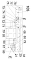
前記挟持装置105は前記ラック35の左側端面に固定的に連結された前記固定ロッド24を含み、前記挟持ロッド25の上側端面にはタッチスイッチ33が設置され、前記プッシュ板27の左側端面には滑車29が回転可能に連結され、前記回転ロッド77の上側端面には回転車78が回転可能に連結され、前記挟持ロッド25の前側端面には蒸気タービン75が固定的に連結され、前記回転軸74が前方へ前記蒸気タービン75の前側端面の外側まで延在し、前記蒸気タービン75が前記回転軸74を駆動して回転させることができ、前記回転軸74には前記回転軸74の前側に位置するカム73が固定的に連結され、前記蒸気タービン75の左側端面には前記カム73と当接できる副位置制限ブロック76が固定的に連結され、前記蒸気タービン75の前側端面には前記カム73と当接できる位置制限ブロック72が固定的に連結され、前記挟持ロッド25の下側端面には前記蒸気タービン75の右側に位置するエアポンプ26が固定的に連結され、前記エアポンプ26と前記蒸気タービン75とが副空気管70により連通するように連結され、前記挟持ロッド25の下側端面には前記エアポンプ26の右側に位置するバルブボディー79が固定的に連結され、前記バルブボディー79の中にはスライド空間80が設置され、前記スライド空間80の中にはスライダ81がスライド可能に連結され、前記スライダ81の中には右方かつ下方に開口する連通空間82が設置され、前記連通空間82の下側開口部には密封板83が回転可能に連結され、前記密封板83が前記連通空間82の下側端面と当接できることを通して前記密封板83が前記連通空間82へ回転することを制限し、前記密封板83において回転連結部にはトーションばね84が設置され、前記スライド空間80と前記エアポンプ26とが気送管66により連通するように連結され、前記連通空間82の下側開口部が前記気送管66と前記スライド空間80との連通部に位置でき、前記スライド空間80と左側の前記エア空間23とが連結管21により連通するように連結され、右側の前記エア空間23と前記連結管21とが連通管32により連通するように連結され、前記連結管21が前記連通空間82の右側開口と連通し、前記挟持ロッド25の前側端面には前記エアポンプ26の上側に位置する連結ロッド68がスライド可能に連結され、前記連結ロッド68の左側端面には前記カム73と当接するプッシュブロック71が固定的に連結され、前記連結ロッド68と前記エアポンプ26とがばね60により連結され、前記連結ロッド68の右側端面にはスライドロッド67が固定的に連結され、前記スライドロッド67が右方へ前記スライド空間80の中まで延在し、かつ前記スライダ81の左側端面と固定的に連結され、
前記エアポンプ26の作動で気流が生じることにより、前記回転ロッド77が駆動されて上方へ回転し、右側の前記スライド栓31が駆動されて左方に移動し、左側の前記スライド栓31が下方に移動し、前記滑車29、前記上挟持ロッド34、前記回転車78がヒートローラーと当接することを通してヒートローラーを挟持固定する。
The
When the
以下、図1〜8を参照して本願発明の印刷業向けのヒートローラー搬送設備の使用手順について詳しく説明する。 Hereinafter, the procedure for using the heat roller transfer equipment for the printing industry of the present invention will be described in detail with reference to FIGS. 1 to 8.
はじめの時、電磁石14が通電し、電磁石14がスライド歯車17と固定ブロック61に吸い付くことにより、スライド歯車17が一番上に位置し、スライド歯車17がネジロッド19と、モーター軸41といずれもフェザーキーにより連結され、スライド歯車17が歯車13との連結から離脱し、固定ブロック61、副スライド栓47、昇降ロッド48、横ロッド50、副プッシュロッド53、昇降ブロック57が一番下に位置し、挟持ブロック56がネジロッド19と当接しなく、密封板83がトーションばね84の弾力作用で連通空間82の下側端面と当接し、カム73が位置制限ブロック72と当接し、プッシュブロック71、連結ロッド68、スライドロッド67が一番右に位置し、スライダ81が気送管66とスライド空間80とを連通しないようにし、回転ロッド77が水平位置にあり、上挟持ロッド34が一番上に位置し、プッシュ板27が一番右に位置する。
At the beginning, the
作動する時、手動で手押し車11を指定位置に押し、モーター15を作動させ、モーター15がモーター軸41を駆動して回転させ、ネジロッド19がネジ山での連結により昇降箱36を上下に移動させて指定位置に至らせた後、電磁石14が停電し、スライド歯車17が重力作用で止めリング16と接触するまで下方に移動し、それと同時にスライド歯車17が歯車13と噛み合うように連結され、スライド歯車17がネジロッド19から離脱してネジロッド19とフェザーキーにより連結されなくなり、ネジロッド19が回転を止め、引っ張りばね49の弾力作用で、副スライド栓47が上方に移動し、かつ昇降ロッド48、横ロッド50、副プッシュロッド53、昇降ブロック57を駆動して上方に移動させ、昇降ブロック57がスライド溝58とスライドピン59とのスライド可能な連結によりコンロッド54と揺れロッド55を駆動して上方に回転させ、かつ昇降ブロック57が挟持ブロック56を駆動して対称中心に近接した片側へ移動させてネジロッド19と当接させ、ネジロッド19を挟持固定し、副スライド栓47が上方に移動する過程に生じた負圧が気送管20を介してピストン空間64の中に輸送され、かつ負圧がピストン65、ピストンロッド62、固定ブロック61を駆動して上方へ一番上に移動させ、それと同時にスライド歯車17が噛合での連結により歯車13と回転軸12を駆動して回転させ、回転軸12がフェザーキーでの連結によりスライド筒40を駆動して回転させ、スライド筒40が副傘歯車39と傘歯車38との噛合での連結により歯車軸42と副歯車43を駆動して回転させ、副歯車43が噛合での連結によりラック35を駆動して左右に移動させて指定位置に至らせた後、モーター15が回転を止める。
When operating, manually push the
同時に、ヒートローラーが下側のタッチスイッチ33と接触して下側のタッチスイッチ33を触発させ、エアポンプ26を作動させて気流を生み出し、一部の気流が副空気管70を介して副位置制限ブロック76の中に輸送され、かつ回転軸74と回転ロッド77を駆動して回転させ、回転ロッド77が上方へ九十度回転した後、カム73が副位置制限ブロック76と当接し、回転軸74と回転ロッド77が回転を止め、連結ロッド68がばね60の弾力作用で左方に移動し、連結ロッド68がスライドロッド67によりスライダ81を駆動して左方に移動させることにより、気送管66がスライド空間80と、連結管21と連通するようになり、エアポンプ26の中の気流が気送管66、スライド空間80、連結管21、連通管32を通してエア空間23の中に輸送され、かつ二つのスライド栓31とプッシュロッド28を押し動かして移動させ、プッシュ板27が左方に移動し、上挟持ロッド34が下方に移動することにより、滑車29、上挟持ロッド34、回転車78がヒートローラーと当接し、ヒートローラーを挟んで固定し、その後、エアポンプ26が回転を止め、ヒートローラーへのロックを解除してヒートローラーを固定しない時、エアポンプ26が逆方向に回転し、エアポンプ26から生じた負圧が副空気管70を介して蒸気タービン75の中に伝達され、かつ回転軸74、カム73、回転ロッド77を駆動して逆方向に回転復帰させ、カム73が位置制限ブロック72と当接した後、回転軸74が回転を止め、同時にカム73がプッシュブロック71、連結ロッド68、スライドロッド67を右方に押し動かすことで、スライダ81が気送管66とスライド空間80との連通口を塞ぎ、エアポンプ26が生じた負圧が密封板83を駆動して下方へ回転させることで、気送管66が連通空間82と、連結管21と連通し、負圧が気送管66、連通空間82、連結管21、連通管32を通してエア空間23の中に伝達され、かつスライド栓31を駆動して復帰させ、プッシュ板27が右方に移動復帰し、タッチスイッチ33が上方に移動復帰し、ヒートローラーをロックしなくなる。
At the same time, the heat roller contacts the
本願発明の有益な効果は:本願発明の昇降装置がネジロッド及びナット構成を利用し、安定的に昇降でき、昇降装置の下側には安全装置が設置され、昇降装置が回転を止めた後にこの安全装置が回転してネジロッドを固定することができ、ネジロッド及びナットは外力の衝撃で自動的なロック機能が効かないために本願発明が下方に移動することを避け、同時に挟持固定装置がエアポンプによりエアシリンダーの伸縮を駆動することにより異なる直径のあるヒートローラーに対応でき、また、挟持固定装置は上下二つの挟持板及び左右二つの挟持ブロックにより、四つの方向からヒートローラーと当接して固定することができ、ヒートローラーをきつく挟持固定でき、従って、本願発明は自動的に異なる直径のあるヒートローラーに対応してヒートローラーをきつく挟持固定でき、広い適応範囲及び高い安全性を有する。 The beneficial effect of the present invention is: The lifting device of the present invention can be lifted and lowered stably by using the screw rod and nut configuration, and a safety device is installed under the lifting device, and this is performed after the lifting device stops rotating. The safety device can rotate to fix the screw rod, and the screw rod and nut do not have the automatic locking function due to the impact of external force, so the present invention avoids moving downward, and at the same time, the pinching fixing device is operated by the air pump. By driving the expansion and contraction of the air cylinder, it is possible to handle heat rollers with different diameters, and the holding and fixing device is fixed by contacting the heat rollers from four directions with two upper and lower holding plates and two left and right holding blocks. The heat roller can be tightly pinched and fixed, and therefore the present invention can automatically pinch and fix the heat roller corresponding to heat rollers having different diameters, and has a wide range of application and high safety.
上記の方式によって、当業者は本発明の範囲内で作動モードに基づいて様々な変わりを行える。 By the above method, those skilled in the art can make various changes based on the operation mode within the scope of the present invention.
Claims (9)
Applications Claiming Priority (2)
| Application Number | Priority Date | Filing Date | Title |
|---|---|---|---|
| CN201910797964.6 | 2019-08-27 | ||
| CN201910797964.6A CN110451433B (en) | 2019-08-27 | 2019-08-27 | A hot-roller haulage equipment for printing industry |
Publications (1)
| Publication Number | Publication Date |
|---|---|
| JP2021031299A true JP2021031299A (en) | 2021-03-01 |
Family
ID=68489448
Family Applications (1)
| Application Number | Title | Priority Date | Filing Date |
|---|---|---|---|
| JP2019217451A Pending JP2021031299A (en) | 2019-08-27 | 2019-11-29 | Heat roller conveyor for printing business |
Country Status (2)
| Country | Link |
|---|---|
| JP (1) | JP2021031299A (en) |
| CN (1) | CN110451433B (en) |
Families Citing this family (6)
| Publication number | Priority date | Publication date | Assignee | Title |
|---|---|---|---|---|
| CN110722088B (en) * | 2019-11-28 | 2020-12-18 | 江苏华兴特钢铸造有限公司 | Forge piece carrying device for free forging processing |
| CN110834247B (en) * | 2019-12-02 | 2020-09-11 | 阜南县中泰工艺品有限公司 | A burnishing and polishing equipment for wood carving aftertreatment |
| CN111204687B (en) * | 2020-01-15 | 2022-04-05 | 南京信息职业技术学院 | Automatic change transfer robot |
| CN111056492A (en) * | 2020-02-05 | 2020-04-24 | 诸暨利心输送机械科技有限公司 | Transfer equipment is used in commodity circulation transportation |
| CN112519861B (en) * | 2021-01-14 | 2022-02-01 | 运易通科技有限公司 | Auxiliary placing and conveying device for logistics transportation |
| CN113320989B (en) * | 2021-05-26 | 2023-07-25 | 黄河水利职业技术学院 | Automatic feeding device for PCB production and working method thereof |
Citations (3)
| Publication number | Priority date | Publication date | Assignee | Title |
|---|---|---|---|---|
| JPH047300A (en) * | 1990-04-25 | 1992-01-10 | Eikou Kaiji Kogyo Kk | Brake for elevating cargo |
| JPH05286699A (en) * | 1992-04-06 | 1993-11-02 | Shimpo Ind Co Ltd | Motor-driven lift with mobility |
| JP2002029310A (en) * | 2000-07-17 | 2002-01-29 | Mitsubishi Heavy Ind Ltd | Loading cargo support device for carrying vehicle |
Family Cites Families (8)
| Publication number | Priority date | Publication date | Assignee | Title |
|---|---|---|---|---|
| JPH10120486A (en) * | 1996-10-14 | 1998-05-12 | Super Silicon Kenkyusho:Kk | Large-bore crucible turnover apparatus |
| CN205687495U (en) * | 2016-06-07 | 2016-11-16 | 厦门合泽机械设备有限公司 | A kind of voltage stabilizing side shifting type ejecting device |
| CN205990217U (en) * | 2016-08-26 | 2017-03-01 | 邓琅 | A kind of automobile tire clamps transporting forklift |
| CN107344705B (en) * | 2017-08-31 | 2023-06-06 | 广西派莱特科技有限公司 | Fork truck and method for boxing by utilizing same |
| CN108483352A (en) * | 2018-04-03 | 2018-09-04 | 王灿灿 | A kind of fork truck |
| CN208843683U (en) * | 2018-11-15 | 2019-05-10 | 海南电网有限责任公司 | Calculator room equipment lifting device |
| CN109665463A (en) * | 2019-01-25 | 2019-04-23 | 江苏达力叉车有限公司 | One kind embracing formula fork truck |
| CN110090782B (en) * | 2019-06-17 | 2020-10-30 | 新乡岳衡电子信息技术有限公司 | Automatic equipment of paining of computer heat conduction silicone grease |
-
2019
- 2019-08-27 CN CN201910797964.6A patent/CN110451433B/en active Active
- 2019-11-29 JP JP2019217451A patent/JP2021031299A/en active Pending
Patent Citations (3)
| Publication number | Priority date | Publication date | Assignee | Title |
|---|---|---|---|---|
| JPH047300A (en) * | 1990-04-25 | 1992-01-10 | Eikou Kaiji Kogyo Kk | Brake for elevating cargo |
| JPH05286699A (en) * | 1992-04-06 | 1993-11-02 | Shimpo Ind Co Ltd | Motor-driven lift with mobility |
| JP2002029310A (en) * | 2000-07-17 | 2002-01-29 | Mitsubishi Heavy Ind Ltd | Loading cargo support device for carrying vehicle |
Also Published As
| Publication number | Publication date |
|---|---|
| CN110451433A (en) | 2019-11-15 |
| CN110451433B (en) | 2020-12-08 |
Similar Documents
| Publication | Publication Date | Title |
|---|---|---|
| JP2021031299A (en) | Heat roller conveyor for printing business | |
| JP6754037B1 (en) | Auxiliary maintenance system for small airplanes | |
| CN105110238B (en) | Double freedom automatically controls scissor-type material conveyer | |
| JP2021046249A (en) | Device for inspecting product package printing | |
| JP2021020308A (en) | Steel material cutting equipment for reinforced concrete | |
| JP2020200184A (en) | Book management facility to be applied to large library | |
| JP2011156621A (en) | Transfer device | |
| WO2021143773A1 (en) | Food forming method and forming mechanism | |
| JPH05146935A (en) | Article handling device | |
| WO2012139460A1 (en) | Guider for conveying sheet-shaped object | |
| JP2021008698A (en) | Printing apparatus for producing fur | |
| CA2992993C (en) | Belt splicer | |
| WO2018210294A1 (en) | Vending machine product-pushing mechanism | |
| CN112638813B (en) | Elevator car door device | |
| US11241870B2 (en) | Membrane bearing device and membrane attaching apparatus | |
| CN206998373U (en) | A kind of line rail Dual-station pneumatic fixture | |
| CN112830150B (en) | Battery auxiliary carrying equipment for new energy automobile production | |
| CN207720536U (en) | A kind of novel upper sheet frame | |
| CN112684902A (en) | Anti-misoperation device in electrical intelligent manufacturing system | |
| ITBO20050013A1 (en) | NOZZLE FOR SECONDARY DOOR OF FIREPROOF DOORS | |
| CN104106837B (en) | A kind of tobacco leaf folding device | |
| CN206530162U (en) | A kind of emergent door opener | |
| JP3241974U (en) | Control system for control valve components in unit piping | |
| CN207067128U (en) | A kind of 3D bend glasses screen detection clamping switching mechanism | |
| KR100774660B1 (en) | Glass door apparatus |
Legal Events
| Date | Code | Title | Description |
|---|---|---|---|
| A521 | Request for written amendment filed |
Free format text: JAPANESE INTERMEDIATE CODE: A523 Effective date: 20200330 |
|
| A521 | Request for written amendment filed |
Free format text: JAPANESE INTERMEDIATE CODE: A523 Effective date: 20200619 |
|
| A977 | Report on retrieval |
Free format text: JAPANESE INTERMEDIATE CODE: A971007 Effective date: 20210629 |
|
| A131 | Notification of reasons for refusal |
Free format text: JAPANESE INTERMEDIATE CODE: A131 Effective date: 20210817 |
|
| A02 | Decision of refusal |
Free format text: JAPANESE INTERMEDIATE CODE: A02 Effective date: 20220329 |